Craftsman 917256812 User Manual TRACTOR Manuals And Guides L0910222
CRAFTSMAN Lawn, Tractor Manual L0910222 CRAFTSMAN Lawn, Tractor Owner's Manual, CRAFTSMAN Lawn, Tractor installation guides
User Manual: Craftsman 917256812 917256812 CRAFTSMAN TRACTOR - Manuals and Guides View the owners manual for your CRAFTSMAN TRACTOR #917256812. Home:Lawn & Garden Parts:Craftsman Parts:Craftsman TRACTOR Manual
Open the PDF directly: View PDF ![]() .
.
Page Count: 56

[RRF
MODEL NUMBER 917.256812 OWNER'S MANUAL
=Assembly
° Operation
• Customer Responsibilities
° Service and Adjustments
° Repair Parts
CAUTION: Read and follow all safety rules and instructions before operating this equipment.
FOR CONSUMER ASSISTANCE HOT LINE, CALLTHIS TOLL FREE NUMBER: 1-800-659-5917
SAFETY RULES
Safe Operation Practices for Ride-On Mowers
IMPORTANT: THIS CUTTING MACHINE IS CAPABLE OF AMPUTATING HANDS AND FEET AND THROWING OBJECTS_
FAILURE TO OBSERVE THE FOLLOWING SAFETY INSTRUCTIONS COULD RESULT iN SERIOUS INJURY OR DEATH.
I. GENERAL OPERATION
-Read, understand, and follow all instructions in the manual
and onthe machine before starting.
,Only ailow responsible aduIts, who are familiar with the
instructions,to operate the machine,
•Clear the area of objects such as rocks, toys, wire, etc.,
which could be picked up and titrown by the blade.
•Besure the area is ctearof other people before mowing. Stop
machine if anyone enters the area_
•Never carry passengers.
• Do not mow in reverse unless absolutely necessary.. Always
look down and behind before and while backing,
•Be aware of the mower discharge direction and do not point
it at anyone. Do not operate the mower without either' the
entire grass catcher or the guard in place..
oSlow down before turning..
° Never leave a running machine unattended, Always turn off
blades, set parking brake, stop engine, and remove keys
before dismounting.
•Tum off blades when not mowing.
° Stop engine before removing grass catcher or unclogging
chute.
•Mow only in daylight or good artificial light.
•Do not operate the machine while under the influence of
alcohol or drugs.
•Watch for traffic when operating near or crossing roadways..
o Use extra care when loading or unloading the machine into
a trailer or truck_
U. SLOPE OPERATION
Slopes are a major factor related to loss-of-control and tipover
accidents, which can result in severe injury or death. All slopes
requireextra caution., if you cannot back up the slope or ifyou feet
uneasy on it, do not mow iL
DO:
•Mow up and down slopes, not across.
= Remove obstacles such as rocks, tree limbs, etc.
oWatch for holes, ruts, or bumps. Uneven terrain couid
overturn the machine. Tall grass can hide obstacles.,
=Use slowspeed. Choose a low gear so that you will not have
to stop or shift while on the slope_
oFollow the manufacturer's recommendations for wheel
weights or counterweights to improve stability.
° Use extra care with grass catchers or other attachments,
These can change the stability of the machine.,
, Keep all movement on the slopes slow and gradual Do not
make sudden changes in speed or direction_
•Avoid starting or stopping on a slope, if tires lose traction,
disengage the blades and proceed s{owly s_raight down the
slope°
DO NOT:
°Do not turn on slopes unlessnecessary, and then, turn slowly
and gradually downhill, if possible.
•Do not mow near drop-otis, ditches, or embankments. The
mower could suddenly turn over if a wheel is over the edge
of acliffor d{tch,or if an edge caves in.
°Do not mow on wet grass. Reduced traction could cause
sliding.
°Do not try to stabilize the machine by puttingyour foot on the
greund_
°Do not use grass catcher on steep slopes.
2
Ul. CHILDREN
Tragic accidents can occur if the operator is not alert to the
presence of children. Children are often attracted tothe machine
and the mowingactivity. Never assume that children will remain
where you last saw them.
• Keep childrenoutof the mowing area and under thewatchful
care of another responsible adult.
• Be alert and turn machine off if children enter the'area,
= Before and when backing, look behind and down for small
children.
°Never carry children. They may raft off and be seriously
injuredor interfere with safe machine operation,.
•Never allow childrento operate the machine.
°Use extra care when approaching blind comers, shrubs,
trees, or other objects that may obscure vision.
IV. SERVICE
-Use extra care inhandlinggasoline andother fuels They are
flammable and vapors are explosive.
-Use only an approved container..
Never remove gas cap or add fuel with the engine
running. Allow engine to cool before refueling. Do not
smoke.
Never refuel the machine indoors..
Never' store the machine or fuel container inside where
there is an open flame, such as a water heater_
° Never run a machine inside a closed area.
•Keep nuts and boils, especially blade attachment boffs, tight
and keep equipment in good condition_
°Never tamper with safety devices° Check their proper
operation regularly_
•Keep machine free of grass, leaves, orother'debrisbuffd-up.
Clean oil or fuel spillage. At!ow machine to cool before
storing..
°Stop and inspect the equipment if you strike an object.,
Repair, if necessary, before restarting,.
•Never make adjustments or repairs with the engine running_
° Grass catcher components are subjectto wear, damage, and
deterioration, which could expose moving parts or attow
objects to be thrown, Frequently check components and
replace withmanufacturer's recommended parts,when nec-
essary.
° Mower blades are sharp and can cut. Wrap the blade(s) or
wear gloves, and use extra caution when servicing them.
• Check brake operation frequently. Adjust and service as
required ................................
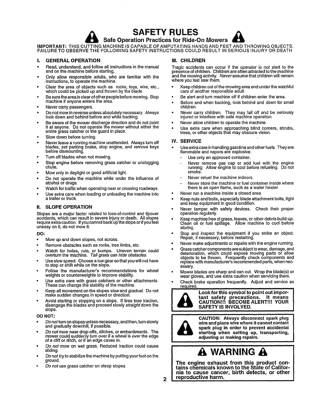
Look for this symbol to point out impor-i
tant safety precautions. It means |
CAUTION!!! BECOME ALERT!ff YOUR i
SAFETY IS INVOLVED. I
wire and place wire where it cannot contact I
spark plug in order to prevent accidental i
starting when setting up, transporting, |
adjusting or making repairs
.................. " i
II!II ....... ULIII........... i,iiii .... : :.
& WARNING &
The engine exhaust from this product con-
tains chemicals known to the State of Califor-
nia to cause cancer, birth defects, or other
reproductive harm.
ii j/1/1/1/1_11:11:11:11ii L I IIjl_ ,...........

CONGRATULATIONS on your purchase of a Sears
Tractor° tt has been designed, engineered and manufac-
tured to give you the best possible dependability and
performance.
Should you experience any problem you cannot easily
remedy, please contact your nearest Sears Authorized
Service CentedDepartment,, We have competent, well-
trained technicians and the proper tools to service or repair
this tractor,,
Please read and retain this manual. The instructions will
enable you to assemble and maintain your tractor properly,,
Always observe the "SAFETY RULES".
MODEL
klUMBER 917.256812
SERIAL
NUMBER
9ATE OF PURCHASE
THE MODELAND SERIAL NUMBERS WILL BE FOUND
ON A PLATE UNDER THE SEAT°
YOU SHOULD RECORD BOTH SERIAL NUMBER AND
DATE OF PURCHASE AND KEEP iN A SAFE PLACE
FOR FUTURE REFERENCE.
MAINTENANCE AGREEMENT
A Sears Maintenance Agreement is available on this prod-
uct. Contact your nearest Sears store for detail&
CUSTOMER RESPONSIBILITIES
• Read and observe the safety rules,
. Follow a regular schedule in maintaining, caring for and
using your tractor.
• Follow the instructions under"Customer ResponsibilF
ties" and "Storage" sections of this owner's manual.
WARNING: This tractor is equipped with an internal
combustion engine and should not be used on or near any
unimproved forest-covered, brush-covered or grass-cov-
ered land unless the engine's exhaust system is equipped
with a spark arrester meeting applicable local or state laws
PRODUCT SPECIFICATIONS
HORSEPOWER: 15.5
GASOLINE CAPACITY 1,25 GALLONS
AND TYPE: UNLEADED REGULAR
OIL TYPE (API-SF/SG): SAE 30 (above 32°F)
SAE 5W-30 (below 32=F)
OIL CAPACITY: 3.0 PINTS
SPARK PLUG: CHAMPION RJ19LM
(GAP: ..030") STD 361458
VALVE CLEARANCE: INTAKE: .005" - ,007"
EXHAUST: °009" - ,011"
GROUND SPEED (MPH): FORWARD:
1st 1,0
2nd 1.3
3rd 2.1
4th 3.1
5th 4.0
6th 5ol
REVERSE: 16
TIRE PRESSURE: FRONT: 14 PSI
REAR: 12 PSi
CHARGING SYSTEM: 3 AMPS BATTERY
5 AMPS HEADLIGHTS
BATTERY: AMP/HR: 25
MIN. CCA: 190
CASE SIZE: U1R
BLADE BOLT TORQUE: 30-35 FT. LBSo
(if any)° If a spark arrester is used, it should be maintained
in effective working order by the operator.
In the state of California the above is required by law
(Section 4442 of the California Public Resources Code).
Other states may have similar taws. Federal laws apply on
federal lands,, A spark arrester for the muffler is available
through your nearest Sears Authorized Service Center/
Department (See REPAIR PARTS section of this manual).
_J:: .... ........: ......... ::....................................................
LIMITED TWO YEAR WARRANTY ON CRAFTSMAN RIDING EQUIPMENT
For two (2) years from the date of purchase, if this Craftsman Riding Equipment is maintained, lubricated and tuned up according
to the instructions in the owner's manual, Sears will repair or replace, tree of charge, any parts found to be defective in material
or workmanship°
This Warranty does not cover:
•Expendable itemswhich become worn during normal use, such as blades, spark plugs, air cleaners, belts, etc.
•Tire replacement or repalr caused by punctures from outside objects, such as nails, thorns, stumps, or glass°
• Repairs necessary because of operator abuse, negligence, improper storage or accident or the failure to maintain the
equipment according to the instructions contained in the owner's manual.
• Riding equipment used for commercial or rental purposes°
LIMITED 90 DAY WARRANTY ON BATTERY
For ninety (90) days from date of purchase, if any battery included with this riding equipment proves defective in mater_al or
workmanship and our testing determines the battery wiEInot hold a charge, Sears will replace the battery at no charge°
IN-HOME WARRANTY SERVICE ON YOUR CRAFTSMAN RIDING EQUIPMENT IS AVAILABLE AT NO-CHARGE FOR 30
DAYS FROM THE DATE OF PURCHASE, PLEASE CONTACT YOUR NEAREST SERVICE CENTER. AFTER 30 DAYS
FROM THE DATE OF PURCHASE, WARRANTY SERVICE IS AVAILABLE BY TAKING YOUR CRAFTSMAN RIDING EQUIP-
MENT TO 'fOUR NEAREST SEARS SERVICE CENTER. (IN-HOME WARRANTY SERVICE WiLL STILL BE AVAILABLE
AFTER 30 DAYS FROM THE DATE OF PURCHASE BUT A STANDARD TRIP CHARGE WILL APPLY°) THIS WARRANTY
APPLIES ONLY WHILE THIS PRODUCT tS 1NTHE UNITED STATES.
This Warranty gives you specific legal rights, and you may also have other rights which may vary from slate to state..
SEARS, ROEBUCK AND CO,, D/817 WA, HOFFMAN ESTATES, IL 60179
TABLE OF CONTENTS
SAFETY RULES ............................................................ 2
PRODUCT SPECIFICATIONS ...................................... 3
CUSTOMER RESPONSIBILITIES ..................... 3, 15-19
WARRANTY ........................................ •......................... 3
TRACTOR ACCESSORIES .......................................... 5
ASSEMBLY ................................................................ 7-9
OPERATION ........................................................... 10_14
MAINTENANCE SCHEDULE ...................................... 15
SERVICE AND ADJUSTMENTS ............................ 20-25
STORAGE ................................................................... 26
TROUBLESHOOTING ............................................ 27-28
REPAIR PARTS -TRACTOR ................................. 30-47
REPAIR PARTS - ENGINE .................................... 48-53
PARTS ORDERING/SERVICE ................ BACK COVER
INDEX
A
Accessories .........................................................5
Adjustments:
Brake ...........................................................22
Carburetor ....................................................25
Mower
Front-To-Back ....................................21
Side-To-Side .................................21
Throttle Control Cable ........................24
Air Filter, Engine ................................................18
Air Screen, Engine .............................................18
Assembly ..........................................................7-9
B
Battery:
Charging .....................................................9
Clean{ng ...........................................................17
Levels......................................................17
Starting with Weak Battery ........... 23
Storage ......................................................26
Terminals ...........................................t7
Belt:
Motion Drive
RemovaVReplacement ............ 22
Mower Blade(s)
Removal/Replacement .............22
Blade:
Sharpening ......................................................I6
Replacement ......................................t6
Brake Adjustment .......................................22
C
Carburetor Adjustment ...............................25
Controls, Tractor .............................................11
Customer Responsibilities ................15-19
Engine:
Atr Filter ......................................................18
Air Screen, Engine ......................18
Cooling Fins, Engine ........................18
Engine Oil .....................................17
Fuel Filter .................................................19
Spark Plug(s) ...................................19
Tractor:.
Battery.........................................................17
Blade ..................................................16
Lubrication Chad ............................15
Maintenance Schedule ..............15
Tire Care ..................................9,I6,23
Transaxle .......................................17
Cutting Height, Mower ....................................12
E
Electdcah
Interlocks and Relays .......................24
Schematic ...................................................29
Wiring Diagram ......................................30
Engine:
Air Filter .....................................................18
Air Screen .................................................t8
Cooling Fins, Engine ...........................18
Oil Change .................................................17
Oil Level ..........................................13,t7
Oil Type ....................................................17
Preparation .......................................13
Repair Parts......................................48-53
Stading...................................................t4
Storage ...................................................26
F
Filter:
Air Filter......................................................18
Fuel .....................................................19
Fuel:
Type ............................................................13
Storage ................................................26
Fuse .................................................................24
H
Hood Removalllnstaliation ......................24
L
Leveling Mower Deck ......................................21
Lubrication:
Chad .......................................................15
M
Maintenance Schedule ............................15
Mower:
Adjustment, Front-to-Back .............21
Adjustment, Side-to-Side .....................2I
Blade Sharpening ......................... 16
Blade Replacement ...........................16
Cutting Height .........................................12
Installation............................................20
Operation ........................................................13
Removal ......................................................20
Mowing Tips .................................................14
Muffler ....................................................................19
Spark Arrestor ..................................3,40
O
Oil:
Cold Weather Conditions .............13,17
Engine ................................................. 17
Storage .................................................26
Operation ........................................................10-I4
Operating Mower .............................................13
Options:
Accessodes .................................................5
Spark Arrester ....................................3,40
P
Parking Brake .........................................11-12
Pads Bag .................................................. 6
Pads, Replacement]Repair ............. 30-47
Product Specifications .........................................3
R
Repair Pads ......................................................30-47
S
Safety Rules ..........................................................2
Seat .................................................................8
Service and Adjustments ............... 20-25
Carburetor ............................................25
Fuse ..........................................................24
Hood Removaltlnstallation ............ 24
Motion Drive Belt
Removal/Replacement ................22
Mower Belt(s)
Removal/Replacement ...............22
Mower Adjustment
Front-to-Back .......................... 21
Side-to-Side ..........................................21
Mower Removal ................................20
Tire Care ....................................9,16,23
Slope Guide Sheet .......................................55
Spark Plug(s) ..................................................19
Specifications .............................................3
Starling the Engine ........................... 13-14
Steering Wheel .......................................... 7,23
Stopping theTractor ...............................12
Storage .....................................................26
T
Throttle Control Cable Adjustment .......25
Tires .......................................................9,t6,23
Trouble ShootZng Chart ...........................27-28
Transaxte ......................................................17
4
W
Warranty ..........................................................3
Widng Diagram ...........................................30
Wiring Schematic ....................................................29
....... iii w ,,_,,,,,_......... ii III'I'I'H............... _ .............. I IIII IW' I ' I I IIII I I'
AND ATTACHMENTS
These accessoriesand attachments were available throughmost Sears retail outlets and service centers when the tractorwas purchased,,
Most Sears stores can order these itemsfor you when you provide the model number of your tractor.
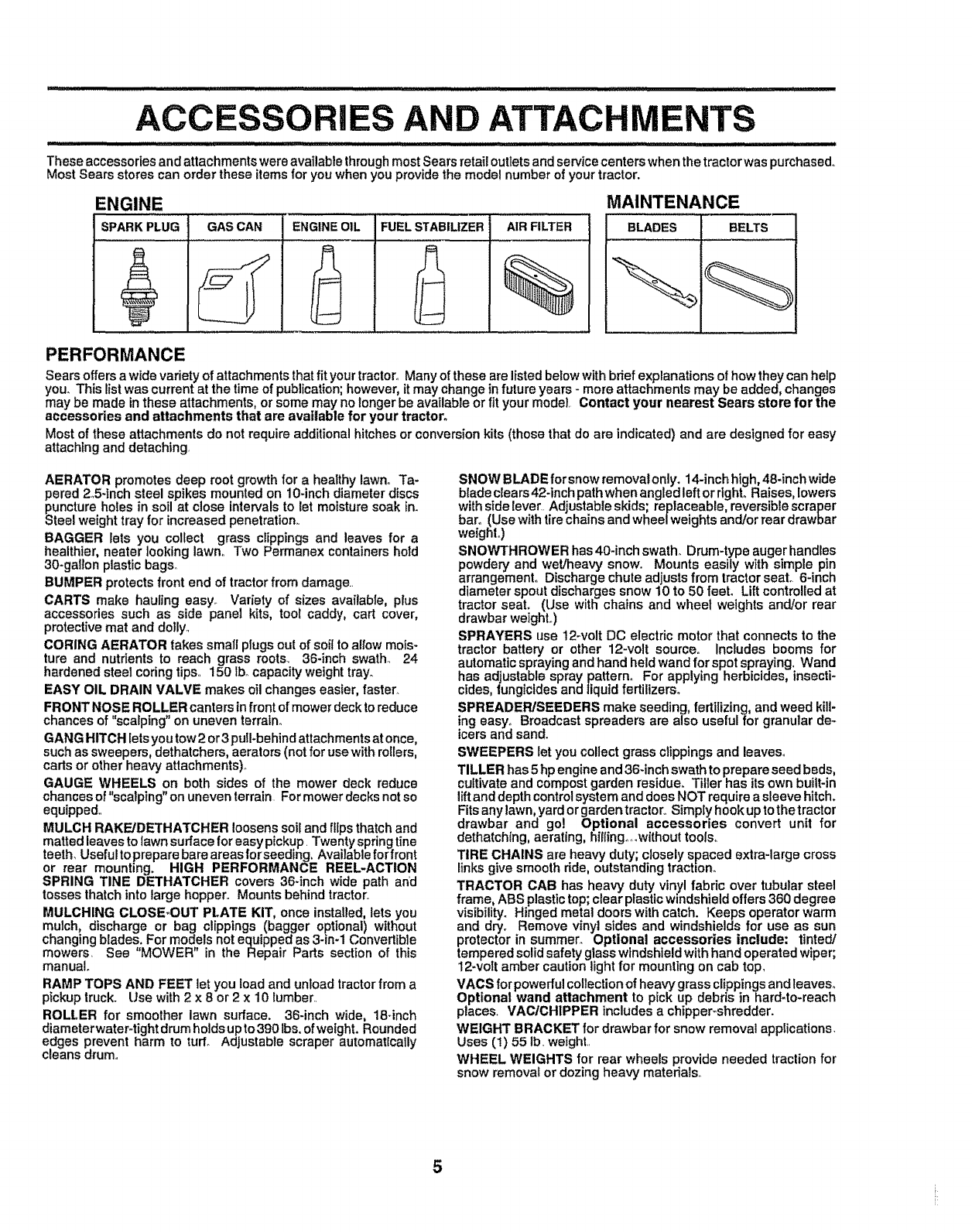
ENGINE MAINTENANCE
SPARKPLUG BLADES BELTSGAS CAN ENGINE OIL FUELSTABILIZER AIRFILTER
%
PERFORMANCE
Sears offers a wide variety of attachments that fit your tractor.,Many of these are listed below with brief explanationsof howthey can help
you. This list was current at the time of publication;however, itmay change in future years - more attachments may be added, changes
may be made in these attachments, or some may no longer be available or fit your model. Contact your nearest Sears store for the
accessories and attachments that are available for your tractor.
Most of these attachments do not require additional hitches or conversion kits (those that do are indicated) and are designed for easy
attaching and detaching,
AERATOR promotes deep root growth for a healthy lawno Ta-
pered 2o5-tnch steel spikes mounted on 10-inch diameter discs
puncture holes in soil at close intervalsto let moisture soak in.
Steel weight tray for increased penetration,,
BAGGER lets you collect grass clippings and leaves for a
healthier, nearer looking lawn. Two Permanex containers hold
30-gallon plastic bags.
BUMPER protects front end of tractor from damage..
CARTS make hauling easy_ Variety of sizes available, plus
accessories such as side panel kits, tool caddy, cart cover,
protective mat and dolly.,
CORING AERATOR takes small plugsout of soil to allow mois-
ture and nutrients to reach grass roots. 36-inch swath., 24
hardened steel coring tips.. 150 Ibocapacity weight tray_
EASY OIL DRAIN VALVE makes oil changes easier, faster_
FRONT NOSE ROLLER canters in front of mower deck toreduce
chances of "scalping" on uneven terraln_
GANG HITCH lets you tow2 or3 pull-behind attach ments at once,
such as sweepers, dethatchers, aerators (notfor use with rollers,
cads or other heavy attachments)°
GAUGE WHEELS on both sides of the mower deck reduce
chances of "scalping" on uneven terrain For mower decks not so
equipped.,
MULCH RAKE/DETHATCHER loosenssoil and flips thatch and
matted leaves to lawn surface for easy pickup. Twentyspring line
teeth, Useful toprepare bare areasforseeding. Available forfront
or rear mounting. HIGH PERFORMANCE REEL-ACTION
SPRING TINE DETHATCHER covers 36-inch wide path and
tosses thatch into large hopper,, Mounts behind tractor.
MULCHING CLOSE.OUT PLATE KIT, once installed, lets you
mulch, discharge or bag clippings (bagger optional) without
changing blades, For models not equipped as 3-in-1 Convertible
mowers, See 'MOWER" in the Repair Parts section of this
manual.
RAMP TOPS AND FEET let you load and unload tractor from a
pickup truck. Use with 2 x 8 or 2 x 10 lumber..
ROLLER for smoother lawn surface. 36-inch wide, 18-inch
diameter water-tightdrum holds up to 390 Ibs, of weight. Rounded
edges prevent harm to turf° Adjustable scraper automatically
cleans drum,,
SNOW BLADE for snow removal only. 14-inch high, 48-inch wide
blade clears42-inch pathwhen angled leftorright. Raises, lowers
with sidelever.. Adjustableskids; replaceable, reversible scraper
bar° (Use withtire chains and wheel weights and/or rear drawbar
weight°)
SNOWTHROWER has 40-inch swath. Drum-type auger handles
powdery and wet/heavy snow,. Mounts easily with simple pin
arrangement° Discharge chute adjusts from tractorseal 6-inch
diameter spout discharges snow 10 to 50 feel Lift controlled at
tractor seat. (Use with chains and wheel weights and/or rear
drawbar weight..)
SPRAYERS use 12-volt DC electric motor that connects to the
tractor battery or other 12-volt source, includes booms for
automatic spraying and hand held wand for spot spraying_ Wand
has adjustable spray pattern. For applying herbicides, insecti*
cides, fungicides and liquid fertilizers°
SPREADER]SEEDERS make seeding, fertilizing, and weed kill-
ing easy° Broadcast spreaders are also useful for granular dm
icers and sand.
SWEEPERS let you collect grass clippings and leaves°
TILLER has 5 hp engine and 36-inch swath to prepare seed beds,
cultivate and compost garden residue. Tiller has itsown built-in
lift and depth controlsystem and does NOT require a sleeve hitch.
Fits any lawn,yard or garden tractor.,Simply hook up to thetractor
drawbar and go! Optional accessories convert unit for
dethatching, aerating, hiilingo_without tools,,
TIRE CHAINS are heavy duty; closely spaced extra-large cross
links give smooth ride, outstanding traction.
TRACTOR CAB has heavy duty vinyl fabric over tubular steel
frame, ABS plastictop; clear plastic windshield offers 360 degree
visibility. Hinged metal doors with catch. Keeps operator warm
and dry. Remove vinyl sides and windshields for use as sun
protector in summer. Optional accessories include: tinted]
tempered solid safety glass windshield with hand operated wiper;
12-volt amber caution light for mounting on cab top,
VACS for powerful collection of heavy grass clippings and leaves°
Optional wand attachment to pick up debris in t_ard-to-reach
places. VAC/CH1PPER includes a chipper_shredder.
WEIGHT BRACKET for drawbar for snow removal applications.
Uses (1) 55 lb, weight,,
WHEEL WEIGHTS for rear wheels provide needed traction for
snow removal or dozing heavy matedals_
5

Parts Bag contents shown full size
(2) Sheet
O Metal
Screws
#10-16 x 1/2
(I) Shoulder Bolt 5/t6-18 (1) Hex Bolt 1/2-13 x I
(1) Lock Washer t/2
(1) Washer 17/32 x I-3/16 x 12 Gauge
(2) Hex Bolts t/4-20 x 3/4 (2) Hex Nuts 1/4-20
(2) Lock Washers 1/4
(2) Washers 9/32 x 5/8 x 16 Gauge
......... Pa_S packed SeParately in carton
, _,,,_........... ill ill ................................
Seat
Steering
Wheel
Manual
Video
Cassette
Steering
Boot
Parts Bag
Parts bag contents not shown full size
Steering Wheel
Adapter Steering
Wheel
Insert
Steering
Bushing
(2) Keys
Slope Sheet
6
LY
......... , ,, , ,,,,, .......... ,,,,....................................
Four new tractor has been assembled at the factory with exception of those parts left unassembled for shipping purposes.
To ensure safe and proper operation of your tractor all parts and hardware you assemble must be tightened securely. Use
the correct tools as necessary to insure proper tightness,
TOOLS REQUIRED FOR ASSEMBLY
A socket wrench set will make assembly easier° Standard
wrench sizes are listed.
(1) 5/16" wrench
(2) 7/16" wrenches
(1) 1/2" wrench
(1) 3/4" wrench
When right and left hand are mentioned in this manual, it
means when you are in the operating position (seated
behind the steering wheel)°
(t) 9/16" wrench
Tire pressure gauge
Utility knife
TO REMOVE TRACTOR FROM CARTON
UNPACK CARTON
° Remove all accessible loose parts and parts cartons
from carton (See page 6),
oCut along lines on carton, from top to bottom, all four
corners of carton and lay panels flat,
-Check for any additional loose parts or cartons and
remove.
BEFORE ROLLING TRACTOR OFF SKID
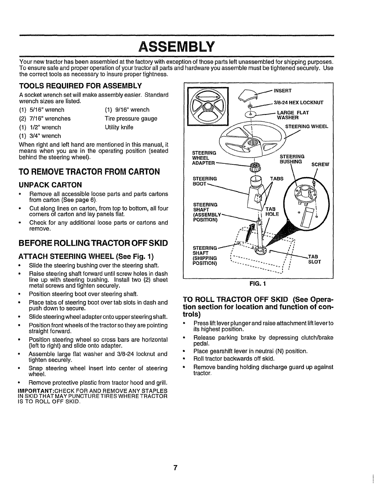
ATTACH STEERING WHEEL (See Fig. 1)
°Slide the steering bushing overthe steering shaft°
°Raise steering shaft forward untilscrew holes in dash
line up with steering bushing. Install two (2) sheet
metal screws and tighten securely,
°Position steering boot over steering shaft.
= Place tabs of steering boot over tab slots in dash and
push down to secure_
°Slide steering wheel adapter onto upper steering shaft,
.Position front wheels of the tractor so they are pointing
straight forward°
•Position steering wheel so cross bars are horizontal
(left to dght) and slide onto adapter,
° Assemble large flat washer and 3/8-24 Iocknut and
tighten securely.
=Snap steering wheel insert into center of steering
wheel,
° Remove protective plastic from tractor hood and grill°
IMPORTANT;CHECK FOR AND REMOVE ANY STAPLES
IN SKIDTHAT MAY PUNCTURETIRES WHERE TRACTOR
IS TO ROLL OFF SKID.
WHEEL t
ADAPTER _
STEERING
SHAFT
(ASSEMBI
POSITION)
BUSHING
,,_ABS
i,HOLE
SCREW
FIG. 1
SLOT
TO ROLL TRACTOR OFF SKID (See Opera-
tion section for location and function of con-
trois)
°Press lift lever plunger and raise attachment liftlever to
its highest position.
° Release parking brake by depressing clutch/brake
pedal°
° Place gearshift lever in neutral (N) position°
•Roll tractor backwards off skid.
°Remove banding holding discharge guard up against
tractor.
7
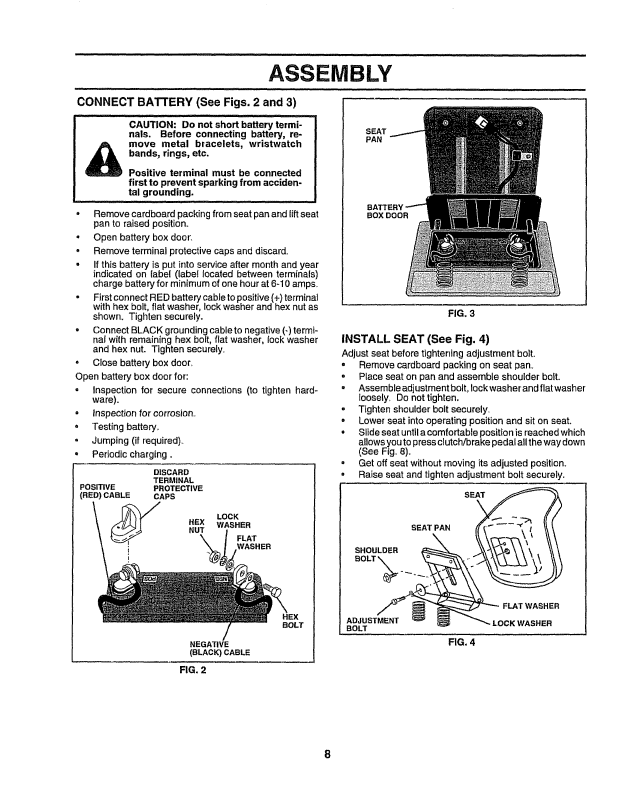
CONNECT BATTERY (See Figs. 2 and 3)
LY
ii i ill • i i iiiiii II_L j,,lll
CAUTION: Do not short battery termi-
nals. Before connecting battery, re-.
move metal bracelets, wristwatch
bands, rings, etc.
Positive terminal must be connected
first to prevent sparking from acciden-
tal grounding.
• Remove cardboard packing from seat pan and lift seat
pan to raised position.
.Open battery box door'.
• Remove terminal protective caps and discard.
• if this battery is put into service after month and year
indicated on label (label located between terminals)
charge battery for' minimum of one hour at 6d 0 ampso
° First connect RED battery cable to positive (+) terminal
with hex bolt, flat washer, lock washer and hex nut as
shown. Tighten securely.
° Connect BLACK grounding cable to negative (-) termi-
nal with remaining hex bolt, flat washer, lock washer
and hex nut. Tighten securely,.
Close battery box door_
SEAT
PAN
BATTERY
BOXDOOR
FIG. 3
INSTALL SEAT (See Fig. 4)
Adjust seat before tightening adjustment boil
•Remove cardboard packing on seat pan.
Open battery box door for:
=Inspection for secure connections (to tlghten hard-
ware)°
° inspection for corrosion,,
* Testing battery,.
. Jumping (if required),,
. Periodic charging.
DISCARD
TERMINAL
POSITIVE PROTECTIVE
(RED) CABLE CAPS
LOCK
HEX WASHER
NUT FLAT
NEGATIVE
(BLACK) CABLE
HEX
BOLT
o Place seat on pan and assemble shoulder bolt.
•Assemble adjustment bolt, lockwasher and flat washer
Ioosely_ Do not tighten.
°Tighten shoulder bolt securely,,
° Lower seat into operating position and sit on seat,
° Slide seat until acomfortable position is reached which
allows you to press clutch/brake pedal all the way down
(See Fig_8)_
•Get off seat without moving its adjusted position.
°Raise seat and tighten adjustment bolt securely.
SEAT
SEAT PAN
SHOULDER
BOLT
X
ADJUSTMENT
BOLT
FIG. 4
FLAT WASHER
LOCK WASHER
FIG. 2
8
BLY
CHECK TIRE PRESSURE ,/'CHECKLIST
The tires on your tractor were ovednflated at the factory for
shipping purposes., Correct tire pressure is important for
best cutting performance,,
o Reduce tire pressure to PSt shown in "PRODUCT
SPECIFICATIONS" on page 3 of this manual,,
CHECK DECK LEVELNESS
For best cutting results, mower housing should be properIy
leveled° See "TO LEVEL MOWER HOUSING" in the
Service and Adjustments section of this manual,,
CHECK FOR PROPER POSITION OF ALL
BELTS
See the figures that are shown for replacing motion and
mower blade drive belts in the Service and Adjustments
section of this manual. Verify that the belts are routed
correctly°
CHECK BRAKE SYSTEM
After you learn how to operate your tractor, check to see
that the brake is properly adjusted. See "TO ADJUST
BRAKE" in the Service and Adjustments section of this
manual°
BEFORE YOU OPERATE AND ENJOY YOUR NEW
TRACTOR, WE WISH TOASSURE THAT YOU RECEIVE
THE BESTPERFORMANCE AND SATISFACTION FROM
THIS QUALITY PRODUCT
PLEASE REVIEW THE FOLLOWING CHECKLIST:
v" All assembly instructions have been completed.
v" No remaining loose parts in carton.
v" Battery is property prepared and charged,, (Minimum
1 hour at 6 amps).
/Seat is adjusted comfortably and tightened securely.
#" All tires are properly inflated. (For shipping purposes,
the tires were overlnflated at the factory).
/Be sure mower deck is properly leveled side-to-side/
front4o-rear for best cutting results. (Tires must be
properly inflated for leveling).
#" Check mower and drive belts. Be sure they are routed
properly around pulleys and inside all belt keepers°
,/ Check wiring. See that all connections are still secure
and wires are properly clamped,,
WHILE LEARNING HOW TO USE YOUR TRACTOR, PAY
EXTRA A TTENTION TO THE FOLLOWING IMPORTANT
ITEMS:
v' Engine oil is at proper level.
v" Fuel tank is filled with fresh, clean, regular unleaded
gasoline°
,/ Become familiar with all controls - their location and
function° Operate them before you start the engine.
J Be sure brake system is in safe operating condition,,
9
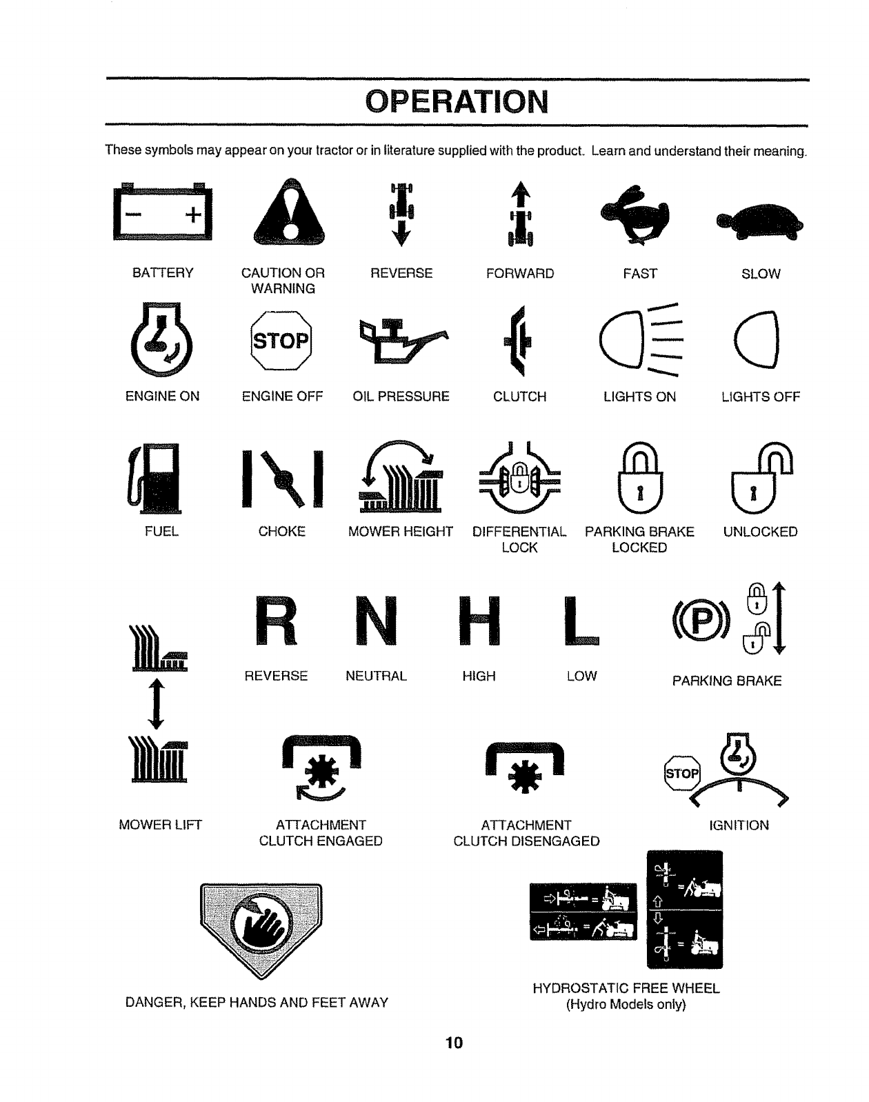
OPERATION
These symbols may appear on your tractor or in literature supplied with the product. Learn and understand their meaning,
CZ3,&
BATTERY CAUTION OR
WARNING
ENGINE ON ENGINE OFF
,f
REVERSE FORWARD FAST SLOW
OIL PRESSURE CLUTCH LIGHTS ON LIGHTS OFF
FUEL CHOKE MOWER HEIGHT DIFFERENTIAL PARKING BRAKE UNLOCKED
LOCK LOCKED
MOWER LIFT
R
REVERSE
H
ATTACHMENT
CLUTCH ENGAGED
NEUTRAL HIGH LOW
ATTACHMENT
CLUTCH DISENGAGED
PARKING BRAKE
IGNITION
DANGER, KEEP HANDS AND FEET AWAY HYDROSTATIC FREE WHEEL
(Hydro Models only)
10
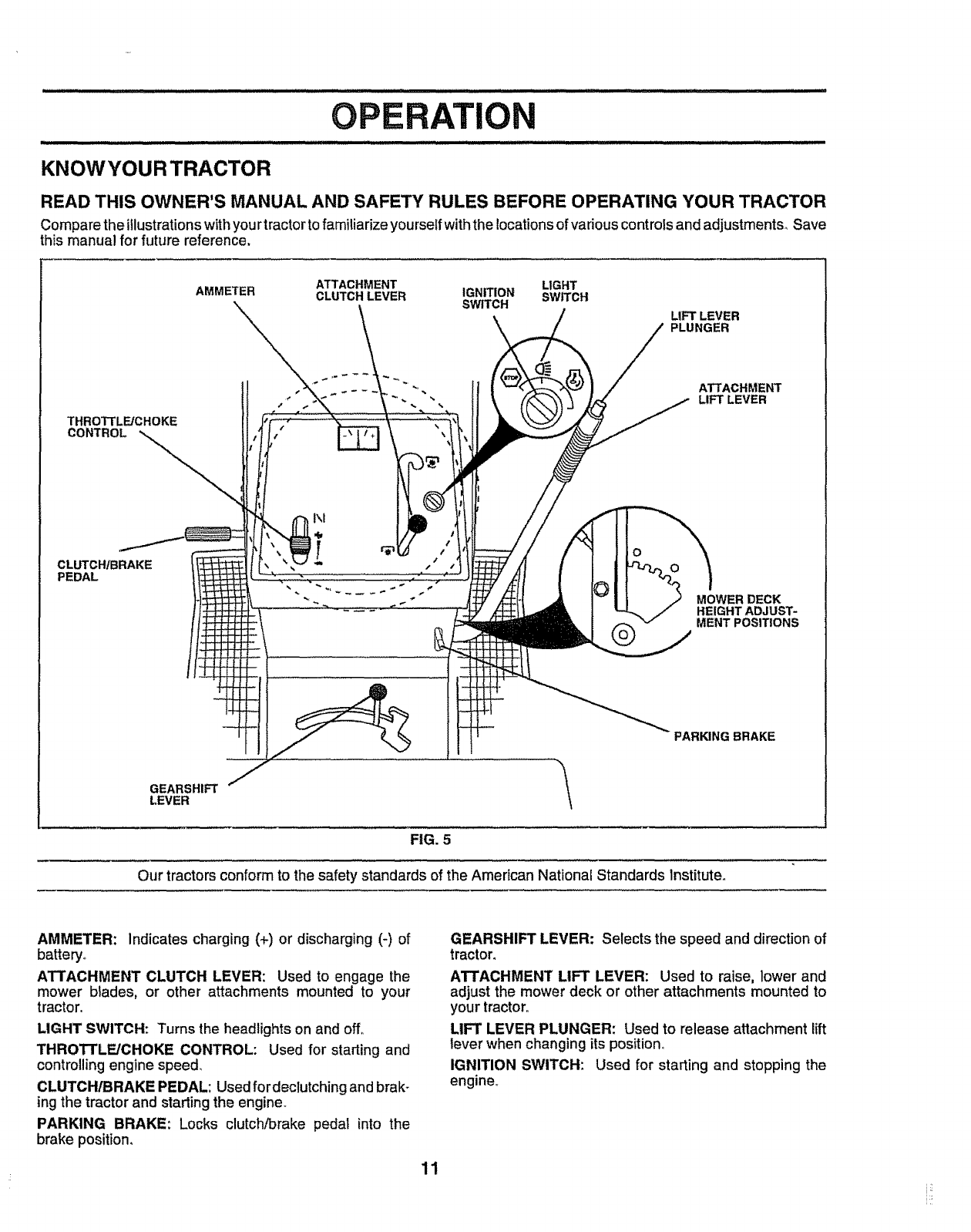
KNOWYOURTRACTOR
READ THIS OWNER'S MANUAL AND SAFETY RULES BEFORE OPERATING YOUR TRACTOR
Compare the illustrationswith you rtractorto familiarize yourselfwith the locationsofvarious controls and adjustments_ Save
this manual for future reference.
THROTTLE/CHOKE
CONTROL
CLUTCH/BRAKE
PEDAL
ATTACHMENT
AMMETER CLUTCH LEVER
t
1\t
%
LIGHT
IGNITION SWITCH
SWITCH
LIFT LEVER
PLUNGER
O
ATTACHMENT
LIFT LEVER
MOWER DECK
HEIGHT ADJUST-
MENT POSITIONS
PARKING BRAKE
GEARSHIFT _/
LEVER
FIG. 5
Our tractors conform to the safety standards of the American National Standards institute.
AMMETER: indicates charging (+) or discharging (-) of
battery.,
ATTACHMENT CLUTCH LEVER: Used to engage the
mower blades, or other attachments mounted to your
tractor.
LIGHT SWITCH: Turns the headlights on and off°
THROTTLE/CHOKE CONTROL: Used for starting and
controllingengine speed,,
CLUTCH/BRAKE PEDAL: Usedfordeclutching and brak-
ing the tractor and startingthe engine.
PARKING BRAKE: Locks clutch/brake pedal into the
brake position,
GEARSHIFT LEVER: Selects the speed and direction of
tractor_
ATTACHMENT LIFT LEVER: Used to raise, lower and
adjust the mower deck or other attachments mounted to
your tractor.
LIFT LEVER PLUNGER: Used to release attachment lift
lever when changing its position°
IGNITION SWITCH: Used for starting and stopping the
engine..
11
OPERATION
...... ............ iii ii iiiiiiii :::::: ............ iiiiiii,qql iiiiii ....
The operation of any tractor can result in foreign objects thrown into the eyes, which
can result in severe eye damage. Always wear safety glasses or eye shields while
operating your tractor or performing any adjustments or repairs. We recommend awide
vision safety mask over the spectacles or standard safety glasses.
HOW TO USE YOUR TRACTOR
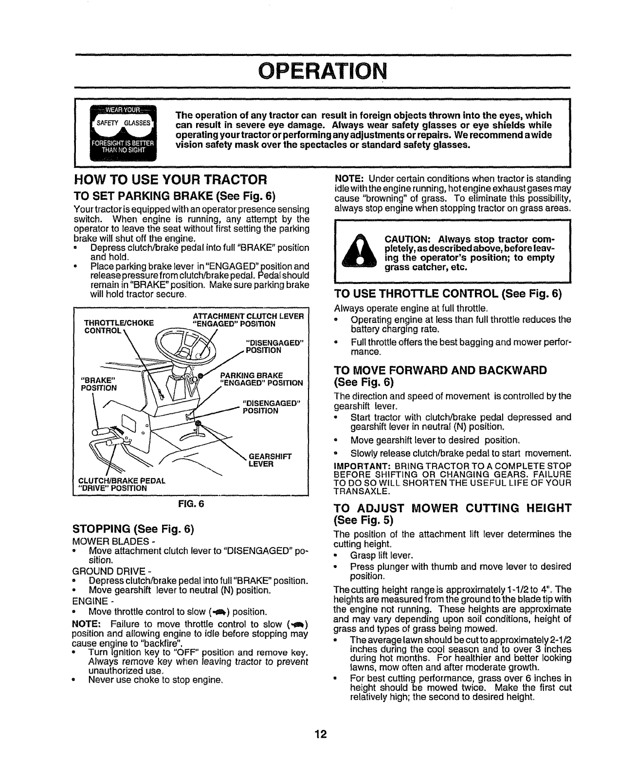
TO SET PARKING BRAKE (See Fig. 6)
Your tractor is equipped with an operator presence sensing
switch. When engine is running, any attempt by the
operator to leave the seat without first setting the parking
brake will shut off the engine.
• Depress clutch/brake pedal into full "BRAKE" position
and hold.
• Place parking brake lever in"ENGAGED"position and
release pressure from clutct'Jbrake pedal+ Pedal should
remain in 'BRAKE" position+ Make sure parking brake
will hold tractor secure_
THROTTLE/CHOKE
CONTROL \_,
ATTACHMENT CLUTCH LEVER
"ENGAGED" POSITION
"DISENGAGED"
"BRAKE"
POSITION
PARKING BRAKE
"ENGAGED" POSITION
CLUrCWBRAKE PEDAL
"DRIVE" POSITION
FIG. 6
GEARSHIFT
LEVER
STOPPING (See Fig. 6)
MOWER BLADES -
•Move attachment clutch lever to "DISENGAGED" po-
sition.
GROUND DRIVE-
°Depress clutch/brake pedal into fuII"BRAKE" position.
•Move gearshift lever to neutral (N) position+
ENGINE -
•Move throttlecontrol to slow (._) posit+on+
NOTE: Failure to move throttle control to slow (._)
positionand allowing engine to idle before stopping may
cause engine to "backfire",
•Turn Ignition key to OFF" position and remove key.
Always remove key when leaving tractor to prevent
unauthorized use.
•Never use choke to stop engine,
NOTE: Under certain conditions when tractor is standing
idle with the engine running,hot engine exhaust gases may
cause "browning" of grass. To eliminate this possibility,
always stop engine when stopping tractor on grass areas+
CAUTION: Always stop tractor com-
pletely, as described above, before leav-
ing the operator's position; to empty
grass catcher, etc.
.... .... I IIUIIIII tlt ..........
TO USE THROTTLE CONTROL (See Fig. 6)
Always operate engine at furl throttle+
+Operating engine at less than futl throttle reduces the
battery charging rate+
° Full throttle offers the best bagging and mower perfor-
mance+
TO MOVE FORWARD AND BACKWARD
(See Fig. 6)
The directionand speed of movement is controlledby the
gearshift lever+
•Start tractor with clutch/brake pedal depressed and
gearshift lever in neutral (N) position_
=Move gearshift lever to desired position.
oSlowly release clutch!brakepedal to start movement,
IMPORTANT: BRING TRACTOR TO ACOMPLETE STOP
BEFORE SHIFTING OR CHANGING GEARS. FAILURE
TO DO SO WILL SHORTEN THE USEFUL LIFE OF YOUR
TRANSAXLE+
TO ADJUST MOWER CUTTING HEIGHT
(See Fig. 5)
The position of the attachment lift lever determines the
cutting height+
• Grasp liftlever.
•Press plunger with thumb and move lever to desired
position+
The cutting height range is approximately 1-1/2 to 4"+ The
heights are measured from the groundto the blade tipwith
the engine not running. These heights are approximate
and may vary depending upon soil conditions, height of
grass and types of grass being mowed+
°The average lawn should be cutto approximately2-1/2
inches during the cool season and to over3 inches
during hot months For healthier and better looking
lawns, mow often and after moderate growth_
°For+best cutting performance, grass over 6 inches in
height shouId be mowed twice+ Make the first cut
relativelyhigh; the second to desired height+
12
OPE N
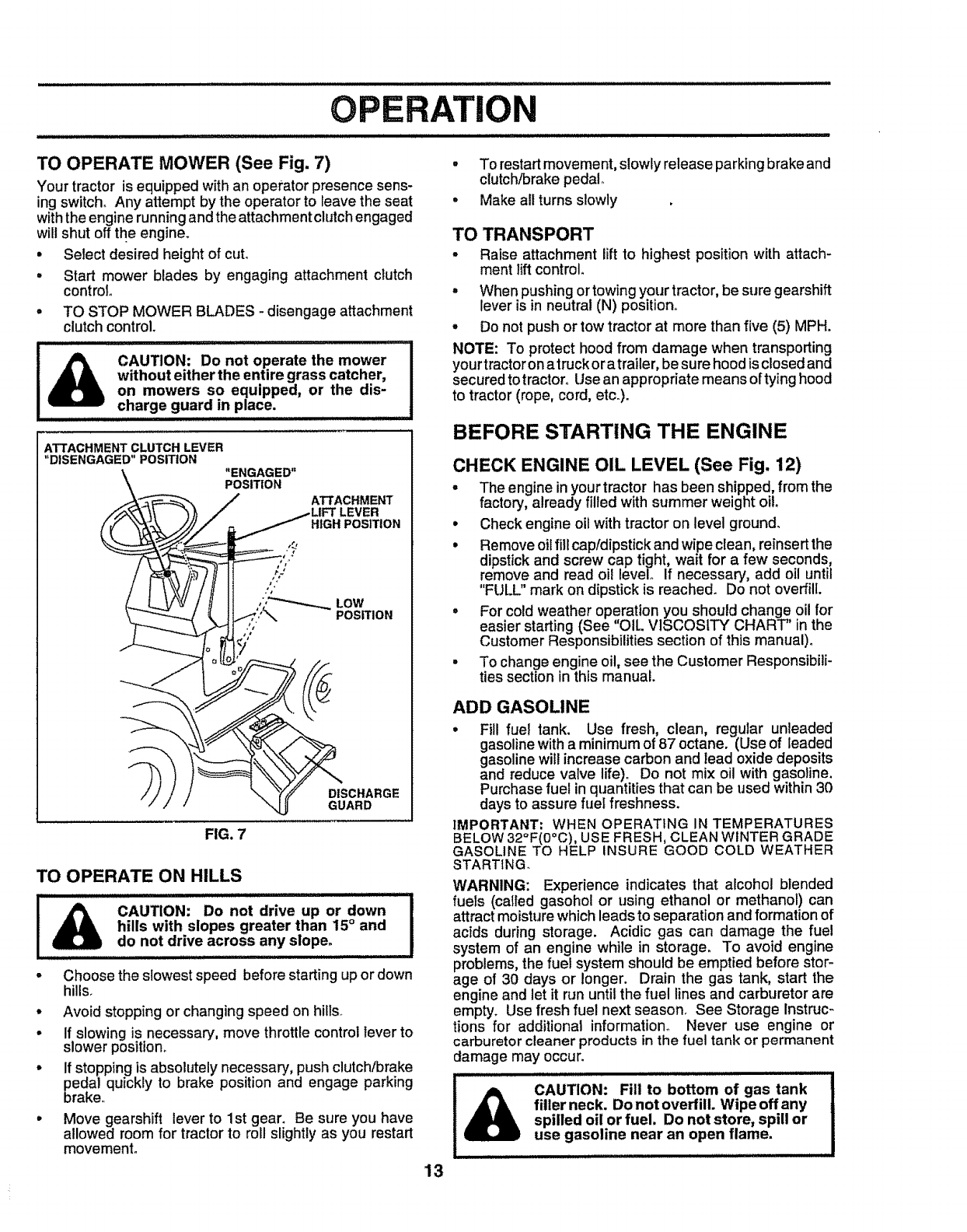
TO OPERATE MOWER (See Fig. 7)
Your tractor is equipped withan operator presence sens-
ing switch_Any attempt by the operator to leave the seat
withthe enginerunning andthe attachmentclutchengaged
will shut off the engine.
• SeIect desired heightof cut,
• Start mower blades by engaging attachment clutch
control
= TO STOP MOWER BLADES _disengage attachment
clutchcontrol.
CAUTION: Do not operate the mower
without either the entire grass catcher,
on mowers so equipped, or the dis-
charge guard in place.
ATTACHMENT CLUTCH LEVER
"DISENGAGED" POSITION
"ENGAGED"
POSITION
ATTACHMENT
HIGH POSITION
LOW
POSITION
DISCHARGE
GUARD
FIG. 7
TO OPERATE ON HILLS
!_ CAUTION_ Do not drive uP or down I
hills with slopes greater than 15° and I
do not drive across any slope. !
-Choose the slowest speed before starting upor down
hills.
,Avoid stopping or changing speed on hills.
-If slowing is necessary, move throttle control lever to
slower position.
• If stopping is absolutely necessary, push clutch/brake
pedal quickly to brake position and engage parking
brake..
•Move gearshift lever to 1st gear. Be sure you have
allowed room for tractor to roll slightly as you restart
movement.
13
° To restartmovement, slowly release parking brake and
clutch/brake pedal°
= Make all turns slowly
TO TRANSPORT
•Raise attachment lift to highest position with attach-
ment lift control.
°When pushingor towing your tractor,be sure gearshift
lever is in neutral (N) position..
°Do not push or tow tractor at more than five (5) MPH.
NOTE: To protect hood from damage when transporting
your tractor on atruckor atrailer, be sure hood is closed and
secured to tractoro Usean appropriate means oftying hood
to tractor (rope, cord, etch).
BEFORE STARTING THE ENGINE
CHECK ENGINE OIL LEVEL (See Fig. 12)
°The engine in yourtractor has been shipped,from the
factory, already filled with summer weight oil
• Check engine oil with tractor on level ground.
° Remove oil fill cap/dipstick and wipe clean, reinsert the
dipstick and screw cap tight, wait for a few seconds,
remove and read oil level° If necessary, add oil until
"FULL" mark on dipstick is reached. Do not overfill.
=For cold weather operation you should change oil for
easier starting (See "OIL VISCOSITY CHART" in the
Customer Responsibilities section of this manual)°
= To change engine oil, see the Customer Responsibili-
ties section in this manual.
ADD GASOLINE
, Fill fuel tank. Use fresh, clean, regular unleaded
gasoline with a minimum of 87 octane. (Use of leaded
gasoline will increase carbon and lead oxide deposits
and reduce valve life). Do not mix oil with gasoline.
Purchase fuel in quantities that can be used within 30
days to assure fuel freshness.
IMPORTANT; WHEN OPERATING IN TEMPERATURES
BELOW 32°F(0°C), USE FRESH, CLEAN WINTER GRADE
GASOLINE TO HELP INSURE GOOD COLD WEATHER
STARTING
WARNING: Experience indicates that alcohol blended
fuels (called gasohol or using ethanol or methanol) can
attract moisture which leads to separation and formation of
acids during storage. Acidic gas can damage the fuel
system of an engine while in storage. To avoid engine
problems, the fuel system should be emptied before stor-
age of 30 days or longer. Drain the gas tank, start the
engine and let it run until the fuel lines and carburetor are
empty. Use fresh fuel next season. See Storage Instruc-
tions for additional information° Never use engine or
carburetorcleaner products in the fuel tank or permanent
damage may occur.
CAUTION: Fill to bottom of gas tank
filler neck. Do not overfill. Wipe offany
spilled oil or fuel. Do not store, spill or
use gasoline near an open flame.
TO START ENGINE (See Fig. 6)
When starting the engine for the first time or if the engine
has run out of fuel, it will take extra cranking time to move
fuel from the tank to the engine.
•Depress clutch/brake pedal and set parking brake.
° Place gear shift lever in neutral (N) position_
° Move attachment clutch to "DISENGAGED" position°
• Move throttle control to choke (N) position_
Note: Before starting, read the warm and cold starting
procedures below.
= Insert key into ignition andtum key clockwise to"START"
position and release key as soon as engine starts.. Do
not run starter continuously for more than fifteen sec-
onds per minute. If the engine does not start after
several attempts, move throttle control to fast (,_)
position, wait afew minutes and try again, If engine still
does not start, move the throttle control back to the
choke (N) position and retry.
WARM WEATHER STARTING (50° F and above)
° When engine starts, move the throttle control to the fast
(,_) position.
° The attachments and ground drive can now be used_ If
tile engine does not accept the load, restart the engine
and allow it to warm up for one minute using the choke
as described above..
COLD WEATHER STARTING ( 50° F and below)
°When engine starts, allow engine to runwith the throttle
control in the choke (N) position until the engine runs
roughly, then move throttle controt to fast (._) position.
This may require an engine warm-up period from
several seconds to several minutes, depending on the
temperature.
°The attachments can also be used during the engine
warm-up period_
NOTE: If at a high altitude (above 3000 feet) or in cold
temperatures (below 32 F) the carburetor fuel mixture may
need to be adjusted for best engine performance. See "TO
ADJUST CARBURETOR" in the Service and Adjustments
section of this manual.
o
°
MOWING TIPS
Tire chains cannot be used when the mower housing
is attached to tractor°
Mower should be property leveled for' best mow!ng
performance. See"TO LEVEL MOWER HOUSING in
the Service and Adjustments section of this manual
•The left hand side of mower should be used for trim-
ming_
. Drive so that clippings are discharged onto the area
that has been cut. Have the cut area to the right of the
machine. This will result in a more even distribution of
clippings and more uniform cutting.
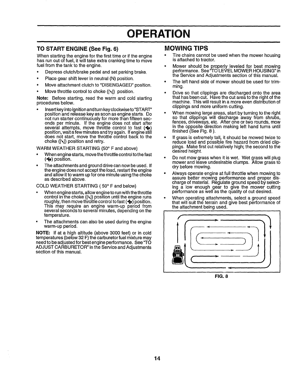
°When mowing large areas, start by turning to the right
so that clippings will discharge away from shrubs,
fences, driveways, etc., After one or' two rounds, mow
in the opposite direction making left hand turns until
finished (See Fig° 8 ).
° tf grass is extremely tall, it should be mowed twice to
reduce load and possible fire hazard from dried clip-
pings. Make first cut relatively high; the second to the
desired height.,
• Do not mow grass when it is wet. Wet grass will plug
mower and leave undesirable clumps. Allow grass to
dry before mowing.
•Always operate engine at full throttle when mowing to
assure better' mowing performance and proper dis-
charge of material. Regulate ground speed by select-
ing a low enough gear to give the mower cutting
performance as well as the quality of cut desired.
• When operating attachments, select a ground speed
that will suit the terrain and give best performance of
the attachment being used.
• .... ..A
FIG. 8
14
CUSTOMER R NSIBILmES
SC.EDU"
Check Brake Operation ll/ !if
Check Tire Pressure Vp' if
TCheok,orLoooeFasteno, .......V', 'v:ir[ .
v
TCheck Battery LeveVRecharge _ _ ..... i.....
0°.,,.CleanBattery and Terminats,'"'_"_'' V' I
a Check Transaxte Cooling V_ i
Adjust Blade Belt(s)''"' ' Tension Ks
Adjust Motion Drive Belt(s) Tension V°s
Check Engine Oil Level V_
Change........... Engine Oil Vp t_1,_,3 ...... if .
E Clean Air Filter ............. 1##2 ...........
N cleanAirscreen ...... V'2 ......
GInspect Muffler!SparkAn'ester
!"°_LReplaceOil Filter (if equipped) ....... 1#_,2 ........
Replace Air Filter Paper Cartridge I/2
Replace "-'Fuel''_"°°Fitter .... , ....... .....I/_ , , "..........
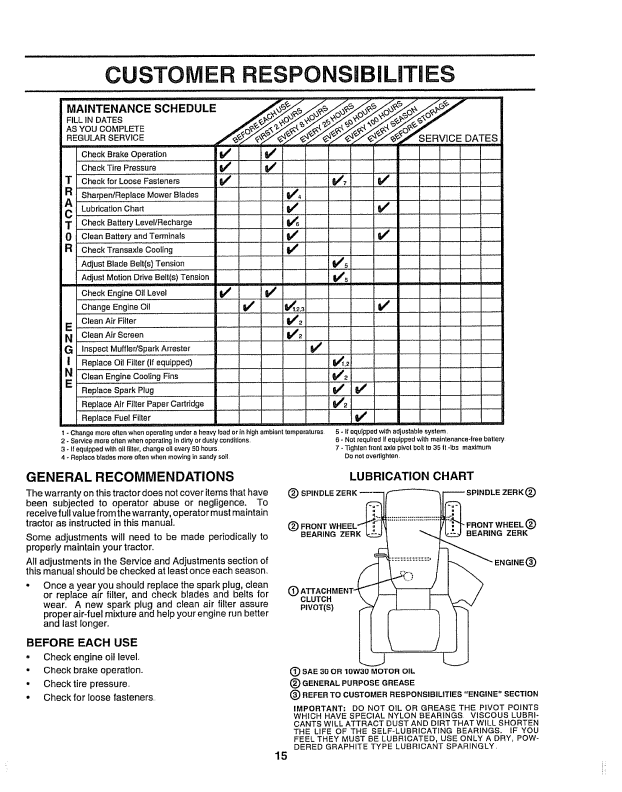
t- Change more often when operating under a heavy load or in high ambient lemperatures
2 - Service more often when operaltng in dirty or dusty conditions,
3-ff equipped with oil filler, change oil every 50 hours,
4 - Replace btades more otlenwhen mowing Ins_ndy suil
5 - If equipped with adjus_ble syslem,
6-Not required If equipped wtth mainten_nce*free be_le_
7-Tighten fronl axle pivotboft to 35 It-lbs maximum
Do not overtighten,
GENERAL RECOMMENDATIONS
The warranty on this tractor does not cover items that have
been subjected to operator abuse or negligence. To
receive full value from the warranty, operator must maintain
tractor as instructedin this manual
Some adjustments will need to be made periodically to
properly maintain your tractor,.
All adjustments in the Service and Adjustments section of
this manual should be checked at least once each season.
wear. A new spark plug and clean air filter assure
BEFORE EACH USE
• Check engine oil level
•Check brake operation.
• Check tire pressure.
• Check for loose fasteners.
LUBRICATION CHART
{_ SPINDLE ZERK ®
® ®
BEARING ZERK BEARING ZERK
®
®CLUTCH
PIVOT(S)
(_ SAE 30 OR IOW30 MOTOR OIL
®GENERAL PURPOSE GREASE
®REFER TO CUSTOMER RESPONSIBILITIES "ENGINE" SECTION
IMPORTANT: DO NOT OIL OR GREASE THE PIVOT POINTS
WHICH HAVE SPECIAL NYLON BEARINGS. VISCOUS LUBRi-
CANTS WILL ATTRACT DUST AND DIRT THAT WILL SHORTEN
THE LtFE OF THE SELF-LUBRICATING BEARINGS, _F YOU
FEEL THEY MUST BE LUBRICATED, USE ONLY A DRY, POW-
DERED GRAPHITE TYPE LUBRICANT SPARINGLY,
15
TRACTOR
Always observe safety rules when performingany mainte-
nance.
BRAKE OPERATION
If tractor requires more than six (6) feet stopping distance
at high speed inhighest gear, then brake must be adjusted.
(See 'q'O ADJUST BRAKE" in the Service and Adjust-
ments section of this manual)_
TIRES
°Maintain proper air'pressure in all tires (See "PROD-
UCT SPECIFICATIONS on page 3 of this manual).
°Keep tiresfree ef gasoline, oil,or insect controlchemi-
cals which can harm rubber.
° Avoid stumps, stones, deep ruts, sharp objects and
other'hazards that may cause tire damage.
BLADE CARE
For best results mower blades must be kept sharp. Re-
place bent or damaged blades..
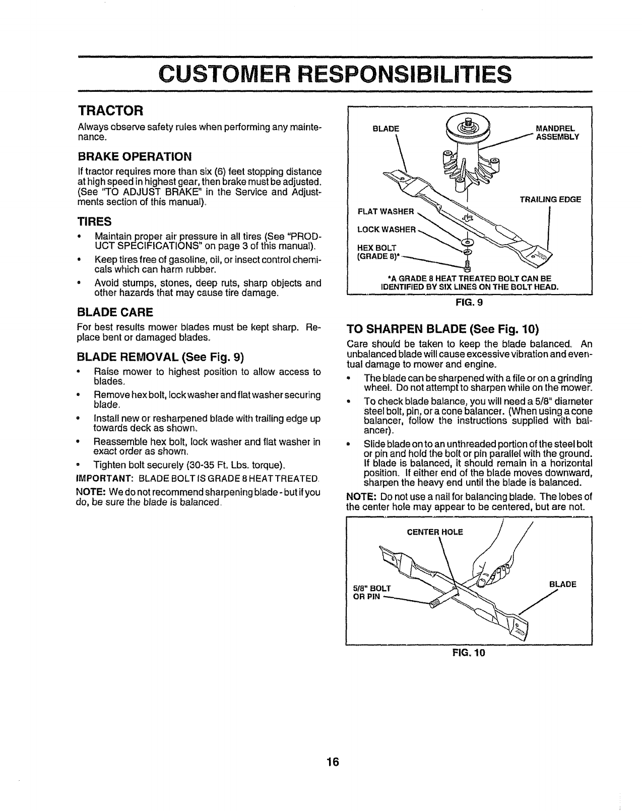
BLADE REMOVAL (See Fig. 9)
° Raise mower' to highest position to allow access to
blades.
= Remove hex bolt, lock washer and flatwasher securing
blade.
o install new or resharpened blade with trailing edge up
towards deck as shown..
• Reassemble hex bolt, lock washer and flat washer in
exact order as shown.
o Tighten bolt securely (30+35 Ft. Lbs+torque).
IMPORTANT: BLADE BOLT IS GRADE 8 HEATTREATED.
NOTE: We do not recommend sharpening blade - but if you
do, be sure the blade is balanced.
BLADE _MANDREL
ASSEMBLY
FLAT WASHER
TRAtUNG EDGE
HEX BOLT
*A GRADE 8HEAT TREATED BOLT CAN BE
IDENTIFIED BY SIX LINES ON THE BOLT HEAD.
FIG. 9
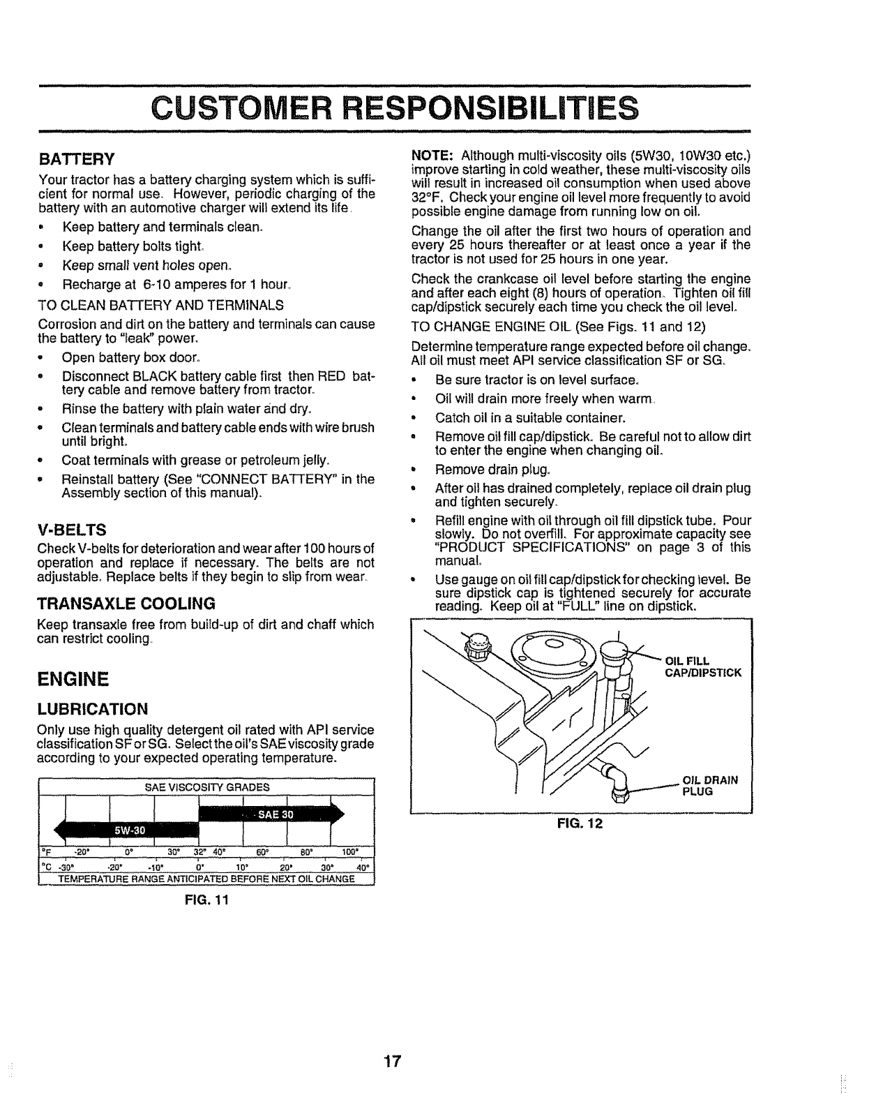
TO SHARPEN BLADE (See Fig. 10)
Care should be taken to keep the blade balanced° An
unbalanced blade will cause excessive vibration and even-
tual damage to mower and engine+
° The blade can be sharpened with a file or on a
on th_ rinding
wheel+ Do not attempt to sharpen while mower+
° To check blade balance, you will need a 5/8" diameter
steel bolt, pin, or a cone batancer. (When using a cone
balancer, follow the instructions supplied with baF
ancer),
°Slide bladeon to an unthreaded portionofthe steel bolt
or pin and hold the boRor pin parallel withthe ground.
If blade is balanced, it should remain in ahorizontal
position+ if either end of the blade moves downward,
sharpen the heavy end until the blade is balanced.
NOTE: Do not use a nail for balancing blade+ The lobes ef
the center hole may appear to be centered, but are not+
CENTER HOLE //
FIG. 10
16
BATTERY
Your tractor has a battery charging system which is suffi-
cient for normal use. However, periodic charging of the
battery with an automotive charger wilt extend its life.
,Keep battery and terminals clean.
• Keep battery bolts tight_
oKeep sma!_vent holes open°
• Recharge at 6-10 amperes for I hour._
TO CLEAN BATTERY AND TERMINALS
Corrosion and dirt on the battery and terminals can cause
the battery to "leak" power.
°Open battery box door°
°Disconnect BLACK battery cable first then RED bat-
tery cable and remove battery from tractor.
oRinse the battery with plain water and dry.
-Clean terminals and battery cable ends with wire brash
until bright°
°Coat terminals with grease or petroleum jelly.
,Reinstall battery (See "CONNECT BATTERY" in the
Assembly section of this manual).
V-BELTS
Check V-belts for deterioration andwear after 100 hoursof
operation and replace if necessary. The belts are not
adjustable° Replace belts if they begin to slip from wear.
TRANSAXLE COOLING
Keep transaxle free from buitd-up of dirt and chaff which
can restrict cooling..
ENGINE
LUBRICATION
Only use high quality detergent oil rated with API service
classification SF or SG. Select the oil's SAEviscosity grade
according to your expected operating temperature.
SAE VISCOSITYGRADES
-30" -20_ *_0_O' 10' 20' 00'400
TEMPERATURE RANGE ANTICIPATED BEFORE NF..XTOIL CHANGE
NOTE: Although multi-viscosity oils (5W30, 10W30 etc.)
improve starting in cold weather, these multi-viscosity oils
will result in increased oil consumption when used above
32°F, Check your engine oil level more frequently to avoid
possible engine damage from running tow on oil.
Change the oil after the first two hours of operation and
every 25 hours thereafter or at least once a year if the
tractor is not used for 25 hours in one year.
Check the crankcase oil level before starting the engine
and after each eight (8) hours of operation_ Tighten oil fill
cap/dipstick securely each time you check the oil level.
TO CHANGE ENGINE OIL (See Figs. 11 and 12)
Determine temperature range expected before oil change.
All oi! must meet API service classification SF or SG..
•Be sure tractor is on level surface°
• Oil will drain more freely when warm
•Catch oil in a suitable container.
•Remove oil fill cap/dipstick. Be careful not to allow dirt
to enter the engine when changing oil.
• Remove drainplug.
• After oil has drained completely, replace oil drain plug
and tighten securely_
• Refill engine with oil through oil fill dipstick tube. Pour
slowly. Do not overfill. For approximate capacity see
'PRODUCT SPECIFICATIONS on page 3 of this
manual.
•Use gauge on oil fill cap/dipstick for checking tevel. Be
sure dipstick cap is tightened securely for accurate
reading. Keep oil at "FULL" line on dipstick.
OIL FILL
CAP/DIPSTICK
OIL DRAIN
PLUG
FIG. 12
FIG, 11
17
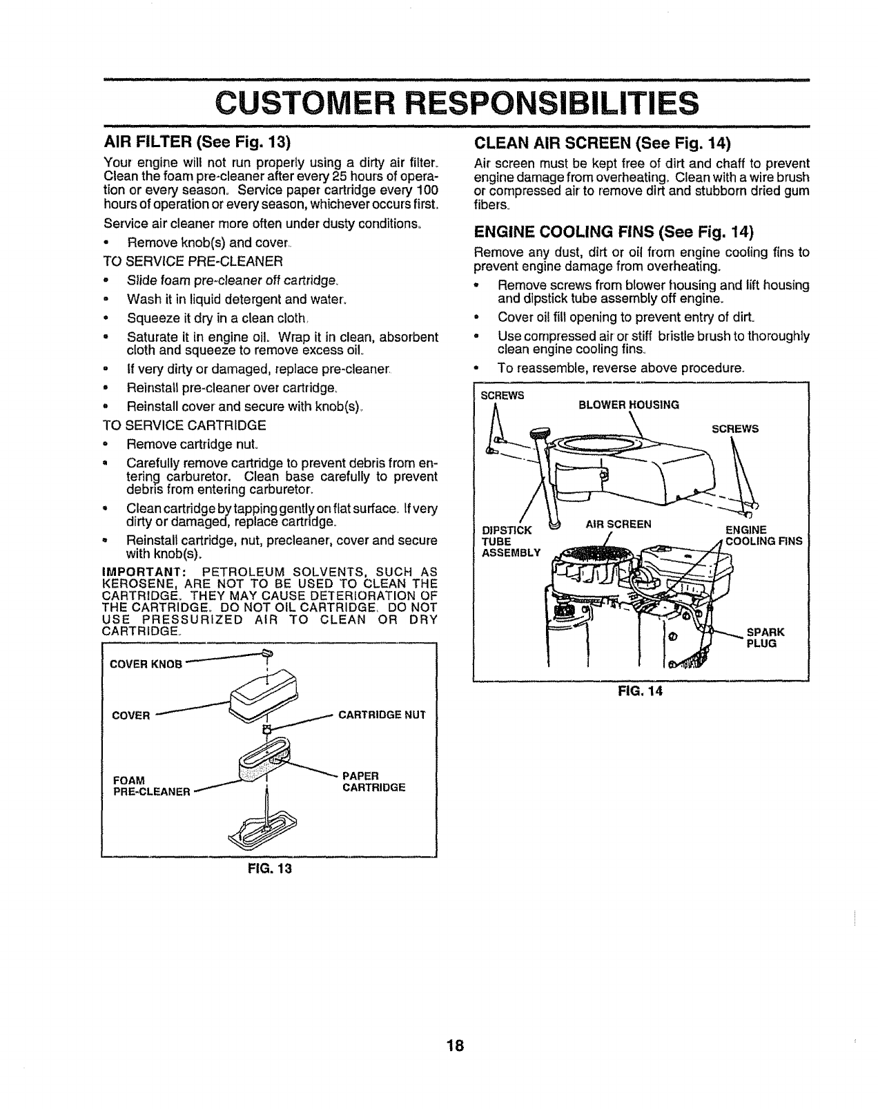
AIR FILTER (See Fig. 13)
Your engine will not run properly using a dirty air fitter_
Clean the foam pre-cleaner after every 25 hours of opera-
tion or every season° Service paper cartridge every 100
hours of operation or every' season, whichever occurs first.
Service air cleaner more often under dusty conditions°
• Remove knob(s) and cover..
TO SERVICE PRE-CLEANER
°Slide foam pre-cleaner off cartridge_ .
• Wash it in liquid detergent and water_
= Squeeze it dry in a clean cloth •
• Saturate it in engine oil. Wrap it in clean, absorbent °
cloth and squeeze to remove excess oil
° If very dirty or damaged, replace pre-cleaner. °
•Reinstall pre-cleaner over cartridge,
° Reinstall cover and secure with knob(s)_
TO SERVICE CARTRIDGE
CLEAN AIR SCREEN (See Fig. 14)
Air screen must be kept free of dirt and chaff to prevent
engine damage from overheating° Clean witha wire brush
or compressed air to remove dirt and stubborn dried gum
fiber's.
ENGINE COOLING FINS (See Fig, 14)
Remove any dust, dirt or oil from engine cooling fins to
prevent engine damage from overheating.
° Remove cartridge nut.
° Carefully remove cartridge to prevent debris from en-
tering carburetor. Clean base carefully to prevent
debris from entering carburetor.
° Cleancartridgebytappinggentlyonflatsurface_ Ifvery
dirty or damaged, replace cartridge.
o Reinstall cartridge, nut, precleaner, cover and secure
with knob(s)_
IMPORTANT; PETROLEUM SOLVENTS, SUCH AS
KEROSENE, ARE NOT TO BE USED TO CLEAN THE
CARTRIDGE. THEY MAY CAUSE DETERIORATION OF
THE CARTRIDGE,, DO NOT OIL CARTRIDGE DO NOT
USE PRESSURIZED AIR TO CLEAN OR DRY
CARTRIDGE..
COVER KNOB "---'-'-_'_
CARTRIDGE
Remove screws from blower housing and lift housing
and dipstick tube assembly off engine.
Cover oil flu opening to prevent entry of dirt.
Use compressed air' or stiff bristle brush to thoroughly
clean engine cooling fins_
To reassemble, reverse above procedure,,
SCREWS BLOWER HOUSING
DIPSTICK
TUBE
ASSEMBLY
AIR SCREEN
SCREWS
ENGINE
rCOOLING FINS
FIG. 14
FIG. 13
18
iJ ilJl i i i i i iillll i iiiiiilll i illllll i i i i i i iillllllllllllllllllll illl illllllll ii ii i ill illllllll ii,l, ll,,ll,
CU ILITIES
....................................................................... i ii i ii ii ii i illllll
MUFFLER
Inspect and reptace corroded muffler and spark arrester (if
equipped) as it could create a fire hazard and!or damage..
SPARK PLUGS
Replace spark plugs at the beginning of each mowing
season or after every 100 hours of operation, whichever
occurs first. Spark plug type and gap setting are shown in
"PRODUCT SPECIFICATIONS" on page 3 of this manual.
CLAMP_ CLAMP
FUEL
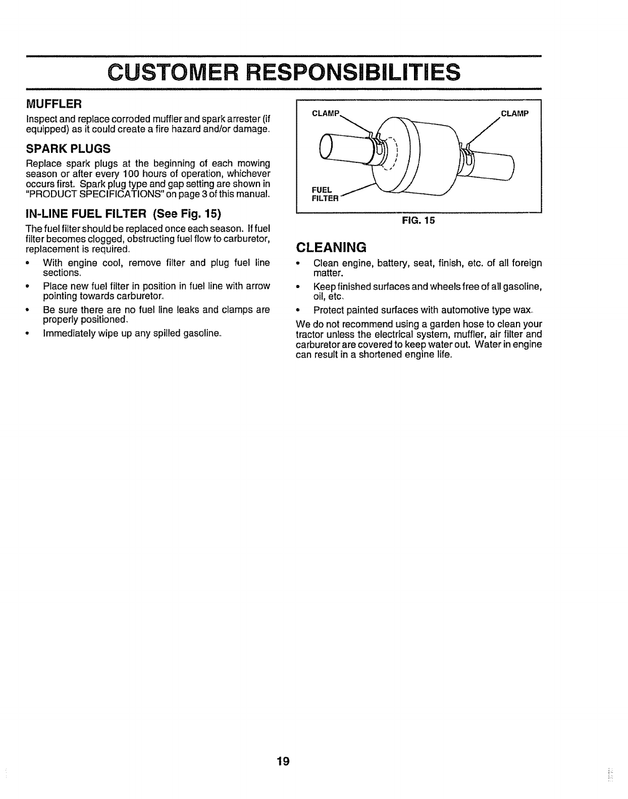
IN-LINE FUEL FILTER (See Fig. 15)
The fuel filter should be replaced once each season. If fuel
filter becomes clogged, obstructingfuel flow to carburetor,
replacement is required°
= With engine cool, remove filter and plug fuel line
sections°
•Place new fuel filter in position in fue! line with arrow
pointing towards carburetor_
• Be sure there are no fuel line leaks and clamps are
properly positioned.
• Immediately wipe up any spilled gasoline._
FIG. 15
CLEANING
°Clean engine, battery, seat, finish, etc. of all foreign
matter.
•Keep finished surfaces and wheels free of all gasoline,
oil, etc.
° Protect painted surfaces with automotive type wax..
We do not recommend using agarden hose to clean your
tractor unless the electrical system, muffler, air filter and
carburetor are covered to keep water out. Water in engine
can result in a shortened engine life.
19
RVICE AND ADJUSTMENTS
i ii _ '............ '_ _.... _ _ _._ _::_ iii _......... _iiiI_........ _ _ .......
CAUTION: BEFORE PERFORMING ANY SERVICE OR ADJUSTMENTS:
•Depress clutcWbrake pedal fully and set parking brake.
Place gearshift lever in neutral (N) position.
Place attachment clutch in "DISENGAGED" position,
Turn ignition key "OFF" and remove key.
•Make sure the blades and al! moving parts have completely stopped.
•Disconnect spark plug wire from spark plug and place wire where it cannot come in contact with
plug.
ii
TRACTOR
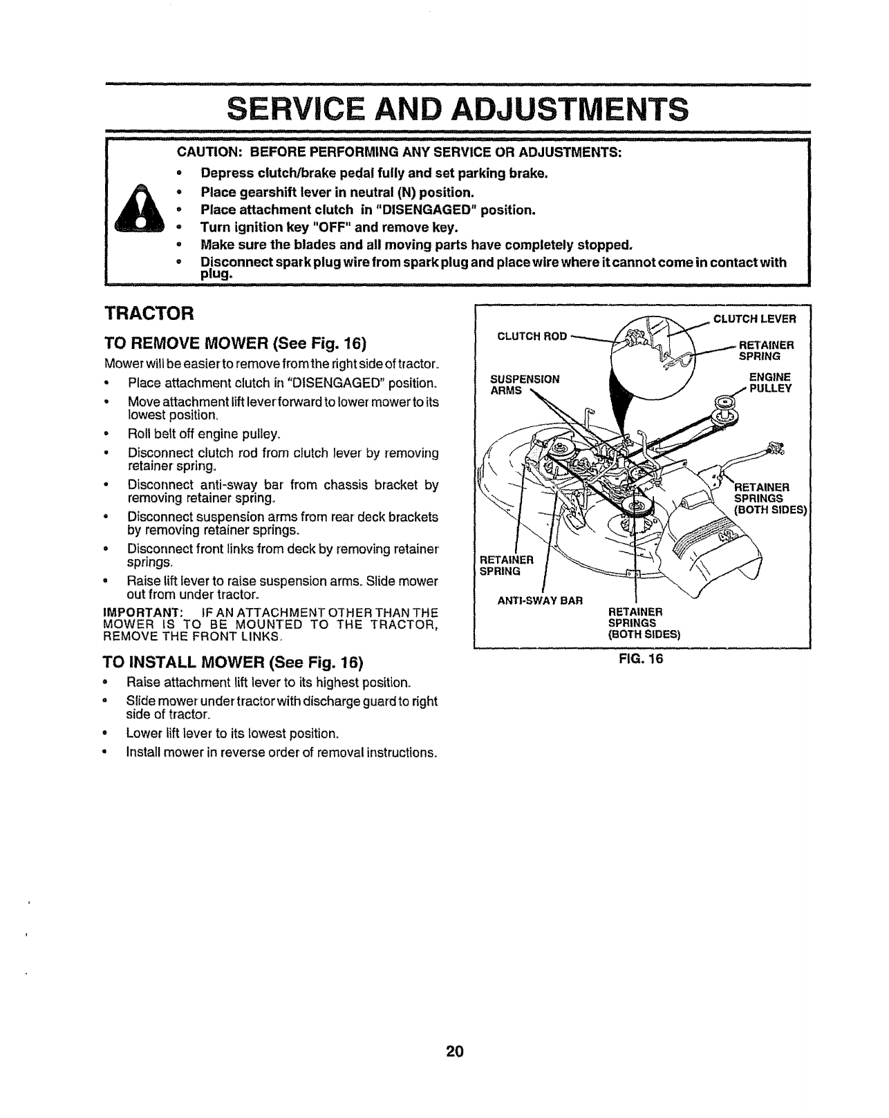
TO REMOVE MOWER (See Fig. 16)
Mower will be easier to remove fromthe right side of tractor_
•Place attachment clutch in "DISENGAGED" position.
•Move attachment lift leverforward to lower mower to its
lowest position,
•Roll belt off engine pulley.
•Disconnect clutch rod from clutch lever by removing
retainer spring°
•Disconnect anti-sway bar from chassis bracket by
removing retainer spring.
• D|sconnect suspension arms from rear deck brackets
by removing retainer springs.
•Disconnect front links from deck by removing retainer'
springs,,
° Raise lift lever to raise suspension arms. Slide mower
out from under tractor.
IMPORTANT: IF AN ATTACHMENT OTHER THAN THE
MOWER iS TO BE MOUNTED TO THE TRACTOR,
REMOVE THE FRONT LINKS,
CLUTCH ROD
SUSPENSION
ARMS
SPRING
ANTI-SWAY BAR RETAINER
SPRINGS
(BOTH SIDES)
FIG. 16
CLUTCH LEVER
SPRING
ENGINE
SPRINGS
TO INSTALL MOWER (See Fig. 16)
•Raise attachment lift lever to its highest position,,
• Slide mower' undertractor with discharge guardto right
side of tractor.
• Lower lift lever to its lowest position.
• Install mower in reverse order of removal instructions.
20
.... ill i illl,,i, H"III I I II II.......... _'_'_'_'_'__................ Ill......................
iCE AND ADJUSTMENTS
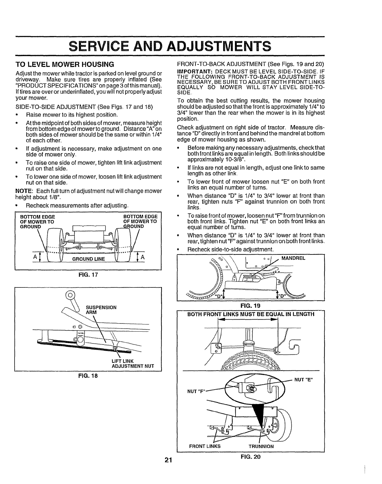
TO LEVEL MOWER HOUSING FRONT-TO-BACK ADJUSTMENT (See Figs. 19 and 20)
IMPORTANT; DECK MUST BE LEVEL SIDE-TO-SIDE, IF
THE FOLLOWING FRONT-TO-BACK ADJUSTMENT IS
NECESSARY, BESURE TO ADJUST BOTH FRONT LINKS
EQUALLY SO MOWER WILL STAY LEVEL SIDE-TO-
SIDE..
Adjust the mower while tractor is parked on level ground or
driveway° Make sure tires are properly inflated (See
"PRODUCT SPECIFICATIONS" on page 3of this manual).
Iftires are over or underinflated, youwill not properly adjust
your mower,.
SIDE-TO-SIDE ADJUSTMENT (See Figs, 17 and 18)
-Raise mower to its highest position.
•At the midpoint of both sides of mower, measure height
from bottom edge of mower to ground_ Distance"A" on
both sides of mower should be the same or within 1/4"
of each other_
.If adjustment is necessary, make adjustment on one
stde of mower only.
• To raise one side of mower, tighten lift link adjustment
nut on that side°
!To lower one side of mower, loosen lift link adjustment
nut on that side,.
NOTE: Each full turn of adjustment nut will change mower
height about 1/8'L
•Recheck measurements after adjusting°
BOTTOM EDGE BOTTOM EDGE
OF MOWER TO OF MOWER TO
GROUND
AGROUND LINE
FIG. 17
To obtain the best cutting results, the mower housing
should be adjusted so that the front is approximately 1/4"to
3/4" lower than the rear when the mower is in its highest
position_
Check adjustment on right side of tractor,, Measure dis-
tance"D" directly infront and behind the mandrel at bottom
edge of mower housing as shown.
•Before making any necessary" adjustments, check that
both front links are equal in length. Both links should be
approximately 10-3/8"o
• If links are not equal in length, adjust one link to same
length as other link.
•To lower front of mower loosen nut "E" on both front
links an equal number of turns.
° When distance "D" is 1/4" to 3/4" lower at front than
rear, tighten nuts "F" against trunnion on both front
links..
.To raise front of mower, loosennut"F' from trunnionon
both front links_Tighten nut "E" on both front links an
equal number of turns,,
°When distance "D" is 1/4" to 3/4" lower at front than
rear, tighten nut"F" against trunnion on both front linkso
Recheck side-to-side adjustment.
MANDREL
LIFT LINK
ADJUSTMENT NUT
FIG. 18
21
FIG. 19
BOTH FRONT LINKS MUST BE EQUAL IN LENGTH
NUT "E"
FRONT LINKS TRUNNION
FIG. 20
SERVICE AND ADJUSTMENTS
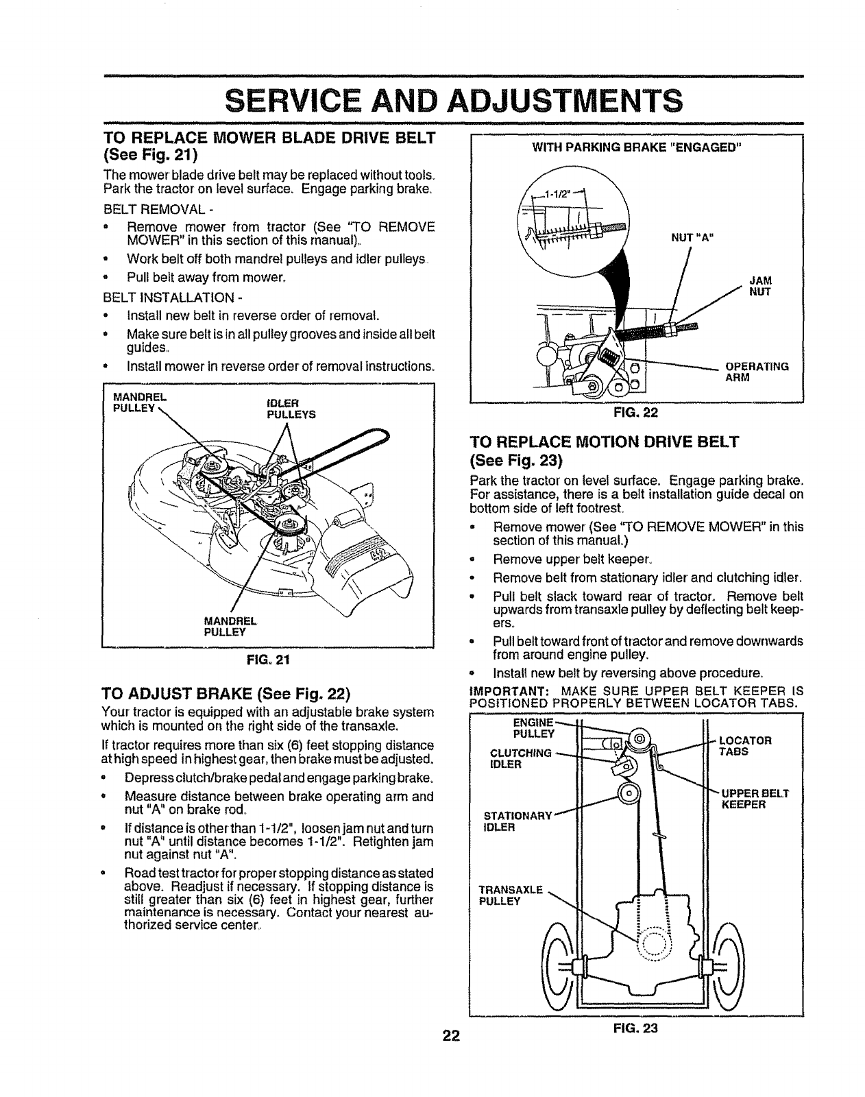
TO REPLACE MOWER BLADE DRIVE BELT
(See Fig. 21)
The mower blade drive belt may be replaced without tools_
Park the tractor on level surface. Engage parking brake_
BELT REMOVAL -
• Remove mower from tractor (See 'q'O REMOVE
MOWER" in this section of this manual).
•Work belt off both mandrel pulleys and idler pulleys,
o Pull belt away from mower.
BELT INSTALLATION -
° Install new belt in reverse order of removal
= Make sure belt isinall pulley grooves and inside all belt
guides,,
•Install mower in reverse order of removal instructions.
MANDREL
PULLEY |DLER
PULLEYS
...... ill ii illll i ill ii
WITH PARKINGBRAKE "ENGAGED"
MANDREL
PULLEY
FIG. 21
TO ADJUST BRAKE (See Fig. 22)
Your tractor is equipped with an adjustable brake system
which is mounted on the right side of the transaxle.
If tractor requires more than six (6) feet stopping distance
at high speed inhighest gear, then brake must be adjusted.
• Depress clutch!brake pedal and engage parking braker
°Measure distance between brake operating arm and
nut "A" on brake rod_
If distance is other than 1-1/2", loosen jam nut and turn
nut A until distance becomes 1-1/2o Retightenjam
nut against nut "A"o
Road test tractor for properstopping distance as stated
above. Readjust if necessary, tf stopping distance is
still greater than six (6) feet in highest gear, further
maintenance is necessary. Contact your nearest au-
thorized service center..,
NUT "A"
JAM
NUT
OPERATING
ARM
FIG. 22
TO REPLACE MOTION DRIVE BELT
(See Fig. 23)
Park the tractor on level surface, Engage parking brake°
For assistance, there is abelt installation guide decal on
bottom side of left footresL
=Remove mower (See "TO REMOVE MOWER" in this
section of this manual,)
° Remove upper belt keeper.
° Remove belt from stationary idler and clutchingidler°
° Pull belt slack toward rear of tractor° Remove belt
upwards from transaxle pulley by deflecting belt keep-
ers.
° Pullbelt towardfront of tractor and remove downwards
from around engine pulley.
oInstallnew belt by reversing above procedure.
IMPORTANT: MAKE SURE UPPER BELT KEEPER IS
POSITIONED PROPERLY BETWEEN LOCATOR TABS.
ENGINE "'---
PULLEY
CLUTCHING"-,-,..
IDLER
STATIONARY... *,.'-_
IDLER
TRANSAXLE
PULLEY
,."LOCATOR
TABS
UPPER BELT
KEEPER
22 FIG. 23
AND ADJUSTMENTS
TO ADJUST STEERING WHEEL ALIGNMENT
If steeringwheel crossbars are not horizontal(left to right)
whenwheels are positioned straightforward, remove steer-
ingwheel and reassemble per instructionsinthe Assembly
section of this manual
FRONT WHEEL TOE-IN/CAMBER
The front wheel toe-in and camber are not adjustable on
your unit. If damage has occurred to affect the front wheel
toe-in or camber, contact your nearest authorized service
center.
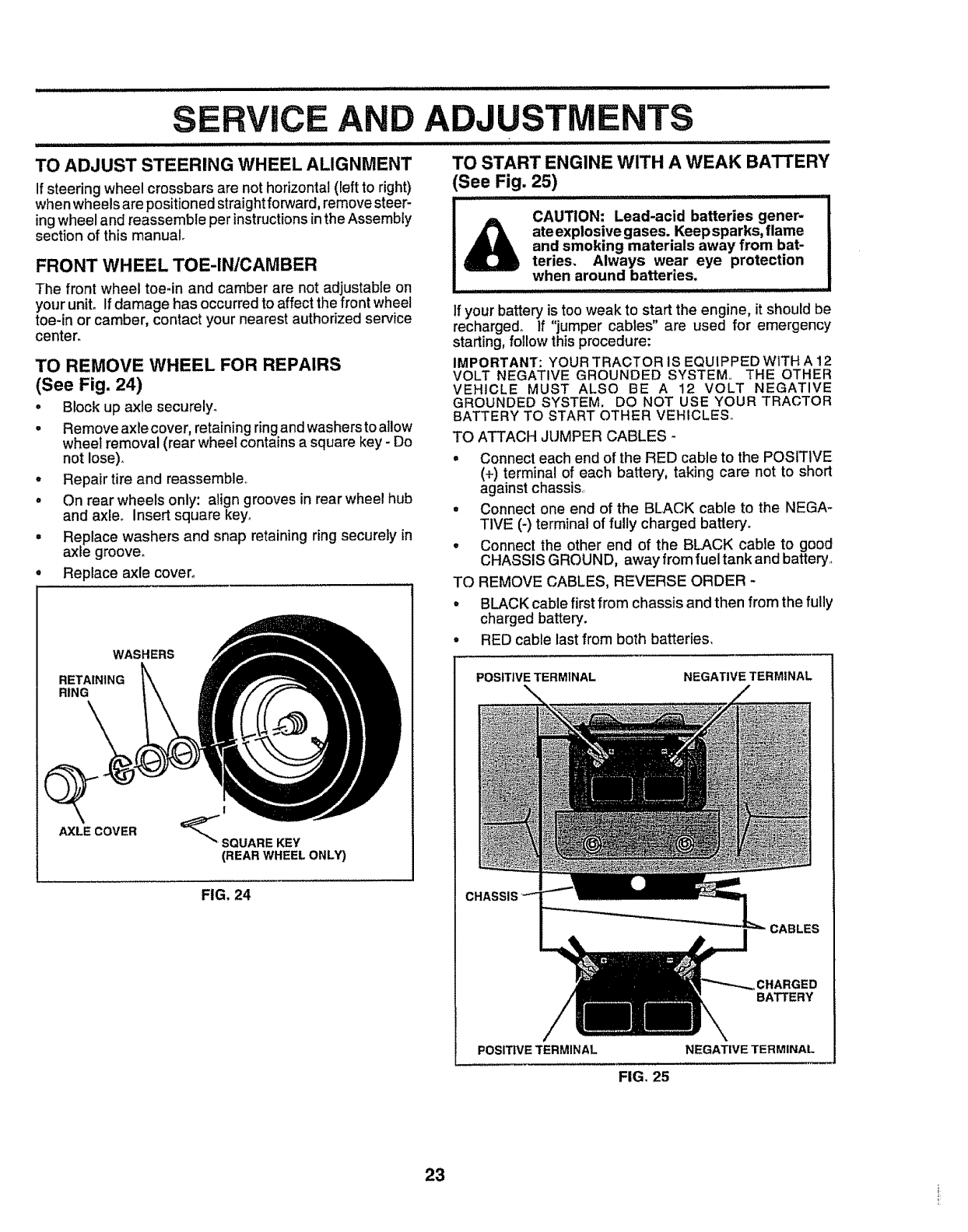
TO REMOVE WHEEL FOR REPAIRS
(See Fig. 24)
•Block up axle securely.
-Remove axle cover, retainingringandwasherstoallow
wheel removal (rear wheel containsa square key- Do
not lose).
•Repair tire and reassemble,,
•On rearwheels only: align groovesin rearwheel hub
and axle. Insert square key,,
°Replace washers and snap retainingring securely in
axle groove°
°Replace axle cover.,
WASHERS
RETAINING
RING
!
_SQUARE KEY
(REAR WHEEL ONLY)
FIG. 24
Q
AXLE COVER
TO START ENGINE WITH A WEAK BATTERY
(See Fig. 25)
[ACAUTi0NI Lead-acid ba"e;ies gener- I
!A[]k ateexplosive gases. Keep sparks, flame !
!_and smoking materials away from bat- I
i_teries, Always wear eye protection I
when around batteries 1
=l =l,,iH "...........
If your battery is too weak to start the engine, it should be
recharged, If "jumper cables" are used for emergency
starting, follow this procedure:
IMPORTANT: YOUR TRACTOR IS EQUIPPED WITH A 12
VOLT NEGATIVE GROUNDED SYSTEM,. THE OTHER
VEHICLE MUST ALSO BE A 12 VOLT NEGATIVE
GROUNDED SYSTEM. DO NOT USE YOUR TRACTOR
BATTERY TO START OTHER VEHICLES,
TO ATTACH JUMPER CABLES -
• Connect each end of the RED cable to the POSITIVE
(+) terminal of each battery, taking care not to short
against chassis,
° Connect one end of the BLACK cable to the NEGA-
TIVE (-) terminal of fully charged battery.
°Connect the other end of the BLACK cable to good
CHASSIS GROUND, away from fuel tank and battery.
TO REMOVE CABLES, REVERSE ORDER -
° BLACK cable first from chassis and then from the fully
charged battery.
° RED cable last from both batteries.
POSITIVE TERMINAL NEGATIVE TERMINAL
CABLES
CHARGED
BATTERY
POSITIVE TERMINAL NEGATIVE TERMINAL
FIG. 25
23
AND ADJUSTMENTS
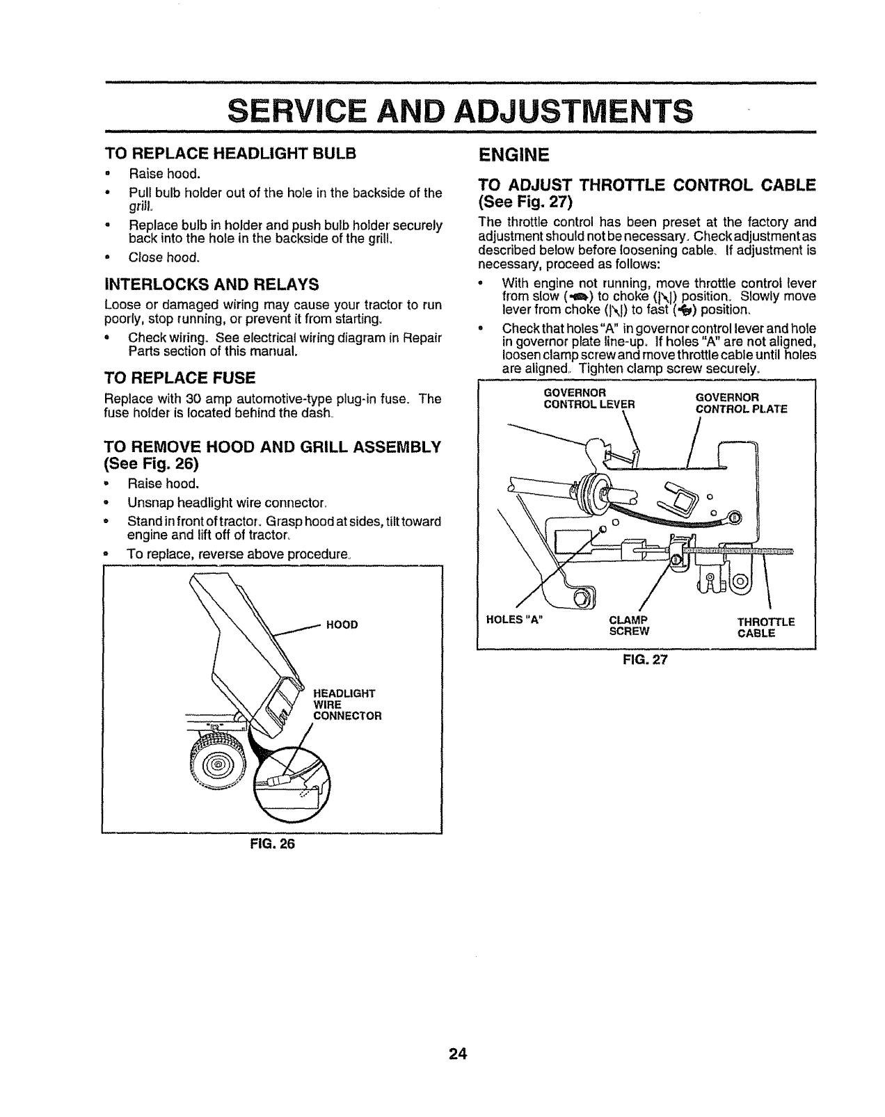
TO REPLACE HEADLIGHT BULB
°Raise hood.
• Pull bulb holder out of the ho]e in the backside of the
griJL
•Replace bulb in holder and push bulb holder' securely
back into the hole in the backside of the grill.
°Close hood.
INTERLOCKS AND RELAYS
Loose or damaged wiring may cause your tractor to run
poorly,stop running, or prevent it from starting.
°Check wiringoSee electrical wiringdiagram in Repair
Parts section of this manual.
TO REPLACE FUSE
Replace with 30 amp automotive-type plug-in fuse. The
fuse holder is located behind the dash_
TO REMOVE HOOD AND GRILL ASSEMBLY
(See Fig. 26)
°Raise hood.
°Unsnap headlight wire connector..
°Stand in front of tractor. Grasp hood at sides, tilt toward
engine and lift off of tractor_
-To replace, reverse above procedure.
HOOD
HEADLIGHT
WIRE
CONNECTOR
ENGINE
TO ADJUST THROTTLE CONTROL CABLE
(See Fig. 27)
The throttle control has been preset at the factory and
adjustment shouldnot be necessary. Check adjustmentas
described below before loosening cable, if adjustment is
necessary, proceed as follows:
°With engine not running, move throttle control lever
from slow (-e_) to choke (N) position_ Slowly move
lever from choke (N) to fast (,te_)position.
° Check that holes"A" in governor control lever and hole
in governor plate line-up. If holes "A" are not aligned,
loosen clamp screw and move throttle cable until holes
are aligned,. Tighten clamp screw securely_
GOVERNOR GOVERNOR
CONTROL LEVER CONTROL PLATE
\
HOLES "A" CLAMP THROTTLE
SCREW CABLE
FIG. 27
FIG. 26
24
SERVICE AND ADJUSTMENTS
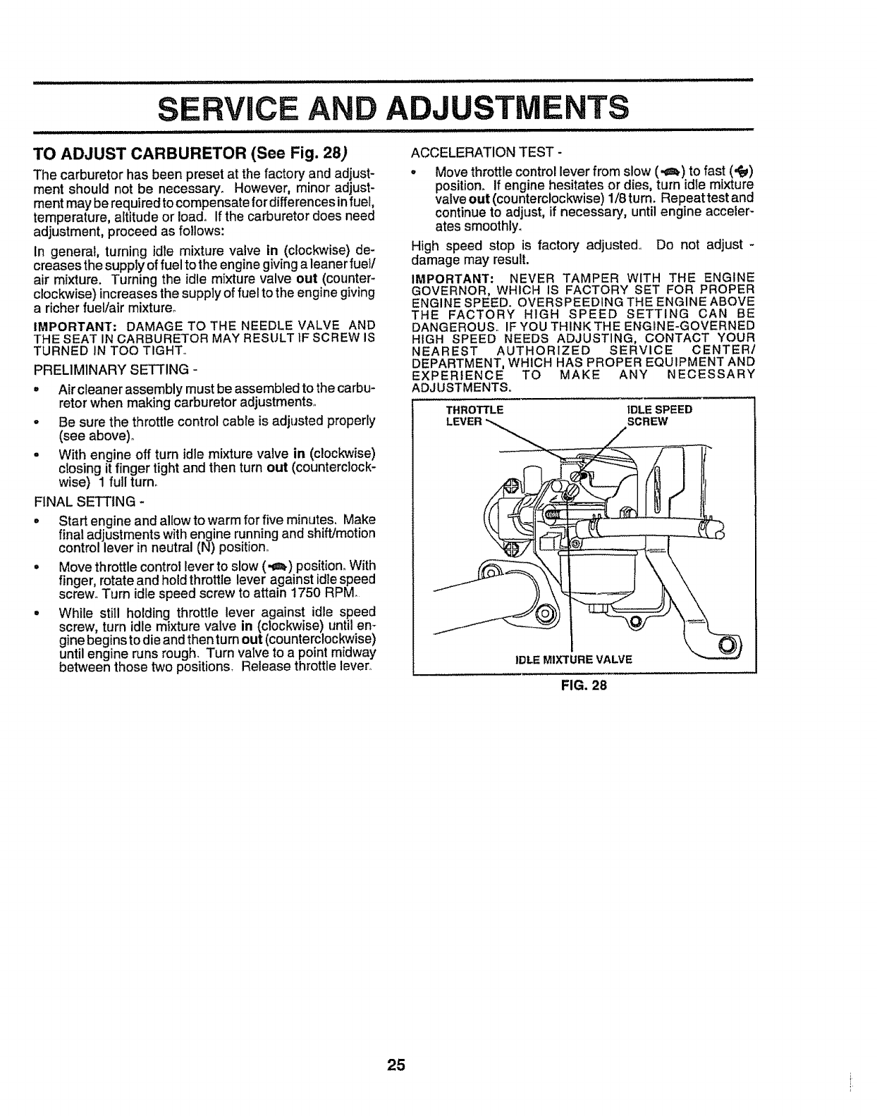
TO ADJUST CARBURETOR (See Fig. 28)
The carburetor has been preset at the factor,] and adjust-
ment should not be necessary. However, minor adjust-
ment may be required to compensate for differences infuel,
temperature, altitude or load+ If the carburetor does need
adjustment, proceed as follows:
In general, turning idle mixture valve in (clockwise) de-
creases the supply of fuel to the engine giving a leaner fuel/
air mixture. Turning the idle mixture valve out (counter-
clockwise) increases the supply of fuel to the engine giving
a richer fuel/air mixture°
IMPORTANT: DAMAGE TO THE NEEDLE VALVE AND
THE SEAT IN CARBURETOR MAY RESULT tF SCREW IS
TURNED IN TOO TIGHT+
PRELIMINARY SETTING -
.Air cleaner assembly must be assembled to the carbu+
retor when making carburetor adjustments+
- Be sure the throttle control cable is adjusted properly
(see above)+
= With engine off turn idle mixture valve in (clockwise)
closing it finger tight and then turn out (counterclock-
wise) 1 fullturn+
FINAL SETTING +
• Start engine and allow to warm for five minutes, Make
final adjustments with engine running and shift/motion
control lever in neutral (N) position+
° Move throttle control lever to slow (,g_) position_ With
finger, rotate and hold throttle lever against idle speed
screw+ Turn idle speed screw to attain 1750 RPM
•While still holding throttle lever against idle speed
screw, turn idle mixture valve in (clockwise) until en+
gine begins to die and then turn out (counterclockw+se)
until engine runs rough. Turn valve to a point midway
between those two positions. Release throttle lever.
ACCELERATION TEST -
. Move throttle control lever from slow (,4_) to fast (,_)
position+ If engine hesitates or dies, turn idle mixture
valve out (counterclockwise) 1/8 turn. Repeat test and
continue to adjust, if necessary, until engine acceler-
ates smoothly_
High speed stop is factory adjusted., Do not adjust +
damage may result.
IMPORTANT: NEVER TAMPER WITH THE ENGINE
GOVERNOR, WHICH IS FACTORY SET FOR PROPER
ENGINE SPEED+ OVERSPEEDING THE ENGINE ABOVE
THE FACTORY HIGH SPEED SETTING CAN BE
DANGEROUS. IF YOU THINK THE ENGINE-GOVERNED
HIGH SPEED NEEDS ADJUSTING, CONTACT YOUR
NEAREST AUTHORIZED SERVICE CENTER/
DEPARTMENT, WHICH HAS PROPER EQUIPMENT AND
EXPERIENCE TO MAKE ANY NECESSARY
_,DJUSTMENTS,.
THROTTLE IDLE SPEED
SCREW
IDLE MIXTURE VALVE
FIG. 28
25
Immediately prepare your tractor for storage at the end of
the season or if the tractor will not be used for 30 days or
more.
CAUTION: Never store the tractor with
gasoline in the tank inside a building
where fumes may reach an open flame
or spark. Allow the engine to cool
before storing in any enclosure.
TRACTOR
Remove mower from tractor for winter storage° When
mower is to be stored for a period of time, clean it thor-
oughly, remove all dirt, grease, leaves, etc. Store in a
ciean, dry area.,
• Clean entire tractor (See "CLEANING" inthe Customer
Responsibilities section of this rnanual)o
•Inspect and replace belts, if necessary (See belt re-
placement instructionsin the Service and Adjustments
section of this manual)_
• Lubricate as shown in the Customer Responsibilities
section of this manual,.
° Be sure that all nuts, bolts and screws are securely
fastened. Inspect moving parts for damage, breakage
and wear. Replace if necessary_
Touch up all rusted or chipped paint surfaces; sand
lightly before painting.
BATTERY
•Fully charge the battery for storage_
°After a period of time in storage, battery may require
recharging.
• To help prevent corrosion and power leakage during
long periods of storage, battery cables should be
disconnected and battery cleaned thoroughly (see q'O
CLEAN BATTERY AND TERMINALS in the Cus-
tomer Responsibilities section of this manual).
• After cleaning, leave cables disconnected and place
cables where they cannot come incontact with battery
terminals.
° Be sure battery drain tube is securely attached.,
• If battery is removed from tractor for storage, do not
store battery directly on concrete or damp surfaces_
ENGINE
FUEL SYSTEM
IMPORTANT: IT IS IMPORTANT TO PREVENT GUM
DEPOSITS FROM FORMING IN ESSENTIAL FUEL
SYSTEM PARTS SUCH AS CARBURETOR, FUEL FILTER,
FUEL HOSE, OR TANK DURING STORAGE. ALSO,
EXPERIENCE INDICATES THAT ALCOHOL BLENDED
FUELS (CALLED GASOHOL OR USING ETHANOL OR
METHANOL) CAN ATTRACT MOISTURE WHICH LEADS
TO SEPARATION AND FORMATION OF ACIDS DURING
STORAGE. ACIDIC GAS CAN DAMAGE THE FUEL
SYSTEM OF AN ENGINE WHILE IN STORAGE,
-Drain the fuel tank.,
- Start the engine and let it run until the fuel lines and
carburetor are empty..
• Never use engine or carburetor cleaner products inthe
fuel tank or permanent damage may occur,
• Use fresh fuel next season.
NOTE: Fuel stabilizer is an acceptable alternative in
minimizing the formation of fuel gum deposits during stor-
age. Add stabilizer to gasoline in fuel tank or storage
container. Always follow the mix ratio found on stabilizer
container. Run engine at least 10 minutes after adding
stabilizer to allow the stabilizer to reach the carburetor. Do
not drain the gas tank and carburetor if using fuel stabilizer.
ENGINE OIL
Drain oil (with engine warm) and replace with clean engine
oil (See "ENGINE" in the Customer Responsibilities
section of this manual).
CYLINDERS
•Remove spark plug(s)_
° Pour one ounce of oil through spark plug hole(s) into
cylinder(s)_
=Turn ignition key to"START" position for a few seconds
to distribute oil
•Replace with new spark plug(s).
OTHER
• Do not store gasoline from one season to another°
° Replace your' gasoline can if your can starts to rust.
Rust and/or dirt in your gasoline will cause problems.
° If possible, store your tractor' indoors and cover it to
give protection from dust and dirt.
° Cover you rtractor with a suitable protective cover that
does not retain moisture. Do not use plastic. Plastic
cannot breathe which allows condensation to form and
will cause your' tractor to rust.
IMPORTANT: NEVER COVER TRACTOR WHILE ENGINE
AND EXHAUST AREAS ARE STILL WARM_
26

TROUBLESHOOTI NTS
PROBLEM
Will not start
Hard to start
Engine will not turn over
Engine clicks but will not
start
Loss of power
Excessive vibration
CAUSE
1,, Out of fuel.,
2., Engine net"CHOKED" properly.
3. Engine flooded,,
4,, Bad spark plug,,
5,, Dirty air filter.
6, Dirty fuel fitter,
7,, Water in fuel,
8o Loose or damaged widng,
9, Carburetor out of adjustment.
10, Engtne valves out of adjustment
1., Dirty air filter
2, Bad spark plug
3. Weak or dead battery,
4, Dirty fuel filter.,
5, Stale or dirty fuel
6, Loose or damaged wiring,
7,, Carburetor out of adjustment,
8. Engine valves out of adjustment°
1, Clutch/brake pedal not depressed,
2, Attachment clutch is engaged,
3. Weak or dead batteR;,
4, Blown fuse,.
5 Corroded battery terminals,
6 Loose or damaged wiring,
7, Faulty ignition switch,,
8 Faulty solenold or starter,,
9, Faulty operator presence switch(es),
1, Weak or dead battery,
2., Corroded battery terminals
3,, Loose or damaged wiring,
4. Faulty solenoid or starter,
I, Cutting too much grass/too fast,
2, Throttle in "CHOKE" position.
3, Bulld-up of grass, leaves and trash under mower.,
4, Dirty air filter.
5, Low otl level/dirty oi!,,
6, Faulty spark plug,
7,, Dirty fuel filter,
8_ Stale or dirty fuel,
9. Water in fuel,
10, Spark plug wire loose,
11,. Dirty engine air screen/fins
12. Dlrb/lclogged muffler
13,, Loose or damaged wiring°
14, Carburetor out of adjustment.
!5 Engine valves out of adjustment
1, Worn, bent or loose blade
2, Bent blade mandrel,
3, Loosetdamaged part(s)
CORRECTION
1, Fill fuel tank
2, See "TO START ENGINE" in Operation section,,
3, Wait several minutes bolero attempting to start,
4. Replace spark plug,
5, Clean/replace air filter
6o Replace fuel filter,
7 Drain fuel tank and carburetor, refill tank with fresh
gasoline and replace fuel filter,,
8, Check all wiring.
9See "To Adjust Carburetor" in Service Adjustments
section,
tO Contact an authorized service center/department,
1, Clean/replace air filter,
2, Replace sparkplug,
3, Recharge or replace battery,
4. Replace fuel rifler,
5, Drain fuel tank and refill with fresh gasoline,
6, Check all widng.
7, See 'q'o Adjust Carburetor" in Service Adjustments
section,
8Contact an authorized servtce center/departmenL
1, Depress clutch/brake pedal,
2, Disengage attachment clutch,
3, Recharge or replace battery.
4, Replace fuse,,
5, Clean baltery terminals,
6o Check all wiring,
7. Check/replace Ignition switch
8, Check/replace solenotd or starter,,
9. Contact an authorized service center/department,,
1., Recharge or reptace battery,
2,, Clean battery terminals,
3. Check all wiring,,
4, Check/replace solenoid or starter,,
1_ Set tn "Higher Cut" position/reduce speed_
2, Adjust throttle control,,
3, Clean underside of mower housing,
4, Clean/replace air filter,,
5, Check oll level/change oil
6, Clean and regep or change spark plug,,
7, Replace fuel filter.,
8 Drain fue! tank and refill with fresh gasoline.
9, Drain fuel tank and carburetor, refill tank with fresh
gasoline and replace fuel filter,
10. Connect and tighten spark plug wire
1! Clean engine air screeniflns.
12, Clean/replace muffler
13, Check all wiring.
14, See "To Adjust Carburetor" in Service Adjustmenls
section.
15., Contact an authorizod sorvioo conter/department.
t. Replace blade, Tighten blade bolt,
2., Replace blade mandrel.,
3. Tighten loose part(s), Replace damaged parts,,
27

TROUBLESHOOTING POINTS
PROBLEM
:..................... iii ill iHll
Engine continues to run
when operator leaves seat
with attachment clutch
engaged
Poor cut _uneven
Mower blades will not
rotate
Poor grass discharge
Headlight(s) not working
(if so equipped)
Battery will not charge
Engine "backfires"
when turning engine
"OFF"
CAUSE
1o Faulty operator-safety presence control system
1o Worn, bent or loose blade,.
2. Mower deck not level
3. Buildup of grass, teaves, and trash under mower
4,, Bent blade mandrel.
5, Clogged mower deck vent holes from buildup of
grass, leaves, and trash around mandrels_
1, Obstruction in clutch mechanism,,
2. Worn/damaged mower drive belt
3, Frozen idler pulley.
4, Frozen blade mandrel.
i,,,,,,,,,,,,,
t,
2
3o
4,,
5o
6
7_
8,
9,
10.
11,,
ill /lllJll i iiill i i llllll,lll ILIIIII
Engine speed too slow
Travel speed too fast°
Wet grase_
Mower deck not level,
Low/uneven tire air pressure
Worn, bent or loose blade.
Buildup of grass, leaves and trash under mower
Mower drive belt wom_
Blades improperly installed,.
improper blades used,
Clogged mower deck vent holes from buildup of
grass, leaves, and trash around mandrets,.
ISwitch is "OFF",,
2,. Bu{b(s) bumedout,
3,, Faulty light switch,
4.. Loose or damaged wiring,
5. B{own fuse,
1o Bad battery celt(s).
2_ Poor cable connections,
& Faulty regulator (if so equipped),,
4, Faulty alternator,,
1_ Eng{ne throttle control not set at "SLOW"
position for 30 seconds before stopping engine,
CORRECTION
Check wiring, switches and connections. If not
corrected, contact an authorized service center!
department.
iiill : ......
1,. Replace blade, Tighten blade bolt,
2. Level mower deck,
3, Clean underside of mower housing,
4. Replace blade mandrel,
5, Clean around mandrels to open vent holes
1_ Remove obstruction_
2,. Replace mower drive bell
3, Repiaca idler puHey_
4 Replace blade mandrel
1, Race throttle control in "FAST" position
2_ Shift to slower speed.
3 Allow grass to dry before mowing
4. Level mower deck_
5, Check tires for proper air pressure.
6_ Replace/sharpen blade_ Tighten blade be[t.
7 Clean underside of mower housing,
8,, Replace mower drive belt,
9. Reinstall blades sharp edge dewn_
i0,. Replace with blades listed In this manual.
11. Clean around mandrels to open vent holes
1, Tum sw_tch "ON",,
2 Replace bulb(s),
3, Check/replace light switch,,
4,, Check w{ring and connections_
5 Replace fuse,
1_ Replace battery.
2, Check/clean atl connections.
3, Replace regulator,
4 Replace alternator,.
1, Move throttle control to "SLOW" position and allow
to idle for 30 seconds before stopping engine.
28
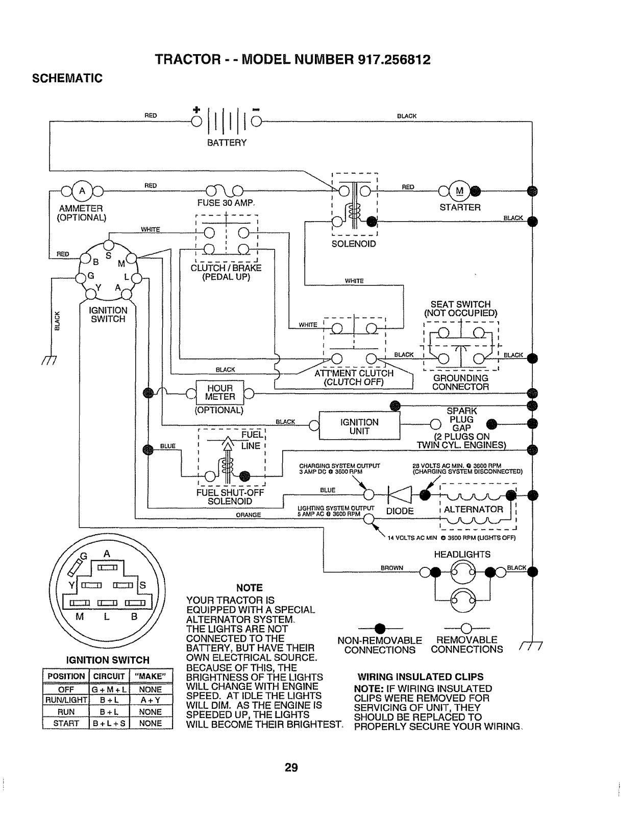
SCHEMATIC
TRACTOR - - MODEL NUMBER 917.256812
RED
BATTERY
BLACK
RED
WHITE
FUSE 30 AMP.
;*---,f--,7
,©,©: ........
i,L ..... J
RED
STARTER
BLACK
J
IGNITION
SWITCH
IGNITION SWITCH
POSITION CIRCUIT "MAKE"
OFF G + M + L NONE
RUN/LIGHT B+ L A + Y
RUN B+L j NONE
H
START B+L+SNONE
J
CLUTCH 1BRAKE
(PEDAL UP)
8LACK
METER
(OPTIONAL)
BLACK
_UEL=
b, BLU_ t "A" LINE'
l!
FUEL SHUT-OFF
SOLENOID j
ORANGE
SOLENOID
WHITE
WHITE _) ! _
1
t u_ '! ........ I
IGNITIONUNIT
SEAT SWITCH
(NOT OCCUPIED)
! .... '1
,,-#_ ] C",--, j
7 .... _
r., _|
GROUNDING
CONNECTOR
SPARK
PLUG ,,,,= d
GAP
PLUGS ON
CYL. ENGINES)
D
_P
u_ca _MO_P_ DIODE , ALTERNATOR I"
HEADLIGHTS
©
REMOVABLE
CONNECTIONS
BROWN
NON*REMOVABLE
CONNECTIONS
NOTE
YOUR TRACTOR IS
EQUIPPED WITH A SPECIAL
ALTERNATOR SYSTEM°
THE LIGHTS ARE NOT
CONNECTED TO THE
BATTERY, BUT HAVE THEIR
OWN ELECTRICAL SOURCE.
BECAUSE OF THIS, THE
BRIGHTNESS OF THE LIGHTS
WILL CHANGE WITH ENGINE
SPEED. AT IDLE THE LIGHTS
WILL DIM. AS THE ENGINE IS
SPEEDED UP, THE LIGHTS
WILL BECOME THEIR BRIGHTEST.
/"77
WIRING INSULATED CLIPS
NOTE: IF WIRING INSULATED
CLIPS WERE REMOVED FOR
SERVICING OF UNIT, THEY
SHOULD BE REPLACED TO
PROPERLY SECURE YOUR WIRING
29
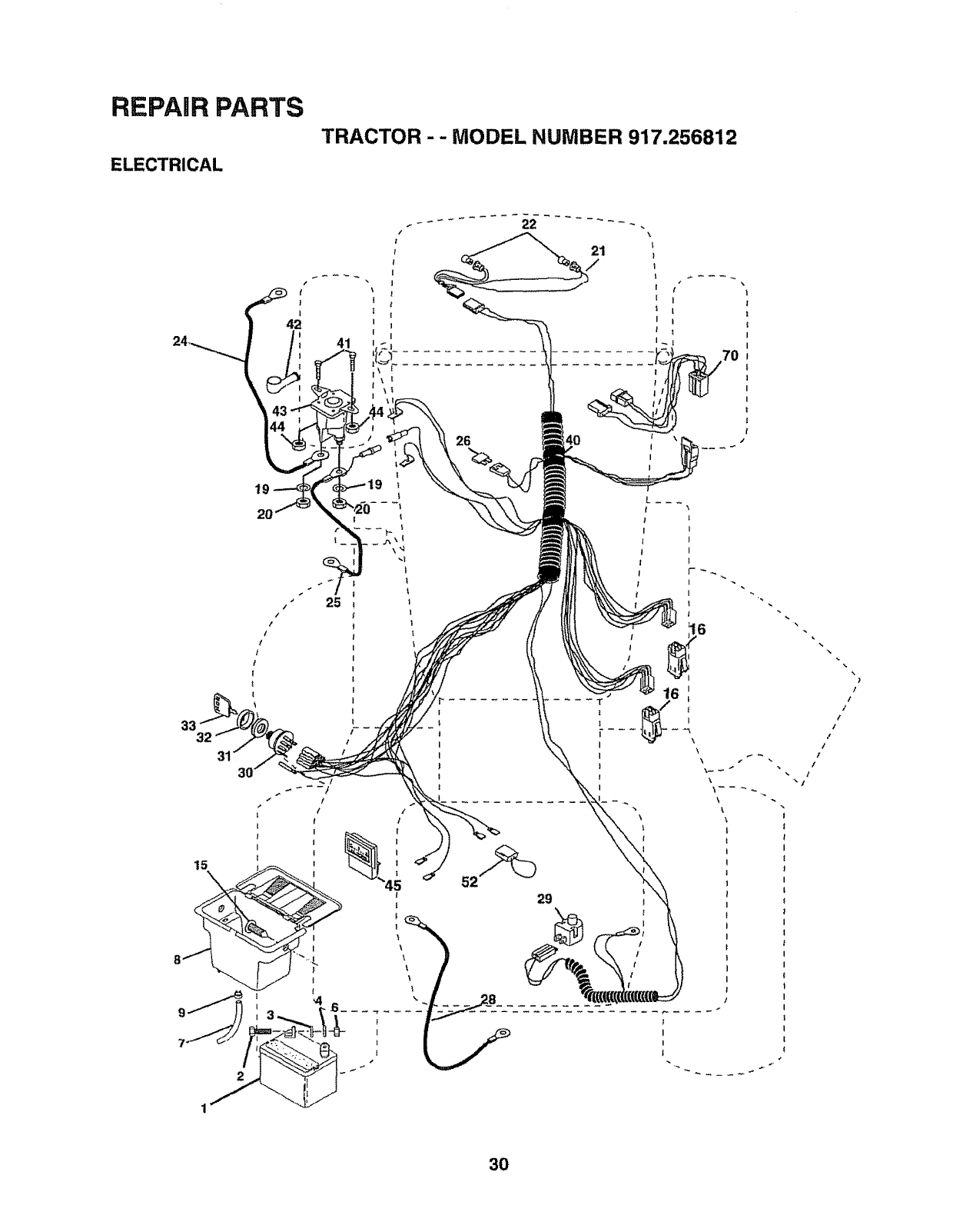
REPAIR PARTS
ELECTRICAL
TRACTOR-- MODEL NUMBER 917.256812
32
|
25
!
I
I
I
t
I
t
t
/
t
I
l
70
I
\
\
\
I
I
I
I
|
30
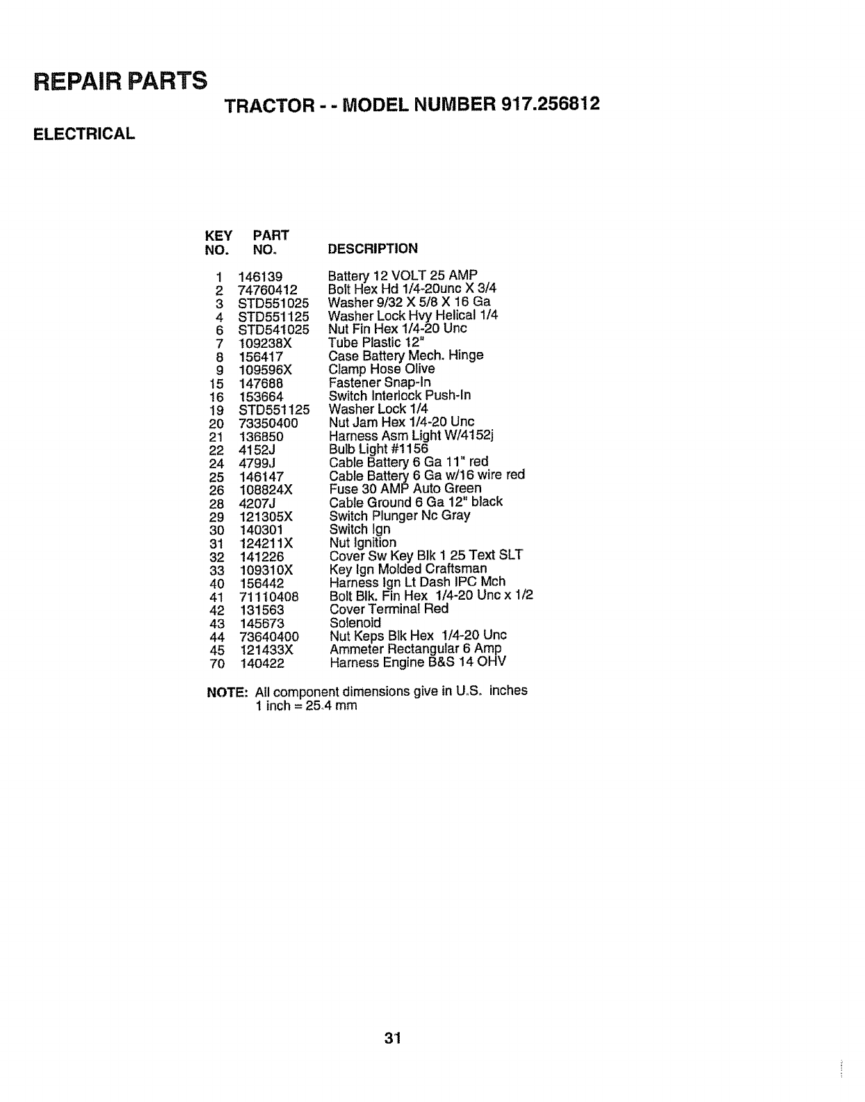
REPAIR PARTS
ELECTRICAL
TRACTOR -- MODEL NUMBER 917.256812
KEY PART
NO. NO° DESCRIPTION
1146139
2 74760412
3STD551025
4 STD551125
6 STD54t025
7 109238X
8 156417
9 109596X
15 147688
16 153664
19 STD55t125
20 73350400
21 136850
22 4152J
24 4799J
25 146147
26 108824X
28 4207J
29 121305X
30 140301
31 124211X
32 141226
33 109310X
40 156442
41 71110408
42 131563
43 145673
44 73640400
45 121433X
70 140422
Battery 12 VOLT 25 AMP
Bolt Hex Hd 1/4-20unc X 3/4
Washer 9/32 X 5/8 X 16 Ga
Washer Lock Hwx'Helical 1/4
Nut Fin Hex 1/4-20 Unc
Tube Plastic 12"
Case Battery Mech. Hinge
Clamp Hose Olive
Fastener Snap-In
Switch Interlock Push-In
Washer Lock 1/4
Nut Jam Hex 1/4-20 Unc
Harness Asm LightW/4152j
ButbLight#1156
Cable Battery 6 Ga 11" red
Cable Battery 6 Ga w/16 wire red
Fuse 30 AMP Auto Green
Cable Ground 6 Ga 12" black
Switch Plunger Nc Gray
Switch Ign
Nut Ignition
Cover Sw Key BIk I 25 Text SLT
Key Ign Motded Craftsman
Harness Ign Lt Dash IPC Mch
Bolt BIk. Fin Hex 1/4-20 Unc x 1/2
Cover Terminal Red
Solenoid
Nut Keps Blk Hex I/4-20 Unc
Ammeter Rectangular 6 Amp
Harness Engine B&S 14 OHV
NOTE: All component dimensions give in U_S, inches
1 inch = 25°4 mm
31
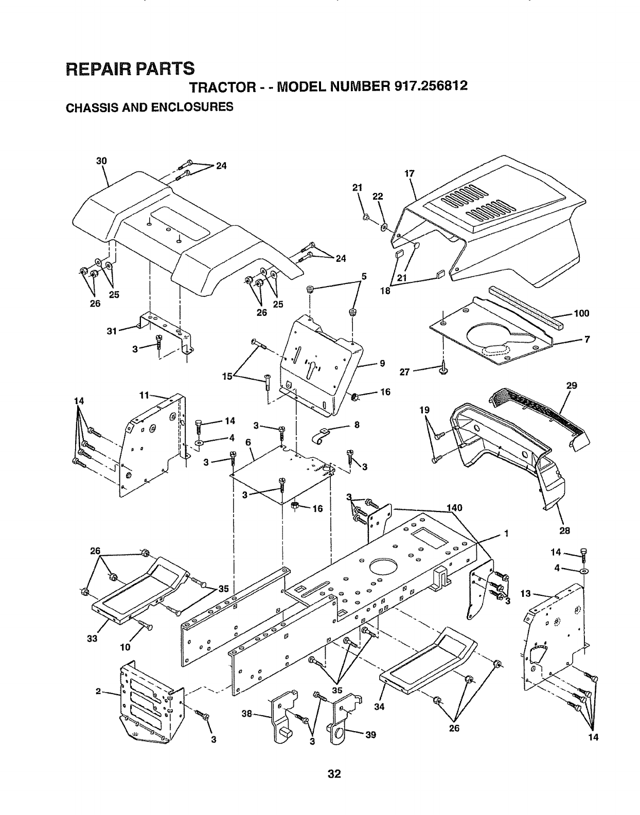
REPAIR PARTS
TRACTOR - - MODEL NUMBER 917.256812
CHASSIS AND ENCLOSURES
30
21 22
17
14
26
25
26
5
18
16
19
33 10
38 =34
39 26
29
28
14 _-.._
4--_
14
32
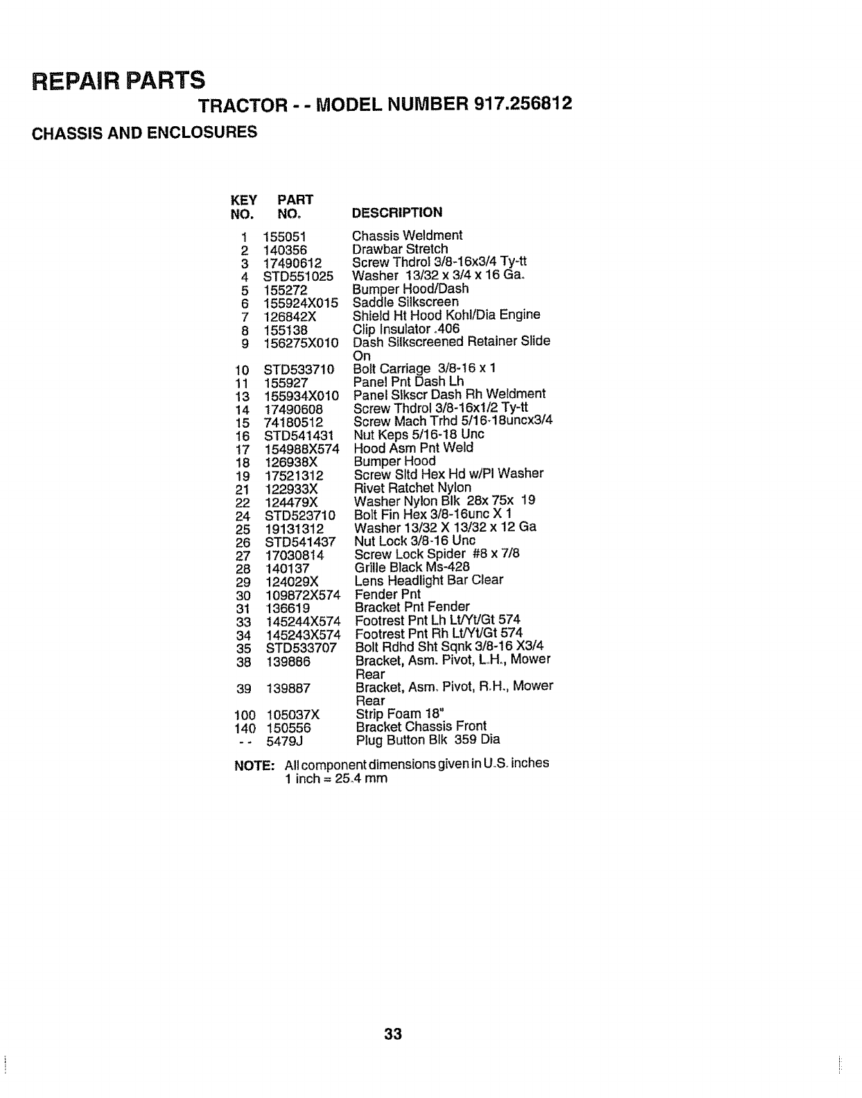
REPAIR PARTS
TRACTOR - - MODEL NUMBER 917.256812
CHASSIS AND ENCLOSURES
KEY PART
NO. NOo DESCRIPTION
1 155051
2 140356
3 17490612
4 STD551025
5 155272
6 155924X015
7 126842X
8 155138
9 156275X010
10 STD533710
11 155927
13 155934X010
14 17490608
15 74180512
16 STD541431
17 15498BX574
18 12693BX
19 17521312
21 122933X
22 124479X
24 STD523710
25 19131312
26 STD541437
27 17030814
28 140137
29 124029X
30 109872X574
31 136619
33 145244X574
34 145243X574
35 STD533707
38 139886
39 139887
100 105037X
140 150556
-- 5479J
NOTE:
Chassis Weldment
Drawbar Stretch
Screw Thdrol 3/8-I6x3/4 Ty-tt
Washer 13/32 x 3/4 x 16 Gao
Bumper Hood/Dash
Saddle Silkscreen
Shield Ht Hood Kohl/Dia Engine
Clip Insulator °406
Dash Silkscreened Retainer Slide
On
Bolt Carriage 3/8-t 6 x 1
Panel Pnt Dash Lh
Panel SIkscr Dash Rh Weldment
Screw Thdrol 3/8-16xl/2 Ty-tt
Screw Mach Trhd 5/16-18uncx3/4
Nut Keps 5/16-18 Uric
Hood Asm Pnt Weld
Bumper Hood
Screw Sltd Hex Hd w/PI Washer
Rivet Ratchet Nylon
Washer Nylon Bik 28x 75x 19
Bolt Fin Hex 3/8-!6unc X 1
Washer 13/32 X 13/32 x 12 Ga
Nut Lock 3/8-16 Unc
Screw Lock Spider #8 x 7/8
Grille Black Ms-428
Lens Headlight Bar Clear
Fender Pnt
Bracket Pnt Fender
Footrest Pnt Lh Lt/Yt/Gt 574
Footrest Pnt Rh Lt/Yt/Gt 574
Bolt Rdhd Sht Sqnk 3/8-16 X3/4
Bracket, Asm. Pivot, LH. Mower
Rear
Bracket, Asm. Pivot, Roll., Mower
Rear
Strip Foam 18"
Bracket Chassis Front
Plug Button BIk 359 Dia
All component dimensions given in U..S.inches
1 inch = 25.,4mm
33
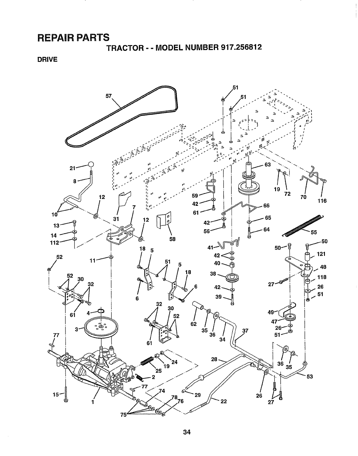
REPAIR PARTS
DRIVE TRACTOR
""MODEL NUMBER 917.256812
/
/
53
26
27
34
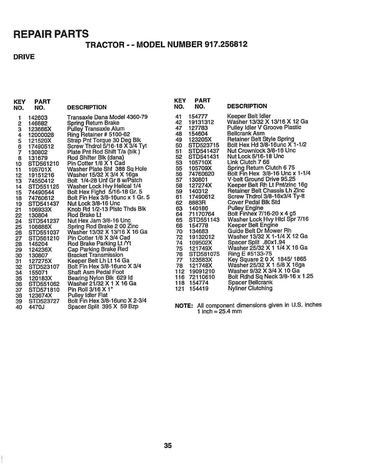
REPAIR PARTS
TRACTOR - - MODEL NUMBER 917.256812
DRIVE
KEY PART KEY PART
NO. NO. DESCRIPTION NO. NO. DESCRIPTION
1 142603 Transaxle Dana Model 4360-79 41 154777
2146682 Spring Return Brake 42 19131312
3 123666X Pulley Transaxte Alum 47 127783
4 12000028 Ring Retainer # 5t00-62 48 154604
5 121520X Strap Pnt Torque 30 Deg BIk 49 123205X
617490512 Screw Thdrol 5/16-18 X 3/4 Tyt 50 STD523715
7 130802 Plate Pnt Rod Shift Tla (blk) 51 STD541437
8 131679 Rod Shifter BIk (dana) 52 STD541431
10 STD561210 Pin Cotter 1/8 X 1 Cad 53 105710X
11 105701X Washer Plate Shf 388 Sq Hole 55 105709X
12 19151216 Washer 15/32 X 3/4 X !6ga 56 74760620
13 74550412 Bolt 1/4-28 Unf Gr 8 w/Patch 57 130801
14 STD551125 Washer Lock Hvy Helical 1/4 58 127274X
t5 74490544 Bolt Hex Flghd 5/16-18 Gr. 5 59 140312
18 74760612 Bolt Fin Hex 3/8-16unc x I Gr, 5 61 17490612
19 STD541437 Nut Lock 3/8-16 Unc 62 8883R
21 106933X Knob Rd 1/2-13 Plstc Thds BIk 63 140186
22 130804 Rod Brake Lt 64 71170764
24 STD541237 Nut Hex Jam 3/8-16 Unc 65 STD551143
25 106888X Spring Rod Brake 2 00 Zinc 66 154778
26 STD551037 Washer13/32 X 13/16 X 16 Ga 70 134683
27 STD561210 Pin Cotter 1/8 X3/4Cad 72 19132012
28 145204 Rod Brake Parking Lt PY't 74 109502X
29 124236X Cap Parking Brake Red 75 121749X
30 130807 Bracket Transmission 76 STD581075
31 127275X Keeper Belt Lh Lt !4 Ga 77 123583X
32 STD523107 Bolt Fin Hex 3/8-16unc X 3/4 78 121748X
34 155071 Shaft Asm Pedal Foot 112 19091210
35 t20183X Bearing Nylon BIk 629 Id 116 72110610
36 STD551062 Washer 21132X 1 X 16 Ga 118 154774
37 STD571810 Pin Roll3/16X 1" 121 154419
38 123674X Pulley Idler Flat
39 STD523727 Bolt Fin Hex 3/8-16unc X 2-3/4
40 4470J Spacer Split 395 X 59 Bzp
Keeper Belt Idler
Washer 13/32 X 13/16 X 12 Ga
Pulley Idler V Groove Plastic
Bellcrank Asm
Retainer Belt Style Spring
Bolt Hex Hd 3/8-16unc X 1-1/2
Nut Crownlock 3/8-16 Unc
Nut Lock 5/16-18 Unc
Link Clutch 7 66
Spring Return Clutch 6 75
Bolt Fin Hex 3/8-16 Uric x1-1/4
Wbelt Ground Drive 95.25
Keeper Belt Rh Lt Pnt/zinc 16g
Retainer Belt Chassis Lh Zinc
Screw Thdrol 3/8-16x3/4 Ty-tt
Cover Pedal BIk Std
Pulley Engine
Bolt Finhex 7/16-20 x 4 g5
Washer Lock Hvy Hlcl Spr 7/16
Keeper Belt Engine
Guide Belt Dr Mower Rh
Washer 13/32 X 1-1/4 X 12 Ga
Spacer Split ,80xl ,94
sher25/32 X 1 1/4 X 16 Ga
Ring E #5133-75
Key Square 2 0 X 1845/1865
Washer 25/32 X 1 5/8 X 16ga
Washer 9/32 X 3/4 X 10 Ga
Bolt Rdhd Sq Neck 3/8-16 x 1,25
Spacer Bellcrank
Nyliner Clutching
NOTE: All component dimensions given in U,S° inches
1 inch = 25.4 mm
35
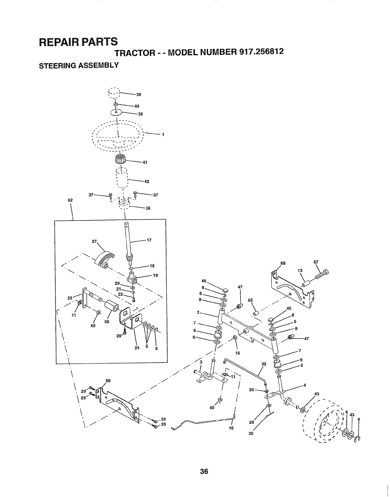
REPAIR PARTS
TRACTOR - - MODEL NUMBER 917.256812
STEERING ASSEMBLY
62
......
39
_t
I
I
!
27
25
\
J
46
47
10
65
32
28
30
68 67
36
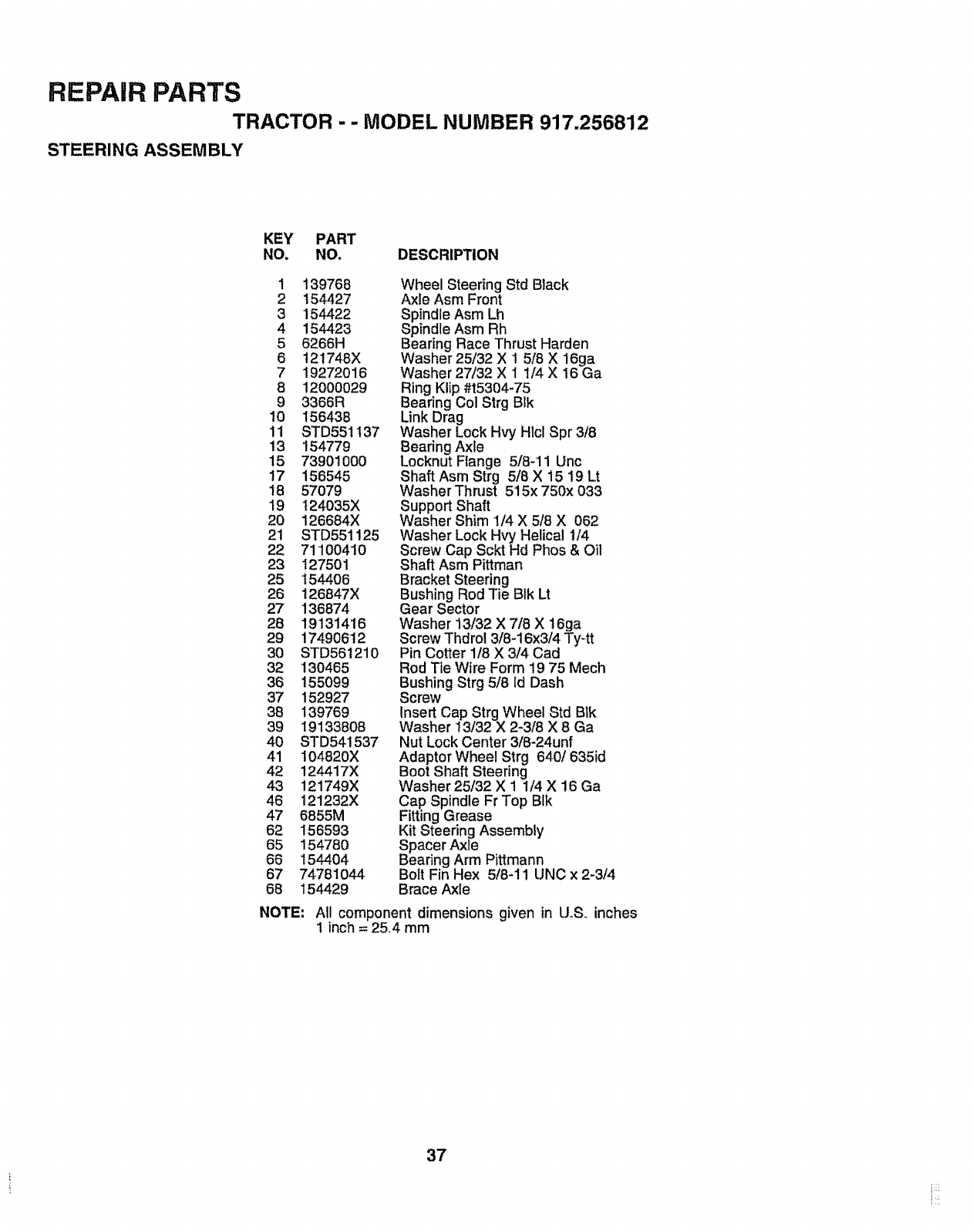
REPAIR PARTS
TRACTOR - - MODEL NUMBER 917.256812
STEERING ASSEMBLY
KEY PART
NO. NO. DESCRIPTION
1 139768
2 154427
3 154422
4 154423
5 6266H
6 12t748X
7 19272016
8 120OOO29
9 3366R
10 156438
11 STD551137
13 154779
15 739010OO
17 156545
18 57079
19 124035X
20 126684X
21 STD551125
22 71100410
23 127501
25 154406
26 !26847X
27 136874
28 19131416
29 17490612
30 STD561210
32 130465
36 155099
37 152927
38 139769
39 19133808
40 STD541537
41 104820X
42 124417X
43 121749X
46 121232X
47 6855M
62 156593
65 15478O
66 154404
67 74781044
68 154429
NOTE:
Wheel Steering Std Black
Axle Asm Front
Spindle Asm Lh
Spindle Asm Rh
Bearing Race Thrust Harden
Washer 25/32 X 1 5/8 X 16ga
Washer 27/32 X 1 1/4 X 16 Ga
Ring Klip #15304-75
Bearing Col Strg BIk
Link Drag
Washer Lock Hvy Hlcl Spr 3/8
Bearing Axle
Locknut Flange 5/8-11 Unc
Shaft Asm Strg 5/8 X 15 19 Lt
Washer Thrust 515x 750x 033
Support Shaft
Washer Shim 1/4 X 5/8 X 062
Washer Lock Hvy Helical 1/4
Screw Cap Sckt Hd Phos & Oil
Shaft Asm Pittman
Bracket Steering
Bushing Rod Tie BIk Lt
Gear Sector
Washer 13/32 X 7/8 X 16ga
Screw Thdrol 3/8-16x3/4 Ty-tt
Pin Cotter 1/8 X 3/4 Cad
Rod Tte Wire Form 19 75 Mech
Bushing Strg 5/8 Id Dash
Screw
Insert Cap Strg Wheel Std Blk
Washer 13/32 X 2-3/8 X 8 Ga
Nut Lock Center 3/8-24unf
Adaptor Wheel Strg 640/635id
Boot Shaft Steering
Washer 25/32 X 1 1/4 X 16 Ga
Cap Spindle Fr Top BIk
Fitting Grease
Kit Steering Assembly
Spacer Axle
Bearing Arm Pittmann
Bolt Fin Hex 5/8-11 UNC x 2-3/4
Brace Axle
All component dimensions given in U.S,, inches
1 inch = 25.4 mm
37
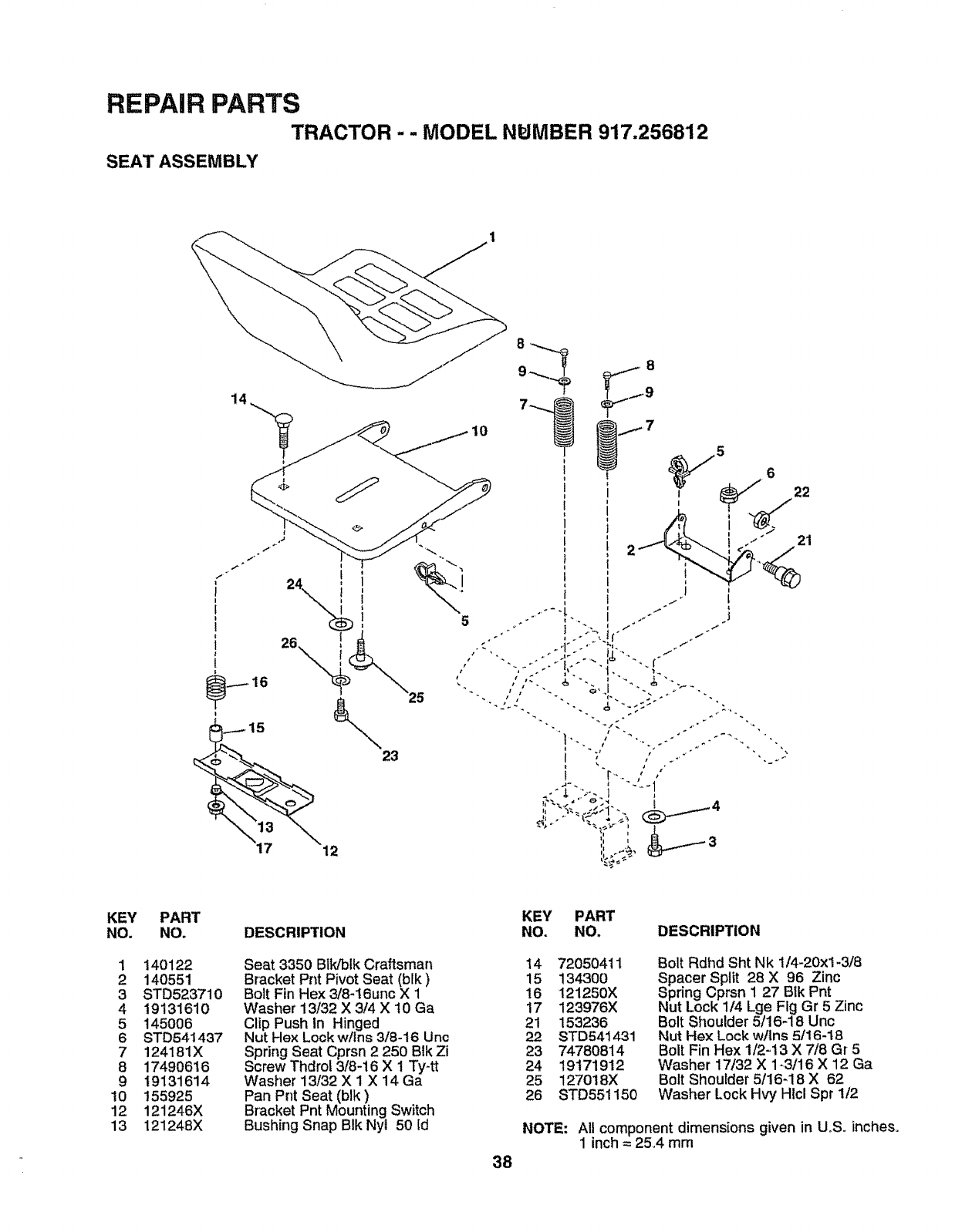
REPAIR PARTS
TRACTOR -- MODEL NPJMBER 917.256812
SEAT ASSEMBLY
KEY
NO.
1
2
3
4
5
6
7
8
9
10
12
13
PART
NO.
140122
140551
STD523710
19131610
145006
STD541437
124181X
17490616
19131614
155925
121246X
121248X
KEY PART
DESCRIPTION NO. NO, DESCRIPTION
Seat 3350 Blk/blk Craftsman
Bracket Pnt Pivot Seat (blk)
Bolt Fin Hex 3/8-16unc X 1
Washer 13/32 X 3/4 X t0 Ga
Clip Push in Hinged
Nut Hex Lock w/Ins 3/8-16 Uric
Spring Seat Cprsn 2 250 Blk Zi
Screw Thdrol 3/8-16 X 1 Ty-tt
Washer 13/32 X 1 X 14 Ga
Pan Pnt Seat (blk)
Bracket Pnt Mounting Switch
Bushing Snap BIk Nyl 50 Id
38
I4 72050411
15 13430O
16 121250X
17 123976X
21 153236
22 STD541431
23 74780814
24 19171912
25 127018X
26 STD551150
Bolt Rdhd Sht Nk 1/4-20xl-3/8
Spacer Split 28 X 96 Zinc
Spring Cprsn I 27 Bik Pnt
Nut Lock 1/4 Lge Fig Gr 5 Zinc
Bolt Shoulder 5/16-18 Unc
Nut Hex Lock w/Ins 5/16-18
Bolt Fin Hex 1/2-13 X 7/8 Gr 5
Washer 17/32 X 1-3/16 X 12 Ga
Bolt Shoulder 5/16-18 X 62
Washer Lock Hvy HIcl Spr 1/2
NOTE: All component dimensions given in UoS. inches.
1 inch = 25A mm
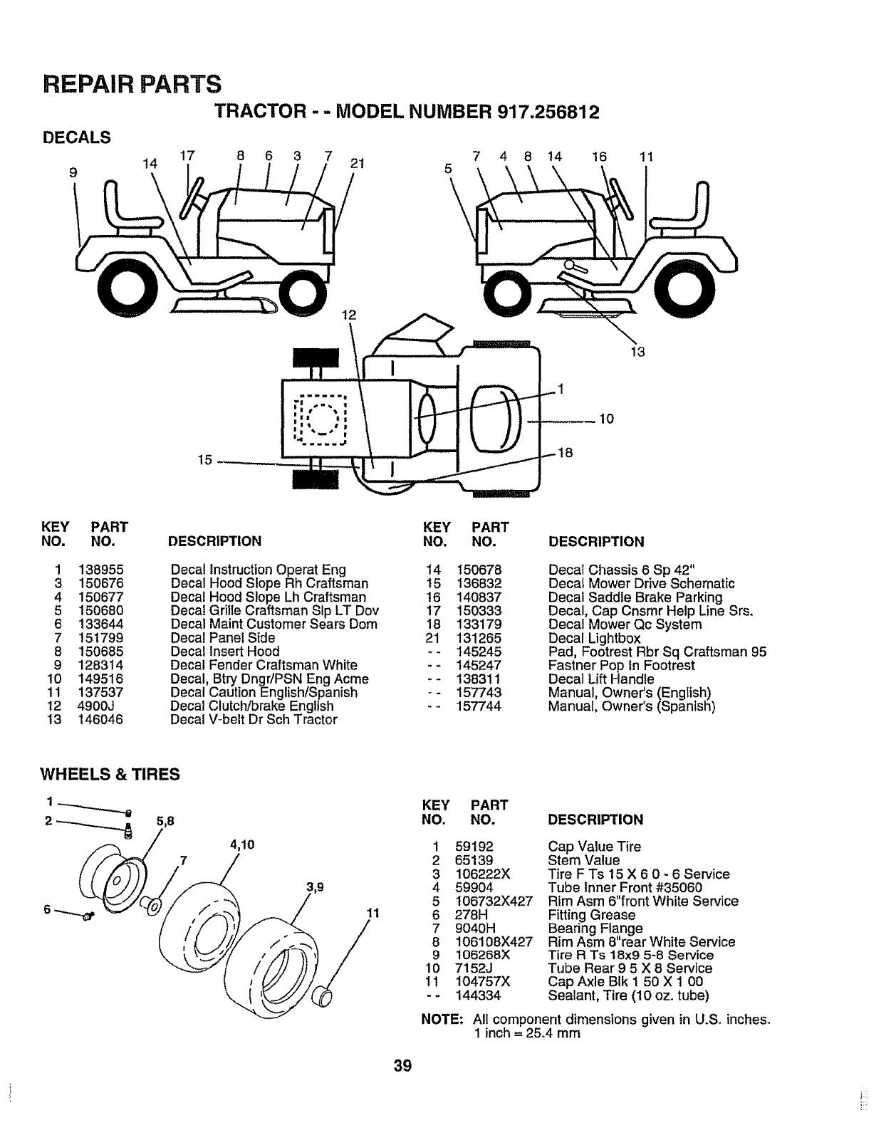
REPAIR PARTS
TRACTOR -- MODEL NUMBER 917.256812
DECALS
914 17 8 6 3 7 29 7 4 8 't4 16 11
5
\
13
15 18
KEY PART KEY PART
NO. NO. DESCRIPTION NO. NO. DESCRIPTION
1 138955 Decal Instruction Operat Eng i4 150678
3 150676 Decal Hood Slope Rh Craftsman !5 136832
4 150677 Decal Hood Slope Lh Craftsman t6 140837
5 150680 Decal Grille Craftsman Sip LT Dov 17 150333
6 133644 Decal Maint Customer Sears Dora 18 133179
7 151799 Decal PanetSide 21 131265
8 150685 Decal Insert Hood - - I45245
9 128314 Decal Fender Craftsman White -- 145247
10 149516 Decal, Btry Dngr/PSN Eng Acme - - 138311
11 137537 Decal Caution English!Spanish _- 157743
t2 4900J Decal Clutch/brake English - - 157744
t3 146046 Decal V-belt Dr SchTractor
Decal Chassis 6 Sp 42"
Decal Mower Drive Schematic
Decal Saddle Brake Parking
Decal, Cap Cnsmr Help Line Srs.
Decal Mower Qc System
Decal Lightbox
Pad, Footrest Rbr Sq Craftsman 95
Fastner Pop In Footrest
Decal Lift Handle
Manual, Owner's (Engtish)
Manual, Owner's (Spanish)
WHEELS & TIRES
1__
2_5,8
74,10
11
KEY PART
NO. NO. DESCRIPTION
1
2
3
4
5
6
7
8
9
10
11
59192
65139
106222X
59904
106732X427
278H
9040H
106108X427
106268X
7152J
104757X
144334
Cap Value Tire
Stem Value
Tire F Ts 15 X 6 0 -6 Service
Tube Inner Front #35060
Rim Asm 6"front White Service
Fitting Grease
Bearing Flange
Rim Asm 8"rear White Service
Tire RTs 18x9 5-8 Service
Tube Rear 9 5X 8 Service
Cap Axle BIk 1 50 X 1 00
Sealant, Tire (10 oz. tube)
NOTE: All component dimensions given in U.S. inches.
1inch = 25.4 mm
39
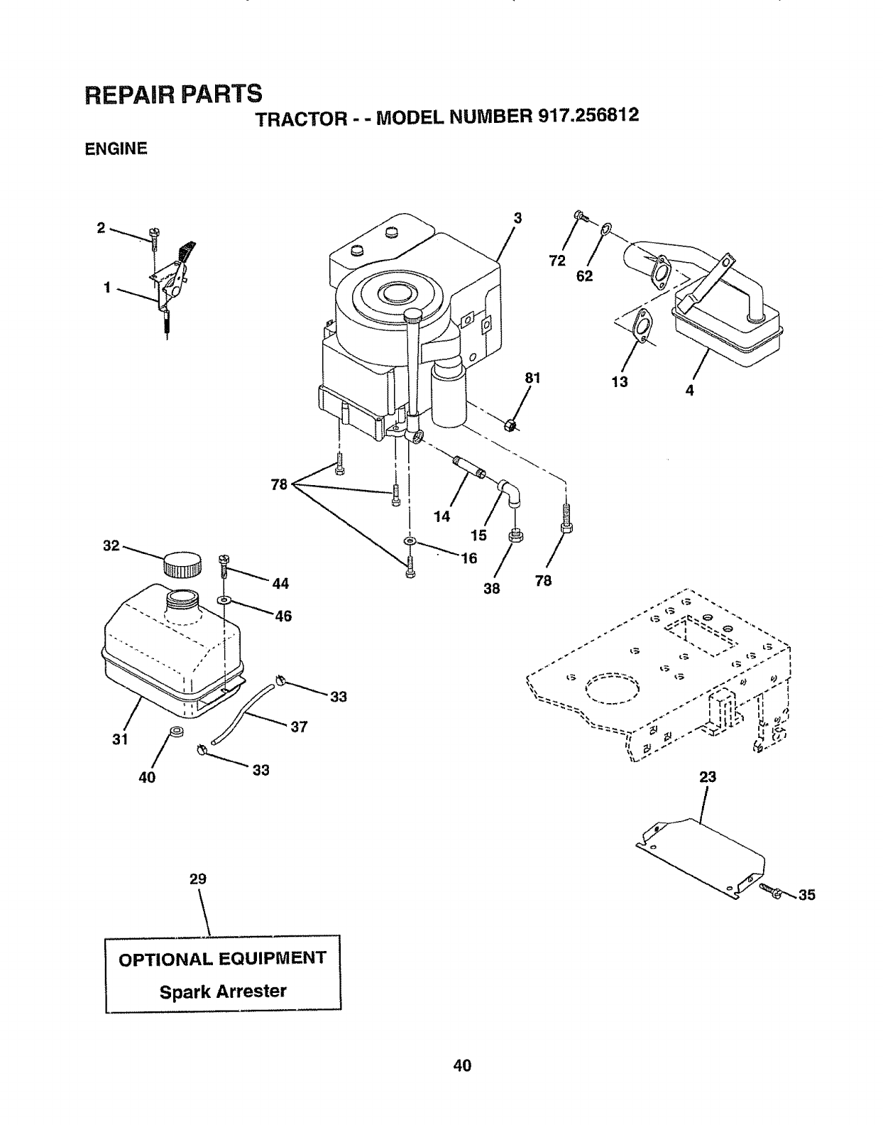
REPAIR PARTS
TRACTOR --MODEL NUMBER 917.256812
ENGINE
4
33
." _ _'_
I fYr'_ _,'H •
23
29
OPTIONAL EQUIPMENT
Spark Arrester
4O
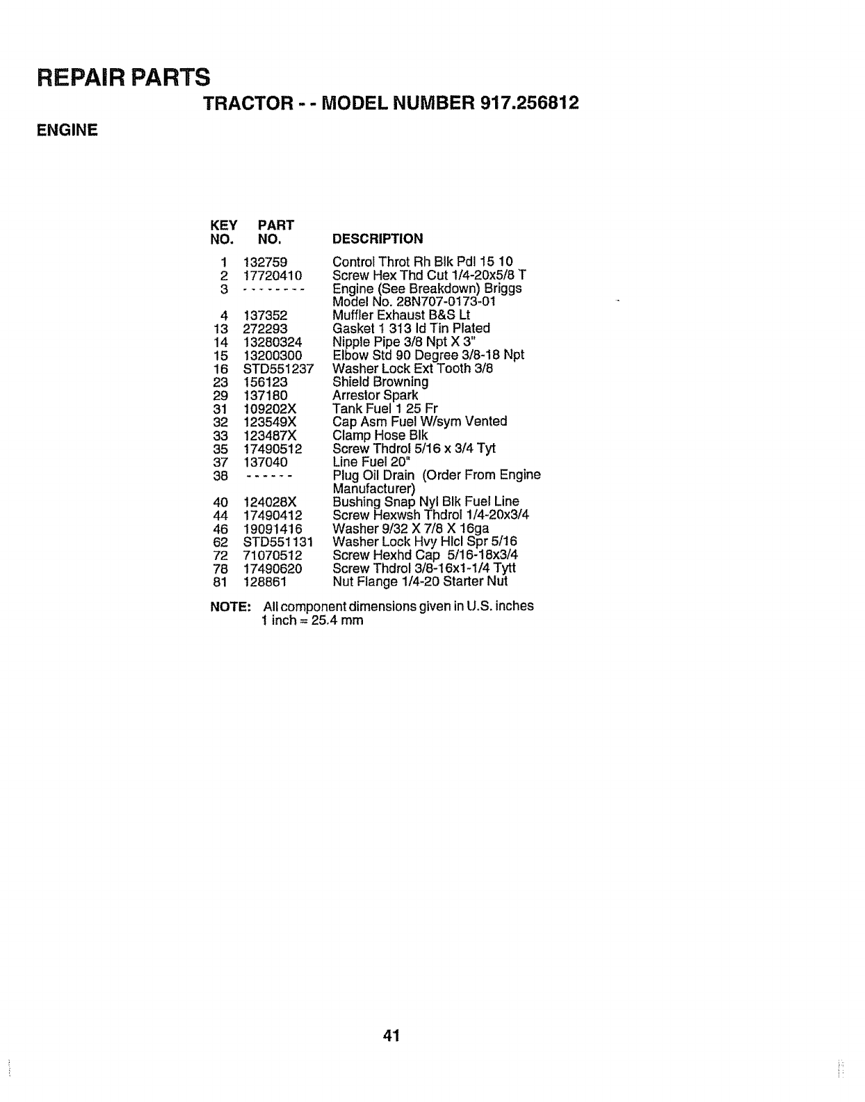
REPAIR PARTS
TRACTOR -- MODEL NUMBER 917.256812
ENGINE
KEY PART
NO. NO. DESCRIPTION
1 132759
2 17720410
........
4 137352
13 272293
14 13280324
15 13200300
16 STD551237
23 156123
29 137180
31 109202X
32 123549X
33 123487X
35 17490512
37 137040
38 ......
4O 124028X
44 17490412
46 19091416
62 STD551131
72 71070512
78 17490620
81 128861
Control Throt Rh BIk Pdl 15 10
Screw Hex Thd Cut 1/4-20x5/8 T
Engine (See Breakdown) Briggs
Model No. 28N707-0173-01
Muffler Exhaust B&S Lt
Gasket t 313 id Tin Plated
Nipple Pipe 3/8 Npt X 3"
Elbow Std 90 Degree 3/8-18 Npt
Washer Lock Ext Tooth 3/8
Shield Browning
Arrestor Spark
Tank Fuel 1 25 Fr
Cap Asm Fuel W/sym Vented
Clamp Hose BIk
Screw Thdrol 5/16 x 3/4 Tyt
Line Fuel 20"
Plug Oil Drain (Order From Engine
Manufacturer)
Bushing Snap Nyl BIk Fuel Line
Screw Hexwsh Thdrol 1/4-20x3/4
Washer 9/32 X 7/8 X 16ga
Washer Lock Hvy Hlcl Spr 5/16
Screw Hexhd Cap 5/16-18x3/4
Screw Thdrol 3/8-16x1-1/4 Tytt
Nut Flange 1/4_20 Starter Nut
NOTE: All component dimensions given inUoS.inches
1 inch = 25,4 mm
4'1
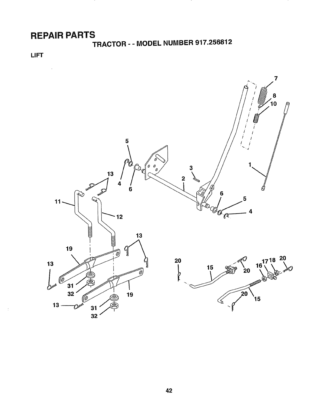
REPAIR PARTS
TRACTOR- - MODEL NUMBER 917.256812
LIFT
11
5
13
12
3
2
8
5
13
13_
19
\i
32
32
19
13
15 2O 161718
15
20
42

REPAIR PARTS
TRACTOR - - MODEL NUMBER 917.256812
LIFT
KEY PART
NO. NO. DESCRIPTION
1 136973 Rod Asmo Lever
2 122507X Shaft Asmo Lift
3 105767X Pin Groove
4 12000002 E Ring #5133-62
5 19211621 Washer 21132xl x2i Ga.
6 120183X Bearing Nylong
7 125631X Grip Handle Fluted
8 122365X Button Plunger Read
10 122512X Spring Cprsn
1t 139865 LinkAsm Lift L,,Ho
12 139866 LinkAsm Lift R.H_
13 STD624008 Retainer Spring
15 127218 Link Front
16 73350800 Nut Jam Hex 1/2d3 Unc
t7 130171 Trunnion BIk Zinc
18 73800800 Nut Lock W/Wsh !/2-13 Unc
19 139868 Arm Suspension Mower
20 3146R Retainer Spdng
31 140302 Bearing, Pvt. Lift. Spherical
32 73540600 Nut Crownlock 3/8-24
NOTE: All component dimensions given in UoS.inches
1 inch = 25,,4 mm
43
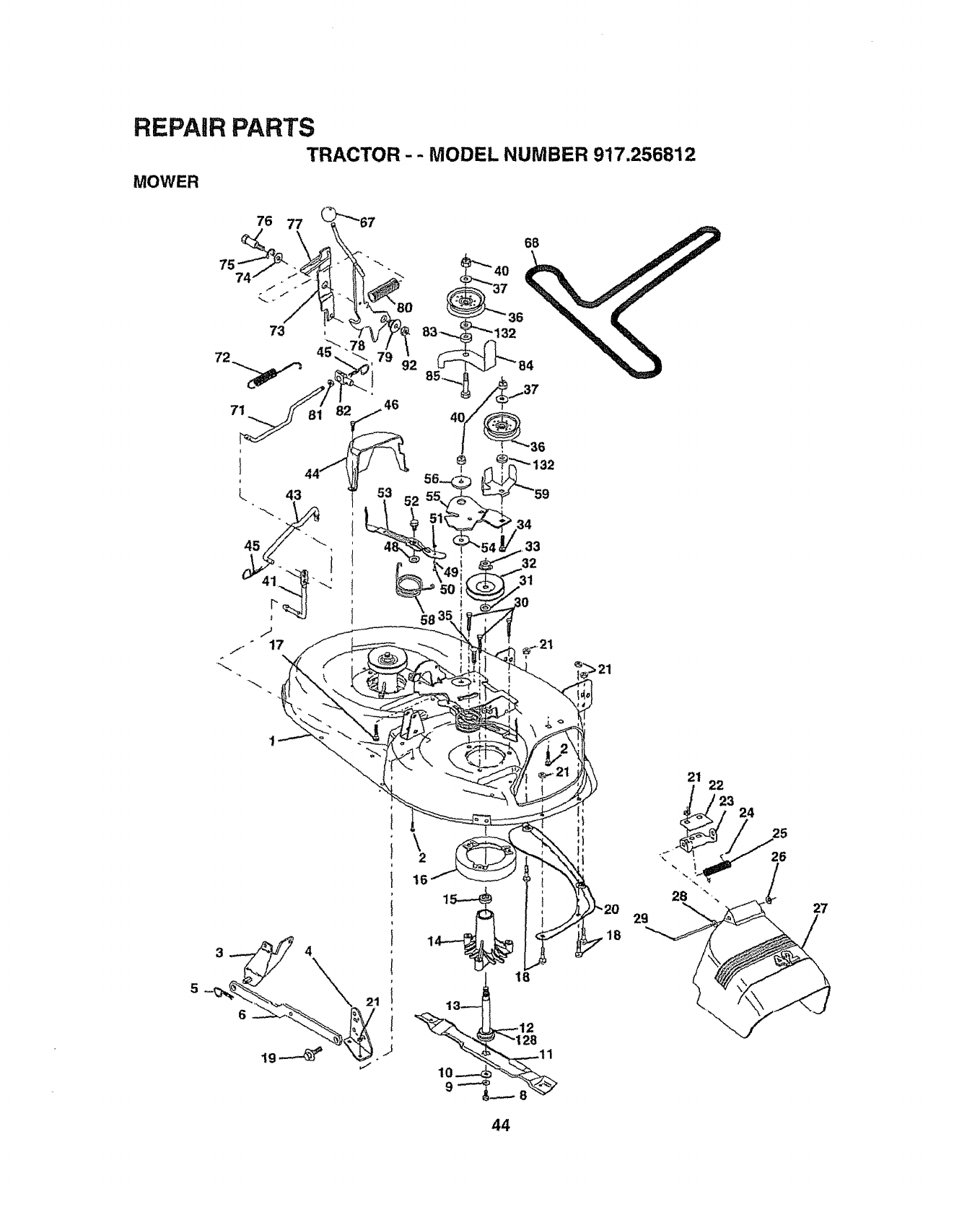
REPAIR PARTS
TRACTOR --MODEL NUMBER 917.256812
MOWER
27
44
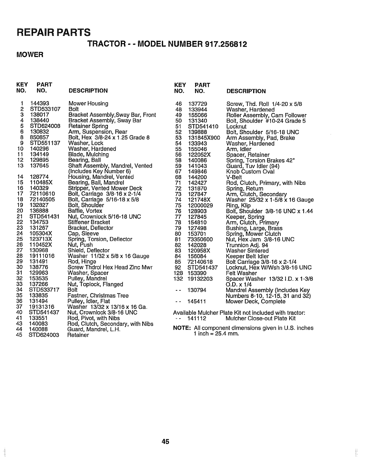
REPAIR PARTS
TRACTOR --MODEL NUMBER 917.256812
MOWER
KEY PART KEY PART
NO. NO. DESCRIPTION NO. NO° DESCRIPTION
1 144393
2 STD533107
3138017
4 138440
5 STD624006
6 130832
8 850857
9 STD551137
10 140296
11 134149
12 129895
13 137645
14 128774
15 110485X
16 140329
17 7211061O
18 72140505
19 t32827
20 136888
2'1 STD541431
22 134753
23 131267
24 105304X
25 123713X
26 110452X
27 130968
28 19111016
29 131491
3O 138776
31 129963
32 153535
33 137266
34 STD533717
35 133835
36 131494
37 19t313'I 6
40 STD541437
41 133551
43 140083
44 140088
45 STD624003
Mower Housing 46
Bolt 48
Bracket Assembly,Sway Bar, Front 49
Bracket Assembly, Sway Bar 50
Retainer Spdng 51
Arm, Suspension, Rear 52
Bolt, Hex 3/8-24 x 1.25 Grade 8 53
Washer, Lock 54
Washer, Hardened 55
Blade, Mulching 56
Bearing, Ball 58
Shaft Assembly, Mandrel, Vented 59
(Includes Key Number 6) 67
Housing, Mandrel, Vented 68
Bearing, Ball, Mandrel 71
Stripper, Vented Mower Deck 72
Bolt, Carriage 3/8_16 x 2-1/4 73
Bolt, Carriage 5/16-18 x 5/8 74
Bolt, Shoulder 75
Baffle, Vortex 76
Nut, Crownlock 5/16-18 UNC 77
Stiffener Bracket 78
Bracket, Deflector 79
Cap, Sleeve 80
Spring, Torsion, Deflector 81
Nut, Push 82
Shield, Deflector 83
Washer 11/32 x 5/8 x 16 Gauge 84
Rod, Hinge 85
Screw Thdrol Hex Head Zinc Mwr 92
Washer, Spacer 128
Pulley, Mandrel 132
Nut, Toplock, Flanged
Bolt - -
Fastner, Christmas Tree
Pulley, Idler, Flat - -
Washer 13/32 x t3/16 x 16 Gab
Nut, Crownlock 3/8-!6 UNC
Rod, Pivot, with Nibs
Rod, Clutch, Secondary, with Nibs
Guard, Mandrel, L.H.
Retainer
137729
133944
155066
131340
STD541410
139888
131845X900
133943
155046
122052X
140086
141043
149846
144200
142427
131870
127847
121748X
12000029
1289O3
127845
15481O
127498
153701
73350600
142028
120958X
156084
72140618
STD54t437
153390
19132203
130794
145411
Screw, Thd. Roll 1/4-20 x 5/8
Washer, Hardened
RoUerAssembly, Cam Follower
Bolt, Shoulder #10-24 Grade 5
Locknut
Bolt, Shoulder 5/16-18 UNC
Arm Assembly, Pad, Brake
Washer, Hardened
Arm, Idler
Spacer, Retainer
Spring, Torsion Brakes 42"
Guard, Tuv Idler (94)
Knob Custom Oval
V-Belt
Rod, Clutch, Primary, with Nibs
Spring, Return
Arm, Clutch, Secondary
Washer 25/32 x 1-5/8 x 16 Gauge
Ring, Klip
Bolt, Shoulder 3/8-16 UNC x 1.44
Keeper, Spring
Arm, Clutch, Primary
Bushing, Large, Brass
Spring, Mower Clutch
Nut, Hex Jam 3/8-16 UNC
Trunnion Adjo 94
Washer Sintered
Keeper Belt Idler
Bolt Carriage 3/8-16 x 2-1/4
Locknut, Hex W/Wsh 3/8-16 UNC
Felt Washer
Spacer Washer 13/32 I.D. x 1-3/8
O.Dox 1/4
Mandrel Assembly (includes Key
Numbers 8_10, 12-15, 31 and 32)
Mower Deck, Complete
Available Mulcher Plate Kit not included with tractor:
- 141112 Mulcher Close-out Plate Kit
NOTE: All component dimensions given in UoSoinches
1 inch = 25.4 mm°
45
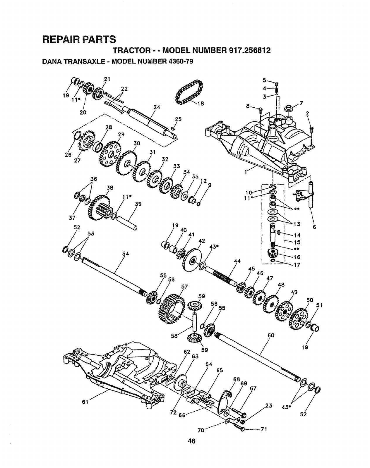
REPAIR PARTS
TRACTOR - - MODEL NUMBER 917.256812
DANA TRANSAXLE -MODEL NUMBER 4360-79
19
26
2t
27
37
52
36
53
61
54
19 40
59
17
45 46 47 48
49
.5O
_655 _I
58_ 0
62 63 59 19
64 65
67
72 52
7O
46
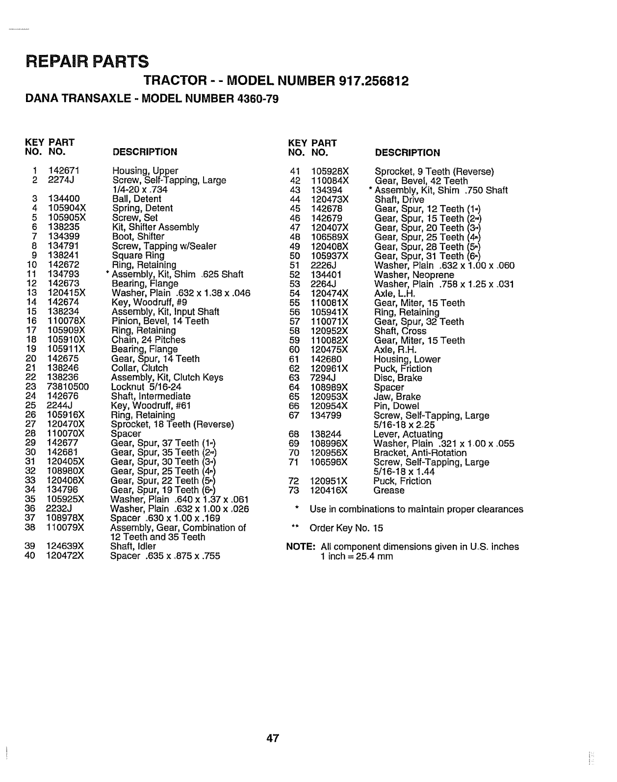
REPAIR PARTS
TRACTOR - - MODEL NUMBER 917,256812
DANA TRANSAXLE - MODEL NUMBER 4360-79
KEY PART KEY PART
NO. NO. DESCRIPTION NO. NO. DESCRIPTION
1 142671 Housing, Upper 41 105928X
2 2274J Screw, Self-Tapping, Large 42 110084X
1/4-20 x °734 43 134394
3 134400 Ball, Detent 44 120473X
4 105904X Spring, Detent 45 142678
5 105905X Screw, Set 46 142679
6 138235 Kit, Shifter Assembly 47 120407X
7 134399 Boot, Shifter 48 106589X
8 134791 Screw, Tapping w/Sealer 49 120408X
9 138241 Square Ring 50 105937X
10 142672 Ring, Retaining 51 2226J
11 134793 * Assembly, Kit, Shim 625 Shaft 52 134401
12 142673 Bearing, Flange 53 2264J
13 1204!5X Washer, Plain .632 x 1o38x .046 54 120474X
14 142674 Key, Woodruff,#9 55 110081X
15 138234 Assembly, Kit, Input Shaft 56 105941X
16 110078X Pinion, Bevel, 14Teeth 57 110071X
17 105909X Ring, Retaining 58 120952X
18 105910X Chain, 24 Pitches 59 110082X
19 105911X Bearing, Flange 60 120475X
20 142675 Gear, Spur, 14 Teeth 61 142680
21 138246 Collar, Clutch 62 120961X
22 138236 Assembly, Kit, CIutch Keys 63 7294J
23 73810500 Locknut 5/16-24 64 108989X
24 142676 Shaft, Intermediate 65 120953X
25 2244J Key, Woodruff, #61 66 120954X
26 105916X Ring, Retaining 67 134799
27 120470X Sprocket, 18 Teeth (Reverse)
28 110070X Spacer 68 138244
29 142677 Gear, Spur, 37 Teeth 11_ 69 108996X
30 14268! Gear, Spur, 35 Teeth 70 120956X
31 120405X Gear' Spur' 30 Teeth !56'ltI 71 106596X
32 108980X Gear, Spur, 25 Teeth
33 120406X Gear, Spur, 22 Teeth 72 120951X
34 134796 Gear, Spur, 19 Teeth _ 73 120416X
35 t05925X Washer, Plain .640 x !.37 x .061
36 2232J Washer, Plain _632xt.O0 x _026
37 108978X Spacer .630 x 1o00x.169
38 110079X Assembly, Gear, Combination of
12 Teeth and 35 Teeth
Shaft, Idler
Spacer .635 x.875 x.755
39 124639X
40 120472X
Sprocket, 9 Teeth (Reverse)
Gear, Bevel, 42 Teeth
* Assembly, Kit, Shim .750 Shaft
Shaft, Drive
Gear, S3ur, 12 Teeth (1-)
Gear, S 3ur, 15 Teeth (2.,)
Gear, S_ur, 20 Teeth I,_/
Gear, S _ur, 25 Teeth
Gear, S _ur, 28 Teeth (5=)
Gear, S :_ur,31 Teeth (6=)
Washer PIain .632 x 1.00 x .060
Washer Neoprene
Washer Plain .758 x 1_25x .031
Axle, L.H.
Gear, Miter, 15 Teeth
Ring, Retaining
Gear, Spur, 32 Teeth
Shaft, Cross
Gear, Miter, 15 Teeth
Axle, R.H.
Housing, Lower
Puck, Friction
Disc, Brake
Spacer
Jaw, Brake
Pin, Dowel
Screw, Self-Tapping, Large
5/16-18 x 2°25
Lever, Actuating
Washer, Plain o321x 1.00 x °055
Bracket, Anti-Rotation
Screw, Self-Tapping, Large
5/16-18 x 1.44
Puck, Friction
Grease
* Use in combinations to maintain proper clearances
** Order Key No. 15
NOTE: All component dimensions given in U_S.inches
1 inch =25A mm
47
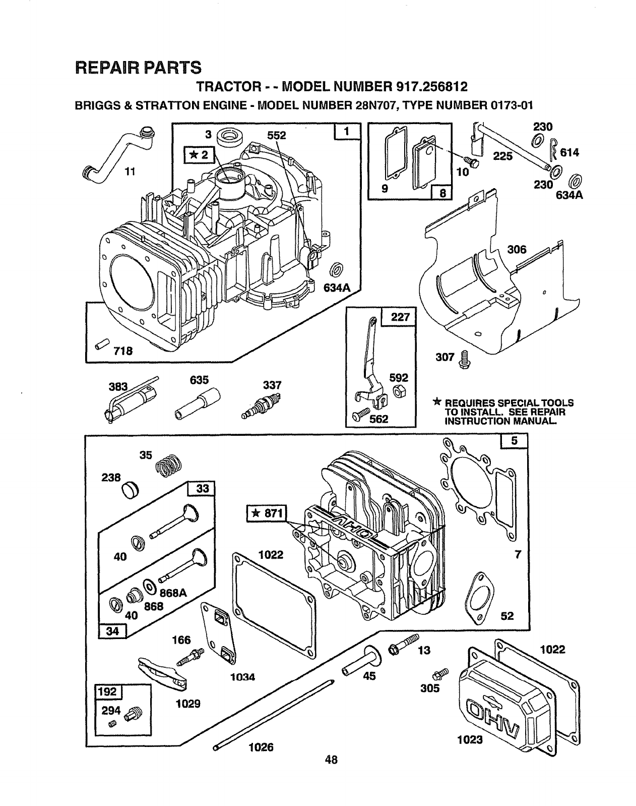
REPAIR PARTS
TRACTOR -- MODEL NUMBER 917.256812
BRIGGS & STRATTON ENGINE -MODEL NUMBER 28N707, TYPE NUMBER 0173-01
230
635 337
307
"_"REQUIRES SPECIAL TOOLS
TO INSTALL. SEE REPAIR
INSTRUCTION MANUAL.
166
1022
1026 48
45
7
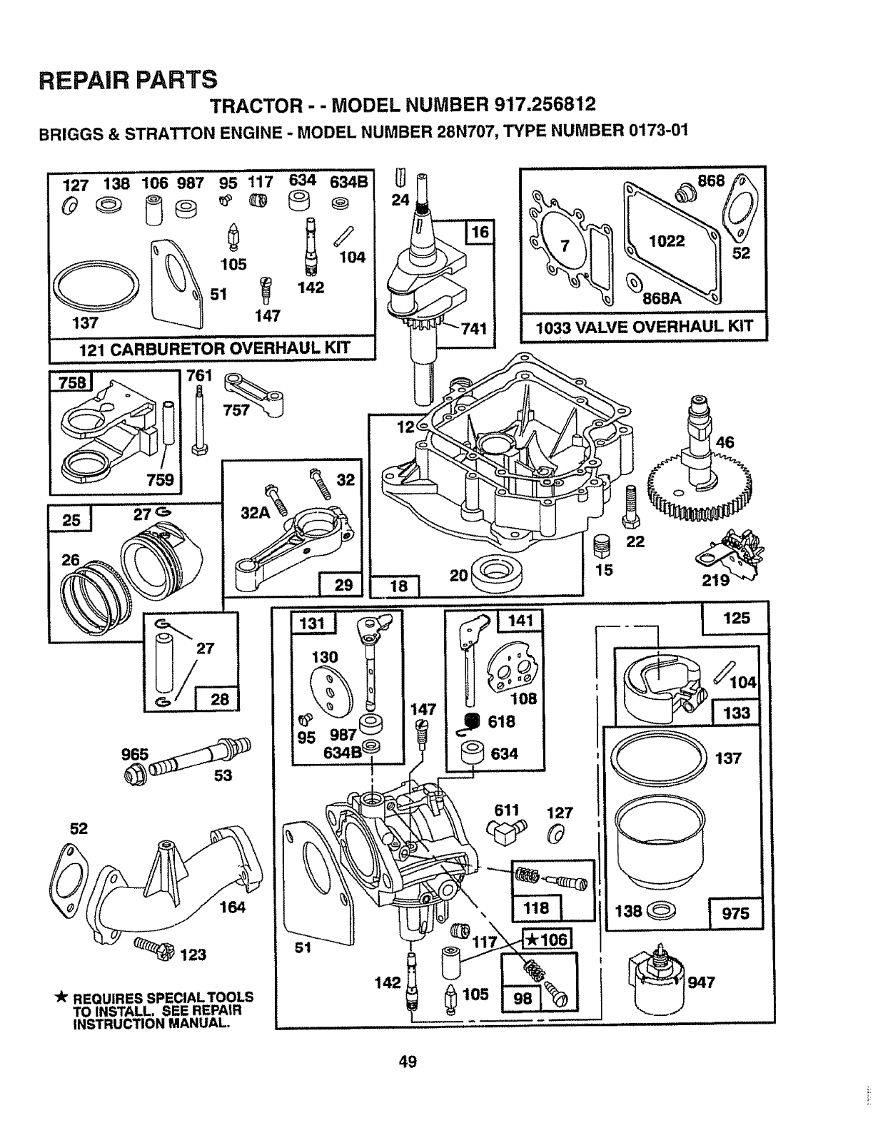
REPAIR PARTS
TRACTOR --MODEL NUMBER 917.256812
BRIGGS & STRATTON ENGINE -MODEL NUMBER 28N707, TYPE NUMBER 0173-01
127 138 106 987 95 117 634 634B
137 7
.............121 CARBUREToR OVERHAUL KIT .........
#r REQUIRES SPECIAL TOOLS
TO INSTALL. SEE REPAIR
INSTRUCTION MANUAL.
130
95 987 t
634B
\1L._
_868
III I1'1 i I /1/_111
1033 VALVE OVERHAUL KIT
1(133 \ _L_
22
15
i, ,,,
j
I
,i ,, ,,,i
147 618
634 137
__ 611 127
49
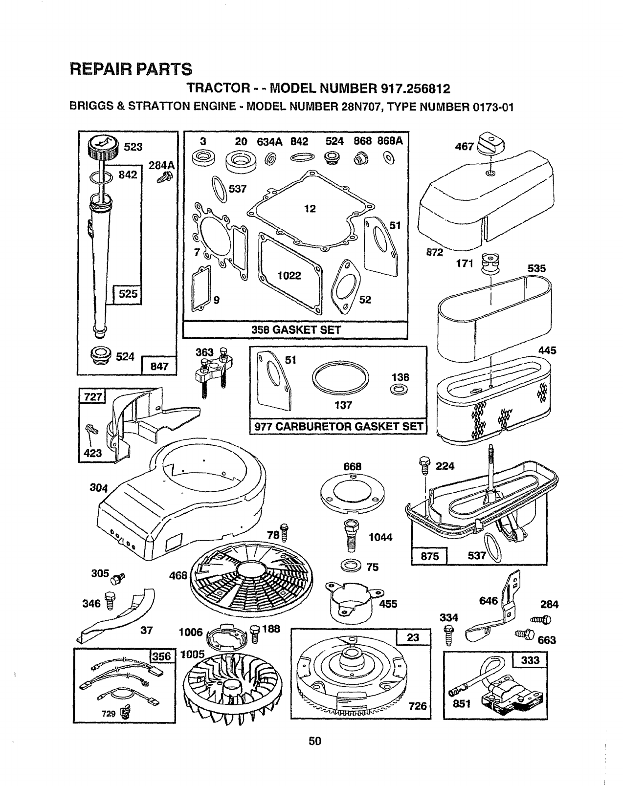
REPAIR PARTS
TRACTOR -- MODEL NUMBER 917.256812
BRIGGS & STRATTON ENGINE -MODEL NUMBER 28N707, TYPE NUMBER 0173-01
523 284A
!_524
304
305_
729
468
3 20 634A 842 524 868 868A
537
....... 358 GASKET sET ..........................................
363
1 138
137
977 CARBURETOR GASKET SET
668 224
I
334
467
171 _535
445
5O
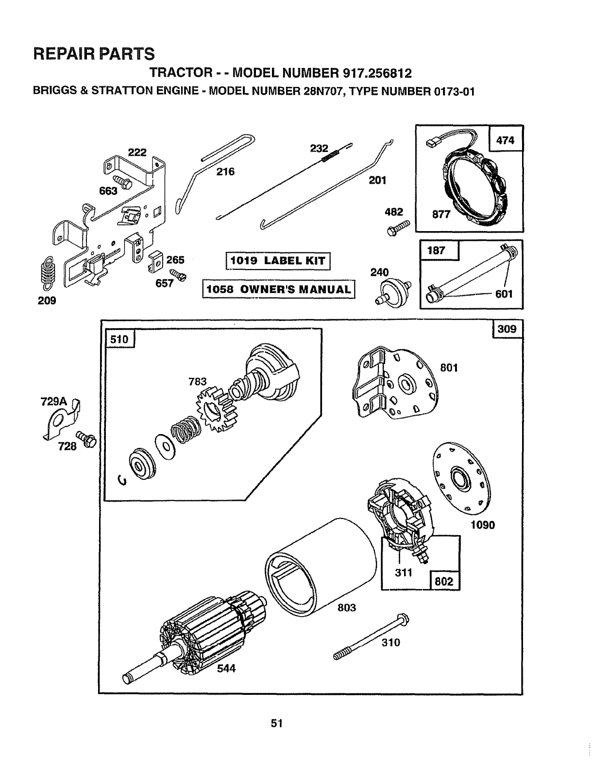
REPAIR PARTS
TRACTOR -- MODEL NUMBER 917.256812
BRIGGS & STRATTON ENGINE - MODEL NUMBER 28N707, TYPE NUMBER 0173-01
209 601
783
801
1090
311
803
544
5"1
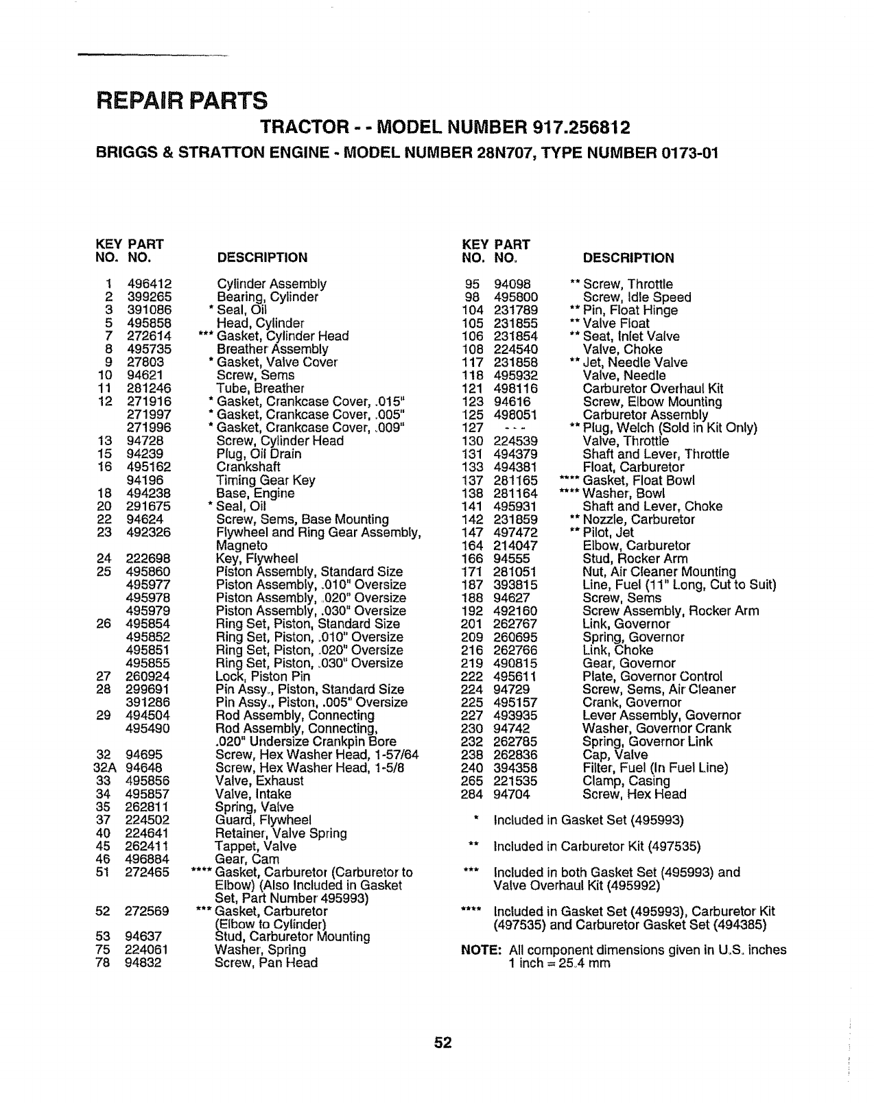
REPAIR PARTS
TRACTOR-- MODEL NUMBER 917.256812
BRIGGS & STRATTON ENGINE -MODEL NUMBER 28N707, TYPE NUMBER 0173-01
KEY PART KEY PART
NO. NO. DESCRIPTION NO. NO. DESCRIPTION
1 496412
2 399265
3391086
5495858
7272614
8 495735
9 27803
10 94621
11 281246
12 271916
271997
271996
13 94728
15 94239
16 495162
94196
18 494238
20 291675
22 94624
23 492326
24
25
26
27
28
29
32
32A
33
34
35
37
40
45
46
51
52
53
75
78
222698
495860
495977
495978
495979
495854
495852
495851
495855
260924
299691
391286
494504
495490
94695
94648
495856
495857
262811
224502
224641
262411
496884
272465
272569
94637
224061
94832
Cylinder Assembly 95
Bearing, Cylinder 98
* Seal, Oit 104
Head, Cylinder 105
*** Gasket, Cylinder Head 106
Breather' Assembly 108
* Gasket, Vatve Cover 117
Screw, Seres 118
Tube, Breather 121
* Gasket, Crankcase Cover, .015" 123
* Gasket, Crankcase Cover, °005" 125
* Gasket, Crankcase Cover, °009" 127
Screw, Cylinder Head 130
Plug, Oil Drain 131
Crankshaft 133
Timing Gear Key 137
Base, Engine 138
* Seal, Oil 141
Screw, Sems, Base Mounting 142
Ftywheel and Ring Gear Assembly, 147
Magneto 164
Key, Flywheel 166
Piston Assembly, Standard Size 171
Piston Assembly, .010" Oversize 187
Piston"Assembly, 020", Oversize 188
Piston Assembly, .030 Oversize 192
Ring Set, Piston, Standard Size 201
Ring Set, Piston, _010"Oversize 209
Ring Set, Piston, .020" Oversize 216
Ring Set, Piston, .030" Oversize 219
Lock, Piston Pin 222
Pin Assy_, Piston, Stan,,dardSize 224
Pin Assy, Piston, .005 Oversize 225
Rod Assembly, Connecting 227
Rod Assembly, Connecting, 230
.020" Undersize Crankpin Bore 232
Screw, Hex Washer Head, 1-57/64 238
Screw, Hex Washer Head, 1-5/8 240
Valve, Exhaust 265
Valve, Intake 284
Spring, Valve
Guard, Flywheel
Retainer, Valve Spring
Tappet, Valve
Gear, Cam
**** Gasket, Carburetor (Carburetor to
Elbow) (Also Included in Gasket
Set, Part Number' 495993)
*** Gasket, Carburetor
(Elbow to Cylinder)
Stud, Carburetor Mounting
Washer, Spring
Screw, Pan Head
94098 ** Screw, Throttle
495800 Screw, Idle Speed
231789 ** Pin, Float Hinge
231855 ** Valve Float
231854 ** Seat, Inlet Valve
224540 Valve, Choke
231858 ** Jet, Needle Valve
495932 Valve, Needle
498116 Carburetor Overhaul Kit
94616 Screw, Elbow Mounting
498051 Carburetor Assembly
- - - ** Plug, Welch (Sold in Kit Only)
224539 Valve, Throttle
494379 Shaft and Lever, Throttle
494381 Float, Carburetor
281165 .... Gasket, Float Bowl
281164 **** Washer, Bowl
495931 Shaft and Lever, Choke
231859 ** Nozzle, Carburetor
497472 ** Pilot, Jet
214047 Elbow, Carburetor
94555 Stud, Rocker Arm
281051 Nut, Air Cleaner Mounting
393815 Line, Fuel (11 Long, Cut to Suit)
94627 Screw, Sems
492160 Screw Assembly, Rocker Arm
262767 Link, Governor
260695 Spring, Governor
262766 Link, Choke
490815 Gear, Govemor
495611 Plate, Governor Control
94729 Screw, Sems, Air Cleaner
495157 Crank, Governor
493935 Lever Assembly, Governor
94742 Washer, Governor Crank
262785 Spring, Governor Link
262836 Cap, Valve
394358 Fifter, Fuel (In Fuel Line)
221535 Clamp, Casing
94704 Screw, Hex Head
* Included in Gasket Set (495993)
** Included in Carburetor Kit (497535)
*** Included in both Gasket Set (495993) and
Valve Overhaul Kit (495992)
.... Included in Gasket Set (495993), Carburetor Kit
(497535) and Carburetor Gasket Set (494385)
NOTE: All component dimensions given in U_SoInches
1inch= 254 mm
52

REPAIR PARTS
TRACTOR -- MODEL NUMBER 917.256812
BRIGGS & STRATTON ENGINE -MODEL NUMBER 28N707, TYPE NUMBER 0173-01
KEY PART NO. NO, DESCRIPTION
NOo NO. DESCRIPTION 729A 225170 Retainer, Wire
284A 94073 Screw, Hex Head 741 262932 Gear, Timing
294 810068 Screw, Set 757 213998 Link, Counterweight
304 496280 Housing, Blower 758 399891 Counterweight Assembly
305 94786 Screw, Hex, Head, 759 298909 Pin, Counterweight
Blower Housing Mounting 761 94593 Screw, Counterweight
306 225020 Shield, Cylinder 783 280104 Gear, Starter
307 94386 Screw, Cylinder Shield 801 394856 Cap, Drive
309 497595 Motor, Starter 802 497605 Cap, End
310 497602 Bolt, Thru 803 497604 Housing, Starter
311 497608 Brush Set 842 270920 *Seal, Oil Filler Cap
333 495859 Armature, Magneto 847 496415 Fill Group, Oil
334 93381 Screw, Sems, Armature Mounting 851 224t10 Terminal, Ignition Cable
337 491055 Plug, Spark 868 494435 *** Seat Assembly, Valve
346 93705 Screw, Hex Head 868A 272610 *** Gasket, Valve
356 497708 Wire Assembly 871 262835 Bushing, Guide (Intake & Exhaust)
358 495993 Gasket Set 872 281361 Cover, Air Cleaner
363 19203 Puller, Flywheel 875 495862 Body, Air Cleaner
383 89838 Wrench, Spark Plug 877 393456 Diode and Connector Assembly
423 94073 Screw, Sems 947 497157 Solenoid
445 493909 Cartridge, AirCleaner 965 94010 Nut, Hex
455 222561 Cup, Screen Mounting 975 495933 Bowl Assembly, Carburetor
467 493903 Knob, Air Cleaner 977 494385 Carburetor Gasket Set
468 494439 Screen, Flush Rotating 987 281166 ** Seal, Throttle Shaft
474 393474 Stator, Alternator 1005 281400 Fan, Flywheel
482 93621 Screw, Sems 1006 224413 Retainer, Fan
510 497606 Drive, Starter 1019 496758 Label Kit
523 495230 . Cap and Dipstick, Oil Filler 1022 272475 *** Gasket, Cover
524 68838 Seal, FillerTube 1023 224552 Cover, RockerArm
525 496113 Tube, Oil Filler 1026 494432 Rod, Push, Intake
535 272403 Element, Filter 495136 Rod, Push, Exhaust
537 281106 * O-Ring, Air Cleaner 1029 224554 Arm, Rocker
544 497603 Armature, Starter 1033 495992 Valve Overhaul Kit
552 231597 Bushing, Governor Crank 1034 495248 Guide Assembly, Push Rod
562 92613 Bolt, Carriage 1044 94673 Screw, Hex Head
592 231082 Nut, Hex 1054 270723 Tie, Cable
601 93053 Clamp, Fuel Pipe 1058 272623 Manual, Owner's
611 493496 Elbow, Fuel Pipe 1090 497607 Retainer, Brush
614 93306 Pin, Cotter
618 262803 Spring, Choke Return RPM Settings: Low: 1650-1850, High: 3200-3400
634 281168 ** Seal, Choke Shaft
634A 491323 * Seal, Governor * Included in Gasket Set (495993)
634B 281167 **Washer, Throttle Shaft
635 280872 Boot, Spark Plug ** Included in Carburetor Kit (497535)
646 224546 Brace, Air Cleaner
657 93496 Screw, Sems *** included in both Gasket Set (495993) and
663 94620 Screw, Self-Tapping Valve Overhaul Kit (495992)
668 280848 Spacer
718 230192 Pin, Dowel .... included in Gasket Set (495993), Carburetor Kit
726 392134 Gear, Ring (497535) and Carburetor Gasket Set (494385)
{Includes Mounting Hardware)
727 490324 Cover. Starter NOTE: AIt component dimensions given in U,S,,inches
728 94627 Screw, Hex Head 1 inch = 25,4 mm
729 281390 Clip, Wire
KEY PART
53

54

SUGGESTED GUIDE FOR SIGHTING SLOPES FOR SAFE OPERATION
ONLY RIDE UP AND DOWN HILL,
NOT ACROSS HILL
SIGHT AND HOLD THIS LEVEL WITH
SKY LINE OR TREE.
15° MAX.
_/_ and down the face of (not
Operate your Tractor up slopes
ALIL greater than 15 ), never across the face. Make turns gradu-
O ally to prevent tipping or loss of control. Exercise extreme
caution when changing direction on slopes I....
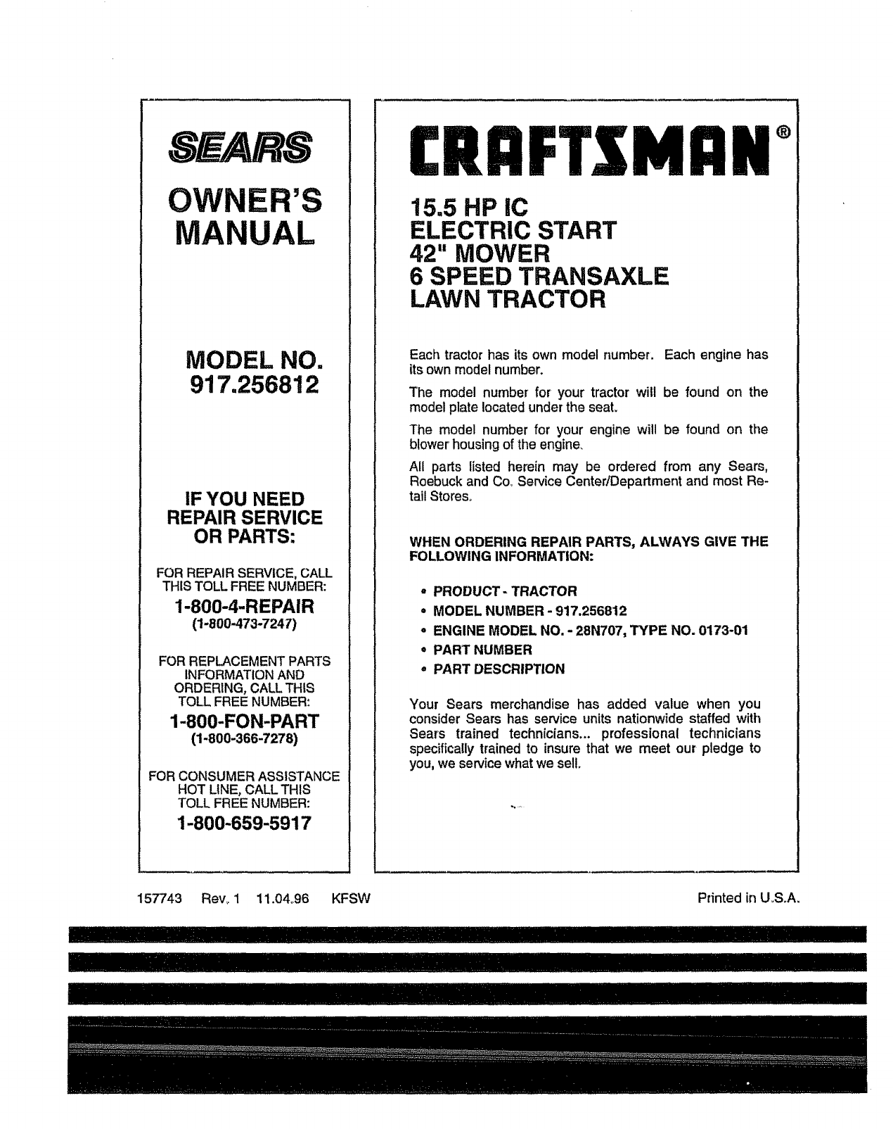
OWNER'S
MANUAL
MODEL NO.
917=256812
IF YOU NEED
REPAIR SERVICE
OR PARTS:
FOR REPAIR SERVICE, CALL
THIS TOLL FREE NUMBER:
1-800-4-REPAIR
(1-800-473-7247)
FOR REPLACEMENT PARTS
INFORMATION AND
ORDERING, CALL THIS
TOLL FREE NUMBER:
1-800-FON-PART
(1-800-366-7278)
FOR CONSUMER ASSISTANCE
HOT LINE, CALL THIS
TOLL FREE NUMBER:
1-800-659-5917
£RIIFTXMIIN°
15.5 HP IC
ELECTRIC START
42" MOWER
6 SPEED TRANSAXLE
LAWN TRACTOR
Each tractor has its own model number. Each engine has
its own model number.
The model number' for your tractor will be found on the
model plate located under the seat.
The model number for your engine will be found on the
blower' housing of the engine.
All parts listed herein may be ordered from any Sears,
Roebuck and Co, Service Center/Department and most Re-
tail Stores.
WHEN ORDERING REPAIR PARTS, ALWAYS GIVE THE
FOLLOWING INFORMATION:
- PRODUCT- TRACTOR
•MODEL NUMBER -917.256812
- ENGINE MODEL NO. - 28N707, TYPE NO. 0173-01
.PART NUMBER
,, PART DESCRIPTION
Your Sears merchandise has added value when you
consider Sears has service units nationwide staffed with
Sears trained technicians.., professional technicians
specifically trained to insure that we meet our pledge to
you, we service what we sell.
157743 Rev_ 1 11.04o96 KFSW Printed in U.S.A.
II/I 1711!117IIHIIIIIIIIIII
