Craftsman 917256890 User Manual TRACTOR Manuals And Guides L0803601
CRAFTSMAN Lawn, Tractor Manual L0803601 CRAFTSMAN Lawn, Tractor Owner's Manual, CRAFTSMAN Lawn, Tractor installation guides
User Manual: Craftsman 917256890 917256890 CRAFTSMAN TRACTOR - Manuals and Guides View the owners manual for your CRAFTSMAN TRACTOR #917256890. Home:Lawn & Garden Parts:Craftsman Parts:Craftsman TRACTOR Manual
Open the PDF directly: View PDF ![]() .
.
Page Count: 56

SEARS
CRRFr,SM
MODEL NUMBER 917.256890 OWNER'SMANUAL
oAssembly
Operation
Customer Responsibilities
Service and Adjustments
Repair Parts
CAUTION: Read and follow all safety rules and instructions before operating this equipment.
FOR CONSUMER ASSISTANCE HOT LINE, CALL THIS TOLL FREE NUMBER: !-800-659-5917
i"rl ............................................ II "111
SAFETY RULES A
Safe Operation Practices for Ride-On Mowers
IMPORTANT: THIS CUTTING MACHINE IS CAPABLE OF AMPUTATING HANDS AND FEET AND THROWING OBJECTS.
FAILURE TO OBSERVE THE FOLLOWING SAFETY INSTRUCTIONS COULD RESULT IN SERIOUS INJURY OR DEATH.
I, GENERAL OPERATION
• Read, understand, and follow alt instructions in the manual
and on the machine before starting.
, Only allow responsible adults, who are familiar with the
instructions, to operate the machine.
•Clear the area of objects such as rocks, toys, wire, etc.,
which could be picked up and thrown by the blade.
•Be sure the area is clear of otherpeopte before mowing. Stop
machine if anyone enters the area.
• Never carry passengers,
° Do not mow in reverse unless absolutely necessary, Always
look down and behind before and while backing.
• Be aware of the mower discharge direction and do not point
it at anyone. Do not operate the mower without either the
entire grass catcher or the guard in place.
• Slow down before turning.
• Never leave a running machine unattended, Always turn off
blades, set parking brake, stop engine, and remove keys
before dismounting,
• Turn off blades when not mowing.
° Stop engine before removing grass catcher or unclogging
chute.
o Mow only in daylight or good artificial light.
° Do not operate the machine while under the influence of
alcohol or drugs.
• Watch for traffic when operating near or crossing roadways.
• Use extra care when loading or unloading the machine into
a trailer or truck.
II. SLOPE OPERATION
Slopes are ama or factor related to toss-of-control and tipover
acc dents, wh ch can resu t n severe injury or death, Alt slopes
require extra caution. If you cannot back up the slope or ifyou fee!
uneasy on it, do not mow it.
DO:
• Mow up and down siopes, not across.
• Remove obstacles such as rocks, tree limbs, etc.
• Watch for holes, ruts, or bumps. Uneven terrain could
overturn the machine. Tall grass can hide obstacles,
• Use slow speed. Choose a low gear so that you will not have
to stop or shift while on the slope.
• Follow the manufacturer's recommendations for wheel
weights or counterweights to improve stability.
, Use extra care with g'rass catchers or other attachments.
These can change the stability of the machine.
, Keep all movement on the elopes slowand gradual. Do not
make sudden changes in speed or direction.
• Avoid starting or stopping on a slope, if tires lose traction,
disengage the blades and proceed slowty straight down the
slope.
DO NOT:
•Donotturnonslopesunlessnecessary, andthen, turnsiowly
and gradually downhill, if possible,
°Do not mow near drop-offs, ditches, or embankments, The
mower could suddenly turn over if a wheel is over the edge
of a cliff or ditch, or if an edge caves in;
,Do not mow on wet grass. Reduced traction could cause
sliding,
•Do not try to stabilize the machine by putting your foot on the
ground,
•Do not use grass catcher on steep slopes,
2
II1. CHILDREN
Tragic accidents can occur if the operator is not alert to the
presence of children. Children are often attracted to the machine
and the mowing activity. Never assume that children will remain
where you last saw them.
• Keep children out of the mowing area and under the watchful
care of another responsible adult.
• Be alert and turn machine off if children enter the area.
° Before and when backing, look behind and down for small
children,
• Never carry children, They may fall off and be seriously
injured or interfere with safe machine operation.
- Never allow children to operate the machine.
•Use extra care when approaching blind corners, shrubs,
trees, or other objects that may obscure vision.
iV. SERVICE
• Use extra care in handling gasoline and other fuel& They are
flammable and vapors are explosive.
Use only an approved container.
Never remove gas cap or add fuel with the engine
running. Allow engine to cool before refueling. Do not
smoke.
Never refuel the machine indoors.
Never store the machine or fuel container inside where
there is an open flame, such as a water heater.
o Never run a machine inside a closed area.
• Keep nuts and bolts, especially blade attachment bolts, tight
and keep equipment in good condition.
• Never tamper with safety devices. Check their proper
operation regularly,
° Keep machine free of grass, leaves, or other debris build-up.
Clean oil or fuel spillage, Allow machine to cool before
storing.
•Stop and inspect the equipment if you strike an object.
Repair, if necessary, before restarting.
•Never make adjustments or repairs with the engine running_
• Grass eatchercomponents are subject to wear, damage, and
deterioration, which could expose moving parts or allow
objects to be thrown. Frequently check components and
replace with manufacturer's recommended parts, when nec-
essary,
•Mower blades are sharp and can cut. Wrap the blade(s) or
wear gloves, and use extra caution when servicing them.
•Check brake operation frequently. Adjust and service as
required. , .........
iiiin unnnl
Look for this symbol to point out impor-
tant safety precautions. It means
CAUTION!!! BECOME ALERT!!! YOUR
SAFETY IS INVOLVED.
ilnl i,nnnn i i i,,,nl i,in
CAUTION: A|ways disconnect spark plug
wire and place wire where it cannot contact
spark plug in order to prevent accidental
starting when setting up, transporting,
adjusting or making repairs.
,unlnn H,,i,,ll ,i i i,, nn
,,i,ilU,nil innl, _ ,,
WARNING A
The engine exhaust from this product con-
tains chemicals known to the State of Califor-
nia to cause cancer, birth defects, or other
reproductiv eharm. ..............

CONGRATULATIONS on your purchase of a Sears
Tractor. It has been designed, engineered'and manufac-
tured to give you the best possible dependability and
performance.
Should you experience any problem you cannot easily
remedy, please contact your nearest Sears Authorized
Service Center/Department: We have competent, well-
trained technicians and the proper tools to service or repair
this tractor.
Please read and retain this manual. The instructions will
enable you to assemble and maintain your unit properly.
Always observe the "SAFETY RULES".
MODEL
NUMBER 917.256890
SERIAL
NUMBER
DATE OF PURCHASE
THE MODELAND SERIAL NUMBERS WILL BE FOUND
ON A PLATE UNDER THE SEAT.
YOU SHOULDRECORD BOTH SERIAL NUMBER AND
DATE OF PURCHASE AND KEEP IN A SAFE PLACE
FOR FUTURE REFERENCE.
MAINTENANCE AGREEMENT
A Sears Maintenance Agreement is available on this prod-
uct, Contact your nearest Sears store for details,
CUSTOMER RESPONSIBILITIES
-Read aria observe the safety rules,
. Follow a regular schedufe in maintaining, cadng for and
using your tractor,
• Follow the instructions under "Customer Responsibili-
ties" and "Storage" sections of troisowner's manuai
PRODUCT SPECIFICATIONS
HORSEPOWER: 15.5
GASOLINE CAPACITY t .25 GALLONS
AND TY_PE: UNLEADED REGULAR
OIL TYPE (API-SF/SG): SAE 30 (above 32'_F)
SAE 5W-30 (below 32°F)
OtL CAPACITY: 3 PINTS
SPARK PLUG: CHAMPION RJt9LM
(GAP: .030")
VALVE CLEARANCE: INTAKE: .005" - .007"
EXHAUST: .009"- ,0tl"
GROUND SPEED (MPH): FORWARD: 5,7 '
REVERSE: 2.7
TIRE PRESSURE: FRONT: 14 PSi
REAR: 12 PSt
CHARGING SYSTEM: 3 AMPS BATTERY
5 AMPS HEADLIGHTS
BATTERY: AMPiHR: 25
MIN. CCA: 190
CASE SIZE: U1R
BLADE BOLT TORQUE: 30-35 FT. LBS. ]
/
WARNING: This tractor is equipped with an internal
combustion engine and should not be used on or near any
unimproved forest-covered brush-covered or g'ass-cov-
ered land unless the engine's exhaust system is equtpped
with a spark arrester meeting applicable local or state laws
(if any). If a spark arrester is used. it should be maintained
in effective working order by the operator,
In the state of California the above is required by Iaw
(Section 4442 ol the California Public Resources Code).
Other states may have similar taws. Federal laws apply on
federal lands. A spark arrester for the muffler is available
through your nearest Sears Authorized Service Center/
Department (See REPAIR PARTS section of this manual!.
LIMITED TWO YEAR WARRANTY ON CRAFTSMAN RIDING EQUIPMENT
For two (2) years from the date of purchase, if this Craftsman Riding Equipment is maintained lubricated and tuned up according
to the instructions in the owner's manual Sears will repair or replace, free of charge, any parts found to be defective in material
or workmanship,
This Warranty does not cover:
o
q
Expendable items which become worn during normai use such as blades spark plugs, air cfeaners, belts, etc.
Tire replacement or repair caused by punctures from outside objects, such as nails, thorns, stumps, or g_ass.
Re_airs necessary because of operator abuse negligence, improper storage or accident or the failure to maintain the
equipment according to the instructions contained in the owner's manual
Riding equipment used for commercial or rental purposes.
LIMITED 90 DAY WARRANTY ON BATTERY
For ninety (90) days from date of purchase, if any battery included with this riding equipment proves defective in material or
workmanship and our testing determines the battery witl not hoId a charge, Sears will replace the batten:/at no charge,
IN-HOME WARRANTY SERVICE ON YOUR CRAFTSMAN RIDING EQUIPMENT IS AVAILABLE AT NO-CHARGE FOR 30
DAYS FROIV THE DATE OF PURCHASE. PLEASE CONTACT YOUR NEAREST SERVICE CENTER. AFTER 30 DAYS
FROM THE DATE OF PURCHASE WARRANTY SERVICE IS AVAILABLE BY TAKING YOUR CRAFTSMAN RIDING EQUIP-
MENT TO YOUR NEAREST SEARS SERVICE CENTER. (IN-HOME WARRANTY SERVICE WILL STILL BE AVAILABLE
AFTER 30 DAYS FROM THE DATE OF PURCHASE BUT A STANDARD TRIP CHARGE WILL APPLY.) THIS WARRANTY
APPLIES ONLY WHILE TH S PRODUCT IS IN THE UNITED STATES.
-his Warranty gives you specific legal rights, and you may also have other rights which may vary from state to state
SEARS, ROEBUCK AND CO., D/817 WA, HOFFMAN ESTATES, IL 60179
3
TABLE OF CONTENTS
SAFETY RULES ............................................................ 2
PRODUCT SPECIFICATIONS ...................................... 3
CUSTOMER RESPONSIBILITIES ..................... 3, 15-18
WARRANTY .................................................................. 3
TRACTOR ACCESSORIES .......................................... 5
ASSEMBLY ................................................................ 7-9
OPERATION ........................................................... 10-14
MAINTENANCE SCHEDULE ...................................... 15
SERVICE AND ADJUSTMENTS ............................ 20-25
STORAGE ................................................................... 26
TROUBLESHOOTING ............................................ 27-28
REPAIR PARTS - TRACTOR ................................. 30-47
REPAIR PARTS - ENGINE .................................... 48-53
PARTS ORDERING/SERVICE ................ BACK COVER
iNDEX
A
Accessories ........................................... 5
Adjustments:
Brake ......................................... 22
Carburetor .................................... 25
Mower
Front-To-Back ......................... 21
Side-To-Side ........................... 21
Throttle Control Cable .................. 24
Air Filter. Engine .................................. 18
_r Screen. Engine .............................. t8
Assembly ............................................ 7-9
B
Battery:
Charging ........................................ 8
CEeanmg ...................................... 17
ns[allation ...................................... 9
Levels ....................................... 8.17
Preoaration ................................... 8
Starting with Weak Battery ........... 23
Storage ........................................ 26
Terminais ................................... I7
Bett:
Motion Drive
Remova{iReplacement ............ 22
4ower Blade(s)
Removal/Replacement ............ 22
Bade:
Sharpening ................................... 16
Replacemeni ................................ 16
Brake Adiustment ................................ 22
C
Carburetor Adjustment ..................... 25
ControJs. Tractor ................................. 11
Customer Responsibilities .............. 15-19
Engine:
A_r Filter ........... : ...................... 18
Air Screen Engine .................. t8
Cooling Fins, Engine ................ 18
Engine Oil ................................ 17
Fuel Fitter ................................ 19
Soark Plug(s) ........................... I9
Tractor:
Battery ..................................... 17
Bla :_e........................................ 16
Lubrication Chart ...................... t5
Maintenance Schedule ............ 15
Tire Care ......................... 8,16,23
Transaxte ................................. 17
SuttJng Height, Mower ......................... 12
E
Electdcak
qterlocks and Relays ................... 24
Schematic .................................... 29
Wiring Diagram ............................ 30
Engine:
Air Filter ....................................... 18
Air Screen .................................... 18
Cooling Fins, Engine .................... 18
OiJ Change ................................. 17
Oil Lever .................................. 13.17
Oil Type ........................................ 17
Preparation .................................. 13
Repair Parts ............................ 44-48
Starting ......................................... 14
Storage ........................................ 26
F
Filter:
Air Filter ........................................ 18
Fue} .............................................. 19
Fuel:
Type ............................................ 13
Storage ........................................ 26
Fuse .................................................... 24
H
Hood Removal/installation .................. 24
L
Leveling Mower Deck .......................... 21
Lubrication:
Chart ............................................ 15
M
Maintenance Schedule ....................... 15
Mower:
Adiustment. Front-to-Back ........... 21
Adiustment, Side-to-Side ............. 21
Bfade Sharpening ..................... 16
Blade Replacement ...................... t 8
Cut[ing Height .............................. 12
installation .................................... 20
Operation ..................................... !3
Removal ....................................... 20
Mowing T@s ........................................ 14
Muffler ................................................. 19
Spark Attester ........................... 3,40
Oil:
O
Cold Weather Conditions ........ 13.17
Engine ......................................... !7
Storage ........................................ 26
Operation ....................................... 10-t4
Operating Mower ................................. 13
Options:
Accessories ................................... 5
Spark Arrester ........................... 3,40
P
Parking Brake ............................ 11-12
Parts Bag .............................................. 6
Parts. Replacement'Repair ............ 30-47
Product Specifications ........................... 3
R
Repair Parts ................................... 30-47
S
Safety Rules .......................................... 2
Seat ..................................................... 8
Service and Adjustments ............... 20-25
Carburetor .................................. 25
Fuse ............................................. 24
Hood Removal/installation ........... 24
Motion Drive Belt
_emova_/Replacement ............ 22
Mower Bett(s)
Removal/Replacement ............ 22
Mower Adjustment
Front-to-Back ........................ 21
Side-to-Side ............................ 21
Mower Removal ........................... 20
Tire Care .............................. 8,16,23
Slope Guide Sheet .............................. 55
Spark Plug(s) ...................................... 19
Specifications ....................................... 3
Starting the Engine ....................... 13q4
Steering Wheel .............................. 7,23
Stopping the Tractor ........................... 12
Storage ................................................ 26
T
Throttle Control Cable Adjustment ..... 25
Tires ............................................ 8,16.23
Trouble Shooting Chart .................. 27-28
Transaxle ............................................ I7
W
Warranty ................................................ 3
Wiring Diagram .................................. 30
Wiring Schematic ................................ 29
4
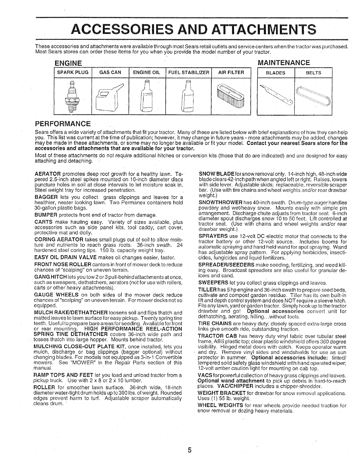
ACC RIES AND ATTACHMENTS
These accessories and attachments were available th rough most Sears retail outlets and service centers when the tractorwas purchased,
Most Sears stores can order these items for you when you provide the model number of your tractor.
MAINTENANCE
ENGINE
SPARK PLUG : AIR FILTER BELTSGAS CAN ENGINE OIL FUEL STABtUZER BLADES
PERFORMANCE
Sears offers a wide variety of attachments that fit your tractor. Many of these are tisted below with brief explanations of how they can help
you. This list was current at the time of publication: however, it may change infuture years -more attachments may be added, changes
may be made in these attachments, or some may no longer be available or fit your model. Contact your nearest Sears store for the
accessories and attachments that are available for your tractor.
Most of these attachments do not require additional hitches or conversion kits (those that do are indicated) and are designed for easy
attaching and detaching.
AERATOR promotes deep root growth for a healthy lawn. Ta-
oered 2.5-inch steel spikes mounted on 10-inch diameter discs
puncture holes in soil at close intervals to let moisture soak in_
SteeI weight tray for increased penetration.
BAGGER lets you colfect grass clippings and leaves for a
healthier nearer looking lawn, Two Permanex containers hold
30-gallon plastic bags.
BUMPER protects front end of tractor from damage.
CARTS make hauling easy, Variety of sizes available plus
accessories such as side panel kits tool caddy, cart cover.
protective mat and dolly,
CORING AERATOR takes small Plugs out Ofsoil to allow mois-
ture and nutrients to reach grass roots 364rich swath. 24
hardened steel coring tips, 150 tb. capae=ty welght tray,
EASY OIL DRAIN VALVE makes oil changes eas_er, faster.
FRONT NOSE ROLLER canters in front of mower deck to reduce
chances of "sca 3ing" on uneven terrain.
GANG HITCH lets you tow 2 or3 pull-behind attachments at once.
such as sweepers, dethatchers, aerators {not for use with rollers,
carts or other heavy attachments_.
GAUGE WHEELS on both sides of the mower deck reduce
chances of "scalping" on uneven terrain. For mower decks not so
equipped.
MULCH RAKE/DETHATCHER loosens soil and flips thatch and
matted leaves to lawn surface for easy pickup. Twenty spring tine
teeth. Useful to prepare bare areasfor seeding, Availabfe for front
or rear mounting_ HIGH PERFORMANCE REEL-ACTION
SPRING TINE DETHATCHER covers 36-inch wide path and
tosses thatch into large hopper. Mounts behind tractor.
MULCHING CLOSE-OUT PLATE KIT, once installed, lets you
mulch, discharge or bag clippings (bagger optiona}) without
changing blades. For models not equipped as 3-in-1 Convertible
mowers. See "MOWER" in the Repair Parts section of this
manual
RAMP TOPS AND FEET let you load and unload tractor from a
pickup truck, Use with 2 x 8 or 2 _: 10 lumber.
ROLLER for smoother lawn surface. 36-inch wide, 18-inch
diamete r water-tight drum holds up to 390 Ibs. otweight. Rounded
edges prevent harm to tuff. Adjustable scraper automatically
cleans drum. '
SNOW BLADE forsnow removalonly, 14-inch high. 48-inch wide
blade clears 42-inch path when angled left or right. Raises. lowers
with side lever, Adjustable skids; replaceable, reversible scraper
bar. (Use with tire chains and wheel weights and/or rear drawbar
weight.)
SNOWTHROWER has 40-inch swath. Drum-type auger handtes
powdery and wet/heavy snow. Mounts easily with simple pin
arrangement. Discharge chute adjusts from tractor seat. 6-inch
diameter spout discharges snow 10 to 50 feet. Lift controlled at
tractor seat. (Use with cr_aLns and wheel weightS and/or rear
drawbar we=ght.)
SPRAYERS use 12-volt DC etectric motor that connects to the
tractor battery or other 12-volt source, Includes booms for
automatic spraying and hand held wand for spot spraying, Wand
has adjustable spray pattern. For applying herbicides, insecti-
cides, fungicides and tic Jid fertilizers
SPREADER/SEEDERS make seeding, fertilizing, and weed kill-
ing easy. Broadcast spreaders are also useful for granular de-
icers and sand.
SWEEPERS let you collect grass clippings and leaves.
TILLER has 5 hp engine and36-inch swath to prepare seed beds,
cultivate and compost garden residue. Tiller has its own built-in
lift and depth control system and does NOT require a sleeve hitch.
Fits any lawn, yard or garden tractor. Simply hook up to the tractor
drawbar and go! Optional accessories convert unit for
dethatching, aerating, hilling...without tools.
TIRE CHAINS are heavy duty; closely spaced extraqarge cross
Iinks give smooth ride, outstanding traction.
TRACTOR CAB has heavy duty vinyl fabric over tubular steel
frame, ABS plastic top; clear plastic windshield offers 360 degree
visibility. Hinged metal doors with catch. Keeps operator warm
and dry. RemOve vinyi sides and windshields for use as sun
protector in summer. Optional accessories include: tinted/
tempered solid safety glass windshield with hand operated wiper;
12-volt amber caution light for mounting on cab top.
VACS for powerful collection of heavy grass clippings and leaves.
Optional wand attachment to pick up debris in hard-to-reach
places. VACICHIPPER includes a chipper-shredder,
WEIGHT BRACKET for drawbar for snow remow_ applications.
Uses (l) 55 lb. weight.
WHEEL WEIGHTS for rear wheels provide needed traction for
snow removal or dozing heavy materials,

CONTENTS OF HARDWARE PACK
.._ ..... =
Parts Bag contents shown full size
/".
/\
O (2) Sheet
Metal
I Screws
#10-16 x 1/2
(t) Locknut 3/8-24
(t) 2-3/8" Diameter Washer
' Shoulder Bolt 5/16-18 (!) Hex Bolt I/2ol 3 x 1
/\
(1) Lock Washer 1/2
1) Washer !7/32 x !-3/16 x 12 Gauge
{2) Hex Bolts 1/4-20 x 3/4 (2) Hex Nuts 1/4-20
(2) Lock Washers !/4
2_ Washers 9/32 x 5/8 x 16 Gauge
Parts packed separately in carton
Seat
Video
Cassette
Steering
Wheel
I f
Manual
Steering
Boot
Parts Bag
Parts bag contents not shown full size
Steering
Steering Wheel Wheel
Adapter Insert
Slope Sheet
(2) Keys
ASSEMBLY
Your new tractor has been assembled at the factory with exception of those parts left unassembled for shipping purposes.
To ensure safe and proper operation of your tractor all parts and hardware you assemble must be tightened securely. Use
the correct tools as necessary to insure proper tightness.
TOOLS REQUIRED FOR ASSEMBLY
A socket wrench set will make assembty easier. Standard
wrench sizes are listed.
(1) 5/16" wrench
(2) 7/16" wrenches
(1) l/2" wrench
(1) 3/4" wrench
When "ight and left hand are mentioned in this manual, it
means when you are in the operating position (seated
behind the steering wheel).
(t) 9/t6" wrench
Tire pressure gauge
Utility knife
TO REMOVE TRACTOR FROM CARTON
UNPACK CARTON
-Remove all accessible loose parts and parts cartons
from carton (See page 6).
-Cut along ines on carton, from top to bottom, all four
corners of carton and lay panels flat.
- Check for any additional loose parts or cartons and
remove.
BEFORE ROLLING TRACTOR OFF SKID
ATTACH STEERING WHEEL (See Fig. 1)
- Slide the steering bushing over the steeling shaft.
, Raise steering shaft forward until screw holes in dash
line up with steering bushing. Install two (2) sheet
metal screws and tighten securety.
,Position steering boot over steering shaft.
• Align tabs of steering boot over slots and hole in dash
and push down to secure.
•Slide steering wheel adapter onto upper steering shaft.
-Position front wheels of the tractor so they are pointing
straight forward.
•Position steering wheel so cross bars are horizontal
(left to right) and slide onto adapter.
, Assemble large fiat washer and 3/8-24 hex iocknut and
tighten securely.
= Snap insert into center of steering wheel.
,Remove protective plastic from tractor hood and grill.
IMPORTANT: CHECK FOR AND REMOVE ANY
STAPLES tN SKID THAT MAY PUNCTURE TIRES WHERE
TRACTOR IS TO ROLL OFF SKID.
STEERING
BUSHING SCREW
SLOT
FIG. 1
TO ROLL TRACTOR OFF SKID (See Opera-
tion section for location and function of con-
trois)
• Press lift lever plunger and raise attachment lift lever to
its highest position.
-Release parking brake by depressing clutch/brake
pedal.
" Place freewheel control in freewheeling position to
disengage transmission (See "TO TRANSPORT" n
the Operation section of this manual).
° Roll tractor backwards off skid.
• Remove banding holding discharge guard up against
tractor.
AS
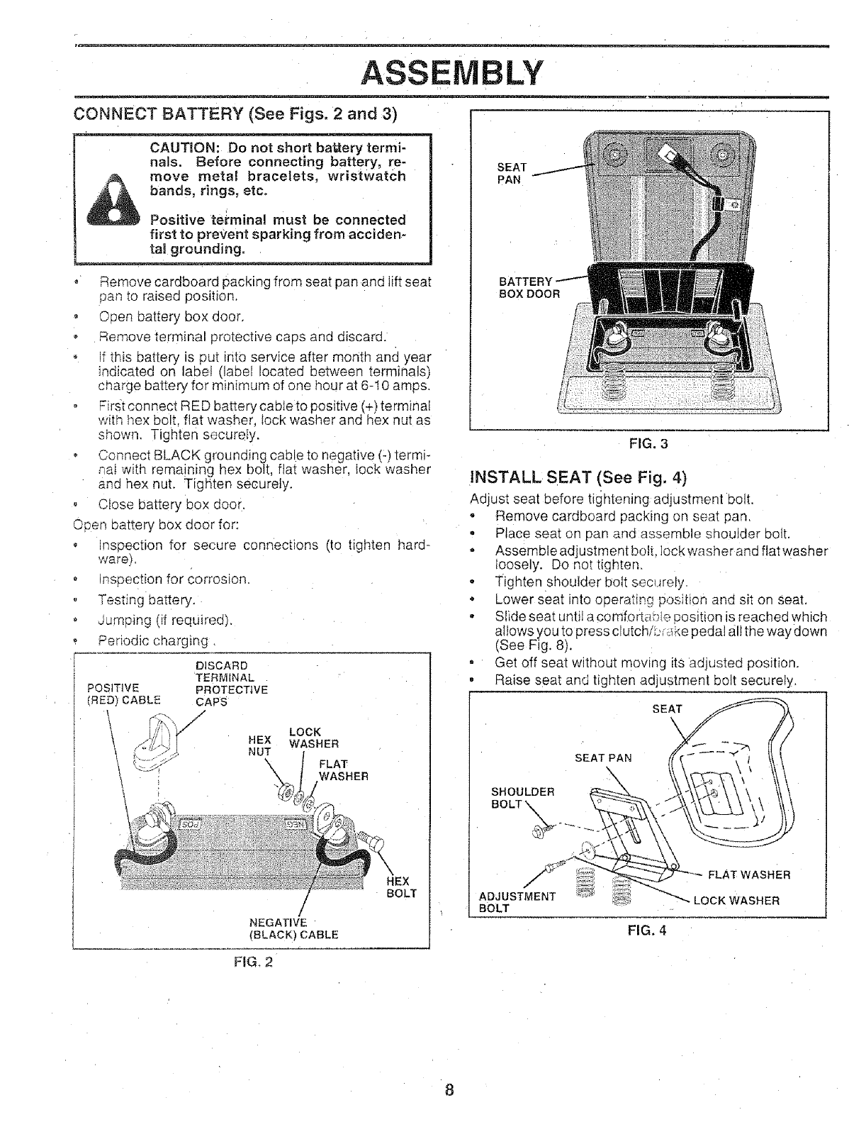
CONNECT BATTERY (See Figs. 2 and 3)
CAUTRON: Do not short battery termi-
nals. Before connecting battery, re-
move metal bracelets, wristwatch
bands, rings, etc.
Positive terminal must be connected
first to prevent sparking from acciden-
tal grounding.
°Remove cardboard packing from seat pan and lift seat
pan to raised position.
, C sen battery box door.
Remove terminal protective caps and discard.
f this battery is put into service after month and year
indicated on label (label located between termina s)
charge battery for minimum of one hour at 6-I0 amps.
First connect RED battery cable to positive (+) terminai
with hex bolt. flat washer lock washer and hex nut as
ShOWn Tighten securely.
Connect BLACK grounding cable to negative (-) termi-
na_with remaining hex bolt, fiat washer, lock washer
and hex nut. Tigr_ten securely.
o Close battery box door.
Open battery box door for:
o nseection for secure connections (to tighten hard-
wareF
o nspection for corrosion.
Testing battery.
oumping (if required).
Periodic charging.
DISCARD
TERMINAL
POSITIVE PROTECTIVE
(RED_ CABLE CAPS
!,...... _.S NUT
LOCK
WASHER
FLAT
WASHER
!
/
NEGATIVE
(BLACK) CABLE
HEX
BOLT
FIG, 2
iVlBLY
SEAT
PAN
BOX DOOR
FIG. 3
INSTALL SEAT (See Fig. 4)
Adjust seat before tightening adjustment bolt.
- Remove cardboard packing on sea_ pan.
• Place seat on pan and assemble shouIder bolt.
- Assemble adjustment bolt. Iock washer and flat washer
Ioosely. Do not tighten.
• Tighten shoulder bolt sec_Jrely.
• Lower seat into operating poseidonand sit on seat.
° Slide seat until a comfortable position is reached which
allows Vou to press clutch/L, ;_kepedal all the way down
(See Fig. 8).
• Get off seat without moving its adjusted position.
, Raise seat and tighten adjustment bolt securely.
SEAT
\
SEAT PAR
SHOULDER
BOLT _.
ADJUSTMENT
BOLT
FIG. 4
FLAT WASHER
LOCK WASHER
ASSEMBLY
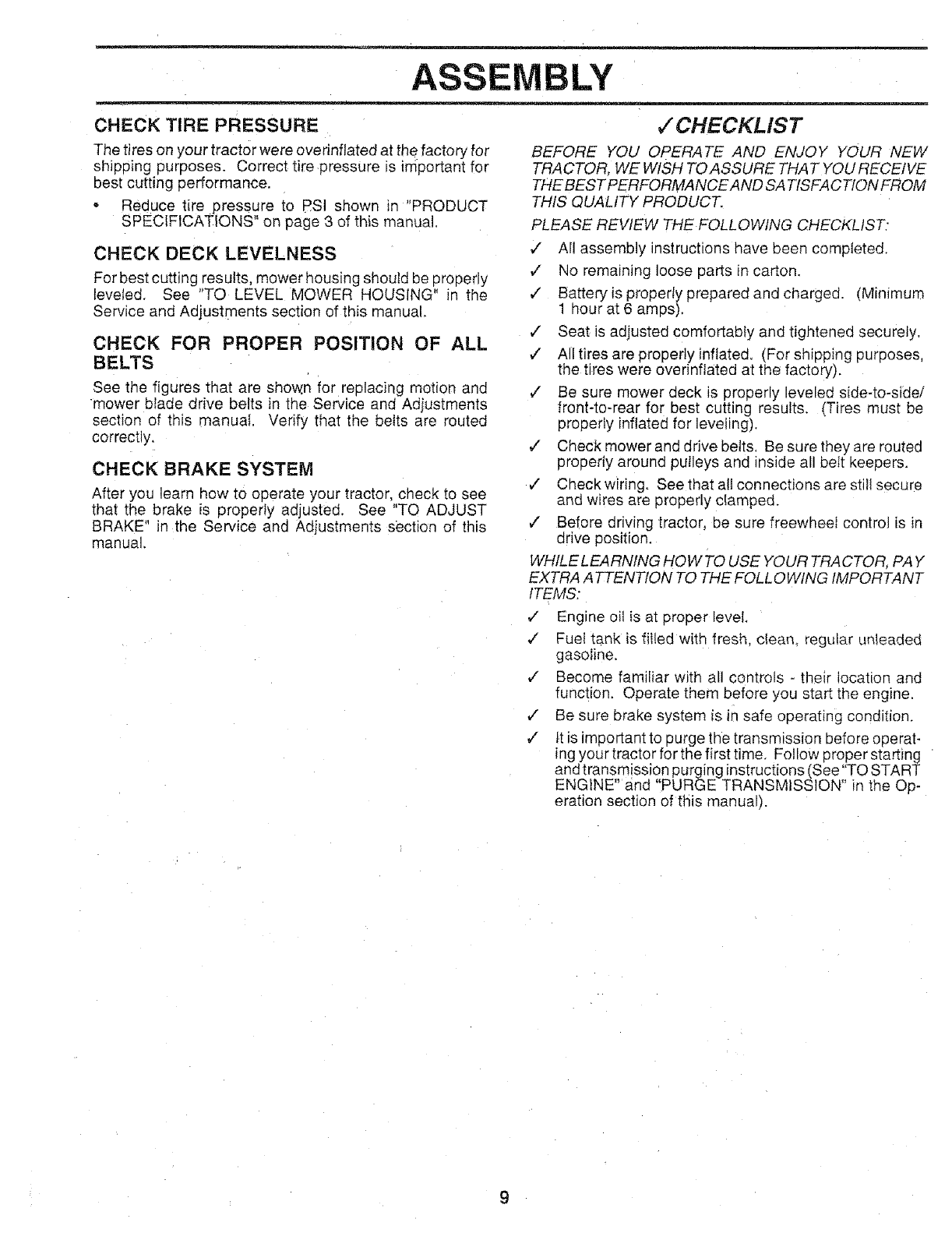
CHECK TIRE PRESSURE
The tires on your tractor were overinflated at the factory' for
shipping purposes. Correct tire pressure is important for
best cutting performance.
• Reduce tire pressure to PSi shown in "PRODUCT
SPECIFICATIONS on page 3 of this manual.
CHECK DECK LEVELNESS
For best cutting results, mower housing should be properly
leveled. See "TO LEVEL MOWER HOUSING" in the
Service and Adjustments section of this manual.
CHECK FOR PROPER POSITION OF ALL
BELTS
See the figures that are shown for replacing motion and
mower blade drive belts in the Service and Adjustments
section of this manual. Verify that the belts are routed
correctly.
CHECK BRAKE SYSTEM
After you learn _ow to operate your tractor, check to see
that the brake is properly adjusted. See "TO ADJUST
BRAKE" n the Service and Adjustments section of this
manual.
,/CHECKLIST
BEFORE YOU OPERATE AND ENJOY YOUR NEW
TRACTOR, WE WISH TO ASSURE THAT YOU RECEIVE
THE BEST PERFORMANCE AND SA TISFA C TION FROM
THIS QUALITY PRODUCT.
PLEASE REVIEW THE FOLLOWING CHECKLIST,"
,/ All assembly instructions have been completed.
,/ No remaining loose parts in carton.
¢" Batteryis properly prepared and charged. (Minimum
1 hour at 6 am os).
z" Seat is adjusted comfortably and tightened securely.
,/ All tires are properly inflated. (For shipping purposes,
the tires were overinflated at the factory).
,/ Be sure mower deck is properly leveled side-to-side/
front-to-rear for best cutting resufts. (Tires must be
properly inflated for leveling).
,/ Check mower and drive belts. Be sure they are routed
properly around pulleys and inside all bett keepers.
€" Checkwiring. See that all connections are stilt secure
and wires are properly clamped.
,/ Before driving tractor, be sure freewhee; control is in
drive position.
WHILELEARNING HOWTO USE YOUR TRACTOR. PAY
EXTRA ATTENTION TO THE FOLLOWING IMPORTANT
ITEMS:
z" Engine oil is at proper level.
¢" Fuel tank is filled with fresh, c[eam regular unleaded
gasoline.
v" Become familiar with al controls -their location and
function. Operate them before you start the engine.
v" Be sure brake system is _nsafe operating condition
v" tt is important to purge the transmission before operat-
ing your tractor for the first time. Follow proper starting
and transmission purging instructions (See 'TO START
ENGtNE" and "PURGE TRANSMISSION" in the Op-
eration section of this manual).
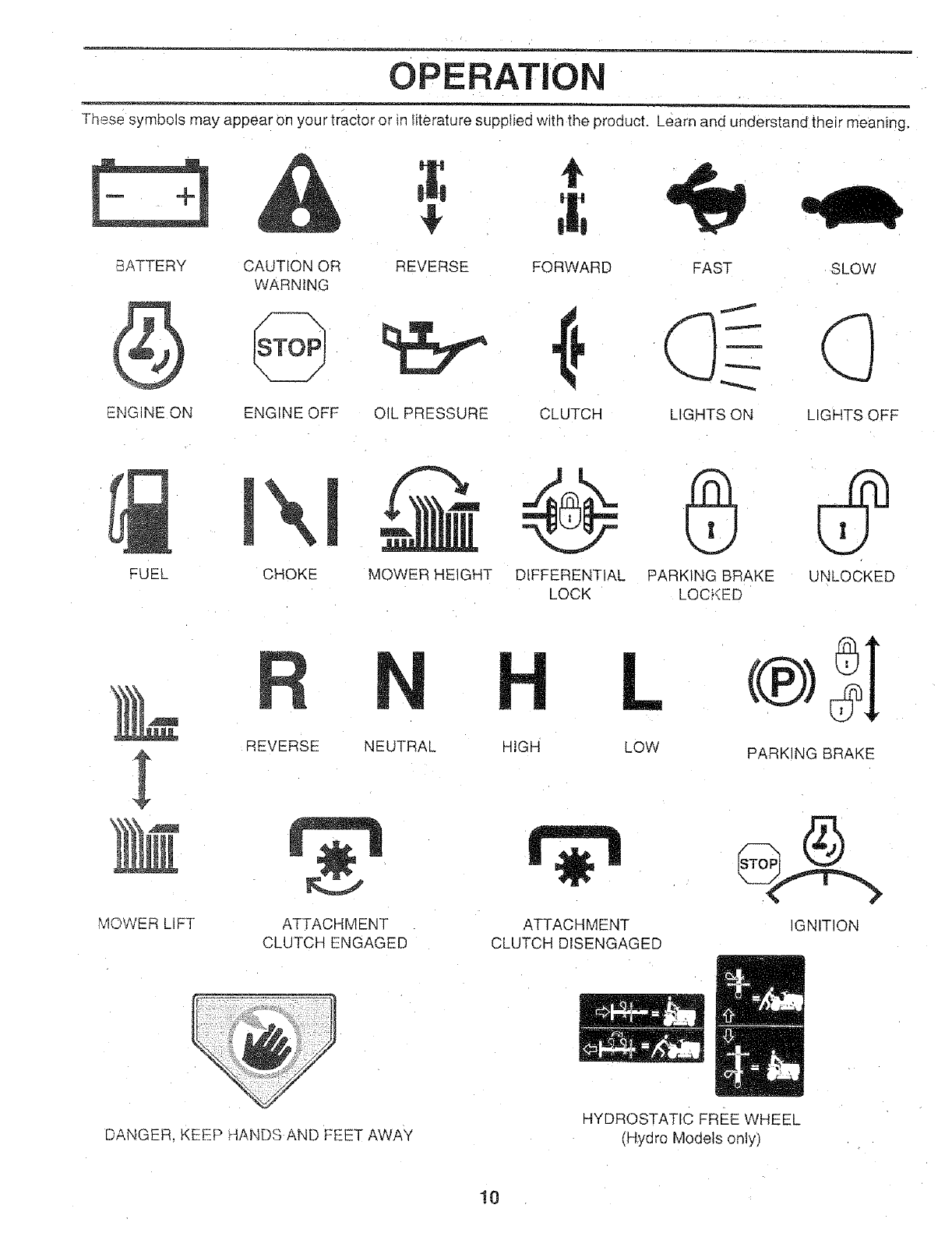
OPERATIO
These symbols may appear on you r tractor or in literature supplied with the product. Learn and understand their meaning,
BATTERY CAUTION OR REVERSE FORWARD FAST SLOW
WARNING
ENGINE ON ENGINE OFF OIL PRESSURE CLUTCH LIGHTS ON LIGHTS OFF
FUEL CHOKE MOWER HEIGHT DIFFERENTIAL PARKING BRAKE UNLOCKED
LOCK LOCKED
REVERSE NEUTRAL HIGH LOW PARKING BRAKE
MOWER _IFT &TTACHMENT
CLUTCH ENGAGED
ATTACHMENT
CLUTCH DISENGAGED
IGNITION
DANGER. KEEP HANDS AND FEET AWAY HYDROSTATIC FREE WHEEL
(Hydro Models only)
10
m
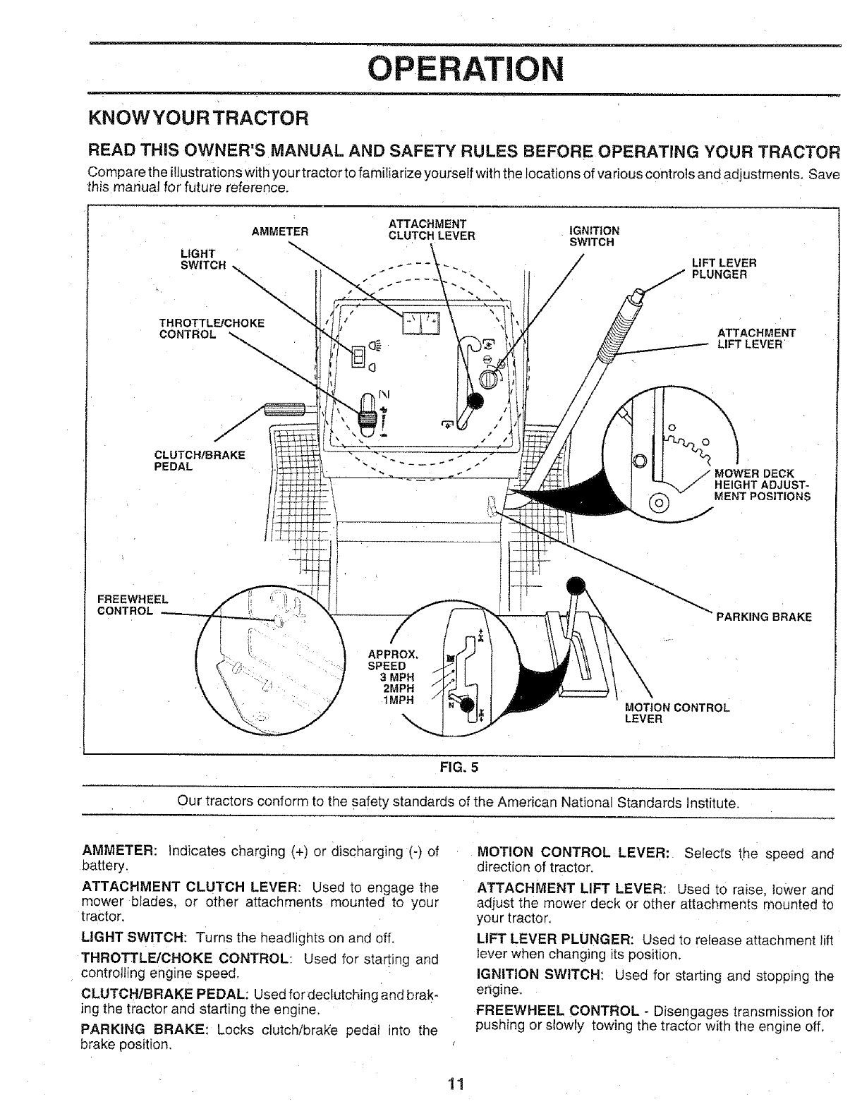
OPERATION
KNOWYOURTRACTOR
READ THIS OWNER'S MANUAL AND SAFETY RULES BEFORE OPERATING YOUR TRACTOR
Compare the itlustrat ons w th your tractor to fami iarize yourself with the locations of various controls and adjustments. Save
this manual for future reference,
ATTACHMENT
AMMETER CLUTCH LEVER IGNITION
SWITCH
LIGHT
SWITCH
THROTTLFJCHOKE
CONTROL
CLUTCH/BRAKE
PEDAL
LIFT LEVER
PLUNGER
ATTACHMENT
LIFT LEVER
©
_,_ MOWER DECK
HEIGHT ADJUST-
MENT POSITIONS
FREEWHEEL
CONTROL
APPROX.
SPEED
3 MPH
2MPH
1MPH MOTION CONTROL
LEVER
PARKING BRAKE
FIG. 5
Our tractors conform to the safety standards of the American National Standards institute.
AMMETER: Indicates charging (+) or discharging (-) of
battery.
ATTACHMENT CLUTCH LEVER: Used to engage the
mower blades, or other attachments mounted to your
tractor.
LIGHT SWITCH: Turns the headlights on and off.
THROTTLE/CHOKE CONTROL: Usec for starting and
controlling engine speed.
CLUTCH/BRAKE PEDAL: Used fordeclutchingandbrak-
ing the tractor and starting the eng_ne
PARKING BRAKE: Locks clutchibra_e pedat into the
brake position,
MOTION CONTROL LEVER: Selects the speed and
direction of tractor.
ATTACHMENT LIFT LEVER: Used to raise, lower and
aajust the mower deck or other attachments mounted to
your tractor.
LIFT LEVER PLUNGER: Used to release attachment lift
lever when changing its position.
IGNITION SWITCH: Used for starting and stooping the
engine.
FREEWHEEL CONTROL - Disengages transmission for
pushing or slowly towing the tractor with the engine off.
11
OPERATION
......... . .... =
The operation of any tractor can result in foreign objects thrown into the eyes, which
can result in severe eye damage. Always wear safety glasses or eye shields while
operatingyourtractororperforming any adjustments or repairs. We recommend awide
vision safety mask over the spectacles or standard safety glasses.
HOW TO USE YOUR TRACTOR NOTE: Under cer[ain conditions when tractor is standing
TO SET PARKING BRAKE (See Fig, 6)
Your tractor is equipped with an operator presence sensing
swl[cn. When engine is running, any attempt by the
_oerator to leave the seat without first setting the Parking
brake will shut off the engine.
• De sress clutch/brake pedal into tult "BRAKE" position
and hold,
PIace 9arking brake lever in "ENGAGED" oosition and
release pressure from clutch/brake pedal. Pedal should
remain _n"BRAKE" position. Make sure parking brake
_ lSO_d_ractor secure.
THROTTLE/CHOKE
CONTFIOL\ \\\
-22c_2
"'BRAKE'
POSITION
\
CLUTCH/BRAKE PEDAL
"DRIVE" ROSITION
ATTACHMENT CLUTCH LEVER
"ENGAGED" POSITION
._-.-:-_... /"DISENGAGED"
}¢ /POS,T,ON
}/:i -:__-;>" PARKING BRAKE
f'_:,4_}}_ /"ENGAGED" POSITION
\
_-_"-x \ MOTION
CONTROL
LEVER
FIG. 6
STOPPING (See Fig. 6)
MOWER BLADES -
Move attachment clutch lever to "DISENGAGED" po-
sLtion.
GROUND DRIVE-
"Deoress clutch/brake pedal into full "BRAKE" position.
oMove motion control lever to neutral (N) position,
MPORTANT: THE MOTION CONTROL LEVER DOES
NOT RETURN TO NEUTRAL (N) POSITION WHEN THE
CLUTCH/BRAKE PEDAL IS DEPRESSED.
ENGINE -
*Move throttle control to s_ow (_,) position.
NOTE: Failure to move, throttle control to slow (,,_)
posmen and allowing engine to idle before stoppng may
cause engine to "backfire",
Turn ignition key to "OFF" position and remove I_ey
A,tways remove ke_! when leaving tractor to prevent
u qauthorized use
Never u,_e choke to stop engine. 12
idle with the engine running, hot engi ne exhaust gases may
cause "browning" of grass. To eliminate this Dossibility,
always stop engine when stopping tractor on grass areas.
CAUTION: Always stop tractor com-
pletely, as described above, before leaw
ing the operator's position; to empty
grass catcher, etc.
TO USE THROTTLE CONTROL (See Fig. 6)
Always operate engine at full throttle.
Operating engine at less than full throttle reduces the
battery charging rate.
-Full throttle offers the best bagging and mower perfor-
mance.
TO MOVE FORWARD AND BACKWARD
(See Fig. 6)
The direction and speed of movement _scontrolled by the
motion controi lever.
Start tractor with mohen centre lever in neutral (N)
position.
° Release parking Drake and clutch/brake pedat.
-Slowly move motion control lever to desired position.
TO ADJUST MOWER CUTTING HEIGHT
(See Fig, 5)
The position of the attachment lift lever determines the
cutting height.
- Grasp lift lever.
- Press plunger with thumb and move lever to desired
position.
The cutting height range is approximately 1-t/2 to 4". The
heights are measured from the ground to the blade tip with
the engine not running. These heigl_ts are approxtmate
and may vary depending upon sol conditions, height of
grass and types of grass being mowed.
, The average lawn should be cut to approximately 2-1/2
nches during the cool season and to over 3 inches
during hot months. For healthier and better looking
lawns, mow often and after moderate growth.
-For sest cutting performance, grass over 6 inches in
qeight should be mowed twice. Make the first cut
relatively high; the second to desired height.
TO OPERATE MOWER (See Fig. 7)
Your tractor is equipped with an opera[or presence sensing
switch. Any attempt by the operator to leave the seat with
the engine running and the attachment clutch engaged will
shut off the engine.
- Select desired height of cut.
- Start mower blades by engaging attachment clutch
control.
TO STOP MOWER BLADES - disengage attachment
clutch control.
OPERATION
Iwithout either the entire gr sa s catcher,
on mowers so equipped, or the dis-
lcharge guard in place.
ATTACHMENT CLUTCH LEVER
"DISENGAGED" POSITION-"ENGAGED"
POSITION
/
ATTACHMENT
HIGH POSITRON
POSiTiON
DISCHARGE
GUARD
FiG. 7
TO OPERATE ON HILLS
_ CAUTION:_
with slopes greater than "15°and do not !
gLJD_ross any slope. = :
• Choose the slowest speed before starting up or down
hills.
• Avoid stc ;)ping or changing speed on hills.
• If sIowing s necessary, move throttle control lever to
slower position.
•If stopping is absolutely necessary, push clutch/brake
pedal quickly to brake position and engage parking
brake.
,Move 'notion control lever to neutral (N) position.
IMPORTANT: THE MOTION CONTROL LEVER DOES
NOT RETURN TO NEUTRAL (N) POS_TtON WHEN THE
CLUTCH/BRAKE PEDAL IS DEPRESSED.
• To restart movement, stowty retease parking brake and
clutch/brake pedal.
•Slowly move motion control lever to slowest setting.
, Make all turns slowly.
TO TRANSPORT (See Fig. 8)
When pushing or towing your tractor, be sure to disengage
transmission by placing freewheel control in freewheeling
position. Free wheel control is Iocated at the rear drawbar
of tractor.
• Raise attachment lift to highest position with attach-
ment lift control,
- Pull freewheel control knob out and hold in position by
inserting retainer spring into forward hole of control
rod.
-Do not push or tow tractor at more than two (2) MPH.
- To reengage transmission, reverse above procedure.
NOTE: To protect hood from damage when transporting
your tractor or a truck or a trailer, be sure hood is closed
and secured to tractor. Use an appropriate means of tying
hood to tractor (rope. cord, etc.).
13
FIG, 8
BEFORE STARTING THE ENGINE
CHECK ENGINE OIL LEVEL (See Fig. 16)
,The engine in your tractor has been shipped, from the
factory, already filled with summer weight oit.
-Check engine oil with tractor on level ground.
•Remove oil fill cap/dipstick and wipe ctean, reinsert the
dipstick and screw cap tight, wait for a few seconds,
remove and read oil level. If necessary, add oil until
"FULL" mark on dipstick is reached. Do not overfill
•For cold weather operation you should change oi! for
easier starting (See "OIL VISCOSITY CHART" in the
Customer Responsibilities section of this manual).
= To change engine oil, see the Customer Responsibili-
ties section in this manual.
ADD GASOLINE
-Fill fuel tank. Use fresh, clean, regular unleaded
gasoline with a minimum of 87 octane. (Use of leaded
gasoline will increase carbon and lead oxidedeposits
and reduce valve life). Do not mix oiI with gasoline.
Purchase fuel in quantities that can be used within 30
days to assure fuel freshness.
IMPORTANT: WHEN OPERATING N TEMPERATURES
BELOW32°F(0°C), USE FRESH. CLEAN WINTER GRADE
GASOLINE TO HELP INSURE GOOD COLD WEATHER
STARTING.
WARNING: Experience indicates that alcohol blended
fuels (called gasohol or using ethanol or methanol) can
attract moisture which leads to separation and formation of
acids during storage. Acidic gas can damage the fuel
system of an engine while in storage. To avoid enaine
problems, the fuel system should be emptied before stor-
age of 30 days or Ionger. Drain the gas tank, start the
engine and let it run until the fuel lines and carburetor are
em3ty. Use fresh fuel next season. See Storage lnstruc_
tions for additional information. Never use engine or
carburetor cleaner products in the fuel tank or permanent
damage may occur.
o,tom ;fgo;, nk
! fill_erfill, Wipe off any
Ispilled oil or fuel. Do not store, spill or
Iuse gasoline near an open flame.
TO START ENGINE (See Fig. 6)
When starting the engine for the first time or if the engine
has run out of fuel. it will take extra cranking time to move
fuel from the tank to the engine.
•Depress clutch/brake pedal and set parking brake.
,Place motion control ever in neutra (N) position.
Move attachment dutch to "DISENGAGED" position.
Move throttle control to choke (IX) position.
Note: Before starting, read the warm and cold starting
procedures below.
OPERATION
InsertKeyintoignitionandturn Keyclockwiseto"START" position and hold for five (5) seconds. Repeat this
oosition and t'eleaSe key as soon as engine starts, Do procedure three (3) times.
qo_run starter continuously for more than fifteen sec-
onus oer minute, If the engine does not start after
severn attempts, move throttle control to fast (,_}
oosltlon, wait a few minutes and try again, Ifengine still
does not start, move the throttle control back to the
choke (IXI) position and retry.
WARM WEATHER STARTING (50_ F and above)
o When engine starts, movethethrottle controltothe fast
(_) position,
The attachments and ground drive can now be JSed. If
me engine does not accept the load, restart the engine
ana allow it to warm up for one minute using the choke
as described above.
COLD WEATHER STARTING ( 500 F and below}
" When engine starts allow engine to run wlth the throttle
control n the choke (JXI)position until the engine "uns
roughly, then move throttle control to fast (,1_) position.
This may require an engine warm-up period from
severat seconds to several m_nutes. (]epending on the
temperature.
HYDROSTATIC TRANSMISSION WARM UP
o Before driving the uriit in cold weather, the transmis-
sion should be warmed up as follows:
Be sure the tractor is on level ground.
o Place the motion control lever in neutral.
Release the parking brake and let the clutch/brake
slowly return to operating position
Allow one minute for transmission to warm up.
This c_n be done dunng the engine warm uD
period,
The attachments can also be used during the engne
warm- Jp period after the transmfssio nhas been warmed
NOTE: f a_ a high altitude (above 3000 feet) or q cold
temoeratures (below 32 F) the carburetor fuel mixture may
peeo to be adjusted for best engine performance. See "TO
ADJUST CARBURETOR" in the Service and Adjustments
section of this manual.
NOTE: During this procedure there wiii be no movement of
drive wheels. The air is being removed from hydraulic drive
system
o Move motion control lever to neutral (N) position. Sh ut-
off engine and set parking brake,
• Engage transmission by placing freewheel control in
driving position (See "TO TRANSPORT" in this section
of manual).
Sitting inthe tractor seat. start engine. Aftertheeng_ne
is running, move throttle control [o half (1/2) speed.
With motion control lever _nneutral (N) position, slowly
disengage clutch/brake pedal,
, Slowly move motion control lever forward, after the
tractor moves approximately five (5) feet. slowly move
motion control lever to reverse position After the
tractor moves approximately five (5) feet return the
motion control lever to the neutral (N) position. Repeat
this procedure with the mohon cent,tel lever three (3)
times,
•Your tractor is now Purged and now ready for normai
operatron.
PURGE TRANSMISSION
Never engage or disengage
vet while the engine is run-
To ensure proper operation and oerformance, it is recom-
menaed that the transmission be purged before operating
tractor for the Iirst time. This procedure wilI remove any
traoDea air inside the transmission whfdh may have devel-
Deec_during shipping of your tractor.
iMPORTANT: SHOULD YOUR TRANSMISSION REQUIRE
REMOVAL FOR SERVICE OR REPLACEMENT, IT
SHOULD BE PURGED AFTER REINSTALLATION
BEFORE OPERATING THE TRACTOR,
Piaee tractor safely on level surface with engine off and
parking brake set,
Disengage transmission by placing freewheel control
in freewheeling position (See "TO TRANSPORT" in
this section of manual).
Sittin ] in the tractor seat, start engine, After the engine
is running move throttle control to.s_ow (,_) position.
With motion control tever in neutral (N) position, slowty
alsengago clutch/brake pedal
Move motion control lever to fun forward position and
qoid fret fly# (5', seconds. Move lever to full reverse
MOWING TiPS
-Tire chains cannot be used when the -newer housing
is attached [o tractor,
-Mower should be properly _eveled for best mowing
performance. See "TO LEVEL MOWER HOUSING" in
the Service and Adjustments section of this manual,
, The left hand side of mowr_r should be usea for trim-
ming.
-Drive so that c',ppings are dlscr_arged onto the area
that has been cut Have the cut area to the right of the
machine. This will resuli ;n a more even distribution of
clippings and more uniform, cutting.
- When mowing large areas, start by turning to the right
so that clippings will discharge away from shrubs,
fences, driveways, etc. After one ortwo rounds, mow
In the opposite direction making left hand turns until
finished (See Fig. 9).
-If grass is extremely tal!, it should be mowed twice to
reduce loa(] and possible fire qazard from dried chp-
pings. Make first cut relatively high; the second to the
desired height.
• Do not mow grass when it is wet. Wet grass w_t}plug
mower and leave undesirable clumps, Allow grass to
dry before mowing.
• Always operate engine at fult throttle when mowing to
assure better mow_ng performance and proper dis-
charge of material. Regulate ground speed by select-
_ng a low enough gear 1o give the mower cutting
performance as well as the quality of cut desired.
When operating attachments, select a ground speed
that wilt suit the terrain and give best performance of
the attachment being used
fr
14 FIG. 9
CUSTOMER ESPO LITIES
MAINTENANCE SCHEDULE ,
FILL IN DATES
AS YOU COMPLETE
REGULAR SERVICE
Check Brake Operation tf .....
Check Tire Pressure
TChec k for Loose Fasteners t_
i_R Sharpen/Replace Mower Blades
_ LubricationOhart
T Check Battery Level/Recharge
: 0 Clean Battery and Terminals
R Check Transaxfe €ooling
Adjust Blade Belt(s) Tension
Adjust Motion Drive Belt(s) Tension
Check Engine Oil Level J
Change Engine Oil t# #
Clean Air Kilter
SERVICE DATES
i/ !
NClean Air Screen .
G Inspect Muffler/Spark Attester
' Pep,ace O,1Fi,ter (,fequ,pped)Cooling -1 1
N Clean Engine Fins 1##'2
Replace Spark Plug tf tt_
Replace Air F}lter Paper Cartridge !_2
'Repi'aceFuel Filter 1 I I_
I. Change more often when operating undera heavy toad or in high ambient temperatures.
2-Service more often when operatingin dirty ordusty conditions.
3- If equipped with eii filter, change oit every 50 hours.
4.- ReplaceMades more of'_enwhen mowing in sandy soil
I/7 t/
V', l
I/ t/
•V' V'
I/
_ _mtmmml iw_mllllm= _5 _ =lllxmml
v' "---'T'-'--'--
J,2_ v'
!/'2
I v'l i
!_1.2
5 _If equipped with adjustable system,
6 - Not required if equipped With maintenance-free battery.
7 _Tighten front a×Ie pivot bert to 35 fLqbs, maximum.
Do not overtighten,
GENERAL RECOMMENDATIONS
The warranty on this tractor does not cover items that have
been subjected to operator abuse or negligence, To
receive full value [rom the warranty, operator must maintain
tractor as instructed in this manual.
Some adjustments will need to be made periodically to
properly maintain your tractor.
All adjustments in the Service and Adjustments section of
this manual should be checked at least once each season,
•Once a year you should replace the spark plug, clean
or replace air filter, and check blades and belts for
wear. A new spark plug and clean air filter assure
proper air-fuel mixture and he!p your engine run better
and last longer.
LUBRICATION CHART
(_ SPINDLE ZERK _. _._ SPINDLE ZERK (_)
(_ FRONT WHEEL"'I_ I'_........F'_"I"FRONT WHEEL (_)
BEARING ZERK _ _ _ BEARING ZERK
ENGINE (_)
©CLUTCH
PIVOT(S)
BEFORE EACH USE
•Check engine oil level:
• Check brake operation.
•Check tire pressure.
•Check for loose fasteners.
(_SAE 30 OR 10W30 MOTOR OIL
(_ GENERAL PURPOSE GREASE
(_ REFER TO CUSTOMER RESPONSIBILITIES "ENGINE'_ SECTION
IMPORTANT; DO NOT OIL OR GREASE THE PIVOT POINTS
WHICH HAVE SPECIAL NYLON BEARINGS. VISCOUS LUBRI-
CANTS WILL ATTRACT DUST AND DIRT 'THAT WILL SHORTEN
THE LIFE OF THE SELF-LUBRICATING BEARINGS, IF YOU
FEEL THEY MUST BE LUBRICATED, USE ONLY A DRY, POW-
15 DERED GRAPHITE TYPE LUBRICANT SPARINGLY.
CUSTOMER RESPC IBILITIES
TRACTOR
Always deservesafetyruleswhen performingany mainte-
nance.
BRAKE OPERATION
If tractor requwes more than six (6) feet stopping distance
at h_ghspeed in highest gear, then brake must be adjusted.
f See "TO ADJUST BRAKE" in the Service and Adjust-
men_s section of this manual).
TIRES
o Maintain proper air pressure in al_tires (See "PROD-
UCT SPECIFICATIONS" on page 3 of this manual).
o _.eee tires free of gasoline, o11,or insect controJ chemP
ca_swhich can harm rubber.
Avoid stumps, stones, deep ruts. sharp objec[s and
ether hazards that may cause tire damage,
BLADE CARE
For best results mower 3lades must be kept snarp. Re-
d,ace Dent or damaged blades.
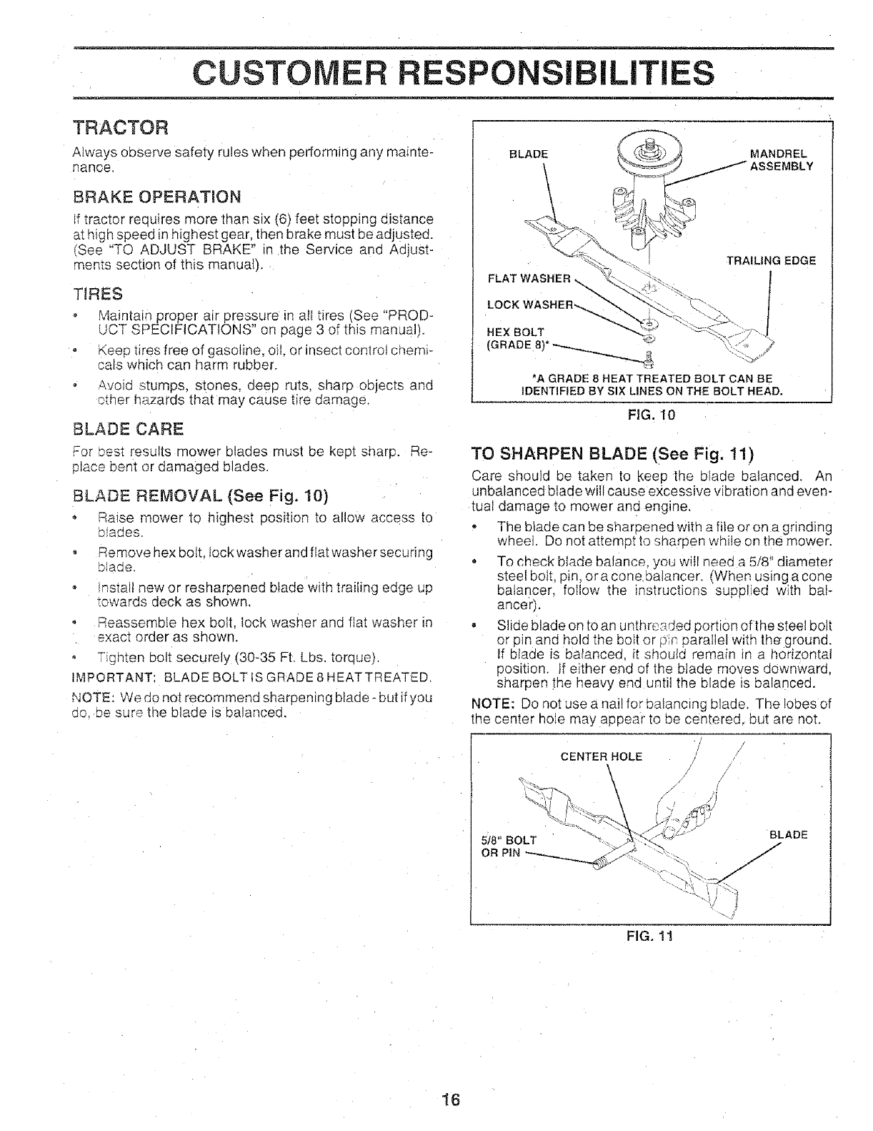
BLADE REMOVAL (See Fig, 10)
Raise mower to highest position 1oallow access to
oiaaes
Remove hex bolt fockwasheranc flat washersecunng
slaqe.
ms,all new or resharpened blade with trailing ec_geup
_owards deck as shown.
Reassemble hex bolt. lock washer and flat washer in
exact order as shown.
Tighten bolt securely (80-85 Ft. Lbs. torque).
I._,_PORTANT BLADE BOLT iS GRADE8HEATTREATED,
NOTE: We do not recommend sharpening blade - but if you
oo De sure the blade is balanced.
BLADE MANDREL
ASSEMBLY
FLAT WASHER_
TRAILING EDGE
HEX BOLT
(GRADE 8)*
*A GRADE 8 HEAT TREATED BOLT CAN BE
IDENTIFIED BY SIX LINES ON THE BOLT HEAD,
FIG. 10
TO SHARPEN BLADE (See Fig. 11)
Care should be taken to _<eepthe blade balanced. An
unbalanced blade will cause excessive vibration and even-
tual damage to mower and engine,
The blade can be sharoened with a file or on a grinding
wheel Do not attempt to sharpen while on the mower.
o To check blade balance, you will need a 5/8 diameter
steel bolt. pin, era cone ba]ancer. [When using a cone
balancer, foIlow the instructions suppliec with bal-
ancer).
• Slide blade on to an unthreaded portion of the steel bolt
or pin and hold the bolt or [_'r,oarallel w_tnthe ground.
tf blade _s balanced, it shoulc remair ir a horizontal
position, if either end of the blade moves downward,
sharpen the heavy end until the blade is balanced.
NOTE: Do not use a nail for balancing blade. The lobes of
the center hoJe may appear to be centered, but are not.
CENTER HOLE
518" BOLT
OR PiN
BLADE
FIG. 11
16
CUSTO RESPONSIBILITIES
BATTERY
Your tractor has a battery charging system which is suffi-
cient for normal use. However periodic charging of the
battery with an automotive charger will extend its life.
o Keep battery and terminals clean.
- Keep battery bolts tight,
• Keep small vent holes open.
• Recharge at 6-10 amperes for 1 hour.
TO CLEAN BATTERY AND TERMINALS
Corrosion and dirt on the battery and terminals can cause
the battery to "leak" power.
• Open battery box door.
• Disconnect BLACK battery cabte first then RED bat-
tery cable anc remove battery from tractor.
, Rinse the battery with plain water and dry.
Clean terminals and battery cable ends with wire brush
until bright,
. Coat terminals with grease or petroleum jetly.
• Reinstall battery (See "CONNECT BATTERY" in the
Assembly section of this manual).
V-BELTS
Check V-belts for deterioration and wear after I00 hours of
operation and replace if necessary. The belts are not
adjustable. Re place oelts if they begin to slip from wear,
TRANSAXLE COOLING
The fan and cooling fins of transmission should be kept
clean to assure 3roper cooling.
Do not attempt to clean fan or transmission while engine is
running or while the transmission is hot.
- Inspect cooling fan to be su re fan blades are intact and
clean.
Inspect cooling fins for dirt. grass clippings and other
materials; To prevent damage to seals, do not use
compressed air or high pressure sprayer to clean
cooling fins.
TRANSAXLE PUMP FLUID
The transaxle was sealed at the factory and fluid mainte-
nance is not required for the life of the transaxle. Should the
transaxle ever leak or require servicing, contact your near-
est authorized service center/department.
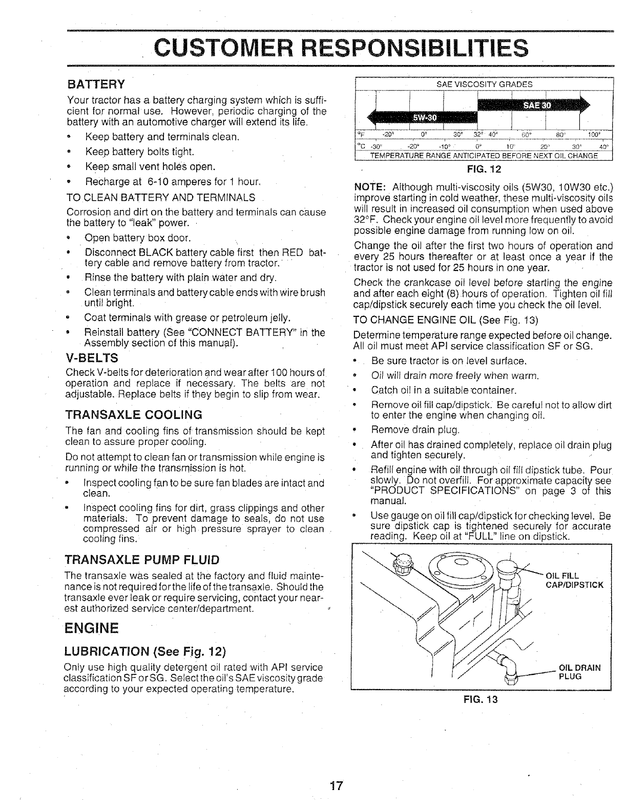
ENGINE
LUBR!CATJON (See Fig. 12)
Only use high quality detergent oil rated witP APt service
classification SF or SG. Select the oil's SAE wscostty grade
according to your expected operating temperature.
SAE VISCOSITY GRADES
30 ° 32o 40" 60 ° 80 t00
-30" -20 ° -100 0_ t0' 20 30_ 40 °
TEMPERATURE RANGE ANT{CIPATED BEFORE NEXT OIL SHANGE
FIG. 12
NOTE: Although multi-viscosity oils (5W30, 10W30 etc.)
improve starting in cold weather, these multi-viscosity oils
will result in increased oil consumption when used above
32°F. Check your engine oil level more frequently to avoid
possible engine damage from running tow on oil.
Change the oil after the first two hours of operation and
every 25 hours thereafter or at least once a year if the
tractor is not used for 25 hours ir one year.
Check the crankcase oil level before starting the engine
and after each eight (8) hours of operation. Tighten oil fill
cap/dipstick securely each time you check the oi level.
TO CHANGE ENGINE OIL (See "ig, t3)
Determine temperature range expected before oil change.
All oil must meet API service classification SF or SG.
- Be sure tractor is on level surface.
oOil will drain more freely when warm.
• Catch oit in a suitabfecontainer.
Remove oil fiit cap/dipstick Be careful not to allow dirt
to enter the eng ne when changing oit.
Remove drain plug.
After oil has drained completely, replace oil drain ptug
and tighten securely.
Refiti engine with oil through oil filt dipstick tube. Pour
slowly. Do not overfill. For approximate capacity see
"PRODUCT SPECIFICATIONS" on page 3 of this
manual
- Use gauge on oil filf cap/dipstick for checking levet. Be
sure dipstick cap is hghtened securely for accurate
reading. Keep oil at "FULL" line on dipstick.
FILL
CAPtDtPSTICK
J
OiL DRAIN
PLUG
FIG. !3
17
CUSTOMER RESPONSi IT
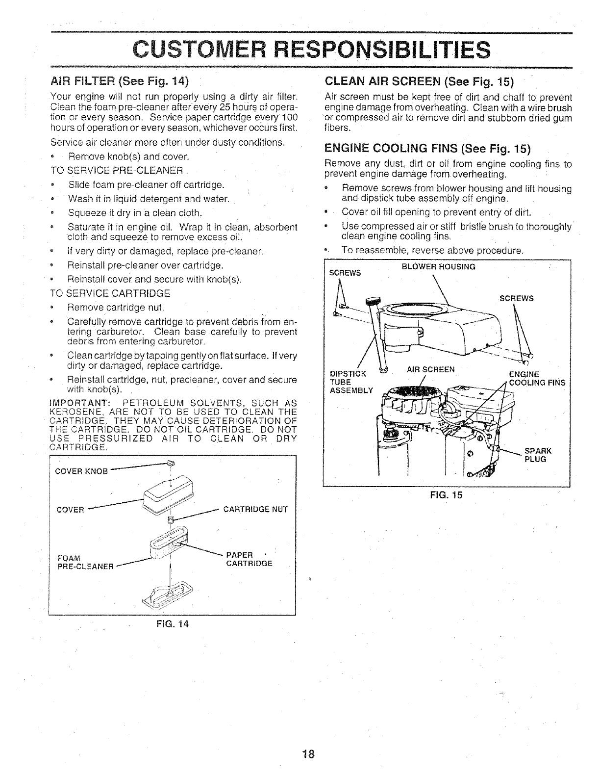
AiR FILTER (See Fig, !4)
Your engine will not run properly using a dirty air filter.
CIean the foam pre-c]eaner after every 25 hours of opera-
tion or every season, Service paper cartridge every 100
_ours of operation or every season, whichever occurs first.
Serwce a_rcleaner more often under dusty conditions.
o Remove knob(s) and cover.
TQ SERVICE PRE-CLEANER
° Slide foam pre-cleaner off cartridge.
o Wash it in liquid detergent and wa_er.
Squeeze it dry in a clean cloth.
Saturate it in engine oil. Wrap it in clean, absorbent
cloth and squeeze to remove excess oil.
if very dirty or damaged, replace pre-cleaner.
• Reinstall pre-c]eaner over cartridge.
Reinstall cover and secure with knob(s).
TO SERVICE CARTRIDGE
, Remove cartridge nut,
Carefully remove cartridge to prevent debris from en-
[ering carburetor. Clean base carefully to prevent
debris from entering carburetor,
Clean cartridge by tapping gently on flat surface. Ifvery
dirty or damaged, replace cartridge.
Reinstall cartridge, nut, precIeaner, cover and secure
witil knob(s).
IMPORTANT: PETROLEUM SOLVENTS, SUCH AS
KEROSENE. ARE NOT TO BE USED TO CLEAN THE
CARTRIDGE, THEY k/lAY CAUSE DETERIORATION OF
THE CARTRIDGE. DO NOT OiL CARTRIDGE. DO NOT
USE PRESSURIZED AIR TO CLEAN OR DRY
CARTRIDGE
COVER KNOB
COVER CARTRtDGE NUT
_ _ PAPER
FOAM .._,_._,r
PRE.CLSANER..._ _'_ CARTRIDGE
CLEAN AIR SCREEN (See Fig, 15)
Air screen must be kept free of dirt and chaff to prevem
engine damage from overheating. Clean with a wire brush
or compressed air to remove dirt and stubborn dried gum
fibers.
ENGINE COOLING FINS (See Fig. 15)
Remove any dust, dirt or oil from engine cooling fins to
prevent engine damage from overheating,
• Remove screws from blower housing and lift housing
anc dipstick tube assembly off engine.
, Cover oil fill opening to prevent entry of dirt.
- Use compressed air or stiff bristle brush to thoroughly
clean engine cooling fins.
- To reassemble, reverse above procedure,
SCREWS BLOWER HOUSING
\\SCREWS
DIPSTICK ENGINE
TUBE rCOOLING FINS
ASSEMBLY
AIR SCREEN
SPARK
PLUG
FIG. 15
FiG. 14
18
CUSTOMER ESPONSIBILITIES
MUFFLER
Inspect and replace corroded muffler and spark arrester (if
equipped) as it could create a fire hazard and/or damage.
SPARK PLUGS
Replace spark plugs at the beginning of each mowing
season or after every 100 hours of operation; whichever
occurs first. Spark plug type and gap setting are shown _n
"PRODUCT SPECIFICATIONS" on page 3 of this manual.
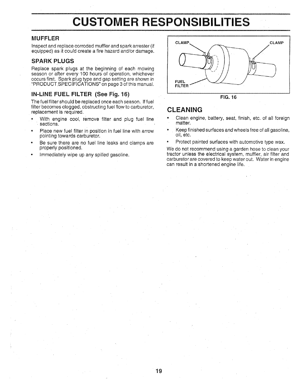
CLAMP_ /CLAMP
/
/
FUEL
FILTER
IN-LINE FUEL FILTER (See Fig. 16)
The fuel filter should be replaced once each season. Iffue!
filter becomes clogged, obstructing fuel flow to carburetor,
replacement is required.
• With engine cool, remove filter and plug fuel !ine
sections.
-Place new fuel filter in position in fue_ line with arrow
pointing towards carburetor.
• Be sure there are no fuel line leaks and clamps are
properly positioned.
o Immediately wipe up any spilled gasoline.
FIG. 16
CLEANING
•Clean engine, battery, seat, finish, etc. of all foreign
matter.
• Keep finished surfaces and wheels free of all gasoline.
oil, etc.
• Protect painted surfaces with automotive type wax.
We do not recommend using a garden hose to clean your
tractor unless the electrical system, muffler, air filter and
carburetor are covered to keep water out. Water in engine
can result in a shortened engine life.
19
SERVICE AND ADJUSTMENTS
CAUTION: BEFORE PERFORMING ANY SERVICE OR ADJUSTMENTS:
o Depress clutch/brake pedal fully and set parking brake,
oPlace motion control lever in neutral (N) position.
*Place attachment ciutch in "DISENGAGED" position.
- Turn ignition key "OFF" and remove key.
oMake sure the blades and all moving parts have completely stopped.
-Disconnect spark plug wire from spark plug and place wire where it cannot come in contact
with plug.
TRACTOR
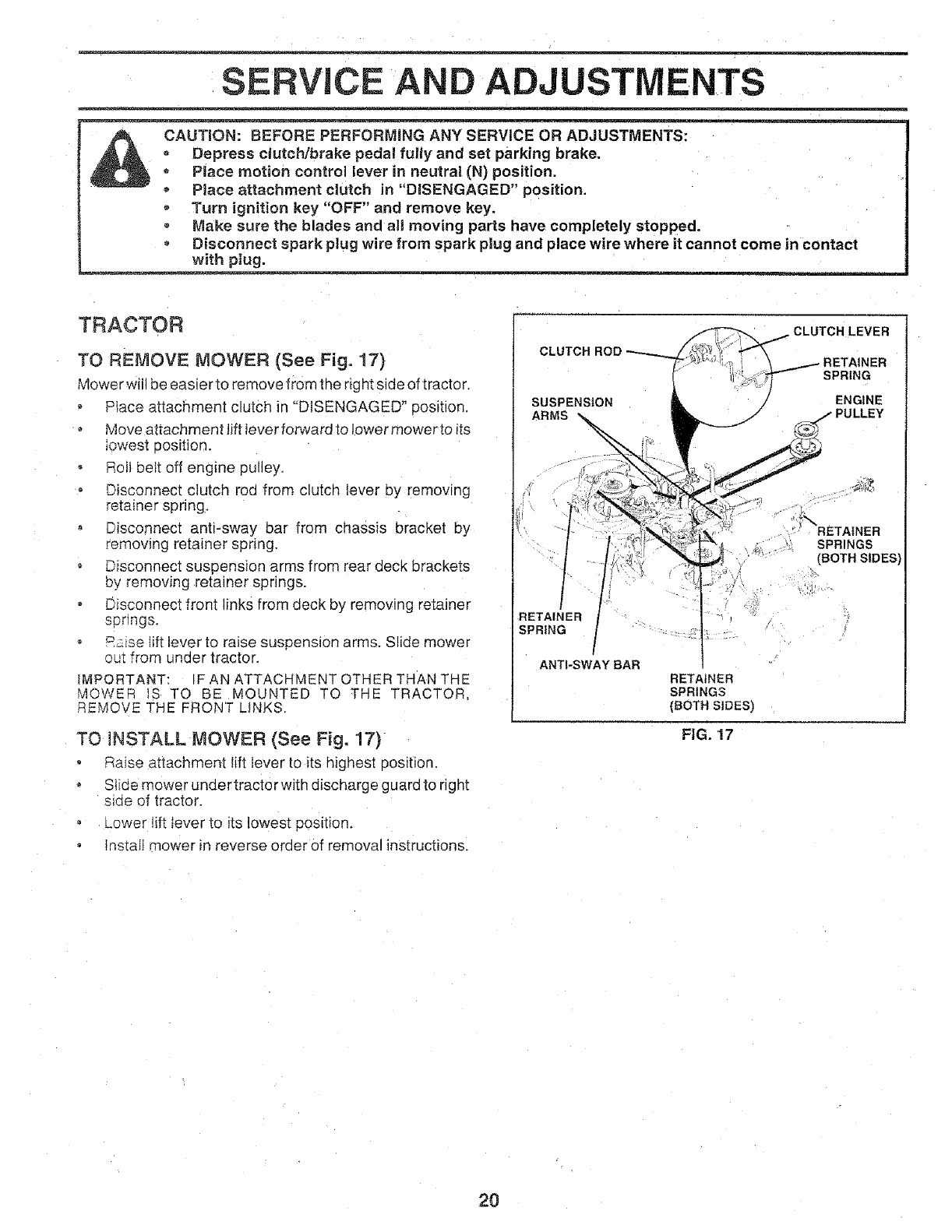
TO REMOVE MOWER (See Fig. 17)
Mower will be easier to remove from the nght side of tractor,
,Ptace attachment clutch in "DISENGAGED" position,
o Move attachment lift lever forward to lower mower to its
lowest position,
• Roll belt off engine pulley,
Disconnect clutch roa from clutch lever by removing
retainer spring,
o Disconnect antPsway bar from chassis bracket by
remowng retainer spring.
• Disconnect suspension arms from rear deck brackets
by removing retainer springs.
Disconnect front links from deck by remowng retainer
sDnngs.
oR__iselift lever to raise suspension arms. Slide mower
om from under tractor.
MPORTANT: F AN ATTACHMENT OTHER THAN THE
MOWER IS TO BE MOUNTED TO THE TRACTOR.
REMOVE THE FRONT LINKS.
TO _NSTALL MOWER {See Fig. 17)
Raise attachment lift lever to its highest position.
• Slide mower under tractor with discharge guard to right
side of tractor.
LOWer tift lever to its lowest position,
Install mower in reverse order of removal instructions.
CLUTCH LEVER
SUSPENSION /
ARMS /
SPRING
ENGINE
RETAINER
SPRING
ANTI-SWAY BAR
RETAINER
SPRINGS
{BOTH SIDES)
SPRINGS
(BOTHSIDES
\
FIG. !7
2O
SERVICE AND ADJUSTMENTS
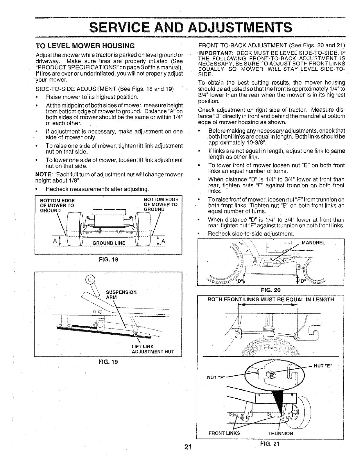
TO LEVEL MOWER HOUSING
Adjust the mower while tractor is parked on level ground or
driveway, Make sure tires are properly inflated (See
"PRODUCT SPECIFICATIONS" on page 3 of this manual).
If tires are over or underinflated, you will not property adjust
your mower.
SIDE-TO-SIDE ADJUSTMENT (See Figs. 18 and 19)
• Raise mower to its highest position.
• At the midpoint of both sides of mower, measure height
from bottom edge of mower to g _ound. Distance"A" on
both sides of mower should be the same or within 1/4"
of each other.
. If adjustment is necessary, make adjustment on one
side of mower only.
°To raise one side of mower, tighten lift link adjustment
nut on that side.
*To tower one side of mower, loosen lift tink adjustment
nut on that side.
NOTE: Each full turn of adjustment nut will change mower
height about 1/8".
•Recheck measurements after adjusting.
BOTTOM EDGE BOTTOM EDGE
OF MOWER TO OF MOWER TO
GROUND GROUND
SUSPENSION
ARM
FIG. 18
\
LIFT LINK
ADJUSTMENT NUT
FIG. 19
FRONT-TO-BACK ADJUSTMENT (See Figs, 20 and 21)
IMPORTANT: DECK MUST BE LEVEL SIDE-TO-SIDE. tF
THE FOLLOWING FRONT-TO-BACK ADJUSTMENT IS
NECESSARY, BE SURE TO ADJUST BOTH FRONT LINKS
EQUALLY SO MOWER WILL STAY LEVEL SiDE-TO-
SIDE.
To obtain the best cutting results, the mower housing
should be adjusted so that the front is approximately 1/4" to
3/4" lower than the rear when the mower is =nits highest
position.
Check adjustment on right side of tractor. Measure dis-
tance "D" directly in front and behind the mandrel at bottom
edge of mower housing as shown.
. Before making any necessa _' adjustments, check that
both front links are equal in length. Both links should be
approximately 10-3/8 _'.
•if links are not equal in length, adjust one tink to same
length as other link.
• To lower front of mower loosen nut "E" on both front
links an equal gumber of turns.
•When distance "D" is 1/4" to 3/4" lower at front than
rear, tighten nuts "F" against trunnion on both front
links.
, To raise front of mower, loosen nut"F" from trunnion on
ooth front links. Tighten nut "E" on both front links an
equal number of turns.
= When distance "D" is 1/4" to 3/4" lower at front than
rear, tighten nut "F" against trunnion on both front links.
• Recheck side-to-side adjustment.
_ n _MANDREL
FIG. 20
BOTH FRONT LINKS MUST BE EQUAL IN LENGTH
NUT "F"
FRONT LINKS TRUNNION
NUT"E"
21 FIG. 21
SERVICE AND AD,
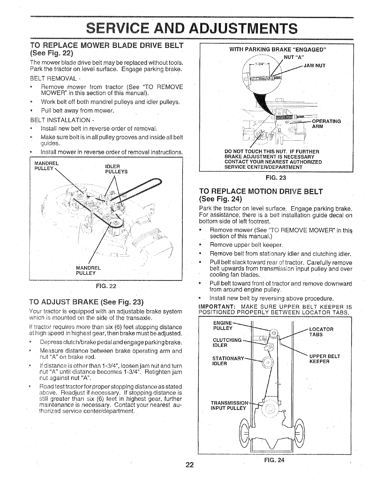
TO REPLACE MOWER BLADE DRIVE BELT
(See Fig. 22)
The mower blade drive belt may be replaced without tools.
Park the tractor on Eevelsurface. Engage parking brake.
BELT REMOVAL -
- Remove mower from tractor (See "TO REMOVE
MOWER" in this section of this manual).
o Work belt off both mandrel pulleys and idler pulleys,
o Pull belt away from mower.
BELT INSTALLATION -
Install new belt in reverse order of removal.
Make sure belt is in all pulley grooves and inside all belt
guides.
o fnstall mower in reverse order of removal instructions.
USTMENTS
WITH PARKING BRAKE "ENGAGED"
_--'_-'_- NUT "A"
DO NOT TOUCH THIS NUT. IF FURTHER
BRAKE ADJUSTMENT IS NECESSARY
MANDREL IDLER
PULLEY \ PULLEYS
\
/
/
/
MANDREL
PULLEY
FiG. 22
TO ADJUST BRAKE (See Fig. 23)
CONTACT YOUR NEAREST AUTHORIZED
SERVICE CENTER/DEPARTMENT
FiG. 23
TO REPLACE MOTION DRIVE BELT
(See Fig. 24)
Park the tractor on levei surface. Engage parking brake.
For assistance, there s a belt instal{ation guide decal on
bottom side of left footrest,
°Remove mower (See "TO REMOVE MOWER" in this
section of this manual,)
= Remove upper belt keeper.
- Remove belt from stat;onary idler and clutching idler,
° Pull belt slack toward rear of tractor. Carefully remove
belt upwards from transmission nput pulley and over
cooling fan blades.
* Pult belt toward front of tractor and remove downward
from around engine putiey.
Install new belt by reversing above procedure,
IMPORTANT: MAKE SURE UPPER BELT KEEPER IS
Your tractor is equipped with an adjustable brake system
which _smounted on the side of the transaxle.
[_tractor requires more than six (6) feet stopping distance
at hign speea in highest gear, then brake must be adjusted.
o Deoress clutch/brake pedal and engage parking brake.
Measure distance between brake operating arrr and
nut "A" on brake rod.
if distance is other than 1-3/4". loosen jam nut and turn
nu_ "A" until distance becomes 1-3/4", Retighten jam
nu_ against nut "A".
Road test tractor for proper stopping distance as stated
above. Readjust if necessary. If stopping distance is
stilt greater than s_x (6) fee! in highest gear, further
maintenance Jsnecessary. Contact your nearest au-
thorized service center/department.
22
POSITIONED PROPERLY BETWEEN LOCATOR TABS.
t LOCATO.
iL '_q_v" "" /TABS
CLUTCHING ",,-._- _,°//_'_:_;!
I1 1"
,_ _UPPER BELT
STATIONARY_'_ |KEEPER
IDLER _\ ":)' L
TRANSM_
INPUT PULLEY ItF
FIG. 24
RVIC AND ADJUSTMENTS
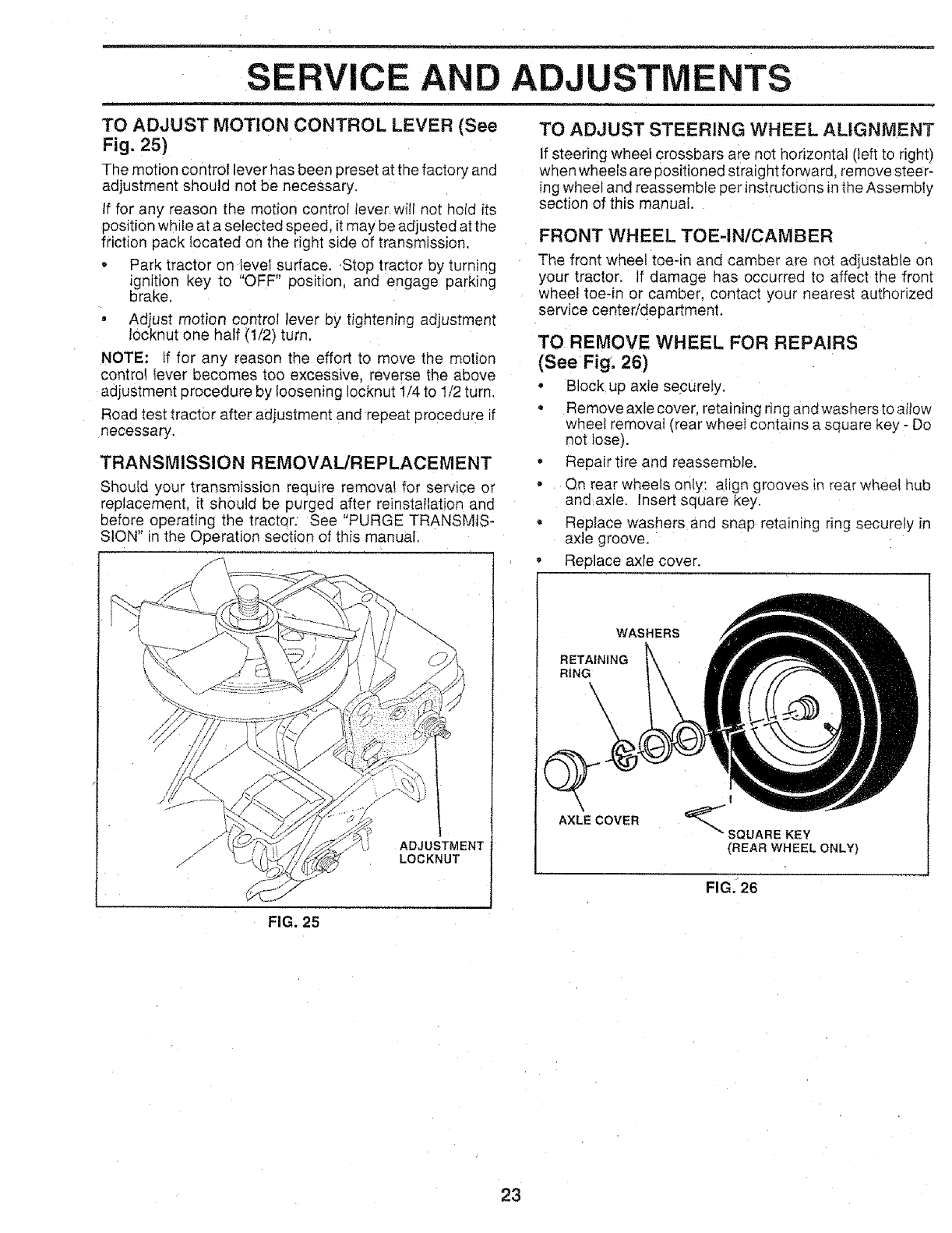
TO ADJUST MOTION CONTROL LEVER (See
Fig. 25)
The motion control lever has been preset at the factory and
adjustment should not be necessary.
If for any reason the motion control lever will not hold its
eosition while at a selected speed, it may be adjusted at the
friction pack located on the right side of transmission.
-Park tractor on level surface..Stop tractor by turning
ignition key to "OFF" position, and engage parking
brake.
• Adjust motion control lever by tightening adjustment
10cknut one half (1/2) turn.
NOTE: tf for any reason the effort to move the motion
control lever becomes too excessive, reverse the above
adjustment procedure by loosening Iocknut 1/4 to 1/2 turn.
Road test tractor after adjustment and repeat procedure if
necessary,
TRANSMISSION REMOVAL/REPLACEMENT
Should your transmission require removal for service or
replacement, it should be purged after reinstallation and
before operating the tractor: See "PURGE TRANSMIS-
SION" in the Operation section of this manual.
ADJUSTMENT
LOCKNUT
TO ADJUST STEERING WHEEL ALIGNMENT
If steering wheel crossbars are not horizontal (left to right)
when wheels are positioned straightforward, remove steer-
ing wheel and reassemble per instructions in the Assembly
section of this manual.
FRONT WHEEL TOE-IN/CAMBER
The front wheel toe-in and camber are not adjustable on
your tractor. If damage has occurrea to affect the front
wheel toeqn or camber, contact your nearest authorized
service center/department.
TO REMOVE WHEEL FOR REPAIRS
(See Fig. 26)
•Block up axle securely,
- Removeaxle cover, retaining ring and washers to altow
wheel removal (rear wheel contatns a square key - Do
not lose),
• Repair tire and reassemble.
- Qn rear wheels only: align grooves in rear wheet hub
and axle. Insert square key.
- Replace washers and snap retaining ring securely in
axle groove.
Replace axle cover,
WASHERS
RETAINING
RING\
AXLE COVER
I
SQUARE KEY
(REAR WHEEL ONLY)
FIG. 26
FIG, 25
23
SERVICE
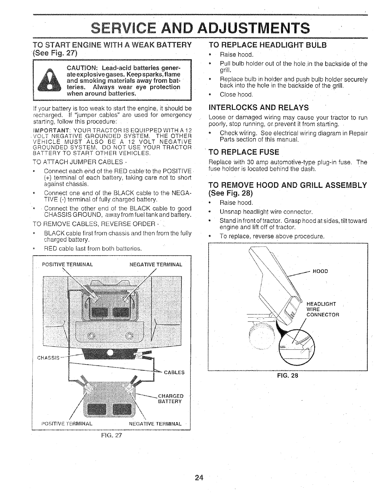
TO START ENGINE WtTH A WEAK BATTERY
See Fig. 27)
CAU TlON_______ Lea d.aci
ate explosivegases, Keep sparks, flame
and smoking materials away from bat -
reties. Always wear eye protection
If your battery is too weak to start the engine, it Should be
recnargea, if "jumper cables" are used for emergency
starbng, follow this procedure:
iMPORTANT: YOUR TRACTOR IS EQUIPPEDWITH A 12
VOLT NEGATIVE GROUNDED SYSTEM, THE OTHER
VEHICLE MUST ALSO BE A 12 VOLT NEGATIVE
GROUNDED SYSTEM. DO NOT USE YOUR TRACTOR
BATTERY TO START OTHER VEHICLES,
TO ATTACH JUMPER CABLES -
Connect each end of the RED cable-to the POSITIVE
(+) terminal of each battery, taking care not to short
against chassis,
• Connecl one end of the BLACK cable to the NEGA-
TIVE (-) terminal of fuIly charged battery.
,Connect the other end ot the BLACK cable to good
CHASSIS GROUND, away from fuel tank and battery.
TO REMOVE CABLES, REVERSE ORDER
o BLACK sable first from chassis and then from the fully
charged battery,
RED sable last from both batteries.
POSITIVE TERMINAL NEGATIVE TERMINAL
AND ADJUSTMENTS
TO REPLACE HEADLIGHT BULB
- Raise hood.
- Pull bulb holder out of the hole in the backside of the
grill.
• Replace bulb in holder andpush bulb holder securely
back into the hole in the backside of the grill
• Close hood.
CABLES
CHARGED
BATTERY
,, \
POStTtVE TERMINAL NEGATIVE TERMINAL
FiG. 27
iNTERLOCKS AND RELAYS
Loose or damaged w_ring may cause your tractor to run
poorly, stop running, or prevent it from starting.
o Check wiring. See electrical wiring diagram _nRe pair
Parts section of this manual.
TO REPLACE FUSE
Replace with 30 amp automotive-type plug-_ fuse. The
fuse holder is located behind the dash.
TO REMOVE HOOD AND GRILL ASSEMBLY
(See Fig. 28)
- Raise hood.
- Unsnap headlight wire connector.
-Stand in front of tractor. Grasp hood at sides, tiIt toward
engine and lift off of tractor.
- To replace, reverse above procedure.
HEADLIGHT
WIRE
CONNECTOR
FIG. 28
24
SERVICE
ENGINE
AND ADJUSTMENTS
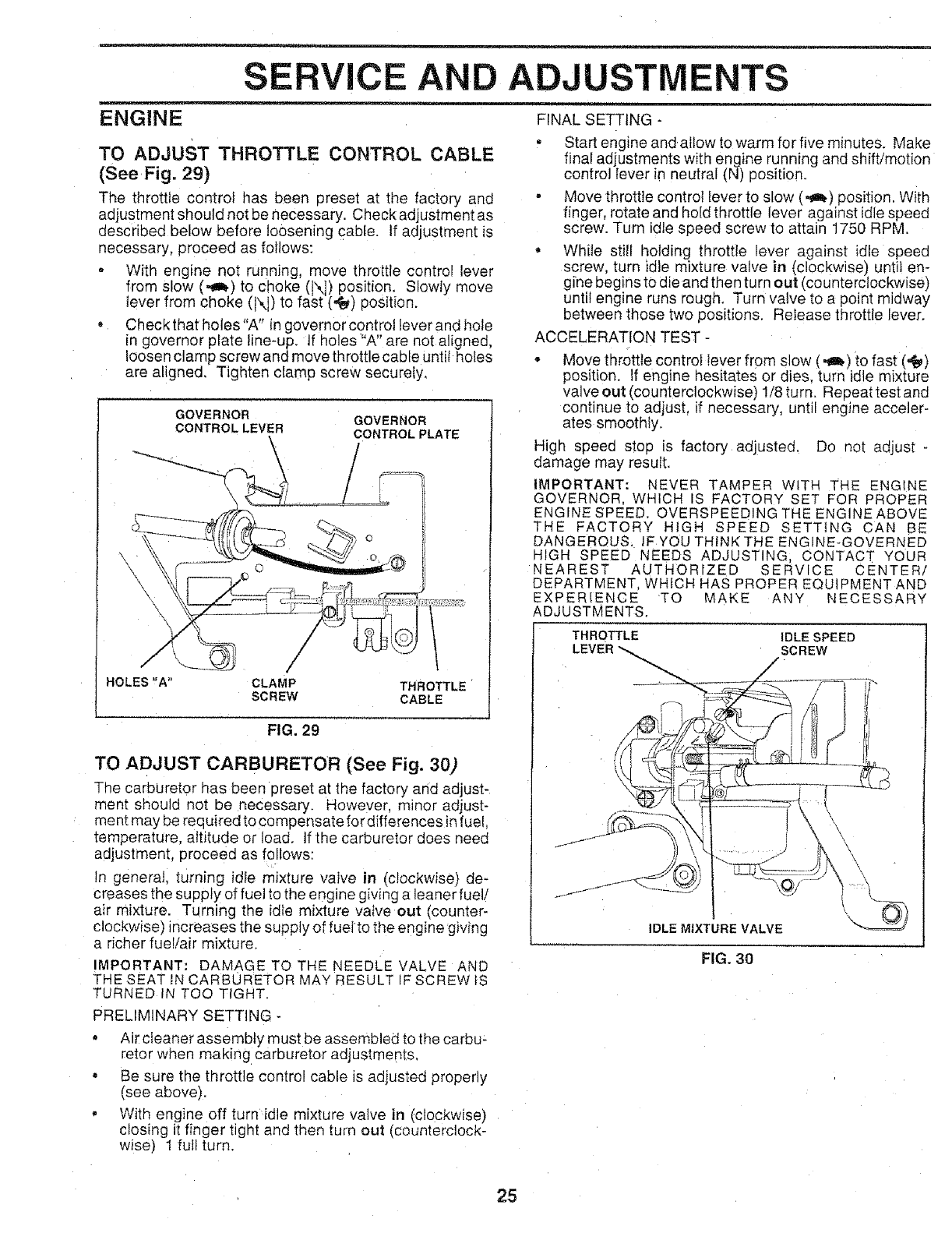
TO ADJUST THROTTLE CONTROL CABLE
(See Fig. 29)
The throttle control has been preset at the factory and
adjustment should not be necessary. Check adjustment as
aescribed below before loosening cable, tf adjustment is
necessary, proceed as follows:
• With engine net running, move throttle control lever
from slow (,_) to choke (X]) position. Slowly move
lever from choke (IXI) to fast (,t_) post on.
Check that holes "A" in governor controt lever and hole
in governor plate line-up. If holes "A" are not a!:gned,
loosen clamp screw and move throttle cable unfit holes
are aligned. Tighten clamp screw securely,
GOVERNOR GOVERNOR
CONTROL LEVER CONTROL PLATE
\
HOLES "A"
/
/
CLAMP THROTTLE
SCREW CABLE
FIG. 29
TO ADJUST CARBURETOR (See Fig. 30)
The carburetor has been preset at the factory and adjust-
ment should not be necessary. However, minor adjust-
ment may be required to compensate for differences in fuel.
temperature, altitude or load. ]f the carburetor does need
adjustmenl proceed as follows:
In general, turning idle mixture valve in (clockwise) de-
creases the supply of fuel to the engine giving a leaner fuel/
air mixture. Turning the idle mixture valve out (counter-
clockwise) increases the supply of fuel to the engine giving
a richer fuel!air mixture.
IMPORTANT: DAMAGE TO THE NEEDLE VALVE AND
THE SEAT IN CARBURETOR MAY RESULT IF SCREW iS
TURNED IN TOO TIGHT.
PRELIMINARY SETTING -
• Air cleaner assembly must be assembled to the carbu-
retor when making carburetor adjustments.
- Be sure the throttle control cable is adjusted propeny
(see above).
• With engine off turn idle mixture valve in (clockwise}
closing it finger tight and then turn out (counterclock-
wise) 1 full turn.
FINAL SETTING -
= Start engine and allow to warm for five minutes. Make
final adjustments with engine running and shift/motion
control lever in neutral (N) position.
- Move throttle control lever to slow (,_) position. With
finger, rotate and hold throttle lever against idle speed
screw. Turn idle speed screw to attain 1750 RPM.
o While still "_olding throttle lever against idle speed
screw turn idle mixture valve in (clockwise) until en-
gine begins to die and then turn out (counterclockwise)
until engine runs rough. Turn valve to a point midway
between those two positions. Release throttle lever.
ACCELERATION TEST -
• Move throttle control lever from slow (,_) to fast (,_)
position. If engine hesitates or dies. turn idle mixture
valve out (counterclockwise) 1/8 turn. Repeattest and
continue to adjust, if necessary, until engine acceler-
ates smoothly.
High speed stop is factory adjusted. Do not adjust -
damage may resutt.
IMPORTANT: NEVER TAMPER WITH THE ENGINE
GOVERNOR, WHICH IS FACTORY SET FOR PROPER
ENGINE SPEED. OVERSPEEDING THE ENGINEABOVE
THE FACTORY HIGH SPEED SETTING CAN BE
DANGEROUS IFYOUTHINKTHEENGINE-GOVERNED
HIGH SPEED NEEDS ADJUSTING CONTACT YOUR
NEAREST AUTHORIZED SERVICE CENTER/
DEPARTMENT, WHICH HAS PROPER EQUIPMENT AND
EXPERIENCE TO MAKE ANY NECESSARY
ADJUSTMENTS.
THROTTLE IDLE SPEED
LEVER SCREW
/
\
IDLE MIXTURE VALVE
FIG. 30
25
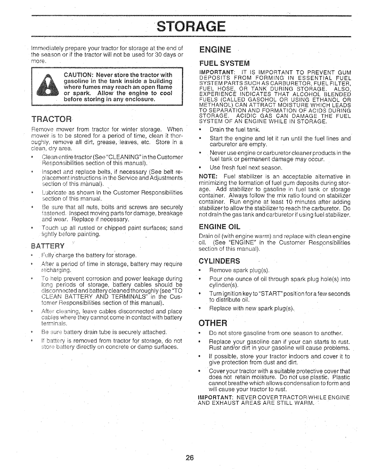
STORAGE
mmediately prepare your tractor for storage at the end of
me season or if the tractor will not be used for 30 days or
more
A c2dT,o"- iroc i
_J&A ga_ inside a building I
where fumes may reach an open flame j
or spark. Allow the engine to cool
_lnany enclosure. . _!
TRACTOR
Remove mower from tractor for winter storage. When
mower Js to be stored for a period of time, clean it thor-
oughty, remove all dirt. grease, leaves, etc. Store in a
clean, ury area.
Clean entire tractor (See"CLEAN 1NG"inthe Customer
ResDonsibiIities section of this manual).
insoec; and replace belts, if necessary (See beIt re-
o]acement instructions in the Service and Adjustments
;ection of this manual).
Lubricate as shown in the Customer Responsibilities
_ection of this manual
Be ;ure that all nuts. bolts and screws are securety
'astened. Inspect moving partsfordamage, breakage
anc wear. Replace if necessary.
Touch up all rusted or chipped paint surfaces: sand
t_ghtIy before painting.
BATTERY
Fully cnarge the battery for storage.
After a period of time in storage, battery may require
recharging.
To help prevent corrosion and power leakage during
_ona periods of storage, battery cables should be
r_sconn_cted and battery cleaned thoroughly (see "TO
CLEAN BATTERY AND TERMINALS" in the Cus-
tomnr Responsibilities section of this manual_.
After cleaning, leave cables disconnected and place
cautes :,__ere they cannot come in contact with battery
terminals.
o Be :_ure battery drain tube is securely attached.
, If battery _s removed from tractor for storage, do not
s,tore battery directly on concrete or damD surfaces.
ENGINE
FUEL SYSTEM
IMPORTANT: IT S IMPORTANT TO PREVENT GUM
DEPOS TS FROM FORMING IN ESSENTIAL FUEL
SYSTEM PARTS SUCH AS CARBURETOR FUEL FILTER.
FUEL HOSE, OR TANK DURING STORAGE. ALSO,
EXPERIENCE INDICATES THAT ALCOHOL BLENDED
FUELS (CALLED GASOHOL OR USING ETHANOL OR
METHANOL) CAN ATTRACT MOISTURE WHICH LEADS
TO SEPARATION AND FORMATION OF ACIDS DURING
STORAGE. ACtD]C GAS CAN DAMAGE THE FUEL
SYSTEM OF AN ENGINE WHILE IN STORAGE.
- Drain the fue! tank.
, Start, the engine ann let it run unti the fue! lines anc
carburetor are empty.
, Never use engine or carburetor cleaner products in the
fuel tank or permanent damage may occur.
, Use fresh fuel next season.
NOTE: Fuel stabilizer is an acceDtable alternative in
minimizing the formation of fuel gum deposits during stor-
age, Add stabilizer to gasoline in fuel tank or storage
container. Always follow the m_x raho found on stabiliZer
container. Run engine at least 10 minutes after adding
stabilizer to allow the stabilizer to reach the carburetor. Do
not drain the gas tank and carburetor if using fuel stabilizer.
ENGINE OIL
Drain oil (with engine warm) and replace with clean engine
off. (See "ENGINE" in the Customer Responsibilities
section of this manual).
CYLINDERS
- Remove spark pIug(s).
- Pour one ounce of oil tnrougn spark plug hole(s) into
cylinder(s).
Turn ig nition key to"START" position for a few seconds
to distribute oil.
Replace with new spark plug(s).
OTHER
- Do not store gasoline from one season to another.
- Replace your gasoline can if your can starts to rust.
Rust and/or dirt in your gasoline wilt cause problems.
- I1 possible, store your tractor indoors and cover it to
give protection from dust and dirt.
, Cover your tractor with a suitable protective cover that
does not retain moisture. Do not use plastic. Plastic
cannot breathe which allows condensation to form and
will cause your tractor to rust.
IMPORTANT: NEVER COVER TRACTOR,WHILE ENGINE
AND EXHAdST AREAS ARE STILL WARM.
26

m
TRO LESHOOTI NTS
CAUSE CORRECTIONPROBLEM
Will not start
Hard to start
Engine willnot turn over
Engine clicks but will not
start
Loss of power
=
Excessive vibration
1. Out of fuel.
2. Engine not "CHOKED" properly.
3. Engine flooded.
4. Bad spark plug.
5. Dirty air filter.
6. Dirty fuel fitter.
7. Waterin fuel
8. Loose or damaged wiring.
9. Carburetor outof adiustment.
10, Engine valves out of adjustment.
1. Dirty air filter.
2. Bad sparkplug.
3, Weakor dead battery,
4. Dirty fuel filter.
5. Stale ordirty fuel
6. Loose or damaged widng.
7. Carburetor out of adjustment,
8. Engine valves out of adjustment.
1. FIII fuel tank.
2. See "TO START ENGINE" in Operation section.
3. Wait severat minutes before attempting to start.
4. Replace spark plug.
5. Clean/replace air filter.
6. Replace fuet filter.
7. Drain fuel tank and carburetor, refitl tank with fresh
gasoline and replace fuel filter.
8, Check eli wiring.
9, See "To Adjust Carburetor" in Service Adjustments
section.
f0, Contact an authorized service centerideeartment.
1. Clean/replace air filter,
2, Replace spark plug,
3. _eeharge or replace battery.
4. Reptace fue! filter,
5. Drain fuel tank and refiIF with fresh gasoline.
6. Check all wiring.
7. See "To Adiust Carburetor" in Service Adiustments
section.
8, Contact an authorized service center/department.
1. Clutch/brake pedal not depressed.
2. Attachment dutch is engaged.
3. Weak or dead battery.
4 Blown fuse.
5, Corroded battery terminals
6, Loose or damaged wiring,
7. Faulty ignition switch,
8. Faulty solenoid or starter.
9, Faulty operator presence switeh(es).
1, Weak ordead battery.
2. Corroded battery terminals.
3. Loose or damaged wiring.
4. Faulty solenoid or Starter.
1. Cutting too much grass/too fast.
2. Throttle in "CHOKE" position.
1. Depress clutchlbrake pedal
2, Disengage attachment clutch.
3. Recharge or replace battery,
4. Replace fuse
5, Clean battery terminats.
6. Check all wiring,
7. Check/replace ignition switch.
8. Check/replace solenoid or starter
9. Contact an authorized service center/department.
1. Recharge or replace battery,
2. Clean battery terminals.
3. Check att wiring,
4. Check/replace solenoidor starter.
1. Set in "Higher Cut" position/reduce speee.
2. Adjust throttle control
3. Buitd-up of grass, leaves and trash under mower,
4. Dirty air fitter.
5, Low oil level/dirty oil.
6. Faultyseark plug.
7. Dirty fuet filter,
8. Stale or d_rty fuel.
9. Water in fuel
10. Spark plug wire loose,
11. Dirty engine air screen/fins.
12. Dirty/dogged muffler,
13, Loose or damaged w_ring.
14. Carburetor out of adjustment.
15. Engine valves out of adiustment.
1. Worn. bent orloose btade_
2. Bent blade mandrel.
3. Loose/damaged part(s),
3, Clean underside of mower housing
4. Clean/replace air filter.
5. Check oil level/change oil
6, Ciean and regap or change spark plug.
7. Replace fuel filter,
8. Drain fuel tank and refill with fresh gasoline.
9, Drain fuel tank and carburetor, refill tank with fresh
gasoline and replace fuel filter.
t0, Connect and tighten spark plug wire
I1. Clean engine air screen/fins.
12. Clean/replace muffler.
13. Check all wiring,
14. See "To Adjust Carburetor" in Service Adjustments
section.
15, "Contact an authorized serv{ce center/department,
t. Replace blade. Tighten blade bolt.
2. Reptace blade mandrel.
3. Tighten loose part(s) Replace damaged parts,
27
PROBLEM
Engine continues to run
TROUBLESHOOTING POINTS
CAUSE CORRECTION
when operator leaves seat
w_th attachment clutch
engage_
Poor ON'E - uneven
Mower blades w]H not
rotate
1 Fauity operator-safety P"esence control system. Check wiring, switches and connecbons. If not
Poor grass discharge
1. Worn bent or loose blade
2. Mower deck not leveI.
corrected, contact an authorized service center/
department,
1 Replace blade Tighten blade bolt.
2Le le] mower decK,
Headlight(s) not working
(if so equipped)
Battery wii! not charge
3. Buildub of grass, _eaves. and trash under mower.
4. Bent blade mandrel.
5, Clogged mower deck vent holes from buildup of
grass. _eaves. and trash around mandrels.
1. Obstruction in clutch mechanism.
2, Wornidamagec_mower drive belt.
3, Frozen idler puiley.
4. Frozen blade mandrel
3, Clean underside of mower housing.
4. Replace blade mandret.
5. Clean around mandrels to open vent notes,
I Remove obstruction,
2 ReD[ace mower drive belt.
3 Replace idIer pulley,
4 Remace blade mandrel
1. Engine speed too slow.
2. Travel speeu too fast.
3. Wet grass.
4. Mower deck not Ievet.
5, Low/uneven tire air pressure
6. Worn bent or loose blade
1 Place throttle control in "FAST" posEio!q.
2 Shift to slower speed
3, Allow grass to dry before mowing
4 Level mower deck,
5 Check tires for proper a_rpressure.
6, Replace/sharpen blade. Tighten blade bolt.
LOSS or drive
Engine "'backfires"
wren zurn]ngengine
'OFF"
7. Buildup of grass, leaves and trash under mower.
8, Mower drive belt worn,
9. Blades improperly installed
0. Improper blades used
11. Clogged mower deck vent holes from buJ]duc,of
grass, leaves, and trash around mandrels.
1. Switch is "OFF"
2. Bulb(s) burned out
3. Faultylight switch
4. Loose or damaged wiring.
5. Blown fuse,
t, Bad battery cell(s)
2. Poor cable connections
3 Faulty regulator (if so equipped}
4. Faulty alternator,
1. Freewheel control *n "disengaged"#osition.
2 Motion drive belt worn. damaged, or broken
3 Air trapped _ntransmission during sh_pmeni
or serwc_ng
1. Engine throttle comro_ not set at "SLOW"
position for 30 seconds before szoppmg engine,
7 Clean underside of mower housing.
8 Reo_ace mower drive belt
9 Reinstall blades sharp cage dOWn.
I O Replace with blades listed in this manual
11 CJean around mandrels to open vent ho_es.
Turn sw_tcn "ON".
2. Replace bu]b_sl
3, Check/replace light switch,
4 Check wiring end connections
5 Replace fuse,
Rap}ace battery,
2 Check!clean all connections
3. Replace regulator.
4 Reelace alternator.
1. Place freewheeJ centro_ _n"engaged" sosition.
2. Rap;ace motion drive belt.
3 Purge transmission.
1 Move throttle control to "SLOW" position ano atlow
to _dlefor 30 seconds before stopp_ng engine.
28
SCHEMATIC
TRACTOR - = MODEL NUMBER 917.256890
RED
BATTERY
BLACK
AMMETER
LGNITION SWITCH
RED
FUSE 30 AMP
T
t--O.. O '
I i '
(PEDAL UP) 1
BLACK
STARTER
BLACK
) _ BU_,CK
/ATT'MENT CLUTCH "" GROUNDING
(CLUTCH OFF/ CONNECTOR
l
:BLACK :
SEAT SWITCH
(NOT OCCUPIED)
t .... I
,r<ziL I
*b °
_ IGNITION _ SPARK H
UNIT PLUG
CHARGING SYSTEM OUTPUT
3 AMP DC @ 3500 RPM
\
28 VOLTS AC MtN @ 3600 _qPM
_CHARGtNG SYSTEM DISCONNECTED_
/
IGNITION SWITCH
POSITION CIRCUIT
OFF M + G
ON B+L
START B + S + L
RED
LtGHT_NG SYSTEM
NOTE OUTPUT DIODE
YOUR TRACTOR IS _AMPAC___,,-_pM_.
EQUIPPED WITH A SPECIAL 1_ "\ 14VOLTS AC MIN @ 3_600RPM LIGHTS OF_
ALTERNATOR SYSTEM. 12< "_
THE LIGHTS ARE NOT t_ HEADLIGHTS
CONNECTED TO THE I _...... _
HAVE
OWN ELECTRICAL SOURCE _ _' _T \. /T --
BECAUSE OF THIS,THE " HE-ADI_IGH# [ _ l
BRIGHTNESS OF THE LIGHTS SWITCH L _
WILL CHANGE WITH ENGINE (OFF) \-j_ '
/.
SPEED. AT IDLE THE LIGHTS
WILL DIM. AS THE ENGINE IS
SPEEDED UP, THE LIGHTS
WILL BECOME THEIR BRIGHTEST.
--_ NON-REMOVABLE .....
CONNECTIONS (_ REMOVABLE
CONNECTIONS
WIRING INSULATED CLIPS |
/:P7NOTE: IF WIRING INSULATED
CLIPS WERE REMOVED FOR
SERVICING OF UNIT, THEY
SHOULD BE REPLACED TO
PROPERLY SECURE YOUR WIRING.
29
REPAIR PARTS
ELECTRICAL
TRACTOR -= MODEL NUMBER 917.256890
1
20
42
40
34
I
16
@36 38 39
/36
/
15
8j l_
/
25 32
\49 31
30
3O
REPAIR PARTS
ELECTRICAL
TRACTOR =- MODEL NUMBER 917.256890
KEY PART
NO. NO. DESCRIPTION
1 146139
2 74760412
3 STD551025
4 STD551125
6 STD541025
7 109238X
8 144940
9 109596X
15 147688
16 153664
19 STD551125
20 73350400
21 136850
22 4152J
24 4799J
25 146147
26 108824X
28 4207J
29 121305X
30 144921
31 140400
32 141226
33 140403
34 110712X
36 STD601005
38 140336
39 109553X
40 146057
41 71110408
42 131563
43 145673
44 73640400
45 121433X
49 153249
70 140422
Battery 12 VOLT 25 AMP
Bolt Hex Hd 1/4-20unc x 3/4
Washer 9/32 X5/8 x 16 Ga
Was qer Lock Hvy HelicaI 1/4
Nut Fin Hex 1/4-20 Unc
Tube Plastic 12"
Case Battery Wi2 Holes W Btry
Clamp Hose Olive
Fastener Snapqn
Switch Interlock Push-In
Washer Lock 1/4
Nut Jam Hex 1/4-20 Uric
Harness Asm Light Wi4152j
Bulb Light #1156
Cable Battery 6 Ga 11" red
Cable Battery 6 Ga w/16 wire red
Fuse 30 AMP Auto Green
Cable Ground 6 Ga 12" black
Switch Plunger Nc Gray
Switch Ign 3 Pos
Nut Ignition
Cover Sw Key BIk I 25 Text SLT
Key Ign Molded Craftsman
Switch Light Blk BIk Red
Screw Tap Hex #10-24unc x 1/2
Bracket Switch Interlock
Switch lntlk Clutch Red 4 Term
Harness Ign Lt Dash IPC Mch 95
Bolt Bik, Fin Hex 1/4-20 Unc x 1/2
Cover Terminal Red
Solenoid
Nut Keps BIk Hex 1/4-20 Unc
Ammeter Rectangular 6 Amp
Washer Pinned Delta
Harness Engine B&S 14 OHV
NOTE: All component dimensions give in U.S. inches
1 inch = 25,4 mm
31
REPAIR PARTS
TRACTOR -.- MODEL NUMBER 917.256890
CHASSIS AND ENCLOSURES
3O
26
14
26
/
33 10
17
21
22
26 25
18
_------9
19
140
35
34
3
29
/
/
\
26
\
\
28
14
32
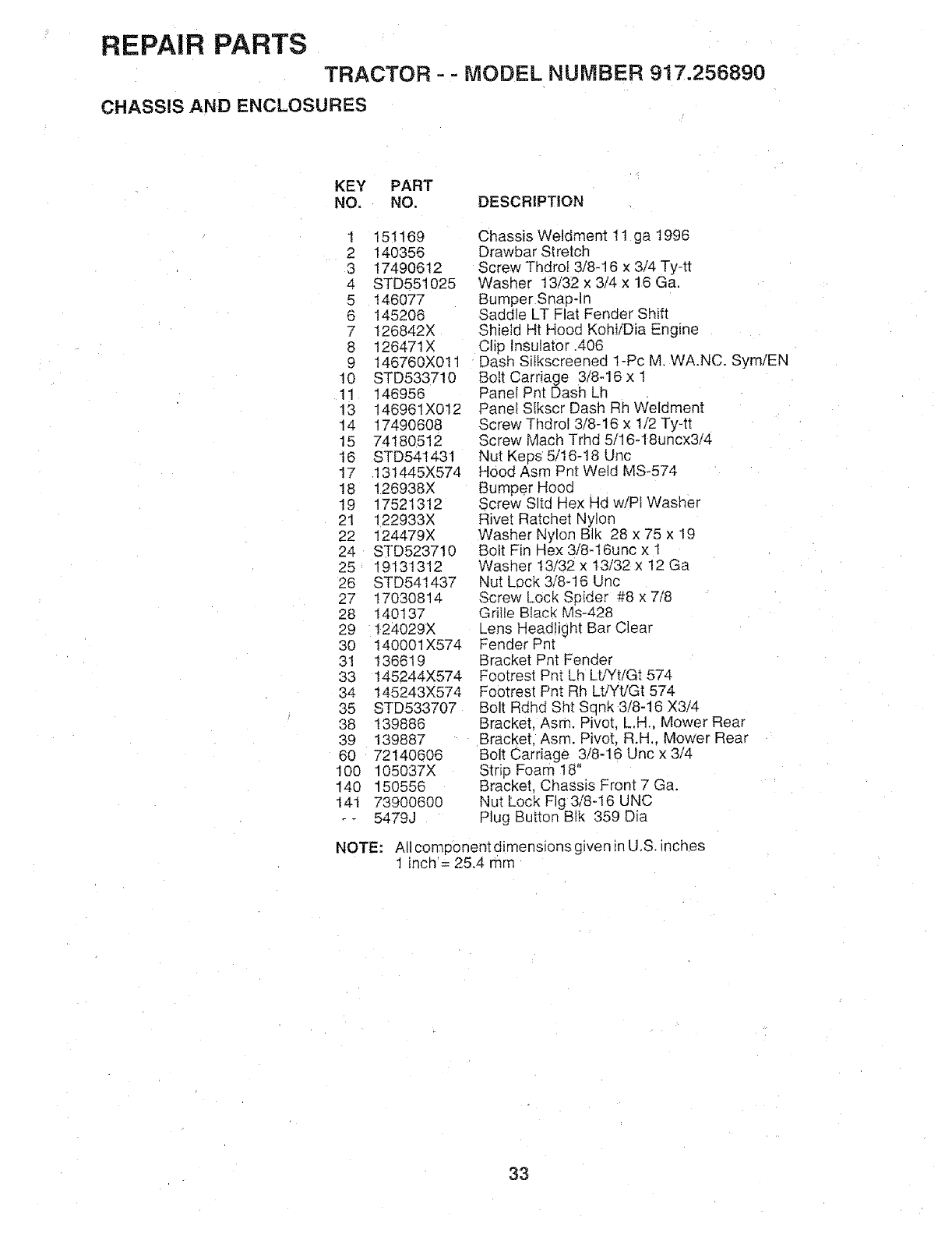
REPAIR PARTS
TRACTOR - -MODEL NUMBER 917.256890
CHASSIS AND ENCLOSURES
KEY PART
NO. NO. DESCRIPTION
1 151169
2 140356
3 17490612
4 STD551025
5 146077
6 145206
7 126842X
8 126471X
9 146760X011
10 STD533710
11 146956
13 146961X012
14 17490608
15 74180512
16 STD541431
17 131445X574
18 126938X
19 17521312
21 122933X
22 124479X
24 STD523710
25 19131312
26 STD541437
27 17030814
28 140137
29 124029X
30 140001X574
31 136619
33 145244X574
34 145243X574
35 STD533707
38 139886
39 139887
60 72140606
100 105037X
140 150556
141 73900600
-- 5479J
Chassis Weldment 11 ga 1996
Drawbar Stretch
Screw Thdrol 3/8-16 x 3/4 Ty-tt
Washer 13/32 x 3/4 x 16 Ga
Bumper Snap-In
Saddle LT Flat Fender Shift
Shield Ht Hood KohVDia Engine
Clip Insulator .406
Dash Silkscreened 1-Pc M. WA.NC. SymiEN
Bolt Carriage 3/8q6 x 1
Panel Pnt Dash Lh
Pane Slkscr Dash Rh Weldment
Screw Thdrol 3/8-16 x 1/2 Tyqt
Screw Mach Trhd 5i16-18uncx3i4
Nut Keps 5/16-18 Unc
Hood Asm Pnt Weld MS-574
Bumper Hood
Screw Sltd Hex Hd wiPt Washer
Rivet Ratchet Nylon
Washer Nylon BIk 28 x 75 x 19
Bolt Fin Hex 3/8-16unc x 1
Washer t3/32 x 13/32 x 12 Ga
Nut Lock 3/8q6 Unc
Screw Lock Spider #8 x 7Z8
Grille Black Ms-428
_ens Headtigtqt Bar Clear
Fender Pnt
Bracket Pnt Fender
Footrest Pnt Lh LtiYtiGt 574
Footrest Pnt Rh LtiYtiGt 574
Bolt Rdhd Sht Sq nk 3/8-16 X3/4
Bracket, Asm. Pivot. L,H., Mower Rear
Bracket. Asm. Pivot, R.H. Mower Rear
Bolt Carriage 3/8-16 Unc x 3/4
Strip Foam 18"
Bracket, Chassis Front 7 Ga.
Nut Lock Fig 3/8-16 UNC
Plug Button BIk 359 Dia
NOTE: All componenidimensionsgiven _nU.S. inches
1 inch = 25.4 mm
33
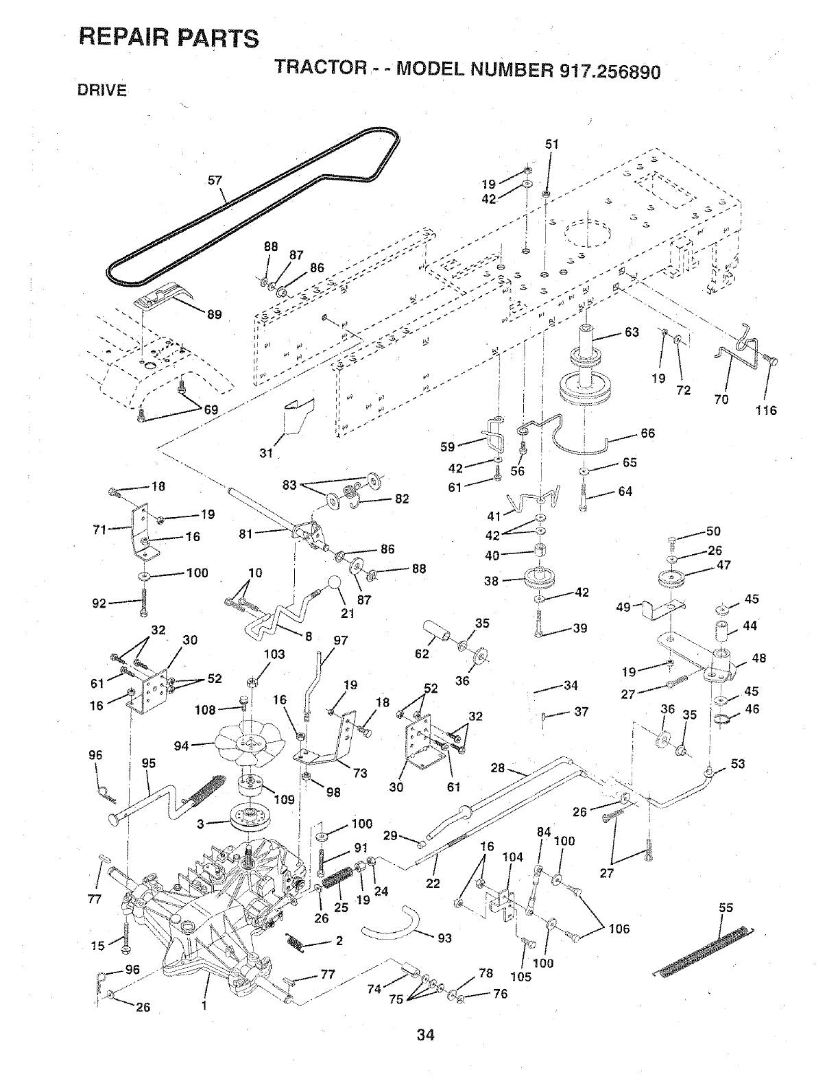
REPAIR PARTS
DRIVE
TRACTOR --MODEL NUMBER 917.256890
97
/
96
91
48
34
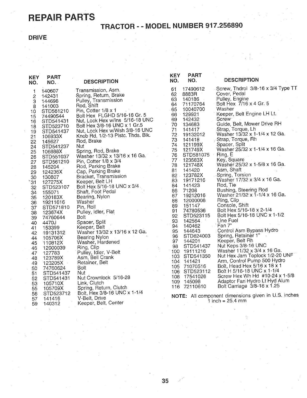
REPAIR PARTS
DRIVE
TRACTOR --MODEL NUMBER 9! 7.256890
KEY
NO.
1
2
3
8
lO
15
16
18
19
21
22
24
25
26
27
28
29
3o
31
32
34
35
36
37
38
39
40
41
42
44
45
46
47
48
49
50
51
52
53
55
56
57
59
PART
NO.
140607
142431
144698
141003
STD561210
74490544
STD541431
STD523710
STD541437
t06933X
145627
STD541237
106888X
STD55t037
STD561210
145204
124236X
130807
127275X
STD523107
155071
120183X
19211616
STD571810
123674X
74760644
4470J
153399
19131312
105706X
110812X
12000039
127783
123789X
123205X
74760624
STD541437
STD 541431
105710X
105709X
STD523712
141416
140312
KEY PART
DESCRIPTION NO. NO. DESCRIPTION
Transmission, Asm. 61 17490612
S3ring, Return, Brake 62 8883R
Pulley, Transmission 63 140186
Rod. Shift 64 71170764
Pin. Cotter 1/8 x 1 65 10040700
Bolt Hex FLGHD 5/16-t8 Gr. 5 66 129921
Nut, Lock Hex w/ins 5/16-18 UNC 69 142432
Bolt Hex 3/8-16 UNC x 1 Gr.5 70 134683
Nut. Lock Hex wiWsh 3/8-16 UNC 71 141417
Knob Rd. 1/2-13 Plstc. Thds. Blk. 72 19132012
Rod, Brake 73 141418
Nut 74 121199X
Spring, Rod, Brake 75 121749X
Washer 13/32 x 13/16 x 16 Ga. 76 STD581075
Pin, Cotter 1/8 x 3/4 77 123583X
Rod, Parking Brake 78 121748X
Cap, Parking Brake 81 141420
Bracket, Transmisston 82 t23782X
Keeper. Belt LH 83 19171216
Bolt Hex 5/16-t8 UNC x 3/4 84 141423
Shaft. Foot Pedal 86 71208
Bearing, Nylon 87 19212016
Washer 88 12000008
Pin, Roll 89 151147
Pulley, Idler. Flat 91 74780536
Bolt 92 STD523115
Spacer, Split 93 142564
Keeper, Belt 94 140462
Washer 13/32 x 13/16 x 12 Ga. 95 144643
Bearing Nylon 96 STD624003
Washer. Hardened 97 144201
Ring, Clip 98 STD541437
Pulley, Idler. V-Belt 100 19111216
Asm. Bell Crank 103 STD541350
Retainer Belt 104 141421
Botl 105 71070516
Nut 106 STD523112
Nut Crownlock 5/16-28 I08 17541026
Link, Clutch 109 145098
Spring, Return. Clutch t16 72110610
Bolt, Hex 3/8-16 UNC x 1-1/4
V-Belt. Drive
Keeper. Belt, Center
Screw, Thdrol 3/8-16 x 3/4 Type TT
Cover, Pedal
Pulley, Engine
Bolt Hex 7/16 x 4 Gr. 5
Washer
Keeper, Belt Engine LH Lt.
Screw
Guide. Belt, Mower Drive RH
Strap, Torque, Lh
Washer 13/32 x 1-1/4 x 12 Ga.
Strap, Torque, Rh
Spacer, Split
Washer 25/32 x 1-1/4 x 16 Ga.
Ring, E
Key, Square
Washer 25/32 x 1-5/8 x 16 Ga.
ASm, Shaft
Spring, Torsion
Washer 17/32 x 3/4 x 16 Ga.
Rod, Tie
Bushing, Steering Rod
Washer 21132 x t-1/4 x 16 Ga.
Ring, Clip
Consoie, Shift
Bolt Hex 5/16-18 x 2-1/4
Bolt Hex 5/16-18 UNC x 1-1/2
Line Fuel
Fan 7"
Control Asm Bypass Hydro
Spring, Retainer 1"
Keeper. Belt Rh
Nut Keps 3/8-16 UNC
Washer 11/32 x 3/4 x 16 Ga.
Nut Hex Jam Toplock 1/2-20 UNF
Arm, Control Pump 500 Hydro
B011.Head Hex 5/16 x 18 x 1
Bolt H 5/16-18 LINC x 1-1/4
Screw Hex Wh Hd #10_24 x 1-5/8
Adaptor Fan Hydro Lt Hyd Alum
Bolt Carriage 3/8-16 x t .25
NOTE: All component dimensions gwen in U.S. inches
1 inch = 25.4 mm
35
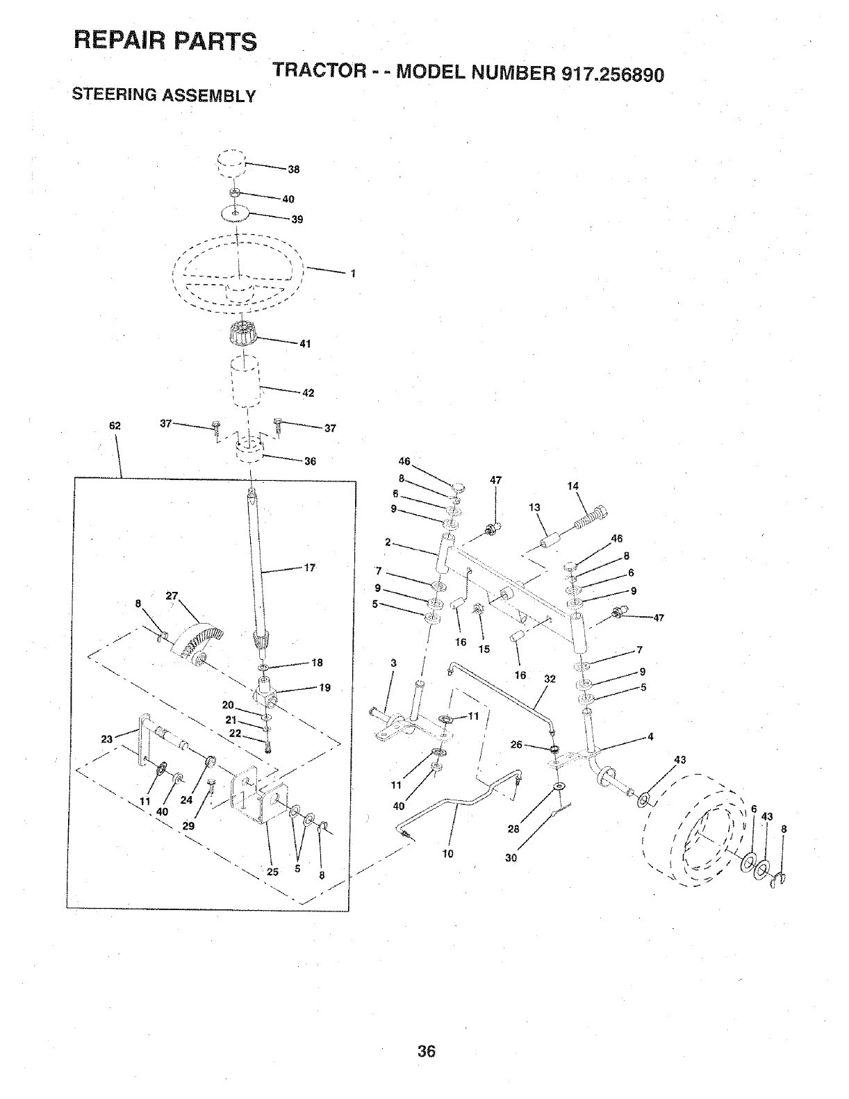
REPAIR PARTS
STEERING ASSEMBLY
TRACTOR - - MODEL NUMBER 917.256890
/.
/ •
62
_-_36
8 27.
J
%
29
j17
46_
47
|
f? j
J 10
J
14
13
28 /
/
30
t4
J
43
8
36
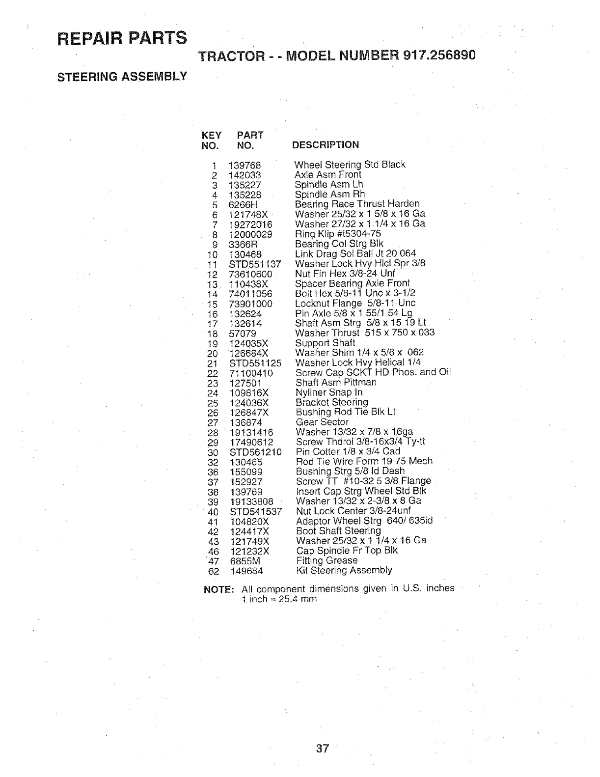
REPAIR PARTS
STEERING ASSEMBLY
TRACTOR = - MODEL NUMBER 917.256890
KEY PART
NO. NO. DESCRIPTION
1 139768
2 142033
3 135227
4 135228
5 6266H
6 121748X
7 19272016
8 12000029
9 3366R
10 130468
11 STD551137
12 73610600
13 110438X
14 74011056
15 73901000
16 132624
17 132614
18 57079
19 I24035X
20 126684X
21 STD551125
22 71100410
23 127501
24 109816X
25 124036X
26 126847X
27 136874
28 19131416
29 17490612
30 STD561210
32 130465
36 155099
37 152927
38 139769
39 19133808
40 STD541537
41 104820X
42 1244!7X
43 t21749X
46 121232X
47 6855M
62 149684
Wheel Steering Std Black
Axte Asm Front
Spindle Asm Lh
Spindle Asm Rh
Bearing Race Thrust Harden
Washer 25/32 x 1 5/8 x 16 Ga
Washer 27/32 x 11/4 x 16 Ga
Ring Kfip #t5304-75
Bearing Col Strg Blk
Link Drag Sol Bali Jt 20 064
Washer Lock Hvy Hlcl Spr 3/8
Nut Fin Hex 3/8-24 Unf
Spacer Bearing Axle Front
Bolt Hex 5/8-11 Uric x 3-1/2
Locknut Flange 5/8-1t Unc
Pin Axle 5/8 x 1 55/1 54 Lg
Shaft Asm Strg 5/8 x 15 19 Lt
Washer Thrust 515 x 750 x 033
Support Shaft
Washer Shim 1/4 x 5/8 x 062
Washer Lock Hvy Helical 1/4
Screw Cap SCKT HD Phos. and Oi
Shaft Asm Pittmar
Nyliner Snap In
Bracket Steering
Bushing Rod Tie Blk Lt
Gear Sector
Washer 13/32 x 7/8 x 16ga
Screw Thdrol 3/8-16x3/4 Ty-tt
Pin Cotter t/8 x 3/4 Cad
Rod Tie Wire Form t 9 75 Mech
Bushing Strg 5/8 Id Dash
Screw TT #10-32 5 3/8 Flange
Insert Cap Strg Wheel Std Blk
Washer 13/32 × 2-3/8 x 8 Ga
Nut Lock Center 3i8-24unf
Adaptor Wheel Strg 640/635id
Boot Shaft Steering
Washer 25/32 x 1 1/4 x 16 Ga
Cap Spindle Fr Top BIk
Fitting Grease
Kit Steering Assembly
NOTE: AI component dimensions given in U.S. inches
i inch = 25,4 mm
37
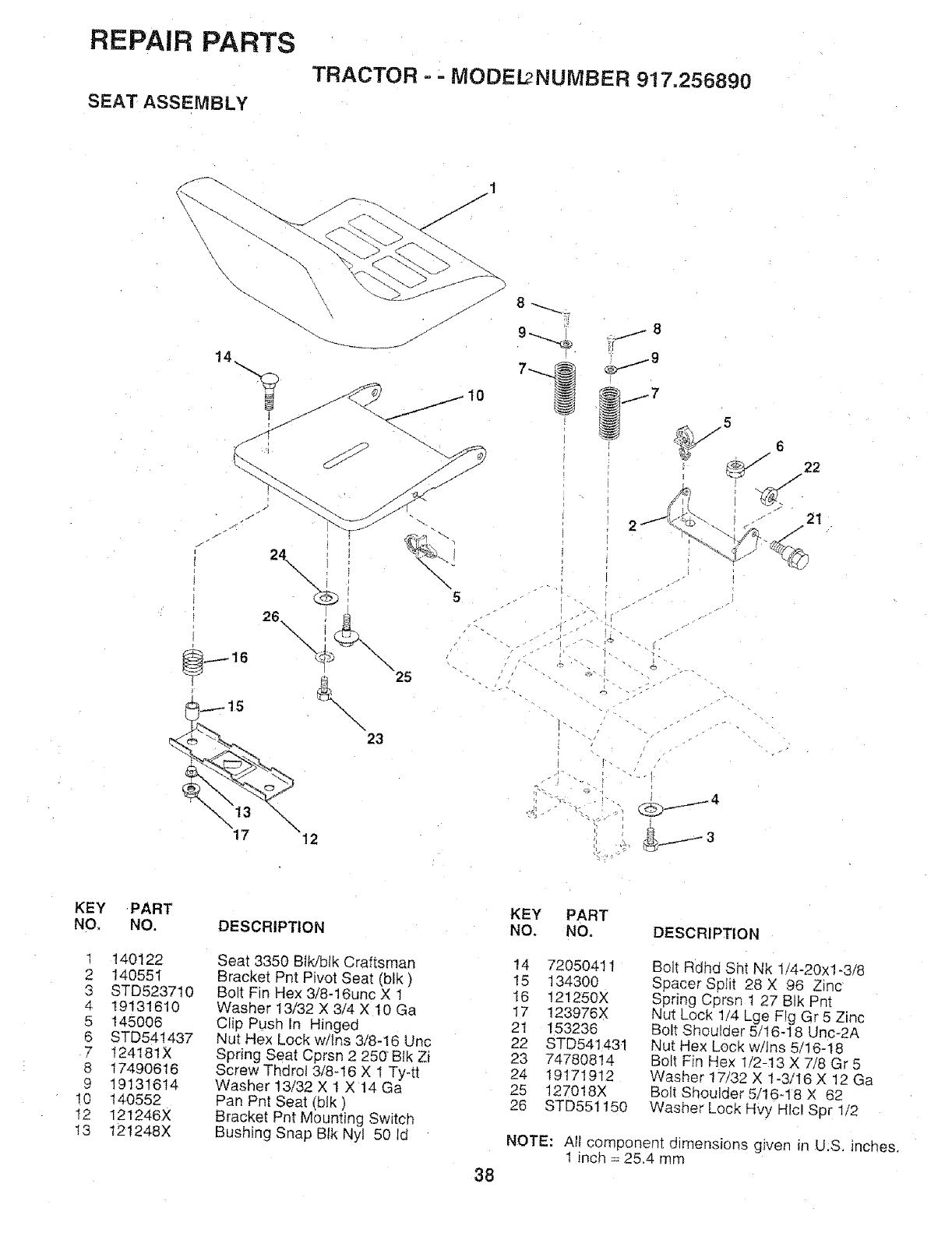
REPAIR PARTS
SEAT ASSEMBLY
TRACTOR --MODEL,2NUMSER 9!7.256890
&\\\23
"25
"5
_.j 8
.--9
z
21
KEY
NO.
!
2
3
4
5
6
7
8
9
!0
!2
13
PART
NO.
140122
140551
STD523710
19131610
145O06
STD541437
124181X
17490616
19131614
140552
12t246X
12!248X
DESCRIPTION
Seat 3350 Blldblk Craftsman
Bracket Pnt Pivot Seat (blk)
Bolt Fin Hex 3/8-16unc X 1
Washer 13/32 X 3/4 X 10 Ga
Clip Push In Hinged
Nut Hex Lock w/Ins 3/8-16 Uric
Spring Seat Cprsn 2 250 Blk Zi
Screw Thdrol 3/8-16 X 1 Ty4t
Washer 13/32 X I X 14 Ga
Pan Pnt Seat (blk)
Bracket Pnt Mounting Switch
Bushing Snap Btk Nyt 50 id
KEY PART
NO. NO. DESCRIPTION
14 7205O411
15 134300
16 121250X
17 123976X
21 153236
22 STD54143t
23 74780814
24 19171912
25 127018X
26 STD551150
Bolt Rdhd Sht Nk 114-20xl-3/8
Spacer Split 28 X 96 Zinc
Spring Cprsn 1 27 BIk Pnt
Nut Lock 1/4 Lge Fig Gr 5 Zinc
Bolt Shoulder 5/16-18 Unc-2A
Nut Hex Lock w/Ins 5/16-18
Bolt Fin Hex 1/2-13 X 7/8 Gr 5
Washer 17/32 X 1-3/I6 X 12 Ga
Bolt Shoulder 5/16-18 X 62
Washer Lock Hvy Hlcl Spr 1/2
NOTE: All component dimensions given in U.S, inches.
1 inch = 25.4 mm
38
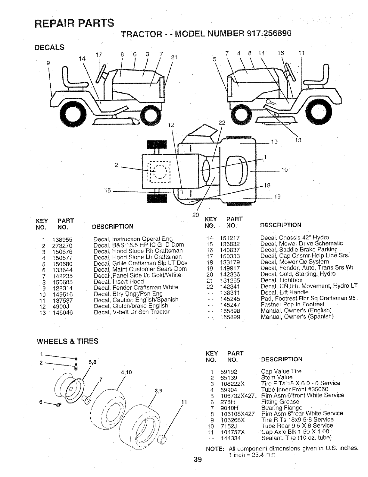
REPAIR PARTS
DECALS
t7
14
9
TRACTOR - -MODEL NUMBER 917.256890
6 3 7 7 4 8 14 16
21 5
/\\\
11
22
\
13
10
15
KEY PART
NO. NO.
1 138955
2 273270
3 150676
4 15O677
5 15068O
6 133644
7 142235
8 15O685
9 128314
10 149516
11 137537
12 4900J
13 146046
DESCRIPTION
Decal Instruction Operat Eng
Decal, B&S 15.5 HP IC G D Dom
Decal, Hood Slope Rh Craftsman
Decal, Hood Slope Lh Craftsman
Decai, Grille Craftsman SIo LT Dov
Decai, Maint Customer Sears Dora
Decal ,Panel Side lic Gold/White
Decal. Insert Hood
Decal. Fender Craftsman White
Decal, Btry DngriPsn Eng
Decal, Caution English/Spanish
Decal, Clutch!brake English
Decal, V-belt Dr Sch Tractor
20 KEY
NO.
PART
NO.
14 151217
15 136832
I6 14O837
I7 150333
18 133179
t9 149917
20 142336
2t 131265
22 142341
-- 138311
-- 145245
-- 145247
-- 155898
-- 155899
DESCRIPTION
Decal, Chassis 42" F4ydro
Decal_ Mower Drive Schematic
Decal Saddle Brake Parking
Decal Cap Cnsmr Help Line Srs.
Decal Mower Qc System
Decal Fender, Auto, Trans Srs Wt
Decal Cold, Starting, Hydro
Decal Lightbox
Decal CNTRL Movement. Hydro LT
Decat Lift Handle
Pad, Footrest Rbr Sq Craftsman 95
Fastner Pop In Footrest
Manual, Owner's (English)
Manual, Owner's (Spanish)
WHEELS &TIRES
5,8
4,t0
7/
11
39
KEY PART
NO. NO. DESCRIPTION
1 59192
2 65139
3 106222X
4 59904
5 t06732X427.
6 278H
7 9040H
8 106t08X427
9 106268X
10 7152J
11 104757X
-- 144334
Cap Value Tire
Stem Value
Tire F Ts 15 X 6 0 - 6 Service
Tube Inner Front #35060
R m Asm 6"front White Service
Fitting Grease
Bearing Flange
Rim Asm 8"rear White Service
Tire R Ts 18x9 5-8 Service
Tube Rear 9 5 X 8 Service
Cap Axle BIk 1 50 X I 00
Sealant, Tire (10 oz. tube)
NOTE: All component dimensions given in U.S, inches.
1 inch = 25°4 mm
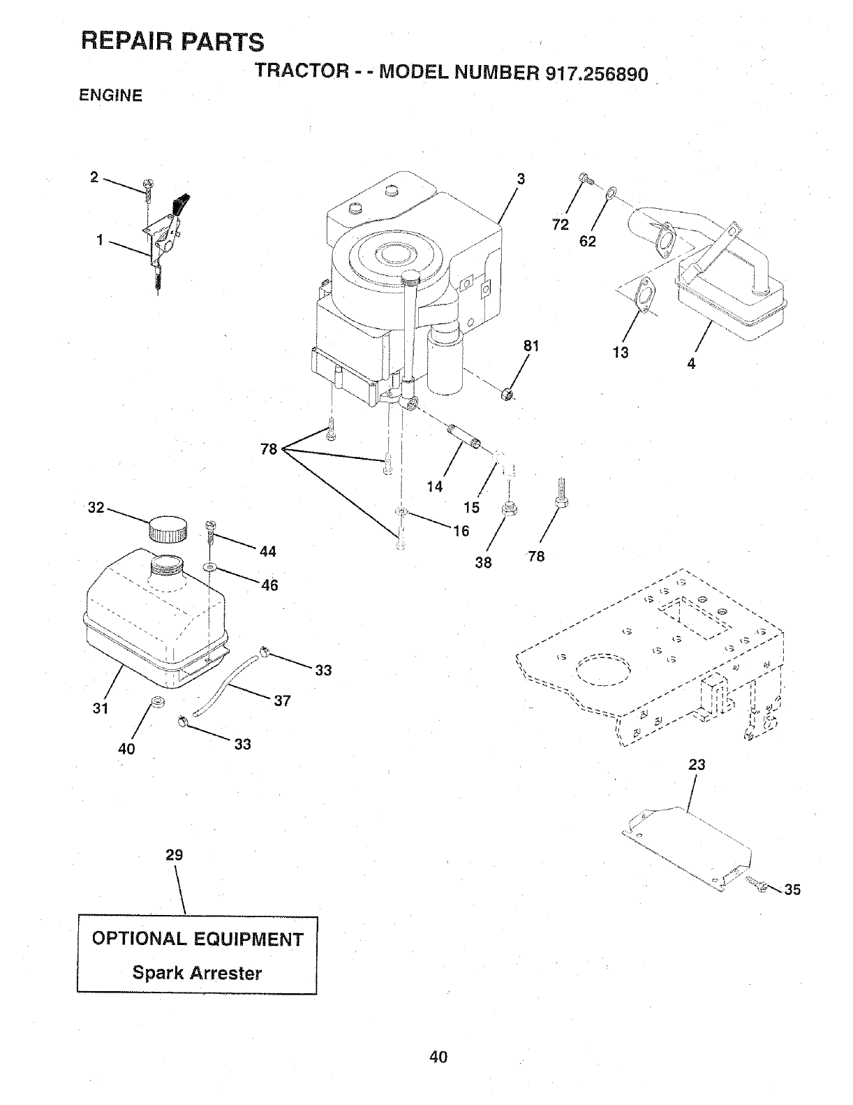
REPAIR PARTS
TRACTOR - -MODEL NUMB ER 917.256890
ENGINE
81
/
72 62
/
/
/
13
/
/
4
/
31
33
78
23
I
29
\\
OPTIONAL EQUIPMENT
Spark Arrester
40
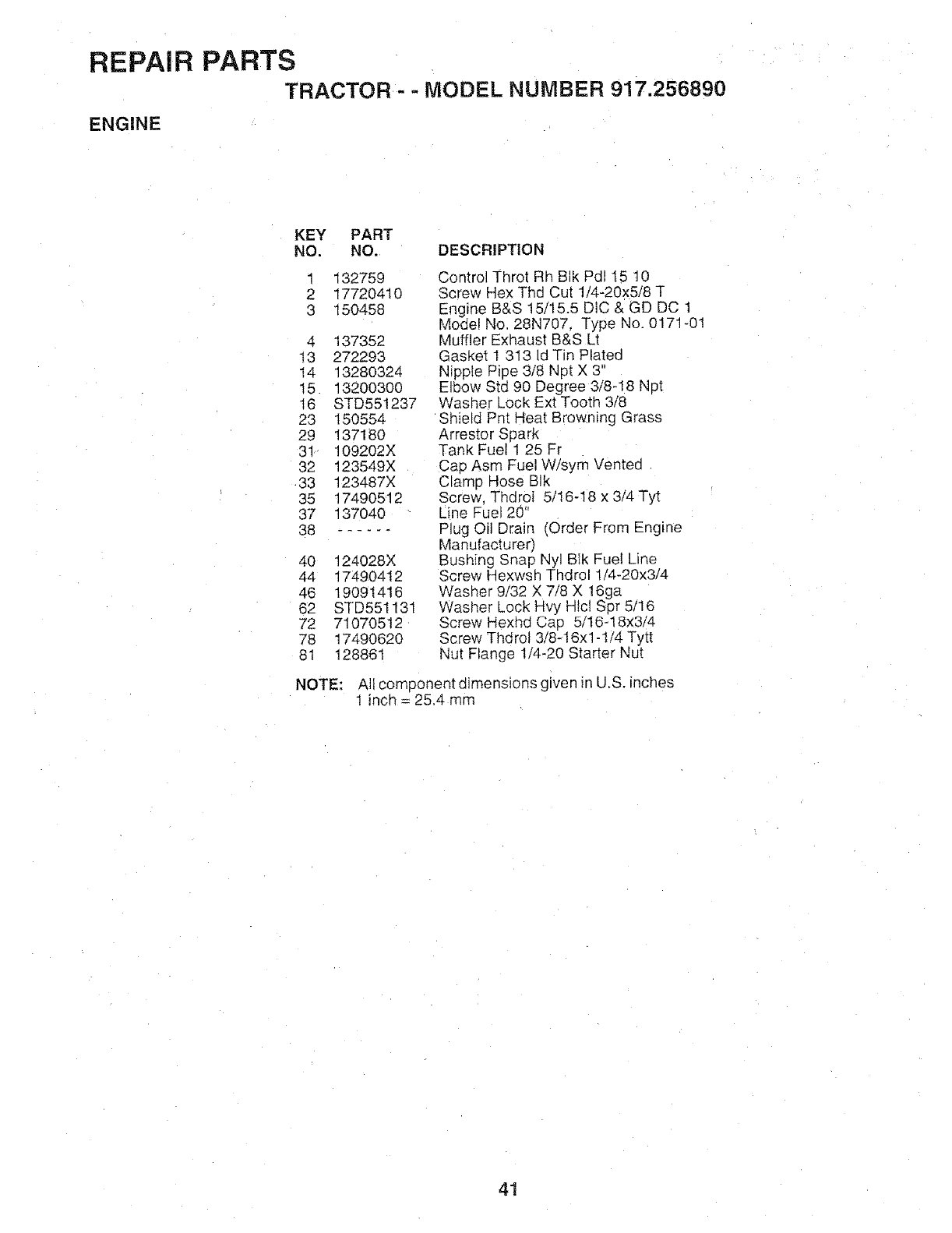
REPAIR PARTS
TRACTOR -- MODEL NUMBER 917.256890
ENGINE
KEY PART
NO. NO. DESCRiPTiON
1
2
3
132759
17720410
150458
4 137352
13 272293
t4 13280324
15 13200300
16 STD551237
23 150554
29 137180
31 109202X
32 123549X
33 123487X
35 17490512
37 137040
38 ......
40 124028X
44 17490412
46 19091418
62 STD551131
72 71070512
78 17490620
81 128861
Control Throt Rh BIk Pd115 10
Screw Hex Thd Cut 1/4-20x5/8 T
Engine B&S 15/15.5 DlC & GD DC 1
Model No. 28N707 Type No, 0171-01
Muffler Exhaust B&S Lt
Gasket 1 313 Id Tin Plated
Nipple Pipe 3/8 Npt X 3"
Elbow Std 90 Degree 3/8-18 Npt
Washer Lock Ext Tooth 3/8
Shield Pnt Heat Browning Grass
Arrestor Spark
Tank Fuel 1 25 Fr
Cap Asm Fuel Wisym Vented
Clamp Hose BIk
Screw, ThdroI 5/16-18 x 3/4 Tyt
Line Fuel 20"
Plug Oil Drain (Order From Engine
Manufacturer)
Bushing Snap Nyl Blk Fue! Line
Screw Hexwsh Thdrol 1/4-20x314
Washer 9/32 X 718 X 16ga
Washer Lock Hvy Hlcl Spr 5/16
Screw Hexhd Cap 5/16-18x314
Screw Thdrol 3/8-16xl -t14 Tytt
Nut Flange 1/4-20 Starter Nut
NOTE: All component dimensions given in U.S. inches
! inch = 25.4 mm
41
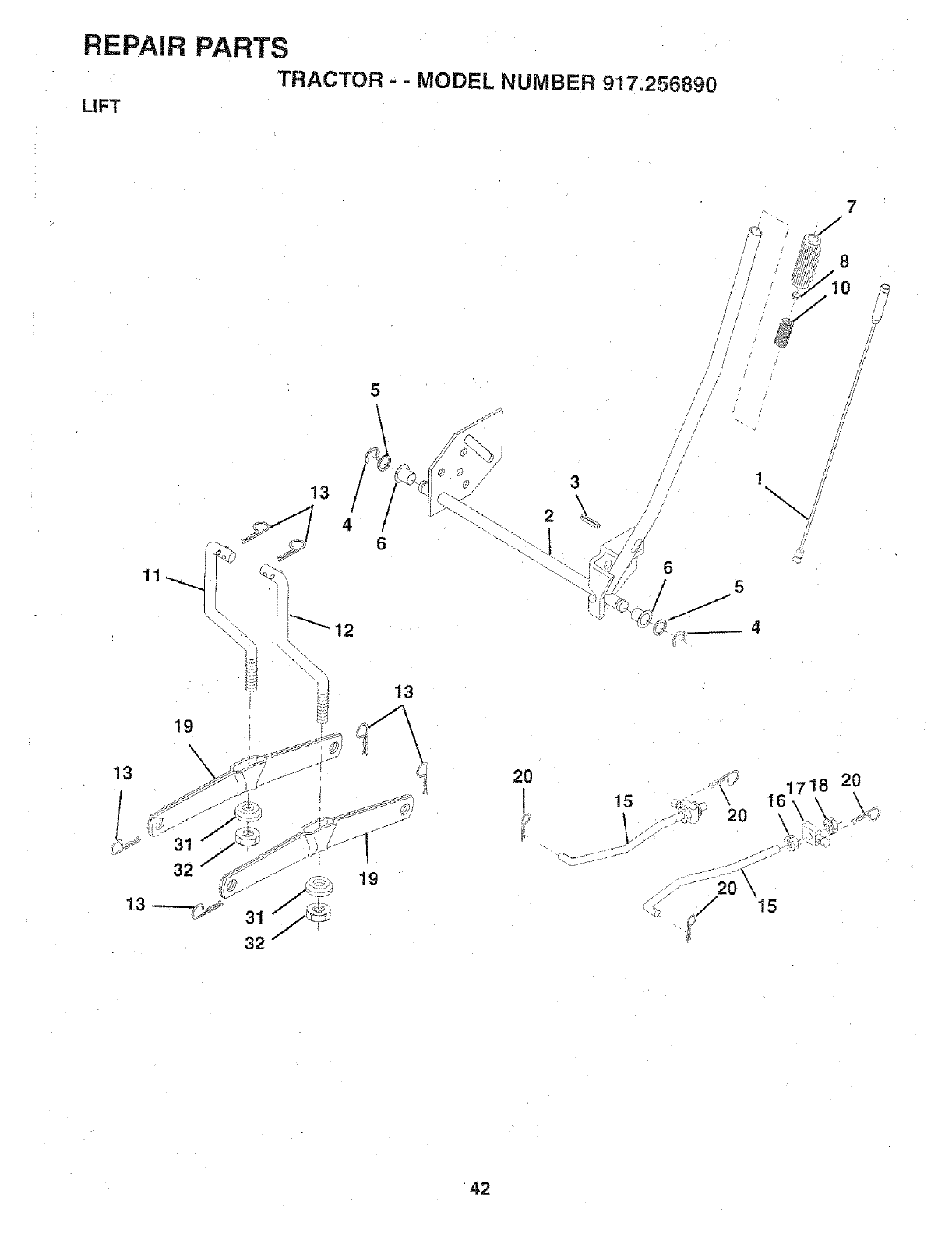
REPAIR PARTS
TRACTOR - -MODEL NUMBER 917.256890
LIFT
7
/
19
\
5
13 _. 3
31
32 7
13
19
6
2O
15
I-
%.
\
\
1718 20
42
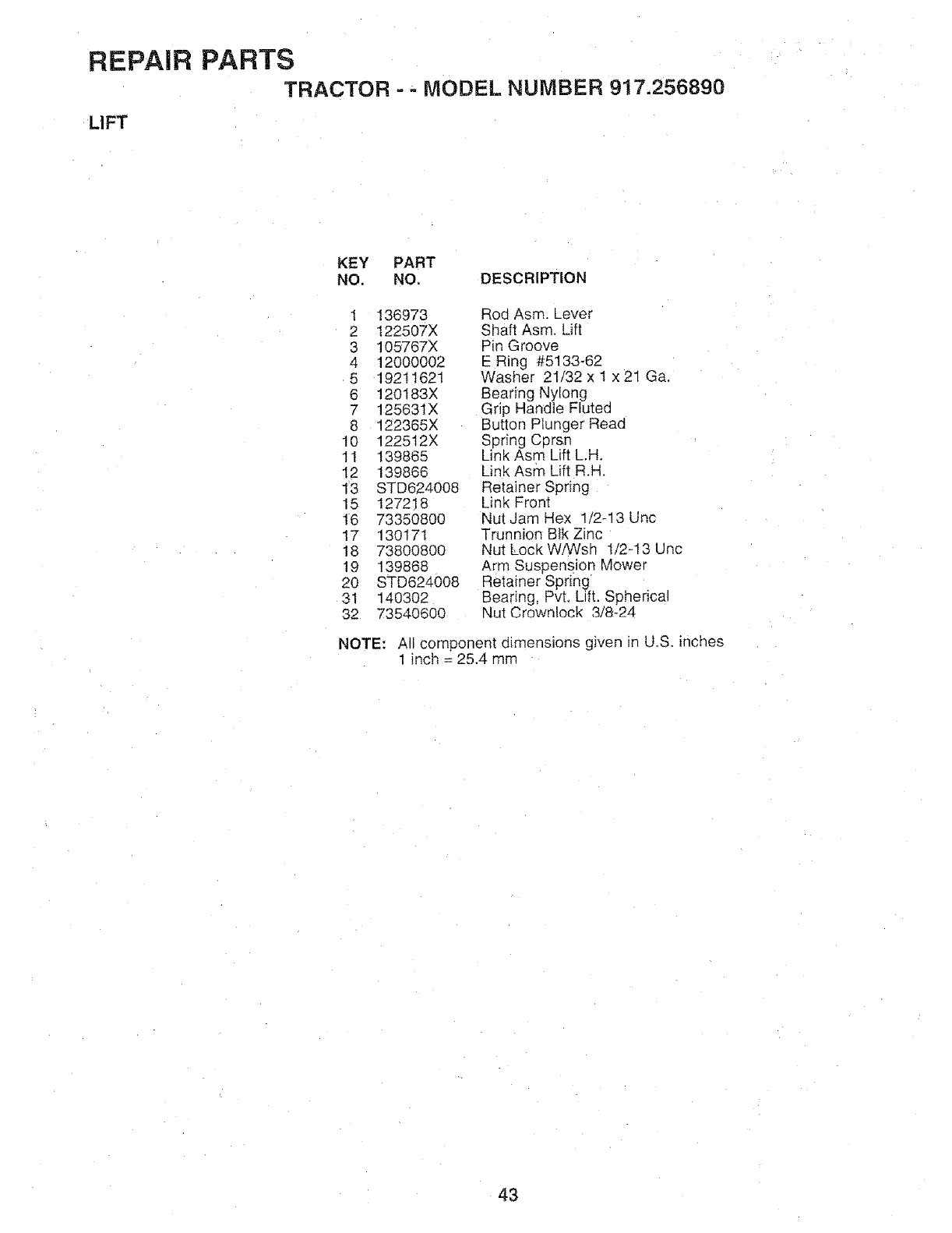
REPAIR PARTS
TRACTOR = - MODEL NUMBER 917.256890
LIFT
KEY PART
NO, NO, DESCRIPTION
1 136973 Rod Asm. Lever
2 122507X Shaft Asm. Lift
3 105767X Pin Groove
4 12000002 E Ring #5133-62
5 19211621 Washer 21/32 x 1 x21 Ga.
6 120183X Bearing Nylong
7 12563IX Grip Handle _luted
8 122365X Button Plunger Read
10 122512X Spring Cprsn
11 139865 Link Asm Lift L.H.
12 139866 Link Asm Lift R.H.
13 STD624008 Retainer Spring
15 127218 Link Front
16 73350800 Nut Jam Hex 1/2-13 Unc
17 130171 Trunnion Blk Zinc
18 73800800 Nut LockWiWsh 1/243 Unc
19 139868 Arm Suspension Mower
20 STD624008 Retainer Spring
31 140302 Bearing, Pvt. Lift. Spherical
32 73540600 Nut Crownlock 3/8-24
NOTE: All component dimensions given in U.S. inches
1 inch = 25.4 mm
43
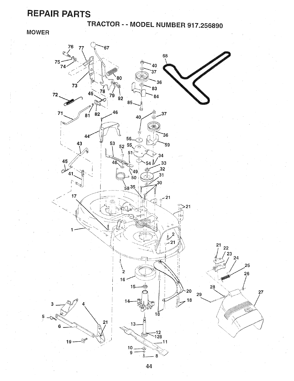
REPAIR PARTS
TRACTOR - - MODEL NUMBER 917.256890
MOWER
.33
32
3t
30
4\\
6
\
\2t
, \2
16
21
5_/ 24
28
27
/
44
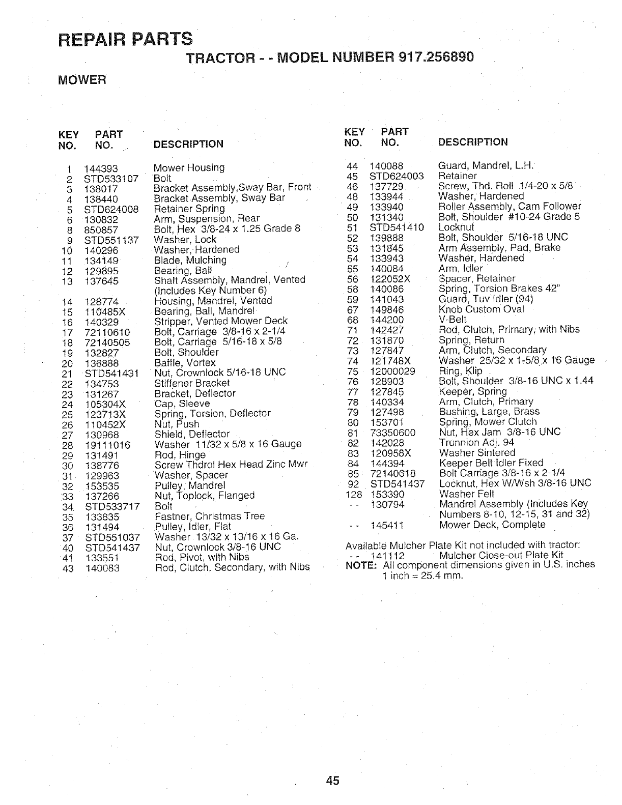
REPAIR PARTS
TRACTOR - - MODEL NUMBER 917.256890
MOWER
KEY PART KEY PART
NO, NO. DESCRIPTION NO, NO. DESCRIPTION
1 144393
2 STD533107
3 138017
4 138440
5 STD624008
6 130832
8 850857
9 STD551137
10 140296
11 134149
t2 129895
13 137645
14 128774
I5 110485X
I6 140329
17 7211O610
18 72140505
19 132827
20 136888
21 STD541431
22 134753
23 131267
24 105304X
25 123713X
26 1t0452X
27 130968
28 19111016
29 131491
30 138776
31 129963
32 153535
33 137266
34 STD533717
35 133835
36 131494
37 STD55t037
40 STD541437
41 133551
43 140083
Mower Housing 44 140088
Bolt 45 STD624003
Bracket Assembly,Sway Bar. Front 46 137729
Bracket Assembly, Sway Bar 48 I33944
Retainer Spring 49 133940
Arm, Suspension, Rear 50 131340
Bolt. Hex 3/8-24 x 1.25 Grade 8 51 STD541410
Washer. Lock 52 139888
Washer. Hardened 53 131845
Blade, Mulching 54 133943
Bearing, Bat1 55 140084
Shaft Assembly, Mandrel, Vented 56 122052X
(Includes Key Number 6) 58 140086
Housing, Mandrel. Vented 59 141043
Bearing, Ball, Mandrel 67 149846
Stripper, Vented Mower Deck 68 144200
Bolt, Cardage 3/8-16 x 2-1/4 71 142427
Bolt. Carriage 5/16-18 x 5/8 72 131870
Bolt, Shoulder 73 127847
Baffle, Vortex 74 121748X
Nut, Crownlock 5/16-18 UNC 75 12000029
Stiffener Bracket 76 128903
Bracket. Deflector 77 127845
Cap, Sleeve 78 140334
Spring, Torsion. Deflector 79 127498
Nut. Push 80 153701
Shield, Deflector 81 73350600
Washer 11/32 x 5/8 x 16 Gauge 82 142028
Rod, Hinge 83 120958X
Screw ThdroI Hex Head Zinc Mwr 84 144394
Washer, Spacer 85 72140618
Pulley, Mandrel 92 STD541437
Nut, Toplock. Flange(] 128 153390
Bott - - 130794
Fastner, Christmas Tree
Pulley, Idler. Ftal - - 14541l
Washer 13/32 x I3/16 x 16 Ga,
Nut, Crownlock 3/8-16 LJNC
Rod. Pivot, with Nibs
Rod, Clutch. Secondary, with Nibs
Guard, Mandrel, LH.
Retainer
Screw. Thd. Roll t/4-20 x 5/8
Washer, Hardenec
Rol er Assembly, Cam Follower
Boll. Shoulder #10-24 Grade 5
Locknut
Bolt, Shoulder 5/16-18 UNC
Arm Assembly, Pad, Brake
Washer, Hardened
Arm. Idler
Spacer. Retainer
Spring, Torsion Brakes 42"
Guard, Tuv Idler (94)
Knob Custom Oval
V-Belt
Rod Clutch, Primary, with Nibs
Spring, Return
Arm. Clutch, Secondary
Washer 25/32 x 1_5/8 x 16 Gauge
Ring, Klip
Bolt, Shoulder 3/8q6 UNC x 1.44
Keeper, Spring
Arm, Clutch, Primary
Bushing, Large, Brass
Spring, Mower Clutch
Nut, Hex Jam 3/8-16 UNC
Trunnion Adj. 94
Washer Sinte red
Keeper Belt Idler Fixed
Bolt Carriage 3/8-16 x 2-1/4
Locknut. Hex WiWsh 3/8-16 UNC
Washer Felt
Mandrel Assembly (Includes Key
Numbers 8-I0, 12-15, 31 and 32)
Mower Deck, Complete
AvailabIe Mulcher Plate Kit not included with tractor:
-- 141112 MulcherClose-out Plate Kit
NOTE: All component dimensions given in U.S. inches
1 inch = 25.4 mm
45
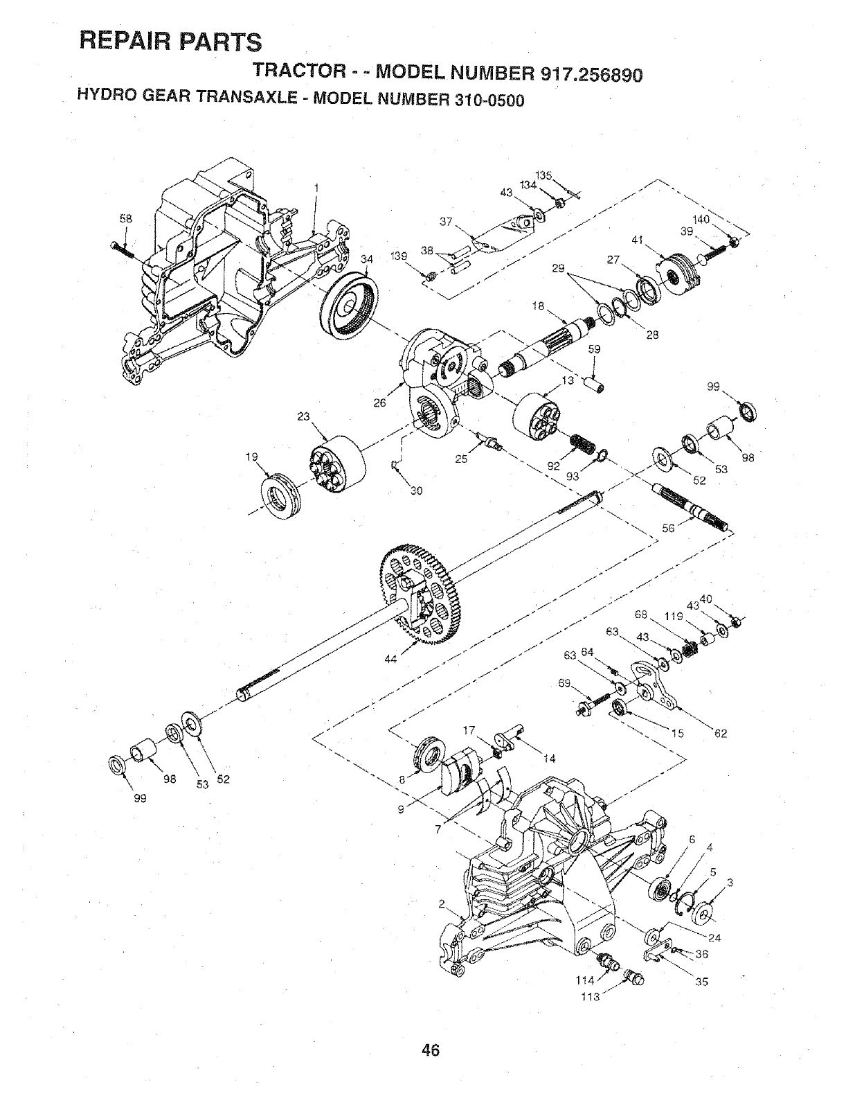
REPAIR PARTS
TRACTOR - =MODEL NUMBER 917.256890
HYDRO GEAR TRANSAXLE -MODEL NUMBER 310-0500
!35
58 37
34 139
J
26
23
\3O
99
18 `%
59
17
7
2
14
6 4.
/
/53
/
114 .35
113 1
46
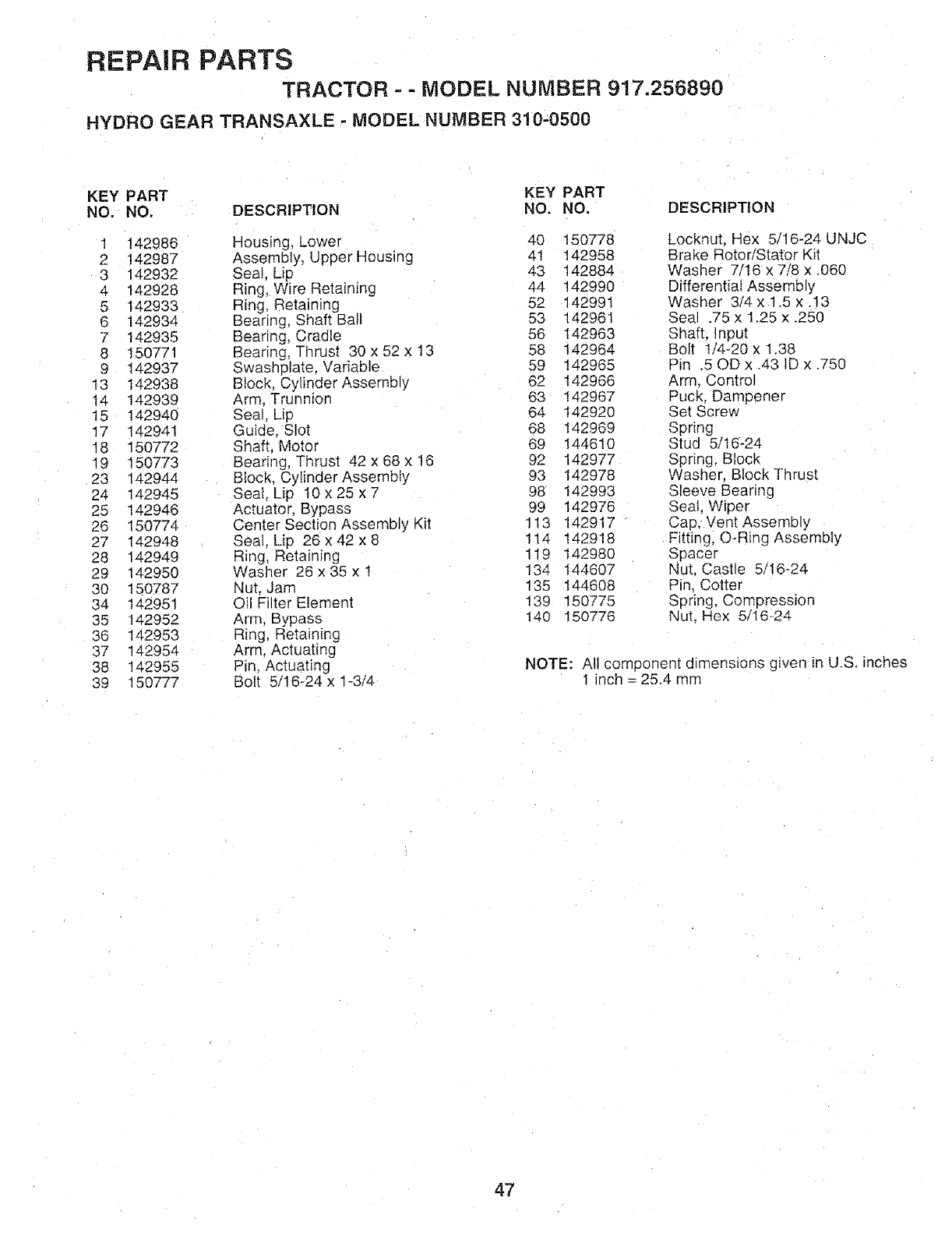
REPAIR PARTS
TRACTOR - -MODEL NUMBER 917.256890
HYDRO GEAR TRANSAXLE . MODEL NUMBER 310-0500
KEY PART KEY PART
NO. NO, DESCRIPTION NO. NO. DESCRIPTION
1 142986 Housing, Lower 40 150778 Locknut. Hex 5/16-24 UNJC
2 142987 Assembly, Upper Housing 41 142958 Brake RotoriStator Kit
3 142932 Sea1, Lip 43 142884 Washer 7/16 x7/8 x .060
a 142928 Ring, Wire Retaining 44 142990 Differentiaf Assembly
5 142933 Ring, Retaining 52 142991 Washer 3/4 x 1.5 x .!3
6 142934 Bearing, Shaft Ball 53 142961 Seal .75 x 1.25 x .250
7 142935 Bearing, Cradle 56 142963 Shaft. input
8 150771 Bearing, Thrust 30 x 52 x 13 58 142964 Bolt 1/4-20 x t.38
9 142937 Swashptate Variable 59 142965 Pin .50D x .43 ID x .750
13 142938 Block, Cylinder Assembly 62 142966 Arm. Control
14 142939 Arm, Trunnion 63 142967 Puck. Dampener
15 142940 Sea, Lip 64 142920 Set Screw
17 142941 Guide, Slot 68 142969 Spring
18 150772 Shaft. Motor 69 144510 Stud 5/16-24
19 150773 Bearing, Thrust 42 x 68 x 16 92 142977 Spring, Block
23 142944 Block, Cylinder Assembly 93 142978 Washer. Biock Thrust
24 142945 Seal Lip 10 x 25 x 7 98 142993 Sleeve Bearing
25 142946 Actuator, Bypass 99 142976 Seat, Wiper
26 150774 Center Section Assembly Kit 113 142917 Cap, Vent Assembly
27 142948 Seal. Lip 26 x 42 x 8 114 142918 Fitting, O-Ring Assembly
28 142949 Ring, Retaining 119 142980 Spacer
29 142950 Washer 26 x 35 x I 134 144607 Nut. Castle 5/16-24
30 150787 Nut. Jam 135 t44608 Pin. Cotter
34 142951 ©il Filter Eiemenl 139 150775 Spring, Compression
35 142952 Arm. Bypass 140 150776 Nut. Hex 5/16=24
36 142953 Ring, Retaining
37 142954 Arm. Actuating
38 142955 Pin. Actuating NOTE: All component dimensions given in U,S. inches
39 150777 Bolt 5/16-24 x 1-3/4 1 inch = 25.4 mm
47
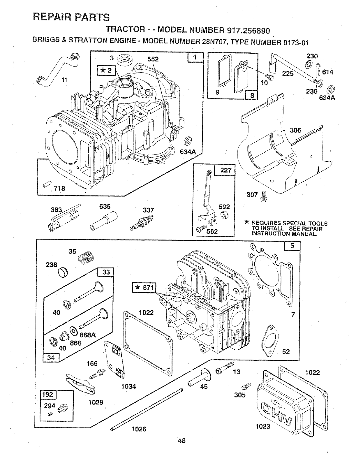
REPAIR PARTS
TRACTOR - - MODEL NUMBER 917.256890
BRIGGS &STRATTON ENGINE - MODEL NUMBER 28N707, TYPE NUMBER 0t73-01
635 337 @
306
REQUIRES SPECIAL TOOLS
TO INSTALL. SEE REPAIR
iNSTRUCTION MANUAL.
35
238 @
_022
40 868 16d_
_ 1034
1029
1026
022
48
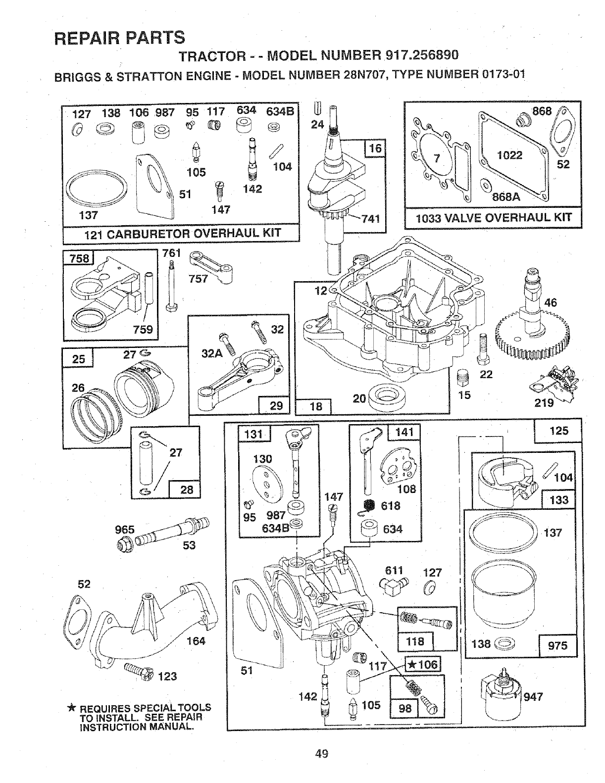
REPAIR PARTS
TRACTOR --MODEL NUMBER 917.256890
BRIGGS & STRATTON ENGINE o MODEL NUMBER 28N707, TYPE NUMBER 0173,01
127 138 10698-/ 95 117 634 634B
105 104
<ID, o, '=
137' 147
121 CARBURETOR OVERHAUL KiT
1033 VALVE OVERHAUL KIT
_!23
REQUIRES SPEC|AL TOOLS
TO INSTALL. SEE REPAIR
INSTRUCTION MANUAL.
142
L _ 105
611 127
46
49
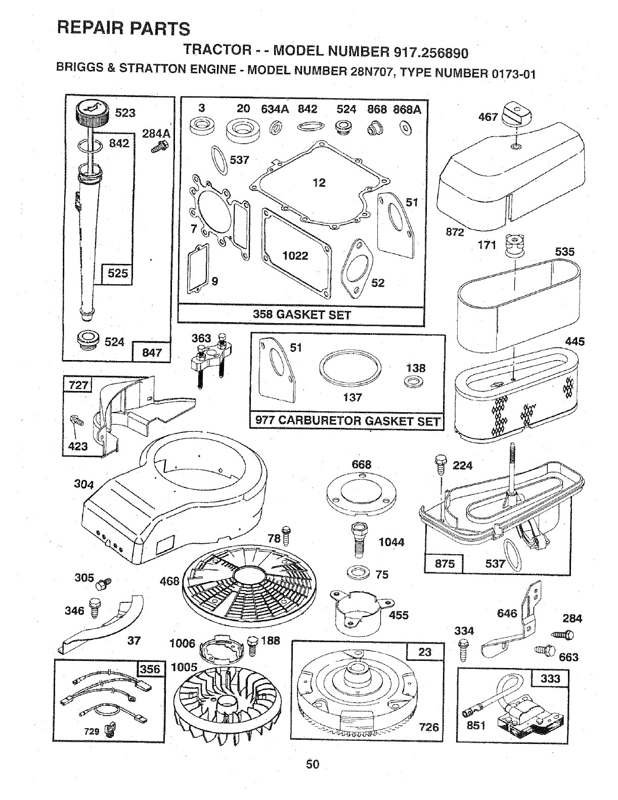
REPAIR PARTS
TRACTOR -- MODEL NUMBER 917.256890
BR1GGS & STRATTON ENGINE - MODEL NUMBER 28N707, TYPE NUMBER 0173-01
523
_524
3 20 634A 842 524 868 868A
537
_i 1 137
138
©)
977 CARBURETOR GASKET SET
467
171 535
304
305_
346
37
729
• . .... =
468
1006
668 _224
78
5O
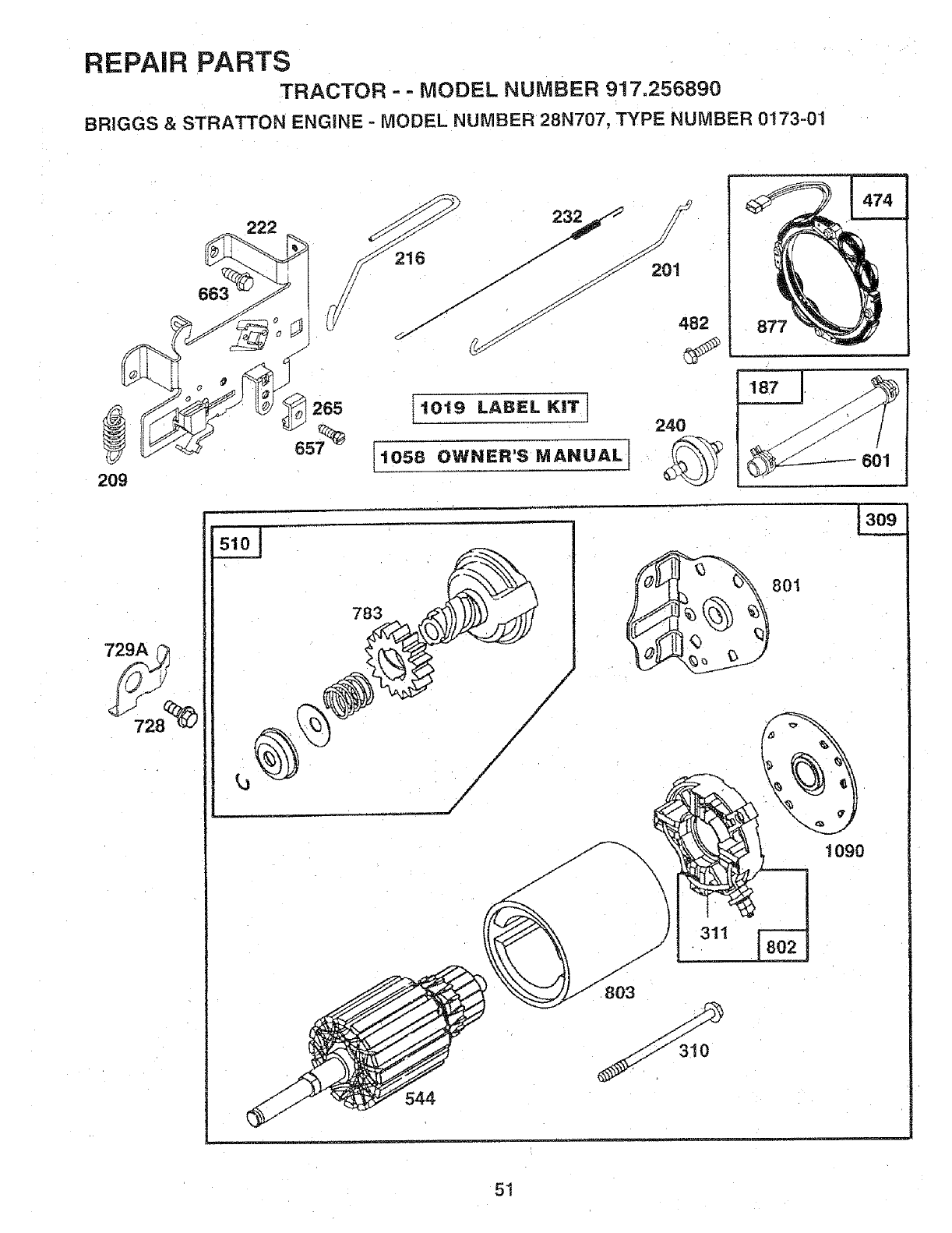
REPAIR PARTS
TRACTOR - = MODEL NUMBER 9!7=256890
BRIGGS & STRATTON ENGINE - MODEL NUMBER 28N707, TYPE NUMBER 0173o01
663
209
265 1019 LABEL KIT] 240
[1058 OWNER'S MANUALI
877
187 j
601
783
J
J
801
\\
311
j-
1090
51
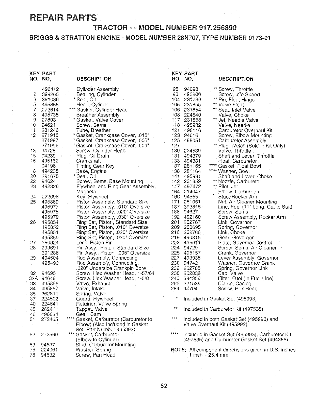
REPAIR PARTS
TRACTOR --MODEL NUMBER 917.256890
BRIGGS &STRATTON ENGINE - MODEL NUMBER 28N707, TYPE NUMBER 0173-01
KEY PART KEY PART
NO. NO, DESCRIPTION NO. NO. DESCRIPTION
1 496412
2399265
3 391086
5 495858
7272614
8 495735
927803
10 94621
11 281246
12 271916
271997
271996
13 94728
15 94239
16 495162
94196
18 494238
20 291675
22 94624
23 492326
24 222698
25 495860
495977
495978
495979
26 495854
495852
495851
495855
27 260924
28 299691
391286
29 494504
495490
32 94695
32A 94648
33 495856
34 495857
35 262811
37 224502
40 224641
45 262411
46 496884
5t 272465
52 272569
53 94637
75 224061
78 94832
Cylinder Assembly 95 94098
Bearing, Cylinder 98 495800
*Seal, Oil 104 231789
Head, Cylinder I05 231855
*** Gasket, Cylinder Head !06 231854
Brealher Assembly 108 224540
Gasket. Valve Cover 117 231858
Screw, Seres 118 495932
Tube, Breather 12! 498116
* Gasket, Crankcase Cover, .0!5" 123 94616
*Gasket, Crankcase Cover, .005" !25 498051
"Gasket, Crankcase Cover .009" 127 - - -
Screw, Cylinder Head 130 224539
Plug, Oil Drain 131 494379
Crankshaft 133 494381
Timing Gear Key I37 281165
Base. Engine !38 281164
* Seal_ Oil 14t 495931
Screw, Seres, Base Mounting 142 231859
Flywheel and Ring Gear Assembly, 147 497472
Magne[o t64 214047
Key, Flywheel 166 94555
Piston Assembly, Standard Size 171 281051
Piston Assembly, .010" Oversize 187 393815
Piston Assembly, .020".Oversize 188 94627
Piston Assembly, .030" Oversize 192 492160
Ring Set, Piston. Standard Size 201 262767
Ring Set, Piston..010" Oversize 209 260695
Ring Set, Piston, .020" Oversize 216 262766
Ring Set, Piston, .030" Oversize 219 490815
Lock, Piston Pin 222 495611
Pin Assy., Piston, Standard Size 224 94729
Pin Assy., Piston..005" Oversize 225 495157
Rod Assembly, Connecting 227 493935
Rod Assembly, Connecting, 230 94742
.020" Undersize Crankpin Bore 232 262785
Screw. Hex Washer Head. 1-57/64 238 262836
Screw. Hex Washer Head. 1-5/8 240 394358
Valve, Exhaust 265 221535
Valve. lntake 284 94704
Spring, Valve
Guard. Flywheel
Retainer, Valve Spring
Tappet, VaNe
Gear, Cam
.... Gasket. Carburetor (Carburetor to
Elbow) (Also included Jn Gasket
Set. Part Number 495993)
*** Gasket Carburetor
(Elbow to Cylinder)
Stud. Carburetor Mounting
Washer. Spring
Screw. Pan Head
** Screw, Throttle
Screw, Idle Speed
** Pin, Float Hinge
** Valve Float
** Seat. Inlet VaNe
Valve, Choke
"" Jet, Needle Valve
Valve. Needle
Carburetor Overhaul Kit
Screw, Elbow Mounting
Carburetor Assembly
"" Plug, Welch (Sold in Kit Only)
Valve, Throttle
Shaft and Lever, Throttle
Float, Carburetor
.... Gasket, Float Bowl
.... Washer, Bowl
Shaft and Lever. Choke
** NozzIe. Carburetor
** Pilot. Jet
EIbow, Carburetor
Stud. Rocker Arm
Nut, Air Cleaner Mounting
Line. Fue_ (11" Long, Cut to Suit)
Screw, Seres
Screw Assembly, Rocker Arm
Link. Governor
Spring, Governor
Link, Choke
Gear. Governor
Plate, Governor Control
Screw, Sems, Air Cleaner
Crank. Governor
Lever Assembly, Governor
Washer. Governor Crank
Spring, Governor Link
Cap, Valve
Filter Fuet (in Fue! Line)
Clamp, Casing
Screw. Hex Head
Included in Gasket Set (495993)
** Included in Carburetor Kit (497535)
*** Included in both Gasket Set (495993) and
Valve Overhaul Kit (495992)
.... Included in Gasket Set (495993), Carburetor Kit
(497535) and Carburetor Gasket Set (494385)
NOTE: All component dimensions given m U.S. inches
t inch = 25.4 mm
52
REPAIR PARTS
TRACTOR --MODEL NUMBER 917.256890
BRIGGS & STRATTON ENGINE -MODEL NUMBER 28N707, TYPE NUMBER 0173-01
KEY PART KEY PART
NO. NO. DESCRIPTION NO. NO, DESCRIPTION
284A 94073 Screw. Hex Head 729A 225170 Retainer. Wire
294 810068 Screw. Set 741 262932 Gear. Timing
304 496280 Housing, Blower 757 213998 Link, Counterweight
305 94786 Screw. Hex, Head, 758 39989.1 Counterweight Assembly
BIower Housing Mounting 759 298909 Pin. Counterweight
306 225020 Shield. Cylinder 761 94593 Screw, Counterweight
307 94386 Screw, Cylinder Shield 783 280104 Gear. Starter
309 497595 Motor, Starter 801 394856 Cap, Drive
310 497602 Bolt. Thru 802 497605 Cap, End
311 497608 Brush Sel 803 497604 Housing, Starter
333 495859 Armature. Magneto 842 270920 * Seal. Oil Filler Ca3
334 93381 Screw Sems, Armature Mounting 847 496415 Fil_ Group, Oil
337 491055 Plug, Spark 85l 224110 Terminal. Ignition Cable
346 93705 Screw Hex Head 868 494435 _* Seal Assembly, Valve
356 497708 Wire Assembly 868A 272610 '** Gasket Valve
358 495993 Gasket Set 871 262835 Bushing, Guide (Intake & Exhaust)
363 19203 Puller Fiywheet 872 281361 Cover. Air Cleaner
383 89838 Wrench Spark Plug 875 495862 Body, Air Cleaner
423 94073 Screw, Sems 877 393456 Diode and Connector Assembly
445 493909 Cartridge Air Cleaner 947 497157 Solenoid
455 222561 Cup, Screen Mounting 965 94010 Nut, Hex
467 493903 Knob. Air Cleaner 975 495933 Bowl Assembly, Carburetor
468 494439 Screen. Flush Rotating 977 494385 Carburetor Gasket Set
474 393474 Stator. Alternator 987 281166 -- Seal Throttle Shaft
482 93621 Screw, Sems 1005 281400 Fan. Flywheel
510 497606 Drive, Starter 1006 224413 Retainer. Fan
523 495230 Cap and Dipstick. Oil Filler 1019 496758 Label Kit
524 68838 _ Seal FiIIer Tube t022 272475 _** Gasket, Cover
525 496113 Tube. Oit Filler 1023 224552 Cover, Rocker Arm
535 272403 Element, Fil.ter 1026 494432 Rod. Push, Intake
537 281106 *O-Ring, AirCleaner 495136 Rod, Push. Exhaust
544 497603 Armature. Starter t029 224554 Arm. Rocker
552 231597 Bushing, Governor Crank 1033 495992 Valve Overhaul Kit
562 92613 Bolt. Carriage 1034 495248 Guide Assembly, Push Rod
592 231082 Nut, Hex 1044 94673 Screw, Hex Head
601 93053 Clamp, Fuel Pipe 1054 270723 Tie, Cabfe
611 493496 Elbow, Fuet Pipe 1058 272623 Manual. Owner's
614 93306 Pin, Cotter I090 497607 Retainer. Brush
618 262803 Spring, Choke Return
634 281168 *_ Seal. Choke Shaft RPM Settings: Low: 1650-1850. High: 3200-3400
634A 491323 * Seal, Governor
634B 281167 ** Washer. Throttle Shaft Included in Gasket Set (495993)
635 280872 Boot. Spark Plug
646 224546 Brace. Air Cleaner "" Included _nCarburetor Kit _497535)
657 93496 Screw Sems
663 94620 Screw. Self-Tapping *- Included in both Gasket Set (495993] and
668 280848 Spacer Valve Overhaul Kit [495992)
718 230192 Pin, Dowel
726 392134 Gear. Ring .... Included in Gasket Set (495993), Carburetor Kit
(lnc,udes Mounting Hardware) (497535) and Carburetor Gasket Set {494385)
727 490324 Cover, Starter
728 94627 Screw, Hex Head NOTE: All component dimensions gwen _nU.S. inches
729 281390 Clip, Wire 1 inch = 25.4 mm
53

SERVICE NOTES
54
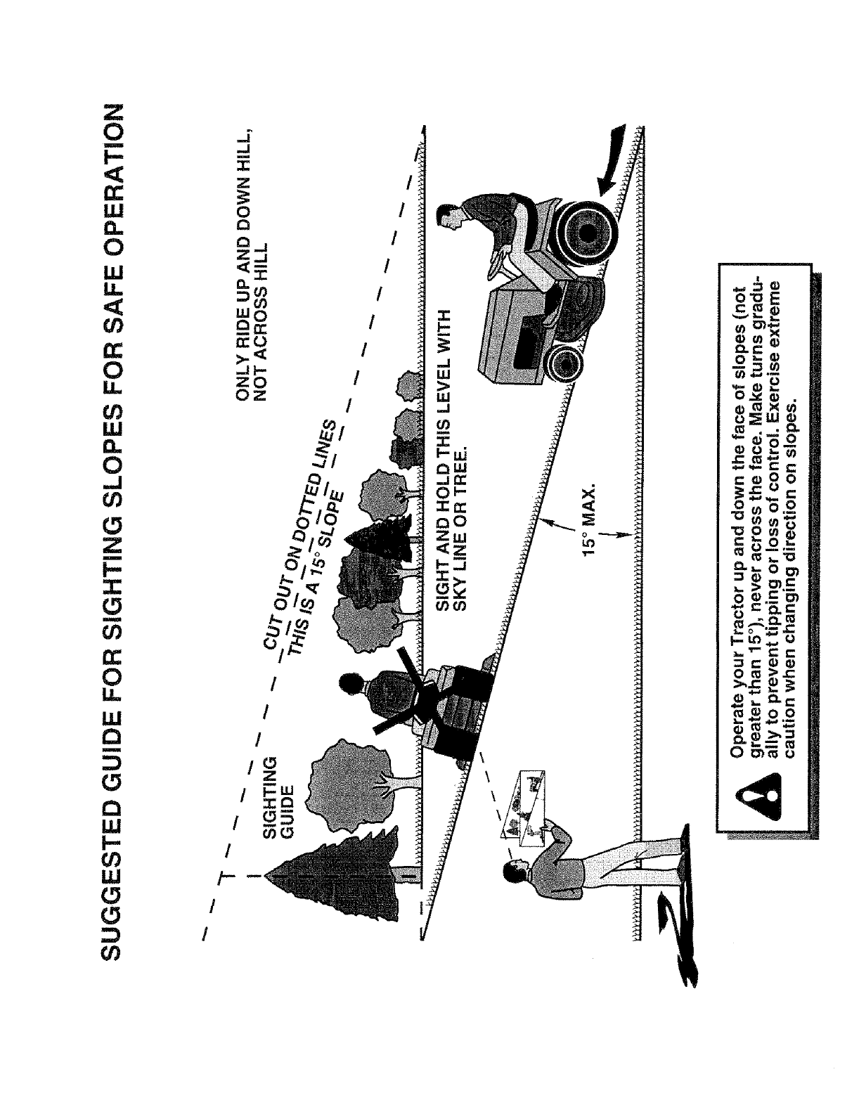
Z
0
I-
,<
rr'
111
I:L
0
UJ
14.
¢0
O:
0
u.
t_
111
0
,.J
Z
m
I-
:Z:
I
0
14,
111
13
m
13
141
I-"
111
¢0
I
I
/--
I
I
i t
!
!
I
I
_s
o

OWNER'S
MANUAL
MODEL NO,
917.256890
IF YOU NEED
REPAIR SERVICE
OR PARTS:
FOR REPAIR SERVICE, CALL
THIS TOLL FREE NUMBER:
1-800-4-REPAIR
(1-800-473-7247)
FOR REPLACEMENT PARTS
INFORMATION AND
ORDERING, CALL THIS
TOLL FREE NUMBER:
1-800-FON-PART
(1-800-366-7278)
FOR CONSUMER ASSISTANCE
HOT LINE, CALL THIS
TOLL FREE NUMBER:
1-800-659-5917
®
15.5 HP IC
ELECTRIC START
42" MOWER
HYDROSTATIC (AUTOMATIC)
LAWN TRACTOR
Each tractor has its own model number. Each engine has
its own model number.
The model number for your tractor will be found on the
model plate located under the seat.
The model number for your engine will be found on the
blower housing of the engine.
All parts listed herein may be ordered from any Sears,
Roebuck and Co. Service Center/Department and most Reo
tail Stores.
WHEN ORDERING REPAIR PARTS, ALWAYS GIVE THE
FOLLOWING INFORMATION:
aPRODUCT- TRACTOR
oMODEL NUMBER - 917.256890
•ENGINE MODEL NO. -28N707, TYPE NO. 0173-01
•PART NUMBER
• PART DESCRIPTION
Your Sears merchandise has added value when you
consider Sears has service units nationwide staffed with
Sears trained technicians.., professional technicians
specifically trained to insure that we meet our pledge to
you, we service what we sell.
155898 6.13.96 JH Printed in U.S.A.
................... III1[IIIIIIIIIIIHIII'
r',,i I11.........il'lil,i Irrl"","/III
Y'!I....I ........................." '111
