Craftsman 917257562 User Manual TRACTOR Manuals And Guides 1007794L
User Manual: Craftsman 917257562 917257562 CRAFTSMAN TRACTOR - Manuals and Guides View the owners manual for your CRAFTSMAN TRACTOR #917257562. Home:Lawn & Garden Parts:Craftsman Parts:Craftsman TRACTOR Manual
Open the PDF directly: View PDF ![]() .
.
Page Count: 56

CRnF'/ X
LNUMBER 917,257562 OWNER'S MANUAL
®
oAssembny
oOperation
®Customer Responsibilities
Service and Adjustments
,Repair Parts
Converl:ibie
CAUTION: Read and follow all safety rules and instructions before opsrating this equipment.
" . .... ,-_ _",,_'-_ ..... ,......................... -
....................... II IIIIIIIII _"..........................
im
Safe Operation Practices for Ride-On Mowers
IMPORTANT: THIS CUTTING MACHINE IS CAPABLE OF AMPUTATING HANDS AND FEET AND THROWING OBJECTS
FAILURE TO OBSERVE THE FOLLOWING SAFETY INSTRUCTIONS COULD RESULT IN SERIOUS INJURY OR DEATH
!. GENERAL OPERATION
• Read, understand, and fotlowall instructionsin the manual
and on the machine before stading
•Only altow responsible adults, who are familiar with the
instructions,to operate the machine
•Clear the area of objects such as rocks, toys, wire, etc,
which couId be picked up and thrown by the blade
•Be sure thearea isclear of other people before mowing Stop
machine if anyone enters the area
.Never carry passengers_
•Do not mow in reverse unless absolutely necessary Always
look down and behind before and white backing
•Be aware of the mower discharge directionand do not point
it at anyone. Do not operate the mower without either the
entire grass catcher or the guard in place
•Slow down before turning
•,Never leave a running machine unattended. Always turn off
blades, set parking brake, stop engine, and remove keys
before dismounting
• Turn off blades when not mowing
• Stop engine before removing grass catcher or unclogging
chute
°Mow only in daytight or good artificial light
•Do not operate the machine while under the influence of
alcohol or drugs
•Watch for trafficwhen operating near or crossing roadways
• Use extra care when readingor unloading the machine into
a trailer ortruck.
I1. SLOPE OPERATION
Slopes are a major factor related to Ioss-ol-contro_ and tipover
accidents which can result in severe injury or death° All slopes
requireextra caution If youcannot back upthe slope or if you fee
uneasy on it, do not mow it
DO:
• Mow up and down slopes, not across
•Remove obstaclessuch as rocks, tree limbs, etc
° Watch for hotes, ruts, or bumps. Uneven terrain could
overturn the machine Tafl grass can hide obstacles
• Use slow speed Choose a tow gear so that you wilt not have
to stop or shift while on the slope
• Follow the manufacturer's recommendations for wheet
weights or counterweights to improve stability.
. Use extra care with grass catchers or other attachments
These can change the stability of the machine
• Keep all movement on the stopes slow and gradual Do not
make sudden changes in speed or direction
, Avoid starting or stopping on a slope, ff tires lose traction,
disengage the blades and proceed slowly straight down the
slope
DO NOT"
=Do not turn on slopes unless necessary, and then, turn slowly
and gradually downhill, if possible
•Do not mow near drop-oils, ditches, or embankments The
mower could suddenly turn over if a wheel is over the edge
of a cliff or ditch, or if an edge caves in
°Do not mow on wet grass. Reduced traction could cause
sliding
•Do not try to stabilize the machine by putting your fool on the
ground
•Do not use grass catcher onsteep slopes
lU. CHILDREN
Tragic accidents can occur if the operator is not alert to the
presence of children Chitdren are often attracted to the machine
and the mowing activity. Never assume that children willremain
where you last saw them
° Keep children out of themowing area and under the watchful
care of another responsible adult
. Be alert and turn machine off if children enter the area
° Before and when backing, look behind and down for small
children
•Never carry children They may fall off and be seriously
injured or interfere with safe machine operation
• Never allow children to operate Ihe machine
,Use extra care when approaching blind corners, shrubs,
trees, ot other objects that may obscure vision
IV.
o
SERVICE
Use extra care inhandling gasoline and other fuels They are
flammable and vapors are explosive
- Use only an approved container
Never remove gas cap or add fuel with lhe engine
running Allow engine to cool before refueling Do not
smoke
- Never refuel the machine indoors
Never store the machine or fuel container inside where
there is an open flame, such as a water heater
• Never runa machine inside a closed area.
•Keep nuts and botts, especially blade attachment bolts, tight
and keep equipment in good condition
° Never tamper with safety devices Check their proper
operation regularly
° Keep machine free of grass, Ieaves, or otherdebris build-up
Clean oil or fuel spillage Allow machine to cool before
storing
o Stop and inspect the equipment if you strike an object
Repair, if necessary, before restarting
• Never make adjustments or repairs with the engine running
°Grass catcher components are subject to wear, damage,and
deterioration, which could expose moving parts or allow
objects to be thrown. Frequently check components and
replace with manufacturer s recommended parts, when nec-
essary
• Mower blades are sharp and can cut Wrap the blade(s) or
wear gloves, and use extra caution when servicing them
•Check brake operation frequently Adjust and service as
required
IA
ii ii illlll illl ill jl, , j
l
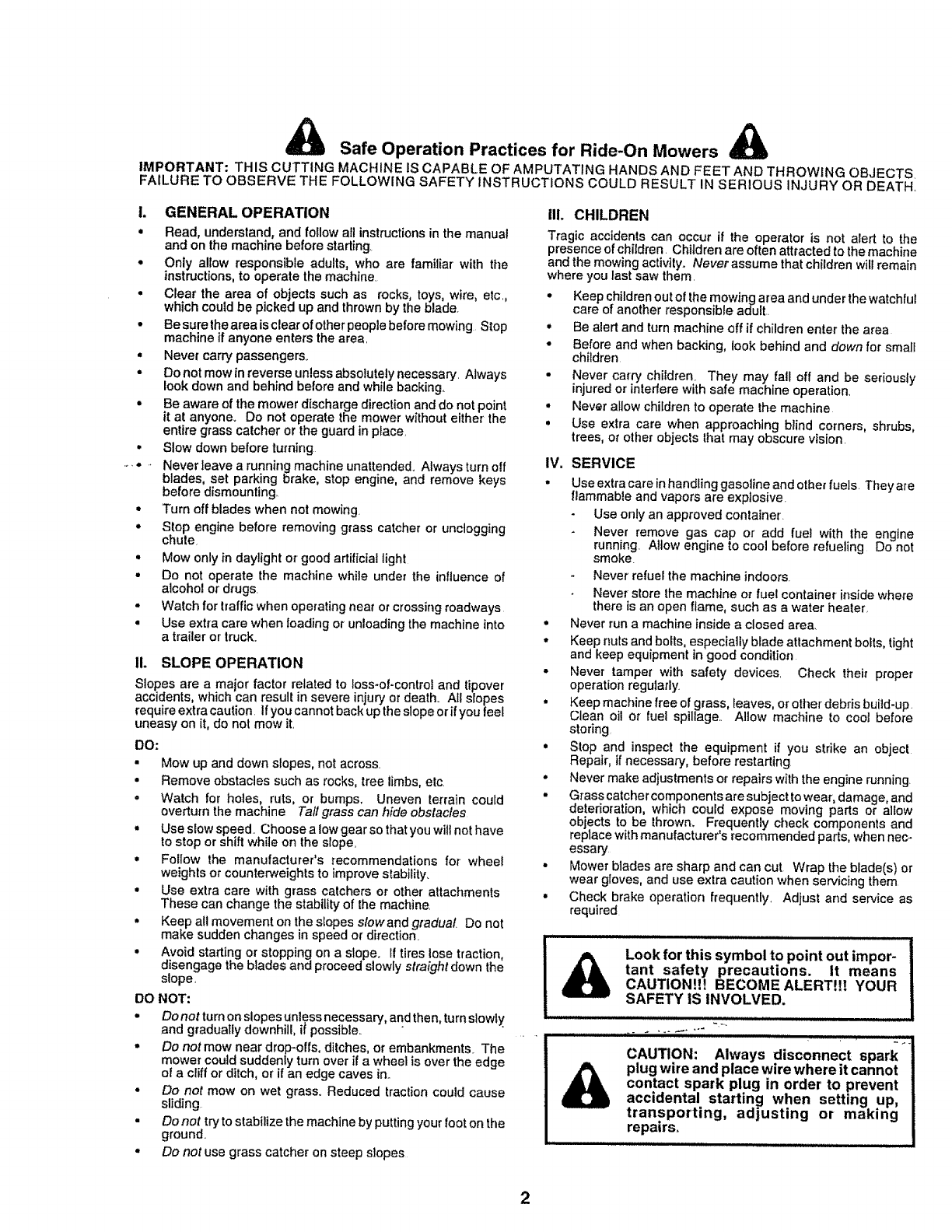
Look for this symbol to point out impor-
tant safety precautions. It means
CAUTION!!! BECOME ALERTH! YOUR
SAFETY IS INVOLVED.
CAUTION: Always disconnect spark
plug who and place wire where it cannot
contact spark plug in order to prevent
accidental starting when setting up,
transporting, adjusting or making
repairs.

CONGRATULATIONS on your purchase of a Sears
Tractor. It has been designed, engineered and manufac-
tured to give you the best possible dependability and
performance.
Should you experience any problem you cannot easily
remedy, please contact your nearest Sears Authorized
Service CentedDepartment, We have competent, well-
trained technicians and the proper tools to service or repair
this uniL
Please read and retain this manual° The instructions will
enable you to assemble and maintain your tractor properly°
Always observe the "SAFETY RULES"°
MODEL
'4UMBER 917,257562
SERIAL
NUMBER
DATE OF PURCHASE
THE MODELAND SERIAL NUMBERS WILL BE FOUND
ON A PLATE UNDER THE SEAT.
YOU SHOULD RECORD BOTH SERIAL NUMBER AND
DATE OF PURCHASE AND KEEP IN A SAFE PLACE
FOR FUTURE REFERENCE..
MAINTENANCE AGREEMENT
A Sears Maintenance Agreement is available on this prod-
uct. Contact your nearest Sears store for details.,
CUSTOMER RESPONSIBILITIES
•Read and observe the safety rules,
= Follow a regular schedule in maintaining, caring for and using
your tractor.
• Follow the instructions under "Customer Responsibilities"
and "Storage" sections of this owner's manual
PRODUCT SPECIFICATIONS
HORSEPOWER: 18,0
GASOLINE CAPACITY 3,5 GALLONS
AND TYPE: UNLEADED REGULAR
OIL TYPE (API-SF!SG): SAE 30 (above 32°F)
SAE 5W-30 (below 32°F)
OIL CAPACITY: 3_0 PINTS
SPARK PLUG: CHAMPION RJ-19LM
(GAP: .030") STD361458
VALVE CLEARANCE: INTAKE: .004" - .006"
EXHAUST: ,.007'__..009"
GROUND SPEED (MPH): FORWARD:
1st 077
2rid 1..46
3rd 341
4th 4.34
5th 5.57
REVERSE: 1.07
TIRE PRESSURE: FRONT: 14 PSI
REAR: 10 PSI
CHARGING SYSTEM: 3 AMPS BATTERY
5 AMPS HEADLIGHTS
BLADE BOLT TORQUE: 30-35 FT. LBS
WARNING: This tractor is equipped with an internal
combustion engine and should not be used on or near any
unimproved forest-covered, brush-covered or grass-cov-
ered land unless the engine s exhaust system is equipped
with a spark arrester meeting applicable local or state laws
(if any),, If a spark arrester is used, it should be maintained
in effective working order by the operator..
In the state of California the above is required by law
(Section 4442 of the California Public Resources Code).
Other states may have similar laws. Federal laws apply on
federal lands. A spark arrester for the muffler is available
through your nearest Sears Authorized Service Center/
Department (See REPAIR PARTS section ofthis manual).
LIMITED TWO YEAR WARRANTY ON ELECTRIC START RIDING EQUIPMENT
For two (2) years from the date of purchase, if this riding equipment is maintained, lubricated and tuned up according to the
instructions in the owner's manual, Sears will repair or replace, free of charge, any parts found to be defective in material or
workmanship.
This Warranty does not cover:
° Expendable items which become worn during normal use, such as blades, spark plugs, air cleaners and belts..
• Tire replacement or repaircaused by punctures from outside objects, such as nails, thorns, stumps, or glass.
• Repairs necessary because of operator abuse, negligence, improperstorage or accident or the failure to maintain the
equipment according to the instructionscontained in the owner's manual.
• Riding equipment used for commercial or rental purposes.
LIMITED 90 DAY WARRANTY ON BATTERY
For ninety (90) days from date of purchase, if any battery included with this riding equipment proves defective in material or
workmanship and our testing determines the batter] will not hold a charge, Sears will replace the battery at no charge.
WARRANTY SERVICE IS AVAILABLE BY RETURNING THE RIDING EQUIPMENT TO THE NEAREST SEARS SERVICE
CENTER/DEPARTMENT IN THE UNITED STATES.
This Warranty gives you specific legal rights, and you may also have other rights which may vary from state to state
SEARS, ROEBUCK AND CO., D/817 WA, HOFFMAN ESTATES, ILLINOIS 60179
3
TABLE OF CONTENTS
SAFETY RULES ........................................................... 2
PRODUCT SPECIFICATIONS ...................................... 3
CUSTOMER RESPONSIBILITIES ..................... 3, 15-18
WARRANTY .................................................................. 3
TRACTOR ACCESSORIES .......................................... 5
ASSEMBLY ............................................................. 7_10
OPERATION ....................................................... L. 11-14
MAINTENANCE SCHEDULE ..................................... 15
SERVICE AND ADJUSTMENTS ........................... 19-24
STORAGE ................................................................... 25
TROUBLESHOOTING ........................................... 26-27
REPAIR PARTS - TRACTOR ........ _....................... 30-47
REPAIR PARTS - ENGINE ................... ,................ 48-53
PARTS ORDERING/SERVICE ............... BACK COVER
INDEX
A
Accessories .......................................................5
Adjustments:
Brake........................................................21
Carburetor. ..............................................24
Mower
Front-To-Back ............................20
Side-To-Side ...................................20
Throttle Control Cable ....................23
Air Filter, Engine ........................................17-18
Air Screen, Engine .....................................18
Assembly ......................................................7-10
B
Battery:
Chargin9 ..............................................8
Cleaning ................................................17
Installation .................................................9
Levels..................................................8,16
Preparation ...................................... 8
Starting with Weak Battery .............22
Storage .................................................25
Terminals .......................................................17
Belt:
Motion Drive
Removal/Replacement ............21
Mower Blade(s)
Removal/Replacement ...............21
Blade:
Sharpening ..........................................16
Replacement ..........................................t6
Brake Adjustment ......................................21
C
Carburetor Adjustment ...................... 24
Controls, Tractor .....................................11
Customer Responsibilities ...............15-18
Engine:
Air Filter.........................................17-18
Air Screen, Engine ........................18
Cooling Fins, Engine .....................18
Engine Oil ........................................17
Fuel Filter ...........................................18
Spark Plug(s) ................................18
Tractor:
Battery ...............................................17
Blade ...................................._.............16
Lubrication Chart ..........................15
Maintenance Schedule ............ 15
Tire Care ............'_....................8,I6,22
Transaxte ......................................t7
Cutting Height, Mower ...........................12
E
Electrical:
Interlocks and Relays .........................23
Schematic ..........................................29
Wiring Diagram ..................................30
Engine:
Air Filter...............................................18
Air Screen .........................................18
Cooling Fins, Engine ..................... 18
Oil Change ............................................17
Oil Level ..........................................13,17
Oil Type ...............................i...............17
Preparation .........................................13
Repair Parts ............................. 30-47
Starting ...............................................14
Storage .............................................25
F
Filter:
Air Filter .........................................17-18
Fuel ..............................................17-18
Fuel:
Type ................................................ 13
Storage .............................................25
Fuse ............................................................23
H
Hood Removal/Installation ........................23
L
Leveling Mower Deck ................................20
Lubrication:
Chart ......................................................15
M
Maintenance Schedule ..........................16
Mower:
Adjustment, Front-to-Back ...............20
Adjustment, Side-to-Side ....................20
Blade Sharpening .........................._. 16
Blade Replacement ...........................16
Cutting Height.....................................12
installation ...........................................19
Operation ...............................................13
Removal ........:........................................19
Mowing Tips ..........................................................14
Muffler ........._...............................................18
Spark Arrester. ................................3,40
Oil:
O
Cold Weather Conditions ..........13,17
Engine ..........................................13,17
Storage ....:......................................i............25
Operation .................................................11-14
Operating Mower. .......................................13
Options:
Accessories ...........................................5
Spark Arrestor. ...............................3,40
P
Parking Brake ...........................................12
Parts Bag .....................................................6
Paris, Replacement/Repair ...............30-47
Product Specifications ...........................:......3
R
Repair Parts .......................................30-47
S
Safety Rules .......................................................2
Seat .................................................................8
Service and Adjustments .....................19-24
Carburetor ..........................................24
Fuse ........................................................23
Hood Removal/Installation ...............23
Motion Drive Belt
Removal/Replacement ............ 21
Mower Belt(s)
Removal/Replacement ..............21
Mower Adjustment
Front-to-Back .............................20
Side-to-Side ..................................20
Mower Removal ................................19
Tire Care .........................................8;t6,22
Slope Guide Sheet .......................................55
Spark Plug(s) ...........................................18
Specifications ...................._.............................3
Starting the Engine ...........................13-14
Steering Wheel ............................................7,22
Stopping the Tractor _...............................12
Storage ..............................................................25
T
Throttle Control Cable Adjustment .......23
Tires ...............................................................8,16,22
Trouble Shooting Chart ....................26-27
Transaxle .........................................................17
W
Warranty ...............................................................3
Wiring Diagram .............................................29
Wiring Schematic ...........................................30
4

ACCESSORIES AND ATTACHMENTS
:......................... i i,i ,ll,l,lll, iiqlJJ ii ii
These accessories and attachments were available through most Sears retail outlets and service centers when the tractorwas purchased,
Most Sears stores can order these items for you when you provide the model number of your tractor.
ENGINE
SPARK PLUG
4GASCAN ENGINEOIL FUELSTABILIZER
MAINTENANCE
BLADES BELTS
PERFORMANCE
Sears offersawidevariety of attachments that fit yourtractor.. Many of theseare listed belowwithbrief explanationsof howthey can help
you.. This listwas current at the time of publication; however, it may change infuture years -more attachments may be added, changes
may be made in these attachments, orsome may no longerbe available or fit your model. Contact your nearest Sears store for the
accessories and attachments that are available for your tractor.
Most of these attachments do not require additional hitches or conversion kits (those that do are indicated) and are designed for easy
attaching and detaching.
AERATOR promotes deep root growth for a healthy lawn.. Ta-
pered 2o54nch steel spikes mounted on 10qnch diameter discs
puncture holes in soil at close intervals to let moisture soak in.
Steel weight tray for increased penetration.
BAGGER lets you collect grass clippings and leaves for a
heatthier, neater looking lawn. Two Permanex containers hold
30-gallon plastic bags.
BUMPER protects front end of tractor from damage.
CARTS make hauling easy. Variety of sizes available, plus
accessories such as side panel kits, tool caddy, cart cover,
protective mat and dolly,
CORING AERATOR takes small plugs out of soil to allow mois-
ture and nutrients to reach grass roots, 36-inch swath. 24
hardened steel coring tips 150 Ib, capacity weight tray..
EASY OIL DRAIN VALVE makes oil changes easier, faster..
FRONT NOSE ROLLER canters infront of mower deck to reduce
chances of "scalping" on uneven terrain.
GANG HITCH lets you tow2 or3 pull-behindattachments at once,
such as sweepers, dethatchers, aerators (not for use with rollers,
carts or other heavy attachments).
GAUGE WHEELS on both sides of the mower deck reduce
chances of "scalping" on uneven terrain For mowerdecks not so
equipped,
MULCH RAKE/DETHATCHER loosens soil and flips thatchand
matted leaves tolawn surface foreasy pickup_Twenty spring tine
teeth° Usefultopreparebare areasforseeding. Available forfront
or rear mounting. HIGH PERFORMANCE REEL-ACTION
SPRING TINE DETHATCHER covers 36-inch wide path and
tosses thatch into large hopper.. Mounts behind tractor.
MULCHING KIT, once installed, lets you mulch, discharge or bag
clippings (bagger optional) without changing blades, For models
not equipped as 3-m-1 Convertible mowers.
RAMP TOPS AND FEET let you load and unload tractor from a
pickup truck. Use with 2 x 8 or 2 x 10 lumber_
ROLLER for smoother lawn surface. 36-inch wide, 18-inch
diameterwater-tight drum holds upto3901bs, of weight. Rounded
edges prevent harm to turf Adjustable scraper automatically
cleans drum
SNOW BLADE for snow removal only. 14-inch high, 42qnch wide
blade clears 38-inc_hpathwhen angled leftor right° Raises, lowers
with side lever.,Adjustable skids; replaceable, reversible scraper
bar. (Use with tire chains and wheel weights andtor rear drawbar
weight.)
SNOWTHROWER has 40qnch swath° Drum4ype auger handles
powdery and wet/heavy snow. Mounts easily with simple pin
arrangement. Discharge chute adjusts from tractor seat. 6-inch
diameter spout discharges snow 10 to 50 feet, Lift controlled at
tractor seat, (Use with chains and wheel weights and/or rear
drawbar weight..)
SPRAYERS use 12-volt DC electdc motor that connects to the
tractor battenj or other 12ovolt source. Includes booms for
automatic spraying and hand held wand for spot spraying. Wand
has adjustable spray pattern. For applying herbicides, insecti-
cides, fungicides and liquid fedilizers.
SPREADER/SEEDERS make seeding, fertilizing, and weed kill-
ing easy. Broadcast spreaders are also useful for granular de-
icers and sand_
SWEEPERS {elyou collect grass clippings and leaves..
TILLER has 5hp engine and 36-inch swath to prepare seed beds,
cultivate and compost garden residue. Tiller has its own built-in
lift and depth control system and does NOT require a sleeve hitch.
Fitsany lawn, yard or garden tractor. Simply hook up to the tractor
drawbar and go! Optional accessories convert unit for
dethatching, aerating, hitling,,oWithout tools.
TIRE CHAINS are heavy duty; closely spaced extra-large cross
links give smooth ride, outstanding tract=on.
TRACTOR CAB has heavy duty vinyl fabric over tubular steel
frame, ABS plastic top; clear plastic windshield offers 360 degree
visibility. Hinged metal doors with catch. Keeps operator warm
and dry.. Remove vinyl sides and windshields for use as sun
protector in summer. Optional accessories include: tinted/
tempered solid safety glass windshield with hand operated wiper;
12-volt amber caution light for mounting on cab top.
VACS for powerful collection of heavy grass clippings and leaves..
Optional wand attachment to pick up debris in hard-to-reach
places VACtCHIPPER includes a chipper-shredder.
WEIGHT BRACKET for drawbar for snow removal applications.
Uses (1) 55 Ib. weight
WHEEL WEIGHTS for rear wheels provide needed traction for
snow removal or dozing heavy materials
5
i, i i iii ............................................ ulluJl ............. ,..............................
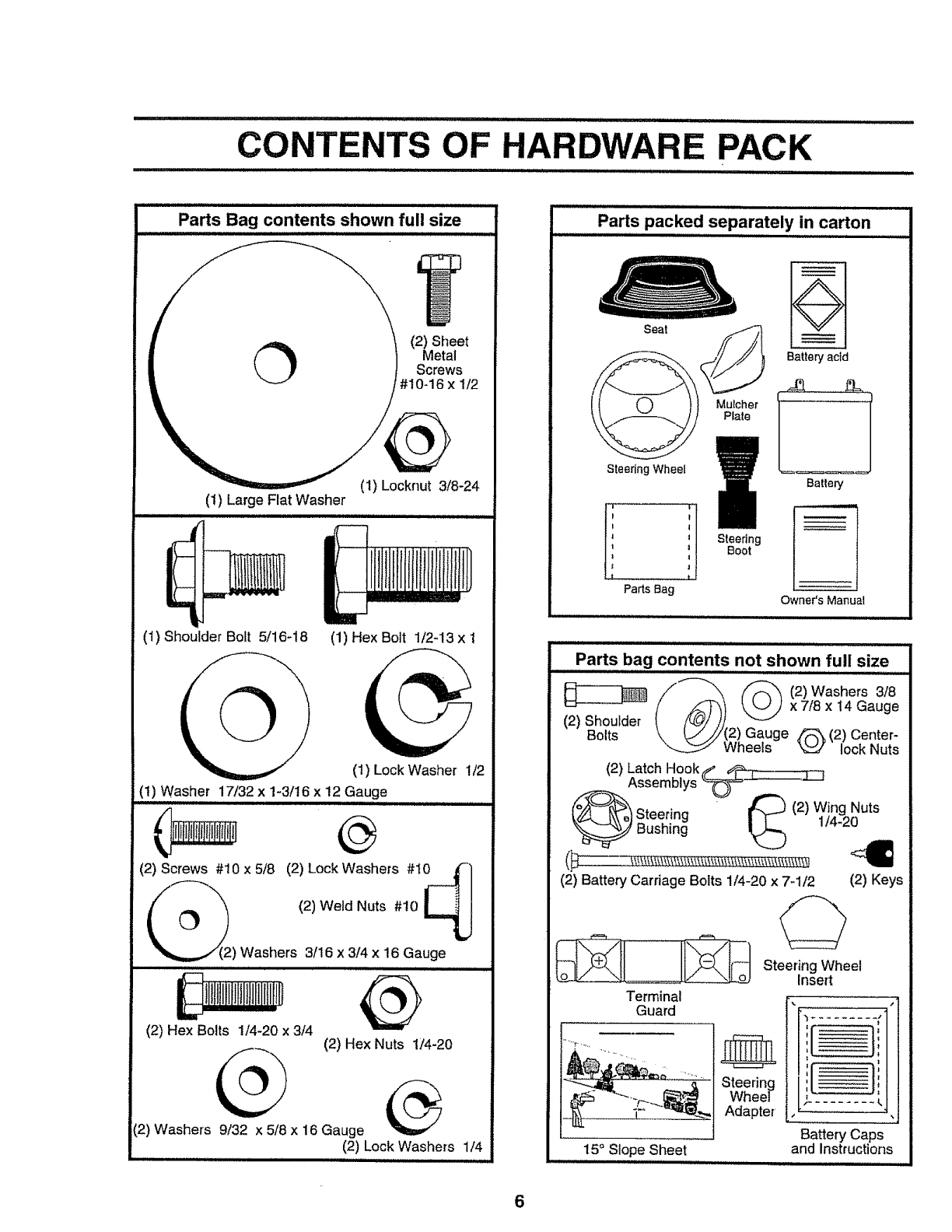
CONTENTS OF HARDWARE PACK
iiiiiiiiiiinll iiii ..................
Parts Bag contents shown full size
O (2) Sheet
Metal
Screws
cknut 3/8-24
(t) Large Flat Washer
(1) Shoulder Bolt 5/16_18 (1) Hex Bolt 1/2-13 x 1
(1) Lock Washer 1/2
(1) Washer 17/32 x 1-3/16 x 12 Gauge
(2) Screws #10 x 5/8 (2) Lock Washers #t0 j'-
) Washers 3/16 x3/4 x 16 Gauge
(2) Hex Bolts 1/4-20 x aN (2) Hex Nuts 1/4-20
(2) Washers 9/32 x 5/8 x 16 Gauge _/_
(2) Lock Washers 1/4
Parts packed separately in carton
Seat ,_
_Plate
SteeringWheel
Steedng
Boot
Batten]acid
Battery
Owner'sManual
Parts bag contents not shown full size
/"-"'_ (2) Washers 3/8
(2) Shoulder (_"_")) x Z18x14 Gauge
Bolts \ LJ/',/(2) Gauge _ (2) Center-
Wheels "_'_V_./lock Nuts
(2) Latch Hook(_.__.__L____ , ,
Assemblys _
_'_ Steering ' _ (2)WjngoNuts
(2) Battery Carriage Bolts 1/4-20 x 7-1/2 (2) Keys
Terminal
Guard
Steering
Wheel
Adapter
15° Slope Sheet
,,,,,,,,
Steering Wheel
Insert
I:
: I
Battery Caps
and instructions
6
ASSEMBLY
..................... ................ i,
Your new tractor has been assembled at the factory withexceptionof those partsleft unassembledfor shippingpurposes°
To ensure safe and proper operationof yourtractor,all partsandhardwareyouassemble must be tightened securely_ Use
the correct tools as necessary to insureproper tightness.
TOOLS REQUIRED FOR ASSEMBLY
A socketwrench set will make assembfy easier.. Standard
wrench sizes are listed.
(1) 5/16" wrench
(2) 7/16" wrenches
(1) 1/2" wrench
(1) 3/4" wrench
(1) 9/t6" wrench
(t) Phillips screwdriver
Utility knife
Tire pressu_'egauge
(1) 3/4" socket with drive ratchet
When right and teft hand is mentioned in this manual, it
means when you are in the operating position (seated
behind the steering wheel).
TO REMOVE TRACTOR FROM CAR-
TON
UNPACK CARTON
°Remove all accessible loose parts and parts cartons
from carton (See page 6),.
= Cut, from top to bottom, along lines on air four corners
of carton, and lay panels flat..
= Check for any additional loose parts or cartons and
remove.
STEERING SHAFT
(ASSEMBLY
POSITION)
STEERING SHAFT ,:::
(SHIPPING .._/,"POSITION) "_,
FIG. I
SLOT
BEFORE ROLLINGTRACTOR OFF SKID
ATTACH STEERING WHEEL (See Fig. 1)
,Slide the steering bushing over the steering shaft
• Raise steering shaft forward until screw holes in dash
line up with steering bushing. Install two (2) sheet
metal screws and tighten securely°
o Position steering boot over steering shall
. Place tabs of steering boot over tab slots in dash and
push down to secure,
° Slide steering wheel adapter onto upper steering shaft,
o Position front wheels of the tractor so they are pointing
straight forward,,
°Position steering wheel so cross bars are horizontal
(left to right) and slide onto adapter.
o Assemble large flat washer and 3/8-24 locknut and
tighten securely.
° Snap steering wheel insert,into center of steering
wheel.
= Remove protective plastic from tractor hood and grill
IMPORTANT:CHECK FOR AND REMOVE ANY STAPLES
IN SKID THAT MAY PUNCTURE TIRES WHERE TRACTOR
IS TO ROLL OFF SKID
TO ROLL TRACTOR OFF SKID (See Fig. 7)
°Raise attachment lift lever to its highest position
.Retease parking brake by depressing clutch/brake
pedal
•Place gearshift lever inneutral (N) position.
•Roll tractor backwards off skid.
• Remove banding holding discharge guard up against
tractor_
7
ASSEMBLY
i i .ii,l,,i iillll ] LL ]II,I II I
HOW TO SET UP YOUR TRACTOR
PREPARE BATTERY (See Fig. 2)
...... i = i i ii i N,ui N Llll u II,H ii,
CAUTION: Wear eye and face shield.
Wash hands or clothing immediately if
accidentally in contact withbattery acid°
Do not smoke. Fumes from charged
battery acid are explosive.
Read the instructions included with the
battery vent caps. Always wear gloves,
clothing and goggles to protect your
hands, skin and eyes.
Your tractor has a battery charging system which is suffi-
cient for normal use. However, periodic charging of the
battery with an automotive charger will extend its lifeo
• See instructions packed with vent caps in parts bag.
• Fill battery with acid. Fill each cell until it reaches the
bottom of the vent wells,, Do not overfill.
• Allow battery to stand and settle for at least thirty
minutes. After standing, check the battery celt acid
level If below the vent wells, add more acid until the
correct level is reached.
While battery is standing (after adding acid) and later, while
battery is being charged, continue with assembly of tractor.
IMPORTANT: TO MAXIMIZE THE LIFE OF YOUR
BATTERY, IT IS NECESSARY THAT THE BATTERY BE
CHARGED BEFORE USE. FAILURE TO CHARGE
BATTERY CAN RESULT IN A SHORTENED BATTERY
LIFE
°Charge battery at a rate of 6 amperes for 1 hour_ Use
a 12 volt battery charger. Observe all safety precau-
tions required for battery charging.
,Check the acid tevet after the battery is charged, If the
acid has fallen below the correct level, add distilled or
iron free water.
-Install the vent caps to cover' the vent wells,. Wash the
top of the battery with water to remove any acid, then
wipe dry,
• Check battery case for leakage to make sure that no
damage has occurred in handling,
• Dispose of excess battery acid. Neutralize acid for
disposal by adding it to two gallons of water in a five
gallon plastic container, Stir with a wooden or plastic
paddle while adding baking soda until the addition of
more soda causes no more foaming,
•-Follow instructionson how to ir_tall battery_
CUT AWAY VIEW _... VENT CAP
_ ..... VENT WELL
FIG. 2
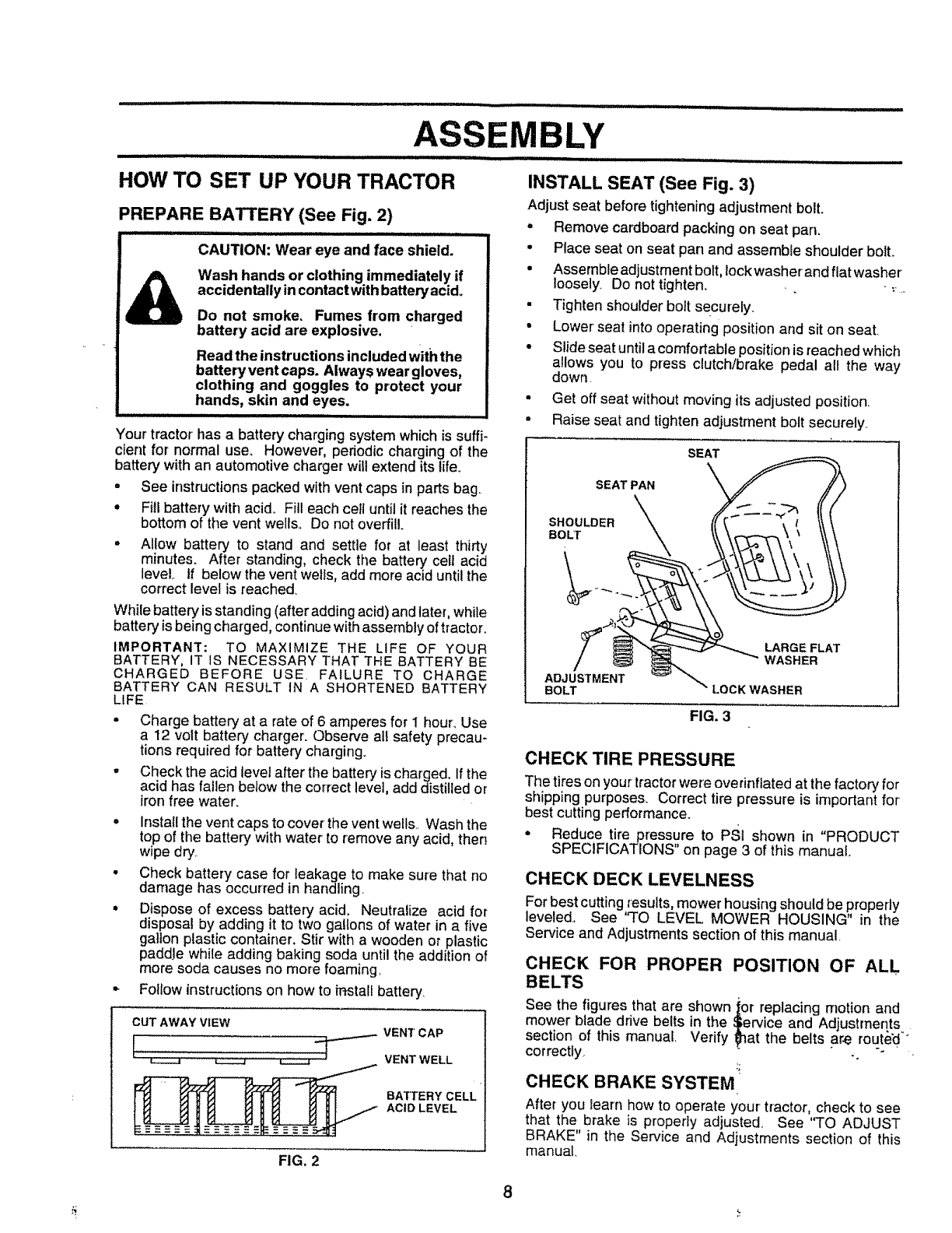
INSTALL SEAT (See Fig. 3)
Adjustseat before tighteningadjustment bolt.
, Remove cardboard packingon seat pan.
°Place seat on seat pan and assemble shoulder bolt.
•Assemble adjustment bolt, lockwasher and flat washer
loosely. Do not tighten_ ,.,,:,.,,
• Tighten shoulder bolt securely,.
• Lower seat into operating position and sit on seat.
•Slide seat until a comfortable position is reached which
allows you to press clutch/brake pedal all the way
down.
•Get off seat without moving its adjusted position.
•Raise seat and tighten adjustment bolt securely,.
BATTERY CELL
ACID LEVEL
FIG. 3
CHECK TIRE PRESSURE
The tireson your tractorwere ove rinflatedat the factory for
shipping purposes. Correct tire pressure is important for
best cutting performance.
•Reduce tire pressure to PSI shown in "PRODUCT
SPECIFICAT!ONS" on page 3 of this manual.
CHECK DECK LEVELNESS
For best cutting results, mower housing should be properly
leveled,, See "TO LEVEL MOWER HOUSING" in the
Service and Adjustments section of this manual,
CHECK FOR PROPER POSITION OF ALL
BELTS
See the figures that are shown ior replacing motion and
mower blade drive belts in the _ervice and Adjustments
section of this manual Verify _at the belts a_e route'd_°
correctly, -.
CHECK BRAKE SYSTEM
After you ieam how to operate your tractor, check to see
that the brake is properly adjusted See "TO ADJUST
BRAKE" in the Service and Adjustments section of this
manual,
8
ASSEMBLY
•....... i , ,i ...................... i i H,,,ll i i
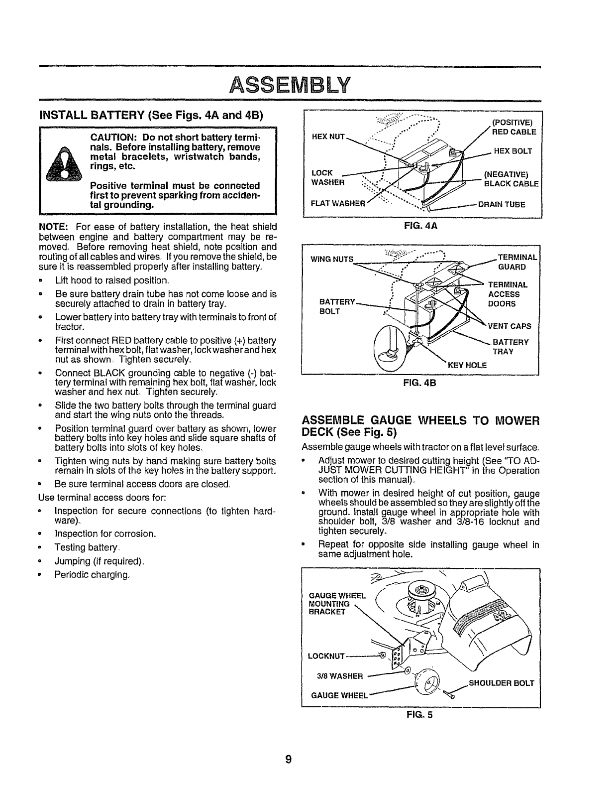
INSTALL BATTERY (See Figs. 4A and 4B)
CAUTION: Do not short battery termi-
nals. Before installing battery, remove
metal bracelets, wristwatch bands,
rings, etc.
Positive terminal must be connected
first to prevent sparking from acciden-
tal grounding.
NOTE: For ease of battery installation,the heat shield
between engine and battery compartment may be re-
moved° Before removing heat shield, note positionand
routing of all cables and wires_ If you remove the shield, be
sure it is reassembled properly after installing battery_
- Lift hood to raised position°
• Be sure battery drain tube has not come looseand is
securely attached to drain in battery tray.
= Lower battery intobattery tray with terminals to front of
tractor.
o First connect RED battery cable to positive (+) battery
terminal with hex bolt, flat washer, lockwasher and hex
nut as shown Tighten securely°
=Connect BLACK grounding cable to negative (-) bat-
tery terminal with remaining hex bolt, fiat washer, lock
washer and hex nut. Tighten securely°
•Slide the two battery bolts through the terminal guard
and start the wing nuts onto the threads°
° Position terminal guard over battery as shown, lower
battery bolts into key holes and slide square shafts of
battery bolts into slots of key holeso
• Tighten wing nuts by hand making sure battery bolts
remain inslots of the key holes in the battery support..
°Be sure terminal access doors are closed,
Use terminal access doors for:
= Inspection for secure connections (to tighten hard-
ware),
° Inspectionfor corrosion°
,Testing battery..
• Jumping (if required).
•Periodic charging.
HEX BOLT
LOCK (NEGATIVE)
WASHER BLACK CABLE
FLAT WASHER TUBE
FIG. 4A
WING NUTS "*_...... ,_ TERMINAL
GUARD
TERMINAL
ACCESS
DOORS
CAPS
BATTERY
TRAY
KEY HOLE
FIG. 4B
ASSEMBLE GAUGE WHEELS TO MOWER
DECK (See Fig. 5)
Assemble gauge wheels with tractor on a flat level surface°
= Adjust mower to desired cutting height (See "TO AD-
JUST MOWER CUTTING HEIGHT in the Operation
section of this manual)°
° With mower in desired height of cut position, gauge
wheels should be assembled so they are slightly off the
ground.. Install gauge wheel in appropriate hole with
shoulder bolt, 3/8 washer and 3/8-16 locknut and
tighten securely.
° Repeat for opposite side installing gauge wheel in
same adjustment hole.
GAUGEWHEEL
MOUNTING
BRACKET
BOLT
FIG. 5
9
iilllllll illllll i i inlnlln ir HI ,i i .............
ASSEMBLY
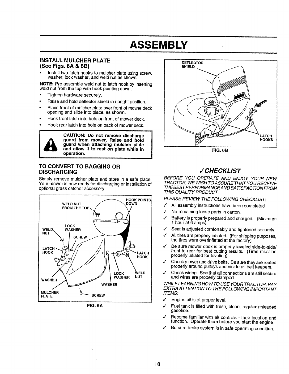
INSTALL MULCHER PLATE
(See Figs. 6A & 6B)
• Install two latch hooks to mulcher plate usingscrew,
washer, lockwasher, and weld nut as shown°
NOTE: Pro-assemble weld nut to latch hook by inserting
weld nut from the top with hook pointingdown.
,Tighten hardware securely.
• Raise and hold deflector shield in uprightposition.
°Place front of mulcher plate over front of mower deck
openingand slide into place, as shown_
°Hook front latch into hole on front of mower deck.
• Hook rear latch into hole on back of mower deck.
CAUTION: Do not remove discharge
_lb guard from mower. Raise and hold !
guard when attaching mulcher plate
and allow it to rest on plate while in
operation.
........................................... ,,,,,,,,, ,
DEFLECTOR
SHIELD
LATCH
HOOKS
FIG. 6B
TO CONVERT TO BAGGING OR
DISCHARGING
Simply remove mulcher plate and store in a safe place.
Your mower is now ready for' discharging or installation of
optional grass catcher accessory,
WELD NUT
FROM THE
HOOK POINTS
DOWN
LOCK
WELD_
NUT "_-_ WASHER
Q
LATCH
HOOK
HOOK
WASHER
MULCHER
PLATE
LOCK
WASHER WELD
NUT
FIG. 6A
,/CHECKLIST
BEFORE YOU OPERATE AND ENJOY YOUR NEW
TRACTOR, WE WISH TOASSURE THAT YOU RECEIVE
THEBEST PERFORMANCE AND SATISFACT!ON FROM
THIS QUALITY PRODUCT
PLEASE REVIEW THE FOLLOWING CHECKI_IST:
,/ All assembly instructionshave been completed.
,/ No remaininglooseparts in carton.
,/' Battery is properly prepared and charged. (Minimum
1 hour at 6 amps)o
#" Seat is adjusted comfortably and tightened securely,
v" All tires are properly infia'ted. (For shipping purposes,
the tires were overinflated at the factory).,
,/' Be sure mower deck is properly leveled side-to-side/
front-to-rear for best cutting results. (Tires must be
properly inflated for leveling).,
#" Check mower and drive belts. Be sure they are routed
properly around pulleys and insideall belt keepers.
,/ Check wiring. See that all connections are still secure
and wires are propedy clamped.
WHILE LEARNING HOW TO USE YOUR TRACTOR, PAY
EXTRA ATTENTION TO THE FOLLOWING IMPORTANT
ITEMS:
,I Engine oil is at proper level
,! Fuel tank is filled with fresh, clean, regular unleaded
gasoline.
J Become familiar with all controls -their location and
function.. Operate them before you start the engine.,
,! Be sure brake system is in safe operating condition.
10
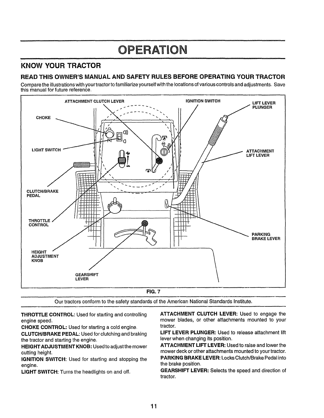
OPERATUON
KNOW YOUR TRACTOR
READ THIS OWNER'S MANUAL AND SAFETY RULES BEFORE OPERATING YOUR TRACTOR
Compare the illustrations with your tractor to familiarize yourself with the locations of various controls and adjustments° Save
this manual for future reference,.
CHOKE
LIGHT SWITCH
CLUTCH/BRAKE
PEDAL
THROTTLE
CONTROL
HEIGHT
ADJUSTMENT
KNOB
ATTACHMENT CLUTCH LEVER IGNITION SWITCH LIFT LEVER
\_ _ ..... -_ PLUNGER
\
GEARSHIFT
LEVER
ATTACHMENT
LIFT LEVER
PARKING
BRAKE LEVER
FIG, 7
Our tractors conform to the safety standards of the American National Standards Institute.
THROTTLE CONTROL: Used for starting and controlling
engine speed.
CHOKE CONTROL" Used for starting a cold engine,
CLUTCH/BRAKE PEDAL: Used for clutchingandbraking
the tractor and starting the engine°
HEIGHT ADJUSTMENT KNOB: Used to adjust the mower
cutting height°
IGNITION SWITCH: Used for starting and stopping the
engine,
LIGHT SWITCH: Turns the headlights on and off.
ATTACHMENT CLUTCH LEVER: Used to engage the
mower blades, or other attachments mounted to your
tractor.
LIFT LEVER PLUNGER: Used to release attachment lift
lever when changing its position°
ATTACHMENT LIFT LEVER: Used to raise and lower the
mower deck or other attachments mounted to your tractor°
PARKING BRAKE LEVER: Locks Clutch/Brake Pedal into
the brake position°
GEARSHIFT LEVER: Selects the speed and direction of
tractor.
11
ill ill ill
JOPERATION
The operation of any tractor can result in foreign objects thrown into the eyes, which
can result in severe eye damage. Always wear safety glasses or eye shields while
operating your tractor or performing any adjustments or repairs. We recommend a
wide vision safety mask for over the spectacles or standard safety glasses.
HOW TO USE YOUR TRACTOR
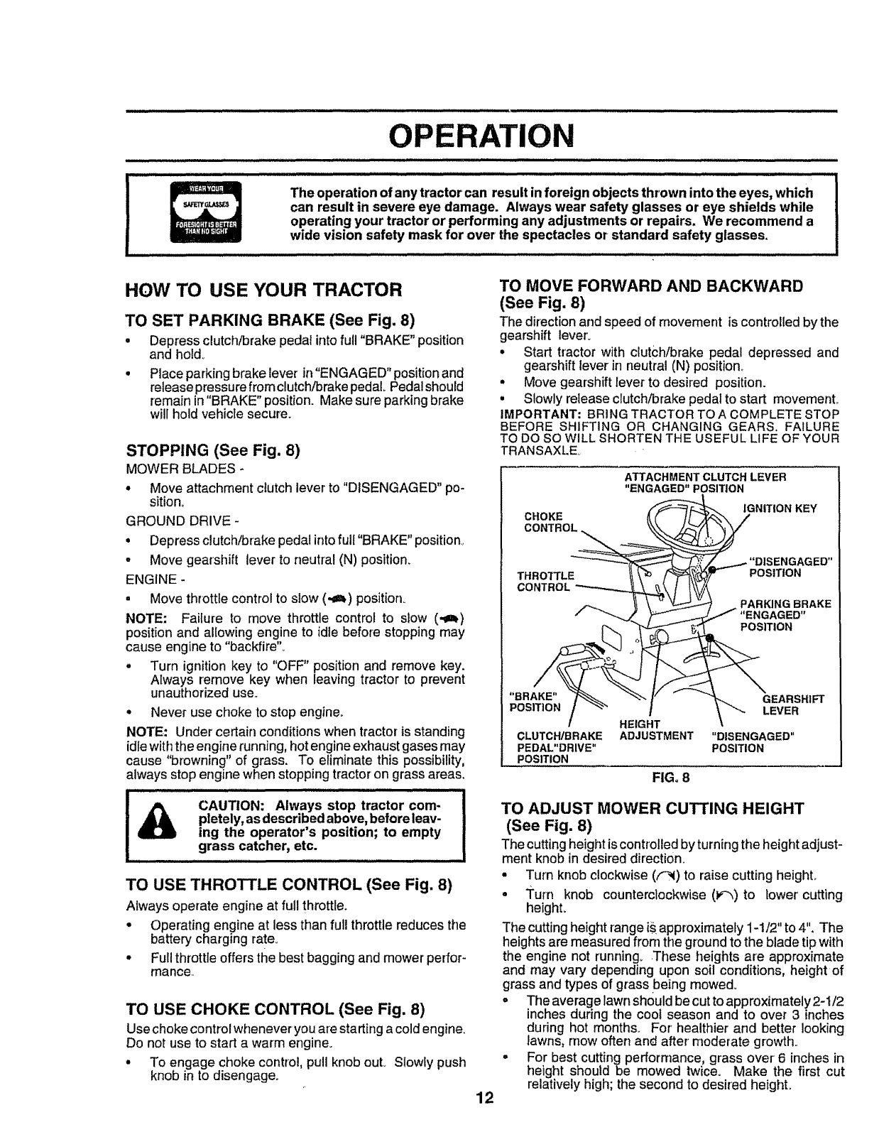
TO SET PARKING BRAKE (See Fig. 8)
• Depress clutch/brake pedal intofull "BRAKE" position
and holdo
° Place parkingbrake lever in"ENGAGED" positionand
release pressure from clutch/brake pedal Pedal should
remain in "BRAKE" position. Make sure parking brake
will hold vehicle secure_
STOPPING (See Fig. 8)
MOWER BLADES -
° Move attachment clutch lever to "DISENGAGED" po-
sition.
GROUND DRIVE-
° Depress clutch/brake pedal intofull "BRAKE" position,,
-Move gearshift lever to neutral (N) position.
ENGINE -
• Move throttle control to slow (-J=b)position°
NOTE: Failure to move throttle control to stow (._)
position and allowing engine to idle before stopping may
cause engine to "backfire",.
.Turn ignition key to "OFF" position and remove key.
Always remove key when leaving tractor to prevent
unauthorized use,.
° Never use choke to stop engine°
NOTE: Under certain conditions when tractor is standing
idle with the engine running, hot engine exhaust gases may
cause "browning" of grass. To eliminate this possibility,
always stop engine when stopping tractor on grass areas.
CAUTION: Always stop tractor com-
pletely, asdescribed above, before leav-
ing the operator's position; to empty
grass catcher, etc.
ill ill .... r ,,, ,,,,,,,,llI,H I II,,llIHHI
TO USE THROTTLE CONTROL (See Fig. 8)
Always operate engine at full throttle.
•Operating engine at less than full throttle reduces the
battery charging rate°
•Full throttle offers the best bagging and mower perfor-
mance.,
TO USE CHOKE CONTROL (See Fig. 8)
Use choke control whenever you are starting a cold engine,
Do not use to start a warm engine.
°To engage choke control, pull knob ouL Slowly push
knob in to disengage.
12
TO MOVE FORWARD AND BACKWARD
(See Fig. 8)
The direction and speed of movement is controlled by the
gearshift lever'_
° Start tractor with clutch/brake pedal depressed and
gearshift lever in neutral (N) position_
°Move gearshift lever to desired position.
•Slowly retease clutch/brake pedal to start movemenL
IMPORTANT: BRING TRACTOR TO A COMPLETE STOP
BEFORE SHIFTING OR CHANGING GEARS. FAILURE
TO DO SO WILL SHORTEN THE USEFUL LIFE OF YOUR
TRANSAXLE,
CHOKE
CONTROL
ATTACHMENTCLUTCHLEVER
"ENGAGED"POSITION
IGNITION KEY
THRO'fTLE
CONTROL
POSITION
PARKING BRAKE
"ENGAGED"
POSITION
"BRAKE" GEARSHIFT
POSITION LEVER
HEIGHT
CLUTCH/BRAKE ADJUSTMENT "DISENGAGED"
PEDAL"DRIVE" POSITION
POSITION
FIG. 8
TO ADJUST MOWER CUTTING HEIGHT
(See Fig. 8)
The cuttingheight is controlledby turningthe height adjust-
ment knob in desired direction.
°Turn knob clockwise ((-_) to raise cutting heighL
oTurn knob counterclockwise (P-'_)to lower cutting
height.
The cuttingheightrange iS.approximately 1-1/2" to 4". The
heights are measured from the ground to the blade tipwith
the engine not running_These heights are approximate
and may vary depending upon soil conditions, height of
grassand types of grass being mowed.
oThe average lawnshould be cutto approximately 2-1/2
inches during the cool season and to over 3 inches
during hot months. For healthier and better looking
lawns, rnow often and after moderate growth_
° For best cutting performance, grass over 6 inches in
height should be mowed twice. Make the first cut
relatively high;the second to desired height.
OPEBAT ON
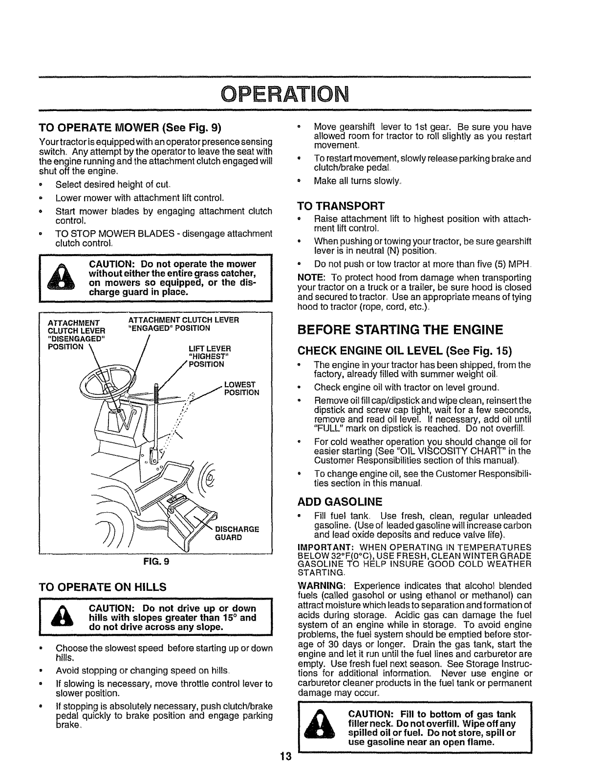
TO OPERATE MOWER (See Fig. 9)
Your tractor isequipped withanoperator presence sensing
switch,. Any attempt by the operator to leave the seat with
the engine running and the attachment clutch engaged wil!
shut off the engine.
o Select desired height of cut°
- Lower mower with attachment lift control.
oStart mower blades by engaging attachment clutch
control.
=TO STOP MOWER BLADES -disengage attachment
clutch control
CAUTION: Do not operate the mower
without either the entire grass catcher,
on mowers so equipped, or the dis-
charge guard in place.
ATTACHMENT ATTACHMENT CLUTCH LEVER
CLUTCH LEVER "ENGAGED" POSITION
"DISENGAGED" /
POSITION "\ /LIFT LEVER
\. /"HIGHEST"
F.__ /POSITION
t' ( \_-"_,.J/_/' _/ .LOWEST
:i_ ).:
FIG. 9
TO OPERATE ON HILLS
I CAUTION: Do not drive up or down
hills with slopes greater than 15°and I
do not drive across any slope
It
o
t
o
Choose the slowest speed before starting up or down
hills,
Avoid stopping or changing speed on hills.
If slowing is necessary, move throttle control lever to
slower position.
If stopping is absolutely necessary, push clutch/brake
pedal quickly to brake position and engage parking
brake°
13
°
°
Move gearshift lever to 1st gear. Be sure you have
allowed room for tractor to roll slightly as you restart
movemenL
To restart movement, slowly release parking brake and
clutch/brake pedal
Make all turns slowly..
TO TRANSPORT
•Raise attachment lift to highest position with attach-
ment lift control
= When pushing ortowing your tractor, be sure gearshift
lever is in neutral (N) position,.
oDo not push or tow tractor at more than five (5) MPH.
NOTE: To protect hood from damage when transporting
your tractor on a truck or a trailer, be sure hood is closed
and secured to tractor_ Use an appropriate means of tying
hood to tractor (rope, cord, etc.)..
BEFORE STARTING THE ENGINE
CHECK ENGINE OIL LEVEL (See Fig. 15)
= The engine inyour tractor has been shipped, from the
factory, already filled with summer weight oil.
.Check engine oil with tractor on level ground,.
= Remove oil fill cap/dipstick and wipe clean, reinsert the
dipstick and screw cap tight, wait for a few seconds,
remove and read oil level. If necessary, add oil until
"FULL" mark on dipstick is reached. Do not overfill.
°For cold weather operation you should change oil for
easier starting (See 'O1L VISCOSITY CHART" in the
Customer Responsibilities section of this manual)..
.To change engine oi1,see the Customer Responsibili-
ties section in this manual,
ADD GASOLINE
•Fill fue! tank. Use fresh, clean, regular unleaded
gasoline. (Use of leaded gasoline will increase carbon
and lead oxide deposits and reduce valve life)..
IMPORTANT: WHEN OPERATING IN TEMPERATURES
BELOW 32°F(0°C), USE FRESH, CLEAN WINTER GRADE
GASOLINE TO HELP INSURE GOOD COLD WEATHER
STARTING.
WARNING: Experience indicates that alcohol blended
fuels (called gasohol or using ethanol or methanol) can
attract moisture which leads to separation and formation of
acids during storage. Acidic gas can damage the fuel
system of an engine while in storage,. To avoid engine
problems, the fuel system should be emptied before stor-
age of 30 days or longer. Drain the gas tank, start the
engine and let it run until the fuel lines and carburetor are
empty. Use fresh fuel next season. See Storage Instruc-
tions for additional information,. Never use engine or
carburetor cleaner products in the fuel tank or permanent
damage may occur.
,,,,,,,,,,,,,,,, i i,,, ,,,,,,,,,r,,,,, I,
CAUTION: Fill to bottom of gas tank
filler neck. Do not overfill. Wipe off any
spilled oil or fuel. Do not store, spill or
use gasoline near an open flame.
iii i.i.iiH ,i,, .............. i iii i HI,L
OPERATION
TO START ENGINE (See Fig. 8)
When starting enginefor the first timeor if engine has run
out of fuel, itwill take extra cranking timeto move fuel from
the tank to the engine°
• Depress clutch/brake pedal and set parking brake.
. Place gearshift lever in neutral (N) position.
• Move attachment clutch to "DISENGAGED" position,
• Pull choke control out to choke (l\J) position for cold
engine start. For-warm engine start do not use choke
control..
• Move throttle control to midway between fast (,re) and
slow (.tl!) positions..
• Insert key into ignition and turn keyc!ockwiseto"START"
position and release key as soon as engine starts. Do
not run starter continuously for more than fifteen
seconds per minute. If engine does not start after
several attempts, move throttle control to fast (,_)
position, wait a few minutes and try again_
. When engine starts, slowly push choke control in.
• Move throttle control to fast (._) position.
° Allow engine to warm up for a few minutes before
engaging drive or attachments_
NOTE: If at a high altitude (above 3000 feet) or in cold
temperatures (below 32°F), the carburetor fuel mixture
may need to be adjusted for best engine performance. See
"TO ADJUST CARBURETOR" in the Service and Adjust-
ments section of this manual.
MOWING TIPS
• Tire chains cannot be used when the mower housing
is attached to tractor.
• Mower should be properly leveled for best mowing
performance_ See'q'O LEVEL MOWER HOUSING" in
the Service and Adjustments section of this manual,
• The left hand side of mower should be used for' trim-
ming,
• Drive so that clippings are discharged onto the area
that has been cut. Have the cut area to the right of the
machine. This will result in a more even distribution of
clippings and more uniform cutting,
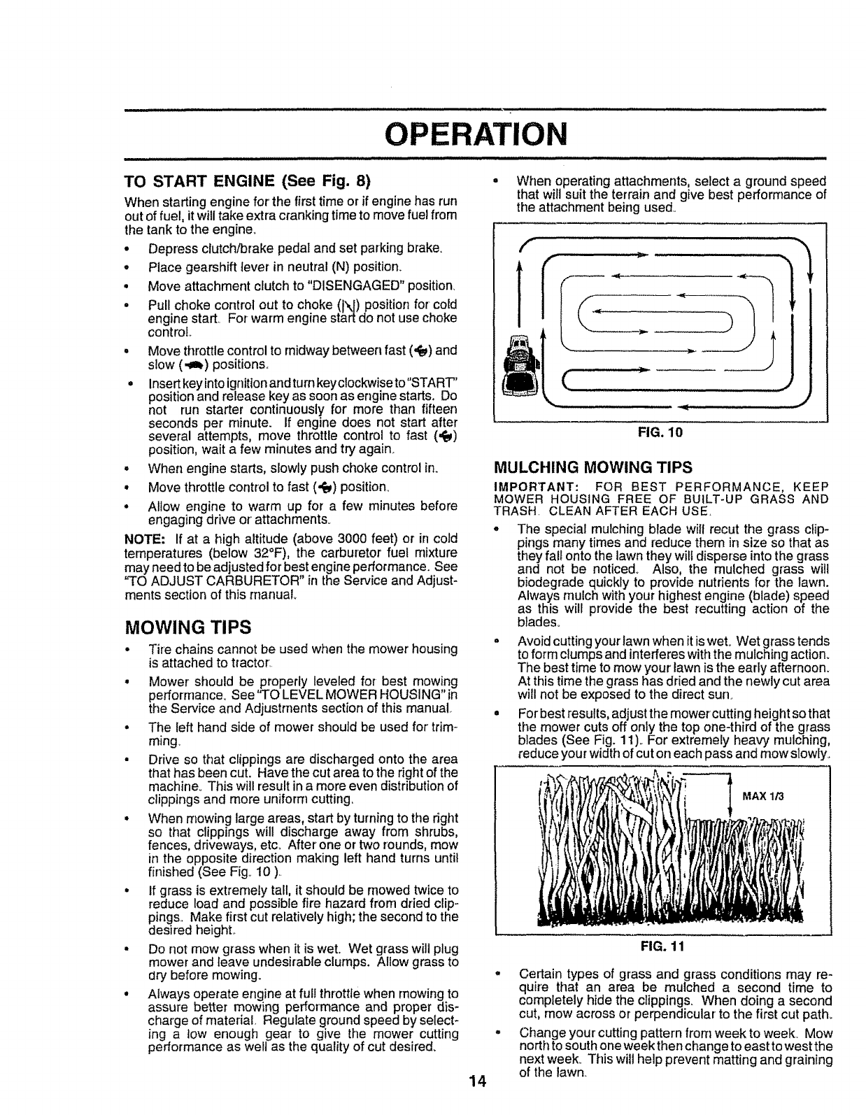
• When mowing large areas, start by turning to the right
so that clippings will discharge away from shrubs,
fences, driveways, etco After one or two rounds, mow
in the opposite direction making left hand turns until
finished (See Fig_ 10 ).
• If grass is extremely tall, it should be mowed twice to
reduce load and possible fire hazard from dried clip-
pings., Make first cut relatively high; the second to the
desired heighL
• Do not mow grass when it is wet. Wet grass will plug
mower and leave undesirable clumps. Allow grass to
dry before mowing_
•Atways operate engine at full throttfe when mowing to
assure better mowing performance and proper dis-
charge of material Regulate ground speed by select-
ing a tow enough gear to give the mower cutting
performance as welt as the quality of cut desired_
• When operating attachments, select a ground speed
that will suit the terrain and give best performance of
the attachment being used_
f...............qll
FIG. 10
MULCHING MOWING TIPS
IMPORTANT: FOR BEST PERFORMANCE, KEEP
MOWER HOUSING FREE OF BUILT-UP GRASS AND
TRASH CLEAN AFTER EACH USE.
•The special mulching blade will recut the grass clip-
pings many times and reduce them in size so that as
they fall onto the lawn they wilt disperse into the grass
and not be noticed° Also, the mulched grass will
biodegrade quickly to provide nutrients for the lawn.
Always mulch with your•highest engine (blade) speed
as this will provide the best recutting action of the
blades.
• Avoid cutting your lawn when it iswet° Wet grass tends
to form clumps and interferes with the mulching action_
The best time to mow your lawn is the early afternoon.
At this time the grass has dried and the newly cut area
will not be exposed to the direct sun.
° For best results, adjust the mower cutting height so that
the mower cuts off only the top one-third of the grass
blades (See Fig. 11)_For extremely heavy mulching,
reduce your width of cut on each pass and mow slowly.
MAX 1/3
llh
14
FIG. 11
.Certain types of grass and grass conditions may re-
quire that an area be mulched a second time to
completely hide the clippings. When doing a second
cut, mow across or perpendicular to the first cut path=
° Change your cutting pattern from week to week. Mow
north to south one week then change to east to west the
next week, This witl help prevent matting and graining
of the lawn.
CUSTOMER RESPONSIBILItTItES
MAINTENANCE SCHEDULE /__,,"f ........
F'LL 'N DATES /_._..,__"
AS YOU COMPLETE /_"_ _j_,_._,_'_O_S"
REGULARSERVICE ./'_" _w/F,_f SERVICE. DATES
Check Brake Operation _' : _ [ ........................ [ i --i ii
Check Tire Pressure
TChe'ckfor Loose Fasteners 6##1_7= , _ _ ..............
=a SharpenlReplace Mower Blades ......... 6#44 '
"'Lubrication Chart .................... " " '"6_ ........ i
Check Battery LeveltRecharge I_e
i_ Clean Battery and Terminals V#_#1
Check Transaxle cooling .__ L##,,, : .....
Adjusi'"Blade Belt(s) Tension Ks "
Adjust Motion Drive Belt(s) Tension Ks
Chec,k Engine OilLevel : _ -$11.... -...............
EClean Air Filter ___ :6#12
N_
GV_'
I
Clean Air Screen
Inspect MuffiertSpark Arrester
Replace Oil Fitter (If equipped)
Clean Engine Cooling Fins t
Replace Air Filter Paper Car_ridge
Rep,ocoFuo,"F,,to,...........
-Change more often when operatingunder a heavy load or in highambient temperatures
2 - Service more often when operating indirty or dusty condiltons
3-I!equipped with oil filter, change oil oval3' 50 hours
4 _Replace blades more often when mowing in sandy soft,
.....
.............
Iv' ................
f - .....
5 _If equippedwIIhadjustablesystem
6-Not requiredifequippedwithmaintenance-freebatte_,
7 -Tightenfrontaxlepivotbottto 35 ftqbs maximum
Donotoverlighten
GENERAL RECOMMENDATIONS
The warranty on this tractor does not cover itemsthat have
been subjected to operator abuse or negligence. To
receive full value from the warranty, operator must maintain
tractor as instructed in this manual
Some adjustments will need to be made periodically to
properly maintain your tractor°
All adjustments in the Service and Adjustments section of
this manual should be checked at least once each season,,
Once a year you should replace the spark plug, clean
or replace air filter, and check blades and belts for
wear. A new spark plug and clean air filter assure
proper air-fuel mixture and help your engine run better
and last longer.
BEFORE EACH USE
•Check engine oil level,,
°Check brake operation,
• Checktire pressure.
• Check for loose fasteners.,
LUBRICATION CHART
'15
® ®
® FRONT
BEARING ZERK
®
FRONT WHEEL (_)
BEARING ZERK
®
CLUTCH
PIVOT(S)
(_) SAE 30 OR t0W30 MOTOR OIL
®GENERAL PURPOSE GREASE
®REFER TO CUSTOMER RESPONSIBILITIES "ENGINE" SECTION
IMPORTANT: DO NOT OIL OR GREASE THE PIVOT POINTS
WHICH HAVE SPECIAL NYLON BEARINGS. VISCOUS LUBRI-
CANTS WiLL ATTRACT DUST AND DIRT THAT WILL SHORTEN
THE UFE OF THE SELF-LUBRICATING BEARINGS. IF YOU
FEEL THEY MUST BE LUBRICATED, USE ONLY A DRY, POW-
DERED GRAPHITE TYPE LUBRICANT SPARINGLY.
CUSTOMER RESPONSIBILITIES
TRACTOR
Always observe safety rules whenperforming any mainte-
nanceo
BRAKE OPERATION
If tractor requires more than six (6) feet stopping distance
at highspeed inhighest gear, thenbrakemust be adjusted.
(See "TO ADJUST BRAKE" in the Service and Adjust-
ments section of this rnanual)o
TIRES
•Maintain proper airpressure in all tires (See "PROD-
UCT SPECiFICATiONS on page 3 of this manual).
,Keeptires free of gasoline,oil,orinsect controlchemi-
cals which can harm rubber.
- Avoid stumps, stories, deep ruts, sharp objects and
other hazards that may cause tire damage_
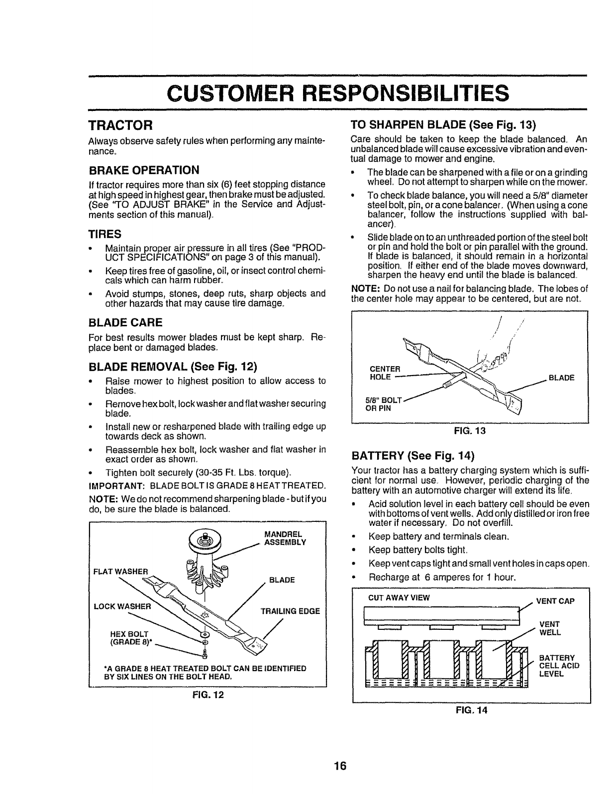
TO SHARPEN BLADE (See Fig. 13)
Care should be taken to keep the blade balanced. An
unbalanced blade will cause excessive vibration and even-
tual damage to mower and engine.
= The blade can be sharpened with a file or on a grinding
wheel., Do not attempt to sharpen while on the mowen
* To check blade balance, you will need a 5/8" diameter
steel bolt, pin, or a cone balancer. (When using a cone
batancer, follow the instructions supplied with bal-
ancer).
• Slide blade on to an unthreaded portionof the steel bolt
or'pin and hold the bolt or pin parallel with the ground.
If blade is balanced, it should remain in a horizontal
position. If either end of the blade moves downward,
sharpen the heavy end until the blade is balanced.,
NOTE: Do not use a nailfor balancing blade. The lobes of
the center hole may appear to be centered, but are not.
BLADE CARE
For best results mower blades must be kept sharp. Re-
place bent or damaged blades..
BLADE REMOVAL (See Fig. 12)
•Raise mower to highest positionto allow access to
blades.,
• Remove hex bolt, lock washer and flat washer securing
bladeo
- Install new or resharpened blade with trailing edge up
towards deck as shown.
°Reassemble hex bolt, lock washer and fiat washer in
exact order' as shown.
• Tighten bolt securely (30-35 Ft. Lbs. torque),
IMPORTANT: BLADE BOLT IS GRADE 8 HEATTREATEDo
NOTE: We do not recommend sharpening blade- but if you
do, be sure the blade is balanced.
MANDREL
ASSEMBLY
FLAT WASHER
LOCK WASHER
HEX BOLT
(GRADE8) °
BLADE
TRAILING EDGE
/
*A GRADE 8HEAT TREATED BOLT CAN BE IDENTIFIED
BY SIX LINES ON THE BOLT HEAD°
FIG. 12
'/ i
///
OR PIN
FIG; 13
BATTERY (See Fig, 14)
Your tractor has a battery charging system which is suffi-
cient for' normal use, However, pedodic charging of the
battery with an automotive charger will extend its life.
•Acid solution level in each batten./cell should be even
with bottoms of vent wells° Add onlydistilled or iron free
water if necessary+ Do not overfill.
•Keep battery and terminals clean+
•Keep battery bolts tight,
•Keepvent caps tight and small vent holes incaps open.
•Recharge at 6 amperes for 1 hour.
AWAY VENTOAP
FIG. 14
16
CUSTOMER RESPONSIBILITUES
............................ r, n ill ,in
TO CLEAN BATTERY AND TERMINALS
Corrosion and dirt on the battery and terminals can cause
the battery to "leak" power,
o Remove terminal guard,
- Disconnect BLACK battery cable first then RED
battery"cable and remove battery from tractor.,
o Wash battery with solution of four tablespoons of
baking soda to one gallon of water, Be careful not to
get the soda solution into the cells.
° Rinse the battery with plain water and dry,
° Clean terminals and battery cable ends with wire
brush until bright..
• Coat terminals with grease or petroleum jelly.
• Reinstall battery (See "INSTALL BATTERY" in the
Assembly section of this manual).
V-BELTS
Check V-belts for deterioration and wear after 100 hours of
operation and replace if necessary, The belts are not
adjustable., Replace belts if they begin to slip from wear,,
TRANSAXLE COOLING
Keep transaxle free from build-up of dirt and chaff which
can restrict cooling,
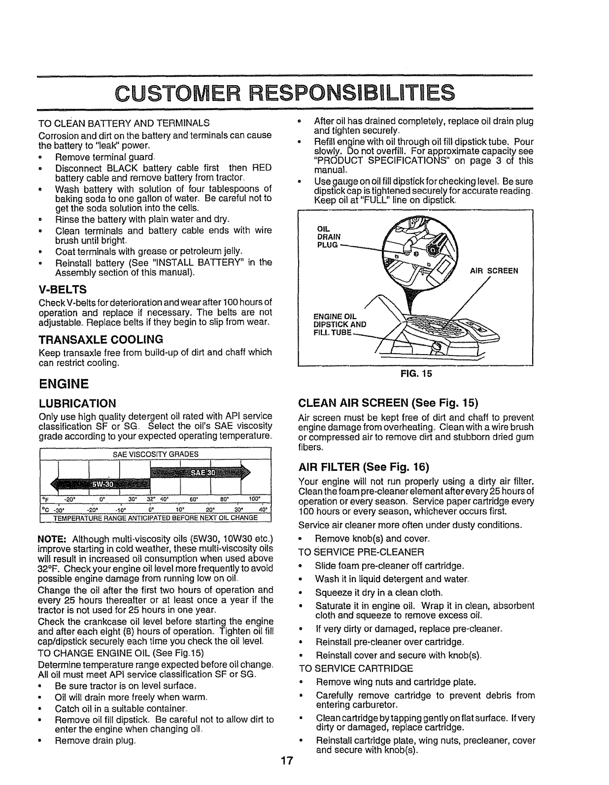
ENGINE
°After oil has drained completely, replace oil drain plug
and tighten securely.
° Refill engine with oil through oil fill dipstick tube. Pour
slowly. Do not overfill For approximate capacity see
"PRODUCT SPECIFICATIONS on page 3 of this
manual
oUse gauge on oil fill dipstick for checking level. Be sure
dipstick cap istightened securely for accu rate reading.
Keep oil at "FULL" line on dipstick,
OIL
DRAIN
AIR SCREEN
ENGINE OiL
DIPSTICK AND
FIG. 15
LUBRICATION
Only use high quality detergent oil rated with API service
classification SF or SG Select the oil's SAE viscosity
grade according to your expected operating temperature,
SAE VISCOSITY GRADES
OF -20 ° 0_ 30" 32" 40 ¢ 60" 80 ° '_00'
°c -3o' *_o" .loo 0' ;0° _o" 3'o. 4o".....
TEMPERATURE RANGE ANTICIPATED 8EFORE NEXT OtL CHANGE ,,,
NOTE; Although multi-viscosity oils (5W30, 10W30 etc.,)
improve starting in cold weather, these multFviscosity oils
will result in increased oil consumption when used above
320F. Check your engine oil level more frequently to avoid
possible engine damage from running Iow on oilo
Change the oil after the first two hours of operation and
every 25 hours thereafter or at least once a year if the
tractor is not used for 25 hours in one year.
Check the crankcase oil level before starting the engine
and after each eight (8) hours of operation. Tighten oil fill
cap/dipstick securely each time you check the oil level,
TO CHANGE ENGINE OIL (See Fig,15)
Determine temperature range expected before oil change.
All oil must meet API service classification SF or SG.
o Be sure tractor is on level surface.
•Oil will drain more freely when warm,,
• Catch oil in a suitable container.
°Remove oil fit! dipstick_ Be careful not to allow dirt to
enter the engine when changing oi!.
• Remove drain plug,,
CLEAN AIR SCREEN (See Fig, 15)
Air screen must be kept free of dirt and chaff to prevent
engine damage from overheating, Clean with a wire brush
or compressed air to remove dirt and stubborn dried gum
fibers°
AIR FILTER (See Fig. 16)
Your engine witl not run properly using a dirty air filter.
Clean the foam pre-cleaner element after every 25 hours of
operation or every season° Service paper cartridge every
100 hours or every season, whichever occurs first,
Service air cleaner more often under dusty conditions.
oRemove knob(s) and cover_
TO SERVICE PRE-CLEANER
*Slide foam pre-cleaner off cartridge.
o Wash it in liquid detergent and water,,
o Squeeze it dry in a clean cloth°
o Saturate it in engine oil. Wrap it in clean, absorbent
cloth and squeeze to remove excess oil
.If very dirty or damaged, replace pre-cleaner.
o Reinstall pre-cleaner over cartridge°
o Reinstall cover and secure with knob(s).
TO SERVICE CARTRIDGE
o Remove wing nuts and cartridge plate.
.Carefully remove cartridge to prevent debris from
entering carburetor.
. Clean cartridge by tapping gently on flat surface° Ifvery
dirty or damaged, reptace cartndge.
° Reinstall cartridge plate, wing nuts, precleaner, cover
and secure with knob(s).,
17
CUSTOMER RESPONSIBILITIES
IMPORTANT; PETROLEUM SOLVENTS, SUCH AS
KEROSENE, ARE NOT TO BE USED TO CLEAN THE
CARTRIDGE. THEY MAY CAUSE DETERIORATION OF
THE CARTRIDGE DO NOT OIL CARTRIDGE. DO NOT
USE PRESSURIZED AIR TO CLEAN OR DRY
CARTRIDGE.
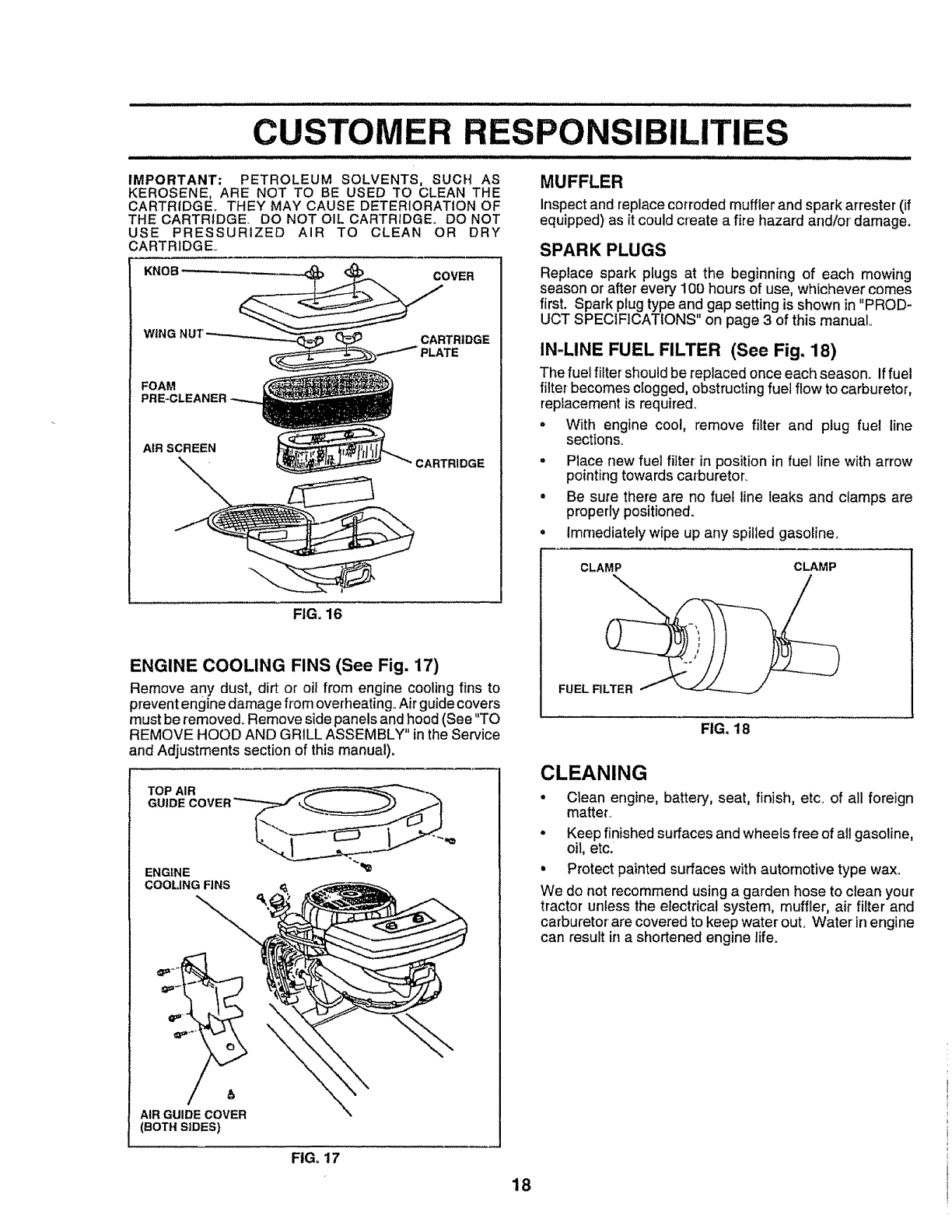
WING CARTRIDGE
FOAM
PRE-CLEANER
AIR SCREEN
CARTRIDGE
FIG, 16
ENGINE COOLING FINS (See Fig. 17)
Remove any dust, dirt or oil from engine coolingfins to
preventenginedamage from overheating°Airguidecovers
must be removed. Removeside panels andhood (See "TO
REMOVE HOOD AND GRILL ASSEMBLY" inthe Service
and Adjustments section of thismanual),
ENGINE
COOLING FINS
--...
AIR GUIDE COVER
(BOTH SIDES)
MUFFLER
Inspectand replace corrodedmuffler and spark arrester(if
equipped)as itcouldcreate a fire hazard and!or damage.
SPARK PLUGS
Replace spark plugs at the beginning of each mowing
season or after every 1O0hours of use, whichever comes
first. Spark plug type and gap setting is shown in "PROD-
UCT SPECIFICATIONS" on page 3 of this manual
IN-LINE FUEL FILTER (See Fig. 18)
The fuel filter should be replaced once each season, if fuel
filter becomes clogged,obstructing fuel flow to carburetor,
replacement is required.
• With engine cool, remove filter and piug fuel line
sections.
•Place new fuel filter in position in fuel line with arrow
pointing towards carburetor°
= Be sure there are no fuel line leaks and clamps are
properly positioned.
° Immediately wipe up any spilled gasoline.
CLAMP
FUEL FILTER
CLAMP
FIG. 18
CLEANING
* Clean engine, battery, seat, finish, etc_ of all foreign
matter_
•Keep finished surfaces and wheels free of all gasoline,
oil, etc.
• Protect painted surfaces with automotive type wax_
We do not recommend using a garden hose to clean your
tractor unless the electrical system, muffler, air filter and
carburetor are covered to keep water outo Water in engine
can result in a shortened engine life.
FIGo17
18
SERVICE AND ADJUSTMENTS
.... .................................. HIi,11ii1,1i
iii rl ilrll .r, _i_,1 ............. , ii i ....................................
CAUTION: BEFORE PERFORMING ANY SERVICE OR ADJUSTMENTS:
=Depress clutch/brake pedal fully and set parking brake,
=Place gearshift lever in neutral (N) position,
oPlace attachment clutch in "DISENGAGED" position,
°Turn ignition key "OFF" and remove key.
=Make sure the blades and all moving parts have completely stopped,
°Disconnect spark plug wire from spark plug and place wire where it cannot come in contact with
plug,
HIll ........................ ijII, HI i.......................... i ,_ ii ii
TRACTOR
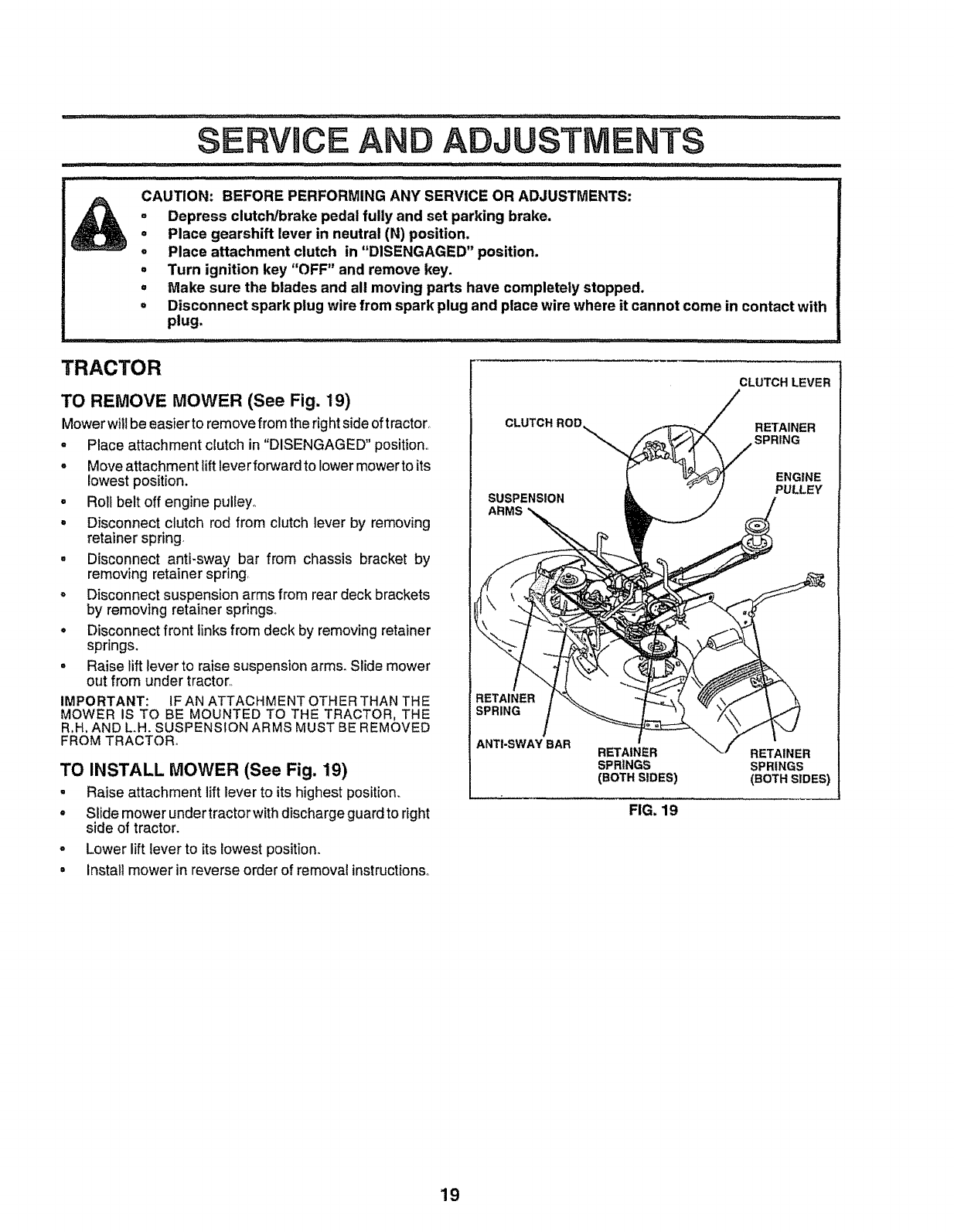
TO REMOVE MOWER (See Fig. 19)
Mowerwillbe easier toremove from the right side oftractor
-Place attachment clutch in"DISENGAGED" position,,
°Move attachment lift leverforward to lower mower to its
lowest position.
°Roll belt off engine pulley°
=Disconnect clutch rod from clutch lever by removing
retainer spring.
• Disconnect anti-sway bar from chassis bracket by
removing retainer spring,
= Disconnect suspension arms from rear deck brackets
by removing retainer springs.,
•Disconnect front links from deck by removing retainer
springs.
•Raise lift lever to raise suspension arms. Slide mower
out from under tractor,,
IMPORTANT: IF AN ATTACHMENT OTHER THAN THE
MOWER IS TO BE MOUNTED TO THE TRACTOR, THE
R,H, AND L.H. SUSPENSION ARMS MUST BE REMOVED
FROM TRACTOR°
TO INSTALL MOWER (See Fig. 19)
•Raise attachment liftlever to its highest position.
° Slide mower undertractorwith discharge guard to right
side of tractor.
o Lower lift lever to its lowestposition.
= Install mower in reverse order of removal instructions°
CLUTCH ROD
SUSPENSION
ARMS
RETAINER
SPRINGS
(BOTH SIDES)
FIG, 19
CLUTCH LEVER
RETAINER
SPRING
ENGINE
PULLEY
RETAINER
SPRINGS
(BOTH SIDES)
19
-- _ illllllljlllll,llllllll,llllJllill i
SERVICE AND ADJUSTMENTS
...................... jl ii ii i ................................
TO LEVEL MOWER HOUSING FRONT-TO-BACK ADJUSTMENT (See Figs°22 and 23)
IMPORTANT: DECK MUST BE LEVEL SIDE-TO-SIDEotF
THE FOLLOW|NG FRONT-TO=BACK ADJUSTMENT IS
NECESSARY, BE SURE TO ADJUSTBOTH FRONT LINKS
EQUALLY SO MOWER WILL STAY LEVEL SIDE-TO-
SIDE.
Adjust the mower while tractor is parked on level ground or
driveway. Make sure tires are properly inflated (See
"PRODUCT SPECIFICATIONS" on page 3of this manual).
if tires are overor underinflated, you witl not properly adjust
your mower°
SIDE-TO-SIDE ADJUSTMENT (See Figs. 20 and 21)
oRaise mower to its highest position°
• Atthe midpoint of both sides of mower, measure height
from bottom edge of mower to ground,. Distance"A" on
both sides of mower should be the same or within 1/4"
of each other°
-If adjustment is necessary, make adjustment on one
side of mower only.
= To raise one side of mower, tighten lift link adjustment
nut on that side,.
•To lower one side of mower, loosen lift link adjustment
nut on that side.
NOTE: Each full turn of adjustment nut willchange mower
height about 1/8'L
• Recheck measurements after adjusting_
BOTTOM EDGE BOTTOM EDGE
OF MOWER TO OF MOWER TO
GROUND GROUND
FIG=20
SUSPENSION
ARM
LIFT LINK
ADJUSTMENT NUT
FIG. 21
To obtain the best cutting results, the mower housing
should be adjusted so that the front is approximately 1/4" to
3/4" lower than the rear when the mower is in its highest
position°
Check adjustment on right side of tractor. Measure dis-
tance "D" directly infront and behind the mandrel at bottom
edge of rnowerhousing as shown°
° Before making any necessary adjustments, check that
both front links are equal in length. Both links should be
approximately t0-3/8'L
°If linksare not equal in length, adjust one linkto same
length as other link.
• To Lower front of mower loosen nut "E" on both front
links an equal number of turns.
• When distance "D" is 1/4" to 3/4" lower at front than
rear, tighten nuts "F" against trunnion on both front
links,
• To raisefront of mower, loosen nut"F" from trunnion on
both front links° Tighten nut "E" on both front tinksan
equal number of turns.
•When distance "D" is 1/4" to 3/4" lower at front than
rear, tighten nut"F" against trunnion on both front links.
• Recheck side-to-side adjustmenL
% I MANDREL
FIG. 22
BOTHFRONTLINKSMUST BE EQUALtN LENGTH
NUT "E"
LINKS TRUNNION
20 FIG. 23
-: ..................................................................... ill
TO REPLACE MOWER BLADE DRIVE BELT
(See Fig. 24)
The mower blade drive belt may be replaced without tools°
Park the tractor on level surface. Engage parking brake.
BELT REMOVAL -
= Remove mower from tractor (See "TO REMOVE
MOWER" in this section of this manual).
oWork belt off both mandrel pulleys and idler pulleys.
o Pull belt away from mower,.
BELT INSTALLATION -
° Install new bett in reverse order of removal
• Make sure belt isinall pulley grooves and inside all belt
guides_
o Install mower in reverse order of removal instruction&
MANDREL PULLEY IDLER PULLEYS
MANDREL PULLEY
FIG. 24
NUT "A"
M NUT
ERATING
O_J ARM
FIG. 25
TO REPLACE MOTION DRIVE BELT
(See Fig. 26)
Park the tractor on level surface, Engage parking brake,
For assistance, there is a belt installationguide decal on
bottom side of left footrest,.
oRemove mower (See ''TO REMOVE MOWER" in this
section of this manual.)
•Remove upper belt keeper,.
,, Remove belt from stationary idlerand clutching idter._
- Pull belt slack toward rear of tractor. Remove belt
upwards from transaxle pulley by deflecting belt keep-
erso
° PUll belt toward front of tractor and remove downwards
from around engine pulley.,
°Installnew belt by reversing above procedure,
IMPORTANT: MAKE SURE UPPER BELT KEEPER ES
POSITIONED PROPERLY BETWEEN LOCATOR TABS
TO ADJUST BRAKE (See Fig. 25)
Your tractor is equipped with an adjustable brake system
which is mounted on the right side of the transaxle.
If tractor requires more than six (6) feet stopping distance
at high speed inhighest gear, then brake must be adjusted.
°Depress clutch/brake pedal andengage parking brake.
o Measure distance between brake operating arm and
nut "A" on brake to&
"e e
• If distance is other than 1-1/2, dis ngag parking
brake, loosen jam nut and turn nut "A" until distance
becomes 1-1/2". Retighten jam nut against nut "A".
° Engage parking brake and recheck distance_
° Road test tractor for proper stopping distance as stated
above. Readjust if necessary. If stopping distance is
still greater than six (6) feet in highest gear, further
maintenance is necessary_ Contact your nearest
authorized service centeddepartment.
EN GINE"'-J,-L.-_ _It
PULLEY _JI--LOOATO.
CLUTCH1NG--...,L-----_.J,,,"_W""-II TABS
'°'" IL-4
It _....tL°J) ! IF" UPPERBELT
_ | l{ KEEPER
STATIONARY_"-I1 I | 11
tl II I]
TRANSAXLE._. II _ I1
FIG. 26
21
illlll,llllllllllllllllllllll/, i, illl ill iill ii ii .......
SERVICE AND ADJUSTMENTS
.,,,,,.,,,,,,,,,,,,,,,,,,,,,,,,,, ....................
TO ADJUST STEERING WHEEL ALIGNMENT TO START ENGINE WITH A WEAK BATTERY
If steeringwheel crossbars are not horizontal (leftto right)
when wheels are positioned straightforward, remove steer-
ing wheel and reassemble per instructions inthe Assembly
section of this manual°
FRONT WHEEL TOE-IN/CAMBER
The front wheel toe-in and camber are not adjustable on
your' tractor° If damage has occurred to affect the front
wheel toe-in or camber, contact your nearest authorized
service center.
(See Fig. 28)
,ll,,,, = lllll ==ll Hl==l i
CAUTION: Lead-acid batteries gener-
ateexplosivegases. Keep sparks, flame
and smoking materials away from bat-
teries. Always wear eye protection
when around batteries.
TO REMOVE WHEEL FOR REPAIRS
(See Fig. 27)
° Block up axle securely.,
• Remove axle cover, retaining ring and washersto allow
wheel removal (rear wheel containsa square key - Do
not lose).
•Repair'tire and reassemble_
.On rear wheels only: align groovesin rear wheel hub
and axle_ Insert square key_
• Replace washers and snap retaining ring securely in
axle groove.
° Replace axle cover'..
WASHERS
RETAINING
RING
AXLE COVER
I
_SQUARE KEY
(REAR WHEEL ONLY)
FIG. 27
I,I.I,HHIIIIll III I Illlllll Illlllllll
If your battery is too weak to start the engine, it should be
recharged. If "jumper cables" are used for emergency
starting, follow this procedure:
IMPORTANT: YOUR TRACTOR IS EQUIPPED WITH A 12
VOLT NEGATIVE GROUNDED SYSTEM THE OTHER
VEHICLE MUST ALSO BE A 12 VOLT NEGATIVE
GROUNDED SYSTEM. DO NOT USE YOUR TRACTOR
BATTERY TO START OTHER VEHICLES
TO ATTACH JUMPER CABLES -
° Connect each end of the RED cable to the POSITIVE
(+) terminat of each battery, taking care not to short
against chassis.
• Connect one end of the BLACK cable to the NEGA-
TIVE (-) terminal of fu{ty chaJged battery.
°Connect the other end of the BLACK cable to good
CHASSIS GROUND, away from fuel tank and battery..
TO REMOVE CABLES, REVERSE ORDER -
° BLACK cable first from chassis and then from the fully
charged battery'.
•RED cable last from both batteries.
"POSITIVE" (+) "NEGATIVE" (-)
PANEL
BOLT
o
FIG. 28
22
............ i....
SERVICE AND
TO REPLACE HEADLIGHT BULB
oRaise hood.
o Pull bulb holder out of the hole in the backside of the
grill,
- Replace bulb in holder and push bulb holder securely
back into the hole in the backside of the grill.
•Close hood.
INTERLOCKS AND RELAYS
Loose or damaged wiring may cause your tractorto run
poorly, stop running, or prevent it from starting.
,check wiring° See electrical wiring diagram in Repair
Parts section of this manual°
TO REPLACE FUSE
Replace with 30 amp automotive-type plug-infuser The
fuse holder is located behind the dash.
TO REMOVE HOOD AND GRILL (See Fig. 29)
•Raise hood.
,, Unsnap headlight wire connector.
°Stand in front of tractor. Grasp hood at sides, tilt
forward and lift off of tractor°
= To reinstall, slide hood pivot brackets into slots in
frame°
° Reconnect headlight wire connector and close hood,
ADJUSTMENTS
HEADLIGHT
WIRE
CONNECTOR
ENGINE
TO ADJUST THROTTLE CONTROL CABLE
(See Fig. 30)
The throttle control has been preset at the factory and
adjustment should not be necessary_ Check adjustment as
described below before looseningcable. If adjustment is
necessary, proceed as follows:
° With engine not running, move throttle control lever to
fast (,_) position.
oCheck that swivel is against side of quarter circle° if it
is not, loosen cable clamp screw and pull cable back
until swivel is against quarter circle. Tighten cable
clamp screw securely_
HOOD
TO ADJUST CHOKE CONTROL (See Fig. 31)
The choke control has been preset at the factory and
adjustment should not be necessary. Check adjustment as
described below before loosening cable. If adjustment is
necessary, proceed as follows:
- With engine not running, move choke control (located
on dash panel) to full choke (l\!) position.
°Remove air cleaner cover, filter and cartridge plate to
expose carburetor choke (see "AIR FILTER" in the
Customer Responsibilities section of this manual)_
o Choke should be closed.. If it is not, loosen casing
clamp screw and move choke cable until choke is
completely closed.. Tighten casing clamp screw se-
curely.
o Reassemble air cleaner.
Ct,AMP SCREW _-_
QUARTER
CIRCLE
SWIVEL
FIG. 30
FIG. 29
23
CHOKECLOSED
FIG. 31
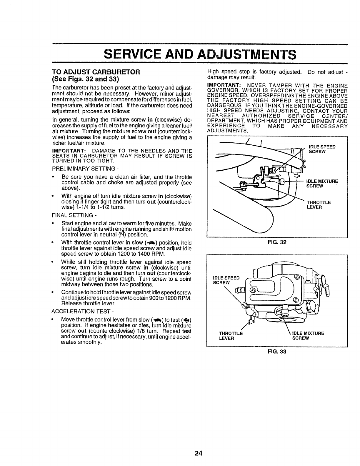
SERVICE AND ADJUSTMENTS
' mlll.l,llll ii i IHI i ii 'imllii t
TO ADJUST CARBURETOR
(See Figs. 32 and 33)
The carburetor has been preset at the factory and adjust-
ment should not be necessary. However, minor adjust-
rnent may be required to compensate for differences infuel,
temperature, altitude or load. If the carburetor does need
adjustment, proceed as follows:
In general, turning the mixture screw in (clockwise) de-
creases the supply offuel to the engine giving a leaner fuel/
air mixture. Turning the mixture screw out (counterclock-
wise) increases the supply of fuel to the engine giving a
dcher fuel/air mixture+
IMPORTANT: DAMAGE TO THE NEEDLES AND THE
SEATS IN CARBURETOR MAY RESULT IF SCREW IS
TURNED IN TOO TIGHT,
PRELIMINARY SETTING -
•Be sure you have a cJean air filter, and the throttle
control cable and choke are adjusted properly (see
above).
•With engine off turn idle mixture screw in (clockwise)
closing it finger tight and then turn out (counterclock-
wise) 1-1/4 to 1-1/2 turns+
FINAL SETTING -
•Start engine and allow to warmfor five minutes+ Make
final adjustments with engine running and shift/motion
control lever in neutral (N) position°
•With throttle control lever in stow (-m_) position, hold
throttle lever against idle speed screw and adjust idle
speed screw to obtain 1200 to 1400 RPM
•While still holding throttle lever against idle speed
screw, turn idle mixture screw in (clockwise) until
engine begins to die and then turn out (counterclock-
wise) until engine runs rough. Turn screw to a point
midway between those two positions.
•Continue to hold throttle lever against idte speed screw
and adjust idle speed screw to obtain900 to 1200 RPM
Release throttlelever:
ACCELERATION TEST-
Move throttle control lever from slow (-€_) to fast (,_)
position, if engine hesitates or dies, turn idle mixture
screw out (counterclockwise) 1/8 turn. Repeat test
and cont}nue to adjust, ifnecessary, until engine accel-
erates smoothly+
High speed stop is factory adjusted° Do not adjust -
damage may result
IMPORTANT: NEVER TAMPER WITH THE ENGINE
GOVERNOR, WHICH IS FACTORY SET FOR PROPER
ENGINE SPEED+ OVERSPEEDING THE ENGINE ABOVE
THE FACTORY HIGH SPEED SETTING CAN BE
DANGEROUS, tF YOU THINK THE ENGINE+GOVERNED
HIGH SPEED NEEDS ADJUSTING, CONTACT YOUR
NEAREST AUTHORIZED SERVICE CENTER/
DEPARTMENT, WHICH HAS PROPER EQUIPMENT AND
EXPERIENCE TO MAKE ANY NECESSARY
ADJUSTMENTS
IDLE SPEED
SCREW
IDLE MIXTURE
SCREW
THROTTLE
LEVER
FIG. 32
LEVER SCREW
FIG, 33
24
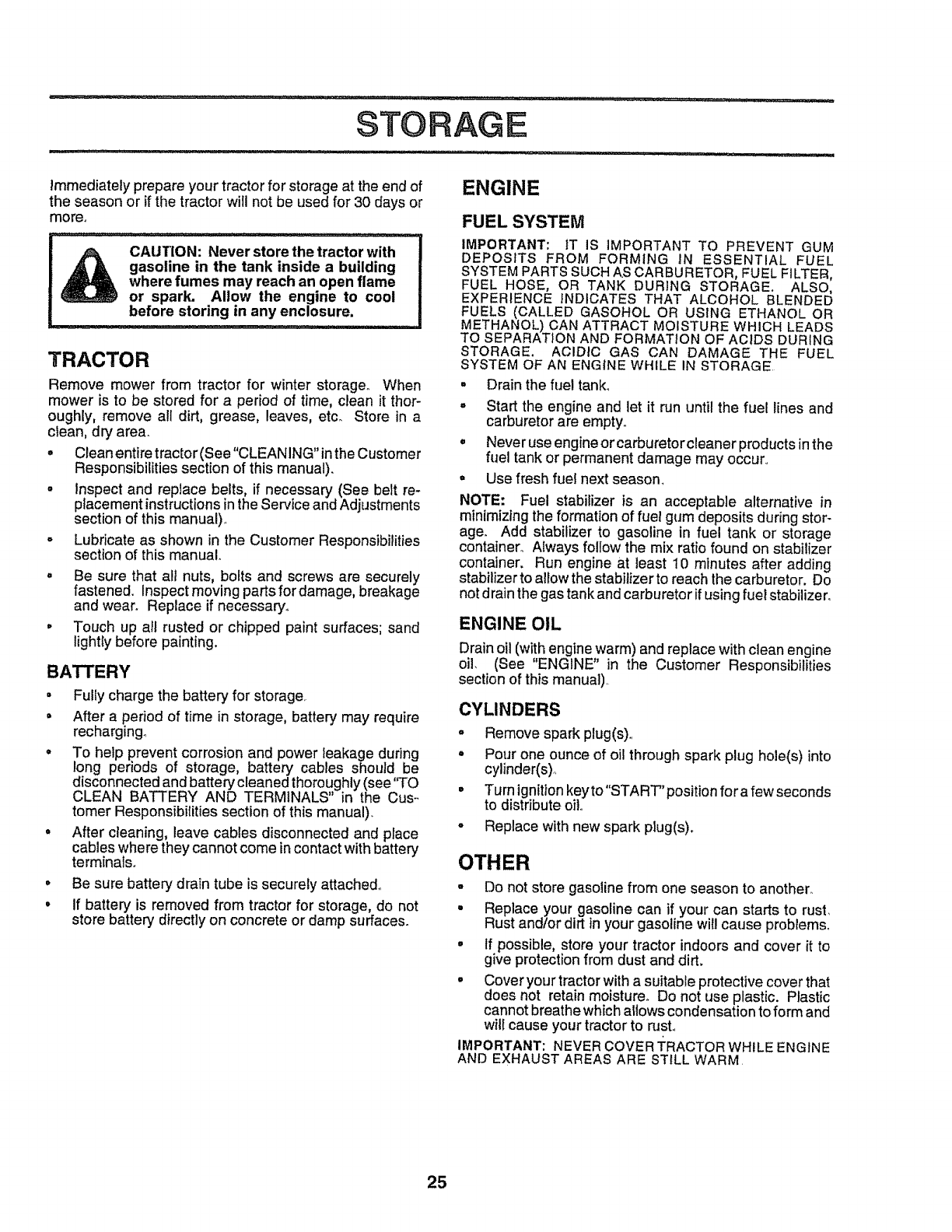
,i,, i1,,,,,,11,,i,,_11,1,_ ,, _ ........
STORAGE
immediately prepare your tractor for storage at the end of
the season or if the tractor will not be used for 30 days or
more°
CAUTION: Never store the tractor with
gasoline in the tank inside a building
where fumes may reach an open flame
or spark. Allow the engine to cool
before storing in any enclosure.
TRACTOR
o
a
Remove mower from tractor for winter storage. When
mower is to be stored for a period of time, clean it thor-
oughly, remove all dirt, grease, leaves, etc. Store in a
clean, dry area.
oClean entire tractor (See "CLEANING" in the Customer
Responsibilities section of this manual).
•inspect and replace belts, if necessary (See belt re-
placement instructions in the Service and Adjustments
section of this manual)
Lubricate as shown in the Customer Responsibilities
section of this manual.
Be sure that all nuts, bolts and screws are securely
fastened, Inspect moving parts for damage, breakage
and wear. Replace if necessary.
Touch up all rusted or chipped paint surfaces; sand
lightly before painting,
BATTERY
•Fully charge the battery for storage.
= After a period of time in storage, battery may require
recharging_
• To help prevent corrosion and power leakage during
long periods of storage, battery cables should be
disconnected and battery cleaned thoroughly (see 'q'O
CLEAN BATTERY AND TERMINALS in the Cus-
tomer Responsibilities section of this manual).
•After cleaning, leave cables disconnected and place
cables where they cannot come incontact with battery
terminals.
° Be sure battery drain tube is securely attached°
°If battery is removed from tractor for storage, do not
store battery directly on concrete or damp surfaces.
ENGINE
FUEL SYSTEM
IMPORTANT: tT IS IMPORTANT TO PREVENT GUM
DEPOSITS FROM FORMING IN ESSENTIAL FUEL
SYSTEM PARTS SUCH AS CARBURETOR, FUEL FILTER,
FUEL HOSE, OR TANK DURING STORAGE, ALSO,
EXPERIENCE INDICATES THAT ALCOHOL BLENDED
FUELS (CALLED GASOHOL OR USING ETHANOL OR
METHANOL) CAN ATTRACT MOISTURE WHICH LEADS
TO SEPARATION AND FORMATION OF ACIDS DURING
STORAGE. ACIDIC GAS CAN DAMAGE THE FUEL
SYSTEM OF AN ENGINE WHILE IN STORAGE
• Drain the fuel tank°
° Start the engine and let it run until the fuel lines and
carburetor are empty.
° Neveruse engineorcarburetorcleanerproductsin the
fuel tank or permanent damage may occur..
° Use fresh fuel next season,
NOTE: Fuel stabilizer is an acceptab]e alternative in
minimizing the formation of fue! gum deposits during stor-
age. Add stabilizer to gasoline in fuel tank or storage
container° Always follow the mix ratio found on stabilizer
container. Run engine at least 10 minutes after adding
stabilizer to allow the stabilizer to reach the carburetor. Do
not drain the gas tank and carburetor ifusing fuel stabilizer.
ENGINE OIL
Drain oil (with engine warm) and replace with clean engine
oil. (See "ENGINE" in the Customer Responsibilities
section of this manual)
CYLINDERS
-Remove spark plug(s).,
= Pour one ounce of oil through spark plug hole(s) into
cylinder(s)..
° Turnignitionkeyto"START"positionforafewseconds
to distribute oilo
-Replace with new spark plug(s).
OTHER
-Do not store gasoline from one season to another.
• Replace your gasoline can if your can starts to rust,
Rust and/or dirt in your gasoline wil! cause problems.
•If possible, store your tractor indoorsand cover it to
give protection from dust and dirt,
•Cover your tractor with a suitable protective cover that
does not retain moisture° Do not use plastic. Plastic
cannot breathe which allows condensation to form and
will cause your tractor to rust,.
IMPORTANT: NEVER COVER TRACTOR WHILE ENGINE
AND EXHAUST AREAS ARE STILL WARM
25

TROUBLESHOOTING POINTS
PROBLEM
Wilt not start
Hard to start
CAUSE
I, Out of fuel,
2 Engine not"CHOKED" properly.
3. Engine flooded_
4, Bad spark plug.
5, Dirty air filter.
6, Dirtyfuel fiiter
7 Water infuel
8. Loose or damaged wiring
9, Carburetor out of adjustment.
t0 Engine valves out of adjustment.
CORRECTION
•mliHillllIll I II UL _ L
1. Fill fuel tank,
2. See "TO START ENGINE" inOperation section
3 Wait several minutes before attempting to start.
4 Repiace spark ptug.
5Clean/replace air filter.
6, Replace fuel lifter
7 Drain fuel tank and carburetor, refill tank with fresh
gasoline and replace fuel filter.
8. Check all wiring
9,, Contact an authorized servtce center/department,
10,. Contact an authorized service center/department,
1Dirtyair filter
2, Bad spark plug
3, Weak or dead battery.
4, Dirty fuel f_Iter
5Stale or dirty fuel.
6 Loose or damaged widng
7Carburetor out of adjustment.
8 Engine valves out of adjustment
1. Clean/replace air filter,
2. Replace spark plug
3. Recharge or replace battery
4 Replace fuel filter.
5 Drain fuel tank and refill with fresh gasoline
6, Check all wiring.
7. Contact an authorized service centeddepartment
8 Contact an authorized service center/department
Engine wilt not turn over
i
Engine cricks but will not
start
Lose ot_power
Excessive vibration
1_ Clutch/brake pedal not depressed
2, Attachment dutch is engaged.
3, Weak ordead battery.
4 Blown fuse,
5. Corroded battery terminals.
6. Loose or damaged widng
7. Faulty ignitionswitch,
8. Faulty solenoid or starter
9. Faulty operator presence swttch(es)
1. Weak or dead battery,
2. Corroded battery terminals
3, Loose or damaged wiring
4_ Faulty solenoid or starter,
1, Cutting too much grass/too fast
2, Throttle in "CHOKE" position,
3, Build-upof grass, leaves and trash under mower
4, Dirty a{r fi_ter_
5, Low oft levetldirty oil,
6, Faulty spark ptug,.
7, Dirty fuel filter_
8. Stale or dirty fuel.
9. Water in fuel,
10. Spark plug wire loose
11, Dirty engine air screen/fins
12, Dtrtylclogged muffler.
13. Loose or damaged wiring.
14, Carburetor out of adjustment
15 Engine valves out of adjustment,
1. Worn, bent or loose blade,
2 Bent btade mandrel,.
3 Loose/damaged part(s)
1 Depress clutch/brake pedal.
2. Disengage attachment clutch.
3 Recharge or replace battery,
4 Replace fuse,
5. Clean battery terminals.
6, Check all wiring,
7 Check/replace ignitionswitch.,
8 Check/replace solenoid or starter
9. Contact an authorized service centerldepartment
1. Recharge or replace battery,
2. Clean battery terminals
3. Check all wiring
4 Check/replace solenoid or starter
1. Set in "Higher Cut" position/reduce speed.
2. Adjust throttle control
3. Clean underside of mower housing,
4. Clean/replace air filter
5, Check oil leveltchange oil.
6. Clean and regap or change spark plug
7, Replace fuel filter.
8, Drain fueFtank and refill with fresh gasoline.
9. Drain fuel tank and carburetor, refill tank with fresh
gasoline and replace fuel filter,
10. Connect and tighten spark plug wire
11, Clean engine air screen/tins
12 Clean/replace muffler
13. Check ati wiring,
14. Contact an authorized service centeddepartment
15, Contact an authorized service center/department
llIHlllllIH=HI ==llJlUll[ H I - -
1, Replace blade. Tighten blade bolt,
2, Replace blade mandrel,
3 Tighten loose part(s). Replace damaged parts
26

i i
TROUBLESHOOTING POUNT$
PROBLEM
Engine continues to run
when operator leaves seat
with attachment clutch
engaged
Poor cut -uneven
Mower blades will not
rotate
Poor grass discharge
Headlight(s) not working
(if so equipped)
Battery will not charge
Engine "backfires"
when turning engine
"OFF"
CAUSE
t FauI_'/operator-safety presence controlsystem,
1, Worn, bent orloose blade,
2.. Mower deck not level.
3 Buildup of grass, leaves, and trash under mower,
4. Bent blade mandrel,
5. Clogged mower deck vent holes from bufldup of
grass, loaves, and trash around mandrels
CORRECTION
1 Check wiring, switches and connections, If not
corrected, contact an authorized service canted
1. Obstruction in clutch mechanism.,
2. Womldamaged mower drive belt.,
3, Frozen idler pulley,
4, Frozen blade mandrel,,
1, Engine speed tooslow.
2, Travel speed too last
3 Wet grass
4 Mower deck not revel.
5. Low/uneven tire air pressure,
6 Worn, bent or loose blade.,
department
1., Replace blade° Tighten blade bolt.
2, Level mower deck
3, Clean underside of mower housing,
4., Replace blade mandrel
5 Clean around mandrels to open vent holes
7Buildup of grass, leaves and trash under mower.
8, Mower drive belt worn
9. Blades improperly installed,
10 improper blades used,
t I Clogged mower deck vent holes from butldup of
grass, leaves, and trash around mandrels
1 Switch Is "OFF",
2 Bulb(s) burned out
3Faulty light switch
4 Loose or damaged wtring,
5. Blown fuse.
t Bad battery calf(s),
2 Poorcable connections,
3,. Faulty regulator (if so equipped)
4. Faulty alternator.
1. Remove obstruction
2, Replace mower drive belt
3. Replace idler pulley,
4, Replace blade mandrel,
1, Place throttle control in "FAST" position.
2. Shtft to slower speed,
3, Allow grass to dry before mowing
4. Level mower deck.
5, Check tires for proper air pressure,
6 Replacelsharpen blade, Tighten blade bolt.
7, Clean underside of mower housing°
8. Replace mower drive belt,
9. Reinstall blades sharp edge down.
10. Replace with blades listed in thla manual,
tt. Clean around mandrels to open vent holes,
Engine throttle control not set at "SLOW"
position for 30 seconds before stopping engine,
I, Turn switch "ON",
2. Replace bulb(s).
3 Checldreplace light switch
4. Check wtringand connections.
5Replace fuse,
1, Replace battery,
2Cheek/clean all connections
3, Replace regulator,
4, Replace afternator,
1, Move throttle control to "SLOW" position and allow
to idle for 30 seconds before stoppingengine,
27

SERVICE NOTES
28
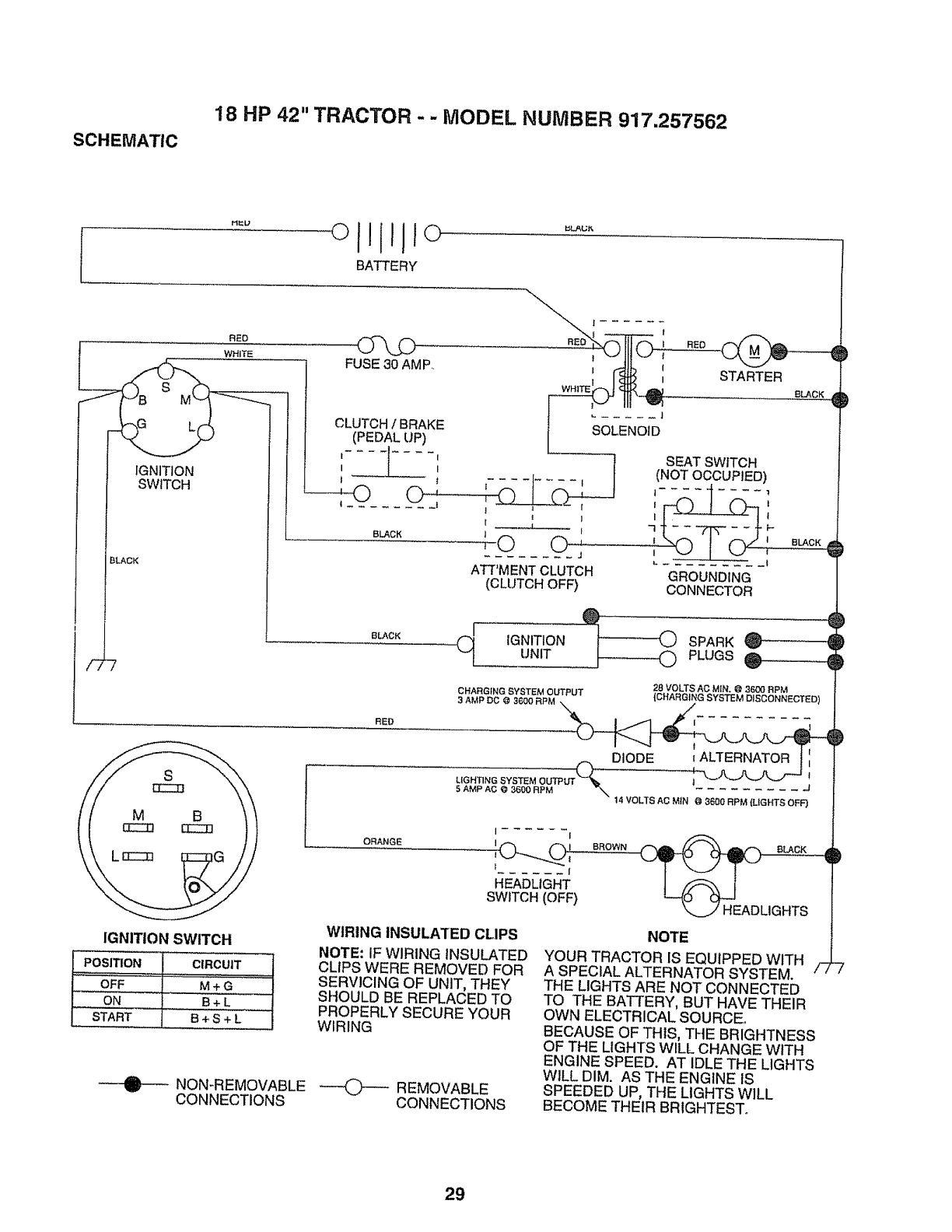
SCHEMATIC
18 HP 42" TRACTOR - - MODEL NUMBER 917.257562
BATTERY
J
/2-7
RED
WHITE
IGNITION
SWITCH
BLACK
CLUTCH/BRAKE
(PEDALUP)
f .... {.... I
I I I
It
BLACK
rE_ SEAT SWITCH
(NOTOCCUPIED)
-tt........ !
I _ I7F-
kO o ;
ATT'MENTCLUTCH GROUNDING
(CLUTCHOFF) CONNECTOR
8LACK
C[ IGNITION : 0 SPARK _
UNiT .............0 PLUGS@
RED
28 VOLTS AG MIN, @ 3600 RPM
CHARGING SYSTEM OUTPUT (CHARGING SYSTEM DISCONNECTED)
3 AMP DC @ 3t500 RPM _ j
,LIGHTING SYSTEM OUTPUT_ 1 _ .j
5AMP AC @ 3600 RPM "_ .........
14 VOLTS AC MtN @ 3600 RPM {LIGHTS OFF)
IGNITION SWITCH
POSITION CIRCUIT
OFF M + G
ON B+ L
START B+ S + L
NON-REMOVABLE
CONNECTIONS
ORANGE
I I
f...... I
HEADLIGHT
SWITCH(OFF)
BROWN
WIRING INSULATED CLIPS
NOTE: IF WIRING INSULATED
CLIPS WERE REMOVED FOR
SERVICING OF UNIT, THEY
SHOULD BE REPLACED TO
PROPERLY SECURE YOUR
WIRING
---(_-- REMOVABLE
CONNECTIONS
NOTE
YOUR TRACTOR IS EQUIPPED WITH
A SPECIAL ALTERNATOR SYSTEM. /-;
THE LIGHTS ARE NOT CONNECTED
TO THE BATTERY, BUT HAVE THEIR
OWN ELECTRICAL SOURCE°
BECAUSE OF THIS, THE BRIGHTNESS
OF THE LIGHTS WILL CHANGE WITH
ENGINE SPEED. AT IDLE THE LIGHTS
WILL DIM. AS THE ENGINE IS
SPEEDED UP, THE LIGHTS WILL
BECOME THEIR BRIGHTEST°
29
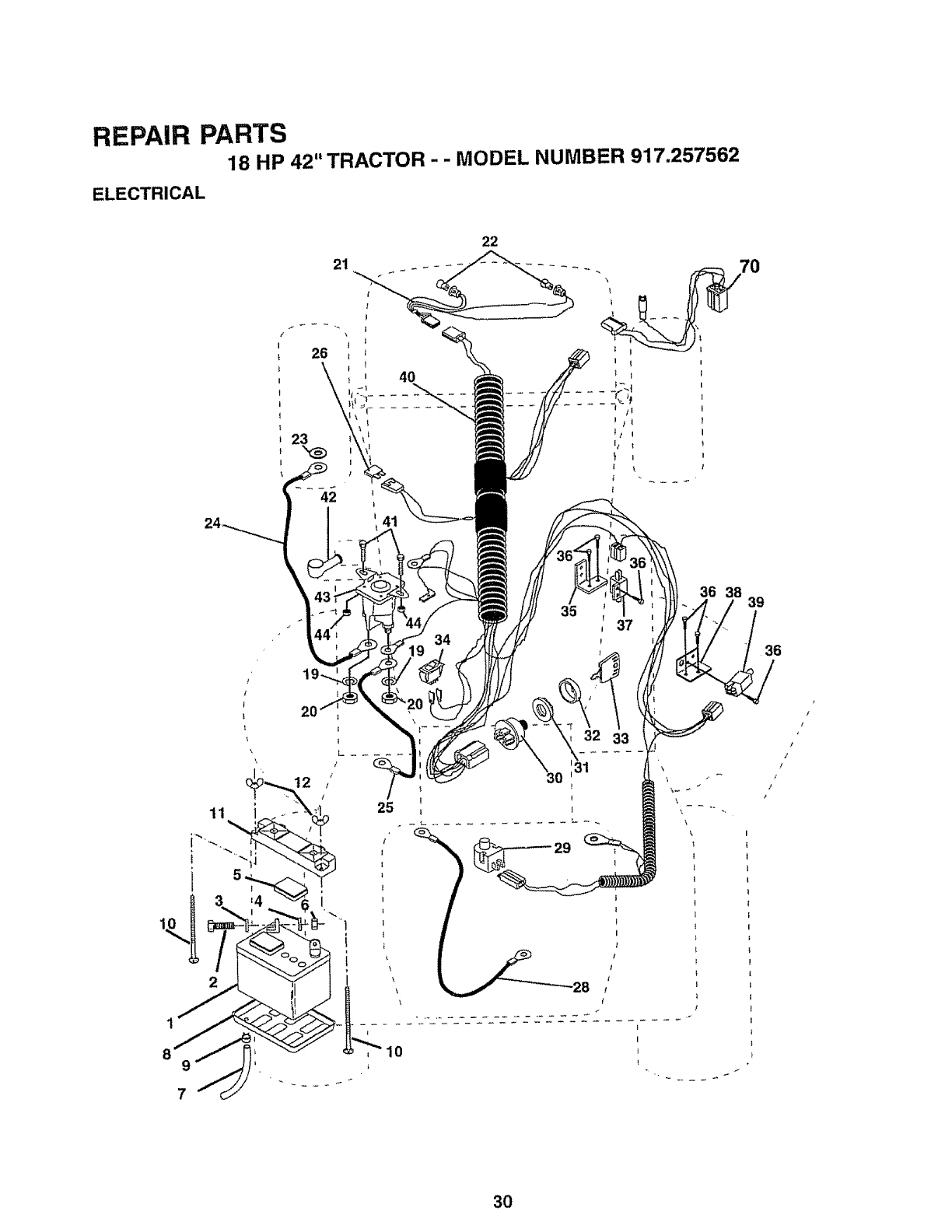
REPAIR PARTS
18 HP 42" TRACTOR-- MODEL NUMBER 917,257562
ELECTRICAL
21
42 I
I
41
22
!
!
t
\
9
7
20
12
25
10
35
I
p
32 33
36 38
.. 39
36
............. ZZZZZ_ ........ "
B
I
!
3O
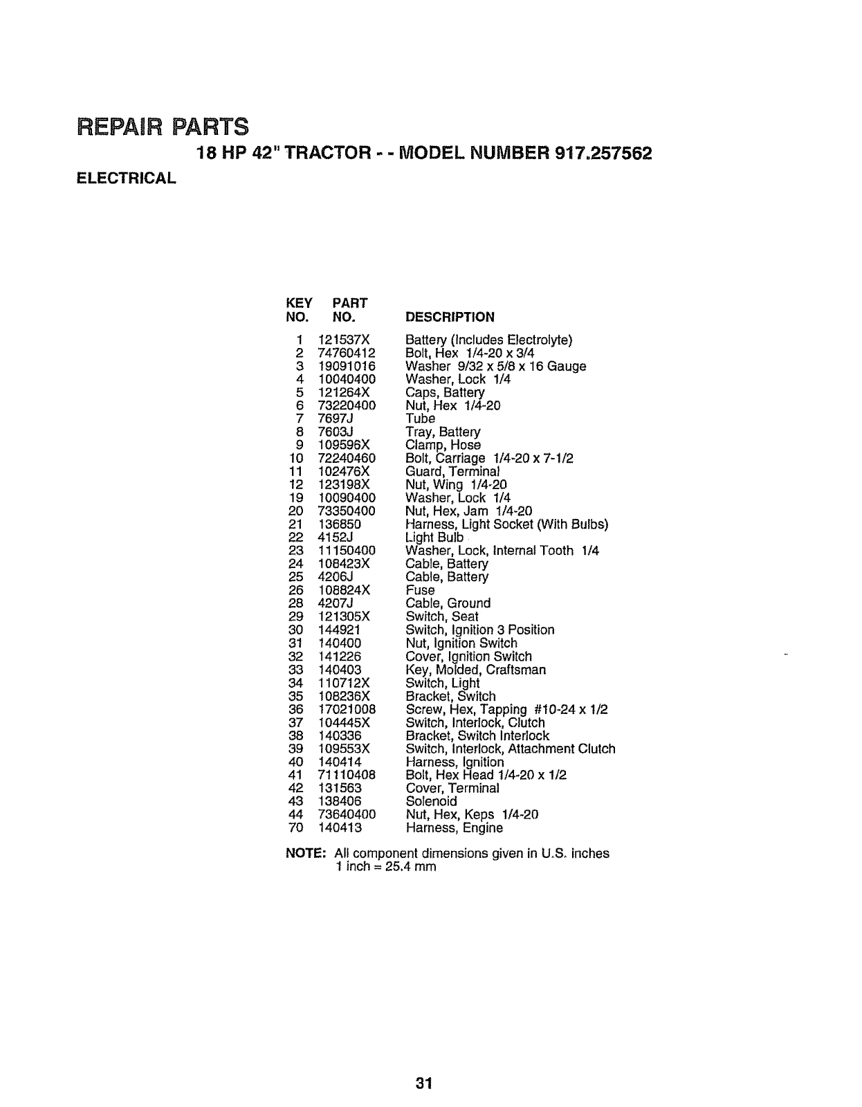
REPAnR PARTS
18 HP 42" TRACTOR -- MODEL NUMBER 917.257562
ELECTRICAL
KEY PART
NO. NO. DESCRIPTION
1 121537X
2 74760412
3 19091016
4 1004O400
5 121264X
6 73220400
7 7697J
8 7603J
9 109596X
t0 72240460
11 102476X
t2 123198X
19 10090400
2O 7335040O
21 136850
22 4152J
23 1115O400
24 108423X
25 4206J
26 108824X
28 4207J
29 121305X
30 144921
31 140400
32 141226
33 140403
34 110712X
35 108236X
36 17021008
37 104445X
38 140336
39 109553X
40 14O414
41 71110408
42 131563
43 138406
44 736404OO
7O 14O413
Battery (Includes Electrolyte)
Bolt, Hex 1/4-20 x 3/4
Washer 9/32 x 5/8 x 16 Gauge
Washer, Lock 1/4
Caps, Battery
Nut, Hex 1/4-20
Tube
Tray, Battery
Clamp, Hose
Bolt, Carriage 1/4-20 x 7-1/2
Guard, Terminal
Nut, Wing 1/4-20
Washer, Lock 1/4
Nut, Hex, Jam t/4-20
Harness, LightSocket (With Bulbs)
Light Bulb
Washer, Lock, Internal Tooth 1/4
Cable, Battery
Cable, Battery
Fuse
Cable, Ground
Switch, Seat
Switch, ignition 3 Position
Nut, Ignition Switch
Cover, Ignition Switch
Key, Molded, Craftsman
Switch, Light
Bracket, Switch
Screw, Hex, Tapping #t0-24 x 1/2
Switch, Interlock, Clutch
Bracket, Switch Interlock
Switch, Interlock, Attachment Clutch
Harness, ignition
Bolt, Hex Head 1/4-20 x 1/2
Cover, Terminal
Solenoid
Nut, Hex, Keps 1/4-20
Harness, Engine
NOTE: All component dimensions given in UoS. inches
1inch = 25.4 mm
31
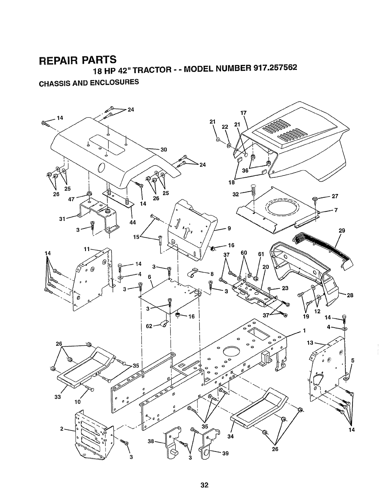
REPAIR PARTS
18 HP 42" TRACTOR - - MODEL NUMBER 917.257562
CHASSIS AND ENCLOSURES
17
21
26 47
31
14
26
33
1
10
44
14
26
14
25
18
32 27
3
26
14
32
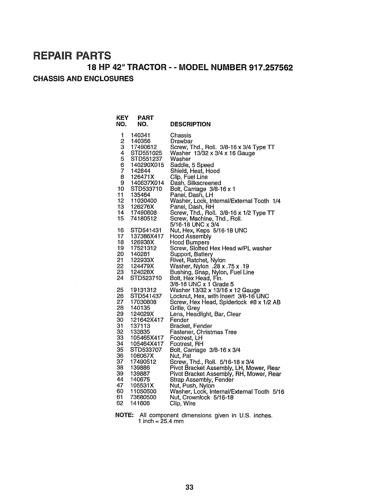
REPAIR PARTS
18 HP 42" TRACTOR - - MODEL NUMBER 917.257562
CHASSIS AND ENCLOSURES
KEY PART
NO. NO. DESCRIPTION
1 140341
2 140356
3 17490612
4 STD551025
5 STD551237
6 140290X015
7 142844
8 12647tX
9 140637X0t4
10 STD533710
11 135464
12 11030400
13 126276X
14 17490608
15 74180512
16 STD541431
17 137386X417
t8 't26938X
19 17521312
2O 14028I
21 122933X
22 124479X
23 124028X
24 STD5237!0
25 19131312
26 STD541437
27 17030808
28 140135
29 124029X
30 t21642X417
31 137113
32 133835
33 t05465X417
34 105464X417
35 STD533707
36 108067X
37 17490512
38 139886
39 139887
44 140675
47 105531X
6O 1105O500
6t 73680500
62 141606
Chassis
Drawbar
Screw, Thd_,Roll. 3/8-16 x 3/4 Type TT
Washer 13/32 x 3/4 x 16 Gauge
Washer
Saddle, 5 Speed
Shield, Heat, Hood
Clip, Fue! Line
Dash, Silkscreened
Bolt, Carriage 3/8-16 x 1
Panel, Dash, LH
Washer, Lock, Internal/External Tooth 1/4
Panel, Dash, RH
Screw, Thd., Roll. 3/8-16 x 1/2 Type TT
Screw, Machine, Thd_,Roll.
5/16-18 UNC x 3/4
Nut, Hex, Keps 5/16-18 UNC
Hood Assembly
Hood Bumpers
Screw, Slotted Hex Head wlPL washer
Support, Battery
Rivet, Ratchet, Nylon
Washer, Nylon .28 x.75 xo19
Bushing, Snap, Nylon, Fuel Line
Bolt, Hex Head, Fin.
3/8-16 UNC x 1 Grade 5
Washer 13/32 x I3/16 x 12 Gauge
Locknut, Hex, with Insert 3/8-16 UNC
Screw, Hex Head, Spidedock #8 x 1/2 AB
Grille, Grey
Lens, Headlight, Bar, Clear
Fender
Bracket, Fender
Fastener, Christmas Tree
Footrest, LH
Footrest, RH
Bolt, Carriage 3/8-16 x 3/4
Nut, Pal
Screw, Thd., Rol!. 5/16-18 x 3/4
Pivot Bracket Assembly, LH, Mower, Rear
Pivot Bracket Assembly, RH, Mower, Rear
Strap Assembly, Fender
Nut, Push, Nylon
Washer, Lock, Internal/External Tooth 5/16
Nut, Crownlock 5/16-18
Clip, Wire
NOTE: All component dimensions given in UoSoinches.
1 inch = 25.4 mm
33
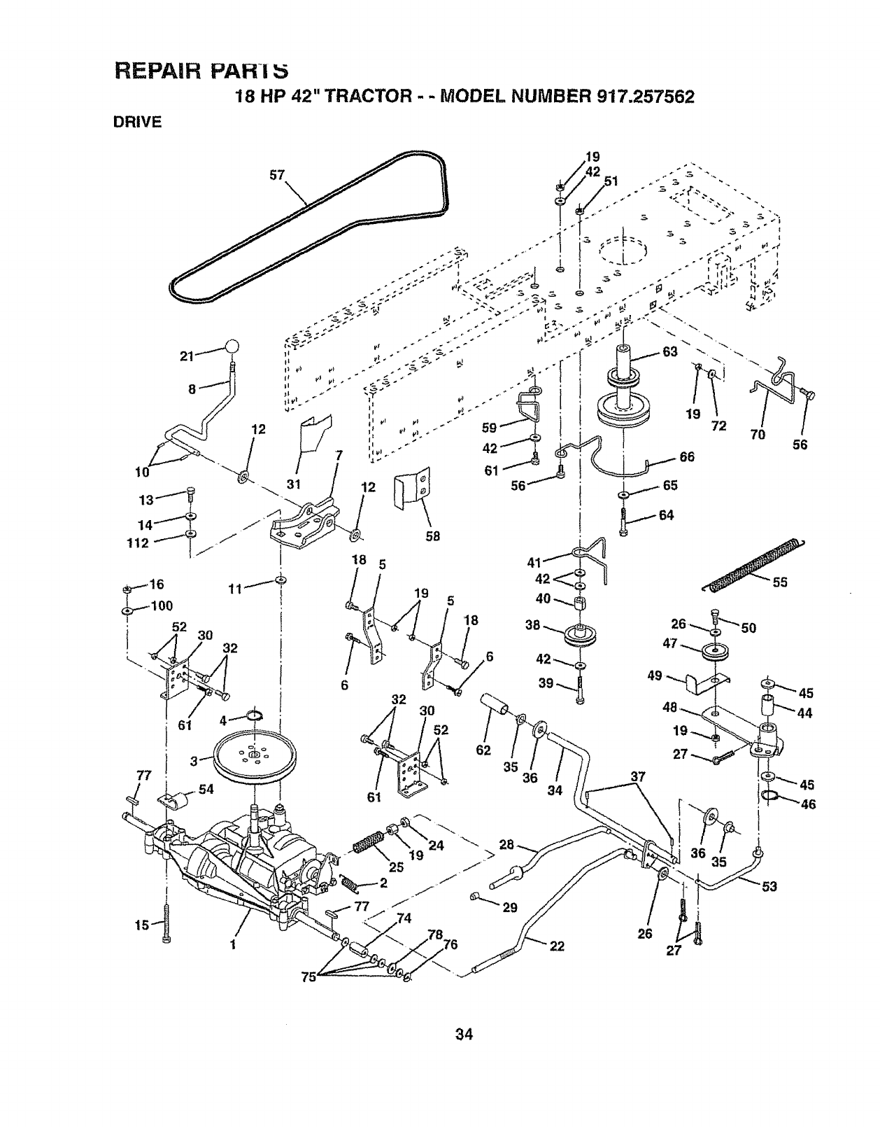
REPA|H PAHi :5
18 HP 42" TRACTOR - - MODEL NUMBER 917.257562
DRIVE
57
18
,65
64
34
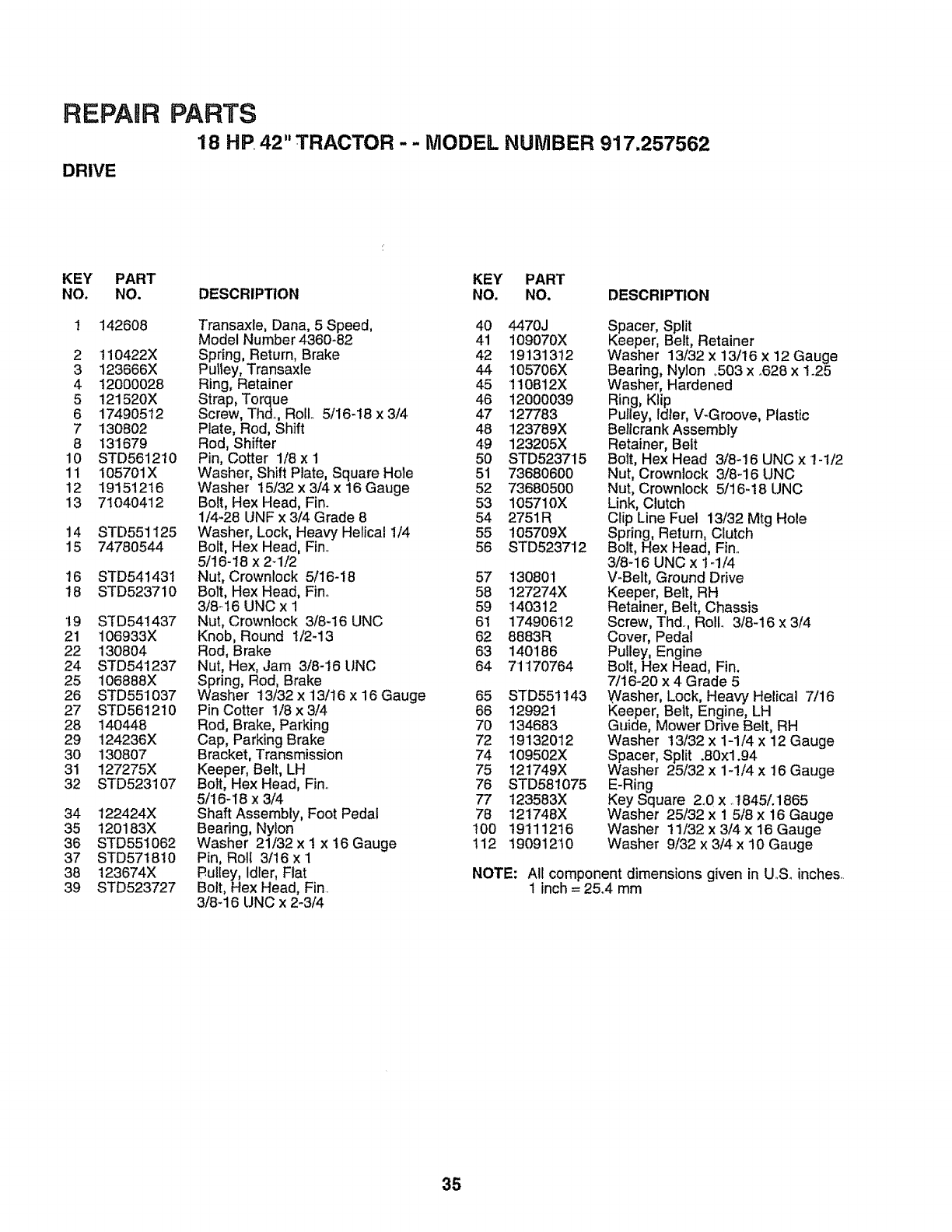
REPAIR
DRIVE
PARTS
18 HP 42" TRACTOR - -MODEL NUMBER 917.257562
KEY
NO.
2
3
4
5
6
7
8
10
11
12
13
14
15
16
18
t9
21
22
24
25
26
27
28
29
30
31
32
34
35
36
37
38
39
PART
NO.
1426O8
110422X
123666X
12000028
121520X
17490512
130802
131679
STD561210
105701X
19151216
7t 04O412
STD551 I25
74780544
STD541431
STD523710
STD541437
106933X
130804
STD541237
106888X
STD551 O37
STD561210
140448
124236X
130807
127275X
STD523107
122424X
120183X
STD55t 062
STD571810
123674X
STD523727
KEY PART
DESCRIPTION NO. NO. DESCRIPTION
Transaxle, Dana, 5 Speed, 40 4470J
Model Number 4360-82 41 109070X
Spring, Return, Brake 42 19131312
Pulley, Transaxle 44 105706X
Ring, Retainer 45 110812X
Strap, Torque 46 t2000039
Screw, Thd. Roll 5/16-18 x 3/4 47 127783
Plate, Rod, Shift 48 123789X
Rod, Shifter 49 123205X
Pin, Cotter 1/8 x 1 50 STD523715
Washer, Shift Plate, Square Hole 51 73680600
Washer 15/32 x 3/4 x 16 Gauge 52 73680500
Bolt, Hex Head, Fin. 53 t05710X
1/4-28 UNF x 3/4 Grade 8 54 2751R
Washer, Lock, Heavy Helical 1/4 55 105709X
Bolt, Hex Head, Finn 56 STD523712
5/16-18 x 2d/2
Nut, Crownlock 5/16-18 57 t30801
Bolt, Hex Head, Fin.. 58 127274X
3/8o16 UNCx 1 59 140312
Nut, Crownlock 3/8-16 UNC 61 17490612
Knob, Round I/2-13 62 8883R
Rod, Brake 63 140186
Nut, Hex, Jam 3/8-16 UNC 64 71170764
Spring, Rod, Brake
Washer 13/32 x 13/t6 x ! 6 Gauge 65 STD551143
Pin Cotter 1/8x3/4 66 129921
Rod, Brake, Parking 70 134683
Cap, Parking Brake 72 19132012
Bracket, Transmission 74 109502X
Keeper, Belt, LH 75 121749X
Bolt, Hex Head, Fin,. 76 STD581075
5/16-I8 x 3/4 77 123583X
Shaft Assembly, Foot Pedal 78 121748X
Bearing, Nylon 100 t9111216
Washer 21/32 x 1 x 16 Gauge 112 19091210
Pin, Roll 3/16 x 1
Pulley, Idler, Flat
Bolt, Hex Head, Fin.
3/8-16 UNC x 2-3/4
Spacer, Split
Keeper, Belt, Retainer
Washer 13/32 x 13/16 x 12 Gauge
Bearing, Nylon ,503 x .628 x ! .25
Washer, Hardened
Ring, Ktip
Pulley, idler, V-Groove, Plastic
Bellcrank Assembly
Retainer, Belt
Bolt, Hex Head 3/8-16 UNC x t-1/2
Nut, Crownlock 3/8-16 UNC
Nut, Crownlock 5/16-18 UNC
Link, Clutch
Clip Line Fuel 13/32 Mtg Hole
Spring, Return, Clutch
Bolt, Hex Head, Fin,.
3/8-16 UNC x 1-1/4
V-Belt, Ground Drive
Keeper, Belt, RH
Retainer, Belt, Chassis
Screw, Thd., Rollo 3/8-16 x 3/4
Cover, Pedal
Pulley, Engine
Bolt, Hex Head, Fin.
7/t6-20 x 4 Grade 5
Washer, Lock, Heavy Helical 7/!6
Keeper, Belt, Engine, LH
Guide, Mower Drive Belt, RH
Washer t3/32 x 1-1/4 x 12 Gauge
Spacer, Split .80xl.94
Washer 25/32 x 1-1/4 x 16 Gauge
E-Ring
Key Square 2°0 x .t845/.1865
Washer 25/32 x 1 5t8 x 16 Gauge
Washer 11/32 x 3/4 x 16 Gauge
Washer 9/32 x 3/4 x 10 Gauge
NOTE: All component dimensions given in U_Soinches,
1inch= 25.4 mm
35
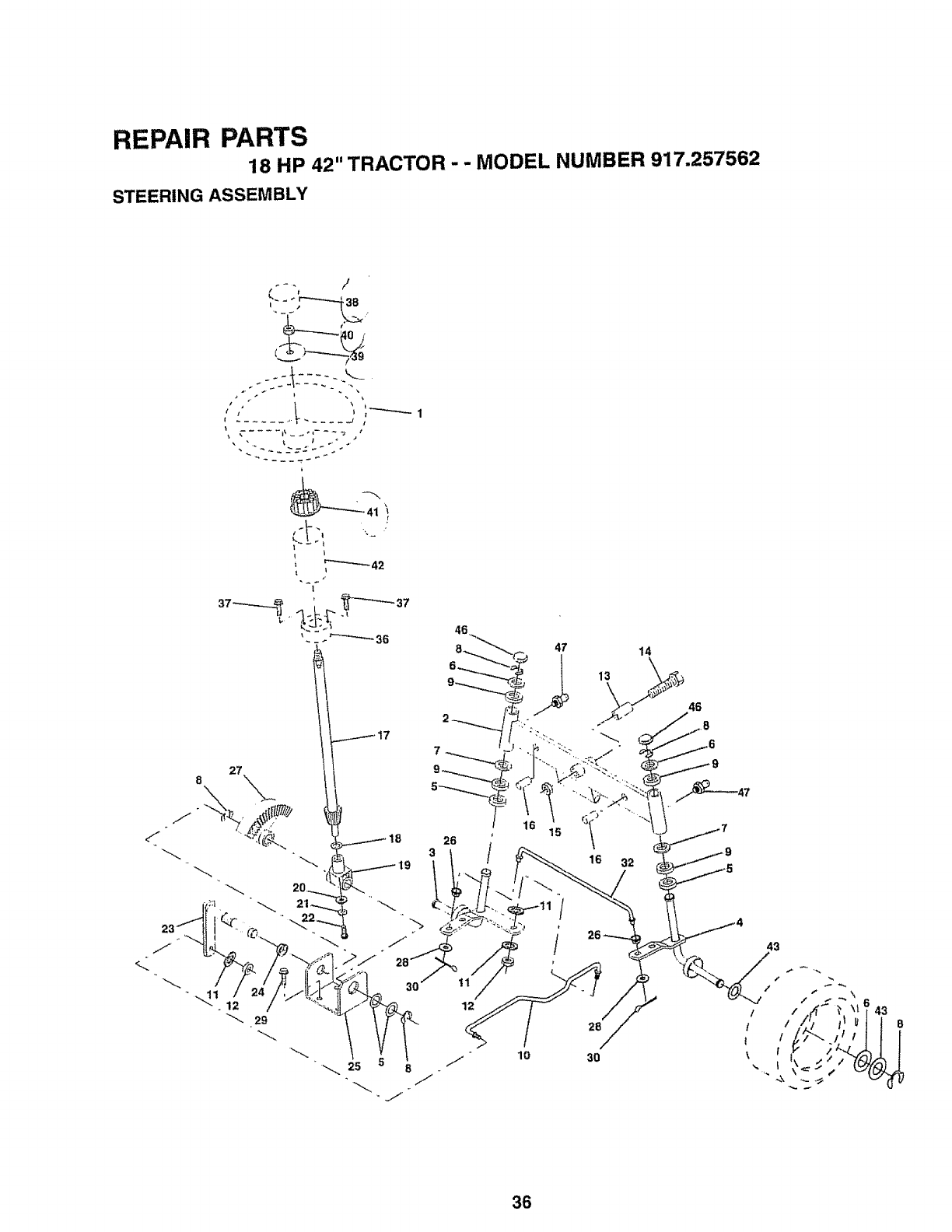
REPAIR PARTS
18 HP 42" TRACTOR - - MODEL NUMBER 917.257562
STEERING ASSEMBLY
t
12
i/ "10 30
43
43
36
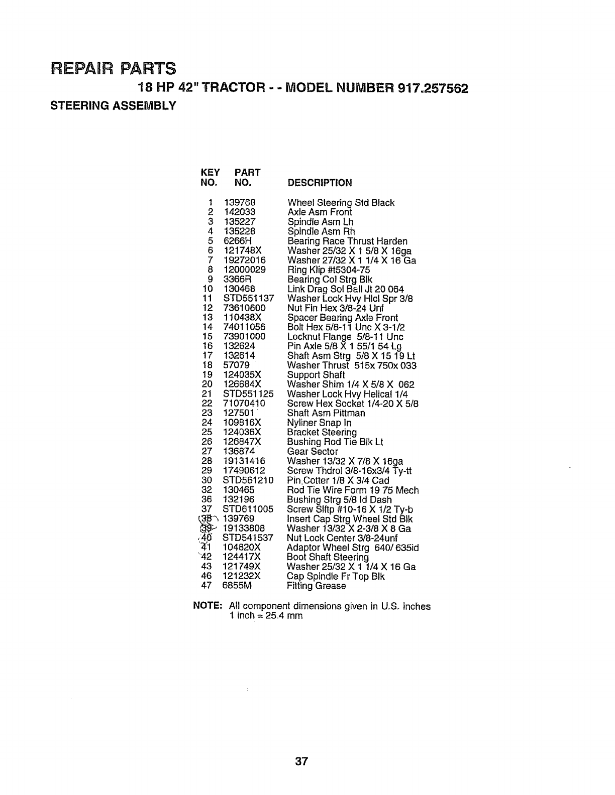
REPAIR PARTS
18 HP 42" TRACTOR - -MODEL NUMBER 917.257562
STEERING ASSEMBLY
KEY PART
NOo NO. DESCRIPTION
1 139768
2 142033
3 135227
4 135228
5 6266H
6 121748X
7 19272O16
8 12000029
9 3366R
10 130468
11 STD551137
12 73610600
13 110438X
14 74011056
15 73901000
16 132624
17 132614
t8 57079'
19 124035X
2O 126684X
21 STD551125
22 71070410
23 127501
24 !09816X
25 124036X
26 126847X
27 136874
28 19131416
29 1749O612
3O STD561210
32 130465
36 132196
37 STD61t005
h139769
19'133808
STD54t537
'_1 104820X
'42 124417X
43 121749X
46 121232X
47 6855M
Wheel Steering Std Black
Axle Asm Front
Spindle Asm Lh
Spindle Asm Rh
Bearing Race Thrust Harden
Washer 25132 X 1 5/8 X 16ga
Washer 27/32 X 1 1/4 X t6 Ga
Ring Ktip #t5304-75
Bearing Col Strg Blk
Link Drag Sol Ball Jt 20 064
Washer Lock Hvy Hlcl Spr 3/8
Nut Fin Hex 3/8-24 Unf
Spacer Bearing Axle Front
Bolt Hex 5/8-11 Uric X 3-1/2
Locknut Flange 5/8-11 Unc
Pin Axle 5/8 X 1 55/1 54 Lg
Shaft Asm Strg 5/8 X 15 19 Lt
Washer Thrust 515x 750x 033
Support Shaft
Washer Shim 1/4 X 5/8 X 062
Washer Lock Hvy Helical 1/4
Screw Hex Socket I/4-20 X 5/8
Shaft Asm Pittman
Nyliner Snap In
Bracket Steering
Bushing Rod Tie BIk Lt
Gear Sector
Washer 13/32 X 7/8 X 16ga
Screw Thdrol 3/84 6x3/4 Ty-tt
Pin.Cotter t/8 X 3/4 Cad
Rod Tie Wire Form t9 75 Mech
Bushing Strg 5/8 Id Dash
Screw Slftp #10-16 X t/2 Ty-b
Insert Cap Strg Wheel Std BIk
Washer t3/32 X 2-3/8 X 8 Ga
Nut Lock Center 3/8-24unf
Adaptor Wheel Strg 640/635id
Boot Shaft Steering
Washer 25/32 X 1 1/4 X 16 Ga
Cap Spindle Fr Top BIk
Fitting Grease
NOTE: All component dimensions given in U.,S.inches
1inch= 25.4 mm
37
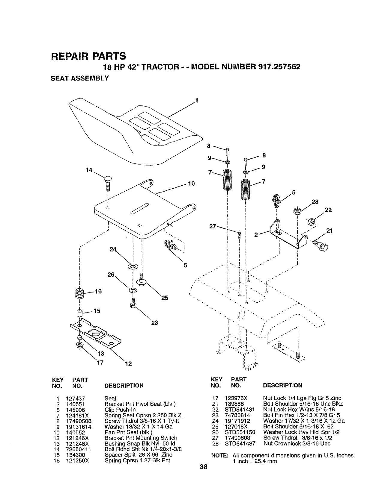
REPAIR PARTS
18 HP 42" TRACTOR - - MODEL NUMBER 917,257562
SEAT ASSEMBLY
KEY
NO+
1
2
5
7
8
9
t0
12
13
14
15
16
25
23
PART
NO. DESCRIPTION
127437
14O551
145006
12418IX
17490508
19131614
140552
121246X
121248X
72050411
1343OO
121250X
Seat
Bracket Pnt Pivot Seat (blk)
Clip Push-In
Spring Seat Cprsn 2 250 Blk Zi
Screw Thdrol 3/8-16 X 1 Ty-tt
Washer' 13/32 X 1 X 14Ga
Pan Pnt Seat (blk)
Bracket Pnt Mounting Switch
Bushing Snap BIk Nyl 50 Id
Bolt Rdhd Sht Nk 1/4+20xl-3/8
Space[ Split 28 X 96 Zinc
Spring Cprsn i 27 Btk Pnt
10
/
38
KEY PART
NO. NO. DESCRIPTION
17 123976X
21 139888
22 STD541431
23 7478O814
24 19171912
25 1270t8X
26 STD551t50
27 t7490608
28 STD541437
Nut Lock I/4 Lge Fig G[ 5 Zinc
Bolt Shoulder' 5/16-18 Unc Blkz
Nut Lock Hex Wllns 5/16-18
Bolt Fin Hex 1/2-13 X 7/8 Gr 5
Washer 17/32 X 1+3/16 X 12 Ga
Bolt Shoulder 5/16+18 X 62
Washer Lock Hvy Hlcl Spr t/2
Screw Thdrol. 3/8-16 x 1/2
Nut Crownlock 3/8-16 Unc
NOTE: All component dimensions given in U.S, inches.
1 inch = 25+4mm
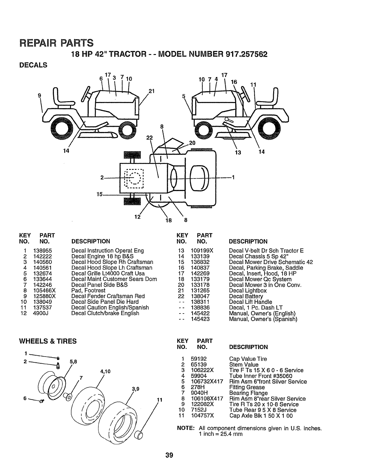
REPAIR
DECALS
PARTS
18 HP 42" TRACTOR --MODEL NUMBER 917.257562
61 10 10 7 4 17 16
21 11
14
15
22
12 18 8
13 14
KEY PART
NO. NO.
1 138955
2 142222
3 140560
4 140561
5 132674
6 133644
7 142246
8 105466X
9 125880X
10 138049
11 137537
12 4900J
KEY PART
DESCRIPTION NO. NO.
Decal Instruction Operat Eng 13 109199X
Decal Engine 18 hp B&S 14 133139
Decal Hood Slope Rh Craftsman 15 136832
Decal Hood Slope Lh Craftsman 16 140837
Decal Grille Lt4000 Craft Usa 17 142269
Decal Maint Customer Sears Dom 18 133179
Decal Panel Side B&S 20 133178
Pad, Footrest 21 !3t265
Decal Fender Craftsman Red 22 138047
Decal Side Panel Die Hard - - 138311
Decal Caution English/Spanish - -138836
Decal Clutch/brake English - - 145422
- - 145423
DESCRIPTION
Decal V-belt Dr Sch Tractor E
Decal Chassis 5 Sp 42"
Decal Mower Drive Schematic 42
Decal, Parking Brake, Saddle
Decal, Insert, Hood, 18 HP
Decal Mower Qc System
Decat Mower 3 in One Convo
Decal Lightbox
Decal Battery
Decal Lift Handle
Decal, 1 Pc, Dash LT
Manual, Owner's (English)
Manual, Owner's (Spanish)
4,10
11
KEY PART
NO. NO. DESCRIPTION
t 59192
2 65139
3 106222X
4 59904
5 106732X417
6 278H
7 9040H
8 I06108X417
9 122082X
10 7152J
11 104757X
Cap Value Tire
Stem Value
Tire F Ts 15 X 6 0 - 6 Service
Tube Inner Front #35060
Rim Asm 6"front Silver Service
Fitting Grease
Bearing Flange
Rim Asm 8"rear Silver Service
Tire R Ts 20 x 10-8 Service
Tube Rear 95 X 8 Service
Cap Axle BIk I 50 X 1 00
NOTE: All component dimensions given in U.S. inches.
1 inch = 25.4 mm
39
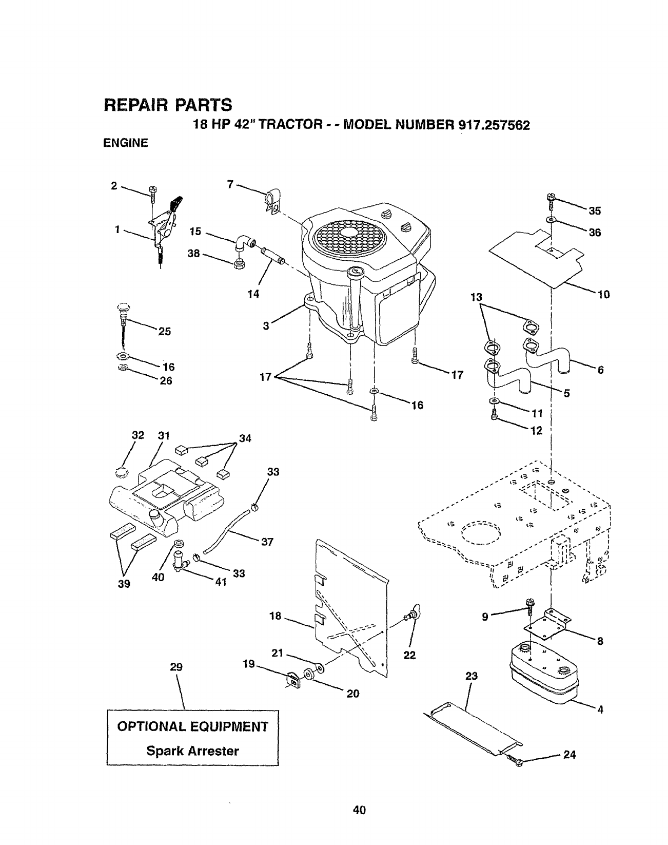
REPAIR PARTS
18 HP 42" TRACTOR - - MODEL NUMBER 917.257562
ENGINE
14 13
25 3
17
32 31 34
33
/
39 4O 41
37
33
18
29
\
OPTIONAL EQUIPMENT
Spark Arrester
2O
/
22
40
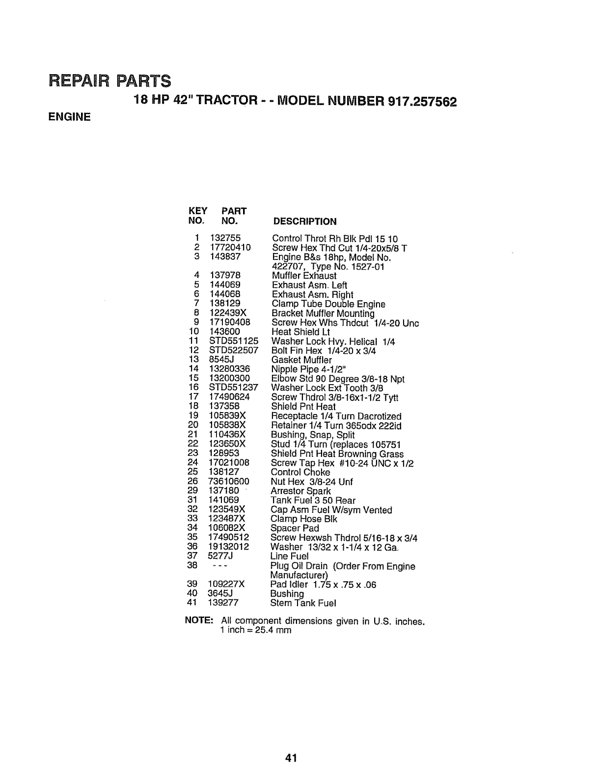
RE!PAaR
ENGINE
PARTS
18 HP 42" TRACTOR - - MODEL NUMBER 917.257562
KEY PART
NO. NO. DESCRIPTION
1 132755
2 17720410
3 143837
4 137978
5144069
6 144068
7138129
8 122439X
9 17190408
10 143600
11 STD551125
12 STD522507
13 8545J
14 13280336
15 132003OO
16 STD551237
17 1749O624
18 137358
19 105839X
20 !05838X
21 110436X
22 123650X
23 128953
24 17O21O08
25 138127
26 73610600
29 137180
31 141069
32 123549X
33 123467X
34 106082X
35 17490512
36 19132012
37 5277J
38 ---
39 109227X
40 3645J
4t 139277
Control Throt Rh Blk Pdl t5 10
Screw Hex Thd Cut 1/4_20x5/8 T
Engine B&s 18hp, Model No.
422707, Type No_1527-01
Muffler Exhaust
Exhaust AsmoLeft
Exhaust Asm. Right
Clamp Tube Double Engine
Bracket Muffler Mounting
Screw Hex Whs Thdcut 1/4-20 Unc
Heat Shield Lt
Washer Lock Hvy. Helical 1/4
Bolt Fin Hex 1/4-20 x 3/4
Gasket Muffler
Nipple Pipe 4-1/2"
Elbow Std 90 Degree 3/8-t8 Npt
Washer Lock Ext Tooth 3/8
Screw Thdrol 318-I6x1-1/2 Tytt
Shield Pnt Heat
Receptacle 1/4 Turn Dacrotized
Retainer 1/4 Turn 365odx 222id
Bushing, Snap, Split
Stud !/4 Turn (replaces 105751
Shield Pnt Heat Browning Grass
Screw Tap Hex #10-24 UNC x 1/2
Control Choke
Nut Hex 3/8-24 Unf
Arrestor Spark
Tank Fuel 3 50 Rear
Cap Asm Fuel W/sym Vented
Clamp Hose Bik
Spacer Pad
Screw Hexwsh Thdrol 5/16-18 x 3/4
Washer t3/32 x 1-1/4 x 12 Ga_
Line Fuel
Plug Oil Drain (Order From Engine
Manufacturer)
Pad Idler 1.75 x °75 x °06
Bushing
Stem Tank Fuel
NOTE: All component dimensions given in UoS. inches.
1 inch = 25.4 mm
41
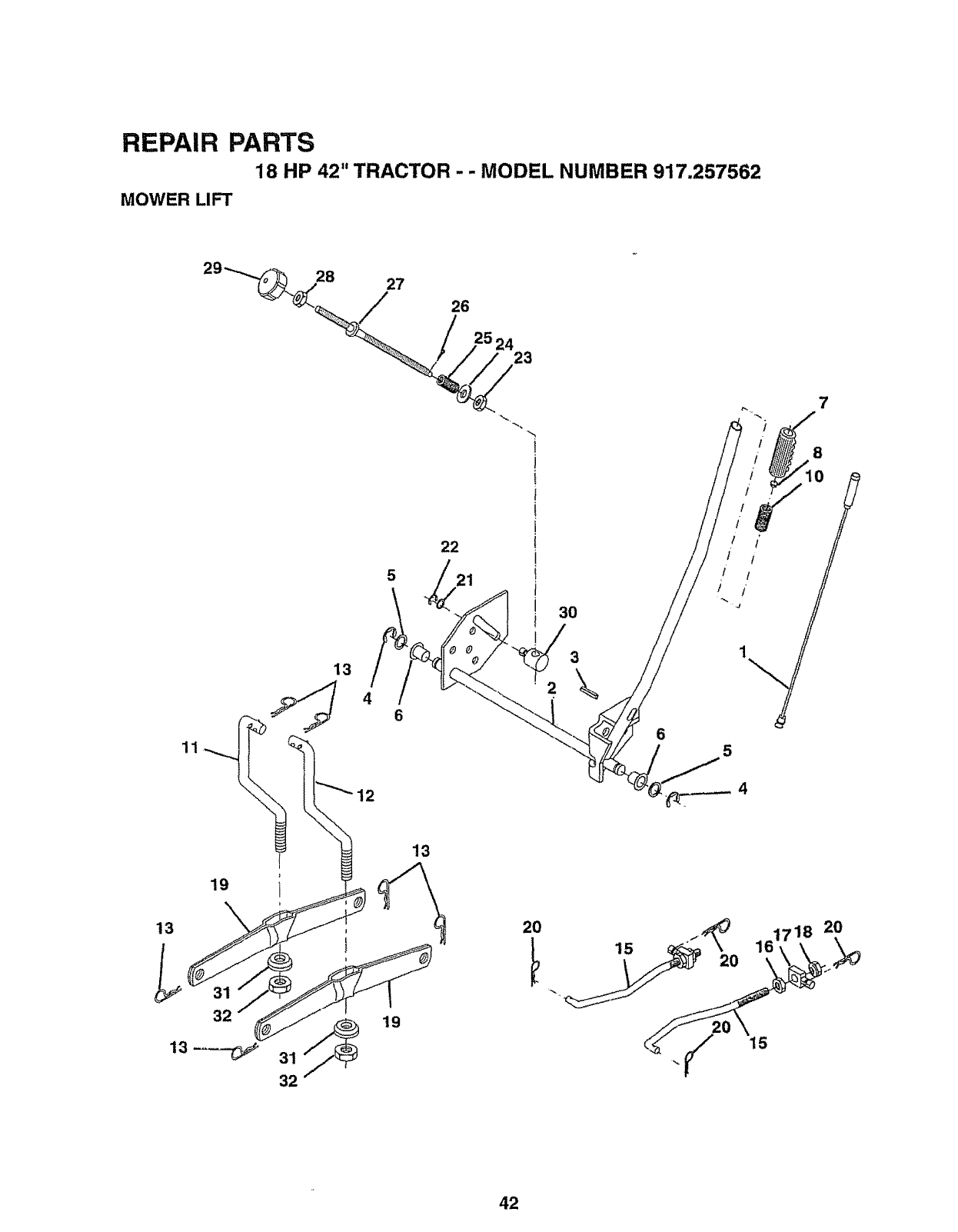
REPAIR PARTS
18 HP 42" TRACTOR - - MODEL NUMBER 917.257562
MOWER LIFT
13
46
11
13
22
21
2O
15
6
8
rI /'
It
/ /
'i
5
42
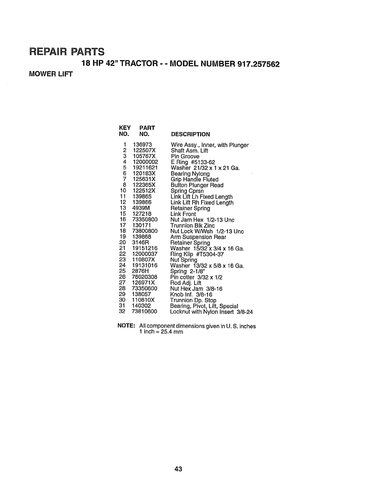
REPAIR PARTS
18 HP 42" TRACTOR - - MODEL NUMBER 917.257562
MOWER LIFT
KEY PART
NO. NO. DESCRIPTION
1 136973
2 122507X
3 105767X
4 12000002
519211621
6 t20183X
7 125631X
8 122365X
10 1225t2X
11 139865
t2 139866
13 4939M
15 127218
16 73350800
17 130171
t8 73800800
t9 139868
20 3146R
21 19151216
22 12000037
23 110807X
24 19131016
25 2876H
26 76020308
27 126971X
28 73350600
29 138057
3O 1108t0X
31 140302
32 73810600
Wire Assyo, Inner, with Plunger
Shaft Asm_Lift
Pin Groove
E Ring #5133-62
Washer 21/32 x 1 x 21 Ga.
Bearing Nylong
Grip Handle Fluted
Button Plunger Read
Spring Cprsn
Link Lift Lh Fixed Length
Link Lift Rh Fixed Length
Retainer Spring
Link Front
Nut Jam Hex 1/2-13 Unc
Trunnion Blk Zinc
Nut Lock W/Wsh 1/2-13 Unc
Arm Suspension Rear
Retainer Spring
Washer 15/32 x 3/4 x 16 Gao
Ring Klip #T5304-37
Nut Spring
Washer 13/32 x 5/8 x 16 Gao
Spring 2-1/8"
Pin cotter 3/32 x 1/2
Rod Adj. Lift
Nut Hex Jam 3/8-16
Knob Inf. 3/8-!6
Trunnion DpoStop
Bearing, Pivot, Lift, Special
Locknut with Nylon Insert 3/8-24
NOTE: All component dimensions given in U. S. inches
1 inch = 25.4 mm
43
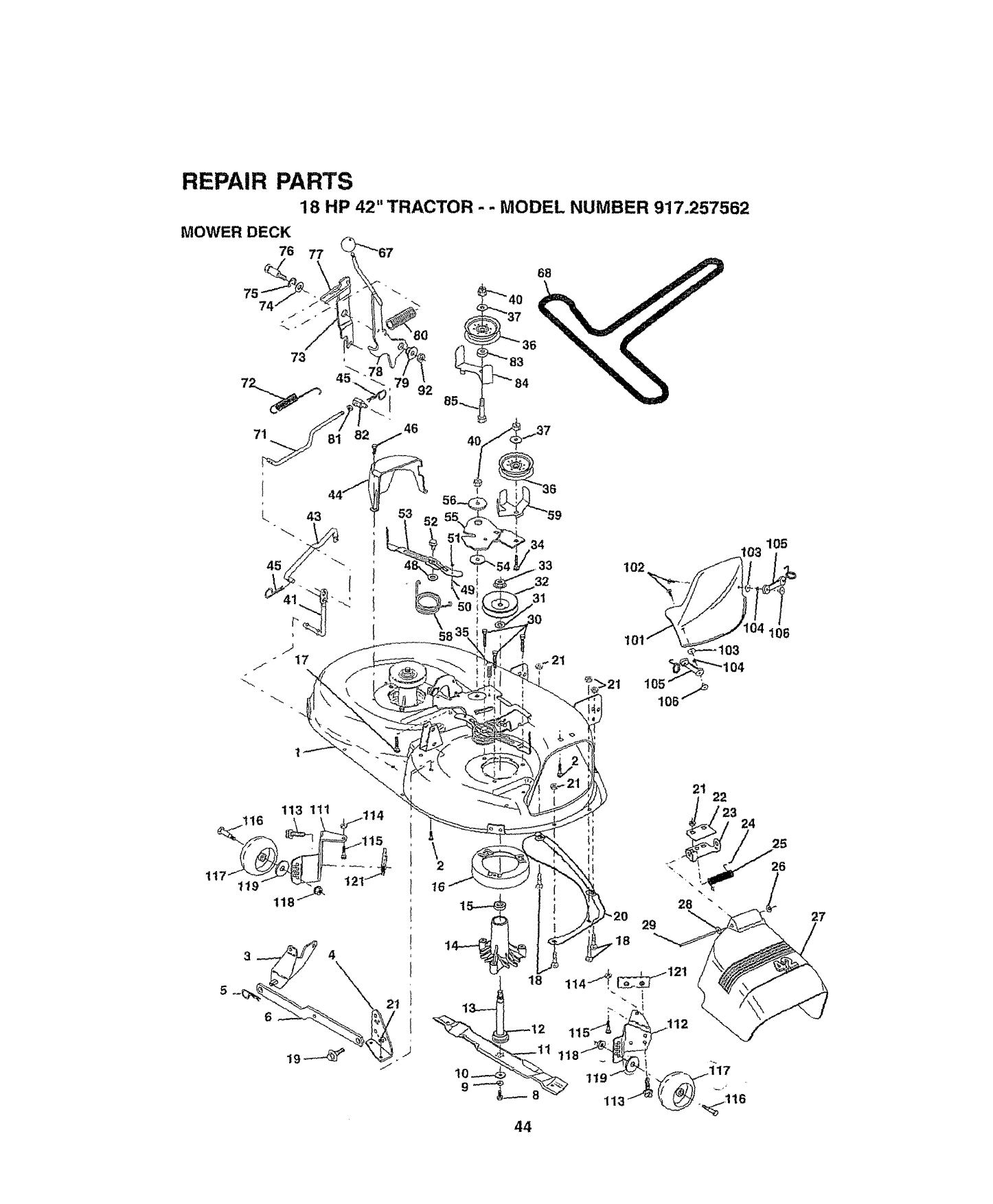
REPAIR PARTS
18 HP 42" TRACTOR --,MODEL NUMBER 917.257562
MOWER DECK
76 77
52
34
,33 102
32 "_,
31
105
27
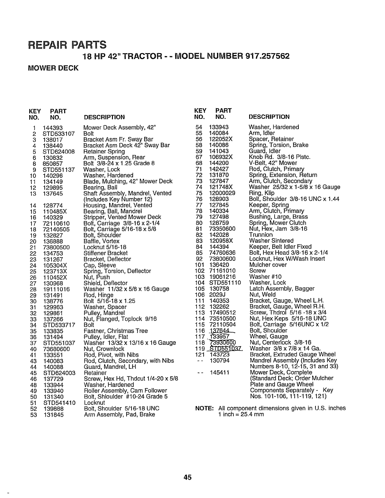
REPAgR PARTS
18 HP 42" TRACTOR - -MODEL NUMBER 917.257562
MOWER DECK
KEY PART KEY PART
NO. NO, DESCRIPTION NO, NO. DESCRIPTION
1 144393
2 STD533107
3 138017
4138440
5 STD624008
6 130832
8 850857
9 STD55t137
10 140296
11 134149
I2 129895
13 137645
14 128774
15 110485X
16 140329
17 72110610
18 72140505
19 132827
20 136888
21 73800500
22 134753
23 131267
24 105304X
25 123713X
26 110452X
27 130968
28 19111016
29 131491
30 138776
31 129963
32 129861
33 137266
34 STD533717
35 133835
36 131494
37 STD55t037
40 73680600
41 133551
43 140083
44 140088
45 STD624003
46 137729
48 133944
49 133940
50 13134O
51 STD541410
52 139888
53 131845
Mower Deck Assembly, 42" 54 133943
Bolt 55 140084
Bracket Asm FroSway Bar 56 122052X
Bracket Asm Deck 42" Sway Bar 58 140086
Retainer Spring 59 141043
Arm, Suspens=on, Rear 67 106932X
Bolt 3/8-24 x 1425Grade 8 68 144200
Washer, Lock 71 142427
Washer, Hardened 72 131870
Blade, Mulching, 42" Mower Deck 73 127847
Bearing, Bali 74 t21748X
Shaft Assembly, Mandrel, Vented 75 12000029
(Includes Key Number t2) 76 128903
Housing, Mandrel, Vented 77 127845
Bearing, Ball, Mandrel 78 140334
Stripper, Vented Mower Deck 79 127498
Bolt, Carriage 3/8_!6 x 2-1/4 80 128759
Bolt, Carriage 5116-18x 5/8 81 73350600
Bolt, Shoulder 82 142028
Baffle, Vortex 83 120958X
Locknut 5/16-18 84 144394
Stiffener Bracket 85 74760636
Bracket, Deflector 92 73800600
Cap, Sleeve 101 136420
Spring, Torsion, Deflector !02 71161010
Nut, Push '103 19061216
Shield, Deflector t04 STD551110
Washer 11/32 x 5/8 x 16 Gauge 105 130758
Rod, Hinge !06 2029J
Bolt 5/16-18 x t.25 1tl 140353
Washer, Spacer 112 132262
Pulley, Mandrel 113 17490512
Nut, Flanged, Toplock 9/16 114 73510500
Bolt 115 72110504
Fastner, Christmas Tree 116 __
Pulley, Idler, Flat 117 1t33957
Washer 13/32 x 13/16 x16 Gauge 118 "_0
Nut, Crownlock 119
Rod, Pivot, with Nibs 121 143723
Rod, Clutch, Secondary, withNibs - _ 130794
Guard, Mandrel, LH
Retainer - - 145411
Screw, Hex Hd, Thdcut 1/4-20 x 5/8
Washer, Hardened
Roller Assembly, Cam Follower
Bolt, Shtoulder #10-24 Grade 5
Locknut
Bolt, Shoulder 5/16_18 UNC
Arm Assembly, Pad, Brake
Washer, Hardened
Arm, Idler
Spacer, Retainer
Spring, Torsion, Brake
Guard, Idler
Knob Rd. 3/8-16 Plstc_
V-Belt, 42" Mower
Rod, Clutch, Primary
Spring, Extension, Return
Arm, Clutch, Secondary
Washer 25/32 x 1-5/8 x 16 Gauge
Ring, Klip
Bolt, Shoulder 3/8-16 UNC x 1.44
Keeper, Spring
Arm, Clutch, Pdmary
Bushing, Large, Brass
Spring, Mower Clutch
Nut, Hex,,Jam 3/8-16
Trunnion
Washer Sintered
Keeper, Belt Idler Fixed
Bolt, Hex Head 3/8-16 x 2-1/4
Locknut, Hex W/Wash Insert
Mulcher cover
Screw
Washer #10
Washer, Lock
Latch Assembly, Bagger
Nut, Weld
Bracket, Gauge, Whee_ L,H..
Bracket, Gauge, Wheel R.Ho
Screw, Thdrol 5/16 -'18x 3/4
Nut, Hex Keps 5/t6-18 UNC
Bolt, Carriage 5/16UNC x 1/2
Bolt, Shoulder
Wheel, Gauge
Nut, Centedock 3/8-16
Washer 3/8 x 7/8 x 14 Ga.
Bracket, Extruded Gauge Wheel
Mandrel Assembly (Includes Key
Numbers 8-10, 12-15, 31 and 33)
Mower Deck, Complete
(Standard Deck; Order Mulcher
Plate and Gauge Wheel
Components Separately - Key
Nos. 101-106, tlt-119, 121)
NOTE: All component dimensions given in U.S. inches
1inch = 25_4mm
45
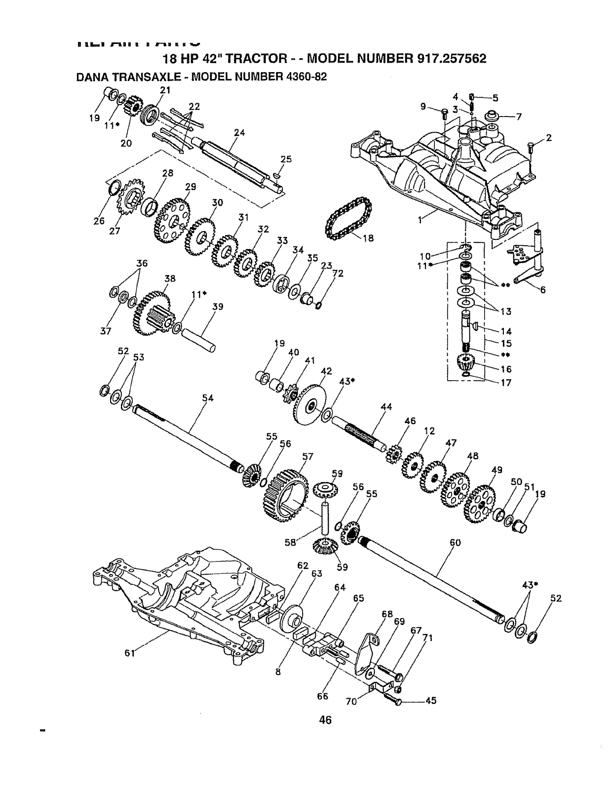
nLL.-.H B"IHB R R J'-"_m I # v
18 HP 42" TRACTOR - - MODEL NUMBER 917.257562
46 12
47
48
49
62
52
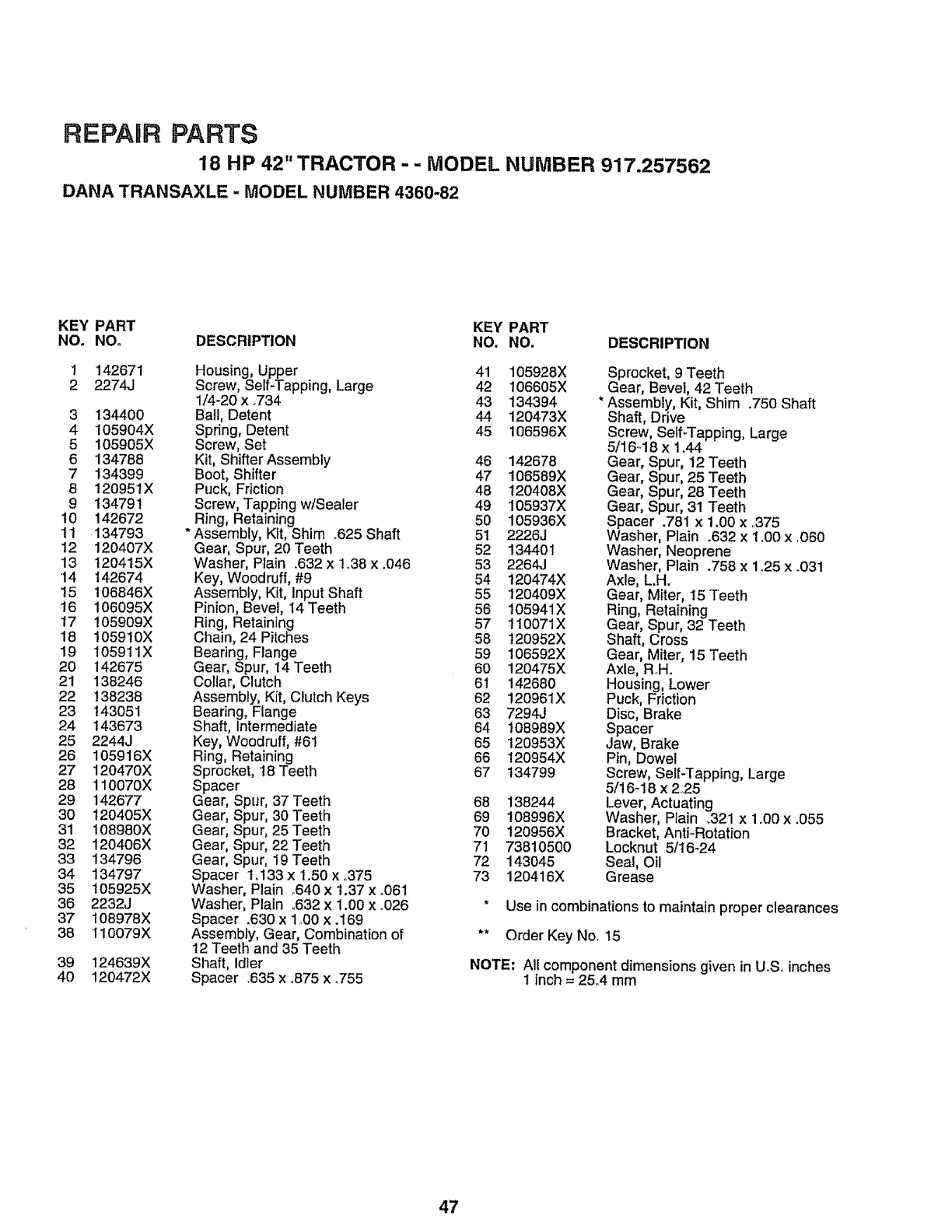
REPAIR PARTS
18 HP 42" TRACTOR-- MODEL NUMBER 917.257562
DANA TRANSAXLE -MODEL NUMBER 4360-82
KEY PART KEY PART
NO. NO. DESCRIPTION NO. NO. DESCRIPTION
1 142671 Housing, Upper 41 105928X
2 2274,.i Screw, Self-Tapping, Large 42 106605X
1/4-20 x .734 43 134394
3 134400 Ball, Detent 44 120473X
4 105904X Spring, Detent 45 106596X
5 105905X Screw, Set
6 134788 Kit, Shifter Assembly 46
7 134399 Boot, Shifter 47
8 12095't X Puck, Friction 48
9 134791 Screw, Tapping w/Sealer 49
10 142672 Ring, Retaining 50
11 134793 Assembly, Kit, Shim ,625 Shaft 51
12 120407X Gear, Spur, 20Teeth 52
13 1204t5X Washer, Plain .632 x t.38 x .046 53
•14 142674 Key, Woodruff, #9 54
!5 106846X Assembly, Kit, Input Shaft 55
16 106095X Pinion, Bevel, I4 Teeth 56
17 105909X Ring, Retaining 57
18 105910X Chain, 24 Pitches 58
19 105911X Bearing, Flange 59
20 142675 Gear, Spur, 14 Teeth 60
2! 138246 Collar, Clutch 61
22 !38238 Assembly, Kit, Clutch Keys 62
23 !43051 Bearing, Flange 63
24 t43673 Shaft, Intermediate 64
25 2244J Key, Woodruff,#6! 65
26 105916X Ring, Retaining 66
27 120470X Sprocket, t8 Teeth 67
28 110070X Spacer
29 142677 Gear, Spur, 37 Teeth 68
30 t20405X Gear, Spur, 30 Teeth 69
31 108980X Gear, Spur, 25Teeth 70
32 120406X Gear, Spur, 22 Teeth 71
33 134796 Gear, Spur, 19 Teeth 72
34 134797 Spacer t.133 x 1.50 x °375 73
35 t05925X Washer, Plain °640 x 1.37 x o061
36 2232J Washer, Plain °632 x 1.00 x °026
37 108978X Spacer .630 x 1.00 x .169
38 110079X Assembly, Gear, Combination of
12 Teeth and 35 Teeth
Shaft, Idler
Spacer ,635 x .875 x °755
39 124639X
40 120472X
142678
106589X
t20408X
105937X
105936X
2226J
134401
2264J
120474X
120409X
t05941X
110071X
120952X
106592X
'120475X
142680
120961X
7294J
108989X
t 20953X
120954X
I34799
138244
108996X
120956X
73810500
143045
120416X
Sprocket, 9 Teeth
Gear, Bevel, 42 Teeth
Assembly, Kit, Shim .750 Shaft
Shaft, Drive
Screw, Self-Tapping, Large
5/1648 x t _44
Gear, Spur, 12 Teeth
Gear, Spur, 25 Teeth
Gear, Spur, 28 Teeth
Gear, Spur, 31 Teeth
Spacer .781 x 1.00 x ,375
Washer, Plain .632 x 1.00 x .060
Washer, Neoprene
Washer, Plain .758 x 1,.25x .031
Axle, L,H.
Gear, Miter, 15 Teeth
Ring, Retaining
Gear, Spur, 32 Teeth
Shaft, Cross
Gear, Miter, 15 Teeth
Axle, R.H.
Housing, Lower
Puck, Friction
Disc, Brake
Spacer
Jaw, Brake
Pin, Dowel
Screw, SeIFTapping, Large
5/16-18 x 2.,25
Lever, Actuating
Washer, Plain ,321 x 1,.00x °055
Bracket, AntFRotation
Locknut 5/16-24
Seal, Oil
Grease
* Use in combinations to maintain proper clearances
** Order Key No. 15
NOTE: All component dimensions given in U.Soinches
tinch = 25°4 mm
47
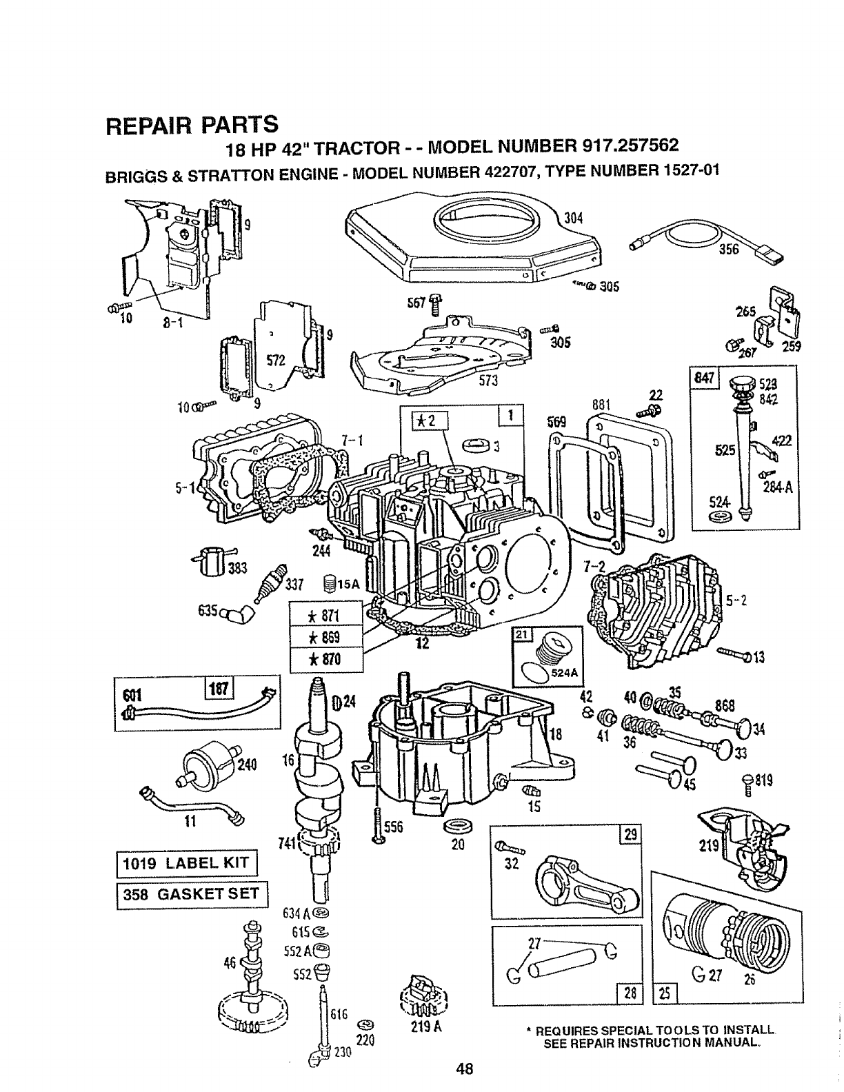
REPAIR PARTS
18 HP 42" TRACTOR - - MODEL NUMBER 917.257562
BRIGGS & STRATTON ENGINE - MODEL NUMBER 422707, TYPE NUMBER 1527-01
30S
"'_b 3Q5
240 I_
mi
[1019 LABEL KIT I
t358 GASKET SET ]
220
2O
219A
48
* REQUIRES SPECIAL TOOLS TO iNSTALL
SEE REPAIR INSTRUCTIO N MANUAL+
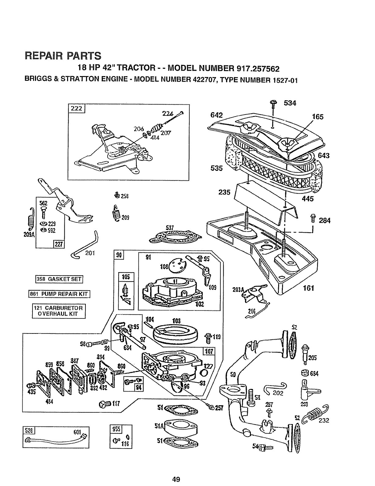
REPAIR PARTS
18 HP 42" TRACTOR -- MODEL NUMBER 917.257562
BRIGGS & STRA_ON ENGINE - MODEL NUMBER 422707, TYPE NUMBER 1527-01
'_ 592
535
235
534
165
643
445
161
49
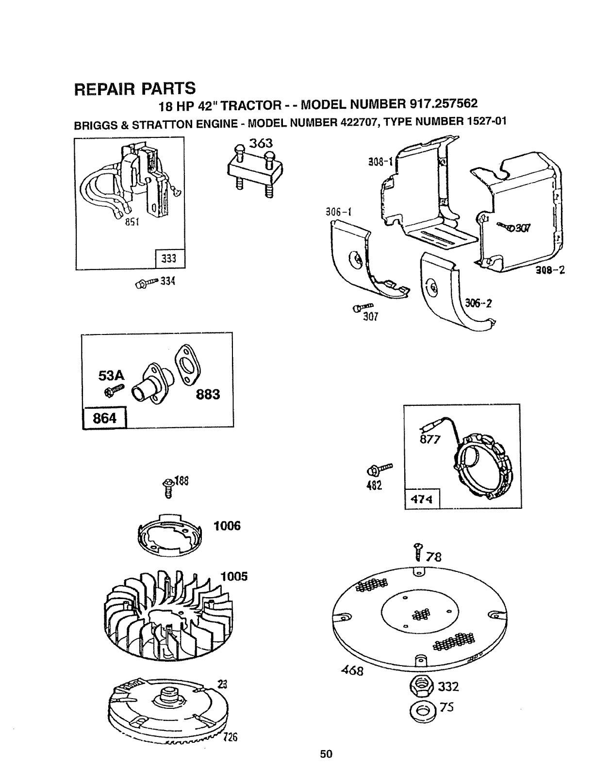
REPAIR PARTS
18 HP 42" TRACTOR -- MODEL NUMBER 917.257562
BRIGGS & STRA'i-TON ENGINE -MODEL NUMBER 422707, TYPE NUMBER 1527-01
53A
i= ...........
864 I
1006
1005
_78
(_332
5O
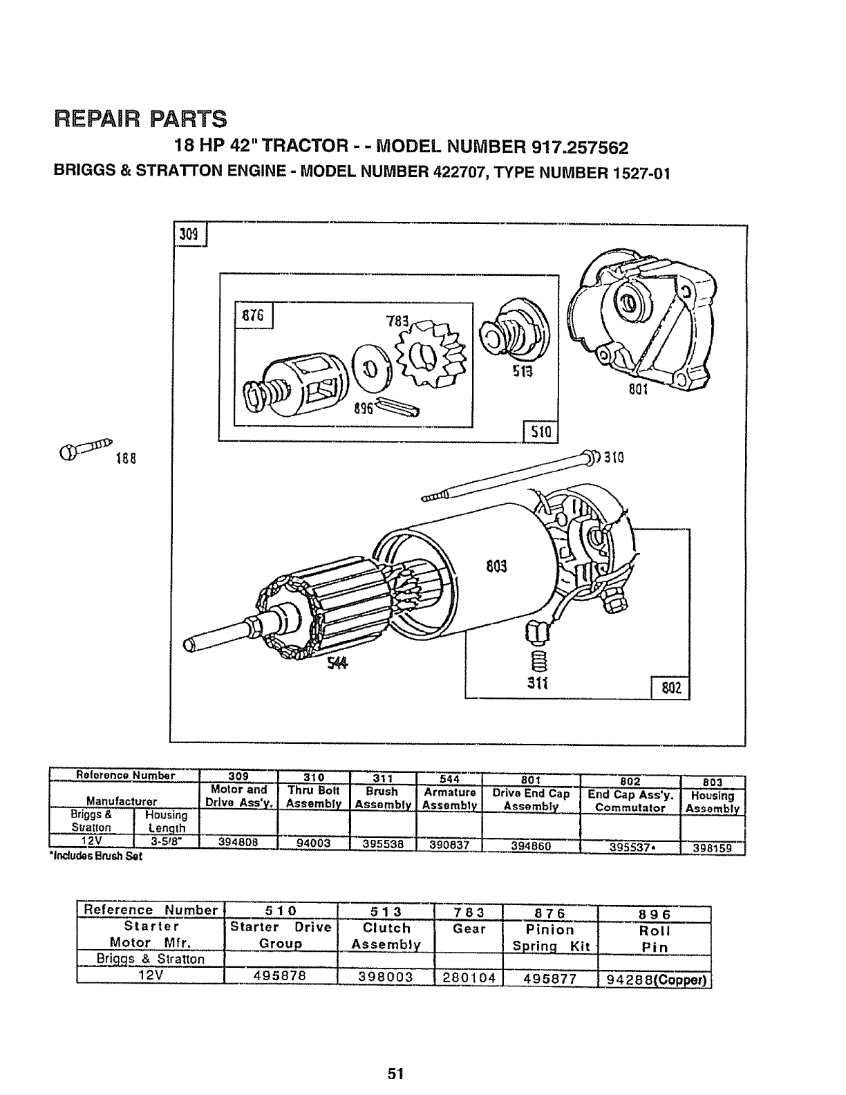
REPAIR PARTS
18 HP 42" TRACTOR -- MODEL NUMBER 917.257562
BRIGGS & STRATTON ENGINE -MODEL NUMBER 422707, TYPE NUMBER 1527-01
Reference Number
Manufacturer
Briggs& _Housing
Stratton ] Length
12V , 3.5/8"
"includ_sBrushSot
309 !...........31o I 3!.! !544
Motor and _Thru Bolt I Brush J Armature
Drive Ass'y, _Assembly IAssembly ] Assnmb__
39480819400313955381390837
col ] 802
Drive End Cap J End Cap Ass'y.
Assembly I Commutator
394860 t 395537,
803
Housing
Assembly
398159
Reference Number
Starter
Motor Mfr.
•Br!ggs & Stratton
12V
510
Starter Drive
Group
495878
513
Clutch
Assembly
398003
783
Gear
280104
876 _896
Pinion [Roll
Spring,, ,Kit P i n
495877 94288(Cop_r)
51
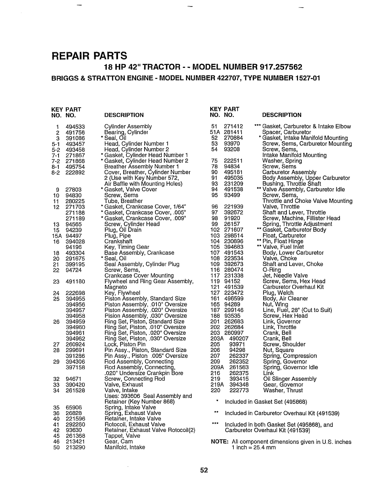
REPAIR PARTS
18 HP 42" TRACTOR - - MODEL NUMBER 917.257562
BRIGGS & STRATTON ENGINE - MODEL NUMBER 422707, TYPE NUMBER 1527-01
KEY PART KEY PART
NO. NO. DESCRIPTION NO. NO. DESCRIPTION
1 494533 Cylinder Assembly 51
2 491756 Bearing, Cylinder 51A
3 391086 *Seal, Oil 52
5-1 493457 Head, Cylinder Number 1 53
5-2 493458 Head, Cylinder Number2 54
7-1 271867 * Gasket, Cylinder Head Number t
7-2 271868 * Gasket, Cylinder Head Number2 75
8-1 495754 Breather Assembly Number I 78
8-2 222892 Cover, Breather, Cylinder Number 90
2 (Use with Key Number 572, 9t
Air Baffle with Mounting Holes) 93
9 27803 * Gasket, Valve Cover 94
10 94830 Screw, Sems 95
11 280225 Tube, Breather
12 271703 * Gasket, Crankcase Cover, 1/64" 96
271188 * Gasket, Crankcase Cover, .005" 97
271189 * Gasket, Crankcase Cover, 009" 98
13 94565 Screw, Cylinder Head 99
15 94239 Plug, Oil Drain 102
15A 94497 Plug, Pipe 103
16 394028 Crankshaft 104
94196 Key, Timing Gear 105
18 493304 Base Assembly, Crankcase 107
20 291675 * Seal, Oil 108
21 399195 Seal Assembly, Cylinder Plug 109
22 94724 Screw, Sems, 116
Crankcase Cover Mounting 117
23 491180 Flywheet and Ring Gear Assembly, 119
Magneto 121
24 222698 Key, Rywheel 127
25 394955 Piston Assembly, Standard Size 161
394956 Piston Assembly, .010" Oversize 165
394957 Piston Assembly, _020"Oversize 187
394958 Pision Assembly, .030" Oversize 188
26 394959 Ring Set, Piston, Standard Size 201
394960 Ring Set, Piston, ..010"Oversize 202
394961 Ring Set, Piston, °020" Oversize 203
394962 Ring Set, Piston, .030" Oversize 203A
27 260924 Lock, Piston Pin 205
28 299691 Pin Assy_, Piston, Standard Size 206
391286 Pin Assy.., Piston .005" Oversize 207
29 394306 Rod Assembly, Connecting 209
397158 Rod Assembfy, Connecting, 209A
,020" Undersize Crankpin Bore 216
32 94671 Screw, Connecting Rod 219
33 390420 Valve, Exhaust 219A
34 261528 Valve, Intake 220
Uses: 393606 Seal Assembly and
Retainer (Key Number 868)
35 65906 Spring, Intake Valve
36 26828 Spring, Exhaust Valve
40 221596 Retainer, Intake Valve
41 292260 Rotocoil, Exhaust Valve
42 93630 Retainer, Exhaust Valve Rotocoil(2)
45 261368 Tappet, Valve
46 213421 Gear, Cam
50 213290 Manifold, Intake
271412
281411
270884
93970
93208
222511
94834
495181
495035
2312O9
491538
93499
221939
392672
91920
26157
271607
298514
230896
394683
491543
223534
392673
280474
231338
94152
491539
223472
496599
94289
299146
93535
262683
262684
280997
490207
93971
94298
262337
262352
261563
262375
393415
394348
222773
*** Gasket, Carburetor & Intake Elbow
Spacer, Carburetor
* Gasket, Intake Manifold Mounting
Screw, Sems, Carburetor Mounting
Screw, Seres,
Intake Manifold Mounting
Washer, Spring
Screw, Seres
Carburetor Assembly
Body Assembly, Upper Carburetor
Bushing, Throttle Shaft
** Valve Assembly, Carburetor Idle
Screw, Sems,
Throttle and Choke Valve Mounting
Valve, Throttle
Shaft and Lever, Throttle
Screw, Machine, Fillister Head
Spring, Throttle Adjustment
** Gasket, Carburetor Body
Float, Carburetor
***Pin, Float Hinge
* Valve, Fuel Inlet
Body, Lower Carburetor
Valve, Choke
Shaft and Lever, Choke
O-Ring
Jet, Needle Valve
Screw, Seres, Hex Head
Carburetor Overhaul Kit
Plug, Welch
Body, Air Cleaner
Nut, Wang
Line, Fuel, 28" (Cut to Suit)
Screw, Hex Head
Link, Governor
Link, Throttle
Crank, Bell
Crank, Bell
Screw, Shoulder
Nut, Square
Spring, Compression
Spring, Governor
Spring, Governor Idle
Unk
Oil Slinger Assembly
Gear, Governor
Washer, Thrust
* Included in Gasket Set (495868)
** _ncluded in Carburetor Overhaul Kit (491539)
*** included inboth Gasket Set (495868), and
Carburetor Overhaul Kit (491539)
NOTE: AIt component dimensions given in U_S.inches
1inch = 2&4 mm
52
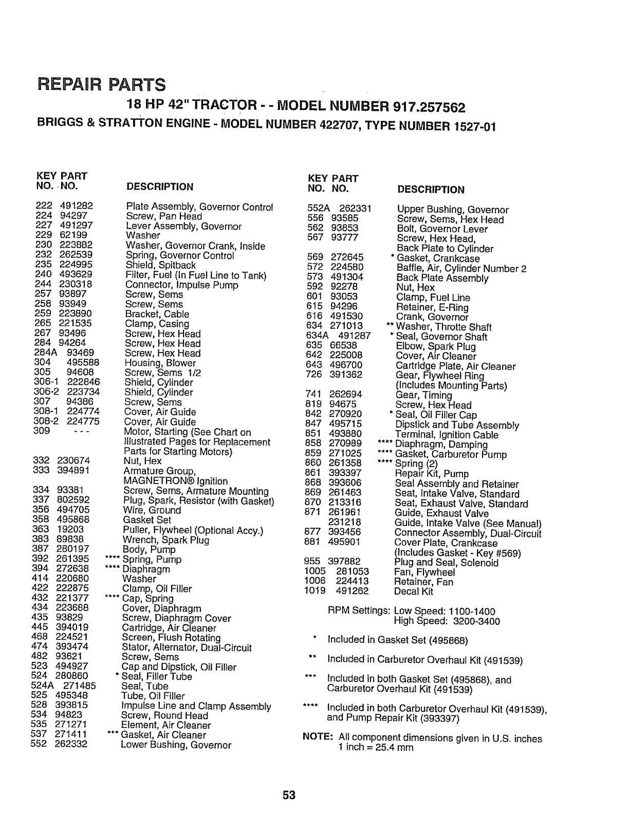
REPAIR PARTS
18 HP 42" TRACTOR - -MODEL NUMBER 917.257562
BRIGGS & STRATFON ENGINE - MODEL NUMBER 422707, TYPE NUMBER 1527-01
KEY PART KEY PART
NO., NO. DESCRIPTION NO. NO. DESCRIPTION
222 491282
224 94297
227 491297
229 62199
230 223882
232 262539
235 224995
240 493629
244 230318
257 93897
258 93949
259 223890
265 221535
267 93496
284 94264
284A 93469
304 495588
305 94608
306-t 222846
306-2 223734
307 94386
308q 224774
308-2 224775
309 _--
332 230674
333 394891
334 93381
337 802592
356 494705
358 495868
363 19203
383 89838
387 280197
392 261395
394 272638
414 220680
422 222875
432 221377
434 223688
435 93829
445 394O19
468 224521
474 393474
482 93621
523 494927
524 280860
524A 271485
525 495348
528 393815
534 94823
535 271271
537 271411
552 262332
Plate Assembly, Governor Control 552A 262331
Screw, Pan Head 556 93585
Lever Assembly, Governor 562 93853
Washer 567 93777
Washer, Governor Crank, Inside
Spring, Governor Control 569 272645
Shield, Spitback 572 224580
Filter, Fuel (In Fuel Line to Tank) 573 491304
Connector, Impulse Pump 592 92278
Screw, Sems 601 93053
Screw, Seres 6!5 94296
Bracket, Cable 616 491530
Clamp, Casing 634 271013
Screw, Hex Head 634A 491287
Screw, Hex Head 635 66538
Screw, Hex Head 642 225008
Housing, Blower 643 496700
Screw, Sems 1/2 726 391362
Shield, Cylinder
Shield, Cylinder 741 262694
Screw, Seres 819 94675
Cover, Air Guide 842 270920
Cover, Air Guide 847 495715
Motor, Starting (See Chart on 851 493880
IllustratedPages for Replacement 858 270989
Parts for Starting Motors) 859 271025
Nut, Hex 860 261358
Armature Group, 861 393397
MAGNETRON® Ignition 868 393606
Screw, Sems, Armature Mounting 869 261463
Plug, Spark, Resistor (with Gasket) 870 213316
Wire, Ground 871 261961
Gasket Set 231218
Pulfer, Flywheel (Optiona_ Accy.) 877 393456
Wrench, Spark Plug 88t 495901
Body, Pump
****Spring, Pump 955 397882
.... Diaphragm t005 281053
Washer 1006 224413
Clamp, Oil Filler 1019 491262
**'* Cap, Spring
Cover, Diaphragm
Screw, Diaphragm Cover
Cartridge, Air Cleaner
Screen, Flush Rotating
Stator, Alternator, Dual-Circuit
Screw, Sems
Cap and Dipstick, Oil Filler
* Seal, Filler Tube ***
Seal, Tube
Tube, Oi! Filler
Impulse Line and Clamp Assembly ....
Screw, Round Head
Element, Air Cleaner
*** Gasket, Air Cleaner
Lower Bushing, Governor
Upper Bushing, Governor
Screw, Sems, Hex Head
Bolt, Governor Lever
Screw, Hex Head,
Back Plate to Cylinder
* Gasket, Crankcase
Baffle, Air, Cylinder Number 2
Back Plate Assembly
Nut, Hex
Clamp, Fuel Line
Retainer, E-Ring
Crank, Governor
** Washer, Throtte Shaft
* Seal, Governor Shaft
Elbow, Spark Plug
Cover, Air Cleaner
Cartridge Plate, Air Cleaner
Gear, Flywheel Ring
(Includes Mounting Parts)
Gear, Timing
Screw, Hex Head
* Seal, Oil Filler Cap
Dipstick and Tube Assembly
Terminal, Ignition Cable
.... Diaphragm, Damping
.... Gasket, Carburetor Pump
**** Spring (2)
Repair Kit, Pump
Seal Assembly and Retainer
Seat, Intake Valve, Standard
Seat, Exhaust Valve, Standard
Guide, Exhaust Valve
Guide, Intake Valve (See Manual)
Connector Assembly, DuaFCircuit
Cover Plate, Crankcase
(includes Gasket - Key #569)
Plug and Seal, Solenoid
Fan, Flywheel
Retainer, Fan
Decal Kit
RPM Settings: Low Speed: 1100q400
High Speed: 3200-3400
* Included in Gasket Set (495868)
** Included in Carburetor Overhaul Kit (491539)
Included in both Gasket Set (495868), and
Carburetor Overhaul Kit (491539)
Included in both Carburetor Overhaul Kit (491539),
and Pump Repair Kit (393397)
NOTE: All component dimensions given in U.S. inches
!inch= 25,4 mm
53

SERVICE N
54

SUGGESTED GUIDE FOR SiGHTiNG SLOPES FOR SAFE OPERATION
ol
O1
SIGHTING
ONLY RIDE UP AND DOWN HILL,
NOT ACROSS HILL
SIGHT AND HOLD THIS LEVEL WITH
SKY LINE OR TREE.
15 ° MAX.
Operate your Tractor up and down the face of Slopes (not I
Igreater than 15°), never across the face. Make turns gradu- |
kally to prevent tipping or loss of control. Exercise extreme
caution when changing direction on slopes, i' I
OWNER'S
MANUAL
MODEL NO.
917.257562
IF YOU NEED
REPAIR SERVICE
OR PARTS:
FOR REPAIR SERVICE,CALL
THIS TOLL FREE NUMBER:
1-800-4-REPAIR
(1-800-473-7247)
FOR REPLACEMENT PARTS
INFORMATIONAND
ORDERING,CALL THIS
TOLL FREE NUMBER:
1-800-FON-PART
(1-800-366=7278)
I:RAFTZ;MAN
!8 HP TWIN CYLINDER
ELECTRIC START ,..
3 in One Convertible
42" MOWER
5 SPEED TRANSAXLE
LAWN TRACTOR
Each tractor has its own model number. Each engine has
its own model numben
The model number' for your tractor will be found on the
model plate located under'the seat,. "...... -.............
The model number for your engine will be found on the
blower housing of the engine°
All parts listed herein may be ordered from any Sears,
Roebuck and Co. Service CentedDepartment and most Re-
tail Stores.
WHEN ORDERING REPAIR PARTS, ALWAYS GIVE THE
FOLLOWING INFORMATION:
•PRODUCT- TRACTOR
. MODEL NUMBER -917.257562
• ENGINE MODEL NO. - 422707, TYPE NO. 1527-01
• PART NUMBER
• PART DESCRIPTION
Your Sears merchandise has added value when you
consider Sears has service units nationwide staffed with
Sears trained technicians.., professional technicians
specifically trained to insure that we meet our pledge to
you, we service what we sell
145422
I II1'111
, , ,,,,,,,,,,,,,,,,,,,,,,,,,,r,,,,,
Printed in U:SoA.
..................IIIlll'l I!11 I'1111
