Craftsman 917259550 User Manual TRACTOR Manuals And Guides L0908374
CRAFTSMAN Lawn, Tractor Manual L0908374 CRAFTSMAN Lawn, Tractor Owner's Manual, CRAFTSMAN Lawn, Tractor installation guides
User Manual: Craftsman 917259550 917259550 CRAFTSMAN TRACTOR - Manuals and Guides View the owners manual for your CRAFTSMAN TRACTOR #917259550. Home:Lawn & Garden Parts:Craftsman Parts:Craftsman TRACTOR Manual
Open the PDF directly: View PDF ![]() .
.
Page Count: 56

®
L917.259550 OWNER'S MANUAL
oAssembly
oOperation
oCustomer Responsibilities
Service and Adjustments
Repair Parts
CAUTION: Read and follow all safety rules and instructions before operating this equipment.
FOR CONSUMER ASSISTANCE HOT LINE, CALL THiS TOLL FREE NUMBER: 1-800-659-5917
............................................................................. IIIIIIIIIIIIIl'lr'l
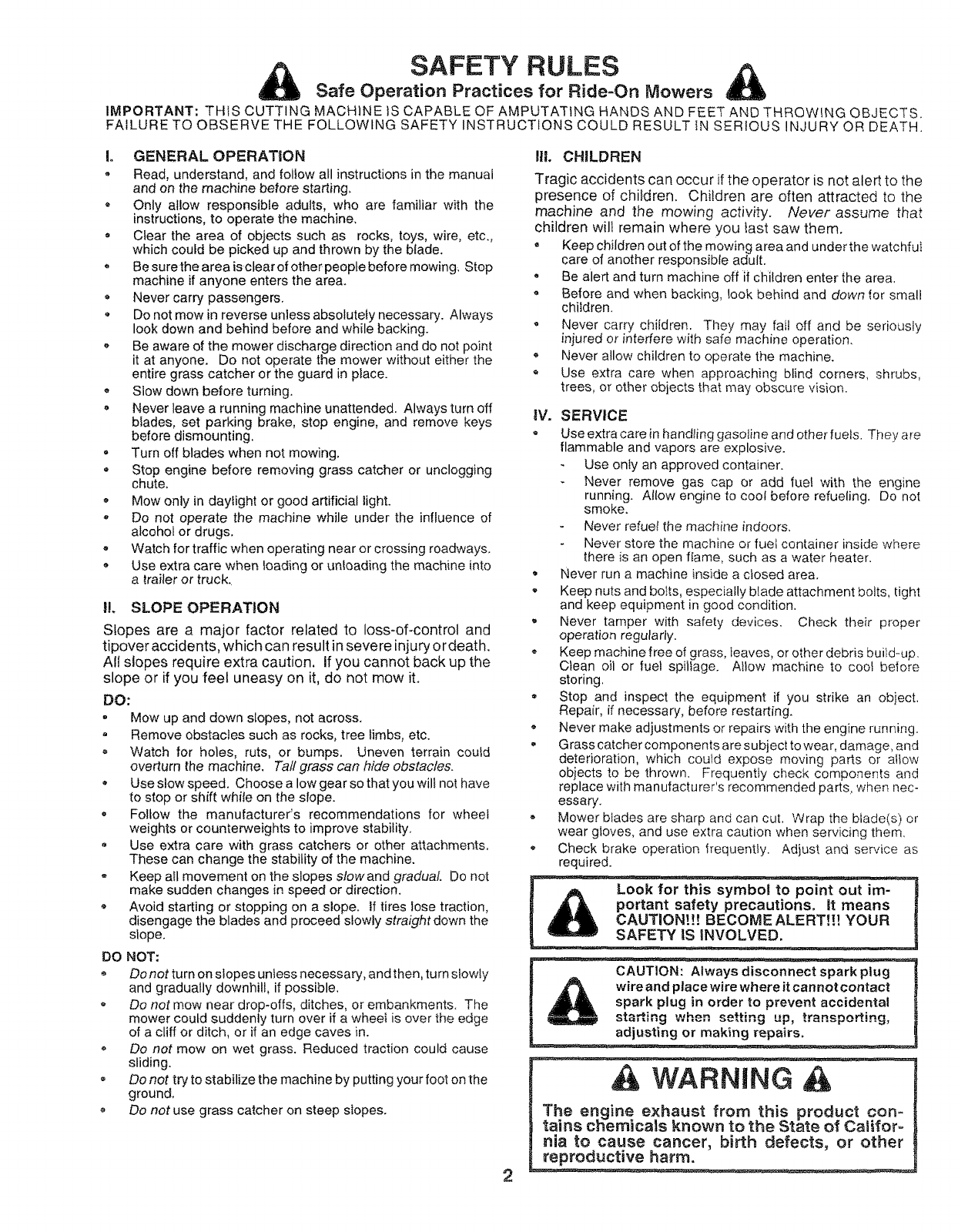
SAFETY RULES
Safe Operation Practices for Ride-On Mowers
IMPORTANT: THIS CUTTING MACHINE tS CAPABLE OF AMPUTATING HANDS AND FEET AND THROWING OBJECTS.
FAILURE TO OBSERVE THE FOLLOWING SAFETY INSTRUCTIONS COULD RESULT IN SERIOUS INJURY OR DEATH.
Io GENERAL OPERATION
,Read, understand, and follow all instructions in the manual
and on the machine before starting_
* Only allow responsible adults, who are familiar with the
instructions, to operate the machine,
o Clear the area of objects such as rocks, toys, wire, etc.,
which could be picked up and thrown by the blade,
,Be sure the area is clear of ether people before mowing, Step
machine if anyone enters the area,
,Never carry passengers,
oDo not mow in reverse unless absolutely necessary. Always
look down and behind before and while backing.
o Be aware of the mower discharge direction and do not point
it at anyone. Do not operate the mower without either the
entire grass catcher or the guard in place.
o Slow down before turning,
, Never leave a running machine unattended. Always turn off
blades, set parking brake, stop engine, and remove keys
before dismounting.
= Turn off blades when not mowing.
=Stop engine before removing grass catcher or unclogging
chute.
°Mow only in daylight or good artificial light.
-Do not operate the machine while under the influence of
alcohol or drugs,
-Watch for traffic when operating near or crossing roadways.
, Use extra care when loading or unloading the machine into
atrailer or truck.
H. SLOPE OPERATION
Slopes are a major factor related to loss*of-control and
tipover accidents, which can result in severe injury or death.
All slopes require extra caution. If you cannot back up the
slope or if you feel uneasy on it, do not mow it.
DO:
o Mow up and down slopes, not across.
Remove obstacles such as rocks, tree limbs, etc.
Watch for holes, ruts, or bumps. Uneven terrain coutd
overturn the machine. Tall grass can hide obstacles.
, Use slow speed. Choose a low gear so that you wilt not have
to stop or shift while on the slope.
o Follow the manufacturer's recommendations for wheel
weights or counterweights to improve stability.
Use extra care with grass catchers or other attachments.
These can change the stability of the machine.
* Keep all movement on the slopes slow and gradual Do not
make sudden changes in speed or direction.
Avoid starting or stopping on a slope. If tires lose traction,
disengage the blades and proceed slowly straight down the
slope.
DO NOT:
Donot turn on slopes unless necessary, and then, turn stowty
and gradually downhill, if possible.
Do not mow near drop-offs, ditches, or embankments. The
mower could suddenly turn over if a wheel is over the edge
of a cliff or ditch, or if an edge caves in.
Do not mow on wet grass. Reduced traction could cause
sliding.
Do not try to stabilize the machine by putting your foot on the
ground,
Do not use grass catcher on steep slopes.
III. CHILDREN
2
Tragic accidents can occur if the operator is not alert to the
presence of children. Children are often attracted to the
machine and the mowing activity. Never assume that
children will remain where you iast saw them.
•Keep children out of the mowing area and under the watchful
care of another responsible adult.
Be alert and turn machine off if children enter the area.
Before and when backing, look behind and down 1or small
children.
Never carry children. They may fall off and be seriously
injured or interfere with safe machine operation.
o Never allow children to operate the machine.
Use extra care when approaching blind corners, shrubs,
trees, or other objects that may obscure vision.
IV. SERVICE
= Use extra care in handling gasoline and other fuels. They are
flammable and vapors are explosive.
Use only an approved container.
Never remove gas cap or add rue! with the engine
running. Allow engine to cool before refueling. Do not
smoke.
Never refuel the machine indoors,
Never store the machine or fuet container inside where
there is an open flame, such as a water heater.
• Never run a machine inside a ctosed area.
, Keep nuts and bolts, especially blade attachment bolts, tight
and keep equipment in good condition.
, Never tamper with safety devices. Check their proper
operation regularly.
• Keep machine free of grass, leaves, or other debris build-up.
Clean oil or fuel spillage. Allow machine to cool bolero
storing,
• Stop and inspect the equipment if you strike an object.
Repair, if necessary, before restarting.
• Never make adjustments or repairs with the engine running.
• Grass catcher components are subject to wear, damage, and
deterioration, which could expose moving parts or altow
objects to be thrown. Frequently check components and
replace with manufacturer's recommended parts, when nec-
essary.
o Mower blades are sharp and can cut, Wrap the blade(s) or
wear gloves, and use extra caution when servicing them,
• Check brake operation frequently. Adjust and service as
required.
Look for this symbol to point out im-
portant safety precautions. It means
CAUTION!!! BECOME ALERT!!! YOUR
SAFETY iS iNVOLVED,
CAUTION: Always disconnect spark plug
wire and place wire whereit cannot contact
spark plug in order to prevent accidental
_;"" when up, )_'_RenO _'i'inneta ..... _ setting ..... _. ..... =,
adjusting or making repairs.
WARNING A
The engine exhaust from this product con-
tains chemicals known to the State of Califoro
nia to cause cancer, birth defects, or other
reproductive harm.

CONGRATULATIONS on your purchase of a Sears
Tractor. It has been designed, engineered and manufac-
tured to give you the best possible dependability and
performance.
Should you experience any problem you cannot easily
remedy, please contact your nearest Sears Authorized
Service Center/Department. We have competent, welF
trained technicians and the proper tools to service or repair
this tractor.
Please read and retain this manual. The instructions will
enable you to assemble and maintain your tractor properly.
Always observe the "SAFETY RULES".
MODEL
NUMBER 917.259550
SERIAL
NUMBER
DATE OF PURCHASE
THE MODEL AND SERIAL NUMBERSWtLL BE FOUND
ON A PLATE UNDER THE SEAT_
YOU SHOULD RECORD BOTH SERIAL NUMBER AND
DATE OF PURCHASE AND KEEP IN A SAFE PLACE
FOR FUTURE REFERENCE.
MAmNTENANCE AGREEMENT
A Sears Maintenance Agreement is available on this prod-
uct. Contact your nearest Sears store for details.
CUSTOMER RESPONSIBmLITIES
o Read and observe the safety rules.
o Foltow a regular schedule in maintaining, caring for and
using your tractor.
o Follow the instructions under "Customer Responsibili-
ties" and "Storage" sections of this owner's manual.
PRODUCT SPECiFiCATiONS
HORSEPOWER: t5.5
GASOLINE CAPACITY t.25 GALLONS
OIL TYPE (APFSFiSG!SH): SAE I0W30 (above 32°F)
SAE 5W-30 (below 32°F)
OIL CAPACITY: Wi FILTER: 4.0 PINTS
W!O FILTER: 3.5 PINTS
SPARK PLUG: CHAMPION RC12YC
(GAP: ,040")
VALVE CLEARANCE: NOT ADJUSTABLE ...................................
GROUND SPEED (MPH): FORWARD: 0 - 5.5
REVERSE: 0- 2.4
TiRE PRESSURE: FRONT: t4 PSt
REAR: 10 PSI
CHARGING SYSTEM: 3 AMPS BATTERY
5 AMPS HEADLIGHTS
BATTERY: AMPiHR: 30
MIN. CCA: 240
CASE SIZE: U1R
BLADE BOLT TORQUE: 30-35 FT. LBS.
AND TYPE: UNLEADED REGULAR
WARNING: This tractor is equipped with an internal
combustion engine and should not be used on or near any
unimproved forest-covered, brush-covered or grass-cov-
ered land unless the engine's exhaust system is equipped
with a spark arrester meeting applicable local or state laws
(if any). If a spark arrester is used, it should be maintained
in effective working order by the operator.
In the state of California the above is required by law
(Section 4442 of the California Public Resources Code).
Other states may have similar laws. Federal laws apply on
federal lands. A spark arrester for the muffler is available
through your nearest Sears Authorized Service Center/
Department (See REPAIR PARTS section of this manual).
LIMITED TWO YEAR WARRANTY ON CRAFTSMAN RtDING EQUIPMENT
For two (2) years from the date of purchase, if this Craftsman Riding Equipment is maintaine& lubricated and tuned up according
to the instructions in the owner's manual, Sears witl repair or replace, free of charge, any parts found to be defective in material or
workmanship.
This Warranty does not cover:
,_ Expendable items which become worn during normal use, such as blades, spark plugs, air cleaners, belts, etc,
o Tire replacement or repair caused by punctures from outside objects, such as nails, thorns, stumps_ or glass.
o Repairs necessary because of operator abuse, negligence, improper storage or accident or the failure to maintain the
equipment according to the instructions contained in the owner's manual.
Riding equipment used for commercial or rental purposes.
LmMITED 90 DAY WARRANTY ON BATTERY
For ninety (90) days from date of purchase, if any battery included with this riding equipment proves defective in material or
workmanship and our testing determines the battery wilt not hold a charge, Sears wilt replace the battery at no charge.
IN-HOME WARRANTY SERVICE ON YOUR CRAFTSMAN RIDING EQUIPMENT IS AVAILABLE AT NO-CHARGE FOR 30
DAYS FROM THE DATE OF PURCHASE. PLEASE CONTACT YOUR NEAREST SERVICE CENTER. AFTER 30 DAYS FROM
THE DATE OF PURCHASE, WARRANTY SERVICE IS AVAILABLE BY TAKING YOUR CRAFTSMAN RIDING EQUIPMENT TO
YOUR NEAREST SEARS SERVICE CENTER. (IN--HOME WARRANTY SERVICE WILL STILL BE AVAILABLE AFTER 30 DAYS
FROM THE DATE OF PURCHASE BUT A STANDARD TRIP CHARGE WILL APPLY.) THiS WARRANTY APPLIES ONLY
WHILE THIS PRODUCT IS IN THE UNITED STATES,
This Warranty gives you specific legal rights, and you may also have other rights which may vary from state to state.
SEARS, ROEBUCK AND CO., D/817 WA, HOFFMAN ESTATES, tL 60179
3
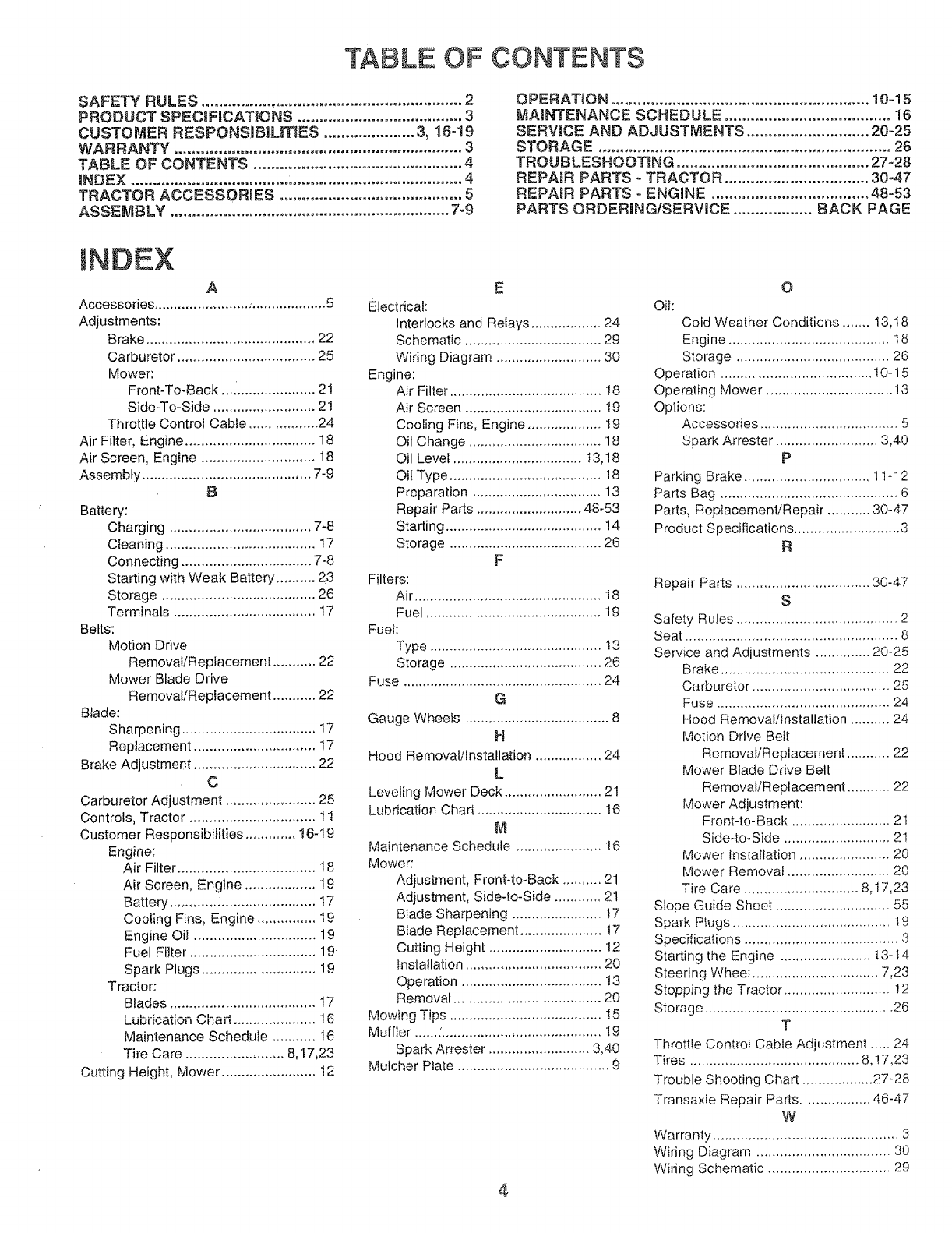
TABLE OF CONTENTS
SAFETY RULES ............................................................ 2
PRODUCT SPECiF!CATiONS ...................................... 3
CUSTOMER RESPONSiBiLiTiES ..................... 3, 16-19
WARRANTY .................................................................. 3
TABLE OF CONTENTS ................................................ 4
INDEX ............................................................................ 4
TRACTOR ACCESSORIES .......................................... 5
ASSEMBLY ................................................................ 7-9
OPERATION ........................................................... 10-15
MAINTENANCE SCHEDULE ...................................... 16
SERVICE AND ADJUSTMENTS ............................ 20-25
STORAGE ................................................................... 26
TROUBLESHOOTING ............................................ 27-28
REPAmR PARTS - TRACTOR ................................. 30-47
REPARR PARTS - ENGINE .................................... 48-53
PARTS ORDERING/SERVICE .................. BACK PAGE
INDEX
A
Accessories ........................ ..................... S
Adjustments:
Brake ........................................... 22
Carburetor ................................... 25
Mower:
Front-To-Back _,. .................... 21
Side-To-Side .......................... 21
Throttle Control Cable ................. 24
Air Filter, Engine ................................. 18
Air Screen, Engine ............................. 18
Assembly ............................................ 7-9
8
Battery:
Charging .................................... 7-8
Cleaning ...................................... 17
Connecting .................................. 7-8
Starting with Weak Battery .......... 23
Storage ....................................... 26
Terminals .................................... 17
Belts:
Motion Drive
Removal/Replacement ........... 22
Mower Blade Drive
Removal/Replacement ........... 22
Blade:
Sharpening .................................. 17
Replacement ............................... t7
Brake Adjustment ............................... 22
C
Carburetor Adjustment ....................... 25
Controls, Tractor ................................ 11
Customer Responsibilities ............. t6-19
Engine;
Air Filter ................................... 18
Air Screen, Engine .................. 19
Battery ............ :........................ t7
Cooling Fins, Engine ............... ! g
Engine Oil ............................... 19
Fuel Filter ................................ 19
Spark Plugs ............................. 19
Tractor:
Blades ..................................... 17
Luu_u_uun _.n_iL ...................... 16
Maintenance Schedule ........... 16
Tire Care ......................... 8,t7,23
Cutting Height, Mower ........................ t 2
E
Electrical:
Interlocks and Relays .................. 24
Schematic ................................... 29
Wiring Diagram ........................... 30
Engine:
Air Filter ....................................... !8
Air Screen ................................... 19
Cooling Fins, Engine ................... 19
Oil Change .................................. 18
Oil Level ................................. 13,18
Oil Type ....................................... 18
Preparation ................................. 13
Repair Parts ........................... 48.53
Starting ........................................ 14
Storage ....................................... 26
F
Filters:
Air ................................................ 18
Fuel ............................................. 19
Fuel:
Type ............................................ !3
Storage ....................................... 26
Fuse ................................................... 24
G
Gauge Wheels ..................................... 8
H
Hood Removal/Installation ................. 24
L
Leveling Mower Deck ......................... 21
Lubrication Chart ................................ 16
Maintenance Schedule ...................... 16
Mower:
Adjustment, Front-to-Back .......... 21
Adjustment, Side-to-Side ............ 21
Blade Sharpening ....................... !7
Blade Replacement ..................... 17
Cutting Height ............................. 12
installation ................................... 20
Operation .................................... 13
Removal ...................................... 20
l_Jlnwnn Tn<
Muffler ...... ;......................................... lg
Spark Attester .......................... 3,40
Mulcher P)ate ....................................... 9
4
O
Oi!:
Cold Weather Conditions ....... 13,18
Engine ......................................... t8
Storage ....................................... 26
Operation ...................................... 10-15
Operating Mower ................................ !3
Options:
Accessories ................................... 5
Spark Arrester .......................... 3,40
P
Parking Brake ................................ 11-t2
Parts Bag ............................................. 6
Parts, Replacement/Repair ........... 30-47
Product Specifications ........................... 3
R
Repair Parts .................................. 30-47
S
Safety Rules ......................................... 2
Seat ...................................................... 8
Service and Adjustments .............. 20-25
Brake ........................................... 22
Carburetor ................................... 25
Fuse ............................................ 24
Hood Removal/Installation .......... 24
Motion Drive Belt
Removal/Replacement ........... 22
Mower Blade Drive Belt
Removal/Replacement ........... 22
Mower Adjustment:
Front-to-Back ......................... 21
Side-to-Side ........................... 21
Mower Installation ....................... 20
Mower Removal .......................... 20
Tire Care ............................. 8,17,23
Slope Guide Sheet ............................. 55
Spark Ptu9s ........................................ 19
Specifications ....................................... 3
Starting the Engine ....................... 13-14
Steering Wheel ................................ 7,23
Stopping the Tractor ........................... 12
Storage ............................................... 26
T
Throttle Controi Cable Adjustment ..... 24
Tires ........................................... 8,17,2.3
Trouble Shooting Chart .................. 27-28
Transaxle Repair Parts ................. 46-47
W
Warranty ............................................... 3
Wiring Diagram .................................. 30
Wiring Schematic ............................... 29
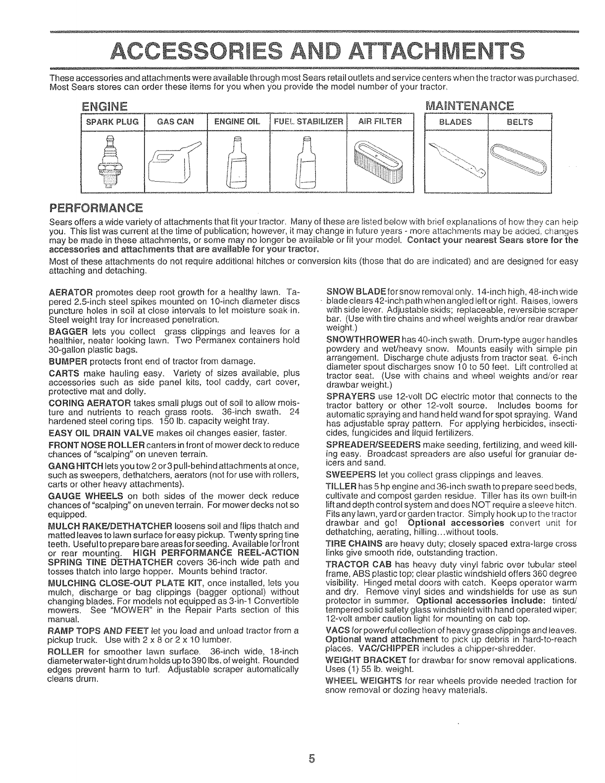
ACCESSORIES ATTACHMENTS
These accessories and attachments were available through most Sears retail outlets and service centers when the tractor was purchased.
Most Sears stores can order these items for you when you provide the model number of your tractor.
ENGINE MAnNTENANCE
SPARK PLUG GAS CAN AIR FILTER BLADES BELTS
ENGINE O|L,
PERFORMANCE
Sears offers a wide variety of attachments that fit your tractor, Many of these are listed below with brief explanations of how they can help
you. This list was current at the time o!_publication; however, it may change in future years - more attachments may be added, changes
may be made in these attachments, or some may no longer be available or fit your model. Contact your nearest Sears store for the
accessories and attachments that are available for your tractor,
Most of these attachments do not require additional hitches or conversion kits (those that do are indicated) and are designed for easy
attaching and detaching.
AERATOR promotes deep root growth for a healthy lawn. Ta-
pered 2.5-inch steel spikes mounted on 10-inch diameter discs
puncture holes in soil at close intervals to let moisture soak in.
Steel weight tray for increased penetration.
BAGGER lets you collect grass clippings and leaves for a
healthier, heater looking lawn. Two Permanex containers hold
30-gallon plastic bags.
BUMPER protects front end of tractor from damage.
CARTS make hauling easy. Variety of sizes available, plus
accessories such as side panel kits, tool caddy, cart cover,
protective mat and dolly.
CORING AERATOR takes smalJ plugs out of soil to allow mois-
ture and nutrients to reach grass roots. 364nch swath. 24
hardened steel coring tips. 150 lb. capacity weight tray.
EASY OIL DRAIN VALVE makes oil changes easier, faster.
FRONT NOSE ROLLER canters in front of mower deck to reduce
chances of "scalping" on uneven terrain.
GANG H_TCH lets you tow 2 or 3 pull-behind attachments at once,
such as sweepers, dethatchers, aerators (not for use with rollers,
carts or other heavy attachments).
GAUGE[ WHEELS on both sides of the mower deck reduce
chances of "scalping" on uneven terrain, For mower decks not so
equipped.
MULCH RAKF,.JDETHATCHER loosens soil and flips thatch and
matted leaves to lawn surface for easy pickup. Twenty spring tine
teeth. Useful to prepare bare areas forseeding. Avaiiabie for front
or rear mounting. HiGH PERFORMANCE REEL-ACTION
SPRING TINE DETHATCHER covers 36-inch wide path and
tosses thatch into large hopper. Mounts behind tractor,
IVIULCHING CLOSE-OUT PLATE KiT, once installed, lets you
mulch, discharge or bag clippings (bagger optional) without
changing blades. For models not equipped as 3-ir!! Convertible
mowers. See "MOWER" in the Repair Parts section of this
manual.
RAMP TOPS AND FEET let you load and untoad tractor from a
pickup truck. Use with 2 x 8 or 2 x 10 lumber.
ROLLER for smoother lawn surface. 36-inch wide, 18-inch
diameterwater4ight drum holds upto3901bs, of weight. Rounded
edges prevent harm to turf. Adjustable scraper automatically
cleans drum.
SNOW BLADE forsnow removal onfy. 14-inch high, 48-inch wide
bladeciears 42-inch path when angled left or right, Raises, lowers
with side lever. Adjustable skids; replaceable, reversible scraper
bar. (Use with tire chains and wheel weights and/or rear drawbar
weight,)
SNOWTHROWER has 40-inch swath. Drum-type auger handles
powdery and wet/heavy snow. Mounts easily with simple pin
arrangement. Discharge chute adiusts from tractor seat. 6-inch
diameter spout discharges snow 10 to 50 feet. Lift controlled at
tractor seat. (Use with chains and wheel weights and/or rear
drawbar weight.)
SPRAYERS use 12-volt DC electric motor that connects to the
tractor battery or other 12wolt source. Includes booms for
automatic spraying and hand held wand for spot spraying. Wand
has adjustable spray pattern. For applying herbicides, insecti-
cides, fungicides and liquid fertilizers.
SPREADER/SEEDERS make seeding, fertilizing, and weed kill-
ing easy, Broadcast spreaders are also useful for granular deo
icers and sand.
SWEEPERS let you collect grass clippings and Ieaves.
TILLER has 5 hp engine and 364nch swath to prepare seed beds,
cultivate and compost garden residue. Tiller has its own built-in
liftand depth control system and does NOT require a sleeve hitch.
Fits any lawn, yard or garden tractor. Simply hook up to the tractor
drawbar and go! Optional accessories convert unit for
dethatching, aerating, hilling...without tools.
TIRE CHAINS are heavy duty; closeiy spaced extra-large cross
links give smooth ride, outstanding traction.
TRACTOR CAB has heavy duty vinyl fabric over tubular steel
frame, ABS plastic top; clear plastic windshield offers 360 degree
visibility. Hinged metal doors with catch. Keeps operator warm
and dry. Remove vinyl sides and windshields for use as sun
protector in summer. Optional accessories incJude: tinted/
tempered solid safety glass windshield with hand operated wiper;
12-volt amber caution light for mounting on cab top.
VACS for powerful collection of heavy grass clippings and leaves.
Optional wand attachment to pick up debris in hard-to-reach
places. VAC/CH;PPER includes a chipper-stiredder.
WEnGHT BRACKET for drawbar for snow removal applications.
Uses (1) 55 Ib. weight.
WHEEL WEIGHTS for rear wheels provide needed traction for
snow removal or dozing heavy materials.
5
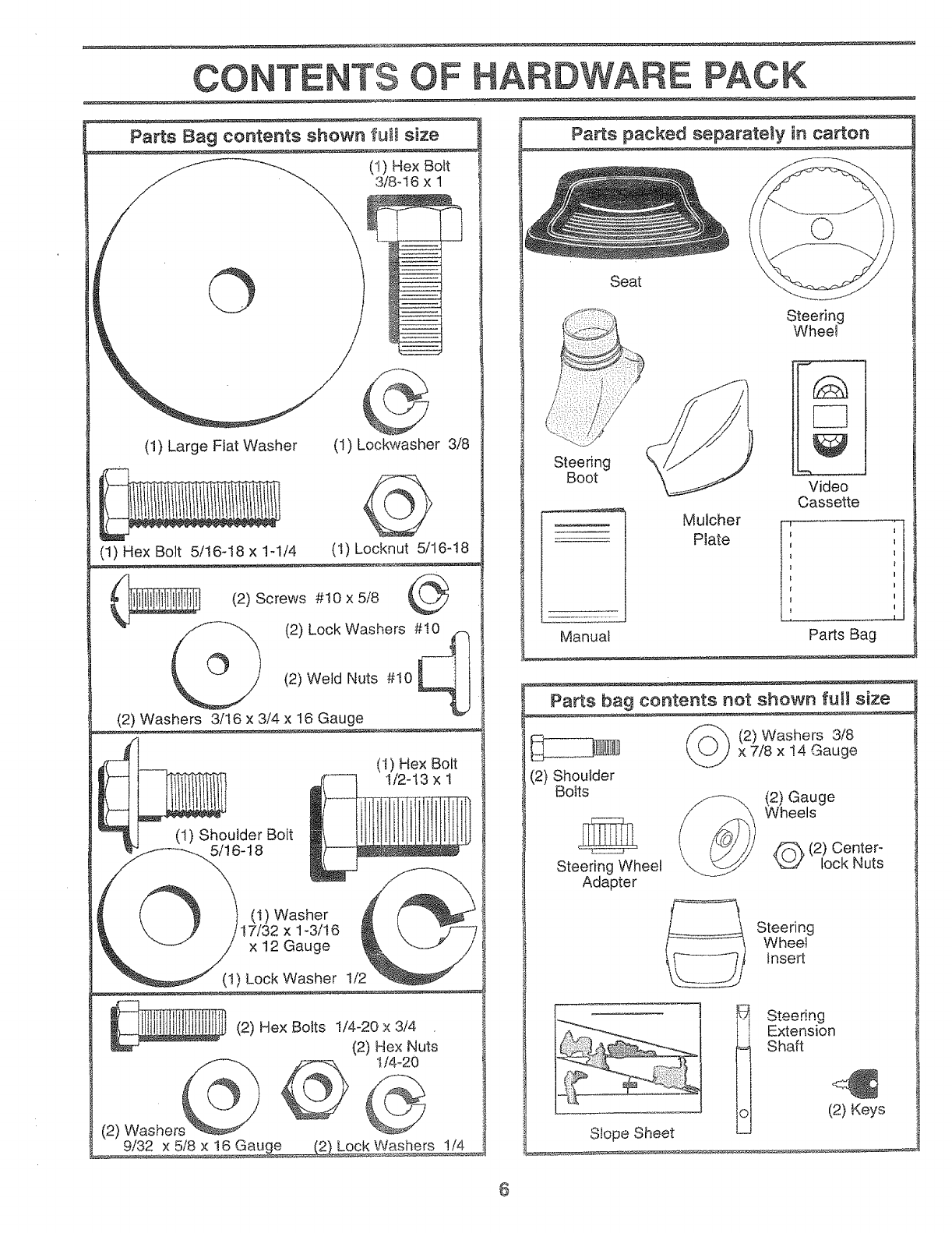
OONTE TS OF ARDWARE PACK
Parts Bag contents shown fuI_ size
(1) Hex Bolt
3/8-16 x 1
©
(1) Large Flat Washer (1) Lockwasher 3/8
(1) Locknut 5/16-18
(1) Hex Bolt 5/16-18 x 1-1/4
(2) Screws #10 x 5/8
_ Washers#tl_
(2) Lock
(2) Weld Nuts #10
(2) Washers 3/16 x 3/4 x 16 Gauge
(1) Shoulder Bolt
5/16-18
(1) Hex Bolt
I/2-13 x 1
(t) Washer
17/32 x t -3/16
x 12 Gauge
(1) Lock Washer t/2
(2) Washers
9/32
(2) Hex Bolts I/4_20 x 3/4
(2) Hex Nuts
t/4_20
x 5/8 x 16 Gauge 2_Lock Washers 1/4
Seat
Steering
Boot
Manual
Mulcher
Plate
Steering
Whee!
Video
Cassette
Parts Bag
Parts bag contents not shown full size
(2) Washers 3/8
x 7/8 x !4 Gauge
(2) Shoulder
Bolts
Steering Wheel
Adapter
____ (2) Gauge
Wheels
(2) Center-
lock Nuts
@ Steering
Wheel
Insert
Slope Sheet
]Steenng
Extension
Shaft
(2} Keys
6
ASSEMBLY
Your new tractor has been assembIed at the factory with exception of those pa_s left unassembted for shipping purposes.
To ensure safe and proper operation of your tractor all part,s and hardware you assemble must be tightened securely. Us_:
the correct tools as necessary to insure proper tightness.
TOOLS REQUIRED FOR ASSEMBLY
A socket wrench set witl make assembly easier. Standard
wrench sizes are listed.
(I) 3/4" Soc_t w/drive rachel
(2) 7/16" wrenches (t) Philtips Screwdriver
(2) I/2" wrenches Tire pressure gauge
(1) 9/16" wrench Utility knife
When right or left hand is mentioned in this manual, it
means when you are in the operating position (seated
behind the steering wheel).
TO REMOVE TRACTOR FROM CARTON
UNPACK CARTON
°Remove all accessible loose parts and parts cartons
from carton (See page 6).
= Cut, from top to bottom, atong lines on all four corners
of carton, and lay panels flat.
• Check for any additional loose parts or cartons and
remove.
BEFORE ROLLING TRACTOR OFF SKID
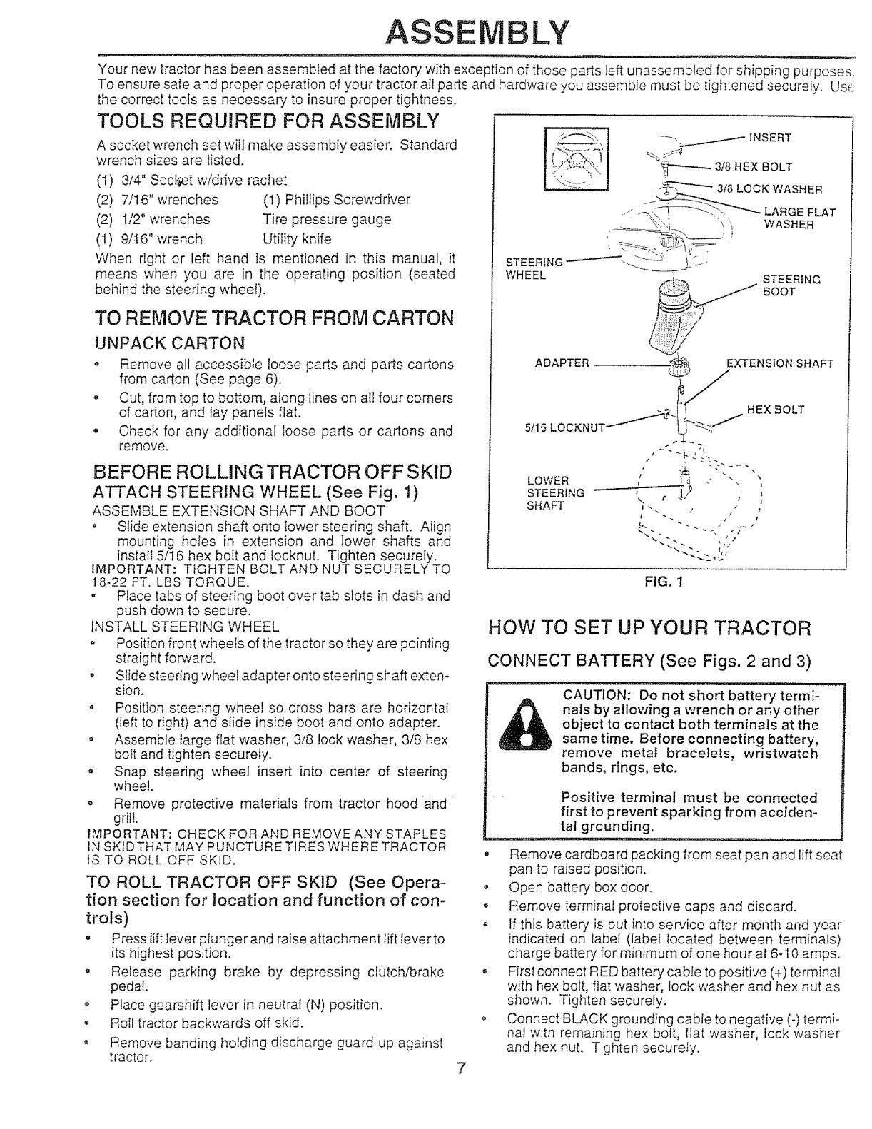
ATTACH STEERING WHEEL (See Fig. 1)
ASSEMBLE EXTENSION SHAFT AND BOOT
, Slide extension shaft onto lower steering shaft. Align
mounting holes in extension and lower shafts and
install 5/16 hex bolt and locknut. Tighten securely.
IMPORTANT: TIGHTEN BOLT AND NUT SECURELY TO
18-22 FT, LBS TORQUE.
" Place tabs of steering boot over tab slots in dash and
push down to secure,
INSTALL STEERING WHEEL
• Position front wheels of the tractor so they are pointing
straight forward.
, Slide steering wheel adapter onto steering shaft exten-
sion.
o Position steering wheel so cross bars are horizontal
(left to right) and slide inside boot and onto adapter.
•Assemble Iarge flat washer, 3/8 lock washer, 3/8 hex
bott and tighten securely.
° Snap steering wheel insert into center of steering
wheel.
o Remove protective materials from tractor hood and
gritl.
IMPORTANT: CHECK FOR AND REMQVEANY STAPLES
IN SKIDTHAT MAY PUNCTURE TIRES WHERE TRACTOR
fS TO ROLL OFF SKID.
TO ROLL TRACTOR OFF SKID (See Opera-
tion section for location and function of con-
trols)
" Press tift lever plunger and raise attachment rift lever to
its highest position.
° ReIease parking brake by depressing clutch/brake
pedal.
o Place gearshift lever in neutral (N) position.
• Roll tractor backwards off skid.
o Remove banding holding discharge guard up against
tractor.
...... , .,...._,----- INSERT
3/8.ExBOLT
WHEEL STEERING
:,,:,,.... BOOT
ADAPTER _ EXTENSION SHAFT
LOWER ,_ ; 4 :
------_._2
STEERING _ _ t_
SHAFT ,- .. ,
FIG. 1
HOW TO SET UP YOUR TRACTOR
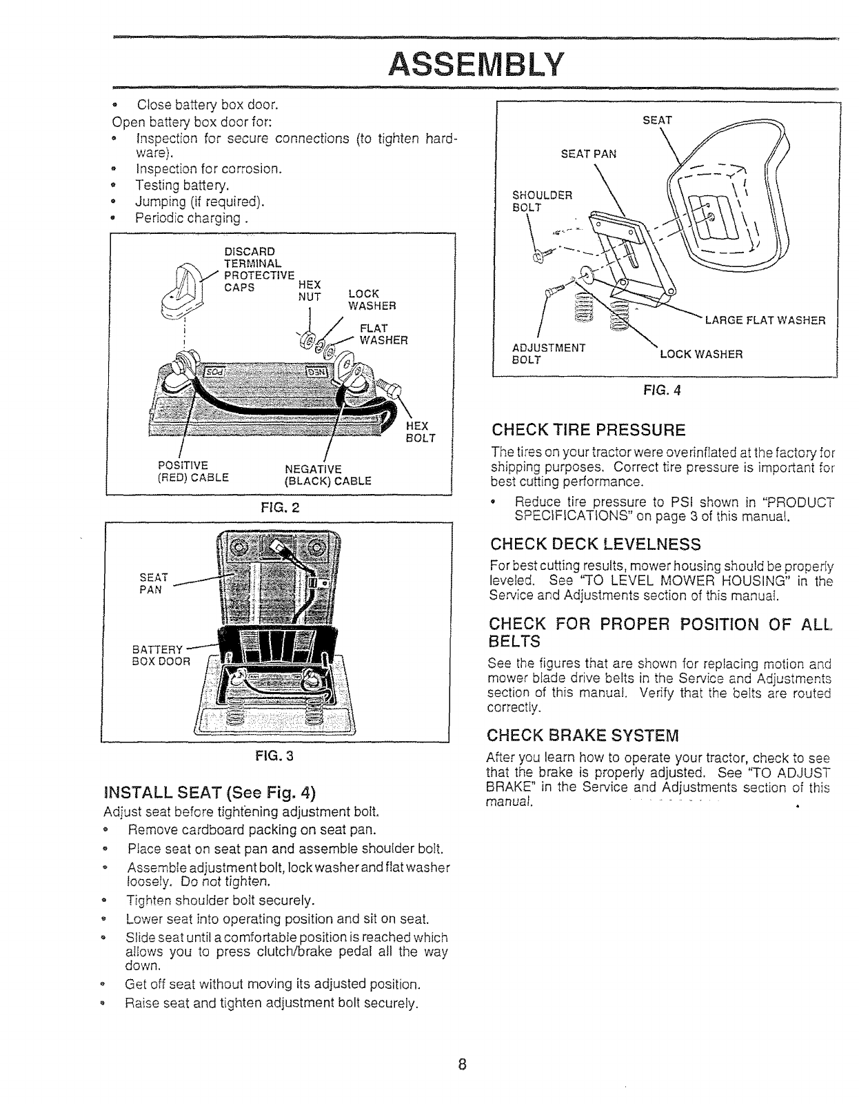
CONNECT BATTERY (See Figs. 2 and 3)
CAUTION: Do not short battery termi-
nais by allowing awrench or any other
object to contact both terminals at the
same time. Before connecting battery,
remove metal bracelets, wristwatch
bands, rings, etc.
Positive terminal must be connected
first to prevent sparking from acciden-
tal grounding.
- Remove cardboard packing from seat pan and lift seat
pan to raised position.
• Open battery box door.
o Remove terminal protective caps and discard.
= If this battery is put into service after month and year
indicated on label (label located between terminals)
charge battery for minimum of one hour at 6-10 amps.
,, First connect RED battery cable to positive (+) terminal
with hex bolt, flat washer, lock washer and hex nut as
shown. Tighten securely.
o Connect BLACK grounding cable to negative (-) termi-
nal with remaining hex bolt, flat washer, lock washer
and hex nut. Tighten securely.
ASSEMBLY
- Close battery box door.
Open battery box door for:
• Inspection for secure connections (to tighten hard-
ware).
- Inspection for corrosion.
, Testing battery.
• Jumping (if required).
. Periodic charging.
I
DISCARD
TERMINAL
PROTECTIVE
CAPS HEX
NUT LOCK
WASHER
FLAT
WASHER
HEX
BOLT
POSITIVE
(RED) CABLE
/
NEGATIVE
(BLACK) CABLE
FIG.2
SEAT
PAN
SEAT
SEAT PAN
SHOULDER
BOLT
L
ADJUSTMENT
BOLT
LARGE FLAT WASHER
LOCK WASHER
FIG. 4
CHECK TIRE PRESSURE
The tires on your tractor were overinflated at the factory for
shipping purposes. Correct tire pressure is important for
best cutting pedormance.
• Reduce tire pressure to PSf shown in "PRODUCT
SPECIFICATIONS" on page 3 of this manual.
BATTERY
BOX DOOR
FIG, 3
iNSTALL SEAT (See Fig. 4)
Adjust seat before tightening adjustment bolt,
o Remove cardboard packing on seat pan.
• PEace seat on seat pan and assemble shoulder bolt.
o Assembte adjustment bolt, lock washer and flat washer
loosely. Do not tighten.
• Tighten shoulder bolt securely.
,, Lower seat into operating position and sit on seat.
o Slide seat until a comfortable position is reached which
allows you to press clutch/brake pedal all the way
down.
o Get off seat without moving its adjusted position.
, Raise seat and tighten adjustment bolt securely.
CHECK DECK LEVELNESS
For best cutting results, mower housing should be properIy
leveled. See "TO LEVEL MOWER HOUSING" in the
Service and Adjustments section of this manual.
CHECK FOR PROPER POSITION OF ALL
BELTS
See the figures that are shown for replacing motion and
mower blade drive belts in the Service and Adjustments
section of this manual. Verify that the belts are routed
correctly.
CHECK BRAKE SYSTEM
After you learn how to operate your tractor, check to see
that the brake is properly adjusted, See "TO ADJUST
BRAKE" in the Service and Adjustments section of this
manual. " ......
ASSEMBLY
GAUGE WHEEL
MOUNTING
OKET "_"
3t84 6
LOCKNUT
3/8 _'WASHER
GAUGE WHEEL
FroG.5A
SHOULDER BOLT
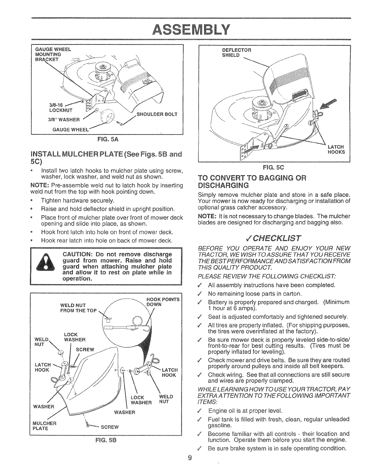
aNSTALL MULCHER PLATE (See Figs° 5B and
5¢)
oInstaIl two latch hooks to mulcher plate using screw,
washer, lock washer, and weld nut as shown.
NOTE: Pre-assembte weld nut to latch hook by inserting
weld nut from the top with hook pointing down.
o Tighten hardware securely.
o Raise and hold deflector shield in upright position.
,, Ptace front of mutcher ptate over front of mower deck
opening and s_ide into place, as shown,
o Hook front latch into hole on front of mower deck.
o Hook rear latch into hote on back of mower deck,
CAUTION: Do not remove discharge
guard from mower. Raise and hold
guard when attaching mulcher plate
and altow it to test on plate whiJe in
operation.
WELD NUT
FROM THE TOP ,.
HOOK POINTS
DOWN
SCREW
HOOK
FIGo 5B
LATCH
HOOKS
FIG. 50
TO CONVERT TO BAGGING OR
DISCHARGING
Simply remove mulcher plate and store in a safe place,
Your mower is now ready for discharging or installation of
optional grass catcher accessory,
NOTE: It is not necessary to change blades, The mulcher
blades are designed for discharging and bagging alsoo
#'CHECKMST
BEFORE YOU OPERATE AND ENJOY YOUR NEW
TRACTOR, WE WISH TO ASSURE THAT YOU RECEIVE
THE BEST PERFORMANCE AND SATISFACTtON FROM
THIS QUALITY PRODUCT.
PLEASE REVIEW THE FOLLOWING CHECKLIST:
,/ All assembly instructions have been completed.
7 No remaining loose parts in carton,
¢' Battery is properly prepared and charged, (Minimum
t hour at 6 amps).
¢" Seat is adjusted comfortably and tightened securely,
,/ All tires are properly inflated, (For shipping purposes,
the tires were overinfiated at the factory).
_/ Be sure mower deck is properly leveled side-to-side/
front-to-rear for best cutting results. (Tires must be
properly inflated for leveling).
d" Check mower and drive belts. Be sure they are routed
properly around pulleys and inside all belt keepers.
7" Check wiring, See that all connections are still secure
and wires are properly clamped,
WHILE LEARNING HO W TO USE YOUR TRACTOR, PAY
EXTRA A TTENTION TO THE FOLLOWING IMPORTANT
FTEMS:
_/ Engine oil is at proper level,
v' Fuel tank is filled with fresh, clean, regular unleaded
gasoline.
7 Become familiar with all controls - their Iocation and
function. Operate them before you start the engine.
/Be sure brake system is in safe operating condition,
9
,,,r ....
PERATION
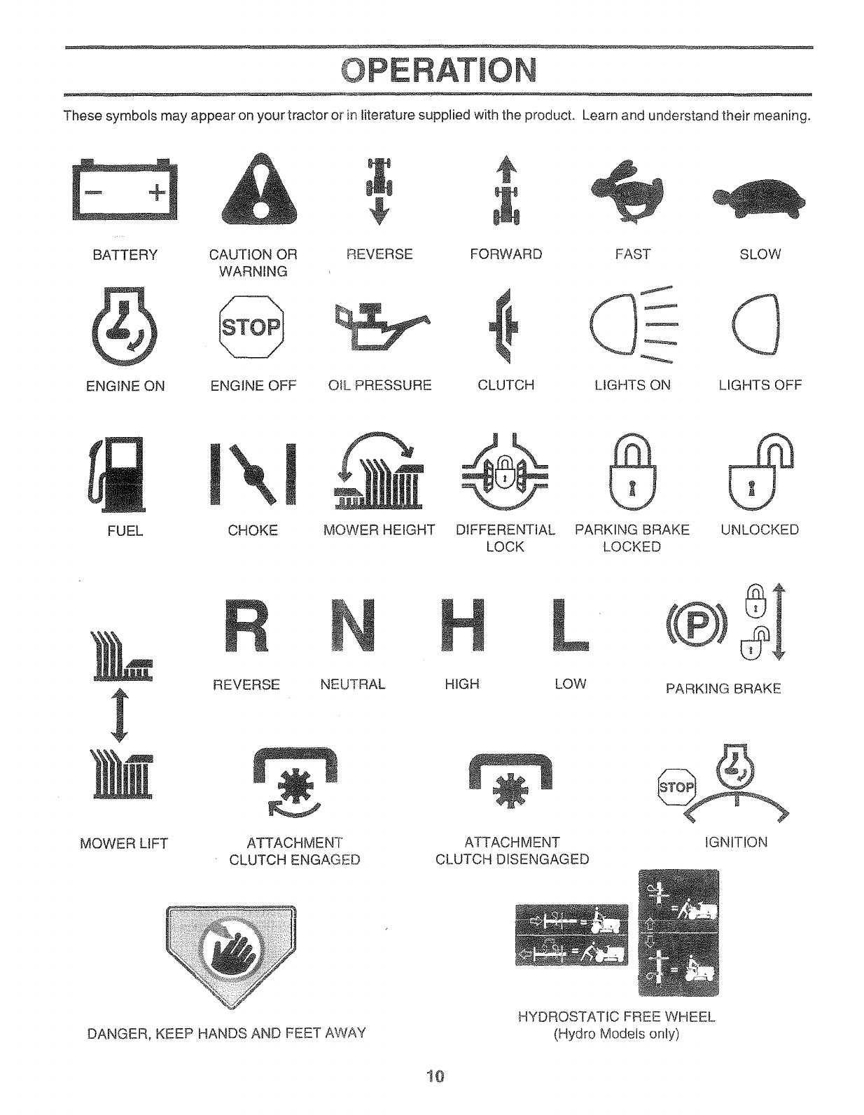
These symbols may appear on your tractor or' in literature supplied with the product. Learn and understand their meaning.
BATTERY
ENGINE ON
CAUTION OR REVERSE FORWARD FAST SLOW
WARNING
ENGINE OFF OIL PRESSURE CLUTCH LIGHTS ON LIGHTS OFF
FUEL
X
CHOKE MOWER HEIGHT DIFFERENTIAL PARKING BRAKE UNLOCKED
LOCK LOCKED
MOWER LIFT
REVERSE NEUTRAL
ATTACHMENT
CLUTCH ENGAGED
H L
HIGH LOW PARKING BRAKE
ATTACHMENT
CLUTCH DISENGAGED
IGNITION
DANGER, KEEP HANDS AND FEET AWAY
HYDROSTATIC FREE WHEEL
(Hydro Models only)
10
OPERATION
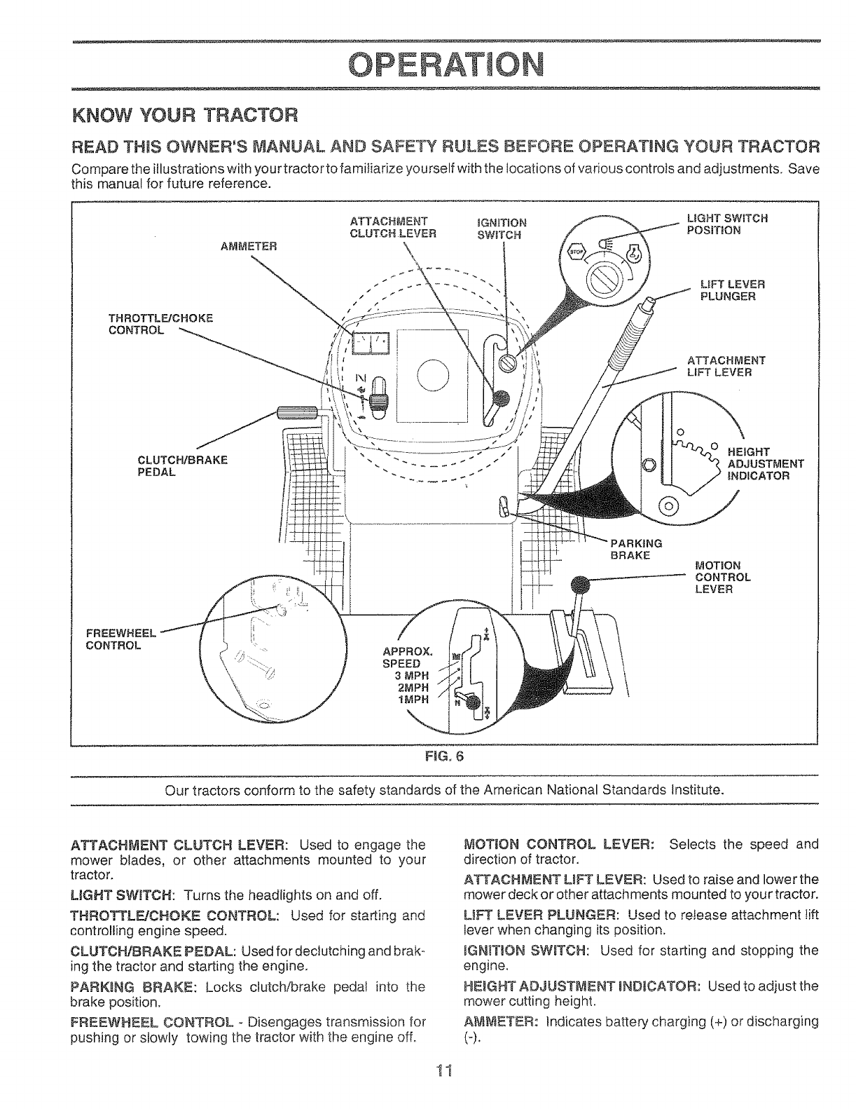
KNOW YOUR TRACTOR
READ TH_S OWNER'S MANUAL AND SAFETY RULES BEFORE OPERATUNG YOUR TRACTOR
Compare the illustrations with your tractor to familiarize yourself with the locations of various controls and adjustments. Save
this manual for future reference.
THROTTLE/CHOKE
CONTROL
CLUTCH/BRAKE
PEDAL
ATTACH_ENT _GN_TtON LIGHT SWtTCH
CLUTCH LEVER SW_TCH POSFFaON
AMMETER _
- " "" LIFT LEVER
," _ PLUNGER
ATTACHMENT
LiFT LEVER
O
HEIGHT
. _ .... ADJUSTMENT
" INDICATOR
FREEWHEEL
CONTROL
\
APPROXo
SPEED
3MPH
2MPH
1MPH
PARKING
BRAKE MOTION
CONTROL
LEVER
FIG. 6
Our tractors conform to the safety standards of the American National Standards Institute.
ATTACHMENT CLUTCH LEVER: Used to engage the
mower blades, or other attachments mounted to your
tractor.
LgGHT SWITCH: Turns the headlights on and off.
controlling engine speed.
CLUTCH/BRAKE PEDAL: Used for declutching and brak-
ing the tractor and starting the engine.
PARKING BRAKE: Locks clutch/brake pedal into the
brake position.
FREEWHEEL CONTROL - Disengages transmission for
pushing or slowly towing the tractor with the engine off°
tVfOT_ON CONTROL LEVER: Selects the speed and
direction of tractor.
ATTACHMENT UFT LEVER: Used to raise and lower the
mower deck or other attachments mounted to your tractor.
L!FT LEVER PLUNGER: Used to re!ease attachment !ift
lever when changing its position.
_GN_T_ONSWITCH: Used for starting and stopping the
engine.
HEIGHT ADJUSTMENT _ND_CATOR: Used to adjust the
mower cutting height.
A_ETER: Indicates batter,/charging (+) or discharging
(-).
PERATION
The operation of any tractor can resuJt in foreign objects thrown into the eyes, which can
[_ s_E_ _ resuttinsevereeyed_mage, ABwayswearsafetyglassesoreyeshieZdswhileoperatingyour
tractor or performing any adjustments or repairs. We recommend a wide v;,sion safety mask
over the spectacles or standard safety g_asseso
HOW TO USE YOUR TRACTOR
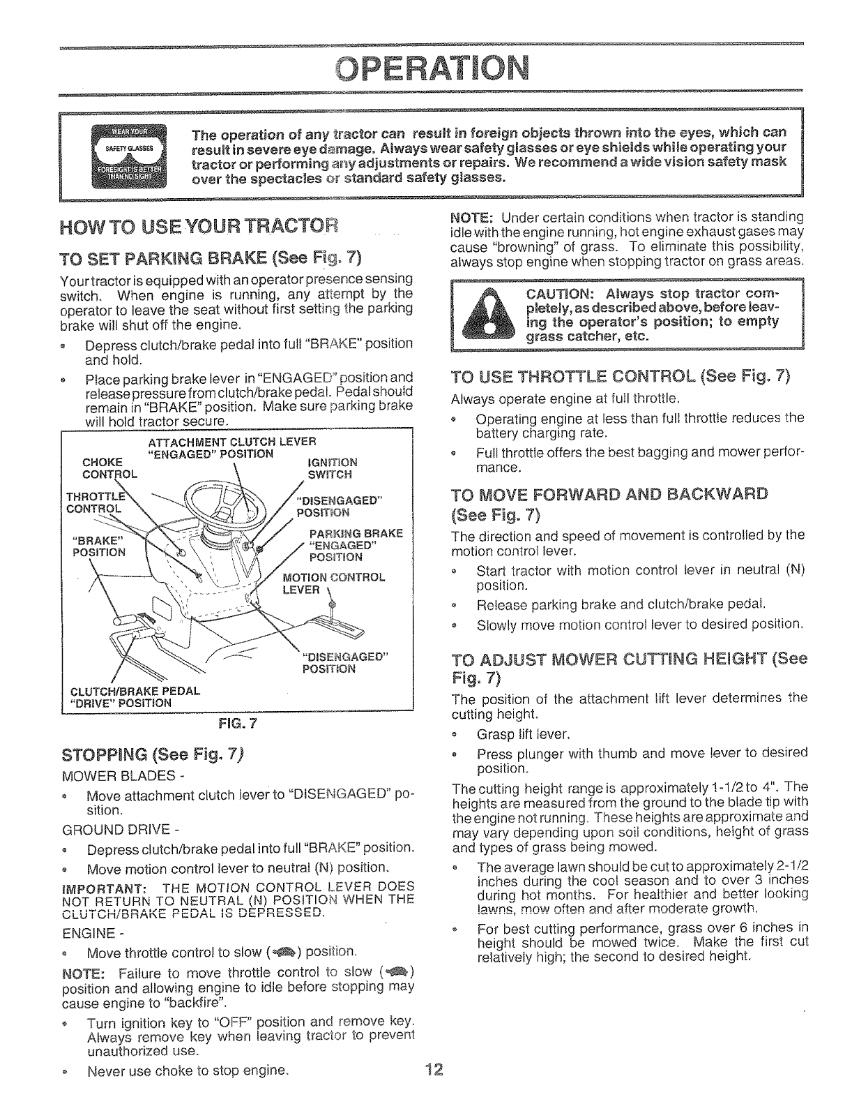
TO SET PARKING BRAKE (See Fig. 7)
You rtractor is equipped With an operator presence sensing
switch, When engine is running, any attempt by the
operator to leave the seat without first setting the parking
brake will shut off the engine.
o Depress clutch/brake pedal into full "BRAKE" position
and hold,
oPlace parking brake lever in "ENGAGED" position and
release pressu refrom clutch/brake pedal, Pedal should
remain in "BRAKE" position. Make sure parking brake
will hold tractor secure,
ATTACHMENT CLUTCH LEVER
"ENGAGED" POS1T!ON
CHOKE iGNITION
CONTROL SWITCH
MOTION CONTROL
CLUTCH/BRAKE PEDAL
"DR_VE" POSITION
FiG. 7
"DISENGAGED"
POS_TION
STOPPING (See Fig. 7)
MOWER BLADES-
o Move attachment clutch lever to "DISENGAGED" po-
sition.
GROUND DRIVE -
o Depress clutch/brake pedal into full "BRAKE" position.
oMove motion control lever to neutral (N) position,
I_PORTANT: THE MOTION CONTROL L,EVER DOES
NOT RETURN TO NEUTRAL (N) POSITION WHEN THE
ULU I L,rliBR_K= r=u_- _o u=rn=ooL;,-,.
ENGINE -
• Move throttte controJ to slow (,_) position.
NOTE: Failure to move throttle control to slow (_)
position and allowing engine to idle before stopping may
cause engine to "backfire".
o Turn ignition key to "OFF" position and remove key.
Always remove key when leaving tractor to prevent
unauthorized use.
o Never use choke to stop engine.
NOTE: Under certain conditions when tractor is standing
idle with the engine running, hot engine exhaust gases may
cause "browning" of grass. To eliminate this possibility,
always stop engine when stopping tractor on grass areas.
r_A_ A,ways stop tr_
_, _ pleteJy, as described above, before _eavo 1
I _ 2_he_P_ rat°r's pos,tion; to empty
grass catcher, etc.
TO USE THROTTLE CONTROL (See Fig, 7}
Always operate engine at full throttle.
o Operating engine at less than full throttle reduces the
battery charging rate.
o Full throttle offers the best bagging and mower perfor-
mance.
TO MOVE FORWARD AND BACKWARD
(See Fig. 7)
The direction and speed of movement is controlled by the
motion control lever.
o Start tractor with motion control lever in neutral (N)
position.
o Release parking brake and clutch/brake pedal.
Slowly move motion control lever to desired position.
TO ADJUST MOWER CUTTING HEUGHT (See
Fig. 7)
The position of the attachment lift lever determines the
cutting height,
o Grasp lift lever.
Press plunger with thumb and move lever to desired
position.
The cutting height range is approximately !-1/2 to 4". The
heights are measured from the ground to the blade tip with
the engine not running. These heights are approximate and
may van./depending upon soil conditions, height of grass
and types of grass being mowed.
• The average lawn should be cut to approximately 2-1/2
inches during the cool season and to over 3 inches
during hot months. For healthier and better looking
lawns, mow often and after moderate growth.
o For best cutting performance, grass over 6 inches in
height should be mowed twice. Make the first cut
relatively high; the second to desired height.
12
OPERATION
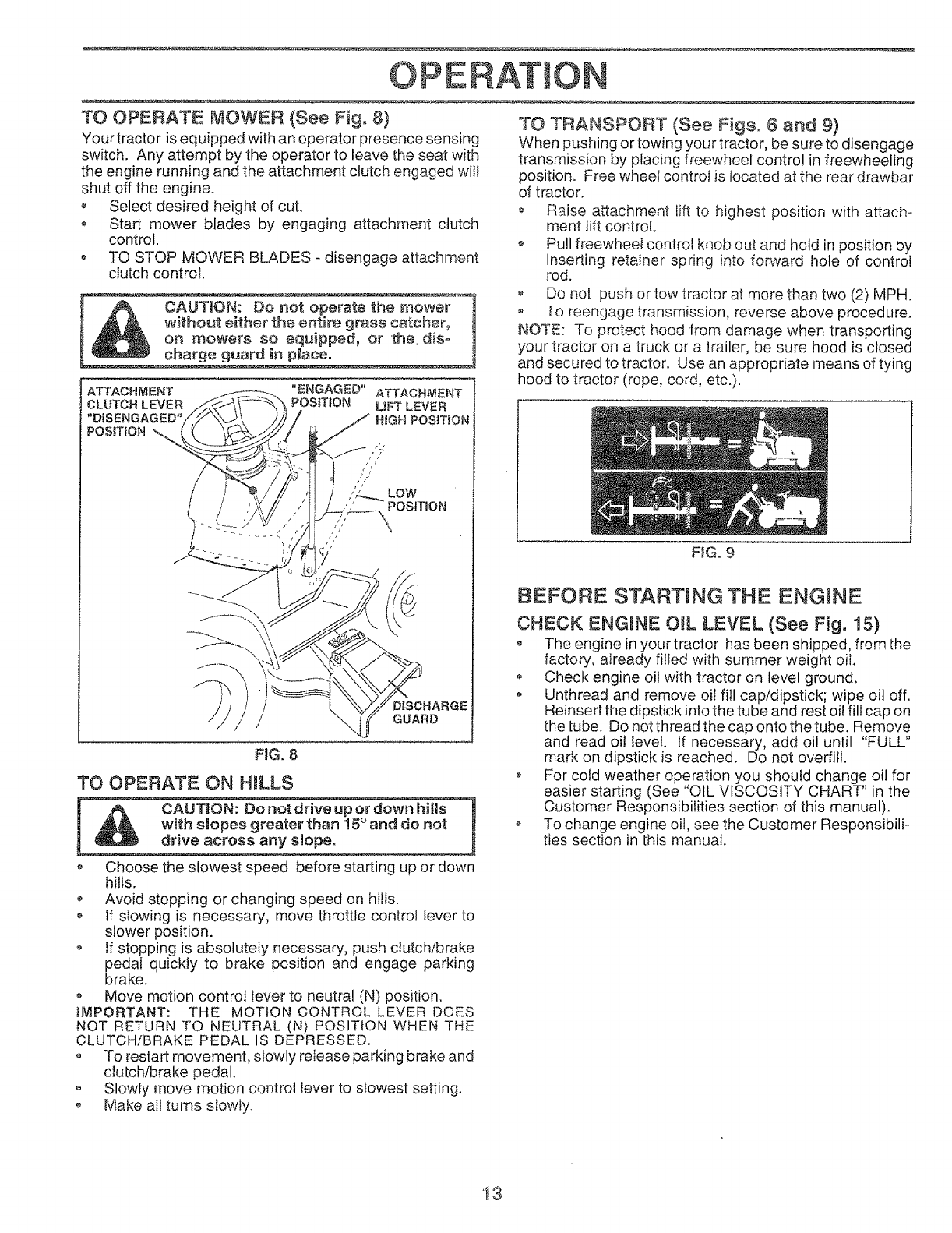
TO OPERATE MOWER (See Fig. 8)
Your tractor is equipped with an operator presence sensing
switch. Any attempt by the operator to leave the seat with
the engine running and the attachment clutch engaged will
shut off the engine.
• Select desired height of cut.
o Start mower blades by engaging attachment clutch
control.
o TO STOP MOWER BLADES - disengage attachment
ctutch control.
CAUTmON: Do not operate the mower
without either the entire grass catcher,
on mowers so equipped, or the. dis-
charge guard in place.
TO OPERATE ON HILLS
---_UT'ON: Do not dr,re up or down h,Hs ]
with slopes greater than 15° and do not
drive across any s!opeo
• Choose the slowest speed before starting up or down
hills.
• Avoid stopping or changing speed on hi!Is.
o If slowing is necessary, move throttle control lever to
slower position.
o If stopping is absolutely necessary, push clutch/brake
pedal quickly to brake position and engage parking
brake.
o Move motion controt tever to neutra! (N) position.
_MPORTANT: THE MOTION CONTROL LEVER DOES
NOT RETURN TO NEUTRAL (N) POSITION WHEN THE
CLUTCH/BRAKE PEDAL IS DEPRESSED.
o To restart movement, slowly release parking brake and
clutch/brake pedal,
• Slowly move motion control lever to slowest setting.
o Make all turns slowly.
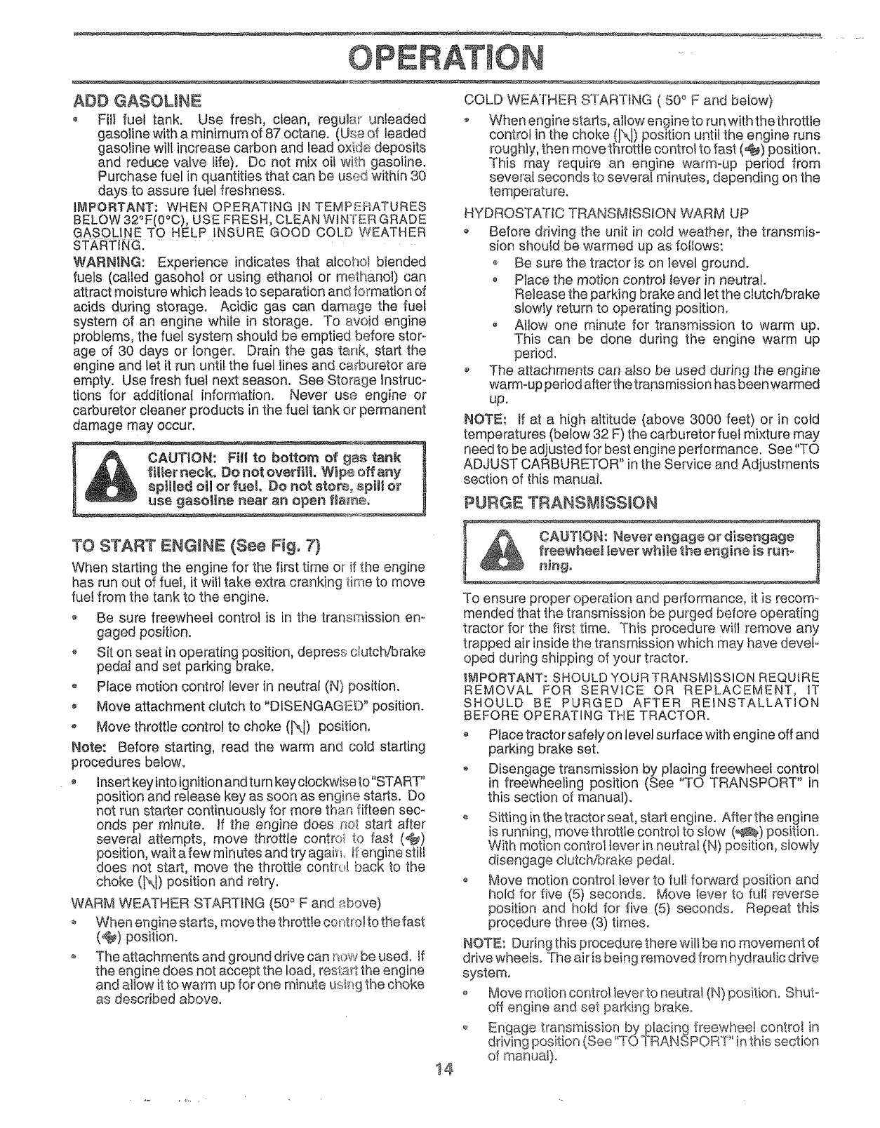
TO TRANSPORT (See Figs. 6 and 9)
When pushing or towing your tractor, be sure to disengage
transmission by placing freewheel control in freewheeling
position. Free wheel controI is located at the rear drawbar
of tractor.
o Raise attachment lift to highest position with attach-
ment lift control.
o Pull freewheel control knob out and hold in position by
inserting retainer spring into forward hole of control
rod.
o Do not push or tow tractor at more than two (2) MPH.
To reengage transmission, reverse above procedure.
NOTE: To protect hood from damage when transporting
your tractor on a truck or a trailer, be sure hood is closed
and secured to tractor. Use an appropriate means of tying
hood to tractor (rope, cord, etc.).
FIG. 9
BEFORE STARTING THE ENGINE
CHECK ENGINE OIL LEVEL (See Fig. 15)
The engine in your tractor has been shipped, from the
factory, already fitled with summer weight oil
Check engine oil with tractor on level ground.
•Unthread and remove oiI fill cap/dipstick; wipe oil off.
Reinsert the dipstick into the tube and rest oil fill cap on
the tube. Do not thread the cap onto the tube. Remove
and read oil leve!. If necessary, add oil until "FULL"
mark on dipstick is reached. Do not overfill.
For cold weather operation you shouid change oil for
easier starting (See "OIL VISCOSITY CHART" in the
Customer Responsibilities section of this manual).
,, To change engine oil, see the Customer Responsibili-
ties section in this manual.
'13
OPEF AT ON ....
ADD GASOLINE
oFill fuel tank. Use fresh, clean, regular unleaded
gasoline with a minimum of 87 octane. (Use of leaded
gaso ine wii! ncrease carbon and lead oxide deposits
and reduce valve life}. Do not mix oil with gasoline.
Purchase fuel in quantities that can be use.Qwithin 30
days to assure fuel freshness.
IMPORTANT: WHEN OPERATING IN TEMP_L:.RATURES
BELOW 32°F(0°0), USE FRESH, CLEAN WINTER GRADE
GASOLINE TO HELP INSURE GOOD COLD WEATHER
STARTING. ............
WARNING: Experience indicates that atcoho} biended
fuels (called gasohol or using ethanol or methanol) can
attract moisture which leads to separation and formation of
acids during storage. Acidic gas can damage the fuel
system of an engine while in storage. To avoid engine
problems, the fuel system shoutd be emptied before stor-.
age of 30 days or tonger. Drain the gas tank, staff the
engine and let it run until the fuel lines and carburetor are
empty. Use fresh fuet next season. See Storage instruc-
tions for additional information. Never use engine or
carburetor cleaner products in the fuel tank or permanent
damage may occur.
CAUTION: Fill to bottom of ge
!_iller neck, Do not ovm'fill. Wipe off any
spitled oimor fUelo Do not stot% _pill or !
TO START ENGINE! (See Fig. 7)
When starting the engine for the first time or if the engine
has mn out of fuel, it will take extra cranking time to move
fuel from the tank to the engine.
,Be sure freewheel control is in the transmission en-
gaged position.
oSit on seat in operating position, depress clutchfbrake
pedat and set parking brake.
o Place motion control lever in neutral (N) position.
•Move attachment clutch to "DISENGAGED" position.
,Move throttle control to choke (JXJ) position.
Note: Before starting, read the warm and cold starting
procedures below.
•insertkey into ignition and turn key clockwise to"START"
position and release key as soon as engine starts. Do
not run stad.er continuously for more than fifteen sec-
onds per minute, if the engine does not start after
severa_ attempts, move throttle contrei to fast (,t_)
position, wait a few minutes and try aguish. H:engine st!!!
does not start, move the throttle contr_._lback to the
choke (t\I) position and retry.
WARM WEATHER STARTING (50° F and _bove)
When engine sta_s, move the th rott!e cent_o! to the fast
(@_) position.
oThe attachments and ground drive can now be used, if
the engine does not accept the toad, res1:a_tthe engine
and aiiow it to warm up for one minute using the cl_oke
as described above.
t4
COLD WEATHER STARTING ( 50 ° F and below}
,When engine starts, allow engine to run with the throttle
control in the choke (N) position until the engine runs
rough!y, then move throttle control to fast (@) position.
This may require an engine warm-up period from
several seconds to several minutes, depending on the
temperature,
HYDROSTATIC TRANSMISSION WARM UP
• Before driving the unit in cold weather, the transmis-
sion should be warmed up as follows:
o Be sure the tractor is on level ground.
• Place the motion controJ lever in neutral.
Release the parking brake and let the clutch/brake
slowly return to operating position.
Allow one minute for transmission to warm up.
This can be done during the engine warm up
period.
o The attachments can also be used during the engine
warm-up period a_er the trans mission has been warmed
up,
NOTE: if at a high altitude (above 3000 feet) or in cold
temperatures (below 32 F) the carburetor fuel mixture may
need to be adjusted for best engine performance. See "TO
ADJUST CARBURETOR" in the Service and Adjustments
section of this manual.
PURGE TRANSMISSION
_e engine is runo
To ensure proper operation and performance, it is recom -
mended that the transmission be purged before operating
tractor for the first time. This procedure will remove any
trapped air inside the transmission wMch may have deveP
oped during shipping of your tractor.
!_i1PORTANT: SHOULD YOUR TRANSMISSION REQUtRE
REMOVAL FOR SERVICE OR REPLACEMENT, iT
SHOULD BE PURGED AFTER REINSTALLATION
BEFORE OPERATING THE TRACTOR.
, Place tractor safely on level surface with engine off and
parking brake set,
Disengage transmission by placing freewheel control
in freewheeling position (See "TO TRANSPORT" in
this section of manual).
Sittff_gin the tractor seat, start engine. After the engine
!s running, move throttle controt to slow (_) position.
With motion control lever in neutral (N) position, slowly
disengage ciutchibrake pedal.
o Move motion control lever to full forward position and
hold for five (5} seconds. Move lever to futI reverse
position and held for five (5) seconds, Repeat this
procedure three (3) times.
NOTE: During this procedure there wilt be no movement of
drive wheeis. The air is being removed from hydraulic drive
system.
o Move motion control lever to neutral (N} position, Shut-
off engine and set parking brake°
o Engage transmi!._sion by placing freewheel cont_o! in
driving position (See TO TRANSr ORT in this _ection
of manual),
OPERAT O
Sitting in the tractor seat, start engine. Afterthe engine
is running, move throttle control to half (1/2) speed.
With motion control lever in neutral (N) position, slowly
disengage ciutchibrake pedal.
Slowly move motion control lever forward, after the
tractor moves approximately five (5) feet, slowly move
motion control lever to reverse position. After the
tractor moves approximately five (5) feet return the
motion control lever to the neutral (N) position. Repeat
this procedure with the moti0n C0ntrol lever three (3)
times.
o Your tractor is now purged and now ready for normal
operation.
MOWMNGTIPS
o Tire chains cannot be used when the mower housing is
attached to tractor.
o Mower should be properly leveied for best mowing
performance. See "TO LEVEL MOWER HOUSING" in
the Service and Adjustments section of this manual.
o The left hand side of mower should be used for trim°
ruing.
, Drive so that clippings are discharged onto the area
that has been cut. Have the cut area to the right of the
tractor. This wilt result in a more even distribution of
clippings and more uniform cutting.
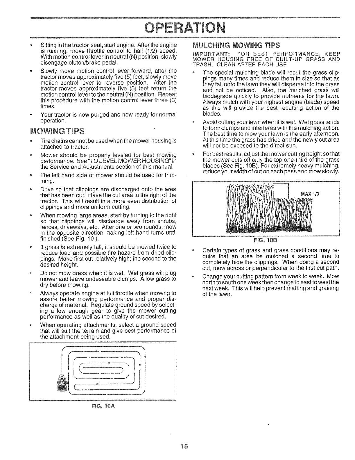
o When mowing large areas, start by turning to the right
so that clippings will discharge away from shrubs,
fences, driveways, etc. After one or two rounds, mow
in the opposite direction making left hand turns until
finished (See Fig. 10 )o
o If grass is extremely tall, it should be mowed twice to
reduce toad and possible fire hazard from dried clip °
pings. Make first cut relatively high; the second to the
desired height.
• Do not mow grass when it is wet. Wet grass will plug
mower and leave undesirable clumps. Allow grass to
dry before mowing.
o Always operate engine at full throttle when mowing to
assure better mowing performance and proper dis-
charge of material. Regulate ground speed by select-
ing a low enough gear to give the mower cutting
performance as well as the quality of cut desired.
o When operating attachments, select a ground speed
that will suit the terrain and give best performance of
the attachment being used.
MULOHtNG MOWING T_PS
IMPORTANT," FOR BEST PERFORMANCE, KEEP
MOWER HOUSING FREE OF BUILT-UP GRASS AND
TRASH. CLEAN AFTER EACH USE.
The special mulching blade will recut the grass clip-
pings many times and reduce them in size so that as
they fall onto the lawn they will disperse into the grass
and not be noticed. Also, the mulched grass will
biodegrade quickly to provide nutrients for the lawn.
Always mulch with your highest engine (blade) speed
as this will provide the best recutting action of the
blades.
o Avoid cutting your lawn when it is wet. Wet grass tends
to form clumps and interferes with the mulching action.
The best time to mow your lawn is the early afternoon.
At this time the grass has dried and the newly cut area
will not be exposed to the direct sun.
o For best results, adjust the mower cutting height so that
the mower cuts off only the top oneothir:d of the grass
blades (See Fig. IOB). For extremely heavy mulching,
reduce your width of cut on each pass and mow slowly.
FKG.10B
MAX 1/3
Certain types of grass and grass conditions may re-
quire that an area be mulched a second time to
completely hide the clippings. When doing a second
cut, mow across or perpendicular to the first cut path.
Change your cutting pattern from week to week. Mow
no rthto south one week then change to east to west the
next week. This will help prevent matting and graining
of the lawn.
FIG. 10A
15
CUSTOMER ESPONStB L TtES
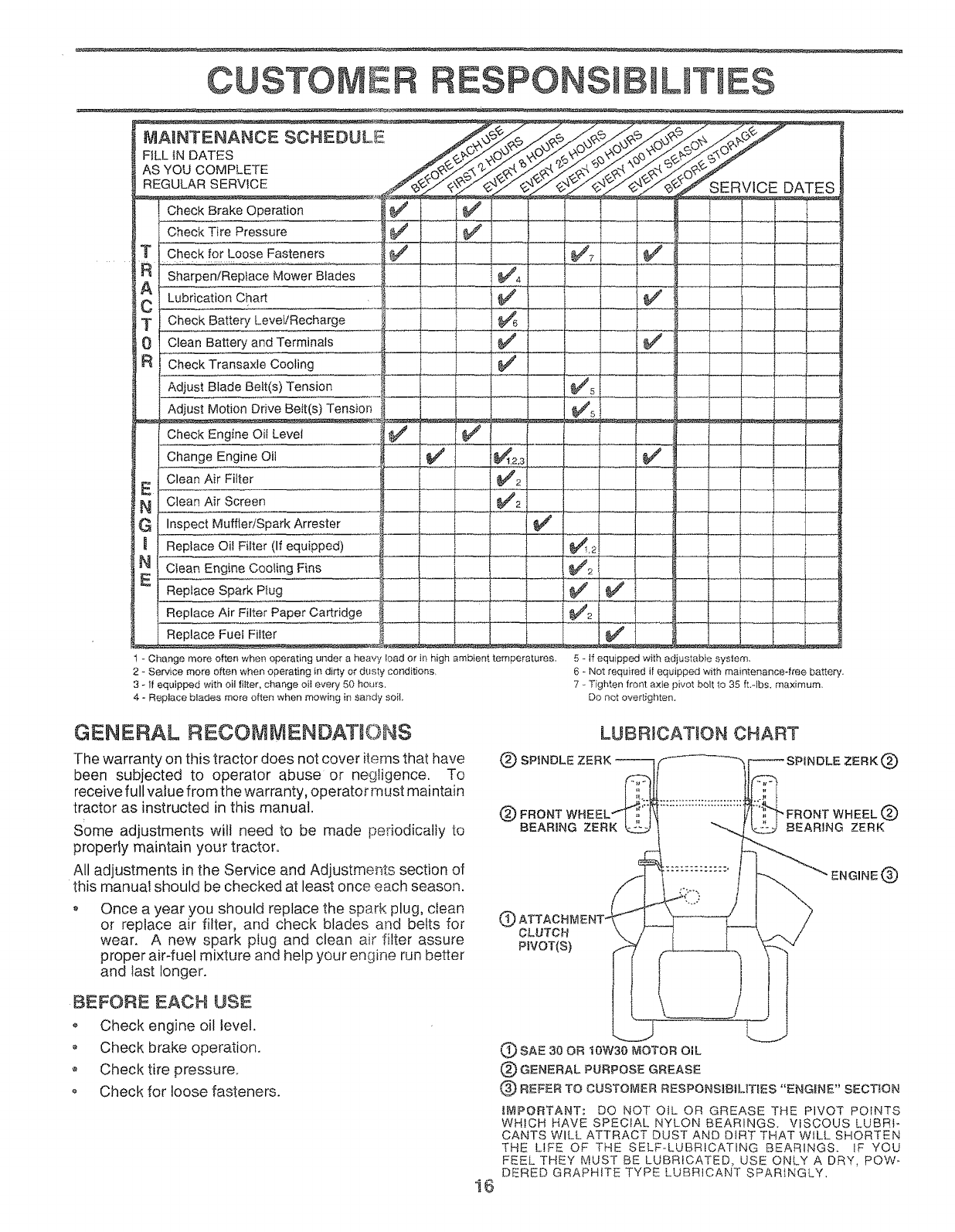
MAINTENANCE SCHEDUL
FiLL iN DATES /,.,_O_"
AS YOU COMPLETE ._.O_¢
REGULAR SERVICE f_J/" _/_'/_
Cheek]ire Pressure _ I !_
T Check for Loose Fasteners __
Adjust Blade Belt(s)Tension
Adjust Motion Drive Bett(s) Tension
"" C,eo n0,oeo,
Change Engine Oil IS# #'
N Clean Air Screen E "
G Inspect MuffleriSparkArrester ....
Replace Oil Filter (If equipped)
N C_ea-----_E,_gi_eCooli_,gFins _"----_ i
E Replace Spark P_ug i_
Replace Air Filter Paper Cartridge
Replace Fuel Filter .j
t - Change more often when operating under a hear, Ioador in high ambienttemperatures.
2-Servicemore often when operatingin dirtyor dusty conditions,
3 - If equipped with oil filter,change oit every 50 hours.
4 - Replaceblades more often when mowing in sandy soil,
5 - If equippedwith adjustable system.
6 - Not requiredif equipped with maintenance-freebattery.
7 - Tightenfront axle pivot bolt to 35 ft.qbs, maximum.
Donot overtighten.
GENERAL RECOMMENDATIONS
The warranty on this tractor does not cover items that have
been subjected to operator abuse or negligence. To
receive full value from the warranty, operator must maintain
tractor as instructed in this manual.
Some adjustments will need to be made periodicaliy to
properly maintain your tractor°
All adjustments in the Service and Adjustments section of
this manual should be checked at least once each season.
Once a year you should replace the spark plug, clean
or replace air filter, and check blades and belts for
wear. A new spark plug and clean air filter assure
proper air-fuel mixture and help your engine run better
and last longer.
LUBRICAT_ON CHART
(_ SPINDLE ZERK _ _ SPINDLE ZERK (_
(_) FRC GD
BEARING ZERK BEARING ZERK
GCLUTCH
PiVOT(S)
ENGINE (_)
BEFORE EACH USE
o Check engine oil level.
Check brake operation.
Check tire pressure,
Check for loose fasteners,
i6
(_ SAE 30 OR IOW30 MOTOR OIL
(_) GENERAL PURPOSE GREASE
(_ REFER TO CUSTOMER RESPONSB_UT_ES "ENGRNE" SECTION
_t:_PORTANT: DO NOT OIL OR GREASE THE PIVOT POINTS
WHICH HAVE SPECIAL NYLON BEARINGS. VISCOUS LUBRI-
CANTS WILL ATTRACT DUST AND DIRT THAT WILL SHORTEN
THE LIFE OF THE SELF-LUBRiCATiNG BEARINGS. IF YOU
FEEL THEY MUST BE LUBRICATED, USE ONLY A DRY, POW-
DERED GRAPHITE TYPE LUBRICANT SPARINGLY,
TRACTOR
Always observe safety rules when performing any mainte _
nance.
BRAKE OPERATION
tf tractor requires more than six (6) feet stopping distance
at high speed in highest gear, then brake must be adjusted.
(See "TO ADJUST BRAKE" in the Service and Adju_t-
ments section of this manual),
TRES
o Maintain proper air pressure in a!i tires (See "PROD°
UCT SPECIFICATIONS" on page 3 of this manual).
o Keep tires free of gasoline, oil, or insect control chemi-
cals which can harm rubber.
o Avoid stumps, stones, deep ruts, sharp objects and
other hazards that may cause tire damage.
NOTE: To seal tire punctures and prevent fla[ tires due to
stow leaks, tire sealant may be purchased from your tocal
par[s dealer. Tire sealant also prevents tire dry rot and
corrosion.
BLADE CARE
For best results mower blades must be kept sharp. Re-
place bent or damaged blades,
BLADE RE_,_OVAL (See Fig. !2)
• Raise mower to highest position to allow access to
blades.
o Remove hex bolt, lock washer and flat washer secu ring
blade.
Install new or resharpened blade with trailing edge up
towards deck as shown.
•Reassemble hex bolt, lock washer and flat washer in
exact order as shown.
o Tighten bolt securely (30-35 Ft. Lbs. torque).
IMPORTANT: BLADE BOLT IS GRADE 8 HEATTREATED.
NOTE: We do not recommend sharpening blade - but if you
do, be sure the blade is balanced.
BLADE\,
_j MANDREL
ASSEMBLY
FLAT WASHER _,,
LOCK
TRAIUNG EDGE
HEX BOLT
(GRADE 8)* _-_._.,_
*A GRADE 8 HEAT TREATED BOLT CAN BE
_DENT_FtED BY S_X LINES ON THE BOLT HEAD,
F_Go12
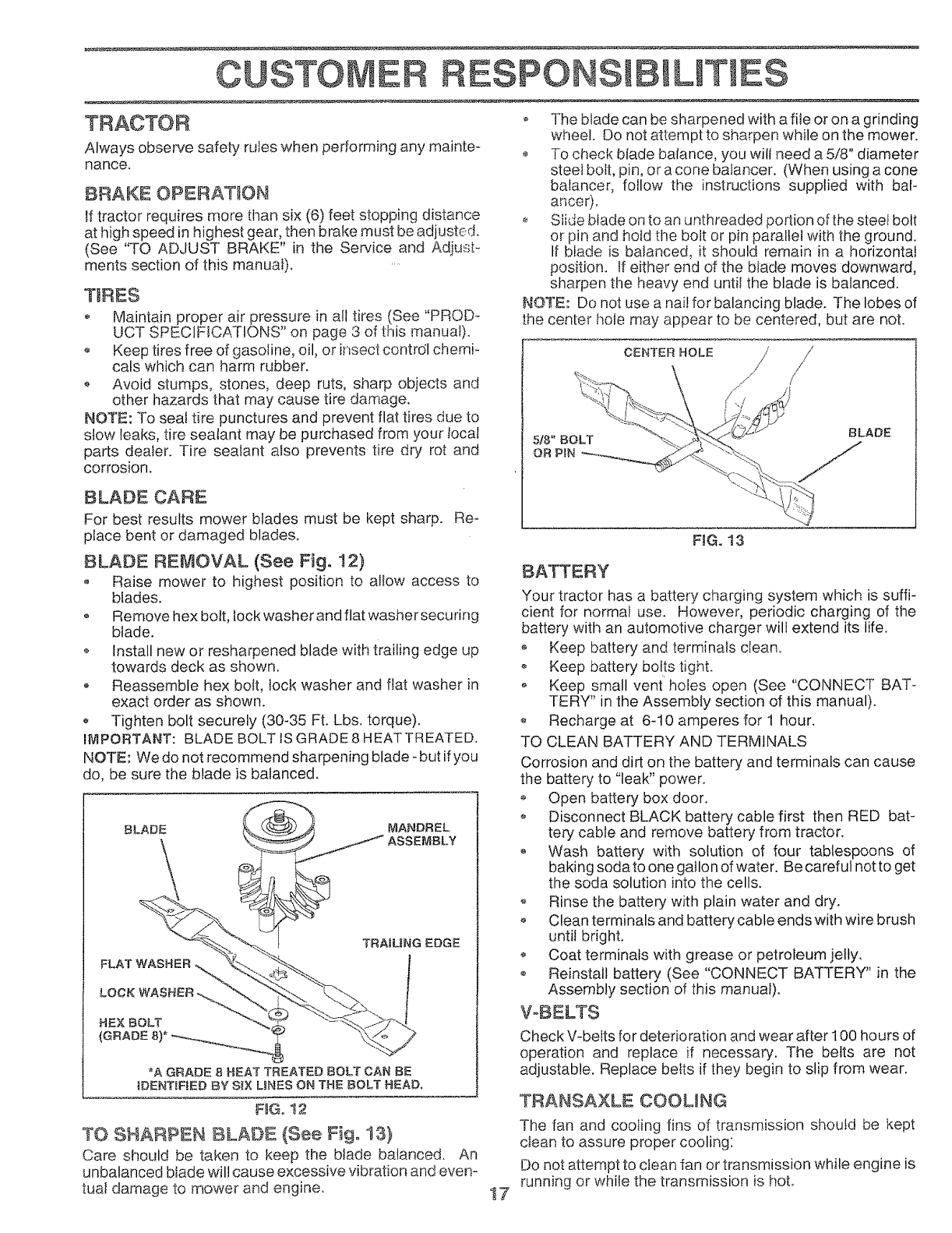
TO SHARPEN BLADE (See Fig° 13}
Care should be taken to keep the blade balanced. An
unbalanced btade will cause excessive vibration and even-
tual damage to mower and engine°
o The blade can be sharpened with a file or on a grinding
wheel. Do not atternpI to sharpen while on the mower.
o To check blade balance, you will need a 5/8" diameter
steeI bolt, pin, ora cone balancer. (When using a cone
batancer, follow the instructions supplied with bah
anoer).
Slide blade on to an unthreaded portion of the steel bolt
or pin and hold the bolt or pin paraltei with the ground.
tf blade is balanced, it should remain in a horizontal
position. If either end of the blade moves downward,
sharpen the heavy end until the blade is balanced.
NOTE: Do not use a nail for balancing blade. The lobes of
the cen[er hole may appear to be centered, but are not.
CENTER HOLE /
/
5/8" BOLT
OR P_N
BLADE
!7
FIG. 13
BATTERY
Your tractor has a battery charging system which is suffi-
cient for normal use. However, periodic charging of the
battery with an automotive charger will extend its life.
o Keep battery and terminals clean.
o Keep batlery bolts tight.
o Keep small vent holes open (See "CONNECT BAT _
TERY" in the Assembly section of this manual).
Recharge at 6-t0 amperes for 1 hour.
TO CLEAN BATTERY AND TERMINALS
Corrosion and dirt on the battery and terminals can cause
the battery to "leak" power.
Open baltery box door.
o Disconnect BLACK battery cable first then RED bat-
tery cable and remove battery from tractor.
Wash battery with solution of four tablespoons of
baking sodato one gallon of water. Be careful notto get
the soda solution into the cells.
o Rinse the battery with plain water and dry.
o Clean terminals and battery cable ends with wire brush
untii bright.
o Coat terminals with grease or petroleum jelly,
o Reinstall battery (See "CONNECT BATTERY" in the
Assembly section of this manual).
VoBELTS
Check V-belts for deterioration and wear af[er 100 hours of
operation and replace if necessary. The belts are not
adjustable. Replace belts if they begin to slip from wear.
TRANSAXLE COOUNG
The fan and cooling fins of transmission should be kept
clean to assure proper cooling:
Do not attempt to clean fan or transmission while engine is
running or while the transmission is hot°
OUSTO RESPONSm LJT ES
o Inspect cooling fan to be sure fan blades are intact and
clean.
Inspect cooling fins for dirt, grass clippings and other
materials. To prevent damage to seals, do not use
compressed air or high pressure sprayer to clean
cooling fins.
TRANSAXLE PUMP FLUID
The transaxle was sealed at the factory and fluid mainte-
nance is not required for the life of the transaxte. Should the
transaxle ever leak or require servicing, contact your near-
est authorized service center/department.
ENGtNE
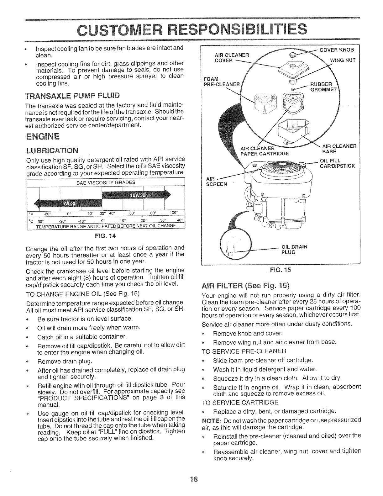
LUBRICATUON
Only use high quality detergent oil rated with API service
classification SF, SG, or SH. Select the oil's SAE viscosity
grade according to your expected operating temperature.
SAE VISCOSITY GRADES
°F -20 ° 0 _ 30 _ 32" 40 _ 60 ° 80 _ 100 _
,-o-- ,:
_C -30 _' -20 _ -t0 _ 0" t0" 20 _ 30 ° 40 =
TEMPERATURE RANGE ANTICIPATED BEFORE NEXT OIL CHANGE
F}G. t4
Change the oil after the first two hours of operation and
every 50 hours thereafter or at least once a year if the
tra;ctor is not used for 50 hours in one year_
Check the crankcase oil level before starting the engine
and after each eight (8) hours of operation. Tighten oil fill
cap/dipstick securely each time you check the oil level.
TO CHANGE ENGINE OIL (See Fig. I5)
Determine temperature range expected before oi! change.
All oil must meet API service classification SF, SG, or SH.
Be sure tractor is on level surface.
o Oil will drain more freely when warm.
Catch oil in a suitable container.
o Remove oil fill cap/dipstick. Be careful not to allow dirt
to enter the engine when changing oil.
o Remove drain plug.
• After oil has drained completely, replace oil drain plug
and tighten securely,
Refill engine with oil through oil fill dipstick tube. Pour
slowly. Do not overfill. For approximate capacity see
"PRODUCT SPECIFICATIONS" on page 3 of this
manual
Use gauge on oil fill captdipstick for checking level.
insert dipstick into the tube and rest the oil fill cap on the
tube, Do not thread the cap onto the tube when taking
reading. Keep oit at "FULL" Jine on dipstick, Tighten
cap onto the tube securely when finished,
COVER KNOB
WING NUT
FOAM
PRE-CLEANER
AIR
SCREEN
PAPER CARTRIDGE
AIR CLEANER
BASE
OIL FILL
CAP/DIPSTICK
FiG. 15
A_R FILTER (See Fig. 15)
Your engine will not run properly using a dirty air filter.
Clean the foam pre-cleaner after every 25 hours of opera -
tion or every season. Service paper cartridge every 100
hours of operation or ever/season, whichever occurs firsL
Service air cleaner more often under dusty conditions.
-_ Remove knob and cover.
Remove wing nut and air cleaner from base.
TO SERVICE PRE-CLEANER
o Slide foam pre-cleaner off cartridge,
• Wash it in liquid detergent and water.
o Squeeze it dry in a clean cloth. Allow it to dry.
o Saturate it in engine oil. Wrap it in clean, absorbent
cloth and squeeze to remove excess oil.
TO SERVlCE CARTRIDGE
o Repiace a dirty, beni, or damaged cartridge.
NOTE: Do not wash the paper cartridge or use pressurized
air, as this will damage the cartridge.
Reinstall the pre-cleaner (cleaned and oiled) over the
paper cartridge.
o Reassemble air cleaner, wing nut, cover and tighten
knob securely.
18
CUSTOMER
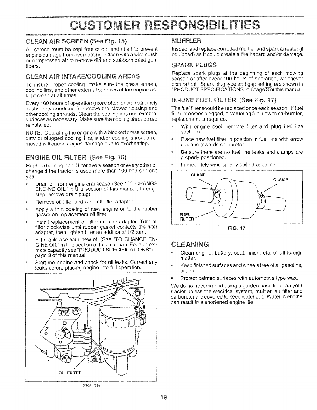
CLEAN AIR SCREEN (See Fig, t5}
Air screen must be kept free of dirt and chaff to prevent
engine damage from overheating. Clean with a wire brush
or compressed air to remove dirt and stubborn dried gum
fibers.
CLEAN AIR INTAKEiCOOMNG AREAS
To insure proper cooling, make sure the grass screen,
cooling fins, and other external surfaces of the engine are
kept clean at all times.
Every !00 hours of operation {more often under extremely
dusty, dirty conditions), remove the bIower housing and
other cooling shrouds. Clean the cooling fins and external
surfaces as necessah/. Make sure the cooling shrouds are
reinstalled.
NOTE: Operating the engine with a blocked grass screen,
dirty or plugged cooling fins, and/or cooling shrouds re-.
moved will cause engine damage due to overheating.
ENGINE OiL RLTER (See Fig, t6)
Replace the engine oil filter every season or every other oil
change if the tractor is used mere than 100 hours in one
year.
o Drain oil from engine crankcase (See "TO CHANGE
ENGINE OIL" in this section of this manual, through
step remove drain plug).
o Remove oil filter and wipe off filter adapter.
• Apply a thin coating of new engine oi! to the rubber
gasket on replacement oil filter.
Install replacement oil filter on filter adapter. Turn oil
filter clockwise until rubber gasket contacts the filter
adapter, then tighten filter an additional !/2 turn.
Fill crankcase with new oil (See "TO CHANGE EN-
GINE OIL" in this section of this manual)+ For approxi-
mate capacity see "PRODUCT SPECIFICATIONS" on
page 3 of this manual.
o Start the engine and check for oil leaks. Correct any
leaks before placing engine into full operation.
ESPONSm ILmTIES
MUFFLER
Inspect and replace corroded muffler and spark arrester (if
equipped) as it could create a fire hazard and/or damage,
SPARK PLUGS
Replace spark plugs at the beginning of each mowing
season or after every 100 hours of operation, whichever
occurs first. Spark plug type and gap setting are shown in
"PRODUCT SPECIFICATIONS" 0n page 3 of this manual.
IN°LINE FUEL FILTER (See Fig. !7)
The fuel filter should be replaced once each season, If fuet
filter becomes clogged, obstructing fuel flow to carburetor,
replacement is required.
o With engine cool, remove filter and plug fuel line
sections.
o Place new fuel filter in position in fue! line with arrow
pointing towards carburetor.
o Be sure there are no fueI line leaks and clamps are
properly positioned.
o Immediately wipe up any spilled gasoline.
CLAMP
FILTER .... _°"-_"
FIG. 17
CLEANING
• Clean engine, battery, seat, finish, etc, of all foreign
matter.
o Keep finished surfaces and wheels free of all gasoline,
oil, etc.
o Protect painted surfaces with automotive type wax.
We do not recommend using a garden hose to clean your
tractor unless the electrical system, muffler, air filter and
carburetor are covered to keep water out. Water in engine
can result in a shortened engine life.
F_Go16
t9
SERVICE AND ADJUSTMENTS
CAUTION: BEFORE PERFOF1MNNGANY SERVICE OR ADJUSTMENTS:
, Depress clutch/brake pedal fully and set parking brake.
*Place motion contro! _ever in neutral (N} position.
,Pmaceattachment ¢_utch in "DISENGAGED" position,
= Turn ignition key"OFF" aT_dremove key.
, Make sure the blades and al_ moving parts have compJetely stopped.
Disconnect spark plug wire from spark plug and place wire where it cannot come in contact
with plug. ..........
TRACTOR
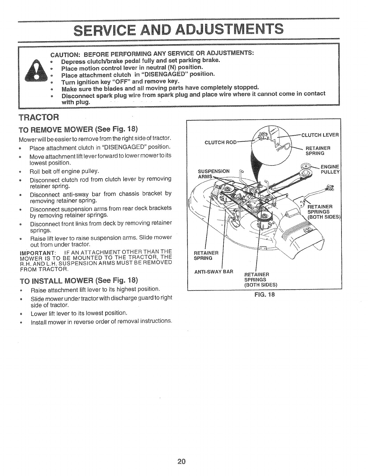
TO REMOVE MOWER (See Fig, 18}
Mowe rwill be easier to remove from the right side of tractor.
oPIace attachment clutch in "DISENGAGED" position.
o Move a_tachment lift Iever forward to lower mower to its
lowest position.
•Roll belt off engine pultey.
Disconnect ctutch rod from clutch lever by removing
retainer spring.
, Disconnect anti-sway bar from chassis bracket by
removing retainer spring.
o Disconnect suspension arms from rear deck brackets
by removing retainer springs.
• Disconnect front links from deck by removing retainer
springs.
,, Raise lift lever to raise suspension arms. Slide mower
out from under tractor.
IMPORTANT: fF AN ATTACHMENT OTHER THAN THE
MOWER IS TO BE MOUNTED TO THE TRACTOR, THE
R.H. AND L.H, SUSPENSION ARMS MUST BE REMOVED
FROM TRACTOR.
TO NNSTALL MOWER (See Fig. 18)
o Raise attachment liftlever to its highest position.
Slide mower under tractor with discharge guard to right
side of tractor.
o Lower lift lever to its lowest position.
Install mower in reverse order of removal instructions.
CLUTCH RO[
SUSPENSION
RETAINER
SPRING
RETAINER
SPRINGS
(BOTH SIDES)
FIG. 18
LEVER
2O
SERVICE A D E
TO LEVEL MOWER HOUSING
Adjust the mower while tractor is parked on level ground or
driveway, Make sure tires are properly inflated (See
"PRODUCT SPECIFICATIONS" on page 3 of this manual).
Iftires are over or underinflated, you will not properly adjust
your mower.
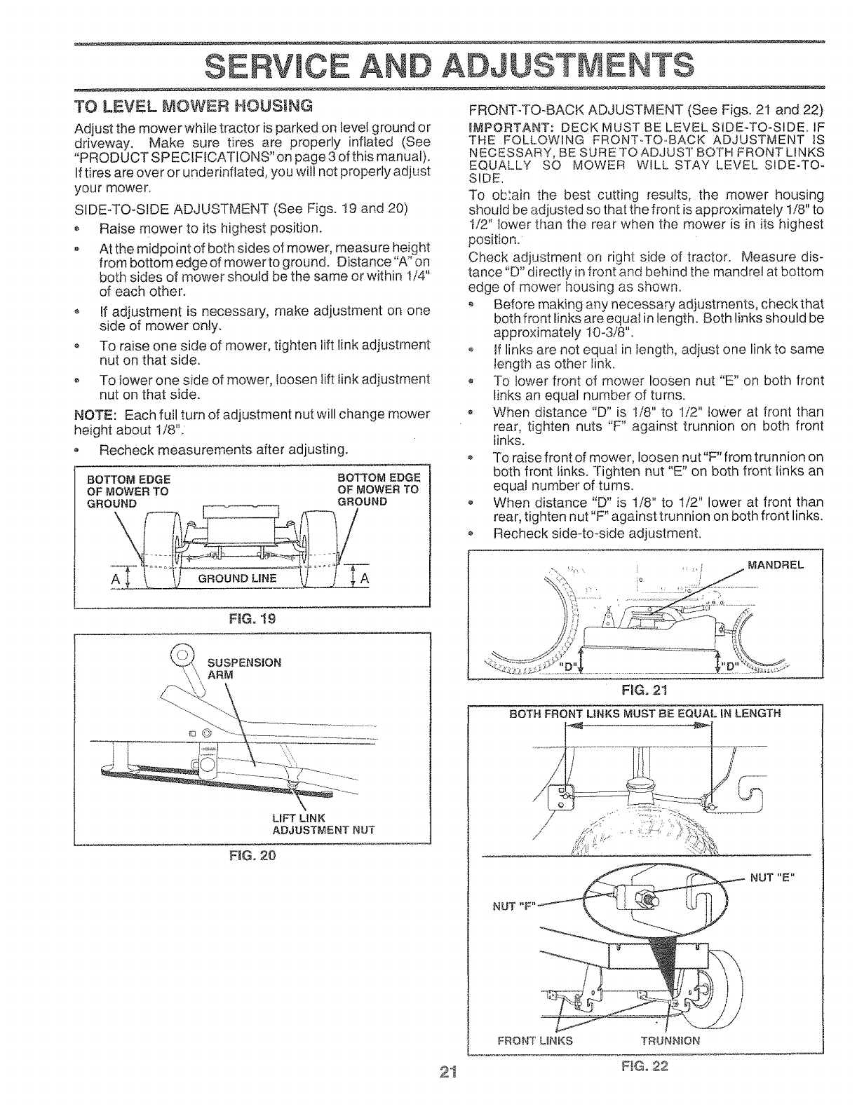
SIDE-.TO-SIDE ADJUSTMENT (See Figs. t9 and 20)
Raise mower to its highest position.
o At the midpoint of both sides of mower, measure height
from bottom edge of mower to ground. Distance "A" on
both sides of mower should be the same or within t/4"
of each other.
o If adjustment is necessary, make adjustment on one
side of mower only.
o To raise one side of mower, tighten lift link adjustment
nut on that side.
To lower one side of mower, loosen lift link adjustment
nut on that side.
NOTE: Each full turn of adjustment nut will change mower
height about 1/8".
° Recheck measurements after adjusting.
BOTTOM EDGE BOTTOM EDGE
OF MOWER TO OF MOWER TO
GROUND GROUND
FIG. 19
SUSPENSION
ARM
LIFT LiNK
ADJUSTMENT NUT
F_G. 20
FRONT-TO-BACK ADJUSTMENT (See Figs. 21 and 22)
WMPORTANT: DECK MUST BE LEVEL SIDE-TO-SIDE_ IF
THE FOLLOWING FRONT-TO.BACK ADJUSTMENT }S
NECESSARY, BE SURE TO ADJUST BOTH FRONT LINKS
EQUALLY SO MOWER WILL STAY LEVEL SIDE-TO-
SIDE,
To obtain the best cutting results, the mower housing
should be adjusted so that the front is approximately t/8" to
I/2" lower than the rear when the mower is in its highest
position.
Check adjustment on right side of tractor. Measure dis-
tance "D" directly in front and behind the mandrel at bottom
edge of mower housing as shown.
Before making any necessary adjustments, check that
both front links are equal in length. Both links should be
approximately 10-3/8".
o tf links are not equal in length, adjust one link to same
length as other link.
To lower front of mower loosen nut "E" on both front
links an equal number of turns.
When distance "D" is 1/8" to 1/2" lower at front than
rear, tighten nuts "F" against trunnion on both front
links.
To raise front of mower, loosen nut"F" from trunnion on
both front links. Tighten nut "E" on both front links an
equal number of turns.
o When distance "D" is 1/8" to I/2" lower at front than
rear, tighten nut "F" against trunnion on both front links.
Recheck side-to-side adjustment.
MANDREL
FmGo21
BOTH FRONT LINKS MUST BE EQUAL IN LENGTH
NUT "F"
FRONT UNKS TRUNNION
NUT "E"
21 FIGo 22
SERVICE A ADJUSTMENTS
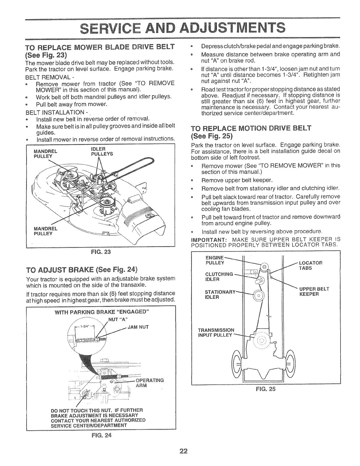
TO REPLACE MOWER BLADE DRIVE BELT
(See Fig. 23)
The mower blade drive belt may be replaced without tools.
Park the tractor on level surface. Engage parking brake,
BELT REMOVAL -
•Remove mower from tractor (See "TO REMOVE
MOWER" in this section of this manual).
oWork belt off both mandrel pulleys and idler pulleys.
o Pull belt away from mower.
BELT INSTALLATION -
• Instatf new belt in reverse order of removal.
, Make su re belt is in all pulley grooves and inside all belt
guides.
Install mower in reverse order of removal instructions,
MANDREL IDLER
PULLEY PULLEYS
MANDREL
PULLEY
FtG. 23
o Depress clutch/brake pedal and engage parking brake.
Measure distance between brake operating arm and
nut "A" on brake rod.
if distance is other than 1-3/4", loosen jam nut and turn
nut "A" until distance becomes 1-3/4". Retighten jam
nut against nut "A".
Road test tractor for proper stopping distance as stated
above. Readjust if necessary. If stopping distance is
still greater than six (6) feet in highest gear, further
maintenance is necessary. Contact your nearest au-
thorized service center/department.
TO REPLACE r'_OTION DRIVE BELT
(See Fig. 25}
Park the tractor on level surface. Engage parking brake.
For assistance, there is a belt installation guide decal on
bottom side of left footrest,
Remove mower (See "TO REMOVE MOWER" in this
section of this manual.)
o Remove upper belt keeper,
o Remove belt from stationary idler and clutching idler.
, Pull belt slack toward rear of tractor, Carefully remove
belt upwards from transmission input pulley and over
cooling fan blades.
,, Pull belt toward front of tractor and remove downward
from around engine pulley.
Install new belt by reversing above procedure.
tr,itPORTANT: MAKE SURE UPPER BELT KEEPER IS
POSITIONED PROPERLY BETWEEN LOCATOR TABS.
TO ADJUST BRAKE (See Fig. 24)
Your tractor is equipped with an adjustable brake system
which is mounted on the side of the transaxle.
If tractor requires more than six (6) feet stopping distance
at high speed in highest gear, then brake must be adjusted.
DO NOT TOUCHTH_S NUT,_FFURTHER
BRAKE ADJUSTMENTIS NECESSARY
CONTACT YOUR NEAREST AUTHOR1ZE_
SERWCE CENTERIDEPARTMENT
PULLEY )CATOR
TABS
CLUTCHBNG
IDLER
UPPER BELT
KEEPER
TRANSMISSION
INPUT
F_G, ,25
FSGo24
22
SERVICE A AOJUSTM
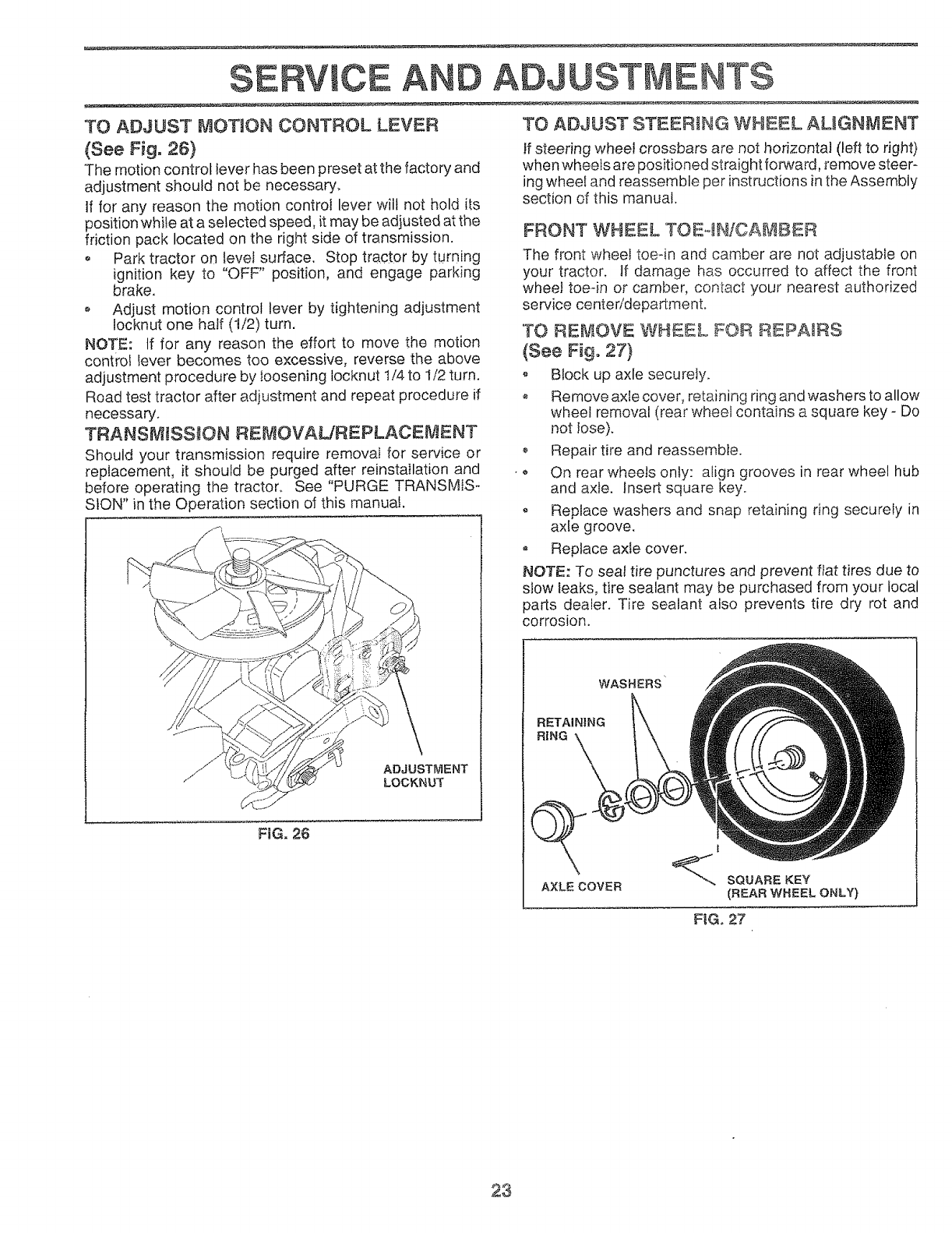
TO ADJUST MOTION CONTROL LEVER
(See Fig. 26)
The motion control lever has been preset at the factory and
adjustment should not be necessary,
If for any reason the motion control lever wilt not hold its
position whi_e at a selected speed, it may be adjusted at the
friction pack located on the right side of transmission.
o Park tractor on level surface. Stop tractor by turning
ignition key to "OFF" position, and engage parking
brake.
• Adjust motion control lever by tightening adjustment
locknut one half (t/2) turn.
NOTE: tf for any reason the effort to move the motion
control lever becomes too excessive, reverse the above
adjustment procedure by loosening locknut 1/4 to 1/2 turn.
Road test tractor after adjustment and repeat procedure if
necessary.
TRANSMBSS_ON REMOVAUREPLACEMENT
Should your transmission require removaI for service or
replacement, it should be purged after reinstailation and
before operating the tractor. See "PURGE TRANSMIS-
SION" in the Operation section of this manual.
ADJUSTMENT
LOCKNUT
FIG. 26
TO ADJUST STEERING WHEEL ALIGNMENT
If steering wheel crossbars are not horizontal (left to right)
when wheets are positioned straightforward, remove steer-
ing wheel and reassemble per instructions in the Assembly
section of this manual.
FRONT WHEEL TOE,4NiCAMBER
The front wheel toeqn and camber are not adjustable on
your tractor. If damage has occurred to affect the front
wheel toe-in or camber, contact your nearest authorized
service centeddepartmento
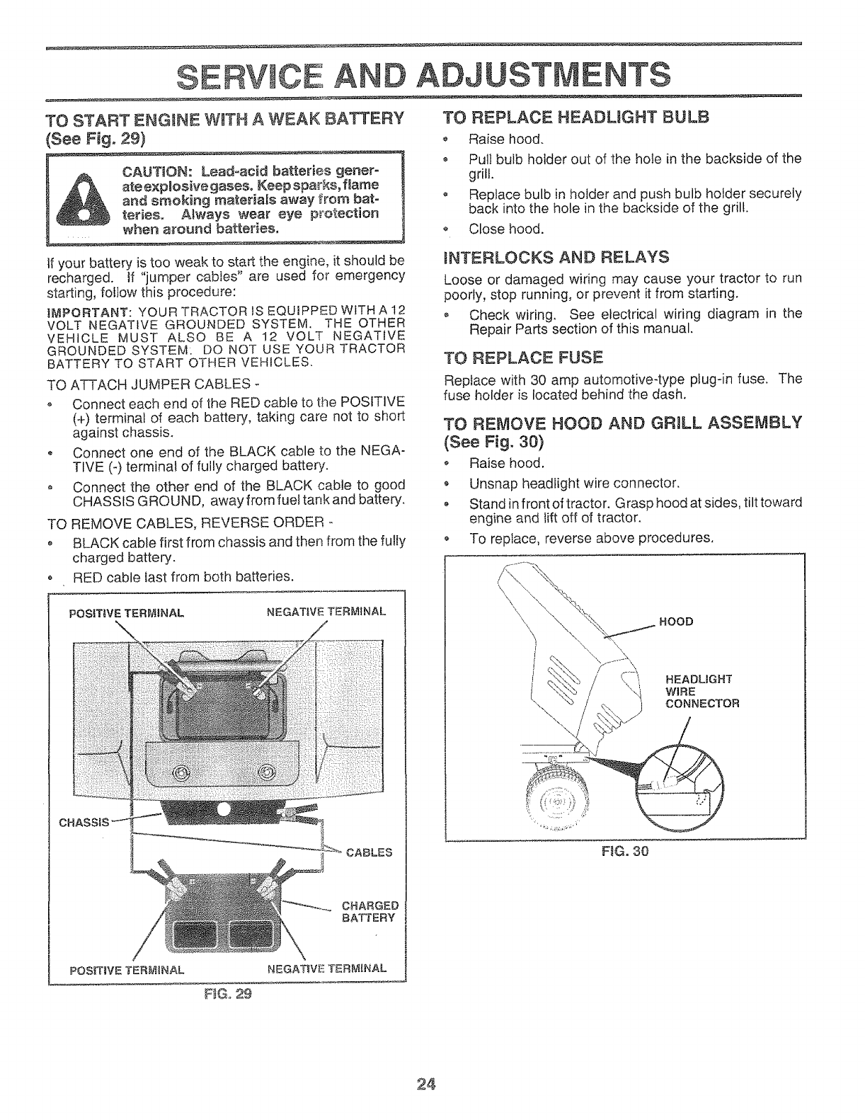
'TO REMOVE WHEEL FOR REPAIRS
(See Fig. 27}
o Block up axle securely.
® Remove axle cover, retaining ring and washers to allow
wheel removal (rear wheel contains a square key - Do
not lose).
Repair tire and reassemble.
On rear wheels only: align grooves in rear wheel hub
and axle. Insert square key.
Replace washers and snap retaining ring securely in
axle groove.
• Replace axle cover.
NOTE: To seal tire punctures and prevent flat tires due to
slow leaks, tire sealant may be purchased from your local
parts dealer. Tire sealant also prevents tire dry rot and
corrosion.
• @
WASHERS
RETAINING
RING
AXLE COVER
I
SQUARE KEY
(REAR WHEEL ONLY)
FIG, 27
23
S E AND ADJUSTMENTS
TO START ENGINE W_TH A WEAK: BATTERY
See Fig, 29)
CAUTION: Lead-acid batteries gener-
ate explosive gases, Keep sparks, fJarne
and smoking rn_teriais away from bat-
teries, Always wear eye protection
when a_'ound batteries.
If your battery is too weak to start the engine, it should be
recharged, if "jumper cables" are used for emergency
starting, follow this procedure:
H_PORT'ANT: YOUR TRACTOR IS EQUIPPED WITH A 12
VOLT NEGATIVE GROUNDED SYSTEM. THE OTHER
VEHICLE MUST ALSO BE A 12 VOLT NEGATIVE
GROUNDED SYSTEM: DO NOT USE YOUR TRACTOR
BATTERY TO START OTHER VEHICLES.
TO ATTACH JUMPER CABLES
o Connect each end of the RED cable to tile POSITIVE
(+) terminal of each batteQz, taking care not to short
against chassis.
Connect one end of the BLACK cable to the NEGA-
TIVE (-) terminal of fully charged battery.
• Connect the other end of the BLACK cable to good
CHASSIS GROUND, away from fue! tank and batteQz.
TO REMOVE CABLES, REVERSE ORDER -
o BLACK cable first from chassis and then from the fully
charged battery.
o RED cable fast from both batteries.
POSITIVE TERIMfRNAL NEGATIVE TERMINAL
CHARGED
BATTERY
POSIT_VE TERMINAL NEGAT_VETERM_NAL
TO REPLACE HEADLIGHT BULB
• Raise hood.
• Pull bulb holder out of the hole in the backside of the
grill.
o Replace bulb in holder and push bulb holder securely
back into the hole in the backside of the grill.
o Close hood.
mNTERLOCKS AND RELAYS
Loose or damaged wiring may cause your tractor to run
poorly, stop running, or prevent it from starting.
o Check wiring, See electrical wiring diagram in the
Repair Parts section of this manual.
TO REPLACE FUSE
Replace with 30 amp automotiveqype plug-in fuse. The
fuse holder is located behind the dash,
TO REMOVE HOOD AND GRILL ASSEMBLY
(See Fig. 30)
o Raise hood.
Unsnap headlight wire connector.
o Stand in front of tracto r. Grasp hood at sides, tilt toward
engine and Iift off of tractor.
,, To replace, reverse above procedures.
\\ \
HOOD
HEAOLIGHT
WIRE
CONNECTOR
F_G. 30
F_G,,29
24
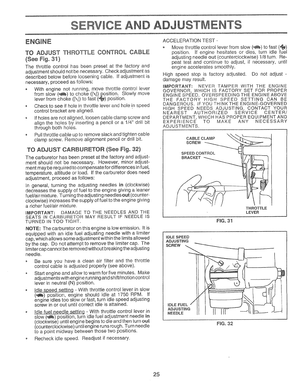
E AND ADJUSTMENTS
ENGINE
TO ADJUST THROTTLE CONTROL CABLE
(See Fig.31)
The throttle control has been preset at the factory and
adjustment should not be necessary. Check adjustment as
described below before loosening cable. If adjustment is
necessary, proceed as follows:
With engine not running, move throttle control Lever
from slow (_) to choke (Xt) position° Slowly move
lever from choke (IXI) to fast (_) position.
Check to see if hole in throttle lever and hole in speed
control bracket are aligned.
o If holes are not aligned, loosen cable clamp screw and
align the holes by inserting a pencil or a !/4" drill bit
through both holes.
o Pull throttle cable up to remove slack and tighten cable
ciamp screw. Remove alignment pencil or drill bit.
TO ADJUST CARBURETOR (See Fig. 32)
The carburetor has been preset at the factory and adjust-
ment should not be necessary, However, minor adjust-
ment may be required to compensate for differences infuel,
temperature, altitude or load. If the carburetor does need
adjustment, proceed as follows:
in general, turning the adjusting needles in (clockwise)
decreases the supply of fuel to the engine giving a leaner
fuel/air mixture. Turningthe adjusting needlesout (counter-
clockwise) increases the supply of fuel to the engine giving
a richer fuel/air mixture.
IMPORTANT: DAMAGE TO THE NEEDLES AND THE
SEATS tN CARBURETOR MAY RESULT IF NEEDLE IS
TURNED IN TOO TIGHT.
NOTE: The carburetor on this engine is tow emission. It is
equipped with an idle fuel adjusting needle with a timiter
cap, which allows some adjustment within the limits allowed
by the cap. Do not attempt to remove the limiter cap. The
limitercap cannot be removed without breaking the adjusting
needle.
• Be sure you have a clean air filter and the throttle
control cable is adjusted properly (see above).
• Start engine and allow to warm for five minutes. Make
adjustmentswith engine running and shift/motion control
lever in neutral (N) position.
o Idle speed setting - With throttle control lever in slow
(_)position, engine should id!e at I750 RPM. If
engine idles too slow or fast, turn idle speed adjusting
screw in or out until correct idle is attained.
o Idle fuel needle setting ° With throttle control lever in
slow (_) position, turn idle fuel adjustment needle in
(clockwise) until engine begins to die and then turn out
(counterclockwise) until engine runs rough, Turn needle
to a point midway between those two positions.
o Recheck idle speed. Readjust if necessary.
ACCELERATION TEST -
o Move throttle control lever from slow (_) to fast (,_)
position. If engine hesitates or dies, turn idle fuel
adjusting needle out (counterclockwise) t/8 turn. Re-
peat test and continue to adjust, if necessary, until
engine accelerates smoothly.
High speed stop is factory adjusted. Do not adjust -
damage may result.
IMPORTANT: NEVER TAMPER WITH THE ENGINE
GOVERNOR, WHICH IS FACTORY SET FOR PROPER
ENGINE SPEED. OVERSPEEDtNG THE ENGINE ABOVE
THE FACTORY HIGH SPEED SETTING CAN BE
DANGEROUS. IF YOU THINKTHE ENGiNE-GOVERNED
HIGH SPEED NEEDS ADJUSTING, CONTACT YOUR
NEAREST AUTHORIZED SERVICE CENTER/
DEPARTMENT, WHICH HAS PROPER EQUIPMENT AND
EXPERIENCE TO MAKE ANY NECESSARY
ADJUSTMENTS.
\
CABLE CLAMP _-
SCREW
SPEED CONTROL
BRACKET
FIG. 31
11
THROTTLE
LEVER
IDLE SPEED
ADJUSTING
SC.EW m
ADJUSTING ] ..__..,
NEEDLE J-4
FtGo 32
25
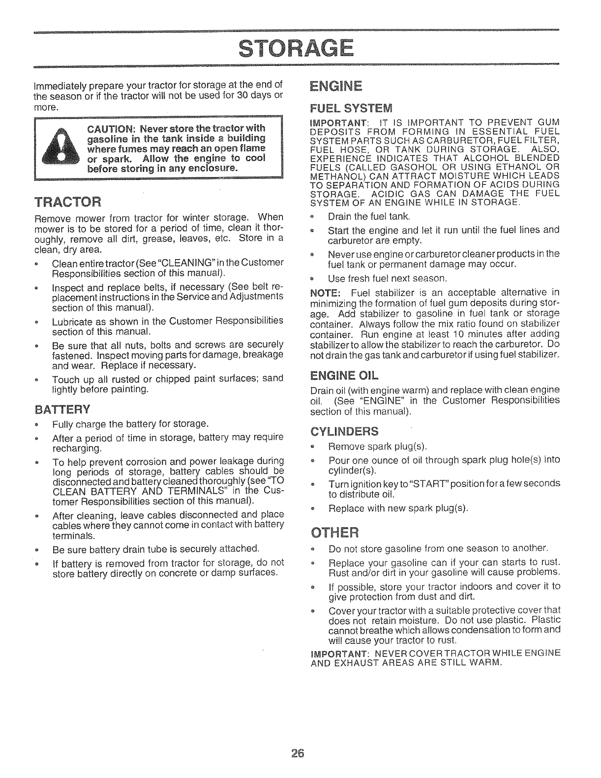
STORAGE
Immediately prepare your tractor for storage at the end of
the season or if the tractor will not be used for 30 days or
mo re.
TRACTOR
Remove mower from tractor for winter storage, When
mower is to be stored for a period of time, clean it thor-
oughly, remove all dirt, grease, leaves, etc. Store in a
clean, dry area.
, Clean entire tractor (See"CLEAN ING" inthe Customer
Responsibilities section of this manual).
o Inspect and replace belts, if necessary (See belt re-
placement instructions in the Service and Adjustments
section of this manual).
o Lubricate as shown in the Customer Responsibilities
section of this manual.
o Be sure that all nuts, bolts and screws are securely
fastened, inspect moving parts for damage, breakage
and wear. Replace if necessary.
o Touch up all rusted or chipped paint surfaces; sand
lightly before painting.
BATTERY
Fully charge the battery for storage.
, After a period of time in storage, battery may require
recharging.
• To help prevent corrosion and power leakage during
long periods of storage, battery cables should be
disconnected and battery cleaned thoroughly (see "TO
CLEAN BATTERY AND TERMINALS" in the Cus-
tomer Responsibilities section of this manuai).
o After cleaning, leave cabtes disconnected and place
cables where they cannot come in contact wibh battery
terminals.
o Be sure battery drain tube is securely attached,
o If battery is removed from tractor for storage, do not
store battery directly on concrete or damp surfaces.
ENGINE
FUEL SYSTEM
_MPORTANT: IT IS IMPORTANT TO PREVENT GUM
DEPOSITS FROM FORMING IN ESSENTIAL FUEL
SYSTEM PARTS SUCH AS CARBURETOR, FUEL FILTER,
FUEL HOSE, OR TANK DURING STORAGE, ALSO,
EXPERIENCE INDICATES THAT ALCOHOL BLENDED
FUELS (CALLED GASOHOL OR USING ETHANOL OR
METHANOL) CAN ATTRACT MOISTURE WHICH LEADS
TO SEPARATION AND FORMATION OF ACIDS DURING
STORAGE. ACIDIC GAS CAN DAMAGE THE FUEL
SYSTEM OF AN ENGINE WHILE IN STORAGE.
o Drain the fuel tank.
o Start the engine and let it run until the fuel lines and
carburetor are empty.
o Never use engine or carburetor cleaner products in the
fuef tank or permanent damage may occur.
o Use fresh fuei next season.
NOTE: Fuel stabilizer is an acceptable alternative in
minimizing the formation of fuel gum deposits during stor-
age, Add stabilizer to gasoline in fuel tank or storage
container. Always follow the mix ratio found on stabilizer
container. Run engine at least 10 minutes after adding
stabilizer to ailow the stabilizer to reach the carburetor, Do
not drain the gas tank and carburetor if using fuel stabilizer.
ENGINE OiL
Drain oil (with engine warm) and replace with clean engine
oil. (See "ENGINE" in the Customer Responsibilities
section of this manual).
CYLINDERS
o Remove spark plug(s).
o Pour one ounce of oil through spark plug hole(s) into
cylinder(s).
Turn ignition key to "START" positio nfor a few seconds
to distribute oil.
Replace with new spark plug(s).
OTHER
Do not store gasoline from one season to another.
o Replace your gasoline can if your can starts to rust.
Rust and/or dirt in your gasoline will cause problems.
If possible, store your tractor indoors and cover it to
give protection from dust and dirt.
Cover your tractor with a suitable protective cover that
does not retain moisture. Do not use plastic. Plastic
cannot breathe which allows condensation to form and
wii! cause your tractor to rust.
_MPORTANT: NEVER COVER TRACTOR WHILE ENGINE
AND EXHAUST AREAS ARE STILL WARM,
26

TROUBLES O0 NG POM TS
PROBLEm]
Wiit not start
Hard to start
Engine will not turn over
Engine cricks but will not
start
......... ..
Loss of power
Excessive vibration
CAUSE
1, Out of fuel,
2, Engine not "CHOKED" properly.
3. Engine flooded,
4. Badspark iSlug,
5. Dirtyair fitter,
6. Dirty fuel filter,
7, Water in fuel.
8, Loose or damaged wiring,
9. Carburetor out of adjustment,
CORRECTION
t. Fill fuel tank.
2. See "TO START ENGINE" in Operation section.
3. Wait several minutes before attempting to start,
4. Repiace spark plug.
5, Clean!replace air filter.
6, Repiace fuel fitter_ ..........
7. Drain fuel tank and carburetor, refill tank with fresh
gasotine and replace fuel filter,
8. Check alf wiring,
9, See "To Adjust Carburetor" in Service Adiustments
10, Engine valves out of adjustment.
1. Dirty air filter.
2, Bad spark plug.
3. Weak or dead battery,
4. Dirty fuel filter.
5, Stale ordirty fuel.
6, Loose or damaged wiring.
7. Carburetor out of adjustment.
8, Engine valves out of adjustment,
section,
10. Contact an authorized service center/department,
t, CJeanireplace air filter.
2, Repface spark plug,
3, Recharge or replace battery,
4. Replace fuel filter.
5, Drain fuet tank and refill with fresh gasoline.
6. CheckaiI wiring_
7. See "To Adjust Carburetor" in Service Adjustments
section,
8. Contact an authorized service center/department.
1. Clutch/brake pedal not depressed,
2, Attachment clutchis engaged.
3, Weak or dead battery.
4. Blown fuse.
5. Corroded battery terminals.
6. Loose or damaged wiring.
7. Faulty ignition switch.
8, Faulty solenoid or starter.
9, Faulty operator presence switch(es).
t, Depress clutch/brake pedai.
2. Disengage attachment clutch.
3, Recharge or replace battery.
4. Replace fuse.
5, Clean battery terminals,
6. Check all wiring.
7. ChecWrepiace ignition switch.
8. Check/replace solenoid or starter.
9. Contact,_n authorized service center/department,
t. Weak or dead battery,
2, Corroded battery terminals.
3. Loose or damaged wiring,
4. Faultysotenoid or starter.
1. Cutting too much grass/too fast,
2. Throttle in "CHOKE" position.
3, Build-up of grass, leaves and trash under mower,
4. Dirty air filter.
5. Low oil level/dirty oil,
6, Faulty spark plug,
7. Dirty fuel filter,
8, StaIe ordirty fuel.
9, Waterin fuet.
10, Spark plug wire loose.
1t. Dirty engine air screen/fins,
12, Dirty/clogged muffler,
13. Loose or damaged wiring,
14. Carburetor out of adjustment,
15, Engine valves out of adjustment,
1. Worn, bent or loose blade.
2, Bent blade mandrel.
3. Loosefdamaged parL(s),
1. Recharge or replace battery.
2. Clean battery terminals,
3, Checkatl wiring,
4, Check/replace solenoid or starter,
1. Set in "Higher Cut" position/reduce speed.
2, Adjust throttle control.
3. C_ean underside of mower housing,
4. Clean/replace air filter,
5, Checkoit level!change oil,
6. Ciean and regap or change spark plug.
7. Replace fuel filter.
8. Drain fuel tank and refil} with fresh gasoline,
9, Drain fuel tank and carburetor, refill tank with fresh
gasoline and replace fuel filter,
t0. Connect and tighten spark plug wire,
tl. Clean engine air screen/fins,
12, Clean/replace muffler.
I3. Checkaf_ wiring,
t4. See "To Adjust Carburetor" in Service Adjustments
section.
t5, Contact an authorized service center/department.
1. Replace btade, Tighten blade bolt.
2, Replace blade mandrel,
3. Tighten loose part(s), Replace damaged parts.
27

TROU LES OOTING POINTS
PROBLEM
Engine continues to run
when operator leaves seat
with attachment clutch
engaged
Poorcut-uneven
Mower blades will not
rotate
Poor grass discharge
Headlight(s) not working
(if so equipped)
Battery will not charge
Loss of drive
Engine "backfires"
when turning engine
"OFF"
CAUSE
1, Faulty operator-safety presence controt system,
1, Worn, bent or loose blade,
2. Mower deck not levet.
3_ Bu_,ldup of grass, leaves, and trash unde_ mower.
4. Bent blade mandrel.
5. Clogged mower deck vent holes from buildup of
grass, leaves, and trash around mandrels.
!, Obstruction in clutch mechanism,
2. Worn/damaged mower drive belt,
3, Frozen idler pulley,
4, Frozen btade mandrel.
t, Engine speed too slow,
2, Travel speed too fast,
3, Wet grass,
4, Mower deck not level.
5. Low/uneven tire air pressure,
6, Wom, bent or loose blade.
7. Buitdup of grass, teaves and trash under mower.
8, Mower drive belt worn.
9, Blades improperly installed,
10. Improper blades used.
11. Clogged mower deck vent holes from buildup of
grass, leaves, and trash around mandrels,
1, Switch is "OFF".
2. Bulb(s) burned out.
3. Faultylight switch.
4. Loose or damaged wiring.
5. Blown fuse,
l, Bad battery cel!(s).
2, Poor cable connections,
3, Faulty regulator (if so equipped),
4, Faulty alternator.
1. Freewheel control in "disengaged" position.
2, Motion drive belt worn, damaged, or broken.
3, Air trapped in transmission during shipment
or servicing.
Engine throttle control not set at "SLOW"
position for 30 seconds before stopping engine.
CORRECTION
I, Check wiring, switches and connections. If not
corrected, contact an authorized service center/
department.
1. Replace blade. Tighten blade bolt,
2. Levet mower deck,
3. Clean underside of mower housing.
4. Replace blade mandrel.
5, Clean around mandrels to open vent holes.
I. Remove obstruction.
2, Replace mower drive belt.
3, Replace idler puIley.
4. Replace blade mandrel.
1. Place throttle control in "FAST" position.
2. Shift to slower speed.
3. Allow grass to dry before mowing,
4. Level mower deck.
5. Check tires for proper air pressure,
6. Replace/sharpen blade, Tighten blade boll
7. Cfean underside of mower housing.
8. Replace mower drive belt.
9. Reinstall blades sharp edge down.
10. Replace with blades listed in this manual,
11, Clean around mandrels to open vent holes,
t. Turn switch "ON".
2. Replace bulb<s).
3. Check/replace _ight switch.
4, Check wiring and connections,
5. Replace fuse,
t. Replace battery.
2, ChecWdean al} connections.
3. Replace regulator.
4. Replace alternator.
1. Place freewheel control in "engaged" position.
2. Replace motion drive belt,
3. Purge transmission,
1, Move throttle controt to "SLOW" position and allow
to idle for 30 seconds before stopping engine.
28
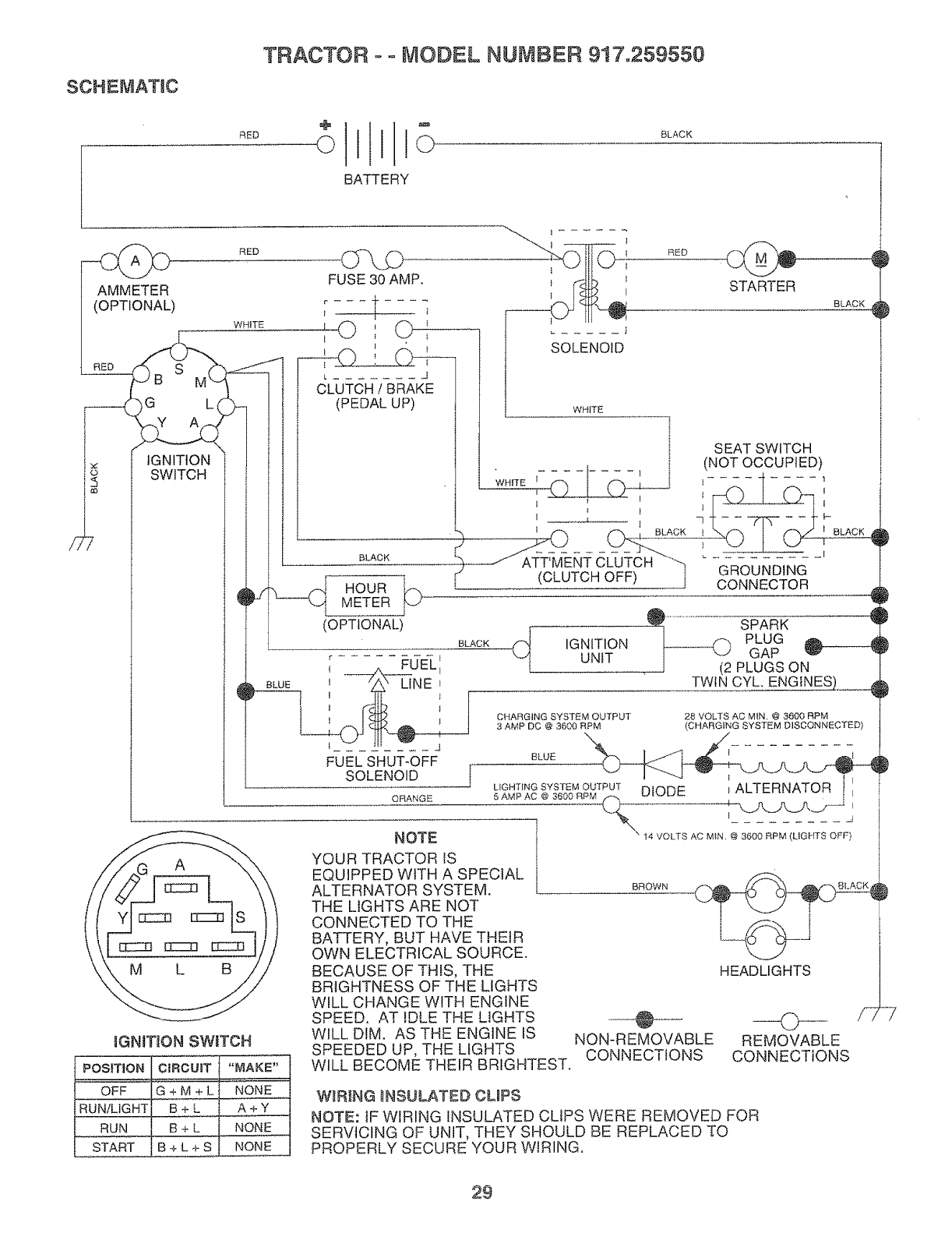
TRACTOR o o MODEL NUMBER 9t7.259550
SCHEMATIC
RED
BATTERY
BLACK
- jo
AMMETER
(OPTIONAL)
RUN/LIGHT
RUN
START
S
G
IGNITION
SWITCH
RED
BGNmON SWITCH
PosmoN C_RCU_TI"r,_AKE"
OFF G + M+._L._ "I'_ONE '
B+£_._ A+Y
B + L _ NONE
_+LT_ 1 NONE
FUSE 30 AMP.
WHITE
t
WHITE L._O _ 0_
L_ (PEDAL UP)
BLACK
HOUR i
METER _
f r
(OPTIONAL)
BLACK
FUEL',
,_ BLUE tI iiiX_X--UNE i
] t t
FUEL SHUT-OFF r
SOLENOID j
ORANGE
F
SOLENOID
WHITE
STARTER
1
RED
}/ ATT MENT CL:O_'_
I (CLUTCH OFF) I
BLACK ._
q[ IGNITION
UNIT
CHARGING SYSTEM OUTPUT'
3 AMP DC @ 3600 RPM
NOTE
SEAT SWITCH
(NOT OCCUPIED)
BLUE
GROUNDING
CONNECTOR _
.__ SPARK _}
PLUG _._______ _
GAP
PLUGS ON
TWIN CYL. ENGINES,,. ___
28 VOLTS AC MIN. @ 3600 RPM
(CHARGING SYSTEM DISCONNECTED)
/
l
LIGHTINGSYSTEMOUTPUTDIODE i ALTERNATOR J
5 AMP AC @ 3600 RPM I
I -J
\ 14 VOLTS AC MIN, @ 3600 RPM (LIGHTS OFF)
i
HEADLIGHTS
/7
YOUR TRACTOR IS I
EQUIPPED WiTH A SPECIAL i
ALTERNATOR SYSTEM. [
THE LIGHTS ARE NOT
CONNECTED TO THE
BATTERY, BUT HAVE THEIR
OWN ELECTRICAL SOURCE.
BECAUSE OF THIS, THE
BRIGHTNESS OF THE LIGHTS
WILL CHANGE WITH ENGINE
C_DC_R AT In] _ TM_' L!GHTS
WILL DIM. AS THE ENGINE IS
SPEEDED UP, THE LIGHTS
WILL BECOME THEIR BRIGHTEST.
BROWN
f-m
--L J----
REMOVABLE
CONNECTIONS
NON-REMOVABLE
CONNECTIONS
W_R_NG INSULATED CUPS
NOTE: IF WIRING INSULATED CLIPS WERE REMOVED FOR
SERVICING OF UNIT, THEY SHOULD BE REPLACED TO
PROPERLY SECURE YOUR WIRING.
29
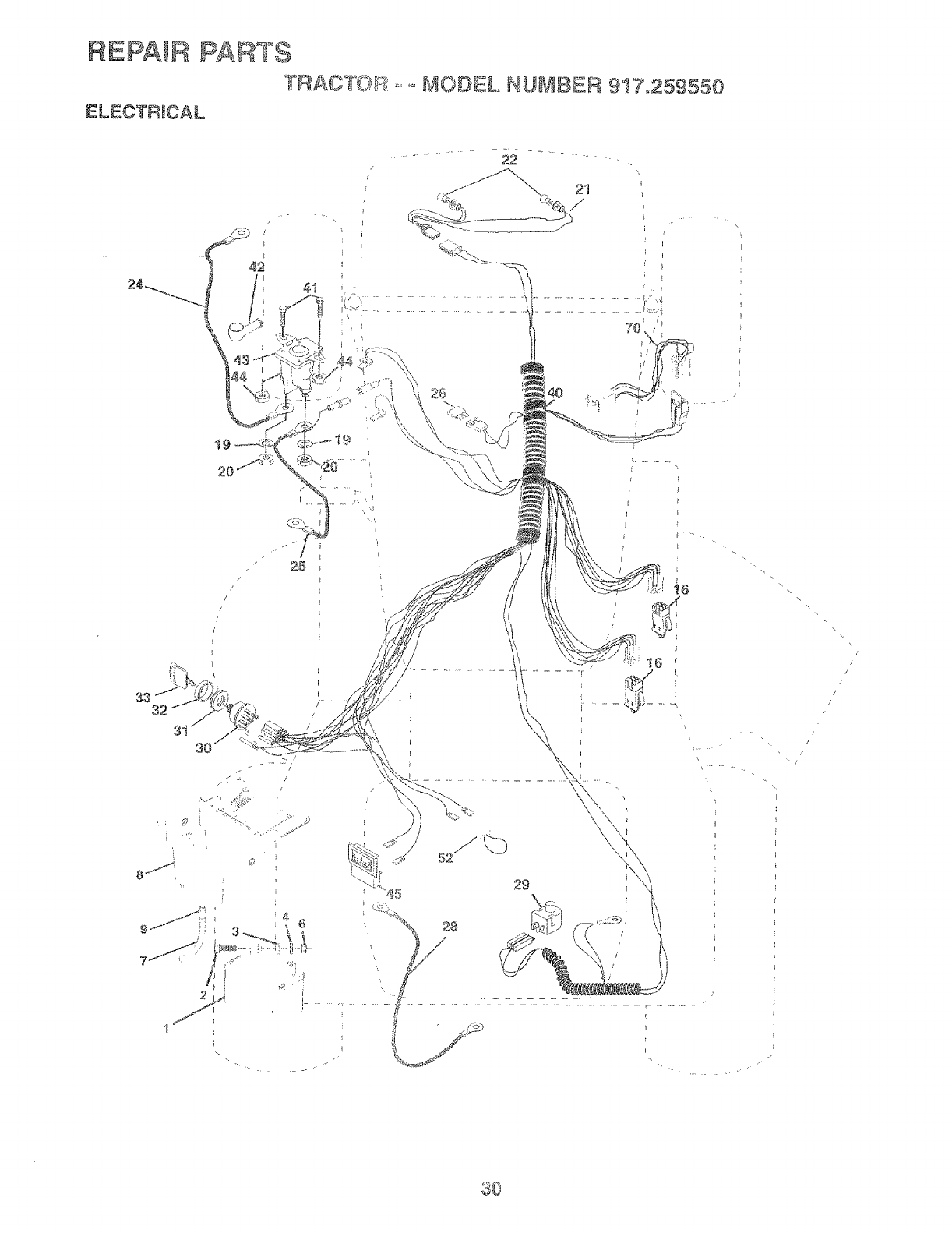
RtEPAIR PARTS
TRAC'UOv-_ B,JODEL NLIMtBER 917.259550
ELECTRICAL
/
/
I
I
43
41
\
t9
/
i
I
i
7
}
I
1 _
\
I
it6
; iGi
/
/
i
i
30
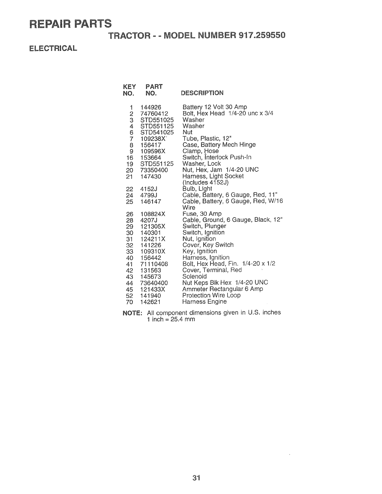
REPAIR PARTS
TRACTOR o ° MODEL NUMBER 917o259550
ELECTRICAL
KEY PART
NO. NO. DESCRIPTUON
1 t44926 Battery 12 Voit 30 Amp
2 74760412 Bolt, Hex Head 1/4-20 unc× 3/4
3 STD551025 Washer
4 STD551125 Washer
6 STD541025 Nut
7 109238X' Tube, Plastic, 12"
8 156417 Case, Battery Mech Hinge
9 109596X Clamp, Hose
16 153664 Switch, hterlock Push-In
19 STD551125 Washer, Lock
20 73350400 Nut, Hex, Jam 1/4-20 UNC
21 147430 Harness, Light Socket
(includes 4152J)
22 4152J Bulb, Light
24 4799J Cable, Battery, 6 Gauge, Red, 11"
25 146147 Cable, Battery, 6 Gauge, Red, W/16
Wire
26 108824X Fuse, 30 Amp
28 4207J Cable, Ground, 6 Gauge, Black, 12"
29 I21305X Switch, Plunger
30 140301 Switch, Ignition
31 12421tX Nut, Ignition
32 141226 Cover, Key Switch
33 109310X Key, Ignition
40 156442 Harness, Ignition
4t 71110408 Bolt, Hex Head, Fin. 1/4-20 x 1/2
42 131563 Cover, Terminal, Red
43 145673 Solenoid
44 73640400 Nut Keps Blk Hex t/4-20 UNC
45 121433X Ammeter Rectangular 6 Amp
52 141940 Protection Wire Loop
70 14262I Harness Engine
NOTE-" All component dimensions given in U.S. inches
1 inch = 25.4 mm
3i
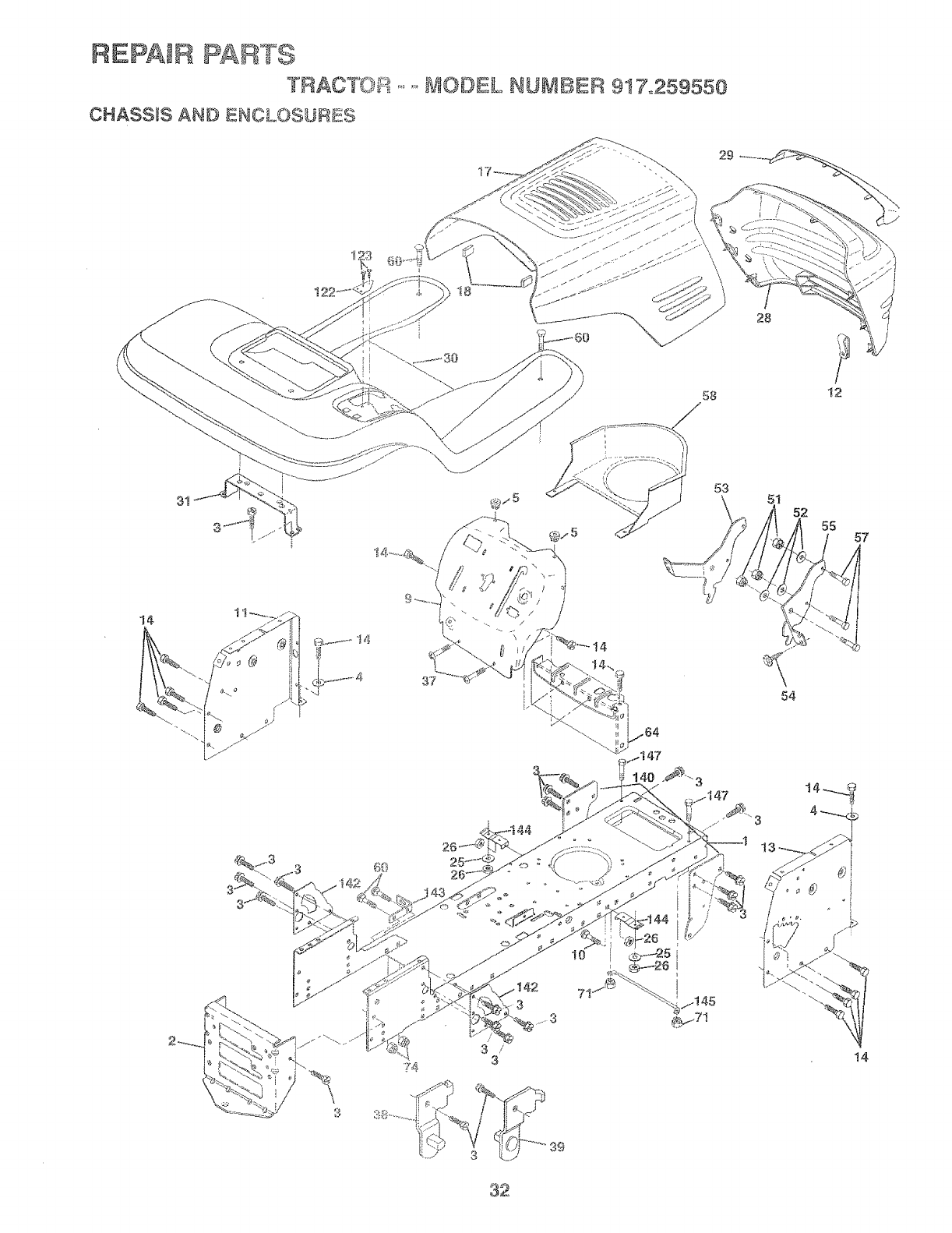
RI!IPAIRPAI_°I'S
.... _,. ',_,_,=_==.......I/IODIL NUI\!IiI 917o259550
CHASSIS AND ftOLOSUIIS
58
28
t2
14
1o
71
53
\51 52 55 57
54
32
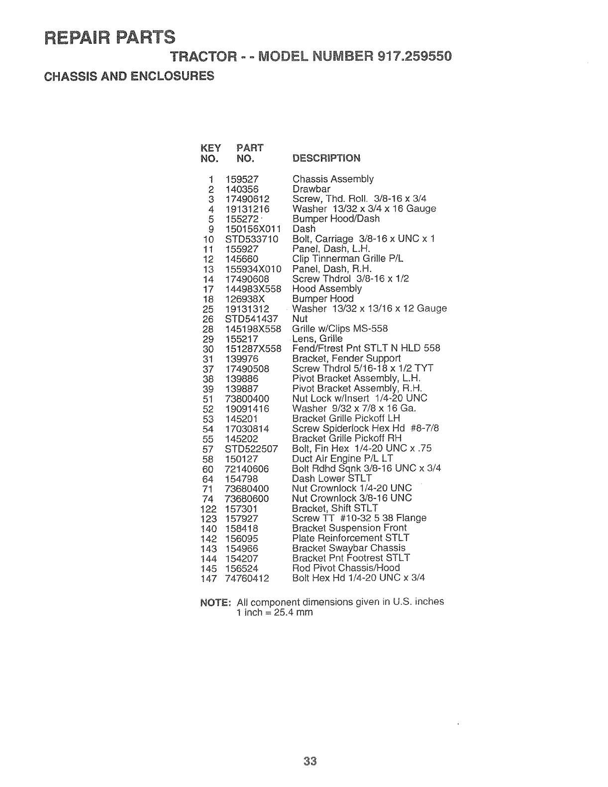
REPAmRPARTS
TRACTOR o = MODEL NUMBER 917.259550
CHASSIS AND ENCLOSURES
KEY PART
NO. NO, DESCRIPTION
1 159527
2 140356
3 17490612
4 19131216
5 155272'
9 150156X011
10 STD5337t0
11 155927
t2 145660
13 t55934X0t0
14 17490608
17 144983X558
18 126938X
25 19131312
26 STD541437
28 145198X558
29 155217
30 !51287X558
3t 139976
37 17490508
38 139886
39 139887
51 73800400
52 19091416
53 145201
54 17030814
55 145202
57 STD522507
58 150127
60 72140606
64 154798
71 73680400
74 73680600
t22 157301
123 157927
140 158418
I42 156095
143 154966
!44 154207
145 156524
147 74760412
Chassis Assembly
Drawbar
Screw, Thd. Roll. 3/8-16 x 3/4
Washer 13/32 x 3/4 x 16 Gauge
Bumper Hood/Dash
Dash
Bolt, Carriage 3/8q 6 x UNC x !
Panel, Dash, L.H.
Clip Tinnerman Grille PiL
Panel, Dash, R.H.
Screw Thdrol 3/8-I6 x 1/2
Hood Assembly
Bumper Hood
Washer 13/32 x !3/16 x !2 Gauge
Nut
Grille wiCiips MS-558
Lens, Gri!le
Fend!Ftrest Pnt STLT N HLD 558
Bracket, Fender Support
Screw Thdrol 5/16-18 x 1/2 TYT
Pivot Bracket Assembly, L.H,
Pivot Bracket Assembly, R.H.
Nut Lock w/Insert 1/4-20 UNC
Washer 9/32 x 7/8 x 16 Ga.
Bracket Grille Pickoff LH
Screw Spiderfock Hex Hd #8-7/8
Bracket Grille Pickoff RH
Bolt, Fin Hex !/4-20 UNC x .75
Duct Air Engine PiL LT
Bolt Rdhd Sqnk 3/8q6 UNC x 3/4
Dash Lower STLT
Nut Crownlock 1/4-20 UNC
Nut Crownlock 3/8-t6 UNC
Bracket, Shift STLT
Screw TT #10-32 5 38 Flange
Bracket Suspension Front
Plate Reinforcement STLT
Bracket Swaybar Chassis
Bracket Pnt Footrest STLT
Rod Pivot Chassis/Hood
Bolt Hex Hd 1/4-20 UNC x 3/4
NOTE: All component dimensions given in U.S. inches
t inch = 25.4 mm
33
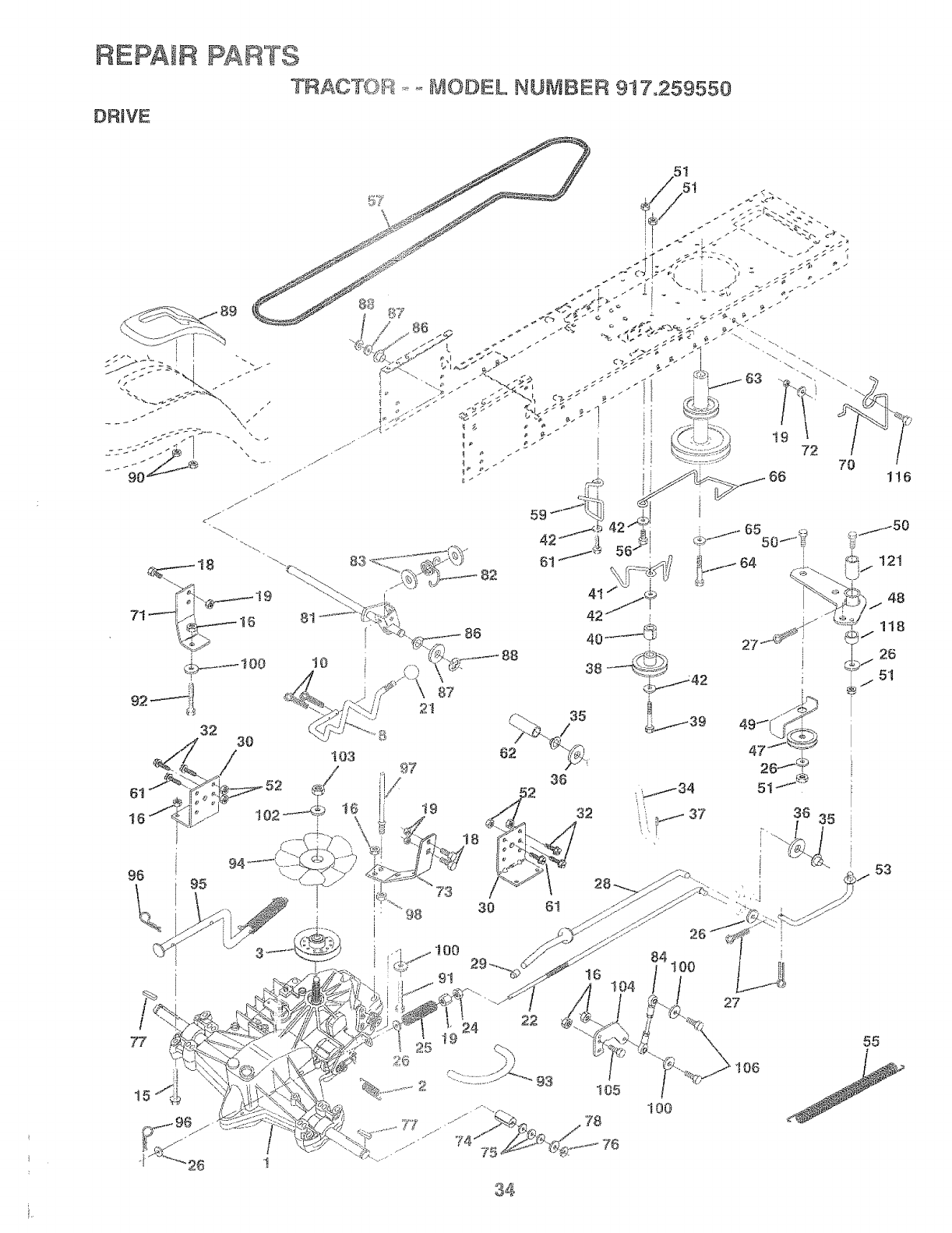
REPAIR PARTS
TRACT{)_ ....._VtODEL NUMBER 917,259550
DRIVE
"98
88
I
77
62
35
36
......... 7,.5.
28
27
84
116
105
78 !00
I06
53
55
34
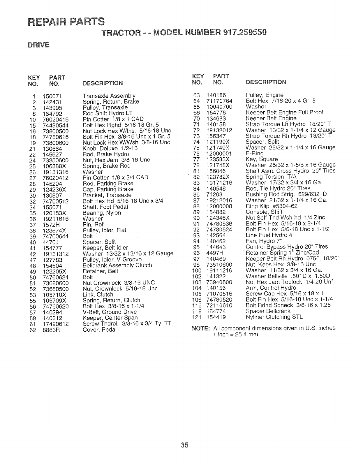
REPAIR PARTS
TRACTOR -= MODEL NUMBER 9!7.259550
DRtVE
KEY PART KEY PART
NO. NO. DESCRIPTION NO. NO. DESCRiPTiON
1 t50071 Transaxle Assembly 63 !40186
2 142431 Spring, Return, Brake 64 7t170764
3 !43995 Pulley, Transaxle 65 10040700
8 t54792 Rod Shift Hydro LT 66 154778
!0 76020416 Pin Cotter 1/8 x t CAD 70 134683
15 74490544 Bolt Hex Flghd 5/16-18 Gr. 5 71 140158
16 73800500 Nut Lock HexW/Ins. 5/16-t8 Unc 72 19132012
t8 74780616 Bolt Fin Hex 3/8-16 Uric x 1 Gr. 5 73 156347
!9 73800600 Nut Lock Hex WiWsh 3/8-t6 Unc 74 121t99X
21 130564 Knob, Deluxe 1/2-13 75 t21749X
22 145627 Rod, Brake Hydro 76 12000001
24 73350600 Nut, Hex Jam 3/8-!6 Unc 77 123583X
25 106888X Spring, Brake Rod 78 12t748X
26 19131316 Washer 81 156046
27 76020412 Pin Cotter 1/8 x 3/4 CAD. 82 t23782X
28 145204 Rod, Parking Brake 83 19171216
29 124236X Cap, Parking Brake 84 140548
30 130807 Bracket, Transaxle 86 71208
32 74760512 Bolt Hex Hd 5/16-18 Unc x 3/4 87 19212016
34 t55071 Shaft, Foot Pedal 88 12000008
35 120183X Bearing, Nylon 89 154882
36 1921!616 Washer 90 124346X
37 I572H Pin, Roll 91 74780536
38 !23674X Pulley, Idler, Flat 92 74780524
39 74760644 Bolt 93 142564
40 4470J Spacer, Split 94 140462
4t 154777 Keeper, Belt Idler 95 144643
42 19131312 Washer 13/32 x t3/16 x 12 Gauge 96 4497H
47 127783 Pulley, Idler, V-Groove 97 140469
48 154604 BeltcrankAssembly Clutch 98 73510600
49 123205X Retainer, Belt t00 19111216
50 74760624 Bolt 102 141322
51 73680600 Nut Crownlock 3/8-16 UNC t03 73940800
52 73680500 Nut, Crownlock 5/16-18 Unc 104 140156
53 105710X Link, Clutch 105 71070516
55 105709X Spring, Return, Clutch 106 74780520
56 74760620 Bolt Hex 3/8-16x !-!/4 116 72110610
57 140294 V-Belt, Ground Drive 118 154774
59 140312 Keeper, Center Span 121 154419
61 17490612 Screw Thdro!. 3/8-16 x 3/4 Ty. TT
62 8883R Cover, Pedal
Pulley, Engine
Bolt Hex 7/16_20 x4 Gr, 5
Washer
Keeper Belt Engine Full Proof
Keeper Belt Engine
Strap Torque Lh Hydro t8/20" T
Washer t3/32 x 1-!/4 x t2 Gauge
Strap Torque Rh Hydro 18/20" T
Spacer, Split
Washer 25/32 x t-1/4 x t6 Gauge
E_Ring
Key, Square
Washer 25/32 x t-5/8 x t6 Gauge
Shaft Asm. Cross Hydro 20" Tires
Spring Torsion TiA
Washer 17/32 x 3/4 x 16 Ga.
Rod, Tie Hydro 20" Tires
Bushing Rod Strig. 629/632 ID
Washer 21/32 x !-1/4 x 16 Ga.
Ring Ktip #5304-62
Console, Shift
Nut Self-Thd Wsh-hd 1/4 Zinc
Bolt Fin Hex 5/I6-18 x 2-1/4
Bolt Fin Hex 5/6-I8 Unc x 1-1/2
Line Fuel Hydro 4"
Fan, Hydro 7"
Control Bypass Hydro 20" Tires
' Retainer Spring I" Zinc/Cad
Keeper Bolt Rh Hydro 0750, 18/20"
Nut Keps Hex 3/8-!6 Unc
Washer 11/32 x 3/4 x !6 Ga,
Washer Bellviile .501D x 1.50D
Nut Hex Jam Toplock I/4-20 Unf
Arm, Controt Hydro
Screw Cap Hex 5/16 x t8 x 1
Bolt Fin Hex 5/16-18 Unc x 1_1/4.
Bolt Rdhd Sqneck 3/8-I6 x 1.25
Spacer Bellcrank
Nyliner Clutching STL
NOTE: All component dimensions given in U.S. inches
1 inch = 25.4 mm
35
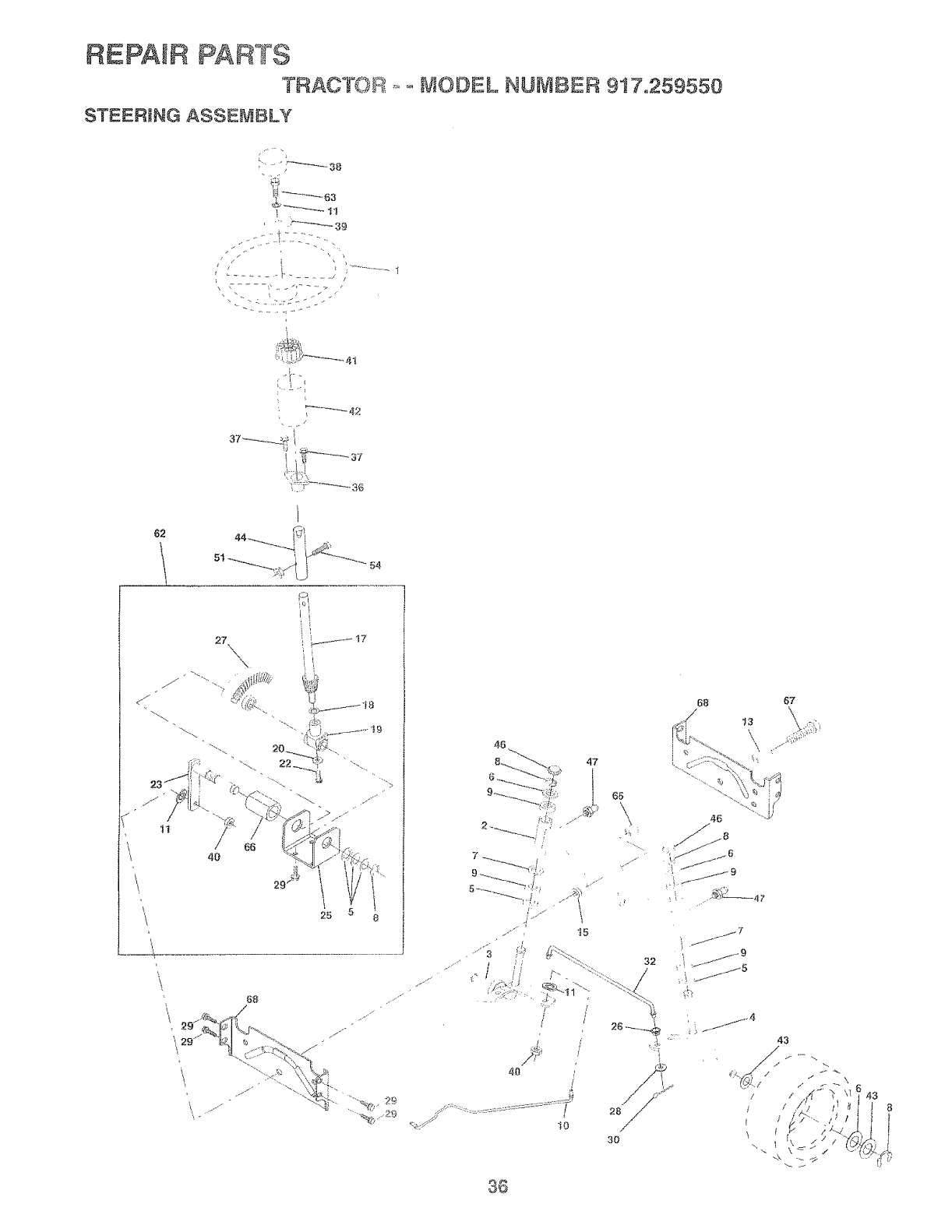
REPAIR PARTS
TRACTOR
STEERtNG ASSEMBLY .... _]OOEL NUMBER 917o259550
/
.............. t-. 'i ..............i
62
27 \X
25 8
jr'
68 67
46
k
46
8_
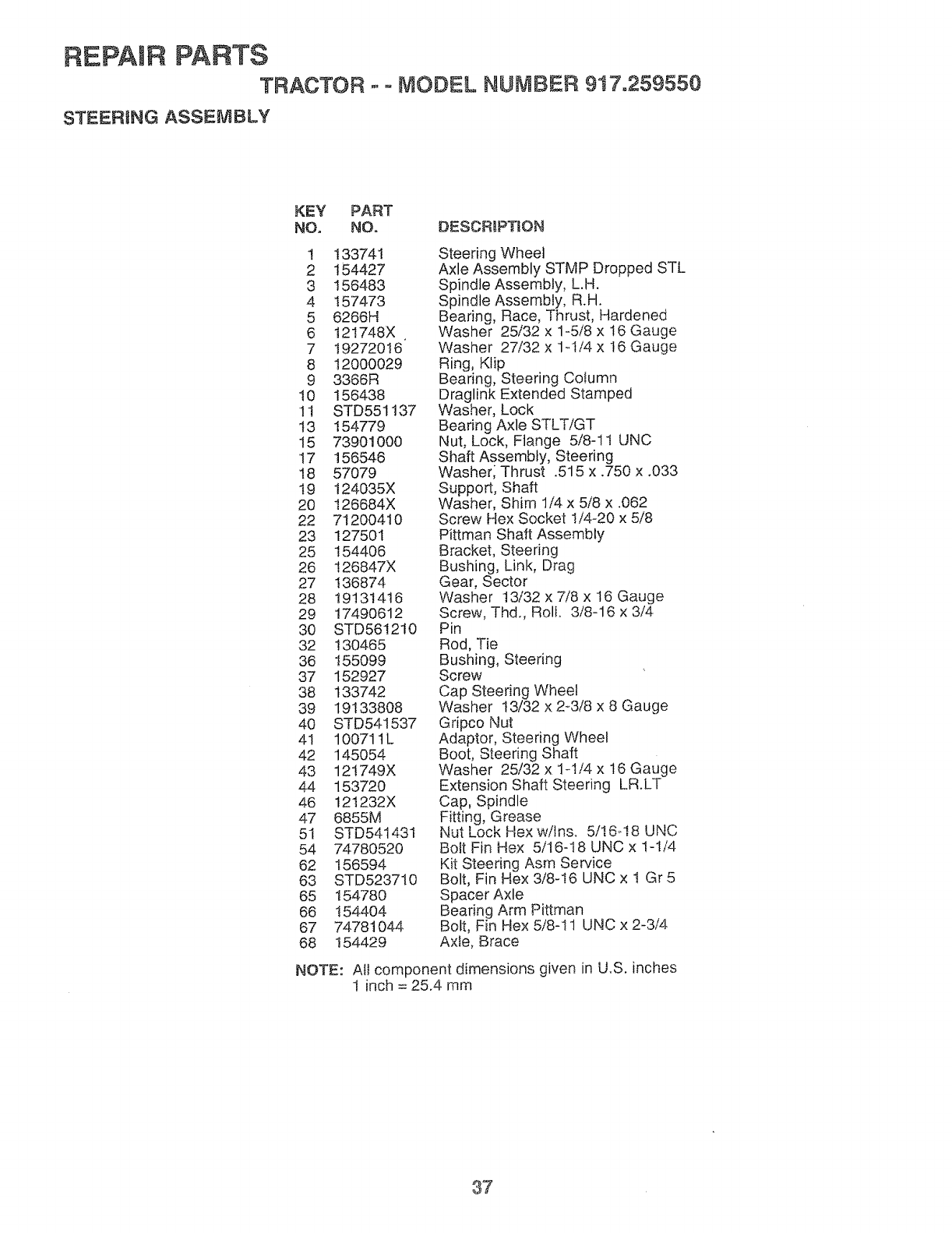
REPAIR PARTS
TRACTOR .--MODEL NUMBER 917o259550
STEERING ASSEMBLY
KEY PART
NO. NO. DESCRmPTION
1 133741
2 154427
3 156483
4 157473
5 6266H
6 121748X
7 19272016
8 12000029
9 3366R
t0 156438
tl STD551137
t3 154779
15 73901000
17 156546
18 57079
19 t24035X
20 126684X
22 71200410
23 127501
25 1544O6
26 t26847X
27 136874
28 19131416
29 17490612
30 STD561210
32 130465
36 155099
37 152927
38 133742
39 19133808
40 STD541537
41 10071tL
42 145054
43 12t749X
44 153720
46 121232X
47 6855M
5i STD541431
54 74780520
62 156594
63 STD523710
65 154780
66 154404
67 74781044
68 154429
Steering Wheel
Axle Assembly STMP Dropped STL
Spindle Assembly, L.H.
Spindle Assembly, R.H.
Bearing, Race, Thrust, Hardened
Washer 25/32 x 1-5/8 x 16 Gauge
Washer 27/32 x 1-1/4 x t6 Gauge
Ring, Klip
Bearing, Steering Column
Draglink Extended Stamped
Washer, Lock
Bearing Axle STLTiGT
Nut, Lock, Flange 5/8-11 UNC
Shaft Assembly, Steering
Washer; Thrust .515 x .750 x .033
Support, Shaft
Washer, Shim 1/4 x 5/8 x .062
Screw Hex Socket 1/4-20 x 5/8
Pittman Shaft Assembly
Bracket, Steering
Bushing, Link, Drag
Gear, Sector
Washer !3/32 x 7/8 x 16 Gauge
Screw, Thd., Rolt. 3/8-16 x 3/4
Pin
Rod, Tie
Bushing, Steering
Screw
Cap Steering Wheel
Washer t3/32 x 2-3/8 x 8 Gauge
Gripco Nut
Adaptor, Steering Wheel
Boot, Steering Shaft
Washer 25/32 x 1-I/4 x 16 Gauge
Extension Shaft Steering LR.LT
Cap, Spindle
Fitting, Grease
Nut Lock Hex w/Ins. 5/16-18 UNC
Bolt Fin Hex 5/16-18 UNC x !-1/4
Kit Steering Asm Service
Bolt, Fin Hex 3/8-16 UNC x ! Gr 5
Spacer Axle
Bearing Arm Pittman
Bolt, Fin Hex 5/8-11 UNC x 2-3/4
Axle, B_ace
NOTE: All component dimensions given in U.S. inches
1 inch = 25.4 mm
@7
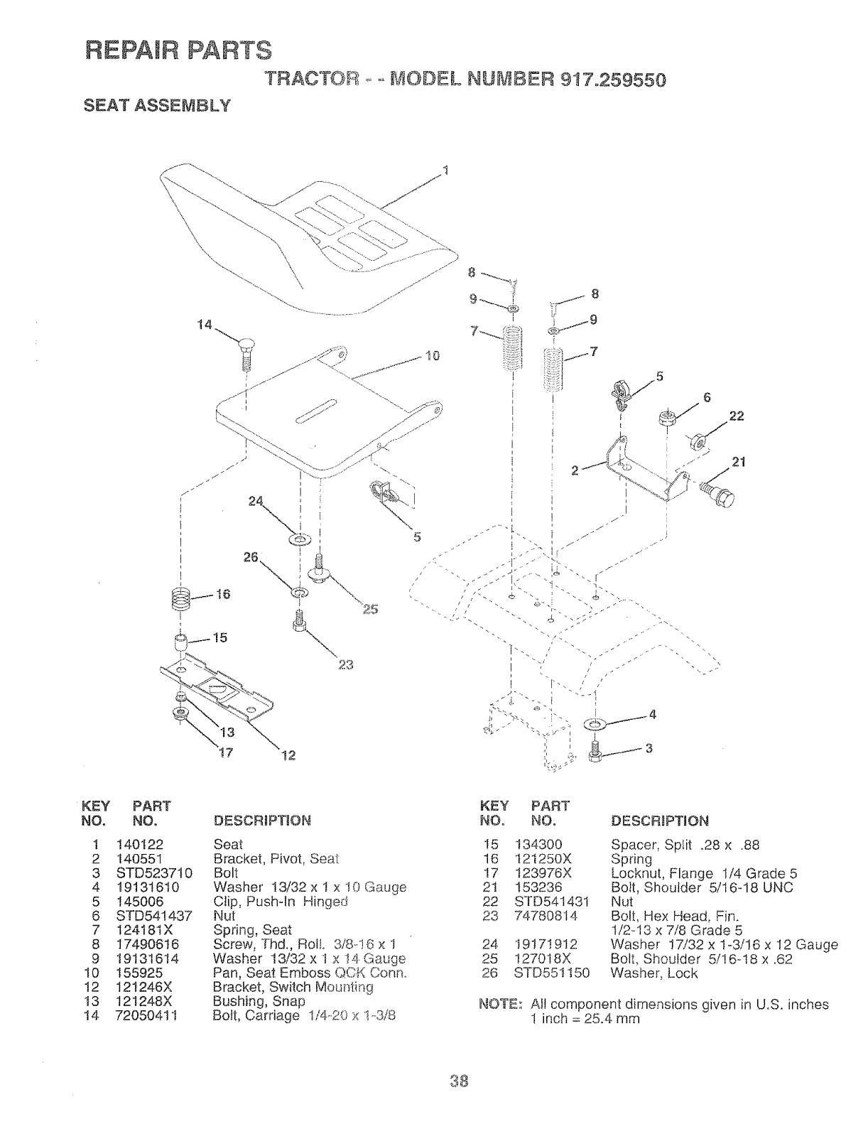
REPAIR PARTS
TRACTOR ..... t ODEL NUMBER 917o259550
SEAT ASSEMBLY
\
17 12
KEY
NO,
1
2
3
4
5
6
7
8
9
t0
12
13
14
PART
NO,
140122
140551
STD523710
19131610
I45006
STD541437
I24181X
17490616
19131614
155925
121246X
12! 248X
72050411
DESCR_PT!ON
Seat
Bracket, Pivot, Seat
Bolt
Washer !3t32 x 1 x t0 Gauge
Clip, Push-In Hinged
Nut
Spring, Seat
Screw, Tnd., RoIL 3/8-.!6 x 1
Washer 13/32 x I x ! 4. Gauge
Pan, Seat Emboss QCK Conn.
Bracket, Switch Mounting
Bushing, Snap
Bolt, Carriage !/4..20 x !-318
KEY PART
NO, NO, DESCRiPTiON
15 134300
16 121250X
!7 t23976X
21 153236
22 STD54143t
23 74780814
24 19171912
25 !27018X
26 STD55!I50
Spacer, Split .28 x .88
Spring
Locknut, Flange 1/4 Grade 5
Bolt, Shoulder 5/16-18 UNC
Nut
Bolt, Hex Head, Fin.
1/Z.13 x 7/8 Grade 5
Washer 17/32 x 1-3/!6 x 12 Gauge
Bolt, Shoulder 5/! 6-!8 x .62
Washer, Lock
NOTE: At! component dimensions given in U.S. inches
I inch = 25.4 mm
38
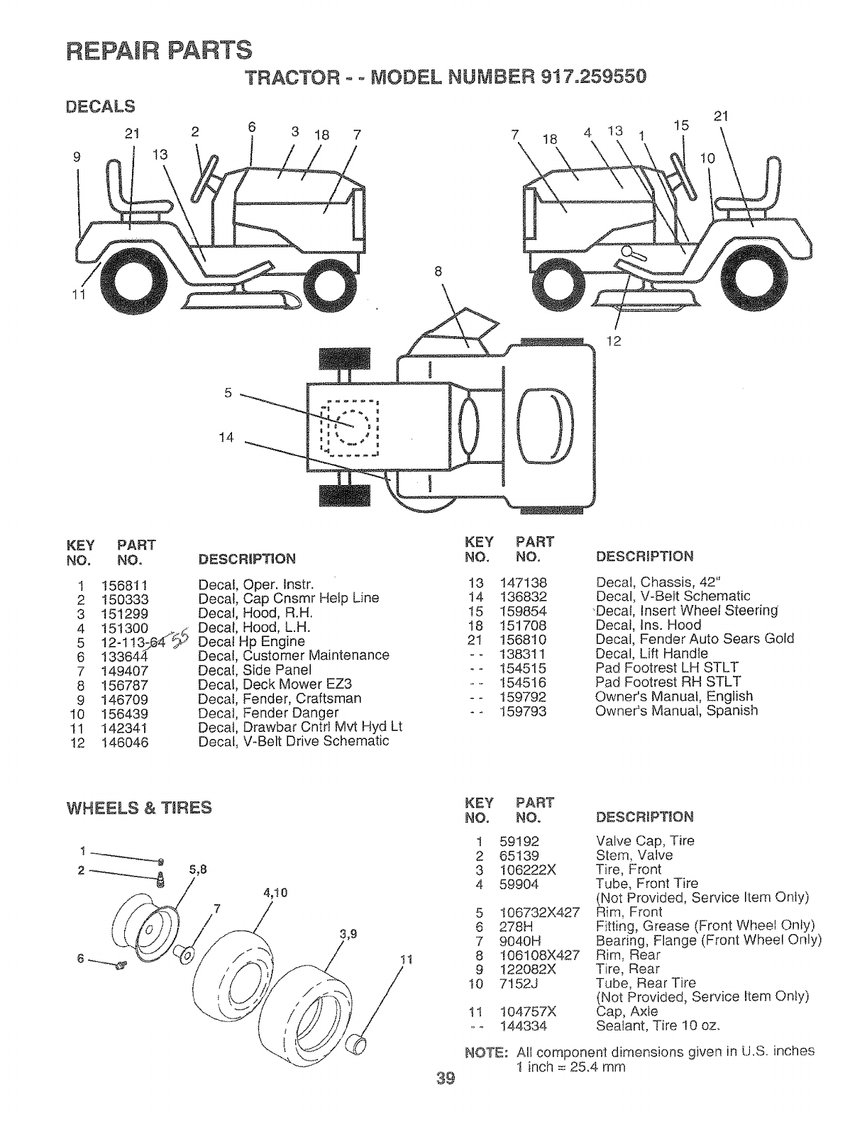
REPAIR
DECALS
21
9
PARTS
TRACTOR o= MODEL NUMBER 917.259550
13
3 18 7 7 18 4 13 1 15 21
11
14
8
0
t2
KSY PART
NO, NO.
1 156811
2 150333
3 151299
4 15130O _d
5 12-113.p@4;2_"
6 133644
7 149407
8 156787
9 146709
10 156439
tl 142341
t2 146O46
DESCRIPTION
Decal, Oper. Instr.
Decal, Cap Cnsmr Hetp Line
Decal, Hood, R.H.
Decal, Hood, L.H.
Decal Hp Engine
Decal, Customer Maintenance
Decal, Side Panel
Decal, Deck Mower EZ3
Decal, Fender, Craftsman
Decal, Fender Danger
Decal, Drawbar Cntrl Mvt Hyd Lt
Decal, V-Belt Drive Schematic
KEY
NO,
t3
14
t5
18
21
PART
NO.
147138
136832
159854
151708
156810
138311
154515
154516
159792
159793
DESCRIPTION
Decal, Chassis, 42"
Decal, V-Belt Schematic
"Decal, Insert Wheel Steering
Decal, ins. Hood
Decal, Fender Auto Sears Gold
Decal, Lift Handle
Pad Footrest LH STLT
Pad Footrest RH STLT
Owner's Manual, English
Owner's Manual, Spanish
WHEELS & TIRES
5,8
7
/
4,10
/3,9
/i1
KEY PART
NO. NO. DESCRiPTiON
1 59192 Valve Cap, Tire
2 65t39 Stem, Valve
3 t06222X Tire, Front
4 59904 Tube, Front Tire
(Not Provided, Service Item Oniy)
5 t06732X427 Rim, Front
6 278H Fitting, Grease (Front Wheel On!y)
7 9040H Bearing, Flange (Front Wheel Only)
8 !06108X427 Rim, Rear
9 122082X Tire, Rear
10 7t52J Tube, Rear Tire
(Not Provided, Service Item Only)
1t t04757X Cap, Axle
oo 144334 Sealant, Tire 10 oz.
NOTE:: All component dimensions given in LJ.S. inches
! inch = 25.4 mm
39
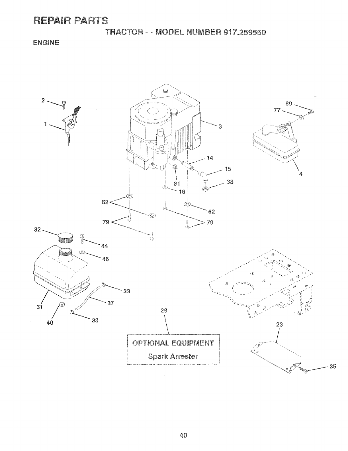
REPAIR PARTS
TRAOTO_+.......B,!ODEL NUMBER 9!7,259550
ENGINE
31
40
33
37
3
I4
2g
L
4
OF ++ONAL EQUIPMENT
Spark Arrest÷r
23
/
s ,¸ "',+.
35
40
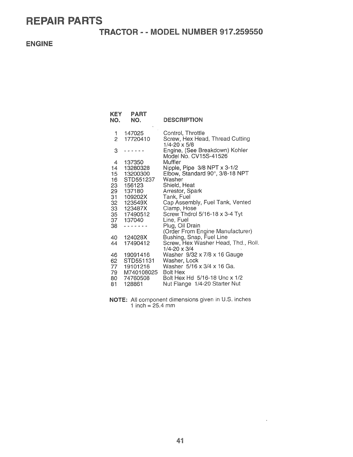
REPAIR
ENGPNE
PARTS
TRACTOR ooMODEL NUMBER 917o259550
KEY PART
NO. NO. DESCRBPTION
1
2147025
17720410
4 137350
14 13280328
15 13200300
!6 STD55!237
23 156123
29 137180
31 109202X
32 !23549X
33 123487X
35 17490512
37 137040
38 .......
40 I24028X
44 17490412
46 19091416
62 STD551131
77 19101216
79 M740108025
80 74760508
81 128861
Control, Throttle
Screw, Hex Head, Thread Cutting
1/4-20 x 5/8
Engine, (See Breakdown) Kohler
Modei No. CV15S-4t 526
Muffler
Nipple, Pipe 3/8 NPT x 3-1/2
Elbow, Standard 90°, 3/8-18 NPT
Washer
Shield, Heat
Arrestor, Spark
Tank, Fuel
Cap Assembly, Fuel Tank, Vented
Clamp, Hose
Screw Thdrol 5/! 6-18 x 3-4 Tyt
Line, Fuel
Plug, Oil Drain
(Order From Engine Manufacturer)
Bushing, Snap, Fue! Line
Screw, Hex Washer Head, Thd., Roll.
!/4-20 x 3/4
Washer 9/32 x 7/8 x t6 Gauge
Washer, Lock
Washer 5/16 x 3/4 x 16 Ga.
Bolt Hex
Bolt Hex Hd 5/16_18 Uric x t/2
Nut Flange 1/4-20 Starter Nut
NOTE: All component dimensions given in U.S. inches
1 inch = 25,4 mm
41
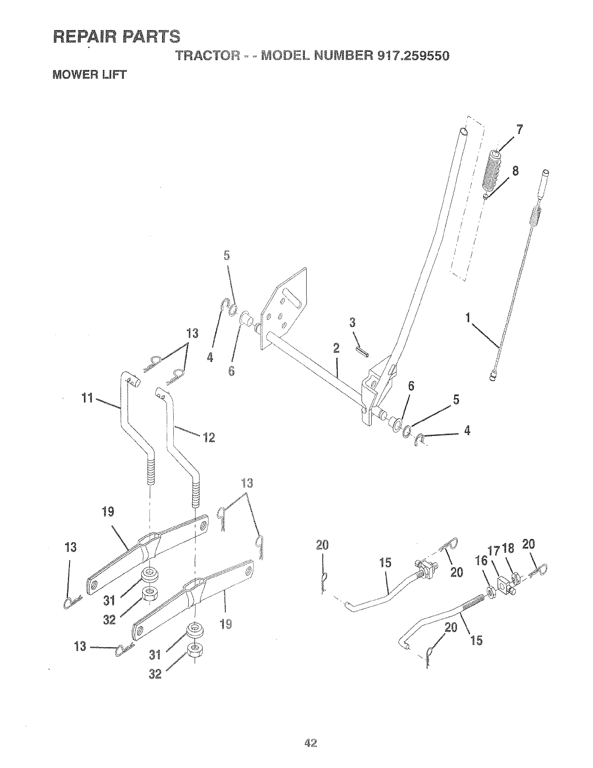
REPAIR PARTS
TRACTOR ......MODEL NU#_BER 9!7.,259550
MOWER LIFT
5
13
32
/3
13 42\
13
20
5
_-_ 1718 20
42
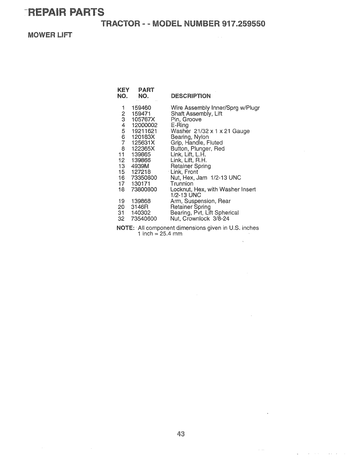
-REPA-IR PARTS
TRACTOR ,-o t'_ODEL NUMBER 917.2.59550
MOWER ,LtFT
KEY PART
NO, NO. DESCRIPTION
1 159460 Wire Assembly Inner!Sprg wiPlugr
2 159471 Shaft Assembly, Lift
3 105767X Pin, Groove
4 t2000002 E-Ring
5 19211621 Washer 21/32 x t x 21 Gauge
6 t20183X Bearing, Nylon
7 I25631X Grip, Handle, Fluted
8 122365X Button, Plunger, Red
1t 139865 Link, Lift, LH.
12 139866 Link, Lift, R.H.
13 4939M Retainer Spring
15 t27218 ' Link, Front
16 73350800 Nut, Hex, Jam !I2-13 UNC
17 130171 Trunnion
18 73800800 Locknut, Hex, with Washer insert
1/2-!3 UNC
19 139868 Arm, Suspension, Rear
20 3t46R Retainer Spring
31 140302 Bearing, Pvt, Lift Spherical
32 73540600 Nut, Crownlock 3/8-24
NOTF..:Alt component dimensions given in U.S. inches
1 inch = 25.4 mm
43
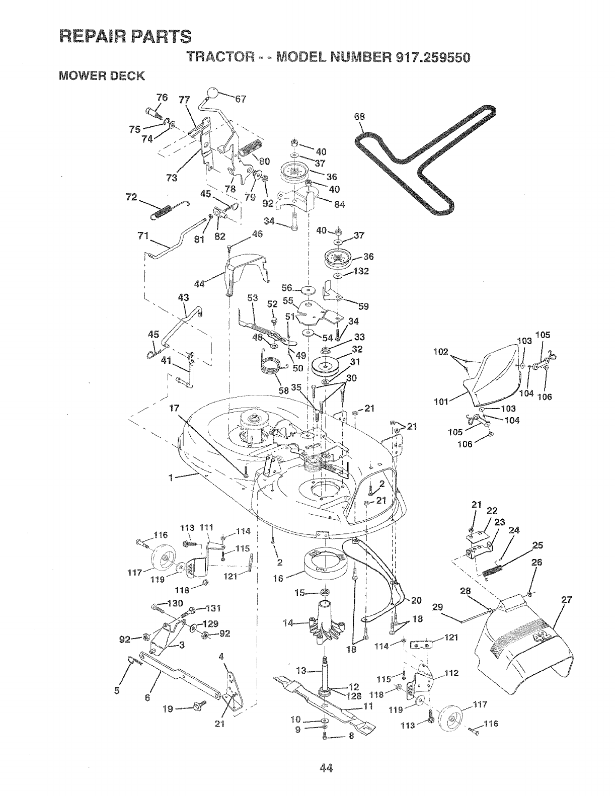
REPABR PARTS
TRACTOR
MOWER DECK .... MODEL NUMBER :917.259550
34
32
31
58
105
106
5
4
21
\2
16
28
29
t8
21 22
27
44
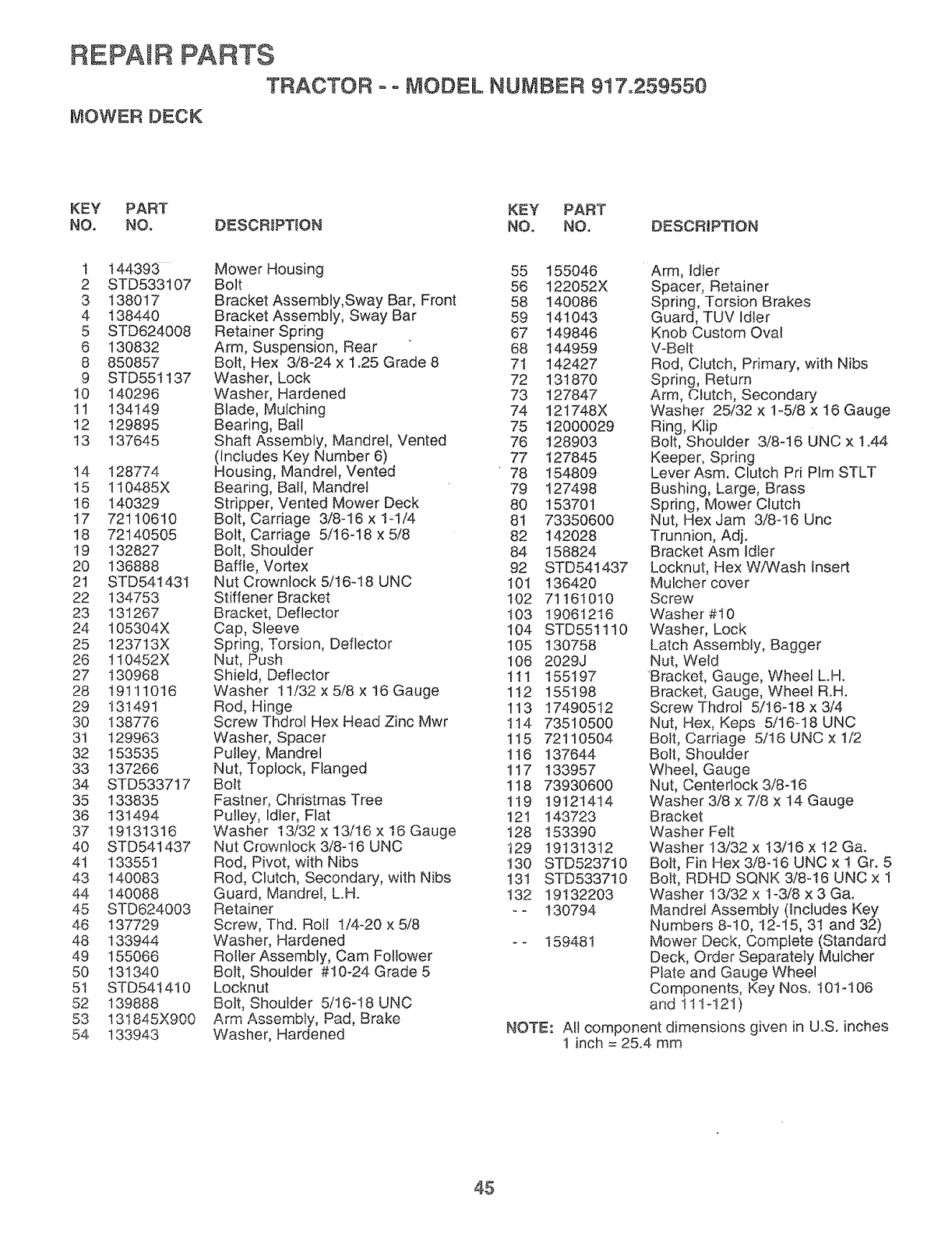
REPAIR PARTS
TRACTOR oo MODEL NUMBER 917.259550
MOWER DECK
KEY PART KEY PART
NO. NO. DESCRIPTION NO. NO. DESCRIPTION
t 144393
2 STD533t07
3 138017
4 138440
5 STD624008
6 130832
8 850857
9 STD551137
10 140296
tl 134149
12 129895
13 137645
14 128774
t5 110485X
t6 140329
t7 72110610
18 72140505
19 132827
20 136888
21 STD54t43I
22 134753
23 131267
24 105304X
25 123713X
26 !I0452X
27 130968
28 19111016
29 131491
30 138776
3I 129963
32 153535
33 137266
34 STD533717
35 133835
36 131494
37 19131316
40 STD541437
4t 133551
43 140083
44 140088
45 STD624003
46 137729
48 133944
49 155066
50 131340
5t STD541410
52 139888
o 131845X900
54 133943
Mower Housing
Bolt
Bracket Assembly,Sway Bar, Front
Brackel Assembly, Sway Bar
Retainer Spring
Arm, Suspension, Rear
Bolt, Hex 3/8-24 x 1.25 Grade 8
Washer, Lock
Washer, Hardened
Blade, Mulching
Bearing, Ball
Shaft Assembly, Mandrel, Vented
(Includes Key Number 6)
Housing, Mandrel, Vented
Bearing, Ball, Mandrel
Stripper, Vented Mower Deck
Bolt, Carriage 3/8-16 x lq/4
Bolt, Carriage 5/16-18 x 5/8
Bolt, Shoulder
Baffle, Vortex
Nut Crowntock 5/t6-I8 UNC
Stiffener Bracket
Bracket, Deflector
Cap, Sleeve
Spring, Torsion, Deflector
Nut, Push
Shield, Deflector
Washer 11/32 x 5/8 x t6 Gauge
Rod, Hinge
Screw Thdrol Hex Head Zinc Mwr
Washer, Spacer
Pulley, Mandrel
Nut, Toplock, Flanged
Bolt
Fastner, Christmas Tree
Pulley, Idler, Flat
Washer 13/32 x t3/I6 x 16 Gauge
Nut Crowntock 3/8-16 UNC
Rod, Pivot, with Nibs
Rod, Clutch, Secondary, with Nibs
Guard, Mandrel, L.H.
Retainer
Screw, Thd. Roll I/4-20 x 5/8
Washer, Hardened
Roller Assembly, Cam Follower
Bolt, Shoulder #t0-24 Grade 5
Locknut
Bolt, Shoulder 5/16-!8 UNC
Arm ^_,._h!,, _,,4 _.,_L.,,
Washer, Hardened
55 155046
56 122052X
58 140086
59 141043
67 149846
68 144959
71 142427
72 131870
73 127847
74 121748X
75 12000029
76 128903
77 127845
78 154809
79 127498
80 153701
81 73350600
82 142028
84 158824
92 STD54t437
101 136420
I02 71161010
t03 19061216
104 STD551110
105 130758
106 2029J
1tl 155197
112 155198
113 17490512
114 73510500
tt5 72110504
!16 137644
117 133957
118 73930600
1t9 19121414
12t 143723
t28 153390
129 19131312
130 STD523710
131 STD533710
t32 19132203
-- 130794
NOTE:
159481
Arm, Idler
Spacer, Retainer
Spring, Torsion Brakes
Guard, TUV Idler
Knob Custom Oval
V-Belt
Rod, Ctutch, Primary, with Nibs
Spring, Return
Arm, Clutch, Secondary
Washer 25/32 x t-5/8 x 16 Gauge
Ring, Klip
Bolt, Shoulder 3/8q6 UNC x t.44
Keeper, Spring
Lever Asm. Clutch Pri PIm STLT
Bushing, Large, Brass
Spring, Mower Clutch
Nut, Hex Jam 3/8-16 Unc
Trunnion, Adj.
Bracket Asm tdler
Locknut, Hex W/Wash insert
Mulcher cover
Screw
Washer #10
Washer, Lock
Latch Assembly, Bagger
Nut, Weld
'Bracket. Gauge, Wheel L.H.
Bracket, Gauge, Whee! R.H.
Screw Thdrol 5/I6-18 x 3/4
Nut, Hex, Keps 5/t6-18 UNC
Bolt, Carriage 5/16 UNC x 1/2
Bolt, Shoulder
Wheel, Gauge
Nut, Centerlock 3/8-16
Washer 3/8 x 7/8 x 14 Gauge
Bracket
Washer Felt
Washer 13/32 x t3/16 x 12 Ga.
Bolt, Fin Hex 3/8-t6 UNC x 1 Gr. 5
Bolt, RDHD SQNK 3/8-!6 UNC x "1
Washer t3/32 x t-3/8 x 3 Ga.
Mandrel Assembly (Includes Key
Numbers 8q0, 12-15, 31 and 32)
Mower Deck, Complete (Standard
Deck, Order Separately Mutcher
Plate and Gauge Wheel
Components, Key Nos. 10t-106
and 1ttq2!)
Aft component dimensions given in U.S. inches
t inch = 25.4 mm
45
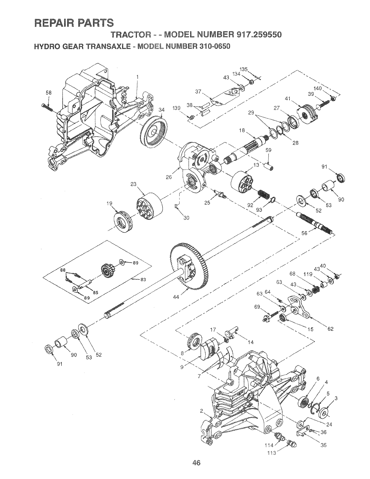
REPAIR PARTS
TRACTOR .... MODEL NUMBER 91'7.259550
HYDRO GEAR TRANSAXLE o MODEL NUMBER 310-0650
43
135
26
19
9!
25
90 53 52 --....
7
28
46
63
63 64
14
4
53
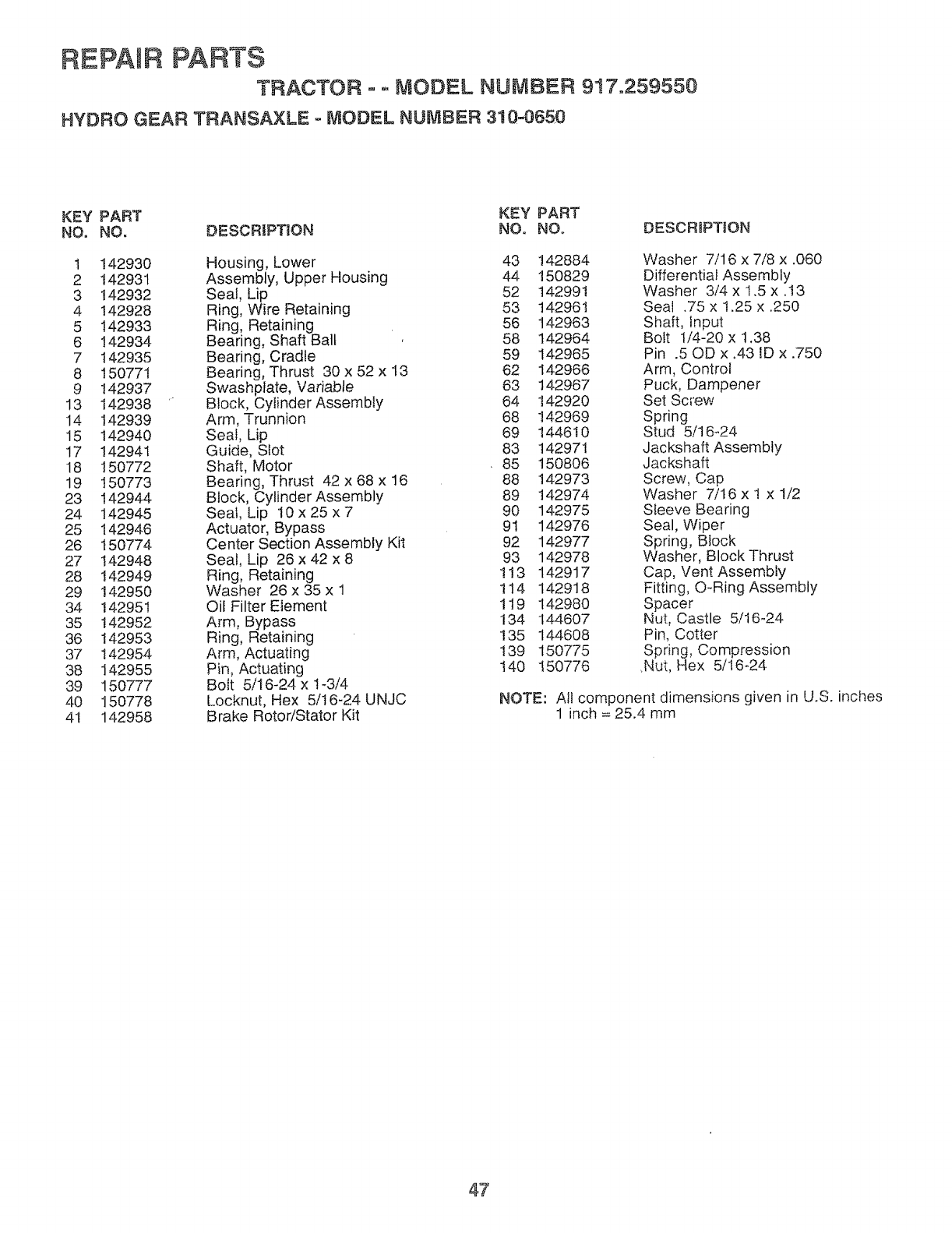
REPAIR PARTS
TRACTOR = o MODEL NUMBER 917.259550
HYDRO GEAR TRANSAXLE -MODEL NUMBER 310=0650
KEY PART KEY PART
NO. NO, DESCRIPTION NO, NO. DESCR_PTION
t 142930 Housing, Lower 43 142884 Washer 7/16 x 7/8 x .060
2 142931 Assembly, Upper Housing 44 150829 Differential Assembly
3 142932 Seat, Lip 52 142991 Washer 3/4 x 1.5 x .!3
4 142928 Ring, Wire Retaining 53 142961 Seal .75 x 1.25 x .250
5 142933 Ring, Retaining 56 142963 Shaft, input
6 142934 Bearing, Shaft Ball 58 142964 Bolt t/4-20 x t.38
7 142935 Bearing, Cradle 59 142965 Pin .50D x.43 iD x .750
8 150771 Bearing, Thrust 30 x 52 x 13 62 142966 Arm, Control
9 142937 Swashplate, Variable 63 142967 Puck, Dampener
13 142938 Block, Cylinder Assembly 64 142920 Set Screw
14 142939 Arm, Trunnion 68 142969 Spring
15 142940 Seal, Lip 69 144610 Stud 5/16-24
17 142941 Guide, Slot 83 14297I Jackshaft Assembly
18 150772 Shaft, Motor 85 150806 Jackshaft
19 150773 Bearing, Thrust 42 x 68 x t6 88 142973 Screw, Cap
23 142944 Block, Cylinder Assembly 89 142974 Washer 7/16 x 1 x 1/2
24 142945 Seal, Lip 10 x 25 x 7 90 142975 Sleeve Bearing
25 142946 Actuator, Bypass 9t 142976 Seal, Wiper
26 t50774 Center Section Assembly Kit 92 142977 Spring, Block
27 142948 Seal, Lip 26 x 42 x 8 93 142978 Washer, Block Thrust
28 142949 Ring, Retaining 1!3 142917 Cap, VentAssembiy
29 142950 Washer 26 x 35 x 1 114 142918 Fitting, O-Ring Assembly
34 142951 Oil Filter Element 119 142980 Spacer
35 142952 Arm, Bypass 134 144607 Nut, Castle 5/16-24
36 142953 Ring, Retaining 135 144608 Pin, Cotter
37 142954 Arm, Actuating 139 150775 Spring, Compression
38 142955 Pin, Actuating I40 150776 .Nut, Hex 5/I6-24
39 150777 Bolt 5/16-24 x 1-3/4
40 150778 Locknut, Hex 5/t6-24 UNJC NOTE: All component dimensions given in U.S. inches
41 142958 Brake RotoriStator Kit 1 inch = 25.4 mm
47
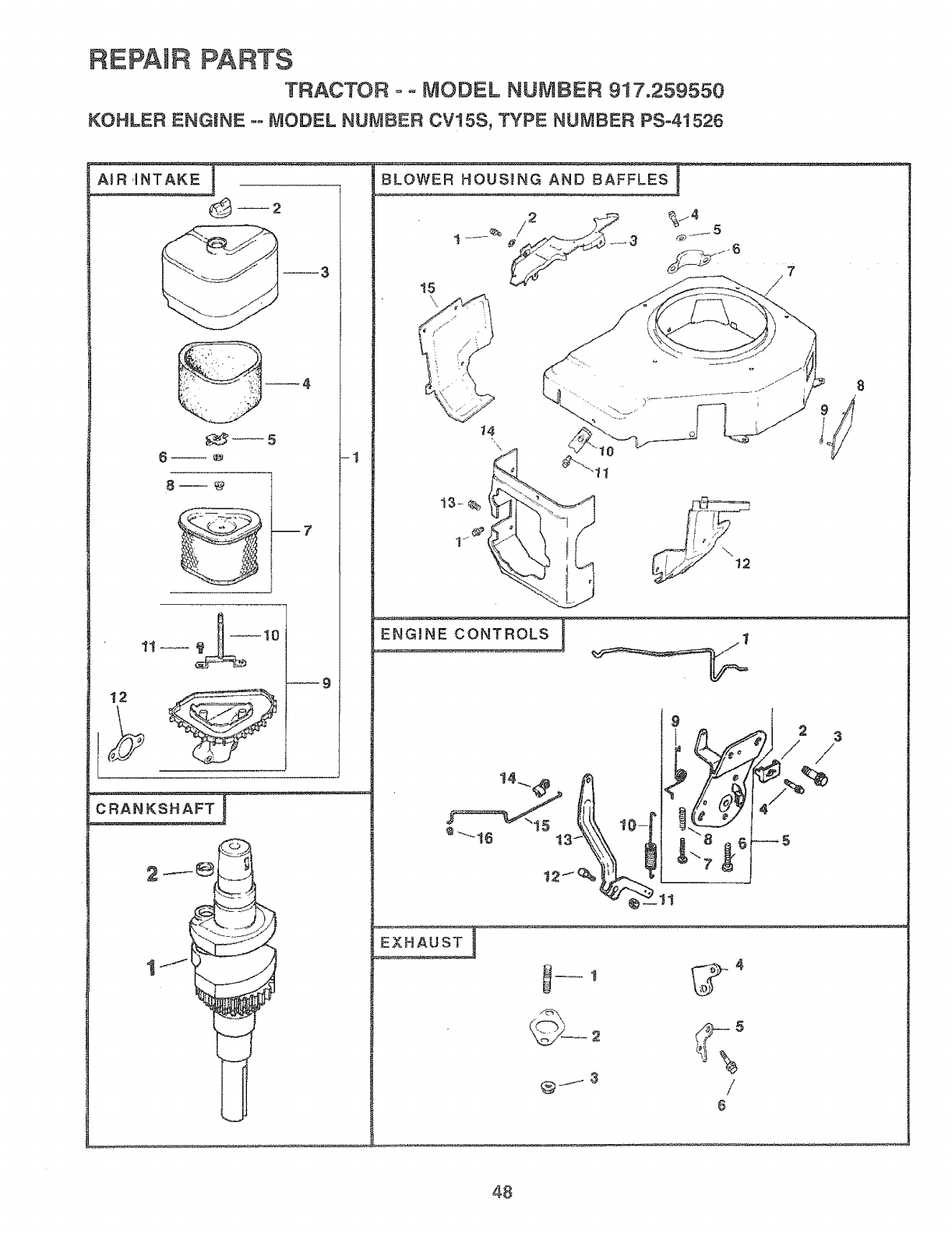
REPAIR PARTS
TRACTOR o° _ODEL NUMBER 917.259550
KOHLER ENGINE °- MODEL NUMBER CVt5S, TYPE NUMBER PSo41526
A_R ,INTAK
6 --.m+ +1
+9
BL--OWE R HOUSIN
15
8
9
EXHAUST I
/
6
48
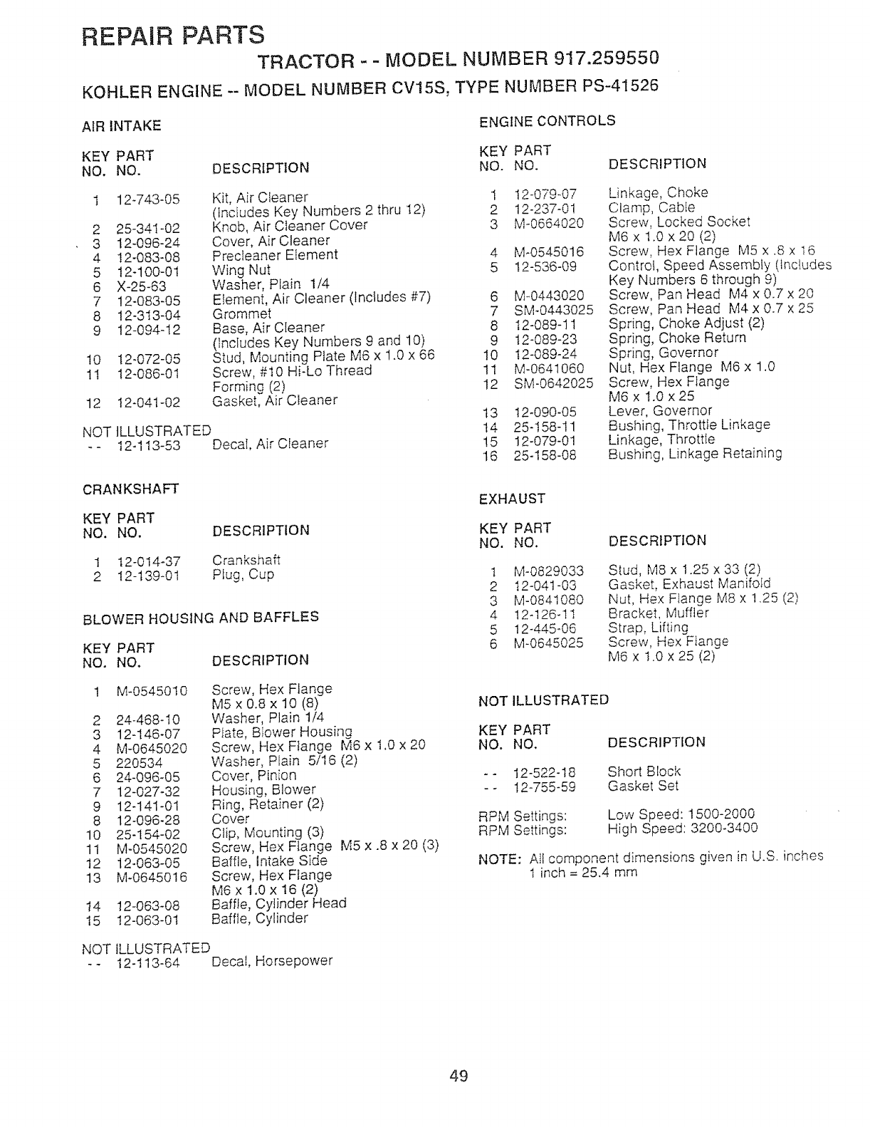
REPAIR PARTS
TRACTOR - - MODEL NUMBER 917.259550
KOHLER ENGINE -- MODEL NUMBER CV15S, TYPE NUMBER PS-41526
AIR INTAKE ENGINE CONTROLS
KEY PART KEY PART
NO. NO. DESCRIPTION NO. NO. DESCRIPTION
12-743-05
2 25-34I -02
3 12-096-24
4 !2-083-08
5 12-100-0t
6 X-25-63
7 12-083-05
8 12-313-04
912-094-12
10 12-072-05
1I 12-086-01
12 t2-041-02
NOT
Kit, Air Cleaner
(Incfudes Key Numbers 2 thru t2)
Knob, Air Cfeaner Cover
Cover, Air Cleaner
Precleaner Element
Wing Nut
Washer, Plain 1/4
EIement, Air Cleaner (Includes #7)
Grommet
Base, Air CIeaner
(Includes Key Numbers 9 and 10)
Stud, Mounting Plate M6 x 1.0 x 66
Screw, #10 Hi-Lo Thread
Forming (2)
Gasket, Air Cleaner
ILLUSTRATED
12-I I3-53 Decal, Air Cleaner
CRANKSHAFT
KEY PART
NO. NO.
1 12-014-37
2 I2-139-01
DESCRIPTION
Crankshaft
Plug, Cup
BLOWER HOUSING AND BAFFLES
KEY PART
NO. NO. DESCRIPTION
M-0545010
2 24-468-I0
3 12-146-07
4 M-0645020
5 220534
6 24-096-05
7 12-027-32
9 12-141-01
8 12-096-28
10 25-154-02
11 M-0545020
12 12-063-05
13 M-06450!6
t4 t2-063-08
t5 12-063-0t
Screw, Hex Flange
M5 x 0.8 x 10 (8)
Washer, Plain t/4
Plate, Blower Housing
Screw, Hex Flange M6 x t,0 x 20
Washer, PIain 5/16 (2)
Cover, Pinion
Housing, Blower
Ring, Retainer (2)
Cover
Clip, Mounting (3)
Screw, Hex Ftange M5 x .8 x 20 (3)
Baffle, Intake Side
Screw, Hex Flange
M6 x 1.0 x 16 (2)
Baffle, Cylinder Head
Baffle, Cylinder
1 12-079-07
2 12-237-01
3 M-0664020
4 M-0545016
5 t2-536-09
6 M-0443020
7 SM-0443025
8 t2-089-11
9 t2-089-23
10 12-089_24
11 M-0641060
12 SM-0642025
13 12-090-05
t4 25-158-11
!5 12-079-01
16 25-158-08
Linkage, Choke
Clamp, Cabfe
Screw, Locked Socket
M6x 1.0x20(2)
Screw, Hex Flange M5 x ,8 x t6
Control, Speed Assembly (tndudes
Key Numbers 6 through 9)
Screw, Pan Head M4 x 0.7 x 20
Screw, Pan Head M4 x 0.7 x 25
Spring, Choke Adjust (2)
Spring, Choke Return
Spring, Governor
Nut, Hex Flange M6 x 1.0
Screw, Hex Flange
M6 x !.0 x 25
Lever, Governor
Bushing, Throttle Linkage
Linkage, Throttle
Bushing, Linkage Retaining
EXHAUST
KEY PART
NO. NO.
l M-0829033
2 t2-041-03
3 M-0841080
4 12q26q1
5 12-445_06
6 M-0645025
DESCRIPTION
Stud, M8 x 1.25 x 33 (2)
Gasket, Exhaust Manifotd
Nut, Hex Flange M8 x 1.25 (2)
Bracket, Muffler
Strap, Lifting
Screw, Hex Flange
M6xl.0x25(2)
NOT ILLUSTRATED
KEY PART
NO. NO. DESCRIPTION
-- 12-522-18 Short Brock
-- !2-755-59 Gasket Set
RPM Settings: Low Speed: 1500-2000
RPM Settings: High Speed: 3200-3400
NOTE: All component dimensions given in U.S. inches
1 inch = 25.4 mm
NOT ILLUSTRATED
- - t2-113-64 Decal, Horsepower
49
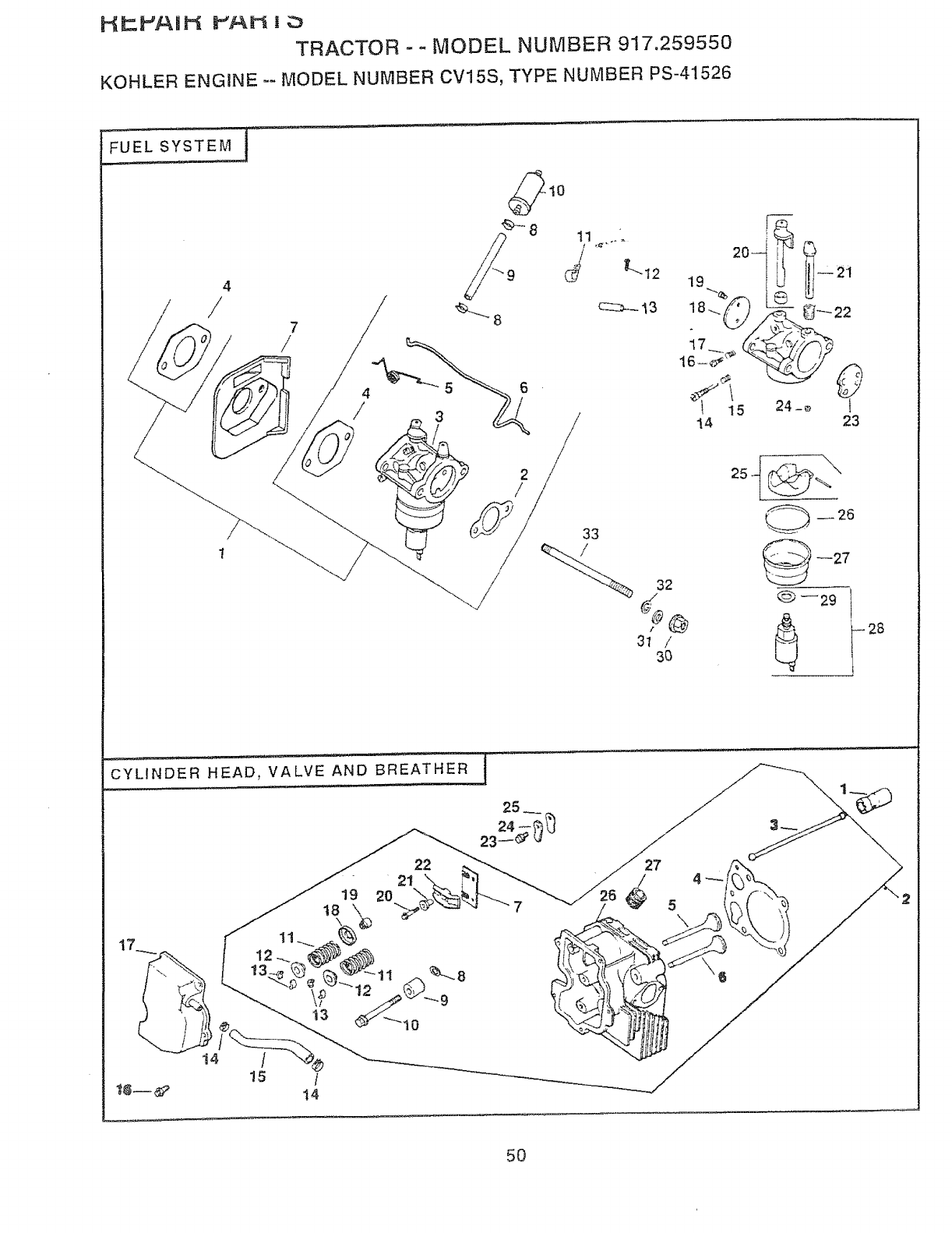
I--_P_P',AIP_ PAN |;_
TRACTOR - - MODEL NUMBER 917.259550
KOHLER ENGINE -MODEL NUMBER CV15S, TYPE NUMBER PS-41526
FUEL SYSTEM
4
/
]
7
/
__8 c::::::z_-_13
20--
19
4 6
/315
14
.....// 32
31 /
3O
®
_'- 22
24-_ }
23
--26
--27
CYLINDER HEAD, VALVE AND BREATHER
19
!5 /
22
21
20 4
5\
50
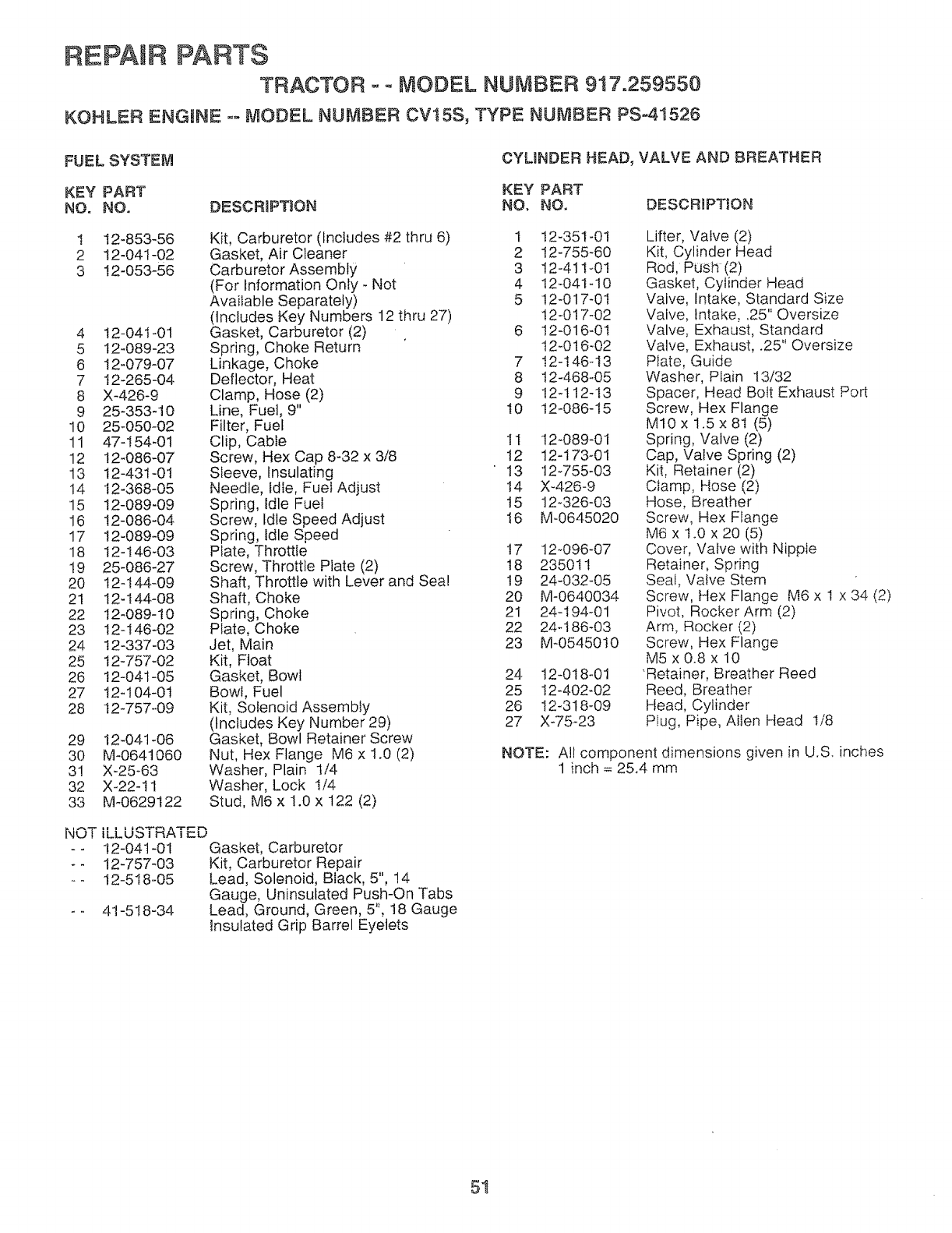
REPAIR PARTS
TRACTOR- o MODEL NUMBER 917.259550
KOHLER ENGINE o- r,_ODEL NUMBER CVt5S, TYPE NUMBER PS-41526
FUEL SYSTEM CYLINDER HEAD, VALVE AND BREATHER
KEY PART KEY PART
NO. NO. DESCRIPTION NO. NO. DESCRIPTION
1 12-853-56
2 I2-041-02
3 t2-053-56
4 t2-04t-01
5 t2-089-23
6 t2-079-07
7 12-265-04
8 X-426-9
9 25-353-10
10 25-050-02
11 47-i54-01
12 t2_086-07
13 t2-431-0t
14 12-368-05
15 t2-089-09
16 12-086-04
17 !2-089-09
18 12-t46-03
t9 25-086-27
20 12-I44-09
21 12-t44-08
22 12-089-10
23 12-t46-02
24 t2-337-03
25 12-757-02
26 12-041-05
27 12o104-0t
28 12-757-09
Kit, Carburetor (Includes #2 thru 6) 1
Gasket, Air Cleaner 2
Carburetor Assembly 3
(For Information Only - Not 4
Available Separately) 5
(Includes Key Numbers 12 thru 27)
Gasket, Carburetor (2) 6
Spring, Choke Return
Linkage, Choke 7
Deflector, Heat 8
Clamp, Hose (2) 9
Line, Fuel, 9" t0
Filter, Fuel
Clip, Cable 11
Screw, Hex Cap 8-32 x 3/8 t2
Sleeve, Insulating 13
Needle, Idle, Fuel Adjust t4
Spring, Idle Fuel 15
Screw, Idle Speed Adjust 16
Spring, Idle Speed
Plate, Throttle 17
Screw, Throttle Plate (2) t8
Shaft, Throttle with Lever and Sea! t9
Shaft, Choke 20
Spring, Choke 21
Plate, Choke 22
Jet, Main 23
Kit, Float
Gasket, Bowl 24
Bow!, Fuel 25
Kit, Solenoid Assembly 26
(Includes Key Number 29) 27
Gasket, Bowl Retainer Screw
Nut, Hex Flange M6 x 1.0 (2)
Washer, Plain 1/4
Washer, Lock I/4
Stud, M6 x 1.0 x 122 (2)
29 12-04t-06
30 M-0641060
31 X-25-63
32 X-22-11
33 M_0629122
iLLUSTRATED
!2-041-01 Gasket, Carburetor
12-757-03 Kit, Carburetor Repair
I2-518-05 Lead, Solenoid, Black, 5", 14
Gauge, Uninsulated Push-On Tabs
41-518-34 Lead, Ground, Green, 5", 18 Gauge
Insulated Grip Barrel Eyelets
NOT
t 2-351-0I
12-755-60
i2-411-0!
12-04I_10
t2-017-0I
t 2-017-02
I2-016-01
t 2-016-02
I2-t46-I3
12-468-05
I2q 12-t3
t2-086-15
12-089-01
12-173_01
12_755-03
X_426o9
12o326-03
M-0645020
12-096-07
235011
24-032_05
M-0640034
24-t94_01
24-186-03
M_0545010
12-018_01
t2-402-02
!2-318_09
X-75_23
Lifter, Valve (2)
Kit, Cylinder Head
Rod, Push (2)
Gasket, Cylinder Head
Valve, Intake, Standard Size
Valve, Intake, ,25" Oversize
Valve, Exhaust, Standard
Valve, Exhaust, .25" Oversize
Plate, Guide
Washer, Plain 13/32
Spacer, Head Bolt Exhaust Port
Screw, Hex Flange
M10x1.5x81(5)
Spring, Valve (2)
Cap, Valve Spring (2)
Kit, Retainer (2)
Clamp, Hose (2)
Hose, Breather
Screw, Hex Flange
M6 x t.0 x 20 (5)
Cover, Valve with Nipple
Retainer, Spring
Seal, Valve Stem
Screw, Hex Flange M6 x 1 x 34 (2)
Pivot, Rocker Arm (2)
Arm, Rocker (2)
Screw, Hex Flange
M5 x 0.8 x 10
"Retainer, Breather Reed
Reed, Breather
Head, Cylinder
Plug, Pipe, Allen Head I/8
NOTE: All component dimensions given in U.S. inches
1 inch = 25A mm
5t
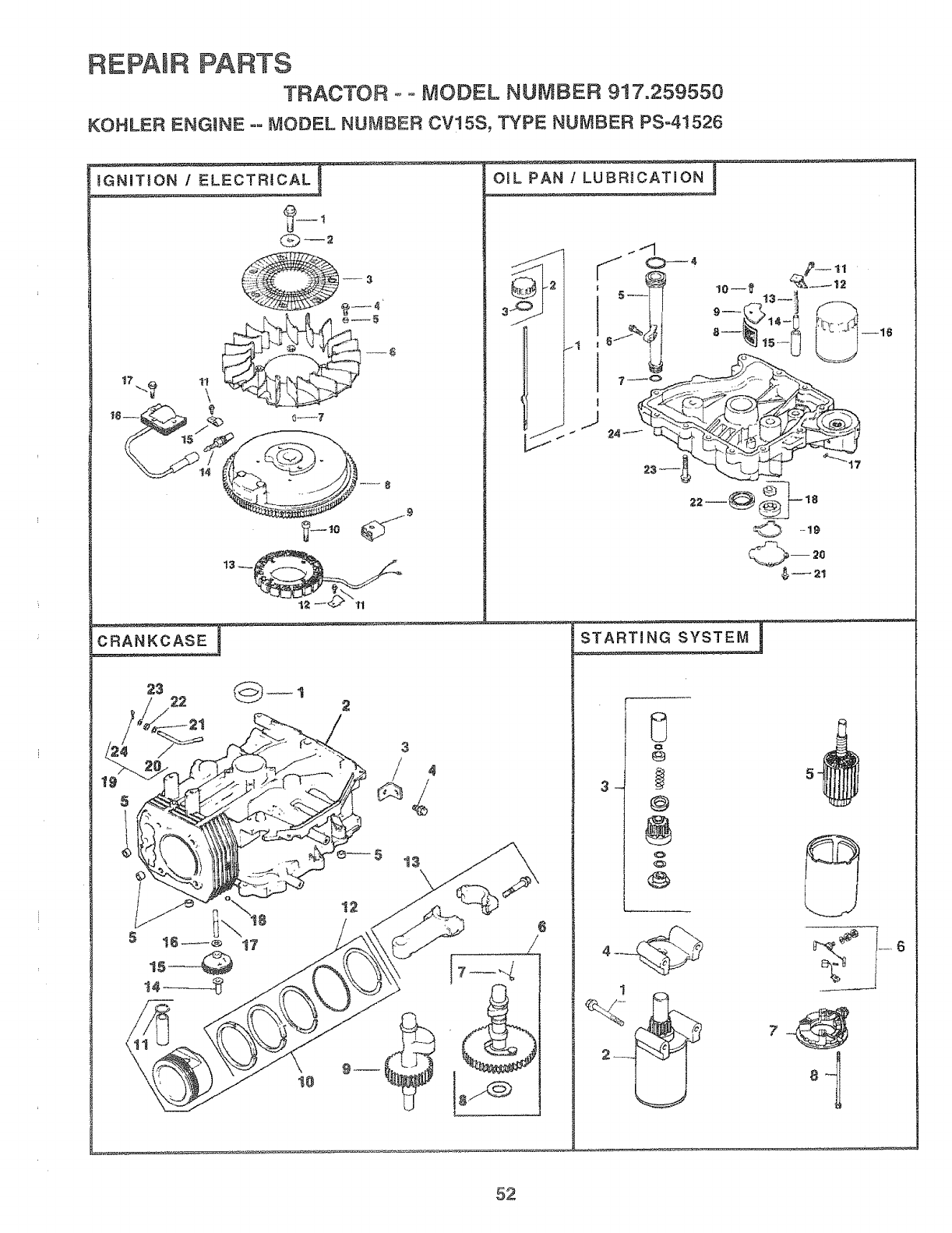
REPAIR PARTS
TRACTOR ,- oMODEL NUMBER 917.259550
KOHLER ENGmNE ooMODEL NUMBER CVt 5S, TYPE NUMBER pso41526
E_CTR_CALI
IGNITION I
.,:@_ 1
¢__--2
e_5 t3
OI L PAN IL_
s-_.._,__Z_
@
@
1
.... 6
'1
52
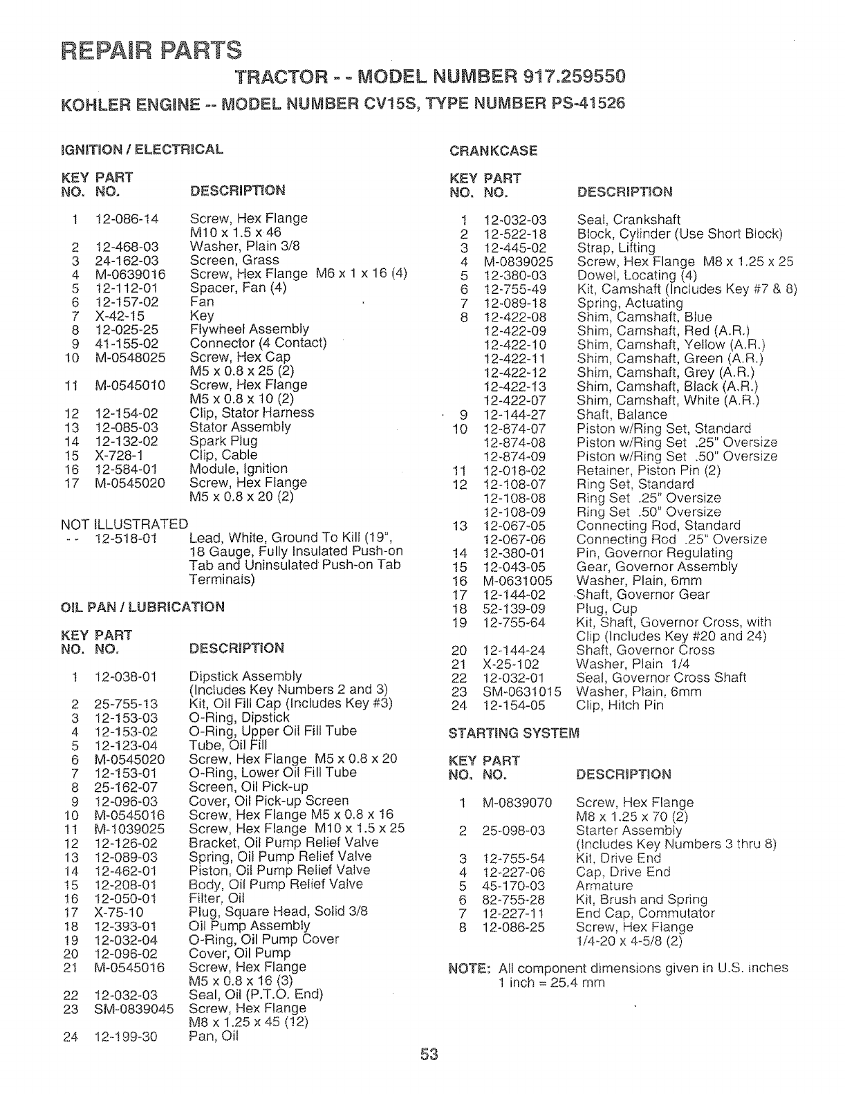
REPAIR PARTS
TRACTOR - o MODEL NUMBER 9i7.259550
KOHLER ENGINE -° MODEL NUMBER CV!5S, TYPE NUMBER PS-41526
_GNITION /ELECTRICAL CRANKCASE
KEY PART KEY PART
NO. NO, DESCRIPTION NO. NO. DESCRmPTJON
1 !2-086-t4 Screw, Hex Flange 1 12-032-03
M10xl.5x46 2 12-522-18
2 t2-468-03 Washer, Plain 3/8 3 12-445-02
3 24-162-03 Screen, Grass 4 M-0839025
4 M-06390t6 Screw, Hex Flange M6 x 1 x 16 (4) 5 12-380-03
5 !2-112-01 Spacer, Fan (4) 6 12-755-49
6 12-t57-02 Fan 7 t2-089-t8
7 X-42-I5 Key 8 t2-422-08
8 t2-025-25 Ffywheef Assembiy 12-422-09
9 4t-I55-02 Connector (4 Contact) 12-422-!0
10 M-0548025 Screw, Hex Cap 12-422-11
M5 x 0.8 x 25 (2) 12-422-12
1I M-0545010 Screw, Hex Flange I2-422-13
M5 x 0.8 x t 0 (2) t2-422-07
12 t2-154-02 Clip, Stator Harness 9 12-144-27
13 t2-085-03 Stator Assembly 10 12-874-07
14 12-132-02 Spark Plug 12-874-08
!5 X-728-1 Clip, Cable 12-874-09
16 t2-584-01 Module, Ignition 11 12-0!8-02
17 M-0545020 Screw, Hex Flange 12 12-108-07
M5 x 0.8 x 20 (2) 12-108-08
t2-108-09
NOT ILLUSTRATED t3 t2-067-05
- - 12-518-01 Lead, White, Ground To Kill (19", t2-067-06
t8 Gauge, Fully Insulated Push-on 14 12-380-01
Tab and Uninsulated Push-on Tab 15 t2-043-05
Terminais) !6 M-0631005
t7 12-t44-02
OiL PAN 1LUBRICATION I8 52-139-09
19 12-755-64
KEY PART
NO. NO. DESCRIPTION
I 12-038-01
2 25-755-13
3 12-153-03
4 12-!53-02
5 12-123-04
6 M-0545020
7 12-153-01
8 25q 62-07
9 12-096-03
10 M-0545016
1I M-1039025
12 12-126-02
13 12-089-03
14 t2-462-01
t5 t2-208-01
16 12-050-01
17 X-75-10
t8 I2-393-0I
!9 12-032o04
20 I2-096-02
2I M-0545016
22 12°032-03
23 SM-0839045
Dipstick Assembly
(Includes Key Numbers 2 and 3)
Kit, Oil Fill Cap (Includes Key #3)
O-Ring, Dipstick
O-Ring, Upper Oil Fill Tube
Tube, Oil Fill
Screw, Hex Flange M5 x 0.8 x 20
O-Ring, Lower Oil Fill Tube
Screen, Oil Pick-up
Cover, Oil Pick-up Screen
Screw, Hex Flange M5 x 0.8 x t6
Screw, Hex Flange M10 x !.5 x 25
Bracket, Oil Pump Relief Valve
Spring, Oil Pump Relief Valve
Piston, Oil Pump Relief Valve
Body, Oil Pump Relief Valve
Filter, Oil
Plug, Square Head, Solid 3/8
Oil Pump Assembly
O-Ring, Oil Pump Cover
Cover, Oil Pump
Screw, Hex Flange
M5 x 0.8 x t6 (3)
Seal, Oil (P.T.O. End)
Screw, Hex Flange
M8 x 1.25 x 45 (!2)
Pan, Oil 53
24 12q99_30
20 12-!44-24
21 X-25-102
22 12-032-01
23 SM-0631015
24 12-154-05
Seal, Crankshaft
Block, Cylinder (Use Short Block)
Strap, Lifting
Screw, Hex Flange M8 x 1.25 x 25
Dowel, Locating (4)
Kit, Camshaft (Includes Key #7 & 8)
Spring, Actuating
Shim, Camshaft, Blue
Shim, Camshaft, Red (A.R.)
Shim, Camshaft, Yellow (A.R.)
Shim, Camshaft, Green (A.R.)
Shim, Camshaft, Grey (A.R.)
Shim, Camshaft, Black (A.R.)
Shim, Camshaft, White (A.R.)
Shaft, Balance
Piston wiRing Set, Standard
Piston w/Ring Set .25" Oversize
Piston w/Ring Set .50" Oversize
Retainer, Piston Pin (2)
Ring Set, Standard
Ring Set .25" Oversize
Ring Set .50" Oversize
Connecting Rod, Standard
Connecting Rod .25" Oversize
Pin, Governor Regulating
Gear, Governor Assembly
Washer, Plain, 6mm
.Shaft, Governor Gear
Plug, Cup
Kit, Shaft, Governor Cross, with
Clip (Includes Key #20 and 24)
Shaft, Governor Cross
Washer, Plain 1/4
Seal, Governor Cross Shaft
Washer, Plain, 6mm
Clip, Hitch Pin
START!NG SYSTEM
KEY PART
NO, NO. DESCRiPTiON
3
4
5
6
7
8
M-0839070
25-098-03
!2-755_54
12-227-06
45-170-03
82-755-28
12-227-11
12-086-25
Screw, Hex Flange
M8 x 1.25 x 70 (2)
Starter Assembly
(Includes Key Numbers 3 thru 8)
Kit, Drive End
Cap, Drive End
Armature
Kit, Brush and Spring
End Cap, Commutator
Screw, Hex Flange
1/4-20 x 4-5/8 (2)
NOTE: Allcomponent dimensions givenin U.S. inches
1 inch = 25.4 mm

SERVICE NOTES
54

SUGGESTED GUIDE FOR SiGHTiNG SLOPES FOR SAFE OPERATmON
_n
ONLY RiDE UP AND DOWN HILL,
NOT ACROSS HiLL
SIGHT AND HOLD THiS LEVEL WiTH
SKY LiNE OR TREE.
A Operate your Tractor up and down the face of stopes (not
A greater than 15°), never across the face. Make turns gradu-
I _1 ally to prevent tipping or loss of control. Exercise extreme
caution• when changing direction on slopes.

OWNER'S
ANUAL
MODEL NO.
917,259550
IF YOU NEED
REPAIR SERVICE
OR PARTS:
FOR REPAIR SERVICE, CALL
THIS TOLL FREE NUMBER:
1-800-4-REPAIR
(1-800-473-7247)
FOR REPLACEMENT PARTS
INFORMATION AND
ORDERING, CALL THIS
TOLL FREE NUMBER:
1-800-FON-PART
(t -800-366-7278)
FOR CONSUMER ASSISTANCE
HOT LINE, CALL THIS
TOLL FREE NUMBER:
1=800-659-5917
®
15.5 HP
ELECTRIC START
42" MOWER
AUTOMATIC (HYDROSTATIC)
LAWN TRACTOR
Each tractor has its own model number. Each engine has
its own model number.
The model number for your tractor wilt be found on the
model plate located under the seat.
The model number for your engine will be found on the
blower housing of the engine,
Alt parts listed herein may be ordered from any Sears,
Roebuck and Co. Service Center/Department and most Re-
tail Stores,
WHEN ORDERING REPAIR PARTS, ALWAYS GIVE THE
FOLLOWING iNFORMATION:
• PRODUCT - TRACTOR
•MODEL NUMBER - 917.259550
ENGINE MODEL NO. -CV15, TYPE NO. PS-41526
PART NUMBER
• PART DESCRIPTION
Your Sears merchandise has added value when you
consider Sears has service units nationwide staffed with
Sears trained technicians.., professional technicians
specifically trained to insure that we meet our pledge to
you, we service what we sell.
159792 Rev. 3 03.05.97 TRiKFSW Printed in U.S.A.
, , , ............. i ...... i .............III IT r _1 !1 ' ........
