Craftsman 917259920 User Manual LAWN TRACTOR Manuals And Guides L0203152
CRAFTSMAN Lawn, Tractor Manual L0203152 CRAFTSMAN Lawn, Tractor Owner's Manual, CRAFTSMAN Lawn, Tractor installation guides
User Manual: Craftsman 917259920 917259920 CRAFTSMAN LAWN TRACTOR - Manuals and Guides View the owners manual for your CRAFTSMAN LAWN TRACTOR #917259920. Home:Lawn & Garden Parts:Craftsman Parts:Craftsman LAWN TRACTOR Manual
Open the PDF directly: View PDF ![]() .
.
Page Count: 56
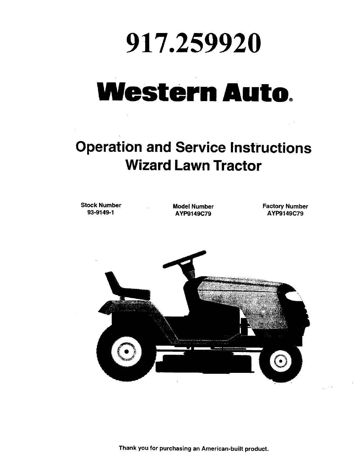
917.259920
Western Auto
Operation and Service Instructions
Wizard Lawn Tractor
Stock Number
93-9149-1 Model Number
AYP9149C79 Factory Number
AYP9149C79
Thank you for purchasing an American-built product.
WESTERN AUTO TRACTOR LIMITED WARRANTY
AYP9149C79
Western Auto Supply Company warrants to the original retail purchaser that this product is free from defects in material or
workmanship and agrees to repair this product free of charge within these time periods from the date of purchase:
•2 years, if the product is used for personal, family, or household use;
•90 days, if the product is used for any other purpose such as commercial or rental use.
Excluded from this warranty are normal wear, maintenance, or mechanical adjustments which are not due to defects in
materialorworkmanship, c_nsu_ty_ur_wner'smanua_f_rhe_pt_maintainy_urpr_duct_rmakeme_hanica_adjustments_ Products
which have been altered, misused, abused, or repaired by other than a Western Auto-authodzed or manufacturer-authorized service
facility are also excluded.
Adder or tractor battery which proves defective within 90 days will be replaced without charge. After 90 days but within 1
year from the date of purchase, Western Auto will replace the battery for a charge of 1/12 of the current retail price of the battery
for each full month between the date of purchase and the date of return.
Engines or transaxles are warranted by the engine or transaxle manufacturer which gives its own 2year warranty and
provides service through its authorized service facilities. See the engine or transaxle warranty for details. Repair may be {_rranged
through participating Western Auto stores.
For repair service return this product with proof of purchase date to a participating Western Auto store. This warranty gives
you specific legal rights and you may have other rights that vary from state to state. If difficulty is encountered in having this warranty
honored, contact:
Western Auto Supply Company
Consumer Affairs Section of the General Service Department
2107 Grand Avenue, Kansas City, Miesoud 64108
Telephone: 816 346-4411
CONGRATULATIONS on your purchase of anew Trac-
tor, It has been designed, engineered and manufactured
to give you the best possible dependability and perfor-
mance.
Should you experience any problem you cannot easily
remedy, please contact your nearest authorized service
center. We have competent, well-trained technicians and
the proper tools to service or repair this tractor.
Please read and retain this manual. The instructions will
enable you to assemble and maintain your tractor prop-
erly. Always observe the "SAFETY RULES".
MODEL
NUMBER AYP9149C79
SERIAL
NUMBER
DATE OFPURCHASE
THE MODEL AND SERIAL NUMBERS WILL BE FOUND ON A
PLATE UNDER THE SEAT.
YOU SHOULD RECORD BOTH SERIAL NUMBER AND DATE OF
PURCHASEANDKEEPINASAFEPLACEFOR FUTURE REFER-
ENCE.
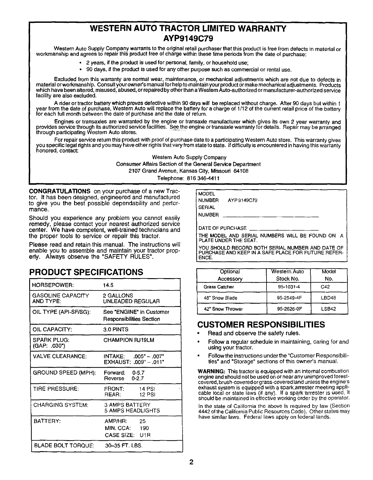
PRODUCT SPECIFICATIONS
HORSEPOWER: 14.5
GASOLINE CAPACITY 2 GALLONS
AND TYPE: UNLEADED REGULAR
OIL TYPE (API-SF/SG): See "ENGINE" in Customer
Responsibilities Section
OIL CAPACITY: 3.0 PINTS
SPARK PLUG: CHAMPION RJ19LM
GAP: .030")
VALVE CLEARANCE: INTAKE: .005" - .007"
EXHAUST: .009" - .011"
GROUND SPEED (MPH}: Forward: 0-5.7
Reverse 0-2.7
TIRE PREsSuRE: FRONT: 14 PSI
REAR: 12 PSI
CHARGING SYSTEM: 3 AMPS BATTERY
5 AMPS HEADLIGHTS
BATTERY: AMP/HR: 25
MIN. CCA: 190
CASE SIZE: U1R
BLADE BOLT TORQUE: 30-35 FT. LBS.
Optional Western Auto Model
Accessory Stock No. No.
Grass Catcher 95-1031-4 C42
48" Snow Blade 95-2549-4F LBD48
42" Snow Thrower 95-2626-0F LSB42
CUSTOMER RESPONSIBILITIES
•Read and observe the safety rules.
• Follow a regular schedule in maintaining, caring for and
using your tractor.
•Follow the thstructions under the "Customer Responsibili-
ties" and "Storage" sections of this owner's manual.
WARNING: This tractor is equipped with an internal combustion
engine and should not be used on or near any unimproved forest-
covered,brush-covered orgrass-coveredland unless the engine's
exhaust system is equipped with a spark.arrester meeting appli-
cab e Ioca or sta elaws (if any). If a spark _rrester s used it
should be maintained in effective working order by the operator.
In the state of California the above is required by law (Section
4442 el the California Public Resources Code). Other states may
have similar laws. Federal laws apply on lederal lands.
2
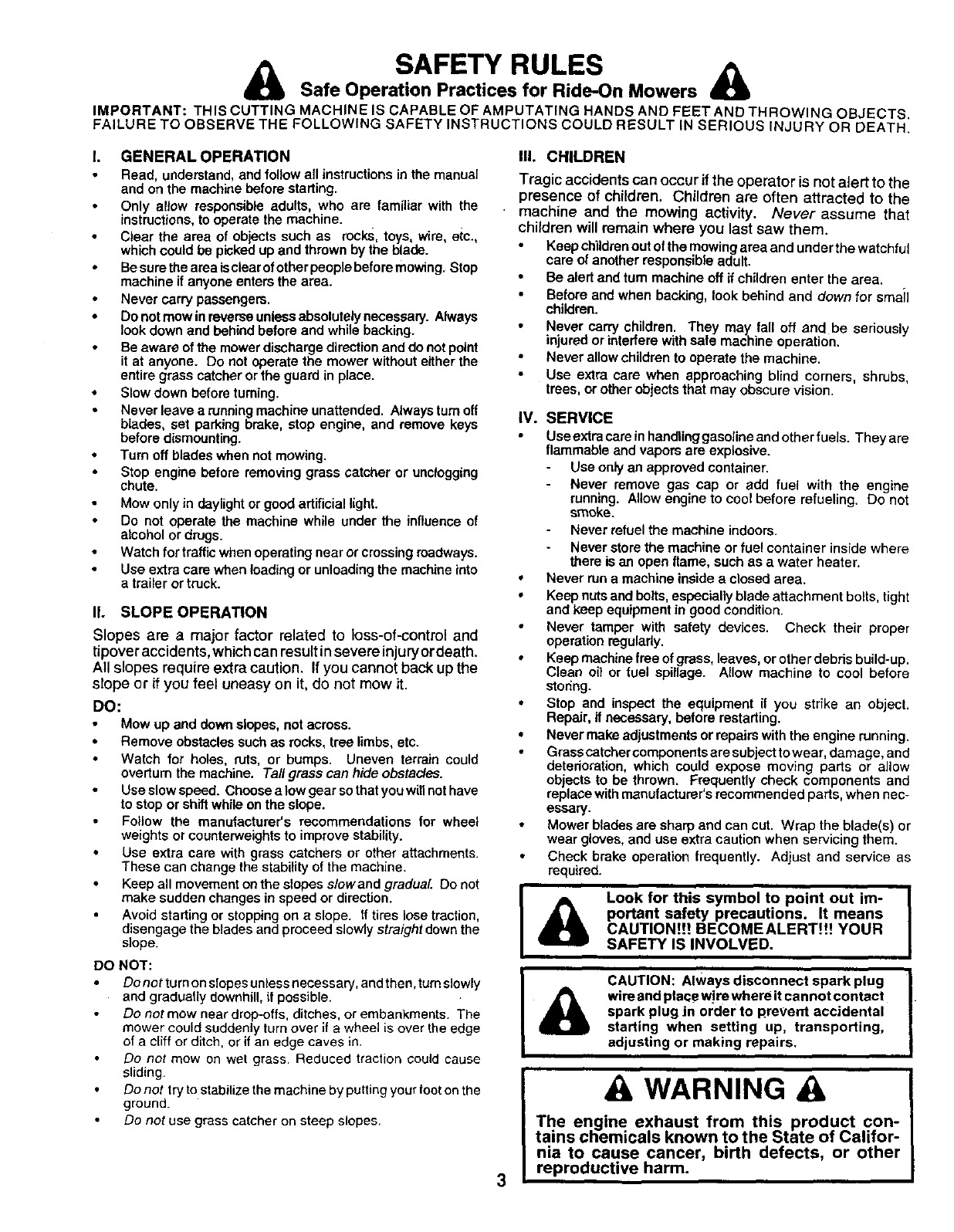
SAFETY RULES A
Safe Operation Practices for Ride-On Mowers
IMPORTANT: THIS CUTTING MACHINE IS CAPABLE OF AMPUTATING HANDS AND FEET AND THROWING OBJECTS.
FAILURE TO OBSERVE THE FOLLOWING SAFETY INSTRUCTIONS COULD RESULT iN SERIOUS INJURY OR DEATH.
I. GENERAL OPERATION
Read, understand, and follow all instructions in the manual
and on the machine before starting,
Only allow responsible adults, who are familiar with the
instructions, to operate the machine.
Clear the area of obiects such as rocks, toys, wire, etc.,
which could be picked up and thrown by the blade.
Be sure the area isclear ofother people before mowing. Stop
machine if anyone enters the area.
Never carry passengers.
• Do not mow in reverse unless absolutely necessary. Always
look down and behind before and while backing.
Be aware of the mower discharge direction and do not point
it at anyone. Do not operate the mower without either the
entire grass catcher or the guard in place.
•Slow down before turning.
• Never leave arunning machine unattended. Always turn off
blades, set parking brake, stop engine, and remove keys
before dismounting.
• Turn off blades when not mowing.
Stop engine before removing grass catcher or unclogging
chute.
Mow only in daylight or good artificial light.
Do not operate the machine while under the influence of
alcohol or drugs.
Watch for traffis when operating near or crossing roadways.
Use extra care when loading or unloading the machine into
a trailer or truck.
II. SLOPE OPERATION
Slopes are a major factor related to loss-of-control and
tipover accidents, which can result in severe injury ordeath.
All slopes require extra caution. If you cannot back up the
slope or if you feel uneasy on it, do not mow it.
DO:
Mow up and down slopes, nat across.
• Remove obstacles such as rocks, tree limbs, etc.
Watch for holes, ruts, or bumps. Uneven terra}n could
overturn the machine. Tall grass can hide obstacles.
Use slow speed. Choose a low gear so that you will not have
to stop or shift while on the slope.
Follow the manufacturer's recommendations for wheel
weights or counterweights to improve stability.
• Use extra care with grass catchers or other attachments.
These can change the stability of the machine.
• Keep all movement on the slopes slow and gradual Do not
make sudden changes in speed or direction.
Avoid starting or stopping on a slope. If tires lose traction,
disengage the blades and proceed slowly straight down the
slope.
DO NOT:
Do not turn on slopes unless necessary, and then, turn slowly
and gradually downhill, if possible.
Do not mow near drop-offs, ditches, or embankments. The
mower could suddenly turn over if awheel is over the edge
of a cliff or ditch, or if an edge caves in.
Do not mow on wet grass• Reduced traction could cause
sliding•
Do not try to stabilize the machine by putting your foot on the
ground.
Do not use grass catcher on steep slopes.
III. CHILDREN
Tragic accidents can occur if the operator is not alert to the
presence of children. Children are often attracted to the
• machine and the mowing activity. Never assume that
children will remain where you last saw them.
Keep children out of the mowing area and under the watchful
care of another responsible adult.
•Be alert and turn machine off if children enter the area.
Before and when backing, look behind and down for smail
children.
Never carry children. They may fall off and be seriously
injured or interfere with safe machine operation.
Never allow children to operate the machine.
Use extra care when approaching blind corners, shrubs,
trees, or other objects that may obscure vision.
IV. SERVICE
Use extra care in handling gasoline and other fuels. They are
flammable and vapors are explosive.
Use only an approved container.
Never remove gas cap or add fuel with the engine
running. Allow engine to cool before refueling. Do not
smoke.
Never refuel the machine indoors.
Never store the machine or fuel container inside where
there is an open flame, such as a water heater.
•Never run a machine inside a closed area.
• Keep nuts and bolts, especially blade attachment bolls, tight
and keep equipment in good condition.
• Never tamper with safety devices. Check their proper
operation regularly.
• Keep machine free of grass, leaves, or other debris build-up.
Clean o{1or fuel spillage. Allow machine to cool before
storing.
• Stop and inspect the equipment if you strike an object.
Repair, if necessary, before restarting.
• Never make adjustments or repairs with the engine running.
Grass catcher components are subject to wear, damage, and
detedoration, which could expose moving parts or allow
objects to be thrown. Frequently check components and
replace with manufacturer's recommended pads, when nec-
essary.
•Mower blades are sharp and can cut. Wrap the blade(s) or
wear gloves, and use extra caution when servicing them.
Check brake operation frequently. Adjust and service as
required.
&Look for this symbol to point out im-
portant safety precautions. It means
CAUTION!!! BECOMEALERT!!! YOUR
SAFETY IS INVOLVED.
3
&CAUTION: Always disconnect spark plug
wire and place w!re where itcannot contact I "
spark plug Jn order to preVent accidental
starting when setting up, transporting,
adjusting or making repairs.
A, WARNING
The engine exhaust from this product con-
tains chemicals known to the State of Califor-
nia to cause cancer, birth defects, or other
reproductive harm.

TABLE OF CONTENTS
SAFETY RULES ............................................................ 3
PRODUCT SPECIFICATIONS ...................................... 2
CUSTOMER RESPONSIBILITIES ..................... 2, 14-18
WARRANTY .................................................................. 2
ASSEMBLY ................................................................ 6-8
OPERATION ............................................................. 9-13
MAINTENANCE SCHEDULE ...................................... 14
SERVICE AND ADJUSTMENTS ............................ 19-24
STORAGE ................................................................... 25
TROUBLESHOOTING ............................................ 26-27
REPAIR PARTS -TRACTOR ................................. 30-47
REPAIR PARTS -ENGINE .................................... 48-53
PARTS ORDERING/SERVICE ................ BACK COVER
INDEX A
Adjustments:
Brake ............................................ 21
Carburetor .................................... 24
Mower
Front-To-Back .................... :.... 20
Side-To-Side ........................... 20
Throttle Control Cable .................. 23
Air Filter, Engine .................................. 17
Air Screen, Engine .............................. !7
Assembly ............................................ 6-8
B
Battery:
Charging ........................................ 7
Cleaning ....................................... 16
installation ...................................... 8
Levels ........................................ 7,16
Preparation .................................... 7
Starting with Weak Battery ........... 22
Storage ........................................ 25
Terminals ..................................... 16
Belt:
Motion Drive
RemovaVReplacement ............ 21
Mower Belt(s)
Removal/Replacement ............ 21
Blade:
Sharpening ................................... 15
Replacement ................................ 15
Brake Adjustment ................................ 21
C
Carburetor Adjustment ........................ 24
Controls, Tractor ................................. 10
Customer Responsibilities .............. 14-18
Engine:
Air Filter .................................... 17
Air Screen ................................ 17
Cooling Fins ............................. 17
Engine Oil ........................... 12,16
Fuel Filter ................................. 18
Spark Plug(s) ........................... 18
Tractor:
Battery ...................................... 16
Blade ........................................ 15
Lubrication Chart ...................... 14
Maintenance Schedule ............ 14
Tire Care .......................... 7,15,22
Transaxle ................................. 16
Cutting Height, Mower ......................... 11
E
Electrical:
Interlseks and Relays ................... 23
Schematic .................................... 29
Widng Diagram ............................ 30
Engine:
Air Filter ........................................ 17
Air Screen .................................... 17
Cooling Fins ................................. 17
Oil Change ................................... 16
Oil Level ....................................... 12
Oil Type ................................... 12,16
Preparation .................................. 12
Repair Parts ............................ 48-53
Starting ......................................... 13
Storage ........................................ 25
F
Filter:
Air Filter ........................................ 17
Fuel .............................................. 18
Fuel:
Type ............................................. 12
Storage ........................................ 25
Fuse .................................................... 23
H
HoodRemoval/installation ..................23
L
Leveling Mower Deck .......................... 20
Lubrication:
Chart ............................................ 14
Engine .......................................... 16
M
Maintenance Schedule ....................... 14
Mower:
Adjustment, Front-to-Back ........... 20
Adjustment, Side-to-Side ............. 20
Blade Replacement ...................... 15
Blade Sharpening ........................ 15
Cutting Height .............................. t 1
Installation .................................... 19
Operation ..................................... 12
Removal ;...................................... 19
Mowing Tips ........................................ 13
Muffler ................................................. 18
Spark Arrester ........................... 2,40
O
Oil:
Cold Weather Conditions ........ 12,16
Engine ......................... :._.............. 16
Storage ........................................ 26
Operation ......................................... 9-13
Operating Mower ................................. 12
Options:
Accessories .................................... 2
Spark An'ester ........................... 2,40
P
Parking Brake ................................. 10-11
Parts Bag .............................................. 5
Parts, Replacement/Repair ............ 30-47
Product Specifications ........................... 2
R
Repair Parts ................................... 30-47
S
Safety Rules .......................................... 3
Seat ....................................................... 7
Service and Adjustments ............... 19-24
Carburetor .................................... 24
Fuse ............................................. 23
Hood Removal/Installation ........... 23
Motion Drive Belt
Removal/Replacement ............ 21
Mower Belt(s)
Removal/Replacement ............ 21
Mower Adjustment
Front-to-Back .......................... 20
Side-to-Side ............................ 20
Mower Removal/Installation ......... 19
Tire Care .............................. 7,15,22
Slope Guide Sheet .............................. 55
Spark Plug(s) ...................................... 18
Specifications ........................................ 2
Starting the Engine ........................ 12-13
Steering Wheel ................................. 6,22
Stopping the Tractor ............................ ! 1
Storage ................................................ 25
- m
Throttle Control Cable Adjustment ...... 23
Tires ............................................ 7,15,22
Troubleshooting Char_ .................... 26-27
Transaxle ....................................... 46-47
4
W
Warranty ................................................ 2
Wiring Diagram ................................... 30
Wiring Schematic ................................ 29
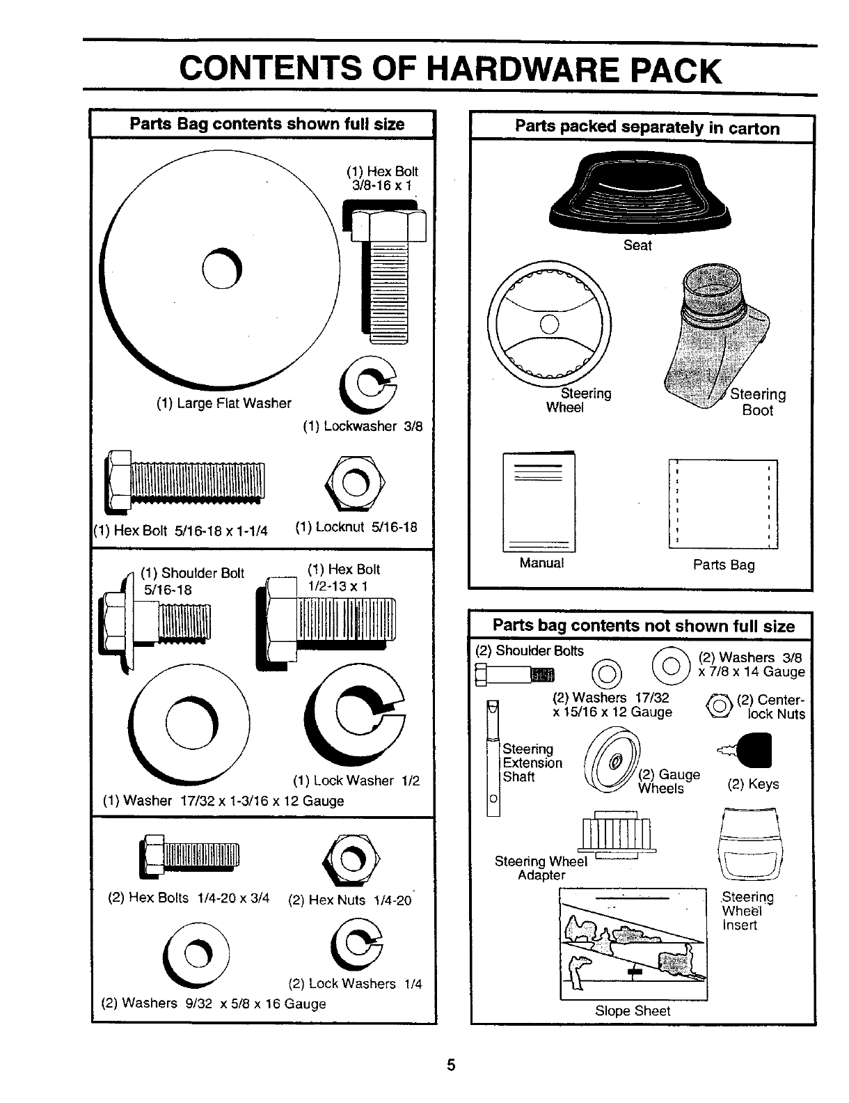
CONTENTS OF HARDWARE PACK
Parts Bag contents shown full size
©
(1) Large Flat Washer
(1) Hex Bolt 5/16-18 x 1-1/4
(1) Lockwasher 3/8
Q
(1) Locknut 5/16-18
(1) Shoulder Bolt
_1 5/16-18
©
(1) Hex Bolt
1/2-13 x 1
(1) LockWasher 1/2
(1) Washer 17/32 x 1-3/16 x 12 Gauge
(2) Hex Bolts 1/4-20 x 3/4 (2) Hex Nuts !/4-20
(2) Lock Washers 114
(2) Washers 9/32 x 5/8 x 16 Gauge
Parts packed separately in carton
Wheel
Seat
Steering
Boot
Manual Parts Bag
Parts bag contents not shown full size
(2) Shoulder Bolts _ (2) Washers 3/8
_(x2 5W€_ x 7/8 x14 Gauge
I17/32 (2) Center-
Gauge lock Nuts
.Steering //_ <3_
IIExtension I// (_///
IIShaft _,{_ -/7/(2) Gauge
U _ Wheels (2) Keys
i i
Steering Wheel
Adapter
Steering
Wheel
Insert
Slope Sheet
5
ASSEMBLY
Your new tractor has been assembled at the factory with exception of those parts left unassembled for shipping purposes.
To ensure safe and proper operation of your tractor all parts and hardware you assemble must be tightened securely. Use
the correct tools as necessary to insure proper tightness.
TOOLS REQUIRED FOR ASSEMBLY
A socket wrench set will make assembly easier. Standard
wrench sizes are listed.
(1) 3/4" Socket w/drive rachet Utility knife
(2) 7/16" wrenches Tire pressure gauge
(2) 1/2" wrench
(1) 9/16" wrench
When right or left hand is mentioned in this manual, it
means when you are in the operating position (seated
behind the steering wheel).
TO REMOVE TRACTOR FROM CARTON
UNPACK CARTON
•Remove all accessible loose parts and parts cartons
from carton (See page 5).
•Cut, from top to bottom, along lines on all four corners
of carton, and lay panels flat.
• Check for any additional loose parts or cartons and
remove.
BEFORE ROLLING TRACTOR OFF SKID
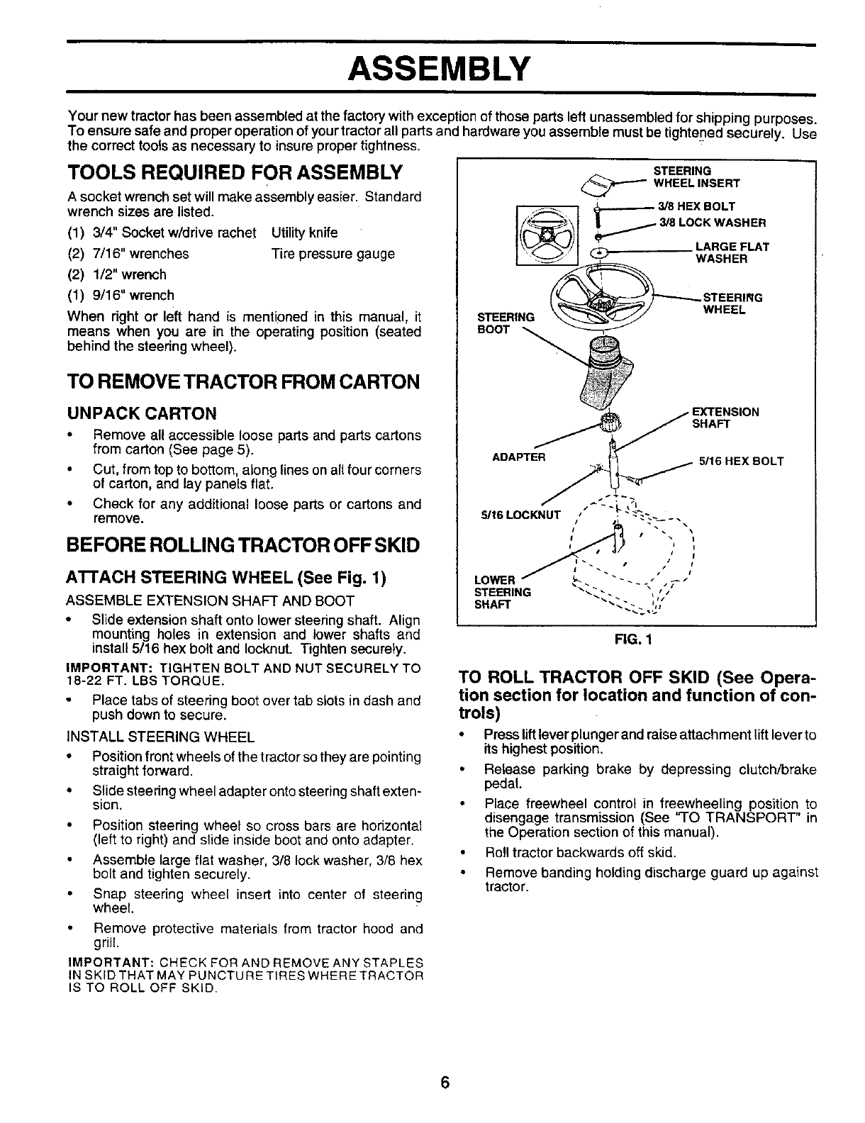
A'I-rACH STEERING WHEEL (See Fig. 1)
ASSEMBLE EXTENSION SHAFT AND BOOT
• Slide extension shaft onto lower steering shaft. Align
mounting holes in extension and lower shafts and
install 5/16 hex bolt and Iocknut. Tighten securely.
IMPORTANT: TIGHTEN BOLT AND NUT SECURELY TO
18-22 FT. LBS TORQUE.
Place tabs of steering boot over tab slots in dash and
push down to secure.
INSTALL STEERING WHEEL
•Position front wheels of the tractor so they are pointing
straight forward.
• Slide staedng wheel adapter onto steering shaft exten-
sion.
Position steering wheel so cross bars are horizontal
(left to right) and slide inside boot and onto adapter.
Assemble large flat washer, 3/8 lock washer, 3/8 hex
bolt and tighten securely.
Snap steering wheel insert into center of steering
wheel.
• Remove protective materials from tractor hood and
grill.
IMPORTANT: CHECK FOR AND REMOVE ANY STAPLES
IN SKID THAT MAY PUNCTURE TIRES WHERE TRACTOR
IS TO ROLL OFF SKID.
SHAFT
ADAPTER 5/16 HEX BOLT
FIG. 1
TO ROLL TRACTOR OFF SKID (See Opera-
tion section for location and function of con-
trois)
•Press liftlever plunger and raise attachment liftlever to
its highest position,
•Release parking brake by depressing clutch/brake
pedal.
Place freewheel control in freewheeling position to
disengage transmission (See "TO TRANSPORT" in
the Operation section of this manual).
Roll tractor backwards off skid.
Remove banding holding discharge guard up against
tractor.
6
ASSEMBLY
HOW TO SET UP YOUR TRACTOR
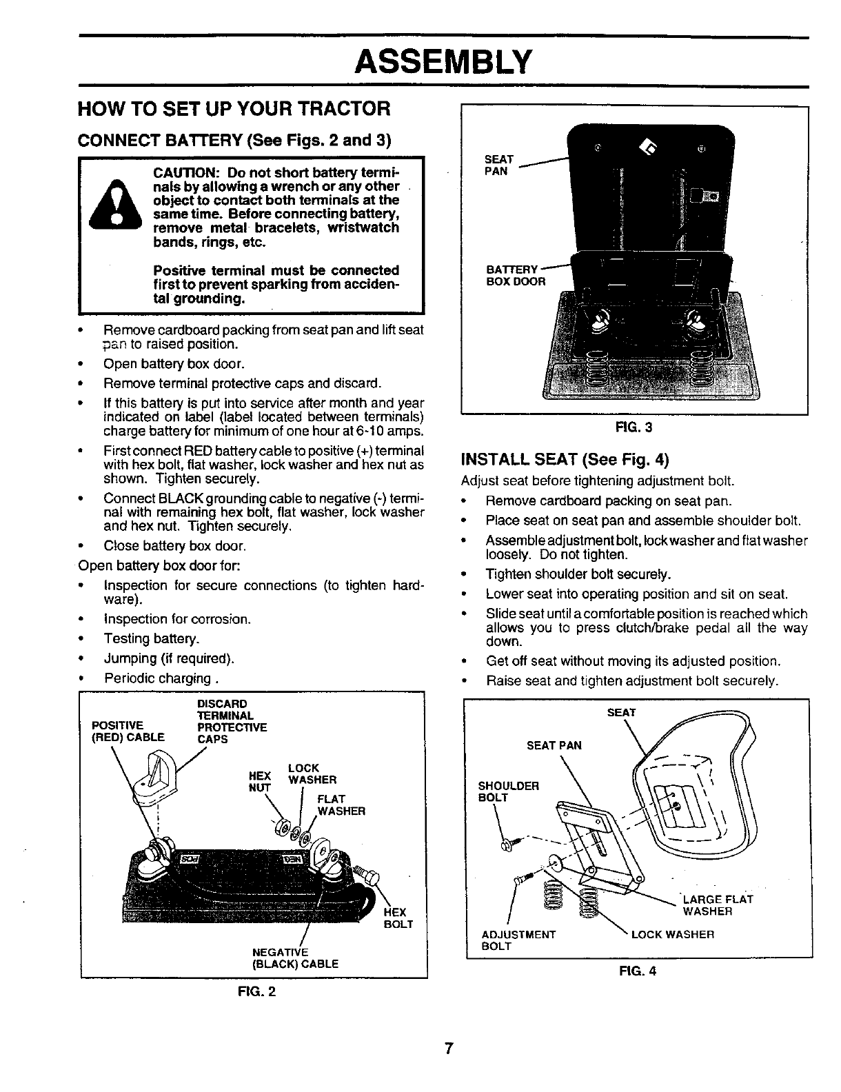
CONNECT BATTERY (See Figs. 2 and 3)
CAUTION: Do not short battery termi-
nals by allowing a wrench or any other .
object to contact both terminals at the
same time. Before connecting battery,
remove metal bracelets, wristwatch
bands, rings, etc.
Positive terminal must be connected
first to prevent sparking from acciden-
tal grounding.
•Remove cardboard packing from seat pan and lift seat
;an to raised position.
• Open battery box door.
• Remove terminal protective caps and discard.
• If this battery is put into service after month and year
indicated on label (label located between terminals)
charge battery for minimum of one hour at 6-10 amps.
First connect RED battery cable to pesitive (+) terminal
with hex bolt, flat washer, lock washer and hex nut as
shown. Tighten securely.
• Connect BLACK grounding cable to negative (-) termi-
nal with remaining hex bolt, flat washer, lock washer
and hex nut. Tighten securely.
• Close battery box door.
Open battery box door for:
• inspection for secure connections (to tighten hard-
ware).
• inspection for corrosion.
• Testing battery.
• Jumping (if required).
•Periodic charging.
DISCARD
TERMINAL
POSITIVE PROTECTIVE
(RED) CABLE CAPS
LOCK
HEX WASHER
NUT FLAT
WASHER
BeLT
NEGATIVE
(BLACK) CABLE
FIG. 2
SEAT
PAN
BOX DOOR
RG. 3
INSTALL SEAT (See Fig. 4)
Adjust seat before tightening adjustment bolt.
Remove cardboard packing on seat pan.
• Place seat on seat pan and assemble shoulder bolt.
• Assemble adjustment bolt, lock washer and flat washer
loosely. Do not tighten.
•Tighten shoulder bolt securely.
• Lower seat into operating position and sit on seat.
• Slide seat until a comfortable position is reached which
allows you to press clutch/brake pedal all the way
down.
• Get off seat without moving its adjusted position.
• Raise seat and tighten adjustment bolt securely.
SEAT
SEAT PAN
SHOULDER
BOLT
ADJUSTMENT
BOLT
"LARGE FLAT
WASHER
LOCK WASHER
FIG. 4
7

ASSEMBLY
CHECK TIRE PRESSURE ,/'CHECKLIST
The tires onyour tractor were overinflated at the factory for
shipping purposes. Correct tire pressure is important for
best cutting performance.
•Reduce tire pressure to PSI shown in =PRODUCT
SPECIFICATIONS" on page 2 of this manual.
CHECK DECK LEVELNESS
For best cutting results, mower housingshould be properly
leveled. See "TO LEVEL MOWER HOUSING" in the
Service and Adjustments section of this manual.
CHECK FOR PROPER POSITION OF ALL
BELTS
See the figures that are shown for replacing motion and
mower blade drive belts in the Service and Adjustments
section of this manual. Verify that the Pelts are muted
correctly.
CHECK BRAKE SYSTEM
After you learn how to operate your tractor, check to see
that the brake is properly adjusted. See "TO ADJUST
BRAKE" in the Service and Adjustments section of this
manual.
ASSEMBLE GAUGE WHEELS TO MOWER
DECK (See Fig. 5)
The gauge wheels are designed to keep the mower deck in
proper position when operating mower. Be sure they are
properly adjusted to ensure optimum mower performance.
• Assemble gauge wheels with tractor on a flat level
surface.
• Adjust mower to desired cutting height (See "TO AD-
JUST MOWER CUFFING HEIGHT" in the Operation
section of this manual).
• With mower in desired height of cut position, gauge
wheels should be assembled so they are slightly off the
ground. Install gauge wheel in appropriate hole with
shoulder bolt, 17/32 washer, 3/8 washer, and 3/8-16
Iocknut and tighten securely.
• Repeat for opposite side installing gauge wheel in
same adjustment hole.
BEFORE YOU OPERATE AND ENJOY YOUR NEW
TRACTOR, WE WISH TO ASSURE THAT YOU RECEIVE
THE BEST PERFORMANCE AND SA TISFA CTION FROM
THIS QUALITY PRODUCT.
PLEASE REVIEW THE FOLLOWING CHECKLIST:
,/ All assembly instructions have been completed.
,_ No remaining loose parts in carton.
•" Battery is properly prepared and charged. (Minimum
1 hour at 6 amps).
4" Seat is adjusted comfortably and tightened" securely.
,/ Alltires are properly inflated. (For shipping purposes,
the tires were overinflated at the factory).
,/ Be sure mower deck is properly leveled side-to-side/
front-to-rear for best cutting results. (Tires must be
propedy inflated for leveling).
#" Check mower and drive belts. Be sure they are routed
properly around pulleys and inside all belt keepers.
,/ Check wiring. See that all connections are still secure
and wires are propedy clamped.
,/ Before driving tractor, be sure freewheel control is in
drive position.
WHILE LEARNING HOW TO USE YOUR TRACTOR, PA Y
EXTRA ATTENTION TO THE FOLLOWING IMPORTANT
ITEMS:
,7 Engine oil is at proper level.
,/ Fuel tank is filled with fresh, clean, regular unleaded
gasoline.
_/ Become familiar with all controls - their location and
function. Operate them before you start the engine.
,/ Be sure brake system is in safe operating condition.
,/ It is important to purge the transmission before operat-
ing your tractor for the first time. Follow proper starting
and transmission purging instructions(See "TO START
ENGINE" and "PURGE TRANSMISSION" in Opera-
tion section of this manual).
GAUGE
WHEEL
BRACKET
3/8-16 \\
LOCKNUT
318 WASHER 17132 WASHER
'3_.t_ _- SHOULDER
_'_ BOLT
FIG. 5
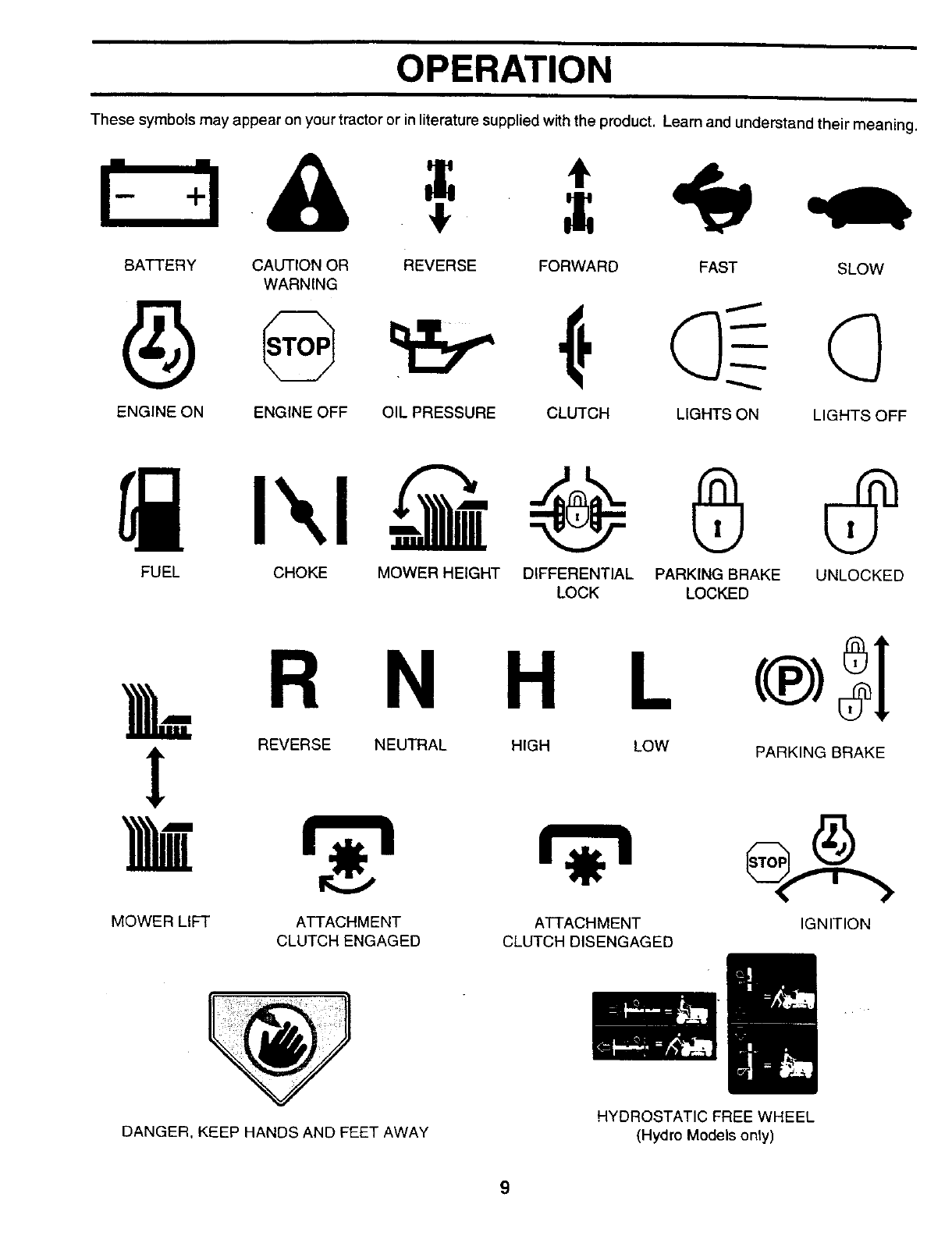
OPERATION
These symbols may appear on your tractor or inliterature supplied withthe product. Learn and understand their meaning.
BATTERY CAUTION OR REVERSE FORWARD FAST SLOW
WARNING
ENGINE ON ENGINE OFF OIL PRESSURE CLUTCH LIGHTS ON LIGHTS OFF
0@
FUEL CHOKE MOWER HEIGHT DIFFERENTIAL PARKING BRAKE UNLOCKED
LOCK LOCKED
&= R
REVERSE
!
MOWER LIFT
N H L
NEUTRAL HIGH LOW
ATTACHMENT
CLUTCH ENGAGED
ATTACHMENT
CLUTCH DISENGAGED
PARKING BRAKE
IGNITION
DANGER, KEEP HANDS AND FEET AWAY HYDROSTATIC FREE WHEEL
(Hydro Models only)
9
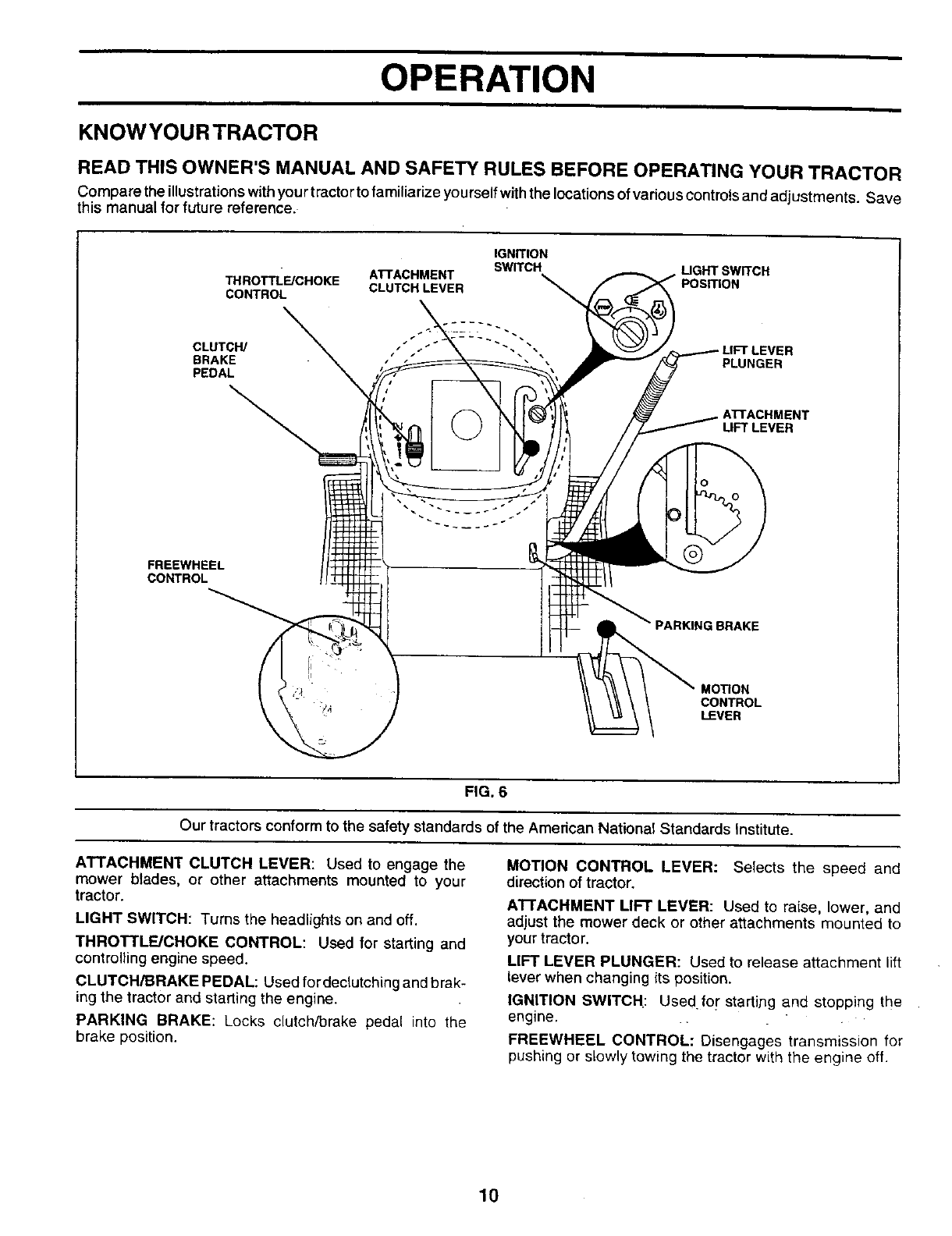
OPERATION
KNOWYOURTRACTOR
READ THIS OWNER'S MANUAL AND SAFETY RULES BEFORE OPERATING YOUR TRACTOR
Compare the illustrationswithyour tractor tofamiliarize yourself withthe locations of vadous controls and adjustments. Save
this manual for future reference.
THROTTL_CHOKE ATrACHMENT
CONTROL CLUTCH LEVER
CLUTCH/ _,"
BRAKE ,"
PEDAL
IGNITION
SWITCH UGHT SWITCH
ER
PLUNGER
• AI-rACHMENT
LIFT LEVER
FREEWHEEL
CONTROL
MORON
CONTROL
LEVER
FIG. 6
Our tractors conform to the safety standards of the American National Standards Institute.
ATTACHMENT CLUTCH LEVER: Used to engage the
mower blades, or other attachments mounted to your
tractor.
LIGHT SWITCH: Turns the headlights on and off.
THROTTLE/CHOKE CONTROL: Used for starting and
controlling engine speed.
CLUTCH/BRAKE PEDAL: Used fordeclutching and brak-
ing the tractor and starting the engine.
PARKING BRAKE: Locks clutch/brake pedal into the
brake position.
MOTION CONTROL LEVER: Selects the speed and
direction of tractor.
ATTACHMENT LIFT LEVER: Used to raise, lower, and
adjust the mower deck or other attachments mounted to
your tractor.
LIFT LEVER PLUNGER: Used to release attachment lift
lever when changing its position.
IGNITION SWITCH: Used.for" starti,ng and stopping the
engine.
FREEWHEEL CONTROL: Disengages transmission for
pushing or slowly towing the tractor with the engine off.
10
OPERATION
The operation of any tractor can result in foreign objects thrown into the eyes, which
can result in severe eye damage. Always wear safety glasses or eye shields while
operating your tractor or performing any adjustments or repairs. We recommend a wide
vision safety mask over the spectacles or standard safety glasses.
HOW TO USE YOUR TRACTOR
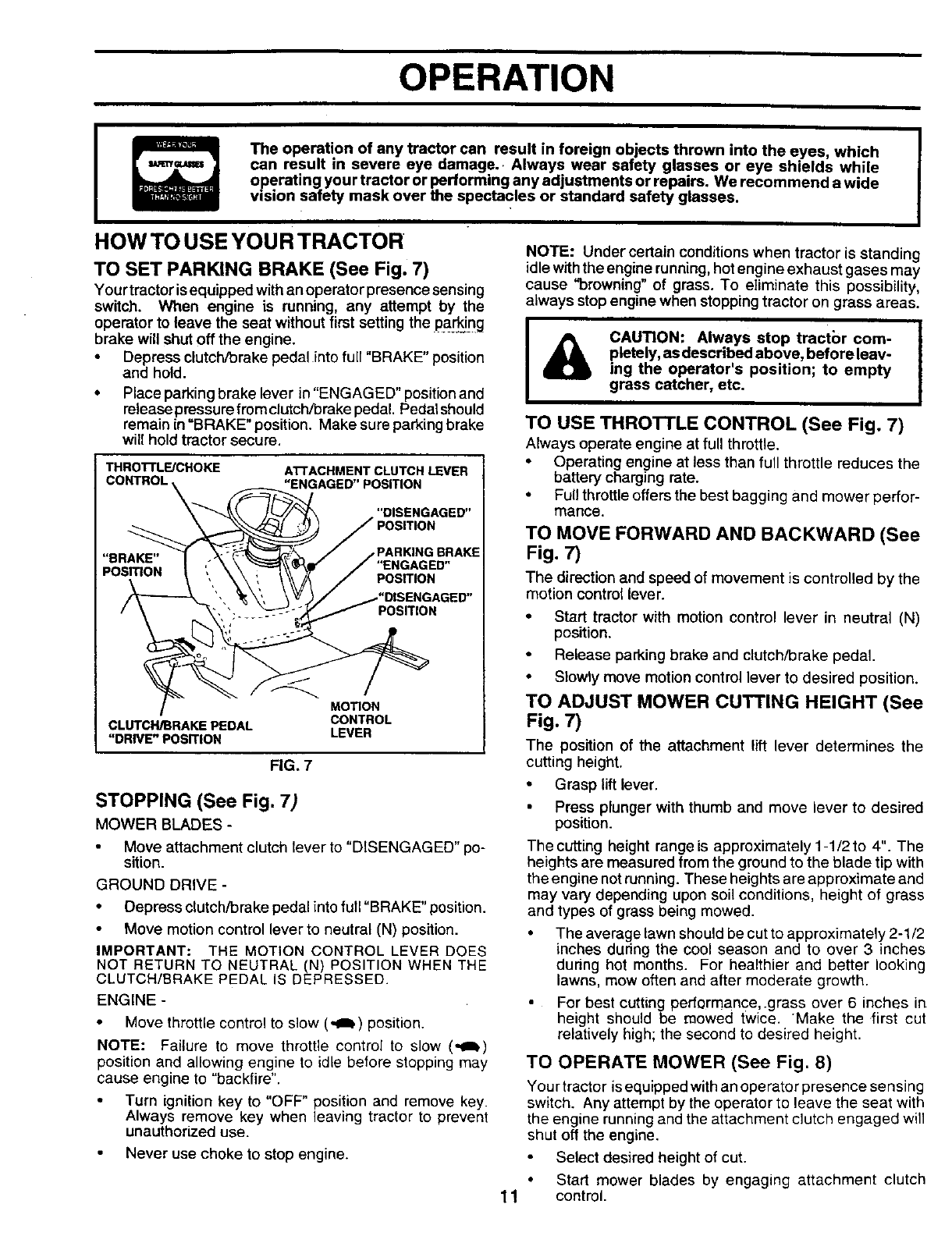
TO SET PARKING BRAKE (See Fig. 7)
Your tractor isequipped with an operator presence sensing
switch. When engine is running, any attempt by the
operator to leave the seat without first setting the pa_ing
brake will shut off the engine.
•Depress clutch/brake pedal into full "BRAKE" position
and hold.
•Place parking brake lever in "ENGAGED" position and
release pressure from clutch/brake pedal. Pedalshould
remain in =BRAKE" position. Make sure parking brake
will hold tractor secure.
THROI-rLE/CHOKE
CONTROL
"BRAKE"_
CLUTCF_RAKEPEDAL
"DRIVE" POSITION
AI-rACHMENT CLUTCH LEVER
"ENGAGED" PO,_TION
"_._ DISENGAGED"
_/POSITION
\\\ ", \\\!A /Posrr,oN
"'_\', \_)/ _"DISENGAGED"
", '. _-POSITION
/
MOTION
CONTROL
LEVER
FIG. 7
STOPPING (See Fig. 7)
MOWER BLADES-
Move attachment clutch lever to "DISENGAGED" po-
sition.
GROUND DRIVE-
• Depress clutch/brake pedal into full "BRAKE" position.
Move motion control lever to neutral (N) position.
IMPORTANT: THE MOTION CONTROL LEVER DOES
NOT RETURN TO NEUTRAL (N) POSITION WHEN THE
CLUTCH/BRAKE PEDAL IS DEPRESSED.
ENGINE-
• Move throttle control to slow (,,a_) position.
NOTE: Failure to move throttle control to slow (,,g_)
position and allowing engine to idle before stopping may
cause engine to "backfire".
• Turn ignition key to "OFF" position and remove key.
Always remove key when leaving tractor to prevent
unauthorized use.
Never use choke to stop engine.
11
NOTE: Under certain conditions when tractor is standing
idle wtth the engine running,hotengine exhaust gases may
cause "browning" of grass. To eliminate this possibility,
always stopengine when stopping tractor on grass areas.
I!
CAUTION: Always stop tractbr com- ]
pletely, as described above, before leav° I
ing the operator's position; to empty
grass catcher, etc.
TO USE THROTTLE CONTROL (See Fig, 7)
Always operate engine at full throttle.
• Operating engine at less than full throttle reduces the
battery charging rate.
•Fullthrottle offers the best bagging and mower perfor-
mance.
TO MOVE FORWARD AND BACKWARD (See
Fig. 7)
The direction and speed of movement is controlled by the
motion control lever.
• Start tractor with motion control lever in neutral (N)
position.
• Release parking brake and clutch/brake pedal.
• Slowly move motion control lever to desired position.
TO ADJUST MOWER CUTTING HEIGHT (See
Fig. 7)
The position of the attachment lift lever determines the
cutting height.
• Grasp lift lever.
Press plunger with thumb and move lever to desired
position.
The cutting height range is approximately 1-1/2 to 4". The
heights are measured from the ground to the blade tip with
the engine not running. These heights are approximate and
may vary depending upon soil conditions, height of grass
and types of grass being mowed.
•The average lawn should be cut to approximately 2-1/2
inches during the cool season and to over 3 inches
dunng hot months. For healthier and better looking
lawns, mow often and after moderate growth.
For best cutting performance,.grass over 6 inches in
height should be mowed twice. Make the first cut
relatively high; the second to desired height.
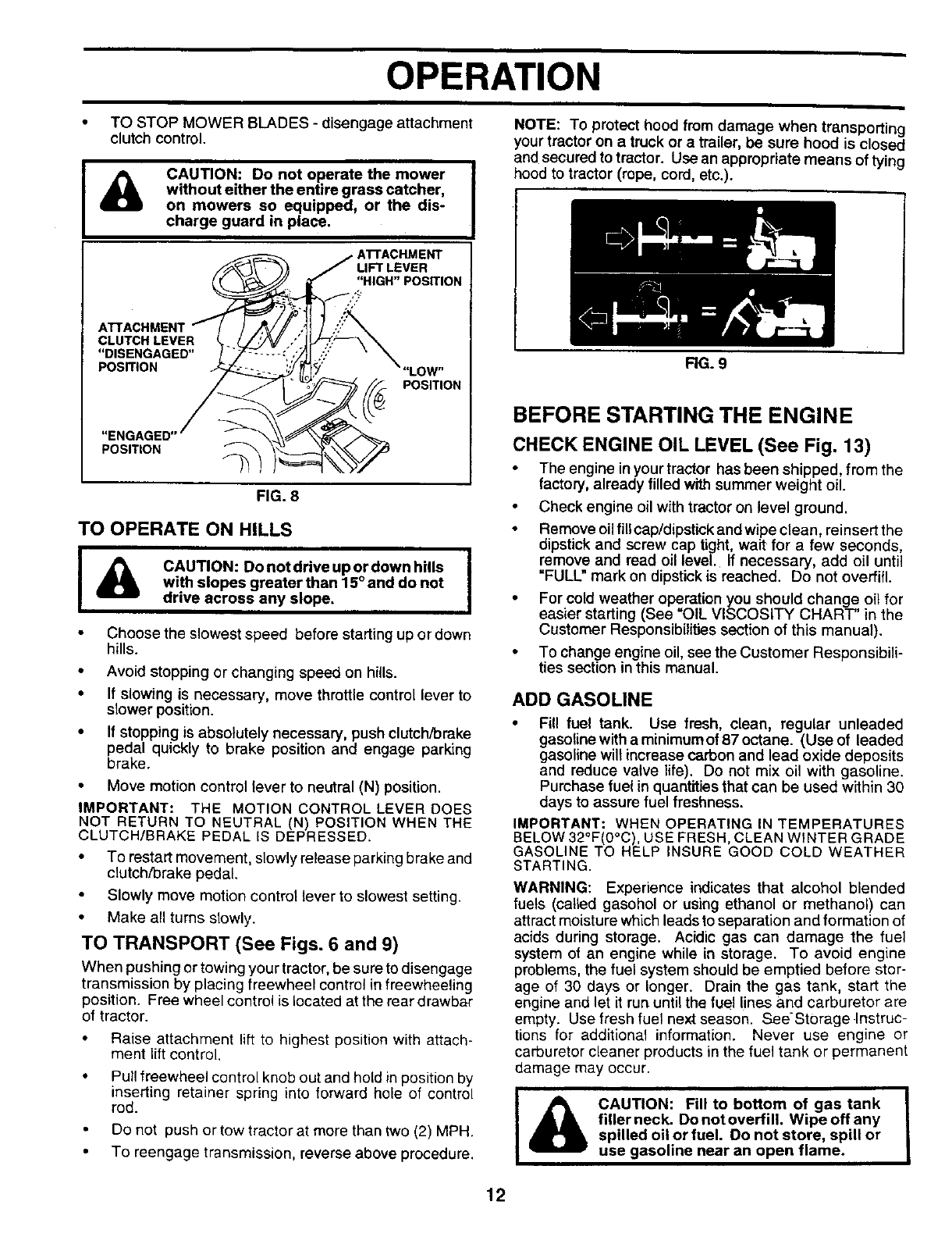
TO OPERATE MOWER (See Fig. 8)
Your tractor is equipped withan operator presence sensing
switch. Any attempt by the operator to leave the seat with
the engine running and the attachment clutch engaged will
shut off the engine.
Select desired height of cut.
• Start mower blades by engaging attachment clutch
control.
OPERATION
•TO STOP MOWER BLADES -disengage attachment
clutch control.
CAUTION: Do not operate the mower
without either the entire grass catcher,
on mowers so equipped, or the dis-
charge guard in place.
LIFT LEVER
"HIGH" POSITION
CLUTCH LEVER
"DISENGAGED"
POSITION LOW"
POSITION
"ENGAGED
POSITION
FIG. 8
TO OPERATE ON HILLS
I_CAUTION: Donotdriveupordownhills !
with slopes greater than 15° and do not
drive across any slope,
Choose the slowest speed before starting up or down
hills.
• Avoid stopping or changing speed on hills.
• If slowing is necessary, move throttle control lever to
slower position.
• If stopping is absolutely necessary, push clutch/brake
pedal quickly to brake position and engage parldng
brake.
• Move motion control lever to neutral (N) position.
IMPORTANT: THE MOTION CONTROL LEVER DOES
NOT RETURN TO NEUTRAL (N) POSITION WHEN THE
CLUTCH/BRAKE PEDAL IS DEPRESSED.
• To restart movement, slowly release parking brake and
clutch/brake pedal.
Slowly move motion control lever to slowest setting.
• Make all turns slowly.
TO TRANSPORT (See Figs. 6 and 9)
When pushingor towing your tractor, he sure to disengage
transmission by placing freewheel control in freewheeling
position. Free wheel control is located at the rear drawbar
of tractor.
• Raise attachment lift to highest position with attach-
ment liftcontrol.
• Pull freewheel control knob out and hold in position by
inserting retainer spring into forward hole of control
rod.
Do not push or tow tractor at more than two (2) MPH.
• To reengage transmission, reverse above procedure.
NOTE: To protect hood from damage when transporting
your tractor on a truck or atrailer, be sure hood is closed
and secured to tractor. Use an appropriate means of tying
hood to tractor (rope, cord, etc.).
RG. 9
BEFORE STARTING THE ENGINE
CHECK ENGINE OIL LEVEL (See Fig. 13)
The engine in your tractor has been shipped, from the
factory, already filled with summer weight oil.
Check engine oil with tractor on level ground.
•Remove oil fill cap/dipsf_ckand wipe clean, reinsert the
dipstick and screw cap tight, wait for afew seconds,
remove and read oil level. If necessary, add oil until
=FULL" mark on dipstickis reached. Do not overfill.
•For cold weather operation you should change oil for
easier starting (See "OIL VISCOSITY CHART" in the
Customer Responsibilitiessection of this manual).
•To change engine oil, see the Customer Responsibili-
ties section in this manual.
ADD GASOLINE
• Fill fuel tank. Use fresh, clean, regular unleaded
gasoline with a minimum of 87 octane. (Use of leaded
gasoline will increase carbon and lead oxide deposits
and reduce valve life). Do not mix oil with gasoline.
Purchase fuel in quantities that can be used within 30
days to assure fuel freshness.
IMPORTANT: WHEN OPERATING IN TEMPERATURES
BELOW 32°F(0°C), USE FRESH, CLEAN WINTER GRADE
GASOLINE TO HELP INSURE GOOD COLD WEATHER
STARTING.
WARNING: Experience indicates that alcohol blended
fuels (called gasohol or using ethanol or methanol) can
attract moisture which leads to separation and formation of
acids during storage. Acidic gas can damage the fuel
system of an engine while in storage. To avoid engine
problems, the fuel system should be emptied before stor-
age of 30 days or longer. Drain the gas tank, start the
engine and let it run until the fuel lines and carburetor are
empty. Use fresh fuel next season. See'Storage .Instruc-
tions for additional information. Never use engine or
carburetor cleaner products in the fuel tank or permanent
damage may occur.
I&!
CAUTION: Fill to bottom of gas tank |
filler neck. Do not overfin. Wipe off any I
spilled oil or fuel. Do not store, spill or
use gasoline near an open flame.
12
OPERATION
PURGE TRANSMISSIONTO START ENGINE (See Fig. 7)
When starting the engine for the first time or if the engine
has run out of fuel, it will take extra cranking time to move
fuel from the tank to the engine,
• Be sure freewheel control is in the transmission en-
gaged position.
• Sit on seat in operating position, depress Clutch/brake
pedal and set paridng brake.
• Place motion control lever in neutral (N) position.
• Move attachment clutch to "DISENGAGED" position.
• Move throttle control to choke (N) position.
Note: Before starting, read the warm and cold starting
procedures below.
Insertkeyinto ignition and turn keyclockwise to "START"
position and release key as soon as engine starts. Do
not run starter continuously for more than fifteen sec-
onds per minute. If the engine does not start after
several attempts, move throttle control to fast (,_)
position, wait a few minutes and try again. If engine still
does not start, move the throttle control back to the
choke (N) position and retry.
WARM WEATHER STARTING (50° F and above)
• When engine starts, move thethrottle controltothe fast
(,_) position.
• The attachments and ground drive can now be used. If
the engine does not accept the load, restart the engine
and allow it to warm up for one minute using the choke
as described above.
COLD WEATHER STARTING ( 50° F and below)
• When engine starts, allow engine to run with thethrottle
control in the choke (\1) position until the engine runs
roughly, then move thrott e control to fast (,_) position.
This may require an engine warm-up period from
several seconds to several minutes, depending on the
temperature.
HYDROSTATIC TRANSMISSION WARM UP
• Before driving the unit in cold weather, the transmis-
sion should be warmed up as follows:
• Be sure the tractor is on level ground.
• Place the motion control lever in neutral.
Release the parking brake and let the clutch/brake
slowly return to operating position.
• Allow one minute for transmission to warm up.
This can be done during the engine warm up
period.
• The attachments can also be used during the engine
warm-up period afterthe transmission has been warmed
up.
NOTE: If at a high altitude (above 3000 feet) or in cold
temperatures (below 32 F) the carburetor fuel mixture may
need to be adjusted for best engine performance. See "TO
ADJUST CARBURETOR" in the Service and Adjustments
section of this manual.
I&CAUTION: Neverengageordisengage I
freewheel lever while the engine is run-
ning.
To ensure proper operation and performance, it is recom-
mended that the transmission be purged before operating
tractor for the first time. This procedure will remove any
trapped air inside the transmission which may have devel:
oped during shipping of your tractor.
IMPORTANT: SHOULD YOUR TRANSMISSION REQUIRE
REMOVAL FOR SERVICE OR REPLACEMENT, IT
SHOULD BE PURGED AFTER REINSTALLATION
BEFORE OPERATING THE TRACTOR.
• Place tractor Safely on level surface with engine off and
parking brake set.
• Disengage transmission by placing freewheel control
in freewheeling position (See "TO TRANSPORT" in
this section of manual).
•Sitting in the tractor seat, start engine. After the engine
is running, move throttle control to slow (,al,) position.
With motion control lever in neutral (N) position, slowly
disengage clutch/brake pedal.
• Move motion control lever to full forward position and
hold for five (5) seconds. Move lever to full reverse
position and hold for five (5) seconds. Repeat this
procedure three (3) times.
NOTE: During this procedure there will be no movement of
drive wheels. The air is being removed from hyd raulic drive
system.
Move motion control tever to neutral (N) position. Shut-
off engine and set parking brake.
Engage transmission by placing freewheel control in
driving position (See "TO TRANSPORT" in this section
of manual).
• Sifting in the tractor seat, start engine. After the engine
is running, move throttle control to half (1/2) speed.
With motion control lever inneutral (N) position, slowly
disengage clutch/brake pedal.
• Slowly move motion control lever forward, after the
tractor moves approximately five (5) feet, slowly move
motion control lever to reverse position. After the
tractor moves approximately five (5) feet return the
motion control lever to the neutral (N) position. Repeat
this procedure with the motion control lever three (3)
times.
• Your tractor is now purged and now ready for normal
operation.
13
i
OPERATION
MOWING TIPS
•Tire chains cannot be used when the mower housing
is attached to tractor.
•Mower should be properly leveled for best mowing
performance. See "TO LEVEL MOWER HOUSING" in
the Service and Adjustments section of this manual.
• The left hand side of mower should be used for trim-
ming.
•Drive so that clippings are discharged onto the area
that has been cut. Have the cut area to the right of the
machine. This will result in a more even distribution of
clippings and more un_orrncutting.
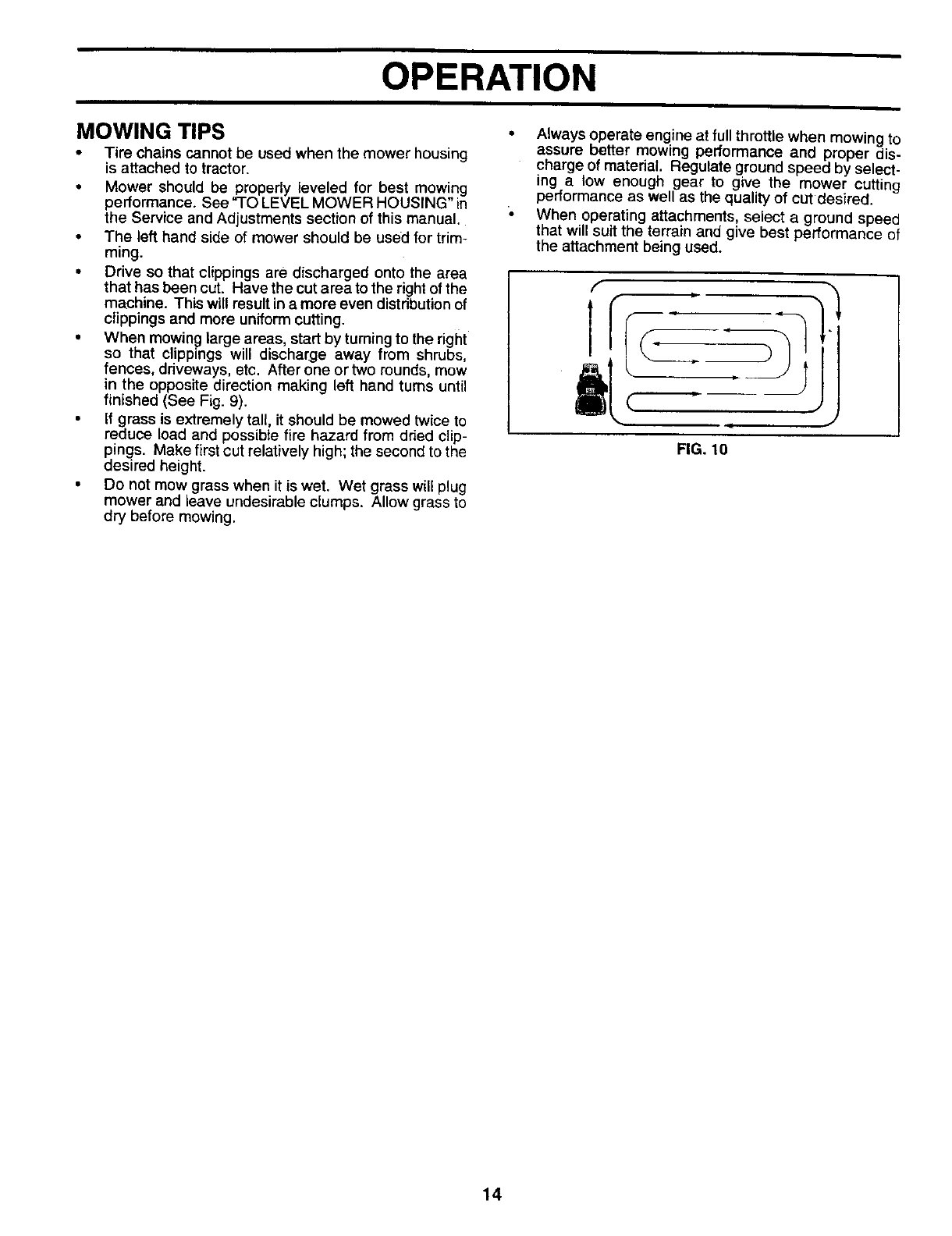
• When mowing large areas, start by turning to the right
so that clippings will discharge away from shrubs,
fences, driveways, etc. After one or two rounds, mow
in the opposite direction making left hand turns ur_til
finished (See Fig. 9).
• If grass is extremely tall, it should be mowed twice to
reduce load and possible fire hazard from dded clip-
pings. Make first cut relatively high; the second to the
desired height.
• Do not mow grass when it is wet. Wet grass will plug
mower and leave undesirable clumps. Allow grass to
dry before mowing.
Always operate engine at full throttle when mowing to
assure better mowing performance and proper dis-
charge of material, Regulate ground speed by select-
1rig a low enough gear to give the mower cutting
performance as well as the quali_ of cut desired.
When operating attachments, select a ground speed
that will suit the terrain and give best performance of
the attachment being used.
f
1
J
FIG. 10
14

CUSTOMER RESPONSIBILITIES
MAINTENANCESCHEDULE
AS YOU COMPL P It: ._ t.u'/ _ .-" _._ /t.-_ /._'_ __"0.7"_,_/<_-'_J/_,'_/ DATES
II _ II
CheckBrakeOperation _
CheckTire Pressure
T Check for Loose Fasteners Ik/ 1_7 I_
HSharpen/ReplaceMowerBlades I##A
LubricationChart l#/
T CheckBatteryLevellRecharge
CleanBatteryandTerminals .... V_
RCheck Transaxle Cooling if
Adjust Blade Belt(s) Tension If 5
AdjustMotionDdveBelt(s)Tension Ik/Fs
Check Engine Oil Level V° if
ChangeEngineOil li_t_,3 Vp
CleanAir Filter
E CleanAir Screen
inspectMuffler/SparkArraster If
Replace Oil Filter(It equipped) 1##_1.2
N CleanEngineCoolingFins _V2
ReplaceSpark Plug if
ReplaceAirFilterPaperCartridge 1_2
Replace Fuel Filter If
1-Change more often when operating under a heavy load or in high ambient lemperatures.
2- See/ice mote often when operating in dirty ordusty COnditions
3-If equipped with oil filter, change oil even/50 hours.
4 - Replace b-ladesmore often when mowing in sandy soil.
5- If e_Jipped with adjustable system,
6 - Not required if equipped with maintenance-free batten/.
7-T_ghtenfront axle pivot holt to 35 fL-Ibs, maximum.
Do not overtighlan.
GENERAL RECOMMENDATIONS
The warranty on this tractor does not cover items that have
been subjected to operator abuse or negligence. To
receive full value from the warranty, operator must maintain
tractor as instructed in this manual.
Some adjustments will need to be made periodically to
properly maintain your tractor.
All adjustments in the Service and Adjustments section of
this manual should be checked at least once each season.
LUBRICATION CHART
(_ SPINDLE ZERI ®
® "FRONT WHEEL ®
BEARING ZERK BEARING ZERK
Once a year you should replace the spark plug, clean (_)
or replace air filter, and check blades and belts for CLUTCH
wear. A new spark plug and clean air filter assure PIVOT(S)
proper air-fuel mixture and help your engine run better
and last longer.
BEFORE EACH USE
Check engine oil level.
Check brake operation.
Check tire pressure.
Check for loose fasteners.
ENGINE (_)
15
(_ SAE 30 OR 10W30 MOTOR OIL
(_ GENERAL PURPOSE GREASE
(_ REFER TO CUSTOMER RESPONSIBILITIES "ENGINE" SECTION
IMPORTANT: DO NOT OiL OR GREASE THE PIVOT POINTS
WHICH HAVE SPECIAL NYLON BEARINGS. VISCOUS LUBRI-
CANTS WILL ATTRACT DUST AND DIRT THAT WILL SHORTEN
THE LIFE OF THE SELF-LUBRICATING BEARINGS. IF YOU
FEEL THEY MUST BE LUBRICATED, USE ONLY A DRY, POW-
DERED GRAPHITE TYPE LUBRICANT SPARINGLY.

CUSTOMER RESPONSIBILITIES
TRACTOR
Always observe safety rules when performing any mainte-
nance.
BRAKE OPERATION
If tractor requires more than six (6) feet stopping distance
at high speed in highest gear, then brake must be adjusted.
(See "TO ADJUST BRAKE" in the Service and Adjust-
ments section of this manual).
TIRES
Maintain proper air pressure in all tires (See "PROD-
UCT SPECIFICATIONS" on page 3 of this manual).
Keep tires free of gasoline, oil,or insect control chemi-
cals which can harm rubber.
• Avoid stumps, stones, deep ruts, sharp objects and
other hazards that may cause tire damage.
NOTE: To seal tire punctures and prevent flat tires due to
slow leaks, tire sealant may be purchased from your local
parts dealer. Tire sealant also prevents tire dry rot and
corrosion.
BLADE CARE
For best results mower blades must be kept sharp. Re-
place bent or damaged blades.
BLADE REMOVAL (See Fig. 10)
Raise mower to highest position to allow access to
TO SHARPEN BLADE (See Fig. 11 )
Care should be taken to keep the blade balanced. An
unbalanced blade willcause excessive vibration and even-
tual damage to mower and engine,
-. The blade can be sharpened with a file or on a grinding
wheel. Do not attempt to sharpen while on the mower.
To check blade balance, you will need a 5/8" diameter
steel bolt, pin, or a cone balancer. (When using a cone
balancer, follow the instructions supplied with bal-
ancer).
•Slide blade on to an unthreaded portion of the steel bolt
or pin and hold the bolt or pin parallel with the ground,
tf blade is balanced, it should remain in a horizontal
position. If either end of the blade moves downward,
sharpen the heavy end until the blade is balanced.
NOTE: Do not use a nail for balancing blade. The lobes of
the center hole may appear to be centered, but are not.
CENTER HOLE
5/8" BOLT
OR PiN
BLADE
iblades. FIG. 12
Removehexbolt,lockwasher andflatwasher secunng BATTERY
• blade.
Install new or resbarpened blade with trailing edge up Your tractor has a battery charging system which is suffi-
towards deck as shown, cient for normal use. However, periodic charging of the
• Reassemble hex bolt, lock washer and flat washer in battery with an automotive charger will extend its life.
exact order as shown. •Keep battery and terminals clean.
• Tighten bolt securely (30-35 Ft. Lbs. torque). •Keep battery bolts tight.
IMPORTANT: BLADEBOLT IS GRADE 8 HEATTREATED. • Keep small vent holes open.
NOTE: Wedonotrecommendsharpeningblade-butifyou • Rechargeat 6-10amperes for 1 hour.
do, be sure the blade is balanced.
__ TO CLEAN BATTERY AND TERMINALS
_ Corrosion and dirt on the battery and termLnals can cause
BLADE _%=(_ MANDREL the battery to "leak" power.
/ Oeeoxoo
Disconnect BLACK battery cable first then RED bat-
tery cable and remove battery from tractor.
Rinse the battery with plain water and dry.
Clean terminals and battery cable ends with wire brush
|FLAT WASHER _-_.._ _ TRAIUNG EDGE until bright. "
tLOCKWASHER_ _/Coat terminals with grease or petroleum jelly.
iHEXBOLT,. _- _'_----_y'-" Reinstall battery (See "CONNECT BATTERY" in the
t(GRADE8)*_ "_ "_ Assembly section of this manual).
*A GRADE 8 HEAT TREATED BOLT CAN BE
IDENTIFIED BY SIX LINES ON THE BOLT HEAD.
FIG. 11
16
CUSTOMER RESPONSIBILITIES
V-BELTS
Check V-belts for deterioration and wear after 100 hours of
operation and replace if necessary. The belts are not
adjustable. Replace belts if they begin to slip from wear.
TRANSAXLE COOLING
The fan and cooling fins of transmission should be kept
clean to assure proper cooling.
Do not attempt to clean fan or transmission while engine is
running or while the transmission is hot.
•Inspect cooling fan to be sure fan blades are intact and
clean.
Inspect cooling fins for dirt, grass clippings and other
materials. To prevent damage to seals, do not use
compressed air or high pressure sprayer to clean
cooling fins.
TRANSAXLE PUMP FLUID
The transaxle was sealed at the factory and fluid mainte-
nance is not required for the life of the transaxle. Should the
transaxle ever leak or require servicing, contact your near-
est authorized service center/department.
ENGINE
LUBRICATION
Only use high quality detergent oil rated with API service
classification SF, SG or SH. Select the oil's SAE viscosity
grade according to your expected operating temperature.
SAE VISCOSITY GRADES
.20 _0•30 °32°40 = 60 _I_ =100"
•30 ° -20 = -10 _ 0°10°20 = 30" 40 °
TEMPERATURE RANGE ANTICIPATED BEFORE NEXT OIL CHANGE
NOTE: Although multi-viscosity oils (5W30, 10W30 etc.)
improve starting in cold weather, these multi-viscosity oils
will result in increased oil consumption when used above
32°F. Check your engine oil level more frequently to avoid
possible engine damage from running low on oil.
Change the oil alter every 25 hours of operation or at least
once a year ifthe tractor is not used for 25 hours in one year.
Check the crankcase oil level before starting the engine
and after each eight (8) hours of operation. Tighten oil fill
cap/dipstick securely each time you check the oil level.
TO CHANGE ENGINE OIL (See Figs. 12 and 13)
Determine temperature range expected before oil change.
All oil must meet API service classification SF, SG or SH.
Be sure tractor is on level surface.
Oil will drain more freely when warm.
Catch oil in a suitable container.
Remove oil fill cap/dipstick. Be careful not to allow dirt
to enter the engine when changing oil
• Remove drain plug.
After oil has drained completely, replace oil drain plug
and tighten securely.
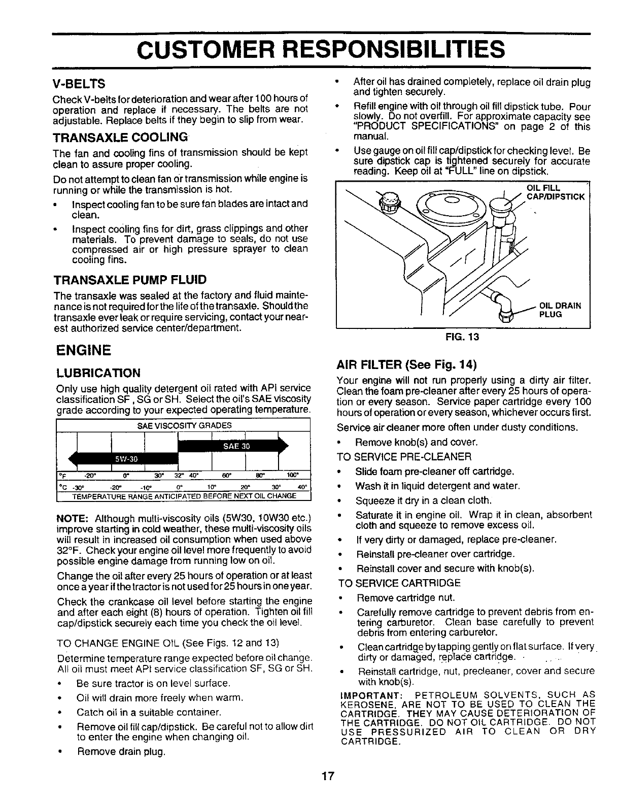
Refill engine with oil through oil fi!1dipstick tube. Pour
slowly. Do not overfill. For approximate capacity see
"PRODUCT SPECIFICATIONS" on page 2 of this
manual.
Use gauge on oil fill cap/dipstick for checking level. Be
sure dipstick cap is tightened securely for accurate
reading. Keep oil at "FULL" line on dipstick.
OIL FILL
CAP/DIPSTICK
• OIL DRAIN
PLUG
FIG. 13
AIR FILTER (See Fig. 14)
Your engine will not run propedy using a dirty air filter.
Clean the foam pre-cleaner after every 25 hours of opera-
tion or every season. Service paper cartridge every 100
hoursof operation orevery season, whichever occurs first.
Service air cleaner more often under dusty conditions.
• Remove knob(s) and cover.
TO SERVICE PRE-CLEANER
•Slide foam pre-cleaner oft cartridge.
•Wash it in liquiddetergent and water•
• Squeeze it dry in a clean cloth.
Saturate it in engine oil. Wrap it in clean, absorbent
cloth and squeeze to remove excess oil.
•If very dirty or damaged, replace pre-cleaner.
Reinstall pre--cleaner over cartridge.
•Reinstall cover and secure with knob(s)•
TO SERVICE CARTRIDGE
Remove cartridge nut.
Carefully remove cartridge to prevent debris from en-
tering carburetor. Clean base carefully to prevent
debris from entering carburetor.
Clean cartridge by tapping gently on flat surface. If very.
d rty or damaged replace carti'iclge. ...
Reinstall cartridge, nut, precleaner, cover and secure
with knob(s).
IMPORTANT: PETROLEUM SOLVENTS, SUCH AS
KEROSENE, ARE NOT TO BE USED TO CLEAN THE
CARTRIDGE. THEY MAY CAUSE DETERIORATION OF
THE CARTRIDGE. DO NOT OIL CARTRIDGE. DO NOT
USE PRESSURIZED AIR TO CLEAN OR DRY
CARTRIDGE.
17

CUSTOMER RESPONSIBILITIES
COVER KNOB
COVER CARTRIDGE NUT
FOAM _PAPER
PRE-CLEANER "_"-_ CARTRIDGE
_BASE
FIG. 14
ENGINE COOLING FINS (See Fig. 15)
Remove any dust, dirt or oil from engine cooling fins to
prevent engine damage from overheating.
Remove screws from blower housing and Eifthousing
and dipstick tube assembly off engine.
•Cover oil fill opening to prevent entry of dirt.
•Use compressed air or stiff bristlebrush to thoroughly
clean engine cooling fins.
•To reassemble, reverse above procedure.
SCREWS BLOWER HOUSING
SCREWS
DIPSTICK TUBE
ASSEMBLY
ENGINE COOLING RNS
SPARK
PLUG
FIG. 15
MUFFLER
Inspectand replace corroded muffler and spark arrester (if
equipped) as it could create a fire hazard and/or damage.
SPARK PLUGS
Replace spark plugs at the beginning of each mowing
season or after every 100 hours of operation, whichever
occurs first. Spark plug type and gap setting are shown in
"PRODUCT SPECIFICATIONS" on page 2 of this manual..
IN-LINE FUEL FILTER (See Fig. 16)
The fuel filter should be replaced once each season. If fuel
filter becomes clogged, obstructing fuel flow to carburetor,
replacement is required.
• With engine cool, remove filter and plug fuel line
sections.
• Place new fuel filter in position in fuel line with arrow
pointing towards carburetor.
Be sure there are no fue_ line leaks and clamps are
properly positioned.
• Immediately wipe up any spilled gasoline.
CLAMP CLAMP
FUEL
FIG. 16
CLEANING
• Clean engine, battery, seat, finish, etc. of all foreign
matter.
• Keep finished surfaces and wheels free of all gasoline,
oil, etc.
• Protect painted surfaces with automotive type wax.
We do not recommend using a garden hose to clean your
tractor unless the electrical system, muffler, air filter and
carburetor are covered to keep water out. Water in engine
can result in a shortened engine life.
CLEAN AIR SCREEN (See Fig. 15)
Air screen must be kept free of dirt and chaff to prevent
engine damage from overheating. Clean with a wire brush
or compressed air to remove dirt and stubborn dried gum
fibers.
18
SERVICE AND ADJUSTMENTS
CAUTION: BEFORE PERFORMING ANY SERVICE OR ADJUSTMENTS:
: Depress clutch/brake pedal fully and set Parking brake.
Place motion control lever in neutral (N) position.
Place attachment clutch in "DISENGAGED" position.
Turn ignition key "OFF" and remove key.
•Make sure the blades and all moving parts have completely stopped.
°Disconnect spark plug wire from spark plug and place wire where it cannot come in contact with
plug.
TRACTOR
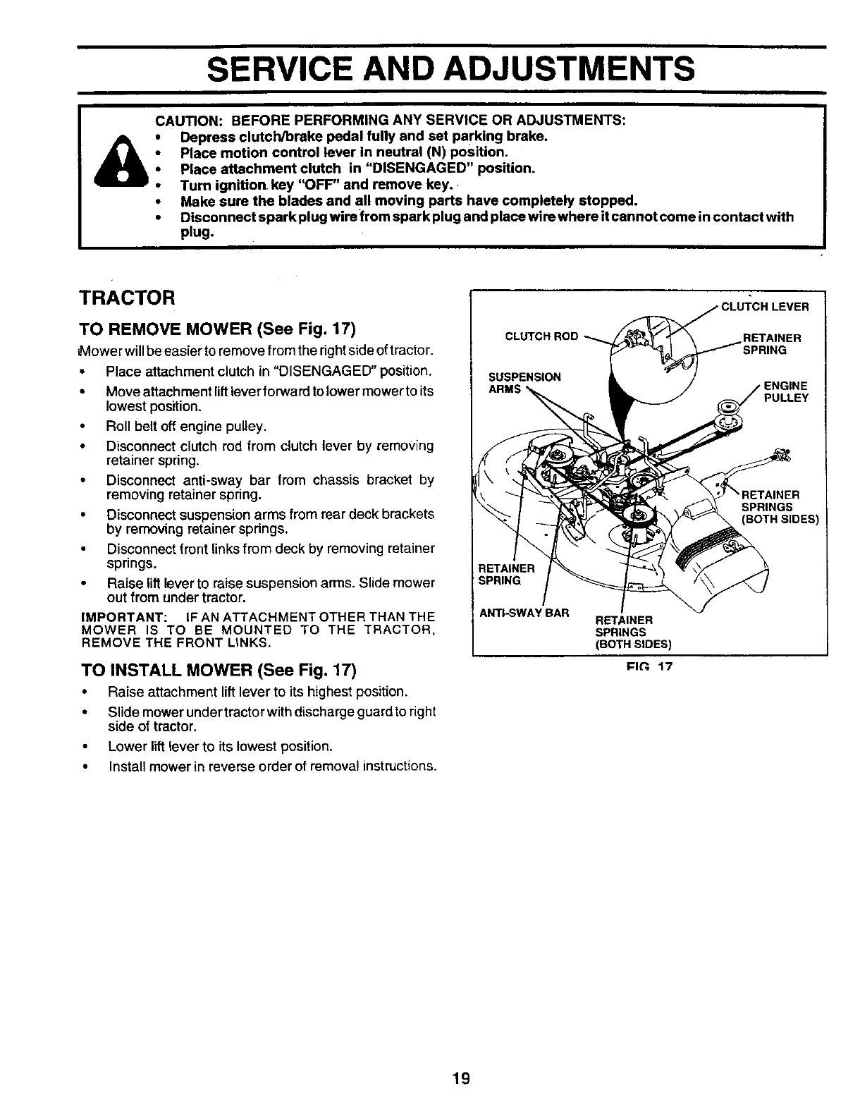
TO REMOVE MOWER (See Fig. 17)
',Mower will be easier to remove from the right side of tractor.
• Place attachment clutch in "DISENGAGED" position.
• Move attachment lift lever forward to lower mower to its
lowest position.
• Roll belt off engine pulley.
• Disconnect clutch rod from clutch lever by removing
retainer spring.
• Disconnect anti-sway bar from chassis bracket by
removing retainer spdng.
•Disconnect suspension arms from rear deck brackets
by removing retainer springs.
• Disconnect front links from deck by removing retainer
springs.
• Raise lift lever to raise suspension arms. Slide mower
out from under tractor.
IMPORTANT: IF AN ATTACHMENT OTHER THAN THE
MOWER IS TO BE MOUNTED TO THE TRACTOR,
REMOVE THE FRONT LINKS.
TO INSTALL MOWER (See Fig, 17)
• Raise attachment lift lever to its highest position.
• Slide mower undertractor with discharge guard to right
side of tractor.
• Lower lilt lever to its lowest position.
• Install mower in reverse order of removal instructions.
RETAINER
SPRING
LEVER
RETAINER
SPRING
'ENGINE
PULLEY
SPRINGS
ANTI-SWAY BAR RETAINER
SPRINGS
(BOTH SIDES)
I=lt'_. 17
19
SERVICE AND ADJUSTMENTS
TO LEVEL MOWER HOUSING
Adjust the mower while tractor is parked on level ground or
driveway. Make sure tires are properly inflated (See
"PRODUCT SPECIFICATIONS" on page 2 of this manual).
If tires are over or underinflated, you will not properly adjust
your mower.
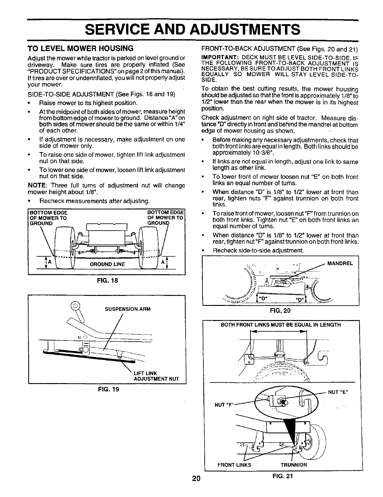
SIDE-TO-SIDE ADJUSTMENT (See Figs. i8 and 19)
•Raise mower to its highest position.
• At the midpoint of both sides of mower, measure height
from bottom edge of mower to ground. Distance"A" on
both sides of mower should be the same or within 1/4"
of each other.
• If adjustment is necessary, make adjustment on one
side of mower only.
• To raise one side of mower, tighten lift link adjustment
nut on that side.
• To lower one side of mower, loosen lift link adjustment
nut on that side.
NOTE: Three full turns of adjustment nut will change
mower height about 1/8".
• Recheck measurements after adjusting.
BO"I-rOM EDGE BO'I-rOM EDGE
OF MOWER TO OF MOWER TO
GROUND _ __ GROUNj
FIG. 18
ARM
ADJUSTMENT NUT
FIG. 19
FRONT-TO-BACK ADJUSTMENT (See Figs. 20 and 21)
IMPORTANT: DECK MUST BE LEVEL SIDE-TO-SIDE. IF
THE FOLLOWING FRONT-TO-BACK ADJUSTMENT IS
NECESSARY, BE SURE TO ADJUST BOTH FRONT LINKS
EQUALLY SO MOWER WILL STAY LEVEL SIDE-TO-
SIDE.
To obtain the best cutting results, the mower housing
should be adjusted so that the front is approximately 1/8" to
1/2" lower than the rear when the mower is in its highest
position.
Check adjustment on right side of tractor. Measure dis-
tance =D"directly infront and behind the mandrel at bottom
edge of mower housing as shown.
•Before making any necessary adjustments, check that
both front links are equal in length. Both links should be
approximately 10-3/8".
If links are not equal in length, adjust one link to same
length as other link.
• To lower front of mower loosen nut "E" on both front
links an equal number of turns.
•When distance "D" is 1/8" to 1/2" lower at front than
rear, tighten nuts "F' against trunnion on both front
links.
To raise front of mower, loosen nut"F" from trunnion on
both front links. Tighten nut "E" on both front links an
equal number of turns.
When distance "D" is 1/8" to 1/2" lower at front than
rear, tighten nut"F" against trunnion on both front links.
Recheck side-to-side adjustment.
::, o_ ! . ot / MANDREL
A
o •
FIG. 20
BOTH FRONT LINKS MUST BE EQUAL IN LENGTH
NUT "F
FRONT LINKS TRUNNION
20 FIG. 21

SERVICE AND ADJUSTMENTS
TO REPLACE MOWER BLADE DRIVE BELT
(See Fig. 22)
The mower blade drive belt may be replaced without tools.
Park the tractor on level surface. Engage parking brake.
BELT REMOVAL -
• Remove mower from tractor (See "TO REMOVE
MOWER =in this section of this manual).
•Work belt off both mandrel pulleys and idler pulleys.
• Pull belt away from mower.
BELT INSTALLATION -
• Install new belt in reverse order of removal.
• Make sure belt is in all putieygrooves and inside all belt
guides.
• Install mower in reverse order of removal instructions.
IDLER
PULLEYS
MANDREL
PULLEYS
FIG. 22
TO ADJUST BRAKE (See Fig. 23)
Your tractor is equipped with an adjustable brake system
which is mounted on the side of the transaxle.
If tractor requires more than six (6) feet stopping distance
at high speed in highest gear, then brake must be adjusted.
Depress clutch/brake pedal and engage parking brake.
•Measure distance between brake operating arm and
nut "A" on brake rod.
If distance is other than 1-1/2", loosenjam nut and turn
nut "A" until distance becomes 1-1/2". Retighten jam
nut against nut "A".
Road test tractor for proper stopping distance as stated
above, Readjust if necessary. If stopping distance is
still greater than six (6) feet in highest gear, further
maintenance is necessary. Contact your nearest au-
thorized service center/department.
WITH PARKING BRAKE "ENGAGED"
NUT "A"
ARM
DO NOT TOUCH THIS NUT. IF FURTHER
BRAKE ADJUSTMENT IS NECESSARY
CONTACT YOUR NEAREST AUTHORIZED
SERVICE CENTER/DEPARTMENT
RG. 23
TO REPLACE MOTION DRIVE BELT
(See Fig. 24)
Park the tractor on level surface. Engage parking brake.
For assistance, there is a belt installation guide decal on
bottom side of left footrest.
•Remove mower (See "TO REMOVE MOWER" in this
section of this manual.)
• Remove upper belt keeper.
• Remove belt from stationary idler and clutching idler.
• Pullbeltslacktowardrearoftractor. Carefully remove
belt upwards from transmission input pulley and over
cooling fan blades.
• Pull belt toward front of tractor and remove downward
from around engine pulley.
•Install new belt by reversing above procedure.
IMPORTANT: MAKE SURE UPPER BELT KEEPER IS
POSITIONED PROPERLY BETWEEN LOCATOR TABS.
PULLEy
TABS
IDLER
STATI
IDLER KEEPER
TRANSMISSION
INPUT PULLEY
FIG. 24
21
SERVICE AND ADJUSTMENTS
TRANSMISSION REMOVAL/REPLACEMENT
Should your transmission require removal for service or
replacement, it should be purged after reinstallation and
before operating the tractor. See "PURGE TRANSMIS-
SION" in the Operation section of this manual.
TO ADJUST STEERING WHEEL ALIGNMENT
If steering wheel crossbars are not horizontal (left to dght)
when wheels are positioned straight forward, remove steer-
ing wheel and reassemble per instructionsin the Assembly
section of this manual.
FRONT WHEEL TOE-IN/CAMBER
The front wheel toe-in and camber are not adjustable on
your tractor. If damage has occurred to affect the front
wheel toe-in or camber, contact your nearest authorized
service center/department.
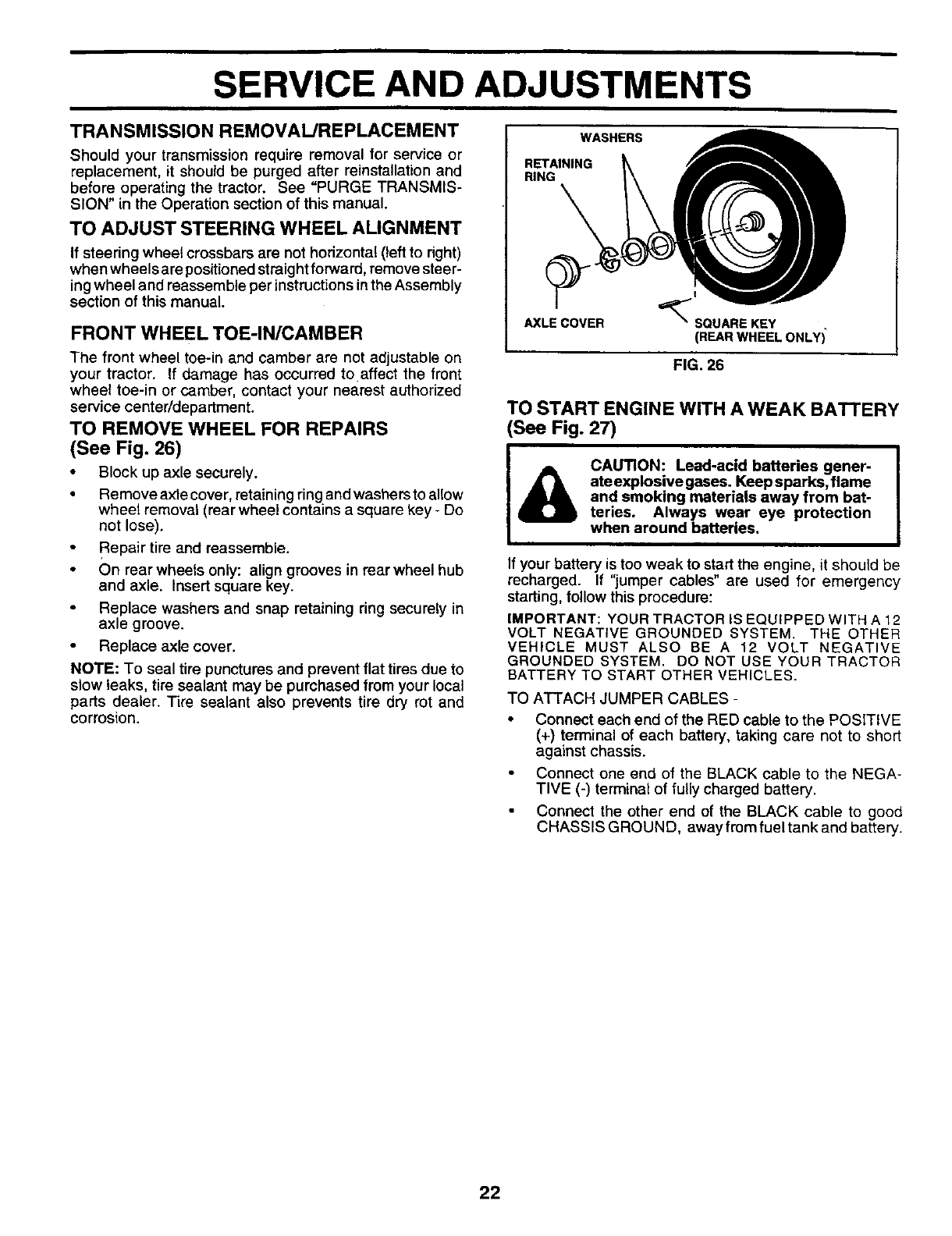
TO REMOVE WHEEL FOR REPAIRS
(See Fig. 26)
•Block up axle securely.
• Remove axle cover, retaining ring and washers to allow
wheel removal (rear wheel contains a square key - Do
not lose).
• Repair tire and reassemble.
• On rear wheels only: align grooves in rear wheel hub
and axle. Insert square key.
Replace washers and snap retaining ring securely in
axle groove.
• Replace axle cover.
NOTE: To seal tire punctures and prevent flat tires due to
slow leaks, tire sealant may be purchased from your local
parts dealer. Tire sealant also prevents tire dry rot and
corrosion.
WASHERS
RETAINING
RING
AXLE COVER
z
_"SQUARE KEY
(REAR WHEEL ONLY)
FIG. 26
TO START ENGINE WITH A WEAK BATTERY
See Fig. 27)
CAUTION: Lead-acid batteries gener-
ate explosive gases. Keep sparks, flame
and smoking materials away from bat-
teries. Always wear eye protection
when around batteries.
If your battery is too weak to start the engine, it should be
recharged. If "jumper cables" are used for emergency
starting, follow this procedure:
IMPORTANT: YOUR TRACTOR IS EQUIPPED WITH A 12
VOLT NEGATIVE GROUNDED SYSTEM. THE OTHER
VEHICLE MUST ALSO BE A 12 VOLT NEGATIVE
GROUNDED SYSTEM. DO NOT USE YOUR TRACTOR
BATTERY TO START OTHER VEHICLES.
TO ATTACH JUMPER CABLES -
Connect each end of the RED cable to the POSITIVE
(+) terminal of each battery, taking care not to short
against chassis.
Connect one end of the BLACK cable to the NEGA-
TIVE (-) terminal of fully charged battery.
Connect the other end of the BLACK cable to good
CHASSIS GROUND, away from fuel tank and battery.
22
SERVICE AND ADJUSTMENTS
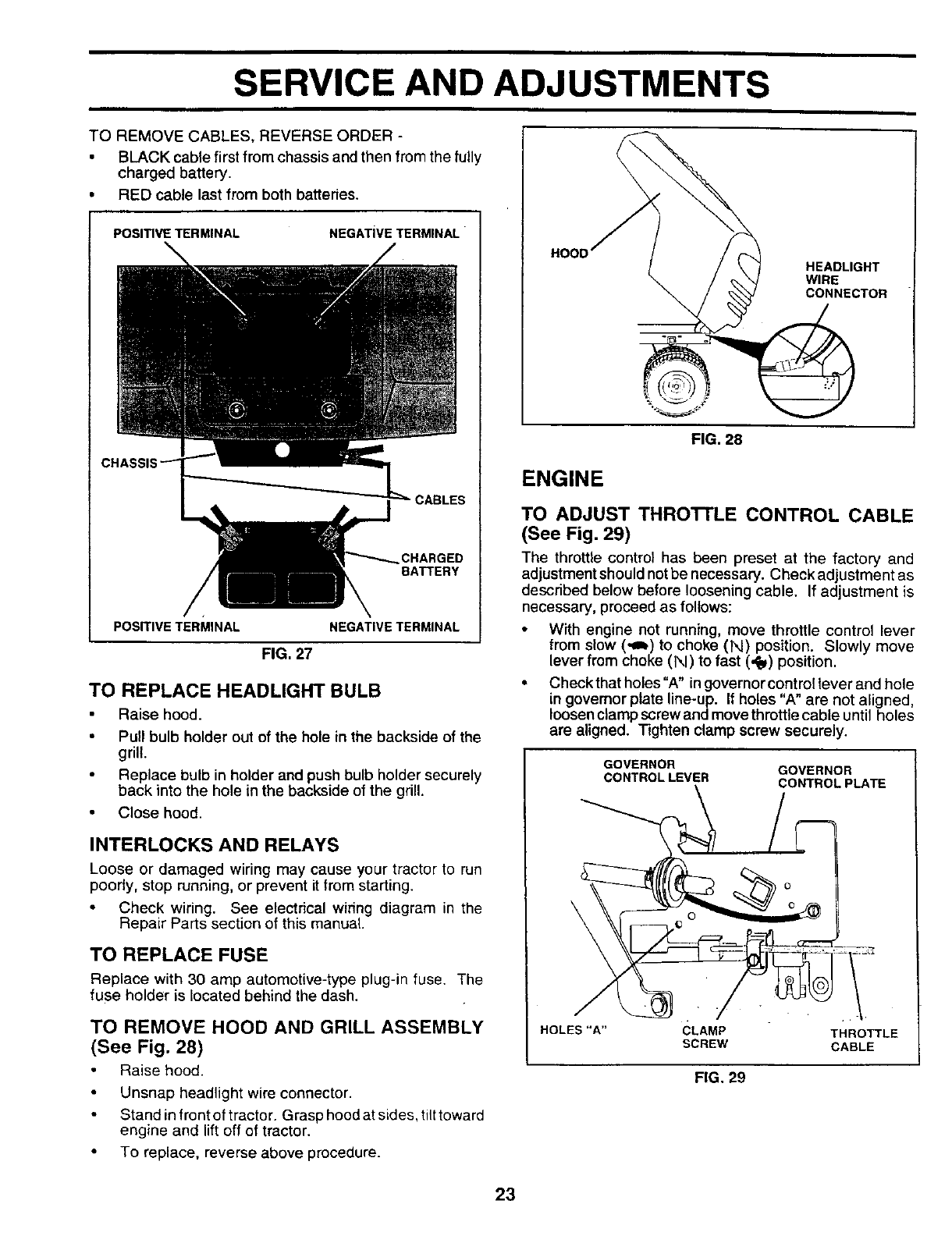
TO REMOVE CABLES, REVERSE ORDER -
•BLACK cable first from chassis and then from the fully
charged battery.
• RED cable last from both batteries.
POSITIVE TERMINAL NEGATIVE TERMINAL
CHARGED
BATTERY
POSITIVE TERMINAL NEGATIVETERMINAL
FIG, 27
TO REPLACE HEADLIGHT BULB
Raise hood.
•Pull bulb holder out of the hole in the backside of the
grill.
• Replace bulb in holder and push bulb holder securely
back into the hole in the backside of the grill.
• Close hood.
INTERLOCKS AND RELAYS
Loose or damaged wiring may cause your tractor to run
poorly, stop running, or prevent it from starting.
• Check wiring. See electrical wiring diagram in the
Repair Parts section of this manual
TO REPLACE FUSE
Replace with 30 amp automotive-type plug-in fuse. The
fuse holder is located behind the dash.
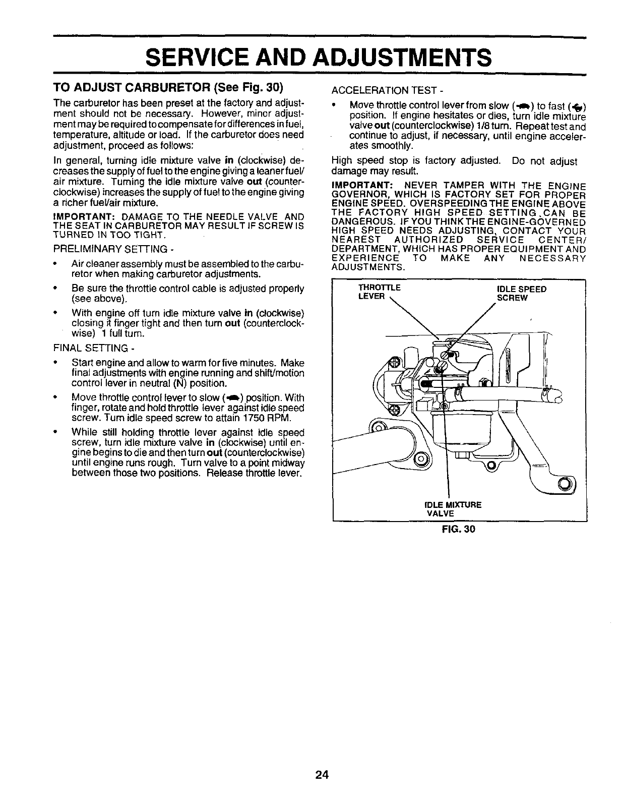
TO REMOVE HOOD AND GRILL ASSEMBLY
(See Fig. 28)
Raise hood.
Unsnap headlight wire connector.
• Stand infront of tractor. Grasp hoodat sides, tilttoward
engine and lift off of tractor.
• To replace, reverse above procedure.
HOOD HEADLIGHT
WIRE
CONNECTOR
FIG. 28
ENGINE
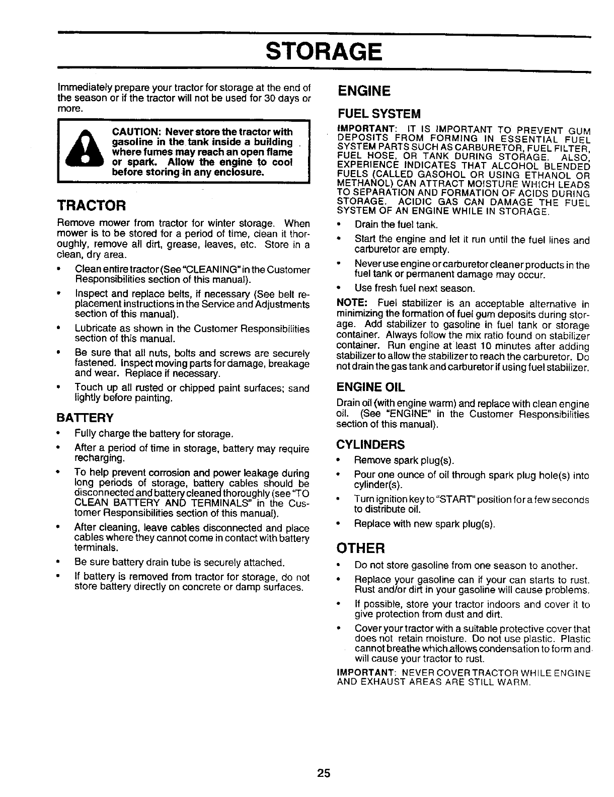
TO ADJUST THROI-I'LE CONTROL CABLE
(See Fig. 29)
The throttle control has been preset at the factory and
adjustment should not be necessary. Check adjustment as
described below before loosening cable. If adjustment is
necessary, proceed as follows:
• With engine not running, move throttle control lever
from slow (,gb) to choke (N) position. Slowly move
lever from choke (1",,I)to fast (,_) position.
• Checkthat holes =A" in governorcontrollever and hole
in govemor plate line-up. If holes "A" are not aligned,
loosen clamp screw and move throttle cable until holes
are aligned. Tighten clamp screw securely.
GOVERNOR
CONTROLLEVER GOVERNOR
CONTROLPLATE
HOLES "A" CLAMP THROTTLE
SCREW CABLE
FIG. 29
23
SERVICE AND ADJUSTMENTS
ACCELERATION TEST -
TO ADJUST CARBURETOR (See Fig. 30)
The carburetor has been preset at the factory and adjust-
ment should not be necessary. However, minor adjust-
ment may be required tocompensate for differences infuel,
temperature, altitude or load. If the carburetor does need
adjustment, proceed as follows:
In general, turning idte mixture valve in (clockwise) de-
creases the supplyof fuel to the engine givinga leanerfuel/
air mixture. Turning the idle mixture valve out (counter-
clockwise) increases the supplyof fuel to the engine giving
a richer fuel/air mixture.
iMPORTANT: DAMAGE TO THE NEEDLE VALVE AND
THE SEAT IN CARBURETOR MAY RESULT IF SCREW IS
TURNED tN TOO T_GHT.
PRELIMINARY SETFING -
Air cleaner assembly must be assembled to the carbu-
retor when making carburetor adjustments.
Be sure the throttle control cable is adjusted properly
(see above).
With engine off turn idle mixture valve in (clockwise)
closing it finger tight and then turn out (counterclock-
wise) 1 full turn.
FINAL SETTING -
• Start engine and allow to warm for five minutes. Make
final adjustments with engine running and shift/motion
control lever in neutral (N) position.
• Move throttle control lever to slow (,_) position. With
finger, rotate and hold throttle lever against idle speed
screw. Turn idle speed screw to attain 1750 RPM.
• While still holding throttle lever against idle speed
screw, turn idle mixture valve in (clockwise) until en-
gine begins to die and then turn out (counterclockwise)
until engine runs rough. Turn valve to a point midway
between those two positions. Release throttle lever.
• Move throttle control lever from slow (._) to fast (._)
position. If engine hesitates or dies, turn idle mixture
valveout(oounterelockwise) 1/8turn. Repeattest and
continue to adjust, if necessary, until engine acceler-
ates smoothly.
High speed stop is factory adjusted. Do not adjust
damage may result.
IMPORTANT: NEVER TAMPER WITH THE ENGINE
GOVERNOR, WHICH IS FACTORY SET FOR PROPER
ENGINE SPEED. OVERS PEEDING THE ENGINE ABOVE
THE FACTORY HIGH SPEED SETTING,CAN BE
DANGEROUS. IF YOU THINKTHE ENGINE-GOVERNED
HIGH SPEED NEEDS ADJUSTING, CONTACT YOUR
NEAREST AUTHORIZED SERVICE CENTER/
DEPARTMENT, WHICH HAS PROPER EQUIPMENT AND
EXPERIENCE TO MAKE ANY NECESSARY
ADJUSTMENTS.
THRO'n'LE IDLE SPEED
LEVER SCREW
IDLE MIXTURE
VALVE
FIG. 30
24
STORAGE
ENGINE
Immediately prepare your tractor for storage at the end of
the season or if the tractor will not be used for 30 days or
more.
ACAUTION: Never store the tractor with
gasoline in the tank inside a building
where fumes may reach an open flame
or spark. Allow the engine to cool
before storing in any enclosure.
TRACTOR
Remove mower from tractor for winter storage. When
mower is to be stored for a period of time, clean it thor-
oughly, remove all dirt, grease, leaves, etc. Store in a
clean, dry area.
• Clean entire tractor (See"CLEANING"in the Customer
Responsibilities section of this manual).
• Inspect and replace belts, if necessary (See belt re-
placement instructions inthe Service and Adjustments
section of this manual).
• Lubricate as shown in the Customer Responsibilities
section of this manual.
• Be sure that all nuts, bolts and screws are securely
fastened. Inspect moving parts fordamage, breakage
and wear. Replace if necessary.
• Touch up all rusted or chipped paint surfaces; sand
lightly before painting.
BA'I-rERY
• Fully charge the battery for storage.
• After a period of time in storage, battery may require
recharging.
•To help prevent corrosion and power leakage during
long periods of storage, battery cables should be
disconnected and battery cleaned thoroughly (see 'q'O
CLEAN BA'I-I'ERY AND TERMINALS" in the Cus-
tomer Responsibilities section of this manual).
•After cleaning, leave cables disconnected and place
cables where they cannot come incontact with battery
terminals.
• Be sure battery drain tube is securely attached.
• If battery is removed from tractor for storage, do not
store battery directly on concrete or damp surfaces.
FUELSYSTEM
IMPORTANT: IT IS IMPORTANT TO PREVENT GUM
DEPOSITS FROM FORMING IN ESSENTIAL FUEL
SYSTEM PARTS SUCH AS CARBURETOR, FUEL FILTER,
FUEL HOSE, OR TANK DURING STORAGE. ALSO,
EXPERIENCE INDICATES THAT ALCOHOL BLENDED
FUELS (CALLED GASOHOL OR USING ETHANOL OR
METHANOL) CAN ATTRACT MOISTURE WHICH LEADS
TO SEPARATION AND FORMATION OF ACIDS DURING
STORAGE. ACIDIC GAS CAN DAMAGE THE FUEL
SYSTEM OF AN ENGINE WHILE IN STORAGE.
• Drain the fuel tank.
• Start the engine and let it run until the fuel lines and
carburetor are empty.
Never use engine or carburetor cleaner products in the
fuel tank or permanent damage may occur.
• Use fresh fuel next season.
NOTE: Fuel stabilizer is an acceptable alternative in
minimizing the formation of fuel gum deposits during stor-
age. Add stabilizer to gasoline in fuel tank or storage
container. Always follow the mix ratio found on stabilizer
container. Run engine at least 10 minutes after adding
stabilizer to allow the stabilizer to reach the carburetor. Do
not drain the gas tank and carburetor if using fuel stabilizer.
ENGINE OIL
Drain oi! (with engine warm) and replace with clean engine
oil. (See "ENGINE" in the Customer Responsibilities
section of this manual).
CYLINDERS
• Remove spark plug(s).
•Pour one ounce of oil through spark plug hole(s) into
cylinder(s).
• Turn ignition key to "START" position for a few seconds
to distribute oil.
• Replace with new spark plug(s).
OTHER
Do not store gasoline from one season to another.
• Replace your gasoline can ff your can starts to rust.
Rust and/or dirt in your gasoline will cause problems.
If possible, store your tractor indoors and cover it to
give protection from dust and dirt.
• Cover your tractor with a suitable protective cover that
does not retain moisture. Do not use plastic. Plastic
cannot breathe whichatlows condensation to form and
will cause your tractor to rust.
IMPORTANT: NEVER COVER TRACTOR WHILE ENGINE
AND EXHAUST AREAS ARE STILL WARM.
25

TROUBLESHOOTING POINTS
PROBLEM
Will not start
Hard to start
Engine will not turn over
Engine clicks but will not
start
Loss of power
Excessive vibration
CAUSE
1. Out of fuel.
2. Engine not "CHOKED" propedy.
3. Engine flooded.
4. Bad spark plug.
5. Dirty air filter.
6. D!rty fuel tilter.
7. Water in fuel
8. Loose or damaged widng.
9. Carburetor outof adjustment.
10, Engine valves out of adjustment.
1. Dirty air filter.
2. Bad spark plug.
3. Weak or dead battery.
4. Dirty fuel filter.
5. State or dirty fuel.
6. Loose or damaged wiring.
7. Carburetor outof adjustment.
8. Engine valves out of adjustment.
1. Clutch!brake pedal not depressed.
2, Attachment dutch is engaged.
3. Weak or dead battery.
4. Blown fuse.
5. Corroded battery terminals.
6. Loose or damaged wiring.
7. Faulty ignitionswitch.
8. Faulty solenoid or starter.
9. Faulty operator presence swffch(es).
1. Weak or dead battery.
2. Corroded battery terminals.
3, Loose or damaged wiring.
4. Faulty solenoid or starter.
1. Cuing too much grass/too fast.
2. Throttle in "CHOKE" position.
3. Build-up of grass, leaves and trash under mower.
4. Dirty air filter.
5. Low oil lavel/dkty oil.
6. Faulty spark plug.
7. Dirty fuel tilter.
8. Stale or dirty fuel.
9. Water in fuel.
10. Spark plug wire loose,
11. Dirty engine air screen/fins.
12. Dirty/clogged muffler.
13. Loose or damaged widng.
14 Carburetor out of adjustment.
15. Engine valves out ot adjustment.
1. Wom, bent orloose blade.
2. Bent blade mandrel
3, Loose/damaged part(s).
CORREC_ON
1. Fill fuel tank.
2. See "TO START ENGINE" in Operation secfion.
3. Wait several minutes before attempting to start.
4. Replace spark plug.
5. Clean/replace air tilter.
6. Replace fuel filter.
7. Drain fuel tank and carburetor, refill tank with fresh
gasoline and replace fuel filter.
8. Check all wiring.
9. See "To Adjust Carburetor" inService Adjustments
section.
10. Contact an authorized service canter/department.
t. Clean/replace air tilter.
2. Replace spark plug.
3. Recharge or replace battery.
4. Replace fuel tilter.
5. Drain fuel tank and refill with fresh gasoline.
6. Check all wiring.
7. See "To Adjust Carburetor" in Service Adjustments
section.
8. Contact an authorized service center/department.
1. Depress dutch/brake pedal.
2. Disengage attachment clutch.
3. Recharge or replace battery.
4. Replace fuse.
5. Clean battery terminals.
6. Check all wiring.
7. Check]raplace ignition switch.
8. Check]replace solenoid or starter.
9. Contact an authorized service center/department.
1. Recharge or replace battery.
2. Clean battery terminals.
3. Check all wiring.
4. Check]replace solenoid or starter.
1. Set in "Higher Cut" positioniredu,:e speed,
2. Adjust thro_e control.
3. Clean underside of mower housing.
4. Clean/replace air filter.
5. Check oil level/change oil.
6, Clean and regap or change spark plug.
7. Replace fuel filter,
8. Drain fuel tank and refill with fresh gasoline.
9. Drain fuel tank and carburetor, refill tank with fresh
gasoline and replace fuel tilter.
10, Connect and tighten spark plug wire.
11. Clean engine air screen/fins.
12. Clean/replace muffler.
13. Check all wiring,
t4. See "To Adjust Carburetor" in Service Adjustments
section.
15. Contact an authorized service center!department.
1. Replace blade. Tighten blade bolt.
2. Replace blade mandrel.
3. T_ghten loose part(s). Replace damaged parts.
26
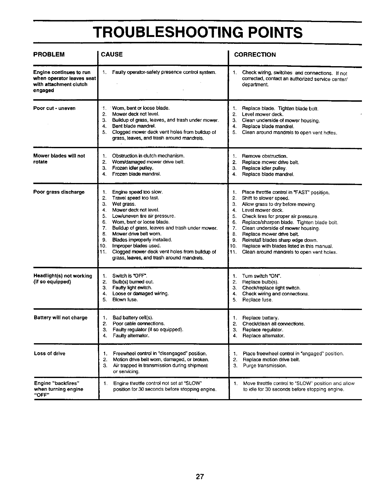
TROUBLESHOOTING POINTS
PROBLEM CAUSE CORRECTION
Engine continues torun
when operatorleaves seat
with attaohmentclutch
engaged
Poorcut-uneven
Mower blades will not
rotate
Poor grass discharge
Headlight(s) not working
(if so equipped)
Ba_erywillnotcharge
Loss of drive
Engine "backfires"
when turning engine
"OFF"
1. Faulty operator-safety presence control system.
1. Worn, bent or loose blade.
2. Mower deck not level.
3. Buildup of grass, leaves, and trash under mower.
4. Bent blade mandrel.
5. Clogged mower deck vent holes from buildup of
grass, laaves, and trash around mandrels.
1. Obstruction in dutch mechanism.
2. Wom/dan'_ged mower ddve belt.
3. Frozen idler pulley.
4. Frozen blade mandrel.
1. Engine speed too slow.
2. Travel speed too fast.
3. Wet grass.
4. Mower deck not level.
5. Low/uneven tire air pressure.
6. Worn, bent or loose blade.
7. Buildup of grass, leaves and trash under mower.
8. Mower ddve belt worn.
9. Blades improperly installed.
10. Improper b_des used.
11. Clogged mower deck vent holes from bundup of
grass, leaves, and trash around mandrels.
1. Switch is "OFF'.
2. Bulb(s) burned out.
3. Faulty light switch.
4. Loose or damaged wihng.
5. Blown fuse.
1. Bad battery ceU(s).
2. Poor cable connections.
3. Faulty regulator (if so equipped).
4. Faulty alternator.
1. Freewheel control in =disengaged" position.
2. Motion ddve belt worn, damaged, or broken.
3. Air trapped in transmission dudng shipment
or servicing.
Engine throtlle control not set at "SLOW"
position for 30 seconds before stopping engine.
1. Check wiring, switches and connections. If not
corrected, contact an authorized service center/
department.
1. Replace blade. Tighten blade bolt.
2. Level mower deck.
3. Clean underside of mower housing.
4. Replace blade mandrel.
5. Clean around mandrels to open vent hOtes.
1. Remove obstruction.
2. Replace mower drive belt.
3. Replace idler pulley.
4. Replace blade mandrel.
1. Place throttle control in "FAST' position.
2. Shift to slower speed.
3. Allow grass to dry before mowing.
4. Level mower deck.
5. Check tires for proper air pressure.
6. Replace/sharpen blade. Tighten blade bolt.
7. Clean underside of mower housing.
8. Replace mower dhve bell
9. Reinstall blades sharp edge down.
10. Replace with blades listed in this manual.
11. Clean around mandrels to open vent holes.
1. Turn switch "ON".
2. Replace bulb(s).
3. ChecWreplace light switch.
4. Check wiring and connections.
5. Replace fuse.
1. Replace battery.
2. Check/cldan all connections.
3. Replace regulator.
4. Replace alternator.
1. Place freewheel control in "engaged" position.
2. Replace motion drive belt.
3. Purge transmission.
1. Move throttle control to =SLOW" position and allow
to idle for 30 seconds before stopping engine.
27

SERVICE NOTES
28
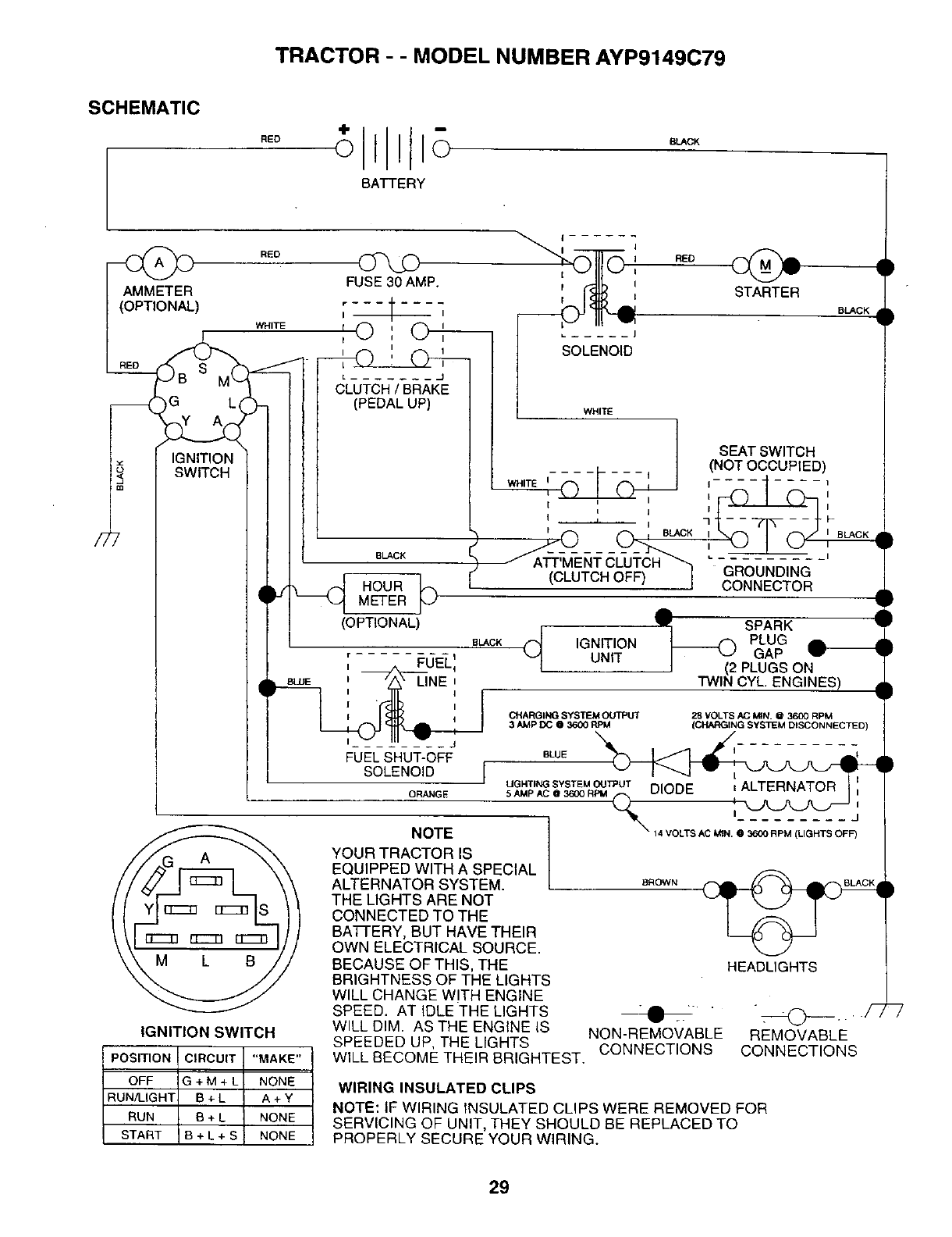
TRACTOR --MODEL NUMBER AYP9149C79
SCHEMATIC
RED
BATTERY
SLACK
/7
RED FUSE30 AMP.
I ,---¢__,
' '
I I i
CLUTCH /BRAK_E
(PEDAL UP)
POSITION
OFF
RUN/LIGHT
RUN
START
G L
IGNITION
SWITCH
n
IGNITION SWITCH
CIRCUIT "MAKE"
G+M+L NONE
B+L A+Y
B+LNONE
B+L+S NONE
BLACK
,_[ HOUR _)
METER
(OPTIONAL)
BLACK
, ©
I
I
L ......
SOLENOID
STARTER
BLACK
WHITE
SEAT SWITCH
(NOT OCCUPIED)
WHITE II II_II........ Ii
I f BLACK I I BLACK ,
_f&-u
(CLUTCH OFF) I " -G-ROUI_DING-
CONNECTOR
qF SPARK '
(_ IGNITION _ PLUG
UNIT GAP
PLUGS ON
TWIN CYL. ENGINES) •
,. FUEL_
BLUE i LINE i
I I
CHARGING SYSTEM OUI_UT 28 VOLTS AC MIN. @ 3600 RPM
3 AMP DO @360(} RPM (CHARGING SYSTEM DISCONNECTED)
FUELSHUT-OFF eWE "N_ ,_.q _l. __,.,
SOLENOID [
-- J UOHTINGSYSTEM_N t'_r_ ; A TL ERNATOR I I,
OR_GE 5 AMP AC @3600 RPM L.Sl "_wLJ F--. ........... i
I......... d
I
NOTE I_ 14 VOLTS AC MIN. @3600 RPM (LIGHTS OFF)
3
YOUR TRACTOR IS I
EQUIPPED WITH A SPECIAL I
ALTERNATOR SYSTEM. L s_ow_
HEADLIGHTS
NON-REMOVABLE REMOVABLE
CONNECTIONS CONNECTIONS
THE LIGHTS ARE NOT
CONNECTED TO THE
BATi-ERY, BUT HAVE THEIR
OWN ELECTRICAL SOURCE.
BECAUSE OF THIS, THE
BRIGHTNESS OF THE LIGHTS
WILL CHANGE WITH ENGINE
SPEED. AT IDLE THE LIGHTS
WILL DIM. AS THE ENGINE IS
SPEEDED UP, THE LIGHTS
WILL BECOME THEIR BRIGHTEST.
WIRING INSULATED CLIPS
NOTE: IF WIRING INSULATED CLIPS WERE REMOVED FOR
SERVICING OF UNIT, THEY SHOULD BE REPLACED TO
PROPERLY SECURE YOUR WIRING.
29
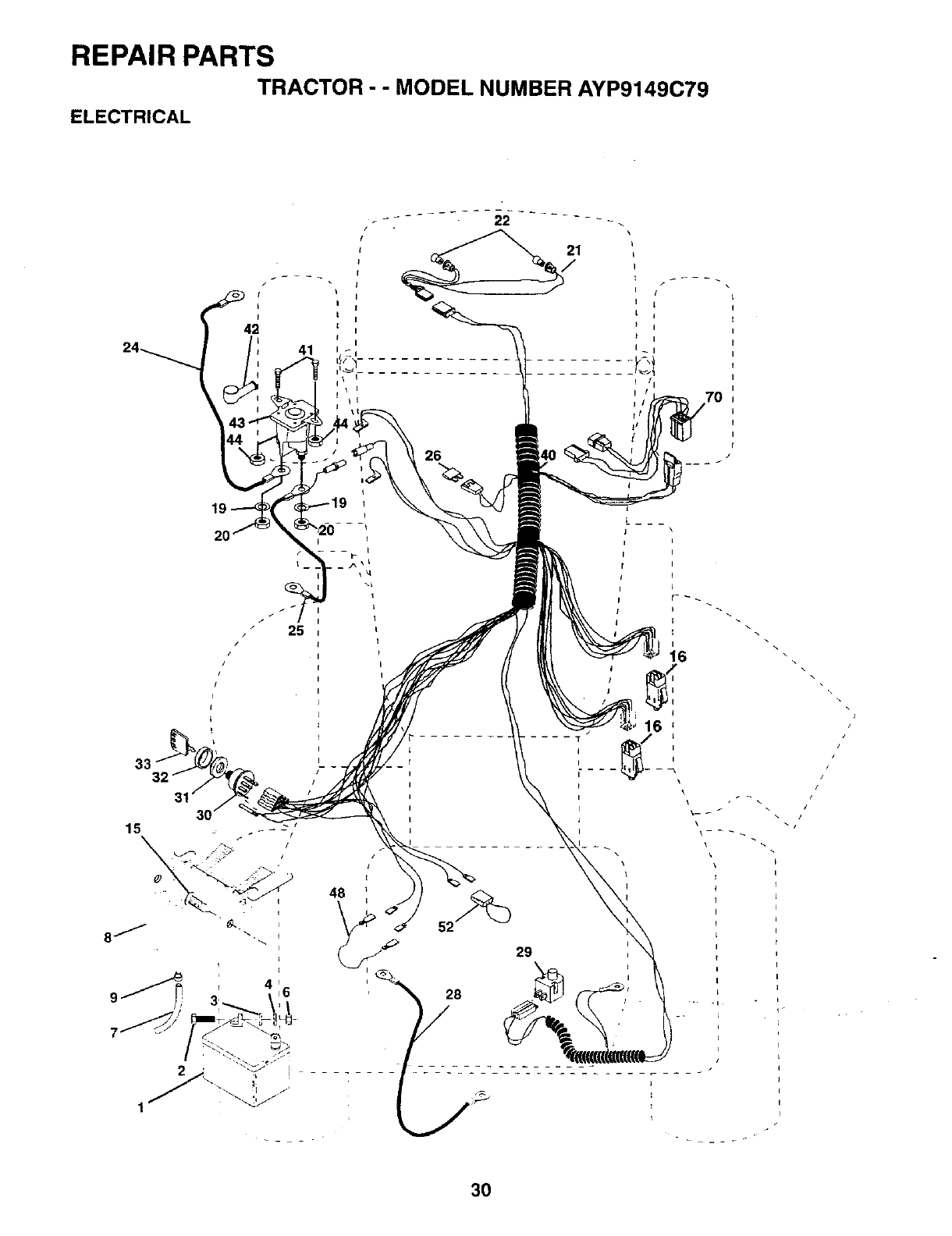
REPAIR PARTS
TRACTOR - - MODEL NUMBER AYP9149C79
ELECTRICAL
/
48 )
21
/
26
I
16
\
t
I
[
I
\/
3O

REPAIR PARTS
TRACTOR - - MODEL NUMBER AYP9149C79
ELECTRICAL
KEY PART
NO. NO. DESCRIPTION
1 144925
2 74760412
319091016
4 10040400
673220400
7109238X
8 156417
9 109596X
15 147688
16 153664
19 10090400
20 73350400
21 136850
22 4152J
24 4799J
25 146147
26 108824X
28 4207J
29 121305X
30 140301
31 124211X
32 141226
33 122147X
4O 156442
41 71110408
42 131563
43 145673
44 73640400
46 140844
52 141940
70 140422
Battery 12 Volt 25 Amp
Bolt Hex Hd 1/4-20unc X 3/4
Washer 9/32 X 5/8 X 16 Ga
Washer Lock Hvy Helical 1/4
Nut Fin Hex 1/4-20 Unc
Tube Plastic 12" Rear Battery
Case Battery
Clamp Hose Olive
Fastner Snap-In
Switch Intlk Push-In
Washer Lock 1/4
Nut Jam Hex 1/4-20 Unc
Hamess Socket Light
Bulb, Light # 1156
Cable Battery 6ga 11" Red
Cable Battery 6 Ga 44" Red W/16 Wire
Fuse 30 Amp Auto Green
Cable Ground 6ga 12' black
Switch Plunger Nc Gray
Switch Ign 4 Pos W/L P/L
Nut Ignition
Cover Sw Ignition
Key Ign Motded Generic
Hamess Ign
Bolt Fin Hex l/4-20uncx1/2
Cover Temminal Red
Solenoid
Nut Keps Hex 1/4-20 Unc
Ammeter Adapter Rectangular
Protection Loop
Harness Engine
NOTE: All component dimensions given in U.S. inches
1 inch = 25.4 mm
31

REPAIR PARTS
TRACTOR --MODEL NUMBER AYP9149C79
CHASSIS AND ENCLOSURES
26
31 44
26
26
33
58
12 28
53
37
2O
54
140
29
33 10
\3
38_.
/
26
32
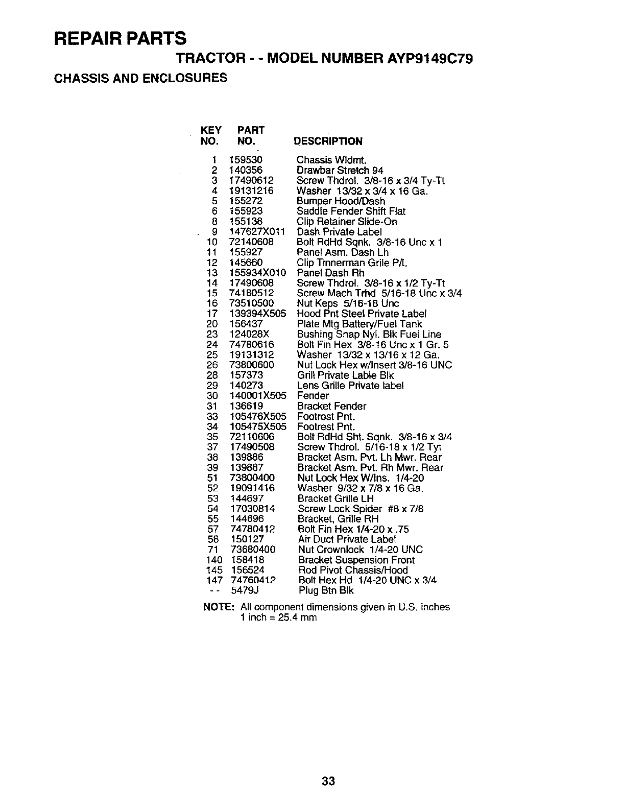
REPAIR PARTS
TRACTOR --MODEL NUMBER AYP9149C79
CHASSIS AND ENCLOSURES
KEY PART
NO. NO.
1 159530
2 140356
3 17490612
4 19131216
5 155272
6 155923
8 155138
9 147627X011
10 72140608
11 155927
12 145660
13 155934X010
14 17490608
15 74180512
16 73510500
17 139394X505
20 156437
23 124028X
24 74780616
25 19131312
26 73800600
28 157373
29 140273
30 140001X505
31 136619
33 105476X505
34 105475X505
35 72110606
37 17490508
38 139886
39 139887
51 73800400
52 19091416
53 144697
54 17030814
55 144696
57 74780412
58 150127
71 73680400
140 158418
145 156524
147 74760412
- - 5479J
DESCRIPTION
Chassis Wldmt.
Drawbar Stretch 94
Screw Thdrol. 3/8-16 x 3/4 Ty-Tt
Washer 13/32 x 3/4 x 16 Ga.
Bumper Hood/Dash
Saddle Fender Shift Flat
Clip Retainer Slide-On
Dash Private Label
Bolt RdHd Sqnk. 3/8-16 Unc x 1
Panel Asm. Dash Lh
Clip Tinnerman Grile P/L
Panel Dash Rh
Screw Thdrol. 3/8-16 x 1/2 Ty-Tt
Screw Mach Trhd 5/16-18 Unc x 3/4
Nut Keps 5/16-18 Unc
Hood Pnt Steel Private Label
Plate Mtg Battery/Fuel Tank
Bushing Snap Nyl. BIk Fuel Line
Bolt Fin Hex 3/8-16 Uncx 1 Gr. 5
Washer 13/32 x 13/16 x 12 Ga,
Nut Lock Hex w/Insert 3/8-16 UNC
Grill Private Lable BIk
Lens Grille Private label
Fender
Bracket Fender
Footrest Pnt.
Footrest Pnt.
Bolt RdHd Sht. Sqnk. 3/8-16 x 3/4
Screw Thdrel, 5/16-18 x 1/2 Tyt
Bracket Asm. Pvt. Lh Mwr. Rear
Bracket Asm. Pvt. Rh Mwr. Rear
Nut Lock HexW/Ins. 1/4-20
Washer 9/32 x 7/8 x 16 Ga.
Bracket Grille LH
Screw Lock Spider #8 x 7/8
Bracket, Grille RH
Bolt Fin Hex 1/4-20 x .75
Air Duct Private Label
Nut Crownlock 1/4-20 UNC
Bracket Suspension Front
Rod Pivot Chassis/Hood
Bolt Hex Hd 1/4-20 UNC x 3/4
Plug Btn BIk
NOTE: All component dimensions given in U.S. inches
1 inch = 25.4 mm
33
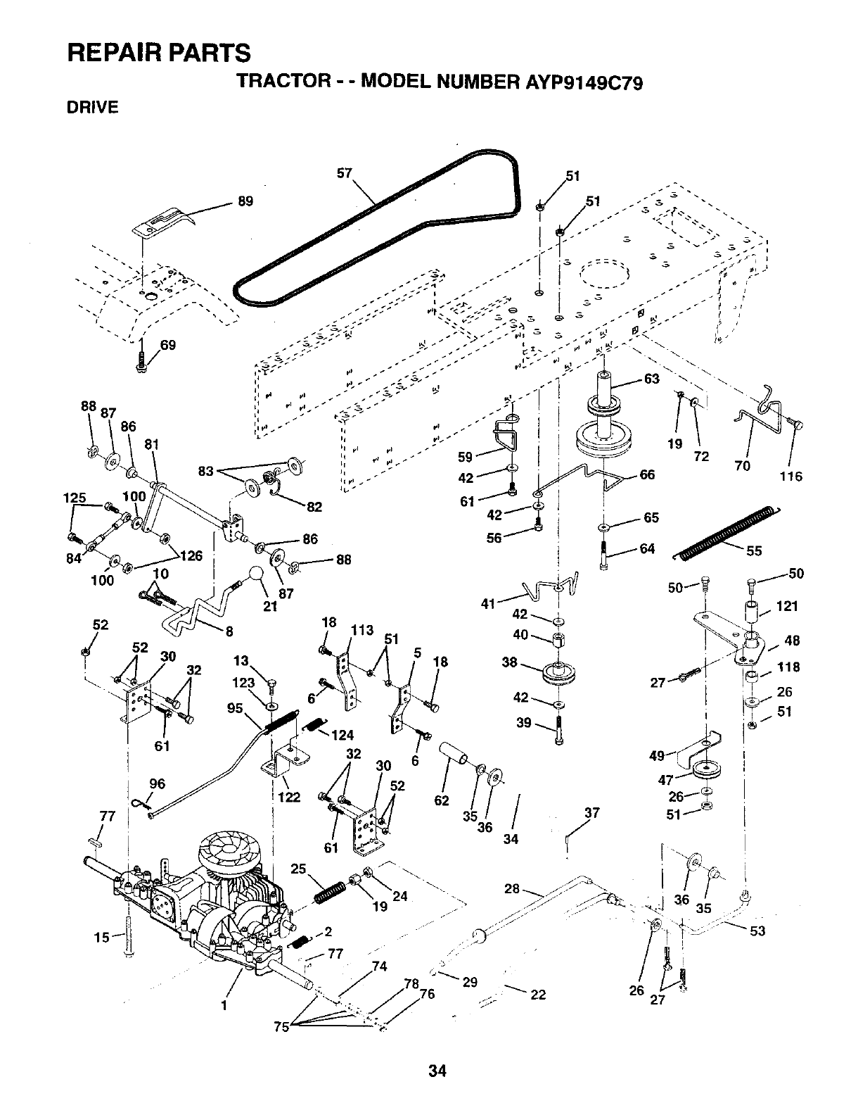
REPAIR PARTS
DRIVE TRACTOR --MODEL NUMBER AYP9149C79
187 86
81
125
lOO
52
61
96
77
I
1122 52
i " ° /37
34 _'/
22 26 -_
27
34
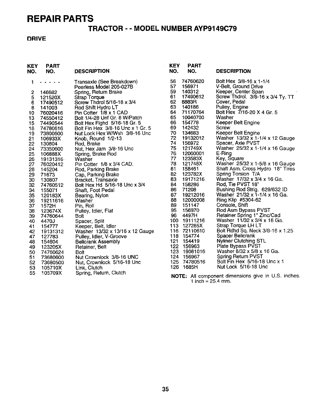
REPAIR PARTS
TRACTOR - - MODEL NUMBER AYP9149C79
DRIVE
KEY PART KEY PART
NO. NO. DESCRIPTION NO. NO. DESCRIPTION
1 .....
2146682
5121520X
617490512
8 141003
10 76020416
13 74550412
15 7449O544
18 74780616
19 73800600
21 106933X
22 130804
24 73350600
25 106888X
26 19131316
27 76020412
28 145204
29 71673
30 130807
32 74760512
34 155071
35 120183X
36 19211616
37 1572H
38 123674X
39 74760644
40 4470J
41 154777
42 19131312
47 127783
48 154604
49 123205X
50 74760624
51 73680600
52 73680500
53 105710X
55 105709X
Transaxle (See Breakdown) 56 74760620
Peerless Model 205-027B 57 156971
Spring, Return Brake 59 140312
Strap Torque 61 17490612
Screw Thdrol 5/16-18 x 3/4 62 8883R
Rod Shift Hydro LT 63 140186
Pin Cotter 1/8 x I CAD 64 71170764
Bolt 1/4-28 Unf Gr. 8 W/Patch 65 10040700
Bolt Hex Flghd 5/16-18 Gr. 5 66 154778
Bolt Fin Hex 3/8-16 Uric x 1 Gr. 5 69 142432
Nut Lock Hex W/Wsh 3/8-16 Unc 70 134683
Knob, Round 1/2-13 72 19132012
Rod, Brake 74 156972
Nut, Hex Jam 3/8-16 Unc 75 121749X
Spring, Brake Rod 76 12000001
Washer 77 123583X
Pin Cotter 1/8 x 3/4 CAD. 78 121748X
Rod, Parking Brake 81 158461
Cap, Parking Brake 82 123782X
Bracket, Transaxle 83 19171216
Bolt Hex Hd 5/16-18 Unc x 3/4 84 158286
Shaft, Foot Pedal 86 71208
Bearing, Nylon 87 19212016
Washer 88 12000008
Pin, Roll 89 151147
Pultey, Idler, Flat 95 156970
Bolt 96 4497H
Spacer, Split 100 19111216
Keeper, Belt, Idler 113 127285X
Washer 13/32 x 13/16 x 12 Gauge 116 72110610
Pulley, Idler, V-Groove 118 154774
Bellcrank Assembty 121 154419
Retainer, Belt 122 156963
Bolt 123 19081016
Nut Crownlock 3/8-16 UNC 124 156967
Nut, Crownlock 5/16-18 Unc 125 74780516
Link, Clutch 126 1685H
Spring, Return, Clutch
Bolt Hex 3/8-16 x 1-1/4
V-Belt, Ground Drive
Keeper, Center Span
Screw Thdrol. 3/8-16 x 3/4 Ty. Tr
Cover, Pedal
Pulley, Engine
Bolt Hex 7/16-20 X 4 Gr. 5
Washer
Keeper Belt Engine
Screw
Keeper Belt Engine
Washer 13/32 x 1-1/4 x 12 Gauge
Spacer, Axle PVST
Washer 25/32 x 1-1/4 x 16 Gauge
E-Ring
Key, Square
Washer 25/32 x 1-5/6 x 16 Gauge
Shaft Asm. Cross Hydro 18" Tires
Spdng Torsion T/A
Washer 17/32 x 3/4 x 16 Ga.
Rod, Tie PVST 18"
Bushing Rod Strig. 629/632 ID
Washer 21/32 x 1-1/4 x 16 Ga.
Ring Klip #5304-62
Console, Shift
Rod Asm Bypass PVST
Retainer Spring 1" Zinc/Cad
Washer 11/32 x 3/4 x 16 Ga.
Strap Torque LH LT
Bolt Rdhd Sq. Neck 3/8-16 x 1.25
Spacer Bellcrank
Nyliner Clutching STL
Plate Bypass PVST
Washer 8/32 x 5/8 x 16 Ga.
Spring Return PVST
Bolt Fin Hex 5/16-18 Unc x 1
Nut Lock 5/16-18 Unc
NOTE: All component dimensions give in U.S. inches.
1 inch = 25.4 ram.
35

REPAIR PARTS
TRACTOR ; -MODEL NUMBER AYP9149C79
STEERING ASSEMBLY
11
•/ , i
[ ...... .-_÷___ s'_|
_41
,_--'---42
|;l _37
4Q
67
7O \
8
36

REPAIR PARTS
TRACTOR - - MODEL NUMBER AYP9149C79
STEERING ASSEMBLY
KEY PART
NO. NO. DESCRIPTION
114OO44
2 154427
3 156483
4 157473
5 6266H
6121748X
7 19272016
8 12000029
9 3366R
10 156438
1! 10040600
13 154779
15 73901000
17 156546
18 57079
19 124035X
20 126684X
21 10040400
22 71100410
23 127501
25 154406
26 126847X
27 136874
28 19131416
29 17490612
30 76020412
32 130465
36 155099
37 152927
38 140045
39 19133808
40 7810H
41 100711L
42 145054
43 121749X
44 153720
46 121232X
47 6855M
51 73800500
53 73680600
54 74780520
62 156594
63 74780616
65 154780
66 154404
67 74781044
68 154429
69 160367
70 74780636
Wheel Steedng Ayp/P/L BIk
Axle Asm Fr LT W/gzks 38/42
Spindle Asm LH
Spindle Asm RH
WasherThrust .75 x 1.230
Washer 25/32 X 1-5/8 X 16 Ga
Washer 27/32 X 1-1/4 X 16 Ga
Ring Klip #t5304-75
Bearing Col Strg BIk
Link Drag
Washer Lock Hvy Hlcl Spr 3/8
Bearing Axle STLT/GT
Nut Lock Flange 5/8-11 Unc
Shaft Asm Strg Private Label
Washer Thrust 515x 750x 033
Support Shaft
Washer Shim 1/4 X 5/8 X 062
Washer Lock Hvy Helical 1/4
Screw Cap Sckt. Hd Phos & Oil
Shaft Asm Pittman
Bracket Steering
Bushing Link Drag BIk Lr
Gear Sector 22 Teeth
Washer 13/32 x 7/8 x 16 Ga.
Screw Thdrol 318-16x314 Ty-tt
Pin Cotter 1/8 x 3/4 Cad
Rod Tie Wire Form 19 75 Mech
Bushing Steering
Screw
Cap Wheel Steer Ayp
Washer 13/32 x 2-3/8 x 8 Ga
Lock Nut
Adapter Wheel Strg
Boot Shaft Steering
Washer 25/32 X 1-1/4 X 16 Ga
Shaft Extension Steering Non-Adj
Cap Spindle FrTop BIk
Fitting Grease
Nut Lock Hex W/Ins. 5/16-18 Unc P
Nut, Crownlock 3/8-16unc
Bolt Fin Hex 5/16-18 Unc 6 x 1-1/4
Kit Steering Asm Service
Bolt in Hex 3/8-16unc x 1 Gr. 5
Spacer Axle
Bearing Arm Pittman
Bolt fin Hex 5/8-11 UNC x 2-3/4
Brace Axle
Spacer, Brace, Axle
Bolt, Fin Hex 3/8-16unc x 2-1/4
NOTE: All component dimensions given in U.S. inches
1inch = 25.4 mm
37
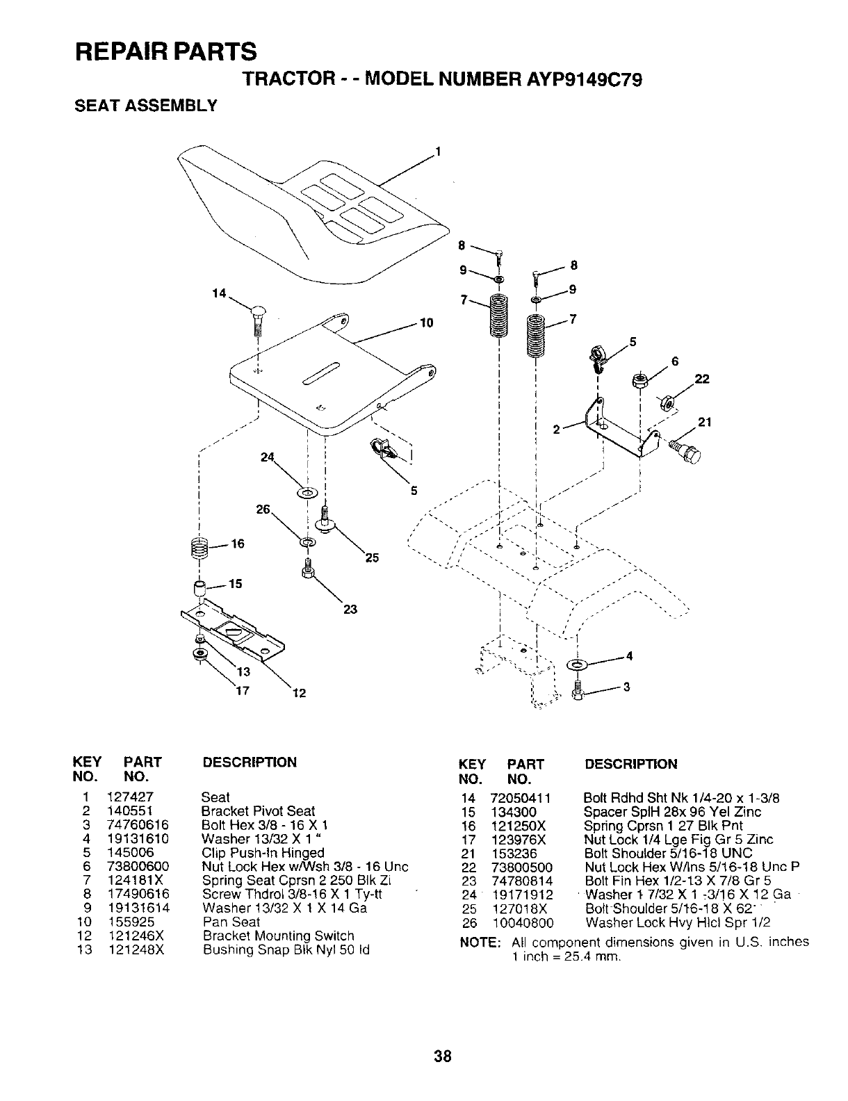
REPAIR PARTS
TRACTOR - -MODEL NUMBER AYP9149C79
SEAT ASSEMBLY
5
21
KEY PART
NO. NO.
1127427
2 140551
3 74760616
4 19131610
5 145006
6 73800600
7 124181X
8 17490616
9 19131614
10 155925
12 121246X
13 121248X
DESCRIPTION
Seat
Bracket Pivot Seat
Bolt Hex 3/8 -16 X 1
Washer 13/32 X 1 "
Clip Push-In Hinged
Nut Lock Hex w/Wsh 3/8 - 16 Unc
Spring Seat Cprsn 2 250 BIk Zi
Screw Thdro[ 3/8-16 X 1 Ty-tt
Washer 13/32 X 1 X 14 Ga
Pan Seat
Bracket Mounting Switch
Bushing Snap BIk Ny150 Id
KEY PART DESCRIPTION
NO. NO.
14 72050411
15 134300
16 121250X
17 123976X
21 153236
22 73800500
23 74780814
24 19171912
25 127018X
26 10040800
Bolt Rdhd Sht Nk 1/4-20 x 1-3/8
Spacer SplH 28x 96 Yel Zinc
Spring Cprsn 1 27 BIk Pnt
Nut Lock 1/4 Lge Fig Gr 5 Zinc
Bolt Shoulder 5/16-18 UNC
Nut Lock Hex W/ins 5/16-18 Unc P
Bolt Fin Hex 1/2-13 X 7/8 Gr 5
• Washer ! 7/32 X 1:3/16 X 12 Ga
Bolt-Shoulder 5/I-6-18 X 62
Washer Lock Hvy Hlcl Spr 1/2
NOTE: All component dimensions given in U.S. inches
1 inch = 25.4 ram.
38
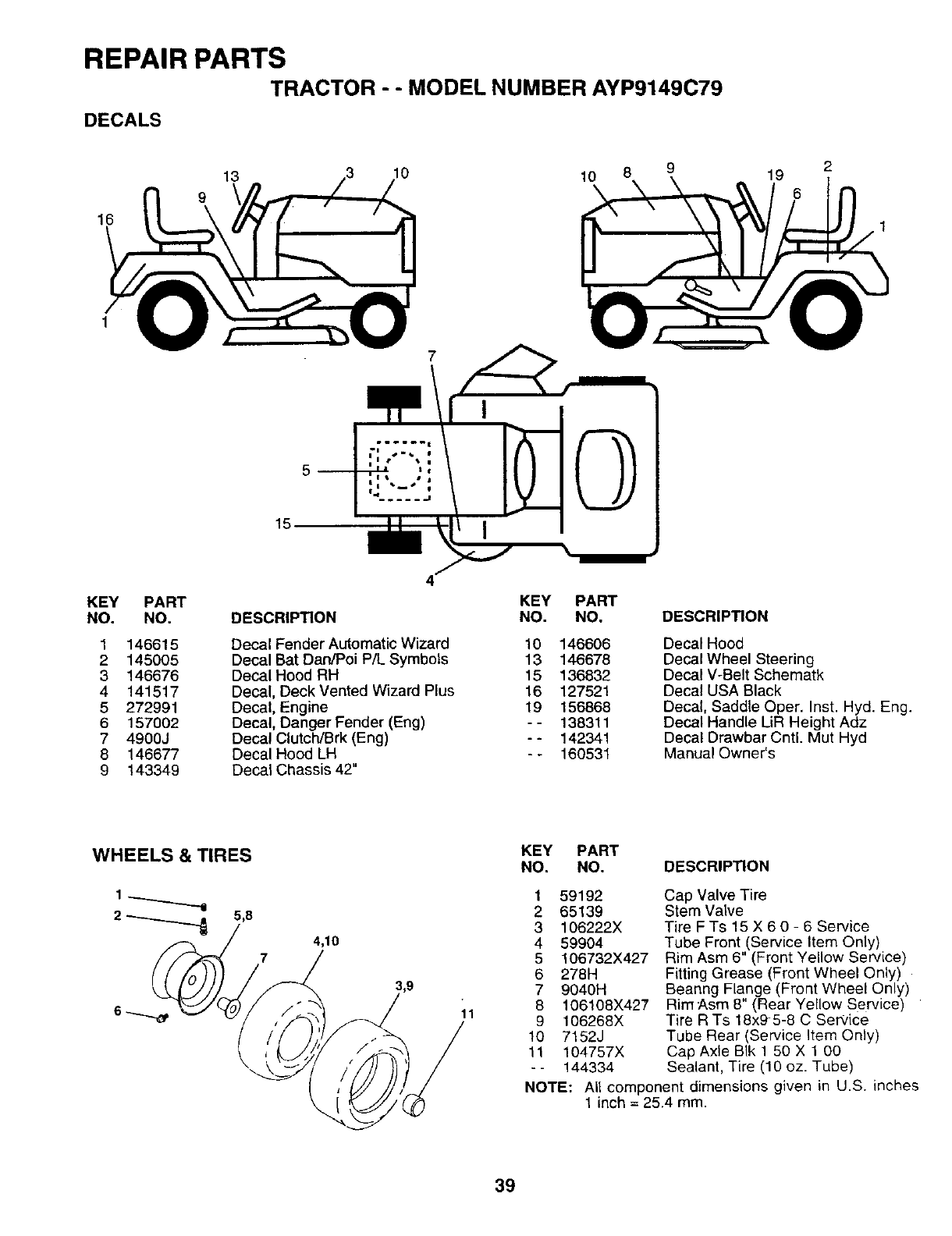
REPAIR PARTS
TRACTOR --MODEL NUMBER AYP9149C79
DECALS
16
13 10 10 819
5
15.
KEY PART KEY PART
NO. NO. DESCRIPTION NO. NO.
1
2
3
4
5
6
7
8
9
146615
145005
146676
141517
272991
157002
4900J
146677
143349
Decal Fender Automatic Wizard 10 146606
Decal Bat Dan/Poi P/L Symbols 13 146678
Decal Hood RH 15 136832
Decal, Deck Vented Wizard Plus 16 127521
Decal, Engine 19 156868
Decal, Danger Fender (Eng) - - 138311
Decal Clutch/Brk (Eng) - - 142341
Decal Hood LH -- 160531
Decal Chassis 42"
DESCRIPTION
Decal Hood
Decal Wheel Steering
Decal V-Belt Schematk
Decal USA Black
Decal, Saddle Oper. Inst. Hyd. Eng.
Decal Handle LiR Height Adz
Decal Drawbar Cntl. Mut Hyd
Manual Owner's
4,10
7
1,9
11
KEY PART
NO, NO. DESCRIPTION
1 59192
2 65139
3 106222X
4 59904
5 106732X427
6 278H
7 9040H
8 106108X427
9 106268X
10 7152J
11 104757X
-- 144334
Cap Valve Tire
Stem Valve
Tire FTs 15 X 6 0 - 6 Service
Tube Front (Service Item Only)
Rim Asm 6" (Front Yellow Service)
Fitting Grease (Front Wheel Only)
Beanng Flange (Front Wheel Only)
Rim Asm 8" (Rear Yellow Service)
Tire R Ts 18x9-5-8 C Service
Tube Rear (Service Item Only)
Cap Axle BIk 1 50 X 1 00
Sealant, Tire (10 oz. Tube)
NOTE: AU component dimensions given in U.S. inches
1 inch = 25.4 mm.
39
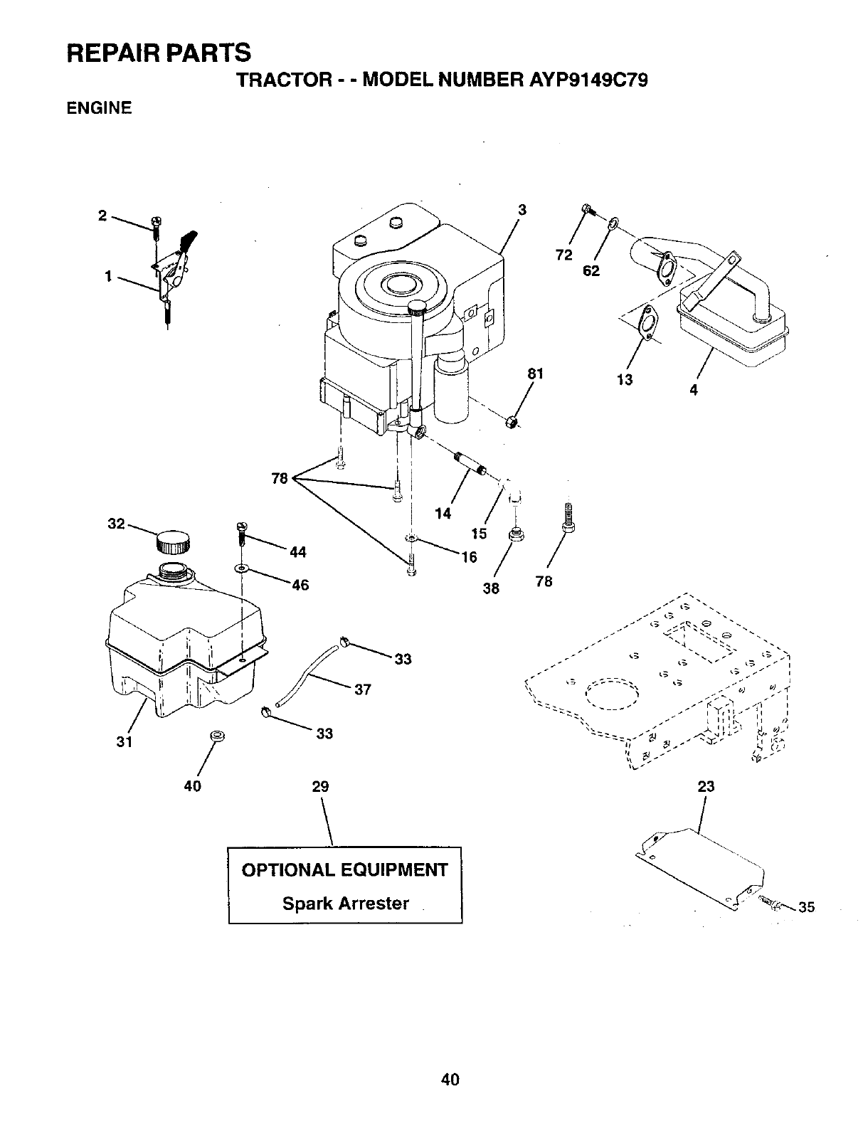
REPAIR PARTS
TRACTOR - - MODEL NUMBER AYP9149C79
ENGINE
4O
3
14 15 /
38
29
OPTIONAL EQUIPMENT
Spark Arrester
72 62
13 4
23
35
4O
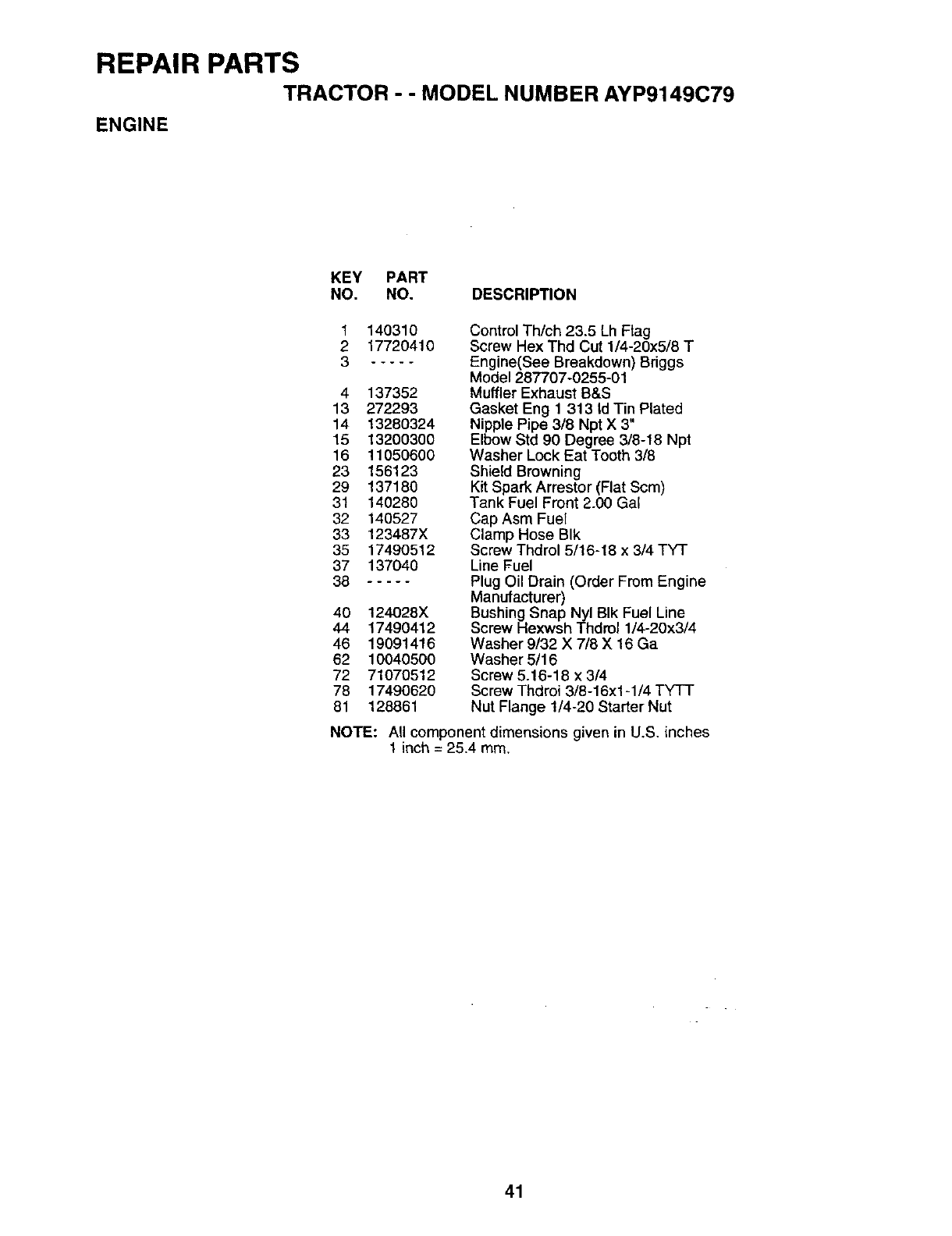
REPAIR PARTS
TRACTOR -- MODEL NUMBER AYP9149C79
ENGINE
KEY PART
NO. NO. DESCRIPTION
1
2
3
140310
17720410
4 137352
13 272293
14 13280324
15 13200300
16 11050600
23 156123
29 137180
31 140280
32 140527
33 123487X
35 17490512
37 137040
38
40 124028X
44 17490412
46 19091416
62 10040500
72 71070512
78 17490620
81 128861
Control Th/ch 23.5 Lh Flag
Screw Hex Thd Cut 1/4-20x5/8 T
Engine(See Breakdown) Briggs
Model 287707-0255-01
Muffler Exhaust B&S
Gasket Eng 1 313 Id Tin Plated
Nipple Pipe 3/8 Npt X 3"
Elbow Std 90 Degree 3/8-18 Npt
Washer Lock Eat Tooth 3/8
Shield Browning
Kit Spark Arrestor (Flat Scm)
Tank Fuel Front 2.00 Gal
Cap Asm Fuel
Clamp Hose BIk
Screw Thdrol 5/16-18 x3/4 TY-I"
Line Fuel
Plug Oil Drain (Order From Engine
Manufacturer)
Bushing Snap Nyl BIk Fuel Line
Screw Hexwsh Thdrol 1/4-20x3/4
Washer 9/32 X7/8 X 16 Ga
Washer 5/16
Screw 5.16-18 x 3/4
Screw Thdroi 3/8-16x1-1/4 TYTT
Nut Flange 1/4-20 Starter Nut
NOTE: All component dimensions given in U.S. inches
1 inch = 25.4 mm.
41

REPAIR PARTS
TRACTOR - - MODEL NUMBER AYP9149C79
LIFT
7
11
5
3
13
6
/'/I /
19
13
13
32
32 /
19
20 15 20 161,718
15
2O
42

REPAIR PARTS
TRACTOR - - MODEL NUMBER AYP9149C79
LIFT
KEY PART
NO. NO.
1 159460
2 159471
3105767X
412000002
519211621
6 120183X
7109413X
8 124526X
11 139865
12 139866
13 4939M
15 127218
16 73360800
17 130171
18 73800800
19 139868
20 3146R
31 140302
32 73540600
DESCRIPTION
Wire Asm Inner/Sprg W/Plunger
Shaft Asm Lft RH
Pin Groove
E-dng Truarc #5133-62
Washer Pltd 21/32 X 1 X 21 Ga
Bearing Nylon
Grip Handle Matte
Button Plunger Black
Link Lift LH
Link Lift RH
Retainer Spring
Link Front
Nut Jam Hex 1/2-13 Unc
Tnunnion BIk Enc
Nut Lock WhNsh 1/2-13unc
Arm Suspension Rear
Retainer Spring
Bearing Pvt. Lift Spherical
Nut Crownlock 3/8-24
NOTE: All component dimensions given in U.S. inches
1 inch = 25.4 mm
43

REPAIR PARTS
TRACTOR --MODEL NUMBER AYP9149C79
MOWER DECK
76
74
45
58
68
34
32
27
44
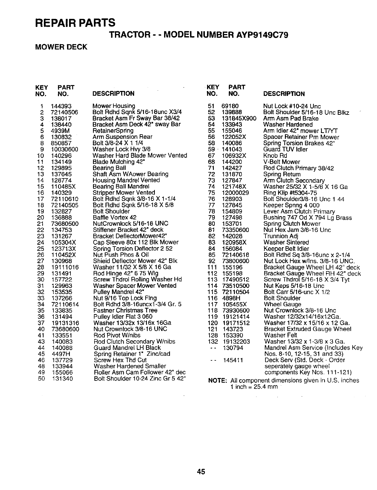
REPAIR PARTS
TRACTOR --MODEL NUMBER AYP9149C79
MOWER DECK
KEY PART KEY PART
NO. NO. DESCRIPTION NO. NO, DESCRIP_ON
1 144393
2 72140506
3 138017
4138440
5 4939M
6 130832
8 850857
9 10030600
!0 140296
11 134149
12 129895
13 137645
14 128774
15 110485X
16 140329
17 72110610
18 72140505
19 132827
20 136888
21 73680500
22 134753
23 131267
24 105304X
25 123713X
26 110452X
27 130968
28 19111016
29 131491
30 157722
3t 129963
32 153535
33 137266
34 72110614
35 133835
36 131494
37 19131316
40 73680600
41 133551
43 140083
44 140088
45 4497H
46 137729
48 133944
49 155066
50 131340
MowerHousing 51 69180
Bolt Rdhd Sqnk 5/16-18unc X3/4 52 139888
Bracket Asm Fr Sway Bar 38/42 53 131845X900
Bracket Asm Deck 42" sway Bar 54 133943
RetainerSpdng 55 155046
Arm Suspension Rear 56 122052X
Bolt 3/8-24 X 1 1/4 58 140086
Washer Lock Hvy 3/8 59 • 141043
Washer Hard Blade Mower Vented 67 106932X
Blade Mulching 42" 68 144200
Bearing Ball 71 142427
Shaft Asm WAower Bearing 72 131870
Housing Mandrel Vented 73 127847
Bearing Ball Mandrel 74 121748X
Stripper Mower Vented 75 12000029
Bolt Rdhd Sqnk 3/8-16 X 1-1/4 76 128903
Bolt Rdhd Sqnk 5/16-18 X 5/8 77 127845
Bolt Shoulder 78 154809
Baffle Vortex42 79 127498
NutCrownlock5/16-18 UNC 80 153701
Stiffener Bracket 42" deck 81 73350600
Bracket DeflectorMower42" 82 142028
Cap Sleeve 80x 112 BIk Mower 83 120958X
Spring Torsion Deflector 2 52 84 156084
Nut Push Phos & Oil 85 72140618
Shield Deflector Mower 42" Blk 92 73800600
Washer 11/32 X 5/8 X 16 Ga 111 155196
Rod Hinge 42" 6 75 Wig 112 155198
Screw Thdrol Rolling Washer Hd 113 17490512
Washer Spacer Mower Vented 114 73510500
Pulley Mandrel 42" 115 72110504
Nut 9/16 Top Lock Flng 116 4898H
Bolt Rdhd 3/8-16uncx1-3/4 Gr. 5 117 105455X
Fastner Christmas Tree 118 73930600
Pulley Idler Flat 3 060 119 19121414
Washer 13/32x 13/16x 16Ga 120 19171512
Nut Crownlock 3/8-16 UNC 121 143723
Rod Pivot W/nibs 128 153390
Rod Clutch Secondary W/nibs 132 19132203
Guard Mandrel LH Black -- 130794
Spring Retainer 1" Zinc/cad
Screw Hex Thd Cut - - 145411
Washer Hardened Smaller
Roller Asm Cam Follower 42" dec
Bolt Shoulder 10-24 Zinc Gr 5 42"
Nut Lock #10-24 Unc
Bolt Shoulder 5/16-18 Uric Blkz
Arm Asm Pad Brake
Washer Hardened
Arm Idler 42" mower LTfY-r
Spacer Retainer Pm Mower
Spring Torsion Brakes 42"
Guard TUV Idler
Knob Rd
V-Belt Mower
Rod Clutch Primary 38/42
Spring Retum
Arm Clutch Secondary
Washer 25/32 X 1-5/8 X 16 Ga
Ring Klip #t5304-75
Bolt Shoulder3/8-16 Unc 1 44
Keeper Spnng 4 000
Lever Asm Clutch Primary
Bushing 747 Od X 794 Lg Brass
Spring Clutch Mower
Nut Hex Jam 3/8-16 Unc
Trunnion Adj
Washer Sintered
Keeper Belt Idler
Bolt Rdhd Sq 3/8-16unc x 2-1/4
Nut Lock Hex w/Ins. 3/8-16 UNC.
Bracket Gauge Wheel LH 42" deck
Bracket Gauge Wheel RH 42" deck
Screw Thdrol 5/16-18 X 3/4 Tyt
Nut Keps 5/16-18 Unc
Bolt Carr 5/16-unc X 1/2
Bolt Shoulder
Wheel Gauge
Nut Crownlock 3/8-16 Unc
Washer 12/32x14/16x12Ga.
Washer 17/32 x 15/16 x 12 Ga.
Bracket Extruded Gauge Wheel
Washer Felt
Washer 13/32 x 1-3/8 x 3 Ga.
Mandrel Asrn Service (Includes Key
Nos. 8-10, 12-15, 31 and 33)
Deck Serv (Std. Deck - Order
seperately gauge wheel
components Key Nos. 111-121 )
NOTE: All component dimensions given
1inch = 25.4 mm in U.S. inches
45
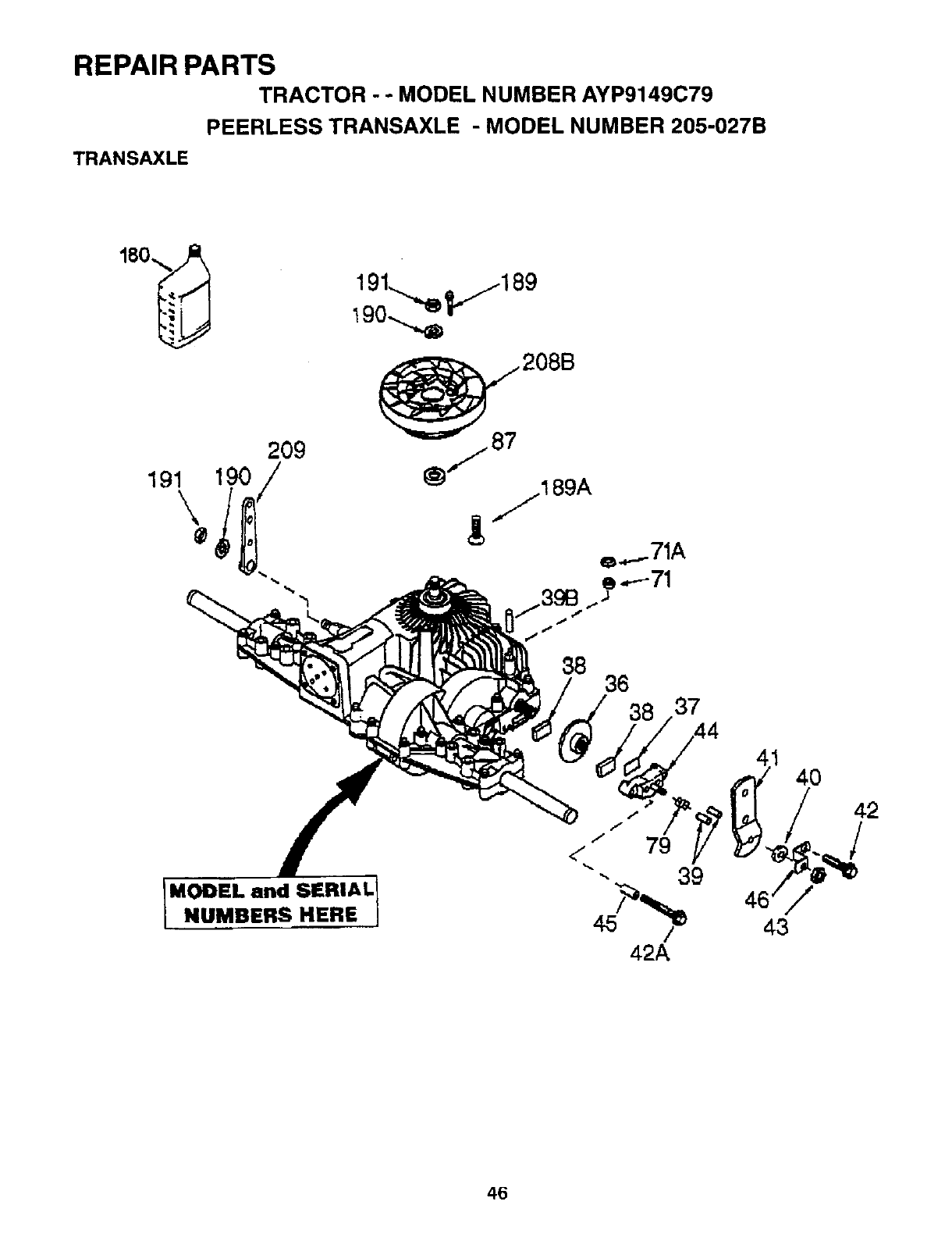
REPAIR PARTS
TRACTOR - - MODEL NUMBER AYP9149C79
PEERLESS TRANSAXLE -MODEL NUMBER 205-027B
TRANSAXLE
209
190
/87 208B
//189A
e,,._..-71A
88 36
38 37
MODEL and SERIAL
NUMBERS HERE
42A
40
42
/
43
46
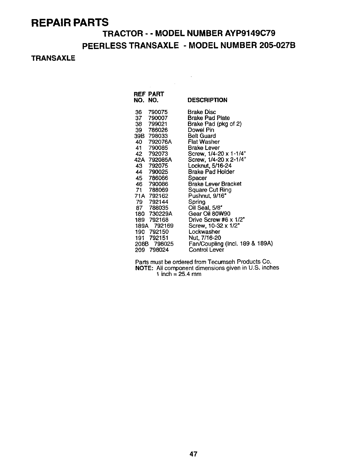
REPAIR PARTS
TRACTOR - - MODEL NUMBER AYP9149C79
PEERLESS TRANSAXLE - MODEL NUMBER 205-027B
TRANSAXLE
REF PART
NO. NO. DESCRIPTION
36 790075 Brake Disc
37 790007 Brake Pad Plate
38 799021 Brake Pad (pkg of 2)
39 786026 Dowe_ Pin
39B 798033 Belt Guard
40 792076A Flat Washer
41 790085 Brake Lever
42 792073 Screw, 1/4-20 x 1-1/4"
42A 792085A Screw, 1/4-20 x 2-1/4"
43 792075 Locknut, 5/16-24
44 790025 Brake Pad Holder
45 786066 Spacer
46 790086 Brake Lever Bracket
71 788069 Square Cut Ring
71A 792162 Pushnut, 9/16"
79 792144 Spring
87 788035 Oil Seal, 5/8"
180 730229A Gear Oi! 80W90
189 792168 Drive Screw#6 x 1/2"
189A 792169 Screw, 10-32x 1/2"
190 792150 Lockwasher
191 792151 Nut, 7/16-20
208B 798025 Fan/Coupling (Incl. 189 & 189A)
209 798024 Control Lever
Parts must be ordered from Tecumseh Products Co.
NOTE: All component dimensions given in U.S. inches
tinch = 25.4 mm
47
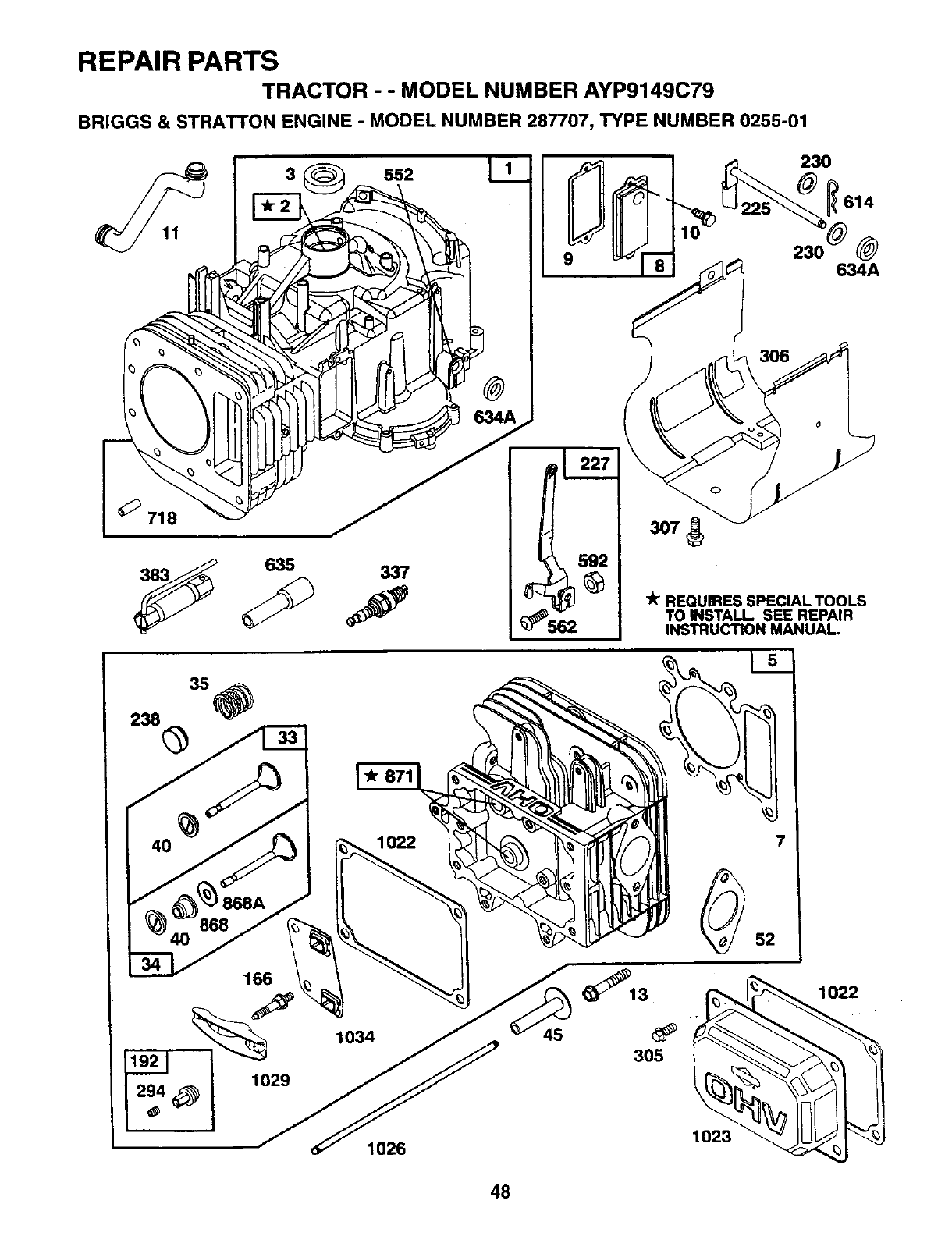
REPAIR PARTS
TRACTOR --MODEL NUMBER AYP9149C79
BRIGGS & STRATTON ENGINE -MODEL NUMBER 287707, TYPE NUMBER 0255-01
718
635
552
337
9
230
!614
@
634A
ltr REQUIRES SPECIAL TOOLS
TO INSTALL SEE REPAIR
INSTRUCTION MANUAL.
868
1034
1022
1026
48

REPAIR PARTS
TRACTOR --MODEL NUMBER AYP9149C79
BRIGGS & STRATTON ENGINE - MODEL NUMBER 287707, TYPE NUMBER 0255-01
127 138 106987 _5 117 _4 634B
121 CARBURETOR OVERHAUL KIT
27
52
164
_123
lit REQUIRES SPECIAL TOOLS
TO INSTALL. SEE REPAIR
INSTRUCTION MANUAL,
1044
741
1045
1033 VALVE OVERHAUL
49
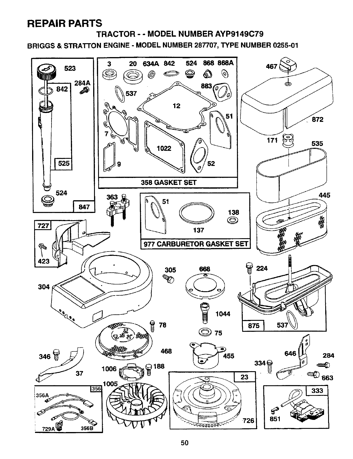
REPAIR PARTS
TRACTOR --MODEL NUMBER AYP9149C79
BRIGGS & STRATTON ENGINE -MODEL NUMBER 287707, TYPE NUMBER 0255-01
524
@
523
284A 2_634A 842 524 868 868A
358 GASKET SET
IO138
137
977 CARBURETOR GASKET SET
467
171 535
445
3O4
726
5O
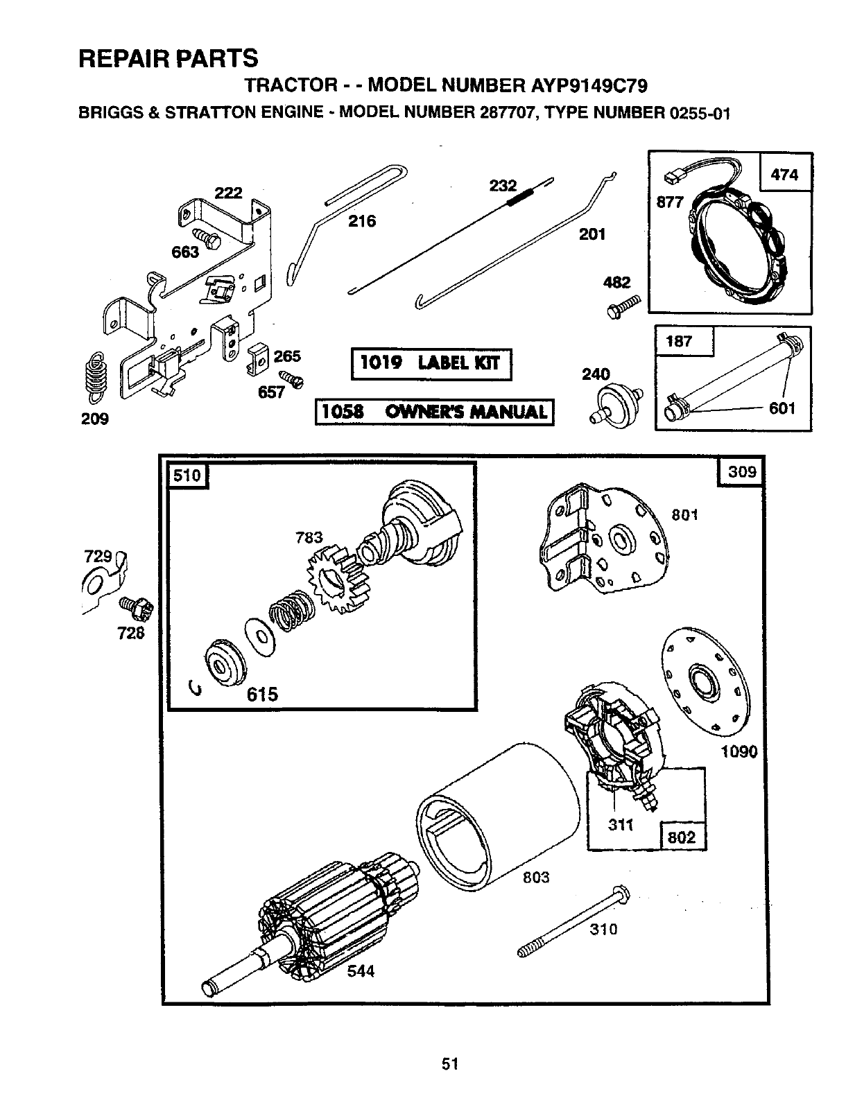
REPAIR PARTS
TRACTOR -- MODEL NUMBER AYP9149C79
BRIGGS & STRATTON ENGINE -MODEL NUMBER 287707, TYPE NUMBER 0255-01
663
877
1265
2O9
11oi,_.L,(." I2_
I10,._ OW_ltS MANUALI 801
729
728
615
783
544
801
311
1090
51
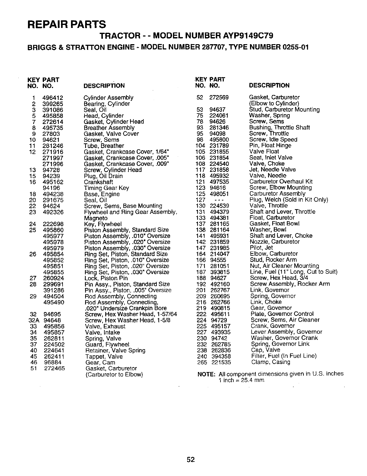
REPAIR PARTS
TRACTOR - - MODEL NUMBER AYP9149C79
BRIGGS & STRA'I-rON ENGINE - MODEL NUMBER 287707, TYPE NUMBER 0255-01
KEY PART .KEY PART
NO. NO. DESCRIPTION NO. NO. DESCRIPTION
1 496412
2 399265
3 391086
5 495858
7272614
8 495735
9 27803
10 94621
11 281246
12 271916
271997
271996
13 94728
15 94239
16 495162
94196
18 494238
20 291675
22 94624
23 492326
24 222698
25 495860
495977
495978
495979
26 495854
495852
495851
495855
27 260924
28 299691
391286
29 494504
495490
32 94695
32A 94648
33 495856
34 495857
35 262811
37 224502
40 224641
45 262411
46 96884
51 272465
Cylinder Assembly 52 272569
Bearing, Cylinder
Seal, Oil 53 94637
Head, Cylinder 75 224061
Gasket, Cylinder Head 78 94626
Breather Assembly 93 281346
Gasket, Valve Cover 95 94098
Screw, Sems 98 495800
Tube, Breather 104 231789
Gasket, Crankcase Cover, 1/64" 105 231855
Gasket, Crankcase Cover, .005" 106 231854
Gasket, Crankcase Cover, .009" 108 224540
Screw, Cylinder Head 117 231858
Plug, Oil Drain 118 495932
Crankshaft 121 497535
Timing Gear Key 123 94616
Base, Engine 125 498051
Seal, Oil 127 - - -
Screw, Sems, Base Mounting 130 224539
Flywheel and Ring Gear Assembly, 131 494379
Magneto 133 494381
Key, Flywheel 137 281165
Piston Assembly, Standard Size 138 281164
Piston Assembly, .010" Oversize 141 495931
Piston Assembly, .020" Oversize 142 231859
Piston Assembly, .030" Oversize 147 231985
Ring Set, Piston, Standard Size 164 214047
Ring Set, Piston, .010" Oversize 166 94555
Ring Set, Piston, .020" Oversize 171 281051
Ring Set, Piston, .030"Oversize 187 393815
Lock, Piston Pin 188 94627
Pin Assy., Piston, Standard Size 192 492160
Pin Assy., Piston, .005" Oversize 201 262767
Rod Assembly, Connecting 209 260695
Rod Assembly, Connecting, 216 262766
.020" Undersize Crankpin Bore 219 490815
Screw, Hex Washer Head, 1-57/64 222 495611
Screw, Hex Washer Head, 1-5/8 224 94729
Valve, Exhaust 225 495157
Valve, Intake 227 493935
Spring, Valve 230 94742
Guard, Flywheel 232 262785
Retainer, Valve Spring 238 262836
Tappet, Valve 240 394358
Gear, Cam 265 221535
Gasket, Carburetor
(Carburetor to Elbow)
Gasket, Carburetor
(Elbow to Cylinder)
Stud, Carburetor Mounting
Washer, Spring
Screw, Sems
Bushing, Throttle Shaft
Screw, Throttle
Screw, Idle Speed
Pin, Float Hinge
Valve Float
Seat, Inlet Valve
Valve, Choke
Jet, Needle Valve
Valve, Needle
Carburetor Overhaul Kit
Screw, Elbow Mounting
Carburetor Assembly
Plug, Welch (Sold in Kit Only)
Valve, Throttle
Shaft and Lever, Throttle
Float, Carburetor
Gasket, Float Bowl
Washer, Bowl
Shaft and Lever, Choke
Nozzle, Carburetor
Pilot, Jet
Elbow, Carburetor
Stud, Rocker Arm
Nut, Air Cleaner Mounting
Line, Fuel (11" Long, Cut to Suit)
Screw, Hex Head, 3/4
Screw Assembly, Rocker Arm
Link, Governor
Spring, Governor
Link, Choke
Gear, Governor
Plate, Governor Control
Screw, Sems, Air Cleaner
Crank, Governor
Lever Assembly, Governor
Washer, Governor Crank
Spring, Governor Link
Cap, Valve
Filter, Fuel (In Fuel Line)
Clamp, Casing
NOTE: All component dimensions given in U.S. inches
1inch = 25.4 mm
52
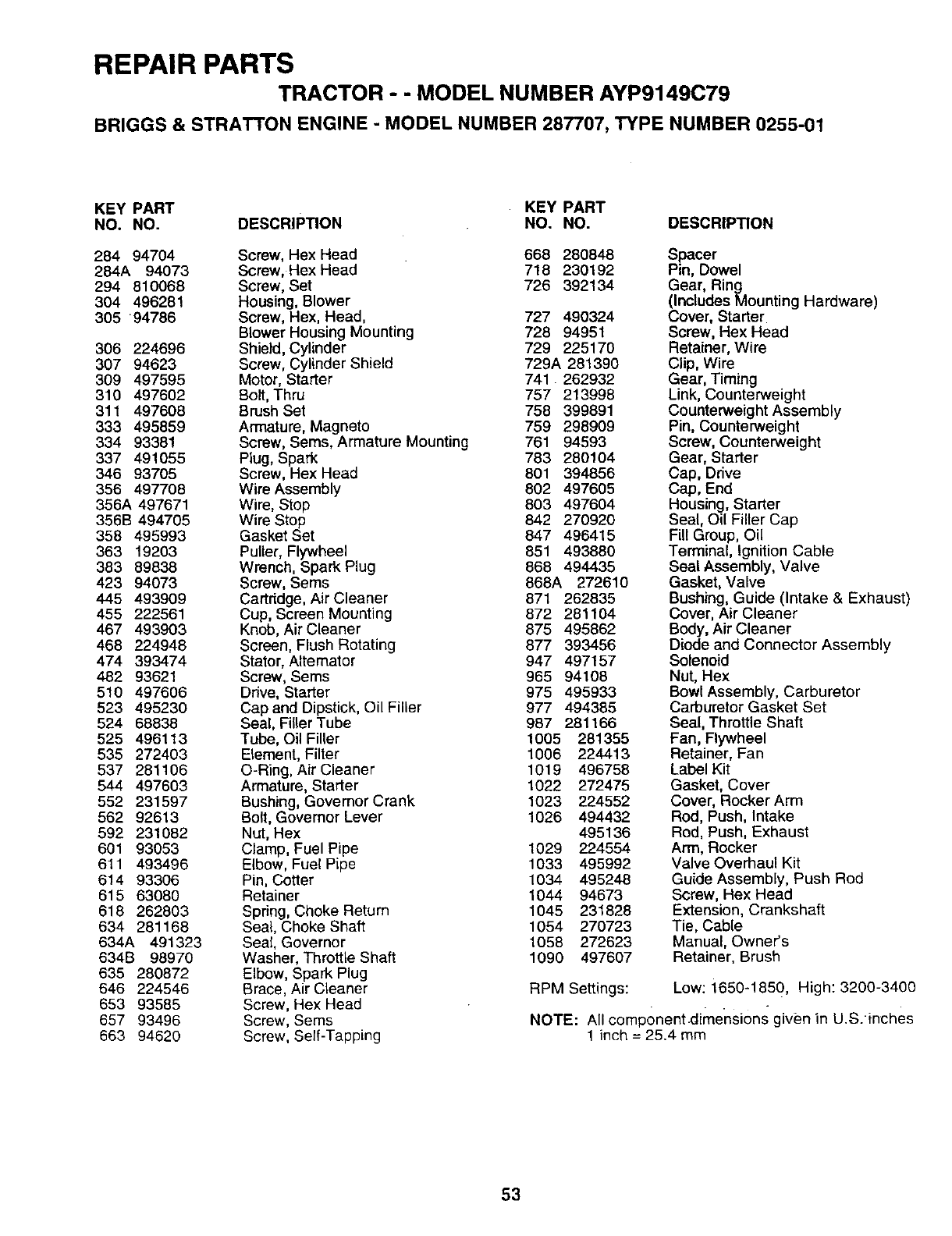
REPAIR PARTS
TRACTOR --MODEL NUMBER AYP9149C79
BRIGGS & STRATTON ENGINE -MODEL NUMBER 287707, TYPE NUMBER 0255-01
KEY PART KEY PART
NO. NO. DESCRIPTION NO. NO.
284 94704 Screw, Hex Head
284A 94073 Screw, Hex Head
294 810068 Screw, Set
304 496281 Housing, Blower
305 94786 Screw, Hex, Head, 727 490324
Blower Housing Mounting 728 94951
306 224696 Shield, Cylinder 729 225170
307 94623 Screw, Cylinder Shield 729A 281390
309 497595 Motor, Starter 741 262932
310 497602 Bolt, Thru 757 213998
311 497608 Brush Set 758 399891
333 495859 Armature, Magneto 759 298909
334 93381 Screw, Sems, Armature Mounting 761 94593
337 491055 Plug, Spark 783 280104
346 93705 Screw, Hex Head 801 394856
356 497708 Wire Assembly 802 497605
356A 497671 Wire, Stop 803 497604
356B 494705 Wire Stop 842 270920
358 495993 Gasket Set 847 496415
363 19203 Puller, Flywheel 851 493880
383 89838 Wrench, Spark Plug 868 494435
423 94073 Screw, Sems 868A 272610
445 493909 Cartridge, Air Cleaner 871 262835
455 222561 Cup, Screen Mounting 872 281104
467 493903 Knob, Air Cleaner 875 495862
468 224948 Screen, Flush Rotating 877 393456
474 393474 Stator, Altemator 947 497157
482 93621 Screw, Sems 965 94108
510 497606 Drive, Starter 975 495933
523 495230 Cap and Dipstick, Oil Filler 977 494385
524 68838 Seal, Filler Tube 987 281166
525 496113 Tube, Oil Filler 1005 281355
535 272403 Element, Filter 1006 224413
537 281106 O-Ring, AirCleaner 1019 496758
544 497603 Armature, Starter 1022 272475
552 231597 Bushing, Govemor Crank 1023 224552
562 92613 Bolt, Governor Lever 1026 494432
592 231082 Nut, Hex 495136
601 93053 Clamp, Fuel Pipe 1029 224554
611 493496 Elbow, Fuel Pipe 1033 495992
614 93306 Pin, Cotter 1034 495248
615 63080 Retainer 1044 94673
618 262803 Spring, Choke Return 1045 231828
634 281168 Seal, Choke Shaft 1054 270723
634A 491323 Seal, Governor 1058 272623
634B 98970 Washer, Throttle Shaft 1090 497607
635 280872 Elbow, Spark Plug
646 224546 Brace, Air Cleaner
653 93585 Screw, Hex Head
657 93496 Screw, Sems
663 94620 Screw, Serf-Tapping
DESCRIPTION
668 280848 Spacer
718 230192 Pin, Dowel
726 392134 Gear, Ring
(Includes Mounting Hardware)
Cover, Starter
Screw, Hex Head
Retainer, Wire
Clip, Wire
Gear, Timing
Link, Counterweight
Counterweight Assembly
Pin, Counterweight
Screw, Counterweight
Gear, Starter
Cap, Drive
Cap, End
Housing, Starter
Seal, Oil Filler Cap
Fill Group, Oil
Terminal, Ignition Cable
Seal Assembly, Valve
Gasket, Valve
Bushing, Guide (Intake & Exhaust)
Cover, Air Cleaner
Body, Air Cleaner
Diode and Connector Assembly
Solenoid
Nut, Hex
Bowl Assembly, Carburetor
Carburetor Gasket Set
Seal, Throttle Shaft
Fan, Flywheel
Retainer, Fan
Label Kit
Gasket, Cover
Cover, Rocker Arm
Rod, Push, Intake
Rod, Push, Exhaust
Arm, Rocker
Valve Overhaul Kit
Guide Assembly, Push Rod
Screw, Hex Head
Extension, Crankshaft
Tie, Cable
Manual, Owner's
Retainer, Brush
RPM Settings: Low: 1650-1850, High: 3200-3400
NOTE: All componentdimensions given in U.S.inches
1 inch = 25.4 mm
53

SERVICE NOTES
54

SUGGESTED GUIDE FOR SIGHTING SLOPES FOR SAFE OPERATION
SIGHTING " -- ...CUT'ou..
r_'i's/_. _oNOOT.r_°
ONLY RIDE UP AND DOWN HILL,
NOT ACROSS HILL
SKY LINE OR TREE.
15° MAX.
&Operate your Tractor up and down the face of slopes (not
greater than 15°), never across the face. Make turns gradu-
ally to prevent tipping or loss of control. Exercise extreme
caution when changing direction on slopes.

HOW AND WHERE TO ORDER PARTS
You can identify your product correctly by looking at its model number label which is located under the seat.
1. A. Name the product that needs a part, for example: tractor.
B. State the product's model number and factory number. These numbers appear on a label on the product.
2. Listthe description and part number of the part you want. This manual showsdrawings, descriptions, and part
numbers.
3. You may order from a participating Western Auto store. If you cannot do that, please order direct from:
Telephone: 1-800-633-8434
Western Auto National Parts Center
2107 Grand Avenue
Kansas City, MO 64108
160531 4.1.97 JH
PRtNTED IN U.S.A.
