Craftsman 917270412 User Manual LAWN TRACTOR Manuals And Guides L0809537
CRAFTSMAN Lawn, Tractor Manual L0809537 CRAFTSMAN Lawn, Tractor Owner's Manual, CRAFTSMAN Lawn, Tractor installation guides
User Manual: Craftsman 917270412 917270412 CRAFTSMAN LAWN TRACTOR - Manuals and Guides View the owners manual for your CRAFTSMAN LAWN TRACTOR #917270412. Home:Lawn & Garden Parts:Craftsman Parts:Craftsman LAWN TRACTOR Manual
Open the PDF directly: View PDF ![]() .
.
Page Count: 60

Owner's Manual
®
13.5 HP
ELECTRIC START -
42" MOWER
6 SPEED TRANSAXLE
LAW TRACTOR
Model No.
917o270412
o Safety
o Assembly
o Operation
Maintenance
o Repair Parts
CAUTION:
Read and follow all
Safety Rules and Instructions
before operating this equip-
ment.
For answers to your questions
about this product, Call:
I=800-659°5917
Sears Craftsman Help Line
5 am - 5 pm, Mon -Sat
Sears, Roebuck and Co., Hoffman Estates, IL 60179
Warranty ...................................................... 2
Safety Rules ............................................ 2
Product Specifications ................... ........ 5
Operation ............................................... 11
Maintenance Schedule .......................... 17
Maintenance ........................................... 17
Service and Adjustments ........................ 21
Storage,... ............ .................................. 27
Tr0uble'shooting..:.:: ........................... :..... 28
Repair Parts .......................................... 34
Parts Ordering ........................ Back Cover
LIMITED ONE YEAR WARRANTY ON CRAFTSMAN RIDING EQUIPMENT
For one (1) year from the date of purchase, if this Craftsman Riding Equipment is main-
tained, lubricated and tuned up according to the instructions in the owner's manual,
Sears will repair or replace, free of charge, any parts found to be defective in material or
workmanship.
This Warranty does not cover:
o Expendable items which become worn during normal use, such as blades, spark
plugs, air cleaners, belts, etco
• Tire replacement or repair caused by punctures from outside objects, such as nails,
thorns, stumps, or glass°
o Repairs necessary because of operator' abuse, negligence, tmproper storage or acci-
dent or the failure to maintain the equipment according to the instructions contained in
the owner's manual.
o Riding equipment used for commercial or rental purposes.
LIMITED 90 DAY WARRANTY ON BATTERY
For ninety (90) days from date of purchase, if any battery included with this riding equip-
ment proves defective in material or workmanship and our testing determines the bat-
tery will not hold a charge, Sears will replace the battery at no charge, in-home warranty
service on your Craftsman riding equipment is available at no charge for 30 days from
the date of purchase. Please contact your nearest service center. After 30 days from the
date of purchase, warranty service is available by taking your Craftsman riding equip-
ment to your nearest Sears Service Center. (In-home warranty service will still be avail-
able after 30 days from the date of purchase but a standard trip charge will apply)° This
warranty applies only while this product is in the United States. This Warranty gives you
specific legal rights, and you may also have other rights which may vary from state to
state.
Sears, Roebuck and Co, D/817 WA, Hoffman Estates, IL 60179
GENERAL OPERATION
o Read, understand, and follow all instruc-
tions in the manual and on the machine
before starting.
o Only allow responsible adults, who are
familiar with the instructions, to operate
the machine.
• Clear the area of objects such as rocks,
toys, wire, etc., which could be picked
up and thrown by the blade°
o Be sure the area is clear of other people
before mowing_ Stop machine if anyone
enters the area.
o Never carry passengers.
oDo not mow in reverse unless absolute-
ly necessary. Always look down and
behind before and while backing.
o Be aware of the mower discharge direc-
tion and do not point it at anyone. Do
not operate the mower without either
the entire grass catcher or the guard in
place°
o Slow down before turning,
o Never leave a running machine unat-
tended, Always turn off blades, set park-
ing brake, stop engine, and remove
keys before dismounting.
o Turn off blades when not mowing.
o Stop engine before removing grass
catcher or unclogging chute°
o Mow only in daylight or good artificial
light.
Do not operate the machine while under
the influence of alcohol or drugs°
o Watch for traffic when operating near or
crossing roadways.
o Use extra care when loading or unload-
ing the machine into a trailer or truck.
SLOPE OPERATION
Slopes are a major factor related to loss-
of-control and tipover accidents, which
can result in severe injury or death,, All
slopes require extra caution_ If you cannot
back up the slope or if you feel uneasy on
it, do not mow it.
DO:
• Mow up and down slopes, not across°
o Remove obstacles such as rocks, tree
limbs, eta
o Watch for holes, ruts, or bumps Uneven
terrain could overturn the machine,. Tall
grass can hide obstacle&
o Use slow speed., Choose a low gear so
that you will not have to stop or shift
while on the slope.
o Follow the manufacturer's recommen-
dations for wheel weights or counter-
weights to improve stability.
• Use extra care with grass catchers or
other attachments° These can change
the stability of the machine,,
. Keep all movement on the slopes slow
and gradual. Do not make sudden
changes in speed or direction_
, Avoid starting or stopping on a slope° tf
tires lose traction, disengage the blades
and proceed slowly straight down the
slope.
DO NOT:
Do notturn on slopes unless necessary,
and then, turn slowly and gradually
downhill, if possible_
,Do not mow near drop-offs, ditches, or
embankments° The mower could sud_
denly turn over if a wheel is over the
edge of a cliff or ditch, or if an edge
caves in.,
,Do not mow on wet grass.. Reduced
traction could cause sliding..
•Do not try to stabilize the machine by
putting your foot on the ground,
oDo not use grass catcher on steep
slopes.
CHILDREN
Tragic accidents can occur if the operator
is not alert to the presence of children,,
Children are often attracted to the
machine and the mowing activity.. Never
assume that children will remain where
you last saw them°
• Keep children out of the mowing area
and under the watchful care of another
responsible adult.
o Be alert and turn machine off if children
enter the area°
o Before and when backing, look behind
and down for small children.
• Never carry children. They may fall off
and be seriously injured or interfere with
safe machine operation°
o Never allow children to operate the
machine.
o Use extra care when approaching blind
corners, shrubs, trees, or other objects
that may obscure vision.
SERVICE
o Use extra care in handling gasoline and
other fuels. "]'hey are flammable and
vapors are explosive,,
- Use only an approved container°
- Never remove gas cap or add fuel
with the engine running° Allow en-
gine to coo! before refueling. Do not
smoke.
- Never refuel the machine indoors°
- Never store the machine or fuel
container inside where there is an
open flame, such as a water heater
o Never run a machine inside a closed
area.
o Keep nuts and bolts, especially blade
attachment bolts, tight and keep equip-
ment in good condition.
o Never tamper with safety devices,
Check their proper operation regularly_
o Keep machine free of grass, leaves, or
other debris build-up. Clean oil or fuel
spillage° Allow machine to cool before
storing°
*Stop and inspect the equipment if you
strike an object,. Repair, if necessary',
before restarting.
3
Nevermakeadjustmentsor repairswith
to wear,damage,anddeterioration,
which could expose moving parts or
allow objects to be thrown. Frequently
check components and replace with
manufacturer's recommended parts,
when necessary.
° Mower blades are sharp and can cut.
Wrap the blade(s) or wear gloves, and
Use extra Caution when Servicing them.
o Check brake operation frequently.
Adjust and service as required.
•Be sure the area is clear of other people
before mowing, Stop machine if anyone
enters the area.
. Never carp] passengers_
, Do not mow in reverse unless absolute-
ly necessary. Always look down and
behind before and while backing.
o Never carry children. They may fall off
and be seriously injured or interfere with
safe machine operation.
o Keep children out of the mowing area
and under the watchful care of another
responsible adulL
o Be alert and turn machine off if children
enter the area_
oBefore and when backing, look behind
and down for small children.
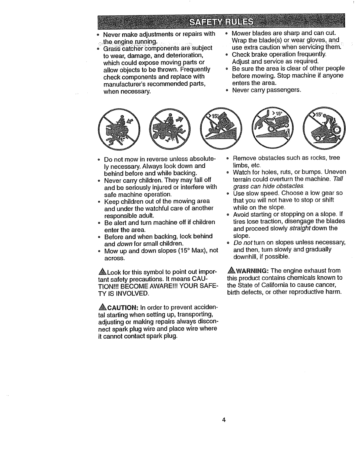
o Mow up and down slopes (15 ° Max), not
across.
,_Look for' this symbol to point out impor-
tant safety precautions. It means CAU-,
TtON!!! BECOME AWARE!!! YOUR SAFE-
TY IS INVOLVED.
_CAUTION: In order to prevent accidem
tal starting when setting up, transporting,
adjusting or making repairs always discon-
nect spark plug wire and place wire where
it cannot contact spark plug.
o Remove obstacles such as rocks, tree
limbs, etc.
• Watch for holes, ruts, or bumps. Uneven
terrain could overturn the machine. Tall
grass can hide obstacles.
o Use slow speed_ Choose a tow gear so
that you will not have to stop or shift
while on the slope_
o Avoid starting or stopping on a slopes If
tires lose traction, disengage the blades
and proceed slowly straight down the
slope.
oDo not turn on slopes unless necessary,
and then, turn slowly and gradually
downhill, if possible_
•_WARNING: The engine exhaust from
this product contains chemicals known to
the State of California to cause cancer,
birth defects, or other reproductive harm°
4
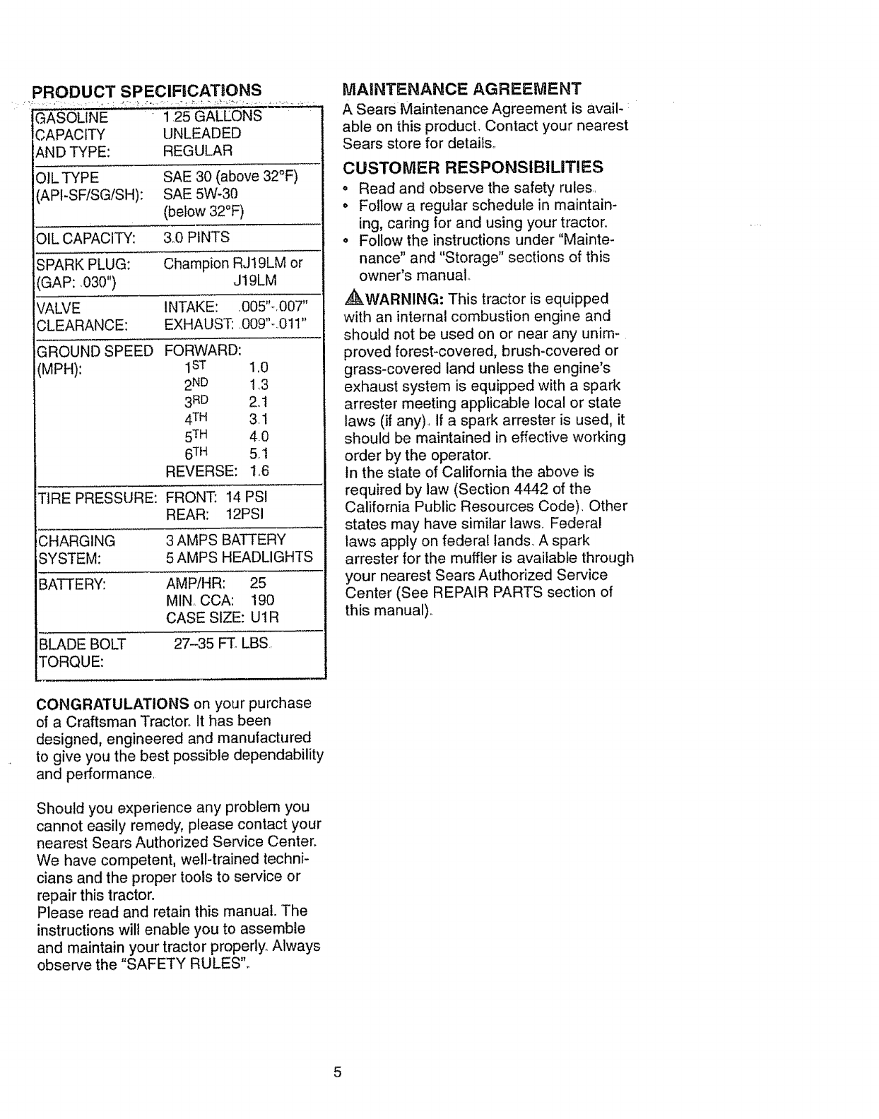
PRODUCT SPECIFICATLONS
" AsouNE: GALLO.S
CAPACITY UNLEADED
AND TYPE: REGULAR
OlL TYPE SAE 30 (above 32°F)
(API-SF/SG/SH): SAE 5W-30
(below 32°F)
OIL CAPACITY: &0 PINTS
SPARK PLUG: Champion RJI9LM or
GAP: ,030") J19LM
VALVE INTAKE: .O05"-.007"
CLEARANCE: EXHAUST: .009"-..01t"
GROUND SPEED
(MPH):
FORWARD:
1sT 1.0
2ND 1,3
3RD 2.t
4 TM 3.1
5TM 4 0
6TM 5.1
REVERSE: Io6
TIRE PRESSURE: FRONT: 14 PSI
REAR: 12PSI
CHARGING 3 AMPS BATTERY
SYSTEM: 5 AMPS HEADLIGHTS
BATTERY: AMP/HR: 25
MIN, CCA: 190
CASE SIZE: UIR
BLADE BOLT 27-35 FT. LBS.
TORQUE:
CONGRATULATIONS on your purchase
of a Craftsman Tractor° It has been
designed, engineered and manufactured
to give you the best possible dependability
and performance.
Should you experience any problem you
cannot easily remedy, please contact your
nearest Sears Authorized Service Center.
We have competent, well-trained techni-
cians and the proper tools to service or
repair this tractor°
Please read and retain this manual. The
instructions wil! enab{e you to assemble
and maintain your tractor properly.. Always
observe the "SAFETY RULES".
MAINTENANCE AGREEMENT
A Sears Maintenance Agreement is avail-
able on this product, Contact your nearest
Sears store for details°
CUSTOMER RESPONSIBILITIES
oRead and observe the safety rules.,
o Follow a regular schedule in maintain-
ing, caring for and using your tractor.
,, Follow the instructions under "Mainte-
nance" and "Storage" sections of this
owner's manual,.
,_WARNING" This tractor is equipped
with an internal combustion engine and
should not be used on or near any unim-
proved forest-covered, brush-covered or
grass-covered land unless the engine's
exhaust system is equipped with a spark
arrester meeting applicable local or state
laws ('#any). if a spark arrester is used, it
should be maintained in effective working
order by the operator.
In the state of California the above is
required by law (Section 4442 of the
California Public Resources Code)_ Other
states may have similar laws, Federal
laws apply on federal lands_ A spark
arrester for the muffler is available through
your nearest Sears Authorized Service
Center (See REPAIR PARTS section of
this manual).
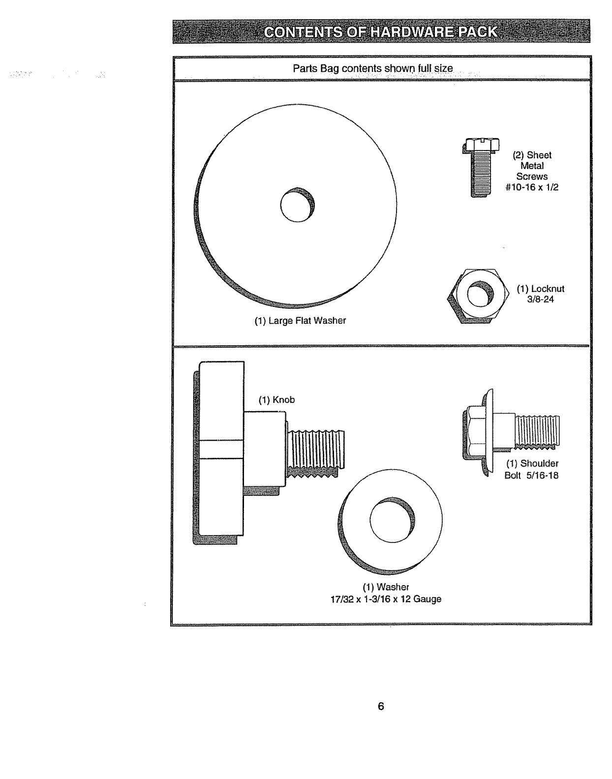
PartsBagcontentsshowr){ull size .....
(2) Sheet
Metal
Screws
#10-16 x 1/2
(1) Large Flat Washer
(1) Locknut
3/8-24
(1) Knob
t
(1) Shoulder
Bolt 5/t6-18
(1) Washer
17/32 x 1-3/16 x 12 Gauge
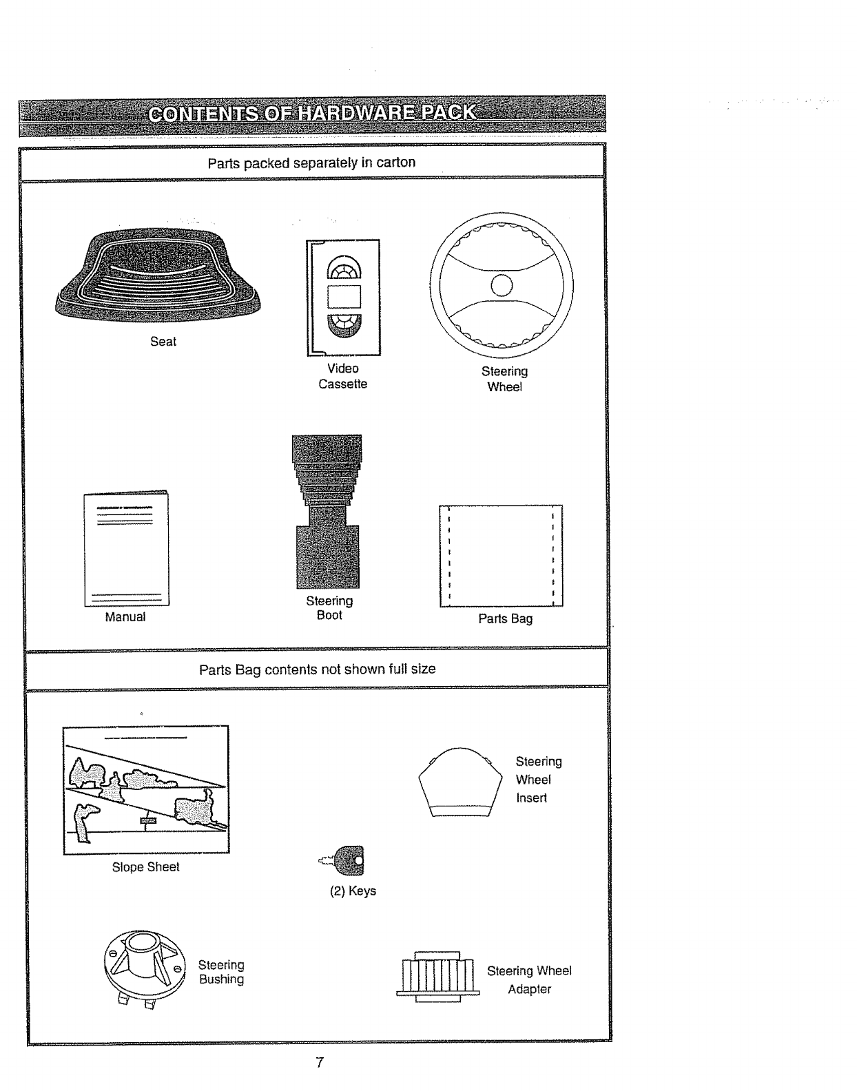
Partspackedseparatelyincarton i :
Seat
-% •.
,,,_,,
Video
Cassette Steering
Wheel
Manual
Steering
Boot
! I
I!
1 I
r 1
I l
II
I t
I I
!
Parts Bag
Parts Bag contents not shown full size
Steering
Wheel
insert
Slope Sheet
(2) Keys
__ teering
Bushing -_ Steering Wheel
,_: ............ Adapter
7
Yournewtractorhasbeenassembledat thefactorywithexceptionofthosepartsleft
unassembledforshippingpurposes.To ensuresafeandproperoperationof yourtractor
:ali_lSa'_s:ahdhardwareyouassiamblemustbetightenedsecurely.Usethecorrecttoots:_ _:
as necessaryto insurepropertightness.Reviewthevideocassettebeforeyoubegin°
TOOLS REQUIRED FOR
ASSEMBLY
A socket wrench set will make assembly
easier. Standard wrench sizes you need
are listed below_
(1) 9/16" wrench (1) Pliers
(2) 1/2" wrench (1) Utility knife
(1) Phillips Screw driver
(1) Tire pressure gauge
When right or left hand is mentioned in
this manual, it means, from your point of
view, when you are in the operating posi-
tion (seated behind the steering wheel).
TO REMOVE TRACTOR FROM
CARTON
UNPACK CARTON
o Remove all accessible loose parts and
parts boxes from shipping carton (See
page 6).
o Cut, from top to bottom, along lines on
all four corners of shipping carton, and
lay panels flat,
= Check for any additional loose parts or
boxes and remove.
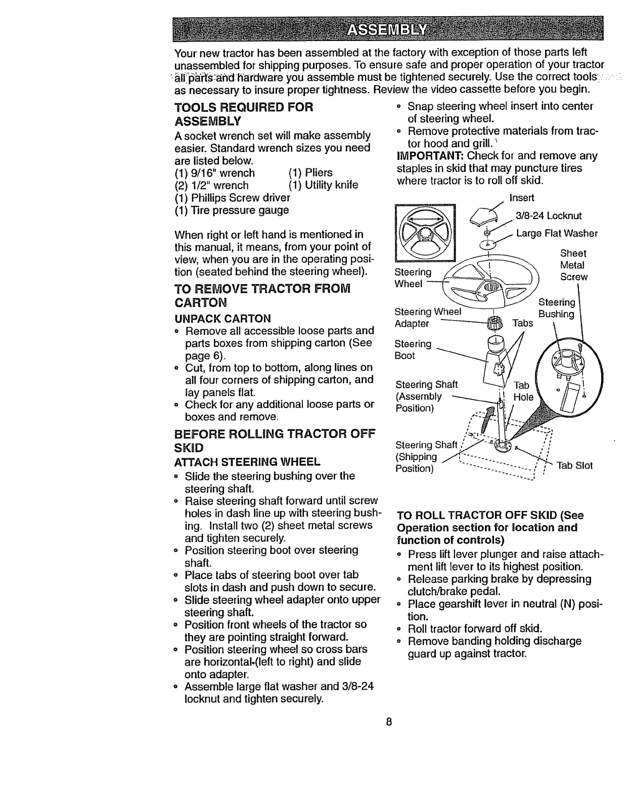
o Snap steedng wheel insert into center
of steering wheel.
o Remove protective materials from trac-
tor hood and grill.
IMPORTANT: Check for and remove any
staples in skid that may puncture tires
where tractor is to roll off skid_
Insert
_ Large Flat Washer
Sheet
StZeering _/f--._ _ -"-Q\ Metal
S" " w_Steering
teenng Bushing
Adapter _ Tabs
BootSteering_b
Steering ,,
(Assembly
Position)
BEFORE ROLLING TRACTOR OFF
SKiD
ATTACH STEERING WHEEL
° Slide the steering bushing over' the
steering shaft,
° Raise steering shaft forward until screw
holes in dash line up with steering bush-
ing_ Install two (2) sheet metal screws
and tighten securely°
o Position steering boot over steedng
shaft.
o Place tabs of steering boot over tab
slots in dash and push down to secure.
= Slide steering wheel adapter onto upper
steering shaft.
= Position flont wheels of the tractor so
they are pointing straight forward.
o Position steering wheel so cross bars
are hodzonta!.(left to right) and slide
onto adapter,
o Assemble large flat washer and 3/8-24
Iocknut and tighten securely.
Steering Shaft ' '
(Shipping "_"- _//
Position) //"'_'" .......... _ Tab Slot
TO ROLL TRACTOR OFF SKID (See
Operation section for location and
function of controls)
•Press lift lever plunger and raise attach-
ment lift lever to its highest position.
o Release parking brake by depressing
clutch/brake pedal,
°Place gearshift lever in neutral (N) posi-
tion.
°Roll tractorforward off skid.
°Remove banding holding discharge
guard up against tractor:
8
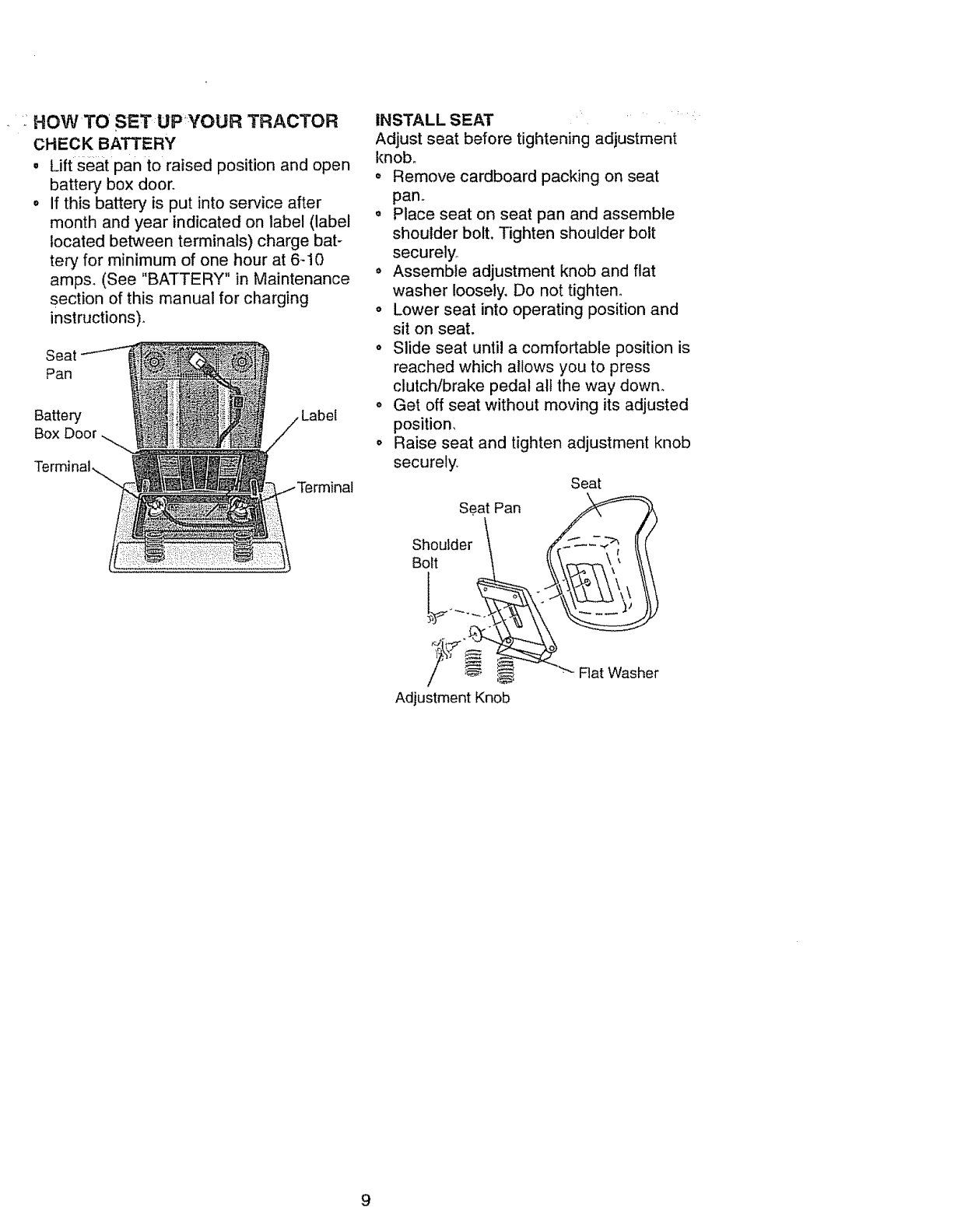
:HOWTO SETUPYOUR TRACTOR
CHECK BATTERY
•Lift seat pan to raised position and open
battery box door.
, If this battery is put into service after
month and year indicated on label (label
located between terminals) charge bat-
tery for minimum of one hour at 6-10
amps. (See "BATTERY" in Maintenance
section of this manual for charging
instructions)°
Seat
Pan
Ba_e_
Box
INSTALL SEAT
Adjust seat before tightening adjustment
knob°
o Remove cardboard packing on seat
pan..
o Place seat on seat pan and assemble
shoulder bolt, Tighten shoulder bolt
securely,
•Assemble adjustment knob and flat
washer loosely, Do not tighten.
o Lower seat into operating position and
sit on seat.
o Slide seat until a comfortable position is
reached which allows you to press
clutch/brake pedal al! the way down.
• Get off seat without moving its adjusted
position,
o Raise seat and tighten adjustment knob
securely.
Seat
Seat Pan
Shoulder
Bolt
Adjustment Knob
Fiat Washer
9
CHECK DECK LEVELNESS
For best cutting results, mower housing
should be properly leveled° See "TO
LEVELMOWER HOUSING":in the
Service and Adjustments section of this:: ....
manual,
CHECK FOR PROPER POSITION OF
ALL BELTS
See the figures that are shown for replaco
ing motion and mower blade drive belts in
the Service and Adjustments sectoin of
this manual° Verify that the belts are rout-
ed correctly.
CHECK BRAKE SYSTEM
After you ieam how to operate your trac-
tor, check to see that the brake is properly
adjusted. See "TO ADJUST BRAKE" in
the Service and Adjustments section of
this manual
_"CHECKLIST
PLEASE REVIEW THE FOLLOWING
CHECKLIST:
,[ A!l:assemblyinstructions have been
completed.
•/No remaining loose parts in carton.
_," Battery is properly prepared and
charged. (Minimum 1 hour at 6 amps)_
•/Seat is adjusted comfortably and
tightened securely.
#" All tires are propedy inflated. (For
shipping pu_oses, the tires were
overinflated at the factory)°
#" Be sure mower deck is properly leveled
side-to-side/front-to-rear for best
cutting results. (Tires must be properly
inflated for leveling).
J Check mower and ddve bett& Be sure
they are routed properly around pulleys
and inside all belt keepers,
,/ Check wiring. See that all connections
are still secure and wires are properly
clamped.
WHILE LEARNING HOW TO USE YOUR
'TRACTOR, PAY EXTRA,_TTENTION TO
THE FOLLOWING IMPORTANT ITEMS:
,/ Engine oil is at proper level.
,/ Fuel tank is filled with fresh, clean,
regular unleaded gasoline.
#' Become familiar with all controls - their
location and function. Operate them
before you start the engine_
,/" Be sure brake system is in safe
operating condition°
10
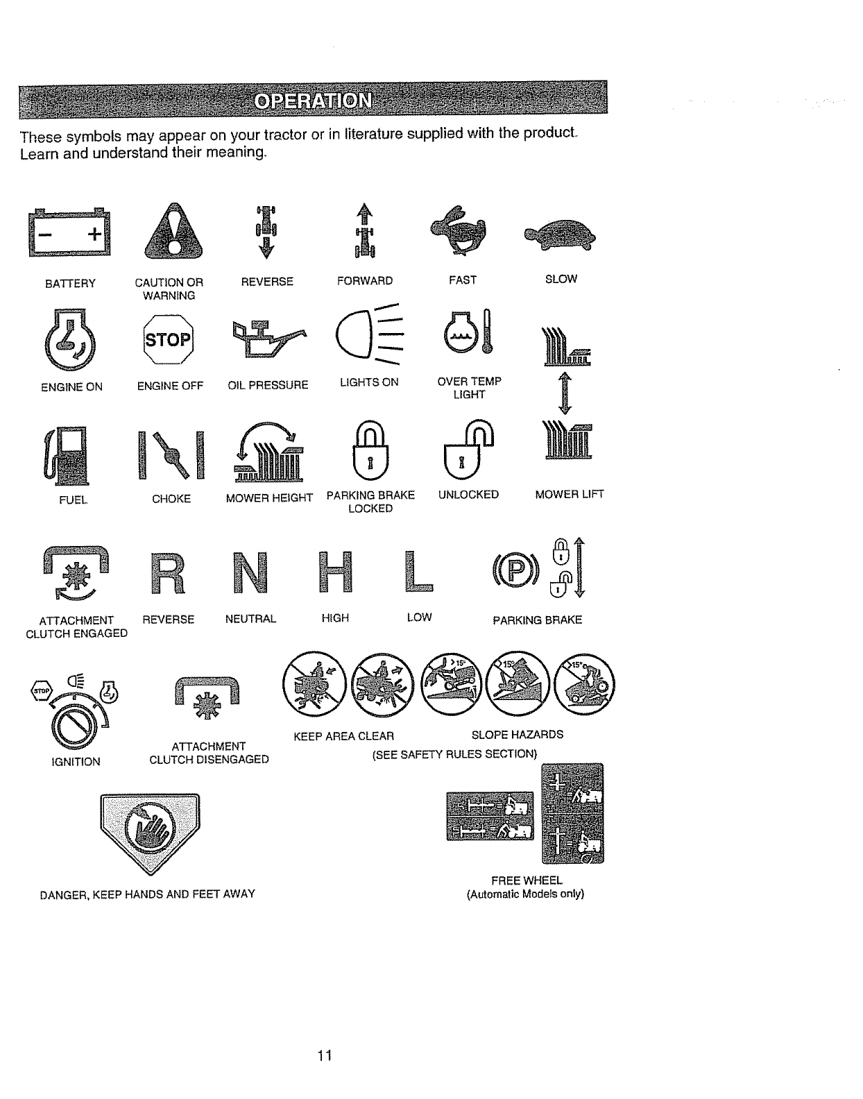
Thesesymbolsmayappearonyourtractoror inliteraturesuppliedwith the producL
Learn and understand their meaning,,
BATTERY
ENGINE ON
FUEL
CAUT1ON OR REVERSE FORWARD
WARNING
ENGINE OFF OIL PRESSURE LIGHTS ON
MOWER HEIGHT
\
CHOKE PARKING BRAKE
LOCKED
FAST
OVER TEMP
LIGHT
UNLOCKED
SLOW
MOWER LIFT
ATTACHMENT
CLUTCH ENGAGED
REVERSE
H
NEUTRAL HIGH
L ®)St
LOW PARKING BRAKE
IGNITION
ATTACHMENT
CLUTCH DISENGAGED
KEEP AREA CLEAR SLOPE HAZARDS
(SEE SAFETY RULES SECTION}
DANGER, KEEP HANDS AND FEET AWAY
FREE WHEEL
(Automatic Models only)
11
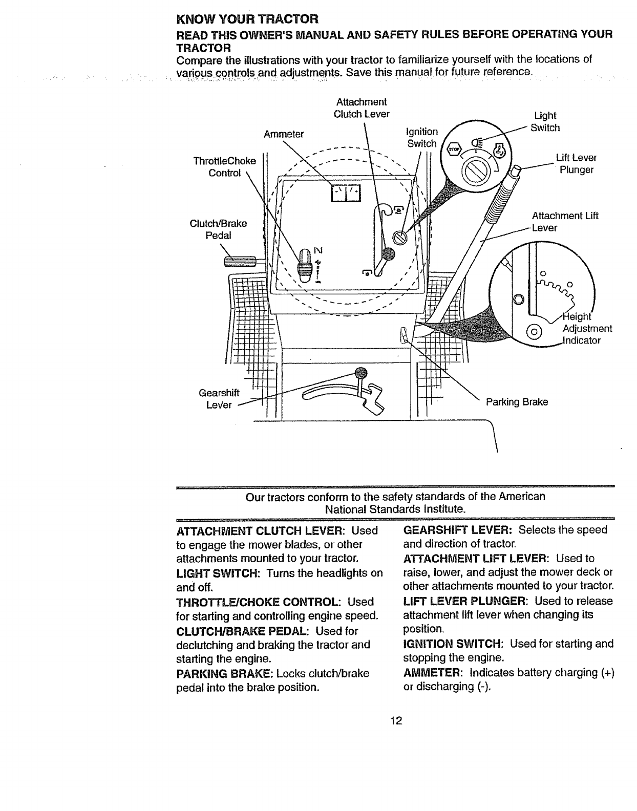
KNOW YOUR TRACTOR
READ THiS OWNER'S MANUAL AND SAFETY RULES BEFORE OPERATING YOUR
TRACTOR
Compare the illustrations with your tractor to familiarize yourseif with the locations of
.... various controls and adjustments. Save this manual for future reference.
ThrottleChoke
Control
Clutch/Brake
Pedal
Attachment
Clutch Lever
Ammeter Ignition
Switch
Light
Switch
LiftLever
Plunger
Attachment Lift
ht
Adjustment
Gearshift
LeVer Parking Brake
.............................Our"'iractors €0-nform toihe safe_"Standards of the Ameiican ......
National Standards Institute.
ATTACHMENT CLUTCH LEVER: Used
to engage the mower blades, or other
attachments mounted to your tractor.
LIGHT SWITCH: Turns the headlights on
and off.
THROTTLE/CHOKE CONTROL: Used
for starting and controllingengine speed.
CLUTCH/BRAKE PEDAL: Used for
declutching and braking the tractor and
starting the engine.
PARKING BRAKE: Locks clutch/brake
pedal into the brake position.
GEARSHIFT LEVER: Selects the speed
and direction of tractor.
ATTACHMENT LIFT LEVER: Used to
raise, lower, and adjust the mower deck or
other attachments mounted to yourtractor.
LIFT LEVER PLUNGER: Used to release
attachment lift lever when changing its
position.
IGNITION SWITCH: Used for starting and
stopping the engine.
AMMETER: Indicates battery charging (+)
or discharging (-).
12
HOW TO USE YOUR TRACTOR
Your tractor is equipped with an operator
presence sensing switch° When engine
is running, any attempt by the operator to
leave the seat without first setting the
parking brake will shut off the engine.
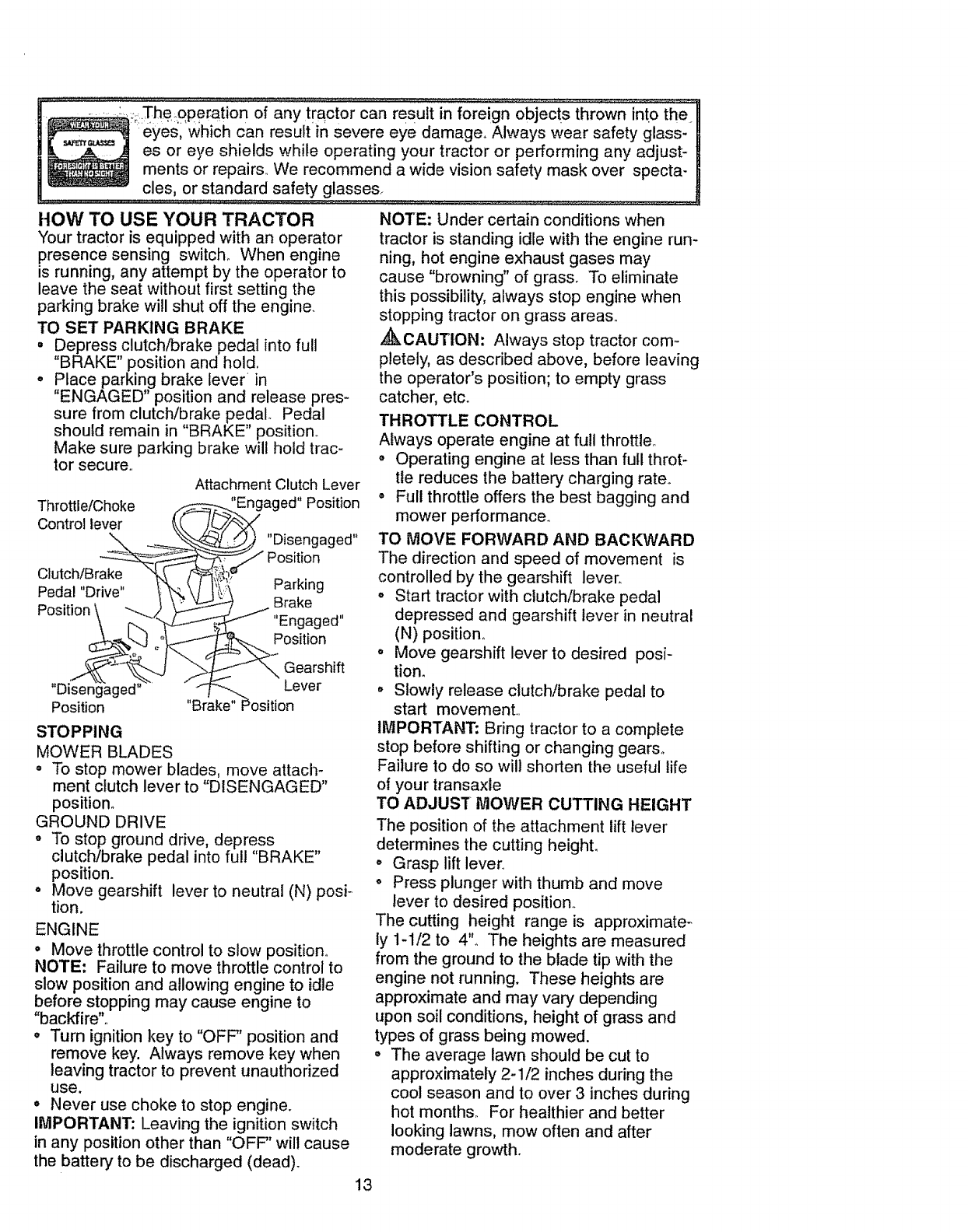
TO SET PARKING BRAKE
. Depress clutch/brake pedal into full
"BRAKE" position and hold,
o Place parking brake lever in
"ENGAGED" position and release pres-
sure from clutch/brake pedal Pedal
should remain in "BRAKE" position.
Make sure parking brake will hold trac-
tor secure.
Attachment Clutch Lever
Throttle!Choke _ -... 'Engaged" Position
Control lever _(f'--" _
_-_ _, _,_ "Disengaged"
_" Position
Clutch/Brake "q_-S- 14__; _" ,
Pedal "D;'v_' I>_._\ Ii,i_:; Park,ng
Position \ ""--4 _ _ /,,_a_e,_a,,
r__k-J o°lr<.1-_ _ Position
,, --" "-
Disengaged ,, .___,,-._ Lever
Position Brake" Position
STOPPING
MOWER BLADES
o To stop mower blades, move attach-
ment clutch lever to "DISENGAGED"
position°
GROUND DRIVE
o To stop ground drive, depress
clutch/brake pedal into full "BRAKE"
position.
o Move gearshift lever to neutral (N) posi-
tion.
ENGINE
o Move throttle control to slow position°
NOTE: Failure to move throttle control to
slow position and allowing engine to idle
before stopping may cause engine to
"backfire",
o Turn ignition key to "OFF" position and
remove key. Always remove key when
leaving tractor to prevent unauthorized
use.
° Never use choke to stop engine.
IMPORTANT: Leaving the ignition switch
in any position other than "OFF" will cause
the battery to be discharged (dead).
NOTE: Under certain conditions when
tractor is standing idle with the engine run-
ning, hot engine exhaust gases may
cause "browning" of grass. To eliminate
this possibility, always stop engine when
stopping tractor on grass areas
,_CAUTION: Always stop tractor com-
pletely, as described above, before leaving
the operator's position; to empty grass
catcher, etc.
THROTTLE CONTROL
Always operate engine at full throttle
• Operating engine at less than full throt-
tle reduces the battery charging rate,,
• Full throttle offers the best bagging and
mower performance°
TO MOVE FORWARD AND BACKWARD
The direction and speed of movement is
controlled by the gearshift lever,
° Start tractor with clutch/brake pedal
depressed and gearshift lever in neutral
(N) position.
° Move gearshift lever to desired posi-
tion.
,, Slowly release clutch/brake pedal to
start movement.
IMPORTANT: Bring tractor to a complete
stop before shifting or changing gears°
Failure to do so wilt shorten the useful life
of your transaxle
TO ADJUST MOWER CUTTING HEIGHT
The position of the attachment lift lever
determines the cutting height,
o Grasp lift lever,,
o Press plunger with thumb and move
lever to desired position.
The cutting height range is approximate-
ly 1-1/2 to 4'L The heights are measured
from the ground to the blade tip with the
engine not running. These heights are
approximate and may vary depending
upon soil conditions, height of grass and
types of grass being mowed.
• The average lawn should be cut to
approximately 2-1/2 inches during the
cool season and to over 3 inches during
hot months For healthier and better
looking lawns, mow often and after
moderate growth.
13
° Forbestcuttingperformance,grass
over6 inchesin heightshouldbe
mowedtwice. Makethe firstcut rela-
tivelyhigh;the secondto desired
TO OPERATEMOWER " ............
'(our tractor is equipped with an operator
presence sensing switch. Any attempt by
the 0perator to leave the seat with the
engine running and the attachment clutch
engaged will shut off the engine.
•Select desired height of cut ....
°Start mower blades by engaging attach-
ment clutch control.
°TO STOP MOWER BLADES - disen-
gage attachment clutch control.
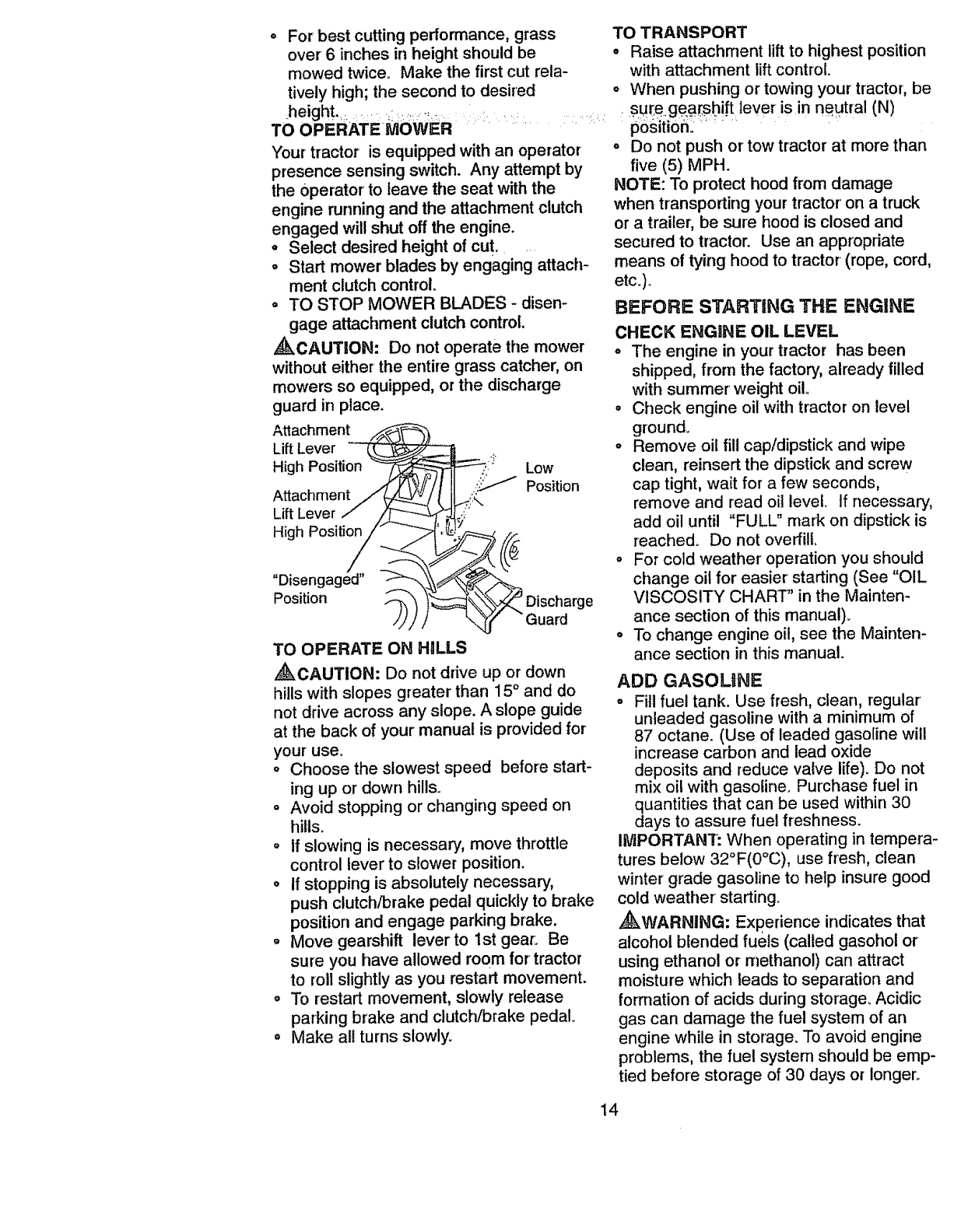
,_kCAUTION: Do not operate the mower
without either the entire grass catcher, on
mowers so equipped, or the discharge
guard in place.
Attachment
Lift Lever _L._- _...
High Position _ _" Low
Attachment /_ _ _/ Position
Lift Lever / /_-- _,.
High Positing//_
"Disengaged" ----_=_
c are
Position _",_ Dis hg
-Guard
TO OPERATE ON HILLS
,_CAUTION: Do not drive up or down
hills with slopes greater than 15 °and do
not drive across any slope. A slope guide
at the back of your manual is provided for
your use.
o Choose the slowest speed before start-
ing up or down hills.
= Avoid stopping or changing speed on
hills°
o If slowing is necessary, move throttle
control lever to slower position.
o if stopping is absolutely necessary,
push clutch/brake pedal quickly to brake
position and engage parking brake.
o Move gearshift leverto 1st gear: Be
sure you have allowed room for tractor
to roll slightly as you restart movement.
o To restart movement, slowly release
parking brake and clutch/brake pedal.
= Make all turns slowly.
TO TRANSPORT
°Raise attachment lift to highest position
with attachment lift control.
=When pushing or towing your tractor, be
sur,e.ge.a[s,hi!t lever isin neutral (N)
1_6Sitiofi:: :''" .... .....
= Do not push or tow tractor' at more than
five (5) MPH.
NOTE: To protect hood from damage
when transporting your tractor on a truck
or a trailer, be sure hood is closed and
secured to tractor. Use an appropriate
means of tying hood to tractor (rope, cord,
etc.)_
BEFORE STARTING THE ENGINE
CHECK ENGINE OIL LEVEL
° The engine in your tractor has been
shipped, from the factory, already filled
with summer weight oil
• Check engine oil with tractor on level
ground_
° Remove oil fill capldipstick and wipe
clean, reinsert the dipstick and screw
cap tight, wait for a few seconds,
remove and read oil level If necessary,
add oil until "FULL" mark on dipstick is
reached° Do not overfilL
o For cold "weather operation you should
change oil for easier starting (See "OIL
VISCOSITY CHART" in the Mainten-
ance section of this manual).
= To change engine oil, see the Mainten-
ance section in this manual
ADD GASOLINE
•Fill fuel tank. Use fresh, clean, regular
unleaded gasoline with a minimum of
87 octane. (Use of leaded gasoline will
increase carbon and lead oxide
deposits and reduce valve life). Do not
mix oil with gasoline. Purchase fuel in
quantities that can be used within 30
days to assure fuel freshness.
IIVlPORTANT: When operating in tempera-
tures below 32°F(0°C), use fresh, clean
winter grade gasoline to help insure good
cold weather starting.
,_WARNING: Experience indicates that
alcohol blended fuels (called gasohot or
using ethanol or methanol) can attract
moisture which leads to separation and
formation of acids during storage° Acidic
gas can damage the fuel system of an
engine while in storage. To avoid engine
problems, the fuel system should be emp-
tied before storage of 30 days or longer.
14
Drain the.gas .tank, start the engine and let
it run until the fuel lines and carburetor are
empty, Use fresh fuel next season. See
Storage instructions for additional informa-
tiono Never use engine or carburetor
cleaner products in the fuel tank or perma-
nent damage may occur°
,_kCAUTION: Fill to bottom of gas tank
filler neck. Do not overfill Wipe off any
spilled oil or fuel Do not store, spil! or use
gasoline near an open flame.
TO START ENGINE
When starting the engine for the first time
or if the engine has run out of fuel, it will
take extra cranking time to move fuel from
the tank to the engine°
o Sit on seat in operating position,
depress clutchlbrake pedal and set
parking brake°
o Place gear shift lever in neutral (N) posi-
tion_
o Move attachment clutch to "DISEN-
GAGED" position..
,Move throttle control to choke position..
NOTE: Before starting, read the warm
and cold starting procedures below..
• insert key into ignition and turn key
clockwise to "START" position and
release key as soon as engine starts..
Do not run starter continuously for more
than fifteen seconds per minute° If the
engine does not start after several
attempts, move throttle control to fast
position, wait a few minutes and try
again_ If engine still does not start,
move the throttle control back to the
choke position and retry..
WARM WEATHER STARTING (50 ° F and
above)
When engine starts, move the throttle
control to the fast position,.
o The attachments and ground drive can
now be used. If the engine does not
accept the load, restart the engine and
allow it to warm up for one minute using
the choke as described above.
COLD WEATHER STARTING ( 50 ° F AND
BELOW)
o When engine starts, allow engine to run
with the throttle control in the choke
position until the engine runs roughly,
then move throttle control to fast posi-
tion,, This may require an engine warm-
up period from several seconds to sev-
eral minutes, depending on the temper-
atureo
° The attachments can also be used dur-
ing the engine warm-up period.
NOTE: If at a high altitude (above 3000
feet) or in cold temperatures (below 32 F)
the carburetor fuel mixture may need to be
adjusted for best engine performance,,
See "TO ADJUST CARBURETOR" in the
Service and Adjustments section of this
manual
t5
f
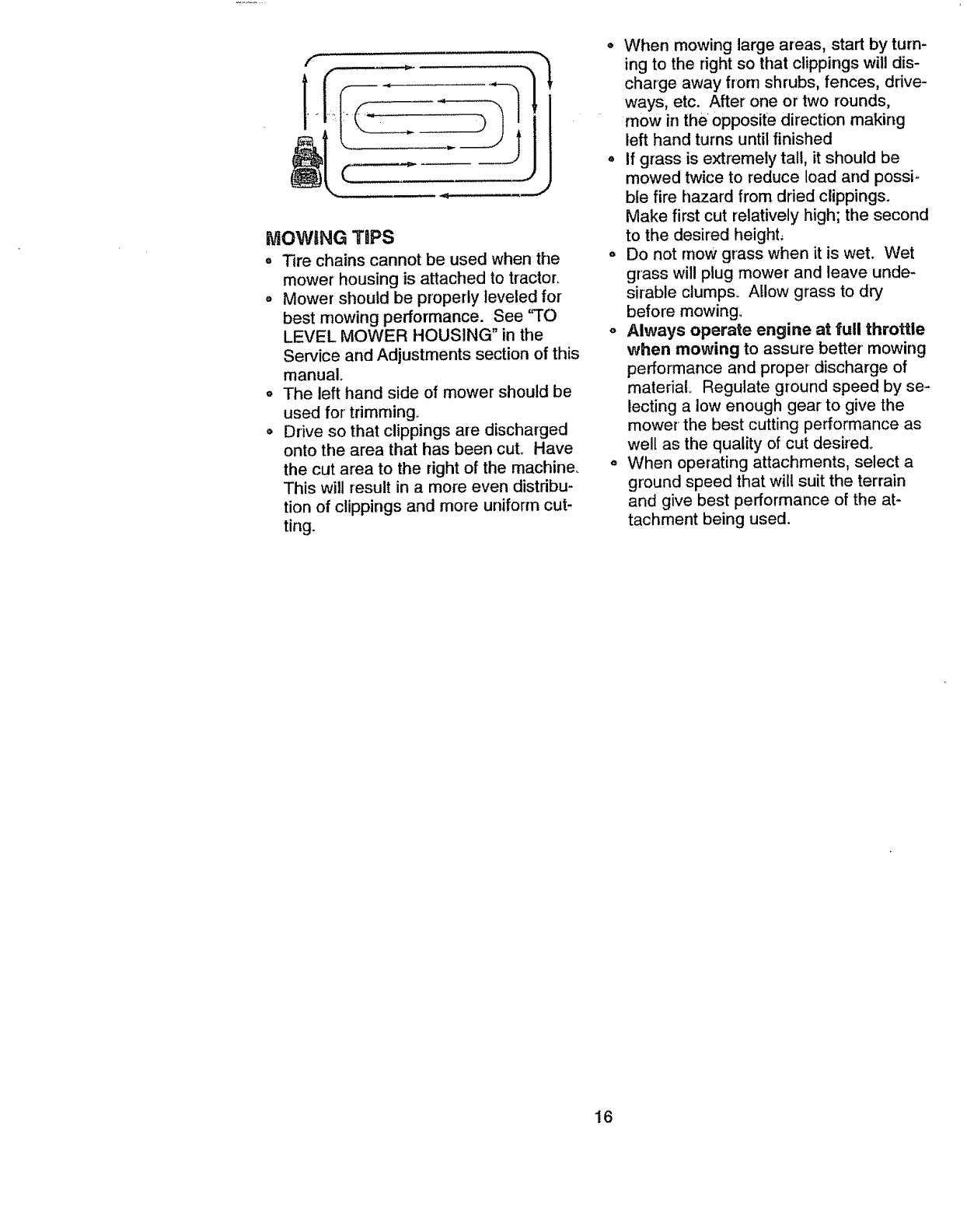
MOWING TiPS
oTire chains cannot be used when the
mower housing is attached to tractor.
o Mower should be properly leveled for
best mowing performance. See 'qO
LEVEL MOWER HOUSING" in the
Service and Adjustments section of this
manual
o The left hand side of mower should be
used for' trimming°
o Drive so that clippings are discharged
onto the area that has been cut. Have
the cut area to the right of the machine_
This will result in a more even distribu-
tion of clippings and more uniform cut-
ting.
o When mowing large areas, start by turn-
ing to the right so that clippings will dis-
charge away from shrubs, fences, drive-
ways, etc. After one or two rounds,
mow in the opposite direction making
left hand turns until finished
, If grass is extremely tall, it should be
mowed twice to reduce load and possi-
ble fire hazard from dried clippings.
Make first cut relatively high; the second
to the desired height,
o Do not rnow grass when it is wet. Wet
grass will plug mower and leave unde-
sirable clumps_ Allow grass to dry
before mowing.
oAlways operate engine at full throttle
when mowing to assure better mowing
performance and proper-discharge of
material,, Regulate ground speed by se-
lecting a low enough gear to give the
mower' the best cutting performance as
well as the quality of cut desired°
oWhen operating attachments, select a
ground speed that will suit the terrain
and give best performance of the at-
tachment being used.
16
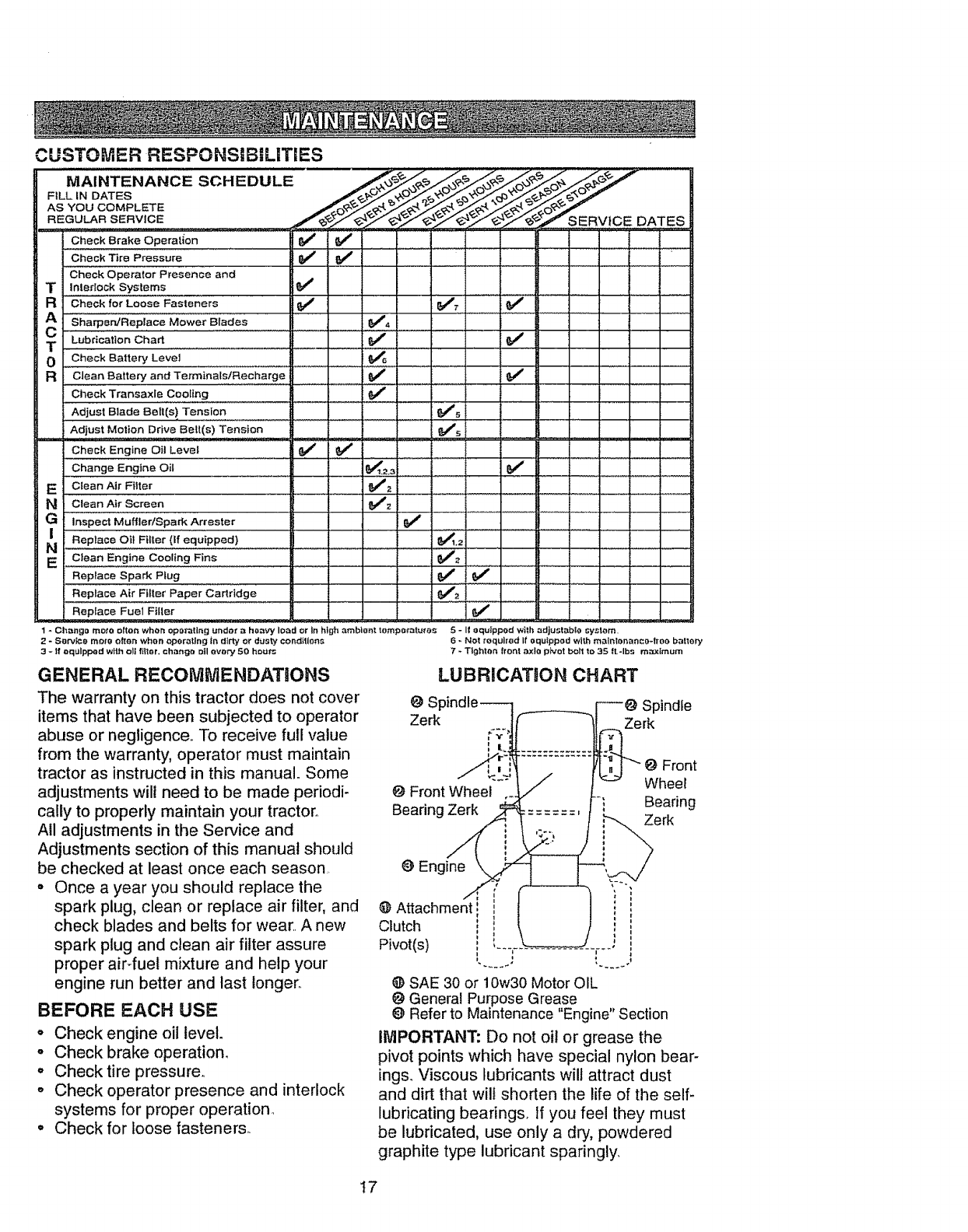
CUSTOMER RESPONSiBiLITIES
MAINTENANCE SCHEDULE /_/_o_/_o_/_ /
AS YOU COMPLETE /_(?,_0_ .......
. REGU_R SERVICE .Jf'_e-_'_SER\,/tCE DATES
CheckB,akeOperat oni '! '1 1I iifill "
Check Tire Pressure _# a##............ ".......
check operator Presence and H
TInledock Systems _'4 tt
• @ ,
RCheck for Loose Fasteners 64# 6/7
A"S'h'a'_e_Repiace MOWer Blades 644,
CLub;icatlonChart V'
0Check Battery Level
Rclean Battery and Terminals/Recharge V_V'
Check Transaxie Cooling
Adjust Blade Belt(s) Tension _s
i Adjust Motion Drive Belt(s) Tension . , , V's
Check Engine Oil Level _ _ ,.
Change Engine Oil _,2,_ V"
EClean Air Filter V_'z
Nciean Air screen 644_
GinspectMuffler!SparkArrestor It V'
/Replace Oii Fiiier(ifequipped) {&_1,2
N _iean E,minec00ii,g runs e/_
Replace Spark pfug _ 6_
Replace Air Filter Paper Cailridge _#"#2
Replace Fuel Filler G/
1 * Change mote ellen when opai'atlng under aheavy load or In high ambient tempefrJt_'e$ 5 - I{ equipped wilb adjustable ;yslom
2-Sorv_{::e mote often when operating Ir_dirty or dusty conditions
3- If equipped with o!1 filter, change oil every 50 hour;
GENERAL RECOMMENDATIONS
The warranty on this tractor does not cover
items that have been subjected to operator
abuse or negligence.. To receive full value
from the warranty, operator must maintain
tractor as instructed in this manual. Some
adjustments will need to be made periodi-
cally to properly maintain your tractor,
All adjustments in the Service and
Adjustments section of this manual should
be checked at least once each season,
= Once a year you should replace the
spark plug, clean or replace air filter, and
check blades and belts for wear,. A new
spark plug and clean air filter assure
proper air-fuel mixture and help your
engine run better and last longer,.
BEFORE EACH USE
o Check engine oil level.
oCheck brake operation.
, Check tire pressure..
o Check operator presence and interlock
systems for proper operation.
• Check for loose fasteners.
6 _ Not required If equipped with mathlenarlco÷froo battery
7-Tlg_hton front axle pivot boil to 35 {t,-Ibs m#,.,_imum
LUBRiCATiON CHART
Spindle--
Zerk FV'
' It.
I I
@ FrontWheel ,.
Bearing _
0 Eng_ne_, '
,_.,, ,°°
@ Attachment! i
Clutch ! i
Pivot(s) i "--'r
@ SAE 30 or 10w30 Motor OIL
@ General Purpose Grease
Refer to Maintenance "Engine" Section
IMPORTANT: Do not oil or grease the
pivot points which have special nylon bear-
ings. Viscous lubricants will attract dust
and dirt that wilt shorten the life of the self-
lubricating bearings. If you feel they must
be lubricated, use only a dry, powdered
graphite type lubricant sparingly,
t7
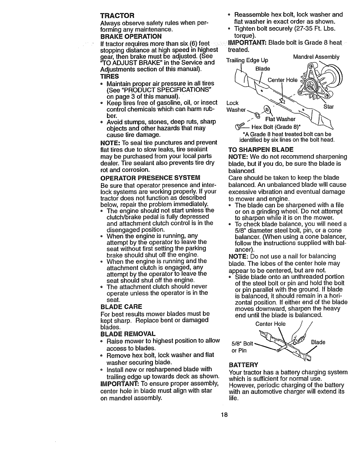
TRACTOR o Reassemble hex bolt, lock washer and
Always observe safety rules when per- flat washer in exact order as shown.
forming any maintenance° =Tighten bolt securely (27-35 Ft. Lbs.
BRAKE OPERATION torque).
tf tractor requires morn than si_ (6)_feet IMPORTANT; Blade bolt is Grade 8heat _
stopping distance at high speed in highest treated.
gear, then brake must be adjusted. (See .... Mandrel Assembly
"TO ADJUST BRAKE" in the Service and _-age up
Adjustments section of this manual).
TIRES
= Maintain proper air pressure in all tires
(See =PRODUCT SPECIFICATIONS"
on page 3of this manual)°
°Keep tires free of gasoline, oil, or insect
control chemicals which can harm rub-
ber,
• Avoid stumps, stones, deep ruts, sharp
objects and other hazards that may
cause tire damage.
NOTE: To seal tire punctures and prevent
flat tires due to slow leaks, tire sealant
may be purchased from your local parts
dealer. Tire sealant also prevents tire dry
rot and corrosion.
OPERATOR PRESENCE SYSTEM
Be sure that operator presence and inter-
lock systems are working properly. If your
tractor does not function as described
below, repair the problem immediately.
o The engine should not start unless the
clutch/15rake pedal is fully depressed
and attachment clutch control is in the
disengaged position.
o When the engine is running, any
attempt by the operator to leave the
seat without first setting the parking
brake should shut off the engme_
o When the engine is running and the
attachment clutch is engaged, any
attempt by the operator to leave the
seat should shut off the engine.
o The attachment clutch should never
operate unless the operator is in the
seat°
BLADE CARE
For best results mower blades must be
kept sharp. Replace bent or damaged
blades.
BLADE REMOVAL
•Raise mower to highest position to allow
access to blades.
, Remove hex bolt, lock washer and flat
washer securing blade.
= Install new or resharpened blade with
trailing edge up towards deck as shown.
IMPORTANT: To ensure proper assembly,
center hole in blade must align with star
on mandrel assembly.
Blade
Center Hole
Lock
Washer -,,..._ .._" Star
.,- "=' Flat Washer
Hex Bolt (Grade 8)*
*A Grade 8 heat treated bolt can be
identified by six lines on the bolt head.
TO SHARPEN BLADE
NOTE: We do not recommend sharpening
blade, but if you do, be sure the blade is
balanced.
Care should be taken to keep the blade
balanced_ An unbalanced blade wilt cause
excessive vibration and eventual damage
to mower and engine_
° The blade can be sharpened with a file
or on a grinding wheel. Do not attempt
to sharpen while it is on the mower.
°To check blade balance, you wilt need a
5/8" diameter steel bolt, pin, or acone
balancer. (When using a cone balancer,
follow the instructions supplied with bal-
ancer)o
NOTE: Do not use a nail for balancing
blade_ The lobes of the center' hole may
appear to be centered, but are not.
oSlide blade onto an unthreaded portion
of the steel bolt or pin and hold the bolt
or pin parallel with the ground_ If blade
is balanced, it should remain in a hori-
zontal position if either end of the blade
moves downward, sharpen the heavy
end until the blade is balanced.
Center Hole
5/8"
or Pin
Blade
BATTERY
Your' tractor has a battery charging system
which is sufficient for normal use.
However, periodic charging of the battery
with an automotive charger will extend its
life.
t8
• Keepbatteryand terminalsclean.
o Keepbatteryboltstight.
° Keepsmallventholesopen,
° Rechargeat 6-to amperesfor i hour°
TOCLEANBATTERYANDTERMINALS
Corrosionanddirton the batteryandter-
minalscancausethebatteryto"leak"
power.
• Openbatteryboxd0or.
• DisconnectBLACKbatterycablefirst
thenRED batterycableand remove
batteryfromtractor°
• Rinsethe batterywithplainwaterand
dry°
• Cleanterminalsand batter,/cableends
withwirebrushuntilbrighL
• Coatterminalswithgreaseorpetroleum
jelly,,
° Reinstallbattery(See"REPLACING
BATTERY"intheSERVICEAND
ADJUSTMENTSsectionofthismanu-
a0.
V-BELTS
Check V-belts for deterioration and wear
after 100 hours of operation and replace if
necessary° The belts are not adjustable,
Replace belts if they begin to slip from
wear.,
TRANSAXLE COOUNG
Keep transaxte free from build-up of dirt
and chaff which can restrict cooling.
ENGINE
LUBRICATION
Only use high quality detergent oil rated
with API service classification SF, SG or
SH° Select the oil's SAE viscosity grade
according to your expected operating tem-
erature.
SAE VISCOSITY GRADES
1
_'F -20" O" 30* 3_" 40" 66" BS" 1_0"
TEMPERATURE RANGE ANTICIPATED BEFORE NEXT OIL CHANGE
NOTE: Although multi-viscosity oils
(5W30, t0W30 etc.)improve starting in
cold weather, these multi-viscosity oils will
result in increased oil consumption when
used above 32°E Check your engine oil
level more frequently to avoid possible
engine damage from running low on oil
Change the oil after every 25 hours of
operation or at least once a year if the
Iractor is not used for 25 hours in one
year..
Check the crankcase oil level before start-
ing the engine and after each eight (8)
hours of operation. Tighten oil fill cap/dip-
stick securely each time you check the oil
level
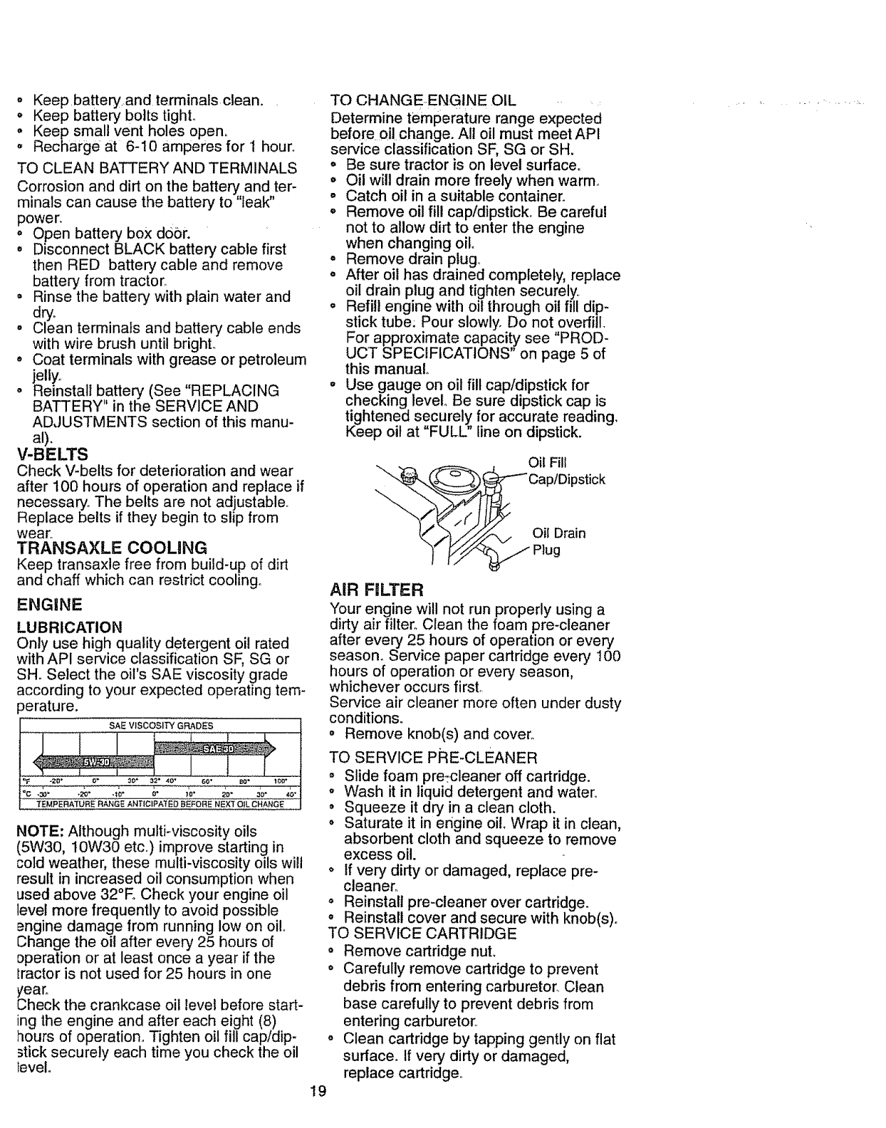
TO CHANGEENGINE OIL ....
Determine temperature range expected
before oil change. All oil must meet API
service classification SF, SG or SH.
° Be sure tractor is on level surface°
• Oil will drain more freely when warm,,
° Catch oil in a suitable container.
. Remove oil fill cap/dipstick. Be careful
not to allow dirt to enter the engine
when changing oil
° Remove drain plugo
. After oil has drained completely, replace
oil drain plug and tighten securely,,
o Refill engine with oil through oil fill dip-
stick tube: Pour slowly. Do not overfill
For approximate capacity see "PROD-
UCT SPECIFICATIONS" on page 5 of
this manual
° Use gauge on oil fill cap/dipstick for
checking level° Be sure dipstick cap is
tightened securely for accurate reading.
Keep oil at "FULL" line on dipstick.
Oil Fill
"'-_(_ _"-- CaptDipstick
o,,O,a,o
19
AIR FILTER
Your engine will not run properly using a
dirty air filter° Clean the foam pre-cleaner
after every 25 hours of operation or every
season. Service paper cartridge every t00
hours of operation or every season,
whichever occurs first.
Service air cleaner more often under dusty
conditions.
° Remove knob(s) and cover°
TO SERVICE PRE-CLEANER
°Slide foam pre:cleaner off cartridge.
,, Wash it in liquid detergent and water,
° Squeeze it dry in a clean cloth.
° Saturate it in engine oil. Wrap it in clean,
absorbent cloth and squeeze to remove
excess oil.
• If very dirty or damaged, replace pre-
cleaner_
= Reinstall pre-cleane]" over cartridge.
= Reinstall cover and secure with knob(s),.
TO SERVICE CARTRIDGE
= Remove cartridge nuL
o Carefully remove cartridge to prevent
debris from entering carburetor,. Clean
base carefully to prevent debris from
entering carburetor..
,, Clean cartridge by tapping gently on flat
surface. If very dirty or damaged,
replace cartridge.
. Reinstallcartridge,nut,precleaner,
cover'andsecurewith knob(s).
iMPORTANT: Petroleum solvents, such as
kerosene, are not to be used to clean the
cartridge._They may cause deterioration of
the cartridge. Do not oil cartridge. Do not
use pressurized air to clean or dry car-
tddge.
Cover
Knob
Cover _ Cartridge
Nut
Foam .-J_ -Paper
Pre'Cle ane_._. Caasrt:idge
CLEAN AIR SCREEN
Air screen must be kept free of dirt and
chaff to prevent engine damage from over-
heating. Clean with a wire brush or com-
pressed air' to remove dirt and stubborn
dried gum fibers.
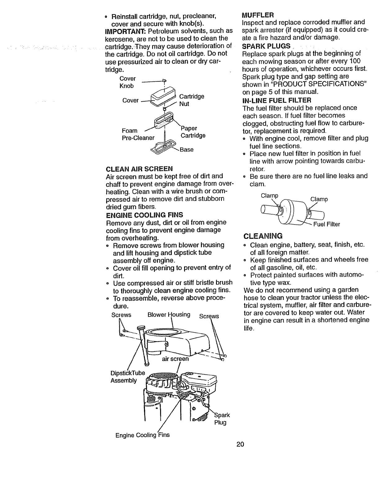
ENGINE COOLING FINS
Remove any dust, dirt or oil from engine
cooling fins to prevent engine damage
from overheating.
o Remove screws from blower housing
and lift housing and dipstick tube
assembly off engine.
,, Cover oil fill opening to prevent entry of
dirt.
o Use compressed air or stiff bdstle brush
to thoroughly clean engine cooling fins.
o To reassemble, reverse above proce-
dure.
Screws Blower
MUFFLER
Inspect and replace corroded muffler and
spark arrester (if equipped) as it could cre-
ate a fire hazard and/or damage.
SPARK PLUGS .. •
Replace spark plugs at the beginning of
each mowing season or after every 100
hour's of operation, whichever occurs first,.
Spark plug type and gap setting are
shown in "PRODUCT SPECIFICATIONS"
on page 5 of this manual.
IN-LINE FUEL FILTER
The fuel filter should be replaced once
each season. If fuel filter becomes
clogged, obstructing fuel flow to carbure-
tor, replacement is required.
°With engine cool, remove filter and plug
fuel line sections.
oPlace new fuel filter in position in fuel
line with arrow pointing towards carbu-
retor,.
= Be sure there are no fuel line leaks and
clarn_
_Fuel Filter
CLEANING
,, Clean engine, battery, seat, finish, etc.
of all foreign matter:.
= Keep finished surfaces and wheels free
of all gasoline, oil, etc_
oProtect painted surfaces with automo-
tive type wax.
We do not recommend using a garden
hose to clean your' tractor unless the elec-
trical system, muffler, air filter and carbure-
tor are covered to keep water out. Water
in engine can result in a shortened engine
life..
20
Ak-_CAUTION:Beforeperforminganyserviceor adjustments:
• Depressclutch/brakepedalfullyand setparkingbrake,
• Placegearshiftleverin neutral(N)position.
° Placeattachmentclutchin"DISENGAGED"position.
° Turnignitionkey"OFF"and removekey
° Makesurethe bladesandall movingpartshavecompletelystopped.
° Disconnectsparkplugwire fromsparkplugandplacewirewhereit cannotcome
incontactwithplugo
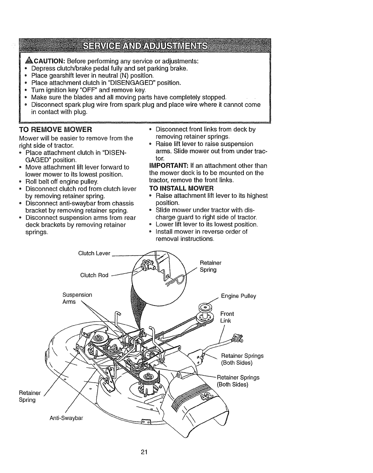
TO REMOVE MOWER
Mower will be easier to remove from the
right side of tractor,.
o Place attachment clutch in "DISEN-
GAGED" position°
°Move attachment lift lever forward to
lower mower to its lowest position.
oRoll belt off engine pulley
• Disconnect clutch rod from clutch lever
by removing retainer spring°
° Disconnect anti-swaybar from chassis
bracket by removing retainer spring°
oDisconnect suspension arms from rear
deck brackets by removing retainer
springs.,
o Disconnect front links from deck by
removing retainer springs.
o Raise lift lever to raise suspension
arms. Slide mower out from under trac-
tor.
IMPORTANT: if an attachment other than
the mower deck is to be mounted on the
tractor, remove the front links_
TO INSTALL MOWER
° Raise attachment lift lever to its highest
position.
o Slide mower under tractor with dis-
charge guard to right side of tractor,,
o Lower lift lever to its lowest position_
o Install mower in reverse order of
removal instructions.
Clutch Lever
Clutch Rod
Retainer
Spring
Suspension
Arms Engine Pulley
Front
Link
Retainer
Spring
Anti-Swaybar
Retainer Springs
(Both Sides)
Springs
(Both Sides)
21
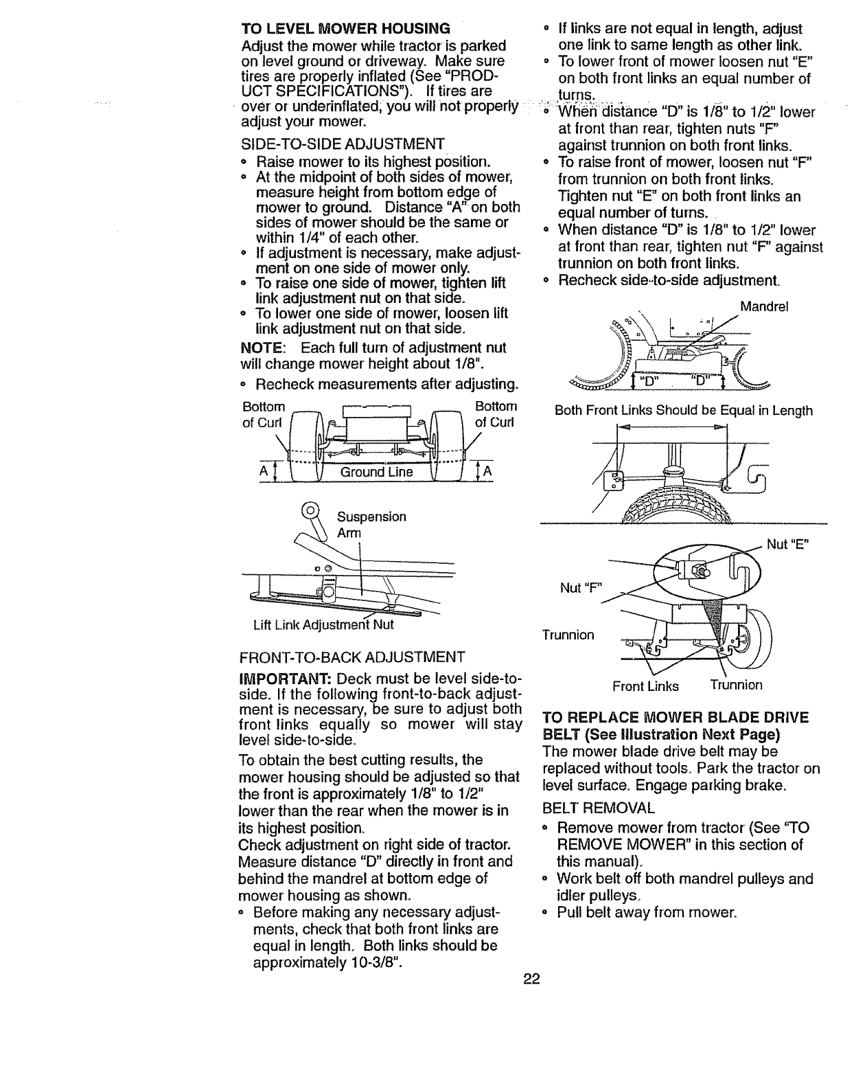
TO LEVEL MOWER HOUSING oIf links are not equal in length, adjust
Adjust the mower while tractor is parked one link to same length as other link.
on level ground or driveway° Make sure = To lower front of mower loosen nut "E"
tires are properly inflated (See "PROD- on both front links an equal number of
UCT SPECIFICATIONS"). If tires are turns.
over or underinflated; you will not properly __ ; Wl_6_ distance "D" is 1/8" to 1/2" lower
adjust your mower, at front than rear, tighten nuts "F"
SIDE-TO-SIDE ADJUSTMENT against trunnion on both front links.
•Raise mower to its highest position, oTo raise front of mower, loosen nut "F"
° At the midpoint of both sides of mower; from trunnion on both front links.
measure height from bottom edge of Tighten nut "E _ on both front links an
mower to ground. Distance 'W' on both equal number of turns.
sides of mower should be the same or ° When distance "D" is 1/8" to I/2" lower
within I/4" of each other.
o If adjustment is necessary, make adjust- at front than rear, tighten nut "F' against
ment on one side of mower only. trunnion on both front links.
oTo raise one side of mower, tighten lift oRecheck side-to-side adjustment.
link adjustment nut on that side°
o To lower one side of rnower, loosen lift , Mandrel
link adjustment nut on that side. %_'_L .......... _° '
NOTE: Each full turn of adjustment nut _ _E/__
will change mower' height about 1/8".
o Recheck measurements after adjusting.
Bottom F ] Bottom Both Front Links Should be Equal in Length
Suspension
Arm
Lift Link Adjustment Nut
FRONT-TO-BACK ADJUSTMENT
IMPORTANT: Deck must be level side-to-
side. If the following front-to-back adjust-
ment is necessary, be sure to adjust both
front links equally so mower wilt stay
level side-to-side,
To obtain the best cutting results, the
mower housing should be adjusted so that
the front is approximately 1/8" to 1/2"
lower than the rear when the rnower is in
its highest position.
Check adjustment on right side of tractor.
Measure distance "D" directly in front and
behind the mandrel at bottom edge of
mower housing as shown.,
o Before making any necessary adjust-
ments, check that both front links are
equal in length, Both links should be
approximately 10-3/8".
_Nut "E"
Nut "F'_
-
Front Links Trunnion
TO REPLACE MOWER BLADE DRIVE
BELT (See Illustration Next Page)
The mower blade drive belt may be
replaced without tools. Park the tractor on
level surface, Engage parking brake,
BELT REMOVAL
° Remove mower from tractor (See "TO
REMOVE MOWER" in this section of
this manual).
°Work belt off both mandrel pulleys and
idler pulleys.
° Pull belt away from mower.,
22
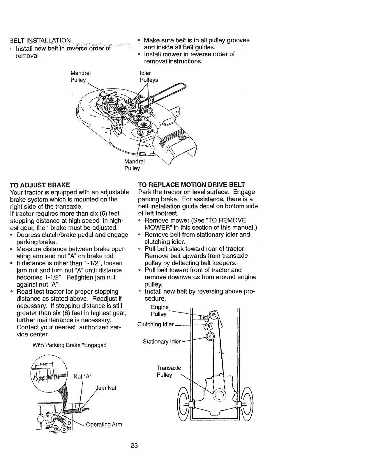
3ELTINSTALLATION o Makesurebeltis in allpulleygrooves
, _ and inside_&llbelt._guide&..... .
removal., o Installmowerin reverseorderof
removalinstructions°
Mandrel Idler
Pulley Pulleys
Mandrel
Pulley
TO ADJUST BRAKE
Your tractor is equipped with an adjustable
brake system which is mounted on the
right side of the transaxle,
If tractor requires more than six (6) feet
stopping distance at high speed in high-
est gear, then brake must be adjusted.
° Depress clutch/brake pedal and engage
parking braker
o Measure distance between brake oper-
ating arm and nut "A" on brake rod°
o If distance is other than 1-1/2", loosen
jam nut and turn nut "A" until distance
becomes 1-1/2"o Retighten jam nut
against nut "A"o
o Road test tractor for proper stopping
distance as stated above_ Readjust if
necessary, tf stopping distance is still
greater than six (6) feet in highest gear,
further maintenance is necessary°
Contact your nearest authorized ser-
vice center.
With Parking Brake "Engaged"
Nut "A"
P_iam Nut
Operating Arm
TO REPLACE MOTION DRIVE BELT
Park the tractor on level surface° Engage
parking brake. For assistance, there is a
belt installation guide decal on bottom side
of left footrest.
o Remove mower (See 'q'O REMOVE
MOWER" in this section of this manuaL)
Remove belt from stationary idler and
clutching idler.
o Pull belt slack toward rear of tractor°
Remove belt upwards from transaxfe
pulley by deflecting belt keepers,
o Pull belt toward front of tractor and
remove downwards from around engine
pultey_
o Install new belt by reversing above pro-
cedure.
Engine
Pulley
Clutching Idler_
Stationary idler----
Transaxle
Pulley
23
TO ADJUST STEERING WHEEL ALIGN-
MENT
If steering wheel crossbars are not hori-
zontal (left to right) when wheels are posi-
;tiodedstr_,ight forward, ='emove Steering
wheel and reassemble per instructions in
the Assembly section of this manual.
FRONT WHEEL TOE-IN/CAMBER
The front wheel toeoin and camber are not
adjustable on your tractor. If damage has
occurred to affect the front wheel toe-in or
camber; contact your nearest authorized
service center:
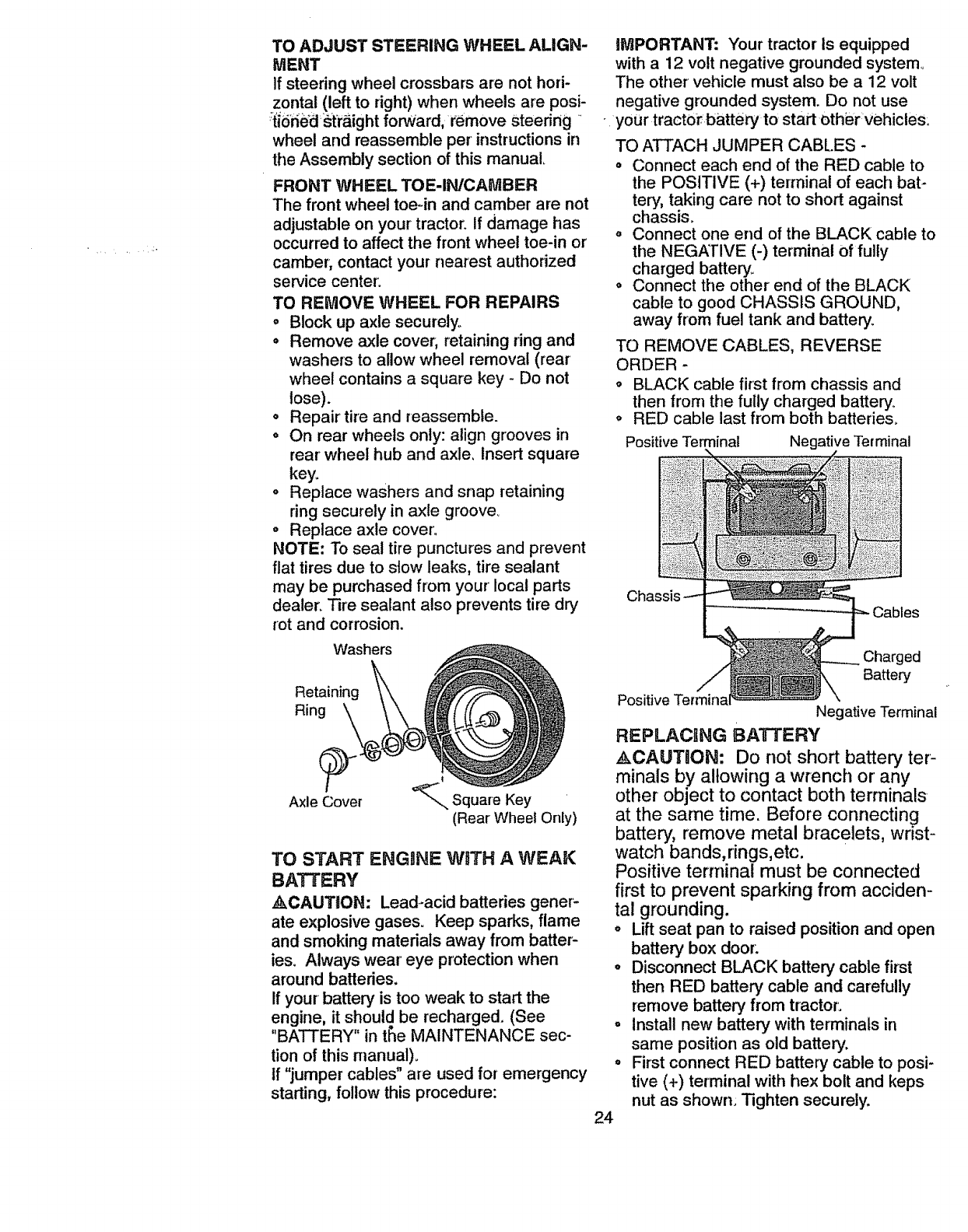
TO REMOVE WHEEL FOR REPAIRS
oBlock up axle securely°
,Remove axle cover, retaining ring and
washers to allow wheel removal (rear
wheel contains a square key - Do not
lose).
• Repair' tire and reassemble.
o On rear wheels only: align grooves in
rear wheel hub and axle, insert square
key.
o Replace washers and snap retaining
ring securely in axle groover
° Replace axle cover:
NOTE: To seat tire punctures and prevent
flat tires due to stow leaks, tire sealant
may be purchased from your local parts
dealer, Tire sealant also prevents tire dry
rot and corrosion.
Washers
Retaining
Ring
Axle Cover '_,, Square Key
(Rear Wheel Only)
TO START ENGONE WlfTH A WEAK
BATTERY
_kCAUTION: Lead-acid batteries gener-
ate explosive gases. Keep sparks, flame
and smoking materials away from batter-
ies. Always wear eye protection when
around battedes.
If your battery is too weak to start the
engine, it should be recharged. (See
"BATTERY" in t_e MAINTENANCE sec-
tion of this manual)_
If "jumper cables" are used for emergency
starting, follow this procedure:
iMPORTANT; Your tractor Is equipped
with a 12 volt negative grounded system_
The other vehicle must also be a 12 volt
negative grounded system. Do not use
• your tractor battery to start othi_rvehicles:
TO ATTACH JUMPER CABLES -
= Connect each end of the RED cable to
the POSITIVE (+) terminal of each bat-
tery, taking care not to short against
chassis_
° Connect one end of the BLACK cable to
the NEGATIVE (-) terminal of fully
charged battery.
, Connect the other end of the BLACK
cable to good CHASSIS GROUND,
away from fuel tank and battery_
TO REMOVE CABLES, REVERSE
ORDER -
o BLACK cable first from chassis and
then from the fully charged battery_
o RED cable last from both battedes_
Positive Terminal Negative Terminal
ed
Battery
24
Positive Negative Terminal
REPLACI1NG BATTERV
ACAUTION: Do not short battery ter-
minals by allowing a wrench or any
other object to contact both terminals
at the same time. Before connecting
battery, remove metal bracelets, wrist-
watch bands,rings,etc.
Positive terminal must be connected
first to prevent sparking from acciden-
tal grounding.
o Lift seat pan to raised position and open
batter,] box door:
= Disconnect BLACK battery cable first
then RED battery, cable and carefully
remove battery from tractor:
= Install new battery with terminals in
same position as old battery.
= First connect RED battery cable to posi-
tive (+) terminal with hex bolt and keps
nut as shown_ Tighten securely.
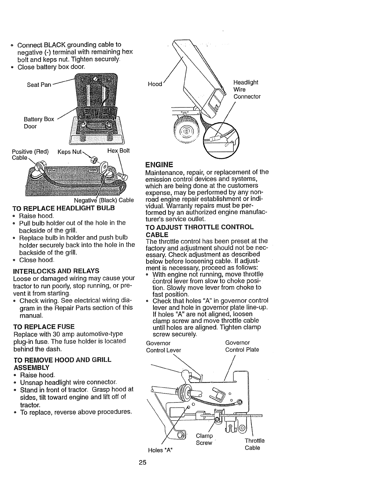
o Connect:.BLACKgroundingcableto
negative(-) terminalwithremaininghex
bo!tand kepsnuLTightensecurely
o Closebatteryboxdoor.
Seat Pan Headlight
Wire
Connector
Battery Box
Door
Ne (Black) Cable
TO REPLACE HEADLIGHT BULB
o Raise hood°
o Pull bulb holder out of the hole in the
backside of the grill.
o Replace bulb in holder and push bulb
holder securely back into the hole in the
backside of the grill,
o Close hood.
INTERLOCKS AND RELAYS
Loose or damaged wiring may cause your
tractor to run poorly, stop running, or pre-
vent it from starting.
• Check wiring. See electrical wiring dia-
gram in the Repair Parts section of this
manual°
TO REPLACE FUSE
Replace with 30 amp automotive-type
plug-in fuse.. The fuse holder is located
behind the dash,.
TO REMOVE HOOD AND GRILL
ASSEMBLY
oRaise hood..
o Unsnap headlight wire connector.
o Stand in front of tractor,, Grasp hood at
sides, tilt toward engine and lift off of
tractor.
° To replace, reverse above procedures.
ENGINE
Maintenance, repair, or replacement of the
emission control devices and systems,
which are being done at the customers
expense, may be performed by any non-
road engine repair establishment or indi-
vidual. Warranty repairs must be per-
formed by an authorized engine manufac-
turerls service outlet.,
TO ADJUST THROTTLE CONTROL
CABLE
The throttle control has been preset at the
factory and adjustment should not be nec-
essary. Check adjustment as described
below before loosening cable. If adjust-
ment is necessary, proceed as follows:
o With engine not running, move throttle
_ontrol lever from slow to choke posi-
tiono Slowly move lever from choke to
fast position.,
• Check that holes "A" in governor control
lever and hole in governor plate line-up.
If holes "A" are not aligned, loosen
clamp screw and move throttle cable
until holes are aligned.. Tighten clamp
screw securely°
Governor Governor
Control Lever Control Plate
\
Holes "A"
Clamp
Screw Throttle
Cable
25
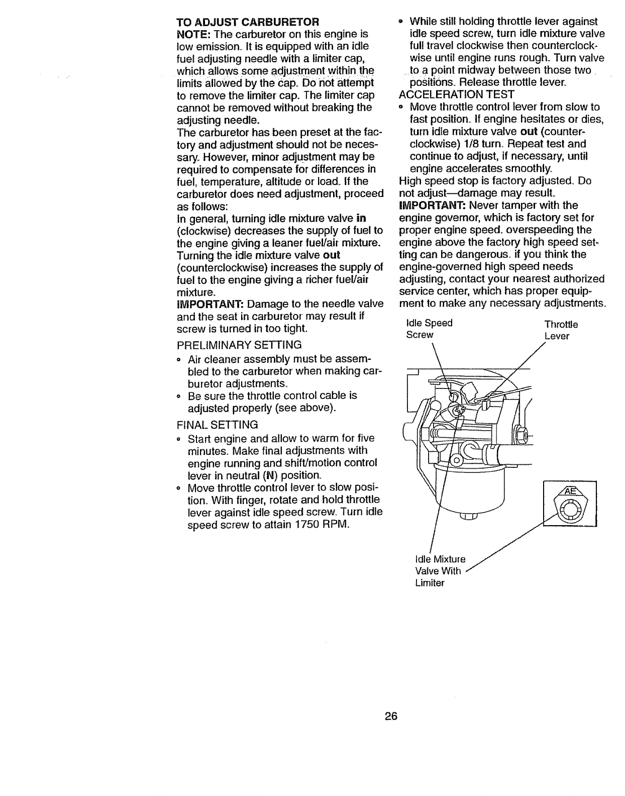
TO ADJUST CARBURETOR
NOTE: The carburetor on this engine is
low emission,, tt is equipped with an idle
fuel adjusting needle with a limiter cap,
which allows some adjustment within the
limits allowed by the CapiDo n0t _attempt
to remove the limiter cap. The limiter cap
cannot be removed without breaking the
adjusting needle.
The carburetor has been preset at the fac-
tory and adjustment should not be neces-
sary, However, minor adjustment may be
required to compensate for differences in
fuel, temperature, altitude or load. If the
carburetor does need adjustment, proceed
as follows:
In general, turning idle mixture valve in
(clockwise) decreases the supply of fuel to
the engine giving a leaner fuel/air mixture.
Turning the idle mixture valve out
(counterclockwise) increases the supply of
fuel to the engine giving a richer fuel/air
mixture.
IMPORTANT: Damage to the needle valve
and the seat in carburetor may result if
screw is turned in too tight.
PRELIMINARY SETTING
o Air cleaner" assembly must be assem-
bled to the carburetor when making car-
buretor adjustments.
o Be sure the throttle control cable is
adjusted properly (see above).
FINAL SETTING
oStart engine and allow to warm for five
minutes° Make final adjustments with
engine running and shif*Jmotion control
lever in neutral (N) position°
= Move throttle control lever to stow posi-
tion, With finger; rotate and hold throttle
lever against idle speed screw. Turn idle
speed screw to attain 1750 RPM.
,, While still holding throttle lever against
idle speed screw, turn idle mixture valve
full travel clockwise then counterclock-
wise until engine runs rough. Turn valve
....to a point midway between those two.
positions. Release throttle lever°
ACCELERATION TEST
= Move throttle control lever from stow to
fast position. If engine hesitates or dies,
turn idle mixture valve out (counter-
clockwise) 1/8 turn. Repeat test and
continue to adjust, if necessary, until
engine accelerates smoothly.
High speed stop is factory adjusted. Do
not adjust--damage may result.
IMPORTANT: Never tamper with the
engine governor, which is factory set for
proper engine speed, overspeeding the
engine above the factory high speed set-
ting can be dangerous, if you think the
engine-governed high speed needs
adjusting, contact your nearest authorized
service center, which has proper equip-
ment to make any necessary adjustments.
idle Speed Throttle
Screw Lever
Limiter
26
Immediatelyprepareyourtractorforstorm
ageatthe endof theseasonorif thetrac-
tor willnotbe usedfor30daysor more_
,_kCAUTION: Never store the tractor with
gasoline in the tank inside a building
where fumes may reach an open flame or
spark. Allow the engine to coo! before
storing in any enclosure.
TRACTOR
Remove mower from tractor for winter
storage. This will allow you to clean it thor-
oughly. Remove all dirt, grease, leaves,
etc. Store in a clean, dry area.
o Clean entire tractor (See "CLEANING"
in the Maintenance section of this man-
uat)o
- Inspect and replace belts, if necessary
(See belt replacement instructions in the
Service and Adjustments section of this
manual).,
o Lubricate as shown in the Maintenance
section of this manual.
. Be sure that all nuts, bolts and screws
are securely fastened° Inspect moving
parts for damage, breakage and wear.
Replace if necessary.
-Touch up all rusted or chipped paint sur-
faces; sand lightly before painting.
BATTERY
° Fully charge the battery for storage.
o After a period of time in storage, battery
may require recharging.
o To help prevent corrosion and power
leakage during long periods of storage,
battery cables should be disconnected
and battery cleaned thoroughly (see
"TO CLEAN BATTERY AND TERMI-
NALS" in the Maintenance section of
this manual).
° After cleaning, leave cables disconnect-
ed and place cables where they cannot
come in contact with battery terminals.
° If battery is removed from tractor for
storage, do not store battery directly on
concrete or damp surface&
ENGINE
FUEL SYSTEM
IMPORTANT: It is important to prevent
gum deposits from forming in essential
fuel system parts such as carburetor, fuel
filter, fuel hose, or tank during storage_
Also, experience indicates that alcohol
blended fuels (called gasohol or using
ethanol or methanol) can attract moisture
which leads to separation and formation of
acids during storage,
Acidic gas can damage the fuel system of
an engine while in storage°
o Drain the fuel tank.
o Start the engine and let it run until the
fuel lines and carburetor are empty,
o Never use engine or carburetor cleaner
products in the fuel tank or permanent
damage may occur°
o Llse fresh fuel next season.
NOTE: Fuel stabilizer is an acceptable
alternative in minimizing the formation of
fuel gum deposits during storage. Add sta-
bilizer to gasoline in fuel tank or storage
container. Always follow the mix ratio
found on stabilizer container. Run engine
at least 10 minutes after adding stabilizer
to allow the stabilizer to reach the carbure-
tor. Do not drain the gas tank and carbure-
tor if using fuel stabilizer..
ENGINE OIL
Drain oil (with engine warm) and replace
with clean engine oil (See "ENGINE" in
the Maintenance section of this manual),
CYLINDER(S)
o Remove spark plug(s),,
o Pour one ounce of oil through spark
plug hole(s) into cylinder(s)_
° Turn ignition key to "START" position for
a few seconds to distribute oil.
,, Replace with new spark plug(s),,
OTHER
o Do not store gasoline from one season
to another.
• Replace your gasoline can if it starts to
rusL Rust and/or dirt in your gasoline
will cause pr6b]ems,,
• If possible, store your tractor indoors
and cover it to give protection from dust
and dirt°
o Cover you[ tractorwith a suitable pro-
tective cover that does not retain mois-
ture. Donot use plastic. Plastic cannot
breathe, which allows condensation to
form and cause your tractor to rust.
IMPORTANT: Never cover tractor while
engine and exhaust areas are still warm.
27
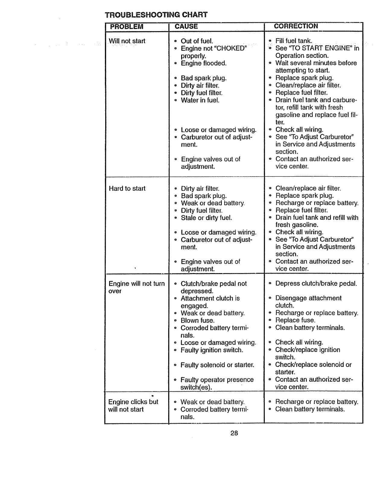
TROUBLESHOOTHNG CHART
PROBLEM CAUSE CORRECTION
Will not start o Out of fuel.
o Engine not "CHOKED"
properly.
o Engine flooded.
Hard to start
o Bad spark plug.
°Dirty air filter:,
°Dirty fuel filter.
o Water in fuel.
o
°
Loose or damaged wiring.
Carburetor out of adjust-
menL
Engine will not turn
over
Engine valves out of
adjustment.
o Dirty air filter:
o Bad spark plug.
o Weak or dead battery.
o Dirty fuel filter:
o Stale or' dirty fuel.
O
°
Loose or damaged wiring,,
Carburetor out of adjust-
ment.
Engine valves out of
adjustment. L,L,, ,,,,,,,
oClutch/brake pedal not
depressed.
o Attachment clutch is
engaged.
o Weak or dead battery.
• Blown fuse,.
o Corroded battery termi-
nals.
Fill fuel tank.
°See 'q'O START ENGINE" in
Operation section.
o Wait several rninutes before
attempting to start.
. Replace spark plug.
oClean/replace air filter.
o Replace fuel filter.
oDrain fuel tank and carbure-
tor; refill tank with fresh
gasoline and replace fuel fil-
ter:
oCheck all wiring.
oSee 'qo Adjust Carburetor"
in Service and Adjustments
section.
oContact an authorized ser-
vice center.
• Clean/replace air' filter.
o Replace spark plug.
o Recharge or replace battery.
o Replace fuel filter:
o Drain fuel tank and refill with
fresh gasoline.
o Check all wiring.
o See "To Adjust Carburetor"
in Service and Adjustments
section.
o Contact an authorized ser-
vice center.
j ...................................
Engine clicks but
will not start
oLoose or damaged wiring.
,, Faulty ignition switch,
o Faulty solenoid or' starter:
o Faulty operator presence
switch(es).
° Depress clutch/brake pedal.
o Disengage attachment
clutch.
* Recharge or replace battery°
o Replace fuse,
oClean battery terminals.
oWeak or dead battery°
• Corroded battery termi-
nals,
o Check all wiring.
oCheck/replace ignition
switch.
•Check/replace solenoid or
starter.
o Contact an authorized ser-
vice center.
• Recharge or replace battery_
oClean battery terminais.
28
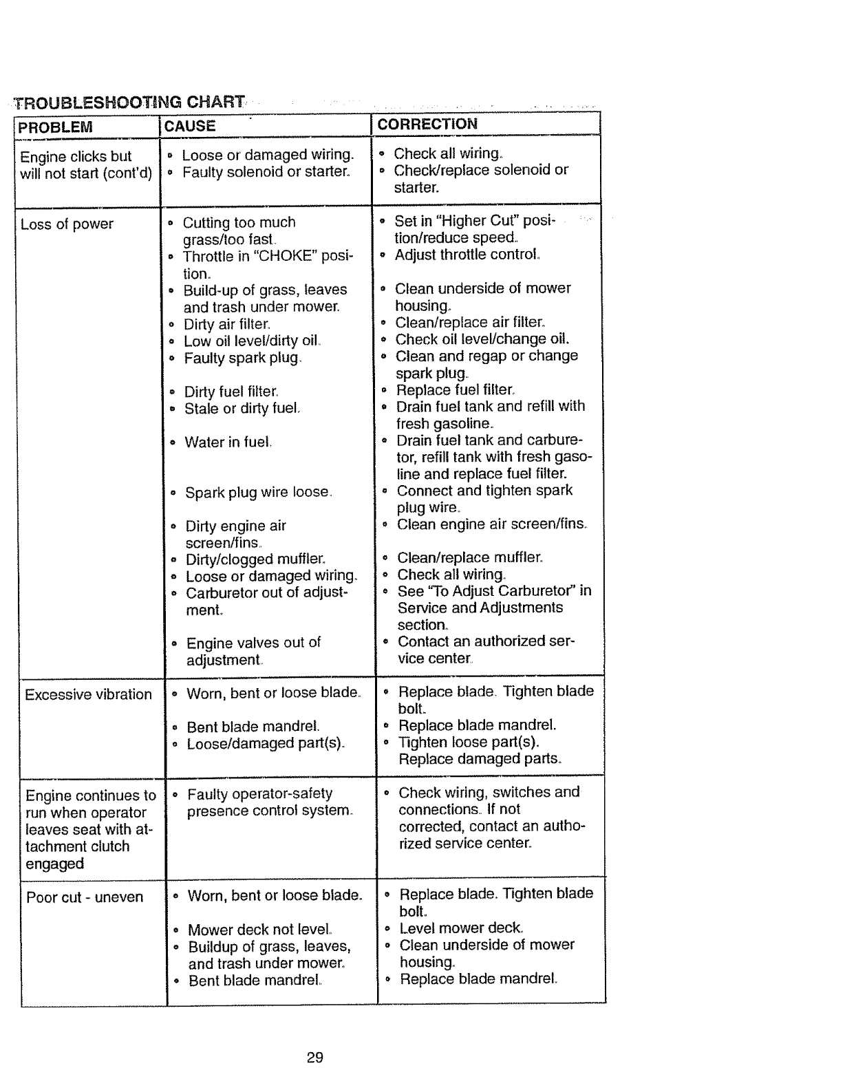
TROUBLESHOOTING CHART,,
PROBLEM CAUSE
Engine clicks but
will not start (cont'd)
o Loose or damaged wiring.
,, Faulty solenoid or starter°
Loss of power
Excessive vibration
Engine continues to
run when operator
leaves seat with at-
tachment clutch
engaged
Cutting too much
grass/too fast..
Throttle in "CHOKE" posi-
tion,.
Build-up of grass, leaves
and trash under mower.
Dirty air filter..
Low oil leve!!dirty oil,.
Faulty spark plug.
,, Water in fuel,
Spark plug wire loose,
o
o
o
O
0
G
,, Dirty fuel filter..
,, Stale or dirty fuel,
o
_ Dirty engine air
screen/fins.
-Dirty/clogged muffler_
o Loose or damaged wiring_
oCarburetor out of adjust-
menL
o
°
o
o
@
CORRECTION
-Check all wiring°
o Check/replace solenoid or
starter.
°Set in "Higher Cut" posF
tion!reduce speed,,
.Adjust throttle control,.
°Clean underside of mower
housing°
• Clean/replace air filter°
o Check oil level/change oil,
o Clean and regap or change
spark plug,.
• Replace fuel filter_
• Drain fuel tank and refill with
fresh gasoline°
° Drain fuel tank and carbure-
tor, refill tank with fresh gaso-
line and replace fuel filter.
= Connect and tighten spark
plug wire.,
• Clean engine air screen/finso
o
o
e
Engine valves out of •
adjustment..
, ,,,,,,,,,,,,,, ............... _
Worn, bent or loose blade.. °
Bent blade mandrel
Looseldamaged part(s)o
,j
Faulty operator-safety
presence control system.
°
o
Poor cut - uneven o Worn, bent or loose blade°
• Mower deck not level,.
• Buildup of grass, leaves,
and trash under mower°
•Bent blade mandrel..
Clean/replace muffler_
Check all wiring.
See "To Adjust Carburetor" in
Service and Adjustments
section°
Contact an authorized ser-
vice center.
Replace blade, Tighten blade
bolt.
Replace blade mandrel.
Tighten loose part(s).
Replace damaged parts.
Check wiring, switches and
connections., if not
corrected, contact an autho-
rized service center°
o Replace blade. Tighten blade
bolt,,
o Level mower deck,.
o Clean underside of mower
housing,.
o Replace blade mandrel,.
29
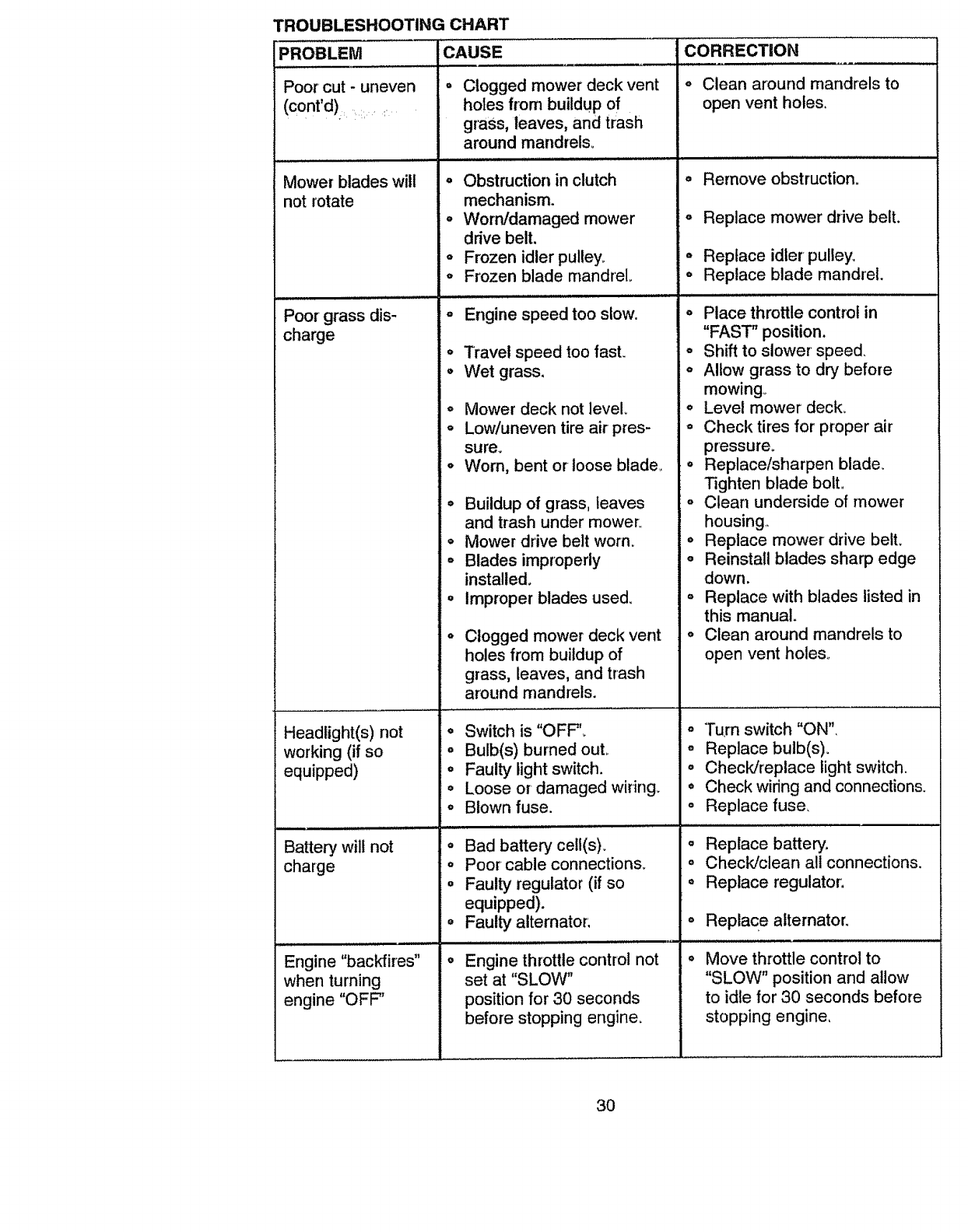
TROUBLESHOOTING CHART
PROBLEM CAUSE
o
Poor cut - uneven
(cont'd) ,: •
Mower blades will
not rotate
Poor grass dis-
charge
Headlight(s) not
working (if so
equipped)
Battery wil! not
charge
Engine "backfires"
when turning
engine "OFF"
Clogged mower deck vent
holes from buildup of
grass, leaves, and trash
around mandrels_
o Obstruction in clutch
mechanism.
oWorn/damaged mower
drive belt,
oFrozen idler pulley.
oFrozen blade mandrel
Engine speed too slow.
o Travel speed too fast.
°Wet grass.
° Mower deck not level.
= Low/uneven tire air pres-
sure.
°Worn, bent or loose blade_
° Buildup of grass, leaves
and trash under mower
°Mower drive belt worn.
°Blades improperly
installed.
=improper blades used_
°Clogged mower deck vent
holes from buildup of
grass, leaves, and trash
around mandrels.
°Switch is "OFF',
• Bulb(s) burned out.
° Faulty light switch.
o Loose or damaged wiring.
o Blown fuse.
° Bad battery cell(s).
oPoor cable connections_
oFaulty regulator (if so
equipped).
o Faulty alternator,
•Engine throttle control not
set at "SLOW"
position for 30 seconds
before stopping engine.
CORRECTION
o Clean around mandrels to
open vent holes.
° Remove obstruction.
° Replace mower drive belt.
o Replace idler pulley.
o Replace blade mandrel.
,, Place throttle control in
"FAST" position.
• Shift to slower speed.
o Allow grass to dry before
mowing°
o Level mower deck.
o Check tires for proper air
pressure.
o Replace/sharpen blade_
Tighten blade bolt.
o Clean underside of mower
housing,
oReplace mower drive belt.
o Reinstall blades sharp edge
down.
°Replace with blades listed in
this manual.
o Clean around mandrels to
open vent holes°
° Turn switch "ON",
o Replace bulb(s).
o Check/replace light switch.
o Check wiring and connections.
= Replace fuse,
o Replace battery.
oCheck/clean all connections.
o Replace regulator.
Replace alternator,
Move throttle control to
"SLOW" position and allow
to idle for 30 seconds before
stopping engine,
3O

31

32
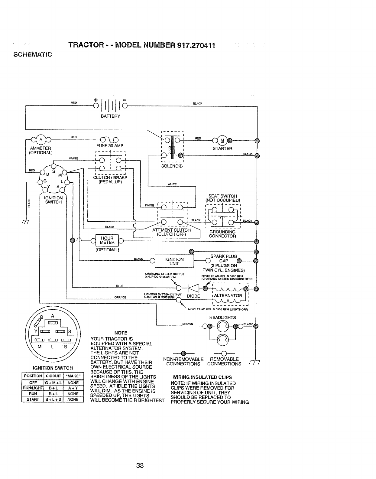
SCHEMATIC
TRACTOR --MODEL NUMBER 917.270411
RED
BATTERY
BLACK
/7
FUSE 30 AMP
I (OPTiOn) .... t ....
t } !
_ j
)G L(
IGNITION
SWITCH
IGNITION SWITCH
STARTER
CLUTCH/BRAKE I SOLENOID
(PEDAL.UP)
_ SEAT SWITCH
,I
(CLUTCH OFF) J CONNECTOR ._
| SPARK PLUG
BLA= IGNITION _ GAP _ )
UNIT _(2 PLUGS ON
TWIN CYL ENGINES)
:3AMP DO O _(30 RPM 28 VOLTS A_ MIN. _t 3t..,_ RP/_
{CHARG_tfG SYSTEM DI,r_ADftNECTED|
J"\ ,..o,...o.,. ;2£._2go_,;o'_
JHEADLIGHTS
_LAC_
(OPTIONAL)
POSITION CIRCUIT "MAKE"
OFF G+M+L NONE
RUN!LIGHT B + L A + Y
RUN B + L NONE
START B + L + S NONE
)
NOTE
YOUR TRACTOR IS
EQUIPPED WITH A SPECIAL
ALTERNATOR SYSTEM.
THE LIGHTS ARE NOT _-
CONNECTED TO THE NON*REMOVABLE REMOVABLE
BA'I-tERY, BUT HAVE THEIR CONNECTIONS CONNECTIONS /_ "7
OWN ELECTRICAL SOURCE
BECAUSE OF THIS, THE
BRIGHTNESS OF THE LIGHTS WIRING INSULATED CLIPS
W|LL CHANGE WITH ENGINE NOTE; IF WIRING INSULATED
SPEED. AT IDLE THE LIGHTS CLIPS WERE REMOVED FOR
WILL DIM, AS THE ENGINE IS SERVICING OF UNIT, THEY
SPEEDED UP, THE LIGHTS SHOULD BE REPLACED TO
W_LLBECOME THEIR BRIGHTEST PROPERLY SECURE YOUR WIRING.
33

ELECTRICAL
TRACTOR -- MODEL NUMBER 917.270412
•=
33
• 25
¢
34
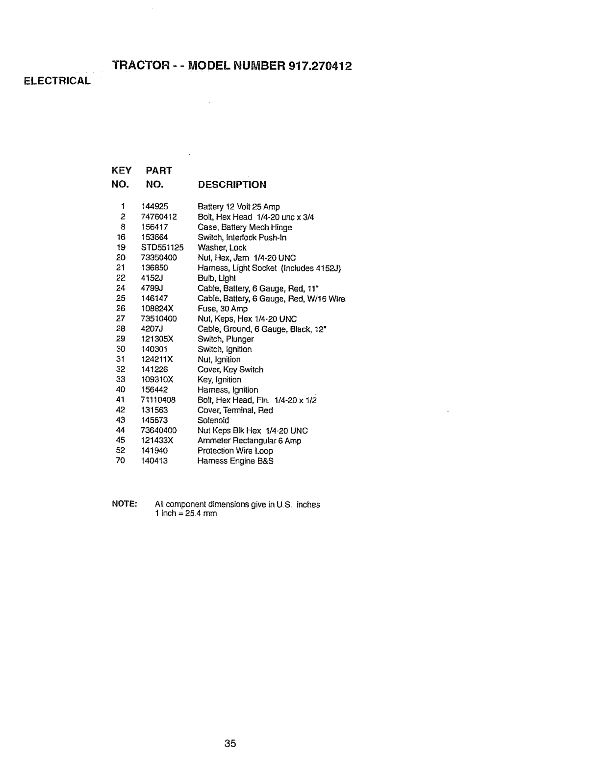
TRACTOR --MODEL NUMBER 917.2704.12
KEY PART
NO. NO. DESCRIPTION
1 144925
274760412
8 156417
16 153664
t9 STD551125
20 73350400
2t 136850
22 4152J
24 4799J
25 146147
26 t08824X
27 73510400
28 4207J
29 I21305X
30 140301
31 I242IIX
32 141226
33 109310X
40 156442
41 71110408
42 131563
43 145673
44 73640400
45 121433X
52 141940
70 140413
Battery 12 Volt 25Amp
Bolt, Hex Head 1./4-20unc x 3/4
Case, Battery Mech Hinge
Switch, Interlock Push-In
Washer, Lock
Nut, Hex, Jam 1/4-20 UNC
Hamess, Ught Socket (includes 4152J)
Bulb, Light
Cable, Battery, 6 Gauge, Red, 11"
Cable, Battery, 6 Gauge, Red, W116Wire
Fuse, 30 Amp
Nut, Keps. Hex 1/4-20 UNC
Cable, Ground. 6 Gauge, Black, 12"
Switch, Plunger
Switch, Ignition
Nut, Ignition
Cover, Key Switch
Key, Ignition
Hamess, ignition
Bolt, Hex Head, Fin 1/4-20 x 1t2
Cover, Terminal, Red
Solenoid
Nut Keps Blk Hex 1/4-20 UNC
Ammeter Rectangular 6 Amp
Protection Wire Loop
Harness Engine B&S
NOTE: Alt component dimensions give in U,S. inches
1 inch = 25.4 mm
35
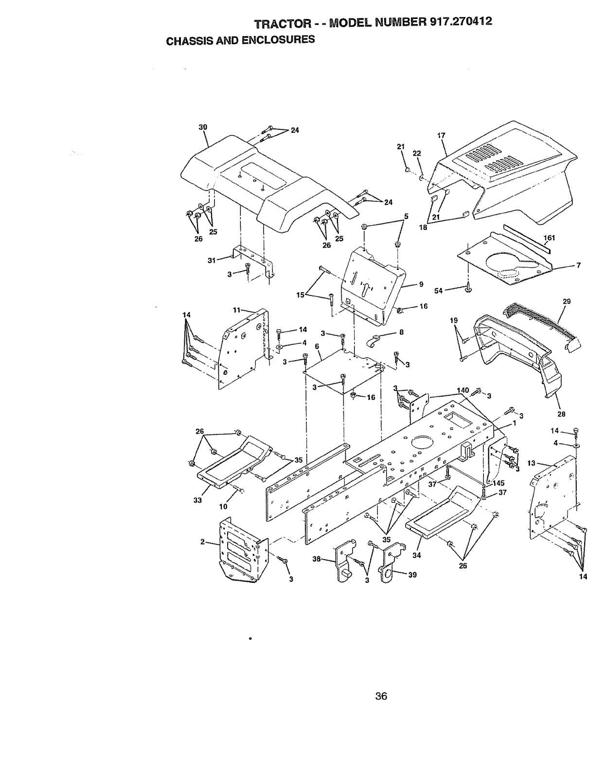
TRACTOR - - MODEL HUMBER 917.270412
CHASSIS AND ENCLOSURES
3O
i
31
14
14
26
6
5
18
.-._8
I7
161
29
26
33 10
26
28
14_
14
36

TRACTOR -- MODEL NUMBER 917.270412
CHASSIS AND ENCLOSURES
KEY PART
NO. NO. DESCRIPTION
1 160393
2 140356
3 17490612
4 STD55t025
5 155272
6 I55924X0t2
7 126842X
8 155138
9 1619t4X0t2
t0 STD533710
11 155927
13 155934X010
14 17490608
15 74180512
16 STD541431
t7 I54988X558
18 I26938X
19 17521312
21 122933X
22 124479X
24 STD523710
25 19131312
26 STD54t437
28 140137
29 124029X
30 157584X558
31 136619
33 145244X558
34 I45243X558
35 STD533707
37 17490508
38 139886
39 139887
54 161464
140 158418
145 156524
16t 161547
-- 5479J
Chassis Asm LT STMP
Drawbar Stretch
Screw Thdrol 3/8-16 x3/4 Ty4t
Washer 13/32 X 3/4 X 16 Ga
Bumper HoodlDash
Saddle Slkscr Fit LT 6SP Peerless
Shield Hr. Hood Lt
Clip Retainer Slide-On
Dash Slkscr l-pc
Bolt Rdhd Sqnk 3/8-16unc X 1
Panel Dash LH
Panel Slkscr Dash RH
Screw Thdrol 3/8-16 x 1/2 Ty-tt
Screw Mach TRHD 5/16-18 unc x 3/4
Nut Keps 5/16-18 Unc o
Hood Asm
Bumper Hood
Screw Sltd Hex Nd W/PI Washer
Rivet Ratchet Nylon
Washer Nylon _k 28 x 75 x t9
Bolt Fin Hex 3/83t6 unc x 1'Gr 5
Washer 13/32 _4_3/16 x 12 Ga
Nut Hex Lock w/ins, 3/8-I6 Unc
Grille Black
Lens Headlight B&rClear :
Fender Pnt LT W/o Shift
Bracket Fender ReP1109673x
Footrest Pnt Lh
Footrest Pnt Rh' ?
Boll Rdhd Sht Sqnk 3/8-16 x 3/4
ScrewThdrol 5/46-16 x t/2
Bracket Asm Pvt LH MWR Rear
Bracket Asm Pvt RH MWR Rear
Screw
Bracket Suspension Front
Rod Pivot Chassis/Hood
Extrusion Hood
Plug Button Blk 359 Dia Choke
NOTE: All component dimensions gige in U S., inches
1 inch = 25 4 mm
37
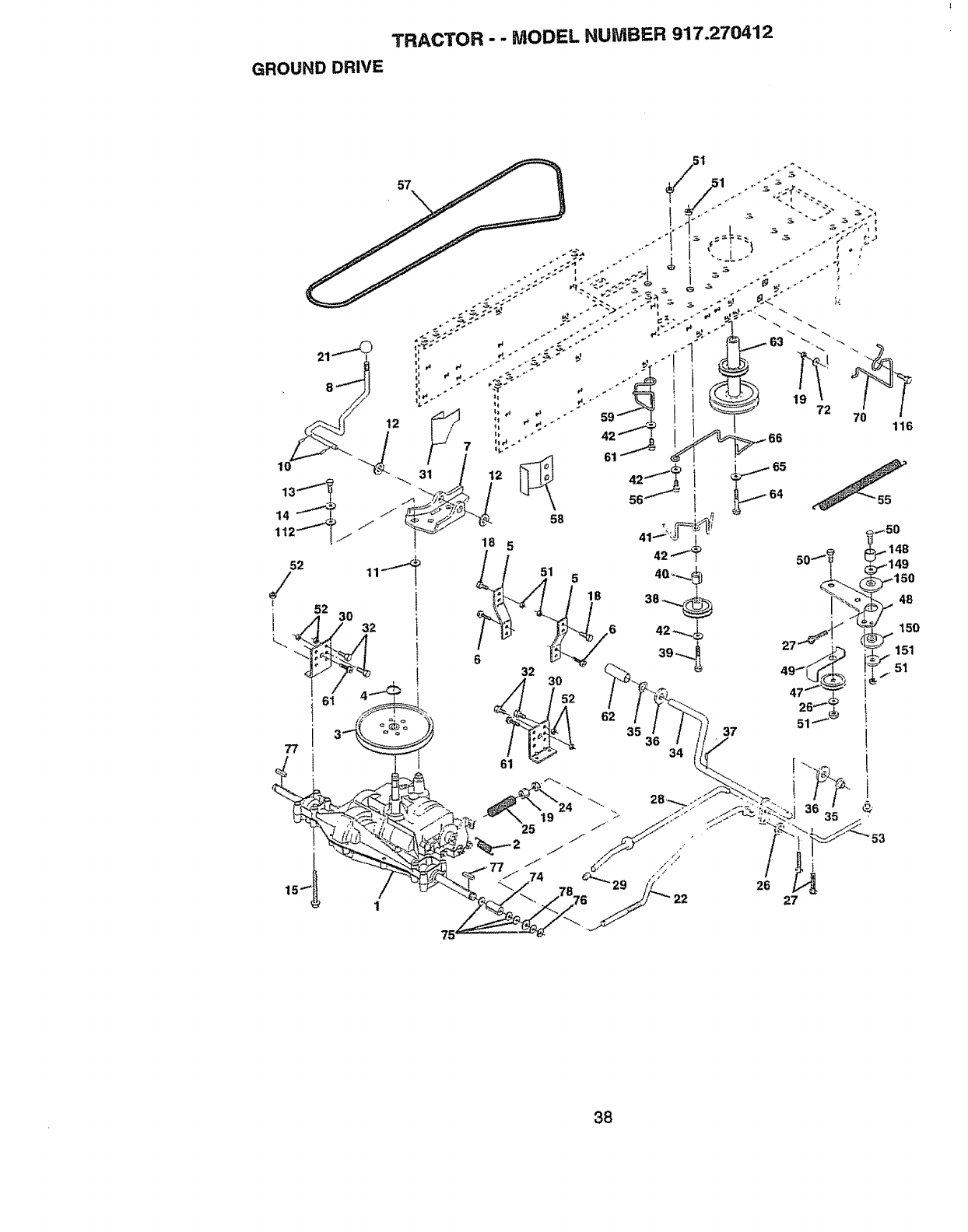
GROUND DRIVE
TRACTOR - "MODEL NUMBER 917.270412
32
62 35
34
37
38

TRACTOR --MODEL NUMBER 917.270412
GROUND DRIVE
KEY PART KEY PART
NO. NO. DESCRIPTION NO. NO.
1 ...... Transaxte Peedess 206-508B 48 154407
(See Breakdown) 49 123205X
2 146682 Spring Return Brake T/a Zinc 50 STD523715
3 t23666X Pulley Transaxle 18/20" tires 51 STD54!437
4 12000028 Ring Retainer # 5100-62 52 STD541431
5 121520X Strap Torque 30 Degrees 53 105710X
6 t7490512 Screw Thdroi 5f16-18 x 314TYT 54 275"tR
7 162240 Bracket Saddle Shift Tfa 55 105709X
8 t 31679 Rod Shl Sd! LY/YT Str Blk Zinc 56 STD523712
10 STD561210 Pin Cotter 1/8 x t Cad 57 130801
11 105701X Washer Plale Shf 388 Sq Hole 58 127274X
12 19151216 Washer 15/32 x 3/4 x 16ga 59 140312
13 74550412 Bolt 1/4*28unf Gr8 W/Patch 61 17490612
14 STD551125 Washer Lock Hvy Helical 1/4 62 8883R
18 STD523710 Bolt Fin Hex 3/8-!6 UNC x 1 Gr..5 63 140186
19 STD541437 Nut Lock Hex W/Ins. 3/8-16 Unc 64 71170764
21 106933X Knob Rd 112-13PIstc Thds Blk 65 STD551143
22 130804 Rod Brake Blk Zinc 26 840 66 154778
24 STD541237 Nut Hex Jam 3/8-16 Unc 70 134683
25 106888X Spring Rod Brake 2 00 Zinc 72 19132012
26 STD551037 Washer 13/32 x 13/16 x 16 Ga 74 137057
27 STD561210 Pin Cotter I/8 x3/4 Cad 75 121749X
28 145204 Rod Brake Parking LL/Yt 76 STD581075
29 124236X Cap Brake Parking Red 77 I23583X
30 130807 Bracket Mtg Transaxie 78 121748X
31 127275X Keeper Belt LH LT 14 Ga 79 2228M
32 STD523107 Bolt Hex Hd 5/t6-18unc x 3/4 96 4497H
34 155071 Shaft Asm Pedal Foot LT/STLT 112 19091210
35 120183X Bearing Nylon BIk 629 Id 113 127285X
36 STD551062 Washer21/32 x 1 x I6 Ga 116 72110610
37 1572H Pin Roll 3/16 x t" 145 74490540
36 123874X PuIleyldler Flat 148 159103
39 STD523727 Bolt Fin Hex 318-16unc x 2-3/4 149 I22052X
40 4470J Spacer Split 395 x 59 Bzp 150 150935
41 154777 Keeper Be_tIdler Fool Proof 151 19133210
42 19131312 Washer 13/32 x 13/16 x12 Ga
47 127783 Pulley Idler V Groove Plastic NOTE:
DESCRIPTION
Bellcrank Asrn Clutch
Retainer Belt Style Spring
Bolt Hex Hd 3t8-16unc x 1-112
Nut Crownlock 3t8-I6 UNC
Nut Crown Lock 5/16-18
Link Clutch 766
Clip Line Fuel 13/32 Myg Hole
Spring Return Clutch 6 75
Bolt Fin Hex 3/8-16 unc x 1-1/4
V-Belt Gd Drive 95 00
Keeper Belt RH LT Pnt!zinc 16g
Keeper Belt Centerspan
ScrewThdrol 3/8_16 x 3/4 Ty-tt
Cover Pedal BIk Round
Pulley Eng Cl Mech 38deg LT/YT
Bolt Hex 7/16-20 x 4 Gr 5
Washer Lock Hvy HIcl Spr 7/16
Keeper Belt Engine Fool Proof
Guide Belt Mower Drive RH
Washer 13/32 x 1-1/4 x 12 Ga
Spacer Axle
Washer 25/32 x 1 1/4 x 16 Ga
E-ring #5133-75
Key Square 2 0 x 1845/1865
Washer 25/32 x 1-5/6 x 16 Ga
Key Woodruff #9 3/16 x 314
Retainer Spring 1"
Washer 9/32 × 3/4 x 10 Ga
Strap Torque LH LT
Bolt Rdhd Sq Neck 3/8-16 x 1..25
Bolt Hex Flghd 5/16-18 x Gr. 5
Spacer
Spacer, Retainer Pm
Bushing, Nylon Coffered
Washer 13/32 x 2 × 10 Ga..
All component dimensions give in US
inches 1 inch= 25 4 mm
39
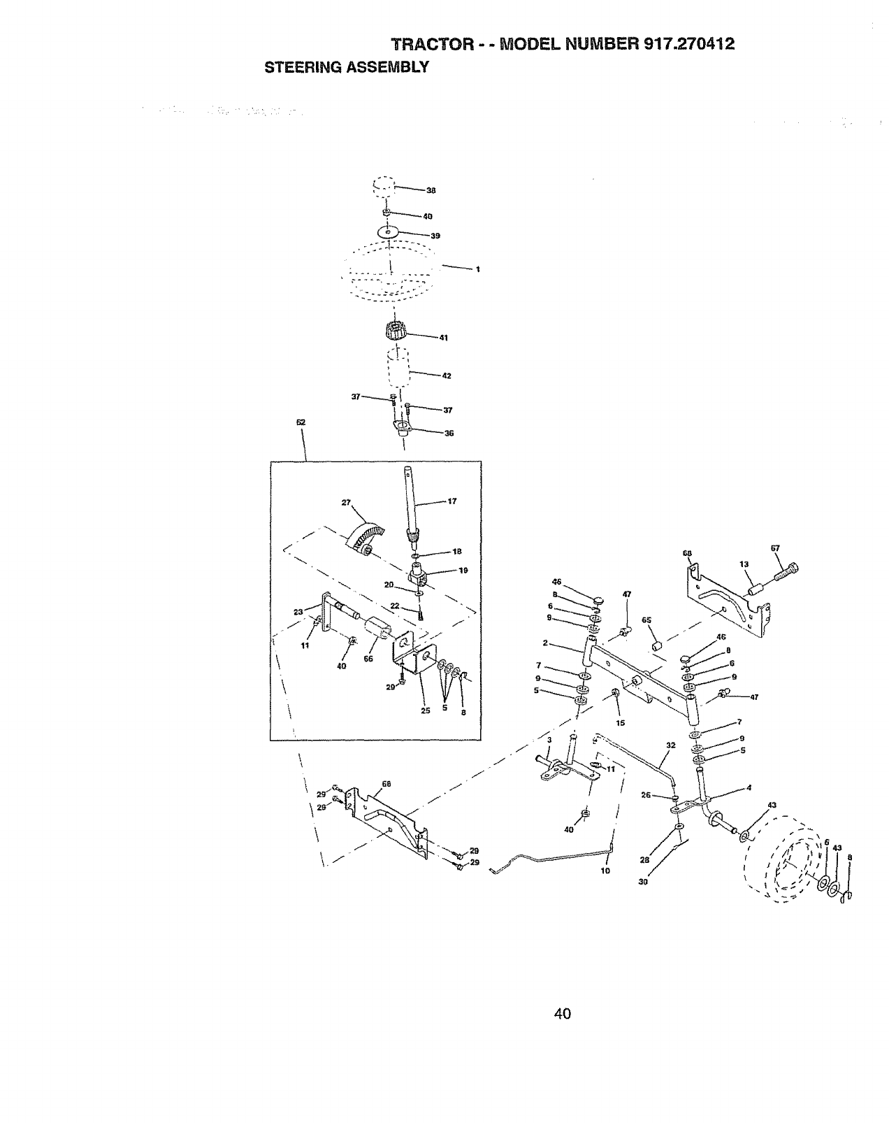
TRACTOR - - MODEL NUMBER 917.270412
STEERING ASSEMBLY
I"-'----1
2t::
4£;
67
13
43
4O
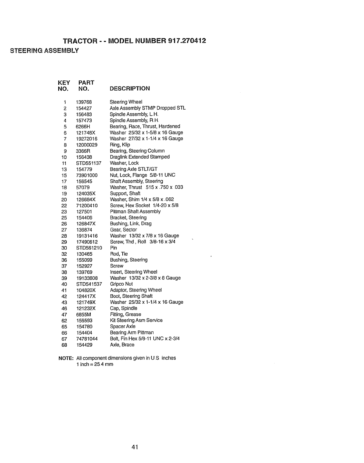
TRACTOR - - MODEL NUMBER 917.270412
STEERING ASSEMBLY
KEY PART
NO. NO. DESCRIPTION
I 139768 Steering Wheel
2 ! 54427 Axle Assembfy STMP Dropped STL
3 156483 Spindle Assembly, L H,
4 t57473 Spindle Assembly, R H
5 6266H Beating, Race, Thrust, Hardened
6 121748X Washer 25132 x t-5t8 x I6 Gauge
7 19272016 Washer 27/32 x 1-1/4 x 16 Gauge
8 12000029 Ring, Klip
9 3366R Bearing, Steedng Column
10 156438 Draglink Extended Stamped
t ! STD55t t37 Washer, Lock
13 154779 Bearing Axle STLTIGT
15 73901000 Nut, Lock, Range 5/8-1t UNC
17 156545 Shaft Assembly, Steering
18 57079 Washer, Thrust 515 x ,.750 x 033
!9 124035X Support, Shaft
20 I26684X Washer, Shim 1/4 x 5/8 x ,062
22 71200410 Screw, Hex Socket 1/4-20 x 5t8
23 12750! Piltman Shaft Assembly
25 t54406 Bracket, Steering
26 126847X Bushing, Link, Drag
27 t36874 Gear, Sector
28 19131416 Washer 13/32 x7/8 x 16 Gauge
29 17490612 Screw, Thd,, Roll 3/8-16 x 3/4
30 STD561210 Pin
32 130465 Rod, Tie
36 155099 Bushing, Steering
37 152927 Screw
38 139769 Insert, Steering Wheel
39 19133808 Washer 13/32 x 2-3/8 x 8 Gauge
40 STD541537 Gfipco Nut
4t 104820X Adaptor, Steering Wheel
42 124417X Boot, Steering Shaft
43 I2t749X Washer 25/32 x 1-1/4 x I6 Gauge
46 121232X Cap, Spindle
47 6855M Fitting, Grease
62 156593 Kit Steering Asm Service
65 154780 Spacer Axle
66 t 54404 Bearing Arm Pittman
67 74781044 Bolt, Fin Hex 5/8ql UNC x 2-3/4
68 154429 Axle, Brace
NOTE: Aft component dimensionsgiven in US inches
1 inch = 25 4 mm
41
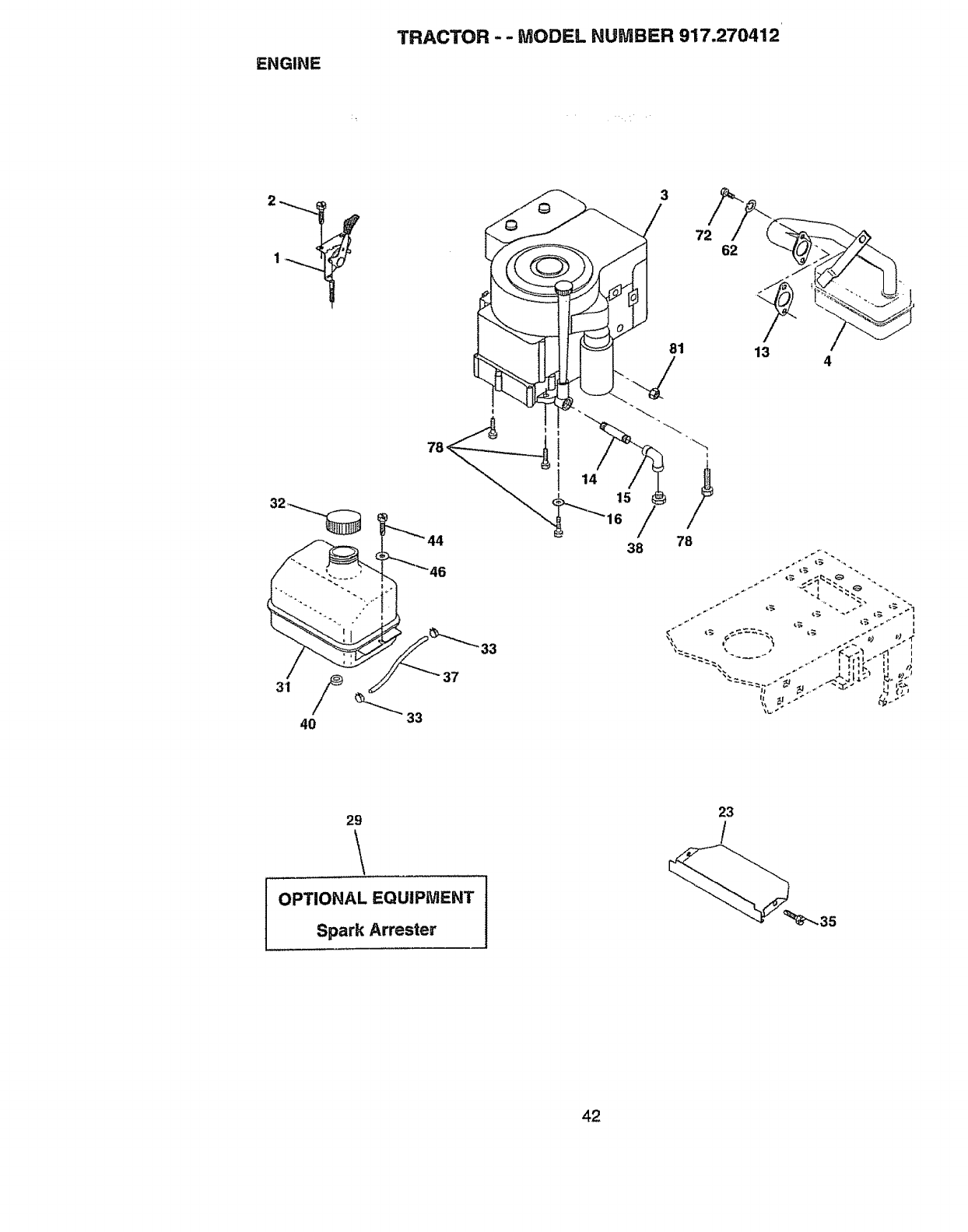
ENGINE
TRACTOR -- MODEL HUMBER 917.270412
40 33
44
33
3
81
i
38 78
4
29
OPTIONAL EQUIPMENT
Spark Arrester
23
/
42
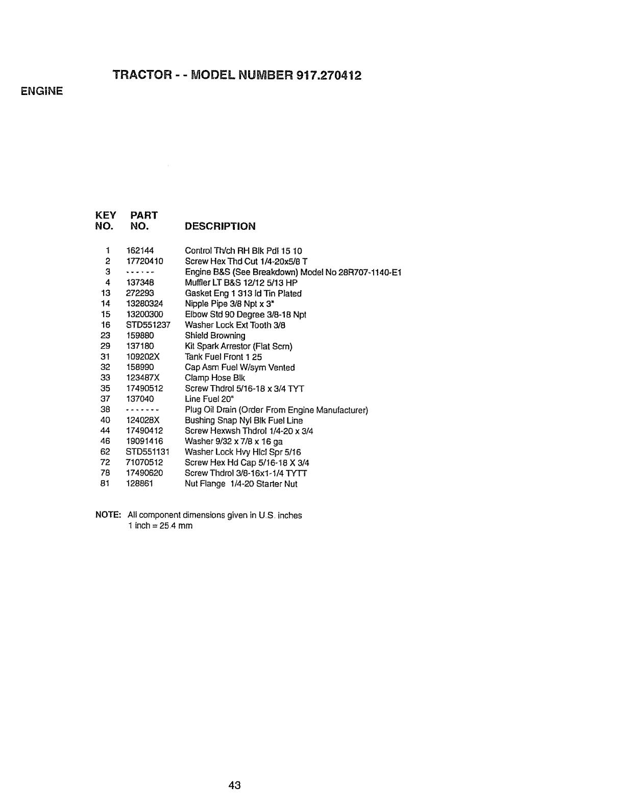
ENGINE
TRACTOR - - MODEL NUMBER 9! 7.2704-12
KEY PART
NO. NO. DESCRIPTION
1 162144
2 17720410
4 137348
13 272293
14 13280324
15 13200300
16 STD551237
23 159880
29 137180
31 109202X
32 158990
33 123487X
35 17490512
37 137040
38 .......
40 124028X
44 17490412
46 19091416
62 STD551131
72 71070512
78 17490620
8! 128861
Control Th/ch RH Btk Pdt 15 10
Screw Hex Thd Cut 1/4-20x5/8 T
Engine B&S (See Breakdown) Model No 28R707-1140-EI
Muffler LT B&S 12/12 5/t3 HP
Gasket Eng I 313 Id 33nPlated
Nipple Pipe 3/8 Npt x 3"
Etbow Std 90 Degree 3/8-18 Npt
Washer Lock Ext Tooth 3/8
Shield Browning
Kit Spark Arrestor (Flat Scm)
Tank Fue_Front 1 25
Cap Asm Fuel Wfsym Vented
Clamp Hose Blk
Screw Thdrol 5/16-18 x 3/4 TY'T
Line Fuel 20"
Plug Oil Drain (Order From Engine Manufacturer)
Bushing Snap Nyl Bfk Fuel Line
Screw Hexwsh Thdrol 1/4-20 x 3/4
Washer 9/32 x 7/8 x 16 ga
Washer Lock Hvy Htcl Spr 5/16
Screw Hex Hd Cap 5/16_18 X 3/4
Screw Thdrol 3/8-16x1-1/4 TYTT
Nut Flange 1/4-20 Starter Nut
NOTE: Atl component dimensions given in US. inches
1 inch = 25,4 mm
43
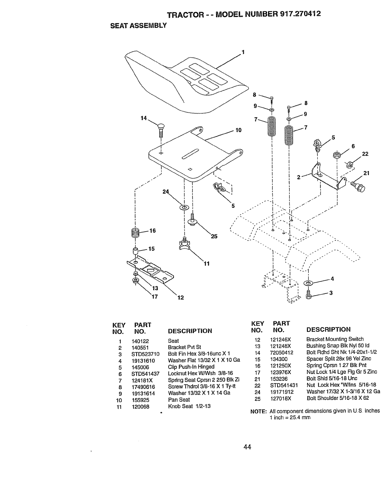
TRACTOR --MODEL NUMBER 917.270412
SEAT ASSEMBLY
14
I
I
i
5
21
KEY
NO.
1
2
3
4
5
6
7
8
9
10
11
PART KEY PART
NO. DESCRIPTION NO. NO.
140122 Seat 12 121246X
140551 Bracket Pvt St 13 121248X
STD523710 BoltFin Hex 3/6-16unc X 1 14 72050412
19131610 Washer Rat 13/32 X 1 X !0 Ga 15 134300
145006 Clip Push-In Hinged 16 121250X
STD54i437 LocknutHex W/Wsh 3/8-16 17 123976X
124181X Spdng Seat Cprsn 2250 Blk Zi 21 153236
17490616 Screw Thdrol 3/8-16 X 1 Ty-tt 22 STD541431
19131614 Washer 13/32 X 1 X 14 Ga 24 19171912
155925 Pan Seat 25 127018X
120068 Knob Seat 1/2-13 NOTE:
DESCRIPTION
Bracket Mounting Switch
Bushing Snap Blk Ny150 Id
Bolt Rdhd Sht Nk 1/4-20x1-1t2
Spacer Split 28x 96 "(el Zinc
Spring Cprsn 127 BIk Pnt
Nut Lock 1/4 Lge Rg Gr 5 Zinc
Boil Shld 5/16_18Unc
Nut Lock Hex "Wtlns 5/16-18
Washer 17/32 X 1-3/16 X 12 Ga
Bolt Shoulder 5t16-t8 X 62
All component dimensions given in US inches
1 inch =25.4 mm
44
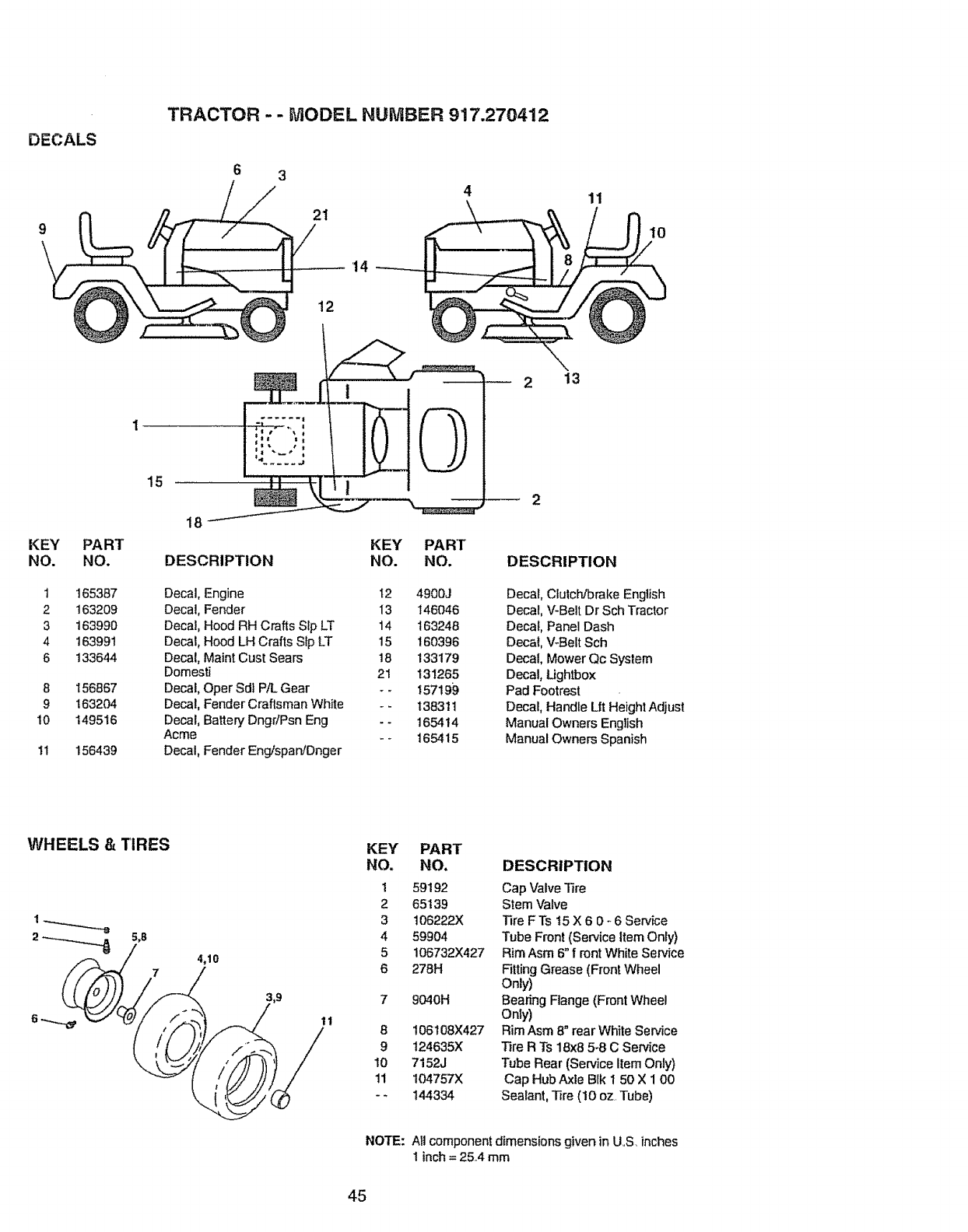
DECALS
K EY PART
NO. NO.
1 165387
2 163209
3 163990
4 163991
6 133644
8 156867
9 163204
10 149516
11 156439
TRACTOR - - MODEL NUMBER 917.270412
63
21
15
12
4
14
\13
11
KEY PART
DESCRIPTION NO. NO. DESCRIPTION
Decal, Engine t2 4900J
Decal, Fender 13 146046
Decal, Hood RH Crafts Sip LT 14 163248
Decal, Hood LH Crafts Sip LT t5 160396
Decal, Maint Cust Sears 18 133179
Domesti 21 131265
Decal, Oper Sdi P/L Gear - - 157199
Decal, Fender Craftsman White - -138311
Decal, Batten/Dngr!Psn Eng -- 165414
Acme - - 165415
Decal, Fender EngispaniDnger
Decal, Clutch/brake English
Decal, V-Belt Dr Sch Tractor
Decal, Panel Dash
Decal, V-Belt Sch
Decal, Mower Qc System
Decal, Lightbox
Pad Footrest
Decal, Handle Lit Height Adjust
Manual Owners English
Manual Owners Spanish
WHEELS &TIRES
4,10
1t
KEY PART
NO. NO.
1 59192
2 65139
3 t06222X
4 59904
5 106732){427
6 278H
9040H
8t06t08X427
9124635X
10 7152J
11 104757X
-- 144334
DESCRIPTION
Cap Valve Tire
Stem Valve
Tire FTs t5X6 0-6 Service
Tube Front (Serviceitem Only)
Rim Asm 6"f ront White Sewice
Fitting Grease (Front Wheel
Only)
Bearing Flange (Front Wheel
Only)
Rim Asm 8" rear White Sen,,ice
Tire R Ts 18x8 5-8 C Service
Tube Rear (Service Item Only)
Cap Hub Axle Blk 1 50 X 1 O0
Sealant, Tire (10 oz Tube)
NOTE: All component dimensions given in US inches
1 inch = 25.,4mm
45
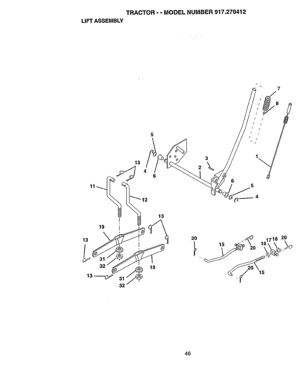
TRACTOR - - MODEL NU IVtBER 917.270412
LIFT ASSEMBLY
7
11
5
3
13 2\
46
12
6
/ /
/ /
/ t
t
5
19
13
32
i
I
32
13
19
17.18 20
15
46
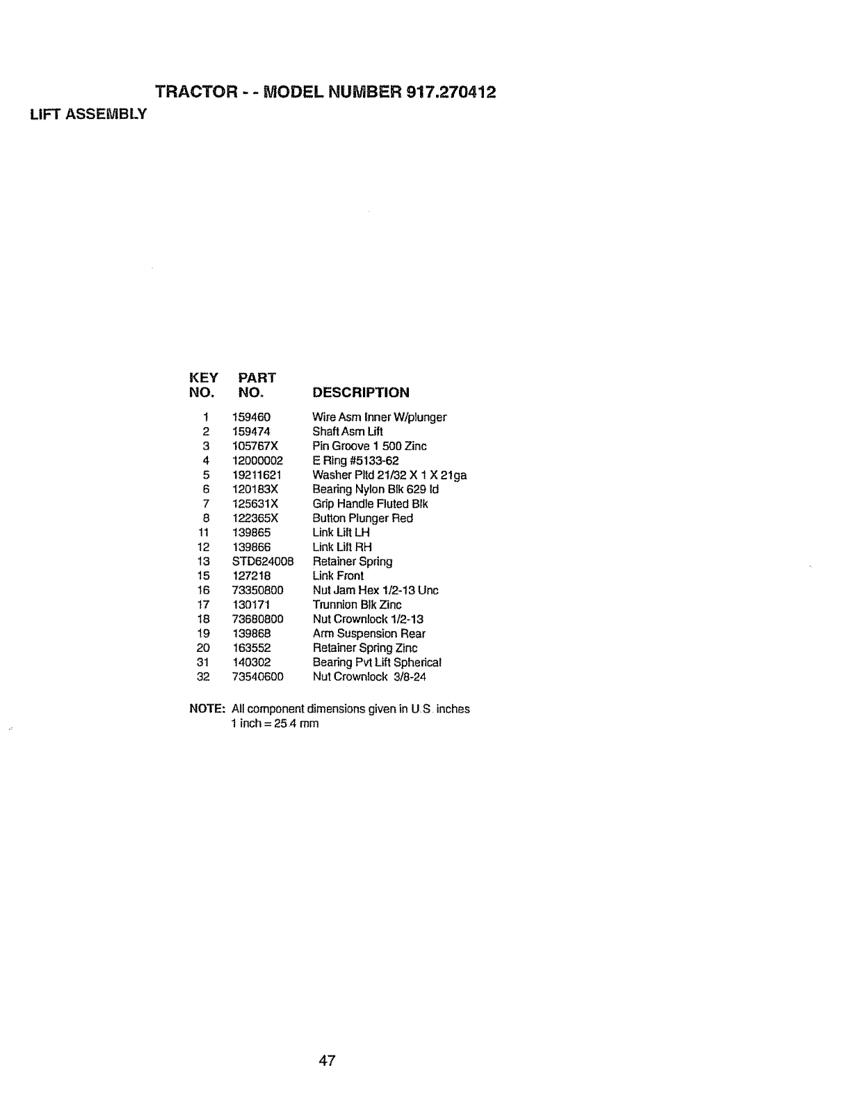
TRACTOR -- MODEL NUMBER 917.270412
LIFT ASSEMBLY
KEY PART
NO. NON DESCRIPTION
1 159460 Wire Asm Inner W/plunger
2 !59474 Shaft Asm Lift
3 105767X Pin Groove I 500 Zinc
4 12000002 E Ring #5133-62
5 19211621 Washer Pttd21/32 X 1 X 21ga
6 120183X Bearing Nylon Bik 629 ld
7 125631X Grip Handle Fluted Brk
8 122365X Button Plunger Red
t 1 139865 Link LiltLH
t2 139866 Link LiltRH
13 STD624008 Retainer Spring
t51272t8 Link Front
16 73350800 Nut Jam Hex 1/2-13 Unc
17 130171 Trunnion Btk Zinc
18 73660800 Nut Crownlock 1/2-13
19 139868 Arm Suspension Rear
20 163552 Retainer Spdng Zinc
31 140302 Bearing Pvt Lift Spherical
32 73540600 Nut Crownlock 3t8-24
NOTE: All component dimensions given in U S. inches
t inch = 25.4 rnm
47

TRACTOR -- MODEL NUMBER 917.270412
MOWER DECK
68
17
58
34
_33
32
\
2
16
29 27
48
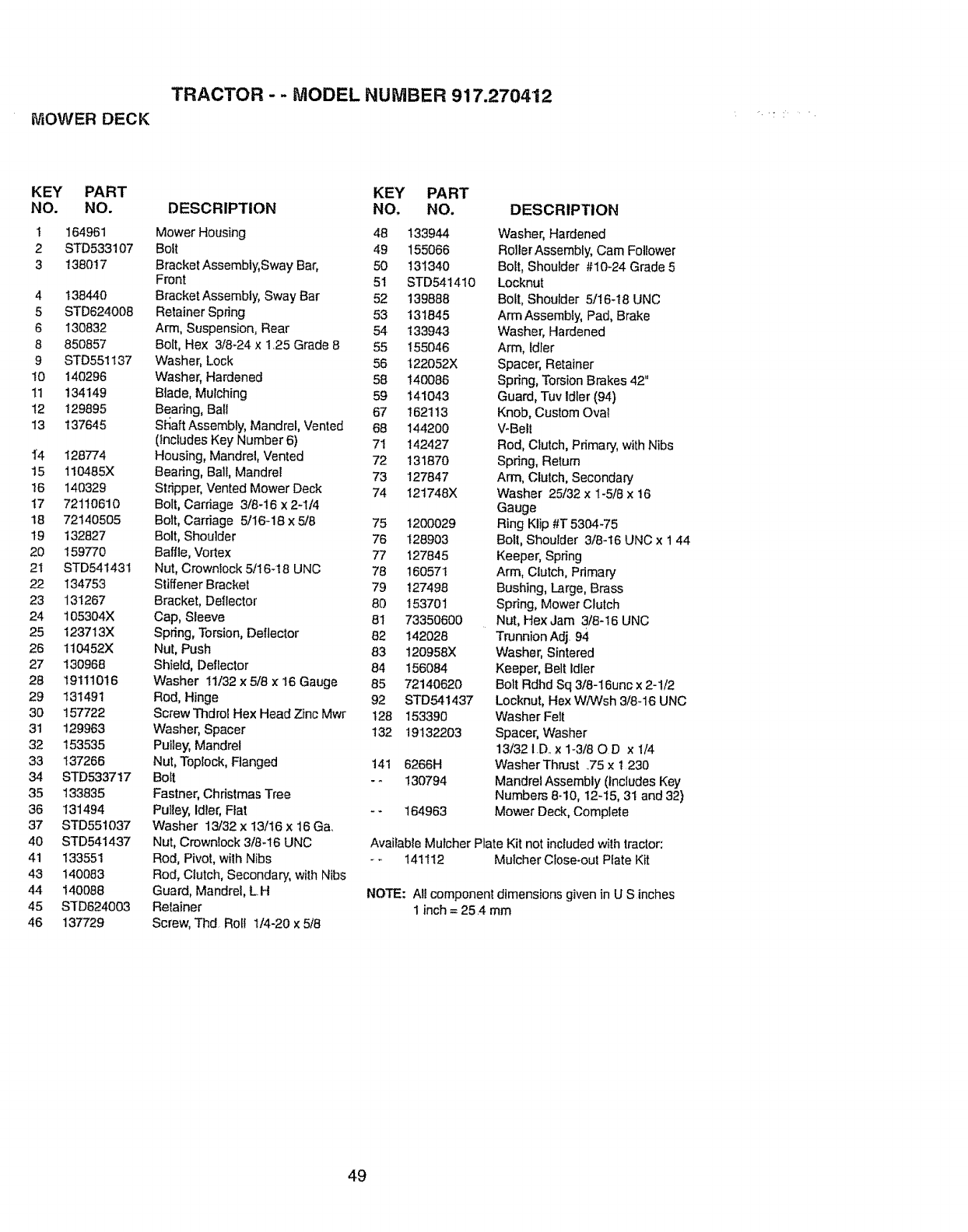
TRACTOR --MODEL NUMBER 917.270412
MOWER DECK
KEY PART KEY PART
NO. NO. DESCRIPTION NO. NO.
t 164961 Mower Housing 48 133944
2 STD533107 Bolt 49 155066
3 138017 Bracket Assembly,Sway Bar, 50 t31340
Front 51 STD541410
4 t38440 Bracket Assembly, Sway Bar 52 139888
5 STD624008 Retainer Spring 53 131845
6 130832 Arm, Suspension, Rear 54 133943
8 850857 Bolt, Hex 3/8-24 x 1,25 Grade 8 55 155046
9 STD551137 Washer, Lock 56 t22052X
i0 140296 Washer, Hardened 58 140086
11 134149 Blade, Mulching 59 141043
12 129895 Bearing, Ball 67 162113
13 137645 Shaft Assembly, Mandrel, Vented 68 144200
(lnctudes Key Number 6) 71 142427
1_4 128774 Housing, Mandrel, Vented 72 131870
15 110485X Bearing, Ball, Mandrel 73 127847
I6 140329 St,_pper,Vented Mower Deck 74 121748X
17 72110610 Bolt, Carriage 3/6-16 x 2-1/4
18 72140505 Bolt, Cardage 5/t6-18 x 5/8 75 1200029
19 132827 Bolt, Shoulder 76 128903
20 159770 Baffle, Vortex 77 127845
2I STD541431 Nut, Crownlock 5/I6-18 UNC 78 160571
22 134753 Stiffener Bracket 79 127498
23 131267 Bracket, Deltector 80 153701
24 t05304X Cap, Sleeve 81 73350600
25 123713X Spring, Torsion, Deflector 82 142028
26 110452X Nut, Push 83 120958X
27 130968 Shield, Deflector 84 156084
28 19111016 Washer 11/32 x 5/8 x 16 Gauge 85 72140620
29 131491 Rod, Hinge 92 STD541437
30 157722 Screw Thdrol Hex Head Zinc Mwr t28 153390
31 129963 Washer, Spacer t32 19132203
32 153535 Pulley,Mandrel
33 137266 Nut, Toplock, Flanged 141 6266H
34 STD533717 Bolt - _ 130794
35 133835 Fastner, Christmas Tree
36 131494 Pulley,Idler, Fiat -- 164963
37 STD551037 Washer 13/32 x 13/t6 x 16 Ga.
40 STD541437 Nut, Crownlock 3/8-16 UNC
41 133551 Rod, Pivot, with Nibs
43 140083 Rod, Clutch, Secondary, with Nibs
44 140088 Guard, Mandrel, LH
45 STD624003 Retainer
46 137729 Screw, Thd Roll 1/4-20 x 5/8
DESCRIPTION
Washer, Hardened
Roller Assembly, Cam Follower
Bolt, Shoulder #10-24 Grade 5
Locknut
Bolt, Shoulder 5/16-18 UNC
Arm Assembly, Pad, Brake
Washer, Hardened
Arm, Idler
Spacer, Retainer
Spring, Torsion Brakes 42"
Guard, Tuv Idler (94)
Knob, Custom Ova!
V-Belt
Rod, Clutch, Primary, with Nibs
Spring, Return
Arm, Clutch, Secondary
Washer 25/32 x 1-5/8 x 16
Gauge
Ring Klip #T 53C'_I.-75
Boll, Shoulder 3/8-16 UNC x t 44
Keeper, Spring
Arm, Clutch, Primary
Bushing, Large, Brass
Spring, Mower Clutch
Nut, Hex Jam 3/8-16 UNC
Trunnion Adj. 94
Washer, Sintered
Keeper, Belt Idler
Bolt Rdhd Sq 318-16unc x 2-1/2
Locknut, Hex WiWsh 3/8-16 UNC
Washer Felt
Spacer, Washer
13/32 I.D..x 1-3/80 D x 1/4
Washer Thrust ..75x t 230
Mandrel Assembly (Includes Key
Numbers 8-10, 12-15, 31 and 32)
Mower Deck, Complete
Available Mulcher Plate Kit not includedwilh tractor:
- _ 141112 Mulcher Close-out Plate Kit
NOTE: Ali component dimensions given in U Sinches
1 inch = 25.4 mm
49
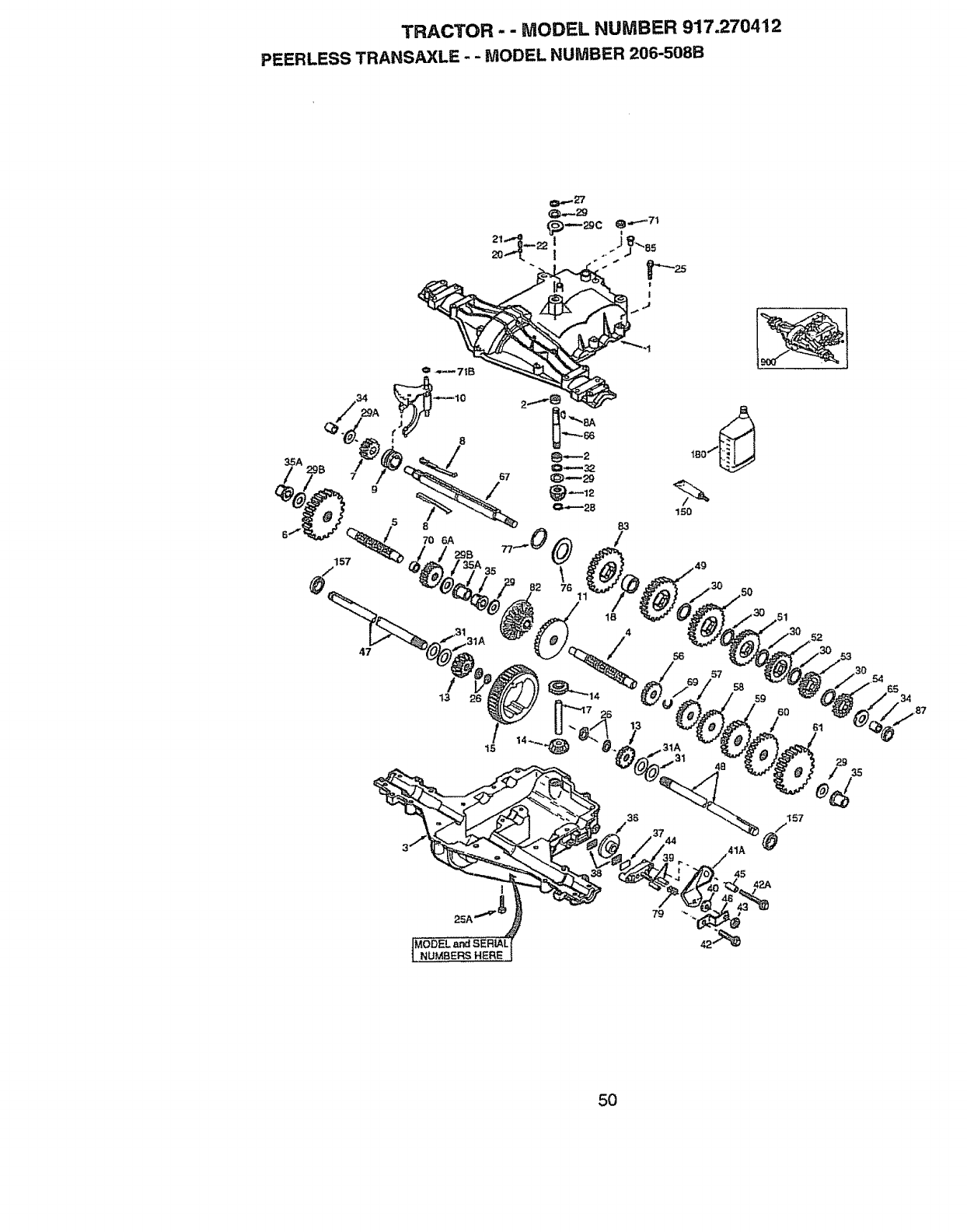
TRACTOR -- MODEL NUMBER 917.270412
PEERLESS TRANSAXLE - -MODEL NUMBER 206-508B
8
/67
9
5
70 6#,
15 29B
/
1B
150
56
57
58 59
60
79
50
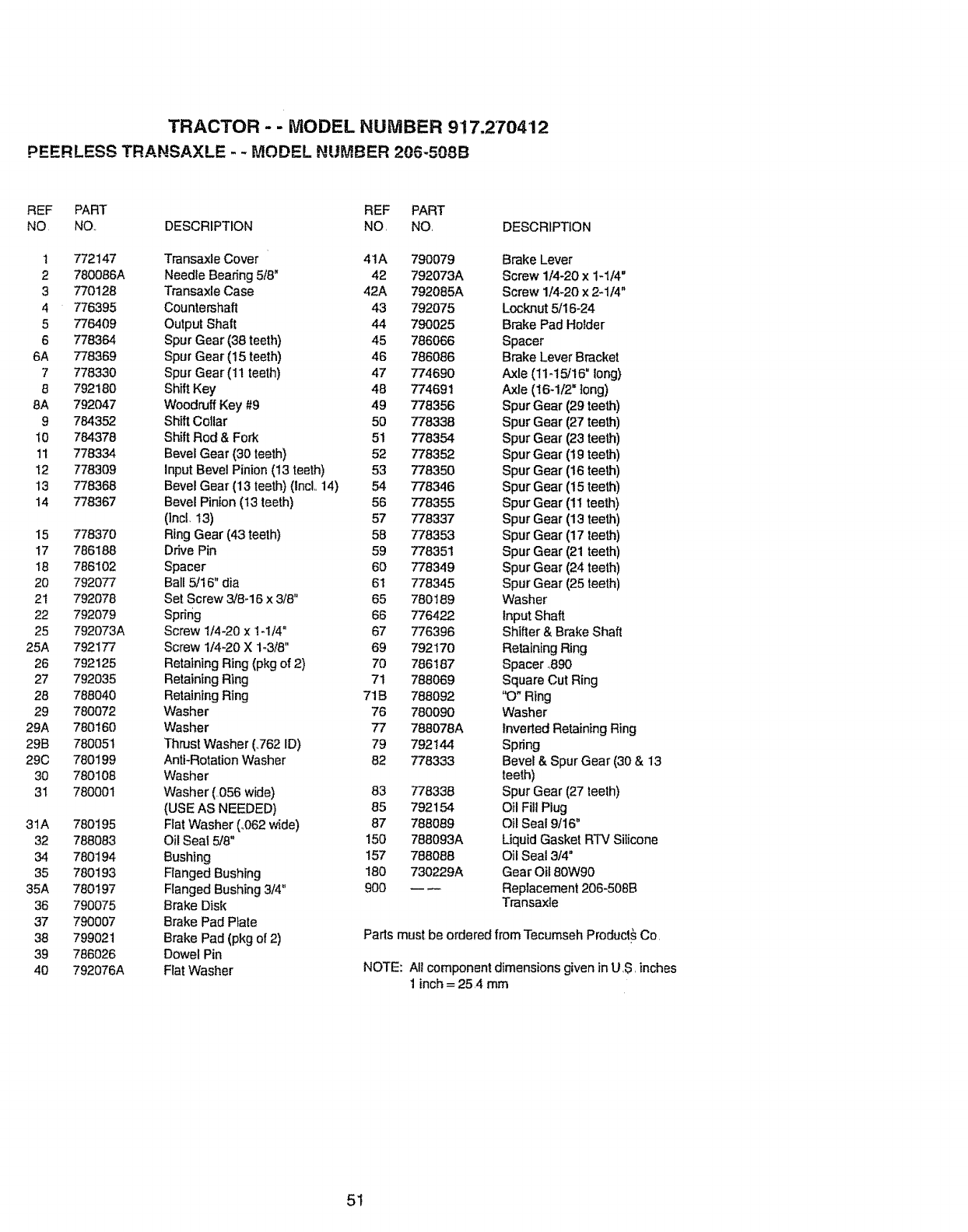
TRACTOR - -MODEL NUMBER 917.270412
PEERLESS TRANSAXLE - -MODEL NUMBER 205-508B
REF PART REF PART
NO NO., DESCRIPTION NO, NO, DESCRIPTION
1 772147 Transaxle Cover 4tA 790079 Brake Lever
2 780086A Needle Bearing 5/8" 42 792073A Screw 1/4-20 x 1-1/4"
3 770128 Transaxle Case 42A 792085A Screw 1/4-20 x 2-1/4"
4 776395 Countershaft 43 792075 Locknut 5/16-24
5 776409 Output Shaft 44 790025 Brake Pad Holder
6 778364 Spur Gear (38 teeth) 45 786066 Spacer
6A 778369 Spur Gear (15 teeth) 46 786086 Brake Lever Bracket
7778330 Spur Gear (11 teeth) 47 774690 Axle (11-15/16" long)
8 792180 Shift Key 48 774691 Axle (16-1/2=tong)
8A 792047 Woodruff Key #9 49 778356 Spur Gear (29 teeth)
9 784352 Shift Collar 50 778338 Spur Gear (27 teeth)
I0 784378 Shift Rod & Fork 51 778354 Spur Gear (23 teeth)
11 778334 Bevel Gear (30 teeth) 52 778352 Spur Gear (19 teeth)
I2 778309 Input Bevel Pinion (!3 teeth) 53 778350 Spur Gear (16 teeth)
13 778368 Bevel Gear (13 teeth) (IncL 14) 54 778346 Spur Gear (t5 teeth)
14 778367 Bevel Pin,on (13 teeth) 56 778355 Spur Gear (11 teeth)
(lnci, 13) 57 778337 Spur Gear (13 teeth)
15 778370 Ring Gear (43 teeth) 58 778353 Spur Gear (17 teeth)
17 786188 Drive Pin 59 778351 Spur Gear (21 teeth)
18 786102 Spacer 60 778349 Spur Gear (24 teeth)
20 792077 Bali 5/16" die 61 778345 Spur Gear (25 teeth)
2t 792078 Set Screw 3/8-16 x 3/8" 65 780189 Washer
22 792079 Spring 66 776422 Input Shaft
25 792073A Screw 1/4-20 x !-1/4" 67 776396 Shifter & Brake Shaft
25A 792177 Screw 1/4-20 X 1-3/8" 69 792170 Retaining Ring
26 792125 Retaining Ring (pkg of 2) 70 786187 Spacer .890
27 792035 Retaining Ring 71 788069 Square Cut Ring
28 788040 Retaining Ring 71B 788092 '_3" Ring
29 780072 Washer 76 780090 Washer
29A 780160 Washer 77 788078A Inverted Retaining Ring
29B 780051 Thrust Washer (..762ID) 79 792144 Spring
29C 780199 Anti-Rotation Washer 82 778333 Bevel & Spur Gear (30 & 13
30 780108 Washer teeth)
31 780001 Washer (056 wide) 83 778338 Spur Gear (27 teeth)
(USE AS NEEDED) 85 792154 Oil Fill Plug
31A 780t95 Fiat Washer (_062wide) 87 788089 Oil Seal 9/16"
32 788083 Oil Seal 5/8" 150 788093A Liquid Gasket RTV Silicone
34 780t94 Bushing 157 788088 Oil Seal 3/4"
35 780193 Flanged Bushing 180 730229A Gear Oil 80W90
35A 780197 Flanged Bushing 3/4" 900 -- -- Replacement 206-508B
36 790075 Brake Disk Transaxle
37 790007 Brake Pad Plate
38 799021 Brake Pad (pkg of 2) Paris must be ordered from Tecumseh Product_ Co.
39 786026 Dowel Pin
40 792076A Flat Washer NOTE: All component dimensions given in U.S. inches
1 inch = 25.4 mm
51
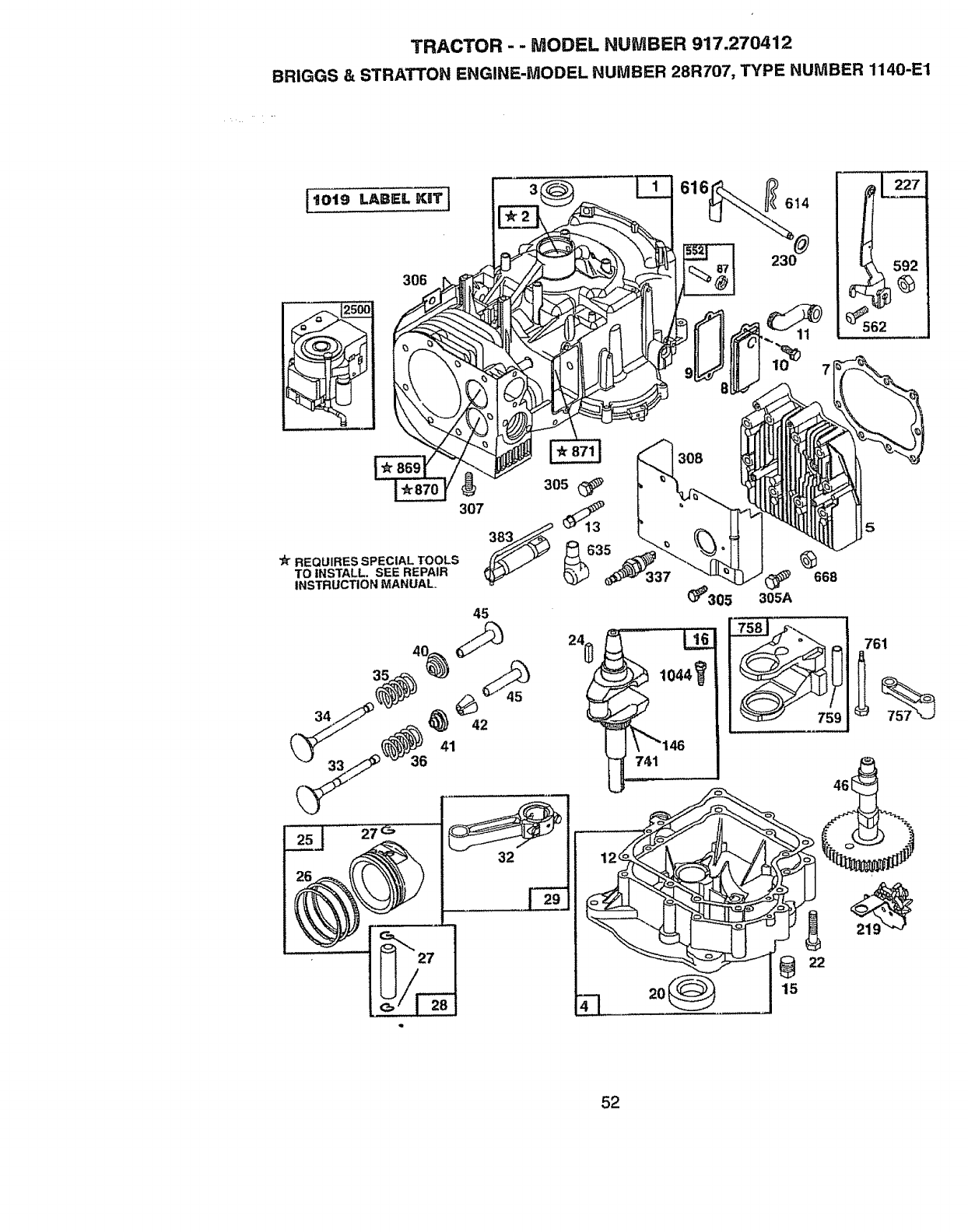
TRACTOR - - MODEL NU_IIBER 917.270412
BRIGGS & STRATTON ENGINE-MODEL NUMBER 28R707, TYPE NUMBER 1140-E1
t019 LAB;:;. KIIT]
306
305(_
307 383_
'_ REQUIRESSPECIAL TOOLS
TO INSTALL. SEE REPAIR qp_
INSTRUCTIONMANUAL
32
4--1
616 _614
230
308
(_305 305A
@
668
5
741
761
022
15
52
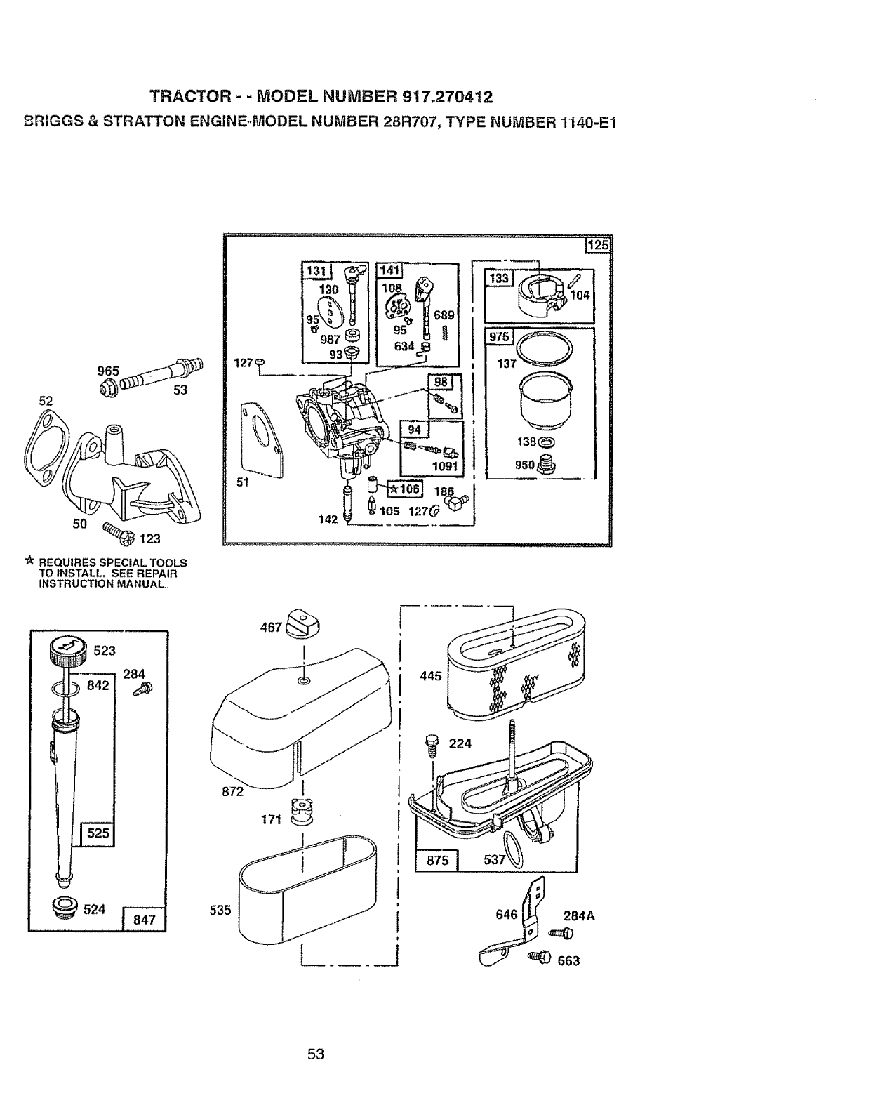
TRACTOR - - MODEL NUMBER 917.270412
BRIGGS & STRATTON ENGINE-MODEL NUMBER 28R707, TYPE NUMBER 1140-E1
52
"_ 123
"_ REQUIRES SPECIAL TOOLS
TO INSTALL, SEE REPAIR
INSTRUCTION MANUAL,
523
284
_)524
142
,,,,L,,J,,,,,,,,,,,,,,,,,,L,,,,
t105 127_ _
104
,........ ,;,;,,
950
53
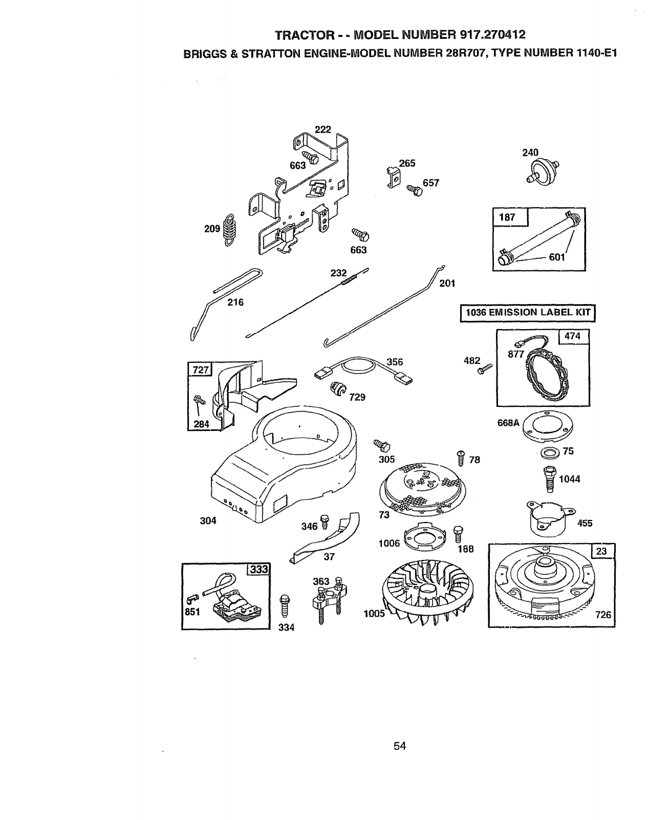
TRACTOR- ,- MODEL NUMBER 917.270412
BRIGGS & STRATTON ENGINE-MODEL NUMBER 28R707, TYPE NUMBER 1140-E1
663_ 2
265
_657
663
I 1036 EM ISSION LABEL KIT
48_
304 73
_7s
1044
_455
334
100!
54
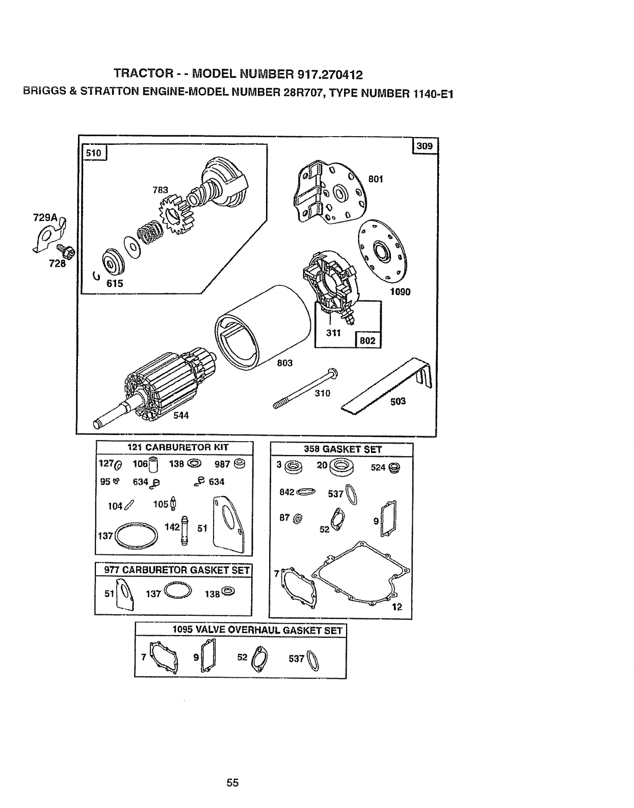
TRACTOR - - MODEL NUMBER 917.270412
BRIGGS & STRATTON ENGINE-MODEL NUMBER 28R707, TYPE NUMBER 1140-E1
783
615 ................ ,, /
544
t801
)
1090
121 CARBURETOR KIT
106_ 138 _987127 0
9s_ 634_ _634
358 GASKET SET
842_ 537_--_
t095 VALVE OVERHAUL GASKET SET
55
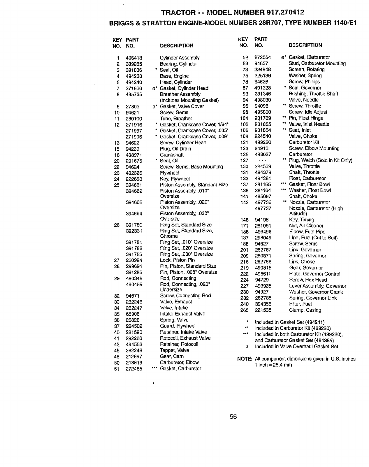
TRACTOR - -MODEL NUMBER 917.270412
BRIGGS & STRATTON ENGINE-MODEL NUIViBER 28R707, TYPE NUMBER 1140-E1
KEY PART KEY PART
NO. NO. DESCRIPTION NO, NO. DESCRIPTION
1
2
3
4
5
7
8
9
10
11
12
13
15
16
20
22
23
24
25
26
27
28
29
32
33
34
35
36
37
40
41
42
45
46
50
51
496413 CylinderAssembly 52 272554 e* Gasket, C_lrburetor
399265 Bearing, Cylinder 53 94637 Stud, Carburetor Mounting
391086 * Seal, Oil 73 224948 Screen, Rotating
494238 Base, Engine 75 225136 Washer, Spring
494240 Head, Cylinder 78 94626 Screw, Phi!lips
271866 e* Gasket, Cylinder Head 87 491323 * Seal, Governor
495735 Breather Assembly 93 281346 Bushing, Throttle Shaft
(Includes Mounting Gasket) 94 498030 Valve, Needle
27803 {_* Gasket, Valve Cover 95 94098 ** Screw, Throttle
94621 Screw, Seres 98 495800 Screw, IdleAdjust
280100 Tube, Breather 104 23.1789 *" Pin, Float Hinge
271916 * Gasket, Crankcase Cover, 1/64" 105 231855 ** Valve, Inlet Needle
271997 * Gasket, Crankcase Cover, ,.605" 106 231854 "" Seat, Inlet
271996 * Gasket, Crankcase Cover, .D09" 108 224540 Valve, Choke
94622 Screw, Cylinder Head 121 499220 Carburetor Kit
94239 Plug, Oil Drain 123 94913 Screw, Elbow Mounting
498971 Crankshaft 125 498027 Carburetor
29167'5 "Seal, Oil 127 - --** Plug,Welch (Sold in Kit Only)
94624 Screw, Sems, Base Mounting 130 224539 "valve,Throttle
492326 Fiywheet 131 494379 Shaft, Throttle
222698 Key, Rywheel 133 494381 Roat, Carburetor
394661 PistonAssembty, Standard Size 137 281165 **" Gasket, Float Bowl
394662 Piston Assembly, ,.010" 138 281164 *** Washer, Float Bowl
Oversize 141 495097 Shaft, Choke
394663 Piston Assembly, _020=142 497736 ** Nozzle, Carburetor
Oversize 497737 Nozzle, Carburetor (High
394664 Piston Assembly, ..030" Altitude)
Oversize 146 94196 Key, Timing
391780 Ring Set, StandardSize 171 281051 Nut, Air Cleaner
392331 Ring Set, Standard Size, 186 493496 Elbow, Fuel Pipe
Chrome 187 298049 Une, Fuel (Cut to Suit)
391781 Ring Set, ..010=Oversize 188 94627 Screw, Serns
391782 Ring Set, °020" Oversize 201 262767 Link, Governor
391783 Ring Set, .030°Oversize 209 260871 Spring, Governor
260924 Lock, PistonPin 216 262766 Link, Choke
299691 Pin, Piston, Standard Size 219 490815 Gear, Governor
391286 Pin, Piston, .005" Oversize 222 495611 Plate, Govemor Control
490348 Rod, Connecting 224 94729 Screw, Hex Head
490469 Rod, Connecting, _020" 227 493935 LeverAssembly, Governor
Undersize 230 94927 Washer, Governor Crank
94671 Screw, Connecting Rod 232 262785 Spring, Governor Link
262246 Valve, Exhaust 240 394358 Filter, Fuel
262247 Valve, Intake 265 221535 Clamp, Casing
65906 Intake Exhaust Valve
26828 Spnng, Valve " Included in Gasket Set (494241)
224502 Guard, Rywheel ** Included in Carburetor Kit (499220)
221596 Retainer,Intake Valve *'* Included in both Carburetor Kit (499220),
292260 Rotocoii, Exhaust Valve and Carburetor Gasket Set (494385)
494553 Retainer, Rotocoit e Inctuded in 'valveOverhaul Gasket Set
262248 Tappet, Valve
212897 Gear, Cam NOTE: All component dimensions given in U_S_inches
213819 Carburetor; Elbow 1 inch =25..4 mm
272465 *** Gasket, Carburetor
56

TRACTOR - - MODEL HUMBER 917.270412
BRtGGS & STRATTON ENGINE-MODEL NUMBER 28R707, TYPE NUMBER 1!40-E!
KEY PART KEY PART
NQ, NO. DESCRIPTION NOr NOr DESCRIPTION
284 94903 Screw, Shoulder 726 392134 Gear, Ring
284A 94704 Screw, Hex Head 727 490324 Cover, Starter
304 496280 Housing, Blower 728 94951 Screw, Torx_
305 94786 Screw, Hex Head 729 281159 Clip, Lead Wire
305A 94881 Screw, Hex 729A 225170 Retainer, Wire
306 224545 Shield, Cylinder 741 262932 Gear, -Iiming
307 94930 Screw, Sems 757 213998 Unk, Counterweight
308 491490 Cover, Cylinder Head 758 399891 Counterweight Assembly
309 497595 Motor, Starter 759 298909 Pin, Counterweight
310 94003 Thru Boll 761 94593 Screw, Counterweight
31t 497608 BrushAssembiy 783 280104 Gear
333 492341 Armature, Magneto 801 394856 Cap, Ddve
334 094731 Screw,Sems 802 497605 Cap, End
337 802592 Plug, Spark 803 497604 Housing, Starter
346 94896 Screw, Hex Head 842 270920 * Seal, Cap
356 494328 Wire Assembly 847 496415 Tube AssembEy,Oil
358 494241 Gasket Set 85t 493880 Terminal, Ignition Cable
363 19203 Puller, Flywheel 869 261463 Seat, Intake Valve
383 89838 Wrench, Spark Plug 870 262924 Seat, Exhaust Valve
445 496894 Cartridge, Air Cleaner 871 261961 Guide, Exhaust Valve
455 221561 Cap, Flywheel 231218 Guide, Intake Valve, Brass
467 493903 Knob, AirCleaner 872 281361 Cover, AirC]eaner
474 393474 Stalor, Alternator 875 494237 Body, Air Cleaner
482 93621 Screw, Seres 877 393456 Diode Assembly
503 806000 Strap, Starter 950 94642 Screw, Fuel Bowl
510 497606 Starter Drive Group 965 94010 Nut, Hex
523 495230 Dipstick, Oil 975 495933 Bowl, Float
524 281370 * Seal, Oil 977 494385 Carburetor Gasket Set
525 496113 Tube, Oil Filler 987 281166 "* Seal, Throttle Shaft
535 272403 Element, Filter t005 281400 Fan, Flywheel
537 281106 e" O-Ring, Air Cleaner 1006 224413 Retainer, Fan
544 497603 Armature, Starter t0t9 491252 Label Kit
552 491986 Bushing, Governor Crank t036 499362 Label, Kit, Emission
562 94907 Bolt, Governor Lever I044 94673 Screw, Hex Head
592 23t978 Nut, Hex 1045 231828 Extension, Crankshaft
601 93053 Clamp, Fuel Pipe 1090 497607 Retainer, Brush
614 93306 Pin, Cotter 1091 281364 Cap, Limiter
615 263080 Retainer 1095 498539 Gasket Set, Valve Overhaul
6t6 495157 Crank, Governor 2500 28R707-1140 Replacement Engine
634 494453 * Seal, Spring Assembly -- 496050 Replacement Shortblock
635 66538 Elbow, Spark Plug
646 224546 Brace, Air Cleaner RPM Settings: Low Speed: 1900-2100
657 94906 Screw, Sems High Speed: 3000-3200
663 94929 Screw, Hex Head
668 231109 Spacer * lncludedin Gasket Set(494241)
668A 280848 Spacer
689 262820 Spring, Fdclion "" Included in Carburetor Kit (499220)
"** Included inboth Carburetor Kit (499220),
and Carburetor Gasket Sel (494385)
Included in Valve Overhaul Gasket Set
NOTE: A{tcomponent dimensions given in U.S. inches
1 inch = 254 mm
57

58
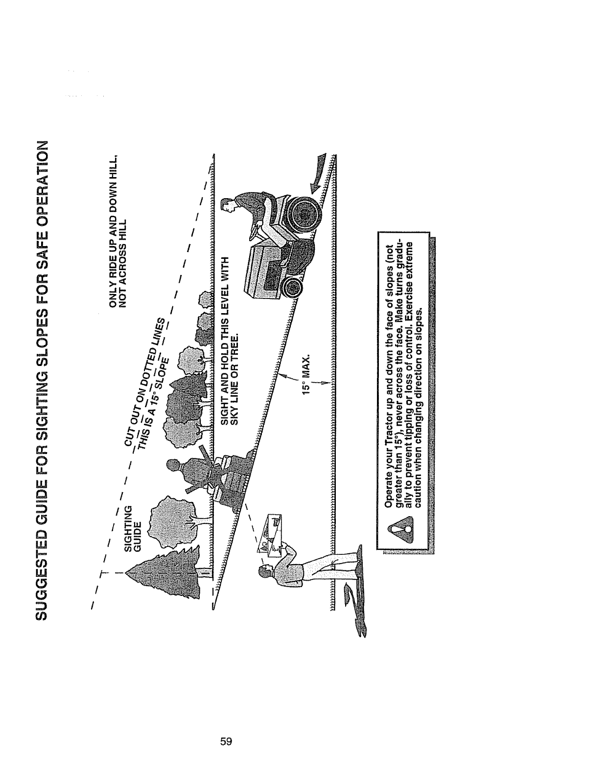
0
m
i=,
u.I
0
LU
0
LL
W
0
0
m
0
m
0
LL
W
m
0
r_
w
w
0
0
I
/
/-
1
/
/
t
1
1
/
/
/
!
0
/
/
/
59
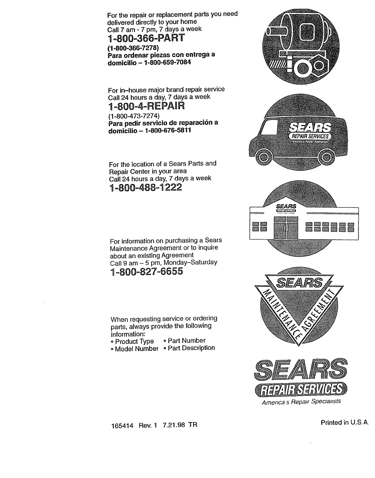
For the repair or replacement parts you need
delivered directly to your home
Call 7 am - 7 pro, 7 days aweek
1=800=366=PART
(1-800'366-7278)
Para ordenar piezas con entrega a
domicilio - 1-800-659-7084
For in-house major brand repair service
Call 24 hours a day, 7 days aweek
1=800=4-REPASR
(1-800-473-7274)
Para pedir servicio de reparaci6n a
domicilio- 1-800-676-5811
For the location of a Sears Parts and
Repair Center in your area
Call 24 hours aday, 7days a week
1=800=488..1222
For' information on purchasing a Sears
Maintenance Agreement or to inquire
about an existing Agreement
Call 9 am - 5 pro, Monday-Saturday
1--800o827-6655
When requesting service or ordering
parts, always provide the following
information:
= Product Type = Part Nurnber
o Model Number o Part Description
Amencas Repair Specialfsts
165414 Rev. 1 7.21.98 TR Printed in U.SA
