Craftsman 917270430 User Manual 13.5 HP 38 MOWER 5SPD LAWN TRACTOR Manuals And Guides L9080036
CRAFTSMAN Lawn, Tractor Manual L9080036 CRAFTSMAN Lawn, Tractor Owner's Manual, CRAFTSMAN Lawn, Tractor installation guides
User Manual: Craftsman 917270430 917270430 CRAFTSMAN CRAFTSMAN 13.5 HP 38 MOWER 5SPD LAWN TRACTOR - Manuals and Guides View the owners manual for your CRAFTSMAN CRAFTSMAN 13.5 HP 38 MOWER 5SPD LAWN TRACTOR #917270430. Home:Lawn & Garden Parts:Craftsman Parts:Craftsman CRAFTSMAN 13.5 HP 38 MOWER 5SPD LAWN TRACTOR Manual
Open the PDF directly: View PDF ![]() .
.
Page Count: 60

Owner's Manual
(RAFTtMAN"
13.5 HP
ELECTRIC START
38" MOWER
5 SPEED TRANSAXLE
LAWN TRACTOR
Model No.
917.270430
• Safety
• Assembly
• Operation
• Maintenance
•Repair Parts
CAUTION:
Read and follow all Safety
Rules and Instructions before
operating this equipment.
For answers to your questions
about this product, Call:
1-800-659-5917
Sears Craftsman Help Line
5 am - 5 pm, Mon - Sat
Sears, Roebuck and Co., Hoffman Estates, II 60179
Visit our Craftsman website:www.sears.comlcraftsman
Warranty............................................... 2
Safety Rules .......................................... 2
Product Specifications .......................... 5
Assembly ............................................... 8
Operation. ............................................ 11
Maintenance Schedule ...................... 17
Maintenance ....................................... 17
Service and Adjustments.................... 21
Troubleshooting ................................. 28
Repair Parts ........................................ 32
Parts Ordering ..................... Back Cover
LIMITED TWO YEAR WARRANTY ON CRAFTSMAN RIDING EQUIPMENT
For two (2) _ears from the date of purchase, if this Craftsman Riding Equipment is
maintained, lubricated and tuned up according to the instructionsin the owner's
manual, Sears will repair or replace, free of charge, any parts found to be defective in
material or workmanship.
This Warranty does not cover:
•Expendable items which become worn during normal use, such as blades, spark
plugs, air cleaners, belts, etc.
•Tire replacement or repair caused by punctures from outside objects, such as nails,
thorns, stumps, or glass.
•Repairs necessary because of operator abuse, negligence, improper storage or acci-
dent or the failure to maintain the equipment according to the instructions contained
in the owner's manual.
•Riding equipment used for commercial or rental purposes.
LIMITED 90 DAY WARRANTY ON BATTERY
For ninety (90) days from date of purchase, if any battery included with this riding
equipment proves defective in material or workmanship and our testing determines the
battery will not hold a charge, Sears will replace the battery at no charge. In-home
warranty service on your Craftsman ridingequipment is available at no charge for 30
days from the date of purchase. Please contact your nearest service center. After 30
days from the date of purchase, warranty service is available by taking your Craftsman
riding equipment to your nearest Sears Service Center. (In-home warranty service will
still be available after 30 days from the date of purchase but astandard trip charge will
apply). This warranty applies only while this product is in the United States. This
Warranty gives you specific legal rights, and you may also have other rights which may
vary from state to state.
Sears, Roebuck and Co., D/817 WA, Hoflman Estates, IL 60179
GENERAL OPERATION
•Read, understand, and follow all in-
structions in the manual and on the
machine before starting.
•Only allow responsible adults, who are
familiar with the instructions, to operate
the machine.
•Clear the area of objects such as
rocks, toys, wire, etc., which could be
picked up and thrown by the blade.
•Be sure the area is clear of other
people before mowing. Stop machine if
anyone enters the area.
•Never carry passengers.
•Do not mow in reverse unless abso-
lutely necessary. Always look down and
behind before and while backing.
•Be aware of the mower discharge di-
rection and do not point it at anyone.
Do not operate the mower without ei-
ther the entire grass catcher or the
guard in place.
•Slow down before tuming.
•Never leave a running machine unat-
tended. Always turn off blades, set
parking brake, stop engine, and re-
2 move keys before dismounting.
• Tum off blades when not mowing.
•Stop engine before removing grass
catcher or unclogging chute.
•Mow only in daylight or good artificial
light.
•Do not operate the machine while un-
der the influence of alcohol or drugs.
•Watch for traffic when operating near
or crossing roadways.
•Use extra care when loading or un-
loading the machine into a trailer or
truck.
SLOPE OPERATION
Slopes are amajor factor related to loss-
of-control and tipever accidents, which
can result in severe injury or death. All
slopes require extra caution. If you can-
not back up the slope or if you feel un-
easy on it, do not mow it.
DO:
•Mow up and down slopes, not across.
•Remove obstacles such as rocks, tree
limbs, etc.
•Watch for holes, ruts, or bumps. Un-
even terrain could overtum the ma-
chine. Tall grass can hide obstacles.
•Use slow speed. Choose alow gear so
that you will not have to stop or shift
while on the slope.
•Follow the manufacturer's recommen-
dations for wheel weights or counter-
weights to improve stability.
•Use extra care with grass catchers or
other attachments. These can change
the stability of the machine.
•Keep all movement on the slopes slow
and gradual. Do not make sudden
changes in speed or direction.
•Avoid starting or stopping on a slope. If
tires lose traction, disengage the
blades and proceed slowly straight
down the slope.
DO NOT:
•Do nottum on slopes unless neces-
sary, and then, turn slowly and gradu-
ally downhill, if possible.
•Do not mow near drop-offs, ditches, or
embankments. The mower could sud-
denly turn over if a wheel is over the
edge of a cliff or ditch, or if an edge
caves in.
•Do not mow on wet grass. Reduced
traction could cause sliding.
•Do nottry to stabilize the machine by
putting your foot on the ground.
•Do not use grass catcher on steep
slopes.
CHILDREN
Tragic accidents can occur if the operator
is not alert to the presence of children.
Children are often attracted to the ma-
chine and the mowing activity. Neveras-
sume that children will remain where you
last saw them.
•Keep children out of the mowing area
and under the watchful care of another
responsible adult.
•Be alert and turn machine off if chil-
dren enter the area.
•Before and when backing, look behind
and down for small children.
•Never carry children. They may fall off
and be sedously injured or interfere
with safe machine operation.
•Never allow children to operate the ma-
chine.
•Use extra care when approaching blind
corners, shrubs, trees, or other objects
that may obscure vision.
SERVICE
•Use extra care in handling gasoline
and other fuels. They are flammable
and vapors are explosive.
Use only an approved container.
Never remove gas cap or add fuel
with the engine running. Allow en-
gine to cool before refueling. Do
not smoke.
Never refuel the machine indoors.
Never store the machine or fuel
container inside where there is an
open flame, such as a water heat-
er.
•Never run a machine inside a closed
3
area.
•Keep nuts and bolts, especially blade
attachment bolts, tight and keep equip-
ment in good condition.
•Never tamper with safety devices.
Check their proper operation regulady.
•Keep machine free of grass, leaves, or
other debris build-up. Clean oil or fuel
spillage. Allow machine to cool before
storing.
•Stop and inspect the equipment if you
strike an object. Repair, if necessary,
before restarting.
• Nevermakeadjustmentsor repairs
withthe enginerunning.
• Grasscatchercomponentsaresubject
to wear,damage,and deterioration,
which could expose moving parts or al-
low objects to be thrown. Frequently
check components and replace with
manufacturer's recommended parts,
when necessary.
•Mower blades are sharp and can cut.
Wrap the blade(s) or wear gloves, and
use extra caution when servicing them.
•Check brake operation frequently. Ad-
just and service as required.
•Be sure the area is clear of other
people before mowing. Stop machine if
anyone enters the area.
•Never carry passengers.
•Do not mow in reverse unless abso-
lutely necessary. Always look down and •
behind before and while backing.
• Never carry children. They may fall off
and be seriously injured or interfere •
with safe machine operation.
•Keep children out of the mowing area
and under the watchful care of another •
responsible adult.
•Be alert and turn machine off if chil-
dren enter the area.
•Before and when backing, look behind •
and down for small children.
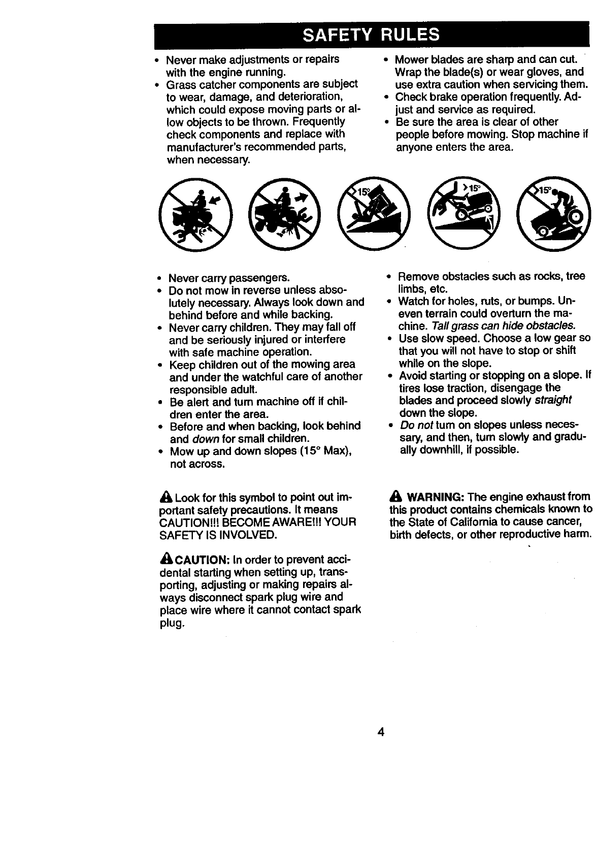
•Mow up and down slopes (15 ° Max),
not across.
Remove obstacles such as rocks, tree
limbs, etc.
Watch for holes, ruts, or bumps. Un-
even terrain could overturn the ma-
chine. Tall grass can hide obstacles.
Use slow speed. Choose a low gear so
that you will not have to stop or shift
white on the slope.
Avoid starting or stopping on a slope. If
tires lose traction, disengage the
blades and proceed slowly straight
down the slope.
Do not tum on slopes unless neces-
sary, and then, tum slowly and gradu-
ally downhill, if possible.
_k, Look for this symbol to point out im-
portant safety precautions. It means
CAUTION!!! BECOME AWARE!!! YOUR
SAFETY IS INVOLVED.
/k CAUTION: In order to prevent acci-
dental starting when setting up, trans-
porting, adjusting or making repairs al-
ways disconnect spark plug wire and
place wire where it cannot contact spark
plug.
WARNING: The engine exhaust from
this product contains chemicals known to
the State of California to cause cancer,
birth defects, or other reproductive harm.
4
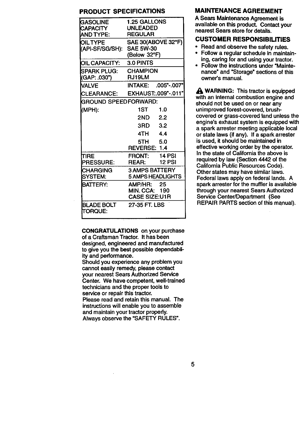
PRODUCT SPECIFICATIONS
GASOLINE
CAPACITY
AND TYPE:
OIL'TYPE
(API-SF/SG/SH):
Z)ILCAPACITY:
;PARK PLUG:
_AP: .030")
CALVE
3LEARANCE:
1.25 GALLONS
UNLEADED
REGULAR
SAE 30(ABOVE 32°F
SAE 5W-30
(Below 32°F)
3.0 PINTS
CHAMPION
RJ19LM
INTAKE: .005"-.007"
EXHAUST:.009"-.0t 1"
3ROUND SPEED FORWARD:
[MPH): 1ST 1.0
2ND 2.2
3RD 3.2
4TH 4.4
5TH 5.0
REVERSE: 1.4
TIRE FRONT: 14 PSI
PRESSURE: REAR: 12 PSI
CHARGING 3 AMPS BATTERY
SYSTEM: 5 AMPS HEADLIGHTS
BATTERY: AMP/HR: 25
MIN. CCA: 190
CASE SIZE:U1R
3LADE BOLT 27-35 FT. LBS
FORQUE:
MAINTENANCE AGREEMENT
A Sears Maintenance Agreement is
available on this product. Contact your
nearest Sears store for details.
CUSTOMER RESPONSlBIUTIES
•Read and observe the safety rules.
•Follow a regular schedule in maintain-
ing, caring for and using your tractor.
•Follow the instructions under "Mainte-
nance" and =Storage" sections of this
owner's manual.
WARNING: This tractor is equipped
with an internal combustion engine and
should not be used on or near any
unimproved forest-covered, brush-
covered or grass-covered land unless the
engine's exhaust system is equipped with
a spark arrester meeting applicable local
or state laws (if any). If a spark arrester
is used, it should be maintained in
effective working order by the operator.
In the state of California the above is
required by law (Section 4442 of the
California Public Resources Code).
Other states may have similar laws.
Federal laws apply on federal lands. A
spark arrester for the muffler is available
through your nearest Sears Authorized
Service Center/Department (See
REPAIR PARTS section of this manual).
CONGRATULATIONS on your purchase
of a Craftsman Tractor. It has been
designed, engineered and manufactured
to give you the best possible dependabil-
ity and performance.
Should you experience any problem you
cannot easily remedy, please contact
your nearest Sears Authorized Service
Center. We have competent, well-trained
technicians and the proper tools to
service or repair this tractor.
Please read and retain this manual. The
instructions will enable you to assemble
and maintain your tractor properly.
Always observe the "SAFETY RULES".
5
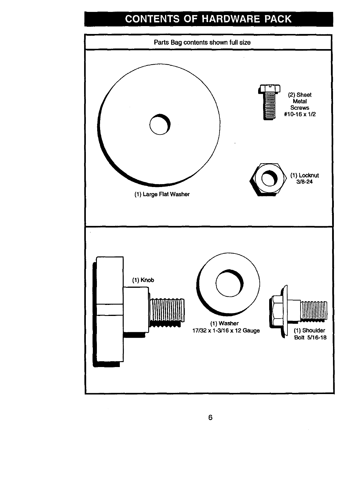
Parts Bag contents shown full size
(1) Large Flat Washer
(2) Sheet
Metal
Screws
#10-16 x 1/2
(1)Locknut
3/8-24
(1) Knob ©
(1) Washer
17/32 x 1-3/16 x 12 Gauge (1) Shoulder
Bolt 5/16-18
6
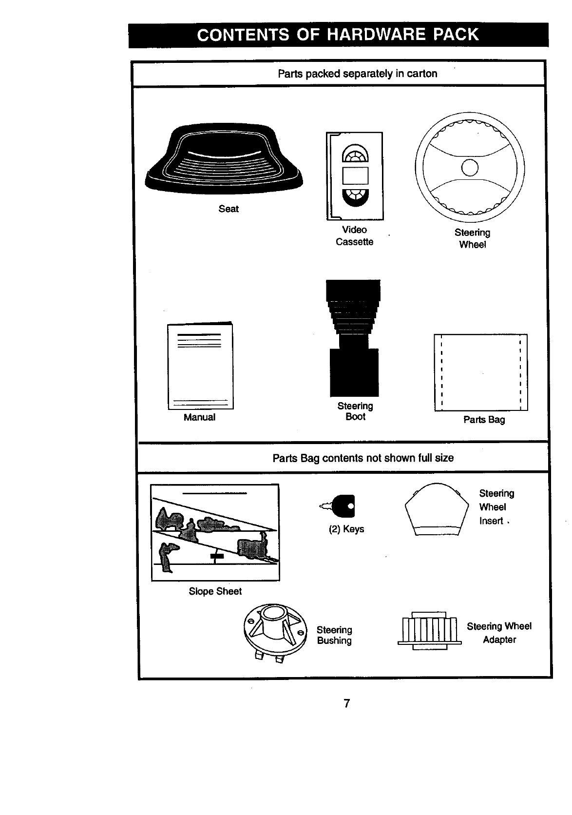
Parts packed separately in carton
Seat
F-7
Video
Cassette Steering
Wheel
Manual Steering
Boot Parts Bag
Parts Bag contents not shown full size
Slope Sheet
(2) Keys
Steering
Bushing
Steering
Wheel
Insert,
Steering Wheel
, , Adapter
= i
7
Your new tractor has been assembled at the factory with exception of those parts left
unassembled for shipping purposes. To ensure safe and proper operation of your
tractor all parts and hardware you assemble must be tightened securely. Use the
correct tools as necessary to insure proper tightness. Review the video cassette before
you begin.
TOOLS REQUIRED FOR
ASSEMBLY
A socket wrench set will make assembly
easier. Standard wrench sizes you need
are listed below.
(1) 5/16"wrench (1) Pliers
(2) 1/2"wrench (1) Utility knife
(1) Tire pressure gauge
When right or left hand is mentioned in
this manual, it means, from your point of
view, when you are in the operating
position (seated behind the steering
wheel).
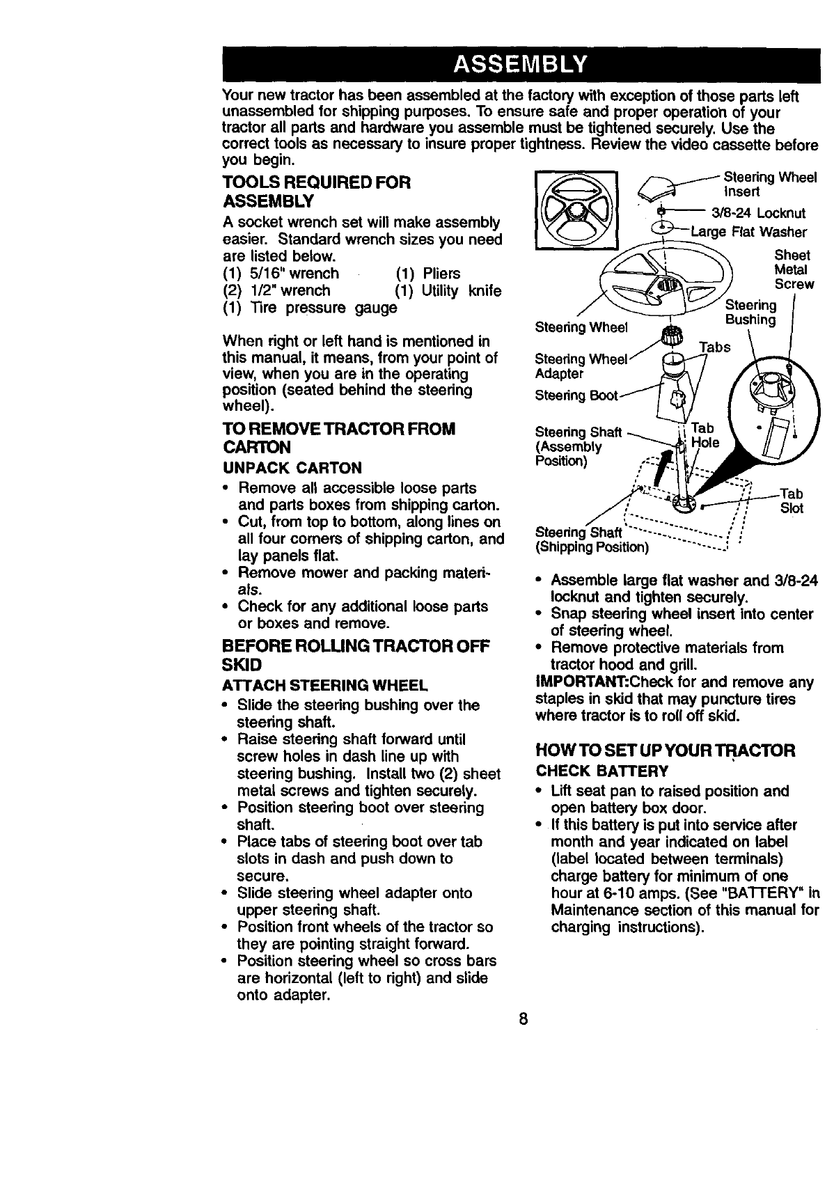
f_ I_Steering Wheel
insert
((J .J lJI 3/8-24Locknut
I(_---Large Fiat Washer
Sheet
") _Metal
Sc,ew
/_"_ _ Steering
"_Bushing
Steering Wheel_ Tabs
Steering Wheel /
Adapter
Steering
TO REMOVE TRACTOR FROM
CARTON
UNPACK CARTON
Steering Shaft
(Assembly
Position)
• Remove all accessible loose parts
and parts boxes from shipping carton.
•Cut, from top to bottom, along lines on
all four comers of shipping carton, and
lay panels flat.
•Remove mower and packing mated-
als.
•Check for any additional loose parts
or boxes and remove.
BEFORE ROLUNG TRACTOR OFF
SKID
ATTACH STEERING WHEEL
•Slide the steedng bushing over the
steedng shaft.
•Raise steedng shaft forward until
screw holes in dash line up with
steering bushing. Install two (2) sheet
metal screws and tighten securely.
•Position steering boot over steedng
shaft.
•Place tabs of steering boot over tab
slots in dash and push down to
secure.
•Slide steedng wheel adapter onto
upper steering shaft.
•Position front wheels of the tractor so
they are pointing straight forward.
•Position steering wheel so cross bars
are horizontal (left to right) and slide
onto adapter.
Steedng ......... .,'
(Shipping Position) ........ J
Slot
•Assemble large flat washer and 3/8-24
Iocknut and tighten securely.
•Snap steedng wheel insert into center
of steedng wheel.
•Remove protective materials from
tractor hood and grill.
IMPORTANT:Check for and remove any
staples in skid that may puncture tires
where tractor is to roll off skid.
HOW TO SET UP YOUR TI:_,C'FOR
CHECK BATTERY
• Lift seat pan to raised position and
open battery box door.
•If this battery is put into service after
month and year indicated on label
(label located between terminals)
charge battery for minimum of one
hour at 6-10 amps. (See "BATTERY" in
Maintenance section of this manual for
charging instructions),
8
Battery Box Label
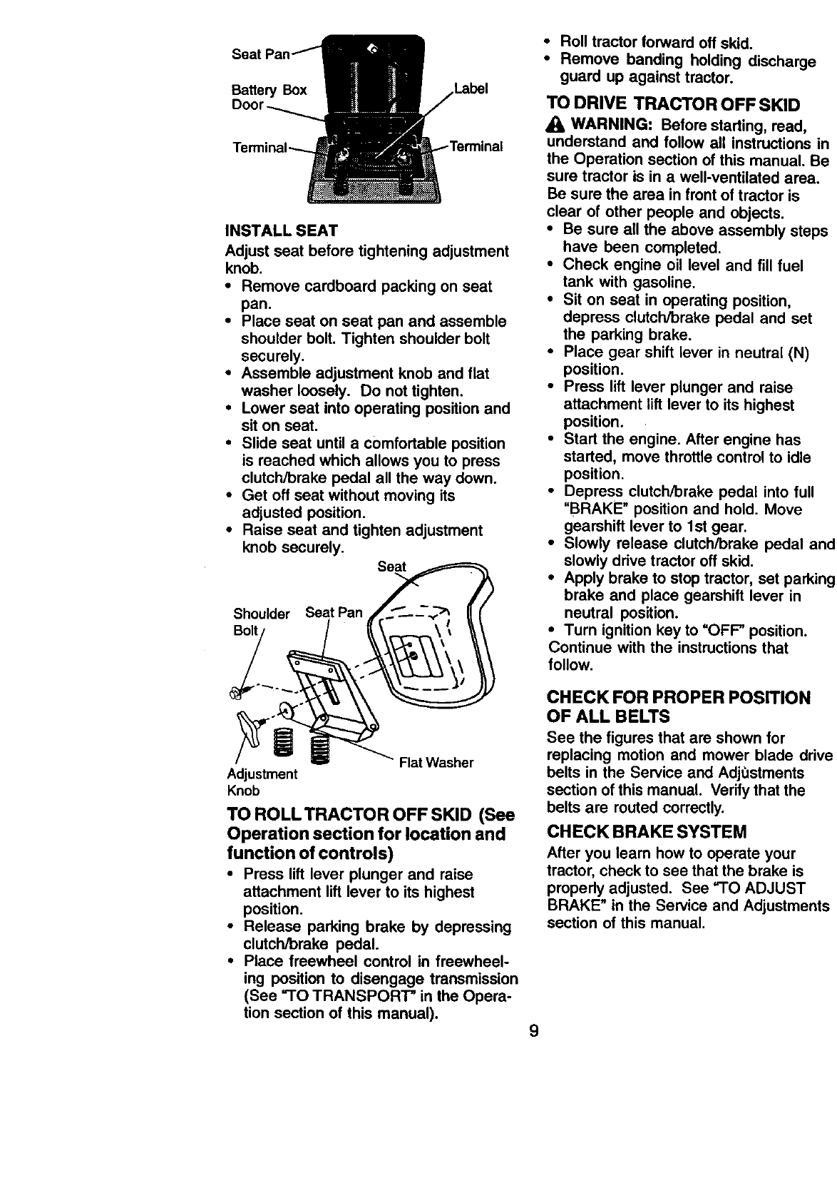
INSTALL SEAT
Adjust seat before tightening adjustment
knob.
•Remove cardboard packing on seat
pan.
•Place seat on seat pan and assemble
shoulder bolt. Tighten shoulder bolt
securely.
•Assemble adjustment knob and fiat
washer loosely. Do not tighten.
•Lower seat into operating position and
sit on seat.
•Slide seat until a comfortable position
is reached which allows you to press
clutcWbrake pedal all the way down.
•Get oft seat without moving its
adjusted position.
•Raise seat and tighten adjustment
knob securely.
Shoulder Seat Pan
Flat Washer
Adjustment
Knob
TO ROLLTRACTOR OFF SKID (See
Operation section for location and
function of controls)
• Press lift lever plunger and raise
attachment lift lever to its highest
position,
•Release parking brake by depressing
clutch/brake pedal.
•Place freewheel control in freewheel-
ing position to disengage transmission
(See "TO TRANSPORT" in the Opera-
tion section of this manual).
•Roll tractor forward off skid.
• Remove banding holding discharge
guard up against tractor.
TO DRIVE TRACTOR OFF SKID
WARNING: Before starting, read,
understand and follow all instructions in
the Operation section of this manual. Be
sure tractor is in a well-ventilated area.
Be sure the area in front of tractor is
clear of other people and obiects.
•Be sure all the above assembly steps
have been completed.
•Check engine oil level and fill fuel
tank with gasoline.
•Sit on seat in operating position.
depress clutch/brake pedal and set
the parking brake.
•Place gear shift lever in neutral (N)
position.
•Press lift lever plunger and raise
attachment lift lever to its highest
position.
•Start the engine. After engine has
started, move throttle control to idle
position.
•Depress clutch/brake pedal into full
"BRAKE" position and hold. Move
gearshift lever to 1st gear.
•Slowly release clutch/brake pedal anq
slowly drive tractor off skid.
•Apply brake to stop tractor, set parkin!
brake and place gearshift lever in
neutral position.
•Turn ignition key to "OFF" position.
Continue with the instructions that
follow.
CHECK FOR PROPER POSITION
OF ALL BELTS
See the figures that are shown for
replacing motion and mower blade driv_
belts in the Service and AdjOstments
section ofthis manual. Verify that the
belts are routed correctly.
CHECK BRAKE SYSTEM
After you learn how to operate your
tractor, check to see that the brake is
properly adjusted. See "TO ADJUST
BRAKE" in the Service and Adiustment.'
section of this manual.
9
CHECK TIRE PRESSURE
The tires on your tractor were overin-
flated at the factory for shipping pur-
poses. Correct tire pressure is important
for best cutting performance.
•Reduce tire pressure to PSI shown in
"PRODUCT SPECIFICATIONS"
section of this manual.
CHECK DECK LEVELNESS
For best cutting results, mower housing
should be properly leveled. See "TO
LEVEL MOWER HOUSING" in the
Service and Adjustments section of this
manual.
4CHECKLIST •
BEFORE YOU OPERATE AND ENJOY
YOUR NEW TRACTOR, WE WISH TO
ASSURE THAT YOU RECEIVE THE
BEST PERFORMANCE AND
SATISFACTION FROM THIS QUALITY
PRODUCT.
PLEASE REVIEW THE FOLLOWING
CHECKLIST:
,/All assembly instructions have been
completed.
/No remaining loose parts in carton.
4Battery is properly prepared and
charged. (Minimum 1 hour at 6
amps).
/Seat is adjusted comfortably and
tightened securely.
/All tires are properly inflated. (For
shipping purposes, the tires were
ovednflated at the factory).
/Be sure mower deck is properly
leveled side-to-side/front-to-rear for
best cutting results. (Tires must be
propedy inflated for leveling).
/Check mower and drive belts. Be sure
they are routed properly around pulleys
and inside all belt keepers.
/Check wiring. See that all connections
are still secure and wires are propedy
clamped.
WHILE LEARNING HOWTO USEYOUR
TRACTOR, PAY EXTRAATTENTION TO
THE FOLLOWING IMPORTANT ITEMS:
/Engine oil is at proper level.
/Fuel tank is filled with fresh, clean,
regular unleaded gasoline.
/Become familiar with all controls - their
location and function. Operate them
before you start the engine.
/Be sure brake system is in safe
operating condition.
10
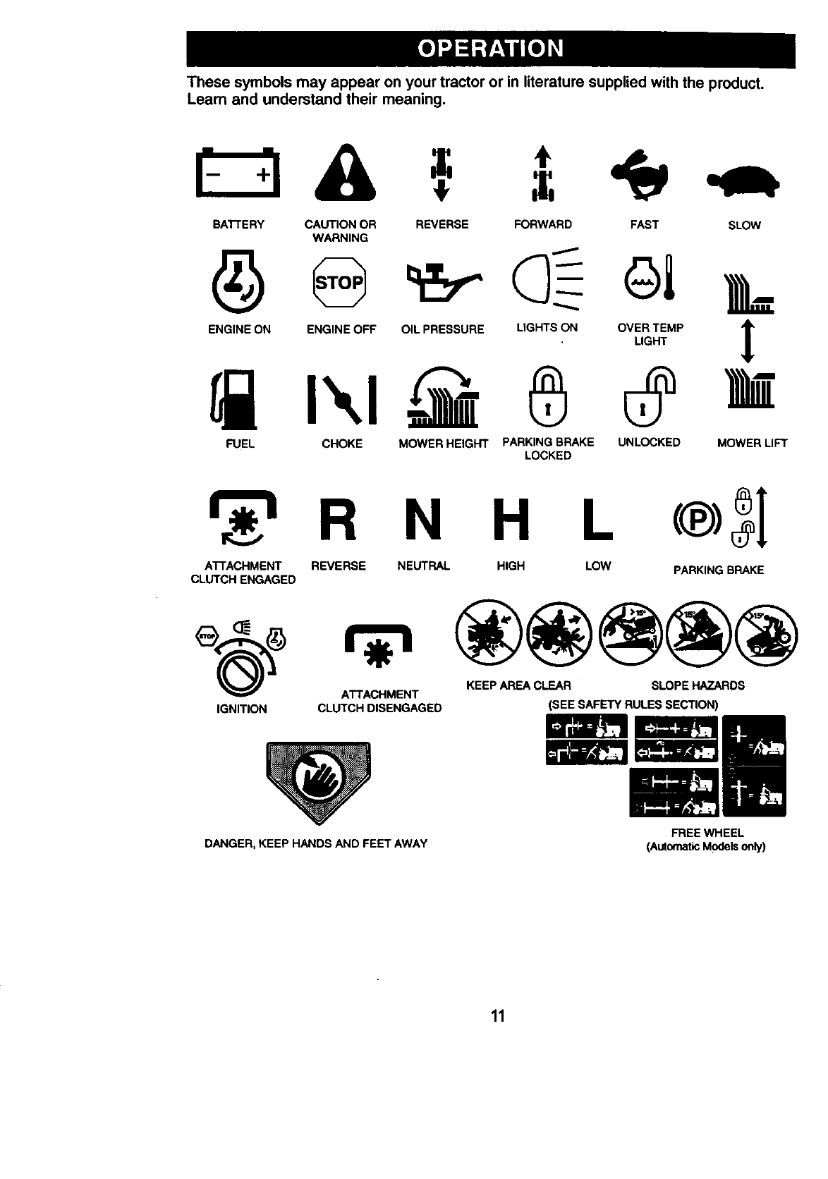
These symbols may appear on your tractor or in literature supplied with the product.
Leam and understand their meaning.
r- A
BATTERY CAUTION OR
WARNING REVERSE FORWARD FAST SLOW
ENGINE ON ENGINE OFF OIL PRESSURE LIGHTS ON OVER TEMP
LIGHT !
FUEL CHOKE MOWER HEIGHT PARKING BRAKE UNLOCKED MOWER LIFT
LOCKED
R N H L
ATTACHMENT REVERSE NEUTRAL HIGH LOW PARKING BRAKE
CLUTCH ENGAGED
KEEP AREA CLEAR SLOPE HAZARDS
ATTACHMENT
IGNITION CLUTCH DISENGAGED
DANGER, KEEP HANDS AND FEET AWAY
(SEE SAFETY RULESSECTION)
FREE WHEEL
(AutomaticModelsonly)
11
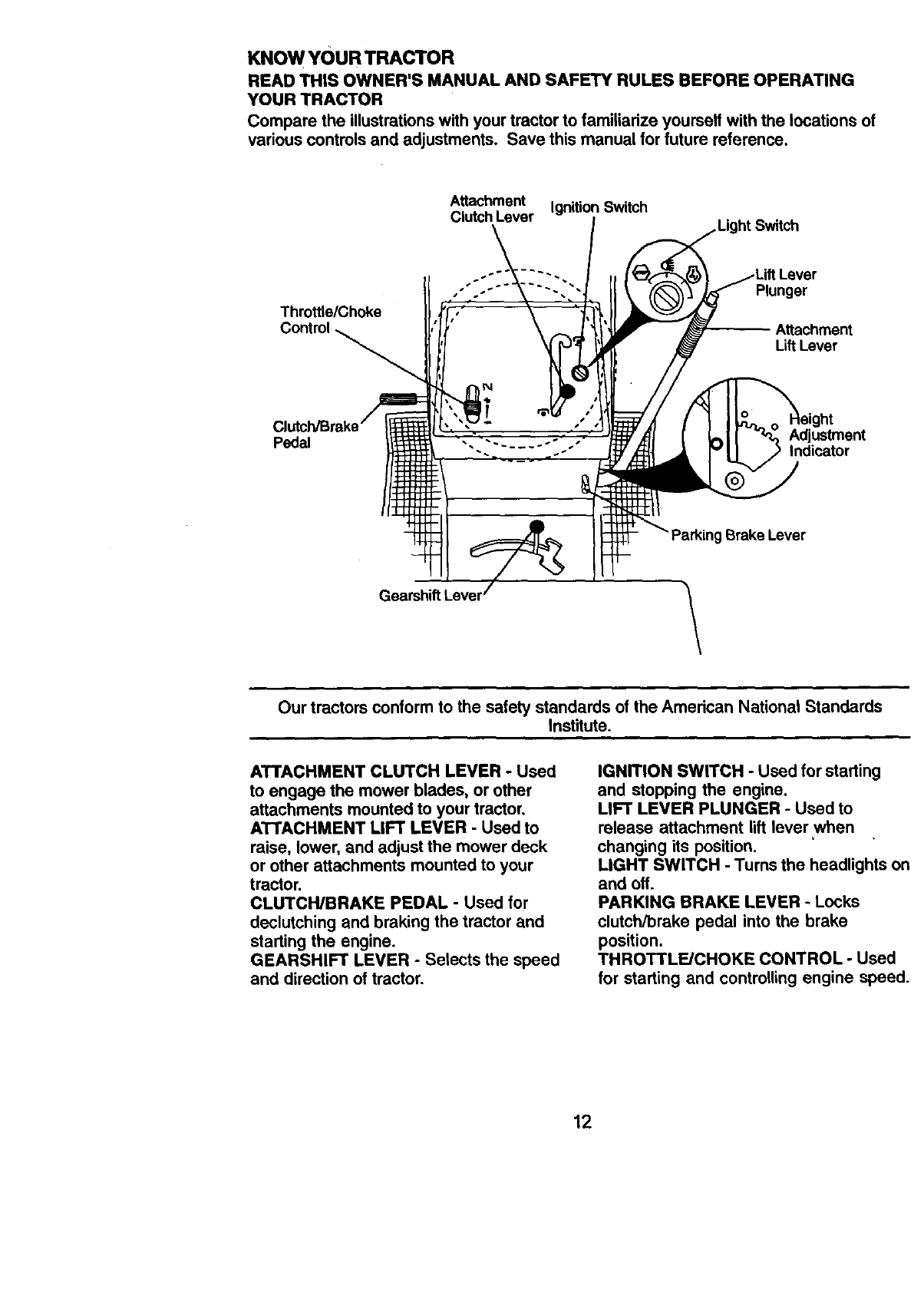
KNOWYOURTRACTOR
READ THIS OWNER'S MANUAL AND SAFETY RULES BEFORE OPERATING
YOUR TRACTOR
Compare the illustrationswith your tractor to familiarize yourself with the locations of
various controls and adjustments. Save this manual for future reference.
Attachment Ignition Switch
Clutch Lever
Throttle/Choke
Plunger
Attachment
LiftLever
Pedal Adjustment
Indicator
Brake Lever
\
Our tractors conform to the safety standards of the American National Standards
Institute.
ATTACHMENT CLUTCH LEVER -Used
to engage the mower blades, or other
attachments mounted to your tractor,
ATTACHMENT LIFT LEVER - Used to
raise, lower, and adjust the mower deck
or other attachments mounted to your
tractor.
CLUTCH/BRAKE PEDAL - Used for
declutching and braking the tractor and
starting the engine.
GEARSHIFT LEVER - Selects the speed
and direction of tractor.
IGNITION SWITCH -Used for starting
and stopping the engine.
LIFT LEVER PLUNGER -Used to
release attachment lift lever when
changing its position,
LIGHT SWITCH -Turns the headlights on
and off.
PARKING BRAKE LEVER -Locks
clutch/brake pedal into the brake
position.
THROTTLE/CHOKE CONTROL -Used
for starting and controlling engine speed.
12
The operation of any tractor can result in foreign objects thrown into
the eyes, which can result in severe eye damage. Always wear safety
glasses or eye shields while operating your tractor or performing any
adjustments or repairs. We recommend a wide vision safety mask
over spectacles or standard safety glasses.
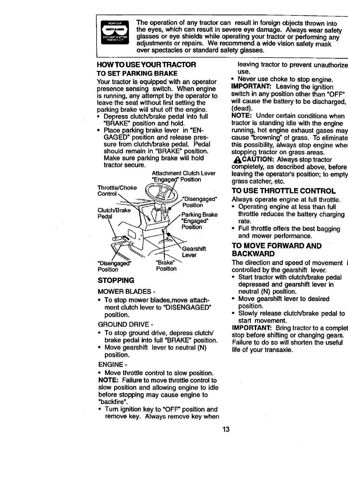
HOW TO USE YOUR TRACTOR
TO SET PARKING BRAKE
Your tractor is equipped with an operator
presence sensing switch. When engine
is running, any attempt by the operator to
leave the seat without first setting the
parking brake will shut off the engine.
•Depress clutch/brake pedal into full
=BRAKE" position and hold.
•Place parking brake lever in =EN-
GAGED" position and release pres-
sure from clutch/brake pedal. Pedal
should remain in "BRAKE" position.
Make sure parking brake will hold
tractor secure.
Attachment Clutch Lever
Throttle/Choke
Pedal
Position
Brake
"Engaged"
Position
Lever
Position Position
STOPPING
MOWER BLADES -
•To stop mower blades,move attach-
ment clutch lever to "DISENGAGED"
position.
GROUND DRIVE-
•To stop ground drive, depress clutch/
brake pedal into full "BRAKE" position.
•Move gearshift lever to neutral (N)
position.
ENGINE -
•Move throttle control to slow position.
NOTE: Failure to move throttle control to
slow position and allowing engine to idle
before stopping may cause engine to
=backfire".
• Turn ignition key to "OFF" position and
remove key. Always remove key when
leaving tractor to prevent unauthodzec
use.
•Never use choke to stop engine.
IMPORTANT: Leaving the ignition
switch in any position other than "OFF"
will cause the battery to be discharged,
(dead).
NOTE: Under certain conditions when
tractor is standing idle with the engine
running, hot engine exhaust gases may
cause "browning" of grass. To eliminate
this possibility, always stop engine when
stopping tractor on grass areas.
_ILCAUTION: Always stop tractor
completely, as described above, before
leaving the operator's position; to empty
grass catcher, etc.
TO USE THROTTLE CONTROL
Always operate engine at full throttle.
•Operating engine at less than full
throttle reduces the battery charging
rate.
•Full throttle offers the best bagging
and mower performance.
TO MOVE FORWARD AND
BACKWARD
The direction and speed of movement i._
controlled by the gearshift lever.
•Start tractor with clutch/brake pedal
depressed and gearshift lever in
neutral (N) position.
•Move gearshift lever to desired
position.
•Slowly release clutch/brake pedal to
start movement,
IMPORTANT: Bring tractor to a complet(
stop before shifting or changing gears,
Failure to do so will shorten the useful
lifeof your transaxle.
13
TO ADJUST MOWER CUTTING
HEIGHT
The position of the attachment lift lever
determines the cutting height.
•Grasp lift lever.
•Press plunger with thumb and move
lever to desired position.
The cutting height range is approxi-
mately 1-1/2 to 4". The heights are
measured from the ground to the blade
tip with the engine not running. These
heights are approximate and may vary
depending upon soil conditions, height
of grass and types of grass being
mowed.
•The average lawn should be cut to
approximately 2-112 inches during the
cool season and to over 3 inches
during hot months. For healthier and
better looking lawns, mow often and
after moderate growth.
•For best cutting performance, grass
over 6 inches in height should be
mowed twice. Make the first cut
relatively high; the second to desired
height.
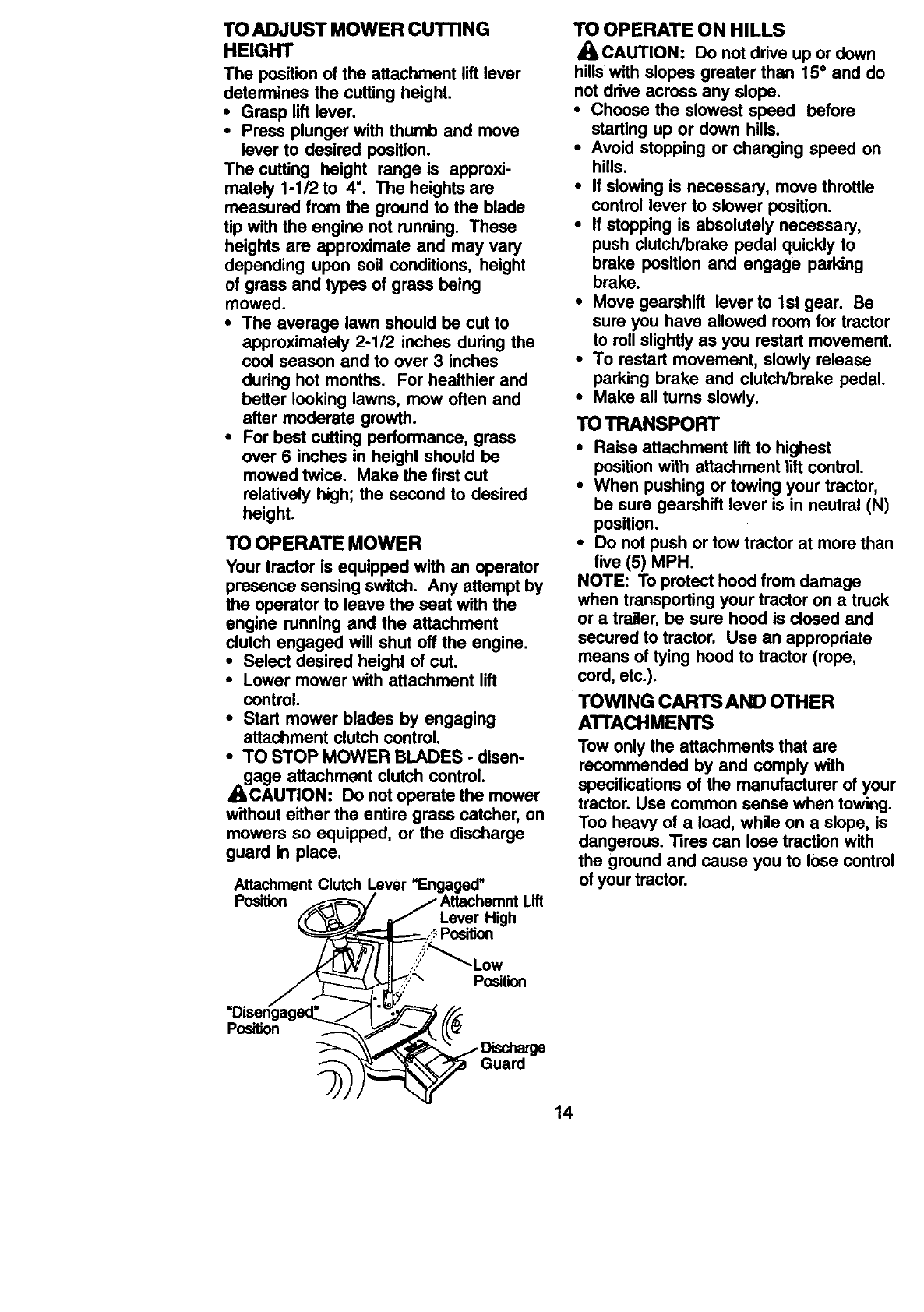
TO OPERATE MOWER
Your tractor is equipped with an operator
presence sensing switch. Any attempt by
the operator to leave the seat with the
engine running and the attachment
clutch engaged will shut off the engine.
•Select desired height of cut.
•Lower mower with attachment lift
control.
•Start mower blades by engaging
attachment clutch control.
•TO STOP MOWER BLADES. disen-
_gage attachment clutch control.
CAUTION: Do not operate the mower
without either the entire grass catcher, on
mowers so equipped, or the discharge
guard in place.
Attachment Clutch Lever "Engaged"
Position
Lever High
TO OPERATE ON HILLS
_CAUTION: Do not drive up or down
hillswith slopes greater than 15°and do
not drive across any slope.
•Choose the slowest speed before
starting up or down hills.
•Avoid stopping or changing speed on
hills.
•If slowing is necessary, move throttle
control lever to slower position.
•If stopping is absolutely necessary,
push clutch/brake pedal quickly to
brake position and engage parking
brake.
•Move gearshift lever to 1st gear. Be
sure you have allowed room for tractor
to roll slightly as you restart movement.
•To restart movement, slowly release
parking brake and clutch/brake pedal.
•Make all turns slowly.
TO TRANSPORT
•Raise attachment lift to highest
position with attachment lift control.
•When pushing or towing your tractor,
be sure gearshift lever is in neutral (N)
position.
•Do not push or tow tractor at more than
five (5) MPH.
NOTE: To protect hood from damage
when transporting your tractor on a truck
or a trailer, be sure hood is closed and
secured to tractor. Use an appropriate
means of tying hood to tractor (rope,
cord, etc.).
TOWING CARTS AND OTHER
A'n'ACHMENTS
Tow only the attachments that are
recommended by and comply with
specifications of the manufacturer of your
tractor. Use common sense when towing.
Too heavy of a load, while on a slope, is
dangerous. "13rescan lose traction with
the ground and cause you to lose control
of your tractor.
Position
Position
Guard
14
ADD GASOLINE
•Fill fuel tank. Use fresh, clean, regular
unleaded gasoline with a minimum of
87 octane. (Use of leaded gasoline
will increase carbon and lead oxide
de_its and reduce valve life). Do
not mix oil with gasoline. Purchase
fuel in quantities that can be used
within 30 days to assure fuel fresh-
ness.
IMPORTANT: When operating in
temperatures below 32°F(0°C), use
fresh, clean winter grade gasoline to
help insure good cold weather starting.
WARNING: Experience indicates that
alcohol blended fuels (called gasohol or
using ethanol or methanol) can attract
moisture which leads to separation and
formation of acids during storage. Acidic
gas can damage the fuel system of an
engine while in storage. To avoid engine
problems, the fuel system should be
emptied before storage of 30 days or
longer. Drain the gas tank, start the
engine and let it run until the fuel lines
and carburetor are empty. Use fresh fuel
next season. See Storage Instructions
for additional information. Never use
engine or carburetor cleaner products in
the fuel tank or permanent damage may
occur.
_CAUTION: Fillto bottom of gas tank
filler neck. Do not ovedill. Wipe off any
spilled oil or fuel. Do not store, spill or
use gasoline near an open flame.
BEFORE STARTING THE ENIGNE
CHECK ENGINE OIL LEVEL
•The engine in your tractor has been
shipped, from the factory, already titled
with summer weight oil.
•Check engine oil with tractor on level
ground.
•Remove oil fill cap/dipstick and wipe
clean, reinsert the dipstick and screw
cap tight, wait for a few seconds,
remove and read oil level. If neces-
sary, add oil until =FULL" mark on
dipstick is reached. Do not overfill.
•For cold weather operation you should
change oil for easier starting (See =OIL
VISCOSITY CHART" in the Customer
ResponsibiUties section of this
manual).
• To change engine oil, see the Mainte-
nance section in this manual.
TO START ENGINE
When starting the engine for the first time
or if the engine has run out of fuel, it will
take extra cranking time to move fuel
from the tank to the engine.
•Sit on seat in operating position,
depress clutch/brake pedal and set
parking brake.
•Place gear shift lever in neutral (N)
position.
•Move attachment clutch to =DISEN-
GAGED" position.
•Move throttle control to fast position
•Pull choke control out for a cold
engine start attempt. For a warm
engine start attempt the choke control
may not be needed.
NOTE: Before starting, read the warm
and cold starting procedures below.
•Insert key into ignition and turn key
clockwise to =START" position and
release key as soon as engine starts.
Do not run starter continuously for
more than fifteen seconds per minute.
If the engine does not start after
several attempts, push choke control
in, wait a few minutes and try again. If
engine still does not start, pull the
choke control out and retry.
WARM WEATHER STARTING (50 ° F and
above)
•When engine starts, slowly push
choke control in until the engine
begins to run smoothly. If the engine
starts to run roughly, pull the choke
control out slightly for a few seconds
and then continue to push the control
in slowly.
•The attachments and ground ddve can
now be used. If the engine does not
accept the load, restart the engine and
allow it to warm up for one minute
using the choke as described above.
15
COLD WEATHER STARTING (50 ° F and
below)
•When engine starts, slowly push
choke control in until the engine
begins to run smoothly. Continue to
push the choke control in small steps
allowing the engine to accept small
changes in speed and load, until the
choke contro/is fully in. If the engine
starts to run roughly, pull the choke
control out slightly for afew seconds
and then continue to push the control
in slowly. This may require an engine
warm-up period from several seconds
to severa/minutes, depending on the
temperature.
•The attachments can be used during
the engine warm-up period and may
require the choke control be pulled out
slightly.
NOTE: If at a high altitude (above 3000
feet) or in cold temperatures (below 32
F) the carburetor fuel mixture may need
to be adjusted for best engine perfor-
mance. See _TO ADJUST CARBURE-
TOR" in the Service and Adjustments
section of this manual.
MOWING TIPS
• Tire chains cannot be used when the
mower housing is attached to tractor.
•Mower should be propedy leveled for
best mowing performance. See TO
LEVEL MOWER HOUSING" in the
Service and Adjustments section of
this manual.
•The left hand side of mower should be
used for trimming.
• Drive so that clippings are discharged
onto the area that has been cut. Have
the cut area to the right of the tractor.
This will result in a more even distribu-
tion of clippings and more uniform
cutting.
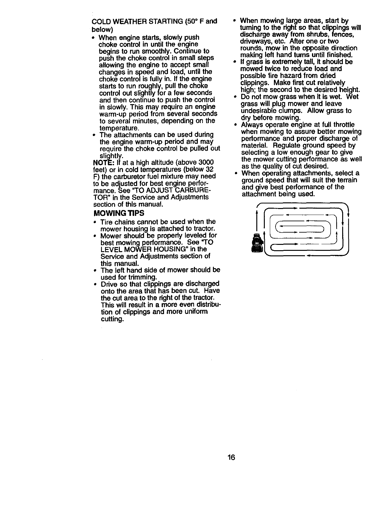
•When mowing large areas, start by
tuming to the right so that clippings will
discharge away from shrubs, fences,
driveways, etc. After one or two
rounds, mow in the opposite direction
making left hand turns until finished.
•If grass is extremely tall, it should be
mowed twice to reduce load and
possible fire hazard from dried
clippings. Make first cut relatively
high; the second to the desired height.
•Do not mow grass when it is wet. Wet
grass will plug mower and leave
undesirable clumps. Allow grass to
dry before mowing.
•Always operate engine at full throttle
when mowing to assure better mowing
performance and proper discharge ot
material. Regulate ground speed by
selecting a low enough gear to give
the mower cutting performance as well
as the quality of cut desired.
•When operating attachments, select a
ground speed that will suit the terrain
and give best performance of the
attachment being used.
[
]
t
16
MAINTENANCE SCHEDULE ..,_._e_
Fi,,,.o. s ""
Check Tire Pressure
Check Operator Presence and
TInterlock Systems
RCheck for L_ose Fasteners _1_7 I_
A SharperVReplace Mower Blades _4
TLubrication Chart I_
0Check Battery Level
RClean Battery and Terminals
Check Transaxle Cooling Ikf
Adjust Blade Belt(s) Tension I_s
Adjust Motion Drive Belt(s Tension _#/s
Check Engine Oil Level i _
Change Engine Oil I_,s
E Clean Air Filter
NClean Air Screen
iG Inspe_ Muffler/Spark Attester
Replace O a FiRe="(If equipped) I_.=
NClean Engine Cooling Fins _2
Replace Spark Plug II_
ReplaCe Air Filtel" Paper Cadddge V_2
Replace Fuel Filter
I - Change more often whefl opiating trade5 a heavy load or in high ambient temperatures. 5 - ff equipped with ad_ustllb]e sy_em.
2-Service _often when operating in dtr(y of dusty cooditions, 6 - Not requited if equipped with mxinterm nce- fnim bRnety.
3-If equipped with oil filler, change oil eve(y 50 hours, 7 -Tighl_ front axle pivot bolt to 35 fl.-Ibs, maximum.
4 - Replace blades rnore o;_n when mowing tn sandy soil Oo not overtighten.
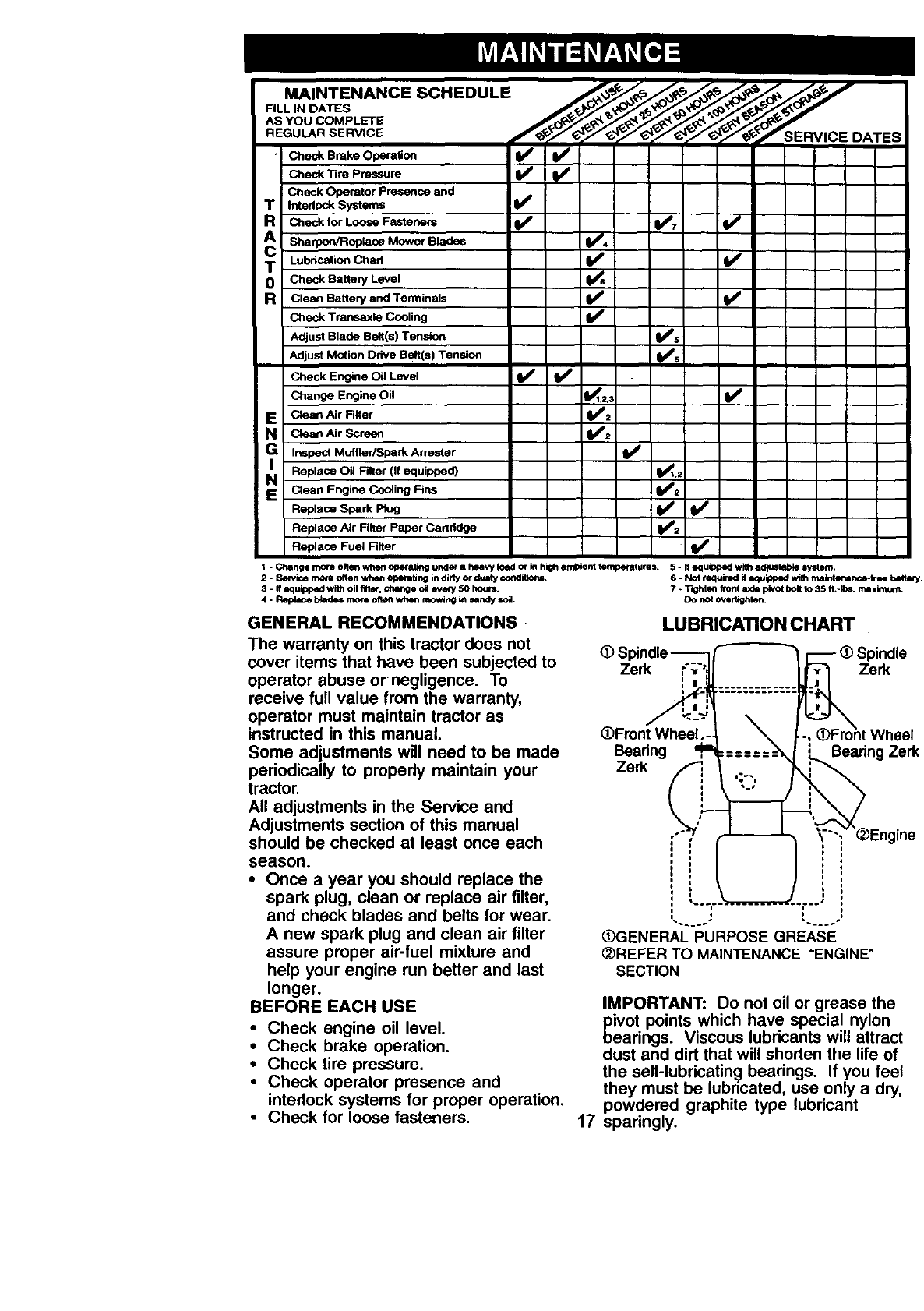
GENERAL RECOMMENDATIONS
The warranty on this tractor does not (D Spindle--
cover items that have been subjected to Zen_ F;"
operator abuse or negligence. To ,
receive full value from the warranty, :._.-
operator must maintain tractor as
instructed in this manual. (DFront Wheel.-.
Some adjustments will need to be made Bearing ,'W
periodically to propedy maintain your Zerk f
tractor.
All adjustments in the Service and
Adjustments section of this manual o
should be checked at least once each i
season.
•Once a year you should replace the
spark plug, clean or replace air filter,
and check blades and belts for wear.
A new spark plug and clean air filter
assure proper air-fuel mixture and
help your engine run better and last SECTION
longer.
BEFORE EACH USE
•Check engine oil level.
•Check brake operation.
•Check tire pressure.
•Check operator presence and
interlock systems for proper operation.
•Check for loose fasteners.
LUBRICA_ONCHART
(_3ENERAL PURPOSE GREASE
_)REFER TO MAINTENANCE "ENGINE"
IMPORTANT: Do not oil or grease the
pivot points which have special nylon
bearings. Viscous lubricants will attract
dust and dirt that will shorten the life of
the self-lubricating bearings. If you feel
they must be lubricated, use only a dry,
powdered graphite type lubricant
17 sparingly.
TRACTOR
Always observe safety rules when
performing any maintenance.
BRAKE OPERATION
If tractor requires more than six (6) feet
stopping distance at high speed in
highest gear, then brake must be
adjusted. (See "TO ADJUST BRAKE" in
the Service and Adjustments section of
this manual).
TIRES
•Maintain proper air pressure in all tires
(See =PRODUCT SPECIFICATIONS"
section of this manual).
•Keep tires free of gasoline, oil, or
insect control chemicals which can
harm rubber.
•Avoid stumps, stones, deep ruts, sharp
objects and other hazards that may
cause tire damage.
NOTE: To seal tire punctures and
prevent fiat tires due to slow leaks, tire
sealant may be purchased from your
local parts dealer. Tire sealant also
prevents tire dry rot and corrosion.
OPERATOR PRESENCE SYSTEM
Be sure operator presence and interlock
systems are working properly. If your
tractor does not function as described,
repair the problem immediately.
•The engine should not start unless the
clutch/brake pedal is fully depressed
and attachement clutch control is in
the disengaged position.
• When the engine is running, any
attempt by the operator to leave the
seat without first setting the parking
brake should shut off the engine.
• When the engine is running and the
attachment clutch is engaged, any
attempt by the operator to leave the
seat should shut off the engine.
•The attachment clutch should never
operate unless the operator is in the
seat.
BLADE CARE
For best results mower blades must be
kept sharp. Replace bent or damaged
blades.
BLADE REMOVAL
•Raise mower to highest position to
allow access to blades.
•Remove hex bolt, lock washer and flat
washer secudng blade.
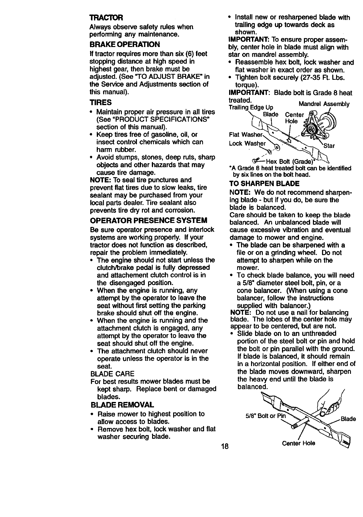
•Install new or resharpened blade with
trailing edge up towards deck as
shown.
IMPORTANT: To ensure proper assem-
bly, center hole in blade must align with
star on mandrel assembly.
•Reassemble hex belt, lock washer and
flat washer in exact order as shown.
•Tighten bolt securely (27-35 Ft. Lbs.
torque).
IMPORTANT: Blade belt is Grade 8 heat
treated. Mandrel Assembly
Trailing Edge Up /
Blade Center D
_£--Hex Bolt (Grade:
*A Grade 8 heat treated bolt can be identified
by six lines on the bolt head.
TO SHARPEN BLADE
NOTE: We do not recommend sharpen-
ing blade -but if you do, be sure the
blade is balanced.
Care should be taken to keep the blade
balanced. An unbalanced blade will
cause excessive vibration and eventual
damage to mower and engine.
•The blade can be sharpened with a
file or on a grinding wheel. Do not
attempt to sharpen while on the
mower.
•To check blade balance, you will need
a 5/8" diameter steel bolt, pin, or a
cone balancer. (When using a cone
balancer, follow the instructions
supplied with balancer.)
NOTE: Do not use a nail for balancing
blade. The lobes of the center hole may
appear to be centered, but are not.
•Slide blade on to an unthreaded
portion of the steel bolt or pin and hold
the bolt or pin parallel with the ground.
If blade is balanced, it should remain
in a horizontal position. If either end of
the blade moves downward, sharpen
the heavy end until the blade is
balanced.
18 Center Hole
BATI'ERY
Your tractor has a battery charging
system which is sufficient for normal use.
However, periodic charging of the battery
with an automotive charger will extend
its life.
• Keep battery and terminals clean.
•Keep battery bolts tight.
•Keep small vent holes open.
•Recharge at 6-10 amperes for 1 hour.
NOTE: The original equipment battery on
your tractor is maintenance free. Do not
attempt to open or remove caps or
covers. Adding or checking level of
electrolyte is not necessary.
TO CLEAN BATTERY AND TERMINALS
Corrosion and dirt on the battery and
terminals can cause the battery to =leak"
power.
•Open battery box door.
•Disconnect BLACK battery cable first
then RED battery cable and remove
battery from tractor.
•Rinse the battery with plain water and
dry.
•Clean terminals and battery cable
ends with wire brush until bright.
•Coat terminals with grease or petro-
leum jelly.
•Reinstall battery (See =REPLACING
BATTERY" in the SERVICE AND
ADJUSTMENTS section of this
manual).
V-BELTS
Check V-belts for deterioration and wear
after 100 hours of operation and replace
if necessary. The belts are not adjustable.
Replace belts if they begin to slip from
wear.
TRANSAXLE COOLING
Keep transaxle free from build-up of dirt
and chaff which can restrict cooling.
ENGINE
LUBRICATION
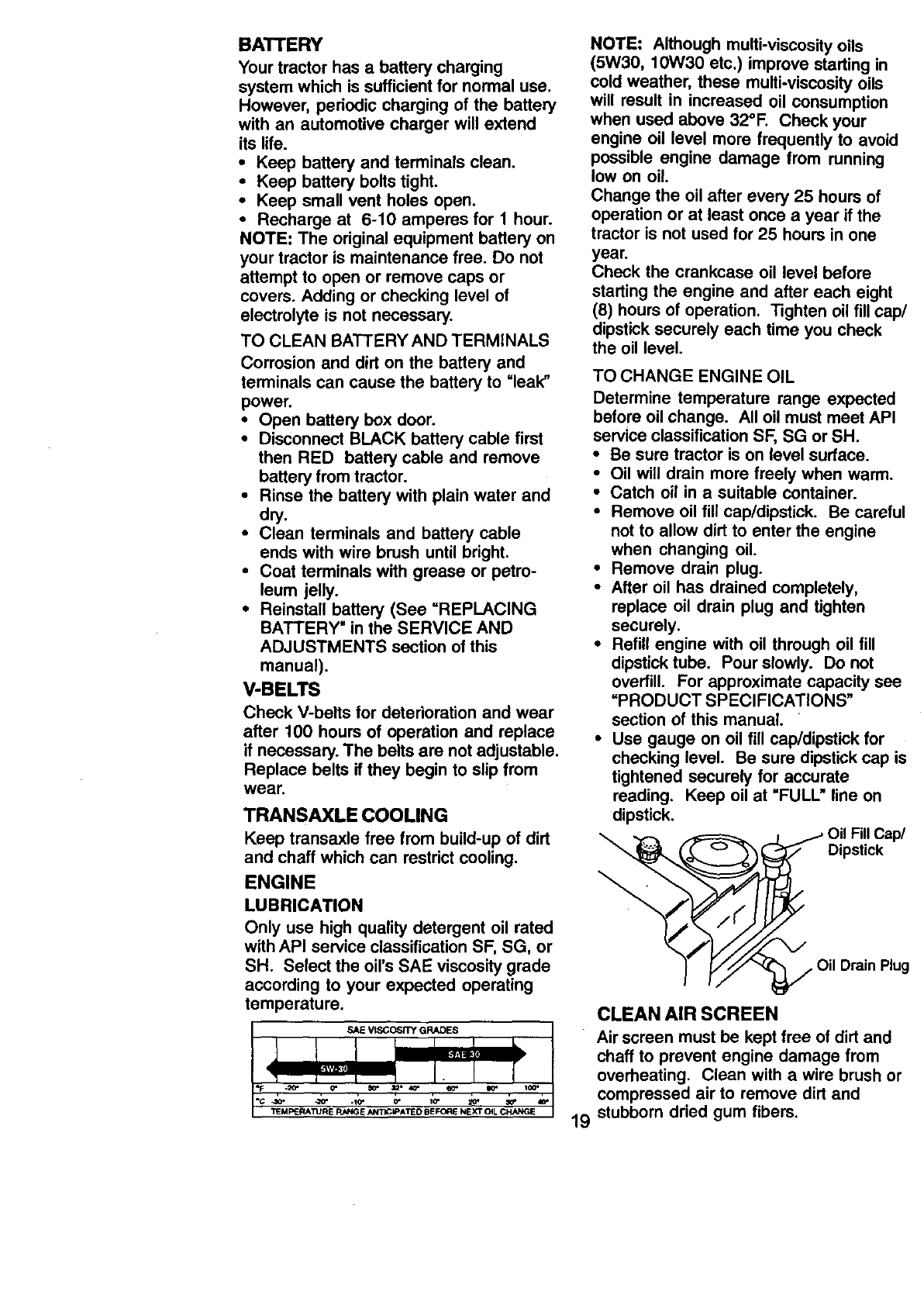
Only use high quality detergent oil rated
with API service classification SF, SG, or
SH. Select the oil's SAE viscosity grade
according to your expected operating
temperature.
SAE VISCOSITY GRADES
NOTE: Although multi-viscosity oils
(5W30, 10W30 etc.) improve starting in
cold weather, these multi-viscosity oils
will result in increased oil consumption
when used above 32°F. Check your
engine oil level more frequently to avoid
possible engine damage from running
low on oil
Change the oil after every 25 hours of
operation or at least once a year if the
tractor is not used for 25 hours in one
year.
Check the crankcase oil level before
starting the engine and after each eight
(8) hours of operation. Tighten oil fill cap/
dipstick securely each time you check
the oil level.
TO CHANGE ENGINE OIL
Determine temperature range expected
before oil change. All oil must meet API
service classification SF, SG or SH.
•Be sure tractor is on level surface.
•Oil will drain more freely when warm.
•Catch oil in a suitable container.
•Remove oil fill cap/dipstick. Be careful
not to allow dirt to enter the engine
when changing oil.
•Remove drain plug.
•After oil has drained completely,
replace oil drain plug and tighten
securely.
•Refill engine with oil through oil fill
dipstick tube. Pour slowly. Do not
overfill. For approximate capacity see
=PRODUCT SPECIFICATIONS"
section of this manual.
•Use gauge on oil fill cap/dipstick for
checking level. Be sure dipstick cap is
tightened securely for accurate
reading. Keep oil at =FULL" line on
dipstick.
/("
Oil FillCap/
Dipstick
_, Oil Drain Plug
CLEAN AIR SCREEN
Air screen must be kept free of dirt and
chaff to prevent engine damage from
overheating. Clean with a wire brush or
compressed air to remove dirt and
stubborn dried gum fibers.
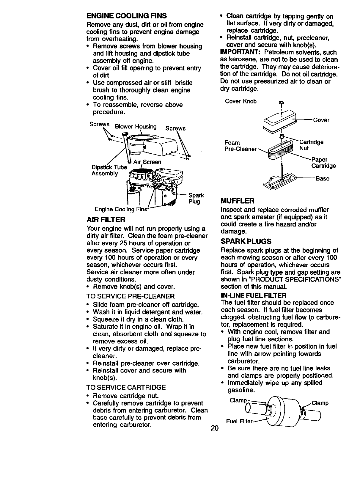
ENGINE COOLING FINS
Remove any dust, dirt or oil from engine
cooling fins to prevent engine damage
from overheating.
•Remove screws from blower housing
and lift housing and dipstick tube
assembly off engine.
•Cover oil fill opening to prevent entry
of dirt.
• Use compressed air or stiff bristle
brush to thoroughly clean engine
cooling fins.
•To reassemble, reverse above
procedure.
Screws Blower Housing Screws
Assembly
•Clean cartridge by tapping gently on
flat surface. If very dirtyor damaged,
replace cartridge.
•Reinstall cartddge, nut, prscleaner,
cover and secure with knob(s).
IMPORTANT: Petroleum solvents, such
as kerosene, are not to be used to clean
the cartridge. They may cause deteriora-
tion of the cartridge. Do not oilcartridge.
Do not use prassudzed air to clean or
dry cartridge.
Cover Knob
_Cover
Foam _Cartridge
Pre-Cleaner _ut
! _'_-Paper
artridge
Base
Plug
Engine Cooling Fins
AIR FILTER
Your engine will not run propedy using a
dirty air filter. Clean the foam pra-cleaner
after every 25 hours of operation or
every season. Service paper cartridge
every 100 hours of operation or every
season, whichever occurs first.
Service air cleaner more often under
dusty conditions.
•Remove knob(s) and cover.
TO SERVICE PRE-CLEANER
•Slide foam pre-cleaner off cartridge.
•Wash it in liquid detergent and water.
•Squeeze it dry in a clean cloth.
•Saturate it in engine oil. Wrap it in
clean, absorbent cloth and squeeze to
remove excess oil.
•If very dirty or damaged, replace pre-
cleaner.
•Reinstall pre-cleaner over cartridge.
•Reinstall cover and secure with
knob(s).
TO SERVICE CARTRIDGE
•Remove cartridge nut.
•Carefully remove cartridge to prevent
debris from entering carburetor. Clean
base carefully to prevent debds from
entering carburetor. 20
MUFFLER
Inspect and replace corroded muffler
and spark arrester (if equipped) as it
could create a fire hazard and/or
damage.
SPARK PLUGS
Replace spark plugs at the beginning of
each mowing season or after every 100
hours of operation, whichever occurs
first. Spark plug type and gap setting are
shown in =PRODUCT SPECIFICATIONS"
section of this manual.
IN-LINE FUEL FILTER
The fuel filter should be replaced once
each season. If fuel filter becomes
clogged, obstructing fuel flow to carbure-
tor, replacement is required.
• With engine cool, remove filter and
plug fuel line sections.
•Place new fuel filter in position in fuel
line with arrow pointing towards
carburetor.
• Be sure there are no fuel line leaks
and clamps are property positioned.
•Immediately wipe up any spilled
gasoline.
Clamp_amp
Fuel Filter_
CLEANING
Cleanengine,battery,seat, finish,etc.
of all foreignmatter.
Keepfinishedsurfacesand wheels
free of all _]asoline, oil, etc.
•Protect painted surfaces with automo-
tive type wax.
We do not recommend using a garden
hose to clean your tractor unless the
electrical system, muffler, air filter and
carburetor are covered to keep water out.
Water in engine can result in a short-
ened engine life.
._CAUTION: Before performing any service or adjustments:
Depress clutch/brake pedal fully and set parking brake.
:Place gearshift lever in neutral (N) position.
Place attachment clutch in =DISENGAGED" position.
iTurn ignition key "OFF" and remove key.
Make sure the blades and all moving parts have completely stopped.
Disconnect spark plug wire from spark plug and place wire where it cannot
come in contact with plug.
TRACTOR
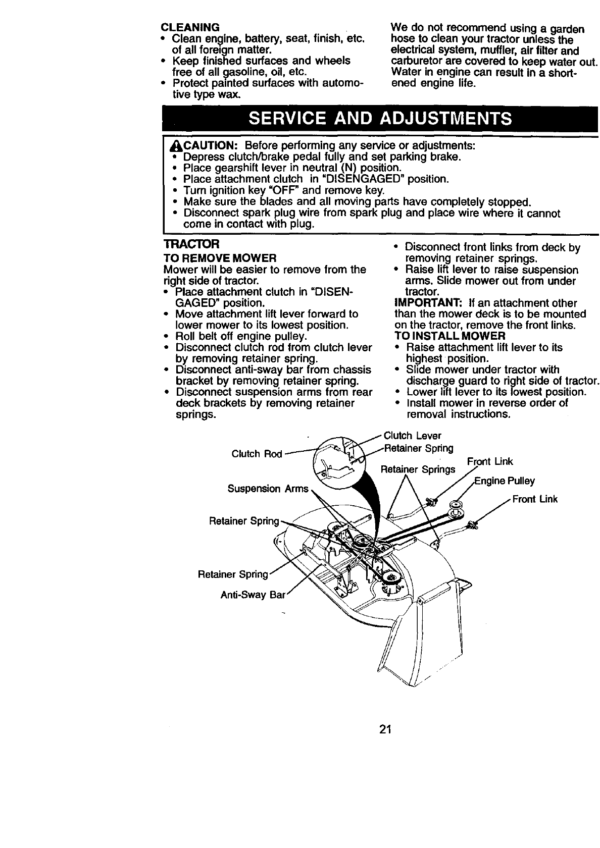
TO REMOVE MOWER
Mower will be easier to remove from the
right side of tractor.
•Place attachment clutch in =DISEN-
GAGED" position.
•Move attachment lift lever forward to
lower mower to its lowest position.
•Roll belt oft engine pulley.
•Disconnect clutch rod from clutch lever
by removing retainer spring.
•Disconnect anti-sway bar from chassis
bracket by removing retainer spring.
•Disconnect suspension arms from rear
deck brackets by removing retainer
springs.
• Disconnect front links from deck by
removing retainer springs.
• Raise lift lever to raise suspension
arms, Slide mower out from under
tractor.
IMPORTANT: If an attachment other
than the mower deck is to be mounted
on the tractor, remove the front links.
TO INSTALL MOWER
•Raise attachment lift lever to its
highest position.
•Slide mower under tractor with
discharge guard to right side of tractor.
•Lower lift lever to its lowest position.
•Install mower in reverse order of
removal instructions.
Lever
Spring
Front Link
Retainer
Link
Retainer
Anti-Sway Bar
21
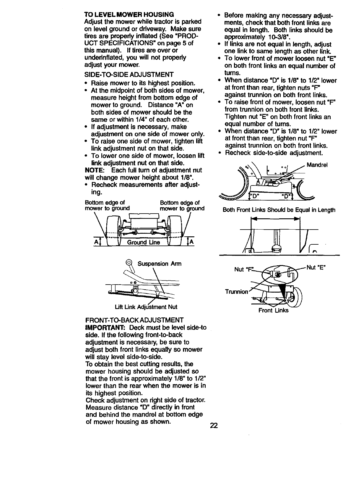
TOLEVELMOWERHOUSING
Adjustthe mowerwhiletractoris parked
on levelgroundor driveway. Makesure
tires are properly inflated (See =PROD-
UCT SPECIFICATIONS" on page 5of
this manual). If tiros are over or
underinflated, you will not properly
adjust your mower.
SIDE-TO-SIDE ADJUSTMENT
•Raise mower to its highest position.
• At the midpoint of both sides of mower,
measure height from bottom edge of
mower to ground. Distance =A" on
both sides of mower should be the
same or within 1/4" of each other.
•If adjustment is necessary, make
adjustment on one side of mower only.
•To raise one side of mower, tighten lift
link adjustment nut on that side.
•To lower one side of mower, loosen lift
link adjustment nut on that side.
NOTE: Each full turn of adjustment nut
will change mower height about 1/8".
•Recheck measurements after adjust-
ing.
Bottom edge of Bottom edge of
mower to ground mower to ground
FRONT-TO-BACK ADJUSTMENT
IMPORTANT: Deck must be level side-to
side. If the following front-to-back
adjustment is necessary, be sure to
adjust both front links equally so mower
will stay level side-to-side.
To obtain the best cutting results, the
mower housing should be adjusted so
that the front is approximately 1/8" to 1/2"
lower than the rear when the mower is in
its highest position.
Check adjustment on right side of tractor.
Measure distance "D" directly in front
and behind the mandrel at bottom edge
of mower housing as shown. 22
•Before making any necessary adjust-
ments, check that beth front links are
equal in length. Both links should be
approximately 10-3/8".
•If links are not equal in length, adjust
one link to same length as other link.
•To lower front of mower loosen nut =E"
on both front links an equal number of
turns.
•When distance =D" is 1/8' to 1/2' lower
at front than roar, tighten nuts =F"
against trunnion on beth front links.
•To raise front of mower, loosen nut =F"
from trunnion on both front links.
Tighten nut =E" on bothfront links an
equal number of tums.
•When distance =D" is 1/8" to 1/2" lower
at front than roar, tighten nut =F"
against trunnion on both front links.
•Recheck side-to-side adjustment.
Mandrel
"D"
Both Front Links Should be Equal in Length
Nut
Front Links
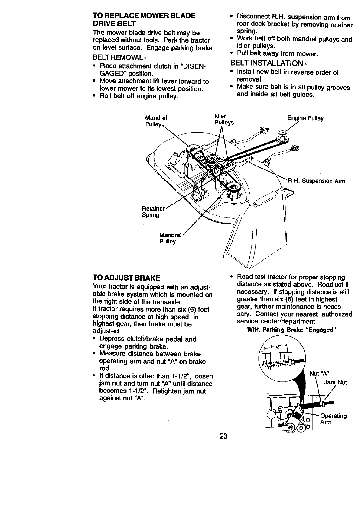
TO REPLACE MOWER BLADE
DRIVE BELT
The mower blade drive bolt may be
replaced without tools. Park the tractor
on level surface. Engage parking brake,
BELT REMOVAL-
•Place attachment clutch in =DISEN-
GAGED" position,
•Move attachment lift lever forward to
lower mower to its lowest position.
• Roll belt off engine pulley.
•Disconnect R.H. suspension arm from
rear deck bracket by removing retaine
spring,
•Work belt off both mandrel pulleys an€
idler pulleys.
•Pull belt away from mower.
BELT INSTALLATION -
•Install new belt in reverse order of
removal.
•Make sure belt is in all pulley grooves
and inside all belt guides.
Mandrel
Retaine
Spring
Mand
Pulley
Idler
Pulleys Pulley
Suspension Arm -
TOADJUSTBRAKE
Your tractor is equipped with an adjust-
able brake system which is mounted on
the right side of the transaxle.
If tractor requires more than six (6) feet
stopping distance at high speed in
highest gear, then brake must be
adjusted.
•Depress clutch/brake pedal and
engage parking brake.
•Measure distance between brake
operating arm and nut =A" on brake
rod.
•If distance is other than 1-1/2", loosen
jam nut and turn nut =A" until distance
becomes 1-1/2". Retighten jam nut
against nut =A'.
°Road test tractor for proper stopping
distance as stated above. Readjust if
necessary. If stopping distance is still
greater than six (6) feet in highest
gear, further maintenance is neces-
sary. Contact your nearest authorize¢
service center/department..
With Parking Brake "Engaged"
Nut =A"
Jam Nut
- Operating
Arm
23
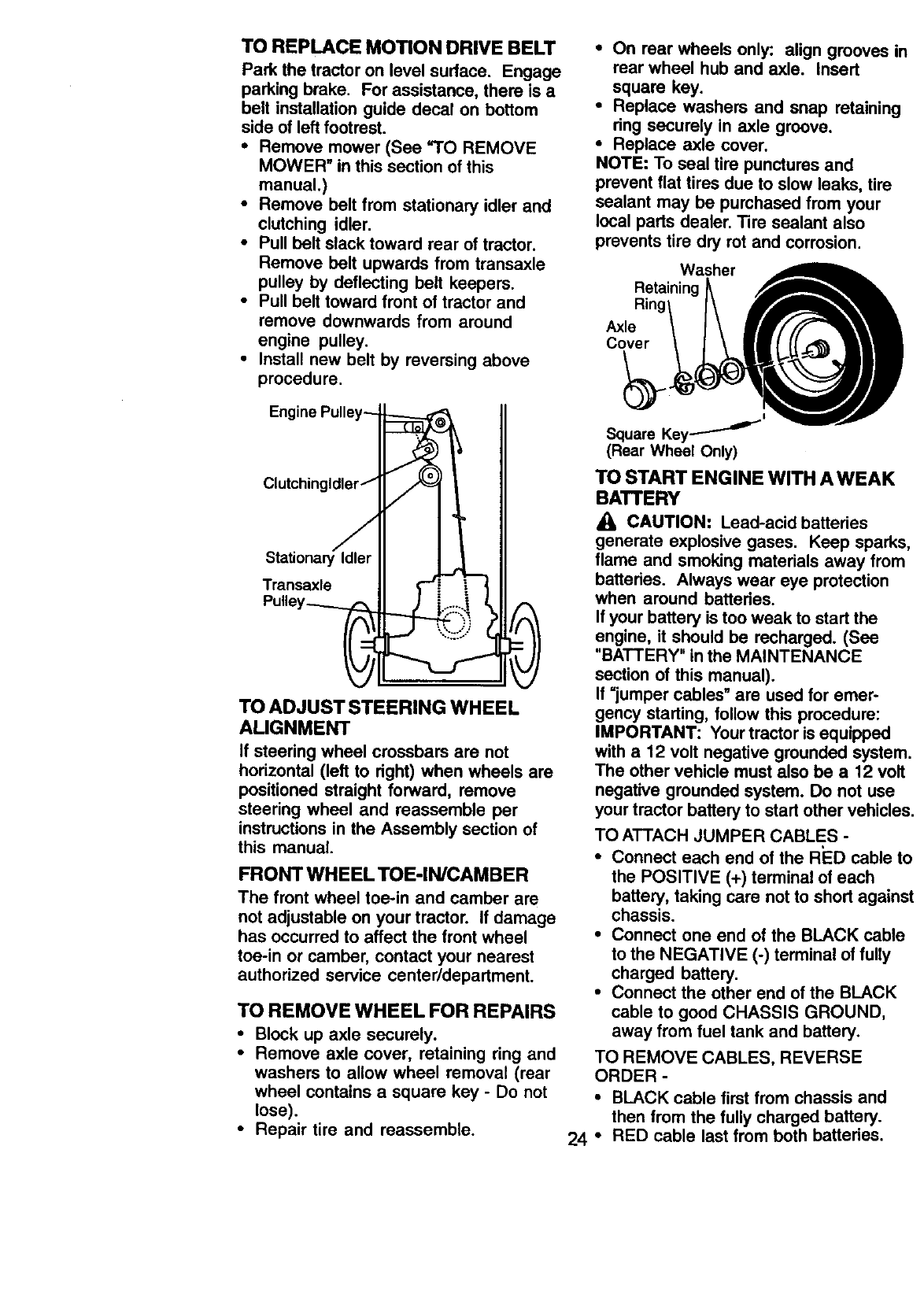
TO REPLACE MOTION DRIVE BELT
Park the tractor on level surface, Engage
parking brake. For assistance, there is a
belt installation guide decal on bottom
side of leftfootrest.
• Remove mower (See "TO REMOVE
MOWER" in this section of this
manual.)
•Remove belt from stationary idler and
clutching idler.
•Pull belt slack toward rear of tractor.
Remove belt upwards from transaxle
pulley by deflecting belt keepers.
•Pull belt toward front of tractor and
remove downwards from around
engine pulley.
•Install new belt by reversing above
procedure.
• On rear wheels only: align grooves in
rear wheel hub and axle. Insert
square key.
•Replace washers and snap retaining
ring securely in axle groove.
•Replace axle cover.
NOTE: To seal tire punctures and
prevent flat tires due to slow leaks, tire
sealant may be purchased from your
local parts dealer. Tire sealant also
prevents tire dry rot and corrosion.
Washer
Retaining
Axle
Cover
Engine Pulley--
Clutchingldler /
J
StationaryIdler
Transaxle
Pulley_
L:::::
TO ADJUST STEERING WHEEL
ALIGNMENT
If steering wheel crossbars are not
horizontal (left to right) when wheels are
positioned straight forward, remove
steering wheel and reassemble per
instructions in the Assembly section of
this manual.
FRONT WHEEL TOE-IN/CAMBER
The front wheel toe-in and camber are
not adjustable on your tractor. If damage
has occurred to affect the front wheel
toe-in or camber, contact your nearest
authorized service center/department.
TO REMOVE WHEEL FOR REPAIRS
•Block up axle securely.
•Remove axle cover, retaining ring and
washers to allow wheel removal (rear
wheel contains a square key - Do not
lose).
•Repair tire and reassemble.
I
SquareKey----'-''_
(Rear Wheel Only)
TO START ENGINE WITH AWEAK
BATTERY
_1_ CAUTION: Lead-acid batteries
generate explosive gases. Keep sparks,
flame and smoking materials away from
batteries. Always wear eye protection
when around batteries.
If your battery is too weak to start the
engine, it should be recharged. (See
"BATTERY" in the MAINTENANCE
section of this manual).
If =jumper cables" are used for emer-
gency starting, follow this procedure:
IMPORTANT: Yourtractor is equipped
with a12 volt negative grounded system.
The other vehicle must also be a 12 volt
negative grounded system. Do not use
your tractor battery to start other vehicles.
TO ATTACH JUMPER CABLES -
•Connect each end of the RED cable to
the POSITIVE (+) terminal of each
battery, taking care not to short against
chassis.
•Connect one end of the BLACK cable
to the NEGATIVE (-) terminal of fully
charged battery.
•Connect the other end of the BLACK
cable to good CHASSIS GROUND,
away from fuel tank and battery.
TO REMOVE CABLES, REVERSE
ORDER -
•BLACK cable first from chassis and
then from the fully charged battery.
24 °RED cable last from both batteries.
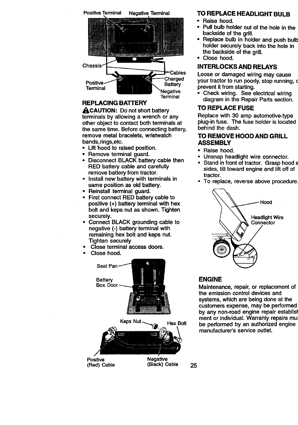
Positive Terminal Negative Terminal
Chassis.
Terminal Battery
Terminal
REPLACING BA'I-rERY
,_CAUTION: Do not short battery
terminals by allowing a wrench or any
other object to contact both terminals at
the same time. Before connecting battery,
remove metal bracelets, wristwatch
bands,rings,etc.
•Lift hood to raised position.
•Remove terminal guard.
•Disconnect BLACK battery cable then
RED battery cable and carefully
remove battery from tractor.
•Install new battery with terminals in
same position as old battery.
• Reinstall terminal guard.
•First connect RED battery cable to
positive (+) battery terminal with hex
bolt and keps nut as shown. Tighten
securely.
•Connect BLACK grounding cable to
negative (-) battery terminal with
remaining hex bolt and keps nut.
Tighten securely
• Close terminal access doors.
•Close hood.
TO REPLACE HEADLIGHT BULB
•Raise hood.
•Pull bulb holder out of the hole in the
backside of the grill.
•Replace bulb in holder and push bulb
holder securely back into the hole in
the backside of the grill.
•Close hood.
INTERLOCKS AND RELAYS
Loose or damaged wiring may cause
your tractor to run poorly, stop running, o
prevent it from starting.
•Check wiring. See electrical wiring
diagram in the Repair Parts section.
TO REPLACE FUSE
Replace with 30 amp automotive-type
plug-in fuse. The fuse holder is located
behind the dash.
TO REMOVE HOOD AND GRILL
ASSEMBLY
• Raise hood.
•Unsnap headlight wire connector.
•Stand in front of tractor. Grasp hood al
sides, tilt toward engine and lift off of
tractor.
•To replace, reverse above procedure.
Hood
,,EoW,,o
Ba_e_
Box
Hex Bolt
ENGINE
Maintenance, repair, or replacement of
the emission control devices and
systems, which are being done at the
customers expense, may be performed
by any non-road engine repair establish
ment or individual. Warranty repairs mus
be performed by an authorized engine
manufacturer's service outlet.
Positive Negative
(Red) Cable (Black) Cable 25
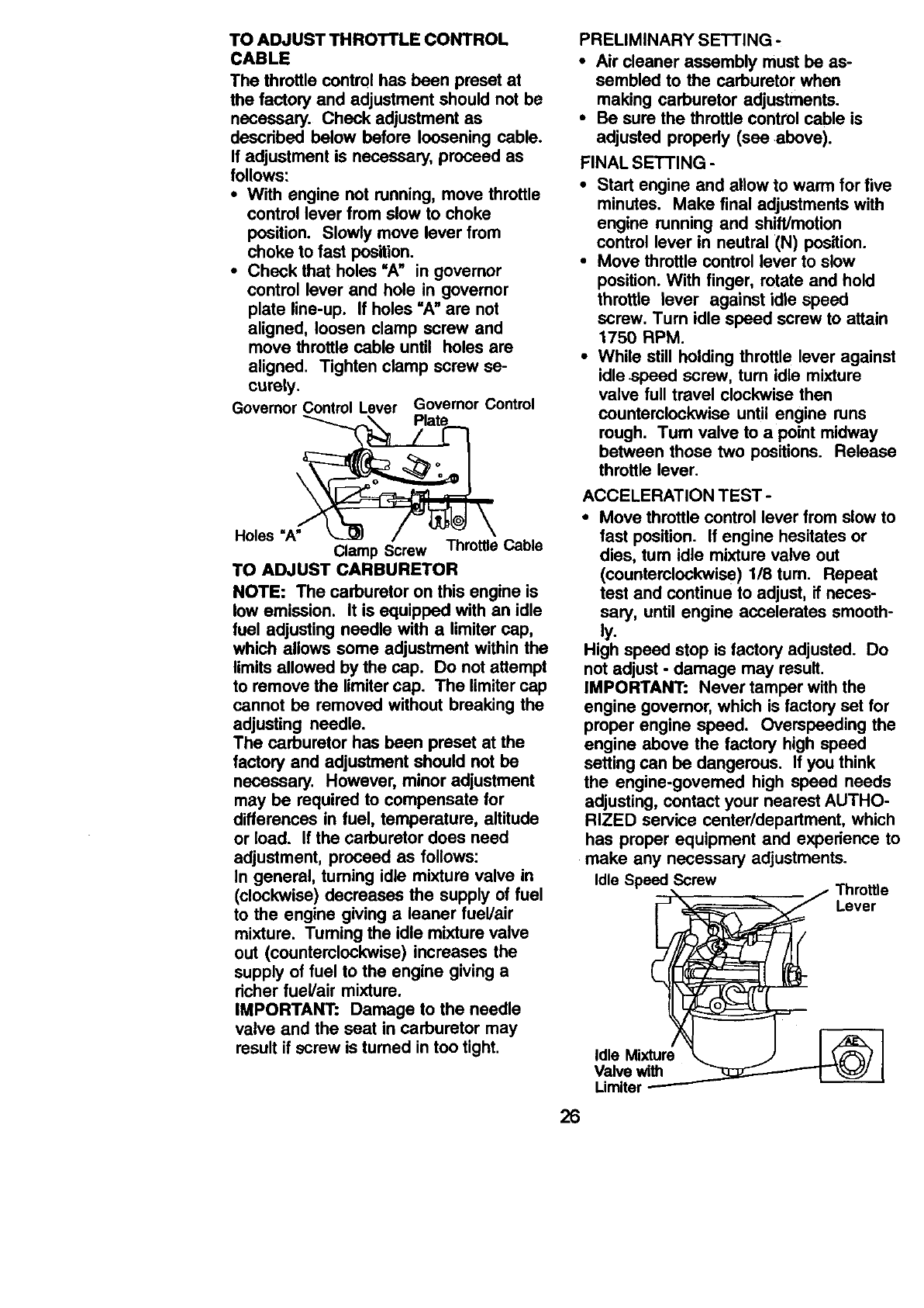
TO ADJUST THROTTLE CONTROL
CABLE
The throttle control has been preset at
the factory and adjustment should not be
necessary. Check adjustment as
descdbed below before loosening cable.
If adjustment is necessary, proceed as
follows:
•With engine not running, move throttle
control lever from slow to choke
position. Slowly move lever from
choke to fast position.
•Check that holes =A" in governor
control lever and hole in governor
plate line-up. If holes =A" are not
aligned, loosen clamp screw and
move throttle cable until holes are
aligned. Tighten clamp screw se-
curely.
GovernorControlLever GovernorControl
Holes "A" Clamp Screw ThrottleCable
TO ADJUST CARBURETOR
NOTE: The carburetor on this engine is
low emission. It is equipped with an idle
fuel adjusting needle with a limiter cap,
which allows some adjustment within the
limits allowed by the cap. Do not attempt
to remove the limiter cap. The limiter cap
cannot be removed without breaking the
adjusting needle.
The carburetor has been preset at the
factory and adjustment should not be
necessary. However, minor adjustment
may be required to compensate for
differences in fuel, temperature, altitude
or load. If the carburetor does need
adjustment, proceed as follows:
In general, turning idle mixture valve in
(clockwise) decreases the supply of fuel
to the engine giving aleaner fueVair
mixture. Tuming the idle mixture valve
out (counterclockwise) increases the
supply of fuel to the engine giving a
dcher fuel/air mixture.
IMPORTANT: Damage to the needle
valve and the seat in carburetor may
result if screw is turned in too tight.
PRELIMINARY SETTING -
•Air cleaner assembly must be as-
sembled to the carburetor when
making carburetor adjustments.
•Be sure the throttle control cable is
adjusted propedy (see above).
FINAL SETTING -
•Start engine and allow to warm for five
minutes. Make final adjustments with
engine running and shift/motion
control lever in neutral (N) position.
• Move throttle control lever to slow
position. With finger, rotate and hold
throttle lever against idle speed
screw. Turn idle speed screw to attain
1750 RPM.
•While still holding throttle lever against
idle-speed screw, tum idle mixture
valve full travel clockwise then
counterclockwise until engine runs
rough. Turn valve to a point midway
between those two positions. Release
throttle lever.
ACCELERATION TEST -
•Move throttle control lever from slow to
fast position. If engine hesitates or
dies, turn idle mixture valve out
(counterclockwise) 1/8 rum. Repeat
test and continue to adjust, if neces-
sary, until engine accelerates smooth-
ly.
High speed stop is factory adjusted. Do
not adjust - damage may result.
IMPORTANT: Never tamper with the
engine govemor, which is factory set for
proper engine speed. Overspeeding the
engine above the factory high speed
setting can be dangerous. If you think
the engine-govemed high speed needs
adjusting, contact your nearest AUTHO-
RIZED service center/department, which
has proper equipment and experience to
make any necessary adjustments.
Idle Speed Screw Throttle
_Lever
Valve with
Limlter
26
Immediately prepare your tractor for
storage at the end of the season or if the
tractor will not be used for 30 days or
more.
_,CAUTION: Never store the tractor
with gasoline in the tank inside a
building where fumes may reach an
open flame or spark. Allow the engine to
cool before stodng in any enclosure.
TRACTOR
Remove mower from tractor for winter
storable. When mower is to be stored for
a penod of time, clean it thoroughly,
remove all dirt, grease, leaves, etc. Store
in a clean, dry area.
•Clean entire tractor (See "CLEANING"
in the Customer Responsibilities
section of this manual).
•Inspect and replace belts, if necessary
(See belt replacement instructions in
the Service and Adjustments section of
this manual).
•Lubricate as shown in the Customer
Responsibilities section of this
manual.
•Be sure that all nuts, bolts and screws
are securely fastened. Inspect moving
parts for damage, breakage and wear.
Replace if necessary.
•Touch up all rusted or chipped paint
surfaces; sand lightly before painting.
BAI"rERY
•Fully charge the battery for storage.
•After a pedod of time in storage,
battery may require recharging.
•To help prevent corrosion and power
leakage during long pedods of
storage, battery cables should be
disconnected and battery cleaned
thoroughly (see "TO CLEAN BATTERY
AND TERMINALS" in the Customer
Responsibilities section of this
manual).
•After cleaning, leave cables discon-
nected and place cables where they
cannot come in contact with battery
terminals.
•If battery is removed from tractor for
storage, do not store battery directly on
concrete or damp surfaces.
ENGINE
FUEL SYSTEM
IMPORTANT: It is important to prevent
_]uUmdeposits from forming in essential
el system parts such as' carburetor, fuel
filter, fuel hose, or tank during storage.
Also, expedence indicates that alcohol
blended fuels 9called gasohol or using
ethanol or methanol) can attract moisture
which leads to separation and formation
of acids during storage. Acidic gascan
damage the fuel system of an engine
while in storage.
•Drain the fuel tank.
•Start the engine and let it run until the
fuel lines and carburetor are empty.
•Never use engine or carburetor
cleaner products in the fuel tank or
permanent damage may occur.
•Use fresh fuel next season.
NOTE: Fuel stabilizer is an acceptable
alternative in minimizing the formation of
fuel gum deposits during storage. Add
stabilizer to gasoline in fuel tank or
storage container. Always follow the mix
ratio found on stabilizer container. Run
engine at least 10 minutes after adding
stabilizer to allow the stabilizer to reach
the carburetor. Do not drain the gas tank
and carburetor if using fuel stabilizer.
ENGINE OIL
Drain oil (with engine warm) and replace
with clean engine oil. (See =ENGINE" in
the Customer Responsibilities section of
this manual).
CYLINDER(S)
• Remove spark plug(s).
•Pour one ounce of oil through spark
plug hole(s) into cylinder(s).
• Tum ignition key to =START" position
for a few seconds to distribute oil.
•Replace with new spark plug(s).
OTHER
•Do not store gasoline from one season
to another.
•Replace your gasoline can if your can
starts to rust. Rust and/or dirt in your
gasoline will cause problems.
•If possible, store your tractor indoors
and cover it to give protection from
dust and dirt.
• Cover your tractor with a suitable
protective cover that does not retain
moisture. Do not use plastic. Plastic
cannot breathe which allows conden-
sation to form and will cause your
tractor to rust.
IMPORTANT: Never cover tractor while
engine and exhaust areas are still
warm.
27
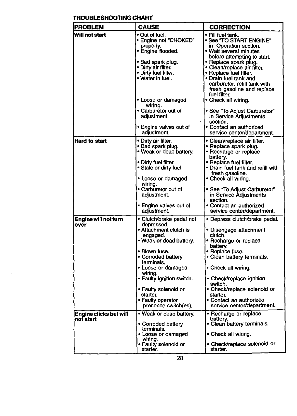
TROUBLESHOOTING CHART
IPROBLEM ' CAUSE CORRECTION
Will notstart • Outoffuel.
Hard to start
Engine will not turn
over
Engine clicks but will
not start
• Engine not =CHOKED"
propedy. .
• Engine flooeea.
•Bad spark plug.
!, Dirty air filter.
•Dirty fuel filter.
• Water in fuel.
•Loose or damaged
wiring.
•Carburetor out of
adjustment.
•Engine valves out of
adjustment.
•Dirty air filter.
•Bad spark plug.
•Weak or dead battery.
•Dirty fuel filter.
•Stale or dirty fuel.
• Loose or damaged
wiring.
•Carburetor out of
adjustment.
•Engine valves out of
adjustment.
•Clutch/brake pedal not
depressed.
•Attachment clutch is
engaged.
•Weak or dead battery.
•Blown fuse.
•Corroded battery
terminals.
•Loose or damaged
wiring. .
•Faulty igmtion switch.
•Faulty solenoid or
starter.
•Faulty operator
presence switch(es).
•Weak or dead battery.
• Corroded battery
terminals.
•Loose or damaged
wiring.
•Fau ty solenoid or
starter.
•Fill fuel tank.
•See "TO START ENGINE"
in Operation section.
•Wait several minutes
before attempting to start.
•Replace spark plu_.
•Clean/replace air fdter.
•Replace fuel filter.
•Drain fuel tank and
carburetor, refill tank with
fresh gasoline and replace
fuel filter.
•Check all wiring.
•See "To Adjust Carburetor"
in Service Adjustments
section.
•Contact an authorized
service center/department.
• Clean/replace air filter.
Replace spark plug.
Recharge or replace
battery.
•Replace fuel filter.
•Drain fuel tank and refill with
fresh gasoline.
•Check all wiring.
• See "To Adjust Carburetor"
in Service Adjustments
section.
I. Contact an authorized
service center/department.
•Depress clutch/brake pedal.
•Disengage attachment
clutch.
*Recharge or replace
battery.
*Replace fuse.
•Clean battery terminals.
• Check all wiring.
•Check/replace ignition
switch.
•Check/replace solenoid or
starter.
•Contact an authorized
service center/department.
•Recharge or replace
battery.
• Clean battery terminals.
• Check all wiring.
• Check/replace solenoid or
starter.
28
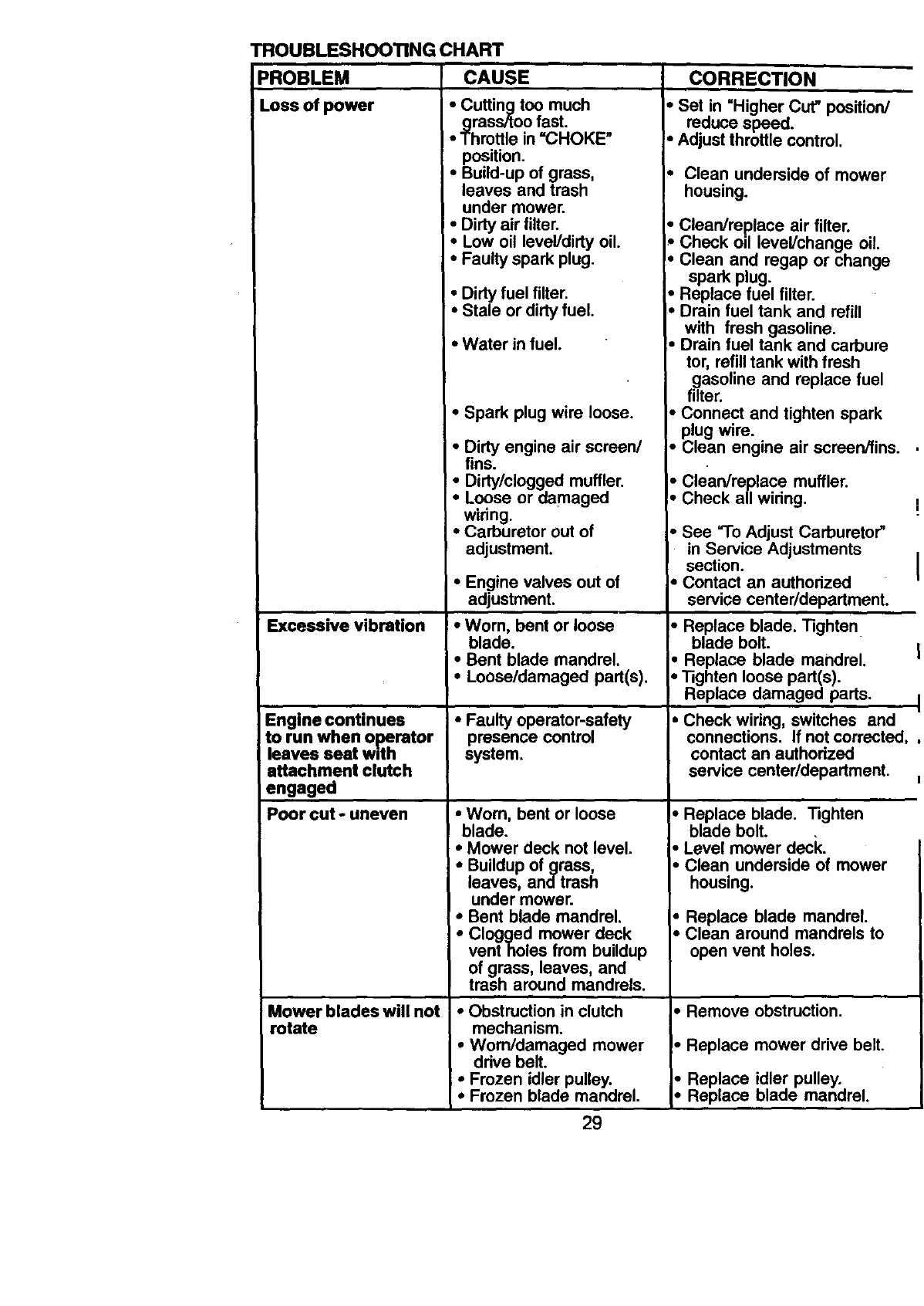
TROUBLESHOOTINGCHART
PROBLEM CAUSE CORRECTION
lLoss of power •Cutting too much
grass/too fast.
•Throttle in =CHOKE"
Excessive vibration
Engine continues
to run when o_. rator
leaves seat w,th
attachment clutch
engaged
Poor cut ouneven
Mower blades will not
rotate
position.
•Build-up of grass,
leaves and trash
under mower.
• Dirty air filter.
•Low oil level/dirty oil.
• Faulty spark plug.
•Dirty fuel filter.
•Stale or dirty fuel.
•Water in fuel.
• Spark plug wire loose.
•Dirty engine air screen/
fins.
•Dirty/clogged muffler.
•Loose or damaged
wiring.
•Carburetor out of
adjustment.
•Engine valves out of
adjustment.
•Worn, bent or loose
blade.
•Bent blade mandrel.
•Loose/damaged part(s).
•Faulty operator-safety
presence control
system.
•Wom, bent or loose
blade.
•Mower deck not level.
•Buildup ofgrass,
leaves, andtrash
under mower.
• Bent blade mandrel.
•Clogged mower deck
vent holes from buildup
of grass, leaves, and
trash around mandrels.
•Obstruction in clutch
mechanism.
•Worn/damaged mower
ddve belt.
•Frozen idler pulley.
•Frozen blade mandrel.
•Set in "Higher Cut" position/
reduce speed.
•Adjust throttle control.
•Clean underside of mower
housing.
•Clean/replace air filter.
Check oil level/change oil.
•Clean and regap or change
spark plug.
• Replace fuel filter.
•Drain fuel tank and refill
with fresh gasoline.
•Drain fuel tank and carbure
tor, refill tank with fresh
gasoline and replace fuel
filter.
J-Connect and tighten spark
plug wire.
Clean engine air screen/fins.
•Clean/replace muffler.
•Check all wiring.
• See "To Adjust Carburetor"
in Service Adjustments
section.
•Contact an authorized
service center/department.
•Replace blade. Tighten
blade bolt.
•Replace blade mandrel.
• Tighten loose part(s).
Replace damaged parts.
• Check wiring, switches and
connections. If not corrected,
contact an authodzed
service center/department.
•Replace blade. Tighten
blade bolt.
•Level mower deck.
•Clean underside of mower
housing.
•Replace blade mandrel.
•Clean around mandrels to
open vent holes.
Remove obstruction.
•Replace mower drive belt.
•Replace idler pulley.
•Replace blade mandrel.
29

TROUBLESHOOTING CHART
PROBLEM CAUSE CORRECTION
Poor grass discharge •Engine speed too slow.
Headlight(s) not
working (if so
equipped)
Battery will not charge
Loss of Ddve
Engine "backfires"
!when turning engine
"OFF"
•Travel speed too fast.
•Wet grass.
•Mower deck not level.
•Low/uneven tire air
pressure.
•Worn, bent or loose blade.
I• Buildup of grass,
leaves and trash under
mower.
•Mower drive belt worn.
•Blades impropedy
installed.
•Improper blades used.
•Clogged mower deck
vent holes from buildup
of grass, leaves, and
trash around mandrels.
•Switch is =OFF'.
•Bulb(s) burned out.
•Faulty lightswitch.
•Loose or damaged
widng.
•Blown fuse.
•Bad battery cell(s).
•Poor cable connections.
•Faulty regulator (ifso
equipped).
•Faulty alternator.
•Freewheel control in
=disengaged" position.
•Motion drive belt worn,
damaged or broken.
•Air trapped in transmiss-
ion during shipment or
servicing,
•Engine throttle control
not set at =SLOW"
position for 30 seconds
before stopping engine.
•Place throttle control in
=FAST"position.
•Shift to slower speed.
•Allow grass to dry before
mowing.
•Level mower deck.
•Check tires for proper air
pressure.
•Replace/sharpen blade.
Tighten blade bolt.
•Clean underside of mower
housing.
•Replace mower drive belt.
•Reinstall blades sharp edge
down.
•Replace with blades listed
in this manual.
•Clean around mandrels to
open vent holes.
•Turn switch =ON".
•Replace bulb(s).
• Check/replace light switch.
•Check wiring and connec
tions.
•Replace fuse,
•Replace battery.
•Check/clean all connec
tions.
•Replace regulator.
•Replace alternator.
•Place freewheel control in
=engagec[' position.
• Replace motion drive belt.
•Move throttle control to
=SLOW" position and allow
to idle for 30 seconds before
stopping engine.
30
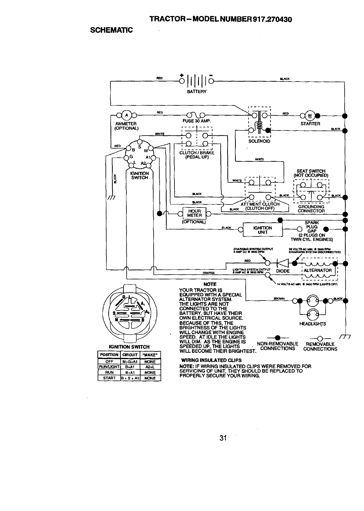
SCHEMATIC
TRACTOR - MODEL NUMBER 917.270430
RED O
BATTERY
AMMETER FUSE 30 AMP. _: STARTER
WHITE I =
I J. , o ,,oq--- I
I " 'SOLENOID
I-_ "- I CLUTCH/BRAKE J J
i_r---QG Al<h<PEO^LUP)I I
L
IGNITION NOT PIED
0
CONNECTOR 1
€',
II(OPTIONAL) SPARK
i} eL_ _IGNITION _(2 PLUG
N,T
I I _,N_. EN_,NES)
_K_ RQIN_ SV_T'B_ OUI_ UT 2g VGLT8 _MIN. I _00 RpM
_i AtqP DC I 3m30 RFI4 ICHARt_NG 8yBT E M _G(_IECTIE [})
REO I i
O_AN_E lAMP AC I _0 R_M i I
NOTE I "%,,,o,..s_,. ;_2,_;=_
YOUR TRACTOR IS I
/,__ EQUIPPED WITH A SPECIAL I
/ (/ _'/'TI"__ __1 \ALTERNATOR SYSTEM. I.cow _
/ y /'/___._A_ _ \ "I'HE LIGHTS ARE NOT v"r '_ "_ "
[IS_I_J I BAI-[ERY. BUT HAVE THEIR _;_
\ _ / / OWN ELECTRICAL SOURCE.
\K_ f_- /1 / BECAUSE OF THIS, THE HEADLIGHTS
\_ _ L_" /)/ BRIGHTNESS OF THE LIGHTS
__/ . WILL CHANGE WITH ENGINE
"_ I_ SPEED. AT IDLE THE LIGHTS ----0---- _ /-/
WILL DIM. AS THE ENGINE IS NON REMOVABLE REMOVABLE
IGNITION SWITCH SPEEDED UP, THE LIGHTS " CONNECTIONS CONNECTIONS
WILL BECOME THEIR BRIGHTEST.
IPosmoN CIRCUIT "I_AKE"
OFF M+G*A1 NONE WIRING INSULATED CLIPS
RUN/LIGHT B+AI A2+L NOTE: IF WIRING INSULATED CLIPS WERE REMOVED FOR
RUN B+AI NONE SERVICING OF UNIT, THEY SHOULD BE REPLACED TO
START B + S+ A1 NONE PROPERLY SECURE YOUR WIRING.
31
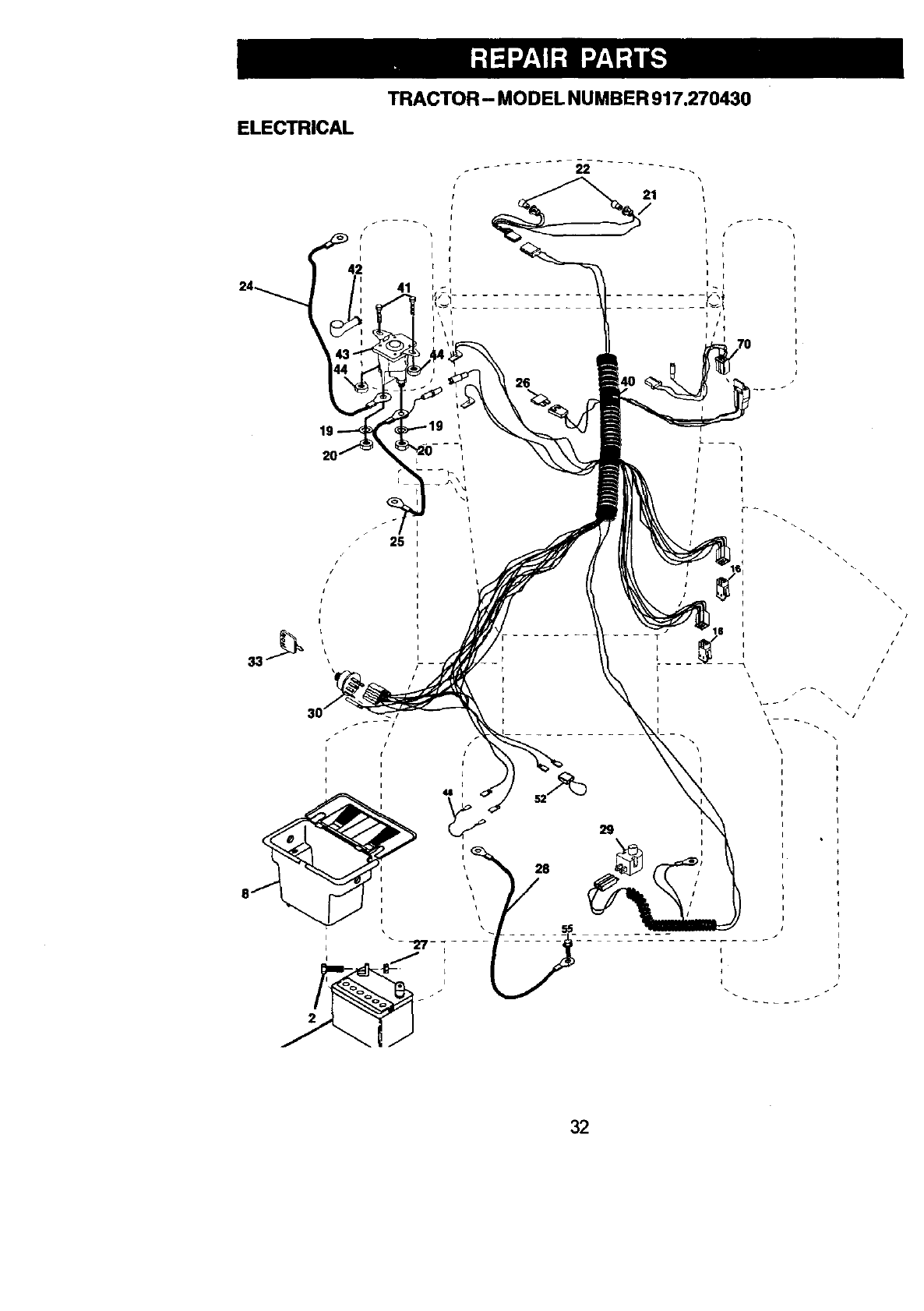
TRACTOR- MODEL NUMBER 917.270430
ELECTRICAL
41
' 21
I
26
25
//
II
II
Ii
II41
i
i
/
J
L _
i
I
\
\
!
\i
29
\1
32
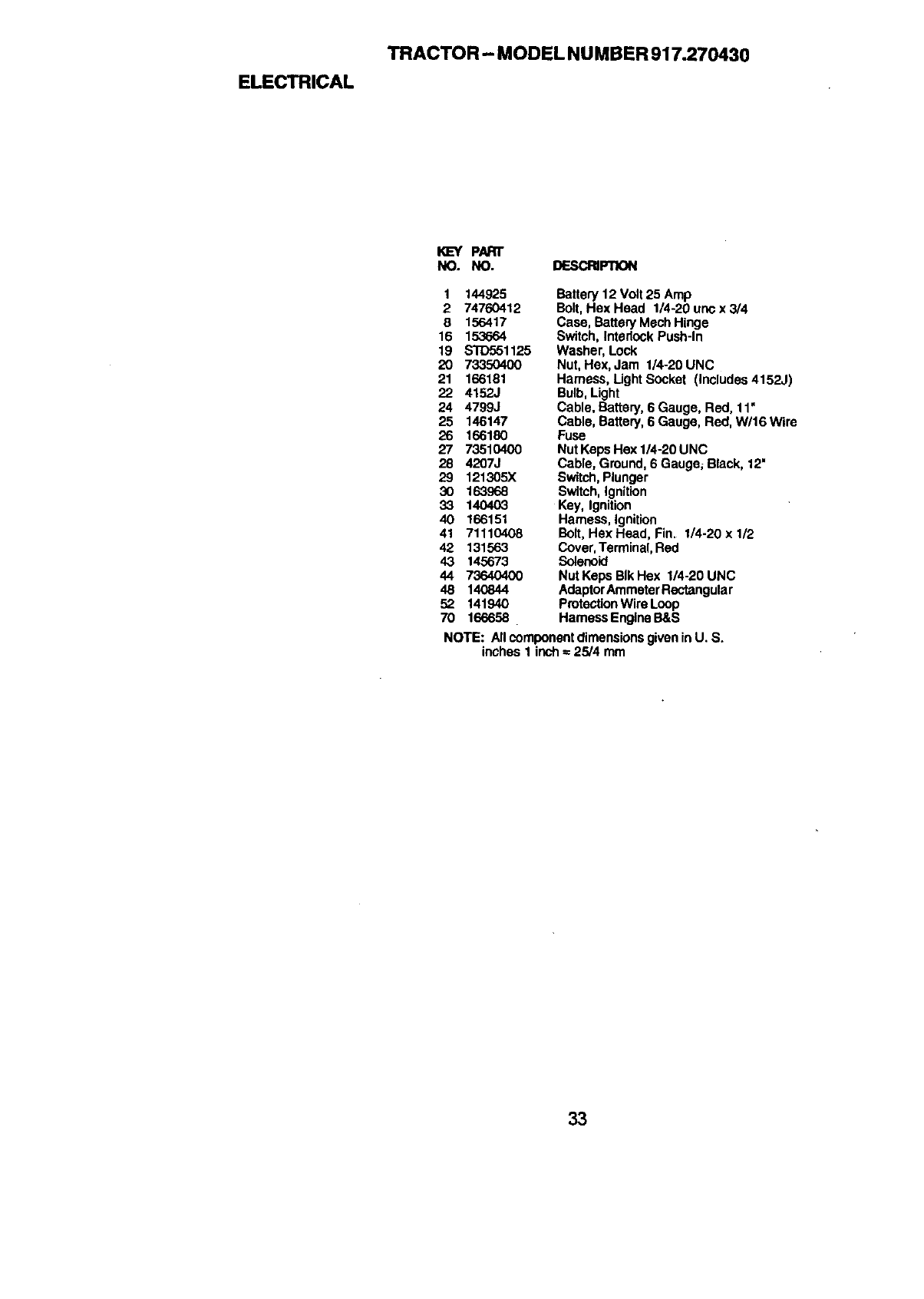
ELECTRICAL
TRACTOR - MODEL NU MBER 917.270430
KE-'YPART
NO. NO. DESCRI_
1 144925
2 74760412
8 156417
16 153664
19 STD551125
20 73350400
21 166181
22 4152J
24 4799J
25 146147
26 166180
27 73510400
28 4207J
29 121305X
30 163968
33 140403
40 166151
41 71110408
42 131563
43 145673
44 73640400
48 14O844
52 141940
Battery 12 Volt 25 Amp
Bolt,Hex Head 1/4-20 unc x 3/4
Case, Battery Mech Hinge
Switch, Intedock Push-In
Washer, Lock
Nut, Hex, Jam 1/4-20 UNC
Harness, Light Socket (includes 4152J)
Bulb,Light
Cable, Battery, 6 Gauge, Red, 11"
Cable, Battery, 6 Gauge, Red, W/16 Wire
Fuse
Nut Keps Hex 1/4-20 UNC
Cable, Ground, 6 Gauge; Black, 12"
Switch,Plunger
Switch, Ignition
Key, Ignition
Harness, Ignition
Bait, Hex Head, Fin. 1/4-20 x 1/2
Cover,Terminal, Red
Solenoid
Nut Keps BIk Hex 1/4-20 UNC
AdaptorAmmeter Rectangular
Protection Wire Loop
70 166658 Harness Engine B&S
NOTE: All componentdimensions givenin U. S.
inches 1 inch - 25/4 mm
33
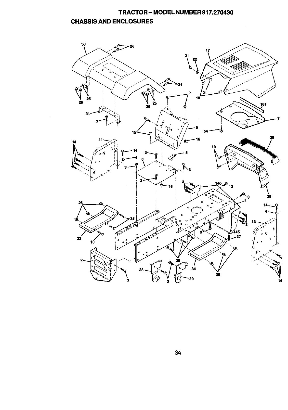
TRACTOR - MODEL NU M BER 917.270430
CHASSIS AND ENCLOSURES
3O
21
17
22
ni
26 31_
14
26
18
161
29
28
33 10
38 34
39
13-
5
26
14
34
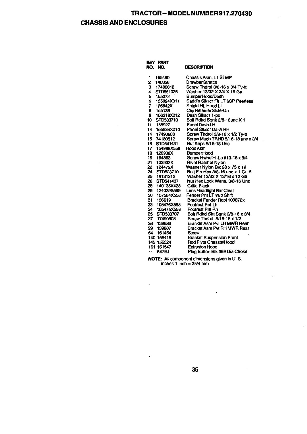
TRACTOR - MODEL NUMBER 917.270430
CHASSIS AND ENCLOSURES
I_EY PARr
NO. NO. DESCRIPTION
1 16548O
2 140356
3 17490612
4 $10551025
5 155272
6 155924X011
7 126842X
8 155138
9 166318X012
10 STD533710
11 155927
13 155934X010
14 17490608
15 74180512
16 STD541431
17 154988X558
18 126938X
19 164863
21 122933X
22 124479)(
24 STD523710
25 19131312
26 STD541437
28 140135X428
29 124G29X599
30 157584X558
31 136619
33 105476X558
34 105475X558
35 STD533707
37 17490508
38 139886
39 139887
54 161464
140 158418
145 156524
161 161547
-- 5479J
ChassisAsm. LT STMP
DrawbarStretch
Screw Thdrol 3/8-16 x 3/4 Ty-tt
Washer 13_32 X 3/4 X 16 Ga
BumperHood/Dash
Saddle Slkscr PitLT 6SP Peedess
Shield Ht, Hood Lt
Clip RetainerSlide-On
Dash Slkscr 1-pc
Bolt Rdhd Sqnk 3/8-16unc X 1
Panel DashLH
Panel SlkscrDash RH
Screw Thdml 3/8-16 x 1/'2Ty-tt
Screw Mach TRHD 5/16-18 uricx 3/4
Nut Keps 5/16-18 Uric
HoodAsm
BumperHood
Screw HwhclHi-Lo #13-16 x3/4
Rivet Ratchet Nylon
Washer Nylon BIk 28 x 75 x 19
Bolt Fin Hex 3/8-16 urmx 1 Gr. 5
Washer 13/32 X 13/16 x 12 Ga
Nut Hex Lock W/Ins, 3/3-16 Unc
GdUeBlack
Lens Headlight BarClear
Fender Pnt LT W/o Shift
Bracket Fender Repl 109873x
Footrest Pnt Lh
FootrestPnt Rh
Bolt Rdhd Sht Sqnk 3/8-16 x3/4
ScrewThdrol 5/16-18 x 1/2
BracketAsm Pvt LH MWR Rear
BracketAsm Pvt RH MWR Rear
Screw
Bracket Suspension Front
Rod PivotChassis/Hood
ExtrusionHood
Plug Button BIk 359 Dia Choke
NOTE: All componentdimensionsgiven in U. S.
inches 1 inch =25/4 mm
35
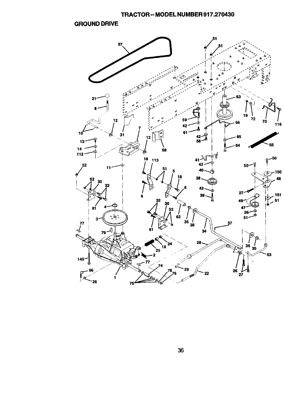
TRACTOR - MODEL NU MBER 917.270430
GROUND DRIVE
37
36
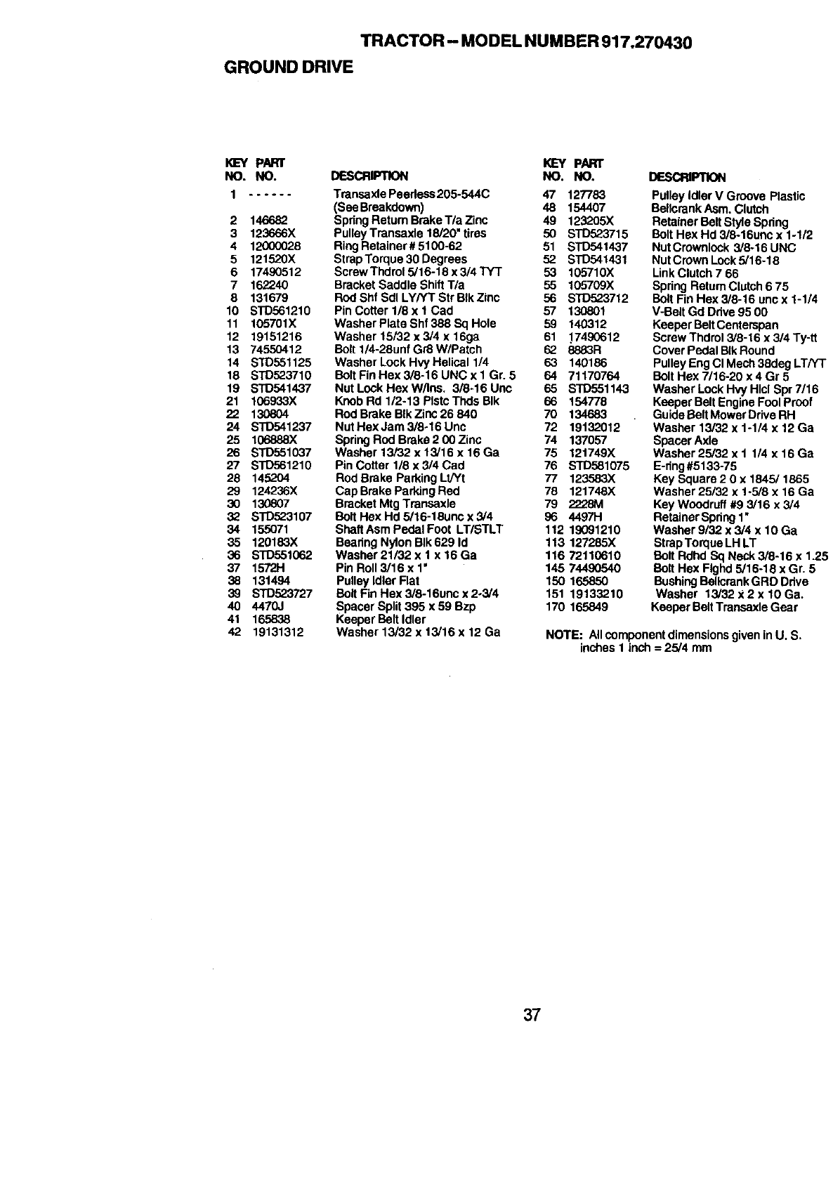
TRACTOR - MODEL NUMBER 917.270430
GROUND DRIVE
KEY PARr KEY PART
NO. NO. DESCRIPTION NO. NO. DESCRIP11ON
Transaxle Peedess 205-544C 47 127783
(See Braakdown) 48 154407
Spring Return Brake Tla Zinc 49 123205X
PulleyTransaxle 18/20" tires 50 STD523715
Ring Retainer # 5100-62 51 STD541437
Strap Torque 30 Degrees 52 STD541431
Screw Thdml 5/16-16 x 3/4 TYT 53 105710X
Bracket Saddle Shift T/a 55 105709X
Rod Shf Sdl LY/YT Str BtkZinc 56 STD523712
PinCotterl/8xl Cad 57 130801
Washer Plate Shf 388 Sq Hole 59 140312
Washer 16132 x3/4 x 16ga 61 17490612
Bolt 1/4-28unf Gr8 W/Patch 62 8883R
Washer Lock Hvy Helical 1/4 63 140186
BoltFinHex3/8-16UNCx1Gr. 5 64 71170764
Nut Lock Hex W/Ins. 3/8-16 Uno 65 STD551143
Knob Rd 1/2-13 PIstcThds BIk 66 154778
Rod Brake BIk Zinc 26 840 70 134683
Nut Hex Jam 3/8-16 Unc 72 19132012
Spring Rod Brake 2 00 Zinc 74 137057
Washer 13/32 x 13/16 x 16 Ga 75 12t749X
Pin Cotter 1/8 x 3/4 Cad 76 STD581075
Rod Brake Parking Lt/Yt 77 123..'.'.'.'.'.'.'.'._X
CapBrake ParkingRed 78 121748X
Bracket Mtg Transaxle 79 2228M
Bolt Hex Hd 5/16-18uno x 3/4 96 4497H
ShaftAsm Pedal Foot LT/STLT 112 19091210
Bearing Nylon BIk 629 Id 113 127285X
Washar 21/32 x tx 16 Ga 116 72110610
Pin Roll 3/16 x 1' 145 74490540
Pulley Idler Flat 150 165850
Bolt Fin Hex 3/8-16unc x 2-3/4 151 19133210
Spacer Split 395 x 59 Bzp 170 165849
Keeper Bolt Idler
Washer 13/32 x 13/16 x 12 Ga
1......
2 146682
3 123666X
4 12000028
5 121520X
6 17490512
7 162240
8 131679
10 STD561210
11 105701X
12 19151216
13 74550412
14 STD551125
18 STD523710
19 STD541437
21 106933X
22 130804
24 STD541237
25 106888X
26 STD551037
27 STD561210
28 145204
29 124236X
30 130807
32 S]O523107
34 155071
35 120183X
36 STD551062
37 1572H
38 131494
39 STD523727
40 4470J
41 165838
42 19131312
Pulley Idler V Groove Plastic
Bollcrank Asm. Clutch
Retainer Belt Style Spring
Bolt Hex Hd 3/8-16unc x 1-1/2
Nut Crownlock 3/8-16 UNC
Nut Crown Lock5/16-18
Link Clutch 7 66
Spring Return Clutch 6 75
Bolt Fin Hex 3/8-16 unc x 1-1/4
V-Belt Gd Drive95 00
Keeper Bolt Centerspan
Screw Thdrol 3/8-t6 x 3/4 Ty-tt
Cover Pedal BIkRound
Pulley Eng CI Mech 38deg LT/YT
Bolt Hex 7/16-20 x 4 Gr 5
Washer Lock Hvy Hlcl Spr 7/16
Keeper Belt Engine Fool Proof
Guide Belt Mower Drive RH
Washer 13/32 x 1-1/4 x 12 Ga
Spacer Axle
Washer 25/32 x 1 1/4 x 16 Ga
E-ring#5133-75
Key Square 20x 1845/1865
Washer 25/32 x 1-5/8 x 16 Ga
Key Woodruff #9 3/16 x 3/4
Retainer Spring1"
Washer 9/32 x 3/4 x 10 Ga
Strap Torque LH LT
Bolt Rdhd Sq Neck 3/8-16 x 1.25
Bolt Hex Flghd5/16-18 x Gr. 5
BushingBollcrank GRD Drive
Washer 13/32 x 2 x 10 Ga,
Keeper BeltTransaxle Gear
NOTE: Allcomponent dimensionsgiven in U. S.
inches 1 inch = 25/4 mm
37
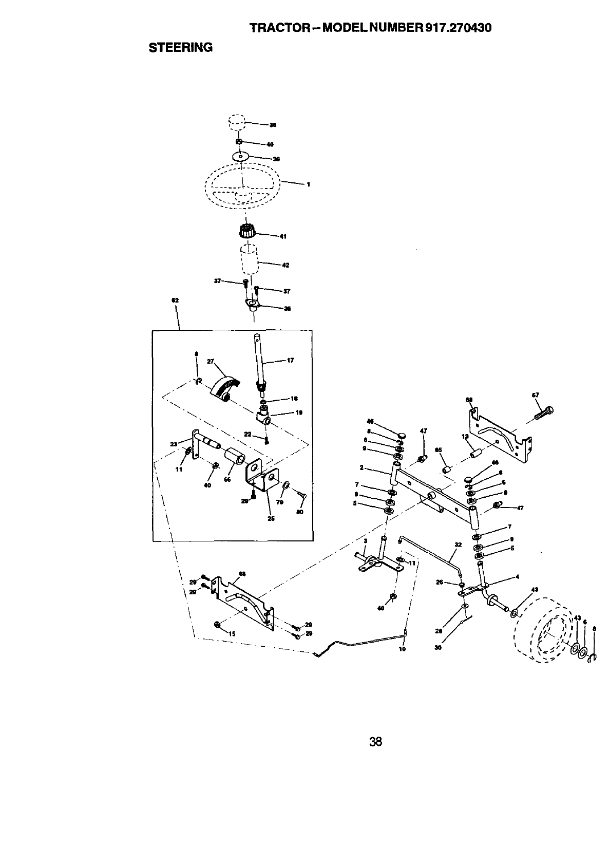
STEERING
TRACTOR -- MODEL NUMBER 917.270430
• j
._./
,t /_
1
30
3B
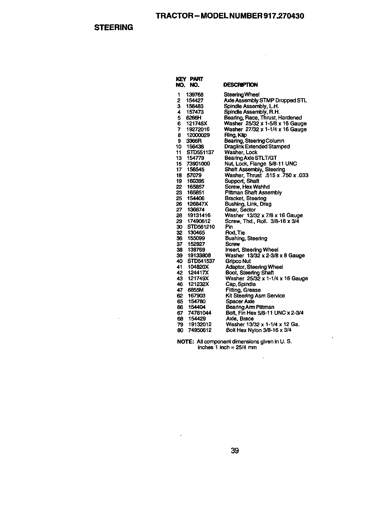
STEERING
TRACTOR - MODEL N U MBER 917.270430
K]EYPART
NO. NO. DESCRIPTX_
1 139768 SteeringWheel
2 154427 AxleAssembly STMP DroppedSTL
3 156483 Spindle Assembly, LH.
4 157473 SpindleAssembly, R.H.
5 6266H Bearing,Race, Thrust, Hardened
6 121748X Washer 25/32 x 1-5/8 x 16 Gauge
7 19272016 Washer 27/32 x 1-1/4 x 16 Gauge
8 12000029 Ring, Klip
9 3366R Beadng, Steedng Column
10 156438 DraglinkExtendedStamped
11 STD551137 Washer, Lock
13 154779 BearingAxle STLT/GT
15 73901000 Nut, Lock, Flange 5/8-11UNC
17 156545 Shaft Assembly, Steedng
18 57079 Washer, Thrust .515 x.750 x.033
19 160395 Support, Shaft
22 165857 Screw, HexWshnd
23 165851 Pittman Shaft Assembly
25 154406 Bracket, Steering
26 t26847X Bushing,Unk, Drag
27 136874 Gear, Sector
28 19131416 Washer 13/32 x 7/8 x16 Gauge
29 17490612 Screw, Thd., Roll. 3/8-16 x 3/4
30 S'ID561210 Pin
3_ 130465 Rod,Tie
36 155G99 Bushing,Steedng
37 152927 Screw
38 139769 Insert, Steadng Wheel
39 19133808 Washer 13i32x2-3/Sx8Gauga
40 STD541537 Gdpco Nut
41 10482X Adaptor,SteeringWheel
42 124417X Boot, Steedng Shaft
43 121749X Washer 25i32x1-1/4x16Gauge
46 121232X Cap, Spindle
47 6855M Fitting,Grease
62 167903 Kit Steedng Asm Service
65 154780 Spacer Axle
66 154404 BeadngArm Pittman
67 74781044 Bolt,Fin Hax 5/8-11 UNC x 2-3/4
68 154429 Axle, Brace
79 19132012 Washer 13/32 x 1-1/4 x 12 Ga.
80 74950612 Bolt Hex Nylon 3/8-16 x 3/4
NOTE: All componentdimensions given in U. S.
inches 1 inch = 25/4 mm
39
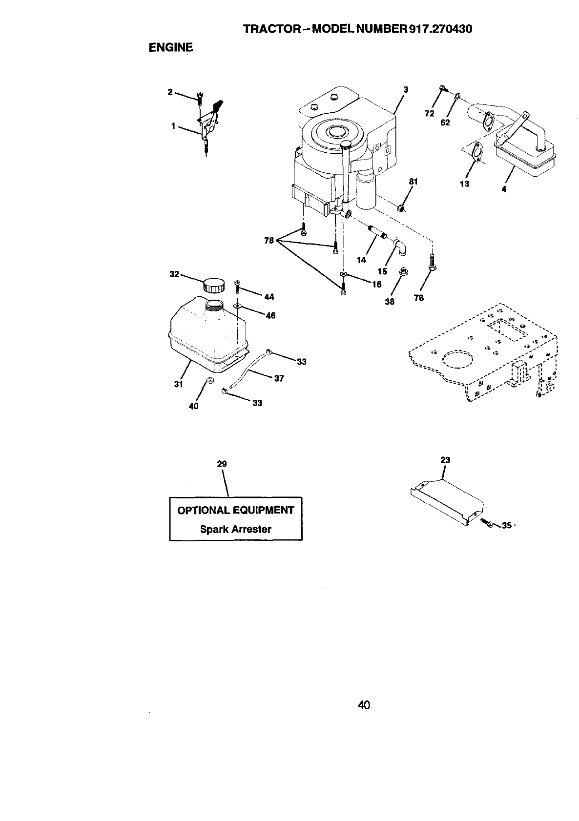
ENGINE
TRACTOR -- MODEL NU MBER 917.270430
33
3
81
38 78
13 4
29
OPTIONAL EQUIPMENT
Spark Arrester
23
/
4O
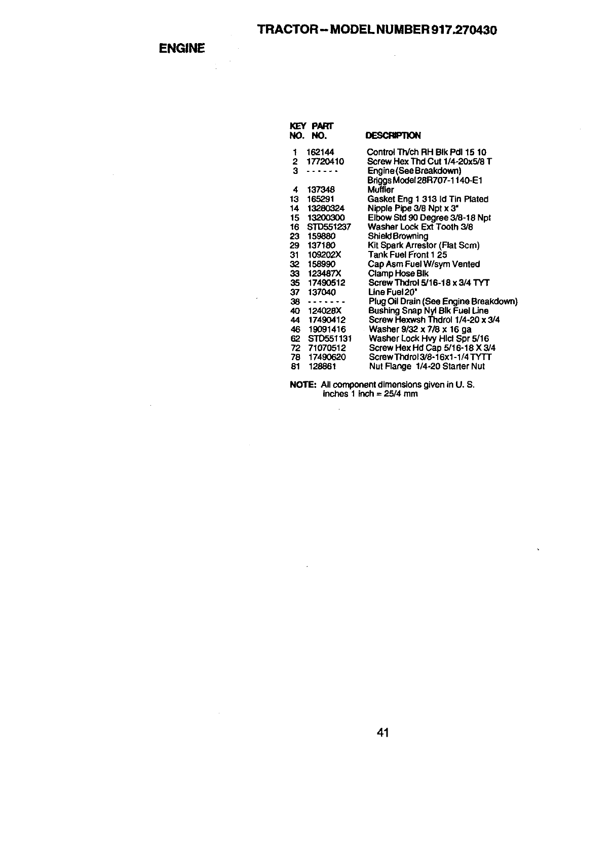
ENGINE
TRACTOR - MODEL NUMBER 917.270430
KEY PN:n"
NO. NO. DESCFIIPTION
1
2
3
162144
17720410
4 137348
13 165291
14 13280324
15 13200300
16 STD551237
23 159880
29 137180
31 1092(_X
32 158990
33 123487X
35 17490512
37 137040
38 .......
4O 124028X
44 17490412
46 19091416
62 STD551131
72 71070512
78 17490620
81 128861
Control Th/ch RH BIk Pd115 10
Screw Hex Thd Cut 1/4-20x5/8 T
Engine (See Breakdown)
BdggsMode128R707-1140.E1
Muffler
Gasket Eng 1 313 Id Tin Plated
Nipple Pipe 3/8 Npt x 3'
Elbow Std90 Degree 3/8-18 Npt
Washer Lock Ext Tooth 3/8
ShieldBrowning
Kit Spark Arrestor (Rat Scm)
Tank Fuel Front I 25
Cap Asm Fuel W/sym Vented
Clamp Hose BIk
Screw Thdrol 5/16-18 x 3/4 TYT
Line Fuel 20'
Plug Oil Drain (See Engine Breakdown)
BushingSnap Nyl BIk Fuel Line
Screw Hexwsh Thdrol 1/4-20 x 3/4
Washer 9/32 x 7/8 x 16 ga
Washer Lock Hvy Hlcl Spr 5/16
Screw Hex Hd Cap 5/16-18 X 3/4
Screw Thdrol3/8-16xl -1/4 TYTT
Nut Range 1/4o20Starter Nut
NOTE: All componentdimensionsgiven in U. S.
inches 1 inch = 25/4 mm
41
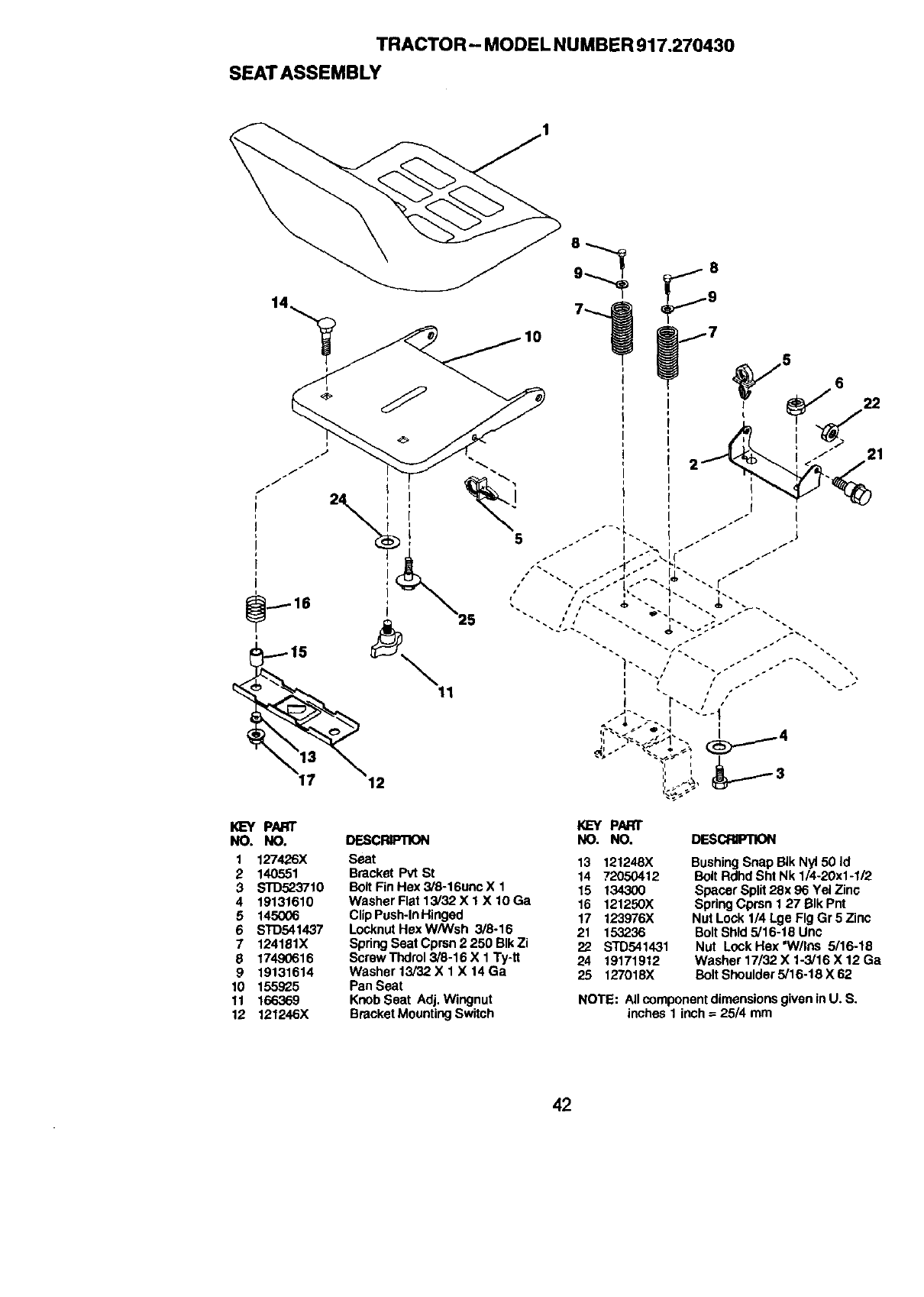
TRACTOR- MODEL NUMBER 917.270430
SEATASSEMBLY
I
5
KIEYPART
NO. NO. DES_
1127426X
2140551
3 STD523710
4 19131610
5 145006
6 S10541437
7 124181X
8 17490616
9 19131614
10 155925
11 166369
12 121246X
Seat
Bracket Pvt St
Bolt Fin Hex 3/6-16unc X 1
Washer Flat 13/32 X 1 X 10 Ga
Clip Push-InHinged
Locknut Hex W/Wsh 3/6-16
Spring Seat Cprsn 2 250 BIk Zi
Screw Thdrol3/8-16 X 1 Ty4t
Washer 13/32 X 1 X 14 Ga
Pan Seat
Knob Seat Adj. Wingnut
Bracket MountingSwitch
I
I
I
I
I
I
I
I<L_t PART
NO. NO. DESCRFIION
13 121248X
14 72050412
15 134300
16 121250X
17 123976X
21 153236
22 STD541431
24 19171912
25 127018X
Bushing Snap SIk Nyl 50 Id
Bolt Rdhd Sht Nk 1/4-20x1-1/2
Spacer Split 28x 96 Yel Zinc
Spring Cprsn 1 27 BIk Pnt
Nut Lock 114Lge Fig Gr 5 Zinc
BoltShld 5/16-18 Unc
Nut Lock Hex "Wiles 5/16-18
Washer 17/32 X 1-3/16 X 12 Ga
Bolt Shoulder 5/16-18 X 62
NOTE: All component dimensions given in U. S.
inches 1 inch = 25/4 mm
42
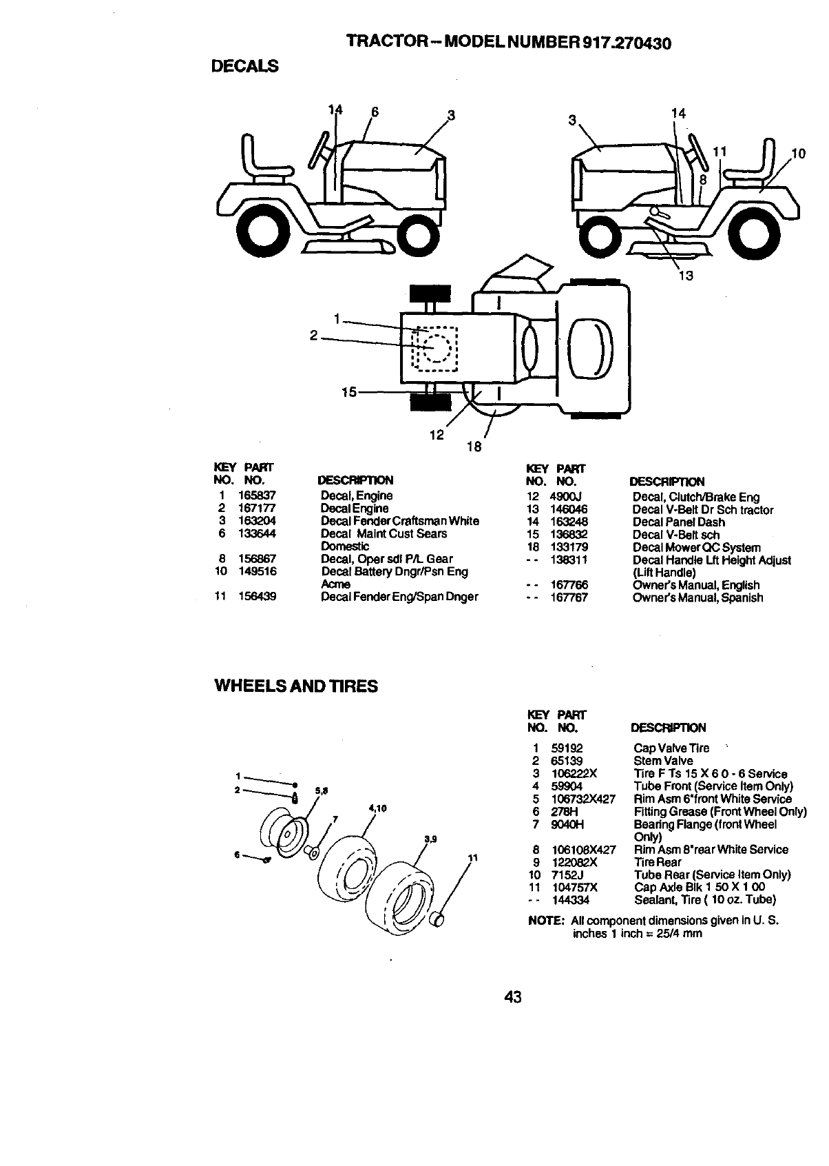
DECALS
TRACTOR- MODEL NUMBER 917.270430
614
11
KEY PART
NO. NO.
1 165837
2 167177
3 1632O4
6 133644
8 156867
10 149516
11 156439
15
12 18
DESCRIPTION
Decal, Engine
Decal Engine
Decal Fender Craftsman White
Decal Maint Cust Sears
Doreeatic
Decal, Oper sdl P/L Gear
Decal Battery DngdPsn Eng
Acme
Decal Fender Eng/Span Dnger
I_EY PART
NO. NO.
12 4900J
13 146046
14 163248
15 136832
18 133179
--138311
- - 167766
- - 167767
13
DESCRIPTION
Decal, Clutch/Brake Eng
Decal V-Belt Dr Sch tractor
Decal Panel Dash
Decal V-Beit sch
Decal MowerQC System
Decal Handle Lft HeightAdjust
(LiftHandle)
Owner's Manual, English
Owner's Manual,Spanish
WHEELSAND_RES
4,10
7
11
KEY PART
NO. NO. DESCRIPTION
1
2
3
4
5
6
7
59192
65139
106222X
599O4
106732X427
2781-1
9040H
8 106108X427
9 1082
10 7152J
11 104757)(
-- 144334
Cap Valve Tire
Stem Valve
Tire FTs 15 X 6 0 - 6 Service
Tube Front (Service Item Only)
Rim Asm 6"frentWhite Service
FittingGrease (FrontWheel Only)
BearingFlange(frontWheel
Only)
Rim Asm 8"rearWhite Service
Tire Rear
Tube Rear (Sen,ice Item Only)
Cap Axle BIk 1 50 X 1 (30
Sealant, Tire ( 10 oz. Tube)
NOTE: Allcomponent dimensionsgiven inU. S.
inches 1 inch = 25/4 mm
43
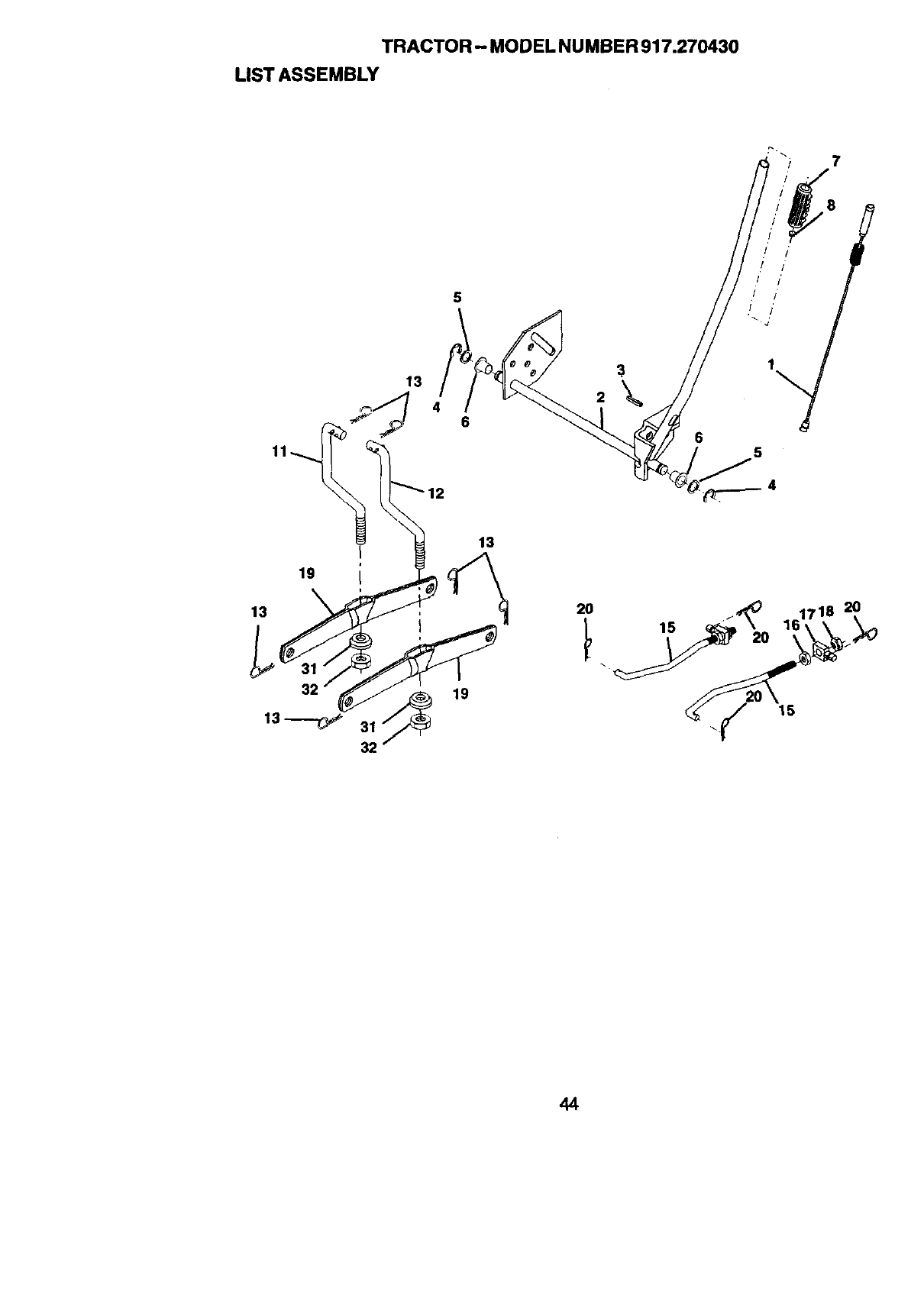
TRACTOR - MODEL NUMBER917.270430
LIST ASSEMBLY
7
11
6
2
8
t /"
!
Ir/'
/ /
65
19
13
13_ 31_
32
13
19 15
20
44
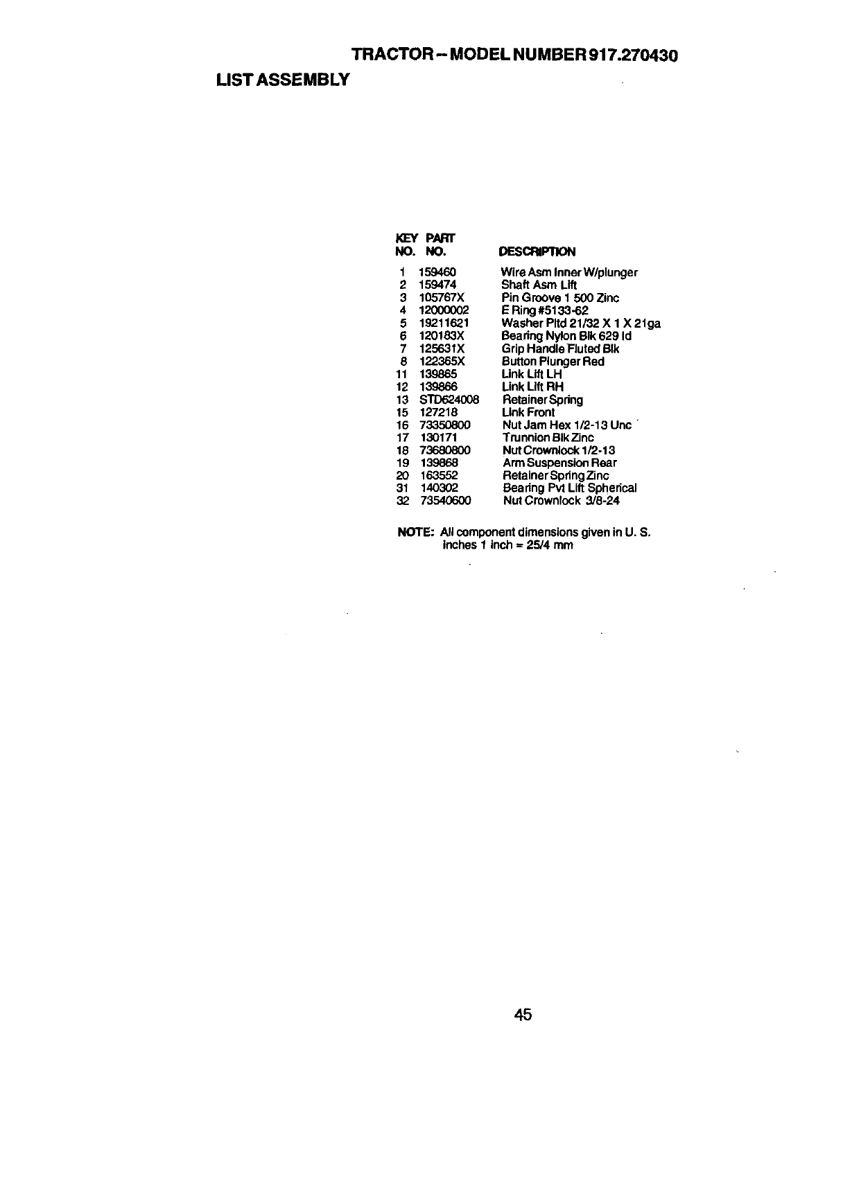
TRACTOR - MODEL NUMBER 917.270430
LIST ASSEMBLY
KL=Y pARr
NO. NO. DESCRIPTION
1 159460 Wire Asm Inner W/plunger
2159474 Shaft Asm Lift
3 105767X Pin Groove 1 500 Zinc
4 12000002 ERing#5133-62
5 19211621 Washer Pltd 21/32 X 1 X 21ga
6 120183X Bearing Nylon BIk 629 Id
7 125631X Grip Handle Fluted BIk
8 122365X Button Plunger Red
11 139865 Link Lift LH
12 139866 Link Lift RH
13 STD624008 RetainerSpring
15 127218 Link Front
16 7_ Nut Jam Hex 1/2-13 Unc '
17 130171 Trunnion BIkZinc
18 73680800 Nut Crownlock1/2.13
19 139868 ArmSuspension Rear
20 1635,52 Retainer SpringZinc
31 140302 Bearing Pvt Lift Spherical
32 73540600 NutCmwnlock 3/8-24
NOTE: All componentdimensions given in U. S.
inches 1 inch = 25/4 mm
45
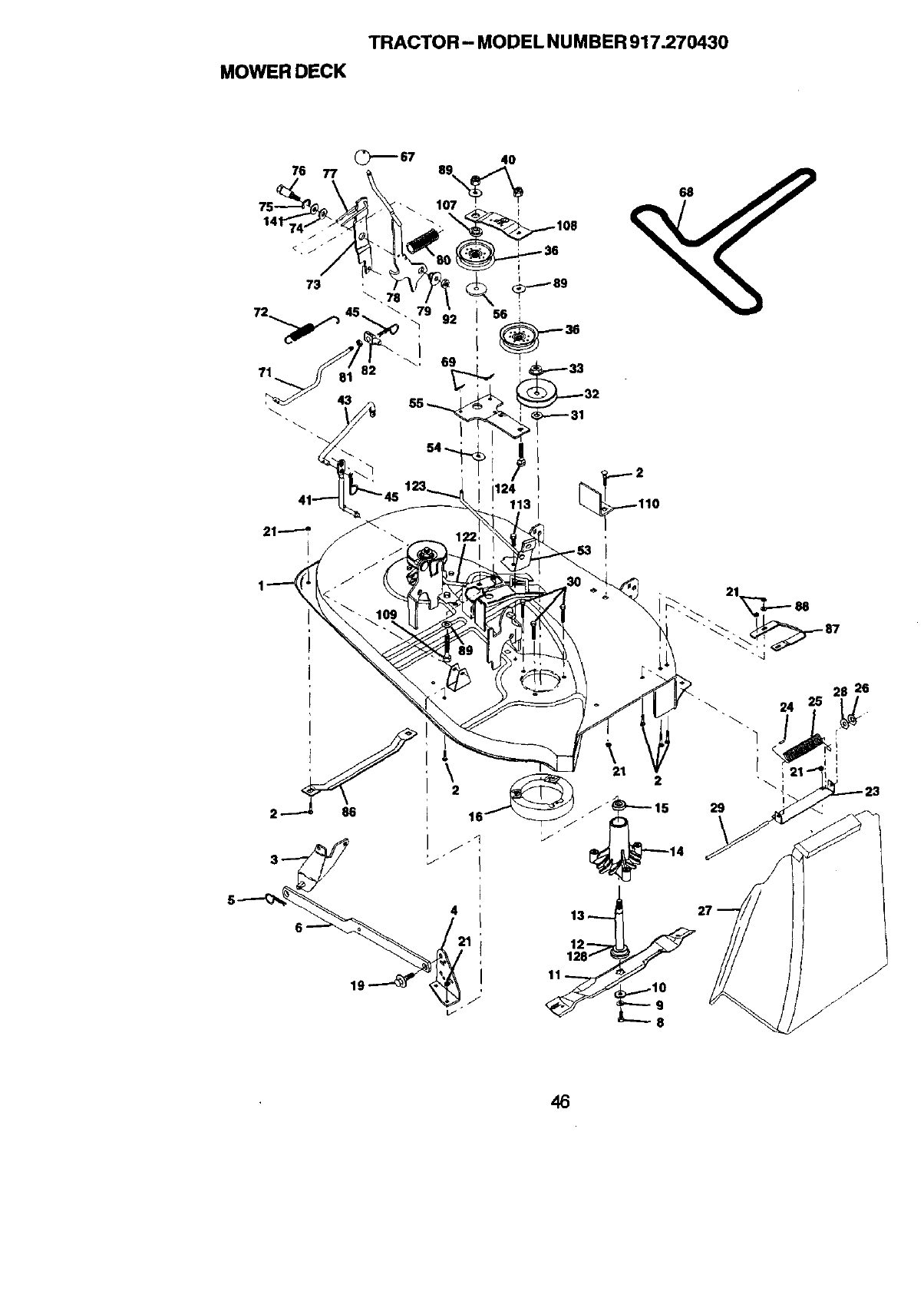
TRACTOR - MODEL NUMBER 917.270430
MOWERDECK
76 77
73
69
71
41-_ _'45 12
\2
4
19
46
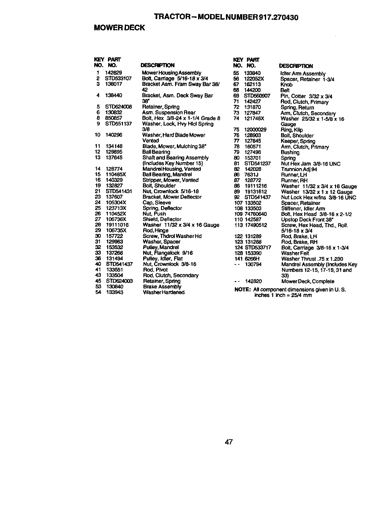
TRACTOR - MODEL NUMBER 917.270430
MOWER DECK
KEY PARr _ PAre"
NO. NO, DESCRIPTION NO. NO,
1 142829 MowerHousingAssembly 55 133840
2 S'rD533107 Bolt, Carriage 9/16-18x3/4 56 122052X
3 138017 BrscketAsm. FmmSwayBar39/ 67 162113
42 68 144200
4 138440 Bracket, Asm. Deck Sway Bar 69 _7
38" 71 142427
5 STD624008 Retainer, Spring 72 131870
6 130832 Asm. Suspension Reef 73 127847
8 850857 Bolt, Hex 3/8-24 x 1-1/4 Grade 6 74 121748X
9 STD551137 Washer, Lock, Hvy Hlcl Spdng
3/8 75 12000029
10 140296 Washer, HardBladeMower 76 128903
Vented 77 127845
11 134148 Blade, Mower, Mulching38" 78 160571
12 129895 BallBeedng 79 127498
13 137645 Shaft and Beadng Assembly 80 153701
(Includes Key Number 15) 81 STD541237
14 128774 MandrelHouslng, Vented 8_ 142028
15 110485X BallBeadng, Mandrel 86 7631J
16 140329 Stripper, Mower, Vented 87 129772
19 132827 Bolt, Shoulder 88 19111216
21 STD541431 Nut, Crowntock 6/16-18 89 19131612
23 137607 Bracket, Mower Deflector _BTD541437
24 105304X Cap, Sleeve 107 133502
25 123713X Spdng, Deflector 108 133503
26 110452X Nut, Push 109 74760640
27 106736X Shield, Deflector 110 142587
28 19111016 Washer 11/32 x 3/4 x16 Gauge 113 17490512
29 106735X Rod,Hinge
30 157722 Screw, ThdrolWashorHd 122 131289
31 129963 Washer, Spacer 123 131288
32 153532 PuUey,Mandrel 124 S'R)533717
33 137266 Nut, Flangelock 9/16 128 153390
36 131494 Pulley, Idler, Flat 141 6266H
40 STD541437 Nut, Crownlock 3/8-16 -- 130794
41 133551 Rod, Pivot
43 133504 Rod,Clutch, Secondary
45 STD624003 Retainer,Spdng -- 142820
53 130840 Brake Assembly
54 133943 Washer Hardened
DESCRIPTION
Idler ArmAssembly
Spacer, Retainer 1-3/4
Knob
Belt
Pin, Cotter 3/32 x 3/4
ROd,Clutch,Pdmary
Spdng, Return
Arm, Clutch, Secondary
Washer 25/32 x 1-5/8 x 16
Gauge
Ring,Klip
Bolt,Shoulder
Keeper, Spdng
Arm, Clutch, Pdmary
Bushing
Spring
Nut Hex Jam 3/8-16 UNC
Trunnion Adj 94
Runner,U-I
Runner,RH
Washer 11/32 x 3/4 x 16 Gauge
Washer 13/32 x 1 x 12 Gauge
Nut Lock Hex w/Ins 3/8-16 UNC
Spacer,Retainer
Stiffener, IdlerArm
Bolt,Hsx Head 3/8-16 x 2.1/2
Upstop Deck Front38"
Screw, Hex Head, Thd., Roll.
5/16-18 x 3/4
ROd,Brake, LH
Rod, Brake, RH
Bolt,Carriage 3/8-16 x %3/4
Washer Felt
Washer Thrust .75 x 1.230
Mandrel Assembly(Includes Key
Numbers 12-15, 17-19, 31 and
33)
Mower Beck, Complete
NOTE: Allcomponent dimensionsgiven in U. S.
inches 1 inch = 25/4 mm
47
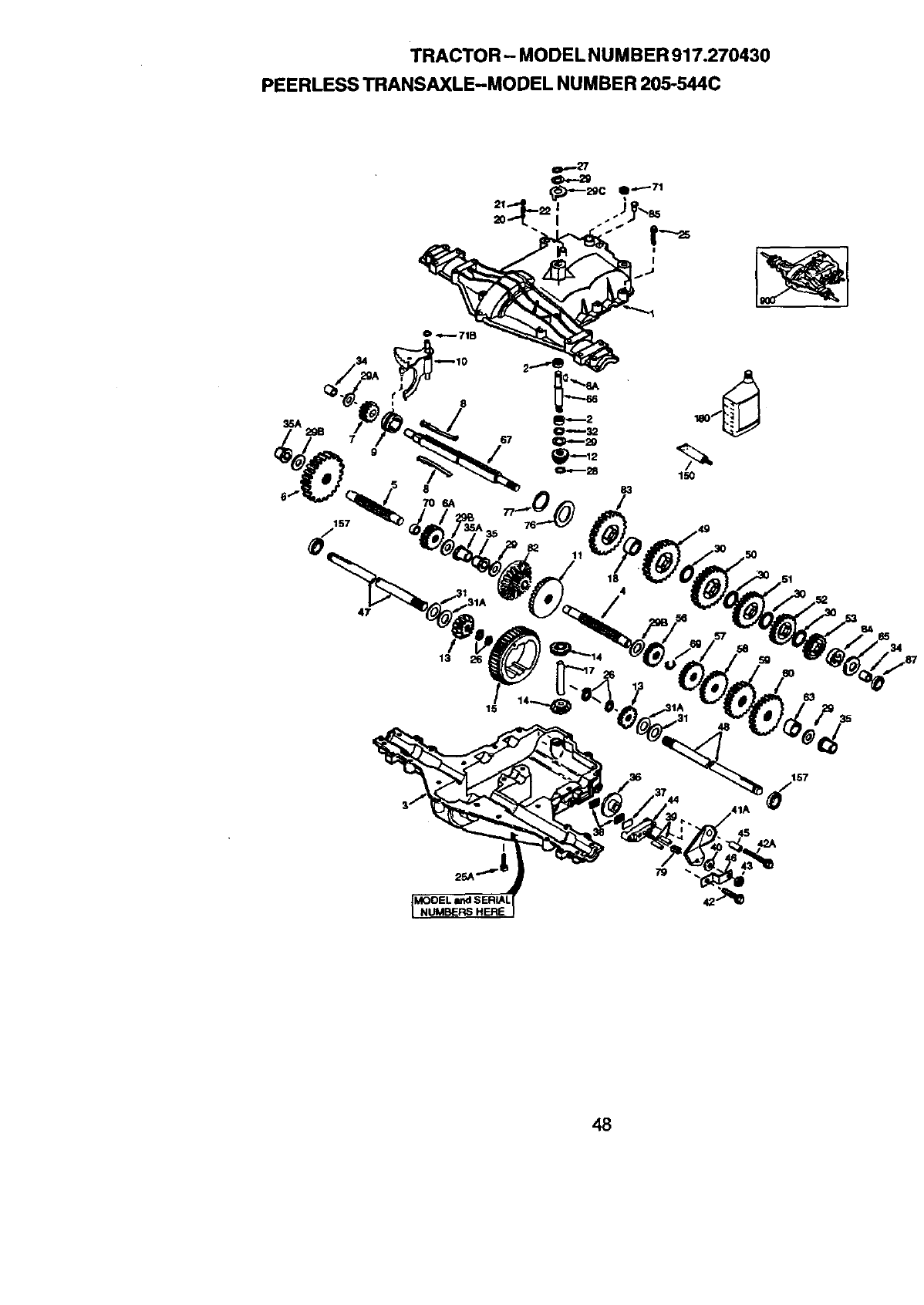
TRACTOR - MODEL NUMBER 917.270430
PEERLESS TRANSAXLE-MODEL NUMBER 205-544C
I
0_71B
47
13
11
I
79
42
48
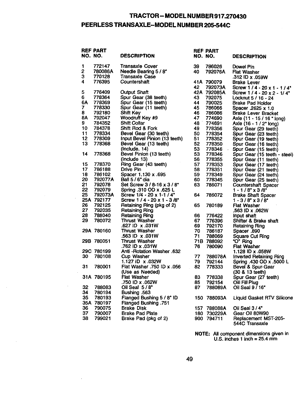
TRACTOR- MODEL NU MBER 917.270430
PEERLESS TRANSAXLE-MODEL NUMBER 205-544C
REF PART REF PART
NO. NO. DESCRIPTION NO. NO.
1 772147 Transaxle Cover 39 786026
2 780086A Needle Bearing 5 /8' 40 792076A
3 770128 Transaxle Case
4 776395 Countershaft 41A 790079
42 792073A
5 776409 Output Shaft 42A 792085A
6 778364 Spur Gear (38 teeth) 43 792075
6A 778369 Spur Gear (15 teeth) 44 790025
7 778330 Spur Gear (11 teeth) 45 786066
8 792180 Shift Key 46 786086
8A 792047 Woodruff Key #9 47 774690
9 784352 Shift Collar 48 774691
10 784378 Shift Red & Fork 49 778356
11 778334 Bevel Gear (30 teeth) 50 778354
12 778309 Input Bevel Pinion (13 teeth) 51 778352
13 778368 Bevel Gear (13 teeth) 52 778350
(Include. 14) 53 778346
14 778368 Bevel Pinion (13 teeth) 53 778346
(include 13) 56 778355
15 778370 Ring Gear (43 teeth) 57 778353
17 786188 Drive Pin 58 778351
18 786102 Spacer 1.130 x .695 59 778349
20 792077A Ball 5 /6" dia 60 778345
21 792078 Set Screw 3 /8-16 x 3 /8" 63 786071
22 792079 Spring .310 OD x .625 L
25 792073A Screw 1/4 -20 x 1-1 /4" 64 786072
25A 792177 Screw 1/4- 20 x 1 -3/8"
26 792125 Retaining Ring (pkg of 2) 65 780189
27 792035 Retaining Ring
28 788040 Retaining Ring 66 776422
29 780072 Thrust Washer 67 776396
.627 ID x .031W 69 792170
29A 780160 Thrust Washer 70 786187
.563 ID x .031W 71 788069
29B 780051 Thrust Washer 71B 788092
.762 ID x ,031W 76 780090
29C 780199 Anti -Rotation Washer .632
30 780108 Cup Washer 77 788078A
1.127 ID x .032W 79 792144
31 780001 Flat Washer .750 ID x .056 82 778333
(Usa as Needed)
31A 780195 Flat Washer 83 778338
.750 ID x .062W 85 792154
32 788083 Oil Seal 5 /8" 87 788089A
34 780194 Bushing ,563
35 780193 Flanged Bushing 5 /8" ID 150 788093A
35A 780197 Flanged Bushing .751
36 790075 Brake Disk 157 788088A
37 790007 Brake Pad Plate 180 730229A
38 799021 Brake Pad (pkg of 2) 900 794711
DESCRIPTION
Dowel Pin
Rat Washer
.312 ID x .059W
Brake Lever
Screw I/4-20 x 1 -1/4 =
Screw 1/4- 20 x2- 1/4"
Locknut 5 /16 -24
Brake Pad Holder
Spacer .2625 x 1.0
Brake Lever Bracket
Axle (11 - 15 /16 =long)
Axle (16 - 1/2" long)
Spur Gear (29 teeth)
Spur Gear (23 teeth)
Spur Gear (19 teeth)
Spur Gear (16 teeth)
Spur Gear (15 teeth)
Spur Gear (15 teeth - steel)
Spur Gear (11 teeth)
Spur Gear (17 teeth)
Spur Gear (21 teeth)
Spur Gear (24 teeth)
Spur Gear (25 teeth)
Countershaft Spacer
1 - 1/8"x3/8"
Brake Shaft Spacer
1 -3/8"x3/8'
Flat Washer
.563 ID x .062W
Input shaft
Shifter & Brake shaft
Retaining Ring
Spacer .890
Square CUt Ring
"O_ Ring
Flat Washer
1.128 ID x .058W
Inverted Retaining Ring
Spring .430 OD x .5000 L
Bevel & Spur,Gear
(30 & 13 teeth)
Spur Gear (27 teeth)
OUlFillPlug
Oil Seal 9 /16"
Liquid Gasket RTV Silicone
Oil Seal 3 /4"
Gear Oil 80W90
Replacement MST-205-
544C Transaxle
NOTE: All component dimensions given in
U.S. inches 1 inch -- 25.4 mm
49
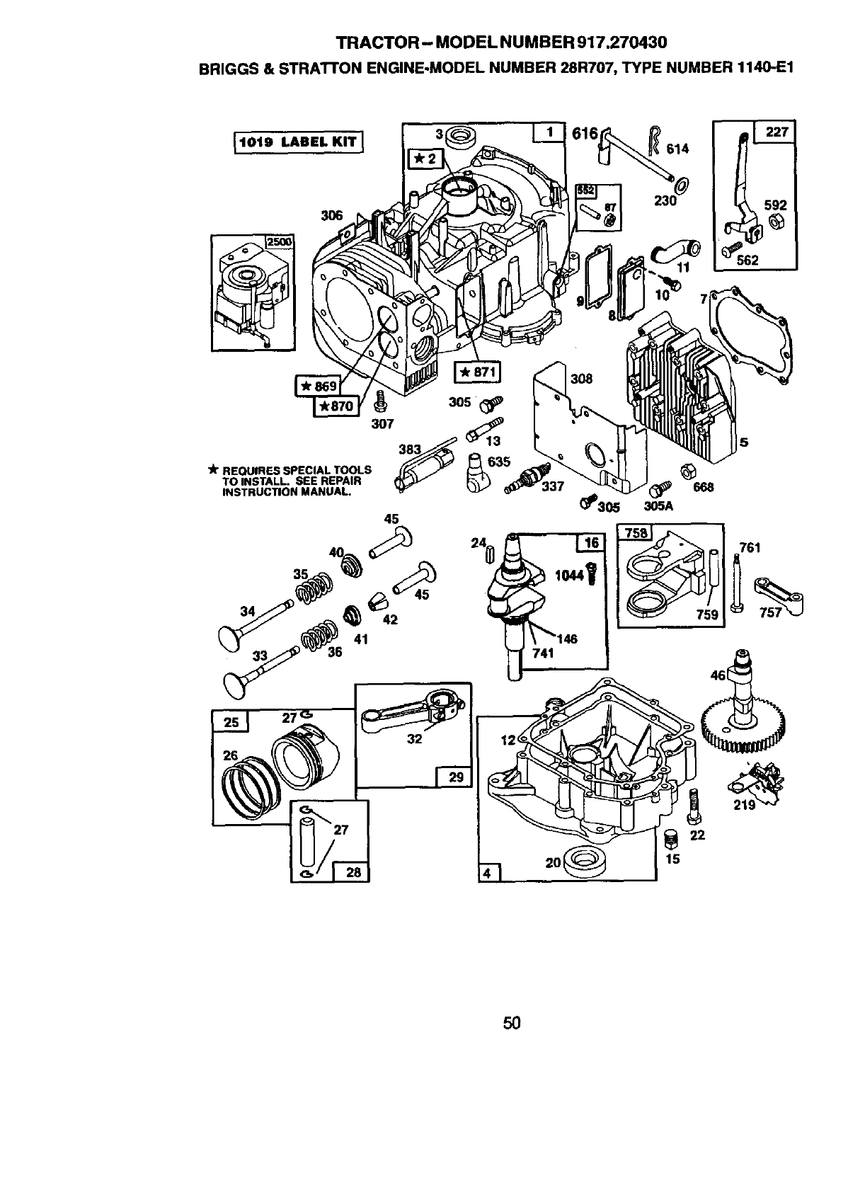
TRACTOR - MODEL NU MBER 917.270430
BRIGGS & STRAI"rON ENGINE.MODEL NUMBER 28R707, TYPE NUMBER 1140-E1
1019 LABEL KIT I
3O6
_562
"_ REQUIRES SPECIAL TOOLS _'_
TO INSTALL. SEE REPAIR
INSTRUCTION MANUAL.
22
15
5O
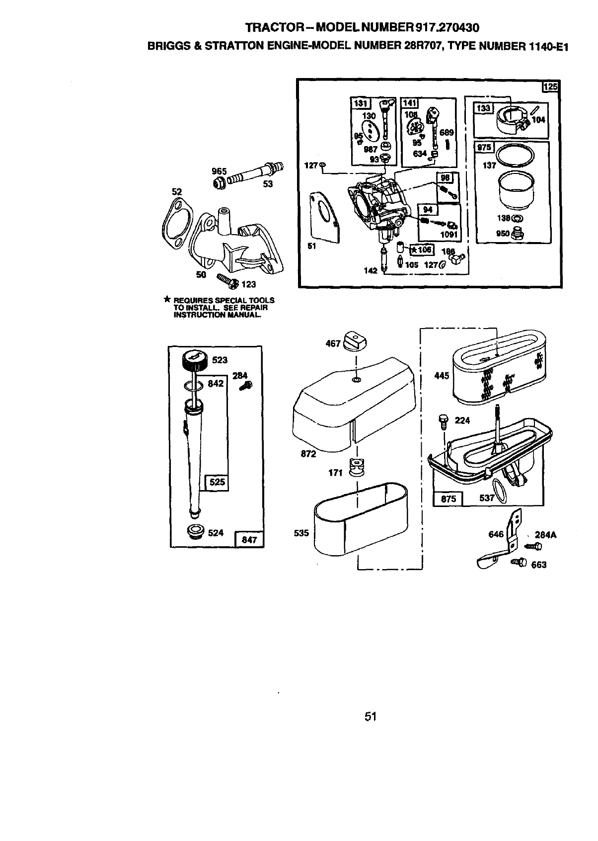
TRACTOR - MODEL NU MBER 917.270430
BRIGGS & STRATrON ENGINE-MODEL NUMBER 28R707, TYPE NUMBER 1140-E1
52
50 _123
lk REQUIRES SPECIAL TOOLS
TO INSTALL. SEE REPAIR
INSTRUCTION MANUAL.
105
51
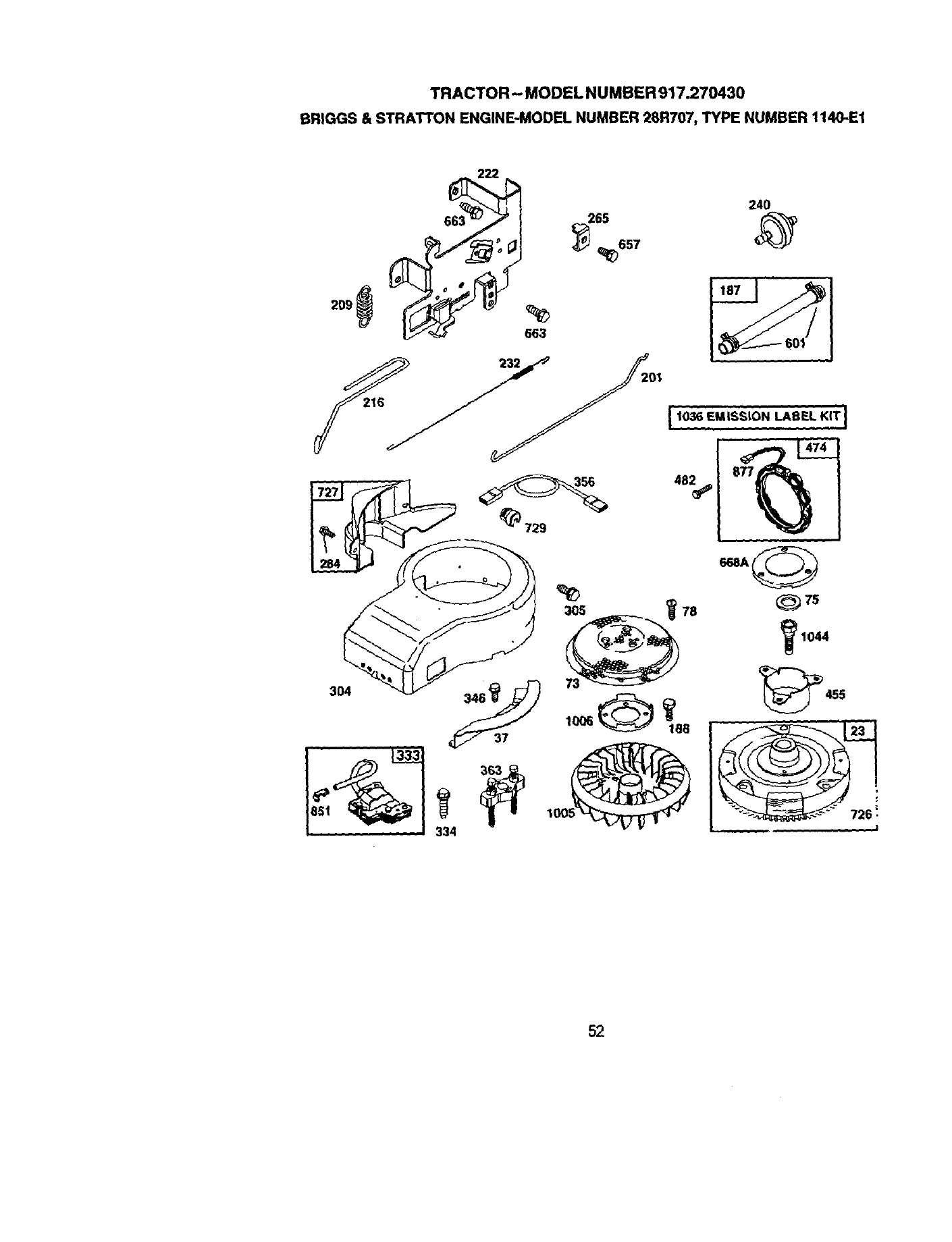
TRACTOR- MODEL NUMBER 917.270430
BRIGGS & STRATTON ENGINE-MODEL NUMBER 28R707, TYPE NUMBER 1140-E1
24O
265
2o9 _l_
663
i. 1036 EMISSLON_,_________________i216 _ /-/-
52
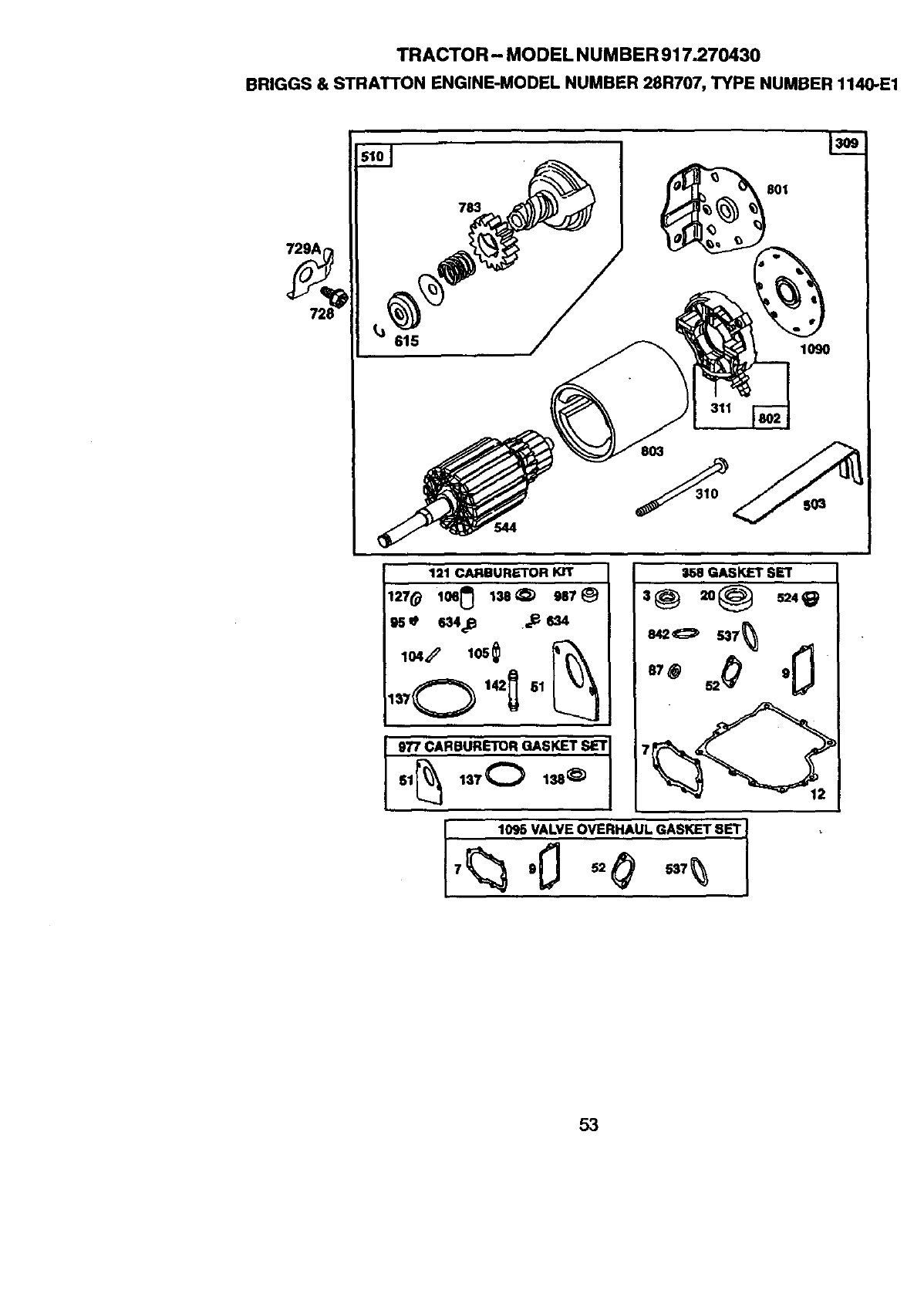
TRACTOR- MODEL NUMBER 917.270430
BRIGGS & STRATTON ENGINE-MODEL NUMBER 28R707, TYPE NUMBER 1140-E1
615
783
803
l.P_
801
1090
121 CARBUR_'OR KIT
127(_ lo6_ l=e_ 9u _)
104_ 105_
1_J7O142_ 61
S58GASKET SET
8420 537_
9"/7 CARBURETOR GASKET SET
1095 VALVE OVERHAUL GASKET SET I
53
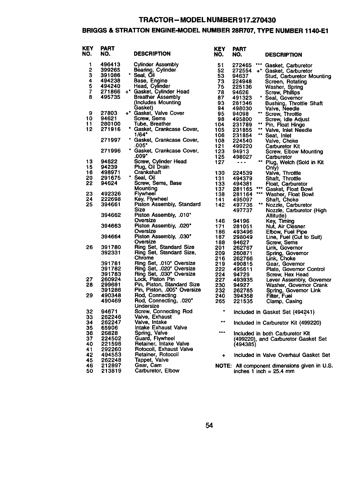
TRACTOR -MODEL NU MBER 917.270430
BRIGGS & STRATTON ENGINE-MODEL NUMBER 28R707, TYPE NUMBER 1140-E1
KEY PART KEY PART
NO. NO. DESCRIPTION NO. NO. DESCRIPTION
1
2
3
4
5
7
8
9
10
11
12
13
15
16
20
22
23
24
25
26
27
28
29
32
33
34
35
36
37
4O
41
42
45
46
5O
496413 Cylinder Assembly 51 272465 *'* Gasket, Carburetor
399265 Bearing, Cylinder 52 272554 +* Gasket, Carburetor
391086 ° Seal, Oil 53 94637 Stud, Carburetor Mounting
494238 Base, Engine 73 224948 Screen, Rotating
494240 Head, Cylinder 75 225136 Washer, Spdng
271866 +* Gasket, Cylinder Head 78 94626 Screw, Phillips
495735 Breather Assembly 87 491323 * Seal, Governor
_ncludes Mounting 93 281346 Bushing, Throttle Shaft
asket) 94 498030 Valve, Needle
27803 +* Gasket, Valve Cover 95 94098 ** Screw, Throttle
94621 Screw, Seres 98 495800 Screw, Idle Adjust
280100 Tube, Breather 104 231789 ** Pin, Float Hinge
271916 * Gasket, Crankcase Cover, 105 231855 °* Valve, Inlet Needle
1/64" 106 231854 *° Seat, Inlet
271997 * Gasket, Crankcase Cover, 108 224540 Valve, Choke
.005" 121 499220 Carburetor Kit
271996 * Gasket, Crankcase Cover, 123 94913 Screw, Elbow Mounting
.009" 125 498027 Carburetor
94622 Screw, Cylinder Head 127 - - - ** Plug, Welch (Sold in Kit
94239 Plug, Oil Drain Only)
498971 Crankshaft 130 224539 Valve, Throttle
291675 * Seal, Oil 131 494379 Shaft, Throttle
94624 Screw, Sems, Base 133 494381 Float, Carburetor
Mounting 137 281165 *** Gasket, Float Bowl
492326 Flywheel 138 281164 *** Washer, Float Bowl
222698 Key, Flywheel 141 495097 Shaft, Choke
394661 Piston Assembly, Standard 142 497736 *° Nozzle, Carburetor
Size 497737 Nozzle, Carburetor (High
394662 Piston Assembly, .010" Altitude)
Oversize 146 94196 Key, Timing
394663 Piston Assembly, .020" 171 281051 Nut, Air Cleaner
Oversize 186 493496 Elbow, Fuel Pipe
394664 Piston Assembly, .030" 187 298049 Line, Fuel (Cut to Suit)
Oversize 188 94627 Screw, Sems
391780 Ring Set, Standard Size 201 262767 Link, Governor
392331 Ring Sot, Standard Size, 209 260871 .S.pdng, Govemor
Chrome 216 262766 Link, Choke
391781 Ring Set, .010" Oversize 219 490815 Gear, Governor
391782 Ring Set, .020" Oversize 222 495611 Plate, Governor Control
391783 Ring Set, .030" Oversize 224 94729 Screw, Hex Head
260924 Lock, Piston Pin 227 493935 Lever Assembly, Govemor
299691 Pin, Piston, Standard Size 230 94927 Washer, Govemor Crank
391286 Pin, Piston, .005" Oversize 232 262785 Spring, Governor Link
490348 Rod, Connecting 240 394358 Filter, Fuel
490469 Rod, Connecting, .020" 265 221535 Clamp, Casing
Undersize
94671 Screw, Connecting Rod included in Gasket Set (494241)
262246 Valve, Exhaust
262247 Valve, Intake ** Included in Carburetor Kit (499220)
65906 Intake Exhaust Valve
26828 Spring, Valve *** Included in both Carburetor Kit
224502 Guard, Flywheel (499220), and Carburetor Gasket Set
221596 Retainer, Intake Valve (494385)
292260 Rotocoil, Exhaust Valve
494553 Retainer, Rotocoil + Included in Valve Overhaul Gasket Set
262248 Tappet, Valve
212897 Gear, Cam NOTE: All component dimensions given in U.S.
213819 Carburetor, Elbow inches 1 inch = 25.4 mm
54
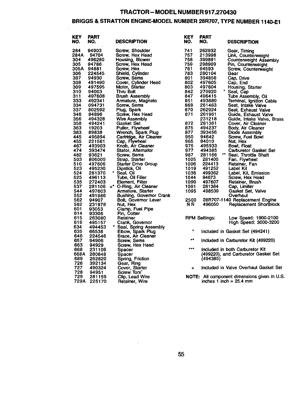
TRACTOR- MODEL NUMBER 917.270430
BRIGGS & STRATTON ENGINE-MODEL NUMBER 28R707, TYPE NUMBER 1140-E1
KEY PART KEY PART
NO. NO. DESCRIPTION NO. NO. DESCRIPTION
284 94903" Screw, Shoulder 741 262932 Gear, Timing
284A 94704 Screw, Hex Head 757 213998 Link, Counterweight
304 496290 Housing, Blower 758 399891 CounterweightAssembly
305 94786 Screw, Hex Head 759 298909 Pin, Counterweight
305A 94881 Screw, Hex 761 94593 Screw, Counterweight
306 224545 Shield, Cylinder 783 280104 Gear
307 94930 Screw, Sems 801 394856 Cap, Dnve
308 491490 Cover, Cylinder Head 802 497605 Cap, End
309 497595 Motor, Starter 803 497604 Housing, Starter
310 94003 Thru Bolt 842 270920 * Seal, Cap
311 497608 Brush Assembly 847 496415 Tube Assembly, Oil
333 492341 Armature, Magneto 851 493880 Terminal, IgnitionCable
334 094731 Screw, Serns 869 261463 Seat, Intake Valve
337 802592 Plug, Spark 870 262924 Seat, Exhaust Valve
346 94896 Screw, Hex Head 871 261961 Guide, Exhaust Valve
356 494328 Wire Assembly 231218 Guide, Intake Valve, Brass
358 494241 Gasket Set 872 281361 Cover, Air Cleaner
363 19203 Puller, Flywheel 875 494237 Body,Air Cleaner
383 89838 Wrench, Spark Plug 877 393456 Diode Assembly
445 496894 Cartridge, Air Cleaner 950 94642 Screw, Fuel Bowl
455 221561 Cap, Flywheel 965 94010 Nut, Hex
467 493903 Knob, Air Cleaner 975 495933 Bowl, Float
474 393474 Stator, Alternator 977 494385 CarburetorGasket Set
482 93621 Screw, Sems 987 281166 ** Seal, Throttle Shaft
503 806000 Strap, Starter 1005 281400 Fan, Flywheel
510 497606 Starter Drive Group 1006 224413 Retainer, Fan
523 495230 Dipstick,Oil 1019 491252 Label Kit
524 281370 * Seal, Oil 1036 499362 Label, Kit, Emission
525 496113 Tube, Oil Filler 1044 94673 Screw, Hex Head
535 272403 Element, Filter 1090 497607 Retainer, Brush
537 281106 +* O-Ring, Air Cleaner 1091 281364 Cap, Umiter
544 497603 Armature, Starter 1095 498539 Gasket Set, Valve
552 491986 Bushing, Govemor Crank Overhaul
562 94907 Bolt, Governor Lever 2500 28R707-1140 Replacement Engine
592 231978 Nut, Hex I_1N 496050 Replacement Shortblock
601 93053 Clamp, Fuel Pipe
614 93306 Pin, Cotter
615 263080 Retainer RPM Settings: Low Speed: 1900-2100
616 495157 Crank, Governor High Speed: 3000-3200
634 494453 "Seal, Spring Assembly
635 66538 Elbow, Spark Plug Included in Gasket Set (494241)
646 224546 Brace, Air Cleaner
657 94906 Screw, Sems ** Included in Carburetor Kit (499220)
663 94929 Screw, Hex Head
668 231109 Spacer *** Includedin both Carburetor Kit
669A 280848 Spacer (499220), and Carburetor Gasket Set
689 262820 Spdng, Friction (494385)
726 392134 Gear, Ring
727 490324 Cover, Starter + Includedin Valve Overhaul Gasket Set
728 94951 Screw.Torx-
729 281159 Clip, Lead Wire NOTE: All componentdimensionsgiven in U.S.
729A 225170 Retainer, Wire inches 1 inch = 25.4 mm
55

56

57

.R8

SUGGESTED GUIDE FOR SIGHTING SLOPES FOR SAFE OPERATION
_1 _ _
SIGHTING
GUIDE
ONLY RIDE UP AND DOWN HILL,
NOT ACROSS HILL
SIGHT AND HOLD THIS LEVEL WITH
SKY LINE OR TREE.
!
Operate your Tractor up and down the face of elopes (not
greater than 15°), never across the face. Make turns gradu- I
ally to prevent tipplng or loss of control. Exercise extreme
caution when changing direction on slopes.

For in-home major brand repair service:
Call 24 hours a day, 7 days a week
1-800-4-MY-HOME" (1-800-469-4663)
Para pedir servicio de reparacibn a domicilio
1-800-676-5811
In Canada for all your service and parts needs call
Au Canada pour tout le service ou les pi_ces
1-600-665-4455
For the repair or replacement parts you need:
Call 6 am - 11 pm CST, 7 days a week
PartsDirect s"
1-800-366-PART (1-800-366-7278)
Para ordenar piezas con entrega a domicilio
1-800-659-7084
For the location of a Sears Parts and Repair Center
in your area:
Call 24 hours a day, 7 days a week
1-800-488-1222
For information on purchasing a Sears Maintenance
Agreement or to inquire about an existing Agreement:
Call 9 am -5 pm, Monday -Saturday
1-800-827-6655
167766 Rev. 1
SEARS
HomeCentral s°
5.17.99 TR Printed in U.S.A.
