Craftsman 917270662 User Manual TRACTOR Manuals And Guides L0904359
CRAFTSMAN Lawn, Tractor Manual L0904359 CRAFTSMAN Lawn, Tractor Owner's Manual, CRAFTSMAN Lawn, Tractor installation guides
User Manual: Craftsman 917270662 917270662 CRAFTSMAN TRACTOR - Manuals and Guides View the owners manual for your CRAFTSMAN TRACTOR #917270662. Home:Lawn & Garden Parts:Craftsman Parts:Craftsman TRACTOR Manual
Open the PDF directly: View PDF ![]() .
.
Page Count: 60

Owner's Manual
15.5 HP
ELECTRIC START
42" MOWER
AUTOMATIC
LAW
Model No.
917.270662
TRACTO
•Safety
oAssembly
oOperation
•Maintenance
° Repair Parts
CAUTION:
Read and follow all Safety
Rules and Instructions before
operating this equipment.
For answers to your questions
about this product, Call:
t-800-659=5917
Sears Craftsman Help Line
5 am _5 pm, Mon -Sat
Sears, Roebuck and Co., Hoffman Estates, il 60179
Visit our Craftsman website:www.sears.com/craftsman
Warranty...............................................2
Safety Rules.........................................3
ProductSpecifications............................6
Assembly.....................................................8
Operation...............................................1I
MaintenanceSchedule......................18
Maintenance.......................................18
Serviceand Adjustments.....................22
Storage ................................................28
Troubleshooting.................................29
RepairParts.........................................34
PartsOrdering...........................BackCover
LIMITEDTWOYEARWARRANTYONCRAFTSMANRIDINGEQUIPMENTPARTS
For two (2)yearsfrom thedate of purchase,if thisCraftsmanRidingEquipmentis
maintained,lubricatedand tuned upaccordingto the instructionsin the owner's
manual,Searswill repairor replace,freeof charge,any partsfoundto bedefectivein
materialor workmanship.Warrantyserviceis availablefree of chargebytaking your
Craftsmanridingequipmentto your nearestSearsServiceCenter. In-homewarranty
serviceis availablebuta trip chargewi!lapply,This warrantyappliesonlywhile this
productis inthe UnitedStates.
This Warrantydoesnot cover:
o Expendableitemswhichbecomeworn duringnormaluse,suchas blades,spark
plugs,air cleaners,beltsand oil filters°
• Tire replacementor repaircausedby puncturesfrom outsideobjects,suchas nails,
thorns,stumps,or glass°
o Repairsnecessarybecauseof operatorabuse,includingbut not limitedto, damage
causedby towingobjectsbeyondthe capabilityof the ridingequipment,impacting
objectsthat bendtheframeor crankshaft,or over speedingthe engine.
° Repairsnecessarybecauseof operatornegligence,includingbut not limitedto,
electricaland mechanicaldamagecausedby improperstorage,failureto use the
propergradeand amountof engineoil, failureto keep the deckclear of flammable
debris,or the failureto maintainthe equipmentaccordingto the instructions
containedin the owner's manual°
° Engine(fuelsystem)cleaningor repairscausedbyfuel determinedto be contami-
natedor oxidized(stale).In general,fuelshouldbe usedwithinthirty (30)daysof its
purchasedate.
o Ridingequipmentusedfor commercialor rentalpurposes.
LIMITED90DAYWARRANTYON BATTERY
For ninety(90)daysfrom dateof purchase,if anybatteryincludedwiththis riding
equipmentprovesdefectivein materialor workmanshipand ourtestingdetermines
the batterywiltnot holda charge,Searswill replacethe batteryat no charge.War-
rantyserviceis availablefree of chargebytakingyour Craftsmanridingequipmentto
your nearestSearsSen,iceCenter. In-homewarrantyserviceis availablebuta trip
chargewill apply.Thiswarrantyappliesonly whilethis productis in the UnitedStates.
TO LOCATETHENEARESTSEARSSERVICECENTERORTOSCHEDULEIN-
HOMEWARRANTYSERVICE,SIMPLYCONTACTSEARSAT 1-800..4-MY-HOME
This Warrantygivesyou specificlegalrights,and you mayalso have otherrights
whichmayvaryfromstateto state°
Sears,Roebuckand Co. D/817WA,HoffmanEstates,IL 60179
2

IMPORTANT: This cutting machine is capable of amputating hands and feet and
throwing objects. Failure to observe the following safety instructions could result in
serious injury or death.
I, GENERAL OPERATION
o Read, understand, and follow all
instructions in the manual and on the
machine before starting.
o Only allow responsible adults, who are
familiar with the instructions, to operate
the machine.
o Clear the area of objects such as
rocks, toys, wire, etc., which could be
picked up and thrown by the blade°
° Be sure the area is clear of other
people before mowing. Stop machine
if anyone enters the area.
° Never carry passengers.
, Do not mow in reverse unless abso-
lutely necessary. Always look down
and behind before and while backing.
° Be aware of the mower discharge
direction and do not point it at anyone°
Do not operate the mower without
either the entire grass catcher or the
guard in place.
° Slow down before turning.
° Never leave a running machine
unattended. Always turn off blades, set
parking brake, stop engine, and
remove keys before dismounting.
o Turn off blades when not mowing.
° Stop engine before removing grass
catcher or unclogging chute°
o Mow only in daylight or good artificial
light.
o Do not operate the machine while
under the influence of alcohol or drugs.
° Watch for traffic when operating near or
crossing roadways.
o Use extra care when loading or
unloading the machine into a trailer or
trucL
o Data indicates that operators, age 60
years and above, are involved in a
large percentage of riding mower-
related injuries. These operators
should evaluate their ability to operate
the riding mower safely enough to
protect themselves and others from
serious injury.
II. SLOPE OPERATION
Slopes are a major factor related to loss-of-
control and tipover accidents, which can
result in severe injury or death. All slopes
require extra caution. If you cannot back up
the slope or if you feel uneasy on it, do not
mow iL
DO:
o Mow up and down slopes, not across,
• Remove obstacles such as rocks, tree
limbs, etCo
• Watch for holes, ruts, or bumps.
Uneven terrain could overturn the
machine, Taft grass can hide ob-
stacleso
°Use slow speed. Choose a low gear
so that you will not have to stop or shift
while on the slope.
°Follow the manufacturer's recommen-
dations for wheel weights or counter-
weights to improve stability°
•Use extra care with grass catchers or
other attachments. These can change
the stability of the machine°
° Keep all movement on the slopes slow
and gradual Do not make sudden
changes in speed or direction.
° Avoid starting or stopping on a slope° If
tires lose traction, disengage the
blades and proceed slowly straight
down the slope.
DONOR
•Do not turn on slopes unless neces-
sary, and then, turn slowly and gradu-
ally downhill, if possible.
°Do not mow near drop-offs, ditches, or
embankments. The mower could
suddenly turn over if a wheel is over
the edge of a cliff or ditch, or if an edge
caves in.
oDo not mow on wet grass, Reduced
traction could cause sliding..
oDo not try to stabilize the machine by
putting your foot on the ground,
° Do not use grass catcher on steep
slopes_
3
Iii. CHILDREN
Tragic accidents can occur if the operator
is not alert to the presence of children.
Children are often attracted to the
machine and the mowing activity. Never
assume that children will remain where
you last saw them.
• Keep children out of the mowing area
and under the watchful care of another
responsible aduIL
, Be alert and turn machine off if children
enter the area.
° Before and when backing, look behind
and down for small children.
• Never carry children. They may fall off
and be seriously injured or interfere
with safe machine operation.
• Never allow children to operate the
machine.
° Use extra care when approaching blind
corners, shrubs, trees, or other objects
that may obscure vision.
IV. SERVICE
.Use extra care in handling gasoline
and other fuels° They are flammable
and vapors are explosive,
-Use only an approved container.
- Never remove gas cap or add fuel
with the engine running, Allow
engine to cool before refueling° Do
not smoke,_
-['.,lever refuel the machine indoors.
- Never store the machine or fuel
container inside where there is an
open flame, such as a water heater,,
o Never run a machine inside a closed
area.
• Keep nuts and bolts, especially blade
attachment bolts, tight and keep
equipment in good condition°
° Never tamper with safety devices.
Check their proper operation regularly.
° Keep machine free of grass, leaves, or
other debris build-.up. Clean oil or fuel
spillage. Allow machine to cool before
storing.
,, Stop and inspect the equipment if you
strike an object. Repair, if necessary,
before restarting,,
° Never make adjustments or repairs
with the engine running.
• Grass catcher components are subject
to wear, damage, and deterioration,
which could expose moving parts or
allow objects to be thrown. Frequently
check components and replace with
manufacturer's recommended parts,
when necessary.
° Mower blades are sharp and can cut°
Wrap the blade(s) or wear gloves, and
use extra caution when servicing them.
• Check brake operation frequently.
Adjust and service as required.
. Be sure the area is clear of other
people before mowing. Stop machine if
anyone enters the area°
•Never carry passengers or children
even with the blades off.
o Do not mow in reverse unless abso-
lutely necessary. Always look down
and behind before and while backing.
. Never carry children. They may fall off
and be seriously injured or interfere
with safe machine operation.
,, Keep children out of the mowing area
and under the watchful care of another
responsible adult.
• Be alert and turn machine off if children
enter the area.
o Before and when backing, look behind
and down for small children.
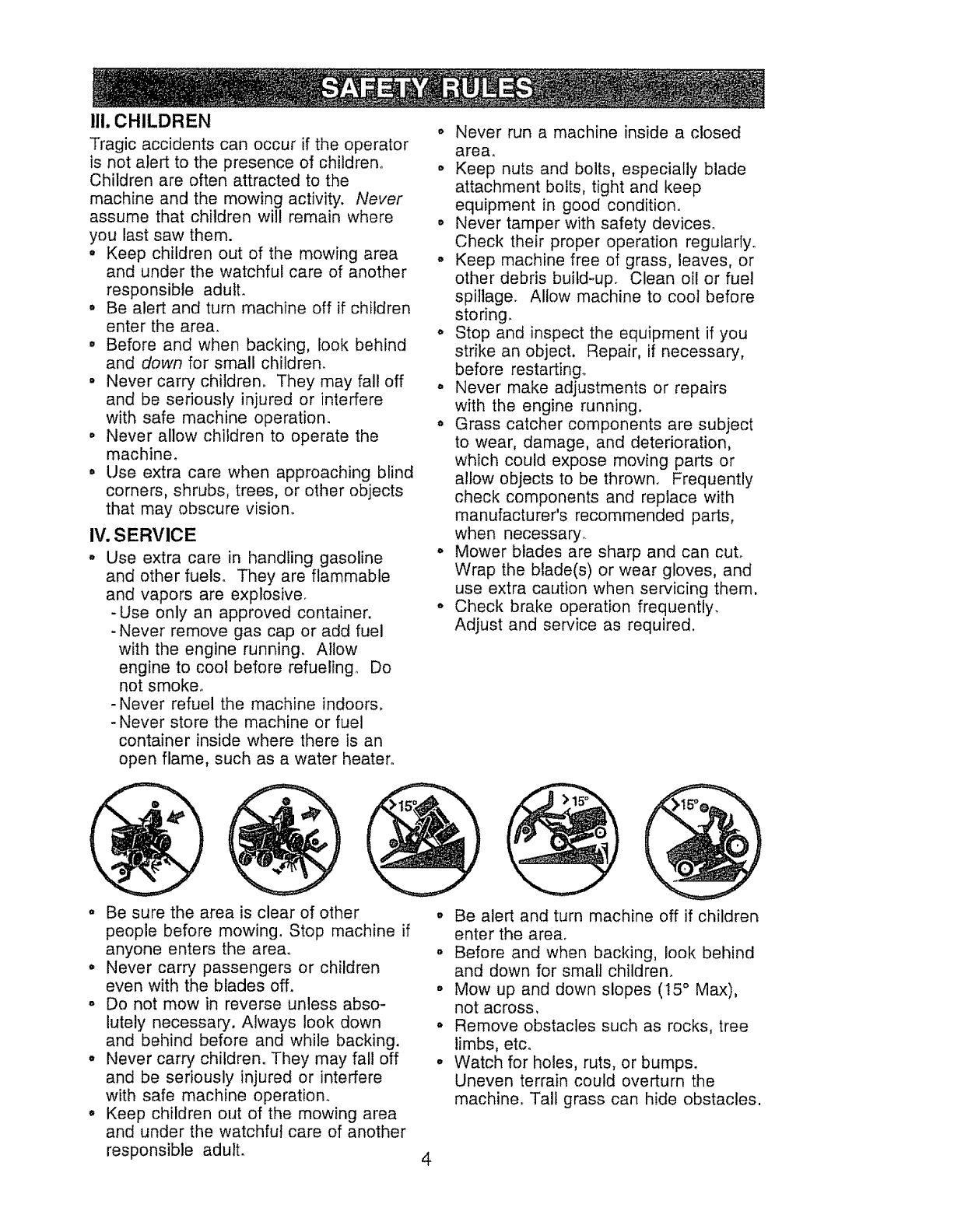
• Mow up and down slopes (15 ° Max),
not across,
• Remove obstacles such as rocks, tree
limbs, etc°
• Watch for holes, ruts, or bumps.
Uneven terrain could overturn the
machine° Tall grass can hide obstacles.
4
oUse slow speed. Choose a low gear so
that you wil! not have to stop or shift
while on the slope.
o Avoid starting or stopping on a slope° If
tires lose traction, disengage the
blades and proceed slowly straight
down the slope.
° If machine stops while going uphill,
disengage blades, shift into reverse
and back down slowly.
° Do not turn on slopes unless neces-
sary, and then, turn slowly and gradu-
ally downhill, if possible.
Look for this symbol to point out
important safety precautions. It means
CAUT!ONtl! BECOMEALERT!H YOUR
SAFETY IS INVOLVED.
_b, CAUTION: In order to prevent
accidental starting when setting up,
transporting, adjusting or making repairs,
always disconnect spark plug wire and
place wire where it cannot contact spark
plug_
CAUTION: Do not coast down a hill
in neutral, you may lose control of the
tractor.
& CAUTION; Tow only the attachments
that are recommended by and comply
with specifications of the manufacturer of
your tractor. Use common sense when
towing. Operate only at the lowest
possible speed when on a slope. Too
heavy of a load, while on a slope, is
dangerous° Tires can lose traction with
the ground and cause you to lose control
of your tractor.
WARNING: Engine exhaust, some of
its constituents, and certain vehicle
components contain or emit chemicals
known to the State of California to cause
cancer and birth defects or other repro-
ductive harm.
_,WARNING: Battery posts, terminals
and related accessories contain lead and
lead compounds, chemicals known to the
State of California to cause cancer and
birth defects or other reproductive harm.
Wash hands after handling,
5
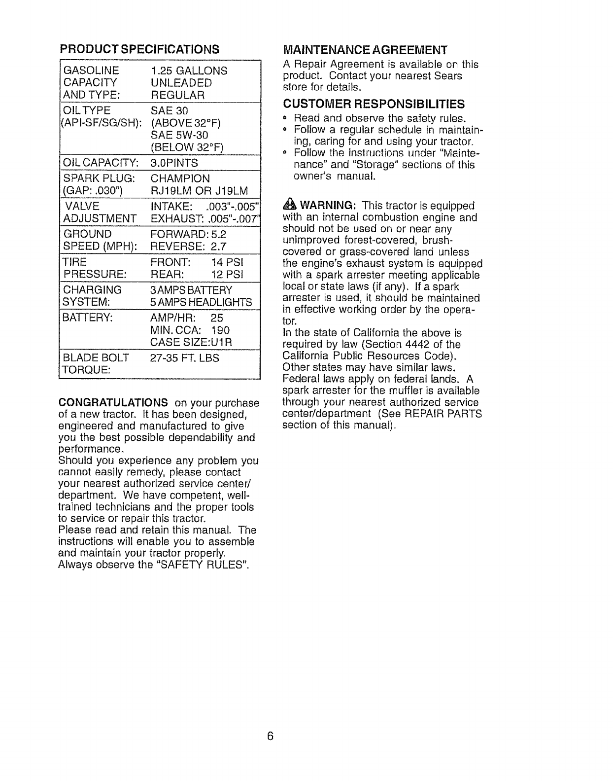
PRODUCT SPECIFICATIONS
GASOLINE 1,25 GALLONS
CAPACITY UNLEADED
AND TYPE: REGULAR
OILTYPE SAE 30
(API-SFiSG/SH): (ABOVE 32°F)
SAE 5W-30
(BELOW 32°F)
OIL CAPACITY: 3.0PINTS
SPARK PLUG: CHAMPION
(GAP: .030") RJ19LM OR J19LM
VALVE INTAKE: .003"-.005"
ADJUSTMENT EXHAUST: .005"-.007"
GROUND FORWARD: 5,2
SPEED (MPH): REVERSE: 2.7
TIRE FRONT: !4 PSI
PRESSURE: REAR: 12 PSI
CHARGING 3AMPS BATTERY
SYSTEM: 5 AMPS HEADLIGHTS
BATTERY: AMP/HR: 25
MIN. CCA: 190
CASE SIZE:U1R
BLADE BOLT 27-35 FT, LBS
TORQUE:
CONGRATULATIONS on your purchase
of a new tractor° It has been designed,
engineered and manufactured to give
you the best possible dependability and
performance_
Should you experience any problem you
cannot easily remedy, please contact
your nearest authorized service center/
department° We have competent, well-
trained technicians and the proper tools
to service or repair this tractor.
Please read and retain this manual. The
instructions will enable you to assemble
and maintain your tractor properly_
Always observe the "SAFETY RULES",.
MAINTENANCE AGREEMENT
A Repair Agreement is available on this
product. Contact your nearest Sears
store for details°
CUSTOMER RESPONSIBILITIES
• Read and observe the safety rules.
° Follow a regular schedule in maintain-
ing, caring for and using your tractor,
o Follow the instructions under "Mainte-
nance" and "Storage" sections of this
owner's manual,
WARNING: This tractor is equipped
with an internal combustion engine and
should not be used on or near any
unimproved forest-covered, brush-
covered or grass-covered land unless
the engine's exhaust system is equipped
with a spark arrester meeting applicable
local or state laws (if any), If a spark
arrester is used, it should be maintained
in effective working order by the opera-
tor.
In the state of California the above is
required by law (Section 4442 of the
California Public Resources Code).
Other states may have similar laws.
Federal laws apply on federal lands. A
spark arrester for the muffler is available
through your nearest authorized service
center/department (See REPAIR PARTS
section of this manual),
6
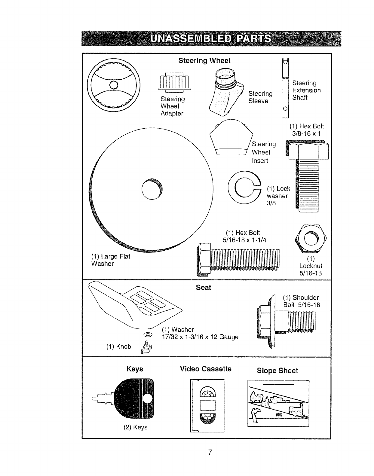
Steering Wheel
Steering
Wheel
Adapter
Steering
Sleeve
Steering
Extension
Shaft
(1) Hex Bolt
3/8-16 x 1
(1)
Locknut
5/16-I 8
O
/"_--_J" 318
__ ._ (1) Hex Bolt
_j 5/1618xl 1/4
(1) Large Flat
Washer
Seat
(1) Shoulder
Bolt 5/I6-18
(I) Knob
@(1) Washer
t7/32 x 1-3/16 x 12 Gauge
Keys
(2) Keys
Video Cassette Slope Sheet
7
'{our new tractor has been assembled at the factory with exception of those parts left
unassembled for shipping purposes. To ensure safe and proper operation of your
tractor all parts and hardware you assemble must be tightened securely. Use the
correct tools as necessary to insure proper tightness°
TOOLS REQUIRED FOR ASSEMBLY
A socket wrench set will make assembly
easier° Standard wrench sizes you need
are listed below.
(1) 9/16" wrench (1) Pliers
(2) 1/2" wrench (1) Utility knife
(1) Tire pressure
gauge
When right or left hand is mentioned in
this manual, it means when you are in
the operating position (seated behind
the steering wheel)_
TO REMOVE TRACTOR FROM
CARTON
UNPACK CARTON
1. Remove all accessible loose parts
and parts cartons from carton.
2. Cut, from top to bottom, along lines
on all four corners of carton, and lay
panels flat.
3. Check for any additional loose parts
or cartons and remove.
BEFORE REMOVING TRACTOR
FROM SKID
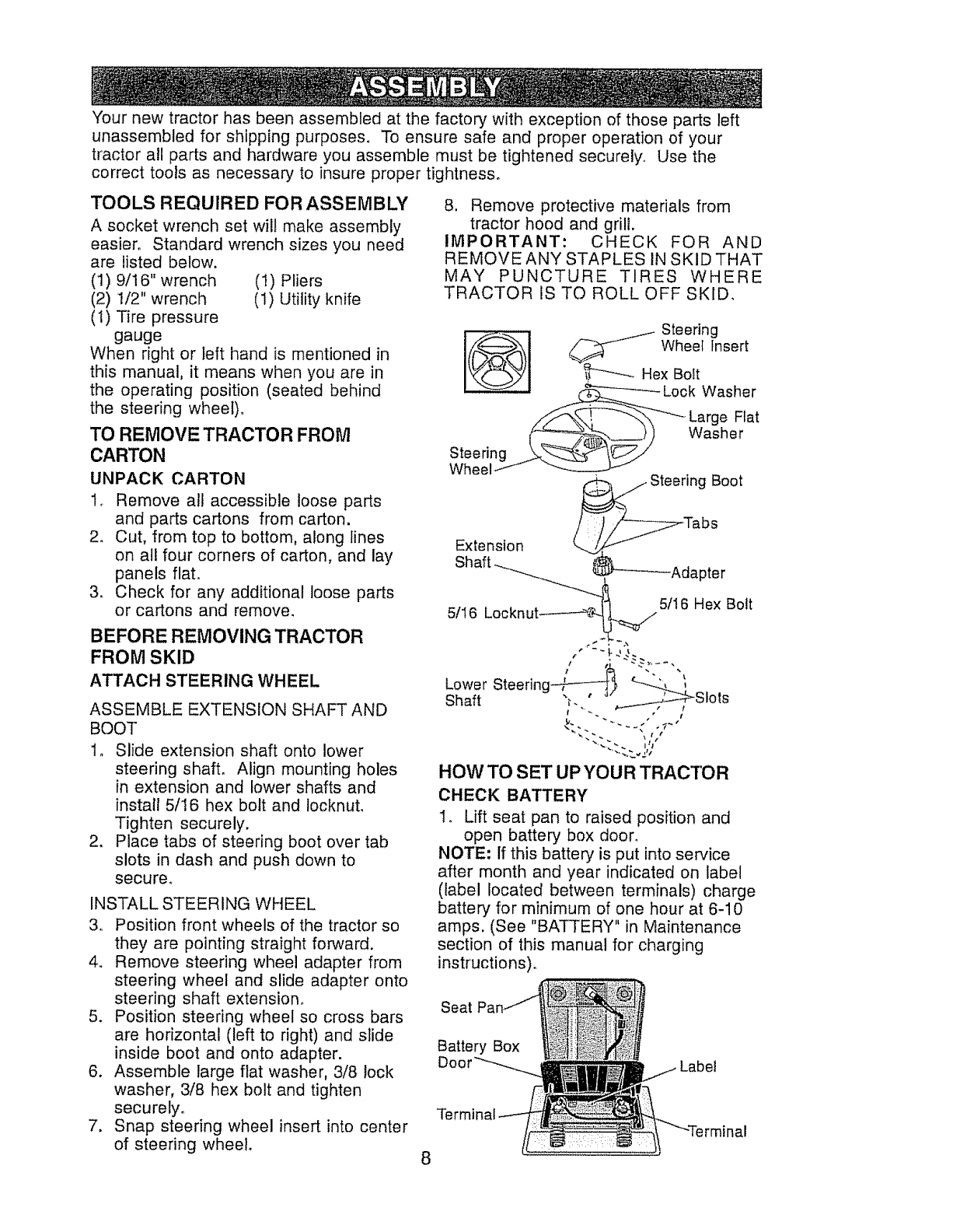
ATTACH STEERING WHEEL
ASSEMBLE EXTENSION SHAFT AND
BOOT
1o Slide extension shaft onto lower
steering shaft. Align mounting holes
in extension and lower shafts and
install 5/16 hex bolt and locknut.
Tighten securely.
2. Place tabs of steering boot over tab
slots in dash and push down to
secure.
INSTALL STEERING WHEEL
3, Position front wheels of the tractor so
they are pointing straight forward.
4. Remove steering wheel adapter from
steering wheel and slide adapter onto
steering shaft extension°
5. Position steering wheel so cross bars
are horizontal (left to right) and slide
inside boot and onto adapter.
6. Assemble large flat washer, 3/8 lock
washer, 3/8 hex bolt and tighten
securely°
7. Snap steering wheel insert into center
of steering wheel.
8. Remove protective materials from
tractor hood and grill.
IMPORTANT: CHECK FOR AND
REMOVE ANY STAPLES IN SKID THAT
MAY PUNCTURE TIRES WHERE
TRACTOR IS TO ROLL OFF SKID.
i_:, _ Steering
/'_----------_'Xi _ Wheel Insert
........,/Sf_., t -'_'X -"-_ Large Ftat
__) Washer
Extension
Shaft ........_.......... _ }--_Adapter
"---....... 5/16 Hex Bolt
5/t6 Locknut -,_-
Lower Steering--_-----_'_ _
Shaft _. _S[ots
HOW TO SET UP YOUR TRACTOR
CHECK BATTERY
Io Lift seat pan to raised position and
open batter,,, box door.
NOTE: if this battery is put into service
after month and year indicated on label
(label located between terminals) charge
battery for minimum of one hour at 6-10
amps. (See "BATTERY" in Maintenance
section of this manual for charging
instructions).
Seat Pa
Battery Box
8
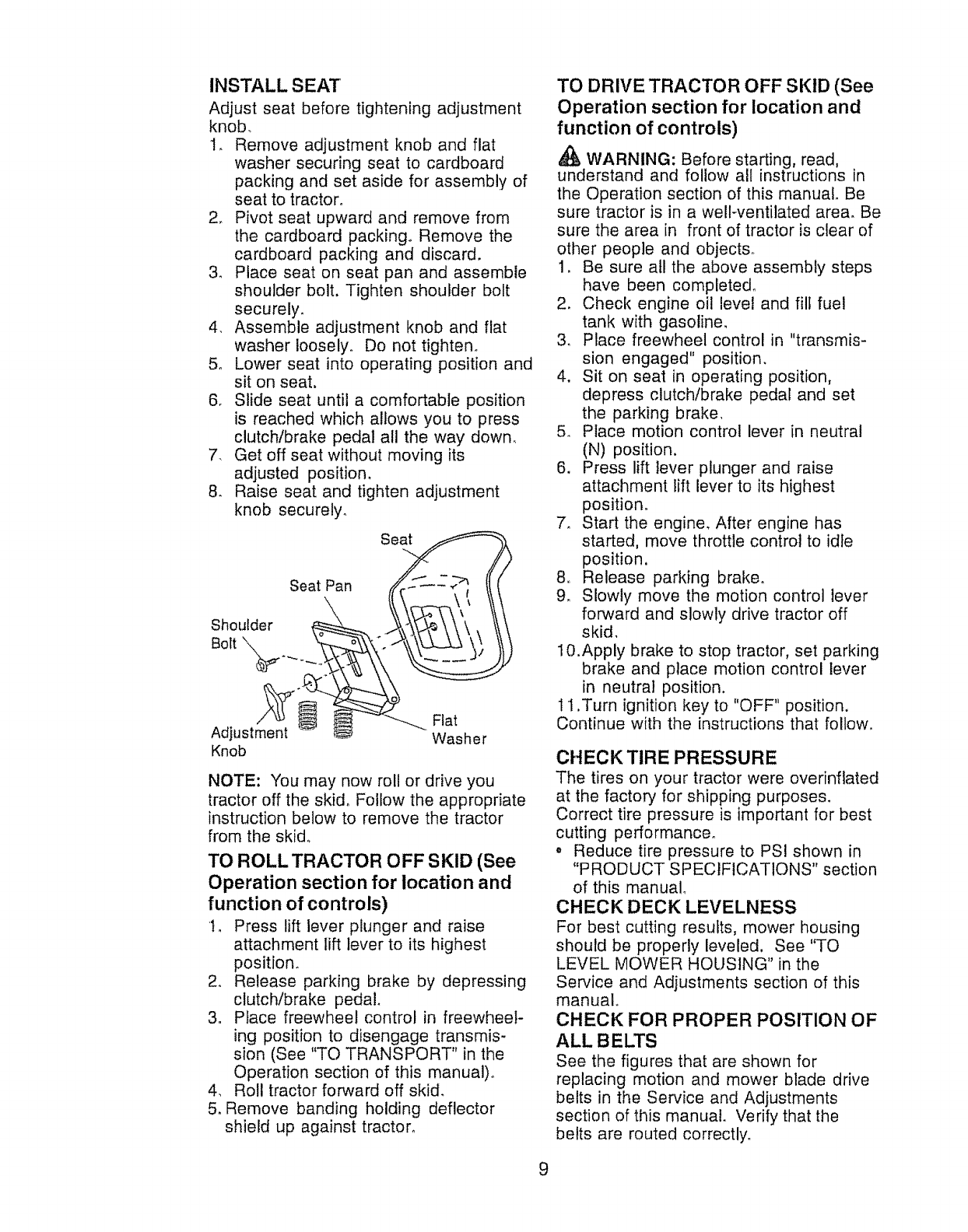
IN STALL S EAT
Adjust seat before tightening adjustment
knob_
1, Remove adjustment knob and flat
washer securing seat to cardboard
packing and set aside for assembly of
seat to tractor°
2, Pivot seat upward and remove from
the cardboard packing° Remove the
cardboard packing and discard.
3. Place seat on seat pan and assemble
shoulder bolt. Tighten shoulder bolt
securely.
4, Assemble adjustment knob and flat
washer loosely° Do not tighten,
5. Lower seat into operating position and
sit on seat.
6, Slide seat until a comfortable position
is reached which allows you to press
clutch/brake pedal all the way down,
7. Get off seat without moving its
adjusted position.
8. Raise seat and tighten adjustment
knob securely.
Seat Pan Se_
Bolt ° "[ /
Knob
NOTE: You may now roll or drive you
tractor off the skid. Follow the appropriate
instruction below to remove the tractor
from the skid.
TO ROLL TRACTOR OFF SKID (See
Operation section for location and
function of controls)
t_ Press lift lever plunger and raise
attachment lift lever to its highest
positron.
2. Release parking brake by depressing
clutch/brake pedal.
3. Place freewheel control in freewheel-
ing positron to disengage transmis-
sion (See "TO TRANSPORT" in the
Operation section of this manual)°
4. Roll tractor forward off skid.
5. Remove banding holding deflector
shield up against tractor_
TO DRIVE TRACTOR OFF SKID (See
Operation section for location and
function of controls)
WARNING: Before starting, read,
understand and follow all instructions in
the Operation section of this manual. Be
sure tractor is in a well-ventilated area. Be
sure the area in front of tractor is clear of
other people and objects°
1. Be sure all the above assembly steps
have been complete&
2. Check engine oil level and fill fuel
tank with gasoline.
3. Place freewheel control in "transmis-
sion engaged" position.
4. Sit on seat in operating position.
depress clutch/brake pedal and set
the parking brake.
5. Place motion control lever in neutral
(N) position.
6. Press lift lever plunger and raise
attachment lift lever to its highest
position.
7. Start the engine. After engine has
started, move throttle control to idle
position.
8. Release parking brake°
9_ Slowly move the motion control lever
forward and slowly drive tractor off
skid.
10.Apply brake to stop tractor, set parking
brake and place motion control lever
in neutral position.
11 .Turn ignition key to "OFF" position.
Continue with the instructions that follow.
CHECK TIRE PRESSURE
The tires on your tractor were overinflated
at the factory for shipping purposes.
Correct tire pressure is important for best
cutting performance,
• Reduce tire pressure to PSI shown in
"PRODUCT SPECIFICATIONS" section
of this manual_
CHECK DECK LEVELNESS
For best cutting results, mower housing
should be properly leveled. See "TO
LEVEL MOWER HOUSING" in the
Service and Adjustments section of this
manual.
CHECK FOR PROPER POSITION OF
ALL BELTS
See the figures that are shown for
replacing motion and mower blade drive
belts in the Service and Adjustments
section of this manual. Verify that the
belts are routed correctly°
9
CHECK BRAKE SYSTEM
After you learn how to operate your
tractor, check to see that the brake is
properly adjusted. See "TO ADJUST
BRAKE" in the Service and Adjustments
section of this manual.
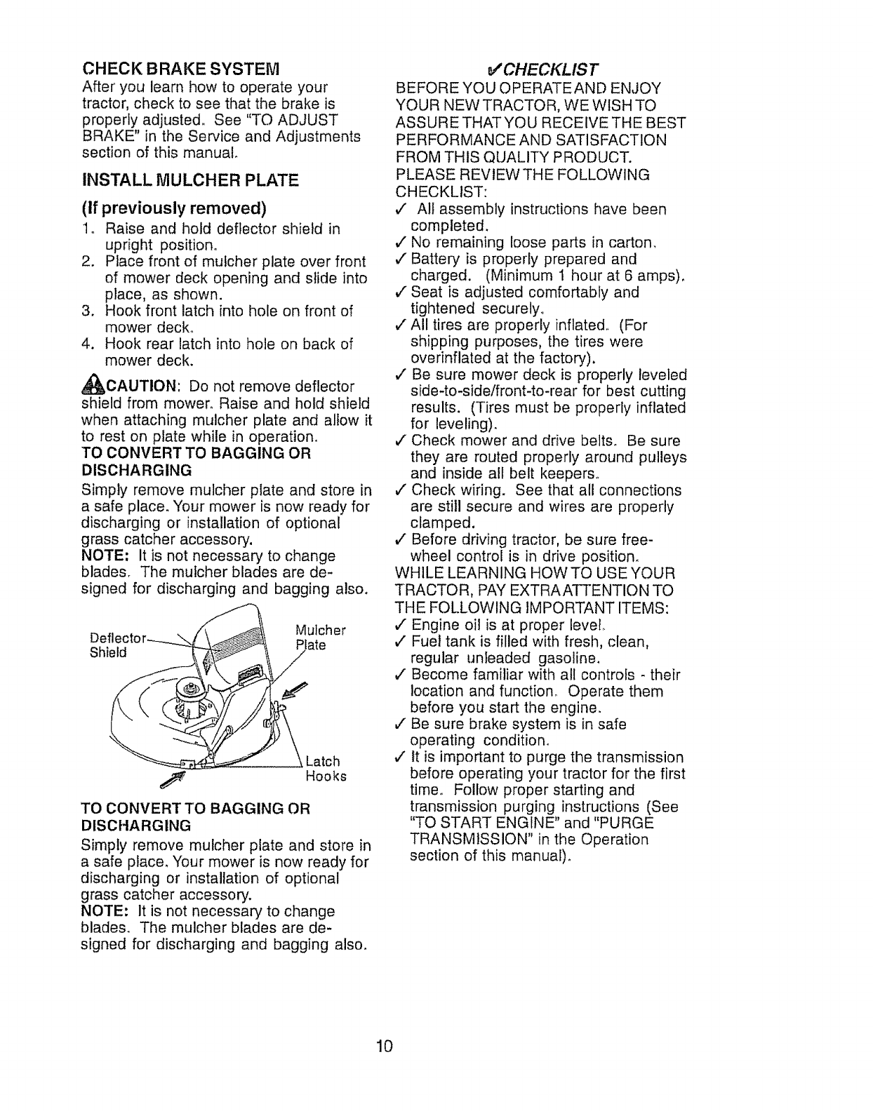
INSTALL MULCHER PLATE
(If previously removed)
1. Raise and hold deflector shield in
upright position°
2. Place front of mufcher plate over front
of mower deck opening and slide into
place, as shown.
3. Hook front latch into hole on front of
mower deck°
4. Hook rear latch into hole on back of
mower deck.
_CAUTION: Do not remove deflector
shield from mower. Raise and hold shield
when attaching mulcher plate and allow it
to rest on plate while in operation_
TO CONVERT TO BAGGING OR
DISCHARGING
Simply remove mulcher plate and store in
a safe place. Your mower is now ready for
discharging or installation of optional
grass catcher accessory.
NOTE: It is not necessary to change
blades. The mutcher blades are de-
signed for discharging and bagging also.
Deft, Mutcher
Shield late
Latch
Hooks
TO CONVERTTO BAGGING OR
DISCHARGING
Simply remove mulcher plate and store in
a safe place. Your mower is now ready for
discharging or installation of optional
grass catcher accessory.
NOTE: It is not necessary to change
blades. The mulcher blades are de-
signed for discharging and bagging also.
_CHECKLIST
BEFORE YOU OPERATE AND ENJOY
YOUR NEW TRACTOR, WE WISH TO
ASSURE THATYOU RECEIVE THE BEST
PERFORMANCE AND SATISFACTION
FROM THIS QUALITY PRODUCT.
PLEASE REVIEW THE FOLLOWING
CHECKLIST:
,/ All assembly instructions have been
completed.
J No remaining loose parts in carton.
,/Battery is properly prepared and
charged. (Minimum 1 hour at 6 amps).
,/Seat is adjusted comfortably and
tightened securely,
v" All tires are properly inflated, (For
shipping purposes, the tires were
overinflated at the factory).
,/Be sure mower deck is properly leveled
side-to-side/front4o-rear for best cutting
results. (Tires must be properly inflated
for leveling).
,/Check mower and drive belts. Be sure
they are routed properly around pulleys
and inside all belt keepers_
v" Check wiring. See that all connections
are still secure and wires are properly
clamped.
,/Before driving tractor, be sure free-
wheel control is in drive position.
WHILE LEARNING HOWTO USE YOUR
TRACTOR, PAY EXTRAATTENTION TO
THE FOLLOWING IMPORTANT ITEMS:
,/Engine oil is at proper level_
,/" Fuel tank is filled with fresh, clean,
regular unleaded gasoline.
v" Become familiar with all controls - their
location and function. Operate them
before you start the engine.
J Be sure brake system is in safe
operating condition.
v' It is important to purge the transmission
before operating your tractor for the first
time° Follow proper starting and
transmission purging instructions (See
"TO START ENGINE" and "PURGE
TRANSMISSION" in the Operation
section of this manual)_
10
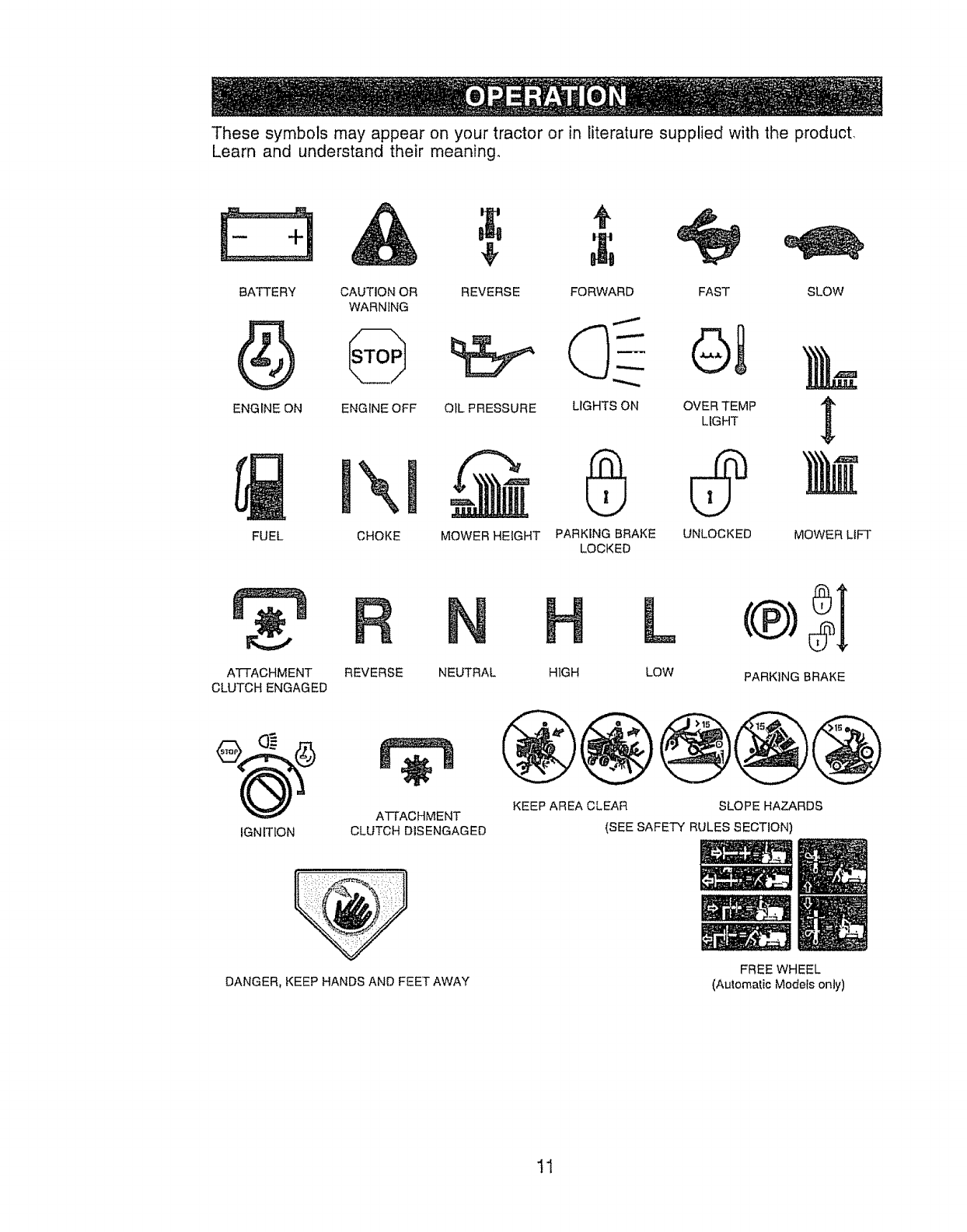
These symbols may appear on your tractor or in literature supplied with the product.
Learn and understand their meaning.
BATTERY CAUTION OR
WARNING
ENGINE ON ENGINE OFF
FUEL
\
CHOKE
4_
REVERSE SLOW
OIL PRESSURE
MOWER HEIGHT
FORWARD FAST
C)- QI
LIGHTS ON OVER TEMP
LIGHT
G
PARKING BRAKE UNLOCKED
LOCKED
MOWER LIFT
ATTACHMENT
CLUTCH ENGAGED
IGN ITION
REVERSE NEUTRAL
A'FFACHMENT
CLUTCH DISENGAGED
H L
HIGH LOW PARKING BRAKE
@@@@
KEEP AREA CLEAR SLOPE HAZARDS
(SEE SAFETY RULES SECTION
DANGER, KEEP HANDS AND FEET AWAY FREE WHEEL
(Automatic Mode{s only)
11
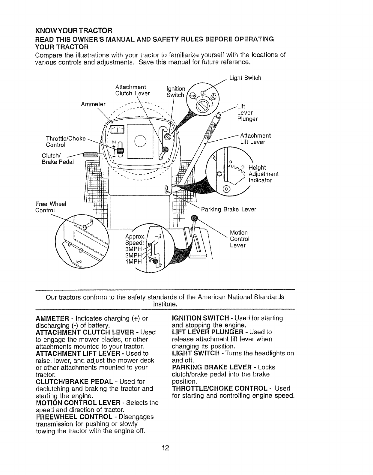
KNOW YOUR TRACTOR
READ THIS OWNER'S MANUAL AND SAFETY RULES BEFORE OPERATING
YOUR TRACTOR
Compare the illustrations with your tractor to familiarize yourself with the locations of
various controls and adjustments° Save this manual for future reference.
Attachment Ignition
Clutch Lever Switch
Ammeter .. _k_,
s s _ .. *•
Light Switch
Lever
Plunger
Control
Clutch/
Brake Peda!
_) Lift Lever
Height
Adjustment
Indicator
Free Wheel
Control g Brake Lever
Motion
Approx. Control
Speed: Lever
2MPH
1MPH
Our tractors conform to the safety standards of the American National Standards
institute.
AMMETER - Indicates charging (+) or
discharging (-) of battery.
ATTACHMENT CLUTCH LEVER - Used
to engage the mower blades, or other
attachments mounted to your tractor.
ATTACHMENT LIFT LEVER - Used to
raise, lower, and adjust the mower deck
or other attachments mounted to your
tractor.
CLUTCHIBRAKE PEDAL - Used for
declutching and braking the tractor and
starting the engine.
MOTION CONTROL LEVER -Selects the
speed and direction of tractor.
FREEWHEEL CONTROL - Disengages
transmission for pushing or slowly
towing the tractor with the engine off.
IGNITION SWITCH - Used for starting
and stopping the engine.
LIFT [..EVER PLUNGER - Used to
release attachment lift lever when
changing its position.
LIGHT SWITCH - Turns the headlights on
and off.
PARKING BRAKE LEVER -Locks
clutch/brake pedal into the brake
position.
THROTTLE/CHOKE CONTROL - Used
for starting and controlling engine speed,
12
The operation of any tractor can result in foreign objects thrown into
the eyes, which can result in severe eye damage° Always wear safety
glasses or eye shields while operating your tractor or performing any
adjustments or repairs. We recommend a wide vision safety mask
over spectacles or standard safety glasses.
HOW TO USE YOUR TRACTOR
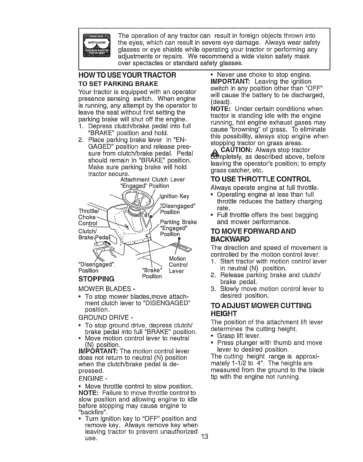
TO SET PARKING BRAKE
Your tractor is equipped with an operator
presence sensing switch. When engine
is running, any attempt by the operator to
leave the seat without first setting the
parking brake will shut off the engine.
1.. Depress clutch/brake pedal into full
"BRAKE" position and hold_
2. Place parking brake lever in "EN-
GAGED" position and release pres-
sure from clutch/brake pedal_ Pedal
should remain in "BRAKE" position.
Make sure parking brake will hold
tractor secure.
Attachment Clutch Lever
"Engaged" Position
7hro.,e C
Choke'---._ ',
Con_
Clutch/
Brake_[_
"Disengaged".
Position
STOPPING
Ignition Key
ed"
Parking Brake
ed"
Position
Motion
Control
"Brake" Lever
Position
MOWER BLADES -
• To stop mower blades,move attach-
ment clutch lever to "DISENGAGED"
position.
GROUND DRIVE -
o To stop ground drive, depress clutch/
brake pedal into full "BRAKE" position.
o Move motion control lever to neutral
(N) position.
IMPORTANT: The motion control lever
does not return to neutral (N) position
when the clutch/brake pedal is de-
pressed°
ENGINE -
o Move throttle control to slow position.
NOTE: Failure to move throttle control to
slow position and allowing engine to idle
before stopping may cause engine to
"backfire".
o Turn ignition key to "OFF" position and
remove key. Always remove key when
leaving tractor to prevent unauthorized
use. 13
•Never use choke to stop engine.
IMPORTANT: Leaving the ignition
switch in any position other than "OFF"
will cause the battery to be discharged,
(dead),
NOTE: Under certain conditions when
tractor is standing idle with the engine
running, hot engine exhaust gases may
cause "browning" of grass. To eliminate
this possibility, always stop engine when
stopping tractor on grass areas.
b_i,nCAUTION: Always stop tractor
pletely, as described above, before
leaving the operator's position; to empty
grass catcher, etc.
TO USE THROTTLE CONTROL
Always operate engine at full throttle.
• Operating engine at less than full
throttle reduces the battery charging
rate.
• Full throttle offers the best bagging
and mower performance°
TO MOVE FORWARD AND
BAClONARD
The direction and speed of movement is
controlled by the motion control lever.
1o Start tractor with motion control lever
in neutral (N) position.
2. Release parking brake and clutch/
brake pedal.
3. Slowly move motion control lever to
desired position.
TO ADJUST MOWER CUTTING
HEIGHT
The position of the attachment lift lever
determines the cutting height.
° Grasp lift lever.
, Press plunger with thumb and move
lever to desired position_
The cutting height range is approxi-
mately 1-1/2 to 4". The heights are
measured from the ground to the blade
tip with the engine not running°
Theseheightsare approximateand may
vary dependinguponsoi! conditions,
heightof grassandtypes of grassbeing
mowed.
• Theaverage lawnshould be cut to
approximately2-1/2 inchesduringthe
coolseasonand to over3 inches
duringhot months. For healthierand
betterlookinglawns,mowoftenand
after moderategrowth.
° For bestcuttingperformance,grass
over6 inchesin heightshouldbe
mowedtwice. Makethefirst cut
relativelyhigh;the secondto desired
height.
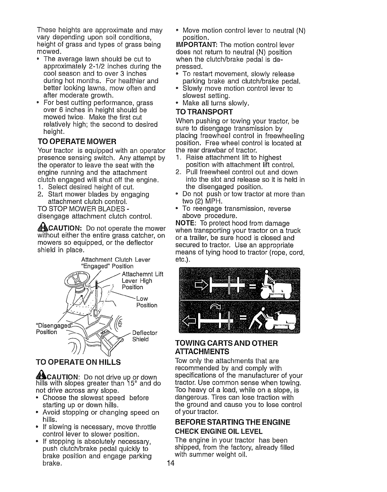
TO OPERATE MOWER
Yourtractor is equippedwith anoperator
presencesensingswitch. Any attemptby
the operatorto leavethe seatwiththe
engine runningand the attachment
clutchengagedwilt shutoff the engine°
1. Selectdesiredheightof cut°
2. Startmower bladesby engaging
attachmentclutchcontrol
TOSTOPMOWERBLADES-
disengageattachmentclutch control.
_f_CAUTION: Donotoperatethe mower
withouteitherthe entiregrasscatcher,on
mowersso equipped,or the deflector
shieldin place.
AttachmentClutchLever
"Engaged"Position
AttachemntLift
LeverHigh
Position
,:!:'_-"-_" Low
_=--'\ Position
• Movemotioncontrol lever'to neutral(N)
position.
IMPORTANT:The motioncontrollever
does not returnto neutral(N) position
whenthe clutch/brakepedalis de-
pressed,
• To restartmovement,slowlyrelease
parkingbrake and clutch/brakepedal.
o Slowlymovemotioncontrol leverto
slowestsetting.
° Makeall turnsslowly.
TOTRANSPORT
Whenpushingor towingyour tractor,be
sureto disengagetransmissionby
placing freewheelcontrol in freewheeling
position. Freewheelcontrolis locatedat
the reardrawbarof tractor.
1. Raiseattachmentlift to highest
positionwithattachmentlift control.
2. Pull freewheelcontrol out and down
intothe slot and releaseso it is heldin
the disengagedposition.
o Do not pushor towtractorat morethan
two(2) MPHo
• To reengagetransmission,reverse
above procedure.
NOTE: Toprotecthoodfromdamage
whentransportingyourtractoron a truck
or a trailer,be surehood is closedand
securedto tractor. Use an appropriate
meansof tyinghoodto tractor(rope,cord,
etc.).
"Disem
Position Deflector
Shield
TO OPERATE ON HILLS
_I, CAUTION: Do not drive up. or down
hills with slopes greater than I5 ° and do
not drive across any slope.
•Choose the slowest speed before
starting up or down hills..
° Avoid stopping or changing speed on
hills.
o If slowing is necessary, move throttle
control lever to slower position.
° tf stopping is absolutely necessary,
push clutch/brake pedal quickly to
brake position and engage parking
brake.
TOWING CARTS AND OTHER
ATTACHMENTS
Tow only the attachments that are
recommended by and comply with
specifications of the manufacturer of your
tractor_ Use common sense when towing.
Too heavy of a load, while on a slope, is
dangerous. Tires can lose traction with
the ground and cause you to lose control
of your tractor.
BEFORE STARTING THE ENGINE
CHECK ENGINE OIL LEVEL
The engine in your tractor has been
shipped, from the factory, already filled
with summer weight oil.
14
1. Check engine oil with tractor on level
ground.
2. Remove oil fill cap/dipstick and wipe
clean, reinsert the dipstick and screw
cap tight, wait for a few seconds,
remove and read oil level. If neces-
sary, add oil until "FULL" mark on
dipstick is reached. Do not overfill.
, For cold weather operation you should
change oii for easier starting (See "OIL
VISCOSITY CHART" in the Mainte-
nance section of this manual).
, To change engine oil, see the Mainte-
nance section in this manual.
ADD GASOLINE
° Fill fuel tank. Use fresh, clean, regular
unleaded gasoline with a minimum of
87 octane. (Use of leaded gasoline
will increase carbon and lead oxide
deposits and reduce valve life). Do
not mix oil with gasoline. Purchase
fuel in quantities that can be used
within 30 days to assure fuel fresh-
ness.
IMPORTANT: When operating in
temperatures below 32°F(0°C), use
fresh, clean winter grade gasoline to
help insure good cold weather starting_
WARNING: Experience indicates
that alcohol blended fuels (called
gasohot or using ethanol or methanol)
can attract moisture which leads to
separation and formation of acids during
storage. Acidic gas can damage the fuel
system of an engine while in storage. To
avoid engine problems, the fuel system
should be emptied before storage of 30
days or longer_ Drain the gas tank, start
the engine and let it run until the fuel
lines and carburetor are empty. Use
fresh fuel next season. See Storage
Instructions for additional information.
Never use engine or carburetor cleaner
products in the fuel tank or permanent
damage may occur.
& CAUTION: Fill to bqt,tom of gastank
filler neck. Do not ovenillo vvjpe OTTany
spilled oil or fuel. Do not store, spill or
use gasoline near an open flame.
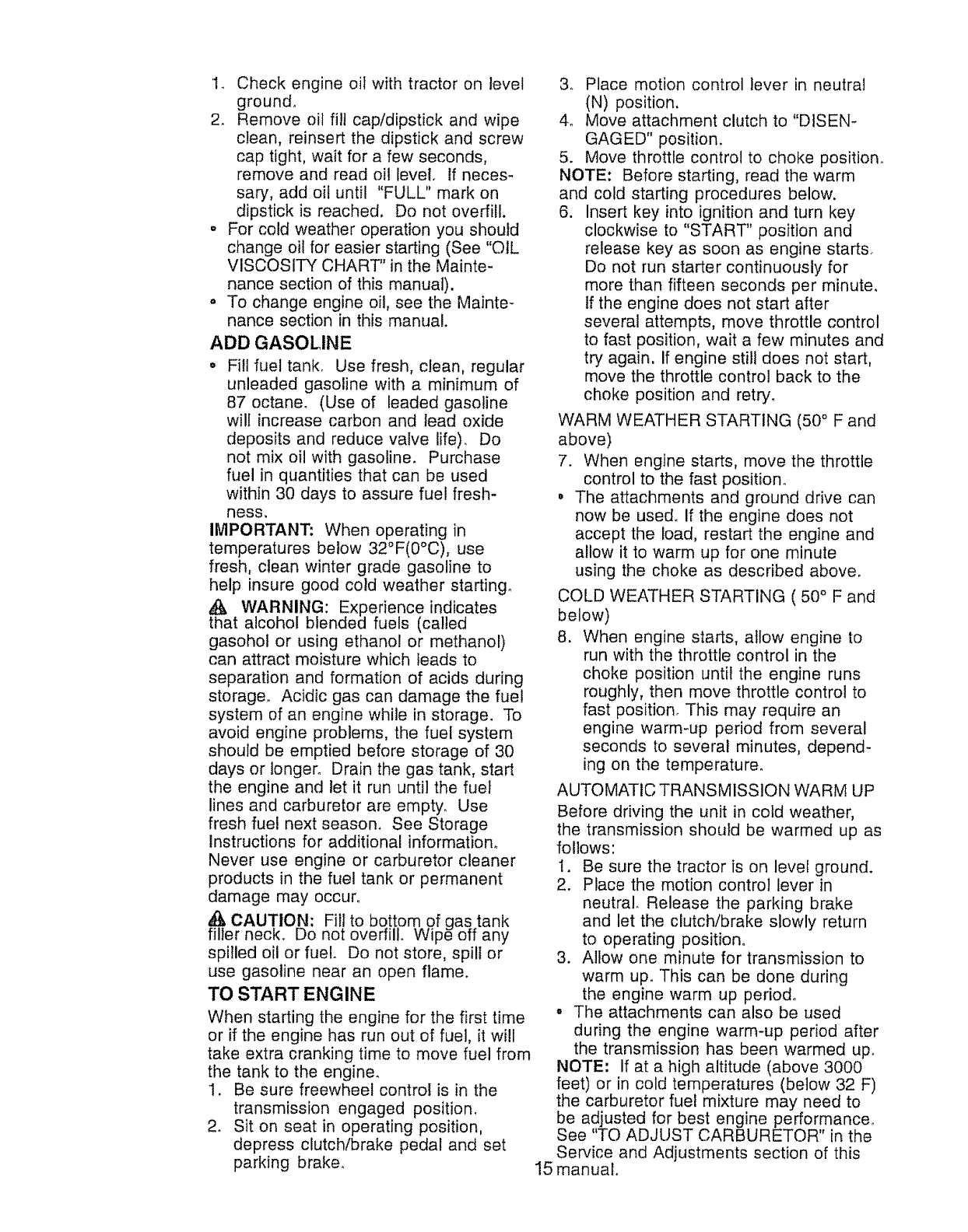
TO START ENGINE
When starting the engine for the first time
or if the engine has run out of fuel, it wi!l
take extra cranking time to move fuel from
the tank to the engine_
1. Be sure freewheel control is in the
transmission engaged position.
2. Sit on seat in operating position,
depress clutch/brake pedal and set
parking brake_
3o Place motion control lever in neutral
(N) position.
4_ Move attachment clutch to "DISEN-
GAGED" position.
5. Move throttle control to choke position.
NOTE: Before starting, read the warm
and cold starting procedures below.
6. Insert key into ignition and turn key
clockwise to "START" position and
release key as soon as engine starts.
Do not run starter continuously for
more than fifteen seconds per minute,
If the engine does not start after
several attempts, move throttle control
to fast position, wait a few minutes and
try again, if engine still does not start,
move the throttle control back to the
choke position and retry.
WARM WEATHER STARTING (50 ° F and
above)
7. When engine starts, move the throttle
control to the fast position.
° The attachments and ground drive can
now be used. If the engine does not
accept the load, restart the engine and
allow it to warm up for one minute
using the choke as described above.
COLD WEATHER STARTING ( 50 ° F and
below)
8. When engine starts, allow engine to
run with the throttle control in the
choke position until the engine runs
roughly, then move throttle control to
fast position. This may require an
engine warm-up period from several
seconds to several minutes, depend-
ing on the temperature.
AUTOMATIC TRANSMISSION WARM UP
Before driving the unit in cold weather,
the transmission should be warmed up as
follows:
1. Be sure the tractor is on level ground.
2. Place the motion control lever in
neutral. Release the parking brake
and let the clutch/brake slowly return
to operating position°
3. Allow one minute for transmission to
warm up. This can be done during
the engine warm up period.
°The attachments can also be used
during the engine warm*up period after
the transmission has been warmed up.
NOTE: If at a high altitude (above 3000
feet) or in cold temperatures (below 32 F)
the carburetor fuel mixture may need to
be adjusted for best engine performance°
See "TO ADJUST CARBURETOR" in the
Service and Adjustments section of this
15manualo
PURGE TRANSMISSION
_,CAUTION: Never engage or disen-
gage freewheel lever while the engine is
running.
To ensure proper operation and perfor-
mance, it is recommended that the
transmission be purged before operating
tractor for the first time° This procedure wilt
remove any trapped air inside the trans-
mission which may have developed during
shipping of your tractor.
IMPORTANT: Should your transmission
require removal for service or replacement,
it should be purged after reinstallation
before operating the tractor.
1. Place tractor safely on level surface
with engine off and parking brake set,
2o Disengage transmission by placing
freewheel control in freewheeling
position (See "TO TRANSPORT" in
this section of manual).
3. Sitting in the tractor seat, start engine.
After the engine is running, move
throttle control to slow position. With
motion control lever in neutral (N)
position, slowly disengage clutch/
brake pedal°
4. Move motion control lever to full
forward position and hold for five (5)
seconds. Move lever to full reverse
position and hold for five (5) seconds.
Repeat this procedure three (3) times.
NOTE: During this procedure there will be
no movement of drive wheels, The air is
being removed from hydraulic drive
system.
5. Move motion control lever to neutral
(N) position, Shut- off engine and set
parking brake.
6. Engage transmission by placing
freewheel control in driving position
(See '_O TRANSPORT" in this section
of manual)°
7. Sitting in the tractor seat, start engine.
After the engine is running, move
throttle control to half (1/2) speed° With
motion control lever in neutral (N)
position, slowly disengage clutch/
brake pedal.
8. Slowly move motion control lever
forward, after the tractor moves
approximately five (5) feet, slowly
move motion control lever to reverse
position, After the tractor moves
approximately five (5) feet return the
motion control lever to the neutral (N)
position° Repeat this procedure with
the motion control lever three (3)
times.
Your tractor is now purged and now ready
for normal operation°
MOWING TIPS
o Mower should be properly leveled for
best mowing performance. See "TO
LEVEL MOWER HOUSING" in the
Service and Adjustments section of this
manual°
• The left hand side of mower should be
used for trimming.
o Drive so that clippings are discharged
onto the area that has been cut. Have
the cut area to the right of the tractor.
This will result in a more even distribu-
tion of clippings and more uniform
cutting.
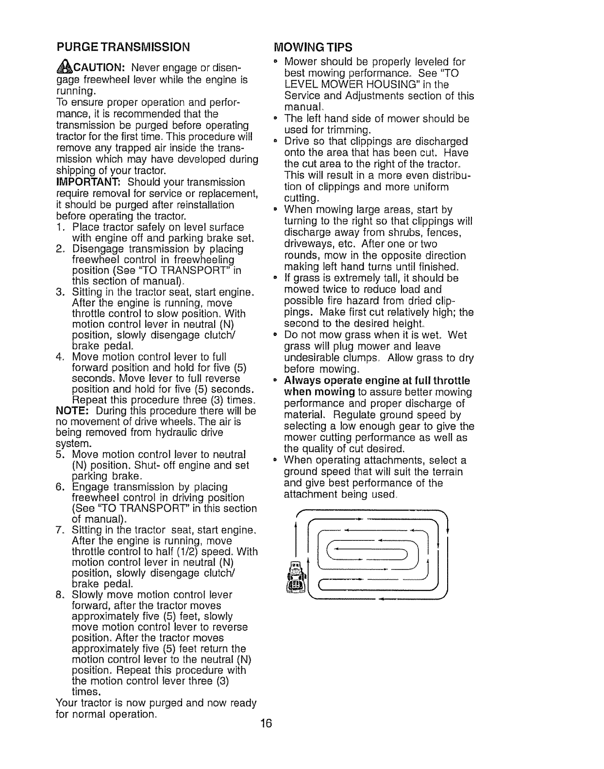
• When mowing large areas, start by
turning to the right so that clippings will
discharge away from shrubs, fences,
driveways, etc. After one or two
rounds, mow in the opposite direction
making left hand turns until finished.
° If grass is extremely tall, it should be
mowed twice to reduce load and
possible fire hazard from dried clip-
pings. Make first cut relatively high; the
second to the desired height°
° Do not mow grass when it is wet° Wet
grass wil! plug mower and leave
undesirable clumps. Allow grass to dry
before mowing_
° Always operate engine at full throttle
when mowing to assure better mowing
performance and proper discharge of
material. Regulate ground speed by
selecting a low enough gear to give the
mower cutting performance as well as
the quality of cut desired,
• When operating attachments, select a
ground speed that wilt suit the terrain
and give best performance of the
attachment being used_
f
]
16
MULCHING MOWING TIPS
IMPORTANT: For best performance,
keep mower housing free of built-up
grass and trash. Clean after each use.
o The special mulching blade will recut
the grass clippings many times and
reduce them in size so that as they fall
onto the lawn they will disperse into the
grass and not be noticed. Also, the
mulched grass will biodegrade quickly
to provide nutrients for the lawn_
Always mulch with your highest engine
(blade) speed as this will provide the
best recutting action of the blades.
o Avoid cutting your lawn when it is wet.
Wet grass tends to form clumps and
interferes with the mulching action.
The best time to mow your lawn is the
early afternoon° At this time the grass
has dried and the newly cut area will
not be exposed to the direct sun,
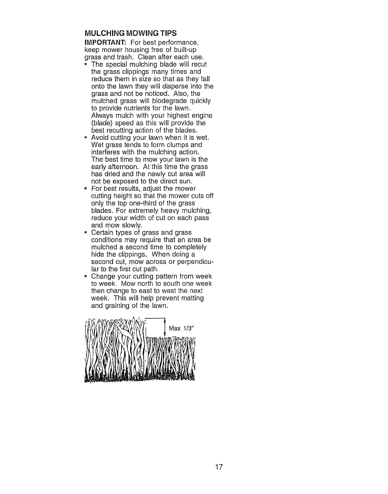
,, For best results, adjust the mower
cutting height so that the mower cuts off
only the top one-third of the grass
blades° For extremely heavy mulching,
reduce your width of cut on each pass
and mow slowly.
o Certain types of grass and grass
conditions may require that an area be
mulched a second time to completely
hide the clippings. When doing a
second cut, mow across or perpendicu-
lar to the first cut path_
° Change your cutting pattern from week
to week. Mow north to south one week
then change to east to west the next
week. This will help prevent matting
and graining of the lawn.
Max 1/3"
i
'17
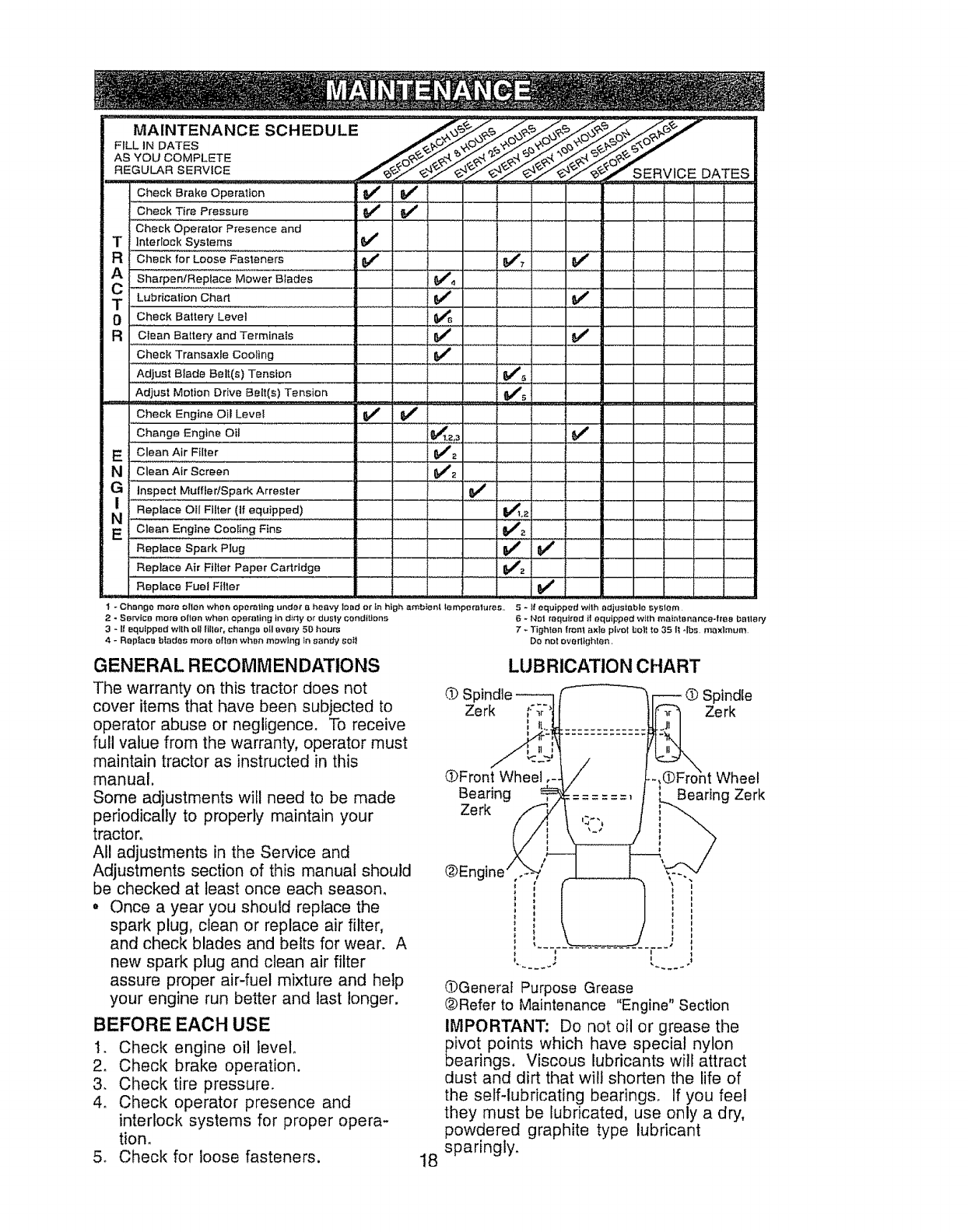
MAINTENANCE SCHEDULE _j_, _///_
F,LLI=OATES
AS YOU COMPLETE
Check Brake .Operat!o n .............. 1#1' $f
Check Tire Pressure V #_ ......
Check Operator Presence and
TInterlock Systems 6f
RCheck for LOose #ast_nars .... _ ' : _;, Vr
TLubrication Ch"_ ......
0 ,,,Check Battery Level
a Clean Battery and Terminals
Cheek Transaxle Cooling
Adjust Blade Belt(s) Tension
Adjust Motion Drive Belt(s) Tension
Check Engine Oil Level
Change Engine Oil
E C!eanA!rFilter
................... _' ______ _
J
I
v,v" ................... , !
......... g. ! ! .....
NClean Air Screen 6_2
? _'"lnspect Muffler/SparkArrester i .............._ " ' !
....Repiac'e OilFilter (If equipped) ..............................._2
ci;a.Engi,;coo,in=Fin= i.....
Replace Spark Plug Vr $f : :
Replace Air Filter Paper Cartridge 6f2
Replace Fuel Filler
I- Change mare ollet_ when operating under e heavy Ioad or in high. ambient !omperalures. 5- If equipped with adjustable l._y_;lem
2_Service more ellen when operating in d_tty or dusty conditions 6 -Not required if equipped with ma_ntenance-frao betlery
3 - II equipped wllh oli fillet, change oil every 51) hours 7 - Tighlon trent axle pivot bo]t to 35 It *Ibs maximum
4 - Rop|ace blades more often whoa mowing ta sandy _Oi_ Do, not overllghlen,
GENERAL RECOMMENDATIONS
The warranty on this tractor does not
cover items that have been subjected to
operator abuse or negligence, To receive
full value from the warranty, operator must
maintain tractor as instructed in this
manual.
Some adjustments will need to be made
periodically to properly maintain your
tractor.
Al! adjustments in the Service and
Adjustments section of this manual should
be checked at least once each season,
o Once a year you should replace the
spark plug, clean or replace air filter,
and check blades and belts for wear. A
new spark plug and clean air filter
assure proper air-fuel mixture and help
your engine run better and last longer.
BEFORE EACH USE
1. Check engine oil level
2, Check brake operation.
3. Check tire pressure.
4. Check operator presence and
interlock systems for proper opera-
tion.
5. Check for loose fasteners. 18
LUBRICATION CHART
..cOSl O Spindle
Zerk _-%'_" Zerk
(DFront Wheel Wheel
Bearing Bearing Zerk
Zerk
OGenerat Purpose Grease
_bRefer to Maintenance "Engine" Section
IMPORTANT: Do not oil or grease the
ivot points which have special nylon
earings. Viscous lubricants will attract
dust and dirt that will shorten the life of
the self-lubricating bearings, If you feel
they must be lubricated, use only a dry,
powdered graphite type lubricant
sparingly.
TRACTOR
Alwaysobservesafety ruleswhen
performingany maintenance.
BRAKE OPERATION
If tractor requires more than six (6) feet
stopping distance at high speed in
highest gear, then brake must be ad-
justed. (See "TO ADJUST BRAKE" in the
Service and Adjustments section of this
manual),
• Maintain proper air pressure in alI tires
(See "PRODUCT SPECIFICATIONS"
section of this manual),
o Keep tires free of gasoline, oil, or insect
control chemicals which can harm
rubber.
• Avoid stumps, stones, deep ruts, sharp
objects and other hazards that may
cause tire damage.
NOTE: To seal tire punctures and prevent
flat tires due to slow leaks, tire sealant
may be purchased from your local parts
dealer. Tire sealant also prevents tire dry
rot and corrosion,
OPERATOR PRESENCE SYSTEM
Be sure operator presence and interlock
systems are working properly, if your
tractor does not function as described,
repair the problem immediately.
• The engine should not start unless the
clutch/brake pedal is fully depressed
and attachement clutch control is in the
disengaged position.
° When the engine is running, any
attempt by the operator to leave the
seat without first setting the parking
brake should shut off the engine.
. When the engine is running and the
attachment clutch is engaged, any
attempt by the operator to leave the
seat should shut off the engine.
• The attachment clutch should never
operate unless the operator is in the
seat°
BLADE CARE
For best results mower blades must be
kept sharp° Replace bent or damaged
blades.
BLADE REMOVAL
1. Raise mower to highest position to
allow access to blades,
2. Remove hex bolt, lock washer and
flat washer securing blade°
3. install new or resharpened blade with
trailing edge up towards deck as
shown.
IMPORTANT: To ensure proper assem-
bly, center hole in blade must align with
star on mandrel assembly.
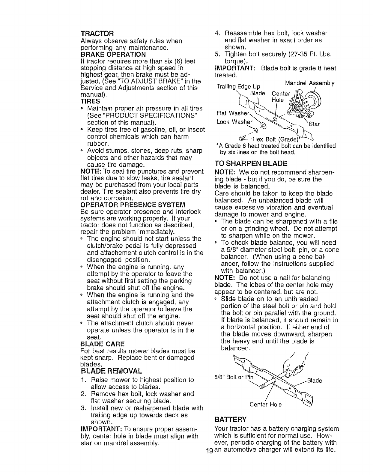
4o Reassemble hex bolt, lock washer
and flat washer in exact order as
shown.
5, Tighten bolt securely (27-35 Ft. Lbs,
torque).
IMPORTANT: Blade bolt is grade 8 heat
treated°
Mandrel Assembly
Trailin( Edge Up
Blade Center
Hole
Flat Washer\
Lock Washer
_---Hex Bolt (Grade)
*A Grade 8 heat treated bolt can be identified
by six lines on the bolt head.
TOSHARPENBLADE
NOTE: We do not recommend sharpen-
ing blade - but if you do, be sure the
blade is balanced.
Care should be taken to keep the blade
balanced° An unbalanced blade will
cause excessive vibration and eventual
damage to mower and engine,
• The blade can be sharpened with a file
or on a grinding wheel. Do not attempt
to sharpen while on the mower.
• To check blade balance, you will need
a 5/8" diameter steel bolt, pin, or a cone
balancer. (When using a cone bal-
ancer, follow the instructions supplied
with balancer,)
NOTE: Do not use a nail for balancing
blade. The lobes of the center hole may
appear to be centered, but are not°
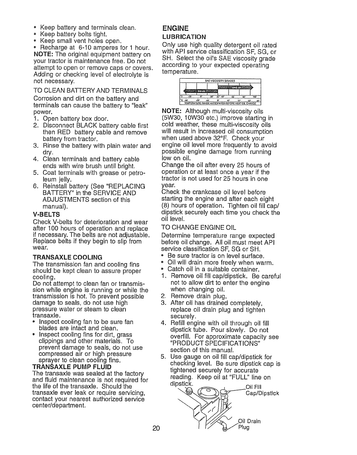
° Slide blade on to an unthreaded
portion of the steel bolt or pin and hold
the bolt or pin parallel with the ground.
If blade is balanced, it should remain in
a horizontal position. If either end of
the blade moves downward, sharpen
the heavy end until the blade is
balanced,
5/8" B de
Center Hole
BATTERY
Your tractor has a battery charging system
which is sufficient for normal use. How-
ever, periodic charging of the battery with
19an automotive charger will extend its life.
.Keep battery and terminals clean.
o Keep battery bolts tight.
o Keep small vent holes open,
o Recharge at 6-10 amperes for ! hour_
NOTE: The original equipment batteR/on
your tractor is maintenance free. Do not
attempt to open or remove caps or covers,
Adding or checking level of electrolyte is
not necessary.
TO CLEAN BATTERY AND TERMINALS
Corrosion and dirt on the battery and
terminals can cause the battery to "leak"
power.
I. Open battery box door.
2. Disconnect BLACK battery cable first
then RED battery cable and remove
battery from tractor.
3. Rinse the battery with plain water and
dry.
4. Clean terminals and battery cable
ends with wire brush until bright.
5. Coat terminals with grease or petro-
leum jelly.
6. Reinstall battery (See "REPLACING
BATTERY" in the SERVICE AND
ADJUSTMENTS section of this
manual).
V-BELTS
Check V-belts for deterioration and wear
after 100 hours of operation and replace
if necessary'. The belts are not adjustable.
Replace belts if they begin to slip from
wear.
TRANSAXLE COOLING
The transmission fan and cooling fins
should be kept clean to assure proper
cooling.
Do not attempt to clean fan or transmis-
sion while engine is running or while the
transmission is hot. To prevent possible
damage to seals, do not use high
pressure water or steam to clean
transaxle.
° Inspect cooling fan to be sure fan
blades are intact and clean.
• Inspect cooling fins for dirt, grass
clippings and other materials. To
prevent damage to seals, do not use
compressed air or high pressure
sprayer to clean cooling fins.
TRANSAXLE PUMP FLUID
The transaxle was sealed at the factory
and fluid maintenance is not required for
the life of the transaxle. Should the
transaxte ever leak or require servicing,
contact your nearest authorized service
center!department.
ENGINE
20
LUBRICATION
Only use high quality detergent oil rated
with AP1 service classification SF, SG, or
SH, Select the oil's SAE viscosity grade
according to your expected operating
temperature,
NOTE: Although multiwiscosity oils
(5W30, 10W30 etc.) improve starting in
cold weather, these multi-viscosity oils
will result in increased oil consumption
when used above 32°R Check your
engine oil level more frequently to avoid
possible engine damage from running
low on oil.
Change the oil after every 25 hours of
operation or at least once a year if the
tractor is not used for 25 hours in one
year.
Check the crankcase oil level before
starting the engine and after each eight
(8) hours of operation. Tighten oil fill cap/
dipstick securely each time you check the
oil level.
TO CHANGE ENGINE OIL
Determine temperature range expected
before oil change. All oil must meet API
service classification SF, SG or SH.
.Be sure tractor is on level surface,,
° Oil will drain more freely when warm.
• Catch oil in a suitable container.
1. Remove oil fill cap/dipstick. Be careful
not to allow dirt to enter the engine
when changing oil.
2. Remove drain plug.
3. After oil has drained completely,
replace oil drain plug and tighten
securely.
4. Refill engine with oil through oil fill
dipstick tube. Pour slowly. Do not
overfill. For approximate capacity see
"PRODUCT SPECIFICATIONS"
section of this manual.
5. Use gauge on oil fill cap/dipstick for
checldng level. Be sure dipstick cap is
tightened securely for accurate
reading. Keep oil at "FULL" line on
dipstick. Oil Fill
_-'---Cap/Dipstlck
/
/
,Oil Drain
Plug
CLEAN AIR SCREEN
Air screen must be kept free of dirt and
chaff to prevent engine damage from
overheating. Clean with a wire brush or
compressed air to remove dirt and
stubborn dried gum fibers.
ENGINE COOLING FINS
Remove any dust, dirt or oil from engine
cooling fins to prevent engine damage
from overheating.
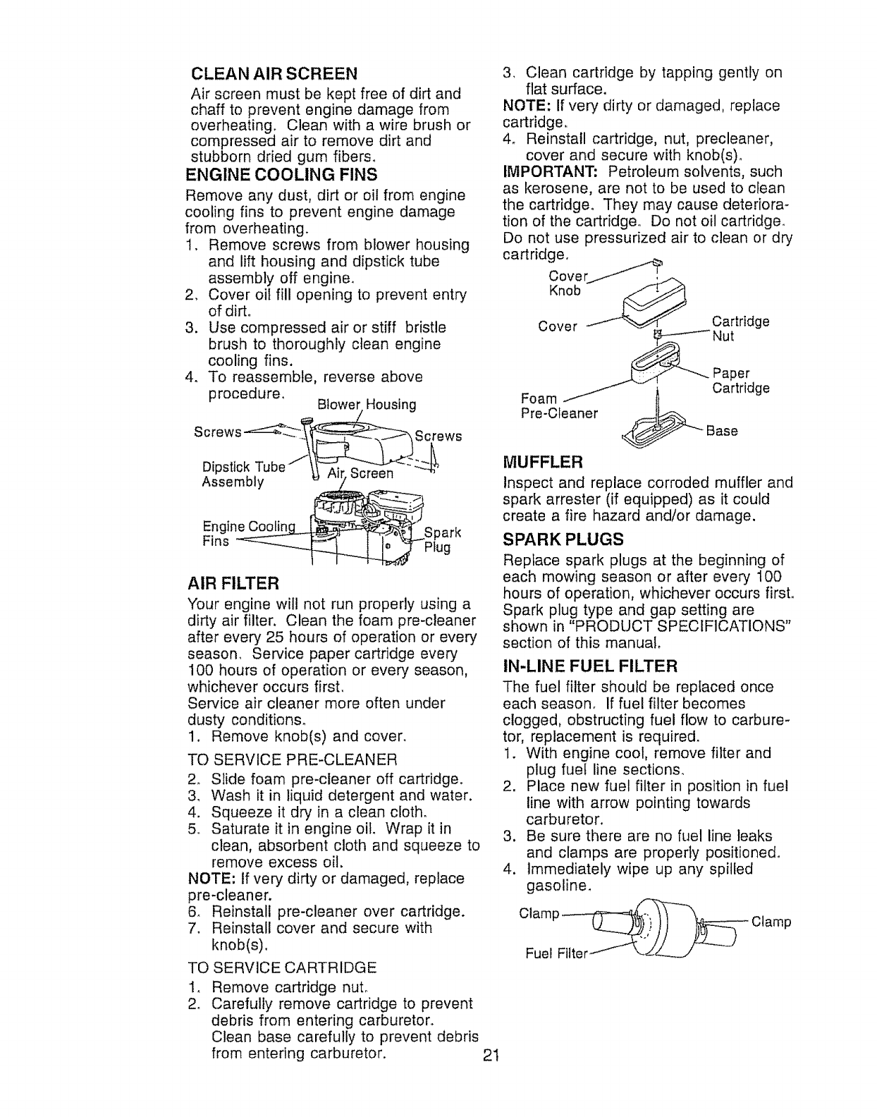
1. Remove screws from blower housing
and lift housing and dipstick tube
assembly off engine.
2. Cover oil fill opening to prevent entry
of dirt.
3. Use compressed air or stiff bristle
brush to thoroughly clean engine
cooling fins.
4o To reassemble, reverse above
procedure. Blower Housing
Screws Screws
Dipstick Ail Screen "L_'_
Assembly
Engine Coolin 3ark
Fins Plug
AIR FILTER
Your engine will not run properly using a
dirty air filter. Clean the foam pre-cleaner
after every 25 hours of operation or every
season. Service paper cartridge every
100 hours of operation or every season,
whichever occurs first.
Service air cleaner more often under
dusty conditions_
1. Remove knob(s) and cover.
TO SERVICE PRE-CLEANER
2. Slide foam pre-cleaner off cartridge.
3. Wash it in liquid detergent and water.
4. Squeeze it dry in a clean cloth.
5. Saturate it in engine oil. Wrap it in
clean, absorbent cloth and squeeze to
remove excess oil.
NOTE: If very dirty or damaged, replace
pre-cleaner.
& Reinstall pre-cleaner over cartridge.
7. Reinstall cover and secure with
knob(s).
TO SERVICE CARTRIDGE
1_ Remove cartridge nut.
2o Carefully remove cartridge to prevent
debris from entering carburetor°
Clean base carefully to prevent debris
from entering carburetor.
3, Clean cartridge by tapping gently on
flat surface.
NOTE: If very dirty or damaged, replace
cartridge,
4. Reinstall cartridge, nut, precleaner,
cover and secure with knob(s).
IMPORTANT: Petroleum solvents, such
as kerosene, are not to be used to clean
the cartridge. They may cause deteriora-
tion of the cartridge, Do not oil cartridge.
Do not use pressurized air to clean or dry
cartridge,
Cover_
Knob
Paper
Foam Cartridge
Pre-Cteaner
_ _Base
MUFFLER
Inspect and replace corroded muffler and
spark arrester (if equipped) as it could
create a fire hazard and/or damage.
SPARK PLUGS
Replace spark plugs at the beginning of
each mowing season or after every 100
hours of operation, whichever occurs firsL
Spark plug type and gap setting are
shown in "PRODUCT SPECIFICATIONS"
section of this manual,
IN-LINE FUEL FILTER
The fuel filter should be replaced once
each season. If fuel filter becomes
clogged, obstructing fuel flow to carbure-
tor, replacement is required.
1. With engine cool, remove filter and
plug fuel line sections.
2. Place new fuel filter in position in fuel
line with arrow pointing towards
carburetor.
3. Be sure there are no fuel line leaks
and clamps are properly positioned.
4. Immediately wipe up any spilled
gasoline.
21
CLEANING
o Clean engine, battery, seat, finish, etco
of all foreign matter.
,Keep finished surfaces and wheels free
of all gasoline, oil, etc.
°Protect painted surfaces with automo-
tive type wax.
We do not recommend using a garden
hose to clean your tractor unless the
electrical system, muffler, air filter and
carburetor are covered to keep water out,
Water in engine can result in a short-
ened engine life.
CAUTION: BEFORE PERFORMING ANY SERVICE OR ADJUSTMENTS"
1o Depress clutch/brake pedal fully and set parking brake.
2. Place motion control lever in neutral (N) position.
3. Place attachment clutch in "DISENGAGED" position.
4_ Turn ignition key "OFF" and remove key°
5., Make sure the blades and all moving parts have completely stopped.
6. Disconnect spark plug wire from spark plug and place wire where it cannot
come in contact with plug.
TRACTOR
TO REMOVE MOWER
Mower will be easier to remove from the
right side of tractor.
1. Place attachment clutch in "DISEN-
GAGED" position.
2. Move attachment lift lever forward to
lower mower to its lowest position,
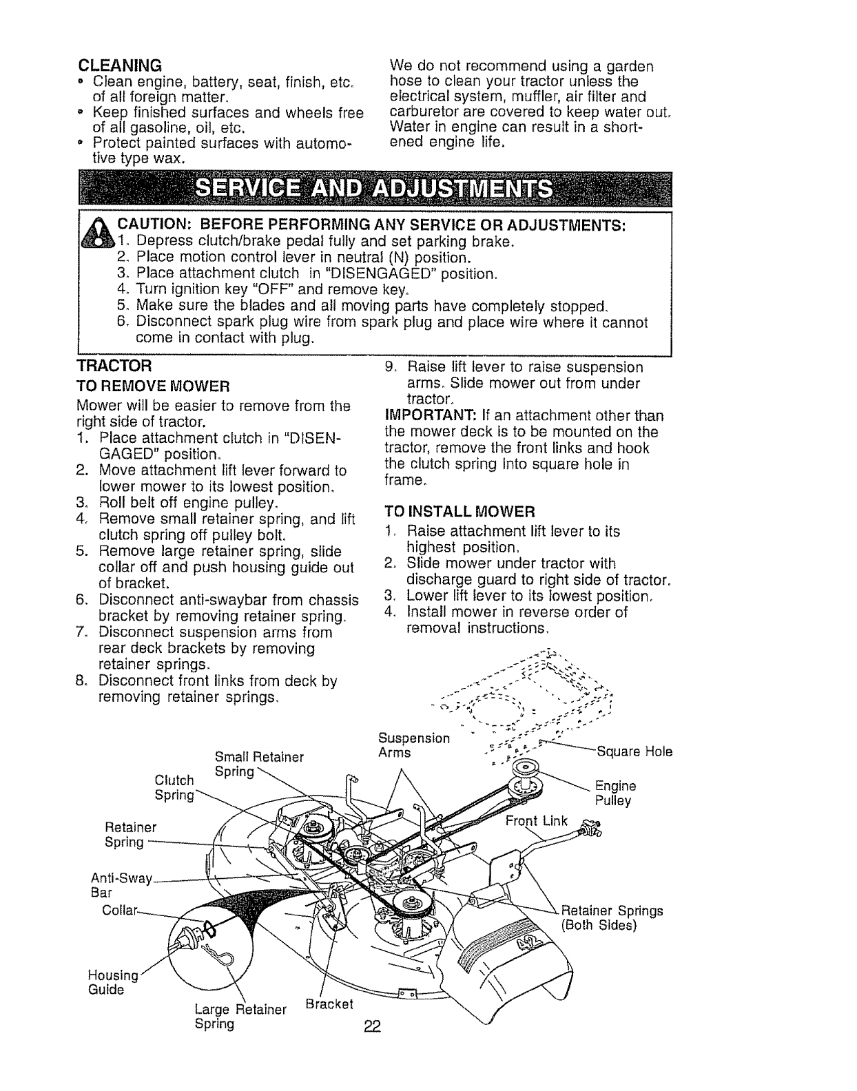
3o Roll belt off engine pulley°
4. Remove small retainer spring, and lift
clutch spring off pulley bolt.
5. Remove large retainer spring, slide
collar off and push housing guide out
of bracket.
6. Disconnect anti-swaybar from chassis
bracket by removing retainer spring.
7o Disconnect suspension arms from
rear deck brackets by removing
retainer springs,
8o Disconnect front links from deck by
removing retainer springs.
Clutch
S
Small Retainer
Spring
9, Raise iift lever to raise suspension
arms. Slide mower out from under
tractor.
IMPORTANT: If an attachment other than
the mower deck is to be mounted on the
tractor, remove the front links and hook
the clutch spring Into square hole in
frame.
TO INSTALL MOWER
1, Raise attachment lift lever to its
highest position_
2. Slide mower under tractor with
discharge guard to right side of tractor.
3. Lower lift lever to its lowest position,
4. Install mower in reverse order of
removal instructions.
Engine
Pulley
Retainer
Spring
Anti-Sway
Bar
_iner Springs
(Both Sides)
Housin(
Guide
Large Retainer
Spring
Bracket
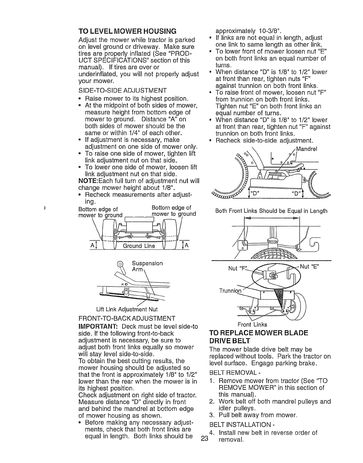
TO LEVEL MOWER HOUSING
Adjust the mower while tractor is parked
on level ground or driveway, Make sure
tires are properly inflated (See "PROD-
UCT SPECIFICATIONS" section of this
manual). If tires are over or
underinffated, you will not properly adjust
your mower.
SIDE-TO-SIDE ADJUSTMENT
. Raise mower to its highest position.
o At the midpoint of both sides of mower,
measure height from bottom edge of
mower to ground. Distance "A" on
both sides of mower should be the
same or within 1/4" of each other.
. If adjustment is necessary, make
adjustment on one side of mower only_
. To raise one side of mower, tighten lift
link adjustment nut on that side.
.To lower one side of mower, loosen lift
link adjustment nut on that side,
NOTE:Each full turn of adjustment nut will
change mower height about 1/8".
,Recheck measurements after adjust-
ing.
Bottom edge of Bottom edge of
mower to ground ,. mower to ground
Lift Link Adjustment Nut
FRONT-TO-BACK ADJUSTMENT
IMPORTANT: Deck must be level side-to
side. If the following front-to-back
adjustment is necessary, be sure to
adjust both front links equally so mower
will stay level side-to-sideo
To obtain the best cutting results, the
mower housing should be adjusted so
that the front is approximately 1/8" to 1/2"
lower than the rear when the mower is in
its highest position.
Check adjustment on right side of tractor.
Measure distance "D" directly in front
and behind the mandrel at bottom edge
of mower housing as shown.
° Before making any necessary adjust-
ments, check that both front links are
equal in length° Both links should be
approximately 10-3/8"o
° If links are not equal in length, adjust
one link to same length as other link.
° To lower front of mower loosen nut "E"
on both front links an equal number of
turns,
o When distance "D" is 1/8" to 1/2" lower
at front than rear, tighten nuts "F"
against trunnion on both front links°
• To raise front of mower, loosen nut "F"
from trunnion on both front links.
Tighten nut "E" on both front links an
equal number of turns.
, When distance "D" is 1/8" to 1/2" lower
at front than rear, tighten nut "F" against
trunnion on both front links.
°Recheck side-to-side adjustmenL
oo \ _o Mandrel
Both Front Links Should be Equal in Length
Nut "F"'_
Trunnio_
llE_t
Front Links
TO REPLACE MOWER BLADE
DRIVE BELT
The mower blade drive belt may be
replaced without tools. Park the tractor on
level surface. Engage parking brake.
BELT REMOVAL-
1o Remove mower from tractor (See "TO
REMOVE MOWER" in this section of
this manual).
2. Work belt off both mandrel pulleys and
idler pulleys.
3o Pull belt away from mower°
BELT INSTALLATION -
4. Install new belt in reverse order of
23 removal.
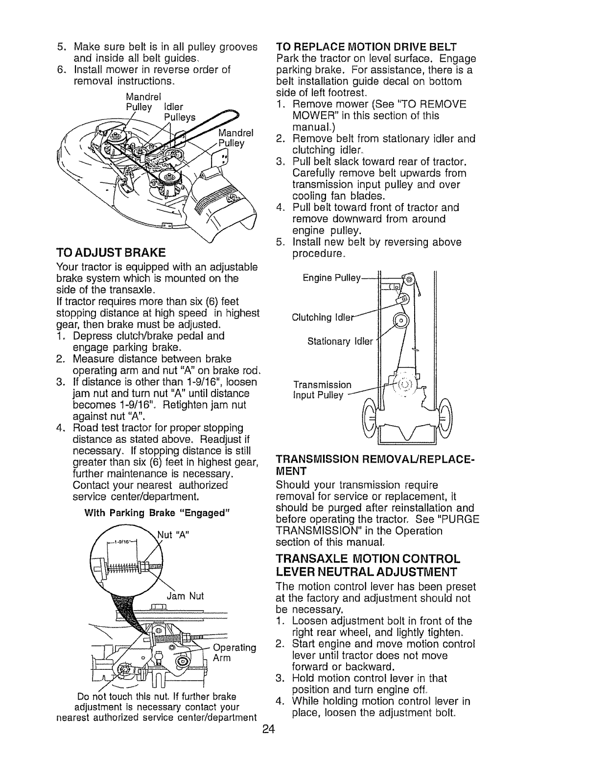
5. Makesurebelt is in all pulleygrooves
and insideall belt guides.
6. Installmowerin reverseorderof
removal instructions.
Mandrel
Pulley Idler
Mandrel
Iley
TO ADJUST BRAKE
Your tractor is equipped with an adjustable
brake system which is mounted on the
side of the transaxleo
If tractor requires more than six (6) feet
stopping distance at high speed in highest
gear, then brake must be adjusted.
1_ Depress clutch/brake pedal and
engage parking brake.
2. Measure distance between brake
operating arm and nut "A" on brake rod.
3. tf distance is other than 1-9/16", loosen
jam nut and turn nut "A" until distance
becomes 1-9/16'L Retighten jam nut
against nut "A".
4. Road test tractor for proper stopping
distance as stated above. Readjust if
necessary. If stopping distance is still
greater than six (6) feet in highest gear,
further maintenance is necessary.
Contact your nearest authorized
service center/department.
With Parking Brake "Engaged"
Nut "A"
Jam Nut
Operating
Arm
*.-.,,,_j
Do not touch this nut. If further brake
adjustment is necessary contact your
nearest authorized service center/department
TO REPLACE MOTION DRIVE BELT
Park the tractor on level surface. Engage
parking brake. For assistance, there is a
belt installation guide decal on bottom
side of left footresL
1. Remove mower (See "TO REMOVE
MOWER" in this section of this
manual.)
2. Remove belt from stationary idler and
clutching idler°
3. Pull belt slack toward rear of tractor.
Carefully remove belt upwards from
transmission input pulley and over
cooling fan blades.
4, Pull belt toward front of tractor and
remove downward from around
engine pulley.
5. Install new belt by reversing above
procedure_
Engine Pulley i _"_½
Clutching ldle_ /'_1
input Pulley i-___
TRANSMISSION REMOVAL/REPLACE-
MENT
Should your transmission require
removal for service or replacement, it
should be purged after reinstallation and
before operating the tractor. See "PURGE
TRANSMISSION" in the Operation
section of this manual.
TRANSAXLE MOTION CONTROL
LEVER NEUTRAL ADJUST[VlENT
The motion control lever has been preset
at the factory and adjustment should not
be necessary,
1_ Loosen adjustment bolt in front of the
right rear wheel, and lightly tighten°
2. Start engine and move motion control
lever until tractor does not move
forward or backward.
3. Hold motion control lever in that
position and turn engine off_
4. While holding motion control lever in
place, loosen the adjustment bolt.
24
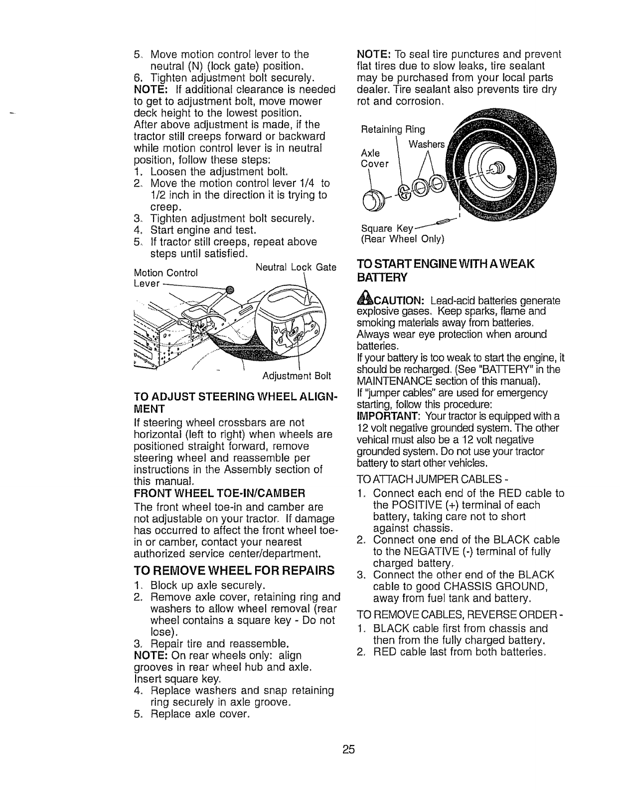
5_ Move motion control lever to the
neutral (N) (lock gate) position_
6. Tighten adjustment bolt securely.
NOTE: If additional clearance is needed
to get to adjustment bolt, move mower
deck height to the lowest position.
After above adjustment is made, if the
tractor still creeps forward or backward
while motion control lever is in neutral
position, follow these steps:
t. Loosen the adjustment bolt.
2. Move the motion control lever 1/4 to
1/2 inch in the direction it is trying to
creep.
3. Tighten adjustment bolt securely.
4, Start engine and test.
5, If tractor still creeps, repeat above
steps until satisfie&
Neutral Lock Gate
Motion Control
Adjustment Bolt
TO ADJUST STEERING WHEEL ALIGN-
MENT
if steering wheel crossbars are not
horizontal (left to right) when wheels are
positioned straight forward, remove
steering wheel and reassemble per
instructions in the Assembly section of
this manual
FRONT WHEEL TOE-IN/CAMBER
The front wheel toe-in and camber are
not adjustable on your tractor,, If damage
has occurred to affect the front wheel toe-
in or camber, contact your nearest
authorized service center/department.
TO REMOVE WHEEL FOR REPAIRS
1. Block up axle securely.
2. Remove axle cover, retaining ring and
washers to allow wheel removal (rear
wheel contains a square key - Do not
lose).
3. Repair tire and reassemble.
NOTE" On rear wheels only: align
grooves in rear wheel hub and axle.
Insert square key,
4o Replace washers and snap retaining
ring securely in axle groove°
5, Replace axle cover,
NOTE: To seal tire punctures and prevent
fiat tires due to slow leaks, tire sealant
may be purchased from your local parts
dealer° Tire sealant also prevents tire dry
rot and corrosion,
Retaining Ring
Washers
Axle
Cover
t
Square Key I-"
(Rear Wheel Only)
TO START ENGINE WITH A WEAK
BATTERY
_,CAUTION: Lead-acid batteries generate
explosive gases. Keep sparks, flame and
smoking materials away from batteries.
Always wear eye protection when around
batteries.
If your battery is too weak to start the engine, it
should be recharged, (See "BATTERY" in the
MAINTENANCE section of this manual).
If "jumper cables" are used for emergency
starting, follow this procedure:
IMPORTANT: Your tractor is equipped with a
12 volt negative grounded system. The other
vehical must also be a 12 volt negative
grounded system. Do not use your tractor
battery to start other vehicles.
TO ATTACH JUMPER CABLES -
1o Connect each end of the RED cable to
the POSITIVE (+) terminal of each
battery, taking care not to short
against chassis.
2o Connect one end of the BLACK cable
to the NEGATIVE (-) termina! of fully
charged battery,
3. Connect the other end of the BLACK
cable to good CHASSIS GROUND,
away from fuel tank and battery.
TO REMOVE CABLES, REVERSE ORDER -
1o BLACK cable first from chassis and
then from the fully charged battery.
2. RED cable last from both batteries.
25
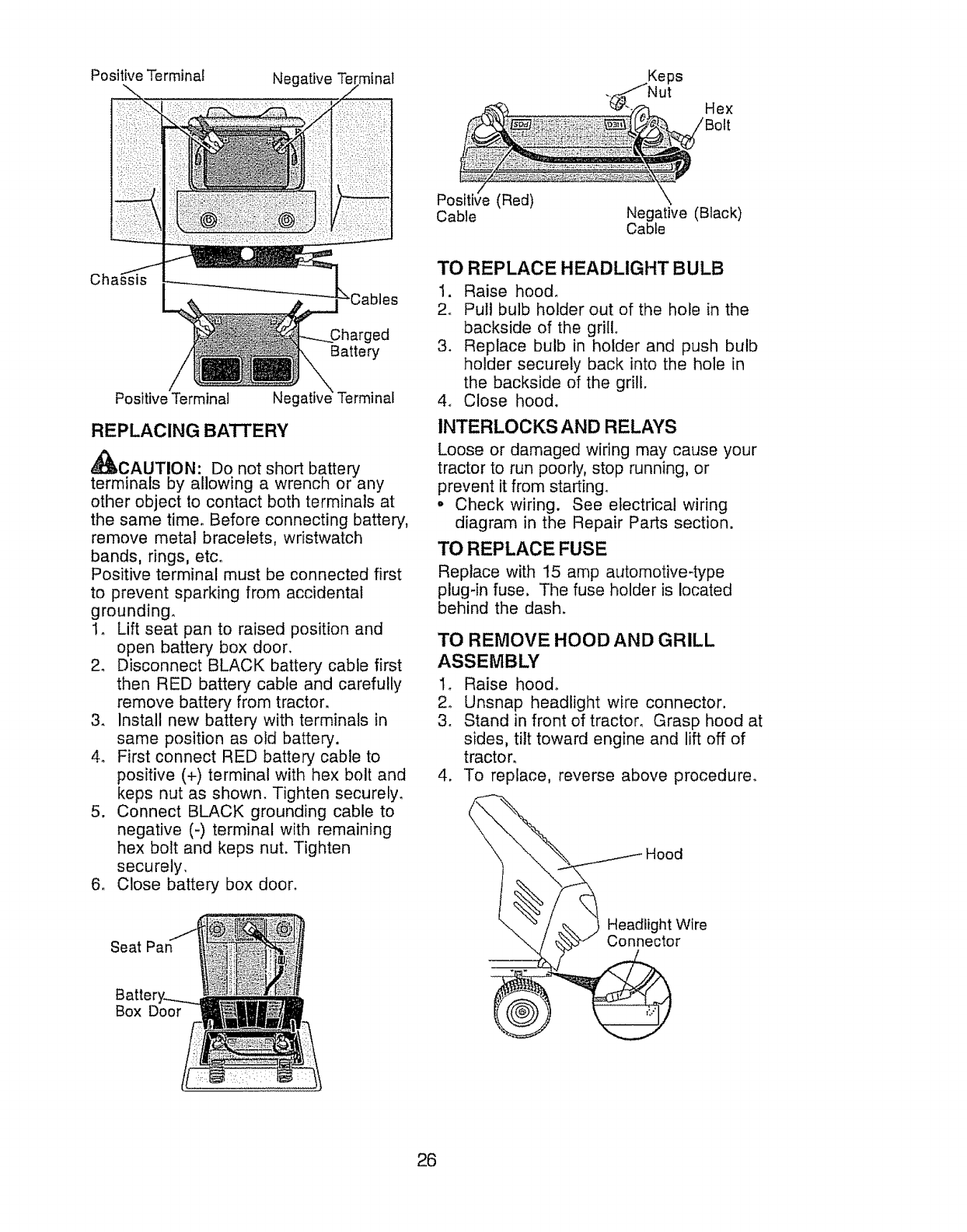
Positive Terminal Negative Te Keps
._. Nut Hex
ed
Battery
Positive Terminal Neg
REPLACING BA'I-I'E RY
z_
_,CAUTION: Do not short battery
terminals by allowing a wrench or any
other object to contact both terminals at
the same time. Before connecting battery,
remove metal bracelets, wristwatch
bands, rings, etco
Positive terminal must be connected first
to prevent sparking from accidental
grounding.
I. Lift seat pan to raised position and
open battery box door.
2. Disconnect BLACK battery cable first
then RED battery cable and carefully
remove battery from tractor.
3. Install new battery, with terminals in
same position as old battery.
4. First connect RED battery cable to
positive (+) terminal with hex bolt and
keps nut as shown. Tighten securely.
5. Connect BLACK grounding cable to
negative (-) terminal with remaining
hex bolt and keps nut. Tighten
securely,
6. Close battery box door.
Seat
Box Door
(Red)
Cable Negative (Black)
Cable
TO
1.
2.
REPLACE HEADLIGHT BULB
Raise hood.
Pul! bulb holder out of the hole in the
backside of the grill°
3. Replace bulb in holder and push bulb
holder securely back into the hole in
the backside of the grill.
4. Close hood.
INTERLOCKS AND RELAYS
Loose or damaged wiring may cause your
tractor to run poorly, stop running, or
prevent it from starting.
• Check wiring. See electrical wiring
diagram in the Repair Parts section.
TO REPLACE FUSE
Replace with 15 amp automotive4ype
plug-in fuse. The fuse holder is located
behind the dash.
TO REMOVE HOOD AND GRILL
ASSEMBLY
1o Raise hood°
2o Unsnap headlight wire connector.
3. Stand in front of tractor, Grasp hood at
sides, tilt toward engine and lift off of
tractor.
4. To re _lace, reverse above procedure.
\
_i H°°d
1'2htoWire
26
ENGINE
Maintenance, repair, or replacement of the
emission control devices and systems, which
are being done at the customers expense,
may be performed by any non-road engine
repair establishment or individual. Warranty
repairs must be performed by an authorized
engine manufacturer's service outlet°
TO ADJUSTTHROTTLE CONTROL
CABLE
The throttle control has been preset at the
factory and adjustment should not be
necessary. Check adjustment as described
below before loosening cable° If adjustment
is necessary, proceed as follows:
1. With engine not running, move throttle
control lever from slow to choke position.
Slowly move lever from choke to fast
position.
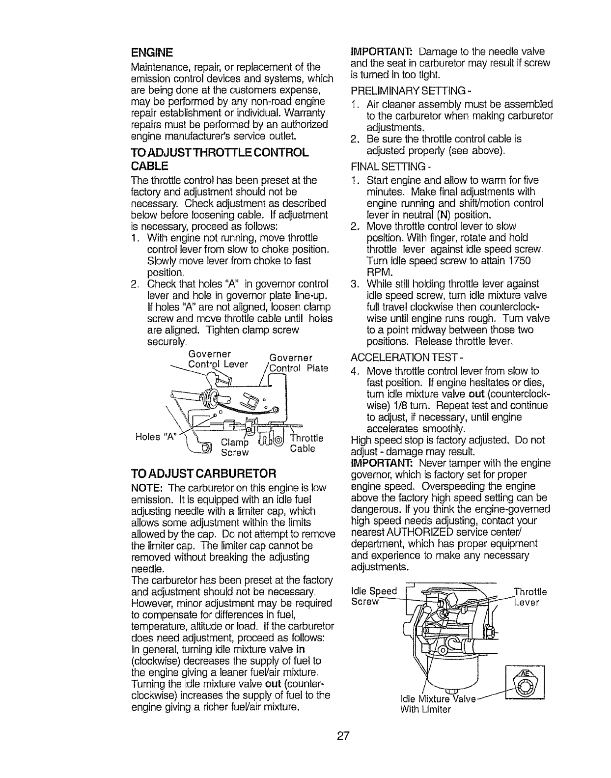
2. Check that holes "A" in governor control
lever and hole in governor plate line-up.
If holes "A" are not aligned, loosen clamp
screw and move throttle cable until holes
are aligned, Tighten clamp screw
securely.
Governer Governer
-.._.Contr_ Lever /Control Plate
S_'ew .... _ Cable
TO ADJUST CARBURETOR
NOTE: The carburetor on this engine is low
emission. It is equipped with an idle fuel
adjusting needle with a limiter cap, which
allows some adjustment within the limits
allowed by the cap. Do not attempt to remove
the iimiter cap. The limiter cap cannot be
removed without breaking the adjusting
needle.
The carburetor has been preset at the factory
and adjustment should not be necessary.
However, minor adjustment may be required
to compensate for differences in fuel,
temperature, altitude or load, If the carburetor
does need adjustment, proceed as follows:
In general, turning idle mixture valve in
(clockwise) decreases the supply of fuel to
the engine giving a leaner fuel/air mixture.
Turning the idle mixture valve out (counter-
clockwise) increases the supply of fuel to the
engine giving a richer fueVair mixture.
IMPORTANT: Damage to the needle valve
and the seat in carburetor may result if screw
is turned in too tighL
PRELIMINARY SETTING -
1_, Air cleaner assembly must be assembled
to the carburetor when making carburetor
adjustments,
2. Be sure the throttle control cable is
adjusted properly (see above)_
FINAL SETTING -
1. Start engine and allow to warm for five
minutes. Make final adjustments with
engine running and shift/motion control
lever in neutral (N) position,
2. Move throttle control lever to slow
position. With finger, rotate and hold
throttle lever against idle speed screw.
Turn idle speed screw to attain 1750
RPM.
3o While still holding throttle lever against
idle speed screw, turn idle mixture valve
full travel clockwise then counterclock-
wise until engine Pans rough. Turn valve
to a point midway between those two
positions. Release throttle lever.
ACCELERATION TEST -
4. Move throttle control lever from slow to
fast position. If engine hesitates or dies,
turn idle mixture valve out (counterclock-
wise) 1/8 turn. Repeat test and continue
to adjust, if necessary, until engine
accelerates smoothly.
High speed stop is factory adjusted. Do not
adjust -damage may result.
IMPORTANT: Never tamper with the engine
governor, which is factory set for proper
engine speed° Overspeeding the engine
above the factory high speed setting can be
dangerous. If you think the engine-governed
high speed needs adjusting, contact your
nearest AUTHORIZED service center/
department, which has proper equipment
and experience to make any necessary
adjustments.
Idle S Throttle
Lever
Idle Mixture Valve __--_
With Limiter
27
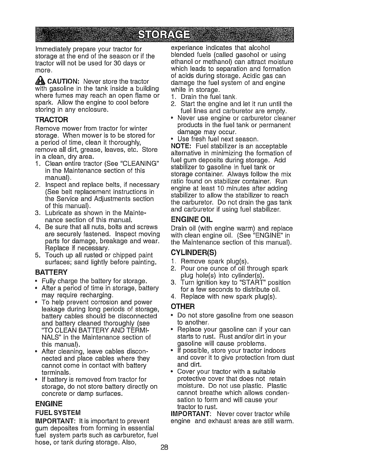
Immediately prepare your tractor for
storage at the end of the season or if the
tractor will not be used for 30 days or
more.
CAUTION: Never store the tractor
with gasoline in the tank inside a building
where fumes may reach an open flame or
spark. Allow the engine to cool before
storing in any enclosure.
TRACTOR
Remove mower from tractor for winter
storage° When mower is to be stored for
a period of time, clean it thoroughly,
remove all dirt, grease, leaves, etc. Store
in a clean, dry area°
I. Clean entire tractor (See "CLEANING"
in the Maintenance section of this
manual).
2_ Inspect and replace belts, if necessary
(See belt replacement instructions in
the Service and Adjustments section
of this manual).
3o Lubricate as shown in the Mainte-
nance section of this manual.
4. Be sure that all nuts, bolts and screws
are securely fastened. Inspect moving
parts for damage, breakage and wear°
Replace if necessary.
5. Touch up all rusted or chipped paint
surfaces; sand lightly before painting.
BATTERY
= Fully charge the battery for storage.
• After a period of time in storage, battery
may require recharging.
o To help prevent corrosion and power
leakage during long periods of storage,
battery cables should be disconnected
and battery cleaned thoroughly (see
"TO CLEAN BATTERY AND TERMI-
NALS" in the Maintenance section of
this manual).
° After cleaning, leave cables discon-
nected and place cables where they
cannot come in contact with batter,/
terminals.
•if batten.7 is removed from tractor for
storage, do not store battery directly on
concrete or damp surfaces.
ENGINE
FUEL SYSTEM
IMPORTANT: It is important to prevent
gum deposites from forming in essential
fuel system parts such as carburetor, fuel
hose, or tank during storage. Also, 28
experiance indicates that alcohol
blended fuels (called gasohol or using
ethanol or methanol) can attract moisture
which leads to separation and formation
of acids during storage. Acidic gas can
damage the fuel system of and engine
while in storage,
1. Drain the fuel tank,
2. Start the engine and let it run until the
fuel lines and carburetor are empty.
o Never use engine or carburetor cleaner
products in the fuel tank or permanent
damage may occur.
o Use fresh fuel next season.
NOTE: Fuel stabilizer is an acceptable
alternative in minimizing the formation of
fuel gum deposits during storage. Add
stabilizer to gasoline in fuel tank or
storage container. Always follow the mix
ratio found on stabilizer container. Run
engine at least 10 minutes after adding
stabilizer to allow the stabilizer to reach
the carburetor° Do not drain the gas tank
and carburetor if using fuel stabilizer,,
ENGINE OIL
Drain oil (with engine warm) and replace
with clean engine oil, (See "ENGINE" in
the Maintenance section of this manual).
CYLINDER(S)
1. Remove spark plug(s).
2. Pour one ounce of oil through spark
plug hole(s) into cylinder(s).
3. Turn ignition key to "START" position
for a few seconds to distribute oil.
4. Replace with new spark plug(s).
OTHER
o Do not store gasoline from one season
to another.
° Replace your gasoline can if your can
starts to rust. Rust and/or dirt in your
gasoline wilt cause problems.
° If possible, store your tractor indoors
and cover it to give protection from dust
and dirt.
° Cover your tractor with a suitable
protective cover that does not retain
moisture. Do not use plastic. Plastic
cannot breathe which allows condem
sation to form and will cause your
tractor to rust.
IMPORTANT: Never cover tractor while
engine and exhaust areas are still warm.
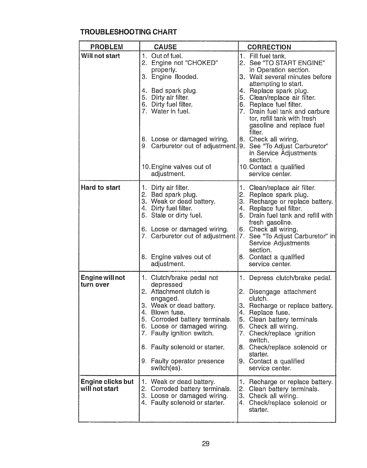
TROUBLESHOOTING CHART
PROBLEM
Will not start
CAUSE
1o Out of fuelo
2o Engine not "CHOKED"
properly.
3, Engine flooded,
Hard to start
4. Bad spark plug,
5_ Dirty air filter.
6, Dirty fuel filter°
7. Water in fuel
8, Loose or damaged wiring,
9. Carburetor out of adjustment
10, Engine valves out of
adjustment.
1_ Dirty air filter.
2. Bad spark plug.
3. Weak or dead battery,
4. Dirty fuel filter,
5, Stale or dirty fuel.
6. Loose or damaged wiring,
7. Carburetor out of adjustmenL
8. Engine valves out of
adjustment°
CORRECTION
1, Fill fuel tank.
2. See "TO START ENGINE"
in Operation section,
3. Wait several minutes before
attempting to start.
4_ Replace spark plug.
5,, Clean/replace air filter.
6. Replace fuel filter°
7, Drain fuel tank and carbure
tor, refill tank with fresh
gasoline and replace fuel
filter,
8, Check all wiring.
9. See "To Adjust Carbureto¢'
in Service Adjustments
section,
10.Contact a qualified
service center.
1. Clean/replace air filter°
2o Replace spark plug.
3_ Recharge or replace battery.
14o Replace fuel filten
5o Drain fuel tank and refill with
fresh gasoline.
i6. Check all wiring.
7. See "To Adjust Carburetor" in
Service Adjustments
sectiom
8. Contact a qualified
sen,ice center_
Engine will not
turn over !2.
3o
L4,
i5o
i6.
17.
8,
9.
Clutch/brake pedal not
depressed
Attachment clutch is
engaged°
Weak or dead battery.
Blown fuse.
Corroded battery terminals.
Loose or damaged wiring°
Faulty ignition switch.
Faulty solenoid or starter.
Faulty operator presence
switch(es).
!o Depress clutch!brake pedal°
!2, Disengage attachment
clutch°
!3. Recharge or replace battery.
i4_ Replace fuse.
15. Clean battery terminals,
i6, Check all wiring.
7, Check!replace ignition
switch,
8, Check/replace solenoid or
starter.
9. Contact a qualified
service centen
Engine clicks but
wilt not start
1o
i2.
3.
Weak or dead battery. 1. Recharge or replace battery.
Corroded battery terminals. 2_ Clean battery terminals.
Loose or damaged wiring. 3. Check all wiring°
Faulty solenoid or starter. 4_ Check/replace solenoid or
starten
29
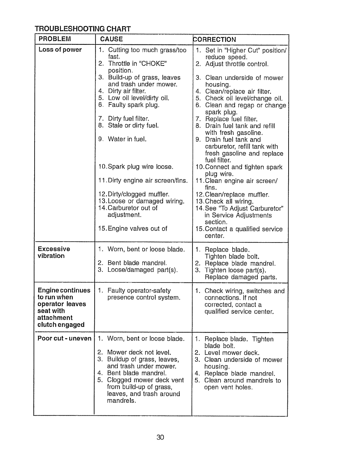
TROUBLESHOOTING CHART
PROBLEM CAUSE
Loss of power 1.
2,
3o
4o
5.
6.
7.
8,
9.
vibration
CORRECTION
Cutting too much grass/too
fast.
Throttle in "CHOKE"
position_
Build-up of grass, leaves
and trash under mower.
Dirty air filter°
Low oil level/dirty oil.
Faulty spark plugo
Dirty fue! filter.
Stale or dirty fuel.
Water in fuel.
1. Set in "Higher Cut" position/
reduce speed.
2, Adjust throttle control.
3. Clean underside of mower
housing.
4_ Clean/replace air filter.
5. Check oil level/change oil.
6. Clean and regap or change
spark plug.
7. Replace fuel filter.
8. Drain fuel tank and refill
with fresh gasoline.
9. Drain fuel tank and
carburetor, refill tank with
fresh gasoline and replace
fuel filter.
Engine continues
to run when
operator leaves
seat with
attachment
clutch engaged
Poor cut -uneven
t0_Spark plug wire loose,
11_ Dirty engine air screen/finso
12.Dirty/clogged muffler.
13.Loose or damaged wiring.
14. Carburetor out of
adjustment.
15. Engine valves out of
1. Worn, bent or loose blade°
2. Bent blade mandrel.
3. Loose/damaged part(s)o
1. Faulty operator-safety
presence control system.
14
2.
3.
4o
5.
Worn, bent or loose blade,,
Mower deck not level.
Buildup of grass, leaves,
and trash under mower.
Bent blade mandrel.
Clogged mower deck vent
from build-up of grass,
leaves, and trash around
mandrels.
1&Connect and tighten spark
plug wire°
11 ,Clean engine air screen/
fins.
I2. Clean/replace muffler,
13,Check all wiring,
14, See "To Adjust Carburetor"
in Service Adjustments
section,
15.Contact a qualified service
center,
1. Replace blade,
Tighten blade bolt.
2. Replace blade mandrel.
3. Tighten loose part(s).
Replace damaged parts.
,Check wiring, switches and
connections. If not
corrected, contact a
qualified service center.
1. Replace blade. Tighten
blade boll
2. Level mower deck.
3. Clean underside of mower
housing.
4. Replace blade mandrel.
5. Clean around mandrels to
open vent holes.
3O

TROUBLESHOOTING CHART
PROBLEM CAUSE
Mower blades will
not rotate
Poor grass
discharge
Headlight(s) not
working
(if so equipped)
Battery will not
charge
Loss of drive
Engine "backfires ''_,
whenturning
engine
"OFF"
CORRECTION
I. Obstruction in clutch
mechanism.
2., Worn/damaged mower
drive belt.
3. Frozen idler pulley.
4. Frozen blade mandrel,
1, Remove obstruction,
2. Replace mower drive belto
3, Replace idler pulley.
4. Replace blade mandrel.
2o
3_
4.
5,
Engine speed too slow.
Travel speed too fast.
Wet grass.
Mower deck not level
Low/uneven tire air
pressure.
1. Place throttle control in
"FAST" position,
2_ Shift to slower speed,
3, Allow grass to dry before
mowing°
4, Level mower deck,
5, Check tires for proper air
pressure_
6. Worn, bent or loose blade.
7, Buildup of grass, leaves and
trash under mower,
8. Mower drive belt worn.
9. Blades improperly installed,,
10. Improper blades used.
11 .Clogged mower deck vent
holes from buildup of
grass, leaves, and trash
around mandrels.
1. Switch is"OFF".
2. Bulb(s) burned out,
3. Faulty light switch.
4. Loose or damaged wiring.
5. Blown fuse.
6. Replacetsharpen blade.
Tighten blade bolto
7. Clean underside of mower
housing,
8, Replace mower drive belt.
9, Reinstall blades sharp edge
down.
10oReplace with blades listed
in this manual.
11 ,Clean around mandrels to
open vent holes°
1, Turn switch "ON",
2. Replace bulb(s).
3, Check/replace light switch.
4, Check wiring and connec
tions.
5o Replace fuse,
2,
3.
4.
1.
2.
3,
Bad battery cetl(s).
Poor cable connections.
Faulty regulator
(if so equipped),
Faulty alternator.
Freewheel control in
"disengaged" position.
Motion drive belt worn,
damaged, or broken.
Air trapped in transmission
during shipment or
servicing.
Engine throttle control not
set at "SLOW"
position for 30 seconds
stopping engine.
31
1. Replace battery.
2. Check/clean all connec-
tions.
3. Replace regulator.
4. Replace alternator.
1. Place freewheel control in
"engaged" position.
2. Replace motion drive bell
3. Purge transmission.
1. Move throttle control to
"SLOW" position and allow
to idle for 30 seconds before
stopping engine°

32
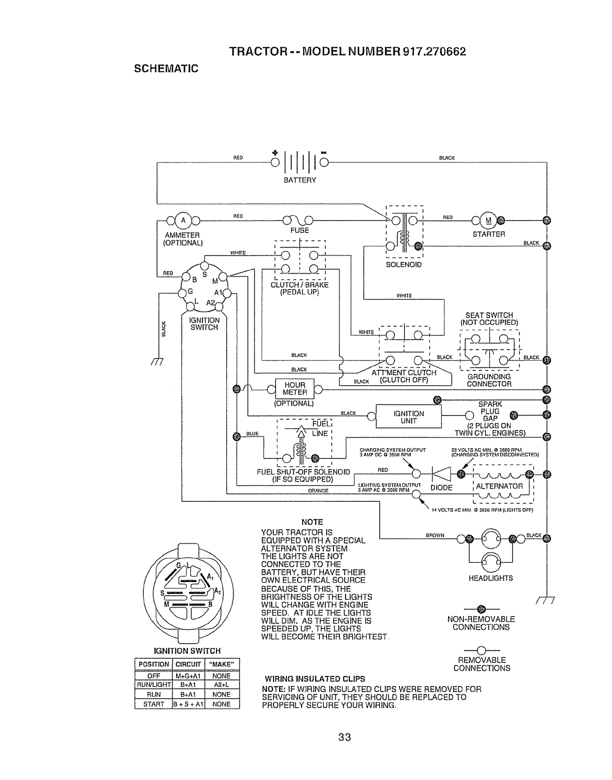
SCHEMATIC
TRACTOR -- MODEL NUMBER 917.270662
"ill--
BATTERY
)WHITE
_ SWITCH
)J
IGNITION SWITCH
C/"\J_ ' '
FUSE ', fi4tf! ,
I
M', _ ISOLENOID
,-+CL_i C,Z-F--
L
CLUTCH /BRAKE
(PEDAL UP) l wHrrB
RED
STARTER
BLACK
SEAT SWITCH
_,I(NOTOCCUPIED)
, ' J1 ..... IL
BLA C;"; I _ BLOC II
B_CK / ATT'MENTCLUTCH _ -a_)I_I_D_I_G-"
_J HOUR l_m BLACK (CLUTCH OFF) J _I_NN_CTOR
--_ METERp' SPARK
PLUG _
I ',J GAP
l (2 PLUGS ON
TWIN CYL. ENGINES)
(_ IGNITIONUNIT
(OPTIONAL)
BLACK
',- - - 1- -FO_LI
)_A_ ; ---7'_LINE ',
FUEL SHUT-OFF SOLENOID
(IF SO EQUIPPED)
ORAI'JGE
CHA_GtNG aYBTEM OI/T_'UT 28 VOL_ AC IAIt'L@ _6_ RP),|
3 AMP DO @3_00 RPM (CHARGING SYBI"EM DISCONHEC'rBD}
_'_cG_"_%%_'_#2P_.uT DIODE , ALTERNATOR t'
NOTE
YOUR TRACTOR IS
EQUIPPED WITH A SPECIAL
ALTERNATOR SYSTEM.
THE LIGHTS ARE NOT
CONNECTED TO THE
BATTERY, BUT HAVE THEIR
OWN ELECTRICAL SOURCE-
BECAUSE OF THIS, THE
BRIGHTNESS OF THE LIGHTS
W1LL CHANGE WITH ENGINE
SPEED, AT IDLE THE LIGHTS
WILL DIM. AS THE ENGINE IS
SPEEDED UP, THE LIGHTS
WILL BECOME THEIR BRIGHTEST
BROWN
POSITION CIRCUIT "MAKE"
OFF M+G+A'_ NONE
NUN]LIGHT B+A1 A2÷L
RUN B+At NONE
START ,3+S+A1 NONE
WIRING INSULATED CLIPS
HEADLIGHTS /_
NON-REMOVABLE
CONNECTIONS
O
REMOVABLE
CONNECTIONS
NOTE: IF WIRING INSULATED CLIPS WERE REMOVED FOR
SERVICING OF UNIT, THEY SHOULD BE REPLACED TO
PROPERLY SECURE YOUR WIRING.
33
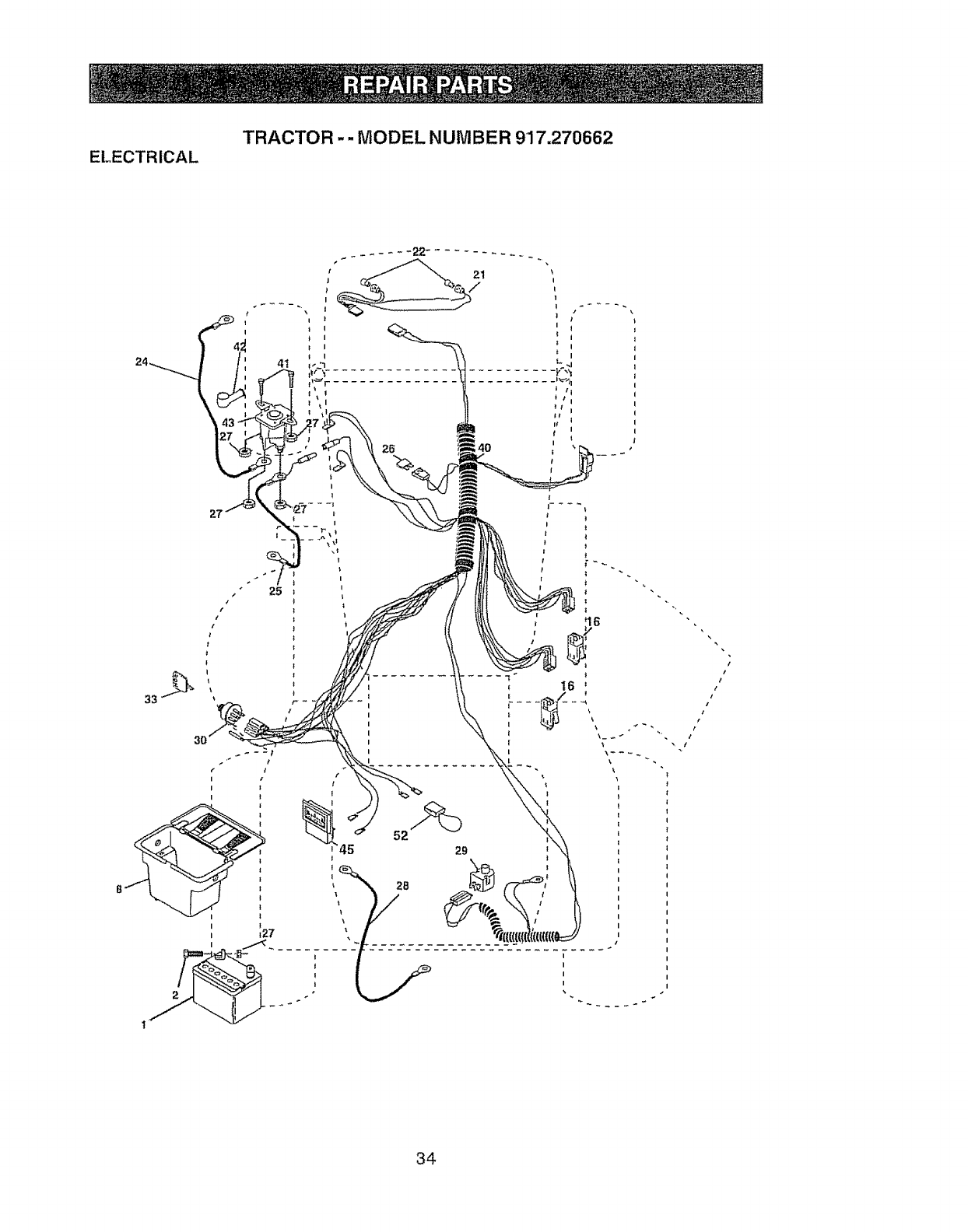
ELECTRICAL
TRACTOR -- MODEL NUMBER 917.270662
t
34

TRACTOR -- MODEL NUMBER 917.270662
KEY PART
NO. NO. DESCRIPTION
t 144925 8artery t2 VOLT 25 AMP
2 74760412 Bolt Hex Hd 1/4-20unc x 3/4
8156417 Case Battery
t6 153664 Switch, Interlock Push-In
21 166182 Harness Asm Light W/4152j
22 4152J Bulb Light #1156
24 4799J Cable Battery 6 Ga 1t" red
25 146147 Cable Battery 6 Ga w/16 wire red
26 166180 Fuse !5 AMP
27 73510400 Nut Keps Hex 1/4-20 Unc
28 4207J Cable Ground 6 Ga 12" black
29 121305X Switch Hunger Nc Gray
30 163968 Switch Ign
33 140403 Key Ign
40 170217 Harness Ign
41 7! 110408 Bolt BikoFin Hex 1/4-20 Unc x 1/2
42 131563 CoverTerminal Red
43 145673 Solenoid
45 121433X Ammeter Rectangular 6Amp
52 141940 Protection Wire Loop
NOTE; All component dimensions given in U.S inches
1 inch = 25 4 mm
35
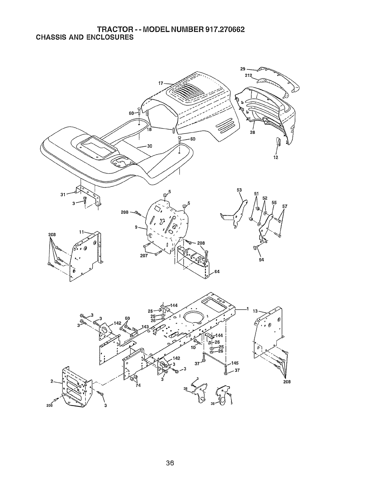
TRACTOR -- MODEL NUMBER 917.270662
CHASSIS AND ENCLOSURES
29
212
28
12
53
52 55
54
57
6O
74 208
36
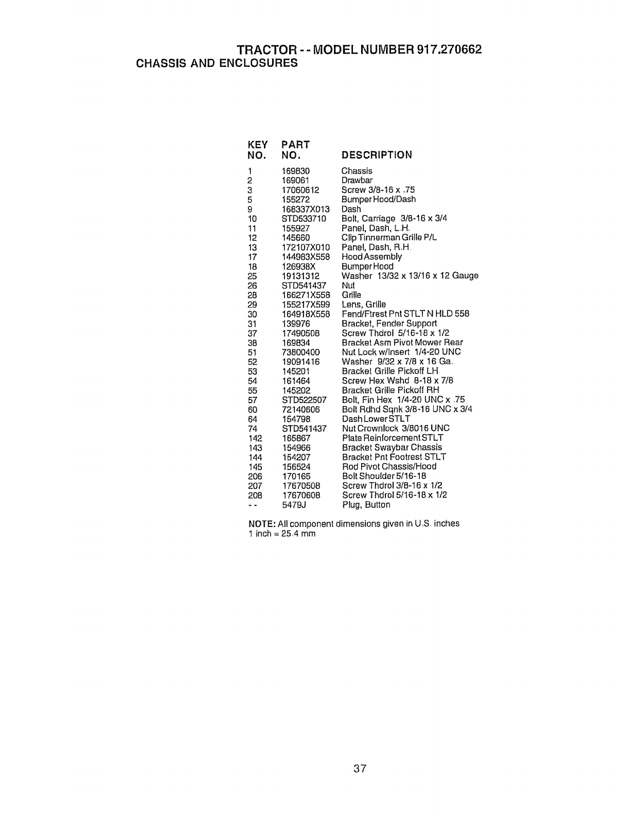
TRACTOR -- MODEL NUMBER 917.270662
CHASSIS AND ENCLOSURES
KEY PART
NO. NO. DESCRIPTION
1 169830 Chassis
2 !69061 Drawbar
3 17060612 Screw 3/8-16 x °75
5 t55272 Bumper Hood/Dash
9 168337X013 Dash
10 STD5337t0 Bolt, Carriage 3/8-16 x 3/4
11 155927 Panel, Dash, LH.
12 145660 CItp Tinnerman Grille P/L
t3 172107X010 Panel, Dash, Roll
t7 144983X558 Hood Assembly
I8 126938X BumperHood
25 19131312 Washer 13/32 x 13/16 x 12 Gauge
26 STD54t437 Nut
28 166271X558 Gdlle
29 t55217X599 Lens, Grftte
30 I64916X558 FendfFtrest Pnt STLT N HLD 558
31 139976 Bracket, Fender Support
37 17490508 Screw Thdrol 5/16-18 x 1/2
38 169834 Bracket Asm Pivot Mower Rear
51 73800400 Nut Lock w/Insert 1/4-20 UNC
52 19091416 Washer 9/32 x 7/8 x 16 Ga°
53 14520t Bracket Grille Pickoff LH
54 161464 Screw Hex Wshd 8-18 x 7/8
55 145202 Bracket Grille Pickoff RH
57 STD522507 Bolt, Fin Hex 1/4-20 UNC x ,75
60 72140606 Bolt Rdhd Sqnk 3/84 6 UNC x 3/4
64 154796 Dash LowerSTLT
74 STD541437 Nut Crownlock 3/8016 UNC
t42 !65867 Plate Reinforcement STLT
143 t54966 Bracket Swaybar Chassis
144 t54207 Bracket Pnt Footrest STLT
145 156524 Rod Pivot Chassis/Hood
206 170165 Bolt Shoulder 5t16-18
207 17670508 Screw Thdrol 3/8-16 x 1/2
208 17670608 Screw Thdrol 5/t6-!6 x 1/2
-- 5479J Plug, Button
NOTE: All component dimensions given in U.S. inches
! inch = 25.4 mm
37
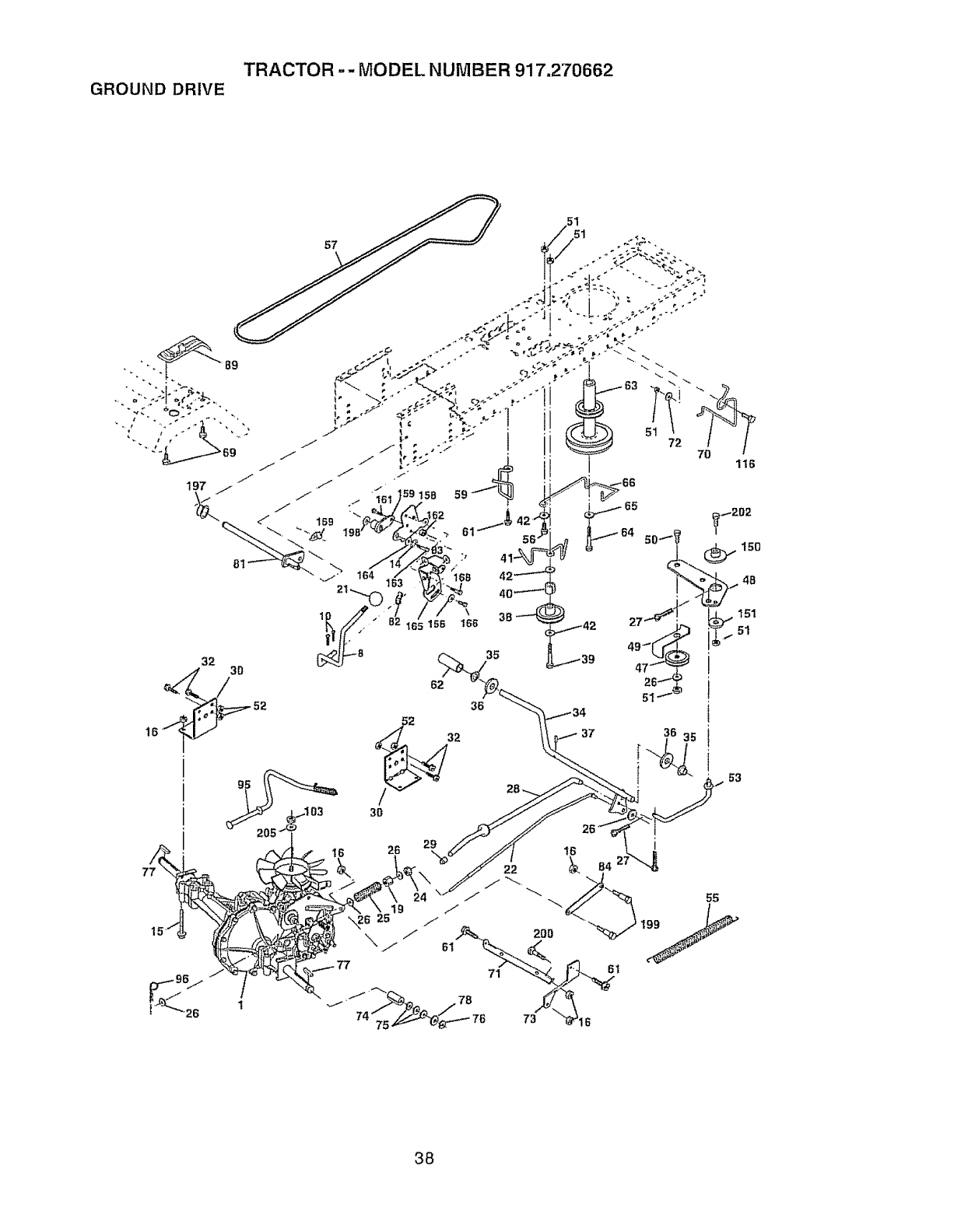
TRACTOR -- MODEL NUMBER 917.270662
GROUND DRIVE
77
15'
38
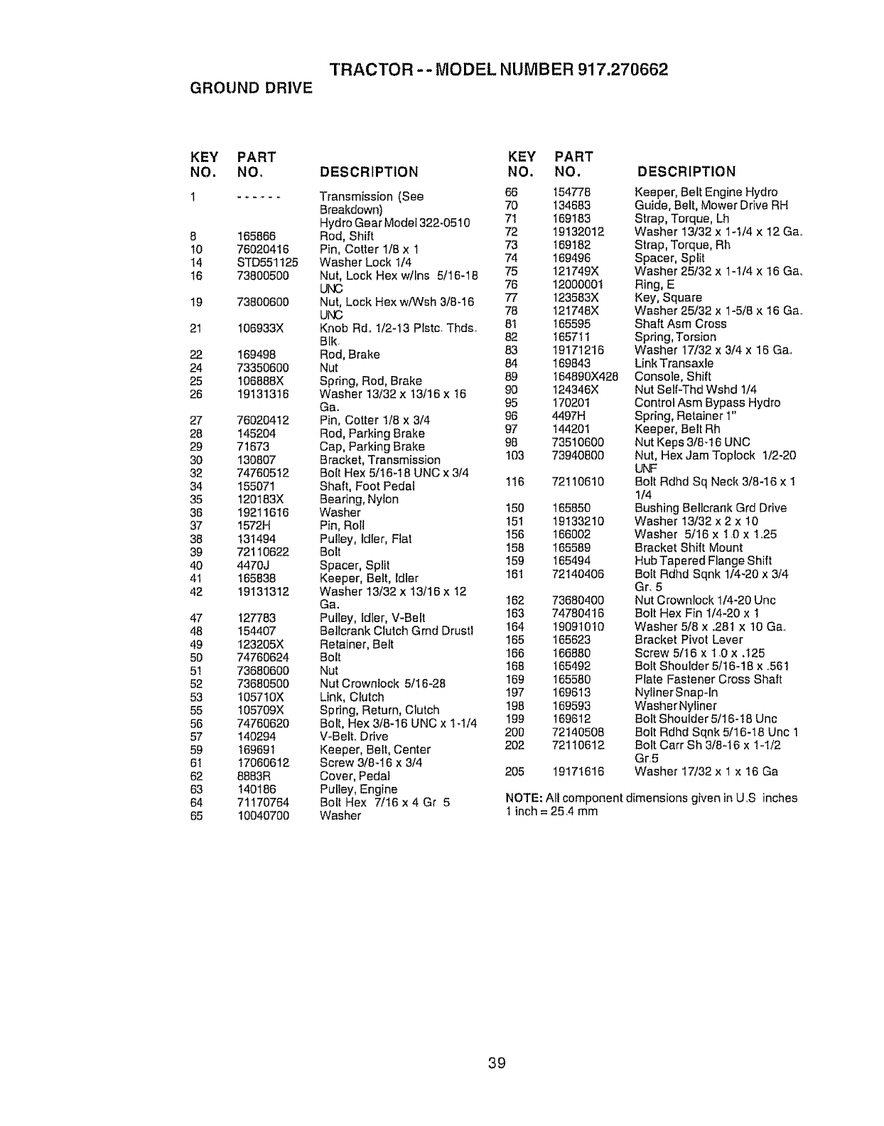
TRACTOR -- MODEL NUMBER 917.270662
GROUND DRIVE
KEY PART KEY PART
NO, NOo DESCRIPTION NO. NO.
1 ...... Transmission (See 66 154778
Breakdown) 70 134683
Hydro Gear Modet 322-0510 71 169183
8 165886 Rod, Shift 72 19132012
10 76020416 Pin, Cotter 1/8 x 1 73 169182
14 STD551125 Washer Lock 1/4 74 !89496
16 73800500 Nut, Lock Hex w/Ins 5/16-18 75 121749X
UNC 76 1200000t
19 73800600 Nut, Lock Hex w/Wsh 3/8-16 77 123583X
UNC 78 12t748X
21 106933X Knob Rd. 1/2-I3 Plstc. Thds_ 81 165595
BIk 82 16571I
22 169498 Rod, Brake 83 19171216
24 73350600 Nut 84 169843
25 106888X Spring, Rod, Brake 89 164890X428
26 19131316 Washer 13/32 x 13/16 x 16 90 124346X
Gao 95 170201
27 76020412 Pin, Cotter t/8 x 3/4 96 4497H
28 145204 Rod, Parking Brake 97 144201
29 71673 Cap, Parking Brake 98 73510600
30 130807 Bracket, Transmission 103 73940800
32 74760512 Bolt Hex 5/t6-t 8 UNC x 3/4
34 155071 Shaft, Foot Pedat 116 72110610
35 120183X Bearing, Nylon
36 19211616 Washer 150 165850
37 1572H Pin, Roll 151 19133210
38 131494 Pulley, Idler, Flat 156 166002
39 72110622 Bolt 158 165589
40 4470J Spacer, Split 159 165494
41 165838 Keeper, Belt, Idler 16t 72140406
42 19131312 Washer 13/32 x t3116 x !2
Ga. 162 73680400
47 127783 Pulley, tdfer, V_Belt 163 74780416
48 154407 Bellcrank Clutch Grnd Drustl 164 19091010
49 I23205X Retainer, Belt 165 165623
50 74760624 Bolt 166 166880
5t 73680600 Nut 168 165492
52 73680500 Nut Crowntock 5/I 6-28 169 165580
53 t05710X Link, Clutch 197 169613
55 I05709X Spring, Return, Clutch t98 169593
56 74760620 Bolt, Hex 3/8-16 UNC x 1-1/4 199 169612
57 140294 V-Belt. Drive 200 72140508
59 169691 Keeper, Belt, Center 202 72110612
6! 17060612 Screw 3/8-I6 x 3/4
62 8883R Cover, Peda] 205 19171616
63 140186 Pulley, Engine
64 71170764 Bolt Hex 7/I6 x 4 Gr 5
65 10040700 Washer
DESCRIPTION
Keeper, Belt Engine Hydro
Guide, Belt, Mower Drive RH
Strap, Torque, Lh
Washer 13t32 x 1q/4 x 12 Ga,.
Strap, Torque, Rh
Spacer, Split
Washer 25/32 x 1-1t4 x 16 Ga,.
Ring, E
Key, Square
Washer 25/32 x 1-5/8 x 16 Ga..
Shaft Asm Cross
Spdng, Torsion
Washer 17/32 x 3/4 x 16 Ga.,
Link Transaxle
Console, Shift
Nut Self-Thd Wshd 1/4
Control Asm Bypass Hydro
Spring, Retainer 1"
Keeper, Belt Rh
Nut Keps 3/846 UNC
Nut, Hex Jam Toplock 1/2-20
U_,,F
Bolt Rdhd Sq Neck 3/6-16 x 1
1/4
Bushing Bellcrank Grd Drive
Washer 13/32 x 2 x 10
Washer 5/16 x t .0 x t,25
Bracket Shift Mount
Hub Tapered Flange Shift
Boit Rdhd Sqnk 1/4-20 x 3/4
Gr. 5
Nut Crownlock 1/4-20 Uric
Bolt Hex Fin 1/4-20 x 1
Washer 5/8 x .281 x 10 Ga..
Bracket Pivot Lever
Screw 5/16 x 1.0 x .t25
Bolt Shoulder 5/16-18 x .561
Plate Fastener Cross Shaft
Nyllner Snap-ln
WasherNyfiner
Bott Shoulder 5/16-18 Unc
Bott Rdhd Sqnk 5/16-18 Unc 1
Bolt Carr Sh 3/8-t6 x t-1/2
Gr.5
Washer 17/32 x 1 x 16 Ga
NOTE: Alt component dimensions given inU.S inches
1inch = 25,4 mm
39
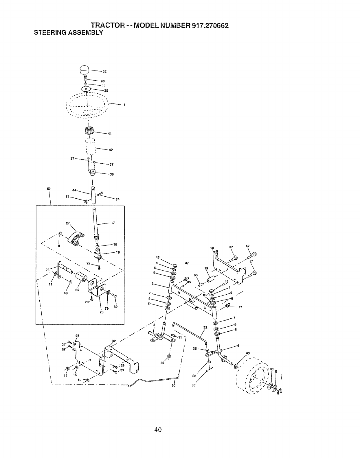
TRACTOR -- MODEL NUMBER 917,270662
STEERING ASSEMBLY
67_
,:!:,,
68
/
4O /
IO
26
3O
67 67
I/
If
I/
\t
40

TRACTOR -- MODEL NUMBER 917.270662
STEERING ASSEMBLY
KEY PART
NO. NO, DESCRIPTION
1 139768
2 154427
3 156463
4 157473
5 6266H
6 t21748X
7 19272016
8 12000029
9 3366R
10 169832
1I STD55!137
13 136516
!5 145212
17 156546
18 57O79
19 160395
22 165857
23 165851
25 154406
26 126847X
27 136874
28 19131416
29 17060612
3O STD561210
32 130465
36 155099
37 152927
38 139769
39 19133812
4O STD541537
4! 100711L
42 145054X428
43 121749X
44 153720
46 121232X
47 6855M
51 STD54143t
54 74780520
62 167902
63 STD523710
65 160367
66 1544O4
67 72140618
68 169827
79 19132012
80 74950612
82 169635
85 133835
SteedngWheel
A×_eAssembly STMP Dropped STL
Spindle Assembly, L.H.
Spindle Assembly, RoHo
Bearing, Race, Thrust, Hardened
Washer 25/32 x 1-5/6 x t6 Gauge
Washer 27/32 x 1-1/4 x 16 Gauge
Ring, Ktip
Bearing, Steering Column
Draglink
Washer, Lock
Spacer Bearing Axle Front
Nut Hex Flange Lock
Shaft Assembly, Steering
Washer, Thrust ..515 x .750 x .033
Support, Shaft
Screw, Hex Wsh Hd Torx
Ptttman Shaft Assembly
Bracket, Steering
Bushing, Link, Drag
Gear, Sector
Washer 13/32 x 7/8 x 16 Gauge
Screw 3f8-16 x 3/4
Pin
Rod,Tie
Bushing, Steering
Screw
Insert, SteeringWheel
Washer 13132x 2-3/8 x12 Gauge
Gripco Nut
Adaptor, Steering Wheel
Boot, Steedng Shaft
Washer 25/32 x 1-114x 16 Gauge
Extension Shaft Steering LR.LT
Cap, Spindle
Fitting, Grease
Nut Lock Hex w/Ins 5/t6-18 UNC
Bolt Fin Hex 5/16_18 UNC x t-1/4
Kit Steering Asm Service
Bolt, Fin Hex 3/8-16 UNC x 1 Gr 5
Spacer Brace Axle
Bearing Arm Pittman
Bolt Rdhd Sq 3/B-16 Unc x 2-1/4
Axle, Brace
Washer 13/32 x I-I/4 x 12 Ga.
Bolt Hex Nylon 3/8-I6 x 3/4
Bracket Susp Chassis Front
Fastner Christmas Tree
NOTE: All component dimensions given in U.S. inches
1 inch = 25.4 mm
41
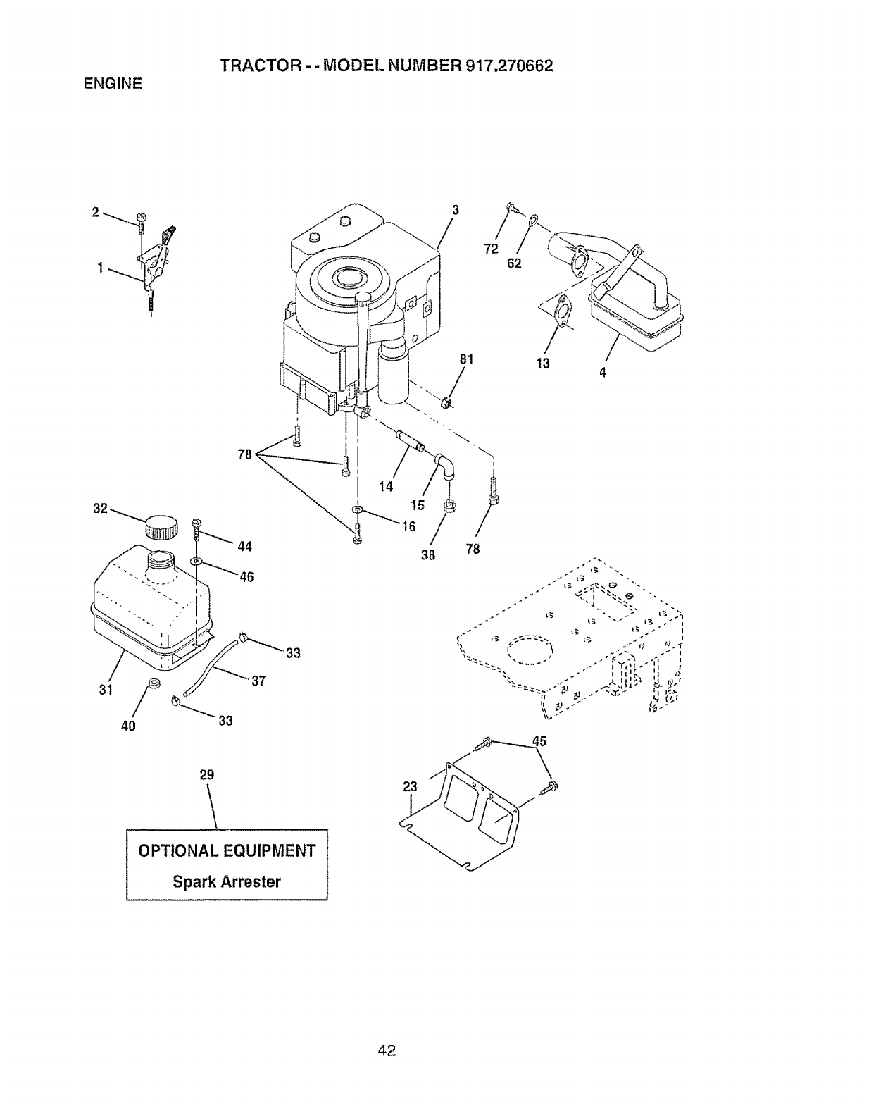
ENGINE TRACTOR - - MODEL NUMBER 917.270662
3
/72 62
?
13 4
33
37
40 33
29 23
OPTIONAL EQUIPMENT
Spark Arrester
42

ENGINE TRACTOR-- MODEL NUMBER 917.270662
KEY PART
NO, NO. DESCRIPTION
1
2
3
162157
17720410
4 137352
13 165291
14 13280324
15 13200300
16 STD551237
23 169837
29 137180
3t 109202X
32 158990
33 123487X
37 137040
36 ......
40 124028X
44 17490412
45 17000612
46 19091416
62 STD55113I
72 71070512
78 17060620
81 73510400
Control Throt/Ch Lh
Screw Hex Thd Cut 1/4-20x5/8 T
Engine (See Breakdown)
Bdggs Modei28U707-1174-E3
Muffler Exhaust B&S Lt
Gasket 1 313 td Tin Plated
Nipple Pipe 318 Np! X 3"
Elbow Std 90 Degree 318q8 Npt
Washer Lock Ext Tooth 3!8
Shield Browning!Debris Guard
Arrestor Spark
Tank Fuel I 25 Fr
Cap Asm Fuel Sears Vented
Clamp Hose BIk
Line Fuel 20"
Plug Oil Drain (See Engine Breakdown)
Bushing Snap Nyt BIk Fuel Line
Screw Hexwsh Thdrol 1/4-20x3/4
Screw Hex Wsh Thdrol 3t8-I6 x 3/4
Washer 9/32 X 7/8 X 16ga
Washer Lock Hvy Hlcl Spr 5/16
Screw Hexhd Cap 5/16q 8x3/4
Screw 3/8-t6 x 1-1/4
Nut Keps Hex 1/4-20 Unc
NOTE: All component dimensions given in U.,S,,inches
1 inch = 25,4 mm
43
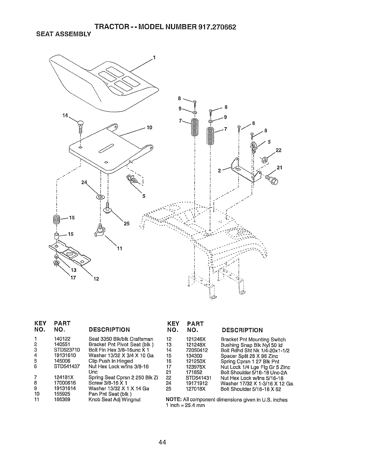
TRACTOR -- MODEL NUMBER 917.270662
SEAT ASSEMBLY
\
t4 J
10
17 12
//8
"_/-5 22
21
KEY
NO.
1
2
3
4
5
6
7
8
9
t0
1t
PART
NO. DESCRIPTION
140122
140551
STD5237t0
19131610
145006
STD54t437
124181X
17000616
19131614
155925
166369
KEY PART
NO. NO. DESCRIPTION
Seat 3350 Bfk/bik Craftsman 12
Bracket Pnt Pivot Seat (bik) 13
Bolt Fin Hex 3/8-16unc X 1 14
Washer 13/32 X 3/4 X 10 Ga 15
Clip Push In Hinged 16
Nut Hex Lock w!Ins 3/8-16 !7
Unc 21
Spring Seat Cprsn 2 250 Bik Zi 22
Screw 3/8-16 X 1 24
Washer 13/32 X 1 X 14 Ga 25
Pan Pnt Seat (blk)
Knob Seat Adj Wingnut
121246X
121248X
72050412
134300
121250X
123976X
171852
STD541431
19171912
127018X
Bracket Pnt Mounting Switch
Bushing Snap Blk Nyl 50 Id
_olt Rdhd Sht Nk !/4-20x1-1/2
Spacer Split 28 X 96 Zinc
Spring Cprsn 1 27 Blk Pnt
Nut Lock 1/4 Lge Fig Gr 5 Zinc
Bort Shoulder 5fl 6-18 Unc-2A
Nut Hex Lock wtlns 5/16-18
Washer 17/32 X 1-3/16 X 12 Ga,
Bolt Shoulder 5/16-18 X 62
NOTE: All componen_ dimensions given in UoS.inches
1 inch = 25,4 mm
44
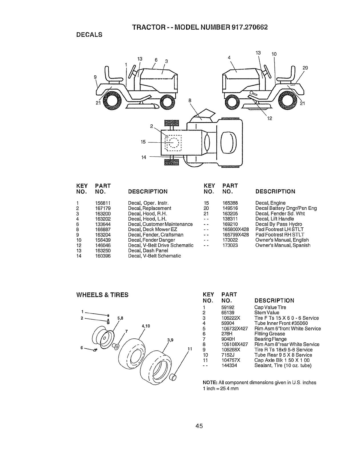
DECALS
TRACTOR -.- MODEL NUMBER 917,270662
t3 6 3
13 10
2O
15_
14_
8
12
KEY PART
NO, NO.
1 156811
2 167179
3 163200
4 163202
6 133644
8 166887
9 163204
10 156439
12 146046
13 163250
I4 160396
DESCRIPTION KEY PART
NO_ NO.
Decal Oper. Instr. 15
Decal, Replacement 20
Decal, Hood, Roll. 21
Decal, Hood, LH. - -
Decal, Customer Maintenance - -
Decal, Deck Mower EZ - -
Decal, Fender, Craftsman _ -
Decal, Fender Danger - -
Decal, V-Belt Drive Schematic - -
Decal, Dash Panel
Decal, V-Belt Schematic
165388
149516
163205
136311
169210
165800X428
165799X428
173022
173023
DESCRIPTION
Decal, Engine
Decal Battery Dngr/Psn Eng
Decal, Fender Sd, Wht
Decal, Lift Handle
Decal By Pass Hydro
Pad Footrest LH STLT
Pad Footrest RH STLT
Owner's Manual, English
Owner's Manual, Spanish
WHEELS & TIRES KEY PART
NO. NO.
t 59192
2 65139
3 I06222X
459904
5 I06732X427
6 278H
7 9040H
8 106108X427
11 9 I06268X
I0 7152J
II 104757X
-- 144334
DESCRIPTION
Cap Value Tire
Stem Value
Tire F Ts 15 X 6 0 - 6 Service
Tube Inner F[ont #35060
Rim Asm 6"front White Service
Fitting Grease
Bearing Flange
Rim Asm 8"rear White Service
Tire R Ts 18x9 5-8 Service
Tube Rear 95 X 8 Service
Cap Axle BIk 1 50 X t 00
Sealant, Tire (t0 oz. tube)
NOTE: All component dimensions given in U,S inches
1inch= 254 mm
45
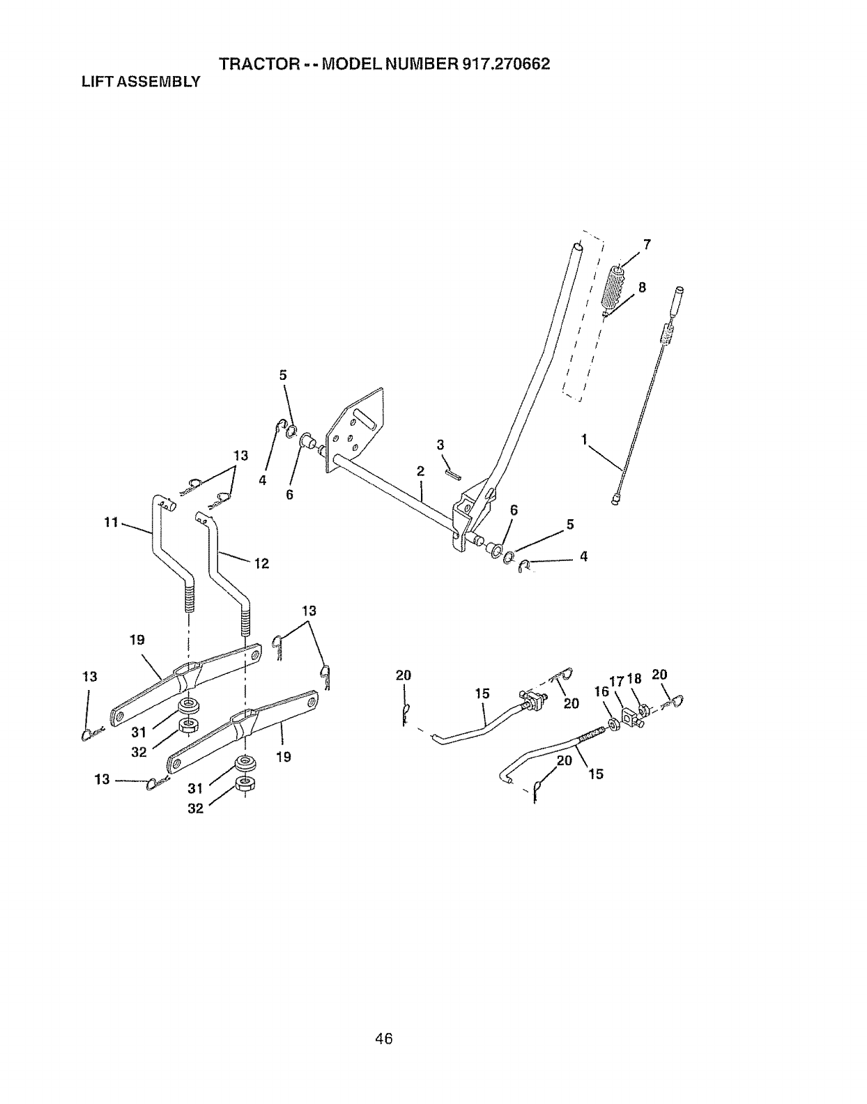
TRACTOR -- MODEL NUMBER 917.270662
LIFTASSEMBLY
7
!1
13
4
12
6
2
6
19
'13
32
I
I
32
19
2O
15
2O
46

TRACTOR -- MODEL NUMBER 917,270662
LIFT ASS EMBLY
KEY PART
NOo NO, DESCRIPTION
1 159460 Washer Asm Inner Spring W/Plunger
2 159471 Shaft Asm_ Lift
3 105787X Pin Groove
4 t2000002 E Ring #5 I33-62
5 19211621 Washer 21/32 x I x 21 Ga,
6 I20183X Bearing Nylong
7 12563tX Grip Handle Fluted
8 122365X Button Plunger Read
11 139865 Link Asm Lift L.H.
12 139866 Link Asm Lift R,H.
13 4939M RetainerSpring
15 167253 Link Front
16 73350800 Nut Jam Hex 1/2-t3 Unc
17 130171 Trunnion BIk Zinc
18 73680800 Nut Crown!ock 1/2-13 Uric
19 t39868 Arm Suspension Mower
20 163552 Retainer Spring
31 140302 Bearing, PvL Lift. Spherical
32 73540600 Nu_,Crownlock 3/8-24
NOTE; Alt component dimensions given in U ,S, inches
1 inch = 25A mm
47
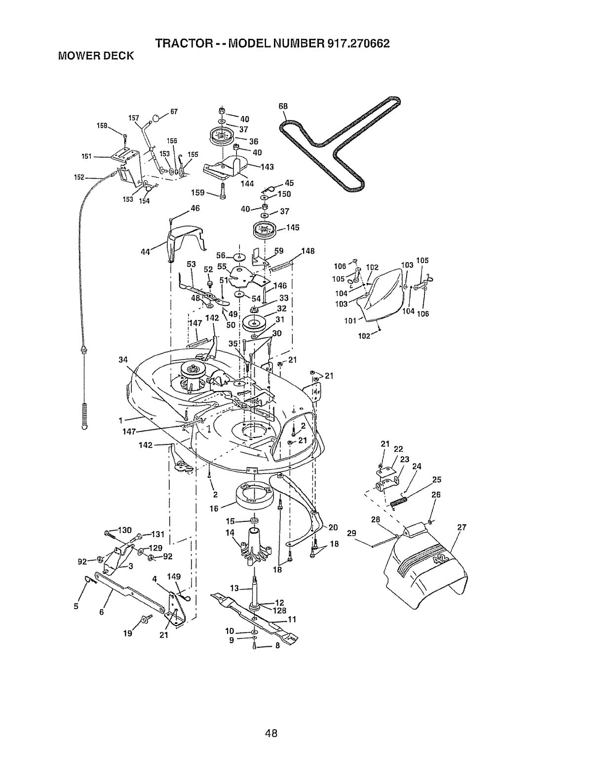
MOWERDECK TRACTOR -= MODEL NUMBER 917.270662
34
\
18
28
29
21 22
23 24
25
26
27
48
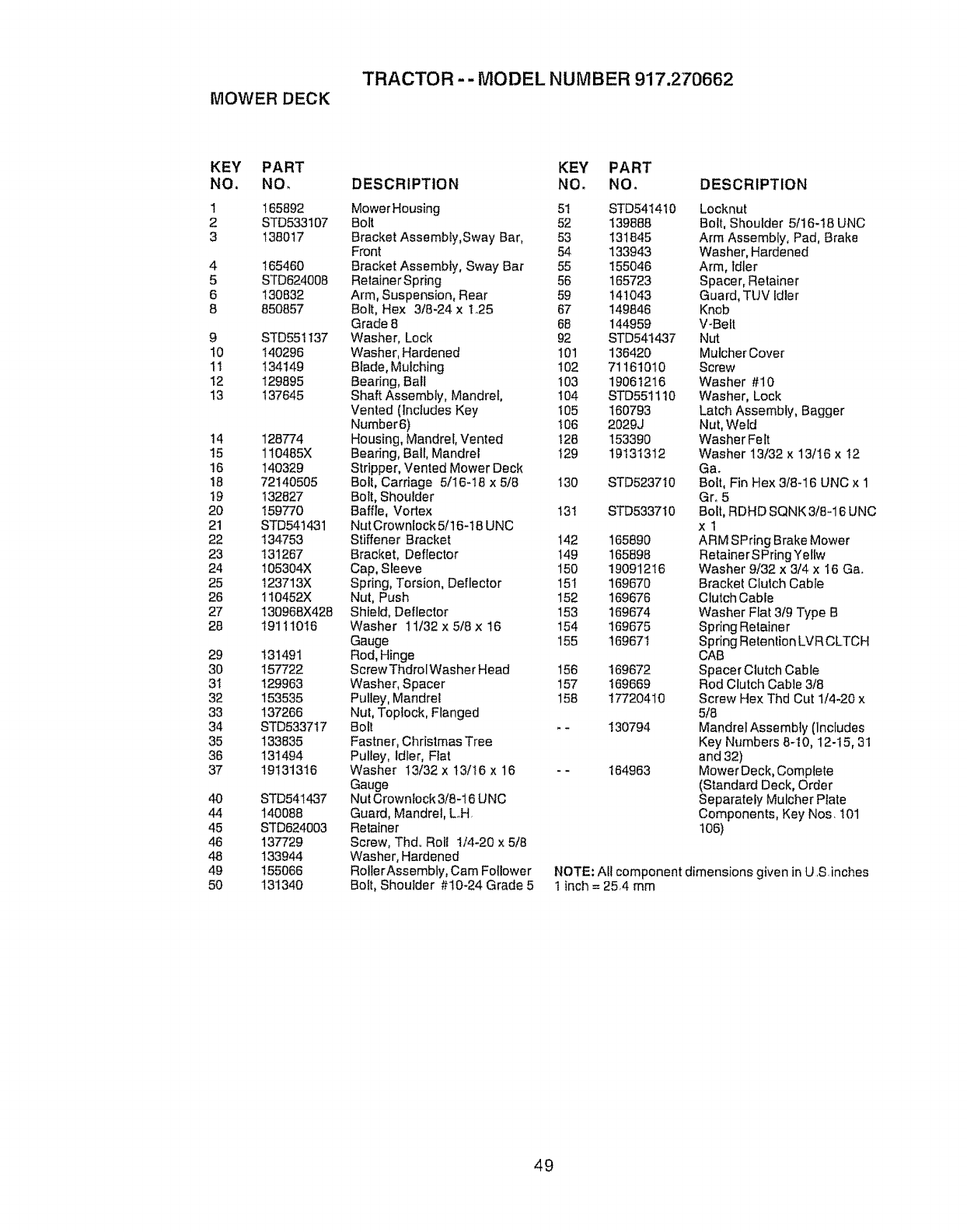
MOWER DECK
TRACTOR - - MODEL NUMBER 917.270662
KEY PART
NO. NOr
1
2
3
4
5
6
8
9
t0
tl
12
13
14
15
16
18
19
20
21
22
23
24
25
26
27
28
29
30
3t
32
33
34
35
36
37
4O
44
45
46
48
49
5O
165892
STD533107
138017
165460
STD624008
130832
850857
STD551137
140296
134149
129895
137645
128774
110485X
140329
72140505
132827
159770
STD541431
134753
131267
t05304X
I23713X
t10452X
130968X428
19111016
131491
157722
129963
153535
137266
STD533717
133835
131494
19131316
STD541437
140088
STD624603
137729
133944
155066
131340
KEY PART
DESCRIPTION NO. NO.
MowerHousing 5t STD541410
Bolt 52 139888
Bracket Assembly,Sway Bar, 53 131845
Front 54 133943
Bracket Assembly, Sway Bar 55 155046
RetainerSpring 56 165723
Arm, Suspension, Rear 59 141043
Bolt, Hex 318-24 x t+,25 67 149846
Grade 8 68 144959
Washer, Lock 92 STD54t437
Washer, Hardened 101 136420
Blade, Mulching 102 71161010
Bearing, Bali 103 19061216
Shaft Assembly, Mandrel, 104 STD551110
Vented (includes Key t05 160793
Number6) 106 2029J
Housing, Mandrel, Vented t28 153390
Bearing, Ball, Mandrel t29 19131312
Stripper, Vented Mower Deck
Bolt, Carriage 5/I6-16 x 5/8 t30 STD5237t0
Bolt, Shoulder
Baffle, Vortex 131 STD5337t0
NutCrownlock 5/16-18 UNC
Stiffener Bracket 142 165890
Bracket, Deflector 149 165898
Cap, Sleeve 150 19091216
Spring, Torsion, Deflector 15t 169670
Nut, Push 152 169676
Shield, Deflector 153 169674
Washer 11/32x5/8x 16 154 169675
Gauge 155 t6967t
Rod, Hinge
ScrewThdrolWasher Head 156 169672
Washer, Spacer 157 t69669
Pulley, Mandrel 158 17720410
Nut, Toptock, Flanged
Bolt -- 130794
Fastner, Christmas Tree
Pulley, Idler, Fiat
Washer I3/32x t3/16 x 16 +- 164963
Gauge
Nut Crown_ock3/8-16 UNC
Guard, Mandrel, L°H+
Retainer
Screw, Thd Rotl 1/4-20 x 5/8
Washer, Hardened
RotlerAssembty, Cam Follower
Bolt, Shouider #10-24 Grade 5
DESCRIPTION
Locknut
Bolt, Shoulder 5/16-18 UNC
Arm Assembly, Pad, Brake
Washer, Hardened
Arm, Idler
Space r, Retainer
Guard, TUV Idler
Knob
V-Belt
Nut
MulcherCover
Screw
Washer #10
Washer, Lock
Latch Assembly, Bagger
Nut, Weld
Washer Felt
Washer 13/32 x 13/I6 x I2
Ca+
Bolt, Fin Hex 3/8-16 UNC x 1
Gr° 5
Bolt, RDHD SQNK 3/8-16 UNC
xl
ARM SPring Brake Mower
Retainer SPringYellw
Washer 9/32 x 3/4 x I6 Ca+
Bracket Clutch Cable
Clutch Cable
Washer Flat 3/9 Type B
Spring Retainer
Spdng Retention LVR CLTCH
CAB
Spacer Clutch Cabte
Rod Clutch Cable 3/8
Screw Hex Thd Cut 1/4-20 x
5/8
Mandrel Assembly (Includes
Key Numbers 8-10, 12-15, 31
and32)
Mower Deck, Complete
(Standard Deck, Order
Separately Mulcher Plate
Components, Key Nos I01
106)
NOTE: All component dimensions given in US inches
1 inch = 254 mm
49
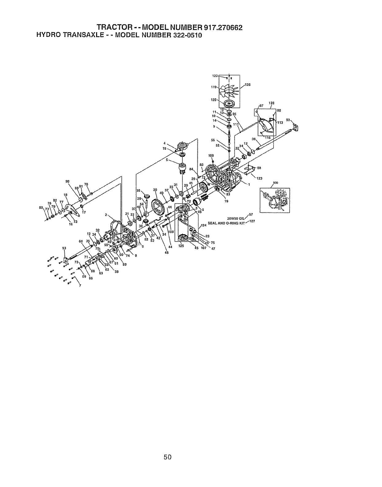
TRACTOR -- MODEL NUMBER 917.270662
HYDROTRANSAXLE- - MODELNUMBER322-0510
73
t6
93
7
4B
5O
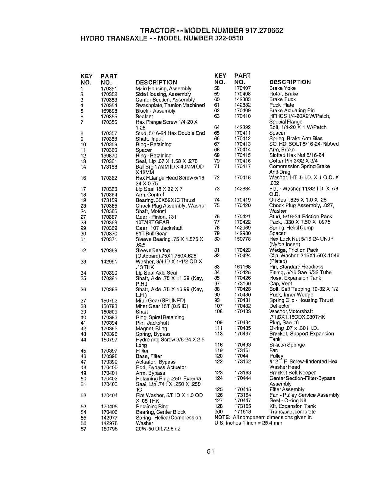
TRACTOR -- MODEL. NUMBER 917.270662
HYDRO TRANSAXLE - - MODEL NUMBER 322-05'10
KEY PART KEY PART
NO. NO. DESCRIPTION NO, NO.
1 170351 Main Housing, Assembly 58 170407
2170352 Side Housing, Assembly 59 170408
3 170353 Center Section, Assembly 60 142883
4 170354 Swashpiate,Trunion Machined 61 142882
5 169898 Block - Assembly 62 170409
6 170355 Sealant 63 170410
7 170356 Hex Flange Screw !/4-20 X
125 64 142892
8 170357 Stud, 5/16-24 Hex Double End 65 170411
9 170358 Shaft, Input 66 170412
10 170359 Ring- Retaining 67 170413
1t 170360 Spacer 68 170414
12 169870 Ring- Retaining 69 1704!5
13 170361 Seal, Up ,67 X to56 X .276 70 170416
14 173158 Ball Brg I7MM IDX 40MM OD 7t 170417
X 12MM
16 170362 Hex FLlange Head Screw 5/16 72 1704t8
24 X 0.75
17 170363 Lip Seal !8 X 32 X 7 73 142884
I8 170364 Arm, Control
19 173159 Bearing, 30X52X13 Thrust 74 170419
23 170365 Check Plug Assembly, Washer 75 170420
24 170366 Shaft, Motor1
27 170367 Gear - Pinion, t3T 76 170421
28 170368 10T/48TGEAR 77 170422
29 170369 Gear, t0T Jackshaft 78 142969
30 170370 60T Bull Gear 79 142980
31 170371 Sleeve Bearing ,75 X 1.575 X 80 150778
°625
32 170389 Sleeve Bearing 8t 170423
(Outboard).75X1.750X,625 82 170424
33 142991 Washer, 3/4 ID X 1-1/20D X
.13THK 83 161168
34 170390 Lip Seal Axle Seal 84 170425
35 170391 Shaft, Axle .75 X t 1.39 (Key, 85 170426
R.H.) 87 173160
36 170392 Shaft, Axle .75 X !6.99 (Key, 88 170428
L.H_) 90 I70€30
37 150792 Miter Gear (SPLiNED) 93 170431
38 150793 Miter Gear 15T (0r5 ID) 107 170432
39 150809 Shaft 108 I70433
40 I70393 Ring, Spiral Retaining
41 !70394 Pin, Jackshaft 109 t70434
42 170395 Magnet, Rling 111 t70435
43 170396 Spring, Bypass ! 13 170437
44 150797 Hydro mtg Screw 3/8-24 X 2.5
Long 116 170438
45 170397 Flilter 119 173161
46 170398 Base, Filter 120 17044
47 170399 Actuator, Bypass 122 173162
48 170400 Rod, Bypass Actuator
49 170401 Arm, Bypass 123 173163
50 170402 Retaining Ring .250 External 124 170444
51 170403 Seal, Lip .741 X 250 X 250
TC 125 170445
52 170404 Flat Washer, 5/8 ID X 1o00D 126 173164
X _05THK 127 170447
53 170405 Retaining Ring 128 173165
54 170406 Bearing, Center Block 900 171613
55 142977 Spring - HelicatCompression
56 142978 Washer
57 150798 20W-50 OIL728 oz
DESCRIPTION
Brake Yoke
Rotor, Brake
Brake Puck
Puck Plate
Brake Actuating Pin
HFHCS 1/4-20X2 W/Patch,
Special Flange
Bolt, 1/4-20 X 1 W/Patch
Spacer
Spring, Brake Arm Bias
SQ. HD. BOLT 5/16-24-Ribbed
Arm, Brake
Slotted Hex Nut 5116-24
Cotter Pin 3t32 X 314
Compression Spring Brake
Anti-Drag
Washer, HT ,5 LDo X 10Do X
.032
Flat-Washer 11/32 ID X 7/6
O.D.
Oil Seal .625 X 1°0 X ,25
Check Plug Assembly, .027,
Washer
Stud, 5/16-24 Friction Pack
Puck, .330 X 1_.50X 0975
Spring, HeliclComp
Spacer
Hex Lock Nut 5/16-24 UNJF
(Nylon Insert)
Wedge, Friction Pack
Clip, Washer .316X1.50X-1046
(Plated)
Pin, Standard Headless
Fitting, 51!6 Sae 5/32 Tube
Hose, Expansion Tank
Cap, Vent
Bolt, Self Tapping I0-32 X 1/2
Puck, Inner Wedge
Spring Clip - Housing Thrust
Deflector
Washer, Motorshaft
,71fDXlo15ODX.030THK
Plug, Sae #6
O-ring ,07 x ..301 I.D..
Bracket, Support Expansion
Tank
Siilicon Sponge
Fan
Pulley
#12 TF. Screw-lindented Hex
Washer Head
Bracket Bett Keeper
Center Section-Filter-Bypass
Assembly
Filter Assembly
Fan - Pulley Service Assembly
Seal - O-ring Kit
Kit, Expansion Tank
Transaxle, complete
NOTE: All component dimensions given in
US, inches 1 inch = 254 mm
51
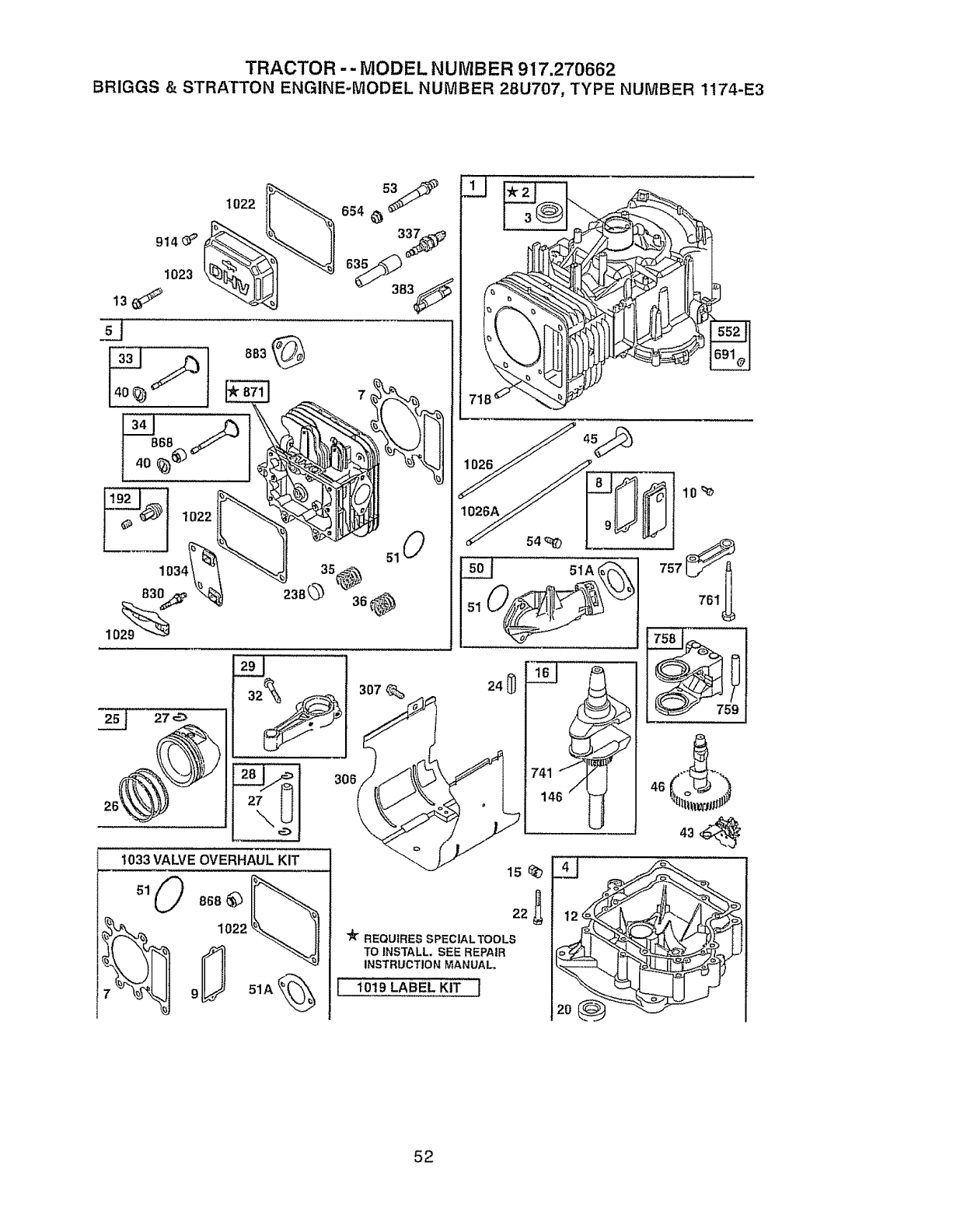
TRACTOR -- MODEL NUMBER 917.270662
BRIGGS & STRATTON ENGINE-MODEL NUMBER 28U707, TYPE NUMBER 1174-E3
914_ _'
1023
13_
1022 ss4 _J
383_
103,
1029
1033 VALVE OVERHAUL KIT
71
"_rREQUIRESSPECIALTOOLS
TO INSTALL. SEE REPAIR
INSTRUCTION MANUAL,
1019 LABEL KIT I
52
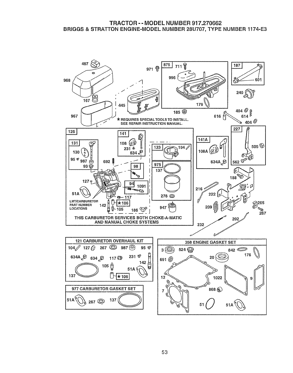
TRACTOR - - MODEL NUMBER 917,270662
BRIGGS 8=STRATTON ENGINE-MODEL NUMBER 28U707, TYPE NUMBER 1174-E3
968
t
95 _' 987
....... 93,_,_....
51A_ /
LMT/CARBURETOR
PART NUMBER 142
LOCATIONs
1-&7
23t $ e I
634_,I
692 g
27s
947
THIS CARBURETOR SERVICES BOTH CHOKE-A-MATIC
AND MANUAL CHOKE SYSTEMS
1=1CARBURETOROVE..AULKmT
104/ 1270 26_@ _87® _
634A_ 634_ 117_ 231 _ I
176
265
%
267
358 ENGINE GASKET SET
53
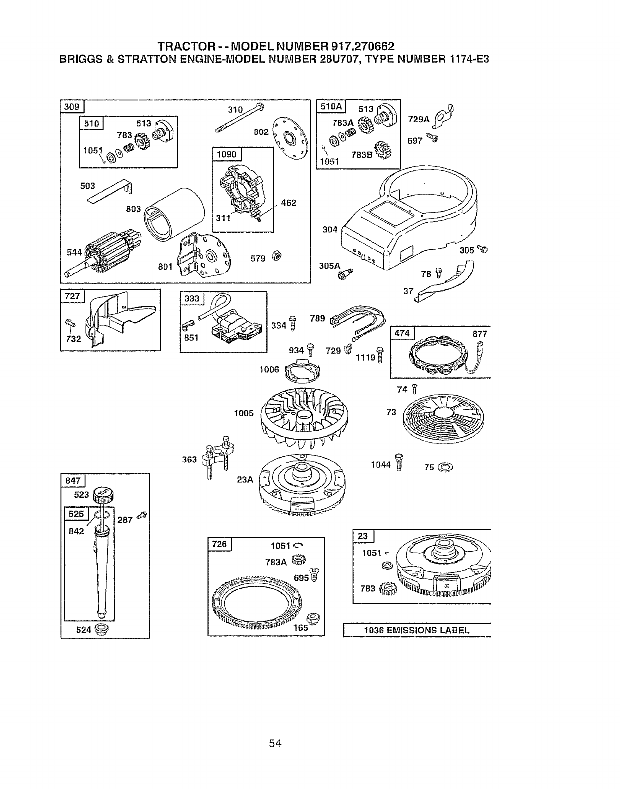
TRACTOR -- MODEL NUMBER 917,270662
BRIGGS & STRATTON ENGINE-MODEL NUMBER 28U707, TYPE NUMBER 1174-E3
3!0_ _,
151ol 513_-,,-,, _ .n "-_ Z83A_lJ
304
3O5A_
729A S
305
287 __'_'
524
1005
363
334
934
I006
789 _ I4741 a77
1044_ 75_
1051c"
783A 1051
0 _
t 1036 EMISSIONS LABEL
54
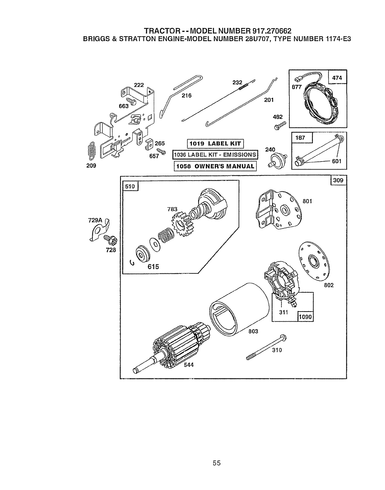
TRACTOR -- MODEL NUMBER 917,270662
BRIGGS & STRATTON ENGINE-MODEL NUMBER 28U707, TYPE NUMBER 1174-E3
209
728
_222
tj 615
201
783
482
1019 LABEL KITI 240
I1036 LABEL KIT- EMISSIONS 1
11058 OWNER'S MANUAL]
;44
801
802
311
803
55
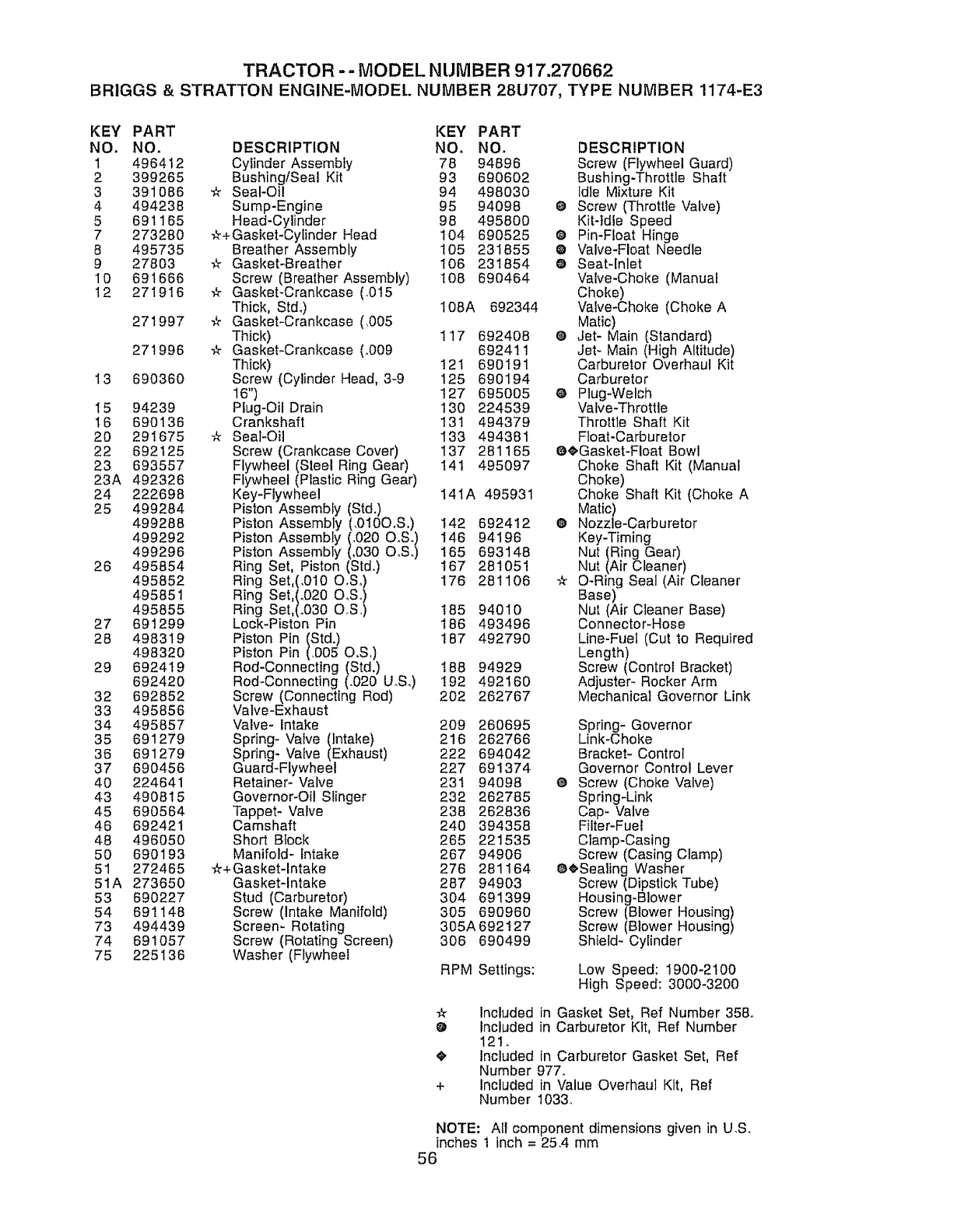
TRACTOR -= MODEL NUMBER 917.270662
BRIGGS & STRATTON ENGINE-MODEl.. NUMBER 28U707, TYPE NurTIBER 1174-E3
KEY PART KEY PART
NO. NO, DESCRIPTION NO. NO. DESCRIPTION
I 496412 Cylinder Assembiy 78 94896 Screw (Flywheel Guard)
2 399265 Bushing/Seal Kit 93 690602 Bushing-Throttle Shaft
3 391086 _ Seal-Oi! 94 498030 Idle Mixture Kit
4 494238 Sump-Engine 95 94098 @ Screw (Throttle Valve)
5 691165 Head-Cylinder 98 495800 Kit-ldle Speed
7 273280 -_r+Gasket-Oylinder Head t04 690525 O Pin-Float Hinge
8 495735 Breather Assembly 105 231855 O Valve-Float Needle
9 27803 -A- Gasket-Breather 106 231854 O Seat-Inlet
10 691666 Screw (Breather Assembly) t08 690464 Valve-Choke (Manual
12 271916 -k GaskebCrankcase (.015 Choke)
Thick, Std.) I08A 692344 Valve-Choke (Choke A
271997 -,_ Gasket-Crankcase (.005 Matic)
Thick) 117 692408 ® Jet- Main (Standard)
271996 _ Gasket_Crankcase (,,009 692411 Jet- Main (High Altitude)
Thick) 121 690191 Carburetor Overhaul Kit
t3 690360 Screw (Cylinder Head, 3-9 125 690194 Carburetor
16") 127 695005 _ Plug_Welch
I5 94239 Plug-Oil Drain 130 224539 Valve-Throttle
t6 690136 Crankshaft 13! 494379 Throttle Shaft Kit
20 291675 ¢r Seat-Oil 133 494381 Float-Carburetor
22 692125 Screw (Crankcase Cover) 137 261165 84,Gasket-Float Bowl
23 693557 Flywheel (Steel Ring Gear) I41 495097 Choke Shaft Kit (Manual
23A 492326 Flywheel (Plastic Ring Gear) Choke)
24 222698 Key-Flywheel 14IA 495931 Choke Shaft Kit (Choke A
25 499284 Piston Assembly (Std.) Matic)
499288 Piston Assembly (.0100.S.) 142 692412 @ Nozzle-Carburetor
499292 Piston Assembly (.020 O S l 146 94196 Key-Timing
499296 Piston Assembly (.030 OISI_ 165 693148 Nut (Ring Gear)
26 495854 Ring Set, Piston (Std.) 167 281051 Nut (Air Cleaner)
495852 Ring Set,(,010 O,S.) 176 281106 -_ O-Ring Seal (Air Cleaner
495851 Ring Set,(.020 O S.I Base)
495855 Ring Set,(.030 OIS_ 185 94010 Nut (Air Cleaner Base)
27 691299 Lock-Piston Pin 186 493496 Connector-Hose
26 498319 Piston Pin (Std.) 187 492790 Line-Fuel (Cut 1o Required
498320 Piston Pin (D05 O,S,) Length)
29 692419 Rod-Connecting (Std,) 188 94929 Screw (Control Bracket)
692420 Rod-Connecting (.020 U.S.) 192 492160 Adjuster- Rocker Arm
32 692852 Screw (Connecting Rod) 202 262767 Mechanical Governor Link
33 495856 Valve-Exhaust
34 495857 Valve- Intake 209 260695 Spring- Governor
35 691279 Spring- Valve (intake) 216 262766 Link-Choke
36 691279 Spring- Valve (Exhaust) 222 694042 Bracket- Control
37 690456 Guard-Flywheel 227 691374 Governor Control Lever
40 224641 Retainer_ Valve 23t 94098 @ Screw (Choke Valve)
43 490815 Governor-Oil Slinger 232 262785 Spring-Link
45 690564 Tappet- Valve 238 262836 Cap- Valve
46 692421 Camshaft 240 394358 Filter-Fuel
48 496050 Short Block 265 221535 Clamp-Casing
50 690193 Manifold- Intake 267 94906 Screw (Casing Clamp)
51 272465 ¢_+Gasket-lntake 276 281164 8,eSealing Washer
51A 273650 Gasket-Intake 287 94903 Screw (Dipstick Tube)
53 690227 Stud (Carburetor) 304 691399 Housing*Blower
54 69t 148 Screw (Intake Manifold) 305 690960 Screw (Blower Housing)
73 494439 Screem Rotating 305A 692127 Screw (Blower Housing)
74 691057 Screw (Rotating Screen) 306 690499 Shield- Cylinder
75 225136 Washer (Flywheel RPM Settings: Low Speed: !900-2100
High Speed: 3000-3200
-2 Included in Gasket Set, Ref Number 358°
@ included in Carburetor Kit, Ref Number
I21.
4_ Included in Carburetor Gasket Set, Ref
Number 977.
+ Included in Value Overhaul Kit, Ref
Number 1033.
NOTE: All component dimensions given in U.So
inches t inch = 25.4 mm
56
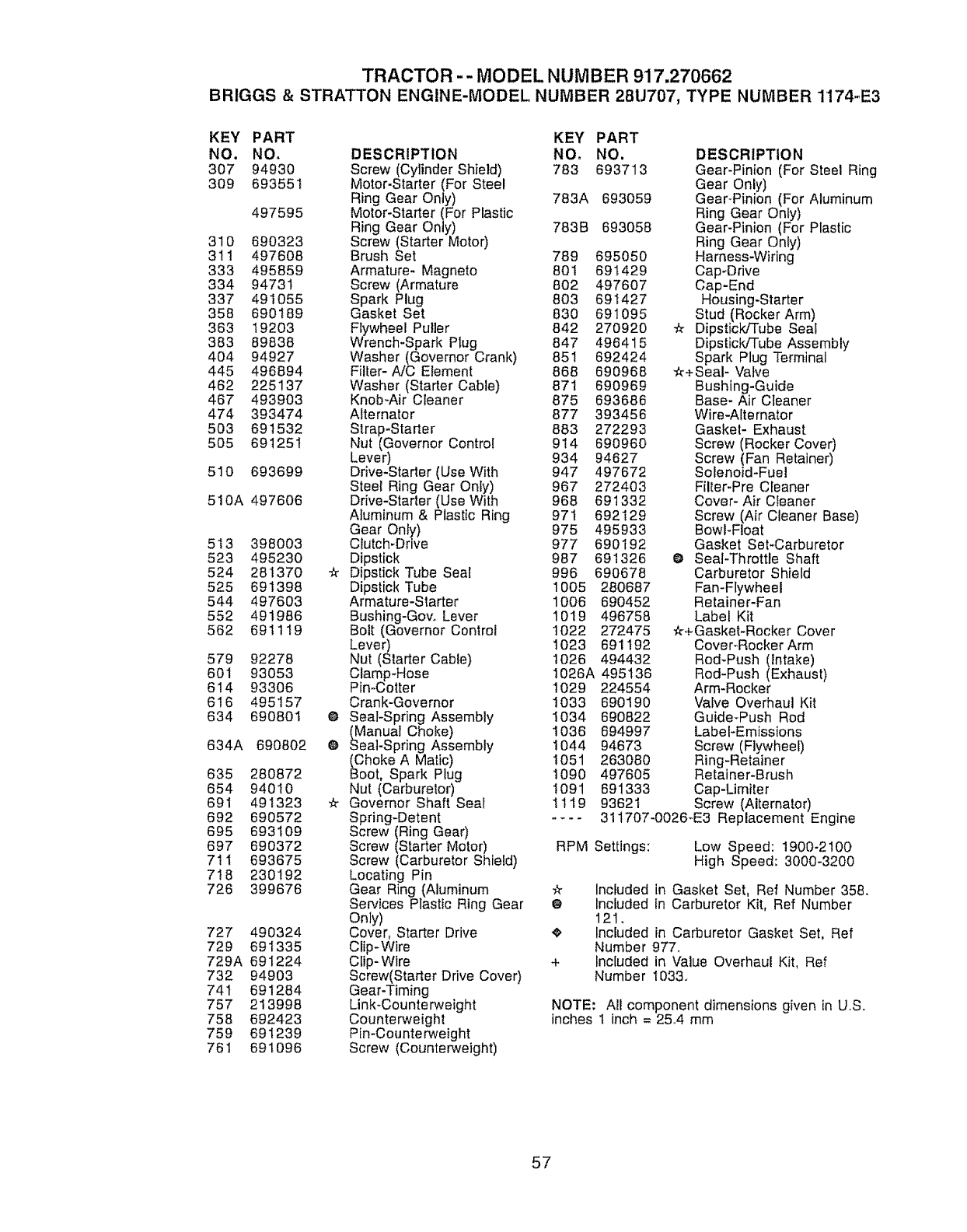
TRACTOR -- MODEL NUMBER 917.270662
BRIGGS & STRATTON ENGINE-MODEL NUMBER 28U707, TYPE NUMBER 1174-E3
KEY PART
NO. NO,
307 94930
3O9 693551
497595
310 690323
311 497608
333 495859
334 94731
337 491055
358 690189
363 19203
383 89838
404 94927
445 496894
462 225137
467 493903
474 393474
503 691532
505 691251
510 693699
510A 497606
513 398003
523 495230
524 281370
525 691398
544 497603
552 491986
562 691119
579 92278
601 93053
614 93306
616 495157
634 690801
634A 69O802
635 280872
654 94010
691 491323
692 690572
695 693109
697 690372
711 693675
7!8 230192
726 399676
727 490324
729 691335
729A 691224
732 94903
74t 691284
757 213998
758 692423
759 691239
761 691096
er
O
O
_r
KEY PART
DESCRIPTION NO. NO.
Screw (Cylinder Shield) 783 693713
Motor-Starter (For Steel
Ring Gear Only) 783A 693059
Motor-Starter (For Plastic
Ring Gear Only) 783B 693058
Screw (Starter Motor)
Brush Set 789 695050
Armature- Magneto 801 691429
Screw (Armature 802 497607
Spark Plug 803 691427
Gasket Set 830 691095
Flywheel Puller 842 270920
Wrench-Spark Plug 847 496415
Washer (Governor Crank) 851 692424
Filter- A/C Element 868 690968
Washer (Starter Cable) 871 690969
Knob_Air Cleaner 875 693686
Alternator 877 393456
Strap-Starter 883 272293
Nut (Governor Control 914 690960
Lever) 934 94627
Drive-Starter (Use With 947 497672
Steel Ring Gear Only) 967 272403
Drive-Starter (Use With 968 691332
Aluminum & Plastic Ring 97t 692129
Gear Only) 975 495933
Clutch-Drive 977 690I 92
Dipstick 987 691326
Dipstick Tube Seal 996 690678
Dipstick Tube 1005 280687
Armature-Starter 1006 690452
Bushing-Govo Lever 1019 496758
Bolt (Governor Control t022 272475
Lever) 1023 691192
Nut (Starter Cable) 1026 494432
Clamp-Hose 1026A 495136
PimCotter 1029 224554
Crank-Governor 1033 690190
Seal-Spring Assembly 1034 690822
(Manual Choke) 1036 694997
Seal-Spring Assembly !044 94673
(Choke A Matic) 1051 263080
Boot, Spark Ptug 1090 497605
Nut (Carburetor) I091 691333
Governor Shaft Seal 1119 93621
Spring-Detent ....
Screw (Ring Gear)
Screw (Starter Motor) RPM
Screw (Carburetor Shield)
Locating Pin
Gear Ring (Aluminum -k Included
Services Plastic Ring Gear e Included
Only) 121.
Cover, Starter Drive e. included
Clip-Wire Number
Clip- Wire + Included
Screw(Starter Drive Cover) Number
Gear-Timing
Li nk-Cou nte r,_eight
Counterweight
Pin-Counterweight
Screw (Counterweight)
DESCRIPTION
Gear-Pinion (For Steel Ring
Gear Only)
Gear-Pinion (For Aluminum
Ring Gear Only)
Gear-Pinion (For Plastic
Ring Gear Only)
Harness-Wiring
Cap-Drive
Cap-End
Housing-Starter
Stud (Rocker Arm)
-# Dipstick/Tube Seal
DipsticldTube Assembly
Spark Plug Terminal
"#+Seal- Valve
Bushing-Guide
Base- Air Cleaner
Wire-Alternator
Gasket- Exhaust
Screw (Rocker Cover)
Screw (Fan Retainer)
Solenoid-Fuel
Filter-Pre Cleaner
Cover- Air Cleaner
Screw (Air Cleaner Base)
Bowl-Float
Gasket Set-Carburetor
O Seal-Throttle Shaft
Carburetor Shield
Fan-Flywheel
Retainer-Fan
Label Kit
#+Gasket-Rocker Cover
Cover-Rocker Arm
Rod-Push (Intake)
Rod-Push (Exhaust)
Arm-Rocker
Valve Overhaul Kit
Guide-Push Rod
Label-Emissions
Screw (Flywheel)
Ring-Retainer
Retainer-Brush
Cap-Limiter
Screw (Alternator)
311707-0026-E3 Replacement Engine
Settings: Low Speed: 1900-2100
High Speed: 3000-3200
in Gasket Set, Ref Number 358.
in Carburetor Kit, Ref Number
in Carburetor Gasket Set, Ref
977_
in Value Overhaul Kit, Ref
1033o
NOTE: All component dimensions given in U,S.
inches 1 inch = 25,4 mm
57

58

SUGGESTED GUIDE FOR SIGHTING SLOPES FOR SAFE OPERATION
ONLY RIDE UP AND DOWN HILL,
NOT ACROSS HILL
¢Jt SIGHT AND HOLD THIS LEVEL WITH
SKY LINE OR TREE.
15 ° MAX.
I
_ _, Operate your Tractor up and down the face of slopes (not
_1_ greater than 15°), never across the face. Make turns gradu-
il _ ally to prevent tipping or loss of control. Exercise extreme
iI caution when changing direction on slopes.

Get it fixed, at your home or ours!
For repair of major brand appliances in your own home...
no matter who made it, no matter who sold it!
lo800-4-MY..HOME sMAnytime,dayor night
(1-800_469-4663)
www.sears=com
To bring in products such as vacuums,
lawn equipment and electronics for repair, call for
the location of your nearest Sears Parts &Repair Center.
1-800=488=1222 Anytime,_ayor night
www.sears.com
For the replacement parts, accessories and owner's manuals
that you need to do-it-yourself, call Sears PartsDirectSM!
1-800-366-PART 6a_- 11p_m,CST,
(! -800-366-7278) 7 days a week
www.sears.com/partsdirect
To purchase or inquire about a Sears Service Agreement:
1-800-827-6655
7 a.m.- 5 p.rn. CST, Mono- Sat.
Pare pedir servicio de reparaci6n a domicilio,
y para ordenar piezas con entrega a domicilio:
1-888-8 U-HOGAR '"
(1-888-784_6427)
Au Canada pour service en franqais:
1-877-LE-FOYER _'_
(1-877-533 =6937)
© Sears, Roebuck and Ceo ® Registered Trademark IT_ Trademark of Sears, Roebuck and Co
® Marca Registrada /T_4Marca de F&brica de Sears, Roebuck and Co,
173022 7.26_00 Rev_ I RD Printed in U.S,A,
