Craftsman 917270721 User Manual TRACTOR Manuals And Guides L0804023
CRAFTSMAN Lawn, Tractor Manual L0804023 CRAFTSMAN Lawn, Tractor Owner's Manual, CRAFTSMAN Lawn, Tractor installation guides
User Manual: Craftsman 917270721 917270721 CRAFTSMAN TRACTOR - Manuals and Guides View the owners manual for your CRAFTSMAN TRACTOR #917270721. Home:Lawn & Garden Parts:Craftsman Parts:Craftsman TRACTOR Manual
Open the PDF directly: View PDF ![]() .
.
Page Count: 64

Owner's Manual
£11AFTSMAII°
17,0 HP
ELECTRIC START
42" MOWER
AUTOMATIC
LAWN TRACTOR
Model No.
917.270721
,, Safety
=Assembly
,, Operation
,, Maintenance
,, Repair Parts
CAUTION:
Read and follow all
Safety Rules and Instructions
before operating thisequip-
ment.
For answers to your questions
about this product, Call:
1-800-659-5917
Sears Craftsman Help Line
5am - 5 pro, Mon- Sat
Sears, Roebuck and Co., Hoffman Estates, IL 60179
Warranty ..................................................... 2
Safety Rules ................................................ 2
Product Specifications ............................ 5
Assembly .................................................. 8
Operation ................................................. 12
Maintenance Schedule ......................... 19
Maintenance ........................................... 19
Service and Adjustments ......................... 23
Storage .................................................. 29
Troubleshooting .................................... 31
Repair Parts ............................................. 34
Paris Ordering ........................ Back Cover
LIMITED TWO YEAR WARRANTY ON CRAFTSMAN RIDING EQUIPMENT
For two (2) years from the date of purchase, if this Craftsman Riding Equipment is main-
tained, lubricated and tuned up according to the instructions in the owner's manual,
Sears will repair or replace, free of charge, any parts found to be defective in material or
workmanship.
This Warranty does not cover:
° Expendable items which become worn during normal use, such as blades, spark
plugs, air cleaners, belts, etc.
,Tire replacement or repair caused by punctures from outside objects, such as nails,
thorns, stumps, or glass.
° Repairs necessary because of operator abuse, negligence, improper storage or acci-
dent or the failure to maintain lhe equipment according to the instructions contained in
the owner's manual.
•Riding equipment used for commercial or rental purposes.
/.1MITED 90 DAY WARRANTY ON BATTERY
For ninety (90) days from date of purchase, if any battery included with this riding equip-
ment proves defective in material or workmanship and our testing determines the bat-
tery will not hold a charge, Sears wilt replace the battery at no charge° In-home warranty
service on your Craftsman riding equipment is available at no charge for 30 days from
the date of purchase. Please contact your nearest service center. After 30 days from the
date of purchase, warranty service is available by taking your Craftsman riding equip-
ment to your nearest Sears Service Center. (In-home warranty service will still be avail-
able after 30 days from the date of purchase but a standard trip charge will apply). This
warranty applies only while this product is in the United States. This Warranty gives you
specific legal rights, and you may also have other rights which may vary from state to
state.
Sears, Roebuck and Co,, D/817 WA, Hoffman Estates, 1L 60179
GENERAL OPERATION
• Read, understand, and follow all instruc-
tions in the manual and on the machine
before starting.
° Only allow responsible adults, who are
familiar with the instructions, to operate
the machine°
• Clear the area of objects such as rocks,
toys, wire, etc., which could be picked
up and thrown by the blade.
•Be sure the area is clear of other people
before mowing. Stop machine if anyone
enters the area.
*Never carry passengers
*Do not mow in reverse unless absolute-
ty necessary. Always took down and
behind before and while backing.
o Be aware of the mower discharge direc-
tion and do not point it at anyone.. Do
not operate the mower without either
the entire grass catcher or the guard in
place.
o Slow down before turning..
. Never leave a running machine unat-
tended Always turn off blades, set park-
ing brake, slop engine, and remove
keys before dismounting
o Turn off bladeswhennot mowing.
o Stop enginebeforeremovinggrass
catcheror uncloggingchute.
• Mow only in daylightor goodartificial
Hght.
o Do not operate the machine while under
the influence of alcohol or drugs.
° Watch for traffic when operating near or
crossing roadways.
o Use extra care when loading or unload-
ing the machine into a trailer or truck.
SLOPE OPERATION
Slopes are a major factor related to loss-
of-control and tipover accidents, which
can result in severe injury or death. All
slopes require extra caution. If you cannot
back up the slope or if you feet uneasy on
it, do not mow iL
DO:
• Mow up and down slopes, not across
• Remove obstacles such as rocks, tree
limbs, etco
° Watch for holes, ruts, or bumps. Uneven
terrain could overturn the machine. Tall
grass can hide obstacles.
,, Use slow speed. Choose a low gear so
that you will not have to stop or shift
while on the slope.
o Follow the manufacturer's recommen-
dations for wheel weights or counter-
weights to improve stability.
•Use extra care with grass catchers or
other attachments. These can change
the stability of the machine°
,, Keep all movement on the slopes slow
and gradual Do not make sudden
changes in speed or direction.
• Avoid starting or stopping on a slope. If
tires lose traction, disengage the blades
and proceed slowly straight down the
slope.
DO NOT:
°Do not turn on slopes unless necessary,
and then, turn slowly and gradually
downhill, if possible.
oDo not mow near drop-offs, ditches, or
embankments° The mower could sud-
denly turn over if a wheel is over the
edge of a cliff or ditch, or if an edge
caves in.
°Do not mow on wet grass. Reduced
traction could cause sliding.
°Do nottry to stabilize the machine by
putting your foot on the ground.
•Do not use grass catcher on steep
slopes.
CHILDREN
Tragic accidents can occur if the operator
is not alert to the pre_sence of children.
Children are often attracted to the
machine and the mowing activity. Never
assume that children will remain where
you last saw them.
o Keep children out of the mowing area
and under the watchful care of another
responsible adult.
• Be aled and turn machine off if children
enter the area.
• Before and when backing, look behind
and down for small children.
° Never carry children. They may fall off
and be seriously injured or interfere with
safe machine operation.
• Never allow children to operate the
machine..
° Use extra care when approaching blind
corners, shrubs, trees, or other objects
that may obscure vision.
SERVICE
•Use extra care in handling gasoline and
other fuels. They are flammable and
vapors are explosive.
Use only an approved container.
- Never remove gas cap or add fue!
with the engine running. Allow en-
gine to cool before refueling. Do not
smoke.
Never refuel the machine indoors.
Never store the machine or fuel
container inside where there is an
open flame, such as a water heater.
•Never run a machine inside a closed
area.
° Keep nuts and bolts, especially blade
attachment bolts, tight and keep equip-
ment in good condition.
° Never tamper with safety devices+
Check their proper operation regularly.
-Keep machine free of grass, leaves, or
other debris build-up. Clean oil or fuel
spillage. Allow machine to cool before
storing.
°Stop and inspect the equipment if you
strike an object. Repair, if necessary,
before restarting.
° Never make adjustments or repairs with
the engine running.
° Grass catcher components are subject
to wear, damage, and deterioration,
which could expose moving parts or
allow objects to be thrown. Frequently
check components and replace with
manufacturer's recommended parts,
when necessary.
Mower blades are sharp and can cut°
Wrap the blade(s) or wear gloves, and
use extra caution when servicing them
Check brake operation frequently°
Adjust and service as required.
• Be sure the area is clear of other people
before mowing. Stop machine if anyone
enters the area.
•Never carry passengers.
•Do not mow in reverse unless absolute-
ly necessary_ Always took down and
behind before and while backing.
• Never carry children. They may fal! off
and be seriously injured or interfere with
sate machine operation,
• Keep children out of the mowing area
and under the watchful care of another
responsible adult.
° Be alert and turn machine off if children
enter the area.
° Before and when backing, look behind
and down for small children,
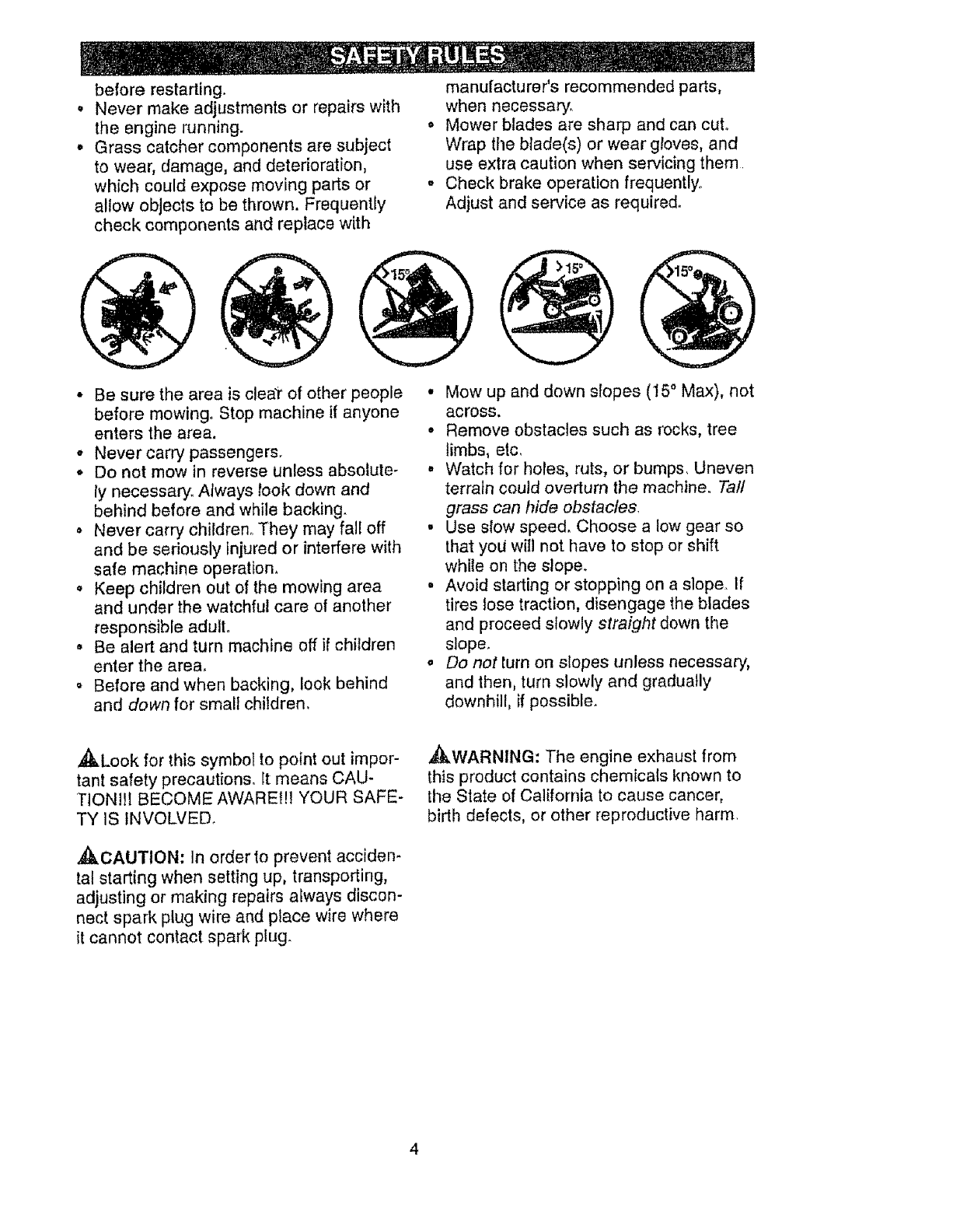
° Mow up and down slopes (15 ° Max), not
across.
° Remove obstacles such as rocks, tree
limbs, etc.
° Watch for holes, ruts, or bumps, Uneven
terrain could overturn the machine. Tall
grass can hide obstacles.
o Use slow speed. Choose a low gear so
that yoLJ will not have to stop or shift
while on the slope.
° Avoid starting or stopping on a slope. If
tires Jose traction, disengage the blades
and proceed slowly straight down the
slope.
oDo not turn on slopes unless necessary,
and then, turn slowly and gradually
downhill, if possible.
_Look for this symbol to point out impor-
tant safety precautions. It means CAU-
TtONIII BECOME AWAREfll YOUR SAFE-
TY iS INVOLVED.
,_CAUTION: In order to prevent acciden-
tal starting when setting up, transporting,
adjusting or making repairs always discon-
nect spark plug wire and place wire where
it cannot contact spark plug.
,_kWARNING: The engine exhaust from
this product contains chemicals known to
the State of California to cause cancer,
birth defects, or other reproductive harm
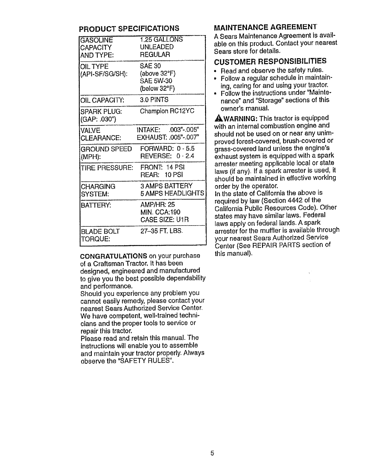
PRODUCT SPECIFICATIONS
G/_SOLiNE 1.25 GALLONS .....
CAPACITY UNLEADED
AND TYPE: REGULAR
OILTYPE SAE 3O
API-SFiSG/SH): (above 32°F)
SAE 5W-30
(below 32°F)
OIL CAPACITY: 3°0 PINTS
SPARK PLUG: Champion RC12YC
GAP: .030 °')
iVALVE INTAKE: _003"-,005"
CLEARANCE: EXHAUST; ,005"-,,007"
GROUND SPEED FORWARD: 0-5.5
(MPH): REVERSE: O- 2.4
TIRE PRESSURE: FRONT: 14 PSI
REAR: 10 PSI
,CHARGING 3 AMPS BATTERY
ISYSTEM: 5 AMPS HEADLIGHTS
BATTERY: AMP/FIR: 25
MIN CCA:190
CASE SIZE: U1R
BLADE BOLT 27-35 FT. LBS.
TORQUE:
CONGRATULATIONS on your purchase
of a Craftsman Tractor, It has been
designed, engineered and manufactured
to give you the best possible dependability
and performance.
Should you experience any problem you
cannot easily remedy, please contact your
nearest Sears Authorized Service Center.
We have competent, well-trained techni-
cians and the proper tools to service or
repair this tractor.
Please read and retain this manual. The
instructions will enable you to assemble
and maintain your tractor properly. Always
observe the "SAFETY RULES".
MAINTENANCE AGREEMENT
A Sears Maintenance Agreement is avail-
able on this product, Contact your nearest
Sears store for details.
CUSTOMER RESPONSIBILITIES
• Read and observe the safety rules.
•Follow a regular schedule in maintain-
ing, caring for and using your tractor,
° Follow the instructions under "Mainte-
nance" and "Storage" sections of this
owner's manual.
,_WARNING: This tractor is equipped
with an internal combustion engine and
should not be used on or near any unim-
proved forest-covered, brush..covered or
grass-covered land unless the engine's
exhaust system is equipped with a spark
arrester meeting applicable local or state
laws (if any). If a spark arrester is used, it
should be maintained in effective working
order by the operator.
In the state of California the above is
required by law (Section 4442 of the
California Public Resources Code), Other
states may have similar laws. Federal
laws apply on federal lands° A spark
arrester for the muffler is available through
your nearest Sears Authorized Service
Center (See REPAIR PARTS section of
this manual),
,i i r ,i,,i,,,111_ ]
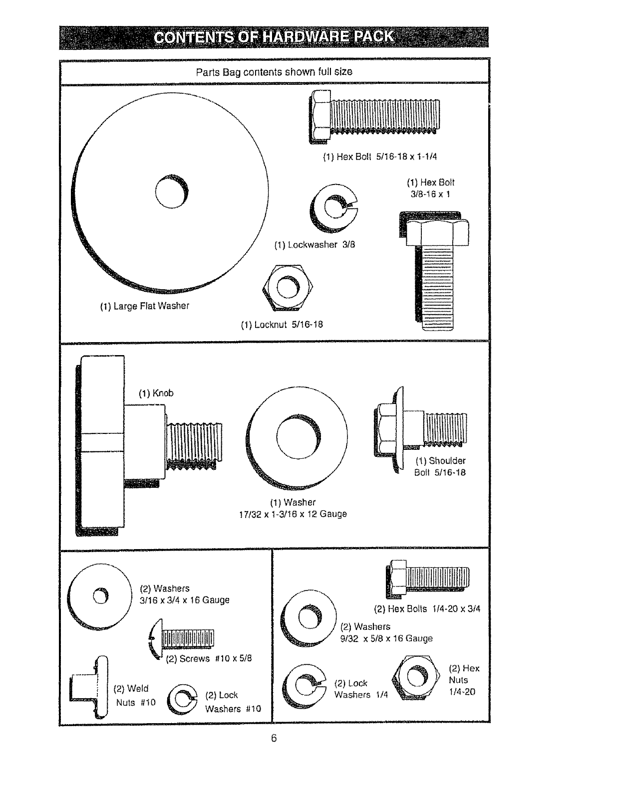
Parts Bag contents shown full size
(1) Large Flat Washer
(1) He× Bolt 5/16-18 x 1-1/4
(1) Lockwasher 3/8
(1) Hex Bolt
3f8-16 x 1
(1) Locknut 5/t6-18
ii inl
(1) Knob O
(1)Wash er
! 7!32 × 1-3/16 x 12 Gauge
(1
(1) Shouide_
_'J Boil 5116-18
(2) WeldNuts _110
(2) Washers
3116x 3/4 x 16 Gauge
(2) Look
Washers #10
II!l P[ III ................ iiii I
6
(2) Hex Bolts tt4-20 x 314
(2) Washers
9132 x 5/8 x 16 Gauge
(2) He×
(2) Lock Nu_,s
Washers 1/4 1/4,_20
i ................
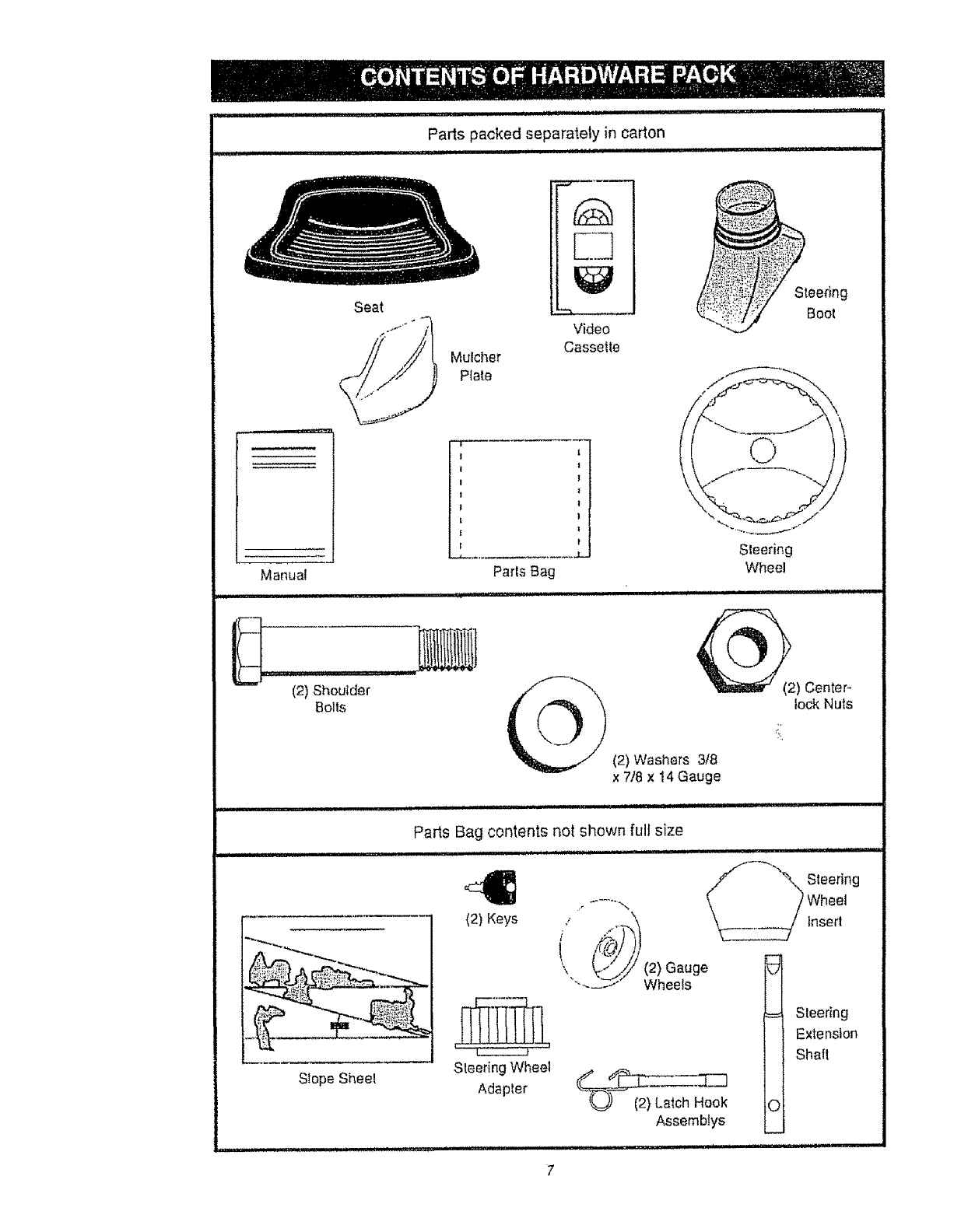
Parts packed separa_.ely in carton
lu, ii u,, ,, i iiii ii i ii,
i ii i hi' iii iiii
i I u'u iii,nUlllll'llll
Seat
Manual
(2) Shoulder
Bolts
Mulcher
Plate
Video
Cassette
1
!
1
}
}
}
Parts Bag
..... , ,,, ,,, ,,,,,,,.,,,,,,,,,,,,,,,,,,,,,,,
Steering
Boot
\
Steering
Wheel
(2) Center _
lock Nuts
(2) Washers 3/8
x 7/8 x 14 Gauge
, ii lUlIM II III'H
Slope Sheet
Parts Bag contents not shown full size
iJ i.....................
(2) Keys
Steering Wheel
Adapter
i ii ii
s,oor,oo
....-..... -.,. Wheel
'\ lnserl
(' I
Assembtys ©
i,,11
Steering
Extension
Shaft
Your new tractor has been assembled at the factory with exception of those parts teft
unassembled for shipping purposes. To ensure safe and proper operation of your tractor
atl parts and hardware you assemble must be tightened securely. Use the correct tools
as necessary to insure proper tightness. Review the video cassette before you begin,
TOOLS REQUIRED FOR
ASSEMBLY
A socket wrench set wellmake assembly
easier. Standard wrench sizes you need
are listed below.
(1) 9/16" wrench
(2) 7/t 6" wrenches
(2) 1/2" wrench
(1) 3/4" wrench
(1) Utility knife
(1)Pliers
(1) 3/4" Socket w!
drive rachet
(1) Phillips Screw-
driver
(1) Tire pressure
gauge
When right or left hand is mentioned in
this manual, it means, from your point of
view, when you are in the operating posi-
tion (seated behind the steedng whee0.
TO REMOVE TRACTOR FROM
CARTON
UNPACK CARTON
• Remove all accessible loose parts and
parts boxes from shipping carton (See
page 6).
.Cut, from top to bottom, arong lines on
all four corners of shipping carton, and
lay panels flat.
°Check for any additional loose parts or
boxes and remove.
BEFORE ROLLING TRACTOR OFF
SKID
ATTACH STEERING WHEEL
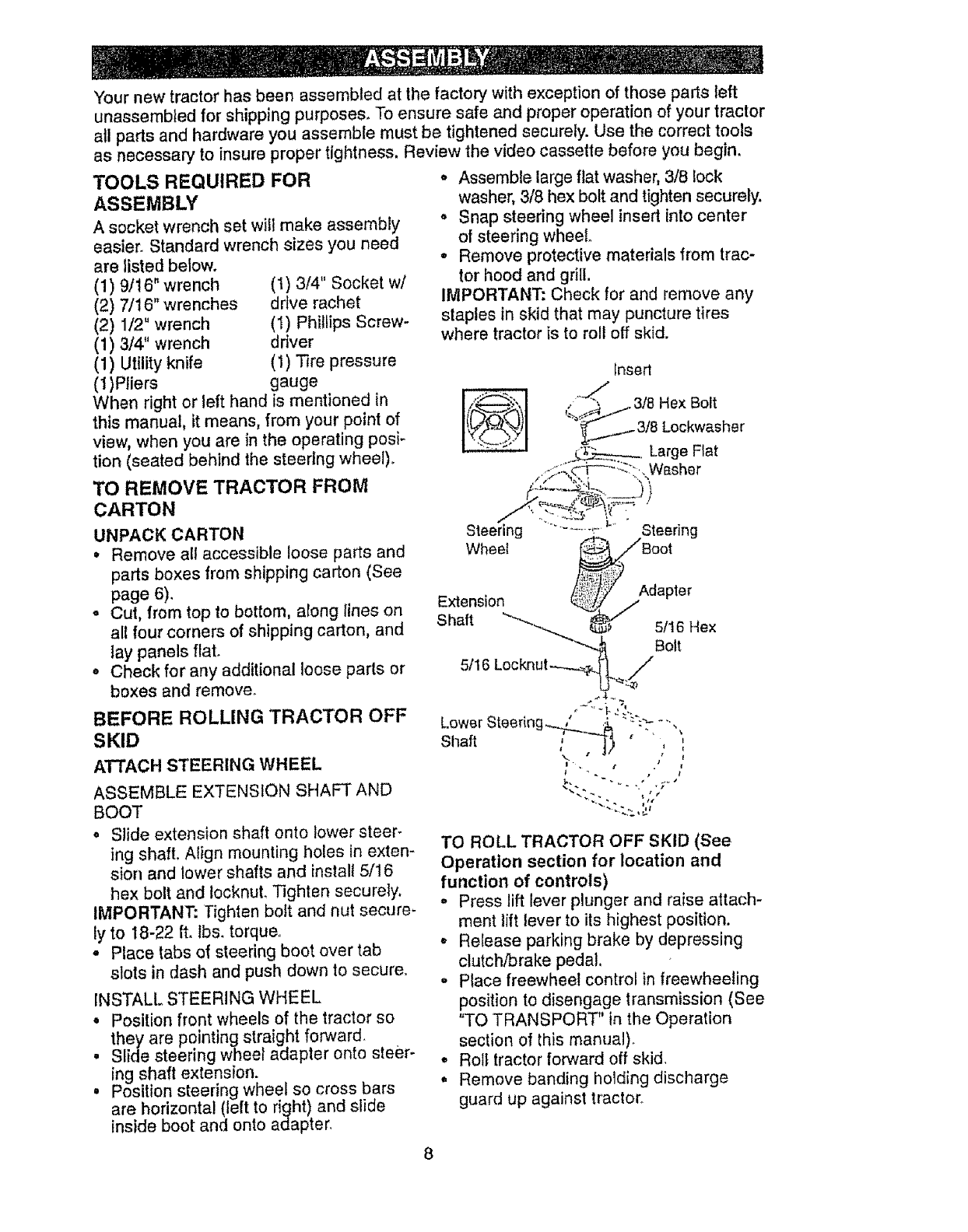
ASSEMBLE EXTENSION SHAFT AND
BOOT
° Slide extension shaft onto lower steer-
ing shaft. Afign mounting holes in exten-
sion and lower shafts and install 5/16
hex bolt and tocknuL Tighten securely,
IMPORTANT: Tighten boit and nut secure-
ly to 18-22 ft. lbs. torque,
• Place tabs of steering boot over tab
slots in dash and push down to secure.
INSTALL STEERING WHEEL
° Position front wheels of the tractor so
they are pointing straight forward.
° Slide steering whee_ adapter onto steer-
ing shaft extension.
• Position steering wheel so cross bars
are horizontal (left to right) and slide
inside boot and onto adapter.
o Assemble large fiat washer, 3/8 lock
washer, 3/8 hex bolt and tighten securely.
• Snap steering wheel insert Into center
of steering wheel.
• Remove protective materials from trac-
tor hood and grill.
IMPORTANT: Check for and remove any
staples in skid that may puncture tires
where tractor is to roll off skid.
lnseri
, ""_', i.,3/8 Hex Bolt
_._ 3/8 Lockwasher
_'_ Lar e Fat
.o_Z&_...... g
.-_:::_._c-F'--:'_:., Washe r
,'," "?,i "'
c.......
Steering ........ _ ' Steering
Wheel _Boot
Extension
Shaft _'_-_._ _ 5!16Hex
_"-,-_ Bolt
51t6 Loc knut -...,.__//
Lower Steering _' " ,'_.... ,,
sha. ,; j
I",¢#I{
TO ROLL TRACTOR OFF SKID (See
Operation section for location and
function of controls)
°Press lift lever plunger and raise attach-
ment lift lever to its highest position,
,, Release parking brake by depressing
clutch/brake pedal
oPlace freewheel control in freewheeling
position to disengage transmission (See
"TO TRANSPORT" in the Operation
section of this manual).
•Roll tractor forward off skid.
° Remove banding holding discharge
guard up against tractor_
HOW TO SET UP YOUR TRACTOH
CONNECT BATTERY
,_I_CAUTION: Do not short battery termi-
nals by allowing a wrench or any other
object to contact both terminals at the
same time Before connecting battery, re-
move metal bracelets, wristwatch bands,
rings, etc_ Positive terminal must be con-
nected first to prevent sparking from acci-
dental grounding.
• Remove cardboard packing from seat
pan and lift seat pan to raised position.
. Open battery box door arid remove pro-
tective plastic
,, Remove terminal protective caps and
discard.
•If this battery is put into service after
month and year indicated en label (iabel
located between terminals) charge bat-
tery for minimum of one tlour at 6-10
amp&
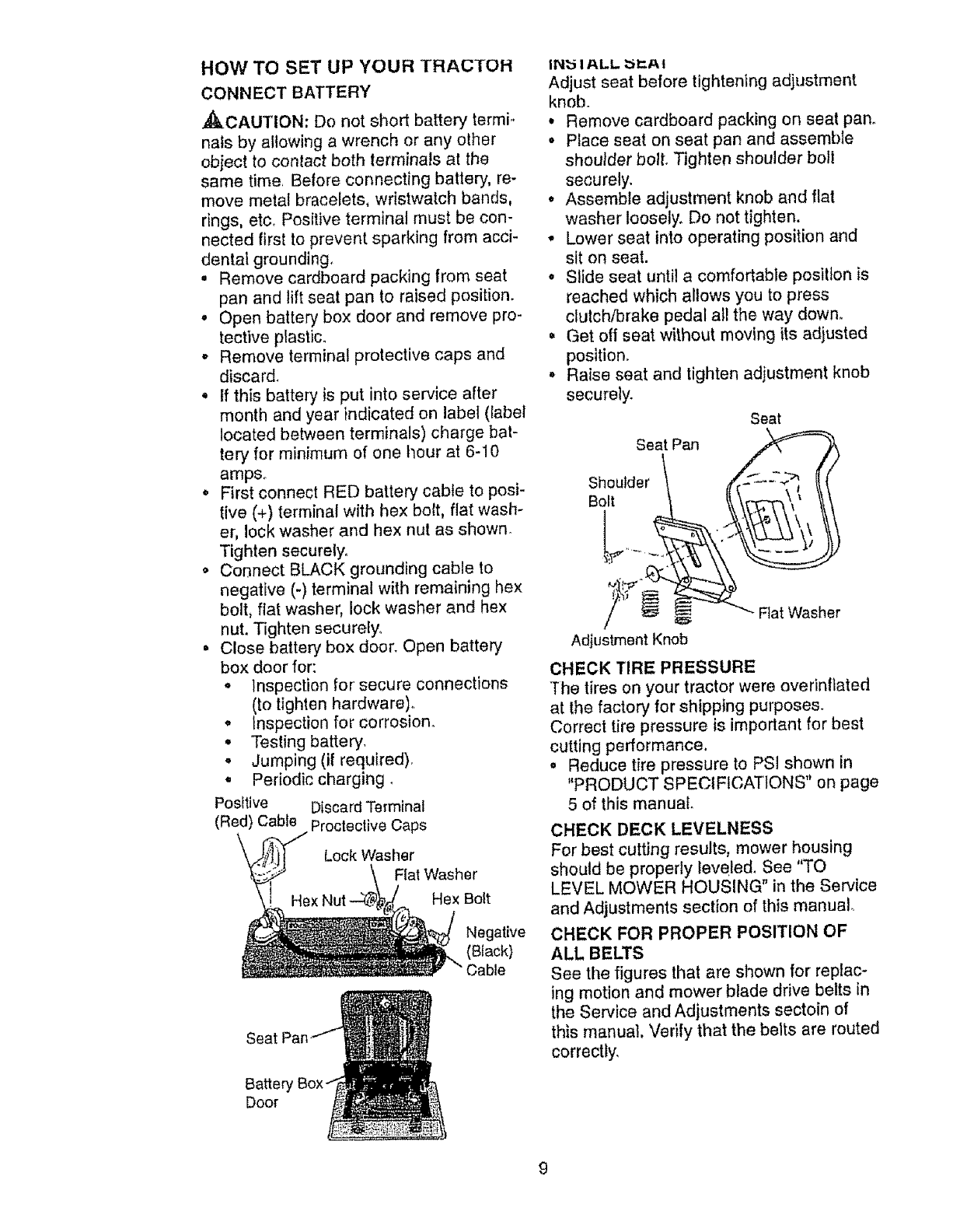
•First connect RED battery cable to posi-
tive (+) terminal with hex bok, fiat wash-
er, lock washer and hex nut as shown°
Tighten securely.
o Connect BLACK grounding cable to
negative (-) terminal with remaining hex
bolt, flat washer, lock washer and hex
nut. Tighten securely
,, Close battery box door Open battery
box door for:
•inspection for secure connections
(to tighten hardware).
°Inspection for corrosion
°Testing battery
° Jumping (if required),
•Periodic charging,
Positive Discard Terminal
(Red) Cabte Proctective Caps
Lock Washer
Flal Washer
Hex Bott
Negative
(Black)
Cable
Seat
Batten
Door
IN_ tALL _EAt
Adjust seat before tightening adjustment
knob.
o Remove cardboard packing on seat pan.
• Place seat on seat pan and assemble
shoulder bolt, Tighten shoulder boll
securely,
• Assemble adjustment knob and flat
washer loosely, Do not tighten.
° Lower seat into operating position and
sit on seat.
° Slide seat until a comfortable position is
reached which allows you to press
clutch/brake pedal all the way down.
•Get off seat without moving its adjusted
position.
• Raise seat and tighten adjustment knob
securely.
Seat Pan
Shoulder
Bolt
Seat
= _ Flat Washer
Adjustment Knob
CHECK TIRE PRESSURE
The tires on your tractor were overinflated
at the factory for shipping purposes.
Correct tire pressure is important for best
cutting performance.
,, Reduce tire pressure to PSI shown in
"PRODUCT SPECIFICATIONS" on page
5 of this manual
CHECK DECK LEVELNESS
For best cutting results, mower housing
should be properly leveled. See "TO
LEVEL MOWER HOUSING" in the Service
and Adjustments section of this manual
CHECK FOR PROPER POSITION OF
ALL BELTS
See the figures that are shown for replac-
ing motion and mower blade drive belts in
the Sewice and Adjustments sectoin of
this manual, Verify that the belts are routed
correctly
Afteryou learnhowto operateyourtrac-
tor,checkto see thatthe brakeis properly
adjusted See"TOADJUSTBRAKE"in
theServiceandAdjustmentssectionof
this manual.
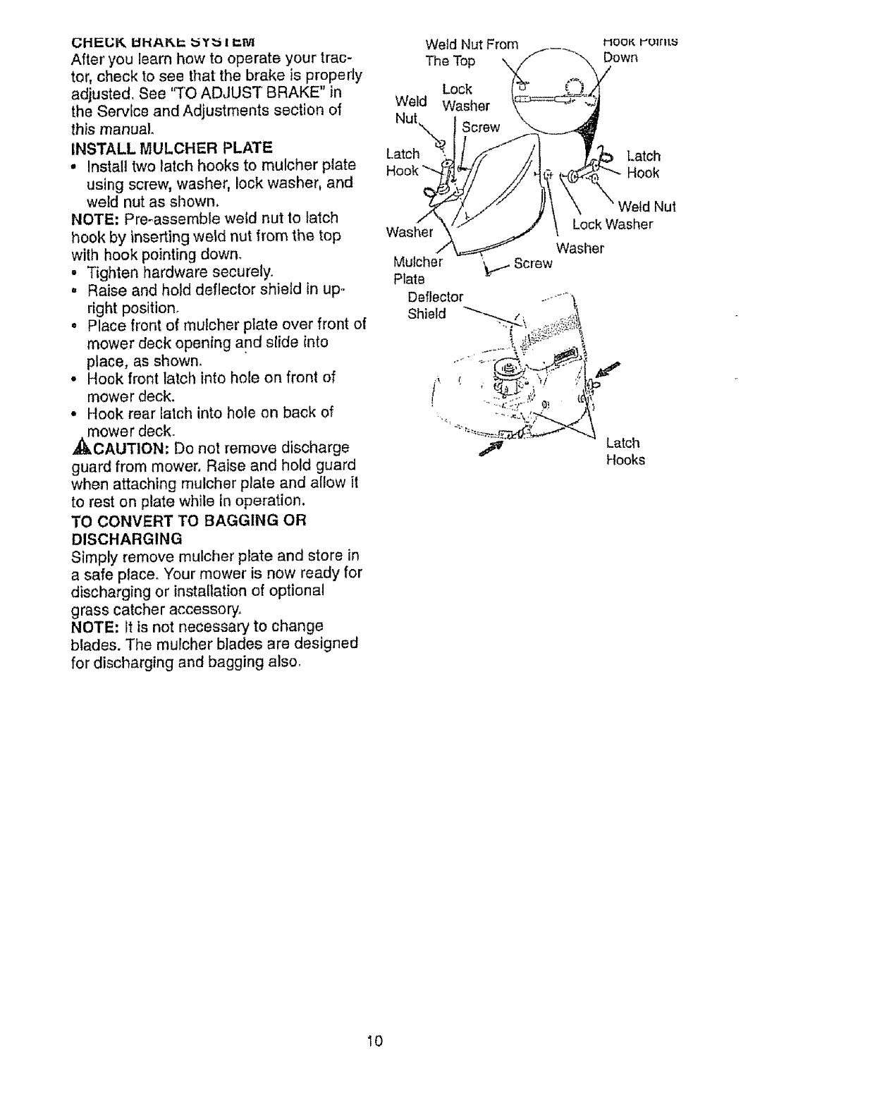
INSTALLMULCHER PLATE
•Install two latch hooks to mulcher prate
using screw, washer, lock washer, and
weld nut as shown.
NOTE: Pre-assemble weld nut to latch
hook by inserting we_d nut from the top
with hook pointing down.
• Tighten hardware securely.
•Raise and hold deflector shield }n up-
right position.
• Place front of mulcher plate over front of
mower deck opening and slide into
place, as shown.
•Hook front latch into hole on front of
mower deck.
•Hook rear latch into hole on back of
mower deck.
._CAUTION. Do not remove discharge
guard from mower, Raise and hold guard
when attaching mulcher plate and allow it
to rest on plate while in operation.
TO CONVERT TO BAGGING OR
DISCHARGING
Simply remove mulcher plate and store in
a safe place. Your mower is now ready for
discharging or installation of optional
grass catcher accessory.
NOTE: It is not necessary to change
blades. The mulcher blades are designed
for discharging and bagging also.
Weld Nut From
The Top
Lock
Weid Washer
Nut.
Latch'_,
Washer
Mulcher
Plate
Deflector
Shield
Latch
Hook
Weld Nut
Lock Washer
Washer
Screw
Latch
Hooks
I0
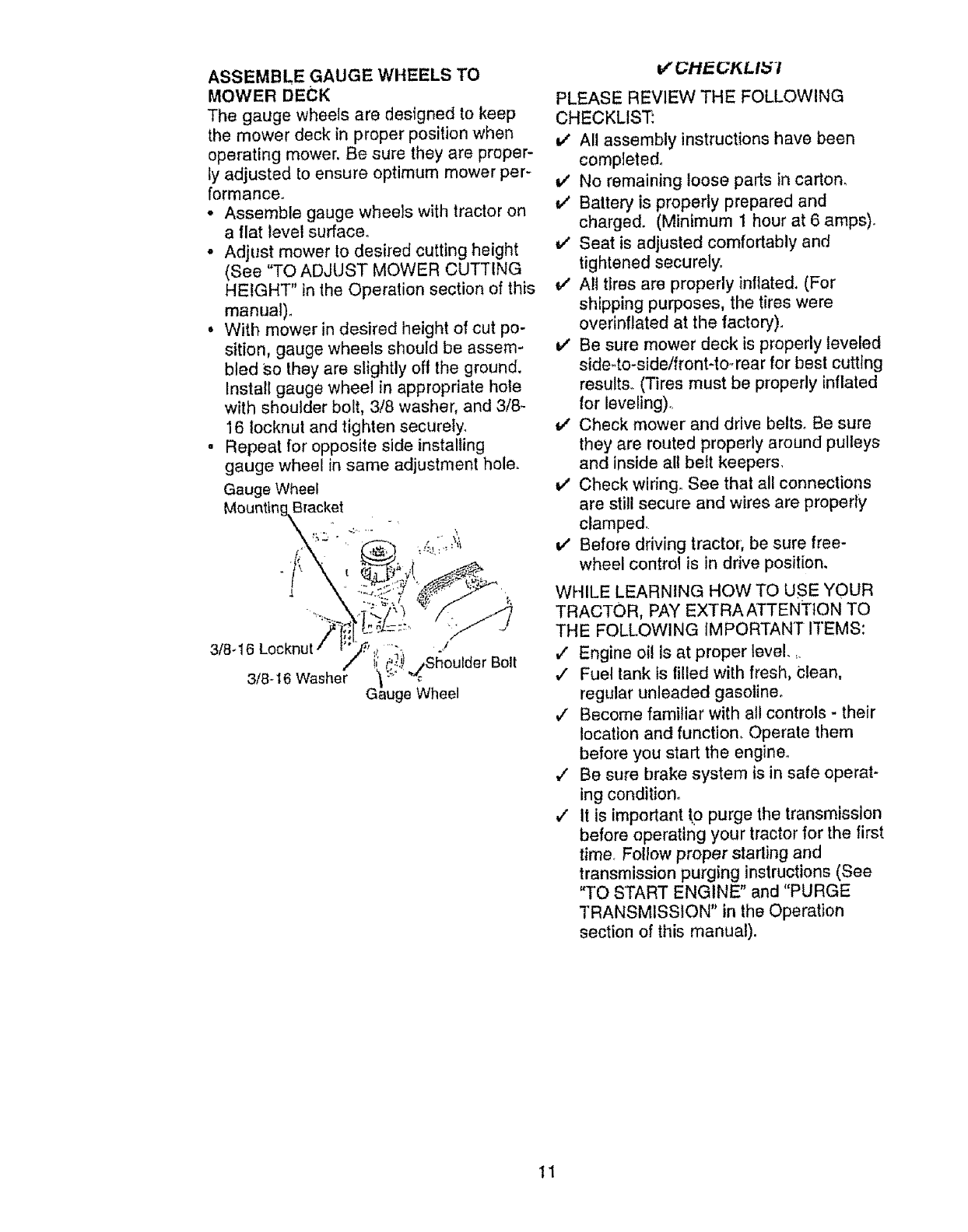
ASSEMBLE GAUGE WHEELS TO
MOWER DECK
The gauge wheels are designed to keep
the mower deck in proper position when
operating mower. Be sure they are proper-
ly adjusted to ensure optimum mower per-
formance.
- Assemble gauge wheels with tractor on
a flat level surface.
°Adjust mower to desired cutting height
(See "TO ADJUST MOWER CUTTING
HEIGHT" in the Operation section of this
manual).
, With mower in desired height of cut po-
sition, gauge wheels should be assem-
bled So they are slightly off the ground.
Install gauge wheel in appropriate hole
with shoulder bolt, 3/8 washer, and 3/8-
16 locknut and tighten securely.
,Repeat for opposite side installing
gauge wheel in same adjustment hole.
Gauge Wheef
Mountin Bracket
=lderBolt
3/8_16
G _/heel
GI"iE.GKLlb"!
PLEASE REVIEW THE FOLLOWING
CHECKLtST_
v' All assembly instructions have been
completed,
No remaining loose parts in carton,
v' Battery is properly prepared and
charged. (Minimum 1 hour at 6 amps),
v' Seat is adjusted comfortably and
tightened securely°
v' All tires are properly inflated. (For
shipping purposes, the tires were
overinflated at the factory),
v' Be sure mower deck is properly leveled
sideqo-side/front-to.,rear for best cutting
results., (Tires must be properly inflated
for leveling),
v' Check mower and drive belts. Be sure
they are routed properly around pulleys
and inside alt belt keepers,
IV' Check wiring. See that all connections
are still secure and wires are properly
clamped.
v' Before driving tractor; be sure free-
wheel control is in drive position,
WHILE LEARNING HOW TO USE YOUR
TRACTOR, PAY EXTRAATTENTtON TO
THE FOLLOWING IMPORTANT ITEMS:
,/ Engine oil is at proper level.,
,/ Fuel tank ts filled with fresh, Clean,
regular unleaded gasoline°
,/ Become familiar with all controls - their
location and function. Operate them
before you start the engine.
,/ Be sure brake system is in safe operat-
ing condition°
,/" it is important _o purge the transmission
before operating your tractor for the first
time. Follow proper starling and
transmission purging instructions (See
"TO START ENGINE" and "PURGE
TRANSMISSION" in the Operation
section of this manual).
11
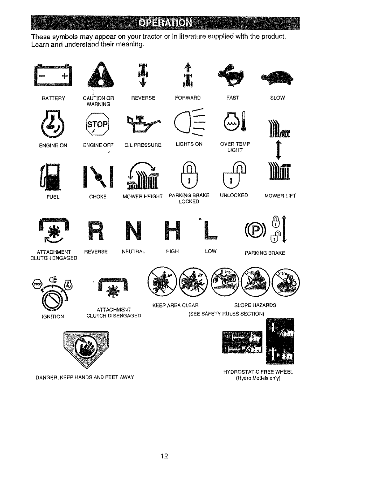
These symbols may appear on your tractor or In literature supplied wfth the prDduct.
Learn and understand their meaning,
E3
BATT+ERY
ENGINE ON
CAUTION OR
WARNING
+
REVERSE
,f
SLOW
ENGINE OFF OtL PRESSURE t
!,
FORWARD FAST
LIGHTS ON OVER TEMP
LIGHT
PARKING BRAKE UNLOCKED
LOCKED
FUEL CHOKE MOWER HEIGHT MOWER LIFT
ATTACHMENT
CLUTCH ENGAGED
REVERSE NEUTRAL
IGNITION
ATTACHMENT
CLUTCH DISENGAGED
DANGER, KEEP HANDS AND FEET AWAY
HL
HIGH LOW PARKING BRAKE
KEEP AREA CLEAR SLOPE HAZARDS
(SEE SAFETY RULES SECTION)
HYDROSTATIC FREE WHEEL
(Hydro Models only)
'12
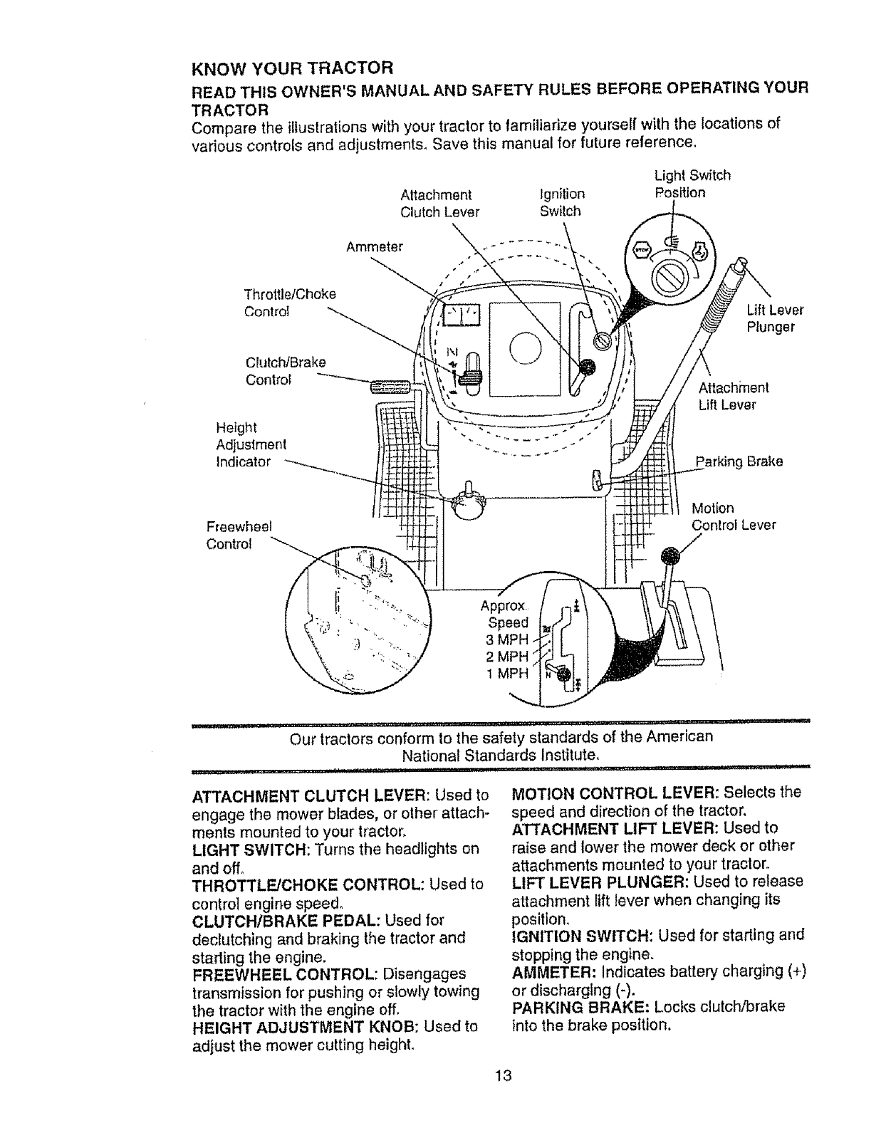
KNOW YOUR TRACTOR
READ THIS OWNER'S MANUAL AND SAFETY RULES BEFORE OPERATING YOUR
TRACTOR
Compare the illustrations with your tractor to tamiliarize yourself with the locations of
various controls and adjustrnents_ Save this manual for future reference,
Throttle/Choke
Control
Attachment Ignition
Clutch Lever Switch
\
Ammeter .,-" ........
Light Switch
Position
Lift Lever
Plunger
Ck_tch/Brake
Control
Height
Adjustment
Indicator
Attachment
Lift Lever
Parking Brake
Freewheel
Control
Motion
Control Lever
Our tractors conform to the safety standards of the American
National Standards Institute,
................... E! I!!l'tl!l'J'll'! IUl, , • ,i _
ATTACHMENT CLUTCH LEVER: Used to
engage the mower blades, or ether attach-
ments mounted to your tractor,
LIGHT SWITCH: Turns the headlights on
and off,
THROTTLE/CHOKE CONTROL: Used to
control engine speed,
CLUTCHIBRAKE PEDAL: Used for
declutching and braking the tractor and
starling the engine.
FREEWHEEL CONTROL: Disengages
transmission for pushing or slowly towing
the tractor with the engine off,
HEIGHT ADJUSTMENT KNOB: Used to
adjust the mower cutting height_
MOTION CONTROL LEVER: Selects the
speed and direction of the tractor.
ATTACHMENT LIFT LEVER: Used to
raise and lower the mower deck or other
attachments mounted to your tractor.
LIFT LEVER PLUNGER: Used to release
attachment lift lever when changing its
positlon,
IGNITION SWITCH: Used for starting and
stopping the engine,
AMMETER: Indicates battery charging (+)
or discharging (-).
PARKING BRAKE: Locks clutch/brake
Into the brake position.
13
The operation of any tractor can result in foreign objects thrown into the
eyes, which can result in severe eye damage. Always wear safety glasses
or eye shields while operating your tractor or performing any adjustments or
repairs. We recommend a wide vision safety mask over spectacles, or
standard safety glasses,
HOW TO USE YOUR TRACTOR
Your tractor is equipped with an operator
presence sensing switch. When engine is
running, any attempt by the operator to leave
the seat without first setting the parking brake
will shut off the engine,
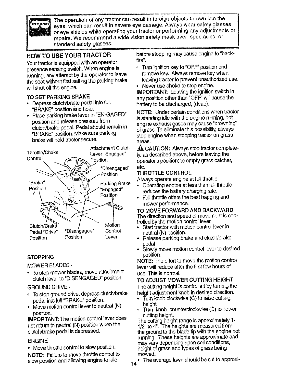
TO SET PARKING BRAKE
• Depress clutch!brake pedal into full
"BRAKE" position and hold,
oPlaceparldngbrakeleverin"EN-GAGED"
position and release pressure from
clutchJbrake pedal Pedal should remain in
"BRAKE" position. Make sure parking
brake will hold tractor secure.
Attachment Clutch
Throttle/Choke [.ever "Engaged"
Control _._-.... =osWon
-.- "_ "'__,t" "D senQaged"
.--post,on
Eiral,e. --.. ---q,,,.._, .....
" "\ - '. \_,_x,;" HarKing _raKe
Position %/' ; \ ';_:' ..- ,,En.a,_ed.
/\ Position
L_ '. -' "%"
ClutclVBrake .[Motion
Pedal "Drive" "Disengaged" Control
Position Position Lever
STOPPING
MOWER BLADES -
• To stop mower blades, move attachment
clutch lever to "DISENGAGED" position.
GROUND DRIVE-
="Tostop ground drive, depress clutch/brake
pedal into full "BRAKE" position.
° Move motion control lever to neutral (N)
position.
IMPORTANT; The motion control lever does
not return to neutral (N) position when the
cl_dch!brakepedal is depressed.
ENGINE -
• Move throttle control to slow position,
NOTE: Failure to move throttle control to
slow position and allowing engine to idIe
before stopping may cause engine to "back-
fire",
. Turn ignition key to "OFF" position and
remove key. Always remove key when
leaving tractor to prevent unaulhorized use.
° Never use choke to stop engine.
IMPORTANT: Leaving the ignition switch in
any position other than "O FF" will cause the
battery to be discharged, (dead).
NOTE: Under certain conditions when tractor
is standing idle with the engine running, hot
engine exhaust gases may cause "browning"
of gras& To eliminate this possibilily, always
stop engine when stopping tractor on grass
areas.
,_k CAUTION: Always stop tractor complete-
Iy, as described above, before leaving the
operator's position; to empty grass catcher,
etc.
THROTTLE CONIrROL
Always operate engine at full throttle
oOperating engine at less than full throttle
reduces the battery charging rate.
o Full throttle offers the best bagging and
mower performance,
TO MOVE FORWARD AND BACKWARD
'The direction and speed of movement is con*
trolted by the motion control lever.
• Start tractor with motion control lever in
neutral (N) position.
o Release parking brake and clutchJbrake
pedal
.Slowly move motion control lever to desired
position.,
NOTE: The efforttomove the motioncontrol
lever will reduce after the first few hours of
use. This is normal.
TO ADJUST MOWER CUTTING HEIGHT
The cutting height is cont_o!led by turning the
height adjustment knob in desired direction.
.Turn knob clockwise (©) to raise cutting
height.
°Turn knob counterclockwise (,.b)to lower
cutting height.
The cutting height range is approximately 1-
1/2" to 4", The heights are measured from
the ground to the bladetip with the engine not
rtmning. These heights are approximate and
may vary depending upon soil conditions,
height of grass and types of grass being
mowed.
•The average lawn should be cut to approxi-
14
mately2-1/2inchesduringthecoolseason
andtoover3inchesduringhotmonths,
Forhealthierandbetterlookinglawns,
mowoftenandaftermoderategrowth.
o Forbestcuttingperformance,grassover6
inchesinheightshouldbemowedtwice_
Makethefirstcutrelativelyhigh;thesec-
ondto desiredheight.
TOOPERATEMOWER
Yourtractorisequippedwithanoperator
presence sensing switch. Any attempt by the
operator to leave the seat with the engine run,-
ning and the attachment clutch engaged will
shut off the engine.
• Select desired height of cut,
• Lower mower with attachment lift control,
• Start mower blades by engaging attach-
ment clutch control
° TO STOP MOWER BLADES -disengage
attachment clutch control.
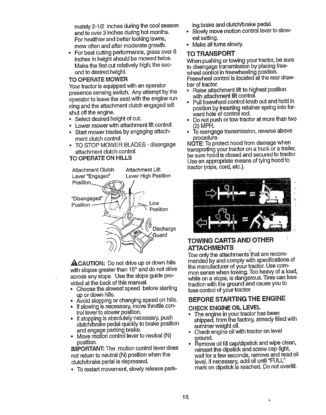
TO OPERATE ON HILLS
Atlachme nt Clutch
Lever "Engaged"
Posit
Attachment Lift
Lever High Position
"Disengaged"
Po_ Low
Posilion
,_CAUTION: Do not drive up or down hills
with slopes greater than 15° and do not drive
across any slope. Use the slope guide pro-
vided at the back of this manual.
• Choose the slowest speed before starting
up or down hills.
° Avoid stopping or changing speed on hills.
. If slowing is necessary, move throttle con-
trol lever to slower position.
• If stopping is absolutely necessary', push
clutch/brake pedal quickly to brake position
and engage parking brake.
, Move motion control lever to neutral (N)
position.
IMPORTANT: The motion control lever does
not return to neutral (N) position when the
clutcDJbrakepedal is depressed.
° To restart movement, slowly release park-
ing brake and clutch/brake pedal.
•Slowly move motion control lever to slow-
est setting.
, Make all turns slowly.
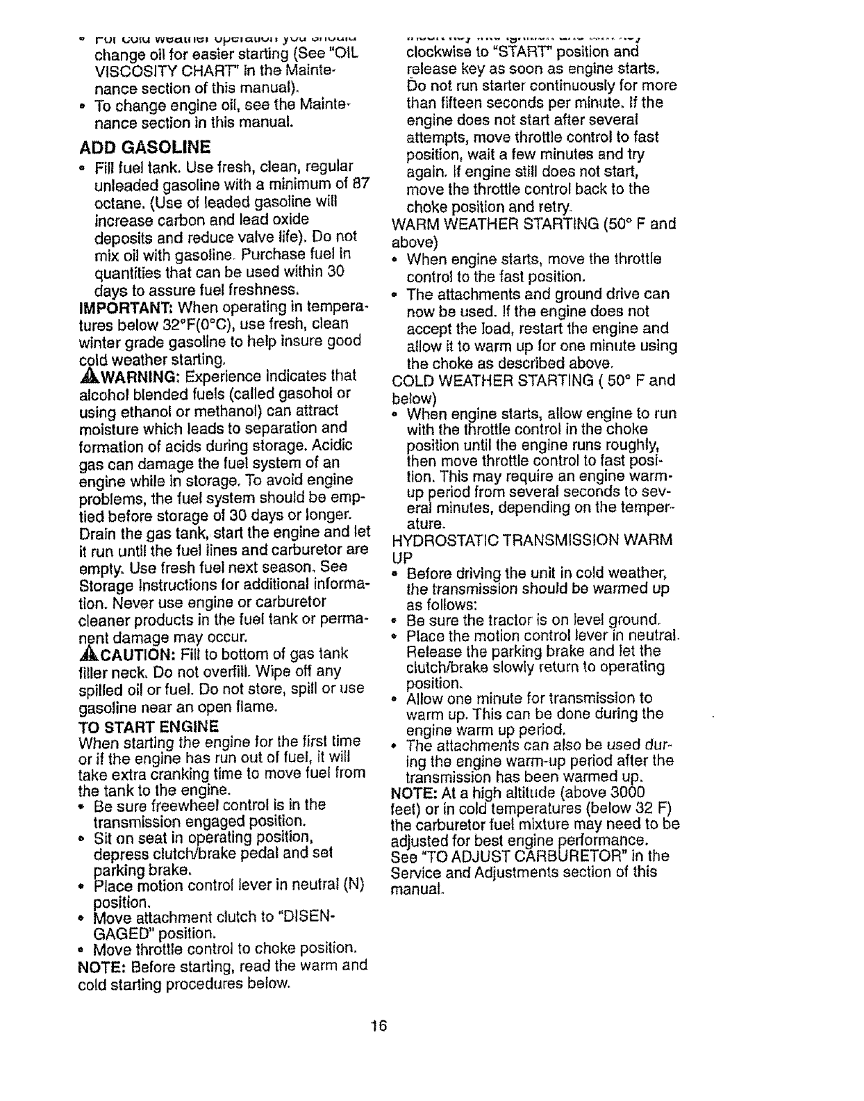
TO TRANSPORT
When pushing or towing your tractor, be sure
to disengage transmission by placing free-
wheel control in freewheeling position.
Freewheel control is located at the rear draw-
bar of tractor.
o Raise attachment liftto highest position
with attachment lift control.
° Pullfreewheel control knob out and hold in
position by inserting retainer spring into for-
ward hole of control rod.
° Do not push or tow tractor at more than two
(2) MPH.
° To reengage transmission, reverse above
procedure.
NOTE: To protect hood from damage when
transporting your tractor on a truck or a trailer,
be sure hood is closed and secured to tractor.
Use an appropriate means of tying hood to
tractor (rope, cord, etc.).
LI
TOWING CARTS ANDOTHER
ATTACHMENTS ,_i
low only the attachments that are recom-
mendedby and comply with specifications of
the manufacturer of your tractor. Use com-
mon sense when towing. Too heavy of a load,
while on a slope, is dangerous. 3ires can lose
traction with the ground and cause you to
lose control of your tractor.
BEFORE STARTING THE ENGINE
CHECK ENGINE OIL LEVEL
• The engine inyourtracter has been
shipped, from the factory, already filied with
summer weight oil.
°Check engine oil with tractor on level
ground.
°Remove oil fill cap/dipstick and wipe clean,
reinserl the dipstick and screw cap tight,
wait for a few seconds, remove and read oil
level. Ifnecessary, add oil until "FULL"
mark on dipstick Is reached. Do not overfill.
15
l+, r*t!l I+Ju|tl WilIIiIIlUlIIIIll Up t,l+lCltlvll _vu ,,lflvui+,+,l
change oil for easier starting (See "OIL
VISCOSITY CHART' in the Mainte-
nance section of this manual):
,' To change engine oil, see the Mainte-
nance section in this manual.
ADD GASOLINE
• Fill fuel tank. Use fresh, clean, regular
unleaded gasoline with a minimum of 87
octane. (Use el leaded gasoline will
increase carbon and lead oxide
deposits and reduce valve life). Do not
mix oil with gasoline. Purchase fuel in
quantities that can be used within 30
days to assure fuel freshness,
IMPORTANT_ When operating in tempera-
tures below 32°F(0°C), use fresh, clean
winter grade gasoline to help insure good
,_d weather starting.
WARNING: Experience Indicates that
alcohol blended fuels (called gasohol or
using ethanol or methanol) can attract
moisture which leads to separation and
formation of acids during storage. Acidic
gas can damage the fuel system of an
engine while in storage° To avoid engine
problems, the fuel system should be emp-
tied before storage of 30 days or longer.
Drain the gas tank, start the engine and let
it run until the fuel lines and carburetor are
empty. Use fresh fuel next season. See
Storage Instructions for additional informa-
tion. Never use engine or carburetor
cleaner products in the fuel tank or perma-
nent damage may occur.
_I]_CAUTION-" Fill to bottom of gas tank
filler neck, Do not oveffillo Wipe off any
spilled oil or fuel. Do not store, spill or use
gasoline near an open flame.
TO START ENGINE
When starting the engine for the first time
or if the engine has run out of fuel, it will
take extra cranking time to move fuel from
the tank to the engine.
•Be sure freewheel control is in the
transmission engaged position.
o Sit on seat in operating position,
depress clutch/brake pedal and set
parking brake.
, Place motion control lever in neutral (N)
position.
° Move attachment clutch to "DISEN-
GAGED" position.
° Move throttle control to choke position.
NOTE: Before starting, read the warm and
cold starting procedures below.
clockwise to "START" position and
release key as soon as engine starts.
Do not run starter continuously for more
than fifteen seconds per minute, tf the
engine does not start after several
attempts, move throttle control to fast
position, wait a few minutes and try
again. If engine still does not start,
move the throttle control back to the
choke position and retry.
WARM WEATHER S'fARTtNG (50 ° F and
above)
• When engine starts, move the throttle
control to the fast position.
- The attachments and ground ddve can
now be used. If the engine does not
accept the load, restart the engine and
allow it to warm up for one minute using
the choke as described above.
COLD WEATHER STARTING ( 50° F and
below)
o When engine starts, allow engine to run
with the throttle control in the choke
position until the engine runs roughly,
then move throttle control to fast posi-
tion. This may require an engine warm-
up period from several seconds to sev-
eralminutes, depending on the temper ,-
ature.
HYDROSTATIC TRANSMISSION WARM
UP
- Before ddving the unit in cold weather,
the transmission should be warmed up
as follows:
• Be sure the tractor is on Ievel ground.
° Place the motion control lever in neutral.
Release the parking brake and iet the
clutchlbrake slowly return to operating
position.
° Allow one minute for transmission to
warm up. This can be done during the
engine warm up period.
° The attachments can also be used dur.-
ing the engine warm-up period after the
transmission has been warmed up.
NOTE: At a high altitude (above 3000
feel) or in cold temperatures (below 32 F)
the carburetor fuel mixture may need to be
adjusted for best engine performance.
See "TO ADJUST CARBURETOR" in the
Service and Adjustments section of this
manual.
t6
_'u_= =N_a_,_,_v_
_CAUTION; Never engage or disen-
gage freewheel lever while the engine is
running.
To ensure proper operation and perfor-
mance, it is recommended lhat the trans-
mission be purged befor e operating tractor
for the first time. 'This procedure will
remove any trapped air inside the trans-
mission which may have developed during
shipping of your tractor,
IMPORTANT; Should your transmission
require removal for service or replace-
ment, it should be purged after reinstalla-
lion before operating the tractor.
= Place tractor safely on level surface with
engine off and parking brake set.
•Disengage transmission by placing free-
wheel control in freewheeling position
(See "TO TRANSPORT" in this section
of manual).
•Sitting in the tractor seat, start engine.
After the engine is running, move throt-
tle control to slow position. With motion
control lever in neutral (N) position,
slowly disengage clutch/brake pedal.
• Move motion control lever to full forward
position and hold for five (5) seconds.
Move lever to full reverse position and
hold for five (5) seconds. Repeat this
procedure three (3) times.
NOTE; During this procedure there will be
no movement of drive wheels. The air is
being removed from hydraulic drive sys.-
tem.
•Move motion control lever to neutral (N)
position. Shut off engine and set parking
brake.
o Engage transmission by placing free-
wheel control in driving position (See
"TO TRANSPORT" in this section of
manual).
° Sitting in the tractor seat, start engine.
After the engine is running, move throt-
tle control to half (1/2) speed. With
motion control lever tn neutral (N) posi-
tion, slowly disengage clutch/brake
pedal.
o Slowly move motion control lever for-
ward; after the tractor moves approxi..
mutely five (5) feet, slowly move motion
control lever to reverse position. After
the tractor moves approximately five (5)
feet return the motion control lever to
the neutral (N) position. Repeat this pro-
cedure with the motion control lever
three (3) times.
normal operation.
MOWING TIPS
•Tire chains cannot be used when the
mower housing is attached to tractor.
•Mower should be properly leveled for
best mowing performance. See "TO
LEVEL MOWER HOUSING" in the
Service and Adjustments section of this
manual.
• The left hand side of mower should be
used for trimming.
•Drive so that clippings are discharged
onto the area that has been cut. Have
the cut area to the right of the tractor,
This will result in a more even distrfbu-
tion of clippings and more uniform cut-
ting.
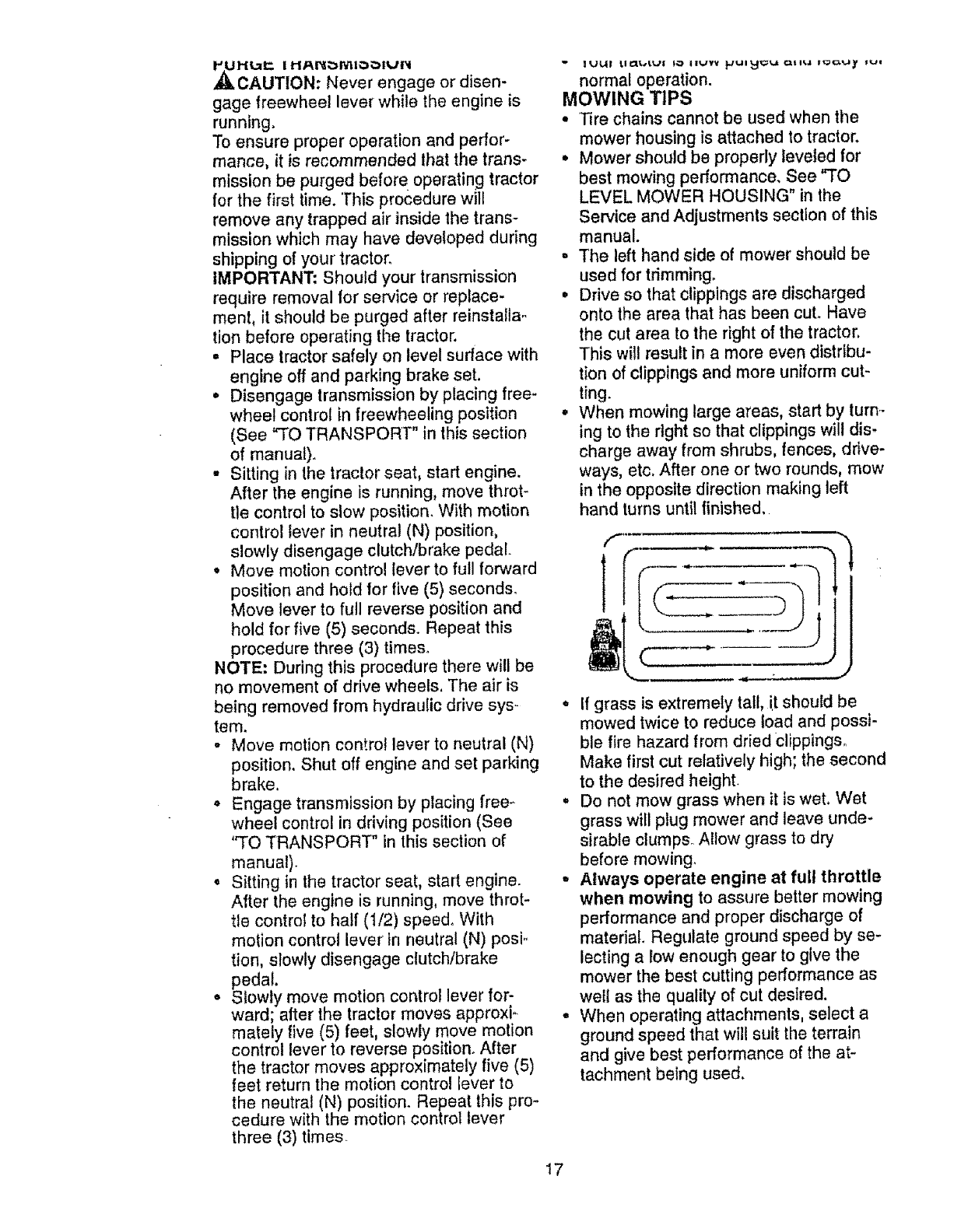
° When mowing large areas, start by turin
ing to the right so that clippings will dis.
charge away from shrubs, fences, drive-
ways, etc. After one or two rounds, mow
in the opposite direction making left
hand turns until finished.
L --_
• If grass is extremely tall, it should be
mowed twice to reduce load and possi-
ble fire hazard from dried €lippings.
Make first cut relatively high; the second
to the desired height.
° Do not mow grass when it is wet. Wet
grass will plug mower and leave unde-
sirable clumps° Allow grass to dry
before mowing
• Always operate engine at full throttle
when mowing to assure better mowing
performance and proper discharge of
material. Regulate ground speed by se-
lecting a low enough gear to give the
mower the best cutting performance as
well as the quality of cut desired.
• When operating attachments, select a
ground speed that wilt suit the terrain
and give best performance of the at-
tachment being used.
17
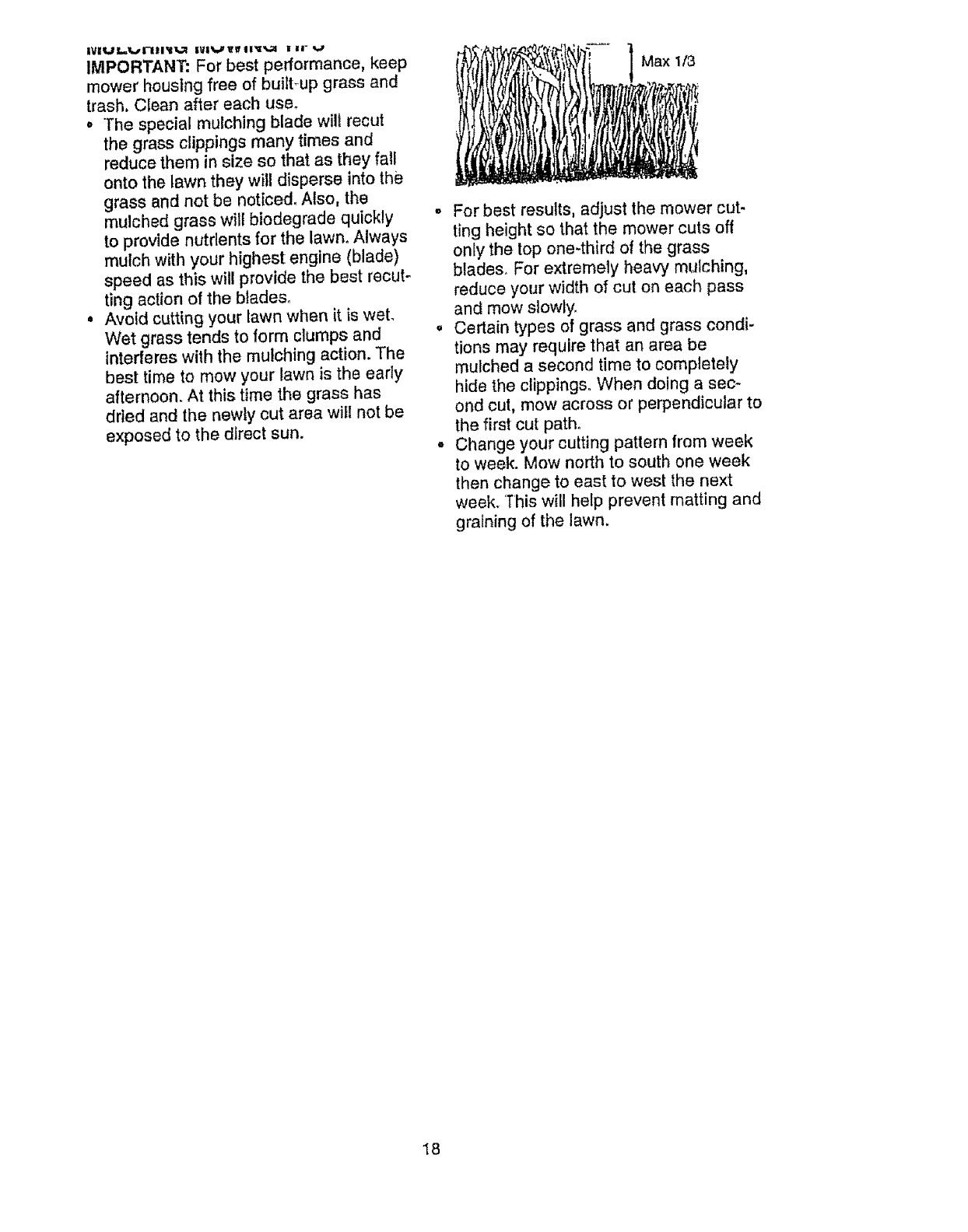
IMPORTANT: For best performance, keep
mower houstng free of bultt_up grass and
trash, Clean after each use.
o "Thespecial mulching blade will recur
the grass clippings many times and
reduce them in size so that as they fall
onto the lawn they will disperse into the
grass and not be noticed. Also, the
mulched grass will biodegrade quickly
to provide nutrients for the lawn_ Always
mulch with your highest engine (blade)
speed as this will provide the best recut-
ling action of the blades.
o Avoid cutting your lawn when it is wet.
Wet grass tends to form clumps and
interferes with the mulching action. The
best time te mow your lawn is the early
aflernoon. At this time the grass has
dried and the newly cut area will not be
exposed to the direct sun.
Max 1/3
° For best results, adjust the mower cut-
ting height so that the mower cuts off
only the top one4hird of the grass
blades_ For extremely heavy mulching,
reduce your width of cut on each pass
and mow slowly.
• Certain types of grass and grass condi-
tions may require that an area be
mulched a second time to completely
hide the clippings. When doing a sec-
ond cut, mow across or perpendicular to
the first cut path.
, Change your cutting pattern from week
to week. Mow north to south one week
then change to east to west the next
week. '1"his will help prevent matting and
graining of the lawn.
18
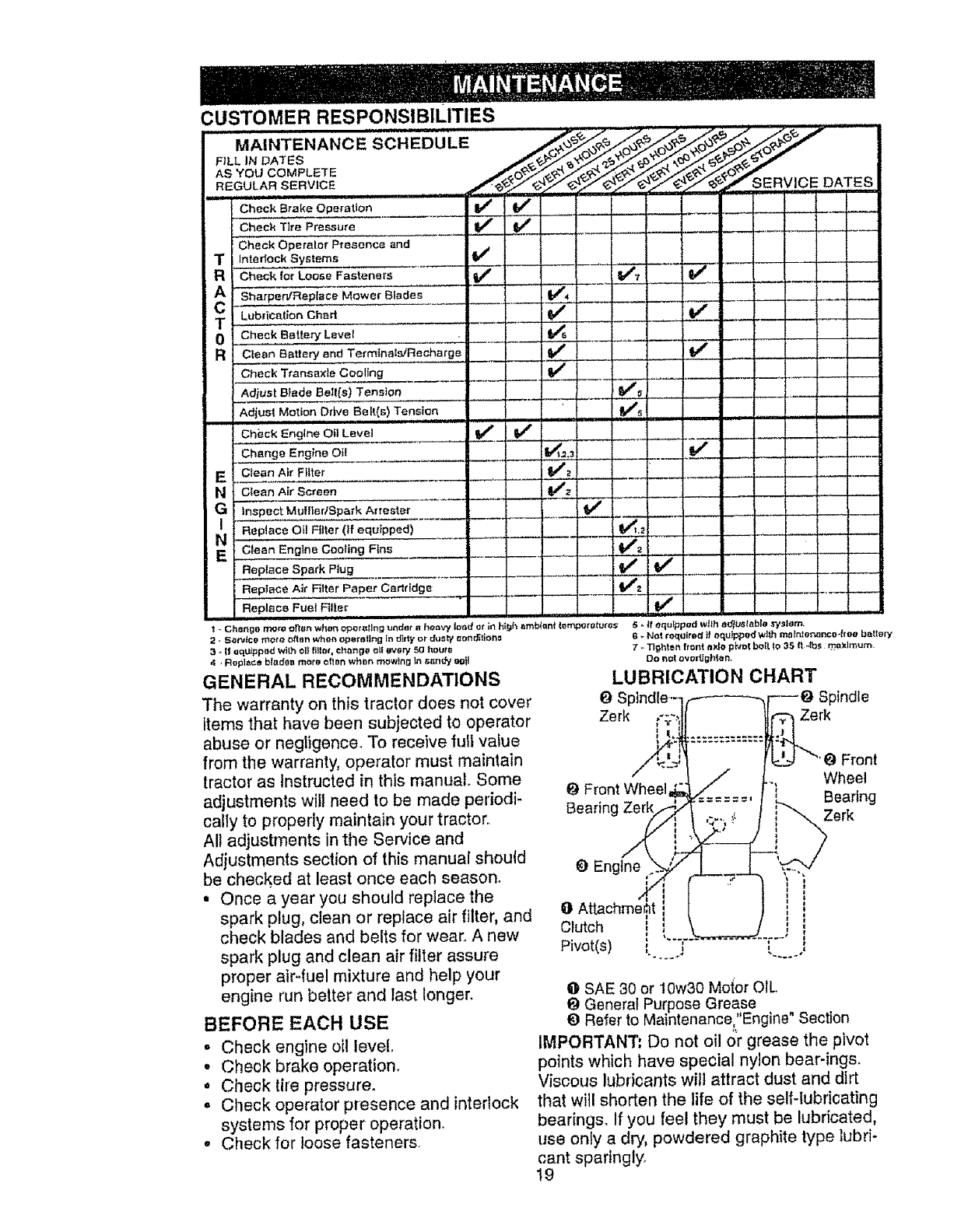
CUSTOMER RESPONSIBILITIES
MAINTENANCE SCHEDULE S_n o_d_.?_ _
F_LL IN DATES
sERvicE..... DATES
Check Brake Operation V_
Check Tlre Pressure tf t_
Check Operaler Presence and
TInterlock Systems V_
RCheekforLooseF..taoer_ V" i..... V', V_-
A SharperVRepisce Mower Blades .... V'4
TLub[icatlon Chart _#' V_
0
E
N
G
E
Clean Battery end Termtna!slRecharge
Check Ttaneaxie Cooling
Adios! Blade Be_i(s) Tension
Adius! Motion Ddve Belt(s) Tensh:tn
m, = m u i H
Ch&ck Engine Oil Level
Change Engine Oil
Clean Air Filter
Clean Air"Screen
Inspect Mufl|edSpark Attester
Replace Oil Fitter (if equipped)
Clean Englne Cooling Fins
Replace Spark Plug
Repiace Air Fitter Paper Cartridge
Replace Fuel Filter
v" v'
v,,.._ . v"
i/,
V'_ v"
2, Sa_Jce mote often wh_,n opert_t_ng fn rJ_ttyor dully t:on_on_
3-If o_lUippod With oI$ lillat, changg oif _vew 50 hours
4,Rop]t, ce b_deo _r_ _tiBtt whon rTR;,wlngin s_nd_ oO_l
GENERAL RECOMMENDATIONS
The warranty on this tractor does not cover
items that have been subjected to operator
abuse or negligence. To receive fullvalue
from the warranty, operator must maintain
tractor as instructed in this manual Some
adjustments will need to be made periodi-
cally to properly maintain your tractor..
Al! adjustments in the Service and
Adjustments section of this manual should
be checked at least once each season.
, Once a year you should replace the
spark plug, clean or replace air filler, and
check blades and belts for wear. A new
spark plug and clean air fitter assure
proper air-fuel mixture and help your
engine run better and last longer.
BEFORE EACH USE
.Check engine oi! level,
•Check brake operation.
° Check tire pressure.
- Check operator presence and interlock
systems for proper operation
•Check for loose fasteners.
Front
t_ Front Wheel Wheel
Bearin( Bearing
Zerk
_) Engtne
Clutch i
t
Pivot(s) _ I l .,,
0SAE 30 or !0w30 Motor OIL
t) General Purpose Grease .
{) Refer to Maintenance:,Engine Section
IMPORTANT: Do not oil or grease the pivot
points which have special nylon bear-ings.
Viscous lubricants will attract dust and dirt
that will shorten the life of the self-lubricating
bearings. If you feet they must be lubricated,
use only a dry, powdered graphite type lubri-
cant spaflngly.
19
TRACTOR
Alwaysobservesafetyruleswhenper-
formingany maintenance.
BRAKEOPERATION
If tractorrequiresmore thansix (6)feet
stoppingdistanceat highspeedin highest
gear,thenbrakemustbe adjusted.(See
"TOADJUSTBRAKE"in theServiceand
Adjustmentssectionof this manual).
TIRES
• Maintainproperair pressurein all tires
(See "PRODUCT SPECIFICATIONS"
on page 5 of this manual).
• Keep tires free of gasoline, oil, or insect
control chemicals which can harm rub-
ber,
, Avoid stumps, stones, deep ruts, sharp
objects and other hazards that may
cause tire damage.
NOTE: To seal tire punctures and prevent
flat tires due to slow leaks, tire sealant
may be purchased from your local parts
dealer. Tire sealant also prevents tire dry
rot and corrosion.
BLADE CARE
For best results mower blades must be
kept sharp. Replace bent or damaged
blades.
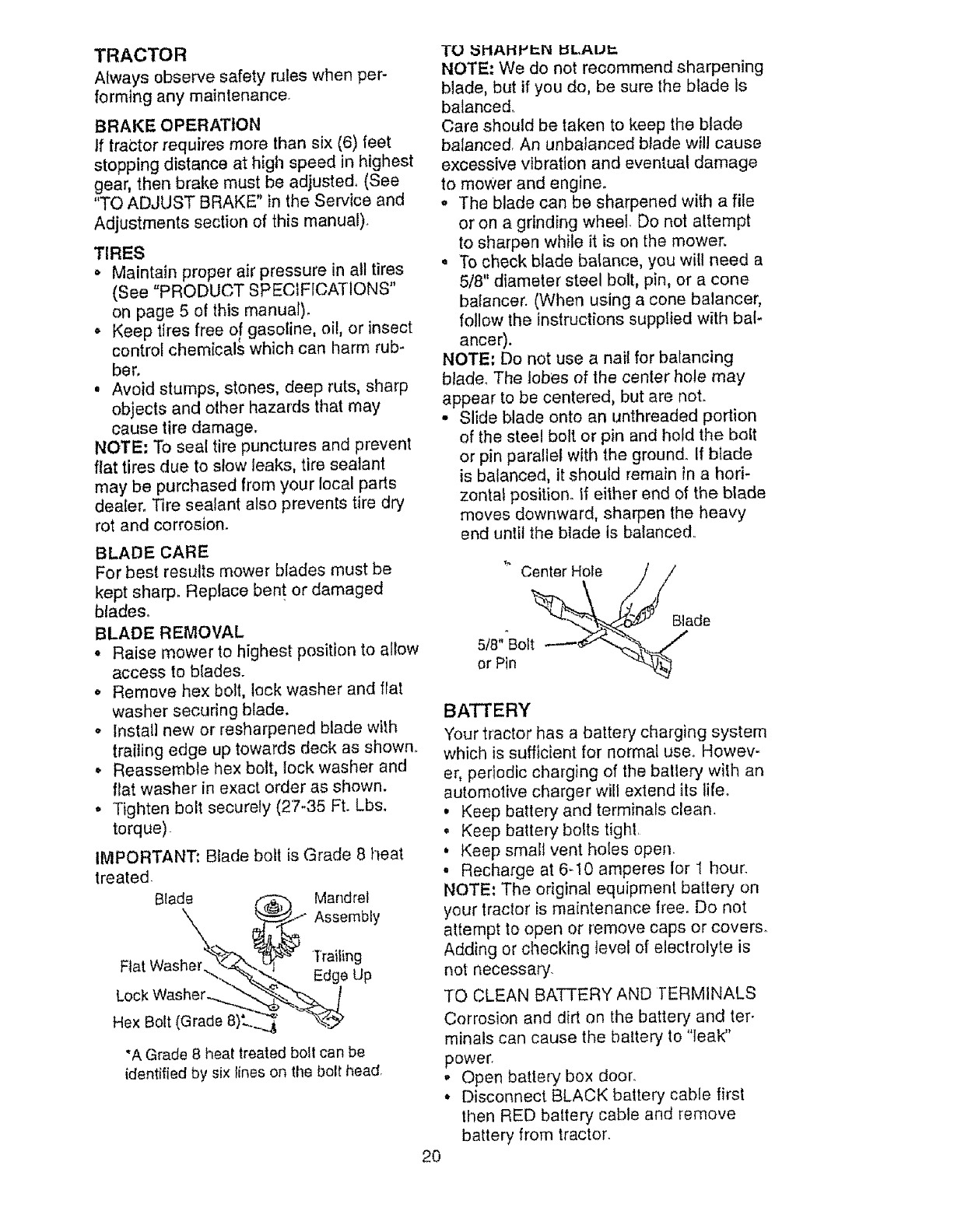
BLADE REMOVAL
• Raise mower to highest position to allow
access to blades.
• Remove hex bolt, lock washer and fiat
washer securing blade.
°Install new or resharpened blade with
trailing edge up towards deck as shown.
• Reassemble hex bolt, lock washer and
fiat washer in exact order as shown.
• Tighten bolt securely (27-35 Ft. Lbs.
torque).
IMPORTANT: Blade bolt is Grade 8 heat
treated
Blade _ Mandrel
X _._" Assemb,y
F,at Washerb%_l ''_'_ Trailing
........x,_-._._... Edge Up
LOck Washer .__.
Hex Bolt (Grade 8)L._ -'-h_._
"A Grade 8 heat treated bolt can be
identified by six lines on the bolt head
20
TO _IIAIIHI:N _LAUI:,
NOTE: We do not recommend sharpening
blade, but if you do, be sure the blade ls
balanced_
Care should be taken to keep the blade
balanced. An unbalanced blade will cause
excessive vibration and eventual damage
to mower and engine.
•The blade can be sharpened with a file
or on agrinding wheel. Do not altempt
to sharpen while it is on the mower.
• To check blade balance, you will need a
5/8" diameter steel bolt, pin, or a cone
bafancer. (When using a cone balancer,
follow the instructions suppt#ed with bal-
ancer).
NOTE: Do not use a nail for balancing
blade. The lobes of the center hole may
appear to be centered, but are not.
• Slide blade onto an unthreaded portion
of the steel bolt or pin and hold the bolt
or pin parallel with the ground. If b{ade
is balanced, it should remain in a hori-
zontal position° If either end of the blade
moves downward, sharpen the heavy
end until the blade is balanced.
Center Hole
5/8""Bolt
or Pin
Blade
BATTERY
Your tractor has a battery charging system
which is sufficient for normal use, Howev-
er, periodic charging of the batlery with an
automotive charger will extend its lifeo
• Keep battery and terminals clean.
, Keep battery bolts tighl.
, Keep small vent holes open.
• Recharge at 6-10 amperes lor 1 hour.
NOTE: The original equipment battery on
your tractor is maintenance free. Do not
attempt to open or remove caps or covers.
Adding or checking/evet of electrolyte is
not necessary.
TO CLEAN BATTERY AND TERMINALS
Corrosion and dirt on the battery and ter-
minals can cause the battery to "leak"
power.
.Open battery box door.
• Disconnect BLACK battery cable first
then RED batter/cable and remove
battery from tractor.
•'Hlnse Ine battery wire plain water ano
dry
• Clean terminals and battery cable ends
with wire brush until bdghL
• Coat terminals with grease or petroleum
jelly.
• Reinstall battery (See"CONNECT BAT-
TERY" in the Assembly section of this
manual)
V-BELTS
Check V-belts for deterioration and wear
after 100 hours of operation and replace if
necessary. The belts are not adjustable.
Replace belts if they begin to slip from
weal
TRANSAXLE COOLING
The transmission fan and cooling fins
should be kept clean to assure proper
cooling.
Do not attempt to clean fan or transmis-
sion while engine is running or while the
transmission is hot.
• inspect cooling fan to be sure fan
blades are intact and clean.
°Inspect cooling fins for dirt, grass clip-
pings and other materials. To prevent
damage to seals, do not use com-
pressed air or high pressure sprayer to
clean cooling fins.
TRANSAXLE PUMP FLUID
The transaxte was sealed at the factory
and fluid maintenance is not required for
the life of the transaxle. Should the
transaxle ever leak or require servicing,
contact your nearest authorized service
center.
ENGINE
LUBRICATION
Only use high quality detergent oil rated
with API service classification SF, SG or
SH, Select the oil's SAE viscosity grade
according to your expected operating tem-
perature,
U_I,_U i::I.UUV_ 0,_" I_ l,._lll:tl..;l_ yuul I_IIL...J|II_ Ull
level more frequently to avoid possible
engine damage from running low on oil.
Change the oil after every 25 hours of
operation or at least once a year if the
Iractor is not used for 25 hours in one
year.
Check the crankcase oil level before start-
ing the engine and after each eight (8)
hours of operation. Tighten oll fill capidip_
stick securely each time you check the oil
level.
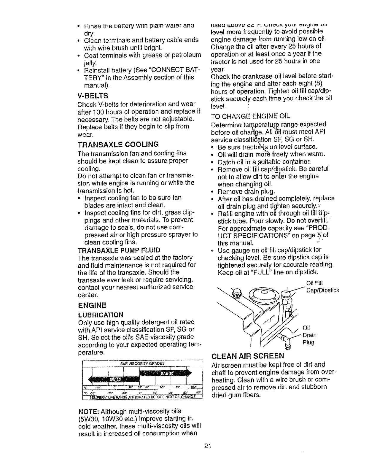
'TO CHANGE ENGINE OIL
Determine teroperatu.[e range expected
before oil char_ge. All _Jil must meet API
service classification SF, SG or SH.
• Be sure tractol_i_ on level surface.
• Oil wilt drain mo_'e freely when warm.
,Catch oil in a suitable container,
° Remove oil fili cap/_pstiCk. Be careful
not to allow dirt to enter the engine
when changing oil
• Remove drain plug.
• After oll has drained completely, replace
oiidrain plug and tighten securely.:_
• Refill engine with oil through oil fill dip-
stick tube. Pour slowly. Do not oveFfilL'
For approximate capacity see "PROD.-
UCT SPECIFICATIONS" on page 5'of
this manual, °-
° Use gauge on oil fill cap/dipstick for
checking level. Be stJre dipstick cap is
tightened securely for accurate reading.
Keep oil at "FULL" line on dipstick.
Oil Fill
Oil
Drain
Plug
CLEAN AIR SCREEN
Air screen must be kept free of dirt and
chaff to prevent engine damage from over-
heating. Clean with a wire brush or com-,
pressed air to remove dirt and stubborn
dried gum fibers,
NOTE: Although multiwiscosity oils
(5W30, 10W30 etc,)improve starting In
cold weather, these multi-viscosity oils will
result in increased oil consumption when
21
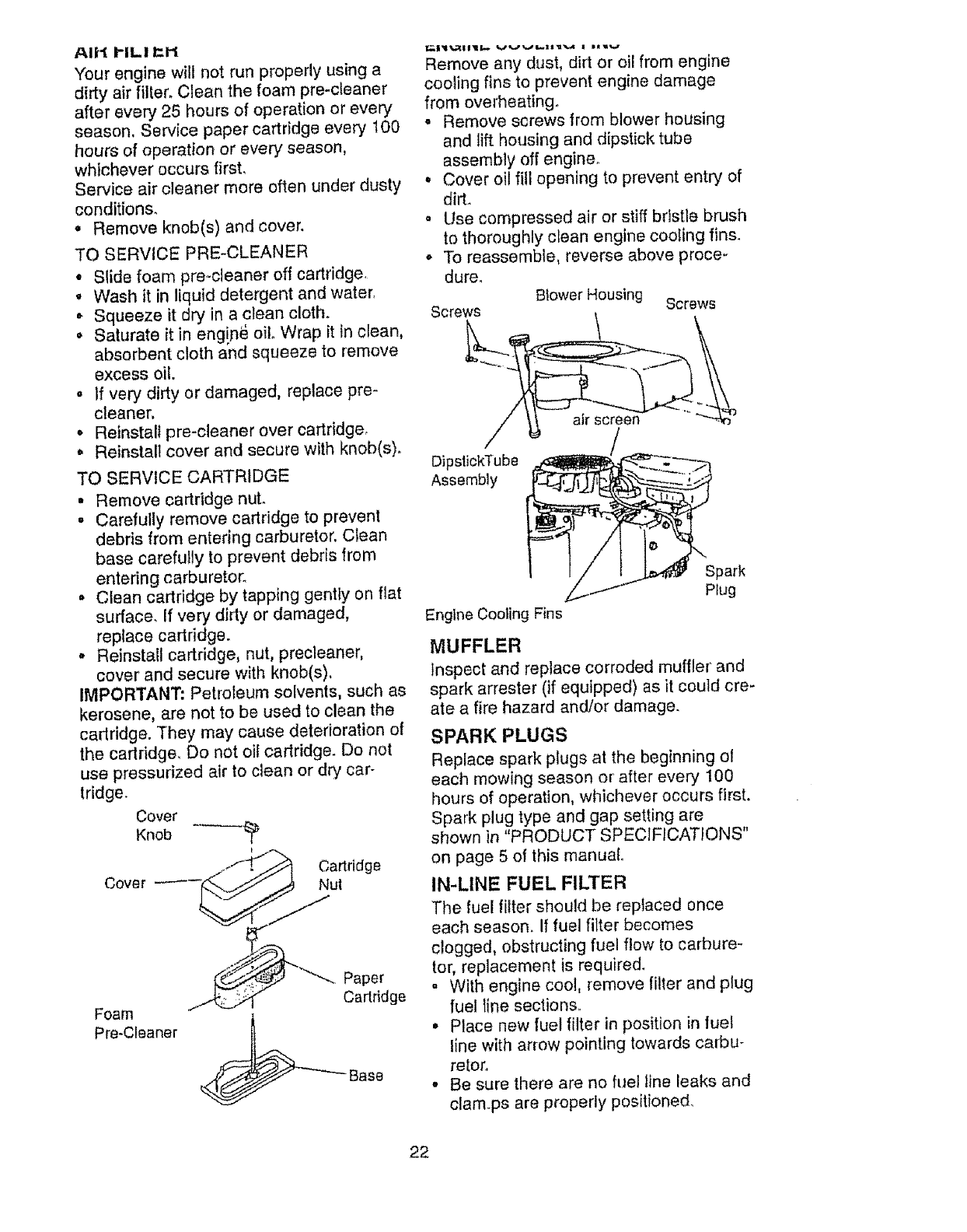
AIH I"IL! _1-I
Your engine will not run properly using a
dirty air filtec Clean the foam pre-cleaner
after every 25 hours of operation or every
season. Service paper cartridge every 100
hours of operation or every season,
whichever occurs first.
Service air cleaner more often under dusty
conditions.
• Remove knob(s) and cover.
TO SERVICE PRE-CLEANER
, Slide foam pre-cleaner off cartridge.
° Wash it in liquid detergent and water.
•Squeeze it dry in a clean cloth.
°Saturate it in eng!n_ oilo Wrap it in clean,
absorbent cloth and squeeze to remove
excess oil.
,tf very dirty or damaged, replace pro-
cleaner,
o Reinstall pre-cleaner over cartridge,
• Reinstall cover and secure with knob(s).
TO SERVICE CARTRIDGE
° Remove cartridge nuL
. Carefully remove cartridge to prevent
debris from entering carburetor, Clean
base carefully to prevent debris from
entering carburetor.
•Clean cartridge by tapping gently on flat
surface. If very dirty or damaged,
replace cartridge.
•Reinstall cartridge, nut, precleaner,
cover and secure with knob(s),
IMPORTANT: Petroleum solvents, such as
kerosene, are not to be used to clean the
cadridge. They may cause deterioration of
the cartridge, Do not oil cadridge. Do not
use pressurized air to clean or dry car-
tridge.
Cover
Knob -
/_.-" .ff_ Cartridge
Cover _--_. _/j _.,_ Nut
Foam
Pre.Cleaner
Paper
Cartridge
__ Base
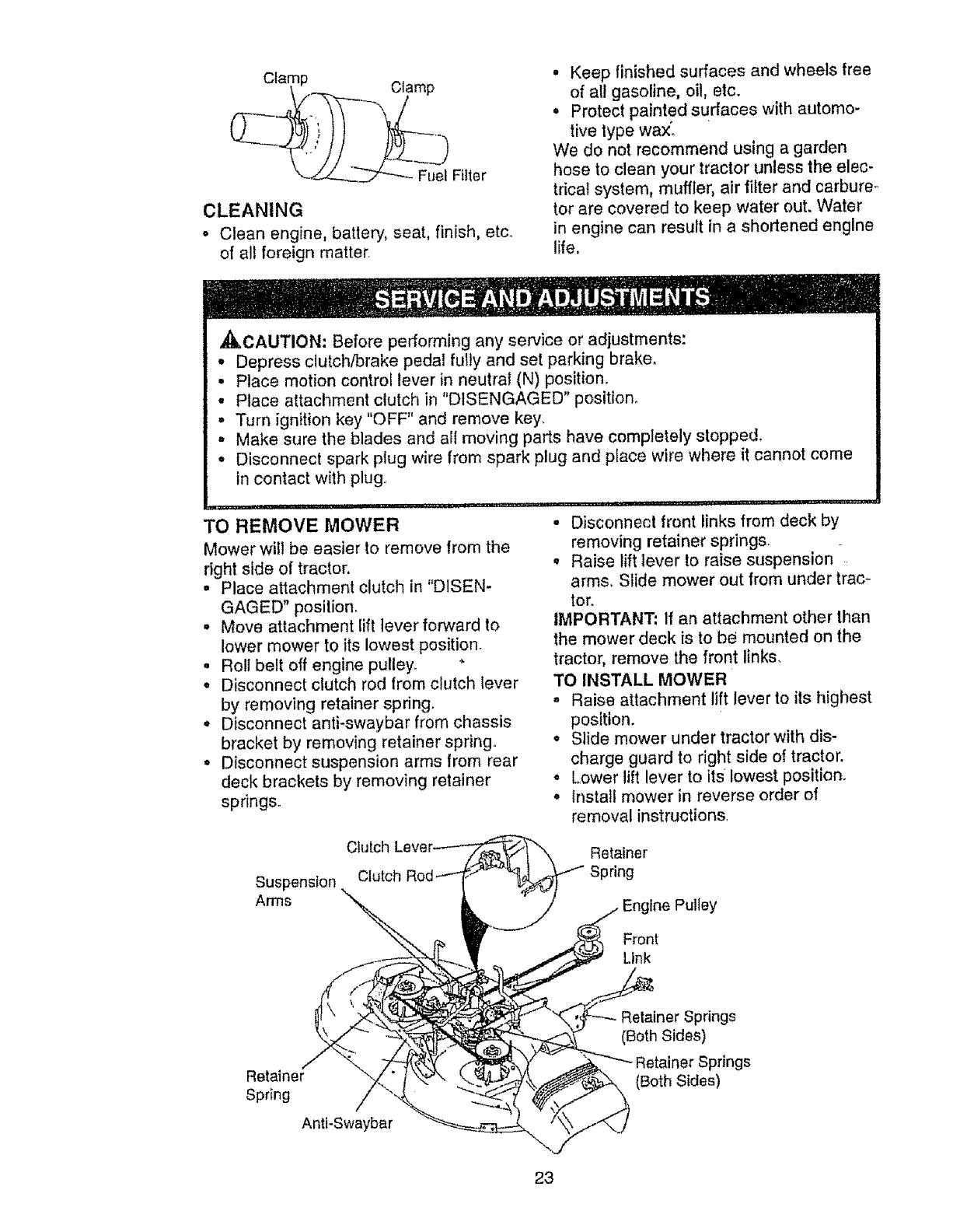
Remove any dust, dirt or oil from engine
cooling fins to prevent engine damage
from overheating°
• Remove screws from blower housing
and lift housing and dipstick tube
assembly off engine_
•Cover oil fill opening to prevent entry of
dirt.
. Use compressed air or stiff bristle brush
to thoroughly clean engine cooling fins.
o To reassemble, reverse above proce-
dure.
Btower Housing
Screws Screws
DipstickTube
Assembly
air screen
Spark
Plug
Engine Cooling Fins
MUFFLER
inspect and replace corroded muffler and
spark arrestor (if equipped) as it could cre-
ate a fire hazard and/or damage.
SPARK PLUGS
Replace spark plugs at the beginning ol
each mowing season or after every 100
hours of operation, whichever occurs first.
Spark plug type and gap setting are
shown in "PRODUCT SPECIFICATFONS"
on page 5 of this manual°
IN-LINE FUEL FILTER
The fuel filter should be replaced once
each season. If fuel filter becomes
clogged, obstructing fuel flow to carbure-
tor, replacement is required.
o With engine cool, remove filter and plug
fuel line sections_
° Place new fuel filter in position in fuel
line with arrow pointing towards carbu-
retor_
• Be sure there are no fuel line leaks and
clamps are properly positioned.
22
Clamp
(__,.._ Clamp
"--J---/--._'__2z'---_FuelFiller
CLEANING
• Clean engine, battery, seat, finish, etc.
of all foreign matter.
• Keep finished surfaces and wheels free
of all gasoline, oil, etc.
o Protect painted surfaces with automo-
tive type wax'.
We do not recommend using a garden
hose to clean your tractor unless the elec-
trical system, muffler, air filter and carbure r.,
tor are covered to keep water out. Water
in engine can result in a shortened engine
life,
,_I_CAUTION: Before performing any service or adjustments:
• Depress clutch/brake pedal fully and set parking brake.
° Place motion control lever in neutral (N) position.
• Place attachment clutch in "DISENGAGED" position,.
° Turn ignition key "OFF" and remove key.
,, Make sure the blades and all moving parts have completely stopped.
• Disconnect spark plug wire from spark plug and place wire where it cannot come
in contact with plug..
JJllllU
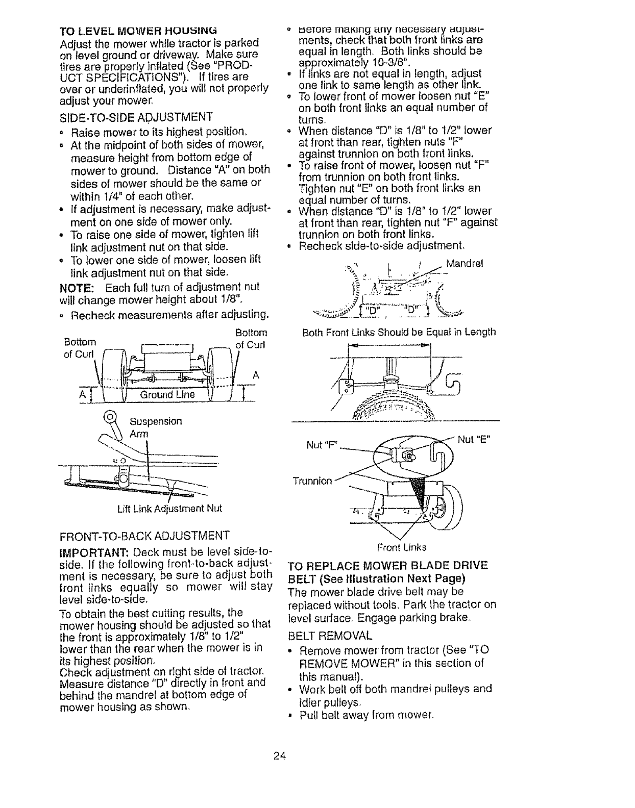
TO REMOVE MOWER
Mower wild be easier to remove from the
right side of tractor.
•Place attachment clutch in "DiSEN-
GAGED" posilion,
• Move attachment lift lever forward to
lower mower to its lowest position.
, Roll belt off engine pulley, "
• Disconnect clutch rod from clutch lever
by removing retainer spring.
•Disconnect anti-swaybar from chassis
bracket by removing retainer spring.
•Disconnect suspension arms from rear
deck brackets by removing retainer
springs.
° Disconnect front links from deck by
removing retainer springs_
°Raise lift lever to raise suspension
arms. Slide mower out from under trac-
tor.
IMPORTANT: l{ an attachment other than
the mower deck is to be mounted on the
tractor, remove the front links,
TO INSTALL MOWER
-Raise attachment lift lever to its highest
position.
•Slide mower under tractor with dis-
charge guard to right side of tractor.
°Lower lift lever to its lowest position.
• Install mower in reverse order of
removal instructions.
Suspension
Arms
Clutch
Clutch Roc
Retainer
Spring
Engtne Pulley
Front
Link
Retainer
Spring
Antl-Swaybar
Retainer Springs
(Both Sides)
er Springs
(Both Sides)
23
TO LEVEL MOWER HOUSING
Adjust the mower whiIe tractor is parked
on level ground or driveway, Make sure
tires are properly inflated (See 'PROD-
UCT SPECIFICATIONS"). If tires are
over or undednflated, you wilt not properly
adjust your mower,
SIDE-TO-S}DE ADJUSTMENT
•Raise mower to its highest position,
• At the midpoint of both sides of mower,
measure height from bottom edge of
mower to ground. Distance "A" on both
sides of mower should be the same or
within 1/4" of each other.
• If adjustment is necessary, make adjust-
ment on one side of mower only,
• To raise one side of mower, tighten lift
link adjustment nut on that side.
°To lower one side of mower, loosen lift
link adjustment nut on that side_
NOTE: Each full turn of adjustment nut
wilt change mower height about 1/8".
° Recheck measurements after adjusting.
Bottom Bottom
Suspension
Arm
Lift Link Adjuslment Nut
FRONT-TO-BACK ADJUSTMENT
IMPORTANT: Deck must be level sideqo-
side° If the following front.-to-back adjust.,
merit is necessary, be sure to adjust both
front links equally so mower will stay
level side-lo-side,
To obtain the best cutting results, the
mower housing should be adjusted so that
the front is approximately 1/8" to 1/2"
lower than the rear when the mower is in
its highest position,
Check adjustment on right side o4 tractor,
Measure distance "D" directly in front and
behind the mandrel at bottom edge of
mower housing as shown.
° L_efore making any necessary uujust-
ments, check that both front links are
equal in length.. Both links should be
approximately 10-3/8",
°If links are not equal in length, adjust
one link to same length as other link.
°To lower front of mower loosen nut "E"
on both front links an equal number of
tumso
°When distance "D" is 1/8" to t/2" lower
at front than rear, tighten nuts "F"
against trunnion on both front links,
°To raise front of mower, loosen nut "F"
from trunnion on both front links.
Tighten nut "E" on both front links an
equal number of turns.
° When distance "D" is !/8" to 1/2" lower
at front than rear, tighten nut "F" against
trunnion on both front links,
° Recheck side-to-side adjustment.
Both Front Links Should be Equal in Length
,-',,,4:",.'::':_....... "'hA
.... _Nut "E"
Nut F".
Front Links
TO REPLACE MOWER BLADE DRIVE
BELT (See Illustration Next Page)
The mower blade dive belt may be
replaced without tools.. Park the tractor on
level suflace. Engage parking brake.
BELT REMOVAL
• Remove mower from tractor (See %0
REMOVE MOWER" in this section of
this manual).
•Work belt off both mandrel pulleys and
idler pulleys,
, Pull belt away from mower.
24
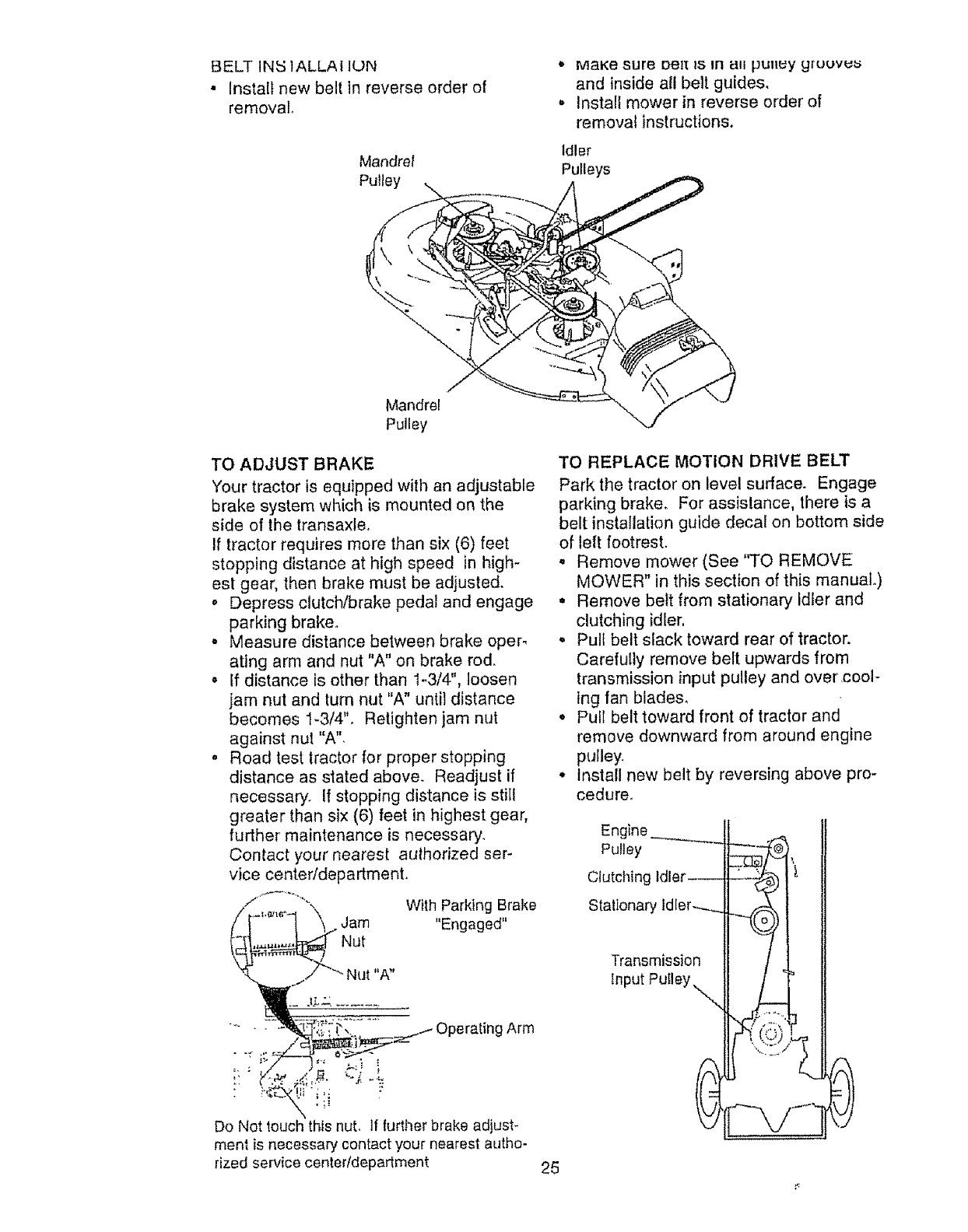
BELTIN_51ALLAIION
•Insta[f new belt in reverse order of
removal
Mandrel
Pulley
*MaKe sure Deit 1S In _11 pulley y[DUV_
and inside all belt guides.
, Install mower in reverse order of
removal instructions,
Idler
Pulleys
Mandrel
Pulley
TO ADJUST BRAKE
Your tractor is equipped with an adjustable
brake system which is mounted on the
side of the transaxleo
If tractor requires more than six (6) feet
stopping distance at high speed in high-
est gear, then brake must be adjusted.
o Depress clutch/brake pedal and engage
parking brake°
o Measure distance between brake oper_
ating arm and nut "A" on brake rod.
° If distance is other than 1-3/4", loosen
jam nut and turn nut "A" until distance
becomes 1-3/4". Retighten jam nut
against nut "A".
° Road test tractor for proper stopping
distance as stated above_ Readjust if
necessary. If stopping distance is sti[f
greater than six (6) feet in highest gear,
further maintenance is necessary.
Contact your nearest aulhorized ser-
vice centeddepartment.
if-'°"°q ..Jam Wit.,,Eo0. ed,,Parkio0 ro,,e
Arm
TO REPLACE MOTION DRIVE BELT
Park the tractor on level surface. Engage
parking brake. For assislance, there is a
belt installation guide decal on bottom side
of left footrest.
°Remove mower (See"TO REMOVE
MOWER" in this section of this manual.)
° Remove belt from stationary idler and
clutching idler,
°Pull belt slack toward rear of tractor.
Carefully remove belt upwards from
transmission input pulley and over cool-
ing fan blades,
°Pull belt toward front of tractor and
remove downward from around engine
pulley.
°Install new belt by reversing above pro-
cedure_
Do Not touch this nut, If further brake adjust-
ment is necessary contact your nearest autho-
rized service center/depadment 25
Engine _---.-..__l/ .,-_
_nput putley "_N.__
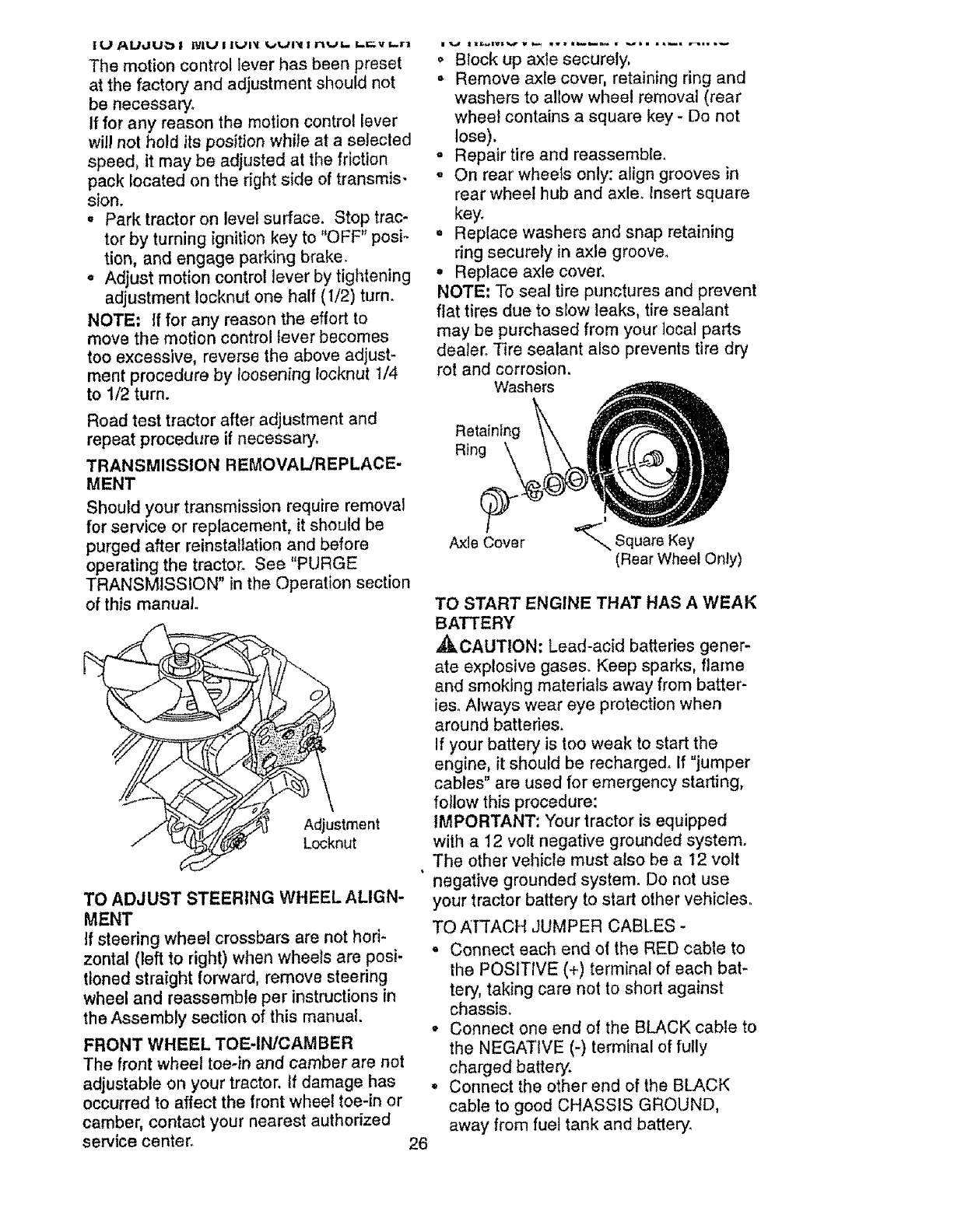
The motion control lever has been preset
at the factory and adjustment should not
be necessary°
If for any reason the motion control lever
will not hold itsposition while at aselecled
speed, it may be adjusted at the friction
pack located on the right side of transmis-
sion.
o Park tractor on level surface. Stop trac-
tor by turning ignition key to "OFF" posi-
tion, and engage parking brake.
- Adjust motion control/ever by tightening
adjustment !ocknut one half (1/2) turn.
NOTE: If for any reason the effort to
move the motion control lever becomes
too excessive, reverse the above adjust-
ment procedure by loosening _ocknut !/4
to 1/2 turn.
Road test tractor after adjustment and
repeat procedure if necessary.
TRANSMISSION REMOVAL/REPLACE-
MENT
Should your transmission require removal
for service or replacement, it should be
purged after reinstaltation and before
operating the tractor. See "PURGE
TRANSMISSION" in the Operation section
of this manual
A_ L_stment
Locknut
TO ADJUST STEERING WHEEL ALIGN-
MENT
If steering wheel crossbars are not hori-
zontal (left to right) when wheels are posi-
tioned straight forward, remove steering
wheel and reassemble per instructions in
the Assembly section of this manual.
FRONT WHEEL TOE-IN/CAM BER
The front wheel toe-in and camber are not
adjustable on your tractor, If damage has
occurred to affect the front wheel toe-in or
camber, contact your nearest authorized
service center. 26
o Block up axle securely,
•Remove axle cover, retaining ring and
washers to allow wheel removal (rear
wheel contains a square key - De not
lose).
= Repair tire and reassemble.
-On rear wheels only: align grooves in
rear wheel hub and axle. insert square
key,r
. Replace washers and snap retaining
ring securely in axle groove.
•Replace axle cover.
NOTE: To seal tire punctures and prevent
flat tires due to slow leaks, tire sealant
may be purchased from your local parts
dealer. Tire sealant also prevents tire dry
rot and corrosion.
Washers
Retaining
Ring
Axle Cover _--,,, Square Key
(Rear Wheel Only)
TO START ENGINE THAT HAS A WEAK
BATTERY
_kCAUTION: Lead-acid batteries gener-
ate explosive gases. Keep sparks, flame
and smoking materials away from batter-
ies. Always wear eye protection when
around batteries.
If your battery is too weak to start the
engine, it should be recharged. If "jumper
cables" are used for emergency starting,
follow this procedure:
IMPORTANT: Your tractor is equipped
with a 12 volt negative grounded system.
The other vehicle must also be a t2 volt
negative grounded system. Do not use
your tractor battery to start other vehicles,
TO AN'ACH JUMPER CABLES -
• Connect each end of the RED cable to
the POSITIVE (+) terminal of each bat-
tery, taking care not to short against
chassi&
°Connect one end of the BLACK cable to
the NEGATIVE (-) terminal of fully
charged battery'.
° Connect the other end of the BLACK
cable to good CHASSIS GROUND,
away from fuel tank and battery.
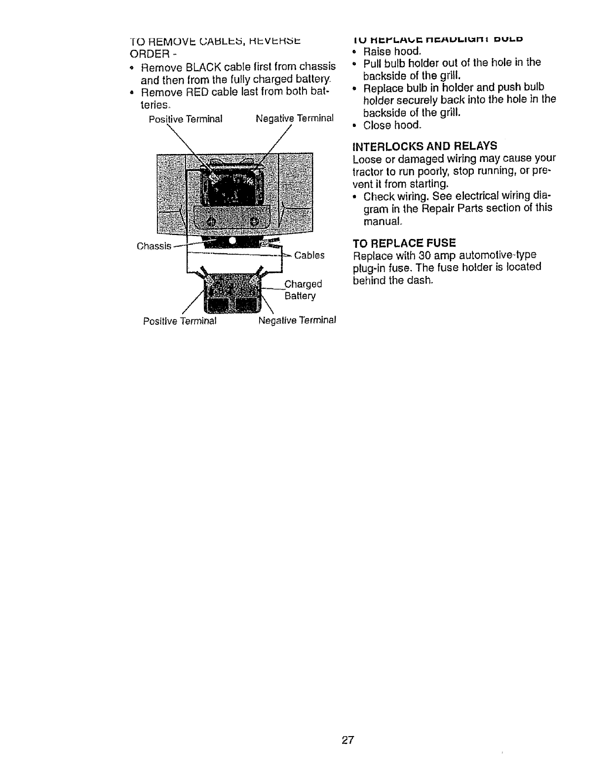
-[O REMr,.)Vt:: (jAt_LI-_, HIc:V!:::H;:5_
ORDER
• Remove BLACK cable first from chassis
and then from the fully charged battery
,Remove RED cable last from both bat-
retie&
Positive Terminal Negative Terminal
Positive Terminal Negative Terminal
• Raise hood.
•Pull bulb holder out of the hole in the
backside of the grill,
•Replace butb in holder and push bulb
holder securely back into the hole in the
backside of the grill.
• Close hood.
INTERLOCKS AND RELAYS
Loose or damaged wiring may cause your
tractor to run poorly, stop running, or pre-
vent it from starting,
• Check wiring. See electrical wiring dia-
gram in the Repair Parts section of this
manual
TO REPLACE FUSE
Replace with 30 amp automotive4ype
plug-in fuse_ The fuse hoider is located
behind the dash.
27
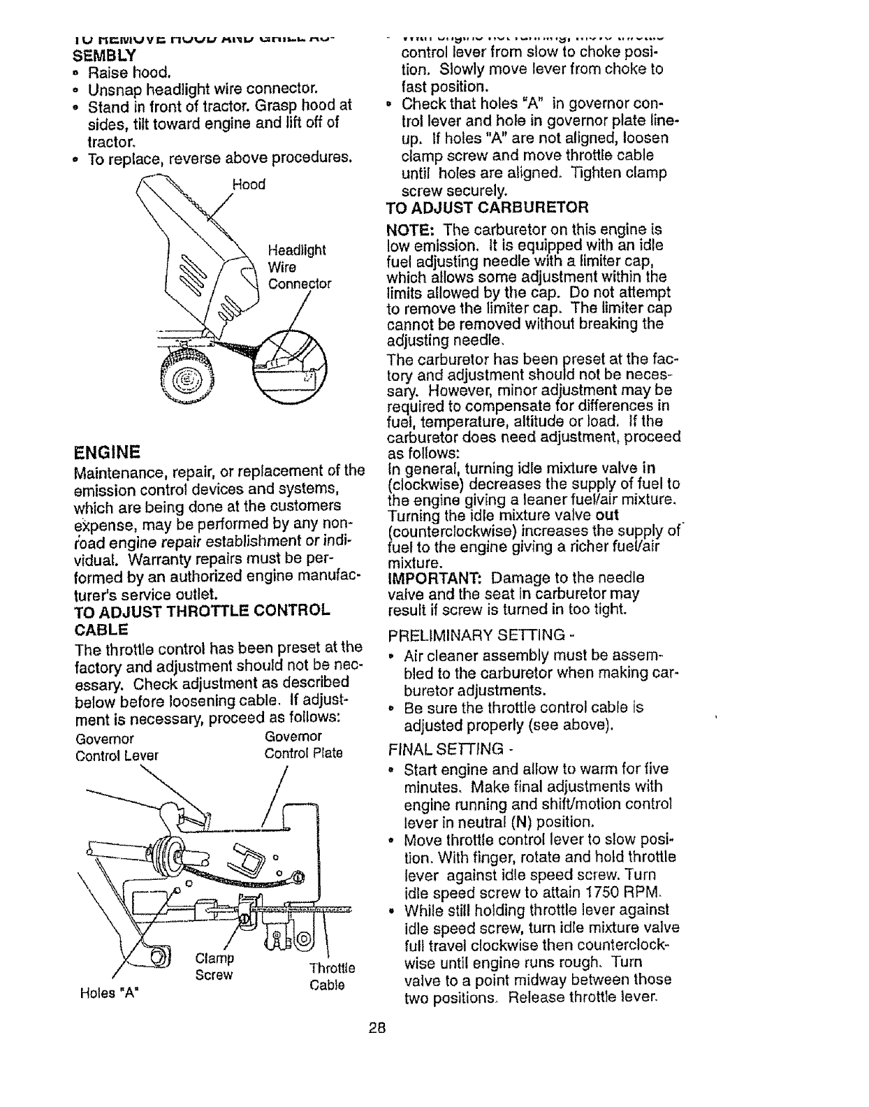
SEMBLY
o Raise hood.
=Unsnap headlight wire connector.
oStand in front of tractor. Grasp hood at
sides, tilt toward engine and lift off of
tractor,
-To replace, reverse above procedures.
\ Hood\
Headlight
Wire
Connector
ENGINE
Maintenance, repair, or replacement of the
emission control devices and systems,
which are being done at the customers
expense, may be performed by any non-
road engine repair establishment or indi-
vidual. Warranty repairs must be per-
formed by an authorized engine manufac-
turer's service outlet.
TO ADJUST THROTTLE CONTROL
CABLE
The throttle control has been preset at the
factory and adjustment should not be nec-
essary. Check adjustment as described
below before loosening cable, If adjust-
ment is necessary, proceed as follows:
Governor Governor
Control Lever Control PFate
\\
Holes "A=
Clamp
Screw "f'hrott{e
Cable
control lever from slow to choke posi-
tion, Slowly move lever from choke to
fast position.
•Check that holes =A" in governor con-
trol lever and hole in governor plate line-
up. If holes "A" are not aligned, loosen
clamp screw and move throttle cable
until holes are aligned° Tighten clamp
screw securely.
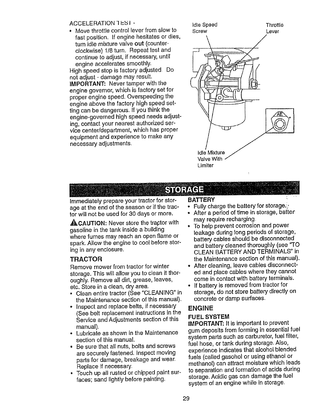
TO ADJUST CARBURETOR
NOTE: The carburetor on this engine is
low emission. It is equippedwith an idle
fuel adjusting needle with a hmiter cap,
which allows some adjustment within the
limits allowed by the cap. Do not attempt
to remove the limiter cap. The limiter cap
cannot be removed without breaking the
adjusting needle,
The carburetor has been preset at the fac-
tory and adjustment should not be neces-
sary. However, minor adjustment may be
required to compensate for differences in
fuel, temperature, altitude or load, If the
carburetor does need adjustment, proceed
as follows:
In general, turning idle mixture valve in
(clockwise) decreases the supply of fuel to
the engine giving a leaner fuel/air mixture.
Turning the idle mixture valve out
lcounterclockwise) increases the supply of
uel to the engine giving a richer fueVair
mixture.
IMPORTANT: Damage to the needle
valve and the seat in carburetor may
result if screw is turned in too tight.
PRELIMINARY SETTING ..
, Air cleaner assembly must be assem-
bled to the carburetor when making car-
buretor adjustments.
,Be sure the throttle control cable is
adjusted properly (see above).
FINAL SETTING -
,Start engine and allow to warm for five
minutes. Make final adjustments with
engine running and shift/motion control
lever in neutral (N) position°
• Move throttle control lever to stow posi-
tion_ With finger, rotate and hold throttle
lever against idle speed screw. Turn
idle speed screw to attain 1750 RPM
• While still holding throttle lever against
idle speed screw, turn idle mixture valve
full travel clockwise then counterclock-
wise until engine runs rough. Turn
valve to a point midway between those
two pesitions_ Release throttle lever.
28
ACCELERATION-t1::_5t
• Move throttlecontrolleverfromslow to
fastposition. If engine hesitatesor dies,
turn idle mixturevalveout (counter°
clockwise)1/8turn,. Repeattestand
continueto adjust,if necessary,untif
engine acceleratessmoothly,
Highspeedstopis factoryadjusted, Do
not adjust- damagemay result,
IMPORTANT:Nevertamperwiththe
enginegovernor,whichis factoryset for
properenginespeed,Overspeedingthe
engineabovethe factoryhighspeedset-
tingcan be dangerous°If you thinkthe
engine-governedhighspeedneedsadjust-
ing,contactyournearestauthorizedser-
vicecenter/department,whichhasproper
equipmentandexperienceto makeany
necessaryadjustments.
Idle Speed
Screw
Throttle
Lever
/
Idle Mixture
Valve Wtth .i,
Limlter
t
Immediately prepare your tractor for stor-
age at the end of the season or if the trac-
tor witl not be used for 30 days or more,
,ACAUTION: Never store the traptor with
gasoline in the tank inside a building
where fumes may reach an open flame or
spark. Allow the engine to coo! before stor-
ing in any enclosure°
TRACTOR
Remove mower from tractor for winter
storage. This will allow you to clean it thor-
oughly. Remove all dirt, grease, leaves,
etc, Store in a clean, dry area.
• Clean entire tractor (See "CLEANING" in
the Maintenance section of this manual).
• Inspect and replace belts, if necessary
(See belt replacement instructions in the
Service and Adjustments section of this
manual).
° Lubricate as shown in the Maintenance
section of this manual.
• Be sure that atl nuts, bolts and screws
are securely fastened, Inspect moving
parts for damage, breakage and wear.
Replace if necessary°
= Touch up all rusted or chipped paint sur--
faces; sand lightly before painting,
BATTERY
O
t
Fully charge the battery for storage.i/
After a period of time in storage, batter
may require recharging.
o To help prevent corrosion and power
leakage during long periods of storage;
battery cables should be disconnected
and battery cleaned thoroughly (see "TO
CLEAN BATTERY AND TERMINALS" in
the Maintenance section of this manual).
• After cleaning, leave cables disconnect-
ed and place cables where they cannot
come in contact with battery terminals.
°If battery is removed from tractor for
storage, do not store battery directly on
concrete or damp surfaces.
ENGINE
FUEL SYSTEM
IMPORTANT: It is important to prevent
gum deposits from forming in essential fuel
system parts such as carburetor, fuel filter,
fuel hose, or tank during storage. Also,
experience indicates that aicohol blended
fuels (called gasohol or using ethanol or
methanol) can attract moisture which leads
to separation and formation of acids during
storage. Acidic gas can damage the fuel
system of an engine while in storage.
29
°Start the engine and let it run until the
fuel lines and carburetor are empty,,
,Never use engine or carburetor cleaner
products in the fuel tank or permanent
damage may occur,
°Use fresh fuel next season°
NOTE: Fuel stabilizer is an acceptable
alternative in minimlzing the formation of
fuel gum deposits dudng storage. Add sta-
bilizer to gasoline in fuel tank or storage
container, Always follow the mix ratio
found on stabilizer container. Run engine
at least 10 minutes after adding stabilizer
to allow the stabilizer to reach the carbure-
tor. Do not drain the gas tank and carbure..
tor if using fuel stabilizer.
ENGINE OIL
Drain oi! (with engine warm) and replace
with clean engine oil. (See "ENGINE" in
the Maintenance section of this manual).
CYLINDER(S)
•Remove spark plug(s).
• Pour one ounce of oil through spark plug
hole(s) into cylinder(s).
,Turn ignition key to "START" position for
a few seconds to distribute oil.
,, Replace with new spark plug(s),
V f I Ir,-_| Q
*Do not store gasoline from one season
to another.
° Replace your gasoline can if it starts to
rust. Rust and/or dirt in your gasoline will
cause problem&
o If possible, store your tractor indoors
and cover it to give protection from dust
and dirt°
o Cover your tractor with a suitable protec-
tive cover that does not retain moisture.
Do not use plastic. Plastic cannot
breathe, which allows condensation to
form and cause your tractor to rusL
IMPORTANT: Never cover tractor while
engine and exhaust areas are still warm.
30
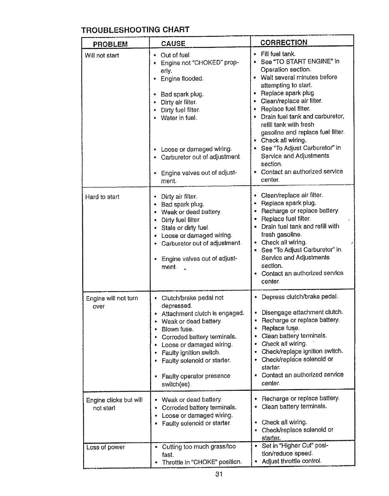
TROUBLESHOOTING CHART
PROBLEM
Will not start
Hard to start
Engine wtll not turn
over
Engine clicks but will
not start
@
CAUSE CORRECTION
Out of fuel
Engine not "CHOKED" prop-
erly.
Engine flooded.
-Badspark plug,.
• Dirty air filter.
•Dirty fuel filter
•Water In fuei_
• Loose or damaged wiring,
•Carburetor out of adjustment
.Engine valves out of adjust-
menL
• Dirty air filter_
•Bad spark pk}go
• Weak or dead battery,
•Dirty fuel filter
.Stale or dirty fuel.
° Loose or damaged wiring,.
•Carburetor out of adjustment,
• Engine valves out of adjust-
ment.
• Clutchlbrake pedal not
depressed,
• Attachment clutch is engaged.
• Weak or dead battery
• Blown fuse.
° Corroded battery terminals.
• Loose or damaged wiring,
• Faulty ignition switch.
. Faulty solenoid or starter°
• Fauttyoperator presence
switch(es)_
, ,,,,u ., i,,.u,,,
• Weak or dead battery,
• Corroded battery terminals,
• Loose or damaged wiring.
•Faulty solenoid or starter.
,, Fill fuel tank.
= See "TO START ENGINE" in
Operation secttono
,, Wait several minutes before
attempting to start.
• Replace spark plug
. Clean/replace air filter.
*Replace fuel filter,
* Drain fuel tank and carburetor,
refill tank with fresh
gasoline and replace fueI filter.
. Check all wiring.
. See "To Adjust Carburetor" in
Service and Adjustments
section,
. Contact an authorized service
center.
•Clean!replace air filter,
° Replace spark plug..
• Recharge or replace battery,
• Replace fuel filter.
• Drain fuel tank and refill with
fresh gasoline.
° Check all wiring.
• See "To Adjust Carburetor" in
Service and Adjustments
section.
= Contact an authorized service
center,
• Depress clutch/brake pedal,
°Disengage attachment clutch.
• Recharge or replace batter's,
•Replace fuse°
• Clean battery terminals.
•Check alt wiring,
Checldreplace ignition switch.
o
• Chectdrepla_ce solenoid or
starter.
• Contact an authorized service
center.
• Recharge or replace battery,
oClean battery terminals.
..... oipo ..........
Loss wet . Cutting too much grassltoo •
fast,
= Throttle in "CHOKE" position. •
31
Check all wiflng_
Check/replace solenoid or
starter.
Set in "Higher Cut" posi-
tion/reduce speed.
Adjust throttle control.
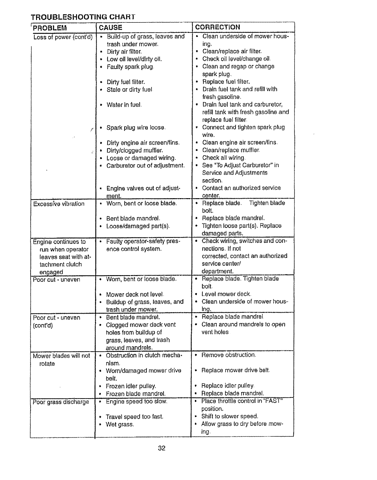
TROUBLESHOOTING CHART
'PROBLEM CAUSE
Loss ofpower (cont'd) • Build-up of grass, leaves and
trash under mower,
• Dirty air filter.
•Low oil level/dirty oil
•Faulty spark prug.
• Dirty fuel titter..
, Stale or dirty fuel
• Water In fuel,
r" Spark plug wire loose,
Excess'rve'vi%'TatiS'........
• Dirty engine air screentfins,
• Dirtylclogged muffler,
• Loose or damaged wiring.
° Carburetor out of adjustment,,
Engine continues to
run when operator
leaves seat with at-
tachment clutch
uengaged .........
Poor cut - uneven
:_eorcut- uneven
(cont'd)
Mower blades will not
rotate
Poor grass discharge
Engine valves out of adjust-
ment,
Worn, bent or loose blade..
o
Bent blade mandrel.
Loose/damaged part(s)
Faulty operator-safety pres-
ence control system.
•Worn. bent or loose blade,
• Mower deck not level.
• Buildup of grass, leaves, and
trash under mower,
, Bent blade mandrel,
• Clogged mower deck vent
holes from buildup of
grass, leaves, and trash
around mandrels.
• Obstruction in clutch mocha*
nlsm.
,, Wornldamaged mower drive
belt.
• Frozen idler pulley,
• Frozen blade mandrel,
'O Engine speed too slow.,
Travel speed too fast,
Wet grass.
CORRECTION
• Clean underside of mower hous-
ingo
•Clean/replace air filter,
• Check oil leveVchange oil,
,Clean and regap or change
spark plug..
,, P,ep_ace _uet,_i_er.
• Drain fuel tank and refill with
_resh gasoline,
• Drain fuel tank and carburetor,
refill tank with fresh gasoline and
replace fuel rifler.
• Connect and tighten spark plug
were.
• Clean engine air screen/fins.
° Cleardreplace muffler.
• Check all wiring.
• See "To Adjust Carburetor" in
Service and Adjustments
section,
• Contact an authorized service
__ _center- ..............................
• Replace blade. Tighten blade
bolL
°Replace blade mandrel,
•Tighten loose part(s), Replace
damaged parts.
•Check wiring, switches and con-
nections. If not
corrected, contact an authorized
service center/
....depadment.
, Replace blade, Tighten blade
bolt.
• Level mowerdeck,
° Clean underside of mower hous-
,!ng.
.Replace blade mandrel
,, Clean around mandrels to open
vent holes
• Remove obstruction,
• Replace mower drive belt,
, Replace idler pulley.
• Replace blade mandrel.
• Place throttle control in"FAST"
position.
• Shift to slower speed,
• Allow grass to dry before mow-
ing,
32
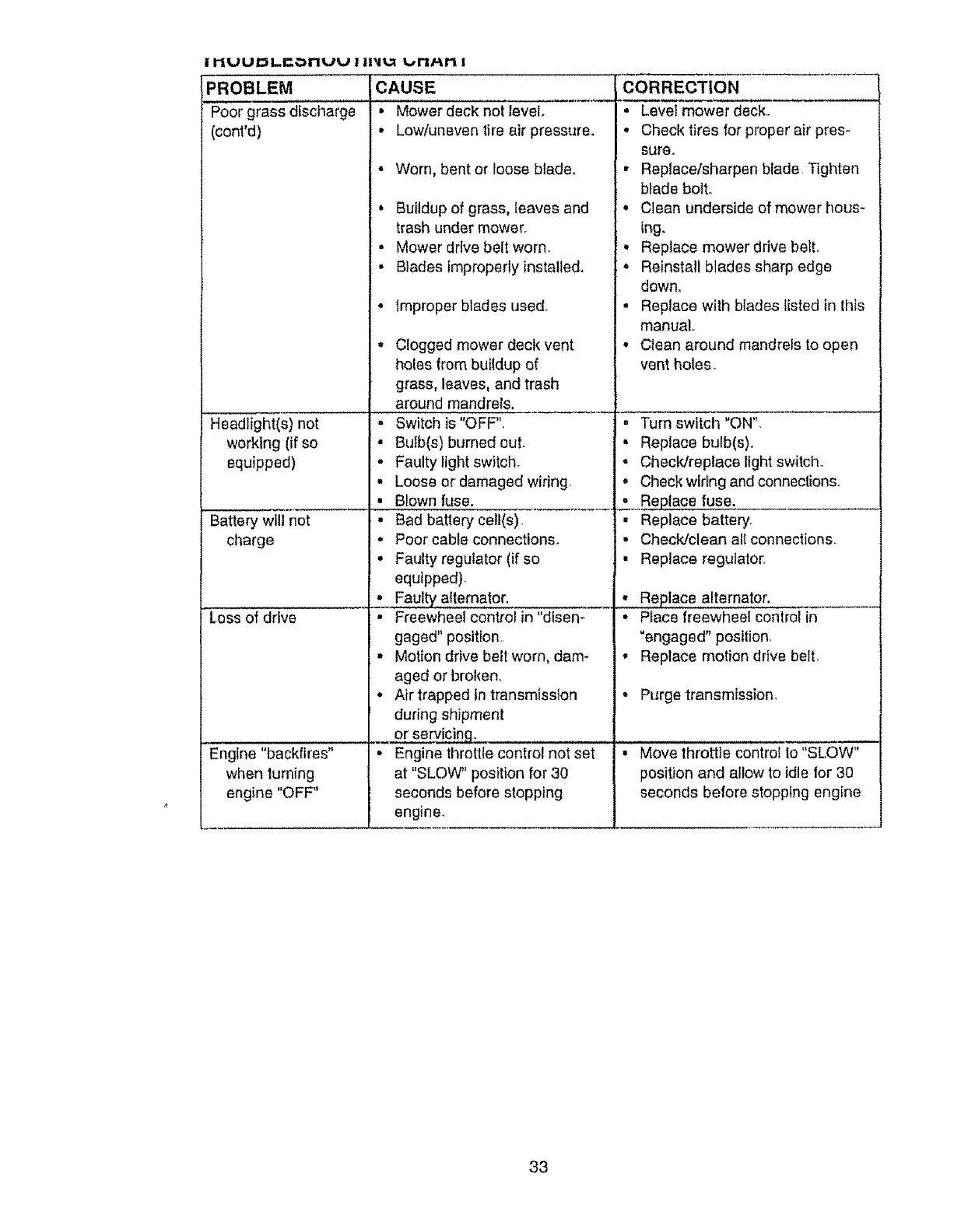
PROBLEM CAUSE
grass discharge
(cont'd)
Headlight(s) not
working (if so
equipped)
Battery will not
charge
Loss of drive
Engine "backfires"
when lurning
engine "OFF"
•Mower deck not level.
•Low/uneven tire air pressure.
• Worn, bent or loose blade.
, Buildup of grass, leaves and
trash under mower.
• Mower drive belt worn,
• Blades improperly installed.
°improper blades used°
• Clogged mower deck vent
holesfrombuildupe(
grass, leaves, and trash
around mandrels, _..........
. Switch is "OFF",
• Bu}b(s) burned out.
•Faulty light switch.
• Loose or damaged wiring,
• Blown fuse.
• Bad battery ceil(s)
• Poor cable connections.
• Faulty regulator (if so
equipped).
, Faulty alternator,
%-Freewheel control in "disen-
gaged" position,
,, Motion drive bell worn, dam-
aged or broken
-Air trapped in transmission
during shipment
or servicing.
Engine throttle control not set
at "SLOW" position for 30
seconds before stopping
engine,
CLCORRECTION
II
D
i*
II
Q
o
o
Level mower deck..
Check tires for proper air pres-
sure.
Replace/sharpen blade Tighten
blade bolto
Clean underside of mower hous-
Ing,
Replace mower drive belt.
Reinstall blades sharp edge
down.
Replace with blades listed in this
manual-
Clean around mandrels to open
vent holes.
, Turn switch "ON".
• Replace bulb(s).
.Checldreplace light switch.,
.Check wiring and connections.
._. p!a eluse-
•Replace battery,
• Check/clean alt connections.
• Replace regulator,
,, Replace alternator.
• Place freewheel control in
"engaged" position
• Replace motion drive belt,
.Purge transmission,
,II ,I " '
' Move throttle control to"SLOW"
position and allow to idte for 30
seconds before stopping engine
33

ELECTRICAl.
TRACTOR - - MODEL NUMBER 917.270721
26
34
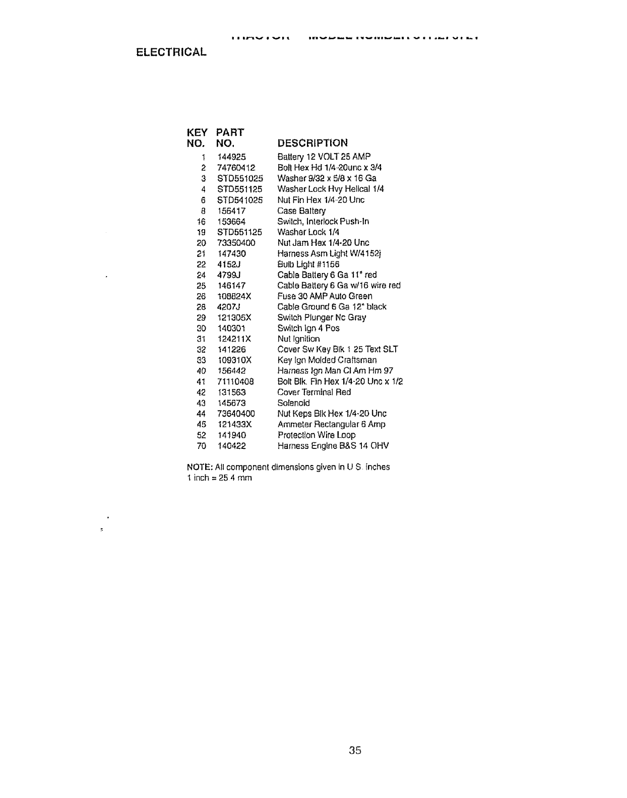
ELECTRICAL
KEY PART
NO. NO.
I 144925
2 74760412
3 81D551025
4 STD551!25
6 STD541025
8 156417
t6 153664
t9 STD551125
20 73350400
2_ 147430
22 4152J
24 4799J
25 146147
26 108624X
28 4207J
29 I21305X
30 140301
31 124211X
32 141226
33 I09310X
40 156442
41 711t0408
42 131563
43 145673
44 73640400
45 121433X
52 141940
70 140422
DESCRIPTION
Battery 12 VOLT25 AMP
Belt Hex Hd 1/4-20unc x 3/4
Washer 9/32 x 5t8 x 16 Ga
Washer Lock Hv,/Helical t/4
Nut Fin Hex 1/4..20Unc
Case Baltery
Switch, Interlock Push-In
Washer Lock I/4
Nut Jam Hex 1/4-20 Unc
Harness Asm Lighl W/4152j
Bulb Lighl#t156
Cable Battery 6 Ga 11" red
Cable BaLlery 6 Ga w/16 wire red
Fuse 30 AMP Auto Green
Cable Ground 6 Ga 12" black
Switch Plunger Nc Gray
Switch Ign 4 Pos
Nut Ignition
Cover Sw Key BIk I 25 Te_ SLT
Key ign Molded Craftsman
Harness Ign Man Ct Am Hm 97
Bolt BIk Fin Hex 1/4-20 Unc x t/2
Cover Termtnal Red
Solenoid
Nut Keps BIk Hex I/4-20 Unc
Ammeter Rectangular 6 Amp
Proleotlon Wire Loop
Harness Engine B&S 14 OHV
NOTE: All component dimensions given in U S inches
t inch = 25 4 mm
35
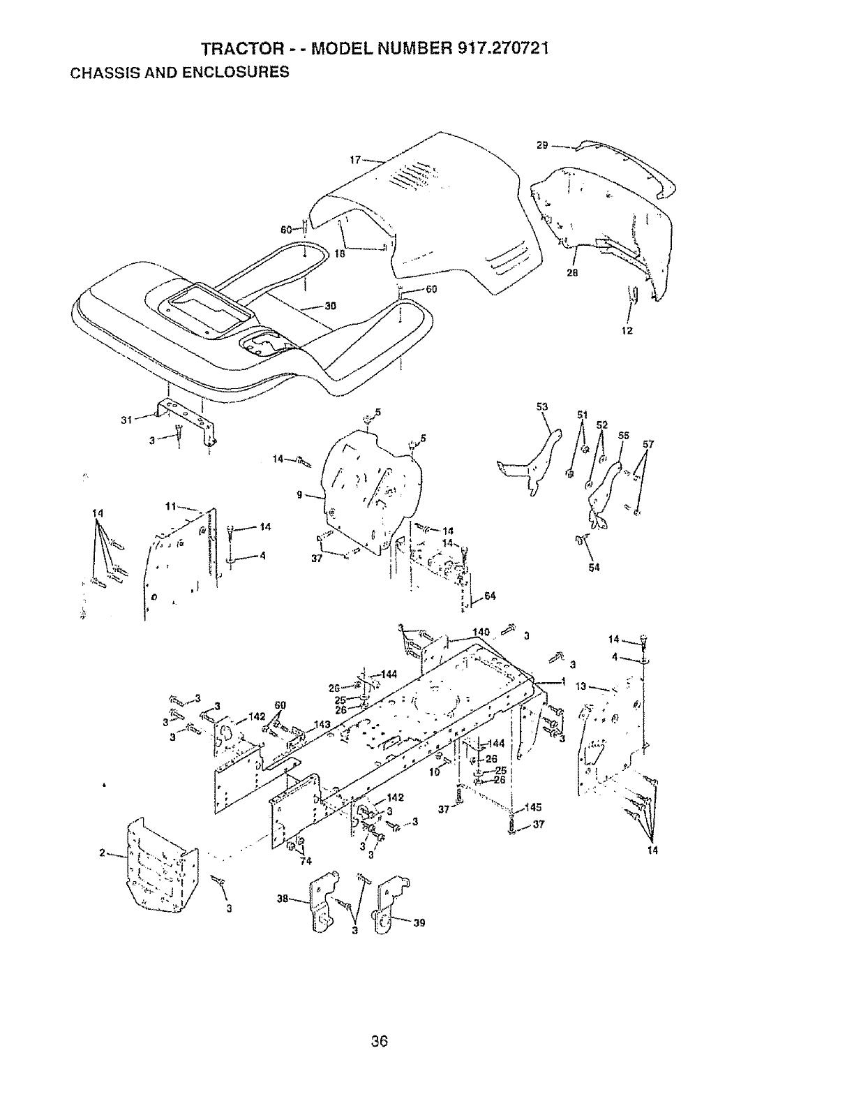
TRACTOR - - MODEL NUMBER 9i7.27'0721
CHASSIS AND ENCLOSURES
i
6O
3
52 55 57
3/
3
74
54
36
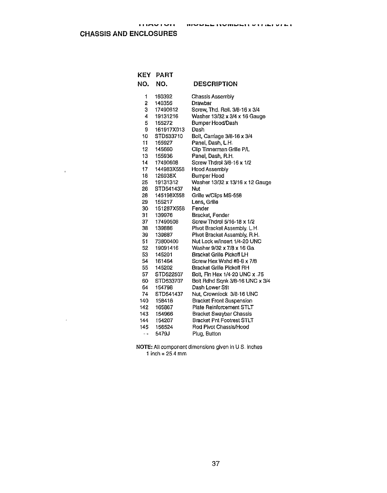
• | •4,'=tv | v• • iw•vm,.,wm..,m._ I lvuw_=.,_-..| • _" • I _m,.,• _,_# _
CHASSIS AND ENCLOSURES
KEY PART
NO. NO, DESCRIPTION
t 160392 Chassis Assembly
2 140356 Drawbar
3 17490612 Screw,Thdo RolE,3/6-16 X3/4
4 19131216 Washer 13/32 x 3/4 x 16 Gauge
5 155272 Bumper Hood/Dash
9 161917X013 Dash
I0 STD533710 Bolt, Carriage 3/8-16 x 3/4
11 155927 Panel, Dash, L..H+
t2 145660 Clip Tinnerman Grille pet.
13 155936 Panel, Dash, R+Ho
14 17490608 Sc_ewThdro13/8-16x 1/2
!7 144983X558 Hood Assembly
18 126938X BumperHood
25 19131312 Washer 13/32 × 13/16 x 12 Gauge
26 STD541437 Nut
28 145198X558 Grille w/ClipsMS..558
29 155217 Lens, Gillie
30 151287X558 Fender
31 139976 Bracket, Fender
37 17490508 ScrewThdml 5/16-18 x 1/2
38 139886 Pivot Bracket Assembly. L.H.
39 139887 Pivot Bracket Asssmb+y,R..H_
51 73800400 Nut Lock w/lnserl 1/4-20 UNC
82 19091416 Washer 9/32 x 7/8 × 16 Ga.
53 145201 Bracket Grille Pickoff LH
54 16'_464 Screw Hex Wshd #8+8× 7/8
55 145202 Bracket Gdlle Pickoff RH
57 STD522507 Bolt, Fin Hex 1/4+20UNC x .75
60 STD533707 Bolt Rdhd Sqnk 3/8+16 UNC x 3/4
64 184798 Dash Lower SUt
74 STD541437 Nut, Crownlock 3f8_16 UNC
140 158418 Bracket Front Suspension
142 165867 Plate Reinforcement STLT
143 154966 Bracket Swaybar Chassis
144 154207 Bracket Pnt Footrest STLT
145 156524 Rod Pivot Chassis/Hood
° - 5479J Plug, Button
NOTE: All component dimensions given tn U+S,_nches
1inch = 25 4 mm
37
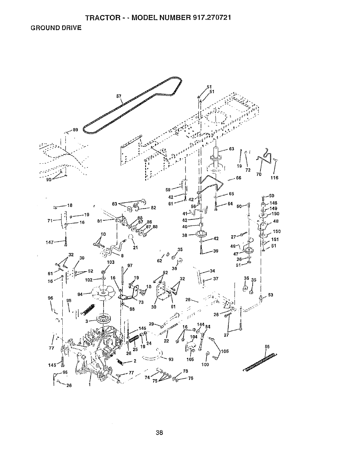
TRACTOR . .MODEL NUMBER 917,270721
GROUND DRIVE
38
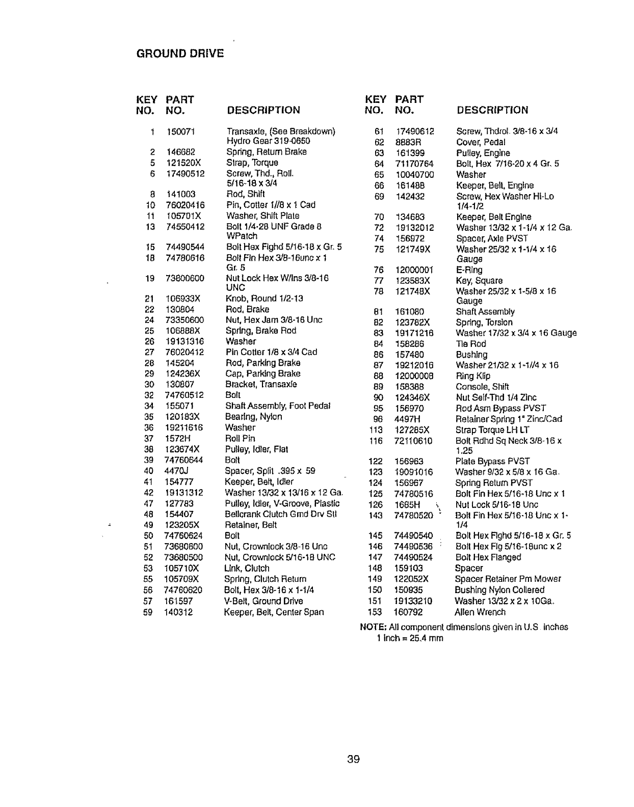
GROUND DRIVE
KEY PART
NO. NO,
1 150071
2 146682
5 121520X
6 17490512
8 1410O3
10 76020416
1t 105701X
13 74550412
15 74490544
18 74780616
19 73800600
21 106933X
22 130804
24 73350600
25 106888X
26 19131316
27 76020412
28 145204
29 124236X
30 130807
32 74760512
34 155071
35 t20t83X
36 19211616
37 I572H
38 123674X
39 74760644
40 4470J
41 154777
42 19131312
47 127783
48 154407
49 123205X
50 74760624
61 73680600
52 73680500
53 105710X
55 105709X
56 74760620
57 161597
59 140312
DESCRIPTION
Transaxte, (See Breakdown)
Hydro Gear 319-0650
Spdng, Return Brake
Strap, Torque
Screw, Thd., Ro!l_
511648 x 3/4
Rod, Shift
Pin, Cotter 1//8 x I Cad
Washer, Shift Plate
Bolt 1/4.28 UNF Grade 8
WPatch
Bolt Hex Ftghd51t6d8 × Gro5
Bolt Fin Hex 3/8-16un0 x 1
Gr. 5
Nut Lock He× W/Ins 3,f8-16
UNC
Knob, Round 1/2o13
Rod, Brake
Nut, Hex Jam 3/8d6 Unc
Spring, Brake Rod
Washer
Pin Cotter 1/8 x 3/4 Cad
Rod, Parking Brake
Cap, Parking Brake
Bracket, Transaxte
Bert
Shaft Assembly, Foot Pedal
Bearing, Nyten
Washer
Roll Pin
Pu]tey, Idler, Flat
Bolt
Spacer, Sp{it .395 x 59
Keeper, Belt, Idler
Washer 13/32 x 13/16 x I2 Ga
Pulley, Idler, V-Groove, Plastic
Bellcrank Clutch Grad Drv Stl
Retainer, Bert
Bolt
Nut, Crowniock 3/8..16Unc
Nut, Crownfock 5/16-18 UNC
Link, Clutch
Spdng, Clutch Return
Bolt, Hex 3/8-16 x 1ol/4
V-Belt, Ground Drive
Keeper, Belt, Center Span
KEY PART
NO, NO. DESCRIPTION
61 17490612
62 8883R
63 161399
64 71170764
65 10040700
66 161488
69 142432
70 134683
72 19132012
74 156972
75 121749X
76 12000O01
77 123583X
78 121748X
81 161080
82 123782X
83 19171216
84 168286
86 157480
87 19212016
88 12000008
89 158388
90 124346X
95 156970
96 4497H
113 127285X
116 72110610
122 156963
123 19091016
124 156967
125 74780516
126 1685H \
143 74780520 •
145 74490540
146 74490536 1
147 74490524
t48 159103
t49 I22052X
150 150935
t51 19133210
153 160792
Screw, ThdroL 3/8-16 x 324
Cover, Pedal
Pu{ley, Engtne
Bolt, Hex 7/t6-20 x 4 Gr, 5
Washer
Keeper, Bert, Engine
Screw, Hex Washer HI-Lo
t/4-1/2
Keeper, Belt Engine
Washer 13/32 x 1-1/4 x 12 Ga.
Spacer, A_le PVST
Washer 25/32 x !-114 x 16
Gauge
E.Rlng
Key, Square
Washer 25/32 x 1-5/8 x 16
Gauge
Shaft Assembly
Spdng, Torsion
Washer 17/32 x314 x 16 Gauge
Tie Rod
Bushing
Washer 21/32 x t-1//4 x 16
Ring Kllp
Console, Shift
Nut Setf-Thd 1/4 Zinc
Rod Asm Bypass PVST
Retalner Spr_ng1" Zinc/Cad
Strap Torqt_eLH LT
Bo{[ Rdhd Sq Neck 3/8-16 x
t _25
Plate Bypass PVST
Washer 9/32 x 5/8 x 16 Ga.
Spring Return PVST
Bolt Fin Hex 5/16o18 1Jnc x 1
Nut Lock 5/16q8 Unc
BoIl Fin Hex 5/16-18 Uric x 1-
I/4
Bott Hex Rghd 5/I6-18 x Gc 5
Boll Hex Rg 5/16-18unc x 2
Bolt Hex Flanged
Spacer
Spacer Retainer Pm Mower
Bush{ng Nylon Coliered
Washer 13/32x 2 x lOGa.
Alien Wrench
NOTE: All component dimensions given in U.S Inches
t Inch = 25.4 mrn
39
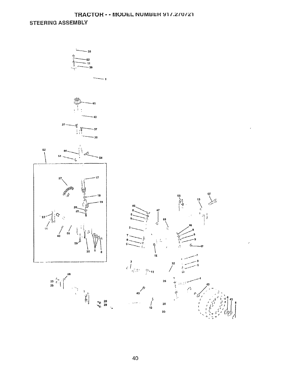
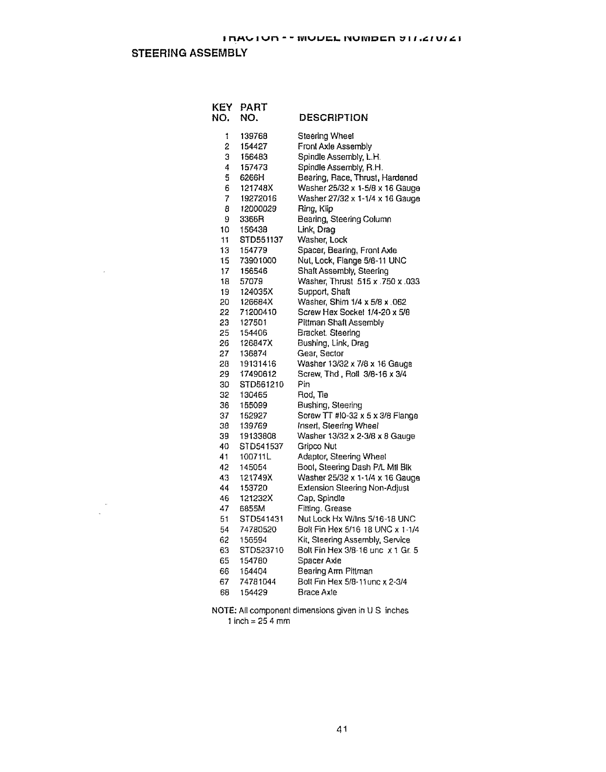
t ri/_%r I Vt'i " " IVIUUr"I.. I_iUlVlDr"l_ _:/ I!_"" ! U! _|
STEERING ASSEMBLY
KEY PART
NO. NO. DESCRIPTION
t 139768
2154427
3156453
4 t 57473
5 6266H
6 121748X
7 192'72016
812000029
9 3366R
10 156438
11 STD55t137
13 154779
15 73901000
17 156546
18 57079
19 124035X
20 126684X
22 71200410
23 127501
25 154406
26 126847X
27 136874
28 19131416
29 17490612
30 STD551210
32 130465
36 155099
37 152927
38 139769
39 19133808
40 STD541537
41 1007!lL
42 145054
43 121749X
44 153720
46 121232X
47 6855M
51 STD541431
54 74780520
62 156594
63 STD5237!0
65 154780
66 154404
67 74781044
68 154429
Steedng Wheel
FrontAxle Assembly
Spindle Assembly, L H
Spindle Assembly, R H
Bearing, Race. Thrust, Hardened
Washer 25/32 x 1-5/8 x 16 Gauge
Washer 27/32 x 1.1/4 x 16 Gauge
Ring, Ktip
Beadng, Steering Column
Link, Drag
Washer, Lock
Spacer, Beadng, Front Axle
Nut, Lock,Flange 5/841 UNC
Shall Assembly, Steering
Washer, Thrust 515 x .750 x °033
Support, Shaft
Washer' Shim 1/4 x 5/8 x 062
Screw Hex Socket I/4-20 x 5/8
Pittman Shaft Assembly
Bracket Steering
Bushing, Link, Drag
Gear, Sector
Washer 13/32 x 718x t6 Gauge
Screw, Thd, RoU 318-t6 x 3/4
Pin
Rod, Tie
Bushing, Steering
Screw TT #10-,32x 5 x 3t8 F_ange
tnsed, Steedng Wheel
Washer 13t32 x 2-3/8 x 8 Gauge
Gripco Nut
Adaptor, Steering Wheel
BOOt,Steering Dash P/L MUBIk
Washer 25/32 x 1-I/4 x 16 Gauge
-ExtensionSteering Non-Adjusl
Cap, Spindle
Fitting. Grease
Nut Lock Hx Wllns 5/!6.I8 UNC
Bolt Fin Hex 5/16 18 UNC x 1-1/4
KiL Steering Assembly, Service
Bolt Fin Hex 3/8-t6 unc x 1 G( 5
Spacer Axle
Bearing Arm Piltman
Bolt Fin Hex 5!8-!1unc × 2-3t4
Brace Axle
NOTE: All component dimensions given in U S inches
1 inch = 25 4 mm
41
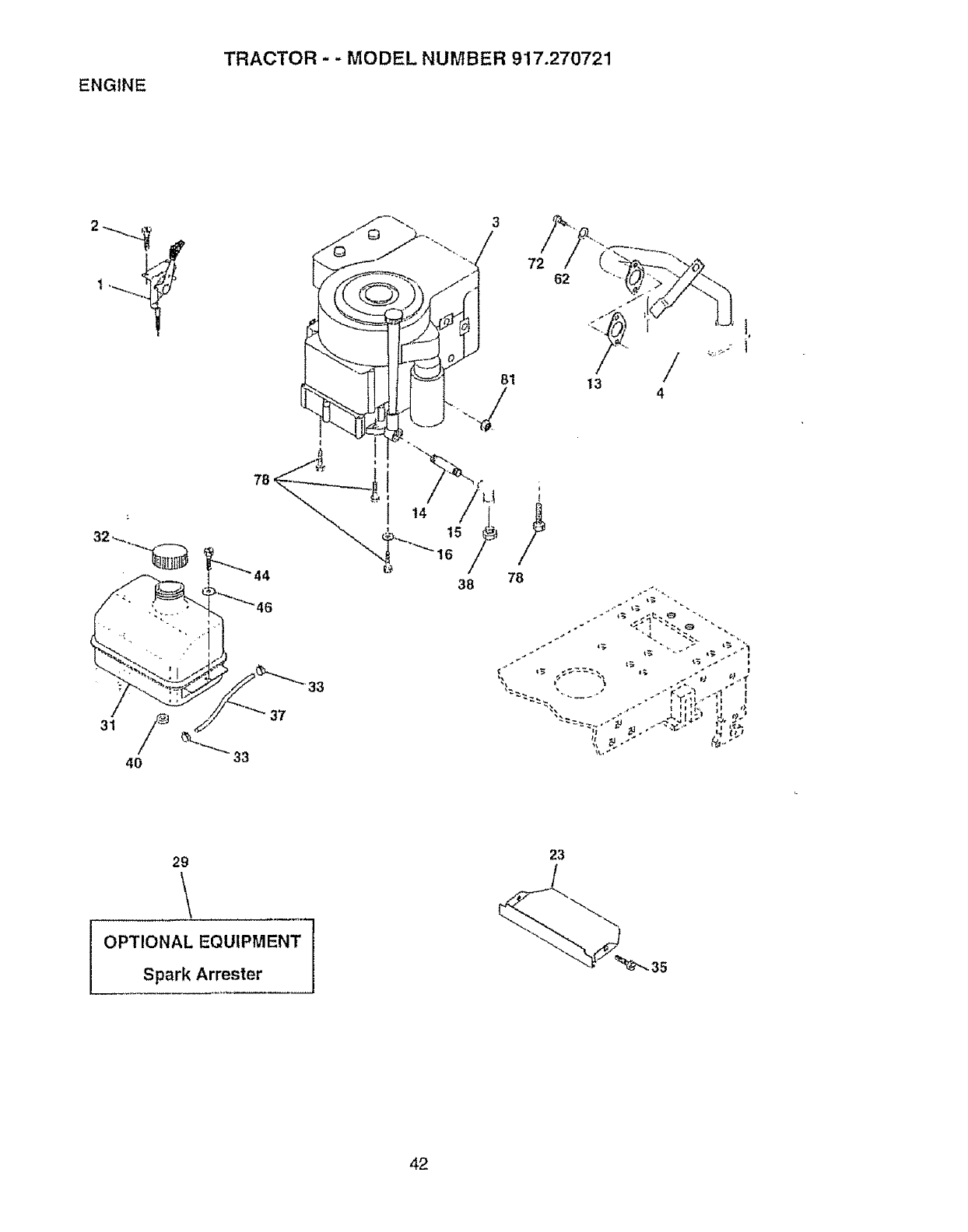
ENGINE
TRACTOR"" MODEL NUMBER 917.2"70721
3
72
33
37
t3 /
4
29
23
/
42
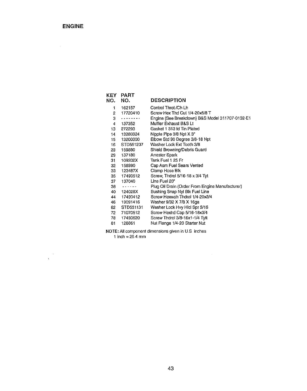
ENGINE
KEY PART
NO, NO.
1 162157
2 17720410
3 .........
4 137352
13 2'72293
14 t3280324
15 t3200300
16 STD551237
23 159880
29 137180
31 109202"(
32 158990
33 123487X
35 17490512
37 ! 37040
38 ......
40 124028X
44 17490412
46 19091416
62 STD551131
72 71070512
78 17490620
81 128861
DESCRIPTION
Control Throt lCh Lh
Screw Hex Thd Cut 114-20x518T
Engine (Bee Breakdown} B&S Model 311707-0132..E 1
Mulfler Exhaust B&S Lt
Gasket 1 313 Id Tin Plated
Nipple Pipe 3/8 Npt X 3"
Elbow Std 90 Degree 3/8-18 Npt
Washer Lock Ext Tooth 318
Shield BrowningtDebds Guard
Arrestor Spark
Tank Fuel 1 25 Fr
Cap Asm Fuel Sears Vented
Clamp Hose Blk
Screw, Thdro! 5116-.18x 3/4 Tyt
Line Fuel 20"
Plug Oit Drain (Order From Engine Manufacturer)
Bushing Snap Nyl Blk Fuel Une
8crew He_{wshThdrot 1/4-20x3/4
Washer 9t32 X 7t8 X 16ga
Washer Lock Hvy Hlcl Spr 5/16
Screw Hexhd Cap 5/16-18x3/'4
Screw Thdrof 318-16xl-1/4 Tytt
Nut Flange 1/4-20 Starter Nut
NOTE: All component dimensions given in U,S inches
1inch = 254 mm
43
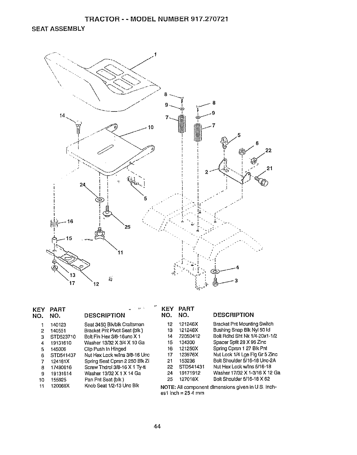
TRACTOR - - MODEL NUMBER 917.270721
SEATASSEMBLY
.... "_._-L" _ .-. ,.
\
\//i
11
5
21
KEY
NO.
1
2
3
4
5
6
7
8
9
10
11
PART
NO,
140123
140551
STD523710
19131610
145006
STD541437
!24181X
11490616
19131614
155925
120068X
t_
DESCRIPTION
Seat 3450 BlkfDlkCraltsman
Bracket Pnt Pivot Seat (blk)
Bolt Fin Hex 3/8-t6unc X 1
Washer 13/32 X 3/4 X t0 Ga
Clip Push In Hinged
Nut He× Lock w/Ins 3/84 6Uric
Spring Seat Cprsn 2 250 Btk Zi
Screw Thdro1318-16 X 1 Ty4t
Washer 13/32 X 1 X 14 Ga
Pan Pnt Seat (blk)
Knob Seat I/2-i3 Unc Btk
KEY PART
NO. NO. DESCRIPTION
t2 t21246X
13 t21248X
14 72050412
15 134300
16 t2125OX
t7 !23976X
21 153236
22 STD54143I
24 19171912
25 1270!8X
Bracket Pnt Mounting Switch
Bushing Snap Blk Ny150 Id
Bolt Rdhd Sht Nk 114-20x1+t/2
Spacer Sptt128 X 96 Zinc
Spring Cprsn 1 27 Bik Pnt
Nut Lock 1/4 Lge Fig Gr 5 Zinc
Bolt Shoulder 5/16-18 Unc-RA
Nut Hex Lock w/Ins 511648
Washer 17t32 X "I-3/16X 12 Ga
Bolt Shoulder 5/16-18 X 62
NOTE: All component dimensions given in U S. Inch-
es1 Inch = 25 4 mm
44
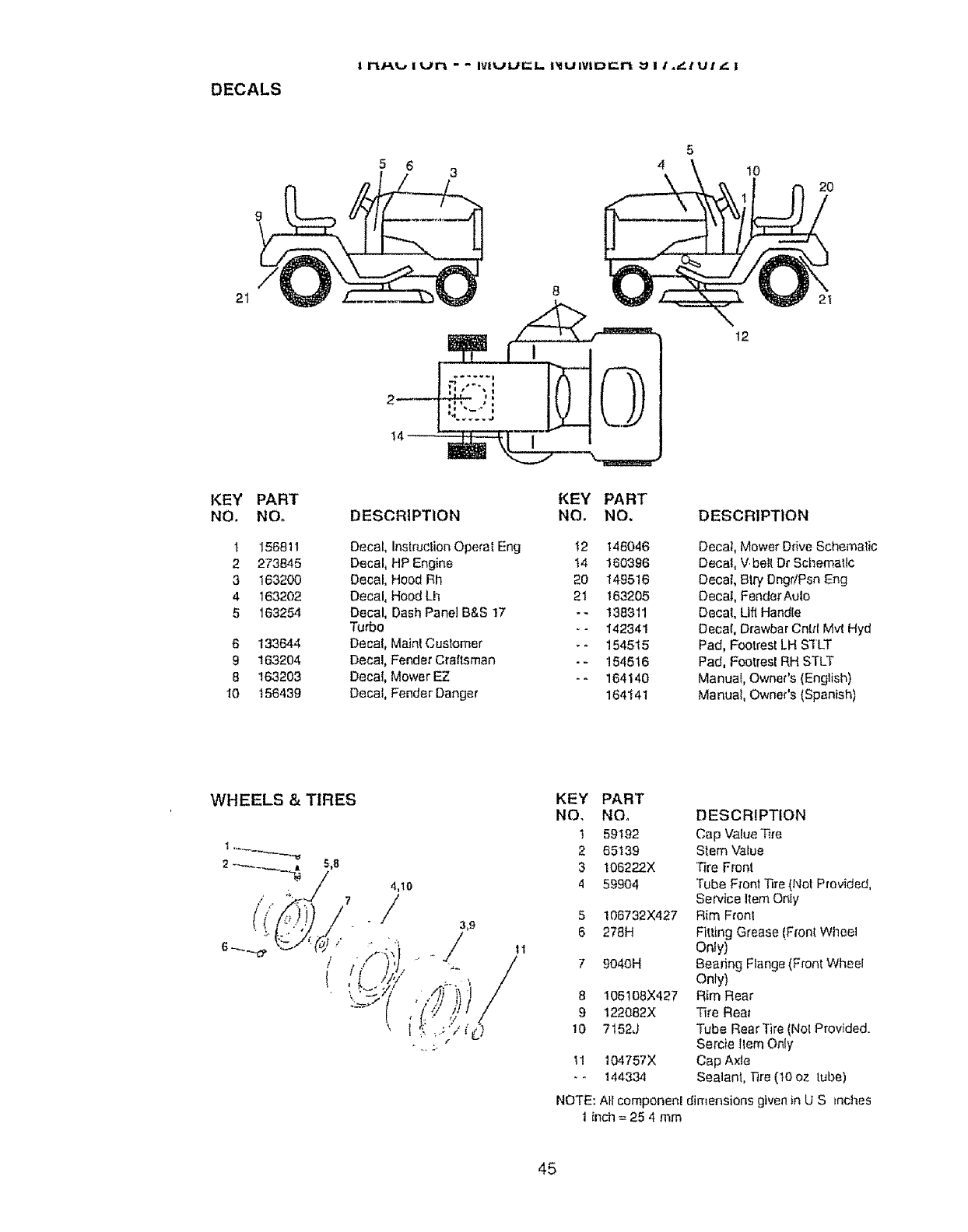
DECALS
I rt/._!,._ I urt -- ivluu r_L I_IUIVlD=N U I i..," !UI t!
5 6 10 2O
21 8
KEY PART KEY PART
NO, NO. DESCRIPTION NO. NO,
1 156811 Oecaf, InstructionOperal Eng !2 146046
2 273845 Decal, HP Engine 14 160396
3 163200 0ecaL Hood Rh 20 149516
4 163202 Decal, Hood Lh 21 163205
5 163254 Decal, Dash Panel B&S t7 -- 138311
Turbo -- 142341
6 133644 Decal, Mainl Customer _- 154515
9 163204 Decal, Fender Craftsman -- 154516
8163203 Decal, MowerEZ -- 164140
10 156439 Decal, Fender Danger 164141
21
t2
DESCRIPTION
Decal, Mower Ddve Schematic
Decal, V.belt Dr Schematic
Decal, Blry DngdPsn Eng
Decal, FenderAulo
Decal, Lift Handle
Decal, Drawbar Cntd M,,4Hyd
Pad, Footrest LH SILT
Pad, Footresl RH STLT
Manua$, Owner's (English)
Manual, Owner's (Spanish)
WHEELS & TIRES
4,10
_/
KEY PART
NO, NOo
1 59192
2 65139
3 108222X
4 59904
106732X427
278H
9o4OH
8 106108X427
9 122082X
10 7152J
11 t04757X
_- 144334
DESCRIPTION
Cap Value Tire
Stem Value
'Fire Front
Tube Front Tire (Not Provided,
Service Item Only
Rim Front
Fitting Grease (Front Wheel
Only)
Beating Flange (Front Wheel
Only)
Rim Rear
Tire Rea_
Tube Rear ]ire (Nol Provided,
Sercie llem Only
Cap Axle
Sealant, ]qre (t0 oz tube)
NOTE: All componenl dimensions given in U S tnches
1 inch = 25 4 mm
45
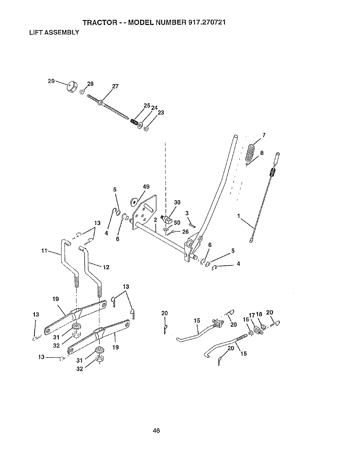
TRACTOR -- MODEL NUMBER 917,270721
LIFT ASSEMBLY
5 49
19
13
13
32
31 _19
32
3O
3\
2O
46
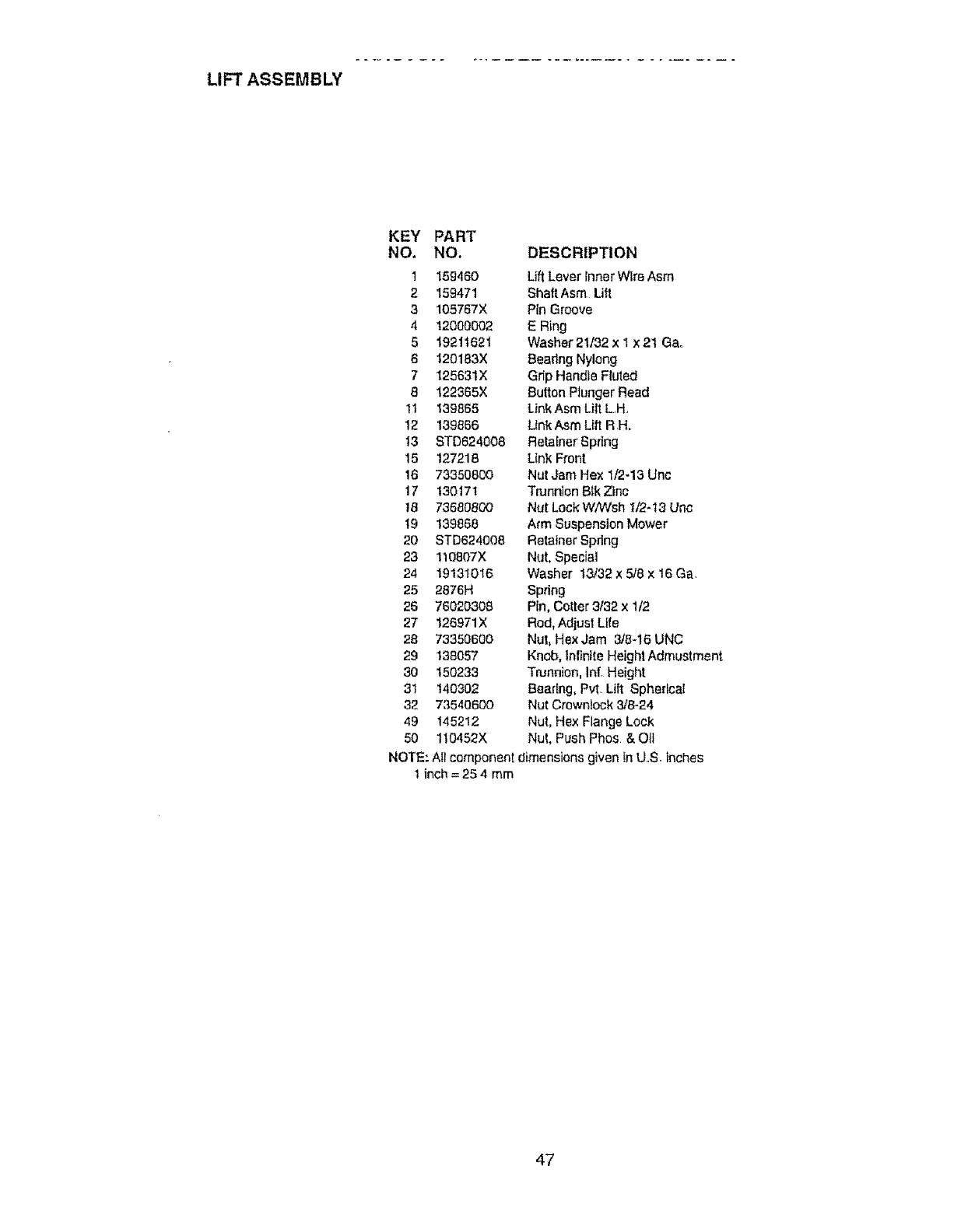
LIFT ASSEMBLY
KEY PART
NO. NO, DESCRIPTION
1 159460 Lift Lever Inner Wire Asm
2 159471 ShaftAsm Lift
3105767X Pin Groove
4 12000002 E Ring
519211621 Washer 21/32 x1x2t Ga.
6 t20183X BearingNylong
7 I25631X Grip Handle FMed
8 122365X Button PtungerRead
1t 139855 Link Asm Lift L..H.
12 139866 UnkAsmLift RH.
13 STD624008 Retainer Spring
15 127218 Link Front
16 73350800 Nut Jam Hex 1/2-13 Unc
17 130171 TrunnionBik Zinc
18 73680800 Nut Lock WNCsh I/2-13 Unc
t9 139868 Arm Suspension Mower
20 STD624008 Retainer Spring
23 110807X Nut. Special
24 19131016 Washer 13/32 x 5/8 x t6 Ga.
25 2876H Spring
28 76020308 Pin, Cotter 3t32 x 1/2
27 126971X Rod, Adjust Life
28 73350600 Nut, HexJam 3/8-16UNC
29 138057 Knob, infinite Heighl Admustment
30 150233 Trunnion, Infr Height
31 140302 Beadng, Pv_ Lift Spherical
32 73540800 Nut Crowntock 3/8-24
49 145212 Nut, Hex Flange Lock
50 110452X Nut, Push Phos &Otl
NOTE: AIi component dimensions given In UoS. inches
1 inch = 25 4 mm
47
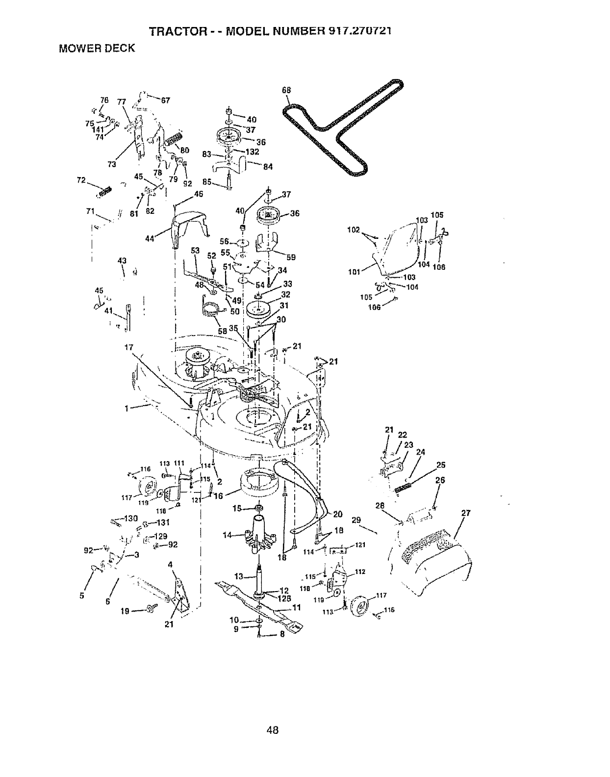
TRACTOR - - MODEL NUMBER 917.27U721
MOWER DECK
73
45
43
.33
3t
30
17\
48
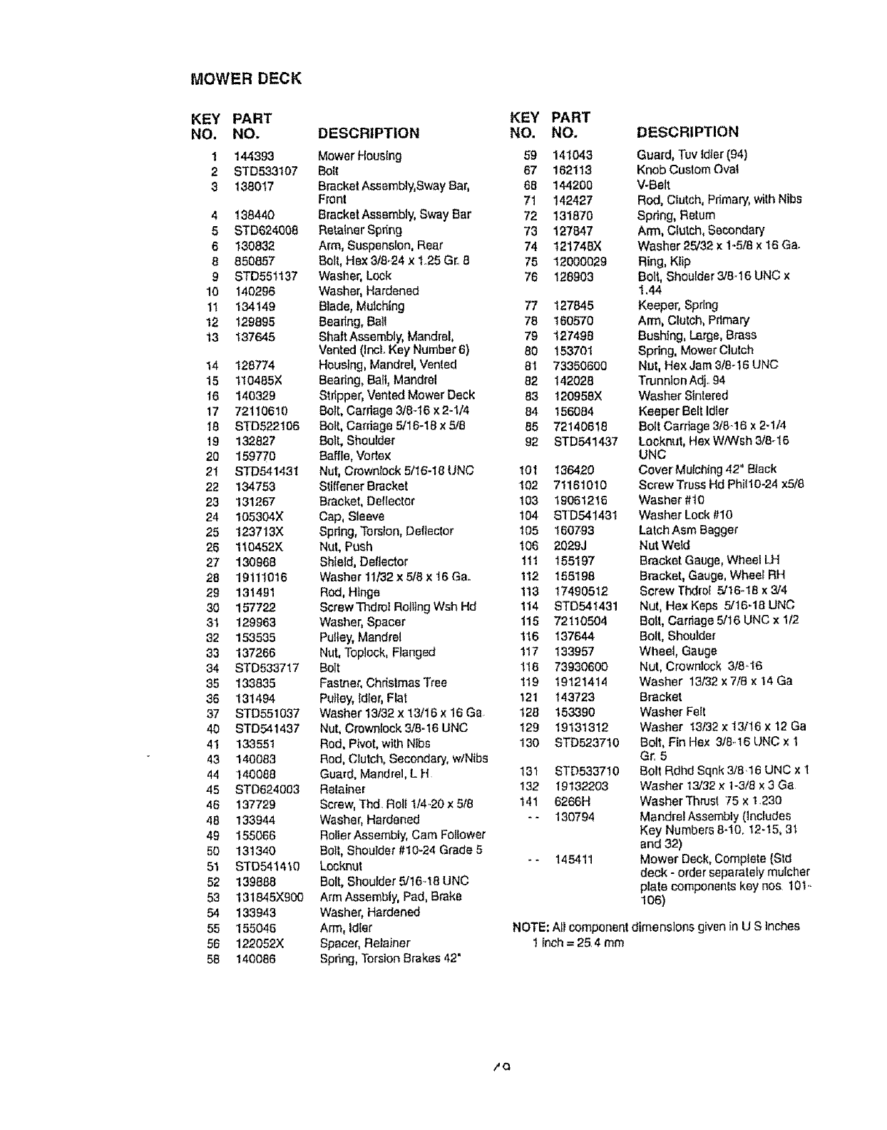
MOWER DECK
KEY PART
NO, NO.
!144393
2 BTD533107
3 138017
4 138440
5 STD624008
6 130832
8 850857
9 STD551137
10 140295
11 134149
12 129895
13 137645
14 128774
15 110485×
I6 140329
17 72110610
18 STD522106
19 132827
20 159770
2t STD541431
22 134753
23 131267
24 105304X
25 t23713X
26 110452X
2'7 130968
28 19111016
29 131491
30 157722
31 129963
32 153535
33 137266
34 STD533717
35 133835
36 131494
37 STD551037
40 STD541437
4! 133551
43 140083
44 140088
45 STD824003
48 137729
48 133944
49 155066
50 131340
51 STD541410
52 139888
53 13t845X900
54 133943
55 155046
56 122052X
58 140086
KEY PART
DESCRIPTION NO. NO.
Mower Housing 59 141043
Bolt 67 162113
Brackef Assembly, Sway Bar, 68 144200
Front 71 142427
Bracket Assembly, Sway Bar 72 131870
Rata(nor Spr_ng 73 127847
Arm, Suspension, Rear 74 121748X
Bolt, Hex 3/8.24 x 1.25 G[. 8 75 12000029
Washer, Lock 76 128903
Washer, Hardened
Blade, Mulching 77 127845
Bealtng, Ball 78 160570
Bha|tAssembly0Mandrel, 79 127498
Vented (thc|.Key Number 6} 80 153701
Housing, Mandrel, Vented 8t 73350600
Beating, Ball, Mandrel 82 142028
Stripper, Vented Mower Deck 83 t 20958X
Bolt, Carriage 318-16x 2-1/4 84 156084
Bolt, Cardaga 5/16-19 x 5/8 85 72140618
Bolt, Shoulder 92 STD541437
Ban_e,Vortex
Nut, Crownlock 5/16-18 LINC I01 136420
Stfffener Bracket 102 71161010
Bracket, Deflector 103 19061215
Cap, Sleeve t04 STD541431
Spring, Torsion, Deflector 105 180793
Nut, Pt_sh t06 2029J
Shield, Deflector 11t 155197
Washer 11/32 x 5/8 x 16 Ga. 112 155198
Rod, Hinge 113 17490512
Screw 33_dro_Rol]JngWsh Hd 114 STD541431
Washer, Spacer 115 72110504
Pulley, Mandrel 116 137644
Nut, Topleck, Flanged 117 133957
BOff 118 73930600
Fastner, ChdslmasTree 119 19121414
Pu}ley, Idler, Flat 121 143723
Washer 13132x 13/16 x 16 Ga 128 153390
Nut, Crownfock 3/8-16 UNC 129 19131312
Rod, Pivot, with Nibs 130 STD523710
Rod, Clutch, Secondary, w/Nibs
Guard, MandreI, L H13t STD533710
Retainer 132 19132203
Screw, Thd. Roll 1/4.20 x 5/8 141 6266H
Washer, Hardened - - 130794
Roller Assembly, Cam Follower
Bolt, Shoulder #10-24 Grade 5
Locknut - - 145411
Bolt, Shoulder 5/16.16 UNC
Arm Assembly, Pad, Brake
Washer, Hardened
Arm, Idler
Spacer, Retainer
Spdng, Torsion Brakes 42"
DESCRIPTION
Guard, Tuv Idler (94)
Knob Custom Qval
V-Belt
Rod, Clutch, Primary, with Nibs
Spring, Return
Arm, Clutch, Secondary
Washer 25/32 x 1.,5/8x 16 Ga.
Ring, Klip
Bolt, Shoulder 3/8-16 UNC x
1,44
Keeper, Spring
Arm, Clutch, Primary
Bushing, Large, Brass
Spdng, Mower Clutch
Nut, Hex Jam 3/8-16 UNC
Trunnion Adj..94
Washer Slntered
Keeper Belt Idler
Bolt Carriage 3/6.-16x 2.1/4
Looknut, Hex W/Wsh 318-16
UNC
Cover Mulchfng 42" Black
Screw Truss Hd Phil10-24 x5/8
Washer #10
Washer Lock #10
Lalch Asm Bagger
Nut Weld
Bracket Gauge, Wheel LH
Bracket, Gauge, Wheel RH
Screw Thdrof 5/16-18 x3/4
Nut, Hex Keps 5/16.18 UNC
BOll, Carriage 5/16 UNC x I/2
Bolt, Shoulder
Wheel, Gauge
Nut, Crownlock 3/8-!6
Washer 13/32 x 7/8 ×14 Ga
Bracket
Washer Fell
Washer I3/32 x 13116x 12 Ga
Bolt, Fin Hex 3t8..16UNC x I
Gr. 5
Bolt Rdhd Sqnk 3/8.16 UNC x 1
Washer 13/32 x 1-3/8 x 3 Ga
Washer Thrust 75 x 1.230
Mandrel Assembly (includes
Key Numbers 6-10. 12-15, 3t
and 32)
Mower Deck, Complete {Std
deck - order separately mulcher
plate components key nos 10t..
106)
NOTE: All component dimensions given in U S inches
1 Inch =25.4 mm
/Q
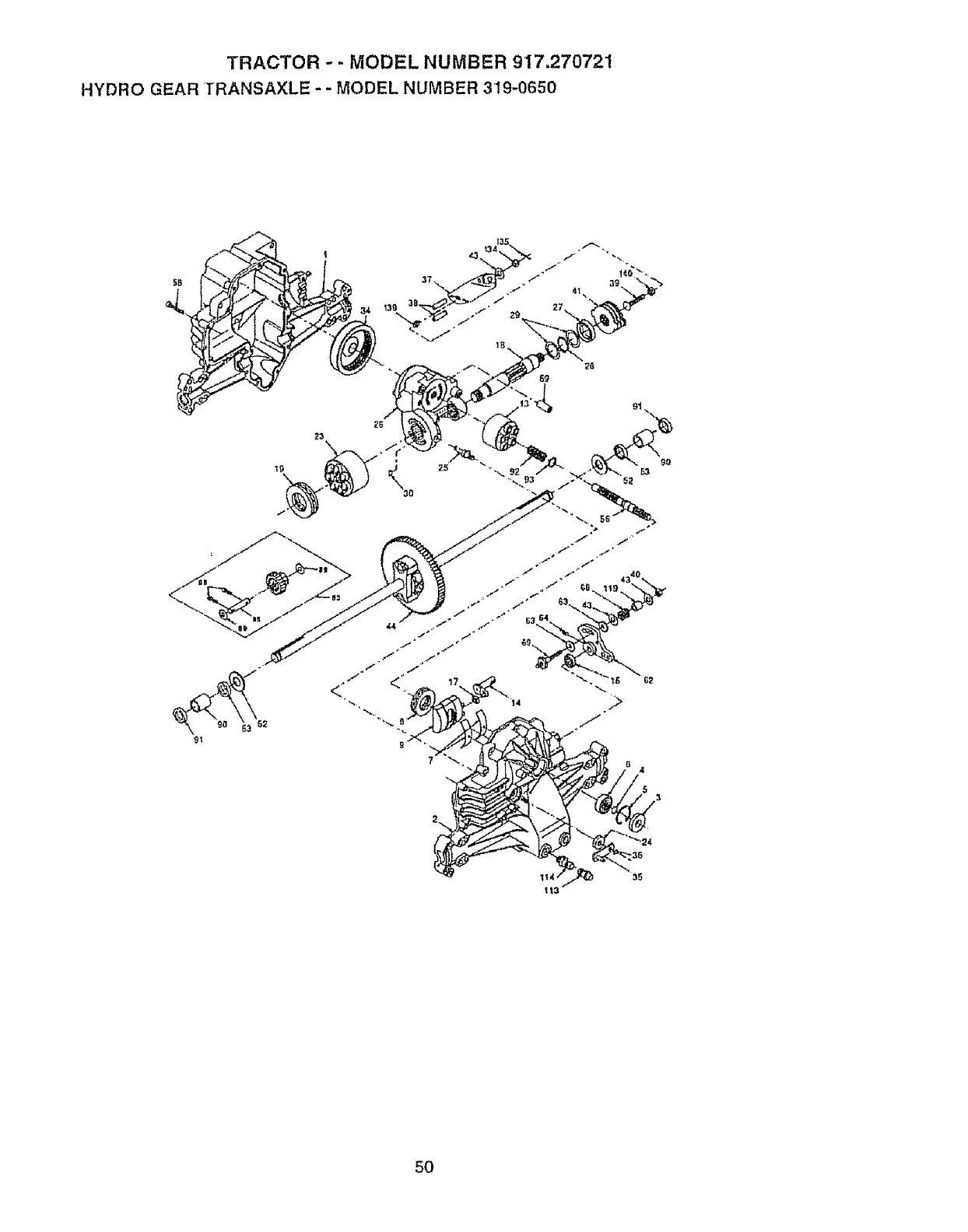
TRACTOR --MODEL NUMBER 917.270721
HYDRO GEAR TRANSAXLE - - MODEL NUMBER 319-0650
37
4t • _\
5O
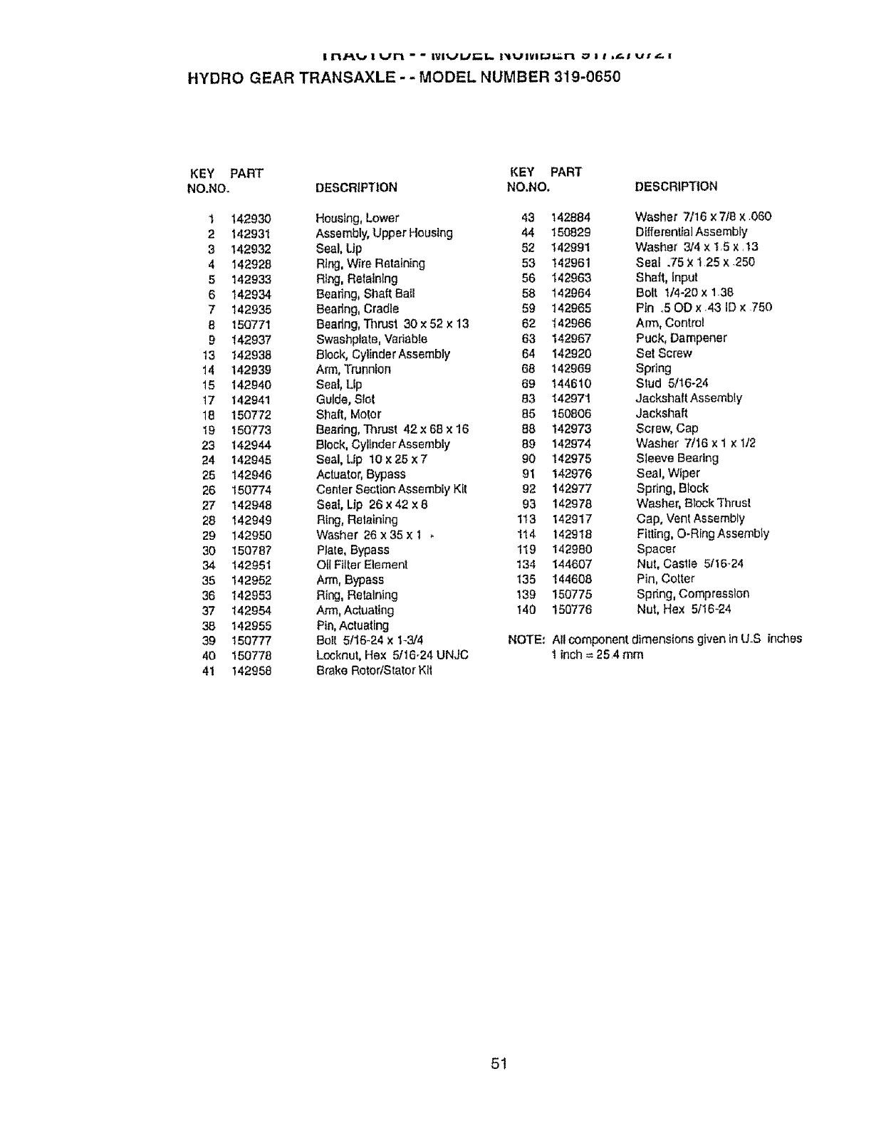
I I"I,tT'_I-B 1 UF'I " " I_IIIUUI_i.. pitUIViI.iL::FI ..1 I I _.! LII L_. t
HYDRO GEAR TRANSAXLE - -MODEL NUMBER 319-0650
KEY PART KEY PART
NO.NO. DESCRIPTION NO.NO, DESCRIPTION
1 142930 Housing, Lower 43 142884 Washer 7/16 x7/9 x.060
2 142931 Assembly, Upper Housing 44 150829 D[fferentialAssembly
3 142932 Seal, Up 52 142991 Washer 3/4 x 15 x.13
4 142928 Ring, Wire Retaining 53 142961 Seal .75X t 25 x.250
5142933 Rtng, Retatntng 56 142963 Shaft, Input
6 142934 Bearing, Shaft BaIi 58 142964 Bolt t14-20 x 1_39
7 142935 Bearing, Cradle 59 142965 Pin .50D x.43 ID x .750
8150771 Bearing, Thrust 30 ×52 x 13 62 _42966 Arm, Controt
9 142937 Swashplate, Variable 63 142967 Puck, Dampener
t3 142938 Block, CylinderAssembly 64 142920 Set Screw
14 142939 Arm, Trunnion 68 142969 Spring
t5 142940 Seal, Lip 69 144610 Stud 5/16-24
t7 142941 Guide, Slot 83 142971 JackshaftAssembty
18 t50772 Shaft, Motor 85 150806 Jackshaft
19 150'773 Beadng, Thrust 42 x 68 x 16 88, 142973 Screw, Cap
23 142944 Block, CyltnderAssembiy 99 142974 Washer 7/16 × 1 x 1/2
24 142945 Seal, Lip 10 x25 x 7 90 142975 Sleeve Bearing
25 142946 Actuator, Bypass 91 142976 Seal, Wiper
26 150774 Center Section Assembly Kit 92 142977 Spring, Block
27 142948 Seat, Lip 26 x42 x 8 93 142978 Washer, Block'Thrust
28 142949 Ring, Retaining 113 142917 Cap, Vent Assembly
29 142950 Washer 26 x35 x 1 , 114 142918 Fitting, O-RingAssembiy
30 150787 Plale, Bypass 119 142980 Spacer
34 142951 OIIFilter Element 134 144607 Nut, Castle 5116_24
35 142952 Arm, Bypass 135 144608 Pin, Cotter
36 142953 Ring, Retaining !39 150775 Spring, Compression
37 142954 Arm, Actuating 140 150776 Nut, Hex 5t16-24
38 142955 Pin, Actuating
39 150777 Bolt 5116-24 x173/4 NOTE: All component, dimensions given in UoS inches
40 150778 LocknuI,Hex 5116-24 UNJC t inch= 25.4 mm
41 142958 Brake RotortStator Kit
51
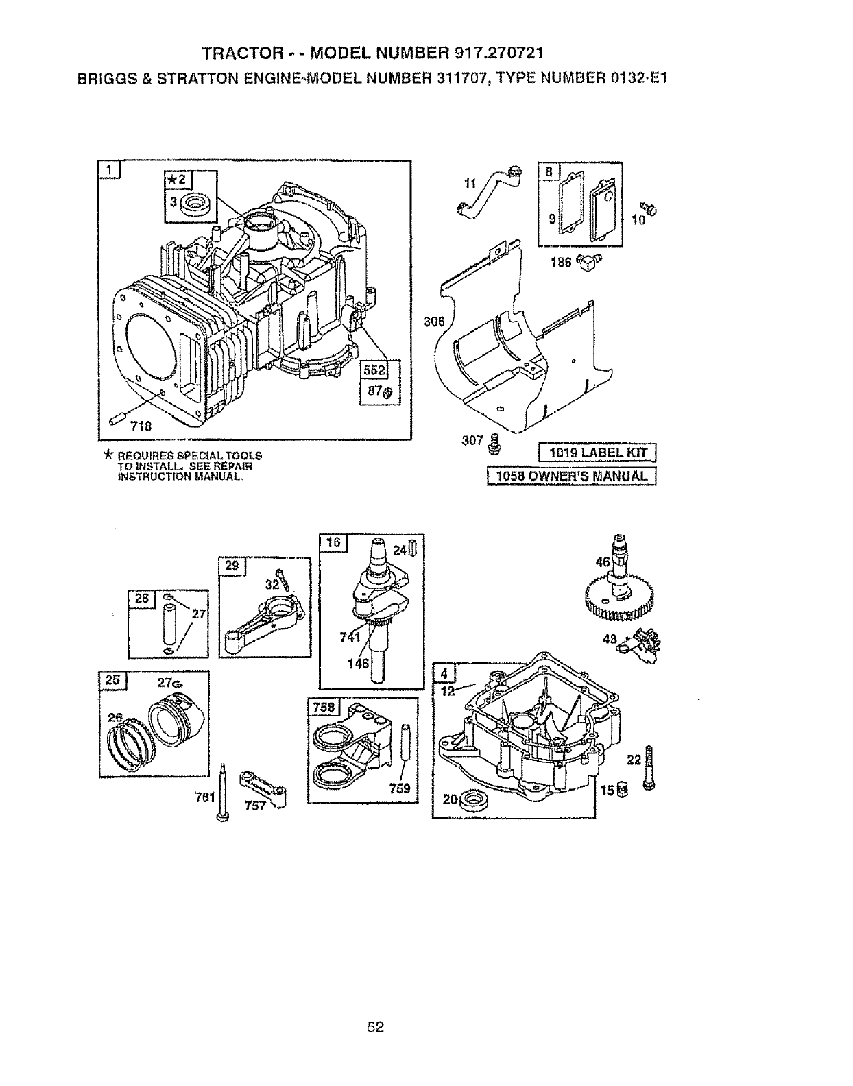
TRACTOR -- MODEL NUMBER 917.270721
BRIGGS & STRATTON ENGINE,.MODEL NUMBER 311707, TYPE NUMBER 0132-E1
"k REQUIRES SPECIAL TOOL.S
TO INSTALL, SEE REPAIR
INSTRUCTION MANUAL..
186
:i, ,,i
m
52
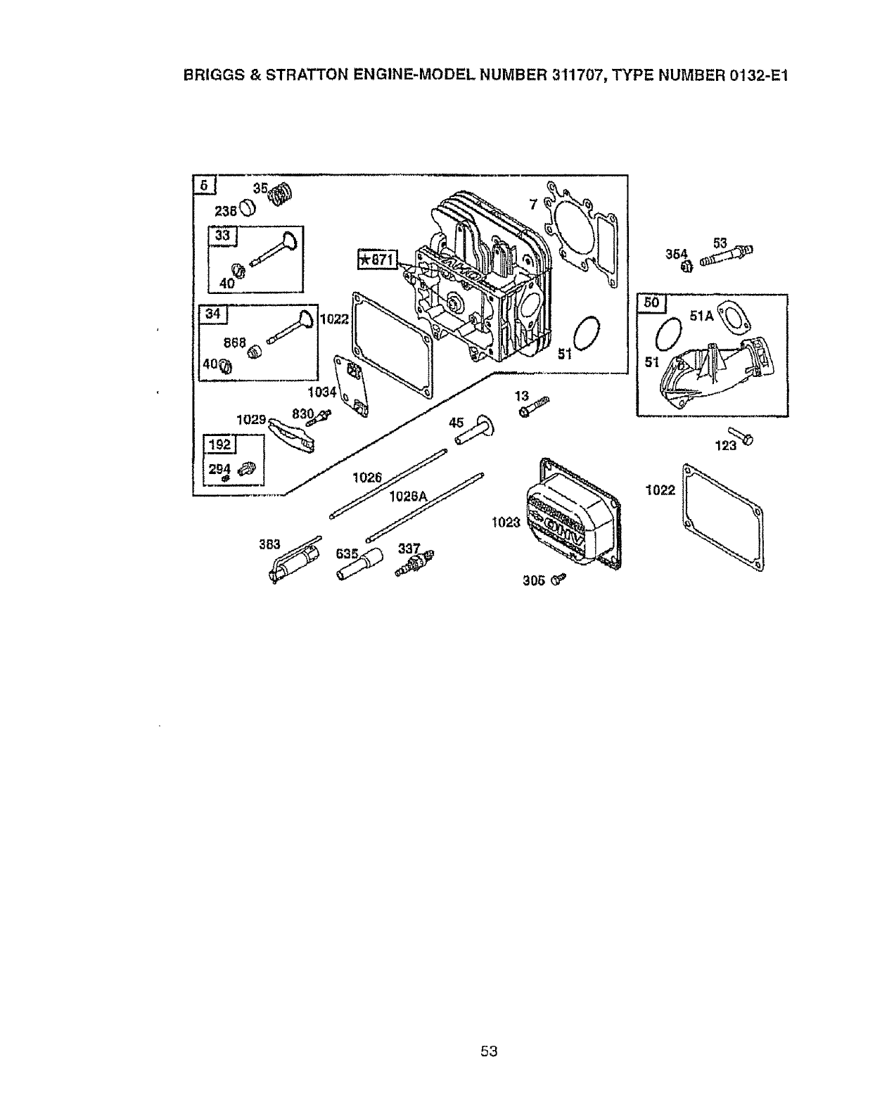
BRIGGS& STRATTON ENGINE-MODEL NUMBER 311707, TYPE NUMBER 0!32-E1
1022
53
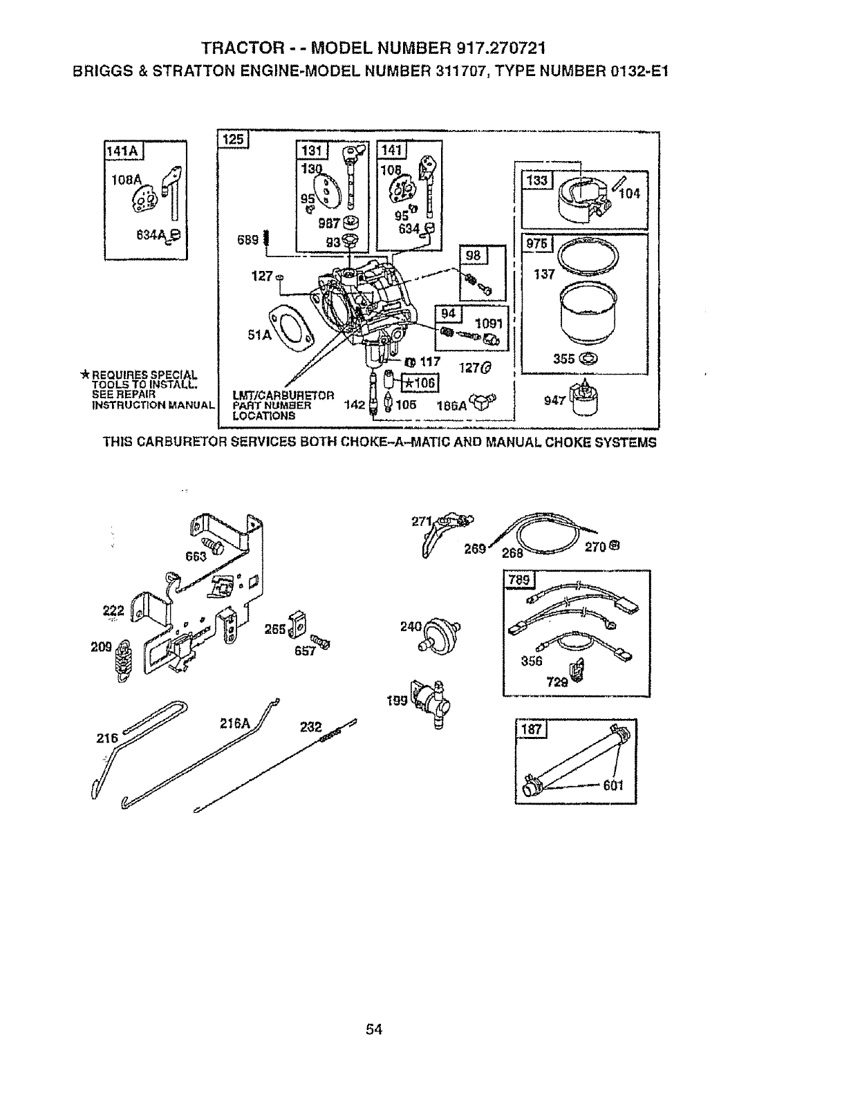
TRACTOR - - MODEL NUMBER 917.270721
BRIGGS &STRATTON ENGINE-MODEL NUMBER 311707, TYPE NUMBER 0132-E1
141A_ "
834A_
-'kREQUIRES SPECIAL
TOOLS TO INSTALL,
SEE REPAIR
INSTRUCTION MANUAL
127,
"_ 117 127_
LOCATIONS 941
THIS CARBURETOR SERVICES BOTH CHOKE-A-.MATIC AND MANUAL CHOKE SYSTEM!
216
!J
27_ _
26_"2_8_=_2708
54
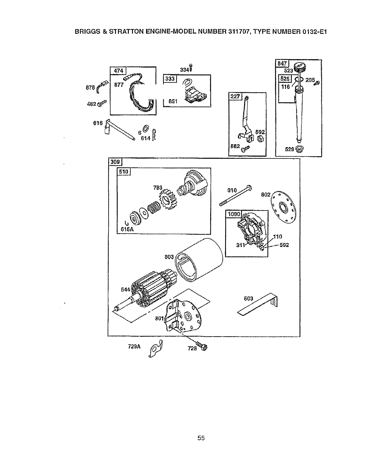
BRIGGS& STRATTONENGINE-MODELNUMBER 311707, TYPE NUMBER 0132-E1
878 877
482
614
334'_
[2s_
sloJ 783
L_
61GA
662
802_
o%
729A ,_- 72_8__--
55
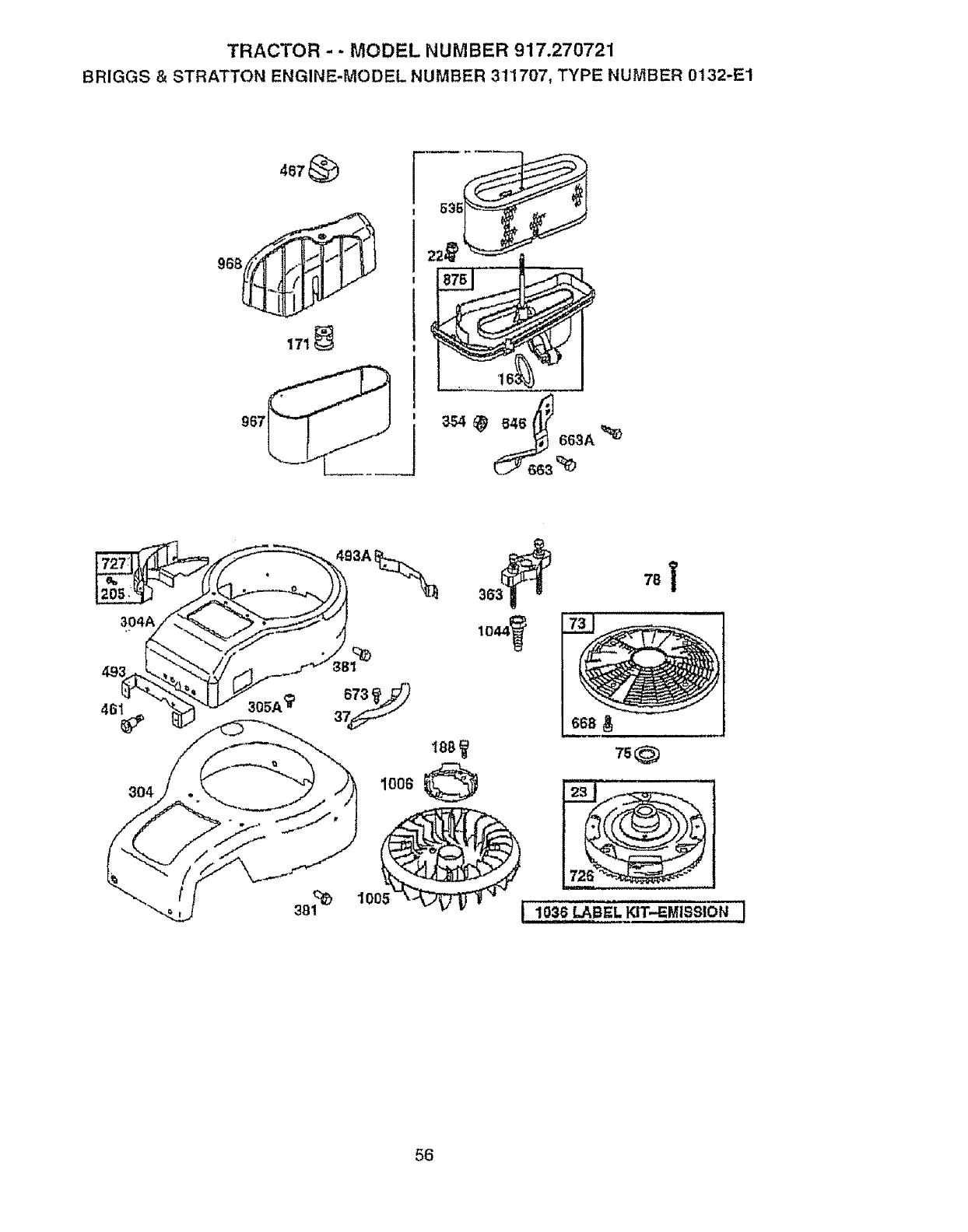
TRACTOR - - MODEL NUMBER 917.270721
BRIGGS & STRATTON ENGINE-MODEL NUMBER 311707, TYPE NUMBER 0132-1=1
467_
17t
967_
2:3S
16
(1
646_ 663A _
354
1006
7_
II I
56
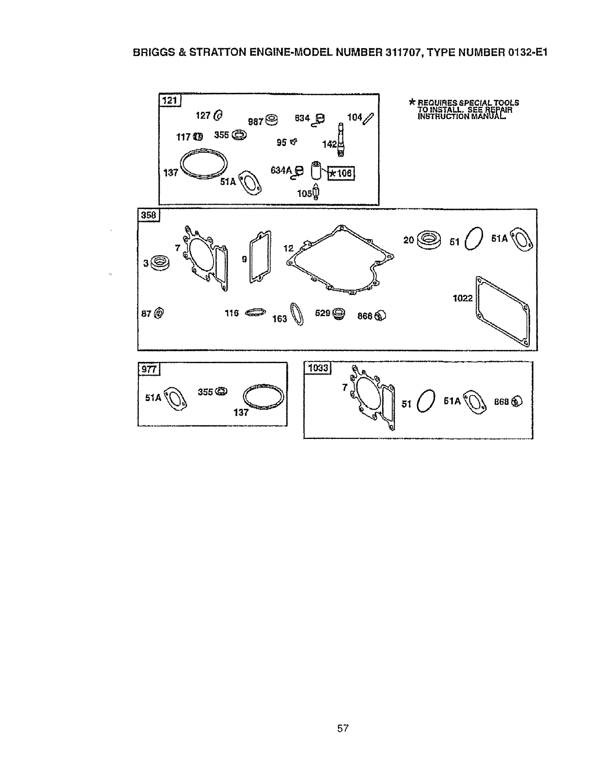
BRIGGS & STRATTON ENGINE-MODEL NUMBER 311707, TYPE NUMBER 0132-E1
12_0 g87@ 834_ ,,1o4_
117 qL9 355_ 95_ 142t
i ii iii
_r REQUIRES SPECIAL TOOLS
TO INSTALL. SEE REPAIR
INBTRUCTION MANUAl.
1022
116,_ 163_ 62_@ 868_
51A
3s5_
lo_3j
°.0 ..,%°°°_
57

TRACTOR - - MODEL NUMBER 917.270721
BRIGGS & STRATTON ENGINE-MODEL NUMBER 311707, TYPE NUMBER 0132-E1
KEY PART'
NO, NO.
1 690156
2 399265
3 391086
4 494238
5 690188
6 94927
7 273763
8 495735
9 27803
10 94621
11 281246
12 271916
271997
13 94728
15 94239
16 690136
20 291675
22 95187
23 690222
24 222598
25 692271
692272
692273
692274
26 690162
690164
690186
690168
27 263129
28 498319
::,: 498320
29 499458
499940
32 95190
33 495856
34 495857
35 262811
40 224641
43 40815
45 262411
46 496884
50 690193
51 281735
51A 273650
53 94637
73 494439
75 225136
78 94821
87 491323
93 281346
94 498030
95 94098
KEY PART
DESCRIPTION NO. NO. DESCRIPTION
Cylinder Assembly 98 495800 Screw, idle Speed
Bushing, Cylinder t04 231789 . Pin, FloatHinge
* Sea_,O11 105 231855 • Valve, Needle
Sump, Engine 106 231854 • Seat, Inlet
Head, Cylinder 108 224558 Valve, Choke (Manual Choke)
Washer, Fiat 108A 224540 Valve, Choke (Choke-A°Matle)
0* Gasket, Cylinder Head 110 225137 Washer, F[al
BrealherAssembly 116 270920 "Seal, O-Ring
° Gasket, Breather 117 232118 • Jet. Main (Standard)
Screw, Hex 232119 Jet, Ma_n[High Att_4ude)
Tube, Breather 121 690191 Carburetor Overhaul Kit
"Gasket, Crankcase (0150 Thk) I23 95160 Screw, Hex
'Gasket, Crankcase (.O05OThk) 125 690194 Carburetor
Screw, Cylinder Head (3- 127 - Plug. Welch (Sold in Kit Only)
9/160) 130 224539 Valve. Throltle
Plug, Oil Drain 131 493379 Throttle Shall Kit
Crankshaft 133 494381 Float, Carburetor
' Seal, Oil !37 281165 0. Gasket, Float Bowl
Screw, Crankcase Cover 141 495097 Choke Shaft Kit (Man, Choke)
Flywheel 141A 495931 Choke Shall Kit (Choke-A-,
Key. Flywheel Matic)
Piston, Assembly (Std) t42 232117 •Nozzle, Carburelor
Piston Assemb{y (0100 O S) 146 94195 Key, Timing
Piston Assembly (0200 O S ) 163 281051 "Gasket, Air Cleaner
PistonAssembfy (0300 OS) 17! 281051 Nut
Ring Set, Piston (Std.) 186 493498 Connector, Hose
Ring Set, Piston (o0100 OS ) 187 298049 Line, Fuel (Cut to Required
Ring Set, Piston (,0200 OS) Length)
Ring Set, Piston (0300 OS ) 188 94627 Screw He×
Loci{, Piston Pin t92 492160 Adjusler, RockerArm
Pin Assembly, Piston (Std) !99 494768 Valve, Shut,Off
Pin Assembly, Piston (0050 205 94903 Screw, Sholder
O&) 205A 94073 Screw, Shoulder
Rod Assembly, Connecting 209 260695 Spring, Governor
(SId) 218 262766 Link. Choke
RodAssy., Connecting ( 020 216A 262766 Unk, Choke
U S) 222 495611 Bracket, Control
Screw, Connecting Rod 224 95t63 Screw, Tbrx@He_
Valve, Exi_aust 227 493935 Lever, Governor
Valve, fnlake 232 262785 Spring, Link
Spring, Valve RPM Settings: Low: 1650.-1850
Retainer, Valve High: 3200-3400
GevlOil Slinger
Tappet, Valve Included in Gasket Set (690189}
Gear, Cam •lnctuded in Carburetor Ktt (690191)
Manifold, Intake 0lncIuded In Carburetor Gasket Set (690192).
'e Gasket, Intake e Included in Valve overhaul Gasket Set (690190)
§ Gasket, Intake § Included in Kits "-0e
Stud, Carb, Mounting
Screen, Rotating NOTE: Aft component dimensions given in U S Inches
Washer, Rywheei 1 inch = 25 4 mm
Sc_'ewTor,4_
• Seal, Governor Shaft 238 262836 Cap, Valve
Bushing Throttle Shaft 240 394358 Filter, Fuel
Valve, ldleAdjustment 265 221535 Clamp, Casing
.Screw, Choke/Throttle
58

! n/_,, I _../nL - - IVI_JLJ_I. PIUIVl_r-n _!I._i u_r t- !
BRIGGS & STRATTON ENGINE_MODEL NUMBER 3'11707, TYPE NUMBER 0132-E1
KEY PART KEY PART
NO. NO. DESCRIPTION NO. NO. DESCRIPTION
238 262836 Cap, Valve 727 490324 Cover, Starter Drive
240 394358 Filter, Fuel 728 94951 Screw, Terx'
265 221535 Clamp, Casing 729 281390 Clip, Wire
294 810104 Adjusler, ReckerArm 729A 225170 Clip, Wire
304 225511 Housing, Blower (Red Outer) 74I 262932 Gear, Timing
304A 225017 Housing, Blower (Blackinner) 757 213998 Link, Counterweight
305 94682 Screw, Hex 758 499994 Counterweight
305A 94822 Screw, Torx" 759 230787 Pin, Counterweight
306 225020 Shield, Cylinder 761 94593 Screw, Hex
307 94930 Screw, Hex 763 280104 Gear, Starter
309 497595 Motor, Starter 789 497708 Harness, Wiring
310 94003 Screw, Hex 801 497626 Cap, Drive
31t 497608 Brush Set 802 497607 Cap, End
333 495859 Armature. Magnelo 803 497604 Housing, Starter
334 94731 Screw, Armature Mounting 830 94555 Slud, RockerArm
337 491055 SparkPtug 847 496415 DipstickfTubeAssy
354 94010 Nut, Hex 85I 224110 _ferminaI,Cable
355 281164 "_ Washer 868 499236 *e Seai, Valve
356 494705 Wire, Stop 871 262835 Bushing, Guide
358 690t89 Gasket Set 875 495862 Base, Air Cleaner
363 19203 Flywheel Putter 877 393456 Wire, Alternator
38t 94863 Screw, Hex 878 393362 Harness, Allernator
383 89838 Wrench, Spark Plug 947 497672 Solenoid, Fuel
481 94734 Screw, Torx, Hex 967 272403 Filter, Pro-Cleaner
467 493903 Nut.Air Cleaner 968 281758 Cover. Air Cleaner
474 393474 A}temator 975 494933 Bowl, Float
482 93621 Screw, Hex 977 690192 Gasket SeLCarburetor
493 224966 Bracket, Mounting (Fronl) 987 281166 ,, Seal, Throtlle Shall
493A 224969 Bracket, Mounting (Rear) 1005 281400 Fan, Flywheel
503 606000 Strap, Slarter I006 224413 Retainer, Fan
510 497606 Ddve, Starter 1019 690180 LabeIKil
523 495230 Dipstick, Oi! I022 272475 "e Gasket, Racker Cover
525 496113 Tube, Oit Fill 1023 225521 Cover, Rocker
529 281370 * Seal, FittTuba 1026 494432 Rod, Push (Intake)
535 496894 Fitter, AJCEtement 1026A 495136 Rod, Push (Exhausl_,
544 497603 Armature, Starter 1029 224554 Arm, Rocker
552 491986 Bushing, GovemerCrank 1033 690190 VaIve Ovarhau[Kit
562 94907 Bolt, Governor Lever I034 495248 Guide, Push Rod
592 231978 Nut, Hex !036 273807 Label Kit Emission
592A 92278 Nut, Hex 1044 94673 Screw, Shoulder
60t 95152 Ctamp, Fuel Line 1050 273686 Owner's Manual
614 93305 Pin, Cotter 1090 497605 Retafner_Bn)sh
615 263080 Ring, Retaining 1091 281364 Cap, Limiter
616 495157 Crank, Governor RPM Settings: Low;1650_ 1850
634 494453 • Seal, SpringAssy (Man_ High: 3200,3400
Choke)
634A 494455 • Seal, Spring Assy (Cheke,A_ included in Gasket Set, Par{ Number 690189
Matic) • included inCarburetor Kit, Part Number 690191
635 2808_'2 Boot, Spark Pfug 0 tncluded inCarburetor Gaskel Set, Pro1
646 224546 Brace Number 690!92
657 94905 Screw, Slotted Hex # Included in Valve Overhaul Gasket Set, Part
663 94929 Screw, Hex Number 690190
663A 94704 Screw, Hex § Included in Kits ','0e
668 805402 Spacer
689 262715 Spring, Friclion NOTE: All component dimensions given in U S inches
673 94896 Screw, He× tinch--25 4rnm
718 230192 Dowel, Sleeve
726 399676 Gear Ring
59
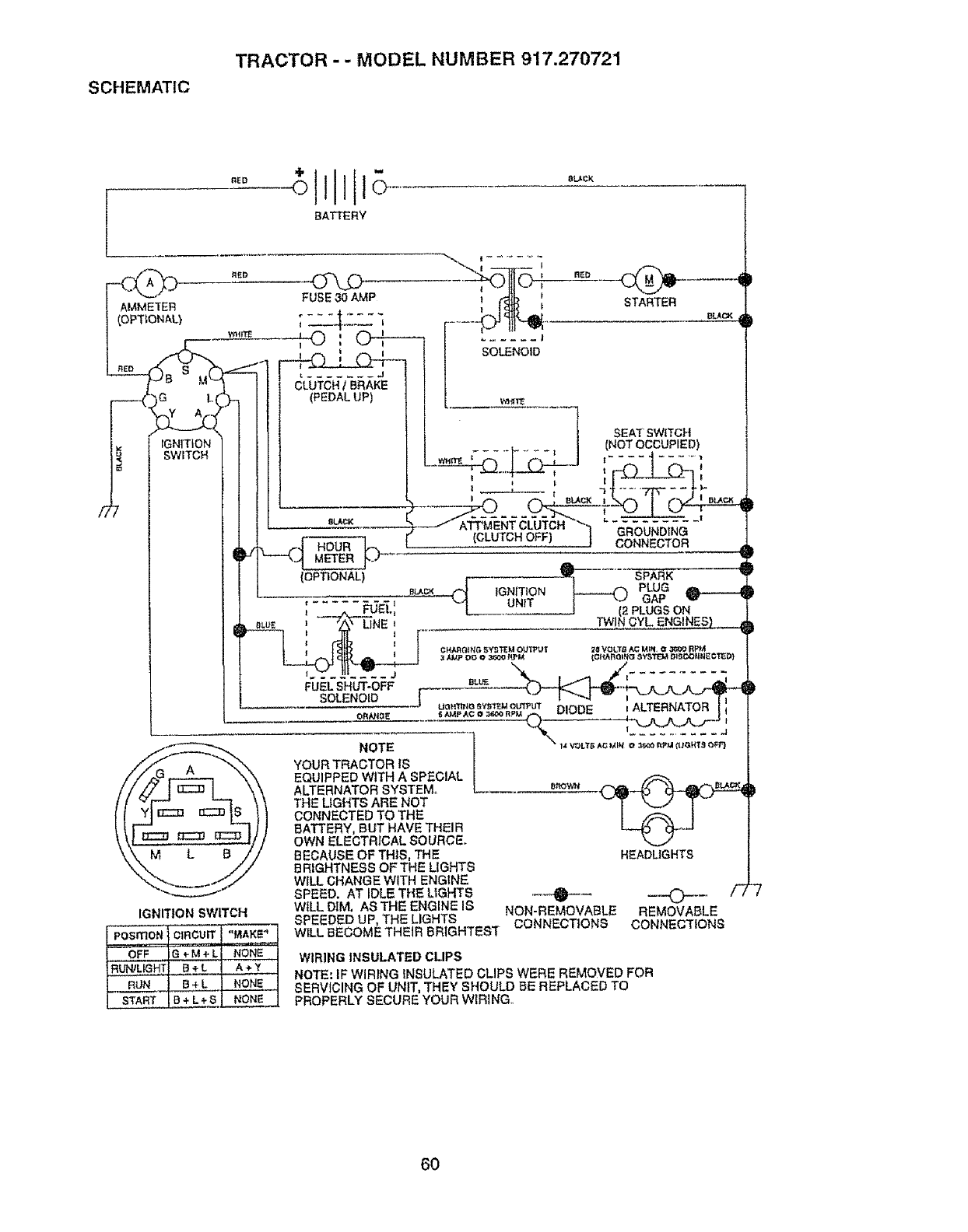
SCHEMATIC
TRACTOR - - MODEL NUMBER 917.270721
BATTERY
f _ )G L
__2c
IGNITION
SWITCH
FUSE 30 AMP
SOLENOID
(PEDAL UP)
l
I SEAT' SWITCH
÷_, ,.. _ | (NOT OCCUPIED)
IBLACK I I _
-- AITMENT CLUTCH ._ "Z'_,'..,T{i,....
Gn',aumDING
(CLUTCH OFF) J CONNECTOR
(OPTIONAL) r _ SPARK
...... IGNITION
El _ UNIT
; "" -j_ - _ -,, 'J[ ...... ..--.J i'_ PL'_3rS ON""
llr__ CHAgGlttG _i,y_'_ M O_T 2_ YO LT_I _MIN, _ 3609 RF_
3AMp DO 0_ RpI,_ (CI'IAR_INo 8_"HTEM DlSC_IINE¢'I_D}
ISOLENOID l "- I -",J -- ,"-L-'-Ti
..... u_os_S_out_u_ DIODE _ALTERNATOR i ;
........... \.z---_-- _-_.,.-'%J--
///;_u r-_ "k"_ EQUIPPED WITH A SPECIAL |
///_j._j _ h_, _\ ALTERNATOR SYSTEM. [e_o_ _-_it_"
[[_1_! O::::_S 1 / THE LIGHTS ARE NOT _T _ T_" "
I I -_ _u._.,u _ } ] CONNECTED TO THE I _ I
f _ I_ _ _ t /BATTERY, BUT HAVE THEIR L_ _.J
\\t _ _ _ I// OWN ELECTRICAL SOURCE_
\\ M LB// BEOAUSEOFTHtS, THE HEADLIGHTS
_, _// BRIGHTNESS OF THE LIGHTS
_......I../WILL GRANGE WITH ENG!NE _ _,
SPEED. AT IDLE THE LIGHIS "1_ --'-0- .... / /
IGNITION SWITCH WILL DIM, AS THE ENGINE 18 NON-REMOVABLE REMOVABLE
SPEEDED UP, THE LIGHTS CONNECTIONS CONNECTIONS
WILL BECOME THEIR BRIGHTEST
WIRING INSULATED CLIPS
NOTE: IF WIRING INSULATED CLIPS WERE REMOVED FOR
SERVICING OF UNIT, THEY SHOULD BE REPLACED TO
PROPERLY SECURE YOUR WIRING,,
6O

61

62

SUGGESTED GUIDE FOR SIGHTING SLOPES FOR SAFE OPERATION
ONLY RIDE UP AND DOWN HILL,
NOT ACROSS HILL
cr_ SIGHT AND HOLD THIS LEVEL WITH
SKY LINE OR TREE,
/
15°MAX.
_j .p_ Operate your Tractor up and down the face of slopes (not !
_1_ greater than !5 ), never across the face. Make turns gradu- I
_1 ti_ ally to prevent tipping or loss of control Exercise extreme I
_i caution when changing direction on slopes. I

For the repair or replacement parts you need
delivered directly to your home
Call 7 am - 7 pm, 7 days a week
1-800-366-PART
(1-800-366-7278)
Para ordenar piezas con entrega a
domtcilio - 1-800-659-7084
For in-house major brand repair service
Call 24 hours a day, 7 days a week
1-800-4-REPAIR
(1-800-473-7274)
Para pedir servicio de reparaci6n a
domicillo- I-8O0-676-5811
For the location of a Sears Parts and
Repair Center in your area
Call 24 hours a day, 7 days a week
1-800-488-1222
For information on purchasing a Sears
Maintenance Agreement or to inquire
about an existing Agreement
Call 9 am - 5 pro, Monday-Saturday
1-800-827-6655
When requesting service or ordering
parts, always provide the following
information:
• Product Type ° Part Number
• Model Number • Part Description
America's Repair Speciatlsts
164140 Rev. 10 9.2.98 JH/TR/VB/RD Printed in UoSoA.
