Craftsman 917271053 User Manual 42 LAWN TRACTOR Manuals And Guides L0101019
CRAFTSMAN Lawn, Tractor Manual L0101019 CRAFTSMAN Lawn, Tractor Owner's Manual, CRAFTSMAN Lawn, Tractor installation guides
User Manual: Craftsman 917271053 917271053 CRAFTSMAN 42 LAWN TRACTOR - Manuals and Guides View the owners manual for your CRAFTSMAN 42 LAWN TRACTOR #917271053. Home:Lawn & Garden Parts:Craftsman Parts:Craftsman 42 LAWN TRACTOR Manual
Open the PDF directly: View PDF ![]() .
.
Page Count: 56

Owner's Manual
15.5 HP
ELECTRIC START
42" MOWER
6 SPEED TRANSAXLE
LAWN TRACTOR
Model No.
917.271053
EZ
• Safety
•Assembly
•Operation
•Maintenance
•Repair Parts
This product has a low emission engine which operates
differently from previously built engines. Before you start the en-
glne, read and understand this Owner's Manual.
CAUTION:
Read and follow all Safety
Rules and Instructions before
operating this equipment.
For answers to your questions
about this product, Call:
1-800-659-5917
Sears Craftsman Help Line
5 am- 5 pm,Mon- Sat
Sears, Roebuck and Co., Hoffman Estates, II 60179
Visit our Craftsman website:www.sears.com/craftsman
Warranty ............................................... 2
Safety Rules ......................................... 3
Product Specifications .......................... 6
Assembly .............................................. 8
Operation ............................................. 11
Maintenance Schedule ...................... 17
Maintenance....................................... 17
Service and Adjustments ....................21
Storage ............................................... 27
Troubleshooting ................................. 28
Repair Pads ........................................ 32
Parts Ordering ..................... Back Cover
LIMITED TWO YEAR WARRANTY ON CRAFTSMAN RIDING EQUIPMENT PARTS
For two (2) years from the date of purchase, if this Craftsman Riding Equipment is
maintained, lubricated and tuned up according to the instructions in the owner's
manual, Sears will repair or replace, free of charge, any parts found to be defective in
material or workmanship. Warranty service is available free of charge by taking your
Craftsman riding equipment to your nearest Sears Service Center. In-home warranty
service is available but atrip charge will apply. This warranty applies only while this
product is in the United States.
This Warranty does not cover:
• Expendable items which become wom during normal use, such as blades, spark
plugs, air cleaners, belts and oil filters.
• Tire replacement or repair caused by punctures from outside objects, such as nails,
thorns, stumps, or glass.
• Repairs necessary because of operator abuse, including but not limited to, damage
caused by towing objects beyond the capability of the riding equipment, impacting
obects that bend the frame or crankshaft, or over speeding the engine.
• Repairs necessary because of operator negligence, includ ng but not limited to,
electrical and mechanical damage caused by improper storage, failure to use the
proper grade and amount of engine oil, failure to keep the deck clear of flammable
debris, or the failure to maintain the equipment according to the instructions
contained in the owner's manual.
•Engine (fuel system) cleaning or repairs caused by fuel determined to be contami-
nated or oxidized (stale). In general, fuel should be used within thirty (30) days of its
purchase date.
• Riding equipment used for commercial or rental purposes.
LIMITED 90 DAY WARRANTY ON BATTERY
For ninety (90) days from date of purchase, if any battery included with this riding
equipment proves defective in material or workmanship and our testing determines
the battery will not hold acharge, Sears will replace the battery at no charge. War-
ranty service is available free of charge by taking your Craftsman riding equipment to
your nearest Sears Service Center. In-home warranty service is available but a trip
charge will apply. This warranty applies only while this product is in the United States.
TO LOCATE THE NEAREST SEARS SERVICE CENTER OR TO SCHEDULE IN-
HOME WARRANTY SERVICE, SIMPLY CONTACT SEARS AT 1-800-4-MY-HOME
This Warrantygivesyou specificlegal rights,andyou may also have other rights
whichmay varyfrom stateto state.
Sears, Roebuck and Co., D/817 WA, Hoffman Estates, IL 60179
2
IMPORTANT: This cuttingmachineis capable of amputatinghands and feet and
throwingobjects.Failureto observethe followingsafetyinstructions couldresultin
serious injury or death.
I. GENERAL OPERATION
• Read, understand, and follow all
instructions in the manual and on the
machine before stading.
• Only allow responsible adults, who are
familiar with the instructions, to operate
the machine.
•Clear the area of objects such as
rocks, toys, wire, etc., which could be
picked up and thrown by the blade.
• Be sure the area is clear of other
people before mowing. Stop machine
if anyone enters the area.
•Never carry passengers.
•Do not mow in reverse unless abso-
lutely necessary. Always look down
and behind before and while backing.
•Be aware of the mower discharge
direction and do not point it at anyone.
Do not operate the mower without
either the entire grass catcher or the
guard in place.
•Slow down before turning.
•Never leave a running machine
unattended. Always tum off blades, set
parking brake, stop engine, and
remove keys before dismounting.
•Tum off blades when not mowing,
•Stop engine before removing grass
catcher or unclogging chute.
•Mow only in daylight or good adificial
light.
•Do not operate the machine while
under the influence of alcohol or drugs.
•Watch for traffic when operating near or
crossing roadways.
•Use extra care when loading or
unloading the machine into a trailer or
truck.
•Data indicates that operators, age 60
years and above, are involved in a
large percentage of riding mower-
related injuries. These operators
should evaluate their ability to operate
the riding mower safely enough to
protect themselves and others from
serious injury.
II. SLOPE OPERATION
Slopes are a major factor related to loss-of-
control and tipover accidents, which can
result in severe in ury or death. All slopes
requ re extra caut on. f you cannot back up
the slope or if you feel uneasy on it, do not
mow it.
DO:
•Mow up and down slopes, not across.
•Remove obstacles such as rocks, tree
limbs, etc.
•Watch for holes, ruts, or bumps.
Uneven terrain could overturn the
machine. Tall grass can hide obstacles.
•Use slow speed. Choose a low gear
so that you will not have to stop or shift
while on the slope.
•Follow the manufacturer's recommen-
dations for wheel weights or counter-
weights to improve stability.
•Use extra care with grass catchers or
other attachments. These can change
the stability of the machine.
•Keep all movement on the slopes slow
and gradual. Do not make sudden
changes in speed or direction.
•Avoid starting or stopping on a slope. If
tires lose traction, disengage the
blades and proceed slowly straight
down the slope.
DO NOT:
• Do not turn on slopes unless neces-
sary, and then, turn slowly and gradu-
ally downhill, if possible.
•Do not mow near drop-offs, ditches, or
embankments. The mower could
suddenly turn over if a wheel is over
the edge of a cliff or ditch, or if an edge
caves in.
•Do not mow on wet grass. Reduced
traction could cause sliding.
•Do not try to stabilize the machine by
putting your foot on the ground.
•Do not use grass catcher on steep
slopes.
lit.CHILDREN
Tragicaccidentscan occur if the operator
is not alert to the presence of children.
Children are often attracted to the
machine and the mowing activity. Never
assume that children will remain where
you last saw them.
• Keep children out of the mowing area
and under the watchful care of another
responsible adult.
•Be alert and turn machine off if children
enter the area.
•Before and when backing, look behind
and down for small children.
•Never carry children, They may fall off
and be seriously injured or interfere
with safe machine operation.
• Never allow children to operate the
machine.
•Use extra care when approaching blind
corners, shrubs, trees, or other objects
that may obscure vision.
IV. SERVICE
•Use extra care in handling gasoline
and other fuels. They are flammable
and vapors are explosive.
- Use only an approved container.
-Never remove gas cap or add fuel
with the engine running. Allow
engine to cool before refueling. Do
not smoke.
- Never refuel the machine indoors.
- Never store the machine or fuel
container inside where there is an
open flame, such as a water heater.
•Never run a machine inside a closed
area.
•Keep nuts and bolts, especially blade
attachment bolts, tight and keep
equipment in good condition.
•Never tamper with safety devices.
Check their proper operation regularly.
•Keep machine free of grass, leaves, or
other debris build-up. Clean oil or fuel
spillage. Allow machine to cool before
storing.
• Stop and inspect the equipment if you
strike an object. Repair, if necessary,
before restarting.
•Never make adjustments or repairs
with the engine running.
•Grass catcher components are subject
to wear, damage, and detedoration,
which could expose moving parts or
allow objects to be thrown. Frequently
check components and replace with
manufacturers recommended parts,
when necessary.
• Mower blades are sharp and can cut.
Wrap the blade(s) or wear gloves, and
use extra caution when servicing them.
•Check brake operation frequently.
Adjust and service as required.
•Be sure the area is clear of other
people before mowing. Stop machine if
anyone enters the area.
•Never carry passengers or children
even with the blades off,
•Do not mow in reverse unless abso-
lutely necessary. Always look down
and behind before and while backing.
•Never carry children. They may fall off
and be sedously iniured or interfere
with safe machine operation.
•Keep children out of the mowing area
and under the watchful care of another
responsible adult. 4
• Be alert and turn machine off if children
enter the area.
•Before and when backing, look behind
and down for small children.
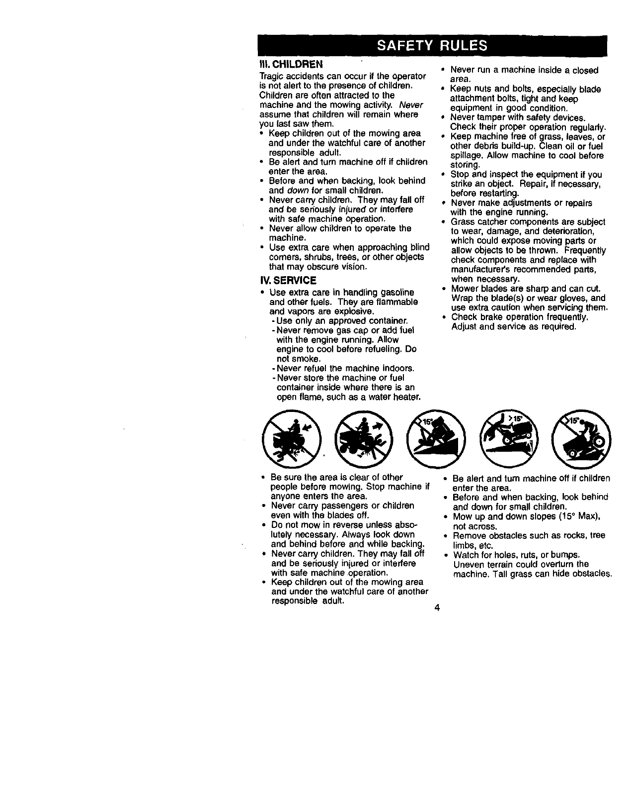
•Mow up and down slopes (15 ° Max),
not across.
• Remove obstacles such as rocks, tree
limbs, etc.
•Watch for holes, ruts, or bumps.
Uneven terrain could overturn the
machine. Tall grass can hide obstacles.
• Useslowspeed.Choosea lowgearso
thatyouwillnot have to stop or shift
while on the slope.
•Avoid starting or stopping on a slope. If
tires lose traction, disengage the
blades and proceed slowly straight
down the slope.
• If machine stops while going uphill,
disengage blades, shift into reverse
and back down slowly.
•Do not turn on slopes unless neces-
sary, and then, turn slowly and gradu-
ally downhill, if possible.
_Look for this symbol to point out
important safety precautions. It means
CAUTION!!! BECOMEALERT!!! YOUR
SAFETY IS INVOLVED.
_i)& CAUTION: In order to prevent
,accidental starting when setting up,
transporting, adjusting or making repairs,
always disconnect spark plug wire and
place wire where it cannot contact spark
plug.
_, CAUTION: Do not coast down ahill
in neutral, you may lose control of the
tractor.
_I, CAUTION: Tow only the attachments
that are recommended by and comply
with specifications of the manufacturer of
your tractor. Use common sense when
towing. Operate only at the lowest
possible speed when on a slope. Too
heavy of a load, while on a slope, is
dangerous. Tires can lose traction with
the ground and cause you to lose control
of your tractor.
,&_WARNING: Engine exhaust, some of
its constituents, and certain vehicle
components contain or emit chemicals
known to the State of California to cause
cancer and birth defects or other repro-
duc_.iveharm.
_,WARNING: Battery posts, terminals
and related accessories contain lead and
lead compounds, chemicals known to the
State of California to cause cancer and
birth defects or other reproductive harm.
Wash hands after handling.
5
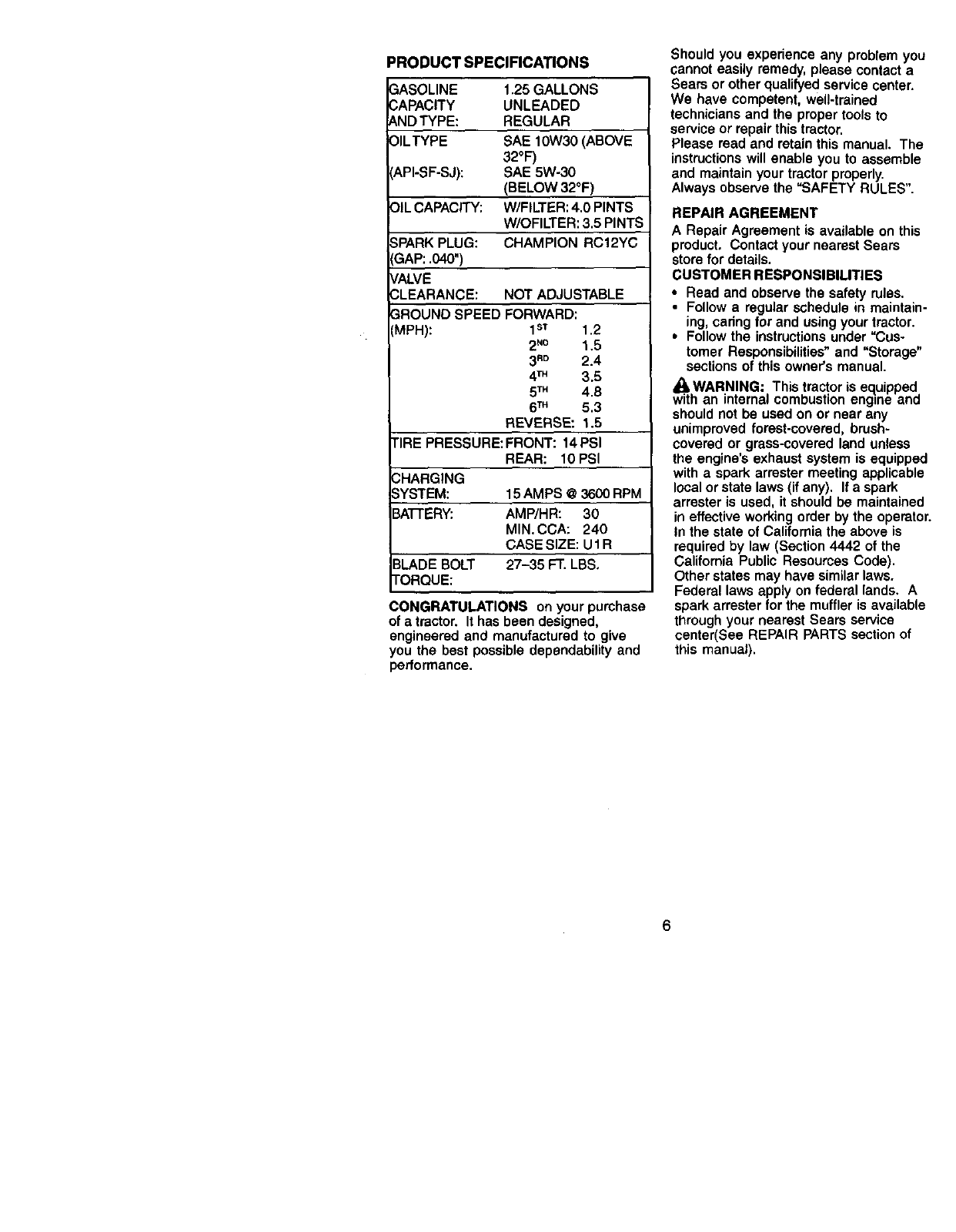
PRODUCT SPECIFICATIONS
3ASOLINE 1.25 GALLONS
3APACITY UNLEADED
a,ND TYPE: REGULAR
DILTYPE SAE 10W30 (ABOVE
32°F)
API-SF-SJ): SAE 5W-30
(BELOW 32°F)
OIL CAPACITY: W/FILTER: 4.0 PINTS
W/OFILTER: 3.5 PINTS
SPARK PLUG: CHAMPION RCf2YC
GAP: .040")
VALVE
CLEARANCE: NOT ADJUSTABLE
GROUND SPEED FORWARD:
(MPH): 1s'r 1.2
2_ 1,5
3R° 2.4
4TM 3.5
5TM 4.8
6TM 5.3
REVERSE: 1.5
TIRE PRESSURE:FRONT: 14PSI
REAR: 10 PSI
CHARGING
SYSTEM:
3ATI'ERY:
15 AMPS @ 3600 RPM
AMP/HR: 30
MIN. CCA: 240
CASE SIZE: U 1 R
3LADE BOLT 27-35 FT. LBS,
FORQUE:
CONGRATULATIONS on your purchase
of atractor. It has been designed,
engineered and manufactured to give
you the best possible dependability and
performance.
Should you experience any problem you
cannot easily remedy, please contact a
Sears or other qualifyed service center.
We have competent, well-trained
technicians and the proper tools to
service or repair this tractor.
Please read and retain this manual. The
instructions will enable you to assemble
and maintain your tractor properly.
Always observe the "SAFETY RULES".
REPAIR AGREEMENT
A Repair Agreement is available on this
product, Contact your nearest Sears
store for details.
CUSTOMER RESPONSIBILITIES
•Read and observe the safety rules.
•Follow a regular schedule in maintain-
ing, caring for and using your tractor.
•Follow the instructions under "Cus-
tomer Responsibilities" and "Storage"
sections of this owner's manual.
_kWARNING: This tractor is equipped
with an internal combustion engine and
should not be used on or near any
unimproved forest-covered, brush-
covered or grass-covered land unless
the engine's exhaust system is equipped
with a spark arrester meeting applicable
local or state laws (if any). If a spark
arrester is used, it should be maintained
in effective working order by the operator.
In the state of California the above is
required by law (Section 4442 of the
California Public Resources Code).
Other states may have similar laws.
Federal laws apply on federal lands. A
spark arrester for the muffler is available
through your nearest Sears service
center(See REPAIR PARTS section of
this manual).
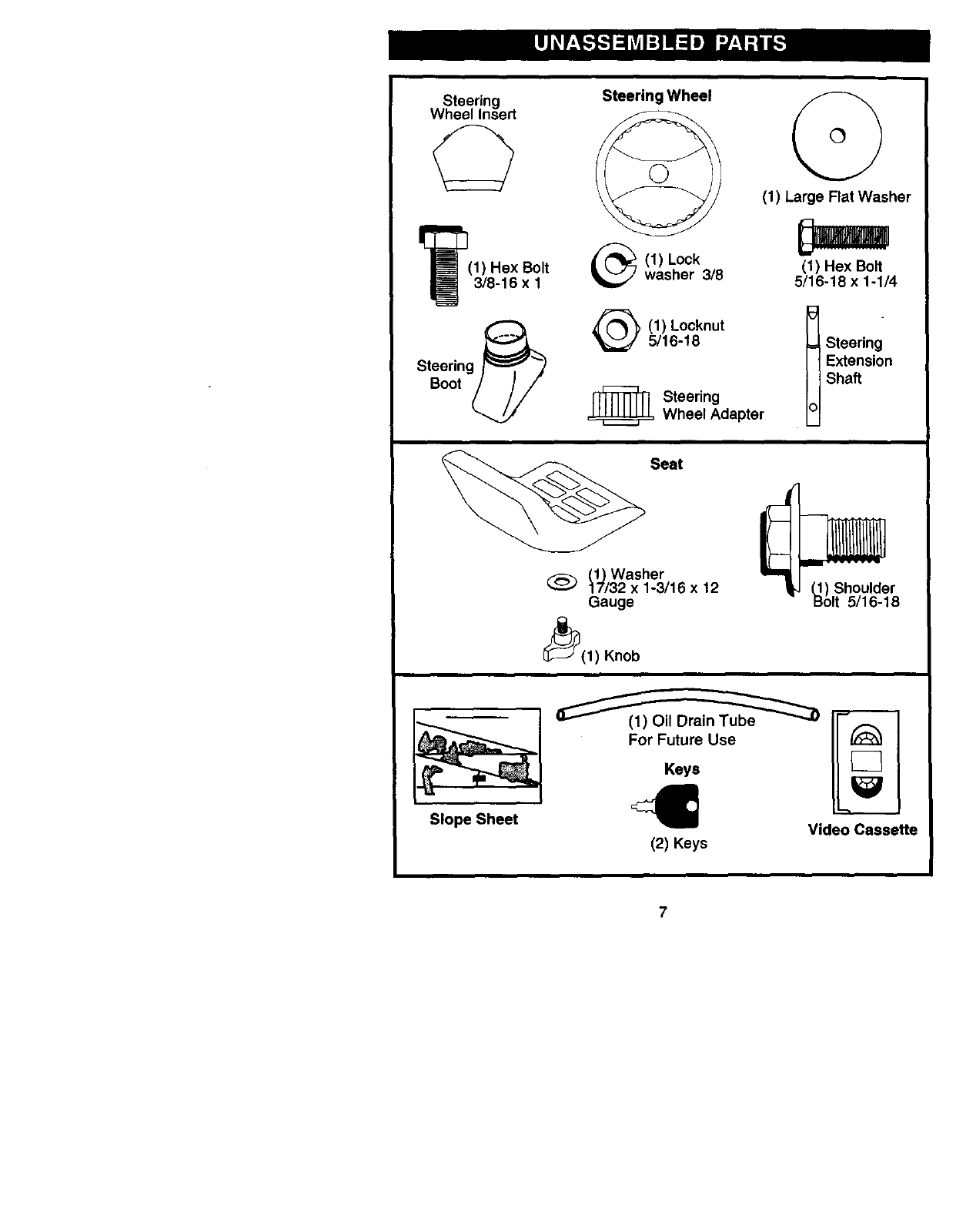
Steering
Wheel Insert
(1) Hex Bolt
3/8-16 x 1
Steering
Boot
Steering Wheel
(1) Large Flat Washer
_(1) (1) Hex Bolt
Lock
washer 3/8 5/16-18 x 1-1/4
(1) Locknut t
5/16-18 Steering
Extension
Shaft
_= Steering
Wheel Adapter
Seat
(_Washer
17/32 x 1-3/16 x 12
Gauge
_(1) Knob
_) Shoulder
olt 5/16-18
Slope Sheet
For Future Use
Keys
(2) Keys Video Casseffe
7
Your new tractor has been assembled at the factory with exception of those parts left
unassembled for shipping purposes. To ensure safe and proper operation of your
tractor all parts and hardware you assemble must be tightened securely. Use the
correct tools as necessary to insure proper tightness. Review the video cassette before
you begin.
TOOLS REQUIRED FOR
ASSEMBLY
A socket wrench set will make assembly
easier. Standard wrench sizes you need
are listed below.
(1) 9/16"wrench (1) Pliers
(2) 1/2"wrench (1) Utility knife
(1) Tire pressure gauge
When right or left hand is mentioned in
this manual, it means, from your point of
view, when you are in the operating
position (seated behind the steering
wheel).
TO REMOVETRACTOR FROM
CARTON
UNPACK CARTON
1. Remove all accessible loose parts
and parts cartons from carton.
2. Cut, from top to bottom, along lines on
all four comers of carton, and lay
panels flat.
3. Check for any additional loose parts
or cartons and remove.
BEFORE REMOVINGTRACTOR
FROM SKID
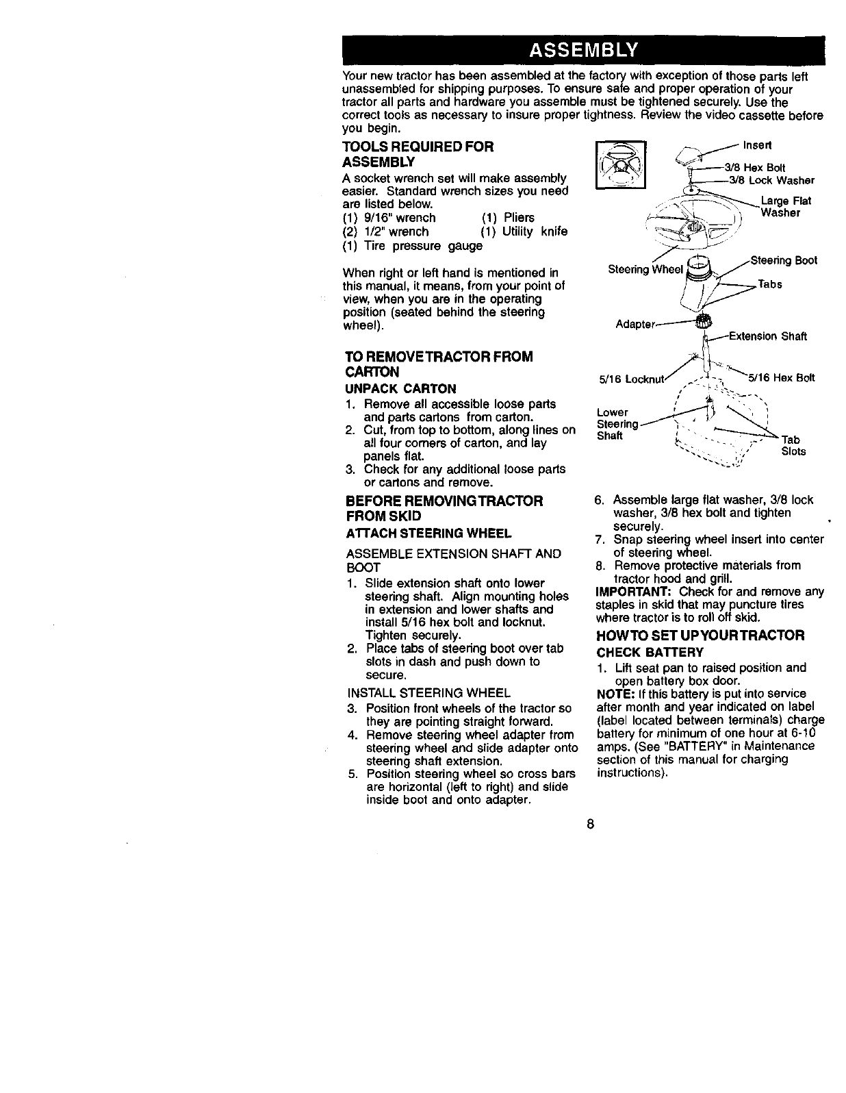
ATTACH STEERING WHEEL
ASSEMBLE EXTENSION SHAFT AND
BOOT
1. Slide extension shaft onto lower
steering shaft. Align mounting holes
in extension and lower shafts and
install 5/16 hex bolt and Iocknut.
Tighten securely.
2. Place tabs of steering boot over tab
slots in dash and push down to
secure.
INSTALL STEERING WHEEL
3. Position front wheels of the tractor so
they are pointing straight forward.
4. Remove steering wheel adapter from
steering wheel and slide adapter onto
steering shaft extension.
5. Position steering wheel so cross bars
are horizontal (left to right) and slide
inside boot and onto adapter.
,nss.
_/_3/8 Hex Bolt
_--------3/8 Lock Washer
• __Large Flat
_ ii Washer
Stae.ag Boat
SteeringWheel
_Tabs
Adapter.-----'_
_ _Extension Shaft
5/16 Locknut ._,"_5/16 Hex Bolt
Lower _'_ '
Steering , •
Shaft _ " Tab
_L:_-_ ,/_" Slots
6. Assemble large flat washer, 3/8 lock
washer, 3/8 hex bolt and tighten
securely.
7. Snap steering wheel insert into center
of steering wheel.
8. Remove protective materials from
tractor hood and grill.
IMPORTANT: Check for and remove any
staples in skid that may puncture tires
where tractor is to roll off skid.
HOWTO SET UPYOURTRACTOR
CHECK BATTERY
1. Lift seat pan to raised position and
open battery box door.
NOTE; If this battery is put into service
after month and year indicated on label
(label located between terminals) charge
battery for minimum of one hour at 6-10
amps. (See "BATTERY" in Maintenance
section of this manual for charging
instructions).
8
Battery
Door
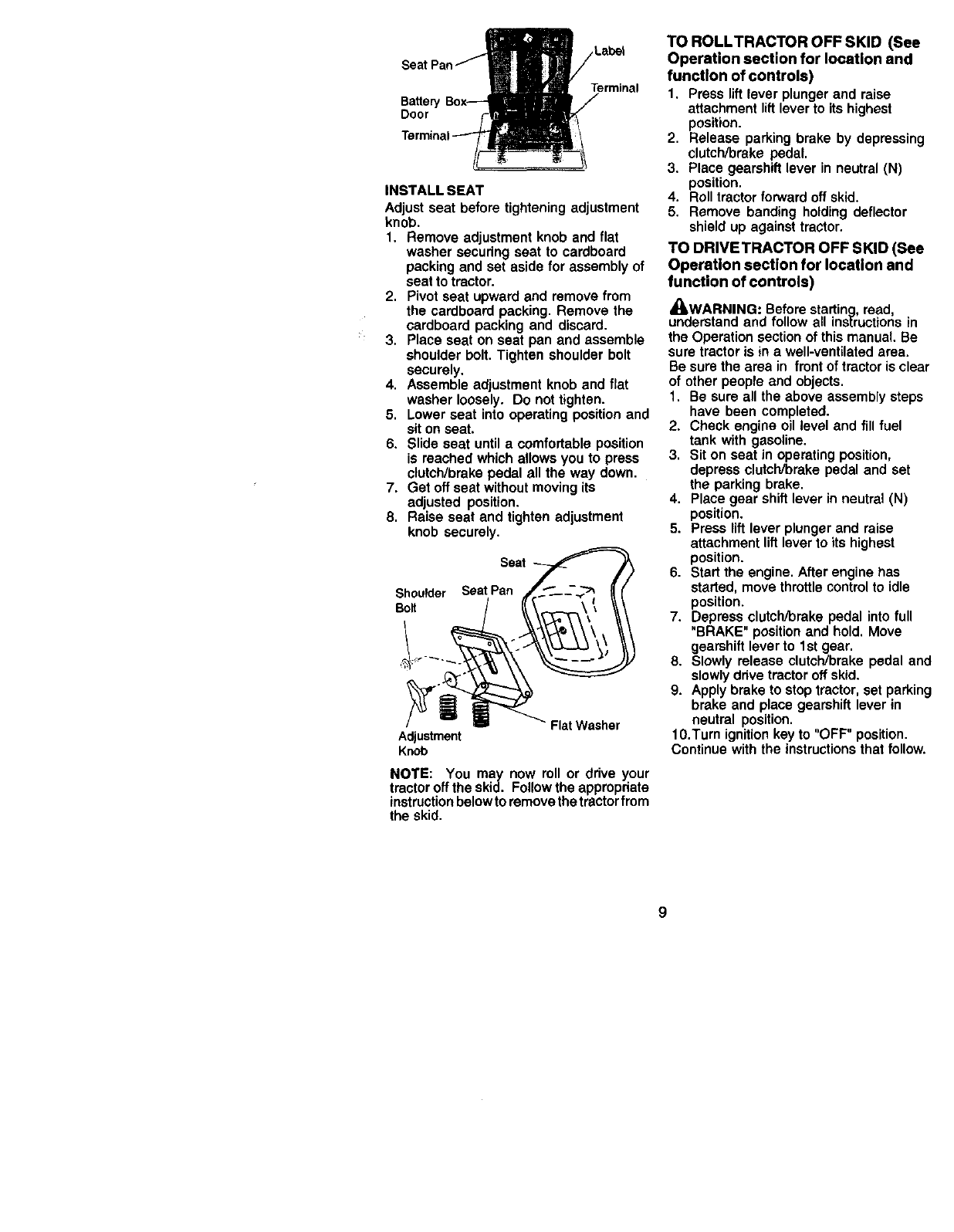
INSTALL SEAT
Adjust seat before tightening adjustment
knob.
1. Remove adjustment knob and flat
washer secudng seat to cardboard
packing and set aside for assembly of
seat to tractor.
2. Pivot seat upward and remove from
the cardboard packing. Remove the
cardboard packing and discard.
3. Place seat on seat pan and assemble
shoulder bolt. Tighten shoulder bolt
securely.
4. Assemble adjustment knob and flat
washer loosely. Do not tighten.
5. Lower seat into operating position and
sit on seat.
6. Slide seat until a comfortable position
is reached which allows you to press
clutch/brake pedal all the way down.
7. Get off seat without moving its
adjusted position.
8. Raise seat and tighten adjustment
knob securely.
Seat
Shoulder SeatPan
Bolt
Flat Washer
Adjustment
Knob
NOTE: You may now roll or ddve your
tractor off the skid. Follow the appropriate
instruction below to remove thetractor from
the skid.
TO ROLLTRACTOR OFF SKID (See
Operation section for location and
function of controls)
1. Press lift lever plunger and raise
attachment liftlever to its highest
position.
2. Release parking brake by depressing
clutch/brake pedal.
3. Place gearshift lever in neutral (N)
position,
4. Roll tractor forward off skid.
5. Remove banding holding deflector
shield up against tractor.
TO DRIVETRACTOR OFF SKID (See
Operation section for location and
function of controls)
_WARNING: Before starting, read,
understand and follow all ins[ructions in
the Operation section of this manual. Be
sure tractor is in a well-ventilated area.
Be sure the area in front of tractor is clear
of other people and objects.
1, Be sure all the above assembly steps
have been completed.
2. Check engine oil level and fill fuel
tank with gasoline.
3. Sit on seat in operating position,
depress clutch/brake pedal and set
the parking brake.
4. Place gear shift lever in neutral (N)
position.
5. Press lift lever plunger and raise
attachment lift lever to its highest
position.
6. Start the engine. After engine has
started, move throttle control to idle
position.
7. Depress clutch/brake pedal into full
"BRAKE" position and hold. Move
gearshift lever to 1st gear.
8. Slowly release clutch/brake pedal and
slowly drive tractor off skid.
9. Apply brake to stop tractor, set parking
brake and place gearshift lever in
neutral position.
10.Turn ignition key to "OFF" position.
Continue with the instructions that follow.
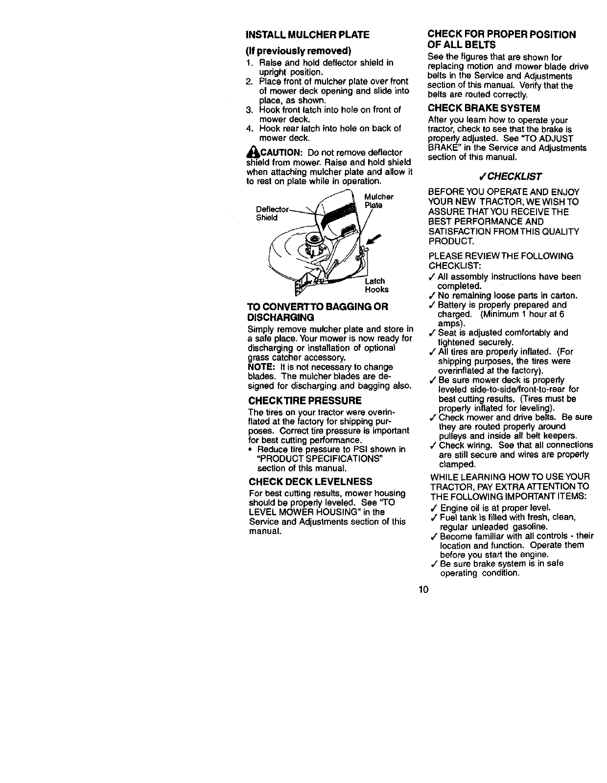
INSTALL MULCHER PLATE
(If previously removed)
1. Raise and hold deflector shield in
upright position.
2. Place front of muleher plate over front
of mower deck opening and slide into
place, as shown.
3. Hook front latch into hole on front of
mower deck.
4. Hook rear latch into hole on back of
mower deck.
_CAUTION: Do not remove deflector
shield from mower. Raise and hold shield
when attaching mulcher plate and allow it
to rest on plate while in operation.
Deflector_
Shield
Mulcher
P_e
Latch
Hooks
TO CONVERTTO BAGGING OR
DISCHARGING
Simplyremove mulcherplate and storein
a safe place.Yourmoweris nowreadyfor
dischargingor installationof optional
grasscatcheraccessory.
NOTE: It is notnecessaryto change
blades. The mulcherblades are de-
signedfor dischargingand baggingalso.
CHECKTIRE PRESSURE
The tires on your tractor were overin-
flared at the factory for shipping pur-
poses. Correct tire pressure is important
for best cutting performance.
• Reduce tire pressure to PSI shown in
=PRODUCT SPECIFICATIONS"
section of this manual.
CHECK DECK LEVELNESS
For best cuttingresults,mowerhousing
shouldbe properlyleveled. See "TO
LEVEL MOWER HOUSING" inthe
Serviceand Adjustmentssectionof this
manual.
CHECK FOR PROPER POSITION
OF ALL BELTS
Bee the figures that are shown for
replacing motion and mower blade drive
belts in the Service and Adjustments
section of this manual. Verify that the
belts are routed correctly.
CHECK BRAKE SYSTEM
After you learn how to operate your
tractor, check to see that the brake is
properly adjusted. See "TO ADJUST
BRAKE" in the Service and Adjustments
section of this manual,
/CHECKLIST
BEFORE YOU OPERATE AND ENJOY
YOUR NEW TRACTOR, WE WISH TO
ASSURE THAT YOU RECEIVE THE
BEST PERFORMANCE AND
SATISFACTION FROM THIS QUALITY
PRODUCT.
PLEASE REVIEWTHE FOLLOWING
CHECKLIST:
,/All assembly instructions have been
completed.
,/No remaining loose parts in carton.
,/Battery is properly prepared and
charged. (Minimum 1 hour at 6
amps).
,/Seat is adjusted comfortably and
tightened securely.
,/All tires are properly inflated. (For
shipping purposes, the tires were
overinflated at the factory).
/Be sure mower deck is properly
leveled side-to-side/front-to-rear for
best cutting results. (Tires must be
properly inflated for leveling).
,/Check mower and drive belts. Be sure
they are routed propedy around
pulleys and inside all belt keepers.
,/Check wiring. See that all connections
are still secure and wires are properly
clamped.
WHILE LEARNING HOWTO USE YOUR
TRACTOR, PAY EXTRA ATTENTION TO
THE FOLLOWING IMPORTANT ITEMS:
/Engine oil is at proper level.
/Fuel tank is filled with fresh, clean,
regular unleaded gasoline.
,/Become familiar with all controls - their
location and function. Operate them
before you start the engine.
,/Be sure brake system is in safe
operating condition.
10
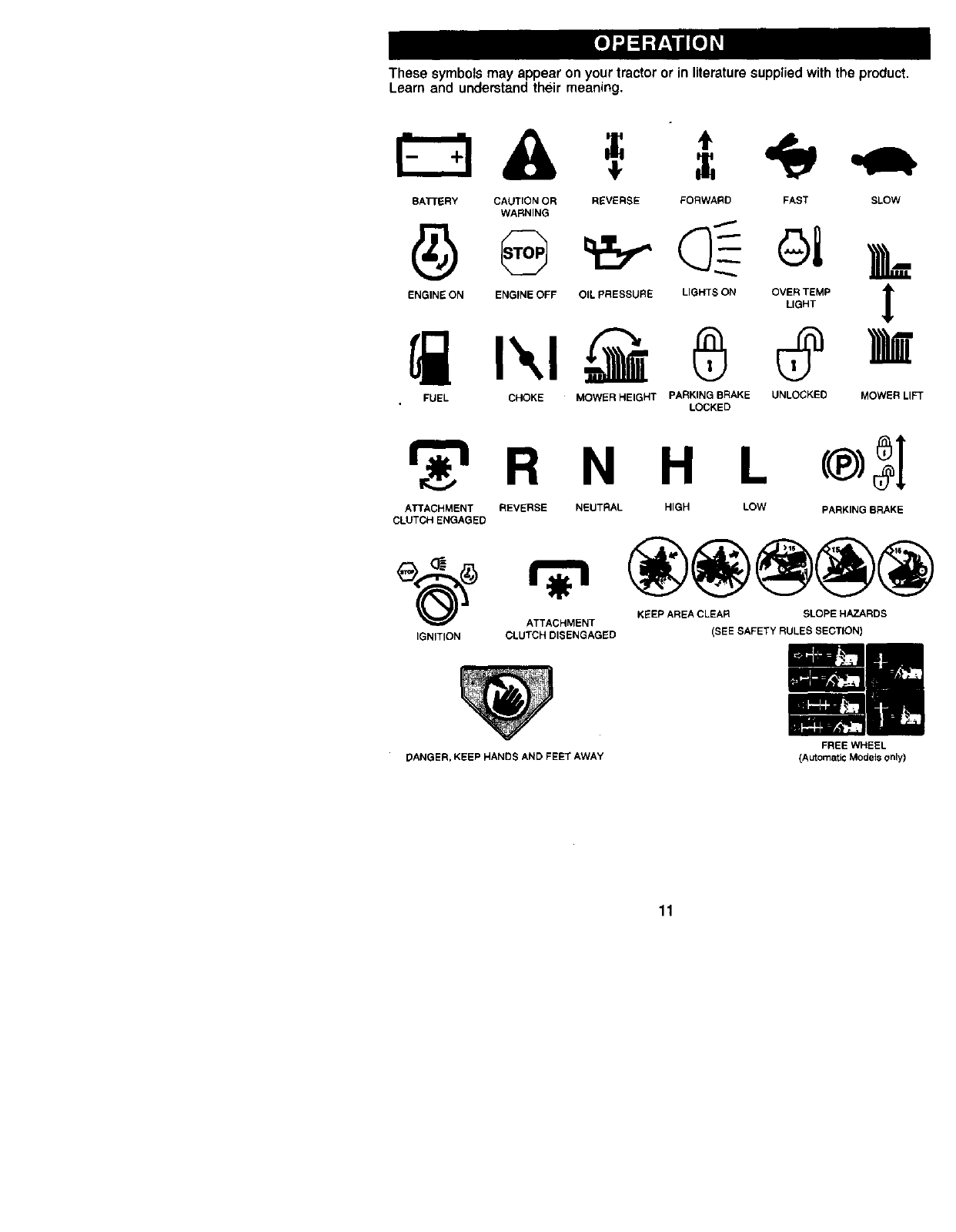
Thesesymbolsmay appear onyour tractoror in literaturesuppliedwiththe product.
Learn and understandtheir meaning.
BA'FrERY CAUTION OR
WARNING
ENGINE ON ENGINE OFF
REVERSE FORWARD FAST SLOW
FUEL CHOKE
A
OIL PRESSURE LIGHTS ON OVER TEMP lr
LIGHT
MOWER HEIGHT PARKING BRAKE UNLOCKEC MOWER LIFT
LOCKED
R N H L
ATTACHMENT REVERSE NEUTRAL HIGH LOW FARKING BRAKE
CLUTCH ENGAGED
KEEP AREA CLEAR SLOPE HAZARDS
ATTACHMENT
IGNITION CLUTCH DISENGAGED (SEE SAFETY RULES SECTION)
DANGER, KEEP HANDS AND FEET AWAY
11
FREE WHEEL
(Automatic Models only)
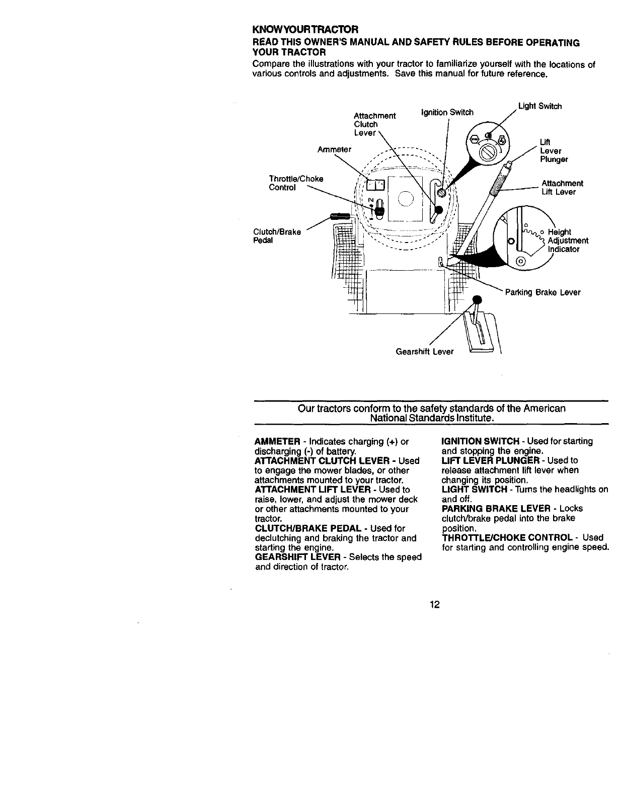
KNOWYOURTRACTOR
READ THIS OWNER'S MANUAL AND SAFETY RULES BEFORE OPERATING
YOUR TRACTOR
Comparethe illustrationswithyour tractorto familiarizeyourselfwiththe locationsof
variouscontrolsandadjustments. Save thismanualforfuture reference.
Light Switch
Attachment Ignition Switch
Clutch
Lift
Ammeter
Plunger
Throttle/Choke Attachment
Control _ Lift Lever
C{utch/Brake Height
Pedal Adjustment
Indicator
Parking Brake Lever
Gearshift Lever
Our tractors conform to the safety standards of the American
National Standards Institute.
AMMETER - Indicates charging (+) or
discharging (-) of battery.
A'rrACHMENT CLUTCH LEVER -Used
to engage the mower blades, or other
attachments mounted to your tractor.
ATTACHMENT UFT LEVER -Used to
raise, lower, and adjust the mower deck
or other attachments mounted to your
tractor.
CLUTCWBRAKE PEDAL -Used for
declutching and braking the tractor and
starting the engine.
GEARSHIFT LEVER -Selects the speed
and direction of tractor.
IGNITION SWITCH - Used for starting
and stopping the engine.
LIFT LEVER PLUNGER -Used to
release attachment lift lever when
changing its position.
LIGHT SWITCH -Turns the headlights on
and off.
PARKING BRAKE LEVER -Locks
clutch/brake pedal into the brake
position.
THROTTLE/CHOKE CONTROL -Used
for starting and controlling engine speed.
12
The operation of any tractor can result in foreign objects thrown into
the eyes, which can result in severs eye damage. Always wear safety
glasses or eye shields while operating your tractor or performing any
adjustments or repairs. We recommend a wide vision safety mask
over spectacles or standard safety glasses.
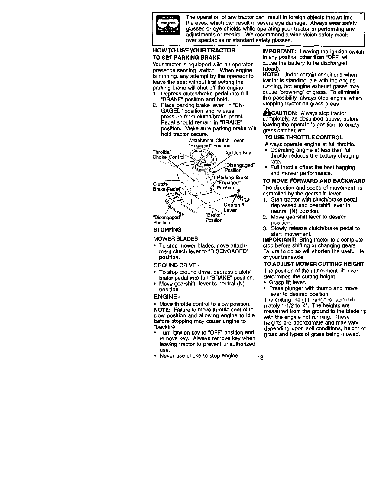
HOWTO USEYOURTRACTOR
TO SET PARKING BRAKE
Your tractor is equipped with an operator
presence sensing switch. When engine
is running, any attempt by the operator to
leave the seat without first setting the
parking brake will shut off the engine.
1. Depress clutch/brake pedal into full
"BRAKE" position and hold.
2. Place parking brake lever in =EN-
GAGED" position and release
pressure from clutch/brake pedal,
Pedal should remain in "BRAKE"
position. Make sure parking brake will
hold tractor secure.
AttachmentClutch Lever
"Engaged"Position
Throttle/ _ _ Ignition Key
Choke Control_'k\\ /_/'_,\
"_:_,_Disengaged"
"_Enyage "
_'_ f_- Gearshift
D sengeged' _
Position ........
STOPPING
MOWER BLADES -
• To stop mower blades,move attach-
ment clutch lever to =DISENGAGED"
position.
GROUND DRIVE -
•To stop ground drive, depress clutch/
brake pedal into full =BRAKE" position.
•Move gearshift lever to neutral (N)
position.
ENGINE-
• Move throttle control to slow position.
NOTE: Failure to move throttle control to
slow position and allowing engine to idle
before stopping may cause engine to
"backfire".
•Turn ignition key to "OFF" position and
remove key. Always remove key when
leaving tractor to prevent unauthorized
use.
IMPORTANT: Leaving the ignition switch
in any position other than "OFF" will
cause the battery to be discharged,
(dead).
NOTE: Under certain conditions when
tractor is standing idle with the engine
running, hot engine exhaust gases may
cause "browning" of grass. To eliminate
this possibility, always stop engine when
stopping tractor on grass areas.
_CAUTION: Always stop tractor
completely, as described above, before
leaving the operator's position; to empty
grass catcher, etc.
TO USE THRO'n'LE CONTROL
Always operate engine at full throttle.
•Operating engine at less than full
throttle reduces the battery charging
rate.
•Full throttle offers the best bagging
and mower performance.
TO MOVE FORWARD AND BACKWARD
The direction and speed of movement is
contro!led by the gearshift lever.
1. Start tractor with clutch/brake pedal
depressed and gearshift lever in
neutral (N) position.
2. Move gearshift lever to desired
position.
3. Slowly release clutch/brake pedal to
start movement.
IMPORTANT: Bring tractor to a complete
stop before shifting or changing gears.
Failure to do so will shorten the useful life
of your transaxle.
TO ADJUST MOWER CUTTING HEIGHT
The position of the attachment lift lever
determines the cutting height.
•Grasp lift lever.
•Press plunger with thumb and move
lever to desired position.
The cutting height range is approxi-
mately 1-1/2 to 4". The heights are
measured from the ground to the blade tip
with the engine not running. These
heights are approximate and may vary
depending upon soil conditions, height of
grass and types of grass being mowed.
•Never use choke to stop engine. 13
•The average lawn should be cut to
approximately 2-1/2 inches during the
cool season and to over 3 inches
during hot months. For healthier and
better looking lawns, mow often and
after moderate growth.
•For best cutting performance, grass
over 6 inches in height should be
mowed twice. Make the first cut
relatively high; the second to desired
height.
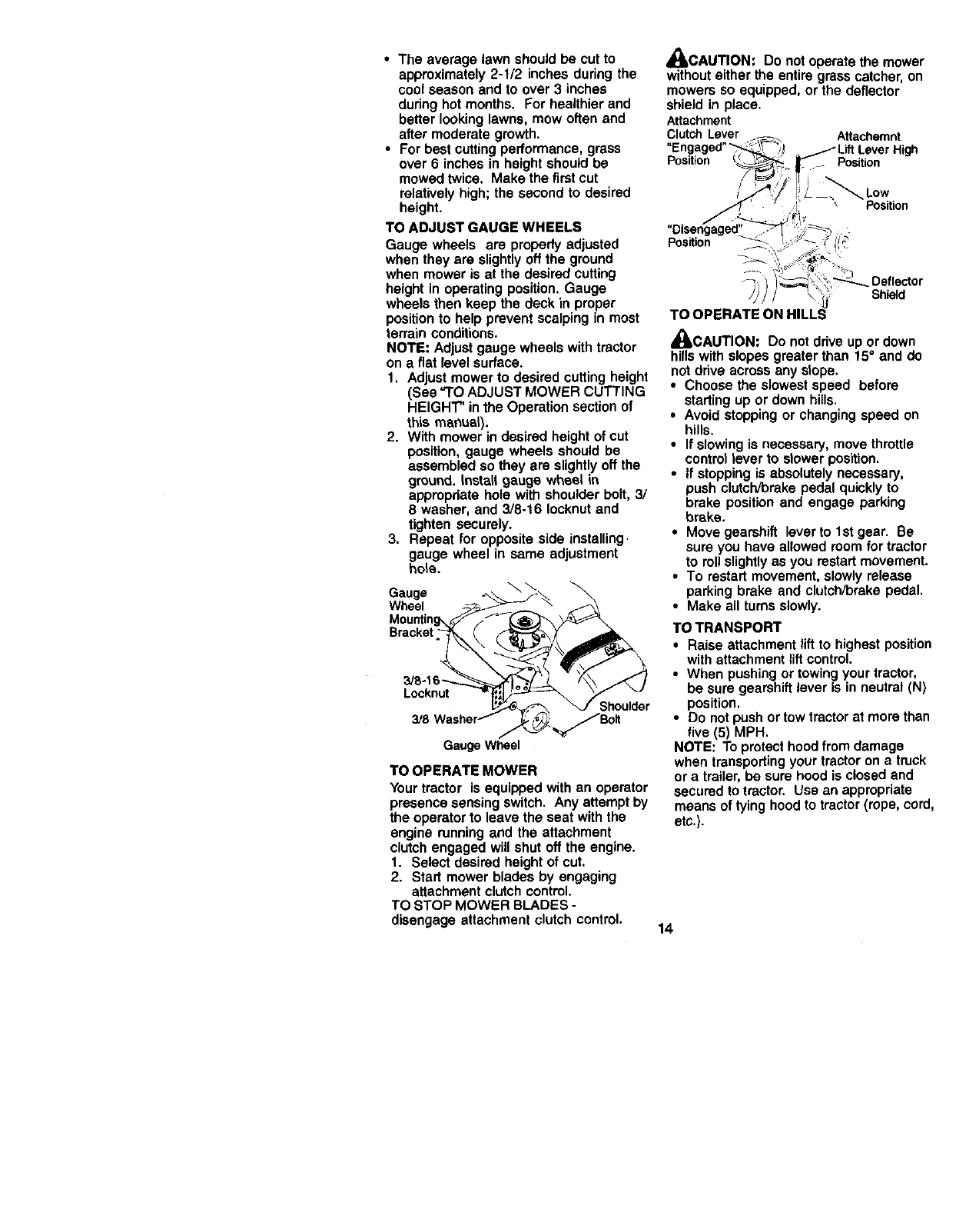
TO ADJUST GAUGE WHEELS
Gauge wheels are properly adjusted
when they are slightly off the ground
when mower is at the desired cutting
height in operating position. Gauge
wheels then keep the deck in proper
position to help prevent scalping in most
terrain conditions.
NOTE: Adjust gauge wheels with tractor
on a flat level surface.
1. Adjust mower to desired cutting height
(See "TO ADJUST MOWER CUTTING
HEIGHT" in the Operation section of
this manual).
2. With mower in desired height of cut
position, gauge wheels should be
assembled so they are slightly off the
ground. Install gauge wheel in
appropdate hole with shoulder bolt, 3/
8 washer, and 3/8-16 Iocknut and
tighten securely.
3. Repeat for opposite side installing.
gauge wheel in same adjustment
hole.
Gauge o...\ _ _.
Wheel __-___.. _ _
Mountin_/f_-_
o
_B-_6_I_L_. _\\ _K /
Locknut _=_houlder
Gauge Wheel
TO OPERATE MOWER
Your tractor is equipped with an operator
presence sensing switch. Any attempt by
the operator to leave the seat with the
engine running and the attachment
clutch engaged will shut off the engine.
1. Select desired height of cut.
2. Start mower blades by engaging
attachment clutch control.
TO STOP MOWER BLADES -
disengage attachment clutch control,
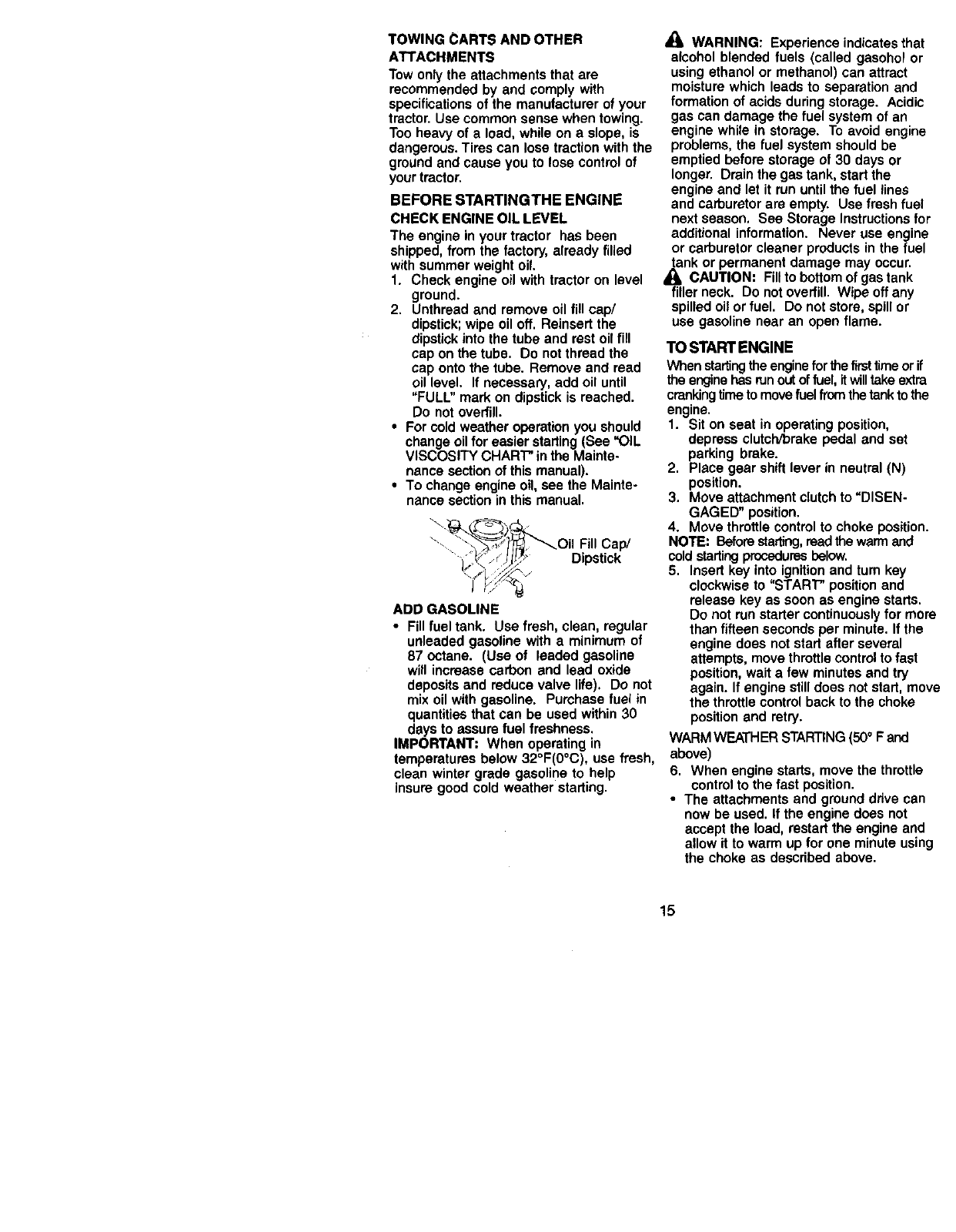
_CAUTION: Do not operate the mower
without either the entire grass catcher, on
mowers so equipped, or the deflector
shield in place.
Attachment
Clutch Lever Attachemnt
Position Position
/'Position
Position
Deflector
Shield
TO OPERATE ON HILLS
_CAUTION: Do not drive up or down
hills with slopes greeter than 15°and do
not drive across any slope.
•Choose the slowest speed before
starting up or down hills.
•Avoid stopping or changing speed on
hills.
•If slowing is necessary, move throttle
control lever to slower position.
•If stopping is absolutely necessary,
push clutclVorake pedal quickly to
brake position and engage parking
brake,
•Move gearshift lever to 1st gear. Be
sure you have allowed room for tractor
to roll slightly as you restart movement.
•To restart movement, slowly release
parking brake and clutch/brake pedal.
• Make all turns slowly.
TO TRANSPORT
•Raise attachment lift to highest position
with attachment liftcontrol.
•When pushing or towing your tractor,
be sure gearshift lever is in neutral (N)
position.
•Do not push or tow tractor at more than
five (5) MPH.
NOTE: To protect hood from damage
when transporting your tractor on a truck
or a trailer, be sure hood is closed and
secured to tractor. Use an appropriate
means of tying hood to tractor (rope, cord,
etc.).
14
TOWING CARTS AND OTHER
ATTACHMENTS
Tow only the attachments that are
recommended by and comply with
specifications of the manufacturer of your
tractor. Use common sense when towing.
Too heavy of a load, while on a slope, is
dangerous. Tires can lose traction with the
ground and cause you to lose control of
your tractor.
BEFORE STARTINGTHE ENGINE
CHECK ENGINE OIL LEVEL
The engine in your tractor has been
shipped, from the factory, already filled
with summer weight oil.
1. Check engine oil with tractor on level
ground.
2. Unthread and remove oil fill cap/
dipstick; wipe oil off. Reinsert the
dipstick into the tube and rest oil fill
cap on the tube. Do not thread the
cap onto the tube. Remove and read
oil level. If necessary, add oil until
"FULL" mark on dipstick is reached.
Do not overfill.
• For cold weather operation you should
change oil for easier starting (See "OIL
VISCOSITY CHART" in the Mainte-
nance section of this manual).
•To change engine oil, see the Mainte-
nance section in this manual.
\_ _,_'_ ,_ _Oil Fill Cap/
_-"'_:_ __'Jl/._" Dipstick
ADD GASOLINE
•Fill fuel tank. Use fresh, clean, regular
unleaded gasoline with a minimum of
87 octane. (Use of leaded gasoline
will increase carbon and lead oxide
deposits and reduce valve life). Do not
mix oil with gasoline. Purchase fuel in
quantities that can be used within 30
days to assure fuel freshness.
IMPORTANT: When operating in
temperatures below 32°F(0°C), use fresh,
clean winter grade gasoline to help
insure good cold weather starting.
A(_ WARNING: Experience indicates that
alcohol blended fuels (called gasohol or
using ethanol or methanol) can attract
moisture which leads to separation and
formation of acids during storage. Acidic
gas can damage the fuel system of an
engine while in storage. To avoid engine
problems, the fuel system should be
emptied before storage of 30 days or
longer. Drain the gas tank, start the
engine and let it run until the fuel lines
and carburetor are empty. Use fresh fuel
next season. See Storage Instructions for
additional information. Never use engine
or carburetor cleaner products in the fuel
tank or permanent damage may occur.
/1= CAUTION: Fill to bottom of gas tank
filler neck. Do not overfill. Wipe off any
spilled oil or fuel. Do not store, spill or
use gasoline near an open flame.
TO START ENGINE
When startingthe engine for_firsttime or if
the engine has run out of fuel, itwill take extra
crankingtime to move fuel from the tank to the
engine.
1. Sit on seat in operating position,
depress clutch/brake pedal and set
parking brake.
2. Place gear shift lever in neutral (N)
position.
3. Move attachment clutch to =DISEN-
GAGED" position.
4. Move throttle control to choke position.
NOTE: Before starting,read the warm and
cold startingprocedures below.
5. Insert key into ignition and tum key
clockwise to "START" position and
release key as soon as engine starts.
Do not run starter continuously for more
than fifteen seconds per minute. If the
engine does not starf after several
attempts, move throttle control to fast
position, wait a few minutes and try
again. If engine still does not starl, move
the throttle control back to the choke
position and retry.
WARM WEATHER STARTING (500 F and
above)
6. When engine starts, move the throttle
control to the fast position.
•The attachments and ground drive can
now be used. If the engine does not
accept the load, restart the engine and
allow it to warm up for one minute using
the choke as described above.
15
COLD WEATHER STARTING (50° Fand
below)
6. When engine starts, allow engine to
run with the throttle control in the
choke position until the engine runs
roughly, then move throttle control to
fast position. This may require an
engine warm-up period from several
seconds to several minutes, depend-
ing on the temperature.
•The attachments can also be used
dudng the engine warm-up period.
NOTE= If at ahigh altitude(above3000 feet)
or in cold temperatures(below 32 F) the
carburetorfuel mixturemay need to be
adjustedfor best engine performance. See
"TO ADJUST CARBURETOR" in the Service
and Adjustmentssectionof this manual.
MOWlNGTIPS
• Mower should be propedy leveled for
best mowing performance. See "TO
LEVEL MOWER HOUSING" in the
Service and Adjustments section of this
manual.
• The left hand side of mower should be
used for trimming.
•Ddve so that clippings are discharged
onto the area that has been cut. Have
the cut area to the dght of the tractor.
This will result in a more even distribu-
tion of clippings and more uniform
cutting.
•When mowing large areas, start by
turning to the right so that clippings will
discharge away from shrubs, fences,
driveways, etc. After one or two
rounds, mow in the opposite direction
making left hand turns until finished.
•If grass is extremely tall, it should be
mowed twice to reduce load and
possible fire hazard from dried
clippings. Make first cut relatively high;
the second to.the desired height.
•Do not mow grass when it is wet. Wet
grass will plug mower and leave
undesirable clumps. Allow grass to dry
before mowing.
•Always operate engine at full throttle
when mowing to assure better mowing
performance and propel'discharge of
material. Regulate ground speed by
selecting a low enough gear to give the
mower cutting performance as well as
the quality of cut desired.
•When operating attachments, select a
ground speed that will suit the terrain
and give best performance of the
attachment being used.
16
MULCHING MOWINGTIPS
IMPORTANT: For best performance,
keep mower housing free of built-up
grass and trash. Clean after each use.
•The special mulching blade will recur
the grass clippings many times and
reduce them in size so that as they fall
onto the lawn they will disperse into
the grass and not be noticed. Also, the
mulched grass will biodegrade quickly
to provide nutrients for the lawn.
Always mulch with your highest
engine (blade) speed as this will
provide the best recutting action of the
blades.
•Avoid cutting your lawn when it is wet.
Wet grass tends to form clumps and
interferes with the mulching action.
The best time to mow your lawn is the
eady afternoon. At this time the grass
has dded and the newly cut area will
not be exposed to the direct sun.
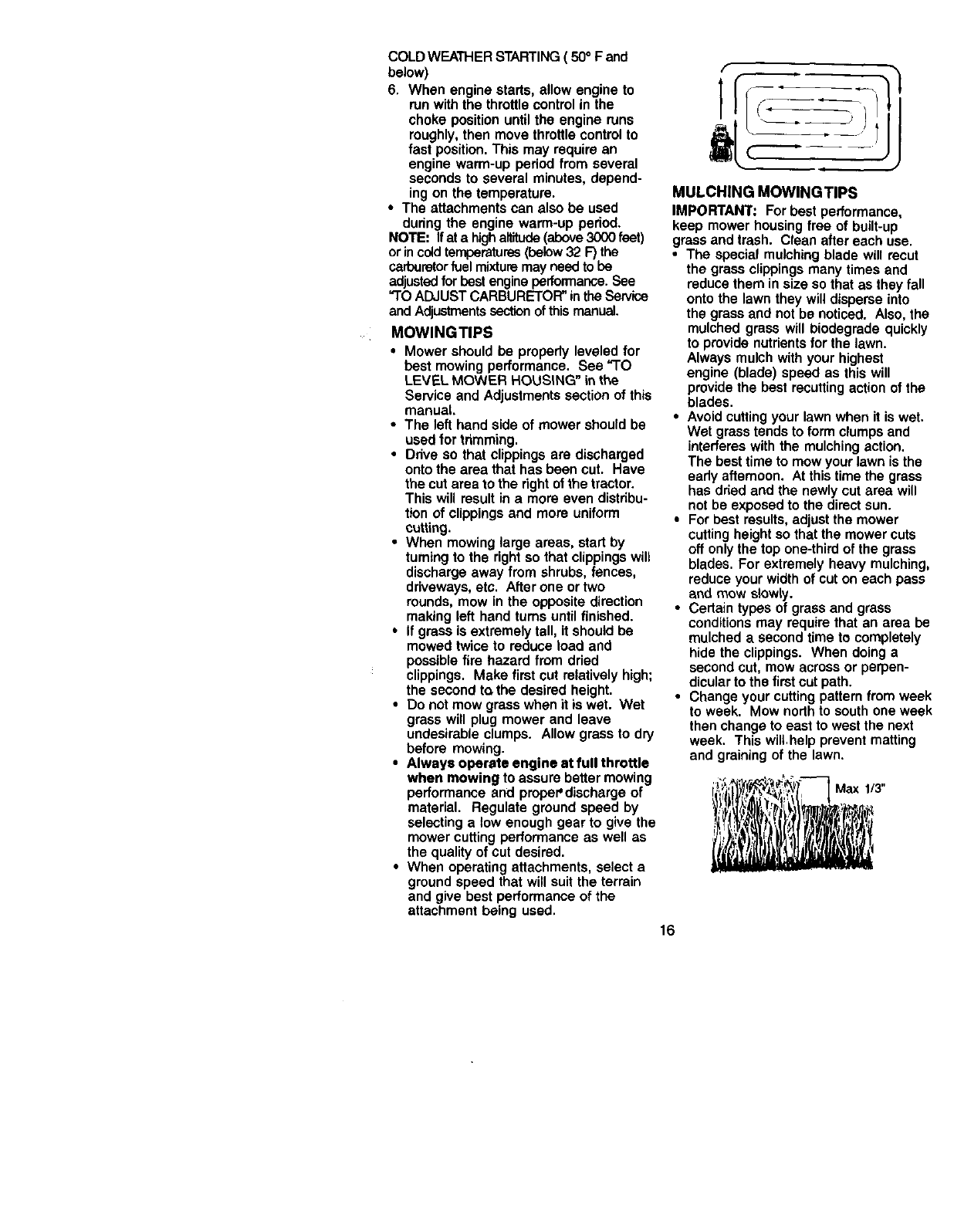
•For best results, adjust the mower
cutting height so that the mower cuts
off only the top one-third of the grass
blades. For extremely heavy mulching,
reduce your width of cut on each pass
and mow s_owly.
• Certain types of grass and grass
conditions may require that an area be
mulched a second time to completely
hide the clippings. When doing a
second cut, mow across or perpen-
dicular to the first cut path.
•Change your cutting pattern from week
to week. Mow north to south one week
then change to east to west the next
week. Thiswill help prevent matting
and graining of the lawn.
Max 1/3"
AS YOU COMPLETE
REGULAR SERVICE
CheCk Brake Operation _
Check Tire Pressure I_
Check Operator Presence and
_i Interlock Systems
Check for Loose Fasteners _I_;' (1_
Sharpen/ReplaCe Mower 8redes _4
0TI Lubrication Chart _ I_
CheCk Battery Level 1_6
RClean Batlery and Terminals I_ tl_
CheCk Transa.xle COOling _1_
Adjusl Blade Bell(a) Tension tills
Adjust Motion Drive Belt(s) Tension I_ _sCheCk Engine Oil Level I_
Change Engine OH (l_t2,3
BE Clean Air Filler t_lz
CleSn Air Screen (I_2
G Inspsct Muffler/Spark A[Tester _1_
Replace Oil Filter (_f equipped) i _2
NClean Engine Cooling Fir,s 1_2
Beq_ce Spark Plug _I_
Replace Nr Filter Paper Cartridge 11_2
Replace Fuel Flge( i# #
I- Ctumge morl of_n wh_'_ opet&fir_ u_r a h_lw k_ o_In Ngh =a't_t _ 5 - II e,_R_Kf wlth =d_lobdd_ _,
2. _r,4c= morn o/ten _Qoeratlng I.__dy ot du=ly oor,dlt_nl= 6. Not r_4 if equlppod wlh r_adt_,mmc=-hN b=_ry
3. II _lulppad w,th o¢filer, d_ane= oil _ve=7 f_0he.Jr= 7* Tl_m Iront ixle pivol b_t _e_ f_-Ibe. rm_xir,.,um
4. R_p/_ce b_d_= more often W_ mowing I_ =4._dy =oil. DO rot o_fflghten
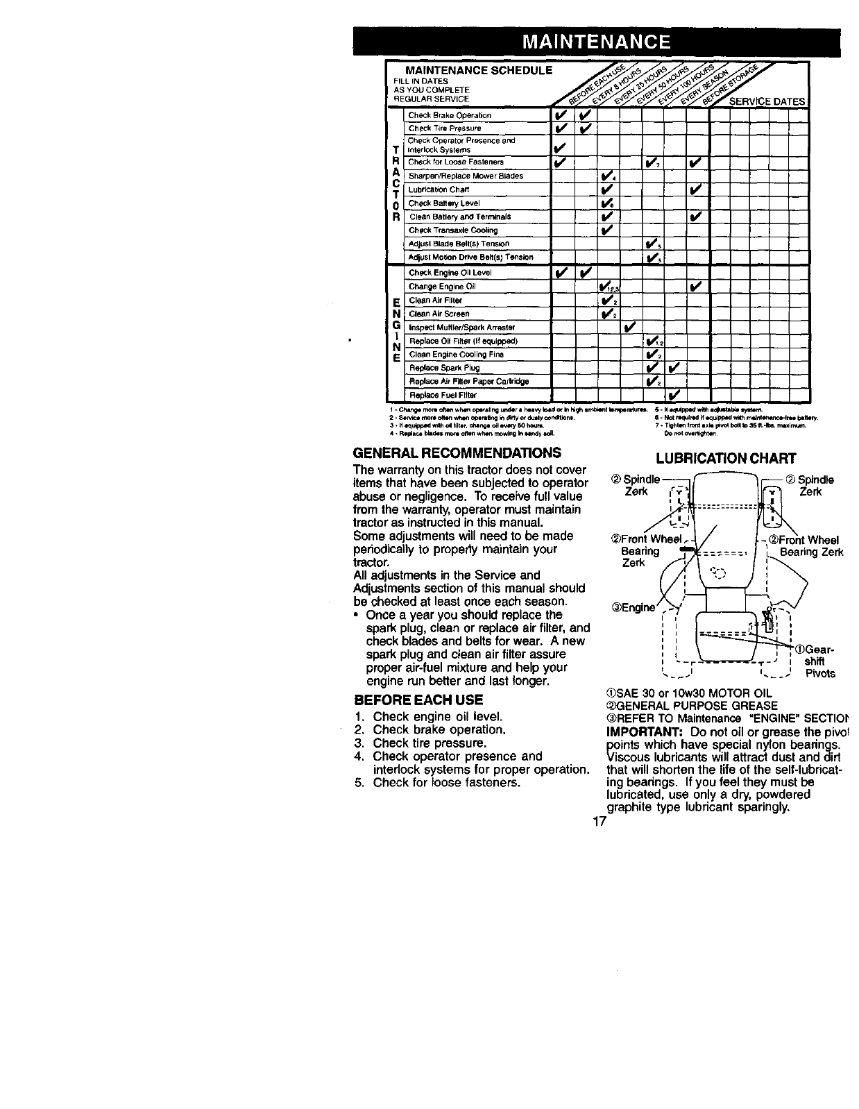
GENERAL RECOMMENDATIONS
The warranty on this tractor does not cover
items that have been subjected to operator
abuse or negligence. To receive full value
from the warranty, operator must maintain
tractor as instructed in this manual.
Some adjustments will need to be made
periodically to properly maintain your
tractor.
All adjustments in the Service and
Adjustments section of this manual should
be checked at least once each season.
•Once ayear you should replace the
spark plug, clean or replace air filter, and
check blades and belts for wear. Anew
spark plug and clean air filter assure
proper air-fuel mixture and help your
engine run better and last longer.
BEFORE EACH USE
1. Check engine oil level.
2. Check brake operation.
3. Check tire pressure.
4. Check operator presence and
interlock systems for proper operation.
5. Check for loose fasteners.
LUBRICATION CHART
-L_Spindle
Zerk Zerk
_Front Wheel
Beedng Bearing Zerk
Zerk
_Engine _
I
I I
_SAE 30 or 10w30 MOTOR OIL
_,_)GENERALPURPOSE GREASE
_>REFERTO Maintenance "ENGINE" SECTIOI_
IMPORTANT: Do not oil or grease the pivot
_/oints which have special nylon bearings.
scous lubricants will attract dust and did
that will shorten the life of the self-lubricat-
ing bearings. If you feel they must be
lubricated, use only a dry, powdered
graphite type lubricant sparingly.
17
TRACTOR
Always observe safety rules when
performing any maintenance.
BRAKE OPERATION
If tractor requires more than six (6) feet
stopping distance at high speed in
highest gear, then brake must be ad-
justed. (See "TO ADJUST BRAKE" in the
Service and Adjustments section of this
manual).
TIRES
• Maintain proper air pressure in all tires
(See "PRODUCT SPECIFICATIONS"
section of this manual).
•Keep tires free of gasoline, oil, or insect
control chemicals which can harm
rubber.
•Avoid stumps, stones, deep ruts, sharp
objects and other hazards that may
cause tire damage.
NOTE: To seal tire punctures and prevent
flat tires due to slow leaks, tire sealant
may be purchased from your local parts
dealer. Tire sealant also prevents tire dry
rot and corrosion.
OPERATOR PRESENCE SYSTEM
Be sure operator presence and interlock
systems are working properly. If your
tractor does not function as described,
repair the problem immediately.
•The engine should not start unless the
clutch/brake pedal is fully depressed
and attachment clutch control is in the
disengaged position.
•When the engine is running, any
attempt by the operator to leave the
seat without first setting the parking
brake should shut off the engine.
•When the engine is running and the
attachment clutch is engaged, any
attempt by the operator to leave the
seat should shut off the engine.
•The attachment clutch should never
operate unless the operator is in the
seat.
BLADE CARE
For best results mower blades must be
kept sharp. Replace bent or damaged
blades.
BLADE REMOVAL
1. Raise mower to highest position to
allow access to blades.
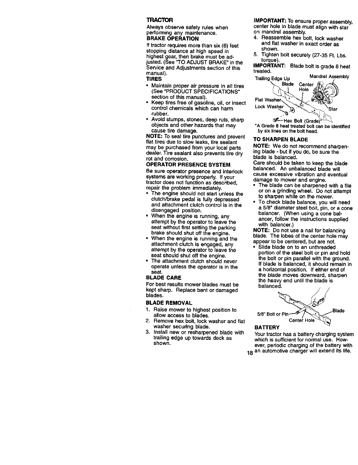
2. Remove hex bolt, lock washer and flat
washer secudng blade.
3. Install new or resharpened blade with
trailing edge up towards deck as
shown.
IMPORTANT: To ensure proper assembly,
center hole in blade must align with star
on mandrel assembly.
4. Reassemble hex bolt, lock washer
and flat washer in exact order as
shown.
5. Tighten bolt securely (27-35 Ft. Lbs.
torque).
IMPORTANT: Blade bolt is grade 8 heat
treated.
TrailingEdge Up Mandrel Assembly
Blade Center
Hole
Lock Washe
_-'-" Hex Bolt
*A Grade 8 heat treatedboltcan be identified
by sixlineson the bolt head.
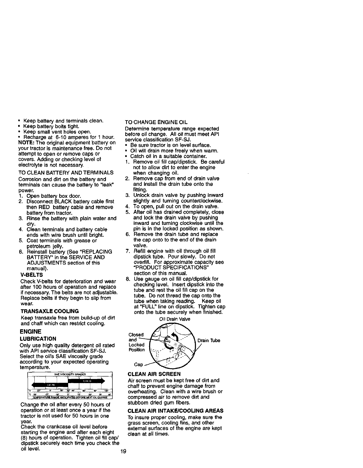
TO SHARPEN BLADE
NOTE: We do not recommend sharpen-
ing blade - but if you do, be sure the
blade is balanced.
Care should be taken to keep the blade
balanced. An unbalanced blade will
cause excessive vibration and eventual
damage to mower and engine.
•The blade can be sharpened with a file
or on agrinding wheel. Do not attempt
to sharpen while on the mower.
•To check blade balance, you will need
a 5/8" diameter steel bolt, pin, or a cone
balancer. (When using a cone bal-
ancer, follow the instructions supplied
with balancer.)
NOTE: Do not use a nail for balancing
blade. The lobes of the center hole may
appear to be centered, but are not.
•Slide blade on to an unthreaded
portion of the steel bolt or pin and hold
the bolt or pin parallel with the ground.
If blade is balanced, it should remain in
ahorizontal position. If either end of
the blade moves downward, sharpen
the heavy end until the blade is
balanced.
ade
5/8"Boltor Pin---'_[,.'_,_,-_._._
BATTERY
Your tractor has abattery charging system
which is sufficient for normal use. How-
ever, periodic charging of the battery with
18 an automotive charger will extend its life.
•Keep battery and terminals clean.
• Keep battery bolts tight.
•Keep small vent holes open,
•Recharge at 6-10 amperes for 1 hour.
NOTE: The original equipment battery on
your tractor is maintenance free. Do not
attempt to open or remove caps or
covers. Adding or checking level of
electrolyte is not necessary.
TO CLEAN BATTERY AND TERMINALS
Corrosion and dirt on the battery and
terminals can cause the battery to "leak"
power.
1. Open battery box door.
2. Disconnect BLACK battery cable first
then RED battery cable and remove
battery from tractor.
3. Rinse the battery with plain water and
dry.
4. Clean terminals and battery cable
ends with wire brush until bright.
5. Coat terminals with grease or
petroleum jelly.
6. Reinstall battery (See "REPLACING
BATTERY" in the SERVICE AND
ADJUSTMENTS section of this
manual).
V-BELTS
Check V-belts for deterioration and wear
after 100 hours of operation and replace
if necessary. The belts are not adjustable.
Replace belts if they begin to slip from
wear.
TRANSAXLE COOLING
Keep transaxle free from build-up of dirt
and chaff which can restrict cooling,
ENGINE
LUBRICATION
Only use high quality detergent oil rated
with API service classification SF-SJ.
Select the oil's SAE viscosity grade
according to your expected operating
temperature.
t_SAE VISCOSITY GRAOES
Change the oil after every 50 hours of
operation or at least once a year if the
tractor is not used for 50 hours in one
year.
Check the crankcase oil level before
starting the engine and after each eight
(8) hours of operation. Tighten oil fill cap/
dipstick securely each time you check the
oil level. 19
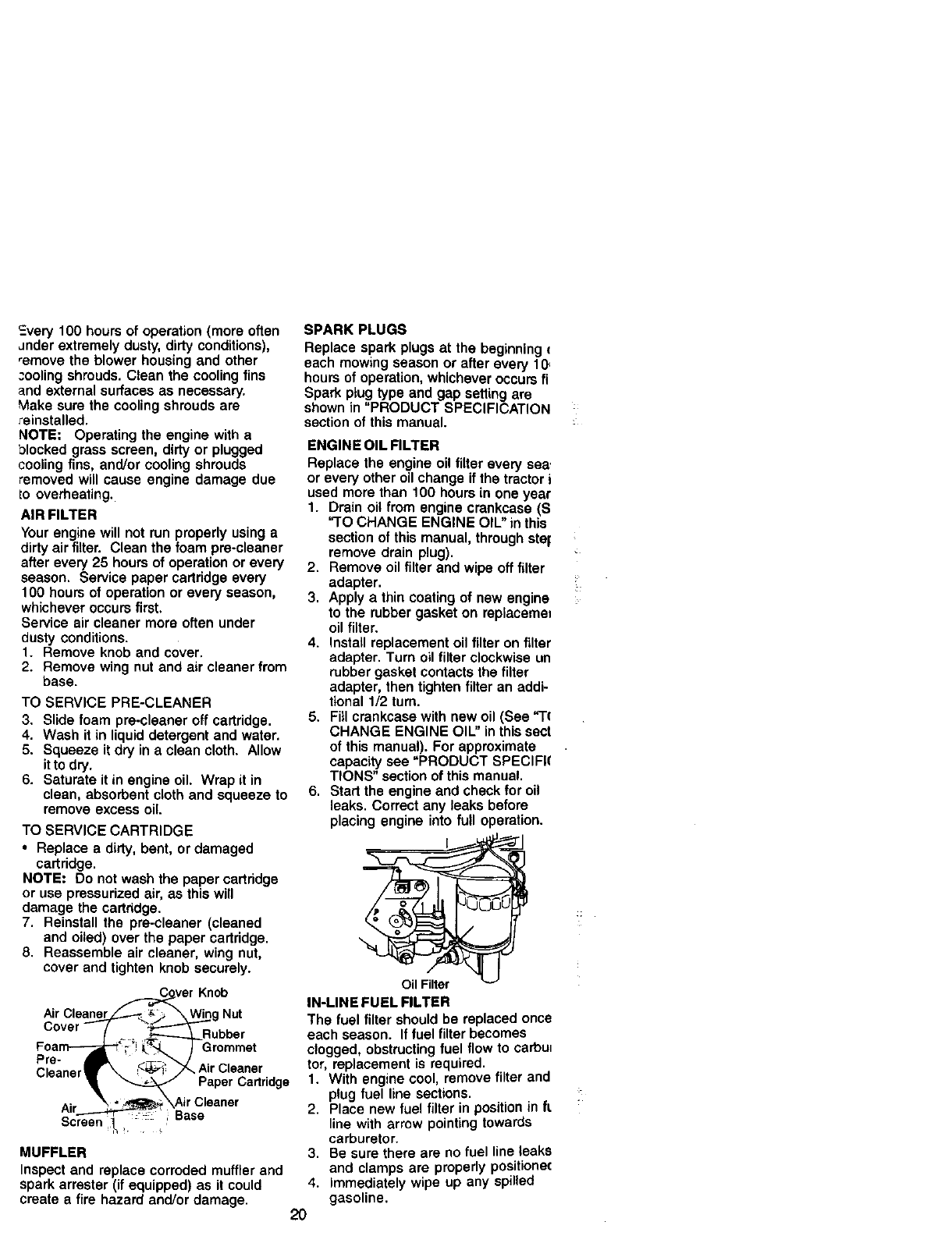
TO CHANGE ENGINE OIL
Determine temperature range expected
before oil change. All oil must meet API
service classification SF-SJ.
•Be sure tractor is on level surface.
•Oil will drain more freely when warm.
•Catch oil in a suitable container.
1. Remove oil fill cap/dipstick. Be careful
not to allow dirt to enter the engine
when changing oil.
2. Remove cap from end of drain valve
and install the drain tube onto the
fitting.
3. Unlock drain valve by pushing inward
slightly and turning counterclockwise.
4, To open, pull out on the drain valve.
5. After oil has drained completely, close
and lock the drain valve by pushing
inward and turning clockwise until the
pin is in the locked position as shown.
6. Remove the drain tube and replace
the cap onto to the end of the drain
valve.
7. Refill engine with oil through oil fill
dipstick tube. Pour slowly. Do not
overfill. For approximate capacity see
"PRODUCT SPECIFICATIONS"
section of this manual.
8. Use gauge on oil fill cap/dipstick for
checking level. Insert dipstick into the
tube and rest the oil fill cap on the
tube. Do not thread the cap onto the
tube when taking reading. Keep oil
at "FULL" line on dipstick. Tighten cap
onto the tube securely when finished.
Oil DrainValve
Closed
and __1_- /_DrainTube
Locked | _. '_ | /
Cap _
CLEAN AIR SCREEN
Air screen must be kept free of dirt and
chaff to prevent engine damage from
overheating. Clean with a wire brush or
compressed air to remove dirt and
stubborn dried gum fibers.
CLEAN AIR INTAKE/COOLING AREAS
To insure proper cooling, make sure the
grass screen, cooling fins, and other
external surfaces of the engine are kept
clean at all times.
Every 100 hours of operation (more often
_nder extremely dusty, dirty conditions),
_emove the blower housing and other
cooling shrouds. Clean the cooling fins
and external surfaces as necessary,
k,lake sure the cooling shrouds are
reinstalled.
NOTE= Operating the engine with a
blocked grass screen, dirty or plugged
cooling fins, and/or cooling shrouds
removed will cause engine damage due
Io overheating.
AIR FILTER
Your engine will not run properly using a
dirty air filter. Clean the foam pre-cleaner
after every 25 hours of operation or every
season, Service paper cartridge every
100 hours of operation or every season,
whichever occurs first.
Service air cleaner more often under
dusty conditions.
1. Remove knob and cover.
2. Remove wing nut and air cleaner from
base.
TO SERVICE PRE-CLEANER
3. Slide foam pre-cleaner off cartridge.
4. Wash it in liquid detergent and water.
5. Squeeze it dry in a clean cloth. Allow
it to dry.
6. Saturate it in engine oil Wrap it in
clean, absorbent cloth and squeeze to
remove excess oil.
TO SERVICE CARTRIDGE
•Replace a dirty, bent, or damaged
cartridge,
NOTE= Do not wash the paper cartridge
or use pressurized air, as this will
damage the cartddge.
7. Reinstall the pre-cleaner (cleaned
and oiled) over the paper cartridge.
8. Reassemble air cleaner, wing nut,
cover and tighten knob securely.
F__ver Knob
Air CleWing Nut
Cover (__. ____Rubber
Foarn--_"; 'SL_"_ )Grommet
Pre-
Cleaner _. <_' _,, Air Cleaner
.... • _ Paper Cartridge
Air _ ___ \Air C,eaner
2"----"'7_ Base
Screen
MUFFLER
Inspect and replace corroded muffler and
spark arrester (if equipped) as it could
create e fire hazard and/or damage.
SPARK PLUGS
Replace spark plugs at the beginning
each mowing season or after avery 10
hours of operation, whichever occurs fi
Spark ptug type and gap setting are
shown in "PRODUCT SPECIFICATtON
section of this manual,
4.
2O
ENGINE OIL FILTER
Replace the engine oil fitter every sea.
or every other oil change if the tractor i
used more than 100 hours in one year
1. Drain oil from engine crankcase (S
"TO CHANGE ENGINE OIU' in this
section of this manual, through ster
remove drain plug).
2. Remove oil filter and wipe off filter
adapter.
3. Apply a thin coating of new engine
to the rubber gasket on replacemen
oil filter.
4. Install replacement oil filter on filter
adapter. Turn oil filter clockwise un
rubber gasket contacts the filter
adapter, then tighten filter an addi-
tional 1/2 turn.
5, Fill crankcase with new oil (See "l't
CHANGE ENGINE OIL" in this sect
of this manual). For approximate
capacity see "PRODUCT SPECIFI(
TIONS" section of this manual.
6. Start the engine and check for oil
leaks, Correct any leaks before
placing engine into full operation.
IN-LINE FUEL FILTER
The fuel filter should be replaced once
each season. If fuel filter becomes
clogged, obstructing fuel flow to carbul
tot, replacement is required.
1. With engine cool, remove filter and
pug fuel line sections.
2. Place new fuel filter in position n ft.
line with arrow pointing towards
carburetor.
3. Be sure there are no fuel line leaks
and clamps are properly positionec
Immediately wipe up any spilled
gasoline.
Clam___ Clamp
Fuel Filter/_
CLEANING
•Clean engine, battery, seat, finish, etc.
of all foreign matter.
ieep finished surfaces and wheels
free of all _]asoline, oil, etc.
Protect painted surfaces with automo-
tive type wax.
We do not recommend using a garden
hose to clean your tractor unless the
electrical system, muffler, air filter and
carburetor are covered to keep water out.
Water in engine can result in a short-
ened engine life.
CAUTION: BEFORE PERFORMING ANY SERVICE OR ADJUSTMENTS:
1. Depress clutch/brake pedal fully and set parking brake.
2. Place gearshift lever in neutral (N) position.
3. Place attachment clutch in "DISENGAGED" position.
4. Turn ignition key "OFF" and remove key.
5. Make sure the blades and all moving parts have completely stopped.
6. Disconnect spark plug wire from spark plug and place wire where it cannot
come in contact with plug.
TRACTOR
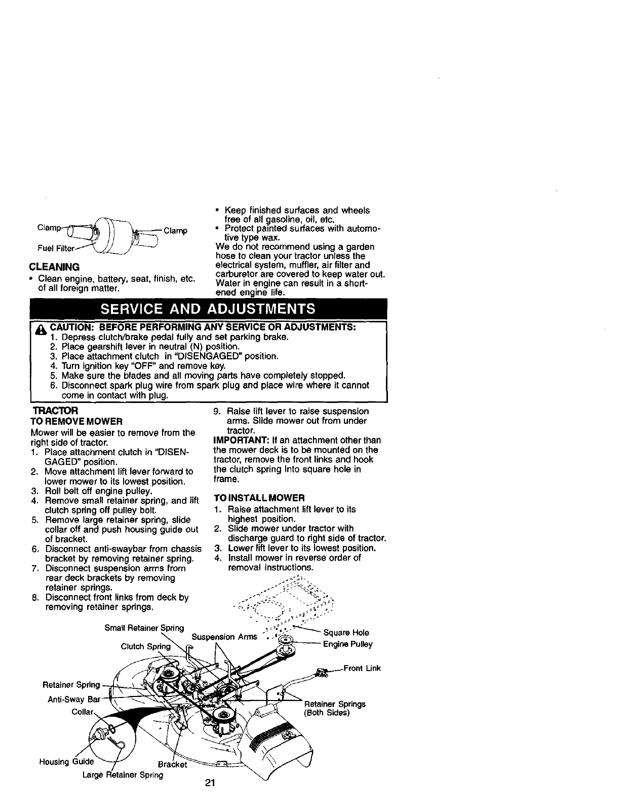
TO REMOVE MOWER
Mower will be easier to remove from the
right side of tractor.
1. Place attachment clutch in "DISEN-
GAGED" position.
2. Move attachment lift lever forward to
lower mower to its lowest position.
3. Roll belt off engine pulley.
4. Remove small retainer spdng, and lift
clutch spdng off pulley bolt.
5. Remove large retainer spring, slide
collar off and push housing guide out
of bracket.
6. Disconnect anti-swaybar from chassis
bracket by removing retainer spring.
7. Disconnect suspension arms from
rear deck brackets by removing
retainer springs.
8. Disconnect front links from deck by
removing retainer spdngs.
Small Retainer Spring
Clutch S
9. Raise lift lever to raise suspension
arms. Slide mower out from under
tractor.
IMPORTANT: If an attachment other than
the mower deck is to be mounted on the
tractor, remove the front links and hook
the clutch spring Into square hole in
frame.
TO INSTALL MOWER
1. Raise attachment lift lever to its
highest position.
2. Slide mower under tractor with
discharge guard to right side of tractor.
3. Lower lift lever to its lowest position.
4. Install mower in reverse order of
removal instructions.
-;' _'_"-°o'_"_"'_ Square Hole
Suspension Arms , oEnginePulley
Anti-Sway
Collar Springs
(Both Sides)
HousingGuide
Larg, Spring 21
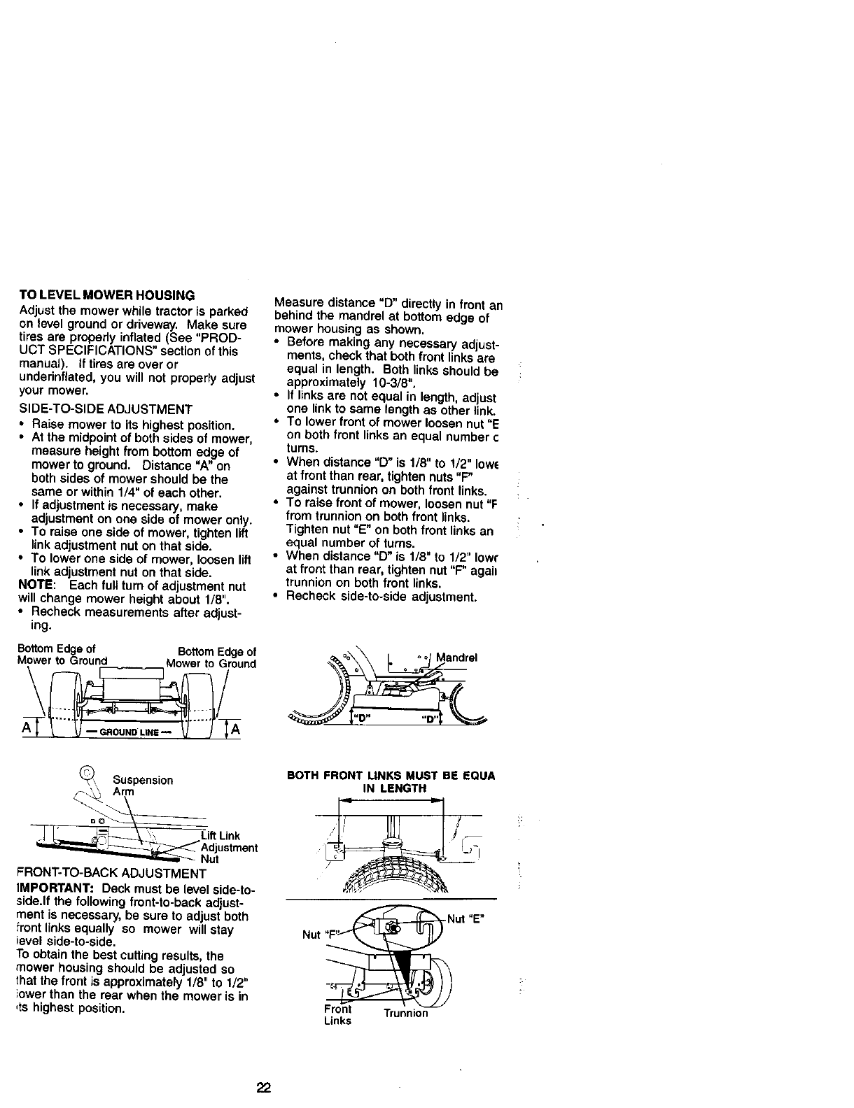
TOLEVELMOWERHOUSING
Adjustthe mower while tractor is parked
on level ground or driveway. Make sure
tires are praperly inflated (See "PROD-
UCT SPECIFICATIONS" section of this
manual), if tires are over or
underinflated, you will not properly adjust
your mower.
SIDE-TO-SIDE ADJUSTMENT
• Raise mower to its highest position.
•At the midpoint of both sides of mower,
measure height from bottom edge of
mower to ground, Distance "A" on
both sides of mower should be the
same or within 1/4" of each other.
•If adjustment is necessary, make
adjustment on one aide of mower only.
•To raise one side of mower, tighten lift
link adjustment nut on that side.
• To lower one side of mower, loosen lift
link adjustment nut on that side.
NOTE: Each full turn of adjustment nut
will change mower height about 1/8".
• Recheck measurements after adjust-
ing.
Bottom Edge of BottomEdge of
Mower to Ground Mower to Ground
Measure distance "D" directly in front an
behind the mandrel at bottom edge of
mower housing as shown.
• Before making any necessa_ adjust-
ments, check that both front links are
equal in length. Both links should be
approximately 10-3/8".
• If links are not equal in length, adjust
one link to same length as other link.
•To lower front of mower loosen nut "E
on both front links an equal number c
turns.
• When distance "D" is 1/8" to 1/2" Iow_
at front than rear, tighten nuts "F"
against trunnion on both front links.
• To raise front of mower, loosen nut "F
from trunnion on both front links.
Tighten nut "E" on both front links an
equal number of turns.
• When distance "D" is 1/8" to 1/2" low(
at front than rear, tighten nut "F" agait
trunnion on both front links.
• Recheck side-to-side adjustment.
Suspension
, Lift Link
Nut
FRONT-TO-BACK ADJUSTMENT
IMPORTANT: Deck must be level side-to-
side.If the following front-to-back adjust-
ment is necessary, be sure to adjust both
front links equally so mower will stay
ievel side-to-side.
To obtain the best cutting results, the
mower housing should be adjusted so
that the front is approximately 1/8" to 1/2"
lower than the rear when the mower is in
,ts highest position.
BOTH FRONT LINKS MUST BE EQUA
IN LENGTH
Front Trunnion
Links
22
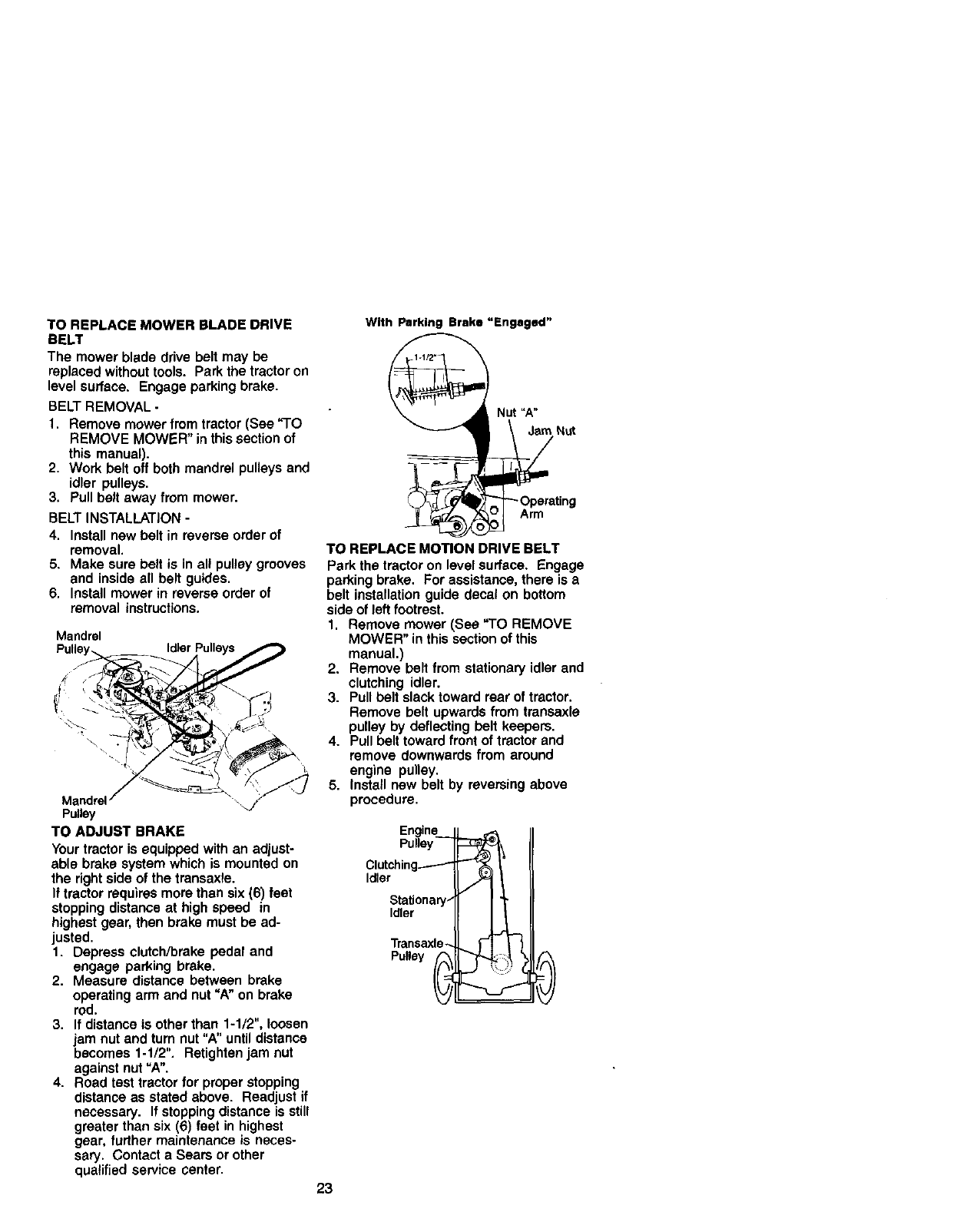
TO REPLACE MOWER BLADE DRIVE
BELT
The mower blade drive belt may be
replaced without tools. Park the tractor on
level surface. Engage parking brake.
BELT REMOVAL -
1. Remove mower from tractor (See _'1"O
REMOVE MOWER" in this section of
this manual).
2. Work belt off both mandrel pulleys and
idler pulleys.
3. Pull belt away from mower.
BELT INSTALLATION -
4. Install new belt in reverse order of
removal.
5. Make sure belt is in all pulley grooves
and inside all belt guides.
6. Install mower in reverse order of
removal instructions.
Mandrel
Mandrel
Pulley
TO ADJUST BRAKE
Your tractor is equipped with an adjust-
able brake system which is mounted on
the right side of the transaxle.
If tractor requires more than six (6) feet
stopping distance at high speed in
highest gear, then brake must be ad-
justed.
1. Depress clutch/brake pedal and
engage parking brake.
2. Measure distance between brake
operating arm and nut =A" on brake
rod.
3. If distance is other than 1-1/2", loosen
jam nut and turn nut "A" until distance
becomes 1-1/2". Retighten jam nut
against nut "A".
4. Road test tractor for proper stopping
distance as stated above. Readjust if
necessary. If stopping distance is still
greater than six (6) feet in highest
gear, further maintenance is neces-
sary. Contact a Sears or other
qualified service center.
With Parking Brake "Engaged"
Nut "A"
Nut
ting
TO REPLACE MOTION DRIVE BELT
Park the tractor on level surface. Engage
parking brake. For assistance, there is a
belt installation guide decal on bottom
side of left footrest.
1. Remove mower (See "TO REMOVE
MOWER" in this section of this
manual.)
2. Remove belt from stationary idler and
clutching idler.
3. Pull belt slack toward rear of tractor.
Remove belt upwards from transaxle
pulley by deflecting belt keepers.
4. Pull belt toward front of tractor and
remove downwards from around
engine pulley.
5. Install new belt by reversing above
procedure.
Engine
Pulley
Clutching-------'- --
Idler
Stationary-
Idler
Transaxle_ _ -_
Pulley I
23
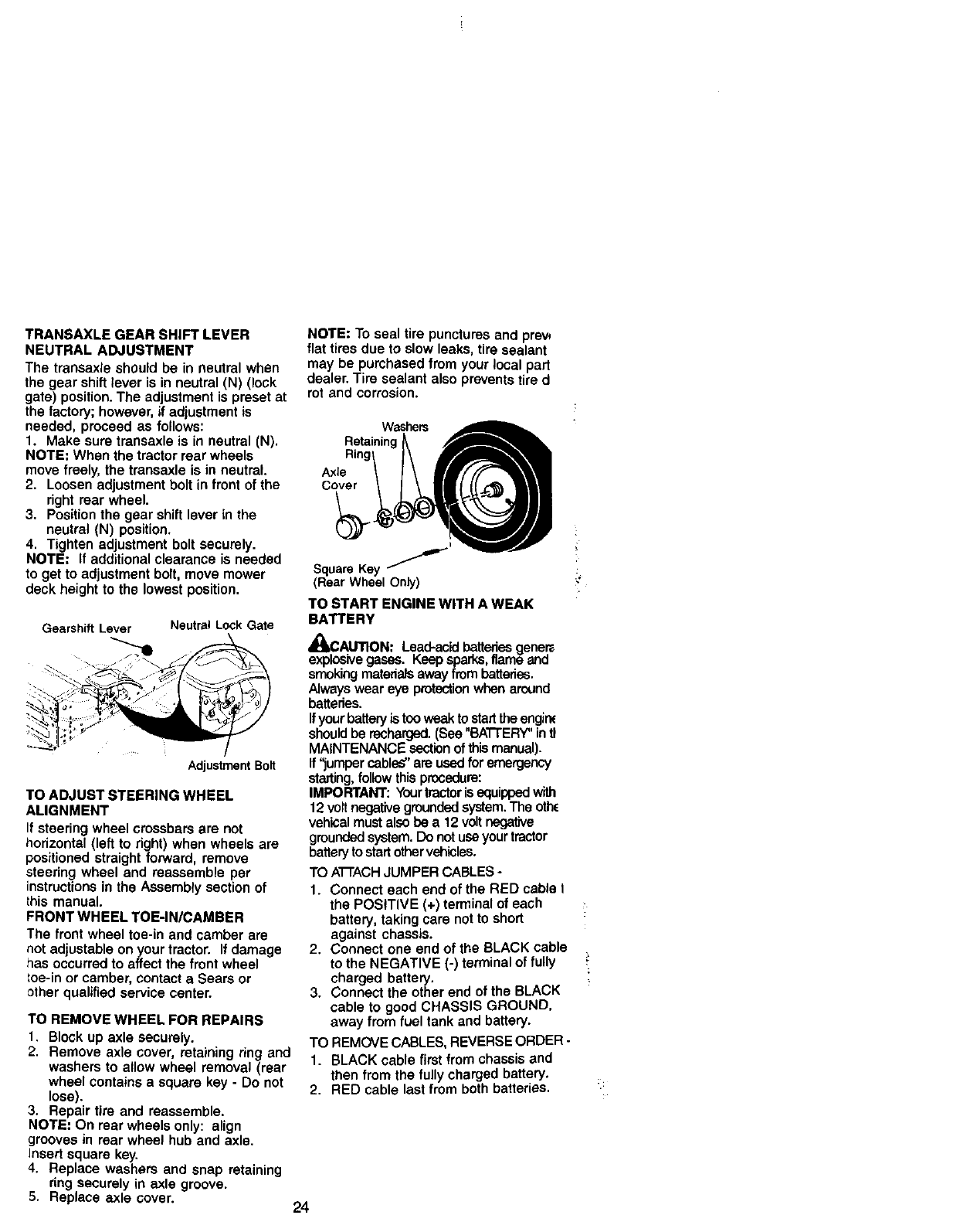
TRANSAXLE GEAR SHIFT LEVER
NEUTRAL ADJUSTMENT
The transaxle should be in neutral when
the gear shift lever is in neutral (N) (lock
gate) position• The adjustment is preset at
the factory; however, if adjustment is
needed, proceed as follows:
1. Make sure transaxle is in neutral (N).
NOTE: When the tractor rear wheels
move freely, the transaxle is in neutral.
2. Loosen adjustment bolt in front of the
right rear wheel.
3. Position the gear shift lever in the
neutral (N) position.
4. Tighten adjustment bolt securely.
NOTE: If additional clearance is needed
to get to adjustment bolt, move mower
deck height to the lowest position.
Gearshift Lever Neutral Lock Gate
AdjustmentBolt
TO ADJUST STEERING WHEEL
ALIGNMENT
If steering wheel crossbars are not
horizontal (left to right) when wheels are
positioned straight forward, remove
steering wheel and reassemble per
instructions in the Assembly section of
this manual.
FRONT WHEEL TOE-IN/CAMBER
The front wheel toe-in and camber are
not adjustable on your tractor. If damage
has occurred to affect the front wheel
toe-in or camber, contact a Sears or
other qualified service center.
TO REMOVE WHEEL FOR REPAIRS
1. Block up axle securely.
2. Remove axle cover, retaining r_ng and
washers to allow wheel removal (rear
wheel contains a square key - Do not
lose).
3. Repair tire and reassemble.
NOTE: On rear wheels only: align
grooves in rear wheel hub and axle.
Insert square key.
4. Replace washers and snap retaining
ring securely in axle groove.
5. Replace axle cover.
NOTE: To seal tire punctures and prew
flat tires due to slow leaks, tire sealant
may be purchased from your local part
dealer. Tire sealant also prevents tire d
rot and corrosion.
Washers
Axle
Cover
I
Square Key
(Rear Wheel Only)
TO START ENGINE WITH A WEAK
BATTERY
AUTION: Lead-acid batteriesgene._
ive gases. _eep sparks, flame anu
smoking materialsaway from batteries.
Always wear eye protectionwhen around
batteries.
Ifyour battery is toov_ak to startthe engin_
should be recharged.(See "BATI'ERY" intl
MAINTENANCE sectionof this manual).
ff "jumper cables" are used for emergency
starting,follow this procedure:
IMPORTANT: Yourtractoris squippedwith
12 volt negative groundedsystem. The othc
vehical must also be a 12 volt negative
groundedsystem. Do not use your tractor
batteryto startothervehicles.
TO A'I-I'ACHJUMPER CABLES -
1. Connect each end of the RED cable I
the POSITIVE (+) terminal of each
battery, taking care not to short
against chassis.
2. Connect one end of the BLACK cable
to the NEGATIVE (-) terminal of fully
charged battery.
3. Connect the other end of the BLACK
cable to good CHASSIS GROUND,
away from fuel tank and battery.
TO REMOVE CABLES, REVERSE ORDER -
1. BLACK cable first from chassis and
then from the fully charged battery.
2. RED cable last from both batteries.
24
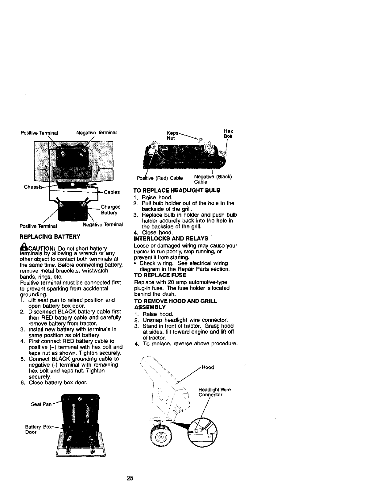
Positive Terminal Negative Terminal
Positive Terminal Negative Terminal
REPLACING BATTERY
,tt
4_CAUTION: Do not short battery
terminals by allowing a wrencn or any
other object to contact both terminals at
the same time. Before connecting battery,
remove metal bracelets, wristwatch
bands, rings, etc.
Positive terminal must be connected first
to prevent sparking from accidental
grounding.
1. Lift seat pan to raised position and
open battery box door.
2. Disconnect BLACK battery cable first
then RED battery cable and carefully
remove battery from tractor.
3. install new battery with terminals in
same position as old battery.
4. First connect RED battery cable to
positive (+) terminal with hex bolt and
keps nut as shown. Tighten securely.
5. Connect BLACK grounding cable to
negative (-) terminal with remaining
hex bolt and keps nut. Tighten
securely,
6. Close battery box door.
Baffe_
Door
Positive (Red) Cable Negative (Black)
Cable
TO REPLACE HEADLIGHT BULB
1. Raise hood.
2. Pull bulb holder out of the hole in the
backside of the grill.
3. Replace bulb in holder and push bulb
holder securely back into the hole in
the backside of the grill.
4. Close hood.
INTERLOCKS AND RELAYS "
Loose or damaged wiring may cause your
tractor to run poorly, stop running, or
prevent it from starting.
•Check wiring. See electrical wiring
diagram in the Repair Parts section.
TO REPLACE FUSE
Replace with 20 amp automotive-type
plug-in fuse. The fuse holder is located
behind the dash.
TO REMOVE HOOD AND GRILL
ASSEMBLY
1. Raise hood.
2. Unsnap headlight wire connector.
3. Stand in front of tractor. Grasp hood
at sides, tilt toward engine and liftoff
of tractor.
4. To replace, reverse above procedure.
_\ \\ _ j Hood
\\ "%
". -_',, HeadlightWire
c
_. ./' Connector
25
ENGINE
Maintenance, rep_r, or replacementof the
emission controldevices end systems, which
are being done at the customers expense,
may be performed by any non-road engine
repair establishment or individual. Warranty
repairs must be performed by an authonzed
_.engine manutacture,%service outlet.
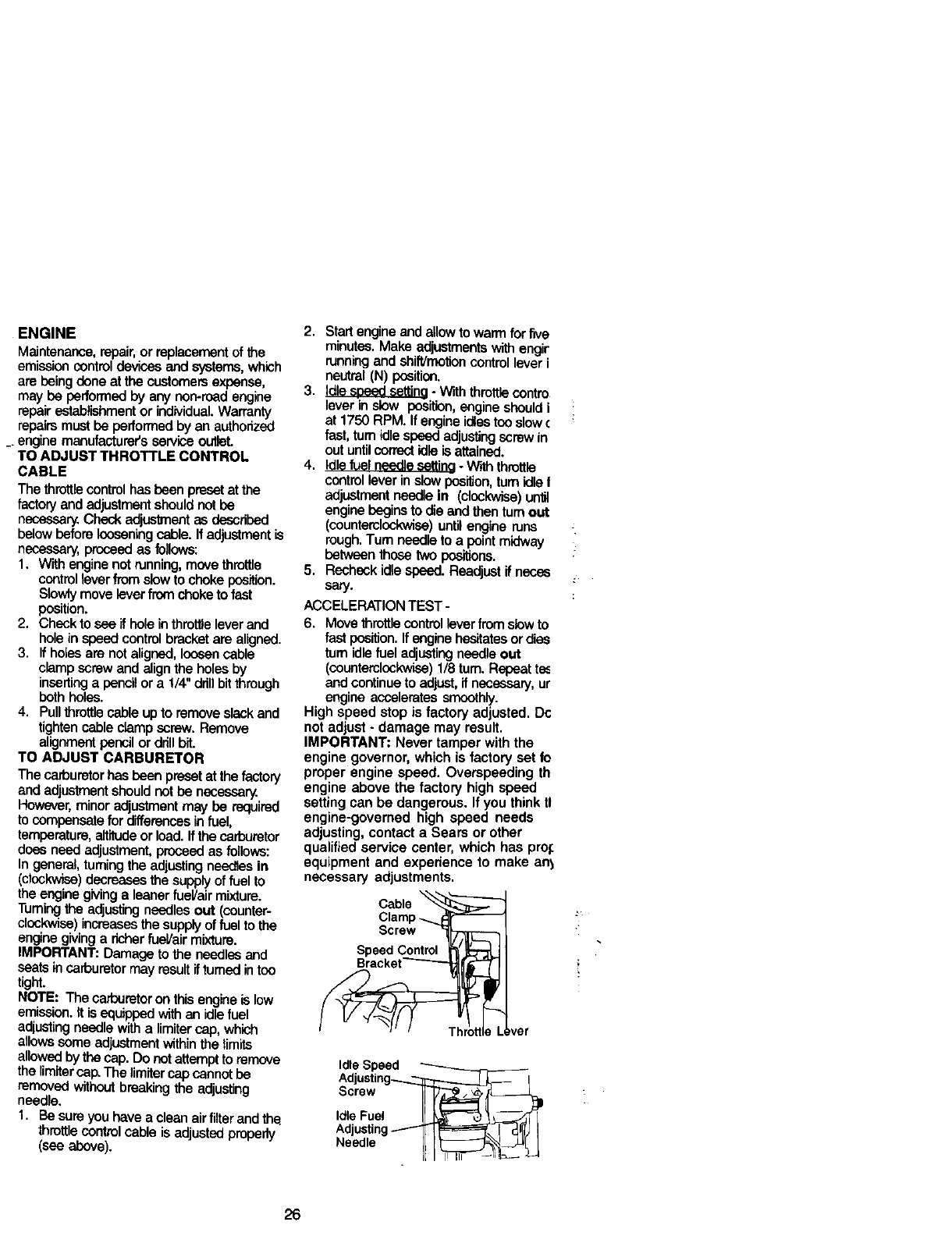
TO ADJUST THROTTLE CONTROL
CABLE
The lhrotttscontrolhas been preset at the
factory and adjustment should not be
necessary. Check adjustment as described
below before icosening c_o_e.If ed_stment is
necessary, proceed as follows:
1. With enginenot running,move throttle
controllever from stow to chokeposition.
Slowlymove leverfrom choketo fast
position.
2. Check to see if hole in thrett_elever end
hole in speed controlbracket are aligned.
3. Ifholes are not aligned, loosen cable
ctompscrew and align the betas by
insertinga pencil or a 1/4"drillbitthrough
both holes.
4. Puttthrottlecable up to remove stack and
tightencable clamp screw. Remove
alignmentper_;Jlor drillbit.
TO ADJUST CARBURETOR
The cad_retor has been preset at the factory
and adjustmentshouldnot be necessary.
However, minor adjustmentmay be required
to compensate for differencesin fuel,
temperature, altitudeor load. If the carburetor
does need adjustment,proceed as follows:
In general, tuming the adjusting needles in
(clockwise) decreases the supply of fuel to
the enginegiving aleaner fuel/air mixture,
Turning the adjusting needles out (counter-
clockwise) Increases the supply of fuel to the
engine giving a richer fueVair mixture.
IMPORTANT: Damage to the needles end
seats in carburetor may result iffumed in too
tight.
NOTE: The carburetor on this engine is low
emission. It is equipped with an idle fuel
adjusting needle with a limiter cap, which
allows some adjustment within the limits
allowed by the cap. Do not attempt to remove
the limiter cap. The limiter cap cannot be
removed without breaking the adjusting
needle.
1. Be sure you have a oleen air fiiterand the
throttlecontrolcable is adjustedproperly
(see above).
2. Start engine and allow to warm for five
minutes. Make adjustmentswith engir
runningand shift/molion control lever i
neutral (N) position.
3. Idle s_sd setting- With throttlecontro
lever in stow position,engine shouldi
at 1750 RPM. If engine idlestoo stow€
fast, turn idle speed adjustingscrew in
out untilcorrectidle Is attained.
4. Idlefuel needle settina - With throttle
controllever in slow position,turn idle t
adjustment needle in (clockwise)until
engine begins to die end then turnout
(countemlcokwiso) untilengine runs
rough.Turn needle to a pointmidway
between those two positions.
5. Recheck idle speed. Readjust if neses
sery.
ACCELERATION TEST -
6. Move throttlecontrollever from stowto
fast position.If engine hesitatesor dies
turn idlefuel adjustingneedle out
(ooenterotoc_) 1/8 turn. Repeat tee
and continue to adjust, if necessary, ur
engine accelerates smoothly.
High speed stop is factory adjusted, Dc
not adjust - damage may result.
IMPORTANT: Never tamper with the
engine governor, which is factory set fo
proper engine speed. Overepeeding th
engine above the factory high speed
setting can be dangerous. If you think tl
engine-governed high speed needs
adjusting, contact a Sears or other
quaitfied service center, which has prof.
equipment and experience to make ant
necessa_ adjustments.
cab,a
Clamp
Screw
SPaecekdetC°ntr°___l
ver
Idle Speed _
Adjusting_ !
Screw I_ i,_i
Idle Fuel !_e_"--'=_,3_ /
Adjusting _ I_='_ I _llI,J I
Needle I[[ _H______ _
26
immediately prepare your tractor for
storage at the end of the season or if the
tractor will not be used for 30 days or
more.
CAUTION: Never store the tractor
with gasoline in the tank inside a building
where fumes may reach an open flame or
spark. Allow the engine to cool before
storing in any enclosure.
TRACTOR
Remove mower from tractor for winter
storage. When mower is to be stored for
a period of time, clean it thoroughly,
remove all dirt, grease, leaves, etc. Store
in a clean, dry area.
1. Clean entire tractor (See =CLEANING"
in the Maintenance section of this
manual).
2. inspect and replace belts, if necessary
(See belt replacement instructions in
the Service and Adjustments section
of this manual).
3. Lubricate as shown in the Mainte-
nance section of this manual.
4. Be sure that all nuts, bolts and screws
are securely fastened. Inspect moving
parts for damage, breakage and wear.
Replace if necessary.
5. Touch up all rusted or chipped paint
surfaces; sand lightly before painting.
BA'rrERY
•Fully charge the battery for storage.
•After a period of time in storage, battery
may require recharging.
•To help prevent corrosion and power
leakage during long periods of storage,
battery cables should be disconnected
and battery cleaned thoroughly (see
"TO CLEAN BATTERY AND TERMI-
NALS" in the Maintenance section of
this manual).
•After cleaning, leave cables discon-
nected and place cables where they
cannot come in contact with battery
terminals.
• if battery is removed from tractor for
storage, do not store battery directly on
concrete or damp surfaces.
ENGINE
FUEL SYSTEM
IMPORTANT: It is important to prevent
gum deposites from forming in essential
fuel system parts such as carburetor, fuel
hose, or tank dudng storage. Also,
expedance indicates that alcohol
blended fuels (called gasohol or using
ethanol or methanol) can attract moisture
which leads to separation and formation
of acids dudng storage. Acidic gas can
damage the fuel system of and engine
while in storage.
1. Drain the fuel tank.
2. Start the engine and let it run until the
fuel lines and carburetor are empty.
•Never use engine or carburetor cleaner
products in the fuel tank or permanent
damage may occur.
•Use fresh fuel next season.
NOTE: Fuel stabilizer is an acceptable
alternative in minimizing the formation of
fuel gum deposits during storage. Add
stabilizer to gasoline in fuel tank or
storage container. Always follow the mix
ratio found on stabilizer container. Run
engine at least 10 minutes after adding
stabilizer to allow the stabilizer to reach
the carburetor. Do not drain the gas tank
and carburetor if using fuel stabilizer.
ENGINEOIL
Drain oil (with engine warm) and replace
with clean engine oil. (See "ENGINE" in
the Maintenance section of this manual).
CYLINDER(S)
1. Remove spark plug(s).
2. Pour one ounce of oil through spark
plug hole(s) into cylinder(s).
3. Tum ignition key to "START" position
for afew seconds to distribute oil.
4. Replace with new spark plug(s).
OTHER
• Do not store gasoline from one season
to another.
•Replace your gasoline can if your can
starts to rust. Rust and/or dirt in your
gasoline will cause problems.
•If possible, store your tractor indoors
and cover itto give protection from dust
and dirt.
•Cover your tractor with a suitable
protective cover that does not retain
moisture. Do not use plastic. Plastic
cannot breathe which allows conden-
sation to form and will cause your
tractor to rust.
IMPORTANT: Never cover tractor while
engine and exhaust areas are still warm.
27
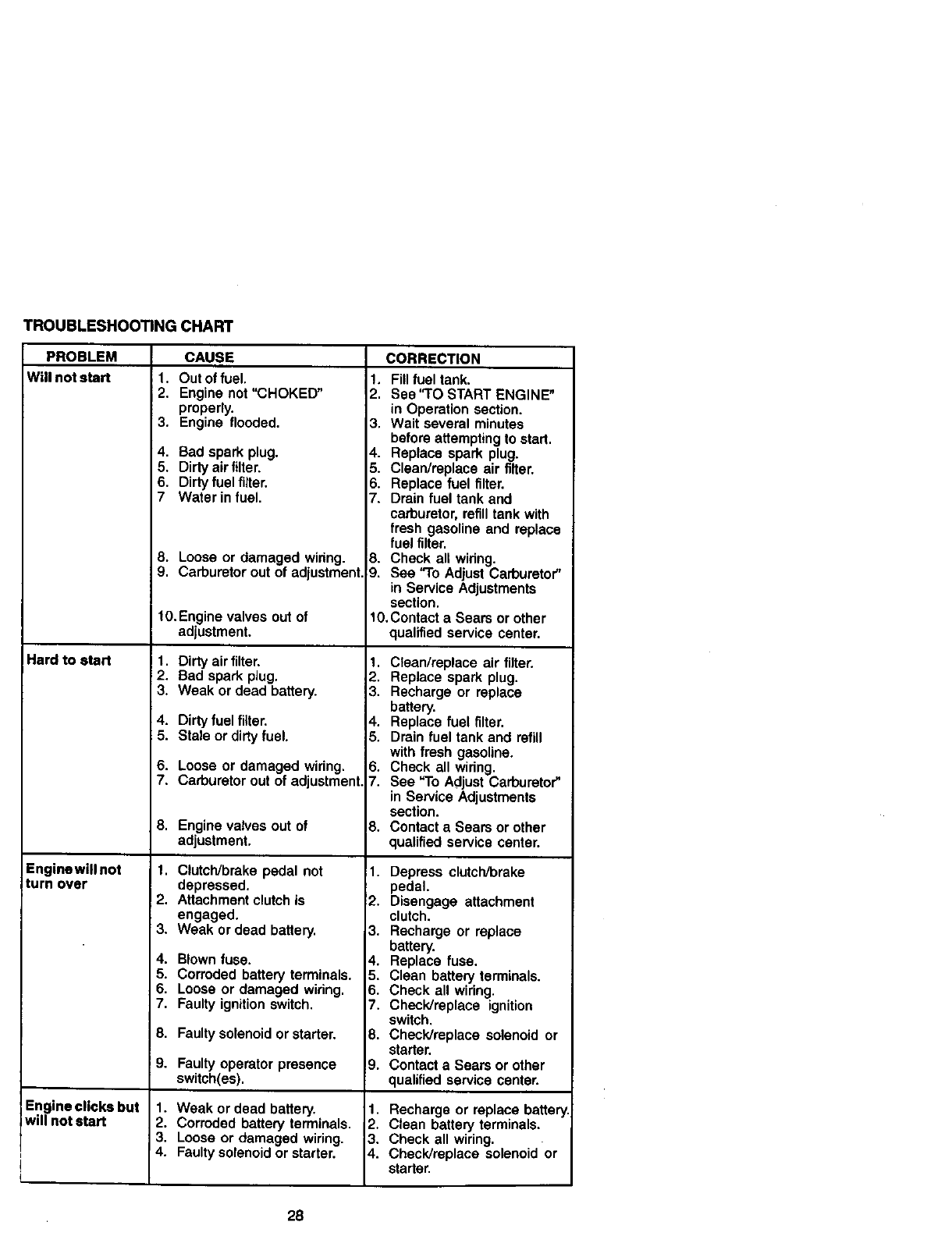
TROUBLESHOOTINGCHART
PROBLEM CAUSE CORRECTION
Will not start
Hard to start
Enginewill not
turn over
Engineclicks but
will not start
1, Out of fuel.
2. Engine not "CHOKED"
properly.
3. Engine flooded.
4. Bad spark plug.
5. Dirty air filter.
6. Dirty fuel filter.
7 Waterin fuel.
8. Loose or damaged wiring.
9. Carburetor out of adjustment.
10.Enginevalves outof
adjustment.
1. Dirty air filter.
2. Bad spark plug.
3. Weak or dead battery.
4. Dirty fuel filter.
5. Stale or dirty fuel.
6. Loose or damaged wiring.
7. Carburetor out of adjustment.
8. Enginevalvesout of
adjustment.
1. Clutch/brake pedal not
depressed.
2. Attachment clutch is
engaged.
3. Weak or dead battery.
4. Blown fuse.
5. Corroded battery terminals.
6. Loose or damaged wiring.
7. Faulty ignition switch.
8. Faulty solenoid or starter.
9. Faultyoperatorpresence
switch(es).
1. Weak or dead battery.
2. Corroded battery terminals.
3. Loose or damaged wiring.
4. Faulty solenoid or starter.
t. Fill fuel tank.
2. See "1"O START ENGINE"
in Operation section.
3. Wait several minutes
before attempting to start.
4. Replace spark plug.
5. Clean/replace air filter.
6. Replace fuel filter.
7. Drain fuel tank and
carburetor, refill tank with
fresh gasoline and replace
fuel filter.
8. Check all widng.
9. See "To Adjust Carburetor"
in Service Adjustments
section.
10.Contact a Sears or other
qualified service center.
1. Clean/replace air filter.
2. Replace spark plug.
3. Recharge or replace
battery.
4. Replace fuel filter.
5. Drain fuel tank and refill
with fresh gasoline.
6. Check all wiring.
7. See "To Adjust Carburetor"
in Service Adjustments
section.
8. Contact a Sears or other
qualified service center.
1. Depress clutch/brake
pedal.
2. Disengage attachment
clutch.
3. Recharge or replace
battery.
4. Replace fuse.
5. Clean battery terminals.
6. Check all wiring.
7. Check/replace ignition
switch.
8. Check/replace solenoid or
starter.
9. Contact a Sears or other
qualified service center.
1. Recharge or replace battery
2. Clean battery terminals.
3. Check all wiring.
4. Check/replace solenoid or
starter.
28
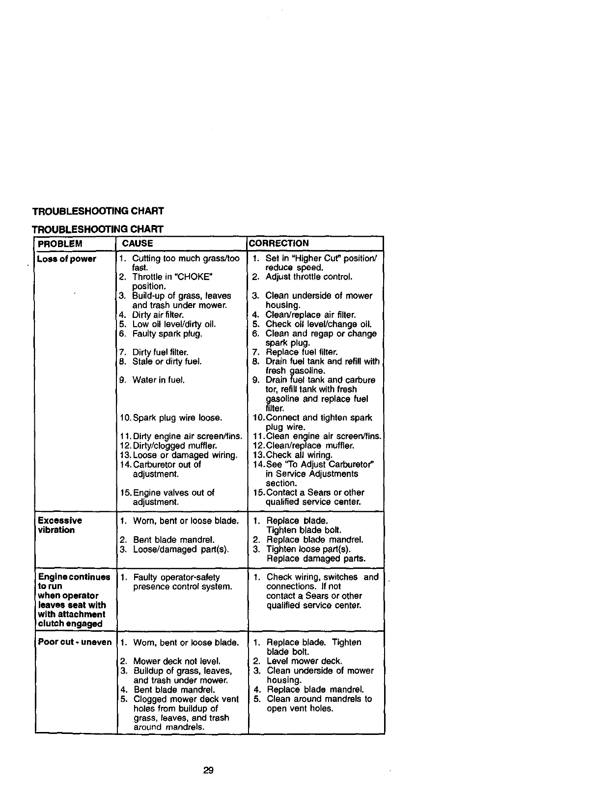
TROUBLESHOOTING CHART
TROUBLESHOOTING
PROBLEM
Loss of power
Excessive
vibration
CHART
CAUSE CORRECTION
1. Cuttingtoo muchgrass/too
Engine continues
to run
when operator
leaves seat with
with attachment
clutch engaged
Poorcut-uneven
fast.
2. Throttle in "CHOKE"
position,
3. Build-up of grass, leaves
and trash under mower.
4. Dirty air filter.
5. Low oil level/dirty oil.
6. Faulty spark plug.
7. Dirty fuel filter.
8. Stale or dirty fuel.
9. Water in fuel.
t0. Spark plug wire loose.
11.Dirty engineair screen/fins.
12.Dirty/clogged muffler.
13.Loose or damaged wiring.
14.Carburetorout of
adjustment.
15. Enginevalves outof
adjustment.
1, Worn, bent or loose blade,
2. Bent blade mandrel.
3. Loose/damaged part(s).
1. Faulty operator-safety
presence control system.
1. Worn, bent or loose blade.
2. Mower deck not level.
3. Buildup of grass, leaves,
and trash under mower.
4. Bent blade mandrel.
5. Clogged mower deck vent
holes from buildup of
grass, leaves, and trash
around mandrels.
1. Set in "Higher Cut" position/
reduce speed.
2. Adjust throttle control.
3. Clean underside of mower
housing.
4. Clean/replace air filter.
5. Check oil level/change oil.
6. Clean and regap or change
spark plug.
7, Replace fuel filter.
8, Drain fuel tank and refill with
fresh gasoline.
9. Drain fuel tank and carbure
tor, refilltank with fresh
gasoline and replace fuel
filter.
t0.Connect and tighten spark
plug wire.
11.Clean engine air screen/fins.
12.Clean/replace muffler.
13.Check all wiring.
14. See "To Adjust Carburetor"
in Service Adjustments
section.
t5.Contect a Sears or other
qualified service center.
1. Replace blade.
Tighten blade bolt.
2. Replace blade mandrel.
3. Tightenloose part(s).
Replace damaged parts.
1. Check wiring, switches and
connections. If not
contact a Sears or other
qualified service center.
1. Replace blade. Tighten
blade bolt.
2. Level mower deck.
!3. Clean underside of mower
housing.
4. Replace blade mandrel.
,5. Clean around mandrels to
open vent holes.
29
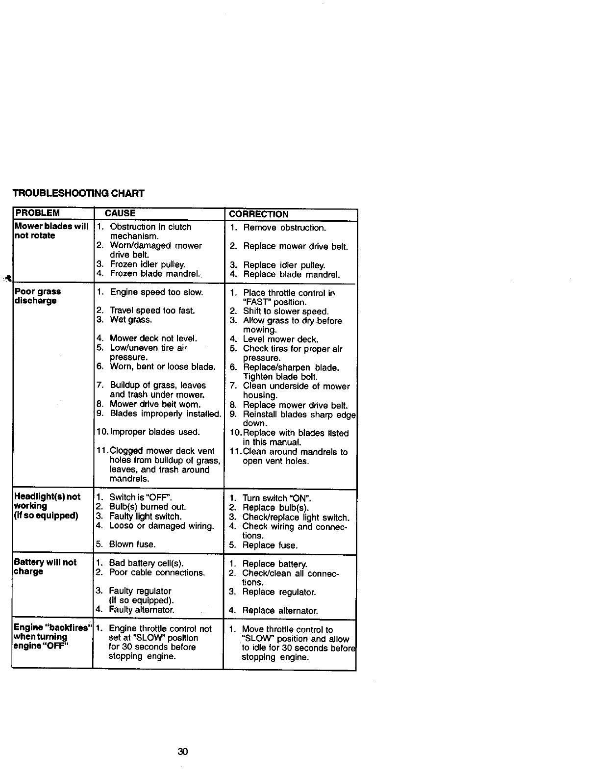
TROUBLESHOOTING CHART
PROBLEM CAUSE CORRECTION
Mower bladea will 1. Obstruction in clutch 1. Remove obstruction.
not rotate mechanism,
2, Worn/damaged mower 2. Replace mower drive belt.
drive belt.
3, Frozen idler pulley. 3. Replace idler pulley.
4. Frozen blade mandrel. 4. Replace blade mandrel.
Poor grass 1, Engine speed too slow.
discharge
Headlight(s) not
working
(If so equipped)
Battery will not
charge
Engine "backfires'
when turning
engine "OFF"
2. Travelspeed too fast.
3. Wet grass.
4. Mower deck not level.
5. Low/uneven tire air
pressure.
6. Worn. bent or loose blade.
7. Buildup of grass, leaves
and trashunder mower.
8. Mower drive beltworn.
9. Blades improperlyinstalled.
10. Improper blades used.
11.Clogged mower deck vent
holes from buildup of grass.
leaves, and trash around
mandrels.
1. Switch is"OFP.
2. Bulb(s) burned out.
3. Faulty light switch.
4. Loose or damaged widng.
5, Blown fuse.
1. Bad battery cell(s).
2. Poor cable connections.
3. Faulty regulator
(if so equipped).
4. Faulty alternator.
1. Engine throttle control not
set at "SLOW" position
for 30 seconds before
stopping engine.
1. Place throttle control in
"FAST" position.
2. Shift to slower speed.
3. Allow grass to dry before
mowing.
4. Level mower deck.
5. Check tires for proper air
pressure.
6. Replace/sharpen blade.
Tighten blade bolt.
7. Clean underside of mower
housing.
8. Replace mower drive belt.
9. Reinstall blades sharp edg*
down.
10. Replace with blades listed
in this manual.
11.Clean around mandrels to
open vent holes.
1. Turnswitch"ON".
2. Replace bulb(s).
3. Check/replace lightswitch.
4. Check wiringand connec-
tions.
5. Replace fuse.
1. Replace battery.
2. Check]clean all connec-
tions.
3. Replace regulator.
4. Replace alternator.
1. Move throttle control to
"SLOW" position and allow
to idle for 30 seconds befor(
stopping engine.
3O
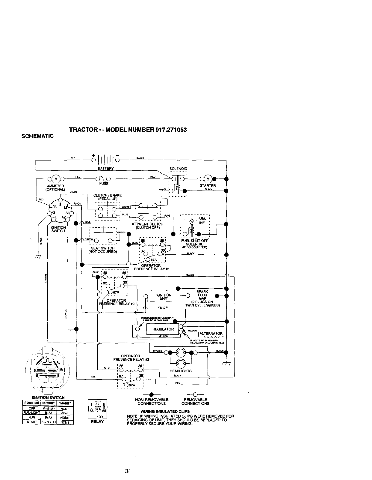
SCHEMATIC TRACTOR - - MODEL NUMBER 917.271053
mE0
m
AMMETER
(OPTIONAL) w._Te
i
;llllJJ;
BATTERY SOLENOID
@ REDP I
v
FUSE i i STARTER
CLM+C._SRA.E ",
(PEDAL UP) i ........
L___, ,_,,_, I
SEAT SWITCH
(NOT OCCUPIED)
p]
IFUEL ,
LINE
FUEL SHUT-OFF
SOLENOID
(IF SO E_IPPED)
OPERATOR
PRESENCE RELAY #1
'85 86_
Ja7 i 3o:
,G_,g,ON e-
YetLow T'WI_ CYL, ENGINES)
P
VB.LOWALTERNATOR_V_TS_ e:_ Rm
B_WN _K
OPERATOR
__PRESENCE RELAY #3
_.ue Ii HF..ADLIGHTB
IGNITION SWITCH
posITION CIRCUIT _MAKE,,
OFF M+G+Af NONE
START B + S ÷ A1 NONE
RUN/LIGHT B+AI A2+L
RUN B+A1 NONE
RELAY
NON-REMOVABLE REMOVABLE
CONNECTIONS CONNECTIONS
WIRING INSULATED CLIPS
NOTE: IF WIRING INSULATED CLIPS WERE REMOVEO FOR
SERVICING OF UNIT, THEY SHOULO BE REPLACED TO
PROPERLY SECURE YOUR WIRING,
31

ELECTRICAL
TRACTOR - - MODEL NUMBER 917.271053
/
/
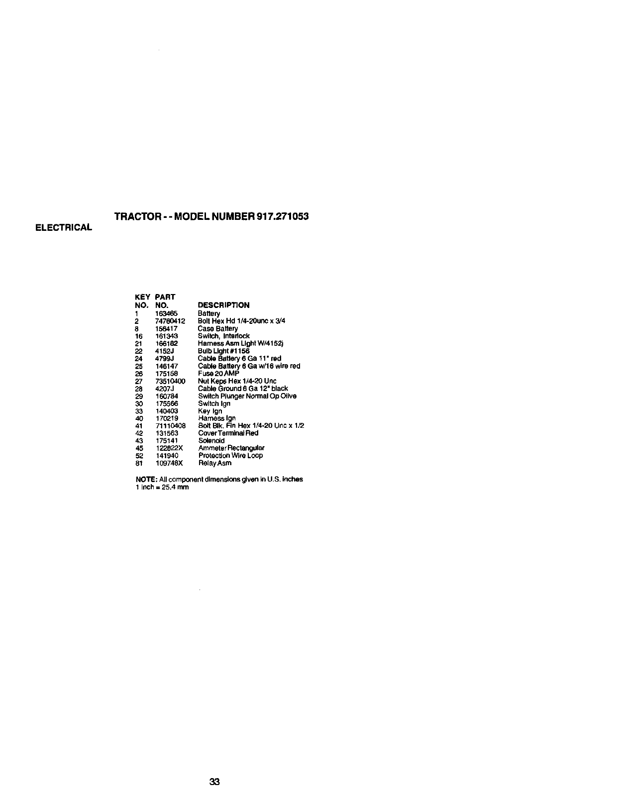
ELECTRICAL
TRACTOR - - MODEL NUMBER 917.271053
KEY PART
NO. NO. DESCRIPTION
1163465 Battery
2 74760412 Bolt Hex Hd 1/4-2Ounc x 3/4
8 156417 Case Baltery
16 161343 Switch, IntedOck
21 166182 Hamess Asm Ught W/4152j
22 4152J Bulb Light #1156
24 4799J Cable Battery 6 Ga 11 •red
25 146147 Cable Battery 6 Ga w/16 wirered
26 175158 Fuse 20AMP
27 73510400 Nut Keps Hex 1/4-20 Unc
28 4207J Cable GrOUnd 6 Ga 12" black
29 160784 Switch Plunger Normal Op O_ive
30 175566 Switch Ign
33 140403 Key Ign
40 170_19 Hamess Ign
41 71110408 Bolt BIk. Rn Hex 1/4,20 Unc x 1/2
42 131563 Cover TerminaJ Red
43 175141 Solenoid
45 122822X Ammeter Rectangular
52 141940 Protection Wire Loop
81 109748X Relay Asm
NOTE: All component dimensionsgivenIn U.S. inches
1 InCh= 25.4 mm
33
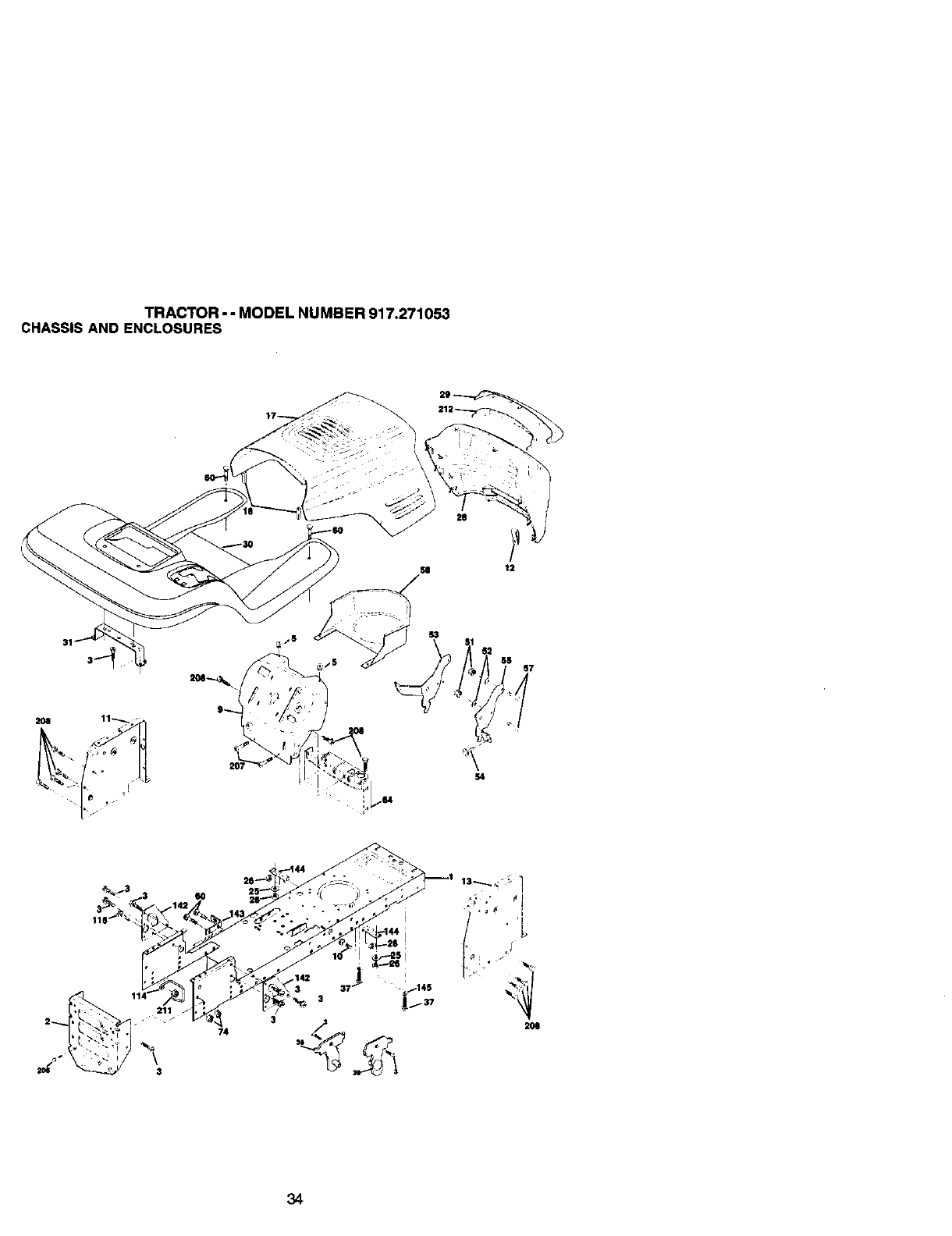
TRACTOR-- MODELNUMBER917.271053
CHASSISANDENCLOSURES
5S 57
2M 11_/
k_ f._ _
34
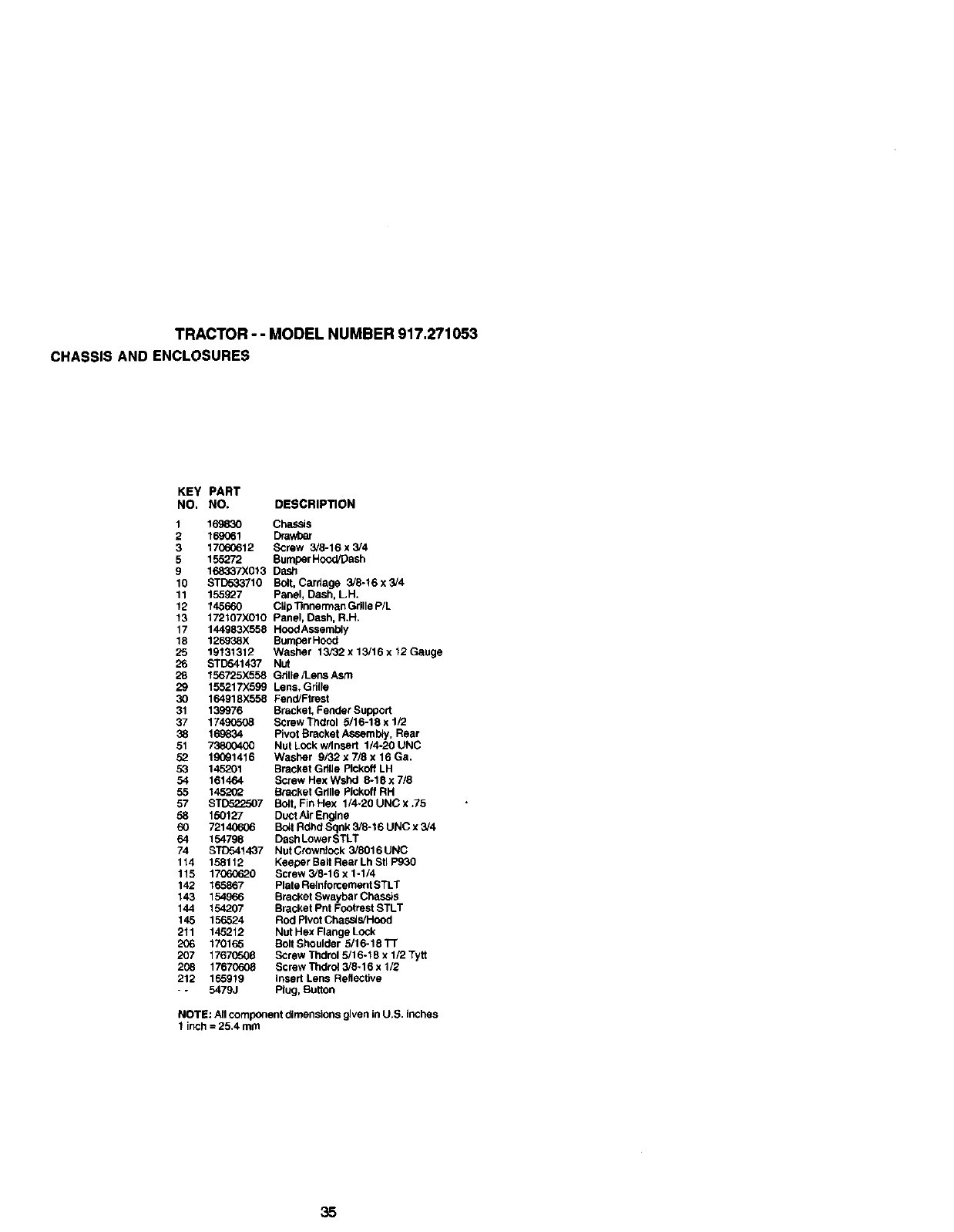
TRACTOR-- MODEL NUMBER 917.271053
CHASSIS AND ENCLOSURES
KEY PART
NO. NO. DESCRIPTION
1 169830 Chassis
2 169061 Drav/oar
3 1706_612 Screw 3/8-16 x 3/4
5 155272 Bumper Hood/[3ash
9 168337X013 Dastl
10 STD5S3710 Bolt, Carriage 3/8-16 x 3/4
11 155927 Panel, Dash, L.H.
12 145660 CIIpllnnermanGiiIleP/L
13 172107X010 Panel, Dash, R.H.
17 144983X558 H_d Assembly
18 126938X Bumper Hood
25 19131312 Washer 13/32 x 13/16 x 12 Gauge
26 STD541437 Nut
28 156725X558 Gillie/L.ens Asm
29 155217X599 Lens, Grille
30 164918X558 Feod/Ftrest
31 139976 Bracket, Fender Support
37 1749(_08 Screw Thdrol 5/16-18 x 1/2
38 169834 Pivot Bracket ASsemb4y, Rear
51 73800400 Nut LOCkw/Insert 1/4-20 UNC
52 19091416 Washer 9F32 x 7/8 x 16 Ga.
53 145201 Bracket Grille Plckoff LH
54 161464 Screw Hex Wshd 8-18 x 7/8
55 1452(_ Bracket Grille Pickoff RH
57 STD522507 Bolt, Fin Hex 1/4.20 UNC x ,75
58 150127 Duct Air En_ne
60 72140606 Boq Rdhd Sqnk 3/8-16 UNC x 3/4
64 154798 Dash Lower STLT
74 S_1437 NutCrown]ock 3/8016UNC
114 158112 Keeper Belt Rear Lh Stl P930
115 17060620 Screw 3/8-16 x 1-1/4
142 165867 Plate Reinforcement STLT
143 154966 Bracket Swaybar Chassis
144 154207 Bracket Pnt Footrest STLT
145 156524 Rod Pivot Chassis/Hood
211 145212 Nut Hex Flange Lock
206 170165 Bolt Shoulder 5/16-18TF
207 17670508 Screw Thdrol 5/16-18 x 1/2 Tytt
208 17670608 Screw Thdrol 3/8-16 x 1/2
212 165919 Insert Lens Reflective
--5479J Plug, Button
NOTE: All component dimensions given in U.S. inches
1 inch = 25.4 mm
35
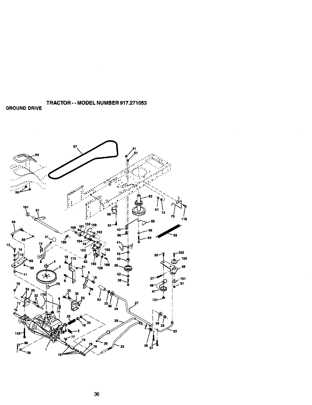
TRACTOR - - MODEL NUMBER 917.271053
GROUND DRIVE
36
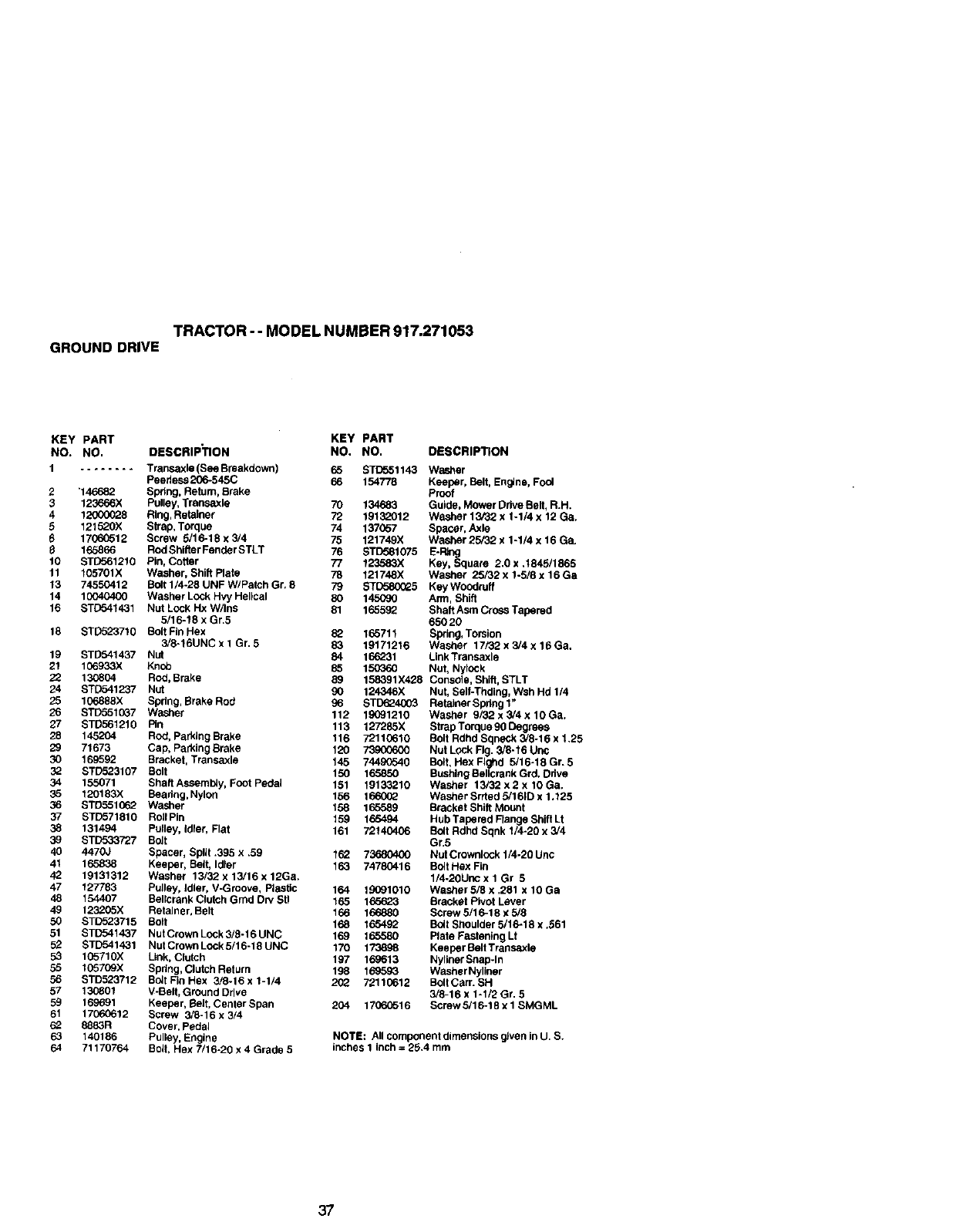
TRACTOR--MODELNUMBER917.271053
GROUNDDRIVE
KEY PART KEY PART
NO. NO. DBSCRIP_ON NO. NO.
1........ Transaxle (See Breakdown) 65 BTD651143
Peedess 206-545C 66 154778
2 "146682 Spring, Return, Brake
312_o66X Pulley, Transaxle 70 134683
4 12000_28 Ring, Retainer 72 19132012
5 121520)( Strap, Torque 74 137057
6 17065512 Screw 5/16-18 x 3/4 75 121749X
165866 Rod Shifter Fender STLT 76 STD581075
10 STD561210 Pin, Coffer 77 123583X
11 105701X Washer, Shift Plate 78 121748X
13 74550412 Bolt 1/4-28 UNF W/Patch Gr, 8 79 STD580025
14 10040400 Washer Lock Hvy Helical 80 145090
16 STC541431 Nut Lock Hx W/Ins 81 165592
5/16-18 x Gr.5
18 STD523718 Bolt Fin Hex 82 165711
3/8-16UNC x I Gr, 5 83 19171216
19 STB541437 Nut 84 166231
21 106933X Knob 85 150360
22 130804 Red, Brake 89 156591X428
24 STD541237 Nut gO 124346X
25 106888X Spring, Brake Rod 96 STD624003
26 ST[_3510G7 Washer 112 1_91210
27 STD561210 Pin 113 127285X
28 145204 Red, Parking Brake 116 72110610
29 71673 Cap, Parking Brake 120 73900600
30 169592 Bracket, Transaxle 145 744.90540
32 ST[Y._23107 Bolt 150 165850
34 155071 Shaft Assembly, Foot Pedal 161 19133210
35 120183)( Beadng, Nylon 156 1660_2
36 STD551062 Washer 158 165589
37 STD571810 RoilPin 159 165494
38 131494 Putley, Idler, Flat 161 72140406
39 STD533727 Bolt
40 4470J Spacer, Split .395 x .59 162 73680400
41 165838 Keeper, Bell, Idter 163 74780416
42 19131312 Washer 13/32 x 13/16 x 12Ga.
47 127783 Pulley, idler, V-Groove, Ptastic 164 19091010
48 154407 Bellcrank Clutch Grad Dry Stl 165 165623
49 123205X Retainer, Belt 166 166880
50 STD523715 Bolt 168 165492
51 STD541437 NutCrownLock3/6-16UNC 169 165580
52 STD541431 NutCrownLock5/16-18UNC 170 173898
53 105710X Link, Clutch 197 169613
55 105709X Spring, Clutch Return 196 169593
56 STD523712 Bolt Fin Hex 3/8-16x 1-1/4 2(;2 72110612
57 130801 V-Belt, Ground Drive
59 166591 Keeper. Bed, Center Span 204 17060516
61 17060612 Screw 3/8-16 x 3/4
62 8653R Cover, pedal
63 140186 Pulley, Engine
64 71170764 Bolt. Hex 7/16-20 x 4 Grade 5
DESCRIPTION
Washer
Keeper, Belt, Engine, Fool
Prcof
Guide, Mower Ddve Belt, R.H.
Washer 13/32 x 1-1/4 x 12 Ga.
Spacer. Axle
Washer 25/32 x 1-1/4 x 16 Ga.
20xI 5/1656
Washer 25/32 x 1-5/8 x 16Ga
Key Woodruff
Arm, Shift
Shaft Asm Cross Tapered
65020
Spring, Torsion
Washer 17/32 x 3/4 x 16 Ga.
Link Transaxle
Nut, Nylock
Console. Shift. STLT
Nut, Self-Thding, Wsh Hd 1/4
Retainer Spdng 1"
Washer 9/32 x 3/4 x 10 Ga.
Strap Torque 96 Degrees
Bolt Rdhd Sqneck 3/8-16 x 1.25
Nut Lock Fig. 3/8-16 Unc
Bolt, Hex Flghd 5/16-18 Gr. 5
Bushing Be.crank Grd. Ddve
Washer 13/32 x 2x 10 Ga.
Washer Srrtad 5/161D x 1.125
Bracket Shift Mount
Hub Tapered Flange Shift Lt
Bolt Rdhd Sqnk 1/4-20 x3/4
Gr.5
Nut Crownlock 1/4-20 Unc
Bolt Hex Fin
1/4-20Unc x 1 Gr 6
Wacher 5/8 x ,281 x 1OGa
Bracket Pivot Lever
Screw 5/16-18 x 5/8
Bolt Sedulder 5/16-18 x .561
Plate Fastening Lt
Keeper Belt Traesaxle
Nyliner Snap-In
Washer Nyllner
Bolt Carr. SH
3/8-16 x 1-I/2 Gr. 5
Screw 5/16-18 x I SMGML
NOTE: All component dimensions g_ven in U. S.
inches 1 inch = 26.4 mm
37
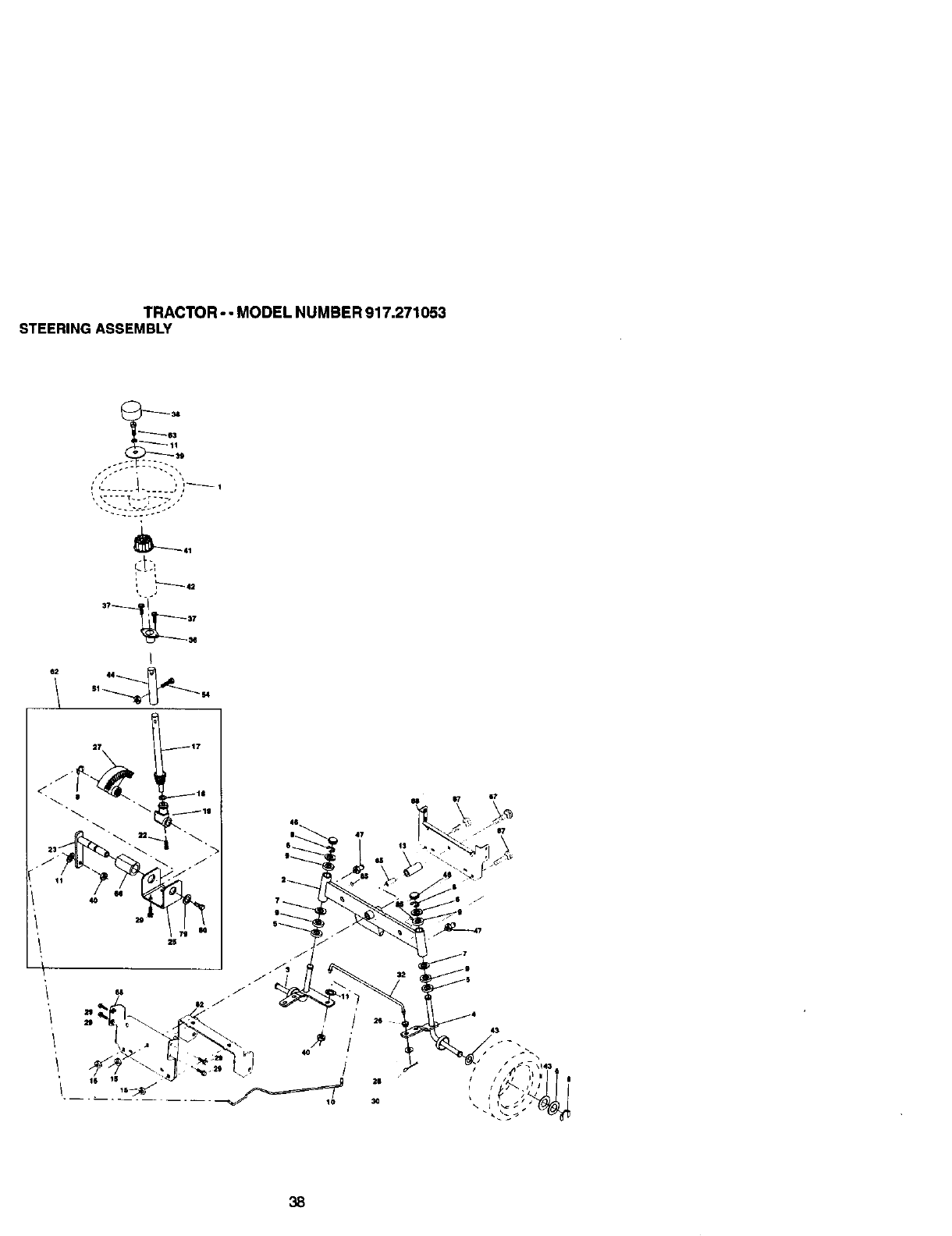
TRACTOR - - MODEL NUMBER 917.271053
STEERING ASSEMBLY
_.63
j17
2S
26
38
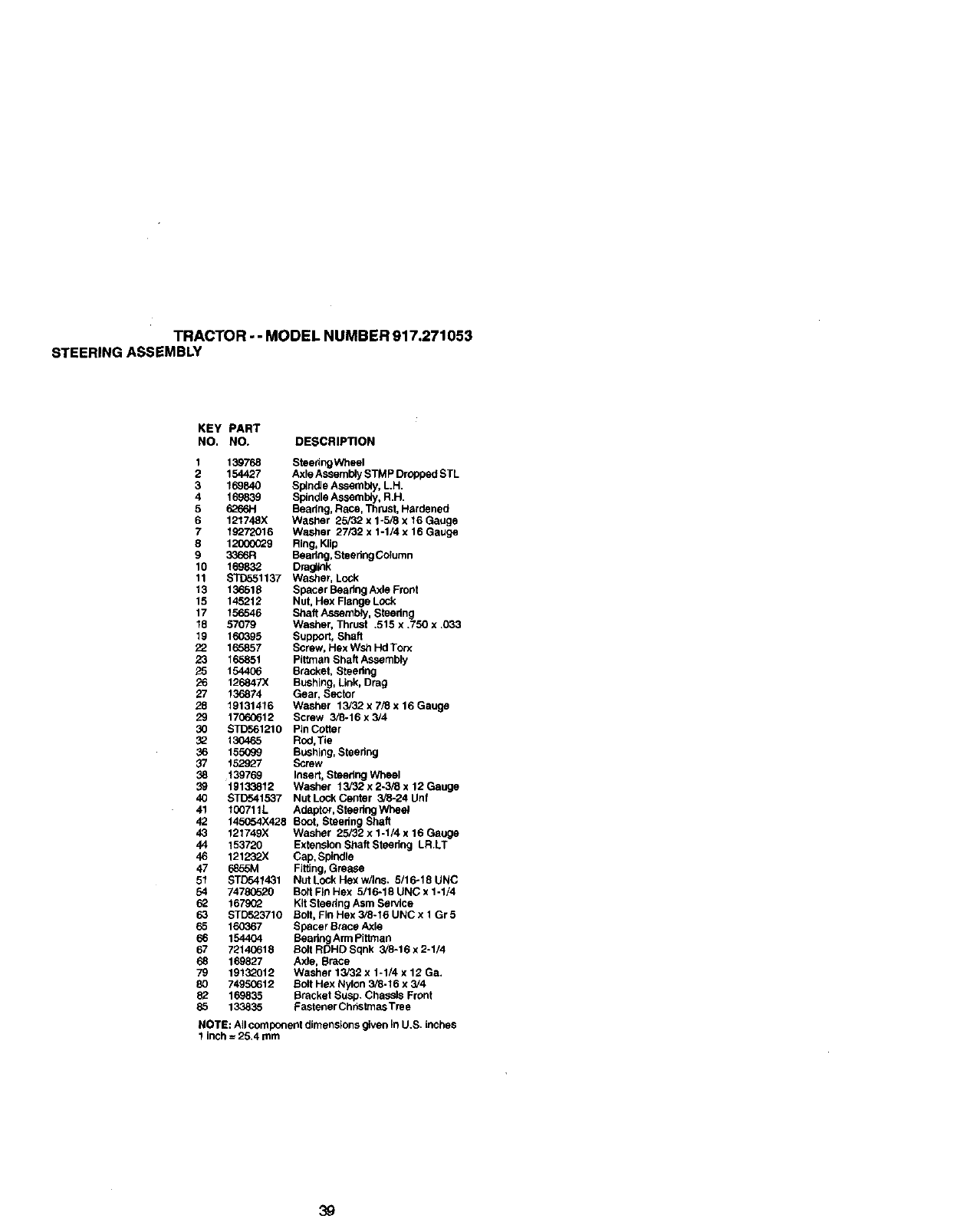
TRACTOR -- MODEL NUMBER 917.271053
STEERING ASSEMBLY
KEY PART
NO. NO. DESCRIPTION
1 139768 Steedng Wheel
2 154427 Axle Assembly STMP Drodped STL
3 169840 Spindle Assembly, L.H.
4 169839 Spindle Assembly, R.H.
5 6266H Beadng, Race, Thrust, Hardened
6 121748X Washer 25/32 x 1-5/8 x 16 Gauge
719272016 Washer 27/32 x 1-1/4 x 16 Gauge
8 12000(_9 Ring, KJip
9 3356R Beadng, StsedngColumn
10 169832 Dmgllnk
11 STD551137 Washer, Lock
13 136518 Spacer Beadng Axle Front
15 145212 Nut, Hex Flange LOck
17 156546 Shaft AssembJy, Steering
18 57079 Washer, Thrust .515 x .750 x .033
19 160395 Support, Shaft
22 165857 Screw, Hex Wsh Hd Tot_
23 165851 Pittman Shaft Assembly
25 154406 Bracket, Stsedng
26 126847X Bushing, Link, Drag
27 136874 Gear, Sector
28 19131416 Washer 13/32 x 7/3 x 16 Gauge
29 17060613 Screw 3/8-16 x 3/4
30 STD561210 Pin Cotter
32 130465 Rod,Tie
36 155099 Bushing, Stsering
37 152927 Screw
38 139769 Insert, Steedng Wheel
39 19133812 Washer 13/'32 x 2-3/8 x 12 Gauge
40 STDr'_41537 Nut LOck Center 3/5-24 Unf
41 I00711L Adeptor, Stsedng Wheat
42 145054X428 Scot, Steedng Shaft
43 121749X Washer 25/32 x 1-1/4 x 16 Gauge
44 153720 Extension Shaft Stsedng LR.LT
46 121232X Cap, Spindle
47 6855M Fitting, Grease
51 STD541431 Nut LOck Hex w/Ins. 5/16-18 UNC
54 74780520 Bolt Fin Hex 5/16-18 UNC x 1-1/4
62 167902 Kit Stsenng Asm Service
63 STD523710 Bolt, Fin Hex 3/6.16 UNC x 1 Gr 5
65 160367 Spacer Brace Axle
66 154404 Beadng Arm pittman
67 73140618 Bolt RDHD Sqnk 3/8-16 x 2-1/4
68 169827 Axle, Brace
79 19132012 Washer 13/32 x 1-1/4 x 12 Ga.
80 74950612 Bolt Hex Nylon 3_-16 x 3/4
82 169835 Bracket Suap. Chassis Front
85 133835 Fastener Christmas Tree
NOTE: All component dJmenslons given in U.S. inches
1 inch = 25.4 mm
39
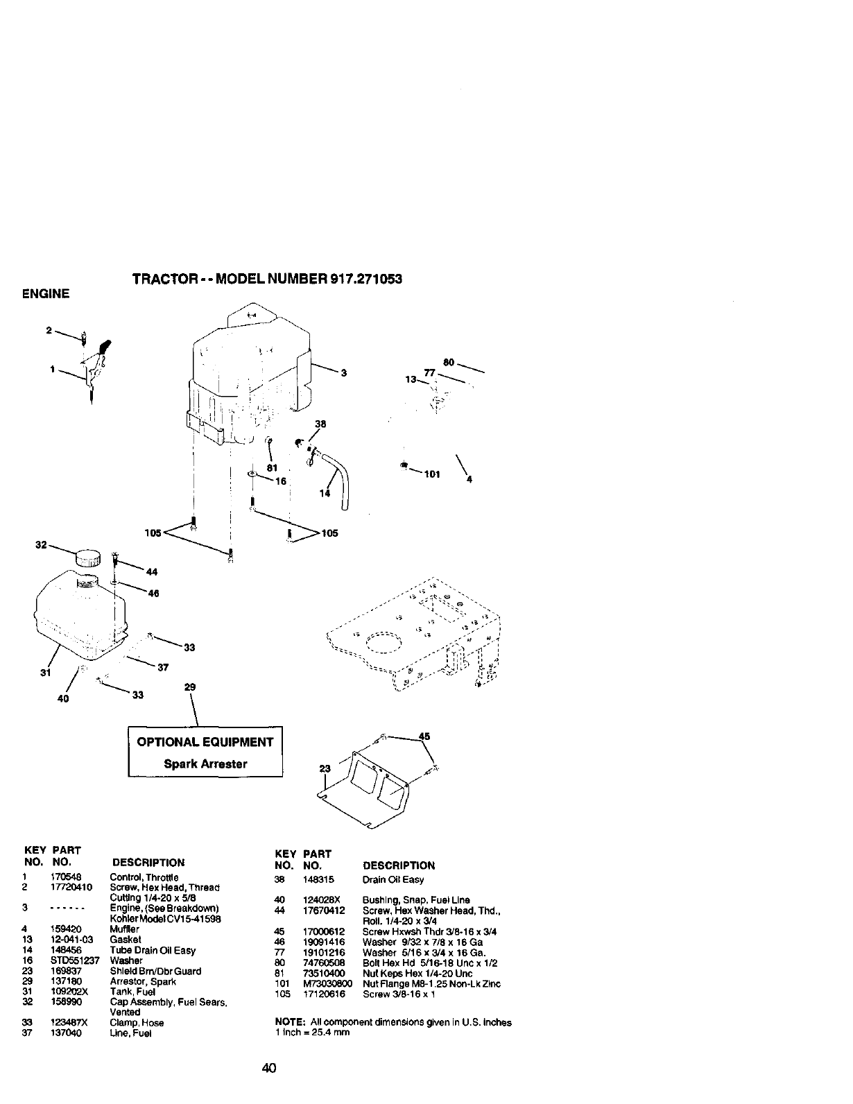
ENGINE TRACTOR - - MODEL NUMBER 917.271053
': _\33
/_'_ _97
91 /' *
/_'_" 33 29
,0 /
OPTIONAL EQUIPMENT
Spark Arrester
4
KEY PART KEY PART
NO, NO, DESCRIPTION NO. NO.
1170548 Control, Throffie 38 148315
2 17720410 Screw, Hex Head, _Phreaci
Cuffing 1/4-20 x 5/8 40 124028X
3...... Engine, (See Breakdown) 44 17670412
Kohler ModelCV15-41598
4 159420 Muffler 45 17000612
13 12-041-03 Gasket 46 19091416
14 148456 Tube Drain Oil Easy 77 19101216
16 STD551237 Washer 80 74760508
23 169837 Shield Brn/Dbr Guard 81 73510400
29 137180 Arrestor, Spark 101 M73030800
31 10920"2X Tank, Fuel 105 17120616
32 158990 Cap Assembly, Fuel Sears,
Vented
33 123487X Clamp, Hose
37 137040 Line, Fuel
DESCRIPTION
Drain Oil Easy
Bushing, Snap, Fuel Line
Screw, Hex Washer Head, Thd.,
Roll. 1/4-20 x 3/4
Screw Hxwsh Thdr 3/8-16 x 3/4
Washer 9/32 x 7/8 x 18 Ga
Washer 8/16 x3/4 x 16 Ga.
Bolt Hex Hd 5/16-18 Unc x 1/2
Nut Keps Hex 1/4-20 Une
Nut Flange M8-1.25 Non-Lk ZFnc
Screw 3/9-16 x 1
NOTE: All component dimensions given in U.S. inches
1 inch = 25.4 mm
4O
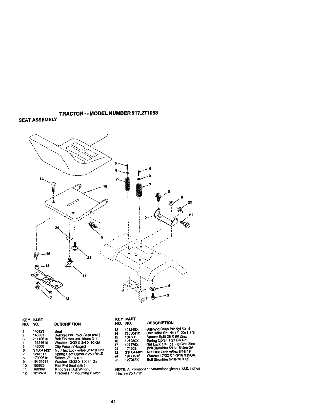
TRACTOR-- MODEL NUMBER 917.271053
SEAT ASSEMBLY
KEY PART KEY PART
NO. NO. DESCRIPTION NO. NO. DESCRIPI"/ON
1140123 Seat 13 121248X Bushing Snap BIk Ny150 Id
2140551 Bracket Phi Pivot Seat (blk _ 14 72(_0412 Bolt RdJld Sht Nk 114-20xl -I]2
3 71110616 Bolt Fin Hex 5/8-16unc X 1 15 134300 Spacer Split 28 X 96 Zinc
4 19131610 Washer 13/32 X 3/4 X 10 Ga 16 121_50X Spdng Cprsn 1 27 BIk Pnt
5 145006 Clip Push tn HInga_i 17 12"3976X Nut Lock 1/4 Lge Fig Gr 5 Zinc
6 STD541437 Nut Hex LOCk w/ins 3/8-16 Llnc 21 171852 Bolt Shoulder 5/16-18 Unc-2A
7 124181X Spdng Seat CprsN 2 250 Sl_ Zi 22 S_1431 Nut Hax Lock w/Ins 5/16-t 8
8 17000616 Screw 3/8-16 X 1 24 19171912 Washer 17/32 X 1-3,'16 X12Ga,
9 19131614 Wacher 13/32 X 1 X 14 Ga 25 127018X Bolt Shoulder 5/16-18 X 62
10 155925 Pan Pnt Seat (blk)
11 166369 Knob Seat Adj Wingnut NOTE: All component dJmensions given in U.S. inches
12 1£_246;€ Bracke_ Fnt _ountlhg Bwitcf) 1 inch = 25.4 mm
41
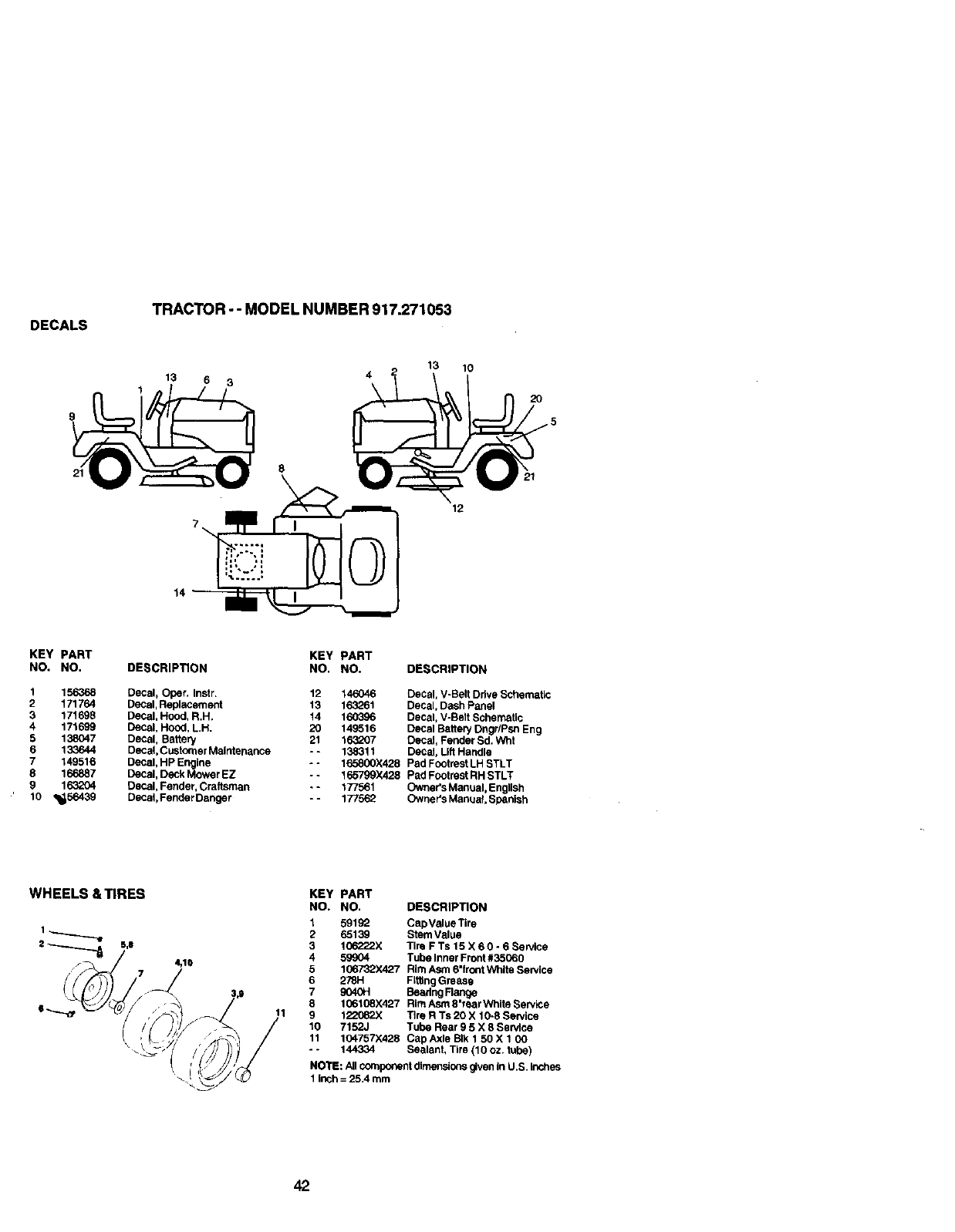
DECALS TRACTOR -- MODEL NUMBER 917.271053
8
\
13
12
10
2O
14 I
KEY PART
NO. NO.
I 156368
2 171764
3 171698
4 171699
5 138047
6 133644
7149516
8 166887
9 163204
'lO _._
DESCRIPTION
Decal, Oper. Instr.
Decal, Replacement
Decal, Hood, R.H.
Decal, Hood, L.H.
Decal, Battery
Decal, Customer Maintenance
Decal, HP Engine
Decal, Deck Mower EZ
Decal, Fender, Craftsman
Decal,Fender Danger
KEY PART
NO. NO. DESCRIPTION
12 146046 Decal, V-Belt Drive Schematic
13 163261 Decal, Dash Panel
14 160396 Decal, V-Bait SchemaUc
20 149516 Decal Battery Dngr/Psn Eng
21 163207 Decal, Fender Sd. Wht
- - 138311 Dacal_ Lift Handle
-- 165800X428 Pad Footrest LH STLT
-- 165799X428 Pad Footn_st RH STLT
•-177561 Owner's Manual, English
-- 177562 Owner's Manual Spanish
WHEELS & TIRES KEY PART
NO. NO. DESCRIPTION
1 59192 CapValue Tire
2 65139 Stem Value
3 106222X Tire F Ts 15 X 6 0 -6Service
4 59904 Tube Inner Front #35060
5 106732X427 Rim Asm 6"front White Service
6 278H Fd6ng Grease
7 gO40H Beedng Flange
8 106108X427 Rim Asm 8"rear Whfte Service
9 122062X Tire R Ts 20 X 10-8 Service
10 7152J Tut)e Rear 9 5 X 8 Service
11 104757"/.428 Cap Axle BIk 1 50 X 1 00
- - 144334 Sealant, Tire (10 oz. tube)
NOTE: All component dimensions given in U.S. inches
1 inch = 25.4 mm
42
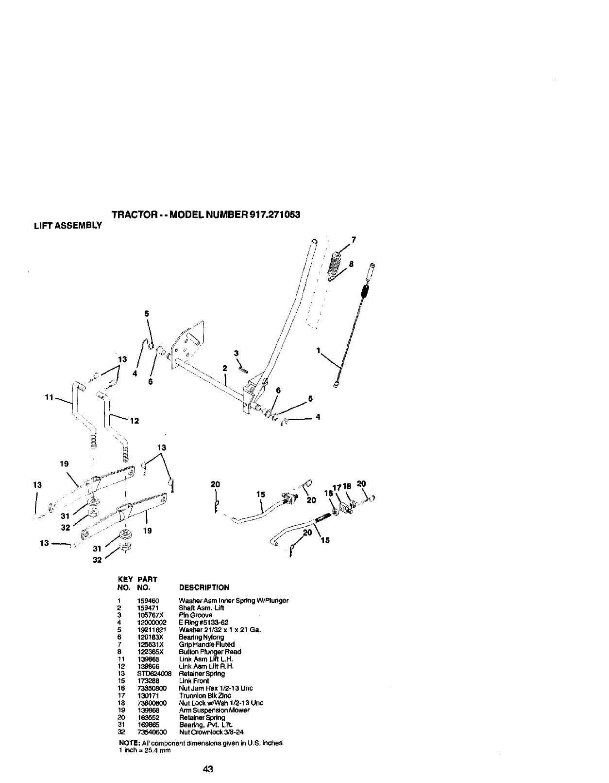
TRACTOR--MODELNUMBER917.271053
LIFTASSEMBLY
13
32
5
13
19
7
32
KEY PART
NO. NO. DESCRIPTION
1 159460 Washer Asm Inner Spring W/Plunger
2 159471 Shaft Asm. Lift
3 1(]5767X Pin Groove
4 12_300(]02 E Ring#5133-62
5 19211621 Washar 21/32 x 1 x 21 Ga.
6 120183X Beadng Nylong
7125631X Gdp Handle Ruted
8 1223_5X Button Plunger Read
11 139865 Link Asm Lift L H.
12 139866 Link Asm Lift R.H.
13 S'rD624008 Retainer Spdng
15 173288 Link Front
16 73350800 Nut Jam Hex 1/2-t3 Un¢
17 130171 Trunnion BIk Z_nc
18 73800800 Nut Lock w/Wsh 1/2ol 3 Unc
19 1398_8 Arm Suspension Mower
20 163552 Retainer Spdng
31 169865 Beadng, Pvt. Lift.
3_ 73540600 Nut Crownlock 3/8-24
NOTE: All component dimensions given in U.S. inches
1 inch = 25.4 mm
43
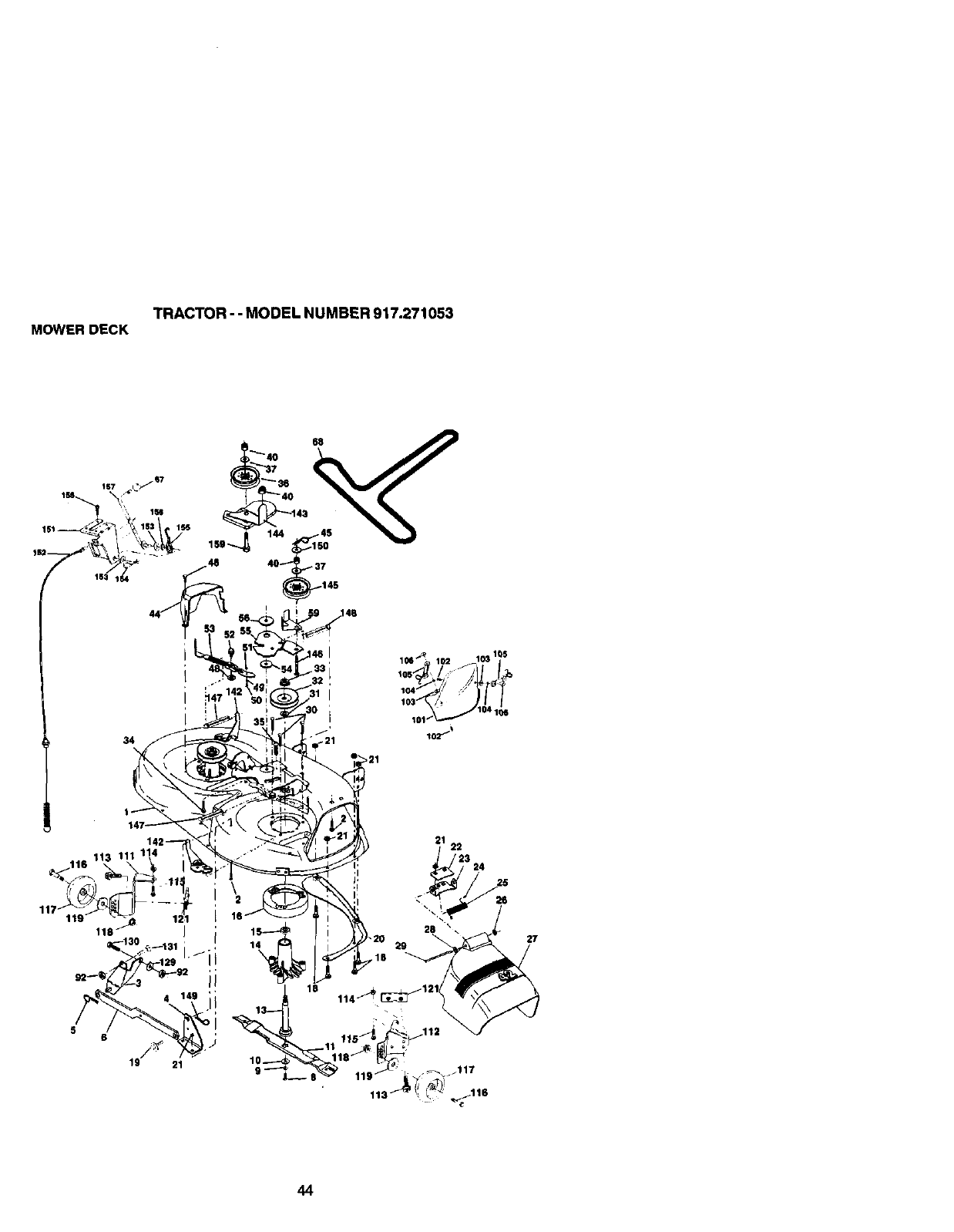
TRACTOR--MODELNUMBER917.271053
MOWERDECK
27
44
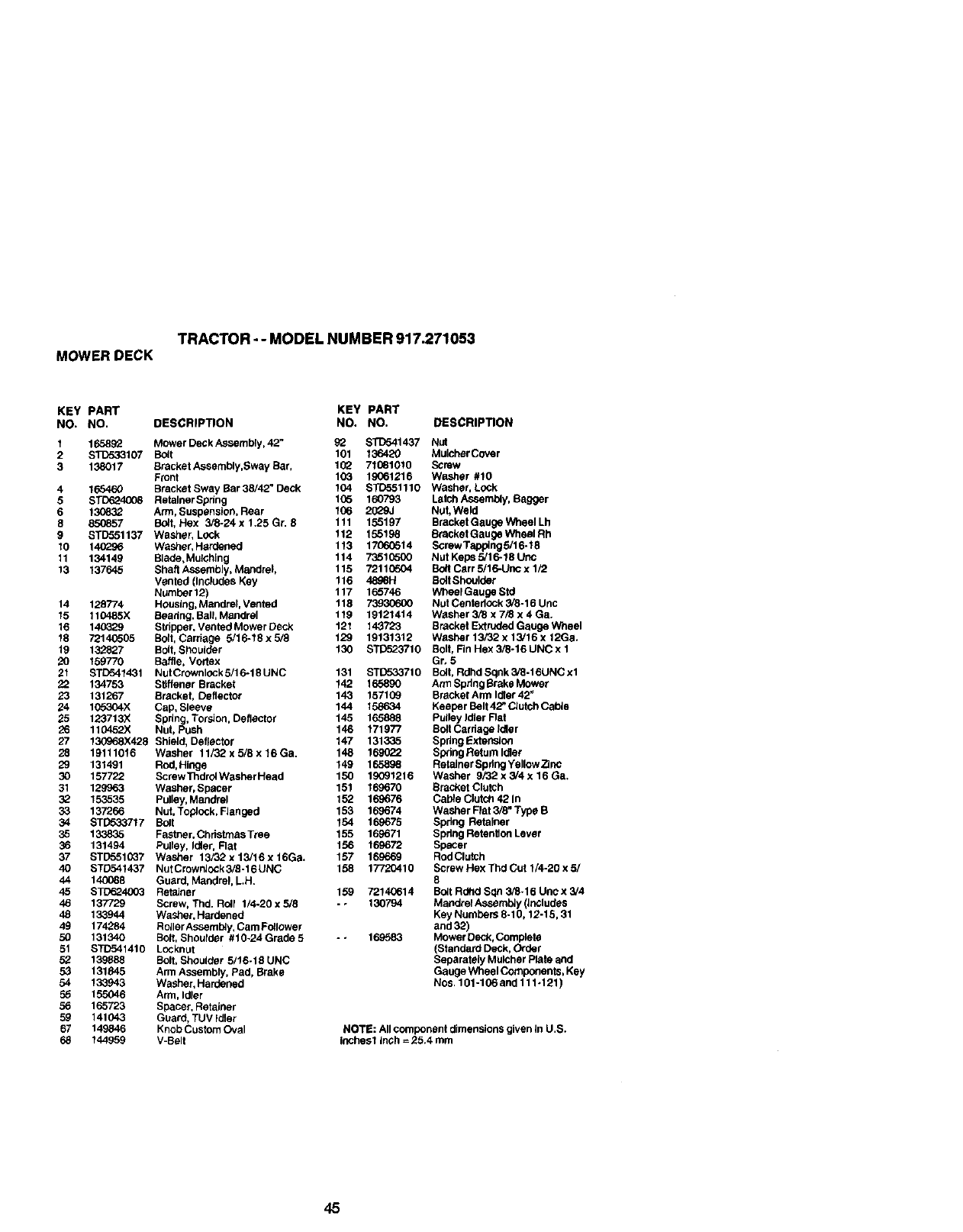
TRACTOR - - MODEL NUMBER 917.271053
MOWER DECK
KEY PART KEY PART
NO. NO. DESCRIPTION NO. NO. DESCRIPTION
1165892 Mower Deck Assembly, 42" 92 STD541437 Nut
2 $1_533107 Bdlt 101 136420 Mulcher Cover
3 138017 Bracket Assembly,Sway Bar, 102 71081010 Screw
Front 103 19061216 Washer #10
4 165460 Bracket Sway Bar 38/42" Deck 104 STD651110 Washer, Lock
5 STD62400_ RetalnerSpdng 105 160793 Latch Assembly, Bagger
6130832 Ann, Suspension, Rear 1(36 2029J Nut, Weld
8 850857 BoJt, Hex 3/8-24 x 1.25 Gr. 9 111 155197 Bracket Gauge Wheel Lh
9 STD651137 Washer, Lock 112 155198 BracketGaugeWheelRh
10 140296 Washer, Hardened 113 17060514 Screw Tapping 5/16-18
11 134149 Blade, Mulching 114 76516500 Nut Keps 5/16-18 UOC
13 137645 Shaft Assembly, Mandrel, 115 7211(3504 Bo_t Cerr 5/16-UOC x 1F2
Vented (Includes Key 116 4898H SoltShoulder
Numher 12) 117 165746 Wheel Gauge Std
14 128774 Houslag, Mandrel, Vented 118 73930600 Nut CentedOck 3/8-16 Unc
15 110465X Seadng, Ball Mandrel 119 19121414 Washer 3/8 x 7/8 x 4 Ga.
16 14C329 Stripper, Vented Mower Deck 121 143723 Bracket Extruded Gauge Wheel
18 72140505 Bolt, Carriage 5/16-18x5/8 129 19131312 Washer13/32x13/16x12Ga.
19 132827 Bolt, Shoulder 130 STiTo23710 Bolt, FinHex3/8-16UNCx1
20 159770 Baffle, Vortex Gr, 5
21 STC541431 NutCrownlockS/16*18UNC 131 STD533710 Bdlt, RdhdSqnk3/8-t6UNCx1
22 134753 Stiffener Bracket 142 165890 ArmSpdngBrakaMower
23 131267 Bracket, Deflector 143 157109 BrackefArmldter42"
24 165304X Cap, Sleeve 144 158634 Keeder Belt 42" Clutch Cahte
25 123713X Spdng, Torsion, Deflector 145 165888 Pulley Idler Flat
26 110452X Nut, Push 146 171977 Bdlt Cardage Idler
27 130968X429 Shlald, Deflactor 147 131335 SpdngExtenolon
28 19111016 Washer 11/32x5/8x16Ga. 148 169022 SpdngReturnldler
29 131491 Rod,Hinge 149 165898 Retainer Spdng Yellow 7]nc
30 157722 ScrewThdrolWasherHeed 150 19091216 Washer 9/32 x 3/4 x 16 Ga.
31 129963 Washer, Spacer 151 169670 Bracket Clutch
32 153535 Pulley, Mandrel 152 16_676 Cable Clutsh 42 In
33 137265 Nut, Toplock, FJanged 153 169674 Washer Ftet 3/8" Type B
34 STD5337"17 Bolt 154 169675 Spdng Retainer
35 133835 Fastner, Christmas Tree 155 169671 Spdng Retentten Lever
36 131494 Pufley, Idler, Rat 156 169672 Spacer
37 STD551(_7 Washer 13/32x13/16xt6Ga. 157 169669 RodClutch
40 ST0541437 NutCrown]ock3/8-16UNC 158 17720410 ScrewHexThdCutl/4-20x5/
44 140088 Guard, Mandrel, LH. 8
45 STD624653 Retainer 159 72140614 Bdlt Rdhd Sqn 3/8-16 Unc x 3/4
46 137729 Screw, Thd. Rdlf 1/4-20 x 5/8 -. 130794 MaodrelAseembly (]ndludes
48 133944 Washer.Hardened Key Numbers 8-10,12-19, 31
49 174284 Rotler Assembly, Cam Fdllower aod 39)
50 131340 Bdlt, Shodlder #10-24 Grade 5 -- 169583 Mower Deck, Complete
51 STD541410 Locknut (Staodard Deck, Order
52 139888 Bolt, Shoulder 5/t6-19 UNC Separately Mulcher Plate and
53 131845 Arm Assembly, Pad, Brake Gauge Wheel Components, Key
54 133943 Washer, Hardened Nos, 101-106 and 111.121)
55 155046 Arm, Idler
56 165729 Spacer, Retainer
59 141043 Guard, TUV idler
67 149846 Knob Custom Oval NOTE: All component dimensions given In U,S.
65 144959 V-Belt inches1 inch = 25.4 mm
45
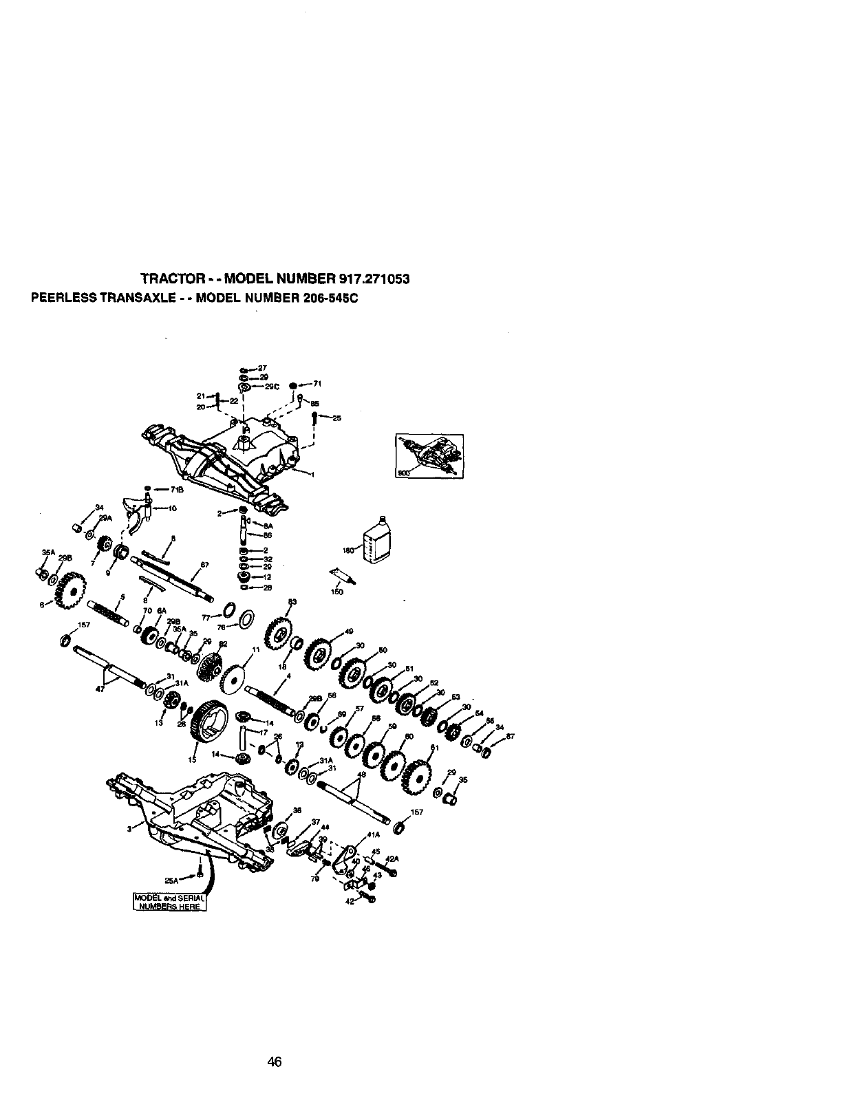
TRACTOR - - MODEL NUMBER 917.271053
PEERLESS TRANSAXLE - - MODEL NUMBER 206-545C
/
13
I
157
46
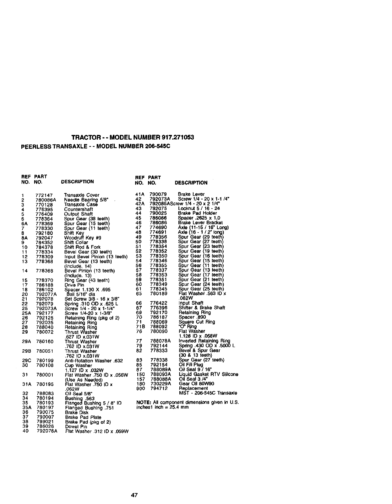
TRACTOR - - MODEL NUMBER 917.271053
PEERLESS TRANSAXLE -- MODEL NUMBER 206-545C
REF PART REF PART
NO. NO. DESCRIPTION NO. NO. DESCRIPTION
1772147 Transaxle Cover 41A
2 780086A Needle Bearing 5/8" 42
3 770128 Transexle Case 42A
4776395 Countershaft 43 792075
5 776409 Output Shaft 44 790025
6 778364 Spur Gear (38 teeth) 45 786066
6A 778369 Spur Gear (15 teeth) 46 786086
7 778330 Spur Gear (11 teeth) 47 774690
8 792180 Shift Key 48 774691
8A 792047 Woodruff Key #9 49 778356
9 784352 Shift Collar 50 778338
10 784378 Shift Rod & Fork 51 778354
11 778334 Bevel Gear (30 teeth) 52 778352
12 778309 Input Bevel Pinion (13 teeth) 53 778350
13 778368 Bevel Gear (13 teeth) 54 778346
include. 14) 56 778355
14 778368 Bevel Pnion (13 teeth) 57 778337
(include. 13) 59 778353
15 778370 Ring Gear (43 teeth) 59 778351
17 786188 Drive Pin 60 778349
18 786102 Spacer 1.130 X .695 61 778345
20 792077A Ball 5/16" dia 65 780189
21 792078 Set Screw 3/8 - 16 x 3/8"
22 792079 Spring .310 OD x .625 L 66 776422
25 792073A Screw 1/4 - 20 x 1-1/4 67 776396
25A 792177 Screw 1/4-20 x 1-3/8" 69 792170
26 792125 Retaining Ring (pkg o1 2) 70 786187
27 792035 Retaining Ring 71 788069
28 788040 Retaining Ring 71B 788092
29 780072 Thrust Washer 76 780090
.627 ID x,031w
29A 780160 Thrust Washer 77 788078A
.762 ID x.O31W 79 792144
29B 780051 Thrust Washer 82 778333
.762 ID x.031W
29C 780199 Anti-Rotation Washer .632 83 778338
30 780108 Cup Washer 85 792154
1.127 ID x .032W 87 788089A
31 780001 Flat Washer ,750 ID x .056W 150 788093A
Use AS Needed) 157 788088A
31A 780195 Fat Washer .750 ID x 180 730229A
.062W 900 794712
32 788083 Oil Seal 5/8"
34 780194 Bushing .563 .
35 780193 Flanged Bushing 5 /8 IO
35A 780197 Flanged Bushing .751
36 790075 Brake Disk
37 790007 Brake Pad Plate
38 799021 Brake Pad (pkg of 2)
39 786026 Dowel Pin
40 792076A Flat Washer .312 ID x .059W
790079 Brake Lever
792073A Screw 1/4 -20 x 1-1 /4"
792085AScrew 1/4 -20 x 2 1/4"
Looknut 5 /16 -24
Brake Pad Holder
Spacer .2625 x 1.0
Brake Lever Bracket
Axle (11-15 /16" Long)
Axle (16- 1 /2" long)
Spur Gear (29 teeth)
Spur Gear (27 teeth)
Spur Gear (23 teeth)
Spur Gear (19 teeth)
Spur Gear (16 teeth)
Spur Gear (15 teeth)
Spur Gear 11 teeth
Spur Gear 113 teethl
Spur Gear (17 teeth)
Spur Gear (21 teeth)
Spur Gear (24 teeth)
Spur Gear (25 teeth)
Flat Washer .563 IO x
.062W
Input Shaft
Shifter & Brake Shaft
Retaining Ring
Spacer .890
Square Cut Ring
"O" Ring
Flat Washer
1.128 tD x,058W
Inverted Retaining Ring
Spring .430 OD x .5000 L
Bevel & Spur Gear
_30& 13 teeth)
pur Gear (27 teeth)
Oil Fill Plug
Oil Seal 9 /16"
Liquid Gasket RTV Sliicone
Oil Sea! 3/4"
Gear Oil 80W90
Replacement
MST - 206-545(; Transaxle
NOTE: All component dimensions given In U.S.
inchasl inch = 25.4 mm
47
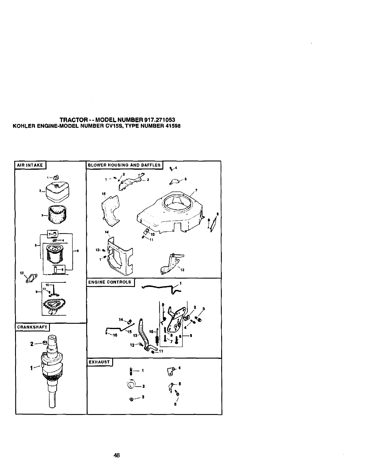
TRACTOR -- MODEL NUMBER 917.271053
KOHLER ENGINE-MODEL NUMBER CV15S, TYPE NUMBER 41598
AIR INTAKE J
5- _--Q
C,."ANNS.AFTI
J
BLOWER HOUSING AND BAFFLES I _..-4
?.
14
\
1-_
ENGINE CONTROLS I
SXHAUSTJ
___S /
6
48
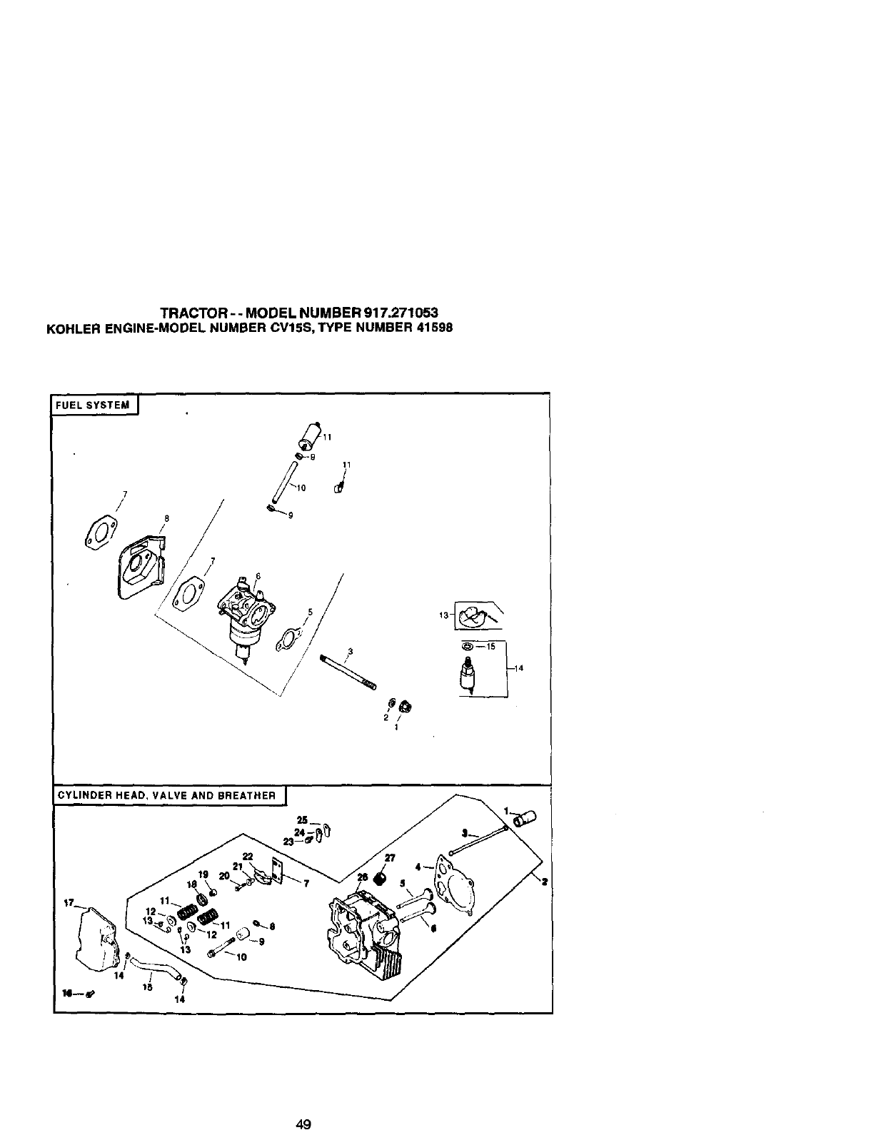
TRACTOR - - MODEL NUMBER 917.271053
KOHLER ENGINE-MODEL NUMBER CV15S, TYPE NUMBER 41598
FUEL SYSTEM I
7
(_11
'_=-9
2/
1
_--1S i
CYLINDER HEAD, VALVE AND BREATHER I
25__
49
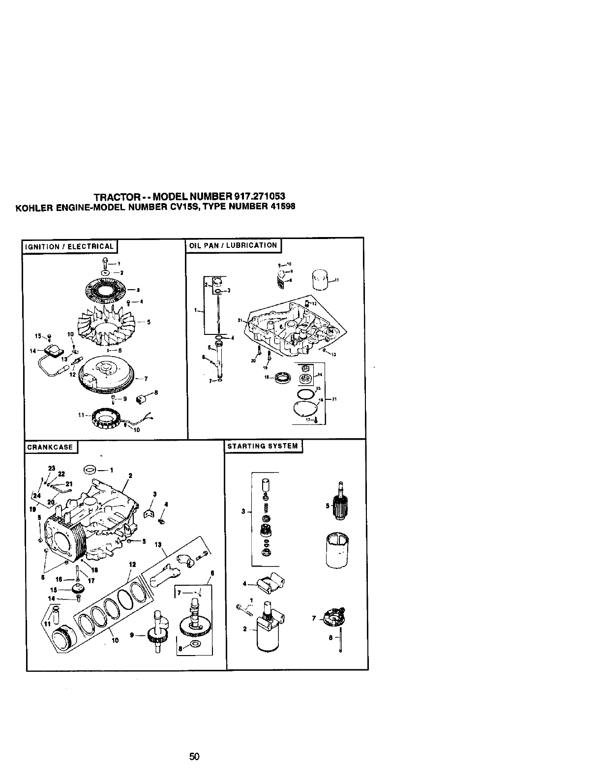
TRACTOR- - MODEL NUMBER 917.271053
KOHLER ENGINE-MODEL NUMBER CV15S,TYPE NUMBER 41598
IGNITION IELECTRICAL J OIL PAN ILUBRICATION I
€_-,--4
1_ _ ]
CRANKCASE J
23 22 (_--1 2
3
-I 13
STARTING SYSTEM I
o
5o
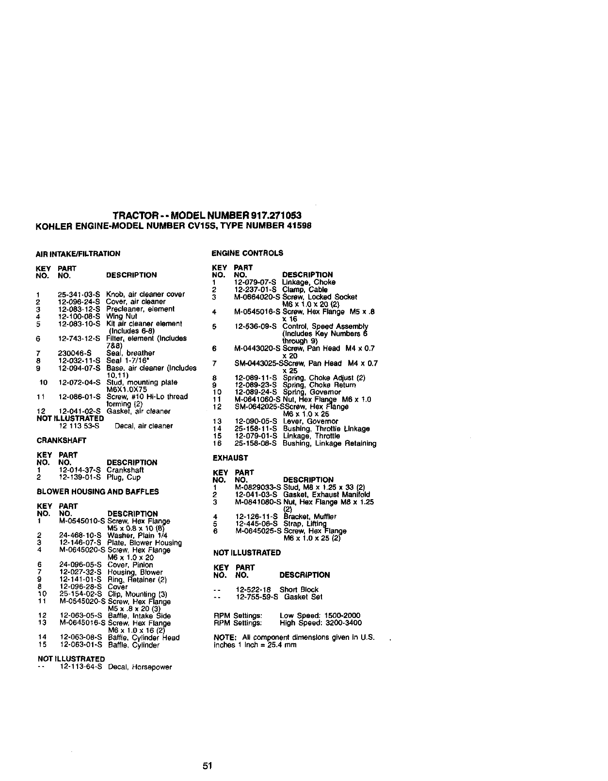
TRACTOR - - MODEL NUMBER 917.271053
KOHLER ENGINE-MODEL NUMBER CV15S, TYPE NUMBER 41598
AIR INTAKE/FILTRATION
KEY PART
NO. NO. DESCRIPTION
1
2
3
4
5
6
lO
25-341-03-S
12-096-24-S
12-083-12-S
12-100-08-S
12-083-10-S
12-743-12-S
230B46-S
12-032-11 -S
12-094-07-S
12-072-O4-S
11 12-086-01-S
Knob, air cleaner cover
Cover, air c_eaner
Precleaner, element
Wing Nut
Kit air cleaner element
(Includes 6-8)
Filter, element (Includes
7&8)
Seal, breather
Seal 1-7/16"
Base, air cleaner (Includes
10,11)
Stud, mounting plate
M6X1.0)(75
Screw, #10 Hi-Lo thread
forming (2)
12 12-041-02-S Gasket, air cleaner
NOT ILLUSTRATED
12 113 53-S Decal, air cleaner
CRANKSHAFT
KEY PART
NO. NO. DESCRIPTION
1 12-014-37-S Crankshaft
2 12-139-01-S Plug, Cup
BLOWER HOUSING AND BAFFLES
KEY PART
NO. NO. DESCRIPTION
1 M-O54501B-S Screw, Hex Flange
M5 x 0.8 x 10(8)
224-468-10-S Washer, Plain 1/4
3 12-146-07-S Plate, Blower Housing
4 M-0645020-S Screw, He:< Flange
M6 x 1.0 x 20
6 24-096-05-S Cover, Pinion
712-027-32-S Housing, Blower
9 12-141-01-S Ring, Retainer (2)
8 12-096-28-S Cover
10 25-154-02-S Clip, Mounting (3)
11 M-0545020-S Screw, Hex Flange
M5 x .8 x 20 (3)
12 12-063-05-S Baffle, Intake Side
13 M-0645016-S Screw, He:<Flange
M6 x 1.0 x16 (2)
14 12-063-08-S Baffle, Cylinder Head
15 12-063-01-S Baffle, Cylinder
NOTILLUSTRATED
-- 12-113-64-S Decal, Horsepower
ENGINE CONTROLS
KEY PART
NO. NO. DESCRIPTION
1 12-079-07-S Linkage, Choke
2 12-237-01-S Clamp, Cable
3 M-0664020-S Screw, Locked Socket
M6 x f.B x 2B (2)
4 M-0545B16-S Screw, Hex Flange M5 x .8
x 16
512-536-09-S Control, Speed AsSembly
(Includes Key Numbers 6
through 9)
6 M-0443020-S Screw, Pan Head M4 x 0.7
x20
7 SM-O443025-SScmw, Pan Head M4 x 0.7
x 25
8 12-089-11-S Spdng, Choke Adjust (2)
912-089-23-S Spring, Choke Return
10 12-089-24-S Spring, Governor
11 M*0641060-S Nut, Hex Flange M6x 1.0
12 SM.0642025-SScrew, Hex Flange
M6x I,B x 25
13 12-090-05-S Lever, Governor
14 25.158-11-S Bushing, Throftle Linkage
15 12-079-01-S Linkage, Throttle
16 25-158-08-S Bushing, Linkage Retaining
EXHAUST
KEY PART
NO. NO. DESCRIPTION
1 M-0829B33-S Stud, M8 x t.25 x 33 2)
212-041-03-S Gasket, Exhaust Manfod
3 M-0841080-S Nut, Hex Flange M8 x 1.25
412-126-11-S (2)
uracket, Muffler
5 12-445-06-S Strap, Lifting
6 M-0645025-S Screw, He:<Flange
M6 x 1,0 x 25 (2)
NOTILLUSTRATED
KEY PART
NO. NO. DESCRIPTION
-- 12-522-18 Shod Block
-- 12-755-59-S Gasket Set
RPM Settings: LOW Speed: 1500-2000
RPM Settings: High Speed: 3200-3400
NOTE: All component dimensions given in U,S.
inches I Inch = 25.4 mm
51
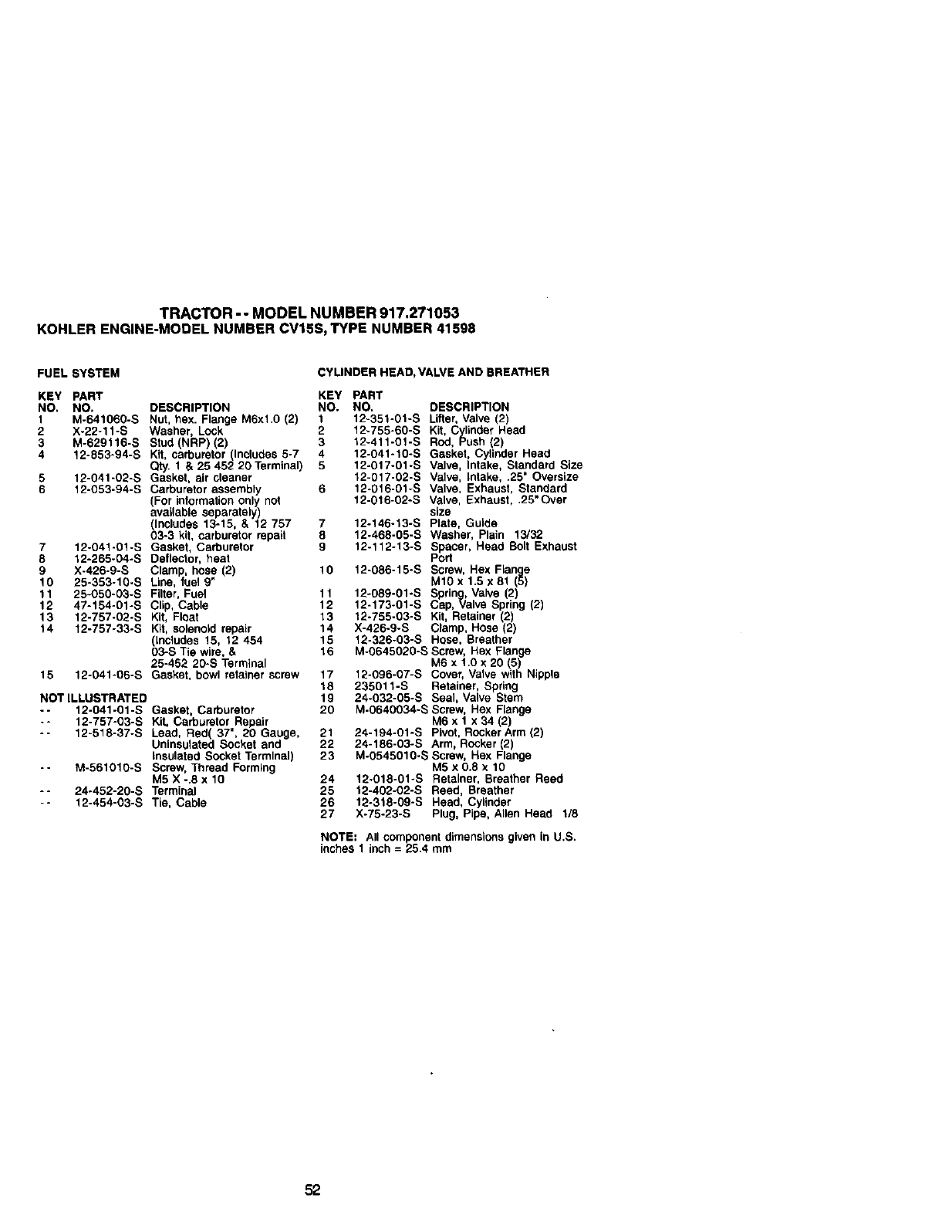
TRACTOR--MODEL NUMBER 917.271053
KOHLER ENGINE-MODEL NUMBER CV15S, TYPE NUMBER 41598
FUEL SYSTEM CYLINDER HEAD, VALVE AND BREATHER
KEY PART KEY PART
NO. NO. DESCRIPTION NO. NO. DESCRIPTION
1 M-641060-S Nut, hex. Flange M6xl.0 (2) 1 12-351-01-S Lifter, Valve (2)
2 X-22-11-S Washer, Lock 2 12.755-60-S Kit, Cylinder Head
3 M-629116-S Stud (NRP) (2) 3 12.411-01-S Rod, Push (2)
4 12-853-94-S Kit, carburetor (Includes 5-7 4 12-041-10-S Gasket, Cylinder Head
Qty. 1 & 25 452 20Terminal) 5 12-017-01-S Valve, Intake, Standard Size
5 12-041-02-S Gasket, air cleaner 12-017-02-S Valve, Intake, .25" Oversize
6 12-053-94-S Carburetor assembly 6 12-016-01-S Valve, Exhaust, Standard
(For information only not 12-016-02-S Valve, Exhaust, .25"Over
available separately) size
(Includes 13-15, & 12 757 7 12-t46-13-S Plate, Guide
03-3 kit, carburetor repair 8 12-468-05-S Washer, Plain 13/32
7 12-041-01-S Gasket, Carburetor 9 12-112-13-S Spacer, Head Bolt Exhaust
8 12-265-04-S Deflector, heat Port
9 X-426-9-S Clamp, hose (2) 10 12-086-15-S Screw, Hex Flange
10 25-353-10-S Line, fuel 9" M10 x 1.5 x 81 (5)
11 25-050-03-S Filter, Fuel 11 12-089-01-S Spring, Valve (2)
12 47-154-01-S Clip, Cable 12 12-173-01-S Cap, Valve Spring (2)
13 12-757-02-S Kit, Float 13 12-755-03-S Kit, Retainer (2)
14 12-757-33-S Kit, solenoid repair 14 X-426-9-S Clamp, Hose (2)
(Includes 15, 12 454 15 12-326-03-S Hese, Breather
03-S Tie wire, & t 6 M-0645020-S Screw, Hex Flange
25-452 20-S Terminal M6 x 1.0 x 20 _5
15 12-041-0E-S Gasket, bowl retainer screw 17 12-096-07-S Cover, Va ve with Npple
18 235011-S Retainer, Spring
NOT ILLUSTRATED 19 24-032-05-S Seal, Valve Stem
-- 12-041-01-S Gasket, Carburetor 20 M-0640034-S Screw, Hex Flange
-- 12-757-03-S KiL Carburetor Repair M6 x 1 x 34 12)
-- 12-518-37-S Lead, Red 37", 20 Gauge, 21 24-194-01-S Pivot, Rocker Arm (2)
Un nsulated Socket and 22 24-186-03-S Arm, Rocker (2)
insulated Socket Terminal) 23 M-0545010-S Screw, Hex Flange
-- M-561010-S Screw, Thread Forming M5 x 0.8 x 10
M5 X -.8 x 10 24 12.018-01-S Retainer, Breather Reed
-- 24-452-20-S Terminal 25 12-402-02-S Reed, Breather
-- 12-454-03-S Tie, Cable 26 12.318-09-S Head, Cylinder
27 X-75-23-S Plug, Pipe, Allen Head 1/8
NOTE: All component dimensions given in U.S.
inches 1 inch = 25.4 mm
52
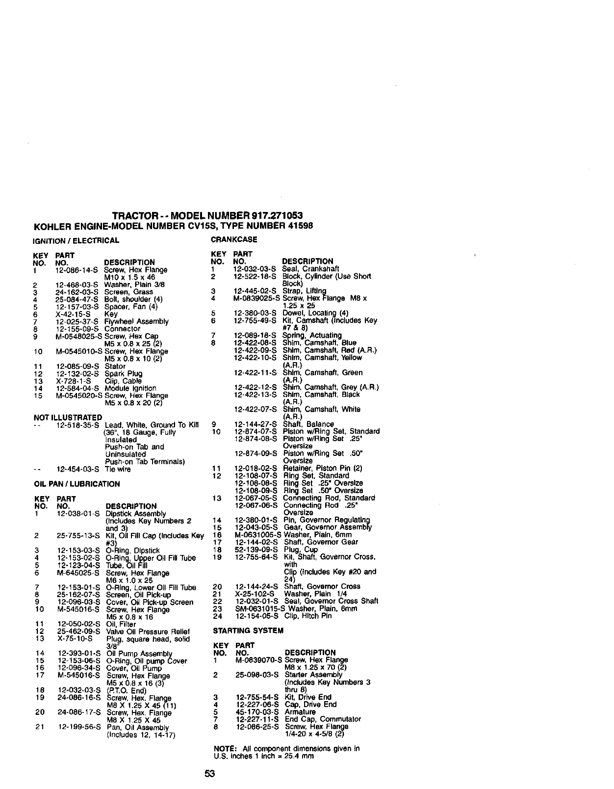
TRACTOR--MODEL NUMBER 917.271053
KOHLER ENGINE-MODEL NUMBER CV15S, TYPE NUMBER 41598
IGNITION /ELECTRICAL CRANKCASE
KEY pART
NO. NO. DESCRIPTION
112-086-14-S Screw, Hex Flange
M1Ox 1.5 x46
212-468-03-S Washer, Plain 3/8
324-162-03-S Screen, Grass
4 25-084-47-S Bolt, shoulder (4)
5 12-157-O3-S Spacer, Fan (4)
6 X-42-15-S Key
7 12-025-37-S Flywheel Assembly
812-155-09-S Connector
9 M-0548025-S Screw, Hex Cap
M5 x 0,E x 25 (2)
t0 M-0545010-S Screw, Hex Flange
MSxO.8x10(2)
11 12-085-09-S Stator
12 12-132-02-S Spark Plug
13 X_728-1-S Clip, Cable
14 12-584-04-S Module ignition
15 M-0545020-S Screw, Hex Flange
M5 x 0.8 x 20 (2)
NOT ILLUSTRATED
-- 12-518-35-S Lead, White, Ground To Kill
(36", 18 Gauge, Fully
Insulated
Push-on Tab and
Uninsulated
Push-on Tab Terminals)
- - 12-454-03-S Tie wire
OIL PAN /LUBRICATION
KEY PART
NO. NO. DESCRIPTION
1 12-038-01-S Dipstick Assembly
(includes Key Numbers 2
and 3
2 25-755-13-S Kit,Oil FII Cap (Includes Key
3 12-153-03-S O- ing, Dipstick
4 12-t53-02-S O-Ring, Upper Oil Fill Tube
512-123-04-S Tube,Oil Fill
6 M-645025-S Screw, Hex Flange
M6x 1.0x25
712-153-01-S O-Ring, Lower Oil FillTube
8 25-162-07-S Screen, Oil Pick-up
9 12-096-03-S Cover, Oil Pick-up Screen
10 M-545016-S Screw, Hex Flange
M5x0.8 x 16
11 12-050-02-S Oil, Filter
12 25-462-09,S Valve Oil Pressure Relief
13 X-75-10-S Plug, square head, solid
3/8"
14 12-393-01-S Oil Pump Assembly
15 12-153-06-S O-Ring, Oil pump Cover
16 12-096-34-S Cover, Oil Pump
17 M-545016-S Screw, Hex Flange
M5 x 0.8 x 16 (3)
18 12o032-O3-S (,_T.O. End)
19 24-086-16-S Screw, Hex. Flang_e
M8 X 1.25 X 45 (-11)
20 24-086-t7-S Screw, Hex. Flange
M8X 1.25X45
21 12-199-56-S Pan, Oil Assembly
(Includes 12, 14-17)
KEY PART
NO. NO. DESCRIPTION
1 12-032-03-S Seal, Crankshaft
2 12-522-18-S Block,Cylinder (Use Short
Block)
312-445-02-S Strap, Lifting
4 M-0839025-S Screw, Hex Flange M8 x
1.25 x 25
512-380-03-S Dowel, Locating (4)
6 12-755o49-S Kit, Camshaft (includes Key
#7 & 8)
7 12-089-18-S Spring, Actuating
8 12-422-08-S Shim, Camshaft, Blue
12-422-09-S Shim, Camshaft, Red (A.R.)
12-422-10-S Shim, Camshaft, Yellow
(_A.R.)
12-422-11-S Shim, Camshaft, Green
(A.R.)
12-422.12-S Shim, Camshaft, Grey (A,R.)
12-422-13-S Shim, Camshaft, Black
A.R.) fI
12-422-07-S ohim, Camsha t, Wh te
(A.R.)
9 12-144-27-S Shaft, Balance
10 12-874-07-S Piston w/Ring Set, Standard
12-874-08-S Piston wiring Set .25"
Oversize
12-874-09-S Piston w/Ring Set .50"
Oversize
11 12-018-02-S Retainer, Piston Pin (2)
12 12-108-07-S Ring Set, Standard
12-108-08-S Ring Set ,25" Oversize
12-108-09-S Ring Set .50" Oversize
13 12-067-05-S Connecting Rod, Standard
12÷067-06-S Connecting Rod .25'
Oversize
14 12-380-01-S Pin, Governor Regulating
t 5 12o043-05-S Gear, Governor Assembly
16 M-0631005-S Washer, Plain, 6ram
17 12-144-02-S Shaft, Governor Gear
18 52-139-09-S Plug, Cup
19 12-755-64-S Kit, Shaft, Governor Cross,
with
Clip (Includes Key #20 and
24)
20 12-144.24-S Shaft, Governor Cross
21 X-25-102-S Washer, Plain 1/4
22 12-032-01-S Seal, Governor Cross Shaft
23 SM-0631015-S Washer, Plain, 6ram
24 12-154-05-S Clip, Hitch Pin
STARTING SYSTEM
KEY PART
NO. NO. DESCRIPTION
1 M-0839070-S Screw. Hex Flange
M8 x 1,25 x 70 (2)
2 25-098-03-S Starter Assembly
(Includes Key Numbers 3
thru 8)
3 12-755-54-S Kit, Drive End
4 12-227-06-S Cap, Drive End
5 45-170-03-S Armature
7 12-227-11-S End Cap, Commutator
8 12-086-25-S Screw, Hex Flange
1/4-20 x 4o5/8 (2)
NOTE: All component dimensions given in
U.S. inches 1 inch = 25.4 mm
53

54
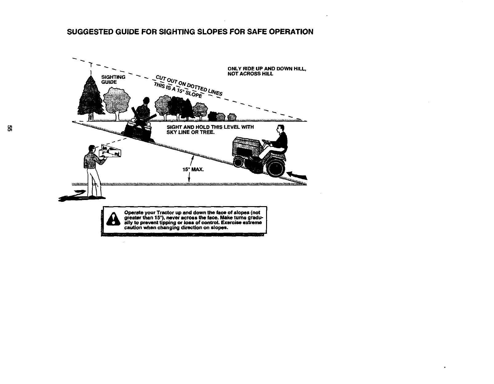
SUGGESTED GUIDE FOR SIGHTING SLOPES FOR SAFE OPERATION
ONLY RIDE UP AND DOWN HILL,
NOT ACROSS HILL
I_ Operate your Tractor up and down the face of slopes (not I
I
greater than 15 ), never across the face. Make rums gradu- |
idly to prevent Upping or loss of control. Exercise extreme I
caution when changing direction on slopes. J
I

Get it fixed, at your home or ours!
For repair of major brand appliances in your own home...
no matter who made it, no matter who sold it!
1"800"4"MY'HOME s. Anytime,day or night
(1-800-469-4663)
www.sears.com
To bring in products such as vacuums,
lawn equipment and electronics for repair, call for
the location of your nearest Sears Parts & Repair Center.
1-800-488-1222 Anytime, day or night
www.sears.corn
For the replacement parts, accessories and owner's manuals
that you need to do-it-yourself, call Sears ParteDirectSM!
1-800-366-PART 8am- 14pmCST
(1-800-366-7278) 7days a week
www.seers.conVpartsdlrect
To purchase or inquire about a Sears Service Agreement:
1-800-827-6655
7 a.m.- 5 p.m.CST,Mon.- Sat.
Pare pedirservlciode reparacibn a domlcilio,
ypare ordenar plazas con entrega a domicilio:
1-888-SU-HOGAR =_
(1-B88-784-6427)
Au Canada pour servicean frangais:
1-877-LE-FOYER _"
(1-a77-533-6937)
SEARS }
HorneCentral ®
®Sears, Roebuck and CO. ®Registered Trademark /TM Trademark of Sears, Roebuck and CO*
TM
®Marca Registrada /Marca de F_brlca de Sears, Roebuck and CO,
177561 Rev. 1 11.29.00 RD Printed in U,S.A.
