Craftsman 917271121 User Manual 16.5 HP ELECTRIC START AUTOMATIC 42 LAWN TRACTOR Manuals And Guides 98120014
CRAFTSMAN Lawn, Tractor Manual 98120014 CRAFTSMAN Lawn, Tractor Owner's Manual, CRAFTSMAN Lawn, Tractor installation guides
User Manual: Craftsman 917271121 917271121 CRAFTSMAN 16.5 HP ELECTRIC START AUTOMATIC 42 LAWN TRACTOR - Manuals and Guides View the owners manual for your CRAFTSMAN 16.5 HP ELECTRIC START AUTOMATIC 42 LAWN TRACTOR #917271121. Home:Lawn & Garden Parts:Craftsman Parts:Craftsman 16.5 HP ELECTRIC START AUTOMATIC 42 LAWN TRACTOR Manual
Open the PDF directly: View PDF ![]() .
.
Page Count: 60

Owner's Manual
CRAFTSMAN"
16.5 HP
ELECTRIC START
42" MOWER
AUTOMATIC
LAWN TRACTOR
Model No.
917.271121
• Safety
•Assembly
• Operation
• Maintenance
•Repair Parts
CAUTION:
Read and follow all
Safety Rules and Instructions
before operating this equip-
ment.
Foranswers to your questions
about this product,Call:
1-800-659-5917
Sears Crahsmn Help Une
5 am-5 pro, Mon -Sat
Sears, Roebuck and Co., Hoffman Estates, IL 60179
Warranty ................................................. 2
Safety Rules ........................................... 2
Product Specifications ....... _..... ............. 5
Assembly ........................... _.................... 8
_._Qpgr_ion,;: ........_......;..... ................ ....... 12
Maintenance Schedule......................... 19
Maintenance ......................................... 19
Service and Adjustments ...................... 23
Storage ................................................. 29
Troubleshooting.................................... 30
Repair Parts ................................... ......34
Parts Ordedng ....................... Back Cover
EtMtTE_-"FWO YEAR WARRANTY ON CRAFTSMAN RIDING EQUIPMENT
._For _o_(.2.)years. from the date of purchase, if this Craftsman Riding Equipment is main-
tained, lubricated and tuned up according to the instructionsin the owner's manual,
._Searswill-repair-or.replace, free of charge, any parts found to be defective in material or
workmanship.
--This Warrantydoes'not cover:.
• Expendable items which become wom during normal use, such as blades, spark
plugs, air cleaners, belts, etc.
•Tire replacement or repair caused by punctures from outside objects, such as nails,
thoms, stumps, or glass.
•Repairs necessary because of operator abuse, negligence, improper storage or acci-
dent or the failure to maintain the equipment accordingto the instructions contained in
the owner's manual.
•Riding equipment used for commercial or rental purposes.
LIMITED 90 DAY WARRANTY ON BATTERY
For ninety (90) days from date of purchase, if any battery included with this riding equip-
ment proves defective in material or workmanship and our testing determines the bat-
tery will not hold a charge, Sears will replace the batteryat no charge. In-home warranty
service on your Craftsman riding equipment is available at no charge for 30 days from
the date of purchase. Please contact your nearest service center. After 30 days from the
date of purchase, warranty service is available by taking your Craftsman dding equip-
ment to your nearest Sears Service Center. (In-home warranty service will still be avail-
able after 30 days from the date of purchase but a standard tripcharge will apply). This
warranty applies only while this product is in the United States. This Warranty gives you
specific legal rights,and you may also have other rightswhich may vary from state to
state.
Sears, Roebuck and Co., D/817 WA, Hoffman Estates, IL 60179
GENERAL OPERATION
•Read, understand, and follow all instruc-
tions in the manual and on the machine
before starting.
•Only allow responsible adults, who are
familiar with the instructions, to operate
the machine.
•Clear the area of objects such as rocks,
toys, wire, etc., which could be picked
up and thrown by the blade.
• Be sure the area is clear of other people
before mowing. Stop machine if anyone
enters the area.
•Never carry passengers.
•Do not mow in reverse unless absolute-
ly necessary.Always lookdown and
behind before and while backing.
•Be aware of the mower discharge direc-
tion and do not point it at anyone. Do
notoperate the mower without either
the entire grass catcher or the guard in
place.
•Slow down before tuming.
•Never leave a running machine unat-
tended. Always tum off blades, set park-
ing brake, stop engine, and remove
keys before dismounting.
2
•Tum off blades when not mowing.
•Stop engine before removing grass
catcher or uncloggingchute.
•Mow only in daylight or good artificial
light. . .
•Do not operate the machine wni e unaer
the influence of alcohol or drugs.
•Watch for traffic when operating near or
crossing roadways.
•Use extra care when loading or unload-
ing the machine into a trailer or truck.
SLOPE OPERATION
Slopes are a major factor related to loss-
of-control and tipover accidents, which
can result in severe injury or death. All
slopes require extra caution. If you cannot
back up the slope or if you feel uneasy on
it, do not mow it.
DO:
•Mow up and down slopes, not across.
•Remove obstacles such as rocks, tree
limbs, etc.
•Watch for holes, ruts, or bumps. Uneven
terrain could overturn the machine. Tall
grass can hide obstacles.
•Use slow speed. Choose a low gear so
that you will not have to stop or shift
while on the slope.
•Follow the manufacturer's recommen-
dations for wheel weights or counter-
weights to improve stability.
•Use extra care withgrass catchers or
other attachments. These can change
the stability of the machine.
•Keep all movement on the slopes slow
and gradual. Do not make sudden
changes in speed or direction.
•Avoidstarting or stopping on a slope. If
tiros lose traction, disengage the blades
and proceed slowly straight down the
slope.
DONOT:
•Donotturnonslopesunlessnecessary,
and then, turn slowly arid gradually
downhill, if possible.
•Do notmow near drop-offs, ditches, or
embankments. The mower could sud-
denly turn over if a wheel is over the
edge Of a cliff or ditch, or if an edge
caves in.
•Do not mow on wet grass. Reduced
traction could cause sliding.
•Do not try to stabilize the machine by
putting your foot on the ground.
•Do not use grass catcher on steep
slopes.
CHILDREN
Tragic accidents can occur if the operator
is not alert to the presence of children.
Children are often attracted to the
machine and the mowing activity. Never
assume that children will remain where
you last saw them.
•Keep children out of the mowing area
and under the watchful care of another
responsible adult.
•Be alert and turn machine off if children
enter the area.
•Before and when backing, look behind
and down for small children.
•Never cam/children. They may fall off
and be senously injured or interfere with
safe machine operation.
•Never allow children to operate the
machine.
•Use extra care when approaching blind
corners, shrubs, trees, or other objects
that may obscure vision.
SERVICE
•Use extra care in handling gasoline and
other fuels. They are flammable and
vapors are explosive.
Use only an approved container.
Never remove gas cap or add fuel
with the engine running. Allow en-
gine to cool before refueling. Do not
smoke.
Never refuel the machine indoors.
Never store the machine or fuel
container inside where there is an
open flame, such as a water heater.
•Never run a machine inside a closed
area.
•Keep nuts and bolts, especially blade
attachment bolts, tight and keep equ=p-
ment in good condition.
•Never tamper with safety devices.
Check their proper operation rogulady.
•Keep machine free of grass, leaves, or
other debris build-up. Clean oil or fuel
spillage. Allow machine to cool before
storing.
•Stop and inspect the equipment if you
strike an object. Repair, if necessary,
before restarting.
•Never make adjustments or repairs with
the engine running.
•Grass catcher components are subject
to wear, damage, and deterioration,
which could expose moving parts or
allow objects to be thrown. Frequently
check components and replace with
manufacturer's recommended parts,
when necessary.
3
•Mower blades are sharp and can cut.
Wrap the blade(s) or wear gloves, and
use extra caution when servicing them.
•Check brake operation frequently.
Adjust and service as required.
•Be sure the area is clear of other people
before mowing. Stop machine if anyone
enters the area.
•Never carry passengers.
•Do not mow in reverse unless absolute-
ly necessary.Always lookdown and
behind before and while backing.
@@@@@
•Never carry children. They may fall off
and be seriously injured or interfere with
safe machine operation.
•Keep children out of the mowing area
and under the watchful care of another
responsible adult.
•Be alert and turn machine off if children
enter the area.
•Before and when backing, look behind
and down for small children.
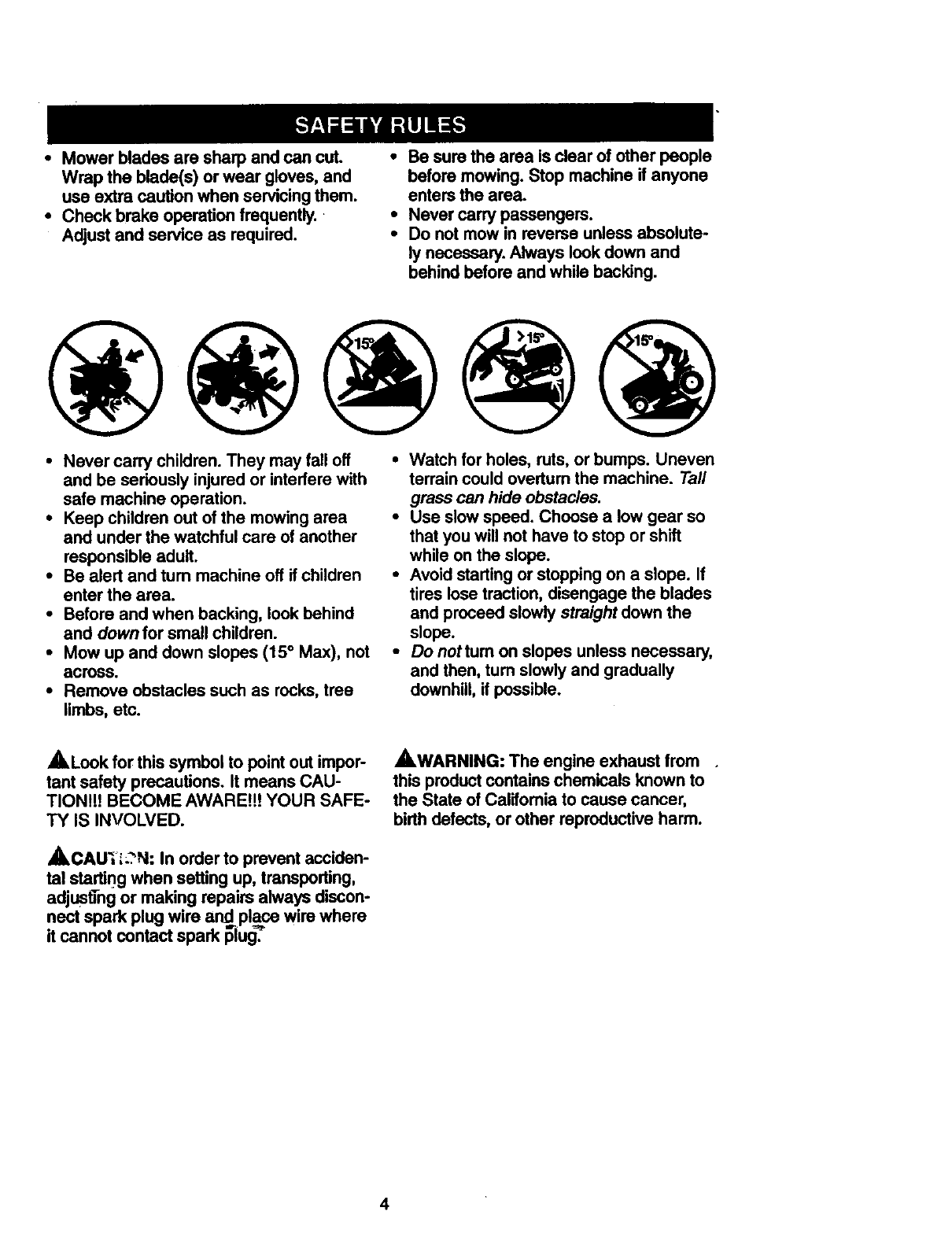
•Mow up and down slopes (15° Max), not
across.
•Remove obstacles such as rocks, tree
limbs, etc.
•Watch for holes, ruts, or bumps. Uneven
terrain could overtum the machine. Tall
grass can hide obstacles.
•Use slow speed. Choose a low gear so
that you will not have to stop or shift
while on the slope.
•Avoid starting or stopping on a slope. If
tires lose traction, disengage the blades
and proceed slowly straight down the
slope.
• Donottumonslopesunlessnecessary,
and then, tum slowly and gradually
downhill, if possible.
,A Look for this symbol to pointout impor-
tant safety precautions. It means CAU-
TIONif! BECOME AWARE!!! YOUR SAFE-
TY IS INVOLVED.
,_CAU'_'I;?N: In order to prevent acciden-
tal startingwhen setting up, transporting,
adjusting or making repairs always discon-
nect spark plug wire and=place wire where
it cannot contact spark plug=".
_.WARNING: The engine exhaust from .
this productcontains chemicals known to
the State of Califomia to cause cancer,
birth defects, or other reproductive harm.
4
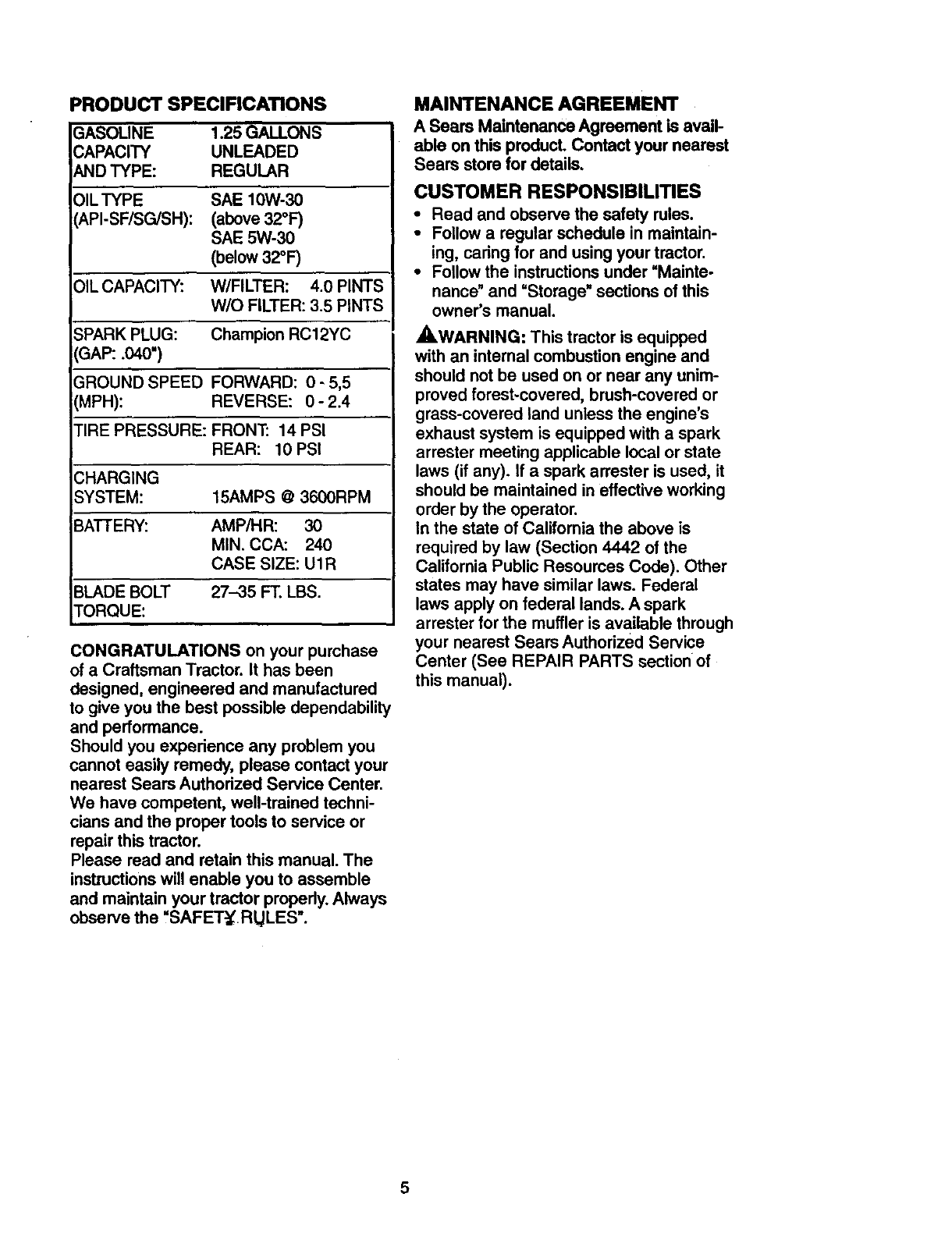
PRODUCT SPECIFICATIONS
GASOLINE 1.25 GALLONS
CAPACITY UNLEADED
AND TYPE: REGULAR
OIL TYPE SAE 10W-30
_.PI-SF/SG/SH): (above 32°F)
SAE 5W-30
(below 32°1=)
OIL CAPACITY: W/FILTER: 4.0 PINTS
W/O FILTER: 3.5 PINTS
SPARK PLUG: Champion RC12YC
3AP: .040")
GROUND SPEED FORWARD: 0- 5,5
_IPH): REVERSE: 0 - 2.4
TIRE PRESSURE: FRONT: 14 PSI
REAR: 10 PSi
CHARGING
SYSTEM: 15AMPS @3600RPM
'BATTERY: AMP/HR: 30
MIN. CCA: 240
CASE SIZE: UIR
BLADE BOLT 27-35 FT. LBS.
TORQUE:
CONGRATULATIONS on your purchase
ofa Craftsman Tractor. It has been
designed, engineered and manufactured
to give you the best possible dependability
and performance.
Should you experience any problem you
cannot easily remedy, please contact your
nearest Sears Authorized Service Center.
We have competent, well-trained techni-
cians and the proper tools to service or
repair this tractor.
Please read and retain this manual. The
instructionswill enable you to assemble
and maintain your tractor properly.Always
observe the "SAFETy RULES".
MAINTENANCE AGREEMENT
A Sears Maintenance Agreement is avail-
able on this product. Contact your nearest
Sears store for details.
CUSTOMER RESPONSlBILmES
•Read and observe the safety rules.
•Follow a regular schedule in maintain-
ing, caring for and using your tractor.
•Follow the instructions under "Mainte-
nance" and "Storage" sections of this
owner's manual.
_,WARNING: This tractor is equipped
with an internal combustion engine and
should not be used on or near any unim-
proved forest-covered, brush-covered or
grass-covered land unless the engine's
exhaust system is equipped with a spark
arrester meeting applicable local or state
laws (if any). If a spark an'ester is used, it
should be maintained in effective working
order by the operator.
In the state of California the above is
required by law (Section 4442 of the
California Public Resources Code). Other
states may have similar laws. Federal
laws apply on federal lands. A spark
arrester for the muffler is available through
your nearest Sears Authorized Service
Center (See REPAIR PARTS section of
this manual).
5
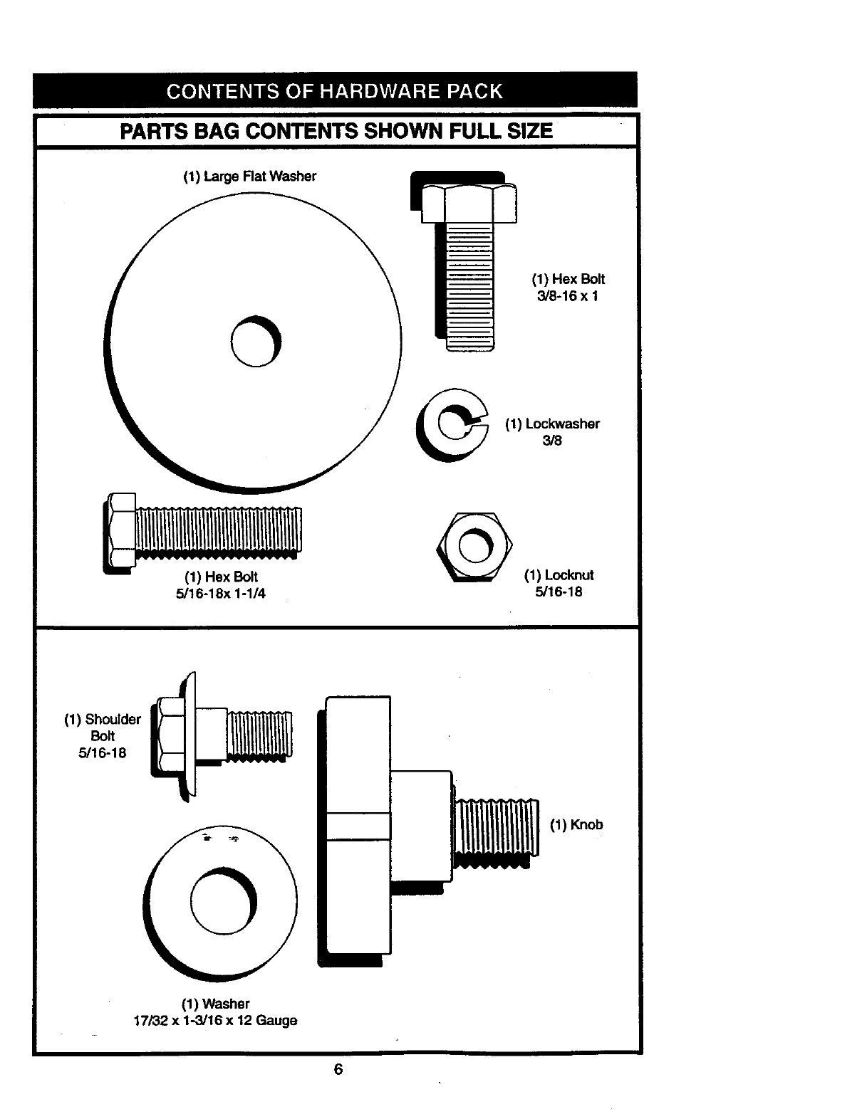
PARTS BAG CONTENTS SHOWN FULL SIZE
(1) Large Flat Washer
O
(1) Hex Bolt
3/8-16 x I
(1) Lockwasher
3/8
(1) Hex Bolt
5/16-18x 1-1/4 @(1) Locknut
5/16-18
(1) Shoulder
Bolt
5/16-18
(1) Knob
©
(1) Washer
17/32 x 1-3/16 x 12 Gauge
6
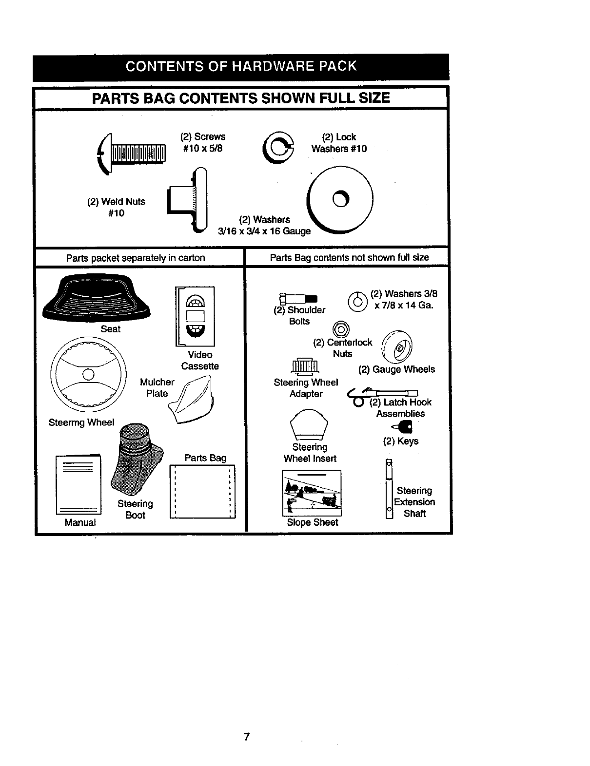
PARTS BAG CONTENTS SHOWN FULL SIZE
(_ (2) Screws _(2) Lock
#10 X5/8 Washers #10
+w+++
#10 12)Washers
3/16 x 3/4 x 16 Gauge
Parts packet separately in carton
Seat
Video
Cassette
Mulcher _/,
Plate@
Steermg Whee_
; Steering
Boot
Manual
Parts Bag
Parts Bag contents not shown full size
(_ (2) Washers 3/8
(2) Shoulder x 718x 14 Ga.
B°lts (2) Ce_nterl°ck _Nuts
._ (2) Gauge Wheels
Steedng Wheel
Adapter U (2) Latch Hook
Assemblies
Steering (2) Keys
Wheel Insert
iI
I
I
I
i
i1
I
Slope Sheet
Steering
Extension
:Shaft
7
Yournewtractorhasbeenassembled at the factory with exception of those parts left
unassembled for shipping purposes. To ensure safe and proper operation of your tractor
all parts and hardware you assemble must be tightened securely. Use the correct tools
as necessary to insure proper tightness. Review the video cassette before you begin.
TOOLS REQUIRED FOR
ASSEMBLY
A socket wrench set will make assembly
easier. Standard wrench sizes you need
are listed below.
(1) 9/16" wrench (1) 3/4" Socket w/
(1)Pliers drive rachet
(2) 1/2" wrench (1) Phillips Screw-
(1) Utility knife driver
(1) Tire pressure gauge
When right or left hand is mentioned in
this manual, it means, from your point of
view, when you are in the operating posi-
tion (seated behind the steering wheel).
TO REMOVE TRACTOR FROM
CARTON
UNPACK CARTON
•Remove all accessible loose parts and
parts boxes from shipping carton (See
page 6).
• Cut, from top to bottom, along lines on
all four comers of shipping carton, and
lay panels flat.
•Check for any additional loose parts or
boxes and remove.
BEFORE ROLLING TRACTOR OFF
SKID
ATTACH STEERING WHEEL
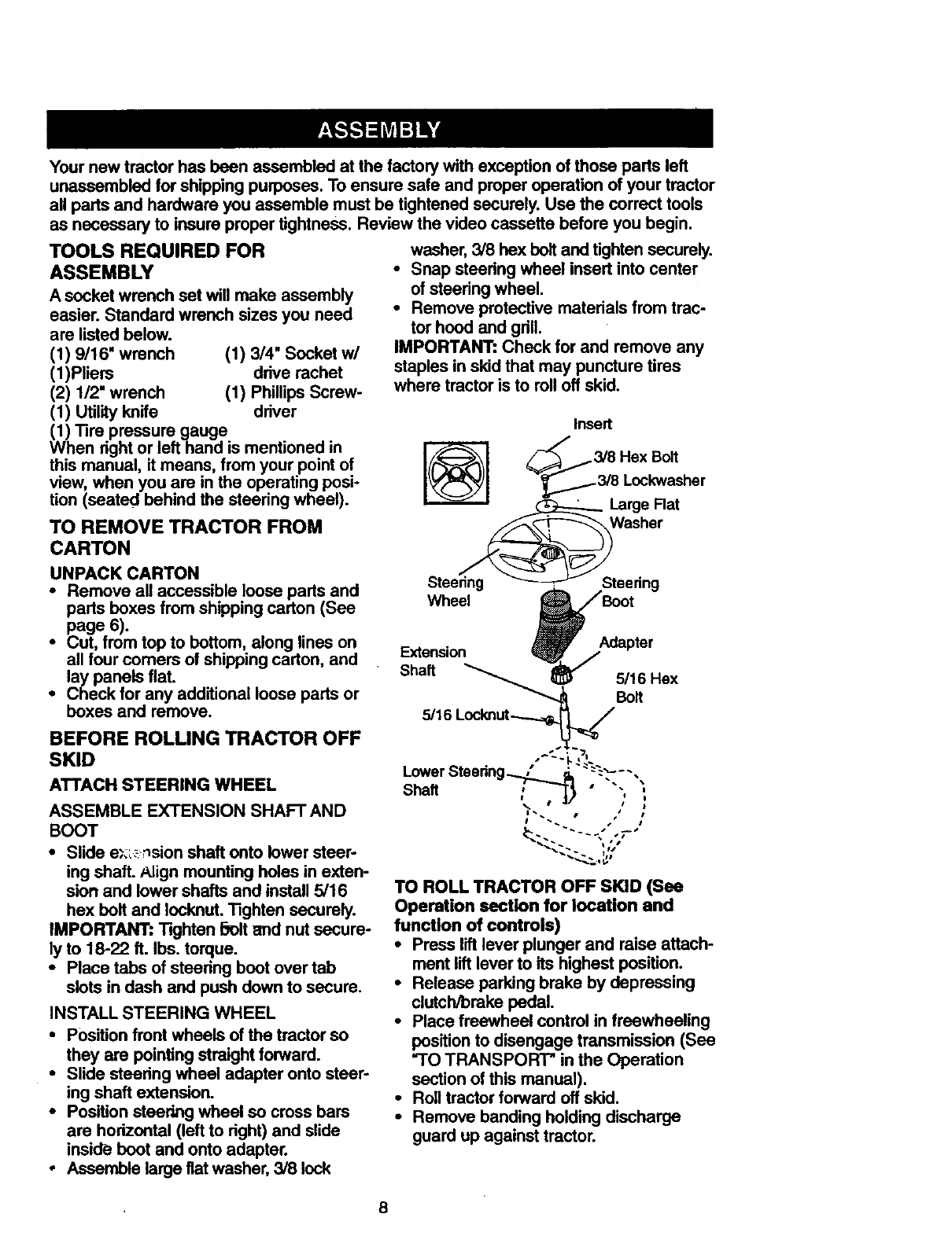
ASSEMBLE EXTENSION SHAFT AND
BOOT
washer, 3/8 hex bolt and tighten securely.
•Snap steedng wheel insert into center
of steering wheel.
•Remove protective materials from trac-
tor hood and gdll.
IMPORTANT: Check for and remove any
staples in skid that may puncture tires
where tractor is to roll off skid.
•Slide e_.',__sion shaft onto lower steer-
ing shaft. Align mounting holes in exten-
sion and lower shafts and install 5/16
hex bolt and Iocknut. Tighten securely.
IMPORTANT: Tighten _olt and nut secure-
ly to 18-22 ft. Ibs. torque.
•Place tabs of steedng boot over tab
slots in dash and push down to secure.
INSTALL STEERING WHEEL
• Position front wheels of the tractor so
they are pointing straight forward.
•Slide steedng wheel adapter onto steer-
ing shaft extension.
•Position steering wheel so cross bars
are horizontal (left to right) and slide
inside boot and onto adapter.
• Assemble large fiat washer, 3/8 lock
TO ROLL TRACTOR OFF SKID (See
Operation section for location and
function of controls)
• Press lift lever plunger and raise attach-
ment lift lever to its highest position.
•Release parking brake by depressing
clutch/brake pedal.
•Place freewheel control in freewheeling
position to disengage transmission (See
=TO TRANSPORT" in the Operation
section of this manual).
•Roll tractor forward off skid.
•Remove banding holding discharge
guard up against tractor.
8
HOW TO SET UP YOUR TRACTOR
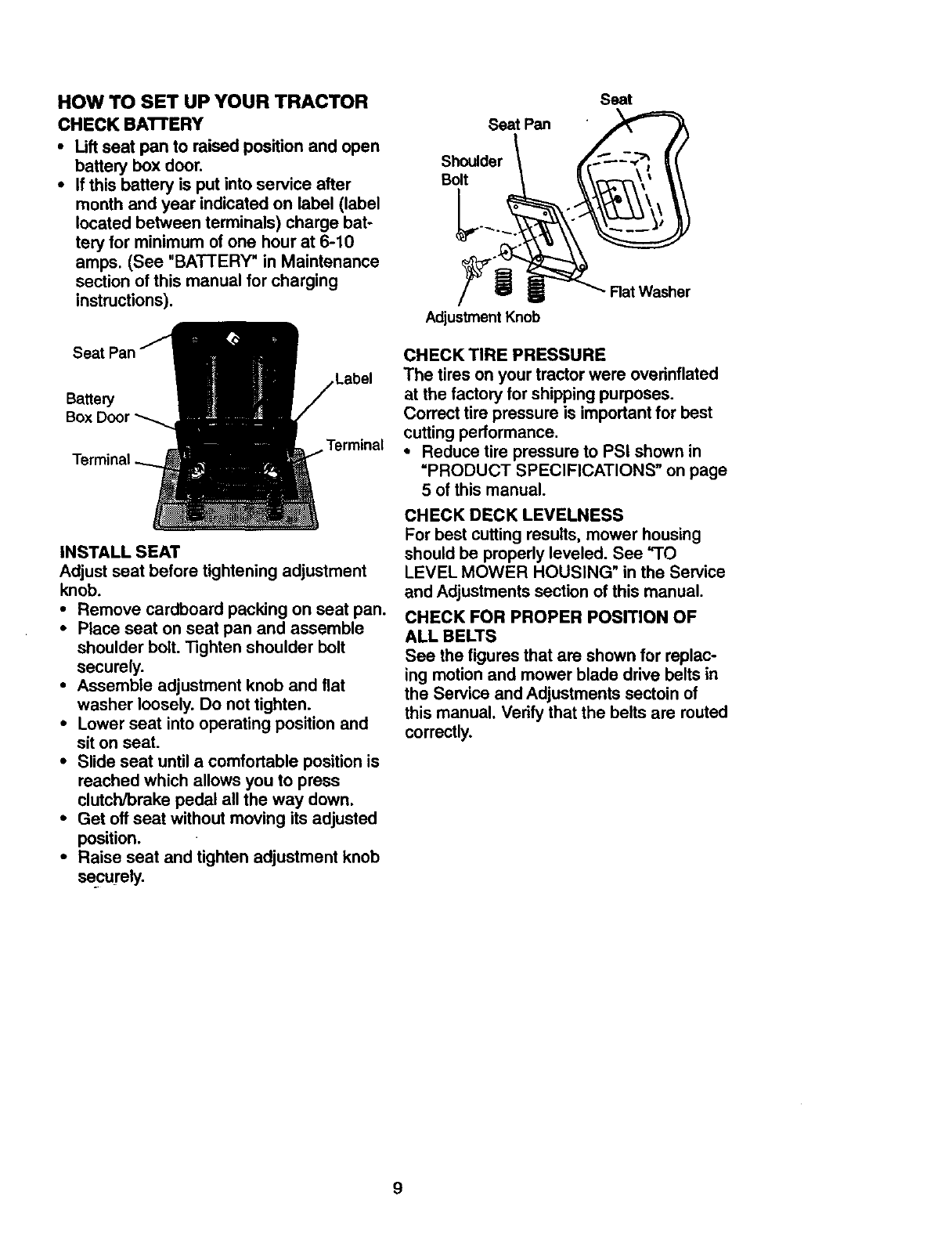
CHECK BA'I-rERY
• Lift seat pan to raised position and open
battery box door.
•If this battery is put into service after
month and year indicated on label (label
located between terminals) charge bat-
tery for minimum of one hour at 6-10
amps. (See "BATTERY" in Maintenance
section ofthis manual for charging
instructions).
Label
Terminal
INSTALL SEAT
Adjust seat before tightening adjustment
knob.
•Remove cardboard packing on seat pan.
•Place seat on seat pan and assemble
shoulder bolt. "13ghtenshoulder bolt
securely.
•Assemble adjustment knob and flat
washer loosely. Do not tighten.
•Lower seat into operating position and
sit on seat.
•Slide seat until a comfortable position is
reached which allows you to press
clutch/brake pedal all the way down.
•Get off seat without moving its adjusted
position.
•Raise seat and tighten adjustment knob
securely.
Seat
Seat Pan
Shoulder
Bolt
Adjustment Knob
Rat Washer
CHECK TIRE PRESSURE
The tires on your tractorwere overinflated
at the factory for shippingpurposes.
Correct tire pressure is important for best
cutting performance.
° Reduce tire pressure to PSI shown in
=PRODUCT SPECIFICATIONS" on page
5 of this manual.
CHECK DECK LEVELNESS
For best cutting results, mower housing
should be properly leveled. See "TO
LEVEL MOWER HOUSING" in the Service
and Adjustments section of this manual.
CHECK FOR PROPER POSITION OF
ALL BELTS
See the figures that are shown for replac-
ing motion and mower blade drive belts in
the Service and Adjustments sectoin of
this manual. Verify that the belts are muted
correctly.
9
CHECKBRAKESYSTEM
Afteryoulearnhowto operateyourtrac-
tor,checkto see thatthe brakeis properly
adjusted.See=TO ADJUST BRAKE" in
the Service and Adjustments section of
this manual.
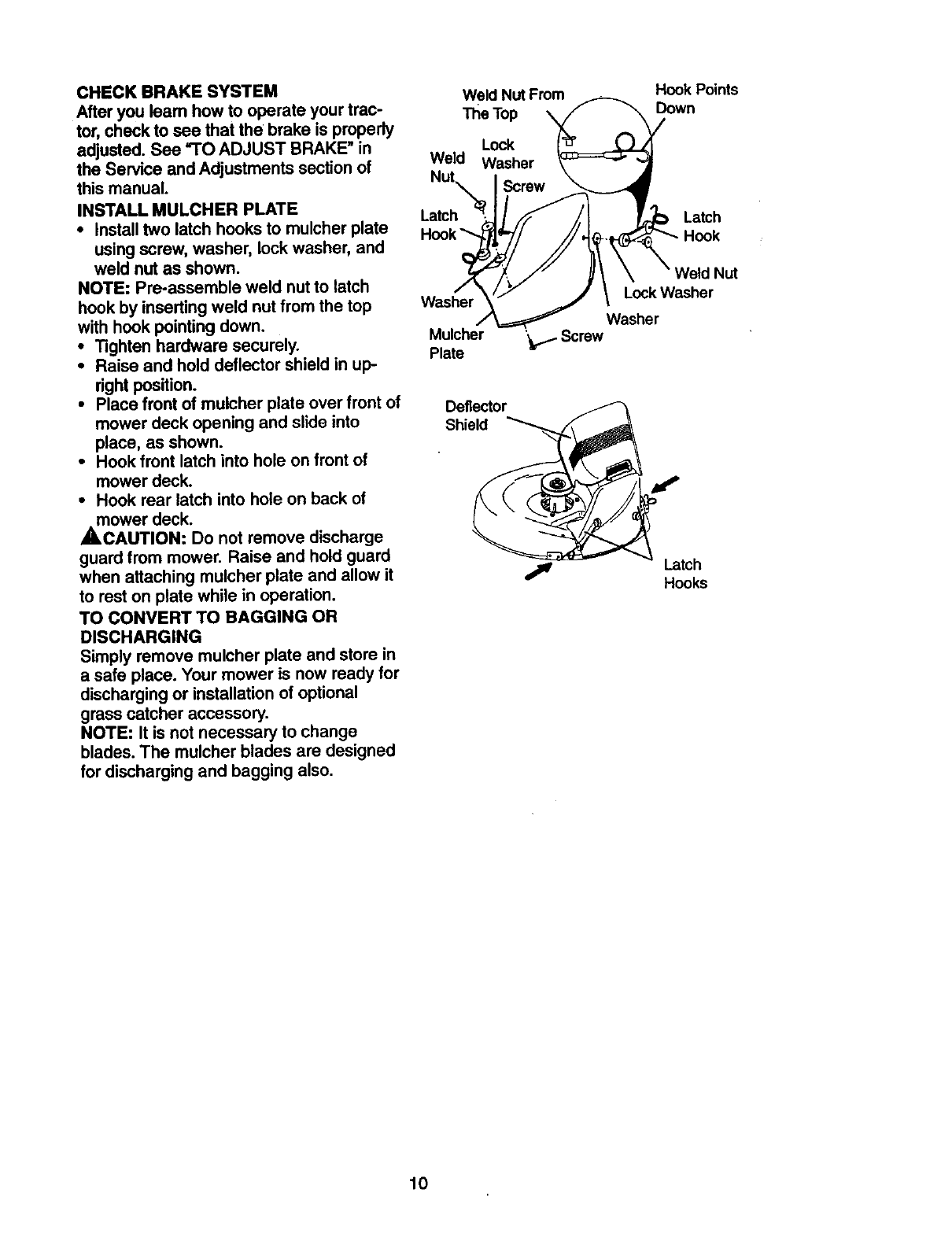
INSTALL MULCHER PLATE
•Install two latch hooks to mulcher plate
using screw, washer, lock washer, and
weld nut as shown.
NOTE: Pre-assemble weld nut to latch
hook by inserting weld nut from the top
with hook pointing down.
•Tighten hardware securely.
•Raise and hold deflector shield in up-
right position.
•Place front of mulcher plate over front of
mower deck opening and slide into
place, as shown.
•Hook front latch into hole on front of
mower deck.
•Hook rear latch into hole on back of
mower deck.
A, CAUTION: Do not remove discharge
guard from mower. Raise and hold guard
when attaching mulcher plate and allow it
to rest on plate while in operation.
TO CONVERT TO BAGGING OR
DISCHARGING
Simply remove mulcher plate and store in
a safe place. Your mower is now ready for
discharging or installation of optional
grass catcher accessory.
NOTE: It is not necessary to change
blades. The mulcher blades are designed
for discharging and bagging also.
Weld Nut From
The Top
Lock
Weld Washer
Latch
Washer
Mulcher ',t,,1. Screw
Plate
Deflector
Shield
Hook Points
Down
Latch
Lock Washer
Washer
Latch
Hooks
10
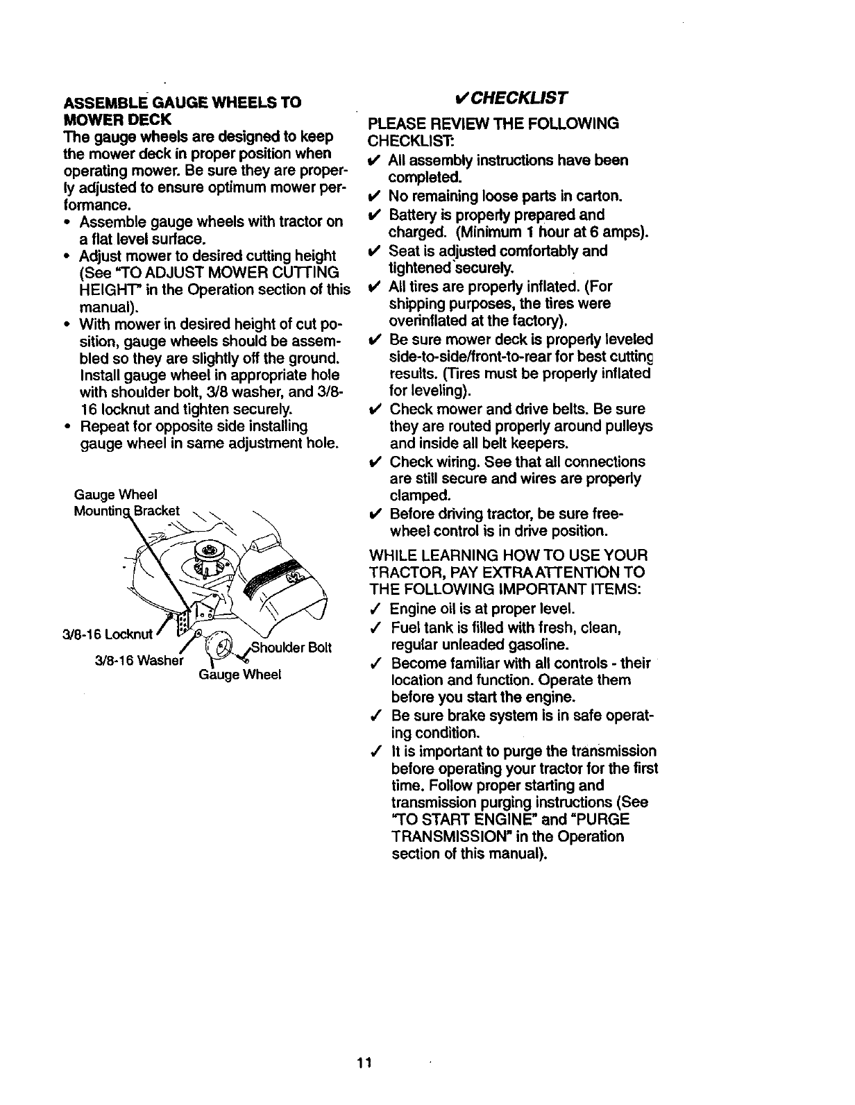
ASSEMBLE GAUGE WHEELS TO
MOWER DECK
The gauge wheels are designed to keep
the mower deck in proper positionwhen
operating mower. Be sure they are proper-
ly adjusted to ensure optimum mower per-
tormance.
• Assemble gauge wheels with tractor on
a flat level surface.
•Adjust mower to desired cutting height
(See "TO ADJUST MOWER CU'I-I'ING
HEIGHT" in the Operation section of this
manual),
•With mower in desired height of cut po-
sition, gauge wheels should be assem-
bled so they are slightlyoff the ground.
Install gauge wheel in appropriate hole
with shoutder bolt, 3/8 washer, and 3/8-
16 Iocknutand tighten securely.
• Repeat for opposite side installing
gauge wheel in same adjustment hole.
Gauge Wheel
Mounting_Bracket\\
3/8"16:°_:n_ het_ _ a_uge_WW_Wh_/e°_lder B°lt
VCHECKUST
PLEASE REVIEW THE FOLLOWING
CHECKLIST:
i/ All assembly instructions have been
completed.
v' No remaining loose parts in carton.
v' Battery is propedy prepared and
charged. (Minimum 1 hour at 6 amps).
v' Seat is adjusted comfortably and
tightened'securely.
i/ All tires are propedy inflated. (For
shipping purposes, the tires were
ovednflated at the factory).
V' Be sure mower deck is properly leveled
side-to-side/front-to-rear for best cuttin_
results. (Tires must be properly inflated
for leveling).
!/ Check mower and drive belts. Be sure
they are routed propedy around pulleys
and inside all belt keepers.
v' Check wiring. See that all connections
are still secure and wires are properly
clamped.
v' Before ddving tractor, be sure free-
wheel control is in drive position.
WHILE LEARNING HOW TO USE YOUR
TRACTOR, PAY EXTRAATTENTION TO
THE FOLLOWING IMPORTANT ITEMS:
/Engine oil is at proper level.
/Fuel tank is filled with fresh, clean,
regular unleaded gasoline.
,/ Become familiar with all controls - their
location and function. Operate them
before you start the engine.
4" Be sure brake system is in safe operat-
ing condition.
•/It is important to purge the transmission
before operating your tractor for the first
time. Follow proper starting and
transmission purging instructions(See
"TO START ENGINE" and "PURGE
TRANSMISSION" in the Operation
section ofthis manual).
11
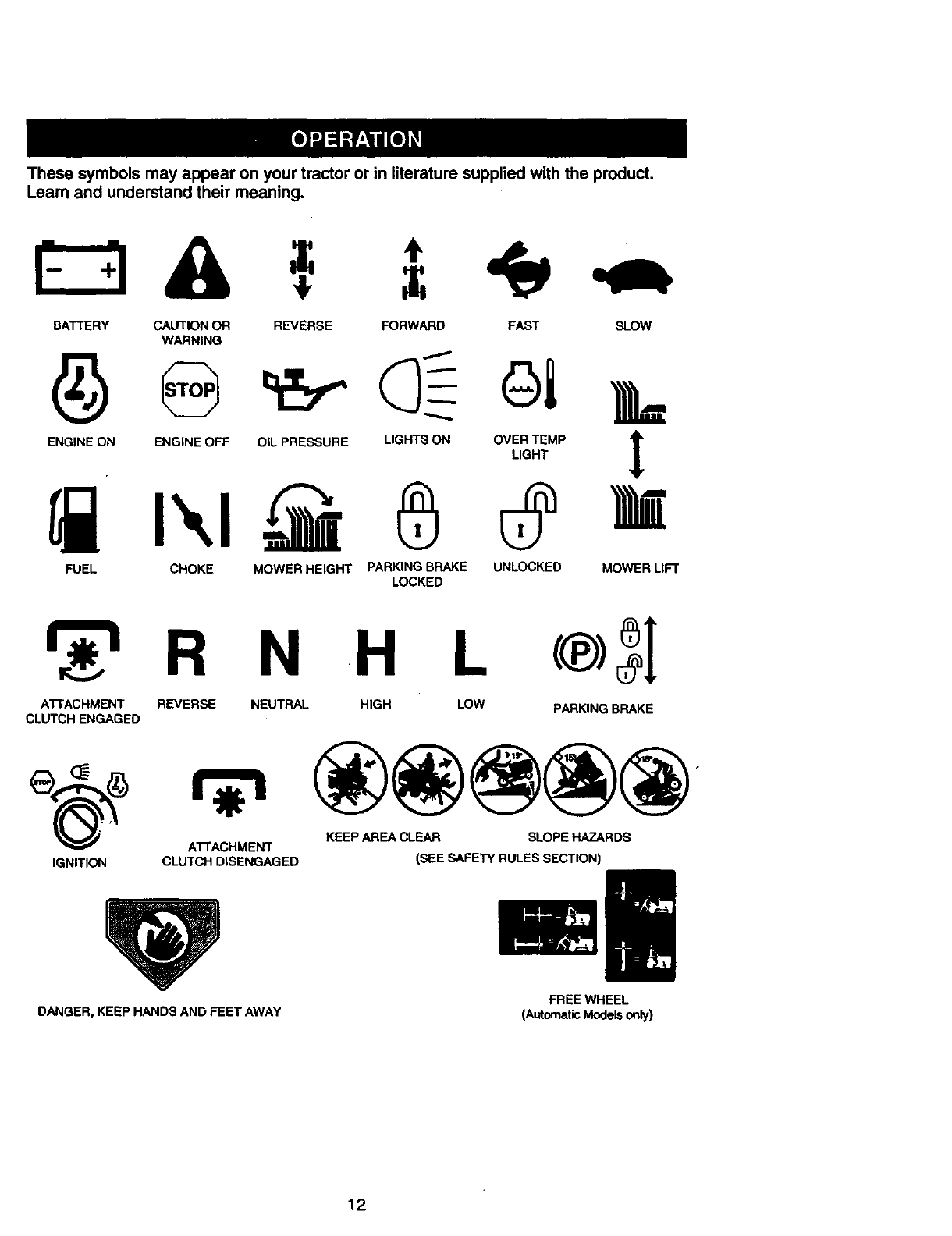
Thesesymbolsmayappearonyourtractororin literaturesuppliedwiththeproduct.
Learnandunderstandtheirmeaning.
=
BATTERY CAUTION OR
WARNING
ENGINE ON ENGINE OFF
REVERSE FORWARD FAST SLOW
OIL PRESSURE LIGHTS ON OVER TEMP t
LIGHT
FUEL CHOKE MOWER HEIGHT PARKING BRAKE UNLOCKED MOWER LIFT
LOCKED
R N H L
ATTACHMENT REVERSE NEUTRAL HIGH LOW PARKING BRAKE
CLUTCH ENGAGED
• ATTACHMENT KEEP AREA CLEAR SLOPE HAZARDS
IGNITION CLUTCH DISENGAGED (SEE SAFETY RULES SECTION)
DANGER, KEEP HANDS AND FEET AWAY FREEWHEEL
(AutomaticModelsonly)
12
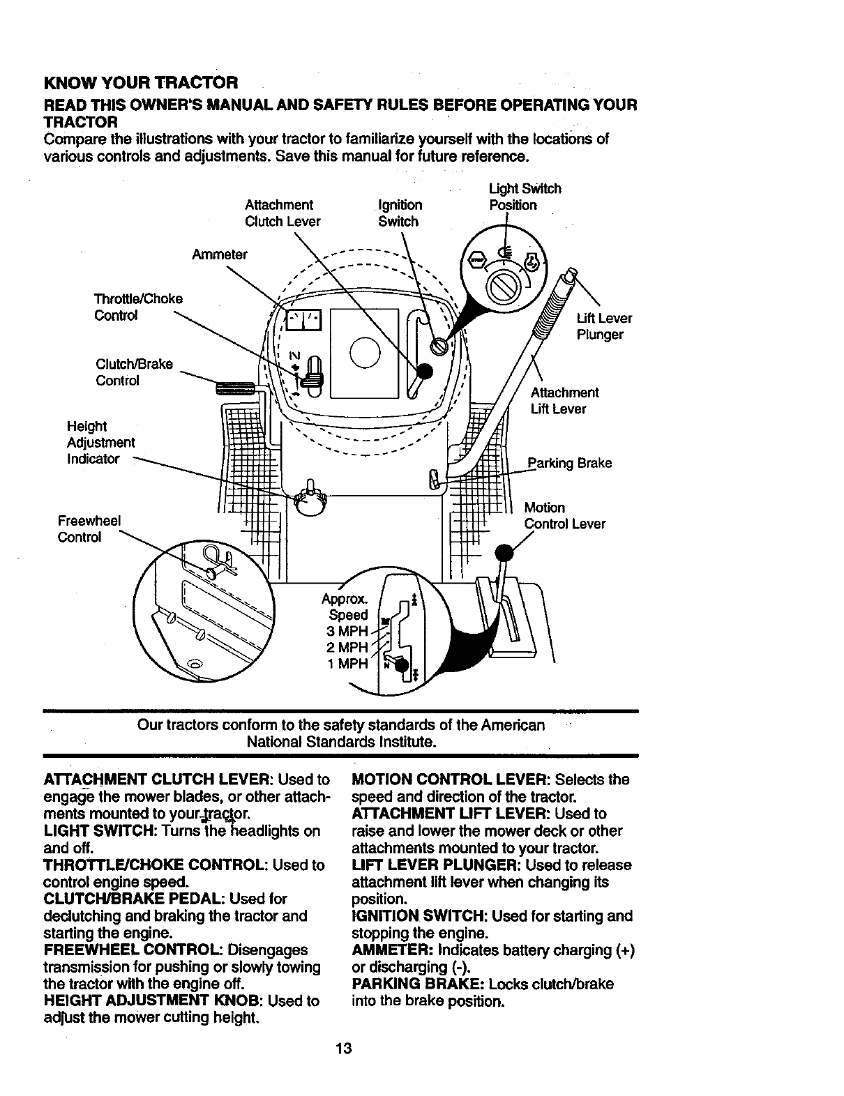
KNOW YOUR TRACTOR
READ THIS OWNER'S MANUAL AND SAFETY RULES BEFORE OPERATING YOUR
TRACTOR •
Compare the illustrationswith your tractor to familiarize yourself with the locations of
vadous controlsand adjustments. Save this manual for future reference.
Attachment Ignition
Clutch Lever Switch
Ught Switch
Position
Throttle/Choke
Control
Clutch/Brake
Control
Height
Adjustment
Indicator
Ammeter
Lift Lever
Plunger
Attachment
Uft Lever
Parking Brake
Freewheel
Control
Motion
Control Lever
Our tractors conform to the safety standards of the American
National Standards Institute.
ATrACHMENT CLUTCH LEVER: Used to
engage the mower blades, or other attach-
ments mounted to your-,_raq_or.
LIGHT SWITCH: Tums the headlights on
and off.
THROTTLE/CHOKE CONTROL: Used to
control engine speed.
CLUTCH/BRAKE PEDAL: Used for
declutching and braking the tractor and
starting the engine.
FREEWHEEL CONTROL: Disengages
transmission for pushing or slowly towing
the tractor with the engine off.
HEIGHT ADJUSTMENT KNOB: Used to
adjust the mower cutting height.
MOTION CONTROL LEVER: Selects the
speed and direction of the tractor.
ATTACHMENT LIFT LEVER: Used to
raise and lower the mower deck or other
attachments mounted to your tractor.
LIFT LEVER PLUNGER: Used to release
attachment lilt lever when changing its
position.
IGNITION SWITCH: Used for starting and
stopping the engine.
AMMETER: Indicates battery charging (+)
or discharging (-).
PARKING BRAKE: Locks clutch/brake
into the brake position.
13
The operation of any tractor can result in foreignobjects thrown into the
eyes, which can result in severe eye damage, Always wear safety glasses
or eye shields while operating yourtractor or performing any adjustments or
repairs. We recommend a wide vision safety mask over spectacles, or stan-
dard safety glasses.
HOW TO USE YOUR TRACTOR
Yourtractor is equipped with an operator
presence sensing switch. When engine is
running, any attempt by the operator to
leave the seat withoutfirst setting the
parking brake will shut off the engine.
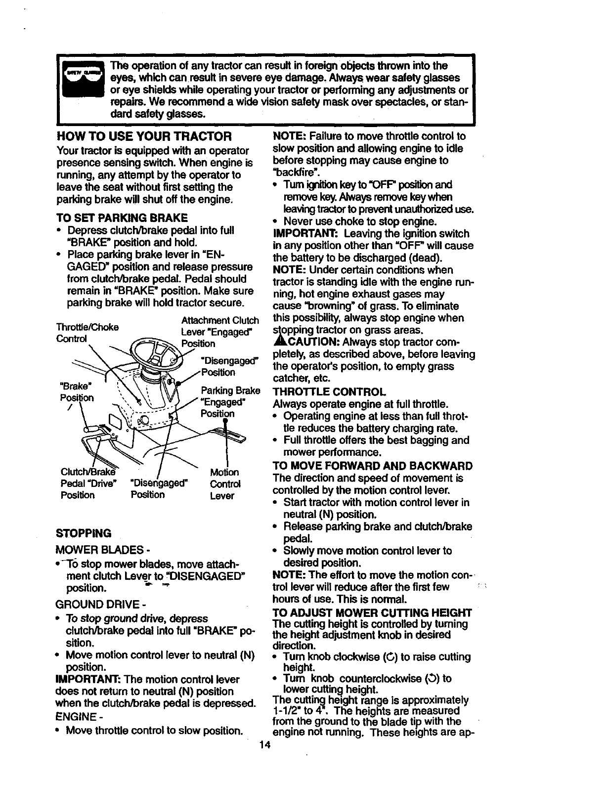
TO SET PARKING BRAKE
•Depress clutch/brake pedal into full
"BRAKE" position and hold.
•Place parking brake lever in =EN-
GAGED" position and release pressure
from clutch/brake pedal Pedal should
remain in =BRAKE" position. Make sure
perking brake will hold tractor secure.
Attachment Clutch
Throttle/Choke Lever "Engaged"
Control Position
\=Disengaged"
"Brake" ', Parking Brake
Position
J ", Position
Motion
Pedal =Drive" "Disengaged" Control
Position Position Lever
STOPPING
MOWER BLADES -
•_To stop mower blades, move attach-
ment clutch Lev_ to =DISENGAGED"
position.
GROUND DRIVE -
• To stop ground ddve, depress
clutch/brake pedal into full "BRAKE" po-
sition.
•Move motion control lever to neutral (N)
position.
IMPORTANT: The motion control lever
does not return to neutral (N) position
when the clutch/Drake pedal is depressed.
ENGINE -
• Move throttle control to slow position.
NOTE: Failure to move throttle control to
slow position and allowing engine to idle
before stopping may cause engine to
=backfire'.
•Turn ignition key to "OFP position and
remove key. Always remove key when
leaving tractor to prevent unauthorized use.
•Never use choke to stop engine.
IMPORTANT: Leaving the ignition switch
in any position other than =OFF" will cause
the battery to be discharged (dead).
NOTE: Under cedain conditions when
tractor is standing idle with the engine run-
ning, hot engine exhaust gases may
cause =browning" of grass. To eliminate
this possibility, always stop engine when
_pping tractor on grass areas.
CAUTION. Always stop tractor com-
pletely, as described above, before leaving
the operator's position, to empty grass
catcher, etc.
THROTTLE CONTROL
Always operate engine at full throttle.
• Operating engine at less than full throt-
tle reduces the battery charging rate.
•Full throttle offers the best bagging and
mower performance.
TO MOVE FORWARD AND BACKWARD
The direction and speed of movement is
controlled by the motion control lever.
•Start tractor with motion control lever in
neutral (N) position.
•Release parking brake and clutch/brake
pedal.
•Slowly move motion control lever to
desired position.
NOTE: The effort to move the motion con-.
trel lever will reduce alter the first few
hours of use. This is normal.
TO ADJUST MOWER CU'I-FING HEIGHT
The cutting height is control!ed by turning
the height adjustment knob mdesired
direction.
•Tum knob clockwise (G) to raise cutting
height.
•Tum knob counterclockwise (,_)to
lower cuttin_l height.
The cutting hezght range is approximately
1-1/2" to 4". The heights are measured
from the ground to the blade tip with the
engine not running. These he=ghts are ap-
14
proximateandmayvarydependingupon
soil conditions,heightof grassandtypes
of grassbeingmowed.
•The average lawn should be cut to
approximately 2-1/2 inches during the
cool season and to over 3 inches during
hot months. For healthier and better
looking lawns, mow often and after
moderate growth.
•For best cutting performance, grass
over 6 inches in height should be
mowed twice. Make the first cut rela-
tively high; the second to desired height.
TO OPERATE MOWER
Your tractor is equipped with an operator
presence sensing switch. Any attempt by
the operator to leave the seat with the
engine running and the attachment clutch
engaged will shut oft the engine.
•Select desired height of cut.
•Lower mower with attachment lift con-
trol.
•Start mower blades by engaging attach-
ment clutch control.
•TO STOP MOWER BLADES - disen-
,_age attachment clutch control.
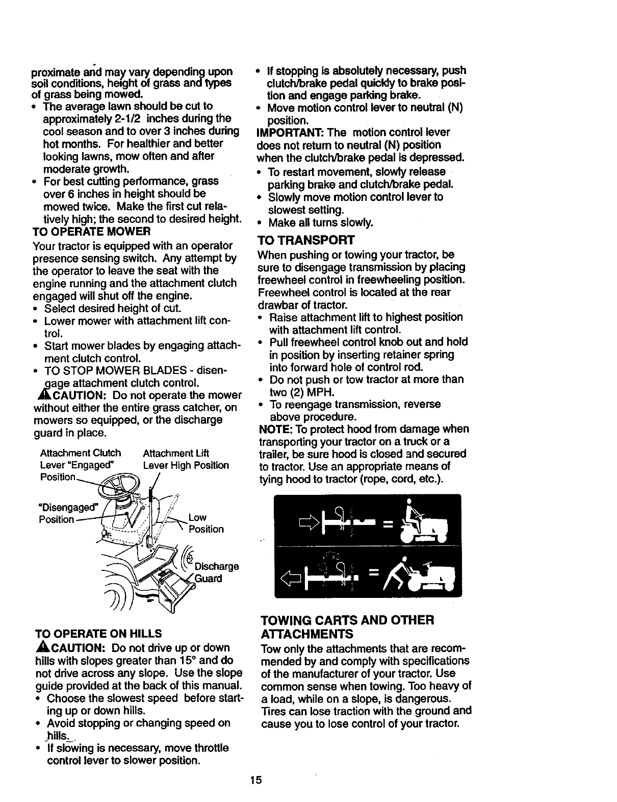
CAUTION: Do not operate the mower
without either the entire grass catcher, on
mowers so equipped, or the discharge
guard in place.
Attachment Clutch
Lever =Engaged"
Attachment Lift
Lever High Position
"Disengaged" YLow
Guard
•If stopping is absolutely necessary, push
clutch/brake pedal quickly to brake posi-
tion and engage parking brake.
•Move motion control lever to neutral (N)
position.
IMPORTANT: The motion control lever
does not retum to neutral (N) position
when the clutch/brake pedal is depressed.
•To restart movement, slowly release
parking brake and clutch/brake pedal.
•Slowly move motion control lever to
slowest setting.
•Make all turns slowly.
TO TRANSPORT
When pushing or towing your tractor, be
sure to disengage transmission by placing
freewheel control in freewheeling position.
Freewheel control is located at the rear
drawbar of tractor.
•Raise attachment liftto highest position
with attachment lift control.
•Pull freewheel control knob out and hold
in position by inserting retainer spring
into forward hole of control rod.
•Do not push or tow tractor at more than
two (2) MPH.
•To reengage transmission, reverse
above procedure.
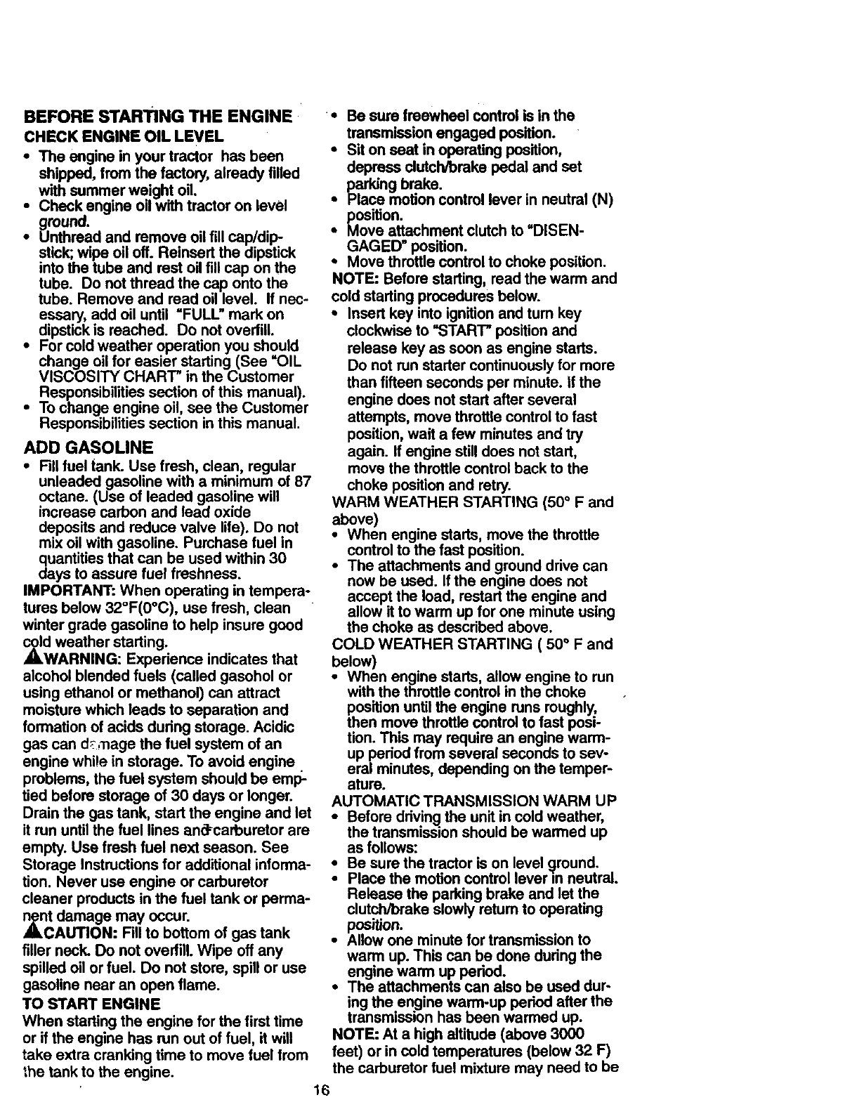
NOTE: To protect hood from damage when
transportingyour tractor on a truckor a
trailer, be sure hood is closed and secured
to tractor.Use an appropriate means of
tying hood totractor (rope, cord, etc.).
TO OPERATE ON HILLS
_CAUTION: Do not drive up or down
hills with slopes greater than 15° and do
not drive across any slope. Use the slope
guide provided at the back of this manual.
•Choose the slowest speed before start-
ing up or down hills.
•Avoid stopping or changing speed on
hills._
•If slowing is necessary, move throttle
control lever to slower position.
TOWING CARTS AND OTHER
ATTACHMENTS
Tow only the attachments that are recom-
mended by and comply with specifications
of the manufacturer of your tractor. Use
common sense when towing. Too heavy of
a load, while on a slope, is dangerous.
Tires can lose traction with the ground and
cause you to lose control of your tractor.
15
BEFORE STARTING THE ENGINE
CHECK ENGINE OIL LEVEL
• The engine in your tractor has been
shipped, from the factory, already tilled
with summer weight oil.
•Check engine oil with tractor on level
ground.
•Unthread and remove oil fill cap/dip
stick;, wipe oil off. Reinsert the dipstick
into the tube and rest oil till cap on the
tube. Do not thread the cap onto the
tube. Remove and read oil level. If nec-
essary, add oil until "FULL" mark on
dipstick is reached. Do not ovedilL
•For cold weather operation you should
change oil for easier starting (See "OIL
VISCOSITY CHART" in the Customer
Responsibilities section of this manual).
• To change engine oil, see the Customer
Responsibilities section in this manual.
ADD GASOLINE
•Fill fuel tank. Use fresh, clean, regular
unleaded gasoline with a minimum of 87
octane. (Use of leaded gasoline will
increase carbon and lead oxide
deposits and reduce valve life). Do not
mix oil with gasoline. Purchase fuel in
quantities that can be used within 30
days to assure fuel freshness.
IMPORTANT: When operating in tempera-
tures below 32°F(0°C), use fresh, clean
winter grade gasoline to help insure good
,_d weather starting.
WARNING: Expedence indicates that
alcohol blended fuels (called gasohol or
using ethanol or methanol) can attract
moisture which leads to separation and
formation of acids dudng storage. Acidic
gas can d_,_nage the fuel system of an
engine while in storage. To avoid engine
problems, the fuel system should be emp-
tied before storage of 30 days or longer.
Drain the gas tank, start the engine and let
it run until the fuel lines an_carburetor are
empty. Use fresh fuel next season. See
Storage Instructions for additional informa-
tion. Never use engine or carburetor
cleaner products in the fuel tank or perma-
znt damage may occur.
CAUTION: Fill to bottom of gas tank
tiller neck. Do not overfill. Wipe off any
spilled oil or fuel. Do not store, spill or use
gasoline near an open flame.
TO START ENGINE
When starting the engine for the first time
or if the engine has run out of fuel, it will
take extra cranking time to move fuel from
the tank to the engine.
••Be sure freewheel control is in the
transmission engaged position.
•Sit on seat in operating position,
depress clutchlbrake pedal and set
parking brake.
• Place motion control lever in neutral (N)
position.
•Move attachment clutch to "DISEN-
GAGED" position.
• Move throttle control to choke position.
NOTE: Before starting, read the warm and
cold starting procedures below.
•Insert key into ignition and turn key
clockwise to _3TART" position and
release key as soon as engine starts.
Do not run starter continuously for more
than fifteen seconds per minute. If the
engine does not start after several
attempts, move throttle control to fast
position, wait a few minutes and try
again. If engine still does not start,
move the throttle control back to the
choke position and retry.
WARM WEATHER STARTING (50 °F and
above)
•When engine starts, move the throttle
control to the fast position.
•The attachments and ground drive can
now be used. If the engine does not
accept the load, restart the engine and
allow it to warm up for one minute using
the choke as described above.
COLD WEATHER STARTING ( 50 °F and
below)
•When engine starts, allow engine to run
with the throttle control in the choke
position until the engine runs roughly,
then move throttle control to fast posi-
tion. This may require an engine warm-
up pedod from several seconds to sev-
eral minutes, depending on the temper-
ature.
AUTOMATIC TRANSMISSION WARM UP
•Before ddvingthe unit in cold weather,
the transmission shouldbe warmed up
as follows:
•Be sure the tractor is on level qround.
•Place the motion control lever =nneutral.
Release the parking brake and let the
clutch/brake slowly ratum to operating
position.
•Allow one minute for transmission to
warm up. This can be done dudng the
engine warm up period.
•The attachments can also be used dur-
ing the engine warm-up pedod after the
transmission has been warmed up.
NOTE: At a high altitude (above 3000
feet) or in cold temperatures (below 32 F)
the carburetor fuel mixture may need to be
16
adjustedfor bestengineperformance,
See"TOADJUSTCARBURETOR"inthe
ServiceandAdjustmentssectionof this
manual.
PURGETRANSMISSION
,_CAUTION: Never engage or disen-
gage freewheel lever while the engine is
running.
To ensure proper operation and perfor-
mance, it is recommended that the trans-
mission be purged before operating tractor
for the first time. This procedure will
remove any trapped air inside the trans-
mission which may have developed during
shipping of your tractor.
IMPORTANT: Should your transmission
require removal for service or replace-
ment, it should be purged after reinstalla-
tion before operating the tractor.
•Place tractor safely on level surface with
engine off and parking brake set.
•Disengage transmission by placing free-
wheel control in freewheeling position
(See =TO TRANSPORT" in this section
of manual).
•Sitting in the tractor seat, start engine.
After the engine is running, move throt-
tle control to slow position. With motion
control lever in neutral (N) position,
slowly disengage clutcl',Jbrake pedal.
•Move motion control lever to full forward
position and hold for five (5) seconds.
Move lever to full reverse position and
hold for five (5) seconds. Repeat this
procedure three (3) times.
NOTE: During this procedure there will be
no movement of drive wheels. The air is
being removed from hydraulic drive sys-
tem.
•Move motion control lever to neutral (N)
position. Shut off engine and set parking
brake.
•Engage transmission by placing free-
wheel control in ddvTng=position (See
=TO TRANSPORT" in this section of
manual).
•Sitting in the tractor seat, start engine.
After the engine is running, move throt-
tle control to half (1/2) speed. With
motion control lever in neutral (N) posi-
tion, slowly disengage clutch/brake
pedal.
•Slowly move motion control lever for-
ward; after the tractor moves approxi-
mately five (5) feet, slowly move motion
-control lever to reverse position. After
the tractor moves approximately five (5)
feet return the motion control lever to
the neutral (N) position. Repeat this pro-
cedura with the motion control lever
three (3) times.
•Your tractor is now purged and ready for
normal operation.
MOWING TIPS
•Tire chains cannot be used when the
mower housing is attached to tractor.
•Mower should be propedy leveled for
best mowing performance. See =TO
LEVEL MOWER HOUSING" in the
Service and Adjustments section of this
manual.
•The left hand side of mower should be
used for trimming.
•Drive so that clippings are discharged
onto the area that has been cut. Have
the cut area to the right of the tractor.
This will result in a more even distribu-
tion of clippings and more uniform cut-
ting.
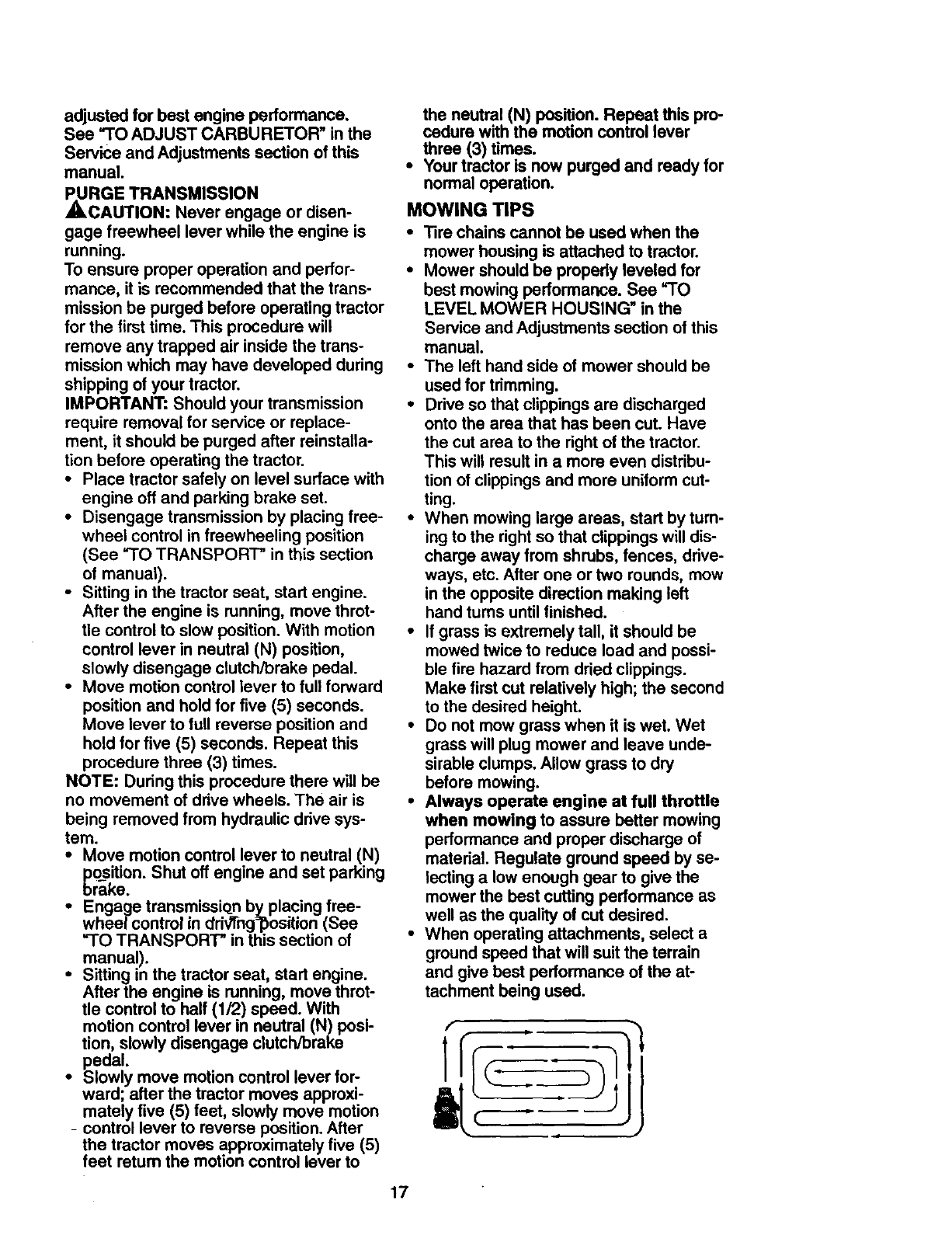
•When mowing large areas, start by turn-
ing to the right so that clippings will dis-
charge away from shrubs, fences, drive-
ways, etc. After one or two rounds, mow
in the opposite direction making left
hand turns until finished.
•If grass is extremely tall, it should be
mowed twice to reduce load and possi-
ble fire hazard from dried clippings.
Make first cut relatively high; the second
to the desired height.
•Do not mow grass when it is wet. Wet
grass will plug mower and leave unde-
sirable clumps. Allow grass to dry
before mowing.
•Always operate engine at full throttle
when mowing to assure better mowing
performance and proper discharge of
material. Regulate ground speed by se-
lecting a low enough gear to give the
mower the best cutting performance as
well as the quality of cut desired.
•When operating attachments, select a
ground speed that will suit the terrain
and give best performance of the at-
tachment being used.
17
MULCHING MOWING TIPS
IMPORTANT: For best performance, keep
mower housing free of built-upgrass and
trash. Clean after each use.
• The special mulching blade will recut
the grass clippingsmany times and
reduce them in size so that as they fall
onto the lawn they will disperse into the
grass and not be noticed. Also, the
mulched grass will biodegrade quickly
to provide nutrientsfor the lawn. Always
mulch with your highest engine (blade)
speed as this will provide the best recur-
ting action of the blades.
• Avoid cutting your lawn when it is wet.
Wet grass tends to form clumps and
interferes with the mulching action. The
best time to mow your lawn is the early
afternoon. At this time the grass has
dried and the newly cut area will not be
exposed to the direct sun.
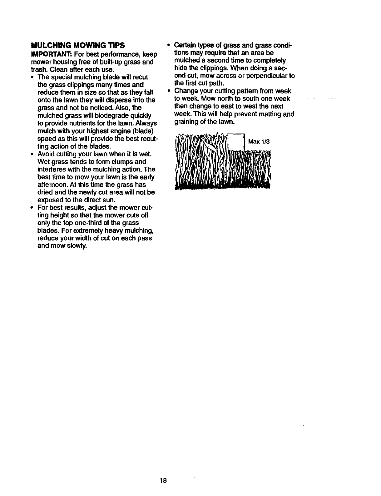
•For best results, adjust the mower cut-
ting height so that the mower cuts off
only the top one-third of the grass
blades. For extremely heavy mulching,
reduce your width of cut on each pass
and mow slowly.
•Certain types of grass and grass condi-
tions may require that an area be
mulched a second time to completely
hide the clippings. When doing a sec-
ond cut, mow across or perpendicular to
the firstcut path.
•Change your cutting pattern from week
to week. Mow northto south one week
then change to east to west the next
week. This will help prevent matting and
grainingof the lawn.
Max 1/3
18
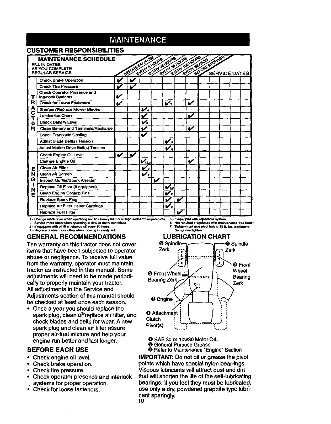
CUSTOMER RESPONSIBILmES
CheCk "Rre Pressure ll_
Check Operator Presence and
TInterlock Systems
R Check for LOOSeFasteners V_'7 ! iI_'
T Lubrication Chart Ik_
0 Check Batteqf Level
Rc_an Battery and Terminals/Recharge V'
Check Transa, xle Cooling If
AdjUst Blade Belt(s) Tension iI_s
Adjust Motion Drive Belt(s) Tension ll_e
Check Engine Oil Level V'
Change Engine Oil I_1.2,: Vp
E Clean Air Filter _2 I
NClean Air Screen V'._
G Insp.ect MuftiedSpark Arre_ter Vw
N Replace Oil Filter (If equipped) _.a
Clean Engine Cooling Fins _2
Replace Spark Plug if=
Rel_lace Air Filter Paper Cartridge
Replace Fuel Filter ll_
I - _p more olten when operating under =heavy load or it) htg_ _t t4w_oeratures. 5. If equipped wil_ mJj*aMable syshml.
2 - Serztce more often whe_ operatir_g ill dirty or dusty conclitioc_s.
3- If eq_ wi_ oil fliter, change o_ eveW 50 ho_-s.
4 - Replace blades mine often when mowing_nsandy soil.
GENERAL RECOMMENDATIONS
The warranty on this tractor does not cover
items that have been subjected to operator
abuse or negligence. To receive full value
from the warranty, operator must maintain
tractor as instructed in this manual. Some
adjustments will need to be made periodi-
cally to propedy maintain your tractor.
All adjustments in the Service and
Adjustments section of this manual should
be che_:ked at least once each season.
•Once ayear you should replace the
spark plug, clean oPreptace air filter, and
check blades and belts for wear. A new
spark plug and clean air filter assure
proper air-fuel mixture and help your
engine run better and last longer.
BEFORE EACH USE
•Check engine oil level.
•Check brake operation.
•Check tire pressure,
•Check operator presence and interlock
_ systems for proper operation.
•Check for loose fasteners,
s - Not requlr_l if _olpped wt_ n_Inten_nce-Tree bebq
7 - T_ghten front L_'fO pivot bolt to 35 It.-I=4. mexknum.
Do not overtighton.
LUBRICATION CHART
OSpindle
Zerk Zerk
Front
Wheel
Bearing
Zerk
49 Engine
Clutch
Pivot(s) , ,
OSAE 30 or 10w30 Motor OIL
_General Purpose Grease
Refer to Maintenance Engine" Section
IMPORTANT: Do not oil or grease the pivot
points which have special nylon bearoings.
Viscous lubricants will attract dust and dirt
that will shorten the life of the self-lubricating
bearings. If you feel they must be lubricated,
use only a dry, powdered graphite type lubri-
cant sparingly.
19
TRACTOR
Always observe safety rules when per-
forming any maintenance.
BRAKE OPERATION
If tractor requires more than six (6) feet
stopping distance at high speed in highest
gear, then brake must be adjusted. (See
"TO ADJUST BRAKE" in the Service and
Adjustments section of this manual).
TIRES
•Maintain proper air pressure in all tires
(See "PRODUCT SPECIFICATIONS"
on page 5 of this manual).
•Keep tires free of gasoline, oil, or insect
controlchemicals which can harm rub-
ber.
•Avoid stumps, stones, deep ruts, sharp
objects and other hazards that may
cause tire damage.
NOTE: To seal tire punctures and prevent
flat tires due to slow leaks, tire sealant
may be purchased from your local pads
dealer. Tire sealant also prevents tire dry
rot and corrosion.
OPERATOR PRESENCE SYSTEM
Be sure that operator presence and inter-
lock systems are working properly. If your
tractor does not function as described
below, repair the problem immediately.
•The engine should not start unless the
clutch/brake pedal is fully depressed
and attachment clutchcontrol is in the
disengaged position.
•When the engine is running, any
attempt by the operator to leave the
seat without firstsetting the parking
brake should shut off the engine.
• When the engine is running and the
attachment clutch is engaged, any
attempt _y the operator to leave the
seat sho_!d shut off the engine.
• The attachment clutch should never
operate unless the operator is in the
seat.
BLADE CARE _- _-
For best results mower blades must be
kept sharp. Replace bent or damaged
blades.
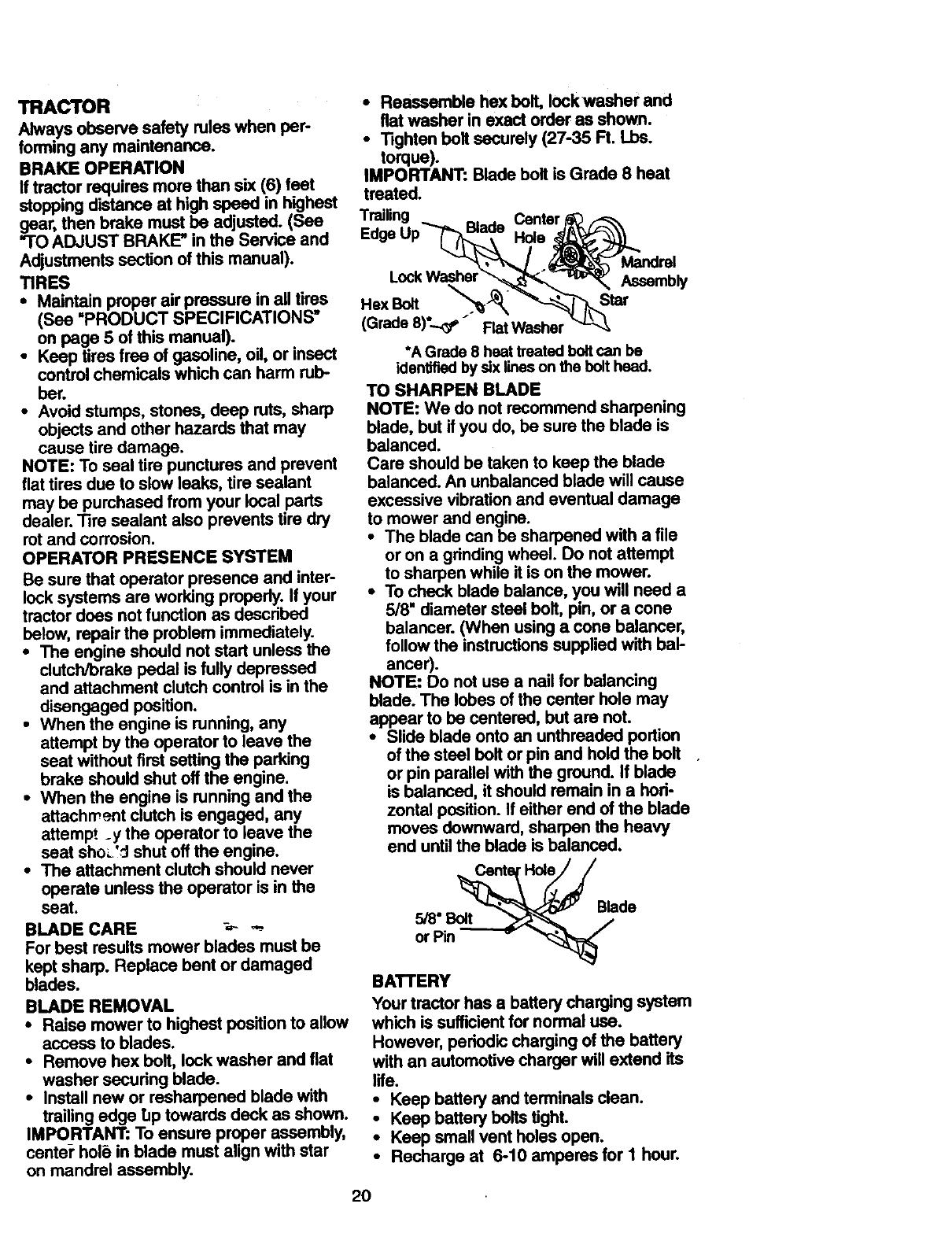
BLADE REMOVAL
•Raise mower to highest position to allow
access to blades.
•Remove hex bolt, lock washer and flat
washer securing blade.
•Install new or resharpened blade with
trailing edge TJptowards deck as shown.
IMPORTANT: To ensure proper assembly,
center" hole in blade must align with star
on mandrel assembly.
•Reassemble hex bolt, Iockwasher and
fiat washer in exact order as shown.
• Tighten bolt securely (27-35 R. Lbs.
torque).
IMPORTANT:. Blade bolt is Grade 8 heat
treated.
Trailing
Edge
Hex Bolt
(Grade 8)°.._3_" Flat Washer
Assembly
Star
*A Grade8 heattreatedboltcanbe
idenlffiedbysixlinesonthebolthead.
TO SHARPEN BLADE
NOTE: We do not recommend sharpening
blade, but if you do, be sure the blade is
balanced.
Care should be taken to keep the blade
balanced. An unbalanced blade will cause
excessive vibration and eventual damage
to mower and engine.
• The blade can be sharpened with a file
or on a grindingwheel. Do not attempt
to sharpen while it is on the mower.
•To check blade balance, you will need a
5/8" diameter steel bolt, pin, or a cone
balancer. (When using a cone balancer,
follow the instructionssupplied with bal-
ancer).
NOTE: Do not use a nail for balancing
blade. The lobes ofthe center hole may
appear to be centered, but are not.
•Slide blade onto an unthreaded portion
ofthe steel bolt or pin and hold the bolt
or pin parallel with the ground. If blade
is balanced, it should remain in a hori-
zontal position. If either end of the blade
moves downward, sharpen the heavy
end untilthe blade is balanced.
Blade
5/8" Bolt
or Pin
BATTERY
Yourtractor has a battery charging system
which is sufficientfor normal use.
However, periodic charging ofthe battery
with an automotive charger will extend its
life.
• Keep batteryand terminalsclean.
•Keep batteryboltstight.
•Keep smallventholesopen,
•Recharge at 6-10 amperes for 1 hour.
20
TO CLEAN BATTERY AND TERMINALS
Corrosion and dirt on the battery and ter-
minals can cause the battery to "leak"
power.
•Open battery box door.
•Disconnect BLACK battery cable first
then RED battery cable and remove
battery from tractor.
•Rinse the battery with plain water and
dry.
•Clean terminals and battery cable ends
with wire brush untilbright.
•Coat terminals with grease or petroleum
jelly.
•Reinstall battery (See =REPLACING
BATTERY" in the SERVICE AND
ADJUSTMENTS section of this manu-
al).
V-BELTS
Check V-belts for deterioration and wear
after 100 hours of operation and replace if
necessary. The belts are not adjustable.
Replace belts if they begin to slip from
wear.
TRANSAXLE COOLING
The transmission fan and cooling fins
should be kept clean to assure proper
cooling,
Do not attempt to clean fen or transmis-
sionwhile engine is running or while the
transmission is hot.
•Inspect coolingfan to be sure fan
blades are intact and clean.
•Inspect coolingfins for dirt, grass clip
pings and other materials. To prevent
damage to seals, do not use com-
pressed air or high pressure sprayer to
clean coolingfins.
TRANSAXLE PUMP FLUID
The transaxle was sealed at the factory
and fluid maintenance is not required for
the life of the transaxle. Should the
transaxle ever leak or require servicing,
contact your nearest authorized service
center.
ENGINE
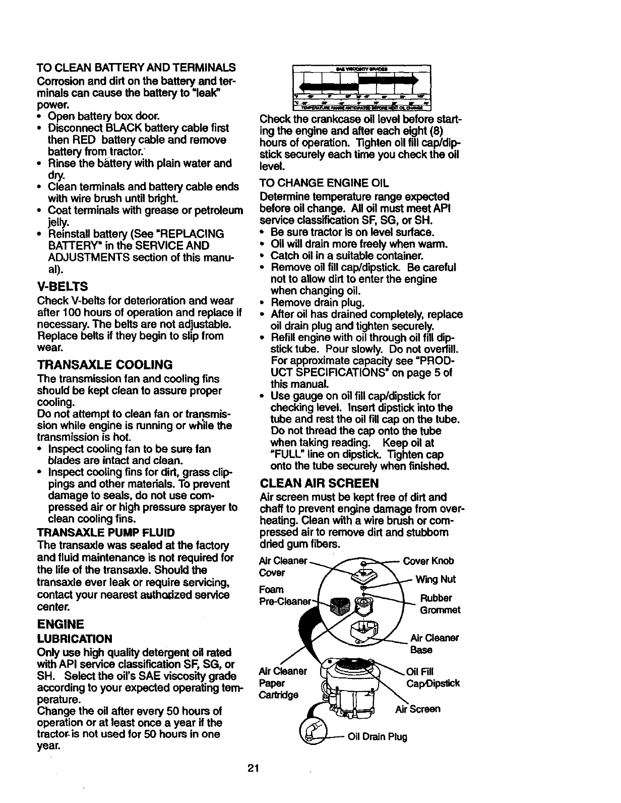
LUBRICATION
Only use high quality detergent oil rated
with API service classification SF, SG, or
SH. Select the oil's SAE viscosity grade
according to your expected operating tern-
perature.
Change the oil after every 50 hours of
operation or at least once a year if the
tractoris not used for 50 hours in one
yeaL
Check the crankcase oil level before start-
ing the engine and after each eight (8)
hours of operation. "tighten oil fill cap/dip-
stick securely each time you check the oil
level.
TO CHANGE ENGINE OIL
Determine temperature range expected
before oil change. All oil must meet API
service classification SF, SG, or SH.
• Be sure tractor is on level surface.
•Oil will drain more freely when warm.
•Catch oil in a suitable container.
•Remove oil fill cap/dipstick. Be careful
not to allow dirt to enter the engine
when changing oil.
•Remove drain plug.
• After oil has drained completely, replace
oil drain plug and tighten securely.
•Refill engine with oil through oil fill dip
stick tube. Pour slowly. Do not overfill.
For approximate capacity see =PROD-
UCT SPECIFICATIONS" on page 5 of
this manual.
•Use gauge on oil fill cap/dipstick for
checking level. Insert dipstick into the
tube and rest the oil fill cap on the tube.
Do not thread the cap onto the tube
when taking reading. Keep oil at
=FULL" line on dipstick. Tighten cap
onto the tube securely when finished.
CLEAN AIR SCREEN
Air screen must be kept free of dirt and
chaff to prevent engine damage from over-
heating. Clean with a wire brushor com-
pressed air to remove dirt and stubborn
dried gum fibers.
Cover
Foam
Knob
Wing Nut
Air Cleaner
Base
Air Cleaner Fill
Paper CapOips_ck
Cartridge
Air Screen
Drain Plug
21
CLEAN AIR INTAKE/COOLING AREAS
To insure proper cooling, make sure the
grass screen, cooling fins, and other
extemal surfaces of the engine are kept
clean at all times.
Every 100 hours of operation (more often
underextremely dusty, dirty conditions),
removethe blower housing and other
coolingshrouds. Clean the coolingfins
and external surfaces as necessary. Make
sure the coolingshrouds are reinstalled.
NOTE: Operating the engine with a
blockedgrass screen, dirty or plugged
coolingfins, and/or coolingshrouds re-
moved will cause engine damage due to
overheating.
AIR FILTER
Your engine will not run propedy using a
dirty air filter. Clean the foam pre-cleaner
after every 25 hours of operation or every
season. Service paper cartridge every
100 hours of operation or every season,
whichever occurs first.
Service air cleaner more often under dusty
conditions.
• Remove knob and cover.
•Remove wing nut and air cleaner from
base.
TO SERVICE PRE-CLEANER
•Slide foam pre-cleaner off cartridge.
• Wash it in liquid detergent and water.
•Squeeze it dry in a clean cloth. Allow it
to dry.
•Saturate it in engine oil. Wrap it in
clean, absorbent cloth and squeeze to
remove excess oil.
TO SE[ _'ICE CARTRIDGE
•Replac'_adirty,bent, or damaged car-
tridge.
NOTE: Do not wash the paper cartridge
or use pressurized air, as this will damage
the cartridge. _._
•Reinstall the pra-cleaner (cleaned and
oiled) over the paper cartridge.
•Reassemble air cleaner, wing nut, cover
and tighten knob securely.
ENGINE OIL FILTER
Replace the engine oil filter every season
or every other oil change if the tractor is
used more than 100 hours in one year.
•Drain oilfrom engine crankcase (See
"TO CHANGE ENGINE OIL" in this sec-
tion of this manual, through step remove
drain plug).
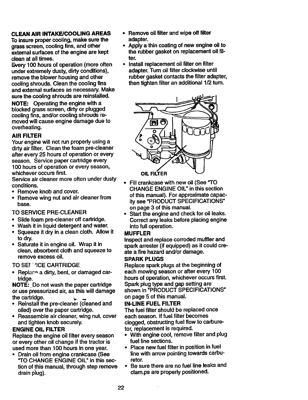
•Remove oil filter and wipe off filter
adapter.
•Apply athin coating of new engine oil to
the rubber gasket on replacement oil fil-
ter.
•Install replacement oil filter on filter
adapter. Tum oil filter clockwise until
rubber gasket contacts the filter adapter,
then tighten filter an additional 1/2 tum.
•Fill crankcase with new oil (See fro
CHANGE ENGINE OIL" in this section
of this manual). For approximate capac-
ity see =PRODUCT SPECIFICATIONS"
on page 3 of this manual.
•Start the engine and check for oil leaks.
Correct any leaks before placing engine
into full operation.
MUFFLER
Inspect and replace corroded muffler and
spark arrester (if equipped) as it could cre-
ate a fire hazard and/or damage.
SPARK PLUGS
Replace spark plugs at the beginning of
each mowing season or after every 100
hours of operation, whichever occurs first.
Spark plug type and gap setting are
shown in "PRODUCT SPECIFICATIONS"
on page 5 of this manual.
IN-LINE FUEL FILTER
The fuel filter should be replaced once
each season. If fuel filter becomes
clogged, obstructingfuel flow to carbure-
tor, replacement is required.
•With engine cool, remove filter and plug
fuel line sections.
•Place new fuel filterin positionin fuel
line with arrow pointingtowards carbu-
retor.
•Be sure there are no fuel line leaks and
clam.ps are propedy positioned.
22
FuelRlter
CLEANING
•Clean engine, battery, seat, finish, etc.
of all foreign matter.
•Keep finished surfaces and wheels free
of all gasoline, oil, etc.
•Protect painted surfaces with automo-
tive typewax.
We do not recommend using a garden
hose to clean your tractor unless the elec-
trical system, muffler, air filter and carbure-
tor are covered to keep water out. Water
in engine can result in a shortened engine
life.
,_CAUTION: Before performing any service or adjustments:
•Depress clutch/brake pedal fully and set parking brake.
•Place motion control lever in neutral (N) position.
•Place attachment clutch in "DISENGAGED" position.
•Turn ignition key =OFF' and remove key.
•Make sure the blades and all moving parts have completely stopped.
• Disconnect spark plug wire from spark plug and place wire where it cannot come
in contact with plug.
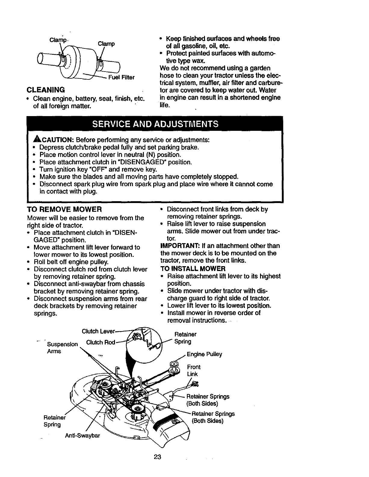
TO REMOVE MOWER
Mower will be easier to remove from the
right side of tractor.
•Place attachment clutch in =DISEN-
GAGED" position.
•Move attachment lift lever forward to
lower mower to its lowest position•
•Roll belt off engine pulley.
•Disconnect clutch rod from clutch lever
by removing retainer spring.
•Disconnect anti-swaybar from chassis
bracket by removing retainer spring.
•Disconnect suspension arms from rear
deck brackets by removing retainer
springs.
Suspension
Arms
•Disconnect front links from deck by
removing retainer springs.
•Raise lift lever to raise suspension
arms. Slide mower out from under trac-
tor.
IMPORTANT: If an attachment other than
the mower deck is to be mounted on the
tractor, remove the front links.
TO INSTALL MOWER
•Raise attachment lift lever to its highest
position.
•Slide mower under tractor with dis-
charge guard to right side of tractor.
•Lower lift lever to its lowest position.
•Install mower in reverse order of
removal instructions .....
Retainer
Engine Pulley
Front
Link
Retainer
Spring
Anti-Swaybar
(Both Sides)
(Both Sides)
23
,O LEVELMOWERHOUSING
\djust the mower while tractor is parked
)n level ground or driveway. Make sure
ires are properly inflated (See =PROD-
JCT SPECIFICATIONS"). If tires are
_ver or underinflated, you will not proPedy
_djust your mower.
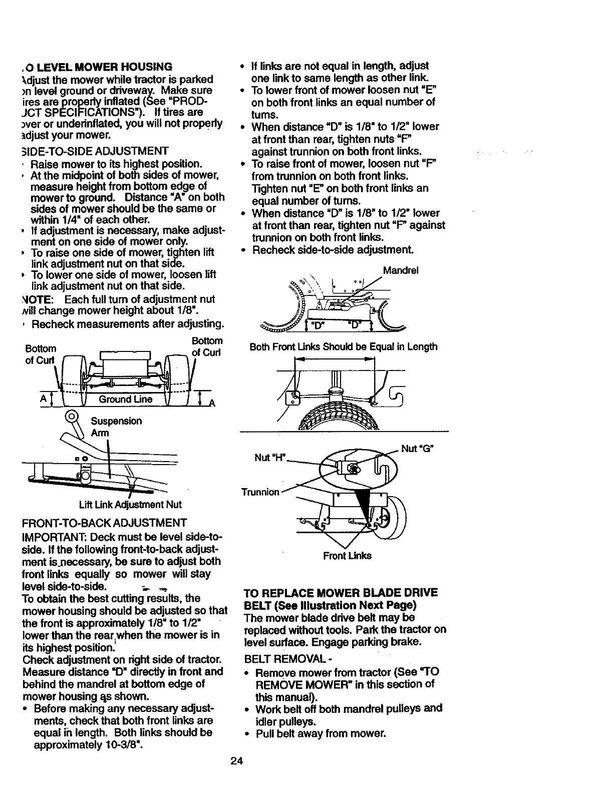
_IDE-TO-SIDE ADJUSTMENT
,Raise mower to its highest position.
,At the midpoint of both sides of mower,
measure height from bottom edge of
mower to ground. Distance "A" on both
sides of mower should be the same or
within 1/4" of each other.
, If adjustment is necessary, make adjust-
ment on one side of mower only.
, To raise one side of mower, tighten lift
link adjustment nut on that side.
, To lower one side of mower, loosen lift
link adjustment nut on that side.
NOTE: Each full turn of adjustment nut
Nill change mower height about 1/8".
, Recheck measurements after adjusting.
Bottom
o%u.°m '°u"
"_'-"_ Ground Line _""_'TA
Suspension
Arm
• If links are not equal in length, adjust
one linkto same length as other link.
•To lower front of mower loosen nut "E"
on bothfront links an equal number of
turns.
•When distance =D" is 1/8" to 1/2" lower
at front than roar, tighten nuts =P
against trunnionon both front links.
• To raise front of mower, loosen nut =P
from trunnion on both front links.
"lightan nut "E"on both front links an
equal number oftums.
•When distance =D"is 1/8" to 1/2" lower
at front than roar, tighten nut =P against
trunnion on both front links.
•Recheck side-to-side adjustment.
Mandrel
Both Front Links Should be Equal in Length
Nut =I-P Nut "G"
LiftLink Adjustment Nut
FRONT-TO-BACK ADJUSTMENT
IMPORTANT: Deck must be level side-to-
side. If the following front-to-back adjust-
ment is.necessary, be sure to adjust both
front links equally so mower will stay
level side-to-side. _ _,_
To obtain the best cutting results, the
mower housing should be adjusted so that
the front is approximately 1/8" to 1/2"
lower than the roar.when the mower is in
its highest position;
Check adjustment on right side of tractor.
Measure distance =D" directly in front and
behind the mandrel at bottom edge of
mower housing as shown.
•Before making any necessary adjust-
ments, check that both front links are
equal i-nlength. Both links should be
approximately 10-3/8".
Front Unks
TO REPLACE MOWER BLADE DRIVE
BELT (See Illustration Next Page)
The mower blade drive belt may be
replaced without tools. Park the tractor on
level surface. Engage parking brake.
BELT REMOVAL -
•Remove mower from tracto[ (See "TO
REMOVE MOWER" in this section of
this manual).
•Work belt off both mandrel pulleys and
idler pulleys.
•Pull belt away from mower.
24
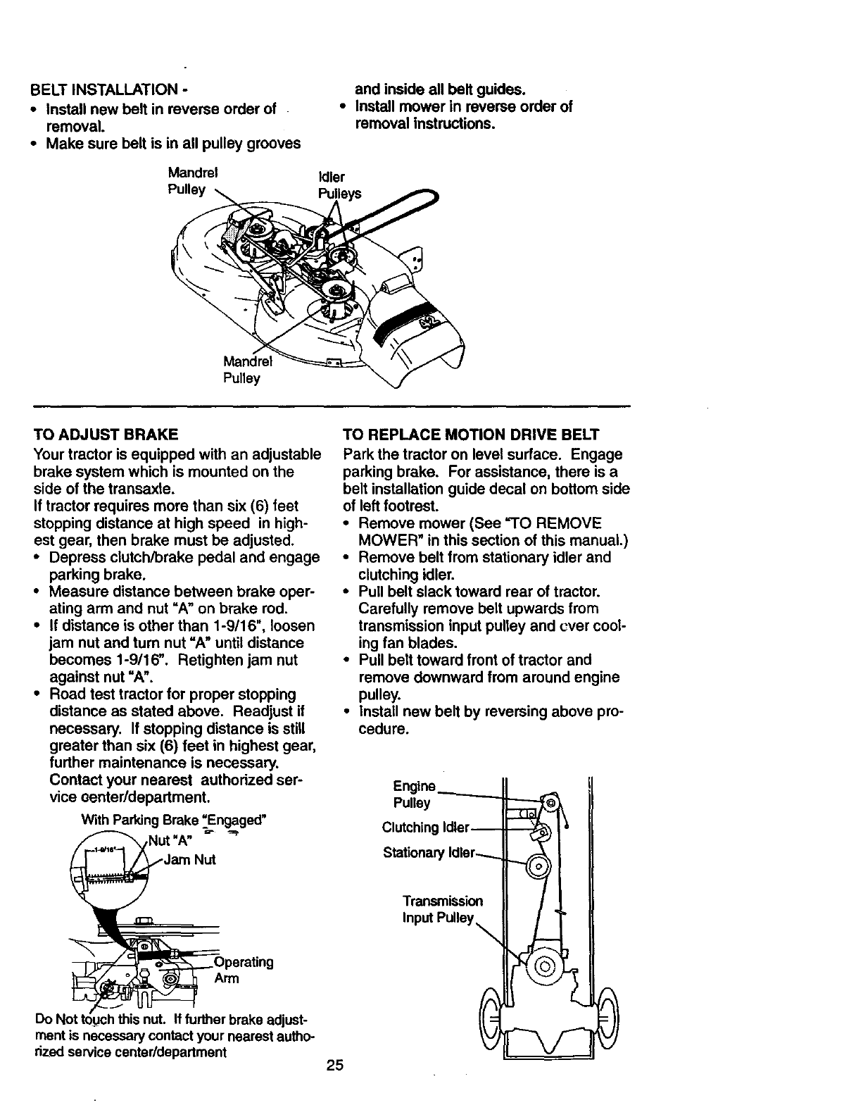
BELT INSTALLATION -
•Install new belt in reverse order of
removal.
•Make sure belt is in all pulley grooves
Mandrel
Pulley
and inside all belt guides.
•Install mower in reverse order of
removal instructions.
Idler
Mandrel
Pulley
TO ADJUST BRAKE
Your tractor is equipped with an adjustable
brake system which is mounted on the
side of the transaxle.
If tractor requires more than six (6) feet
stopping distance at high speed in high-
est gear, then brake must be adjusted.
•Depress clutch/brake pedal and engage
parking brake.
•Measure distance between brake oper-
ating arm and nut =A" on brake rod.
•If distance is other than 1-9/16", loosen
jam nut and turn nut =A" until distance
becomes 1-9/16". Retighten jam nut
against nut "A".
•Road test tractor for proper stopping
distance as stated above. Readjust if
necessary. If stopping distance is still
greater than six (6) feet in highest gear,
further maintenance is necessary.
Contact your nearest authorized ser-
vice oenter/department.
With Parking Brake =_Engaged"
,Nut "A"
Nut
Arm
Do I' _ If further brake adjust-
rnentis necessary contact your nearest autho-
rized service center/department
TO REPLACE MOTION DRIVE BELT
Park the tractor on level surface. Engage
parking brake. For assistance, there is a
belt installation guide decal on bottom side
of left footrest.
•Remove mower (See =TO REMOVE
MOWER" in this section of this manual.)
•Remove belt from stationary idler and
clutching idler.
•Pull belt slack toward rear of tractor.
Carefully remove belt upwards from
transmission input pulley and cver cool-
ing fan blades.
•Pull belt toward front of tractor and
remove downward from around engine
pulley.
•Install new belt by reversing above pro-
cedure.
25
Engine.__._......_
Pulley
Clutching Idler--
Stationary Idler........
Transmission
Input Pulley _
B..,==.
TO ADJUST MOTION CONTROL LEVER
The motioncontrol lever has been preset
at the factory and adjustment should not
be necessary.
If for any mason the motion control lever
will not hold its positionwhile at a selected
speed, it may be adjusted at the friction
pack located on the right side of transmis-
sion.
• Park tractor on level surface. Stop trac-
tor by tuming ignition key to =OFF" posi-
tion, and engage parking brake.
• Adjust motion control lever by tighteni_j
adjustment Iocknut one half (1/2) rum.
NOTE: If for any reason the effortto
move the motion control lever becomes
too excessive, reverse the above adjust-
ment procedure by loosening Iocknut 1/4
to 1/2 turn.
Road test tractor after adjustment and
repeat procedure if necessary.
TRANSMISSION REMOVAL/REPLACE-
MENT
Should your transmission require removal
for service or replacement, it should be
purged after reinstallation and before
operatingthe tractor. See =PURGE
TRANSMISSION" in the Operation section
of this manual.
Adjustment
Locknut
TO ADJUST STEERING WHEEL ALIGN-
MENT
If steedng wheel crossbars are not hori-
zontal (left to dght) when wheels are posi-
tioned straight forward, remove steedng
wheel and reassemble per instructions in
the Assembly section ofthis manual.
FRONT WHEEL TOE-IN/CAMBER
The front wheel toe-in and camber are not
adjustable on your tractor. If damage has
occurred to affect the front wheel toe-in or
camber, contact your nearest authorized
service center.
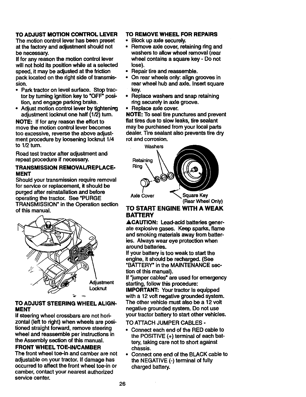
TO REMOVE WHEEL FOR REPAIRS
•Block up axle securely.
• Remove axle cover, retaining dng and
washers to allow wheel removal (rear
wheel contains a square key - Do not
lose).
•Repair tire and reassemble.
•On rear wheels only:align grooves in
rear wheel hub and axle. Insert square
key.
•Replace washers and snap retaining
dng securely in axle groove.
•Replace axle cover.
NOTE: To seal tire punctures and prevent
flat tires due to slow leaks, tire sealant
may be purchased from your local parts
dealer. Tire sealant also prevents tire dry
rot and corrosion.
Washe_ A
Retaining
Rin_____.,
AxleCover "_ SquareKey
(Rear Wheel Only)
TO START ENGINE WITH A WEAK
BAI"rERY
ACAUTION: Lead-acid batteries gener-
ate explosive gases. Keep sparks, flame
and smoking materials away from batter-
ies. Always wear eye protection when
around batteries.
If your battery is too weak to start the
engine, it should be recharged. (See
"BATTERY" inthe MAINTENANCE sec-
tion ofthis manual).
If =jumper cables" are used for emergency
starting,followthis procedure:
IMPORTANT: Your tractor Is equipped
with a 12 volt negative grounded system.
The other vehicle must also be a 12 volt
negative grounded system. Do not use
your tractor battery to start other vehicles.
TO A'I-I'ACHJUMPER CABLES -
•Connect each end of the RED cable to
the POSITIVE (+) terminal of each bat-
tery, taking care not to short against
chassis.
•Connect one end of the BLACK cable to
the NEGATIVE (-) terminal offully
charged battery.
26
•Connect the other end of the BLACK
cable to good CHASSIS GROUND,
away from fuel tank and battery.
TO REMOVE CABLES, REVERSE
ORDER -
•BLACK cable first from chassis and
then from the fully charged battery.
• RED cable last from both batteries.
Positive
Terminal - Terminal
Charged
Negative
Positive Terminal Terminal
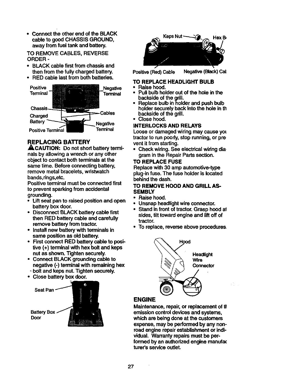
cPLACING BA'I-rERY
AUTION: Do not short battery termi-
nals by allowing a wrench or any other
object to contact both terminals at the
same time. Before connecting battery,
remove metal bracelets, wristwatch
bands,rings,etc.
Positive terminal must be connected first
to prevent sparking from accidental
grounding.
•Lift seat pan to raised position and open
battery box door.
•Disconnect BLACK battery cable first
then RED battery cable and carefully
remove battery from tractor.
•Install new battery with terminals in
same position as old battery.
•First connect RED battery cable to posi-
tive (+) terminal with hex bolt and keps
nut as shown. Tkjhten securely.
•Connect BLACK grounding cable to
negative (-) terminal with remaining hex
-bolt and keps nut. Tighten securely.
•Close battery box door.
Hex B_
Positive (Red) Cable Negative (Black) Cat
TO REPLACE HEADLIGHT BULB
•Raise hood.
•Pull bulb holder out of the hole in the
backside of the grill.
•Replace bulb inholder and push bulb
holder securely back into the hole in th
backside of the gdll.
•Close hood.
INTERLOCKS AND RELAYS
Loose or damaged widng may cause yol
tractor to run pcody, stop running, or pre
vent it from starting.
• Check wiring. See electdcal wiring dia.
gram in the Repair Parts section.
TO REPLACE FUSE
Replace with 30 amp automotive-type
plug-in fuse. The fuse holder is located
behind the dash.
TO REMOVE HOOD AND GRILL AS-
SEMBLY
•Raise hood.
•Unsnap headlight wire connector.
•Stand in front of tractor. Grasp hood at
sides, tilt toward engine and lift off of
tractor.
•To replace, reverse above procedures.
Headlight
Wim
Connector
Seat Par
Battery
Door
ENGINE
Maintenance, repair, or replacement of t!
emission control devices and systems,
which are being done at the customers
expense, may be performed by any non-
road engine repair establishment or indi-
vidual. Warranty repairs must be per-
formed by an authorized engine manufa(
turar's service outlet.
27
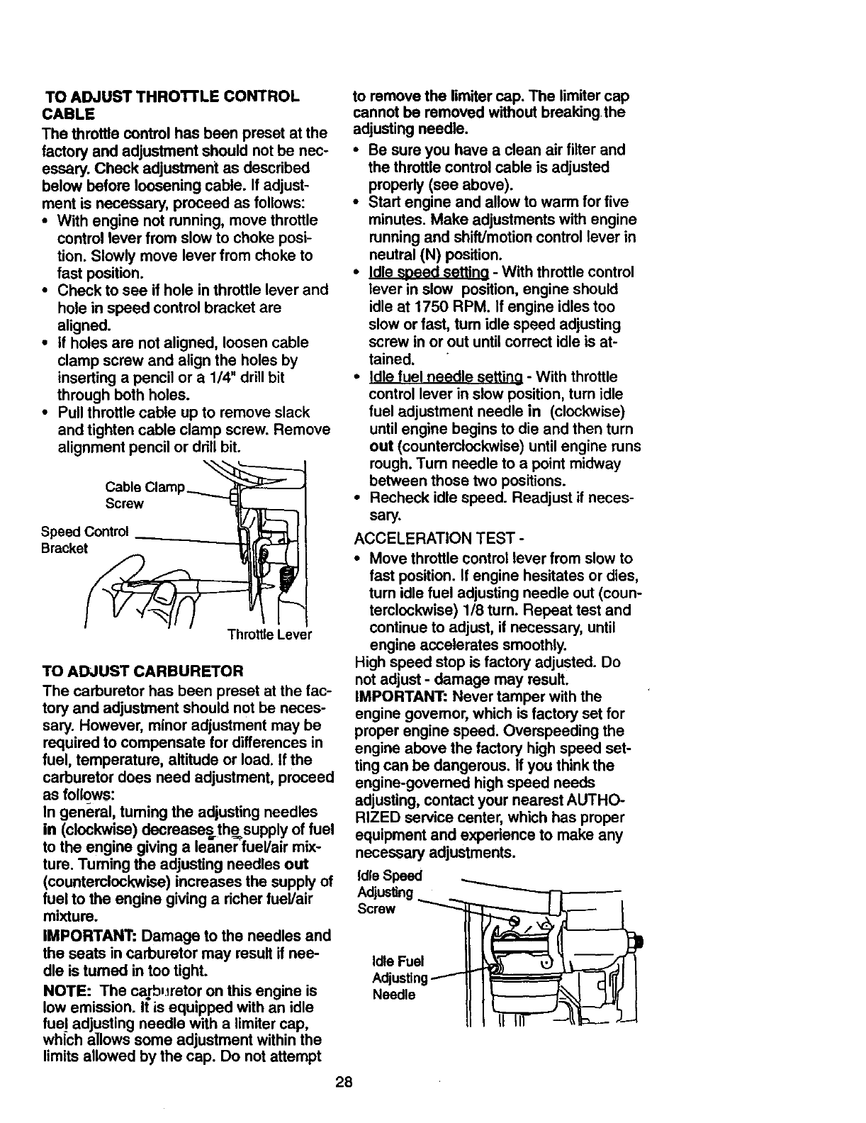
TO ADJUST THRO'n'LE CONTROL
CABLE
The throttle control has been preset at the
factory and adjustment should not be nec-
essary. Check adjustment as described
below before loosening cable. If adjust-
ment is necessary, proceed as follows:
•With engine not running, move throttle
control lever from slow to choke posi-
tion. Slowly move lever from choke to
fast position.
•Check to see if hole in throttle lever and
hole in speed control bracket are
aligned.
•if holes am not aligned, loosen cable
clamp screw and align the holes by
inserting a pencil or a 1/4" drill bit
through beth holes.
•Pull throttle cable up to remove slack
and tighten cable clamp screw. Remove
alignment pencil or drill bit.
Cable Clamp_
Screw _7_
SpeaedeCOntrol _'_]_[
Throttle Lever
TO ADJUST CARBURETOR
The carburetor has been preset at the fac-
tory and adjustment should not be neces-
sary. However, minor adjustment may be
required to compensate for differences in
fuel, temperature, altitude or load. if the
carburetor does need adjustment, proceed
as fol_ws:
In general, fuming the adjusting needles
in (clockwise) decreasesthe= supply of fuel
to the engine giving a leaner fuel/air mix-
ture. Tuming the adjusting needles out
(counterclockwise) increases the supply of
fuel to the engine giving a richer fuel/air
mixture.
IMPORTANT: Damage to the needles and
the seats in carburetor may result if nee-
dle is tumed in too tight.
NOTE: The carburetor on this engine is
low emission. It is equipped with an idle
fuel adjusting needle with a limiter cap,
which allows some adjustment within the
limits allowed by the cap. Do not attempt
to remove the limiter cap. The limiter cap
cannot be removed without breaking the
adjusting needle.
•Be sure you have a clean air filter and
the throttle control cable is adjusted
propedy (see above).
•Start engine and allow to warm for five
minutes. Make adjustments with engine
running and shift/motion control lever in
neutral (N) position.
•Idle speed setting - With throttle control
lever in slow position, engine should
idle at 1750 RPM. If engine idles too
slow or fast, turn idle speed adjusting
screw in or out until correct idle is at-
tained.
•Idle fuel needle S_tting - With throttle
control lever in slow position, turn idle
fuel adjustment needle in (clockwise)
until engine begins to die and then turn
out (counterclockwise) until engine runs
rough. Turn needle to a point midway
between those two positions.
•Recheck idle speed. Readjust if neces-
sary.
ACCELERATION TEST -
• Move throttle control lever from slow to
fast position. If engine hesitates or dies,
tum idle fuel adjusting needle out (coun-
terclockwise) 1/8 turn. Repeat test and
continue to adjust, if necessary, until
engine accelerates smoothly.
High speed stop is factory adjusted. Do
not adjust -damage may result.
IMPORTANT: Never tamper with the
engine governor, which is factory set for
proper engine speed. Overspeeding the
engine above the factory high speed set-
ting can be dangerous. If you think the
engine-governed high speed needs
adjusting, contact your nearest AUTHO-
RIZED service center, which has proper
equipment and experience to make any
necessary adjustments.
Idle Speed
Adjusting
Screw _ _ _ l
Adj ..gf l- rr l I
Needle I
II I_r--t_b-- )...4
28
Immediatelyprepareyourtractorfor stor-
age,attheendof theseasonor if thetrac-
torwill notbeusedfor 30 days or more.
,_CAUTION: Never store the tractor with
gasoline in the tank inside a building
where fumes may reach an open flame or
spark. Allow the engine to cool before stor-
ing in any enclosure.
TRACTOR
Remove mower from tractor for winter
storage. This will allow you to clean it thor-
oughly. Remove all dirt, grease, leaves,
etc. Store in a clean, dry area.
• Clean entire tractor (See "CLEANING"
in the Maintenance section of this man-
ual).
• Inspect and replace belts, if necessary
(See belt replacement instructions in the
Service and Adjustments section of this
manual).
• Lubricate as shown in the Maintenance
section of this manual.
• Be sure that all nuts, bolts and screws
are securely fastened. Inspect moving
parts for damage, breakage and wear.
Replace if necessary.
• Touch up all rusted or chipped paint sur-
faces; sand lightly before painting.
BATTERY
•Fully charge the battery for storage.
•After a period of time in storage, battery
may require recharging.
•To help prevent corrosion and power
leakage during long periods of storage,
battery cables should be disconnected
and battery cleaned thoroughly (see
"TO CLEAN BATTERY AND TERMI-
NALS" in the Maintenance section of
thi_ manual).
°After cleaning, leavecables disconnect-
ed and place cables_,h_re they cannot
come in contact with battery terminals.
•If battery is removed from tractor for
storage, do not store battery directly on
concrete or damp surfaces.
ENGINE
FUEL SYSTEM
IMPORTANT: It is important to prevent
gum deposits from forming in essential
fuel system parts such as carburetor, fuel
filter, fuel hose, or tank during storage.
Also, experience indicates that alcohol
blended fuels (called gasohol or using
ethanol or methanol) can attract moisture
which leads to separation and formation of
acids during storage. Acidic gas can dam-
age the fuel system of an engine while in
storage.
•Drain the fuel tank.
•Start the engine and let it run until the
fuel lines and carburetor are empty.
•Never use engine or carburetor cleaner
products in the fuel tank or permanent
damage may occur.
•Use fresh fuel next season.
NOTE: Fuel stabilizer is an acceptable
alternative in minimizing the formation of
fuel gum deposits during storage. Add sta-
bilizer to gasoline in fuel tank or storage
container. Always follow the mix ratio
found on stabilizer container. Run engine
at least 10 minutes after adding stabilizer
to allow the stabilizer to reach the carbure-
tor. Do not drain the gas tank and carbure-
tor if using fuel stabilizer.
ENGINE OIL
Drain oil (with engine warm) and replace
with clean engine oil. (See "ENGINE" in
the Maintenance section of this manual).
CYLINDER(S)
•Remove spark plug(s).
•Pour one ounce of oil through spark plug
hole(s) into cylinder(s).
•Turn ignition key to "START" position for
a few seconds to distribute oil.
•Replace with new spark plug(s).
OTHER
• Do not store gasoline from one season
to another.
•Replace your gasoline can if it starts to
rust. Rust and/or dirt in your gasoline will
cause problems.
•If possible, store your tractor indoors
and cover it to give protection from dust
and dirt."
•Cover your tractor with asuitable protec-
tive cover that does not retain moisture.
Do not use plastic. Plastic cannot
breathe, which allows condensation to
form and cause your tractor to rust.
IMPORTANT: Never cover tractor while
engine and exhaust areas are still warm.
29
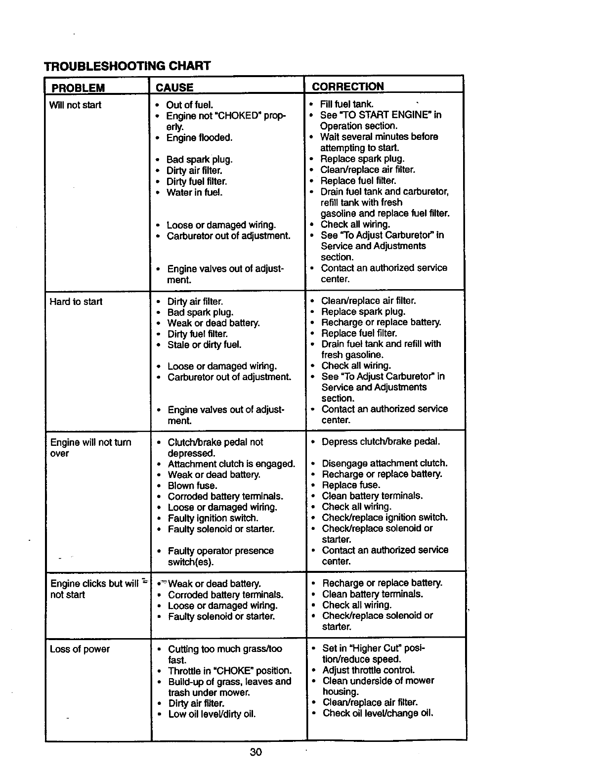
TROUBLESHOOTING CHART
PROBLEM CAUSE
Willnotstart
Hard to start
Engine will not turn
over
Engine clicks but will _
notstart
Loss ofpower
CORRECTION
• Out of fuel.
•Engine not =CHOKED" prop-
erly.
•Engine flooded.
• Bad sparkplug.
•Dirty airfilter.
•Dirty fuel filter.
•Water in fuel.
• Loose or damaged wiring.
•Carburetor out of adjustment.
•Engine valves out of adjust-
ment.
• Dirty air filter.
•Bad spark plug.
•Weak or dead battery.
•Dirty fuel tilter.
•Stale or dirty fuel.
•Loose or damaged wiring.
•Carburetor out of adjustment.
•Engine valves out of adjust-
ment.
•Clutch/brake pedal not
depressed.
•Attachment clutch is engaged.
•Weak or dead battery.
•Blownfuse.
•Corroded batteryterminals.
•Loose or damaged wiring.
•Faulty ignitionswitch.
•Faulty solenoidor starter.
•Faulty operator presence
switch(es).
•--Weak or dead battery.
•Corroded battery terminals.
•Loose or damaged wiring.
•Faulty solenoidor starter.
•Cutting too much grass/too
fast.
• Throttle in =CHOKE" position.
•Build-up of grass, leaves and
trash under mower.
•Dirty air filter.
• Low oil level/dirtyoil.
•Fillfuel tank.
•See "TO START ENGINE _in
Operation section.
•Wait several minutes before
attemptingto start.
•Replace spark plug.
•Clean/replace air filter.
•Replace fuel filter.
•Drain fuel tank and carburetor,
refilltank with fresh
gasoline and replace fuel filter.
•Check all wiring.
•See "To AdjustCarburetor"in
Service and Adjustments
section.
•Contact an authorized service
center.
• Clean/replace air tilter.
• Replace spark plug.
•Recharge or replace battery.
•Replace fuel tilter.
•Drain fuel tank and refill with
fresh gasoline.
•Check all wiring.
•See "To Adjust Carburetor"in
Service and Adjustments
section.
•Contact an authorized service
center.
•Depress clutch/brake pedal.
•Disengage attachment clutch.
•Recharge or replace battery.
•Replace fuse.
•Clean battery terminals.
•Check all wiring.
. Check/replace ignitionswitch.
•Check/replace solenoidor
starter.
•Contact an authorized service
center.
•Recharge or replace battery.
•Clean battery terminals.
•Check all wiring.
•Check/replace solenoid or
starter.
•Set in "Higher Cut" posi-
tion/reduce speed.
•Adjustthrottlecontrol.
•Clean underside of mower
housing.
• Clean/replace air filter.
•Check oil level/change oil.
3O
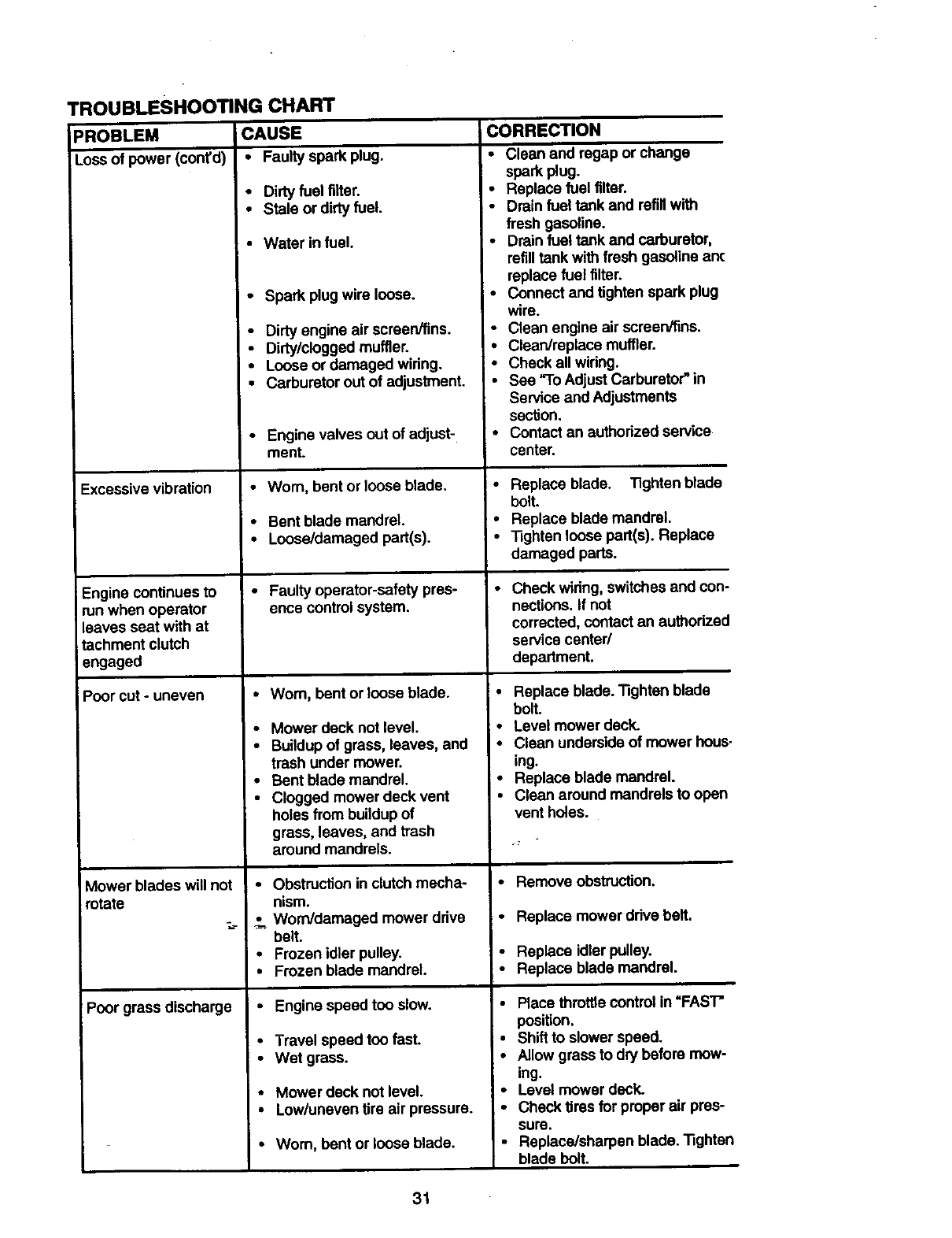
TROUBLESHOOTING CHART
PROBLEM CAUSE
Loss of power (coot'd) • Faulty spark plug.
• Dirtyfuel tilter.
•Stale or dirtyfuel.
•Water infuel.
•Spark plugwire loose.
• Dirty engine air screen/tins.
•Dirty/clogged muffler.
•Loose or damaged wiring.
Excessive vibration
Engine continues to
run when operator
leaves seat with at
tachment clutch
engaged
Poor cut- uneven
Mower blades will not
rotate
Poor grass discharge
•Carburetor out of adjustment.
•Engine valves out of adjust-
ment.
• Worn, bent or loose blade.
• Bent blade mandrel.
• Loose/damaged part(s).
• Faulty operator-safety pres-
ence control system.
•Wom, bent or loose blade.
•Mower deck not level.
•Buildup of grass, leaves, and
trash under mower.
•Bent blade mandrel.
•Clogged mower deck vent
holes from buildup of
grass, leaves, and trash
around mandrels.
•Obstruction in clutch mecha-
nism.
Worn/damaged mower drive
belt.
• Frozan idler pulley.
•Frozen blade mandrel.
• Engine speed too slow.
•Travel speed too fast.
• Wet grass.
•Mower deck not level.
•Low/uneven tire air pressure.
• Worn, bent or loose blade.
CORRECTION
•Clean and regap or change
spark plug.
• Replace fuel filter.
•Drain fuel tank and refillwith
fresh gasoline.
•Drain fuel tank and carburetor,
refilltank withfresh gasoline an(
replace fuel filter.
•Connect and tighten spark plug
wire.
•Clean engine air screen/fins.
•ClearVreplace muffler.
• Check all widng.
• See =ToAdjust Carburetor" in
Service and Adjustments
sacfion.
• Contact an authodzed service
center.
•Replace blade. "13ghtenblade
bolt.
•Replace blade mandrel.
• Tighten loose part(s). Replace
damaged parts.
• Check wiring, switches and con-
nections. If not
corrected, contact an authorized
servicecenter/
department.
•Replace blade. Tighten blade
bolt.
•Level mower deck.
•Clean underside of mower hous.
ing.
•Replace blade mandrel.
•Clean around mandrels to open
vent holes.
• Remove obstruction.
•Replace mower drive belt.
•Replace idlerpulley.
•Replace blade mandrel.
•Place throttle control in =FAST"
position.
•Shift to slower speed.
•Allow grass to dry before mow-
ing.
•Level mower deck.
•Check tires for proper air pres-
sure.
•Replace/sharpen blade. Tighten
blade bolt.
31
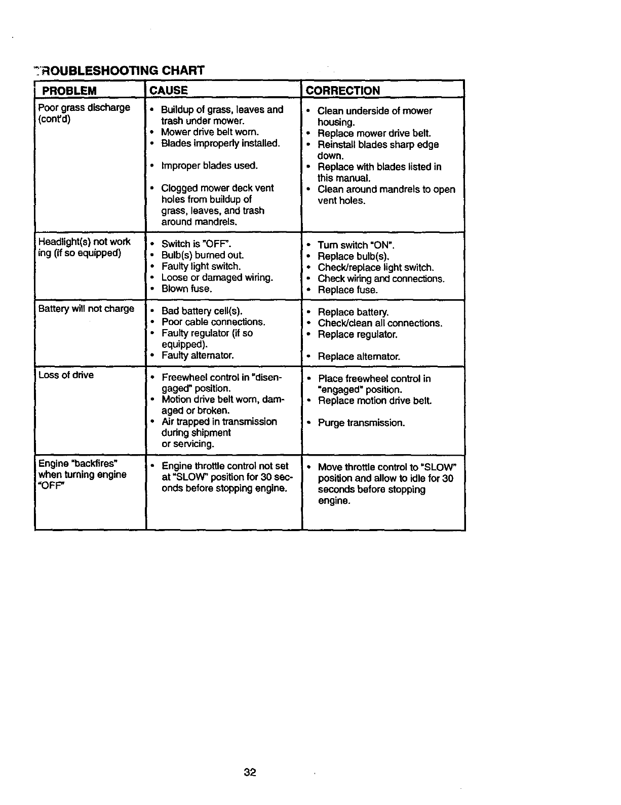
_ROUBLESHOOTING CHART
PROBLEM
Poor grass discharge
(coot'd)
Headlight(s) not work
ing (if so equipped)
Battery will notcharge
Lossof drive
Engine "backfires"
when turning engine
"OFF"
CAUSE CORRECTION
• Buildup of grass, leaves andtrash under mower.
;•Mower drive beltworn.
I• Blades improperly installed.
I. Improper blades used.
•Clogged mowerdeck vent
holes from buildup of
grass, leaves, and trash
around mandrels.
•Switch is "OFF".
• Bulb(s) burned out.
•Faulty light switch.
•Loose or damaged wiring.
•Blown fuse.
• Bad battery ceU(s).
•Poor cable connections.
• Faulty regulator (if so
equipped).
• Faulty alternator.
•Freewheel control in"disen-
gaged" position.
•Motion drive belt worn, dam-
aged or broken.
•Air trapped in transmission
dudng shipment
or servicing.
• Engine throttlecontrolnot set
at "SLOW" position for 30 sec-
onds before stoppingengine.
•Clean underside of mower
housing.
•Replace mower drive belt.
•Reinstall blades sharp edge
down.
•Replace with blades listed in
this manual.
•Clean around mandrels to open
vent holes.
•Turn switch"ON".
•Replace bulb(s),
• Check/replace light switch.
• Check wiring and connections.
• Replace fuse.
•Replace battery,
• Check/clean all connections.
• Replace regulator.
• Replace alternator.
•Place freewheel controlin
"engaged" position.
• Replace motion drive belt.
•Purge transmission.
Move throttlecontrol to "SLOW"
positionand allow to idle for 30
seconds before stopping
engine.
32
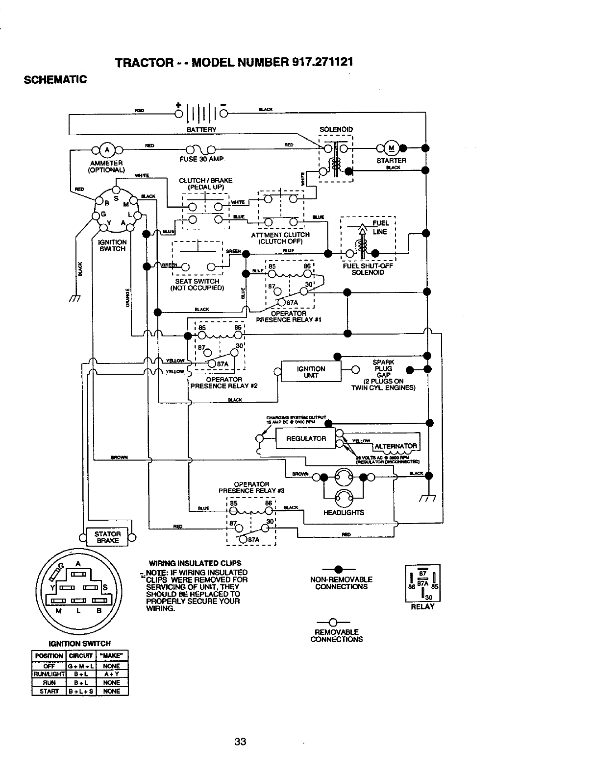
SCHEMATIC
TRACTOR - - MODEL NUMBER 917.271121
-o'l Itli
BATTERY SOLENOID
AMMETER
_s_TTIcO_ _IGNITIO_
FUSE30AMP.
CLUTCH IBRAKE
(PEDAL UP)
I i
-- I i I
I i _ i _ i _ I FUEL
,.... _" - - -e (CLUTCH OFF) I:
i
; 85 86 ' FUEL SHUT-OFF
=SEAT........ SWITCH t _ _ue I SOLENOID
(NOT OCCUPIED)__87A JII !
PRESENCE RELAY #1
_ir 85 86 _i
187 30
°"_'_-- - -_Z__-' 1 SBAR_ "
J IGNITION PLUG
OPERATOR UNiT GAP
(2 PLUGS ON
PRESENCE RELAY #2 TfIIN CYL ENGINES)
BLACK
M )
STATOR _Rm
BRAKE
_RO_ IPf Sf_4 I_J_JT
IGNt_ON SWITCH
tS At4P OC e 3a00 RFt4
_IREGUI _REGULATOR ow ALTERNATOR
L
OPERATOR
PRESENCE RELAY #3
t85 _
iHEADLIGHTS
NON-REMOVABLE
CONNECTIONS
REMOVABLE
CONNEC_ONS
RELAY
WIRING INSULATED CUPS
;, NO'I_: IF WIRING INSULATED
CLIPS WERE REMOVED FOR
SERVICING OF UNIT, THEY
SHOULD BE REPLACED TO
PROPERLY SECURE YOUR
WIRING.
33
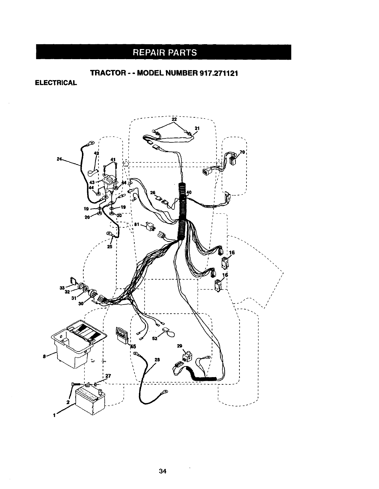
ELECTRICAL
TRACTOR - - MODEL NUMBER 917.271121
I
i•
34
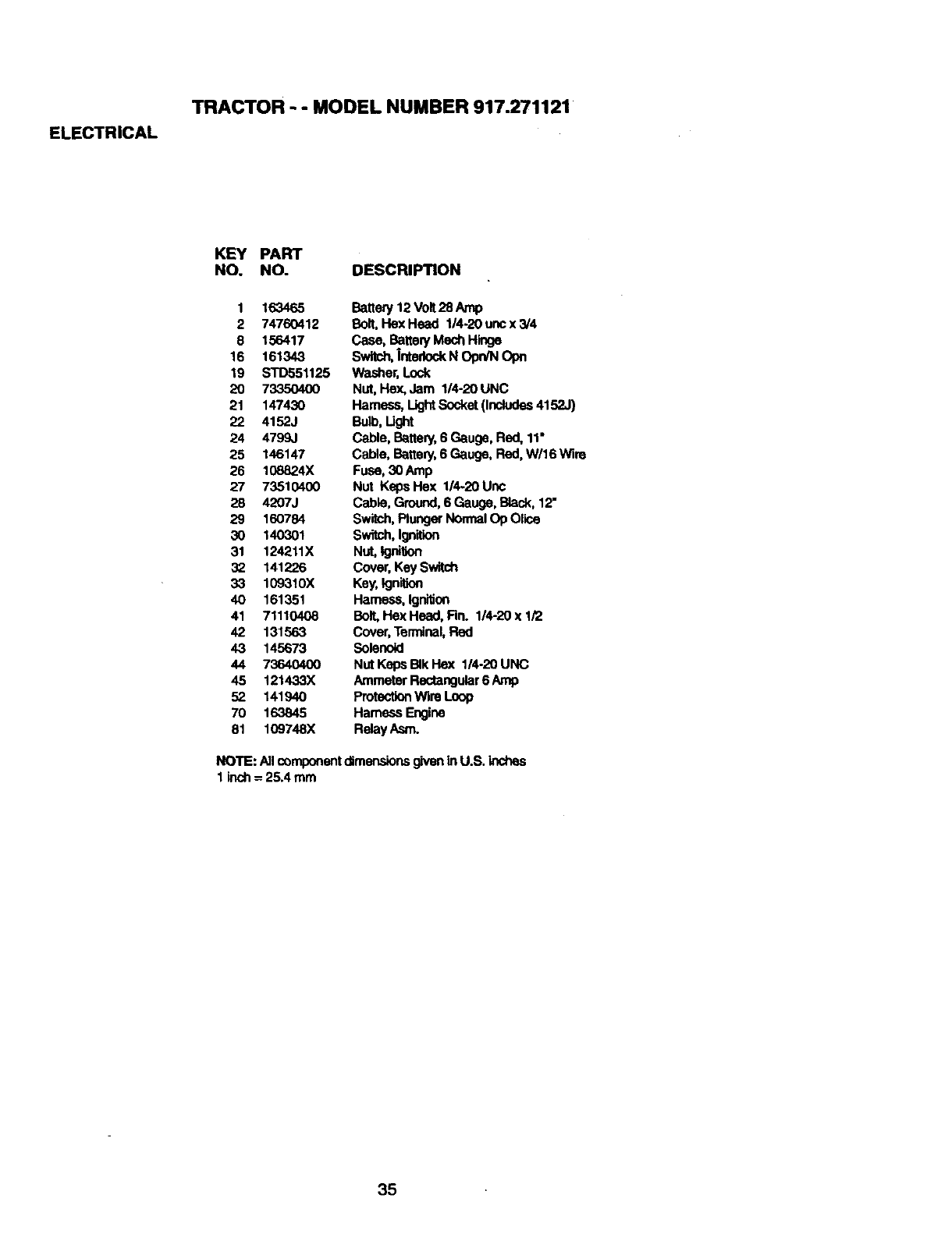
ELECTRICAL
TRACTOR - - MODEL NUMBER 917.271121
KEY PART
NO. NO. DESCRIPTION
1 163465
2 74760412
8 156417
16 161343
19 STD551125
20 73350400
21 147430
22 4152J
24 4799J
25 146147
26 108824X
27 73510400
28 4207J
29 160784
30 140301
31 124211X
32 141226
33 109310X
40 161351
41 71110408
42 131563
43 145673
44 73640400
45 121433X
52 141940
70 163845
81 109748X
Battery 12 Volt28Amp
Bolt,Hex Head 1/4,20 onc x 3/4
Case, Battery Mech Hinge
Switch,Interlock NOpn/N Opn
Washer, Lock
Nut, Hex, Jam 1/4-20 UNC
Hamese, LightSocket(Includes4152J)
Bull, Light
Cable, Battery,6 Gauge, Red, 11"
Cable, Battery, 6Gauge, Red, W/16 Wire
Fuse, 30Amp
Nut Keps Hex 1/4-20 Unc
Cable, Ground,6 Gauge, Black, 12"
Switch,PlungerNormalOp Olico
Switch,19nition
Nut,Igni'_n
Cover, Key Switch
Key,Ign_don
Harness, Ignition
Bolt,Hex Head, Fin. 1/4-20 x 1/2
Cover,Terminal,Red
Solenoid
Nut Keps BIkHex 1/4-20 UNC
Ammeter Rectangular6 Amp
ProtectionWire Loop
Hamese Engine
RelayAsm.
NOTE: Allcomponentdimensionsgivenin U.S. inches
1 inch =25.4 mm
35
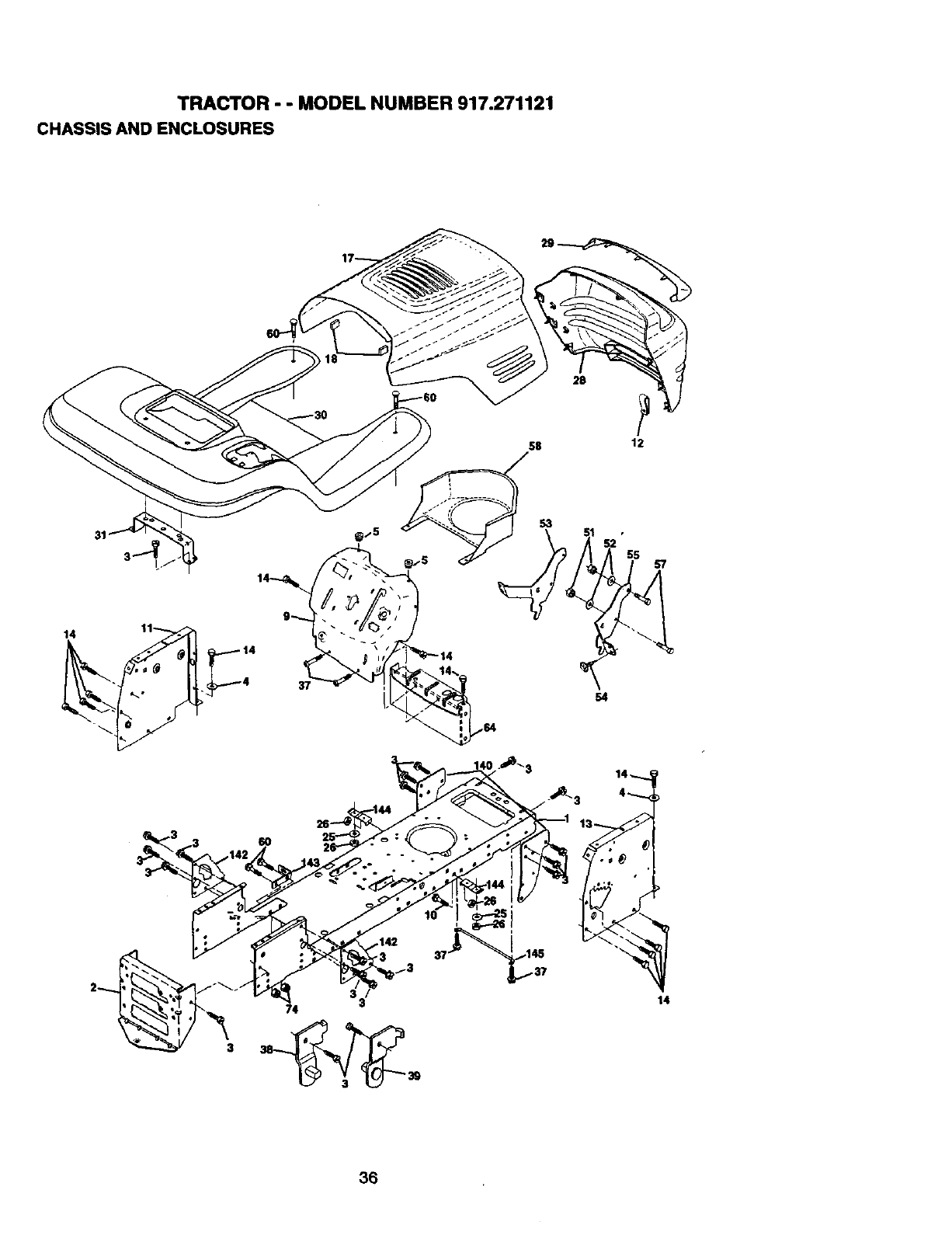
TRACTOR - - MODEL NUMBER 917.271121
CHASSIS AND ENCLOSURES
28
58 12
14 11
4
3
3
74 3
51 •
36
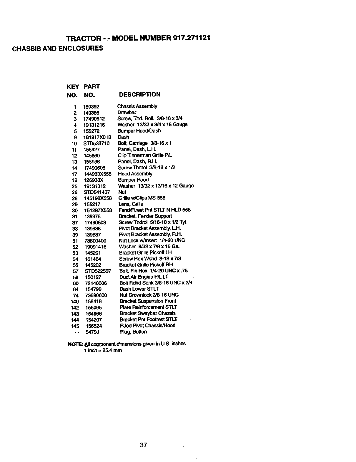
TRACTOR - . MODEL NUMBER 917.271121
CHASSIS AND ENCLOSURES
KEY PART
NO. NO. DESCRIPTION
1 160392
2 140356
3 17490612
4 19131216
5 155272
9 161917X013
10 STD533710
11 155927
12 145660
13 155936
14 17490608
17 144983X558
18 126938X
25 19131312
26 STD541437
28 145198X558
29 155217
30 151287X558
31 139976
37 17490508
38 139886
39 139887
51 73800400
52 19091416
53 145201
54 161464
55 145202
57 STD522507
58 150127
60 72140606
64 154798
74 736806OO
140 158418
142 156095
143 154966
144 154207
145 156524
-- 5479J
ChassisAssembly
Dmwbar
Screw,TIxI. Roll. 3/8-16 x 3/4
Washer 13/32 x 3/4 x 16 Gauge
Bumper Hood/Dash
Dash
Bolt,Carriage 3/8-16 x 1
Panel, Dash, LH.
Clip_neerman Gdlle P/L
Panel, Dash, R.H.
ScrewThdrol 3/8-16 x 1/2
Hood Assembly
Bumper Hood
Washer 13/32 x 13/16 x 12 Gauge
Nut
Gdllew/ClipsMS-558
Lens,Gdlle
Fend/Ftrest Pnt STLTN HLD 558
Bracket, Fender Support
Screw Thdrol 5/16-18 x 1/2 Tyt
Pivot BracketAssembly,LH.
PivotBracketAssembly,R.H.
Nut Lockw/Insert I14-20 UNC
Washer 9/32 x 7/8 x 16 Ga.
BracketGdne PickoffLH
Screw Hex Wshd 9-18 x 7,_
BracketGdlle PickoffRH
Bolt, Fin Hex 114-20UNC x .75
DuotAir Engina P/t. LT
BoltRdhd Sqnk 3/8-16 UNC x 3/41
Dash LowerSTLT
Nut Crownlock3/8-16 UNC
BracketSuspensionFront
Plate ReinforcementSTLT
Bracket SwaybarChassis
Bracket Pnt FootrestSTLT
RJodPivot Chassis/Hood
Plug, Button
NOTE:Allco_oonentdlmendonsgiveninU.S.inches
1inch= 25.4mm
37
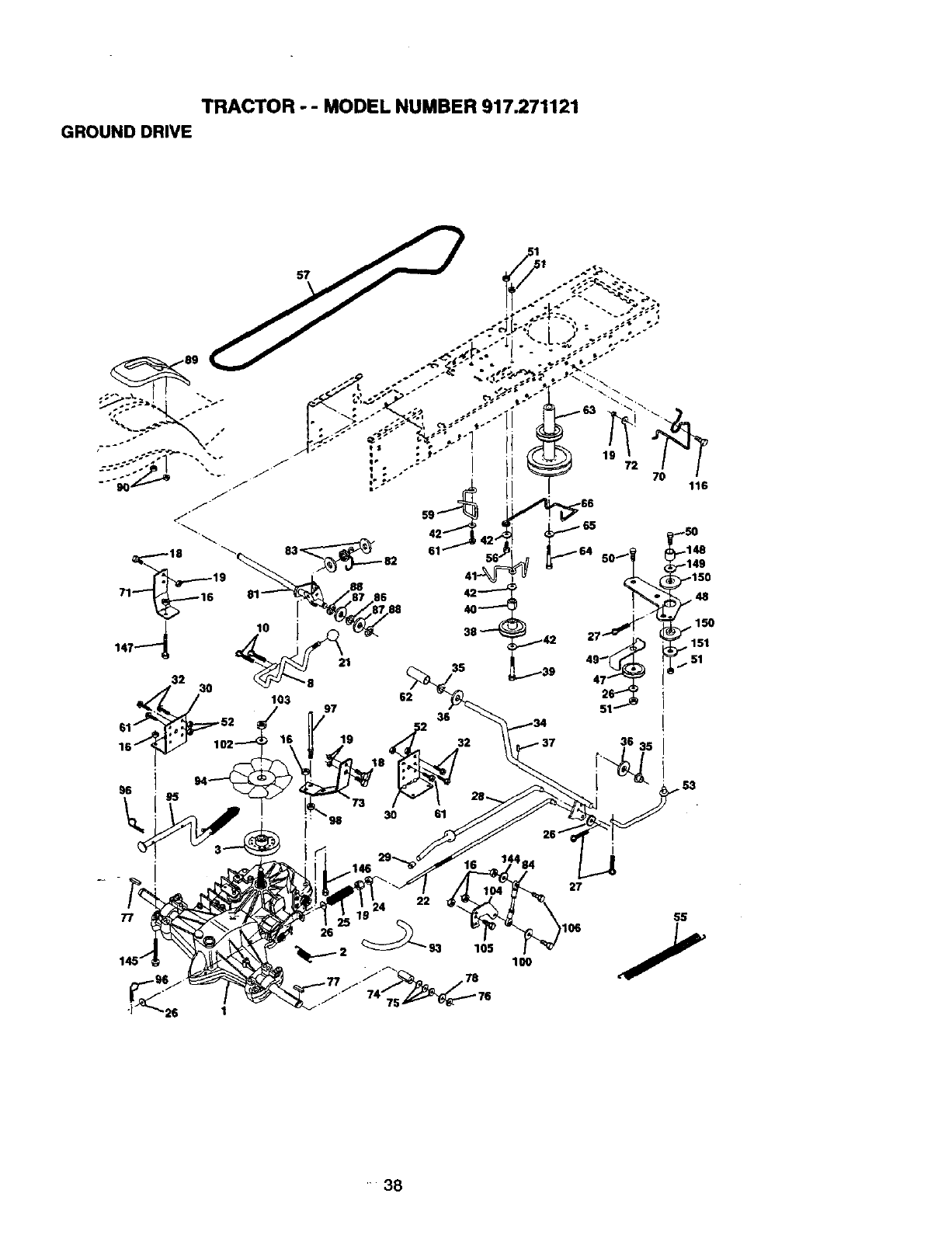
TRACTOR - - MODEL NUMBER 917.271121
GROUND DRIVE
62
.146
27
77
100
H38
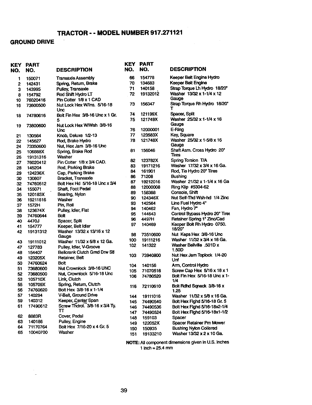
TRACTOR - - MODEL NUMBER 917.271121
GROUND DRIVE
KEY PART KEY PART
NO. NO. DESCRIPTION NO. NO.
1 150071 TransaxleAssembly 66 154778
2 142431 Spring, Return, Brake 70 134683
3 143995 Pulley,Transmde 71 140158
8 154792 Rod ShiftHydroLT 72 19132012
10 76020416 Pin Cotter 1/8 x I CAD
16 73800500 NutLockHexW/Ins. 5/16-18 73 156347
Uric
18 74780616 BoltFinHex 3/8-16Uncx1 Gr. 74 121199X
5 75 121749X
19 73800600 NutLockHexW/Wsh 3/8-16
Unc 76 1200(X)01
21 130564 Knob, Deluxe 1/2-13 77 123583X
22 145627 Rod, Brake Hydro 78 121748X
24 73350600 Nut, Hex Jam 3/6-16 Uric
25 106888X Spring, Brake Rod 81 156046
26 19131316 Washer
27 76020412 Pin Cotter 1/8 x 3/4 CAD. 82 123782X
28 145204 Rod, ParkingBrake 83 19171216
29 124236X Cap, ParkingBrake 84 161901
30 130807 Bracket,Transaxle 86 71208
32 74760512 BoltHexHd 5/16-18Uncx3/4 87 19212016
34 155071 Shaft, Foot Pedal 88 12_
35 120183X Bearing, Nylon 89 158388
36 19211616 washer 90 124346X
37 1572H Pin, Roll 93 142564
38 123674X Pulley,Idler,Flat 94 140462
39 74760644 Bolt 95 144643
40 4470J Spacer, Split 96 4497H
41 154777 Keeper, BeltIdler 97 140469
42 19131312 Washer 13/32x 13/16x 12
Gauge 98 73510600
43 19111012 Washer 11/32x5i8x12Ga. 100 19111216
47 127783 Pulley, Idler,V-Groove 102 141322
48 154407 Bollcrank ClutchGrnd Drw SIJ
49 123205X Retainer,Bolt 103 73940800
50 74760624 Bolt 104 140156
51 73680600 Nut Crowolock 3/6-16 UNC 105 71070516
52 73680500 Nut, Crownlcok 5/16-18 Unc 106 74780520
53 105710X Link,Clutch
55 1(_5709X Spring,Return,Clutch 116 72110610
56 74760620 BoltHex 3/8-16 x 1-1/4
57 140294 V-Bait, GroundDrive 144 19111016
59 140312 Keeper,Cent_Span 145 74490540
61 17490612 SerewT_roll 3/8-16x3/4Ty. 146 74490536
"IT 147 74490524
62 8883R Cover, Pedal 148 159103
63 140186 Pulley,Engine 149 122052X
64 71170764 BoltHex 7/16-20x4Gr.5 150 150935
65 10040700 Washer 151 19133210
DESCRIPTION
Keeper Belt EngineHydro
Keeper Belt Engine
StrapTorqueLh Hydro 18/20"
Washer 13/32 x 1-1/4 x 12
Gauge
StrapTorqua Rh Hydro 18/20"
T
Spacer,Split
Washer 25/82 x 1-1/4 x 16
Gauge
E-Ring
Key,Square
washer 25/32 x 1-5/8 x 16
Gauge
ShaftAsm. Cross Hydro 20"
Tires
SpringTorsion T/A
Washer 17/32 x 3/4 x 16Ga.
Rod, "13eHydro 20" Tires
Bushing
Washer 21132x 1-1/4 x 16 Ga
RingKlip #5304-62
Console, Shift
Nut Self-ThdWsh-hd 1/4 Zinc
Une Fuel Hydro4"
Fan, Hydro7"
Control BypassHydro 20" Tire._
RetainerSpring 1"Zinc/Cad
Keeper Bolt Rh Hydro 0750.
18/20"
Nut KepsHex 3/8-16Unc
Washer 11/32x 3/4 x 16 Ga.
Washer BOlMIle .501D x
1.50D
Nut Hex JamToplook 1/4-20
Unf
Arm,ControlHydro
Screw Cap Hex 5/16x 18 x I
Bolt FinHex 5/16-18 Unc x 1-
114
Bolt Rdhd Sopeck 3/8-16 x
1.25
Washer 11/32x 5/8 x 16 Ga.
Bolt Hex Flghd 5/16-18 Gr. 5
BoltHex Flghd 5/16-18x2-1/4
BoltHex Rghd 5/16-18)(1-1/2
Spacer
Spacer Retainer Pm Mower
BushingNylonCoiterod
Washer 13/82 x 2 x 10 Ga.
NOTE: All componentdimensionsgivenin U.S. inches
1 inch= 25.4 mm
39
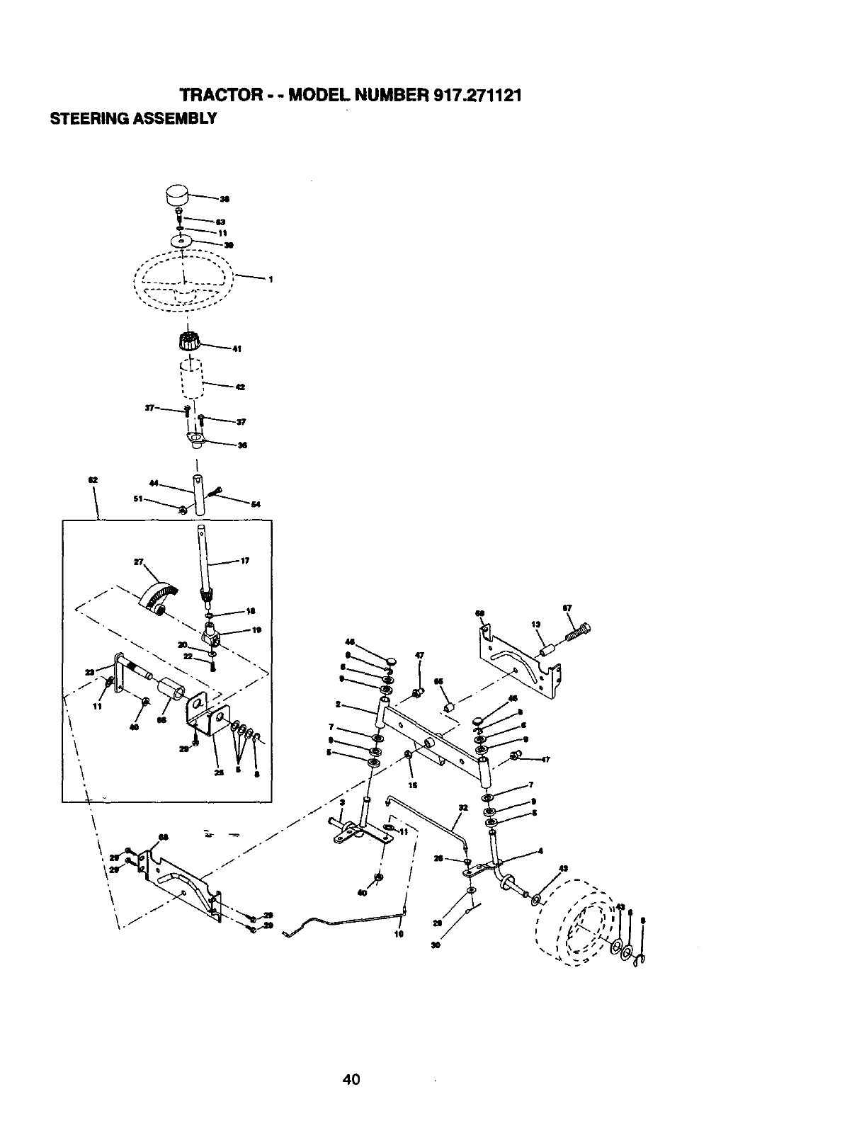
TRACTOR - - MODEL NUMBER 917.271121
STEERINGASSEMBLY
_M
_41
I
62 44
47
67
15
4O
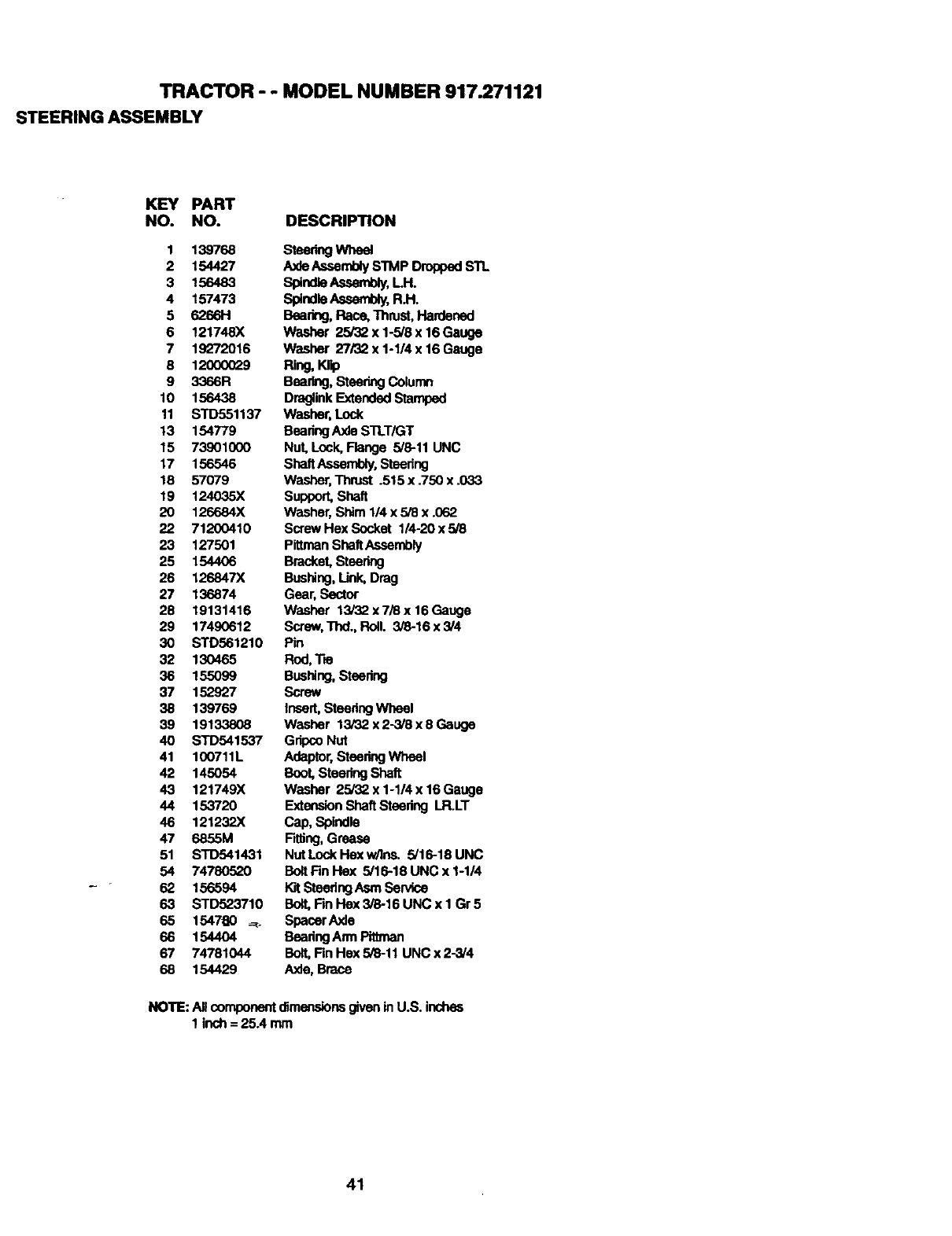
TRACTOR - - MODEL NUMBER 917.271121
STEERINGASSEMBLY
KEY PART
NO. NO. DESCRIPTION
1 139768
2 154427
3 156483
4 157473
5 6266H
6 121748X
7 19_r/2016
9 120(XX_9
9 3366R
10 156438
11 STD551137
13 154779
15 73901000
17 156546
18 57079
19 124035X
20 126684X
22 71200410
23 127501
25 154406
26 126847X
27 136874
28 19131416
29 17490612
30 STD561210
32 130465
36 155O99
37 152927
38 139769
39 19133808
40 STD541537
41 100711L
42 145054
43 121749X
44 153720
46 121232X
47 6855M
51 STD541431
54 74780520
62 156594
63 STD523710
65 1547_0 -=r-
66 1544O4
67 74781044
68 154429
steer_ whe_
Ax_ AssemblyS'I'MP Dropped STL
SpindleAssembly,LH.
SpindleAssembly,R.H.
Bearing,Race, Thrust, Hardened
Washer 25/32 x 1-5/6 x16 Gauge
Washer 27/32 x 1-1/4 x 16 Gauge
Ring,Klip
Bearing,SteeringColumn
DruglinkExtendedStamped
Washer,Lock
BeadngAxle STLT/GT
Nut, Lock,Flange 5/8-11 UNC
ShaftAssembly,steering
Washer,Thrust .515 x .750 x .033
Support,Shaft
Washer, Shim 114x 5/8 x .062
Screw Hex Socket 1/4-20 x 5/8
Pign_n ShaftAssembly
Bracket, Steering
Bushing,Link, Drag
Gear, Sector
Washer 13/32 x 7/8 x 16 Gauge
Screw,Thd., Roll. 5/8-16 x 3/4
Pin
Rod,Tm
Bushing,steedug
Screw
Insert,steedug Wheel
Washer 13/32 x 2-3/8 x 8 Gauge
GripcoNut
Adaptor,steering Wheel
Boot, SteeringShaft
Washer 25_32x 1-1/4 x 16 Gauge
ExtensionShaftsteedng LR.LT
Cap, Spindle
FiWng,Grease
NutLock Hex w.qns. 5/16-18 UNC
Bolt Fin Hex 5/16-18 UNC x 1-1/4
I_t Steedng Asm Sen/ice
Bolt,Fm Hex 3/8-16 UNC x 1 Gr5
Spacer Axle
BeadngAnn Pittman
Bolt,Fin Hex 5/8-11 UNC x 2-3/4
Axle, Brace
NOTE: A, componentdimensionsgivenin U.S. inches
1 inch = 25A mm
41
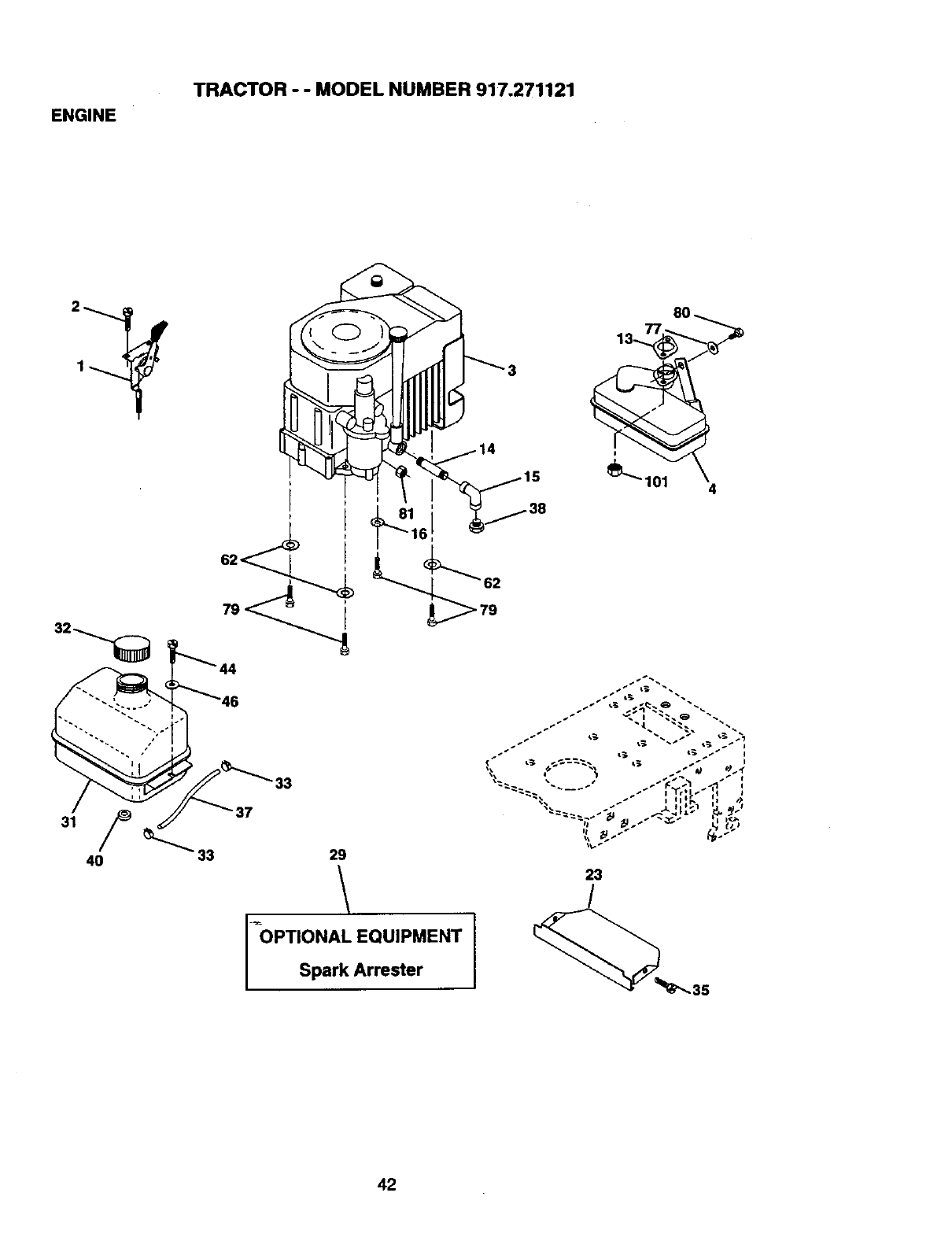
ENGINE
TRACTOR - - MODEL NUMBER 917.271121
t
8O
33
33
29
/
_OPTIONAL EQUIPMENT
42
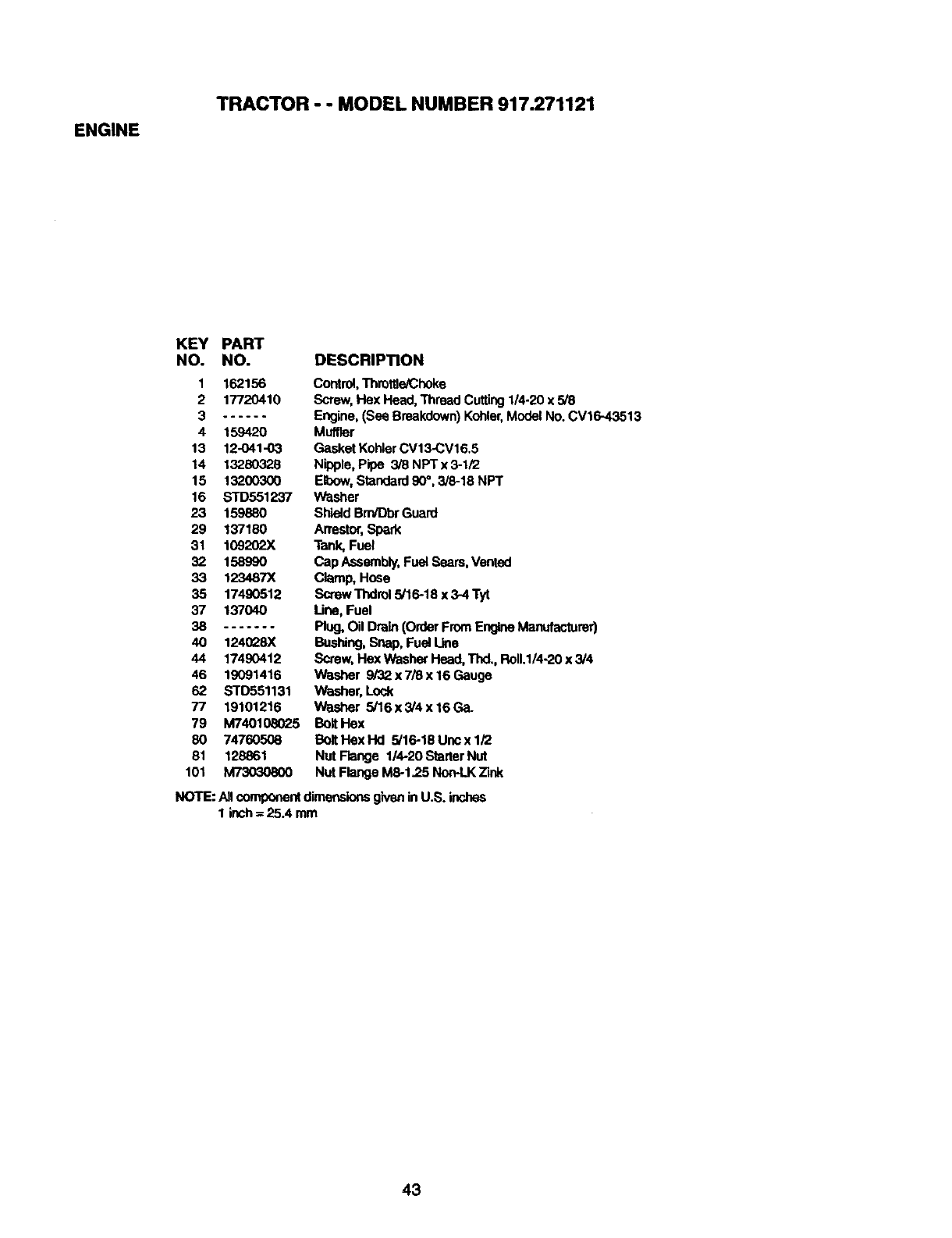
ENGINE
TRACTOR - - MODEL NUMBER 917.271121
KEY PART
NO. NO. DESCRIPTION
1 162156
2 17720410
3......
4 159420
13 12-041-03
14 13280328
15 132OO3O0
16 STD551237
23 159880
29 137180
31 109202X
32 158990
33 123487X
35 17490512
37 137040
38 .......
40 124028X
44 17490412
46 19091416
62 STD551131
77 19101216
79 M740108025
80 74760508
81 128861
101 M73030800
Control,ThrottteiChoke
Screw, Hex Head, Thread Cutting 1/4-20 x 5/8
Engine, (See Breakdown)Kohler,ModelNo. CV16-43513
Muffler
Gasket KohlerCV13-CV16.5
Nipple, Pipe 3/8 NPT x 3-1/2
Elbow, Standard 90°, 3/8-18 NPT
Washer
Shield Brn/DbrGuard
Arrestor,Spark
Tank,Fuel
Cap Assembly,Fuel Seam, Vented
Clamp, Hose
Screw Thdrol 5/16-18 x 3-4 Tyt
Une, Fuel
Plug, Oil Drain (Order FromEngineManufacturer)
Bushing,Snap, Fuel Line
Screw,FlexWasher Head,Thd,, Ro11.1/4-20x 3/4
Washer 9/32 x 7/8 x 16 Gauge
Washer, Lock
Washer 5/16x 3/4 x 16 Ga.
Bolt Hex
Bolt Hex Hd 5/16-18 Unc x 1/2
Nut Flange 1/4-20 StarterNut
Nut Flange M8-1.25 Non-LK Zink
NOTE: Allcomponentdimensionsgivenin U.S. inches
1 inch=25.4 mm
43
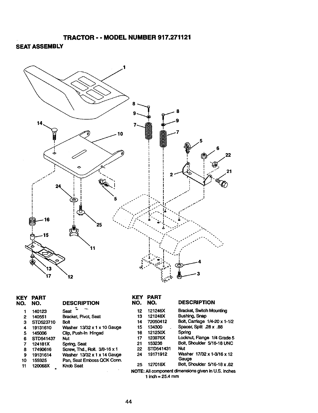
TRACTOR - - MODEL NUMBER 917.271121
SEAT ASSEMBLY
I
I
i
1
I
i
5
21
KEY PART
NO. NO.
1 140123
2 140551
3 STD523710
4 19131610
5 145006
6 STD541437
7 124181X
8 17490616
9 19131614
10 155925
11 120068X
KEY PART
DESCRIPTION NO. NO.
Seat _ _ 12 121246X
Bracket,Pivot, Seat 13 121248X
Bolt 14 72050412
Washer 13/32xl xlOGauge 15 134300
Clip, Push-In Hinged 16 121250X
Nut 17 123976X
Spdng, Seat 21 153236
Screw,Thd.,Roll. 3/8-16xl 22 STO541431
Washer 13/32xl x14Gauge 24 19171912
Pan, Seat EmbossQCK Conn.
KnobSeat 25 127018X
DESCRIPTION
Bracket,SwitchMounting
Bushing,Snap
Bolt,Carriage 1/4-20 x 1-1/2
Spacer, Split .28 x .88
Spdng
Lockout,Flange 114Grade 5
Bolt,Shoulder 5/16-18 UNC
Nut
Washer 17/32 x 1-3/16 x 12
Gauge
Bolt,Shoulder 5/16-18 x .62
NOTE: All componentdimensionsg'wenin U.S. inches
1 inch= 25.4 mm
44
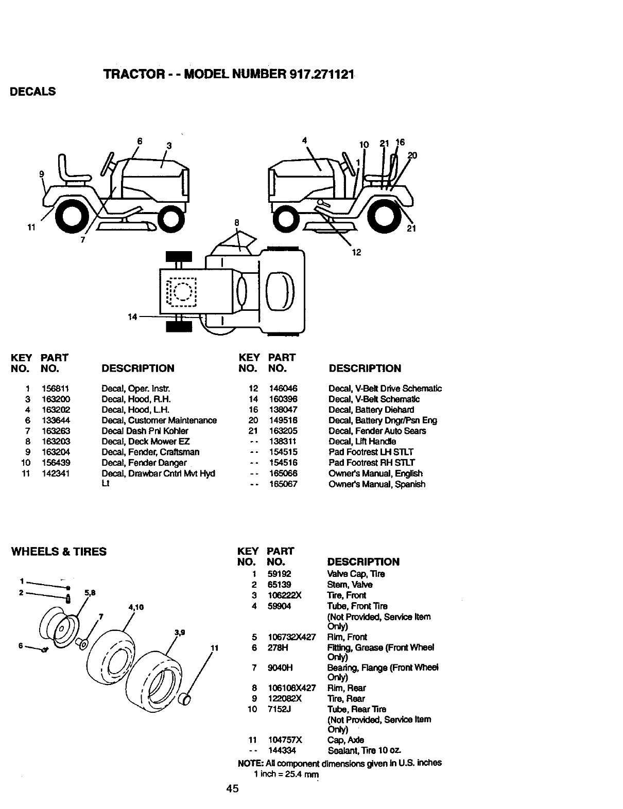
DECALS
TRACTOR - - MODEL NUMBER 917.271121
11
6 3 4
12
10 16
20
KEY PART
NO. NO.
1 156811
3 1632OO
4 1632.(_
6 133644
7 163263
8 163203
9 163204
10 156439
11 142341
KEY PART
DESCRIPTION NO. NO.
Decal, Oper. Instr. 12 146046
Decal, Hood, R.H. 14 160396
Decal, Hood, LH. 16 138047
Decal, Customer Maintenance 20 149516
Decal Dash Pnl Kohler 21 163205
Decal, Deck Mower F_Z -- 138311
Decal, Fender, Craftsman - - 154515
Decal, Fender Danger -- 154516
Decal, Drawbar Cntd Mvt Hyd - - 165066
Lt -- 165067
DESCRIPTION
Decal, V-Belt Drive Schematic
Decal, V-Belt SchamaEc
Decal, Battery Diehard
Decal, Battery Dngr/Psn Eng
Decal, FenderAuto Sears
Decal, Lift Handle
Pad FootrestLH S'I1.T
Pad FootrestRH STLT
OwneCsManual, Eng,sh
Owner's Manual, SpanPoh
WHEELS & TIRES
2_5,8 4,10
/
3,g
KEY PART
NO. NO. DESCRIPTION
1 59192 ValveCap, Tire
2 65139 Stem, Valve
3 106222X Tire, Front
4 59904 Tube, Front'rim
(Not Provided,Sen_lceItem
Only)
5 106732.X427 Rim, Front
6 278H Fitting,Grease (FrontWheel
oray)
7 9040H Beadng, Flange (FrontWheei
Orgy)
8 106108X427 Rim, Rear
9 122082X Tire, Rear
10 7152J Tube, Rear'fim
(NotProvided,Service Item
only)
11 104757X Cap, Axle
- - 144334 Sealant, Tire 10 o_.
NOTE: Allcomponentdimensionsgiven in U.S. inches
1 inch= 25A mm
45
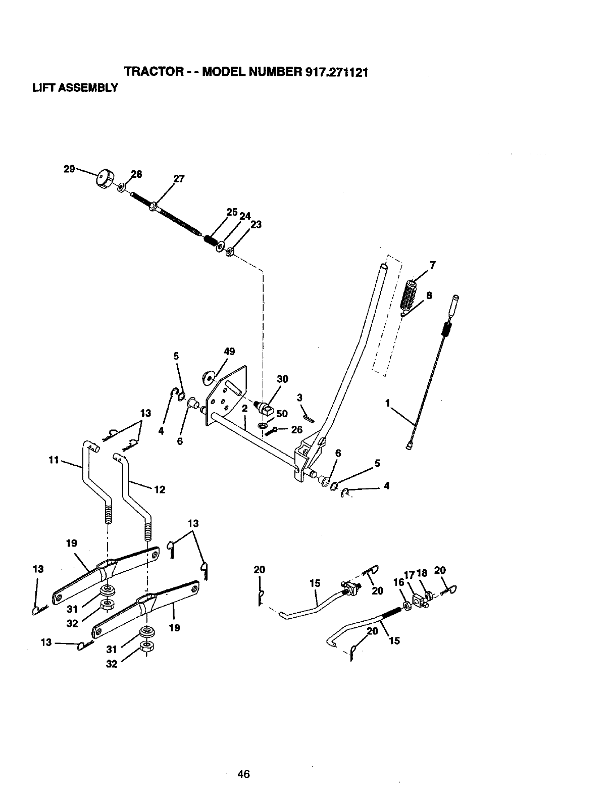
TRACTOR - - MODEL NUMBER 917.271121
LIFT ASSEMBLY
29_ 28 27
25 24 23
7
13
49
6
3O
3
\
26
6
o8
i/
i!
/ /'
,/ /'
19
13
19
13
15
2O
46
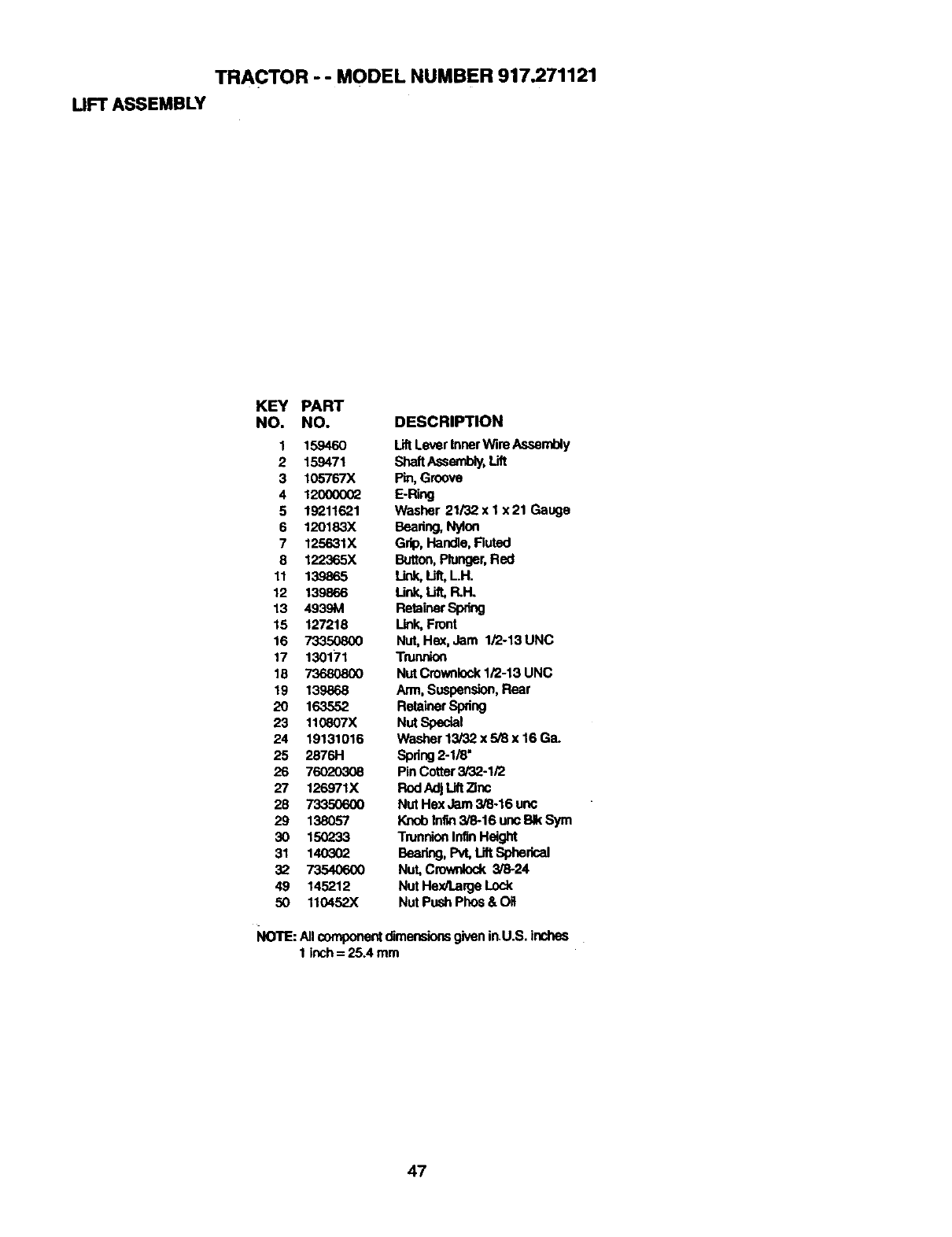
TRACTOR -- MODEL NUMBER 917.271121
UFT ASSEMBLY
KEY PART
NO. NO. DESCRIPTION
1 159460 LiftLever InnerWire Assembly
2 159471 ShaftAssembly,Lift
3 105767X Pin, Groove
412000002 E-RilxJ
5 19211621 Washer 21/32 x 1 x 21 Gauge
6 120183X Beadng, Nylon
7 125631X Grip, Handle,Fluted
8 122365X Button,Plunger,Red
11 139865 Link,Ult, LH.
12 139866 Link,Lift, P,.H.
13 4939M RetainerSpring
15 127218 Link, Front
16 73350800 Nut,He_, Jam 1/2-13 UNC
17 130171 Trunnion
18 73680800 NutCrownlock1/2-13 UNC
19 139868 Arm, Suspension,Rear
20 163552 RetainerSpring
23 110807X Nut Special
24 19131016 Washer13/32 x 5/8 x 16 Ga.
25 2876H Spdug2-1/8"
26 76020308 Pin Cotter3/32-1/2
27 126971X Rod AdjUft Zinc
28 73350600 Nut Hex Jam 3/8-16 uric
29 138057 Knob Infi_ 3/8-16 uncBIk Sym
30 1502"33 TrunnionInfinHeight
31 140302 Beadng,Pvt, Lift Spherical
32 73540600 Nut, Crownlock3/8-24
49 145212 Nut Hex/Large Lock
50 110452X Nut Push Phos& OH
NOTE: AllcomponentdimensionsgiveninU.S. inches
I inch= 25A mm
47
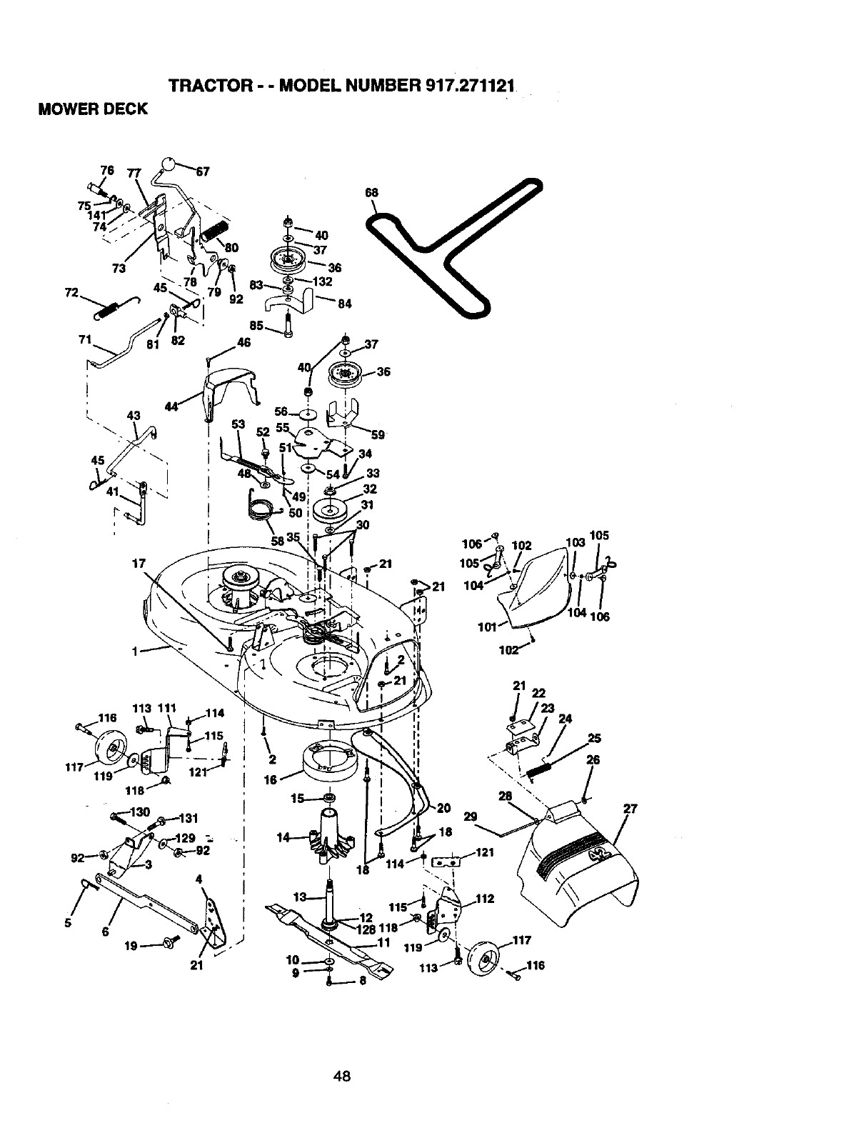
TRACTOR - - MODEL NUMBER 917.271121
MOWER DECK
71
17
,_ 40
""--132
83 _""_ 84
58
34
.33
31
116 113\ 111\ _14
118.t "_
4
5619_ i
21
.J
\
16
21
28
29
,18
,_121
22
26
27
48
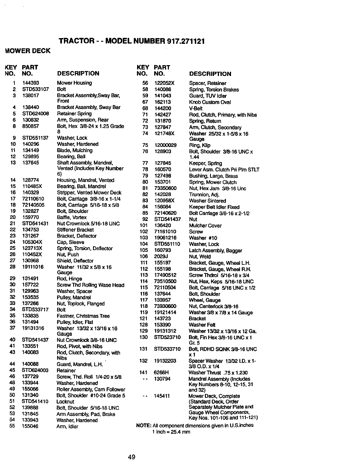
TRACTOR - - MODEL NUMBER 917.271121
I_OWER DECK
KEY PART KEY PART
NO. NO. DESCRIPTION NO. NO.
1 144393 Mower Housing 56 122052X
2 STD533107 Bolt 58 140086
3 138017 BracketAssembly,SwayBar, 59 141043
Front 67 162113
4 138440 BracketAssembly,Sway Bar 68 144200
5 STD624008 RetainerSpring 71 142427
6 130832 Arm, Suspension,Rear 72 131870
8 850857 Bolt, Hex 3/8-24 x 1.25 Grade 73 127847
8 74 121748X
9 STD551137 Washer,Lock
10 140296 Washer,Hardened 75 12000029
11 134149 Blade,Mulching 76 128903
12 129895 Baadng, Ball
13 137645 ShaftAssembly,Mandrel, 77 127845
Vented (IncludesKey Number 78 160570
6) 79 127498
14 128774 Housing,Mandrel,Vented 80 153701
15 110485X Beadng, Ball, Mandrel 81 73350600
16 140329 Stripper,Vented Mower Deck 82 142028
17 72110610 Bolt, Carriage 3/8-16 x 1-I/4 83 120958X
18 72140505 Bolt,Carriage 5/16-18 x 5/8 84 156084
19 132827 Bolt, Shoulder 85 72140620
20 159770 Baffle,Vortex 92 STD541437
21 STD541431 NutCrownlock5/16-18UNC 101 136420
22 134753 StltfenerBracket 102 71161010
23 131267 Bracket,Deflector 103 19061216
24 105304X Cap, Sleeve 104 STD551110
25 123713X Spdng,Torsion,Deflector 105 160793
26 110452X Nut, Push 106 2029J
27 130968 Shield,Deflector 111 155197
28 19111016 Washer 11/32x 5/8 x16 112 155198
Gauge 113 17490512
29 131491 Rod,Hinge 114 73510500
30 157722 ScrewThdRoltingWaseHead 115 72110504
31 129963 Washer, Spacer 116 137644
32 153535 Pulley,Mandrel 117 133957
33 137266 Nut,Toplock,Ranged 118 73930600
34 s'rD533717 Bolt 119 19121414
35 133835 Fastner,ChristmasTree 121 143723
36 131494 Pulley, Idler,Rat 128 153390
37 19131316 Washer 13/32x 13/16x 16 129 19131312
Gauge 130 STD523710
40 STD541437 Nut Crownlock3/8-16 UNC
41 133551 Rod, Pivot, wi_ N_os 131 STD533710
43 140083 Rod, Clutch, Secondary,with
Nibs 132 19132203
44 140088 Guard, Mandrel,LH.
45 STD624003 Retainer 141 6266H
46 137729 Screw,Thd. Boll 1/4-20 x 5/8 - - 130794
48 133944 Washer, Hardened
49 155066 RollerAssembly,Cam Follower
50 131340 Bolt, Shoulder #10-24Grade5 -- 145411
51 STD541410 Locknut
52 139888 Bolt, Shoulder 5/16-18 UNC
53 131845 Arm Assembly,Pad, Brake
54 133943 Washer, Hardened
55 155046 Arm, Idler
DESCRIPTION
Spacer,Retainer
Spring,TorsionBrakes
Guard,TUV Idler
KnobCustom Oval
V-Belt
Rod,Clutch,Pdmary,withNibs
Spring,Return
Arm,Clutch,Secondary
Washer 25/32 x 1-5/8 x 16
Gauge
Ring,KUp
Bolt,Shoulder 3/8-16 UNC x
1.44
Keeper,Spdng
LevorAsm. Clutch Pd PImSTLT
Bushing,Large, Brass
Spring,Mower Clutch
Nut, HexJam 3/8-16 Unc
Trunnion, Adj.
WasherSintered
Keeper BeltIdler Fixed
BoltCarriage 3/6-16 x 2-1/2
Nut
MulcherCover
Screw
Washer #10
Washer, Lock
LatchAssembly,Bagger
Nut,Weld
Bracket,Gauge, Wheel LH.
Bracket,Gauge, Wheel R.H.
Screw Thdrol 5/16-18 x3/4
Nut, Hex, Keps 5/16-18 UNC
Boll Carriage 5/16 UNC x 1/2
Bolt, Shoulder
Wheel, Gauge
Nut,Centedeek 3/8-16
Washer3/8 x 715x 14 Gauge
Bracket
Washer Felt
Washer 13/32 x 13/16 x 12 Ga.
Bolt, FinHe)( 3/8-16 UNC x 1
Gr. 5
Bolt,RDHD SQNK 3/6-16 UNC
xl
Spacer Washer 13/32 I.D. x 1-
3/80.D. x 1/4
Washer Thrust .75 x 1.230
Mandrel Assembly(Includes
Key Numbers 6-10, 12-15, 31
and 32)
Mower Deck, Complete
(StandardDeck, Order
Separately MulcherPlate and
Gauge Wheel Components,
Key Nos. 101-106 and 111-121)
NOTE: Allcomponentdimensiousgivenin U.S.inchas
1 inch= 25.4 mm
49
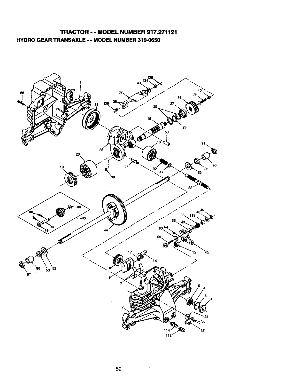
TRACTOR - - MODEL NUMBER 917.271121
HYDRO GEAR TRANSAXLE - - MODEL NUMBER 319-0650
58
139
41
28
59
23
19
26
4
35
50
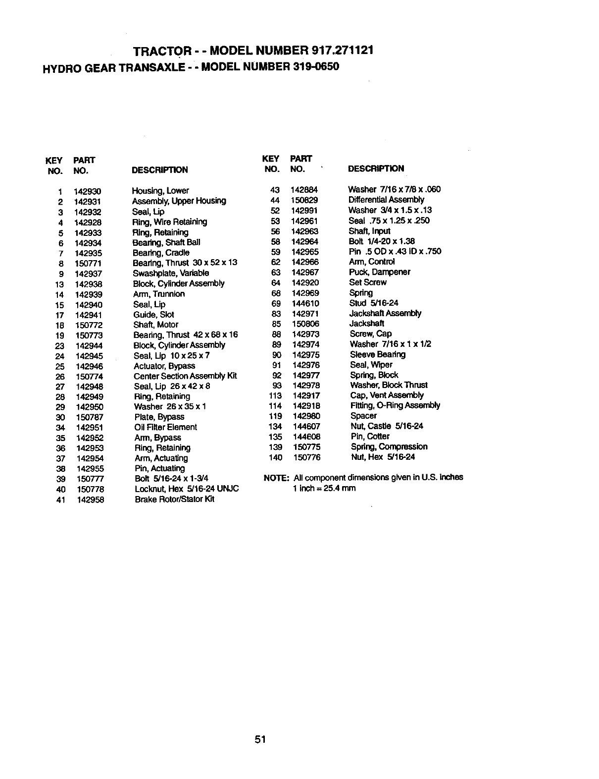
TRACTOR - - MODEL NUMBER 917.271121
HYDRO GEAR TRANSAXLE - -MODEL NUMBER 319-0650
KEY PART KEY PART
NO. NO. DESCRIPTION NO. NO. DESCRIPTION
1 142930 Housing,Lower 43 142884 Washer 7/16 x 7/8 x .060
2142931 Assembly,UpporHousing 44 150829 DilferantialAssembly
3 142932 Seal, Lip 52 142991 Washer 3/4 x 1.5 x,13
4 142928 Ring,Wire Retaining 53 142961 Seal .75 x 1.25 x .250
5 142933 Ring, Retaining 56 142963 Shaft, Input
6142934 Rearing, ShaftBall 58 142964 Bolt 1/4-20 x 1.38
7 142935 Beadeg, Cradle 59 142965 Pin .50D x.43 ID x.750
8 150771 Bearing,Thrust 30 x 52 x 13 62 142966 Arm,Control
9 142937 Swashplata,Variable 63 142967 Puck, Dampener
13 142938 B_:_ck,Cy/inderAssembly 64 142920 Set Screw
14 142939 Arm,Trunnion 68 142969 Spring
15 142940 Seal, Up 69 144610 Stud 5/16-24
17 142941 Guide, Slot 83 142971 JackshaftAssembly
16 150772 Shaft, Motor 85 150806 Jackshaft
19 150773 Bearing,Thrust 42x68x16 88 142973 Screw,Cap
23 142944 Block,CylinderAssembly 89 142974 Washer 7/16 x 1 x 1/2
24 142945 Seal, Up 10x25x7 90 142975 SleeveBeadng
25 142946 Actuator,Bypass 91 142976 Seal, Wiper
26 150774 Center SectionAssemblyKit 92 142977 Spring,Block
27 142948 Seal, Lip 26 x 42 x 8 93 142978 Washer,BlockThrust
28 142949 Ring, Retaining 113 142917 Cap, VentAssembly
29 142950 Washer 26 x35 x 1 114 142918 Fitting,O-Ring Assembly
30 150787 Plate, Bypass 119 142980 Spacer
34 142951 Oil Filter Element 134 144607 Nut, Castle 5/16-24
35 142952 Arm, Bypass 135 144608 Pin, Cotter
36 142953 Ring, Retaining 139 150775 Spdng,Compression
37 142954 Arm,Actuating 140 150776 Nut, Hex 5/16-24
38 142955 Pin, Actuating
39 150777 Bolt 5/16-24 x 1-314 NOTE: All componentdimensions givenin U.Soinches
40 150778 Locknut,Hex 5I16-24UNJC 1 inch=25.4mm
41 142958 Brake RotortStatorKit
51
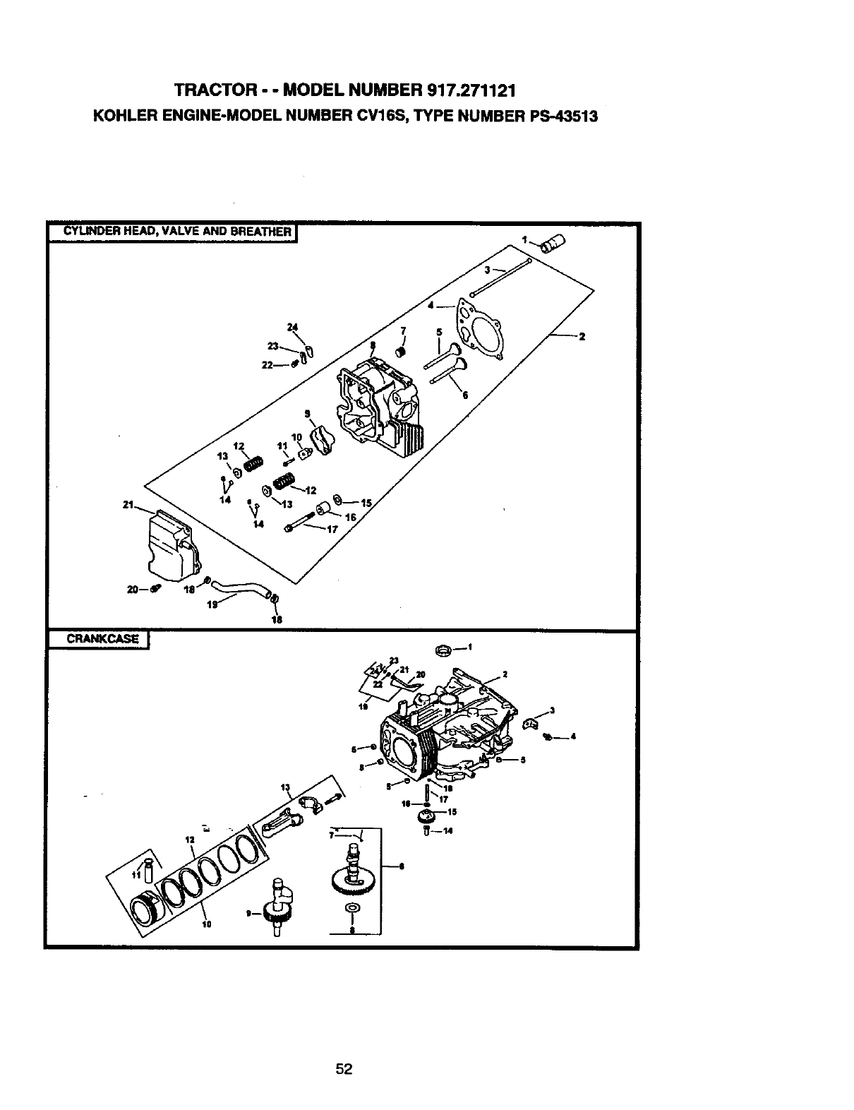
TRACTOR - - MODEL NUMBER 917.271121
KOHLER ENGINE-MODEL NUMBER CV16S, TYPE NUMBER PS-43513
CYLINDERHEAD, VALVE AND BREATHERI
$
12 11 10
14
_-15
_--14
52
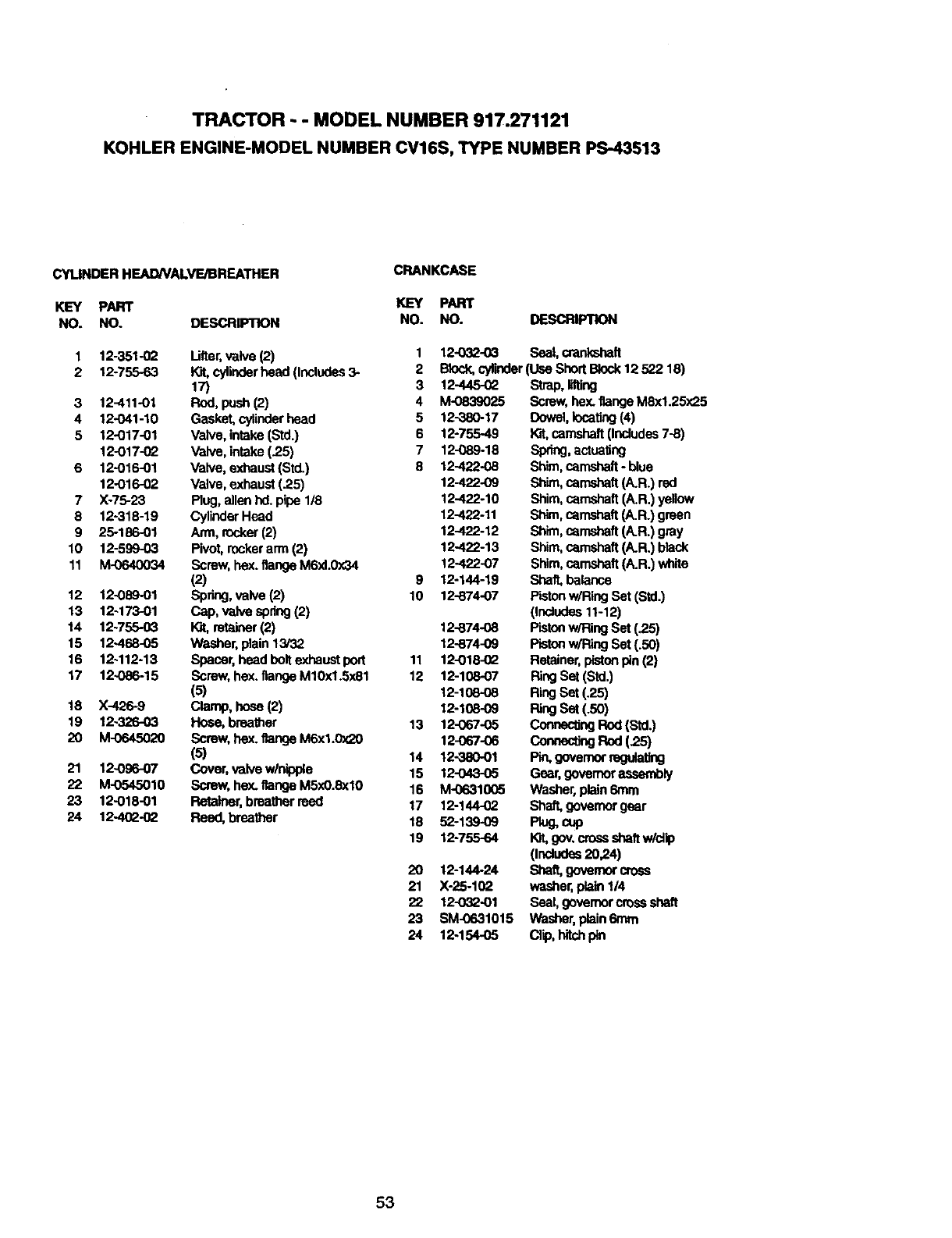
TRACTOR - - MODEL NUMBER 917.271121
KOHLER ENGINE-MODEL NUMBER CV16S, TYPE NUMBER PS-43513
CYLINDER HEADNALVE/BREATHER
KEY PART
NO. NO.
CRANKCASE
1 12-3514_
2 12-755-63
3 12-411-01
4 12-041-10
5 12-017-01
12-017-02
6 12-016-01
12-016-02
7 X-75-23
8 12-318-19
9 25-186-01
10 12-599-03
11 M-0640034
12 12-089-01
13 12-173-01
14 12-755-03
15 12468-05
16 12-112-13
17 12-086-15
18 X-426-9
19 12-326-03
20 M-064502O
21 12-096-07
22 M-0545010
23 12-018-01
24 12-402-02
KEY PART
DESCRIPTION NO. NO.
Lifter,valve (2)
Kit, cylinderhead (Includes3-
17)
Rod, push(2)
Gasket, cylinderhead
Valve, intake(Std.)
Valve, intake(25)
Valve, exhaust(Std.)
Valve, exhaust(.25)
Plug, allenhd. pipe 1/8
CylinderHead
Arm, rocker(2)
Pivot,rockerarm (2)
Screw,hox. flange M6xl.0x34
(2)
Spring,valve (2)
Cap, valvespdng(2)
ICJt,retainer(2)
Washer,plain 13/32
Spacer, head bolt exhaustport
Screw, hex. flange M10xl.5x81
(5)
Clamp, hose (2)
Hock, breather
Screw, hex. flange M6xl.0x20
(s)
Cover,valve w/nipple
Screw, hex. flange M5x0.8xl0
Retainer,breatherreed
Reed, breather
DESCRIPTION
1
2
3
4
5
6
7
8
9
10
11
12
13
14
15
16
17
18
19
2O
21
22
23
24
12032-03 Seal, crankshaft
Block,cylinder(Use ShortBlock12 522 18)
12-445-02
M-0839025
12-380-17
12-755-49
12-089-18
12-422-08
12-422-09
12-422-10
12-422-11
12-422-12
12-422-13
12-422-07
12-144-19
12-874-07
12-874.08
12-874-09
12-018-02
12-108-07
12-108-08
12-108-09
12-067435
12-067-06
12-380-O1
12-043-05
M4To31005
12-144-02
52-139-09
12-755-64
12-144-24
X-25-102
12-032-01
SM-0631015
12-154-05
Strap,lifting
Screw, hex.flange M8x1.25x25
Dowel,Iocatlag(4)
Kit,camshaft(Includes7-8)
Spring,actualing
Shim,camshaft-blue
Sh_, camshaft(A.R.) red
Shim,camshaft(A.R.) yellow
Shim,camshaft(A.R.) green
Shim,camshaft(A.R.) gray
Shim, camshaft(A.R.) black
Shim,camshaft(A.R.) white
Shaft,balance
Pistonw/Ring Set (Std.)
(Indudes 11-12)
Pistonw/RingSet (.25)
Pisten w/Ring Set (.50)
Retainer,pistonpin(2)
RingS= (S_.)
RingSet (.25)
RingSet (.50)
Connec_ngRod(Std.)
cormect_Rnd(25)
Pin,governorregula_g
Gear,governorassembly
Washer, plain 6ram
Shaft, govamorgear
P_g,cup
K}t,gov,crossshaftw/clip
pnc_Jdes20,24)
Shaft,governorcross
washer,plain 1/4
Seal, govemorcreas shaft
Washer, plain6ram
Qip, hitchpin
53
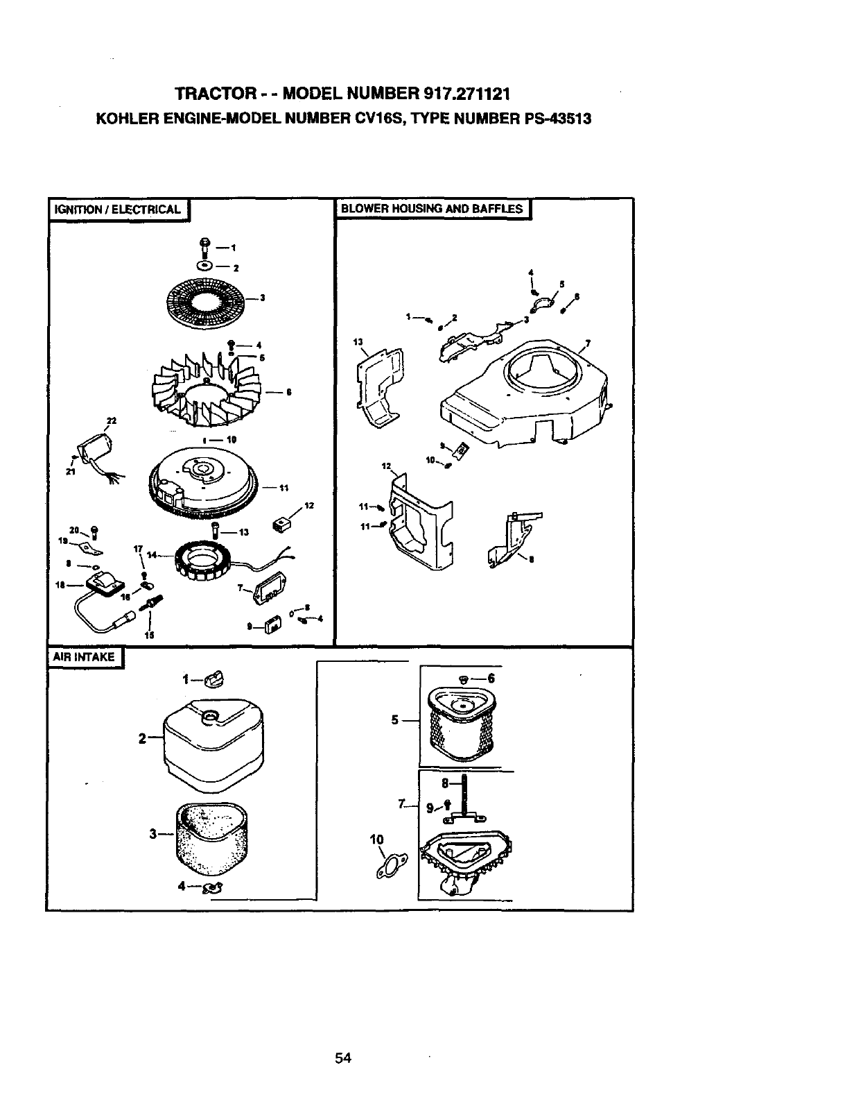
TRACTOR - - MODEL NUMBER 917.271121
KOHLER ENGINE-MODEL NUMBER CV16S, TYPE NUMBER PS-43513
IGNITION/ELECTRICAL
22
/
11_ 17 14--
AIR INTAKE
t- 8
BLOWER HOUSING AND BAFFLES i
54
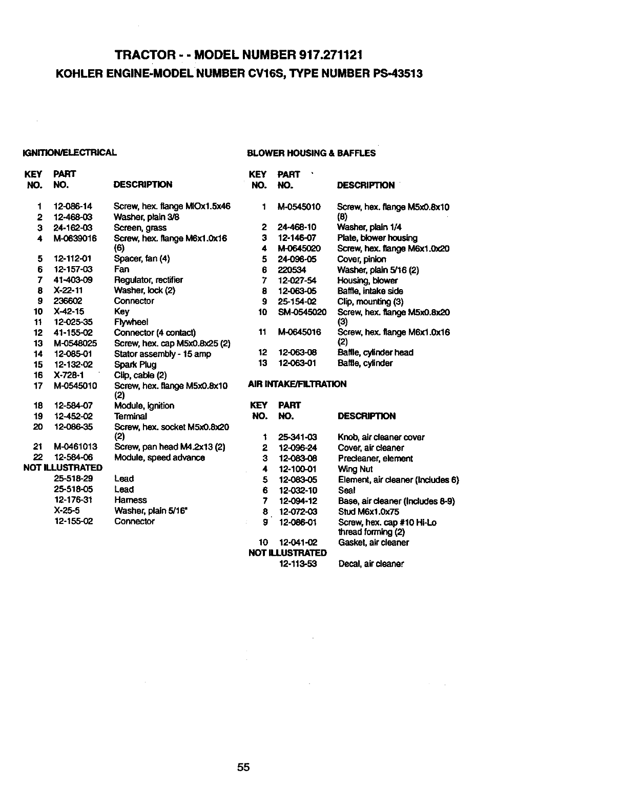
TRACTOR - - MODEL NUMBER 917.271121
KOHLER ENGINE-MODEL NUMBER CV16S, TYPE NUMBER PS-43513
IGNITION/ELECTRICAL
KEY PART
NO. NO.
BLOWER HOUSING & BAFFLES
1 12-086-14
2 12-468-03
3 24-162-03
4 M-0639016
5 12-112-01
6 12-157-03
7 41-40309
8 X-22-11
9 2366_
10 X-42-15
11 12-025-35
12 41-155-(_
13 M-0548025
14 12-085-01
15 12-132-O2
16 X-728-1
17 M-0545010
18 12-584-07
19 12-452-02
20 12-086-35
21 M-0461013
22 12-584-06
NOT ILLUSTRATED
25-518-29
25-518-05
12-176-31
X-25-5
12-155-02
KEY PART
DESCRIPTION NO. NO. DESCRIPTION
Lead
Lead
Harness
Washer, plain 5/16"
Connector
Screw, hex. flange MIOx1.5x46 1 M.0545010
Washer, plain 3/8
Screen, grass 2 24-468-10
Screw, hex. flange M6x1.0x16 3 12-146-07
(6) 4 M-0645(Y20
Spacer,fan (4) 5 24096-95
Fan 6 220534
Regulator,rectifier 7 12-027-54
Washer, lock(2) 8 12-063.05
Connector 9 25-154-02
Key 10 SM-0545020
nywheal
Connector (4 contact) 11 M-0645016
Screw,hex. cap M5x0.8_5 (2)
Stator assembly- 15 amp 12 12-063-08
Spark Plug 13 12-063-01
Clip, cable (2)
Screw, hex. flange M5x0.8xl0 AIR INTAKE/FILTRATION
(2)
Module, ignition KEY PART
Terminal NO. NO.
Screw, hex.socket M5xO.8x20
(2) 1 25-341-03
Screw,pan head M4.2x13 (2) 2 12-096-24
Module, speed advance 3 12-083.08
4 12-100-01
5 12-083-05
6 12-032-10
7 12-094-12
8 12-072.03
9 12-086-01
Screw, hex.flange MSx0.8xlO
(8)
Washer,plain 1/4
Plato,blower housing
Screw, hex.flange M6xl.0x20
Cover, pinion
Washer,plain 5/16 (2)
Housing,blower
Baffle,intakeside
Clip,mounting(3)
Screw, hex.flange M5x0.8x20
(3)
Screw, he)(.flange M6x1.0x16
(2)
Baffle,cylinderhead
Baffle, cylinder
DESCPJPTION
10 12-041.0_
NOT ILLUSTRATED
12-113-53
Knob,air cleanercover
Cover,air cleaner
Predeaner, element
Wing Nut
Element,aircleaner (Includes6)
Seal
Base, aircleaner (Includes8-9)
StudM6xl.0x75
Screw, hex. cap#10 Hi-Lo
threadforming (2)
Gasket,air cleaner
Decal,air cleaner
55
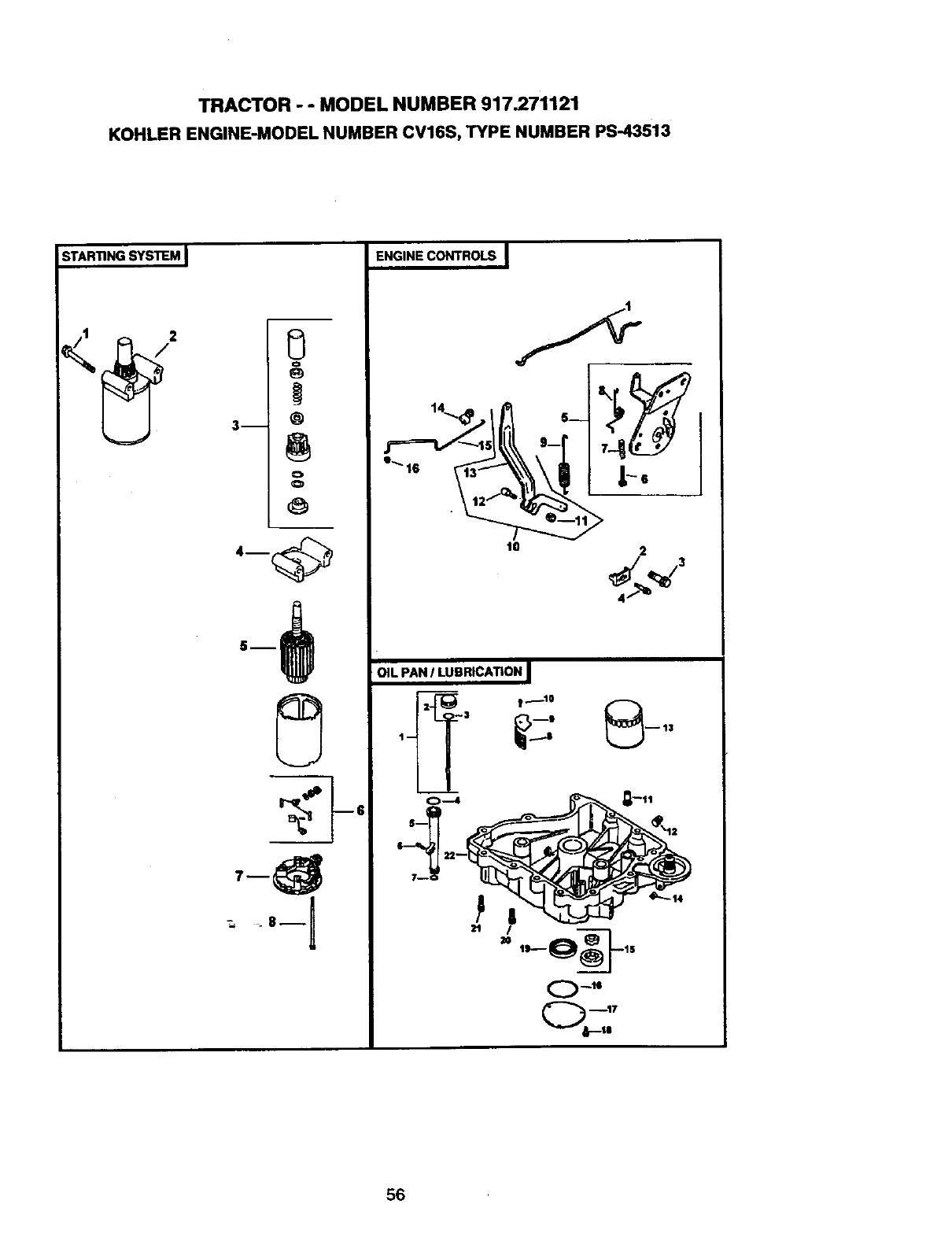
TRACTOR - - MODEL NUMBER 917.271121
KOHLERENGINE-MODELNUMBERCV16S,TYPENUMBERPS-43513
STARTING SYS'_EM I
g
o
3m @
o
O
_8m I
ENGINE CONTROLS I
t0 2
OIL PAN ILUBRICATIONI
t --3 _
0---4
56
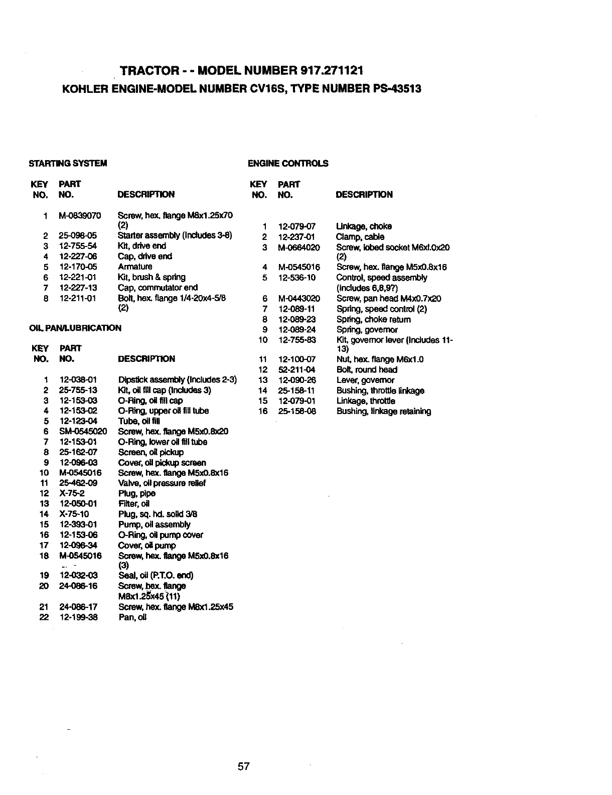
TRACTOR - - MODEL NUMBER 917.271121
KOHLER ENGINE-MODEL NUMBER CV16S, TYPE NUMBER PS-43513
STARTING SYSTEM
KEY PART
NO. NO. DESCRIPTION
2
3
4
5
6
7
8
M-0839070
25-098-05
12-755-54
12.227-06
12-170-05
12221-01
12-227-13
12-211-01
Screw, hex. flange M8x1.25x70
(2)
Starterassembly(Includes3-8)
Kit,driveend
Cap, driveend
Armature
Kit, brush& spnng
Cop, commutatorend
Bolt,hey..flange 1/4-20x4-5/8
(2)
OIL PAN/LUBRICATION
KEY PART
NO. NO. DESCRIPTION
1
2
3
4
5
6
7
8
9
10
11
12
13
14
15
16
17
18
19
2O
21
22
12-038-01
25-755-13
12-153-03
12-153-02
12-123-04
SM-0545020
12-153-01
25-162-07
12-096-03
M-0545016
25-462-09
X-75-2
12-050-01
X-75-10
12-393-01
12-153-06
12-096-34
M-0545016
12-032-03
24-086-16
24-086-17
12-199-38
Dipstickassembly(Includes2-3)
Kit,oilfillcap(Includes3)
O-Ring, oil fillcap
O-Ring, upperoHfiHtube
Tube, oil fill
Screw,hex.flange M5xO.Sx20
O-Riflg, loweroil filltube
Screen,oil pickup
Cove_,oil pickup screen
Screw, hex.flange MSxO.8x16
Valve, oil pressurerelief
Rug, pipe
F_er, oil
Plug, sq. hd.sogd3/8
Pump, oilassembly
O-Ring, oilpump cover
Cover, oil pump
Screw,hes.flange MSxO.Sx16
(3)
sesJ,oii(P.T.O.end)
Screw,J_. flauge
MSx1.2_x45 (11)
Screw,hex. flange MSx1.25x45
Pan, og
ENGINE CONTROLS
KEY PART
NO. NO.
1 12-079-07
2 12-237-01
3 M-0664020
4 M-0545016
5 12-536-10
6 M-0443020
7 12-089-11
8 12-089-23
9 12-089-24
10 12-755-83
11 12-100-07
12 52-211-04
13 12-090-26
14 25-158-11
15 12-079-01
16 25-158-08
DESCRIPTION
Unkage, choke
Clamp, cable
Screw, lobedsocketM6xLox20
(2)
Screw, hex. flange M5xO.Sx16
Control,speed assembly
(Includes6,8,97)
Screw, pen head M4xO.7x20
Spring,speed control(2)
Spdng,choke return
Spring,governor
Kit,gevemor lever (Includes11-
13)
Nut, hex.flange M6xl.0
Bolt, round head
Lever, govemor
Bushing,throttlelinkage
Unkage, throttle
Bushing,linkageretaining
57

58

SUGGESTED GUIDE FOR SIGHTING SLOPES FOR SAFE OPERATION
_r _
ISIGHTING
GUIDE
ONLY RIDE UP AND DOWN HILL,
NOT ACROSS HILL
O1
cO
I
Operate your Tractor up and down the face of slopes (not I
greater than 15 ), never across the face. Make turns gradu- I
ally to prevent tlpplng or loss of control. Exerclse extreme
ceutlon when changlng dlrectlon on slopes.

For the repair or replacement parts you need
delivered directlyto your home
Call 7 am - 7 pm, 7 days a week
1-800-366-PART
(1-800-366-7278)
Para ordenar plezas con entrega a
domicilio - 1-800-659-7084
For in-house major brand repair service
Call 24 hours a day, 7 days a week
1-800-4-REPAIR
(1-800-473-7274)
Para pedir servicio de repamci6n a
domicilio- 1-800-676-5811
For the location of a Sears Parts and
Repair Center in your area
Call 24 hours a day, 7 days a week
1-800-488-1222
For information on purchasing a Sears
Maintenance Agreement or to inquire
about an existing Agreement
Call 9 am - 5 pm, Monday-Saturday
1-800-827-6655
When requesting service or ordering
partS, always provide th_ following
information:
•Product Type •Pad Number ,
•Model Number •Part DescdpUon SEARS
America's Repair Specia/tsts
165066 Rev. 3 9.14.98 VB/RH Pdnted in U.S.A.
