Craftsman 917272011 User Manual LAWN TRACTOR Manuals And Guides 98100088
CRAFTSMAN Lawn, Tractor Manual 98100088 CRAFTSMAN Lawn, Tractor Owner's Manual, CRAFTSMAN Lawn, Tractor installation guides
User Manual: Craftsman 917272011 917272011 CRAFTSMAN LAWN TRACTOR - Manuals and Guides View the owners manual for your CRAFTSMAN LAWN TRACTOR #917272011. Home:Lawn & Garden Parts:Craftsman Parts:Craftsman LAWN TRACTOR Manual
Open the PDF directly: View PDF ![]() .
.
Page Count: 64

Owner's Manual
rRRFTSMRN
16.5 HP
ELECTRIC START
46" MOWER
6 SPEED TRANSA;Xl]=
LAWN TRACTOR
Model No.
917.272011
• Safety
•Assembly
•Operation
•Maintenance
•Repair Parts
CAUTION:
Read and follow all
Safety Rules and Instructions
before operating this equip-
ment.
For answers to your questions
about this product, Call:
1-800-659-5917
Sears Craftsman Help Line
5 am -5 pm, Mon- Sat
:Sears, Hoebuck and Co., Hoffman Estates, IL 60179
Warranty ........................... ,]_.]................ 2
Safety Rules ........................................... 2
Product Specifications ........................... 5
Assembly ................................................ 8
Operation .............................................. 12
Maintenance Schedule ......................... 18
Maintenance ......................................... 18
Service and Adjustments ...................... 22
Storage ................................................. 29
Troubleshooting .................................... 30
Repair Parts ......................................... 34
Parts Ordering ....................... Back Cover
LIMITED TWO YEAR WARRANTY ON CRAFTSMAN RIDING EQUIPMENT
For two (2) years from the date of purchase, if this Craftsman Riding Equipment is main-
tained, lubricated and tuned up according to the instructions in the owner's manual,
Sears will repair or replace, free of charge, any parts found to be defective in material or
workmanship.
This Warranty does not cover:
•Expendable items which become worn during normal use, such as blades, spark
plugs, air cleaners, belts, etc.
•Tire replacement or repair caused by punctures from outside objects, such as nails,
thorns, stumps, or glass.
•Repairs necessary because of operator abuse, negligence, improper storage or acci-
dent or the failure to maintain the equipment according to the instructions contained in
the owner's manual.
•Riding equipment used for commercial or rental purposes.
LIMITED 90 DAY WARRANTY ON BATTERY
For ninety (90) days from date of purchase, if any battery included with this riding equip-
ment proves defective in material or workmanship and our testing determines the bat-
tery will not hold a charge, Sears will replace the battery at no charge. In-home warranty
service on your Craftsman riding equipment is available at no charge for 30 days from
the date of purchase. Please contact your nearest service center. After 30 days from the
date of purchase, warranty service is available by taking your Craftsman riding equip-
ment to your nearest Sears Service Center. (In-home warranty service will still be avail-
able after 30 days from the clate of purchase but a standard trip charge will apply). This
warranty applies only while this product is in the United States. This Warranty gives you
specific legal rights, and you may also have other rights which may vary from state to
state.
Sears, Roebuck and Co., D/817 WA, Hoffman Estates, IL 60179
GENERAL OPERATION
•Read, understand, and follow all instruc-
tions in the manual and on the machine
before starting.
•Only allow responsible adults, who are
familiar with the instructions, to operate
the machine.
•Clear the area of objects such as rocks,
toys, wire, etc., which could be picked
up and thrown by the blade.
•Be sure the area is clear of other people
befoT_mowing. Stop machine if anyone
enters the area.
2
•Never carry passengers.
•Do not mow in reverse unless absolute-
ly necessary. Always look down and
behind before and while backing.
•Be aware of the mower discharge direc-
tion and do not point it at anyone. Do
not operate the mower without either
the entire grass catcher or the guard in
place.
•Slow down before tuming.
•Never leave a running machine unat-
tended. Always turn off blades, set park-
ing brake, stop engine, and remove
keys before dismounting.
•Turn off blades when not mowing.
• Stop engine before removing grass
catcher or unclogging chute.
•Mow only in daylight or good artificial
light.
•Do not operate the machine while under
the influence of alcohol or drugs.
•Watch for traffic when operating near or
crossing roadways.
•Use extra care when loading or unload-
ing the machine into a trailer or truck.
SLOPE OPERATION
Slopes are a major factor related to loss-
of-control and tipover accidents, which
can result in severe injury or death. All
slopes require extra caution. If you cannot
back up the slope or if you feel uneasy on
it, do not mow it.
DO:
•Mow up and down slopes, not across.
•Remove obstacles such as rocks, tree
limbs, etc.
•Watch for holes, ruts, or bumps. Uneven
terrain could overturn the machine. Tall
grass can hide obstacles.
•Use slow speed. Choose a low gear so
that you will not have to stop or shift
while on the slope.
• Follow the manufacturer's recommen-
dations for wheel weights or counter-
weights to improve stability.
•Use extra care with grass catchers or
other attachments. These can change
the stability of the machine.
•Keep all movement on the slopes slow
and gradual. Do not make sudden
changes in speed or direction.
•Avoid-starting or stopping on a slope. If
tires lose traction, disengage the blades
and proceed slowly straight down the
slope.
DO NOT:
•Do notturn on slopes unless necessary,
and then, turn slowly and gradually
downhill, if possible.
•Do not mow near drop-offs, ditches, or
embankments. The mower could sud-
denly turn over if a wheel is over the
edge of a cliff or ditch, or if an edge
caves in.
•DJ_not mow on wet grass. Reduced
traction could cause sliding.
•Do nottry to stabilize the machine by
puttingyour foot on the ground.
•Do not use grass catcher on steep
slopes.
CHILDREN
Tragic accidents can occur if the operator
is not alert to the presence of children.
Children are often attracted to the
machine and the mowing activity. Never
assume that children will remain where
you last saw them.
•Keep children out of the mowing area
and under the watchful care of another
responsible adult.
•Be alert and turn machine off if children
enter the area.
•Before and when backing, look behind
and down for small children.
•Never carry children. They may fall off
and be seriously injured or interfere with
safe machine operation.
•Never allow children to operate the
machine.
•Use extra care when approaching blind
corners, shrubs, trees, or other objects
that may obscure vision.
SERVICE
•Use extra care in handling gasoline and
other fuels. They are flammable and
vapors are explosive.
Use only an approved container.
Never remove gas cap or add fuel
with the engine running. Allow en-
gine to cool before refueling. Do not
smoke.
Never refuel the machine indoors.
Never store the machine or fuel
container inside where there is an
open flame, such as a water heater.
•Never run a machine inside a closed
area.
•Keep nuts and bolts, especially blade
attachment bolts, tight and keep equip-
ment in good condition.
•Never tamper with safety devices.
Check their proper operation regularly.
•Keep machine free of grass, leaves, or
other debris build-up. Clean oil or fuel
spillage. Allow machine to cool before
storing.
•Stop and inspect the equipment if you
strike an object. Repair, if necessary,
before restarting.
•Never make adjustments or repairs with
the engine running.
•Grass catcher components are subject
to wear, damage, and deterioration,
which could expose moving parts or
allow objects to be thrown. Frequently
check components and replace with
manufacturer's recommended pads,
when necessary.
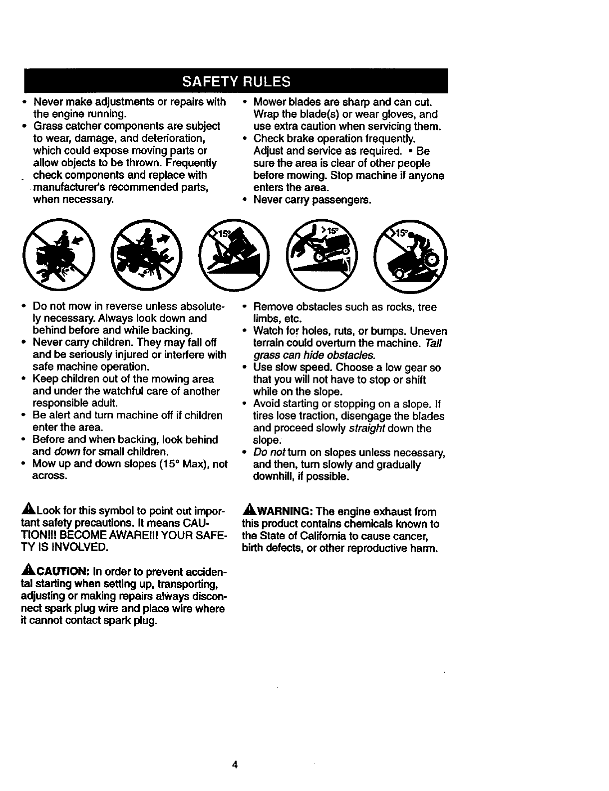
•Mower blades are sharp and can cut.
Wrap the blade(s) or wear gloves, and
use extra caution when servicing them.
•Check brake operation frequently.
Adjust and service as required. •Be
sure the area is clear of other people
before mowing. Stop machine if anyone
enters the area.
•Never carry passengers.
•Do not mow in reverse unless absolute-
ly necessary. Always look down and
behind before and while backing.
•Never carry children. They may fall off
and be seriously injured or interfere with
safe machine operation.
•Keep children out of the mowing area
and under the watchful care of another
responsible adult.
•Be alert and turn machine off if children
enter the area.
•Before and when backing, look behind
and down for small children.
•Mow up and down slopes (15 ° Max), not
across.
•Remove obstacles such as rocks, tree
limbs, etc.
•Watch for holes, ruts, or bumps. Uneven
terrain could overturn the machine. Tall
grass can hide obstacles.
•Usa slow speed. Choose a low gear so
that you will not have to stop or shift
while on the slope.
•Avoid starting or stopping on a slope. If
tires lose traction, disengage the blades
and proceed slowly straight down the
slope.
•Do nottum on slopes unless necessary,
and then, tum slowly and gradually
downhill, if possible.
_.Look for this symbol to point out impor-
tant safety precautions. It means CAU-
TIONt!! BECOME AWAREtt! YOUR SAFE-
TY IS INVOLVED.
ACAgTION: In order to prevent acciden-
tal starting when setting up, transperting,
adjusting or making repairs always discon-
nect spark plug wire and place wire where
it cannot contact spark plug.
AWARNING: The engine exhaust from
this product contains chemicals known to
the State of California to cause cancer,
birth defects, or other reproductive harm.
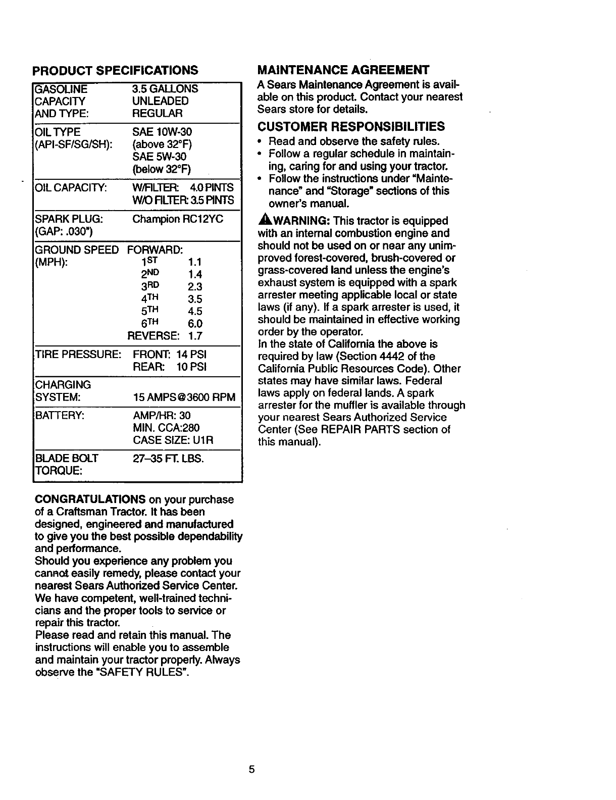
PRODUCT SPECIFICATIONS
GASOLINE 3.5GALLONS
CAPACITY UNLEADED
ANDTYPE: REGULAR
OILTYPE SAE10W-30
API-SF/SG/SH): (above32°F)
SAE5W-30
(below32°F)
)IL CAPACITY: W/FILTER: 4.0 PINTS
WiO RLTER: 3.5 RNTS
3PARK PLUG: Champion RC12YC
GAP: .030")
GROUND SPEED FORWARD:
(MPH): I sT 1.1
2ND 1.4
3RD 2.3
4TM 3.5
5TM 4.5
6TM 6.0
REVERSE: 1.7
TIRE PRESSURE: FRONT: 14 PSI
REAR: 10 PSI
CHARGING
SYSTEM: 15 AMPS @3600 RPM
BATTERY: AMP/HR: 30
MIN. CCA:280
CASE SIZE: U1R
BLADE BOLT 27-35 FT. LBS.
TORQUE:
MAINTENANCE AGREEMENT
A Sears Maintenance Agreement is avail-
able on this product. Contact your nearest
Sears store for details.
CUSTOMER RESPONSIBILITIES
• Read and observe the safety rules.
•Follow a regular schedule in maintain-
ing, caring for and using your tractor.
•Follow the instructions under "Mainte-
nance" and "Storage" sections of this
owner's manual.
,_WARNING: This tractor is equipped
with an intemal combustion engine and
should not be used on or near any unim-
proved forest-covered, brush-covered or
grass-covered land unless the engine's
exhaust system is equipped with a spark
arrester meeting applicable local or state
laws (if any). If a spark arrester is used, it
should be maintained in effective working
order by the operator.
In the state of California the above is
required by law (Section 4442 of the
California Public Resources Code). Other
states may have similar laws. Federal
laws apply on federal lands. Aspark
arrester for the muffler is available through
your nearest Sears Authorized Service
Center (See REPAIR PARTS section of
this manual).
CONGRATULATIONS on your purchase
of a Craftsman Tractor. It has been
designed, engineered end manufactured
to give you the best possible dependability
and performance.
Should you experience any problem you
canna easily remedy, please contact your
nearest Sears Authorized Service Center.
We have competent, well-trained techni-
cians and the proper tools to service or
repair this tractor.
Please read and retain this manual. The
instructions will enable you to assemble
and maintain your tractor properly. Always
observe the "SAFETY RULES".
5
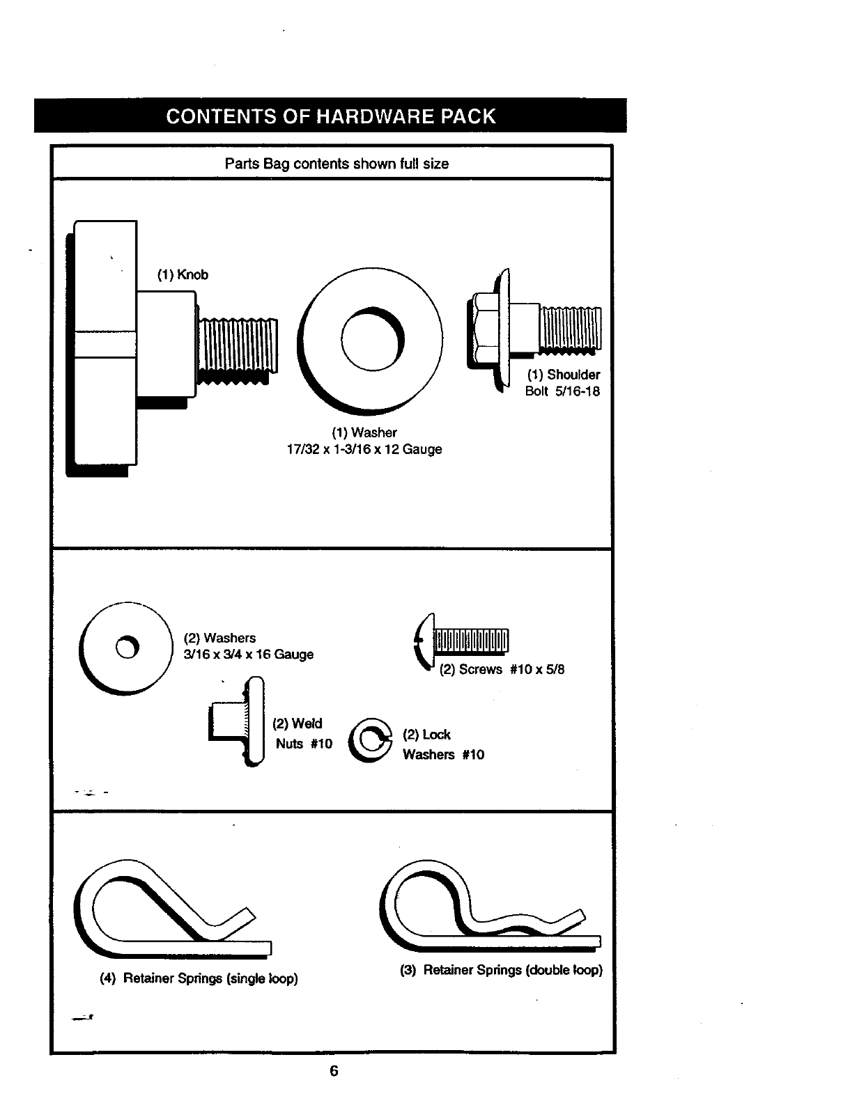
Parts Bag contents shown fu!l size
(1) Knob
(1) Washer
17/32 x 1-3116x 12 Gauge
(1) Shoulder
Bolt 5/16-18
(2) Washers
3/16 x 3/4 x 16 Gauge _#10 x 5/8
(2) Weld _(2) Lock
Nuts #10 Washers #10
(4) Retainer Springs (singleloop) (3) Retainer Spdngs (double loop)
6
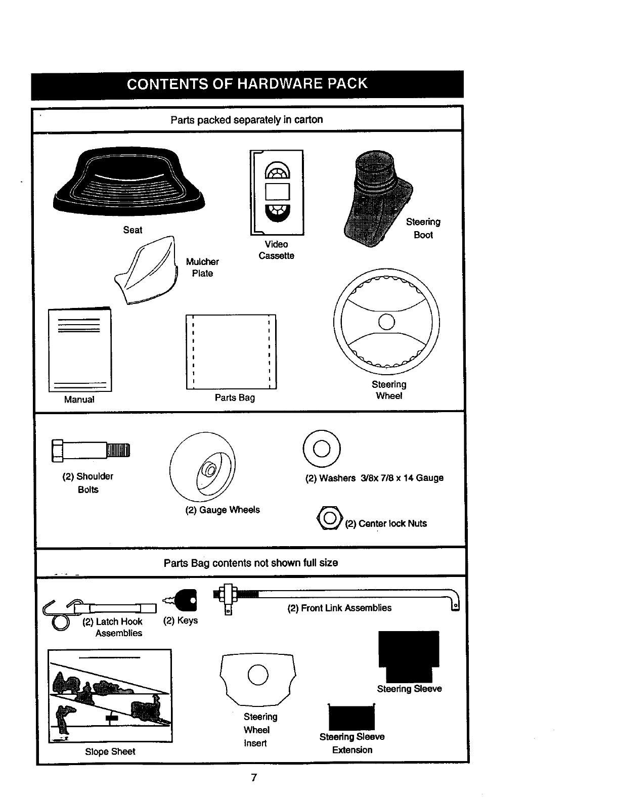
Partspacked separately in carton
Seat
Mulcher
Plate
[13
Video
Cassette
Steering
Boot
Manual Parts Bag
Steering
Wheel
(2) Shoulder
Bolts
(2) GaugeWheels
©
(2) Washers 3/8x 7/8 x 14 Gauge
Q(2) Center lock Nuts
Parts Bag contents not shown full size
--0---(2) LatchHock
Assemblies
(2) FrontLinkAssemblies
Slope Sheet
Steering
Wheel
Insert
SteeringSleeve
Steedng Sleeve
Extension
7
Your new tractor has been assembled at the factory with exception ofthose parts left
unassembled for shipping purposes. To ensure safe and proper operation of your tractor
all parts and hardware you assemble must be tightened securely. Use the correct tools
as necessary to insure proper tightness. Review the video cassette before you begin.
TOOLS REQUIRED FOR
ASSEMBLY
" A socket wrench set will make assembly
easier. Standard wrench sizes you need
are listed below.
(1) 3/4" wrench (1) 3/4" Socket w/
(2) 1/2" wrench drive rachet
(1) Pliers (1) Phillips Screw-
(1) Utility knife driver
(1) Tire pressure gauge
When right or left hand is mentioned in
this manual, it means, from your point of
view, when you are in the operating posi-
tion (seated behind the steering wheel).
TO REMOVE TRACTOR FROM
CARTON
UNPACK CARTON
•Remove all accessible loose parts and
parts boxes from shipping carton (See
page 6).
• Cut, from top to bottom, along lines on
all four comers of shipping carton, and
lay panels flat.
•Remove mower and package materials.
•Check for any additional loose parts or
boxes and remove.
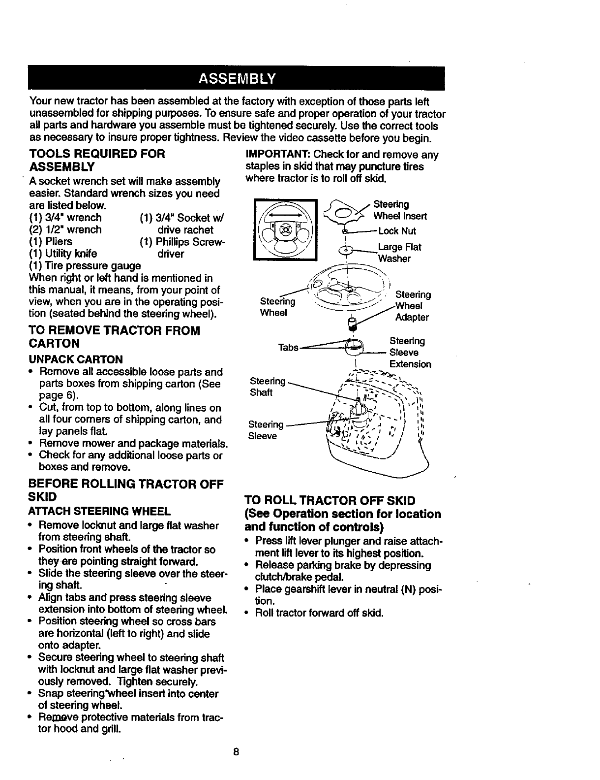
IMPORTANT: Check for and remove any
staples in skid that may puncture tires
where tractor is to roll oftskid.
I(_1 J_--'_'J Steering
Wheel Insert
t_---- Lock Nut
_Large Flat
_. Washer
_. _ ._'_S-'. Steering
_teering "__" Wheel
Wheel _Adapter
Steering
Tabs i_Sleeve
IExtension
Steering
Sleeve
BEFORE ROLLING TRACTOR OFF
SKID
ATTACH STEERING WHEEL
•Remove Iocknut and large flat washer
from steering shaft.
•Position front wheels of the tractor so
they are pointing straight forward.
•Slide the steering sleeve over the steer-
ing shaft.
•Align tabs and press steering sleeve
extension into bottom of steering wheel.
•Position steering wheel so cross bars
are horizontal (left to right) and slide
onto adapter.
• Secure steering wheel to steering shaft
with Iocknut and large flat washer previ-
ously removed. "lighten securely.
•Snap steering'wheel insert into center
of steering wheel.
•ReEve protective materials from trac-
tor hood and grill.
TO ROLL TRACTOR OFF SKID
(See Operation section for location
and function of controls)
•Press lift lever plunger and raise attach-
ment lift lever to its highest position.
•Release parking brake by depressing
clutch/brake pedal.
•Place gearshift lever in neutral (N) posi-
tion.
•Roll tractorforward off skid.
8
HOW TO SET UP YOUR TRACTOR
CHECK BATrERY
• Lift hood to raised position.
• If this battery is put into service after
month and year indicated on label (label
located between terminals) charge bat-
tery for minimum of one hour at 6-10
amps. (See "BATTERY" in Maintenance
section of this manual for charging
instructions).
_.=::_;_-" •l=.. '_,
,L °•• °•*
q
Label
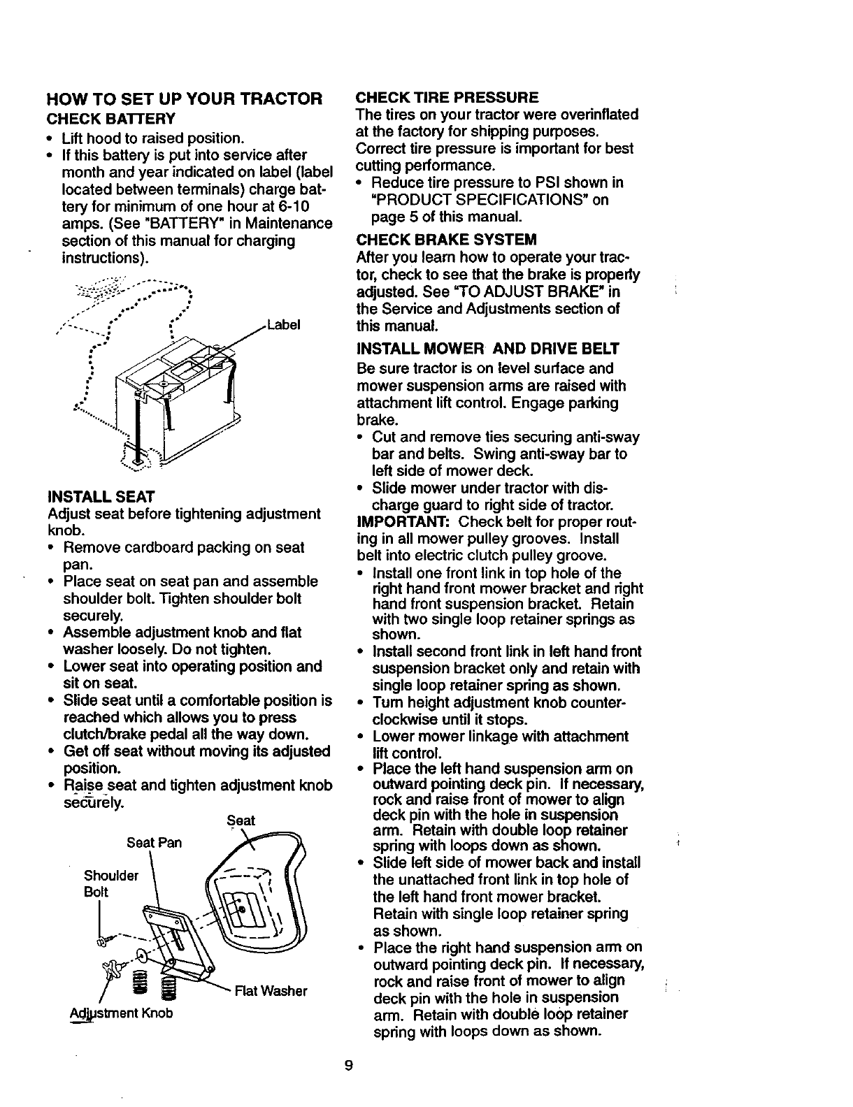
INSTALL SEAT
Adjust seat before tightening adjustment
knob.
• Remove cardboard packing on seat
pan.
•Place seat on seat pan and assemble
shoulder bolt. Tighten shoulder bolt
securely.
•Assemble adjustment knob and flat
washer loosely. Do not tighten.
•Lower seat into operating position and
sit on seat.
•Slide seat until a comfortable position is
reached which allows you to press
clutch/brake pedal all the way down.
•Get off seat without moving its adjusted
position.
•Rai_seseat and tighten adjustment knob
securely. Seat
Seat Pan
Shoulder
Bolt
Ad__".stment Knob
Flat Washer
CHECK TIRE PRESSURE
The tires on your tractor were overinflated
at the factory for shipping purposes.
Correct tire pressure is important for best
cutting performance.
•Reduce tire pressure to PSI shown in
"PRODUCT SPECIFICATIONS" on
page 5 of this manual.
CHECK BRAKE SYSTEM
After you learn how to operate your trac-
tor, check to see that the brake is properly
adjusted. See =TOADJUST BRAKE" in
the Service and Adjustments section of
this manual.
INSTALL MOWER AND DRIVE BELT
Be sure tractor is on level surface and
mower suspension arms are raised with
attachment lift control. Engage parking
brake.
•Cut and remove ties securing anti-sway
bar and belts. Swing anti-sway bar to
left side of mower deck.
•Slide mower under tractor with dis-
charge guard to right side of tractor.
IMPORTANT: Check belt for proper rout-
ing in all mower pulley grooves. Install
belt into electric clutch pulley groove.
•Install one front link in top hole of the
right hand front mower bracket and right
hand front suspension bracket. Retain
with two single loop retainer springs as
shown.
•Install second front link in left hand front
suspension bracket only and retain with
single loop retainer spring as shown.
•Tum height adjustment knob counter°
clockwise until it stops.
•Lower mower linkage with attachment
lift control.
• Place the left hand suspension arm on
outward pointing deck pin. If necessary,
rock and raise front of mower to align
deck pin with the hole in suspension
arm. Retain with double loop retainer
spring with loops down as shown.
•Slide left side of mower back and install
the unattached front link in top hole of
the left hand front mower bracket.
Retain with single loop retainer spring
as shown.
•Place the right hand suspension arm on
outward pointing deck pin. If necessary,
rock and raise front of mower to align
deck pin with the hole in suspension
arm. Retain with double loop retainer
spring with loops down as shown.
9
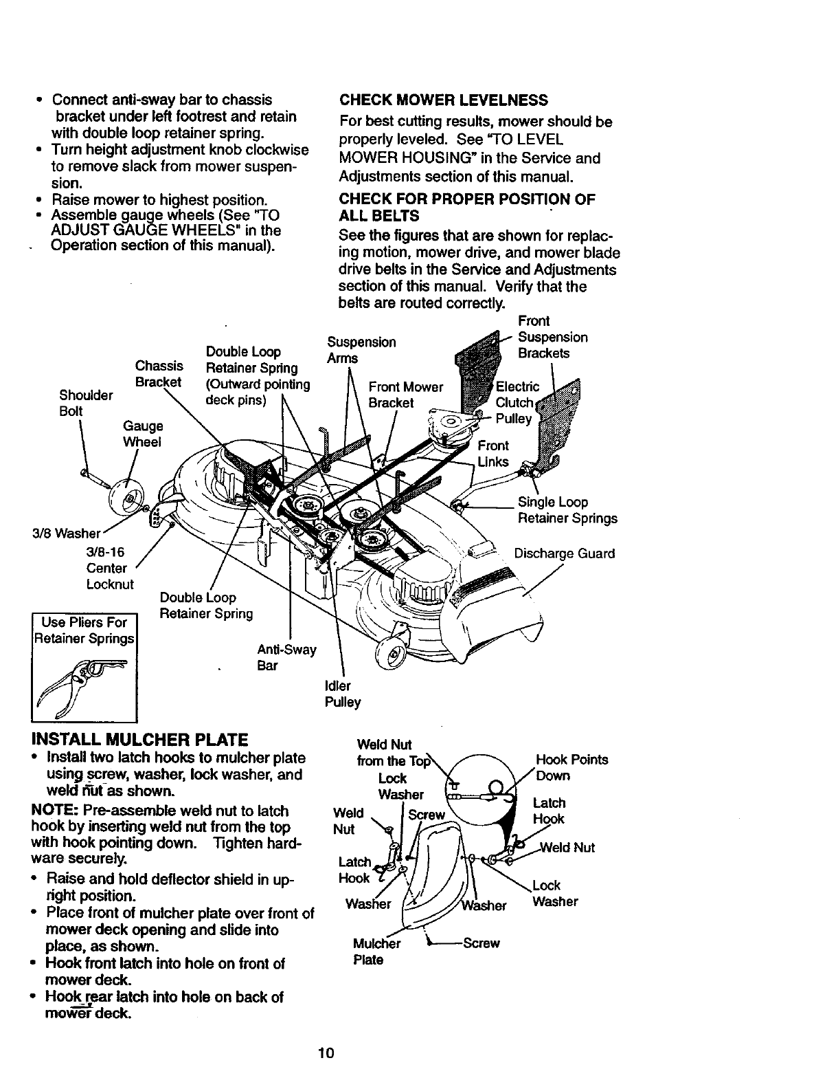
•Connect anti-sway bar to chassis
bracket under left footrest and retain
with double loop retainer spring.
•Turn height adjustment knob clockwise
to remove slack from mower suspen-
sion.
•Raise mower to highest position.
•Assemble gauge wheels (See "TO
ADJUST GAUGE WHEELS in the
Operation section of this manual).
Double Loop
Chassis Retainer Spring
Bracket (Outward pointing Front Mower
Shoulder deck pins) Bracket
Bolt
CHECK MOWER LEVELNESS
For best cutting results, mower should be
properly leveled. See "TO LEVEL
MOWER HOUSING" in the Service and
Adjustments section of this manual.
CHECK FOR PROPER POSITION OF
ALL BELTS
See the figures that are shown for replac-
ing motion, mower drive, and mower blade
drive belts in the Service and Adjustments
section of this manual. Verify that the
belts are routed correctly. Front
Suspension Suspension
Arms Brackets
3/8 Washel
3/8-16
Center
Locknut
Use Pliers For
Retainer Springs
Double Loop
Retainer Spring
Anti-Sway
Bar
Idler
Pulley
INSTALL MULCHER PLATE WeldNut
•Install two latch hooks to mulcher plate
using _screw,washer, lock washer, and Lock
weld nut-as shown. Washer
NOTE: Pre-assemble weld nut to latch Weld
hook by inserting weld nut from the top Nut
with hook pointing down. Tighten hard-
ware securely. Latch
• Raise and hold deflector shield in up-
dght position.
•Place front of mulcher plate over front of
mower deck opening and slide into
place, as shown. Mulcher "_-_-Screw
•Hook front latch into hole on front of Plate
mower deck.
•Hook roar latch into hole on back of
mo_"_ deck.
Single Loop
Retainer Springs
Discharge Guard
Hook Points
Latch
Hook
Nut
Lock
Washer
10
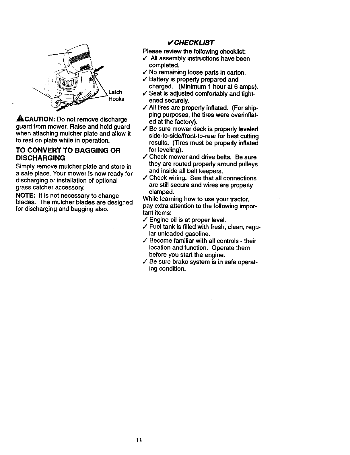
_,CAUTION: Do not remove discharge
guard from mower. Raise and hold guard
when attaching mulcher plate and allow it
to rest on plate while in operation.
TO CONVERT TO BAGGING OR
DISCHARGING
Simply remove mulcher plate and store in
a safe place. Your mower is now ready for
discharging or installation of optional
grass catcher accessory.
NOTE: It is not necessary to change
blades. The mulcher blades are designed
for discharging and bagging also.
CHECKLIST
Please review the following checklist:
,/ All assembly instructions have been
completed.
,/No remaining loose parts in carton.
/Battery is propedy prepared and
charged. (Minimum 1 hour at 6 amps).
,/Seat is adjusted comfortably and tight-
ened securely.
,/All tires are propedy inflated. (For ship-
ping purposes, the tires were overinflat-
ed at the factory).
/Be sure mower deck is properly leveled
side-to-side/front-to-rear for best cutting
results. (Tires must be properly inflated
for leveling).
/Check mower and drive belts. Be sure
they are routed properly around pulleys
and inside all belt keepers.
,/Check wiring. See that all connections
are still secure and wires are propedy
clamped.
While learning how to use your tractor,
pay extra attention to the following impor-
tant items:
,/" Engine oil is at proper level.
/Fuel tank is filled with fresh, clean, regu-
lar unleaded gasoline.
,/Become familiar with all controls - their
location and function. Operate them
before you start the engine.
4" Be sure brake system is in safe operat-
ing condition.
11
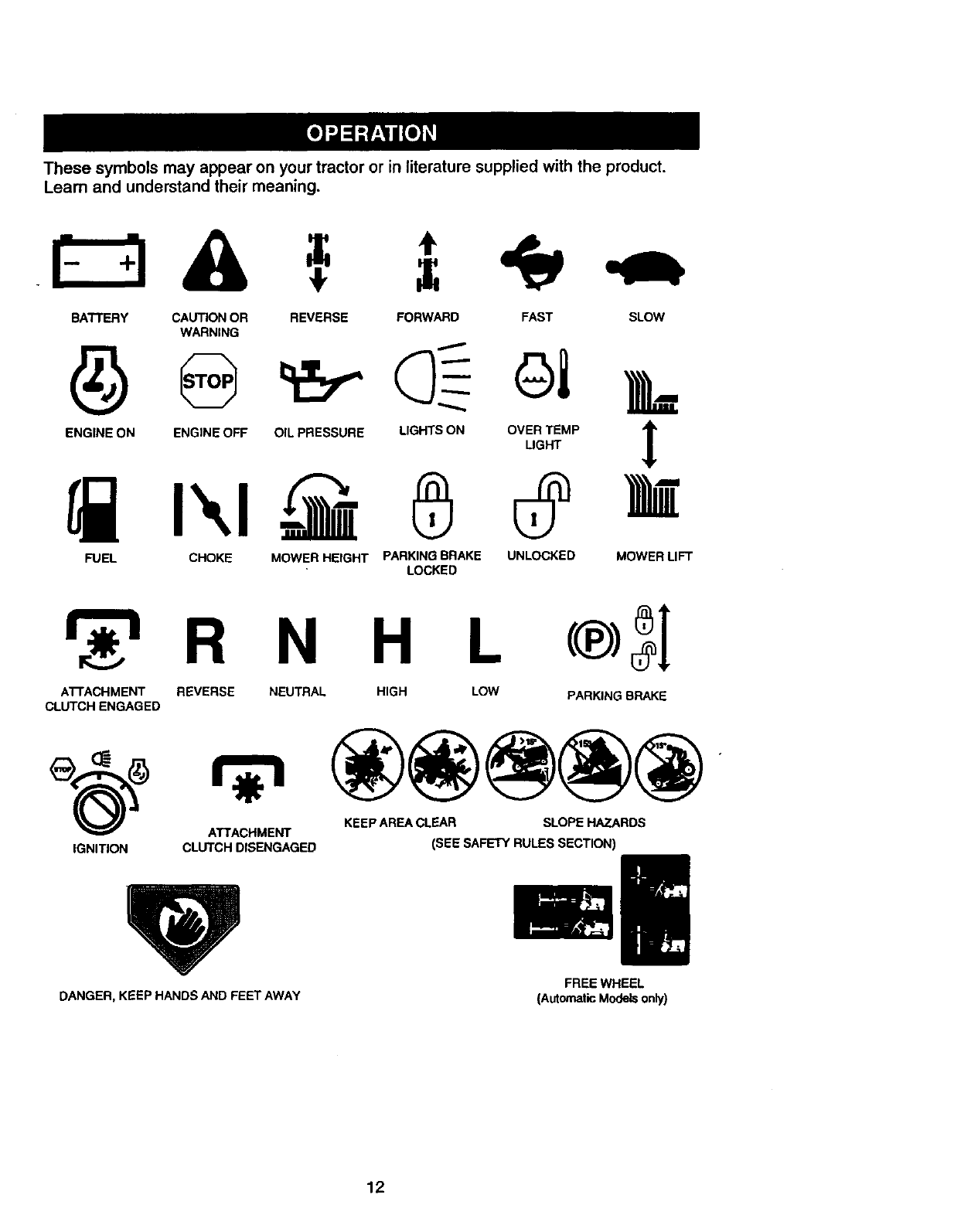
Thesesymbolsmayappearonyour tractor or in literature supplied with the product.
Learn and understand their meaning.
BATTERY CAUTION OR
WARNING
ENGINE ON ENGINE OFF
REVERSE FORWARD FAST SLOW
OIL PRESSURE
n' n
FUEL CHOKE MOWER HEIGHT
LIGHTS ON OVER TEMP '_
LIGHT L
PARKING BRAKE UNLOCKED MOWER LIFT
LOCKED
H L
AI-rACHMENT REVERSE NEUTRAL HIGH LOW PARKING BRAKE
CLUTCH ENGAGED
KEEP AREA CLEAR SLOPE HAZARDS
ATTACHMENT
IGNITION CLUTCH DISENGAGED (SEE SAFETY RULES SECTION)
DANGER, KEEP HANDS AND FEET AWAY FREE WHEEL
(Automatic Models only)
12
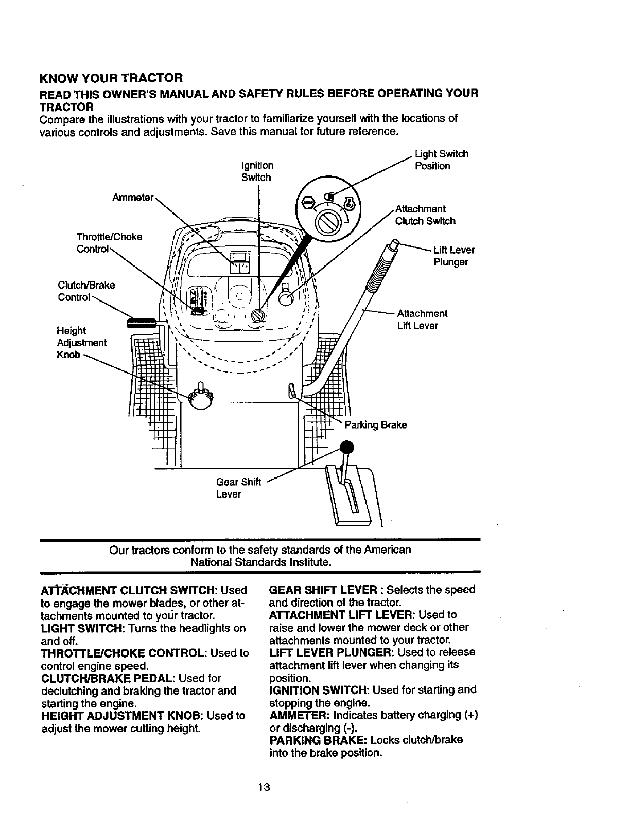
KNOW YOUR TRACTOR
READ THIS OWNER'S MANUAL AND SAFETY RULES BEFORE OPERATING YOUR
TRACTOR
Compare the illustrations with your tractor to familiarize yourself with the locations of
various controls and adjustments. Save this manual for future reference.
Ignition
Switch
LightSwitch
Position
Throttle/Choke
Clutch/Brake '\f'_t_
Height '
Adjustment . , .
Clutch Switch
Plunger
Attachment
LiftLever
Brake
Gear Shift
Lever
Our tractors conform to the safety standards of the American
National Standards Institute.
A'II"._Cl-IMENT CLUTCH SWITCH: Used
to engage the mower blades, or other at-
tachments mounted to yotJr tractor.
LIGHT SWITCH: Turns the headlights on
and off.
THROTTLE/CHOKE CONTROL: Used to
control engine speed.
CLUTCH/BRAKE PEDAL: Used for
declutching and braking the tractor and
starting the engine.
HEIGHT ADJUSTMENT KNOB: Used to
adjust the mower cutting height.
GEAR SHIFT LEVER : Selects the speed
and direction of the tractor.
ATTACHMENT LIFT LEVER: Used to
raise and lower the mower deck or other
attachments mounted to your tractor.
LIFT LEVER PLUNGER: Used to release
attachment lift lever when changing its
position.
IGNITION SWITCH: Used for starting and
stopping the engine.
AMMETER: Indicates battery charging (+)
or discharging (-),
PARKING BRAKE: Locks clutch/brake
into the brake position.
13
I I1_ Theoperationof anytractorcanresultin foreignobjectsthrownintothe I
[---I =- ] eyes, which can result in severe eye damage. Always wear safety glasses |
Wor eye shields while operating your tractor or performing any adjustments or |
repairs. We recommend a wide vision safety mask over spectacles, or stan- |
dard safety glasses. I
HOW TO USE YOUR TRACTOR
Your tractor is equipped with an operator
presence sensing switch. When engine is
running, any attempt by the operator to
leave the seat without first setting the
parking brake will shut off the engine.
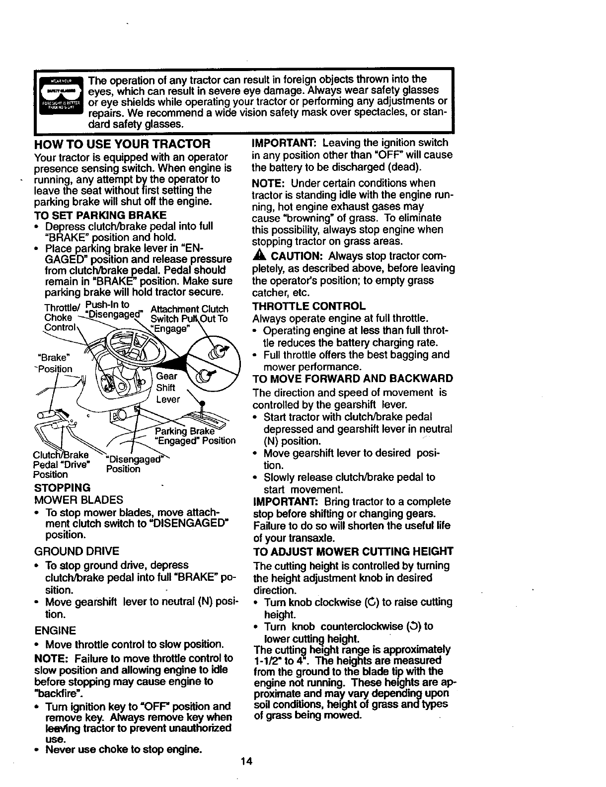
TO SET PARKING BRAKE
• Depress clutch/brake pedal into full
"BRAKE" position and hold.
•Place parking brake lever in =EN-
GAGED" position and release pressure
from clutch/brake pedal. Pedal should
remain in "BRAKE" position. Make sure
parking brake will hold tractor secure.
Throttle/ Push-In to Attachment Clutch
Choke
HarKing_raKe
=Engaged" Position
"Brake"
-Position
Pedal "Ddve" Position
Position
STOPPING
MOWER BLADES
•To stop mower blades, move attach-
ment clutch switch to "DISENGAGED"
position.
GROUND DRIVE
• To stop ground drive, depress
clutch/brake pedal into full "BRAKE" po-
sition.
• Move gearshift lever to neutral (N) posi-
tion.
ENGINE
•Move throttle control to slow position.
NOTE: Failure to move throttle controlto
slow position and allowing engine to idle
before stopping may cause engine to
'%ackfire'.
•Turn ignition key to "OFF" position and
remove key. Always remove key when
leaving tractor to prevent unauthorized
use.
IMPORTANT: Leaving the ignition switch
in any position other than "OFF" will cause
the battery to be discharged (dead).
NOTE: Under certain conditions when
tractor is standing idle with the engine run-
ning, hot engine exhaust gases may
cause "browning" of grass. To eliminate
this possibility, always stop engine when
stopping tractor on grass areas.
_, CAUTION: Always stop tractor com-
pletely, as described above, before leaving
the operator's position; to empty grass
catcher, etc.
THROTTLE CONTROL
Always operate engine at full throttle.
•Operating engine at less than full throt-
tle reduces the battery charging rate.
•Full throttle offers the best bagging and
mower performance.
TO MOVE FORWARD AND BACKWARD
The direction and speed of movement is
controlled by the gearshift lever.
•Start tractor with clutch/brake pedal
depressed and gearshift lever in neutral
(N) position.
•Move gearshift lever to desired posi-
tion.
•Slowly release clutch/brake pedal to
start movement.
IMPORTANT: Bring tractor to a complete
stop before shifting or changing gears.
Failure to do so will shorten the useful life
of your transaxle.
TO ADJUST MOWER CU'I-FING HEIGHT
The cutting height is controlled by turning
the height adjustment knob in desired
direction.
•Turn knob clockwise ((3) to raise cutting
height.
•Tum knob counterclockwise (_)to
lower cutting height.
The cutting height range is approximately
1-1/2" to 4". The heights are measured
from the ground to the blade tip with the
engine not running. These heights are ap-
proximate and may vary depending upon
soil conditions, height of grass and types
of grass being mowed.
•Never use choke to stop engine. 14
•The average lawn should be cut to
approximately 2-1/2 inches during the
cool season and to over 3 inches during
hot months. For healthier and better
looking lawns, mow often and after
moderate growth.
•For best cutting performance, grass
over 6 inches in height should be
mowed twice. Make the first cut rela-
tively high; the second to desired height.
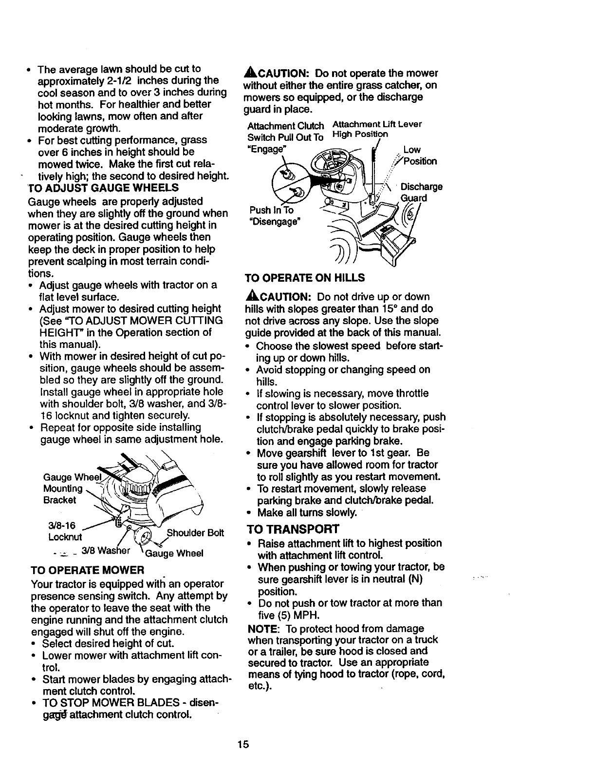
TO ADJUST GAUGE WHEELS
Gauge wheels are propedy adjusted
when they are slightly off the ground when
mower is at the desired cutting height in
operating position. Gauge wheels then
keep the deck in proper position to help
prevent scalping in most terrain condi-
tions.
•Adjust gauge wheels with tractor on a
flat level surface.
• Adjust mower to desired cutting height
(See "TO ADJUST MOWER CUFFING
HEIGHT" in the Operation section of
this manual).
• With mower in desired height of cut po-
sition, gauge wheels should be assem-
bled so they are slightly off the ground.
install gauge wheel in appropriate hole
with shoulder bolt, 3/8 washer, and 3/8-
16 Iocknut and tighten securely.
•Repeat for opposite side installing
gauge wheel in same adjustment hole.
Mounting
Bracket
3/8-16
Locknut Shoulder Bolt
. __ _ 3/8 Washer Gauge Wheel
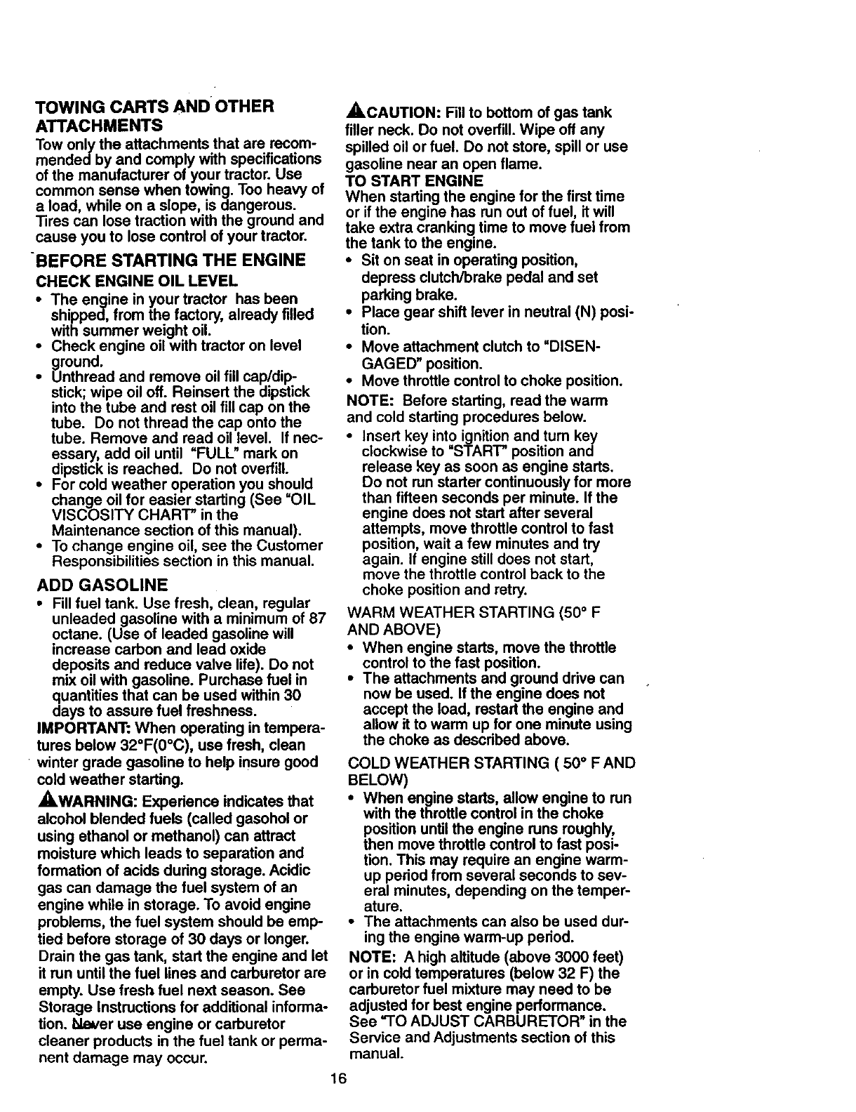
TO OPERATE MOWER
Your tractor is equipped witll an operator
presence sensing switch. Any attempt by
the operator to leave the seat with the
engine running and the attachment clutch
engaged will shut off the engine.
• Select desired height of cut.
•Lower mower with attachment lift con-
trol.
•Start mower blades by engaging attach-
ment clutch control.
•TO STOP MOWER BLADES -disen-
gag_ attachment clutch control.
,_,CAUTION: Do not operate the mower
without either the entire grass catcher, on
mowers so equipped, or the discharge
guard in place.
Attachment Clutch Attachment Uft Lever
Switch Pull Out To High Position
"Enga_ ...., •_, ._.L°w
._Positien
- -7_\ Discharge
_" Guard
Push In To <'-_ I. Y-/_/','_/
=Disengage" _____
ngage" 4
TO OPERATE ON HILLS
_CAUTION: Do not drive up or down
hills with slopes greater than 15 ° and do
not drive across any slope. Use the slope
guide provided at the back of this manual.
•Choose the slowest speed before start-
ing up or down hills.
•Avoid stopping or changing speed on
hills.
• If slowing is necessary, move throttle
control lever to slower position.
•If stopping is absolutely necessary, push
clutch/brake pedal quickly to brake posi-
tion and engage parking brake.
•Move gearshift leverto 1st gear. Be
sure you have allowed room for tractor
to roll slightly as you restart movement.
•To restart movement, slowly release
parking brake and clutch/brake pedal.
•Make all turns slowly.
TO TRANSPORT
•Raise attachment lift to highest position
with attachment lift control.
•When pushing or towing your tractor, be
sure gearshift lever is in neutral (N)
position.
•Do not push or tow tractor at more than
five (5) MPH.
NOTE: To protect hood from damage
when transporting your tractor on a truck
or a trailer, be sure hood is closed and
secured to tractor. Use an appropriate
means of tying hood to tractor (rope, cord,
etc.).
15
TOWING CARTS AND OTHER
ATTACHMENTS
Towonlythe attachmentsthat arerecom-
mendedbyandcomplywithspecifications
of themanufacturerof yourtractor.Use
commonsensewhentowing.Tooheavyof
a load,whileona slope,is dangerous.
Tiroscanlosetractionwiththe groundand
causeyouto losecontrolof yourtractor.
BEFORE STARTING THE ENGINE
CHECK ENGINE OIL LEVEL
•The engine in your tractor has been
shipped, from the factory, already filled
with summer weight oil.
•Check engine oil with tractor on level
ground.
•Unthread and remove oil fill cap/dip-
stick; wipe oil off. Reinsert the dipstick
into the tube and rest oil fill cap on the
tube. Do not thread the cap onto the
tube. Remove and road oil level. If nec-
essary, add oil until =FULL" mark on
dipstick is reached. Do not overfill.
•For cold weather operation you should
change oil for easier starting (See =OIL
VISCOSITY CHART" in the
Maintenance section of this manual).
•To change engine oil, see the Customer
Responsibilities section in this manual.
ADD GASOLINE
•Fill fuel tank. Use fresh, clean, regular
unleaded gasoline with a minimum of 87
octane. (Use of leaded gasoline will
increase carbon and lead oxide
deposits and reduce valve life). Do not
mix oil with gasoline. Purchase fuel in
quantities that can be used within 30
days to assure fuel freshness.
IMPORTANT: When operating in tempera-
turos below 32°F(0°C), use fresh, clean
• winter grade gasoline to help insure good
cold weather starting.
_WARNING: Experience indicates that
alcohol blended fuels (called gasohol or
using ethanol or methanol) can attract
moisture which leads to separation and
formation of acids during storage. Acidic
gas can damage the fuel system of an
engine while in storage. To avoid engine
problems, the fuel system should be emp-
tied before storage of 30 days or longer.
Drain the gas tank, start the engine and let
it run until the fuel lines and carburetor are
empty. Use fresh fuel next season. See
Storage Instructions for additional informa-
tion. bleuer use engine or carburetor
cleaner products in the fuel tank or perma-
nent damage may occur.
_,CAUTION: Fill to bottom of gas tank
filler neck. Do not overfill. Wipe off any
spilled oil or fuel. Do not store, spill or use
gasoline near an open flame.
TO START ENGINE
When starting the engine for the first time
or if the engine has run out of fuel, it will
take extra cranking time to move fuel from
the tank to the engine.
•Sit on seat in operating position,
depress clutch/brake pedal and set
parking brake.
•Place gear shift lever in neutral (N) posi-
tion.
•Move attachment clutch to =DISEN-
GAGED" position.
•Move throttle control to choke position.
NOTE: Before starting, road the warm
and cold starting procedures below.
• Insert key into ignition and turn key
clockwise to "START" position and
release key as soon as engine starts.
Do not run starter continuously for more
than fifteen seconds per minute. If the
engine does not start after several
attempts, move throttle control to fast
position, wait a few minutes and try
again. If engine still does not start,
move the throttle control back to the
choke position and retry.
WARM WEATHER STARTING (50 ° F
AND ABOVE)
•When engine starts, move the throttle
control to the fast position.
•The attachments and ground drive can
now be used. If the engine does not
accept the load, restart the engine and
allow it to warm up for one minute using
the choke as described above.
COLD WEATHER STARTING ( 50 ° F AND
BELOW)
•When engine starts, allow engine to run
with the throttle control in the choke
position until the engine runs roughly,
then move throttle control to fast posi-
tion. This may require an engine warm-
up period from several seconds to sev-
eral minutes, depending on the temper-
ature.
•The attachments can also be used dur-
ing the engine warm-up period.
NOTE: Ahigh altitude (above 3000 feet)
or in cold temperatures (below 32 F) the
carburetor fuel mixture may need to be
adjusted for best engine performance.
See "TO ADJUST CARBURETOR" in the
Service and Adjustments section of this
manual.
16
MOWING TIPS
•Tire chains cannot be used when the
mower housing is attached to tractor.
•Mower should be propedy leveled for
best mowing performance. See =TO
LEVEL MOWER HOUSING" in the
Service and Adjustments section of this
manual.
•The left hand side of mower should be
used for trimming.
•Drive so that clippings are discharged
onto the area that has been cut. Have
the cut area to the right of the tractor.
This will result in amore even distribu-
tion of clippings and more uniform cut-
ting.
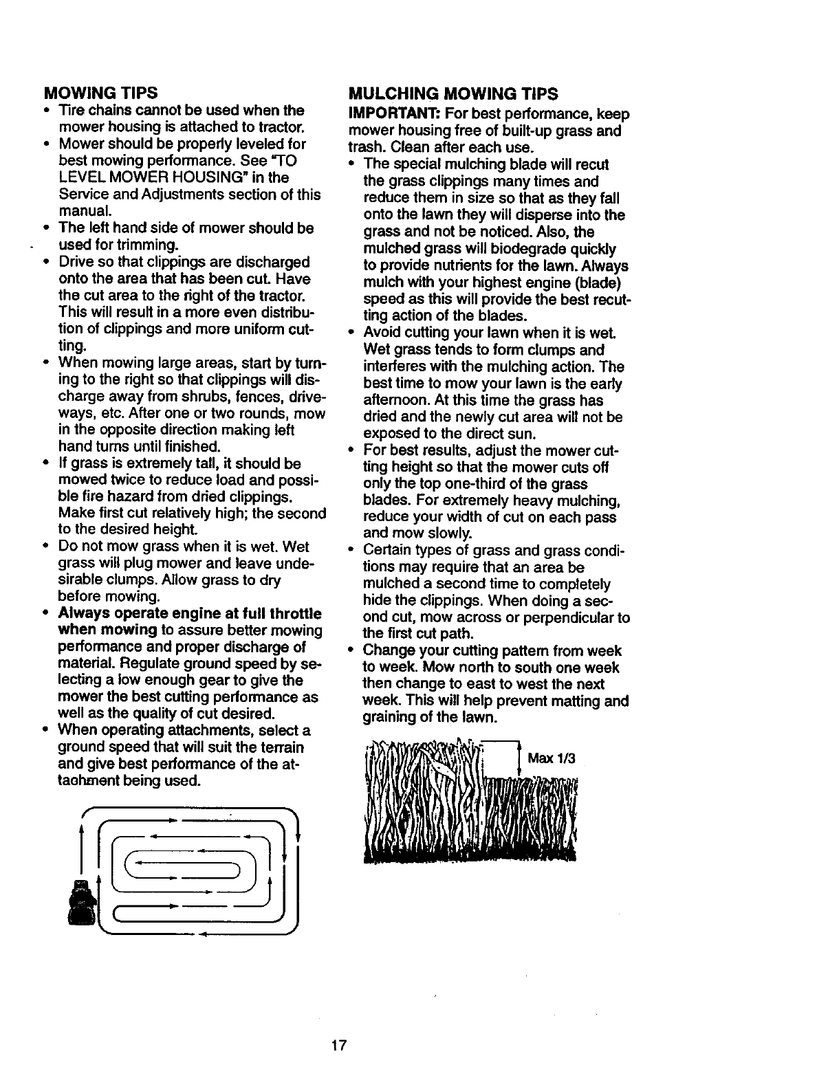
•When mowing large areas, start by tum-
ing to the right so that clippings will dis-
charge away from shrubs, fences, drive-
ways, etc. After one or two rounds, mow
in the opposite direction making left
hand turns until finished.
• If grass is extremely tall, it should be
mowed twice to reduce load and possi-
ble fire hazard from dried clippings.
Make first cut relatively high; the second
to the desired height.
• Do not mow grass when it is wet. Wet
grass will plug mower and leave unde-
sirable clumps. Allow grass to dry
before mowing.
•Always operate engine at full throttle
when mowing to assure better mowing
performance and proper discharge of
material. Regulate ground speed by se-
lecting a low enough gear to give the
mower the best cutting performance as
well as the quality of cut desired.
•When operating attachments, select a
ground speed that will suit the terrain
and give best performance of the at-
taohment being used.
f
|4/
MULCHING MOWING TIPS
IMPORTANT: For best performance, keep
mower housing free of built-up grass and
trash. Clean after each use.
•The special mulching blade will recut
the grass clippings many times and
reduce them in size so that as they fall
onto the lawn they will disperse into the
grass and not be noticed. Also, the
mulched grass will biodegrade quickly
to provide nutrients for the lawn. Always
mulch with your highest engine (blade)
speed as this will provide the best recut-
ting action of the blades.
•Avoid cutting your lawn when it is wet.
Wet grass tends to form clumps and
interferes with the mulching action. The
best time to mow your lawn is the early
aftemoon. At this time the grass has
dried and the newly cut area will not be
exposed to the direct sun.
•For best results, adjust the mower cut-
ting height so that the mower cuts off
only the top one-third of the grass
blades. For extremely heavy mulching,
reduce your width of cut on each pass
and mow slowly.
•Certain types of grass and grass condi-
tions may require that an area be
mulched a second time to completely
hide the clippings. When doing a sec-
ond cut, mow across or perpendicular to
the first cut path.
•Change your cutting pattem from week
to week. Mow north to south one week
then change to east to west the next
week. This will help prevent matting and
graining of the lawn.
', i
17
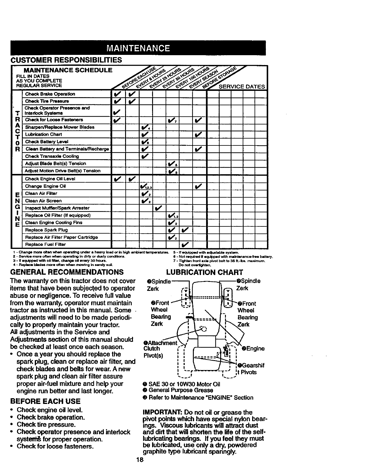
CUSTOMER RESPONSIBILITIES
FILL IN DATES
AS.OOCO- . ....
DATES
: Check Brake Operation _
Check Tim Pm_um
Interlock Systems
Check for Loose Fasteners I_7 If
A i ShsrperdReplace M°wer Blades _"
Lubdcation Chart
oT Check Battery Level _s
R!Clmm Battery and Ten_inaL_lecl'_r_ _
Check T.m_ C_,ng II,/'
Adjust Blade Belt(s) Tension fl_s
v'0Adjust Motion Drive Belt(s) Tension
Check Engine Oil Level V' I_
Change Engine Oil _1.2_3 V_
E Clean Air Filter
NClean Air Screen
Inspect Muffler/Spark Attester If
Replace Oil Filter (If equipped) 1_1.2
NClean Engine C°°ting Fins _=
Replace Spark Plug If
Replace Air Filter Paper Cartridge V'_
Replace Fuel Filter If
2 - Serv;ce more often when openltJng in dir_ or d4,mty con_tk)ns.
3 - If equlpped wi_1 oU fli1_r, change oil evm'y 50 hours.
4 - Replace b4ade4more oftqmwhen mowlng in =andy =o_.
GENERAL RECOMMENDATIONS
1-Change mole often when opet'abng under a heavy load or in h4gh ambient temperatures. $ - If ecFdpped with i_ustltble system.
6- Not required if equipped with rnalntenar_e-fTse batter/.
7 o TH_hten front axle pivot bolt to 35 ft,-Ibs, maximum.
DO not overUg_ton,
The warranty on this tractor does not cover
items that have been subjected to operator
abuse or negligence. To receive full value
from the warranty, operator must maintain
tractor as instructed in this manual. Some
adjustments will need to be made periodi-
cally to properly maintain your tractor.
All adjustments in the Service and
Adjustmeats section of this manual should
be checked at least once each season.
• Once ayear you should replace the
spark plug, clean or replace air filter, and
check blades and belts for wear. A new
spark plug and clean air filter assure
proper air-fuel mixture end help your
engine run better and last longer.
BEFOREEACH USE
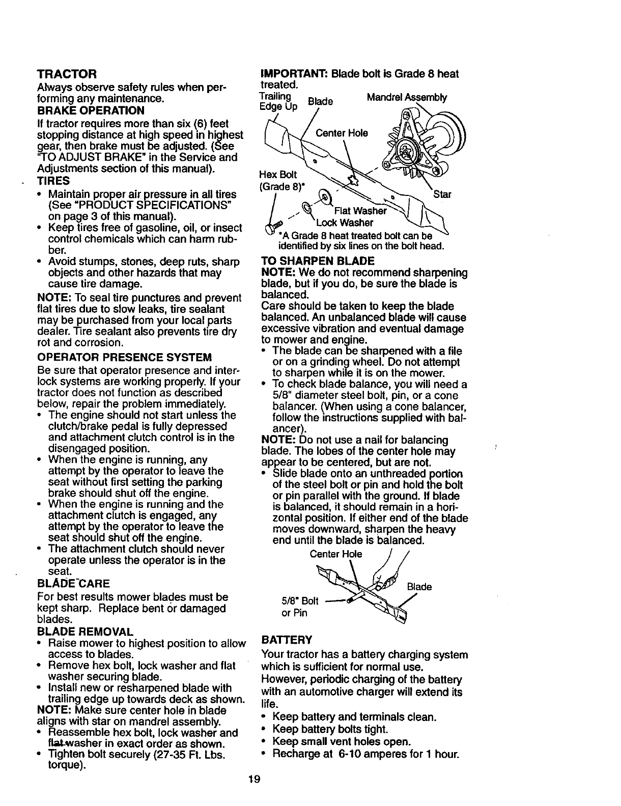
LUBRICATION CHART
• Spindle--
Zerk _7,
eFmnt
Wheel -'.
Zerk ,'_
eAttachment .
Clutch
Pivot(s)
m_=_ --e_ pindle
r'_J-"ewF_e_t
I_a_ng
_-5 eEngine
- - - = = = _--,._ II
I,_ OGearshif
_'_'m'vm'w_-- "r -- ';' I'
,t Pivots
O SAE 30 or 10W30 Motor Oil
• General Purpose Grease
• Refer to Maintenance "ENGINE" Section
•Check engine oil level.
•Check brake operation.
•Check tire pressure.
•Check operator presence and interlock
systen_ for proper operation.
•Check for loose fasteners.
IMPORTANT: Do not oil or grease the
pivot points which have special nylon bear-
gs. V'kscous lubricants will attract dust
and dirt that will shorten the life of the self-
lubricating beadngs. If you feel they must
be lubricated, use only a dn/, powdered
graphite type lubricant spanngly.
18
TRACTOR
Alwaysobservesafetyruleswhenper-
forming any maintenance.
BRAKE OPERATION
If tractor requires more than six (6) feet
stopping distance at high speed in highest
gear, then brake must be adjusted. (See
"TO ADJUST BRAKE" in the Service and
Adjustments section of this manual).
TIRES
•Maintain proper air pressure in all tires
(See "PRODUCT SPECIFICATIONS"
on page 3 of this manual).
• Keep tires free of gasoline, oil, or insect
control chemicals which can harm rub-
ber.
• Avoid stumps, stones, deep ruts, sharp
objects and other hazards that may
cause tire damage.
NOTE: To seal tire punctures and prevent
flat tires due to slow leaks, tire sealant
may be purchased from your local parts
dealer. Tire sealant also prevents tire dry
rot and corrosion.
OPERATOR PRESENCE SYSTEM
Be sure that operator presence and inter-
lock systems are working properly. If your
tractor does not function as described
below, repair the problem immediately.
• The engine should not start unless the
clutch/brake pedal is fully depressed
and attachment clutch control is in the
disengaged position.
•When the engine is running, any
attempt by the operator to leave the
seat without first setting the parking
brake should shut off the engine.
• When the engine is running and the
attachment clutch is engaged, any
attempt by the operator to leave the
seat should shut off the engine.
•The attachment clutch should never
operate unless the operator is in the
seat.
BLADE-CARE
For best results mower blades must be
kept sharp. Replace bent or damaged
blades.
BLADE REMOVAL
•Raise mower to highest position to allow
access to blades.
•Remove hex bolt, lock washer and flat
washer securing blade.
•Install new or resharpened blade with
trailing edge up towards deck as shown.
NOTE: Make sure center hole in blade
aligns with star on mandrel assembly.
•Reassemble hex bolt, lock washer and
flaLwasher in exact order as shown.
• Tighten bolt securely (27-35 Ft. Lbs.
torque).
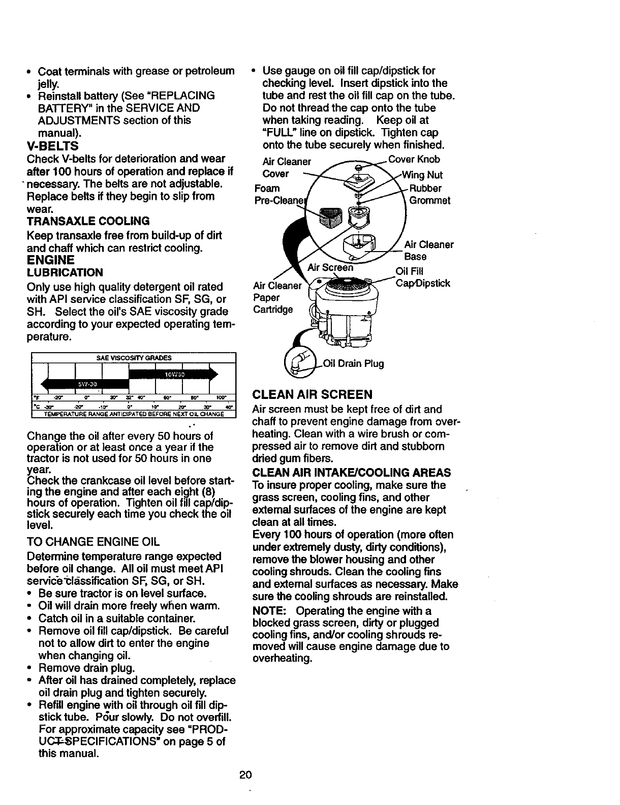
IMPORTANT: Blade bolt is Grade 8 heat
treated.
Trailing Mandrel Assembly
Edge Up Blade
Hex Bolt
(GTde 8;_._ _,at Washe, Star
_*A GradL_ke_t_:lred bolt can bi
identified by six lines on the bolt head.
TO SHARPEN BLADE
NOTE" We do not recommend sharpening
blade, but if you do, be sure the blade is
balanced.
Care should be taken to keep the blade
balanced. An unbalanced blade will cause
excessive vibration and eventual damage
to mower and engine.
•The blade canbe sharpened with a tile
or on a grinding wheel. Do not attempt
to sharpen while it is on the mower.
•To check blade balance, you will need a
5/8" diameter steel bolt, pin, or a cone
balancer. (When using a cone balancer,
follow the instructions supplied with bal-
ancer).
NOTE: Do not use a nail for balancing
blade. The lobes of the center hole may
appear to be centered, but are not.
•Slide blade onto an unthreaded portion
of the steel bolt or pin and hold the bolt
or pin parallel with the ground. If blade
is balanced, it should remain in a hori-
zontal position. If either end of the blade
moves downward, sharpen the heavy
end until the blade is balanced.
Center Hole
5/8" Bolt
or Pin
Blade
BATTERY
Your tractor has abattery charging system
which is sufficient for normal use.
However, periodic charging of the battery
with an automotive charger will extend its
life.
•Keep battery and terminals clean.
•Keep battery bolts tight.
•Keep small vent holes open.
•Recharge at 6-10 amperes for I hour.
19
•Coat terminals with grease or petroleum
jelly.
•Reinstall battery (See =REPLACING
BATTERY" in the SERVICE AND
ADJUSTMENTS section of this
manual).
V-BELTS
Check V-belts for deterioration and wear
after 100 hours of operation and replace if
-necessary. The belts are not adjustable.
Replace belts if they begin to slip from
wear.
TRANSAXLE COOLING
Keep transaxle free from build-up of dirt
and chaff which can restrict cooling.
ENGINE
LUBRICATION
Only use high quality detergent oil rated Air I
with API service classification SF, SG, or Paper
SH. Select the oil's SAE viscosity grade Cartridge
according to your expected operating tem-
perature.
Change the oil after every 50 hours of
operation or at least once a year if the
tractor is not used for 50 hours in one
(_ear.
heck the crankcase oil level before start-
ing the engine and after each eight (8)
hours of operation. Tighten oil fill cap/dip-
stick securely each time you check the oil
level.
TO CHANGE ENGINE OIL
Determine temperature range expected
before oil change. All oil must meet API
servic-e'i:ldssification SF, SG, or SH.
•Be sure tractor is on level surface.
•Oil will drain more freely when warm.
•Catch oil in a suitable container.
•Remove oil fill cap/dipstick. Be careful
not to allow dirt to enter the engine
when changing oil.
•Remove drain plug.
-After oil has drained completely, replace
oil drain plug and tighten securely.
•Refill engine with oil through oil fill dip-
stick tube. P_ur slowly. Do not overfill.
For approximate capacity see =PROD-
UC.T.._PECIFICATIONS" on page 5 of
this manual.
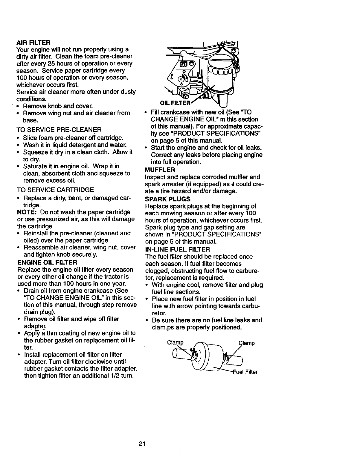
•Use gauge on oil fill cap/dipstick for
checking level. Insert dipstick into the
tube and rest the oil fill cap on the tube.
Do not thread the cap onto the tube
when taking reading. Keep oil at
=FULL _line on dipstick. Tighten cap
onto the tube securely when finished.
Air Cleaner . Cover Knob
Cover Nut
Foam _Rubber
Pre-Cleanel Grommet
Base
Oil Fill
CLEAN AIR SCREEN
Air screen must be kept free of dirt and
chaff to prevent engine damage from over-
heating. Clean with a wire brush or com-
pressed air to remove dirt and stubborn
dried gum fibers.
CLEAN AIR INTAKE/COOLING AREAS
To insure proper cooling, make sure the
grass screen, cooling fins, and other
extemal surfaces of the engine are kept
clean at all times.
Every 100 hours of operation (more often
under extremely dusty, dirty conditions),
remove the blower housing and other
cooling shrouds. Clean the cooling fins
and extemal surfaces as necessary. Make
sure the cooling shrouds are reinstalled.
NOTE: Operating the engine with a
blocked grass screen, dirty or plugged
cooling fins, and/or cooling shrouds re-
moved will cause engine damage due to
overheating.
2O
AIR FILTER
Yourenginewill notrunproperlyusinga
dirtyairfilter. Cleanthefoampre-cleaner
afterevery25hoursof operationor every
season. Servicepapercartridgeevery
100 hours of operation or every season,
whichever occurs first.
Service air cleaner more often under dusty
conditions.
"•Remove knob and cover.
•Remove wing nut and air cleaner from
base.
TO SERVICE PRE-CLEANER
•Slide foam pre-cleaner off cartridge.
•Wash it in liquid detergent and water.
•Squeeze it dry in a clean cloth. Allow it
to dry.
•Saturate it in engine oil. Wrap it in
clean, absorbent cloth and squeeze to
remove excess oil.
TO SERVICE CARTRIDGE
•Replace a dirty, bent, or damaged car-
tridge.
NOTE: Do not wash the paper cartridge
or use pressurized air, as this will damage
the cartridge.
•Reinstall the pre-cleaner (cleaned and
oiled) over the paper cartridge.
•Reassemble air cleaner, wing nut, cover
and tighten knob securely.
ENGINE OIL FILTER
Replace the engine oil filter every season
or every other oil change if the tractor is
used more than 100 hours in one year.
•Drain oil from engine crankcase (See
"TO CHANGE ENGINE OIL" in this sec-
tion of this manual, through step remove
drain plug).
•Remove oil filter and wipe off filter
adapter.
•Apply a thin coating of new engine oil to
the rubber gasket on repl_acement oil fil-
ter.
•Install replacement oil filter on filter
adapter. Turn oil filter clockwise until
rubber gasket contacts the filter adapter,
then tighten filter an additional 1/2 turn.
• Fill crankcase with new oil (See =TO
CHANGE ENGINE OIL" in this section
of this manual). For approximate capac-
ity see "PRODUCT SPECIFICATIONS"
on page 5 of this manual.
•Start the engine and check for oil leaks.
Correct any leaks before placing engine
into full operation.
MUFFLER
Inspect and replace corroded muffler and
spark arrester (if equipped) as it could cre-
ate a fire hazard and/or damage.
SPARK PLUGS
Replace spark plugs at the beginning of
each mowing season or after every 100
hours of operation, whichever occurs first.
Spark plug type and gap setting are
shown in "PRODUCT SPECIFICATIONS"
on page 5 of this manual.
IN-LINE FUEL FILTER
The fuel filter should be replaced once
each season. If fuel filter becomes
clogged, obstructing fuel flow to carbure-
tor, replacement is required.
•With engine cool, remove filter and plug
fuel line sections.
•Place new fuel filter in position in fuel
line with arrow pointing towards carbu-
retor.
•Be sure there are no fuel line leaks and
clam.ps are properly positioned.
21
CLEANING
•Clean engine, battery, seat, finish, etc.
of all foreign matter.
•Keep finished surfaces and wheels free
of all gasoline, oil, etc.
•Protect painted surfaces with automo-
tive type wax.
We do not recommend using a garden
hose to clean your tractor unless the elec-
trical system, muffler, air filter and carbure-
tor are covered to keep water out. Water
in engine can result in a shortened engine
life.
A, CAUTION: Before performing any sewice or adjustments:
•Depress clutch/brake pedal fully and set parking brake.
•Place gearshift lever in neutral (N) position.
•Place attachment clutch in =DISENGAGED" position.
•Tum ignition key =OFP and remove key.
•Make sure the blades and all moving pads have completely stopped.
•Disconnect spark plug wire from spark plug and place wire where it cannot come
in contact with plug.
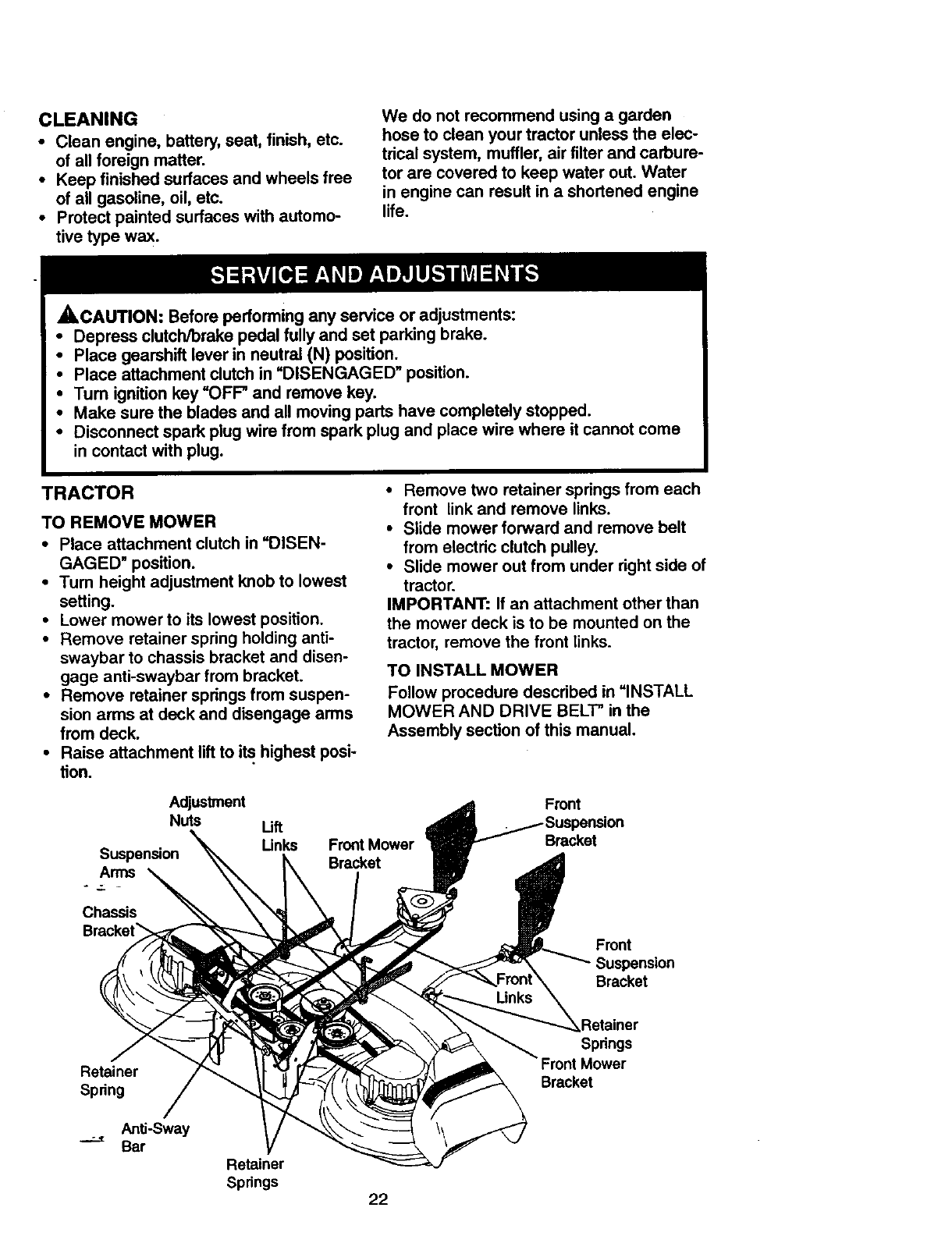
TRACTOR
TO REMOVE MOWER
• Place attachment clutch in =DISEN-
GAGED" position.
•Tum height adjustment knob to lowest
setting.
•Lower mower to its lowest position.
•Remove retainer spring holding anti-
swaybar to chassis bracket and disen-
gage anti-swaybar from bracket.
•Remove retainer springs from suspen-
sion arms at deck and disengage arms
from deck.
•Raise attachment lift to its.highest posi-
tion.
•Remove two retainer springs from each
front link and remove links.
•Slide mower forward and remove belt
from electric clutch pulley.
•Slide mower out from under right side of
tractor.
IMPORTANT: If an attachment other than
the mower deck is to be mounted on the
tractor, remove the front links.
TO INSTALL MOWER
Follow procedure described in =INSTALL
MOWER AND DRIVE BELT" in the
Assembly section of this manual.
Adjustment
Nuts
Suspension
Arms
Chassis
utt
Unks Front Mower
Bracket
Front
Bracket
Front
Suspension
Bracket
Retainer
Spring
Anti-Sway
Bar
Spdngs
Bracket
Retainer
Spdngs 22
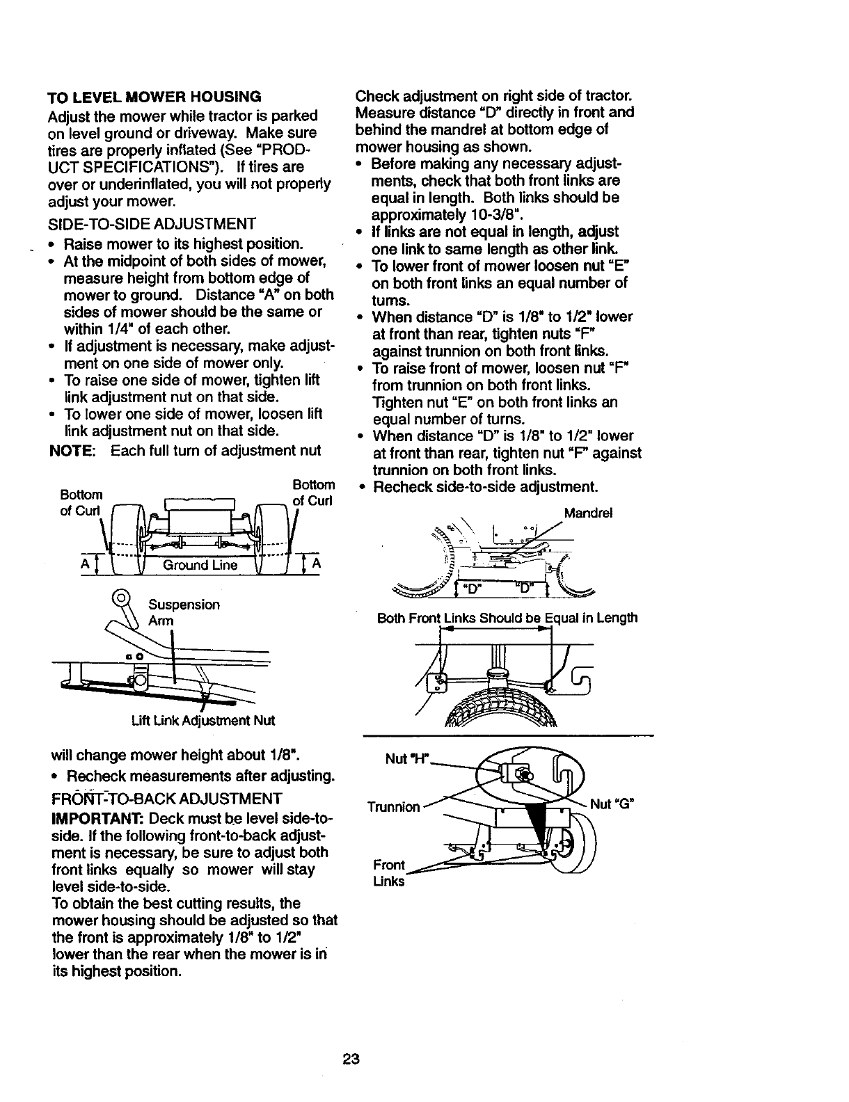
TO LEVEL MOWER HOUSING
Adjust the mower while tractor is parked
on level ground or driveway. Make sure
tires are properly inflated (See =PROD-
UCT SPECIFICATIONS"). If tires are
over or underinflated, you will not properly
adjust your mower.
SIDE-TO-SIDE ADJUSTMENT
•Raise mower to its highest position.
•At the midpoint of both sides of mower,
measure height from bottom edge of
mower to ground. Distance =An on both
sides of mower should be the same or
within 1/4" of each other.
•If adjustment is necessary, make adjust-
ment on one side of mower only.
•To raise one side of mower, tighten lift
link adjustment nut on that side.
•To lower one side of mower, loosen lift
link adjustment nut on that side.
NOTE: Each full turn of adjustment nut
Bottom
Suspension
Arm
Lift Link Adjustment Nut
will change mower height about 1/8".
•Recheck measurements after adjusting.
FRORT-TO-BACK ADJUSTMENT
IMPORTANT: Deck must be level side-to-
side. If the following front-to-back adjust-
ment is necessary, be sure to adjust both
front links equally so mower will stay
level side-to-side.
To obtain the best cutting results, the
mower housing should be adjusted so that
the front is approximately 1/8" to 1/2"
lower than the rear when the mower is in
its highest position.
Check adjustment on right side of tractor.
Measure distance "D" directly in front and
behind the mandrel at bottom edge of
mower housing as shown.
•Before making any necessary adjust-
ments, check that both front links are
equal in length. Both links should be
approximately 10-3/8".
•If links are not equal in length, adjust
one link to same length as other link.
•To lower front of mower loosen nut =E"
on both front links an equal number of
turns.
•When distance =D" is 1/8" to 1/2" lower
at front than rear, tighten nuts =P
against trunnion on beth front links.
•To raise front of mower, loosen nut =P
from trunnion on both front links.
Tighten nut =E" on both front links an
equal number of turns.
•When distance "D" is 1/8" to 1/2" lower
at front than rear, tighten nut "P against
trunnion on both front links.
•Recheck side-to-side adjustment.
Mandrel
I.
Both F_ Length
Nut =1-1"_
Trunnion__Nut =G"
Front '___ '
Links
23
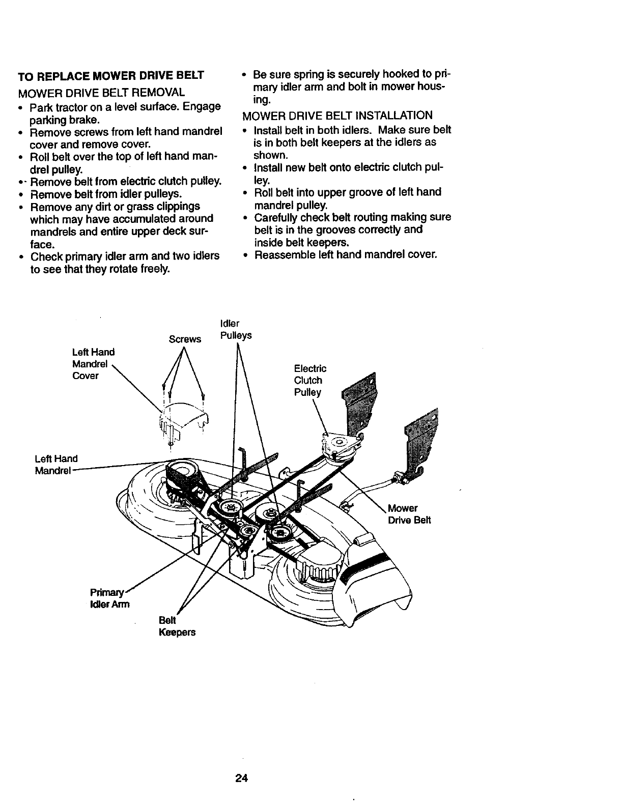
TO REPLACEMOWERDRIVEBELT
MOWER DRIVE BELT REMOVAL
•Park tractor on a level surface. Engage
parking brake.
•Remove screws from left hand mandrel
cover and remove cover.
• Roll belt over the top of left hand man-
drel pulley.
•- Remove belt from electdc clutch pulley.
• Remove belt from idler pulleys.
• Remove any dirt or grass clippings
which may have accumulated around
mandrels and entire upper deck sur-
face.
• Check primary idler arm and two idlers
to see that they rotate freely.
•Be sure spring is securely hooked to pri-
mary idler arm and bolt in mower hous-
ing.
MOWER DRIVE BELT INSTALLATION
•Install belt in both idlers. Make sure belt
is in both belt keepers at the idlers as
shown.
• Install new belt onto electric clutch pul-
ley.
•Roll belt into upper groove of left hand
mandrel pulley.
•Carefully check belt routing making sure
belt is in the grooves correctly and
inside belt keepers.
•Reassemble left hand mandrel cover.
Left Hand
Mandrel
Cover
Screws
Idler
Pulleys
Electric
Clutch
Pulley
Left Hand
Mower
Ddve Belt
Pdmaly
Idler Arm
Belt
Keepers
24
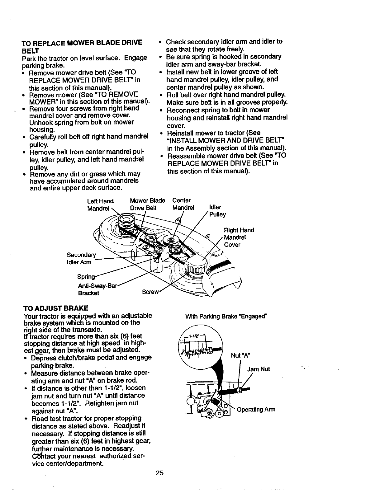
TO REPLACE MOWER BLADE DRIVE
BELT
Park the tractor on level surface. Engage
parking brake.
•Remove mower drive belt (See =TO
REPLACE MOWER DRIVE BELT" in
this section of this manual).
•Remove mower (See =TO REMOVE
MOWER" in this section of this manual).
•Remove four screws from right hand
mandrel cover and remove cover.
Unhook spring from bolt on mower
housing.
•Carefully roll belt off right hand mandrel
pulley.
•Remove belt from center mandrel pul-
ley, idler pulley, and left hand mandrel
pulley.
•Remove any dirt or grass which may
have accumulated around mandrels
and entire upper deck surface.
Left Hand Mower Blade
Mandrel Drive Belt
•Check secondary idler arm and idler to
see that they rotate freely.
•Be sure spring is hooked in secondary
idler arm and sway-bar bracket.
•Install new belt in lower groove of left
hand mandrel pulley, idler pulley, and
center mandrel pulley as shown.
•Roll belt over right hand mandrel pulley.
Make sure belt is in all grooves properly.
•Reconnect spring to bolt in mower
housing and reinstall right hand mandrel
cover.
•Reinstall mower to tractor (See
=INSTALL MOWER AND DRIVE BELl"
in the Assembly section of this manual).
•Reassemble mower drive belt (See =TO
REPLACE MOWER DRIVE BELT" in
this section of this manual).
Center
Mandrel Idler
Secondary
Idler Arm
Right Hand
Cover
Bracket Screw
TO ADJUST BRAKE
Your tractor is equipped with an adjustable
brake system which is mounted on the
right side of the transaxle.
If tractor requires more than six (6) feet
stopping distance at high speed in high-
est gear, then brake must be adjusted.
•Depress clutcWbrake pedal and engage
parking brake.
•Measure distance between brake oper-
ating arm and nut =A" on brake rod.
•If distance is other than 1-1/2", loosen
jam nut and turn nut =An until distance
becomes 1-1/2". Retighten jam nut
against nut =A".
•Road test tractor for proper stopping
distance as stated above. Readjust if
necessary. If stopping distance is still
greater than six (6) feet in highest gear,
further maintenance is necessary.
C'_ntact your nearest authorized ser-
vice center/department.
With Parking Brake =Engaged"
Nut "A"
Jam Nut
Operating Arm
25
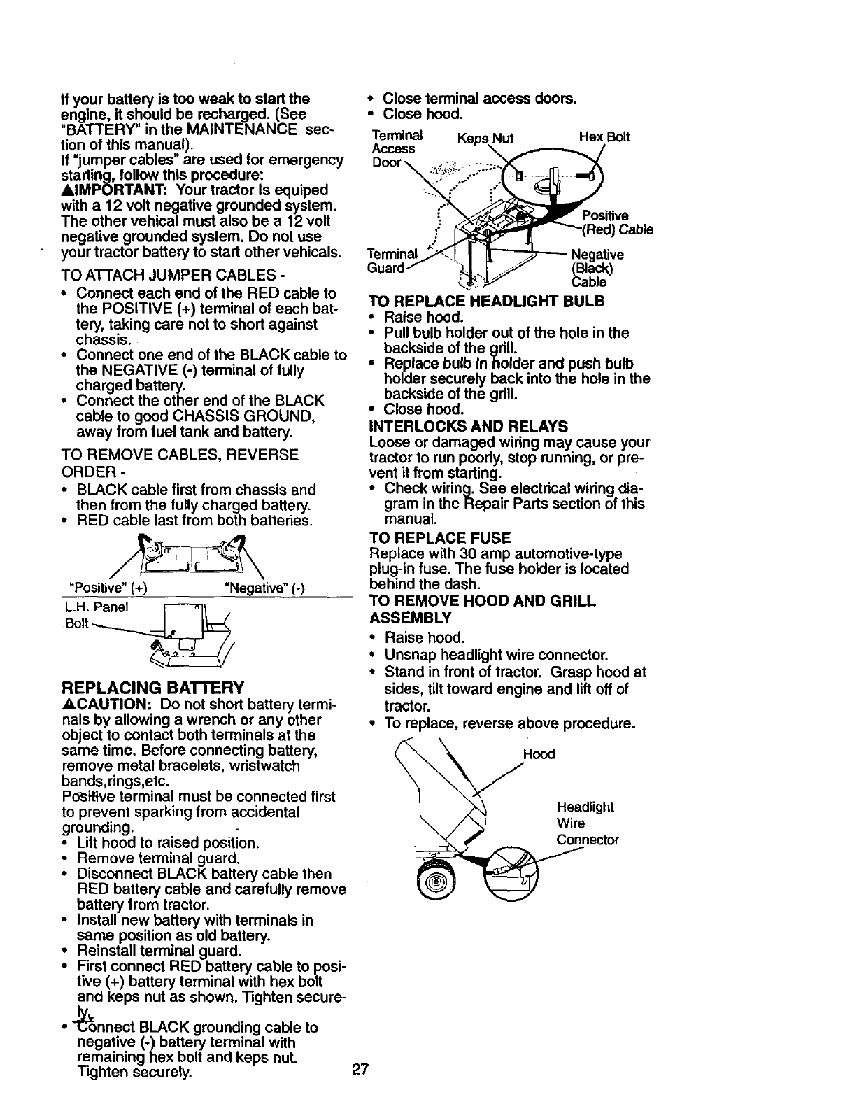
TOREPLACEMOTIONDRIVEBELT
Parkthetractoron levelsurface. Engage
parkingbrake. Forassistance,thereis a
beltinstallationguidedecalonbottomside
of leftfootrest.
• Removemower(See"TO REMOVE
MOWER" in this section of this manual.)
•Disconnect clutch wire harness.
• Remove clutch Iocator.
oRemove belt from Stationary idler and
clutching idler.
•Pull belt slack toward rear of tractor.
Remove belt upwards from trensaxle
pulley by deflecting belt keepers.
•Pull belt toward front of tractor and
remove downwards from around electric
clutch.
•Install new belt by reversing above pro-
cedure.
Electric Clutch Locater
Clutch _/
Station_ _-'_-_ X
>11 c utc,w,rs
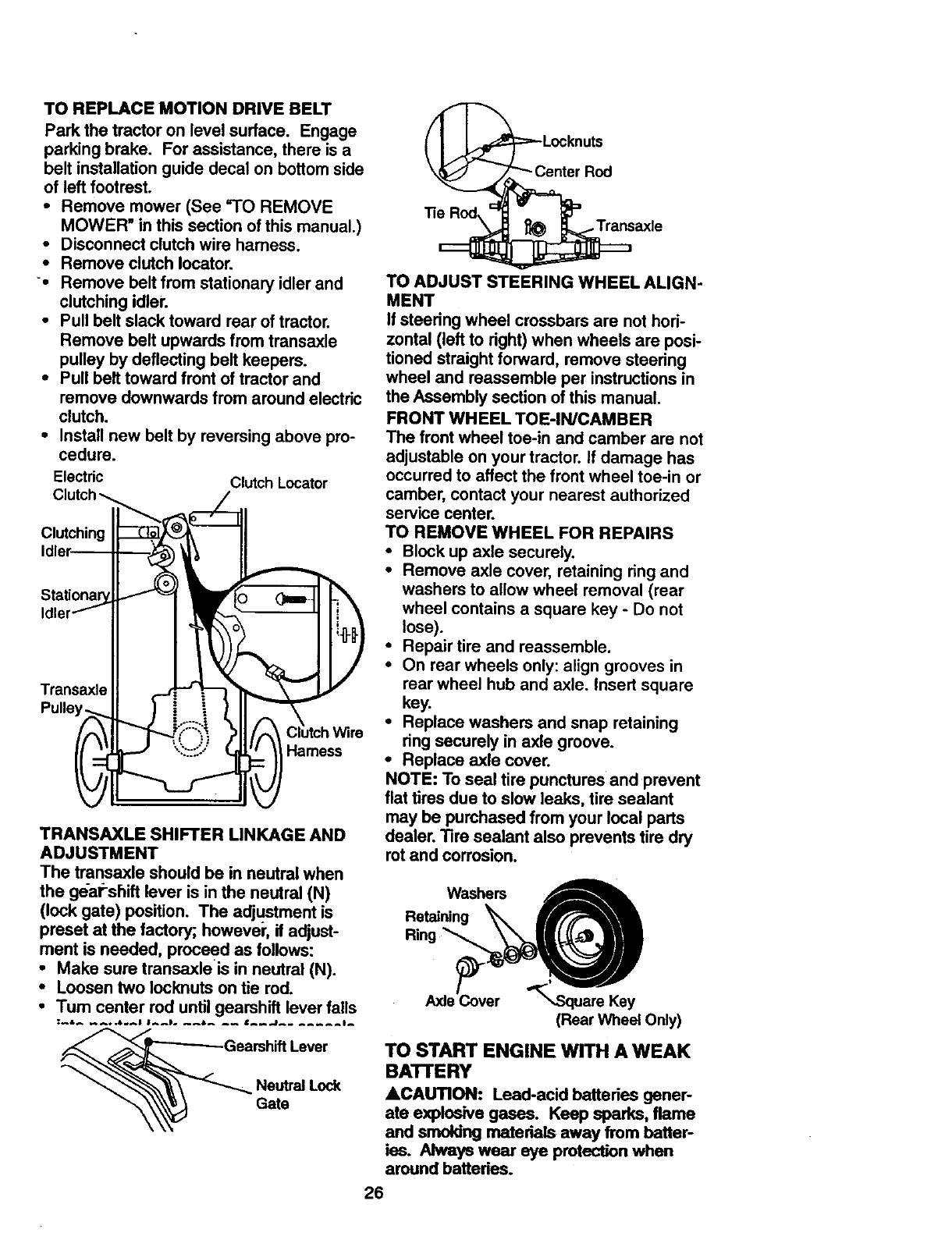
TRANSAXLE SHIFTER LINKAGE AND
ADJUSTMENT
The transaxle should be in neutral when
the ge-al;-shift lever is in the neutral (N)
(lock gate) position. The adjustment is
preset at the factory; howevei', if adjust-
ment is needed, proceed as follows:
•Make sure transaxle is in neutral (N).
•Loosen two Iocknuts on tie rod.
•Tum center rod until gearshift lever falls
Neutral Lock
Gate
"_ Center Rod
TO ADJUST STEERING WHEEL ALIGN-
MENT
If steering wheel crossbars are not hori-
zontal (left to right) when wheels are posi-
tioned straight forward, remove steering
wheel and reassemble per instructions in
the Assembly section of this manual.
FRONT WHEEL TOE-IN/CAMBER
The front wheel toe-in and camber are not
adjustable on your tractor. If damage has
occurred to affect the front wheel toe-in or
camber, contact your nearest authorized
service center.
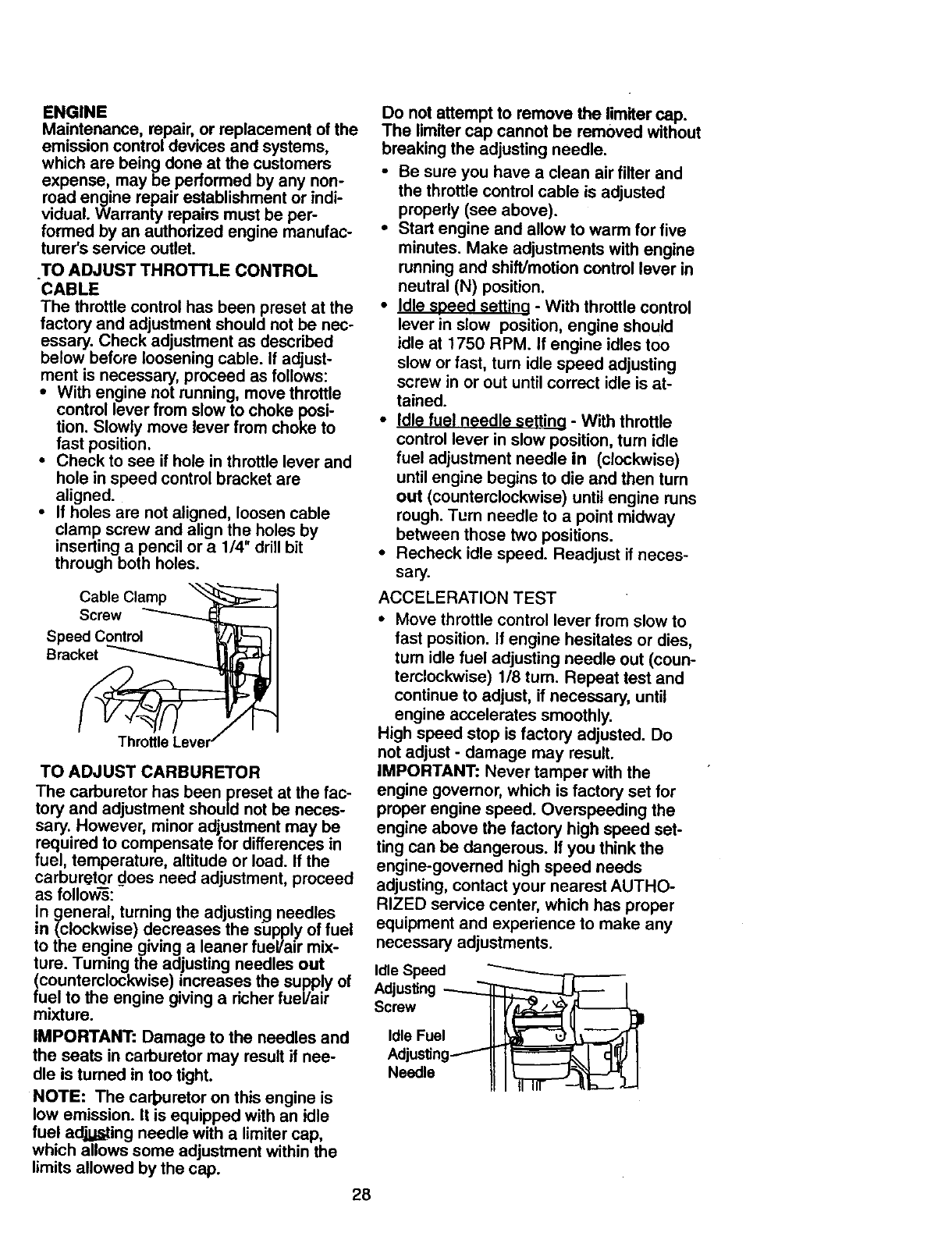
TO REMOVE WHEEL FOR REPAIRS
•Block up axle securely.
•Remove axle cover, retaining ring and
washers to allow wheel removal (rear
wheel contains a square key - Do not
lose).
•Repair tire and reassemble.
•On rear wheels only: align grooves in
rear wheel hub and axle. Insert square
key.
•Replace washers and snap retaining
ring securely in axle groove.
•Replace axle cover.
NOTE: To seal tire punctures and prevent
flat tires due to slow leaks, tire sealant
may be purchased from your local parts
dealer. Tire sealant also prevents tire dry
rot and corrosion.
Washers
Retaining
Rim
AxJe_ver
(Rear Wheel Only)
TO START ENGINE WITH A WEAK
BA'I-rERY
&CAUTION: Lead-acid battedee gener-
ate explo6ive gases. Keep sparks, flame
and smoking materials away from batter-
ies. Always wear eye protection when
around batteries.
26
if yourbatteryistooweakto startthe
engine,it shouldbe recharged.(See
"BATTERY" in the MAINTENANCE sec-
tion of this manual).
If =jumper cables" are used for emergency
starting, follow this procedure:
AIMPORTANT: Your tractor Is equiped
with a 12 volt negative grounded system.
The other vehical must also be a 12 volt
negative grounded system. Do not use
your tractor battery to start other vehicals.
TO ATTACH JUMPER CABLES -
•Connect each end of the RED cable to
the POSITIVE (+) terminal of each bat-
tery, taking care not to short against
chassis.
•Connect one end of the BLACK cable to
the NEGATIVE (-) terminal of fully
charged battery.
•Connect the other end of the BLACK
cable to good CHASSIS GROUND,
away from fuel tank and battery.
TO REMOVE CABLES, REVERSE
ORDER -
• BLACK cable first from chassis and
then from the fully charged battery.
• RED cable last from both batteries.
"Positive" (+) "Negative" (-)
L.H. Panel [---_
Bolt
REPLACING BATTERY
_CAUTION: Do not short battery termi-
nals by allowing a wrench or any other
object to contact both terminals at the
same time. Before connecting battery,
remove metal bracelets, wristwatch
bands,rings,etc.
Posifive terminal must be connected first
to prevent sparking from accidental
grounding.
•Lift hood to raised position.
•Remove terminal guard.
iDisconnect BLACK battery cable then
RED battery cable and carefully remove
battery from tractor.
Install new battery with terminals in
same position as old battery.
•Reinstall terminal guard.
•First connect RED battery cable to posi-
tive (+) battery terminal with hex bolt
and keps nut as shown. Tighten secure-
Iw
• _onnect BLACK grounding cable to
negative (-) battery terminal with
remaining hex bolt and keps nut.
Tighten securely.
•Close terminal access doors.
•Close hood.
Terminal Keps Nut Hex Bolt
Access
Door
Terminal
Guard Cable
TO REPLACE HEADLIGHT BULB
•Raise hood.
•Pull bulb holder out of the hole in the
backside of the grill.
•Replace bulb inholder and push bulb
holder securely back into the hole in the
backside of the grill.
•Close hood.
INTERLOCKS AND RELAYS
Loose or damaged wiring may.cause your
tractor to run poorly, stop running, or pre-
vent it from starting.
•Check wiring. See electrical wiring dia-
gram in the Repair Parts section of this
manual.
TO REPLACE FUSE
Replace with 30 amp automotive-type
plug-in fuse. The fuse holder is located
behind the dash.
TO REMOVE HOOD AND GRILL
ASSEMBLY
• Raise hood.
•Unsnap headlight wire connector.
•Stand in front of tractor. Grasp hood at
sides, tilt toward engine and liftoff of
tractor.
•To replace, reverse above procedure.
Hood
L HeadlightWire
Connector
27
ENGINE
Maintenance,repair,orreplacementofthe
emissioncontroldevicesandsystems,
whicharebeingdoneat thecustomers
expense may be pedormed by any non-
road engine repair establishment or ind -
viduaL Warranty repairs must be per-
formed by an authorized engine manufac-
turer's service outlet.
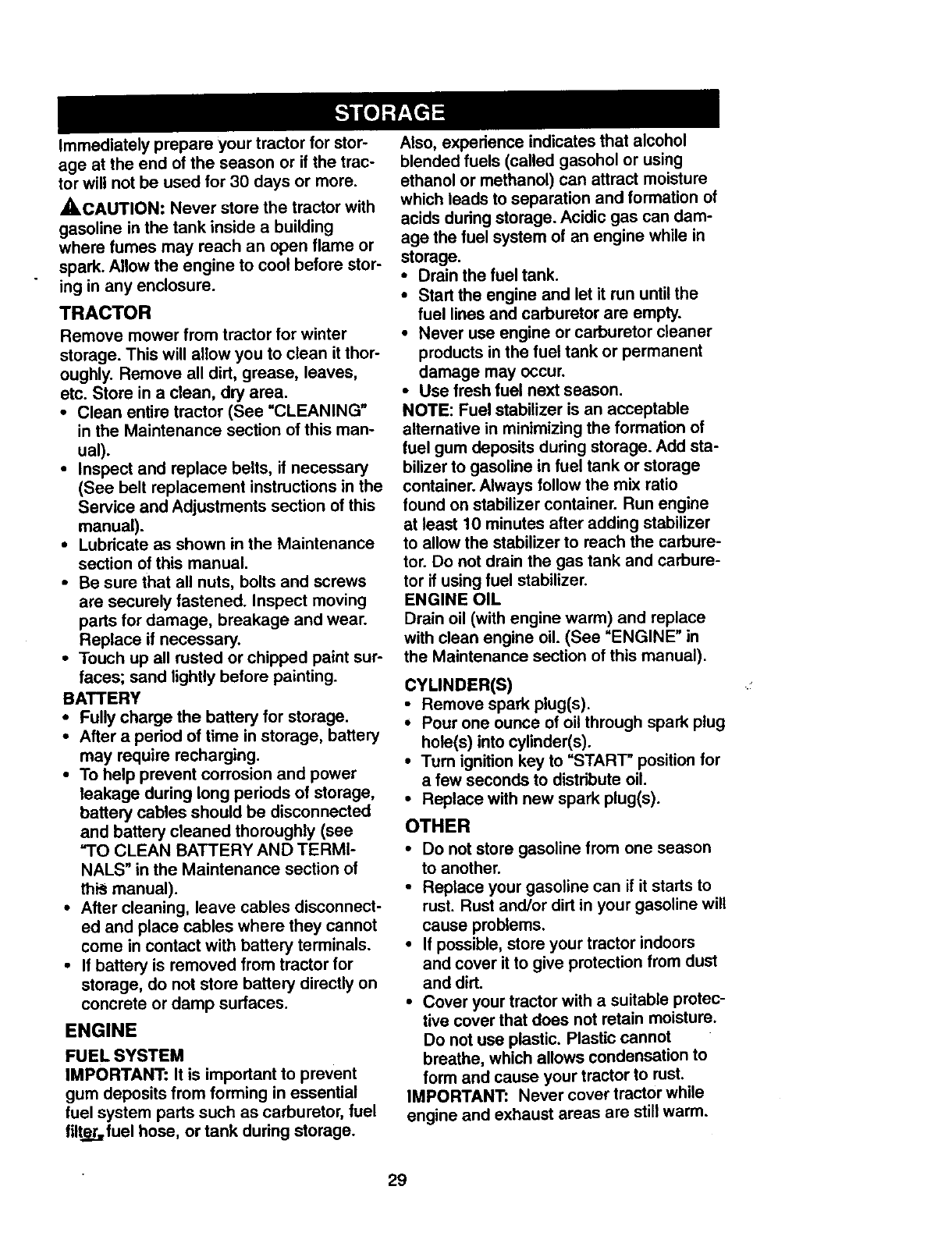
TO ADJUST THROTTLE CONTROL
CABLE
The throttle control has been preset at the
factory and adjustment should not be nec-
essary. Check adjustment as described
below before loosening cable. If adjust-
ment is necessary, proceed as follows:
•With engine not running, move throttle
control lever from slow to choke posi-
tion. Slowly move lever from choke to
fast position.
•Check to see if hole in throttle lever and
hole in speed control bracket are
aligned.
• If holes are not aligned, loosen cable
clamp screw and align the holes by
inserting a pencil or a 1/4" drill bit
through both holes.
Cable Clamp "_
Screw
Speed Control
Bracket
Throttle Lever
TO ADJUSTCARBURETOR
The carburetor has been preset at the fac-
tory and adjustment should not be neces-
sary. However, minor adjustment may be
required to compensate for differences in
fuel, temperature, altitude or load. If the
carburetor does need adjustment, proceed
as follow_:
In general, turning the adjusting needles
in (clockwise) decreases the supply of fuel
to the engine giving a leaner fuel/a=r mix-
ture. Tuming the adjusting needles out
(counterclockwise) increases the supply of
fuel to the engine giving a richer fueVair
mixture.
IMPORTANT: Damage to the needles and
the seats in carburetor may result if nee-
dle is turned in too tight.
NOTE; The ca_uretor on this engine is
low emission. It is equipped with an idle
fuel adjI_,_ting needle with a limiter cap,
which allows some adjustment within the
limits allowed by the cap.
Do not attempt to remove the limiter cap.
The limiter cap cannot be removed without
breaking the adjusting needle.
• Be sure you have a clean air filter and
the throttle control cable is adjusted
properly (see above).
•Start engine and allow to warm for five
minutes. Make adjustments with engine
running and shift/motion control lever in
neutral (N) position.
•Idle speed settina - With throttle control
lever in slow position, engine should
idle at 1750 RPM. If engine idles too
slow or fast, turn idle speed adjusting
screw in or out until correct idle is at-
tained.
•Idle fuel needle settino - With throttle
control lever in slow position, turn idle
fuel adjustment needle in (clockwise)
until engine begins to die and then tum
out (counterclockwise) until engine runs
rough. Turn needle to a point midway
between those two positions.
•Recheck idle speed. Readjust if neces-
sary.
ACCELERATION TEST
• Move throttle control lever from slow to
fast position. If engine hesitates or dies,
tum idle fuel adjusting needle out (coun-
terclockwise) 118 turn. Repeat test and
continue to adjust, if necessary, until
engine accelerates smoothly.
High speed stop is factory adjusted. Do
not adjust - damage may result.
IMPORTANT: Never tamper with the
engine governor, which is factory set for
proper engine speed. Overspeeding the
engine above the factory high speed set-
ting can be dangerous. If you think the
engine-governed high speed needs
adjusting, contact your nearest AUTHO-
RIZED service center, which has proper
equipment and experience to make any
necessary adjustments.
Idle Speed
Adjusting
Screw
Idle Fuel
Needle
28
Immediately prepare your tractor for stor-
age at the end of the season or if the trac-
tor will not be used for 30 days or more.
_,CAUTION: Never store the tractor with
gasoline in the tank inside a building
where fumes may reach an open flame or
spark. Allow the engine to cool before stor-
ing in any enclosure.
TRACTOR
Remove mower from tractor for winter
storage. This will allow you to clean it thor-
oughly. Remove all did, grease, leaves,
etc. Store in a clean, dry area.
• Clean entire tractor (See =CLEANING n
in the Maintenance section of this man-
ual).
•Inspect and replace belts, if necessary
(See belt replacement instructions in the
Service and Adjustments section of this
manual).
•Lubricate as shown in the Maintenance
section of this manual.
•Be sure that all nuts, bolts and screws
are securely fastened. Inspect moving
parts for damage, breakage and wear.
Replace if necessary.
•Touch up all rusted or chipped paint sur-
faces; sand lightly before painting.
BATTERY
•Fully charge the battery for storage.
•After a period of time in storage, battery
may require recharging.
•To help prevent corrosion and power
leakage during long periods of storage,
battery cables should be disconnected
and battery cleaned thoroughly (see
"TO CLEAN BATTERY AND TERMI-
NALS" in the Maintenance section of
this manual).
•After cleaning, leave cables disconnect-
ed and place cables where they cannot
come in contact with battery terminals.
• If battery is removed from tractor for
storage, do not store battery directly on
concrete or damp surfaces.
ENGINE
FUEL SYSTEM
IMPORTANT: It is important to prevent
gum deposits from forming in essential
fuel system parts such as carburetor, fuel
filt._,, fuel hose, or tank during storage.
Also, experience indicates that alcohol
blended fuels (called gasohol or using
ethanol or methanol) can attract moisture
which leads to separation and formation of
acids during storage. Acidic gas can dam-
age the fuel system of an engine while in
storage.
•Drain the fuel tank.
•Start the engine and let it run until the
fuel lines and carburetor are empty.
•Never use engine or carburetor cleaner
products in the fuel tank or permanent
damage may occur.
•Use fresh fuel next season.
NOTE: Fuel stabilizer is an acceptable
alternative in minimizing the formation of
fuel gum deposits during storage. Add sta-
bilizer to gasoline in fuel tank or storage
container. Always follow the mix ratio
found on stabilizer container. Run engine
at least 10 minutes after adding stabilizer
to allow the stabilizer to reach the carbure-
tor. Do not drain the gas tank and carbure-
tor if using fuel stabilizer.
ENGINE OIL
Drain oil (with engine warm) and replace
with clean engine oil. (See =ENGINE" in
the Maintenance section of this manual).
CYLINDER(S)
•Remove spark plug(s).
•Pour one ounce of oil through spark plug
hole(s) into cylinder(s).
•Turn ignition key to =START" position for
a few seconds to distribute oil.
•Replace with new spark plug(s).
OTHER
•Do not store gasoline from one season
to another.
•Replace your gasoline can if it starts to
rust. Rust and/or dirt in your gasoline will
cause problems.
•If possible, store your tractor indoors
and cover it to give protection from dust
and dirt.
•Cover your tractor with a suitable protec-
tive cover that does not retain moisture.
Do not use plastic. Plastic cannot
breathe, which allows condensation to
form and cause your tractor to rust.
IMPORTANT: Never cover tractor while
engine and exhaust areas are still warm.
29
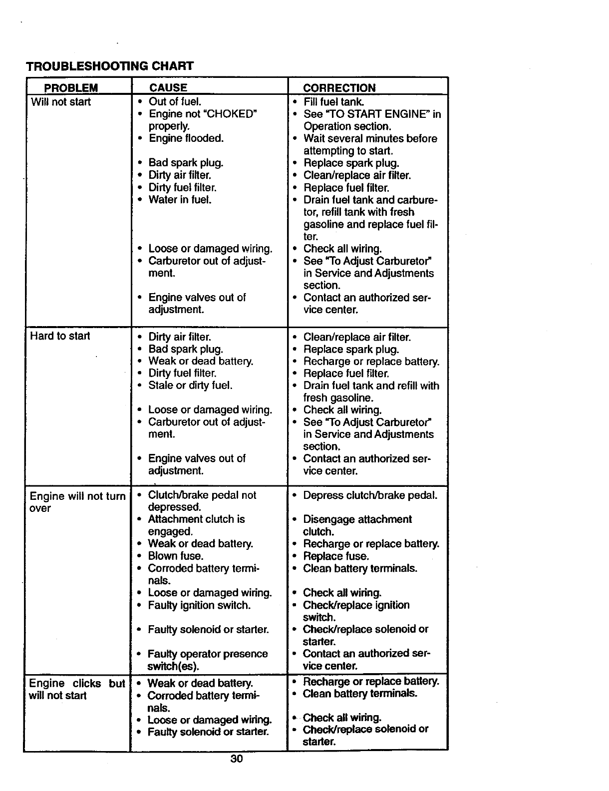
TROUBLESHOOTING CHART
PROBLEM
Will not start
Hard to start
Engine will not turn
over
Engine clicks but:
will not start
!•
CAUSE
Out of fuel.
Engine not "CHOKED"
properly.
Engine flooded.
Bad spark plug.
Dirty air filter.
Dirty fuel filter.
Water in fuel.
Loose or damaged wiring. •
Carburetor out of adjust- •
ment.
Engine valves out of •
adjustment.
Dirty air filter.
Bad spark plug. •
Weak or dead battery.
Dirty fuel filter.
Stale or dirty fuel. •
Loose or damaged wiring. •
Carburetor out of adjust- •
ment.
Engine valves out of •
adjustment.
Clutch/brake pedal not •
depressed.
Attachment clutch is
engaged.
Weak or dead battery.
Blown fuse.
Corroded battery termi-
nals.
CORRECTION
Fill fuel tank.
See ='1"0 START ENGINE" in
Operation section.
Wait several minutes before
attempting to start.
Replace spark plug.
Clean/replace air filter.
Replace fuel filter.
Drain fuel tank and carbure-
tor, refill tank with fresh
gasoline and replace fuel fil-
ter.
Check all wiring.
See "To Adjust Carburetor"
in Service and Adjustments
section.
Contact an authorized ser-
vice center.
Clean/replace air filter.
Replace spark plug.
Recharge or replace battery.
Replace fuel filter.
Drain fuel tank and refill with
fresh gasoline.
Check all wiring.
See "To Adjust Carburetor"
in Service and Adjustments
section.
Contact an authorized ser-
vice center.
Depress clutch/brake pedal.
• Disengage attachment
clutch.
•Recharge or replace battery.
•Replace fuse.
•Clean battery terminals.
Loose or damaged wiring. •Check all wiring,
Faulty ignition switch. •Check/replace ignition
•Faulty solenoid or starter.
•Faulty operator presence
switch(•s).
•Weak or dead battery.
•Corroded battery termi-
nals.
•Loose or damaged wiring.
•Faulty solenoid or starter.
switch.
•Check/replace solenoid or
starter.
• Contact an authorized ser-
vice center.
•Recharge or replace battery.
•Clean battery terminals.
• Check all wiring.
•Cheddreplace solenoid or
starter.
30
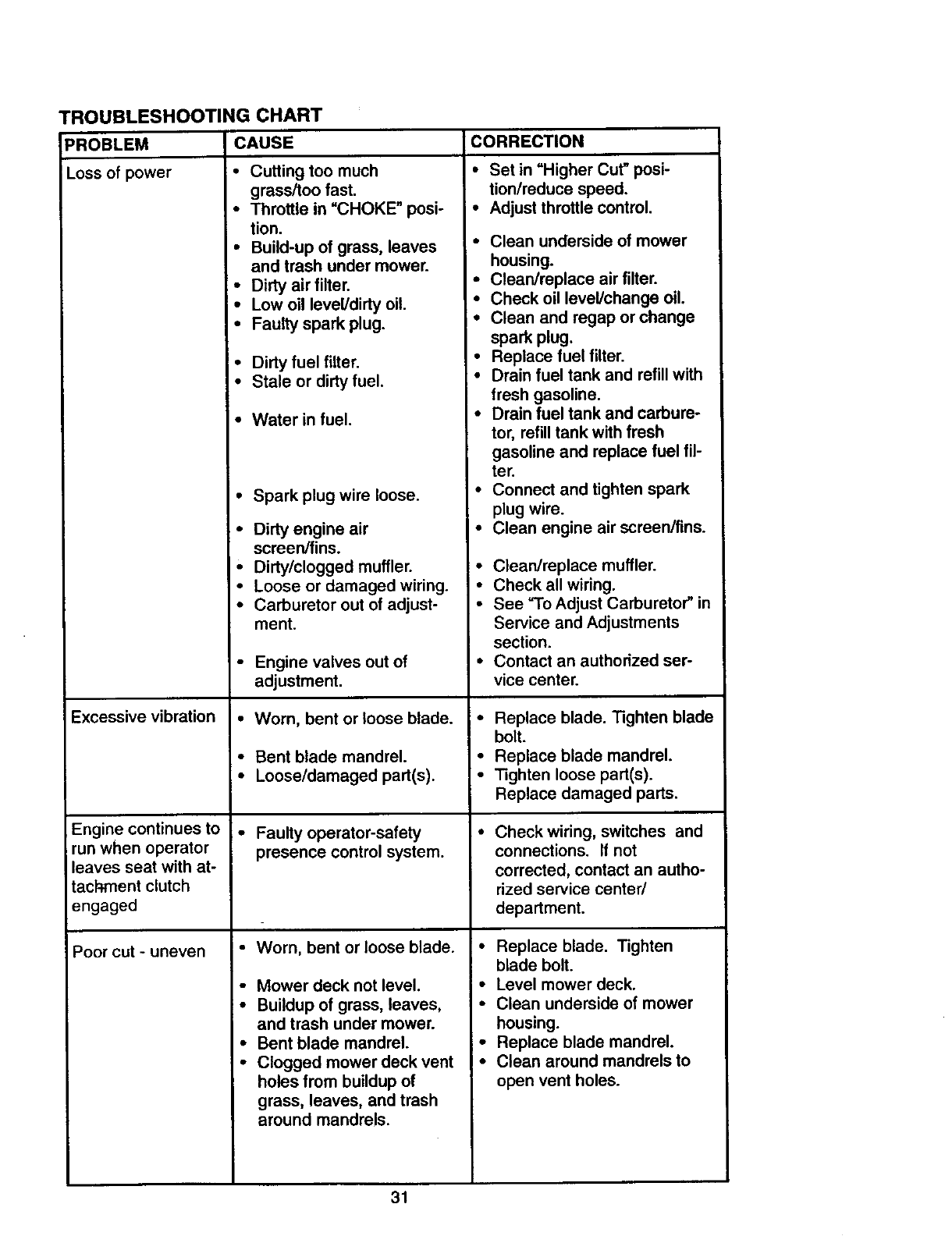
TROUBLESHOOTING CHART
CAUSE
PROBLEM
Lossofpower
Excessive vibration
Engine continues to
run when operator
leaves seat with at-
tachment clutch
engaged
Poor cut - uneven
• Cutting too much
grass/too fast.
• Throttle in "CHOKE" posi-
tion.
•Build-up of grass, leaves
and trash under mower.
• Dirty air filter.
•Low oil level/dirty oil.
•Faulty spark plug.
•Dirty fuel filter.
• Stale or dirty fuel.
•Water in fuel.
•Spark plug wire loose.
•Dirty engine air
screen/fins.
•Dirty/clogged muffler.
•Loose or damaged wiring.
•Carburetor out of adjust-
ment.
•Engine valves out of
adjustment.
•Worn, bent or loose blade.
• Bent blade mandrel.
•Loose/damaged part(s).
•Faulty operator-safety
presence control system.
• Worn, bent or loose blade.
•Mower deck not level.
•Buildup of grass, leaves,
and trash under mower.
•Bent blade mandrel.
•Clogged mower deck vent
holes from buildup of
grass, leaves, and trash
around mandrels.
CORRECTION
•Set in =Higher Cut" posi-
tion/reduce speed.
•Adjust throttle control.
• Clean underside of mower
housing.
• Clean/replace air filter.
•Check oil level/change oil.
•Clean and regap or change
spark plug.
•Replace fuel filter.
•Drain fuel tank and refill with
fresh gasoline.
•Drain fuel tank and carbure-
tor, refill tank with fresh
gasoline and replace fuel fil-
ter.
•Connect and tighten spark
plug wire.
•Clean engine air screen/fins.
• Clean/replace muffler.
• Check all wiring.
• See "To Adjust Carburetor" in
Service and Adjustments
section.
•Contact an authorized ser-
vice center.
•Replace blade. Tighten blade
bolt.
•Replace blade mandrel.
• Tighten loose part(s).
Replace damaged parts.
•Check wiring, switches and
connections. If not
corrected, contact an autho-
rized service center/
department.
• Replace blade. Tighten
blade bolt.
•Level mower deck.
•Clean underside of mower
housing.
=• Replace blade mandrel.
I • Clean around mandrels to
open vent holes.
31
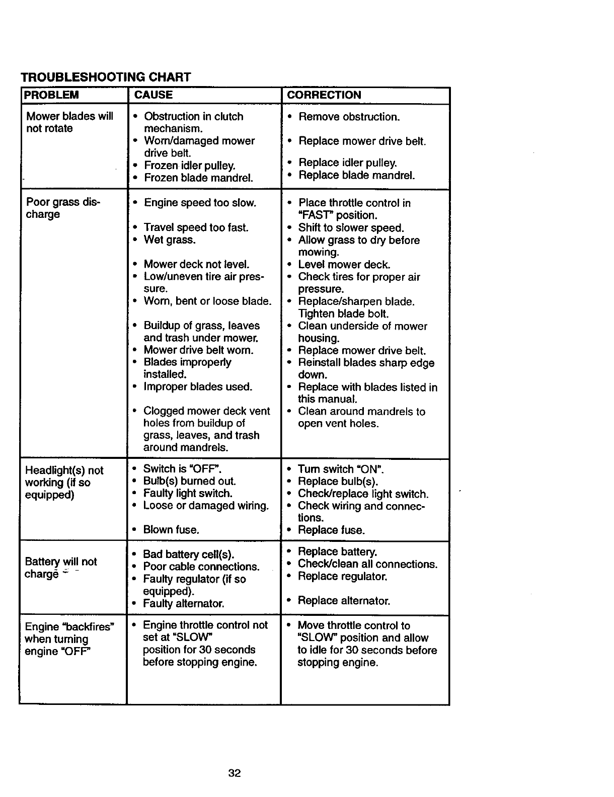
TROUBLESHOOTING CHART
PROBLEM
Mower blades will
not rotate
Poor grass dis-
charge
Headlight(s) not
working (if so
equipped)
Battery will not
charge "=- -
Engine =backfires"
when turning
engine "OFP
CAUSE
• Obstruction in clutch
mechanism.
•Worn/damaged mower
drive belt.
•Frozen idler pulley.
•Frozen blade mandrel.
•Engine speed too slow.
• Travel speed too fast.
•Wet grass.
•Mower deck not level.
•Low/uneven tire air pres-
sure.
•Worn, bent or loose blade.
•Buildup of grass, leaves
and trash under mower.
•Mower drive belt worn.
•Blades improperly
installed.
•Improper blades used.
• Clogged mower deck vent
holes from buildup of
grass, leaves, and trash
around mandrels.
• Switch is "OFP.
•Bulb(s) burned out.
•Faulty light switch.
•Loose or damaged wiring.
•Blown fuse.
• Bad battery cell(s).
•Poor cable connections.
!•Faulty regulator (if so
equipped).
•Faulty altemator.
•Engine throttle control not
set at "SLOW"
position for 30 seconds
before stopping engine.
CORRECTION
•Remove obstruction.
•Replace mower drive belt.
•Replace idler pulley.
•Replace blade mandrel.
• Place throttle control in
"FAST" position.
•Shift to slower speed.
•Allow grass to dry before
mowing.
•Level mower deck.
•Check tires for proper air
pressure.
•Replace/sharpen blade.
Tighten blade bolt.
•Clean underside of mower
housing.
•Replace mower drive belt.
•Reinstall blades sharp edge
down.
•Replace with blades listed in
this manual.
•Clean around mandrels to
open vent holes.
•Turn switch =ON".
•Replace bulb(s).
•Check]replace light switch.
•Check wiring and connec-
tions.
•Replace fuse.
• Replace battery.
•Check]clean all connections.
• Replace regulator.
• Replace alternator.
•Move throttle control to
"SLOW" position and allow
to idle for 30 seconds before
stopping engine.
32
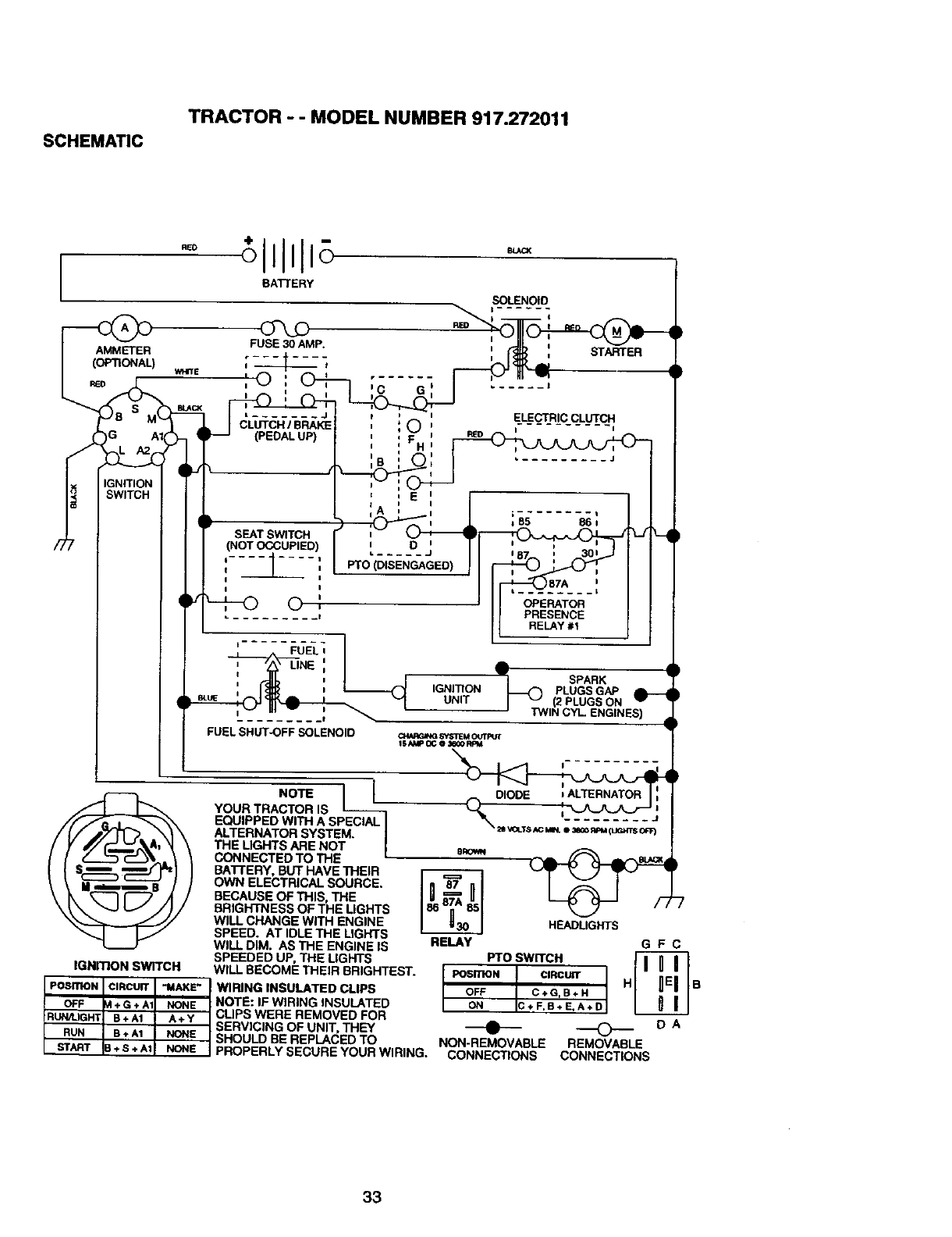
SCHEMATIC TRACTOR -- MODEL NUMBER 917.272011
RED
BATTERY
SOLENOID
FUEL i
,_l LINE',
, -' ____;
FUEL SHUTOFF SOLENOID
IGNmON SWITCH
POSITIONI:IRCUIT "MAKE" I
OFF +G*A1 NONE
RUN/LIGHT B+A1 A+Y
RUN B+ A1 NONE
START + S + A1 NONE
RED
STARTER
A
V •
(_ IGNITION _SPARK
-- PLUGSGAP
UNIT I _(2 PLUGS ON
'TWIN CYL ENGINES)
O,'L4RGINGSYSlrEM ou*rptrr
ISAMP OC 03_ORPM
DIODE JALTERNATOR :
8ROVM
HEADLIGHTS
RELAY G F C
PTO SWITCH
POSITION CIRCUIT H B
OFF C+G,B+H
ON C+F,B+E,A+D
_ DA
NON-REMOVABLE REMOVABLE
CONNECTIONS CONNECTIONS
NOTE 1 I
YOUR TRACTOR IS
EQUIPPED WITH A SPECIAL I
ALTERNATOR SYSTEM. I
THE LIGHTS ARE NOT I
CONNECTED TO THE =
BATTERY, BUT HAVE THEIR
OWN ELECTRICAL SOURCE.
BECAUSE OF THIS, THE
BRIGHTNESS OF THE LIGHTS
WILL CHANGE WITH ENGINE
SPEED. AT IDLE THE LIGHTS
WILL DIM. AS THE ENGINE IS
SPEEDED UP, THE LIGHTS
WILL BECOME THEIR BRIGHTEST.
WIRING INSULATED CUPS
NOTE: IF WIRING INSULATED
CLIPS WERE REMOVED FOR
SERVICING OF UNIT, THEY
SHOULD BE REPLACED TO
PROPERLY SECURE YOUR WIRING.
33
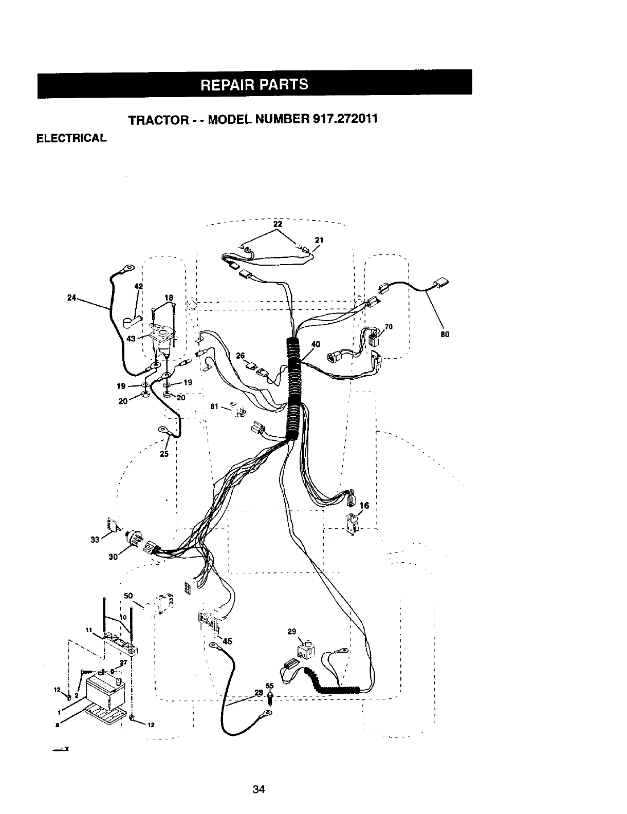
ELECTRICAL
TRACTOR - - MODEL NUMBER 917.272011
21
4O
I
t70
8O
i
34
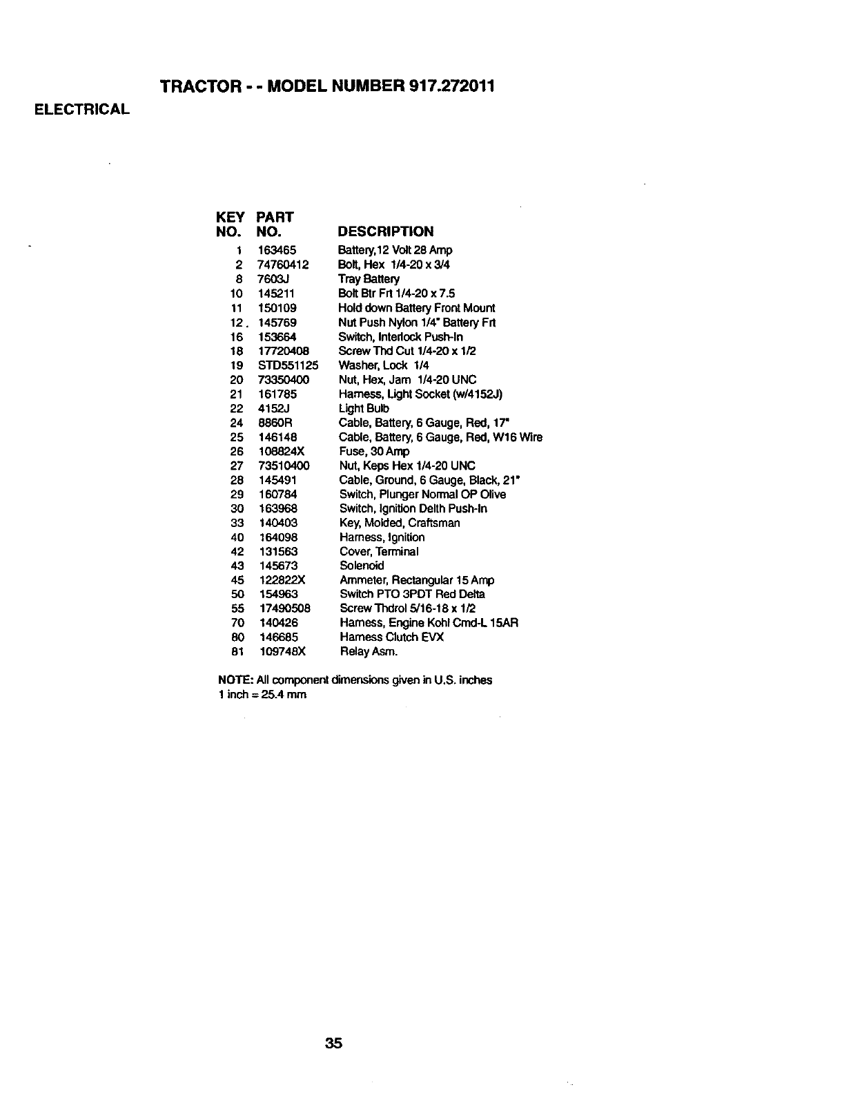
ELECTRICAL
TRACTOR -- MODEL NUMBER 917.272011
KEY PART
NO. NO.
t 163465
2 74760412
8 7603J
10 145211
11 150109
12. 145769
16 153664
18 17720408
19 STD551125
20 73350400
21 161785
22 4152J
24 8860R
25 146148
26 108824X
27 73510400
28 145491
29 160784
30 163968
33 140403
40 164098
42 131563
43 145673
45 122822X
50 154963
55 17490508
70 140426
80 146685
81 109746X
DESCRIPTION
Battery,12Volt28 Amp
Bolt,Hex 114-20x 3/4
Tray Batlery
BoltBtr Frt 1/4-20 x 7.5
Hold downBattery FrontMount
Nut Push Nylon 1/4" BatteryFrt
Switch,IntedockPush-In
Screw TIxI Cut 1/4-20 x 1/2
Washer,Lock 1/4
Nut, Hex,Jam 1/4-20 UNC
Hamess, LightSocket (w/4152J)
LightBulb
Cable, Battery, 6 Gauge, Red, 17'
Cable, Battery, 6 Gauge, Red, W16 Wire
Fuse, 30 Amp
Nut, Keps Hex 1/4-20 UNC
Cable, Ground,6 Gauge,Black, 21•
Switch,PlungerNormal OP Olive
Switch,IgnitionDelth Push-In
Key,Molded,Craftsman
Harness,Ignition
Cover,Terminal
Solenoid
Ammeter,Rectangular15Amp
SwitchPTO 3PDT Red Delta
Screw Thdrol5/16-18 x 1/2
Harness, Engine KohlCmd-L 15AR
Harness ClutchEVX
Relay Asm.
NOTE: All componentdimensionsgivenin U.S. inches
1 inch = 25.4 mm
35
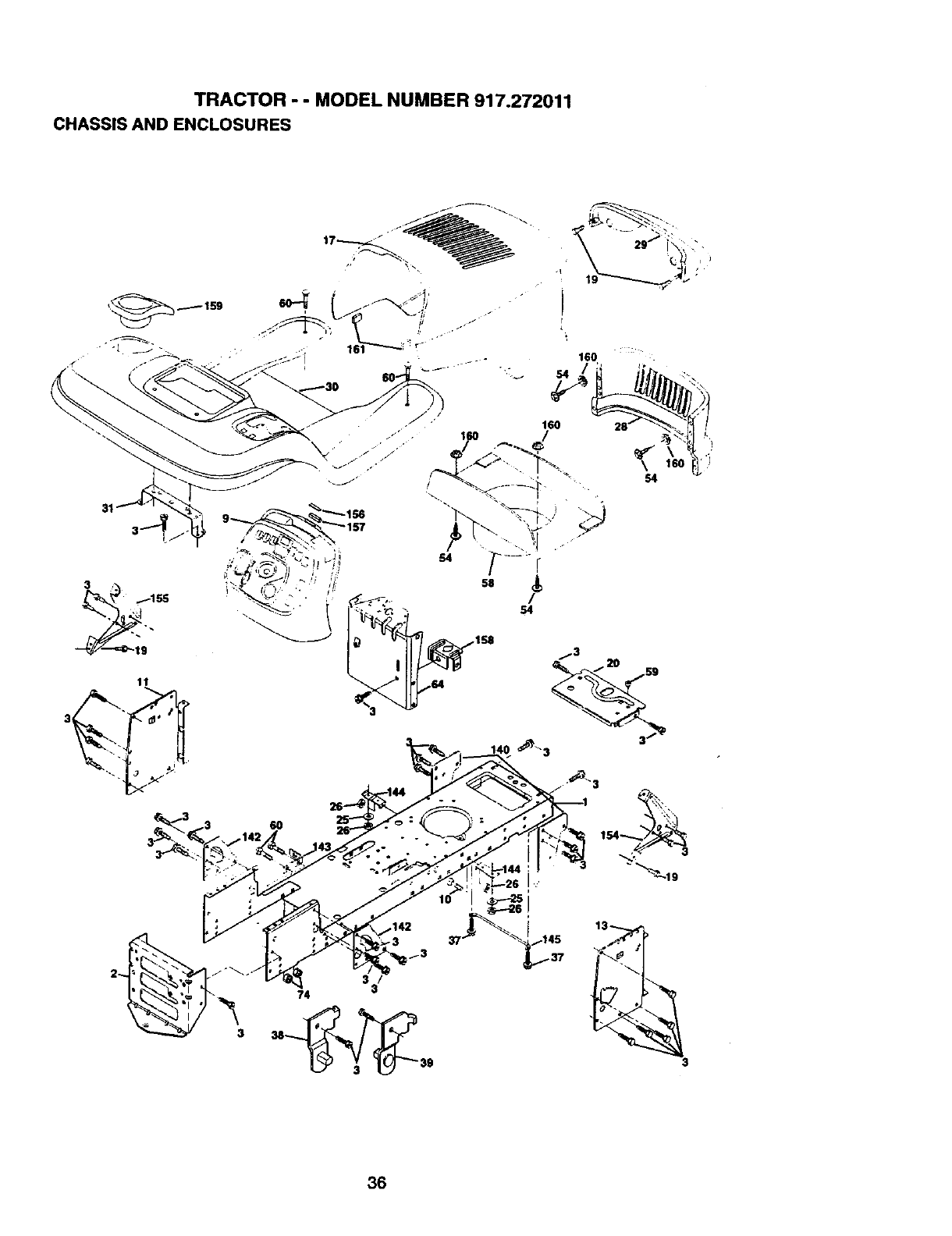
-rRitlcTOR " " MODEL HUMBER 917.27201"1
cHASSIS AHD EHCt.OSURES
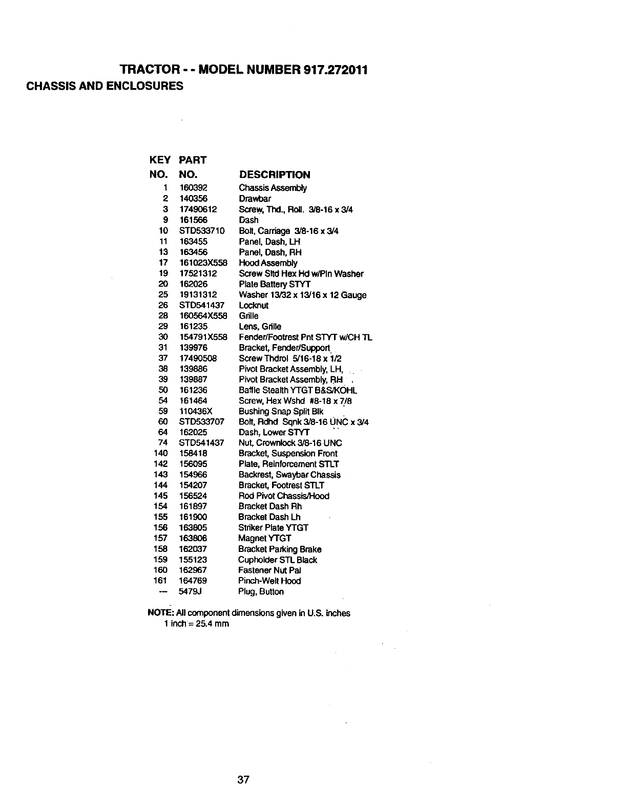
TRACTOR --MODEL NUMBER 917.272011
CHASSIS AND ENCLOSURES
KEY PART
NO. NO. DESCRIPTION
1 160392 ChassisAesembly
2 140356 Drawbar
3 17490612 Screw,Thd., Roll. 3/8-16 x 3/4
9 161566 D3sh
10 STD533710 Bolt,Carriage 3/8-16 x3/4
11 163455 Panel, Dash, LH
13 163456 Panel, Dash, RH
17 161_3X558 HoodAssembly
19 17521312 Screw Slid Hex Hd w/Pin Washer
20 162026 Plate BatterySTYT
25 19131312 Washer 13/32 x 13/16x 12 Gauge
26 STD541437 Locknut
28 160564X558 Grille
29 161235 Lens,Grille
30 154791X558 Fender/FootrestPnt STY'r w/CH TL
31 139976 Bracket,Pender/Suppod.
37 17490508 ScrewThdrol 5/16-18x1F2
38 139886 PivotBracketAssembly,LH, _
39 139887 PivotBracketAssembly,BEI ,
50 161236 BaffleStealthYTGT B&s/KOHL
54 161464 Screw,Hex Wshd #8-18 x 7/'8
59 110436X BushingSnap SplitBIk
60 STD533707 Bolt,RdlxI Sqnk3/8-16UNCx3/4
64 162025 Dash, Lower STYT
74 STD541437 Nut,Crownlock3/8-16 UNC
140 158418 Bracket,SuspensionFront
142 156095 Plate, ReinforcementSTLT
143 154966 Backrest,SwaybarChassis
144 154207 Bracket,FootrestSTLT
145 156524 Rod PivotChassisJHood
154 161897 Bracket Dash Rh
155 161900 Bracket Dash Lh
156 163805 StrikerPlate YTGT
157 163806 Magnet YTGT
158 162037 BracketParkingBrake
159 155123 CupholderSTL Black
160 162967 Fastener Nut Pal
161 164769 Pinch-WeltHood
-- 5479J Plug, Button
NOTE: All componentdimensionsgivenin U.S. inches
1 inch= 25.4 mm
37
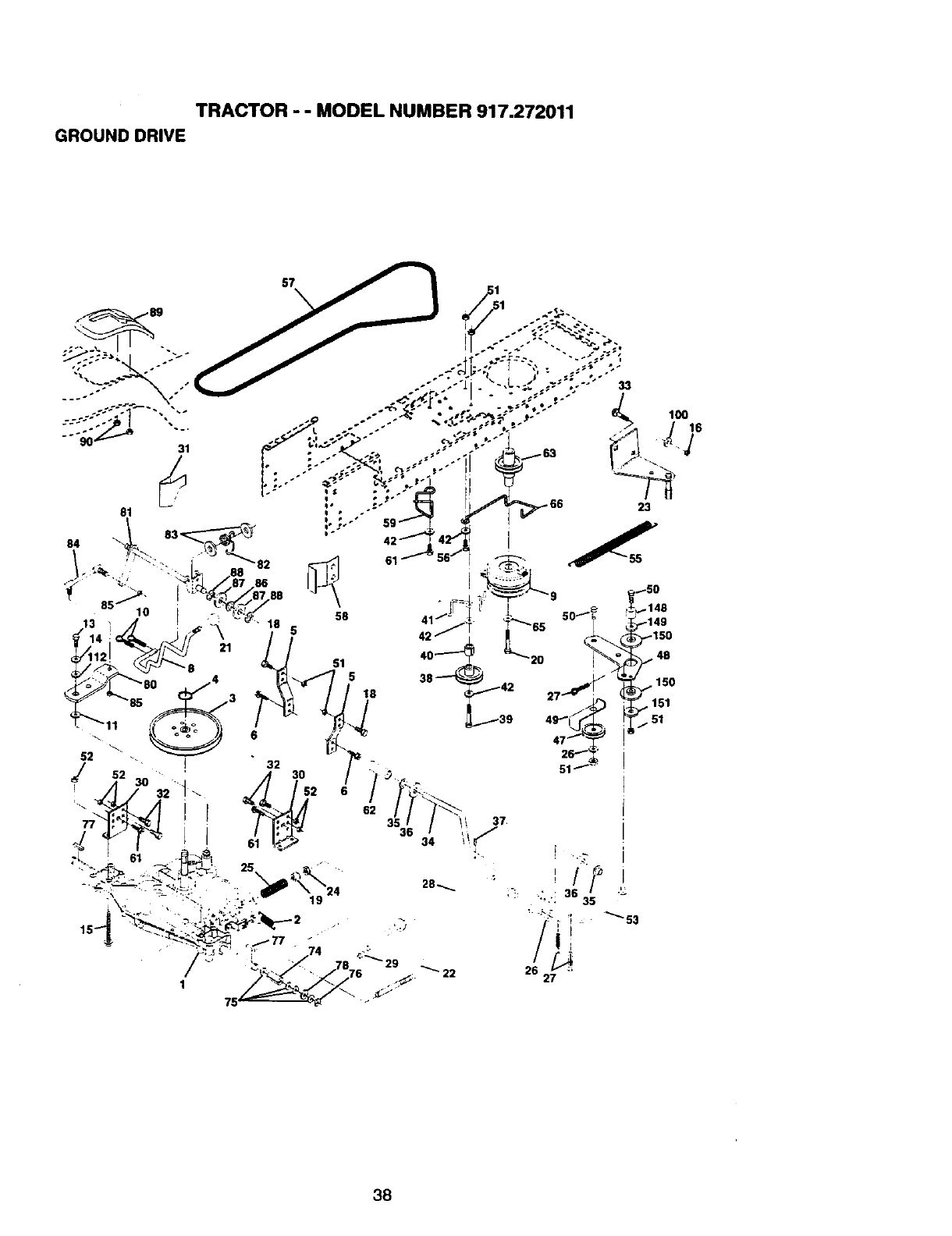
TRACTOR - - MODEL NUMBER 917.272011
GROUND DRIVE
lOO16
22
3?
36 35 ""
38
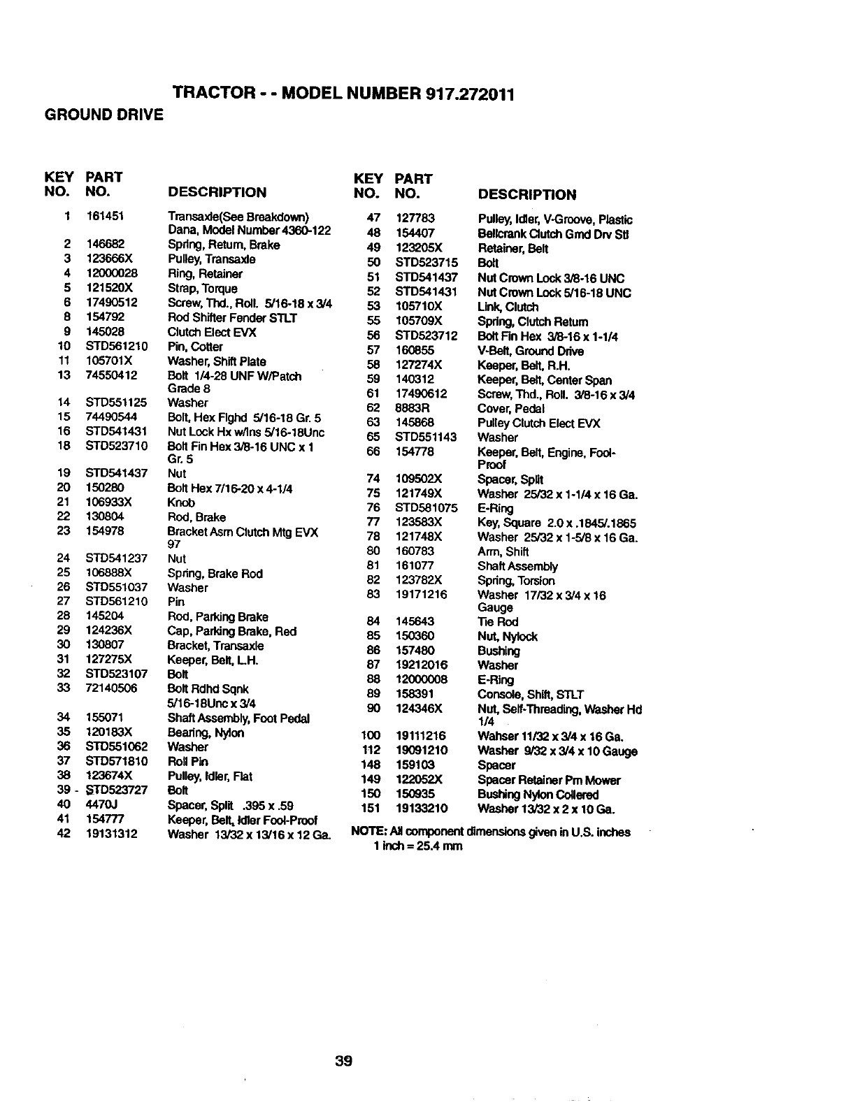
TRACTOR - - MODEL NUMBER 917.272011
GROUNDDRIVE
KEY PART KEY PART
NO. NO. DESCRIPTION NO. NO.
1 161451 Transaxle(See Breakdown) 47 127783
Dana, ModelNumpar4360-122 48 154407
2146682 Spdng, Return.Brake 49 123205X
3 123666X Pulley,Transaxle 50 STD523715
4 12000028 Ring, Retainer 51 STD541437
5 121520X Strap, Torque 52 STD541431
6 17490512 Screw,Thd., Roll. 5/16-18 x 3/4 53 105710X
8 154792 Rod Shifter Fender STLT 55 105709X
9 145028 Clutch Elect EVX 56 STD523712
10 STD561210 Pin, Cotter 57 160855
11 105701X Washer, Shift Plate 58 127274X
13 74550412 Bolt 1/4-28 UNF W/Patch 59 140312
Grade 8 61 17490612
14 STD551125 Washer 62 8883R
15 74490544 Bolt,Hex Rghd 5/16-18 Gr. 5 63 145868
16 STD541431 Nut Lock Hx w/ins 5/16-18Unc 65 $TD551143
18 STD523710 BOltFinHex3i8-16UNCxl 66 154778
Gr. 5
19 STD541437 Nut 74 109502X
20 150280 Bolt Hex 7/16-20 x 4-1/4 75 121749X
21 106933X Knob 76 STD581075
22 130804 Rod, Brake 77 123583X
23 154978 BracketAsm Clutch Mtg EVX 78 121748X
97 80 160783
24 STD541237 Nut 81 161077
25 106888X Spdng, Brake Rod 62 123782X
26 STD551037 Washer 83 19171216
27 STD561210 Pin
28 145204 Rod, ParkingBrake 84 145643
29 124236X Cap, ParkingBrake, Red 85 150360
30 130807 Bracket, Transaxle 86 157480
31 127275X Keeper, Bell,LH. 87 19212016
32 STD523107 Boll 88 12000008
33 72140506 Boll Rdhd Sqnk 89 158391
5/16-18Unc x 3/4 90 124346X
34 155071 Shaft Assembly,Foot Pedal
35 120183X Bearing, Nylon 100 19111216
36 STD551062 Washer 1t2 19091210
37 STD571810 RollPin 148 159103
38 123674X Pulley,Idler, Rat 149 122052X
39 * _TD523727 Boll 150 150935
40 4470J Spacer, Split .395 x .59 151 19133210
41 154777 Keeper, Belt,Idler Fool-Proof
42 19131312 Washer t3/32x 13/16x 12 Ga.
DESCRIPTION
Pulley,Idler,V-Groove, Plastic
Bellcrank Clutch Grad Drv Stl
Retainer,Belt
Bo_
Nut Crown Lock 3/8-16 UNC
Nut Crown Lock 5/16-18 UNC
Link,Clutch
Spring, ClutchReturn
BoltFin Hex 3/6-16 x 1-1/4
V-Bell, GroundDrive
Keeper, Belt, R.H.
Keeper, Belt, Center Span
Screw,Thd., Roll. 3/8-16 x 3/4
Cover, Pedal
PulleyClutchElect EVX
Washer
Keeper, Belt, Engine.Fool-
Proof
Spacer, Spnt
Washer 25/32 x 1-1/4 x 16 Ga.
E-Ring
Key,Square 2.0x .184.5/.1865
Washer 25/32 x 1-5/8 x 16 Ga.
Arm, Shift
ShaftAssembly
Spring, Torsion
Washer 17/32 x 3/4 x 16
Gauge
"fieROd
Nut, Nylo_
Bushing
Washer
E-R_j
Console,Shift, STLT
Nut, Self-Threading,Washer Hd
1/4
Wahser 11/32x 3/4 x 16 Ga.
Washer 9/32 x 3/4 x 10Gauge
Spacer
Spacer Retainer Pm Mower
BushingNylonCollered
Washer 13/32 x 2 x 10 Ga.
NOTE: All componentdimensionsgiveninU.S. inches
1 inch= 25.4 mm
39
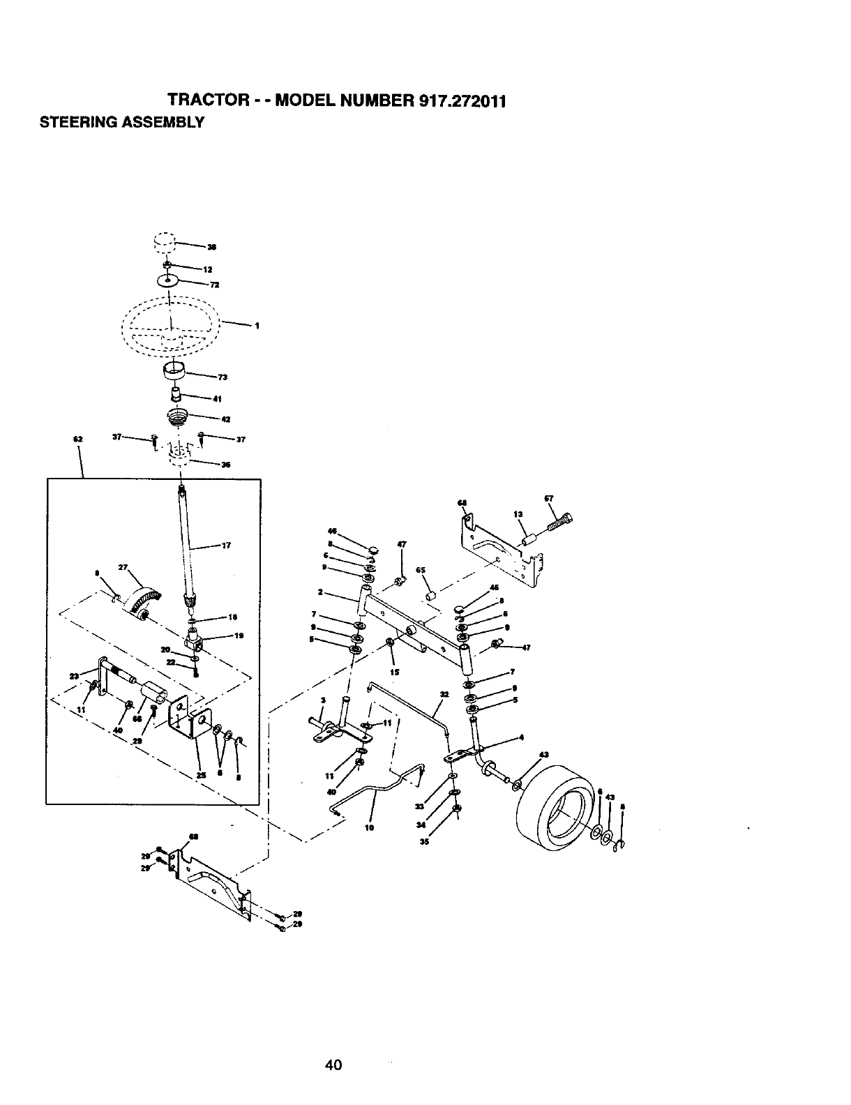
TRACTOR - - MODEL NUMBER 917.272011
STEERING ASSEMBLY
•r
!
L..__-" .... di
41
GII
15
lO
4O
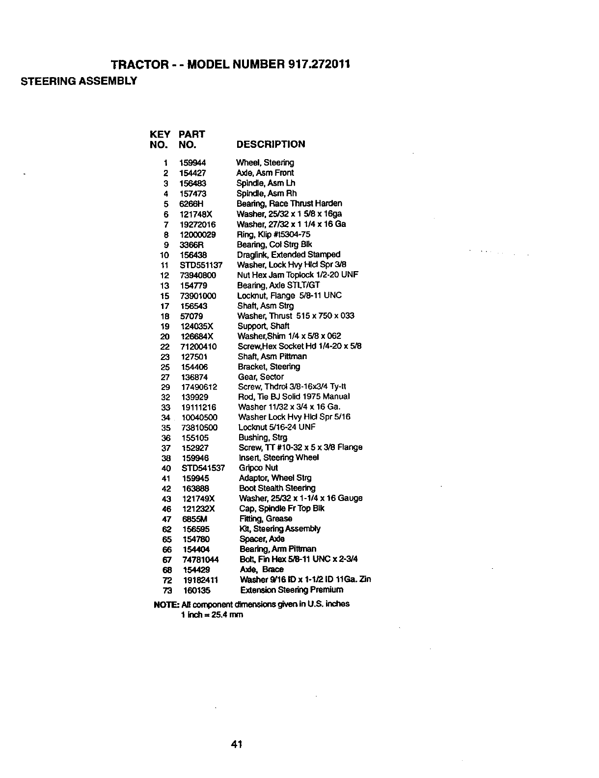
TRACTOR - - MODEL NUMBER 917.272011
STEERING ASSEMBLY
KEY PART
NO. NO. DESCRIPTION
1 159944
2 154427
3 156483
4 157473
5 626611
6 121748X
7 19272016
8 12000029
9 3366R
10 156438
11 STD551137
12 73940800
13 154779
15 73901000
17 156543
18 57079
19 124035X
20 126684X
22 71200410
23 127501
25 154406
27 136874
29 17490612
32 139929
33 19111215
34 10040500
35 73810500
36 155105
37 152927
38 159946
40 STD541537
41 159945
42 163888
43 121749X
46 121232)(
47 6855M
62 156595
65 154780
66 154404
67 74781044
68 154429
72 19182411
73 160135
Wheel, Steering
Axle,Asm Front
Spindle,Asm Lh
Spindle,Asm Rh
Beadng, RaceThrustHarden
Washer,25/32 x I 5/8 x 16ga
Washer,27/32 x I 1/4 x 16 Ga
Ring, Klip#t5304-75
Beedng, Col Strg BIk
Draglink,ExtendedStamped
Washer, Lock HWHlcl Spr3/8
Nut Hex JamToplock1/2.20 UNF
Bearing,AxleSTLT/GT
Locknut, Flange 5/8-11 UNC
Shaft,Asm Strg
Washer, Thrust 515 x 750 x 033
Support, Shaft
Washer,Shim 1/4 x 5/8 x 062
Screw,Hex Socket Hd 1/4-20 x 5/8
Shaft,Asm Pittman
Bracket,Steedng
Gear, Sector
Screw,Thdrol 3/8-16x3/4 Ty-tt
Rod,-13eBJ Solid 1975 Manual
Washer 11/32x 3/4 x 16 Ga.
Washer Lock Hvy Hlcl Spr 5/16
Locknut5/16-24 UNF
Bushing,Strg
Screw,Tr #10-32 x 5 x 3/8 Range
Insert,SteeringWheel
Gdpco Nut
Adaptor,Wheel Strg
BootStealth Steering
Washer, 25/32 x 1-1/4 x 16 Gauge
Cap, SpindleFrTop BIk
Fitting,Grease
Kit,Steedng Assembly
Spacer,Axle
Bearing,Arm Pittrnan
Bolt, Fin Hex 5/8-11 UNC x 2-3/4
Axle, Brace
Washer 9/16 ID x 1-1/2 ID 11Ga.Zin
ExtensionStaedng Premium
NOTE: Allcomponentdimensionsgivenin U.S. inches
1 inch==25.4 mm
41
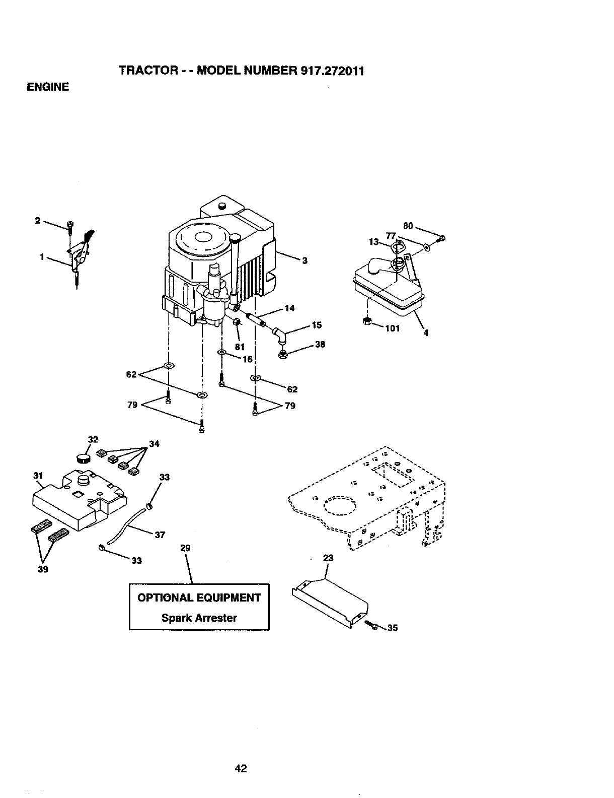
ENGINE
TRACTOR - - MODEL NUMBER 917.272011
OPTIONAL EQUIPMENT
Spark Arrester
42
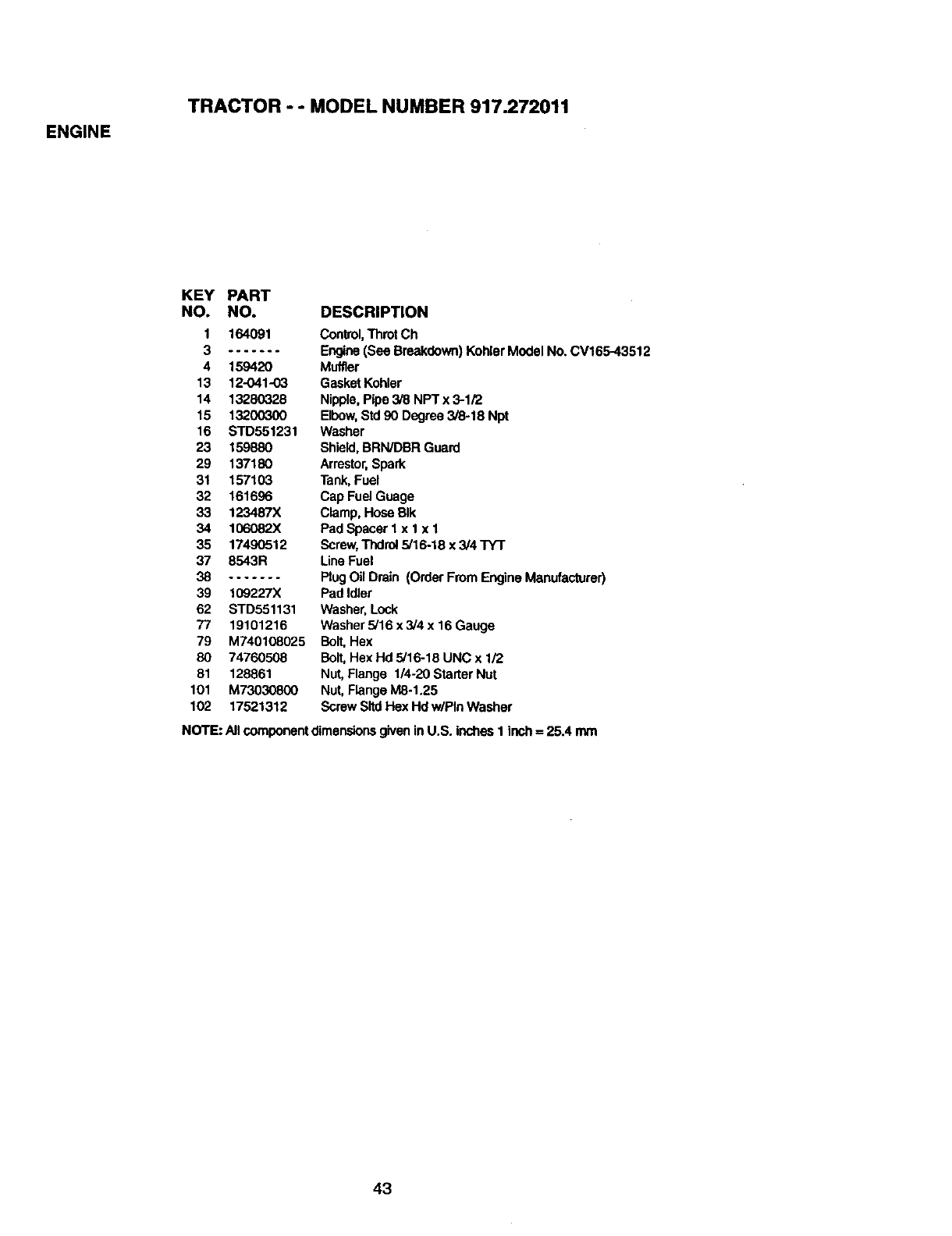
ENGINE
TRACTOR - - MODEL NUMBER 917.272011
KEY PART
NO. NO. DESCRIPTION
1 164091 Control,ThrotCh
3....... Engine(See Breakdown)Kohler Model No. CV165-43512
4 159420 Muffler
13 12-041-03 Gasket Kohler
14 13280328 Nipple,Pipe 3/8 NPTx 3-1/2
15 13200300 Elbow,Std90 Degree 3/8-18 Npt
16 STD551231 Washer
23 159880 Shield,BRWDBR Guard
29 137180 Arrestor,Spark
31 157103 Tank,Fuel
32 151696 Cap Fuel Guage
33 123487X Clamp, Hose BIk
34 106082X Pad Spacer lx 1 x 1
35 17490512 Screw,Thdrol5/15-18 x 3/4 TY'r
37 8543R Line Fuel
38 ....... PlugOil Drain (Order From Engine Manufacturer)
39 109227X Pad Idler
62 STD551131 Washer,Lock
77 19101216 Washer5/16 x 3/4 x 16 Gauge
79 M740108025 Bolt,Hex
80 74760508 Bolt, Hex Hd 5/16-18 UNC x 1/2
81 128861 Nut, Flange 1/4-20 Starter Nut
101 M73030800 Nut, Flange M8-1.25
102 17521312 Screw SltdHex Hd w/Pin Washer
NOTE: AllcomponentdimensionsgiveninU.S. inchesI inch = 25.4 mm
43
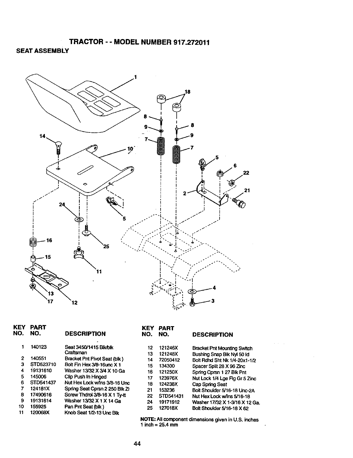
TRACTOR - - MODEL NUMBER 917.272011
SEAT ASSEMBLY
I
t
f
18
12
KEY PART
NO. NO.
1 14O123
2 140551
3 STD523710
4 19131610
5 145006
6 STD541437
7 124181X
8 17490616
9 19131614
10 155925
11 120068X
KEY PART
DESCRIPTION NO. NO. DESCRIPTION
Seat 3450/1415 B_PJblk 12 121246X
Craftsman 13 121248X
BracketPntPivotSeat (blk) 14 72050412
Bolt FinHex 3/8-16uncX 1 15 134300
Washer 13/32 X 3/4 X 10Ga 16 121250X
Clip Push In Hinged 17 123976X
Nut Hex Lockw/lns348-16Uric 18 124238X
SpringSeat Cpmn 2 250 BIk7t 21 153236
ScrewThdrol 3/8-16 X 1 Ty-tt 22 STD541431
Washer 13/32 X 1 X 14 Ga 24 19171912
Pan Pnt Seat (b!_) 25 127018X
Knob Seat 1/2-13 Unc BIk
BracketPntMountingSwitch
BushingSnap BIk Ny150 Id
BoltRdhd Sht Nk 1/4-20x1-1/2
Spacer Spilt28 X 96 Zinc
SpdngCprsn 1 27 BIk Pnt
Nut Lock 1/4 Lge Rg Gr 5 Zinc
Cap SpringSeat
Bolt Shoulder5/16-18 Unc-2A
Nut Hex Lock w/Ins 5/16-18
Washer 17/32 X 1-3/16 X 12Ga.
BoltShoulder5/16-18 X 62
NOTE: All componentdimensionsgiven in U.S. inches
1 inch = 25.4 mm
44
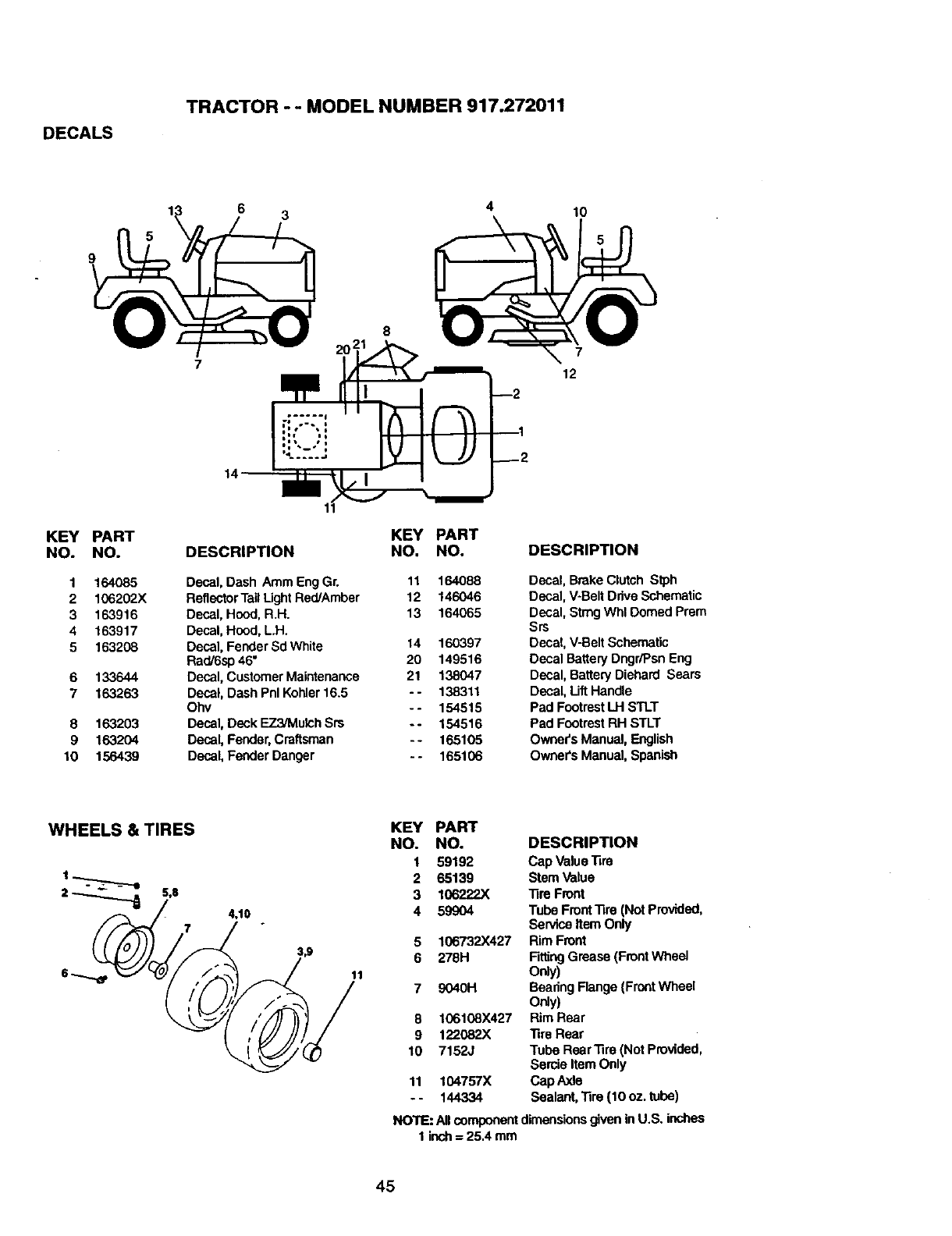
DECALS
TRACTOR -- MODEL NUMBER 917.272011
6310
9
KEY PART
NO. NO.
1 164085
2 106202X
3 163916
4163917
5 163208
6 133644
7 163263
8 163203
9 163204
10 156439
14
KEY PART
DESCRIPTION NO. NO.
Decal, Dash Amm EngGr. 11 164088
ReflectorTagLight Red/Amber 12 146046
Decal, Hood, R.H. 13 164065
Decal, Hood, L.H.
Decal, Fender Sd White 14 160397
Rad/6sp 46" 20 149516
Decal, CustomerMaintenance 21 138047
Decal, Dash Pnl Kohler16,5 - - 138311
Ohv -- 154515
Decal, Deck EZ3/Mulch Srs - - 154516
Decal, Fender,Craftsman -- 165105
Decal, Fender Danger - - 165106
7
12
--2
DESCRIPTION
Decal, BrokeClutch Stph
Decal, V-Belt DriveSchematic
Decal, Sting Whl Domed Prom
Srs
Decal, V-BaitSchematic
Decal BatteryDngr/Psn Eng
Decal, Battery Diehard Sears
Decal, LiftHandle
Pad FootrestLH STLT
Pad FootrestRH STLT
Owners Manual, English
Owners Manual, Spanish
WHEELS & TIRES
2_S,8 4,10
11
KEY PART
NO. NO. DESCRIPTION
1 59192 Cap Value'fire
2 65139 Stem Value
3 106222X Tire Front
4 59904 Tube FrontTire (Not Provided,
Service Item Only
5 106732X427 Rim Front
6 278H FittingGrease (FrontWheel
Ordy)
7 9040H Bearing Flange (FrontWheel
Only)
6 106108X427 Rim Rear
9 122082X Tire Rear
10 7152J Tube Rear.fire (Not Provided,
Sercie Item Only
11 104757X Cap Axle
- - 144334 Sealant, .fire (10 oz. tube)
NO'_E:AllcomponentdimensionsgiveninU.S. inches
1 inch= 25.4 mm
45
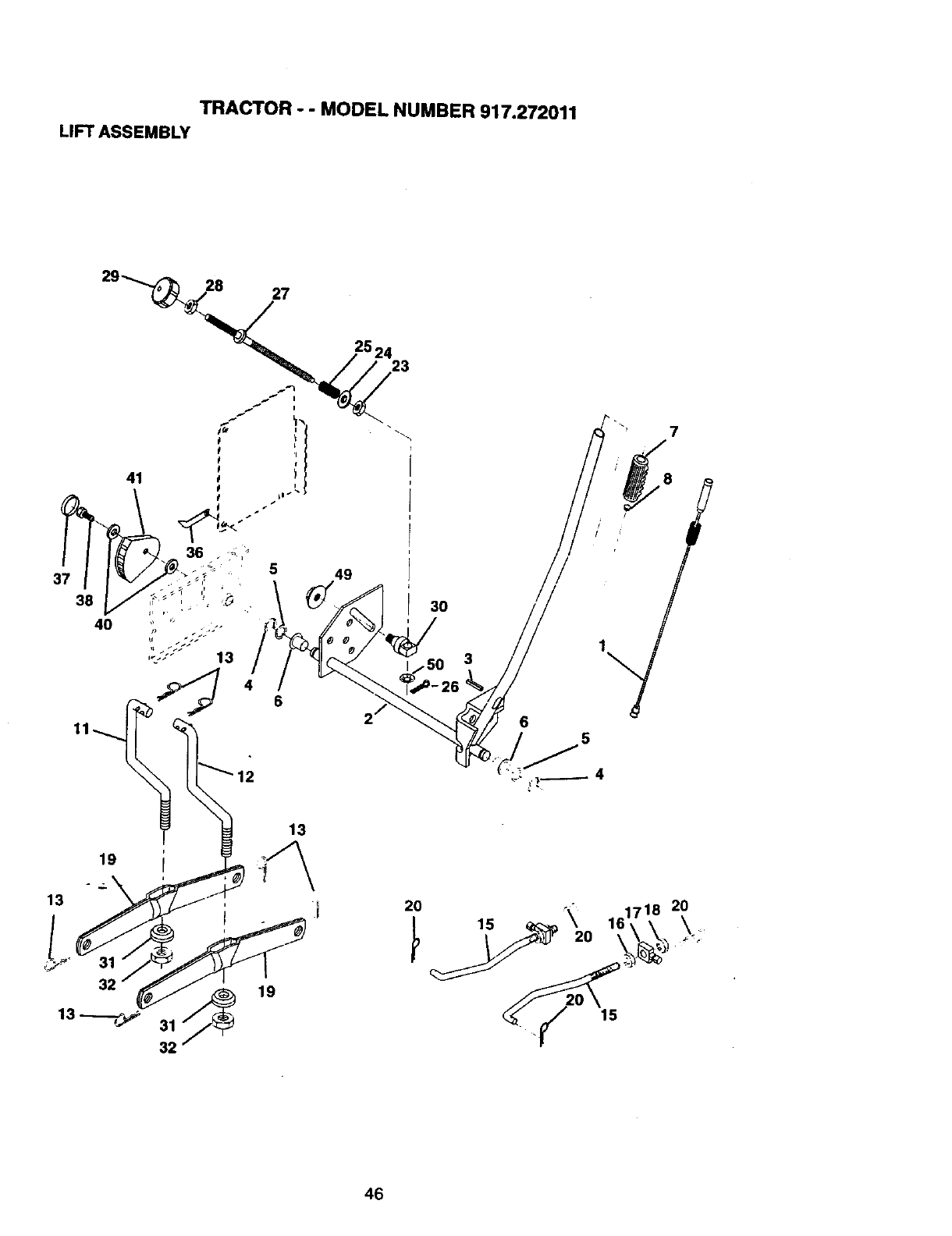
TRACTOR -- MODEL NUMBER 917.272011
LIFT ASSEMBLY
27
49
23
3O
3
7
/8
15
46
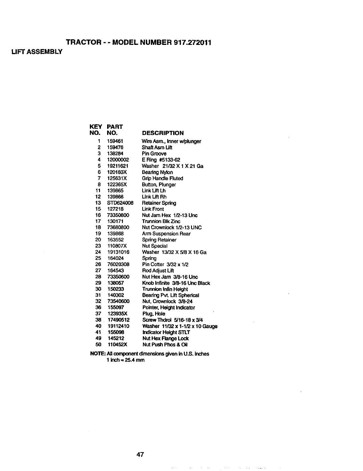
TRACTOR - - MODEL NUMBER 917.272011
LIFT ASSEMBLY
KEY PART
NO. NO. DESCRIPTION
1 159461 Wire Asm.,Inner w/plunger
2 159476 ShaftAsm Lift
3 138284 Pin Groove
4 12000002 E Ring #5133-62
5 19211621 Washer 21/32 X 1 X 21 Ga
6 120183X Bearing Nylon
7 125631X Grip Handle Rutnd
8 122365X Bu_on, Plunger
11 139865 Unk Lift Lh
12 139866 LinkLift Rh
13 STD624008 Retainer Spring
15 127218 Link Front
16 73350800 NutJamHex 1/2-13Unc
17 130171 TrunnionBIkZinc
18 73680800 NutCrowniock1/2-13 UNC
19 139868 Arm SuspensionRear
20 163552 SpringRetainer
23 110807X Nut Special
24 19131016 Washer 13/32 X 5/8 X 16 Ga
25 164024 Spring
26 76020308 PinCotter 3/32xl/2
27 164543 RodAdjustLift
28 73350600 Nut Hex Jam 3/8-16 Une
29 138057 Knoblnfinite 3/8-16 Unc Black
30 150233 TrunnionInfinHeight
31 140302 Beadng PVLLiftSpherical
32 73540600 Nut, Crownlock 3/8-24
36 155097 Pointer,Height Indicator
37 123935X Plug, Hole
38 17490512 ScrewThdrol 5/16-18x3/4
40 19112410 Washer 11/32 x 1-1/2 x 10Gauge
41 155098 IndioatorHeightSTLT
49 145212 NUtHex Flange Lock
50 110452X Nut Push Phos & Oil
NOTE: Allcomponentdimensionsgiven inU.S. inches
1 inch= 25.4 mm
47
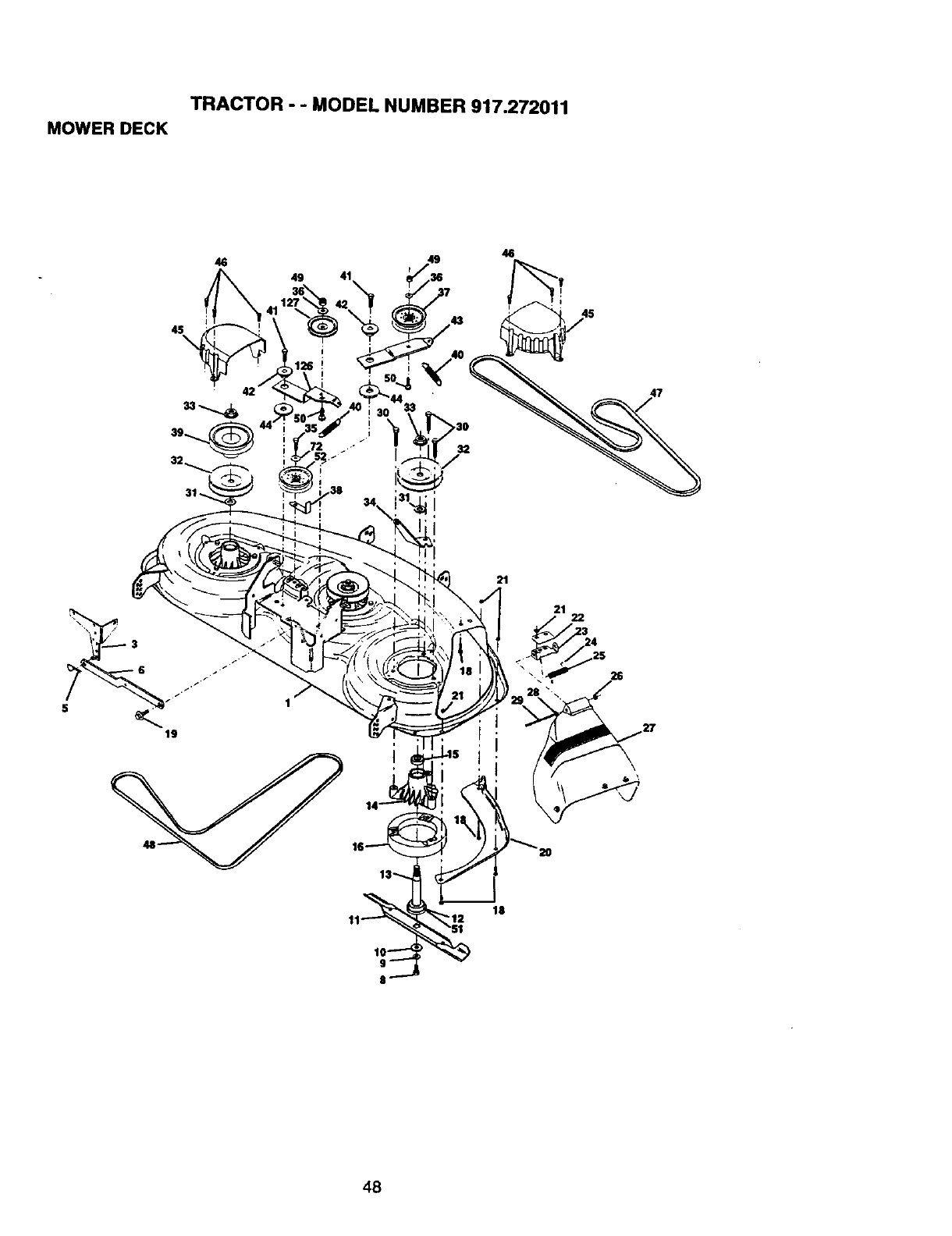
TRACTOR - - MODEL NUMBER 917.272011
MOWER DECK
49 41
21
21 22
26
18
,48
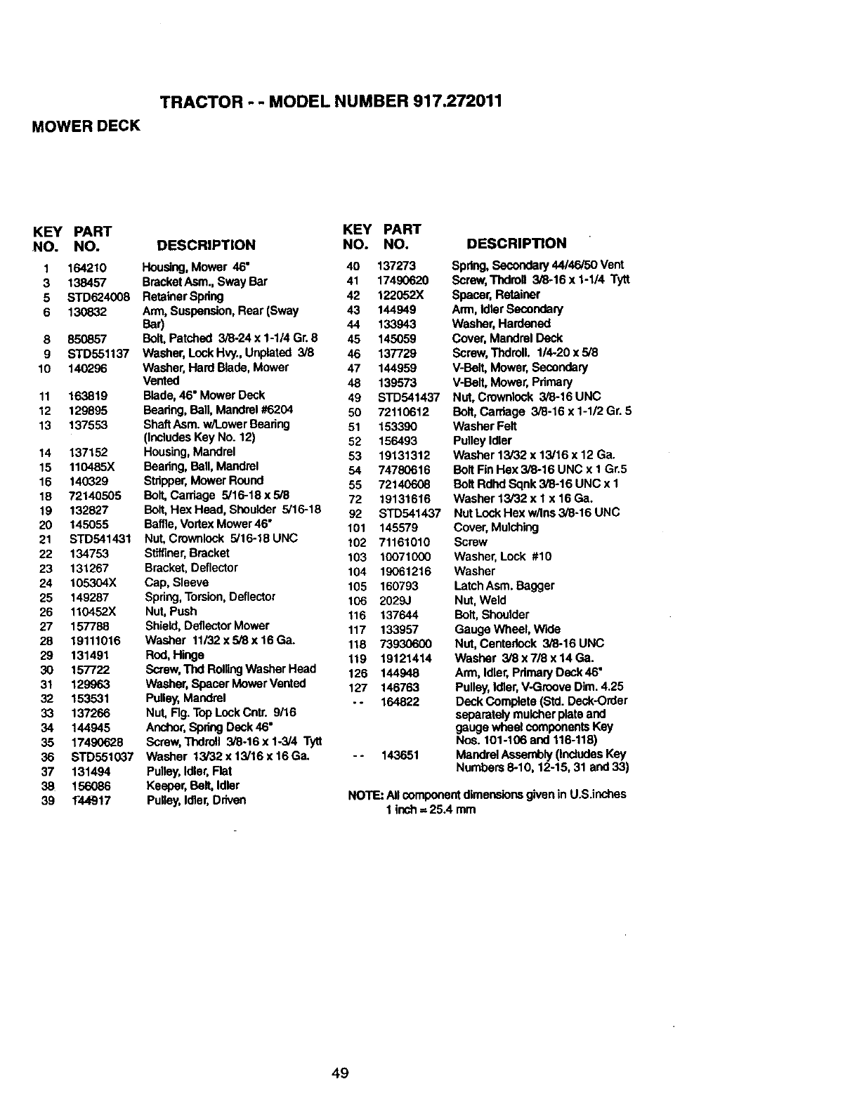
TRACTOR - - MODEL NUMBER 917.272011
MOWER DECK
KEY PART KEY PART
NO. NO. DESCRIPTION NO. NO.
1 164210 Housing,Mower 46" 40 137273
3 138457 BracketAsm., Sway Bar 41 17490620
5 STD624008 Retainer Spdng 42 122052X
6 130832 Arm, Suspension,Rear (Sway 43 144949
Bar) 44 133943
8 850857 Ball Patched 3/8-24 x 1-1/4 Gr. 8 45 145059
9 STD551137 Washer, Lock Hvy, Unplated 3/8 46 137729
10 140296 Washer, Hard Bade, Mower 47 144959
Vented 48 139573
11 163819 Blade,46" Mower Deck 49 STD541437
12 129895 Beadng, Ball, Mandrel #6204 50 72110612
13 137553 ShaftAsm. w/LowerBearing 51 153390
(IncludesKey No. 12) 52 156493
14 137152 Housing,Mandrel 53 19131312
15 110485X Beadng, Ball, Mandrel 54 74780616
16 140329 Stripper,Mower Round 55 72140608
18 72140505 Bolt,Cardage 5/16-18 x 5/8 72 19131616
19 132827 Boil Hex Head, Shoulder 5/16-18 92 STD541437
20 145055 Baffle, VortexMower 46" 101 145579
21 STD541431 Nut, Crownlock 5/16-18 UNC 102 71161010
22 134753 Stiffiner,Bracket 103 10071000
23 131267 Bracket, Deflector 104 19061216
24 105304X Cap, Sleeve 105 160793
25 149287 Spring, Torsion,Deflector 106 2029J
26 110452X Nut, Push 116 137644
27 157788 Shield, DeflectorMower 117 133957
28 19111016 Washer 11/32xSi8x16Gao 118 73930600
29 131491 Rod, Hinge 119 19121414
30 157722 Screw,Thd RollingWasher Head 126 144948
31 129963 Washer, Spacer MowarVented 127 146763
32 153531 Pulley,Mandrel . - 164822
33 137266 NuL Fig. Top LockCntr. 9/16
34 144945 Anchor,SpringDeck 46"
35 17490628 Screw,Thdroll 3/8-16x 1.3/4 Tytt
36 STD551037 Washer 13/32x13/16x16Ga. -- 143651
37 131494 Pulley,Idler,Flat
38 156086 Keeper, Bolt, Idler
39 144917 Pulley,Idler,Driven
DESCRIPTION
Spring, Secondary44146/50 Vent
Screw,Thdron 3/8-16 x 1-1/4 Tytt
Spacer, Retainer
Arm, IdlerSecondary
Washer, Hardened
Cover, Mandrel Deck
Screw,ThdrolL 1/4-20 x 5/8
V-BOIl Mower, Secondary
V-BaR,Mower, Pdmary
Nut, Crownlock 3/8-16 UNC
Bolt, Carriage 3/8-16 x 1-1/2 Gr. 5
Washer Felt
Pulley Idler
Washer 13/32 x 13/16 x 12 Ga.
Bolt Fin Hex 3/8-16 UNC x I Gr.5
Bolt Rdhd Sqnk 3/8-16 UNC x 1
Washer 13/32 x I x 16 Ga.
Nut Lock Hex w/Ins 3/6-16 UNC
Cover, Mulching
Screw
Washer, Lock #10
Washer
LatchAsm. Bagger
Nut, Weld
Bolt,Shoulder
Gauge Wheel, W'lde
Nut, Centedock 3/8-16 UNC
Washer 3/8 x 7/8 x 14 Ga.
Arm, Idler,Pdmary Deck 46"
Pulley,Idler,V-GrooveDim. 4.25
Deck Complete (Std. Deck-Order
separately mulcherplate and
gauge wheel componentsKey
Nos. 101-106 and 116-118)
Mandrel Assembly (includesKey
Numbers 8-10, 12-15, 31 and 33)
NOTE: Allcomponentdimensionsgivenin U.S.inches
1 inch=25.4 mm
49
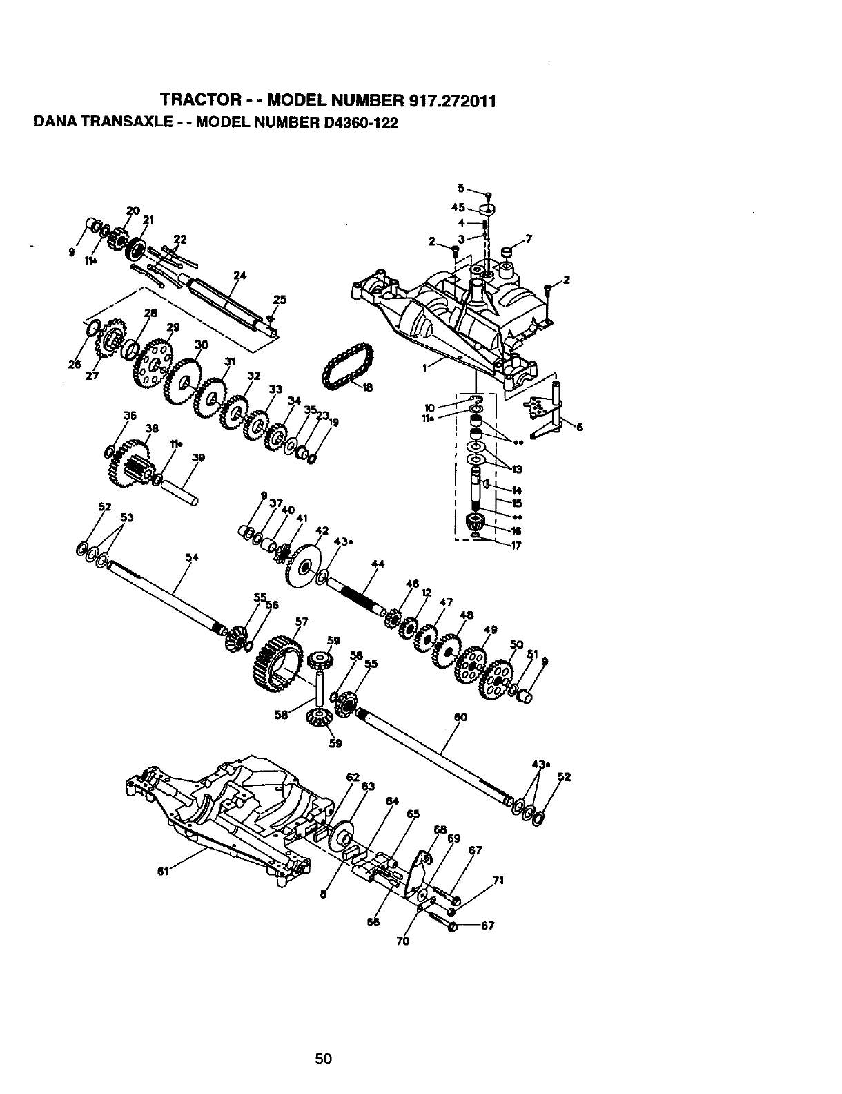
TRACTOR -- MODEL NUMBER 917.272011
DANA TRANSAXLE - - MODEL NUMBER D4360-122
20
22
24
25
27 32 33
35 38
53 42
7
44
47
5O
59
62
71
8
7O
5O
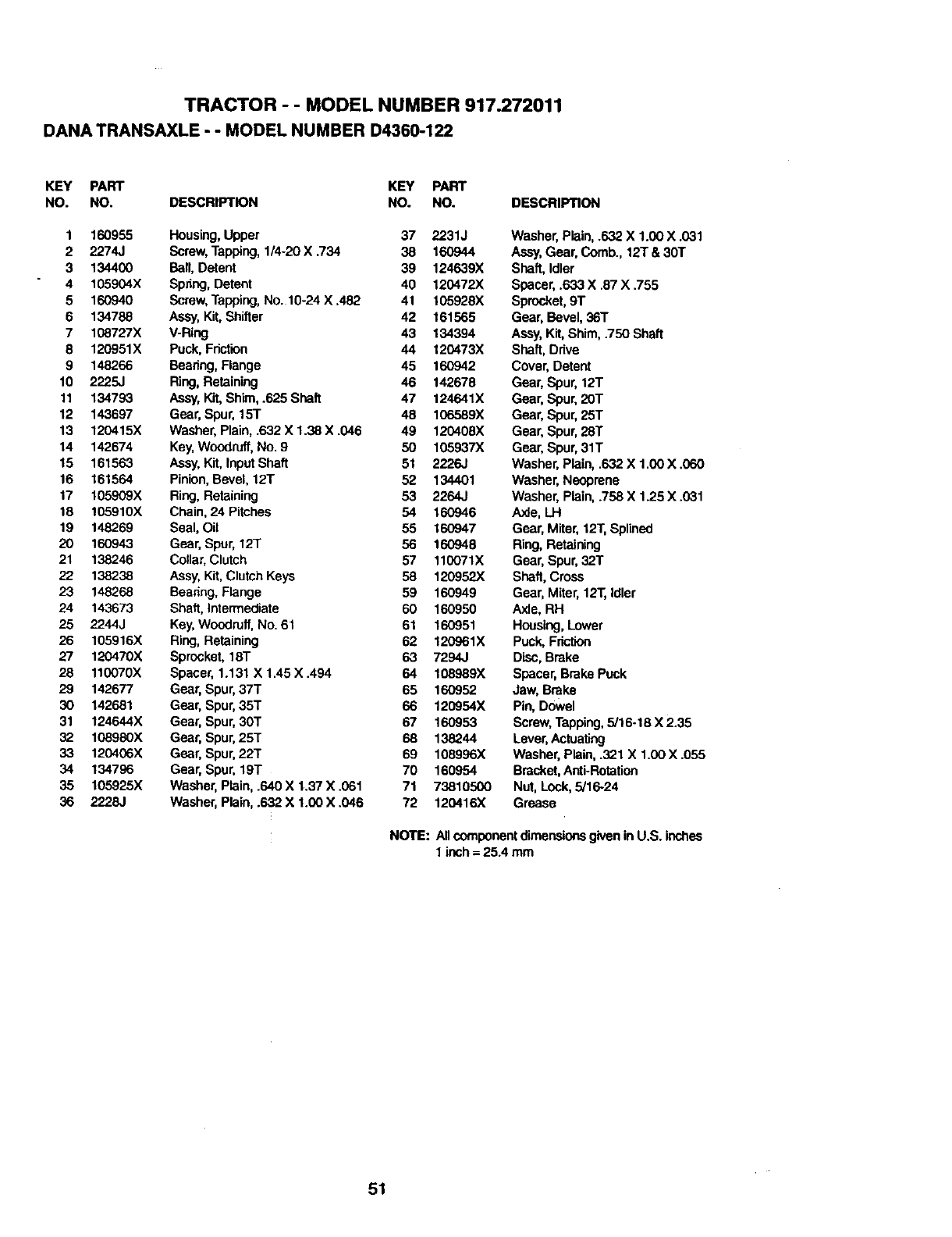
TRACTOR - - MODEL NUMBER 917.272011
DANA TRANSAXLE - - MODEL NUMBER D4360-122
KEY PART KEY PART
NO. NO. DESCRIPTION NO. NO. DESCRIPTION
1 160955 Housing,Upper 37 2231J
2 2274J Screw, Tapping,1/4-20 X .734 38 160944
3 134400 Ball, Detent 39 124639X
4 105904X Spdng, Detent 40 120472X
5 160940 Screw, Tapping,No. 10-24 X ,482 41 105928X
6 134788 Assy,Kit,Shifter 42 161565
7 108727X V-Ring 43 134394
8 120951X Puck, Friction 44 120473X
9 148266 Bearing,Flange 45 160942
10 2225J Ring,Retaining 46 142678
11 134793 Assy,Kit, Shim, .625 Shaft 47 124641X
12 143697 Gear, Spur, 15T 48 106589X
13 120415X Washer, Plain, .632 X 1.38 X .046 49 120408X
14 142674 Key,Woodruff,No. 9 50 105937X
15 161563 Assy,Kit, InputShaft 51 2226J
16 161564 Pinion,Bevel, 12T 52 134401
17 105909X Ring,Retaining 53 2264J
18 105910X Chain, 24 Pitches 54 160946
19 148269 Seal, Oil 55 160947
20 160943 Gear, Spur, 12T 56 160948
21 138246 Collar,Clutch 57 110071X
22 138238 Assy, Kit,Clutch Keys 58 120952X
23 148268 Bearing,Flange 59 160949
24 143673 Shaft,Intermediate 60 160950
25 2244..I Key,Woodruff,No. 61 61 160951
26 105916X Ring,Retaining 62 120961X
27 120470X Sprocket,18T 63 7294J
28 110070X Spacer, 1.131 X 1.45X.494 64 108989X
29 142677 Gear, Spur, 37T 65 160952
30 142681 Gear, Spur, 35T 66 120954X
31 124644X Gear, Spur, 30T 67 160953
32 108980X Gear, Spur, 251 68 138244
33 120406X Gear, Spur, 22T 69 108996X
34 134796 Gear, Spur, 19T 70 160954
35 105925X Washer,Plain, .640 X 1.37 X .061 71 73810500
36 2228J Washer,Plain, .632 X 1.00 X .046 72 120416X
Washer, Plain, .632 X 1.00 X .031
Assy,Gear, Comb., 12T & 30T
Shaft, Idler
Spacer, .633 X .87 X .755
Sprocket, 9T
Gear, Bevel, 36T
Assy,Kit,Shim, .750 Shaft
Shaft, Drive
Cover, Detent
Gear, Spur, 12T
Gear, Spur, 20T
Gear, Spur, 25T
Gear, Spur, 28T
Gear, Spur, 31T
Washer, Plain, .632 X 1,00 X .060
Washer, Neoprene
Washer, Plain,.758 X 1.25 X .031
Axle, LH
Gear, Miter,12T,Splined
Ring, Retaining
Gear, Spur, 32T
Shaft, Cross
Gear, Miter, 12T,Idler
Axle, RH
Housing,Lower
Puck, Friction
Disc,Brake
Spacer, Brake Puck
Jaw, Brake
Pin, Dowel
Screw,Tapping,5/16-18 X 2.35
Lever,Actuating
Washer, Plain, .321 X 1.00 X .055
Bracket,Anti-Rotation
Nut, Lock,5,'16.-24
Grease
NOTE: Allcomponentdimensionsgivenin U.S. inches
1 inch= 25.4 mm
51
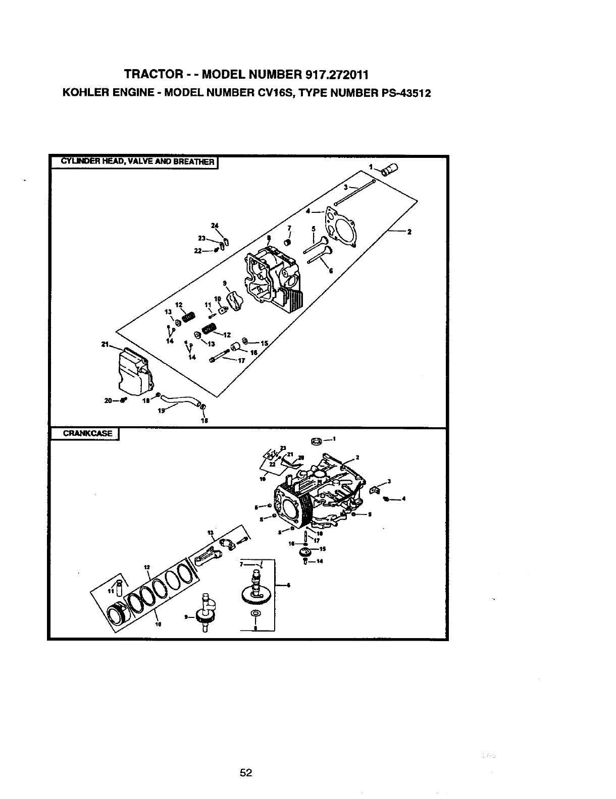
TRACTOR --MODEL NUMBER 917.272011
KOHLER ENGINE -MODEL NUMBER CV16S, TYPE NUMBER PS-43512
CYLINDER HEAD, VALVE ANO BREATHERJ
52
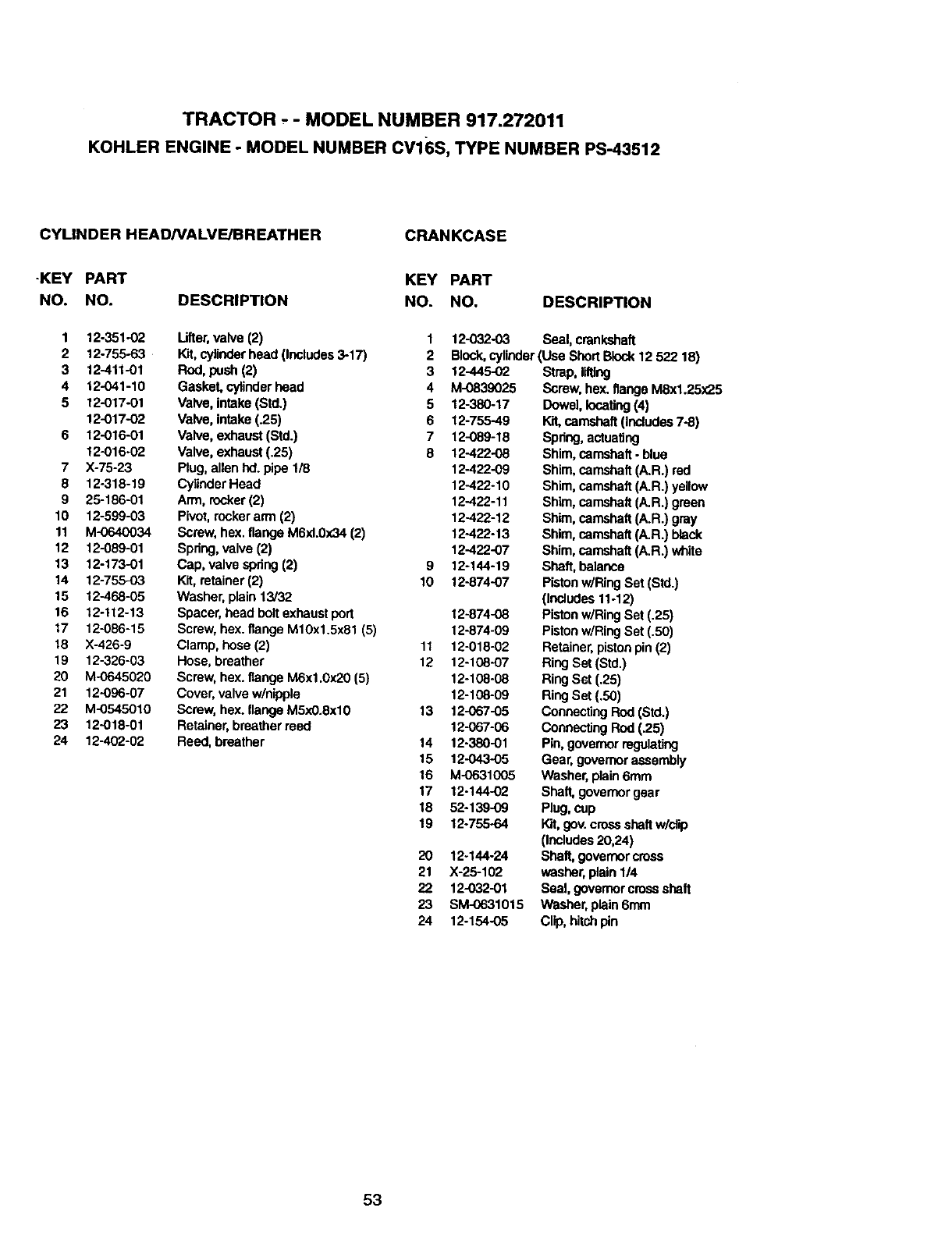
TRACTOR - - MODEL NUMBER 917.272011
KOHLER ENGINE -MODEL NUMBER CV16S, TYPE NUMBER PS-43512
CYLINDER HEAD/VALVE/BREATHER CRANKCASE
-KEY PART KEY PART
NO. NO. DESCRIPTION NO. NO. DESCRIPTION
1
2
3
4
5
6
7
8
9
10
11
12
13
14
15
16
17
18
19
20
21
22
23
24
12-351-O2 Lifter,valve (2) 1
12-755-63 Kit,cylinderhead (Includes3-17) 2
12-411-01 Rod,push (2) 3 12-445-02
12-041-10 Gasket, cylinderhead 4 M.0839025
12-017-01 Valve, intake (Std.) 5 12-380-17
12-017-O2 Valve, intake (.25) 6 12-755-49
12-016-01 Valve, exhaust (Stdo) 7 12-089-18
12-016.02 Valve, exhaust (.25) 8 12-422-08
X-75-23 Plug, allen hd.pipe 1/8 12-422-09
12-318-19 CylinderHead 12-422-10
25-186-01 Arm, rocker(2) 12-422-11
12-599-03 Pivot,rockerarm (2) 12-422-12
M-0640034 Screw, hex. flange M6xl.0x34 (2) 12-422-13
12-089-01 Spring, valve (2) 12-422-07
12-173-01 Cap, valve spring(2) 9 12-144-19
12-755-03 Kit, retainer(2) 10 12-874-07
12-468-05 Washer, plain 13/32
12-112-13 Spacer, head bolt exhaustport 12-874-O8
12-086-15 Screw, hex. flange M10x1.5x81 (5) 12-874-09
X-426-9 Clamp, hose (2) 11 12-018-02
12-326-03 Hose, breather 12 12-108-07
M-0645020 Screw, hex.flange M6xl.0x20 (5) 12-108-08
12-096-07 Cover, valvew/nipple 12-108-09
M-0545010 Screw, hex.flange M5xO.8xlO 13 12-067-05
12-018-01 Retainer, breatherreed 12-067-06
12-402-02 Reed, breather 14 12-380-01
15 12-043-05
16 M-0631005
17 12-144-02
18 52-139-O9
19 12-755-64
20 12-144-24
21 X-25-102
22 12-032-01
23 SM.0631015
24 12-154-05
12-032-03 Seal, crankshaft
Block,cylinder(Use ShortBlock12 522 18)
Strap, lifting
Screw, hex.flange M8x1.25x25
DowelIocaitng(4)
Kit,camshaft(Includes7-8)
Spnng, actuating
Shim. camshaft, blue
Shim, camshaft (A.R.) red
Shim, camshaft (A.R.) yellow
Shim, camshaft (A.R.) green
Shim, camshaft (A.R.) gray
Shim, camshaft (A.R.) black
Shim,camshaft (A.R.) white
Shaft, balance
Pistonwiring Set (Std.)
(Includes11-12)
PistonwiRingSet (.25)
Pistonw/RingSet (.50)
Retainer,pistonpin (2)
RingSet (Std.)
RingSet (.25)
RingSet (.50)
ConnectingRod (Std.)
ConnectingRod (.25)
Pin, governorregulating
Gear, governorassembly
Washer, plain6mm
Shaft,governorgear
Plug,cup
Kit,gov. crossshaft w/citp
(Includes20,24)
Shaft, governorcress
washer, plain 1/4
Seal, govemorcrossshatt
Washer,plain 6ram
Clip, hitchpin
53
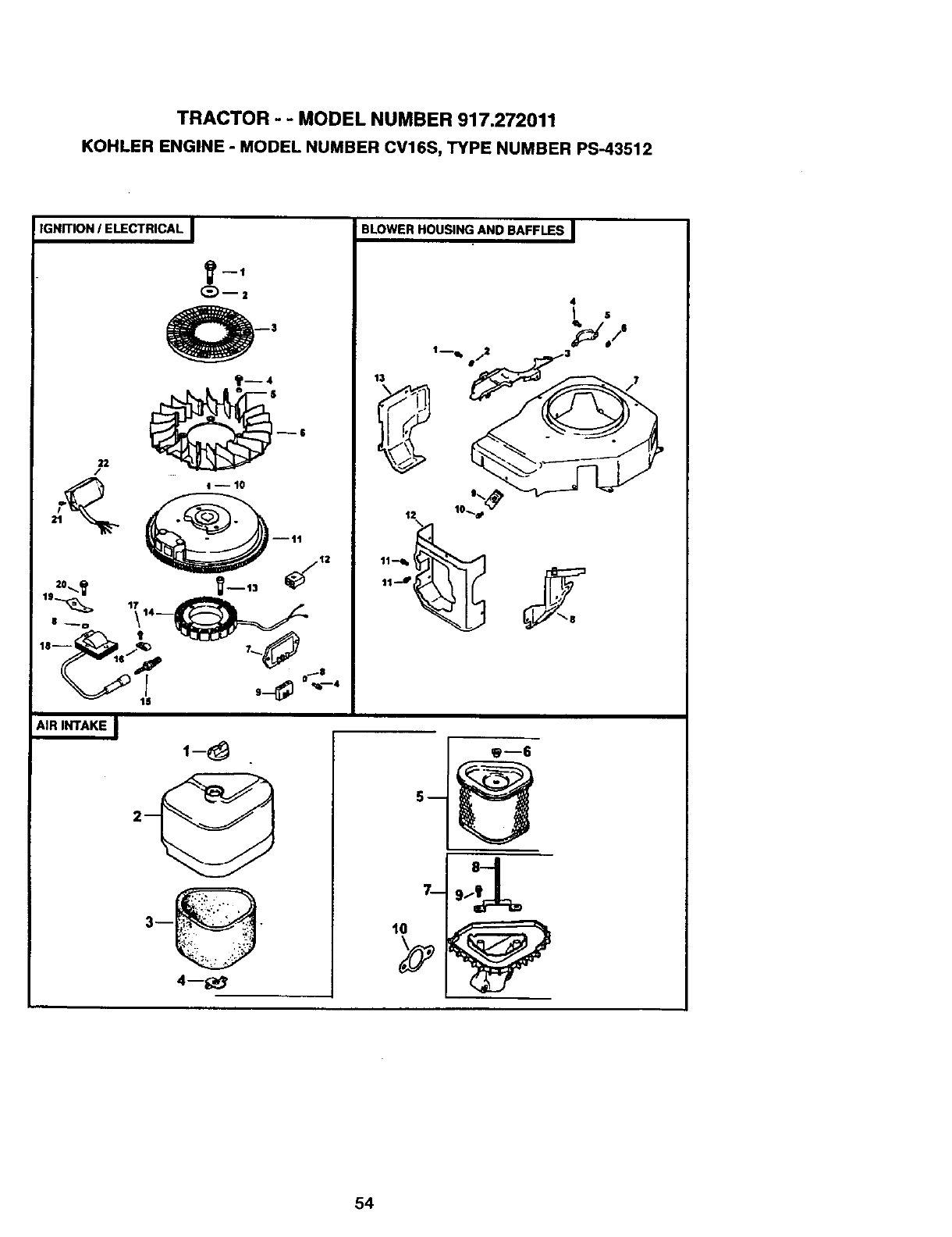
TRACTOR -- MODEL NUMBER 917.272011
KOHLER ENGINE - MODEL NUMBER CV16S, TYPE NUMBER PS-43512
IGNmON IELECTRICAL I
_--2
22 _S $
/
AIR INTAKE I
1-8
4--_,
BLOWER HOUSING AND BAFFLES I
tl J
g--6
7-- 9_
54
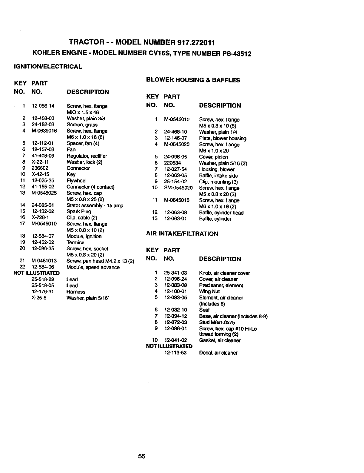
TRACTOR - - MODEL NUMBER 917.272011
KOHLER ENGINE -MODEL NUMBER CV16S, TYPE NUMBER PS--43512
IGNITION/ELECTRICAL
KEY PART
NO. NO.
1 12-086-14
2 12-468-03
3 24-162-03
4 M-0639016
5 12-112-01
6 12-157-03
7 41-403-09
8 X-22-11
9 236602
10 X-42-15
11 12-025-35
12 41-155-02
13 M-0548025
14 24-085-01
15 12-132-02
!6 X-728-1
17 M-0545010
18 12-584-07
19 12-452-02
20 12-086-35
21 M-0461013
22 12-584-06
NOT ILLUSTRATED
26-518-29
25-518-O5
12-176o31
X-25-5
DESCRIPTION
Screw,hex. flange
MIO x 1.5 x 46
Washer, plain 3/8
Screen, gross
Screw, hex. flange
M6 x 1.0 x 16 (6)
Spacer, fan (4)
Fan
Regulator,rectifier
Washer, lock(2)
Connector
Key
Flywheel
Connector (4 contact)
Screw, hex. cap
M5 x 0.8 x 25 (2)
Stator assembly- 15 amp
Spark Plug
Clip, cable (2)
Screw, hex.flange
M5 x 0.8 x 10 (2)
Module, ignition
Terminal
Screw, hex. socket
M5 x 0.8 x 20 (2)
Screw, pen head M4.2 x 13(2)
Module, speedadvance
Lead
Lead
Harness
Washer, plain 5/16"
BLOWER HOUSING & BAFFLES
KEY PART
NO. NO. DESCRIPTION
2
3
4
5
6
7
8
9
10
11
12
13
M-0545010 Screw,hex.flange
M5 x0.8 x 10 (6)
24-468-10 Washer, plain 1/4
12-146-07 Plate, blowerhousing
M-0645020 Screw, hex.flange
M6xl.0x20
24-096-05 Cover, pinion
220534 Washer, plain 5/16 (2)
12-027-54 Housing,blower
12-063-05 Baffle,intakeside
25-154-02 Clip, mounting(3)
SM-0545020 Screw, heY,.flange
M5 x 0.8 x 20 (3)
M-0645016 Screw, hey..flange
M6 x 1.0 x 16 (2)
12-063-08 Baffle,cylinderhead
12-063-01 Baffle,cylinder
AIR INTAKE/FILTRATION
KEY PART
NO. NO.
1 25-341-O3
2 12-096-24
3 12-083-08
4 12-100-01
5 12-083-05
6 12-O32-10
712-094-12
8 12-072-03
9 12-086-01
10 12-O41-02
NOT ILLUSTRATED
12-113.53
DESCRIPTION
Knob,air dasner cover
Cover, airdeaner
Predeaner, element
Wing Nut
Element,air cleaner
(Includes6)
Seal
Base, aircleaner (Includes8-9)
Stud M6x1.0x75
Screw, hex.cap #10 Hi-Lo
thread forming(2)
Gasket,aircleaner
Decal, air cleaner
55
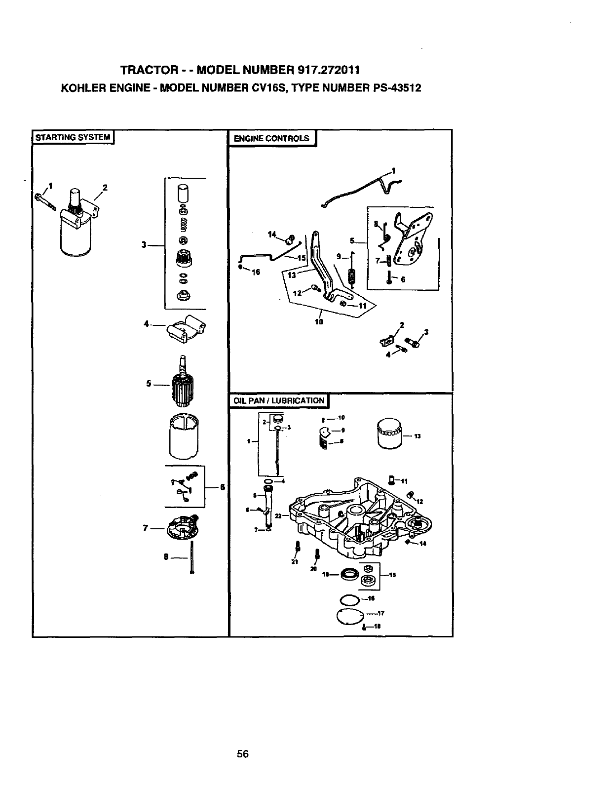
TRACTOR --MODEL NUMBER 917.272011
KOHLER ENGINE - MODEL NUMBER CV16S, TYPE NUMBER PS-43512
STARTING SYSTEM I
0
o
3-- @
o
O
ENGINE CONTROLS I
Ig 2
OIL PAN /LUBRICATION I
1
56
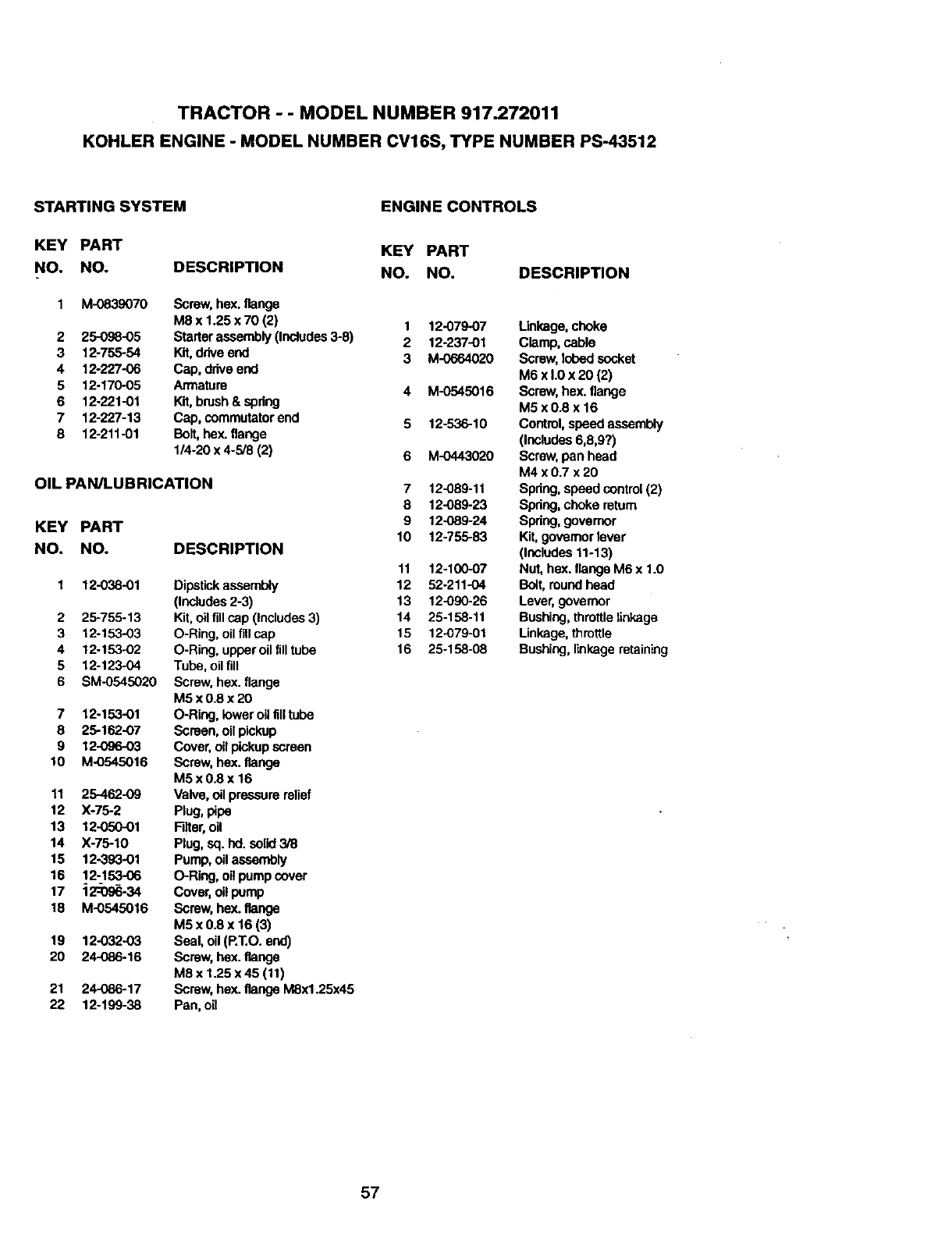
TRACTOR --MODEL NUMBER 917.272011
KOHLER ENGINE -MODEL NUMBER CV16S, TYPE NUMBER PS-43512
STARTING SYSTEM ENGINE CONTROLS
KEY PART
NO. NO. DESCRIPTION
1 M-0839070
2 25-098-05
3 12-755-54
4 12-227-06
5 12.170-O5
6 12.221-01
7 12-227-13
8 12-211-01
Screw,hex. flange
M8 x 1.25 x 70 (2)
Starterassembly (Includes3-8)
Kit,driveend
Cap, driveend
Armature
Kit,brush& spring
Cap, commutatorend
Bolt,hex.flange
1/4-20 x 4-5/8 (2)
OIL PAN/LUBRICATION
KEY PART
NO. NO. DESCRIPTION
1 12-038-01 Dipstickassembly
(Includes2-3)
2 25-755-13 Kit,oil fillcap (includes3)
3 12-153-03 O-Ring, oil fillcap
4 12-153-02 O-Ring, upperoil fill tube
5 12-123-04 Tube, oil fill
6 SM-0545020 Screw,hex. flange
M5xO.8x20
7 12-153-01
8 25-162-07
9 12.-096-O3
10 M-0545016
11 25-462-09
12 X-75-2
13 12-050-01
14 X-75-10
15 12-393-01
16 12-153-06
17 1_-34
18 M-0545016
19 12-032..03
20 24-086-16
21 24086-17
22 12-199-38
O-Ring, loweroilfilltube
Screen, oil pickup
Cover,oil pickupscreen
Screw,hex. flange
M5 x 0.8 x 16
Valve, oil pressurerelief
Plug, pipe
Filter,oil
Plug, sq. hd. solid3/8
Pump, oil assembly
O-Ring, oil pumpcover
Cover,oil pump
Screw,hex. flange
M5 x 0.8 x 16 (3)
Seal, oil (RT.O. end)
Screw, hex. flange
M8 x 1.25 x 45 (11)
Screw, hex. flange M8x1.25x45
Pan, oil
KEY PART
NO. NO.
1 12-079-07
2 12o237-01
3 M-0664020
4 M-0545016
5 12-536-10
6 M-0443020
7 12-089-11
8 12-089-23
9 12-089-24
10 12-755-83
11 12-100-07
12 52o211-04
13 12-090-26
14 25-158-11
15 12-o79-01
16 25-158-08
DESCRIPTION
Linkage, choke
Clamp, cable
Screw, lobedsocket
M6 x 1.0x 20 (2)
Screw, hex. flange
M5xO.8 x 16
Control, speed assembly
(Includes6,8,9?)
Screw,pan head
M4 xO.7 x 20
Spring,speed control (2)
Spring,choke return
Spdng,governor
Kit,governorlever
(Includes11°13)
Nut, hex. flange M6 x 1.0
Bolt,roundhead
Lever,governor
Bushing,throRlelinkage
Linkage,throttle
Bushing,linkage retaining
57
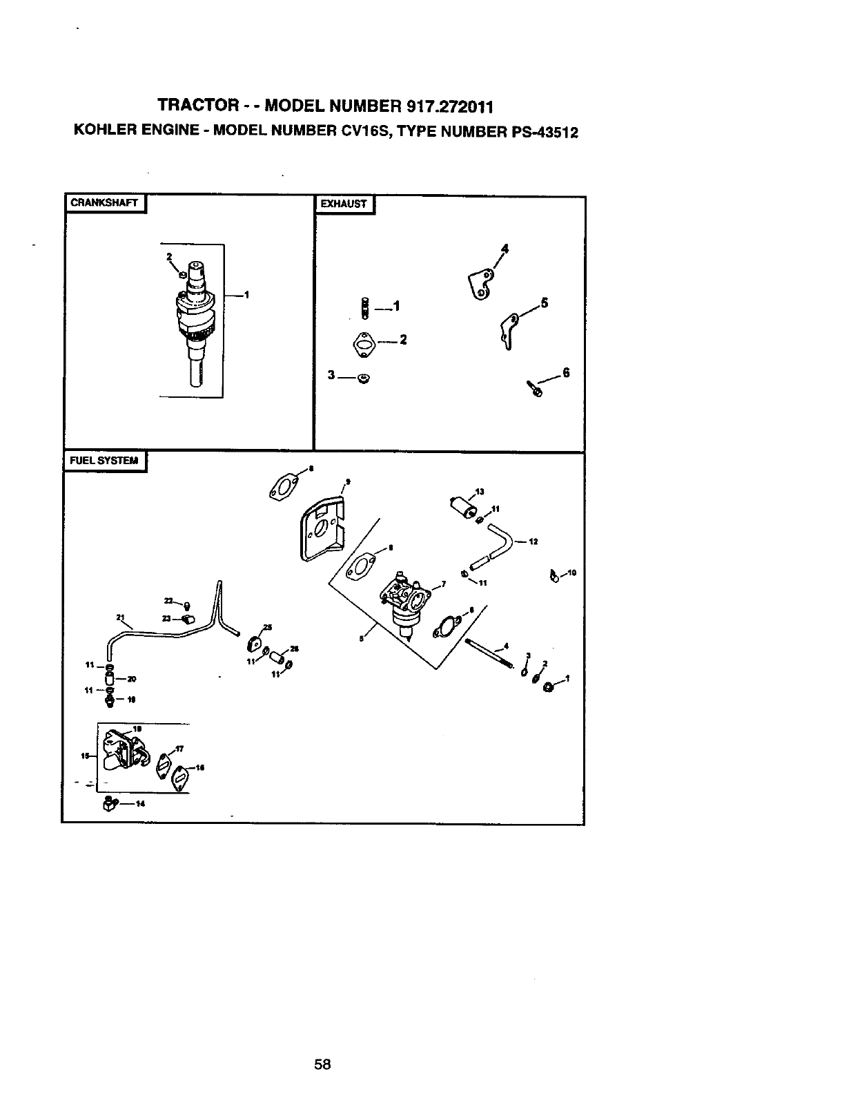
TRACTOR - - MODEL NUMBER 917.272011
KOHLER ENGINE - MODEL NUMBER CVI 6S, TYPE NUMBER PS-43512
CRANKSHAFT J _HAUST _
2
--1
I
J
•I-1 ,_15
O--2
3--_ _6
FUEL SYSTEM _ •
11 --__ qB
_mt4
58
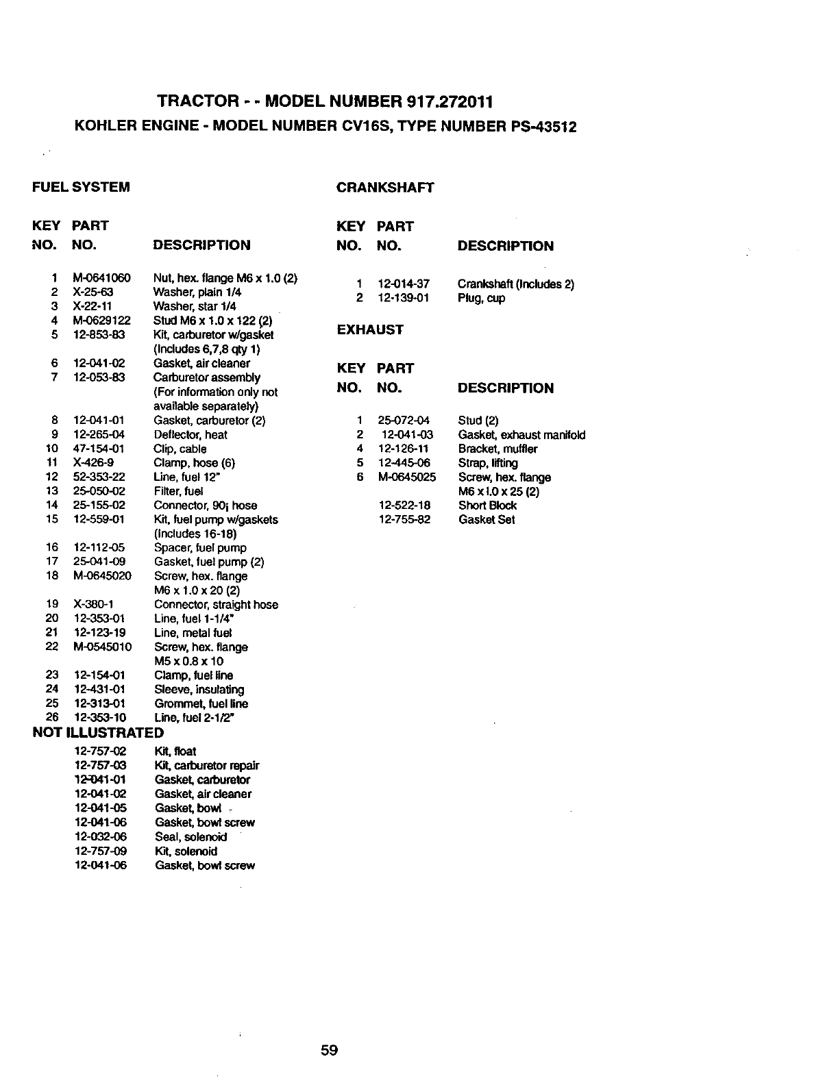
TRACTOR -- MODEL NUMBER 917.272011
KOHLER ENGINE -MODEL NUMBER CV16S, TYPE NUMBER PS-43512
FUELSYSTEM CRANKSHAFT
KEY PART
NO. NO. DESCRIPTION
1 M-0641060
2 X-25-63
3 X-22-11
4 M-0629122
5 12-853-83
6 12-O41-O2
7 12-053-83
8 12-O41-01
9 12-265.04
10 47-154-01
11 X-426-9
12 52-353-22
13 25-050-02
14 25-155-02
15 12-559-01
16 12-112-05
17 25-O41-09
18 M-0645020
19 X-380-1
20 12-353-01
21 12-123-19
22 M-0545010
23 12-154-01
24 12431-01
25 12-313-01
26 12-353-10
Nut, hex. flange M6 x 1.0 (2)
Washer, plain 1/4
Washer, star 1/4
Stud M6 x 1.0 x 122 12)
Kit, carburetorw/gasket
(Includes6,7,6 qty 1)
Gasket, air cleaner
Carburetor assembly
(For informationonly not
available separately)
Gasket, carburetor(2)
Deflector,heat
Clip, cable
Clamp, hose (6)
Une, fuel 12"
Filter,fuel
Connector,90i hose
Kit,fuel pumpw/gaskets
(includes 16-18)
Spacer,fuel pump
Gasket, fuel pump(2)
Screw, hex. flange
M6 x 1.0 x 20 (2)
Connector,straight hose
Line, fuel 1-1/4"
Line, metal fuel
Screw, hex. flange
M5x0.8x 10
Clamp, fuel line
Sleeve, insulaUng
Gmmmet, fuel line
Line, fuel2ol/2,
NOTILLUSTRATED
12-757-02 Kit,goat
12-757--03 Kit,carburetor repair
12.._41-01 Gasket, carburetor
12-O41-02 Gasket, aircleaner
12-041-05 Gasket, bowl -
12-041-06 Gasket, bowl screw
12-o32-06 Seal, solenoid
12-757-09 l_t, solenoid
12-041-06 Gasket, howl screw
KEY PART
NO. NO.
1 12-014-37
2 12-13901
EXHAUST
KEY PART
NO. NO.
1 25-072-04
2 12-041-03
4 12-126-11
5 12-445-06
6 M-0645025
12-522-18
12-755-82
DESCRIPTION
Crankshaft (Includes2)
Plug, cup
DESCRIPTION
Stud (2)
Gasket, exhaustmanifold
Bracket, muffler
Strap, lifting
Screw,hex. flange
M6 x L0 x 25 (2)
Short Block
Gasket Set
59

60

61

62

SUGGESTED GUIDE FOR SIGHTING SLOPES FOR SAFE OPERATION
ISIGHTING
GUIDE
ONLY RIDE UP AND DOWN HILL,
NOT ACROSS HILL
I
Operate your Tractor up and down the face of slopes (not I
greater than 15°), never across the face. Make turns gradu- I
ally to prevent tipping or loss of control. Exercise extreme
caution when changing direction on slopes.

For the repair or replacement parts you need
delivered directly to your home
Call 7 am - 7 pm, 7 days a week
1-800-366-PART
(1-800-366-7278)
Para ordenar piezas con entrega a
domicilio - 1-800-659-7084
For in-house major brand repair service
Call 24 hours a day, 7 days a week
1-800-4-REPAIR
(1-800-473-7274)
Para pedir servicio de reparaci6n a
domicilio - 1-800-676-5811
For the location of a Sears Parts and
Repair Center in your area
Call 24 hours a day, 7 days a week
1-800-488-1222
For information on purchasing a Sears
Maintenance Agreement or to inquire
about an existing Agreement
Call 9 am - 5 pm, Monday-Saturday
1-800-827-6655
When requesting service or ordering
parts, always provide the following
information:
•Product Type •Part Number
•Model Number •Part Description
mmmlmm
mmmmm|
SEARS
America's Repair Specialists
165105 Rev. 27.21.98 TR Printed in U.S.A.
