Craftsman 917272055 User Manual LAWN TRACTOR Manuals And Guides L0103155
CRAFTSMAN Lawn, Tractor Manual L0103155 CRAFTSMAN Lawn, Tractor Owner's Manual, CRAFTSMAN Lawn, Tractor installation guides
User Manual: Craftsman 917272055 917272055 CRAFTSMAN LAWN TRACTOR - Manuals and Guides View the owners manual for your CRAFTSMAN LAWN TRACTOR #917272055. Home:Lawn & Garden Parts:Craftsman Parts:Craftsman LAWN TRACTOR Manual
Open the PDF directly: View PDF ![]() .
.
Page Count: 60

Owner's Manual
16.0 HP
ELECTRIC START
42" MOWER
6 SPEED TRANSAXLE
LAWN TRACTOR
Model No.
917.272055
•Safety
•Assembly
•Operation
•Maintenance
•Repair Parts
CAUTION:
Read and follow all Safety
Rules and Instructions before
operating this equipment.
For answersto your questions
about this product, Call:
1-800-659-5917
Sears Craftsman Help Line
5 am -5 pro, Mc_ -Set
Sears, Roebuck and Co., Hoffman Estates, II 60179
Visit our Craftsman website:www.sears.comlcraftsman

Warranty ............................................... 2
Safety Rules ......................................... 3
Product Specifications.......................... 6
Assembly .............................................. 8
Operation ............................................ 11
Maintenance Schedule ...................... 17
Maintenance ....................................... 17
Service and Adjustments.................... 21
Storage ............................................... 27
Troubleshooting ................................. 28
Repair Parts........................................ 32
Parts Ordedng ..................... Back Cover
LIMITED TWO YEAR WARRANTY ON CRAFTSMAN RIDING EQUIPMENT PARTS
For two (2) years from the date of purchase, if this Craftsman Riding Equipment is
maintained, lubdcatod and tuned up according to the instructionsin the owner's
manual, Sears will repair or replace, free of charge, any parts found to be defective in
material or workmanship. Warranty service is available flee of charge by returning
your Craftsman ridingequipment to your nearest Sears Service Center. In-home
warranty service is available but a tdp charge will apply. This warranty applies only
while this product is in the United States.
This Warranty does not cover:
• Expendable items which become worn during normal use, such as blades, spark
plugs, air cleaners, belts and oil filters.
•Tire replacement or repair caused by punctures from outside objects, such as nails,
tbems, stumps, or glass.
•Repairs necessary because of operator abuse, including but not limited to, damage
caused by towing objects beyond the capability of the dding equipment, impacting
objects that bend the frame or crankshaft, or over speeding the engine.
•Repairs necessary because of operator negligence, including but not limitedto,
electrical and mechanical damage caused by improper storage, failure to use the
proper grade and amount of engine oil, failure to keep the deck clear of flammable
debds, or the failure to maintain the equipment according to the instructions
contained in the owner's manual.
•Engine (fuel system) cleaning or repairs caused by fuel determined to be contami-
nated or oxidized (stale). In general, fuel shOUldbe used within thirty(30) days of its
purchase date.
• Riding equipment used for commercial or rental purposes. Aproductis =used for
commercial purpose" if is used for any purpose other than single family household
dwellings or in usage where profit is made.
LIMITED 90 DAY WARRANTY ON BA'F]'ERY
For ninety (90) days from date of purchase, if any battery included with this dding
equipment proves defective in metedal or workmanship and our testing determines
the battery will not hold a charge, Sears will replace the battery at no charge. War-
ranty service is available free of charge by returning your Craftsman ridingequipment
to your nearest Sears Service Center, In-home warranty service Is available but atrip
charge will apply. This warranty applies only while this product is in the United States.
TO LOCATE THE NEAREST SEARS SERVICE CENTER OR TO SCHEDULE IN-
HOME WARRANTY SERVICE, SIMPLY CONTACT SEARS AT 1-800-4-MY-HOME
This Warranty gives you specific legal dghts, and you may also have other dghts
which may vary from state to state.
Sears, Roebuck and Co., D/817 WA, Hoftman Estates, IL 60179
2

IMPORTANT: This cutting machine is capable of amputating hands and feet and
throwing objects. Failure to observe the follewing safety instructionscould result in
serious injury or death.
I. GENERAL OPERATION
•Read, understand, and follow all
instructionsin the manual and on the
machine before starting.
• Only allow responsible adults, who are
familiar with the instructions,to operate
the machine.
•Clear the area of objects such as
rocks, toys, wire, etc., which could be
picked up and thrown by the blade.
•Be sure the area is clear of other
#_anPlebefore mowing. Stop machine
yone enters the area.
•Never carry passengers.
•Do not mow in reverse unless abso-
lutely necessary. Always look down
and behind before and while backing.
•Be aware of the mower discharge
directionand do not point it at anyone.
Do not operate the mower without
either the entire grass catcher or the
guard in place.
Slow down before turning.
Never leave a running machine
unattended. Always turn off blades, set
parking brake, stop engine, and
remove keys before dismounting.
•Turn off blades when not mowing.
•Stop engine before removing grass
catcher or unclogging chute.
•Mow only in daylight or good artificial
light.
• Do not operate the machine while
under the influence of alcohol or drugs.
•Watch for traffic when operating near or
crossing roadways.
•Use extra care when loading or
unloading the machine into a trailer or
truck.
•Data indicates that operators, age 60
years and above, are involved in a
large percentage of dding mower-
related injudas. These o!_era_rs
should evaluate their abihty to operate
the dding mower safely enough to
protect themselves and others from
sedous injury.
•Keep machine free of gress, leaves or
other debris build-up which can touch
hot exhaust/engine partsand bum. Do
not allowthe mower deck to plow leaves
or other debds which can cause build-.
up to occur. Clean any oil or fuel
spillagebeforeopera_ngorstoringthe
machine. Allow machine to cool before
storage.
II. SLOPE OPERATION
Slopes are a majorfactor related to loss-of÷
control and Upover accidents, which can
result in severe injury or death. All slopes
require extra caution. Ifyou cannotback up
the slope or if you feel uneasy on it, do not
mow it.
DO:
•Mow up and down slopes, not across.
•Remove obstacles such as rocks, tree
limbs, etc.
Watch for holes, ruts, or bumps.
Uneven terrain could overturn the
machine. Ta/I grass can hide obstacles.
Use slow speed. Choose a low gear so
that you willnot have to stopor shth
while on the slope.
Follow the manufacturer's recommen-
dations for wheel weights or counter-
weights to improve stability.
Use extra care with grass catchers or
other attachments. These can change
the stabilityof the machine.
Keep all movement on the slopes slew
and gradual. Do not make sudden
changes in speed or direction,
Avoid starting or stepping on a slope. If
tires lose traction, disengage the
blades and proceed slowly straight
down the slope.
DO NOT:
• Do not turn on slopes unless neces-
sary, and then, turn slowly and gradu-
ally downhill, if possible.
•Do not mow near drop-offs, ditches, or
embankments. The mower could
suddenly tam over if a wheel is over the
edge of acliffor ditch, or if an edge
caves in.
•Do not mow on wet grass. Reduced
traction could cause sliding.
•Do not try to stabilize the machine by
putting your foot on the ground.
•Do not use grass catcher on steep
slopes.
3

IlL CHILDREN
Tragic accidents can occur if the operator
is not alert to the presence of children.
Children are often attracted to the
machine and the mowing activity. Never
assume that children will remain where
you last saw them.
•Keep children out of the mowing area
and under the watchful care of another
responsible adult.
•Be alert and turn machine off if children
enter the area.
•Before and when backing, look behind
and down for small children.
• Never carry children. They may fall off
and be sadously injured or interfere
with safe machine operation.
•Never allow children to operate the
machine.
•Use extra care when approaching blind
corners, shrubs, trees, or other objects
that may obscure vision.
IV. SERVICE
•Use extra care in handling gasoline
and other fuels. They are flammable
and vapors are explosive.
-Usa only an approved container.
-Never remove gas cap or add fuel
with the engine running. Allow
engine to cool before refueling. Do
not smoke.
-Never refuel the machine indoors.
-Never store the machine or fuel
container inside where there is an
open flame, such as a water heater.
•Never run a machine inside a closed
area.
•Keep nuts and bolts, especially blade
attachment bolts, tight and keep
equipment in good condition.
•Never tamper with safety devices.
Check their proper operation regularly.
•Keep machine free of grass, leaves, or
other debds build-up. Clean oil or fuel
spillage. Allow machine to cool before
stodng.
•Stop and inspect the equipment if you
stdke an object. Repair, if necessary,
before restarting.
•Never make adjustments or repairs
with the engine running.
•Grass catcher components are subject
to wear, damage, and detedoretion,
which could expose moving parts or
allow objects to be thrown. Frequently
check components and replace with
manufacturer's recommended parts,
when necessary.
•Mower blades are sharp and can cut.
Wrap the blade(s) or wear gloves, and
use extra caution when servicingthem.
•Check brake operation frequently.
Adjust and service as required.
•Be sure the area is clear of other
people before mowing. Stop machine if
anyone enters the area.
•Never carry passengers or children
even with the blades off.
•Do not mow in reverse unless abso-
lutely necessary. Always look down
and behind before and while backing.
•Never carry children. They may fall off
and be seriously injured or interfere
with safe machine operation.
•Keep children out of the mowing area
and under the watchful care of another
responsible adult.
•Be alert and turn machine off if children
enter the area.
•Before and when backing, look behind
and down for small children.
•Mow up and down slopes (15 °Max),
not across.
•Remove obstacles such as rocks, tree
limbs,etc.
•Watch for holes, ruts, or bumps.
Uneven terrain could overturn the
machine. Tall grass can hide obstacles.

• Useslowspeed.Choosealowgearso
thatyouwillnothavetostoporshift
whileontheslope.
•Avoid staring or stopping on a slope. If
tiros lose traction, disengage the
blades and proceed slowly straight
down the slope.
• If machine stops while going uphill,
disengage blades, shiftinto reverse
and back down slowly.
• Do not turn on slopes unless neces-
sary, and then, turn slowly and gradu-
ally downhill, if possible,
,_Loak for this symbol to point out
importantsafety precautions. It means
CAUTIONll! BECOME ALERTIl! YOUR
SAFETY IS INVOLVED.
,_ CAUTION: In order to prevent
accidental starting when setting up,
transpo_ng, adjusting or making repairs,
always disconnect spark plug wire and
place wire where it cannot contact spark
plug.
,_ CAUTION: Do not coast down a hill
in neutral, you may lose controlof the
tractor.
,_ CAUTION: Tow only the attachments
that are recommended by and comply
with specifications of the manufacturer of
your tractor. Use common sense when
towing. Operate only at the lowest
possible speed when on aslope. Too
heavy of a load, while on a slope, is
dangerous. Tires san lose tractionwith
the ground and cause you to lose control
of your tractor.
.,_WARNING: Engine exhaust, some of
its constituents, and certain vehicle
components contain or emit chemicals
known to the State of California to cause
cancer and birthdefects or other repro-
ductive harm.
_I, WARNING: Battery posts, terminals
and related accassehes contain lead and
lead compounds, chemicals known to the
State of California to cause cancer and
birth defects or other reproductive harm.
Wash hands after handling.
5

PRODUCTSPECIFICATIONS
GASOLINE 1.25 GALLONS
CAPACITY UNLEADED
ANDTYPE: REGULAR
OILTYPE SAE 10W30 (ABOVE
32°F)
(API-SF-SJ): SAE 5W-30
(BELOW 32°F)
OIL CAPACITY: W/FILTER: 4.0 PINTS
W/OFILTER: 3.5 PINTS
SPARK PLUG: CHAMPION RC12YC
GAP: .040")
GROUND SPEED FORWARD:
(MPH): I sT 1.2
2N° 1.5
3R° 2.4
4TM 3.5
5TM 4.8
6TM 5.3
REVERSE: 1.5
TIRE PRESSURE:FRONT: 14 PSI
REAR: 10 PSI
CHARGING 3 AMPS BATTERY
SYSTEM: 5 AMPS HEADLIGHTS
BATTERY: AMP/HR: 30
MIN. CCA: 240
CASE SIZE: U1R
BLADE BOLT 27-35 FT. LSS.
TORQUE:
CONGRATULATIONS on your purchase
of a new tracton It has been designed,
engineered and manufactured to give
you the best possible dependability and
performance.
Should you experience any problem you
cannot easily remedy, please contact a
Sears or other qualified service center.
We have competent, well-trained techni-
cians and the proper tools to service or
repair this tractor.
Please read and retain this manual. The
instructionswill enable you to assemble
and maintain your tractor properly.
Always observe the =SAFETY RULES".
REPAIR AGREEMENT
A Repair Agreement is available on this
product. Contact your nearest Sears
store for details.
CUSTOMER RESPONSIBILITIES
• Read and observe the safety roles.
• Follow a regular schedule in maintain-
ing, cadng for and usingyour tractor.
•Follow the instructionsunder "Mainte-
nance" and °Storage" sections of this
owner's manual.
_LWARNING: This tractor is equipped
with an internal combustion engine and
should not be used on or near any
unimproved forest-covered, brush-
covered or grass-covered land unless the
engine's exhaust system is equipped with
a spark an'ester meeting applicable local
or state laws (if any). If a spark an'ester is
used, it should be maintained in effective
working order by the operator.
Jnthe state of California the above is
required by law (Section 4442 of the
California Public Resoumes Code).
Other states may have similarlaws.
Federal laws apply on federal lands. A
spark arrester for the muffler is available
through your nearest Sears service
center (See REPAIR PARTS section of
this manual).
6

Steering
WheelInsert
C2
(1) Hex Bolt
3/8-16 x 1
Steering
Boot
Steering Wheel
-_,_(1) Lockwasher 3/8
1) Locknut
5/16-16
_ Steering
Wheel Adapter
(1) Large Flat Washer
(1) Hex Bolt
5/16-18 x 1-1/4
Shaft
Seat
\
(_Washer
_-_ 17132x1-3/16 x12
Gauge
_(1) Knob
Slope Sheet
For Future Use
Keys
tl
(2) Keys Video Cassette

Your now tractor has been assembled at the factorywith exception of those parts left
unassembled for shipping purposes. To ensure safe and proper operation of your
tractor all parts and hardware you assemble must be tightened securely. Use the
correct toolsas necessary to insure proper tightness. Review the video cassette before
you begin.
TOOLS REQUIRED FOR
ASSEMBLY
A socket wrench set will make assembly
easier. Standard wrench sizes you need
are listed below.
(1) 9/16"wrench (1) Pliers
(2) 1/2"wrench (1) Utility knife
(1) Tire pressure gauge
When dght or left hand is mentioned in
this manual, it means, from your point of
view, when you are in the operating
position (seated behind the steedng
wheel).
TO REMOVETRACTOR FROM
CARTON
UNPACK CARTON
1. Remove all accessible loose parts
and parts cartons from carton.
2. Cut, from top to bottom, along lines on
all four comers of carton, and lay
panels fiat.
3. Check for any additional loose parts
or cartons and remove.
BEFORE REMOVING TRACTOR
FROM SKID
ATTACHSTEERINGWHEEL
ASSEMBLE EXTENSION SHAFT AND
BOOT
1. Slide extension shaft onto lower
steedng shaft. Align mounting holes
in extension and lower shafts and
install 5/16 hex bolt and Iocknut.
Tighten securely.
2. Place tabs of steedng boot over tab
slots in dash and push down to
secure.
INSTALL STEERING WHEEL
3. Positionfront wheels of the tractor so
they are pointing straightforward.
4. Remove steedng wheel adapter from
steedng wheel and slide adapter onto
steedng shaft extension.
5. Position steedng wheel so cross bars
are horizontal (left to right) and slide
inside boot and onto adapter.
6. Assemble large fiat washer, 3/8 lock
washer, 3/8 hex belt and tighten
securely.
7. Snap steedng wheel insert into center
of steedng wheel.
8. Remove protective matedals from
tractor hood and gdll.
IMPORTANT: Check for and remove any
staples in skid that may puncture tires
where tractor is to roll off skid.
HOWTO SET UPYOURTRACTOR
CHECK BATTERY
1. Lift seat pan to raised position and
open battery box door.
NOTE: If this battery is put into service
after month and year indicated on label
(label located between terminals) charge
battery far minimum of one hourat 6-10
amps. (See "BATTERY" in Maintenance
section of this manual for charging
instructions).

Label
Seat
Batter
Door
INSTALL SEAT
Adjust seat before tightening adjustment
knob.
1. Remove adjustment knob and fiat
washer securing seat to cardboard
packing and set aside for assembly of
seat to tractor.
2. Pivot seat upward and remove from
the cardboard packing. Remove the
cardboard packing and discard.
3. Place seat on seat pan so head of
shoulder bolt is positioned over large
slotted hole in pan.
4. Push down on seat to et'_:Jage
shoulder belt in slot and pull scot
towards rear of tractor.
5. Pivot seat and pan forward and
assemble adjustment knob and fiat
washer loosely. Do not tighten.
6. Lower seat into operating position and
sit in seat.
7, Slide seat until a comfortable position
is reached which allows you to press
clutch/brake pedal ell the way down.
8. Get off seat without moving its
adjusted position,
8. Raise seat and tighten adjustment
knob securely.
SeatPan_ulder
Flat W_h_r _
Adjustmen_tKiob OIm
NOTE: You may now roll or driveyour
tractor off the skid. Follow the appropriate
instructionbelow to remove the tractor
from the skid.
TO ROLLTRACTOR OFF SKID (See
Operation section for location and
function of controls)
1. Press lift lever plunger and raise
attachment liftlever to its highest
position.
2. Release parking brake by depressing
clutch/brake pedal,
3. Place gearshift lever in neutral (N)
position.
4. Roll tractor forward offskid.
5. Remove banding holding deflector
shield up against tractor.
TO DRIVETRACTOR OFF SK/D (See
Operation section for location and
function of controls)
=_I_WARNING: Before starting, read,
understand and follow all instructions in
the Operation section of this manual. Be
sure tractor is in a weil-ventilated area.
Be sure the area in front of tractor is clear
of other people and objects.
1. Be sure all the above assembly steps
have been completed.
2. Check engine oil level and fill fuel
tank with gasoline.
3. Sit on seat in operating position,
depress clutch/brake pedal and set
the parking brake.
4. Place gear shift lever in neutral (N)
position.
5. Press lift lever plunger and raise
attachment rift lever to its highest
position.
6. Start the engine, After engine has
started, move throttle controlto idle
position.
7. Depress clutch/brake pedal into full
"BRAKE" position and hold, Move
gearshift lever to 1st gear.
8. Slowly release elutch/brake pedal and
slowly ddve tractor off skid.
9. Apply brake to stop tractor, set parking
brake and place gearshift lever in
neutral position.
10.Turn ignitionkey to "OFF" position.
Continue with the instructionsthat follow.

INSTALL MULCHER PLATE
(If previously removed)
1. Raise and hold deflector shield in
upright position.
2. Place front of mulcher plate over front
of mower deck opening and slide into
place, as shown.
3. Hook front latch into hole on front of
mower deck.
4. Hook rear latch into hole on back of
mower deck.
_CAUTION: Do not remove deflector
shield from mower. Raise and hold shieM
when attaching mulcher plate and allow it
to rest on plate while in operation.
Mulcher
Plate
Shield
Latch
Hooks
TO CONVERTTO BAGGING OR
DISCHARGING
Simply remove mulcher plate and store in
a safe place. Yourmower is now ready for
discharging or installation of optional
grass catcher accessory.
NOTE: It is not necessary to change
blades. The mulcher blades are de-
signed for discharging and bagging also.
CHECKTIRE PRESSURE
The tires on your tractor were ovedn-
flated at the factory for shipping pur-
poses. Correct tire pressure is important
for best cutting performance.
•Reduce tire pressure to PSI shown in
=PRODUCT SPECIFICATIONS"
section of this manual.
CHECK DECK LEVELNESS
For best cutting results, mower housing
should be pmpedy leveled. See =TO
LEVEL MOWER HOUSING" in the
Service and Adjustments section of this
manual.
CHECK FOR PROPER POSITION
OF ALL BELTS
Bee the figures that are shown for
replacing motion and mower blade drive
belts in the Service and Adjustments
sectionof this manual. Verify that the
belts are muted correctly.
CHECK BRAKE SYSTEM
After you learn how to operate your
tractor, check to see that the brake is
propedy adjusted. See "TO ADJUST
BRAKE" in the Service and Adjustments
section of this manual.
,/CHECKLIST
BEFORE YOU OPERATE AND ENJOY
YOUR NEW TRACTOR, WE WISH TO
ASSURE THATYOU RECEIVE THE
BEST PERFORMANCE AND
SATISFACTION FROM THIS QUALITY
PRODUCT.
PLEASE REVIEWTHE FOLLOWING
CHECKLIST:
,/All assembly instructions have been
completed.
,/No remaining loose parts in carton.
,/Battery is propedy prepared and
charged. (Minimum 1 hour at 6
amps).
,/Seat is adjusted comfortablyand
tightened securely.
,/All tires are propedy inflated. (For
shipping purposes, the tires were
ovednflated at the factory).
JBe sure mower deck is propedy
leveled side-to-side/fmnt-to-rear for
best cutting results. (Tires must be
propedy inflated for leveling).
,/Check mower and ddve belts. Be sure
they am muted propedy around
pulleys and inside all belt keepers.
•/Check widng. See that all connections
are still secure and wires are propedy
clamped.
WHILE LEARNING HOWTO USEYOUR
TRACTOR, PAYEXTRA ATTENTION TO
THE FOLLOWING IMPORTANT ITEMS:
•/Engine oil is at proper level.
4" Fuel tank is filled with fresh, clean,
regular unleaded gasoline.
,/Become familiar with all controls- their
location and function. Operate them
before you start the engine.
4" Be sure brake system is in safe
operating condition.
10

These symbols may appear on your tractor or in literature supplied with the product.
Learn and understand their meaning.
SATFERY CAUTION OR REVERSE FORWARD FAST SLOW
WARNING
ENGINE ON ENGINE OFF OIL PRESSURE LIGHTS ON OVER TEMP
LIGHT
FUEL CHOKE MOWER HEIGHT PARKING BRAKE UNLOCKED
LOCKED
!
MOWER LIFT
r_'t R N H L
ATTACHMENT REVERSE NEUTRAL HIGH LOW PARKING BRAKE
CLUTCH ENGAGED
ATTACHMENT KEEP AREA CLEAR SLOPE HAZARDS
IGNITION CLUTCH DISENGAGED
DANGER. KEEP HANDS AND FEETAWAY
(SEE SAFETY RULES SECTION)
FREE WHEEL
(AutomaticMode_sonly)
11

KNOWYOURTRACTOR
READ THIS OWNER'S MANUAL AND SAFETY RULES BEFORE OPERATING
YOUR TRACTOR
Compare the tilusb'ations with your tractor to famtiiadze yourself with the locationsof
vadous controls and adjustments. Save this manual for future reference.
Attachment
Clutch
Ammeter
Throttle/Choke
Control
Ignition Switch Light Switch
Uft
Plunger
Attachment
Lift Lever
Clutch/Brake
Pedal Height
Adjustment
Indicator
parking Brake Lever
Gearshift Lever
Our tractors conformto the safety standards of tha American
NationarStandards Institute.
AMMETER - Indicates charging (+) or
discharging(-) of battery.
ATTACHMENT CLUTCH LEVER -Used
to engage the mower blades, or other
attachments mounted to your tractor.
ATTACHMENT LIFT LEVER -Used to
raise, lower, and adjust the mower deck
or other attachments mounted to your
tractor.
CLUTCWBRAKE PEDAL - Used for
dectutchingand braking the tractor and
starting the engine.
GEARSHIFT LEVER - Selects the speed
and direction of tractor.
IGNITION SWITCH ÷Used for starting
and stopping the engine.
LIFT LEVER PLUNGER - Used to
release attachment liftlever when
changing its position.
LIGHT SWITCH - Turnsthe headlightson
and off.
PARKING BRAKE LEVER - Locks
clutch/brake pedal into the brake
position.
THROTTLEICHOKE CONTROL- Used
for starting and controllingengine speed.
12
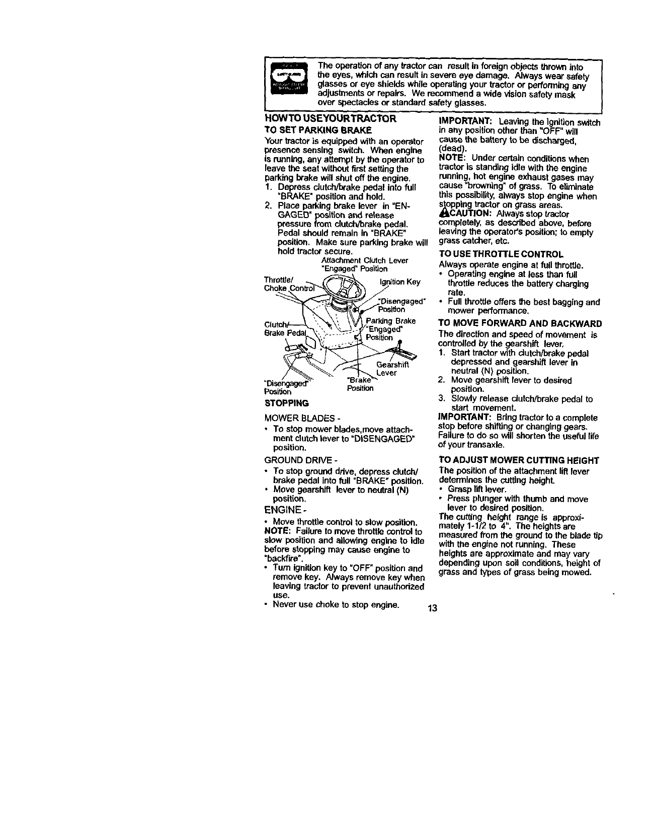
The operation of any tractor can result in foreign objects thrown into
the eyes, which can result in severe eye damage. Always wear safety
glasses or eye shields while operating your tractor or performing any
adjustments or repairs. We recommend a wide vision safety mask
over spectacles or standard safety glasses.
HOWTO USEYOURTRACTOR
TO SET PARKING BRAKE
Your tractor is equipped with an operator
presence sensing switch. When engine
is running, any attempt by the operator to
leave the seat without firstsetting the
parking brake will shut off the engine.
1. Depress clutch/brake pedal into full
=BRAKE"position and hold.
2. Place parking brake lever in "EN-
GAGED" pesitio_ and release
pressure from clutch/brake pedal.
Pedal should remain in "BRAKE"
position. Make sure parking brake will
hold tractor secure.
Attachment Clutch Lever
=Engaged"Position
Thro_el
Choke
Brake
Lever
"Disengaged'
Postiion Position
STOPPING
MOWER BLADES -
• To stop mower blades.move attach-
ment clutch lever to "DISENGAGED"
position.
GROUND DRIVE -
•To stop ground ddve, depress clutch/
brake Pedal into full "BRAKE"position.
•Move gearshift lever to neutral (N)
position.
ENGINE-
•Move throttle control to slow position.
NOTE: Failure to move throttle controlto
slow position and allowing engine to idle
before stoppingmay cause engine to
"backfire".
•Turn ignition key to "OFF" position and
remove key. Always remove key when
leaving tractor to prevent unauthorized
use.
IMPORTANT: Leaving the ignitionswitch
in any positionother than "OFF" will
cause the battery to be discharged,
(dead).
NOTE: Under certain conditionswhen
tractor is standing idle with the engine
running, hot engine exhaust gases may
cause "browning" of grass. To eliminate
this possibility, always stop engine when
_cpping tractor on grass areas.
AUTION: Always stop tractor
completely, as described above, before
leaving the operator's position; to empty
grass catcher, etc,
TO USE THROTTLE CONTROL
Always operate engine at full throttle.
•Operating engine at less than full
throttle reduces the battery charging
rate.
•Full throttle offers the best baggingand
mower performance,
TO MOVE FORWARD AND BACKWARD
The direction and speed of movement is
controlled by the gearshift lever,
1. Start tractor with dutch/brake pedal
depressed and gearshift lever in
neutral (N) position.
2. Move gearshift lever to desired
position.
3. Slowly release clutch/brake pedal to
start movement.
IMPORTANT: Bdng tractor to a complete
stop before shiftingor changing gears.
Failure to do so will shorten the useful life
of your transaxle.
TO ADJUST MOWER CUTTING HEIGHT
The position of the attachment lift lever
determines the cutting height.
.Grasp lift lever.
•Press plunger with thumb and move
lever to desired position.
The cutting height range is approxi-
mately 1-112to 4". The heights are
measured from the ground to the blade tip
with the engine not running. These
heights are approximate and may vary
depending upon soil conditions, height of
grass and types of grass being mowed.
• Never use choke to stop engine. 13

• Theaveragelawnshouldbecut to
approximately 2-112 inches dudng the
cool season and to over 3 inches
duringhot months. For healthier and
better looking lawns, mew often and
after moderate growth.
•For best cutting performance, grass
over 6 inches in height should be
mowed twice. Make the first cut
relatively high; the second to desired
height.
TO ADJUST GAUGE WHEELS
Gauge wheels are properly adjusted
when they are slightlyoff the ground
when mower is at the desired cutting
height in operating position. Gauge
wheels then keep the deck in proper
positionto help prevent scalping in most
terrain conditions.
NOTE: Adjustgauge wheels with tractor
on a fiat level surface.
1. Adjust mower to desired cutting height
(See "TO ADJUST MOWER cUTTING
HEIGH'P" in the Operation section of
this manual.
2. With mower n desired height of cut
position, gauge wheels should be
assembled so they are slightlyoff the
ground. Install gauge wheel in
appropdata hole with shoulder belt, 3/
8 washer, and 3/8-16 lesknut and
tighten securely.
3. Repeat for opposite side installing
gauge wheel in same adjustment
hole.
Gaug .\,,.
Wheel _--_-__-_ "_ _\
MOUnting__""_l_i_
3/8"t6 _=_*'vl .%-_ /\\ /<'-/
Locknut "_;4 F'-=_---'_ _ "J
rY/_ ,,f'_, _J" Shoulder
3/8 Washer_ _ ,_Bolt
GaugeWheel
TO OPERATE MOWER
Yourtractor is equipped with an operator
presence sensing switch. Any attempt by
the operator to leave the seat with the
engine running and the attachment
clutch engaged will shut off the engine.
1. Select desired height of cut.
2. Start mower blades by engaging
attachment clutch control.
TO STOP MOWER BLADES -
disengage attachment clutch control.
_CAUTION: Do not operate the mower
without either the entire grass catcher, on
mowers so equipped, or the deflector
shield in place.
Attachment
ClutchLever Attachemnt
"Engaged" High
Position Position
PosilJon
PosilJon
Shield
TO OPERATE ON HILLS
_kCAUTION: Do not drive up or down
hills with slopes greater than 15" and do
not drive across any slope.
•Cheese the slowest speed before
starting up or down hills.
*Avoid stopping or changing speed on
hills,
oIf slowing is necessary, move throttle
control lever to slower position.
•If stopping is absolutely necessary,
push clutch/brake pedal quickly to
brake position and engage parking
brake.
• Move gearshift lever to 1st gear. Be
sure you have allowed room for tractor
to roll slightlyas you restart movement.
•To restart movemenL slowly release
parking brake and clutch/brake pedal.
• Make all turns slowly.
TO TRANSPORT
•Raise attachment liftto highest position
with attachment liftcontrol.
•When pushing or towing your tractor,
be sure gearshift lever is in neutral (N)
position.
•Oo not push or tow tractor at more than
five (5) MPH.
NOTE: To protect hoodfrom damage
when transporting your tractor on a truck
or a trailer, be sure hoed is closed and
secured to tractor. Use an appropriate
means of tying hood to tractor (rope, cord,
etc.).
14

TOWING CARTS AND OTHER
ATTACHMENTS
Tow only the attachments that are
recommended by and comply with
specificationsof the manufacturer of your
tractor. Use common sense when towing.
Too heavy of a load, while on a slope, is
dangerous. Tires can lose traction with the
ground and cause you to lose control of
yourtractor.
BEFORE STARTINGTHE ENGINE
CHECK ENGINE OIL LEVEL
The engine in your tractor has been
shipped, from the factory, already filled
with summer weight oil.
1. Check engine oil with tractor on level
ground,
2. Unthread and remove oil fill cap/
dipstick;wipe oil off. Reinsert the
dipstickinto the tube and rest oil fill
cap on the tube. Do not thread the
cap onto the tube. Remove and read
oil level. If necessary, add oil until
"FULL" mark on dipstickis reached.
Do not overfill.
• For cold weather operation you should
change oil for easier startlng(Sea "OIL
VISCOSITY CHART' in the Mainte-
nance section of this manual).
•To change engine oil, see the Mainte-
nance section in this manual.
Oll Fill Cap/
Dipstick
ADD GASOLINE
•Fill fuel tank. Use fresh, clean, regular
unleaded gasoline with a minimum of
87 octane. (Use of leaded gasoline
will increase carbon and lead oxide
deposits and reduce valve life). Do not
mix oil with gasoline. Purchase fuel in
quantities that can be used within 30
days to assure fuel freshness.
IMPORTANT: When operating in
temperatures below 32°F(0°C), use fresh,
clean winter grade gasoline to help
insure good cold weather starting.
,_WARNING: Experience indicates that
alcohol blended fuels (called gasehol or
using ethanol or methanol) can attract
moisturewhich leads to separation and
formation of acids dudng storage. Acidic
gas can damage the fuel system of an
engine while in storage. To avoid engine
problems, the fuel system should be
emptied before storage of 30 days or
longer. Drain the gas tank, start the engine
and let it run until the fuel lines and
carburetorare empty. Use flesh fuel next
season. See Storage Instructionsfor
additional information. Never use engine
or carburetor cleaner products in the fuel
tank or permanent damage may occur.
_CAUTION: Fill to bottomef gas tank
filler neck. Do not overfill. Wipe off any
spilledoil or fuel. Do not store, spillor use
gasoline near an open flame.
TO START ENGINE
Whenstadingthe engineforthefirst lime or if
enginehas mn outef fual, itwill take extra
clankingtime to move ft_ fromthetankto the
engine.
1. Sit on seat in operating position,
depress clutch/brake pedal and set
parking brake.
2. Place gear shift lever in neutral (N)
position.
3. Move attachment clutch to =DISEN-
GAGED" position.
4. Move throttle control to choke position.
NOTE'. Beforestarting,readthewarmand
coldsta_ng proceduresbelow.
5. Insert key into ignition and tam key
clockwise to "START" positionand
release key as soon as engine starts.
Do not run starter continuously for
more than fifteen seconds per minute. If
the engine does not start after several
attempts, move throttle controlto fast
position, wait a few minutes and try
again. If engine still does not start,
move the throttle control back to the
choke position and retry.
WARM WEATHER STARTING(50" Fand
above)
6. When engine starts, move the throttle
control to the fast position.
•The attachments and ground ddve can
now be used, If the engine does not
accept the load, restart the engine and
allow it to warm up for one minute using
the choke as descdbed above.
15

COLD WEATHER STARTING ( 50° F and
below)
6. When engine starts, allow engine to
run with the throttle control in the
choke position untilthe engine runs
roughly, then move throttle control to
fast position.This may require an
engine warm-up pedod from several
seconds to several minutes, depend-
ing on the temperature.
• The attachments can also be used
dudng the engine warm-up pedod.
NOTE: If ata highal_tude(above 3000 feet)
or incoldtemperotures(below32 F) the
cad0uretorfuelmixturemay need to be
a_usted for best engine perfommnce.See
"TO ADJUST CARBURETOR" in the Sewice
and Ac_ustmeetsse_on of this manual.
MOWINGTIPS
• Mower should be propedy leveled for
best mowing performance. See "TO
LEVEL MOWER HOUSING" in the
Service and Adjustments section of this
manual.
•The left hand side of mower should be
used for trimming.
•Ddve so that clippings are discharged
onto the area that has been cut, Have
the cutarea to the dght of the tractor.
This will result in a more even distdbu-
tion of clippingsand more uniform
cutting.
•When mowing large areas, start by
tuming to the dght so that clippingswill
discharge away from shrubs, fences,
ddveways, etc. After one or two
rounds, mow in the opposite direction
making left hand turns until finished.
• If grass is extremely tall, it should be
mowed twice to reduce load and
possible fire hazard from dded
clippings. Make first cut relatively high;
the second to the desired height.
• Do not mow grass when it is wet. Wet
grass will plug mower and leave
undesirable clumps. Allow grass to dry
before mowing.
•Always operate engine at full throttle
when mowing to assure better mowing
performance and proper discharge of
matedal. Regulate ground speed by
selecting a low enough gear to give the
mower cutting performance as well as
the qualityof cut desired.
•When operating attachments, select a
ground speed that will suit the terrain
and give best performance of the
attachment being used.
16
MULCHING MOWlNGTIPS
IMPORTANT: For best performance,
keep mower housingfree of built-up
grass and trash. Clean after each use.
•The special mulching blade will recut
the grass clippingsmany times and
reduce them in size so that as they fall
onto the lawn they will disperse into
the grass and not be noticed. Also, the
mulched grass will biodegrade quickly
to provide nutdents for the lawn.
Always mulch with your highest
engine (blade) speed as this will
provide the best recurringaction of the
blades.
•Avoid cuffing your lawn when it is wet.
Wet grass tends to form clumps and
interferes with the mulching action.
The best time to mow your lawn is the
eady aftemoon. At this time the grass
has dded and the newly cut area will
not be exposed to the direct sun.
•For best results, adjust the mower
cutting heightso that the mower cuts
off only the top one-third of the grass
blades. For extremely heavy mulching,
reduce your width of cut on each pass
and mow slowly.
•Certain types of grass and grass
conditions may require that an area be
mulched a second time to completely
hide the clippings. When doing a
second cut, mow across or perpen-
dicular to the firstcut path.
• Change your cutting pattern from week
to week. Mow north to southone week
then change to east to west the next
week. This will help prevent matting
and graining of the lawn.
'Max 113"

2. _A_km rr_o c_ _ _ In _V ar _'f condl_r4. 6 I_t r_ ed ff _ _ rrmln_m_ce_ tmem'].
GENERAL RECOMMENDATIONS
The warranty on this b'ectordoes not cover
items that have been subjectedto operator
abuse or negligence. To receive full value
fromthe warranty,operator must maintain
tractoras instructedin this manual.
Soma adjustments willneed to be made
periodically to properly maintain your
tractor.
All adjustments in the Service and
Adjustmentssec_on of this manual should
be checked at least once each season.
•Once a year you should replace the
spark plug,clean or replace air filter, and
check _adas and belts for wear. A new
spark plug and clean airfilter assure
proper air-fuel mixtureand help your
engine run better and last longer.
BEFORE EACH USE
1. Check engine oil level.
2. Check brake operation.
3. Check tire pressure.
4. Check operator presence and
intedock systems for proper operation.
5, Check for loose fasteners.
LUBRICATION CHART
(_ Spindle--
Zerk Zerk
(_Front Wheel
Bearing Beating Zerk
Zerk
(_SAE 30 or 10w30MOTOR OIL
_ENERJ_L PURPOSE GREASE
_REFER TO Ma_terta_ce "ENGINE"SECTION
IMPORTANT: Do not oil or grease the pivot
points which have special nylon bearings.
Viscous lubricants will attract dust and dirt
that will shorten the life of the self-lubricat-
ing beadngs. If you feel they must be
lubdcated, use only a dry, powdered
graphite type lubricant sparingly.
17

TRACTOR
Always observe safety rules when
performing any maintenance.
BRAKE OPERATION
If tractor requires more than six (6) feet
stoppingdistance at high speed in
highest gear, then brake must be ad-
justed. (See "TO ADJUST BRAKE" in the
Service and Adjustments section of this
manual).
TIRES
• Maintain proper air pressure in ell tires
(See =PRODUCT SPECIFICATIONS"
section of this manual).
•Keep tires free of gasoline, oil, or insect
control chemicals which can harm
rubber.
• Avoid stumps, stones, deep ruts, sharp
objects and other hazards that may
cause tire damage.
NOTE: To seal tire punctures and prevent
fiat tires due to slow leaks, tire sealant
may be purchased from your local parts
dealer. Tire sealant also prevents tire dry
rot and corrosion.
OPERATOR PRESENCE SYSTEM
Be sure operator presence and intedock
systemsare working propedy. If your
tractor does not function as described,
repair the problem immediately.
•The engine should oct start unless the
brake pedal is fully depressed and
attachment clutch control is in the
disengaged position.
•When the engine is running, any
attempt by the operator to leave the
seat without firstsetting the parking
brake should shut off the engine.
•When the engine is running and the
attachment dutch is engaged, any
attempt by the operator to leave the
seat should shut off the engine.
•The attachment clutch should never
operate unless the operator is in the
seat.
BLADE CARE
For best results mower blades must be
kept sharp. Replace bent or damaged
blades.
BLADE REMOVAL
1. Raise mower to highest positionto
allow access to blades.
2. Remove hex bolt, lockwasher and fiat
washer secudng blade.
3. Install new or resharpenad blade with
trailing edge up towards deck as
shown,
IMPORTANT: To ensure proper assembly,
center hole in blade must align with star
on mandrel assembly.
4. Reassemble bex bolt, lock washer
and fiat washer in exact order as
shown.
5. Tighten belt securely (27-35 Ft. Lbs.
torque).
IMPORTANT: Blade bolt is grade 8 heat
treated. Star
Center
FlatWasher
Lock Mandrel
"_ Assembly
Hex Bolt
*AGrade8 heat t_eatedboltcanbeidentJ_ed
by sixlinesonthebolt head.
TO SHARPEN BLADE
NOTE: We do not recommend sharpen-
ing blade - but if you do, be sure the
blade is balanced.
Care should be taken to keep the blade
balanced. An unbalanced blade will
cause excessive vibrationand eventual
damage to mower and engine.
•The blade can be sharpened with a file
or on a grindingwheel. Do not attempt
to sharpen while on the mower.
• To check blade balance, you will need
a 5/8" diameter steel bolt, pin, or a cone
balancor. (When using a cone bal-
ancer, follow the instructions supplied
with balancer.)
NOTE: Do not usa anail for balancing
blade. The lobes of the center hole may
appear to be centered, but are not.
•Slide blade on to an unthreaded
portion of the steel boltor pin and hold
the bolt or pin parallel with the ground.
If blade is balanced, itshould remain in
ahorizontal position. If either end of
the blade moves downward, sharpen
the heavy end untilthe blade is
balanced. CenterHole
5/8" Bolt
or Pin
BATTERY
Your tractor has a battery charging system
which is sufficientfor normaluse. How-
ever, periodic chargingof the battery with
an automotive charger will extend its life.
18

•Keep battery and terminals clean.
• Keep battery belts tight.
•Keep small vent holes open.
• Recharge at 6-10 amperes for lhour.
NOTE: "l_e odginal equipment battery on
your tractor is maintenance free. Do not
attempt to open or remove caps or covers.
Adding or cheeki_g level of electrolyte is
not necessary,
TO CLEAN BATTERY AND TERMINALS
Corrosion and dirt on the battery and
terminals can cause the battery to "leak"
power.
1. Open battery box door.
2. Disconnect BLACK battery cable first
then RED battery cable and remove
battery from tractor.
3. Rinse the battery with plain water and
dry.
4. Clean terminals and battery cable
ends with wire brush until bdght,
5. Coat terminals with grease or petro-
leum jelly.
6. Reinstall battery (See "REPLACING
BATTERY" in the SERVICE AND
ADJUSTMENTS section of this
manual).
V-BELTS
Ched< V-belts for deterioration and wear
after 100 hours of operation and replace
if necessary, The belts are not adjustable.
Replace belts if they begin to slip from
wear.
TRANSAXLE COOLING
Keep transaxle free from build-up of dirt
and chaff which can restrictcooling.
ENGINE
LUBRICATION
Only use high quality detergent oll rated
with API service classification SF-SJ.
Select the oil's SAE viscositygrade
according to your expected operating
temperature.
Change the oll after every 50 hours of
operation or at least once a year if the
tractor is not used for 50 hours in one
year.
Check the crankcase oil level before
starting the engine and after each eight
(8) hours of operation. Tighten oil till cap/
dipsticksecurely each time you check the
oil level.
TO CHANGE ENGINE OIL
Determine temperature range expected
before oil change. All oil must meet API
service c_asslficatlonSF-SJ,
• Be sure tractor is on level surface.
• Oil will drain more freely when warm.
•Catch oil in a suitable container.
1. Remove oUfill cap/dipstick. Be careful
not to allow dirt to enter the engine
when changing oil.
2. Remove cap from end of drain valve
and instaU the drain tube onto the
fitting.
3. Unlock drain valve by pushing inward
slightly and turning counterclockwise.
4. To open, pull out on _drain valve.
5. After oil has drained completely, close
and lock the drain valve by pushing
inward and turning clockwise until the
pin is in the locked positionas shown.
6. Remove the drain tube and replace
the cap onto to the end of the drain
valve.
7. Refill engine with oil through oil fill
dipstick tube. Pour slowly. Do not
overfill. For approximate capadty see
=PRODUCT SPECIFICATIONS"
section of this manual.
8. Use gauge on oil fill cap/dipstick for
checking level. Insert dipstickinto the
tube and rest the oil fill cap on the
tube. Do not thread the cap ontothe
tube when taking reading. Keep oil
at =FULL"line on dipstick. Tighten cap
onto the tube securely when finished.
Oil DrainValve
DrainTube
Closed
and
Locked
PcsitJon
Cap _ _
CLEAN AIR SCREEN
Air screen must be kept free of dirt and
chaff to prevent engine damage from
overheating. Clean with a wire brush or
compressed air to remove dirtand
stubborn dded gum fibers,
CLEAN AIR INTAKE/COOLING AREAS
To insure proper cooling, make sure the
grass screen, cooling fins, and other
external sun_acasof the engine are kept
19clean at all times.

Every100hoursofoperation(moreoften
underextremely dusty, dirty conditions),
remove the blower housing and other
cooling shrouds. Clean the cooling fins
and external surfaces as necessary.
Make sure the cooling shrouds are
reinstalled.
NOTE: Operating the engine with a
blocked grass screen, dirty or plugged
cooling fins, end/or cooling shrouds
removed wilt cause m",giue damage due
to overheating.
AIR FILTER
Your engine will not run properly using a
dirty airfilter. Clean the foam pre--cleauer
after avery 25 hours of operation or every
season. Service paper cartridge every
100 hours of operation or every season,
whichever occurs first.
Service air cleaner more offeRunder
dusty conditions.
1. Remove knob and cover.
2. Remove wing nut and air cleaner _TOm
base.
TO SERVICE PRE-CLEANER
3. Slide foam pre--cleaner off cartddge.
4. Wash it in liquid detergent and water.
5. Squeeze it dry in a clean cloth. Allow
itto dry,
6. Saturate it in engine oil. Wrap it in
clean, absorbent cloth and squeeze to
remove excess oil.
Air Cleaner
Cover
Foam_
Pre- _
Creaner
Air___._
Screen
TO SERVICE CARTRIDGE
•Replace a dirty, bent, or damaged
cartddge.
NOTE: Do not wash the paper cartddge
or use pressurized air, as this will
damage the cartddge.
7. Reinstall the pre-cleaner (cleaned
and oiled) over the paper cartridge.
8. Reassemble air cleaner, wing nut,
cover and tighten knob securely.
verKnob
._ W_ingNut
Rubber
Grommet
Cleaner
Paper cartridge
AirCleaner
Base
MUFFLER
Inspect and replace corroded muffler
and spark arraster (if equipped) as it
could create a fire hazard and/or
damage.
SPARK PLUGS
Replace spark plugs at the beginning
each mowing season or after every 11
hours of operation, whichever occurs 1
Spark plug type and gap setting are
shown in =PRODUCT SPECIFICATIOI
section of this manual.
ENGINE OIL FILTER
Replace the engine oil filter every set
or every other oil change if the tractor
used more than 100 hours In one year
1. Drain oil from engine crankcase (S
"TO CHANGE ENGINE OIL" in this
section of this manual, through stel
remove drain plug).
2. Remove oil filter and wipe off filter
adapter.
3. Apply a thin coating of new engine
to the rubber gasket on replaceme
oil filter.
4. Install replacement oil filter onfilter
adapter. Turn oil filter clockwise ur
rubber gasket contacts the filter
adapter, then tighten filter an addi-
tional 1/2 turn.
5. Fill crankcase with new oil (See "T
CHANGE ENGINE OIL" in this sec
of this manual). For approximate
capacity see "PRODUCT SPECIFI
TIONS" section of this manual.
6. Start the engine and check for oil
leaks. Correct any leaks before
placing engine into full operation.
Oil Filter
IN-LINE FUEL FILTER
The fuel filter should be replaced onc_
each season. If fuel filter becomes
clogged, obstructing fuel flow to carbL
tar, replacement is required.
1, With engine cool, remove filter anc
plug fue| line sections.
2. Place new fuel filter in positionin f
line with arrow pointing towards
carburetor.
3. Be sure there are no fuel line leak=
and clamps are propedy pesitione
4. Ira,mediately wipe up eey spilled
gasoline.
2O

CLEANING
ilean engine, batter/, seat, finish, etc.
of all foreign matter.
Keep finished surfaces and wheels
free of all gasoline, oil, etc.
Protect painted surfaceswith automo-
tive type wax.
We do not recommend using a garden
hose to clean your tractor unless the
electrical system, muffler, air filter and
carburetor are covered to keep water out.
Water in engine can result in a short-
ened engine life.
_k, CAUTION: BEFORE PERFORMING ANY SERVICE OR ADJUSTMENTS:
1. Depress clutch/brake pedal fully and set parking brake.
2. Place gearshift lever In neutral (N) position.
3. Place attachment clutch in "DISENGAGED" position.
4. Turn ignitionkey "OFF" and remove key.
5. Make sure the blades and all moving parts have completely stopped.
6. Disconnect spark plug wire from spark plug and place wire where it cannot
come in contact with plug.
TRACTOR
TO REMOVE MOWER
Mower will be easier to remove from the
right side of tractor.
1. Place attachment clutch in "DISEN-
GAGED" position.
2. Move attachment lift lever forward to
lower mower to its lowest position,
3. Roll belt off engine pulley,
4. Remove small retainer spdng, and lift
clutch spdng off pulley bolt.
5, Remove large retainer spdng, slide
collar off and push housing guide out
of bracket.
6. Disconnect anti-swayber from chassis
bracket by removing retainer spdng,
7, Disconnect suspension arms from
rear deck brackets by removing
retainer spdngs.
8, Disconnect front links from deck by
removing retainer spdngs.
9. Raise lift lever to raise suspension
arms. Slide mower out from under
tractor. SmallRetainerSpring
IMPORTANT: If an attachment otherthan
the mower deck is to be mounted on the
tractor, remove the front links and hook
the clutch spdng into square hole in
frame.
TO INSTALL MOWER
1. Raise attachment I_ lever to its
highest position.
2. Slide mower under tractor with
discharge guard to dght side of tractor.
3. Lower liftlever to its lowest position.
4. Install mower in reverse order of
removal instructions.
Clutch Sprin!
Retainer Sprin!
Anti-Sway
Collar
Link
Springs
(Both Sides)
Housing Guide
Large ;pdng
21

TO LEVEL MOWER HOUSING
Adjustthe mower while tractor Is parked
on level ground or driveway. Make sure
tires are propedy inflated (See _PROD-
UCT SPECIFICATIONS" section of this
manual). If tires are over or
undednflated, you will not propedy adjust
your mower.
SIDE-TO-SIDE ADJUSTMENT
• Raise mower to its highest position.
• At the midpoint of both sides of mower,
measure height from bottomedge of
mower to ground. Distance =,6,"on
both sides of mower should be the
same or within t/4" of each other.
• if adjustment is necessary, make
adjustment on one side of mower only.
•To raise one side of mower, tighten I_
linkadjustment nut on that side.
• To lower one side of mower, loosen llft
linkadjustment nut on that side.
NOTE: Each full turn of adjustment nut
willchange mower height about 1/8".
• Recheck measurements after adjust-
ing.
BottomEdgeof BottomEdgeof
Mower to Ground Mowerto Ground
\/
Measure distance =D"dir_=cttyin fTont;
behind the mandrel at bottom edge of
mower housing as shown.
• Before making any necessary adju_
merits, check that both front linksat',
equal in length.
•If links ere not equal in length, adju_
one link to same length as other linl
•To lower front of mower loosen nut _
on both front links an equal number
turns.
•When distance "ETis 1/8" to 1/2" Io_
at front than rear, tighten nuts =F"
against thJnnion on beth front links,
•To raise front of mower, loosen nut =
from trunnion on bothfront links.
Tighten nut "E" on beth front links er
equal number of turns.
•When distance =D"is 1/8" to 1/2"Iov
at front than rear, tighten nut"F" ag_
trunnion on both front links.
•Recheck side-to-side adjustment,
BOTH FRONT UNKS MUST BE EQUJ
IN LENGTH
Suspension
Jstment
Nut
FRONT-TO-BACK ADJUSTMENT
IMPORTANT: Deck must be level side-to-
side.If the following front-to-back ediust-
ment is necessary, be sure to adjust beth
front links equally so mower will stay
level side-to-side.
To obtain the best cutting results, the
mower housing should be adjusted so
that the front is approximately 1/8" to 1/,2"
lower than the rear when the mower is In
its highest position.
Nut
Front
Links Trunnion
22

TO REPLACE MOWER BLADE DRIVE
BELT
The mower blade drive belt may be
replaced without tools. Park the tractor on
level surface. Engage parking brake.
BELT REMOVAL -
1. Remove mower from tractor (See "TO
REMOVE MOWER" in this sectionof
this manual).
2. Work belt off both mandrel pulleys and
idler pulleys.
3. Pull belt away from mower.
BELT INSTALLATION -
4. Install new belt in reverse order of
removal.
5. Make sure belt is in all pulley grooves
and inside all belt guides.
6. Install mower in reverse order of
removal instructions.
Mandrel Idler
Mandrel
Pulley
TO ADJUST BRAKE
Your tractor is equipped with an adjust-
able brake system which is mounted on
the rightside of the transaxle.
Iftractor requires more than six (6) feet
stoppingdistance at high speed in
highest gear on a level dry concrete or
paved surface, then brake must be
adjusted.
1. Depress clutch/brake pedal and
engage parking brake.
2. Measure distance between brake
operating arm and nut =A" on brake
rod.
3. If distance is other than 1-1/2", loosen
jam nut and tum nut =A" untildistance
becomes 1-1/2". Retighten jam nut
against nut "A'.
4. Road test tractor for proper stopping
distance as stated above. Readjust if
necessary. If stoppingdistance is still
greater than six (6) feet in highest
gear, further maintenance is neces-
sary. Contact aSears or other
qualified service center.
WITH PARKING BRAKE "ENGAGED"
Nut"AI_
Jam Nut
Operating
Arm
TO REPLACE MOTION DRIVE BELT
Park the tractor on level surface. Engage
parking brake. For assistance, there is a
belt installationguide decal on bottom
side of leftfootrest.
1, Remove mower (See =TO REMOVE
MOWER" in this section of this
manual.)
2. Remove belt from stationary idler and
clutching idler.
3. Pull belt slack toward rear of tractor.
Remove belt upwards from transaxle
pulley by deflecting belt keepers.
4. Pull belt toward front of tractorand
remove downwards from around
engine pulley.
5. Install new belt by reversing above
procedure.
Engine___
Pulley
Clutching-.----.--
Idler
Stationary/
Idler _ 1
Transaxle_. i i
Pulley ___ =
23

TRANSAXLE GEAR SHIFT LEVER
NEUTRAL ADJUSTMENT
The trancaxle should be in neutral when
the gear shif_lever is in neutral (N) (lock
gate) position.The adjustment is preset at
the factory; however, if adjustment is
needed, proceed as follows:
1. Make sure transaxle is in neutral (N).
NOTE: When the tractor rear wheels
move freely, the transaxle is in neutral.
2. Loosen adjustment bolt in front of the
dght rear wheel.
3. Position the gear shift lever in the
neutral (N) position.
4. Tighten adjustment bolt securely.
NOTE: If additional clearance is needed
to get to adjustment belt, move mower
deck heightto the lowest position.
Gearshift Lever Neutral Lock Gate
Adjustment Bolt
TO ADJUST STEERING WHEEL ALIGN-
MENT
If steedng wheel crossbars are not
horizontal (left to dght) when wheels are
positioned straight forward, remove
steedng wheel and reassemble per
instructionsin the Assembly section of
this manual.
FRONT WH EEL TOE-IN/CAMBER
The front wheel tee-in and camber are
not adjustable on your tractor. Jfdamage
has occurred to affect the front wheel toe-
in or camber, contact a Sears or other
qualified service center.
TO REMOVE WHEEL FOR REPAIRS
1. Block up axle securely.
2. Remove axle cover, retaining dng and
washers to allow wheel removal (rear
wheel contains a square key -Do not
lose).
3. Repair tire and reassemble.
NOTE: On rear wheels only: align
grooves in rear wheel hub and axle.
Insert square key.
4. Replace washers and snap retaining
dng securely in axle groove.
5. Replace axle cover. 24
NOTE: To seal tire punctures and prevent
flat tires due to slow leaks, tire sealant
may be purchased from your local parts
dealer. Tire sealant also prevents tire dry
rot and corrosion.
Retaining
Ring
Axle
C
SquareKey
(Rear Wheel Only)
TO START ENGINE WITH A WEAK
BATTERY
/I=CAUTION: Lead-ecid batteries
generate explosive gases. Keep sparks,
flame and smoking matedals away from
batteries. Always wear eye protection
when around batteries.
If your battery is tee weak to start the
engine, it should be recharged. (See
"BATTERY" in the MAINTENANCE
section of this manual).
If =jumper cables" are used for emergency
starting, follow this procedure:
IMPORTANT: Yourtractor is equipped
with a 12 volt negative grounded system.
The other vehical must also be a 12 volt
negative grounded system. Do not use
your tractor battery to start other vehicles.
TO ATTACHJUMPER CABLES -
1. Connect each end of the RED cable to
the POSITIVE (+) terminal of each
battery, taking care not to short
against chassis.
2. Connect one end of the BLACK cable
to the NEGATIVE (-) terminal of fully
charged battery.
3. Connect the other end of the BLACK
cable to good CHASSIS GROUND,
away from fuel tank and battery.
TO REMOVE CABLES,REVERSE ORDER-
1. BLACK cable first from chassis and
then from the fully charged battery.
2. RED cable last from beth battedes.

posi'dve Terminal Negative Terminal Hex
Nut Bolt
Battery
positive Terminal Negative Terminal
REPLACING BATTERY
_I_CAUTION: Do not shortbattery
terminals by allowing a wrench or any
other object to contact both terminals at
the same time. Before connecting battery,
remove metal bracelets, wristwatch
bands, rings, etc.
Positive terminal must be connected first
to prevent sparking from accidental
grounding.
1. Liftseat pan to raised positionand
open battery box door.
2. Disconnect BLACK battery cable first
then RED battery cable and carefulty
remove battery from tractor.
3. Install new battery with terminals in
same position as old battery.
4. First connect RED battery cable to
positive(+) terminal with hex bolt and
keps nut as shown. Tighten securely.
5. Connect BLACK grounding cable to
negative (-) terminal with remaining
hex bolt and keps nut. Tighten
securely.
6. Close battery box door.
Seat
Battery
Doer
positive (Red) Cable Negative (Black)
Cable
TO REPLACE HEADLIGHT BULB
1. Raise hood.
2. Pull bulb holder out of the hole in the
backside of the gdlL
3. Replace bulb in holder and push bulb
holder securely back into the hole in
the backside of the grill.
4. Close hood.
INTERLOCKS AND RELAYS
Loose or damaged wiling may cause your
tractor to run poorly,stoprunning, or
preventitfrom starting.
•Check widng. See electrical wiring
diagram in the Repair Parts section.
TO REPLACE FUSE
Replace with 20 amp automotive-type
plug-infuse. The fuse holder is located
behind the dash.
TO REMOVE HOOD AND GRILL
ASSEMBLY
1. Raise hood.
2. Unsnap headlight wire connector.
3. Stand in front of tractor. Grasp hood
at sides, tilt toward engine and liftoff
of tractor.
4. To replace, reverse above procedure.
25

ENGINE
Maintenance, repair, or replacement of
the emission controldevices and sys-
tems, which are being done at the
customers expense, may be performed
by any non-read engine repair establish-
ment or individual. Warranty repairs must
be performed by an authedzed engine
manufacturer's service outlet.
TO ADJUST THROTTLE CONTROL
CABLE
The throttle control has been preset at the
factory and adjustment should not be
necessary. Check adjustment as de-
scribed below before loosening cable. If
adjustment is necessary, proceed as
follows:
1. With engine not running, move throttle
control lever from slow to choke
position. Slowly move lever from
choke to fast position.
2. Check to see if hole in throttle lever
and hole in speed control bracket are
aligned.
3. If holes are not aligned, loosen cable
clamp screw and align the holes by
insertinga pencil or a 1/4" drill bit
through both holes.
4. Pull throttle cable up to remove slack
and tighten cable clamp screw.
Remove alignment pencil or drill bit.
TO ADJUST CARBURETOR
The carburetor has been preset at the
factory and adjustment should not be
necessary. However, minor adjustment
may be required to compensate for
differences in fuel, temperature, altitude
or load. If the carburetor does need '
adjustment, proceed as follows:
In general, turning the adjusting needles
In (clockwise) decreases the supply of
fuel to the engine giving a leaner fuel/air
mixture. Tuming the adjusting needles out
(counterclockwise) increases the supply
of fuel to the engine giving a richer fuel/
air mixture.
IMPORTANT: Damage to the needles
and seats in carburetor may result if
turned in too tight.
NOTE: The carburetor on this engine is
low emission. It is equipped with an idle
fuel adjusting needle with a limiter cap,
which allows some adjustment within the
limitsallowed by the cap. Do not attempt
to remove the limiter cap. The limitercap
cannot be removed without breaking the
adjusting needle.
26
1. Be sum youhavea dean ek fitierandthe
throtUecontrolcable is adjustedproperly
(seeabove).
2. Startengineand anowfa warmfor five
minutes. Make adjustmentswithengine
runningand shiifhneiinecotWollever in
neutral(N) l_Sition.
3. Idleseeed s_ - Wilh lhrolfie ocotml
kwer in slow pe.._on, engine sheuld idfa
at 1750 RPM. If engineidlestooslowor
fast, turn idis speedadjustbgscrewk_or
out un_lcolrect idleis attained.
4. _ - W_hthrottle
central isvor in # _, turn idle fuel
a_us'lme_ needleIn (_) unUl
engk;ebeginsto die erbdthen turnout
(ceunterdeskv_ise) untilengine runs
rough.Turn needleto a pointmidway
between thosetwo pesi_ons.
5. Recheckidlespeed. Readjustif neces-
sa_.
ACCELERATIONTEST-
6. MovethretUecontrol leverfloraslow to
fast position.Ifenginehesitatesor dies,
tom idlefuela<_ustingneadleout
(counterdod_L_) 1/8turn. Repeat test
and cenSnceto ac_st, If necessary,until
engine _r_emtes smoothly.
High speed stop is factory adjusted. Do
not adjust - damage may result.
IMPORTANT: Never tamper with the
engine governor, which is factory set for
proper engine speed. Overspeeding the
engine above the factory high speed
setting can be dangerous. If you think the
engine-governed high speed needs
adjusting,contact a Sears or other
qualified service center, which has proper
equipment and exbedence to make any
necessary adjustments.
Cable
Clamp
Screw
_Speed Control
"-- I nrottle Lever
Idle Speed
Adjusting-_..__ _
Screw
Idle Fuel
Adjusting -I"
Needle

Immediately prepare your tractor for
storage at the end of the season or If the
tractor will not be used for 30 days or
more.
_CAUTION: Never stora the tractorwith
gasoline in the tank inside a building
where fumes may reach an open flame or
spark. Allow the engine to cool before
storing in any enclosure.
TRACTOR
Remove mower from tractor for winter
storage. When mower is to be stored for
a period of time, clean it thoroughly,
remove all dirt, grease, leaves, etc. Store
in a clean, dry area.
1. Clean entire tractor (See =CLEANING"
in the Maintenance section of this
manual).
2. Inspect and replace belts, if necessary
(See belt replacement instructionsin
the Service and Adjustments section
of this manual).
3. Lubricate as shown in the Mainte-
nance section of this manual.
4. Be sure that all nuts, boltsand screws
are securely fastened. Inspect moving
parts for damage, breakage and wear.
Replace if necessary.
5. Touch up all rusted or chipped paint
surfaces; sand lightly before painting.
BA'r'FERY
• Fully charge the battery for storage.
•After a pedod of time in storage, battery
may require recharging.
• To help prevent corrosionend power
leakage during long periods of storage,
battery cables should be disconnected
and battery cleaned thoroughly (see
"TOCLEAN BATTERY AND TERMI-
NALS" in the Maintenance section of
this manuel).
•After cleaning, leave cables discon-
nected and place cables where they
cannot come in contact with battery
terminals.
• If battery is removed from tractor for
storage, do not store battery directly on
concrete or damp surfaces.
ENGINE
FUEL SYSTEM
IMPORTANT: It is importantto prevent
gum depositea from forming in essential
fuel system parts such as carburetor,fuel
hose, or tank dudng storage. Also,
expedance indicates that alcohol
blended fuels (called gasohol or using
ethanol or methanol) can attract moisture
which leads to separation and formation
of acids dudng storage. Acidicgas can
damage the fuel system of end engine
while in storage.
1. Drain the fuel tank.
2. Start the engine end let it run until the
fuel lines and carburetor are empty.
•Never use engine or carburetor cleaner
products in the fuel tank or permanent
damage may occur.
•Use fresh fuel next season.
NOTE: Fuel stabilizer is an acceptable
alternative in minimizing the formation of
fuel gum depositsduring storage. Add
stabilizer to gasoline in fuel tank or
storage container. Always follow the mix
ratio found on stabilizer container. Run
engine at least 10 minutes after adding
stabilizer to allow the stabilizer to reach
the carburetor. Do not drain the gas tank
and carburetor If using fuel stabilizer.
ENGINEOIL
Drain oil (with engine warm) and replace
with clean engine oil. (See =ENGINE" in
the Maintenance section of this manual).
CYLINDER(S)
1, Remove spark plug(s).
2, Pear one ounce of oil through spark
plug hole(s) into cylinder(s).
3. Tum ignitionkey to =START" position
for a few seconds to distdbuteoil.
4, Replace with new spark plug(s),
OTHER
•Do not store gasoline from one season
to another,
•Replace your gasoline can if your can
startsto rust. Rust end/or dirtin your
gasoline will cause problems.
•If possible, store your tractor indoors
and cover it to give protectionfrom dust
and dirt.
• Cover your tractor with a suitable
protective cover that does not retain
moisture. Do not use plastic. Plastic
cannot breathe which allows conden-
sation to form end will cause your
tractorto rust.
IMPORTANT: Never cover tractor while
engine and exhaust areas are still warm.
27

TROUBLESHOOTINGCHART
PROBLEM CAUSE CORRECTION
Wlllnots_H
Hard to start
Englnewillnot
turn over
Engine clicks but
will not start
1. Out of fuel.
2. Engine not "CHOKED"
properly.
3. Engine flooded.
4. Bad spark plug.
5. Dirty air filter.
6. Dirty fuel filter.
7 Water in fuel.
8. Loose or damaged wiring.
9. Carburetor out of adjustment.
10. Engine valves out of
adjustment,
1. Dirty air filter.
2. Bad spark plug.
3. Weak or dead battery.
4. Dirtyfuel filter,
5. Stale or dirty fuel.
6. Loose or damaged wiring.
7. Carburetor out of adjustment,
8. Engine valves out of
adjustment.
1. Clutch/brake pedal not
depressed.
2. Attachment clutch is
engaged.
3. Weak or dead battery.
4. Blown fuse.
5. Corroded battery terminals.
6. Loose or damaged widng.
7. Faulty ignition switch.
8. Faulty solenoidor starter.
9. Faultyoperatorpresence
switch(es).
1. Weak or dead battery,
2. Corroded battery terminals.
3. Loose or damaged wiring.
4. Faulty solenoid or starter.
1, Fill fuel tank.
2. See "TO START ENGINE"
in Operation section.
3. Wait several minutes
before attempting to start.
4. Replace spark plug.
5. Clean/replace air filter.
6. Replace fuel filter.
7. Drain fuel tank and
carburetor, refilltank with
fresh gasoline and replace
fuel filter.
8. Check all widng.
9. See "ToAdjust Carburetor"
in Service Adjustments
section.
10.Contact a Sears or other
qualified service center.
1. Clean/replace air filter.
2. Replace spark plug.
3. Recharge or replace
battery.
4. Replace fuel filter.
5. Drain fuel tank end refill
with fresh gasoline.
6. Check all widag.
7. See "To Adjust Carburetor"
in Service Adjustments
section.
8. Contact a Sears or other
qualified service center,
1. Depress clutch/brake
pedal,
2. Disengage attachment
clutch.
3. Recharge or replace
battery.
4. Replace fuse,
5. Clean battery terminals.
6. Check all widng.
7. Checldraplace ignition
switch,
8. Check/raplace solenoid or
starter.
9. Contact a Sears or other
qualified service center.
1. Recharge or replace battery
2. Clean battery terminals.
3. Check all widng.
4. Check/replace solenoid or
starter.
28

TROUBLESHOOTING CHART
PROBLEM CAUSE CORRECTION
Loss of power I. Cutting too much grass/too
Excessive
vibration
Engine continues
to run
when operator
leaves seat wlth
with attachment
clutch engaged
Poorcut-uneven
fast.
2. Throttle in =CHOKE"
position.
3. Build-up of grass, leaves
and trash under mower.
4. Dirtyair filter.
5. Low oil level/dirty oil.
6. Faulty spark plug.
7. Dirtyfuel filter.
8. Stale or dirtyfuel.
9. Water in fuel.
10.Spark plug wire loose.
11.Dirty engine air screen/fins.
12.Dirty/clogged muffler.
13.Loose or damaged wiring.
14.Carburetor out of
adjustment.
15.Engine valves out of
adjustment.
1. Worn, bent or loose blade.
2. Bent blade mandrel.
3. Loose/damaged part(s).
1. Faulty operator-safety
presence control system.
1. Wom, bent or loose blade.
2. Mower deck not level.
3. Buildup of grass, leaves,
and trash under mower.
4. Beat blade mandrel.
5. Clogged mower deck vent
holes from buildup of
grass, leaves, and trash
around mandrels.
1. Set in =Higher Cut" position/
reduce speed.
2. Adjust throttle control.
3. Clean underside of mower
housing.
4. Clean/replace air filter.
5. Check oil level/change oi1.
6. Clean and regap or change
spark plug.
7. Replace fuel filter.
8. Drain fuel tank and ret'dlwith
fresh gasoline.
9. Drain fuel tank and carbure
tot, refilltank with fresh
gasoline and replace fuel
filter.
10.Connect and tighten spark
plug wire.
11.Clean engine air screen/fins
12.Clean/replace muffler,
13.Check all widng.
14.See =ToAdjust Carburetor"
in Service Adjustments
section.
15. Contact a Sears or other
qualified service center.
1. Replace blade.
Tighten blade bolt.
2. Replace blade mandrel
3. Tighten loose part(s).
Replace damaged parts.
1. Check widng, switches and
connections. If not
contact a Sears or other
qualified service center.
1. Replace blade. Tighten
blade bolt.
2. Level mower deck.
3. Clean underside of mower
housing.
4. Replace blade mandrel.
5. Clean around mandrels to
open vent holes.
29

TROUBLESHOOTING CHART
PROBLEM CAUSE CORRECTION
Mowerbladeswlll 1, Obstruction in clutch 1. Remove obstruction,
not rotate mechanism.
2. Worn/damaged mower 2. Replace mower ddve belt.
ddve belt.
3. Frozen idler pulley. 3. Replace idler pulley.
4. Frozen blade mandrel. 4. Replace blade mandrel.
Poor grass 1. Engine speed too slow.
discharge
Headlight(s) not
wod(ing
(If so equipped)
2. Travel speed too fast.
3. Wet grass.
4. Mower deck not level.
5. Low/uneven tire air
pressure.
6. Worn, bent or loose blade.
7. Buildup of grass, leaves
and trash under mower.
8. Mower drive belt worn.
9. Blades improperly installed.
10.Improper blades used.
11.Clogged mower deck vent
holes from buildup of grass,
leaves, and trash around
mandrels.
1. Switch is "OFF".
2. Bulb(s) or lamp(s) burned
out.
3. Faulty light switch.
4. Loose or damaged widog.
5.
Battery will not 1.
charge 2.
3.
4.
Engine "backfires" 1.
_thenturning
Bnglna "OFF"
Blown fuse.
Bad battery ceU(s).
Poor cable connections.
1. Place throttle controlin
"FAST" position.
2. Shift to slower speed.
3. Allow grass to dry before
mowing.
4. Level mower deck.
5. Check tires for proper air
pressure.
6. Replace/sharpen blade.
Tighten blade bolt.
7. Clean underside of mower
housing.
8. Replace mower ddve belt.
9. Reinstall blades sharp edge
down.
10. Replace with blades listed
in this manual.
11.Clean around mandrels to
open vent holes.
1. Turn switch"ON".
2. Replace bulb(s) or lamp(s).
3. Check/replace light switch.
4. Check widng and coenec
tions.
5. Replace fuse.
1. Replace battery.
2. Check/clean all connec
tions.
3. Replace regulator.Faulty regulator
(if so equipped).
Faulty alternator. 4. Replace altemator.
Engine throttle control not 1. Move throttle controlto
set at =SLOW" position "SLOW" positionand allow
for 30 seconds before to idle for 30 seconds befon
stopping engine, stopping engine.
3O

TRACTOR--MODEL NUMBER 917.272055
SCHEMATIC
BAT;_RY SCLENCiD
FUSE J _ _
AMMETER i _ STARTER
(OPTIONAL) CLUTCH IBRAKE A_
pen uP) L___
q _
i i i i _
.... i -_'FUEL :
I _r_ UNE ,
_i ,- .... ; (CLUTCHO_ _:
' ; I _" II. =',Y mi_
N I ........ = ........
_::_ (:_: 'T 185 86, FUEL SHUTOFF
SEAT S_ITCH _ I F SO [QUIPPED)
(NOT OCCURED) ,,. eu_
i ir
4pRESENCE RELAy #1
UNIT
C_6_A][_)R _GyL ENGINES)
TO STATI_
IGNITION SWITCH
STATOR
QK,_RGIN GS¥_FIE M c_r_P_ T
----O----
NON-REMOVABLE REMOVABLE
CONNECTIONS CONNECTIONS
NOTE !
YOUR TRACTOR IS
EQUIPPED WITH A SPECIAL _
ALTERNATOR SYSTEM
THE LIGHTS ARE NOT
CONNECTED TO THE
BATHE RY, BUT HAVE THEIR
OWN ELECTRICAL SOURCE. HEADUGI-_r S
BECAUSE OF THIS. _tE
BRIGHTNESS OF THE LIGHTS
WILL CHANGE WITH ENGINE
SPEED AT IDLE THE LIGHTS RELAY
WILL DIM, ASTHE ENGINE IS
SPEEDED UP, THE LIGHTS
WILL BECOME THEIR BRIGHTEST
WIRING INSULATED CLIPS
NOTE: IF WIRING INSULATED CLIPS WERE REMOVED FOR
SERVICING OF UNIT, THEY SHOULD BE REPLACED TO
PROPERLY SECURE YOUR WIRING
31

TRACTOR--MODEL NUMBER 917.272055
ELECTRICAL
:32

TRACTOR-- MODEL NUMBER 917.272055
ELECTRICAL
KEY PART
NO. NO. DESCRIPTION
1 163465 Battery
2 74760412 Bolt Hex Hd 114-20unc x 3/4
8 156417 Case Battery
16 161343 Switch, InterlOCk
21 166182 Harness Asm Ught W/4152j
22 4152J Bulb Ught #1156
24 4799J Cable Battery 6 Ga 11" red
25 146147 Cable Battery 6 Ga W/16 wire red
26 175158 Fuse
27 73510400 Nut Keps Hex 1/4-20 Unc
28 4207J Cable Ground 6 Ga 12" black
29 160784 Swttch Plunger Normal Op Ollve
30 175566 Switch Ign
33 140403 Key Ign
40 178440 Harness Ign
41 71110408 B(dt BIk. Fin Hex 1/4-20 Unc x 112
42 131563 Cover Terminal Red
43 178861 Solenoid
45 121433X Ammeter Rectangular 16 Amp
52 141940 Prote_on Wke Loop
81 10_48X ReIayAsm
NOTE: AJIcomponent dimensions given in U.S. Inches
1 Inch = 25.4 mrn
33

TRACTOR--MODEL NUMBER 917.272055
CHASSISAND ENCLOSURES
t2
2O8
°
74 14
3|
2118
34

TRACTOR-- MODEL NUMBER 917.272055
CHASSISAND ENCLOSURES
KEY PART
NO. NO. DESCRIPTION
1 174619
2 176554
3 17060612
5155272
9 168337X013
10 $10533716
11 155927
12 145660
13 172107X010
14 17490608
17 144983X558
18 126938X
25 19131312
26 STD541437
28 156725X558
29 155217X599
30 175692X558
31 139976
37 174,90508
38 175710
51 73800400
52 19091416
53 145201
54 161464
55 145202
57 $10522507
58 150127
60 72140606
64 154798
74 STD541437
114 158112
115 17660629
142 165867
143 154966
144 176582
146 156824
211
206
207
208
212
Chassis
Screw 3/8-16 x 3/4
BumperHood_ash
[_sh
Bctt, Cardage 3/8-16 x 3/4
Panel, Dash, LH.
ClipTinner man Gdlie P/L
Panel, Dash, R.H.
Screw Thdrol 3/8-16 x 1/2
Hood Assembly
BumperHood
Washer 13132 x 13/16 x 12 Gauge
Nut
Grille/Lens Asm
Lens, Gdi_e
Fend/Ftrest
Bracket, Fender Support
Screw l"hdrol 5/16-18 x 1/2
Pivot Bracket Assembly, Rear
Nut Lockw/Insert 1/4-20 UNC
Washer 9/32 x 7/8 x 16 Ga.
Bracket Grille Pickoff LH
Screw Hex Wshd 8-18 x 7/3
Brackel Grille P_koff RH
Bolt, Fin Hex 1/4-20 UNC x .75
Duct Air Engine
Bolt Rdhd Sqnk 3/8-16 UNC x 3/4
DashLowerSTLT
Nut Crownlock 318016 UNC
Keeper Belt Rear Lh Sti P930
Screw 3/8-16 x 1-1/4
Plate Reinforcement STLT
Bracket Swaybar Chassis
Bracket Pnt Footrest STLT
Rod Pivot Chassis/Hood
158123X428 Cupholder Stir Black
145212 Nut Hex Flange Lock
170165 BO8Shodider 5/16-18 TT
17670508 Screw Thdrol 5/16-18 x1/2 Tytt
17670608 Screw Thdrol 3/8-16 x 112
165919 Insert Lens Reflective
5479J Plug, Button
NOTE: All component dimensions given inU.S. inches
1 inch = 25.4 mm
35

TRACTOR - - MODEL NUMBER 917.272055
GROUNDDRIVE
9
57
e_Sl
24
26 27
36

TRACTOR--MODELNUMBER917.272055
GROUNDDRIVE
KEY pART KEY PART
NO. NO. DESCRIPTION NO. NO. DESCRIPTION
1........ Transaxle (See Breakdown) 63
Peerless 206-545C 64
2 146682 Spdng, Rotum, Brake 65
3 123666X Pulley, Transaxle 66
4 12_00028 Ring, Rehener 70
5 121520X Strap,Torque 74
5 17060512 Scow 5/16-18 x 3/4 75
8 165866 Rod Shlfter Fender STLT 76
10 STD561210 Pin, Cotter 77
11 105701X Washer, Shift Plate 75
13 74550412 Bolt 1/4-28 UNF W/Patch Gr. 8 79
14 10040400 Washer Lock Hvy Helical 80
16 STD541431 Nut Lock Hx Wllr'_ 5/16-18 x Gr,5 81
18 STD623710 Bolt Fin Hex 3/8-16UNC x 1 Gr. 5 82
19 STD541437 Nut 83
21 106933X Knob 84
22 130804 Rod, Brake 85
24 STD541237 Nut 89
25 106888X Spdng, Brake Rod 90
26 STD551037 Washer 96
27 STD561210 Pin 112
28 175765 Rod, Parking Brake 113
29 71673 Cap, Parking Brake 116
30 169592 Bracket, Transaxle 120
32 STD623107 Bolt 145
34 175578 Shaft Assembly, Fool Pedal 150
35 126183X Bearing,Nylon 151
36 STD551(_2 Washer 156
37 STD5"/1810 RollPin 158
38 165936 Pulley, Idler, Flat 159
39 74760648 Bod 161
40 175461 Spacer, Split 1_
41 175556 Keeper, Belt, Idler 163
42 19131312 Washer 13/32 x 13/16 x 12Ga, 164
47 127783 Pulley, Idler, V-Groove, Plastic 165
48 154407 Bollcrank Clutch Grnd Dry $6 166
49 123205X Retainer, Belt 168
50 STD523715 Bolt 169
51 STD541437 Nut Crown Lock 3/8-16 UNC 170
52 STD541431 Nut Crown LGck5/16-18 UNC 197
53 105710X Lick, Clutch 196
55 105709X Spdag, Clutch Return 2_
56 STD623712 Bolt Fin Hex 3/8-16 x 1-114 212
57 130801 V-Belt, Ground Drive
59 169691 Keeper, Belt, Canter Span
61 17060612 Screw 3/8-16 x 3/4
62 8_3R Cover, Pedal
175410 pulley, Engine
71170764 Bolt, Hex 7/16-20 x 4 Grade 5
STD551143 Washer
154778 Keeper, Belt, Engine, Fool Proof
134683 Guide, Mower Drive Belt, R.H.
137057 Spacer, Axle
121749X Washer 25/32 x 1-114 x 16 Ga.
STD581075 E-PJng
123583X Key, Square 2.0 x .184511865
121748X Washer 25/82 x 1-518 x 16 Ga
STD580025 Key Woodruff
145090 Ann, Shift
165592 Shaft Asm Cross Tapered 650 20
165711 Spdng,Torslon
19171216 Washer 17132 x 3/4 x 16 Ga.
166231 Link Transaxte
150360 Nut, Nylock
158391X428 Console, Shift, STLT
124346X Nut, Self-Thding, Wsh Hd 1/4
S'rD624003 Retainer Spdng 1"
19_31210 Washer 9/32 x 3/4 x 10 Ga.
127285X Strap Torque 90 Degrees
72140608 Bolt Rdhd Sqneck 3/8-16 x 1.00
73900600 Nut Lock Fig. 3/8-16 Unc
74490540 Bolt, Hex Flghd 5/16-18 Gr. 5
175456 Spacer Retainer
19133210 Washer 13132 x 2 x 10 Ga.
166002 Washer Srrted 51161Dx 1.125
165589 Bracket Shift Mount
165494 Hub Tapered Flange Shift Lt
72140406 Bolt Rdhd Sqck 1/4-20 x 314 Gr.5
73680400 Nut Crownlock 1/4-20 Unc
74780415 Bolt Hex Fin 1/4-20Unc x 1Gr 5
19091010 Washer 5/8 x .281 x 10 Ga
165623 Bracket Pivot Lever
166880 Screw SI16-18 x 518
165492 Bolt Shoutder 5/16-18 x 561
165580 Plate Fastening Lt
173898 Keeper Belt Trar=;axle Gear
169613 Nyliner Snap-In 5/8 ID
16_593 Washer Nyliner 7/8 {D x .105 Hd
72110612 Bolt CarriSH 3/8-16 x 1-1/2 Gr. 5
145212 Nut Flange Lock
NOTE: All component dimensions given in U. S. inches
1 inch = 25A mm
37

TRACTOR-- MODELNUMBER917.272055
STEERINGASSEMBLY
,/
/
- "'1°°'_-

TRACTOR- -MODEL NUMBER 917.272055
STEERINGASSEMBLY
KEY PART
NO. NO. DESCRIPTION
1 139768 Steedng Wheel
2 154427 Axle Assembly STMP Dropped STL
3 169840 Spindle Assembly, LH.
4 16_839 Spindle Assembly, R.H.
56366H Beadng, Race, Thrust, Hardened
6 121748X Washer 25/32 x 1-5/8 x 16 Gauge
7 19272016 Washer 27/32 x 1-1/4 x 16 Gauge
812G00029 Ring, Klip
9 3366R Bearing, Steedng Colurnn
10 175121 Dragllnk
11 STD551137 Washer, Lock
13 136516 Spacer Beadng Axle Front
15 145212 NUt, Hex Flange Lock
17 177876 Shaft Assembly, Steering
26 126847X Bushing, Link, Drag
28 19131416 Washer 13/32 x 7/8 x 16 Gauge
29 17060612 Screw 3/6-16 x 3/4
30 STD561210 Pin Cotter
32 130465 Rod, Tie
36 155099 Bushing, Steedng
37 152927 Screw
38 139769 Insert, Steering Wheel
39 16133812 Washer 13/32 x 2-3/8 x 12 Gauge
40 STD541537 Nut Lock Center 3/8-24 Unf
41 100711L Adaptor, Steering Wheel
42 145064X428 BOOt,Steering Shaft
43 121749X Washer 25/32 x 1o1/4 x 16 Gauge
44 153720 Extension Shaft Steering LR.L7
46 121232X Cap, Spindle
47 6855M Fitting, Grease
51 STD541431 NutLockHexw/Ins. 5/16-18UNC
54 74780520 Bolt Fin Hex 5/16-18 UNC x 1-1/4
63 STD523710 Bolt, Fin Hex 3/8-16 UNC x 1 Gr 5
65 160367 Spacer Brace Axle
67 72140618 Bcft RDHD Sqnk 3/6-16 x 2-1/4
68 169827 Axle, Brace
71 175146 Steering ASm
63 169835 Bracket Susp. Chassis Front
85 133835 Fastener Christmas Tree
88 177118 Bolt Shoulder 7/16-20
9t 175553 Clip
NOTE: All component dimensions given in U.S. inches
1 inch = 25.4 mm
39

TRACTOR--MODELNUMBER917.272055
ENGINE
35
1o6
_46
f' -33
31 _37 29
33 \
IOPTIONAL EQUIPMENT
Spark Arrester
4
KEY PART
NO. NO. DESCRIPTION
I170548 Control, Throttle
2 17720410 Screw, Hex Head, Thread
Cutting 114-20 x 5/8
3...... Eugine, (See Breakdown)
Kohler Model CV460-26599
4 174667 Muffler
13 12-o4t-03 Gasket
14 148456 Tube Drain Oil Easy
16 STD551237 Washer
23 169837 Shield Bm/Dbr Guard
29 137180 Arrestor, Spark
31 10°_02X Tank, Fuel
32
33
KEY PART
NO. NO. DESCRIPTION
37 137040 Line, Fuel
38 148315 Plug DrainOil Easy
44 17670412 Screw, Hex Washer Head,
Thd,, Roll. 1/4-20 x 3/4
45 17000612 Screw Hxwsh Thdr 3/8-16 x 3/4
46 19_91416 Washer 9/32 x 7/8 x 16 Ga
77 19101216 Washer 5116 x 3/4 x 16 Ga.
80 74760508 Bolt Hex Hd 5/16-18 Unc x 1/2
81 73510400 Nut Keps Hex 1/4-20 Unc
101 M730_0800 NutFlangeM8-1.25Non-LkZinc
105 17120616 Screw 3/8-16 x 1
158990 Cap Assembly, Fuel Sears, Vented NOTE: /_1component dimensions given In U.S. inches
123487X Clamp, Hose 1 inch = 25.4 mm
4O

TRACTOR--MODELNUMBER917.272055
SEATASSEMBLY
KEY PART
NO, NO. DESCRtPTION
1 14O123 Seat
2 140551 Bracket Pnt pivot Seat (blk)
3 71110616 BOllFin Hex 3/8-16ur_c X 1
4 19131610 Washer 13/32 X 3/4 X 10 Ga
5 145006 Clip Push in Hinged
9930541437 htut Hex Loc_ w/tns 3/8-16 'Jnc
7 124181X SprlngSeatCprsn2250BIkZI
8 17QOQ616 Screw 3/8-16 X 1
9 19131614 Washer 13/32 X 1 X 14 Ga
18 174894 Pan Pnt Seat (blk)
11 166369 Knob Seat Adj Wingnut
12 121246X Bracket Pnt Mountln9 Switch
KEY pART
NO. NO. DESCRIPT_DN
13 121248X Bushing Snap Ell< Nyl 50 Id
14 72050412 Bolt Rdhd Sht Nk 1/4-20x1-1/2
15 134300 Spacer Split 28 X 96 Zinc
16 121250X SpSn 0 Cprsrt 1 27 _k pr'4
17 123976X Nut LOCk1/4 Lge Fig Gr 5 Zinc
21 171852 Bolt Shoulder 5/16-18 Unc-2A
22 STD541431 Nut Hex Lock w/Ins 5/16-18
24 19171912 Washer 17/32 X to3/16 X12Ga,
25 127018X Bolt Shoulder 5/16-18 X 62
NO'RE: All ccmponeut dimensions gl'_n in U.S, inches
1 inch = 25.4 mm
41

TRACTOR-- MODELNUMBER917.272055
DECALS
11
\
8
\
13 10
2O
12
14
KEY PART
NO. NO.
1 156368
2 171762
3 171698
4 171699
5 138047
6 133644
7 177368
6 172331
9 163204
10 156439
DESCRIPTION
Decal, Open Instr.
Decal, Replacement
Decal, Hood, R.H.
Decal, Hood, LH.
Decal, Battery
Decal, Customer Maintenance
OecaL HP Engine
Decal, Mower Srs
Decal, Fender, Craftsman
Decal Fender Danger
KEY PART
NO. NO. DESCRIPTION
11 177325 Decal, Hood Side
12 146046 Decal, V-Belt Drive Schematic
13 177336 Decal, Dash Panel
14 160396 Decal, V-Be6 Schematic
20 149516 Decal Battery DngrlPsn Eng
- - 138311 Decal, Ufl Handle
-- 165800)(428 Pad Footrest LH STLT
-- 165799)(428 Pad Footrest RH STLT
-- 178560 Owner's M anual, English
-- 178561 Owner's Manual, Spa nish
4,10
KEY PART
NO. NO. DESCRIPTION
1 591_ Cap Value Tire
2 65139 SternValue
3 IC6222X Tire F Ts 15 X 6 0 - 6 Service
459904 Tube Inner Front #35060
5 106732X427 Rim Asm 6*front White Setrice
6 278H Fitting Grease
7 9040H BeadngFlange
8 106108X427 Rim Asm 8"rear White SewIce
9 122082X Tire R Ts 20 X 10-8 Service
10 7152J Tube Rear 9 5 X 8 Bervlce
11 104757X428 Cap Axle BIk 1 50 X 1 0(3
- - 144334 Bealant, Tire (10 oz. tube)
NOTE: AJIcomponent dimensior_ given in U.S. klct_s
1 inch = 25.4 mm
42

TRACTOR- - MODEL NUMBER 917.272055
UFTASSEMBLY
3
13
11 6
12
i' I'_
,I
l I'
,I 1'
I, I'
1
4
19
13
13 2,o
32
19
KEY PART KEY PART
NO. NO. DESCRIPTION NO. NO. DESCRIPTION
1 159460 Washar Asm Inner Spflng W/ 13 SFD624008 Retainer Spdng
Pkmger 15 173288 LinkFront
2 15_471 Shaft Asrn. Lilt 16 73350800 Nut Jam Hex 1/2o13 Unc
3 105767X Pin Groove 17 130171 Trunnion BIkZinc
4 12000002 E Ring#5133-62 18 73800800 Nut Lock w/Wsh 112*13 U nc
5 19211621 Washer 21/32 x 1 x 21 Ga. 19 139868 Arrn Suspension Mower
6 120183X Beadng Nylong 20 163562 Retainer Spring
7 125631X GdpHandle Fluted 31 169865 Beadng, Pvt. Lift
8 122365X Button Plunger Read 32 73540600 Nut CrowrCock 3/8-24
11 139865 Link Asm Lift LH
12 139866 Link Asm Lilt R.H, NOTE: All component dimensions given in U,S. inches
1inch = 25.4 mm
43

TRACTOR--MODELNUMBER917.272055
MOWERDECK
44

TRACTOR--MODEL NUMBER 917.272055
MOWERDECK
KEY pART KEY PART
NO. NO, DESCRIPTION NO. NO. DESCRIPTION
1 165892 Mower Deck Assembly, 42" 68 144999 V-Belt
2 S'10533107 Bolt _STD541437 Nut
3 138017 Bracket Assembly,Sway Bar, 101 136420 Mulcher Cover
Front 102 71081010 Screw
4 165460 Bracket Sway Bat 38/42" Deck 103 19061216 Washer #10
5 STD624_Q8 RetainerSpring 104 STD551110 Washer, LOCk
6 130832 Arm, Suspension, Rear 105 160793 Latch Assembly, Bagger
8 850857 Bolt, Hex 3/8-24 x 1.25 Gr. 8 106 2029J Nut, Weld
9 STD551137 Washer, Lock 111 155197 Bracket Gange Whest Lh
10 140296 Washer, Hardened 112 155198 Bracket Gauge Wheel Rh
11 134149 Blade, Mulching 113 17060514 Screw 5/16-18 Ur_
13 137645 Shelt Assembly, Mandrel 114 73510500 NUt Keps 5/16-18 Unc
14 128774 Houstng, Maodref, Ventad 115 72110504 Bolt Cart 5/16-Unc x 1/2
15 11C485X Beadng, Ball, Mandrel 116 4898H Bolt Shcutder
16 174493 Stripper, Mower Deck 117 165746 Wheel Gange Std
18 72140505 Bolt, Carriage 9/18-18x5/8 119 73930600 NutCentedock3/8-16Unc
19 13_827 Belt, ShoUlder 119 19121414 Washer 3/8 x 7/8 x 4 Ga.
20 159770 Baffle, Vortex 121 143723 Bracket Extruded Gauge WheeJ
21 BTD541431 NutCrownlockS/16-18UNC 129 19131312 Washer 13/32x 13/16 x 12Ga.
22 134753 Sfffener Bracket 130 STD523710 Bolt, Fin Hex 3/8-16 UNC x 1 Gr, 5
23 131267 Bracket, Deflector t31 STD533719 Bolt, RdhdSqck3/8-16UNCxl
24 105304X Cap, Sleeve 142 165890 ArmSprtng Brake Mower
25 123713X Spring, Torsion, Deflector 143 157109 Bracket Arm Idler 42"
26 110452X NUt, Push t44 158634 KeeperBett42"ClutchCabst
27 130968X428 Shidld, Detlector 145 165888 PuneyldlerFlet
28 19111016 Washer 11132 x 5/6 x 16 Ga. t46 171977 BoltCarriageldler
29 131491 Rod,Hinge 147 131335 Spdng Extension
30 157722 Screw Thdrol Washer Head 149 169022 Bpnng Ruturn Idler
31 129963 Washer, Spacer 149 165B98 Retainer Spring Yellow Zinc
32 153535 Pulley, Mandrel 150 19091216 Washer 9/32 x 3/4 x 16 Ga.
33 137266 Nut, Toplock, Flanged 151 15_670 Bracket Clutch
34 BTD533717 Bolt 152 169676 Cable CILdch42 _n
36 131494 Pulley, Idler, Fiat 153 169674 Washer Flat 3/8" Type B
37 STD551037 Washer 13,'32x13/16x16Ga. 154 169675 BpdngRetainer
40 STD541437 NutCrownlock3/8-19UNC 155 169671 BprlngRetentJonLever
44 140088 Guard, Mandrel, LH. 156 169672 Spacer
45 STD624CO3 Retainer 157 169669 RodClutch
46 137729 Screw, Thd. Roll 1/4-20 x 5/8 158 17720410 Screw Hex Thd Cut 1/4-20 x 5/8
48 133944 Washer, Hardened 159 7214C614 Bolt Rdhd Sqn 3/8-16 Unc x 3/4
49 174284 Roller Assembly, Cam Follower -- 130794 Maodrel Assembly (Inclodes Key
5_ 131340 Bolt, Shoulder #10-24 Grade 5 Numbers 9-10, 13-15, 31 and 32)
51 STD541410 Locknut - - 16_583 MowerDeck, Complete(Stanpard
52 139888 Bolt, Shoulder 5/16-18 UNC Deck, Order Separately Mulcher
53 131845 Arm Assembly, Pad, Brake plate and Gauge Wheel
54 133943 Washer, Hardened Components, KeyNos. 101.106
55 155046 Arm, Idler and111-121)
56 165723 Spacer, Retainer
5g 141043 Guard, TUV Idler
67 149846 Knob Custom Oval NOTE: All component dimensions given in U.S. Inches
1 inch = 254 mm
45

TRACTOR- - MODEL NUMBER 917.272055
PEERLESSTRANSAXLE- - MODEL NUMBER206-545C
157
47
46

TRACTOR-- MODELNUMBER917.272055
PEERLESSTRANSAXLE--MODELNUMBER206-545C
pART RB'= PARr
NO. NO. DESCRft:qlON NO. NO. DESCRIPTION
1 772147 Transaxle Cover 41A 790079
2 780086A Needle Beadng 5/8" 42 792073A
3 770128 Trarmaxle Case 42A 792085A
4 776395 Countershad 43 792075
5776409 Oulpof Shaft 44 790025
6 778364 Spur Gear (38 teeth) 45 786066
6A 778369 Spur Gear (15 teeth) 46 786086
7778330 Spur Gear (11 teeth) 47 774690
8792180 Shh_ Key 48 774691
8A 792047 WoodnJff Key #9 49 778356
9 784352 Shift Cetfar 50 778338
10 784378 Shift Rod & Fork 51 778354
11 778334 Beret Gear 30 teeth) 52 778352
12 778309 Input Bevel Pinion 13 teeth) 53 778350
13 778368 Bevet Gear (13 teeth) 54 778346
(Fnclude. 14) 56 778355
14 778368 Bevet Pirdo_ (t3 teeth) 57 778337
(Include. 13) 58 778353
15 778370 Ring Gear (43 teeth) 5_ 778351
17 786188 DdvePIn 60 778349
18 786102 Spacer 1.130 X .695 61 778345
20 792077A Ball 5/16" dla 65 780189
21 792078 Set SCreW 3/8 -16 x 3/8" 66 776422
22 792079 Spring .310 OD x .625 L 67 776396
25 792073A Screw 1/4 - 20 x 1-1/4" 69 792170
25A 7_177 screw 1/4_20 x 1-3/8" 70 786187
26 7_125 Retaining Ring (pkg o_ 2) 71 788069
27 792035 RetainingRing 71B 788092
28 788040 RetainingRing 76 780090
29 780072 Thrust Washer .627 ID x.031W 77 788078A
29A 780160 Thrust Washer ,762 JDx,031W 79 7_144
29B 780051 Thrust Washer ,762 ID x.031W 82 778333
29C 780199 AntJ-RofationWasher .632 83 778338
30 780108 Cup Washer 1.127 ID x .032W 65 7_154
31 78000t Flat Washer .750 ID x .056W 87 788089A
(Use As Needed) 130 788093A
31A 780195 Flat Washer .750 JDx .062W 157 788088A
32 788033 Oil Seal 5/8" 180 73_2gA
34 780194 BUShing,563 900 794712
35 780193 Flar_ed Bushing 5 /8" ID
35A 780197 Flanged Bushing .751
36 790075 Brake Disk
37 790007 Brake pad Plate
38 799021 Brake Pad (pkg of 2)
39 786026 Dowel Pin
40 792076A Flat Washer .312 ID x .059W
Stoke Lever
Screw 1/4 - 20 x t-1/4"
Scrs_ 1/4- 20 x 2 1/4"
Locknut 5 /16 - 24
Brake Pad Holder
Spacer .2625 x 1.0
Brake Lever Bracket
Axle (11-13 /16" Long)
Axle (16 - 1 / 2" long)
Spur Gear (29 teeth)
Spur Gear (27 teeth)
Spur Gear (23 teeth)
Spur Gear (19 teeth)
Spur Gear (13 teeth)
Spur Gear (15 teeth)
Spur Gear (11 teeth)
Spur Gear (13 teeth)
Spur Gear (17 teeth)
Spur Gear (21 teeth)
Spur Gear (24 teeth)
Spur Gear (25 teeth)
Flat Washer ,563 ID x ,062W
tnput Shaft
Shifter & Srak_ Shaft
Retaining Ring
Spacer .890
Square Cut Ring
"O'Ring
Fiat Washer 1.128 ID x ,058W
Inverted Retaining Ring
Spring .430 OD x .5000 L
Bevel & Spur Gear (33 & 13 teeth)
Spur Gear (27 teeth)
Oil Fill Plug
Oil Seal 9 /16"
Liquid Gasket RTV Silicone
Oil Seal 3/4"
Gear OilSOWgO
Replacement
MST - 206-545C Transaxle
NOTE: All component dimensions given in U.S. Inche_
1Inch = 25.4 mm
47

TRACTOR --MODEL NUMBER 917.272055
KOHLERENGINE-MODELNUMBER CV460,TYPE NUMBER26509
CYLINDER HEAD, VALVE AN D BREATHER I
\\
16--_
t4f_
48

TRACTOR-- MODEL NUMBER 917,272055
KOHLERENGINE-MODELNUMBERCV460,TYPE NUMBER 26509
CYLINDER HEAD/VALVF./BRF.._I].I ER CRANKCASE
KEY PART KEY PART
NO. NO. DESCRIPTION NO. NO. DESCRIPTION
1 25-351-01.5 Lifter. valve (2) 1 12-032-03-S Seal. crankshaft
2 12-755-94-S Kit, cylinder head 2 Block, cylinder
_ncludes 3-17,Gaskets 12 (Use Short Block 12 522
41 01.5 (Qty. 2), 50)
12 O41 02.5, & 12 041 3 12-445-02-S Strap, lifting
03.5) 4 M-539025-S Screw, hex. flange
3 12-411-03.5 Rod. push (2 M8x1.25x25
4 12-041-08-S Gasket, oyl nder head 5 24-380-13.S Dowel, locating (4)
5 12-017-01-S Valve, intake (Std.) 6 12-755-49.5 Kit, camshaft (includes
12-017-02.5 Valve, Intake (.25) 7,8)
6 12=016.01.5 Valve, exhaust Std.) 7 12-059-31.5 Spdng, actuatin g
12-015-02.5 Valve. exhaust .25) 8 12-422-08.5 Shim. camshaft (A.R.) blue
7 X-75-23-S Plug, allen hd. pipe 1/8" 12-422-09.5 Shim, camshaft (A.R.) red
5 12-315-36.S Cylloder Head 12-422-10.5 Shim, camshaft (A.R.)
25-186-01 -S Ann, rocker (2 yellow
90 12-899-03-S Pivot, rockerarrn 2 12-422-11.5 Shim, camshaft (A.R.)
"i1 M-640034.5 Screw, hex. flange reen
M6xlOx34 (21 12-422-12-S _him. camshaft (AR) gray
12 12-089-01-5 Spring, vah, e (2) 12-422-13-S Shim. camshaft (AR)
13 12-173-01-S Cap, valve spring (2) black
14 12-755-03-S Kit. retaber (2} 12-422-07-5 Shim, camshaft (A.R.)
15 12-468-05.5 Washer, plain 13/32" white
16 12-112-13-5 Spacer, head bolt exhaust 9 12-144-28.S Shaft, balance
port 10 12-874-01.5 Piston w/Ring Set (Std,)
17 12-086-15.5 Screw, hex. flange (Includes 11,12)
M10x1.5x81 (5) 12-874-02-S Piston w/Ring Set (.25)
15 25 237 14.5 Clamp, hose (2) 12-874-03-5 Piston w/Ring Set ().5g
19 12-326-03-S Hose. breather 11 12 018 02-S Retainer, pinton pin (2)
20 M-645020.5 Screw, hex. flange 12 12-108-01-5 Ring Set (Std.)
M6xl.0x2g (5) 12-108-02-S Ring Set (.25)
21 12-096-07-5 Cover, valve w/nippla 12-108-03-S Ring Set (.50)
22 M-845010-S Screw, hex. flange 13 12-067-11-5 Connecting Rod Std)
M5X08XlO 12-067-12-5 Connecting Rod .25
23 12-018-01-5 Retainer. breather reed 14 12-380-01-S Pin, governor regulating
24 12-402-02-S Reed, breather 15 12-043-05.5 Gear, governor
16 M-631005-S Washer, plain 6 mm
17 12-144-02.5 Shaft, governor gear
18 52-139-09.5 Plug, cup
19 12-755-84.5 Kit, gov cross shaft w/clip
(Includes 23)
20 X-25-102-S Washer. plain 1/4"
21 12-032-01-S Seal, governor cross shaft
22 M.531015-S Washer. plain 6 mm
23 12-154-05-S Clip, hitch pin
NOTE: All component dimensionsgivenIn U.S.
inches 1 inch = 25.4 mm
49

TRACTOR --MODEL NUMBER 917.272055
KOHLERENGINE-MODELNUMBER CV460,TYPE NUMBER26509
IGNITION/ELECTRICAL ISLOWER ROUSING AND BAFFLES I
12
4
AIR INTAKE I
7
50

TRACTOR-- MODEL NUMBER 917.272055
KOHLERENGINE-MODELNUMBER CV460,TYPE NUMBER26509
IGNITION/I_LECIRICAL AIR INTAKE/FILTRATION
KEY pART KEY PART
NO. NO. DESCRIPTION NO. NO. DESCRIPTION
1 12-056-14-S Screw, pax. flange 1 12-281-01-8 Duct, air
M10x1.5x46 2 25-341-03-S Knob, air cleaner cover
2 12-458-03-$ Washer, plain 3/8" 3 12-096-24-S Cover, air c_eaner
3 24-162-03.8 Screen, grass 4 12-083-12-B Predeaner, element
425-056-47-8 Bolt, shoulder M6xl.0x16 5 12-100-08-S Wing Nut
(4) 6 12-083-10-8 Kit, air cleaner element
5 12-157-06-8 Fan (Includes 5, 7, 8)
6 X-42-15-S Key 7 12-743-12-8 Filter, element (IncJudes
7 12-025-37-8 Flywheel 5, 8)
8 12-155-09.8 Connector 8 12-032-11-S Seal 1-7/16"
9 M-548025-8 Screw, he_. cap 912-094-07-S Base, air cleaner (Includes
M5x0.8x25 (2) 10, 11)
10 12-085-10-S Stator. 3amp 10 12-072-04-S Stud, mountingpiete
11 M-545020-S Screw, hex. flange M6x1.gx75
M5x0.8x20 (2) 11 12-086-0t.8 Screw, #10 HFLo thread
17 12-132-02-8 Spark Plug forming(2)
18 X-728.1-S Clip, cable (2) 12 12-041-02.8 Gasket, air cleaner
19 M.54501g-8 Screw. hex. flange
M5xO.Sxl0 (2) NOT ILLUSTRATED
20 12-584-04-8 Module, ignition 12-113.83.8 Decal, air cleaner
NOT ILLUSTRATED
12 154 06-S Ctip (2)
12 454 O3-S Tie. wire
12-518-35-S Lead. white (36" - 18
gauge - fully Insulated
push on tab and
unins ulated socket
terminals)
BLOWER HOUSING & BAFFLES
KEY PART
NO. NO. DESCRIPTION
1 M-545010-8 Screw, hex. flange
M5x0 8x10 (4)
2 24-468-10-8 Washer, plain 1/4"
3 12-146-07-8 Plate, blower housing
4 M-550010.8 Screw, hex. flange
M5x0.8xl0
524-096-05.S Cover, plnton
6 12-027-55-S Housing, bloWer
7 12-063-18-S Baffle, Intake side
8 25-154-02÷S Clip, mounting (3)
g 12-086-37÷S Screw, ca tlve washer
MSxO8x2_ (31
10 12-063÷2g-s Baffle, cylinder head
11 M-645016-S Screw, hex. flange
M6xl.0x16 (2)
12 12-063-19.8 Baffle, cylinder
NOT ILLUSTRATED
M-541050.8 Nut. pax flange M5xO.8
t 2 096 40.8 Cover (goes over rectfllar-
regulator hole In bk)wer
housing)
12 141 01-8 Retainer, dng (2) (secures
cover 12 096 40÷S to
housing)
NOTE: All component dimensions given kl U.S.
inches 1 inch = 25.4 mm
51

TRACTOR--MODEL NUMBER 917.272055
KOHLERENGINE-MODELNUMBER CV460,TYPE NUMBER26509
3TARTING SYSTEM I
1
I
m
ENGINE CONTROLS
t
/
ar_ ;....
1t
2
OIL PAN ILU B RICA'I1ON I
°--*1
0/16
52

TRACTOR --MODEL NUMBER 917.272055
KOHLERENGINE-MODELNUMBERCV460,TYPE NUMBER26509
STARTING SYSTEM F..NGINF- CONTROLS
KEY PART KEY pART
NO. NO. DESCRIPTION NO, NO. DESCRIPTION
1 M-839070-S Screw, bex. flange 1 t 2-079-11 -S
Mex1.25x?O (2) 2 t2-237-01 -S
225-0gfl-04-S Staffer assembly (Includes 3 24.086-43-S
3-8) 4 M-664020-S
3 12.755-39-S Kit, ddve end
4 12-227-03-S Cap, drive end 5 12-536-10-S
5 12.170.04-S Armature
6 12.755-38-S Kit, ddve parts 6 M-443025-S
7 12.243-O4-S Cap, commutator end
8 12-086-20-S Screw, he_. flange (2) 7 M-443020-S
8 12-089-11 -S
OIL PAN/LUBRICATION 9 12-089-23-S
KEY PART 10 12-089-24-S
NO. NO. DESCRIPTION 11 12-755-83-S
1 12-D38-01-S DIps(Jck assembly 12 12-10g-07-S
(Includes 2-3) 13 52-211-04-S
2 25÷755-13-S Kit, oit flit cap (includes 37 _4 12-090-26-S
3 12-153-03-S O-Ring, oil flil cap 15 25-158-08-S
4 12-153-02-S O-Ring, upper oil fill tube 16 12-079-16-S
512-123-04-S Tube, oU fill 17 25-158-11-S
6 M-645025-S Screw, bex flange
M6xl 0x25
712-153-01-S O-Ring, lower o_ fill tube
8 25-162-g7.s Screen, oil pl¢iekup
9 12-096-03-S Cover, oil pickup screen
10 M-5450t6-S Screw, hex. flange
M5x0.Sx16
'_t 25-462-99-S Vat,_, o6 pressure relief
12 12-050-01-S Filter, oil
13 X-75-10-S Plug, sq. hd. solid 3/8"
14 12.393-91-S Pump, oil
15 12-153-06-S O-Ring, oll pump cover
16 12-O96-34-S Cover, oil pump
17 M-545016-S S_ew, hex. _ange
MSx0,Sx16 (3)
18 12.032-03-S Seal, oil (R'£O. end)
19 24-086-16-S Screw, hex. flange
MSxl,25x45 (t 1)
20 24-086-17-S Screw, bex. flange
Mflx1.25x45
21 12-199-56-S Assemb111,14.1_y'7)'PSn'oil (Incl.
Linkage, choke
Ctamp, cabta
Screw, hex. flange
Screw, lobed s_:kat
M6xl.Ox20 (2)
Control, speed assemb{y
(Includes 6-9)
Screw, pan head
M4x0.7x25
Screw, pan head
M4x0.7x20
Spdng, choke (2)
Spdng, choke return
Spring, govemor
Kit, governor lever
(Includes 12-14)
Nut, hex flan e 1/4-20
Bolt, 1/4-20x_ I"
Lever, 9ove_r',_"
Bushing, throtse linkage
Linkage, throttle
Bushing, tamttta linkage
NOTE: All component dimensions given In U.S.
Inches 1 Inch = 25.4 mm
53

TRACTOR-- MODELNUMBER917.272055
KOHLERENGINE-MODELNUMBERCV460,TYPENUMBER26509
CRANKSHAFT IEXHAUST J
FUELSYSTEMJ
.//1t
54

TRACTOR - - MODEL NUMBER 917.272055
KOHLERENGINE*MODELNUMBER CV460,TYPE NUMBER26509
FUEL SYSTEM CRANKSHAFT
KEY PART KEY PART
NO. NO. DESCRIPTION NO. NO.
1 M.641060-S Nut, hex. flange M6xl.0(2) 1t2-014-57-S
2 X-22-11-S Washer, lock 1/4" 2 25-t39-27-S
3M-629116-S Stud M6x1.0x116 (2)
4 12-853-115-S Ki, carburatorw/gasket EXHAUST
(Includes 5,6,7 qty 1
512-041-g2-S Gasket, ak"cleaner KEY PART
6 12÷053-115 Carburetorassembly NO. NO.
(For informationonly not
avaUableseparately) 1 25-072-04.S
(Servicewith: lot. float 12 212-841-03-S
757 02-S,Kit. sotenok_ 3 12-126-11-S
re air 12-757o33-S, 4 12-445-06-S
Ki_ repair 12-757-03-S) 5M-645025-$
7 12-041-01-S Gasket, carburetor(2)
8 12-265-06-S Deflector, heat 12 522 50
9 25 237 14-S Clamp, hose (2) 12-755-93-S
10 25-353-10-S Line, fuel _'
11 25-050-02-S Filter.fuel In-line
12 47-154-01-S CNpcable
DESCRIPTION
Crankshaft (InCludes2)
Plug, cup
D6SCRIPTION
Stud, MSX1.25X33 (2)
Gasket, exhaust manifold
Bracket muffler
Strap, lifting
Screw, hox. flange
M6xl.Ox25 (2)
ShOrt Block
Gasket Set
NOTE: All component dimensionsgNen in U.S.
Inches 1 Inch = 25.4 mm
NOT ILLUSTRATED
M÷56t0t0-S Screw, thread forming
M5xO.SxlO
12-757-02-S Kit, float
12-757.33-S Kit, solenoidrepair
12-757-03-S Kit. repair
12.-454-03-S "Recable
12-515-37-S Lead, red, (37" - 20 _auge
.unlnsulatedsocket and
Insulated socket terminals)
55

56

57

58

SUGGESTED GUIDE FOR SIGHTING SLOPES FOR SAFE OPERATION
ONLY RIDE UP AND DOWN HILL,
NOT ACROSS HILL
_OpemteyourTmctorupanddownthefaceofslopes(not J
greater than 15 ), never across the face. Make turns gradu- |
Mr_ ally to prevent tlpping or loss of controI. ExercJse extreme I
-- _hanglng direction onslopes. I

Forrepairofmajorbrandappliancesinyour own home...
nomatterwhomadeit,nomatterwhosoldifJ
1-800-4-MY-HOME _/_. dayorright
(1_Y30-469-4663) (U.S.A.andCanada)
Forrepairofcarry-inproductsJikeVaCULirns,lawnequipment,and
elec_onics,callfor_e nearestSears Parts andRepairCenter.
1-800-488-1222 iw/,ime,dayorr_ (U.SAor_)
www,4_al, sJx_ln
Forthe rep_cement parts,accessoriesand owners manuals
thatyouneedto do-it-yourself,call Sears PartsDirectS"!
1-800-366-PART 6a.m.- 11 p.m., 7daysa_sek
(1-_o_6_-727e) (u.sJ_rely)
wtw_.seam.com/pat_rect
To purchaseor inquireaboutaSearsServiceAgreement
orSearsMaintenanceAgreement:
1-800-827-6655 (U.s._.) 1-600-361-6665 (Canada)
7 a.m.-5 p.m.,CST, Mort.- Sa'L 9a.m.- 8 p.m.EST, M- F,4p.m.Sat.
Parapedrservicioderepatad_la
dom_lk_yparaordenar_ezas:
1.888-$U+IOGARs_
(1-88e-Te4-6,LW)
®Registered Trademark /TM Trademark IsMService Mark of Sears, Roebuck and Co.
®Marca Registrada /TM Marca de Fdbdca /_Marca de Servlclo de Seats, Roebuck and Co.
Marque de commerce IMDMarque depos_e de Sears, Roebuck and Co.
178560 3,5.01 JH Printedin U.S.A.
