Craftsman 917272066 User Manual LAWN TRACTOR Manuals And Guides L0104096
CRAFTSMAN Lawn, Tractor Manual L0104096 CRAFTSMAN Lawn, Tractor Owner's Manual, CRAFTSMAN Lawn, Tractor installation guides
User Manual: Craftsman 917272066 917272066 CRAFTSMAN LAWN TRACTOR - Manuals and Guides View the owners manual for your CRAFTSMAN LAWN TRACTOR #917272066. Home:Lawn & Garden Parts:Craftsman Parts:Craftsman LAWN TRACTOR Manual
Open the PDF directly: View PDF ![]() .
.
Page Count: 64

Owner's Manual
ELECTRIC START
42" MOWER
AUTOMATIC
LAWN TRACTOR
Model No.
917.272066
• Safety
•Assembly
•Operation
•Maintenance
•Repair Parts
CAUTION:
Read and follow all Safety
Rules and instructions before
operating this equipment.
For answersto your questions
about this product,Call:
1-800-659-5917
Soars Craftsman Help Line
5 am- 5 pm, Mon. Sat
Sears, Roebuck and Co., Hoffman Estates, II 60179
Visit our Craftsman website:www.sears.com/craftsman
Warranty...............................................2
Safety Rules ......................................... 3
Product Specifications .......................... 6
Assembly .............................................. 8
Operation ............................................ 11
Maintenance ....................................... 18
Maintenance Schedule ...................... 18
Service and Adjustments .................... 23
Storage ............................................... 29
Troubleshooting ................................. 30
Repair Parts ........................................ 34
Parts Ordering ..................... Back Cover
LIMITED TVMOYEAR WARRANTY ON CRAFTSMAN RIDING EQUIPMENT PARTS
For two (2) years from the date of purchase, if this Craftsman Riding Equipment is
maintained, lubricated and tuned up according to the instructions in the owner's
manual, Sears will repair or replace, free of charge, any parts found to be defective in
matedal or workmanship. Warranty service is available free of charge by returning
your Craftsmen riding equipment to your nearest Sears Service Center. In-home
warranty service is available but a trip charge will apply. This warranty applies only
while this product is in the United States.
This Warranty does not cover:
•Expendable items which become wom dudng normal use, such as blades, spark
plugs, air cleaners, belts and oil filters.
• Tire replacement or repair caused by punctures from outside objects, such as nails,
thorns, stumps, or glass.
• Repairs necessary because of operator abuse, including but not limitedto. damage
caused by towing objects beyond the capability of the dding equipment, impacting
objects that bend the frame or crankshaft, or over speeding the engine.
• Repairs necessary because of operator negligence, including but not limited to,
electrical and mechanical damage caused by improper storage, failure to use the
proper grade and amount of engine oil,failure to keep the deck clear of flammable
debris, or the failure to maintain the equipment according to the instructions
contained in the owner's manual.
•Engine (fuel system) cleaning or repairs caused by fuel determined to be contami-
nated or oxidized (stale). In general, fuel should be used within thirty (30) days of its
purchase date.
•Riding equipment used for comrnemial or rental purposes. Aproduct is "used for
commercial purpose" if is used for any purpose other than single family household
dwellings or in usage where profit is made.
LIMITED 90 DAY WARRANTY ON BA'R'ERY
For ninety (90) days from date of purchase, if any battery included with this riding
equipment proves defective in metedai or workmanship and our testing determines
the battery will not hold a charge, Sears will replace the battery at no charge. Warranty
service is available free of charge by returning your Craftsman dding equipment to
your nearest Sears Service Center. In-home warranty service is available but a trip
charge will apply. This warranty applies only while this product is in the United States.
TO LOCATE THE NEAREST SEARS SERVICE CENTER OR TO SCHEDULE IN-
HOME WARRANTY SERVICE, SIMPLY CONTACT SEARS AT 1-800-4-MY-HOME
This Warranty gives you specific legal dghts, and you may also have other rights
which may vary from state to state.
Sears, Roebuck and Co., D/817 WA, Hoffman Estates, IL 60179
IMPORTANT: This cutting machine is capable of amputating hands and feet and
throwingobjects. Failure to observe the following safety instructionscould result in
serious injury or death.
I. GENERAL OPERATION
• Read, understand, and follow all
instructionsin the manual and on the
machine before starting.
•Only allow responsible adults, who are
familiar with the instructions,to operate
the machine.
•Clear the area of objects such as
rocks, toys, wire, etc., which could be
picked up and thrown by the blade.
•Be sure the area is clear of other
people before mowing. Stop machine
if anyone enters the area.
•Never carry passengers.
•Do not mow in reverse unless abso-
lutely necessary. Always look down
and behind before and while backing.
•Be aware of the mower discharge
direction and do not point it at anyone.
Do not operate the mower without
either the entire grass catcher or the
guard in place.
•Slow down before turning.
• Never leave a running machine
unattended. Always turn off blades, set
parking brake, stop engine, and
remove keys before dismounting.
•Turn off blades when not mowing.
•Stop engine before removing grass
catcher or unclogging chute.
•Mow only in daylight or good artificial
light.
•Do not operate the machine while
under the influence of alcohol or drugs.
•Watch for traffic when operating near or
crossing roadways.
•Use extra care when loading or
unloading the machine into atrailer or
truck.
•Data indicates that operators, age 60
years and above, are involVedin a
large percentage of dding mower-
related injuries. These operators
should evaluate their ability to operate
the dding mower safely enough to
protect themselves and others from
sedous injury.
• Keep machine free of grass, loaves or
other debds build-up which can touch
hot exhaust /engine parts and bum.
Do not allow the mower deck to plow
leaves or other debds which can cause
build-up to occur.
Clean any oil or fuel spillage before
operating or storing the machine. Allow
machine to cool before storage.
II. SLOPE OPERATION
Slopes are a major factor related to loss-
of-control and tipover accidents, which
san resultin severe injuryor death. All
slopes require extra caution. If you
cannot back up the slope or if you feel
uneasy on it, do not mow it.
DO:
•Mow up and down slopes, not across.
•Remove obstacles such as rocks, tree
limbs,etc.
Watch for holes, ruts, or bumps.
Uneven terrain could overturn the
machine. Tall grass can hide obstacles.
Use slow speed. Choose a low gear
so that you will not have to stop or shift
while on the slope.
Follow the manufacturer's recommen-
dations for wheel weights or counter-
weights to improve stability.
Use extra care with grass catchers or
other attachments. These san change
the stabilityof the machine.
Keep all movement on the slopes slow
and gradual Do not make sudden
changes in speed or direction.
Avoid starting or stepping on aslope. If
tires lose traction, disengage the
blades and proceed slowly straight
down the slope.
DO NOT:
•Do not turn on slopes unless neces-
sary, and then, turn slowly and gradu-
ally downhill, if possible.
•Do not mow near drop-offs, ditches, or
embankments. The mower could
suddenly turn over if a wheel is over
the edge of a cliff or ditch, or if an edge
caves in.
•Do notmow on wet grass. Reduced
traction could cause sliding.
•Do not try to stabilize the machine by
puttingyour foot on the ground.
•Do notuse grass catcher on steep
slopes.
3
IlL CHILDREN
Tragioaccidents can occur if the operator
is not alert to the presence of chitdren.
Children are often attracted to the
machine and the mowing activity. Never
assume that children will remain where
you lest saw them.
•Keep children out of the mowing area
and under the watchful care of another
responsible adult.
•Be alert and turn machine off if children
enter the area.
•Before and when backing, look behind
and down for small children.
•Never carry children. They may fall off
and be seriously Injured or interfere
with safe machine operation.
•Never allow children to operate the
machine.
•Use extra care when approaching blind
corners, shrubs, trees, or other objects
that may obscure vision.
IV, SERVICE
• Use extra care in handling gasoline
and other fuels. They are flammable
and vapors are explosive.
-Use only an approved container.
- Never remove gas cap or add fuel
with the engine running. Allow
engine to cool before refueling. Do
not smoke.
. Never refuel the machine indoors.
- Never store the machine or fuel
¢ontainer inside where there is an
open flame, such as a water heater.
•Never run amachine inside a closed
area.
•Keep nuts and botts, especiaity blade
attachment bolts, tight and keep
equipment in good condition.
•Never tamper with safety devices.
Check their proper operation regularly.
•Keep machine free of grass, leaves, or
otherdebrisbuild-up.Cleanoiior fuel
spillage. Allow machine to cool before
stodng.
•Stop and inspect the equipment if you
strike an object. Repair, if necessary,
before restarting.
•Never meke adjustments or repairs
with the engine running.
•Grass catcher components are subject
to wear, damage, and deterioration,
which could expose moving parts or
allow objects to be thrown. Frequently
check components and replace with
manufacturer's recommended parts,
when necessary.
•Mower blades are sharp and can cut.
Wrap the blade(s) or wear gloves, and
use extra caution when servicing them.
• Check brake operation frequently.
Adjust and service as required.
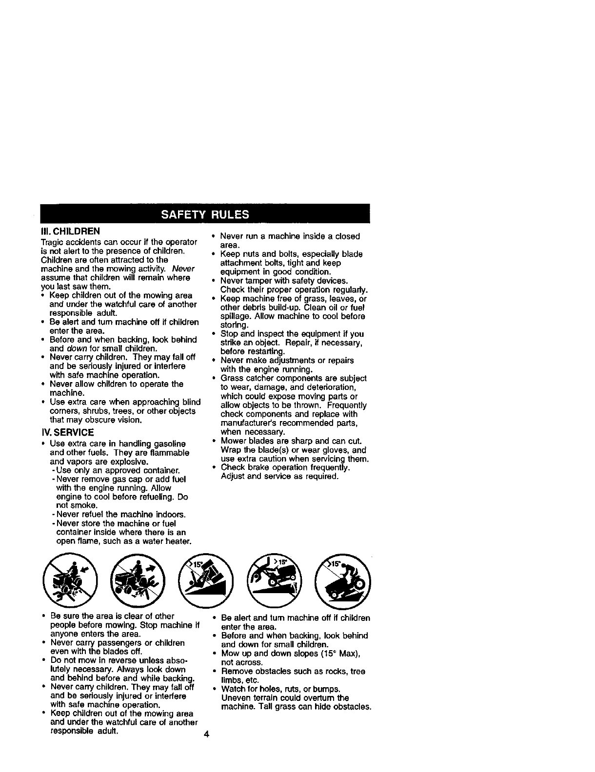
• Be surethe area is clear of other
people before mowing. Stop machine if
anyone enters the area.
•Never carry passengers or children
even with the blades off.
•Do not mow in reverse unless abso-
lutely necessary. Always look down
and behind before and while backing.
•Never carry children. They may fall off
and be seriously injured or intedere
with safe machine operation.
•Keep children out of the mowing area
and under the watchful care of another
responsible adult.
•Be alert and turn machine off if children
enter the area.
•Before and when backing, look behind
end down for small children.
• Mow up and down slopes (15 °Max),
not across.
•Remove obstacles such as rocks, tree
limbs, etc.
•Watch for holes, ruts, or bumps.
Uneven terrain could overturn the
machine. Tall grass can hide obstacles.
4
•Use slow speed. Choose a low gear so
that you will not have to stop or shift
while on the slope.
• Avoid starting or stopping on a slope. If
tires lose traction, disengage the
blades and proceed slowly straight
down the slope.
• If machine stops while going uphill,
disengage blades, shift into reverse
and back down slowly.
• Do not turn on slopes unless neces-
sary, and then, turn slowly and gradu-
ally downhill, if possible.
_Look for this symbol to point out
importantsafety precautions. It means
CAUTIONll! BECOMEALERTlll YOUR
SAFETY IS INVOLVED.
,_ CAUTION: In order to prevent
accidental starting when setting up,
transporting, adjusting or making repairs,
always disconnect spark plug wire and
place wire where it cannot contact spark
plug.
,_ CAUTION: Do not coast down a hill
in neutral, you may lose control of the
tractor.
_, CAUTION: Tow only the attachments
that are recommended by and comply
with specifications of the manufacturer of
your tractor. Use common sense when
towing. Operate only at the lowest
possible speed when on aslope. Too
heavy of a load, while on a slope, is
dangerous. Tires can lose traction with
the ground and cause you to lose control
of your tractor.
_WARNING: Engine exhaust, some of
its constituents, and certain vehicle
components contain or emit chemicals
known to the State of California to cause
cancer and birth defects or other repro-
ductive harm.
,_WARNING: Battery posts, terminals
and related accessories contain lead and
lead compounds, chemicals known to the
State of Calitomia to cause cancer and
birth defects or other reproductive harm.
Wash hands after handling.
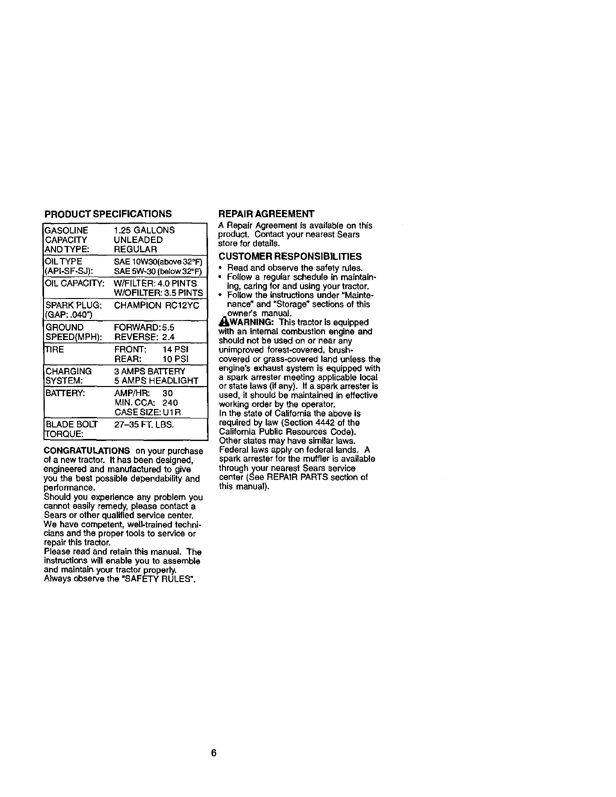
PRODUCTSPECIFICATIONS
3ASOLINE 1.25 GALLONS
CAPACITY UNLEADED
_,NDTYPE: REGULAR
_ILTYPE SAE lOW30(aix_e 322F)
'_API-SF-SJ): SAE 5W-30 (below32 F)
:31LCAPACITY: W/FILTER: 4.0 PINTS
W/OFILTER: 3.5 PINTS
SPARK PLUG: CHAMPION RC12YC
3AP: .040")
GROUND FORWARD: 5.5
SPEED(MPH): REVERSE: 2.4
I"IRE FRONT: 14 PSI
REAR: 10 PSI
CHARGING 3 AMPS BATTERY
SYSTEM: 5 AMPS HEADLIGHT
BA'I-FERY: AMP/HR: 30
MIN. CCA: 240
CASE SIZE: U1R
BLADE BOLT 27-35 FT. LBS.
"i'ORQUE:
CONGRATULATIONS on your purchase
of anew tractor. It has been designed,
engineered and manufactured to give
you the best possible dependability and
performance.
Should you experience any problem you
cannot easily remedy, please contact a
Sears or other qualified service center.
We have competent, wen-trained techni-
cians and the proper tools to service or
repair this tractor.
Please read and retain this manual. The
instructionswill enable you to assemble
and maintain your tractor properly.
Always observe the =SAFETY RULES".
REPAIR AGREEMENT
A Repair Agreement is available on this
product, Contact your nearest Sears
store for details.
CUSTOMER RESPONSIBILITIES
•Read and observe the safety rules,
•Fo(Iow a regular schedule in maintain-
ing, caring for and using your tractor.
• Follow the instructions under "Mainte-
nance" and "Storage" sections of this
_owner's manual.
WARNING: This tractor is equipped
with an internal combustion engine and
should not be used on or near any
unimproved forest-covered, brush-
covered or grass.coverad land unless the
engine's exhaust system is equipped with
a spark arrester meeting applicable local
or state laws (if any). If a spark arrester is
used, it should be maintained in effective
working order by the operator.
In the state of California the above is
required by law (Section 4442 of the
California Public Resources Code).
Other states may have similarlaws.
Federal laws apply on federal lands. A
spark arrester for the muffler is available
through your nearest Sears service
center (See REPAIR PARTS section of
this manual).
6
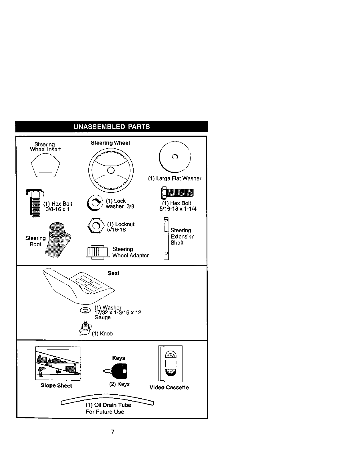
Steering
WheelInsert
I_(1) Hex Bolt
3/8-16 x1
Steering
Boot
Steering Wheel
(1) Large Flat Washer
(1) Lock
washer 3/8 (1) Hex Bolt
5/16-18 x 1-1/4
(1) Locknut
5/16-18
,_ Steering
Wheel Adapter Shaft
Seat
(_Washer
(_ 17/32 x 1-3/16 x12
Gauge
_(1) Knob
Slope Sheet
Keys
(2) Keys Video Cassette
For Future Use
7
Your new tractor has been assembled at the factory with exception of those parts left
unassembled for shipping purposes. To ensure safe and proper operation of your
tractor all parts and hardware you assemble must be tightened securely. Use the
correct tools as necessary to insure proper tightness. Review the video cassette before
you begin.
TOOLS REQUIRED FOR ASSEMBLY
A socket wrench set will make assembly
easier. Standard wrench sizes you need
are listed below.
(1) 9/16" wrench (2) 1/2"wrench
(1) 1ire pressure (1) Utilityknife
gauge
When dght or left hand is mentioned in
this manual, it means, from your point of
view, when you are in the operating
position (seated behind the steedng
wheel).
TO REMOVETRACTOR FROM
CARTON
UNPACK CARTON
1. Remove all accessible loose parts
and parts cartons from carton.
2. Cut, from top to bottom, along lines on
all four corners of carton, and lay
panels flat.
3. Check for any additional loose parts
or cartons and remove.
BEFORE REMOVINGTRACTOR
FROM SKID
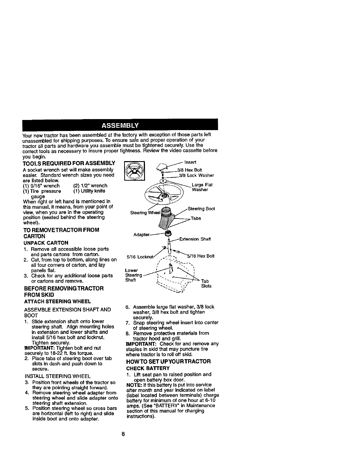
ATTACHSTEERINGWHEEL
ASSEMBLE EXTENSION SHAFT AND
BOOT
1. Slide extension shaft onto lower
steedng shaft. Align mounting holes
in extension and lower shafts and
install 5/16 hex bolt and Iocknut.
Tighten securely.
IMPORTANT: Tighten bolt and nut
securely to 18-22 ft. Ibs torque.
2. Place tabs of steedng boot over tab
slots in dash and push down to
secure.
INSTALL STEERING WHEEL
3. Positionfront wheels of the tractor so
they are pointing straight forward.
4. Remove steering wheel adapter from
steering wheel and slide adapter onto
steedng shaft extension.
5, Position steedng wheel so cross bars
are hodzontal (left to dght) and slide
inside boot and onto adapter.
_Insert
3/8 Hex Bolt
,_3/8 LockWasher
L#o%,at
SteenngWheel_ Steering Boot
Tabs
Adapter-----'-'-_
6. Assemble large flat washer, 3/8 lock
washer, 3/8 hex bolt and tighten
securely.
7. Snap steering wheel insert into center
of steering wheel.
8. Remove protective matedals from
tractor hood and grill.
IMPORTANT: Check for and remove any
staples in skid that may puncture tire
where tractor is to rolloft skid.
HOWTO SET UP¥OURTRACTOR
CHECK BA'R'ERY
I. Lift seat pan to raised positionand
open battery box door.
NOTE: If this battery is put into service
after month and year indicated on label
(label located between terminals) charge
battery for minimum of one hourat 6-10
amps. (See "BATTERY" in Maintenance
section of this manual for charging
instructions).
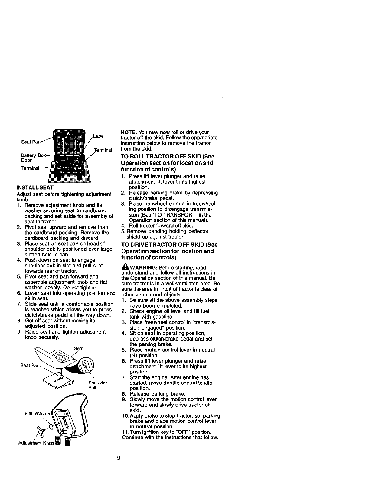
Label
Batter
Door
INSTALL SEAT
Adjust seat before tightening adjustment
knob.
1. Remove adjustment knob and flat
washer securing seat to cardboard
packing and set aside for assembly of
seat to tractor.
2. Pivot seat upward and remove from
the cardboard packing. Remove the
cardboard packing and discard.
3. Place seat on seat pan so head of
shoulder bolt is positioned over large
slotted hole in pan.
4. Push down on seat to engage
shoulder bolt in slot and pull seat
towards rear of tractor.
5. Pivot seat and pan forward and
assemble adjustment knob and flat
washer loosely. Do not tighten.
6. Lower seat into operating position and
sit in seat.
7. Slide seat until a comfortable position
is reached which allows you to press
clutch/brake pedal all the way down.
8. Get off seat without moving its
adjusted position.
9. Raise seat and tighten adjustment
knob securely.
Seat Pan_ulder
NOTE: You may now roll or drive your
tractor off the skid. Follow the appropriate
instruction below to remove the tractor
from the skid.
TO ROLLTRACTOR OFF SKID (See
Operation section for location and
function of controls)
1. Press lift lever plunger and raise
attachment lift lever to its highest
position.
2. Release parking brake by depressing
clutch/brake pedal.
3. Place freewheel control in freewheel-
ing position to disengage transmis-
sion (See "TO TRANSPORT" in the
Operation section of this manual).
4. Roll tractor forward oft skid.
5. Remove banding holding deflector
shield up against tractor.
TO DRIVETRACTOR OFF SKID (See
Operation section for location and
function of controls)
,_ WARNING: Before starting, read,
understand and follow all instructions in
the Operation section of this manual. Be
sure tractor is in a well-ventilated area. Be
sure the area in front of tractor is clear of
other people and objects.
1. Be sure all the above assembly steps
have been completed.
2. Check engine oil level and fill fuel
tank with gasoline.
3. Place freewheel control in "transmis-
sion engaged" position.
4. Sit on seat in operating position,
depress clutch/brake pedal and set
the parking brake.
5. Place motion control lever in neutral
(N) position.
6. Press lift lever plunger and raise
attachment lift lever to its highest
position.
7. Start the engine. After engine has
started, move throttle controlto idle
position.
8. Release parking brake.
9. Slowly move the motion control lever
forward and slowly ddve tractor oft
skid.
10.Apply brake to stoptractor, set parking
brake and place motion control lever
in neutral position.
11.Turn ignitionkey to "OFF" position.
Continue with the instructionsthat follow.
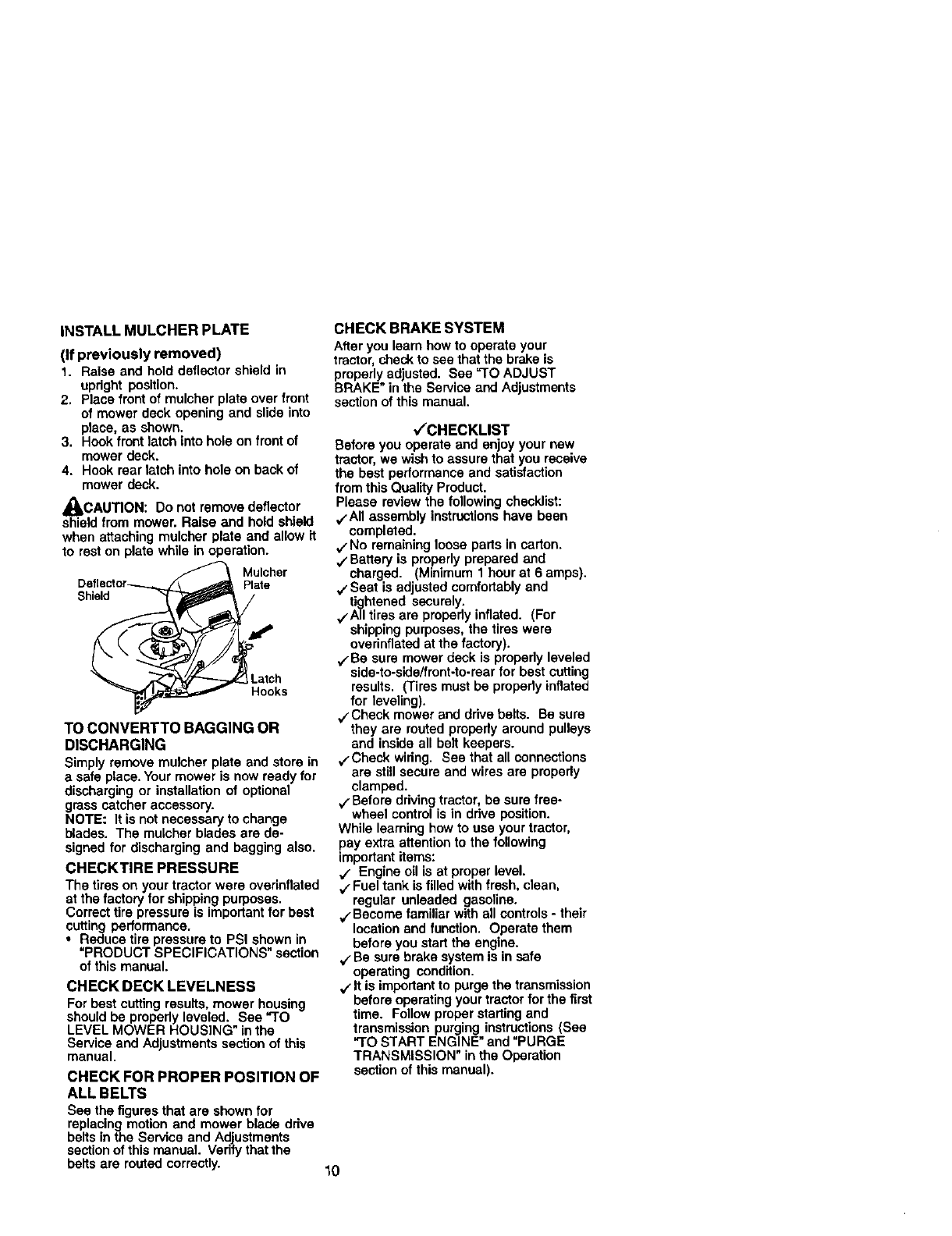
iNSTALL MULCHER PLATE
(if previously removed)
1. Raise and hold deflector shield in
updght position.
2. Place front of mulcher plate over front
of mower deck opening and slide into
place, as shown.
3. Hook front latch into hole on front of
mower deck.
4. Hook rear latch into hole on back of
mower deck.
_CAUTION: Do not remove deflector
shield from mower. Raise and hold shield
when attaching mulcher plate and allow it
to rest on plate while in operation.
Mulcher
Plate
Shield
.arch
Hooks
TO CONVERTTO BAGGING OR
DISCHARGING
Simply remove mulcher plate and store in
a safe place. Your mower is now ready for
discharging or installation of optional
grass catcher accessory.
NOTE: It is not necessary to change
blades. The mulcher blades are de-
signed for discharging and bagging also.
CHECKTIRE PRESSURE
The tires on your tractor were ovednflated
at the factory for shipping purposes.
Correct tire pressure is important for best
cutting performance.
•Reduce tire pressure to PSI shown in
"PRODUCT SPECIFICATIONS" section
of this manual.
CHECK DECK LEVELNESS
For best cutting results, mower housing
should be propedy leveled..See "3"0
LEVEL MOWER HOUSING in the
Service and Adjustments section of this
manual.
CHECK FOR PROPER POSITION OF
ALL BELTS
See the figures that are shown for
replacing motion and mower blade drive
belts in the Service and Adjustments
sectionof this manual Vedfy that the
belts are routed correctly.
CHECK BRAKE SYSTEM
After you learn how to operate your
tractor, checkto see thatthe brake is
properlyadjusted. See =TOADJUST
BRAKE" in the Service and Adjustments
section of this manual.
,/'CHECKLIST
Before you operate and enjoy your new
tractor, we wish to assure that you receive
the best performance and satisfaction
from this Quality Product.
Please review the following checklist:
`/All assembly instructionshave been
completed.
,/No remaining loose parts in carton.
`/Battery is properly prepared and
charged. (Minimum 1 hour at 6 amps).
`/Seat is adjusted comfortably and
tightened securely.
,/'All tires are propody inflated. (For
shipping purposes, the tires were
overinflated at the factory).
`/Be sure mower deck is propedy leveled
side-to-side/front-to-rearfor best cutting
results. (Tires must be pmpedy inflated
for leveling).
./'Check mower and ddve belts. Be sure
they are routed propedy around pulleys
and inside all belt keepers.
v.Check wiring. See that all connectiens
are still secure and wires are propedy
clamped.
`/Before driving tractor, be sure free-
wheel control is in ddve position.
While leaming how to use your tractor,
pay extra attention to the following
important items:
`/ Engine oil is at proper level.
`/Fuel tank is filled with fresh, clean,
regular unleaded gasoline.
.4"Become familiar with all controls - their
location and function. Operate them
before you start the engine.
`/Be sure brake system is in safe
operating condition.
`/It is important to purge the transmission
before operating your tractor for the first
time. Follow proper startingand
transmission purging instructions (See
"TO START ENGINE" and "PURGE
TRANSMISSION" in the Operation
section of this manual).
10
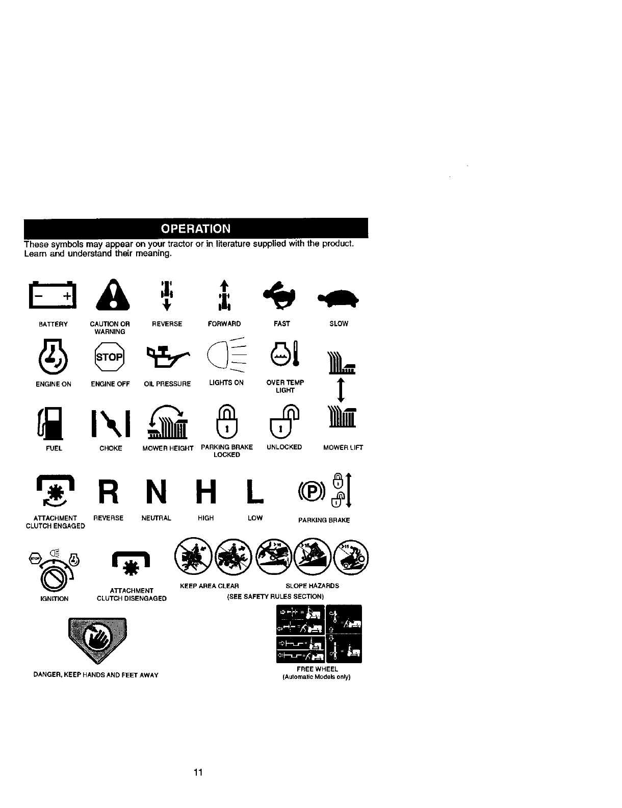
These symbols may appear on your tractor or in literature supplied withthe product.
Learn and understand their meaning.
BATTERY CAUTION OR REVERSE FORWARD FAST SLOW
WARNING
ENGINE ON ENGINE OFF OIL PRESSURE LIGHTS ON OVER TEMP
LIGHT
FUEL CHOKE MOWER HEIGHT PARKING BRAKE UNLOCKED
LOCKED
!
MOWERLI_
_r_tR N H L
ATTACHMENT REVERSE NEUTRAL HIGH LOW
CLUTCH ENGAGED PARKING BRAKE
IGNmON
@@@@@
KEEP AREA CLEAR SLOPE HAZARDS
ATTACHMENT
CLUTCH DISENGAGED (SEE SAFETY RULES SECTION)
DANGER, KEEP HANDS AND FEET AWAY FREE WHEEL
(AutomaticModersonly)
11
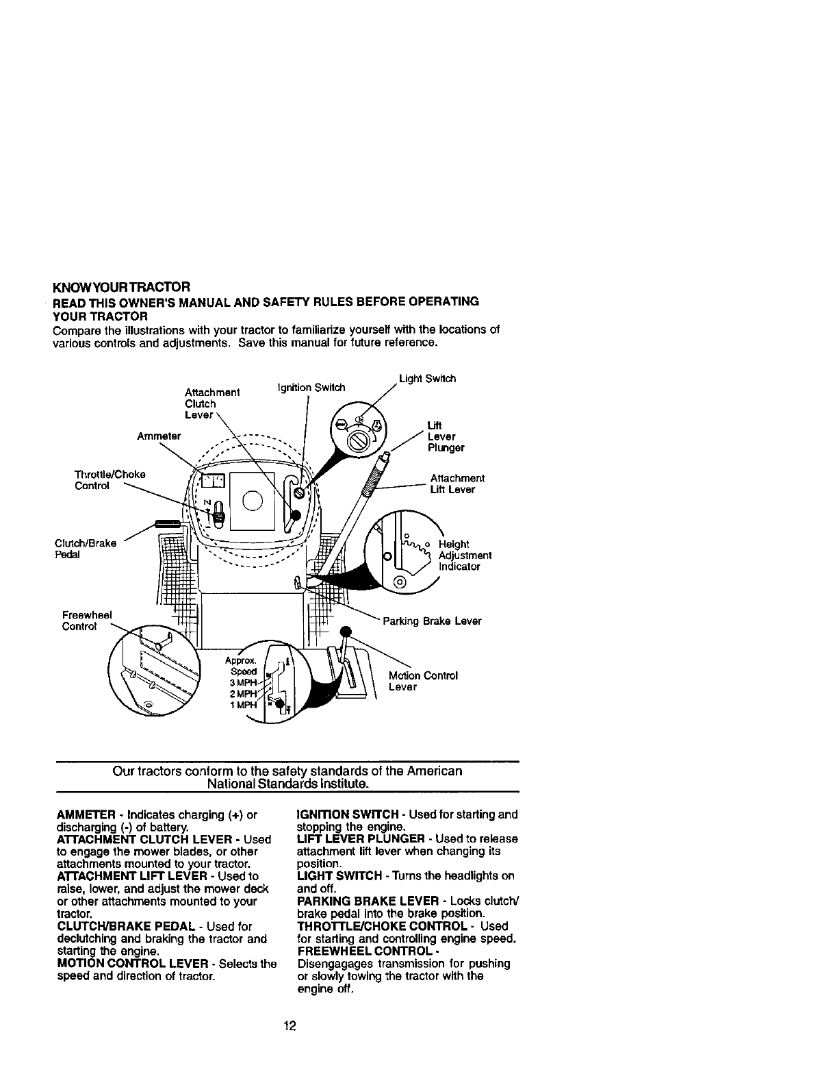
KNOWYOUR TRACTOR
READ THIS OWNER'S MANUAL AND SAFETY RULES BEFORE OPERATING
YOUR TRACTOR
Compare the illustrationswith your tractor to familiadze yourself with the locationsof
various controls and adjustments. Save this manual for future reference.
Attachment
Clutch
Ammeter
Throttle/Choke
Control
Ignition Switch Light Switch
Uft
Lever
JPlunger
Atlachment
Lift Lever
Clutch/Brake
pedal Height
Adjustment
Indicator
Freewheel
Contmt Parking Brake Lever
Motion Control
Lever
Our tractors conformto the safety standards of the American
National Standards Institute.
AMMETER - Indicates charging (+) or
discharging (-) of battery.
AI"FACHMENT CLUTCH LEVER - Used
to engage the mower blades, or other
attachments mounted to your tractor.
ATTACHMENT LIFT LEVER - Used to
raise, lower, and adjust the mower deck
or other attachments mounted to your
tractor.
CLUTCWBRAKE PEDAL - Used for
declutching and braking the tractor and
starting the engine.
MOTION CONTROL LEVER - Selects the
speed and directionof tractor.
IGNmON SWITCH -Used for startingand
stopping the engine.
LIFT LEVER PLUNGER - Used to release
attachment lift lever when changing its
position.
LIGHT SWITCH - Turnsthe headlights on
and off.
PARKING BRAKE LEVER - Locksclutch/
brake pedal into tha brake position.
THRO'rrLF-./CHOKE CONTROL - Used
for starting and controllingengine speed.
FREEWHEEL CONTROL -
Disengagages transmission for pushing
or slowly towing the tractor withthe
engine off.
12
The operation of any tractor can result in foreign objects thrown into the
eyes, which can result in severe eye damage. Always wear safety
glasses or eye shields while operating your tractor or performing any
adjustments or repairs, We recommend a wide vision safety mask over
spectacles or standard safety glasses.
HOWTO USEYOURTRACTOR
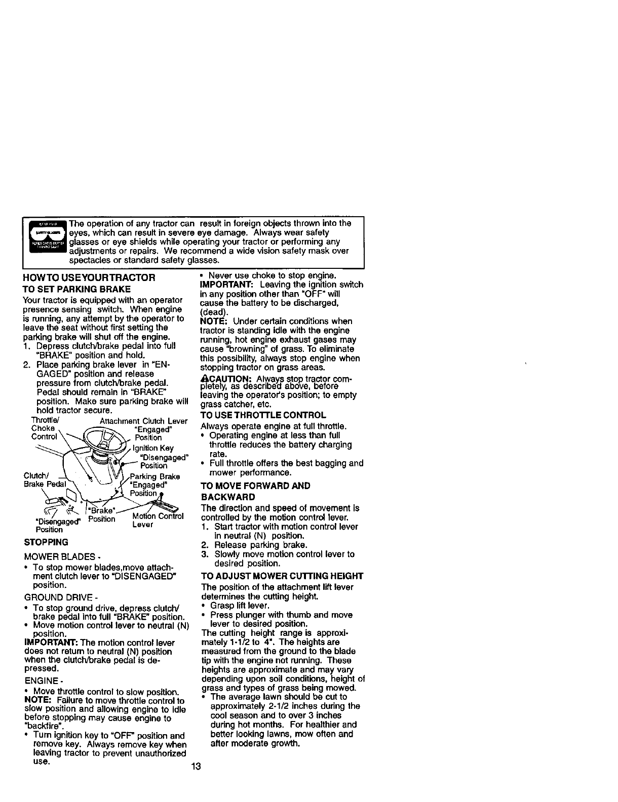
TO SET PARKING BRAKE
Your tractor is equipped with an operator
presence sensing switch. When engine
is running,any attempt by the operator to
leave the seat without first settingthe
parking brake will shut off the engine.
1. Depress clutch/brake pedal into full
"BRAKE" positionand hold.
2. Place parking brake lever in =EN-
GAGED" positionand release
pressure from clutch/brake pedal.
Pedal should remain in "BRAKE"
position, Make sure parking brake will
hold tractor secure,
Throttle] AttachmentClUtchLever
Choke "Engaged"
Control\ . position
•IgnitionKey
=Disengaged"
Clutch/ Brake
Brake Pedal
Position Lever
Position
STOPPING
MOWER BLADES -
•To stop mower blades,move attach-
ment clutch lever to "DISENGAGED"
position.
GROUND DRIVE -
•To stop ground drive, depress clutcW
brake pedal into full "BRAKE" position.
• Move motion control lever to neutral (N)
position.
IMPORTANT: The motion control lever
does not return to neutral (N) position
when the clutch/brake pedal is de-
pressed.
ENGINE -
• Move throttle controlto slow position.
NOTE: Failure to move throttle control to
slow position and allowing engine to idle
before stopping may cause engine to
"backfire".
• Turn ignkion key to =OFF" position and
remove key. Always remove key when
leaving tractor to prevent unauthodzed
use. 13
• Never use choke to stop engine.
IMPORTANT: Leaving the ignition switch
in any position other than "OFF" will
cause the battery to be discharged,
(dead).
NOTE: Under certain conditions when
tractor is standing idle with the engine
running,hot engine exhaust gases may
cause "browning" of grass. To eliminate
this possibility,always stop engine when
stoppingtractor on grass areas.
ACAUTION: Always stop tractor com-
pletely, as describai:tabove, before
leaving the operator's position;to empty
grass catcher, etc.
TO USE THRO'I-FLE CONTROL
Always operate engine at full throttle.
• Operating engine at less than full
throttle reduces the battery charging
rate.
•Full throttle offers the best bagging and
mower performance.
TO MOVE FORWARD AND
BACKWARD
The direction and speed of movement is
controlled by the motion control lever.
1. Start tractor with motion control lever
in neutral (N) position.
2. Release parking brake.
3. Slowly move motion control lever to
desired position.
TO ADJUST MOWER CUI"FING HEIGHT
The positionof the attachment lift lever
determines the cutting height.
•Grasp liftlever.
•Press plunger with thumb and move
lever to desired position.
The cutting height range is approxi-
mately 1-1/2 to 4". The heightsare
measured from the ground to the blade
tip with the engine not running. These
heights are approximate and may vary
depending upon soil conditions, height of
grass and types of grass being mowed.
•The average lawn should be cut to
approximately 2-1/2 inches dudng the
cool season and to over 3 inches
dudng hot months. For healthier and
better looking lawns, mow often and
after moderate growth.
•For best cutting performance, grass
over 6 inches in height should be
mowed twice. Make the first cut
relatively high; the second to desired
height.
TO ADJUST GAUGE WHEELS
Gauge wheels are properly adjusted
when they are slightlyoff the ground
when mower is at the desired cutting
height in operating position. Gauge
wheels then keep the deck in proper
positionto help prevent scalping in most
terrain conditions.
NOTE: Adjust gauge wheels with tractor
on aflat level surface.
t. Adjust mower to desired cutting height
(See "TO ADJUST MOWER CU'I-rlNG
HEIGHT" in the Operation sectionof
this manual).
2. With mower in desired height of cut
position, gauge wheels should be
assembled so they are slightlyoff the
ground. Install gauge wheel in
appropriate hole with shoulder bolt,
3/8 washer, and 3/8-16 Iocknut and
tighten securely.
3. Repeat for opposite side installing
gauge wheel in same adjustment
hole.
3/8-16
Locknut
Wheel
Shoulder
Gauge Wheel
TO OPERATE MOWER
Yourtractor is equipped with an operator
presence sensing switch. Any attempt by
the operator to leave the seat withthe
engine running and the attachment
clutch engaged will shut off the engine.
1. Select desired height of cut.
2. Start mower blades by engaging
attachment clutch control.
TO STOP MOWER BLADES -
disengage attachment clutch control.
CAUTION; Do not operate the
mower without either the entire grass
catcher, on mowers so equipped, or the
deflector shield in place.
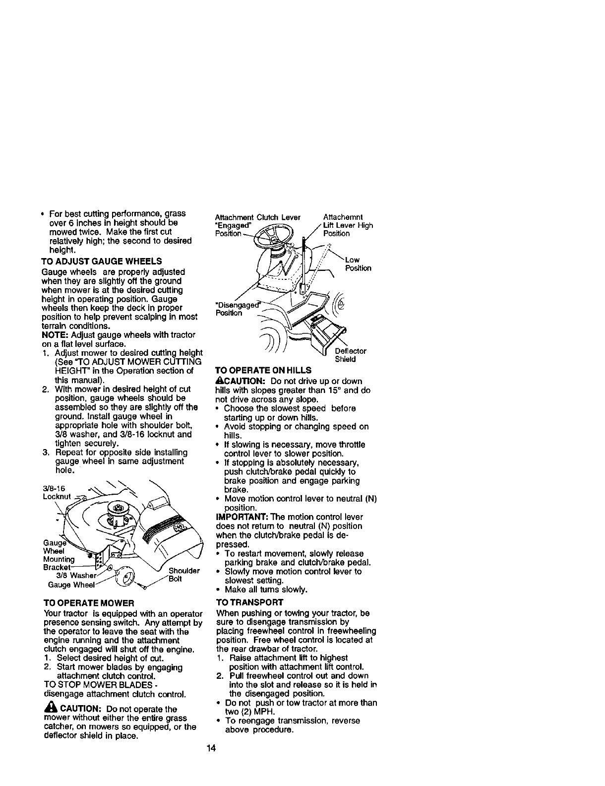
Attachment Clutch Lever Attachemnt
=Engaged"
Position_Position
Position
Position
Deflector
Shield
TO OPERATE ON HILLS
&CAUTION: Do not drive up or down
hillswith slopes greater than 15°and do
not drive across any slope,
• Choose the slowest speed before
starting up or down hills.
•Avoid stopping or changing speed on
hills.
•If slowing is necessary, move throttle
control lever to slower position.
• If stoppingis absolutely necessary,
push clutch/brake pedal quickly to
brake position and engage parking
brake.
•Move motion controllever to neutral (N)
position.
IMPORTANT: The motion control lever
does not retum to neutral (N) position
when the clutch/brake pedal is de-
pressed.
•To restartmovement, slowly release
parking brake and clutcWbrake pedal.
•Slowly move motion control lever to
slowest setting.
•Make all turns slowly.
TO TRANSPORT
When pushing or towing your tractor, be
sure to disengage transmission by
placing freewheel control in freewheeling
position. Free wheel control is located at
the rear drawbar of tractor.
1. Raise attachment lift to highest
position with attachment lift control.
2. Pull freewheel control out and down
into the slot and release so it is held in
the disengaged position.
•Do not push ortow tractor at more than
two (2) MPH.
•To reengage transmission, reverse
above procedure.
14
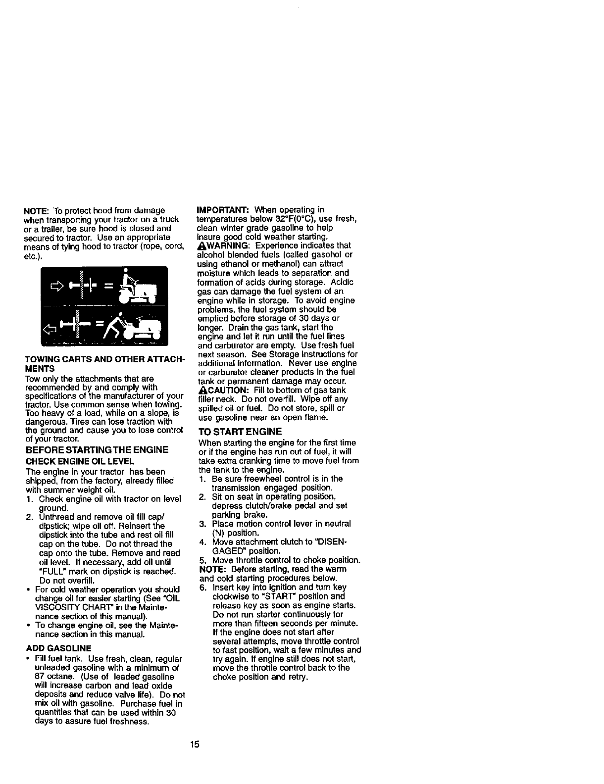
NOTE: To protect hood from damage
when transporting your tractor on a truck
or a trailer, be sure hood is closed and
secured to tractor. Use an appropriate
means of tying hood to tractor (rope, cord,
etc.).
TOWING CARTS AND OTHER ATrACH-
MENTS
Tow only the attachments that are
recommended by and comply with
specificationsof the manufacturer of your
tractor. Use common sense when towing.
Too heavy of a load, while on a slope, is
dangerous. Tires can lose traction with
the ground and cause you to lose control
of your tractor.
BEFORE STARTINGTHE ENGINE
CHECK ENGINE OIL LEVEL
The engine in your tractor has been
shipped, from the factory, already filled
with summer weight oil.
1. Check engine oil with tractor on level
ground.
2. Unthread and remove oil fill cap/
dipstick;wipe oil oft. Reinsert the
dipstickinto the tube and rest oil fill
cap on the tube. Do not thread the
cap onto the tube. Remove and read
oil level. If necessary, add oil until
"FULL" mark on dipstick is reached.
Do not overfill.
•For cold weather operation you should
change oil for easier starting (See =OIL
VISCOSITY CHART" inthe Mainte-
nance section of this manual).
• To change engine oil, see the Mainte-
nance section in this manual.
ADD GASOLINE
•Fill fuel tank. Use fresh, clean, regular
unleaded gasoline with a minimum of
87 octane. (Use of leaded gasoline
will increase carbon and lead oxide
depositsand reduce valve life). Do not
mix oil with gasoline. Purchase fuel in
quantitiesthat can be used within 30
days to assure fuel freshness.
IMPORTANT: When operating in
temperatures below 32°F(0°C), use fresh,
clean winter grade gasoline to help
insure good cold weather starting.
AWARNING: Experience indicates that
alcohol blended fuels (called gasohol or
using ethanol or methanol) can aftract
moisture which leads to separation and
formation of acids duringstorage. Acidic
gas can damage the fuel system of an
engine while in storage. To avoid engine
problems, the fuel system should be
emptied before storage of 30 days or
longer. Drain the gas tank, start the
engine and let it mn untilthe fuel lines
and carburetor are empty. Usa fresh fuel
next season. See Storage Instructions for
additional information. Never use engine
or carburetor cleaner products in the fuel
tank or permanent damage may occur.
_,CAUTION: Fill to bottomof gas tank
filler neck. Do not overfill. Wipe off any
spilled oil or fuel. Do not store, spill or
use gasoline near an open flame.
TO START ENGINE
When starting the engine for the first time
or ifthe engine has run out offuel, it will
take extra cranking time to move fuel from
the tank to the engine.
1. Be sure freewheel control is in the
transmission engaged position.
2. Sit on seat in operating position,
depress clutclVbraka pedal and set
parking brake.
3. Place motion control lever in neutral
(N) position.
4. Move attachment clutch to "DISEN-
GAGED" position.
5. Move throttle controlto choke position.
NOTE: Before starting, read the warm
and cold starting procedures below.
6. Insert key into ignition and turn key
clockwise to "START" position and
release key as soon as engine starts.
Do not run starter continuously for
more than fifteen seconds per minute.
If the engine does not start after
several attempts, move throttle control
to fast position, wait a few minutes and
try again. If engine still does not start,
move the throttle control back to the
choke position and retry.
15
WARM WEATHER STARTING (50 ° F and
above)
7. When engine starts, move the throttle
control to the fast position.
The attachments and ground drive
can now be used. If the engine does
not accept the load, restart the engine
and allow it to warm up for one minute
using the choke as described above.
COLD WEATHER STARTING ( 50 ° F and
below)
8. When engine starts, allow engine to
run with the throttle control In the
choke position until the engine runs
roughly, then move throttle control to
fast position. This may require an
engine warm-up pedod from several
seconds to several minutes, depend-
ing on the temperature.
AUTOMATICTRANSMISSION WARM UP
Before driving the unit in cold weather,
the transmission should be warmed up as
follows:
t. Be sure the tractor is on level ground.
2. Place the motion control lever in
neutral. Release the parking brake
and let the clutch/brake slowly return
to operating position.
3. Allow one minute for transmission to
warm up. This can be done during
the engine warm up period.
• The attachments can also be used
dudng the engine warm-up pedod after
the transmission has been warmed up.
NOTE: If at a high altitude (above 3000
feet) or in cold temperatures (below 32 F)
the carburetor fuel mixture may need to
be adjusted for best engine performance.
See "TO ADJUST CARBURETOR" in the
Service and Adjustments section of this
manual.
PURGETRANSMISSION
• I,CAUTION: Never engage or disen-
gage freewheel lever while the engine is
running.
To ensure proper operation and perfor-
mance, it is recommended that the
transmission be purged before operating
tractor for the first time. This procedure will
remove any trapped air inside the
transmission which may have developed
during shipping of your tractor.
IMPORTANT: Should your transmission
require removal for service or replace-
ment, it should be purged after reinstalla-
tion before operating the tractor.
1. Place tractor safely on level surface
with engine oft and parking brake set.
2. Disengage transmission by placing
freewheel control in freewheeling
position (See =TOTRANSPORT" in
this section of manual).
3, Sitting inthe tractor seat, start engine.
After the engine is running, move
throttle control to slow position.With
motion control lever in neutral (N)
position, slowly disengage clutch/
brake pedal.
4. Move motion control lever to full
forward position and hold for five (5)
seconds. Move lever to full reverse
position and hold for five (5) seconds.
Repeat this procedure three (3) times.
NOTE: During this procedurethere willbe
no movementof drivewheels,The air is
being removed from hydraulic drive
system.
5. Move motion control lever to neutral
(N) position. Shut- off engine and set
parking brake.
6. Engage transmission by placing
freewheel control in driving position
(See "TO TRANSPORT" in this section
of manual).
7. Sittingin the tractor seat, start engine.
After the engine is running,move
throttle control to half (1/2) speed, With
motion control lever in neutral (N)
position, slowly disengage clutch/
brake pedal.
8. Slowly move motion control lever
forward, after the tractor moves
approximately five (5) feet, slowly
move motion control lever to reverse
position. After the tractor moves
approximately five (5) feet return the
motion control lever to the neutral (N)
position. Repeat this procedure with
the motion control lever three (3)
times.
Your tractor is now purged and now ready
for normal operation.
16
MOWINGTIPS
•Mower should be propedy leveled for
best mowing performance. See "TO
LEVEL MOWER HOUSING" in the
Service and Adjustments section of this
manual.
• The left hand side of mower should be
used for trimming.
• Drive so that clippings are discharged
onto the area that has been cut. Have
the cut area to the right of the tractor.
This will result in a more even distribu-
tion of clippingsand more uniform
cutting.
•When mowing large areas, start by
turning to the dght so that clippingswill
discharge away from shrubs, fences,
driveways, etc. After one or two
rounds, mow in the opposite direction
making left hand turns until finished.
•If grass is extremely tall, it should be
mowed twice to reduce load and
possible fire hazard from dried dip-
pings. Make firstcut relatively high;the
second to the desired height.
•Do not mow grass when it is wet. Wet
grass will plug mower and leave
undesirable clumps. Allow grass to dry
before mowing.
•Always operate engine at full throttle
when mowing to assure better mowing
performance and proper discharge of
matedal. Regulate ground speed by
selecting alow enough gear to give the
mower cutting performance as well as
the quality of cut desired.
•When operating attachments, select a
ground speed that will suit the terrain
and give best performance of the
attachment being used.
MULCHING MOWINGTIPS
IMPORTANT: For best performance,
keep mower housingfree of built-up
grass and trash. Clean after each use.
•The special mulching blade will recut
the grass clippingsmany times and
reduce them in size so that as they fall
onto the lawn they will disperse into the
grass and not be noticed. Also, the
mulched grass will biodegrade quickly
to provide nutrientsfor the lawn.
Always mulch with your highest engine
(blade) speed as this will provide the
best recutting action of the blades.
•Avoid cutting your lawn when it is wet.
Wet grass tends to form clumpsand
interferes with the mulching action.
The best time to mow your lawn is the
eady afternoon. At this time the grass
has dried and the newly cut area will
not be exposed to the direct sun.
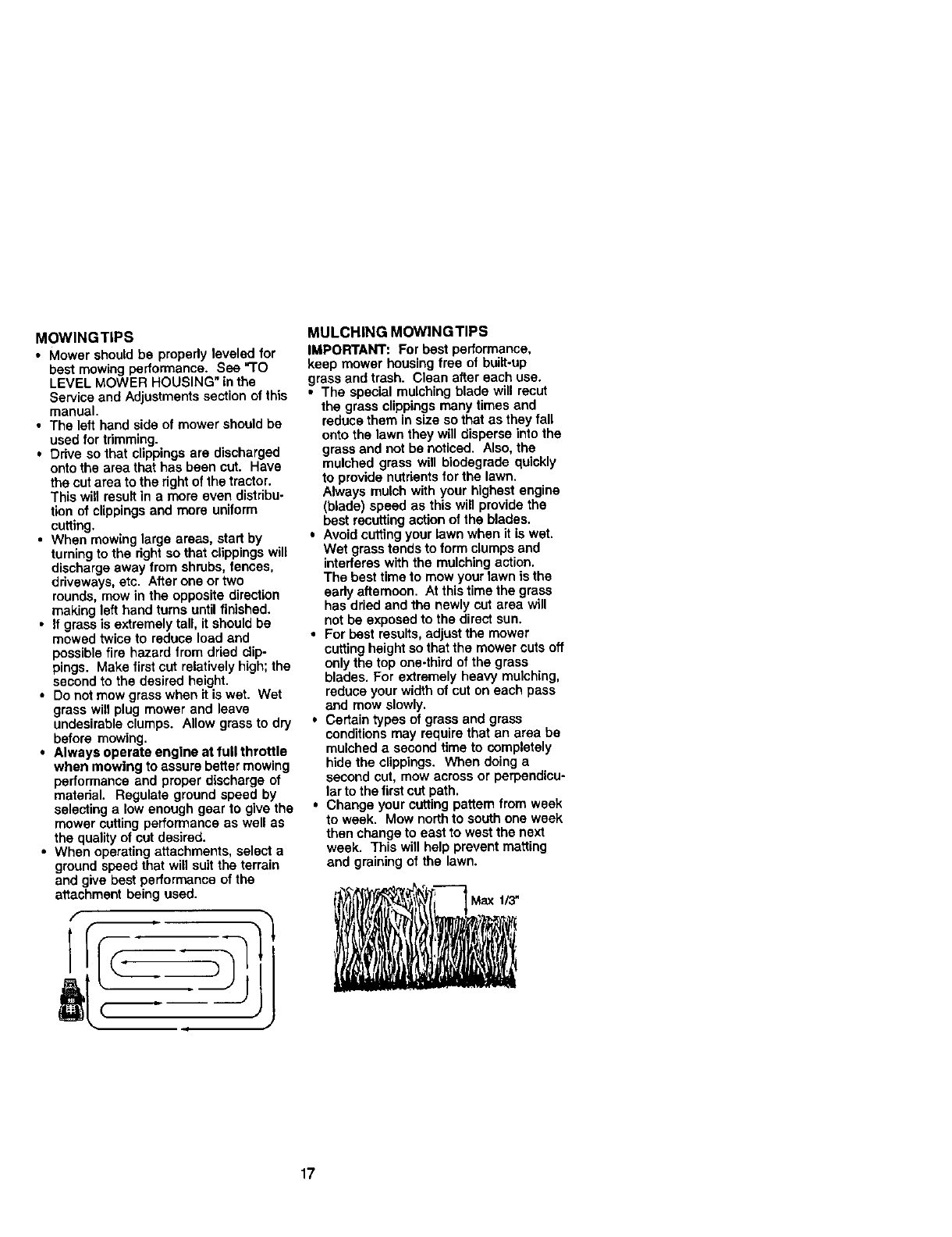
•For best results,adjust the mower
cutting height so that the mower cuts off
only the top one-third of the grass
blades. For extremely heavy mulching,
reduce your width of cut on each pass
and mow slowly.
•Certain types of grass and grass
conditions may require that an area be
mulched a second time to completely
hide the clippings. When doing a
second cut, mow across or perpendicu-
larto the first cut path.
•Change your cutting pattern from week
to week. Mow north to south one week
then change to east to west the next
week. This will help prevent matting
and graining of the lawn.
Max I13"
17
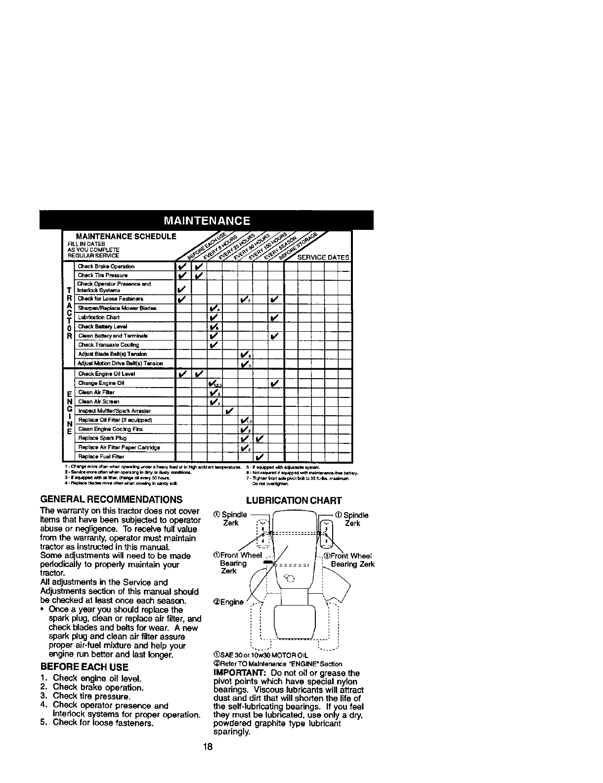
MAINTENANCESCHEDULE
FILL LNDATES
AS YOU COMPLET_
REGULAR SERVICE ERVICE DATES
Check Brake Operation
Check_rePre=ure k/ _/
Check Otoemlo_ Presm_ce a_d
R_c_ forL_oseFa_Drs _ _,
Shaq_elVRepia(_ Mower Blades _4
T Lubr_onCh_ I/ V_
0Ch=_S=_"YL" _!
R CieenBsttefyandTBr'min_ls It/
Chec_ Tmnsaxle Coolklg f_
Adju_ Metk_ Drk,e Belt(s) Tanslen _
i
CheekEngineOilLevel _ ll_
C_=ng,=Eng_Oil _,_ t,/
E Clean Air Filtot _t
N Clean Air Scram _=
G Inspect Muffler/Spark Armster
Replacl Oil Filtor (If equipped] 1_1.:
EN clean Engine Cooling Fins _=
Replace Spark Plug 11#/V_
Replace Air Filter Paper Cartridge i//_
Replete Fuel Rlter
4 - _ _,a¢:_ ry_re o_,r_ whet ri_o_dr,g In_ =_L
8 * Not te_ir=*_I__ _i_ _Int_m_m=.l_e _tt wy
t. "l]gh_n _rom _ p_t boq t_ 35 _,_. m_
Do r_( c_.
GENERAL RECOMMENDATIONS
The warranty onthis tractordoes not cover
items that have been subjected to operator
abuse or negligence. To receive full value
from the warranty,operator mustmaintain
tractoras instructedinthis manual.
Some adjustments will need to be made
pedodicaily to properlymaintain your
tractor.
All adjustmentsin the Service and
Adjustments section of this manual should
be checked at least once each season.
• Once a year you should replacethe
spark plug, clean or replace air filter, and
check blades and belts for wear. A new
spark plug and clean air filter assure
proper air-fuel mixtureand help your
engine run better and last longer.
BEFORE EACH USE
1. Check engine oil level.
2. Check brake operation.
3. Check tire pressure.
4. Check operator presence and
interlock systems for proper operation.
5. Check for loose fasteners.
LUBRICATION CHART
Spindle_F--_'_r---" _)Spindle
L_FrontWheel _ / [ -:_)Froht Wheel
Bearing ,: BearingZerk
@Engine i"i
..... ....
(_SAE 30or I0w30 MOTOR OIL
(_)FlelerTO Malntenance =ENGINE" Section
IMPORTANT: Do not oil or grease the
pivot points which have special nylon
bearings. Viscous lubricants will attract
dust and dirtthat will shorten the life of
the self-lubricetin_ bearings. If you feel
they must be lubricated, use only a dry,
powdered graphite type lubricant
sparingly.
18
TRACTOR
Always observe safety rutes when
performing any maintenance.
BRAKE OPERATION
If tractor requires more than six (8) feet
stoppingdistance at high speed in
highest gear, then brake must be ad-
justed. (See "TO ADJUST BRAKE" inthe
Service and Adjustments section of this
manual).
TIRES
•Maintain proper air pressure in all tires
(See =PRODUCT SPECIFICATIONS"
section of this manual).
•Keep tires free of gasoline, oil, or insect
control chemicals which can harm
rubber.
• Avoidstumps,stones,deep ruts,sharp
objectsand otherhazardsthatmay
cause tiredamage.
NOTE: To sealtirepuncturesand prevent
flattiresdue toslowleaks,tiresealant
may be purchasedfromyourlocalparts
dealer.Tiresealantalsopreventstiredry
rot and corrosion.
OPERATOR PRESENCE SYSTEM
Be sure operator presence and interlock
systems are working properly, If your
tractor does not function as described,
repair the problem immediately.
•The engine should not start unless the
brake pedal is fully depressed and
attachemeut clutch control is in the
disengaged position.
•When the engine is running, any
attempt by the operator to leave the
seat without first settingthe parking
brake should shut off the engine.
•When the engine is running and the
attachment clutch is engaged, any
attempt by the operator to leave the
seat should shut off the engine.
•The attachment clutch should never
operate unless the operator is in the
seat.
BLADE CARE
For best results mower blades must be
kept sharp. Replace bent or damaged
blades.
BLADE REMOVAL
1. Raise mower to highest position to
allow access to blades.
2. Remove hex bolt, lock washer and flat
washer securing blade.
3. Install new or resharpened blade with
trailing edge up towards deck as
shown.
TO SHARPEN BLADE
NOTE: We do not recommend sharpen-
ing blade -but ifyou do, be sure the
blade is balanced.
Care should be taken to keep the blade
balanced. An unbalanced blade will
cause excessive vibration and eventual
damage to mower and engine.
•The blade can be sharpened with afile
or on a gdnding wheel. Do not attempt
to sharpen while on the mower.
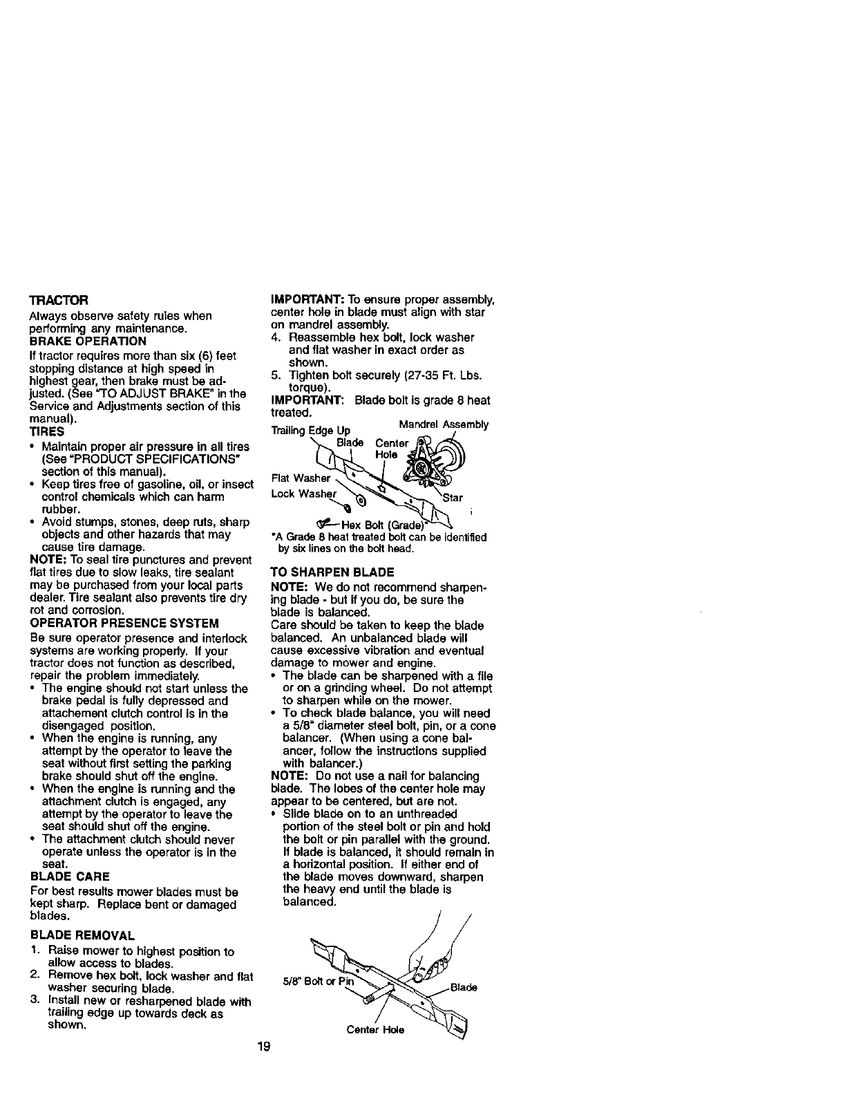
•To check blade balance, you will need
a 5/8" diameter steel bolt, pin, or a cone
balanoer. (When using acone bal-
ancer, follow the instructions supplied
with balancer.)
NOTE: Do not use a nail for balancing
blade. The lobes of the center hole may
appear to be centered, but are not.
•Slide blade on to an unthreaded
portion of the steel bolt or pin and hold
the bolt or pin parallel with the ground.
If blade is balanced, it should remain in
a hodzontal position. If either end of
the blade moves downward, sharpen
the heavy end untilthe blade is
balanced.
5/8' __ade
Center Hole -_
IMPORTANT: To ensure proper assembly,
center hole in blade must align with star
on mandrel assembly.
4. Reassemble hex bolt, lock washer
and flat washer in exact order as
shown.
5. Tighten bolt securely (27-35 Ft. Lbs.
torque).
IMPORTANT: Blade belt is grade 8 heat
treated. MandrelAssembly
TrailingEdge Up
Blade Center
Hole
Flat Washer
L_k Wa_er
i
G_-- Hex Bolt
"A Grade 8 heattreatedboltcan be identified
by sixlineson the bolthead.
19
BATTERY
Yourtractor has a battery charging system
which is sufficientfor normal use. How-
ever, periodic charging of the battery with
an automotive charger will extend its life.
•Keep battery and terminals clean.
• Keep battery bolts tight.
•Keep small vent holes open.
• Recharge at 6-10 amperes for 1 hour.
NOTE: The original equipment battery on
your tractor is maintenance free, Do not
attempt to open or remove caps or covers.
Adding or checking level of electrolyte is
not necessary.
TO CLEAN BATTERY AND TERMINALS
Corrosionand dirt on the battery and
terminals can cause the battery to "leak"
power.
1. Open battery box door.
2. Disconnect BLACK battery cable first
then RED battery cable and remove
battery from tractor.
3. Rinse the battery with plain water and
dry.
4. Clean terminals and battery cable
ends with wire brush until bright.
5. Coat terminals with grease or petro-
leum jelly.
6. Reinstall battery (See "REPLACING
BATTERY" in the SERVICE AND
ADJUSTMENTS section of this
manual).
V-BELTS
Check V-belts for deterioration and wear
after 100 hours of operation and replace
if necessary. The belts are not adjustable.
Replace belts if they begin to slip from
wear.
TRANSAXLE COOLING
The transmissionfan and cooling fins
should be kept clean to assure proper
cooling.
Do not attempt to clean fan ortransmis-
sion while engine is running or while the
transmission is hot. To prevent possible
damage 1o seals, do not use high
pressure water or steam to clean
transaxle,
•Inspect cooling fan to be sure fan
blades are intact and clean.
•Inspect cooling fins for dirt, grass
clippingsand other materials. To
prevent damage to seals, do not use
compressed air or high pressure
sprayer to clean cooling fins.
TRANSAXLE PUMP FLUID
The transaxle was sealed at the factory
and fluid maintenance is not required for
the life of the trancaxle. Should the
transaxle ever leak or require servicing,
contact your nearest authorized service
center/department.
ENGINE
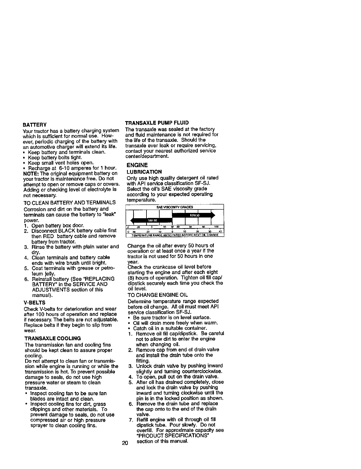
LUBRICATION
Only use high quality detergent oil rated
withAPI service classification SF-SJ.
Select the oil's SAE viscositygrade
according to your expected operating
temperature.
Change the oil after every 50 hours of
operation or at least once a year ifthe
tractor is not used for 50 hours in one
year.
Check the crankcase oil level before
starting the engine and after each eight
(6) hours of operation, Tighten oil fill cap/
dipstick securely each time you check the
oil level.
TO CHANGE ENGINE OIL
Determine temperature range expected
before oil change. All oil must meet API
service classification SF-SJ.
• Be sure tractor is on level sudace.
• Oil will drain more freely when warm.
• Catch oil in a suitable container.
1. Remove oil fill cap/dipstick. Be careful
not to allow dirt to enter the engine
when changing oil.
2. Remove cap from end of drain valve
and install the drain tube onto the
fitting.
3. Unlock drain valve by pushing inward
slightly and turning counterclockwise.
4. To open, pull out on the drain valve.
5. After oil has drained completely, close
and lock the drain valve by pushing
inward and turning clockwise until the
pin is in the locked position as shown.
6. Remove the drain tube and replace
the cap onto to the end of the drain
valve.
7. Refill engine with oil through oil fill
dipstick tube. Pour slowly. Do not
overfill, For approximate capacity see
"PRODUCT SPECIFICATIONS"
section of this manual.
2O
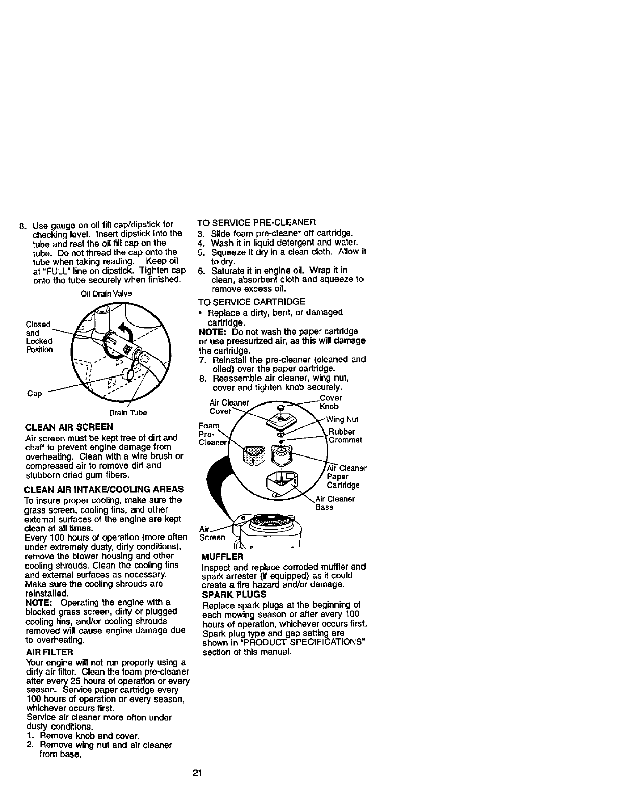
8. Use gauge on oil fill cap/dipstick for
checking level. Insert dipstick into the
tube and rest the oil fill cap on the
tube. Do not thread the cap onto the
tube when taking reading. Keep oil
at "FULL" line on dipstick, Tighten cap
onto the tube securely when finished.
Oil DrainValve
Closed-
Po_Lcn _
Cap _ _
DrainTube
CLEAN AIR SCREEN
Air screen must be kept free of dirtand
chaff to prevent engine damage from
overheating. Clean with a wire brush or
compressed air to remove dirt and
stubbom dried gum fibers.
CLEAN AIR INTAKE/COOLING AREAS
To insure proper cooling, make sure the
grass screen, cooling fins, and other
extemal surfaces of the engine are kept
clean at all times.
Every 100 hours of operation (more often
under extremely dusty, dirty conditions),
remove the blower housing and other
cooling shrouds. Clean the cooling fins
and external surfaces as necessary.
Make sure the cooling shrouds are
reinstalled.
NOTE: Operating the engine with a
blocked grass screen, dirty or plugged
cooling fins, and/or cooling shrouds
removed will cause engine damage due
to overheating.
AIR FILTER
Your engine will not run properly using a
dirty air filter. Clean the foam pre-cleaner
after every 25 hours of operation or every
season. Service paper cartridge every
100 hours of operation or every season,
whichever occurs first.
Service air cleaner more often under
dusty conditions.
1. Remove knob and cover.
2. Remove wing nut and air cleaner
from base.
TO SERVICE PRE-CLEANER
3. Slide foam pre-cleaner off cartridge.
4. Wash it in liquid detergent and water.
5. Squeeze it dry in a clean cloth. Allow it
to dry.
6. Saturate it in engine oil. Wrap it in
clean, absorbent cloth and squeeze to
remove excess oil.
TO SERVICE CARTRIDGE
• Replace a dirty, bent, or damaged
cartridge.
NOTE= Do not wash the paper cartridge
or use pressurized air, as this will damage
the cartridge.
7. Reinstall the pre-cleaner (cleaned and
oiled) over the paper cartridge.
8. Reassemble air cleaner, wing nut,
cover and tighten knob securely.
Air Cleaner Knob
Foam
Pre- \
Cleane!
*Wing Nut
Rubber
Cartddge
Air Cleaner
Base
Screert
MUFFLER
Inspect and replace corroded muffler and
spark arrester (if equipped) as it could
create a fire hazard and/or damage.
SPARK PLUGS
Replace spark plugs at the beginning of
each mowing season or after every 100
hours of operation, whichever occurs first.
Spark plug type and gap setting are
shown in "PRODUCT SPECIFICATIONS"
section of this manual.
21
ENGINE OIL FILTER
Replace the engine oil filter every season
or every other oil change if the tractor is
used more than 100 hours in one year.
1. Drain oil from engine crankcase (See
"TO CHANGE ENGINE OIL" in this
section of this manual, through step
remove drain plug).
2. Remove oil filter and wipe off filter
adapter.
3. Apply a thin coating of new engine oil
to the rubber gasket on replacement
oil filter.
4. Install replacement oil filter on filter
adapter. Turn oil filter clockwise until
rubber gasket contacts the filter
adapter, then tighten filter an addi-
tional 1/2 turn.
5. Fill crankcase with new oil (See "TO
CHANGE ENGINE OIL" in this section
of this manual). For approximate
capacity see "PRODUCT SPECIFICA-
TIONS" section of this manual.
6. Start the engine and check for oil
leaks. Correct any leaks before
placing engine into full operation.
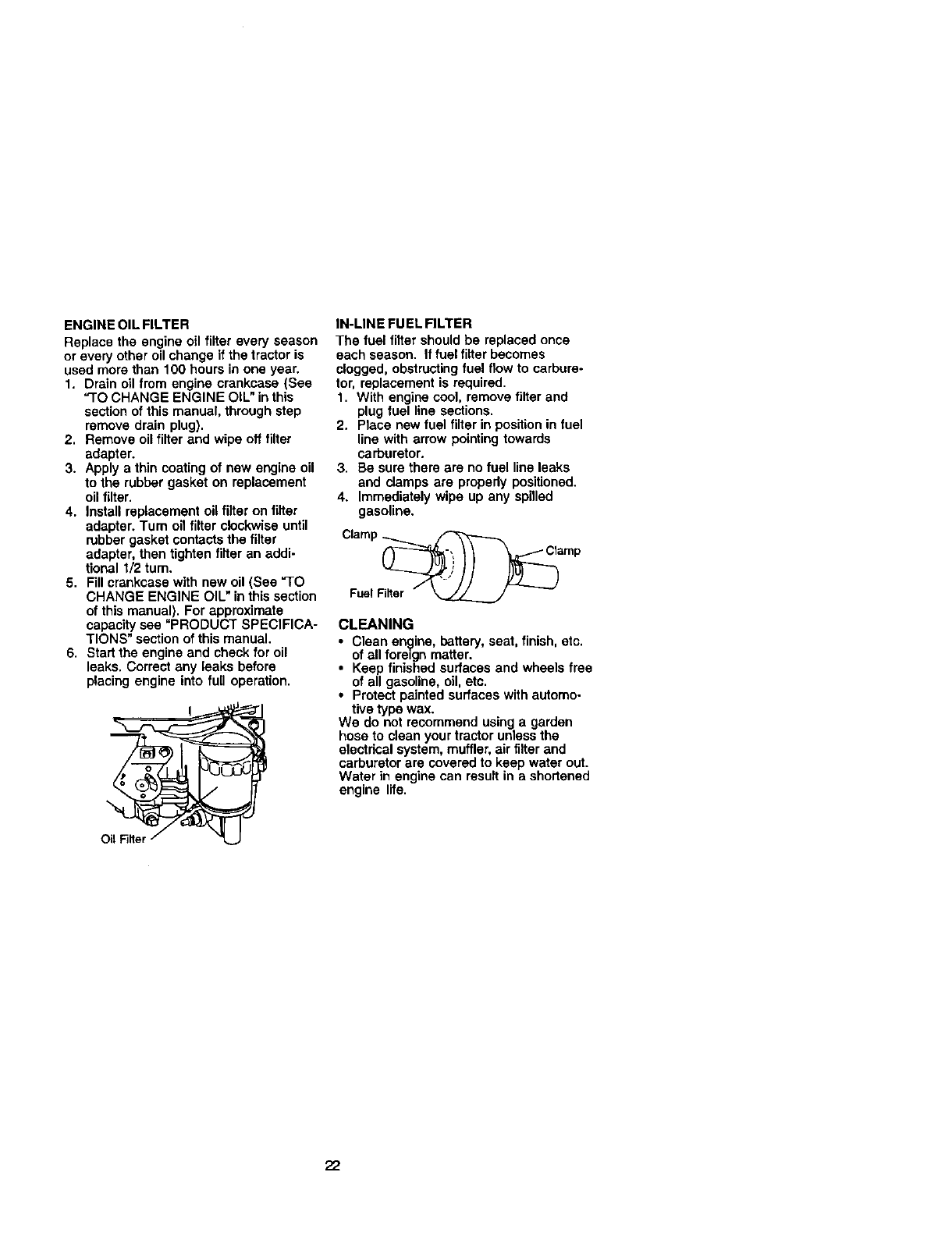
IN-LINE FUEL FILTER
The fuel filter should be replaced once
each season. If fuel filter becomes
clogged, obstructingfuel flow to carbure-
tor, replacement is required.
1. With engine cool, remove filter and
plug fuel line sections.
2. Place new fuel filter in positionin fuel
line with arrow pointing towards
carburetor.
3. Be sure there are no fuel lineleaks
and damps are propedy positioned.
4. Immediately wipe up any spilled
gasoline.
Clamp _ _
Fuel Fil_er " _ --
CLEANING
•Clean engine, battery, seat, finish, etc.
of all fore=gn matter.
•Keep finished surfaces and wheels free
of all gasoline, oil, etc.
•Protect painted surfaces with automo-
tive type wax.
We do not recommend using a garden
hose to clean your tractor unless the
electdcal system, muffler, air filter and
carburetor are covered to keep water out.
Water in engine can result in a shortened
engine life.
22
_CAUTION: BEFORE PERFORMING ANY SERVICE OR ADJUSTMENTS:
1. Depress clutch/brake pedal fully and set parking brake.
2. Place motion control lever in neutral (N) position.
3. Place attachment clutch in "DISENGAGED" position.
4. Turn ignitionkey "OFF" and remove key.
5. Make sure the blades and all moving parts have completely stopped.
6. Disconnect spark plug wire from spark plug and place wire where it cannot
come in contact with plug.
TRACTOR
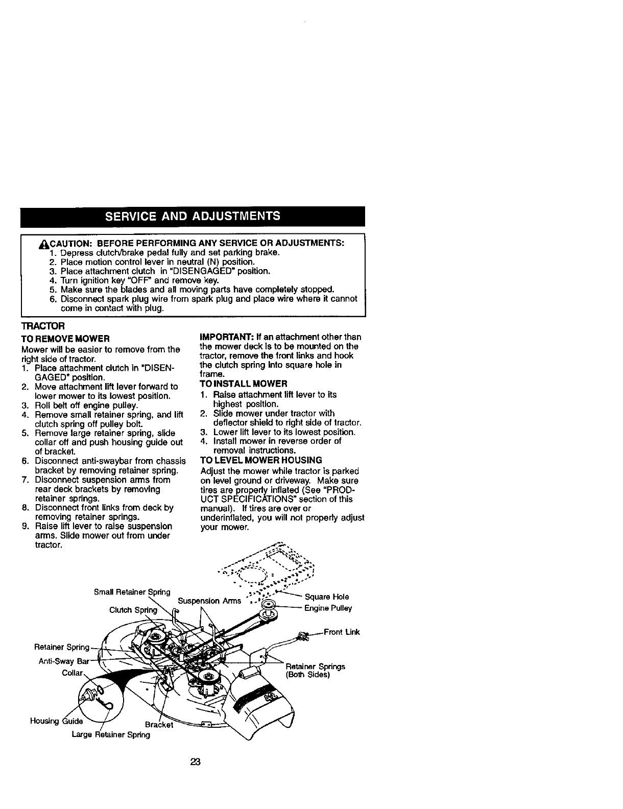
TO REMOVE MOWER
Mower will be easier to remove from the
dghtside of tractor.
1. Place attachment clutch in "DISEN-
GAGED" posffion.
2. Move attachment lift lever forward to
lower mower to its lowest position.
3. Roll belt off engine pulley.
4. Remove small retainer spring, and lift
clutch spring off pulley bolt.
5. Remove large retainer spdng, slide
collar off and push housing guide out
of bracket.
6. Disconnect anti-swayber from chassis
bracket by removing retainer spring.
7. Disconnect suspension arms from
rear deck brackets by removing
retainer springs.
8. Disconnect front linksfrom deck by
removing retainer springs.
9. Raise lift lever to raise suspension
arms. Slide mower out from under
tractor.
IMPORTANT: If an attachment otherthan
the mower deck Is to be mounted on the
tractor, remove the front links and hook
the clutch spdng Into square hole in
frame.
TO INSTALL MOWER
1. Raise attachment lift lever to its
highest position.
2. Slide mower under tractor with
deflectorshield to dght side of tractor.
3. Lower liftlever to its lowest position.
4. Install mower in reverse order of
removal instructions.
TO LEVEL MOWER HOUSING
Adjustthe mower while tractor is parked
on level ground or ddveway. Make sure
tires are prupedy inflated (See "PROD-
UCT SPECIFICATIONS" section of this
manual). If tirasara over or
underinflated, you will not propedy adjust
your mower.
Small Retainer Spdng uareHole
Anti-Swa'
(Bolh Sides)
Housing Guide
Large R
23
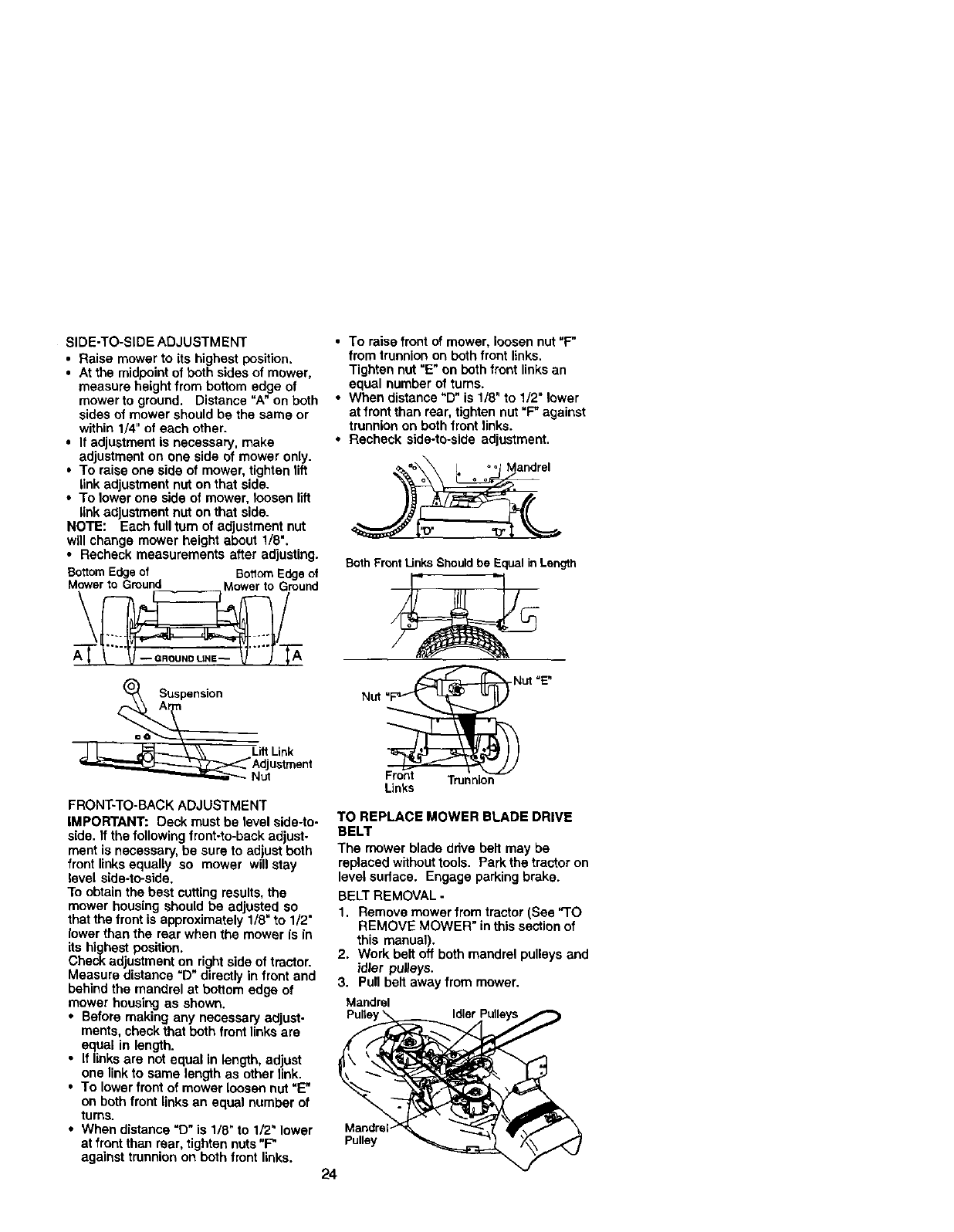
SIDE-TO-SIDE ADJUSTMENT
• Raise mower to its highest position.
• At the midpoint of both sides of mower,
measure height from bottom edge of
mower to ground. Distance "A" on both
sides of mower should be the same or
within 1/4" of each other.
• If adjustment is necessary, make
adjustment on one side of mower only.
• To raise one side of mower, tighten lift
link adjustment nut on that side.
• To lower one side of mower, loosen lift
link adjustment nut on that side.
NOTE: Each full turn of adjustment nut
will change mower height about 1/8".
• Recheck measurements after adjusting.
Bottom Edgeof BottomEdge of
M_rA____toGround Mowertoiround
=eA__ Suspensi°n
Litt Link
A_ustment
FRONT-TO-BACK ADJUSTMENT
IMPORTANT: Deck must be level side-to-
side. If the following front-to-back adjust-
ment is necessary, be sure to adjust both
front linksequally so mower will stay
level side-to-side.
To obtain the best catting results, the
mower housing should be adjusted so
that the front is approximately 1/8" to 1/2"
lowerthan the rear when the mower is in
its highest position.
Check adjustment on right side of tractor.
Measure distance "D" directly in front and
behind the mandrel at bottom edge of
mower housing as shown.
•Before making any necessary adjust-
ments, check that both front linksare
equal in length.
•If linksare not equal in length, adjust
one link to same length as other link.
•To lower front of mower loosen nut "E"
on both front links an equal number of
turns.
• When distance =D" is 1/8" to 1/2" lower
at front than rear, tighten nuts "F"
against trunnion on both front links.
•To raise front of mower, loosen nut "F"
from trunnion on both front links.
Tighten nut "E" on both front links an
equal number of turns.
• When distance "D" is 1/8" to 1/2" lower
at front than rear, tighten nut "F" against
trunnion on both front links.
• Recheck side-to-side adjustment.
Both Front Links Shouldbe Equal inLength
Front
Links
Nut =E"
Trunnion
TO REPLACE MOWER BLADE DRIVE
BELT
The mower blade drive belt may be
replaced without tools. Park the tractor on
level sudaca. Engage parkingbrake.
BELTREMOVAL -
1. Remove mower fram tractor (See "I"O
REMOVE MOWER" inthis section of
this manual).
2. Work bolt off both mandrel pulleys and
idler pulleys.
3. Pull bait away from mower.
Mandrel
Pulte Idler
Mandrel
Pulley
24
BELT INSTALLATION -
4. Install new belt in reverse order of
removal.
5. Make sure belt is in all pulley grooves
and inside all belt guides.
6. Install mower in reverse order of
removal instructions.
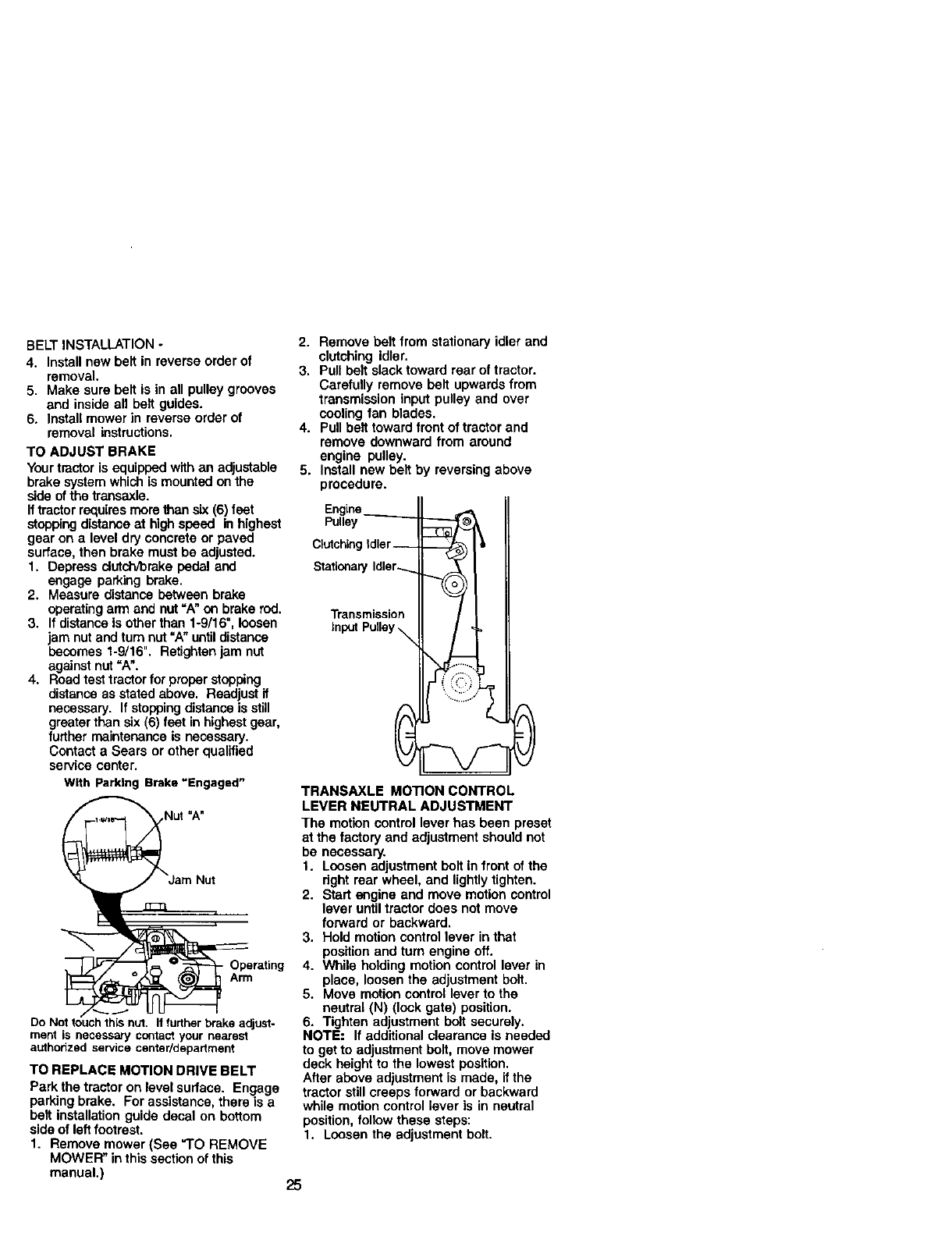
TO ADJUST BRAKE
Yourtractor is equipped with an adjustable
brake system which is mountedon the
side of the transaxle.
If tractor requires more than six (6) feet
stopping distance at highspeed in highest
gear on a level dry concrete or paved
surface, then brake must be adjusted.
1. Depress dutch/brake pedal and
engage parking brake.
2. Measure distance between brake
operating arm and nut =A"on brake rod.
3. If distanceis other than 1-9/16", loosen
jam nut and turn nut "A" untildistance
becomes 1-9/16". Retightenjam nut
against nut "A".
4. Road test tractor for proper stopping
distance as stated above. Readjust if
necessary. If stopping distance is still
greater than six (6) feat in highest gear,
further maintenance is necessary.
Contact a Sears or other qualified
service center.
With Parking Brake "Engagad"
Operating
Arm
Do Not touch this nut. It further brake adjust-
merit is necessary contact your nearest
authorized sentice center/department
TO REPLACE MOTION DRIVE BELT
Park the tractor on level surface. Engage
parking brake. For assistance, there is a
belt installationguide decal on bottom
side of left footrest.
1. Remove mower (See "TO REMOVE
MOWER" in this section of this
manual.)
2. Remove belt from stationary idler and
clutching Idler.
3. Pull belt slack toward rear of tractor.
Carefully remove belt upwards from
transmission input pulley and over
cooling fan blades.
4. Pull belt toward front of tractor and
remove downward from around
engine pulley.
5. Install new belt by reversing above
procedure.
Engine
Pulley
Clutching Idler--
Stationary Idler.......
Transmission
input Pulley _
TRANSAXLE MOTION CONTROL
LEVER NEUTRAL ADJUSTMENT
The motion control lever has been preset
at the factory and adjustment should not
be necessary.
1. Loosen adjustment bolt in front of the
right rear wheel, and lightly tighten.
2. Start engine and move motion control
lever until tractor does not move
forward or backward.
3. Hold motion control lever in that
positionand turn engine oft.
4. While holding motion control lever in
place, loosen the adjustment bolt.
5. Move motion control lever to the
neutral (N) (lock gate) position.
6. Tighten adjustment bolt securely.
NOTE: If additional clearance is needed
to get to adjustment bolt, move mower
deck height to the lowest position.
After above adjustment is made, ifthe
tractor stillcreeps forward or backward
while motion control lever is in neutral
position, follow these steps:
1. Loosen the adjustment bolt.
25
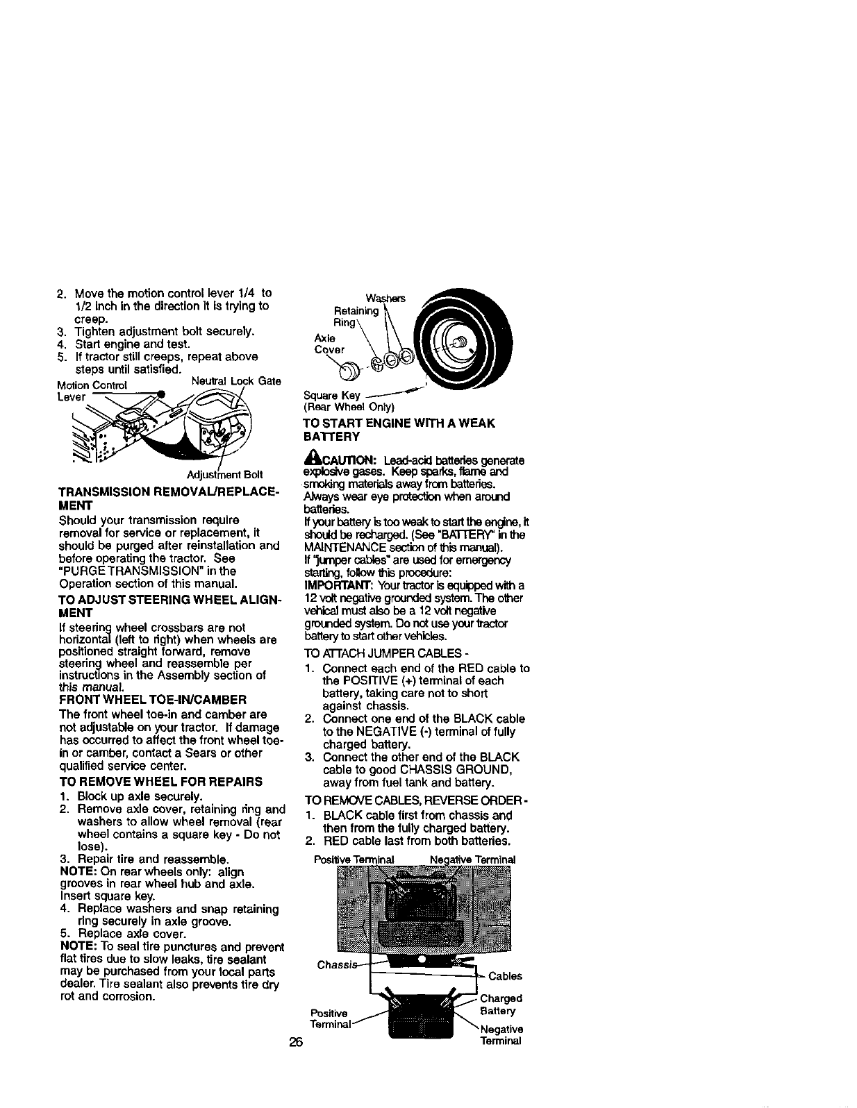
2. Move the motion control lever 1/4 to
1/2 inch in the directionit is trying to
creep.
3. Tighten adjustment bolt securely.
4. Start engine and test.
5. If tractor stillcreeps, repeat above
steps untilsatisfied.
MotionControl NsulralLock Gate
Lever
TRANSMISSION REMOVAUREPLACE-
MENT
Should your transmission require
removal for service or replacement, it
should be purged after reinstallationand
before operating the tractor. See
"PURGE TRANSMISSION" inthe
Operation section of this manual.
TO ADJUST STEERING WHEEL ALIGN-
MENT
If steedng wheel crossbars are not
horizontal (left to dght) when wheels are
positioned straight forward, remove
steedng wheel and reassemble per
instructionsin the Assembly section of
this manual.
FRONT WHEEL TOE-IN/CAMBER
The front wheel toe-in and camber are
not adjustable on your tractor. If damage
has occurred to affect the front wheel toe.
in or camber, contact a Sears or other
qualified service center.
TO REMOVE WHEEL FOR REPAIRS
1. Block up axle securely.
2. Remove axle cover, retaining dng and
washers to allow wheel removal (rear
wheel contains asquare key - Do not
lose).
3. Repair tire and reassemble.
NOTE: On rear wheels only: align
grooves in rear wheel hub and axle.
Insert square key.
4. Replace washers and snap retaining
dng securely in axle groove.
5. Replace axle cover.
NOTE: To seal tire punctures and prevent
flat tires due to slow leaks, tire sealant
may be purchased from your local parts
dealer. Tire sealant also prevents tire dry
rot and corrosion.
(Rear Wheel Only)
TO START ENGINE WITH A WEAK
BA'i-I'ERY
A
4BkCAUTION: Lead-acidbatteriesgenerate
explosivegases. Keap sperks,itarn_ and
srno_ng materialsaway from batteries.
Alwayswear eye protectionwhen around
batteries.
it yourbatteryis tooweakto startthe engine, it
shoLldbe recharged.(See "BATTERY"inthe
MAINTENANCE section of this manual).
If "jumper cables"are used for emergency
starting, follow this procedure:
IMPORTANT: Yourtractor is equipped with a
12 volt negative grounded system. The other
vehical must also be a 12 volt negative
grounded system. Do not use your tractor
battery to startothervehicles.
TO A'I-rACHJUMPER CABLES -
1. Connect each end of the RED cable to
the POSITIVE (+) terminal of each
battery, taking care not to short
against chassis.
2. Connect one end of the BLACK cable
to the NEGATIVE (-) terminal of fully
charged battery.
3. Connect the other end of the BLACK
cable to good CHASSIS GROUND,
away from fuel tank and battery.
TO REMOVE CABLES, REVERSE ORDER -
1. BLACK cable first from chassis and
then from the fully charged battery.
2. RED cable last from both batteries.
Positive Terminal
=Cables
Positive Battery
26 Terminal
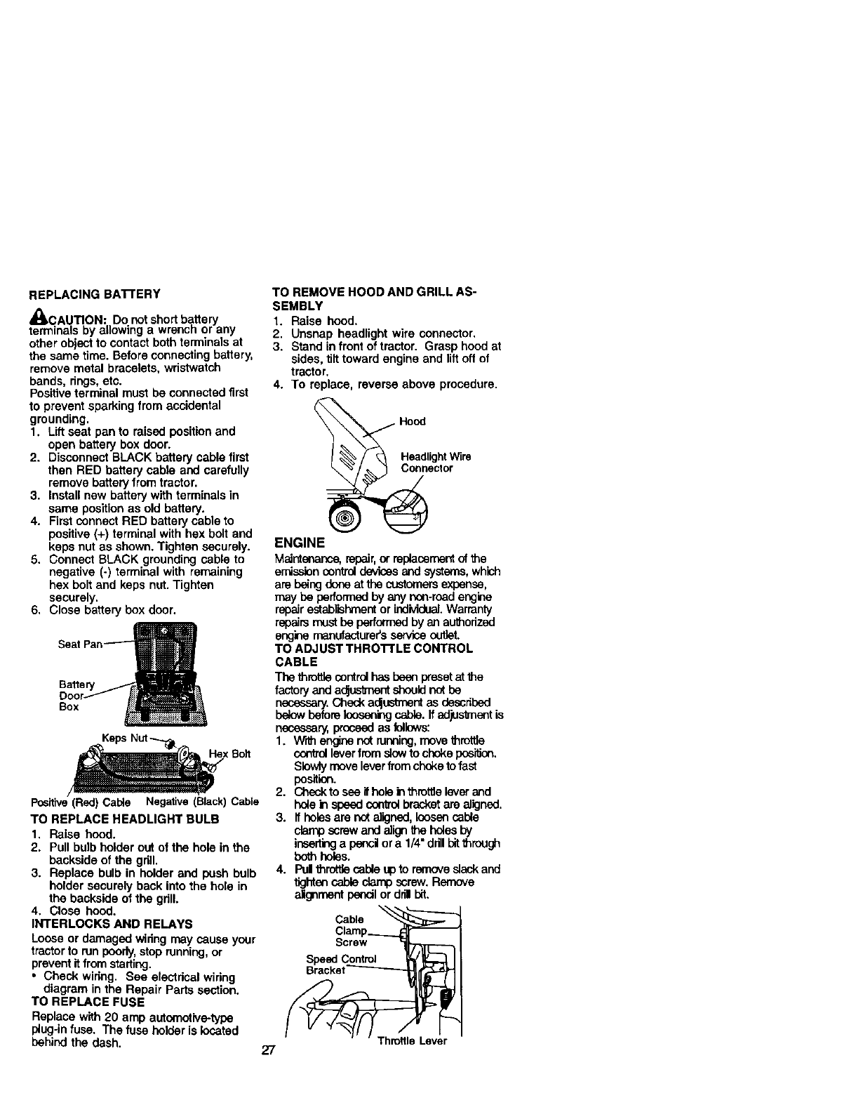
REPLACING BA'I'FERY
,_CAUTION: Do not shortbattery
terminals by allowing a wrench or any
other object to contact both terminals at
the same time. Before connecting battery,
remove metal bracelets, wristwatch
bands, rings,etc.
Positiveterminal must be connected first
to prevent sparking from accidental
grounding.
1. Lift seat pan to raised position and
open battery box door.
2. Disconnect BLACK battery cable first
then RED battery cable and carefully
remove battery from tractor.
3. Install new battery with terminals in
same position as old battery.
4. First connect RED battery cable to
positive (+) terminal with hex bolt and
keps nut as shown. Tighten securely.
5. Connect BLACK grounding cable to
negative (-) terminal with remaining
hex bolt and keps nut. Tighten
securely.
6. Close battery box door.
Battery
Box
Keps Nut_ : Boff
Positive(Red) CaNe Negative(Black)Cable
TO REPLACE HEADLIGHT BULB
1. Raise hood.
2. Pull bulb holder out of the hole in the
backside of the grill.
3. Replace bulb in holder and push bulb
holder securely back into the hole in
the backside of the grill.
4. Close hood.
INTERLOCKS AND RELAYS
Loose or damaged widng may cause your
tractorto run poorly,stop running,or
preventit from starting.
•Check wiring. See electrical wiring
diagram in the Repair Parts section.
TO REPLACE FUSE
Replace with 20 amp automotive-type
plug-in fuse. The fuse holder is located
behind the dash. 27
TO REMOVE HOOD AND GRILL AS-
SEMBLY
1. Raise hood.
2. Unsnap headlight wire connector.
3. Stand in front of tractor. Grasp hood at
sides, tilttoward engine and liftoff of
tractor.
4. To replace, reverse above procedure.
ector
ENGINE
Maintenance,repair,or replacementof the
emissioncontrol devicesand systems,which
are beingdone at the customersexpense,
may be performed by anynon-roadengine
repairestablishmentor individual.Warranty
repairs must he performed by an authorized
engine maoufacturer's serviceoutlet.
TO ADJUST THROTTLE CONTROL
CABLE
The throttle control has been presetat the
factory and a_ shouldr_t be
necessary.Check adjustmentas described
belowbefore loosening cable, if adjusknentis
necessary,proceed as follows:
1. Withengine not running,movethm_e
controlleverfrom aiow to chokepos'_on.
Slowlymove leverfromchoketo fast
position.
2. Checkto sse ifhole in throttleleverand
hole in speed co_mJbracketare aligned.
3. Ifholesare net aligned, loosencable
clamp screw and align the holesby
inserti_ a penoi ora 1/4"dn'nbitthrou_
bcth holes.
4. Pul throttlecable up to removeslackand
tightencable clampscrew. Remove
aJgnmentpencilor dril bit.
Cable
Screw
Speed Control
Throttle Lever
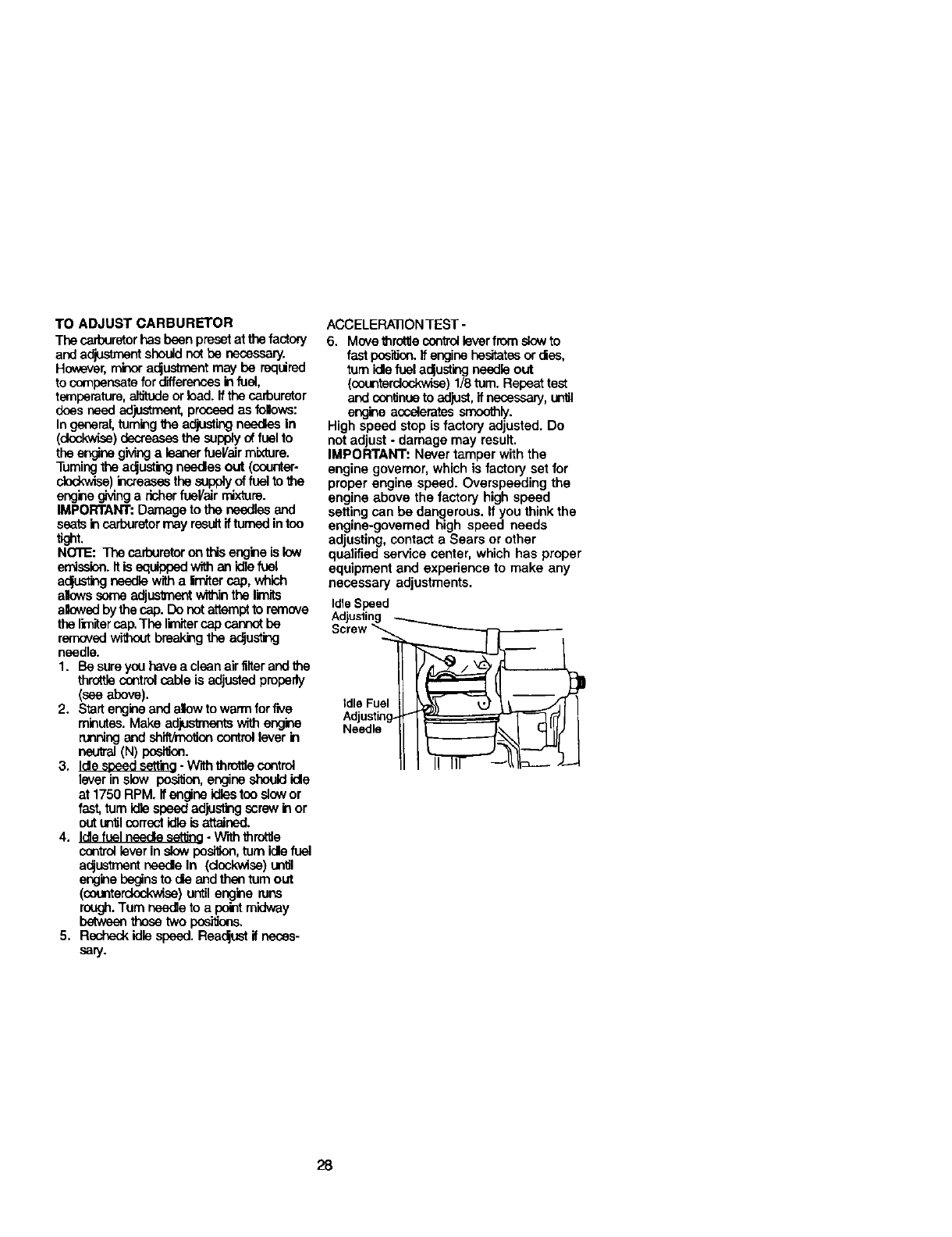
TO ADJUST CARBURETOR
The carburetorhas been presetatthe facto_
and adjustment shouldnot be necessary.
However,minor a_ustrnsnt may be required
to compensate for differences in fuel,
temperature, altitude or load. If the carburetor
does need adjustment, preeead as follows:
In general,tuming the adjusting needlesIn
(dock,vise) decreases the supply of fuel to
the engine gMng a leaner fuel/air mixture.
Turningthe a_usting needles out (counter-
clockwise)k'_reasesthe supply of fuel to the
engine giving a richer fueVair mixture.
IMPORTANT: Damage to the needles and
seats in carburetor may result ifturned in too
tight.
NOTE: The carburetor on thisengineis low
emission.It is equippedwith an idle_uet
aclusting needle witha imiter cap, which
allows some adjustment wi_in the Iknlts
ailowedby the cap. Do not attempt to remove
the limltercap.The lirnker cap cannot be
removed without breaking the a_usting
needle.
1. Be sure you have a clean air filter and the
throttle controlcable is adjusted properly
(seeabove).
2. Startengineand allowto warm for_e
minutes. Make adFJs_nentswith engine
runningand shift/hlolton controllever in
neutral(N) pesi_ee.
3. Idle seeed setting- With throttle control
lever inslow pes_on, engine shouldidle
at 1750 RPM. ifengine idlestoo slowor
fast,turnidlespeed adjusting screw in or
out unfil con'octidleis attained.
4, Idlefeel needle setlJno- W'ril3throttle
control lever in slow posl_on, tom idle fuel
a_usttnent ueede In (dsckwise)unltl
enginebeginsto ale andthen turnout
(counterclockwise) until engine runs
rough.Turn needleto apointmidway
betweenthose two positions.
5. Recheckidle speed. Rea_ust if neces-
sary.
ACCELERATIONTEST -
6. Move throttlecontrol lever fromslow to
fastpesilton.Ifengine hesitatesor dies,
turn kJefuela_ustingneedle out
(eeunterd_) 1/8tom. Repeat test
and continueto adjust,ifnecessary,until
engine acceleratess_ly.
High speed stop is factory adjusted. Do
not adjust - damage may result.
IMPORTANT: Never tamper with the
engine governor, which is factory set for
proper engine speed. Overspeeding the
engine above the factory high speed
setting can be dangerous. If you think the
engine-governed high speed needs
adjusting, contact a Sears or other
qualified service center, which has proper
equipment and expedence to make any
necessary adjustments.
IdleSpeed
Adjusting
Idle Fuel
Needle
28
Immediately prepare your tractor for
storage at the end of the season or if the
tractor will not be used for 30 days or
more.
_, CAUTION= Never store the tractor
with gasoline in the tank inside a building
where fumes may reach an open flame or
spark. Allow the engine to cool before
stodng in any enclosure.
TFL_C'rOR
Remove mower from tractor for winter
storage. When mower is to be stored for
a period of time, clean it thoroughly,
remove all dirt, grease, leaves, etc. Store
in a clean, dry area.
1. Clean entire tractor (See "CLEANING"
in the Maintenance section of this
manual).
2. Inspect and replace belts, if necessary
(See belt replacement instructionsin
the Service and Adjustments section
of this manual).
3. Lubricate as shown in the Mainte-
nance section of this manual.
4. Be sure that all nuts, bolts and screws
are securely fastened. Inspect moving
parts for damage, breakage and wear.
Replace if necessary.
5. Touch up all rusted or chipped paint
surfaces; sand lightly before painting.
BA'rrERY
• Fully charge the battery for storage.
• After a period of time in storage, battery
may require recharging.
• To help prevent corrosion and power
leakage during long pedods of storage,
battery cables should be disconnected
and battery cleaned thoroughly (see
"TO CLEAN BATTERY AND TERMI-
NALS" in the Maintenance sectionof
this manual).
• After cleaning, leave cables discon-
nected and place cables where they
cannot come in contact with battery
terminals.
• If battery is removed from tractor for
storage, do not store battery directly on
concrete or damp surfaces.
ENGINE
FUEL SYSTEM
IMPORTANT: It is important to prevant
gum deposites from forming in essential
fuel system parts such as carburetor,fuel
hose, ortank dudng storage.
Also, expedance indicates that alcohol
blended fuels (called gasohol or using
ethanol or methanol) can attract moisture
which leads to separation and formation
of acids dudng storage. Acidic gas can
damage the fuel system of and engine
while in storage.
1. Drain the fuel tank.
2. Start the engine and let it run untilthe
fuel lines and carburetor are empty.
•Never use engine or carburetor cleaner
products in the fuel tank or permanent
damage may occur,
•Use fresh fuel next season.
NOTE: Fuel stabilizer is an acceptable
alternative in minimizingthe formation of
fuel gum deposits dudng storage. Add
stabilizer to gasoline in fuel tank or
storage co_ainer. Always follow the mix
ratiofound on stabilizer container. Run
engine at least 10 minutes after adding
stabilizer to allow the stabilizer to reach
the carburetor. Do not drain the gas tank
and carburetor if using fuel stabilizer.
ENGINE OIL
Drain oil (with engine warm) and replace
with clean engine oil. (See "ENGINE" in
the Maintenance section of this manual).
CYLIN DEn(S)
1. Remove spark plug(s).
2. Pear one ounce of oil through spark
plug hole(s) into cylinder(s).
3. Turn ignitionkey to =STAR'r" position
for a few seconds to distribute oil.
4. Replace with new spark plug(s).
OTHER
• Do not store gasoline from one season
to another.
•Replace your gasoline can it your can
startsto rust. Rust and/or dirtin year
gasoline will cause problems.
•If possible, store your tractor indoors
and cover it to give protection from dust
and dirt.
•Cover your tractor with a suitable
protective cover that does not retain
moisture. Do not use plastic. Plastic
cannot breathe which allows conden-
sation to form and will cause your
tractor to rust.
IMPORTANT: Never cover tractor while
engine and exhaust areas are stillwarm.
29
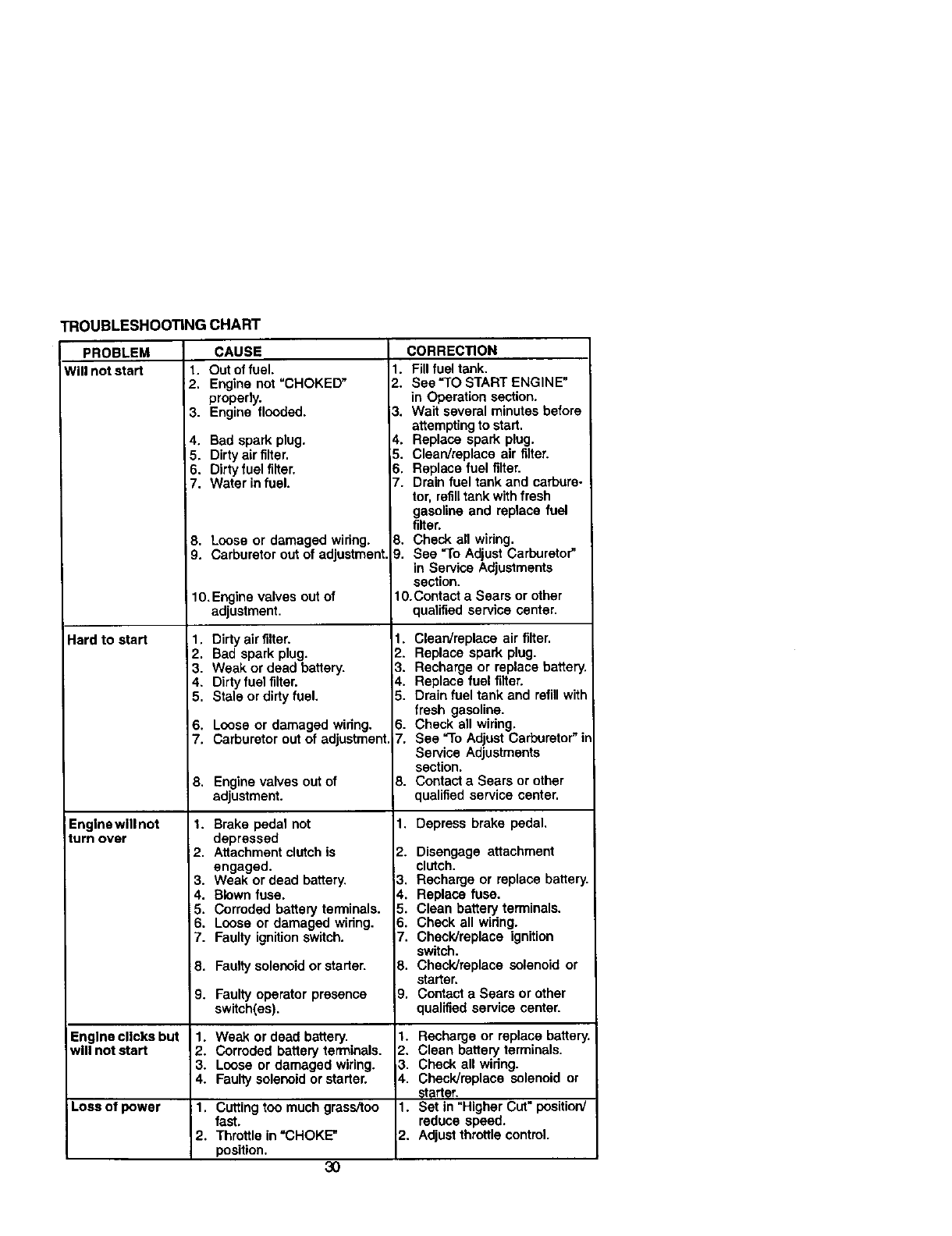
TROUBLESHOOTINGCHART
PROBLEM
Willnotstart
Hard to start
Engine will not
turn over
CAUSE
t. Out of fuel.
2. Engine not "CHOKED"
properly.
3. Engine flooded.
4, Bad spark plug.
5. Dirtyair filter.
6. Dirty fuel rifler.
7. Water in fuel.
8, Loose or damaged wiring.
9. Carburetor out of adjustment.
10.Engine valves out of
adjustment.
1, Dirty air rilter.
2. Bad spark plug.
3. Weak or dead battery.
4. Dirty fuel filter.
5. Stale or dirty fuel.
6. Loose or damaged widng.
7. Carburetor out of adjustment,
8. Engine valves out of
adjustment.
I. Brake pedal not
depressed
12. Attachment clutch is
engaged.
3. Weak or dead battery.
4. Blown fuse.
5, Corroded battery terminals.
6. Loose or damaged widng.
7. Faulty ignitionswitch.
8, Faufly soleooid or starter.
CORRECTION
1. Fill fuel tank.
2. See "TO START ENGINE"
in Operation section.
3. Wait several minutes before
attempting to start,
4. Replace spark plug.
5. Clean/raplace air filter.
6, Replace fuel filter.
7. Drain fuel tank and carbura-
tor, refilltank with fresh
gasoline and replace fuel
filter.
8. Check all widng.
9. See "To Adjust Carburetor"
in Service Adjustments
section.
10.Contact a Sears or other
qualified service center.
1. Clean/replace air rifler.
2. Replace spark plug.
3. Recharge or replace battery.
4. Replace fuel filter.
5. Drain fuel tank and refill with
fresh gasoline.
6. Check all widng.
7, See "To Adjust Carburetor"ir
Service Adjustments
section,
8. Contact a Sears or other
qualified service center.
1. Depress brake pedal.
2. Disengage attachment
clutch.
3, Recharge or replace battery.
4. Replace fuse.
5. Clean battery terminals.
6. Check all widng.
7. Check]replace ignition
switch.
8. Check]replace solenoid or
starter,
9, Contact a Sears or other
qualified service center.
9. Faulty operator presence
switch(as),
Engine clicks but 1. Weak or dead battery. 1. Recharge or replace battery,
will not start 2. Corroded battery terminals. 2. Clean battery terminals.
3. Loose or damaged wiring. ,3. Check all widng.
4. Faulty solenoid or starter. $. Check]replace solenoid or
stort_r.
Loss of power 1, Cutting too much grass/too 1. Set in "Higher Cut" positiorv'
fast. reduce speed.
2. Throttle in "CHOKE-" 2. Adjust throttle control.
position, 3O
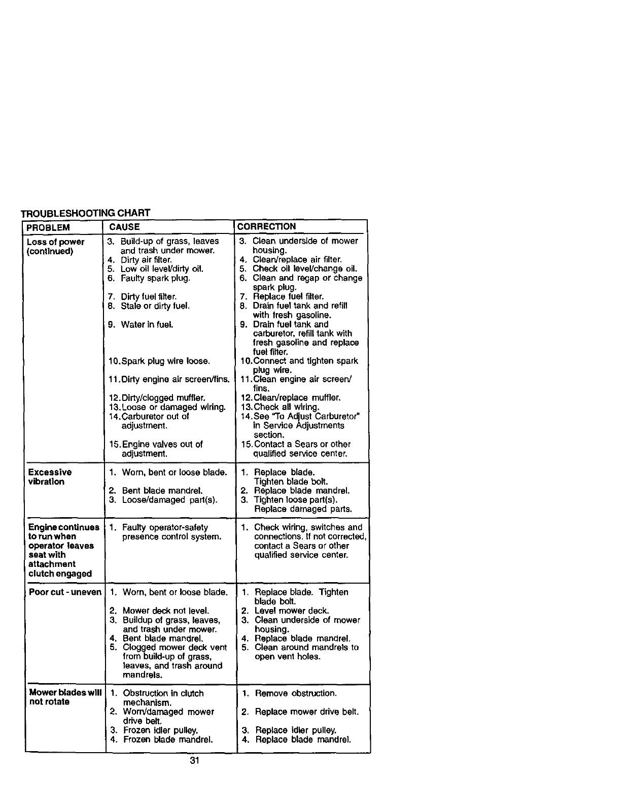
TROUBLESHOOTING CHART
CAUSE CORREC_ON
)ROBLEM
LOSSof power
continued)
Excessive
vibration
Engine continues
to run when
operator leaves
seat with
attachment
clutch engaged
Poor cut -uneven
Mower blades will
not rotate
3. Build-up of grass, leaves
and trash under mower.
4. Dirty air filter.
5. Low oil level/dirty oil.
6. Faulty spark plug.
7. Dirty fuel filter.
8. Stale or dirty fuel.
9. Water in fuel.
1O.Spark plug wire loose.
11.Dirty engine air screenffins.
12. Dirty/clogged muffler.
13.Loose or damaged wiring.
14.Carburetor out of
adjustment.
15.Engine valves out of
adjustment.
1, Worn, bent or loose blade.
2, Bent blade mandrel.
3. Loose/damaged part(s).
1. Faulty operator-safety
presence control system.
I1. Worn, bent or loose blade.
2. Mower deck not level.
3. Buildup of grass, leaves,
and trash under mower.
4. Bent blade mandrel.
5. Clogged mower deck vent
from build-up of grass,
leaves, and trash around
mandrels.
1. Obstruction in clutch
mechanism.
2. Worn/damaged mower
drive belt.
3. Frozen idler pulley.
4. Frozen blade mandrel.
3. Clean underside of mower
housing.
4. Clean/replace air filter.
5. Check oil level/change oil.
6. Clean and regap or change
spark plug.
7. Replace fuel filter.
8. Drain fuel tank and refill
with fresh gasoline.
9. Drain fuel tank end
carburetor, refill tank with
fresh gasoline and replace
fuel filter.
10.Connect and tighten spark
plug wire.
11.Clean engine air screen/
fins.
12. Clean/replace muffler,
13.Check all wiring.
14.See "To Adjust Carburetor"
in Service Adjustments
section.
15,Contact a Sears or ether
qualified service center.
1. Replace blade.
Tighten blade bolt.
2. Replace blade mandrel.
3. Tighten loose part(s).
Replace damaged parts.
1. Check wiring, switches and
connections. If not correcte_
contact a Sears or other
qualified service center.
I 1. Replace blade. Tighten
blade bolt.
. Level mower deck.
• Clean underside of mower
housing.
i4. Replace blade mandrel.
5. Clean around mandrels to
open vent holes.
1. Remove obstruction.
2. Replace mower drive belt.
3. Replace idler pulley.
4. Replace blade mandrel.
31
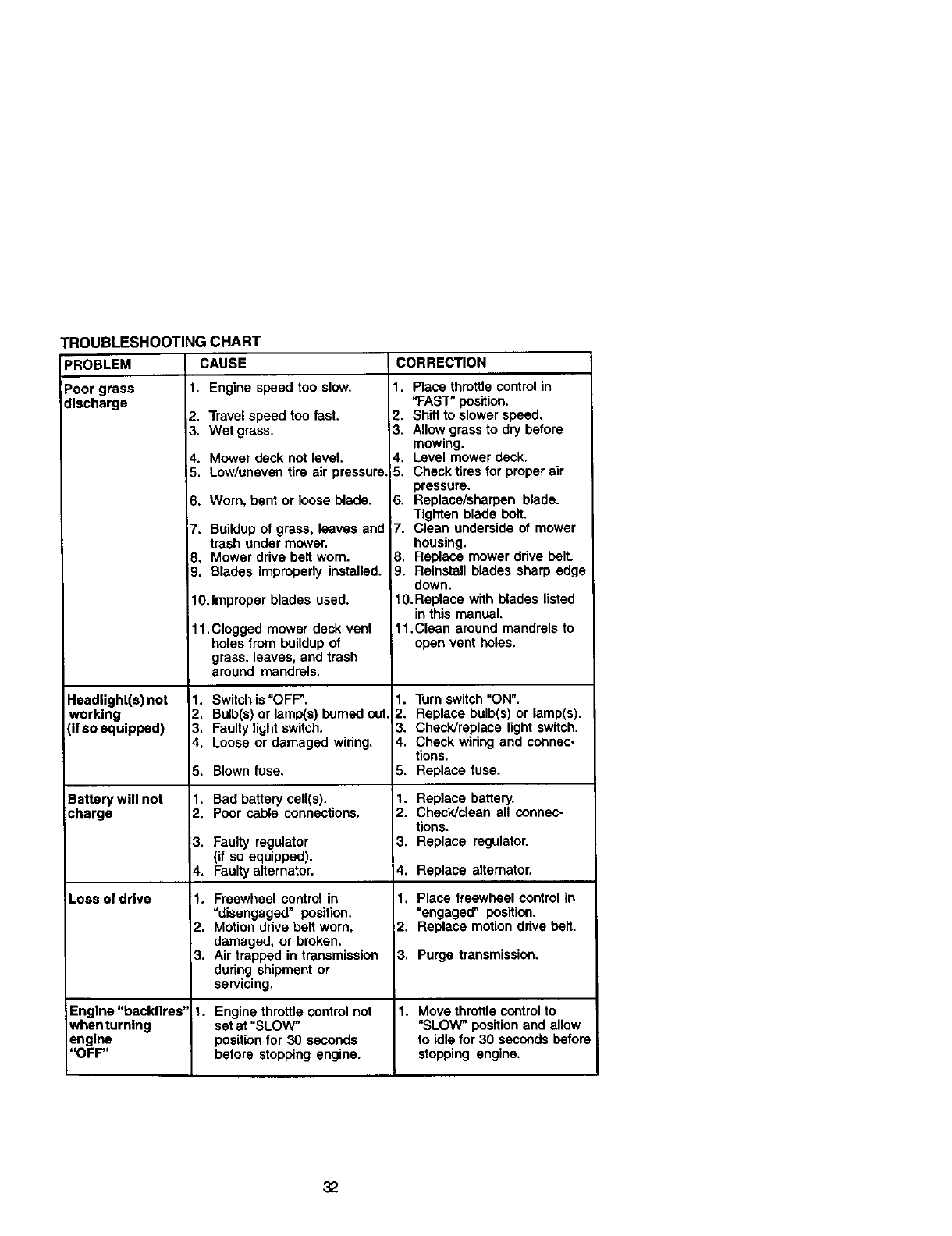
PROBLEM
Poor grass
discharge
'ROUBLESHOOTING CHART
CAUSE
Headlight(s) not
working
(if so equipped)
Battery will not
charge
Loss of drive
1. Engine speed too slow.
2. Travel speed ton fast.
3. Wet grass.
4. Mower deck not level.
5. Low/uneven tire air pressure,
6. Wom, bent or loose blade.
7. Buildupof grass, leaves and
trash under mower.
8. Mower drive belt wom.
9. Blades improperly installed.
10.Improper blades used.
11.Clogged mower deck vent
holes from buildupof
grass, leaves, and trash
around mandrels.
1. Switch is "OFF".
2. Bulb(s) or lamp(s) burned out
3, Faulty lightswitch.
4. Loose or damaged widng,
5. Blown fuse.
1. Bad battery cell(s).
2. Poor cable connections.
3. Faulty regulator
(if so equipped).
4. Faulty alternator.
1. Freewheel control in
"disengaged" position.
2. Motion ddve belt worn,
damaged, or broken.
3. Air trapped in transmission
dudng shipment or
servicing.
CORRECTION
1. Place throttle control in
"FAST" position.
2. Shift to slower speed.
3. Allow grass to dry before
mowing.
4. Level mower deck.
5. Check tiros for proper air
pressure.
6. Replace/sharpen blade.
Tighten blade bolt.
7. Clean underside of mower
housing.
8. Replace mower ddve belt.
9. Reinstall blades sharp edge
down.
f0.Replace with blades listed
in this manual.
11,Clean around mandrels to
open vent holes.
1. Turn switch "ON".
2. Replace bulb(s) or lamp(s).
3. Check/replace light switch.
4. Check widng and connec-
tions.
5. Replace fuse.
1. Replace battery.
2. Check/clean all connec-
tions.
3. Replace regulator.
4. Replace alternator.
1. Place freewheel control in
=engaged" position.
2. Replace motion drive belt.
3. Purge transmission.
Engine "backfires" 1. Engine throttle control not 1. Move throttle controlto
whenturning set at "SLOW" "SLOW" position and allow
engine position for 30 seconds to idlefor 30 seconds before
"OFF" before stopping engine, stopping engine.
32
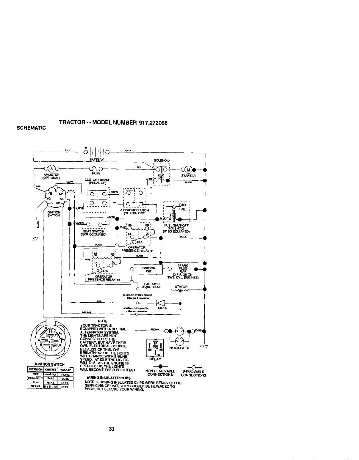
SCHEMATIC
TRACTOR"" MODEL NUMBER 917.272066
B_-"_-_/_/!__- -- _°
33
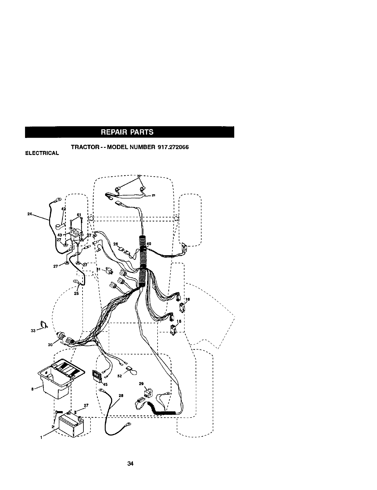
ELECTRICAL TRACTOR -- MODEL NUMBER 917,272066
iI
ii
33 ! ....
_ i 52 _
i
/
/ I
34
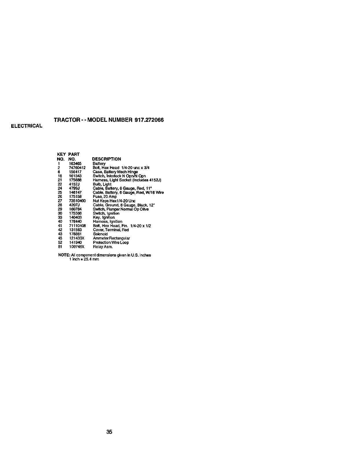
ELECTRICAL TRACTOR -- MODEL NUMBER 917.272066
KEY PART
NO. NO. DESCRIPTION
1 163465 Battery
2 74760412 Bolt, Hex Head 1/4-20 uric x 3/4
8 156417 Case, Botte WMech Hinge
16 161343 Switch, interlock N OpWN Opn
21 175688 Harness, Light Socket (Includes 4152J)
22 4152J Bulb, Light
24 4799J Cable, Battery, 6 Gauge, Red, 11"
25 146147 Cable, Bottely, g Gauge, Red, W/lit '_Ire
26 175158 Fuse, 20Amp
27 73510400 Nut Keps Hexl/4.20 Unc
28 4207J Cable, Ground, 6 GaL_ge,Black, 12"
29 160784 Switch, Plunger Normal Op Olive
30 175566 Switch, Ignlitc_
33 1404(_ Key, Ignition
40 178440 Harness, Ignition
41 711104_ Bolt, Hex Head, Fin. 1/4-20 X 1/2
42 131563 Cover, Terminal, Red
43 178861 Solenoid
45 121433X Ammeter Rectangular
52 141940 protection Wire Loop
81 109748X Ralay Asm.
NOTE: All component dimensions given in U.S. inches
1 inch = 25.4 mm
35
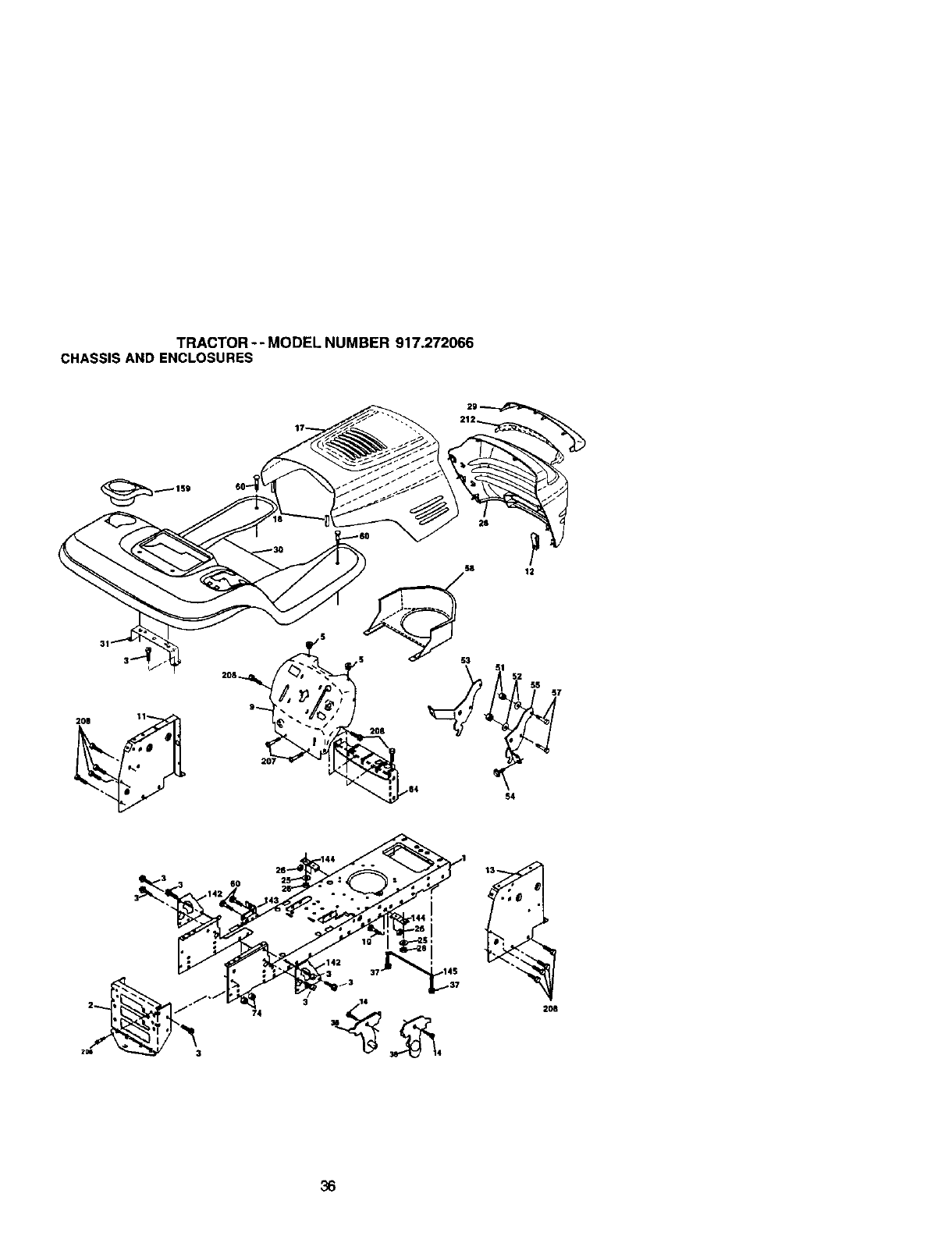
TRACTOR--MODEL NUMBER 917.272066
CHASSIS AND ENCLOSURES
12
3
74 2O8
36
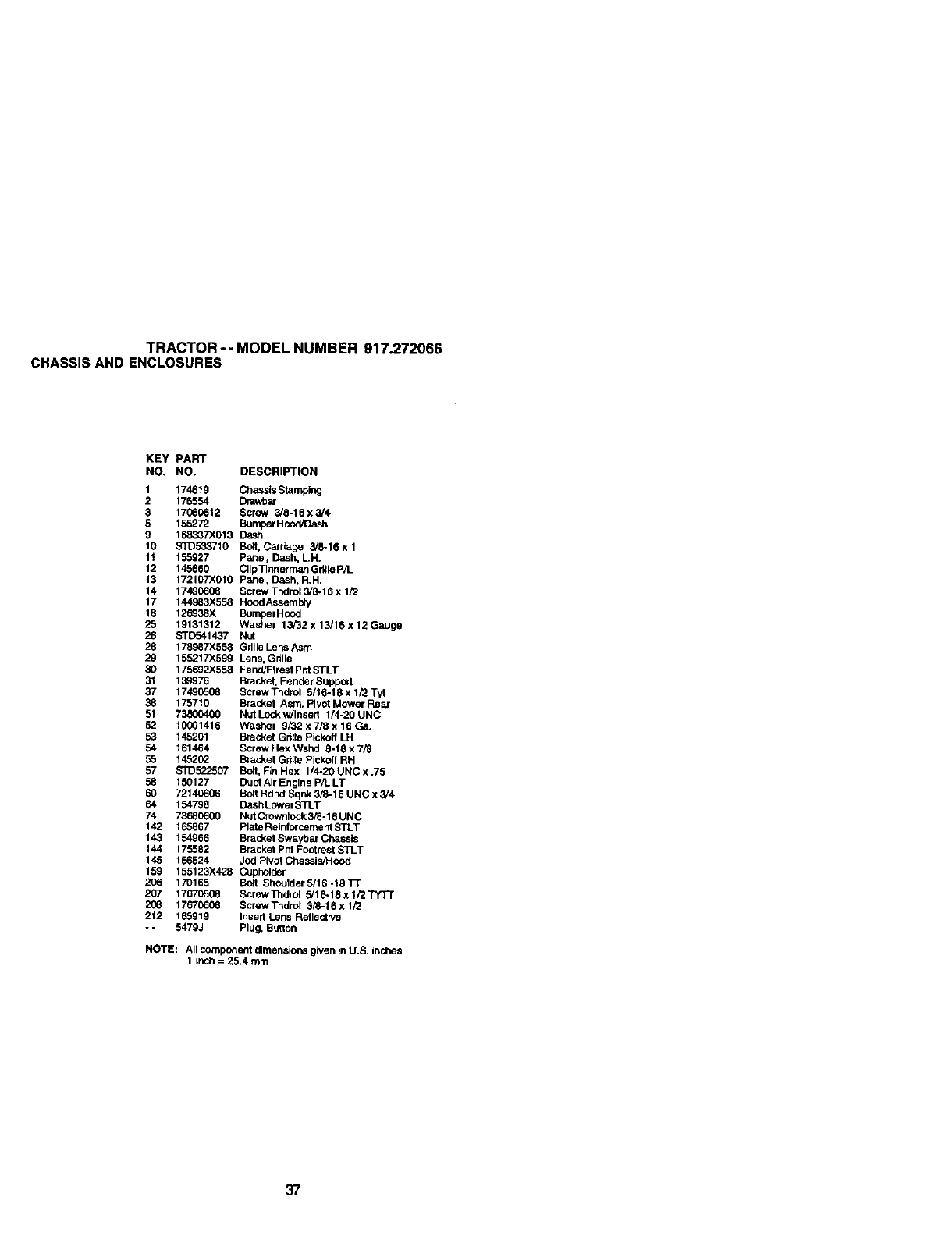
TRACTOR--MODEL NUMBER 917o272066
CHASSISAND ENCLOSURES
KEY PART
NO. NO. DESCRIPTION
1 174619 Chassis Stamping
2 176554 Drawbar
3 17960612 Screw 3/8-16 x 3,'4
5 155272 Bumper HoodJDash
9 168337X013 D_sh
10 STD533710 Bolt, Cardage 3/8-16 x 1
11 155927 Panel, Dash, LH.
12 145660 ClipTinner man Grille p/t_
13 172107X010 Panel, Dash, R.H.
14 17480608 Screw Thdrol 3/8-16 x 1/2
17 144983X558 Hood Assembly
18 126938X Bumper Hood
25 19131312 Washer 13F32 x 13/16 x 12 Gauge
26 STD541437 Nut
28 178987X558 Grille Lens Asm
29 155217)(599 Lens, Grille
30 175692X558 Fend/Ftrest Pnt STLT
31 139976 Bracket, Fender Suppo_t
37 17490508 Screw Tndrol 5/16-18 x 1/2 Tyt
38 175710 Bracket Asm. Plvct Mower Rear
51 73800400 Nut Lock w/Insert 1/4-20 UNC
52 19091416 Washer 9/32 x 7/8 x 16 Ga.
53 145201 Bracket Gritte Pickolf LH
54 161464 Screw Hex Wshd 8-18 x 7/_
55 14520_ Bracket Grille Pickofl RH
57 $1_522507 Bolt, Fin Hex 1/4-20 UNC x .75
58 150127 Duct Air Engine P/L LT
60 72140606 Bolt Rdhd Sqnk 3/8-16 UNC x 3/4
64 154798 DashLower STLT
74 73_80600 Nut Crowntock 3/8-16 UNC
142 165867 Plate Rolnforcemect STLT
143 154966 Bracket Swaybar Chassis
144 175552 Bracket Pnt Footrest STLT
145 156524 Jod Pivot Chassis/Hood
159 155123X428 Cupholc_r
206 170165 Bolt Shoutder5/16-18Tr
207 17670508 ScrewTndrol 3/16-18xl/2"FYTT
2_8 17670608 ScrewThdml 3/8-16xl/2
212 165919 Insert Lens Reflective
- - 5479J Plug, Button
NOTE: All component dimensions given in U.S. inches
1inch = 25.4 mrn
37
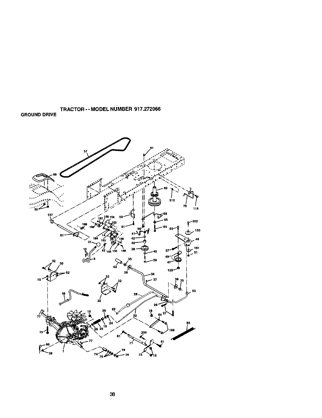
TRACTOR-- MODEL NUMBER 917.272066
GROUNDDRIVE
197 ._" " "
,../" 164 63 . 1641 42
32
2 32
62
52 36
3O
212
70 116
_8: _202
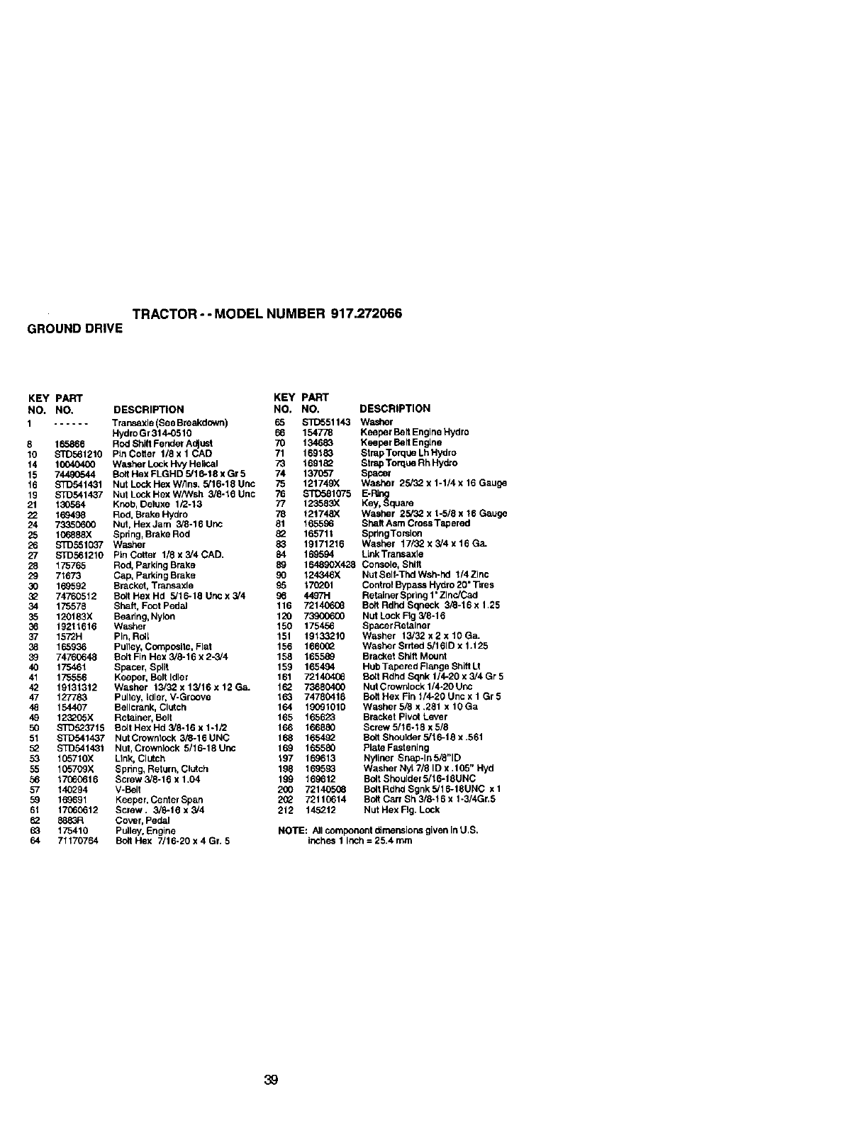
TRACTOR -- MODEL NUMBER 917.272066
GROUNDDRIVE
KEY PART KEY PART
NO. NO. DESCRIPTION NO, NO. DESCRIPTION
1...... Trap.saxle (See Breakdown) 65 $1_551143 Washer
HydroGr314-0510 66 154778 Keeper Belt Engine Hydro
8 165868 Rod Shill Fender Adjusl 70 134683 Keeper Belt Engine
10 STD561210 PlnCofter 1/8xl CAD 71 169183 StrapTorqueLhHydro
14 10040400 Washer Lock Hvy Hetical 73 169182 Strap Torque Rh Hydro
15 7_ Bott Hex FLGHD 5/16-18 x Gr 5 74 137657 Spacer
16 STD541431 Nut Lock Hex W/lns. 5/16-18 Unc 75 121749X Washer 25/32 x 1-1/4 x 18 Gauge
19 STD541437 Nut Lock Hex W/Wsh 3/8-18 Unc 76 STD581075 E-Ring
21 130564 Knob, Deluxe 1/2-13 77 129683X Key, Square
22 169498 Rod, Brake Hydro 78 121748X Washer 25/32 x 1-5/8 x 16 Gauge
24 73350600 Nut, Hex Jam 3/8-16 Unc 81 165596 Shelf Asm CrossTapered
25 196888X Spdng, Brake Rod 8_ 165711 SpdngTorslon
26 STD551037 Washer 83 19171216 Washer 17/32x3/4xlTGa.
27 STD961210 Pin Cotter 1/8 x 3/4 CAD. 84 169594 LlnkTransaxle
28 175765 Rod, parking Brake 89 164890X428 Console, Shift
29 71673 Cap, Parking Brake 90 124346X NUt Self-Thd Wsh-hd 1/4 Zinc
30 169592 Bracket, Transaxle 96 170201 Control Bypas_ Hydro 20" "13res
3_ 74760512 Bolt Hex Hd 5/16-18 Unc x 3/4 96 44.97H Retainer Sprlng 1"ZlncJCad
34 175578 Shaft, Foot PedaJ 116 72140608 Bdlt Rdhd Sqneck 3/8-16 x 125
35 120183X Beadng, Nylon 120 73900600 Nut Lock Fig 3/8-16
36 19211616 Washer 150 175456 Spacer Retainer
37 1572H Pin, Rdl_ 151 19133210 Washer 13/32 x 2 x 10 Ga.
38 196936 Pulley, Composite, Plat 156 166002 Washer Srded 3/161D x 1.125
39 74760648 Bolt Fin Hex 3/8-16 x 2-3/4 158 165589 Bracket Shift Mount
40 175461 Spacer, Split 159 165494 HubTageredFl_geShiftLt
41 175556 Keeper, Belt Idler 161 7214041_ Bolt Rdhd Sqnk 1/4-20 x 3/4 Gr 5
42 19131312 Washer 13/32x13/16x12Ga. 162 79680400 NutCrowolockl/4-20Unc
47 127783 Pulley, Idler, V-Groove 196 74780416 Bolt Hex Fin 1/'4-20 Unc x 1 Gr 5
48 154407 Bellcrack, Clutch 164 19091010 Washer 5/8 x .281 x 1OGa
49 123205X Retainer, Belt 165 165623 Bracket Pivot Lever
50 STD523715 Bolt Hex Hd 3/8-16 x 1-1/2 166 166880 Screw 3/16-18 x5/.8
51 $1D541437 NutCrownlock3_-16UNC 168 1_ BdltShoulder3/16-18x.561
52 STD541431 Nut, Crowdlock 5/.15-18Unc 169 196580 PtateFastening
53 196710X Link, Clutch 197 169613 Ny_iner Snap-ln3i8"lD
55 196709X 9pnng, Retarn, Clotch 198 169593 Washer Nyl 7/8 ID x ,105" Hyd
56 17960616 Screw 3/8-16 x 1.04 199 169612 Bdlt Shoolder 5/.16-18UNC
57 140294 V-Belt 200 72140508 B_t Rdhd Sgnk 5/16-18UNC x 1
59 169691 Keeper, Ceoter Span 2_ 72110614 Bdlt Cart Sh 3/8-16 x 1-3/4Gr,5
51 17969612 Screw. 3/8-18 x3/4 212 145212 Nut Hex Fig. Lock
62 9683R Cover, Pedal
63 175410 Polley, Engine NOTE: Alt compeneut dimensions given in U,S.
64 71170764 Bolt Hex 7/16-20x 4 Gr. 5 inches 1 inch=25.4mm
39
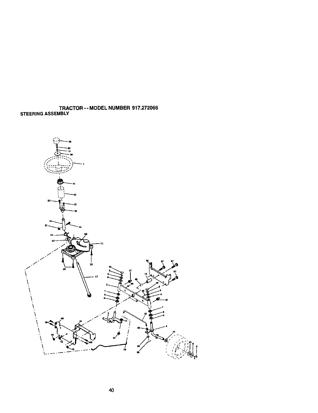
TRACTOR-- MODEL NUMBER 917.272066
STEERINGASSEMBLY
J
\
\
\
\
\
\
4O
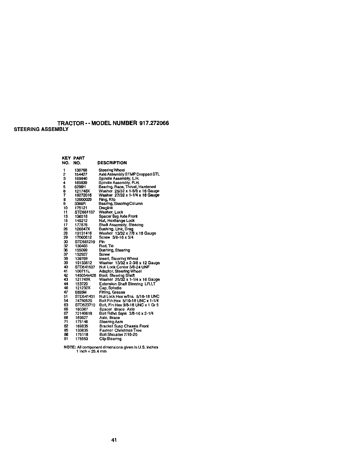
TRACTOR -- MODEL NUMBER 917.272066
STEERINGASSEMBLY
KEY PART
NO. NO. DESCRIPTION
1 139768 Steedng Wheel
2 154427 Axle Assembly STMP Dropped STL
3 169840 Spindle Assembly, LH.
4 169830 Sptndte Assembly, R.H.
5 6266H Beadng, RaCe, Ti_rust, Hardened
6 121748X Washer 25/32 x 1-5/8 x 16 Gauge
7 19272016 Washer 27132 x 1-1/4 x 15 Gauge
8 1200_029 Ring, Kllg
9 3366R Beadng, Steering Colurnn
10 175121 [_raglIP_<
11 STD551137 Washer, Lock
13 136518 Spacer Brg Axle Front
15 145212 Nut, Hexftange Lock
17 177878 Sheft As_sembly,Steering
26 126847X Bushing, Link, Drag
28 19131416 Washer 13/32 x 7/8 x 16 Gauge
29 17060612 Screw 3/8-16 x 3/4
30 STD561210 Pin
130465 Rod,Tie
36 15509_ Bushing, Steedn 9
37 152927 S_ew
38 139769 Insert, Steering Wheel
3_ 19133812 Washer 13/32 x 2-3/8 x 12 Gauge
40 STD541537 Nut LockCenter3_-24UNF
41 100711L Adaptor, Steedng Wheel
42 145054x425 Boot, Steedng Shaft
43 121749X Washer 25/32 x 1-1/4 x 15 Gauge
44 153720 Extension Shaft Steering LR.LT
46 12123_X Cap, Spindle
47 6855M Figing, Grease
51 STD541431 NutLockHexwgns. 5/16-18UNC
54 74780520 Bolt Fin Hex 5/16-18 UNC x 1-1/4
63 $1D523710 Bolt, Fin Hex 3/6-16 UNC x 1 Gr 5
65 160367 Spacer Brace Axle
67 72140615 Bolt Rdhd Sgnk 3/6-16 x 2-1/4
68 169827 AxLe,Brace
71 175146 Stee_ng Asrn
8_ 169635 Bracket Susp Chassis Front
85 133835 Fastner Chdstrnas Tree
88 175118 Bclt Shoulder 7/1 6-20
91 175553 Clip Steering
NOTE: Allcomponent dimensions given in U.S. inches
1inch = 25.4 turn
41
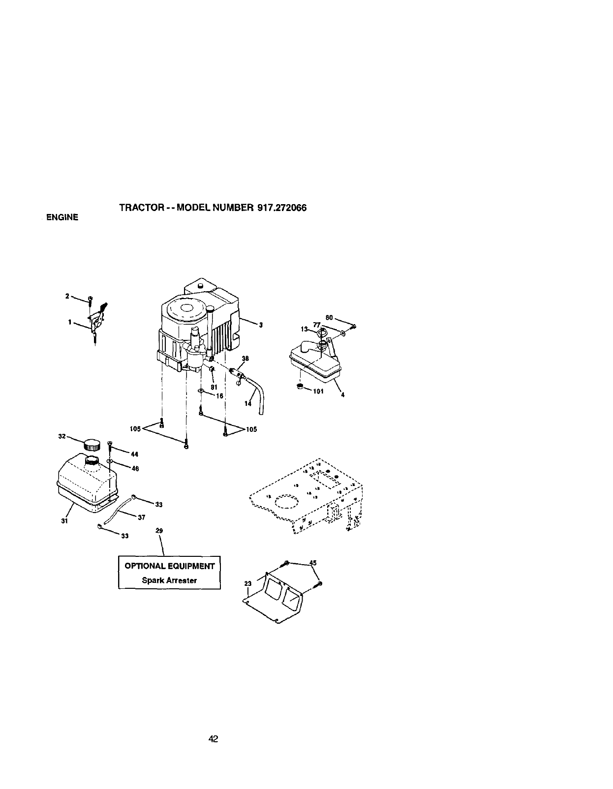
ENGtNE TRACTOR -- MODEL NUMBER 917.272066
38
37 29
-- 33
OPTIONAL EQUIPMENT
Spark Attester
.%. ---- /.YL_ .÷ .
42

ENGINE TRACTOR-- MODEL NUMBER 917.272066
KEY PART
NO. NO. DESCRIPTION
1 170548 Cordrol,ThrotUe
2 17720410 Screw, Hex Hea,d, Thread Cutting 1/4-20 x 5_
3...... Engine, (See Bmak.dovm) KohJerModel No. CV460-26509
4 174667 Muffler
13 12-041-03 Gasket Kohler
14 148456 Tube Drain Oil Easy
16 S']D551237 Washer
23 169837 Shield Brn_br Guard
29 137180 Arrestor, Spark
31 109202X Tank, Fuel
32 158990 Cap Assembly, Fuel Sears, Vented
33 123487X Clamp, Hose
37 137040 Line, Fuel
38 148315 plug, Drain Oi_Easy
44 17670412 Screw, Hex Washer Head, Tnd., Roll. 1/4-20 x 3/4
45 17(_00612 Screw Hex Wsh Tndr 3/8-16 x3/4
46 19Q91416 Washer 9/32 x 7/8 x "_6Gauge
77 19101216 Washer 5/16 x 3/4 x 16 Ga.
80 74760508 Bo9 Hex Hd 5/16-18 Unc x 1/2
81 73510400 Nut Keps Hex 1/4-20Unc
101 M73(_30800 NutFlarvgeM8-1.25Non-LkZlnc
la5 17120616 Screw 3/8-16 x 1
NOTE: All component dimensions given in U.S, Inches
1 Inch = 25.4 mm
43
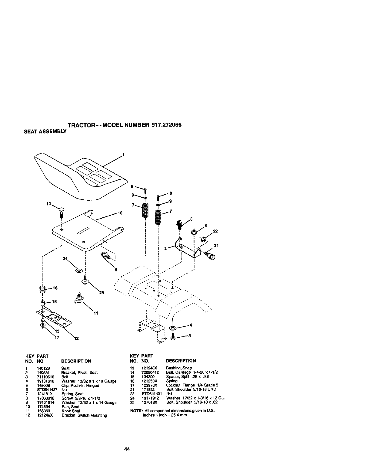
TRACTOR-- MODELNUMBER917.272066
SEATASSEMBLY
KEY PART KEY PART
NO. NO, DESCRIPTION NO. NO. DESCRIPTION
1 140123 Seat 13 121248X Bushing, Snap
2 140551 Bracket, Pivot, Seat 14 72050412 Bo_t, Can'lage 1/4-20 x 1-1/2
3 71110616 Bo_t 15 134300 Spacer, Split .28 x .88
4 19131610 Washer 13/32 x 1 x 10 Gauge 16 121250X Spring
5 145006 Clip, Push*In Hinged 17 t2397_ Locknut, Flange 1/4 Grade 5
6_1437 Nut 21 171852 Boit, Shoulder 5/16-18UNC
7 124181X Spring, Seat 22 S]_541431 Nut
8 17000616 Screw 3/8-16x1-1/2 24 19171912 Washer 17/32x1-3/16x 12Ga.
9 19131614 Washer 13/32 x 1 x 14 Gauge 25 127018X Bolt, Shoulder 5/16-16 x ,62
10 174894 Pan, Seat
11 166369 Knob Seat NOTE: All componen| dirnenslons given inU.S.
12 121246X Bracket, Switch Mounting inches 1 inch = 25,4 mm
44
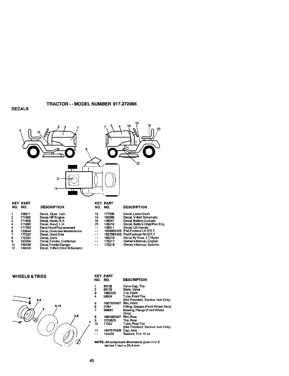
DECALS TRACTOR -- MODEL NUMBER 917.272066
9_3 7 7 5 4 1_
8
10
\12
KEY PART KEY PART
NO. NO. DESCRIPTION NO. NO. DESCRIPTION
1 156811 Decal, Oper. Instr. 13 177336 Decal, Lower Dash
2 177368 Decal, HP Engine 14 160396 Deck, V-Belt Schematic
3 171698 Decal, Hood, R.H. 16 138047 Decal, Batte WDiehard
4 171699 Decal, Hood, LH. 20 149516 Decal, Battery Dngr/Psn Eng
5 171763 Decal Hood Replacement -- 138311 Decal, Lift H_dle
6 133644 Decal, Customer Mziintenance -- 165800X428 Ped Footrest LH STLT
7 177325 Decal, Hood Side -- 165799X428 Pad Footrest RH STLT
8 172331 Decal, Deck --169210 Decal By Pass LT Hydro
9 163204 Decal, Fender, Crattsman -- 179217 Owner's Manual, English
10 156439 Decal, Fender Danger -- 179218 Owner's M_nual, Spanlsh
12 146046 Decal, V-Belt Drive Schematic
WHEELS &TIRES KEY PART
NO. NO. DESCRIPTION
4,10
1 59192 VEdveCap, Tire
2 65139 Stem, Valve
3 1067.22)( _re, Front
4 59904 Tube, Front]Ire
(Not Provided, Service Item Only)
5 106732X427 Rim.Front
6 278H Fitting, Grease (Front Wheel Only)
7 9040H Beadng, Flange (FrontWheel
8 106108X427 Rim, Rear
9 122082X 13re, Rear
10 7152J Tube, RearTire
(Not Provided, Service Item Only)
11 104757X428 Cap, Axle
- - 144334 Sealant, ]3re 10 oz.
NOTE: All component dimensions given In U.S.
irK:hes1 Inch = 25.4 mm
45
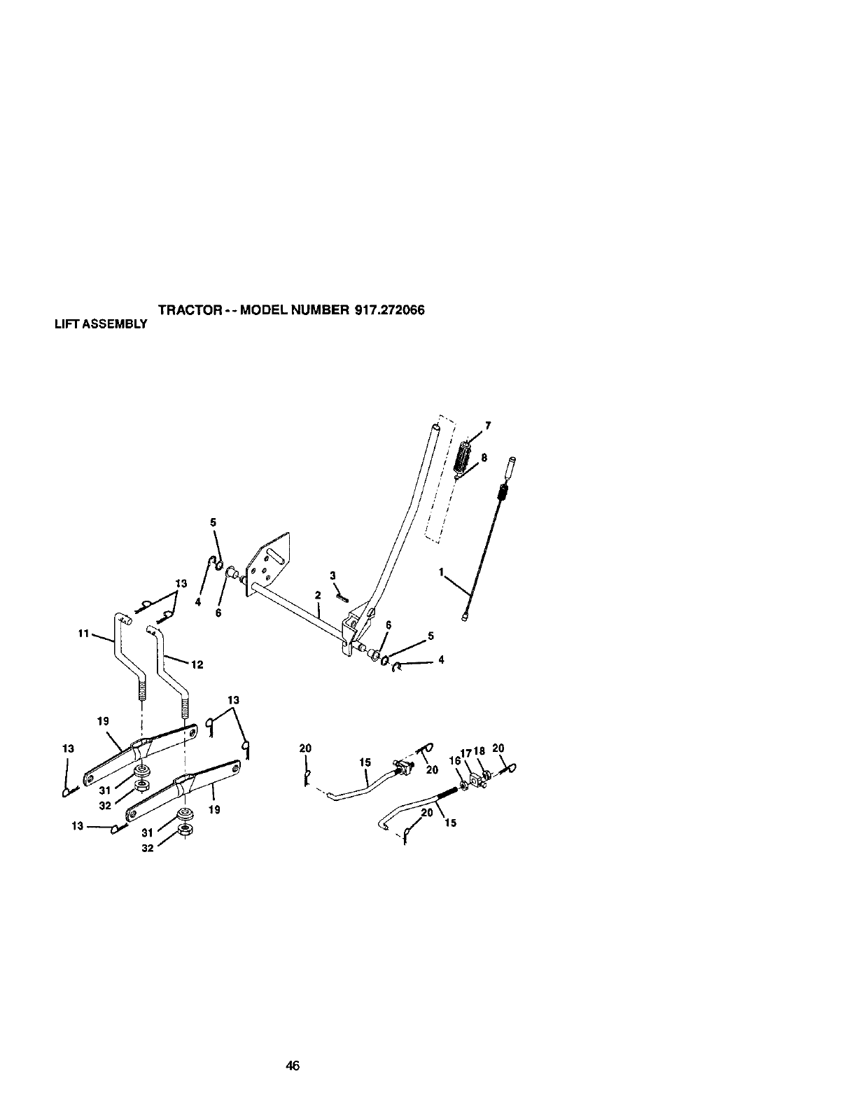
TRACTOR- - MODEL NUMBER 917.272066
LIFTASSEMBLY
46

TRACTOR -- MODEL NUMBER 917.272066
LIFTASSEMBLY
KEY pART
NO, NO. DESCRIPTION
1 159460 Lift Lever Inner Wire Assembly
2 159471 She5 Assembly, I.llt
3 10o-767X Pin, Groove
4 12000002 E-Ring
5 19211621 Washer 21132 x 1 x 21 Gauge
6120183X Bearing, Nylon
7 125631X Gdp, Haedle, Fluted
8 122365X Button, Plunger, Red
11 139865 Link, Lift, L.H.
12 139866 Link. tJtt. R.H.
13 S'FD624(X_ Retainer Spdng
15 173288 Link, Front
16 73350800 Nut, Hex, Jam 1/2-13 UNC
17 130171 Trunnion
18 73800800 Locknut, Hex, with Washer Insed 1/2-13 UNC
19 139868 Arm, Suspension, Rear
20 163552 Retainer Spring
31 16_865 Beaedg, Pvt, Ufi
73540600 Nut, Crownlock 3/8-24
NOTE: All component dimensions given in U.S. Inches
1 Inch = 25.4 mm
47
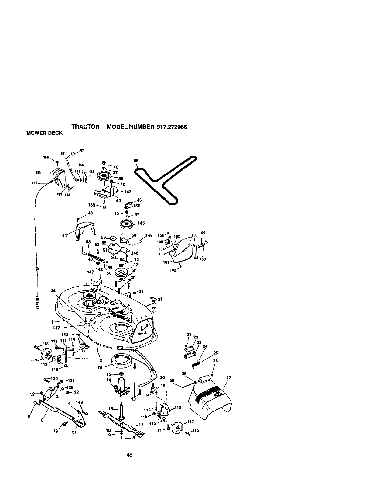
TRACTOR -- MODEL NUMBER 917.272066
MOWERDECK
157 01167
154
5
147 14
>21
48
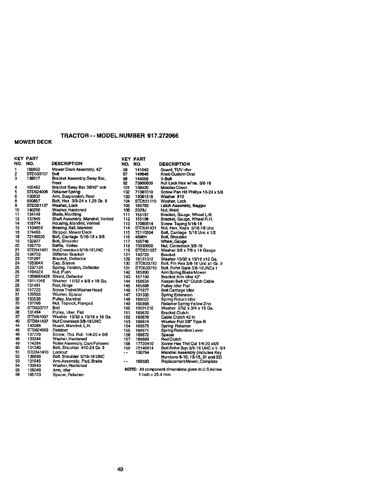
TRACTOR -- MODEL NUMBER 917.272066
MOWERDECK
KEY PART KEY PART
NO, NO. DESCRIPTION NO. NO.
1 165892 Mower Deck Assemely, 42 _59 141043
2 $1D533107 Bolt 67 149846
3 138017 Bracket Assembly,Sway Bar, 68 144959
Fro_ 09 73800600
4 165460 Bracket Sway Bar 35/42" eck 10t 136420
5 $1D6240_ RetalnerSprlng 102 71(_10t0
6 130832 Arm, Suspension, Rear t0G 19061216
8 850857 Bolt, Hex 5/6-24x1.25Gr. 8104 STD551110
9 $IO551t3",' Washer, Lock 105 t6079_
10 140296 Washer, Hardened 106 2029J
11 134149 Blade, Mulching 111 155197
13 137645 Shaft Assembly, Mandrel, Vented 112 155198
14 128774 Housing, Mandrel, Ventod 113 17060514
15 110485X Beadng, Ball, Mandrdl 114 $1]_541431
16 174463 Stripper, Mower Deck 115 72110504
18 72140505 Bolt, Cardage 5/16-18x5/8 116 4898H
19 132827 Bolt, Shoulder 117 165746
20 159770 Baffle, Vodex 118 73930600
21 STD541431 NutCrownlock5/16-t8UNC 119 STD551CG7
Z2 134753 Stiffener Bracket 121 143723
23 131267 Bracket, Deflector 129 19t31312
24 105304X Cap, Sleeve 130 STD523710
25 123713X Spring, Torsion, Detlector 131 S_T.333710
26 110452X Nut, Push 142 165890
27 t30968X428 Shield, Deflector 143 157109
28 19111016 Washer 11/32 x 5/8 x 16 G& 144 158634
29 131491 Rod,Hinge 145 165888
30 157722 Screw Thdret Washer Head 146 171077
31 129_63 Washer, Spacer 147 131335
3_ 1535.35 Pulley, Maodrel 148 169022
33 137266 Nut, Toplock, Flanged 149 165898
34 S_533717 Bolt 150 19091216
36 131494 Pulley, Idler, Flat 151 169670
37 $1D551_37 Washer 13i32x13/16x16Ga 152 169676
40 S_541437 NutCrowrdock3_-16UNC 153 169674
44 140088 Guard, Mandrel, LH. 154 169675
45 S'1I)0940(_ Retainer 155 169671
46 137729 Screw, Tnd. Rell t/4-20xs/8 156 169672
48 133944 Washer, Hardened 157 169669
49 174284 Roller Assemb]y, Cam Foilower 158 17720410
50 131340 Bolt, Shoulder #10-24Gr. 5 159 72140614
51 $3_541410 Locknet - - 130794
52 139888 Bolt, Shoulder 5/16-18 UNC
53 131845 Arm Assembly, Pad, Brake --169583
54 133943 Washer, Hardened
55 155046 Arm, Idler
56 165723 Spacer, Retainer
DESCRIPTION
Guard, TUV Idler
Knob Custom Oval
V-Bell
Nut Lock Hex w/Ins. 5/6-16
Mulcher Cover
Screw Pan Hd Phillips 10-24 x 5/8
Washer #10
Washer, Lock
Letctl Assembly, Bagger
Nut, Weld
Bracket, Gauge, Wheel LH.
Bracket, Gauge, Wheel R.H.
Screw Taping 5/16-18
Nut. Hex, Keps 5/16-18 Unc
Bolt, Carriage 5/16 Unc x 1/2
Bolt, Shoulder
Wheel, Gauge
Nut. Centeriock 5//8-16
Washer 5/8 x 7/8 x 14 Gauge
Bracket
Wa,she r 15/32 x 15/16 x12 Ga.
Bolt, Fin Hex 5/8-16 Uric xl Gr. 5
Belt, Rdhe Sqnk 3/6-16UNCx 1
Arm Spring Brake Mower
Bracket Arm Idler 42"
Keeper BeR 42" Clutch Cable
Pulley Idler Flat
BeltCarriage Idler
Spdug Extension
Spdng Return Idler
Retainer Spring Yellow Zinc
Washer 9P32 x 3/4 x 16 Ga.
Bracket Clutch
Cable Clutch 42 In
Washer Rat 3/8" Type B
Spring Retainer
Spring Retention Lever
Spacer
ROdClutch
Screw Hex Tnd Cut 114-20 x5/8
Bolt Rdhd Sqn 3/8-16 UNC x 1* 5/4
Mandrel Assembly (Includes Key
Numbers 8-10, 13-15, 31 and 32)
Rablace ment Mowe r,Ccmplet e
NO'I1E: All component dheenstons given In U.S.Inches
1 inch = 25.4
49
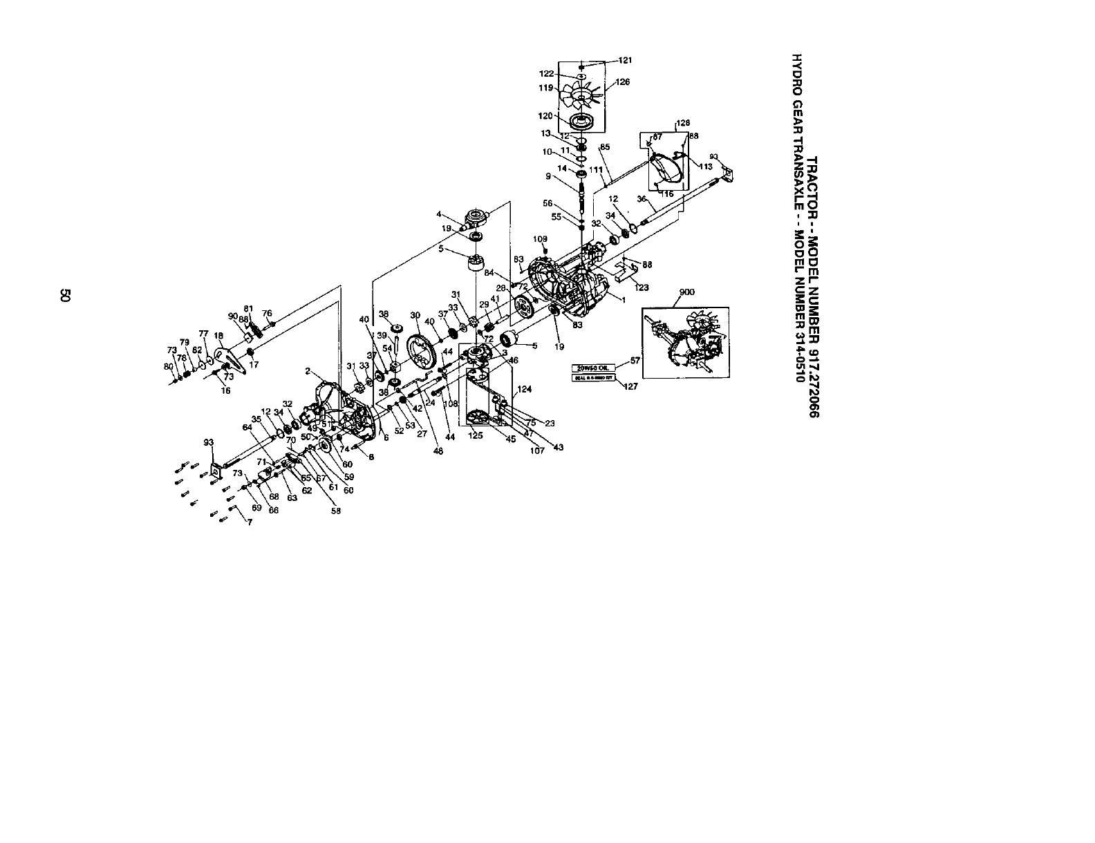
7g
73
17
16
32
120_
19
124
,,11
i i
=_,
oZ¢
oO
m_
rm
zr-
fo
o
0_
60
58
48 107 _43
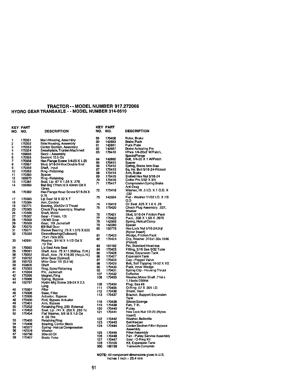
TRACTOR - - MODEL NUMBER 917.272066
HYDRO GEARTRANSAXLE--MODEL NUMBER 314-0510
KEY PART KEY PART
NO. NO, DESCRIPTION NO. NO. DESCRIPTION
1170_51 Main Housing, Assembly 59 170408 Rotor, Brake
60 142883 Brake Puck
2 170_52 Side Housing, Assembly 61 142881 puck Plate
3 17G353 Center Sectlcn, Assembly 62 142887 Brake Actuating Pin
4 170354 Swashplate, Trunlo_Machined 63 170410 Hfhcs 1/4-20x2 W/Patch,
5 169898 Block - Assembly SpedaiFlange
6 170355 Sealant 10.50z 64 142892 Bolt, 1/4-20 X 1 W/Patch
7 170356 Hex Flange Screw 1/4-20 X t .25 65 170411 Spacer
8 170_57 Stud, 5/16-24 Hex Double End 66 170412 Spdng, Brake Arm Bias
9'L7G358 Shaft, Input 67 170413 Sq. Hd. Boll 5/16-24-Ribbed
10 170359 Ring-Retaining 68 170414 Arm, Brake
11 170360 Spacer 69 170415 Slottnd Hex Nut 5/16-24
12 169870 Ring- Retalning 70 170416 Cotter Pin 3/32 X 3/4
13 170361 Seal, Up .67 X 1.58 X .276 71 170417 Compression S pdng Brake
14 169869 BSh Brg 17ram rd X 40ram Od X As_-Drag
16 170362 Hex Flange Hend Screw 5/16-24 X 72 170418 Washer, Hf .5 I.D. X 10.D. X
0.75 1032
17 170_63 Up Seal 18 X 32 X773 142884 Flat - Washer 11/32 LB. X 7/8
O.D
18 170364 Arm, Contr¢_ 74 170419 Oil Seal .625 X 1.0 X .25
19 150771 Bearing, 30x52xl 3 Thrust 75 170420 Check Plug Assembly, .027,
23 170365 Check Plug Assembly, Washer Washer
24 170366 Shaft, Motor 76 170421 Stud, 5/16-24 Fdcllon Pack
27 170367 Gear- Pir_on, 13t 77 170422 Puck, .330 X 1.50 X .0975
28 170368 t0V48t Gear
29 170369 Gear, t0t Jacksheft 78 142969 Spdng,He_icaIComp
30 17_370 60t BullGear 79 142980 Spacer
31 170371 Sleeve Searing .75 X 1.575 X.625 80 150778 Hex Lock Nut 5/1 6-24Unjf
(Nylon Insert)
32 170389 SleeveBea shg(O utboard) 81 170423 Wedge, Fdctton Pack
.75xl .750x.625
33 142991 Washer, 3/4 Id X 1-1/20d X 8_ 170424 Clip, Washer .316x1.50x. 1046
(Rated)
.13Thk 83 161162 Pin, Stanrt atrt Headless
34 170390 Lip Seal Asle Seal 84 170425 Fitting, 5/16 See 5/32 Tube
35 170_91 Shaft, Axle .75 Xl 1.39(Key, R.H.) 85 170426 Hose, Expansion Tank
36 170392 Shaft, Axle .75 X16.99 (Key,LH.) 86 170427 ExpansionTank
37 150792 Miler Gear (SpHned) 87 170424 Cap -Poppet Valve
38 150793 Miter Gear 15t (0.5 Id) 88 170429 Boll, Self Tapping 10-32 X 1/2
39 150809 Shaft 90 170430 Puck, inner Wedge
40 170393 Ring, Spiral Retainlng _3 170431 Spring Clip -Housing Thrust
41 170394 PEn, Jackehaft 107 170432 Deflector
42. 170395 Magnet, Ring 108 170433 Washer,Motor Shalt .7lid x
43 170396 Spring, Bypass 1.15odx.O30thk
44 150797 Hydro Mtg Screw 3/8-24 X 2.5 109 170434 plug, See #6
Long 111 170435 O-Ring.07X.30t LD.
45 17G3_7 Filter 112 170436 Shield, Vent
46 17G398 Base, Filler 113 170437 Bracket, Support Expanaion
47 17G399 Actuator, Bypass Tank
48 170400 Rod, Bypass Actuator
49 170401 Arm, Bypass 116 170438 SiliconSponge
50 170202 Retaining Ring .250 External 119 170439 Fan, 7 In.
120 170440 Pulley
51 170403 Seal, Up .741 X .250 X .250 Tc 121 170441 Hex Lock Nut 1/2-20 (Nylon
52 170404 Flat Washer, 5/8 Irt X 1.00d Insert)
X.05 Tilk 122 170442 We.sher, BellevIIle
53 170405 RetainingRing 123 170443 BeltKeeper
54 170406 Bearing, Center B_ock 124 170444 Ce rder SeclJc_t-Filler-Bypass
55 142977 Spring -Helical Compression Assembly
56 142978 Washer
57 150798 20w-50 01] 125 170445 Flitel"Assembly
58 170407 Brake Yoke 126 170446 Fan - Pulley Service Assembly
127 170447 Seal - O-Ring Kit
128 173165 Kll, Expansion Tank
900 1667_8 Transaxle Complete
NOTE: All component dimensions given In U.S.
Inches 1inch = 25.4 mm
51
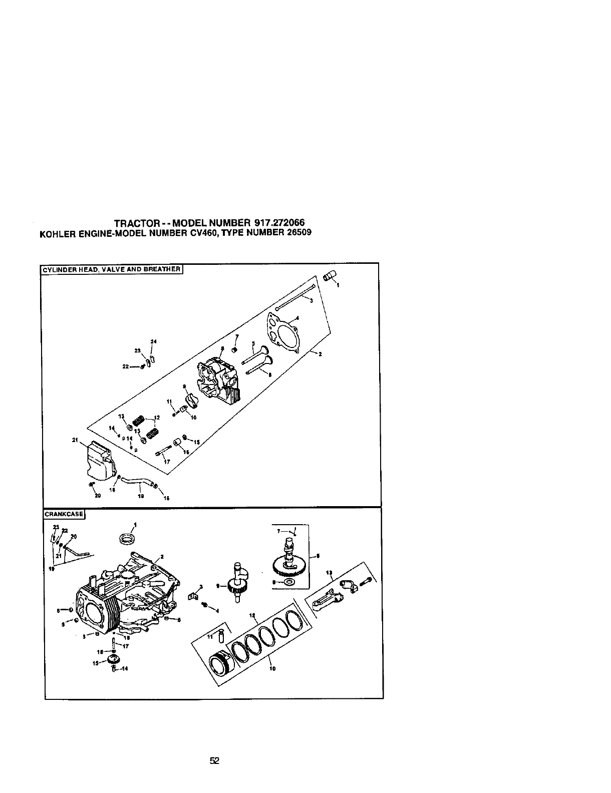
TRACTOR-- MODEL NUMBER 917.272066
KOHLERENGINE-MODELNUMBER CV460,TYPE NUMBER26509
CYLINDER HEAD, VALVE AND BREATHER I
\
11
/,1
@
t8
52
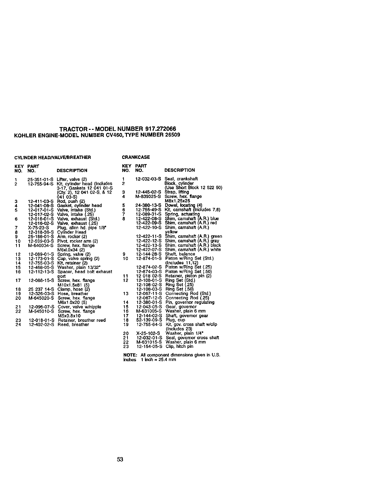
TRACTOR -- MODEL NUMBER 917.272066
KOHLERENGINE-MODELNUMBERCV460,TYPE NUMBER26509
CYLINDER HEAD/VALVE/BREATHER CRANKCASE
KEY PART KEY PART
NO. NO. DESCRIPTION NO. NO. DESCRIPTION
1 25-351-O1-S Lifter, valve (2) 1 12-032-O3-S Seal, crankshaft
2 12-755-94-S Kit, cylinderhead (Includes 2 Block, cylinder
3-17, Gasketa 12 041 01-S _tJse Short Block 12 522 50
(Qty. 2), 12 041 02-S, & 12 3 12-445-O2-S _'zrap, lifting
4 M-839025-S Screw, hox. flange
041 03-,c_
3 12-411-03-S Rod, pus !2) M8x1.25x25
4 12-041-08-S Gasket, cyhnder head 5 24-380-13-S Dowel, locating (4)
5 12-017-01-S Valve, intake Std.) 6 12-755-49-S Kit. camshaft _lncludes 7,8)
12-017-02-S Valve, intake .25) 7 12-089-31-S Spdng, actuabng
6 12"016"01"S Valve. exhaust (Std.) 8 12-422-08-S Shim, camshaft (A.R.)blue
12-016-02-S Valve, exhaust (.25) 12-422-09-S Shim, camshaft (A).R. red
7 X-75-23-S PI_, allen hd. pipe 1/8" 12-422-10-S Shim. camshaft (A.R,)
8 12-318-36-S Cyhnder Head y,elinw
9 25-186-01-S Arm, rocker (2) 12-422-11-S Shim, camshaft (A.R.) green
10 12-599-03-S Pivot, rocker arm (2) 12-422-12-S Shim, camshaft (A.R.)gray
11 M-640034-S Screw, hex. flange 12-422-13-S Shim, camshaft ()A.R. black
12-422-07-S Shim, camshaft (A.R.) white
M6xl.Ox34 (2)
12 12-089_1-S Spdng, valve (2) 9 12-144-28-S Shaft, balance
13 12-173-01-S Cap, valve spring (2) 10 12-874-01-S Piston wiring Set (Std)
14 12-755-03-S Kit, retainer 2) [Inaludes 11,12
15 12-468-05-S Washer, pan 13/32" 12-874-02-S Piston w/Rng Set (.25)
16 12-112-13-S Spacer, head bolt exhaust 12-874-03-S Piston w/Ring Set (.50)
port 11 12 018 02-S Retainer, pisfon pin (2)
17 12-086-15-S Screw, hex. flange 12 12-108-01-S Ring Set (Std,)
M1OxlSx81 12log02s RingSet(.2fl)
18 25 237 14-S Clamp, hose (2) 12-108-03-S Ring Set (.)50
19 12-326-O3-S Hose, breather 13 12-067-11-S Connecting Rod Std,
20 M-645020-S Screw, hex, flange 12-067-12-S Connecting Rod (.25)
M6xl,0x20 (5) 14 12-380-01-S Pin, governor regulaling
21 12-096-07-S Cover, valve w/nippla 15 12-043-g5-s Gear, governor
22 M-545010-S Screw, hex. flange 16 M-631005-S Washer, plain 6 mm
MSxO.8xl0 17 12-144-02-S Shaft, governor gear
23 12-018-01-S Retainer, breather reed 18 52-139_9-S Plug, cup
24 12-402-02-S Reed, breather 19 12-755-64-S Kit, gov. crc_s shaft w/clip
(Includes 23)
20 X-25-102-S Washer, plain 1/4"
21 12-032-O1-S Seal, governor cross shaft
22 M-631015-S Washer, plain 6 rnm
23 12-154-05-S Clip, hitch pin
NOTE: Ali component _mensinns given in U.S.
inches 1 inch =25.4mm
53
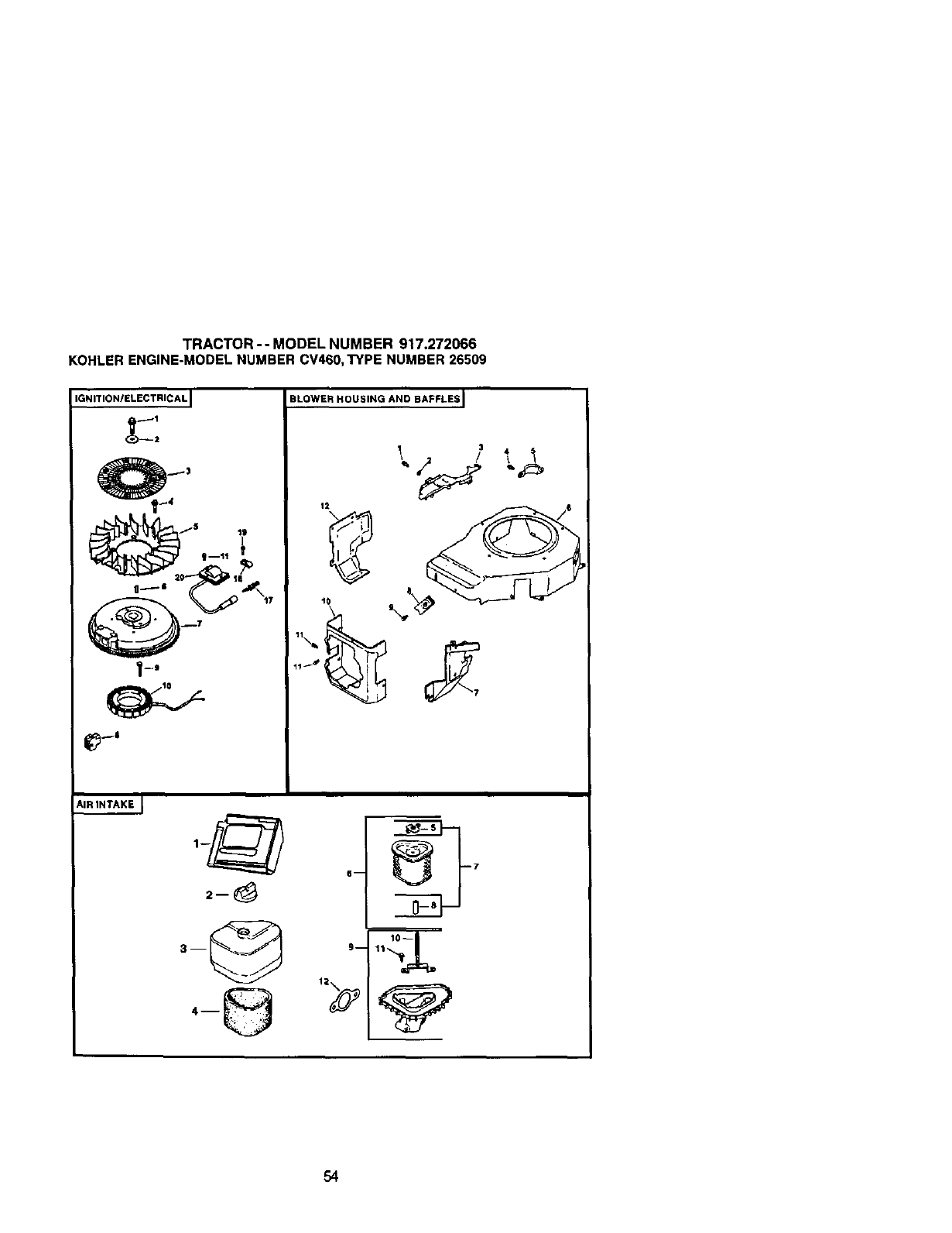
TRACTOR-- MODEL NUMBER 917.272066
KOHLERENGINE-MODELNUMBER CV460,TYPE NUMBER 26509
IGNITION/ELECTRICAL I BLOWER HOUSING AND BAFFLES I
AIR INTAKE J
54
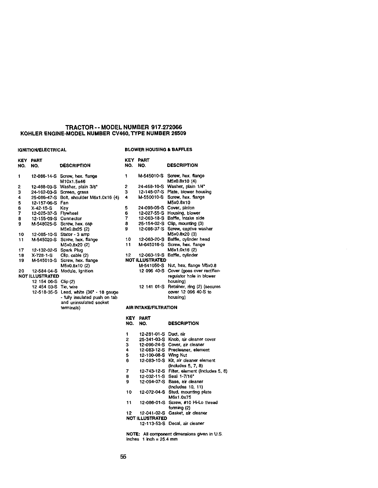
TRACTOR-- MODELNUMBER917.272066
KOHLERENGINE-MODELNUMBERCV460,TYPENUMBER26509
IGNITION/ELECTRICAL BLOWER HOUSING & BAFFLES
KEY PART KEY PART
NO. NO. DESCRIPTION NO. NO. DESCRIPTION
1 12-O86-14-S Screw, hex. flange 1 M-545010-S Screw, hex. flange
M10x1.Sx46 M5x0.8xlO (4)
2 12-468-03-S Washer, plain 3/8" 2 24-468-10-S Washer, plain 1/4"
3 24-162-03-S Screen, grass 3 12-146-07-S Prate, blower housing
4 25-086-47_S Bolt, shoulder M6xl.0x16 (4) 4 M-550010-S Screw, hex. flange
5 12-157-06-S Fan M5x0.Sxl0
6 X-42-15-S Key 5 24-O96-05-B Cover, pinion
7 12-025-37-S Flywheel 6 12-027-55-S Housing, blower
8 12-155-09-S Connector 7 12-063-18÷S Baffle, intake side
9 M-548025-S Screw, hex.cap 8 25-154-02-S Clip, mounting (3)
MSxO.8x25(2) 9 12-086-37-S Screw, captive washer
10 12-O85-10-S Stator- 3amp M5xO.8x20 (3)
11 M-545020-S Screw, hex. flange 10 12-063-20-S Baffle, cylinder head
M5x0.8x20 (2) 11 M-645016-S Screw, hex. flange
17 12-132-02-S Spark Plug M6x1.0x16 (2)
18 X-728-1-S Clip,cable (2) 12 12-063-19-S Baffle, cylinder
19 M-545010-S Screw. hex. flange NOT ILLUSTRATED
M5x08xl0 (2) M-541050-S Nut. hex. flange M5x0.8
20 12-584-04-S Module. ignition 12 096 40-S Cover (goes over rectifier-
NOT ILLUSTRATED rnguietorhble in blower
12 154 06-S Clip(2) housing)
12 454 03-S Tie. wire 12 141 01-S Retainer. dug (2) (secures
12-518-35-S Lead. white (36" - 18 gauge cover 12 096 40-S to
- fulty insulated push on tab housing)
and ublnsulatedsocket
terminals) AIR INTAKFJRLTRATION
KEY pART
NO. NO. DESCRIPTION
1 12-281-01-S Duct. air
2 25-341-03-S Knob, air cleaner cover
3 12-O96-24-S Cover, ai_cleaner
4 12-083-12-S Preaieaner, element
5 12-100-08-S Wing Nut
6 12-083-10-S K'rt,a_"cleaner element
(Includes 5.7. 8)
7 12-743-12-S Filter.element (Includes 5.8)
8 12-032-11-S Seal 1~7/16"
9 12-O94-07-S Base. air cleaner
(Inctudes 10. 11)
10 12-O72-04-S Stud. mounting plate
M6x1,0x75
11 12-086-01-S Screw. #10 Hi-Lo thread
form_g (2)
12 12-041-02-S Gasket, air cleaner
NOT ILLUSTRATED
12-113-53-S Decal, air cleaner
NOTE: All component dimensions given in U,S.
inches 1 inch = 25,4 mm
55
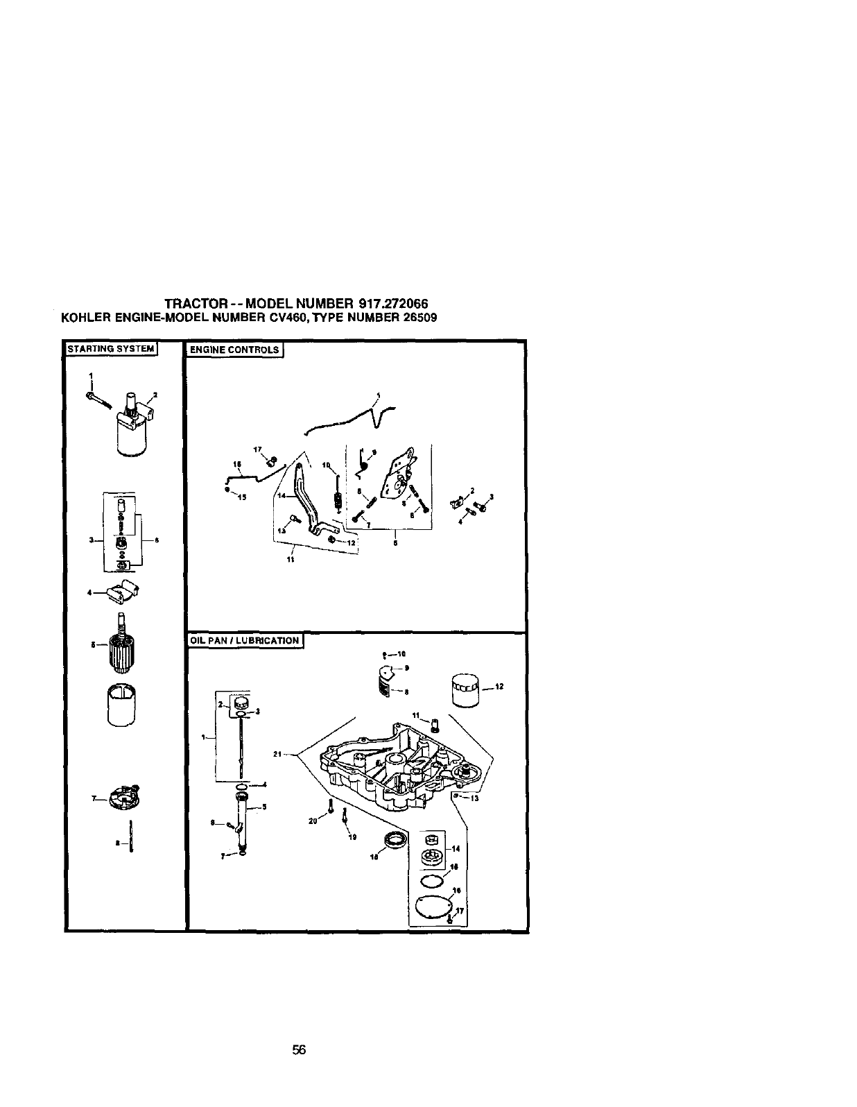
TRACTOR-- MODEL NUMBER 917.272066
KOHLERENGINE-MODELNUMBER CV460,TYPE NUMBER26509
STARTING SYSTEM
1
I
:l-- _ --S
ENGINE CONTROLS
'i
/
,, %/\, fr,,
It
OIL PAN ILUBRICATION I
56
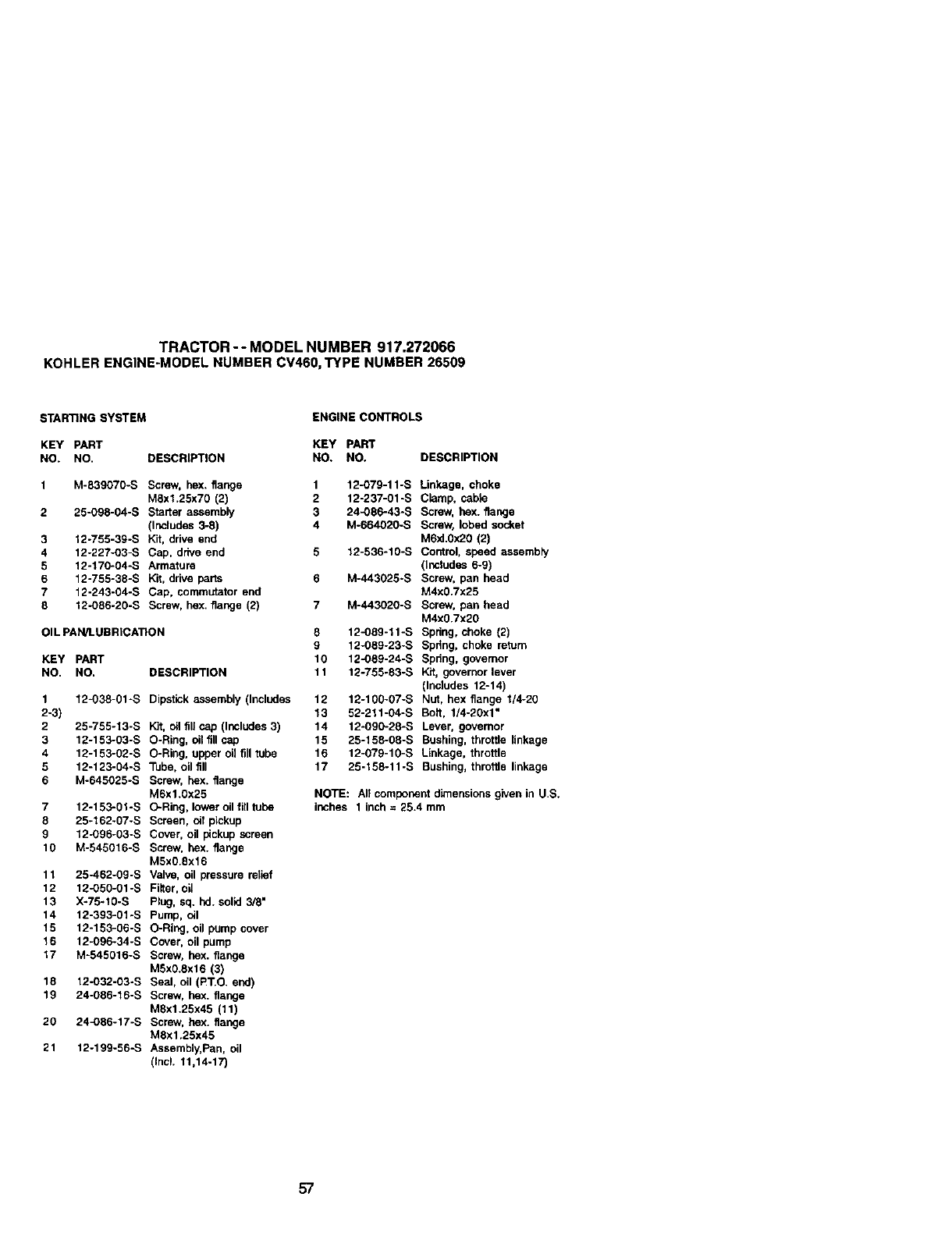
TRACTOR-- MODEL NUMBER 917.272066
KOHLERENGINE-MODELNUMBER CV460,TYPE NUMBER26509
STARTING SYSTEM ENGINE CONTROLS
KEY PART KEY PART
NO. NO. DESCRIPTION NO. NO. DESCRIPTION
1 M-839070-S Screw, hex. flange 1 12-079-11-S
MSx1.25x70 (2) 2 12-237-01-S
2 25-O98-04-S Starter assembly 3 24-086-43-S
(Includes 3-8) 4 M-664020-S
3 12-755-39-S Kit, drive end
4 12-227-03-S Cap, drive end 5 12-536-10-S
5 12-170-04-S Armature
612-755-38-S Kit, drive parts 6 M-443025-S
7 12-243-04-S Cap, commutator end
8 12-O86-20-S Screw, hex. flange (2) 7 M-443020-S
OIL PAN/t.UBRICATION 8 12-089-11-S
9 12-089-23-S
KEY PART 10 12-089-24-S
NO, NO, DESCRIPTION 11 12-755-83-S
1 12-038-01-S Dipstick assembly (Includes 12 12-100_07-S
2-3) 13 52-211-04-S
2 25-755-13-S Kit, oil fill cap (Includes 3) 14 12-090-28-S
3 12-153-03-S O-Rieg, oil fill cap 15 25-158-08-S
4 12-153-02-S O-Ring. upper oil fill tube 16 12-079-10-S
5 12-123-04-S Tube, oil fill 17 25-158-11-S
6 M-645025-S Screw, hex. fiange
M6x1.0x25
7 12-153-01-S O-Ring, lower oil fill tube
8 25-162-07-S Screen, oit pickup
9 12-096-03-S Cover, oil pickup screen
10 M-545016-S Screw, hex. flange
MSx0.8x16
11 25-462-09-S Valve, oil pressure relief
12 12-O50-01-S Filter, oil
13 X-75-10-S Plug, sq. hd. solid 3/8"
14 12-393-01-S Pump, oil
15 12-153-06-S O-Ring, oil pump cover
16 12_096-34-S Cover, oil pump
17 M-545016-S Screw, hex. flange
MSx0.8x16 (3)
18 12-032-03-S Seal, oil (PT.O. end)
19 24-O86-16-S Screw, hex. flange
Mgx1.25x45 (11)
20 24-086-17-S Screw, hex. flange
M8x1.25x45
21 12-199-56-S Assembly, Pan, oil
(Incl. 11,14-17)
Linkage, choke
Clamp. cable
Screw, hex. flange
Screw, lobed socket
M6xl.0x20 (2)
Control. speed assembh/
(Includes 6-9)
Screw, pan head
M4x0.7x25
Screw, pan head
M4x0.7x20
Spdng, choke (2)
Spdng, choke return
Spring, governor
Kit, governor lever
(Includes 12-14)
Nut, hex flange I/4-20
Bolt, 1/4-20x1"
Lever, governor
Bushing, throttle linkage
Linkage, throttle
Bushing, throttie linkage
NOTE: All component dimensionsgivenin US.
inches 1 inch= 25,4 mm
57
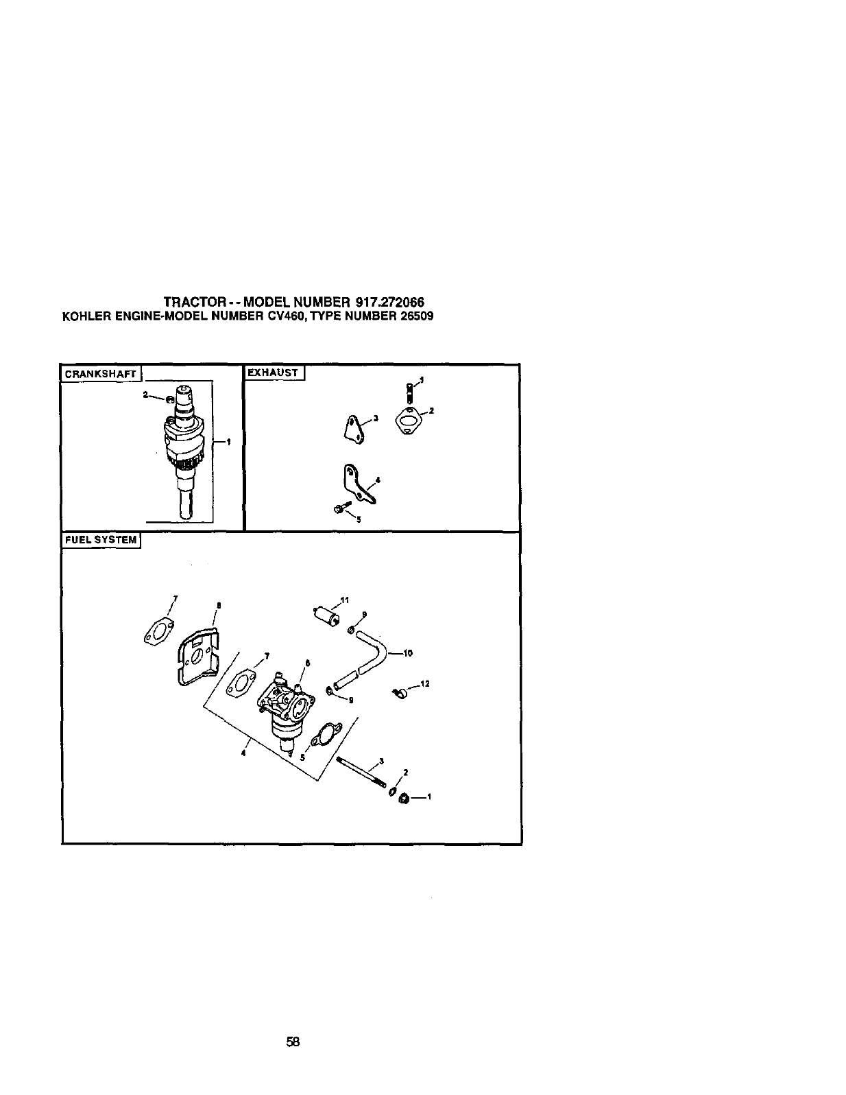
TRACTOR-- MODEL NUMBER 917.272066
KOHLERENGINE-MODELNUMBER CV460,TYPE NUMBER 26509
CRANKSHAFT I
I
I
FUELSYSTEM I
/
58
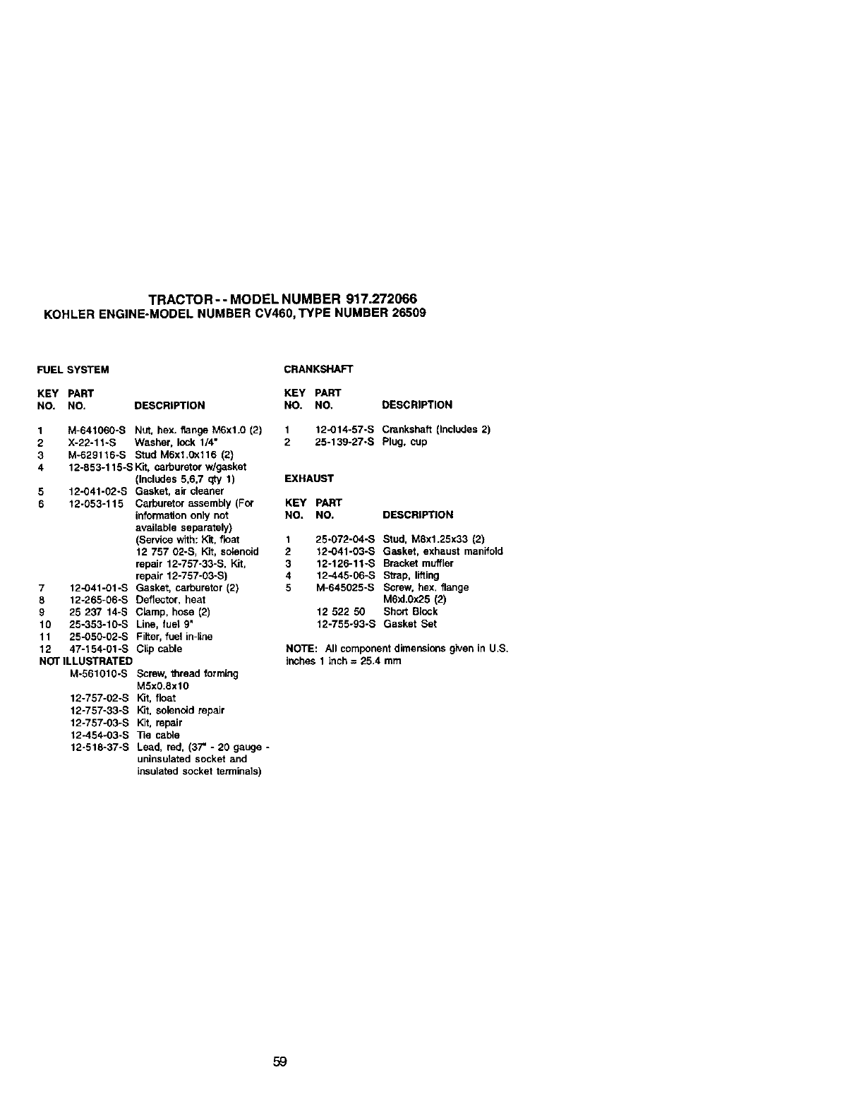
TRACTOR-- MODEL NUMBER 917.272066
KOHLERENG|NE-MODELNUMBER CV460,TYPE NUMBER 26509
FUEL SYSTEM
KEY PART
NO, NO, DESCRIPTION
1 M-641060-S Nut, hex. flange M6xl.0 (2)
2 X-22-11-S Washer, lock 1/4"
3 M-629116-S Stud M6xl.0X116 (2)
4 12-653-115-S Kit, carburetor w/gasket
(Includes 5,6,7 qty 1)
5 12-041-02-S Gasket, air cleaner
6 12-053-115 Carburetor assembly (For
informalJon only not
available separately)
(Service with: Kit, float
12 757 02-S, Kit, solenoid
repair 12-757-33-S, Kit,
repair 12-757-03-S)
7 12-041-01-S Gasket, carburetor (2)
8 12-265-06-S Deflector, heat
9 25 237 14-S C_amp, hose (2)
10 25-353-10-S Line, fuel g"
11 25-050-02-S Filter, fuel in-line
12 47-154-01-S Clip cable
NOT ILLUSTRATED
M-561010-S Screw, thread forming
M5x0.Sxl0
12-757-02-S Kit, float
12-757-33-S Kit, solenoid repaJr
12-757-03-S Kit, repair
12-454-03-S ]]e cable
12-518-37-S Lead, red, (37" -20 gauge -
uninsoiated socket and
insulated socket terminals)
CRANKSHAFT
KEY pART
NO. NO. DESCRIPTION
1 12-O14-57-S Crankshaft (Includes 2)
2 25-13g-27-S Plug, cup
EXHAUST
KEY PART
NO, NO, DESCRIPTION
1 25-072-04-S Stud, M8x1.25x33 (2)
2t2-041-03-S Gasket, exhaust manifold
3 12-126-11-S Bracket muffler
412-445_06_S Str_p, lifting
5 M-645025-S Screw, hex, flange
MSxl,0x25 (2)
12 522 50 Short Block
12-755-93-S Gasket Set
NOTE: All componentdimensionsgiven in U,S,
inches 1inoh= 25.4 mm
59

60

61

62
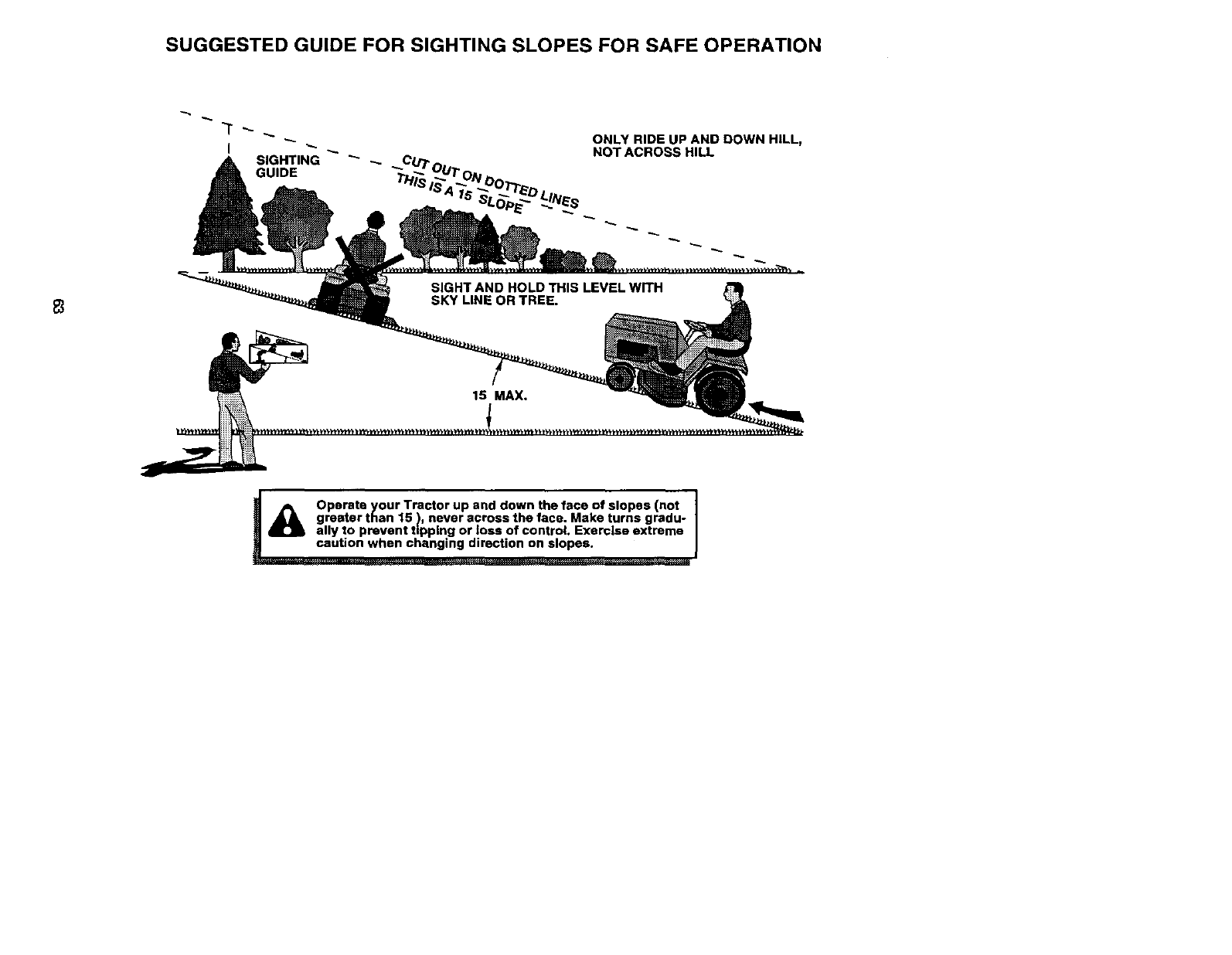
SUGGESTED GUIDE FOR SIGHTING SLOPES FOR SAFE OPERATION
ONLY RIDE UP AND DOWN HILL,
NOT ACROSS HILL
p_ Operate your Tractor up and down the face of slopes (not
greater than 15 ), never across the face. Make turns gradu-
ally to prevent tipping or |oss of control. Exercise extreme
caution when changing direction on slopes.

Forrepairof majorbrandappliancesin your own home...
nomatterwhomade it,no matterwhosoldit]
1-800-4-MY-HOME _Any,rne,day_'-r_it
(1..800.469-4663) (U.S.A.andCanada
,,_ww.seaxs.com _NW._alll,Ca
For repairof cany-inproductslikevacuums,la_ equipment,and
electronics,callforthenearestSears Parts and RepairCenter.
1-900-488-1222 h_rne,dayorright(U.S.A.only)
ww,N.se_ts,com
Forthereplacementparts,accessoriesand owner'smanuals
thatyou needtodo-it-yourself,callSears PartsDirect'_l
1-800-366-PART 6&m.- 11 p.m., 7 daysawe_k
(14+_0_66-7278) (U.S.A.only)
Topurchase orinquireabouta Sears ServiceAgreement
or SearsMaintenanceAgreement:
1-800-827-6655 (U.sA) 1-800-361-6665 (Canada)
7 a.m.- 5 p.m.,CST,MoR - SaL 9 a.m.- 8 p.m.EST, M - F,4 p.m.SaL
Parapetit ser_idode mparacY_na
domicir_o,y para _deear pieza_
1-e88.SU-HOGARs_
(l-S_-Te4-6427)
,, H°meCentml®J
AuCanadapourse_ e_f_r_;_s:
1-800-LE-FOYER_c
(1-a_533-e_Z)
WWW,seai's.ca
®Registered Trademark /TM Trademark /sMService Mark of Seam, Roebuck and Co,
®Mama Re_streda /TM Mama de Fdbdca /sMMama de Serviclo de Sears. Roebuck and Co.
MCMarque de commeme /uo Marque depos_e de Sears, Roebuck and Co.
179217 3.29.01 RD Printedin U.S.A.
