Craftsman 917272220 User Manual LAWN TRACTOR Manuals And Guides L0010520
CRAFTSMAN Lawn, Tractor Manual L0010520 CRAFTSMAN Lawn, Tractor Owner's Manual, CRAFTSMAN Lawn, Tractor installation guides
User Manual: Craftsman 917272220 917272220 CRAFTSMAN LAWN TRACTOR - Manuals and Guides View the owners manual for your CRAFTSMAN LAWN TRACTOR #917272220. Home:Lawn & Garden Parts:Craftsman Parts:Craftsman LAWN TRACTOR Manual
Open the PDF directly: View PDF ![]() .
.
Page Count: 60
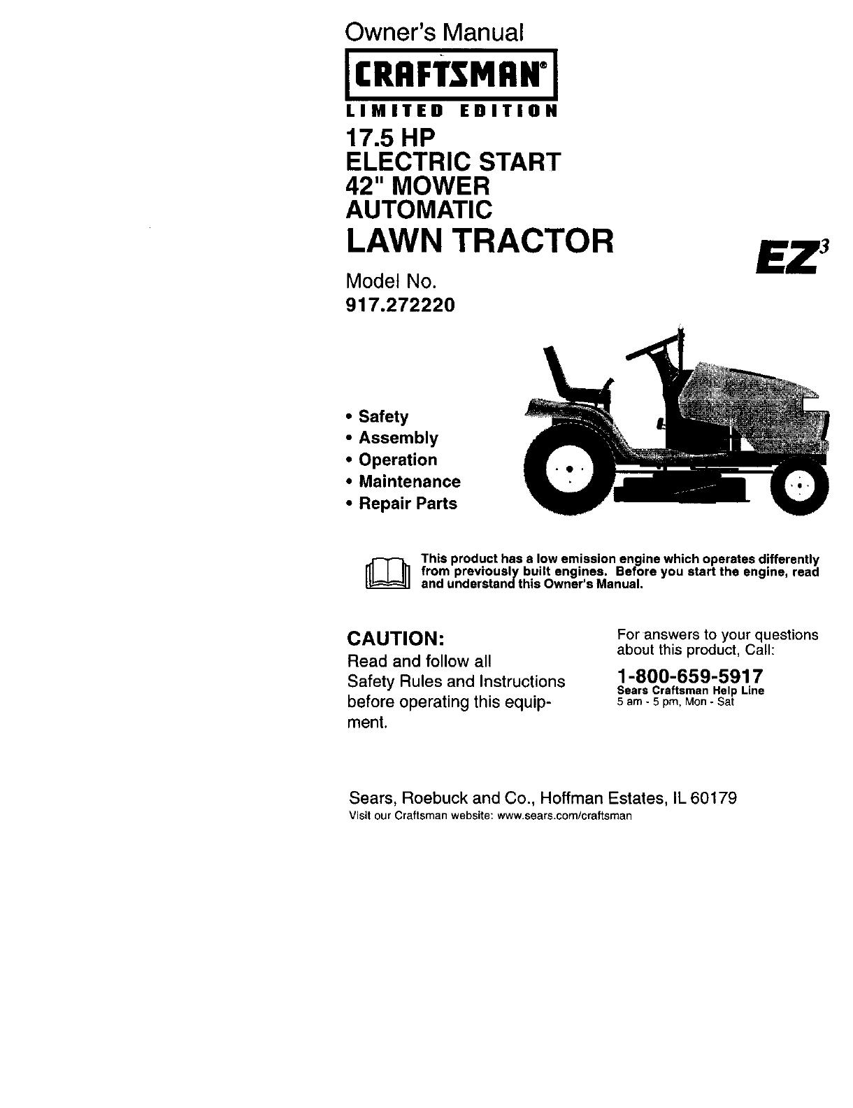
Owner's Manual
IC..mM.N'l
LIMITED EDITION
17.5 HP
ELECTRIC START
42" MOWER
AUTOMATIC
LAWN TRACTOR
Model No.
917.272220
• Safety
•Assembly
•Operation
•Maintenance
•Repair Parts
[_ This product has alow emission engine which operates differently
from previously built engines. Before you start the engine, read
and understand this Owner's Manual.
CAUTION:
Read and follow all
Safety Rules and Instructions
before operating this equip-
ment.
For answers to your questions
about this product, Call:
1-800-659-5917
Sears Craftsman Help Line
5 am - 5 pro, Mon- Sat
Sears, Roebuck and Co., Hoffman Estates, IL 60179
Visit our Craftsman website: www.sears.com/craftsman
Warranty ............................................... 2
Safety Rules ......................................... 3
Product Specifications .......................... 5
Assembly .............................................. 7
Operation ............................................ 11
Maintenance Schedule ...................... 18
Maintenance ....................................... 18
Service and Adjustments .................... 22
Storage ............................................... 29
Troubleshooting .................................. 30
Repair Parts ........................................ 34
Parts Ordering ..................... Back Cover
LIMITED TWO YEAR WARRANTY ON CRAFTSMAN RIDING EQUIPMENT PARTS
For two (2) years from the date of purchase, if this Craftsman Riding Equipment is
maintained, lubricated and tuned up according to the instructions in the owner's
manual, Sears will repair or replace, free of charge, any parts found to be defective in
material or workmanship. Warranty service is available free of charge by taking your
Craftsman riding equipment to your nearest Sears Service Center. In-home warranty
service is available but a trip charge will apply. This warranty applies only while this
product is in the United States.
This Warranty does not cover:
• Expendable items which become worn during normal use, such as blades, spark
plugs, air cleaners, belts and oil filters.
• Tire replacement or repair caused by punctures from outside objects, such as nails,
thorns, stumps, or glass.
• Repairs necessary because of operator abuse, including but not limited to, damage
caused by towing objects beyond the capability of the riding equipment, impacting
objects that bend the frame or crankshaft, or over speeding the engine.
• Repairs necessary because of operator negligence, including but not limited to,
electrical and mechanical damage caused by improper storage, failure to use the
proper grade and amount of engine oil, failure to keep the deck clear of flammable
debris, or the failure to maintain the equipment according to the instructions con-
tained in the owner's manual.
• Engine (fuel system) cleaning or repairs caused by fuel determined to be contami-
nated or oxidized (stale). In general, fuel should be used within thirty (30) days of its
purchase date.
• Riding equipment used for commercial or rental purposes.
LIMITED 90 DAY WARRANTY ON BATTERY
For ninety (90) days from date of purchase, if any battery included with this riding
equipment proves defective in material or workmanship and our testing determines the
battery will not hold a charge, Sears will replace the battery at no charge. Warranty ser-
vice is available free of charge by taking your Craftsman riding equipment to your
nearest Sears Service Center. In-home warranty service is available but a trip charge
will apply. This warranty applies only while this product is in the United States.
To locate the nearest sears service center or to schedule in-home warranty service,
simply contact sears at 1-800-4-my-home
This Warranty gives you specific legal rights, and you may also have other rights which
may vary from state to state.
Sears, Roebuck and Co., D/817 WA, Hoffman Estates, IL 60179

IMPORTANT: This cutting machine is ca-
pable of amputating hands and feet and
throwing objects. Failure to observe the
following safety instructions could result
in serious injury or death.
GENERAL OPERATION
• Read, understand, and follow all in-
structions in the manual and on the
machine before starting.
•Only allow responsible adults, who are
familiar with the instructions, to operate
the machine.
•Clear the area of objects such as rocks,
toys, wire, etc., which could be picked
up and thrown by the blade.
• Be sure the area is clear of other
people before mowing. Stop machine if
anyone enters the area.
•Never carry passengers.
• Do not mow in reverse unless abso-
lutely necessary. Always look down
and behind before and while backing.
•Be aware of the mower discharge di-
rection and do not point it at anyone.
Do not operate the mower without ei-
ther the entire grass catcher or the
guard in place.
• Slow down before turning.
• Never leave a running machine unat-
tended. Always turn off blades, set
parking brake, stop engine, and re-
move keys before dismounting.
• Turn off blades when not mowing.
• Stop engine before removing grass
catcher or unclogging chute.
• Mow only in daylight or good artificial
light.
• Do not operate the machine while un-
der the influence of alcohol or drugs.
• Watch for traffic when operating near or
crossing roadways.
• Use extra care when loading or un-
loading the machine into a trailer or
truck.
• Data indicates that operators, age 60
years and above, are involved in a
large percentage of riding mower-re-
lated injuries. These operators should
evaluate their ability to operate the
riding mower safely enough to protect
themselves and others from serious in-
jury.
SLOPE OPERATION
Slopes are a major factor related to loss-
of-control and tipover accidents, which
can result in severe injury or death. All
slopes require extra caution. If you cannot
back up the slope or if you feel uneasy on
it, do not mow it.
DO:
Mow up and down slopes, not across.
• Remove obstacles such as rocks, tree
limbs, etc.
Watch for holes, ruts, or bumps. Un-
even terrain could ovedurn the ma-
chine. Tall grass can hide obstacles.
Use slow speed. Choose a low gear so
that you will not have to stop or shift
while on the slope.
Follow the manufacturer's recommen-
dations for wheel weights or counter-
weights to improve stability.
Use extra care with grass catchers or
other attachments. These can change
the stability of the machine.
Keep all movement on the slopes slow
and gradual. Do not make sudden
changes in speed or direction.
Avoid starting or stopping on a slope. If
tires lose traction, disengage the
blades and proceed slowly straight
down the slope.
DO NOT:
•Do notturn on slopes unless neces-
sary, and then, turn slowly and gradual-
ly downhill, if possible.
•Do not mow near drop-offs, ditches, or
embankments. The mower could sud-
denly turn over if a wheel is over the
edge of a cliff or ditch, or if an edge
caves in.
•Do not mow on wet grass. Reduced
traction could cause sliding.
•Do nottry to stabilize the machine by
putting your foot on the ground.
• Do not use grass catcher on steep
slopes.
CHILDREN
Tragic accidents can occur if the operator
is not alert to the presence of children,
Children are often attracted to the ma-
chine and the mowing activity. Neveras-
sume that children will remain where you
last saw them.
3
• Keep children out of the mowing area
and under the watchful care of another
responsible adult.
• Be aled and turn machine off if children
enter the area.
• Before and when backing, look behind
and down for small children.
• Never carry children. They may fall off
and be seriousry injured or interfere
with safe machine operation.
• Never allow children to operate the ma-
chine.
•Use extra care when approaching blind
corners, shrubs, trees, or other objects
that may obscure vision.
SERVICE
•Use extra care in handling gasoline
and other fuels. They are flammable
and vapors are exp|osive.
Use only an approved container.
Never remove gas cap or add fuel
with the engine running. Allow engine
to cool before refueling.Do not
smoke.
Never refuel the machine indoors.
Never store the machine or fuel
container inside where there is an
o_en flame, such as a water heater.
•Never run a machine inside a closed
area.
•Keep nuts and bolts, especially blade
attachment bolts, tight and keep equip-
ment in good condition.
• Never tamper with safety devices.
Check their proper operation regulady.
• Keep machine free of grass, leaves, or
other debris build-up. Clean oil or fuel
spillage. Allow machine to cool before
storing.
• Stop and inspect the equipment if you
strike an object, Repair, if necessary,
before restarting.
• Never make adjustments or repairs
with the engine running.
• Grass catcher components are subjec
to wear, damage, and deterioration,
which could expose moving parts or a
low objects to be thrown. Frequently
check components and replace with
manufacturer's recommended parts,
when necessary.
• Mower blades are sharp and can cut.
Wrap the blade(s) or wear gloves, anc
use extra caution when serviaing therr
• Check brake operation frequently. Ad-
just and ser_iIce as required.
• Be sure the area is clear of other
people before mowing. Stop machine if
anyone enters the area,
• Never carry passengers or children
even with the blades off.
• Do not mow in reverse unless abso-
lutely necessary. Always look down and
behind before and while backing.
• Never carry children. They may fat1 off
and be seriously injured or interfere
with safe machine operation.
• Keep children out of the mowing area
and under the walchful care of another
responsible adult.
• Be alert and turn machine off if children
enter the area.
•Before and when backing, look behind
and down for small children.
• Mow up and down slopes (15 ° Max),
not across.
• Remove obstacles such as rocks, tree
limbs, etc.
•Watch for holes, ruts, or bumps. Un-
even terrain could overturn the ma-
chine, Tall grass can bide obstacJes.
•Use slow speed, Choose a low gear s
that you will not have to stop or shift
while on the slope.
•Avoid starting or stopping on a s_ope, t
tires lose traction, disengage the
blades and proceed slowly straight
down the slope.
•If machine stops while going uphill, di,
engage blades, shift into reverse and
back down slowly.
•Do notturn on slopes unless neces-
sary, and then, turn slowly and gradu_
ly downhill, if possible.

_ILLook for this symbol to point out impor-
tant safety precautions. It means CAU-
TION!!! BECOMEALERT!!! YOUR
SAFETY IS INVOLVED.
CAUTION: In order to prevent acci-
dental starting when setting up, transport-
ing, adjusting or making repairs, always
disconnect spark plug wire and place wire
where it cannot contact spark plug.
CAUTION: Do not coast down a hill in
neutral, you may lose control of the tractor.
CAUTION: Tow only the attachments
that are recommended by and comply
with specifications of the manufacturer of
your tractor. Use common sense when
towing. Operate only at the lowest pos-
sible speed when on a slope. Too he
of a load, while on a slope, is danger_
Tires can lose traction with the groun
and cause you to lose control of your
tractor.
_WARNING: Engine exhaust, some
its constituents, and certain vehicle c
ponents contain or emit chemicals
known to the State of California to ca
cancer and birth defects or other rep=
ductive harm.
• I,WARNING: Battery posts, termina
and related accessories contain leac
and lead compounds, chemicals knc
to the State of California to cause cal
and birth defects or other reproducti'.,
harm. Wash hands after handling.
PRODUCT SPECIFICATIONS
GASOLINE 3.5 GALLONS
CAPACITY UNLEADED
AND TYPE: REGULAR
OILTYPE SAE 10W30
API-SF/SG/SH): (ABOVE 32°F)
SAE 5W-30
(BELOW 32°F)
]ILCAPACITY: W/FILTER:4.5 PINTS
W/O FILTER: 4.0 PINTS
_PARK PLUG: CHAMPION RC12YC
3AP: .030")
CALVE INTAKE: .004"-.006"
3LEARANCE: EXHAUST: .004"-.006"
,3ROUND SPEED FORWARD: 0-5.5
',MPH): REVERSE: 0-2.4
TIRE PRESSURE: FRONT: 14 PSI
REAR: 10PSI
CHARGING
SYSTEM: 15 AMPS @3600 RPM
BATIERY: AMP/HR: 30
MIN. CCA: 240
CASE SIZE: U1 R
BLADE BOLT 27-35 FT. LBS.
TORQUE:
CONGRATULATIONS on your purchase
of a Craftsman Tractor. It has been de-
signed, engineered and manufactured to
give you the best possible deper_dabitity
and performance.
Should you experience any problem you
cannot easily remedy, please contact your
and the proper tools to service or rep_
this tractor.
Please read and retain this manual. "1"
instructions will enable you to assemt
and maintain your tractor properly. AI.
ways observe the "SAFETY RULES".
REPAIR AGREEMENT
ARepair Agreement is available on tl
product. Contact your nearest Sears
store for details.
CUSTOMER RESPONSIBILITIES
•Read and observe the safety rules,
•Follow a regular schedule in maint
ing, caring for and using your tract¢
•Follow the instructions under "Mair
nance" and "Storage" sections of tf
owner's manual.
,&WARNING: This tractor is equippe
with an internal combustion engine s
should not be used on or near any ur
proved forest-covered, brush-covere(
grass-covered land unless the engin,
exhaust system is equipped with a s_
arrester meeting applicable local or
laws (if any). If a spark arrester is use
should be maintained in effective wor
order by the operator.
In the state of California the above is
quired by law (Section 4442 of the C_
fornia Public Resources Code). Othe
states may have similar laws. Feders
laws apply on federal lands. A spark
rester for the muffler is available throl
your nearest authorized service cent_
nearest authorized service center. We department (See REPAIR PARTS se
have competent, well-trained technicians 5 of this manual).

Steering Wheel
0
Wheel Insert
_ (1) Large Flat Wasl
(1) HexBolt 5/16-18x 1-1/4 (1)Locknut 5/16-18 _._ (1) Lockwasher 3/8
/v J Steering
Steering Wheel _/J/S teenngBoot ShaftExtension[
,_,Adapter _//
Seat
J
(1) Washer (1) Should_
17/32 x 1-3/16 x 12 Gauge Bolt 5/16-"
_( 1) Knob
Keys
(2) Keys Slope Sheet
Video Cassette
6

Your new tractor has been assembled at the factory with exception of those parts left
unassembled for shipping purposes. To ensure safe and proper operation of your trac-
tor all parts and hardware you assemble must be tightened securely. Use the correct
tools as necessary to insure proper tightness. Review the video cassette before you
begin.
TOOLS REQUIRED FOR ASSEMBLY
A socket wrench set will make assembly
easier, Standard wrench sizes you need
are listed below.
(1) 1/2" wrench (1) Pliers
(1) Utility knife (1) 9/16" wrench
(1) 33re pressure gauge
When right or left hand is mentioned in
this manual, it means, from your point of
view, when you are in the operating posi-
tion (seated behind the steering wheel).
TO REMOVE TRACTOR FROM CARTON
UNPACK CARTON
•Remove all accessible loose parts and
parts boxes from shipping carton.
•Cut, from top to bottom, along lines on
all four corners of shipping carton, and
lay panels flat.
• Check for any additional loose parts or
boxes and remove.
BEFORE REMOVING TRACTOR
FROM SKID
ATTACH STEERING WHEEL
• Remove lecknut and large flat washer
from steering shaft.
•Position front wheels of the tractor so
they are pointing straight forward.
•Slide the steering sleeve over the
steering shaft.
•Align tabs and press steering sleeve
extension into bottom of steering
wheel.
•Position staedng wheel so cross bars
are horizontal (left to dght) and slide
onto adapter.
•Secure steedng wheel to steering shaft
with Iocknut and large flat washer pre-
viously removed• Tighten securely.
•Snap steering wheel insert into center
of steering wheel.
•Remove protective matedals from trac-
tor hood and grill.
IMPORTANT: Check for and remove any
staples in skid that may puncture tires
where tractor is to roll off skid•
._Steefing Wheel
nss. _-Hex Bolt
To./Lock Washer
• _Large Flat
SteenngWheel'-_-_ _
,7._ _\ Washer
_) Steering
Steering _Adaptor
Wheel E_enUon _Tabs
Steering _-_ _--"'-
Shaft
Sleeve
HOW TO SET UP YOUR TRACTOR
CHECK BATTERY
•Lifthoodto raisedposition.
•If thisbattery is putintosen/iceafter
monthand year indicatedon label (la-
bel locatedbetweenterminals)charge
batteryfor minimumof one hourat 6-10
amps.(See"BATTERY" inMAINTE-
NANCE sectionof this manualfor
charginginstructions).
Label
••%
7

INSTALL SEAT
Adjust seat before tightening adjustment
knob,
• Remove adjustment knob and flat
washer securing seat to cardboard
packing and set aside for assembly of
seat to tractor.
• Pivot seat upward and remove from the
cardboard packing. Remove the card-
board packing and discard.
• Place seat on seat pan and assemble
shoulder bolt. Tighten shoulder bolt se-
curely.
• Assemble adjustment knob and flat
washer loosely. Do not tighten.
• Lower seat into operating position and
sit on seal.
• Slide seat until a comfortable position
is reached which allows you to press
clutch/brake pedal all the way down.
• Get off seat without moving its adjusted
position,
• Raise seat and tighten adjustment
knob securely.
Seal
Shoulder Seat Pan
Bolt
Flat Washer
Adjustment
Knob
NOTE: You may now roll or drive your
tractor off the skid. Follow the appropri-
ate instruction below to remove the trac-
tor from the skid.
TO ROLL TRACTOR OFF SKID
(See Operation section for location
and function of controls)
•Press lift lever plunger and raise at-
tachment lift lever to its highest posi-
tion.
• Release parking brake by depressing
clutch/brake pedal.
• Place freewheel control in freewheel-
ing position to disengage transmission
(See "TO TRANSPORT" in the Opera-
tion section of this manual).
• Roll tractor forward off skid.
• Remove banding holding discharge
guard up against tractor.
TO DRIVE TRACTOR OFF SKID
(See Operation section for location
and function of controls)
_.WARNING: Before starting, read, un-
derstand and follow all instructions in the
Operation section of this manual. Be sure
tractor is in a well-ventilated area. Be sure
the area in front of tractor is clear of other
people and objects.
• Be sure all the above assembly steps
have been completed.
•Check engine oil level and fill fuel tank
with gasoline,
• Place freewheel control in "transmis-
sion engaged" position.
• Sit on seat in operating position, de-
press clutch/brake pedal and set the
parking brake.
• Place motion control lever in neutral
(N) position.
• Press lift lever plunger and raise at-
tachment lift lever to its highest posi-
tion.
• Stad the engine. After engine has
started, move throttle control to idle po-
sition.
• Release parking brake.
• Slowly move the motion control lever
forward and slowly drive tractor off skid.
• Apply brake to stop tractor, set parking
brake and place gearshift lever in neu-
tral position.
• Turn ignition key to "OFF" position.
Continue with the instructions that follow.
8

INSTALL MULCHER PLATE (If previ-
ously removed)
•Raise and hold deflector shield in up-
right position.
•Place front of muloher plate over front
of mower deck opening and slide into
place, as shown.
• Hook front latch into hole on front of
mower deck.
•Hook rear latch into hole on back of
mower deck.
_CAUTION: Do not remove deflector
shield from mower. Raise and hold shield
when attaching mulcher plate and allow it
to rest on plate while in operation.
TO CONVERT TO BAGGING OR
DISCHARGING
Simply remove mulcher plate and store in
a safe place. Your mower is now ready for
discharging or installation of optional
grass catcher accessory.
NOTE: It is not necessary to change
blades. The mulcher blades are de-
signed for discharging and bagging also.
Deflector
Shield Mulcher
Plate
CHECK TIRE PRESSURE
The tires on your tractor were overinflated
at the factory for shipping purposes. Cor-
rect tire pressure is important for best cut-
ting performance.
•Reduce tire pressure to PSI shown in
"PRODUCT SPECIFICATIONS" section
of this manual.
CHECK MOWER LEVELNESS
For best cutting results, mower should be
properly leveled. See "TO LEVEL
MOWER HOUSING" in the Service and
Adjustments section of this manual.
CHECK FOR PROPER POSITION OF
ALL BELTS
See the figures that are shown for replac-
ing motion, mower drive, and mower
blade drive belts in the Service and Ad-
justments section of this manual. Verify
that the belts are routed correctly.
CHECK BRAKE SYSTEM
After you learn how to operate your trac-
tor, check to see that the brake is properly
adjusted. See "TO ADJUST BRAKE" in
the Service and Adjustments section of
this manual.
Latch
Hooks
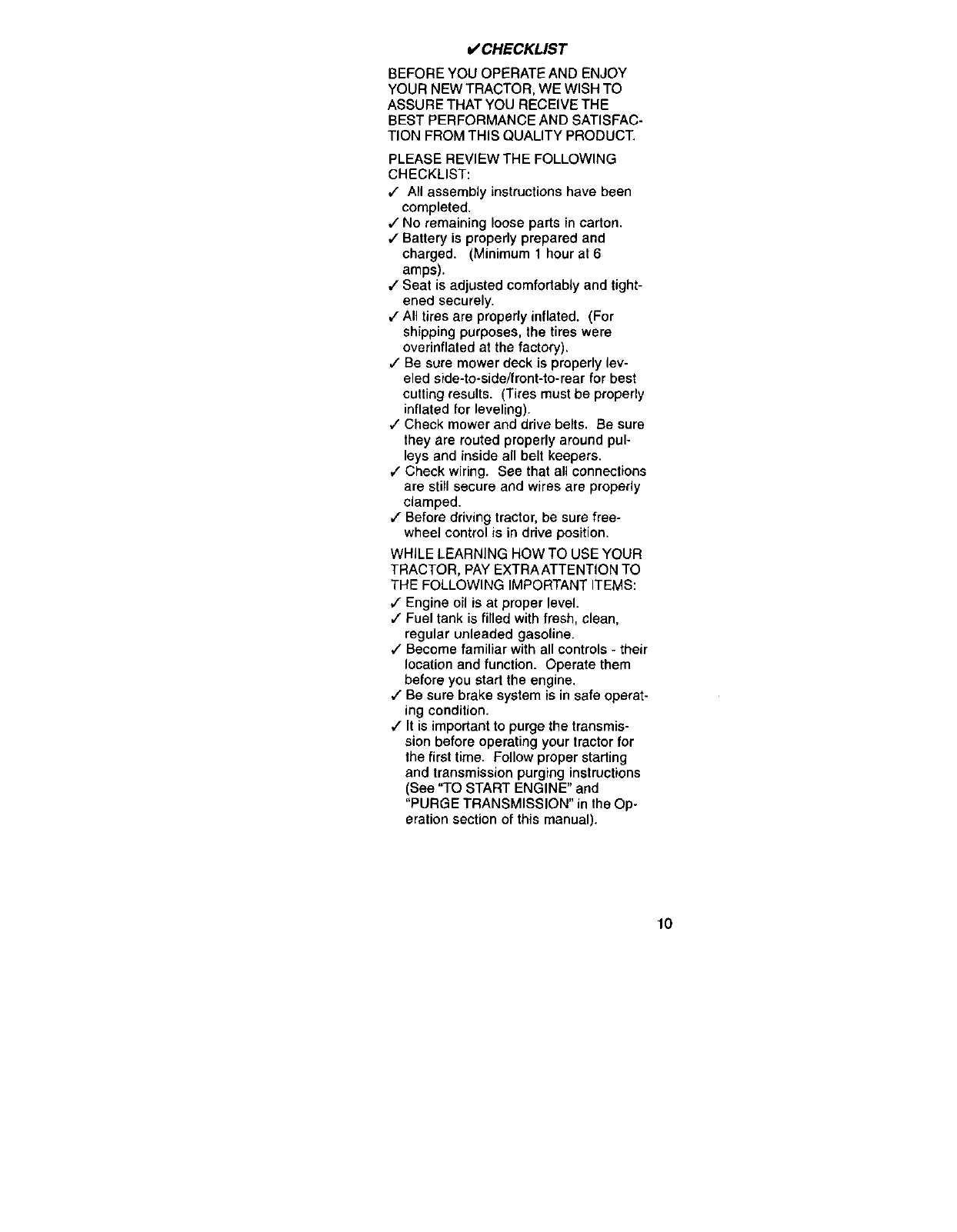
o/ CHECKLIST
BEFORE YOU OPERATE AND ENJOY
YOUR NEW TRACTOR, WE WISH TO
ASSURE THAT YOU RECEIVE THE
BEST PERFORMANCE AND SATISFAC-
TION FROM THIS QUALITY PRODUCT.
PLEASE REVIEW THE FOLLOWING
CHECKLIST:
,/ All assembly instructions have been
completed.
,/No remaining loose parts in carton.
,/Battery is properly prepared and
charged. (Minimum 1 hour at 6
amps).
,/Seat is adjusted comfortably and tight-
ened securely.
,/All tires are property inflated. (For
shipping purposes, the tires were
overinflated at the factory).
J" Be sure mower deck is properly lev-
eled side-to-side/front-to-rear for best
cutting results. (Tires must be properly
inflated for leveling).
#" Check mower and drive belts. Be sure
they are routed properly around pul-
leys and inside all belt keepers.
#" Check wiring. See that all connections
are still secure and wires are properly
clamped.
,/Before driving tractor, be sure free-
wheel control is in drive position.
WHILE LEARNING HOW TO USE YOUR
TRACTOR, PAY EXTRA ATTENTION TO
THE FOLLOWING IMPORTANT ITEMS:
,1 Engine oil is at proper level.
,/" Fuel tank is filled with fresh, clean,
regular unleaded gasoline.
,/Become familiar with all controls - their
location and function. Operate them
before you start the engine.
,/Be sure brake system is in safe operat-
ing condition.
,/It is important to purge the transmis-
sion before operating your tractor for
the first time. Follow proper starting
and transmission purging instructions
(See "TO START ENGINE" and
"PURGE TRANSMISSION" in the Op-
eration section of this manual).
lO
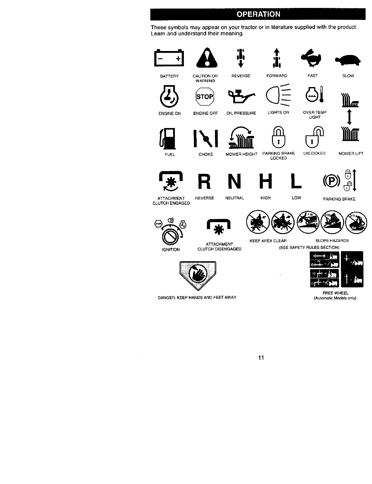
These symbols may appear on your tractor or in literature supplied with the product,
Learn and understand their meaning.
BATTERY CAUTION OR REVERSE FORWARD FAST SLOW
WARNING
ENGINE ON ENGINE OFF O_L PRESSURE LIGHTS ON OVER TEMP
LIGHT !
FUEL CHOKE MOWER HEIGHT PARKING BRAKE UNLOCKED
LOCKED MOWER LIFT
_r_'=R N H L (®_1
ATTACHMENT REVERSE NEUTRAL HIGH LOW PARKING BRAKE
CLUTCH ENGAGED
KEEP AREA CLEAR SLOPE HAZARDS
ATTACHMENT
IGNITION CLUTCH DISENGAGED (SEE SAFETY RULES SECTION)
DANGER, KEEP HANDS AND FEET AWAY
FREE WHEEL
(Automatic Models only)
11
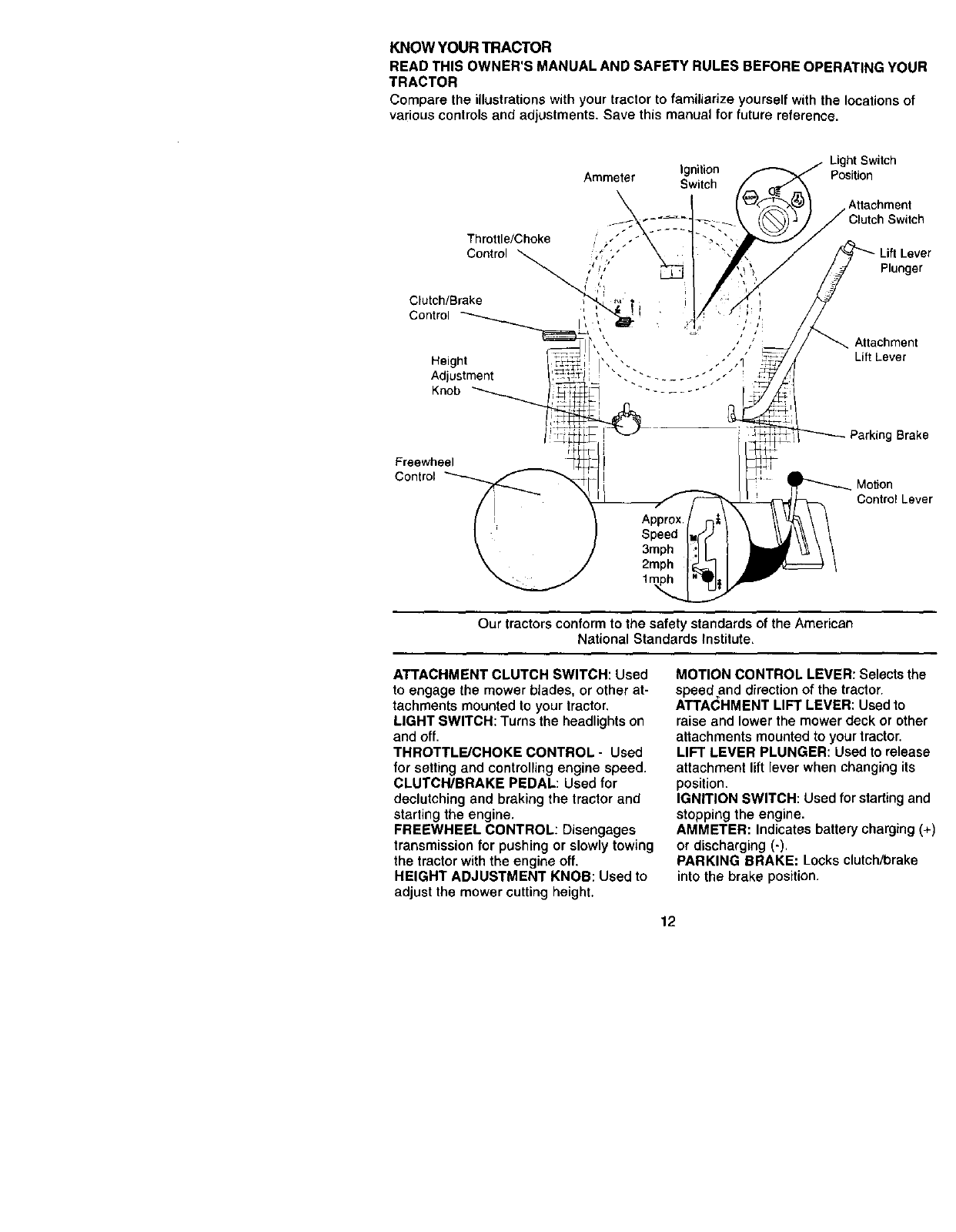
KNOW YOUR TRACTOR
READ THIS OWNER'S MANUAL AND SAFETY RULES BEFORE OPERATING YOUR
TRACTOR
Compare the illustrations with your tractor to familiarize yourself with the locations of
various controls and adjustments. Save this manual for future reference.
Ignition
Ammeter Switch
Light Switch
Position
Attachment
Switch
Our tractors conform to the safety standards of the American
National Standards Institute.
ATTACHMENT CLUTCH SWITCH: Used
to engage the mower blades, or other at-
tachments mounted to your tractor.
LIGHT SWITCH: Turns the headlights on
and off.
THROTTLE/CHOKE CONTROL- Used
for setting and controlling engine speed.
CLUTCH/BRAKE PEDAL: Used for
deelutching and braking the tractor and
starting the engine.
FREEWHEEL CONTROL: Disengages
transmission for pushing or slowly towing
the tractor with the engine off.
HEIGHT ADJUSTMENT KNOB: Used to
adjust the mower cutting height.
MOTION CONTROL LEVER: Selects the
speed ,and direction of the tractor.
ATTACHMENT LIFT LEVER: Used to
raise and lower the mower deck or other
attachments mounted to your tractor.
LIFT LEVER PLUNGER: Used to release
attachment lift lever when changing its
position.
IGNITION SWITCH: Used for starting and
stopping the engine.
AMMETER: Indicates battery charging (+)
or discharging (-).
PARKING BRAKE: Locks clutch/brake
into the brake position.
12
The operation of any tractor can result in foreign objects thrown into the I
eyes, which can result in severe eye damage. Always wear safety glasses I
or eye shields while operating your tractor or performing any adjustments I
or repairs. We recommend awide vision safety mask over spectacles, or I
standard safety glasses. I
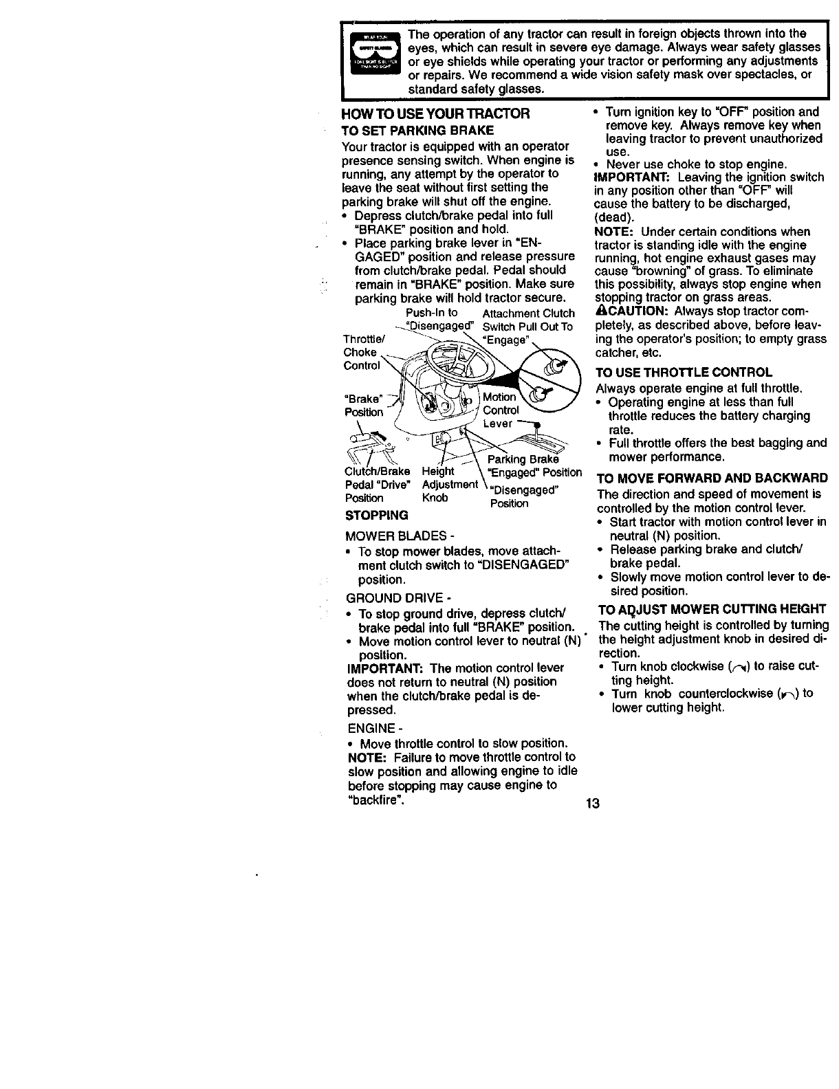
HOW TO USE YOUR TRACTOR
TO SET PARKING BRAKE
Your tractor is equipped with an operator
presence sensing switch. When engine is
running, any attempt by the operator to
leave the seat without first setting the
parking brake will shut off the engine.
•Depress clutch/brake pedal into full
"BRAKE" position and hold.
• Place parking brake lever in =EN-
GAGED" position and release pressure
from clutch/brake pedal. Pedal should
remain in "BRAKE" position. Make sure
parking brake will hold tractor secure.
Push-Into AttachmentClutch
_engaged' SwitchPullOut To
Throttle/ _ _-_._ "Engage"
Choke .._._s_'_'_ _- '-,_
Brake' --_ \"('_-_ Motion_%7 .7
Po6ition_/ _f_'_,_ Control
__• Lever
_Brake_.He!gh! X "Engaged Position
Pedal"Drive" Adjustment\,Disengaged,,
Position Knob Position
STOPPING
MOWER BLADES -
• To stop mower blades, move attach-
ment clutch switch to "DISENGAGED"
position.
GROUND DRIVE -
• To stop ground drive, depress clutch/
brake pedal into full =BRAKE" position.
•Move motion control lever to neutral (N)"
position.
IMPORTANT: The motion control lever
does not return to neutral (N) position
when the clutch/brake pedal is de-
pressed.
ENGINE -
• Move throttle control to slow position.
NOTE: Failure to move throttle control to
slow position and allowing engine to idle
before stopping may cause engine to
"backfire".
•Turn ignition key to "OFF" position and
remove key. Always remove key when
leaving tractor to prevent unauthorized
use.
•Never use choke to stop engine.
IMPORTANT; Leaving the ignition switch
in any position other than "OFF" will
cause the battery to be discharged,
(dead).
NOTE: Under certain conditions when
tractor is standing idle with the engine
running, hot engine exhaust gases may
cause "browning" of grass. To eliminate
this possibility, always stop engine when
stopping tractor on grass areas.
ACAUTION: Always stop tractor com-
pletely, as described above, before leav-
ing the operator's position; to empty grass
catcher, etc.
TO USE THROTTLE CONTROL
Always operate engine at full throttle,
•Operating engine at less than full
throttle reduces the battery charging
rate.
•Full throttle offers the best bagging and
mower performance.
TO MOVE FORWARD AND BACKWARD
The direction and speed of movement is
controlled by the motion control lever.
•Stad tractor with motion control lever in
neutral (N) position.
•Release parking brake and clutch/
brake pedal.
•Slowly move motion control lever to de-
sired position.
TO AI_JUST MOWER CUTTING HEIGHT
The cutting height is controlled by tuming
the height adjustment knob in desired di-
rection.
•Turn knob clockwise (F.q) to raise cut-
ting height.
•Turn knob counterclockwise (w)to
lower cutting height.
13
The cutting height range is approximately
1-1/2" to 4". The heights are measured
from the ground to the blade tip with the
engine not running. These heights are
approximate and may vary depending
upon soil conditions, height of grass and
types of grass being mowed.
•The average lawn should be cut to ap-
proximately 2-1/2 inches dudng the
cool season and to over 3 inches dur-
ing hot months. For healthier and bet-
ter looking lawns, mow often and after
moderate growth•
•For best cutting performance, grass
over 6 inches in height should be
mowed twice. Make the first cut rela-
tively high; the second to desired
height.
TO ADJUST GAUGE WHEELS
Gauge wheels are propedy adjusted
when they are slightly off the ground
when mower is at the desired cutting
height in operating position. Gauge
wheels then keep the deck in proper po-
sition to help prevent scalping in most ter-
rain conditions.
•Adjust gauge wheels with tractor on a
flat level surface.
•Adjust mower to desired cutting height
(See "TO ADJUST MOWER CUTTING
HEIGHT" in the Operation section of
this manual).
•With mower in desired height of cut po-
sition, gauge wheels should be as-
sembled so they are slightly off the
ground. Install gauge wheel in appro-
priate hole with shoulder bolt, 3/8
washer, and 3/8-16 Iocknut and tighten
securely.
•Repeat for opposite side installing
gauge wheel in same adjustment hole.
OougeWhae,-<2
Mounting ._ _ r_ _"
Srockot
3/8-16 /,_._,_
Locknutf3/8 Was'_her(_. _6houlder Bolt
Gauge Wheel
TO OPERATE MOWER
Your tractor is equipped with an operator
presence sensing switch• Any attempt by
the operator to leave the seat with the en-
gine running and the attachment clutch
engaged will shut off the engine.
•Select desired height of cut.
•Lower mower with attachment liftcon-
trol.
•Start mower blades by engaging at-
tachment clutch control.
•TO STOP MOWER BLADES - disen-
gage attachment clutch control.
_CAUTION: Do not operate the mower
without either the entire grass catcher, on
mowers so equipped, or the deflector
shield in place.
AttachmentClutch AttachmentLift Lever
Switch Pull Out To HighPosition
"Engage" _ - , Low
_ _ :::_position
_:\ Deflector
PushlnTo_ _< _;;F_'_,/Shield
"Disengage" f Y _ _\_/
_ _ _,__r_._../
_)))_ \_#_
TO OPERATEON HILLS
A.CAUTION: Do not ddve up or down
hills with slopes greater than 15° and do
not drive across any slope, Use the slope
guide provided at the back of this manual,
•Choose the slowest speed before
starting up or down hills,
•Avoid stopping or changing speed on
hills.
•If slowing is necessary, move throttle
control lever to slower position.
•If stopping is absolutely necessary,
push clutch/brake pedal quickly to
brake position and engage parking
brake.
•Move motion control lever to neutral (N)
position.
IMPORTANT: The motion control lever
does r_t return to neutral (N) position
•when the clutch/brake pedal is de-
pressed.
•To restart movement, slowly release
parking brake and clutch/brake pedal.
•Slowly move motion control lever to
slowest setting.
•Make all turns slowly.
TO TRANSPORT
When pushing or towing your tractor, be
sure to disengage transmission by plac-
ing freewheel control in freewheeling po-
sition. Free wheel control is located at the
rear drawbar of tractor.
14
• Raise attachment lift to highest position
with attachment lift control.
• Pull freewheel control out and down
into the slot and release so it is held in
the disengaged position.
•Do not push or tow tractor at more than
two (2) MPH.
•To reengage transmission, reverse
above procedure.
NOTE: To protect hood from damage
when transporting your tractor on a truck
or a trailer, be sure hood is closed and se-
cured to tractor. Use an appropriate
means of tying hood to tractor (rope,
cord, etc.).
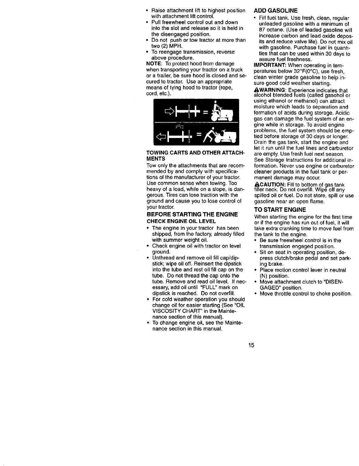
TOWING CARTS AND OTHER ATTACH-
MENTS
Tow only the attachments that are recom-
mended by and comply with specifica-
tions of the manufacturer of your tractor.
Use common sense when towing. Too
heavy of aload, while on a slope, is dan-
gerous. Tires can lose traction with the
ground and cause you to lose control of
your tractor.
BEFORE STARTING THE ENGINE
CHECK ENGINE OIL LEVEL
•The engine in your tractor has been
shipped, from the factory, already filled
with summer weight oil.
• Check engine oil with tractor on level
ground.
•Unthraad and remove oil fill cap/dip-
stick; wipe oil off. Reinsert the dipstick
into the tube and rest oil fill cap on the
tube. Do not thread the cap onto the
tube. Remove and read oil level. If nec-
essary, add oil until "FULL" mark on
dipstick is reached. Do not overfill.
•For cold weather operation you should
change oil for easier starting (See "OIL
VISCOSITY CHART" in the Mainte-
nance section of this manual).
•To change engine oil, see the Mainte-
nance section in this manual.
ADD GASOLINE
•Fill fuel tank. Use fresh, clean, regular
unleaded gasoline with a minimum of
87 octane. (Use of leaded gasoline will
increase carbon and lead oxide depos-
its and reduce valve life). Do not mix oil
with gasoline. Purchase fuel in quanti-
ties that can be used within 30 days to
assure fuel freshness.
IMPORTANT: When operating in tem-
peratures below 32°F(0°C), use fresh,
clean winter grade gasoline to help in-
sure good cold weather starting.
_,WARNING: Experience indicates that
alcohol blended fuels (called gasohol or
using ethanol or methanol) can attract
moisture which leads to separation and
formation of acids during storage. Acidic
gas can damage the fuel system of an en-
gine while in storage. To avoid engine
problems, the fuel system should be emp-
tied before storage of 30 days or longer.
Drain the gas tank, start the engine and
let it run until the fuel lines and carburetor
are empty. Use fresh fuel next season.
See Storage Instructions for additional in-
formation. Never use engine or carburetor
cleaner products in the fuel tank or per-
manent damage may occur.
ACAUTION: Fill to bottom of gas tank
filler neck. Do not overfill. Wipe off any
spilled oil or fuel. Do not store, spill or use
gasoline near an open flame.
TO START ENGINE
When starting the engine for the first time
or if the engine has run out of fuel, it will
take extra cranking time to move fuel from
the tank to the engine.
•Be sure freewheel control is in the
transmission engaged position.
• Sit on seat in operating position, de-
press clutch/brake pedal and set park-
ing brake.
•Place motion control lever in neutral
(N) position.
•Move attachment clutch to "DISEN-
GAGED" position.
•Move throttle control to choke position.
15

NOTE: Before starting, read the warm
and cold starting procedures below.
• Insert key into ignition and turn key
clockwise to "START" position and re-
lease key as soon as engine starts. Do
not run starter continuously for more
than fifteen seconds per minute. If the
engine does not start after several at-
tempts, move throttle control to fast po-
sition, wait a few minutes and try again.
If engine stilldoes not start, move the
throttle control back to the choke posi-
tion and retry.
WARM WEATHER STARTING (50 ° F and
above)
•When engine starts, move the throttle
control to the fast position.
• The attachments and ground drive can
now be used. If the engine does not ac-
cept the load, restart the engine and al-
low it to warm up for one minute using
the choke as described above.
COLD WEATHER STARTING ( 50° F and
below)
• When engine starts, allow engine to
run with the throttle control in the choke
position until the engine runs roughly,
then move throttle control to fast posi-
tion. This may require an engine warm-
up period from several seconds to sev-
eral minutes, depending on the tem-
perature.
AUTOMATIC TRANSMISSION WARM UP
• Before driving the unit in cold weather,
the transmission should be warmed up
as follows:
• Be sure the tractor is on level
ground,
• Place the motion control lever in
neutral. Release the parking brake
and let the clutch/brake slowly return
to operatingposition.
• Allow one minute for transmission to
warm up. This can be done during
the engine warm up period.
• The attachments can also be used dur-
ing the engine warm-up period after the
transmission has been warmed up.
NOTE: If at a high altitude (above 3000
feet) or in cold temperatures (below 32 F)
the carburetor fuel mixture may need to
be adjusted for best engine performance.
See "TO ADJUST CARBURETOR" in the
Service and Adjustments section of this
manual.
PURGE TRANSMISSION
ACAUTION: Never engage or disen-
gage freewheel lever while the engine is
running.
To ensure proper operation and perfor-
mance, it is recommended that the trans-
mission be purged before operating trac-
tor for the first time. This procedure will re-
move any trapped air inside the transmis-
sion which may have developed during
shipping of your tractor.
IMPORTANT: Should your transmission
require removal for service or replace-
ment, it should be purged after reinstalla-
tion before operating the tractor.
•Place tractor safely on level surface
with engine off and parking brake set.
• Disengage transmission by placing
freewheel control in freewheeling posi-
tion (See "TO TRANSPORT" in this sec-
tion of manual).
• Sitting in the tractor seat, start engine.
After the engine is running, move
throttle control to slow position. With
motion control lever in neutral (N) posi-
tion, slowly disengage clutch/brake
pedal.
•Move motion control lever to full for-
ward position and hold for five (5) sec-
onds, Move lever to full reverse position
and hold for five (5) seconds. Repeat
this procedure three (3) times.
NOTE: During this procedure there will
be no movement of drive wheels. The air
is being removed from hydraulic drive
system.
• Move motion control lever to neutral (N)
position, Shut off engine and set park-
ing brake.
• Engage transmission by placing free-
wheel control in driving position (See
"TO TRANSPORT" in this section of
maniJal).
• Sitting in the tractor seat, start engine.
After the engine is running, move
throttle control to half (1/2) speed. With
motion control lever in neutral (N) posi-
tion, slowly disengage clutch/brake
pedal.
t6

• Slowly move motion control lever for-
ward; after the tractor moves approxi-
mately five (5) feet, slowly move motion
control lever to reverse position. After
the tractor moves approximately five (5)
feet return the motion control lever to
the neutral (N) position. Repeat this
procedure with the motion control lever
three (3) times.
MOWING TIPS
• Mower should be properly leveled for
best mowing performance. See "TO
LEVEL MOWER HOUSING" in the Ser-
vice and Adjustments section of this
manual.
• The left hand side of mower should be
used for trimming.
•Drive so that clippings are discharged
onto the area that has been cut. Have
the cut area to the right of the tractor.
This will result in a more even distribu-
tion of clippings and more uniform cut-
ting.
• When mowing large areas, start by
turning to the right so that clippings will
discharge away from shrubs, fences,
driveways, etc. After one or two rounds,
mow in the opposite direction making
left hand turns until finished.
• If grass is extremely tall, it should be
mowed twice to reduce load and pos-
sible fire hazard from dried clippings.
Make first cut relatively high; the sec-
ond to the desired height.
• Do not mow grass when it is wet. Wet
grass will plug mower and leave unde-
sirable clumps. Allow grass to dry be-
fore mowing.
• Always operate engine at full throttle
when mowing to assure better mowing
performance and proper discharge of
material. Regulate ground speed by se-
lecting a low enough gear to give the
mower the best cutting performance as
well as the quality of cut desired.
• When operating attachments, select a
ground speed that will suit the terrain
and give best performance of the at-
tachment being used.
f
/
MULCHING MOWING TIPS
IMPORTANT: For best performance, keep
mower housing free of built-up grass and
trash. Clean after each use.
•The special mulching blade will recut
the grass clippings many times and re-
duce them in size so that as they fall
onto the lawn they will disperse into the
grass and not be noticed. Also, the
mulched grass will biodegrade quickly
to provide nutrients for the lawn. Always
mulch with your highest engine (blade)
speed as this will provide the best re-
cutting action of the blades.
•Avoid cutting your lawn when it is wet.
Wet grass tends to form clumps and in-
terferes with the mulching action. The
best time to mow your lawn is the early
afternoon. At this time the grass has
dried and the newly cut area will not be
exposed to the direct sun.
•For best results, adjust the mower cut-
ting height so that the mower cuts off
only the top one-third of the grass
blades. For extremely heavy mulching,
reduce your width of cut on each pass
and mow slowly.
• Certain types of grass and grass condi-
tions may require that an area be
mulched a second time to completely
hide the clippings. When doing a sec-
ond cut, mow across or perpendicular
to the first cut path.
• Change your cutting pattern from week
to Week. Mow north to south one week
then change to east to west the next
week. This will help prevent matting
and graining of the lawn.
Max 1/3
17
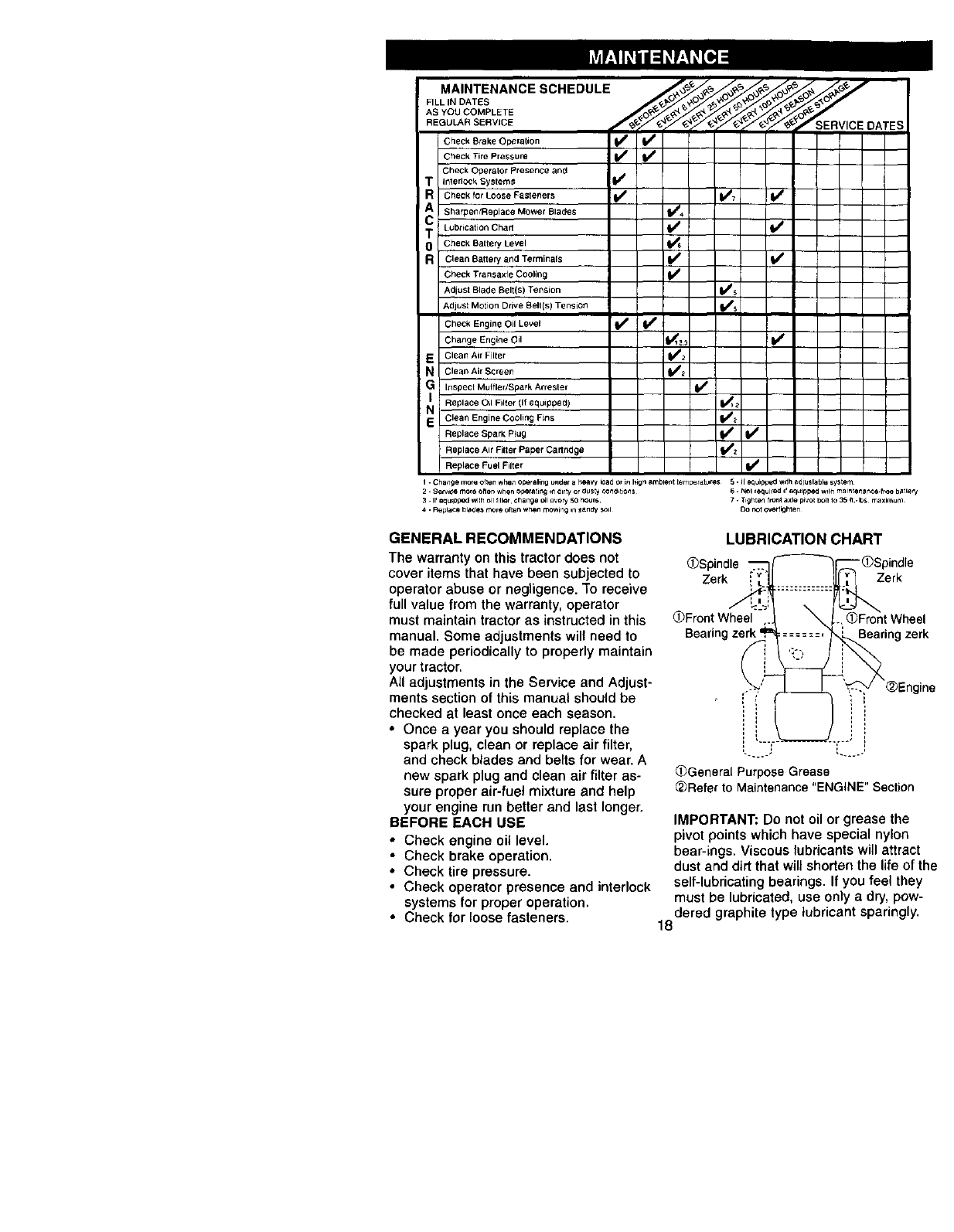
F,LL,NDA EE
AS COMPLETE .....
REaULAR SERVICE _'/_SERVICE DATES
Check Brake Operation Vf I/
Check Tire Pressure if I1_
Check Operator Presence and
rInterlc.:k System_ I_
Check for Loose Fasteners ii_ 11_7 JIf
Shargen/Replace Mower Blades I_4
Lubrication Chart i/ II/
0Check Battery Level I_s
R Clean Battery and Terminals I_ V*
Check Ttansaxfe Cooling I_
Adjust Blade Belt(S) Tension I_s
Adjust Motion Drive Belt(s) Tension I_s
Check Engine Oil Level II/ If
Change Engine Oil 11_1z: IIIt
EClean Air Filter 1_2
NCleanAirScreen 11/2
GInspect Muffler/Spark Arrester I1 /
NI Replace Oil Filter (If equipped) 2
E Clean Engine Cooling Fins I_1_
Replace Spark Plug i# #I/
Replace Air Filter Paper Cartridge I##z
Replace Fuel Filter I_
i. Change more often wr,,enoper aling under afteavy k)ad or mh4gn ambient [emperatures 5. II equlppe:l Withadjuslable system
2. Ser_e more often when operating ,T1dirty or dIJsty cond,tions 6. NOl requi_e_ ,f equ_ppe_ w,lh maintenance-free batlery
3. If eq uJpped with oil filler¸ €flange C41every 5O hours¸ 7. Tight,_l front axle prvot bolt Io 35 ft .It,s maximum
,_. ReplaCa blades n_re often when mowing ,n _andy sod {3o r_t ovc*rt=ghten
GENERAL RECOMMENDATIONS
The warranty on this tractor does not
cover items that have been subjected to
operator abuse or negligence. "Toreceive
full value from the warranty, operator
must maintain tractor as instructed in this
manual. Some adjustments will need to
be made periodically to properly maintain
your tractor.
All adjustments in the Service and Adjust-
ments section of this manual should be
checked at least once each season.
• Once a year you should replace the
spark plug, clean or replace air filter,
and check blades and belts for wear. A
new spark plug and clean air filter as-
sure proper air-fuel mixture and help
your engine run better and last longer.
BEFORE EACH USE
• Check engine oil level.
•Check brake operation,
•Check tire pressure.
•Check operator presence and interlock
systems for proper operation.
• Check for loose fasteners.
LUBRICATION CHART
_Spindle -QSpindle
Zerk Zerk
OFront Wheel Wheel
Bearing zerk Bearing zerk
(_Engine
i
OGeneral PurposeGrease
_Refer to Maintenance"ENGINE" Section
IMPORTANT: Do not oil or grease the
pivot points which have special nylon
bear-ings. Viscous lubricants will attract
dust and dirt that will shorten the life of the
self-lubricating bearings. If you feel they
must be lubricated, use only a dry, pow-
dered graphite type lubricant sparingly.
18

TRACTOR
A_ways observe safety rules when per-
forming any maintenance.
BRAKE OPERATION
If tractor requires morn than six (6) feet
stopping distance at high speed in high-
est gear, then brake must be adjusted.
(See "TO ADJUST BRAKE" in the Service
and Adjustments section of this manual).
TIRES
• Maintain proper air pressure in all tires
(Bee "PRODUCT SPECIFICATIONS"
section of this manual).
• Keep tires free of gasoline, oil, or insect
control chemicals which can harm rub-
ber.
• Avoid stumps, stones, deep ruts, sharp
objects and other hazards that may
cause tire damage.
NOTE: To seat tire punctures and prevent
flat tires due to slow leaks, tire sealant
may be purchased from your local parts
dealer. Tire sealant also prevents tire dry
rot and corrosion.
OPERATOR PRESENCE SYSTEM
Be sure that operator presence and inter-
lock systems are working properly. If your
tractor does not function as described be-
low, repair the problem immediately.
•The engine should not start unless the
clutch/brake pedal is fully depressed
and attachment clutch control is in the
disengaged position.
•When the engine is running, any at-
tempt by the operator to leave the seat
without first setting the parking brake
should shut off the engine.
•When the engine is running and the at-
tachment clutch is engaged, any at-
tempt by the operator to leave the seat
should shut off the engine.
•The attachment clutch should never op°
erate unless the operator is in the seat.
BLADE CARE
For best results mower blades must be
kept sharp, Replace bent or damaged
blades.
BLADE REMOVAL
• Raise mower to highest position to a_-
low access to blades,
•Remove hex bolt, lock washer and fiat
washer securing blade.
• Install new or resharpened blade with
trailing edge up towards deck as
shown.
IMPORTANT: To ensure proper assembly,
center hole in blade must align with star
on mandrel assembly.
• Reassemble hex bolt, lock washer and
flat washer in exact order as shown.
•Tighten bolt securely (27-35 Ft. Lbs
torque).
IMPORTANT: Blade bolt is Grade 8 h
treated.
TrailingEdge Up _,. _.. Man(
Fiat Washer "_2\_'_._ _/_; Center
Washer _Hex Bolt -?. Blad_
(Grade 8)*
*A Grade 8 heat treated bolt can be
identifiedby six lines on the bolt heac
TO SHARPEN BLADE
NOTE: We do not recommend sharp,
ing blade, but if you do, be sure the t
is balanced.
Care should be taken to keep the bla,
balanced. An unbalanced blade will
cause excessive vibration and eventt
damage to mower and engine.
•The blade can be sharpened with
or on a grinding wheel. Do not attel
to sharpen while it is on the mower.
• To check blade balance, you will n_
a5/8" diameter steel bolt, pin, or a
balancer. (When using a cone bala
follow the instructions supplied witl
balancer).
NOTE: Do nor use anail for balancin,
blade. The lobes of the center hole m
appear to be centered, but are not.
•Slide blade onto an unthreaded pc
of the steel bolt or pin and hold the
or pin parallel with the ground. If bl
is balanced, it should remain in a f
zontal position. If either end of the
blade moves downward, sharpen 1
heavy end until the blade is balam
BA'I-rERY
Your tractor has abattery charging sl
which is sufficient for normal use. H_
ever, periodic charging of the batter_
an automotive charger will extend it.,
• Keep battery and terminals clean.
• Keep battery bolts tight.
• Keep small vent holes open.
• Recharge at 6-10 amperes for 1 I
NOTE: The original equipment batte
your tractor is maintenance free. Do
attempt to open or remove caps or c
Adding or checking level of electrol_
19 not necessary.

TOCLEANBATTERYANDTERMINALS
Corrosionanddirtonthebatteryandter-
minalscancausethebatteryto"leak"
power.
•Remove terminal guard.
• Disconnect BLACK battery cable first
then RED battery cabre and remove
battery from tractor.
• Rinse the battery with plain water and
dry.
• Clean terminals and battery cable ends
with wire brush until bright.
• Coat terminals with grease or petro-
leum jelly.
• Reinstall battery (See "REPLACING
BATTERY" in the SERVICE AND AD-
JUSTMENTS section of this manual).
V-BELTS
Check V-belts for deterioration and wear
after 100 hours of operation and replace
it necessary. The belts are not adjustable.
Replace belts if they begin to slip from
wear.
TRANSAXLE COOLING
The transmission fan and cooling fins
should be kept clean to assure proper
cooling.
Do not attempt to clean fan or transmis-
sion while engine is running or while the
transmission is hot. To prevent possible
damage to seals, do not use high pres-
sure water or steam to clean transaxle.
• Inspect cooling fan to be sure fan
blades are intact and clean.
• Inspect cooling fins for dirt, grass clip-
pings and other materials, To prevent
damage to seals, do not use com-
pressed air or high pressure sprayer to
clean cooling fins.
TRANSAXLE PUMP FLUID
The transaxle was sealed at the factory
and fluid maintenance is not required for
the life of the transaxle. Should the
transaxle ever leak or require servicing,
contact your nearest authorized service
centeddepar_ment.
ENGINE
LUBRICATION
Only use high quality detergent oil rated
with API service classification SF, SG, or
SH. Setect the oil's SAE viscosity grade
according to your expected operating
temperature.
Change the oil after every 50 hours of (
eration or at least once a year if the tra{
for is not used for 50 hours in one year.
Check the crankcase oil level before
starting the engine and after each eigh _
(8) hours of operation. Tighten oil fill ce
dipstick securely each time you check 1
oil level.
TO CHANGE ENGINE OIL
Determine temperature range expecte
before oil change, All oil must meet AF
service classification SF, SG, or SH.
• Be sure tractor is on level surface.
• Oil will drain more freely when warm
• Catch oil in a suitable container.
• Remove oil fill cap/dipstick. Be care
not to allow dirt to enter the engine
when changing oil.
• Remove drain plug.
• After oil has drained completely, re-
place oil drain plug and tighten se+
curely.
• Refill engine with oil through oil fill d
stick tube. Pour slowly. Do not overfi
For approximate capacity see "PRO[
UCT SPECIFICATIONS" section of tP
manual.
• Use gauge on oil fill cap/dipstick for
checking level. Insert dipstick into th
tube and rest the oil fill cap on the tu
Do not thread the cap onto the tube
when tak(ng reading. Keep oil at
"FULL" line on dipstick. Tighten cap
onto the tube securely when finishe(
Air C_eaner Cover
Foam
Pre- Rubb
• Groin
Air
Ctea
Pap{
Cart=
AirCleam
Base
Dipstick
Screen
Oil Drain
Plug
2O

CLEAN AIR SCREEN
Air screen must be kept free of dirt and
chaff to prevent engine damage from
overheating. Clean with a wire brush or
compressed air to remove dirt and stub-
born dried gum fibers.
CLEAN AIR INTAKE/COOLING AREAS
To insure proper cooling, make sure the
grass screen, cooling fins, and other ex-
ternal surfaces of the engine are kept
clean at all times.
Every 100 hours of operation (more often
under extremely dusty, dirty conditions),
remove the blower housing and other
cooling shrouds. Clean the cooling fins
and external surfaces as necessary. Make
sure the cooling shrouds are reinstalled.
NOTE: Operating the engine with a
blocked grass screen, dirty or plugged
cooling fins, and/or cooling shrouds re-
moved will cause engine damage due to
overheating.
AIR FILTER
Your engine will not run properly using a
dirty air filter. Clean the foam pre-cleaner
after every 25 hours of operation or every
season. Service paper cartridge every
100 hours of operation or every season,
whichever occurs first.
Service air cleaner more often under
dusty conditions.
•Remove knob and cover.
•Remove wing nut and air cleaner from
base.
TO SERVICE PRE-CLEANER
• Slide foam pre-cleaner off cartridge.
• Wash it in liquid detergent and water.
• Squeeze it dry in a clean cloth. Allow it
to dry.
• Saturate it in engine oil. Wrap it in
clean, absorbent cloth and squeeze to
remove excess oil.
TO SERVICE CARTRIDGE
• Replace a dirty, bent, or damaged car-
tridge.
NOTE: Do not wash the paper cartridge
or use pressurized air, as this will dam-
age the cartridge.
• Reinstall the pre-cleaner (cleaned and
oiled) over the paper cartridge.
• Reassemble air cleaner, wing nut,
cover and tighten knob securely.
ENGINE OIL FILTER
Replace the engine oil filter every season
or every other oil change if the tractor is
used more than 100 hours in one year.
• Drain oil from engine crankcase (See
"TO CHANGE ENGINE OIL" in this sec-
tion of this manual, through step re-
move drain plug).
• Remove oil filter and wipe off filter
adapter.
• Apply a thin coating of new engine oil
to the rubber gasket on replacement oil
filter.
• Install replacement oil filter on filter
adapter. Turn oil filter clockwise until
rubber gasket contacts the filter
adapter, then tighten filter an additional
1/2 turn.
•Fill crankcase with new oil (See "TO
CHANGE ENGINE OIL" in this section
of this manual). For approximate capac-
ity see "PRODUCT SPECIFICATIONS"
section of this manual.
• Start the engine and check for oil leaks.
Correct any leaks before placing en-
gine into full operation.
_Oil
_ Filter
MUFFLER
Inspect and replace corroded muffler and
spark arrester (if equipped) as it could
create a fire hazard and/or damage.
SPARK PLUGS
Replace spark plugs at the beginning of
each mowing season or after every t 00
hours of operation, whichever occurs first.
Spark plug type and gap setting are
shown in "PRODUCT SPECIFICATIONS"
section of this manual.
IN-LINE FUEL FILTER
The fuel filter should be replaced once
each season, If fuel filter becomes
clogged, obstructing fuel flow to carbure-
tor, replacement is required,
•With engine cool, remove filter and
plug fuel line sections.
• Place new fuel filter in position in fuel
line with arrow pointing towards carbu-
retor.
• Be sure there are no fuel line leaks and
clamps are properly positioned.
• Immediately wipe up any spilled gaso-
line.
21

(_1__ Clamp
Clamp / \__uel Filter
CLEANING
•Clean engine, battery, seat, finish, etc.
of all foreign matter.
•Keep finished surfaces and wheels free
of all gasoline, oil, etc.
• Protect painted surfaces with automo-
tive type wax.
We do not recommend using a garden
hose to clean your tractor unless the elec-
trical system, muffler, air filter and carbu-
retor are covered to keep water out. Water
in engine can result in a shortened en-
gine life.
_CAUTION: Before performing any service or adjustments:
Depress clutch/brake pedal fully and set parking brake.
• Place motion control lever in neutral (N) position.
•Place attachment clutch in "DISENGAGED" position.
• Turn ignition key "OFF" and remove key.
• Make sure the blades and all moving parts have completely stopped.
• Disconnect spark plug wire from spark plug and place wire where it cannot come
in contact with plug.
TRACTOR
TO REMOVE MOWER
Mower will be easier to remove from the
right side of tractor.
• Place attachment clutch switch in "DIS-
ENGAGED" position.
•Move attachment lift lever forward to
lower mower to its lowest position.
• Roll belt off electric clutch pulley.
• Disconnect anti-sway bar from chassis
bracket by removing retainer spring.
• Disconnect suspension arms from rear
deck brackets by removing retainer
springs.
• Disconnect front links from deck by re-
moving retainer springs.
Small Retainer
• Raise lift lever to raise suspension
arms. Slide mower out from under trac-
tor.
IMPORTANT: If an attachment other than
the mower deck is to be mounted on the
tractor, remove the front links.
TO INSTALL MOWER
• Raise attachment lift lever to its highest
position.
• Slide mower under tractor with dis-
charge guard to right side of tractor.
• Lower lift lever to its lowest position.
• Install mower in reverse order of re-
moval instructions.
Suspension Arms
Electric
Pulley
Retainer
Anti-Sway
Bar \
(Both Sides)
Retainer Spring
22
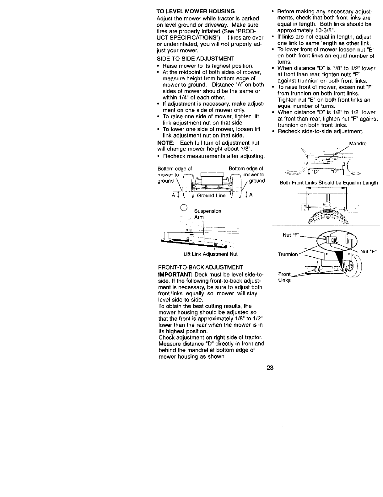
TO LEVEL MOWER HOUSING
Adjust the mower while tractor is parked
on level ground or driveway. Make sure
tiros are properly inflated (See "PROD-
UCT SPECIFICATIONS"). If tiros are over
or underinflated, you will not properly ad-
just your mower.
SIDE-TO-SIDE ADJUSTMENT
•Raise mower to its highest position.
•At the midpoint of both sides of mower,
measure height from bottom edge of
mower to ground. Distance "A" on both
sides of mower should be the same or
within 1/4" of each other.
•If adjustment is necessary, make adjust-
ment on one side of mower only.
•To raise one side of mower, tighten lift
link adjustment nut on that side.
• To lower one side of mower, loosen lift
link adjustment nut on that side.
NOTE: Each full turn of adjustment nut
will change mower height about 1/8".
•Recheck measurements after adjusting.
Bottom edge of Bottom edge of
gmr°uWedt_g rWoe;td
A_-_"'_ Ground Line _--/_A
Q Suspension
Arm
• Before making any necessary adjust-
ments, check that both front links are
equal in length. Both links should be
approximately 10-3/8".
•If links are not equal in length, adjust
one link to same length as other link.
•To Lower front of mower loosen nut "E"
on both front links an equal number of
turns.
•When distance "D" is 1/8" to 1/2" lower
at front than rear, tighten nuts "F"
against trunnion on both front links.
•To raise front of mower, loosen nut "F"
from trunnion on both front links.
Tighten nut "E" on both front links an
equal number of turns.
•When distance "D" is 1/8" to 1/2" lower
at front than rear, tighten nut "F" against
trunnion on both front links.
•Recheck side-to-side adjustment.
Mandrel
......... j, °L_ -Lr T_ ......
Both Front Links Should be Equal inLength
Nut
Lift Link Adjustment Nut
FRONT-TO-BACK ADJUSTMENT
IMPORTANT: Deck must be level side-to-
side. If the following front-to-back adjust-
ment is necessary, be sure to adjust both
front links equally so mower will stay
level side-to-side.
To obtain the best cutting results, the
mower housing should be adjusted so
that the front is approximately 1/8" to 1/2"
lower than the rear when the mower is in
its highest position.
Check adjustment on right side of tractor.
Measure distance "D" directly in front and
behind the mandrel at bottom edge of
mower housing as shown.
Trunnion
Front
Links
23
Nut "E"

TO REPLACE MOWER BLADE
DRIVE BELT
The mowerblade drive belt maybe re-
placedwithouttools. Parkthe tractoron
lev91surface. Engage parkingbrake.
BELTREMOVAL-
* Removemowerfrom tractor(See "TO
REMOVE MOWER" inthissectionof
this manual).
• Work belt off bothmandrelpulleys'and
idler pulleys.
•Pullbelt awayfrom mower.
BELTINSTALLATION-
•Install new beltin reverseorderof re-
moval.
•Make surebelt is in all pulleygrooves
and insideall belt guides.
•Installmower in reverseorderof re-
movalinstructions.
Idler
Pull
Mandrel
Pulle'
Pulley
TO ADJUST BRAKE
Yourtractoris equippedwithan adjust-
able brake systemwhichis mountedon
the sideof the transaxle.
If tractorrequiresmorethansix (6) feet
stoppingdistance at highspeed inhigh-
est gear, thenbrake mustbe adjusted.
•Depressclutch/brakepedal and en-
gage parkingbrake.
•Measure distance betweenbrake oper-
atingarm and nut=A"on brakerod.
•If distanceis otherthan 1-9/16", loosen
jam nutand turn nut=A"untildistance
becomes1-9/16". Retightenjam nut
againstnut =A".
•Road testtractorfor properstopping
distanceas statedabove. Readjustif
necessary. If stoppingdistanceis still
greaterthan six (6) feet inhighestgear,
further maintenance is necessary. Con-
tactyour nearest authorizedservice
center/department. 24
With Parking Brake "Engaged"
Jam Nut
Arm
Do Not touchthisnut. Iffurther brake adjus
ment is necessarycon_.actyour nee,rest su_
rized service center/department
TO REPLACE MOTION DRIVE BELT
Parkthe tractor on levelsurface. Engac
parkingbrake. Forassistance,thereis'
belt installationguide decal on bottom
sideof left footrest.
•Removemower(See "TO REMOVE
MOWER" inthissectionof thismanu
•Disconnectclutchwire harness.
•RemoveclutchIocator.
•Remove beltfrom stationaryidleran
clutchingidler.
•Pull beltslacktowardrearof tractor.
Carefullyremovebeltupwardsfrom
transmissioninputpulleyand over
coolingfan blades.
•Pullbelttowardfront of tractorand r(
move downwardsfrom aroundelect_
clutch,
•Installnew belt by reversingabovep
cedure.
E_ectrlc
Clutch
Clutching_---"
idler
Statiorfary /
Idler
Transmission
Input Pulley6
_Ctutch Loc_t(
,._, Clutch
Wire Harnes

TRANSAXLE MOTION CONTROL
LEVER NEUTRAL ADJUSTMENT
The motion control lever has been preset
at the factory and adjustment should not
be necessary.
• Loosen adjustment bolt in front of the
right rear wheel, and lightly tighten,
•Start engine and move motion control
lever until tractor does not move for-
ward or backward.
•Hold motion control lever in that posi-
tion and turn engine off.
•While holding motion control lever in
place, loosen the adjustment bolt.
•Move motion control lever to the neutral
(N) (lock gate) position.
•Tighten adjustment bolt securely.
NOTE: If additional clearance is needed
to get to adjustment bolt, move mower
deck height to the lowest position,
After above adjustment is made, if the
tractor still creeps forward or backward
while motion control lever is in neutral po-
sition, follow these steps:
•Loosen the adjustment bolt,
•Move the motion control lever 1/4 to 1/2
inch in the direction it is trying to creep.
•Tighten adjustment bolt securely.
•Start engine and test,
•If tractor still creeps, repeat above steps
until satisfied.
TO ADJUST STEERING WHEEL ALIGN-
MENT
If steering wheel cressbars are not hori-
zontal (left to right) when wheels are posi-
tioned straight forward, remove steedng
wheel and reassemble per instructions in
the Assembly section of this manual.
FRONT WHEEL TOE-IN/CAMBER
The front wheel toe-in and camber are
not adjustable on your tractor. If damage
has occurred to affect the front wheel toe-
in or camber, contact your nearest autho-
rized service center.
TO REMOVE WHEEL FOR REPAIRS
•Block up axle securely.
•Remove axle cover, retaining ring and
washers to allow wheel removal (rear
wheel contains a square key - Do not
lose).
•Repair tire and reassemble.
•On rear wheels only: align grooves in
rear wheel hub and axle. Insed square
key.
•Replace washers and snap retaining
dng securely in axle groove.
•Replace axle cover.
NOTE: To seal tire punctures and prevent
flat tires due to slow leaks, tire sealant
may be purchased from your local parts
dealer. Tire sealant also prevents tire dry
rot and corrosion.
MotionControl Neutral Washers
Lever _ /_Lock Gate Retaining _fr__
'! _ "Adjustment
Bolt (Rear Wheel Only)
TRANSMISSION REMOVAL/REPLACE-
MENT
transmission removal/replacement
Should your transmission require re-
moval for service or replacement, it
should be purged after reinstallation and
before operating the tractor. See =PURGE
TRANSMISSION" in the Operation sec-
tion of this manual.
25
TOSTARTENGINEWITHA WEAK
BATFERY
& CAUTION: Lead-acid batteries gener-
ate explosive gases. Keep sparks, flame
and smoking materials away from batter-
ies. Always wear eye protection when
around batteries.
If your battery is too weak to start the en-
gine, it should be recharged. (See "BAT-
TERY" in the MAINTENANCE section of
this manual).
If =jumper cables" are used for emergency
starting, follow this procedure:
IMPORTANT: Your tractor Is equipad with
a 12 volt negative grounded system. The
other vehical must also be a 12 volt nega-
tive grounded system. Do not use your
tractor battery to start other vehicles.
TO ATTACH JUMPER CABLES -
•Connect each end of the RED cable to
the POSITIVE (+) terminal of each bat-
tery. taking care not to short against
chassis.
• Connect one end of the BLACK cable
to the NEGATIVE (-) terminal of fully
charged battery.
• Connect the other end of the BLACK
cable to good CHASSIS GROUND.
away from fuel tank and battery.
TO REMOVE CABLES. REVERSE OR-
DER -
•BLACK cable first from chassis and
then from the fully charged battery.
•RED cable last from both batteries.
=Positive" (+) =Negative" (-)
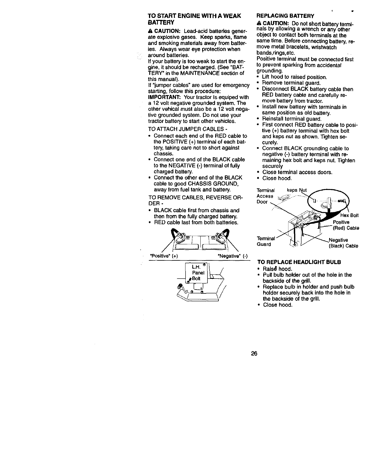
REPLACING BATTERY
& CAUTION: DOnotshortbatteryterm-
nals by allowingawrenchor any other
objectto contactbothterminalsat the
same time.Beforeconnectingbattery,re-
move metal bracelets, wristwatch
bands,dngs,etc,
Positiveterminalmustbe connectedfirst
to preventsparkingfrom accidental
grounding.
•Lifthoodto raisedposition.
•Removeterminalguard.
•DisconnectBLACK batterycable then
RED batterycableand carefullyre-
movebatteryfromtractor.
•Installnew batterywithterminalsin
same positionas old battery.
•Reinstallterminalguard.
•FirstconnectRED batterycable to posi-
tive (+) batteryterminalwithhex bolt
and kepsnutas shown.Tightense-
curely.
•ConnectBLACKgroundingcable to
negative(-) batteryterminalwith re-
maininghex boltand keps nut.Tighten
securely
• Close terminal access doors.
• Close hood.
Terminal keps
Access
Door
Hex Bolt
Positive
Red) Cable
Guard (Black) Cable
TO REPLACE HEADLIGHT BULB
•Rais_ hood.
•Pull bulb holder out of the hole in the
backside of the gdll.
•Replace bulb in holder and push bulb
holder securely back into the hole in
the backside of the grill.
•Close hood.
26
INTERLOCKS AND RELAYS
Loose or damaged wiringmay cause your
tractorto run poorly,stoprunning,or pre-
vent it fromstarting.
•Check wiring.See electricalwiringdia-
gram inthe RepairParts section.
TO REPLACE FUSE
Replace with 15 amp automotive-type
plug-infuse. The fuse holderis located
behindthe dash.
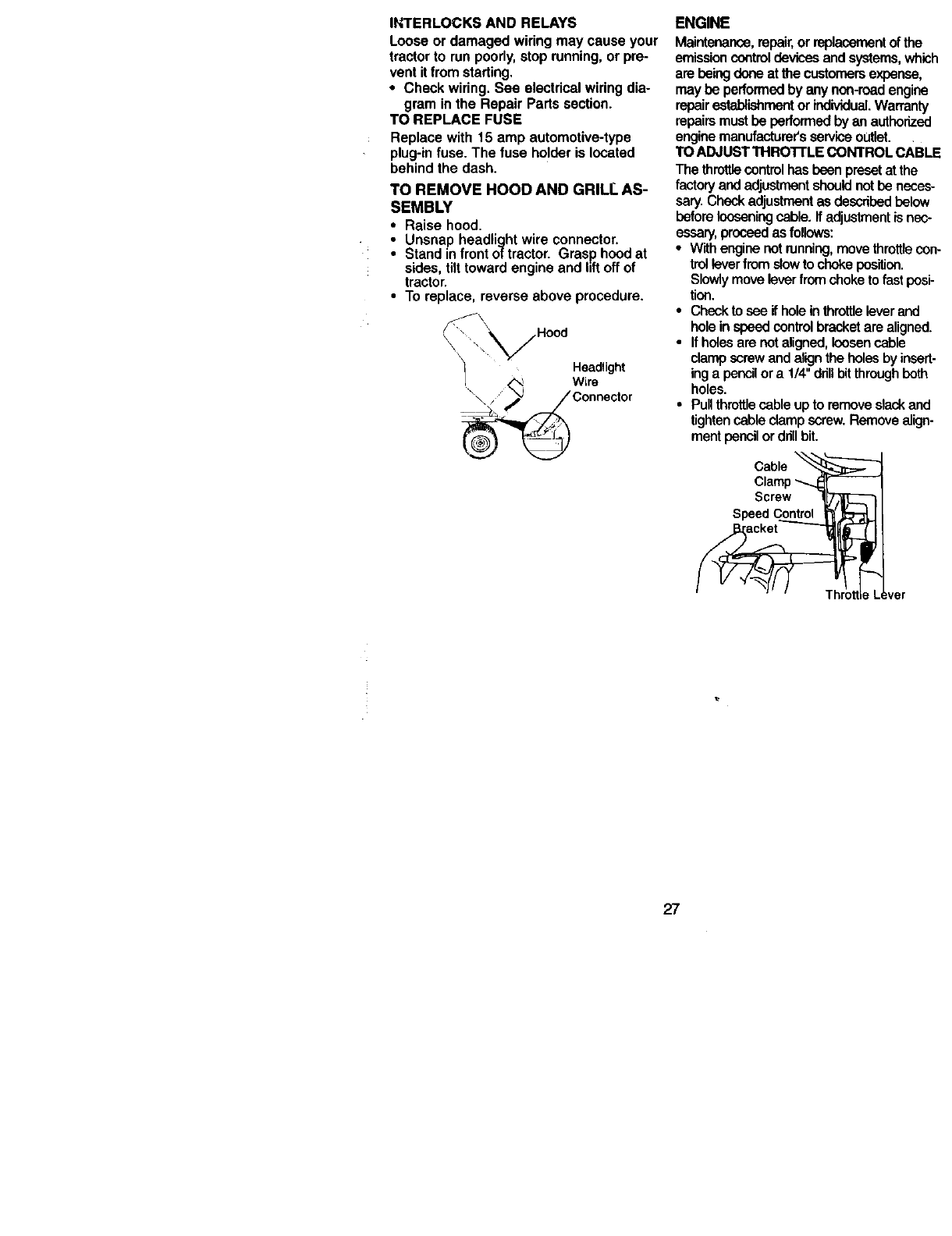
TO REMOVE HOOD AND GRIL I" AS-
SEMBLY
•Raise hood.
•Unsnap headlightwire connector.
Standinfront of tractor.Grasphoodat
sides,tilttowardengineand liftoffof
tractor.
• To replace, reverseabove procedure.
_//Hood
Headlight
W'°r:°ect°r
ENGINE
Maintenance, repair, or replacementof the
emission controldevices and systems, which
are being done at the customersexpense,
may be performed by any non-road engine
repairestablishmentor individual.Warranty
repairsmust be performed by an authorized
engine manufacturers service outlet.
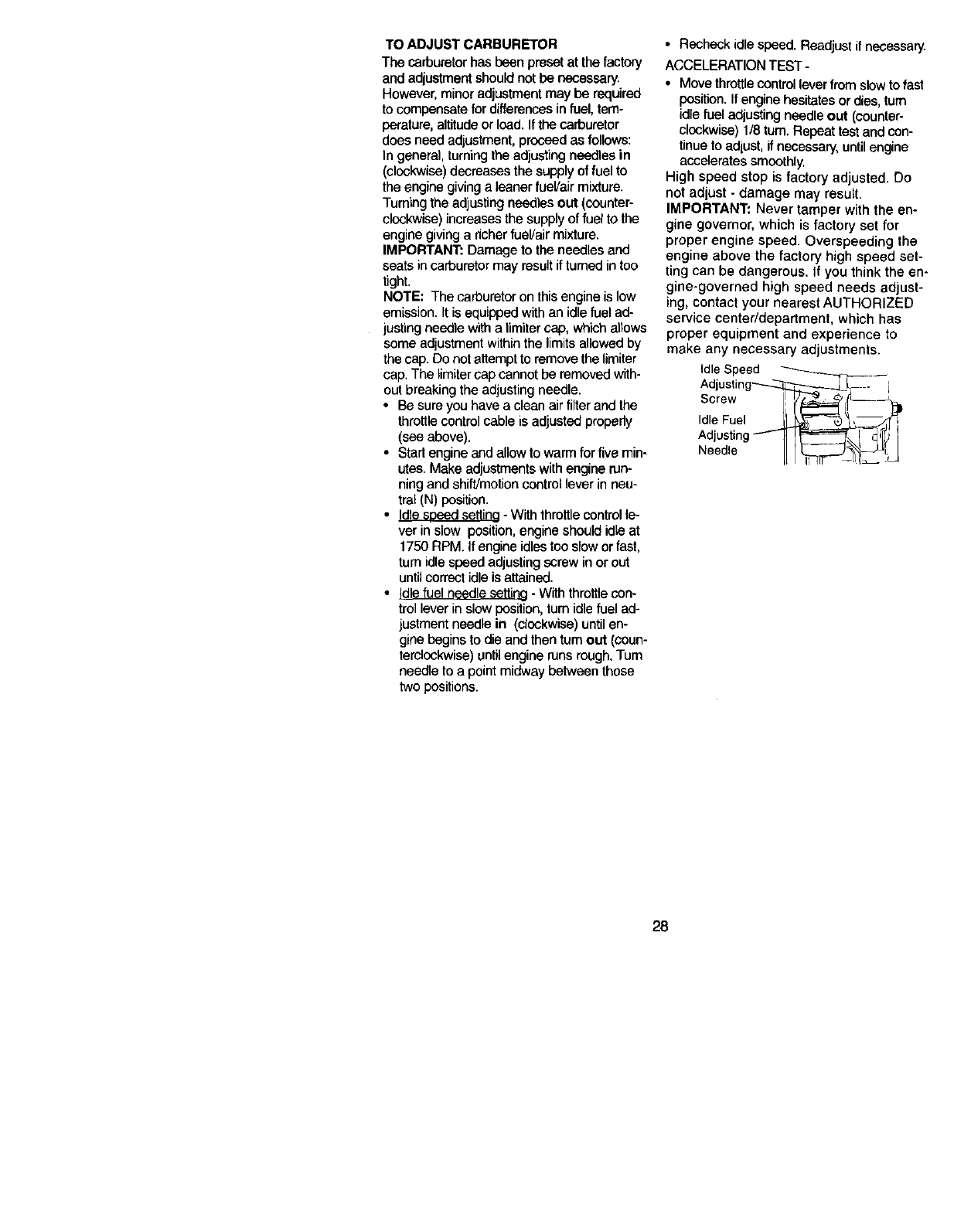
TO ADJUST THRO'I"rLE CONTROL cABLE
The throttlecontrolhas been preset at the
factory and adjustmentshould not be neces-
sary. Chock adjustment as described below
before looseningcable, ff adjustmentis nec-
essary,proceed asfollows:
•W_thengine not running,move throttlecon-
trolleverfrom slow to choke pes'rUon.
Slowly move lever from choke to fast posi-
tion.
•Check to see if hole in throttlelever and
hole in speed controlbracket are aligned.
•Ifholes are not aligned, loosen cable
clamp screw and alignthe holes by insert-
ing a pencilor a 1/4"drinbit throughboth
holes.
•Pull throttlecable up to remove slack and
tighten cable clamp screw. Remove align-
merit pencilor drillbit.
Screw
Speed
27
TO ADJUST CARBURETOR
The carburetorhas been preset at the factory
and adjustment shouldnot be necessary.
However, minoradjustment may be required
to compensate for differencesin fuel, tam-
perature, altitudeor load.Ifthe carburetor
does need adjustment,proceed as follows:
In general, turningthe adjusting needles in
(clockwise)decreases the supply of fuel to
the engine givinga leaner fueVair mixture.
Turning the adjustingnoodles out (counter-
clockwise)increases the supply of fuel to the
engine givinga richerfuel/air mixture.
IMPORTANT: Damage to the needles and
seats incarburetormay resultiffumed intoo
tight.
NOTE: The carburetor on this engine is low
emission. It is equipped with an idle fuel ad-
justing needle with a limitercap, which allows
some adjustment within the limits allowed by
the cap. Do not attempt to remove the limiter
cap. The limiter cap cannot be removed with-
out breaking the adjusting needle.
• Be sure you have a clean air filter and the
throttle control cable is adjusted properly
(see above).
• Start engine and allow to warm for five min-
utes. Make adjustments with engine run-
ning and shift/motion control lever in neu-
tral (N) position.
• Idle seeed settina - With throttle control le-
ver in slow position, engine should idle at
1750 RPM. If engine idles too slow or fast,
turn idle speed adjusting screw in or out
until correct idle is attained.
• Idle fuel needle setting - With throttle con-
trol lever in slew position, turn idle fuel ad-
justment needle in (clockwise) until en-
gine begins to die and then turn out (coun-
terclockwise) until engine runs rough. Tum
needle to a point midway between those
two positions.
• Recheck idle speed. Readjust if necessary.
ACCELERATION TEST-
• Move throttle control lever from slow to fast
position. If engine hesitates or dies, turn
idle fuel adjusting noodle out (counter-
clockwise) 1/8 turn. Repeat test and con-
tinue to adjust, ifnecessary, until engine
accelerates smoothly,
High speed stop is factory adjusted. Do
not adjust - damage may result.
IMPORTANT; Never tamper with the en-
gine governor, which is factory set for
proper engine speed. Overspeeding the
engine above the factory high speed set-
ting can be dangerous. If you think the en-
gine-governed high speed needs adjust-
ing, contact your nearest AUTHORIZED
service center/department, which has
proper equipment and experience to
make any necessary adjustments.
Idle Speed
Screw [ IL _ _(_-_[_1
Idle Fuel II _,
Adjust,n il
Needle LI1
28
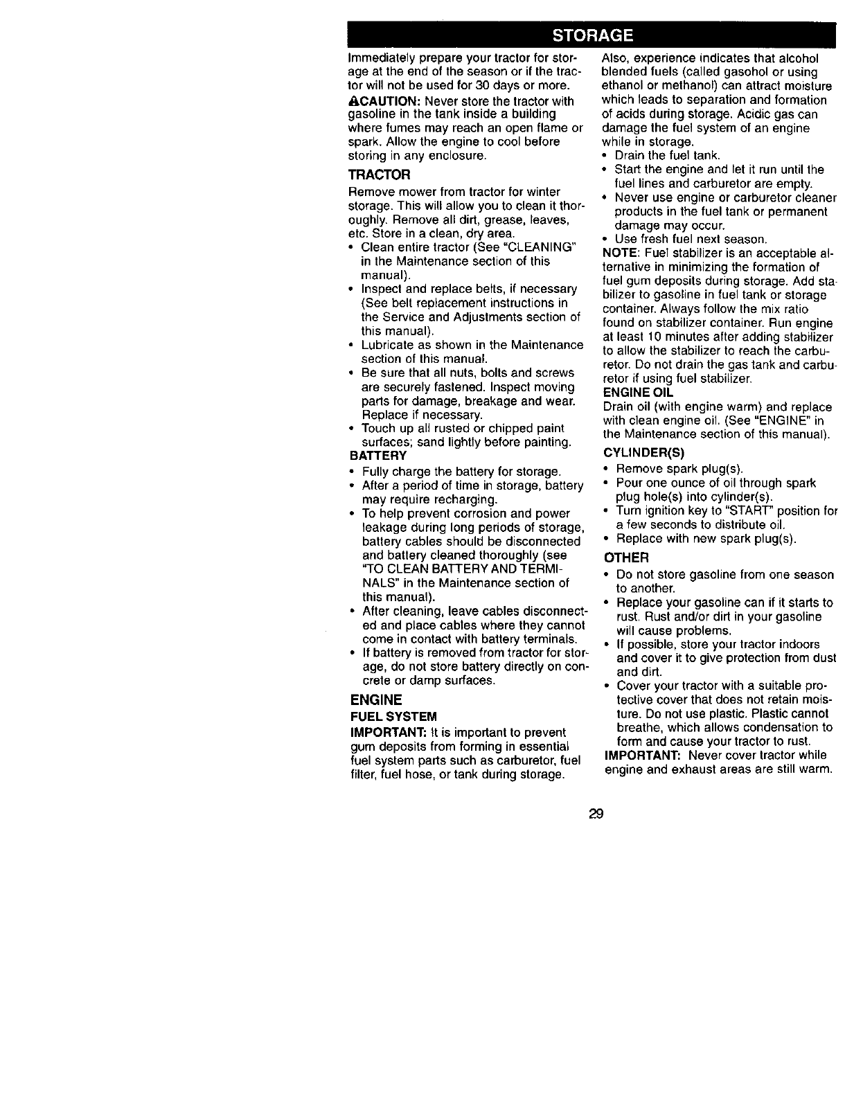
Immediately prepare your tractor for stor-
age at the end of the season or if the trac-
tor will not be used for 30 days or more.
_CAUTION: Never store the tractor with
gasoline in the tank inside a building
where fumes may reach an open flame or
spark. Allow the engine to cool before
storing in any enclosure.
TRACTOR
Remove mower from tractor for winter
storage. This will allow you to clean it thor-
oughly. Remove all dirt, grease, leaves,
etc. Store in a clean, dry area.
• Clean entire tractor (See "CLEANING"
in the Maintenance section of this
manual).
• Inspect and replace belts, if necessary
(See belt replacement instructions in
the Service and Adjustments section of
this manual).
• Lubricate as shown in the Maintenance
section of this manual.
• Be sure that all nuts, bolts and screws
are securely fastened. Inspect moving
parts for damage, breakage and wear.
Replace if necessary.
• Touch up all rusted or chipped paint
surfaces; sand lightly before painting.
BATTERY
• Fully charge the battery for storage.
• After a period of time in storage, battery
may require recharging.
• To help prevent corrosion and power
leakage during long periods of storage,
battery cables should be disconnected
and battery cleaned thoroughly (see
"TO CLEAN BATTERY AND TERMI-
NALS" in the Maintenance section of
this manual).
•After cleaning, leave cables disconnect-
ed and place cables where they cannot
come in contact with battery terminals.
• If battery is removed from tractor for stor-
age, do not store battery directly on con-
crete or damp surfaces.
ENGINE
FUEL SYSTEM
IMPORTANT: It is important to prevent
gum deposits from forming in essential
fuel system parts such as carburetor, fuel
filter, fuel hose, or tank during storage.
Also, experience indicates that alcohol
blended fuels (called gasohol or using
ethanol or methanol) can attract moisture
which leads to separation and formation
of acids during storage. Acidic gas can
damage the fuel system of an engine
while in storage.
• Drain the fuel tank.
• Start the engine and let it run until the
fuel lines and carburetor are empty.
• Never use engine or carburetor cleaner
products in the fuel tank or permanent
damage may occur.
• Use fresh fuel next season.
NOTE: Fuel stabilizer is an acceptable al-
ternative in minimizing the formation of
fuel gum deposits during storage. Add sta-
bilizer to gasoline in fuel tank or storage
container. Always follow the mix ratio
found on stabilizer container. Run engine
at least 10 minutes after adding stabilizer
to allow the stabilizer to reach the carbu-
retor. Do not drain the gas tank and carbu-
retor if using fuel stabilizer.
ENGINE OIL
Drain oil (with engine warm) and replace
with clean engine oil. (See "ENGINE" in
the Maintenance section of this manual).
CYLINDER(S)
• Remove spark plug(s).
• Pour one ounce of oil through spark
plug hole(s) into cylinder(s).
• Turn ignition key to "START" position for
a few seconds to distribute oil.
• Replace with new spark plug(s).
OTHER
• Do not store gasoline from one season
to another.
• Replace your gasoline can if it starts to
rust. Rust and/or dirt in your gasoline
will cause problems,
• If possible, store your tractor indoors
and cover it to give protection from dust
and dirt.
• Cover your tractor with a suitable pro-
tective cover that does not retain mois-
ture. Do not use plastic. Plastic cannot
breathe, which allows condensation to
form and cause your tractor to rust.
IMPORTANT: Never cover tractor while
engine and exhaust areas are still warm.
29
TROUBLESHOOTING CHART
=ROBLEM CAUSE CORRECTION
Will not start •Outof fuel.
Hard to start
Engine will not
turn over
Engine clicks but
Nill not start
Loss of power
•Engine not "CHOKED"
properly.
•Engine flooded.
• Bad spark plug.
• Dirty air filter.
• Dirty fuel filter.
• Water in fuel.
• Loose or damaged wiring.
• Carburetor out of adjustment.
• Engine valves out of
adjustment.
•Dirty air filter.
• Bad spark plug.
• Weak or dead battery,
• Dirty fuel filter.
• Stale or dirty fuel.
• Loose or damaged wiring.
• Carburetor out of adjustment.
• Engine valves out of
adjustment,
• Clutch/brake pedal not
depressed.
• Attachment clutch is engaged.
• Weak or dead battery.
•Blown fuse.
• Corroded battery terminals,
• Loose or damaged wiring.
• Faulty ignition switch.
• Faulty solenoid or starter.
• Faulty operator presence
switch(es).
• Weak or dead battery.
• Corroded battery terminals.
• Loose or damaged wiring.
• Faulty solenoid or starter.
• Cutting too much grass/too
fast.
• Throttle in "CHOKE" position.
• Build-up of grass, leaves
and trash under mower.
• Dirty air filter,
• Low oil level/dirty oil.
• Fill fuel tank.
• See "TO START ENGINE"
in Operation section.
• Wait several minutes before
attempting to start.
• Replace spark plug.
• Clean/replace air filter.
•Replace fuel filter.
• Drain fuel tank and carburetor,
refill tank with fresh gasoline
and replace fuel filter.
• Check all wiring.
• See "To Adjust Carburetor"
in Service Adjustments
section.
• Contact an authorized service
center/department.
• Clean/replace air filter,
• Replace spark plug,
• Recharge or replace battery.
• Replace fuel filter.
• Drain fuel tank and refill with
fresh gasoline.
• Check all wiring.
• See "To Adjust Carburetor"
in Service Adjustments section.
• Contact an authorized service
center/department.
• Depress clutch/brake pedal,
• Disengage attachment clutch.
• Recharge or replace battery.
• Replace fuse.
• Clean battery terminals.
• Check all wiring.
• Check/replace ignition switch.
• Check/replace solenoid or
starter.
• Contact an authorized service
center/department.
• Recharge or replace battery.
• Clean battery terminals.
• Check all wiring.
• Check/replace solenoid or
starter.
• Set in "Higher Cut" position/
reduce speed.
• Adjust throttle control.
• Clean underside of mower
housing,
• Clean/replace air filter.
• Check oil level/change oil
30

TROUBLESHOOTING CHART
PROBLEM CAUSE CORRECTION
Loss of power
Continued • Faulty spark plug.
• Didy fuel filter.
• Stale or dirty fuel.
• Water in fuel.
Excessive
vibration
• Spark plug wire loose.
• Dirty engine air screen/fins.
• Dirty/clogged muffler.
• Loose or damaged wiring.
• Carburetor out of adjustment.
• Engine valves out of
adjustment.
• Worn, bent or loose blade.
• Bent blade mandrel.
• Loose/damaged part(s).
Enginecontinues
lorun when
operator leaves
seatwith attach-
ment clutch
engaged
•Faultyoperator-safety
presence control system,
Poor cut - uneven • Worn, bent or loose blade,
• Mower deck not level.
• Buildup of grass, leaves, and
trash under mower.
• Bent blade mandrel.
• Clogged mower deck vent
holes from buildup of grass,
leaves, and trash around
mandrels.
Mower blades will
not rotate • Obstruction in clutch
mechanism.
• Worn/damaged mower drive
belt.
• Frozen idler pulley.
• Frozen blade mandrel.
Poor grass
discharge • Engine speed too slow.
•Travel speed too fast.
• Wet grass,
• Mower deck not level.
• Low/uneven tire air
pressure. 31
• Clean and regap or change
spark plug.
• Replace fuel filter.
•Drain fuel tank and refill with
fresh gasoline.
• Drain fuel tank and carburetor,
refill tank with fresh gasoline
and replace fuel filter.
• Connect and tighten spark
plug wire.
• Clean engine air screen/fins.
• Clean/replace muffler.
• Check all wiring.
• See "To Adjust Carburetor"
in Service Adjustments section
• Contact an authorized
service center/department.
• Replace blade. Tighten blade
bolt.
•Replace blade mandrel.
• Tighten loose part(s).
Replace damaged pads.
• Check wiring, switches and
connections. If not corrected,
contact an authorized service
center/department.
• Replace blade. Tighten blade
bolt.
• Level mower deck.
• Clean underside of mower
housing.
• Replace blade mandrel.
• Clean around mandrels to
open vent holes.
• Remove obstruction.
• Replace mower drive belt.
• Replace idler pulley.
• Replace blade mandrel.
•Place throttle control in "FAST"
position.
• Shift to slower speed.
• Allow grass to dry before
mowing.
•Level mower deck.
• Check tires for proper air
pressure.

_ROBLEM
Poor grass
:lischarge (Contn)
TROUBLESHOOTING CHART
CAUSE CORRECTION
• Worn, bent or loose blade.
_leadlight(s) not
Norking (if so
.,quipped)
3attery will not
;harge
Loss of Drive
• Buildup of grass, leaves, and
trash under mower.
• Mower drive belt worn.
•Blades improperly installed.
• Improper blades used.
•Clogged mower deck vent
holes from buildup of grass,
leaves, and trash around
mandrels.
• Switch is "OFF".
• Bulb(s) burned out.
• Faulty light switch.
• Loose or damaged wiring.
• Blown fuse.
• Bad battery cell(s).
• Poor cable connections.
• Faulty regulator (if so
equipped).
• Faulty alternator.
•Freewheel control in
"disengaged" position.
• Motion drive belt worn,
damaged or broken.
• Air trapped in transmission
during shipment or servicing.
Replace/sharpen blade.
Tighten blade bolt,
Clean underside of mower
housing,
Replace mower drive belt.
Reinstall blades sharp edge
down.
Replace with blades listed
in this manual.
Clean around mandrels to
open vent holes.
,Turn switch "ON".
Replace bulb(s).
I, Check/replace light switch.
• Check wiring and connections.
• Replace fuse.
• Replace battery.
• Check/clean all connections.
• Replace regulator.
• Replace alternator.
•Place freewheel control in
"engaged" position.
• Replace motion drive belt.
• Purge transmission.
Engine "backfires" •Engine throttle control at •Move throttle control to not set
when turning "SLOW" position for 30 "SLOW" position and allow to
engine "OFF" seconds before stopping idle for 30 seconds before
engine, stopping engine.
32

TRACTOR --MODEL NUMBER 917,272220
SCHEMATIC
BATTERY
SOLENOID
'
_u_W" ' "_11"_'_', _"
AMMETER .... m p STARTER
(OPTIONAL) ;"_-' _ ,_ ....
WHITE i , _,_ITE ...... . 'q_
°o i0, (>t_ ,o G, J _ -"'--:'
Ii _ r i
'i'ELECTRIC CLUTCH
3. I _,-UT_H,,_,_,-_l0 . .
SW,TCH :A i E :.........
i i i
,, 85 86
/7 _(NOT OCCUPIED) _ D 'i,,
_ _ ••i87 i30
o ,°.... I I
/ __ __ 'PRESENCE
mFUEL m (OPTIONAL)
mLINE : m,
,_e_AGK PLUGS GAP A--
L_ i _ __ ,
FUEL SHUT-OFF SOLENOID CHARGmN_SYSTm OUTPUT =eVOLTSAC i _00.tM
%(_5 *_rJPDei3600_eM (nEOUL*_TOAOIS¢O_N_C_
R_O REGULATOR___
:2_L
/_4_OWN
WIRING INSULATED CUPS "_F _ T 'J
NOTE: IF WIRING INSULATED
CLIPS WERE REMOVED FOR
SERVICING OF UNIT, THEY HEADLIGHTS
SHOULD BE REPLACED TO
-_'_ -_] PROPERLY SECURE YOUR WIRING, G F C
IGNITION SWITCH PTO SWITCH
POSII'_ON CIRCUIT HB
OFF C÷G,B÷H
_C+F B+E,_ RELAY DA
NON-REMOVASLE REMOVABLE
CONNECTIONS CONNECTIONS
33

TRACTOR--MODELNUMBER917.272220
ELECTRICAL
i
i
i
8O
i
b
4O
26
i
i I
/
34

TRACTOR --MODEL NUMBER 917.272220
ELECTRICAL
KEY PART
NO. NO. DESCRIPTION
1 163465 Battery
2 74760412 Bolt, Hex 1/4-20 x 3/4
8 7603J Tray, Battery
10 145211 Bolt, Blr Front 1/4-20 x 7-1/2
11 150109 Holddown Battery Front Mount
12 145769 Nut, Push Nylon Battery Front 1/4
16 153664 Switch Interlock Push-In
16 17720406 Bolt BIk Fin Hex 1/4-20 UNC x 1/2
21 166184 Harness, Light
22 4152J Light Bulb
24 8860R Cable, Battery
25 146148 Cable, Battery
26 166180 Fuse
27 73510400 Nut Keps Hex 1/4-20 UNC
26 145491 Cable, Ground
29 160784 Switch, Seat
30 163968 Switch, Ignition
33 140463 Key, Molded, Craftsman
40 170233 Harness, Ignition
42 131563 Cover, Terminal
43 145673 Solenoid
45 122822X Ammeter Rectangular 15 Amp
50 169416 Switch Pro 3Pdt Red Delta
55 17490508 Screw Thdrol 5/16-18x 1/2
79 163996 Socket, Light Bulb
80 146685 Harness Clutch EVX
81 109748X RelayAsm
NOTE: All component dimensions given in U.S. inches
1 inch =25.4 mm
35

TRACTOR -- MODEL NUMBER 917.272220
CHASSIS AND ENCLOSURES
209 \\
"_7155
11
2O9
/
/
I
_"166
2_
/
13
36

TRACTOR-- MODEL NUMBER 917.272220
CHASSIS AND ENCLOSURES
KEY PART
NO. NO. DESCRIPTION
1 169830 Chassis
2 169061 Drav,bar
3 17060612 Screw, 3/8-16 x 3/4
9 161566X614 Dash
10 STD533710 Bolt, Carriage 3/8-16 x 1
11 167203 Panel, Dash, LH
13 167202 Panel, Dash, RH
17 161023X612 Hood Assembly
20 162026 Plate Battery STYT
25 19131312 Washer 13/32 x 13/16 x12 Gauge
26 STD541437 Locknut, Hex, with Insert 3/8-16 UNC
28 160564X612 Gnlle
29 174886 Lens, Grille
30 164919X612 Fender/Footrest
31 139976 Bracket, Fender/Support
37 17490508 Screw, Thdrel. 5/16-18 x 1/2 T_'T
38 169834 Bracket Asm Pivot Mower Rear
54 161464 Screw Hex Wshd 8-18 x 7/8
58 161236 DuctHood
59 110436X Bushing, Snap, Split
60 STD533707 Bolt Rdhd Sqnk 3/8-16 UNC x 3/4
64 162025 Dash Lower STYT
74 STD541437 Nut Crownlock3/8-16 UNC
142 165867 Plate Reinforcement STLT
143 154966 Bracket Swaybar Chassis
144 154207 Bracket Footrest STLT
145 156524 Rod Pivot Chassis!Hood
154 161897 Brackel Dash Rh
155 161900 Bracket Dash Lh
156 163805 Striker Plate
157 163806 Magnet YTGT
158 162037 Parking Brake Bkrt
159 155123X614 Cupholder Stl
160 162967 Fastner Nutpal
161 164655 Pinch-Welt Hood
166 164863 HWHDH:-Lo. #13-16x3/4
206 170165 Bolt Shoulder 5/16-18
209 17000612 Screw Hexwsh Thdr 3/8-16 x 3/4
- - 174818 Plug, Button
NOTE: All component dimensions given in U,S. inches
1 inch = 25.4 mm
37

TRACTOR - - MODEL NUMBER 917.272220
GROUND DRIVE
52
32
16
23
38

TRACTOR- - MODEL NUMBER 917.272220
GROUND DRIVE
j:
KEY PART KEY PART
NO. NO. DESCRIPTION NO. NO. DESCRIPTION
1 ...... Transaxle (See Breakdown) 59 169691 Keeper, Center Span
Hydro gear Model314-0510 61 17060612 Screw 3/8-16 x 3/4
8 165866 Rod Shift Fender Adjust Lt 62 8883R Cover, Pedal
9 145028 Clutch Elec Evx 63 145868 Pulley, Clutch
10 76620416 Pin Cotter 1/8 x 1 CAD 65 10040700 Washer
14 10040460 Washer Lock Hvy Helical 66 154778 Keeper Belt Engine
15 74490544 Bolt Hex Flghd 5/16-18 Gr. 5 71 169183 Strap Torque Lh
16 739(_500 Nut Lock Hex W/Ins. 5/16-18 73 169182 StrapTorque Rh
Ur_ 74 137957 Spacer, Axle
19 73800600 Nut Lock Hex W/Wsh 3/8-16 75 121749X Washer 25/32 x 1-1/4 x16 Ga
Unc 76 12000(301 E-Ring
20 150280 Bolt Hex 7/16-20 x4-1/4 5 Ga. 77 123583X Key, Square
21 174779 Knob, Deluxe 1/2-13 79 121748X Washer 25/32 x 1-5/8 x 16 Ga
22 169496 Rod, Brake Hydro 81 165596 Shaft Asm. Cross Tapered
23 171258 Bracket Asm Clutch Mtg 82 165711 Spring Torsion T/A
24 73350600 Nut, HexJam 3/8-16Unc 83 19171216 Washer 17/32x3/4x16Ga.
25 106888X Spring, Brake Rod 84 169594 Link Transaxle
26 19131316 Washer 89 164890X614 Console, Shift
27 76020412 Pin Cotter 1/8 x 3/4 CAD. 90 124346X Nut Self-Thd Wsh-hd 1/4 Zinc
28 145204 Rod, Parking Brake 95 170201 Control Bypass
29 71673 Cap, Parking Brake 96 4497H Retainer Spring 1" Zinc/Cad
30 169592 Bracket, Transaxle 144 19111016 Washer 11/32 x 5/8 x 16 Ga.
32 74760512 BoltHexHd 5/16-18Uncx3!4 150 165850 BushingBellcrankGrdDdve
33 72140506 Bolt Rdhd Sqnk 151 19133210 Washer 13/32 x 2 x 10 Ga.
5/16-18 Unc x 3/4 156 166002 Washer Srded 5/161D x 1.125
34 155071 Shaft, Foot Pedal 158 165589 Bracket Shift Mount
35 120163X Bearing, Nylon 159 165494 Hub Tapered Flange Shift LI
36 19211616 Washer 161 72140406 Bolt Rdhd Sqnk 1/4-29 x 3/4
37 1572H Pin, Roll Gr 5
38 131494 Pulley, Idler, Flat 162 73680400 Nut Crownlock 1/4-20 Unc
39 74760644 Bolt 163 74780416 Bolt Hex Fin
40 4479J Spacer, Split 1/4-29 Unc x 1 Gr 5
41 165838 Keeper, Belt Idler 164 19091910 Washer 5/8 x .281 x 10 Ga.
42 19131312 Washer 13/32 x 13/16 x 12 165 165623 Bracket Pivot Lever
Gauge 166 166880 Screw 5/16-18 x .561
47 127783 Pulley, Idler, V-G roove 168 165492 Bolt Shoulder 5/16-18 x .561
48 154407 Bellcrank Clutch Grnd Drw Stl 169 165580 Plate Fastening Lt
49 123205X Retainer, Belt 197 169613 Nyliner Snap-In 5/8" ID
50 74760624 Bolt 198 169593 Washer Nyt 7/8 ID x .105"
51 73680600 Nut Crownlock 3/8-16 UNC 199 169612 Bolt Shoulder 5/16-18 Uric
52 73680500 Nut, Crownlock 5/16-16 Unc 200 72140508 Bolt Rdhd Sqnk 5/16-18 Unc x
53 105710X Link, Clutch 202 72110612 Boll Carr Sh 3/8-16 x 1-1/2 Gr.
55 105709X Spring, Return, Clutch
56 74760620 Bolt Hex 3/8-16 x 1-1/4 NOTE: All component dimensions given in U.S. inches
57 149294 V-Belt, Ground Dnve 1 inch = 25.4 mm
39

I H/._ ! UH - -MUUI::L NUMBER 917.272220
STEERING ASSEMBLY
62
/
41
_42
i
lo
40

TRACTOR - - MODEL NUMBER 917.272220
STEERING ASSEMBLY
KEY PART
NO. NO. DESCRIPTION
1 159944X614 Steering Wheel
2 154427 Axle Assembly STMP Dropped STL
3 169840 Spindle Assembly, LH.
4 169839 Spindle Assembly, R,H.
5 6266H Bearing, Race, Thrust, Hardened
6 121748X Washer 25/32 x 1-5/8 x 16 Gauge
719272016 Washer 27/32 x1-1/4 x16 Gauge
8 12000029 Ring, Klip
9 3366R Beadng, Steering Column
10 169832 Draglink
11 STD551137 Washer, Lock
12 73940800 Nut Hex Jam Toplock 1/2-20 Unf
13 136518 Spacer Brg Axle Front
15 145212 Nut Hexflange Lock
17 156543 Shaft Assembly, Steedng
18 57079 Washer, Thrust 515 x 750 x .033
19 160395 Support, Shaft
22 165857 Screw Hex Wshhd Torx
23 165851 Pittman Shaft Assembly
25 154406 Bracket, Steering
27 136874 Gear, Sector
29 17960612 Screw, 3/8-16 x 3/4
32 171888 Rod, Tie
33 19111216 Washer 11/32 x 3/4 x 16 Ga/
34 STD551131 Washer Lock Hvy Spr, 5/16
35 73810500 Locknut 5/16-24 Unf
36 155105 Bushing, Steering
37 152927 Screw
38 159946X614 Insert, Steering Wheel
40 STD541537 Gripco Nut
41 159945 Adaptor, Steering Wheel
42 163888X614 Boot, Steering Shaft
43 121749X Washer 25/32 x 1-1/4 x 16 Gauge
46 121232X Cap, Spindle
47 6855M Fitting, Grease
62 167905 it Steering Asm Service
65 160367 Spacer Brace Axle
66 154404 Beadng Arm Pittman
67 72140618 Bolt Rdhd Sd 3/8-16 UNC x 2-1/4
68 169827 Axle, Brace
72 19182411 Washer 9/16 Id x 1-1/2Od 11 GZin
73 160135X614 Steering Sleeve Extension
79 19132012 Washer 13/32 x 1-1/4 x 12 Ga
80 74950612 Bolt Hex Nylon 3/8-16 x 3/4
82 169835 Bracket Susp Chassis Front
85 133835 Fastner Christmas Tree
NOTE: All component dimensions given in U.S. inches
1inch = 25.4 mm
41
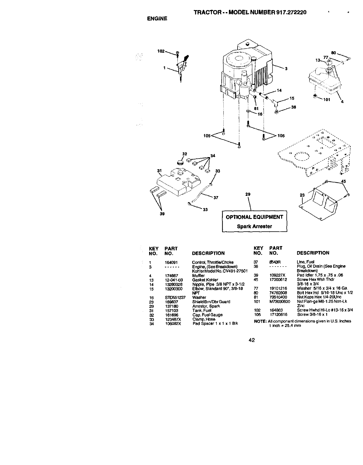
TRACTOR - - MODEL NUMBER 917.272220
ENGINE
31
29
39 OPTIONAL EQUIPMENT
Spark Arrester
i
4
KEY
NO.
4
13
14
15
16
23
29
31
32
33
34
PART KEY PART
NO. DESCRIPTION NO. NO. DESCRIPTION
164091 Control, Th roffle/Clloke 3? 8543FI Line, Fuel
...... Engine, (See Breakdown) 38 ....... Plug, Oil Drain (See Engine
Kohfflr Model No. CV491-27501 Breakdown)
174667 Muffler 39 109227X Pad Idler 1,75 x .75 x .06
12-041-o3 Gasket Kohler 45 17000612 Screw Hex Wsh Thdr
13280323 Nipple, Pipe 5/8 NPT x 3-1/2 3/8-16 x 3/4
13200300 ElbOw, Standard 90°, 3/8-18 77 19101216 Washer 5/16 x 5/4 x 16 Ga.
NPT 80 74760508 Bolt Hex Hd 5/16-18 Uric x 1/2
$1Dr-_1237 Washer 81 73510400 Nut Keps Hex 1/4-20Unc
169837 Shield Brn/Dbr Guard 101 M_ Nut Flan-ge M6-1.25 Non-Lk
137180 Arrestor, Spark Zinc
15710_ Tank, Fuel 102 164863 Screw Hwhd Hi-Lo #t 3-16 x 3/4
161696 Cap, FuelGauge 105 17120616 Screw 3/6-16 x 1
123487X Clamp,t-_se
106082X Pad Spacer 1 x I x 1 BIk NOTE: All component dimensions given in U.S. inches
1 inch = 25.4 mm
42
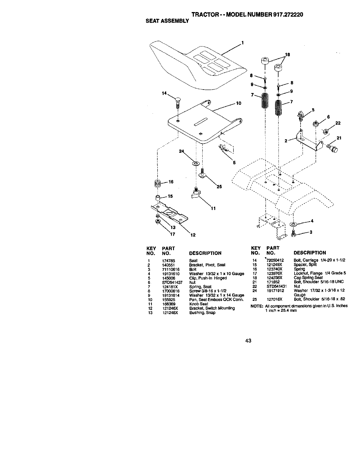
TRACTOR- -MODELNUMBER917.272220
SEATASSEMBLY
5
21
KEY PART KEY PART
NO. NO. DESCRIPTION NO. NO. DESCRIPTION
1 174785 Seat 14 "72050412 Bolt, Carriage 114-20 x1-1/2
2 140551 Bracket, P;voL Seat 15 121249X Spacer, Split
3 71110616 Bolt 16 123740X Spdug
4 19131610 Washer 13/32 x 1 x 10 Gauge 17 123976X Loci(nut, Flange 114 Grade 5
5 145006 Clip, Push-In Hinged 18 124238X Cap Spring Seat
6 STD541437 Nut 21 171852 Bolt, Shoulder 5/16-18 UNC
7 124181X Spdng, Seat 22 STD541431 Nut
8 17000616 Screw 3/6-16 x 1o1/2 24 19171912 Washer 17132 x 1-3/16 x 12
9 19131614 Washer 13/32 x 1 x 14 Gauge Gauge
10 155925 Pan, Seat Emboss QCK Corm+ 25 127018X Bolt, Shoulder 5/16-18 x .62
11 166369 KnOb Seat
12 121246X Bracket, Switch Mounting NOTE: All component dimensions given in U,S. inches
13 121248X Bushing, Snap 1 inch = 25.4 mm
43
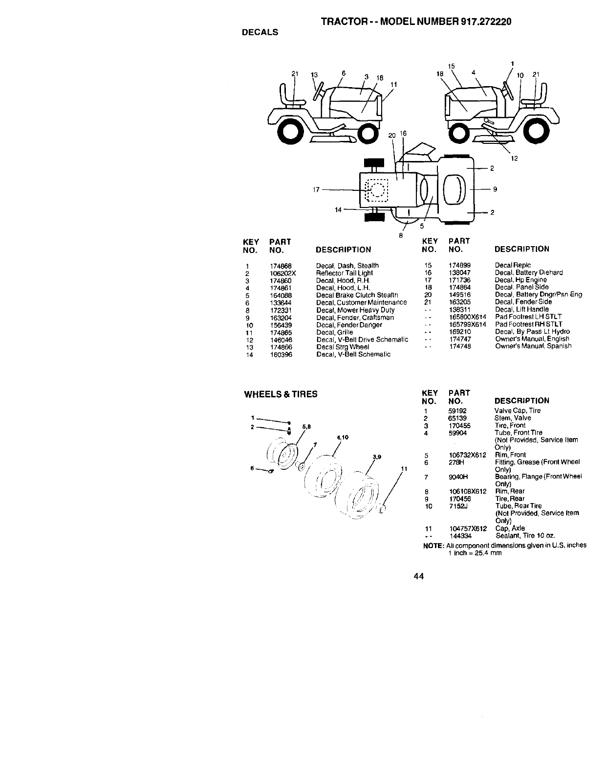
TRACTOR- - MODEL NUMBER 917.272220
DECALS
21
15 1
13 6 18 18 4 21
11
16
12
KEY
NO.
1
2
3
4
5
6
8
9
10
11
12
13
14
PART
NO.
174868
106202X
174860
174961
164088
133644
172331
163204
156439
174865
146046
174866
160396
KEY PART
DESCRIPTION NO. NO. DESCRIPTION
Decal, Dash, Stealth 15 174899 DecalReplc
Reflector Tail Light t6 138047 Decal, Battery Diehard
Decal, Hood, R,H t7 171736 Decal, Hp Engine
Decal, Hood, L.H. 18 174864 Decal, Panel Side
Decal Brake Clutch Stealth 20 149516 Decal, Battery DngdPsn Eng
Decal, Customer Maintenance 21 163205 Decal, Fender Side
Decal, Mower Heavy Duty - - 138311 Decal, Lift Handle
Decal, Fender, Craftsman - - 165800)(614 Pad Footrest LH STLT
DecaI, FenderDanger - - 165799X614 PadFootrestRHSTLT
Decal, Grille -*169210 Decal, By Pass Lt Hydro
Decal, V-Belt Drive Schematic - - 174747 Owner's Manual, English
Decal Strg Wheel - - 174748 Owner's Manua!, Spanish
Decal, V-Belt Schematic
KEY PART
NO. NO. DESCRIPTION
1 59192 Valve Cap, Tire
265139 Stem, Valve
3 170455 Tire, Front
4 59904 Tube, Front Tire
(Not Provided, Service Item
Only)
5 106732X612 Rim, Front
6 278H Fitting, Grease (Front Wheel
11 Only)
7 9040H Bea ring, Flange (Front Wheel
On_y)
9 106108X612 Rim, Rear
9 170456 Tire, Rear
10 7152J Tube, RearTire
(Not Provided, Service Item
Only)
11 104757X612 Cap, Axle
- - 144334 Sealant, Tire 10 oz.
NOTE: All component dimensions given in U.S, inches
1 inch = 25,4 mm
44
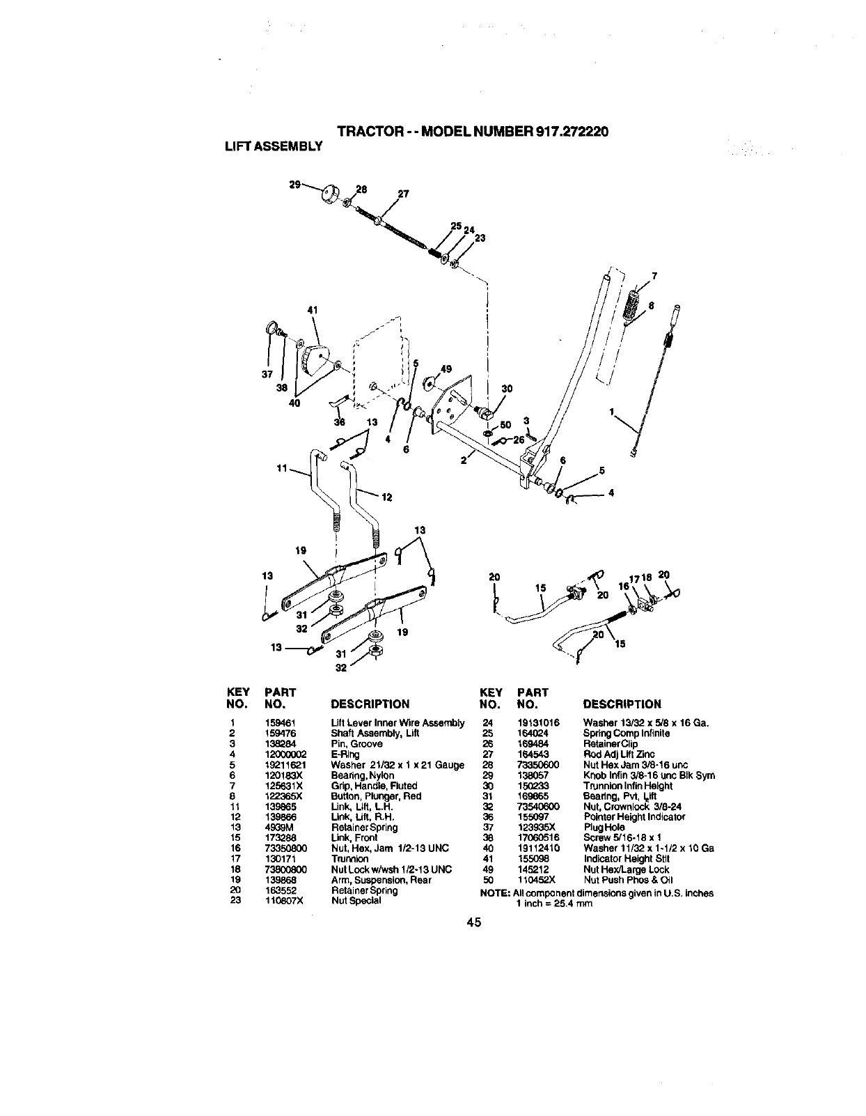
TRACTOR - - MODEL NUMBER 917.272220
LIFT ASSEMBLY
27
41
49
37
38
4O
/j
g0
KEY PART KEY PART
NO, NO, DESCRIPTION NO. NO. DESCRIPTION
1
2
3
4
5
6
7
8
11
12
13
15
16
17
18
19
2O
23
159461 Lift Lever Inner Wire Assembly 24 19131016 Washer 13/32 x 5/8 x 16 Ga.
159476 Shaft Assembly, Lift 25 164024 Spring Comp Infinite
138284 Pin, Groove 26 169484 Retainer Clip
12000002 E-PJng 27 164543 Rod Adj Lift Zinc
19211621 Washer 21132 x 1 x 21 Gauge 28 73350600 Nut Hex Jam 3/8-16 unc
12Of83X Bearing, Nylon 29 138057 Knob Infin 3/8-16 unc BIk Sym
125631X Grip_ Handle, Fluted 30 15(_33 Tr'Jnnion Infin Height
122365X Button, plunger, Red 31 169665 Bearing, Pvt, leift
139e65 Link, Lift, LH 3_ 73540600 Nut, Crownlock 3/8-24
139866 Link, Utt, R.H. 36 155097 Pointer Height Indicator
4939M Retainer Spring 37 123935X Rug Hole
173288 Link, Front 38 1706o0516 Screw 5/16-18 x 1
73350800 Nut, Hex, Jam 1/2-13 UNC 40 19112410 Washer 11/32 x 1-1/2 x 10 Ga
130171 Tru_llon 41 155098 Indicator Height Stir
73800800 Nut Lock wiwsh 1/2-13 UNC 49 145212 Nut Hex/Large LOck
1_Arm, Suspension, Rear 50 110452X Nut Push Phos & Oil
163552 Retainer Spring NOTE: All component dimensions given in U.S. inches
110807X Nut Special 1 inch = 25.4 mm
45
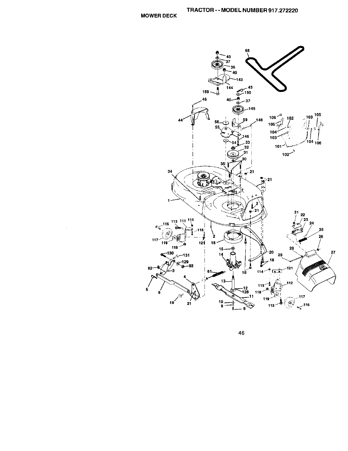
TRACTOR--MODEL NUMBER 917.272220
MOWER DECK
_144 143
34
46
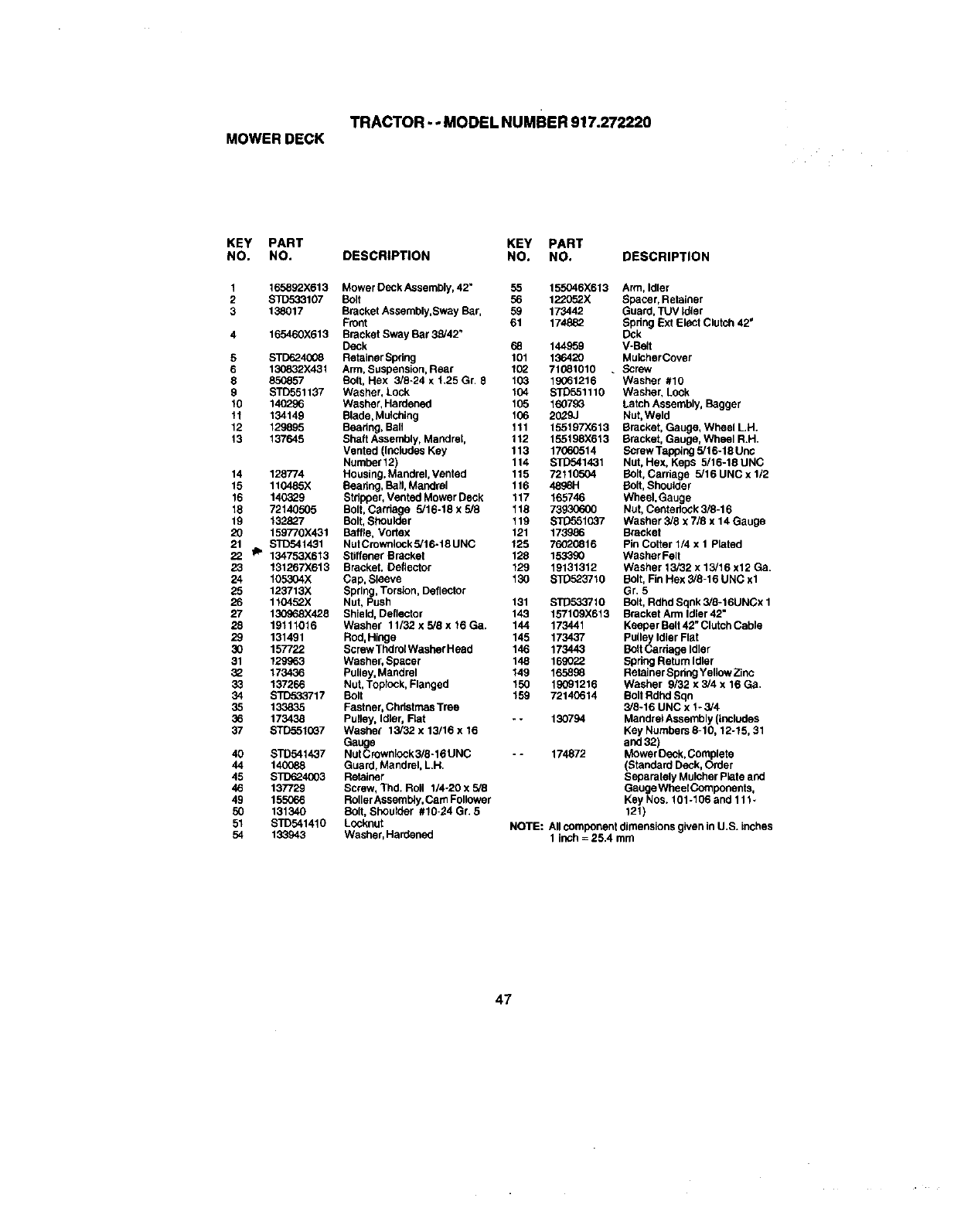
TRACTOR--MODELNUMBER917.272220
MOWERDECK
KEY PART
NO. NO.
1 165892X613
2 S]D533107
3 138017
4 165460)(613
5 STD6243O8
6 130832)(431
8 850857
9 STD551137
10 140296
11 134149
12 129895
13 137645
14 128774
15 110485X
16 140329
18 72140505
19 132827
20 159770X431
21 $1_541431
22 _134753X613
23 131267)(613
24 105304X
25 123713X
26 110452X
27 13OS68X428
28 19111016
29 131491
3O 157722
31 129963
32 173436
33 137266
34 STD533717
35 133_35
36 173438
37 STD5510G7
40 STD541437
44 140088
45 STD624G03
46 137729
49 155066
50 131340
51 STD541410
54 133943
KEY PART
DESCRIPTION NO. NO. DESCRIPTION
Mower Deck Assembly, 42" 55 155046X613 Arm, Idler
Bolt 56 122052X Spacer, Retainer
Bracket Assembly,Sway Bar, 59 173442 Guard, TUV Idldr
Front 61 174882 Spdng Bxt EleCt Clutch 42"
Bracket Sway Bar 33/42" Dck
Deck 68 144959 V-Belt
Retainer Spdng 101 136420 MulcherCover
Arm, Suspension, Rear 102 71081010 . Screw
Bolt, Hex 3/8-24 x 1,25 Gr 8 103 19061216 Washer #10
Washer, Lock 104 STD551110 Washer, Lock
Washer, Hardened 105 16079_ Latch Assembly, Bagger
Blade, Mulching 106 20,?.9J Nut, Weld
Bearing, Ball t 11 155197X619 Bracket, Gauge, Wheel LH.
Shaft Assembly, Mandret, 112 155198X613 Bracket, Gauge, Wheel R.H.
Vented (Inclndes Key 113 17060514 Bomw Tapping 5/16-18 Unc
Number 12) 114 STD541431 Nut, Hex, Keps 5/16-18 UNC
Housing, Mandrel, Vented 115 72110504 Bolt, Cardage 5/16 UNC x 1/2
Beadng, Bafl, Mandrel 116 _Bolt, Shoulder
Stflpper, Vented Mower Deck 117 165746 Wheel, Gauge
Bolt, Carduge 5/16-18 x 5/8 118 73930600 Nut, Centedcok 3/8-16
Bolt, Shoulder t 19 _1037 Washer 3/8 x 7/8 x 14 Gauge
Baffle, Vodex 121 173986 Bracket
NutCmwnlocksi16-18UNC 125 76020816 Pin Cotter 1/4 x 1 Plated
Stiffener Bracket 128 153390 Washer Felt
Bracket, Deflector 129 19131312 Washer 13/32 x 13/16 x12 Ga.
Cap, Sleeve 130 STD523710 Bolt, Fin Hex 3/8-16 UNC xl
Spring, Torsion, DefleCtOr Gr. 5
Nut, Push 131 ST0533/10 Bolt, Rdhd Sqnk 3!8-16UNCx 1
Shield, Deflector 143 1b'7109X613 Bracket Arm Idler 42"
Washer 11/32 x 5/8 x 16 Ga. 144 173441 Keeper Belt 42" Clutch Cable
Rod, Hiuge 145 173437 PuUe_ylIdler Flat
Screw Thdrol Washer Head 146 173443 BOlt Cardage idler
Washer, Spacer 148 169022 Spring Return Idler
Pulley, Mandrel 149 165896 Retainer Spdng Yellow Zinc
Nut, Topldck, Flanged 150 19091216 Washer 9/32 x 3/4 x 16 Ga.
Bolt 159 72140614 Bolt Rdhd Sqn
Fastner, Christmas Tree 3/8-16 UNC x 1- 3/4
Pulley, Idler, Rat - - 130794 Mandrel Assembly (includes
Washer 13/32 x 13/16 x 16 Key Numbers 8-10, 12-15, 31
Gauge and 32)
Nut Crownlock 3/8-16 UNC - - 174872 Mower Deck, Complete
Guard, Mandrel, LH, (Standard Deck, Order
Retainer Separately Mulcher Plate and
Screw, Thd. Roll 1/4-20 x 5/8 GaugeWheetComponents,
Roller Assemb4y, Cam Follower Key Nos. 101-106 and 111 •
Bolt, Shoulder #10-24 Gr. 5 121)
Locknut NOTE: All component dimensions given in U.S. inches
Washer, Hardened 1 inch =25.4 rnm
47

TRACTOR-- MODEL NUMBER 917.272220
HYDRO GEAR TRANSAXLE - -MODEL NUMBER 314-0510
48
122
119
120
13_
10.
56
107
88
123 9C_
!
48

TRACTOR -- MODEL NUMBER 917.272220
HYDRO GEAR TRANSAXLE - - MODEL NUMBER 314-0510
KEY PART KEY PART
NO. NO. DESCRIPTION NO. NO. DESCRIPTION
1
2
3
4
5
6
7
8
9
10
11
12
13
14
16
17
18
19
23
24
27
28
29
3O
31
32
33
34
35
36
37
38
39
4O
41
42
43
44
45
46
47
48
49
50
51
52
53
54
55
56
57
58
170351 Main Housing, Assembly 59 170408 Rotor, Brake
170352 Side Housing, Assembly 60 142883 Brake Puck
170353 Center Section, Assembly 61 142881 Puck Plate
170354 Swashplate, Tfunion Machined 62 142887 Brake Actuating Pin
169898 Block -Assembly 63 170410 Hfhcs 1/4-20x2 W/
170355 Sealant 10.50z Patcb,SpeclalFlange
170356 HexFlangeScrew 64 142892 Bolt, 1/4-20 X 1 W/Patch
1/4-20 X 1,25 65 170411 Spacer
170357 Stud, 5/16-24 Hex Double End 66 170412 Spring, Brake Arm Bias
170358 Shaft, Input 67 170413 Sq, Hd. Bolt 5/16-24-Ribbed
170359 Ring-Retaining 68 170414 Arm, Brake
170360 Spacer 69 170415 Slotted Hex Nut 5/16-24
169870 Ring- Retaining 70 170416 Cotter Pin 3/32 X 3/4
170361 Seal, Lip .67 X1.58 X ,276 71 170417 Com_ressionSpdngBrake
169869 Ball Brg 17mm Id X 40mm Od Anti-Drag
X12mm 72 170418 Washer, Ht
170362 HexFlangeHeadScmw ,5 I,D. X 10.D. X ,032
5/16-24)(0.75 73 142884 Flat - Washer 11/32 I.D. X 7/8
170363 Lip Seal 19 X 32 X 7 O.D
170364 Ann,Control 74 170419 Oil Seal .625 X 1.0 X .25
150771 Bearing, 30x52x13 Thrust 75 170420 Check Plug Assembly, .027,
17(Y365 Check Plug Assembly, Washer Washer
170366 Shaft, Motor 76 170421 Stud, 5/16-24 Friction Pack
170367 Gear - Pinion, 13t 77 170422 Puck, .330 X 1.50 X ,0975
170368 10t/48t Gear 78 142S69 Spdng, Halinal Comp
170369 Gear, 10t Jankshaft 79 142980 Spacer
170370 60t Bull Gear 80 150778 Hex Lock Nut
170371 Slaeve Beadug 3i16-24Unjf(Nylon Insert)
_' .75 X 1.575 X .625 61 170423 Wedge, Fdction Pack
170389 SleeveBearing(Outpoard ) 83 170424 Clip, Washar .316x1.50x.1046
.75xl ,750x,625 (Plated)
142991 Washer, 83 161183 Pin, Standard Headless
3/4 Id X 1-1/20d X .13 Thk 84 170425 Fitting, 5/16 Sae 5/32 Tube
170390 Lip Seal Axle Sea_ 85 170426 Hose, Expansion Tank
170391 Shaft, Axle .75 X 11.39 (Key, 86 170427 Expansion Tank
R.H.) B7 170424 Cap- Poppet Valve
170392 Shaft, Axle .75 X 16.99 (Key, 88 170429 Bolt, Serf Tapping 10_32 X 1/2
LH.) g0 170430 Puck, Inner Wedge
150792 Miter Gear (Splined) 93 170431 Spdng Clip - Housing Thrust
183793 Miter Gear 16t (0,5 Id) 107 17043_ Deflector
150809 Shaft 108 170433 Washer,Motor Shaft
170G93 R_ng,Spiral Retaining ,71idxl.15odx.030thk
170394 Pin, Jackshaft 109 170434 Plug, Sae #6
170395 Magnet, Ring 111 170435 O-Ring .07X .301 I.C,
170396 Spring, Bypass 112 170436 Shield, Vent
150797 Hydro Mtg Screw 3/8-24 X 2.5 113 170437 Bracket, Support Expansion
Long Tank
170397 RJter 116 170438 Silicon Sponge
170398 Base, Filter 119 170439 Fan. 7 In,
170999 Actuator, Bypass 120 170440 Pulley
170400 Rod, Bypass Actuator 121 170441 Hex Lock Nut 1/2-20 (Nylon
170401 Arm, Bypass Insert)
170_83 Retaining Ring .250 External 122 170442 Washer, Ballevflte
170403 Seal, Lip .741 X .250 X .250 123 170443 Belt Keeper
Tc 124 170444 Certte rSectlort-Filt er-Bypass
170404 Flat Washer, Assembly
5/8 Id X 1.00d X .05 Thk 125 170445 Filter Assembly ,
170405 Retaining Ring 126 170446 Fan - Pulley Service Assembly
1704(;6 Beadng, Center Block t27 170447 Seal - O-Ring Kit
142977 Spl'ing - Helical Compression 128 173165 Kit, Expansion Tank
142976 Washer 900 166768 Transsxle Complete
150798 20w-500[I
170407 Brake Yoke NOTE: All component dimensions given In U,S. inches
1 inch = 25.4 rnm
49

TRACTOR-- MODELNUMBER917.272220
KOHLERENGINE-MODELNUMBERCV491,TYPENUMBER27501
CYLINDER HEAD, VALVE AND BREATHER I
10
1
/
@
/2
50
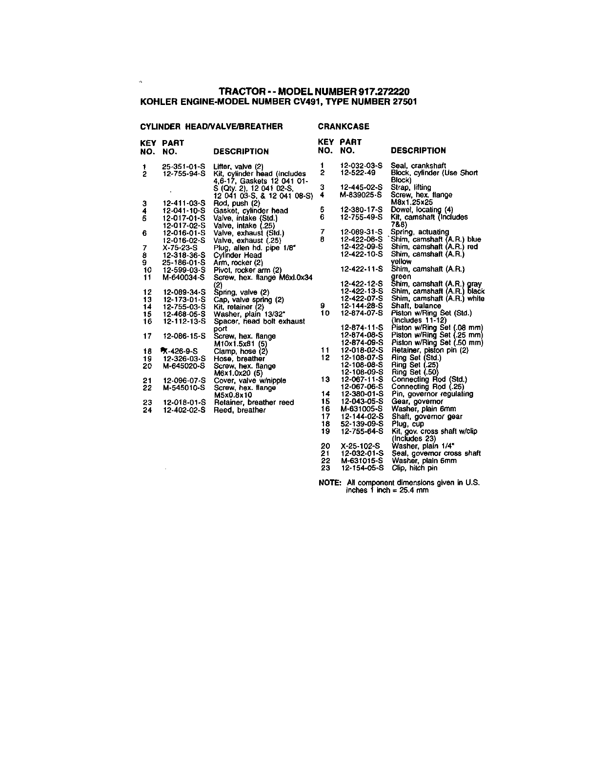
TRACTOR- -MODELNUMBER917.272220
KOHLERENGINE-MODELNUMBERCV491,TYPENUMBER27501
CYLINDER HEADNALVE/BREATHER CRANKCASE
KEY PART KEY PART
NO. NO, DESCRIPTION NO. NO. DESCRIPTION
1 25o351-01-S Lifter, valve (2) 1 12-032-03-S Seal, crankshaft
2 12-755-94-S Kit, cylindernead (includes 2 12-522-49 Block, cylinder (Use Short
4,6-17, Gaskets 12 041 01- Block)
S (Qty. 2), 12 041 02-S, 3 12-445-02-S Strap, lifting
12 041 03-S, & 12 041 08-S) 4 M-839025-S Screw, hex. flange
M8x1.25x25
3 12-411-03-S Rod, push 2) 5 12-380-17-S Dowel, locating (4)
4 12_041-10-S Gasket, cylinder head 6 f2-755-49-S Kit, camshaft (Includes
5 12-017-0f-S Valve, intake (Std.)
12-017-02-S Valve, intake (.25) 7&8
6 12-016-01-S Valve, exhaust Std. 7 12-089-31-S Spring, actuating
12-016-02-S Valve, exhaust (.25) 8 12-422-08-S "Shim, camshaft (A.R.) blue
7 X-75-23-S Ping, allen hd. pipe 1/8" 12-422-09-S Shim, camshaft (A.R.) red
8 12-318-36-S Cylinder Head 12-422-10-S Shim, camshaft (A.R,)
9 25-186-01-S Arm, rocker (2)
10 12-599-03-S 12-422.11-S SII°w
ye
him, camshaft (A,R.)
Pivot, rocker arm (2)
11 M-540034-S Screw, hax. flange M6xl.Ox34 g.reon
12 12-089-34-S _ 12-422-12-S ::,him, camshaft (A.R.) gray
bring, valve 2) 12-422-13-S Shim, camshaft (A.R.) black
12-422.07-S Shim, camshaft (A.R.) white
13 12-173-01-S Cap, valve spring (2)
14 12-755-03-S Kit, retainer (2) 9 12-144-28-S Shaft, balance
15 12-468-O5-S Washer, plain 13/32" 10 12-874-07-S piston w/Ring Set Std.)
16 12-112-13_S Spacer, head bolt exhaust (Includes 11-12)
port 12-874-11-S Piston w/Ring Set (.08 ram)
17 f2-086-15-S Screw, hex, flange 12-874-08-S piston w/Ring Set (.25 ram)
MtOxf,5x81 5) 12-874-09-S Piston w/Ring Set (.50 mm)
18 ¢X-426-9-S Clamp, hose 2) 11 12-018-02-S Retainer, piston pin (2)
19 12-326-03oS Hose, breather 12 12-108-07-S Ring Set (Std.)
20 M-645020-S Screw, hex. flange 12-108-08-S Ring Set (.25)
M6xl.0x20 (5) 12-108-09-S Ring Set (.50)
21 12-096-07-S Cover, valve w/nipple 13 12-G67-11-S Connecting Rod (Std.)
22 M-545010-S Screw, hex. flange 12-067-06-S Connecting Rod (.25
M5xO.8xl0 14 12-380°01-S Pin, governor regulating
23 12-018-01-S Retainer, breather reed 15 12-043-05-S Gear, governor
24 12o402-02-S Reed, breather 16 M-631005-S Washer, plain 6ram
17 12-144-02-S Shaft, governor gear
18 52-139-09-S Plug, cup
19 12-755-64-S Kit, gov. cross shaft w/clip
(Includes 23)
20 X-25-102-S Washer, plain 1/4"
21 12-032-01-S Seal, governor cross shaft
22 M-631015-S Washer, plain 6mm
23 12-154-05-S Clip, hitch pin
NOTE: All component dimensions given in U.S.
inches 1 inch = 25.4 mm

TRACTOR - oMODEL NUMB ER 917.272220
KOHLER ENGINE-MODEL NUMBER CV491, TYPE NUMBER 27501
IGNITIONIELECTRICAL I
--8
13 14
\ 1
_= 6"e 15
19
BLOWER HOUSING AND BAFFLESJ
AIR INTAKE
,-8
52
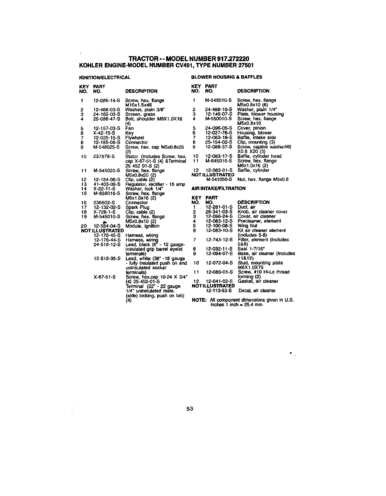
TRACTOR-- MODELNUMBER917.272220
KOHLERENGINE-MODELNUMBERCV491,TYPENUMBER27501
IGNITION/ELECTRICAL BLOWER HOUSING &BAFFLES
KEY PART KEY PART
NO. NO. DESCRIPTION NO. NO. DESCRIPTION
1 12-086-14-S Screw, hex, flange 1 M-545010-S
M10xl.5x46
2 12-468-03-S Washer, plain 3/8" 2 24-468-10-S
324-162-03-S Screen, grass 3 12-146-07-S
4 25-086-47-S Bolt, shoulder M6Xl.OX16 4 M-55G010.S
(4)
5 12-157-03-S Fan 5 24-096-05-S
6X-42-15-S Key 6 t2-027-76-S
712-025-15-S Flywheel 7 12-063-18-S
8 12-155-09-S Connector 8 25-154-02-S
9M-540025-S Screw, hex. cap MSx0.8x25 9 12-086-37-S
(2)
10 237878-S Stator (Includes Screw, hex. 10 12-063-17-S
11 M-645016-S
cap X-67-51-S (4) &Terminal
25 452 01-S (2)
11 M-545020-S Screw, hex. flange 12 12-063-01-S
M5xO.8x20 (2) NOT ILLUSTRATED
12 12-154-06-S Clip, cable (2)
13 41-403-09-S Regulator, rectifier- 15 amp
14 X-22-11-S Washer, lock 1/4" AIRINTAKE/FILTRATION
15 M-63g016-S Screw, hex. flange
M6x1,0x16 (2) KEY PART
16 236602-S Connector NO, NO.
17 12-132-02-S Spark Plug 1 12-28t-01-S
18 X-728-1-S Clip, cable (2 2 25-341-03-S
19 M-545010.S Screw, hex. flange 3 12-096-24-S
M5x0.Sxl0 !2) 4 12-083-12-S
20 12-5_4-04-S MOdule, ignition 5 12-100.08-S
NOT ILLUSTRATED 6 12-083-10-S
12-176-45-S Harness, wiring
12-176-44-S Harness, widng 7 12-743/12-S
24-515-12-S Lead, black (6" -!2 geuge-
insulated grip barrel eyelet 5 12-032-11-S
terminals) g 12-094-07-S
12-518-35-S Lead, white (36" -18 gauge
-fully insulated push on and 10 12-072-04-S
uninsulated socket
terminals) 11 12-086-01-S
X-67-51-S Screw, hex.cap 10-24 X 3/4"
(4) 25-452-01-S 12 12-041-02-S
Terminal (22" -22 gauge NOTILLUSTRATED
1/4" uninslulated male. 12-113-53-S
(side) looking, push on tab)
(4)
Screw, hex. flange
M5x0.8xl0 (6)
Washer, plain 1/4"
Plate, blower housing
Screw, hex. flange
M5x0.flxl0
Cover, pinion
Housing, blower
Baffle, intake side
Clip, mounting (3)
Screw, captive washerM5
XO.8 X20 (3)
Baffle, cylinder head
Screw, hex. flange
M6x1.0x16 (2)
Baffle, cylinder
M-541050-S Nut, hex. flange M5x0.8
DESCRIPTION
Duct, air
Knob, air cleaner cover
Cover, air cleaner
Preclaaner, element
Wing Nut
Kit air cleaner element
(Includes 5-6)
Filter, element (Includes
5&8)
Seal 1-7/16"
Base, air cleaner (Includes
11&12
Stud, mount ng p a e
MTX1.0X75
Screw, #10 Hi-Lo thread
forming (2)
Gasket, air cleaner
Decal, air cleaner
NOTE: All component dimensions given in U.S.
inches 1 inch = 25.4 mm
53
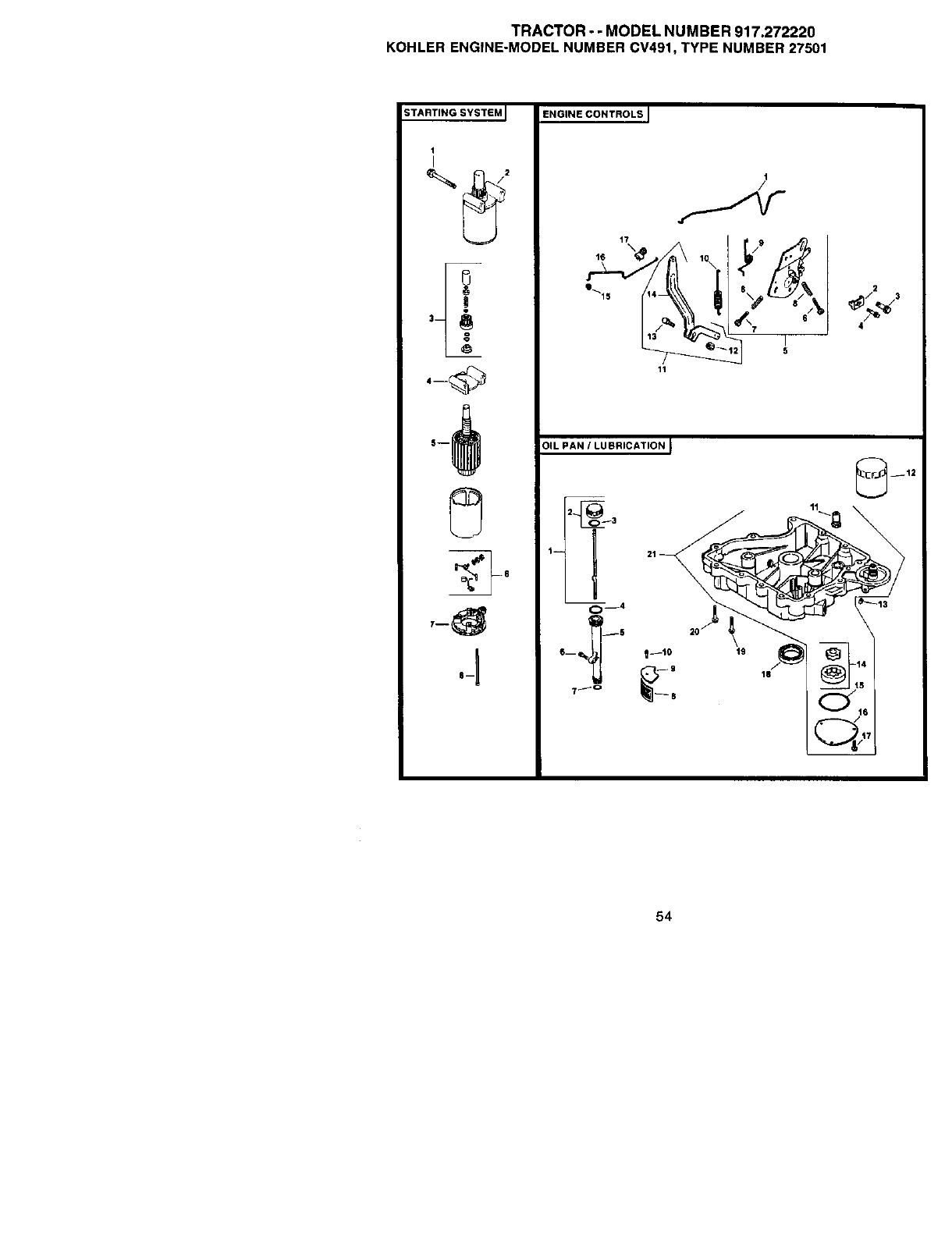
TRACTOR - - MODEL NUMBER 917.272220
KOHLER ENGINE-MODEL NUMBER CV491, TYPE NUMBER 27501
STARTING SYSTEM I
1
I
3
ENGINE CONTROLS I
I
/
2
4
31L PAN ILUBRICATION I
C=_4 2°/" I
6_ !--1o
__12
11
54

TRACTOR - -MODEL NUMBER 917.272220
KOHLER ENGINE-MODEL NUMBER CV491, TYPE NUMBER 27501
STARING SYSTEM ENGINE CONTROLS
KEY PART KEY PART
NO. NO. DESCRfP_ON NO. NO. DESCRIP_ON
M-839070-S Screw, hex. flange 1 12-079-11-S
M8x1.25x70 (2) 2 12-237-01-S
25-098-07-S Starter assembly (Includes 3 24-086_43-S
3-8)
12-755-54-S Kit, drive end 4 M-664020-S
12-227-18-S Cap, ddva end
12-170-05-S Armature 5 12-536-10-S
12-221-01-S Kit, brush & spring
12-227-13-S Cap, commutator end 6 M-443025-S
12-211-01-S Bolt, hex. flange
1/4-20x4-5/8 (2) 7 M-443020-S
3
4
5
6
7
8
OIL PAN/LUBRICATION
KEY PART
NO. NO.
112-01P38-01-S
OESCRIP'RON
Dipstick assembly (Includes
2-3)
Kit, oit fill cap (Includes 3)
O-Ring, oilfill cap
O-Ring, upper oil fill tube
Tube, oil fill
Screw, hex. flange
M6x1.0x25
O-Ring, lower oil fill tube
Screen, oil pickup
Cover, oil pickup screen
Screw, hex. flange
M5x0.8x16
Valve, oil pressure relief
Filter, oil
Ping, sq. hd. solid 3/8"
Pump, oit
O-Ring, oil pump cover
Cover, oi! pump
Screw, hex. flange
M5xO.8x16 (3)
Seal, oil (P.T.O. end)
Screw, hex. flange
MSxl.25x45 (11)
Screw, hex. flange
M8x1.25x45
Assembly, oil pan (Incl.
1t,14-17)
2 25-755-13-S
3 12-153-03-S
4 12-153-02-S
5 12-123-04-S
6 M-645025-S
712-153-01-S
8 25-162-07-S
9 12-096-03-S
10 M-545016-S
11 25-462-09-S
12 52-050-02-S
13 X-75-10-S
14 12-393-01.S
15 12-153-06-S
16 12-096-34-S
17 M-545016-S
18 12-032-03-S
19 24-086-16-S
20 24-086-17-S
21 12-199-56-S
8 12-089-11 -S
9 12-089-23-S
10 12-089-24-S
11 12-755-83-S
12 12.100-07.S
13 52-211-04-S
14 12-090-28-S
15 25-158-08-S
16 12-079-10-S
17 26-168-11-S
Linkage, choke
Clamp, cable
Screw, thread forming
M5x0.Sx16
Screw, lobed socket
M6xl.Ox20 (2)
Control, speed assembly
(Includes 6-9)
Screw, pan head
M4x0.7x25
Screw, pan head
M4x0.7x20
Spring, choke (2)
Spring, choke retum
Spring, governor
Kit, governor lever (Includes
12-14)
Nut, hex flange t/4 -20"
Bolt, 1/4 -20 X 1"
Lever, governor
Bushing, throttle linkage
Linkage, throttle
Bushing, throttle linkage
NOTE: All component dimensions given in U,S.
inches 1 inch = 25.4 mm
55
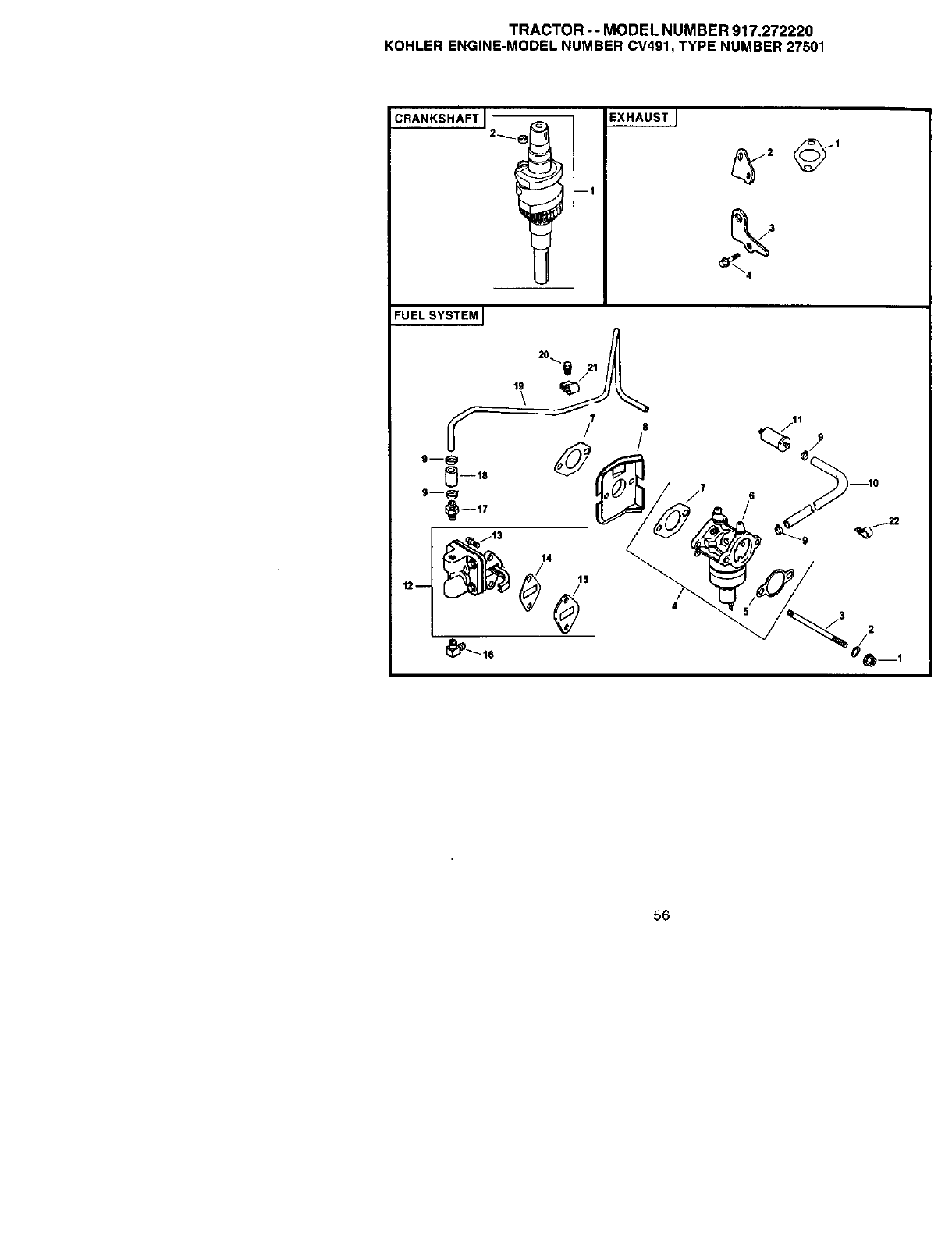
TRACTOR--MODELNUMBER917.272220
KOHLERENGINE-MODELNUMBERCV491,TYPENUMBER27501
2
/
56

TRACTOR-- MODELNUMBER917.272220
KOHLERENGINE-MODELNUMBERCV491,TYPENUMBER27501
FUEL SYSTEM CRANKSHAFT
KEY PART
NO. NO. DESCRIP_ON
1 M-641060-S Nut, hex. flange M6xl.0 (2)
2 X-22-1t-S Washer, lock t/4"
3 M-629116-S Stud MSxt,0xt16 (2)
4 12-853-95-S Kit, carburetor w/gasket
(Includes 5-7. (qty 1)
Tie, cable 12-454.03-S,
Terminal 25-452-20-S)
5 12-041-02-S Gasket, air cleaner
6 12-053-107 Carburetor assembly
(For information ocly not
available separately)
(Includes Kit, float
12-757- 02-S, Kit,
carburetor repair
12 -757- 03-S, Kit,
Solenoid repair 12-757-33-S)
7 12-041-01-S Gasket, carburetor (2)
8 12-265-05-S Deflector, heat
9 X-426-9-S Clamp, ho_e (6)
10 52-353-22-S Line, fuel
11 25-050-03-S Filter, fuel in-line
12 12-559-01-S Kit, fuel pump (Includes 13-
15)
13 /_M-645020-S Screw, hex. flange
M6xt,0x20 (2)
14 25-041-09-S Gasket, fuel pump (2)
15 12-112-05-S Spacer, fuel pump
16 25-155-02-S Connector, 90 degree hose
17 25-326-03-S Connector, straight hose
15 12-353-01-S Line, fuel 1.25
19 12-123-19-S Une, fuel
20 M-545010-S Screw, hex. flange
M5x0.Sxl0
21 12-154-01-S Clip
22 47-154-01-S Clip cable
NOT ILLUSTRATED
41-353-18-S Une, fnel 2.7
M-561010-S Scl'ew, thread forming
M5XO.8XI0
Kit, float
Kit, carburetor repair
Gasket, carburetor
Gasket, air cleaner
Gasket, bowl
Gasket, bowl screw
Seal, solenoid
Kit, solanold repair
Gasket, bowl screw
Tie cable
Terminal
Lead, red, (37" 20 gauge-
insulated socket and
aolnsulated socket
terminals)
12-757-02-S
12-757-03-S
12-041-01-S
12-041-02-S
12-041-05-S
12-041.06-S
12-032-06-S
12-757-33-S
12-041-06-S
12-454-03-S
25-452-20-S
12-518-37-S
KEY PART
NO. NO. DESCRIPTION
1 12-014-57-S Crankshaft (Includes 2)
225-139-27-S Plug, cup
EXHAUST
KEY PART
NO. NO. ,DESCRIPTION
1 12-041-03-S Gasket, exhaust manifold
(53)
2 12-126-11-S Bracket muffler
3 12-445-06-S Srap, lifting
4 M-645025-S Stew, hex. flange M6xL0x2.5
(2)
12-522-49 Shofl Block
12-755_82-S Gasket Set
NOTE: All component dimensions given in U.S.
inches 1 inch =25.4 mm
57

58
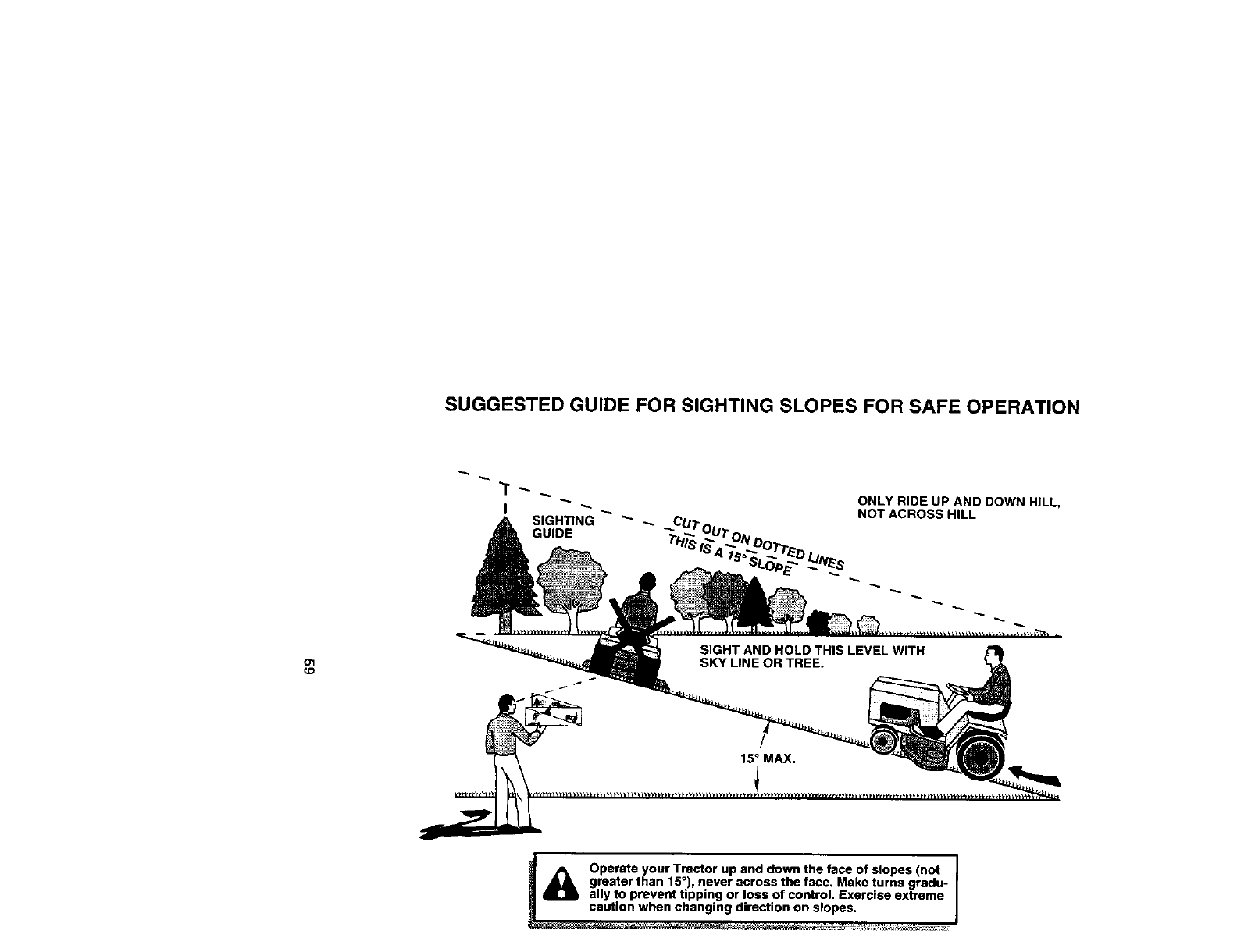
SUGGESTED GUIDE FOR SIGHTING SLOPES FOR SAFE OPERATION
I SIGHTING"_
GUIDE
ONLY RIDE UP AND DOWN HILL,
NOT ACROSS HILL
O'1
_D
._ Operate your Tractor up and down the face of slopes (not I
I
greater than 15°), never across the face. Make turns gredu- J
ally to prevent tipping or loss of control. Exercise extreme

Get it fixed, at your home or ours!
For repair of major brand appliances in your own home...
no matter who made it, no matter who sold it!
1-800-4-MY-HOME sM Anytime, day or night
(1-800-469-4663)
www.sears.com
To bring in products such as vacuums,
lawn equipment and electronics for repair, call for
the location of your nearest Sears Parts &Repair Center.
1-800-488-1222 Anytime,day or night
www, sears.com
For the replacement parts, accessories and owner's manuals
that you need to do-it-yourself, call Sears ParteDirectSMf
1"800"366-PART 6a.m.- 11 p.m. CST,
(1-800-366-7278) 7days a week
www, sears.condpartsdirect
To purchase or inquire about a Sears Service Agreement:
1-800-827-6655
7 a.m. - 5 p.m. CST, Mon. - Sat.
Para pedir servicio de reparaci6n a domicilio,
y para ordenar piezas con entrega a dornicilio:
1-888-SU-HOGAR sM
(1®88-784-6427)
AuCanada pourserviceen tran_ais:
1-877-LE-FOYER sM
(1-877-533-6937)
© Sears, Roebuck and Co
®Registered Trademark /TM Trademark of Sears, Roebuck and Co
®Marca Registrada !rM Marca de Fdbrica de Sears, ROebuck and Co
174747 Rev. 1 6.23.00 RH/SV Printed inU.S.A.
