Craftsman 917272432 User Manual LAWN TRACTOR Manuals And Guides L0104114
CRAFTSMAN Lawn, Tractor Manual L0104114 CRAFTSMAN Lawn, Tractor Owner's Manual, CRAFTSMAN Lawn, Tractor installation guides
User Manual: Craftsman 917272432 917272432 CRAFTSMAN LAWN TRACTOR - Manuals and Guides View the owners manual for your CRAFTSMAN LAWN TRACTOR #917272432. Home:Lawn & Garden Parts:Craftsman Parts:Craftsman LAWN TRACTOR Manual
Open the PDF directly: View PDF ![]() .
.
Page Count: 60

Owner's Manual
ICRRFTSMRWI
20.0 HP
ELECTRIC START
42" MOWER
6 SPEED TRANSAXLE
LAWN TRACTOR
Model No.
917.272432
•Safety
•Assembly
• Operation
•Maintenance
•Repair Parts
CAUTION:
Read and follow all
Safety Rules and Instructions
before operating this equip-
ment.
For answers to your questions
about this product, Call:
1-800-659-5917
Sears Craftsman Help Line
5 am- 5 pm, Mon- Sat
Sears, Roebuck and Co., Hoffman Estates, IL 60179
visit our Craftsman website: www.sears.com/craftsman

Warranty ............................................... 2
Safety Rules ......................................... 3
Product Specifications .......................... 6
Assembly .............................................. 8
Operation ............................................ 12
Maintenance Schedule ...................... 19
Maintenance ....................................... 19
Service and Adjustments .................... 23
Storage ............................................... 29
Troubleshooting .................................. 30
Repair Parts ........................................ 34
Parts Ordering ..................... Back Cover
LIMITED'FWOYEAR WARRANTY ON CRAFTSMAN RIDING EQUIPMENT PARTS
For two (2) years from the date of purchase, if this Craftsman Riding Equipment is
maintained, lubricated and tuned up according to the instructions in the owner's
manual, Sears will repair or replace, free of charge, any parts found to be defective in
matedal or workmanship. Warranty service is available free of charge by returning
your Craftsman riding equipment to your nearest Sears Service Center. In-home
warranty service is available but a trip charge will apply. This warranty applies only
while this product is in the United States.
This Warranty does not cover:
• Expendable items which become worn during normal use, such as blades, spark
plugs, air cleaners, belts and oil riflers.
• Tire replacement or repair caused by punctures from outside objects, such as nails,
thorns, stumps, or glass.
• Repairs necessary because of operator abuse, including but not limited to, damage
caused by towing objects beyond the capability of the riding equipment, impacting
objects that bend the frame or crankshaft, or over speeding the engine.
• Repairs necessary because of operator negligence, including but not limited to,
electrical and mechanical damage caused by improper storage, failure to use the
proper grade and amount of engine oil, failure to keep the deck clear of flammable
debris, or the failure to maintain the equipment according to the instructions
contained in the owner's manual
•Engine (fuel system) cleaning or repairs caused by fuel determined to be contami-
nated or oxidized (stale). In general, fuel should be used within thirty (30) days of its
purchase date.
• Riding equipment used for commercial or rental purposes. A product is "used for
commercial purpose" if is used for any purpose other than single family household
dwellings or in usage where profit is made.
LIMITED 90 DAY WARRANTY ON BA'I-FERY
For ninety (90) days from date of purchase, if any battery included with this riding
equipment proves defective in material or workmanship and our testing determines
the battery will not hold a charge, Sears will replace the battery at no charge. War-
ranty service is available free of charge by returning your Craftsman dding equipment
to your nearest Sears Service Center. In-home warranty service is available but a trip
charge will apply. This warranty applies only while this product is in the United States.
TO LOCATE THE NEAREST SEARS SERVICE CENTER OR TO SCHEDULE IN-
HOME WARRANTY SERVICE, SIMPLY CONTACT SEARS AT 1-800-4-MY-HOME
This Warranty gives you specific legal rights, and you may also have other rights
which may vary from state to state.
Sears, Roebuck and Co., D/817 WA, Hoftman Estates, IL 60179
2

IMPORTANT: This cutting machine is capable of amputating hands and feet and
throwing ob ects. Failure to observe the following safety instructions could result in
serious injury or death.
I. GENERAL OPERATION
•Read, understand, and followall
instructions in the manual and on the
machine before starting.
• Only aTTowresponsibre adults, who are
familiar with the instructions, to operate
the machine.
• Clear the area of objects such as rocks,
toys, wire, etc., which could be picked
up and thrown by the blade.
•Be sure the area is clear of other people
before mowing. Stop machine if anyone
enters the area.
• Never carry passengers.
•Do not mow in reverse unless absolutely
necessary. Always look down and
behind before and while backing.
•Be aware of the mowerdischarge
directionand do not point it at anyone.
Do not operate the mower without either
the entiregrass catcher or the guard in
place.
• Slow down before turning,
•Never leave arunning machine
unattended. Always turn off blades, set
parkingbrake, stop engine, and remove
keys before dismounting.
•Turn off blades when not mowing.
•Stop engine before removinggrass
catcher or uncloggingchute.
• Mow only in daylightor good artificial
light.
•Do not operate the machine while under
the influenceof alcoholor drugs.
•Watch for trafficwhen operating near or
crossing roadways.
•Use extra care when loading or unload-
ing the machine into a traileror truck.
•Data indicatesthat operators, age 60
years and above, are involved in alarge
percentage of dd[ng mower-related
injuries. These operators should
evaluate their ability to operate the riding
mower safely enough to protect them-
selves and others from sehous injury.
• Keep machine free of grass, leaves or
other debds build-up which can touch
hot exhaust /engine parts and bum. Do
not allow the mower deck to plow leaves
or other debris which can cause build-
up to occur. Clean any oil or fuel
spillagebefore operating or stodng the
machine. Allow machine to cool before
storage.
II. SLOPE OPERATION
Slopes are a major factor related to loss-of-
control and tipover accidents, which can re-
sult in severe injury or death. All slopes
requireextra caution. Ifyou cannot back up
the slope or if you feel uneasy on it, do not
mow it.
DO:
•Mow up and down slopes, not across.
•Remove obstacles such as rocks, tree
limbs,etc.
• Watch for holes, ruts, or bumps. Uneven
terrain could overtum the machine. Tall
grass can hide obstacles.
• Use slow speed. Choose a low gear so
that you will not have to stop or shift
while on the slope.
• Follow the manufacturer's recommenda-
tions for wheel weights or counter-
weights to improve stability.
• Use extra care with grass catchers or
other attachments. These can change
the stability of the machine.
•Keep all movement on the slopes slow
and gradual. Do not make sudden
changes in speed or direction.
• Avoid starting or stopping on aslope. If
tires lose traction, disengage the blades
and proceed slowly straightdown the
slope.
DO NOT:
•Do not turn on slopes unless necessary,
and then, tum slowly and gradually
downhill, ff possible.
• Do not mow near drop-offs, ditches, or
embankments. The mower could
suddenly turn over if a wheel is over the
edge of acliffor ditch, or if an edge
caves In.
•Do not mow on wet grass. Reduced
traction could cause sliding.
• DO not try to stabilizethe machine by
puttingyour foot on the ground.
•Do not use grass catcher on steep
slopes.

IlLCHILDREN
Tragicaccidentscanoccuriftheoperator
is not alert to the presence of children.
Children are often attracted to the
machine and the mowing activity. Never
assume that children will remain where
you last saw them.
•Keep children out of the mowing area
and under the watchful care of another
responsible adult.
•Be alert and turn machine off if children
enter the area.
•Before.and when backing, look behind
and down for small children.
• Never carry children. They may fall off
and be seriously injured or interfere
with safe machine operation.
• Never allow children to operate the
machine.
• Use extra care when approaching blind
corners, shrubs, trees, or other objects
that may obscure vision.
IV. SERVICE
•Usa extra care in handling gasoline
and other fuels. They are flammable
end vapors are explosive.
-Use only an approved container.
-Never remove gas cap or add fuel
with the engine running. Allow
engine to cool before refueling. Do
not smoke.
-Never refuel the machine indoors.
- Never store the machine or fuel
container inside where there is an
open flame, such as a water heater.
Never run a machine inside a closed
area.
Keep nuts and bolts, especially blade
attachment bolts, tight and keep
equipment in good condition.
Never tamper with safety devices.
Check their proper operation regularly.
Keep machine free of grass, leaves, or
other debris build-up. Clean oil or fuel
spillage. Allow machine to cool before
storing.
Stop and inspect the equipment if you
strike an object. Repair, if necessary,
before restarting.
Never make adjustments or repairs with
the engine running.
Grass catcher components are subject
to wear, damage, and deterioration,
which could expose moving parts or
allow objects to be thrown. Frequently
check components and replace with
manufacturer's recommended parts,
when necessary.
Mower blades are sharp and can cut.
Wrap the blade(s) or wear gloves, and
usa extra caution when servicing them.
Check brake operation frequently.
Adjust and service as required.
•Be sure the area is clear of other
people before mowing. Stop machine if
anyone enters the area.
•Never carry passengers or children
even with the blades off.
•Do net mow in reverse unless abso-
lutely necessary. Always look down
and behind before and while backing.
• Never carry children, They may fall off
and be seriously injured or interfere
with safe machine operation.
• Keep children out of the mowing area
and under the watchful care of another
responsible adult.
•Be alert and turn machine off if children
enter the area.
•Before and when backing, look behind
and down for small children.
•Mow up and down slopes (15 °Max),
not across.
•Remove obstacles such as rocks, tree
limbs, etc,
• Watch for holes, ruts, or bumps,
Uneven terrain could overturn the
machine. Tall grass can hide obstacles.

•Use slow speed. Choose a low gear so
that you will not have to stop or shift
while on the slope.
• Avoid starting or stopping on a slope. It
tires lose traction, disengage the blades
and proceed slowly straight down the
stope.
•If machine stops while going uphill,
disengage blades, shift into reverse
and back down slowly.
•Do not turn on slopes unless neces-
sary, and then, turn slowly and gradu-
ally downhill, if possible.
_&Look for this symbol to point out
important safety precautions, it means
CAUTION!!! BECOMEALERTIfl YOUR
SAFETY IS INVOLVED.
_CAUTION: In order to prevent
accidental starting when setting up,
transporting, adjusting or making repairs,
always disconnect spark plug wire and
place wire where it cannot contact spark
plug.
_- CAUTION: Do not coast down a hill
in neutral, you may lose controlof the
tractor.
_CAUTION: Tow only the attachments
that are recommended by and comply
with specifications of the manufacturer of
your tractor. Use common sense when
towing. Operate only at the lowest
possible speed when on a slope. Too
heavy of aload, while on a slope, is
dangerous. Tires can lose traction with
the ground and cause you to lose control
of your tractor.
_ILWARNING: Engine exhaust, some of
its constituents,and certain vehicle
components contain or emit chemicals
known to the State of California to cause
cancer and birth defects or other repro-
ductive harm.
_WARNING: Battery posts, terminals
and related accessories contain lead and
lead compounds, chemicals known to the
State of California to cause cancer and
birth defects or other reproductive harm.
Wash hands after handling.
5

PRODUCT SPECIFICATIONS
GASOLINE 1.25 GALLONS
CAPACITY UNLEADED
ANDTYPE: REGULAR
OILTYPE SAE 30 (ABOVE 32°F
API-SF-SJ): SAE 5W-30
(BELOW 32°F)
OIL CAPACITY: 4.0 PINTS
SPARKPLUG: CHAMPION RC12YC
GAP: .040")
GROUND SPEED FORWARD:
(MPH): I s'r 1.2
2"0 1.5
3_° 2.4
4TM 3.5
5TM 4.8
6TM 5.3
REVERSE: 1.5
TIRE PRESSURE: FRONT: 14 PSi
REAR: 10 PSI
CHARGING 3 AMPS BATTERY
SYSTEM: 5 AMPS HEADLIGHT
BATTERY: AMP/HR: 28
MIN. CCA: 230
CASE SIZE'. U 1R
BLADE BOLT 27-35 F'£ LBS.
TORQUE:
CONGRATULATIONS on your purchase
of anew tractor. It has been designed,
engineered and manufactured to give you
the best possible dependability and
performance.
Should you experience any problem you
cannot easily remedy, please contact a
Sears or other qualified service center,
We have competent, well-trained techni-
cians and the proper tools to service or
repair this tractor.
Please read and retain this manual. The
instructions wi_lenable you to assemble
and maintain your tractor properly.
Always observe the "SAFETY RULES".
REPAIR AGREEMENT
ARepair Agreement is available on this
product. Contact your nearest Sears
store for details.
CUSTOMER RESPONSIBILITIES
•Read and observe the safety rules.
•Follow aregular schedule in maintain-
ing, caring for and using your tractor.
•Follow the instructionsunder "Mainte-
nance" and "Storage" sections of this
owner's manual.
_I_WARNING: This tractor is equipped
with an internal combustion engine and
should not be used on or near any
unimproved forest-covered, brush-
covered or grass-covered tend unless the
engine's exhaust system is equipped with
aspark arrester meeting applicable local
or state taws (if any). If aspark attester is
used, it should be maintained in effective
working order by the operator.
In the state of California the above is
required by law (Section 4442 of the
California Public Resources Code).
Other states may have similar laws.
Federal laws apply onfederal lands. A
spark arrester for the muffler is available
through your nearest Sears service
center (See REPAIR PARTS section of
this manual).

Steering
Wheel Insert
Steering Wheel
(1)
3/8-16 x 1
(1) Hex Bolt 5/16-18x 1-1/4
Steering Wheel
Adapter
(1) Large Flat Washer
(1) Locknut 5/1g-18_ (1) Lockwasher 3/8
_,/ Steering
_:_Steedng ShExtaeftnsiOn
_ Bcot
@(1) Washer
_17/32 x 1-3/I 6 x 12 Gauge
(1) Knob
For FutureUse
Keys
Slope Sheet
(2) Keys
Video Cassette
7

Your new tractor has been assembled at the factory with exception of those parts left
unassembled for shipping purposes. To ensure safe and proper operation of your
tractor all parts and hardware you assemble must be tightened securely. Use the
correcttools as necessary to insure proper tightness. Review the video cassette before
you begin.
TOOLS REQUIRED FOR ASSEMBLY
A socket wrench set will make assembly
easier. Standard wrench sizes you need
are listed below.
(1) 9/16" wrench (2) 1/2" wrench
(1) Utility knife (1) Pliers
(1) Tire pressure gauge
When right or left hand is mentioned in
this manual, it means, from your point of
view, when you are in the operating
position (seated behind the steering
wheel).
TO REMOVETRACTOR FROM
CARTON
UNPACK CARTON
1. Remove all accessible loose parts
and parts cartons from carton.
2. Cut, from top to bottom, along lines on
all four corners of carton, and lay
panels flat.
3. Check for any additional loose parts
or cartons and remove.
BEFORE REMOVINGTRACTOR
FROM SKID
A'I-FACH STEERING WHEEL
ASSEMBLE EXTENSION SHAFT AND
BOOT
1. Slide extension shaft onto lower
steering shaft. Align mounting holes
in extension and lower shafts and
install 5/16 hex bolt and Iocknut.
Tighten securely.
IMPORTANT: Tighten bolt and nut
securely to 18-22 ft. Ibs torque.
2. Place tabs of steering boot over tab
slots in dash and push down to
secure.
INSTALL STEERING WHEEL
3. Position frontwheels of the tractor so
they are pointing straight forward.
4. Remove steering wheel adapter from
steering wheel and slide adapter onto
steering shaft extension.
5. Position steering wheel so cross bars
are horizontal (left to right) and slide
inside boot and onto adapter.
6. Assemble large flat washer, 3/8 lock
washer, 3/8 hex bolt and tighten
securely.
7. Snap steering wheel insert into center
of steering wheel.
8. Remove protective materials from
tractor hood and grill
IMPORTANT: Check for and remove any
staples in skid that may puncturetires
where tractor is to roll off skid.
Insert
@_/_ Hex Bolt
_-/3lB
_Lockwesher
LargeRat
Washer
Steerlng_ Steering
Wheel _./Boot
E_tef_sion _ _Tabs
_ _Adapter
5/16 5/16
Locknut Hex Bolt
Lower ," _ _-:",
Steering_ _Tab
Shaft
HOWTO SET UPYOURTRACTOR
CHECK BATTERY
1. Lift seat pan to raised position and
open battery box door.
NOTE: If this battery is put into service
after month and year indicated on label
(label located between terminals) charge
battery for minimum of one hourat 6-10
amps. (See "BATTERY" in Maintenance
secdionof this manual for charging
instructions).
8

INSTALL SEAT
Adjust seat before tightening adjustment
knob,
1, Remove "adjustment knob and flat
washer securing seat to cardboard
packing and set aside for assembly of
seat to tractor,
2. Pivot seat upward and remove from
the cardboard packing. Remove the
cardboard packing and discard.
3. Ptase seat on seat pan so head of
shoulder bolt is positioned over large
slotted bole in pan.
4. Push down on seat to engage
shoulder bolt in slot and pull seat
towards rear of tractor.
5. Pivot seat and pan forward and
assemble adjustment knob and flat
washer loosely. Do not tighten.
6. Lower seat into operating position and
sit in seat.
7. Slide seat untila comfortable position
is reached which allows you to press
clutch/brake pedal all the way down.
8. Get off seat without moving its
adjusted position.
9. Raise seat a¢'_ tighten adjustment
knob securely.
NOTE: You may now roll or drive your
tractor off the skid. Follow the appropriate
instruction below to remove the tractor
from the skid.
3"0 ROLLTRACTOR OFF SKID (See
Operation section for location and
function of controls)
1. Press lift lever plunger and raise
attachment liftlaver to its highest
position.
2. Release parking brake by depressing
clutch/brake pedal.
3. Place gearsh=ftlever in neutral (N)
position.
4. Roll tractor forward offskid.
5. Remove banding holding deflector
shield up against tractor.
TO DRIVE3-RAC3"OR OFF SKID (See
Operation section for location and
function of controls)
AWARNING: Before starting read,
understand and fo ow a nalructions in
the Operation section of this manual. Be
sure tractor is in awell-ventilated area. Be
sure the area in front of tractor is clear of
other people and objects.
1. Be sure all the above assembly steps
have been completed.
2. Check engine oil level and fill fuel
tank with gasoline.
3. Sit on seat in operating position.
depress clutch/brake pedal and set
the parking brake.
4. Place gear shift lever in neutral (N)
position.
5. Press lift lever plunger and raise
attachment liftlever to its highest
position.
6. Start the engine. After engine has
started, move throttle control to idle
position.
__ 7. bepress clutch/brake pedal into full
"BRAKE" position and hold. Move
gearshift lever to 1st gear,
SeatPan-_ "_\\'_\ _,! 8. Slowly release clutch/brake pedal and
slowly drive tractor oft skid.
9. Apply brake to stop tractor, set parking
ulder brake and place gearshift lever in
neutral position.
10.Turn ignition key to "OFF" position.
Continue with the instructions that follow.
9

INSTALL MULCHER PLATE
(If previously removed)
t. Raise and hold deflector shield in
upright position.
2. Place front of mulcher plate over front
of mower deck opening and slide into
place, as shown.
3. Hook front latch into hole on front of
mower deck.
4. Hook rear latch into hole on back of
mower deck.
_LCAUTION: Do not remove deflector
shield from mower. Raise and hold shield
when attaching mulcher plate and allow it
to rest on plate while in operation.
TO CONVERT TO BAGGING OR
DISCHARGING
Simply remove mulcher plate and store in
a safe place. Your mower is now ready for
discharging or installation of optional
grass catcher accessory.
NOTE: It is not necessary to change
blades. The mulcher blades are designed
for discharging and bagging also.
Deflector
Mulcher
Latch
Hooks
CHECK TIRE PRESSURE
The tires on your tractor were overinflated
at the factory for shipping purposes.
Correct tire pressure is important for best
cutting performance.
•Reduce tire pressure to PSI shown in
"PRODUCT SPECIFICATIONS" section
of this manual.
CHECK DECK LEVELNESS
For best cutting results, mower housing
should be properly leveled, See "TO
LEVEL MOWER HOUSING" in the
Service and Adjustments section of this
manual.
CHECK FOR PROPER POSITION OF
ALL BELTS
See the figures that are shown for
replacing motion and mower blade drive
belts in the Service and Adjustments
section of this manual Verify that the belts
are routed correctly.
CHECK BRAKE SYSTEM
After you learn how to operate your
tractor, check to see that the brake is
properly adjusted. See "TO ADJUST
BRAKE" in the Service and Adjustments
section of this manual.
10

t/ CHECKLIST
Before you operate and enjoy your new
tractor, we wish to assure that you receive
the best performance and satisfaction
from this quality product.
Please review the following checklist:
J All assembly instructions have been
completed.
,/No remaining loose parts in carton.
/Battery is properly prepared and
charged.(Minimum 1 hour at 6 amps).
•/Seat is adjusted comfortably and
tightened securely.
,/All tires are properly inflated. (For
shipping purposes, the tires were
ovednfiated at the factory).
,/Be sure mower deck is propedy leveled
sida-to-side/front-to-rear for best cutting
results. (Tires must be properly inflated
for leveling).
/Check mower and drive belts. Be sure
they are routed properly around pulleys
and inside all belt keepers.
,/Check wiring. See that all connections
are stillsecure and wires are properly
clamped.
While learning how to use your tractor,
pay extra attention to the following
important items:
,/Engine oil is at proper level.
,/Fuel tank is filled with fresh, clean,
regular unleaded gasoline.
,/Become familiar with all controls -their
location and function. Operate them
before you start the engine.
/Be sure brake system is in safe operat-
ing condition.
11

These symbols may appear on your tractor or in literature supplied with the product,
Learn and understand their meaning.
€
A,
BATrERY CAUTION OR REVERSE FORWARD FAST SLOW
WARNING
ENGINE ON ENGINE OFF OIL PRESSURE LIGHTS ON OVER "rE MP
LIGHT
FUEL CHOKE MOWER HEIGHT PARKING BRAKE UNLOCKED
LOCKED
!
MOWERLI_
_r_RN H L
ATrACHMENT REVERSE NEUTRAL HIGH LOW
CLUTCHENGAGED
®5]
PARKING BRAKE
IGNITION
KEEP AREA CLEAR SLOPE HAZARDS
ATrACHMENT
CLUTCH DISENGAGED (SEE SAFETY RULES SECTION)
DANGER, KEEP HANDS AND FEET AWAY FREE WHEEL
(Autocnati¢Models only)
12
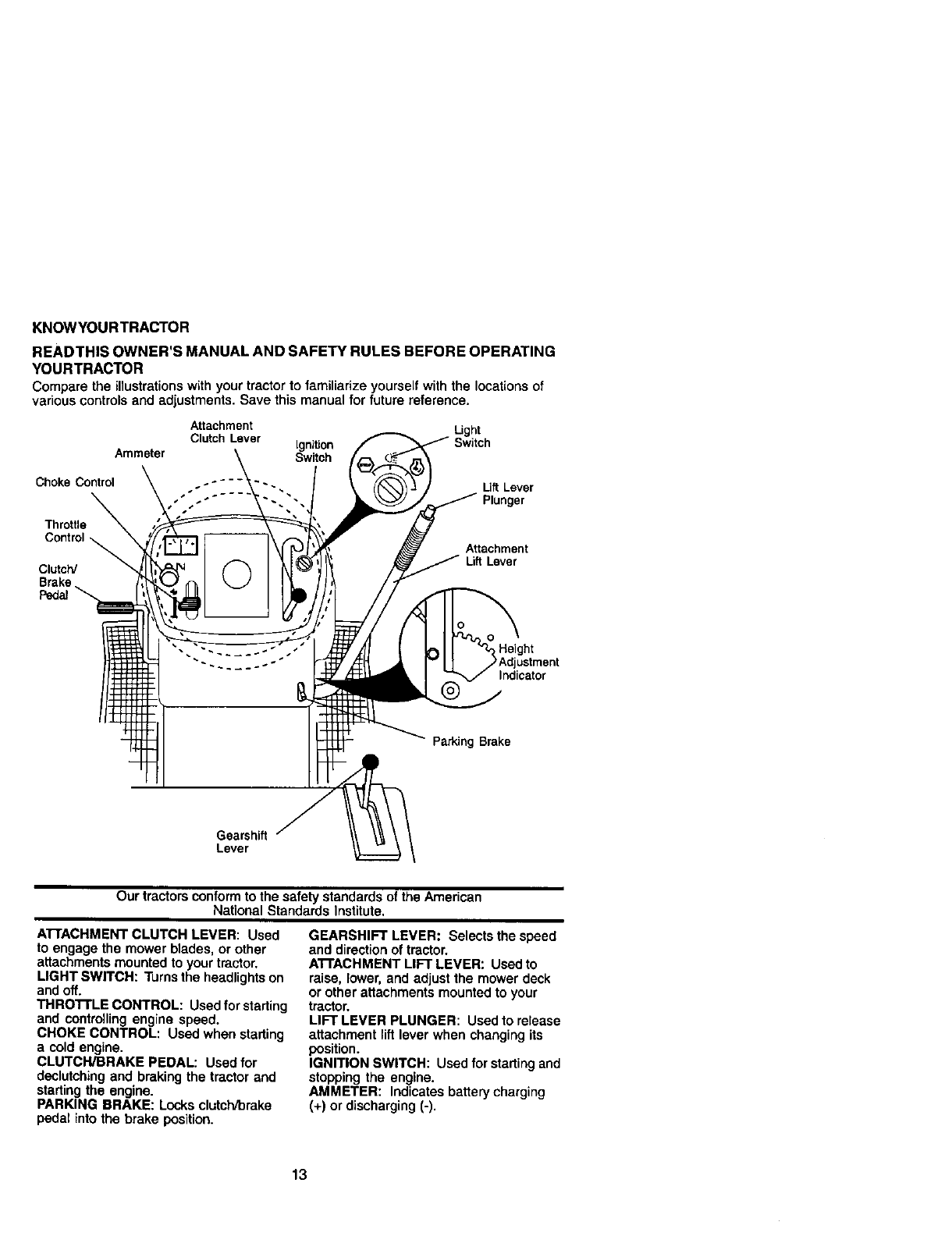
KNOWYOURTRACTOR
READTHIS OWNER'S MANUAL AND SAFETY RULES BEFORE OPERATING
YOURTRACTOR
Comparethe Ulustrationswithyourtractorto familiarizeyourselfwiththe locationsof
variouscontrols end adiustments.Savethis manualfor futurereference.
Attachment
Clutch Lever Ignition
Ammeter Switch
Light
Choke Control Lift Lever
Plunger
Throttle
Control
Clutch/
Brake
Pedal
Attachment
Lift Lever
Height
Indicator
Parking Brake
Gearshift
Lever
Our tractors conform to the safety standards of the American
National Standards Institute,
ATI'ACHMENT CLUTCH LEVER: Used
to engage the mower blades, or other
attachments mounted to your tractor.
LIGHT SWITCH: Turns the headlights on
and off.
THRO'I'rLE CONTROL: Used for starting
and controlling engine speed.
CHOKE CONTROL: Used when starting
a cold engine.
CLUTCH/BRAKE PEDAL: Used for
declutching and braking the tractor and
starting the engine.
PARKING BRAKE: Locks clutch/brake
pedal into the brake position.
GEARSHIFT LEVER: Selects the speed
and direction of tractor.
A'n'ACHMENT LIFT LEVER: Used to
raise, tower, and adjust the mower deck
or other attachments mounted to your
tractor.
LIFT LEVER PLUNGER: Used to release
attachment lift lever when changing its
position.
IGNITION SWITCH: Used for starting and
stopping the engine.
AMMETER: Indicates battery charging
(+) or discharging (-).
13

IThe operation of any tractor can result in foreign objects thrown into the
eyes, which can result in severe eye damage. Always wear safety
_L_ glasses or eye shields while operating your tractor or performing any
iadjustments or repairs. We recommend a wide vision safety mask over
spectacles, or standard safety glasses.
HOWTO USEYOURTRACTOR
TO SET PARKING BRAKE
Your tractor is equipped with an operator
presence sensing switch. When engine
is running,any attempt by the operator to
leave the seat without first setting the
parking brake will shut off the engine.
1. Depress clutch/brake pedal into full
"BRAKE" position and hold.
2. Place parking brake lever in "EN-
GAGED" position and release
pressure from clutch'brake pedal.
Pedal should remain in "BRAKE"
position. Make sure parking brake will
holdtractor secure.
Choke Attachment Clutch Lover
Control "Engaged" Position Ignition Key
Throttle ,Position
Clutch/Brak_ Parking Brake
Pedal Position
Position
"Disengaged" "Brake"
PosiUon Position
Gearshift
Lever
STOPPING
MOWER BLADES -
• To StOpmower blades,move attachment
clutch lever to "DISENGAGED" position.
GROUND DRIVE -
• To stop ground drive, depress clutch/
brake pedal into full "BRAKE" position.
• Move gearshift lever to neutral (N)
position.
ENGINE -
• Move throttle control to slow position.
NOTE: Failure to move throttle control to
slow position and allowing engine to idle
before stopping may cause engine to
"backfire".
I
•Turn ignition key to "OFF" position and
remove key. Always remove key when
leaving tractor to prevent unauthorized
use.
•Never use choke to stop engine.
IMPORTANT: Leaving the ignitionswitch
in any position other than "OFF" will cause
the battery to be discharged, (dead).
NOTE: Under certain conditions when
tractor is standing idle with the engine
running, hot engine exhaust gases may
cause "browning" of grass. To eliminate
this possibility, always stop engine when
stopping tractor on grass areas.
,_CAUTION: Always stop tractor
completely, as described above, before
leaving the operator's position; to empty
grass catcher, etc.
TO USE THROTTLE CONTROL
Always operate engine at fug throttle.
•Operating engine at less than full
throttle reduces the battery charging
rate.
•Full throttle offers the best bagging and
mower performance.
TO USE CHOKE CONTROL
Use choke control whenever you are
starting a cold engine. Do not use to start
awarm engine.
•To engage choke control, pull knob out.
Slowly push knob in to disengage.
TO MOVE FORWARD AND BACK-
WARD
The direction and speed of movement is
controlled by the gearshift lever.
1. Start tractor with clutch/brake pedal
depressed and gearshift lever in
neutral (N) position.
2. Move gearshift lever to desired
position.
3. Slowly release clutchlbrake pedal to
start movement.
IMPORTANT: Bringtractor to a complete
stop before shiftingor changing gears.
Failure to do so will shorten the useful life
of your transaxle.
14

TO ADJUST MOWER cu'rrlNG HEIGHT
The position of the attachment lift lever
determines the cutting height.
•Grasp lift lever.
•Press plunger with thumb and move
lever to desired position.
The cutting height range is approxi-
mately 1-1/2 to 4". The heights are
measured from the ground to the blade tip
with the engine not running. These
heights are approximate and may vary
depending upon soil conditions, height of
grass and types of grass being mowed.
• The average lawn should be cut to
approximately 2-1/2 inches during the
cool season and to over 3 inches
during hot months. For healthier and
better looking lawns, mow often and
after moderate growth.
• For best cutting performance, grass
over 6 inches in height should be
mowed twice. Make the first cut
relatively high; the second to desired
height.
TO ADJUST GAUGE WHEELS
Gauge wheels are properly adjusted
when they are slightly off the ground
when mower is at the desired cutting
height in operating position. Gauge
wheels then keep the deck in proper
position to help prevent scalping in most
terrain conditions.
NOTE: Adjust gauge wheels with tractor
on a flat level surface.
1. Adjust mower to desired cutting height
(See "TO ADJUST MOWER CUFFING
HEIGHT" in the Operation section of
this manual).
2. With mower in desired height of cut
position, gauge wheels should be
assembled so they are slightly off the
ground. Install gauge wheel in
appropriate hole with shoulder bolt, 3/
8 washer, and 3/8-16 Iocknut and
tighten seeurery.
3. Repeat for opposite side installing
gauge wheel in same adjustment hole.
GaugeWheel _ _ _,\
Mounting_ _'_/'_,_-_
Bracket ___
3/8 Washer _-_" _<'_ "_'Shoulder
Gauge Wheel_'_ Bolt
TO OPERATE MOWER
Your tractor is equipped with an operator
presence sensing switch. Any attempt by
the operator to leave the seat with the
engine running and the attachment clutch
engaged will shut off the engine.
1. Select desired height of cut.
2. Start mower blades by engaging
attachment clutch control.
TO STOP MOWER BLADES -
disengage attachment clutch control.
_IkCAUTION: Do not operate the mower
without either the entire grass catcher, on
mowers so equipped, or the deflector
shield in place.
Attachment Clutch Attachment LiftLever
Lever Hig
Low
Position _Position
_Shield
TO OPERATE ON HILLS
_kCAUTION: DO not drive up or down
hills with slopes greater than 15°and do
not drive across any slope. A slope guide
at the back of your manual is providedfor
your use.
•Choose the slowest speed before
starting up or down hills.
•Avoid stopping or changing speed on
hills.
•If slowing is necessary, move throttle
control lever to slower position.
•If stopping is absolutely necessary,
push clutch/brake pedal quickly to
brake position and engage parking
brake.
•Move gearshift lever to 1st gear. Be
sure you have allowed room for tractor
to roll slightlyas you restart movement.
•To restart movement, slowly release
parking brake and clutch/brake pedal.
•Make all turns slowly.
15

TO TRANSPORT
• Raise attachment liftto highest position
with attachment liftcontrol.
•When pushing or towing your tractor,
be sure gearshift lever is in neutral (N)
position.
• Do not push or tow tractor at more than
five (5) MPH.
NOTE: To protect hood from damage
when transportingyour tractor on a truck
or a trailer, be sure hood is closed and
secured to tractor. Use an appropriate
means of tying hood to tractor (rope, cord,
etc.).
TOWING CARTS AND OTHER ATrACH-
MENTS
Tow only the attachments that are
recommended by and comply with
specificationsof the manufacturer of your
tractor. Use common sense when towing.
Too heavy of a load, while on aslope, is
dangerous. Tires can lose traction with
the ground and cause you to lose control
of your tractor.
BEFORE STARTINGTHE ENGINE
CHECK ENGINE OIL LEVEL
The engine in your tractor has been
shipped, from the factory, already filled
with summer weight oil.
1. Check engine oil with tractor on level
ground.
2. Remove oil fill cap/dipstick and wipe
clean, reinsert the dipstick and screw
cap tight, wait for afew seconds,
remove and read oil level. If neces-
sary, add oil until "FULL" mark on
dipstick is reached. Do not overfill.
•For cold weather operation you should
change oil for easier starting (See "OIL
VISCOSITY CHART" in the Mainte-
nance section of this manual).
•To change engine oil, see the Mainte-
nance section in this manual.
ADD GASOLINE
•Fill fuel tank. Use fresh, clean, regular
unleaded gasoline with a minimum of
87 octane. (Use of leaded gasoline will
increase carbon and lead oxide
deposits and reduce valve life). Do not
mix oil with gasoline. Purchase fuel in
quantities that can be used within 30
days to assure fuel freshness.
IMPORTANT: When operating in tem-
peratures below 32°F(0°C), use fresh,
clean winter grade gasoline to help
insure good cold weather starting.
_I_WARNING: Experience indicates that
alcohol blended fuels (called gasohol or
using ethanol or methanol) can attract
moisture which leads to separation and
formation of acids during storage. Acidic
gas can damage the fuel system of an
engine while in storage. To avoid engine
problems, the fuel system should be
emptied before storage of 30 days or
longer. Drain the gas tank, start the
engine and let it run until the fuel lines
and carburetor are empty. Use fresh fuel
next season. See Storage Instructionsfor
additional information. Never use engine
or carburetor cleaner products in the fuel
tank or permanent damage may occur.
_kCAUTION: Fill to bottom of gas tank
filler neck. Do not overfill. Wipe off any
spilled oil or fuel. Do not store, spill or use
gasoline near an open flame.
16

TO START ENGINE
When startingtheengineforthe firsttime orif
the enginehas run out of fuel, itwill take extra
crankingtime to movefuelfrom the tank to the
engine.
1. Sit on seat in operating position,
depress clutch/brake pedal and set
parking brake.
2. Place gear shift lever in neutral (N)
position.
3. Move attachment clutch to "DISEN-
GAGED" position.
4. Move throttle controlto fast position
5. Pull choke control out for a cold
engine start attempt. For a warm
engine start attempt the choke control
may not be needed.
NOTE: Before starting,mad thewarmand
coldstarting procedures below.
6. Insert key into ignition and turn key
clockwise to "START" position and
release key as soon as engine starts.
Do not run starter continuously for
more than fifteen seconds per minute.
Ifthe engine does not start after
several attempts, push choke control
in, wait a few minutes and try again. If
engine still does not start, pull the
choke control out and retry.
WARM WEATHER STARTING (50°F and
above)
7. When engine starts, slowly push
choke control in until the engine
begins to run smoothly. If the engine
starts to run roughly, pull the choke
control out slightly for a few seconds
and then continue to push the control
in slowly.
•The attachments and ground drive can
now be used. If the engine does not
accept the load, restart the engine and
allow it to warm up for one minute using
the choke as described above.
COLD WEATHER STARTING (50' Fand
below)
7. When engine starts, slowly push
choke control in until the engine
begins to run smoothly. Continue to
push the choke control in small steps
allowing the engine to accept small
changes in speed and load, until the
choke control is fully in. If the engine
starts to run roughly, pull the choke
control out slightly for a few seconds
and then continue to push the control
in slowly. This may require an engine
warm-up period from several seconds
to several minutes, depending on the
temperature.
• The attachments can be used during
the engine warm-up period and may
require the choke control be pulled out
slightly.
NOTE: If at a high altitude (above 3000
feet) or in cold temperatures (below 32 F)
the carburetor fuel mixture may need to
be adjusted for best engine performance.
See "TO ADJUST CARBURETOR" in the
Service and Adjustments section of this
manual.
17

MOWING TIPS
• Mower should be properly leveled for
best mowing performance, See "TO
LEVEL MOWER HOUSING" in the
Service and Adjustments section of this
manual.
• The left hand side of mower should be
used for trimming.
•Drive so that clippings are discharged
onto the area that has been cut. Have
the cut area to the right of the machine.
This will result in a more even distribu-
tion of clippings and more uniform
cutting.
• When mowing large areas, start by
turning to the right so that clippings will
discharge away from shrubs, fences,
driveways, etc. After one or two
rounds,
mow in the opposite direction making
left hand turns until finished
• If grass is extremely tall, it should be
mowed twice to reduce load and
possible fire hazard from dried clip-
pings. Make first cut relatively high; the
second to the desired height.
•Do not mow grass when it is wet. Wet
grass will plug mower and leave
undesirable clumps. Allow grass to dry
before mowing,
•Always operate engine at full throttle
when mowing to assure better mowing
performance and proper discharge of
material. Regulate ground speed by
selecting alow enough gear to give the
mower the best cutting performance as
well as the quality of cut desired.
•When operating attachments, select a
ground speed that will suit the terrain
and give best performance of the
attachment being used.
MULCHING MOWINGTIPS
IMPORTANT: For best performance,
keep mower housing free of built-up grass
and trash. Clean after each use.
•The special mulching blade will recut
the grass clippings many times and
reduce them in size so that as they fall
onto the lawn they will disperse into the
grass and not be noticed. Also, the
mulched grass will biodegrade quickly
to provide nutrientsfor the lawn.
Always mulch with your highest engine
(blade) speed as this will provide the
best recutting action of the blades.
• Avoid cutting your lawn when it is wet.
Wet grass tends to form clumps and
interferes with the mulching action. The
best time to mow your lawn is the early
afternoon. At this time the grass has
dried and the newly cut area will not be
exposed to the direct sun.
• For best results, adjust the mower
cutting height so that the mower cuts off
only the top one-third of the grass
blades. For extremely heavy mulching,
reduce your width of cut on each pass
and mow slowly.
• Certain types of grass and grass
conditions may require that an area be
mulched a second time to completely
hide the clippings. When doing a
second cut, mow across or perpendicu-
lar to the first cutpath.
•Change your cutting pattern from week
to week. Mow north to south one week
then change to east to west the next
week. This will help prevent matting
and graining of the lawn.
Max 1/3
18

MAINTENANCESCHEDULE
FILL IN DATES
AS yOU COMPLETE
REGULAR SERVICE
C_eck IB_ke Opera,on I_'
Check Opmator pmseflce and
,_,arp_,_ Mower BLa(_,es t_' 4
Check Transm_ C_<_i_ t_'
Adj_ B]_e Belt(s) Tension _j
_ust MotionDr_eBe_s) Te_ f_
C_eanNr F_ter t_=
Clean ._r So'sen _2
Ir_l:_ F,_f_Im_rk Arr_s_r t_'
Rep_oeO_nn_er(Ofequ_pp_) _.:
C_ar, ER_r_ Cooling R_ I_
Re_ace Air FilterPapel Carl_,ge if=
t-CM_ morno_t_ whe_ o_mlt_ ur,d_ a hN_ toed ,X _h_h a,_ld_ t_mpera_=, 5, I_ Kplp_<l W_ _=tab_ =y=Va
GENERAL RECOMMENDATIONS
The warranty on this tractordoes not cover
items that have been subjected to operator
abuse or negligence. To receive fullvalue
fromthe warranty,operator must maintain
tractoras instructedin this manual.
Some adjustmentswill need to be made
periodicallyto property maintain your
tractor.
All adjustments in the Service and
Adjustmentssection of this manual should
be checked at least once each season.
•Once a year you should replace the
spark plug, clean or replace air filter, and
check blades and pelts for wear. Anew
spark plugand clean air filter assure
proper air-fuel mixture and help your
engine run better and last !onger.
BEFORE EACH USE
1. Check engine oil level
2. Check brake operation.
3. Check tire pressure.
4. Check operator presence and
interlock systems for proper operation.
5. Check for loose fasteners,
LUBRICATION CHART
- Spindle _)
Zerk Zerk
(_ Front
Wheel Wheel
Bearing -, Bearing
Zerk Zerk
Gearshift
_--" _~--_ Pivots
_)SAE 30 or 10w30 motor oil
_)General Purpose Grease
@Refer to Maintenance "ENGINE"
Section
IMPORTANT: Do not oil or grease the
pivot points which have special nylon
bearings. Viscous lubricantswill attract
dust and dirtthat wig shorten the life of the
self-lubricating bearings. Ifyou feel they
must be lubricated, use only e dry,pow-
dered graphite type lubricant sparingly.
19

TRACTOR
Always observe safety rules when
performing any maintenance.
BRAKE OPERATION
If tractor requires more than six (6) feet
stopping distance at high speed in
highest gear, then brake must be ad-
justed. (See "TO ADJUST BRAKE" in the
Service and Adjustments section of this
manual).
TIRES
•Maintain proper air pressure in all tires
(See "PRODUCT SPECIFICATIONS"
section of this manual).
•Keep tires free of gasoline, oil, or insect
control chemicals which can harm
rubber.
• Avoid stumps, stones, deep ruts, sharp
objects and other hazards that may
cause tire damage.
NOTE; To seal tire punctures and prevent
flat tires due to slow leaks, tire sealant
may be purchased from your local parts
dealer. Tire sealant also prevents tire dry
rot and corrosion.
OPERATOR PRESENCE SYSTEM
Be sure that operator presence and
interlock systems are working properly. If
your tractor does not function as de-
scribed below, repair the problem
immediately.
•The engine should not start unless the
clutch/brake pedal is fully depressed
and attachment dutch control is in the
disengaged position.
• When the engine is running, any
attempt by the operator to leave the
seat without first setting the parking
brake should shut off the engine.
• When the engine is running and the
attachment clutch is engaged, any
attempt by the operator to leave the
seat should shut off the engine.
• The attachment clutch should never
operate unless the operator is in the
seat.
BLADE CARE
For best results mower blades must be
kept sharp. Replace bent or damaged
blades.
BLADE REMOVAL
1. Raise mower to highest position to
allow access to blades.
2. Remove hex belt, lock washer and flat
washer securing blade.
3. Install new or reeharpened blade with
trailing edge up towards deck as
shown. 20
IMPORTANT: TOensure proper assembly,
center hole in blade must align with star
on mandrel assembly.
4. Reassemble hex bolt, lock washer and
flat washer in exact order as shown.
5. Tighten bolt securely (27-35 Ft. Lbs.
torque).
IMPORTANT: Blade bolt is grade 8 heat
treated.
MandrelAssembly
TrailingEdge Up_, _
_,_ umeeCenter _
Hole
Flat Washer_'LL_._. //'___'_J
Lock " "_ r
Was .P h__a
_Hex Bolt (Grade 8)*
"A Grade 8 heat treated bolt canbe identified
by sixlines on the bolt heed.
TO SHARPEN BLADE
NOTE: We do not recommend sharpen-
ing blade - but if you do, be sure the blade
is balanced.
Care should be taken to keep the blade
balanced. An unbalanced blade will
cause excessive vibration and eventual
damage to mower and engine.
• The blade can be sharpened with a file
or on a gdnding wheel. Do not attempt
to sharpen while on the mower.
• To check blade balance, you will need
a 5/8" diameter steel bolt, pin, or a cone
balancer. (When using a cone bal-
aneer, follow the instructions supplied
with balaneer.)
NOTE: Do not use a nail for balancing
blade. The lobes of the center hole may
appear to be centered, but are not.
• Slide blade on to an unthreaded portion
of the steel bolt or pin and hold the bolt
or pin parallel with the ground. If blade
is balanced, it should remain in a
horizontal position. If either end of the
blade moves downward, sharpen the
heavy end until the blade is balanced.
5/8" lade

BATrERY
Your tractor has abattery charging system
which is sufficientfor normal use. How-
ever, periodic charging of the battery with
an automotive charger will extend its life.
•Keep battery and terminals clean.
• Keep battery bolts tight.
• Keep small vent holes open.
• Recharge at 6-10 amperes for 1 hour.
NOTE: The original equipment battery on
your tractor is maintenance free. Do not
attempt to open or remove caps or covers.
Adding or checking level of electrolyte is
not necessary,
TO CLEAN BATTERY AND TERMINALS
Corrosion and dirt on the battery and
terminals can cause the battery to =leak"
power.
1. Open battery box door.
2. Disconnect BLACK battery cable first
then RED battery cable and remove
battery fromtractor.
3. Rinse the battery with plain water and
dry.
4. Clean terminals and battery cable
ends with wire brush until bright.
5. Coat terminals with grease or petro-
leum jelly.
6. Reinstall battery (See "REPLACING
BA'I-I'ERY" in the SERVICE AND
ADJUSTMENTS section of this
manual).
V-BELTS
Check V-belts for deterioration and wear
after 100 hours of operation and replace
if necessary. The belts are not adjustable.
Replace belts if they begin to slip from
wear,
TRANSAXLE COOLING
Keep transaxle free from build-up of dirt
and chaff which can restrictcooling.
ENGINE
LUBRICATION
Only use high quality detergent oil rated
with API service classification SF-SJ.
Seloct the oil's SAE viscositygrade
according to your expected operating
temperature.
VISCOSiTy GRADES
m ;o _ 4o
NOTE: Although multi-viscosity oils
(5W30, 10W30 etc.) improve starting in
cold weather, these multi-viscosity oils
will result in increased oil consumption
when used above 32°E Chock your
engine oil level more frequently to avoid
possible engine damage from running
low on oil.
Change the oil after every 50 hours of
operation or at least once a year if the
tractor is not used for 50 hours in one
year.
Check the crankcase oil level before
starting the engine and after each eight
(8) hours of operation. Tighten oil fill cap/
dipstick securely each time you check the
oil level.
21
TO CHANGE ENGINE OIL
Determine temperature range expected
before oil change. All oil must meet API
service classification SF-SJ.
• Be sure tractor is on level surface.
• Oil will drain more freely when warm,
• Catch oil in a suitable container.
1. Remove oil fill cap/dipstick. Be careful
not to allow dirt to enter the engine
when changing oil.
2. Remove cap from end of drain valve
and install the drain tube onto the
fitting.
3. Unlockdrainvalveby pushinginward
slightlyand turningcounterclcokwise.
4. To open,pullouton thedrainvalve.
5. After oil has drained completely, close
and lock the drain valve by pushing
inward and turning clockwise until the
pin is in the locked positionas shown.
6. Remove the drain tube and replace
the cap onto to the end of the drain
valve.
7. Refill engine with oil through oil fill
dipstick tube. Pour slowly. 0o not
overfill. For approximate capacity see
"PRODUCT SPECIFICATIONS"
section of this manual.
8. Use gauge on oil fill cap/dipstick for
checking level. Be sure dipstickcap is
tightened securely for accurate
reading. Keep oil at "FULL" line on
dipstick. OilDrainValve
Closed _1
poNtion _
Cap _ _
DrainTube

CLEANAIRSCREEN
Airscreenmustbekeptfreeofdirtand
chafftopreventenginedamagefrom
overheating. Clean with a wire brush or
compressed air to remove dirtand
stubborn dried gum fibers.
CLEAN AIR INTAKE/COOLING AREAS
To insure proper cooling, make sure the
grass screen, cooling fins, and other
external surfaces of the engine are kept
clean at all times.
Every 100 hours of operation (more often
under extremely dusty, dirty conditions),
remove the blower housing and other
cooling shrouds. Clean the cooling fins
and external surfaces as necessary. Make
sure the cooling shrouds are reinstalled.
NOTE: Operating the engine with a
blocked grass screen, dirty or plugged
cooling fins, and/or cooling shrouds
removed will cause engine damage due
to overheating.
AIR FILTER
Your engine will not run properly using a
dirty air filter. Clean the foam pre-cleaner
after every 25 hours of operation or every
season. Service paper cartridge every
100 hours of operation or every season,
whichever occurs first.
Service air cleaner more often under
dusty conditions.
1. Remove knobs and cover.
TO SERVICE PRE-CLEANER
2. Wash it in liquid detergent and water.
3. Squeeze it dry in a clean cloth.
4. Saturate it in engine oil. Wrap it in
clean, absorbent cloth and squeeze to
remove excess oil.
NOTE; If very dirty or damaged, replace
pre-cleaner.
TO SERVICE CARTRIDGE
5. Clean cartridge by tapping gently on
flat surface. If very dirty or damaged,
replace cartridge.
6. Reinstall precleaner cartridge, cover
and secure with knobs.
IMPORTANT: Petroleum solvents, such
as kerosene, are not to be used to clean
the cartridge. They may cause deteriora-
tion of the cartridge. Do not oil cartridge.
Do not use pressurized air to clean or dry
cartridge.
ENGINE OIL FILTER
Replace the engine oil filter every season
or every other oil change if the tractor is
used more than 100 hours in one year.
MUFFLER
Inspect and replace corroded muffler and
spark arrester (if equipped) as it could
create a fire hazard and/or damage.
SPARK PLUGS
Replace spark plugs at the beginning of
each mowing season or after every 100
hours of operation, whichever occurs first.
Spark plugtype and gap setting are
shown in "PRODUCT SPECIFICATIONS"
section of this manual
IN-LINE FUEL FILTER
The fuel filter should be replaced once
each season. If fuel filter becomes
clogged, obstructingfuel flow to carbure-
tor, replacement is required.
1. With engine cool, remove filter end
plug fuel line sections.
2. Place new fuel filter in positionin fuel
line with arrow pointing towards
carburetor.
3. Be sure there are no fuel line leaks
and clamps are propedy positioned.
4. Immediately wipe up any spilled
gasoline.
22

CLEANING
• Clean engine, battery, seat, finish, etc.
of all foreign matter.
•Keep finished surfaces and wheels free
of all gasoline, oil, etc.
•Protect painted surfaces with automo-
tive type wax.
We do not recommend using a garden
hose to clean your tractor unless the
electrical system, muffler,air filter and
carburetor are covered to keep water out.
Water inengine can result in ashortened
engine life.
ADJUSTMENTS:
_CAUTION: BEFORE PERFORMING ANY SERVICE OR
1. Depress clutchForakepedal fully and set parking brake.
2, Place gearshift lever in neutral (N) position,
3. Place attachment clutch in "DISENGAGED" position.
4. Turn ignition key "OFF" and remove key.
5. Make sure the blades and all moving parts have completely stopped.
6. Disconnect spark plug wire from spark plug and place wire where it cannot
come in contact with plug.
TRACTOR
TO REMOVE MOWER
Mower will be easier to remove from the
rightside of tractor.
1. Place attachment clutch in "DISEN-
GAGED" position.
2. Move attachment liftlever forward to
lower mower to its lowest position.
3. Roll belt off engine pulley.
4. Remove small retainer spring, and lift
clutch spring off pulley bolt.
5. Remove large retainer spring, slide
collar off and push housing guide out
of bracket.
6. Disconnect anti-swaybar from chassis
bracket by removing retainer spring.
7. Disconnect suspension arms from
rear deck brackets by removing
retainer springs,
8. Disconnect front links from deck by
removing retainer springs.
9. Raise lift lever to raise suspension
arms. Slide mower out from under
tractor.
IMPORTANT: It an attachment otherthan
the mower deck is to be mounted on the
tractor, remove the front links and hook
the clutch spring Into square hole in
frame.
TO INSTALL MOWER
1. Raise attachment lift lever to its
highest position.
2. Slide mower under tractor with
deflector shield to right side of tractor.
3. Lower lift lever to its lowest position.
4. install mower in reverse order ol
ramoval instructions.
Small Retainer Spring
Clutch S
Retainer Spnng _,
AnU-Swa Front Link
Collar
Housing (Both Sides)
Large
Spr_ng Bracket
23

TO LEVEL MOWER HOUSING
Adjust the mower while tractor is parked
on level ground or driveway. Make sure
tires are properly inflated (See "PRODUCT
SPECIFICATIONS" section of this manual).
If tires are over or underinflated, you will
not properly adjust your mower.
SIDE-TO-SIDE ADJUSTMENT
•Raise mower to its highest position.
• At the midpoint of both sides of mower,
measure height from bottom edge of
mower to ground. Distance "A"on both
sides of mower should be the same or
within 1/4" of each other.
•If adjustment is necessary, make
adjustment on one side of mower only.
•To raise one side of mower, tighten lift
link adjustment nut on that side,
•To lower one side of mower, loosen lift
link adjustment nut on that side.
NOTE: Each full turn of adjustment nut will
change mower height about 1/8".
•Recheck measurements after adjusting.
BottomEdge r----'---'--n BottomEdge
of Mowertof--_K-'_of Mowerto
Ground \ I [_,,=,J=_L==_I IGround
(_ Suspension
Arm
LiftLinkAdjustment
Nut
• Before making any necessary adjust-
ments, check that both front links are
equal in length.
•If links are not equal in length, adjust
one ]ink to same length as other link.
•To lower front of mower loosen nut "E"
on both front links an equal number of
turns.
•When distance "D" is 1/8" to 1/2" lower
at frontthan rear, tighten nuts "F"
against trunnion on both front links.
•To raise front of mower, loosen nut "F'
from trunnion on both front links.
Tighten nut "E" on both front links an
equal number of turns.
•When distance "D" is 1/8" to 1/2" lower
at front than rear, tighten nut "F" against
trunnion on both front links.
•Recheck side-to-side adjustment.
Mandrel
Both FrontUnks Shouldbe Equalin Length
Nut
Trunnion
FRONT-TO-BACK ADJUSTMENT
IMPORTANT: Deck must be level side-to-
side. If the following front-to-back adjust-
ment is necessary, be sure to adjust both
front links equally so mower will stay
level side-to-side.
To obtainthe best cutting results, the
mower housing should be adjusted so
that the front is approximately 1/8" to 1/2"
lower than the rear when the mower is in
its highest position.
Check adjustment on right side of tractor.
Measure distance "D" directly in front and
behind the mandrel at bottom edge of
mower housing as shown.
Front Links
TO REPLACE MOWER BLADE DRIVE
BELT
The mower blade drive belt may be
replaced without tools. Park the tractor on
level surface. Engage parking brake.
BELT REMOVAL -
1. Remove mower from tractor (See "TO
REMOVE MOWER" in thissection of
this manual).
2. Work belt off both mandrel pulleys and
idler pulleys.
3. Pull belt away from mower.
24

BELT iNSTALLATION -
4. Install new belt in reverse order of
removal.
5. Make sure belt is in all pulley grooves
and inside all belt guides.
6. Install mower in reverse order of
removal instructions.
Mandrel Idler Pulleys
Mandrel
TO ADJUST BRAKE
Your tractor is equipped with an adjust-
able brake system which is mounted on
the rightside of the transaxle.
If tractorrequiresmore than six (6) feet
stoppingdistance at high speed in highest
gear on a level dry concrete or paved
surface, then brake must be adjusted.
1. Depress clutch/brake pedal and
engage parking brake.
2. Measure distance between brake
operating arm and nut "A" on brake
rod.
3. If distance is other than 1-1/2", loosen
jam nut and turn nut "A" until distance
becomes 1-1/2". Retighten jam nut
against nut "A".
4. Road test tractor for proper stopping
distance as stated above. Readjust if
necessary. If stoppingdistance is still
greater than six (6) feet in highest
gear, further maintenance is neces-
sary. Contact a Sears or other
qualified service center.
With Parklng Brake
"Engaged"
Nut "A"
am Nut
_ OperatingArm
TO REPLACE MOTION DRIVE BELT
Park the tractor on levelsurface. Engage
parking brake. For assistance, there is a
belt installation guide decal on bottom
side of leftfootrest.
1. Remove mower (See "TO REMOVE
MOWER" in this section of this
manual.)
2. Remove belt from stationary idler and
clutching idler.
3. Pull belt slack toward rear of tractor.
Remove belt upwards from transaxle
pulley by deflecting belt keepers.
4. Pull belt toward front of tractor and
remove downwards from around
engine pulley.
5. Install new belt by reversing above
procedure.
Engine
Pulley
Clutching
Idler
Stationar
Idler
Transaxie
Pulley
TRANSAXLE GEAR SHIFT LEVER
NEUTRAL ADJUSTMENT
The transaxle should be in neutral when
the gear shift lever is in neutral (N) (lock
gate) position. The adjustment is preset at
the factory; however, if adjustment is
needed, proceed as follows:
1. Make sure transaxle is in neutral (N).
NOTE: When the tractor rear wheels move
freely, the trensaxle is in neutral.
2. Loosen adjustment bolt in front of the
right rear wheel.
3. Position the gear shift lever in the
neutral (N) position.
4. Tighten adjustment bolt securely.
NOTE: If additional clearance is needed
to get to adjustment bolt, move mower
deck height to the lowest position.
25

Gearshift Lever Neutral
Lock Gate
• ... j...- _A
djustment
Bolt
TO ADJUST STEERING WHEEL ALIGN-
MENT
If steering wheel crossbars are not
horizontal (left to right) when wheels are
positioned straight forward, remove
steering wheel and reassemble per
instructionsin the Assembly section of this
manual.
FRONT WHEEL TOE-IN/CAMBER
The front wheel toe-in and camber are not
adjustable onyour tractor. If damage has
occurred to affect the front wheel toe-in or
camber, contact aSears or other qualified
service center.
TO REMOVE WHEEL FOR REPAIRS
1. Block up axle securely.
2. Remove axle cover, retaining ring and
washers to allow wheel removal (rear
wheel contains a square key - Do not
lose).
3. Repair tire and reassemble.
NOTE; On rear wheels only: align
grooves In rear wheel hub and axle.
Insert square key.
4. Replace washers and snap retaining
ring securely in axle groove.
5. Replace axle cover.
NOTE; To seal tire punctures and prevent
fiat tires due to slow leaks, tire sealant
may be purchased from your local parts
dealer. Tire sealant also prevents tire dry
rot and corrosion.
Square Key
(Rear Wheel Only)
TO START ENGINEWlTH AWEAK
BATTERY
=_.CAUTION: Lead-acidbatteriesgenerate
explosive gases. Keep sparks,ltame and
smoking rnatedais away from batteries.
Always wear eye protecBonwhen around
batteries.
Ifyourbattery istooweak to startthe engine,it
shouldbe recharged.(See "BATTERY"inthe
MAINTENANCE sectionot this manual).
If"jumper cables" are used for emergency
starling, follow this procedure:
IMPORTANT: Yourtractor is equipped with a
12 voltnegative grounded system.The other
vehicalmustalsobe a 12 volt negafive
groundedsystem.Do not useyourtractor
battery tostartothervehicles.
TO ATTACHJUMPER CABLES-
1, Connect each end of the RED cable to
the POSITIVE (+) terminal of each
battery, taking care not to short
against chassis.
2, Connect one end of the BLACK cable
to the NEGATIVE (-) terminal of fully
charged battery.
3, Connect the other end of the BLACK
cable to good CHASSIS GROUND,
away from fuel tank and battery.
TO REMOVE CABLES, REVERSE ORDER -
1, BLACK cable first from chassis and
then from the fully charged battery.
2, RED cable lest from both batteries.
J Terminal
Battery
Terminal
26

REPLACING BA'I'rERY
,_CAUTION: Do not short battery
terminals by allowing a wrench or any
other oblect to contact both terminals at
the same time. Before connecting battery,
remove metal bracelets, wristwatch
bands, rings, etc.
Positiveterminal must be connected first
tp prevent sparking from accidental
grounding.
1. Lift seat pan to raised position and
open battery box door.
2. Disconnect BLACK battery cable first
then RED battery cable and carefully
remove battery from tractor.
3. Install new battery with terminals in
same position as old battery.
4. First connect RED battery cable to
positive (+) terminal with hex bolt and
keps nut as shown, Tighten securely.
5. Connect BLACK grounding cable to
negative (-) terminal with remaining
hex bolt and keps nut. Tighten
securely.
6. Close battery box door.
TO REPLACE HEADLIGHT BULB
1. Raise hood.
2. Puff bulb holder out of the hole in the
backside of the grill.
3. Replace bulb in holder and push bulb
holder securely back into the hole in
the backside of the grill.
4. Close hood.
INTERLOCKS AND RELAYS
Loose or damaged wiring may cause your
tractorto run poorly,stop running, or
prevent itfrom starting.
• Check wiring. See electrical wiring
diagram in the Repair Parts section.
TO REPLACE FUSE
Replace with 20 amp automotive-type
plug-in fuse. The fuse holder is located
behind the dash.
TO REMOVE HOOD AND GRILL
ASSEMBLY
1. Raise hood.
2. Unsnap headlight wire connector.
3. Stand in frontof tractor. Grasp hood at
sides, tilt toward engine and lift off of
_.ractor.
4. To replace, reverse above procedure.
Bat_er
Box Door
Positive
(Red)
Cable
Keps Hex
V8
(Black) Cable
CorlRector
27

ENGINE
Maintenance, repair, or replacementof the
omission control devices and systems,which
are being done at the customersexpense,
may be performed by any non-mad engine
_pair establishment or indMdual. Warranty
repairs must be performed by an authedzed
engine manufacturers sewico outJeL
TO ADJUSTTHROTTLE CONTROL
CABLE
The throttle control has been preset at the
factory and adjustment should not be
necessary. Check adjustment as de-
scribed below before loosening cable. If
adjustment is necessary, proceed as
follows:
1. With engine not running, move throttle
control lever to fast position.
2. Check that swivel is against stop. If it is
not, loosen cable clamp screw and
pull cable back until swivel is against
stop. Tighten cable clamp screw
securely.
TO ADJUST CHOKE CONTROL
The choke control has been preset at the
factory and adjustment should not be
necessary. Check adjustment as de-
scribed below before loosening cable. If
adjustment is necessary, proceed as
follows:
1. With engine not running, move choke
control (located on dash panel) to full
choke position.
2. Loosen knob and remove cover
assembly from air cleaner.
3. Choke should be closed. If it is not,
loosen casing clamp screw and move
choke cable untilchoke is completely
closed. Tighten casing clamp screw
securely.
4. Replace air cleaner cover assembly
and tighten knob.
TO ADJUST CARBURETOR
Your carburetor is not adjustable. If your
engine does not operate properly due to
suspected carburetor problems, take your
tractor to an authorized service center for
repair and/or adjustment.
High speed stop is factory adjusted. Do
not adjust - damage may result.
IMPORTANT: Never tamper with the
engine governor, which isfactory set for
proper engine speed. Overspeeding the
engine above the factory high speed
setting can be dangerous. Ifyou think the
engine-governed high speed needs
adjusting, contacta Searsor otherqualified
serv_:ecenter,,which has proper equip-
ment and experience to make any
necessary adjustments.
Swivel Clamp
Screw
Clamp
28

Immediately prepare your tractor for
storage at the end of the season or if the
tractor will not be used for 30 days or
more.
_CAUTION: Never store thgtra_or with
gasoline in the tank inside aDuilding
where fumes may reach an open flame or
spark. Allow *,heengine _o cool before
storing in any.enclosure.
TRACTOR
Remove mower from tractor for winter
storage. When mower is to be stored for
a period of time, clean it thoroughly,
remove a]l did, grease, leaves, etc. Store
in a clean, dry area.
1. Clean entire tractor (See "CLEANING"
in the Maintenance section of this
manual).
2. Inspect and replace belts, if necessary
(See belt replacement instructionsin
the Service and Adjustments section
of this manual).
3. Lubricate as shown in the Mainte-
nance section of this manual.
4. Be sure that all nuts, bolts and screws
are securely fastened. Inspect moving
parts for damage, breakage and wear.
Replace if necessary.
5. Touch up all rusted or chipped paint
surfaces; sand lightly before painting.
BATTERY
• Fully charge the battery for storage.
•After a period of time in storage, battery
may require recharging.
•To help prevent corrosion and power
leal_go dodng tong periods of storage,
battery cables should be disconnected
and battery cleaned thoroughly (see
'q'O CLEAN BATI'ERY AND TERMI-
NALS" in the Maintenance section of
this manual).
• After cleaning, leave cables discon-
nected and place cables where they
cannot come in contact with battery
terminals.
•If battery is removed from tractor for
storage, do not store battery directly on
concrete or damp surfaces.
ENGINE
FUEL SYSTEM
IMPORTANT: It is important to prevent
gum deposites from forming in essential
fuel system parts such as carburetor, fuel
hose, or tank duringstorage.
Also, exporiance indicates that alcohol
blended fuels (called gasohoI or using
ethanol or methanol) can attract moisture
which leads to separation and formation
of adds during storage. Acidic gas can
damage the fuel system of and engine
while in storage.
1. Drain the fuel tank.
2. Start the engine and let it run until the
fuel lines and carburetor are empty.
•Never use engine or carburetor cleaner
products in the fuel tank or permanent
damage may occur.
• Use fresh fuel next season.
NOTE: Fuel stabilizer is an acceptable
atternative in minimizing the formation ol
fuel gum deposits during storage. Add
stabilizer to gasoline in fuel tank or
storage container. Always follow the mix
ratio found on stabilizer container. Run
engine at least 10 minutes after adding
stabilizer to allow the stabilizer to reach
the carburetor, Do not drain the gas tank
and carburetor if using fuel stabilizer.
ENGINE OIL
Drain oil (with engine warm) and replace
with clean engine oil. (See "ENGINE" in
the Maintenance section of this manual).
CYLINDER(S)
1. Remove spark p_ug(s).
2. Pour one ounce of oil through spark
plug hole(s) into cylinder(s),
3. Turn ignition key to "START" position
for a few seconds to distribute oil.
4. Replace with new spark plug(s).
OTHER
•DO not store gasoline from one season
to another.
•Replace your gasoline can if your can
starts to rust. Rust and/or did in your
gasoline will cause problems.
•If possible, store your tractor indoors
and cover it to give protection from dust
and dirt.
• Cover your tractor with a suitable
protective cover that does not retain
moisture. Do not use plastic. Plastic
cannot breathe which allows conden-
sation to form and will cause your
tractor to rust.
IMPORTANT: Never cover tractor while
engine and exhaust areas are still warm.
29

TROUBLESHOOTING CHART
PROBLEM
Willnotstart
Hard to start
Engine will not
turn over
Engine clicks but
will not start
CAUSE
1. Out of fuel.
2. Engine not "CHOKED"
properly.
3. Engine flooded.
4. Bad spark plug.
5. Dirty air filter.
6. Dirty fuel filter.
7 Water in fuel.
8. Loose or damaged wiring.
9. Carburetor out of adjustment.
10.Engine valves out of
adjustment.
1. Dirty air filter.
2. Bad spark plug.
3. Weak or dead battery.
14. Dirty fuel filter.
5. Stale or dirty fuel.
6. Loose or damaged wiring.
7. Carburetor out of adjustment.
8. Engine valves out of
adjustment.
1. Clutch/brake pedal not
depressed.
2. Attachment clutch is
engaged.
3. Weak or dead battery.
4. Blown fuse.
5. Corroded battery terminals.
6. Loose or damaged wiring.
7. Faulty ignition switch.
8. Faulty solenoid or starter.
9. Faulty operator presence
switch(es).
1. Weak or dead battery.
2. Corroded battery terminals.
3. Loose or damaged wiring.
4. Faulty solenoid or starter.
CORRECTION
1. Fill fuel tank.
2. See "TO START ENGINE"
in Operation section.
3. Wait several minutes
before attempting to start.
4. Replace spark plug.
5. Clean/replace air filter.
6. Replace fuel filter.
7. Drain fuel tank and
carburetor, refill tank with
fresh gasoline and replace
fuel filter.
8. Check all wiring.
9. See "To Adjust Carburetor"
in Service Adjustments
section.
10.Contact a Sears or other
qualified service center.
1. Clean/replace air filter.
2. Replace spark plug.
3. Recharge or replace
battery.
4. Replace fuel filtan
5. Drain fuel tank and refill
with fresh gasoline.
6. Check all wiring.
7. See "To Adjust Carburetor"
in Service Adjustments
section.
B. Contact a Sears or other
qualified service center.
1. Depress clutch/brake
pedal.
2. Disengage attachment
clutch.
3. Recharge or replace
battery.
4. Replace fuse.
5. Clean battery terminals.
6. Check all widng.
7. Check]replace ignition
switch.
8. Check]replace solenoid or
starter.
9. Contact a Sears or other
qualified service center.
1. Recharge or replace batter
2. Clean battery terminals.
3. Check all widng.
4. Check]replace solenoid or
starter.
30

TROUBLESHOOTING CHART
PROBLEM CAUSE CORRECTION
Loss of power 1. Cutting too much grass/too
Excessive
vibration
Engine continues
to run
when operator
leaves seat with
with attachment
clutch engaged
Poorcut-uneven
fast.
2. Throttle in "CHOKE"
position.
3. Build-up of grass, leaves
and trash under mower.
4. Dirty air filter.
5. Low oil level/didy oil.
6. Faulty spark plug.
7. Dirty fuel fitter.
8. Stale or dirty fuel.
9. Water in fuel.
10.Spark plug wire loose.
11.Dirty engine air screen/fins.
12. Dirty/clogged muffler.
13.Loose or damaged wiring.
14.Carburetor out of
adjustment.
15.Engine valves out of
adjustment.
1. Worn, bent or loose blade.
2. Bent blade mandrel.
3. Loose/damaged part(s).
1. Faulty operator-safety
presence controlsystem.
1. Worn, bent or _oose b_.de.
2. Mower deck not level.
3. Buildup of grass, leaves,
and trash under mower.
4. Bent blade mandrel.
5. Clogged mower deck vent
holes from buildupof
grass, leaves, and trash
around mandrels.
1. Set in "Higher Cut" position/
reduce speed.
2. Adjust throttle control.
3. Clean underside of mower
housing.
4. Clean/replace air filter.
5. Check oil level/change oil.
6. Clean and regap or change
spark plug.
7. Replace fuel filter.
8. Drain fuel tank and refillwith
fresh gasoline.
9. Drain fuel tank and carbure-
tor, refilltank with fresh
gasoline and replace fuel
filter.
10.Connect and tighten spark
plug wire.
11.Clean engine air screen/fins
12.Clean/replace muffler.
13.Check all wiring.
14.See "To Adjust Carburetor"
in Service Adjustments
section.
15.Contact a Sears or other
qualified service center.
1. Replace blade.
Tighten blade bolt.
2. Replace blade mandrel.
3. Tighten loose part(s).
Replace damaged pads.
1. Check wiring, switches and
connections. If not
contact a Sears or other
qualified service center.
1. Replace blade. Tighten
blade bolt.
2. Level mower deck.
3. Clean underside of mower
housing.
4. Replace blade mandrel.
5. Clean around mandrels to
open vent holes.
31

TROUBLESHOOTING CHART
)ROBLEM CAUSE CORRECTION
Mower blades will 1, Obstruction in clutch 1. Remove obstruction,
not rotate mechanism.
2. Worn/damaged mower 2. Replace mower drive belt.
drive belt.
3. Frozen idler pulley. 3. Replace idler pulley.
4. Frozen blade mandrel. 4. Replace blade mandrel.
1. Engine speed too slow.
Poor grass
discharge
Headlight(s) not
working
(if so equipped)
2. Travel speed too fast.
3. Wet grass.
4. Mower deck not level.
5. Low/uneven tire air
pressure.
6. Worn, bent or loose blade.
7. Buildup of grass, leaves
and trash under mower.
8. Mower drive belt worn.
9. Blades improperly installed.
10.Improper blades used.
11.Clogged mower deck vent
holes from buildup of grass,
leaves, and trash around
mandrels.
1. Switch is "OFF".
2. Bulb(s) or lamp(s) burned out
3. Faulty light switch.
4. Loose or damaged wiring.
5.
Battery will not 1.
charge 2.
!3.
4.
Engine "backfires" 1.
when turning
engine "OFF"
Blown fuse.
Bad battery cell(s).
Poor cable connections.
Faulty regulator
(if so equipped).
Faulty alternator.
Engine throttle control not
set at "SLOW" position
for 30 seconds before
stopping engine,
1. Place throttle control in
"FAST" position.
2. Shift to slower speed.
3. Allow grass to dry before
mowing.
4. Level mower deck.
5. Check tires for proper air
pressure.
6. Replace/sharpen blade.
Tighten blade bolt.
7. Clean underside of mower
housing.
8. Replace mower drive belt.
9. Reinstall blades sharp edg_
down.
1O.Replace with blades listed
in this manual.
11.Clean around mandrels to
open vent holes.
1. Turn switch "ON".
2. Replace bulb(s) or lamp(s).
3. Check/replace light switch.
4. Check wihng and connec-
tions.
5. Replace fuse.
1. Replace battery.
2. Check/clean all connec-
tions.
3. Replace regulator.
4. Replace alternator.
1. Move throttle control to
"SLOW" position and allow
to idle for 30 seconds befon
stopping engine.
32

SCHEMATtC
•t'RAc'TOR°"MODEL NUMBER 917.272432
pROpERLY S _'C
3S

TRACTOR --MODEL NUMBER 917.272432
ELECTRICAL
22
25
1
34

ELECTRICAL TRACTOR - - MODEL NUMBER 917.272432
KEY PART
NO. NO. DESCRIPTION
I 163465 Battery 12 VOLT 28 AMP
2 747604'_2 Bolt Hex Hd 1/4-20unc x 3/4
8 156417 Case Battery
16 153664 Switch, Intedock Push-In
21 175688 Harness Light Socket 1W/4152j)
22 4152J Bulb
24 4799J Cable Battery
25 146147 Cable Battery
26 175158 Fuse
27 73510400 Nut Keps Hex 1/4-20 Unc
28 4207J Cable Ground
29 121305X Switch Seat
30 175566 Switch Ign
33 140403 Key Molded Craftsman
40 178437 Harness Ign
41 71110408 Bolt BIk. Fin Hex 1/4-20 Unc x 1/2
42 131563 Cover Terminal
43 178861 Solenoid
45 121433X Ammeter Rectangular 6 Amp
52 141940 Protection Wire Loop
NOTE: All component dimensions given in U, S,
inches 1 inch = 25.4 mm
35

TRACTOR --MODEL NUMBER 917.272432
CHASSIS AND ENCLOSURES
159_
31 Q i$
39
2O8
36

TRACTOR-- MODEL NUMBER 917.272432
CHASSISAND ENCLOSURES
KEY PART
NO. NO. DESCRIPTION
1
2
3
5
9
10
11
13
14
17
18
25
26
28
29
3O
31
37
38
39
58
6O
64
74
114
115
142
143
144
145
159
166
2O6
207
208
211
212
174619
176554
17060612
155272
168337X013
ST[T_33710
155927
172107X010
17490608
174330X612
126g_SX
19131312
S'T_o41437
177403
Chassis Assembly
Drawbar
Screw 3/8-16 x 3/4
Bumpor Hood/Dash
Dash
Bolt, Cardage 3/8-16 x 1
Panel, Dash, L.H.
Panel, Dash, R.H.
Screw Thdrol 3/8-16 x 1/2
Hood Assembly
Bumper Hood
Washer 13/32 x 13/16 x 12 Gauge
Locknut, Hex, with Insert 3/8-16 Unc
Grille/Lens Asm
174332X599 Lens, Laser
175692X612 Fend/Ftrest
139976 Bracket, Fender Support
17490508 Screw Thdrol 5/16-18 x I/2
175710 Pivot Bracket Assembly
174714 Bracket Pivot Laser LT
174930 Air Duct P/L B&S
_707 Bolt Rdhd Sqnk 3/8-16 UNC x 3/4
154798 Dash LOwerSTLT
ST[To41437 Nut Crownlock 3/8-16 UNC
158112 Keeder Belt Rear Lh Stl
17060620 Screw 3/8-16 x 1-1/4
165867 Plate Reinforcement STLT
154966 Bracket Swaybar Chassis
175582 Bn_cket Pnt FOOtrest STLT
156524 Rod Pivot Chassis/Hood
15.5123X428 Cupholder
164863 ScrewHwhd. Hi-Lo.#13-16x3/4
170165 Bolt Shoulder 5/16-18 TT
17670506 Screw Thdrol 5/16-18 x 1/2
17670608 Screw Thdrol 3/8-16 x 1/2
145212 Nut Hexflange Lock
175143 InSed Le_s Reflective Laser
5479J Plug Button
NOTE: All component dimensions given in U S.
inches tinch =25.4 mm
37

TRACTOR--MODELNUMBER917.272432
GROUNDDRIVE
57
.;o.. --. ,._-_.
197 212

TRACTOR --MODEL NUMBER 917.272432
GROUND DRIVE
KEY PART KEY PART
NO. NO. DESCRIPTION NO. NO, DESCRIPTION
1........ Transaxle (See Breakdown) 62
Peedess 206-545C 83
2 146682 Spring, Return, Brake 64
3 123666X Pulley, Transaxle 65
4 120_00_8 Ring, Retainer 66
5 121520X Strap,Torque 70
6 17060612 Screw 5/16-18 x 3/4 74
8 165866 Rod Shifter Fender STLT 75
10 STD561210 Pin, Cotler 76
11 105701x Washer, Shift Plate 77
13 74550412 Bolt 1/4-28 UNF W/Patch Gr. 8 78
14 10040400 Washer Lock Hvy Helical 79
16 73800500 Nut Lock Hx W/Ins 5/16-18 80
18 STD523710 Bolt Fin Hex 3/8-16UNC x 1 Gr 5 81
19 STO541437 Nut 82
21 106933X Knob 83
22 130804 Rod, Brake 84
24 STD541237 Nut 86
25 106888X Spring, Brake Rod 89
26 STD581837 Washer 90
27 ST[To61210 Pin 96
28 175765 Rod, Parking Brake 112
29 71673 Cap, Parking Brake 113
30 169592 Bracket, Transaxle 116
32 STD523107 Bolt 120
34 175o"78 Shaft Assembly, Foot Pedal 145
35 120183X Bearing, Nylon 150
36 STD551062 Washer 151
37 STDo-71810 Roll Pin 156
38 165936 pulley, Corn posita, Flat 158
39 74760648 Bolt Fin Hex 3/8-16 x 3 159
40 175461 Spacer, Split 161
41 175556 Keeper, Belt, Idler 162
42 19131312 Washer 13/32 x 13/16 x 12 Ga. 163
47 127783 Pulley, Idler, ",,'*Groove,Plastic 164
48 154407 Bellcrank Clutch Grad Dw St1 165
49 123205X Retainer, Bolt 166
50 STD523715 Bolt 168
51 STD541437 Nut Crown Lock 3/8-16 UNC 169
52 ST[To41431 Nut Crown Lock 5/16-18 UNC 170
53 105710X Link, Clutch 197
55 105709X Spring, Clutch Return 198
B5 17060616 Screw 3/8_16 x 1.0 202
57 130801 V-Belt, Ground Drive
59 169691 Keeper, Belt, Center Span
61 17060612 Screw 3/8-16 x 3/4
8883R Cover, Pedal
175410 Pulley, Engine
71170764 Bolt, Hex 7/16-20 x 4 Grade 5
STD551143 Washer
154778 Keeper, Belt, Engine, Fool-Proof
134683 Guide, Mower Drive Belt, R.H.
137057 Spacer, Axid
121749X Washer 25/32 x 1-1/4 x 16 Ga.
S_581075 E-Ring
123583X Key, Square 2.0 x .1845/.1865
121748X Washer 25/32 x 1-5/8 x 16 Ga
STD580025 Key Woodruff
145090 Arm, Shift
165592 Shaft Asm Cross Tapered 650 20
165711 Spring,Torsion
19171216 Washer 17/32 x 3/4 x 16 Ga.
166231 Link Tmnsaxta
15C360 Nut, Nylock
158391X428 Console, Shift, STLT
124346X Nut, Se_f-Thdin9, Wsh Hd 1/4
STD624CO3 Retainer Spring 1"
19091210 Washer 9/32 x 3/4 x 10 Gauge
127285X Strap Torque 90 Degrees
721406(_ Bolt Rdhd Sqneck 3/8-16 x 1
73900600 Nut Lock Fig. 3/8-16
74490540 Bolt, Hex FIghd 5/16-18 Gr. 5
175456 Spacer Retaider
19133_10 WaSher 13/32 x 2 x 10 Ga.
166(_2 Washer Srrtad 5/161D x 1.125
165589 Bracket Shift Mount
165494 Hub Tapered Flange ShiftLt
721_ Belt Rdhd Sclnk 1/4-20 x 3/4 Gr.5
73680400 Nut Cmwnlock 1/4-20 Unc
74780416 Bolt Hex Fin l/4-2OUnc x 1Gr 5
19091010 Washer 5/8 x .231 x 10 Ga
165623 Bracket Pivot Lever
166880 Screw 5/16-18 x 5/8
165492 Bolt Shoulder 5/16-18 x.561
165580 plate Fastening U
173898 Keeper Bait Transaxle Gear
169613 Nyliner Snap*In
169593 Washer Nyliner
72110614 Bolt Cart. SH 3/8-16 x1-3/4
212 145212 Nut Hex Fig. Look
NOTE: All component dimensions given in U. S.
inches 1 inch =25.4 mm
39

STEERING TRACTOR --MODEL NUMBER 917.272432
i_42
40

STEERING TRACTOR -- MODEL NUMBER 917.272432
KEY PART
NO, NO. DESCRIPTION
1 159944X428 Steedng Wheel
2 154427 Axle Assembly STMP Dropped STL
3 169840 Spindle Assembly, L.H.
4 169839 Spindle Assembly, R.H.
5 6266H Bearing, Race, Thrust, Hardened
6 121748X Washer 25/32 x 1-5/8 x 16 Gauge
7 19272016 Washer 27/32 x 1-1/4 x 16 Gauge
8 12_O29 Ring, Klip
9 3366R Beadng, Steedng Column
10 175121 Oraglink
11 STD551137 Washer, Lock
13 136518 Spacer, Bearing, Axle
15 145212 Nut, Hexflange Lock
17 177876 Shaft Assembly, Steedng
26 126847X Bushing, Link. Drag
28 19131416 Washer 13/32 x 7/8 x 16 Gauge
29 17060612 Screw 3/8-16 x 3/4
30 STD561210 Pin Cotter
32 130465 Rod,Tie
36 155099 Bushing, Steedng
37 152_27 Screw
38 159946X428 Insed, Steering Wheel
39 19132411 WaSher 13/32 x 1-1/20 x 11 Gauge
40 STD541537 Gdpco Nut
41 159945 Adaplor. Steedng Wheel
42 145054X428 Boot, Steering Shaft
43 121749X Washer 25/32 x 1-I/4 x 16 Gauge
44 153720 Extension Shaft Steering LR.LT
46 121232X Cap, Spindle
47 6855M Fitting, Grease
51 s'r_341431 NutLockHexw/Ins. 5/16-18UNC
54 74780520 Bolt Fin Hex 5/16-18 UNC x 1-1/4
63 $3_323710 Bolt, Fin Hex 3,'8-16 UNC x 1 Gr 5
65 160367 Spacer Axte
67 72140618 B08 RDHD SQNK 3/8-16 x 2-1/4
169827 Axle, Brace
71 175146 SteedngAsm
82 169835 Bracket Susp Chassis Front
85 13,3835 Fastner Christmas Tree
88 175118 Bolt Shouk:ler 7/16-20
91 175553 ClipSteedng
NOTE: All component dimensions given in U. S.
inches 1inch = 25.4 mm
41

ENGINE TRACTOR -- MODEL NUMBER 917.272432
I
OPTIONAL EQUIPMENT
Spark Arrester
42

ENGINE TRACTOR - - MODEL NUMBER 917,272432
KEY PART
NO. NO. DESCRIPTION
1 170546 Control, Throt Paddle
2 17720410 Screw, Hex Thd Cut 1/4-20 x 5/8
3...... Engine, B&S, (See Breakdown) NO.407777-0119-E3
4 149723 Muffler Exhaust
5 159955 Exhaust Asm. Left
6 16(E_89 Exhaust Asm. Right
8171877 Bolt 5/16-18unc x 3/4 W/Sems
10 162797 Heat Shield Lt
13 165391 Gasket, Muffler
14 148456 Tube Drain Oil Easy
16 STD551237 Washer Lock Ext Tooth 3/8
17 17490624 Screw Thdrol 5/8-16xl -1/2 Tytt
23 169_.37 Shield, Bm/Dbr Guard
25 145996 Control Choke
26 73920600 Nut Keps 3/8-24 Unf
29 137180 Arrestor, Spark
31 109202.X Tank,Fuel
32 158990 Cap FuelGuage
33 123487X Clamp,Hose
37 137040 Une, Fuel
38 148315 Plug, Oil Drain Easy
44 17670412 Screw Hxwsh Thdrel 1/4-20 x 3/4
45 17000612 Screw Hex Wsh3/8-16 x 3/4
46 19091416 Washer 9/32 x 718x 16 Ga
62 10040500 Washer Lock Hlcl 5/16
72 71070512 Screw Hx Hd Cap 5/16-18 x3/4
@1 73510400 Nut Keps Hex 1/4-20 Stader Nut
NOTE: All component dimensions given in U. S.
inches 1 inch = 25.4 mm
43

TRACTOR--MODEL NUMBER 917.272432
SEATASSEMBLY
KEY PART
NO. NO. DESCRIPTION
1 140123 Seat 3350 BIk/olk Craftsman
2 140551 Bracket Pnt Pivot Seat (blk)
3 71110616 Bolt Fin Hex 3J8-16uric X 1
4 19131610 Washer 13/32 X 3/4 X 10 Ga
5 145006 Clip Push In Hinged
6 STD541437 Nut Hex Lock w/Ins 3/8-16 Unc
7 124181X Spring Seat Cprsn 2 250 BIk Zi
8 17000616 Screw 3/9-16 x 1.5 SMGML
9 19131614 Washer 13/32 X 1 X 14 Ga
10 174894 Pan Pnt Seat (bin)
11 166369 Knot)Seat
12 121246X Bra(:ket Pnt Mounting Switch
KEY PART
NO, NO, DESCRIPTION
13 121248X Bushing Snap BIk Nyl 50 Id
14 72050412 Bott Rdhd Sht Nk 1/4-20x1-1/2
15 134300 Spacer Split 28 X 96 Zinc
16 121250X Swing Cprsn 1 27 BIk Pnt
17 123976X Nut Lock 1/4 Lge Fig Gr 5 Zinc
21 171852 Bolt Shoutder 3/16-18 Unc-2A
22 STD541431 Nut Hex Lock wftns 5/16-18
24 19171912 Washer 17/32 X 1-3/16 X 12 Ga,
25 127018X Bolt Shoulder 5/16-18 X 62
NOTE: All component dimensions given in U, S,
inches 1 inch = 25.4 mm
44

DECALS TRACTOR - - MODEL NUMBER 917.272432
10
19 13
KEY PART
NO. NO.
1 156439
2 165407
3 177356
4 177357
5 177355
6 133644
7 177284
8 174321
9 163204
10 164O65
15
KEY PART
DESCRIPTION NO, NO.
Decal, Fender Oanger Sears 11 15#_368
Decal, Engine S
Decal, Hood, R.H. 13 146046
Decal, Hood, LH. 15 16(X396
Decal, Hood Side 19 138047
Decal, Maintenance 20 172331
Decal, Lower Dash 22 149516
Decal, Rplcmrd --138311
Decal, Fender, Craftsman Gold -- 165800X428
Decal Steering Whl Domed Prem -- 165799X428
• - 17842_
•-178430
DESCRIPTION
Decal, Fender STLT Opor Inst E/
DeCal, V-Belt Dr Sch Tractor
Decal, Mower Drive Schematic
Decal, Battery Diehard Sears
Decal, Deck Sears
DeCal, Battery
Decal, Lift Handle
Pad Footrest LH STLT
Pad Footrest RH STLT
Owner's Manual, English
Owner's Manual Spanish
WHEELS AND TIRES
4,10
11
KEY PART
NO, NO. DESCRIPTION
1 59192 Valve Cap, Tire
2 65139 Stem, Vaive
3 106222X Tire, Front
4 59904 Tube, Front1]re
(Not Provided, Service Item Only)
5 106732X427 Rim, Front
6 278H Fitting, Grease (Front Wheel Only)
7 9040H Bearing, Flange (Front Wheel
On;y)
8 106108X427 Rim, Rear
g 1220_.X Tire,Rear
10 7152J Tube, Rear Tke
(Not Provided, Service Item Only)
11 104757X428 Cap, Axle
NOTE: All component dimensions given inU. S.
inches 1 inch --=254 mm
45

TRACTOR -- MODEL NUMBER 917.272432
LIFT ASSEMBLY

TRACTOR- - MODEL NUMBER 917.272432
LIFTASSEMBLY
KEY PART
NO. NO. DESCRIPTION
1 159460 Lift Lever Inner Wire Assembly
2 159471 Shaft Assembly, Lift
3105767X Pin, Groove
4 12000002 E-Ring
5 19211621 Washer 21132 x 1 x 21 Gauge
6 120183X Bearing,Nylon
7 125631X Grip, Hand_e,Fluted
ft 122365X Button, Plunger, Red
11 139865 Link, Lift, LH.
12 139866 Link, Lift, R,H.
13 ST[To240(_ Retainer Spring
15 173288 Link, Front
16 73350800 Nut, Hex, Jam 1/2-13 UNC
17 130171 Trunnion
18 73800800 Nut Lock w/V'/sh 1/2-13 UNC
19 139868 Arm, Suspension, Rear
20 163552 Retainer Spring
31 169865 Bearing, Pvt, Lift
3_ 7354(To00 Nut, Crowntock 3/8-24
36 155097 Pointer Hght. Ind
37 123935X Plug Hole BIk
38 17060516 Screw 5/16-18 x 1
40 19112410 Washer 11/32 x 1-1/2 x 10 Ga
41 155098 Indication Hght.
NOTE: .aJIcomponent dimensions given in U. S,
inches 1 inch = 25.4 mm
47

TRACTOR -- MODEL NUMBER 917.272432
MOWER DECK
48

TRACTOR -- MODEL NUMBER 917.272432
MOWER DECK
KEY PART KEY PART
NO. NO. DESCRIPTION NO. NO, DESCRIPTION
1 165892 Mower Deck Assembly, 42" 67 149846 Knob Custom Ova_
2_TD533107 Bolt 68 144959 V-Bell
3 138017 Bracket AsSembly,Sway Bar, 92 ST[T._41437 Nut
Front 101 136420 Mulcher Cover
4 165460 Bracket Sway Bar 35/42" Deck 1(_ 71081010 Screw Pan HD Phittip 10-24 x 3/6
5 STD624008 RetainerSpdng 103 19061216 Washer #10
6130832 Arm, Suspension, Rear 104 STD551110 Washer, Lock
8 850857 Boll. Hex 3/8-24 x 1,25 Gr. 8 165 160793 Latch Assembly, Bagger
9 STD551137 Washer, Lock 166 20_9J Nut,Weld
10 140296 Washer, Hardened 111 155197 Bracket, Gauge, Wheel LH.
11 134149 Btade, Mulchlng 112 155198 Bracket, Gauge, Wheel R.H,
13 137645 Shaft Assembly, Mandrel, Vented 113 1706_514 Screw 5/16-18
14 128774 Housing, Mandrel,Vented 114 STD541431 Nut, Hex, Keps 5/16-16UNC
15 110485X Boating, Boll, Mandrel 115 72110504 Boll, Carriage 5/16UNCxl/2
t6 174493 Stripper, MowerDeck 116 4898FI Boll, Shoulder
18 72140505 Boll, Cardage 5/16-18 x 5/8 117 165746 Wheel, Gauge
19 132827 Bolt, Shoulder 118 73930600 Nut, Centerlock 3/8-16
20 159770 Baffle, Vodex 119 STD551037 Washer3/8x7/Sx14Gauge
21 $1D541431 Nut Crownldck 5/16-18 UNC 121 143723 Bracket
22 134753 Stiffener Bracket 129 19131312 Washer 13/32 x 13/16 x 12 Ga.
23 131267 Bracket, Deflector 130 STD523710 Bolt, Fin Hex 3/8-16 UNC x 1
24 195304X Cap, Steeve Gr. 5
25 123713X Spring, Torsion, Deflector 131 BT[T_33710 Boll, Rdhd Sqnk 3/8-16UNC x 1
26 110452X Nut, Push 142 165890 ArmSpdngBrakeMower
27 130968)(428 Shield, Deflector 143 157109 Bracket Arm Idter42"
28 19111016 Washer 11/32x5/8x16Ga. 144 158634 KeeperBelt42"ClutchCable
29 131491 Red, Hinge 145 165888 Pulley IdLerRat
30 157722 Borew ThdrolWasher Head 146 171977 Bolt Cardage Idler
31 129963 Washer, Spacer 147 131335 Spdng Extension
53 153535 Pulley,Mandrel 148 169022 Spdng Return Idldr
33 137266 NUt,ToploCk, Flanged 149 165898 Retainer Spdng Yellow Zinc
34 STD533717 Belt 150 19(;91216 Washer 9/32x3/4x16Ga.
36 131494 Pulle_,, Idler, Flat 151 169670 Bracket Clutch
37 STD551(_7 Washer 13/32 x13/16 x16 152 169676 Cable Clutch 421n
Gauge 153 169674 Washer Flat 3/8" Type B
40 STD541437 NutCrownldck3/8-16UNC 154 169675 Spring Retainer
44 140088 Guard, Mandrel, LH. 155 169671 Spring Retention Lever
45 STD624003 Retainer 156 169672 Spacer
46 137729 Screw, Thd. Roll 1/4-20 x 5/8 157 169669 ROdClutch
48 133944 Washer, Hardened 158 17720410 Screw Hex Thd Cut 1/4-20 x3/8
49 174284 RollerAssemb_y, CamFolldwer 159 72140614 Bolt Rdhd Sqn 3/8-t6Unc x 1-3/4
50 131340 Bolt. Shoulder #10-24 Grade 5 -- 130794 Mandrel Assembly (Includes Key
51 BTITo41410 Locknut Numbers 8-10, 13-15, 31 and 32)
52 139888 Bolt, Shoulder 5/16-18 UNC -- 169583 Replacement Mower, Complete
53 131845 Arm Assembly, Pad, Brake
54 1:33943 Wastper. H_rdened
55 155046 Arm, Idler
56 165723 Spacer, Retainer NOTE: All component dimensions given in U. S.
59 141043 Guard, TUV Idler inches 1 inch =25,4 mrn
49

TRACTOR -- MODEL NUMBER 917.272432
PEERLESSTRANSAXLE--MODELNUMBER 206-545C
47
I
5O

TRACTOR- - MODEL NUMBER 917.272432
PEERLESSTRANSAXLE-MODEL NUMBER 206-545C
KEY PART KEY PART
NO, NO. DESCRIPTION NO. NO. DESCRIPTION
1772147 Transaxle Cover 39 786026
2 780086A Needle Bearing 5/8" 40 792076A
3 770128 TransaLxleCase
4 776395 CountershaR 41A 790079
5 776409 Output Shuff 42 792073A
6 778364 Spur Gear (38 teeth) 42A 792085A
6A 778369 Spur Gear (15 teeth) 43 792075
7 778330 Spur Gear (11 teeth) 44 790025
87921@0 Sh:_ Key 45 786066
8A 792047 Woodruff Key #9 46 786086
9 784352 Shift Collar 47 774690
10 784378 Shift Rod & Fork 48 774691
11 778334 Bevel Gear (30 teeth) 49 778356
12 778309 Input Bevel Pinion (13 teeth) 50 778338
13 778368 Bevel Gear (13 teeth) 51 778354
(Include, 14) 52 778352
14 778368 Bevel Pinion (13 teeth) 53 778350
(Include. 13) 54 778346
15 778370 Ring Gear (43 teeth) 56 778355
17 786188 Drive Pin 57 778337
18 786102 Spacer 1.130 x .695 59 778353
20 792077A Ball 5J16" dia 59 778351
21 792078 Set Screw 3/8 -16 x 3/8= 60 778349
22 792079 Spring .310 OD x ,625L 61 778345
25 792073A Screw 1/4 -20 x 1-1/4 65 780189
25A 792177 Screw 1/4-20 x 1-3/8"
26 792125 Retaining Ring (pkg of 2) 66 776422
27 792035 Retaialng Ring 67 776396
28 788040 Retaining Ring 69 792170
29 780072 Thrust Washer 70 786187
.627 ID x .031W 71 788069
29A 780160 ThtustWasher 71B 788092
.762 ID x .031W 76 780090
29B 780051 Thrust washer
•762 _Ox .031W 77 788078A
29C 780199 Ant_-Retat_on Washer .632 79 792144
30 780108 DupWasher 82 778333
1.127 ID x .032W
31 780001 Flat Washer .750 ID x .056W 83 778338
(Use As Needed) 85 792154
31A 780195 Flat Washer 87 788069A
.750 ID x ,062W 150 788093A
32 788083 Oil Seal 5/8" 157 78808_A
34 780194 Bushing ,563 180 _A
35 780193 Flanged Bushing 5 /g" IO 900 794712
35A 780197 Flanged Bushing .751
36 790075 Brake Disk
37 79(_O7 Brake Pad Plate
36 799021 Brake Pad (pkg of 2)
Dower Pin
FlatWasher
.312 ID x .osgw
Brake Lever
Screw 1/4 -20 x 1-1 /4"
Screw 1/4 -20 x 2 1/4"
Locknut 5 /16 - 24
Brake Pad Holder
Spacer ,2625 x 1,0
Brake Lever Bracket
Axle (11- 15 /16" Long)
Axle (16 -112" long)
Spur Gear (29 teetl
Spur Gear (27 teetl
Spur Gear (23 teet_
Spur Gear (19 teeth
Spur Gear (t 6 teeth
Spur Gear (15 teeth
Spur Gear (11 teeth
Spur Gear (13 teeth
Spur Gear (17 teeth
Spur Gear (21 teeth)
Spur Gear (24 teeth)
Spur Gear (25 teeth)
FletWasher
,563 ID x .062W
Input Shaft
Shifter & Brake Shaft
Retaining Ring
Spacer .890
Square Cut Ring
"O"Ring
PierWasher
1,128 ID x .058W
Inverted Retaining Ring
Spnng .430 OD x .5000 L
Bevel & Spur Gear (30 & 13
teeth)
Spur Gear (27 teeth)
Oil Fill Plug
Oil Seal 9/16"
Liquid Gasket RTV Silicone
Oil Seal 3/4"
Gear Oil 8gwg0
Replacement MST
206-545C Transaxal
NOTE: All component dimensions given inU.S,
inches 1 inch =25.4 mm
51

TRACTOR- MODELNUMBER917.272432
BRIGGS&STRA'I-I'ONENGINE-MODELNUMBER407777,TYPENUMBER0119-E3

TRACTOR- MODELNUMBER917.272432
BRIGGS&STRA'I-I'ONENGINE-MODELNUMBER407777,TYPENUMBER0119-E3
I• 121 CARBURETOR KIT
t_ 117_ 1125|
13,Q
01A
276 _104 _==
1123
1124_' 105_ 6330 987@
•977 CARBURETOR GASKET SET
51A_ 137Q
993_ 150_ 2760
987@
1123_ 1124_ 8330
552
552A 8
742_'_
404o
552A 8
691 e
53

TRACTOR - MODEL NUMBER 917.272432
BRIGGS & STRA3-1"ONENGINE-MODEL NUMBER 4077"/7, TYPE NUMBER 0119-E3
363i
1005 878_
358 GASKET SET
s_ 2oL_
7_ 51_ 183_276 _
9_;_ 51A_ 868_
-2_ 691 _B2_
1 17T_
1081 _10
i
s3s
573
48
802_
31,++,
697 _)
54

TRACTOR - MODEL NUMBER 917.272432
BRIGGS & STRA'I'rON ENGINE-MODEL NUMBER 407777, TYPE NUMBER 0119-E3
KEY PART KEY PART
NO. NO. DESCRIPTION NO. NO. DESCRIPTION
t 690231 Cylinder Assembly
2 499555 Bushing-Cylinder
3 690926 •Seal-Oil
4 690069 Sump-Engine
5 499587 Heed*Cylinder No. 1
5A 499595 Head-Cylinder No. 2
7 690962 +, Gasket-Cylinder Head
8 499601 Breather Assembly
9 690937 •Gasket-Breather
10 690960 Screw (Breather As.sy.)
11 690942 Tube-Breather
12 690945 •Gasket-Crankcase
13 690360 Screw (Cylinder Head
15 690946 Plug-Oil Brain
16 691046 Crankshaft
20 690947 •Seal-Oil (PTO Side)
23 691054 Flywheel
24 690974 Key-Flywheel
25 499555 Piston Assembly (Std.)
499589 Piston Assembly (.010 =O.S.
499590 Piston Assembly (.020" O.S.)
499591 Piston Assembly (.030" O.S.)
26 499604 Ring Set-Piston (6td.)
489605 i /
Ring Set-Piston .010 "O.S.
499606 Ring Set-Piston .020 "O.S.
499607 Ring Set-Piston .030 "O.S.
27 690975 Lock-Piston Pin
28 499582 Pin-Piston
29 499583 Hod-Connecting
39 690976 Screw (Connecting Rod)
33 499596 Valve-Exhaust
34 499597 Valve-Intake
35 690963 Spring-Valve (Intake)
36 590963 Spring-Valve (Exhaust)
40 590964 Retainer-Valve
42 499586 Keeper-Valve
45 690977 Valve Tappet
46 690978 Cam Shaft
46 692714 Short Block
50 590948 Manifold-Intake
51 690949+9. Gasket-Intake
51A 690950t_• Gasket-Intake
53 690951 Stud Carburetor)
54 690953 Screw ntake Manifold)
73 691055 Screen-Rotating
74 691057 Screw Rotating Screen)
75 691056 Washer Flywhee
89 690238 Plug-Oil
95 690718 Screw (Throttle Valve)
98 499802 Idle Speed Kit
104 690984 O Pin-Float Hin_cl*e
105 690985 _Valve-Float Needle
108 690986 Valve-Choke
117 690232 _Jet-Main (Standard)
690989 Jet-Main High Altitude)
121 499811 Carburetor Overhaul Kit
122 690952 Spacer-Carburetor
125 499804 Carburetor
130 690993 Valve-Throttle
131 499805 Throttle Shaft Kit
133 499806 Float-Carburetor
135 499803 Fuel Transfer Tube
137 690994 ._O Gasket-Float Bowl
141 499807 Choke Shaft Kit
142 499808 _Nozzle-Carburetor
146 94388 Key-Timing
150 281767 t_ Gasket-Nozzle
160 690996 Retainer-Solenoid
163 691001 +° Gasket-Air Cleaner
177 691031 •O-Ring Seal (Dipstick
187 691050 Line-Fuel (Cut to Requred
Length)
187A 691049 Line-Fuel
188 690960 Screw (Control Bracket)
192 690083 Adjuster-ROcker Arm
209 690018 Spring-Governor
211 690019 Spdn -Governed Idle
212 691020 Link-_hrottle
213 691021 Bracket-Choke Control
216 691022 Link-Choke
219 394348 Gear-Governor
220 690412 Washer _Governor Lever)
222 691023 Bracket-Control
227 691048 Control Lever-Governor
231 690718 Screw (Choke Valve
240 691035 Fi ter-Fuel
252 690956 Element-Breather
256 690957 Retainer-Element
258 690308 Screw (Engine Sump
265 691024 Clamp=Casing
267 95346 Screw (Casing Clamp)
276 6909970+• Sealing Washer
278 690097 Washer (Gov. Control Lever)
287 690960 Screw (Dipstick Tube
304 691004 Hous ng-Dlower
305 691005 Screw(Blower Housing)
309 691262 Motor*Starter
310 691263 Bolt-Starter Motor
311 691264 Brush Set
332 690059 Nut (Flywheel)
333 691060 Armature-Magneto
334 691061 Screw (Armature)
337 691043 Spark Plug
358 499889 Gasket Set
363 691062 FlywheiFeel Puller
383 580966 W_nch-Spar_Plug
385 690960 Screw (Fuel Pump)
367 691034 Pump-Fuel
404 690442 Washer (Governor Crank)
RPM Settings: Low Speed: 1900-2100
High Speed: 3000-3200
InCluded in Gasket Set, Ref. No. 358
Included In Gasket Set, Ref. No, 121
t Included in Gasket Set, Ref. No. 977
+ Included in Gasket Set, Ref. NO. 1033
NOTE: All component dimensionsgiven in U.S.
inches 1 Inch = 25.4 mm
55

TRACTOR- MODELNUMBER917.272432
BR|GGS&STRATTONENGINE-MODELNUMBER407777,TYPENUMBER0119-E3
KEY PART KEY PART
NO. NO. DESCRIPTION NO. NO. DESCRIPTION
405 690960 Screw (Back Plate_ 883 690970 +* Gasket-Exhaust
445 691007 Filter-Air Cleaner Cartridge 914 690960 Screw(Rocker Cover)
447 691003 Screw (Air Guide Cover) 918 691040 Hose-Vacuum
447A 690969 Screw (Air Guide Cover) 929 691003 Screw t0Choke Control462 891261 Knob-Air Cleaner Bracke
474 691063 Alternator 934 691058 Screw (Fan Retainer)
505 691029 Nut Gov. Control Lever) 943 690589 •O-Ring Seal (Oil Pump Cover
510 497606 Drve*Serter 947 499809 Solenoid-Fuel
513 692024 Clutch-Drive 965 499613 Oil Pump Cover
523 691036 Dipstick 967 691016 Filter-Pre-Cleaner
525 691037 Dipstick Tube 968 499788 Cover*Air Cfeaner
544 Armature-Starter Service 975 499810 Bowl-Float
with 691262 Starter Motor 977 499812 Gasket Set-Carburetor
552 690552 Bushing-Governor Crank 987 691000 tfD Seat-Throttle Shaft
552A 690553 Bushing-Governor Crank 993 690234 tO Gasket-Plate
562 690311 Bolt (Gov. Control Lever) 1005 691243 Fan-Flywheel
573 691009 Plate-Back 1006 691247 Retainer-Fan
579 691029 Nut (Starter Cable) 1013 690954 Nipple-Oil Filter
601 691038 Clamp-Hose 1017 690770 Oi/Pump Screen
615 690317 Retainer-Governor Shaft 1019 690103 Label Kit
616 691045 Crank-Governor 1022 690971 +. Gasket-Rocker Cover
628 690960 Screw (Fuel Pump Bracket)
633 690998 _:Q Seal-Choke Shaft
635 691210 Boot-Spark Plug
654 690958 Nut (Carburetor)
668 691215 Spacer
691 690657 *Governor Shaft Seal
697 690372 Screw (Drive Cap)
703 690010 Clip
718 690959 PIn-Locator
726 499612 Gear-R_ng
741 690980 Gear-Timing
742 690326 E-Ring Retainer
750 691033 Screw (Oil Pump Cover)
783 693058 Gear-Pinion
788 691039 Fuel Pump Bracket
789 694209 Hamess-Wirin g
797 693167 Screw (Brush_etainer)
798 690967 Screw (Rocker Arm)
801 691283 Cap-Drive
802 691286 Cap-End
803 Housing-Starter (Service with
691262 Starter Motor)
847 499602 Dipstick/Tube Assembly
851 691234 Termfeai-Cabfe
855 691011 Adapter-Air
865 691012 Cover-Air Guide
865A 691014 Cover-Air Guide
865B 691016 Cover-Air Guide
868 690968 +° Seal-Valve
871 690969 Bushing-Guide
877 399916 Alternator Connector/Wire
878 691237 Harness-Alternator
881 690999 Plate-Cover
1023 499599 Cover-Rocker (Cyl. No. 1)
1023A 499600 Cover-Rocker (Cyl. No. 2)
1024 499054 Pump-Oil
1026 690981 Rod-Push (Steel_
I026A 690982 Rod-Push (Aluminum)
1027 690041 Filter-Oil
1029 690972 Rocker Arm
1033 499890 Valve Overhaul Kit
1035 691042 Shaft-Pump
1036 499783 Emissions Label
1051 691265 Ring-Retaining
1058 273694 Owner's Manual
1981 691032 •O-Ring Seai DipsgckTube)
1690 691293 Reta ner-Brush
1100 690973 Rocker Arm Pivot
1119 93621 Screw (Alternator)
1123 690987 _:(_ O-Ring Seal (Solenoid
Retainer
1124 690988 :_Q O-Ring Seai-Fuel Transfer
Tube
1125 690990 _ Screw (Cover Rate)
1126 890991 Screw (Fuel Transfer Tube
1127 690992 Screw ,(Float Bowl)
1128 690999 QScrew (CarburetorNozzle)
---- 407777-0027-E1 Replacement Engine
RPM Settings: Low Speed: 1900-2100
High Speed: 3000-3200
tncluded in Gasket Set, Ref. No. 358
Included in Gasket Set, Ref. No. 121
Included in Gasket Set, Ret. No. 977
+ included in Gasket Set, Ref. No. 1033
NOTE: All component dimensionsgiven in
U.S.inches 1 inch = 25.4 mrn
56


_UL_f_I::_ I I-U L_iUIU I" rUM _IL_M IIN{3 _LUI_If._ I;;UH _AI _1" UpI-HA I IUN
ONLY RIDE UP AND DOWN HILL,
NOT ACROSS HILL
I_ erate your Tractor up and down the face of slopes (not
greater than 15 ), never across the face. Make turns gradu-
ally to prevent tipping or loss of control. Exercise extreme
caution when changing direction on slopes.

For repairof major brand appliancesin your own home...
no matterwho made it,no matter who sold it!
1-800-4-MY-HOME ® _, _ayorr_
(1_oo-4_e-4_) (U.SAandCanada)
•ww_N._ears,(_3fn WWW._lt_.l_l
For repairof carry-inproductslike vacuums, lawn equipment,and
electronics,callfor the nearestSears Parts and RepairCenter.
1-800-488-1222 Any_me.dayorrt_J_(U.SAon'y)
_t,seats.co_n
For the replacement parts, accessoriesand owner's manuals
thatyou needto do-it-yourself,call Sears PartsDirectS"!
1-800-366-PART 6a.m.- 11 p.m., 7 claysaweek
0_oo_66-7278) (U.SAone,)
w'_w.._ars_rect
To purchaseor inquireabout a Sears Servk:;eAgreement
orSears MaintenanceAgreement:
1-800-827-6655 (u,sA) 1-800-361-6665 (Canada)
7a.m.- 5 p,m.,CST, Mort.- SaL 9 a.m. - 8 p.m. EST, M - F,4 p.m.Sat.
Parape_ser,id_de_'aci_ a
d0rnicilio,y paraordenarpJezas:
1.888-SU-HOGARsM
(1-ea]-'r84-642_
Au_pourserviceenfran_ais:
1-_O-LE-FOYER _
(1-800_33-6937)
'hvw_t.se_rs.c_
@Saels,Ro_ouckandC_ H°meCentral®J
®Registered Trademark /¢MTrademark /sa Service Mark of Sears, Roebuck and Co.
®Mama Registrada /TMMama de Fdbeda /_u Mama de Servicio de Sears, Roebuck _nd Co.
uc Marque de commerce /uo Marque deposde de Sears. Roebuck and Co.
178429 2.27.01 RD Printedin U.S.A.
