Craftsman 917273030 User Manual GARDEN TRACTOR Manuals And Guides L0804241
CRAFTSMAN Lawn, Tractor Manual L0804241 CRAFTSMAN Lawn, Tractor Owner's Manual, CRAFTSMAN Lawn, Tractor installation guides
User Manual: Craftsman 917273030 917273030 CRAFTSMAN GARDEN TRACTOR - Manuals and Guides View the owners manual for your CRAFTSMAN GARDEN TRACTOR #917273030. Home:Lawn & Garden Parts:Craftsman Parts:Craftsman GARDEN TRACTOR Manual
Open the PDF directly: View PDF ![]() .
.
Page Count: 64

Owner's Manualhi"
20.0 P
ELECTRIC START
46" MOWER
6 SPEED
GARDEN TRACTOR
Model No.
917.273030
=Safety
, Assembly
, Operation
oMaintenance
Repair Parts
CAUTION:
Read and follow all
Safety Rules and Instructions
before operating this equip-
ment.
For answers to your questions
about this product, Call:
1-800=659=5917
Sears Craftsman Help Line
5am- 5pm, Mon- Sat
Sears, Roebuck and Co., Hoffman Estates,°lL 60179
Warranty ................................................. 2
Safety Rules ........................................... 2
Product Specifications ..; ........................ 5
Assembly .............. .;...................... ........... 8
Operation .............................................. 12
Maintenance Schedule ............... ;........ 19
Maintenance .................................. :...... 19
Service and Adjustments ...................... 23
Storage..., ............................................. 31
Troublesh°oting .................................... 32
Repair Parts ......................................... 36
Parts Ordering ....................... Back Cover
LIMITED TWO _'EAR WARRANTy ON CRAFTSMAN RIDING EQUIPMENT
For two (2) yea_ from the date of purchase, if this Craftsman Riding Equipment is main-
tained, lubricated and tuned up according to the instructions in the owner's manual,
Sears will _epair'or replace, free of charge, any parts found to be defective in matedat or
workmanship.
This Warranty does not cover:.
o Expendable items which become worn during normal use, such as blades, spark
plugs, air cleaners, belts, etc.
o Tire replacement or repair caused by punctures from outside objects, such as nails,
thorns, stumps, or glass.
o Repairs necessary because of operator abuse, negligence, improper storage or acci-
dent or the failure to maintain the equipment accordirtg to the instructions contained in
the owner's manual.
o Riding equipment used for commercial or rental purpbses.
LIMITED _0 DAY WARRANTY ON BATTERY
For ninety i90) days from date of purchase, if any battery included with this riding equip-
ment proves defective in matedat or workmanship and bur testing determines the bat-
tery will not hold a Charge, Sears will replace the batter_ at no charge. In-home warranty
service on your Craftsman riding equipment is available at no charge for 30 days from
the date of purchase. Please contact your nearest service center. After 30 days from the
date of purchase, warranty service is available by takin_ your Craftsman riding equip-
ment to your nearest Sears Service Center. (in-home warranty service will still be avail-
able after 30 days from the date of purchase but a stanciard trip charge will apply). This
warranty applies only while this product is in the United States. This Warranty gives you
specific legal rights, and you may also have other rights which may vary from state to
state.
Sears, Roebuck an_l Co., D/_17 WA, Hoffman Estates, IL 60179
GENERAL OPERATa0N
=Read, understand, and follow all instruc-
tions in the manual and on the machine
before starting.
°Only allow responsible adults, who are
familiar with the itlstructions, to operate
the machine.
oClear the area of,objects such as rocks,
'/toys, wire, etc., which could be picked
up and thrown by the blade.
o Be sure the area is clear of other people
before mowing. Sto p rnachine if anyone
enters the area.
2
o Never carry passengers.
° Do not mow in reverse unless absolute-
ly necessary.Always lookdown and
behind before and while backing.
° Be aware of the mowerdischarge direc-
tion and do not pointit at anyone. Do
not operate the mower withouteither
the entire grasscatcher or the guard in
place.
o Slow down beforeturning.
oNever leave a runningmachine unat-
tended. Always turnoff blades, set park-
ingbraise,stop engine, and remove
keysbefore dismounting.
•"rum off blades when not mowing.
, Stop engine before removing grass
catcher or unclogging chute.
• Mow only in daylight or good artificial
light.
, Do not operate the machine while under
the influence of alcohol or drugs.
° Watch for traffic when operating near or
crossing roadways.
o Use extra care when loading or unload-
ing the machine into a trailer or truck.
SLOPE OPERATION
Slopes are a major factor related to loss-
of-control and tipover accidents, which
can result in severe injury or death. All
slopes require extra caution, if you cannot
back up the slope or if you feel uneasy on
it, do not mow it.
DO:
° Mow up and down slopes, not across.
•Remove obstacles such as rocks, tree
limbs, etc.
=Watch for holes, ruts, or bumps. Uneven
terrain could overturn the machine. Tall
grass can hide obstacles.
° Use slow speed. Choose a low gear so
that you will not have to stop o[ shift
while on the slope.
oFollow the manufacturer's recommen-
dations for wheel weights or counter-
weights to improve stability.
° Use extra care with grass catchers or
other attachments. These can change
the stability of the machine.
=Keep all movement on the slopes slow
and gradual. Do not make sudden
changes in speed or direction.
•Avoid starting or stopping on a slope° If
tires lose traction, disengage the blades
and proceed slowly straight down the
slope.
DONOT:
=Do not turn on slopes unless necessary,
and then, turn slowly and gradually
downhill, if possible.
•Do not mow near drop-offs, ditches, or
embankments. The mower could sud-
denly turn over if a wheel is over the
edge of a cliff or ditch, or if an edge
caves in,
oDo not mow on wet grass. Reduced
traction could cause sliding.
oDo nottry to stabilize the machine by
putting your foot on the ground.
oDo not use gra_s catcher on steep
slopes.
CHILDREN
Tragic accidents can occur if the operator
is not alert to the presence of children.
Children are often attracted to the
machine and the mowing activity. Never
assume that children will remain where
you last saw them.
oKeep children out of:the mowing area
and under the watchful care of another
responsible adult.
°Be alert and turn machine off if children
enter the area.
°Before and 'when backing, look behind
and down for small children.
• Never carry children, They may fall off
and be seriously injured or interfere with
safe machine operation.
• Never allow children_to operate the
machine°
°Use extra care when approaching blind
comers, shrubs, trees, or other objects
that may Obscure vision.
SERVICE
° Use extra care in handling gasoline and
other fuels. They are flammable and
vapors are explosive.
- Use only an approved container.
- Never remove gas cap or add fuel
with the engine running. Allow en-
gine,to cool before refueling. Do not
smoke. ._
- Never refuel the machine indoors.
- Never store the machine or fuel
container inside where there is an
open flame, such as a water heater.
°Never run a machine inside a closed
area.
° Keep huts and bolts', especially blade
attachment bolts, tight and keep equip-
ment in good condition.
°Never tamper with safety devices.
Checktheir proper operation regularly.
° Keep machine !re.e Ofgrass, leaves, or
other debris bu=ld-up. Clean oil or fuel
spillage. Allow machine to cool before
storing.
°Stop and inspect the equipment if you
strike an object. Repair, if necessary,
before restarting. •
o
a
Never make adjustments or repairs with
the engine running.
Grass catcher components are subject
to wear, damage, and deterioration,
which could expose moving_paffs or
allow objects_to be thrown. Frequently
check compa_ents and replace with
manufacturer's re'commended parts,
w_hen necessary.
• Mower blades are sharp and can cut.
Wrap the blade(s) or wear gloves, and
use extra caution when servicing them.
= Checkbrake operation frequently.
Adjust and service as required.
° Be sure the area is clear of other people
before mowing. Stop machine if anyone
enters the area.
° Never carry passengers.
• Do not mow in reverse unless absolute-
ly necessary. Always look down and
behind before and while backing.
° Never carry children. They may fall off
and be seriously injured or interfere with
safe machine operation.
°Keep children out of the mowing area
and under the watchful care of another
responsible adult}
°Be alert and tum_achine off if children
enter the area.
•Before and whenbacking, look behind
and down for sm&ll childrep.
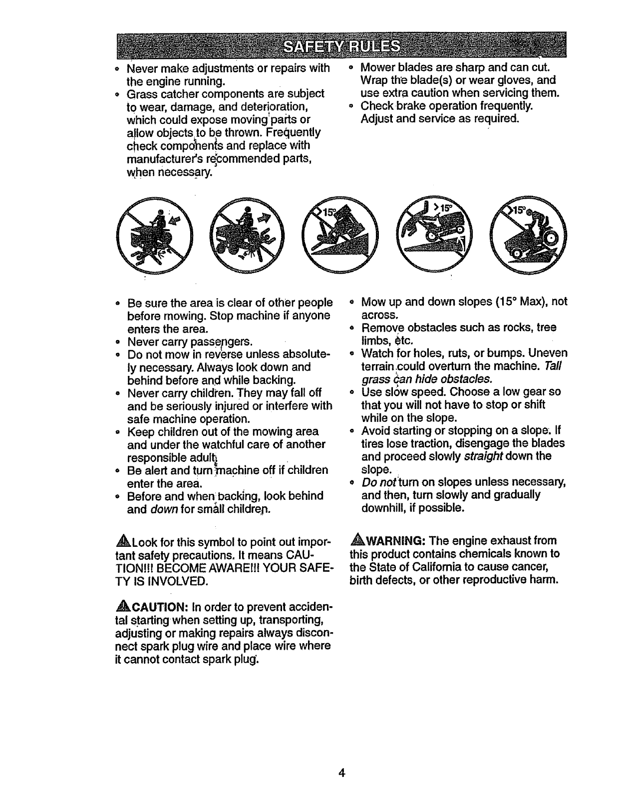
o Mow up and down slopes (15 °Max), not
across.
° Remove obstacles such as rocks, tree
limbs, _tc.
oWatch for holes, ruts, or bumps. Uneven
terrain;could overturn the machine. Taft
grass Can hide obstacles.
° Use sl0w speed. Choose a low gear so
that you will not have to stop or shift
while on the slope.
° Avoid starting or stopping on a slope'. If
tires lose traction, disengage the blades
and proceed slowly straight down the
slope.
•Do not'tum on slopes unless necessary,
and then, turn slowly and gradually
downhill, if possible.
_kLook for this symbol to point out impor-
tant safety precautions. It means CAU-
TION!!! BECOME AWARE!l! YOUR SAFE-
TY IS INVOLVED.
,_WARNING: Tile engine exhaust from
this product contains chemicals known to
the State of California to cause cancer,
birth defects, or other reproductive harm.
,_CAUTION: in order to prevent acciden-
tal startingwhen setting up, transporting,
adjustingor making repairsalways discon-
nect spark plug wire and place wire where
it cannot contact spark plug'.
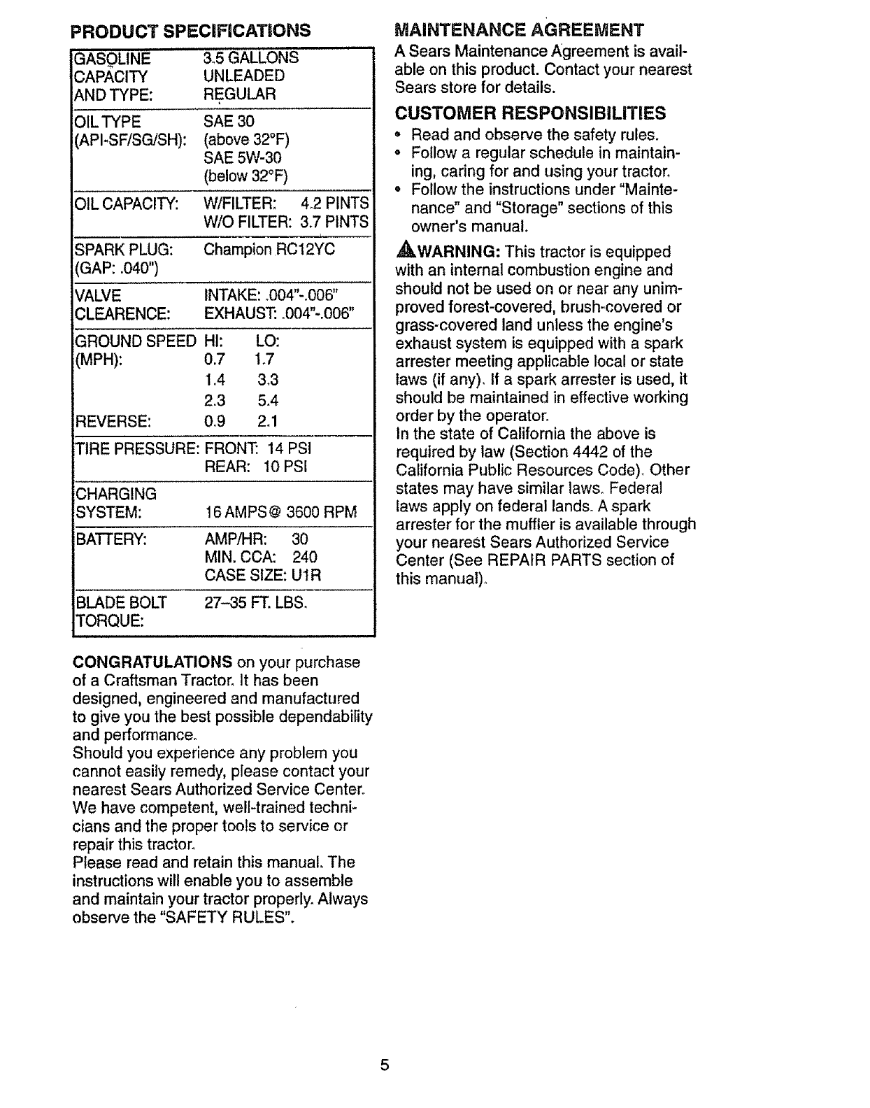
PRODUCT SPECIFICATIONS
=lll,,lll =H= ,,== tll
GASOLINE &5 GALLONS
CAPACITY UNLEADED
AND TYPE: REGULAR
O/L TYPE SAE 30
'API-SF/SGJSH): (above 32°F)
SAE 5W-30
(below 32°F)
W/FILTER: 4°2 PINTS
W/O FILTER: 3.7 PINTS
Champion RC12YC
)IL CAPACITY:
SPARK PLUG:
(GAP: ,040")
VALVE
CLEARENCE:
GROUND SPEED
(MPH):
INTAKE: .004"-.006"
EXHAUST: .004"-.006"
HI: LO:
0.7 1.7
1.4 &3
2.3 5.4
REVERSE: 0.9 2.1
TIRE PRESSURE: FRONT: 14 PSI
REAR: 10 PSI
CHARGING
SYSTEM: 16 AMPS@ 3600 RPM
BATTERY: AMP/HR: 30
MIN. CCA: 240
CASE SIZE: UIR
BLADE BOLT 27-35 FT. LBS.
TORQUE:
MAINTENANCE AGREEMENT
A Sears Maintenance Agreement is avail-
able on this product. Contact your nearest
Sears store for details.
CUSTOMER RESPONSIBILITIES
•Read and observe the safety rules.
o Follow a regular schedule in maintain-
ing, caring for and using your tractor°
• Follow the instructions under"Mainte-
nance" and "Storage" sections of this
owner's manual.
_WARNING: This tractor is equipped
with an internal combustion engine and
should not be used on or near any unim-
proved forest-covered, brush-covered or
grass-covered land unless the engine's
exhaust system is equipped with a spark
arrester meeting applicable local or state
taws (if any). If a spark arrester is used, it
should be maintained in effective working
order by the operator°
In the state of California the above is
required by law (Section 4442 of the
California Public Resources Code). Other
states may have similar laws. Federal
taws apply on federal lands. A spark
arrester for the muffler is available through
your nearest Sears Authorized Service
Center (See REPAIR PARTS section of
this manual).
CONGRATULATIONS on your purchase
of a Craftsman Tractor. It has been
designed, engineered and manufactured
to give you the best possible dependability
and performance.
Should you experience any problem you
cannot easily remedy, please contact your
nearest Sears Authorized Service Center_
We have competent, well-trained techni-
cians and the proper tools to service or
repair this tractor_
Please read and retain this manual° The
instructions will enable you to assemble
and maintain your tractor properly. Always
observe the "SAFETY RULES".
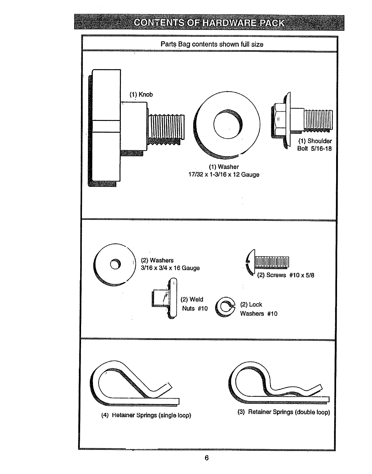
Parts Bagcontents shown fdll size
(1) Knob
(1) Washer
17/32 x 1-3/16 x 12 Gauge
(1) Shoulder
Bolt 5/16-18
_,,,,,,,,,J,J,,_,,,,,,J . ,J JJl,,_,,,_,, 1 ,,, r
O(2) Washers
3/16 x3/4 x16 Gauge
]___ (2) Weld
Nuts #10 @(2) Lock
Washers #10
_4) Hetainer Springs (single loop) (3) Retainer Springs (double loop)
6
.................................. JJ ;
1
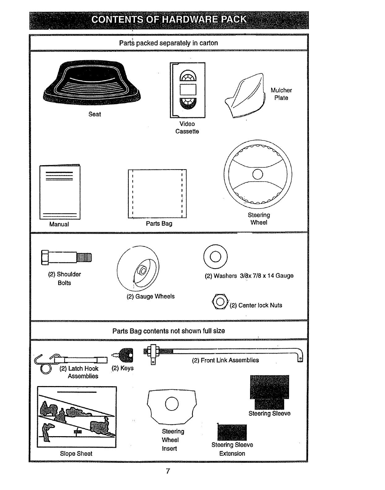
Parts packed separately in carton
Seat
Video
Cassette
Mulcher
Plate
Manual
I •
I I
I I
I I
II
I I
II
I !
_-_ , |
Parts Bag
Steering
Wheel
(2) Shoulder
Bolts Lk
(2) Gauge Wheels
©
(2) Washers 3/8x 7/8 x 14 Gauge
Q'(2) Center lock Nuts
Parts Bag contents not shown full size
(2) Front Link Assemblies
_(2) Latch Hook (2) Keys
Assemblies
Slope Sheet
Steering
Wheel
Insert
7
Steering Sleeve
Steering Sleeve
Extension
Your new tractor has been assembled at the factory with exception of those parts'left
unassembled for shipping purposes. To ensure safe and proper operation of your tractor
all parts and hardware you assemble must be tightened securely. Use the correct tools
as necessary tQ insure proper tightness. Review the video cassette before you begin.
TOOLS REQUIRED FOR
ASSEMBLY
Asocket wrench set will make assembly
easier. Standard wrench sizes you need
are listed below_
(1) 9/16" wrench
(1) 1/2" wrench (1) 3/4." Socket wl
drive rachet
(1) Pliers : (1) Phi!lips, Screw-
(1) Utility knife driver
(1) Tire pressure gauge
When right or left hand is mentioned in
this manual, it means, from your point of
view, when you are in the operating posi-
tion (seated behind the steering wheel).
TO REMOVE TRACTOR FROM
CARTON
UNPACK CARTOI_ i
oRemove all accessible loose parts and
parts boxes fromshipping carton (See
page 6).
o Cut, from top to bottom, along lines on
all four corners of shipping carton, and
lay panels flat. i
°Remove mower and package materials°
°Check for any additional loose parts or
boxes and remove.
BEFORE ROLLING TRACTOR OFF
SKiD
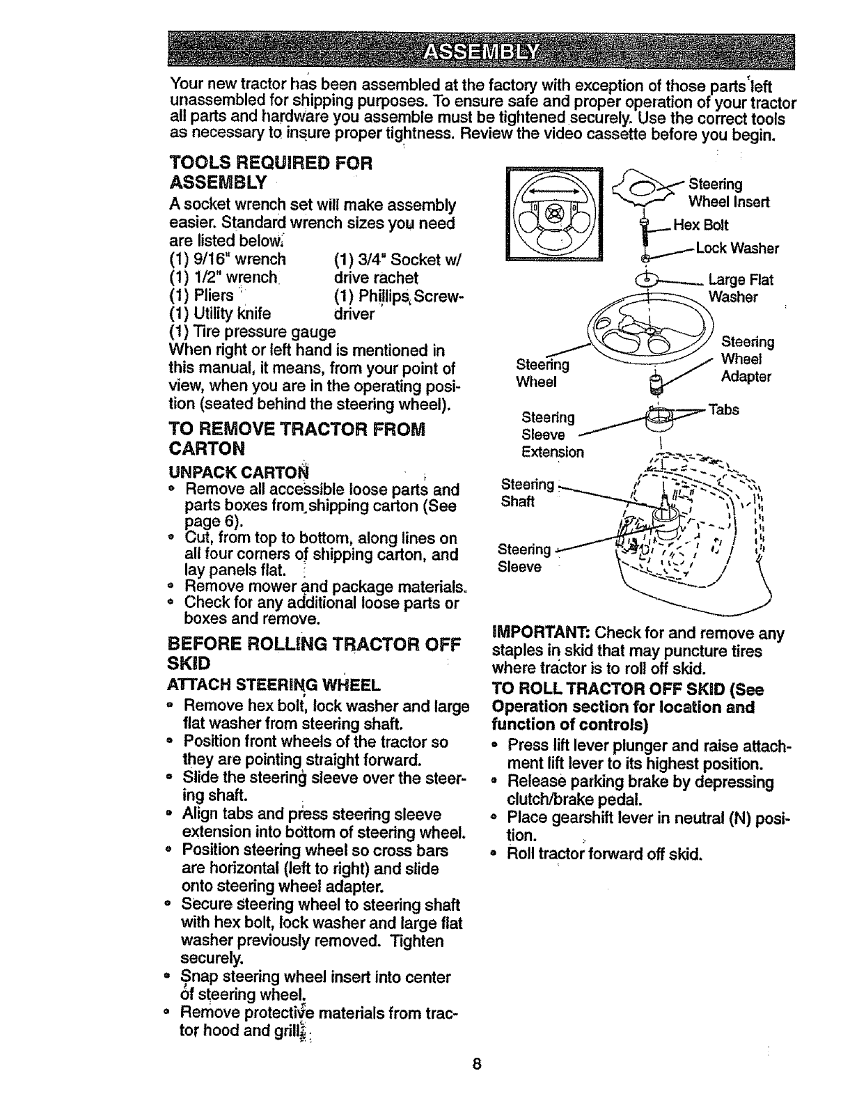
ATTACH STEERING WHEEL
°Remove hex bolt, lock washer and large
flat washer from steering shaft.
°Position front wheels of the tractor so
they are pointing straight forward.
°Slide the steerin_t sleeve over the steer-
ing shaft. I
°Align tabs and press steering sleeve
extension into bdttom of steering wheel.
°Position steering wheel so cross bars
are horizontal (left to right) and slide
onto steering wheel adapter.
=Secure Steering wheel to steering shaft
with hex bolt, lock washer and large flat
washer previously removed. Tighten
securely.
°Snap steering wheel insert into center
of steenng wheel.
oRemove protective materials from trac-
tor hood and gnll_;
"_----" Wheel Insert
.._ Hex Bolt
Lock Washer
Large Flat
Washer
Steering
Steering Wheel
Wheel Adapter
Steering _Tabs
Sleeve t
Extension
Shaft ,_,1
Steedng
Sleeve
_MPORTANT- Check for and remove any
staples in skid that may puncture tires
where tractor is to roll off skid.
TO ROLL TRACTOR OFF SKiD (See
Operation section for location and
function of controls)
• Press lift lever plunger and raise attach-
ment lift lever to its highest position.
=Release parking brake by depressing
clutch/brake pedal.
o Place gearshift lever in neutral (N) posi-
tion.
°Roll tractor forward off skid.
HOW TO SET UP YOUR TRACTOR
CHECK BATTERY
oLift hood to raised position.
oIf this battery is put into service a_er
month and year indicated on label (label
located between terminals) charge bat-
tery for minimum of one hour at 6-10
amps. (See "BATTERY" in Maintenance
section of this manual for charging
instructions).
tF _ • s,
-'" .-" .: Label
7" •*
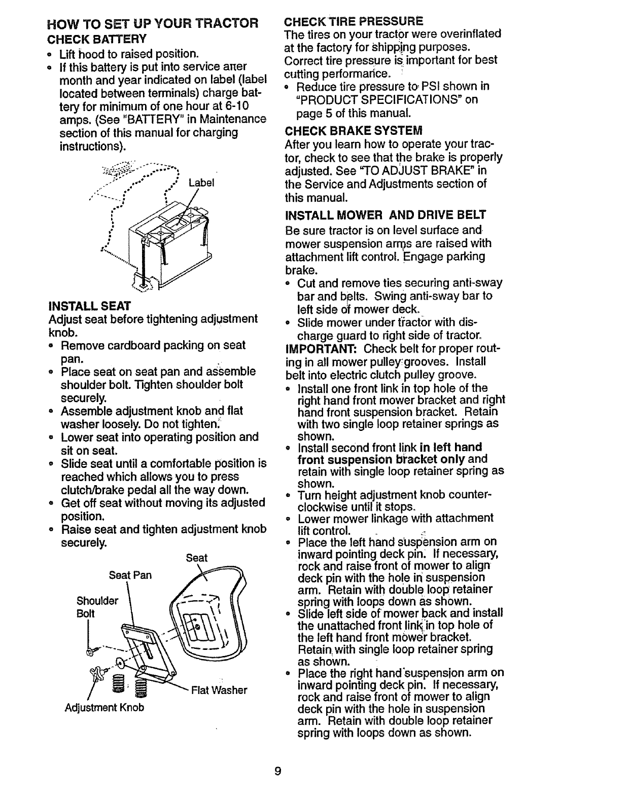
INSTALL SEAT
Adjust seat before tightening adjustment
knob.
oRemove cardboard packing on seat
pan.
•Place seat on seat pan and as'semble
shoulder bolt. "i3ghtenshoulder bolt
securely.
°Assemble adjustment knob and flat
washer loosely. Do not tightenl
° Lower seat into operating position and
sit on seat.
° Slide seat until a comfortable position is
reached which allows you to press
clutch/brake pedal all the way down.
° Get off seat without moving its adjusted
position.
°Raise seat and tighten adjustment knob
securely.
Seat
Seat Pan
Shoulder
Bolt
Adjustment Knob
Flat Washer
CHECKTIRE PRESSURE
The tires on your tractor were overinflated
at the factory for Shipping purposes.
Correct tire pressure is..important for best
cutting pefformarice.
•Reduce tire pressure to-.PSt shown in
"PRODUCT SPECIFICATIONS" on
page 5 of this manual.
CHECK BRAKE SYSTEM
After you learn how to operate your trac-
tor, check to see that the brake is properly
adjusted, See "TO AD3UST BRAKE" in
the Service and Adjustments section of
this manual.
INSTALL MOWER AND DRIVE BELT
Be sure tractor is on level surface and
mower suspension arras are raised with
attachment lift control. Engage parking
brake.
°Cut and remove ties securing anti=sway
bar and bplts. Swing anti-sway bar to
left side of mower deck_
° Slide mower under tiact0r with dis-
charge guard to right side of tractor.
IMPORTANT: Check belt for proper rout-
ing in all mower pulley;grooves. Install
belt into electric clutch pulley groove_
•Install one front link in top hole of the
right hand front mower bracket and right
hand front suspension bracket. Retain
with two single loop retainer springs as
shown.
°Install second front link in left hand
front suspension bracket only and
retain with single loop retainer spring as
shown.
°Turn height adjustment knob counter-
clockwise until it stops,
° Lower mower linkage with attachment
lift control. _
•Place the left hand suspension arm on
inward pointing deck pin. If necessary,
rock and raise front of mower to align
deck pin with the hole ir_suspension
arm. Retain with double loop retainer
s.pring with loops down as shown.
°Shde left side of mower back and install
the unattached front link_iintop hole of
the left hand front mower bracket.
Retain, with single loop retainer spring
as shown.
° Place the right hand'suspension arm on
inward pointing deck pin. If necessary,
rock and raise front of mower to align
deck pin with the hole in suspension
arm. Retain with double loop retainer
spring with loops down as shown.
9
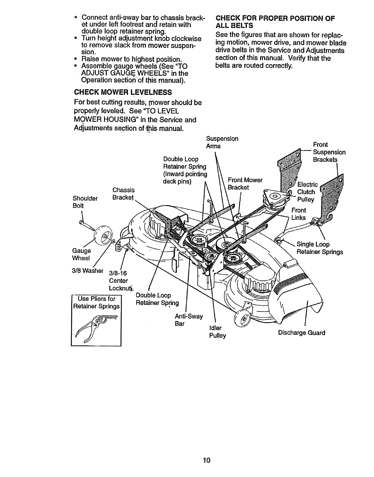
Connect anti-sway bar to chassis brack-
et under left footrest and retain with
double loop retainer spring.
o Turn height adjustment knob clockwise
to remove slack from mower suspen-
sion°
-Raise mower to highest position.
o Assemble gauge wheels (See "TO
ADJUST GAUGE WHEELS" in the
Operation section of this manual).
CHECK MOWER LEVELNESS
For best cutting resultsLrnower should be
properly leveled. See %0 LEVEL
MOWER HOUSING" inthe Service and
Adjustments section of_!hismanual.
Chassis
Shoulder Bracket
Bolt '
Double Loop
Retainer Spring
(Inward pointing
deck pins)
CHECK FOR PROPER POSITSON OF
ALL BELTS
See the figures that are shown for replac-
ing motion, mower drive, and mower blade
drive belts in the Service and Adjustments
section Ofthis manual. Verify that the
belts are routed correctly.
Suspension
Arms Front
Brackets
FrontMower
Bracket Electric
Clutch
Front
Gauge
Wheel
3/8 Washer 3/8-16
Center
Lockrlu_.
Use Pliers for
:letainer Springs
!
DoubleLoop
Retainer Sp.ring
Anti-Sway
Bar Idler
Pulley Discharge Guard
Single Loop
Retainer Springs
10
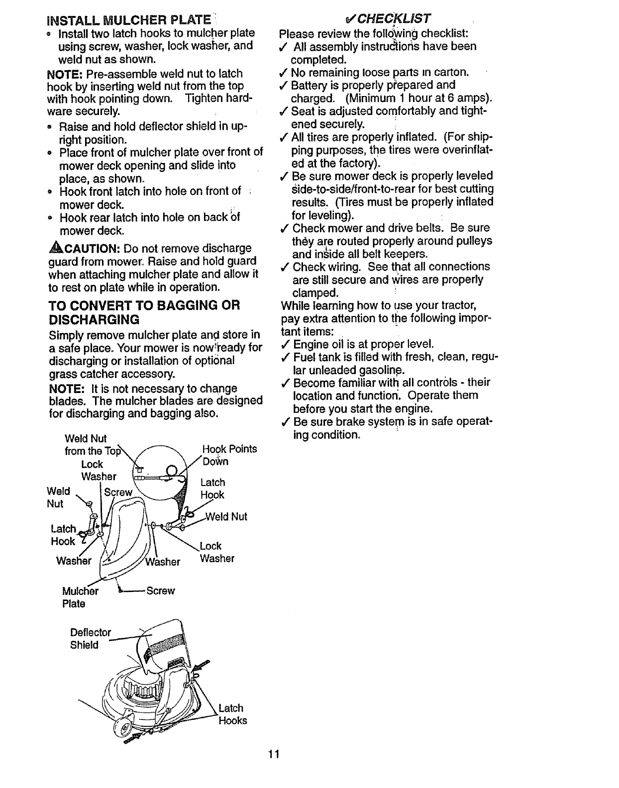
iNSTALL MULCHER PLATE:
oInstall two latch hooks to mulcher plate
using screw, washer, lock washer, and
weld nut as shown.
NOTE: Pre-assemble weld nut to latch
hook by inserting weld nut from the top
with hook pointing down. Tighten hard-
ware securely.
o Raise and hold deflector shield in up-
right position.
oPlace front of mulcher plate over front of
mower deck opening and slide into
place, as shown_
= Hook front latch into hole on front of ;
mower deck. _,
°Hook rear latch into hole on back bf
mower deck.
,_CAUTION: Do not remove discharge
guard from mower° Raise and hold guard
when attaching mulcher plate and allow it
to rest on plate while in operation.
TO CONVERT TO BAGGING OR
DISCHARGING
Simply remove mulcher plate and store in
a safe place. Your mower is now'ready for
discharging or installation of optional
grass catcher accessory.
NOTE: It is not necessary to change
blades. The mulcher blades are designed
for discharging and bagging also.
Weld Nut
from Hook Points
Lock
Washer Latch
Weld Hook
Nut
Latch
Lock
Washer
CHECKLIST
Please review the follQWingchecklist:
#' All assembly instruc_ior_s have been
completed.
,,! No remaining loose parts In carton.
,/Battery is properly p_epared and
charged. (Minimum 1 hour at 6 amps).
_" Seat is adjusted comfortably and tight-
ened securely.
,/All tires are properly inflated. (For ship-
ping purposes, the tires were overinflat-
ed at the factory).
,/Be sure mower deck is properly leveled
side-to-side/front-to-rear for best cutting
results. (Tires must be properly inflated
for leveling).
,/Check mower and drive belts. Be sure
they are routed properly around pulleys
and inside all belt keepers.
,I Check wiring. See that all connections
are still secure and Wires are properly
clamped.
While learning how to use your tractor,
pay extra attention to tl_e following impor-
tant items:
,I Engine oii is at proper level.
,# Fuel tank is filled with fresh, clean, regu-
lar unleaded gasoline.
,/" Become familiar with all controls - their
location and function _. Operate them
before you start the engine.
#" Be sure brake system is in safe operat-
ing condition.
Mulch'_r
Plate
Deflector
Shield
'_Latch
_Hooks
11
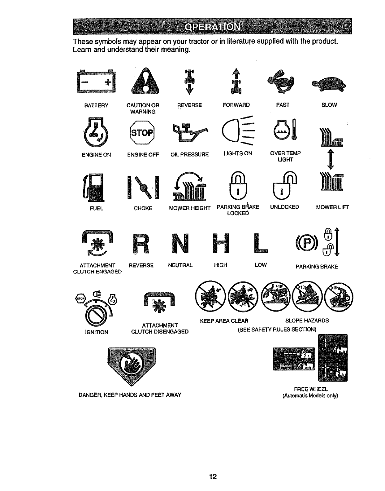
These symbols may appear on yourtractor or in literature supplied with the product.
Learn and understand their meaning.
T÷
BATTERY CAUTION OR SLOW
WARNING
ENGINE ON ENGINE OFF t
REVERSE FORWARD
OIL PRESSURE LIGHTS ON
MOWER HEIGHT PARKING BI_KE
LOCKEI_
FUEL CHOKE MOWER LIFT
FAST
OVER TEMP
LIGHT
UNLOCKED
ATTACHMENT
CLUTCH ENGAGED
iGNITION
,,
REVERSE NEUTRAL
ATTACHMENT
CLUTCH DISENGAGED
HIGH LOW PARKING BRAKE
KEEP AREA CLEAR SLOPE HAZARDS
(SEE SAFETY RULES SECTION)
DANGER, KEEP HANDS AND FEET AWAY FREE WHEEL
(AutomaticModels only)
12
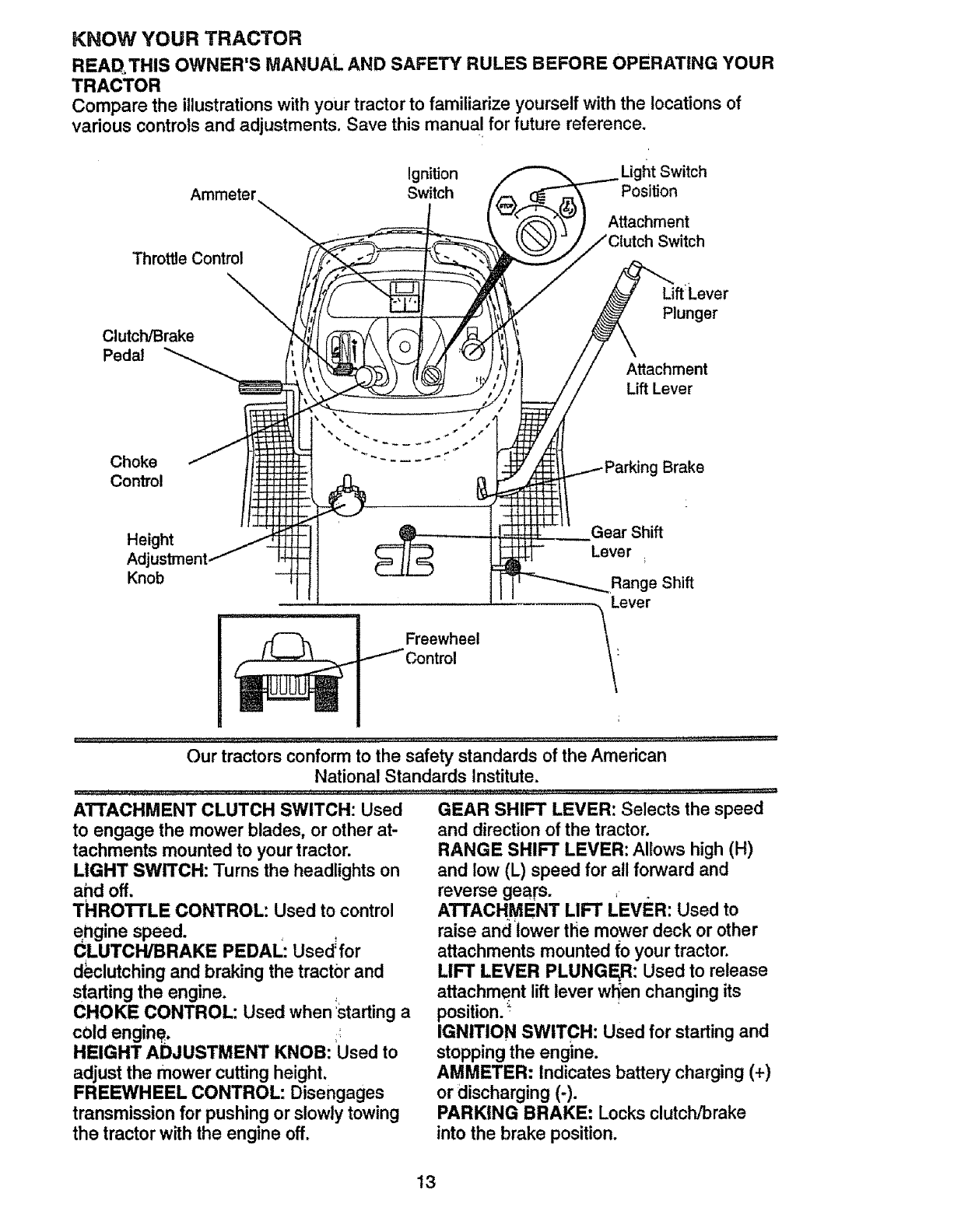
KNOW YOUR TRACTOR
READ.THIS OWNER'SMANUAL AND SAFETYRULES BEFORE OPERATINGYOUR
TRACTOR
Comparethe illustrationswith your tractorto familiarize yourself with the locations of
various controls and adjustments. Save this manual for future reference.
Ignition l_tSwitch
Ammeter Switch PosiUon
Throttle Control
Attachment
Switch
Clutch/Brake
Pedal
Lift'Lever
Plunger
Attachment
Lift Lever
Choke g Brake
Control
Height Gear Shift
Adj
Knob
Freewheel
Range Shift
-le ve r
Our tractors conform to the safety standards of the American
National Standards Institute.
ATTACHMENT CLUTCH SWITCH: Used
to engage the mower blades, or other at-
tachments mounted to your tractor.
LIGHT SWITCH: Turns the headlights on
and off.
THROTrLE CONTROL: Used to control
engine speed.
CLUTCH/BRAKE PEDAL: Used'for
declutchmg and braking the tractor and
starting the engine.
CHOKE CONTROL: Used when :starting a
cold engine.
HEIGHT ADJUSTMENT KNOB: Used to
adjust the mower cutting height.
FREEWHEEL CONTROL: Disengages
transmission for pushing or slowly towing
the tractor with the engine off.
GEAR SHIFT LEVER: Selects the speed
and direction of the tractor.
RANGE SHIFT LEVER: Allows high (H)
and low (L) speed for all forward and
reverse gears. EV
ATTACHMENT LIFT L ER: Used to
raise and lower tlie mower deck or other
attachments mounted fo your tractor.
LIFT LEVER PLUNGE, R: Used to release
attachment lift lever wl_en changing its
position.
IGNITION SWITCH: Used for starting and
stopping the engine.
AMMETER: Indicates battery charging (+)
or discharging (-).
PARKING BRAKE: Locks clutch/brake
into the brake position.
13
The operation-of any tractor can result in foreign objects thrown into the
eyes, which can result in severe eye damage. Always wear safety glasses
or eye shields while operating your tractor or performing any adjustments or
repairs. We recomrnend a wide vision safety mask over spectacles, or stan-
dard safety glasses.
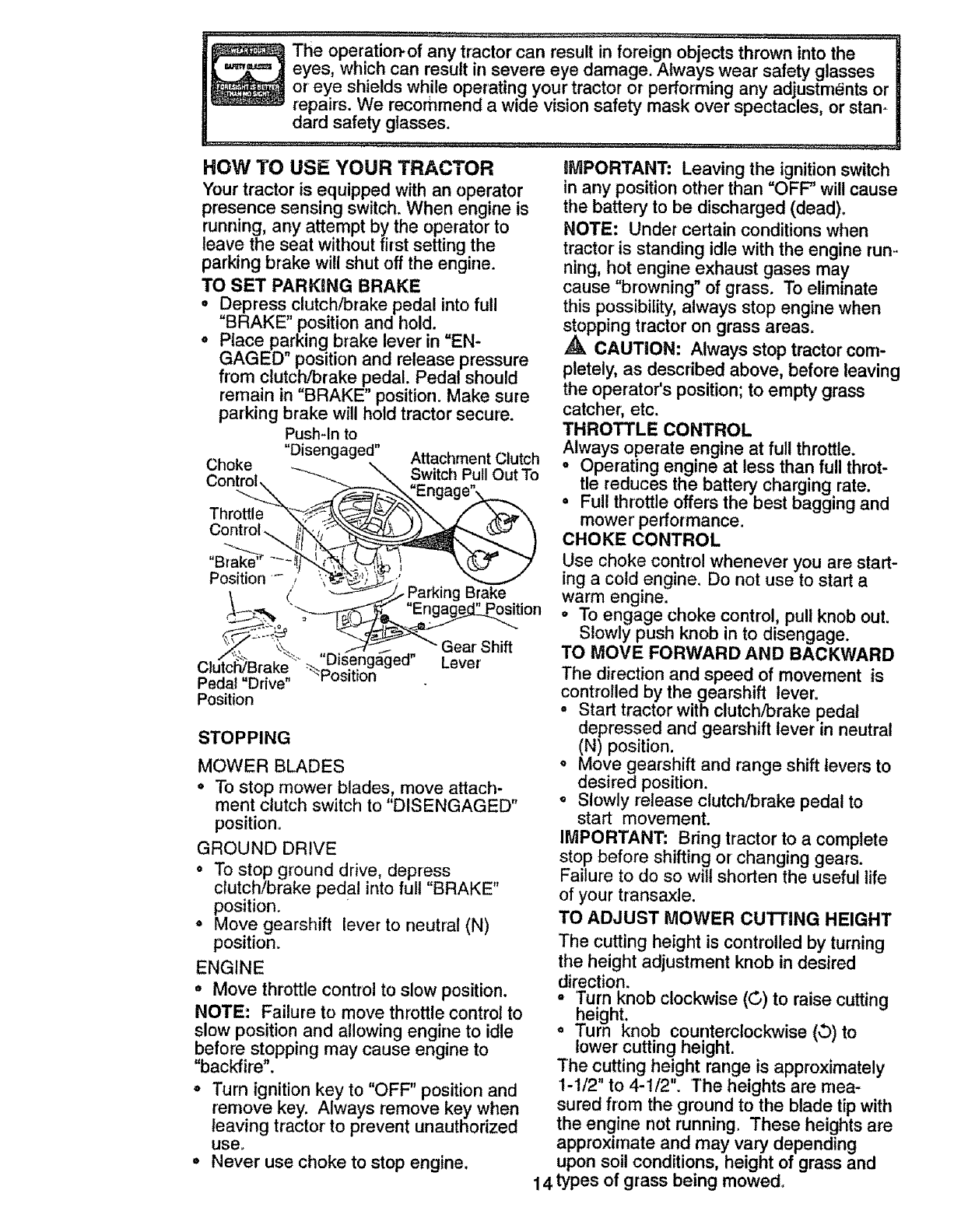
HOW TO USE YOUR TRACTOR
Your tractor is equipped with an operator
presence sensing switch, When engine is
running, any attempt by the operator to
leave the seat without first setting the
parking brake will shut off the engine.
TO SET PARKING BRAKE
• Depress clutch/brake pedal into full
"BRAKE" position and hold.
°Place parking brake lever in "EN-
GAGED" position and release pressure
from clutch!brake pedal. Pedal should
remain in "BRAKE" position. Make sure
parking brake will hold tractor secure.
Push-In to
"Disengaged" Attachment Clutch
Choke
_,,,,,,,,_ ""_-.._ _ Switch PullOut To
,.,uHu,.,_\ _ \ "En a "
Throft__._/"_N_ /_'_w'N,
Control _!',_;"
Position_-" "__/_ ..
\(' '---_'-_ Parking Brake
_-q: "_ "Engage_sition
;lutci _Brake _"D_sengaged Lever'
Pedal "Drive" _osmon .
Position
STOPPING
MOWER BLADES
°To stop mower blades, move attach-
ment clutch switch to "DISENGAGED"
position.
GROUND DRIVE
°To stop ground drive, depress
clutch/brake pedal into full "BRAKE"
position.
oMove gearshift lever to neutral (N)
position.
ENGINE
• Move throttle control to slow position.
NOTE: Failure to move throttle control to
slow position and allowing engine to idle
before stopping may cause engine to
"backfire".
° Turn ignition key to "OFF" position and
remove key. Always remove key when
leaving tractor to prevent unauthorized
use_
°Never use choke to stop engine. 14
iMPORTANT: Leaving the ignition switch
in any position other than "OFF" will cause
the battery to be discharged (dead).
NOTE: Under certain conditions when
tractor is standing idle with the engine run-
ning, hot engine exhaust gases may
cause "browning" of grass. To eliminate
this possibility, always stop engine when
st.opping tractor on grass areas.
,_. CAUTION: Always stop tractor corn-
pletely, as described above, before leaving
the operator's position; to empty grass
catcher; etc.
THROTTLE CONTROL
Always operate engine at full throttle.
oOperating engine at less than full throt-
tle reduces the battery charging rate.
=Full throttle offers the best bagging and
mower performance.
CHOKE CONTROL
Use choke control whenever you are start-
ing a cold engine. Do not use to start a
warm engine.
oTo engage choke control, pull knob out.
Slowly push knob in to disengage.
TO MOVE FORWARD AND BACKWARD
The direction and speed of movement is
controlled by the gearshift lever=
° Start tractor with clutch/brake pedal
depressed and gearshift lever in neutral
(N) position.
°Move gearshift and range shift levers to
desired position.
° Slowly release clutch/brake pedal to
start movement.
IMPORTANT: Bring tractor to a complete
stop before shifting or changing gears,
Failure to do so wilt shorten the useful life
of your transaxle.
TO ADJUST MOWER cu'n'ING HEIGHT
The cutting height is controlled by turning
the height adjustment knob in desired
direction.
=Turn knob clockwise (©) to raise cutting
height.
°Turn knob counterclockwise (,3) to
lower cutting height.
The cutting height range is approximately
1-1/2" to 4-1/2". The heights are mea-
sured from the ground to the blade tip with
the engine not running. These heights are
approximate and may vary depending
upon soil conditions, height of grass and
types of grass being mowed,
- The average lawn should be cut to
approximately2-1/2 inchesduring the
cool season and to over3 inch_esduring
hot months. For healthier and better
looking lawns, mowoften and after
moderategrowth.
° For bestcutting performance,grass
over 6 inchesin heightshould be
mowedtwice° Makethe first cut rela-
tively high; the secondto desired height.
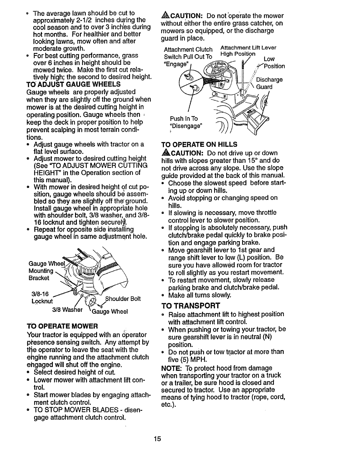
TO ADJUST GAUGE WHEELS
Gauge wheels are properly adjusted
when they are slightly off the ground when
mower is at the desired cutting height in
operating position. Gauge wheels then ,
keep the deck in proper position to help
prevent scalping in most terrain condi-
tions.
• Adjust gauge wheels with tractor on a
flat level surface.
• Adjust mower to desired cutting height
(See =TOADJUST MOWER CUTTING
HEIGHT" in the Operation section of
this manual).
° With mower in desired height of cut po-
sition, gauge wheels should b_ assem-
bled so they are slightly off the'ground.
Install gauge wheel in appropriate hole
with shoulder bolt, 3/8 washer, and 3/8-
16 Iocknut and tighten securely.
• Repeat for opposite side installing
gauge wheel in same adjustment hole.
Gauge
Moun_ng,_
Bracket
3/8-16
Locknut ShoulderBolt
3/8 Washer Gauge Wheel
TO OPERATE MOWER
Your tractor is equipped with an Operator
p_esence sensing switch. Any attempt by
t_e operator to leave the seat with the
ehgine running and the attachment clutch
ehgaged will shut off the engine.
°Select desired height of cut.
•Lower mower with attachment !ift con-
trol.
• Start mower blades by engaging attach-
ment clutch control,
oTO STOP MOWER BLADES - disen-
gage attachment clutch contro].
,_kCAUTION: Do not'operate the mower
without either the entire grass catcher, on
mowers so equipped, or the discharge
guard in place.
Attachment Clutch
Switch Pull Out To
=Enga_
Push in To --_
=Disengage"
Attachment Lift Lever
High Position LoW
_._'Position
..YDischarge
Guard
TO OPERATE ON HILLS
,_CAUTION: Do not drive up or down
hills with slopes greater than t5 ° and do
not drive across any slope_ Use the slope
guide provided at the back of this manual.
•Choose the slowest speed before start-
ing up or down hills.
° Avoid stopping or changing speed on
hills.
°If slowing is necessary, move throttle
control lever to slower position.
=If stopping is absolutely necessary, push
clutch/brake pedal quickly to brake posi-
tion and engage parking brake.
°Move gearshift lever to 1st gear and
range shift lever to low (L) position. Be
sure you have allowed room for tractor
to roll slightly as you restart movement.
°To restart movement, slowly release
parking brake and clutch/brake pedal.
°Make all turns slowly.
TO TRANSPORT
•Raise attachment lift to highest position
with attachment lift control°
°Whenpushing or towing your. tractor, be
sure gearshift lever is in neutral (N)
position.
• Do not push or tow tractor at more than
five (5) MPHo
NOTE: To protect hood from damage
when transporting your tractor on a truck
or a trailer, be sure hood is closed and
secured to tractor. Use an appropriate
means of tying hood to tractor (rope, cord,
etc.).
15
TOWING CARTS AND OTHER
ATTACHMENTS
Tow only the attachments that are recom-
mendedby and comply with specifications
of the manufacturer of your tractor. Use
common sense when towing. Too heavy of
aload, while on a slope, i_ dangerous.
Tires carl lose traction with the ground and
cause you to lose contro! ,of your iractor.
BEFORE STARTING THE ENGINE
CHECK ENGINE OIL LEVEL
•The engine in,your tractor has been
shipped, from the factory, atreadv filled
with summer weight oil.
•Check engine oil with tractor on level
ground. _ .
° Unthread and remove oil fill capldip-
stick; wipe oil off. Reinsert the dipstick
into the tube and rest oil fill capon the
tube. Do not thread the cap onto the
tube. Remove and read oil level. If nec-
essary, add oil until "FULL" mark on
dipstick is reache_l. Do not overfill.
=For cold weather ooperation you should
change oil for e_ier starting (See_. OIL
VISCOSITY CH/_IT" in the Customer
Responsibilities section of this manual).
o To change engin_ oil, see the Customer
Responsibilities section in this manual.
ADD GASOLINE!
°Fill fuel tank. Uselfresh, clean, regular
unleaded gasolin.b with aminimum of 87
octane. (Use of I_aded gasoline will
increase carbon _nd tead oxide
deposits and redSce valve life). Do not
mix oil with gasoline. Purchase fuel in
_uantities that can be used within 30
ays to assure fu_etfreshness.
iMPORTANT. When operating in tempera-
tures below 32°F(0°C), use fresh, clean
winter grade gasoline to help insure good
cold weather starting.
,AWARNING: Experience indicates that
alcohol blended fuels (called gasohol or
using ethanol or methanol) can attract
moisture which leads to separation and
formation of acids during storage. Acidic
gas can damage the fuel system of an
erigine while in storage. To avoid engine
problems, the fuel system should be emp-
tied before storage of 30 days or longer.
Drain the gas tank, start the engine and let
it run until the fuel lines and carburetor are
empty. Use fresh fuel next season. See
Storage Instructions for additional
information. Never use engine or
carburetor cleaner _roducts in the fuel
tank or permanent _mage may occur.
16
,_kCAUTnON: Fill to bottom of gas tank
filler neck. Do not overfill. Wipe off any
spilled oil or fuel. Do not store, spill or use
gasoline r_ear an open flame.
TO START ENGINE
When starting the engine for the first time
or if the engine has run out of fuel, it will
take extra cranking time to move fuel from
the tank to the engine.
oSit on _eat in operating position,
depress clutch/brake pedal and set
parking brake.
o Place gear shift lever in neutral (N)
position.
= Move attachment clutch to "DISEN-
GAGED" position.
o Move throttle control to fast position
°Pull choke control out for a cold engine
start attempt. For a warm engine start
attempt the choke control may not be
needed.
NOTE: Before starting, read the warm and
cold starting procedures below.
oInsert key into ignition and turn key
clockw!se to "START" position and
release key as soon as engine starts.
Do not run starter continuously for more
than fifteen seconds per minute, if the
engine does not start after several
attempts, push choke control in, wait a
few minutes and try again. If engme still
does not start, pull the choke control out
and retry.
WARM WEATHER STARTING (50° F
AND ABOVE)
°When engine starts, slowly push choke
control in until the engine begins to run
smoothly. If the engine starts to run
roughly, pull tile choke control out slight-
ly for a few seconds and then continue
to push the control in slowly.
°The attachments and ground drive can
now be used. If the engine does not
accept the load, restart the engine and
allow it to warm up for one minute using
the choke as described above. 1
COLDWEATHERSTARTING(50°F AND
BELOW)
o Wh6n engine starts, slowly push choke
control in until the engine begins to run
smoothly. Continue to push the choke
control in small steps allowing the
engine to accept small changes in
speed and load, until the choke control
is fully in. if the engine starts to run
roughly, pull the choke control out slight-
ly for a few seconds and then continue
to push the control in slowly. This may _
require an engine warm-up period from
several seconds to several minutes,
depending on the temperature.
, The attachments can be used during
the engine warm-up period and may
require the choke control be pulled out
slightly.
NOTE: A high altitude (above 3000 feet)
or in cold temperatures (below 32 F) the
carburetor fuel mixture may need to be
adjusted for best engine performance.
See "TO ADJUST CARBURETOR" in the
Service and Adjustments section of this
manual.
o Do not' mow grass When it is wet. Wet
grass'will plug mower and leave unde-
sirable clumps. Allow grass to dry
before mowing.
° Always operate engine at full throttle
when mowing to assure better mowing
performance and proper discharge of
material. Regulate ground speed by se-
lecting a low enough gear to give the
mower the best cutting performance as
well as the quality of cut desired.
= When operating attachments, select a
ground speed that will suit the terrain
and give best performance of the at-
tachment being used.
f
i
MOWING TIPS
o Tire chains cannot be used when the
mower housing is attached to tractor.
°Mower should be properly leveled for
best mowing performance. See "TO
LEVEL MOWER HOUSING" in'the
Service and Adjustments sectiqn of this
manual.
° The left hand side of mower sPibuld be
used for trimming.
°Drive so that clippings are discharged
onto the area that has been cuL Have
the cut area to the right of the tractor.
This will result in a more even distribu-
tion of clippings and more uniform cut-
ting.
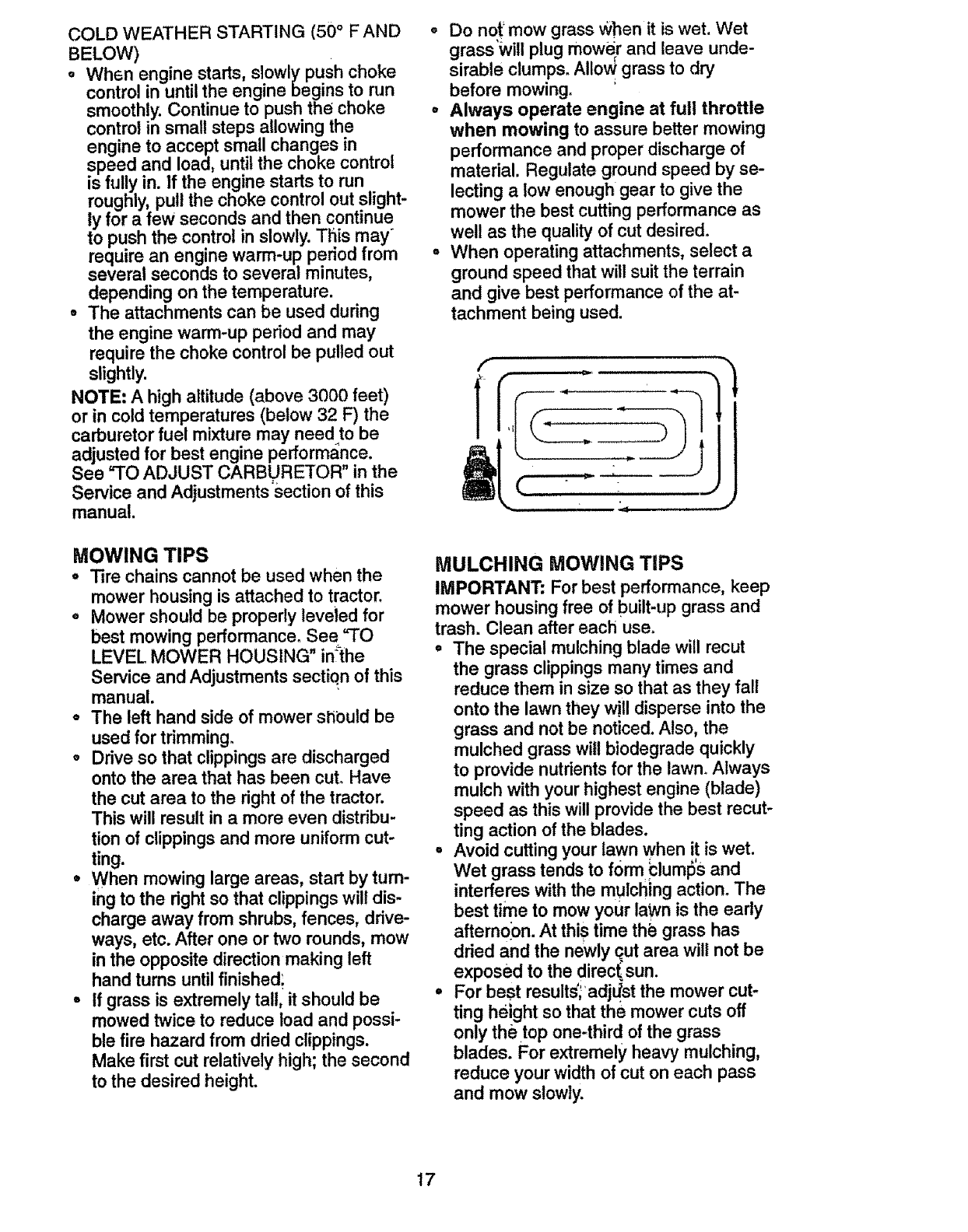
*When mowing large areas, start by turn-
ii_gto the right so that clippings will dis-
charge away from shrubs, fences, drive-
ways, etc. After one or two rounds, mow
in the opposite direction making left
hand turns until finished_
= If grass is extremely tall, it should be
mowed twice to reduce load and possi-
ble fire hazard from dried clippings.
Make first cut relatively high; the second
to the desired height.
MULCHING MOWING TIPS
IMPORTANT: For best performance, keep
mower housing free of built-up grass and
trash. Clean after each use.
° The special mulching blade will recut
the grass clippings many times and
reduce them in size so that as they fall
onto the lawn they will disperse into the
grass and not be noticed. Also, the
mulched grass wilt biodegrade quickly
to provide nutrients for the lawn. Always
mulch with your highest engine (blade)
speed as this will provide the best recut-
ting action of the blades.
° Avoid cutting your lawn when it is wet.
Wet grass tends to f0rm _lumlS'Sand
interferes with the mulching action. The
best time to mow your lawn is the early
afternoon. At this time th_ grass has
dried and the newly cut area will not be
exposed to the direct sun.
•For best results;adjLtst the mower cut-
ting helght so that the mower cuts off
only the top one-third of the grass
blades. For extremely heavy mulching,
reduce your width of cut on each pass
and mow slowly.
17
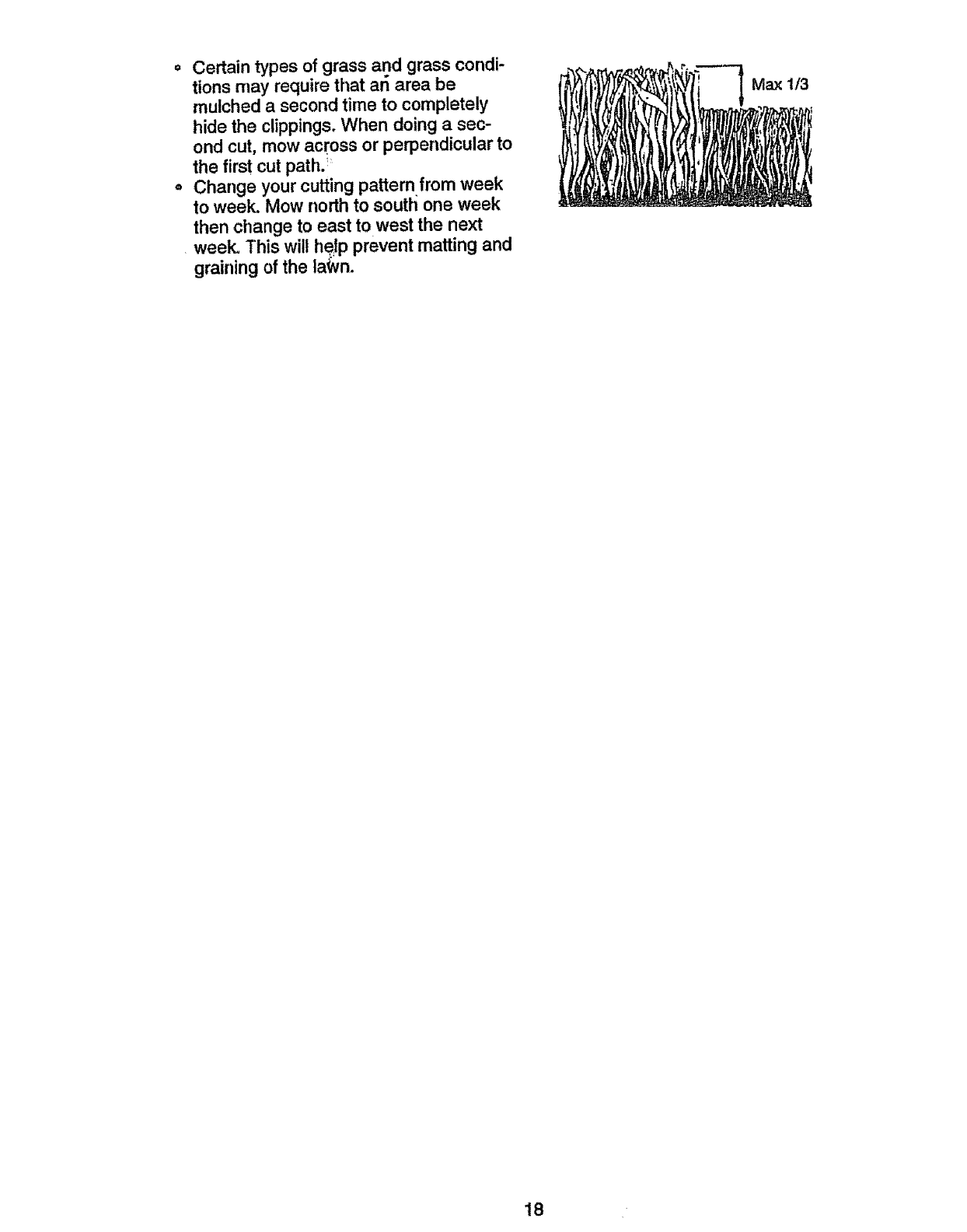
•Certain types of grass and grass condi-
tions may require that an area be
mulched a second time to completely
hide the clippings. When doing a sec-
ond cut, mow across or perpendicular to
the first cut path. _
° Change your cutting pattern from week
to week. Mow north to south one week
then change to east to west the next
week. This will he,tp prevent matting and
graining of the la_vn.
Max t/3
18
,, i ,i =.
MAINTENANCE SCHEDULE
FiLL IN DATES
AS YOU COMPLETE
REGULAR SERVICE
Check Brr_ke,Oper,at!an _
Check "rim Pressure _ _ .......
Check Operator Presence and
TInterlock Systems , _'
R"_e_ forLoose Fastener's ......... lb=#' _4'7
Sh_'peniRep_ce Mower Blades _/',
MI
TLubrication Chart = _'
0 Check Battery Level
RClean Battery and Terminals/Recharge
Check Trensaxle Cooling I
Adjust Blade Belt(s) Tension
Adjust Metion Drive Belt(s) Tensten Ks
ii i i1,,1,,..... i1,,....
-Check Engine Oil Level V_
Change Engine Oil _2,3
E Ctesrt Air Filter ...... _'2 .....
Clean Air Screen _2
v'
v"
v'
Rep!ace Spark Plug .......................... _'
d_ ....
Replace Air Filter Paper Cartridge ., _-
Replace Fuel Filter
t- Changemortaoftanwhen operatEng_,Idera heavyload9r in h_ghambientterr_:_ratures..5_I!equ_ppodwith_dJL_st_b_asystem
2-S=_'tc_moreoPdmwhenoperating in dirtyor dusty.condPJon_. 6 - Not r_qubed if equipped wt_,hma]ntenance-fr_ebs_tety.
3 - If equipped with oi1fl_r, oh=rageoite_vety50 bourn; 7 - T_ghtenfror_trodep_votboltto35 ft .tbs ma_rnum
4_Replaceblade=mote of_ettwhenmowingin r,_ndy._l.. Do notov_ghtan_
GENERAL RECOMMENDATIONS
The warranty on thistractordoesnot cover
itemsthat have been subjectedt_ operator
abuse or negligence.To receivefull value
from the warranty,operatormust maintain
tractor as instructedinthis manual. Some
adjustmentswill need to be made periodi-
cally to properlymaintainyour tractor.
All adjustmentsinthe Service and
Adjustmentssectionof this manualshould
be checked at least once each season.
, !Once a year you should replace the
sparkplug, clean or replaceair filter, and
check blades and beltsfor wear. A new
spark plug and clean air filter assure
properair-fuel mixturea_ndhelp your
engine runbetter and last longer.
BEFORE EACH USE
oCheck engine oil level.
°Check brakeoperation.
°Check tire pressure.
°Check operatorpresence and interlock
systemsfor properoperation.
•Check for loosefasteners.
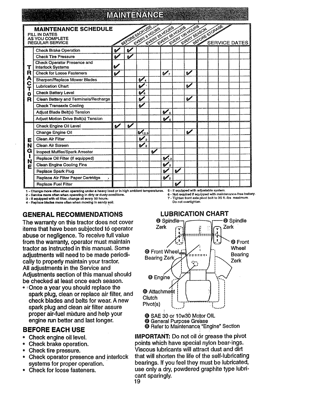
LUBRICATION CHART
Zerk Zerk
Front Wheel
Bearing
Front
Wheel
Bearing
Zerk
Engine i
c,utchi i
Pivot(s) t t ,:
@SAE 30 or 10w30 Motor OIL
@ General PurposeGrease
Refer to Ma ntenance_"Engine" Section
IMPORTANT= Do not oil 6r grease the pivot
points which have special nylon bear-ings.
Viscous lubricants will attract dust and dirt
that will shorten the life of the self-lubricating
bearings. If you feet they must be lubricated,
use only a dry, powdered graphite type lubri-
cant spadnglyo
19
TRACTOR '
Always observe safety rules when per-
forming any maintenance.
BRAKE OPERATION
tf tractor requires more than six (6) feet
stopping distance at high speed in highest
gear, then brake must be adjusted. (See
=TO ADJUST BRAKE" in the Service and
Adjustments section of this manual).
TIRES
• Maintain proper air pressure in all tires
(See "PRODUCT SPECIFICATIONS" on
page 3 of this manual).
• Keep tires free of gasoline, oil, or insect
control chemicals which can harm rub-
ber.
• Avoid stumps, stones, deep ruts, sharp
objects and other hazards that may
cause tire damage.
NOTE: To seal tire punctures and prevent
flat tires due to slow leaks, tire sealant
may be purchased from your local parts
dealer° Tire sealant also prevents tire dry
rot and corrosion.
OPERATOR PRESENCE SYSTEM
Be sure that operator presence and inter-
lock systems are working properly. If your
tractor does not function as described
below, repair the problem immediately.
• The engine should not start unless the
clutch/brake pedal is fully depressed
and attachment clutch control is in the
disengaged position.
° When the engine is running, any
attempt by the operator to leave the
seat without first setting the parking
brake should shut off the engine.
•When the engine is running and the
attachment clutch is engaged, any
attempt by the operator to leave the
seat should shut off the engine.
•The attachment clutch should never
operate unless the operator is in the
seat.
BLADE CARE
For best results mower blades must be
kept sharp. Replace bent or damaged
blades.
BLADE REMOVAL
•Raise mower to highest position to allow
access to blades.
°Remove hex bolt, lock washer and flat
washer securing blade°
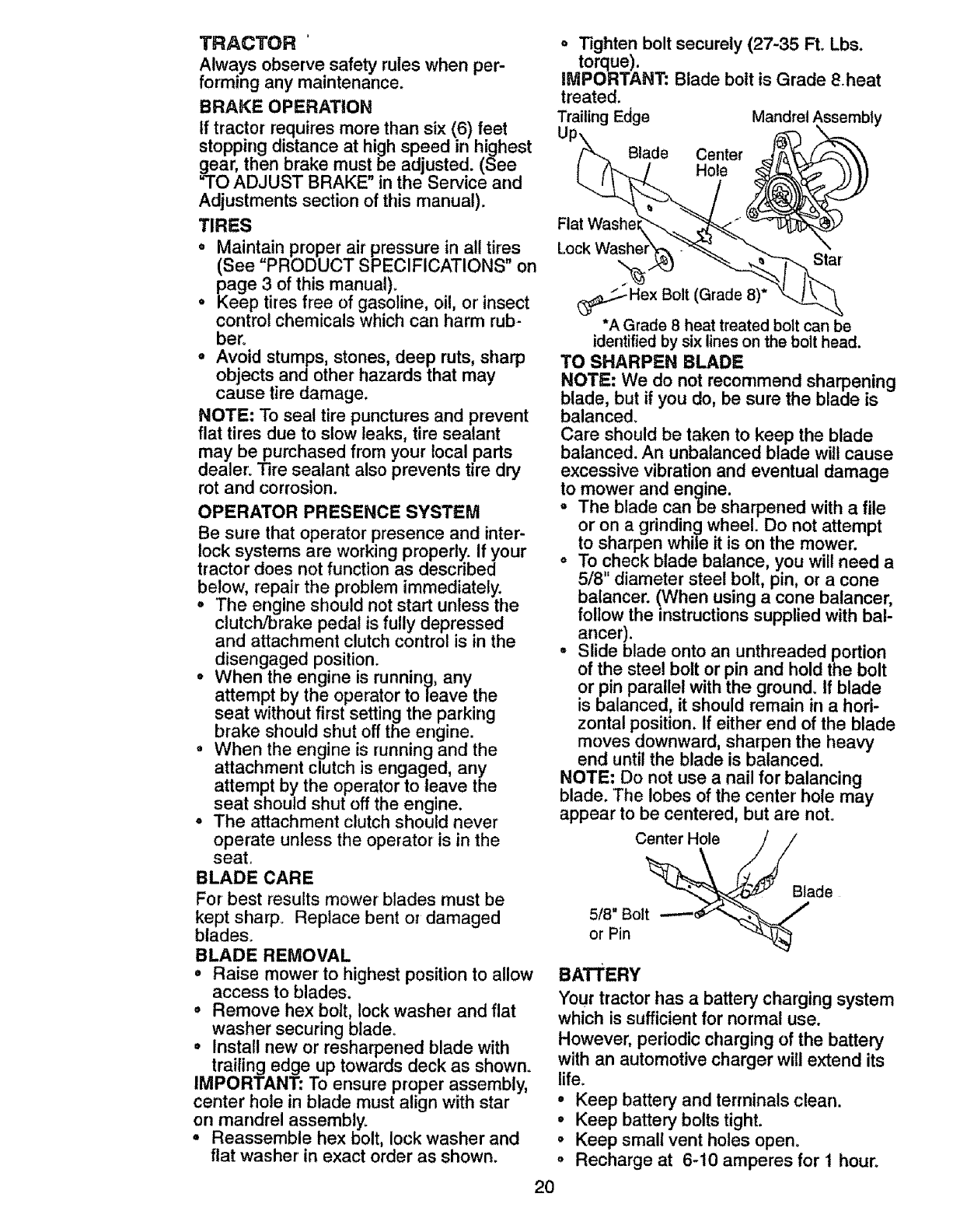
• Install new or resharpened blade with
trailing edge up towards deck as shown.
IMPORTANT: To ensure proper assembly,
center hole in blade must align with star
on mandrel assembly_
°Reassemble hex bolt, lock washer and
flat washer in exact order as shown.
°Tighten bolt securely (27-35 Ft. Lbs.
torque).
IMPORTANT: Blade bolt is Grade 8.heat
treated.
TrailingEdge Mandrel Assembly
Up_.... Blade Center
Flat Washe_-'_..._ ____._.
*A Grade 8 heat treated bolt can be
identifiedby six lines on the bolt head.
TO SHARPEN BLADE
NOTE: We do not recommend sharpening
blade, but if you do, be sure the blade is
balanced.
Care should be taken to keep the blade
balanced. An unbalanced blade will cause
excessive vibration and eventual damage
to mower and engine.
°The blade can be sharpened with a file
or on a grinding wheel. Do not attempt
to sharpen while it is on the mower.
oTo check blade balance, you will need a
5/8" diameter steel bolt, pin, or a cone
balancer. (When using a cone balancer,
follow the instructions supplied with bat-
ancer).
-Slide blade onto an unthreaded portion
of the steel bolt or pin and hold the bolt
or pin parallel with the ground. If blade
is balanced, it should remain in a hori-
zontal position. If either end of the blade
moves downward, sharpen the heavy
end until the blade is balanced.
NOTE: Do not use a nail for balancing
blade. The lobes of the center hole may
appear to be centered, but are not.
Center Hole
5/8" Bolt
or Pin
Blade
BATTERY
Your tractor has a battery charging system
which is sufficient for normal use.
However, periodic charging of the battery
with an automotive charger will extend its
life.
•Keep battery and terminals clean.
• Keep battery bolts tight.
° Keep small vent holes open°
°Recharge at 6-10 amperes for t hour°
2O
TO CLEAN BA't-I'ERY AND TERMINALS
Corrosion and dirt on the battery and ter-
minals can cause the battery to "leak"
power.
• Remove terminal guard.
° Disconnect BLACK battery cable first
then RED battery cable and remove
battery from tractor.
° Rinse the battery with plain water and
dry.
° Clean terminals and battery cable ends
with wire brush until bright.
° Coat terminals with grease or petroleum
jell F
• Remstatl battery (See "REPLACING
BATTERY" in the SERVICE AND
ADJUSTMENTS section of this manu-
al).
V-BELTS
Check V-belts for deterioration and wear
after 100 hours of operation and replace if
necessary. The belts are not adjustable.
Replace belts if they begin to slip from
wear.
TRANSAXLE COOLING
Keep transaxle free from build-up of dirt
and chaff which can restrict cooling.
CHECK TRANSAXLE OIL LEVEL
°Block up rear axle securely.
° Remove left rear wheel by removing
hub bolts.
°Remove filler plug from transa_ieo Oil
level must be even with plug threads. If
necessary, fill with SAE 30 motor oil,
API SF, SG or SH. Replace filler plug.
° Reassemble wheel to hub.
Transaxle
Filler Plug
ENGINE
LUBRICATION
Only use high quality detergent oil rated
with API service classification SF, SG, or
SH. Select the oil's SAE viscosity grade
according to your expected operating tem-
perature.
SAE VISCOSITY GRADES
-20" -ffi" 0" 10" 20' 30"
TEMPERATURE RANGE ANT_CtPA3ED BEFORE NEXT OIL CHANGE
Change the oil after every 50 hours of
operation or at least once a year if the
tractor is not used for 50 hours in one
year.
Check the crankcase oil level before start-
ing the engine and after each eight (8)
hours of operation. Tighten oil fill cap/dip-
stick securely each time you check the oil
level.
TO CHANGE ENGINE OIL
Determine temperature range expected
before oil change. All oil must meetAPt
service classification SF, SG or SHo
°Be sure tractor is on level surface.
• Oil will drain more freely when warm.
° Catch oil in a suitable container.
°Remove oil fill cap/dipstick. Be careful
not to allow dirt to enter the engine
when changing oil.
, Remove drain plug.
° After oil has drained completely, replace
oil drain plug and tighten securely.
°Refill engine with oil through oil fill dip-
stick tube. Pour slowly. Do not overfill.
For approximate capacity see "PROD-
UCT SPECIFICATIONS" on page 3 of
this manual
°Use gauge on oil fill cap/dipstick for
checking level. Be sure dipstick cap is
tightened securely for accurate reading.
Keep oil at "FULL" line on dipstick.
Air Screen
Oil Drain ___--.
y- -.<.
Cap/Dipstick _=
CLEAN AIR SCREEN
Air screen must be kept free of dirt and
chaff to prevent engine damage from over-
heating. Cleart with a wire brush or com-
pressed air to remove dirt and stubborn
dried gum fibers.
ENGINE COOLING FINS
Remove any dust, dirt or oil from engine
cooling fins toprevent engine damage
from overheating. Air guide covers must
be removed. Remove side panels and
hood (See '_TO REMOVE HOOD AND
GRILL ASSEMBLY" in the Service and Ad-
justments section of this manual).
21
Engine
Cooling
Air (
(Both Sides)
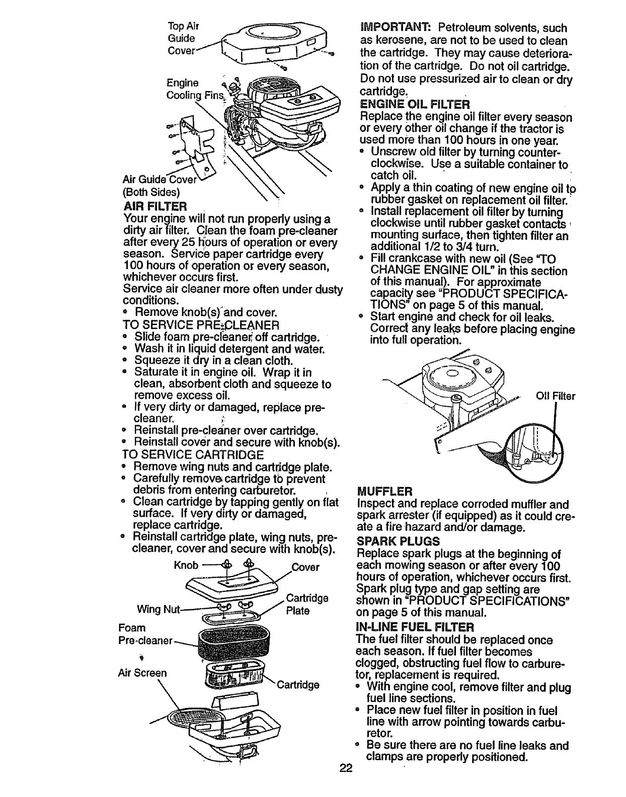
AIR FILTER
Your engine wili not run properly using a
dirty air filter. Clean the foam pre-cleaner
after every 25 t_0urs of operation or every
season. Service paper cartridge every
100 hours of operation or every season,
whichever occurs first.
Service air cleaner more often under dusty
conditions.
• Remove knob(s)'and cover.
TO SERVICE PRE_CLEANER
° Slide foam pre-cleaner, off cartridge.
° Wash it in liquid detergent and water.
o Squeeze it dry in a clean cloth.
° Saturate it in engine oil. Wrap it in
clean, absorbent cloth and squeeze to
remove excess oil.
- If very dirty or damaged, replace pre-
cleaner. ;:
° Reinstall pre-cleaner over cartridge.
=Reinstall cover and secure with knob(s).
TO SERVICE CARTRIDGE
• Remove wing nuts and cartridge plate.
•Carefully remov(_ cartridge tb prevent
debris from entering carburetor. ,
° Clean cartridge by tapping gently on flat
surface. If very dtrty or damaged,
replace cartridge.
. Reinstall cartridge plate, wing nuts, pre-
cleaner, cover and secure with knob(s).
Knob
Wing
Foam
Plate
Air Screen Cartridge
gMPORTANT: Petroleum solvents, such
as kerosene, are not to be used to clean
the cartridge. They may cause deteriora-
tion of the cartridge. Do not oil cartridge.
Do not use pressurized air to clean or dry
cartridge:
ENGINE OIL FILTER
Replace the engine oil filter every season
or every Other oil change if the tractor is
used more than 100 hours in one year.
°Unscrew old filter by turning counter-
clockwise. Use asuitable container to
catch oil.
° Apply a thin coating of new engine oil tp
rubber gasket on replacement oil filter, i
°Install replacement oil filter by turning
clockwise until rubber gasket contacts÷
mounting surface, then tighten filter an
additional 1/2 to 3/4 turn.
= Fil! crankcase with new oil (See "TO
CHANGE ENGINE OIL" in this section
of this manuaJ). For approximate
capaci_ see PRODUCT SPECIFICA-
TIONS on page 5 of this manual.
•Start engine and check for oil leaks.
Correct any leaks before placing engine
into full operation.
O11Filter
°
22
MUFFLER
Inspect and replace corroded muffler and
spark arrester (if equipped) as it could cre-
ate a fire hazard and/or damage.
SPARK PLUGS
Replace spark plugs at the beginning of
each mowing season or after every 100
hours of operation, whichever occurs first.
Spark plug type and gap setting are
shown in "PRODUCT SPECIFICATIONS"
on page 5 of this manual.
IN-LINE FUEL FILTER
The fuel filter should be replaced once
each season, if fuel filter becomes
clogged, obstructing fuel flow to carbure-
tor, replacement is required.
° With engine cool, remove filter and plug
fuel line sections.
°Place new fuel filter in position in fuel
line with arrow pointing towards carbu-
retor.
Be sure there are no fuel line leaks and
clamps are properly positioned.
. Cl__lamp
_'-_--" _"_Fuel Filter
CL_EANING
•Clean engine, battery, seat, finish, etc.
of all foreign matter.
oKeep finished surfaces and wheels free
of all g_soline, oil, etc.
o Protect painted surfaces with automo-
tive type wax.
We do not recommendusing a garden
hose to clean your tractor unless the elec-
trical system, muffler, air filter and carbure-
tor are covered to keep water out. Water
in engine can result in a shortened engine
life.
,_kCAUTION: Before performing any service or adjustments:
•Depress clutch/brake pedal fully and set parking brake.
°Place gearshift lever in neutral (N) position.
° Place attachment clutch in =DISENGAGED" position.
°Turn ignition key "OFF" and remove key.
° Make sure the blades and all moving parts have completely stopped.
°Disconnect spark ptug wire from spark plug and place wire where it cannot come
in contact with plug.
............... _ ....................... J............................................................ ... .............. _............................................ ,u ....................... ,,,J ..............
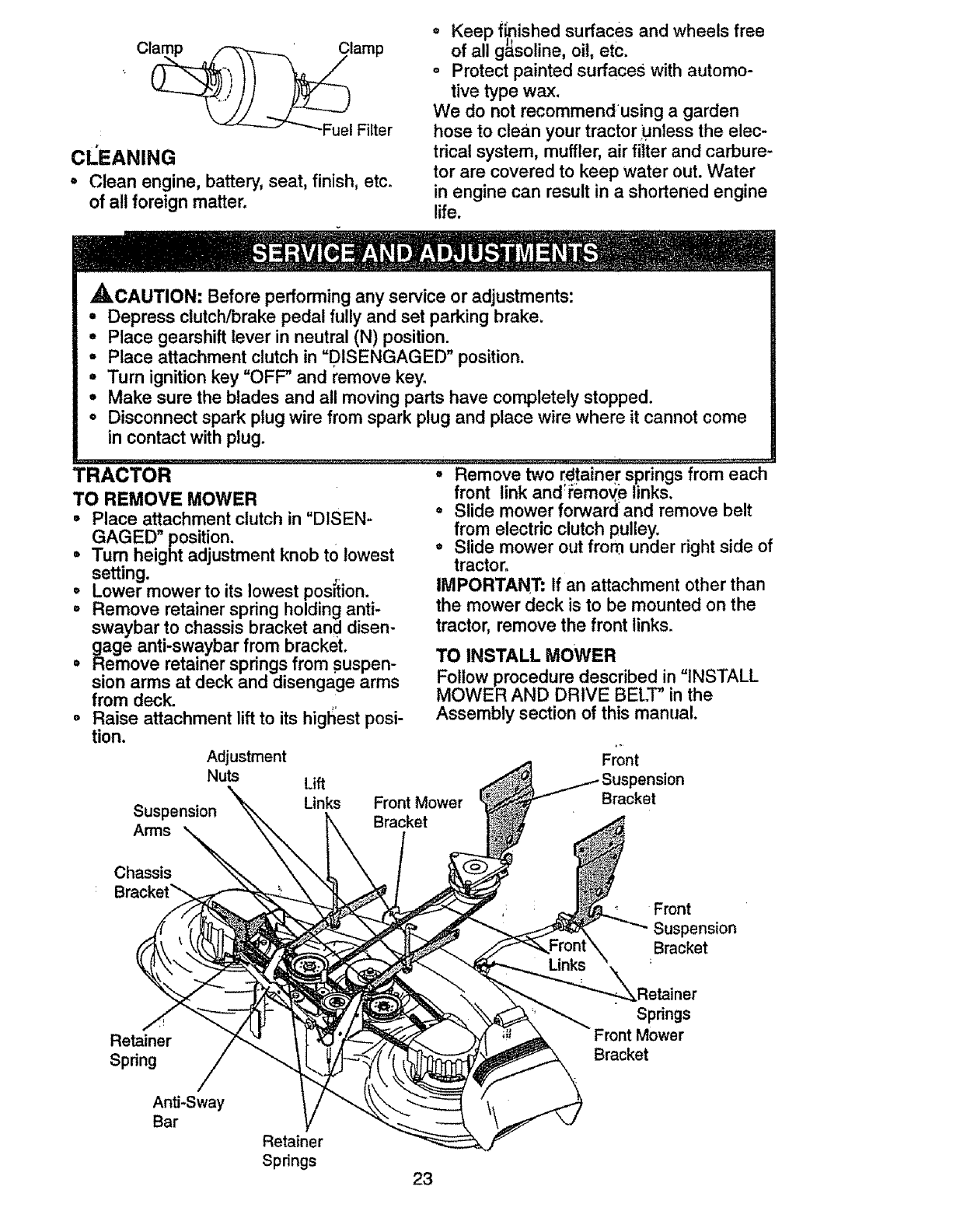
TRACTOR
TO REMOVE MOWER
° Place attachment clutch in "DISEN-
GAGED" position.
=Turn height adjustment knob tOlowest
setting,
°Lower mower to its lowest position.
°Remove retainer spring holding anti-
swaybar to chassis bracket and disen-
gage anti-swaybar from bracket.
°Remove retainer springs from suspen-
sion arms at deck and disengage arms
from deck.
°Raise attachment lift to its highest posi-
tion.
Adjustment
Nuts
Suspension
Arms
Lift
Links
°Remove two rdtainer springs from each
front link and_i:emoYe links.
° Slide mower forward: and remove belt
from electric clutch pulley.
• Slide mower out from under right side of
tractor.
IMPORTANT: If an attachment other than
the mower deck is to be mounted on the
tractor, remove the front Sinks.
TO INSTALL MOWER
Follow procedure described in "INSTALL
MOWER AND DRIVE BELT" in the
Assembly section of this manual.
Front
Front Mower
Bracket
Bracket
Chassis
Bracket_ Front
Suspension
Bracket
Retainer
Spdng
Anti-Sway
Bar
Spdngs
mower
Bracket
Retainer
Spdngs 23
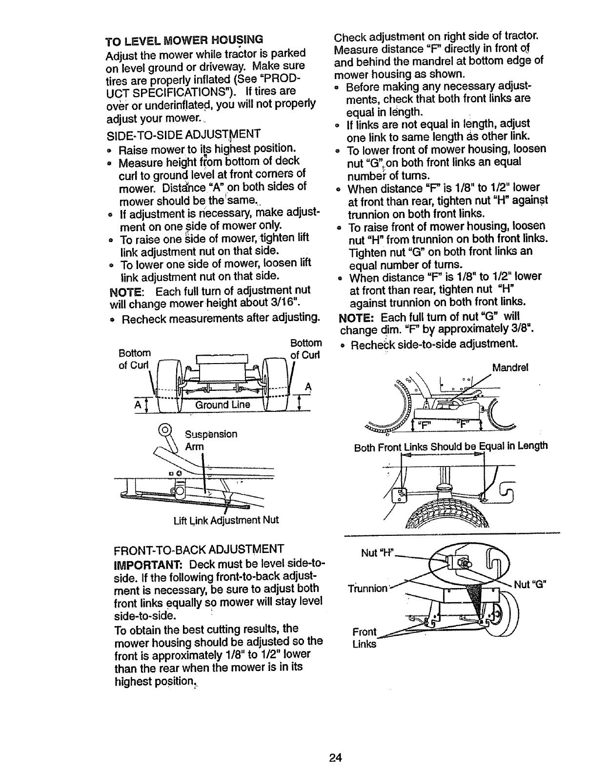
TO LEVEL MOWER HOUSING
Adjust the mower while tractor is parked
on level ground or driveway. Make sure
tires are properly inflated (See =PROD-
UCT SPECIFICATIONS"). If tires are
over or underinflated, you will not properly
adjust your mower..
SIDE-TO-SIDE ADJUS'rHENT
, Raise mower to its highest position.
'l k
°Measure height from bottom of dec
curl to ground level at front corners of
mower. Distance =A"on both sides of
mower should be the_same.
•If adjustment is necessary, make adjust-
ment on one side of mower only.
°To raise one _ide of mower,:tighten lift
link adjustment nut on that side.
oTo lower one side of mower, loosen lift
link adjustment nut on that side.
NOTE: Each futl turn of adjustment nut
will change mower height about 3/16".
•Recheck measurements after adjusting.
Bottom Bottom
Lift Link Adjustment Nut
FRONT-TO-BACK ADJUSTMENT
IMPORTANT: Deck must be level side-to-
side. If the following front-to-back adjust-
ment is necessary, be sure to adjust both
front links equally so mower will stay level
side-to-side.
To obtain the best cutting results, the
mower housing should be adjusted so the
front is approximately 1/8" to 1/2" lower
than the rear when the mower is in its
highest position.
Check adjustment on right side of tractor.
Measure distance =F" directly in front of.
and behind the mandrel at bottom edge of
mower housing as shown.
o Before making any necessary adjust-
ments, check that both front links are
equal in Idngth.
o If links are not equal in length, adjust
one link to same length as other link.
o To lower front of mower housing, loosen
nut "G",on both front links an equal
numbe_ of tums.
o When distance "F" is 1/8" to 1/2" lower
at front than rear, tighten nut "H" against
trunnion on both front Sinks.
o To raise front of mower housing, loosen
nut =H" from trunnion on both front links.
Tighten nut =G" on both front links an
equal number of tums.
° When distance =F" is 1/8" to 1/2" lower
at front than rear, tighten nut =H"
against trunnion on both front links.
NOTE: Each full turn of nut =G" will
change dim. =F"b}i' approximately 3/8".
o Reche_;k side-to-side adjustment.
Mandrel
oo
BothFront LinksShouldbe Equal in Length
UGn
Front
Links
24
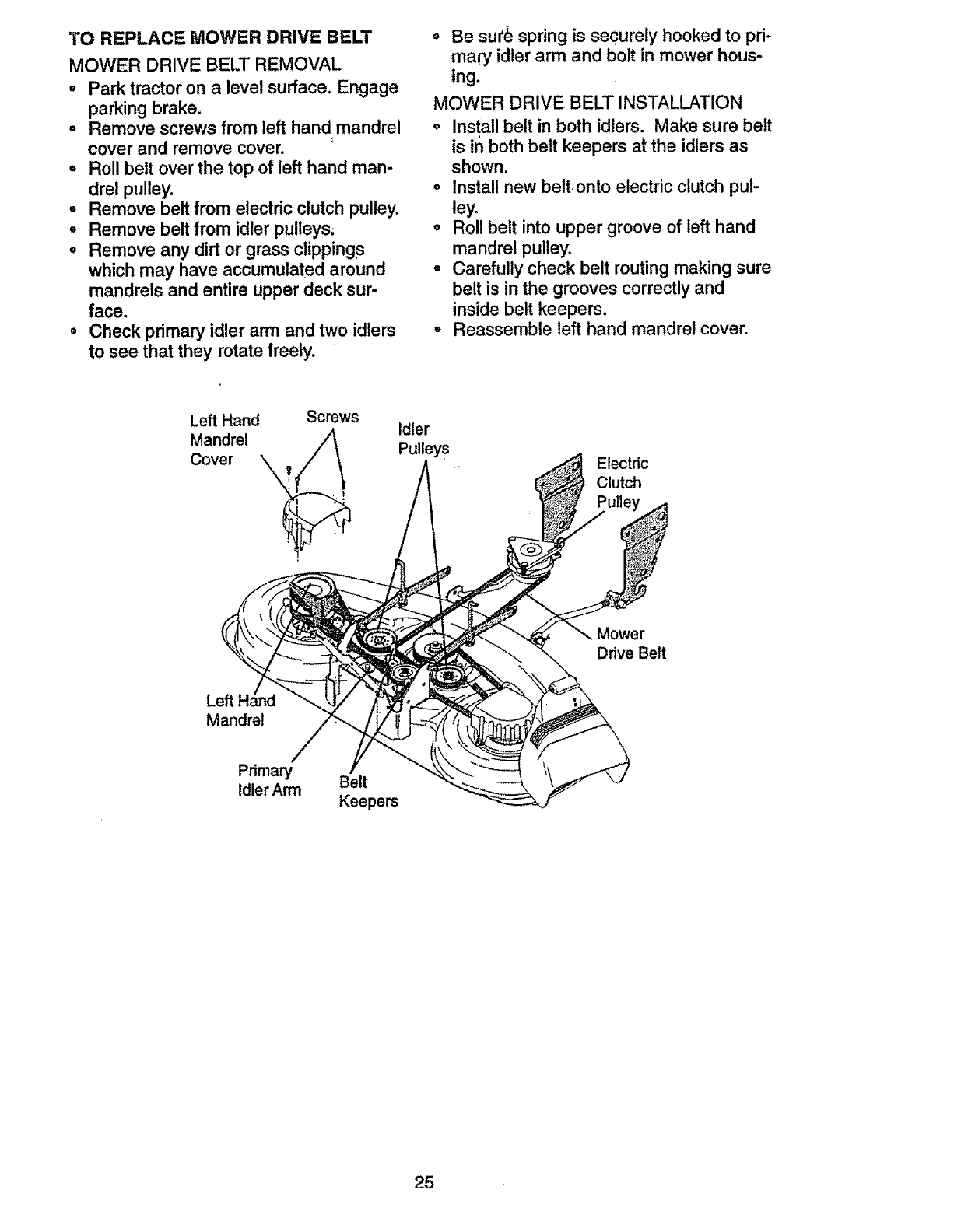
TO REPLACE MOWER DRIVE BELT
MOWER DRIVE BELT REMOVAL
o Park tractor on a level surface. Engage
parking brake.
°Remove screws from left hand mandrel
cover and remove cover.
• Roll belt over the top of left hand man-
drel pulley.
° Remove belt from electric clutch pulley.
° Remove belt from idler pulleys,
° Remove any dirt or grass clippings
which may have accumulated around
mandrels and entire upper deck sur-
face.
° Check primary idler arm and two idlers
to see that they rotate freely.
o Be sut_ spring is securely hooked to pri-
mary idler arm and bolt in mower hous-
ing.
MOWER DRIVE BELT INSTALLATION
° Install belt in both idlers. Make sure belt
is in both belt keepers at the idlers as
shown.
o Install new belt onto electric clutch pul-
ley.
° Roll belt into upper groove of left hand
mandrel pulley.
• Carefully check belt routing making sure
belt is in the grooves correctly and
inside belt keepers.
- Reassemble left hand mandrel cover.
Left Hand
Mandrel
Cover
Screws Idler
PulleysElectric
Clutch
Mower
Drive Belt
Left I
Mandrel
Primary
IdlerArm Belt
Keepers
25
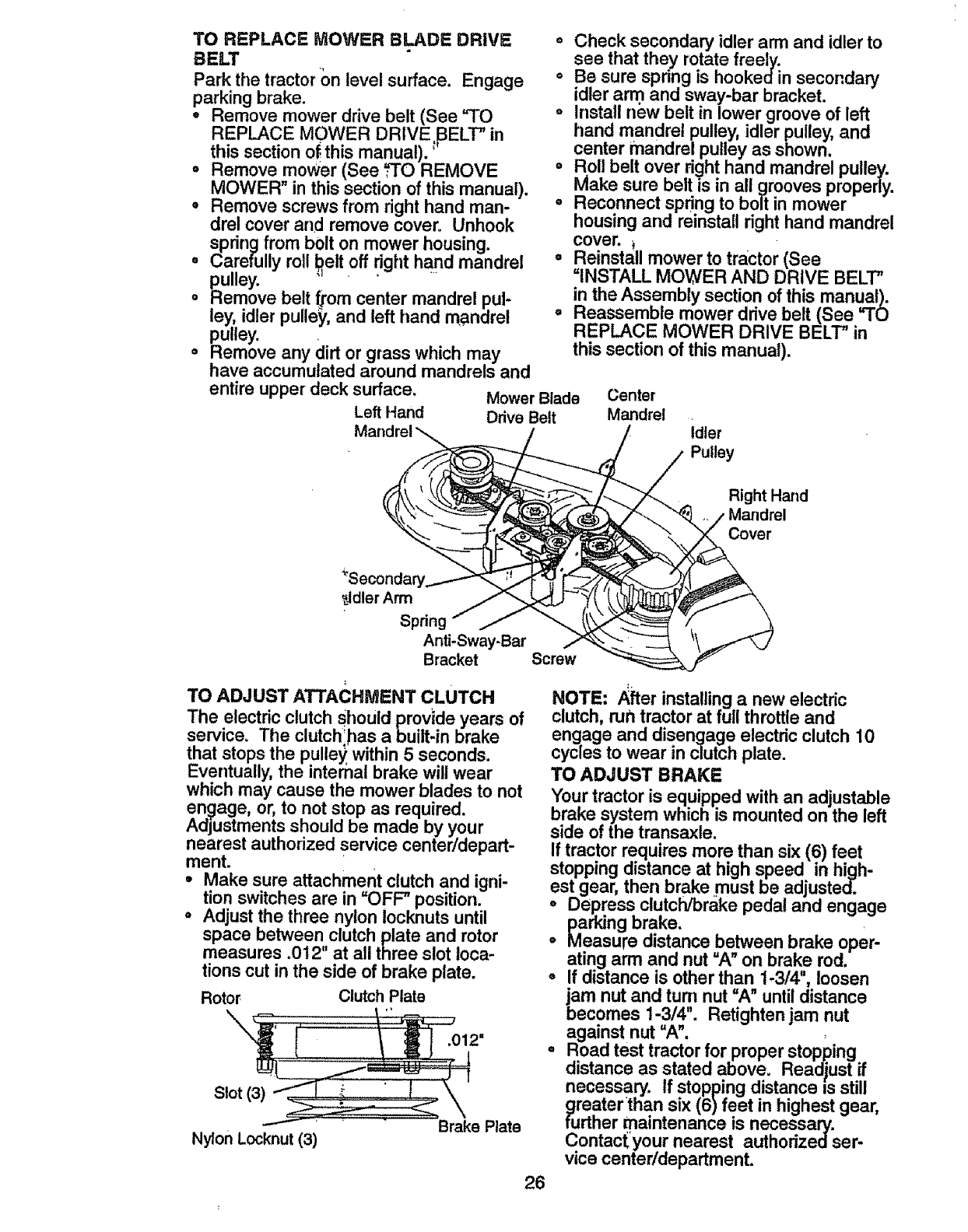
TO REPLAC_ MOWER BLADE DRIVE
BELT
Park the tractor on level surface. Engage
parking brake.
, Remove mower drive belt (See "TO
REPLACE MOWER DRIVE,_ELT" in
this section of this manual).'
°Remove mower (See _O REMOVE
MOWER" in this section of this manual).
.Remove screws from right hand man-
drel cover and remove cover= Unhook
spring from bolt on mower housing.
• Carefully roll _elt off nght hand mandrel
p_ulley.
o Remove belt from center mandrel pul-
ley, idler pulley, and left hand mandrel
pulley.
oRemove any dirt or grass which may
have accumulated around mandrels and
entire upper deck surface.
Left Hand
o Check secondary idler arm and idler to
see that they rotate freely.
o Be sure spring is hookedin secondary
idler arm and sway-bar bracket.
= install new belt in lower groove of left
hand mandrel pulley, idler pulley, and
center mandrel pulley as shown.
oRoll belt over right hand mandrel pulley,
Make sure belt is in all grooves properly.
o Reconnect spring to bolt in mower
housing and reinstall right hand mandrel
cover.
o Reinstall mower to tractor (See
=INSTALL MOWER AND DRIVE BELT"
in the Assembly section of this manual).
° Reassemble mower drive belt (See "TO
REPLACE MOWER DRIVE BELT" in
this section of this manual).
Mower Blade
Drive Belt
Center
Mandrel idler
Pulley
Right Hand
.jdler Arm
Anti-Sway-Bar
Bracket Screw
TO ADJUST ATTACHMENT CLUTCH
The electric clutch Should provide years of
service. The clutchlhas a built-in brake
that stops the pulley within 5 seconds.
Eventually, the internal brake will wear
which may cause the mower blades to not
en_age, or, to not stop as required.
Adjustments should be made by your
nearest authorized service center/depart-
ment.
• Make sure attachment clutch and igni-
tion switches are in =OFF" position.
°Adjust the three nylon locknuts until
space between clutch plate and rotor
measures .012" at all three slot loca-
tions cut in the side of brake plate.
Rotor ClutchPlate
\.012"
Slot (3)
Nylon Locknut (3) Brake Plate
26
NOTE: After installing anew electric
clutch, run tractor at full throttle and
engage and disengage electric clutch 10
cycles to wear in clutch plate.
TO ADJUST BRAKE
Your tractor is equipped with an adjustable
brake system which is mounted on the left
side of the transaxle.
If tractor requires more than six (6) feet
stopping distance at high speed in high-
est gear, then brake .must be adjusted.
°Depress clutch/brake pedal and engage
parking brake.
°Measure distance between brake oper-
ating arm and nut =A" on brake rod.
° If distance is other than 1-3/4", loosen
jam nut and rum nut =A" until distance
becomes 1-3/4". Retighten jam nut
against nut =A".
° Road test tractor for proper stopping
distance as stated above, Readjust if
necessary. If stopping distance is still
greater than six (6)feet in highest gear,
further maintenance is necessary.
Contacf,'your nearest authorizedser-
vice center/department.
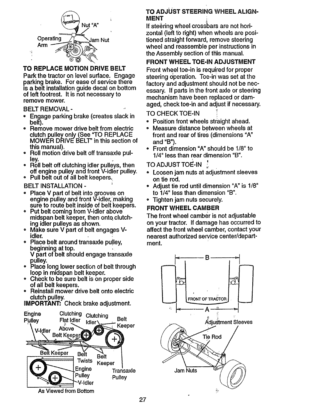
OperatJng==_
@
t"A"
_,,arn Nut
TO REPLACE MOTION DRIVE BELT
Park the tractor on level surface. Engage
parking brake. For ease of service there
=sa belt installation guide decal on bottom
of left footrest. It is not necessary to
remove mower°
BELT REMOVAL-
, Engage parking brake (creates slack in
belt).
• Remove mower drive belt from electric
clutch pulleyonly (See =TO REPLACE
MOWER DRIVEBELT" in this section of
this manual).
o Roll motion drive belt off transaxle pul-
° _lYil belt off clutching idler pulleys, then
off engine pulley and front V-idler pulley.
o Pull belt out of all belt keepers.
BELT INSTALLATION -
° Place V part of belt into grooves on
engine pulley and front V-idler, making
sure to route belt inside of belt keepers.
o Put belt coming from V-idler above
midspan belt keeper, then ontq clutch-
ing idler pulleys as shown.
oMake sure V part of belt engag_esV-
idler.
° Place belt around transaxle pulley,
beginning at top.
V part of belt should engage transaxle
pulley.
= Place long lower section of belt through
loop in midspan belt keeper.
° Check to be sure belt is on proper side
of all belt keepers.
° Reinstall mower drive belt onto electric
clutch pulley.
_MPORTANT: Check brake adjustment.
Ehgine Clutching Clutching Belt
PIJlley Flat Idler Idler\__.--_
\V-Idler Al_°ve__ eeper
B;rtKe er
_pV .Twists Keeper
Engine Trar _ax[e
ulley Pulley
Idler
As Viewed from Bottom
TO ADJUST STEERING WHEEL ALiGN-
MENT i
J
If steering wheel crossbars are not hori-
zontal (left tb right) when wheels are posi-
tioned straight forward, remove steedng
wheel and reassemble per instructions in
the Assembly section of this manual.
FRONT WHEEL TOE-IN ADJUSTMENT
Front wheel toe-in is requ{red for proper
steering 0peration. Toe-in was set at the
factory and adjustment should not be nec-
essary. If parts in the front axle or steering
mechanism have been replaced or dam-
aged, check toe-in and adjust if necessary.
TO CHECK TOE-IN _
° Position front wheels straight ahead.
o Measure distance between wheels at
front and rear of tires (dimensions "A"
and "B").
=Front dimension "A" should be I/8" to
1/4" less than rear dimension "B".
TO ADJUST TO_-tN _;
° Loosen jam nuts at adjustment sleeves
on tie rod,
°Adjust tie rod until dimension "A" is 1/8"
to 1/4" less than dimension "B"°
°Tighten jam nuts securely.
FRONT WHEEL CAMBER
The front wheel camber is not adjustable
on your tractor. If damage has occurred to
affect the front wheel camber, contact your
nearest authorized service center/depart-
ment.
B
FRONT oF'IRA OR
dju_ment Sleeves
Jam Nuts
27
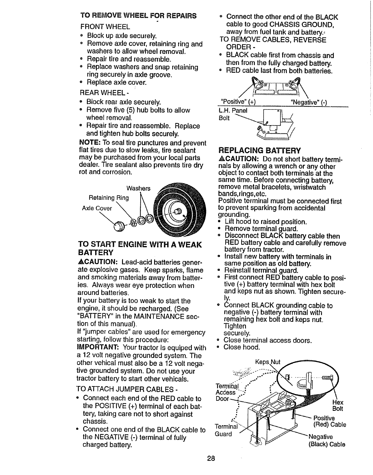
TO REMOVE WHEEL FOR REPAIRS
FRONT WHEEL
o Block up axle securely.
o Remove axle cover, retaining ring and
washers to allow wheel removal.
° Repair tire and reassemble°
° Replace washers and snap retaining
ring securely in axle groove.
° Replace axle cover.
REAR WHEEL-
° Block rear axle securely.
• Remove five (5) hub bolts to allow
wheel removal.
° Repair tire and reassemble. Replace
and tighten hub bolts securely.
NOTE: To seal tire punctures and prevent
flat tires due to slow leaks, tire sealant
may be purchased from your local parts
dealer. Tire sealant also prevents tire dry
rot and corrosion.
Washers
Retaining Ring
Axle Co_\
TO START ENGINE WITH A WEAK
BATTERY
ACAUTION: Lead-acid batteries gener-
ate explosive gases° Keep sparks, flame
and smoking materials away from batter-
ieso Always wear eye protection when
around batteries.
If your battery is too weak to start the
engine, it should be recharged. (See
"BATTERY" in the MAINTENANCE sec-
tion of this manual).
If "jumper cables" are used for emergency
starting, follow this procedure:
IMPORTANT: Your tractor Is equiped with
a12 volt negative grounded system. The
other vehical must also be a12 volt nega-
tive grounded system. Do not use your
tractor battery to start other vehicals.
TO ATTACH JUMPER CABLES -
°Connect each end of the RED cable to
the POSITIVE (+) terminal of each bat-
tery, taking care not to short against
chassis.
•Connect one end of the BLACK cable to
the NEGATIVE (-) terminal of fully
charged battery.
° Connect the other end of the BLACK
cable to good CHASSIS GROUND,
away from fuel tank and battery..;
TO REMOVE CABLES, REVERSE
ORDER -
=BLACK cable first from chassis and
then from the fully charged battery.
°RED cable last from both batteries.
"Positive" (+) "Negati._...ve" ,(-)
LH. Panel F---_t .
Bolt "-_-_.._
REPLACING BATTERY
,ACAUTION: Do not short battery termi-
nals by allowing awrench or any other
object to contact both terminals at the
same time. Before connecting battery,
remove metal bracelets, wristwatch
bands,rings,etc.
Positive terminal must be connected first
to prevent sparking from accidental
grounding.
° Lift hood to raised position.
• Remove terminal guard.
° Disconnect BLACK battery cable then
RED battery cable and carefully remove
battery from tractor,
o Install new battery with terminals in
same position as old battery.
Reinstall terminal guard.
First connect RED battery cable to posi-
tive (+) battery terminal with hex bolt
and keps nut as shown. Tighten secure-
hi
• _onnect BLACK grounding cable to
negative (-) battery terminal with
remaining flex bolt and keps nuL
Tighten
securely.
• Close terminal access doors.
-Close hood.
Keps_\
Terminal :-" ,-"
Acdess _-., ;._..,_IL..==_ _ \
Door_...£ _JY _._J_._>_ ,,_
,." I i_ f _ _"'--Positive
Terminai"_ _ (Red)Cable
Guard - _ _;"-;I__'_"Negative
_,,.,__ _ (Black) Cable
28
TO REPLACE HEADUGHT BULB
• Raise hood.
°Pul! bulb holder out of the hole in the
backside of the gdll.
oReplace bulb inholder and push bulb
holder securely back into the hole in the
backside of the gdlL
oClose hood.
INTERLOCKS AND RELAYS
Loose or damaged wiring may cause your
tractor to run poorly, stop running, or pre-
vent it from starting.
• Check wiring. See electrical wiring dia-
gram in the Repair Parts section of this
manual.
TO REPLACE FUSE
Replace with 30 amp automotive-type
plug-in fuse. The fuse holder is located
behind the dash.
formed by an authorized engine manufac-
turer's service outlet.
TO REMOVE HOOD AND GRILL
ASSEMBLY
•Raise hood.
° Unsnap headlight wire connector.
°Stand in front of tractor° Grasp hood at
sides, tilt toward engine and lift off of
tractor.
oTo replace, reverse above procedure°
Hood
_\ Headlight
t Wire
Connector
ENGINE
Maintenance, repair, or replacement of the
emission control devices and systems,
which are being done at the customers
expense, may be performed by any non-
road engine repair establishment or indi-
vidual. Warranty repairs must be per-
formed by an authorized engine manufac-
turer's service outlet.
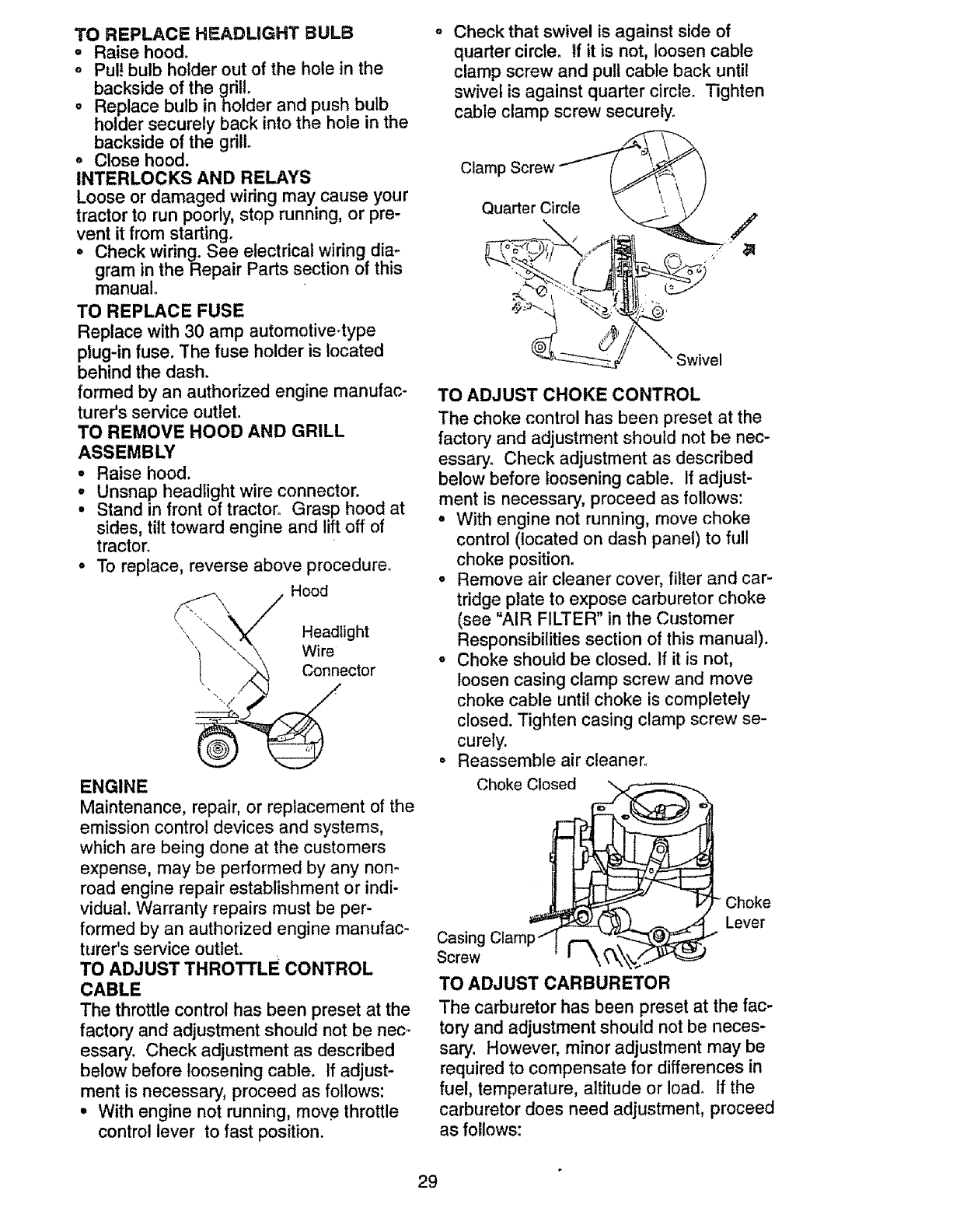
TO ADJUST THROTTLE CONTROL
CABLE
The throttle control has been preset at the
factory and adjustment should not be nec-
essary. Check adjustment as described
below before loosening cable. If adjust-
ment is necessary, proceed as follows:
°With engine not running, move throttle
control lever to fast position.
Check that swivel is against side of
quarter circle. If it is not, loosen cable
clamp screw and pull cable back until
swivel is against quarter circle. Tighten
cable clamp screw securely.
Clamp Screw _
Quarter Circle \ \ \ /
Swivel
TO ADJUST CHOKE CONTROL
The choke control has been preset at the
factory and adjustment should not be nec-
essary. Check adjustment as described
below before loosening cable. If adjust-
ment is necessary, proceed as follows:
° With engine not running, move choke
control (located on dash panel) to fuU
choke position°
° Remove air cleaner cover, filter and car-
tridge plate to expose carburetor choke
(see "AIR FILTER" in the Customer
Responsibilities section of this manual).
° Choke should be closed. If it is not,
loosen casing clamp screw and move
choke cable until choke is completely
closed. Tighten casing clamp screw se-
curely.
• Reassemble air cleaner_
Choke Closed ".
Casing Clamp /
Screw
Choke
Lever
TO ADJUST CARBURETOR
The carburetor has been preset at the fac-
tory and adjustment should not be neces-
sary. However, minor adjustment may be
required to compensate for differences in
fuel, temperature, altitude or load. If the
carburetor does need adjustment, proceed
as follows:
29
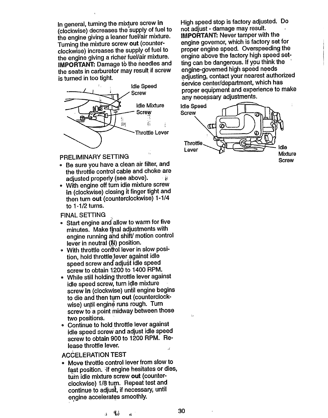
In general, turning the mixture screw in
(clockwise) decreases the'supply of fuel to
the engine giving a leaner fuel/air mixture.
Turning the mixture screw out (counter-
clockwise) increases the supply of fuel to
the engine giving aricher fuel/air mixture.
iMPORTANT: Damage tb the needles and
the seats in carburetor may result if screw
is tumed in too tight°
_' idle Speed
_Screw
Idle Mixture
Screw
"-_-_'-Throttte Lev'er
PRELIMINARY SETTING
•Be sure you have a clean air filter, and
the throttle control cable and choke are
adjusted properly (see above), i,
= With engine off turn idle mixture screw
in (clockwise) closing it finger tight and
then turn out (counterclockwise) 1-1/4
to 1-1/2 turns.
FINAL SETTING
eStart engine and allow to warm for five
minutes. Make final adjustments with
engine running a_hdshift/motion control
lever in neutral (_) position.
= With throttle conffol lever in slow posi-
tion, hold throttle',lever against idle
speed screw and' adjust idle speed
screw to obtain 1200 to 1400 RPM.
= WhUe still holding throttle lever against
idle speed screw, turn idle mixture
screw in (clockwise) until engine begins
to die and then turn out (counterclock-
wise) until engine runs rough, Turn
screw to a point midway between those
two positions,
o Continue to hold throttle lever against
idle speed screw and adjust idle speed
screw to obtain 900 to 1200 RPM. Re-
lease throttle lever. H
ACCELERATION TEST
° Move throttle control lever from slow to
fast position. ;If engine hesitates or dies,
turn idle mixture screw out (counter-
clockwise) 1/8 turn. Repeat test and
continue to adjust, if necessary, until
engine accelerates smoothly.
High speed stop is factory adjusted, Do
not adjust -damage may result.
llVlPORTANT: Never tamper with the
engine governor, which is factory set for
proper engine speed. Overspeeding the
engine above the factory high speed set-
ting can be dangerous. If you think the '
engine.govemed high speed needs
adjusting, contact your nearest authorized
service center/department, which has
proper equipment and experience to make
any nece,ssary adjustments.
Th :ro_
Lever _"-M_--_--'-_ Mixture
Screw
Immediately prepare your tractor for stor-
age at the end of the season or if the trac-
tor will not be used for 30 days or more.
_kCAUTION: Never store the tractor with
ga_solinein the tank inside a building
where fumes may reach an open flame or
spark. Allow the engine to cool before stor-
ing in any enclosure.
TRACTOR
Remove mower from tractor for winter
storage. This will allow you to clean it thor-
oughly. Remove all dirt, grease, leaves,
etc. Store in a clean, dry area.
• Clean entire tractor (See "CLEANING"
in the Maintenance section of this man-
ual).
°Inspect and replace belts, if necessary
(See belt replacement instructions in the
Service and Adjustments section of this
manual).
•Lubricate as shown in the Maintenance
section of this manual. _
° Be sure that all nuts, bolts and,',screws
are securely fastened. Inspect_moving
parts for damage, breakage and wear.
Replace if necessary. :_
o Touch up all rusted or chipped paint sur-
faces; sand lightly before painting.
BATTERY !
oFully charge the battery for storage.
•After a period of time in storage, battery
may require recharging.
°To help prevent corrosion and power
leakage during tong periods of storage,
battery cables should be disconnected
and battery cleaned thoroughly (see
"TO CLEAN BATTERY AND TERMI-
NALS" in the Maintenance section of
this manual). _
o After cleaning, leave cables diSconnect-
ed and place cables where they cannot
come in contact with battery terminals.
• If battery is _moved from tractor for
storage, do not store battery directly on
concrete or damp surfaces.
ENGINE
FUEL SYSTEM
IMPORTANT: It is important to prevent
gum deposits from forming in essential
fuel system parts such as carburetor,fuel
filter,fuel hose, or tank duringstorage.
Also, experience ithat alcohol
blended fuels (called gasohol or using
ethanol or methanol) can attract moisture
which leads to separation and formation of
acids during storage. Acidic gas can dam-
age the fuel system of an engine while in
storage.
•Drain the fuel tank.
°Start the engine and let it run until the
fuel lines and carburetor are empty.
o Never use engine or carburetor cleaner
products in the fuel tank or permanent
damage may occur°
°Use fresh fuel n'extseason.
NOTE: Fuel stabilizer is an acceptable
altemative in minimizing the formation of
fue! gum deposits during storage. Add sta-
bilizer to gasoline in fuel tank or storage
container. Always follow the mix ratio
found on stabilizer container. Run engine
at least 10 minutes after adding stabilizer
to allow the stabilizer to reach the carbure-
tor. Do not drain the g_,s tank and carbure-
tor if using fuel stabilizer. ;
ENGINE OIL ,
Drain oil (with engine Warm) and replace
with clean engine oil. (.See "ENGINE" in
the Maintenance section of this manual).
CYLINDER(S) _
°Remove spark plug(_).
°Pour one ounce of o_1through spark plug
hole(s) into cyli'nder(_).
°Turn ignition key to "START" position for
afew seconds to dis'tribute oil.
o Replace with new spark plug(s).
OTHER
=Do not store gasoline from one season
to another.
°'Replace your gasoline can if it starts to
rust. Rust and/or dirt in your gasoline will
cause problems. :'
o If possible, store your tractor indoors
and cover it to give protection'from dust
and did. ' _
• Cover your tractor with a suitable protec-
tive cover that does not retain moisture.
Do not use plastic. Plastic cannot
breathe, which allows condensation to
form and cause your tractor to rust.
IMPORTANT: Never cover tractor while
engine and exhaust areas are still warm.
31
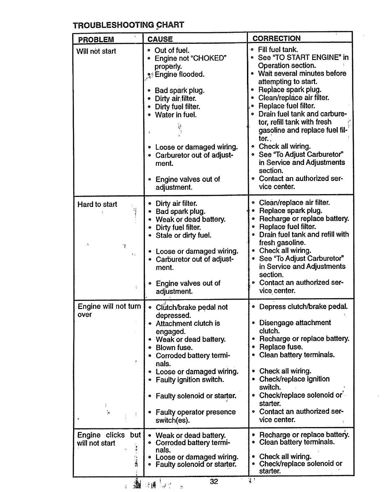
TROUBLESHOOTING CHART
_jPROBLEM
Will not start
Hard to start
t
"1
i;
Engine will not turn
over
Engine clicks
will not start
but
CAUSE
ill ii,,i, NII'HHHH,,I
, Out of fuel.
=Engine not"CHOKED"
properly.
=_;Engine flooded.
o
Q
o
8
I
a
o
Bad spark plug. o
Dirty air fUter. =
Dirty fuel filter. ,=
Water in fuel. •
i
Loose or damaged wiring.
Carburetor out of adjust-
ment.
Enginevalves out of
adjustment.
•Dirty air filter.
oBad spark plug.
-Weak or dead battery.
oDirty fuel filter.
°Stale or dirty fuel.
Loose or damaged wiring.
Carburetor out of adjust-
ment.
Q
i llll ................................
32
o Engine valves out of
adjustment.
H iii,
o ClUtch/brake pedal not
depressed°
°Attachment clutch is
engaged.
,Weak or dead battery.
oBlown fuse.
•Corroded battery termi-
nals.
= Loose or damaged wiring.
oFaulty ignition switch.
°Faulty solenoid or starter.
°Faulty operator presence
switch(es).
N N IIHH
Weak or dead battery.
Corroded battery termi-
nals.
Loose or damaged wiring.
Faulty solenoid or starter.
CORRECT!Q,N
_a
O
Fill fuel tank.
See %O START ENGINE" in
Operation section.
= Wait several minutes before
attemPting to start.
Replace spark plug.
Clean/replace air filter.
Replace fuel filter.
Drain fuel tank and carbure-
tor, refill tank with fresh il
gasoline and replace fuel ill-'
ter..
° Check all wiring.
° See "To Adjust Carburetor"
in Service and Adjustments
section.
° Contact an authorized ser-
vice center.
°Clean/replace air filter.
-Replace spark plug.
-Recharge or replace battery.
-Replace fuel filter.
=Drain fuel tank and refill with
fresh gasoline.
•Check all widng.
oSee "To Adjust Carburetor"
in Service and Adjustments
section.
oContact an authorized ser-
vice center.
IH,I ,,, ,I,,I,IJ,,JIJ=ILL
•Depress clutch/brake pedal.
° Disengage attachment
clutch.
,Recharge or replace batter),.
•Replace fuse.
•Clean battery terminals.
-Check all wiring.
•Check/replace ignition
switch.
o Check/replace solenoid or'
starter.
o Contact an authorized ser-
vice center.
o
o
Recharge or replace batte_.
Clean battery terminals.
Check all wiring.
Check/replace solenoid or
starter. HI ill Hi

ROUBLESHOOTiNG CHART
_ROBLEM _ iCAUSE
H,,,,,,,,,i ,,, i ii H,l,, J ii,liH i
loss of power = Cutting too much
a
Q
grass/too fast.
Throttle in "CHOKE" posi-
tion.
Build_up of grass, leaves
and trash under mower.
• Dirty air filter.
°Low oil level/dirty oil.
, Faulty spark plug.
oDirty fuel filter.
o Stale or dirty fuel.
Excessive vibration
Engine continues to
run when operator
leaves seat with at-
tachment clutch
engaged
Poor cut -uneven
•Water in fuel.
o Spark plug wire loose.
o
o
°
o
o
o
o
o
°
o
o
Dirty engine air
screen/finso
Dirty/clogged muffier, "
Loose or damaged wiring. °
Carburetor out of adjust- °
ment.
Engine valves out of °
adjustment,
Worn, bent or loose blade. °
Bent blade mandrel.'
Loose/damaged part(s)_ °
Faulty operator-safety °
presence control system.
Worn, bent or loose blade. °
Mower deck not level. °
Buildup of grass, leaves, °
and trash under mower.
Bent blade mandrel. °
Clogged mower deck vent °
holes from buildup of
grass, leaves, and trash
around mandrels.
if_l, ,ui i,,,i, J i,Jl,l.,,
CORRECTION
° Set in "Higher Cut" posi-
tion/reduce speed.
° Adjust throttle control.
°Clean underside of mower
housing°
° Clean/replace air filter.
° Check oil level!change oil.
•Clean and regap or change
spark plug.
= Replace fuel filter.
°Drain fuel tank and refill with
fresh gasoline.
° Drain fuel tank and carbure-
tor, refill tank with fresh
gasoline and replace fuel fil-
ter,
o Connect and tighten spark
plug wire°
Clean engine air screen/fins.
Clean!replace muffler.
Check all wiring.
See "To Adjust Carburetor" in
Service and Adjustments
section.
Contact an authorized ser-
vice center.
Replace blade. Tighten blade
bolt.
ReplaCe blade mandrel.
Tighteh loose part(s).
Replace damaged parts.
Check wiring, switches and
connections. If not
corrected, contact an autho-
rized service center/
department
Replace blade. Tighten
blade bolt.
Level mower deck.
Clean underside of mower
housing.
Replace blade mandrel.
Clean around mandrels to
open vent holes.
33
,_ _ ..4¸
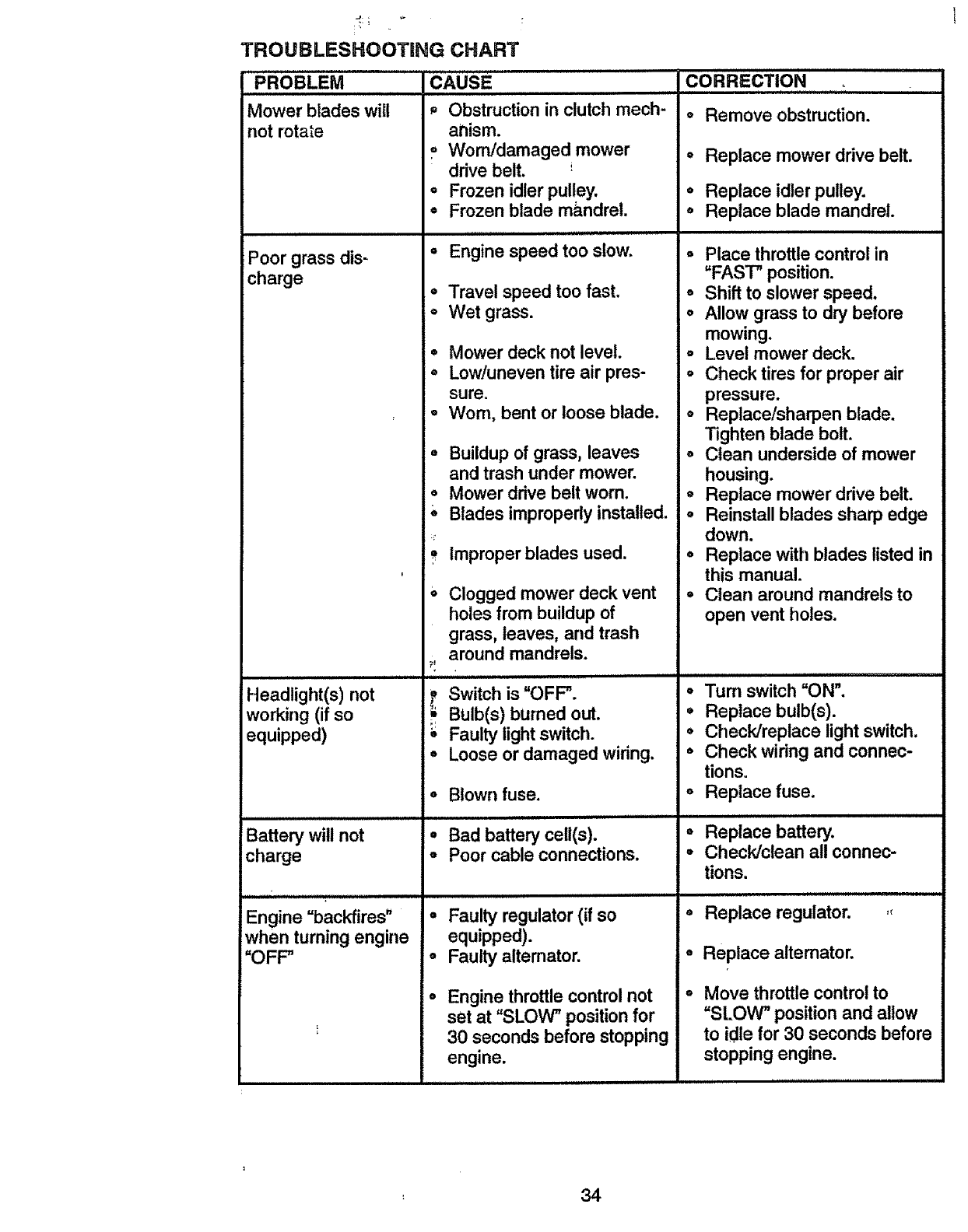
TROUBLESHOOTING CHART
CAUSE
Mower blades will
not rotate
Poor grass dis-
charge
Headlight(s) not
working (if so
equipped)
Battery will not
charge
Engine =backfires"
when turning engine
=OFF"
Obstruction in clutch mech-
anism.
= Worn/damaged mower
drive belt.
•Frozen idler pulley.
• Frozen blade ma,ndrel.
=l=IH=ll=lllll
°Engine speed too slow.
o
°
°
°
°
o
Travel speed too fast.
Wet grass.
Mower deck not level.
Low/uneven tire air pres-
sure°
Worn, bent or loose blade.
Buildup of grass, leaves
and trash under mower.
Mower drive belt worn. o
Blades improperly installed. °
Improper blades used.
Clogged mower deck vent
holes from buildup of
grass, leaves, and trash
around mandrels.
Switch is "OFF".
BUlb(s) burned out.
Faulty light switch.
°Loose or damaged wiring.
o
o
o
Blown fuse. °
Bad battery ceU(s). °
Poor cable connections. °
Faulty regulator (if so
equipped).
Faulty altemator.
CORRECTION
o Remove obstruction.
= Replace mower drive belt.
. Replace idler pulley.
° Replace blade mandrel.
i llll i ll=
o Place throttle control in
"FAST" position.
o Shift to slower speed.
o Allow grass to dry before
mowing.
° Level mower deck.
o Check tires for proper air
pressure.
o Replace/sharpen blade.
Tighten blade bolt.
° Clean underside of mower
housing.
Replace mower drive belt.
Reinstall blades sharp edge
down.
° Replace with blades listed in
this manual.
= Clean around mandrels to
open vent holes.
°Tum switch "ON".
• Replace bulb(s).
= Check/replace light switch.
° Check wiring and connec-
tions.
Replace fuse.
°
o
Replace battery.
Check/clean all connec-
tions.
=H,,I,,,,
Replace regulator.
Replace alternator.
Enginethrottlecontrolnot
set at "SLOW" positionfor
30 secondsbefore stopping
engine.
Move throttlecontrolto
=SLOW" positionand allow
to idle for 30 secondsbefore
stoppingengine.
:34
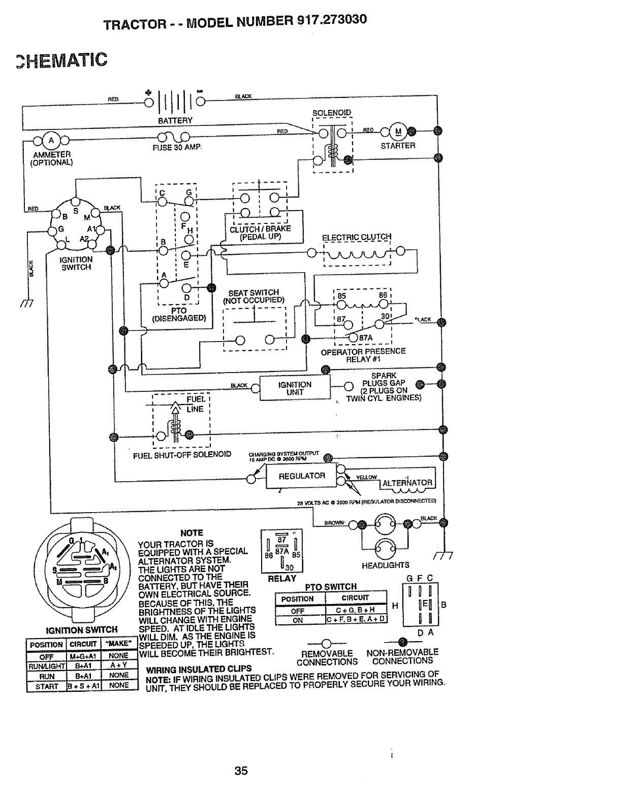
TRACTOR -- MODEL NUMBER 917.273030
3HEIVIATIC
/7
l
AMMETER
(OPTIONAL)
RFJ} +lllJll
BATTERY
FUSE30AMP,
BLAC_
_G A_
IGNITION
SWITCH
IGNmON SWITCH
HEADLIGHTS
NOTE r_,== ,,
YOUR TRACTOR IS {[I 87 ill
EQUIPPED WITH A SPECIAL
ALTERNATOR SYSTEM.
THE LIGHTS ARE NOT
CONNECTED TO THE RELAY
BATTERY,BUT HAVE THEIR G F C
OWN ELECTRICAL SOURCE. PTO SWITCH
BECAUSEOF THIS, THE iPosmoN { CiRcurr l
BRIGHTNESS OF THE LIGHTS IOFF IC + GIB+ H I H _ BWILL CHANGE WITH ENGINE !ON I_ +F,B_EI_+ _l
SPEED, AT IDLE THE LIGHTS
i,.,..,-,..-,,..,,,"{"_,...,,_ i ..... IWILL DIM. ASTHE ENGINE IS D A
,-v.,,,,,,r, I ...... I *"'*"_ ISPEEDED UP, THE LIGHTS ('_ O -
!OFF !M_+Ai I NONE IWILL BECOMETHEIR BRIGHTEST. _=_AO'_AmI= _,_ ==..nt,^o.=
I+. !t .o+1WIRING,NS ,TE°C"P
{" START _B._S'+'Ad NONE { NOTE: IF WIRING INSULATED CLIPS WERE REMOVED FOR SERVICING OF
L. .... i _ UNIT, THEY SHOULDBE REPLACEDTO PROPERLY SECURE YOUR WIRING°
35
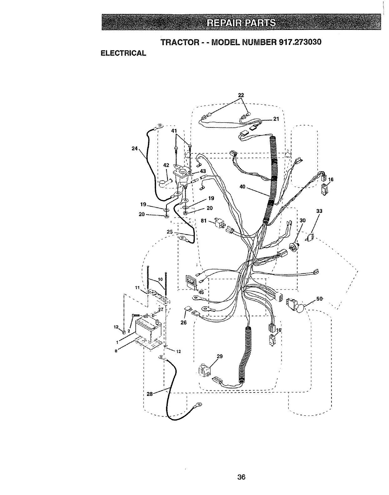
ELECTRICAL
TRACTOR - -MODEL NUMBER 917.273030
22
24\
2O 33
I
I
I
I
/
/
t
36
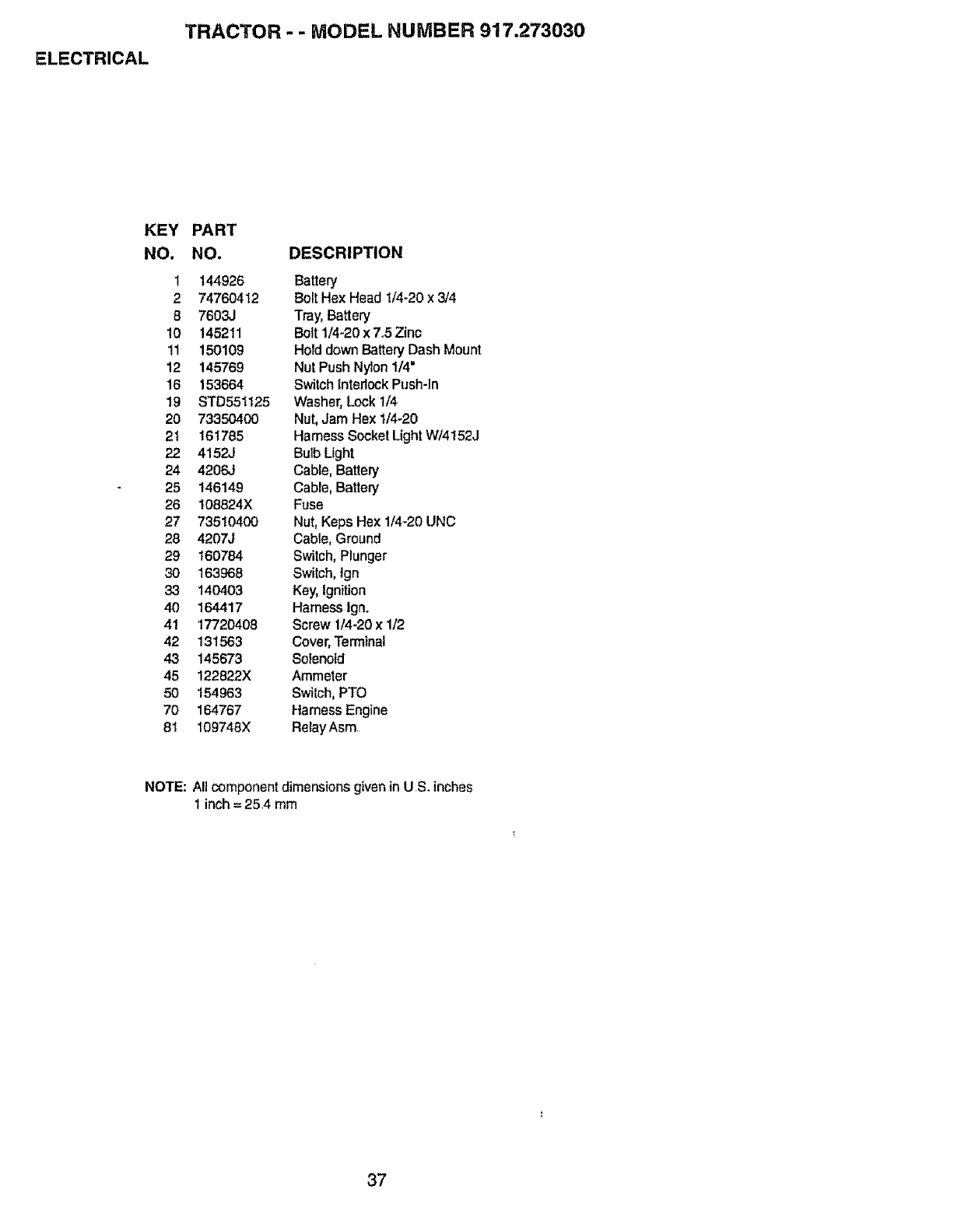
ELECTRICAL
TRACTOR --MODEL NUMBER 917.273030
KEY
NO.
PART
NO. DESCRIPTION
1 144926 Battery
2 74760412 Bolt Hex Head 1/4-20 x 3/4
87603,.I Tray, Battery
10 145211 Bolt 1/4-20 x 7°5 Zinc
11 150109 Hold down Battery Dash Mount
12 145769 Nut Push Nylon 1/4'
16 153664 Switch Interlock Push-In
19 STD551125 Washer, Lock 1/4
20 73350400 Nut, Jam Hex 1/4-20
21 161785 Hamess Socket Light W/4152J
22 4152J Buib Light
24 4206J Cable, Battery
25 146149 Cable, Batten]
26 108824X Fuse
27 73510400 Nut, Keps Hex I/4-20 UNC
28 4207J Cable, Ground
29 160784 Switch, Plunger
30 163968 Switch, tgn
33 140403 Key, Ignition
40 164417 Hamess Ign.
41 17720408 Screw 1/4-20 x 1/2
42 131563 Cover, Terminal
43 145673 Solenoid
45 122822X Ammeter
50 154963 Switch, PTO
70 164767 Harness Engine
81 109748X Relay Asm
NOTE: A!] component dimensions given in US_ inches
I inch = 25.4 rnm
37
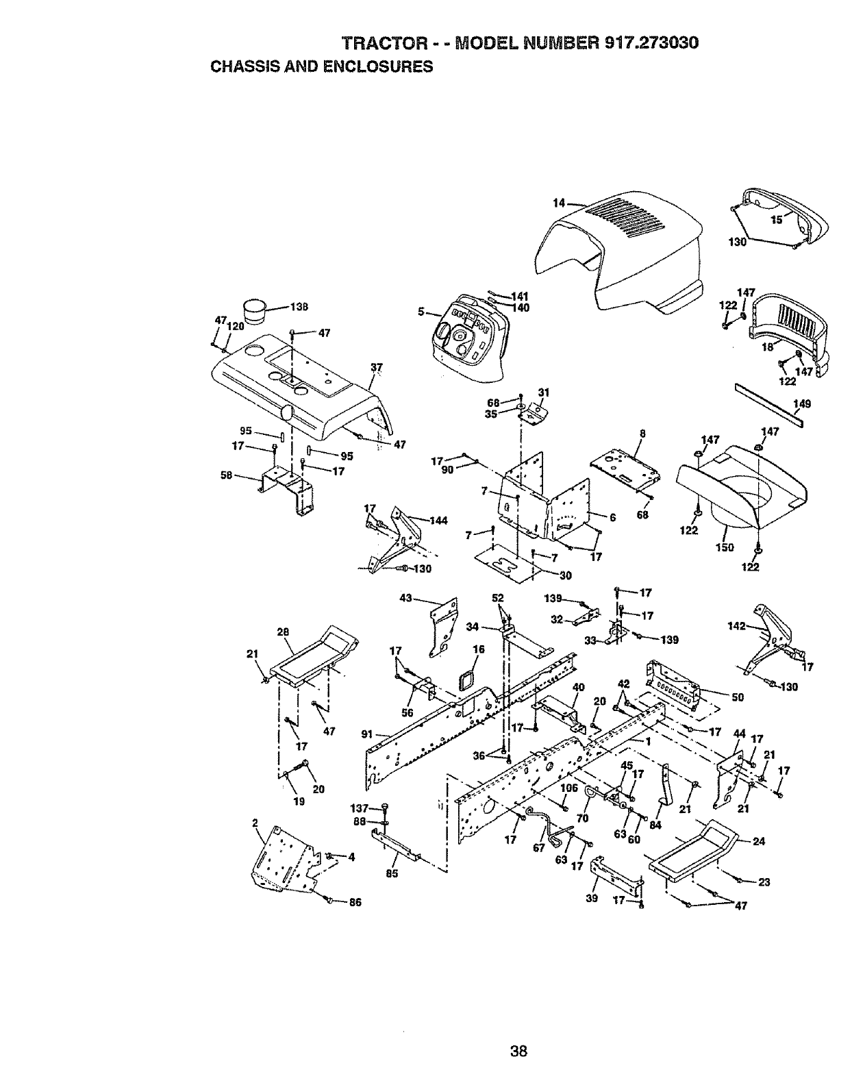
TRACTOR - - MODEL NUMBER 917.273030
CHASSIS AND ENCLOSURES
17
63.
39
42
38
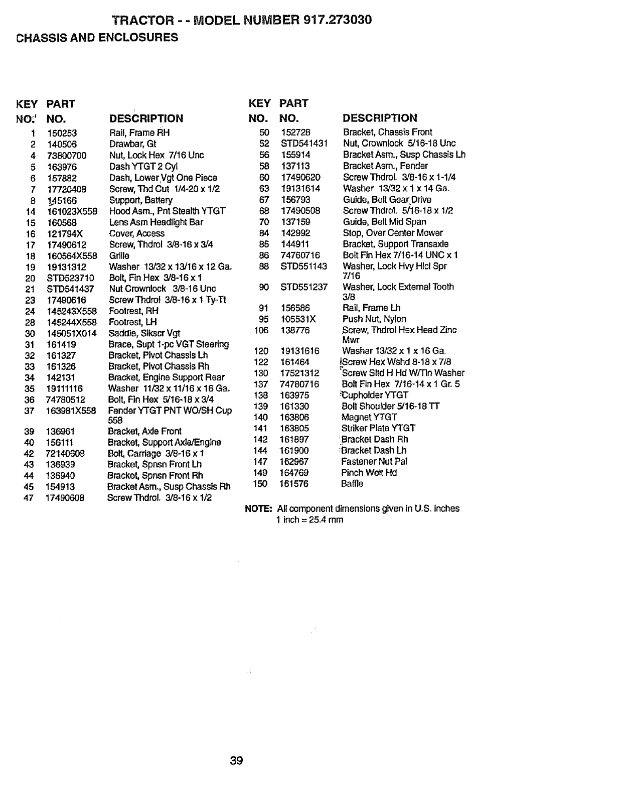
TRACTOR - - MODEL NUMBER 917.273030
CHASSIS AND ENCLOSURES
KEY PART
NO:' NO.
1 150253
2 140506
4 73800700
5 163976
6 157882
717720408
8 1_,45166
14 161023X558
15 160568
16 121794X
17 17490612
18 160564X558
!9 19131312
20 8TD5237!0
21 STD641437
23 17490616
24 145243X558
28 145244X558
30 145051X014
31 161419
32 161327
33 161326
34 142131
35 19111116
36 74780512
37 163981X558
39 136961
40 156111
42 72140608
43 136939
44 136940
45 154913
47 17490608
KEY PART
DESCRIPTION NO. NO.
Rail,FrameRH 50 152728
Dmwbar,Gt 52 STD54143!
Nut,LockHex 7/16 Unc 56 155914
DashYTGT2 Cyt 58 137113
Dash,Lower,VgtOne Piece 60 17490620
Screw,"fhd Cut 1/4-20x 1/2 63 19131614
Support,Battery 67 156793
HoodAsmo,PntStealthYTGT 68 17490508
LensAsmHeadlightBar 70 137159
Cover,Access 84 142992
Screw,Thdrol 3/846 x 3/4 85 144911
Gdtle 86 74760716
Washer 13/32x13/16x12Ga. 88 STD55t143
Bolt, Fin Hex 3/8-16 x1
NutCrownlock 3/8-16 Unc 90 STD551237
ScrawThdrot3/8-16 x 1 Ty-Tt
Footrest,RH 91 156586
Footrest,LH 95 t0553tX
Saddle, SlkscrVgt 106 138776
Brace,Supt1-pc VGT Steering
Bracket,PivotChassis Lh 120 19131616
Bracket,PivotChassisRh 122 161464
Bracket, EngineSupport Rear 130 17521312
Washer 11/32x 11/16x 16Gao t37 74780716
Bolt, Rn Hex 5/16-18x 3/4 138 163975
FenderYTGT PNTWO/SH Cup 139 161330
558 140 163806
Bracket,Axle Front 141 163805
Bracket,SupportAxle/Engine 142 161897
Bolt, Cardage3/8-16 xt 144 161900
Bracket,Spnsn Front Lh 147 162967
Bracket,Spnsn Front Rh !49 164769
BracketAsm., SuspChassis Rh 150 16i576
ScrewThdrolo 3/8-16 x I/2
NOTE:
DESCRIPTION
Bracket,ChassisFront
Nut,Crown!ock5/16-18 Unc
BracketAsm°,SuspChassis Lh
BracketAsm_,Fender
ScrewThdroL 3/8-16 x 1-1/4
Washer 13/32x i x 14G&
Guide,Belt Gea£Drive
ScrewThdroL 5/16-18x 1/2
Guide, Belt Mid Span
Stop, Over Center Mower
Bracket, SupportTransaxle
Bolt Fin Hex 7/16-14 UNC x 1
Washer, Lock HWHlcl Spr
7/16
Washer, Lock ExternalTooth
3/8
Rail, Frame Lh
Push Nut, Nylon
Screw,Thdrol Hex Head Zinc
Mwr
Washer 13/32x I x 16Ga..
_ScrewHex Wshd 8-18 x 7/8
_'ScrewSltdH Hd W/TInWasher
Bolt Fin Hex 7/1644 x 1 Gr. 5
_upholder YTGT
Bolt Shoulder 5/16q 8 TT
MagnetYTGT
Striker PlateYTGT
:Bracket Dash Rh
_BracketDash Lh
FastenerNut Pal
Pinch Welt Hd
Baffle
Ali component dimensionsgiven in U.& inches
1inch= 25.4 mm
39
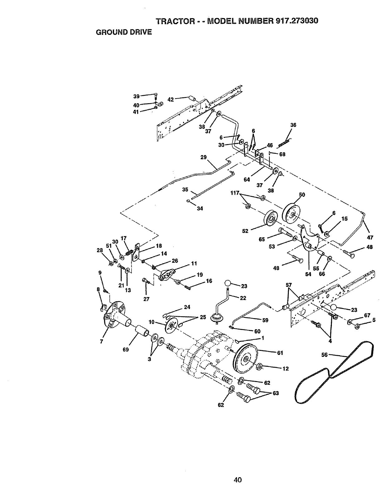
TRACTOR -- MODEL NUMBER 917.273030
GROUND DRIVE
39
: 38 36
!,, 37 6 /
_l_°
4O
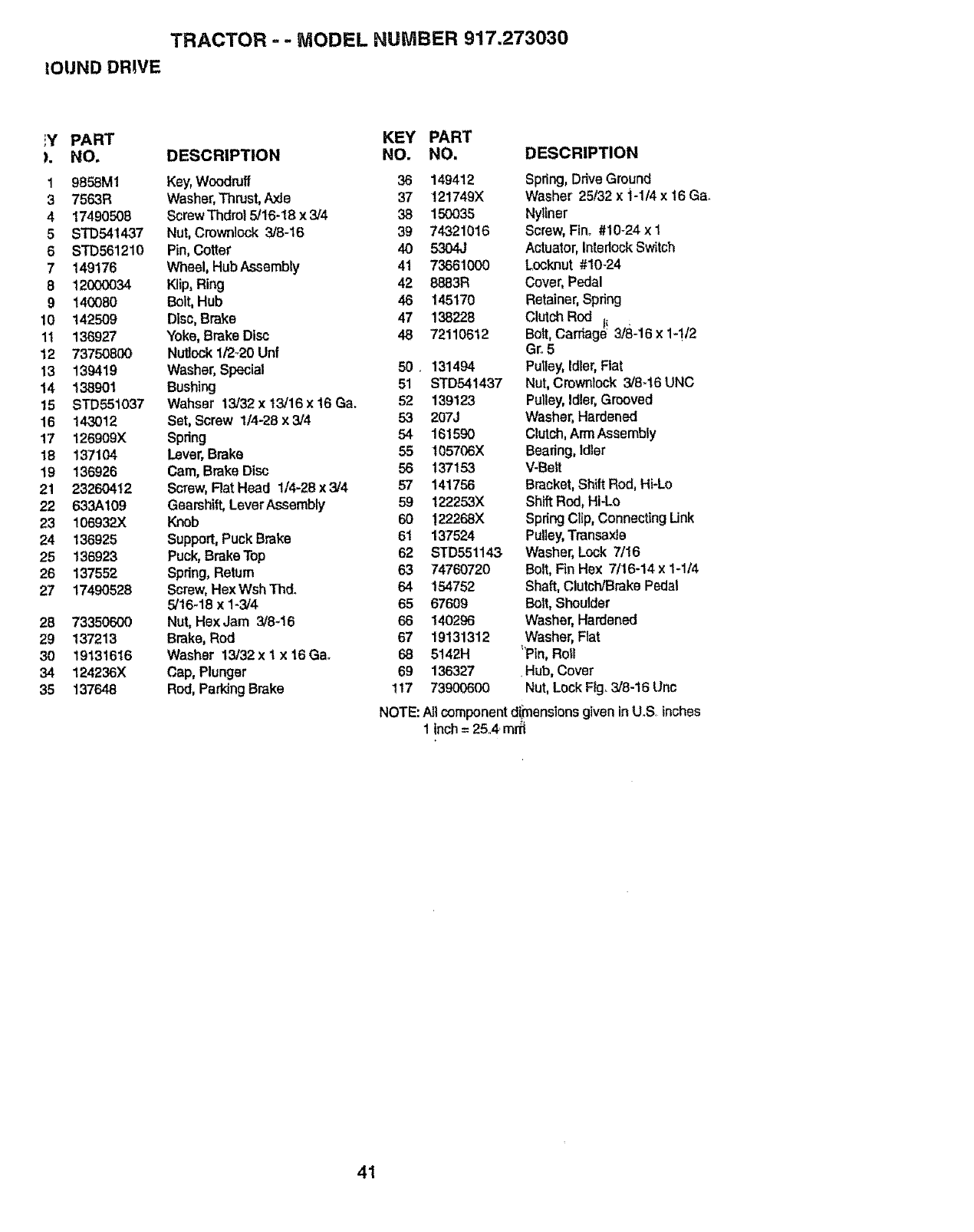
TRACTOR =-MODEL NUMBER 917.273030
IOUND DRWE
iY PART KEY PART
). NO. DESCRIPTION NO. NO.
19858M1 Key, Woodruff 36 149412
3 7563R Washer, Thrust, Axle 37 !21749X
4 17490508 Screw Thdro15/16-18 x 3/4 38 150035
5 STD54!437 Nut, Crownlock 3J8-16 39 74321016
6 STD561210 Pin, Cotter 40 5304J
7 149176 Wheel, Hub Assembly 41 73661000
8 12000034 Klip, Ring 42 8883R
9140080 Bolt, Hub 46 145170
10 142509 Disc, Brake 47 138228
1t 136927 Yoke, Brake Disc 46 72110612
12 73750800 Nutlock 1/2_20 Unf
13 139419 Washer, Special 50 131494
14 138901 Bushing 51 STD541437
15 STD551037 Wahser 13/32xt3/16x16Ga. 52 139123
16 143012 Set, Screw 1/4-28 x3/4 53 207J
17 126909X Spring 54 161590
16 137104 Lever, Brake 55 t05706X
t9 136926 Cam, Brake Disc 56 137153
21 23260412 Screw, Rat Head 1/4-28 x 3/4 57 141756
22 633A109 Gearshift, LeverAssembly 59 122253X
23 106932X Knob 60 !22268X
24 136925 Support, Puck Brake 6I 137524
25 136923 Puck, BrakeTop 62 STD551143
26 137552 Spdng, Return 63 74760720
27 17490528 Screw, Hex Wsh Thd, 54 154752
5/16-18 x 1-3/4 65 67609
26 73350600 Nut, HexJam 3/8-16 66 140296
29 137213 Brake, Rod 67 19131312
30 19131616 Washer 13/32x 1 x 16Gao 68 5142H
34 124236X Cap, Plunger 69 136327
35 137648 Rod, Parking Brake 117 73900600
DESCRIPTION
Spring,Drive Ground
Washer 25/32 x i-1/4 x 16Ga.
Nytiner
Screw, Fin° #10-24 x 1
Actuator, interlock Switch
Locknut #10-24
Cover, Pedal
Retainer,Spring
Clutch Rod 1_
Bert,Cardage 3/8-16 x 1-!/2
Gro5
Putley,Idler,Flat
Nut,Crownlock3/8..t6 UNC
Pulley,Idler,Grooved
Washer,Hardened
Clutch,ArmAssembly
Bearing, Idler
V-Belt
Bracket,Shift Rod,Hi-Lo
ShiftRod,Hi-Lo
SpringClip,ConnectingUnk
Pulley,Transaxle
Washer,Lock 7/16
Bolt,Fin Hex 7/16-14 x 1-1/4
Shaft,Clutch/BrakePedal
Bolt,Shoulder
Washer,Hardened
Washer,Flat
_Pln,Ro_l
Hub, Cover
Nut,Lock FIg_3/8-16 Unc
NOTE:Atl componentd!_ensionsgiven inU.S, inches
1inch= 25A, mr_
41

TRACTOR - - MODEL NUMBER 917.273(}30
STEERING ASSEMBLY
2O
34
32
42
19
27
/
/16
/
\
\
\
\
23
31
42
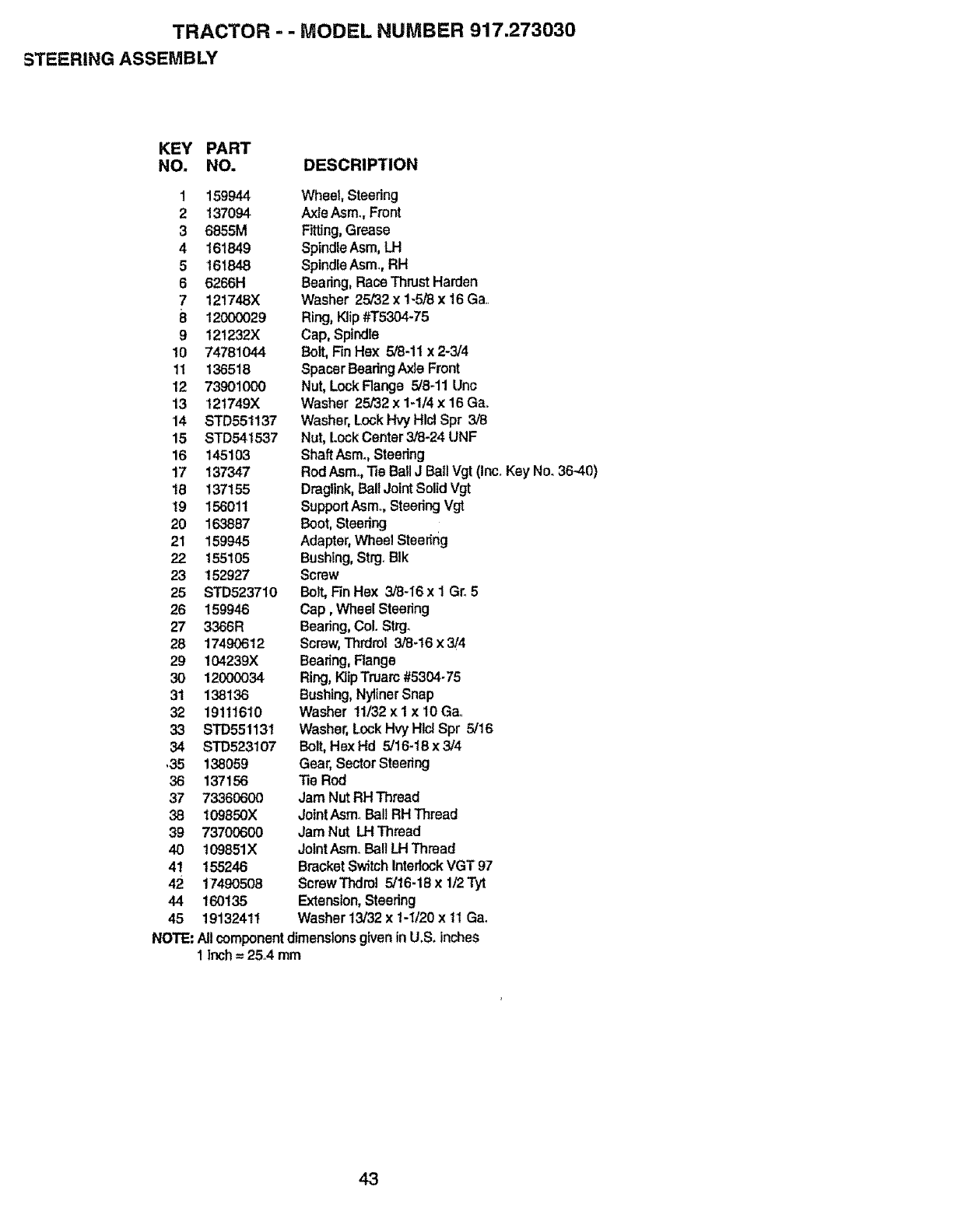
TRACTOR - - MODEL NUMBER 917.273030
STEERING ASSEMBLY
KEY PART
NO. NO. DESCRIPTION
1159944
2137094
36555M
4161849
5 161848
66266H
7 121746X
812000029
9 121232X
10 74781044
11 136518
12 73901000
13 121749)(
14 STD65t137
15 STD541537
16 145103
17 137347
18 137155
19 156011
20 163887
21 159945
22 155105
23 152927
25 STD523710
26 159946
27 3366R
28 17490612
29 104239)(
30 12000034
31 138136
32 19111610
33 STD551131
34 STD523107
,35 138059
36 137156
37 73360600
38 I09850X
39 73700600
40 109851X
41 155246
42 17490508
44 160135
45 19132411
NOTE:
Wheel, Steedng
Axle Asmo,Front
Fitting,Grease
SpindleAsm,LH
SpindleAsm., RH
Bearing, RaceThrust Harden
Washer 25/32 x 1-5/8 x t6 Ga..
Ring, Klip#T5304-75
Cap, Spindle
Bolt, Rn Hex 5/8-11 x 2-3/4
Spacer BaadngAxle Front
Nut, LockRange 5/8-11Unc
Washer 25/32 x 1-114x 16Gao
Washer,Lock Hvy Hlcl Spr 3/8
Nut, Lock Center3/8-24 UNF
ShaftAsmo,Steadng
Rod Asmo,TieBall J Bail Vgt (Inc°Key No. 36-40)
Dragltnk,Ball Joint Solid Vgt
SupportAsmo,Steering Vgt
Boot,Steadng
Adapter,Wheel Steedrig
Bushing,Strg_BIk
Screw
Bolt,Rn Hex 3/8-16 x IGr+5
Cap, Wheel Steering
Bearing, Col. Strgo
Screw,Thrdret 3/8-16 x 3/4
Bearing, Range
Ring, KtipTruarc #6304°75
Bushing,Nytiner Snap
Washer 11/32x 1 x lOGao
Washer,Lock Hvy Hlci Spr 5/16
Bolt,Hex Hd 5/16-16 x 3/4
Gear,SectorSteering
TieRod
Jam NutRH Thread
JointAsm_Ball RHThread
Jam Nut LH Thread
JointAsm, Ball LH Thread
Bracket Switch Inter!ockVGT 97
ScrewThdrol 5/16-18 x 1/2Tyt
Extension,Steering
Washer 13/32x 1-1/20x 11Ga_
All componentdimensionsgiven inU.S. inches
1 Inch= 25A mm
43
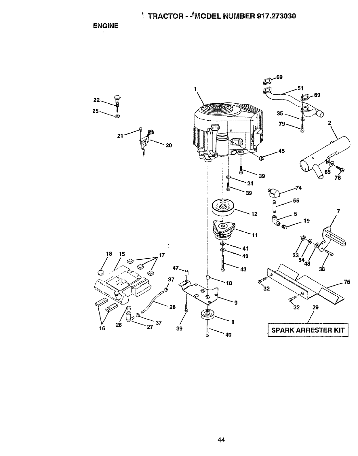
ENGINE
TRACTOR - JMODEL NUMBER 917.273Q30
25 --...........,,_
20
79
16 6 27 39
11
43
39
7
54
35
32 29
iSPARK ARRESTER KIT J
44
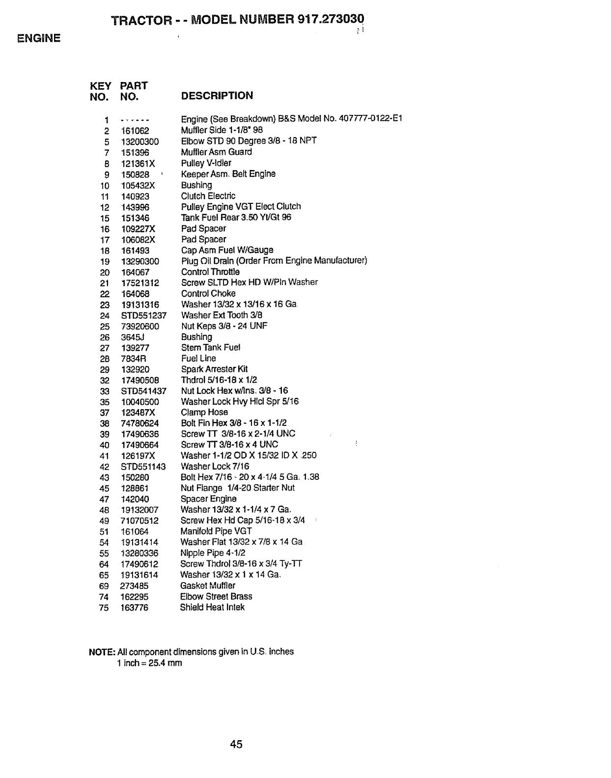
ENGINE
TRACTOR --MODEL NUMBER 917.273030
KEY
NO.
PART
NO. DESCRIPTION
2t61062
5 13200300
7151396
8 121361X
9150828 '
10 105432X
11 140923
12 143996
15 151346
16 109227X
17 106082X
18 161493
19 13290300
20 164067
21 17521312
22 164068
23 19131316
24 STD551237
25 73920600
26 3645J
27 139277
28 7834R
29 132920
32 17490508
33 STD541437
35 10040500
37 123487X
38 74780624
39 17490636
40 17490664
41 126197X
42 STD551143
43 150280
45 128861
47 142040
48 19132007
49 71070512
51 161064
54 19131414
55 13280336
64 17490612
65 19131614
69 273485
74 162295
75 163776
Engine (See Breakdown) B&S Model No. 407777.-0122-E1
Muffler Side 1-1/8" 96
Elbow STD 90 Degree 3/8 - 18 NPT
MuHler Asm Guard
Pulley V-tdler
Keeper AsmoBelt Engine
Bushing
Clutch Electric
Pulley Engine VGT Elect Clutch
Tank Fuel Rear 3.50 Yt/Gt 96
Pad Spacer
Pad Spacer
Cap Asm Fuel W/Gauge
Plug Oil Drain (Order From Engine Manufacturer)
Control Throttle
Screw SLTD Hex HD WlPtn Washer
Control Choke
Washer 13/32 x 13/16 x 16 Ga
Washer Ext Tooth 3/8
Nut Keps 3/8 -24 UNF
Bushing
Stem Tank Fuel
Fuel Line
Spark Arrester Kit
Thdrol 5/16-I8 x 1/2
Nut Lock Hex w/ins,,3/8 -16
Washer Lock HW HIcl Spr 5/t6
Clamp Hose
Bolt Fin Hex 3/8 - 16 x 1-1/2
Screw TT 3/6-16 x 2-1/4 UNC
Screw TT 318-t6 x 4 UNC !
Washer 1.1/20D X 15/32 ID X 250
Washer Lock 7/t6
Bolt Hex 7/16- 20 x 4-1/4 5 Gao 1_38
Nut Flange 1/4-20 Starter Nut
Spacer Engine
Washer 13/32 x I-1/4 x 7 Ga.
Screw Hex Hd Cap 5/16-18 x 3/4
Manifold Pipe VGT
Washer Flat t3/32 x 7/8 x 14 Ga
Nipple Pipe 4-t/2
Screw Thdrol 3/8-16 x 3/4 Ty-TT
Washer 13132 x 1 x 14 Ga,
Gasket Muffler
Elbow Street Brass
Shield Heat Inlek
NOTE:Allcomponentdimensionsgiven inU,S. inches
1 inch= 25°4rnm
45
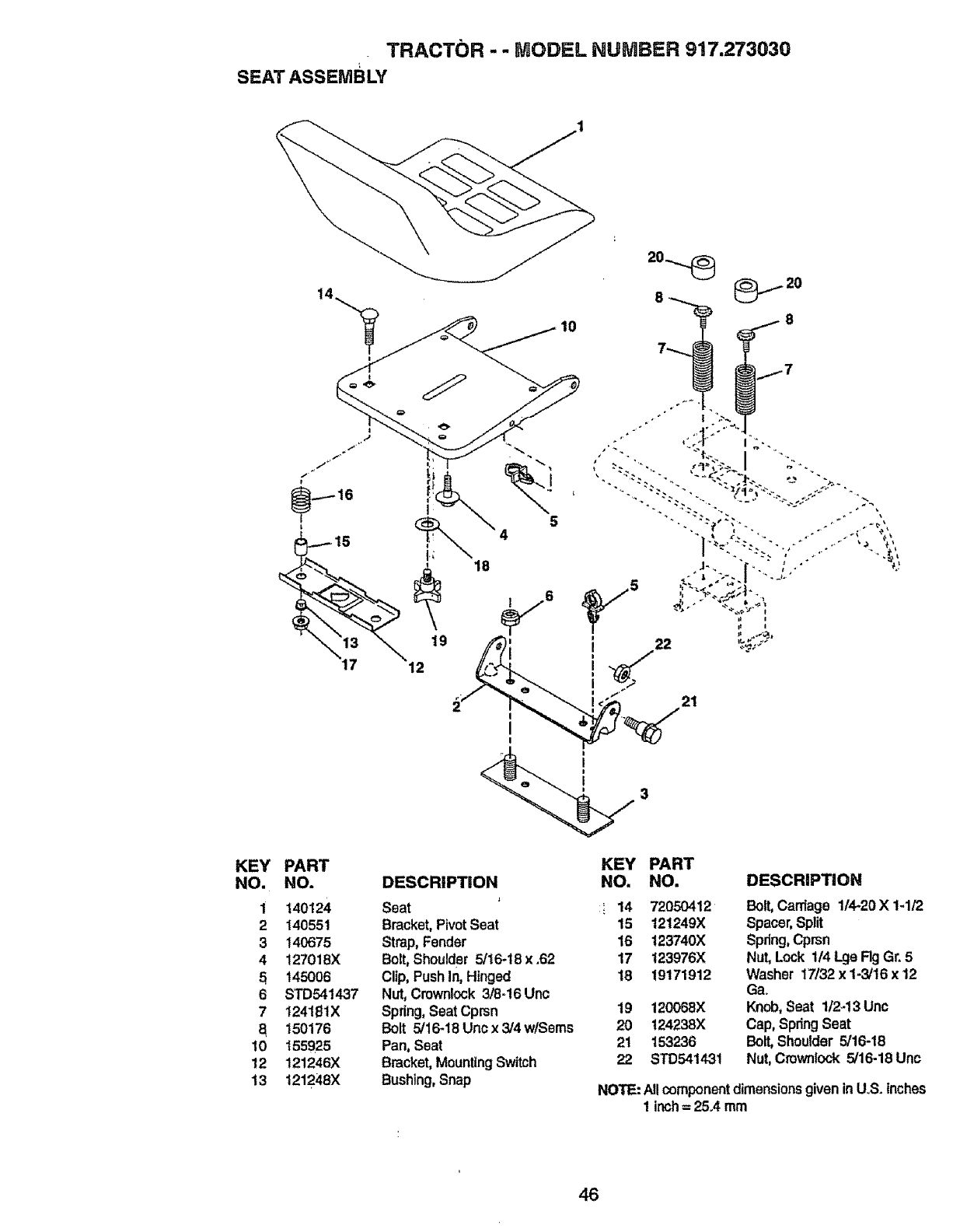
TRACTOR -- MODEL NUMBER 917.273(}30
SEAT ASSEMBLY
19
12
I
I
I
KEY
NO.
2
3
4
5
6
7
a
10
12
13
PART
NO.
140124
140551
140675
127018X
145006
STD541437
1241_1X
150176
155925
121246X
1212_8X
KEY PART
DESCRiPTiON NO, NO.
Seat ' _14 72050412
Bracket,PivotSeat 15 121249X
Strap,Fender 16 123740X
Bolt,Shoulder5/t6-18 x .62 17 123976X
Clip,Pushin, Hir_jed 18 19171912
Nut, Cmwnlock3/8=16Unc
Spring,Seat Cprsn 19
Bolt 5/16-18 Uncx 3/4 w/Seres 20
Pan, Seat 21
Bracket,MountingSwitch 22
Bushing,Snap
DESCRiPTiON
Boll Cantage 1/4-20 X 1-1/2
Spacer,Split
Spring,Cprsn
Nut,Lock 1/4 LgeRg Gr.5
Washer 17/32 x 1-3/16x 12
Ga.
120068)( Knob,Seat 1/2-13 Unc
124238)( Cap, SpringSeat
153236 Bolt,Shoulder5/16-18
STD54143t Nut,Crown!ock5/16-18 Unc
NOTE:Allcomponentdimensionsgiven inUoS.inches
1 inch= 25°4mm
46
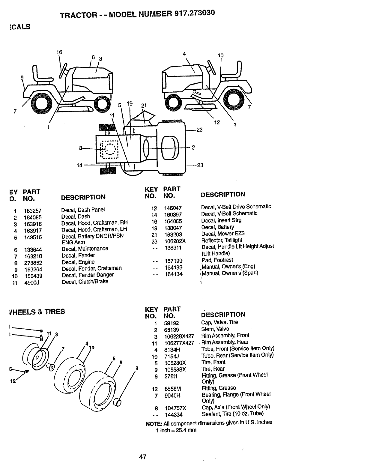
:"CALS
TRACTOR --MODEL NUMBER 917.273030
16
14
6 3
21
_23
2
_23
12
10
7
1
EY
O.
1
2
3
4
5
6
7
8
9
10
1I
PART
NO.
163257
164085
163916
163917
149516
133644
163210
273852
1632O4
156439
4900,1
DESCRIPTION
Decal, DashPanel
Decal,Dash
Decal,Hood,,Craftsman,RH
Decal, Hood, Craltsman,LH
Decal,Battery DNGPJPSN
ENG Asm
Decal, Maintenance
Decal,Fender
Decal, Engine
Decal, Fender,Craftsman
Decal, FenderDanger
Decal,Clutch/Brake
KEY
NO.
12
14
t6
t9
21
23
PART
NO. DESCRIPTION
146047 Decal,V-Belt DriveSchematic
160397 Decal,V-Bait Schematic
164065 Decal,InsertStrg
138047 Decal, Battery
163203 Decal, Mower E7_3
106202X Reflector,Taillight
138311 Decal, Handle LftHeightAdjust
(Uft Handte)
157199 :Pad, Footrest
164133 _Manual,Owner's (Eng)
164134 ,,Manual,Owner's (Span)
I/HEELS &TIRES
410
KEY PART
NO. NO, DESCRIPTION
159192 Cap,Valve,T_ra
2 65139 Stem, Valve
3 106228X427 RimAssembly,Fmrtt
11 1062T7X427 RimAssembly,Rear
4 8134H Tube,Front (ServiceItem Only)
!0 7154J Tube, Rear (ServiceItem Only)
5 106230X Tire, Front
9 105588X Tire,Rear
6 278H RtUng,Grease (FrontWheel
Only)
12 6856M Fitting,Grease
79040H Bearing,Flange(FrontWheel
Only)
8104757X Cap, Axle(Front.WheelOnly)
- - 144334 Sealant,Tire(10 5z, Tube)
NOTE: Allcomponentdimensions given in U.S. Inches
1Inch = 25.4 mm
7
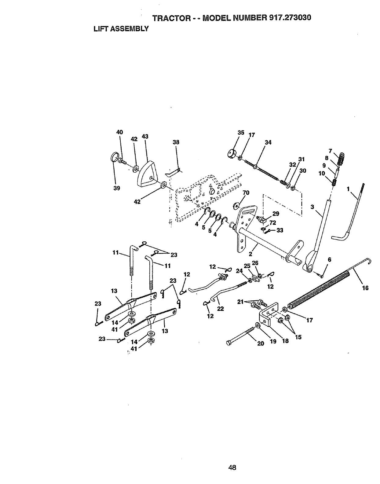
TRACTOR --MODEL NUMBER 917.273030
LiFT ASSEMBLY
40 35 17
42 43 38 34
39
32 31
15
9
10
\
16
48
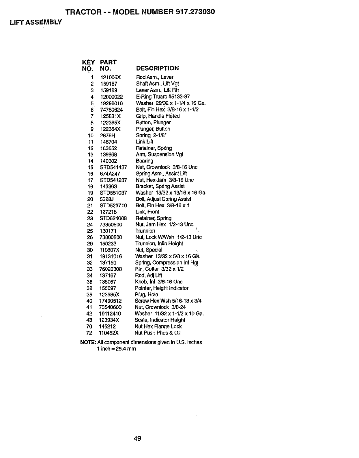
TRACTOR --MODEL NUMBER 917.273030
LIFT ASSEMBLY
KEY
NO.
r_ 1
2
3
4
6
7
8
9
10
11
12
13
14
15
t6
17
18
19
2O
21
22
23
24
25
26
29
3O
3t
32
33
34
35
38
39
4O
41
42
43
7'0
72
NOTE:
PART
NO. DESCRIPTION
121006X
159187
159189
120000_
19292016
74780624
125631X
122365X
122384X
2876H
146704
163552
139868
140302
STD541437
674A247
STD541237
143363
STD551037
5328J
STD523710
127218
STD624C_
73350800
130171
73800800
150238
110807X
19131016
137150
76020308
137167
138057
155097
123935X
17490512
73540600
19112410
123934X
145212
110452X
RodAsm. Lever
ShaftAsm,, LiftVgt
LeverAsm. Lift Rh
E-RingTruarc#5133_87
Washer 29t32 x 1-1/4 x t6 Gao
Bolt, Fin Hex 3/8-16 x1-1/2
Grip, Handle Fluted
Button, Plunger
Plunger,Button
Spring 2-1/8"
Unk Lift
Retainer,Spring
Arm, SuspensionVgt
Bearing
Nut,Crownlock3/8-16 Unc
SpringAsm.Assist Lift
Nut,HexJam 3/8-16 Une
Bracket,SpringAssist
Washer 13/32x 13/16 x 16Ga_
Bolt,AdjustSpringAssist
Bolt,Fin Hex 3/8-16 x t
Unk, Front
Retainer,Spring
Nut,Jam Hex 1/2-13 Unc
Trunnion
Nut, LockW/Wsh 1/2-13Uiio
Trunnion,InfinHeight
Nut, Special
Washer 13/32x 518x 16G_.
Spring,CompressionInfH_
Ptn,Cotter 3/32 x 1/2
Rod,AdjLift
Knob,Inf 3/8-16 Unc
Pointer,HeightIndicator
Plug, Hole
ScrewHexWsh 5/16-18x 3/4
Nut, Cmwn!ock 3/8-24
Washer 11/32x 1-t/2 x 10Ga.
Scale, IndicatorHeight
Nut He)(Flange Lock
Nut Push Phos & Oil
All component dimensionsgiven in U,S. inches
1Inch= 25.4 mm
49
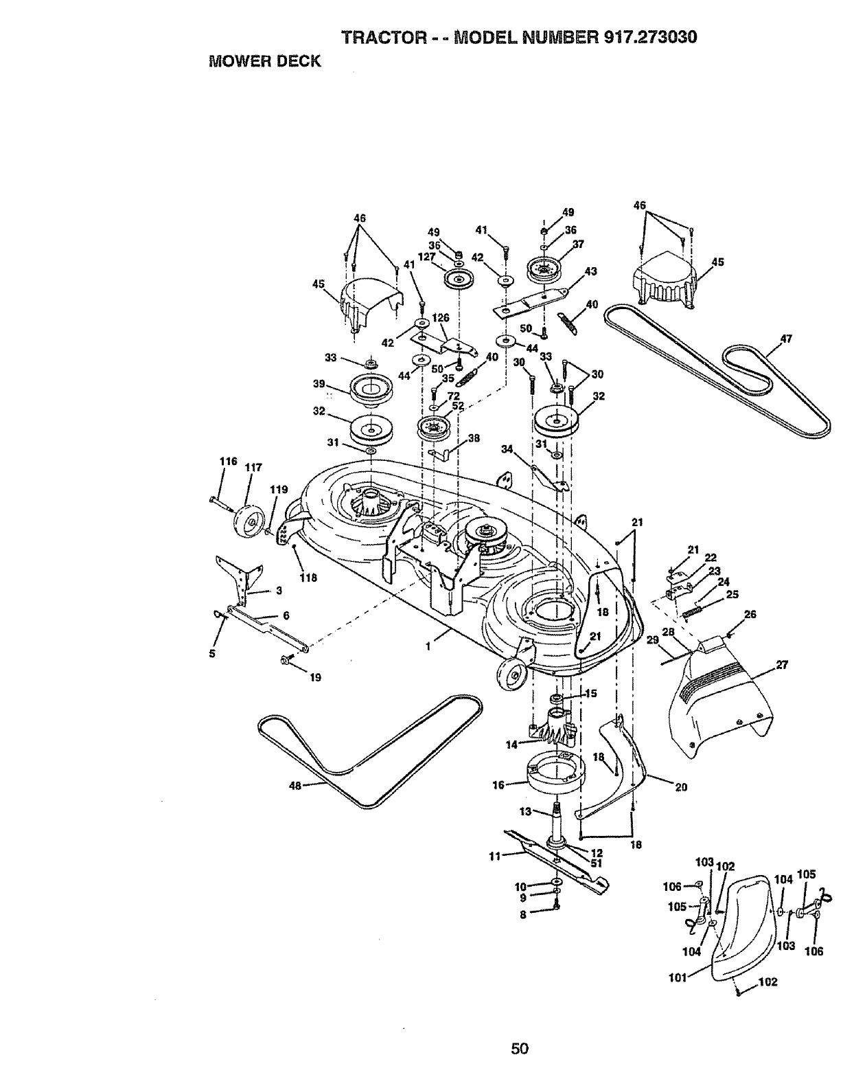
TRACTOR --MODEL HUMBER 917.273030
MOWER DECK
46
49
46
>30
"!32
116 117
21
26
18
103102
lo6-_ 105
104 106
101 ,...1 O2
5O
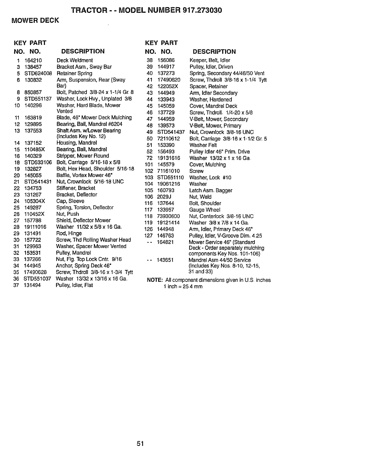
MOWERDECK
TRACTOR - -MODEL NUMBER 917.273030
KEY PART
NO. NO.
I 164210
3 138457
5 STD624008
6 130832
8850857
9STD551137
10 140296
11 163819
12 129895
13 137553
14 137152
15 1!0485X
16 140329
18 STD533106
19 132627
20 145055
21 STD541431
22 134753
23 131267
24 105304X
25 149287
26 110452X
27 157768
28 19111O16
29 131491
30 157722
31 129963
32 153531
33 137266
34 144945
35 17490628
36 STD551037
37 131494
DESCRIPTION
DeckWeldment
BracketAsm, SwayBar
RetainerSpdng
Arm, Suspension, Rear (Sway
Bar)
Bolt, Patched 3/8-24 x 1-1/4 G_8
Washer, LockHvy, Unplated 3/8
Washer, Hard Blade, Mower
Vented
Blade, 46" Mower Deck Mulching
Boadng, Ball, Mandrel #6204
ShaftAsm. w/Lower Bearing
(Includes Key Neet2)
Housing, Mandrel
Bearing, Ball, Mandrel
Stripper,MowerRound
Boll, Carriage 5/16-18 x 5/8
Bolt, Hex Head,Shoulder 5/16-18
Baffle,Vortex Mower46"
Nut, Crownlock 5/16_18UNC
Stiffener,Bracket
Bracket, Defleclor
Cap,Sleeve
Spdng,Torsion,Dellector
Nut, Push
Shield,DeflectorMower
Washer 11/32x 5/8 x 16Ga.
Rod,Hinge
Screw,Thd Rolling WasherHead
Washer,Spacer MowerVented
Pulley,Mandrel
Nut, Fig. TopLock Cntr_9/t6
Anchor,SpringDeck 46"
Screw,Thdrell 3/8-16 x 1-3/4 Tytt
Washer 13/32x 13116x 16 Ga.
PuJley,Idler, Fiat
KEY PART
NO, NO.
36 156086
39 144917
40 137273
4t 17490620
42 122052X
43 144949
44 133943
45 145O59
46 137729
47 144959
48 139573
49 STD541437
50 72110612
51 153390
52 156493
72 19131616
101 145579
102 71161010
103 STD551110
104 19061216
105 160793
106 2029J
116 137644
117 133957
118 73930600
119 19121414
126 144948
127 146763
-- 164821
-- 143651
DESCRIPTION
Keeper, Belt, Idler
Pulley, ldier, Ddven
Spring, Secondary 44/46/50 Vent
Screw, ThdroJl 3/8-16 x 1-t/4 Tytt
Spacer, Retainer
Arm, Idler Secondary
Washer, Hardened
Cover, Mandrel Deck
Screw, ThdrolL 1/4-20 x 5/8
V-Belt, Mower, Secondary
',,'-Belt,Mower, Pdmary
Nut, Crownlock 3/8-16 UNC
Bolt, Carriage 3/8-16 x 1-1/2 Gr. 5
Washer Felt
Pulley Idler 46" Prim. Ddve
Washer 13132x I x 16 Gar
Cover, Mulching
Screw
Washer, Lock #10
Washer
Latch Asm. Bagger
Nut, Weld
Bolt, Shoulder
Gauge Wheel
Nut, Centariock 3/8-16 UNC
Washer 3/8 x7/8 × 14 Ga.
Arm, Idler, Primary Deck 46"
Pulley, Idler, V-Groove Dim. 425
Mower Service 46" (Standard
Deck - Order separately mulching
components Key Nos. 10 t-106)
Mandrel Asm 44150 Service
(Includes Key Nos. 8-10, 12-!5,
31 and 33)
NOTE: All component dimensions given in US inches
tinch = 254 mm
51
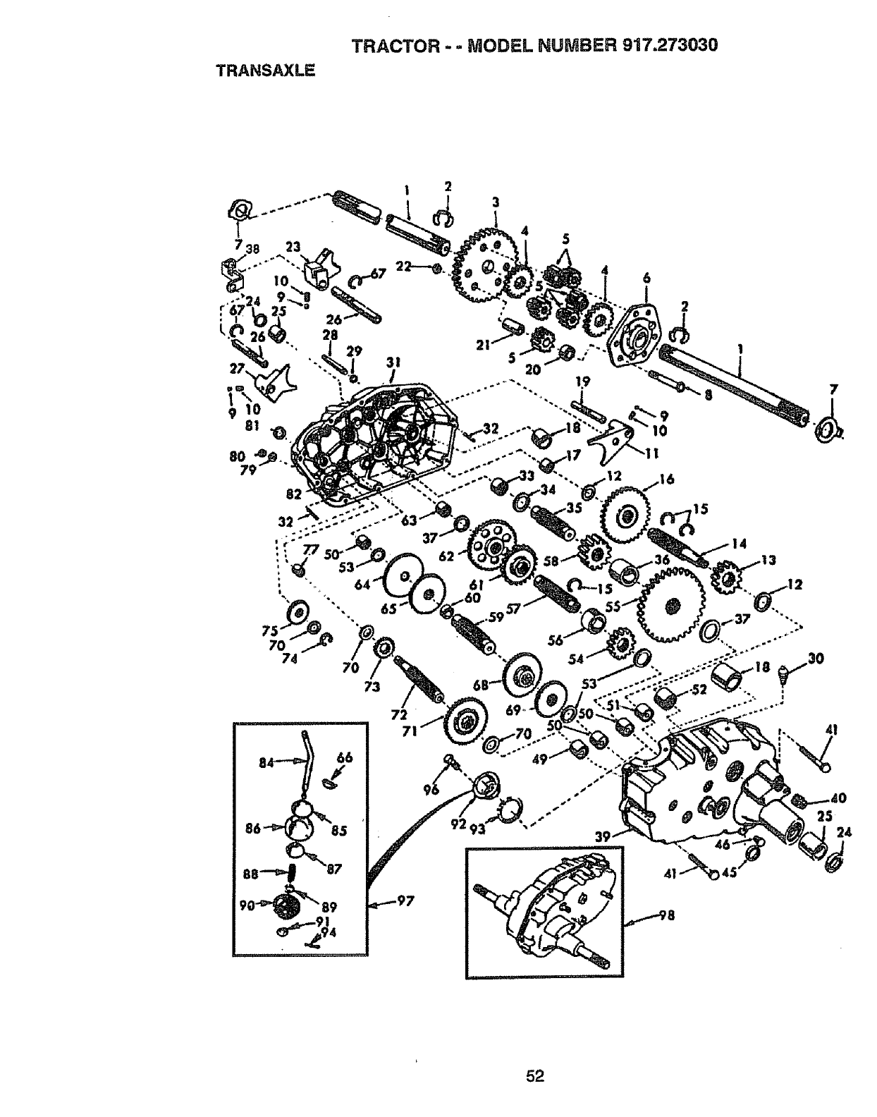
TRANSAXLE
TRACTOR -=MODEL NUMBER 917.273030
5
8O
31 2O
6I
73
72
71
46
15
7
r, 41
25 24
52
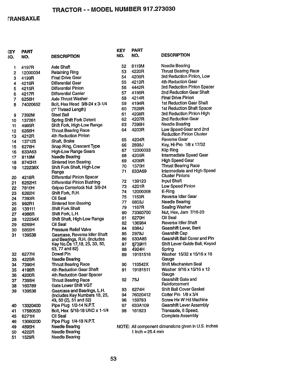
rRANSAXLE
TRACTOR - -MODEL NUMBER 917.273030
¢EY PART
_0. NO.
14197R
212000034
34199R
4 4216R
54215R
64217R
76256H
8 74020652
9 7392M
10 137261
11 4985R
12 62661-1
13 4212R
14 137125
15 6276[-I
t6 633A63
17 8118M
18 8740H1
19 122238X
20 4218R
21 6252HI
22 7810H
23 6262H
24 7393R
25 992R1
26 139111
27 49861=1
28 122254X
29 62691"1
3O 5855H
31 139538
32 6277H
33 4225R
34 7396H
35 4198R
36 4200R
37 7395H
38 160789
39 139536
40 13320400
4! 1758O520
45 6271H
46 13060200
49 48951-1
50 4222R
51 15291:1
KEY PART
DESCRIPTION NO. NO. DESCRIPTION
Axle Shaft 52 81t9M
Retaining Ring 53 4220R
Final DriveGear 54 4209R
DifferentialGear 55 4213R
DifferentialPinion 56 4442R
DifferenlialCarder 57 4195R
Axle ThrustWasher 58 4214R
Bolt,Hex Head 3/8-24 x 3-114 59 4194R
(1"Thread Length) 60 7528R
SteelBall 61 4208R
SpringShiftForkDetent 62 4207R
ShiftFork,High-LowRange 63 7398H
ThrustBearingRace 64 4203R
4th ReductionPinion
Shaft, Brake 65 4204R
Snap Ring,CrescentType 66 2898J
High-LowRange Gears 67 12000033
NeedleBearing 68 4205R
SinteredIronBearing 69 4206R
ShiftForkShaft,High-Low 70 1370t-I
Range 7t 633A69
D_erentlalPinlonSpacer
DifferentialPinion Bushing 72 139120
GripcoCentedockNut 3/8-24 73 4201R
Shift Fork, R.H. 74 12000008
OllSeal 75 1153R
SInteredIronBearing 77 6863J
ShiftForkShaft 79 1167R
ShiftFork,LH. 60 73360700
ShiftShaft,High-LowRange 81 6270H
Oil Seal 82 136984
PressureReliefValve 84 5384J
Gearcese,ReverseIdlerShaft 85 2978J
andBearings,R.H. (Includes 86 633A85
KeyNo.(_s17,18,25, 33, 50, 87 §739H1
63, 77 and82) 88 4924H
DowelPin 89 19151516
NeedleBearing
Thrust BearingRace 90 110542X
4thReductionGearShaft 91 1918t51!
4th Reduction GearSpacer
ThrustBearingRace 92 75J
Gate LowerShiftVGT
GearcaseandBearings,LH. 93 6274H
(includes KeyNumbers 18, 25, 94 76020412
49, 50 (2), 51 and 52) 96 !59783
PipePlug 1/2-14 N.P.T. 97 633A109
Bolt,Hex 5/16-18 UNC x 1-1/4 98 161823
Oil Seal
PipePlug 114-18NoP.T.
Needle Bearing NOTE:
NeedleBearing
NeedleBearing
NeedleBearing
Thrust Bearing Race
3rdReductionPinion,Low
4th ReductionGear
3rd Reduction PinionSpacer
2ndRaduclionGear Shaft
Final Drive Piniori
1st ReductionGear Shaft
1st ReductionShaft Spacer
3rd ReductionPinionHigh
2nd ReductionGear
Needle Bearing
Low SpeedGearand 2nd
Reduction PinionCluster
ReverseGear
Key, Hi-Pro lt8x 17/32
Klip Ring
IntermediateSpeed Gear
High SpeedGear
Thrust Bearing Race
IntermediateandHighSpeed
ClusterPinions
InputShaft
Low SpeedPinion
E-Ring
ReverseIdlerGear
Needle Bearing
SealingWasher
Nut,Hex,Jam 7/16-20
Oil Seal
ReverseidlerShaft
GearshiftLever,Bent
GearshiftCap
GearshiftBallCoverandPin
ShiftLeverGuideBall,Keyed
Spring
Washer 15/32 x 15/16 x 16
Gauge
ShiftMechanismSeal
Washer 9/16x 15/16x 12
Gauge
Gearshift Gate and
Reinforcement
Shift BallCover Gasket
Cotter Pin 1/8 x3/4
ScrewHx W Hd Machine
GearshiftLeverAssembly
Trancaxle,6 Speed,
CompleteAssembly
Altcomponentdimensfonsgiven in U.S. inches
1inch = 25°4mm
53
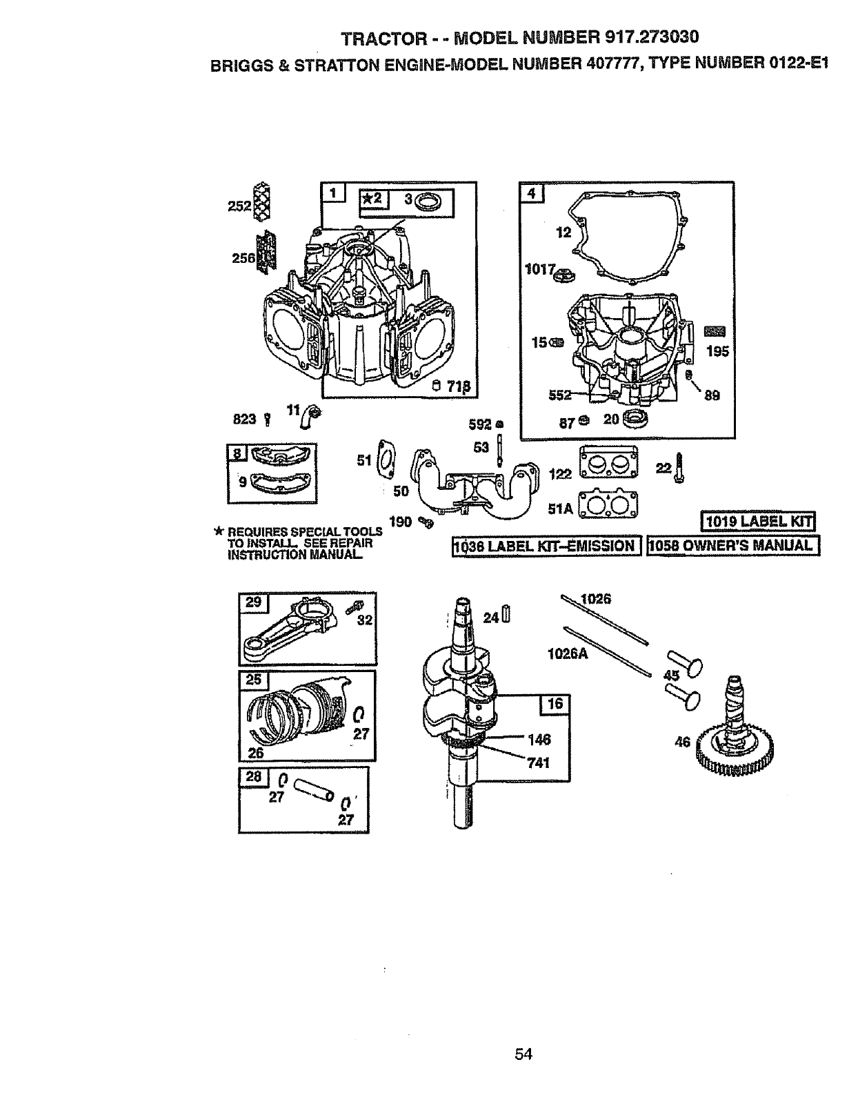
TRACTOR - - MODEL HUMBER 917.273030
BRIGGS & STRATTON ENGINE-MODEL NUMBER 407777, TYPE NUMBER 0122-[=1
256
101
823 f11_!_: 5_'2= 87 ®20@
0 S1A_
REQUIRES;SPECIAL TOOLS
To,,,s,,,.s_RE,A', _e _SEL_-_"_SSSO"III_0"OW,en's"_UA, I
INSTRUGTIONMANUAL
26 46
54
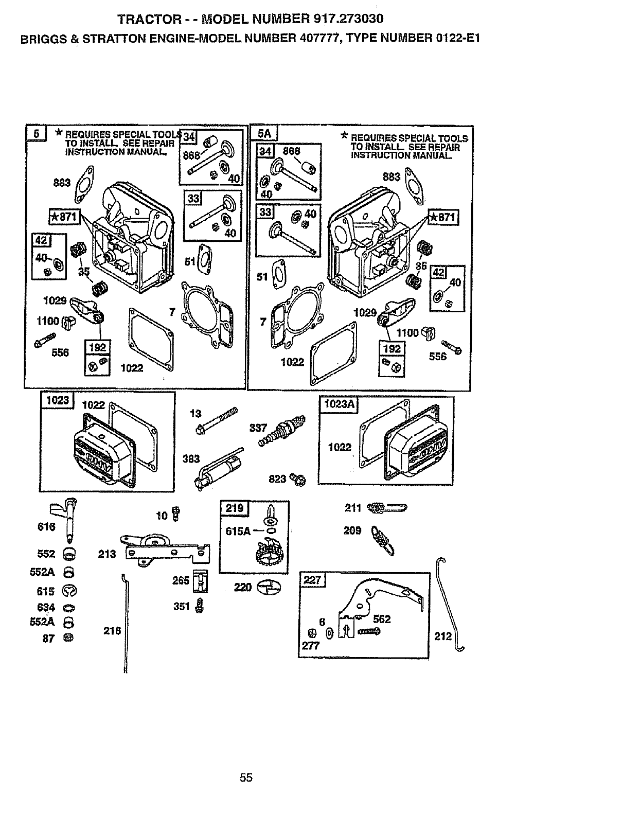
TRACTOR - - MODEL NUMBER 917.273030
BRIGGS & STRATTON ENGINE-MODEL NUMBER 407777, TYPE NUMBER 0122-E1
616_ 10
552 _213
_2A 13
615 _)
634 €:>
218
87_)
265
615A _o
211
27"7
55
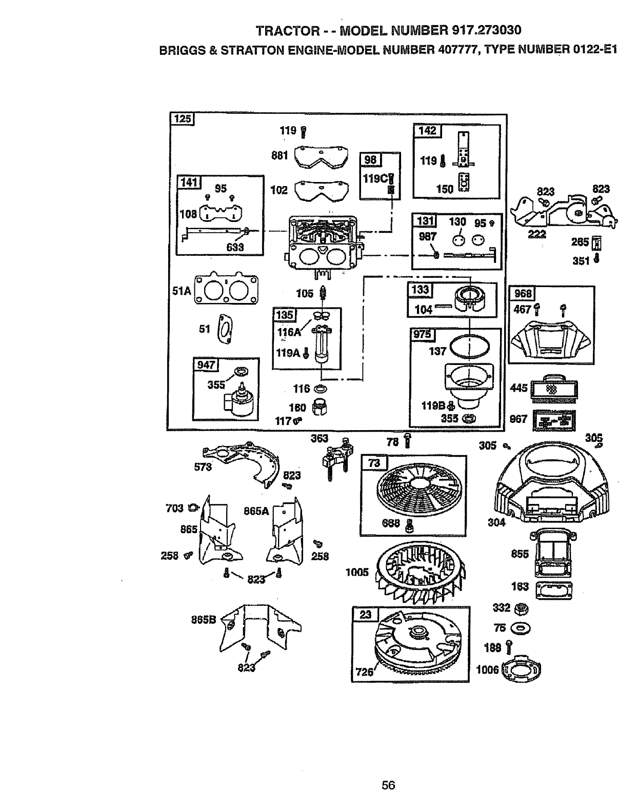
TRACTOR --MODEL HUMBER 917.273030
BRIGGS & STRATTON ENGINE-MODEL NUMBER 407777, TYPE NUMBER 0122-E1
i
119
150
116
1BO
_8
1005
823
3O4
163 _ •
188
56
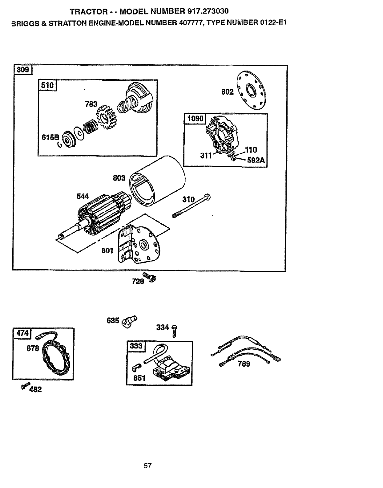
TRACTOR --MODEL NUMBER 917.273030
BRIGGS & STRATTON ENGINE-MODEL NUMBER 407777, TYPE NUMBER 0122-E1
783
311
803
544
.........................................,_:_
878
_d82
635 _334,
57
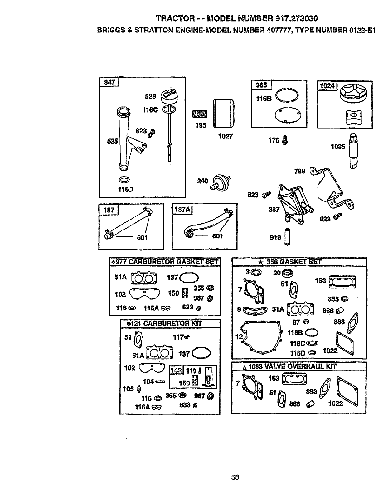
TRACTOR -.. MODEL NUMBER 917.273030
BRIGGS & STRATTON ENGINE-MODEL NUMBER 407777, TYPE NUMBER 0122-E1
601
195
t027
HI
_977 CARBURI_'TOR QASKET,,,,S,,_
1o2_ lSO_ 355_
_7@
116 _) 116#, _;' 633 @
e121 CARBURETOR KIT
51 _1170
102 _ _119| "
lO4= lsol o;
105 116_:_ 155@ 987
116A_ 633 @
116B Q
176
788
387
1035
a33_'
.......... _ 358 GASKET S_
30 2o@
1 116B (_1
116C_
116D O10
"_, 1033 VALVE OVERHAUL KIT .........
86s _ 1o_
58
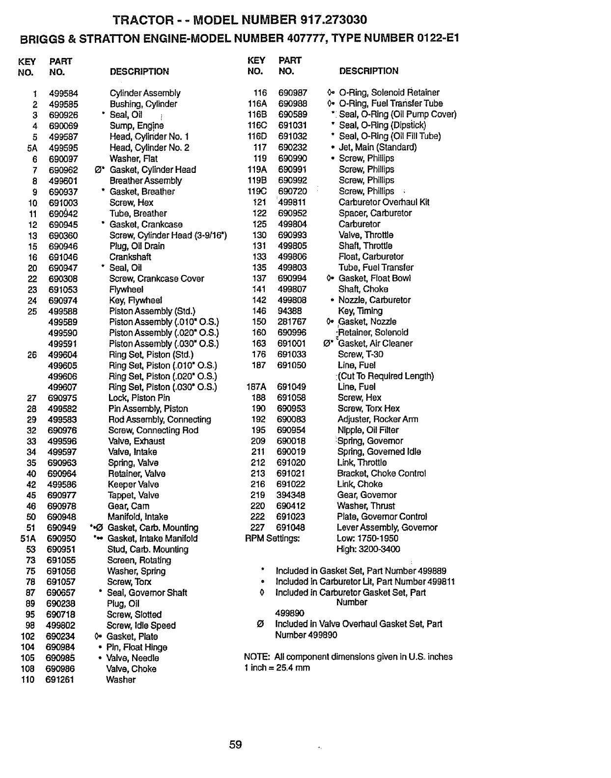
TRACTOR -- MODEL NUMBER 917.273030
BRIGGS & STRATTON ENGINE-MODEL NUMBER 407777, TYPE NUMBER 0122-E1
KEY PART KEY PART
NO. NO. DESCRIPTION NO. NO. DESCRIPTION
1 499584 CylinderAssembly 116 690987
2499585 Bushing,Cylinder 116A 690988
3 690926 * Seal,Oil i 116B 690589
4 690069 Sump,Eng!ne 116(3 691031
5499587 Heed,CylinderNo. t 116D 691032
5A 499595 Head,CylinderNo. 2 117 690232
6 690097 Washer, Rat 119 690990
7 690962 0* Gasket,CylinderHead 119A 690991
8 499601 BreatherAssembly 119B 690992
9 690937 *Gasket, Breather 119C 690720
10 691003 Screw, Hax t21 499811
11 690_2 Tube,Breather 122 690952
12 690945 ° Gasket, Crankcase 125 499804
13 690360 Screw,Cylinder Head (3-9/16") 130 690993
15 690946 Plug,Oil Drain 131 499805
16 691046 Crankshaft 133 499806
20 690947 "Seal, Oil 135 499803
22 690308 Screw,CrankcaseCover !37 690994
23 691053 Rywheel 141 499807
24 690974 Key,Rywheal 142 499808
25 499588 PistonAssembly (Std.) 146 94388
499589 PistonAssembly (.010"O.S.) 150 281767
499590 PistonAssembly (.020"O.S.) 160 690996
499591 PistonAssembly (.030"O.S.) 163 691001
26 499504 Ring Set, Piston(Std.) 176 691033
499605 Ring Set,Piston (o010"O°S.) 187 691050
499606 Ring Set,Piston (.020"O.S.)
499607 Ring Set, Piston (,030° O.S.) 187A 691049
27 690975 Lock, Piston P}n 188 691058
28 499582 PinAssembly, Piston 190 690953
29 499583 Rod Assembly,Connecting 192 690083
32 690976 Screw,Connecting Rod 195 690954
33 499596 Valve,Exhaust 209 690018
34 499597 Valve,Intake 2tl 690019
35 690963 Spring,Valve 212 691020
40 690964 Retainer,Valve 213 691021
42 499586 KeeperValve 216 691022
45 690977 Tappet,Valve 219 394348
46 690978 Gear,Cam 220 690412
50 690948 Manifold, Intake 2_ 691023
51 690949 "._ Gasket,Carb. Mounting 227 691048
51A 690950 *,- Gasket, IntakeManifold RPM Settings:
53 690951 Stud,Caff:)oMounting
73 691055 Screen,Rotating
75 691056 Washer,Spdng
78 691057 Screw,Torx
87 690657 * Seal, GovernorShaft
89 690238 Plug,Oil
95 690718 Screw, Slotted
98 499802 Screw, IdleSpeed
102 690234 0,, Gasket,Plate
104 690984 • Pin, FloatHinge
105 690985 • Valve, Needle
10B 690986 Valve,Choke
110 691261 Washer
_, O-Ring,Solenoid Retainer
0. O-Ring,Fuel Transfer Tube
°:Seat,O-Ring (Oil Pump Cover)
" Seal, O-Ring (Dipstick)
* Seal, O-Ring (Oil Fill Tube)
.Jet, Main (Standard)
. Screw,Phillips
Screw,Phillips
Screw, Phillips
:Screw,Phillips ;
Carburetor Overhaul Kit
Spacer,Carburetor
Carburetor
Valve,Throttle
Shaft, Thro_e
Float,Carburetor
Tube, FuelTransfer
0- Gasket, Float Bowl
Shaft, Choke
.No_le, Carburetor
Key,"riming
0. ,Gasket,No771e
_Retainer,Solenoid
O* Gasket,Air Cleaner
Screw,T-30
Line, Fuel
:(Cut To Required Length)
Line, Fuel
Screw, Hex
Screw,Torx Hex
Adjuster, RockerArm
Nipple,Oil Filter
_Spdng,Govemor
Spring, Govemed Idle
Link,Throttle
Bracket,ChokeControl
Link,Choke
Gear,Governor
Washer,Thrust
Plate,GovernorControl
LeverAssembly,Governor
Low:1750-1950
High:3200-3400
* IncludedinGasketSet, PartNumber 499889
* IncludedlnCarburetorUt,PartNumber499811
0IncludedinCarburetor Gasket Set, part
Number
499890
O Includedin Valve Overhaul Gasket Set, Part
Number499890
NOTE: All component dimensions given in U.S. inches
tinch = 25.4 mm
59
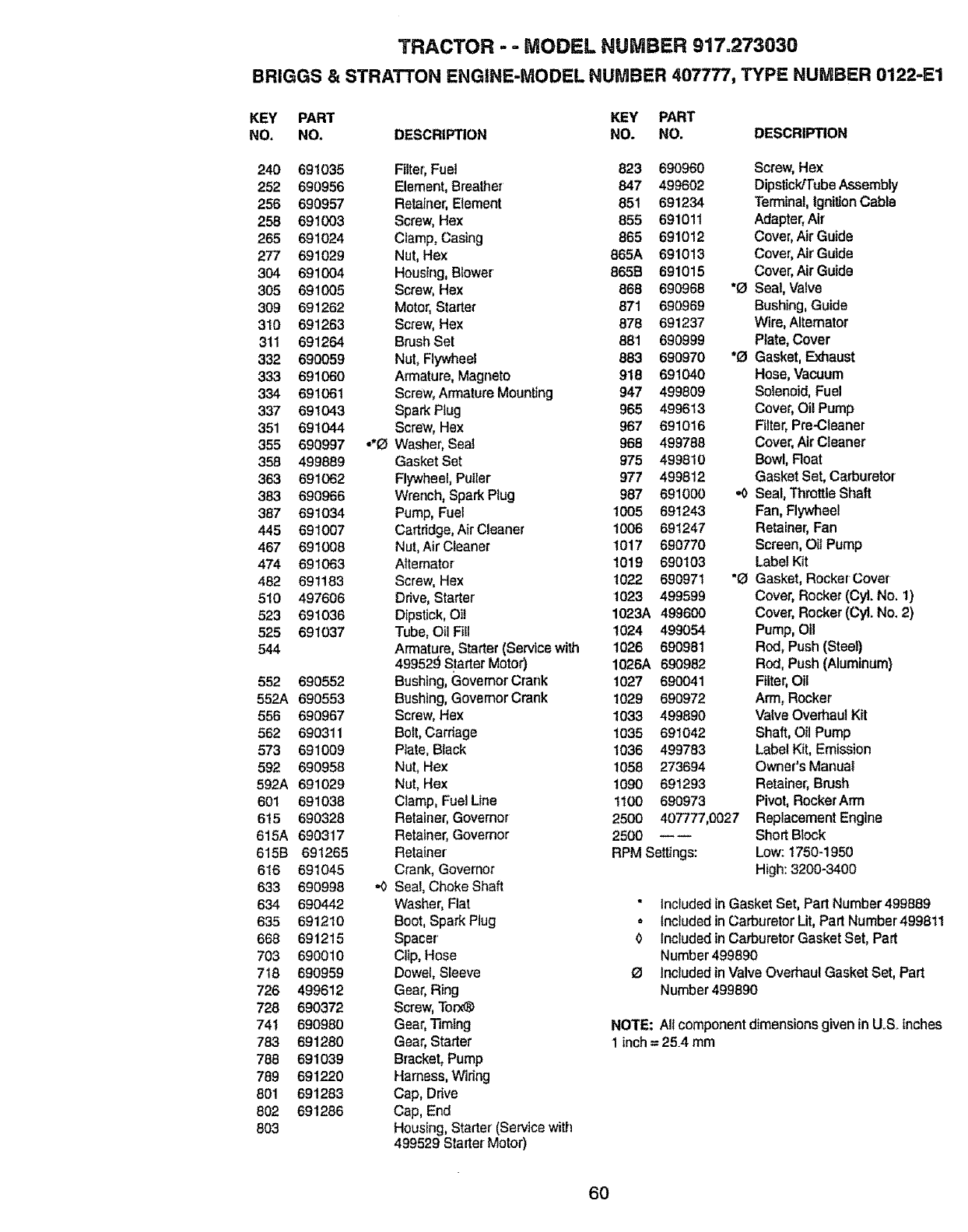
TRACTOR - - MODEL NUMBER 917.273030
BRIGGS & STRATTON ENGiNE-MODEL NUMBER 407777, TYPE NUMBER 0122-E1
KEY PART KEY PART
NO. NO. DESCRIPTION NO. NO. DESCRIPTION
240 691035 Filter; Fuel 823 690960 Screw, Hex
252 690956 Element, Breather 847 499602 Dipstick/Tube Assembly
256 690957 Retainer, Element 851 691234 Terminal, Ignition Cable
258 691003 Screw, Hex 855 691011 Adapter, Air
265 691024 Clamp, Casing 865 691012 Cover, Air Guide
277 691029 Nut, Hex 865A 691013 Cover, Air Guido
304 691004 Housing, Blower 865B 691015 Cover, Air Guide
305 691005 Screw, Hex 868 690968 *0 Seal, Valve
309 691262 Motor, Starter 871 690969 Bushing, Guide
310 691263 Screw, Hex 878 691237 Wire, Alternator
311 691264 Brush Set 881 690999 Plate, Cover
332 690059 Nut, Flywheel 883 690970 "0 Gasket, Exhaust
333 691060 Armature, Magneto 918 691040 Hose, Vacuum
334 691061 Screw, Armature Mounting 947 499809 Solenoid, Fuel
337 691043 Spark Plug 965 499613 Cover, Oil Pump
351 691044 Screw, Hex 967 691016 Filter, Pro-Cleaner
355 690997 -'O Washer, Seat 968 499788 Cover, Air Cleaner
358 499889 Gasket Set 975 499810 Bowl, Roar
363 691062 Flywheel, Puller 977 499812 Gasket Set, Carburetor
383 690966 Wrench, Spark Plug 987 691000 ,,0 Seal, Throttle Shaft
387 691034 Pump, Fuel 1005 691243 Fan, Flywheel
445 691007 Cartridge, Air Cleaner 1006 691247 Retainer; Fan
467 691008 Nut, Air Cleaner 1017 690770 Screen, Oil Pump
474 691063 Alternator 1019 690103 Label Kit
482 691183 Screw, Hex 1022 690971 "a Gasket, RockerCover
510 497606 Drive, Starter 1023 499599 Cover, Rocker (Cyl. No. 1)
523 691036 Dipstick, Oil 1023A 499600 Cover, Rocker (CyL No. 2)
525 691037 Tube, Oil Fill 1024 499054 Pump, Oil
544 Armature, Starter (Service with 1026 690981 Rod, Push (Steer)
499529 Starter Motor) 1026A 690982 Rod, Push (Aluminum)
552 690552 Bushing, Govemor Crank 1027 690041 Filter, Oil
552A 690553 Bushing, GovemorCrank 1029 690972 Arm, Rocker
556 690967 Screw, Hex 1033 499890 Valve Overhaul Kit
562 690311 Bolt, Carriage 1035 691042 Shaft, Oil Pump
573 691009 Ptate, Black 1036 499783 Label Kit, Emission
592 690958 Nut, Hex 1058 273694 Owner's Manual
592A 691029 Nut, Hex 1090 691293 Retainer, Brush
601 691038 Clamp, Fuel Line 1100 690973 Pivot, RockerArm
6t5 690328 Retainer, Governor 2500 407777,0027 Replacement Engine
615A 690317 Retainer, Govemor 2500 _-- Short Block
615B 691265 Retainer RPM Settings: Low: t750-1950
616 691045 Crank, Governor High: 3200-3400
633 690998 ,,0 Seal, Choke Shaft
634 690442 Washer, Fiat " included in Gasket Set, Part Number 499889
635 691210 Boot, Spark Plug ° Included inCarburetor Lit, Part Number499811
668 691215 Spacer 0 Included in Carburetor Gasket Set, Part
703 690010 Clip, Hose Number 499890
718 690959 Dowel, Sleeve _ Included in Valve Overhaul Gasket Set, Part
726 499612 Gear, Ring Number 499890
728 690372 Screw, Torx_
741 690980 Gear, Timing NOTE: All component dimensions given in UoSoInches
783 691280 Gear, Starter 1 inch = 25.4 mm
788 691039 Bracket, Pump
789 691220 Harness, Wiring
801 691283 Cap, Drive
802 691286 Cap, End
803 Houslng, Starter (Service with
499529 Starter Motor)
60

61

62

SUGGESTED GUIDE FOR SiGHTiNG SLOPES FOR SAFE OPERATION
O3
I"-"
SIGHTING
GUIDE
ONLY RIDE UP AND DOWN HILL,
NOT ACROSS HILL
SIGHT AND HOLD THIS LEVEL WITH
SKY LINE OR TREE.
15o MAX.
I _, Operate your Tractor up and down the face of slopes (not I
_greater than 15 ), never across the face. Make turns gradu- !
ally to prevent tipping or loss of control. Exercise extreme I
caution when changing direction on slopes. I
•.... __.,_:_,,,

For the repair or replacement parts you need
delivered directly to your home
Call 7 am - 7 prn, 7 days a week
1=8()0-366=PART
(1-800-366-7278)
Para ordenar piezas con entrega a
domicilio - 1-800-659-7084
For in-house major brand repair service
Call 24 hours a day, 7 days a week
1-800-4=REPAIR
(1-800-473-7274)
Para pedir servicio de reparaci6n a
domicilio - 1.800.676-5811
For the location of a Sears Parts and
Repair Center in your area
Call 24 hours a day, 7 days a week
1-800-488-1222
For information on purchasing a Sears
Maintenance Agreement or to inquire
about an existing Agreement
Call 9 am -5 pm, Monday-Saturday
1-800-827-6655
When requesting service or ordering
parts, always provide the following
information:
- Product Type = Part Number
• Model Number = Part Description
Americas Repair Specta/_sts
164133 Rev. 4 7.27.9'8 RDiTR Printed in U.S.A.
