Craftsman 917273111 User Manual TRACTOR Manuals And Guides 98100098
CRAFTSMAN Lawn, Tractor Manual 98100098 CRAFTSMAN Lawn, Tractor Owner's Manual, CRAFTSMAN Lawn, Tractor installation guides
User Manual: Craftsman 917273111 917273111 CRAFTSMAN TRACTOR - Manuals and Guides View the owners manual for your CRAFTSMAN TRACTOR #917273111. Home:Lawn & Garden Parts:Craftsman Parts:Craftsman TRACTOR Manual
Open the PDF directly: View PDF ![]() .
.
Page Count: 64
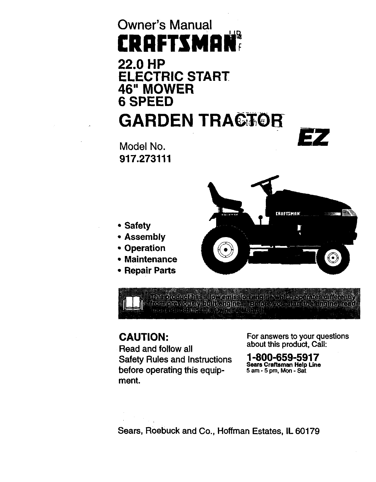
Owner's Manual
CRnFTsMnli
22.0 HP
ELECTRIC START
46" MOWER
6 SPEED
GARDEN TRACiTOR
Model No.
917.273111
•Safety
•Assembly
•Operation
• Maintenance
•Repair Parts
CAUTION:
Read and follow all
Safety Rules and Instructions
before operating this equip-
ment.
For answers to your questions
about this product, Call:
1-800-659-5917
Sears Craftsman Help Line
5 am - 5 pm, Mon- Sat
Sears, Roebuck and Co., Hoffman Estates, IL 60179
Warranty ................................................. 2
Safety Rules ........................................... 2
Product Specifications ........................... 5
Assembly ................................................ 8
Operation..:..: ........................................ 12
Maintenance Schedule ......................... 19
Maintenance ......................................... 19
Service and Adjustments .............. :_T,.,..23
Storage ......................................... ........ 31
Troubleshooting .................................... 32
Repair Parts ......................................... 36
Parts Ordering ....................... Back Cover
LIMITED TWO YEAR WARRANTY ON CRAFTSMAN RIDING EQUIPMENT
For two (2) years from the date of purchase, ifthis Craftsman Riding Equipment is main-
tained, lubricatedand tuned up according tothe instructionsin the owner's manual,
Sears will repair or replace, free of charge, any parts found to be defective in material or
workmanship.
This Warranty does not cover:. __--.
• Expendable items which become wom during normal use, such as blades, spark
plugs, air cleaners, belts, etc.
•Tire replacement or repair caused by punctures from outside objects, such as nails,
thorns, stumps, or glass.
•Repairs necessary because of operator abuse, negligence, improper storage or acci-
dent or the failure to maintain the equipment according to the instructionscontained in
the owner's manual.
• Riding equipment used for commercial or rental purposes.
LIMITED 90 DAY WARRANTY ON BAI-I'ERY
For ninety (90) days from date of purchase, if any battery included with this riding equip-
ment proves defective in material or workmanship and our testing determines the bat-
tery will not hold a charge, Sears will replace the battery at no charge. In-home warranty
service on your Craftsman riding equipment is available at no charge for 30 days from
the date of purchase. Please contact your nearest service center. After 30 days from the
date of purchase, warranty service is available by taking your Craftsman riding equip-
ment to your nearest Sears Service Center. (In-home warranty service will still be avail-
able after 30 days from the date of purchase but a standard trip charge will apply). This
warranty applies only while this product is in the United States. This Warranty gives you
specific legal rights, and you may also have other rights which may vary from state to
state.
Seam, Roebuck and Co., D/817 WA, Hoffman Estates, IL 60179
GENERAL OPERATION
•Read, understand, and foflowall instruc-
tions in the manual and on the machine
before starting.
• Only allow responsible adults, who are
familiar with the instructions,to operate
the machine.
•Clear the area of objects such as rocks,
toys, wire, etc., which could be picked
up and thrown by the blade.
•Be sure the area is clear of other people
before mowing. Stop machine if anyone
enters the area.
2
•Never carry passengers.
•Do not mow in reverse unless absolute-
ly necessary. Always look down and
behind before and while backing.
•Be aware of the mower discharge direc-
tion and do not point it at anyone. Do
not operate the mower without either
the entire grass catcher or the guard in
place.
•Slow down before tuming.
•Never leave arunning machine unat-
tended. Always tum off blades, set park-
ing brake, stop engine, and remove
keys before dismounting.
•Turn off blades when not mowing.
•Stop engine before removing grass
catcher or unclogging chute.
•Mow only in daylight or good artificial
light.
•Do not operate the machine while under
the influence of alcohol or drugs.
•Watch for traffic when operating near or
crossing roadways.
•Use extra care when loading or unload*
ing the machine into a trailer or truck.
SLOPE OPERATION
Slopes are a major factor related to loss-
of-control and tipover accidents, which
can result in severe injury or death. All
slopes require extra caution. If you cannot
back up the slope or if you feel uneasy on
it, do not mow it.
DO:
•Mow up and down slopes, not across.
•Remove obstacles such as rocks, tree
limbs, etc.
•Watch for holes, ruts, or bumps. Uneven
terrain could overturn the machine. Tall
grass can hide obstacles.
•Use slow speed. Choose a low gear so
that you will not have to stop or shift
while on the slope.
•Follow the manufacturer's recommen-
dations for wheel weights or counter-
weights to improve stability.
•Use extra care with grass catchers or
other attachments, These can change
the stability of the machine.
•Keep all movement on the slopes slow
and gradual. Do not make sudden
changes in speed or direction.
•Avoid starting or stopping on a slope. If
tires lose traction, disengage the blades
and proceed slowly straight down the
slope.
DO NOT:
• Do nottum on slopes unless necessary,
and then, turn slowly and gradually
downhill, if possible.
*Do not mow near drop.offs, ditches, or
embankments. The mower could sud*
denly turn over if awheel is over the
edge of a cliff or ditch, or if an edge
caves in.
•Do not mow on wet grass. Reduced
traction could cause sliding.
•Do nottry to stabilize the machineJ_
putting your foot on the ground.
• Do not use grass catcher on steep
slopes.
CHILDREN
Tragic accidents can occur if the operator
is not alert to the presence of children.
Children are often attracted to the
machine and the mowing activity. Never
assume that children will remain where
you last saw them.
•Keep children out of the mowing area
and under the watchful care of another
responsible adult. - _ -
• Be alert and turn machine off if children
enter the area.
• Before and when backing, look behind
and down for small children.
•Never carry children. They may fall off
and be seriously injured or interfere with
safe machine operation.
•Never allow children to operate the
machine.
•Use extra care when approaching blind
comers, shrubs, trees, or other objects
that may obscure vision.
SERVICE
•Use extra care in handling gasoline and
other fuels. They are flammable and
vapors are explosive.
Use only an approved container.
Never remove gas cap or add fuel
with the engine running. Allow engine
to cool before refueling. Do not
smoke.
Never refuel the machine indoors.
Never store the machine or fuel con-
tainer inside where there is an open
flame, such as a water heater.
•Never run a machine inside a closed area.
•Keep nuts and bolts, especially blade
attachment bolts, tight and keep equip-
ment in good condition.
•Never tamper with safety devices. Check
their proper operation regularly.
•Keep machine free of grass, leaves, or
other debris build-up. Clean oil or fuel
spillage. Allow machine to cool before
storing.
•Stop and inspect the equipment if you
strike an object. Repair, if necessary,
before restarting.
3
• Never make adjustments or repairs with
the engine running.
•Grass catcher components are subject
to wear, damage, and detedoration,
which could expose moving parts or
allow objects to be thrown. Frequently
check components and replace with
manufacturer's recommended parts,
when necessary.
•Mower blades are sharp and_"_n cut.
Wrap the blade(s) or wear gloves, and
use extra caution when servicing them.
•Check brake operation frequently.
Adjust and service as required.
•Be sure the area is clear of other people
before mowing. Stop machine if anyone
enters the area.
•Never carry passengers.
•Do not mow in reverse unless absolute-
ly necessary. Always look down and
behind before and while backing.
•Never carry children. They may fall off
and be sedously injured or interfere with
safe machine operation.
•Keep children out of the mowing area
and under the watchful care of another
responsible adult.
•Be alert and turn machine off if children
enter the area.
•Before and when backing, look behind
and down for small children.
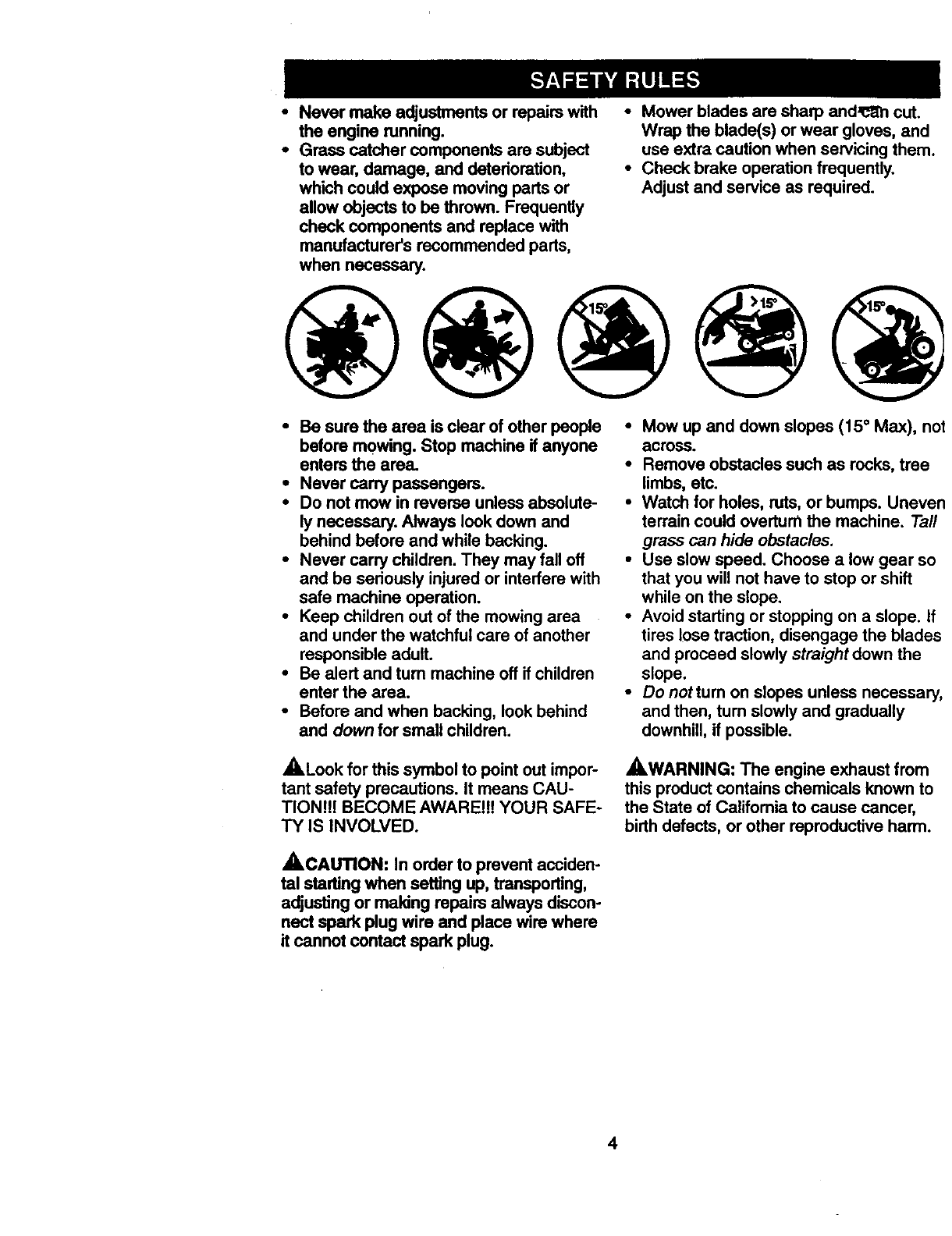
•Mow up and down slopes (15 ° Max), not
across.
•Remove obstacles such as rocks, tree
limbs, etc.
•Watch for holes, ruts, or bumps. Uneven
terrain could overturn the machine. Taft
grass can hide obstacles.
•Use slow speed. Choose a low gear so
that you will not have to stop or shift
while on the slope.
•Avoid starting or stopping on a slope. If
tires lose traction, disengage the blades
and proceed slowly straight down the
slope.
•Donottum on slopes unless necessary,
and then, tum slowly and gradually
downhill, if possible.
,ALook for this symbol to point out impor-
tant safety precautions. It means CAU-
TION!I! BECOME AWARE!!! YOUR SAFE-
TY IS INVOLVED.
AWARNING: The engine exhaust from
this product contains chemicals known to
the State of Califomia to cause cancer,
birth defects, or other reproductive harm.
_.CAUTION: In order to prevent acciden-
tal starting when setting up, transporting,
adjusting or making repairs always discon-
nect spark plug wire and place wire where
it cannot contact spark plug.
4
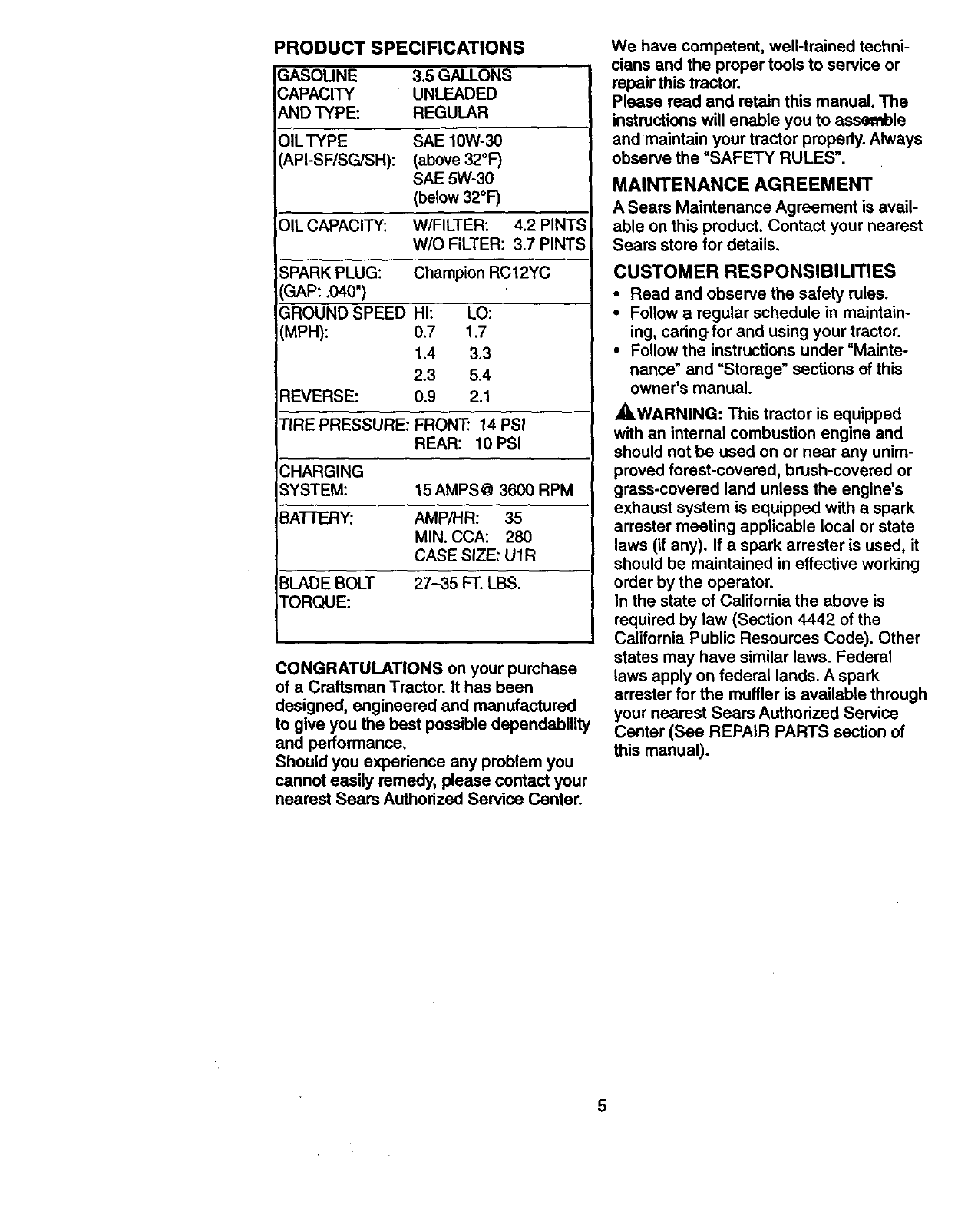
PRODUCT SPECIFICATIONS
GASOUNE 3.5 GALLONS
CAPACITY UNLEADED
AND TYPE: REGULAR
OlLTYPE SAE 10W-30
API-SF/SG/SH): (above 32°1=)
SAE 5W-30
(below 32°F)
OIL CAPACITY: W/FILTER: 4.2 PINTS
W/O FILTER: 3.7 PINTS
SPARK PLUG: Champion RC12YC
GAP: ,040")
GROUND SPEED
(MPH):
HI: LO:
0.7 1.7
1.4 3,3
2.3 5.4
REVERSE: 0.9 2.1
TIRE PRESSURE: FRONT.' 14 PSI
REAR: 10 PSI
CHARGING
SYSTEM: 15 AMPS @3600 RPM
BA'I-rERY: AMP/HR: 35
MIN. CCA: 280
CASE SIZE: U1R
BLADE BOLT 27-35 FT. LBS.
TORQUE:
CONGRATULATIONS on your purchase
of a Craftsman Tractor. It has been
designed, engineered and manufactured
to give you the best possible dependability
and performance,
Should you experience any problem you
cannot easily remedy, please contact your
nearest Sears Authorized Service Center.
We have competent, well-trained techni-
cians and the proper tools to service or
repair this tractor.
Please read and retain this manual. The
instructions will enable you to assemble
and maintain your tractor properly. Always
observe the =SAFETY RULES".
MAINTENANCEAGREEMENT
A Sears Maintenance Agreement is avail-
able on this product. Contact your nearest
Sears store for details,
CUSTOMER RESPONSIBILITIES
• Read and observe the safety rules.
•Follow a regular schedule in maintain-
ing, cadngfor and using your tractor.
•Follow the instructions under "Mainte-
nance" and "Storage" sections of this
owner's manual.
_.WARNING: This tractor is equipped
with an internal combustion engine and
should not be used on or near any unim-
proved forest-covered, brush-covered or
grass-covered land unless the engine's
exhaust system is equipped with a spark
arrester meeting applicable local or state
laws (if any). If a spark arrester is used, it
should be maintained in effective working
order by the operator,
In the state of California the above is
required by taw (Section 4442 of the
California Public Resources Code). Other
states may have similar laws. Federal
laws apply on federal lands. A spark
arrester for the muffler is available through
your nearest Sears Authodzed Service
Center (See REPAIR PARTS section of
this manual),
5
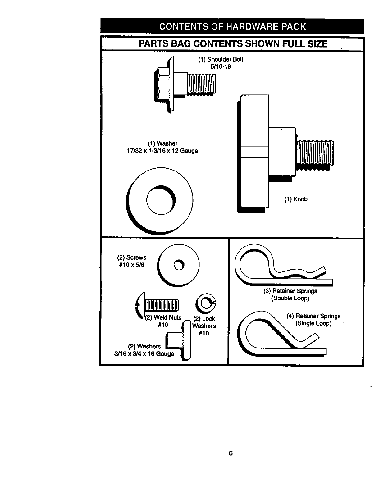
PARTS BAG CONTENTS SHOWN FULL SIZE
"!
((1) Shoulder Bolt
5/16-18
(1) Washer
17/32 x 1-3/16 x 12 Gauge
(1) Knob
(2) Screws
#10 x 5/8 I
(2) Weld Nuts _(2) Lock
#1_ Washers
i #1o
(2) Washers
3/16 x 3/4 x 16 Gauge _..,
(3) Retainer Springs
(Double Loop)
(4) Retainer Springs
___ (Single Loop)
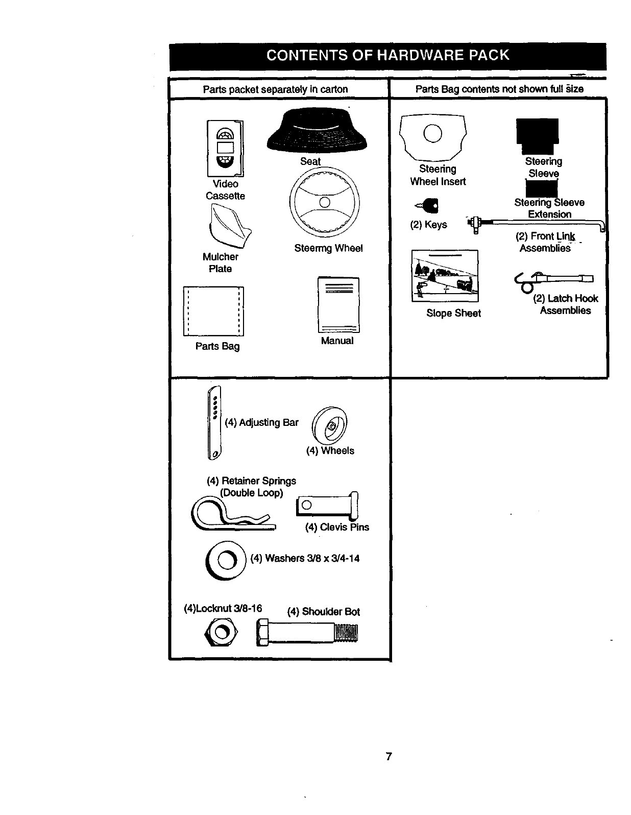
Partspacketseparatelyincarton PartsBagcontentsnotshownfull§ize
re.l== 4
Seat
Video
Cassette
Mulcher
Plate
i
0
i
a
Parts Bag
Steering
Wheel Insert
Steering Wheel
Manual
o
o
°®
a
" (4) Adjusting Bar
(4) Wheels
(4) Retainer Springs
(4) Clevis Pins
®
(4)Locknut 3/8-16
(4) Washers 3/8 x 3/4-14
(4) Shoulder Bot
!
Steering
Sleeve
(2) Keys °n_
Slope Sheet
Steedng _;leeve
Extension
(2) Front Lin_
Assemblies
_(_)) nLatch H_k
Assemblies
7
Your new tractor has been assembled at the factory with exception of those I_ts left
unassembled for shipping purposes. To ensure safe and proper operation of your trac
all pads and hardware you assemble must be tightened securely. Use the correct tool
as necessary to insure proper tightness. Review the video cassette before you begin.
ASSEMBLY _Wheel Insert
_.._ Hex Bolt
_p._._._ Lock Washe_
Large Flat
Washer
A socket wrench set will make assembly
easier. Standard wrench sizes you need
are listed below.
(1) 9/16" wrench (1) 3/4" Socket w/
(1) 112"wrench ddve rachet
(1) Utility knife (1) PhillipsScrew-
(1)Pliers driver
(1) Tire pressure gauge
When right or left hand is mentioned in
this manual, it means, from your point of
view, when you are in the operating posi-
tion (seatedbehind the steering wheel).
TO REMOVE TRACTOR FROM
CARTON
UNPACK CARTON
• Remove all accessible loose parts and
parts boxes from shipping carton (See
page 6).
•Cut, from top to bottom, along lines on
all four comers of shipping carton, and
lay panels flat.
oRemove mower and package materials.
•Check for any additional loose parts or
boxes and remove.
BEFORE ROLLING TRACTOR OFF
SKID
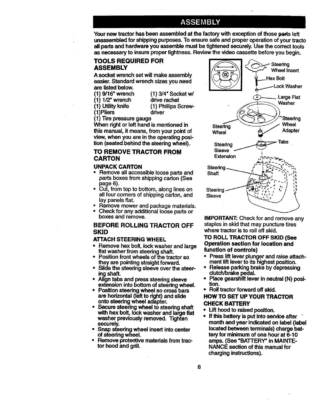
ATTACH STEERING WHEEL
•Remove hex bolt, lock washer and large
fiat washer from steering shaft.
•Positionfront wheels of the tractor so
they are pointing straightforward.
•Slide the steering sleeve over the steer-
in_ shaft.
Align tabs and press steering sleeve
extension into bottom of steedng wheel.
Positionsteering wheel so crossbars
are horizontal (left to right)and slide
onto steering wheel adapter.
Secure steering wheel to steering shaft
with hex bolt, lock washer and large flat
washer previously removed. Tighten
securely.
iSnap steering wheel insert into center
of steedng wheel.
Remove protentive matedals from trac-
tor heed and gdll.
Steering Wheel
Wheel Adapter
Steering _Tabs
Sleeve I
Extension __-__
Shaft
Steering
Sleeve
IMPORTANT: Check for and remove an
staples in skid that may puncture tires
where tractor is to roll off skid.
TO ROLL TRACTOR OFF SKID (See
Operation section for location and
function of controls)
iress lift lever plunger and raise attac
ment lift lever to its highest position.
Release parking brake by depressing
clutch/brake pedal.
Place gearshift lever in neutral (N) po=
tion.
•Roll tractor forward off skid.
HOW TO SET UP YOUR TRACTOR
CHECK BA'I'rERY
•Lift hood to raised position.
•If this battery is put into service after
month and year indicated on label (lab
located between terminals) charge bat
ten] for minimum of one hour at 6-10
amps. (See "BATTERY" in MAINTE-
NANCE section of this manual for
charging instructions).
8
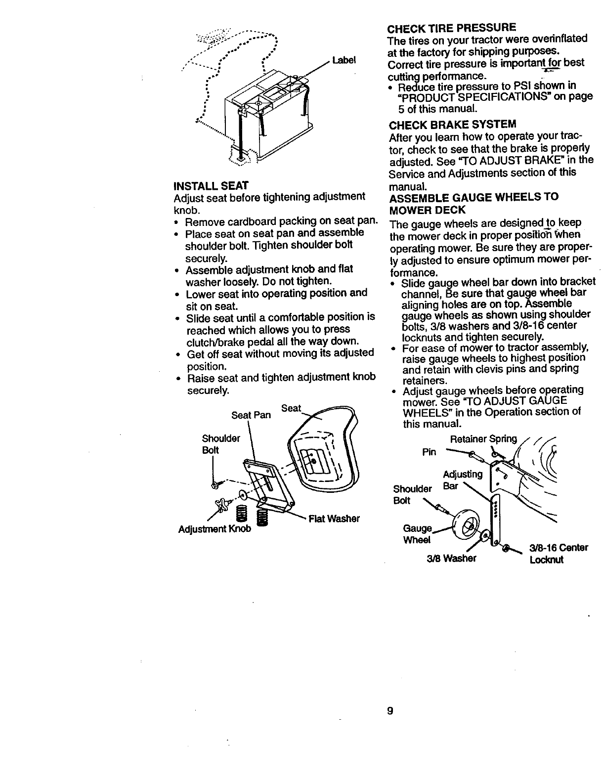
INSTALL SEAT
Adjust seat before tightening adjustment
knob.
•Remove cardboard packing on seat pan.
• Place seat on seat pan and assemble
shoulder bolt, Tighten shoulder bolt
securely.
•Assemble adjustment knob and flat
washer loosely. Do not tighten.
•Lower seat into operating position and
sit on seat.
•Slide seat until a comfortable position is
reached which allows you to press
clutch/brake pedal all the way down.
•Get off seat without moving its adjusted
position.
•Raise seat and tighten adjustment knob
securely.
Seat
Seat Pan
Shoulder
Bolt
L_°_._
Adjustment Knob Flat Washer
CHECK TIRE PRESSURE
The tires on your tractor were overinflated
at the factory for shipping purposes.
Correct tire pressure is important for best
cutting performance.
•Reduce tire pressure to PSI shown in
=PRODUCT SPECIFICATIONS on page
5 of this manual.
CHECK BRAKE SYSTEM
After you learn how to operate yourtrac-
tor, check to see that the brake is propedy
adjusted. See "TO ADJUST BRAKE" in the
Service and Adjustments section of this
manual.
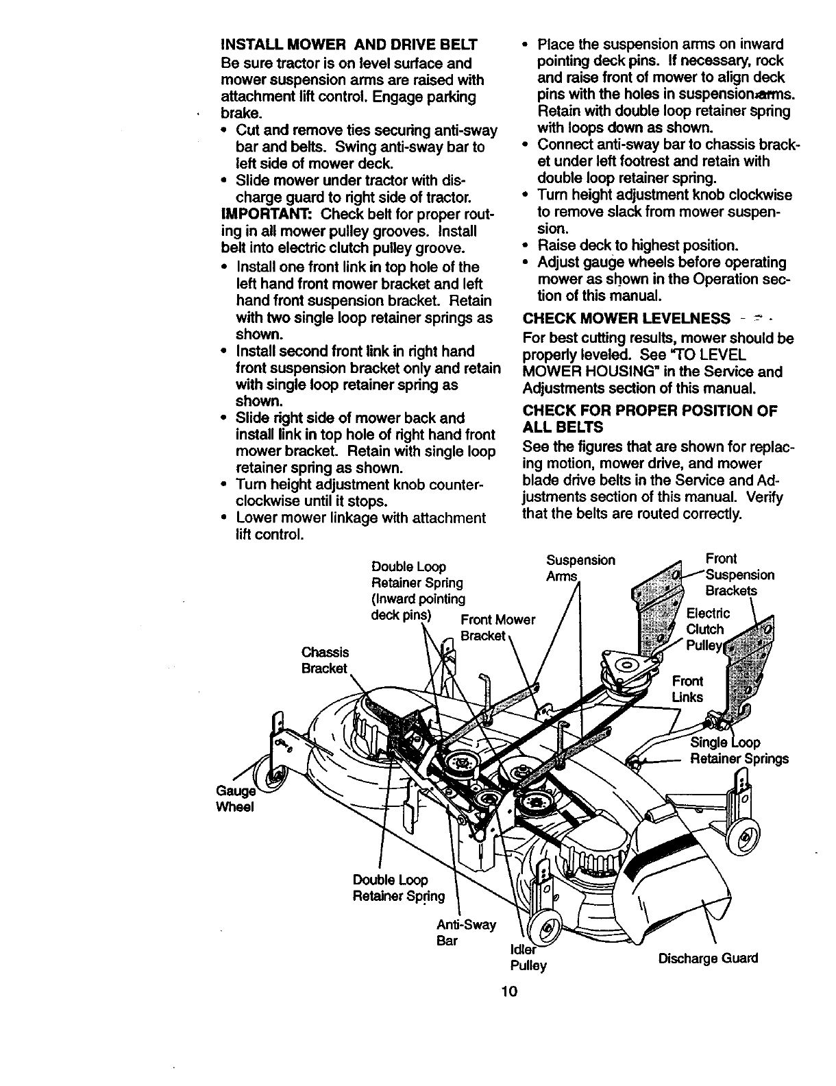
ASSEMBLE GAUGE WHEELS TO
MOWER DECK
The gauge wheels are designedto keep
the mower deck in proper pesffidn When
operating mower. Be sure they are proper-
ly adjusted to ensure optimum mower per-
formance.
•Slide gauge wheel bar down into brackef
channel, Be sure that gauge wheel bar
aligning holes are on top. Assemble
gauge wheels as shown using shoulder
bolts, 318 washers and 3/8-16 center
Iocknuts and tighten securely.
•For ease of mower to tractor assembly,
raise gauge wheels to highest position
and retain with clevis pins and spnng
retainers.
•Adjust gauge wheels before operating
mower. See "TO ADJUST GAUGE
WHEELS" in the Operation section of
this manual.
Retainer Spring
Pin
Shoulder Bar
Bolt
Wheel
3/8 Washer 3/8-16 Center
Locknut
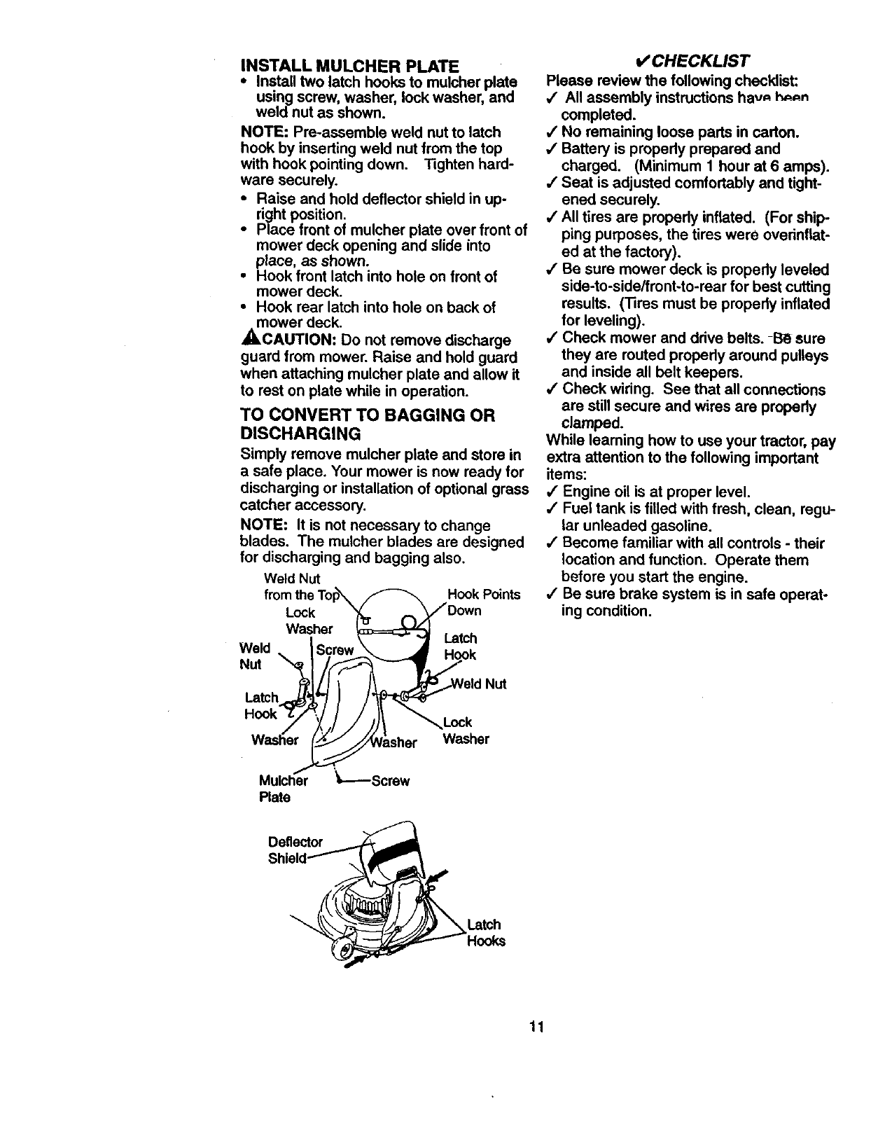
INSTALLMOWERANDDRIVEBELT
Besuretractorison levelsurfaceand
mowersuspensionarmsareraisedwith
attachmentlift control.Engageparking
brake.
•Cut and remove ties securing anti-sway
bar and belts. Swing anti-sway bar to
left side of mower deck.
•Slide mower under tractor with dis-
charge guard to right side of tractor.
IMPORTANT: Check belt for proper rout-
ing in all mower pulley grooves. Install
belt into electric clutch pulley groove.
•Install one front link in top hole of the
left hand front mower bracket and left
hand front suspension bracket. Retain
with two single loop retainer springs as
shown.
•Install second front link in right hand
front suspension bracket only and retain
with single loop retainer spring as
shown.
•Slide right side of mower back and
install link in top hole of right hand front
mower bracket. Retain with single loop
retainer spring as shown.
•Turn height adjustment knob counter-
clockwise until it stops.
•Lower mower linkage with attachment
lift control.
•Place the suspension arms on inward
pointingdeck pins. If necessary, rock
and raise front of mower to align deck
pins with the holes in suspension,at'ms.
Retain with double loop retainer spring
with loops down as shown.
•Connect anti-sway barto chassis brack-
et under left footrest and retain with
double loop retainer spring.
•Turn height adjustment knob clockwise
to remove slack from mower suspen-
sion.
•Raise deck to highestposition.
•Adjust gauge wheels before operating
mower as shown in the Operation sec-
tion of this manual.
CHECK MOWER LEVELNESS - -- -
For best cutting results, mower should be
properly leveled. See =TO LEVEL
MOWER HOUSING" in the Service and
Adjustments section of this manual.
CHECK FOR PROPER POSITION OF
ALL BELTS
See the figures that are shown for replac-
ing motion, mower drive, and mower
blade drive belts in the Service and Ad-
justments section of this manual. Verify
that the belts are routed correctly.
Double Loop
Retainer Spring
(Inward pointing
deck Front Mower
Bracket,
Suspension Front
Brackets
Chassis
Bracket
Retainer Springs
V_leel
Double Loop
Retainer Sp.dng
Anti-Sway
Bar
Pulley
10
Discharge Guard
INSTALL MULCHER PLATE
• Install two latch hooks to mulcher plate
using screw, washer, lock washer, and
weld nut as shown.
NOTE: Pre-assemble weld nut to latch
hook by inserting weld nut from the top
with hook pointing down. Tighten hard-
ware securely.
•Raise and hold deflector shield in up-
right position.
•Place front of mulcher plate over front of
mower deck opening and slide into
place, as shown.
•Hook front latch into hole on front of
mower deck.
•Hook rear latch into hole on back of
mower deck.
_,CAUTION: Do not remove discharge
guard from mower. Raise and hold guard
when attaching mulcher plate and allow it
to rest on plate while in operation.
TO CONVERT TO BAGGING OR
DISCHARGING
Simply remove mulcher plate and store in
a safe place. Your mower is now ready for
discharging or installation of optional grass
catcher accessory.
NOTE: It is not necessary to change
blades. The mulcher blades are designed
for discharging and bagging also.
Weld Nut Hook Points
Lock
Washer Latch
_CHECKLIST
Please review the following checklist:
,/ All assembly instructions havA h,=_n
completed.
/No remaining loose pads in carton.
,/Battery is properly prepared and
charged. (Minimum 1 hour at 6 amps).
/Seat is adjusted comfortably and tight-
ened securely.
,/All tires are properly inflated. (For ship-
ping purposes, the tires were ovednflat-
ed at the factory),
/Be sure mower deck is propedy leveled
side-to-side/front-to-rear for best cutting
results. (Tires must be propedy inflated
for leveling).
,/Check mower and drive belts. -B_ sure
they are routed propedy around pulleys
and inside all belt keepers.
/Check widng. See that all connections
are still secure and wires are propedy
clamped.
While leaming how to use your tractor, pay
extra attention to the following important
items:
,/" Engine oil is at proper level.
/Fuel tank is filled with fresh, clean, regu-
lar unleaded gasoline.
/Become familiar with all controls - their
location and function. Operate them
before you start the engine.
,/Be sure brake system is in safe operat-
ing condition.
Mulcher
Plate
Lock
Washer
Deflector
Latch
Hooks
11
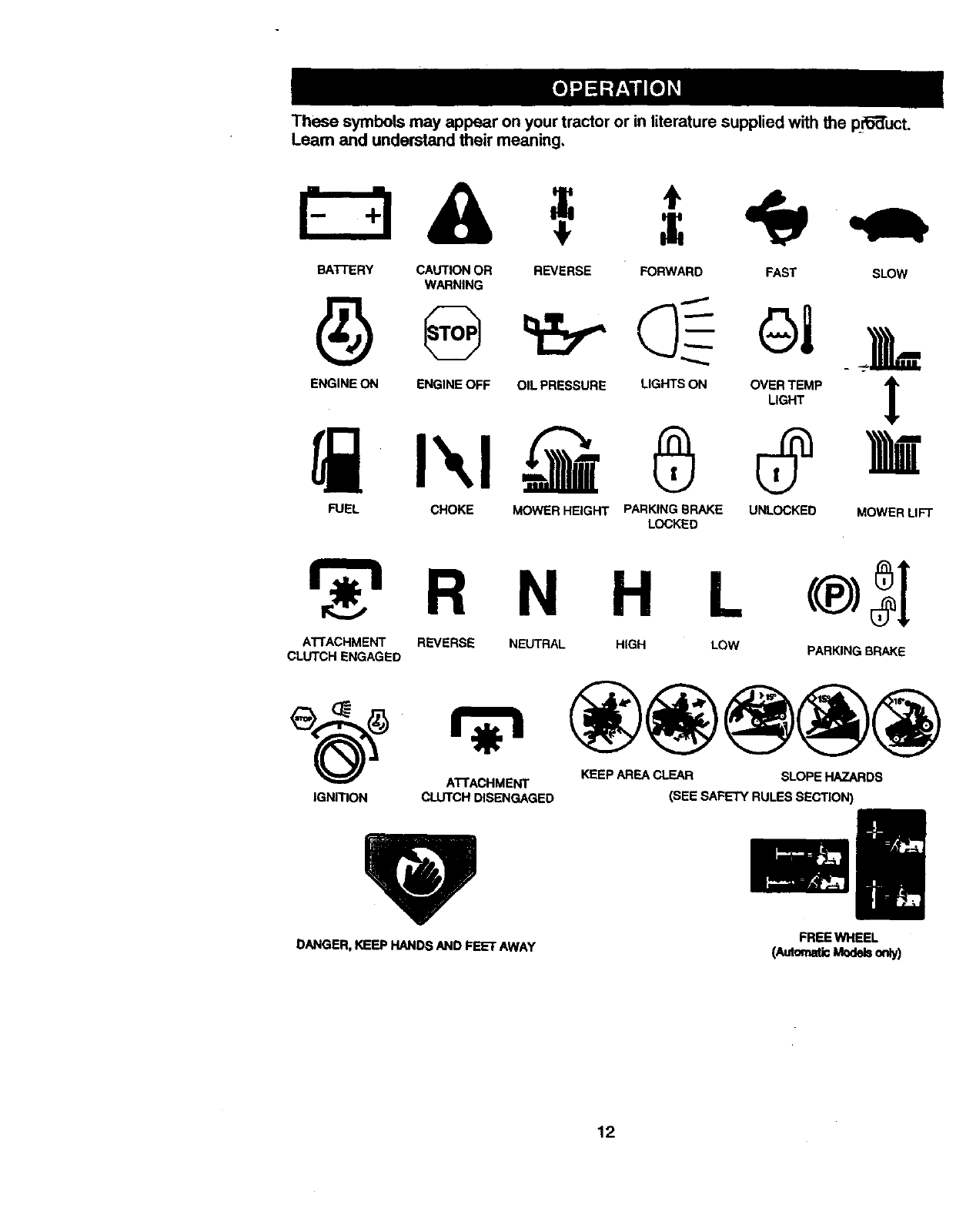
Thesesymbolsmayappearonyourtractoror inliteraturesuppliedwiththepr_"duct.
Learnand understandtheirmeaning,
BATTERY CAUTION OR
WARNING
ENGINE ON ENGINE OFF
REVERSE FORWARD FAST SLOW
OIL PRESSURE LIGHTS ON
®OVER TEMP IAlm
LIGHT
FUEL CHOKE MOWER HEIGHT PARKING BRAKE UNLOCKED MOWER LIFT
LOCKED
N H
A'CrACHMENT REVERSE NEUTRAL HIGH
CLUTCH ENGAGED LOW PARKING BRAKE
KEEP AREA CLEAR SLOPE HAZARDS
A3-1"ACHMENT
IGNITION CLUTCH DISENGAGED (SEE SAFETY RULES SECTION)
DANGER,KEEP HANDSAND FEET AWAY FREE WHEEL
(AutomaticModelsonly)
12
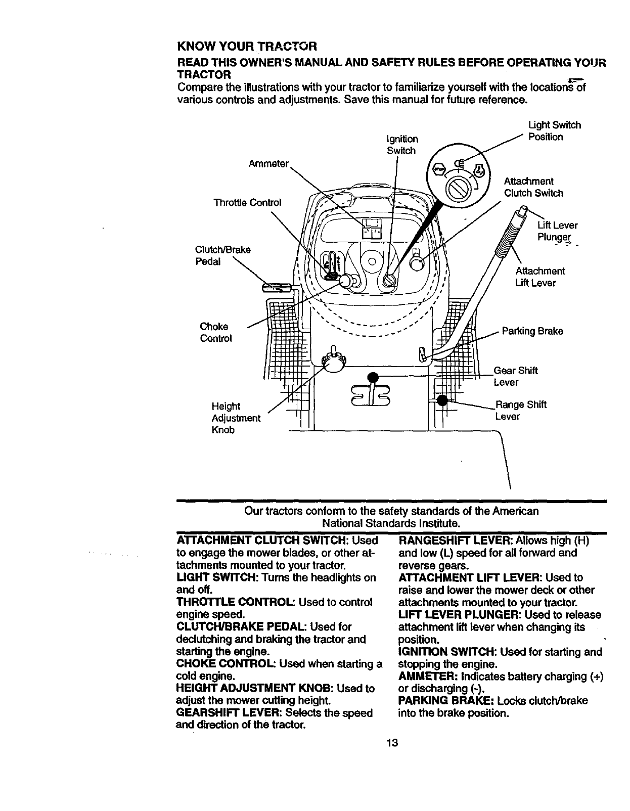
KNOW YOUR TRACTOR
READ THIS OWNER'S MANUAL AND SAFETY RULES BEFORE OPERATING YOUR
TRACTOR
Compare the illustrations with your tractor to familiarize yourself with the Iocations_f
various controls and adjustments. Save this manual for future reference.
Ignition
Switch
Ught Switch
Position
Ammeter
Attachment
Clutch Switch
Throttle Control
Clutch/Brake
Pedal
Uft Lever
Plun=ger .
Attachment
Lift Lever
Choke Brake
Control
Gear Shift
Lever
Height
Adjustment Lever
Knob \
Our tractors conformto the safety standards of the American
National Standards Institute.
ATFACHMENT CLUTCH SWITCH: Used
to engage the mower blades, or other at-
tachments mounted to your tractor.
LIGHT SWITCH: Tums the headlights on
and off.
THROTTLE CONTROL: Used to control
engine speed.
CLUTCH/BRAKE PEDAL: Used for
declutching and braking the tractor and
starting the engine.
CHOKE CONTROL: Used when starting a
cold engine.
HEIGHT ADJUSTMENT KNOB: Used to
adjust the mower cutting height.
GEARSHIFT LEVER: Selects the speed
and direction of the tractor.
RANGESHIFT LEVER: Allows high (H)
and low (L) speed for all forward and
reverse gears.
ATTACHMENT LIFT LEVER: Used to
raise and lower the mower deck or other
attachments mounted to your tractor.
LIFT LEVER PLUNGER: Used to release
attachment liftlever when changing its
position.
IGNmON SWITCH: Used for starting and
stopping the engine.
AMMETER: Indicates battery charging (+)
or discharging (-).
PARKING BRAKE: Locks clutch/brake
into the brake position.
13
I
The operation of any tractor can result in foreign objects thrown into the
eyes, which can result in severe eye damage. Always wear safety glasses
or eye shields while operating your tractor or performing any adjustmedt_-or
repairs. We recommend a wide vision safety mask over spectacles, or stan-
dard safety glasses.
HOW TO USE YOUR TRACTOR
Your tractor is equipped with an operator
presence sensing switch. When engine is
running, any attempt by the operator to
leave the seat without first setting the
parking brake will shut off the engine.
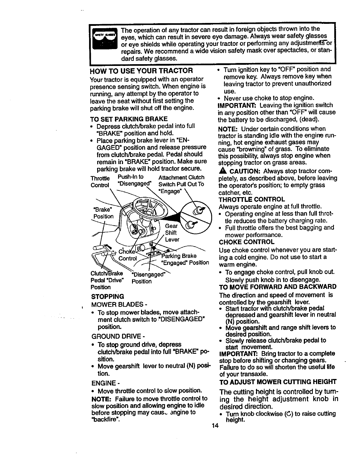
TO SET PARKING BRAKE
•Depress clutch/brake pedal into full
=BRAKE* position and hold.
•Place parking brake lever in "EN-
GAGED" position and release pressure
from clutch/brake pedal. Pedal should
remain in "BRAKE" position. Make sure
parking brake will hold tractor secure.
Throttle Push-In to Attachment Clutch
Control Switch Pull Out To
\ "Engage"
=Brake"
Position
Brake
"Engaged_Pos_on
=Disengaged'
Pedal =Ddve" Position
Position
STOPPING
MOWER BLADES -
•To stop mower blades, move attach-
ment clutch switch to "DISENGAGED"
position.
GROUND DRIVE -
• To stop ground drive, depress
clutch/brake pedal into full =BRAKE* po-
sition.
•Move gearshift lever to neutral (N) posi-
tion.
ENGINE -
• Move throttle control to slow position.
NOTE: Failure to move throttle control to
slow position and allowing engine to idle
before stopping may caus_ _ngine to
"backfire".
•Turn ignition key to "OFF' position and
remove key. Always remove key when
leaving tractor to prevent unauthorized
use.
•Never use choke to stop engine.
IMPORTANT: Leaving the ignition switch
in any position other than "OFF" will cause
the battery to be discharged, (dead).
NOTE: Under certain conditions when
tractor is standing idle with the engirm run-
ning, hot engine exhaust gases may
cause =browning" of grass. To eliminate
this possibility, always stop engine when
stopping tractor on grass areas.
_. CAUTION: Always stop tractor com-
pletely, as described above, before leaving
the operator's position; to empty grass
catcher, etc.
THROI-rLE CONTROL
Always operate engine at full throttle.
•Operating engine at less than full throt-
tle reduces the battery charging rate.
•Full throttle offers the best bagging and
mower performance.
CHOKE CONTROL
Use choke control whenever you are start-
ing a cold engine. Do not use to start a
warm engine.
•To engage choke control, pull knob out.
Slowly push knob in to disengage.
TO MOVE FORWARD AND BACKWARD
The direction and speed of movement is
controlled by the gearshift lever.
•Start tractorwith clutch/brake pedal
depressed and gearshift lever in neutral
(N)position.
• Move gearshift and range shift levers to
desired position.
•Slowly release clutch/brake pedal to
start movement.
IMPORTANT: Bring tractor to a complete
stop before shifting or changing gears.
Failure to do so will shortenthe useful life
of your transaxle.
TO ADJUST MOWER CUTTING HEIGHT
The cutting height is controlled by turn-
ing the height adjustment knob in
desired direction.
•Tum knob clockwise (G) to raise cutting
height.
14
The cutting height range is approximately
1-112" to 4-1/2". The heights are meao
sured from the ground to the blade tip with
the engine not running. These heights are
approximate and may vary depending
upon soil conditions, height of grass and
types of grass being mowed.
•The average lawn should be cut to
approximately 2-1/2 inches during the
cool season and to over 3 inches during
hot months. For healthier and better
looking lawns, mow often and after
moderate growth.
•For best cutting pedormance, grass
over 6 inches in height should be
mowed twice. Make the first cut rela-
tively high; the second to desired height.
TO ADJUST GAUGE WHEELS
Gauge wheels are propedy adjusted
when they are slightly oft the ground when
mower is at the desired cutting height in
operating position. Gauge wheels then
keep the deck in proper position to help
prevent scalping in most terrain condi-
tions.
•Be sure tractor is on a flat level surface.
•Lower mower and adjust mower to
desired cutting height.
• Remove retainer spring and clevis pin
which secure each gauge wheel bar,
• Lower gauge wheels to ground. Raise
gauge wheels slightly to align holes in
bracket and gauge wheel bar and insert
clevis pin. Gauge wheels should be
slightly off the ground.
• Replace retainer spring into clevis pin,
IMPORTANT: Be sure to readjust gauge
wheels if you change the cutting height of
the mower deck.
Retainer spring
Clevis Pin
,p
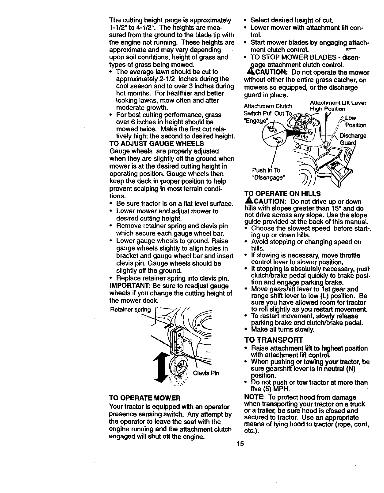
TO OPERATE MOWER
Your tractor is equipped with an operator
presence sensing switch. Any attempt by
the operator to leave the seat with the
engine running and the attachment clutch
engaged will shut off the engine.
•Select desired height of cut.
•Lower mower with attachment lilt con-
trol.
• Start mower blades by engaging attach-
ment clutch control.
• TO STOP MOWER BLADES - disen-
zage attachment clutch control.
CAUTION: Do not operate the mower
without either the entire grass catcher, on
mowers so equipped, or the discharge
guard in place. Attachment Uft Lever
Attachment Clutch High Position
Switch Pull Out T_ /,_LoW
..':/ Position
- _:."._Discharge
Pus.l To
TO OPERATE ON HILLS
_,CAUTION: Do not drive up or down
hills with slopes greater than 15° and do
not drive across any slope. Use the slope
guide provided at the back of this manual.
•Choose the slowest speed before start-,
ing up or down hills.
•Avoid stopping or changing speed on
hills.
•If slowing is necessary, move throttle
control lever to slower position.
i f stopping is absolutely necessary, pusl-
clutch/brake pedal quiddy to brake posi-
tion and engage parking brake. .
Move gearshift lever to 1st gear anCl
range shift lever to low (L) position. Be
sure you have allowed room for tractor
to rol/slightly as you restart movement.
•To restart movement, slowly release
parking brake and clutch/brake pedal.
•Make all turns slowly.
TO TRANSPORT
•Raise attachment lift to highest position
with attachment lift control.
•When pushing or towing your tractor, be
sure gearshift lever is in neutral (N)
position.
• Do not push or tow tractor at more than
five (5) MPH.
NOTE: To protect hood from damage .
when transporting your tractor on a trUCK
or a trailer, be sure hood is closed and
secured to tractor. Use an appropriate
means of tying hood to tractor (rope, cord,
etc.).
15
TOWING CARTS AND OTHER
ATTACHMENTS
Towonlytheattachmentsthat are recom-
mended by and comply with specifications
of the manufacturer of your tractor. Use
common sense when towing. Too heavy of
a load, while on a slope, is dengemus.
1ires can lose tractionwith the ground and
cause you to lose controlof your tractor.
BEFORE STARTING THE ENGINE
CHECK ENGINE OIL LEVEL
• The engine in your tractor has been
shipped, from the factory, already filled
with summer weight oil.
•Check engine oil with tractor on level
ground.
•Unthread and remove oil fill cap/dip
stick; wipe oil off. Reinsert the dipstick
into the tube and rest oil fill cap on the
tube. Do not thread the cap onto the
tube. Remove and read oil level. If nec-
essary, add oil until =FULL" mark on
dipstick is reached. Do not overfill.
•For cold weather operation you should
change oil for easier starting (See =OIL
VISCOSITY CHART" in the Customer
Responsibilities section of this manual).
•To change engine oil, see the Customer
Responsibilities section in this manual.
ADD GASOLINE
•Fill fuel tank. Use fresh, clean/regular
unleaded gasoline with a minimum of 87
octane. (Use of leaded gasoline will
increase carbon and lead oxide
deposits and reduce valve life). Do not
mix oil with gasoline. Purchase fuel in
quantities that can be used within 30
days to assure fuel freshness.
IMPORTANT: When operating in tempera-
turas below 32°F(0°C), use fresh, clean
winter grade gasoline to help insure good
,_dAweather starting.
RNING: Expedence indicates that
alcohol blended fuels (called gasohol or
using ethanol or methanol) can attract
moisture which leads to separation and
formation of acids dudng storage. Acidic
gas can damage the fuel system of an
engine while in storage. To avoid engine
problems, the fuel system should be emp-
tied before storage of 30 days or longer.
Drain the gas tank, start the engine and le
it run until the fuel lines and carburetor ar_
empty. Use fresh fuel next season. See
Storage Instructions for additioea4-
information. Never use engine or
carburetor cleaner products in the fuel
_k or permanent damage may occur.
CAUTION: Fill to bottom of gas tank
filler neck. Do not overfill. Wipe off any
spilled oil or fuel. Do not store, spill or use
gasoline near an open flame.
TO START ENGINE
When starting the engine for the first time
or if the engine has run out of fuel, it will
take extra cranking time to move fuel from
the tank to the engine.
•Sit on seat in operating position,
depress clutch/brake pedal and set
parking brake.
•Place gear shift lever in neutral (N)
position.
•Move attachment clutch to =DISEN-
GAGED" position.
•Move throttle control to fast position
•Pull choke control out for a cold engine
start attempt. For a warm engine start
attempt the choke control may not be
needed.
NOTE: Before starting, read the warm ant
coldstarting procedures below.
•Insert key into ignitionand tum key
clockwise to =START" positionand
release key as soon as engine starts.
Do not run starter continuouslyfor more
than fifteen seconds per minute. If the
engine does not start after several
attempts, push choke control in, wait a
few minutes and try again. If engine still
does not start, pullthe choke control out
and retry.
WARM WEATHER STARTING (50° F
AND ABOVE)
•When engine starts, slowly push choke
controlin untilthe engine begins to run
smoothly. If the engine starts to run
roughly,pull the choke control out slight-
ly for a few seconds and then continue
to push the control in slowly.
•The attachments and ground drive can
now be used. If the engine does not
accept the load, restart the engine and
allow it to warm up for one minute using
the choke as described above.
16
COLD WEATHER STARTING (50 ° FAND
BELOW)
•When engine starts, slowly push choke
control in until the engine begins to run
smoothly. Continue to push the choke
control in small steps allowing the
engine to accept small changes in
speed and load, until the choke control
is fully in. If the engine starts to run
roughly, pull the choke control out slight-
ly for a few seconds and then continue
to push the control in slowly. This may
require an engine warm-up peried from
several seconds to several minutes,
depending on the temperature.
• The attachments can be used during
the engine warm-up period and may
require the choke control be pulled out
slightly.
NOTE: A high altitude (above 3000 feet)
or in cold temperatures (below 32 F) the
carburetor fuel mixture may need to be
adjusted for best engine performance.
See "TO ADJUST CARBURETOR" in the
Service and Adjustments section of this
manual.
MOWING TIPS
•Tire chains cannot be used when the
mower housing is attached to tractor.
•Mower should be properly leveled for
best mowing performance. See =TO
LEVEL MOWER HOUSING" in the
Service and Adjustments section of this
manual.
•The left hand side of mower should be
used for trimming.
•Drive so that clippings are discharged
onto the area that has been cut. Have
the cut area to the right ofthe tractor.
This will result in a more even distribu-
tion of clippingsand more uniform cut-
ting.
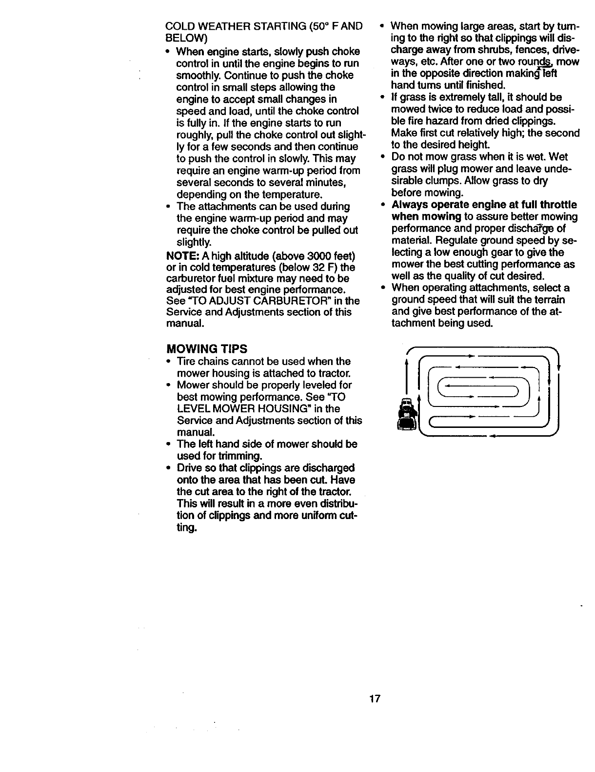
• When mowing large areas, start by turn-
ing to the right so that clippings will dis-
charge away from shrubs, fences, drive-
ways, etc. After one or two rounds_,mow
in the opposite direction making=Teft
hand tums until finished.
• If grass is extremely tall, it should be
mowed twice to reduce load and possi-
ble fire hazard from dried clippings.
Make first cut relatively high; the second
to the desired height.
•Do not mow grass when it is wet. Wet
grass will plug mower and leave unde-
sirable clumps. Allow grass to dry
before mowing.
•Always operate engine at full throttle
when mowing to assure better mowing
performance and proper discharge of
material. Regulate ground speed by se-
lecting alow enough gear to give the
mower the best cutting performance as
well as the quality of cut desired.
• When operating attachments, select a
ground speed that will suit the terrain
and give best performance of the at-
tachment being used.
17
MULCHING MOWING TIPS
IMPORTANT: For best performance, keep
mower housing free of built-upgrass and
trash. Clean after each use.
• The special mulching blade will recut
the grass clippings many times and
reduce them in size so that as they fall
onto the lawn they will disperse intothe
grass and not be noticed. Also, the
mulched grass will biodegrade quickly
to provide nutrients for the lawn. Always
mulch with your highestengine (blade)
speed as this will provide the best recut-
ring action of the blades.
•Avoid cutting your lawn when it is wet.
Wet grass tends to form clumps and
interferes with the mulching action. The
best time to mow your lawn is the early
afternoon. At this time the grass has
dried and the newly cut area will notbe
exposed to the direct sun.
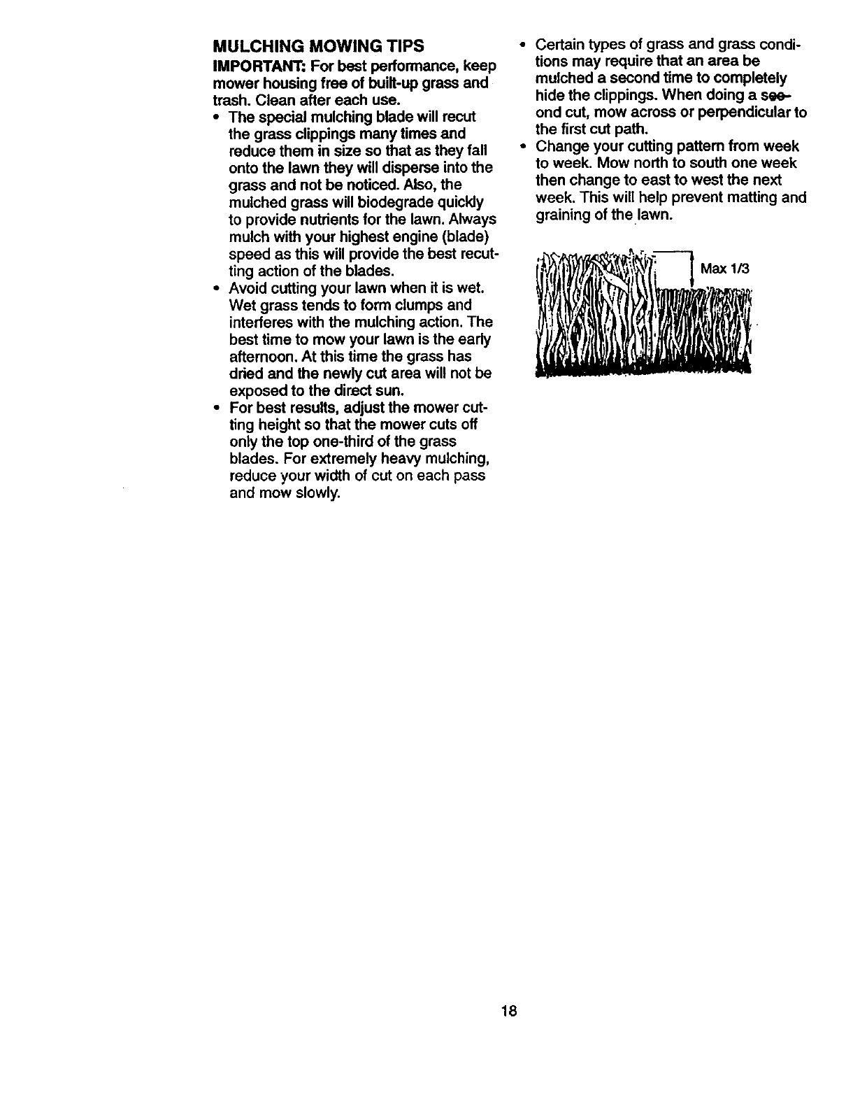
•For best results, adjust the mower cut-
ting height so that the mower cutsoff
onlythe top one-third of the grass
blades. For extremely heavy mulching,
reduce your width of cut on each pass
and mow slowly.
• Certain types of grass and grass condi-
tions may require that an area be
mulched a second time to completely
hide the clippings. When doing a see-
ond cut, mow across or perpendicular to
the first cut path.
•Change your cuffing pattem from week
to week. Mow north to south one week
then change to east to west the next
week. This will help prevent matting and
graining of the lawn.
18
CUSTOMER RESPONSIBILITIES
Check Tim Pressure
Check Op_ator Presence and ii_
Tfnmdoc_systems
R Ched(forLooseFasteners _1_7
TLubrication Chart :ll_
0 Check Battery Level
Raean Sstteryand'l'errrCr_s_echarge II,/'
Check Transaxle Cooling
Adjust Bade Belt(s) Tensk)n _s -
Adjust Motion Drive Belt(s) Tension II_,
cr,ck E_,,, (_l L_,,= V' V'
i E c_eanAirRlter
Nclean_r Screen
I G 0nspectMuffler/SparkArrester I_
I Replace Oil Rner (if equipped) I_tz
! N Clean Engine C°°llng Fin_ _=
Replace Spark Plug
Replace Air Filter Paper Cartridge _2
Replace Fuel Rner
1 .Chlmgemofllohetlwhenoperattngunderit14Nr_fo_lorinhighambtenttemper=_. 5-ffequlpc_d_hIK_ustablesystem.
2-Sew_cl more often v/_en opersting m dL.ty or dusty cx)ndt_or4,
3 - if equipped w;_ o_ fdter. _oil eve.y 50 hours.
4 - Replace bte,des m.o_ ohen "_*_m m_vlng bt ta=_dy =oq.
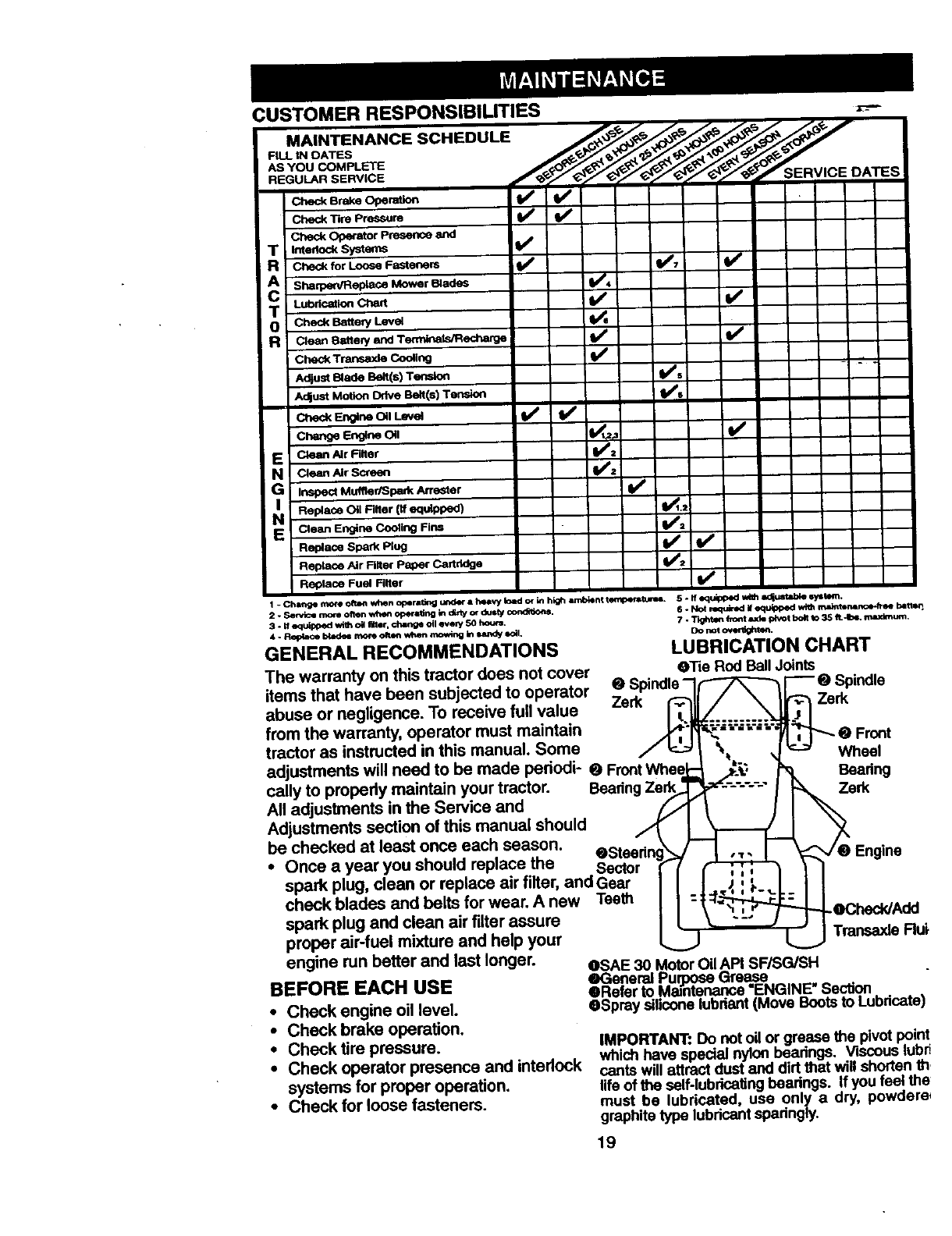
GENERAL RECOMMENDATIONS
The warranty on this tractor does not cover
items that have been subjected to operator
abuse or negligence. To receive full value
from the warranty, operator must maintain
tractor as instructed in this manual. Some
adjustments will need to be made pedodi- _Front Wheel
6-Not required=equ_ped ',4_ .'_n_ b=tten
7 - T_ fro_t rod=f4"_t bolt to 35 It.4b_ maxl_m_.
Do not o_,_e_.
callyto propedy maintain your tractor. Beadng Ze_
All adjustments in the Service and _,_
Adjustments section of this manual should
be checked at least once each season. OSteedr
• Once a year you should replace the Sector
spark plug, clean or replace air filter, and Gear
check blades and belts for wear. A new Teeth
spark plug and clean air filter assure
proper air-fuel mixture and help your
Ii!
"-: j
engine run better and last longer. OSAE 30 Motor Oil API SF/SG/SH
_Engine
._Che<:k/Add
Transexle Rui
BEFORE EACH USE
• Check engine oil level.
•Check brake operation.
•Check tire pressure.
•Check operator presence and intedock
systems for proper operation.
• Check for loose fasteners.
• General Purj09seGrease
eRefer to Maintenance "ENGINE" Section
OSprey silicone lubdant (Move Bootsto Lubdcate)
IMPORTANT: Do not oil or grease the pivot point
which have special nylon bearings. Viscous lubr
cants will attract dust and dirt that will shorten th
life of the self-lubricating bearings. If you feel the
must be lubricated, use only a dry, powdere
graphite type lubdcant sparingly.
19
TRACTOR
Alwaysobservesafetyruleswhenper-
forminganymaintenance.
BRAKEOPERATION
If tractorrequiresmorethansix (6)feet
stoppingdistanceat highspeedmhighest
gear, then brake must be adjusted. (See
"TO ADJUST BRAKE in the Service and
Adjustments section of this manual).
TIRES
•Maintain proper air pressure in all tires
(See =PRODUCT SPECIFICATIONS"
on page 3 of this manual).
•Keep tires free of gasoline, oil, or insect
control chemicals which can harm rub-
ber.
•Avoid stumps, stones, deep ruts, sharp
objects and other hazards that may
cause tire damage.
NOTE: To seal tire punctures and prevent
flat tires due to slow leaks, tire sealant
may be purchased from your local parts
dealer. Tire sealant also prevents tire dry
rot and corrosion.
OPERATOR PRESENCE SYSTEM
Be sure that operator presence and inter-
lock systems are working propedy. If your
tractor does not function as described
below, repair the problem immediately.
•The engine should not start unless the
clutch/brake pedal is fully depressed
and attachment clutch control is in the
disengaged position.
•When the engine is running, any
attempt by the operator to leave the
seat without first setting the parking
brake should shut off the engine.
•When the engine is running and the
attachment clutch is engaged, any
attempt by the operator to leave the
seat should shut off the engine.
•The attachment clutch should never
operate unless the operator is in the
seat.
BLADE CARE
For best results mower blades must be
kept sharp. Replace bent or damaged
blades.
BLADE REMOVAL
•Raise mower to highest position to allow
access to blades.
•Remove hex bolt, lock washer and flat
washer secudng blade.
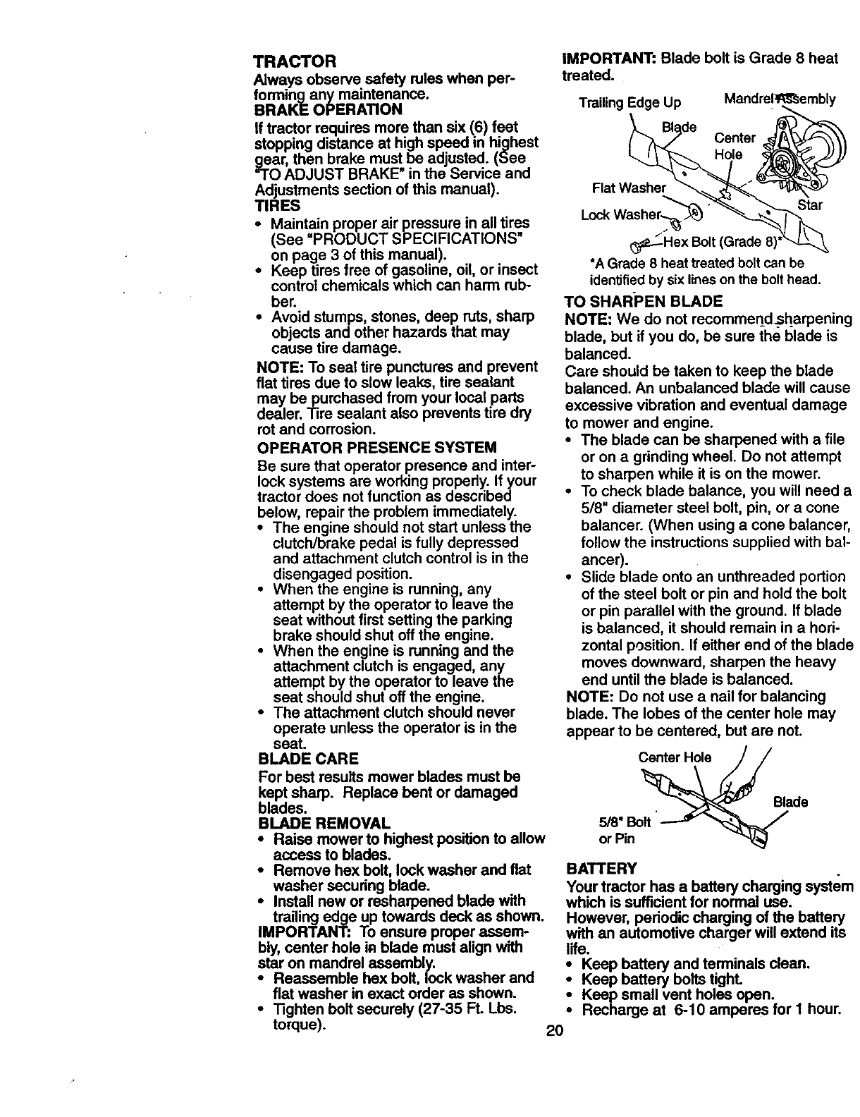
•Install new or re,sharpened blade with
trailing edge up towards deck as shown.
IMPORTANT: To ensure proper assem-
bly, center hole iR blade must align with
star on mandrel assembly.
•Reassemble hex belt, lock washer and
flat washer in exact order as shown.
• Tighten belt securely (27-35 FL Lbs.
torque).
IMPORTANT: Blade belt is Grade 8 heat
treated.
Trailing Edge Up Mandrel_embly
Center
Hole
Flat Washer
Lock Washer_ Star
_-_-H ex Bolt
*A Grade 8 heat treated bolt can be
identified by six lines on the bolt head.
TO SHARPEN BLADE
NOTE: We do not recommend_harpening
blade, but if you do, be sure the blade is
balanced.
Care should be taken to keep the blade
balanced. An unbalanced blade will cause
excessive vibration and eventual damage
to mower and engine.
•The blade can be sharpened with a file
or on a grinding wheel. Do not attempt
to sharpen while it is on the mower.
•To check blade balance, you will need a
5/8" diameter steel bolt, pin, or a cone
balancer. (When using a cone baiancer,
follow the instructions supplied with bal-
ancer).
•Slide blade onto an unthreaded portion
of the steel bolt or pin and hold the bolt
or pin parallel with the ground. If blade
is balanced, it should remain in a hori-
zontal position. If either end of the blade
moves downward, sharpen the heavy
end until the blade is balanced.
NOTE: Do not use a nail for balancing
blade. The lobes of the center hole may
appear to be centered, but are not.
Center Hole
5/8" Bolt
or Pin
Blade
BATTERY
Your tractor has a battery charging system
which is sufficientfor normal use.
However, pedodic charging of the battery
with an automotive charger will extend its
life.
Keep battery and terminals clean.
Keep battery bolts tighL
Keep small vent holes open.
Recharge at 6-10 amperes for I hour.
2O
TO CLEAN BAI-FERY AND TERMINALS
Corrosion and dirt on the battery and ter-
minals can cause the battery to =leal¢'
power.
: Remove terminal guard.
Disconnect BLACK battery cable first
then RED battery cable and remove
battery from tractor.
•Rinse the battery with plain water and
dry.
• Clean terminals and battery cable ends
with wire brush until bright.
• Coat terminals with grease or petroleum
jelly.
•Reinstall battery (See "REPLACING
BATTERY" in the SERVICE AND
ADJUSTMENTS section of this manu-
al).
V-BELTS
Check V-belts for deterioration and wear
after 100 hours of operation and replace if
necessary. The belts are not adjustable.
Replace belts if they begin to slip from
wear.
TRANSAXLE COOLING
Keep transaxle free from build-up of dirt
and chaff which can restrict cooling.
CHECK TRANSAXLE OIL LEVEL
• Block up rear axle securely.
•Remove left rear wheel by removing
hub bolts.
•Remove filler plug from transaxle. Oil
level must be even with plug threads. If
necessary, fill with SAE 30 motor oil,
API SF, SG or SH. Replace filler plug.
•Reassemble wheel to hub.
Change the oil after every 50 hours of
operation or at least once a year if the
tractor is not used for 50 hours in one
year.
Check the crankcase oil level before start-
ing the engine and after each eight (8)
hours of operation. Tighten oil fill cap/dip-
stick securely each time you check the oil
level.
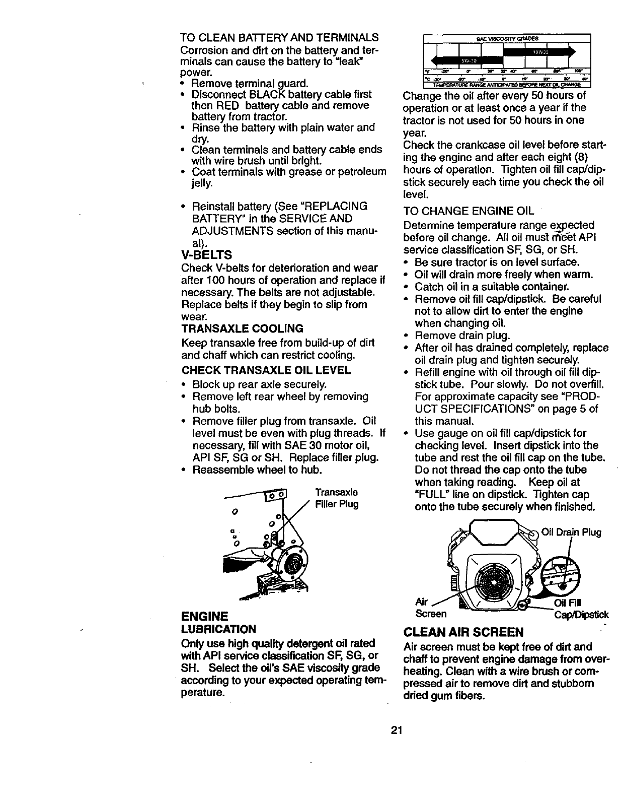
TO CHANGE ENGINE OIL
Determine temperature range expected
before oil change. All oil must meet API
service classification SF, SG, or SH.
•Be sure tractor is on level surface.
•Oil will drain more freely when warm.
•Catch oil in a suitable container.
•Remove oil fill cap/dipstick. Be careful
not to allow dirt to enter the engine
when changing oil.
• Remove drain plug.
•After oil has drained completely, replace
oil drain plug and tighten securely.
• Refill engine with oil through oil fill dip-
stick tube. Pour slowly. Do not overfill.
For approximate capacity see "PROD-
UCT SPECIFICATIONS" on page 5 of
this manual.
•Use gauge on oil fill cap/dipstick for
checking level. Insert dipstick into the
tube and rest the oil fill cap on the tube.
Do not thread the cap onto the tube
when taking reading. Keep oil at
"FULL" line on dipstick. Tighten cap
onto the tube securely when finished.
Oil Drain Plug
ENGINE
LUBRICATION
Only use high quality detergent oil rated
with API service classification SF, SG, or
SH. Select the oil's SAE viscositygrade
according to your expected operating tem-
perature.
Oil Fill
Screen Cap/Dips_k
CLEAN AIR SCREEN
Air screen must be kept free of dirt and
chaff to prevent engine damage from over-
heating. Clean with awire brush or com-
pressed air to remove dirt and stubborn
dried gum fibers.
21
CLEAN AIR INTAKE/COOUNG AREAS
To insure proper cooling, make sure the
grass screen, coolingfins, and other
external surfaces of the engine are kept
clean at all times.
Every 100 hours of operation (more often
under extremely dusty,dirty conditions),
remove the blower housing and other
cooling shrouds. Clean the coolingfins
and external surfaces as necessary. Make
sure the cooling shrouds are reinstalled.
NOTE: Operating the engine with a
blocked grass screen, dirty or plugged
coolingfins, and/or cooling shrouds re-
moved will cause engine damage due to
overheating.
AIR FILTER
Your engine will not run propedy using a
dirty air filter. Clean the foam pre-cleaner
after every 25 hours of operation or every
season. Service paper cartridge every
100 hours of operation or every season,
whichever occurs first.
Service air cleaner more often under dusty
conditions.
• Loosen knob and remove cover.
TO SERVICE PRE-CLEANER
•Slide foam pre-claaner off cartridge.
•Wash it in liquid detergent and water.
•Squeeze it dry in a clean cloth. Allow it
to dry.
•Saturate it in engine oil. Wrap it in
clean, absorbent cloth and squeeze to
remove excess oil.
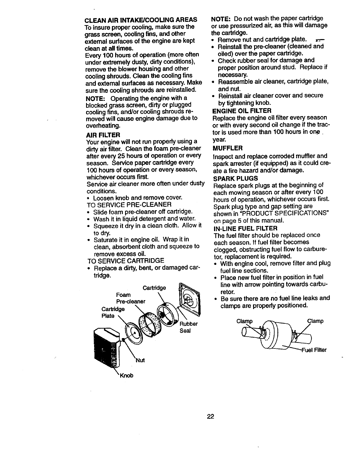
TO SERVICE CARTRIDGE
•Replace a dirty, bent, or damaged car-
tridge.
Cartridge
Foam
Pre-deaner
Cartridge
Plate
Rubber
Se_
NOTE: Do not wash the paper cartridge
or use pressurized air, as this will damage
the cartddge.
• Remove nut and cartridge plate.
• Reinstall the pre-cleaner (cleaned and
oiled) over the paper cartridge.
•Check rubber seal for damage and
proper positionaround stud. Replace if
necessary.
•Reassemble air cleaner, cartridge plate,
and nut.
•Reinstall air cleaner cover and secure
by tightening knob.
ENGINE OIL FILTER
Replace the engine oil filter every season
or with every second oil change if the trac-
tor is used more than 100 hours in one__
year.
MUFFLER
Inspect and replace corroded muffler and
spark arrester (if equipped) as it could cre-
ate a fire hazard and/or damage.
SPARK PLUGS
Replace spark plugs at the beginning of
each mowing season or after every 100
hours of operation, whichever occurs first.
Spark plug type and gap setting are
shown in "PRODUCT SPECIFICATIONS"
on page 5 of this manual.
IN-LINE FUEL FILTER
The fuel filter should be replaced once
each season. If fuel filter becomes
clogged, obstructing fuel flow to carbure-
tor, replacement is required.
•With engine cool, remove filter and plug
fuel line sections.
•Place new fuel filter in position in fuel
line with arrow pointing towards carbu-
retor.
•Be sure there are no fuel line leaks and
clamps are properly positioned.
22
CLEANING
•Clean engine, battery, seat, finish, etc.
of all foreign matter.
•Keep finished sudeces and wheels free
of all gasoline, oil, etc.
•Protect painted surfaces with automo-
tive type wax.
We do not recommend usinga garden
hose to clean your tractor unlessthe elec-
trical system, muffler,air filter and P.,_re-
tor are covered to keep water out. _/_.ter
in engine can result in a shortened engine
life.
_CAUTION: Before performing any service or adjustments:
•Depress clutch/brake pedal fully and set parking brake.
•Place gearshift lever in neutral (N) position.
•Place attachment clutchin =DISENGAGED" position.
•Tum ignition key =OFF_and remove key.
•Make sure the blades and all moving parts have completely stopped. _ _
•Disconnect spark plug wire from spark plug and place wire where it cannot come
in contact with plug.
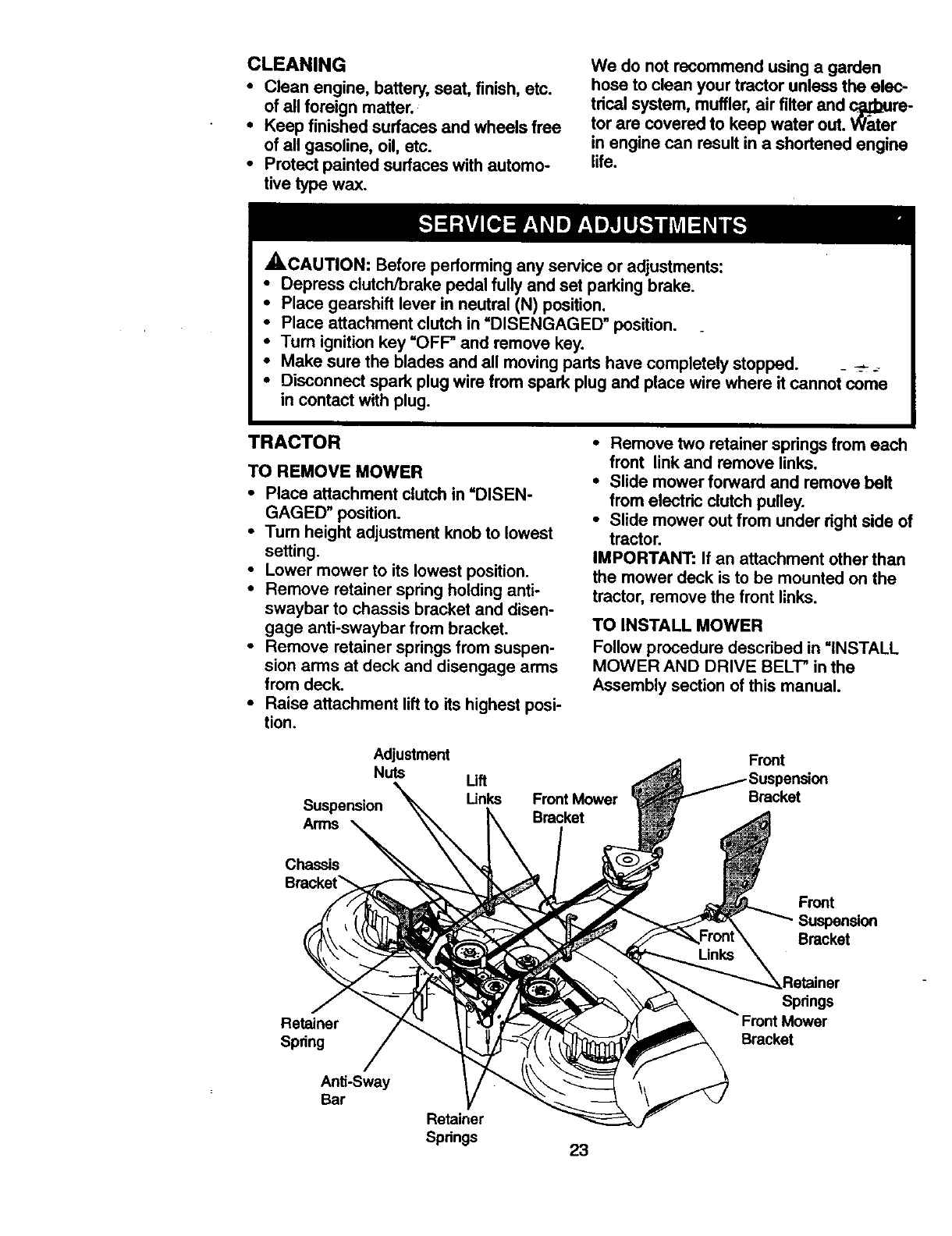
TRACTOR
TO REMOVE MOWER
•Place attachment clutch in =DISEN-
GAGED" position.
•Turn height adjustment knob to lowest
setting.
•Lower mower to its lowest position.
•Remove retainer spring holding anti-
swaybar to chassis bracket and disen-
gage anti-swaybar from bracket.
•Remove retainer springs from suspen-
sion arms at deck and disengage arms
from deck.
•Raise attachment lift to its highest posi-
tion.
•Remove two retainer springs from each
front link and remove links,
•Slide mower forward and remove belt
from electric clutch pulley.
•Slide mower out from under dght side of
tractor.
IMPORTANT: If an attachment other than
the mower deck is to be mounted on the
tractor, remove the front links.
TO INSTALL MOWER
Follow procedure described in =INSTALL
MOWER AND DRIVE BELT" in the
Assembly section of this manual.
Adjustment
Nuts
Suspension
Arms
Uft
Unks Front Mower
Bracket
Front
Bracket
Chassis
Retainer
Spring
Anti-Sway
Bar
Front
Suspension
Bracket
--_Retalner
Springs
Mower
Bracket
Retainer
Springs 23
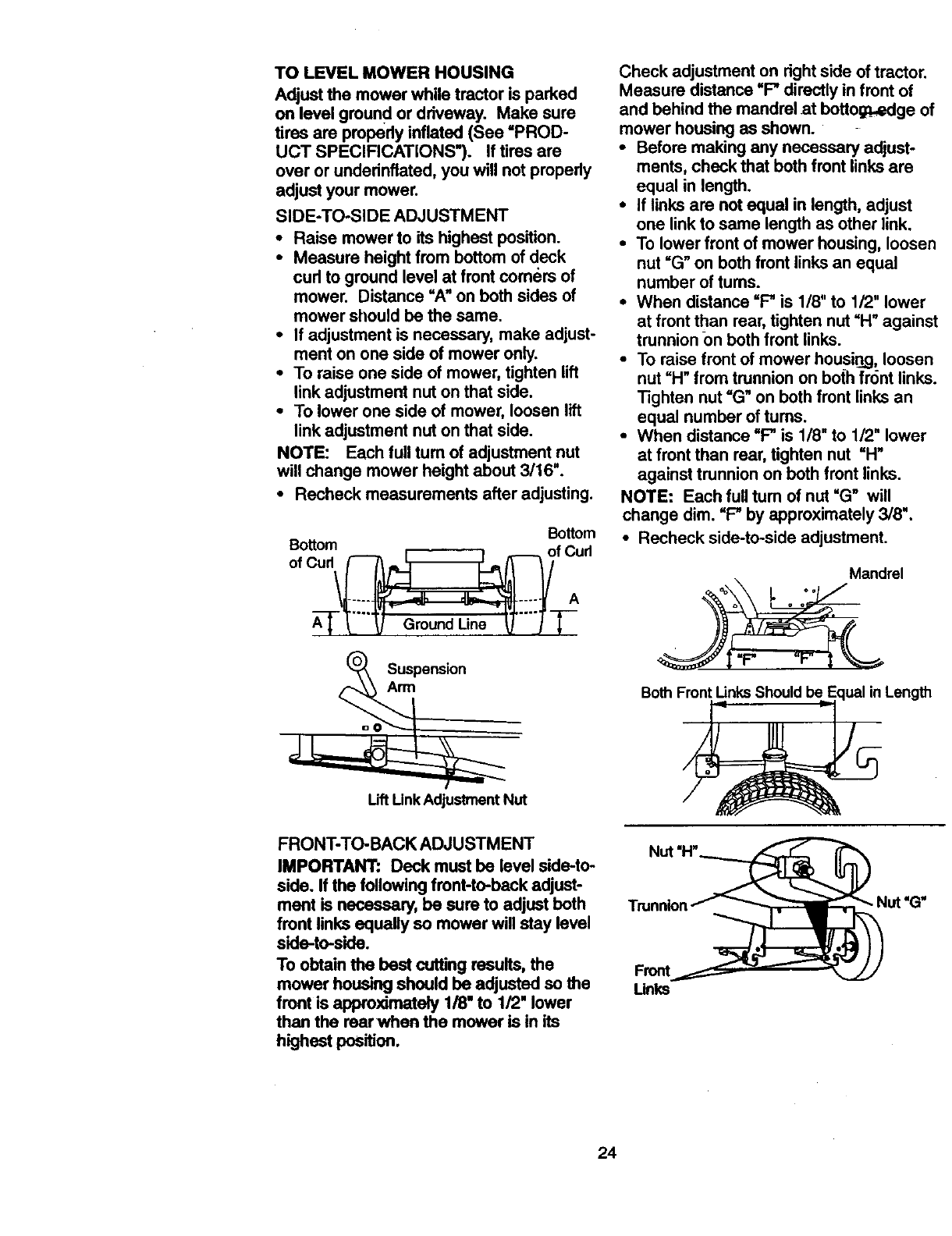
TO LEVELMOWERHOUSING
Adjustthemowerwhiletractoris parked
onlevelground ordriveway.Makesure
tiresareproperlyinflated(See=PROD-
UCT SPECIFICATIONS"). If tires are
over or underinflated, you will not properly
adjust your mower.
SIDE-TO-SIDE ADJUSTMENT
•Raise mower to its highest position.
•Measure height from bottom of deck
cud to ground level at front comers of
mower. Distance =A" on both sides of
mower should be the same.
•If adjustment is necessary, make adjust-
ment on one side of mower only.
•To raise one side of mower, tighten lift
link adjustment nut on that side.
•To lower one side of mower, loosen lift
link adjustment nut on that side.
NOTE: Each full turn of adjustment nut
will change mower height about 3/16".
•Recheck measurements after adjusting.
Bottom
Bottom
of Cud _ _ _ olfCurl
Suspen_on
Arm
Check adjustment on rightside of tractor.
Measure distance =F" directlyin front of
and behind the mandrel at bottog_=dge of
mower housing as shown.
•Before making any necessary adjust-
ments, check that both front linksare
equal in length.
•If linksare not equal in length, adjust
one link to same length as other link.
•To lower front of mower housing, loosen
nut =G"on bothfront linksan equal
number of tums.
•When distance =F" is 1/8" to 1/2" lower
at front than mar, tighten nut =H" against
trunnion ()n both front links.
•To raise front of mower housing,loosen
nut =H"from trunnionon both fr6nt links.
Tighten nut =G"on both front linksan
equal number of turns.
•When distance "F" is 1/8" to 1/2" lower
at front than rear,tighten nut =H"
against trunnionon both front links.
NOTE: Each full tum of nut "G" will
change dim. "F" by approximately 3/8".
•Recheck side-to-side adjustment.
Mandrel
Both Front LinksShould be Length
Uft Unk Adjustment Nut
FRONT-TO-BACK ADJUSTMENT
IMPORTANT: Deck must be level side-to-
side. If the following front-to-back adjust-
mant is necessary, be sure to adjust both
front links equally so mower will stay level
side-to-side.
To obtain the best cutting results, the
mower housing should be adjusted so the
front is approximately 1/8" to 1/2" lower
than the rearwhen the mower is in its
highest position.
Unks
24
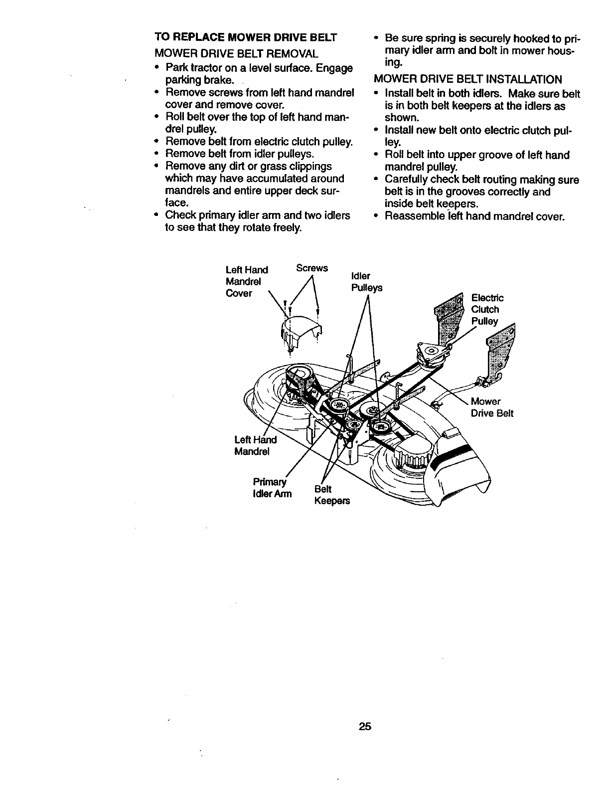
TO REPLACE MOWER DRIVE BELT
MOWER DRIVE BELT REMOVAL
•Park tractor on a level surface. Engage
parking brake.
• Remove screws from left hand mandrel
cover and remove cover.
•Roll belt over the top of left hand man-
drel pulley.
• Remove belt from electric clutch pulley.
• Remove belt from idler pulleys.
•Remove any dirt or grass clippings
which may have accumulated around
mandrels and entire upper deck sur-
face.
•Check pdmary idler arm and two idlers
to see that they rotate freely.
•Be sure spdng is securely hooked to pd-
mary idler arm and bolt in mower hous-
ing.
MOWER DRIVE BELT INSTALLATION
•Install belt in both idlers. Make sure belt
is in both belt keepers at the idlers as
shown.
• Install new belt onto electdc clutch pul-
ley.
•Roll belt into upper groove of left hand
mandrel pulley.
• Carefully check belt routing making sure
belt is in the grooves correctly and
inside belt keepers.
•Reassemble left hand mandrel cover.
Left Hand Screws
Mandrel
Cover _
'i ,
Idler
Pulleys Electric
Clutch
Mower
Drive Belt
Left
Mandrel
Idler Arm Belt
Keepers
25
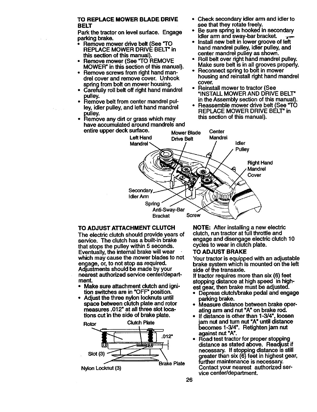
TO REPLACEMOWERBLADEDRIVE •
BELT
Park the tractor on level surface. Engage •
parking brake.
• Remove mower drive belt (See "TO •
REPLACE MOWER DRIVE BELT" in
this section of this manual).
•Remove mower (See "TO REMOVE
MOWER" in this section of this manual).
•Remove screws from right hand man-
drel cover and remove cover. Unhook
spring from bolt on mower housing.
•Carefully roll belt off right hand mandrel •
p_.ulley.
• Hemove belt from center mandrel pul-
ley, idler pulley, and left hand mandrel •
pulley.
•Remove any did or grass which may
have accumulated around mandrels and
entire upper deck surface.
Left Hand
Check secondary idler arm and idler to
see that they rotate freely.
Be sure spring is hooked in secondary
idler arm and sway-bar brackeL _l-,--
Install new belt in lower groove of left
hand mandrel pulley, idler pulley, and
center mandrel pulley as shown.
Roll belt over ri_/hthand mandrel pulley.
Make sure belt =sin all grooves properly.
Reconnect spring to bolt in mower
housing and reinstall right hand mandrel
cover.
Reinstall mower to tractor (See
=INSTALL MOWER AND DRIVE BELT"
in the Assembly section of this manual).
Reassemble mower drive belt (See =TO
REPLACE MOWER DRIVE BELT" in
this section of this manual).
Mower Blade Center
Ddve Belt Mandrel Idler
Pulley
Right Hand
Idler Arm
Anti-Sway-Bar
Bracket Screw
TO ADJUST ATTACHMENT CLUTCH
The electric clutch should provide years of
service. The clutch has a built-in brake
that stops the pulley within 5 seconds.
Eventually, the intemal brake will wear
which may cause the mower blades to not
en_age, or, to not stop as required.
Adjustments should be made by your
nearest authorized service center/depart-
ment.
•Make sure attachment clutch and igni-
tion switches are in "OFF" position.
•Adjust the three nylon Iocknutsuntil
space between clutch plate and rotor
measures .012" at all three slot Ioca-
tions cut in the side of brake plate.
Rotor Clutch Plate
NOTE: After installinga new electric
clutch, run tractor at full throttle and
engage and disengage electric clutch 10
cycles to wear in clutch plate.
Slot(3)
Nylon Locknut (3)
TO ADJUST BRAKE
Your tractor is equipped with an adjustable
brake system which is mounted on the left
side of the transaxle.
If tractor requires more than six (6) feet
stopping distance at high speed in high-
est gear, then brake must be adjusted.
• Depress clutch/brake pedal and engage
parking brake.
• Measure distance between brake oper-
ating arm and nut =Au on brake rod.
•If distance is other than 1-3/4", loosen
jam nut and tum nut "A" until distance
becomes 1-3/4". Retighten jam nut
.012" against nut =A'.
•Road test tractor for proper stopping
distance as stated above. Readjust if
necessary. If stopping distance is still
greater than six (6)feet in highest gear,
Brake Plate further maintenance is necessary.
Contact your nearest authorizedser-
vice center/department.
26
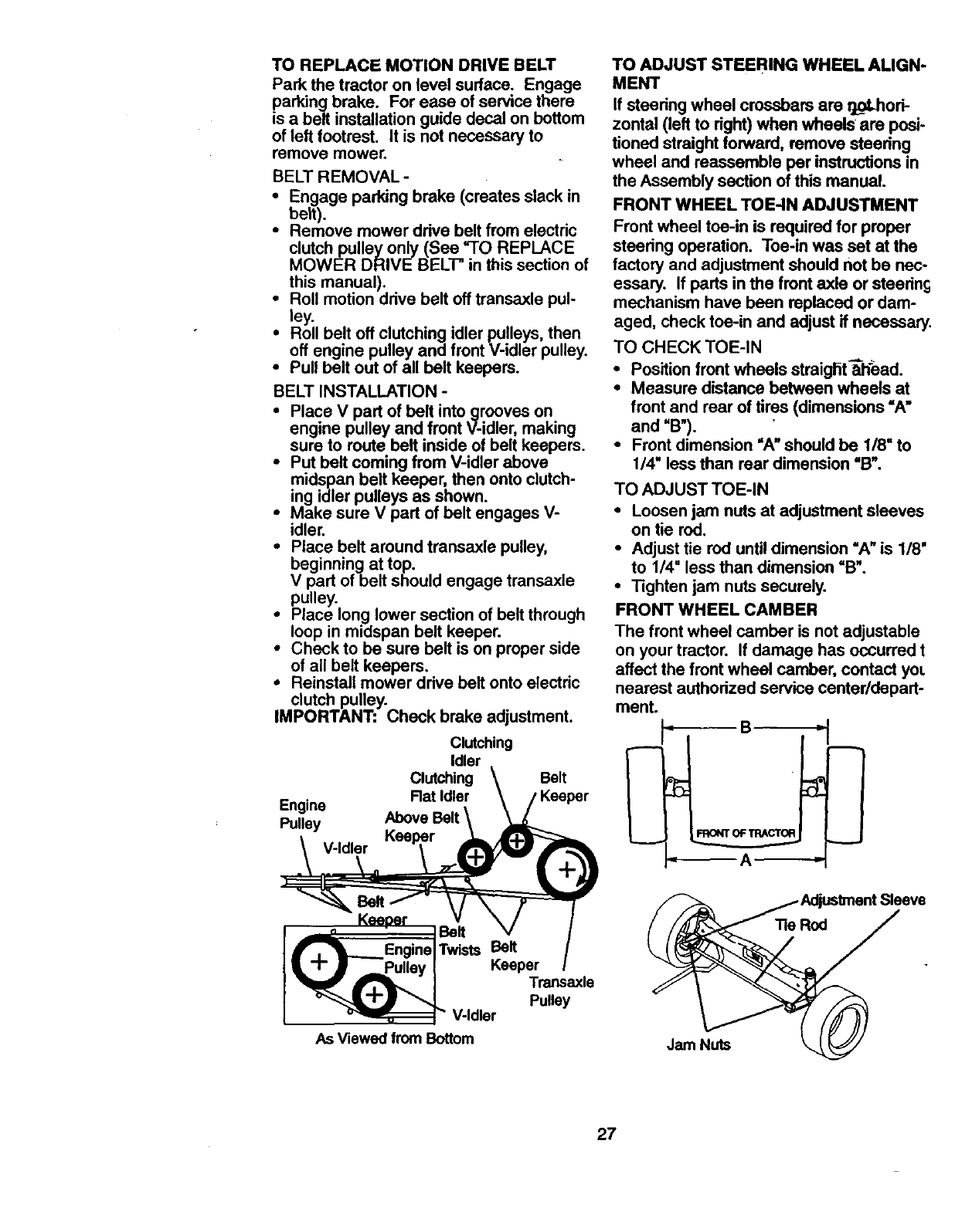
TO REPLACEMOTIONDRIVEBELT
Parkthetractoron levelsurface. Engage
parkingbrake. Foreaseofservicethere
isa beltinstallationguidedecalonbottom
ofleft footrest. It isnot necessaryto
removemower.
BELT REMOVAL-
•Engage parking brake (creates slack in
belt).
•Remove mower drive belt from electric
clutch pulley only (See "TO REPLACE
MOWER DRIVE BELT" in this section of
this manual).
•Roll motion drive belt off transaxle pul-
ley.
iRoll belt off clutching idler pulleys, then
off engine pulley and front V-idler pulley.
Pull belt out of all belt keepers.
BELT INSTALLATION -
•Place V part of belt intogroovas on
engine pulley and front V-idler, making
sure to route belt inside of belt keepers.
•Put belt coming from V-idler above
midspen belt keeper, then onto clutch-
ing idler pulleys as shown.
•Make sure V part of belt engages V-
idler.
•Place belt around transaxle pulley,
beginning at top.
V part of belt should engage transaxle
pulley.
• Place long lower section of belt through
loop in midspan belt keeper.
•Check to be sure belt is on proper side
of all belt keepers.
•Reinstall mower drive belt onto electric
clutch pulley.
IMPORTANT: Check brake adjustment.
Engine
Pulley
Clutching
Idler
Clutching Belt
Rat ldler ,Keeper
V-Idler
TO ADJUST STEERING WHEEL ALIGN-
MENT
If steering wheel crossbars are tLoLhori-
zontal (left to right) when wheels are posi-
tioned straight forward, remove steering
wheel and reassemble per instructions in
the Assembly section of this manual.
FRONT WHEEL TOE-IN ADJUSTMENT
Front wheel toe-in is required for proper
steering operation. Toe-in was set at the
factory and adjustment should not be nec-
essary. If parts in the front axle or steering
mechanism have been replaced or dam-
aged, check toe-in and adjust if necessary,
TO CHECK TOE-IN
• Position front wheels straigritTlh'ead.
• Measure distance between wheels at
front and rear of tires (dimensions "A"
and "B").
•Front dimension "A" should be 1/8" to
1/4" less than rear dimension "B".
TO ADJUST TOE-IN
•Loosen jam nuts at adjustment sleeves
on tie red.
• Adjust tie rod until dimension "A" is 1/8'
to 1/4" less than dimension "B".
•Tighten jam nuts securely.
FRONT WHEEL CAMBER
The front wheel camber is not adjustable
on your tractor. If damage has occurred t
affect the front wheel camber, contact yoL
nearest authorized service center/depart-
men
--A--
Keeper
! _ iBelt
•, _L.__EnginelTwists Belt
•-I- • --Pulley I Keeper
_'__ V-Idler Pulley
As Viewed from Bottom Jam Nuts
27
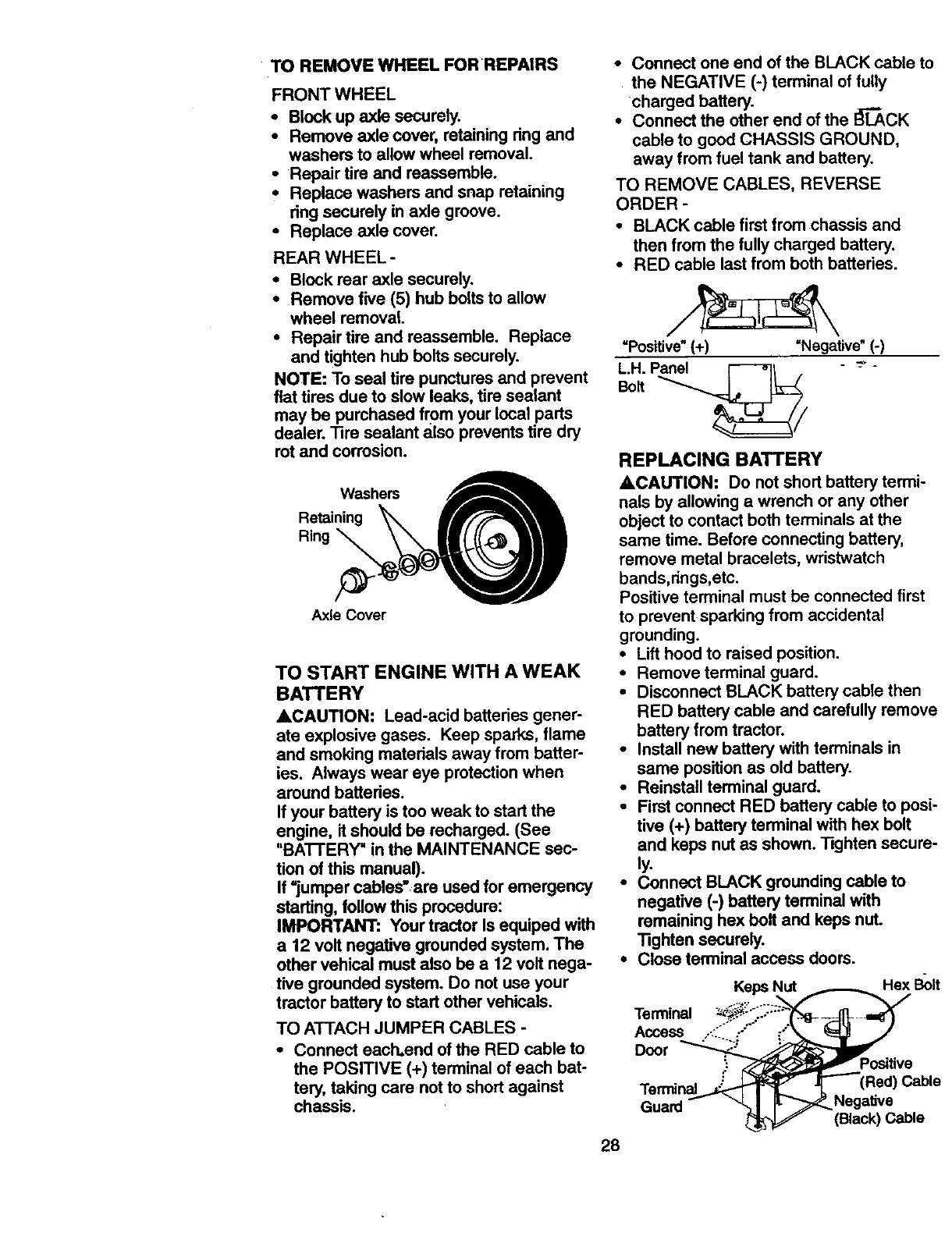
TO REMOVEWHEELFORREPAIRS
FRONT WHEEL
• Block up axle securely.
• Remove axle cover, retaining ring and
washers to allow wheel removal.
• Repair tire and reassemble.
• Replace washers and snap retaining
ring securely in axle groove.
•Replace axle cover.
REAR WHEEL -
•Block rear axle securely.
• Remove five (5) hub boltsto allow
wheel removal.
•Repair tire and reassemble. Replace
and tighten hub bolts securely.
NOTE: To seal tire punctures and prevent
flat tires due to slow leaks, tire sealant
may be purchased from your local parts
dealer. Tire sealant also prevents tire dry
rot and corrosion.
Washers
Retaining _
Ring
Axle Cover
TO START ENGINE WITH A WEAK
BATTERY
ACAUTION: Lead-acid batteries gener-
ate explosive gases. Keep sparks, flame
and smoking materials away from batter-
ies. Always wear eye protection when
around batteries.
If your battery is too weak to start the
engine, it should be recharged. (See
"BA'I-rERY" in the MAINTENANCE sec-
tion of this manual).
If =jumper cables" are used for emergency
starting, follow this procedure:
IMPORTANT: Your tractor Is equiped with
a 12 volt negative grounded system. The
other vehical must also be a 12 volt nega-
tive grounded system. Do not use your
tractor battery to start other vehicals.
TO ATTACH JUMPER CABLES -
•Connect each.end of the RED cable to
the POSITIVE (+) terminal of each bat-
tery, taking care not to short against
chassis.
•Connect one end of the BLACK cable to
the NEGATIVE (-) terminal of fully
charged battery.
•Connect the other end of the I_"_CK
cable to good CHASSIS GROUND,
away from fuel tank and battery.
TO REMOVE CABLES, REVERSE
ORDER -
•BLACK cable first from chassis and
then from the fully charged battery.
•RED cable last from both batteries.
=Positive" (+) =Negative" (-)
L.H. Panel i--_-_l .- _ "
REPLACING BATTERY
4kCAUTION: Do not short battery termi-
nals by allowing awrench or any other
object to contact both terminals at the
same time. Before connecting battery,
remove metal bracelets, wristwatch
bands,rings,etc.
Positive terminal must be connected first
to prevent sparking from accidental
grounding.
•Lift hood to raised position.
• Remove terminal guard.
•Disconnect BLACK battery cable then
RED battery cable and carefully remove
battery from tractor.
•Install new battery with terminals in
same position as old battery.
•Reinstall terminal guard.
•First connect RED battery cable to posi-
tive (+) battery terminal with hex belt
and keps nut as shown. "lighten secure-
ly.
•Connect BLACK grounding cable to
negative (-) battery terminal with
remaining hex belt and keps nut.
Tighten securely.
•Close terminal acceas doors.
Keps
Terminal
Access
Door
Hex Bolt
:'ositive
Terminal
Guard Negative
(Black) Cable
28
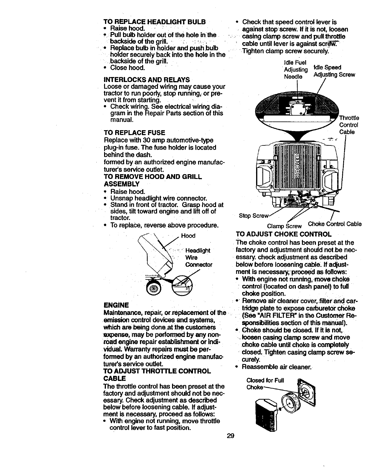
TO REPLACEHEADLIGHTBULB
• Raisehood.
•Pull bulb holder out of the hole in the
backside of the grill. - ._ :,
•Replace bulb in holder and push bulb
holder securely back into the hole in the
backside of the grill.
•Close hood.
INTERLOCKS AND RELAYS
Loose or damaged wiring may. cause your
tractor to run poody, stop running, or pre-
vent it from starting. •
•Check wiring. See electrical wiring dia-
gram in the Repair Parts section of this
manual.
TO REPLACE FUSE
Replace with 30 amp automotive-type
plug-in fuse. The fuse holder is located
behind the dash.
formed by an authodzed engine manufac-
turar's service outlet.
TO REMOVE HOOD AND GRILL
ASSEMBLY
•Raise hood.
.* Unsnap headlight wire connector.
Stand in front of tractor. Grasp hood at
sides, tilt toward engine and lift off of
tractor.
•To replace, reverse above procedure.
_.\ . Hood
ENGINE
Maintenance, repair, orreplacement of the
emission control devices and systems,
wh'w,hare being done at the customers
expense, may be performed by any non-
road engine repair establishment or indi-
vidual Warranty repairs must be per-
formed by an authorized engine manufao
turer's service outlet.
TO ADJUST THROTTLE CONTROL
CABLE
The throttle control has been preset at the
factory and adjustment should not be nec-
essary. Check adjustment as described
below before loosening cable. If adjust-
ment is necessary, proceed as follows:
•With engine not running, move throttle
control lever to fast position.
•Check that speed control lever is
against stop,screw. If it is not, loosen
casing clamp screw and pull throttle
cable until lever is against scr__R_.
Tighten clamp screw securely.
Idle Fuel
Adjusting Idle Speed
Needle Screw
Control
Cable
sto_
Clamp Screw Choke Control Cable
TO ADJUST CHOKE CONTROL
The choke control has been preset at the
factory and adjustment should notbe nec-
essary,check adjustment as described
below before loosening cable. If adjust-
ment is necessary;procaed as follows:
•With engine not running,movechoke
control (located on dash panel) to full
choke position.
• "Remove a_ cleaner cover,.f'dterand car-
tddge plate to expose carburetor choke
(See =AIR FILTER" in the Customer Re-
sponsibilitiessection of this manual).
•Choke should be closed. If it is not,
•loosen casing clamp screw and move
choke cable until choke is completely
closed. T_jhten casing clamp screw se-
curaly.
•Reassemble air cleaner.
Closed for Full
29
TO ADJUST CARBURETOR
The carburetor has been present at the
factory and adjustment should not be nec-
essary. However, minor adjustment may
be required to compensate for differences
in fuel, temperature, altitude or load. If the
carburetor does need adjustment, proceed
as follows:
In general, tuming the adjusting needles
in (clockwise) decreases the supply of fuel
to the engine giving a leaner fuel/air mix-
ture. Turning the adjusting needles out
(counterclockwise) increases the supply of
fuel to the engine giving a richer fuel/air
mixture.
IMPORTANT: Damage to the needles
and the seats in carburetor may result if
screw is tumed in too tight.
PRELIMINARY SETTING -
•Be sure you have a clean air filter, and
the throttle control cable is adjusted
properly (see "TO ADJUST THROI-I'LE
CONTROL CABLE" in the Service and
Adjustments section of this manual).
•With engine off turn idle fuel adjusting
needle in (clockwise) closing it finger
tight and then turn out (counterclock-
wise) 1 tum.
FINAL SE'I-rlNG -
•Start engine and allow to warm for five
minutes. Make final adjustments with
engine running and shift/motion control
lever in neutral (N) position.
•The high idle is set at the factory and
cannot be adjusted.
•Idle speed _ettina - With throttle control
lever in slow position, engine should
idle at 1200 RPM. If engine idles too
slow or fast, tum idle speed adjusting
screw in or out until correct idleis
attained.
•Idle fuel needle settina - With throttle
control lever in slow position, tum idle
fuel adjusting needle in (clockwise) until
engine speed decreases end then tum
out (counterclockwise) approximately
314tum to obtain the best low speed
performance.
•Recheck idle speed. Readjust if neces-
sary.
ACCELERATION TEST -
•Move throttle control lever from-Slow to
fast position. If engine hesitates or dies,
tum idle fuel adjusting needle out
(counterclockwise) 1/8 tum. Repeat test
and continue to adjust, if necessary,
until engine accelerates smoothly.
High speed stop is factory adjusted. Do
not adjust-damage may result.
IMPORTANT: Never tamper with the
engine governor, which is factory set for
proper engine speed. Overspeeding the
engine above the facory high speed set-
ting can be dangerous. If you think the
engine-governed high speed needs
adjusting, contact your nearest authorized
service center/department, which has
proper equipment and experience to make
any necessary adjustments.
30
Immediately prepare your tractorfor stor-
age at the end of the season or if the trac-
tor will not be used for 30 days or more.
_CAUTION: Never store the tractor with
gasoline in the tank inside a building
where fumes may reach an open flame or
spark. Allow the engine to cool before stor-
ing in any enclosure.
TRACTOR
Remove mower from tractor for winter
storage. This will allow you to clean it thor-
oughly. Remove all dirt, grease, leaves,
etc. Store in a clean, dry area.
• Clean entire tractor (See "CLEANING"
in the Maintenance section of this man-
ual).
•Inspect and replace belts, if necessary
(See belt replacement instructionsin the
Service and Adjustments section of this
manual).
•Lubricate as shown in the Maintenance
section of this manual.
•Be sure that all nuts, bolts and screws
are securely fastened. Inspect moving
parts for damage, breakage and wear.
Replace if necessary.
•Touch up all rusted or chipped paint sur-
faces; sand lightlybefore painting.
BATrERY
•Fully charge the battery for storage,
•After a period of time in storage, battery
may require recharging,
•To help prevent corrosion and power
leakage during long periods of storage,
battery cables should be disconnected
and battery cleaned thoroughly (see
"TO CLEAN BATTERY AND TERMI-
NALS" in the Maintenance section of
this manual).
•After cleaning, leave cables disconnect-
ed and place cables where they cannot
come in contact with battery terminals.
•If battery is removed from tractor for
storage, do not store battery directly on
concrete or damp surfaces.
ENGINE
FUEL SYSTEM
IMPORTANT: It is important to prevent
gum deposits from forming in essential
fuel system parts such as carburetor, fuel
filter, fuel hose, or tank during storage.
Also, experience indicates that alt_ff-ol :
blended fuels (called gasohol or using
ethanol or methanol) can attract moisture
which leads to separation and formation of
acids during storage. Acidic gas can dam-
age the fuel system of an engine while in
storage.
•Drain the fuel tank.
•Start the engine and let it run until the
fuel lines and carburetor are empty.
•Never use engine or carburetor cleaner
products in_thefuel tank or permanent
damage may occur.
•Use fresh fuel next season.
NOTE: Fuel stabilizer is an acceptable
altemative in minimizing the formation of
fuel gum deposits during storage. Add sta-
bilizer to gasoline in fuel tank or storage
container.Always follow the mix ratio
found on stabilizer container. Run engine
at least 10 minutes after adding stabilizer
to allow the stabilizer to reach the carbure-
tor. Do notdrain the gas tank and carbure-
tor if usingfuel stabilizer.
ENGINE OIL
Drain oil (with engine warm) and replace
with clean engine oil. (See "ENGINE" in
the Maintenance section of this manual).
CYLINDER(S)
• Remove spark plug(s).
• Pour one ounce of oilthrough spark plug
hole(s) into cylinder(s).
•Tum ignitionkey to =START" positionfor
afew seconds to distribute oil.
• Replace with new spark plug(s).
OTHER
•Do not store gasoline from one season
to another.
• Replace your gasoline can if it starts to
rust. Rust and/or dirt in your gasoline will
cause problems.
•If possible, store your tractor indoors
and cover it to give protection from dust
and dirt.
• Cover your tractor with a suitable protec-
tive cover that does not retain moisture.
Do not use plastic. Plastic cannot
breathe, which allows condensation to
form and cause your tractor to rust.
IMPORTANT: Never cover tractor while
engine and exhaust areas are still warm.
31
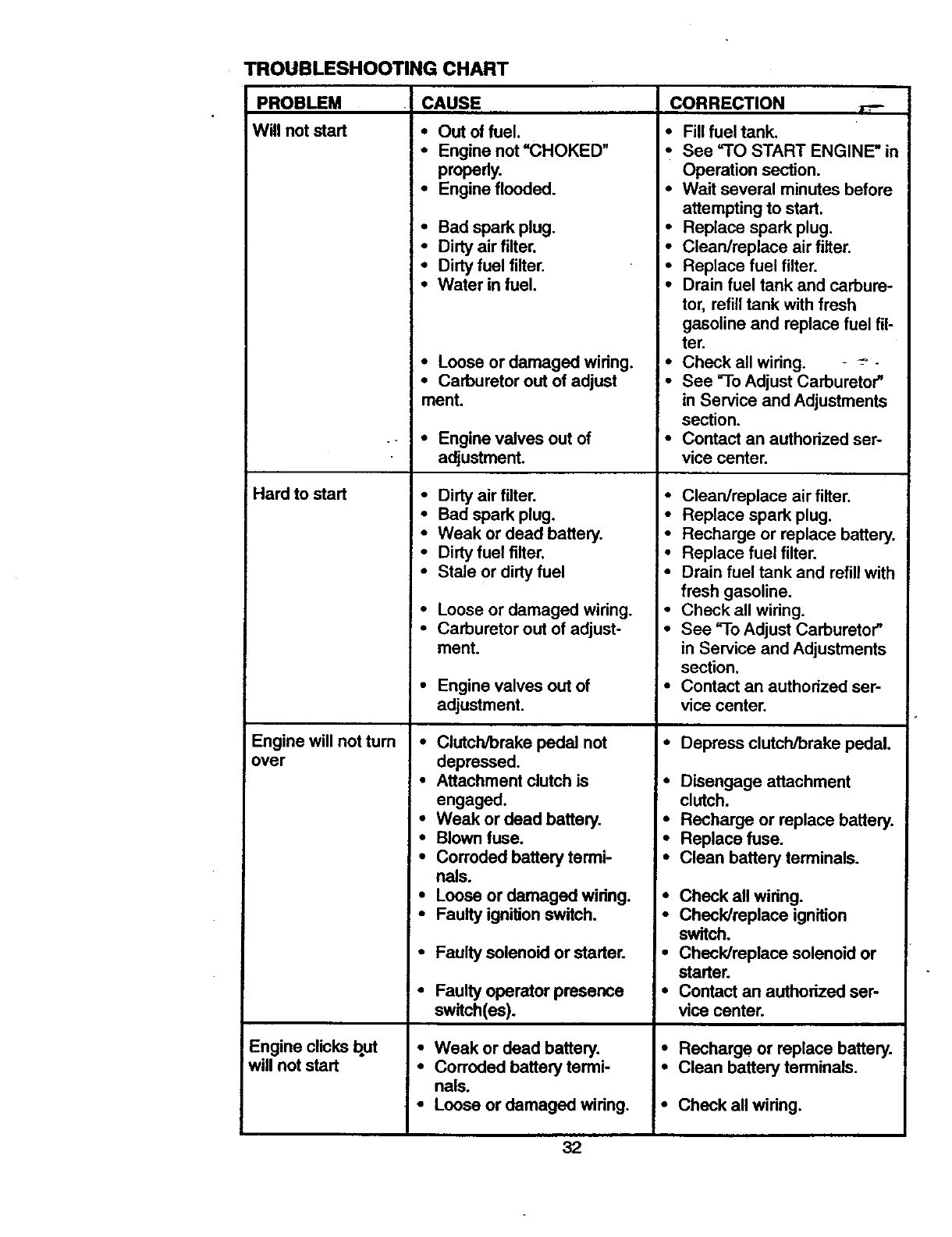
TROUBLESHOOTING CHART
PROBLEM
Will not start
Hard to start
Engine will not turn
over
Engine clicks but
will not start
CAUSE CORRECTION
•Out of fuel.
Engine not "CHOKED"
properly.
Engine flooded.
Bad spark plug.
Dirty air filter.
Dirty fuel filter.
Water in fuel. •
• Loose or damaged wiring. •
•Carburetor out of adjust •
ment.
• Engine valves out of •
adjustment.
• Dirty air filter. •
• Bad spark plug.
•Weak or dead battery.
•Dirty fuel filter.
•Stale or dirty fuel °
•Loose or damaged wiring. •
•Carburetor out of adjust- •
ment.
•Engine valves out of •
adjustment.
•Clutch/brake pedal not
depressed.
•Attachment clutch is
engaged.
• Weak or dead battery.
•Blown fuse.
•Corroded battery termi-
nals.
• Fill fuel tank.
, See "TO START ENGINE" in
Operation section.
•Wait several minutes before
attempting to start.
Replace spark plug.
Clean/replace air filter.
Replace fuel filter.
Drain fuel tank and carbure-
tor, refill tank with fresh
gasoline and replace fuel fil-
ter.
Check all widng. - -- -
See "To Adjust Carburetor"
in Service and Adjustments
section.
Contact an authorized ser-
vice center.
Clean/replace air filter.
Replace spark plug.
Recharge or replace battery.
Replace fuel filter.
Drain fuel tank and refill with
fresh gasoline.
Check all widng.
See "To Adjust Carburetor"
in Service and Adjustments
section.
Contact an authorized ser-
vice center.
•Depress clutch/brake pedal.
• Disengage attachment
clutch.
•Recharge or replace battery.
•Replace fuse.
•Clean battery terminals.
•Loose or damaged widng. •
•Faulty ignition switch.
•Faulty solenoid or starter.
i. Faulty operator presence
switch(es).
•Weak or dead battery.
•Corroded battery termi-
nals.
•Loose or damaged widng.
Check all widng.
Check/replace ignition
switch.
•Check/replace solenoid or
starter.
•Contact an authorized ser-
vice center.
•Recharge or replace battery.
• Clean battery terminals.
•Check all wiring.
32
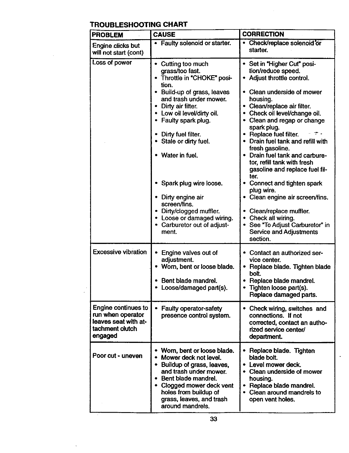
TROUBLESHOOTING CHART
PROBLEM CAUSE CORRECTION
Engine clicks but -Faulty solenoid or starter. •Check/replace solenoid'or
will not start (cont) starter.
Loss of power
Excessive vibration
Engine continues to
run when operator
leaves seat with at-
tachment dutch
engaged
Poor cut -uneven
•Cutting too much
grass/too fast.
•Throttle in =CHOKE" posi-
tion.
•Build,up of grass, leaves
and trash under mower.
•Dirty air filter.
•Low oil level/dirty oil.
•Faulty spark plug.
•Dirty fuel filter.
•Stale or dirty fuel.
•Water in fuel.
•Spark plug wire loose.
• Dirty engine air
screen/fins.
• Dirty/clogged muffler.
• Loose or damaged wiring.
• Carburetor out of adjust-
ment.
• Engine valves out of
adjustmenL
•Worn, bent or loose blade.
• Bent blade mandrel.
•Loose/damaged part(s).
• Faulty operator-safety
presence controlsystem.
•Wom, bent or loose blade.
•Mower deck not level.
•Buildup of grass, leaves,
and trash under mower.
• Bent blade mandrel.
•Clogged mower deck vent
holes from buildup of
grass, leaves, and trash
around mandrels.
•Set in =Higher Cut" posi-
tion/reduce speed.
•Adjust throttle control.
•Clean underside of mower
housing.
•Clean/replace air filter.
•Check oil level/change oil.
•Clean and regap or change
spark plug.
• Replace fuel filter. -_ -
•Drain fuel tank and refill with
fresh gasoline.
•Drain fuel tank and carbure-
tor, refill tank with fresh
gasoline and replace fuel fil-
ter.
•Connect and tighten spark
plug wire.
•Clean engine air screen/fins.
Clean/replace muffler.
Check all wiring.
See =ToAdjust Carburetor" in
Service and Adjustments
section.
•Contact an authorized ser-
vice center.
•Replace blade. Tighten blade
bolt.
• Replace blade mandrel.
•Tighten loose part(s).
Replace damaged parts.
Check wiring, switches and
connections. If not
corrected, contact an autho-
rized service center/
department.
•Replace blade. Tighten
blade bolt.
•Level mower deck.
•Clean underside of mower
housing.
•Replace blade mandrel.
•Clean around mandrels to
open vent holes.
33
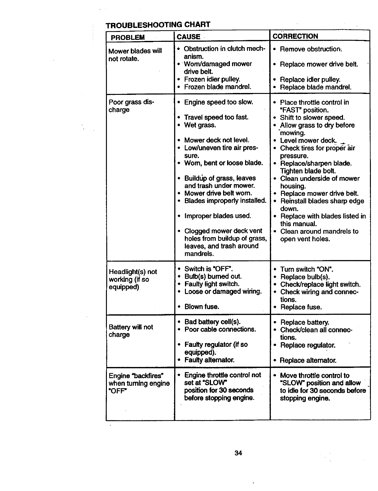
"ROUBLESHOOTING CHART
CAUSE CORRECTION
PROBLEM
Mower blades will
not rotate.
Poorgrassdis-
cha_e
Headlight(s) not
working (if so
equipped)
Battery will not
charge
Engine "backfires"
when tuming engine
=OFF"
•Obstruction in clutch mech-
anism.
•Worn/damaged mower
drive belt.
•Frozen idler pulley.
•Frozen blade mandrel.
•Engine speed too slow.
•Travel speed too fast.
•Wet grass.
•Mower deck not level.
•Low/uneven tire air pres-
sure.
•Wom, bent or loose blade.
•Builddp of grass, leaves
and trash under mower.
•Mower drive belt wom.
•Blades imprepedy installed.
•Improper blades used.
Clogged mower deck vent
holes from buildup of grass,
leaves, and trash around
mandrels.
•Switch is "OFF'.
•Bulb(s) bumed out.
•Faulty light switch.
•Loose or damaged wiring.
•Blown fuse.
•Bad battery cell(s).
•Poor cable connections.
•Faulty regulator (if so
equipped).
•Faulty alternator.
•Engine throffiecontrol not
set at "SLOW _
positionfor 30 seconds
before stopping engine.
•Remove obstruction;.
•Replace mower drive belt.
•Replace idler pulley.
•Replace blade mandrel.
•Place throttle control in
=FAST" position.
•Shift to slower speed.
• Allow grass to dry before
mowing.
•Level mower deck...,.
•Check tires for prosper _ir
pressure.
•Replace/sharpen blade.
"13ghtanblade bolt.
•Clean underside of mower
housing.
•Replace mower drive belt.
•Reinstall blades sharp edge
down.
•Replace with blades listed in
this manual.
•Clean around mandrels to
open vent holes.
•Tum switch "ON'.
•Replace bulb(s).
•Check/replace light switch.
•Check wiring and connec-
tions.
•Replace fuse.
•Replace battery.
•Check/clean all connec-
tions.
•Replace regulator.
•Replace altemator.
Move throttle control to
=SLOW" position and allow
to idle for 30 seconds before
stopping engine.
34
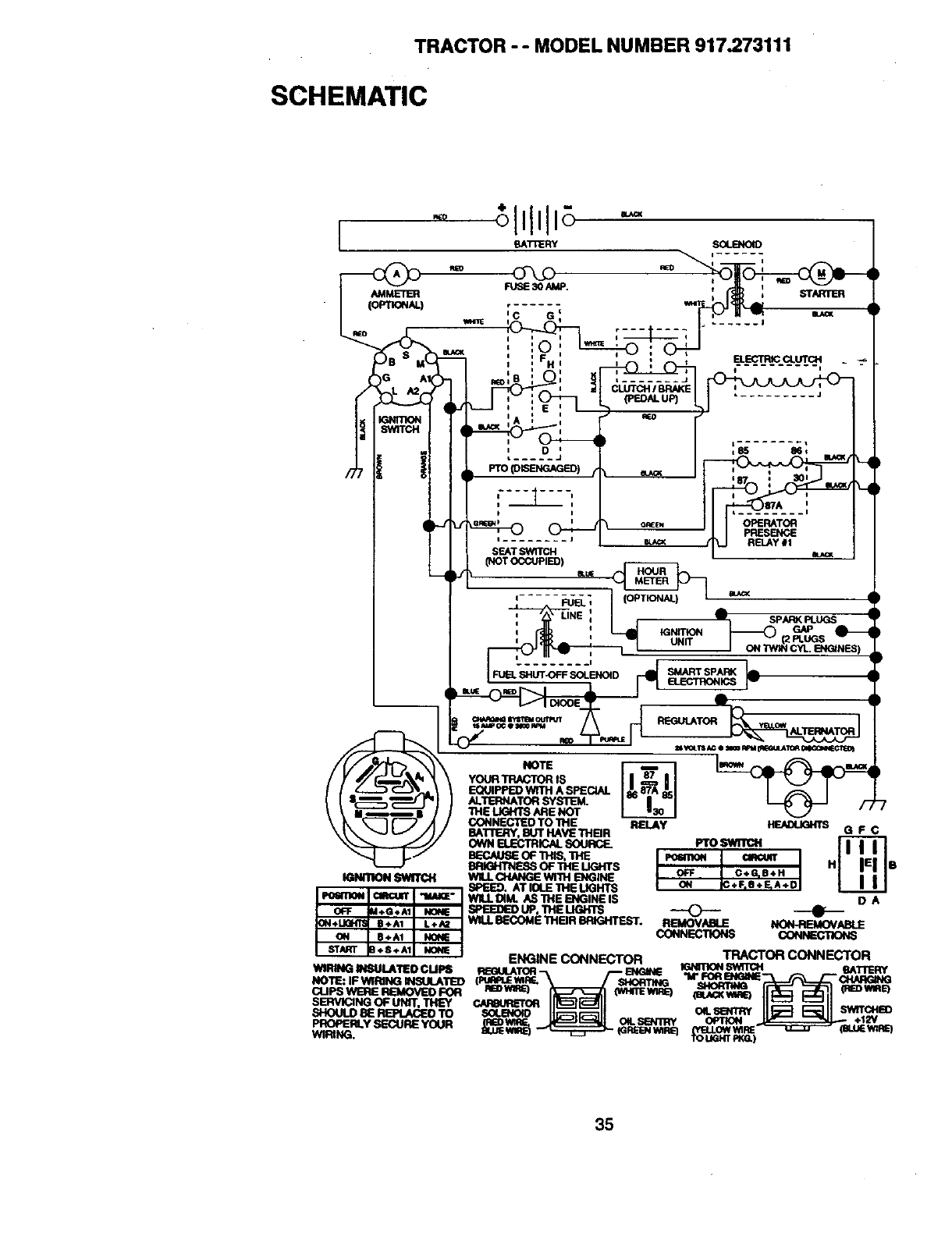
TRACTOR " " MODEL NUMBER 917.273111
SCHEMATIC
___--_l_llll _----_ i ......
AB0
35
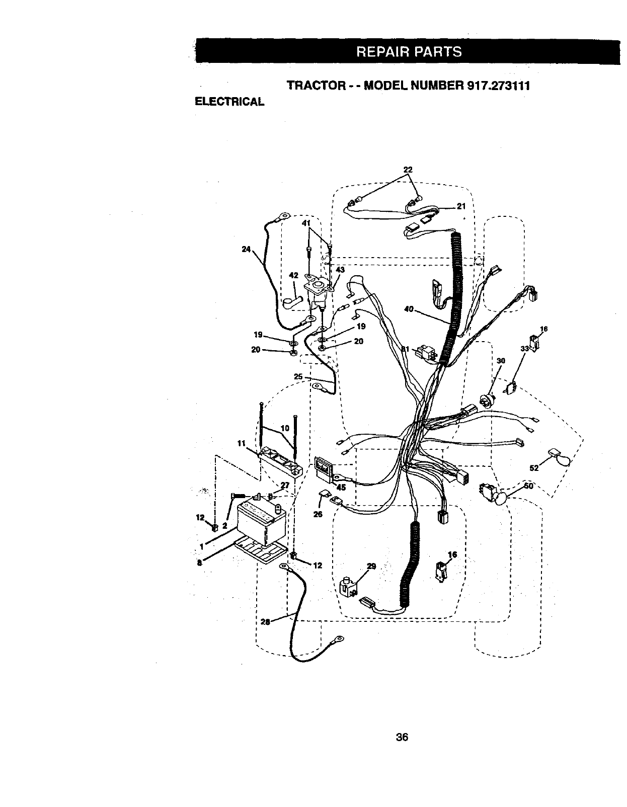
ELECTRICAL
TRACTOR - - MODEL NUMBER 917.273111
24
43
11
12
.i ,'
26
36
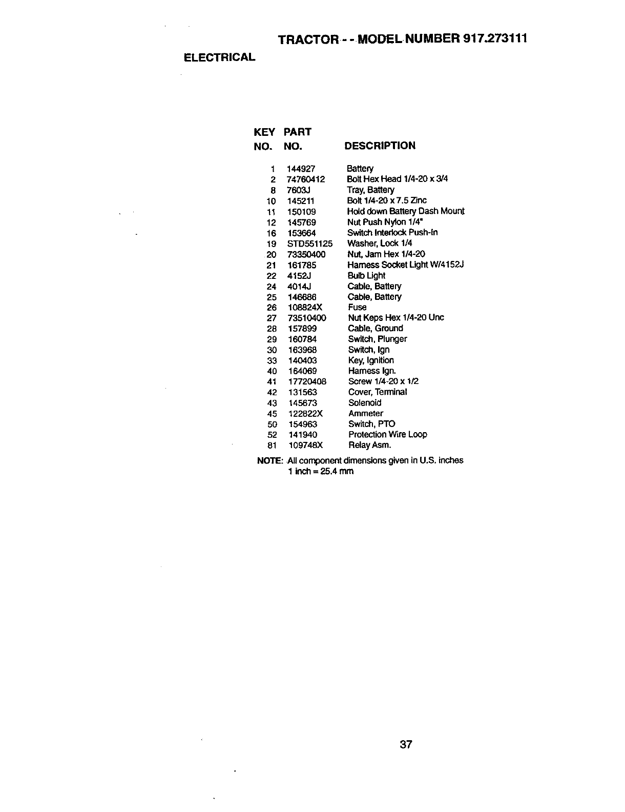
ELECTRICAL
TRACTOR - - MODELNUMBER 917.273111
KEY PART
NO. NO. DESCRIPTION
1144927 Battery
2 74760412 BoitHexHead 1/4-20x3/4
8 7603J Tray,Battery
10 145211 Bolt1/4-20 x 7.5 Zinc
! 1 150109 Holddown BatteryDash Mount
12 145769 Nut Push Nylon1/4"
16 153664 SwitchInterlockPush-in
19 STD551125 Washer,Lock 1/4
20 73350400 Nut, Jam Hex 114-20
21 161785 Harness SocketLightW/4152J
22 4152J Bulb Light
24 4014J Cable, Battery
25 146686 Cable, Battery
26 108824X Fuse
27 73510400 Nut Keps Hex 1/4-20 Unc
28 157899 Cable, Ground
29 160784 Switch, Plunger
30 163968 Switch, Ign
33 140403 Key,Ignition
40 164069 Harness Ign.
41 17720408 Screw 1/4-20 x 1/2
42 131563 Cover,Terminal
43 145673 Solenoid
45 122822)( Ammeter
50 154963 Switch,PTO
52 141940 ProtectionWire Loop
81 109748X RelayAsm.
NOTE: Allcomponentdimensionsgivenin U.S. inches
1 inch= 25.4 mm
37
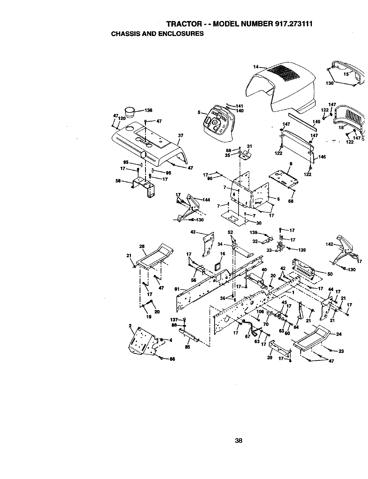
TRACTOR - - MODEL NUMBER 917.273111
CHASSIS AND ENCLOSURES
37
28
ii
19
21
68 31
!
17
52
17
146
68
17
42
>
63
39
38
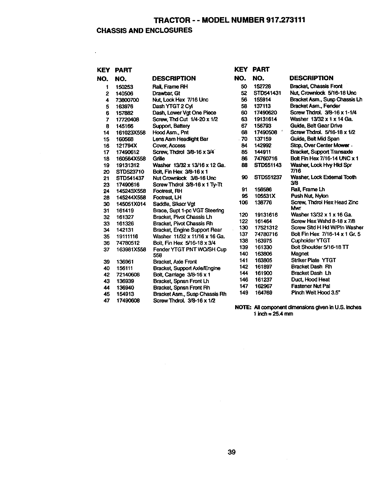
TRACTOR - - MODEL NU MBER 917.273111
CHASSIS AND ENCLOSURES
KEY PART KEY PART
NO. NO. DESCRIPTION NO. NO.
1 150_53 Rail, Frame RH 50 152728
2 140506 Drawbar,Gt 52 STD541431
4 73800700 Nut, Lock Hex 7/16 Une 56 155914
5 163976 DashYTGT2Cyt 58 137113
6 157882 Dash, LowerVgtOnePlace 60 17490620
7 17720408 Sc_w, ThdCut 1/4-20xl/2 63 19131614
8 145166 Support,BattePj 67 156793
14 161023X558 HoodAsm., Pnt 68 17490508 "
15 160568 LensAsm HeadlightBar 70 137159
16 121794X Cover,Access 84 142992
17 17490612 Sc_w, Thdrol 3/8-16x3/4 85 144911
18 160564X558 Grilla 86 74760716
19 19131312 Washer 13i32x13/16x12Ga. 88 STD551143
20 STD523710 Bolt,Fin Hex 3/8-16xl
21 STD541437 NutCrownlock 3/8-16Unc 90 STD551237
23 17490616 ScrewThdrol 3/8-16x1Ty-Tt
24 145243X558 Footrest,RH 91 156586
28 145244X558 Footrest,LH 95 105531X
30 145051X014 Saddle, SlkscrVgt 106 138776
31 161419 Brace, Supt 1-pcVGT Steedng
32 161327 Bracket, PivotChassis Lh 120 19131616
33 161326 Bracket, PivotChassis Rh 122 161464
34 142131 Bracket, EngineSupport Rear 130 17521312
35 19111116 Washer 11/32x11/16x16Ga. 137 74780716
36 74780512 Bolt, Fin Hex 5/16-18 x 3/4 138 163975
37 163981X558 FenderYTGTPNTWOiSHCup 139 161330
558 140 163806
39 136961 Bracket,AxleFront 141 163805
40 156111 Bracket, SupportAxle/Engine 142 161897
42 72140608 Bolt, Carriage 3/8-16 x 1 144 161900
43 136939 Bracket, Spnsn FrontLh 146 161237
44 136940 Bracket, Sposn FrontRh 147 162967
45 154913 BracketAsm.,SuspChasslaRh 149 164769
47 17490608 ScrawThdrol. 3./8-16x 1/2
DESCRIPTION
Bracket,Chassis Front
Nut, Crownlock 5/16-18 Uric
BracketAsm., Susp Chassis Lh
BracketAsm., Fender
Screw Thdrol. 3/8-16 x 1-114
Washer 13/32 x lx 14 Ga.
Guile, BeltGear Drive
Scraw "rhdml. 5/16.18 x I/2
Guide, Belt Mid Span
Stop,Over CenterMower.
Bracket, SupportTmneaxla
Belt Fin Hex 7/16-14 UNC x 1
Washer,Lock Hvy Hlcl Spr
7/16
Washer,Lock ExtematToo81
3/8
Rail, Frame Lh
Push Nut, Nylon
Screw,ThdrolHex Head Zinc
Mwr
Washer 13/32 x 1 x 16 Ga.
Screw Hex Wshd 8-18 x 7/8
Screw SltdH Hd W/PIn Washer
BoltFin Hex 7/16-14 x 1 Gr. 5
CupholderYTGT
BoltShoulder5/16-18 Tr
Magnet
StdkerPlate YTGT
BracketDash Rh
BracketDash Lh
Duct,Hood Heat
Fastener Nut Pal
PinchWeltHood 3.5"
NOTE: Allcomponentdimensionsgivenin U.S. inches
1 Inch= 25A mm
39
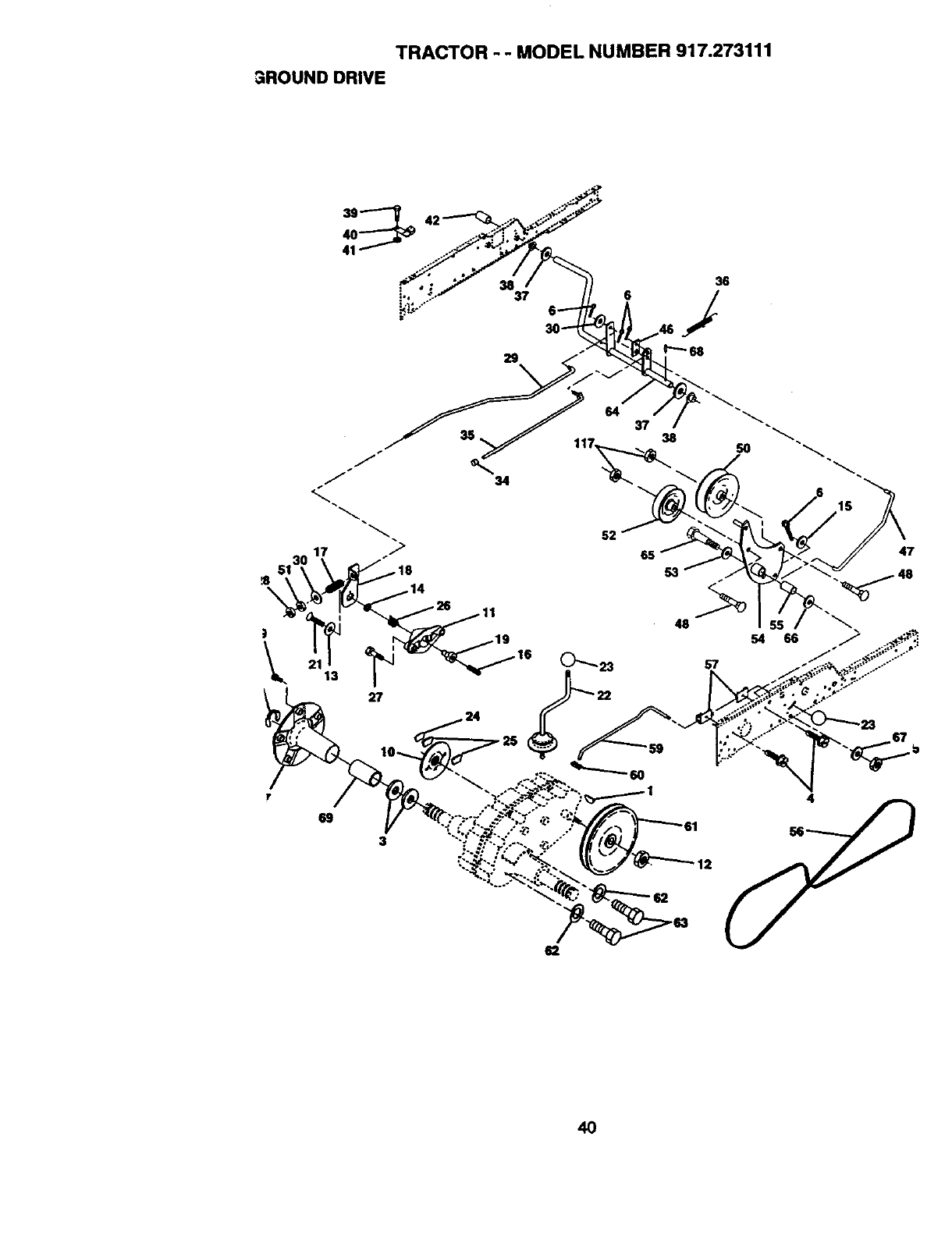
TRACTOR - - MODEL NUMBER 917.273111
3ROUNDDRIVE
13
27
69
3
62
4O
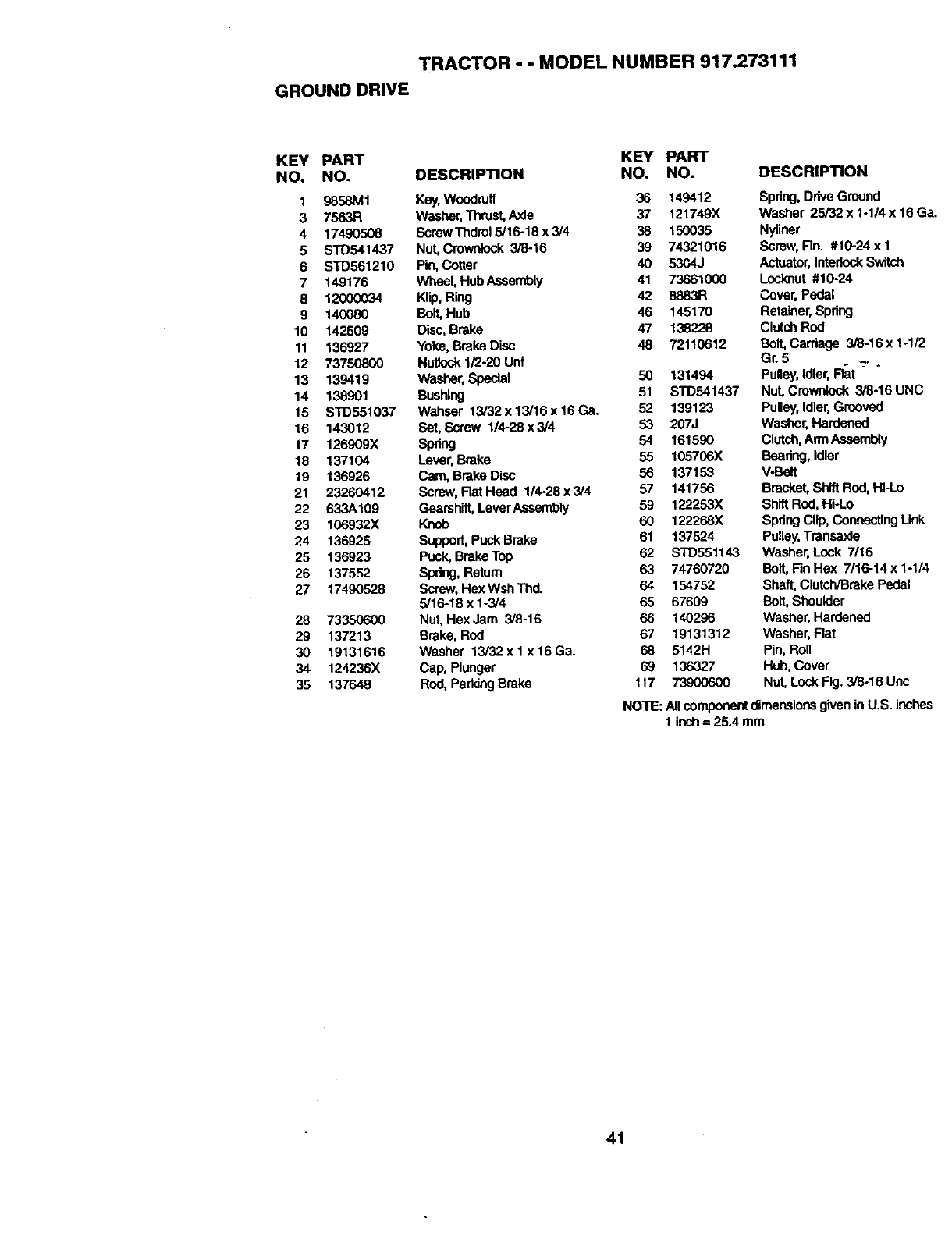
TRACTOR - - MODEL NUMBER 917.273111
GROUNDDRIVE
KEY PART KEY PART
NO. NO. DESCRIPTION NO. NO.
1 9858M1 Key,Woodruff 36 149412
3 7563R Washer,Thrust,Axle 37 121749X
417490508 ScrewThdro15/16-18x3/4 38 150035
5 STD541437 Nut,Crownlock 3/6-16 39 74321016
6 STD561210 Pin,Cotter 40 53C4J
7 149176 WheaI. Hub Assembly 41 73661000
8 12000034 Klip,Ring 42 8883R
9 140080 Bolt,Hub 46 145170
10 142509 Disc, Brake 47 138228
11 136927 Yoke, BrakeDisc 48 72110612
12 73750800 NultockI/2-20 Unf
13 139419 Washer,Special 50 131494
14 138901 Bushing 51 STD541437
15 STD551037 Wahser 13i32x13/16x16Ga. 52 139123
16 143012 Set,Screw 1/4-28 x 3/4 53 207J
17 126909X Spring 54 161590
18 137104 Lever,Brake 55 105706X
19 136926 Cam, Brake Disc 56 137153
21 23260412 Screw, Flat Head 11428 x 3/4 57 141756
22 633A109 Gearshift,LeverAssembly 59 122253X
23 106932X Knob 60 122268X
24 136925 Support,PuckBrake 61 137524
25 136923 Puck, Brake Top 62 STD551143
26 137552 Spdng, Return 63 74760720
27 17490528 Screw,HexWshThd. 64 154752
5/16-18 x 1-3/4 65 67609
28 73350600 Nut, HexJam 3/6-16 66 140296
29 137213 Brake, Rod 67 19131312
30 19131616 Washer 13/32x 1 x 16Ga. 68 5142H
34 124236X Cap, Plunger 69 136327
35 137648 Rod,PaddngBrake 117 73900600
DESCRIPTION
Spring, DriveGround
Washer 25/32 x 1-1/4 x 16 Ga.
Nyliner
Screw, Fin. #10-24 x 1
Actuator,InterlockSwitch
Lucknut #10-24
Cover,Pedal
Retainer,Spdng
ClutchROd
Bolt, Carriage 3/8-16 x 1-1/2
Gr.5
Pulley,Idler,Flat
Nut' Cmwnleck 3/8-16 UNC
Pulley,Idler,Grooved
Washer, Hardened
Clutch,Ann Assembly
Bearing,Idler
V-Belt
Bracket,Shift ROd,Hi-Lo
ShiftRod, Hi-Lo
SpdngClip, Connecting Link
Pulley,Transaxle
Washer,Lock 7/16
Bolt, Fin Hex 7116-14x 1-1/4
Shaft, Clutch/BrakePedal
Bolt, Shoulder
Washer, Hardened
Washer, Rat
Pin, Roll
Hub, Cover
Nut, Lock Fig. 3/8-16 Unc
NOTE: AllcomponentdimensionsgiveninU.S. inches
1 inch=25.4 mm
41
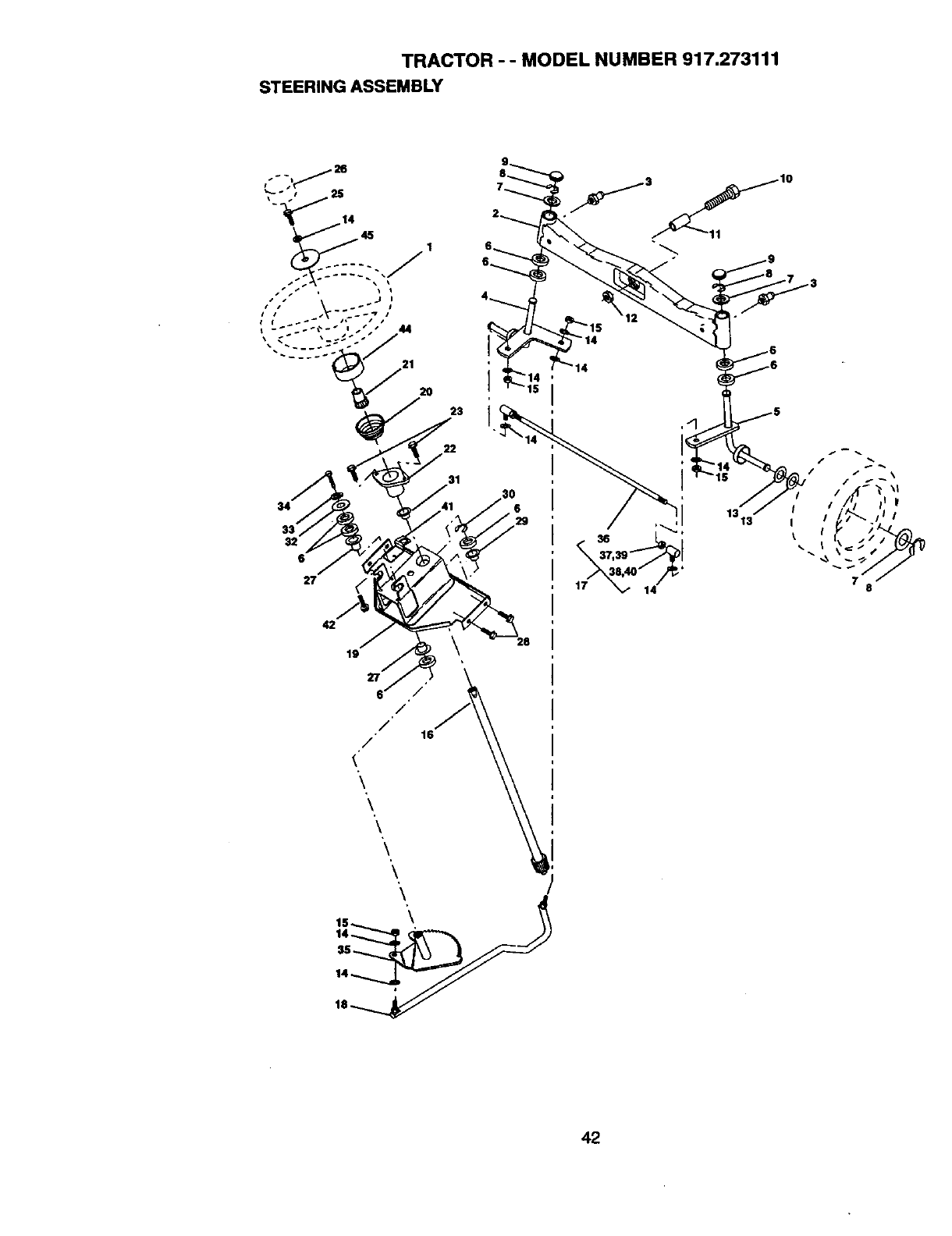
TRACTOR - - MODEL NUMBER 917.273111
STEERING ASSEMBLY
42
/
42
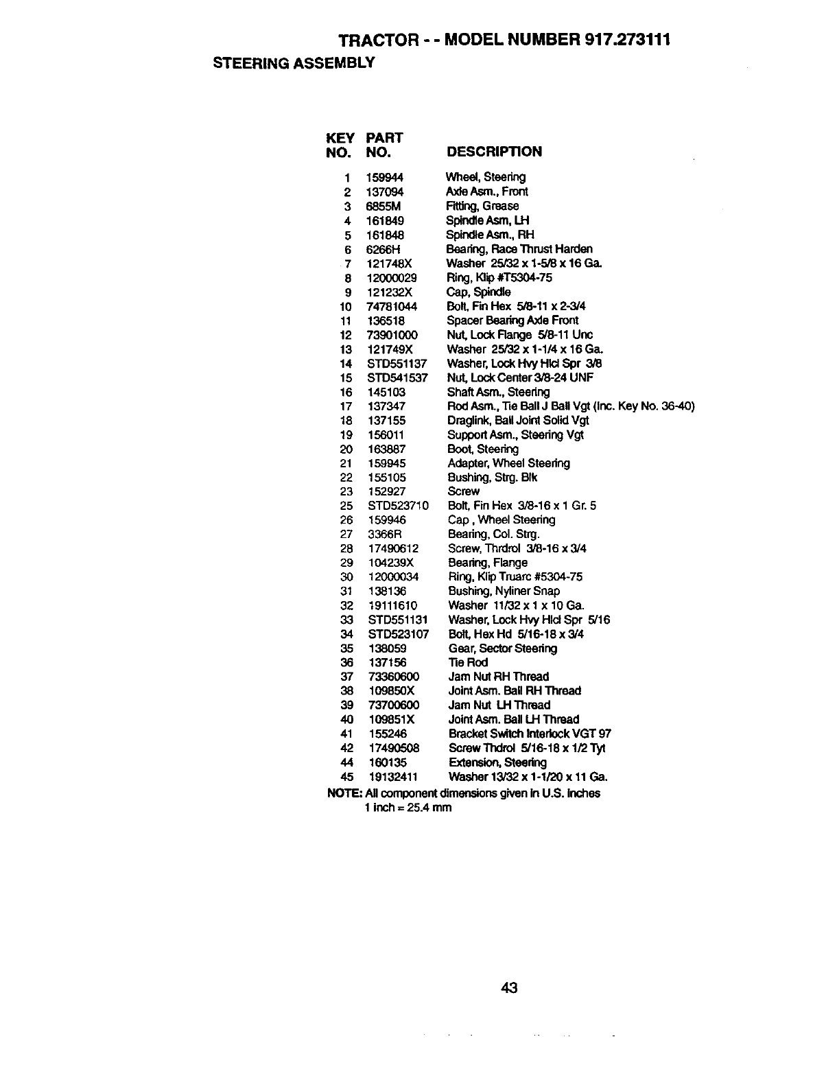
TRACTOR - - MODEL NUMBER 917.273111
STEERINGASSEMBLY
KEY PART
NO. NO. DESCRIPTION
1 159944
2 137094
3 6855M
4 161849
5 161848
6 6266H
7 121748X
8 12000029
9 121232X
10 74781044
11 136518
12 73901000
13 121749X
14 STD551137
15 S'rD541537
16 145103
17 137347
18 137155
19 156011
20 163887
21 159945
22 155105
23 152927
25 STD523710
26 159946
27 3366R
28 17490612
29 104239X
30 12000034
31 138136
32 19111610
33 STD551131
34 STD523107
35 138059
36 137156
37 73360600
38 109850X
39 73700600
40 109851X
41 155246
42 17490508
44 160135
45 19132411
Wheel, Steering
A._deAsm.,Front
F_ng, Grease
Spinde Asm, LH
SpindleAsm., RH
Beadng, RaceThrustHarden
Washer 25/32 x 1-5/8 x 16 Ca.
Ring, K,p #T5304-75
Cap,Spindle
Bolt, RnHex 5/8-11 x 2-314
Spacer BearingAxle Front
Nut, Lock Range 5/8-11 Unc
Washer 25/32 x 1-114x 16 G&
Washer, Lock _ Hlcl Spr 3/8
Nut, Lock Center 3/8-24 UNF
ShaftAsm., Steering
Rod Asm.,3ie BallJ Ball Vgt (inc. Key No. 36-40)
Draglink,Ball Joint SolidVgt
Support Asm.,Steering Vgt
Boot,Steering
Adapter,Wheel Steering
Bushing,Strg. BIk
Screw
Bolt, FinHex 3/8-16 x I Gr. 5
Cap, Wheel Steering
Baadng, Col. Strg.
Screw, Thrdrol 3/8-16 x 3/4
Bearing, Flange
Ring, Klip Truarc #5304-75
Bushing,Nyliner Snap
Washer 11/32x 1 x 10 Ga.
Washer, Lock Hvy Hlel Spr 5/16
Bolt,Hex Hd 5/16-18 x 3/4
Gear, SectorSteering
"heRod
Jam Nut RH Thread
JointAsm. Ball RH Thread
Jam Nut LH Thread
JointAsm. Ball LH Thread
BracketSwitchInterlockVGT 97
Screw Thdrol 5/16-18 x 1/2 Tyt
Extension,Steering
Washer 13/32 x 1-1/20 x 11Ca.
NOTE: Allcomponentdimensionsgivenin U.S. inches
1 inch= 25.4 mm
43
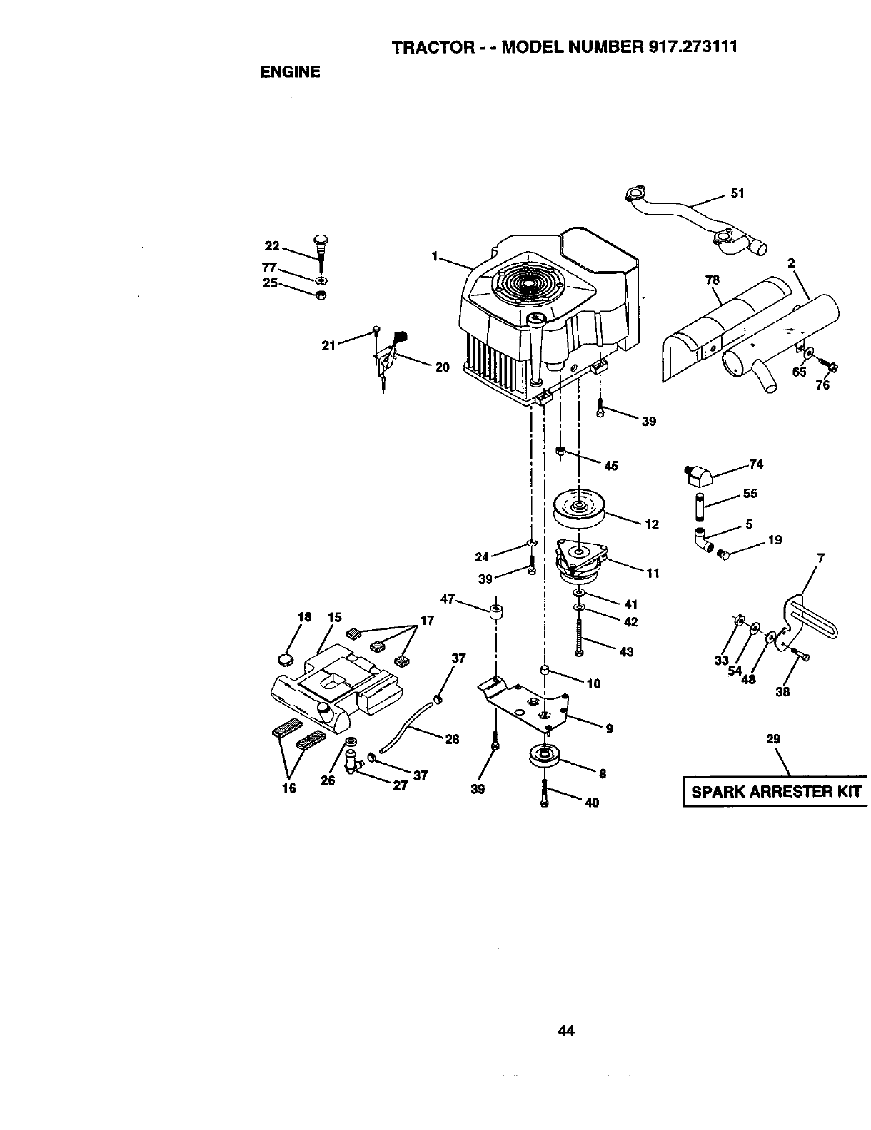
ENGINE
TRACTOR - - MODEL NUMBER 917.273111
2
76
29
\
I SPARK ARRESTER KIT
44
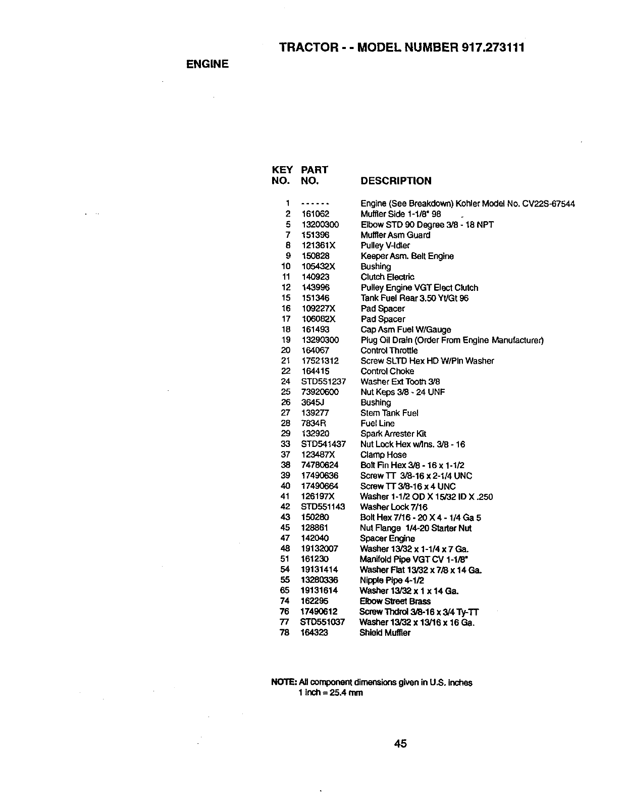
ENGINE
TRACTOR - - MODEL NUMBER 917.273111
KEY PART
NO. NO. DESCRIPTION
2 161062
513200300
7 151396
8 121361X
9 150828
10 105432X
11 140923
12 143996
15 151346
16 109227)(
17 106082X
18 161493
19 13290300
20 164067
21 17521312
22 164415
24 STD551237
25 73920600
26 3645J
27 139277
28 7834R
29 132920
33 STD541437
37 123487X
38 74780624
39 17490636
40 17490664
41 126197X
42 STD551143
43 150280
45 128861
47 142040
48 19132007
51 16123O
54 19131414
55 1328O336
65 19131614
74 162295
76 17490612
77 STD551037
78 164323
Engine (See Breakdown)KohlerModel No.CV22S-67544
Muffler Side 1-118"98
Elbow STD 90 Degree 3/8 -"18 NPT
MufflerAsm Guard
PulleyV-Idler
KeeperAsm. BoltEngine
Bushing
ClutchElectric
Pulley Engine VGT Elect Clutch
Tank Fuel Rear 3,50 Yt/Gt 96
Pad Spacer
Pad Spacer
Cap Asm Fuel W/Gauge
Plug Oil Drain (Order FromEngine Menufacturer)
ControlThrottle
Screw SLTD Hex HD W/PIn Washer
ControlChoke
WasherExt Tooth3/8
Nut Keps 3/8 - 24 UNF
Bushing
Stem Tank Fuel
Fuel Line
SparkArresterKit
NutLock Hex w/Ins. 3/8 - 16
Clamp Hose
Bolt Fin Hex 3/8 - 16 x 1-1/2
Screw l-r 3/8-16 x 2-1/4 UNC
Scmw'N" 3/8-16 x 4 UNC
Washer 1-1/20D X 15/32 ID X .250
Washer Lock7/16
Bolt Hex 7/16- 20 X 4- 114Ga 5
Nut Range 1/4-20 Starter Nut
Spacer Engine
Washer 13/32 x 1-1/4 x 7 Ga.
ManifoldPipe VGT CV 1-1/8"
Washer Flat 13/32 x 7/8 x 14 Ga.
NipplePipe 4-1/2
Washer 13/32 x 1 x 14 Ga.
ElbowStreet Brass
Screw "rhdrol3/8-16 x 3/4 Ty-TT
Washer 13/32 x 13/16 x 16 Ga.
ShieldMuffler
NOTE: AUcomponentdimensionsgivenin U.S. Inches
1 ioch= 25A mm
45
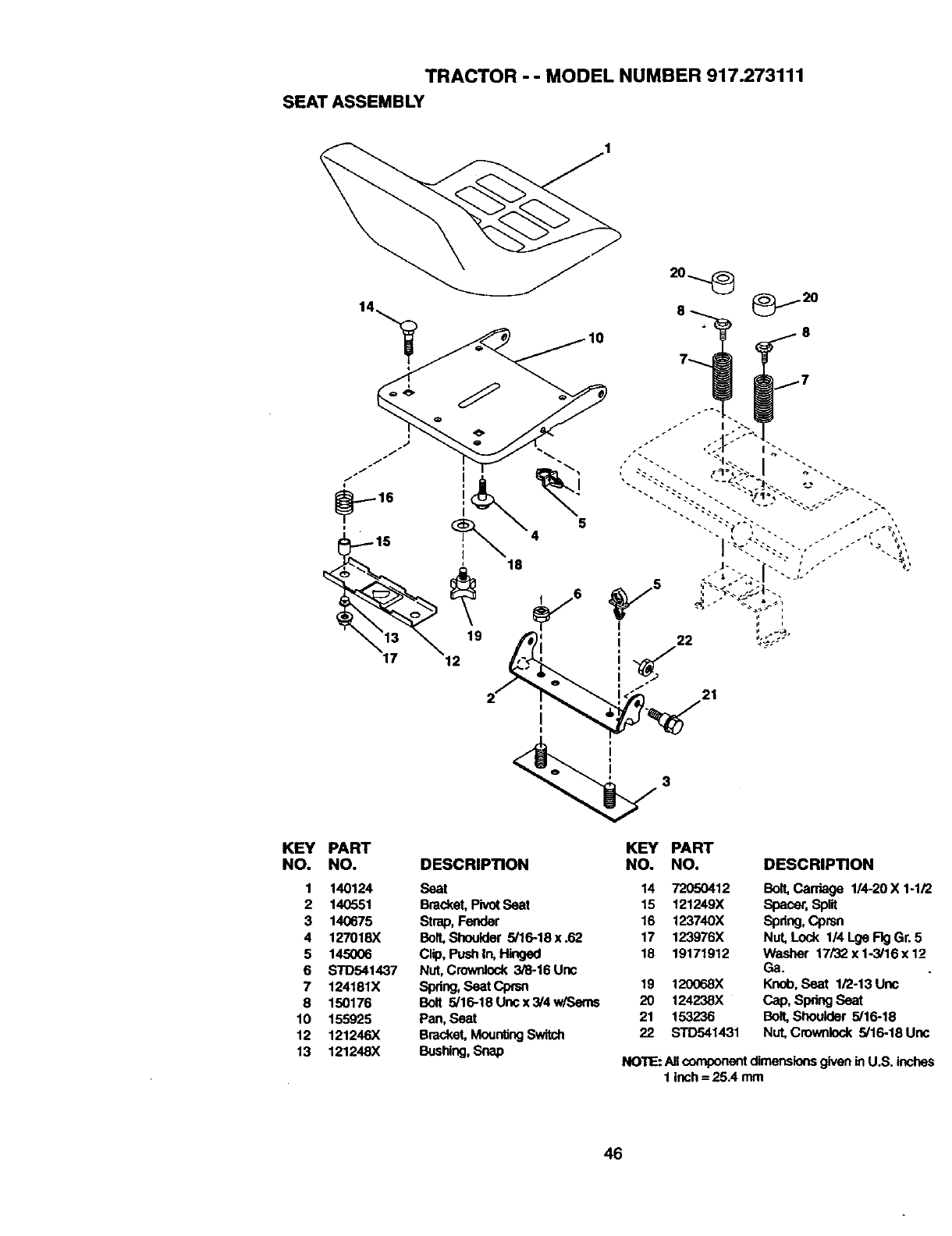
TRACTOR - - MODEL NUMBER 917.273111
SEAT ASSEMBLY
KEY PART KEY PART
NO. NO. DESCRIPTION NO. NO. DESCRIPTION
1 140124 Seat 14 72050412 Bo_Cardage 1/4-20X1-1/2
2 140551 Bracket, PivotSeat 15 121249X Spacer, Split
3 140675 Strap, Fender 16 123740X Spdng, Cprsn
4 127018X Bolt,Shoulder 5/16-18x.62 17 123976X Nut, Lock l/4LgeFlgGr. 5
5 145006 Clip, Pushln, Hinged 18 19171912 Washer 17/32xlo3/16x12
6 STD541437 Nut, Crownlock 3,_-16 Unc Ga.
7 124181X Spdng, SeatCprsn 19 120068X Knob, Seat 1/2-13Unc
8 150176 Bolt 5/16-18Uncx3/4w/Sems 20 124238X Cap, SpdngSeat
10 155925 Pan, Seat 21 153236 Bolt, Shoulder 5/16-18
12 121246X Bracket, MounlJ_ Switch 22 s'rD541431 Nut.Crownlock 5/16-18 Uric
13 121248X Bushing,Snap NOTE: All componentdimensionsgiven in U.S. inches
1 inch= 25.4 mm
46
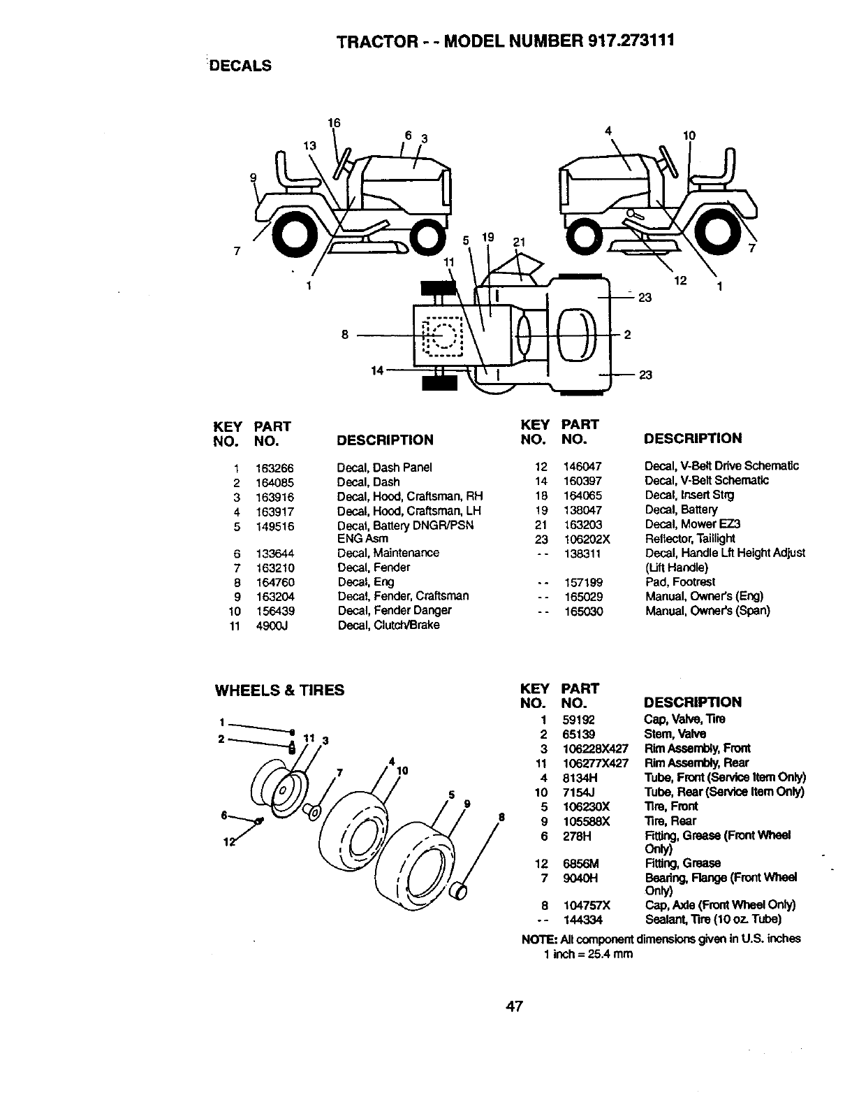
DECALS
TRACTOR --MODEL NUMBER 917.273111
16
6 3
8
21
10
12 1
KEY
NO.
1
2
3
4
5
6
7
8
9
10
11
PART
NO.
163266
164085
163916
163917
149516
133644
163210
164760
163204
156439
4900J
DESCRIPTION
Decal, Dash Panel
Decal, Dash
Decal, Hood, Craftsman, RH
Decal, Hood, Craftsman,LH
Decal, BatteryDNGR/PSN
ENG Asm
Decal, Maintenance
Decal, Fender
Decal, Eng
Decal, Fender,Craftsman
Decal, Fender Danger
Decal, Clutch/Brake
KEY PART
NO. NO.
12 146047
14 160397
18 164065
19 138047
21 163203
23 106202X
- - 138311
--157199
-- 165029
- - 165030
DESCRIPTION
Decal, V-Belt Ddve Schematic
Decal, V-Belt Schematic
Decal, Insert Stag
Decal, Battery
Decal, Mower EZ3
Reflector, Taillight
Decal, Handle Lft HeightAdjust
(Lift Handle)
Pad, Footrest
Manual, Owner's(Eng)
Manual, Owners (Span)
WHEELS & TIRES
7410
59
KEY PART
NO. NO. DESCRIPTION
1 59192 Cap, Valve, Tira
2 65139 Stem, Valve
3 106228x427 RimAseambly, Front
11 106277X427 Rim Assembly,Rear
48134H Tube, Front (ServiceItem Only)
10 7154J Tube, Rear (ServiceItem Only)
5 106230X Tire, Front
9 105588X Tire, Rear
6 278H Fdtlng,Grease (FrontWheel
Only)
12 6856M Rttlng,Grease
7 9040H Beadng, Range (Front Wheal
Onh/)
8 104757X Cap, Axle (FrontWheel Only)
-- 144334 Sealant, Tire (10 07- Tube)
NOTE: All componentdimensionsgivenin U.S. inches
1 inch= 25A mm
47
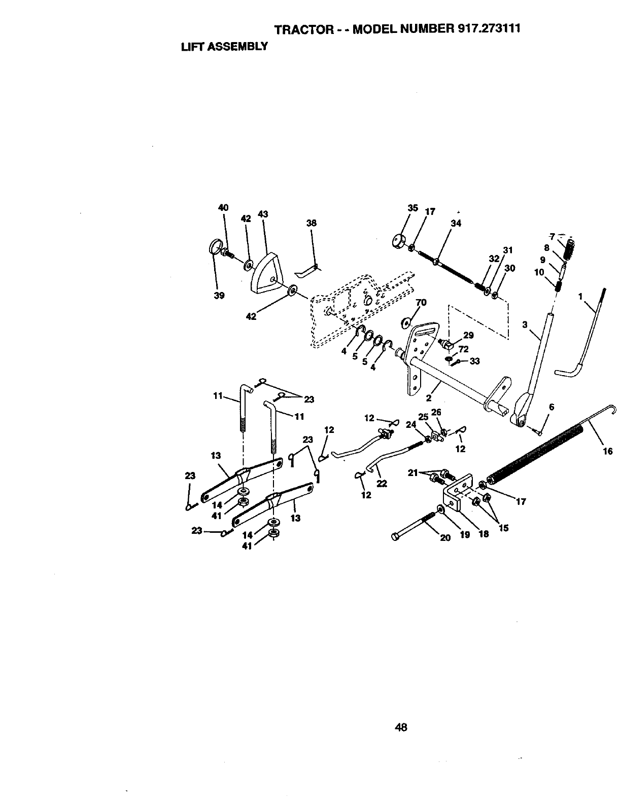
TRACTOR - - MODEL NUMBER 917.273111
LIFT ASSEMBLY
40 43 35 17 34 -7 --'- -
31 8
1
39 1
,, 70
42
23
2
3
\
6
22
12
15
20 19 18
48
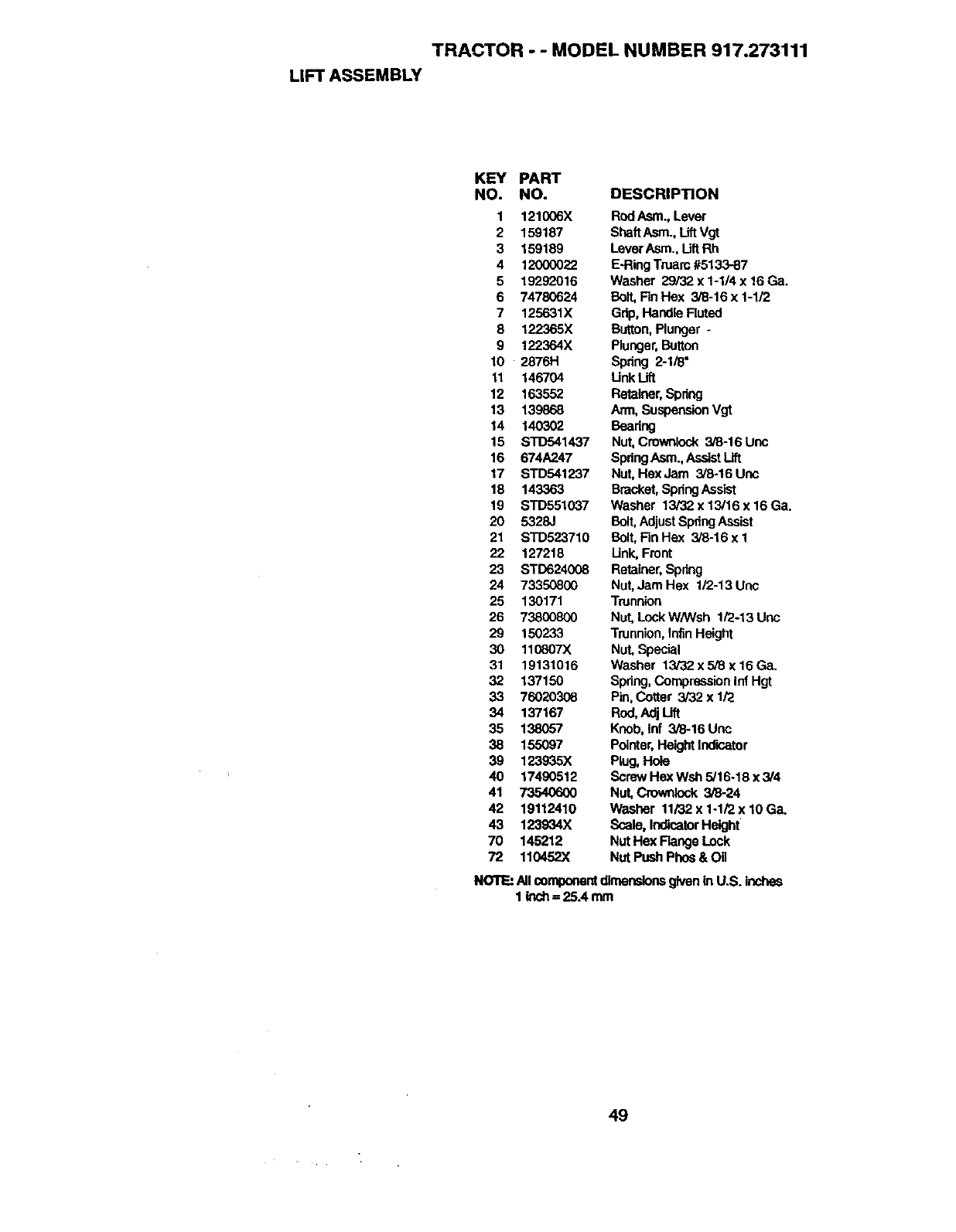
TRACTOR - - MODEL NUMBER 917.273111
LIFT ASSEMBLY
KEY PART
NO. NO. DESCRIPI"ION
1 121006X RodAsm., Lever
2159187 ShaftAsm., LiftVgt
3 159189 LeverAsm., LiftRh
412000022 E-RingTruam #513387
5 19292016 Washer 29/32 x 1-1/4 x 16 Ga.
6 74780624 Bolt,FinHex 3/8-16x1-1/2
7 125631X Grip, Handle Ruted
8 122365X Button,Plunger -
9 122364X Plunger,Button
10 2876H Spring 2-1/8"
11 146704 Unk Lift
12 163552 Retainer,Spdng
13 139868 Arm, SuspensionVgt
14 140302 Bearing
15 STD541437 Nut, Crownlock 3/8-16 Linc
16 674A247 SpdngAsm.,AssistLift
17 STD541237 Nut, HexJam 3/8-16 Unc
18 143363 Bracket,SpdngAssist
19 STD551037 Washer 13/32x13/16x16Ga.
20 5328J Bolt,AdjustSpringAssist
21 STD523710 Bolt,FinHex 3/8-16 x 1
22 127218 Link, Front
23 STD624008 Retainer,Spdng
24 73350800 Nut,Jam Hex 1/2-13 Une
25 130171 Trunnion
26 73800800 Nut, Lock W/Wsh 1/2-13 Unc
29 150233 Trunnion,infin Height
30 110807X Nut, Special
31 19131016 Washer 13/32 x 5/8 x 16 Ga.
32 137150 Spdng, CompressionInf Hgt
33 76020308 Pin, Cotter 3/32 x 1/2
34 137167 Rod,Adj Lift
35 138057 Knob, lnf 3/8-16Unc
38 155097 Pointer,HeightIndicator
39 123935X Plug, Hole
40 17490512 Screw Hex Wsh 5/16-18 x 3/4
41 73540600 Nut, Crownlock 3/8-24
42 19112410 Washer 11/32x1-1i2x10Ga.
43 123934X Scale, IndicatorHeight
70 145212 Nut Hex Flange Lock
72 110452X Nut Push Phos & Oil
NOllF_All componentdimensionsgivenin U.S. inches
1inch = 25A mm
49
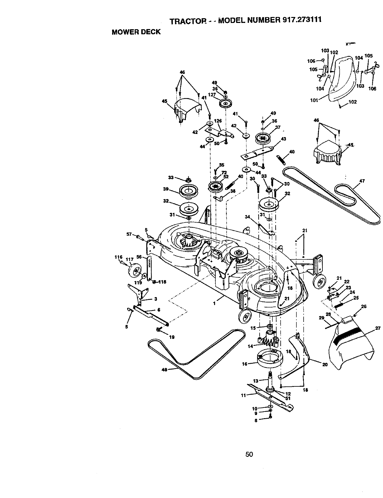
MOWERDECK
45\
TRACTOR - -MODEL NUMBER 917.273111
46
49
12
49
21
116
22
26
,27
18
5O
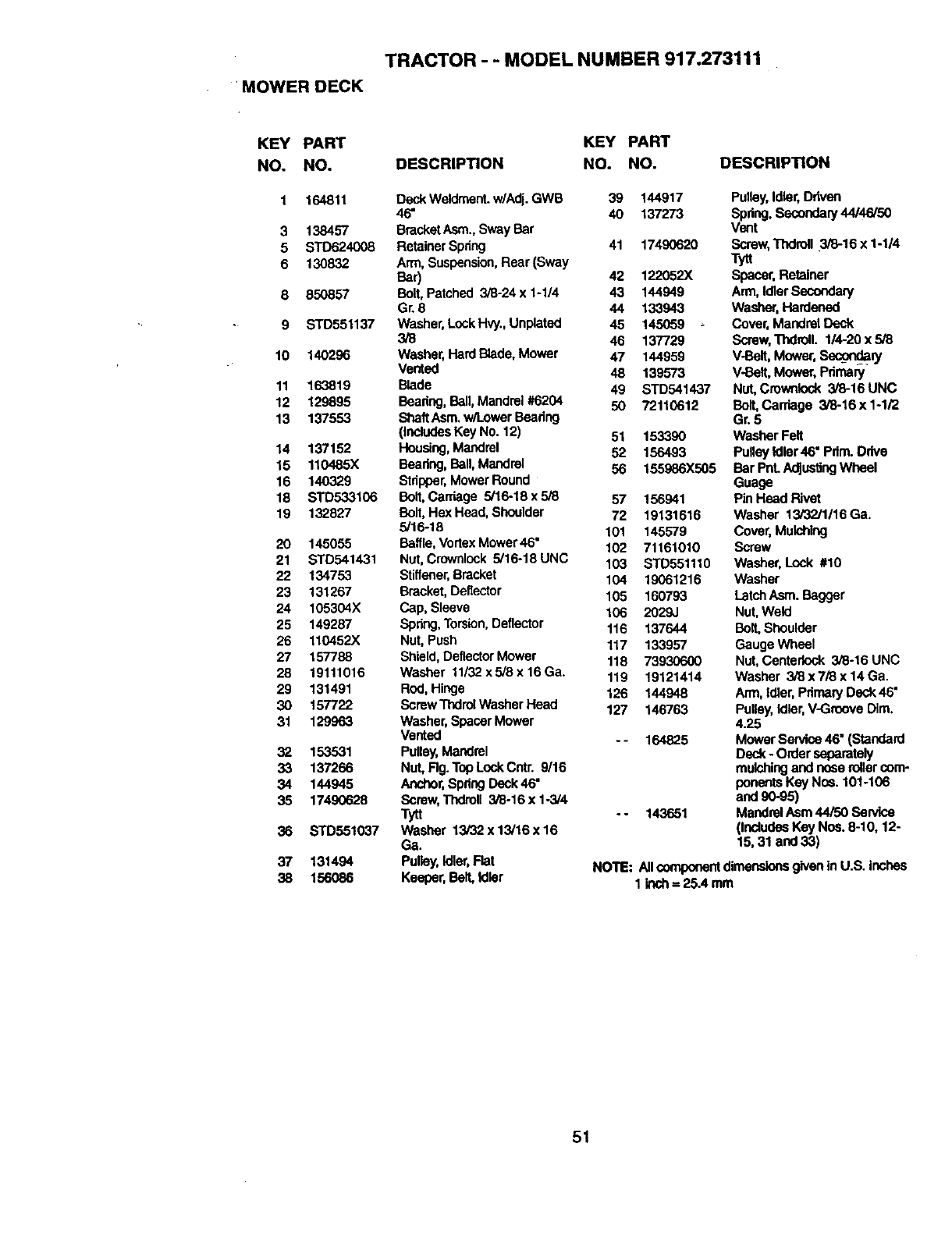
TRACTOR -- MODEL NUMBER 917.273111
MOWER DECK
KEY PART KEY PART
NO. NO. DESCRIPTION NO. NO.
1 164811 DeckWeidment.w/Adj. GWB 39 144917
46" 40 137273
3 138457 BracketAsm.,Sway Bar
5 STD624008 RetainerSpdng 41 17490620
6 130832 Arm, Suspension,Rear (Sway
Bar) 42 122052X
8 850857 Bolt,Patched 3/8-24 x 1-1/4 43 144949
Gr. 8 44 133943
9 STD551137 Washer,Lock HW., Unplated 45 145059
3/8 46 137729
10 140286 Washer, Hard Blade,Mower 47 144959
Vented 48 139573
11 163819 Blade 49 STD541437
12 129895 Beadng, Ball, Mandrel #6204 50 72110612
13 137553 ShaftAsm. w/Lower Beadng
(includesKey No. 12) 51 153390
14 137152 Housing,Mandrel 52 156493
15 110485X Beadng, Ball, Mandrel 56 155986X505
16 140329 Stdpper,Mower Round
18 STD533106 Bolt,Carriage 5/16-18 x 5/8 57 156941
19 132827 Bolt, Hex Head, Shoulder 72 19131616
5/16-18 101 145579
20 145055 Baffle,VortexMower46" 102 71161010
21 STD541431 Nut, Crownlock 5/16-18UNC 103 STD551110
22 134753 Stiffener,Bracket 104 19061216
23 131267 Bracket,Deflector 105 160793
24 105304X Cap, Sleeve 106 2029J
25 149287 Spdng,Torsion,Deflector 115 137644
26 110452X Nut, Push 117 133957
27 157788 Shield, DeflectorMower 118 73930600
28 19111016 Washer 11i32x5/8x16Ga. 119 19121414
29 131491 Rod,Hinge 126 144948
30 157722 Screw ThdrolWasher Head 127 146763
31 129963 Washer, SpacerMower
Vented -- 164825
32 153531 Pulley,Mandrel
33 137266 NUt,Rg. Top LockCntr. 9/16
34 144945 Anchor,Spdng Deck46"
35 17490628 Screw,Thdroll 3/6-16xl-3/4
Tytt - - 143651
36 STD551037 Washer 13/32 x 13/16 x 16
Ga.
37 131494 Pulley,Idler,Flat
38 1560e6 Keeper, Ball Idler
DESCRIPTION
Pulley,Idler,Ddven
Spdng.Secondary44/46/50
Vent
Screw, Thdrofl 3/8-16 x 1-1/4
Tytt
Spacer, Retainer
Arm, IdlerSecondary
Washer, Hardened
Cover, Mandrel Deck
Screw,Tndroll. 1/4-20 x 5/8
V-Belt, Mower, Sec_ian]
V-Bait, Mower, Pdmary
Nut, Cmwdlock 3/8-16 UNC
Bolt,Cardage 3/8-16 x 1-1/2
Gr, 5
Washer Felt
Pulley Idler 46" Pdm. Drive
Bar PnLAdJus_ngWheel
Guage
Pin Head Rivet
Washer 13/32/1/16 Ga.
Cover, Mulching
Screw
Washer, Lock #10
Washer
LatchAsm. Bagger
Nut, Weld
BOIl Shoulder
Gauge Wheel
Nut, Centedock 3/6-16 UNC
Washer 3/8x7i8x 14Ga.
Arm, idler,Pdmary Deck 46"
Pulley,Idler, V-Groove Dim.
4.25
Mower Service 46" (Standard
Deck- Order separately
mulchingand neae rollercom-
ponentsKey Nce. 101-106
and90-95)
Mandrel Asm 44/50 Balvice
(IncludeaKey No6. 8-10, 12-
15, 31 and 33)
NOTE: Allcomponentdimensionsgiven in U.S. inches
1 inch= 25A mm
5t
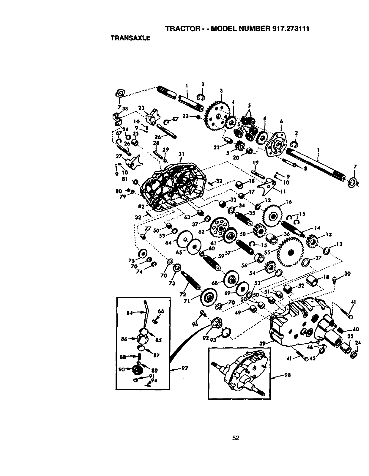
TRANSAXLE
TRACTOR -- MODEL NUMBER 917.273111
3
7
41
52
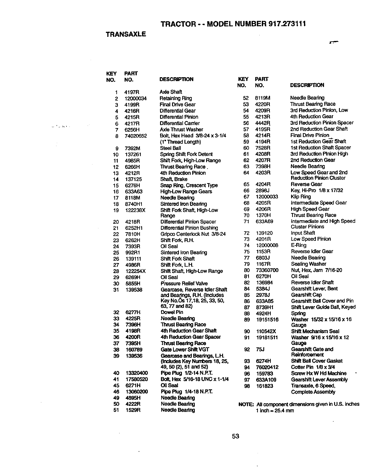
TRANSAXLE
TRACTOR - - MODEL NUMBER 917.273111
KEY PART
NO. NO.
1 4197R
2 12000034
3 4199R
4 4216R
5 4215R
64217R
7 6256H
874020652
9 7392M
10 137261
11 4985R
12 6266H
13 4212R
14 137125
15 6276H
16 633A63
17 8118M
18 8740H1
19 122238X
20 4218R
21 6252H1
22 7810H
23 6262H
24 7393R
25 992R1
26 139111
27 4986R
28 122254X
29 6269H
3O 5855H
31 139538
32 6277H
33 4225R
34 7396H
35 4198R
36 4200R
37 739511
38 160789
39 139536
40 13320400
41 17580520
45 6271H
46 13060200
49 48951"1
50 4222R
51 1529R
DESCRIP11ON KEY PART
NO. NO. DESCRIPTION
A_deShaft
Retaining Ring 52 8119M
Final Dnve Gear 53 4220R
DifferentialGear 54 4209R
DifferentialPinion 55 4213R
DifferentialCarder 56 4442R
AxleThrustWasher 57 4195R
Bolt,Hex Head 3/8-24 x 3-1/4 58 4214R
(1"Thread Length) 59 4194R
Steel Ball 60 7528R
Spdng ShiftFork Detent 61 4208R
Shift Fork, High-LowRange 62 4207R
ThrustBeating Race. 63 7398H
4th Reducl_n Pinion 64 4203R
Shaft, Brake
Snap Ring,CrescentType 65 4204R
High-LowRange Gears 66 2898J
Needle Beadng 67 12000033
SinteredIronBearing 68 4205R
ShiftFork Shaft, High-Low 69 4206R
Range 70 1370H
DifferentialPinionSpacer 71 633A69
DifferentialPinionBushing
GdpeoCentedockNut 3/8-24 72 139120
Shift Fork, R.H. 73 4201R
Oil Seal 74 12000008
SinteredIronBaadng 75 1153R
ShiftForkShaft 77 6803J
Shift Fork, LH. 79 1167R
ShiftShaft, High-LowRange 80 73360700
Oil Seal 81 6270H
PressureReliefValve 82 136984
Gearcese, Reverse Idler Shaft 84 5384J
and Beadngs,R.H. (Includes 85 2978J
Key No.Os 17,18, 25, 33, 50, 86 633A85
63, 77 and 82) 87 8739H1
Dowel Pin 88 4924H
Needie Beadng 89 19151516
Thrust Beedng Race
4th ReductionGear Shaft 90 110542X
4th ReduotlonGear Spacer 91 19181511
ThrustBeadngRace
Gate Lower ShiftVGT 92 75J
Gearceae and Bearings,LH.
(IncludesKey Numbers18, 25, 93 6274H
49, 50 (2), 51 and 52) 94 76020412
Pipe Plug 1/2-14 N.P.T. 96 159783
BolLHex 5/16-18UNCx1-1/4 97 633A109
Oil Seal 98 161823
Pipe Plug 1/4-18 N.P.T.
Needle Beating
Needle Beadng
Needle Beadng
Needle Beadng
Thrust BeadngRace
3rd ReductionPinion, Low
4th ReductionGear
3rd ReductionPinion Spacer
2nd ReductionGear Shaft
Final Drive Pinion
I st ReductionGe_ Shaft
1st ReductionShaftSpacer
3rd ReductionPinionHigh
2nd ReductionGear
Needle Beadng
LowSpeed Gear and 2nd
ReductionPinionCluster
Reverse Gear
Key,Hi-Pro 1/8x 17/32
KlipRing
IntermediateSpeed Gear
HighSpeed Gear
Thrust Beadng Race
Intermediateand HighSpeed
Cluster Pinions
input Shaft
Low Speed Pinion
E-Ring
Reverse IdlerGear
Needle Beadng
Sealing Washer
Nut, Hex, Jam 7/16-20
Oil Seal
Reverse Idler Shaft
GearshiftLever, Bent
GearshiftCap
GearshiftBall Cover and Pin
Shift Lever Guide Ball, Keyed
Spdng
Washer 15/32 x 15/16 x 16
Gauge
Shi_ Mechanism Seal
Washer 9/16 x 15/'16x 12
Gauge
Geamhift Gate and
Reinforcement
ShiftBagCover Gasket
Cotter Pin 1/8 x 3/4
Screw Hx W Hd Machine
GearshiftLever Assembly
Transaxle, 6 Speed,
Complete Assembly
NOTE: All componentdimensionsgivenin U.S. inches
1 inch= 25A mm
53
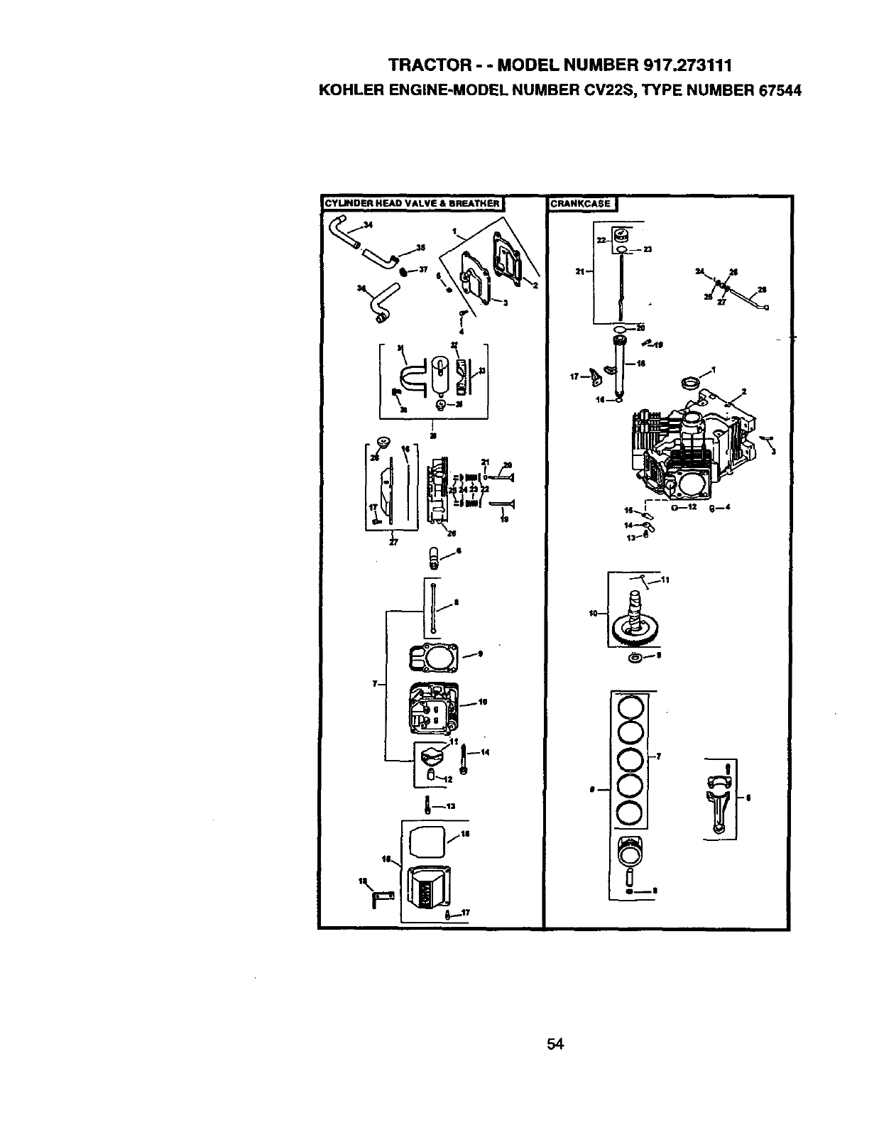
TRACTOR - - MODEL NUMBER 917.273111
KOHLER ENGINE-MODEL NUMBER CV22S, TYPE NUMBER 67544
_fe
_1--13
,\ i=
xI
_,.,J I
e-- _ I|
0i|
54
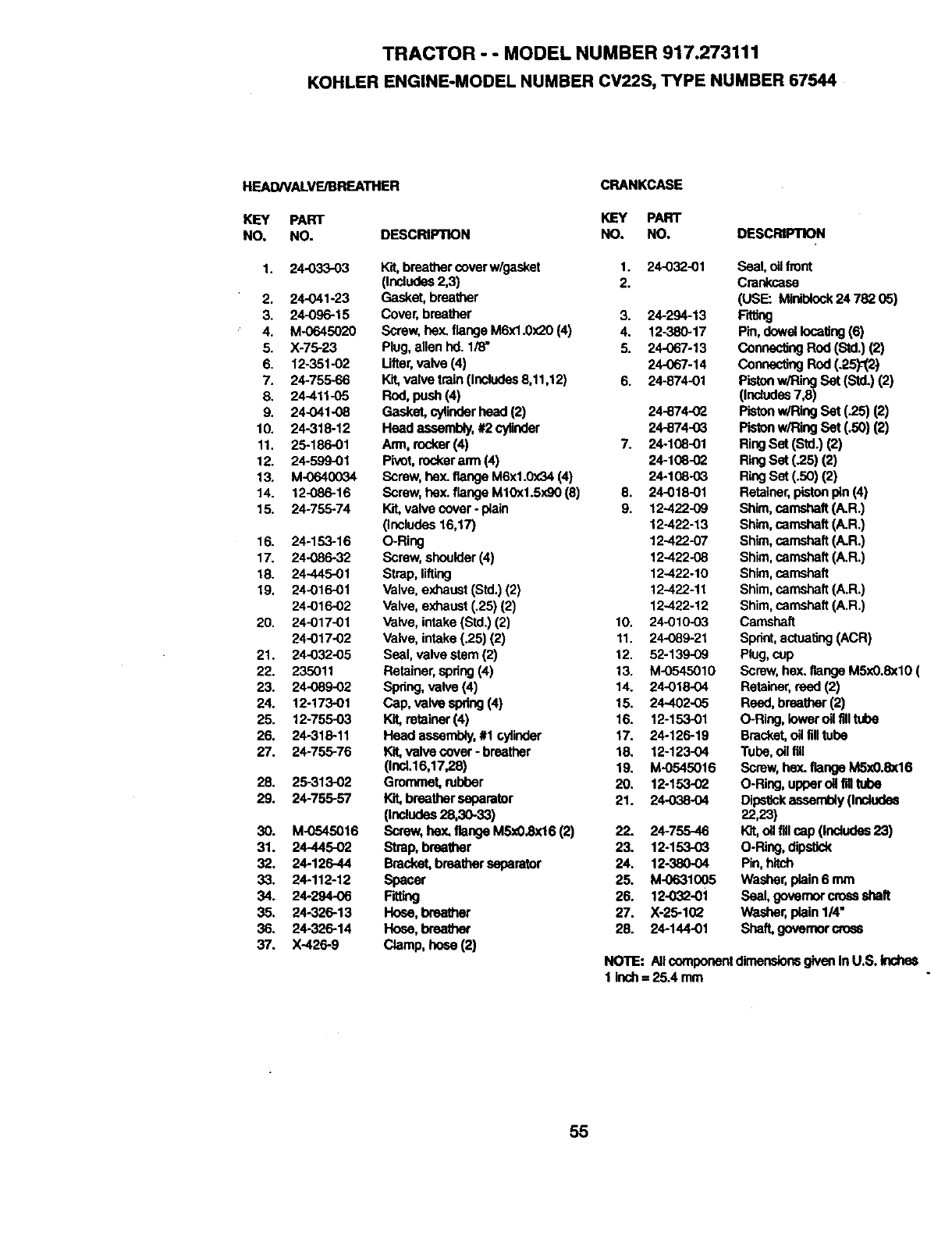
TRACTOR --MODEL NUMBER 917.273111
KOHLER ENGINE-MODEL NUMBER CV22S, TYPE NUMBER 67544
HEAD/VALVE/BREATHER
KEY PART
NO, NO. DESCRIPTION
1.
2,
3.
4.
5.
6.
7.
8.
9.
10.
11.
12.
13.
14.
15.
16.
17.
18.
19.
20.
21.
22.
23.
24.
25.
26.
27.
28.
29.
30.
31.
32.
33.
34.
35,
36.
37.
24-033-03
24-041-23
24-O96-15
M-0645020
X-75-23
12-351-02
24-755-66
24-411-05
24-041-O8
24-318-12
25-186-01
24-599-01
M-0640034
12-086-16
24-755-74
24-153-16
24-086-32
24-445-01
24-01601
24-016-02
24-017-01
24-017-02
24-032-05
235011
24-089-02
12-173-01
12-755-03
24-316-11
24-755-76
26-313-02
24-755-57
M-0545016
24-445-02
24-126-44
24-112-12
24-294-06
24-326-13
24-326-14
X-426-9
Wit,breathercoverw/gasket
(Includes2,3)
Gasket, breather
Cover,breather
Screw, hey..flange M6xl.0x20 (4)
Plug, allen hd. 1/8"
Ufter,valve (4)
K'_ valve train (Includes8,11,12)
Rod,push(4)
Gasket, cylinderhead (2)
Head assembly,#2 cylinder
Arm, rocker (4)
Pivot, rockerarm (4)
Screw,hax. flange M6xl.0x34 (4)
Screw,bex. flange M10x1.5x90 (8)
Kit,valve cover-piain
(Includes16,17)
O-Ring
Screw,shoulder(4)
Strap, lifting
Valve, exhaust(Std.) (2)
Valve, exhaust(`25) (2)
Valve, intake(Std.) (2)
Valve, intake(,25) (2)
Seal, valve stem (2)
Retainer, spdng(4)
Spring, valve(4)
Cap, va_ sprlng(4)
Kit,retainer (4)
Head assembly,#I cylinder
Kit,valve cover - breather
(inoi.16,17,28)
Grommet, rubber
breather separator
(inck_e6 28,30-33)
Screw, hex.flange MSx0.8x16(2)
Strap, breather
Bracket,breatherseparator
spacer
FdtJng
Hose, breather
Hnee, breetber
Clamp, ho¢_ (2)
CRANKCASE
KEY PART
NO. NO. DESCRIPTION
1. 24-032-01 Seal, oil front
2. Crankcase
(USE: Miniblock24 782 05)
3. 24-294-13 FAting
4. 12-380-17 Pin, dowel Iocal_ng(6)
5. 24-067-13 Connec_ng Rod (Std.) (2)
24-067-14 ConnectingRod (.P.5_2)
6. 24-874-01 PistonwiRing Set (Stcl.)(2)
(includes 7,8)
24-874-02 Pistonw/RingSet (,25) (2)
24-874-03 Pistonw/RingSet (.50) (2)
7. 24o108-01 Ring Set (Std.) (2)
24-106--02 RingSet (,25) (2)
24-108-03 RingSet (.50) (2)
8. 24-018-01 Retainer,pistonpin (4)
9. 12-422-09 Shim,camshaft(A.R.)
12-422-13 Shim,camshaft (A.R.)
12-422-07 Shim,camshaft (A.R.)
12-422-08 Shim,camshaft (A,R.)
12-422.10 Shim,camshaft
12-422-11 Shim,camshaft (A.R.)
12-422-12 Shim,camshaft (A,R,)
10. 24-010-03 Camshaft
11. 24089-21 Sprint,actuating (ACR)
12. 52-139-09 Plug, cup
13. M-0545010 Screw,he](.flange M5x0.8xl0 (
14. 24-018-04 Retainer,reed (2)
15. 24-402-05 Reed, breather(2)
16. 12-153-01 O-Ring, ldwer oil fill tube
17. 24-126-19 Bracket,ell filltube
18. 12-123-04 Tube, oilfill
19. M-0545016 Screw,hey..flange M5x0.8x16
20, 12-153-02 O-Ring, upperoilfilltube
21. 24-038-04 DipsW_kassembly(Includes
22,23)
22. 24-755-46 Kit,oil fillcap (Includes 23)
23. 12-153-03 O-Ring, dipsUck
24. 12-380-04 Pin, hitch
25. M-0631005 Washer,plain 6 mm
26. 12-032-01 Seal, govemorcrossshaft
27. X-25-102 Washer,plain 1/4"
28. 24-144-01 Shaft,governor cross
NOTE: Allcomponentdimensionsgiven in U.SoInche_
1 inch= 25.4 mm
55
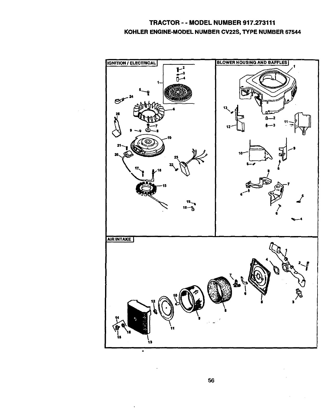
TRACTOR - -MODEL NUMBER 917.273111
KOHLER ENGINE-MODEL NUMBER CV22S, TYPE NUMBER 67544
IGNITION !ELECTRICALJ
19_
18--_
BLOWER HOUSING AND BAFFLES J
/1
• I]
6
|
6
14 |
8
56
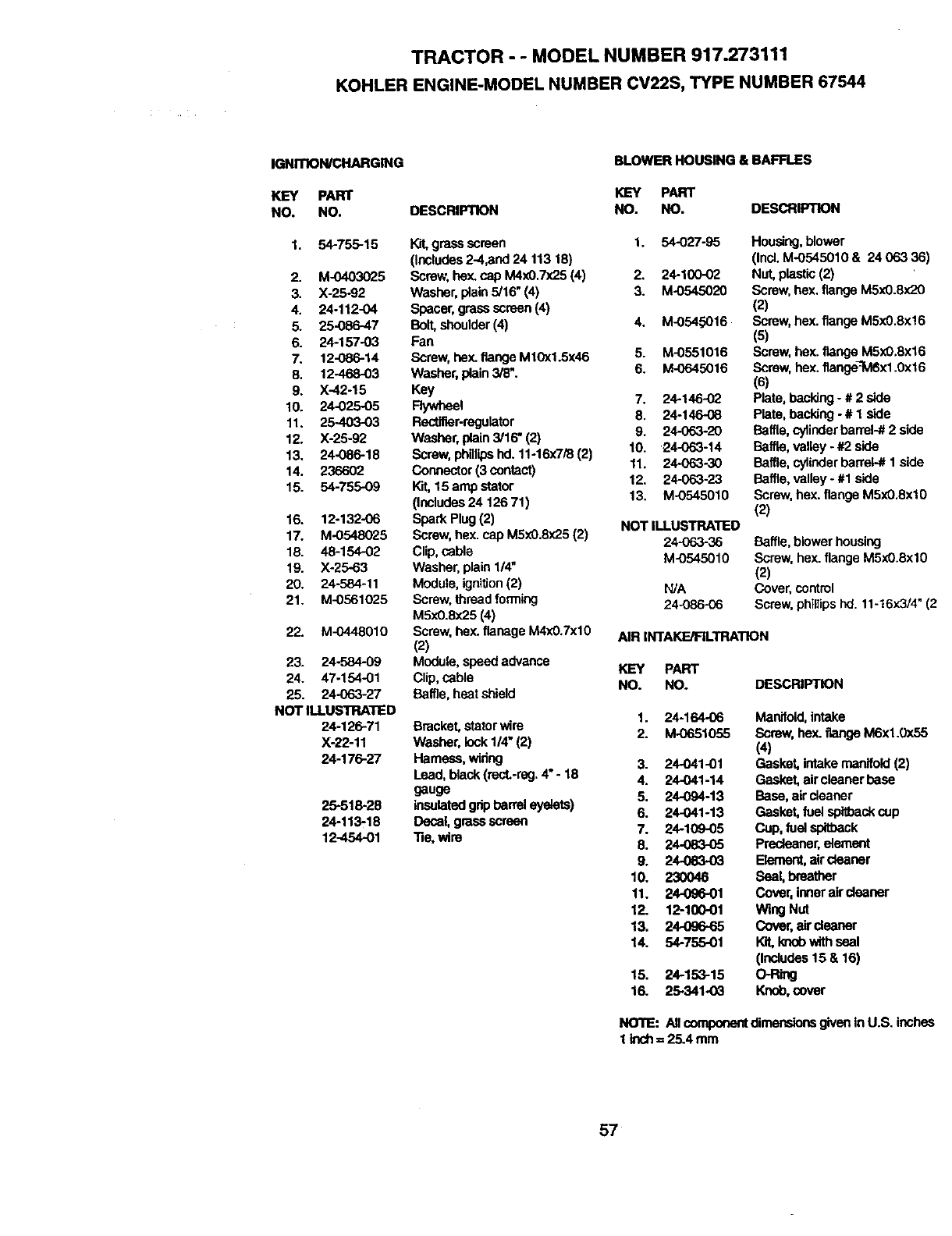
TRACTOR - - MODEL NUMBER 917.273111
KOHLER ENGINE-MODEL NUMBER CV22S, TYPE NUMBER 67544
IGNITION/CHARGING BLOWER HOUSING & BAFFLES
KEY PART KEY PART
NO. NO. DESCRIPTION NO. NO. DESCRIPTION
1. 54-755-15 WJt,grass screen 1. 54-027-95
(Includes2-4,and 24 113 18)
2. M-0403025 Screv,;hey,.cap M4x0,7x25 (4) 2. 24-100-02
3. X-25-92 Washer, plain 5/16"(4) 3. M-0545020
4. 24-112-04 Spacer,grassscreen (4)
5. 25-086-47 Bolt,shoulder(4) 4. M-0545016
6. 24-157-03 Fan
7. 12-086-14 Screw, hex. flange M10x1.5x46 5. M-0551016
8. 12-468-03 Washer,plain 3/8". 6. M-0645016
9. X-42-15 Key
10. 24-025-05 Flywheel 7. 24-14602
11. 25-403-03 Rectifier-regulator 8, 24-146-08
12. X-25-92 Washer, plain3/16" (2) 9. 24-063-20
13. 24-086-18 Screw, phglipshd. 11-16x7/8(2) 10. 24-063-14
14. 236602 Connector(3 contact) 11. 24-063-30
15. 54-755-09 Kit,15 amp stator 12. 24-063.23
(Includes24 126 71) 13. M-0545010
16. 12-132-06 Spark Plug (2) NOT ILLUSTRATED
17. M-0548025 Screw, hex. cap MSx0.8x25(2) 24-963-36
18. 48-154-02 Clip,cable M-0545010
19. X-25-63 Washer, plain1/4"
20. 24-584-11 Module, ignition(2) WA
21. M-0561025 Screw, thread forming 24-086-06
MSx0.8x25 (4)
22. M-0448010 Screw, hex. flanege M4x0.7xl 0 AIR INTAKE/FILTRATION
(2)
23. 24-584-09 Module, speed advance KEY PART
24. 47-154-01 Clip, cable NO. NO.
25. 24-063-27 Baffle, heat shield
NOT ILLUSTRATED
24-126-71 Bracket, statorwire
X-22-11 Washer, lock1/4"(2)
24.176-27 Hameaa,widng
Lead, black (rect.-rag,4" -18
gauge
insulatedgripbarreleyelets)
Decal, grass screen
"i3e,wire
26-518-28
24-113-18
12-454-01
Housing, blower
(Incl.M-O545010 & 24 063 36)
Nut,plastic (2)
Screw, hex.flange M5x0.8x20
(2)
Screw, hex.flange M5x0.Sx!6
(5)
Screw, hex. flange M5x0,8x16
Screw, hex. flange_M6x1.0x16
(6)
Plate, backing- # 2 side
Plate, backing - # 1 side
Baffle, cylinderbarrel-# 2 side
Baffle, valley - #2 side
Baffle,cylinderbarrel-# 1 side
Baffle,valley -#1 side
Screw, hex.flange M5xO.8xl0
(2)
Baffle, blower housing
Screw, hex. flange M5xO.8xl0
(2)
Cover,control
Screw, phillips nd. 11-16x3/4" (2
DESCRIPTION
1. 24-164-06 Manifold,intake
2. M-0651055 Screw, he)(.flange M6xl.0x55
(4)
3. 24-041-01 Gasket,intakemanifold(2)
4. 24-041-14 Gasket,aircleaner base
5. 24-094-13 Base, aircleaner
6. 24-041-13 Gasket, fuel spitbackcup
7. 24-1(79-05 Cup, fuel spltback
8. 24-083-05 Predeaner, element
9. 24-063-03 Element,aircleaner
10. 230046 Seal, breather
11. 24-096-01 Cover, inner aircleaner
12. 12-100-01 Wing Nut
13, 24-096.-65 Cover,air cleaner
14. 54-755-01 Kit,knobwithseal
(Includes15 & 16)
15. 24-153-15 O-Ring
16. 25-341-03 Knob,cover
NO'fiE: All componentdimensionsgiven inU.S. inches
1 kid1= 25.4 mm
57
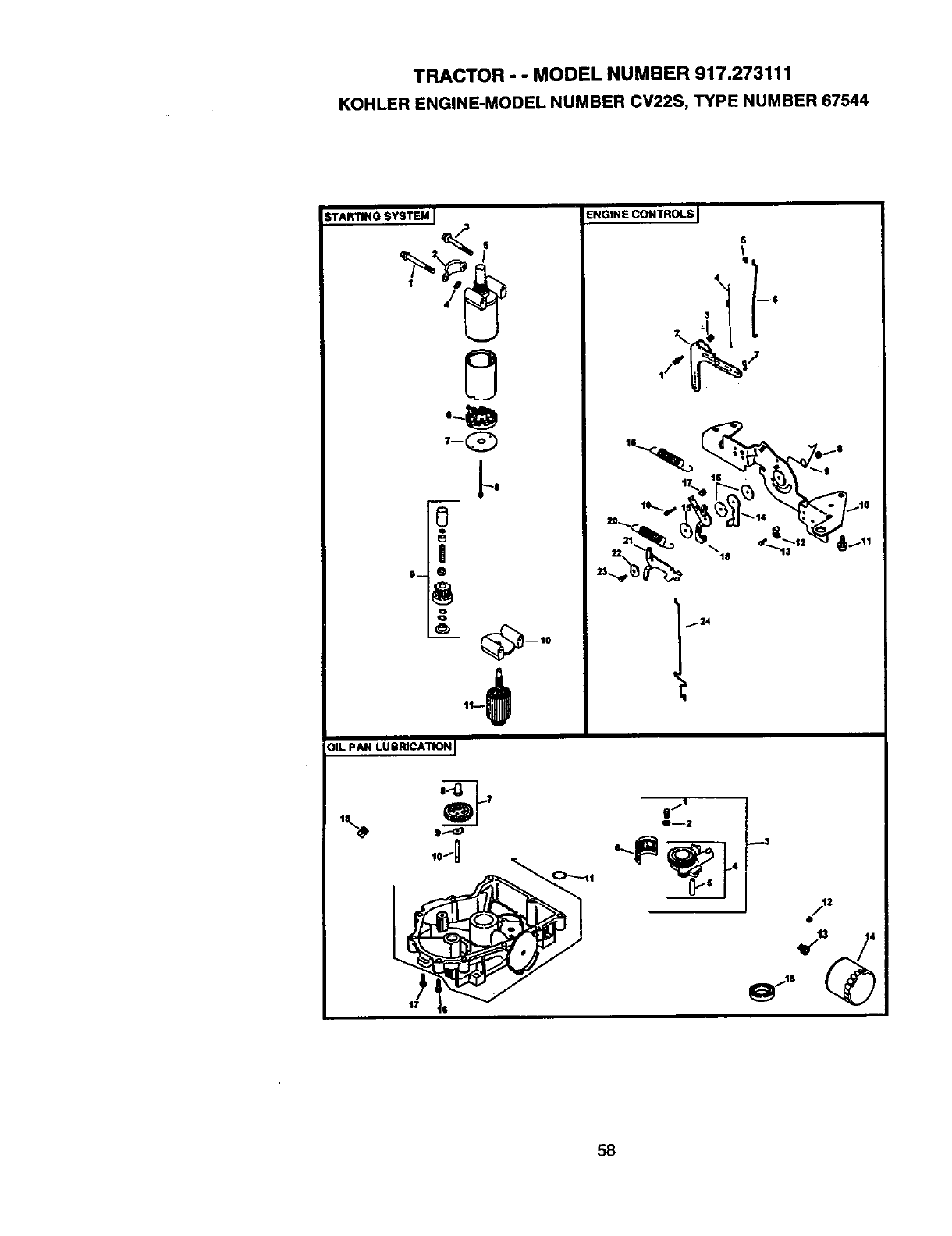
TRACTOR - - MODEL NUMBER 917.273111
KOHLER ENGINE-MODEL NUMBER CV22S, TYPE NUMBER 67544
STARTING SYSTEM J
0
._!
0_,o
[L PAN LUBRICATION J
17
ENGINE CONTROLS J
5
I
l-'4
gfl
e--2
_3
2
58
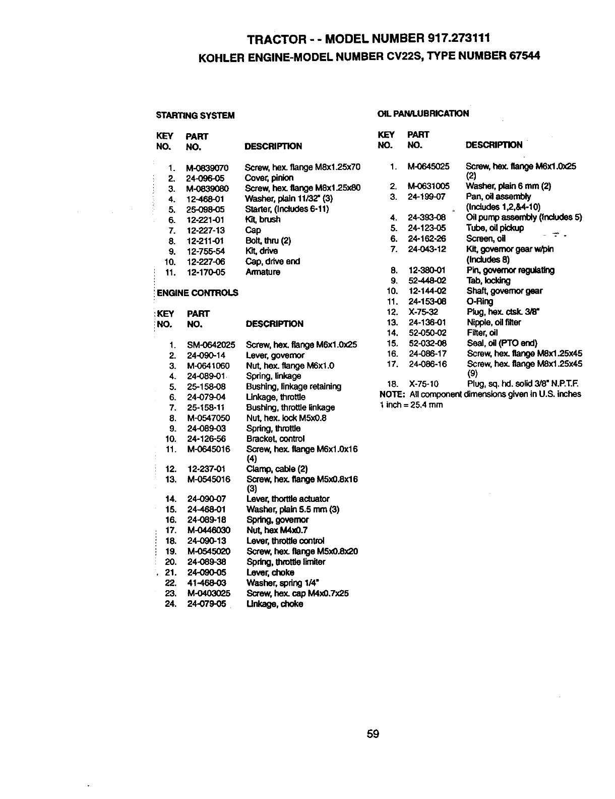
TRACTOR - - MODEL NUMBER 917.273111
KOHLER ENGINE-MODEL NUMBER CV22S, TYPE NUMBER 67544
STARTING SYSTEM
KEY PART
NO. NO.
1. M-0839070
2. 24-096-05
3. M-0839080
4. 12-468-01
5. 25-098-05
6. 12-221-01
7. 12-227-13
8. 12-211-01
9. 12-755-54
10. 12-227-06
: 11. 12-170-05
::ENGINE CONTROLS
KEY PART
NO. NO.
1, SM-0642025
2. 24-090-14
3. M-0641060
4. 24-O89-01
5. 25-158-08
6. 24-079-04
7. 25-158-11
8. M-O547050
9. 24-089-03
10. 24-126-56
11. M-0645016
12. 12-237-01
13. M-0545016
14. 24-090-07
15. 24-468-01
16. 24-089-18
17. M-0446030
18. 24-090-13
19. M-0545020
20. 24-089-38
21. 24-090-05
22. 41-468-03
23. M-04030_.5
24. 24-079-05
OiLPAWLUBR_ATION
KEY PART
DESCRIPTION NO. NO.
Screw, hex.flange M8x1.25x70 1. M-0645025
Cover,pinion
Screw, hey..flange M8x1.25xS0 2. M-0631005
Washer,plain 11/32" (3) 3. 24-19907
Starter,(Includes6-11)
W.d,brush 4. 24-393-08
Cap 5. 24-123-05
Bolt, thru (2) 6. 24-162-26
Kit,drive 7. 24-O43-12
Cap, driveend
An'nature 8, 12-380-01
9. 52-448-02
10. 12-144-02
11. 24-153-08
12. X-75-32
DESCRIPTION 13. 24-136-01
14. 52-050-02
Screw, hex.flange M6x1.0x25 15. 52-032-08
Lever,governor 16. 24-086-17
Nut, he)(.flange M6xl.0 17. 24-086-16
Spring,linkage
Bushing,linkageretaining
Unkage, throttle
Bushing,throttlelinkage
Nut, hex. lockM5x0.8
Spdng,throttle
Bracket,control
Screw, hex. flange M6xl.0x16
(4)
Clamp, cable (2)
Screw, hex.flange M5x0,8x16
(3)
Lever, thorttleactuator
Washer, plain5.5 mm (3)
Spring, govemor
Nut, hexM4x0.7
Lever, throttle control
Screw, hex.flange M5x0.Sx20
Spring, throttlelimiter
Lever, choke
Washer, spdng1/4"
Screw, hex.cap M4x0.7x25
Unkage, choke
DESCRIPTION "
Screw, hex. flange M6x1.0x25
(2)
Washer,plain 6 mm (2)
Pan, oilassembly
(thdudes 1,2,&4-10)
Oil pump asesmbly (thciodes5)
Tube,o_pickup
Screen, og
Kit,governorgearw/pth
(Includes8)
P_ geve._ mgCaeng
Tab, Ioddng
Shaft, governorgear
O-Ring
Piog, hex.ctsk.3/8"
Nipple, ollfilter
Filter,oil
Seal, oll(PTO end)
Screw, hex.flange MSx1.25x45
Screw, hex.flange MSx1.25x45
(s)
18. Xo75-10 Plug, sq. hd. solid3/8"N.P.T.F.
NOTE: NI componentdimensionsgivenin U.S. inches
1 inch = 25.4 mm
59
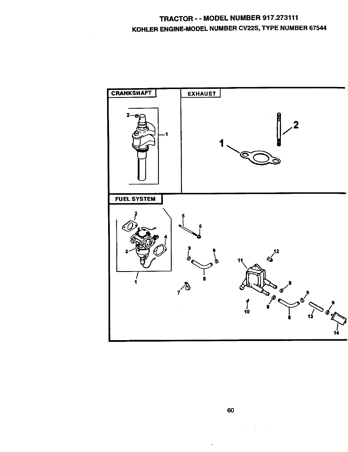
TRACTOR -- MODEL NUMBER 917.273111
KOHLERENGINE-MODELNUMBERCV22S,TYPENUMBER67544
CRANKSHAFT [
--1
EXHAUST I
1
FUEL SYSTEM I
2 \
3
!
1
9 g
8
/g
7
14
6O
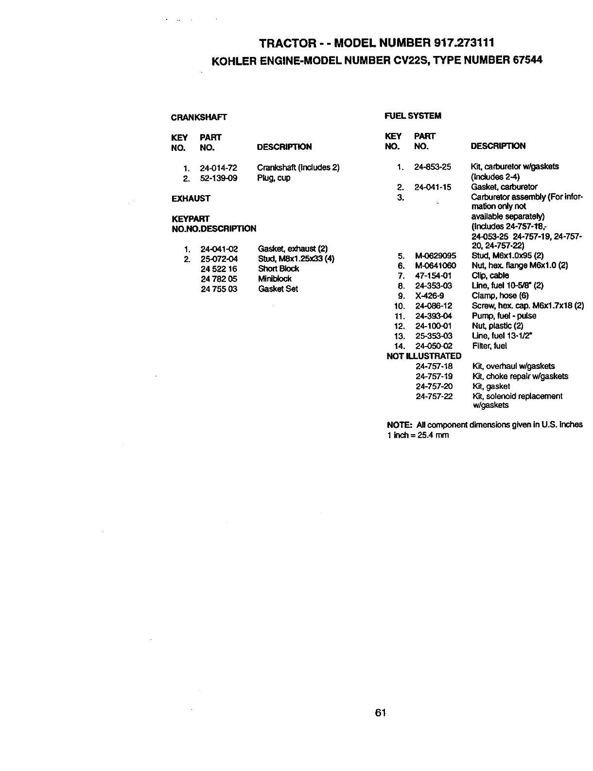
TRACTOR - - MODEL NUMBER 917.273111
KOHLER ENGINE-MODEL NUMBER CV22S, TYPE NUMBER 67544
CRANKSHAFT
KEY PART
NO. NO.
1. 24-014-72
2. 52-139-09
EXHAUST
KEYPART
NO.NO.DESCRIPTION
1. 24-O41-02
2. 25-072-04
24 522 16
2478205
24 755 03
DESCRIPTION
Crankshaft(Includes2)
Plug, cup
Gasket,exhaust(2)
Stud,M8x1.25x33 (4)
ShortBlock
Miniblock
Gasket Set
FUEL SYSTEM
KEY PART
NO. NO. DESCRIPTION
1. 24-853-25
2. 24-041-15
3.
5. M-0629095
6. M-0641060
7. 47-154-01
8. 24-353-03
9. X-426-9
10. 24-086-12
11. 24-393-04
12. 24-100-o1
13. 25-353-03
14. 24-050-02
NOT ILLUSTRATED
24-757-18
24-757-19
24-757-20
24-757-22
Kit,carburetorw/gaskets
(includes2-4)
Gasket, carburetor
Carburetorassembly(For infer-
mariononly not
availableseparately)
(Includes24.757-1_8;
24-053-25 24-757-19, 24-757-
20, 24-757-22)
Stud,M6x1.0x95 (2)
Nut, hey=flange M6xl.0 (2)
Clip,cable
Une, fuel 10-5/8" (2)
Clamp, hose (6)
Screw,hex. cap.M6x1.7x18 (2)
Pump,fuel - pulse
Nut,plastic(2)
Line,fuel 13-1/2"
Filter,fuel
Kit,overhaulw/gaskets
Kit,chokerepairw/gaskets
Kit, gasket
Kit,solenoidreplacement
w/gaskets
NOTE: Allcomponentdimensionsgiven in U.S. inches
1 inch= 25.4 mm
61

SUGGESTED GUIDE FOR SIGHTING SLOPES FOR SAFE OPERATION
,_r _ONLY RIDE UP AND DOWN HILL,
NOT ACROSS HILL
• ,j
A Operate your Tractor up and down the face of slopes (not_i
II _greater thsn15O), never across the face. Make turns gradu -
III _ally to prevent tipping or loss of control. Exercise extreme
Icaution when changing direction on slopes.
-- III III

63

Forthe repairor replacementpartsyouneed
delivereddirectlyto yourhome
Call7am - 7 pm, 7 days aweek
1-800-366-PART
(1-800-366-7278)
Para ordenar piezas con entrega a
domicilio - 1-800-659-7084
For in-house major brand repair service
Call 24 hours a day, 7 days a week
1-800-4-REPAIR
(1-800-473-7274)
Para pedir servicio de reparaci6n a
domicilio - 1-800-676o5811
For the location of a Sears Parts and
Repair Center in your area
Call 24 hours a day, 7 days a week
1-800-488-1222
For information on purchasing a Sears
Maintenance Agreement or to inquire
about an existing Agreement
Call 9 am - 5 pm, Monday-Saturday
1-800-827-6655
mmmmmm
mmmmmm
When requesting service or ordering
parts, always provide the following
information:
•Product Type •Part Number
•Model Number °Part Description
SE ARS
America's Repair Specialists
165029 Rev.3 07.28.98 VB/SJ/RD PdntedinU.SJ
