Craftsman 917370733 User Manual LAWN MOWER Manuals And Guides L0604692
CRAFTSMAN Walk Behind Lawnmower, Gas Manual L0604692 CRAFTSMAN Walk Behind Lawnmower, Gas Owner's Manual, CRAFTSMAN Walk Behind Lawnmower, Gas installation guides
User Manual: Craftsman 917370733 917370733 CRAFTSMAN LAWN MOWER - Manuals and Guides View the owners manual for your CRAFTSMAN LAWN MOWER #917370733. Home:Lawn & Garden Parts:Craftsman Parts:Craftsman LAWN MOWER Manual
Open the PDF directly: View PDF ![]() .
.
Page Count: 48
Owner's Manual
(RRFTSMRN °
ROTARY LAWN MOWER
6.75 Horsepower
Power-Propelled
21" Multi-Cut
Model No.
917.370733
•EspaSol, p. 20
CAUTION:
Read and follow all
Safety Rules and Instructions
before operating this equipment
Sears, Roebuck and Co., Hoffman Estates, IL 60179
Visit our Craftsman website: www.sears.com/craftsman
U.S.A.
Warranty ................................................... 2
Safety Rules .......................................... 2-4
Product Specifications .............................. 4
Assembly !Pre-Operation ..................... 6-7
Operation ............................................. 8-12
Maintenance Schedule ........................... 13
Maintenance ...................................... 13-16
Service and Adjustments ................... 16-17
Storage .............................................. 17-18
Troubleshooting ................................. 18-19
Repair Parts ....................................... 38-45
Sears Service .......................... Back Cover
2-YEAR FULL WARRANTY ON CRAFTSMAN LAWN MOWER
If this Craftsman Lawn Mower fails due to manufacturer defects in material or
workmanship within two years from the date of purchase, return it to any Sears store,
Parts & Repair Center or other Craftsman outlet for free repair (or replacement if repair
proves impossible).
This warranty applies for only 90 days from the date of purchase if this Lawn Mower is
ever used for commercial or rental purposes.
This warranty does not cover:
Expendable items that become worn during normal use, such as rotary mower
blades, blade adapters, belts, air cleaners and spark plug.
Repairs necessary because of operator abuse or negligence, including bent
crackshafts and the failure to assemble, operate or maintain this Lawn Mower
according to all supplied product instructions.
This warranty applies only while this product is used in the United States.
This warranty gives you specific legal rights, and you may also have other rights which
vary from state to state.
Sears, Roebuck and Co., Hoffman Estates, IL 60179
IMPORTANT: This cutting machine is capable of amputating hands and feet and throw-
ing objects. Failure to observe the following safety instructions could result in serious
injury or death.
&Look for this symbol to point out impor-
tant safety precautions. It means
CAUTION!!! BECOME ALERT!!!
YOUR SAFETY IS INVOLVED.
& WARNING: In order to prevent ac-
cidental starting when setting up, trans-
porting, adjusting or making repairs,
always disconnect spark plug wire and
place wire where it cannot come in contact
with plug.
&WARNING: Engine exhaust, some of its
constituents, and certain vehicle components
contain or emit chemicals known to the State
of California to cause cancer and birth defects
or other reproductive harm.
&WARNING: Battery posts, terminals and
related accessories contain lead and lead
compounds, chemicals known to the State
of California to cause cancer and birth
defects or other reproductive harm. Wash
hands after handling.
_:_ CAUTION: Muffler and other engine
parts become extremely hot during
operation and remain hot after engine has
stopped. To avoid severe burns on contact,
stay away from these areas.
2
I. GENERAL OPERATION
• Read, understand, and follow all
instructions on the machine and in the
manual(s) before starting. Be thoroughly
familiar with the controls and the proper
use of the machine before starting.
• Do not put hands or feet near or under
rotating parts. Keep clear of the dis-
charge opening at all times.
• Only allow responsible individuals, who
are familiar with the instructions, to oper-
ate the machine.
• Clear the area of objects such as rocks,
toys, wire, bones, sticks, etc., which
could be picked up and thrown by blade.
• Be sure the area is clear of other people
before mowing. Stop machine if anyone
enters the area.
• Do not operate the mower when bare-
foot or wearing open sandals. Always
wear substantial foot wear.
• Do not pull mower backwards unless
absolutely necessary. Always look down
and behind before and while moving
backwards.
• Never direct discharged material toward
anyone. Avoid discharging material
against a wall or obstruction. Material
may richochet back toward the opera-
tor. Stop the blade when crossing gravel
surfaces.
• Do not operate the mower without
proper guards, plates, grass catcher or
other safety protective devices in place.
• See manufacturer's instructions for
proper operation and installation of
accessories. Only use accessories ap-
proved by the manufacturer.
• Stop the blade(s) when crossing gravel
drives, walks, or roads.
• Stop the engine (motor) whenever you
leave the equipment, before cleaning the
mower or unclogging the chute.
• Shut the engine (motor) off and wait until
the blade comes to complete stop before
removing grass catcher.
• Mow only in daylight or good artificial
light.
• Do not operate the machine while under
the influence of alcohol or drugs.
• Never operate machine in wet grass.
Always be sure of your footing: keep a
firm hold on the handle; walk, never run.
• Disengage the self-propelled mech-
anism or drive clutch on mowers so
equipped before starting the engine.
• If the equipment should start to vibrate
abnormally, stop the engine (motor) and
check immediately for the cause. Vibra-
tion is generally a warning of trouble.
• Always wear safety goggles or safety
glasses with side shields when operating
mower.
II. SLOPE OPERATION
Slopes are a major factor related to slip &
fall accidents which can result in severe in-
jury. All slopes require extra caution. If you
feel uneasy on a slope, do not mow it.
DO:
• Mow across the face of slopes: never
up and down. Exercise extreme caution
when changing direction on slopes.
• Remove obstacles such as rocks, tree
limbs, etc.
• Watch for holes, ruts, or bumps. Tall
grass can hide obstacles.
DO NOT:
• Do not trim near drop-offs, ditches or
embankments. The operator could lose
footing or balance.
• Do not trim excessively steep slopes.
• Do not mow on wet grass. Reduced foot-
ing could cause slipping.
III. CHILDREN
Tragic accidents can occur if the operator
is not alert to the presence of children.
Children are often attracted to the machine
and the mowing activity. Never assume
that children will remain where you last
saw them.
• Keep children out of the trimming area
and under the watchful care of another
responsible adult.
• Be alert and turn machine off if children
enter the area.
• Before and while walking backwards,
look behind and down for small children.
• Never allow children to operate the ma-
chine.
• Use extra care when approaching blind
corners, shrubs, trees, or other objects
that may obscure vision.
IV. SAFE HANDLING OF GASOLINE
Use extreme care in handling gasoline.
Gasoline is extremely flammable and the
vapors are explosive.
• Extinguish all cigarettes, cigars, pipes
and other sources of ignition.
• Use only an approved container.
• Never remove gas cap or add fuel with
the engine running. Allow engine to cool
before refueling.
• Never refuel the machine indoors.
• Never store the machine or fuel contain-
er where there is an open flame, spark
or pilot light such as a water heater or on
other appliances.
• Neverfill containersinsidea vehicle,on
a truck or trailerbed with a plastic liner.
Alwaysplacecontainerson the ground
awayfrom yourvehiclebeforefilling.
• Removegas-poweredequipmentfrom
the truck or trailer and refuel it on the
ground. Ifthis is not possible,then
refuel suchequipmentwith a portable
container,ratherthanfrom a gasoline
dispensernozzle.
• Keepthe nozzlein contactwiththe rim
of the fuel tank or containeropeningat
all timesuntil fueling is complete. Do
not use a nozzlelock-opendevice.
• Iffuel isspilled on clothing,change
clothingimmediately.
• Neveroverfillfuel tank. Replacegas
cap and tightensecurely.
V. GENERAL SERVICE
• Never run a machine inside a closed
area.
• Never make adjustments or repairs with
the engine (motor) running. Disconnect
the spark plug wire, and keep the wire
away from the plug to prevent accidental
starting.
• Keep nuts and bolts, especially blade
attachment bolts, tight and keep equip-
ment in good condition.
• Never tamper with safety devices. Check
their proper operation regularly.
• Keep machine free of grass, leaves, or
other debris build-up. Clean oil or fuel
spillage. Allow machine to cool before
storing.
• Stop and inspect the equipment if you
strike an object. Repair, if necessary,
before restarting.
• Never attempt to make wheel height
adjustments while the engine is running.
• Grass catcher components are subject
to wear, damage, and deterioration,
which could expose moving parts or
allow objects to be thrown. Frequently
check components and replace with
manufacturer's recommended parts,
when necessary.
• Mower blades are sharp and can cut.
Wrap the blade(s) or wear gloves, and
use extra caution when servicing them.
• Do not change the engine governor set-
ting or overspeed the engine.
• Maintain or replace safety and instruc-
tion labels, as necessary.
AWARNING: This lawn mower is equipped with an internal combustion engine and
should not be used on or near any unimproved forest-covered, brush-covered or
grass-covered land unless the engine's exhaust system is equipped with a spark
arrester meeting applicable local or state laws (if any). If a spark arrester is used, it
should be maintained in effective working order by the operator.
In the state of California the above is required by law (Section 4442 of the California
Public Resources Code). Other states may have similar laws. Federal laws apply on
federal lands. A spark arrester for the muffler is available through your nearest Sears
Parts & Repair Center (See the REPAIR PARTS section of this manual).
Serial Number:
Date of Purchase:
Gasoline Capacity /Type: 1.6 Quarts (Unleaded Regular)
Oil Type (API SG-SL): SAE 30 (above 32°F); SAE 5W-30 (below 32°F)
Oil Capacity: 20 Ounces
Spark Plug (Gap: .030") Champion RJ19HX
Blade Bolt Torque: 35-40 ft. Ibs.
• The model and serial numbers will be found on a decal on the rear of the lawn mower
housing. Record both serial number and date of purchase in space provided above.
4
Repair Protection Agreements
Congratulations on making a smart pur-
chase. Your new Craftsman® product is
designed and manufactured for years of
dependable operation. But like all prod-
ucts, it may require repair from time to
time. That's when having a Repair Protec-
tion Agreement can save you money and
aggravation.
Purchase a Repair Protection Agreement
now and protect yourself from unexpected
hassle and expense.
Here's what's included in the Agreement:
• Expert service by our 12,000 profe-
sional repair specialists.
• Unlimited service and no charge for
parts and labor on all covered repairs.
• Product replacement if your covered
product can't be fixed.
• Discount of 10% from regular price of
service and service-related parts not
covered by the agreement; also, 10%
off regular price of preventive mainte-
nance check.
• Fast help by phone- phone sup-
port from a Sears representative on
products requiring in-home repair, plus
convenient repair scheduling.
Once you purchase the Agreement, a
simple phone call is all that it takes for you
to schedule service. You can call anytime
day or night, or schedule a service ap-
pointment online.
Sears has over 12,000 professional repair
specialists, who have access to over 4.5
million quality parts and accessories.
That's the kind of professionalism you can
count on to help prolong the life of your
new purchase for years to come. Purchase
your Repair Protection Agreement today!
Some limitations and exclusions apply.
For prices and additional information
call 1-800-827-6655.
Sears Installation Service
For Sears professional installation of home
appliances, garage door openers, water
heaters, and other major home items, in
the U.S.A. call 1-800-4-MY-HOME®.
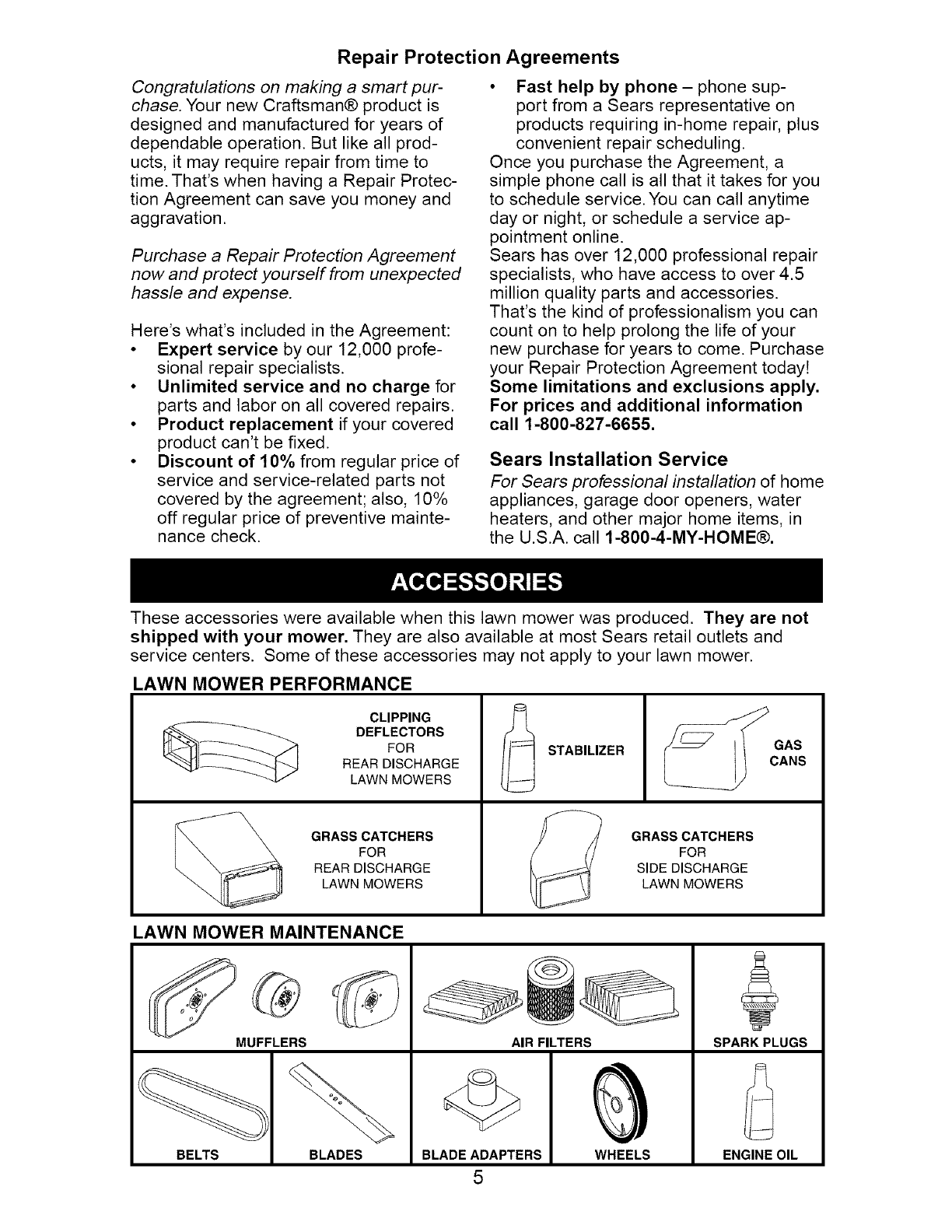
These accessories were available when this lawn mower was produced. They are not
shipped with your mower. They are also available at most Sears retail outlets and
service centers. Some of these accessories may not apply to your lawn mower.
LAWN MOWER PERFORMANCE
CLIPPING
DEFLECTORS
FOR
REAR DISCHARGE
LAWN MOWERS
GRASS CATCHERS
FOR
REAR DISCHARGE
LAWN MOWERS
STABILIZER
GRASS CATCHERS
FOR
SIDE DISCHARGE
LAWN MOWERS
LAWN MOWER MAINTENANCE
MUFFLERS
BELTS BLADES
AIR FILTERS
BLADE ADAPTERS
5
WHEELS
SPARK PLUGS
ENGINE OIL
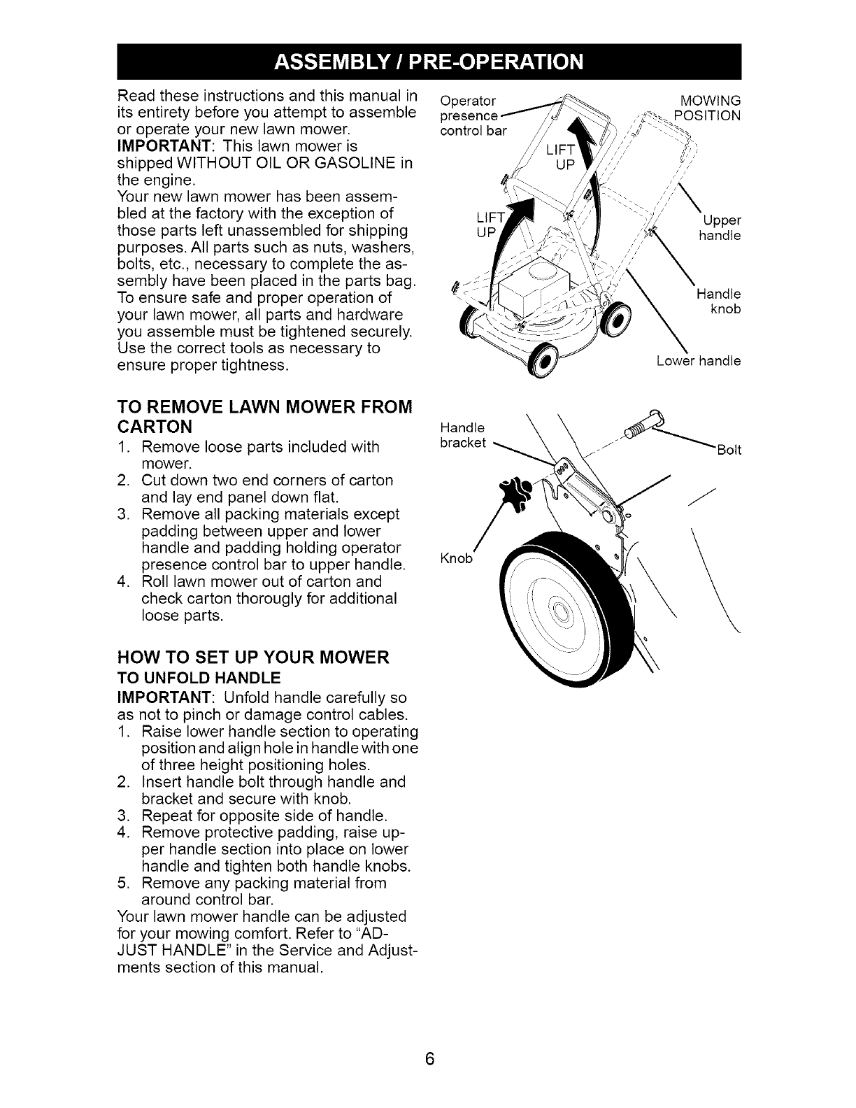
Read these instructions and this manual in Operator
its entirety before you attempt to assemble I
or operate your new lawn mower, control bar
IMPORTANT: This lawn mower is
shipped WITHOUT OIL OR GASOLINE in
the engine.
Your new lawn mower has been assem-
bled at the factory with the exception of
those parts left unassembled for shipping UP
purposes. All parts such as nuts, washers,
bolts, etc., necessary to complete the as-
sembly have been placed in the parts bag.
To ensure safe and proper operation of _ "
your lawn mower, all parts and hardware
you assemble must be tightened securely.
Use the correct tools as necessary to
ensure proper tightness.
/
//
///
MOWING
POSITION
Upper
handle
Handle
knob
Lower handle
TO REMOVE LAWN MOWER FROM
CARTON Handle
1. Remove loose parts included with bracket
mower.
2. Cut down two end corners of carton
and lay end panel down flat.
3. Remove all packing materials except
padding between upper and lower
handle and padding holding operator
presence control bar to upper handle. Knob
4. Roll lawn mower out of carton and
check carton thorougly for additional
loose parts.
HOW TO SET UP YOUR MOWER
TO UNFOLD HANDLE
IMPORTANT: Unfold handle carefully so
as not to pinch or damage control cables.
1. Raise lower handle section to operating
position and align hole in handle with one
of three height positioning holes.
2. Insert handle bolt through handle and
bracket and secure with knob.
3. Repeat for opposite side of handle.
4. Remove protective padding, raise up-
per handle section into place on lower
handle and tighten both handle knobs.
5. Remove any packing material from
around control bar.
Your lawn mower handle can be adjusted
for your mowing comfort. Refer to "AD-
JUST HANDLE" in the Service and Adjust-
ments section of this manual.
"Bolt
2
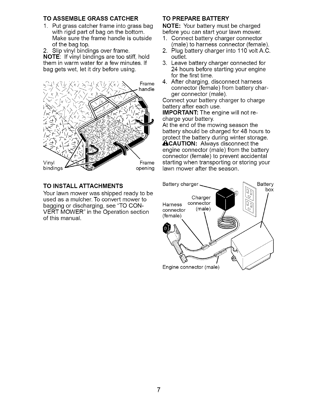
TO ASSEMBLE GRASS CATCHER
1. Put grass catcher frame into grass bag
with rigid part of bag on the bottom.
Make sure the frame handle is outside
of the bag top.
2. Slip vinyl bindings over frame.
NOTE: If vinyl bindings are too stiff, hold
them in warm water for a few minutes. If
bag gets wet, let it dry before using.
Vinyl Frame
bindings opening
TO PREPARE BATTERY
NOTE: Your battery must be charged
before you can start your lawn mower.
1. Connect battery charger connector
(male) to harness connector (female).
2. Plug battery charger into 110 volt A.C.
outlet.
3. Leave battery charger connected for
24 hours before starting your engine
for the first time.
4. After charging, disconnect harness
connector (female) from battery char-
ger connector (male).
Connect your battery charger to charge
battery after each use.
IMPORTANT: The engine will not re-
charge your battery.
At the end of the mowing season the
battery should be charged for 48 hours to
,_otect the battery during winter storage.
CAUTION: Always disconnect the
engine connector (male) from the battery
connector (female) to prevent accidental
starting when transporting or storing your
lawn mower after the season.
TO INSTALL ATTACHMENTS
Your lawn mower was shipped ready to be
used as a mulcher. To convert mower to
bagging or discharging, see "TO CON-
VERT MOWER" in the Operation section
of this manual.
Batter, Battery
box
Charger
Harness connector
connector (male)
(female)
Engine connector (male)
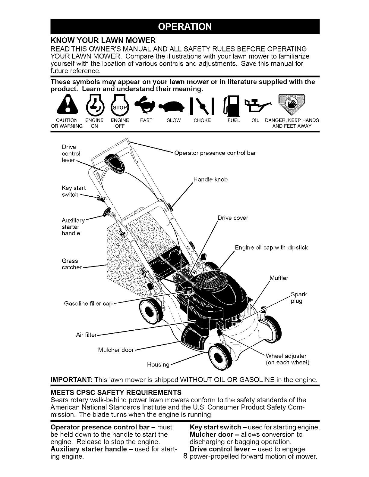
KNOW YOUR LAWN MOWER
READ THIS OWNER'S MANUAL AND ALL SAFETY RULES BEFORE OPERATING
YOUR LAWN MOWER. Compare the illustrations with your lawn mower to familiarize
yourself with the location of various controls and adjustments. Save this manual for
future reference.
These symbols may appear on your lawn mower or in literature supplied with the
product. Learn and understand their meaning.
CAUTION ENGINE ENGINE FAST SLOW CHOKE FUEL OIL DANGER, KEEP HANDS
OR WARNING ON OFF AND FEET AWAY
Drive
control
lever_
Operator presence control bar
Key start
Handle knob
Auxiliary
starter
handle
Drive cover
Engine oil cap with dipstick
Grass
catche_
Gasoline filler cap
Air filter
Muffler
plug
Mulcher door 'Wheel adjuster
Housinc (on each wheel)
IMPORTANT: This lawn mower is shipped WITHOUT OIL OR GASOLINE in the engine.
MEETS CPSC SAFETY REQUIREMENTS
Sears rotary walk-behind power lawn mowers conform to the safety standards of the
American National Standards Institute and the U.S. Consumer Product Safety Com-
mission. The blade turns when the engine is running.
Operator presence control bar- must
be held down to the handle to start the
engine. Release to stop the engine.
Auxiliary starter handle - used for start-
ing engine.
Key start switch -used for starting engine.
Mulcher door - allows conversion to
discharging or bagging operation.
Drive control lever- used to engage
8 power-propelled forward motion of mower.
The operationof any
SAFETYGLASSESlawn mower can result
in foreign objects thrown
into the eyes, which can
result in severe eye dam-
age. Always wear safety glasses or eye
shields while operating your lawn mower
or performing any adjustments or repairs.
We recommend a standard safety glasses
or wide vision safety mask worn over
spectacles.
HOW TO USE YOUR LAWN MOWER
ENGINESPEED
The engine speed was set at the factory
for optimum performance. Speed is not
adjustable.
ENGINE ZONE CONTROL
ACAUTION: Federal regulations require
an engine control to be installed on this
lawn mower in order to minimize the
risk of blade contact injury. Do not under
any circumstances attempt to defeat the
function of the operator control. The blade
turns when the engine is running.
• Your lawn mower is equipped with an
operator presence control bar which
requires the operator to be positioned
behind the lawn mower handle to start
and operate the lawn mower.
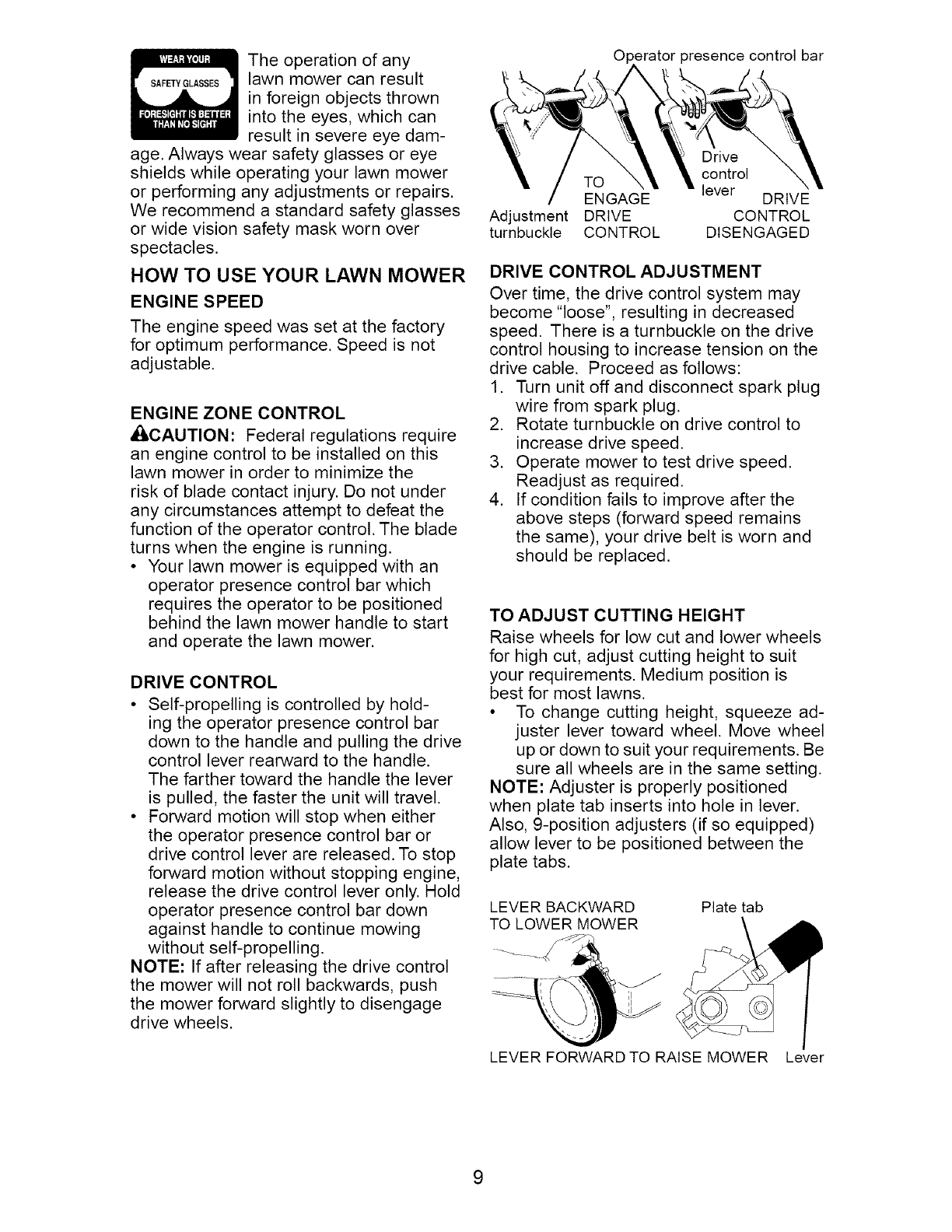
DRIVE CONTROL
• Self-propelling is controlled by hold-
ing the operator presence control bar
down to the handle and pulling the drive
control lever rearward to the handle.
The farther toward the handle the lever
is pulled, the faster the unit will travel.
• Forward motion will stop when either
the operator presence control bar or
drive control lever are released. To stop
forward motion without stopping engine,
release the drive control lever only. Hold
operator presence control bar down
against handle to continue mowing
without self-propelling.
NOTE: If after releasing the drive control
the mower will not roll backwards, push
the mower forward slightly to disengage
drive wheels.
sesence control bar
Drive
control
TO lever
ENGAGE DRIVE
Adjustment DRIVE CONTROL
turnbuckle CONTROL DISENGAGED
DRIVE CONTROL ADJUSTMENT
Over time, the drive control system may
become "loose", resulting in decreased
speed. There is a turnbuckle on the drive
control housing to increase tension on the
drive cable. Proceed as follows:
1. Turn unit off and disconnect spark plug
wire from spark plug.
2. Rotate turnbuckle on drive control to
increase drive speed.
3. Operate mower to test drive speed.
Readjust as required.
4. If condition fails to improve after the
above steps (forward speed remains
the same), your drive belt is worn and
should be replaced.
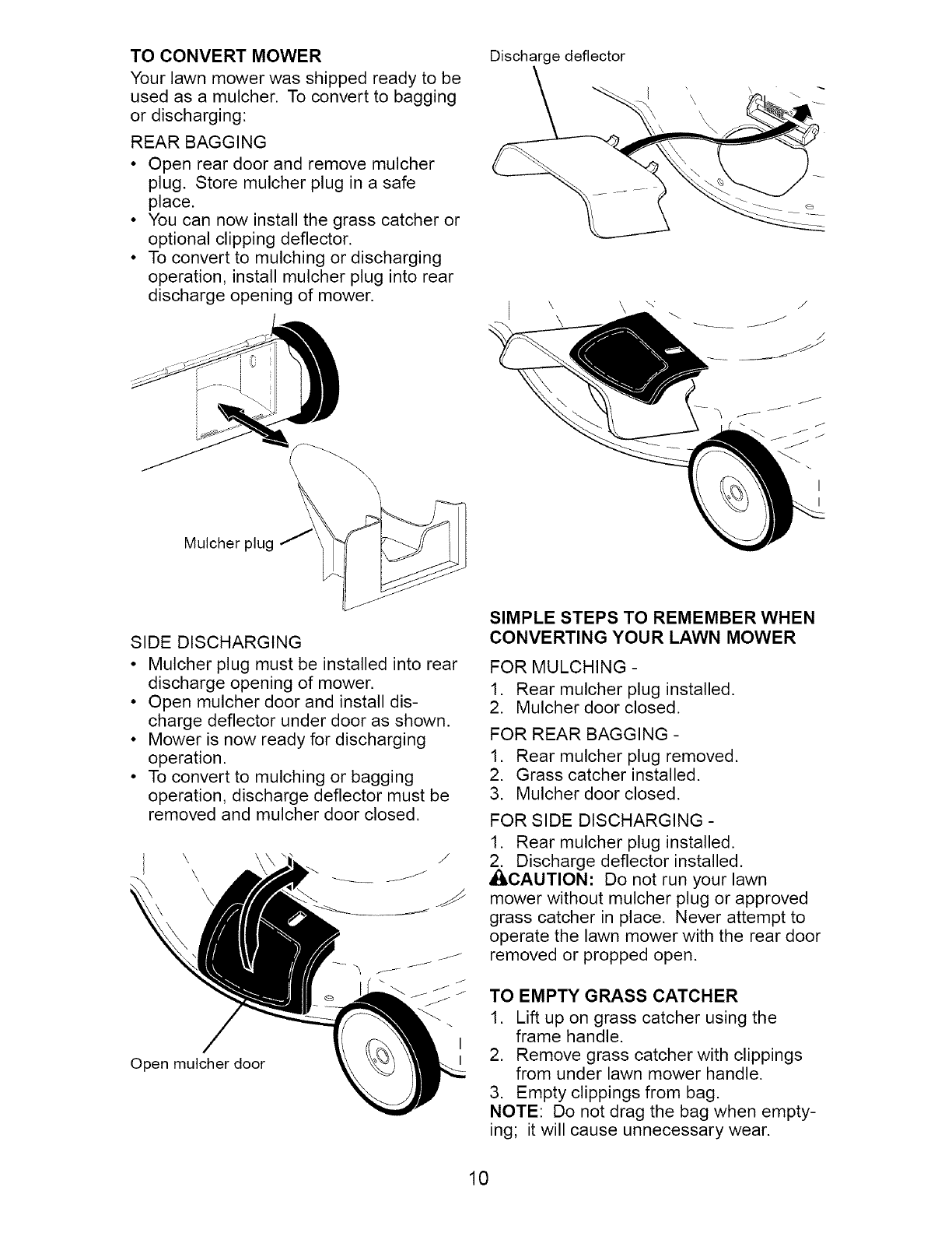
TO ADJUST CUTTING HEIGHT
Raise wheels for low cut and lower wheels
for high cut, adjust cutting height to suit
your requirements. Medium position is
best for most lawns.
• To change cutting height, squeeze ad-
juster lever toward wheel. Move wheel
up or down to suit your requirements. Be
sure all wheels are in the same setting.
NOTE: Adjuster is properly positioned
when plate tab inserts into hole in lever.
Also, 9-position adjusters (if so equipped)
allow lever to be positioned between the
plate tabs.
LEVER BACKWARD
TO LOWER MOWER Plate tab
LEVER FORWARD TO RAISE MOWER Lever
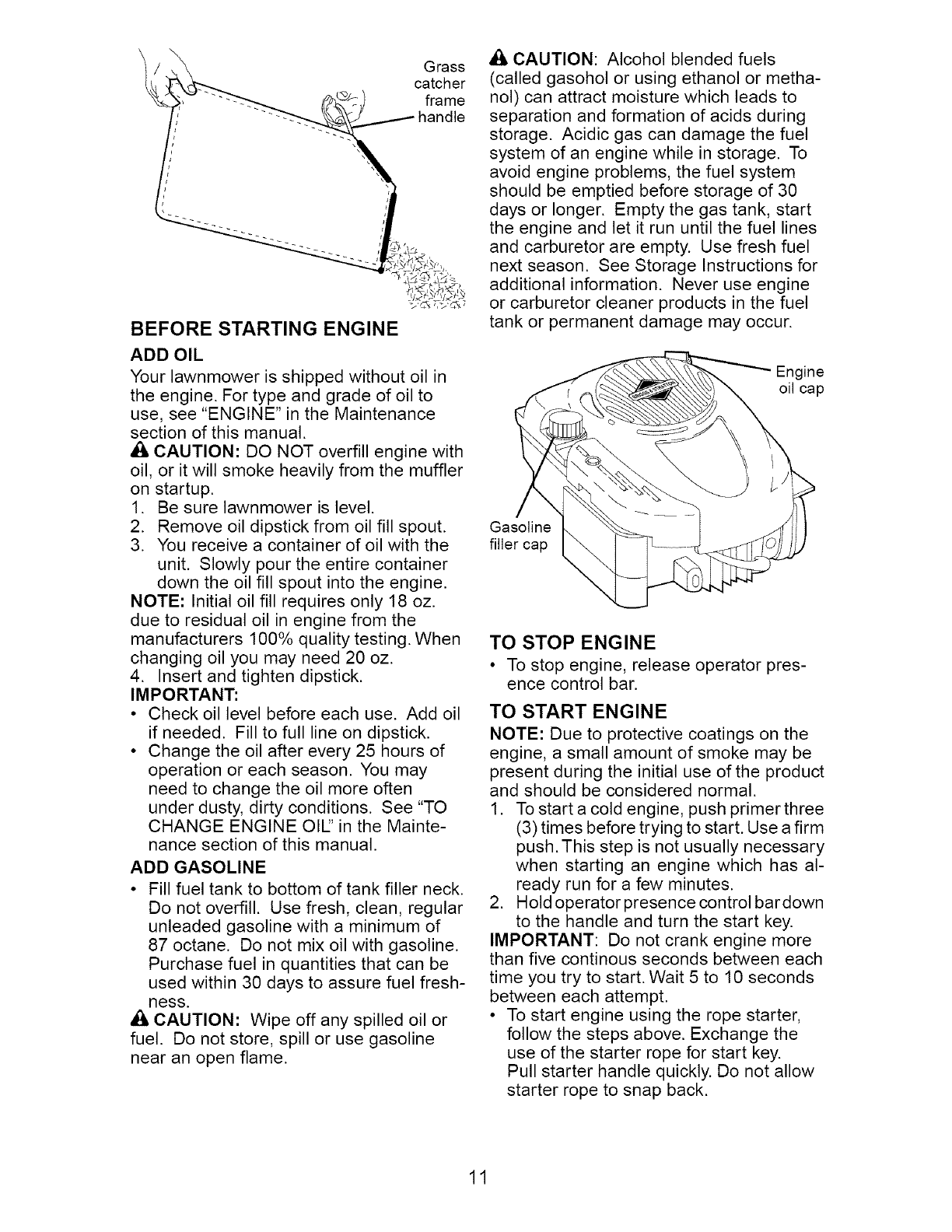
TO CONVERT MOWER
Your lawn mower was shipped ready to be
used as a mulcher. To convert to bagging
or discharging:
REAR BAGGING
• Open rear door and remove mulcher
plug. Store mulcher plug in a safe
place.
• You can now install the grass catcher or
optional clipping deflector.
• To convert to mulching or discharging
operation, install mulcher plug into rear
discharge opening of mower.
Discharge deflector
/
Mulcher plug
SIDE DISCHARGING
• Mulcher plug must be installed into rear
discharge opening of mower.
• Open mulcher door and install dis-
charge deflector under door as shown.
• Mower is now ready for discharging
operation.
• To convert to mulching or bagging
operation, discharge deflector must be
removed and mulcher door closed.
Open mulcher door
SIMPLE STEPS TO REMEMBER WHEN
CONVERTING YOUR LAWN MOWER
FOR MULCHING -
1. Rear mulcher plug installed.
2. Mulcher door closed.
FOR REAR BAGGING -
1. Rear mulcher plug removed.
2. Grass catcher installed.
3. Mulcher door closed.
FOR SIDE DISCHARGING -
1. Rear mulcher plug installed.
2. Discharge deflector installed.
ACAUTION: Do not run your lawn
mower without mulcher plug or approved
grass catcher in place. Never attempt to
operate the lawn mower with the rear door
removed or propped open.
TO EMPTY GRASS CATCHER
1. Lift up on grass catcher using the
frame handle.
2. Remove grass catcher with clippings
from under lawn mower handle.
3. Empty clippings from bag.
NOTE: Do not drag the bag when empty-
ing; it will cause unnecessary wear.
10
BEFORE STARTING ENGINE
ADD OIL
Your lawnmower is shipped without oil in
the engine. For type and grade of oil to
use, see "ENGINE" in the Maintenance
section of this manual.
• I, CAUTION: DO NOT overfill engine with
oil, or it will smoke heavily from the muffler
on startup.
1. Be sure lawnmower is level.
2. Remove oil dipstick from oil fill spout.
3. You receive a container of oil with the
unit. Slowly pour the entire container
down the oil fill spout into the engine.
NOTE: Initial oil fill requires only 18 oz.
due to residual oil in engine from the
manufacturers 100% quality testing. When
changing oil you may need 20 oz.
4. Insert and tighten dipstick.
IMPORTANT:
• Check oil level before each use. Add oil
if needed. Fill to full line on dipstick.
• Change the oil after every 25 hours of
operation or each season. You may
need to change the oil more often
under dusty, dirty conditions. See "TO
CHANGE ENGINE Oil" in the Mainte-
nance section of this manual.
ADD GASOLINE
• Fill fuel tank to bottom of tank filler neck.
Do not overfill. Use fresh, clean, regular
unleaded gasoline with a minimum of
87 octane. Do not mix oil with gasoline.
Purchase fuel in quantities that can be
used within 30 days to assure fuel fresh-
ness.
A CAUTION: Wipe off any spilled oil or
fuel. Do not store, spill or use gasoline
near an open flame.
A CAUTION: Alcohol blended fuels
(called gasohol or using ethanol or metha-
nol) can attract moisture which leads to
separation and formation of acids during
storage. Acidic gas can damage the fuel
system of an engine while in storage. To
avoid engine problems, the fuel system
should be emptied before storage of 30
days or longer. Empty the gas tank, start
the engine and let it run until the fuel lines
and carburetor are empty. Use fresh fuel
next season. See Storage Instructions for
additional information. Never use engine
or carburetor cleaner products in the fuel
tank or permanent damage may occur.
Engine
oil cap
Gasoline
filler cap
TO STOP ENGINE
• To stop engine, release operator pres-
ence control bar.
TO START ENGINE
NOTE: Due to protective coatings on the
engine, a small amount of smoke may be
present during the initial use of the product
and should be considered normal.
1. To start a cold engine, push primer three
(3) times before trying to start. Use a firm
push. This step is not usually necessary
when starting an engine which has al-
ready run for a few minutes.
2. Hold operator presence control bardown
to the handle and turn the start key.
IMPORTANT: Do not crank engine more
than five continous seconds between each
time you try to start. Wait 5 to 10 seconds
between each attempt.
• To start engine using the rope starter,
follow the steps above. Exchange the
use of the starter rope for start key.
Pull starter handle quickly. Do not allow
starter rope to snap back.
11
NOTE: In cooler weather it may be neces-
sary to repeat priming steps. In warmer
weather over priming may cause flooding
and engine will not start. If you do flood
engine wait a few minutes before at-
tempting to start and do not repeat priming
steps.
MOWING TIPS
A CAUTION: Do not use de-thatcher
blade attachments on your mower. Such
attachments are hazardous, will damage
your mower and could void your warranty.
• Under certain conditions, such as very
tall grass, it may be necessary to raise
the height of cut to reduce pushing
effort and to keep from overloading the
engine and leaving clumps of grass clip-
pings. It may also be necessary to re-
duce ground speed and/or run the lawn
mower over the area a second time.
• For extremely heavy cutting, reduce the
width of cut by overlapping previously
cut path and mow slowly.
• For better grass bagging and most cut-
ting conditions, the engine speed should
be set in the FAST position.
• Pores in cloth grass catchers can be-
come filled with dirt and dust with use
and catchers will collect less grass. To
prevent this, regularly hose catcher off
with water and let dry before using.
• Keep top of engine around starter clear
and clean of grass clippings and chaff.
This will help engine air flow and extend
engine life.
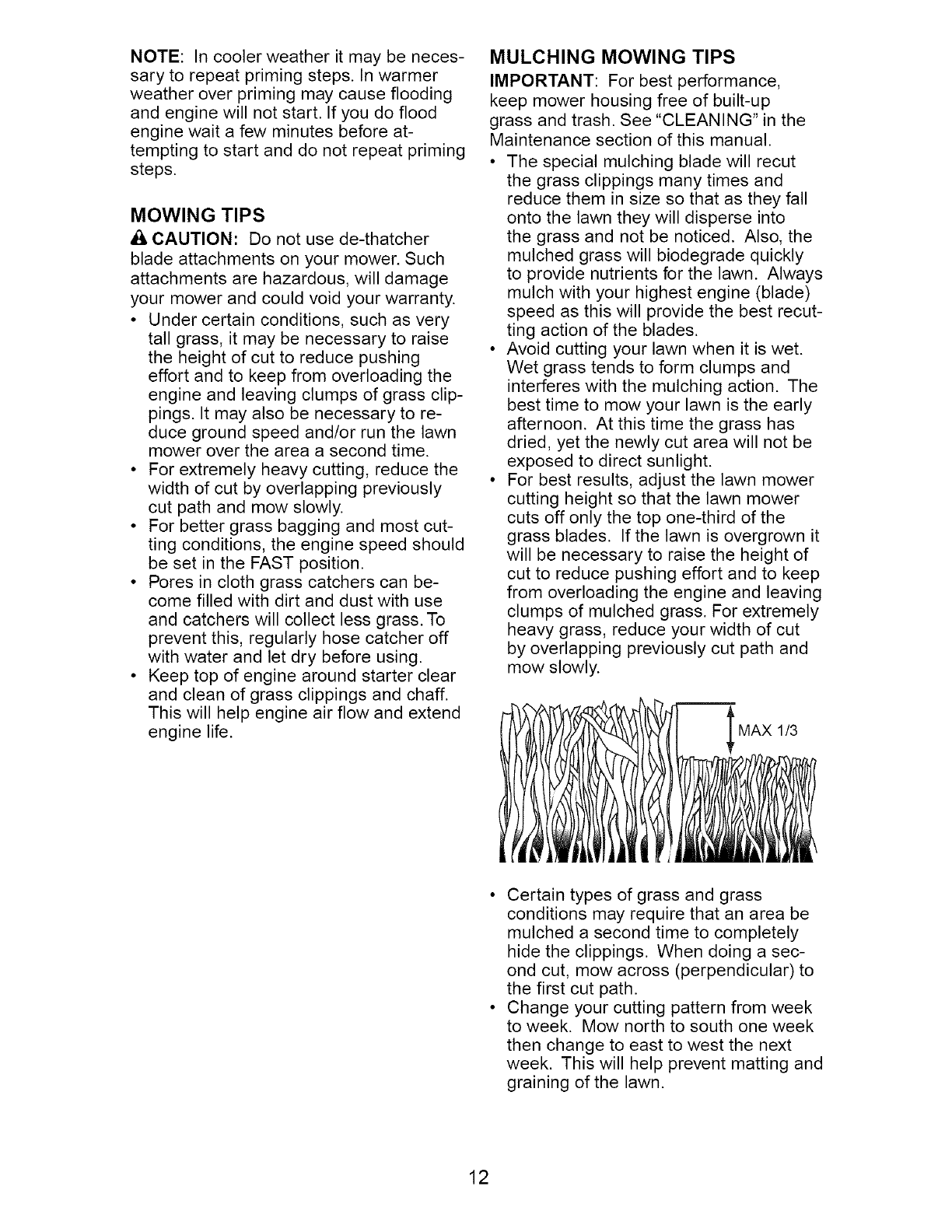
MULCHING MOWING TIPS
IMPORTANT: For best performance,
keep mower housing free of built-up
grass and trash. See "CLEANING" in the
Maintenance section of this manual.
• The special mulching blade will recut
the grass clippings many times and
reduce them in size so that as they fall
onto the lawn they will disperse into
the grass and not be noticed. Also, the
mulched grass will biodegrade quickly
to provide nutrients for the lawn. Always
mulch with your highest engine (blade)
speed as this will provide the best recut-
ting action of the blades.
• Avoid cutting your lawn when it is wet.
Wet grass tends to form clumps and
interferes with the mulching action. The
best time to mow your lawn is the early
afternoon. At this time the grass has
dried, yet the newly cut area will not be
exposed to direct sunlight.
• For best results, adjust the lawn mower
cutting height so that the lawn mower
cuts off only the top one-third of the
grass blades. If the lawn is overgrown it
will be necessary to raise the height of
cut to reduce pushing effort and to keep
from overloading the engine and leaving
clumps of mulched grass. For extremely
heavy grass, reduce your width of cut
by overlapping previously cut path and
mow slowly.
MAX 1/3
• Certain types of grass and grass
conditions may require that an area be
mulched a second time to completely
hide the clippings. When doing a sec-
ond cut, mow across (perpendicular) to
the first cut path.
• Change your cutting pattern from week
to week. Mow north to south one week
then change to east to west the next
week. This will help prevent matting and
graining of the lawn.
12
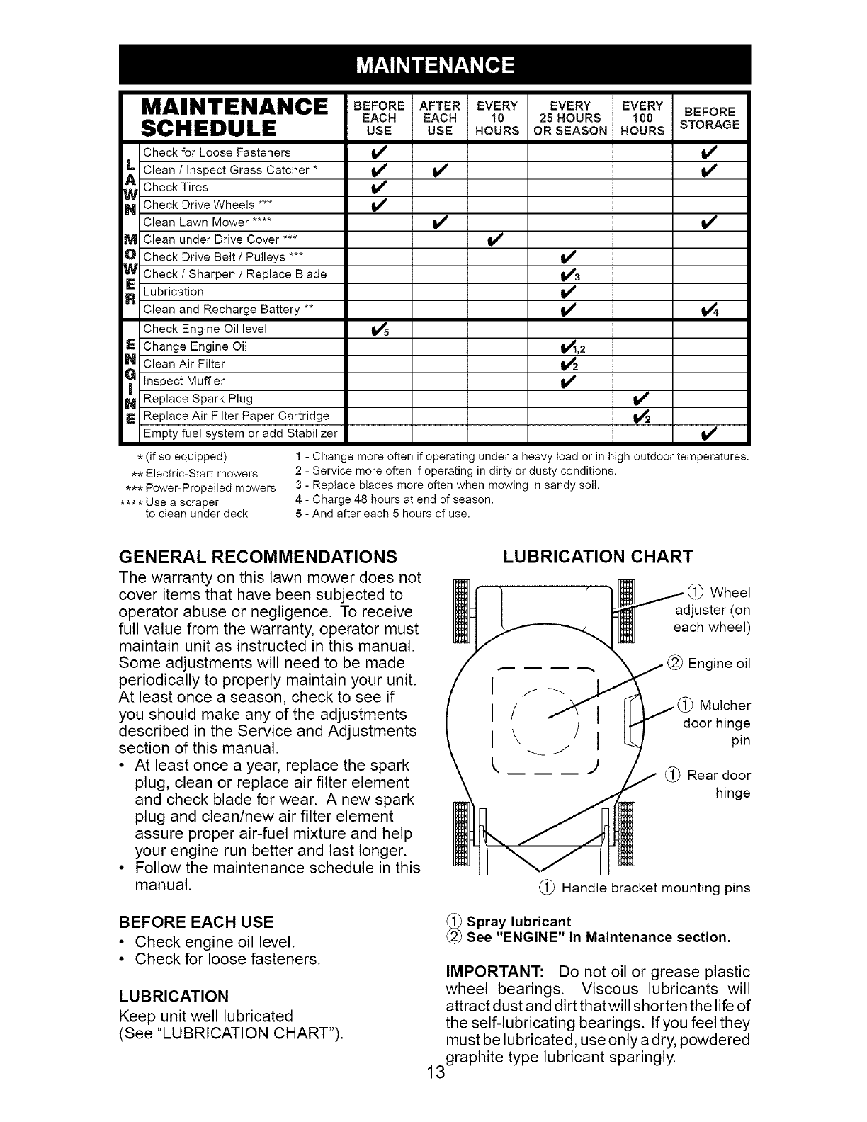
MAINTENANCE
SCHEDULE
Check for Loose Fasteners
_ Clean /Inspect Grass Catcher *
Check Tires
_ Check Drive Wheels
Clean Lawn Mower ....
M Clean under Drive Cover ***
O Check Drive Belt /Pulleys ***
W Check /Sharpen /Replace Blade
_ ubrication
Clean and Recharge Battery **
Check Engine Oil level
E Change Engine Oil
N Clean Air Filter
_ Inspect Muffler
N Replace Spark Plug
E Replace Air Filter Paper Cartridge
Empty fuel system or add Stabilizer
BEFORE AFTER EVERY EVERY EVERY BEFORE
EACH EACH 10 25 HOURS 100
USE USE HOURS OR SEASON HOURS STORAGE
14
I," v'
v' v'
v'3
_,2
=4
V' I/
V_
* (if so equipped)
** Electric-Start mowers
*** Power-Propelled mowers
**** Use a scraper
to clean under deck
1 - Change more often if operating under a heavy toad or in high outdoor temperatures.
2 - Service more often if operating in dirty or dusty conditions.
3 - Replace blades more often when mowing in sandy soil.
4 - Charge 48 hours at end of season.
5 - And after each 5 hours of use.
GENERAL RECOMMENDATIONS
The warranty on this lawn mower does not
cover items that have been subjected to
operator abuse or negligence. To receive
full value from the warranty, operator must
maintain unit as instructed in this manual.
Some adjustments will need to be made
periodically to properly maintain your unit.
At least once a season, check to see if
you should make any of the adjustments
described in the Service and Adjustments
section of this manual.
• At least once a year, replace the spark
plug, clean or replace air filter element
and check blade for wear. A new spark
plug and clean/new air filter element
assure proper air-fuel mixture and help
your engine run better and last longer.
• Follow the maintenance schedule in this
manual.
BEFORE EACH USE
• Check engine oil level.
• Check for loose fasteners.
LUBRICATION
Keep unit well lubricated
(See "LUBRICATION CHART").
(
LUBRICATION CHART
Wheel
adjuster (on
each wheel)
(_) Engine oil
Mulcher
door hinge
pin
(_) Rear door
hinge
(_) Handle bracket mounting pins
_Spray lubricant
See "ENGINE" in Maintenance section.
IMPORTANT: Do not oil or grease plastic
wheel bearings. Viscous lubricants will
attract dust and dirt that will shorten the life of
the self-lubricating bearings. If you feel they
must be lubricated, use only adry, powdered
3graphite type lubricant sparingly.
1
LAWN MOWER
Always observe safety rules when per-
forming any maintenance.
TIRES
• Keep tires free of gasoline, oil, or insect
control chemicals which can harm rubber.
• Avoid stumps, stones, deep ruts, sharp
objects and other hazards that may
cause tire damage.
DRIVE WHEELS
Check rear drive wheels each time before
you mow to be sure they move freely.
The wheels not turning freely means trash,
grass cuttings, etc. are in the drive wheel area
and must be cleaned to free drive wheels.
If necessary to clean the drive wheels, be
sure to clean both rear wheels.
BLADE CARE
For best results, blade must be kept sharp.
Replace a bent or damaged blade.
ACAUTION: Use only a replacement blade
approved by the manufacturer of your mower.
Using a blade not approved by the manu-
facturer of your mower is hazardous, could
damage your mower and void your warranty.
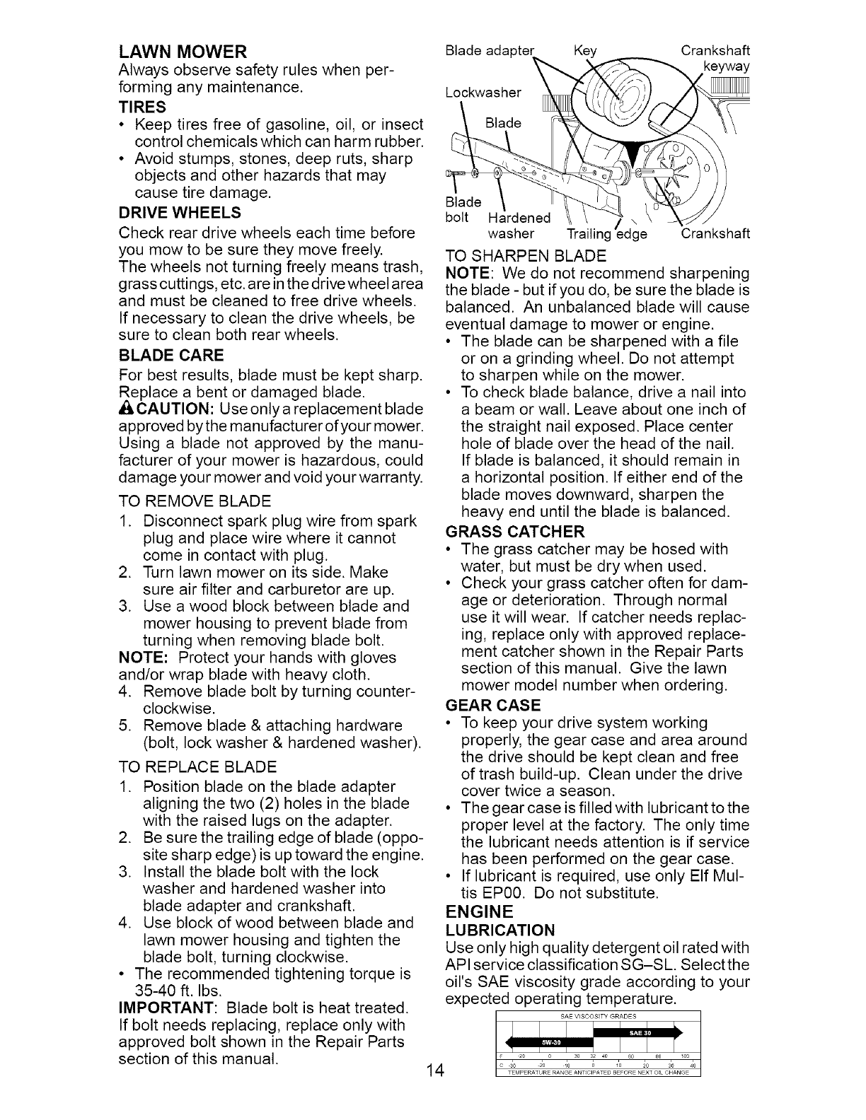
TO REMOVE BLADE
1. Disconnect spark plug wire from spark
plug and place wire where it cannot
come in contact with plug.
2. Turn lawn mower on its side. Make
sure air filter and carburetor are up.
3. Use a wood block between blade and
mower housing to prevent blade from
turning when removing blade bolt.
NOTE: Protect your hands with gloves
and/or wrap blade with heavy cloth.
4. Remove blade bolt by turning counter-
clockwise.
5. Remove blade & attaching hardware
(bolt, lock washer & hardened washer).
TO REPLACE BLADE
1. Position blade on the blade adapter
aligning the two (2) holes in the blade
with the raised lugs on the adapter.
2. Be sure the trailing edge of blade (oppo-
site sharp edge) is up toward the engine.
3. Install the blade bolt with the lock
washer and hardened washer into
blade adapter and crankshaft.
4. Use block of wood between blade and
lawn mower housing and tighten the
blade bolt, turning clockwise.
• The recommended tightening torque is
35-40 ft. Ibs.
IMPORTANT: Blade bolt is heat treated.
If bolt needs replacing, replace only with
approved bolt shown in the Repair Parts
section of this manual.
Blade adapter Key
Lockwasher _ _/
bolt Hardened
TO SHARPEN BLADE
Crankshaft
ICrankshaft
NOTE: We do not recommend sharpening
the blade - but if you do, be sure the blade is
balanced. An unbalanced blade will cause
eventual damage to mower or engine.
• The blade can be sharpened with a file
or on a grinding wheel. Do not attempt
to sharpen while on the mower.
• To check blade balance, drive a nail into
a beam or wall. Leave about one inch of
the straight nail exposed. Place center
hole of blade over the head of the nail.
If blade is balanced, it should remain in
a horizontal position. If either end of the
blade moves downward, sharpen the
heavy end until the blade is balanced.
GRASS CATCHER
• The grass catcher may be hosed with
water, but must be dry when used.
• Check your grass catcher often for dam-
age or deterioration. Through normal
use it will wear. If catcher needs replac-
ing, replace only with approved replace-
ment catcher shown in the Repair Parts
section of this manual. Give the lawn
mower model number when ordering.
GEAR CASE
• To keep your drive system working
properly, the gear case and area around
the drive should be kept clean and free
of trash build-up. Clean under the drive
cover twice a season.
• The gear case is filled with lubricant to the
proper level at the factory. The only time
the lubricant needs attention is if service
has been performed on the gear case.
• If lubricant is required, use only Elf Mul-
tis EP00. Do not substitute.
ENGINE
LUBRICATION
Use only high quality detergent oil rated with
API service classification SG-SL Select the
oil's SAE viscosity grade according to your
expected operating temperature.
NOTE: Althoughmulti-viscosityoils
(5W30,10W30etc.)improve starting in
coldweather,thesemulti-viscosityoils will
resultin increasedoil consumptionwhen
usedabove32°F. Checkyourengineoil
levelmorefrequentlyto avoidpossible
engine damagefrom runninglow on oil.
Changethe oil after every25 hoursof op-
erationorat leastonce a year if the mower
is not usedfor 25 hours in one year.
Checkthe crankcaseoil level before
startingthe engineand after each five (5)
hoursof continuoususe.Tightenoil plug
securelyeach time youcheckthe oil level.
TO CHANGEENGINEOIL
NOTE: Beforetipping lawnmowerto drain
oil, emptyfuel tank by runningengine until
fuel tank is empty.
1. Disconnectspark plugwire from spark
plug and place wire where it cannot
come in contact with plug.
2. Remove engine oil cap; lay aside on a
clean surface.
3. Tip lawn mower on its side as shown
and drain oil into a suitable container.
Rock lawn mower back and forth to re-
move any oil trapped inside of engine.
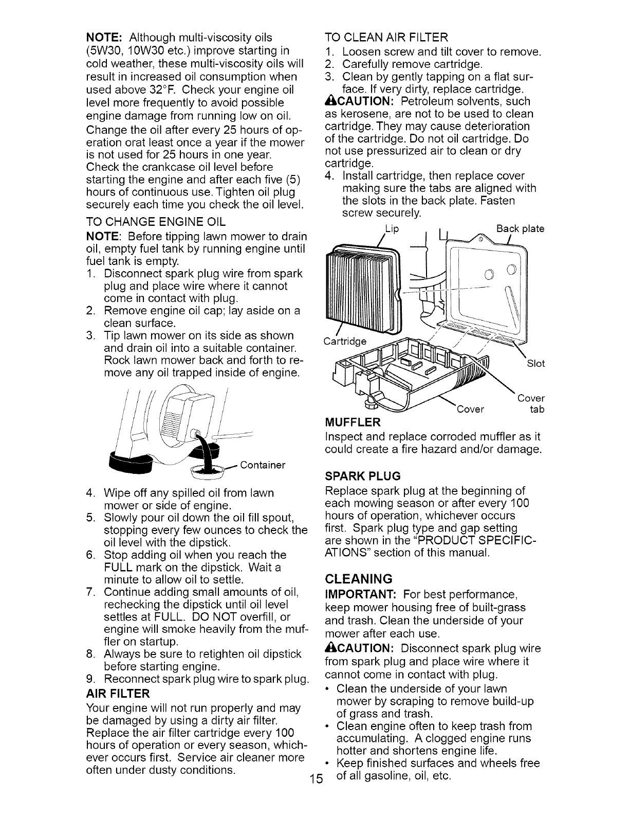
TO CLEAN AIR FILTER
1. Loosen screw and tilt cover to remove.
2. Carefully remove cartridge.
3. Clean by gently tapping on a flat sur-
face. If very dirty, replace cartridge.
_CAUTION: Petroleum solvents, such
as kerosene, are not to be used to clean
cartridge. They may cause deterioration
of the cartridge. Do not oil cartridge. Do
not use pressurized air to clean or dry
cartridge.
4. Install cartridge, then replace cover
making sure the tabs are aligned with
the slots in the back plate. Fasten
screw securely.
Back plate
Cart_
MUFFLER
/
Slot
Cover
tab
Inspect and replace corroded muffler as it
could create a fire hazard and/or damage.
4. Wipe off any spilled oil from lawn
mower or side of engine.
5. Slowly pour oil down the oil fill spout,
stopping every few ounces to check the
oil level with the dipstick.
6. Stop adding oil when you reach the
FULL mark on the dipstick. Wait a
minute to allow oil to settle.
7. Continue adding small amounts of oil,
rechecking the dipstick until oil level
settles at FULL. DO NOT overfill, or
engine will smoke heavily from the muf-
fler on startup.
8. Always be sure to retighten oil dipstick
before starting engine.
9. Reconnect spark plug wire to spark plug.
AIR FILTER
Your engine will not run properly and may
be damaged by using a dirty air filter.
Replace the air filter cartridge every 100
hours of operation or every season, which-
ever occurs first. Service air cleaner more
often under dusty conditions. 15
SPARK PLUG
Replace spark plug at the beginning of
each mowing season or after every 100
hours of operation, whichever occurs
first. Spark plug type and gap setting
are shown in the "PRODUCT SPECIFIC-
ATIONS" section of this manual.
CLEANING
IMPORTANT: For best performance,
keep mower housing free of built-grass
and trash. Clean the underside of your
mower after each use.
ACAUTION: Disconnect spark plug wire
from spark plug and place wire where it
cannot come in contact with plug.
• Clean the underside of your lawn
mower by scraping to remove build-up
of grass and trash.
• Clean engine often to keep trash from
accumulating. A clogged engine runs
hotter and shortens engine life.
Keep finished surfaces and wheels free
of all gasoline, oil, etc.
We do not recommendusing a garden
hose to cleanlawnmower unlessthe
electricalsystem,muffler,air filter and
carburetorare coveredto keepwater
out. Water in enginecan resultinshort-
ened enginelife.
CLEAN UNDERDRIVECOVER
Cleanunderdrivecoverat least twice a sea-
son. Scrape underside of cover with putty
knife or similar tool to remove any build-up
of trash or grass on underside of drive cover.
• ILWARNING: To avoid serious injury, before performing any service and adjustments:
.
2.
3.
contact with plug.
Release control bar and stop engine.
Make sure the blade and all moving parts have completely stopped.
Disconnect spark plug wire from spark plug and place wire where it cannot come in
LAWN MOWER
TO ADJUST CUTTING HEIGHT
See "TO ADJUST CUTTING HEIGHT" in
the Operation section of this manual.
REAR DEFLECTOR
The rear deflector, attached between the
rear wheels of your mower, is provided to
minimize the possibility that objects will
be thrown out of the rear of the mower
into the operator mowing position. If the
deflector becomes damaged, it should be
replaced.
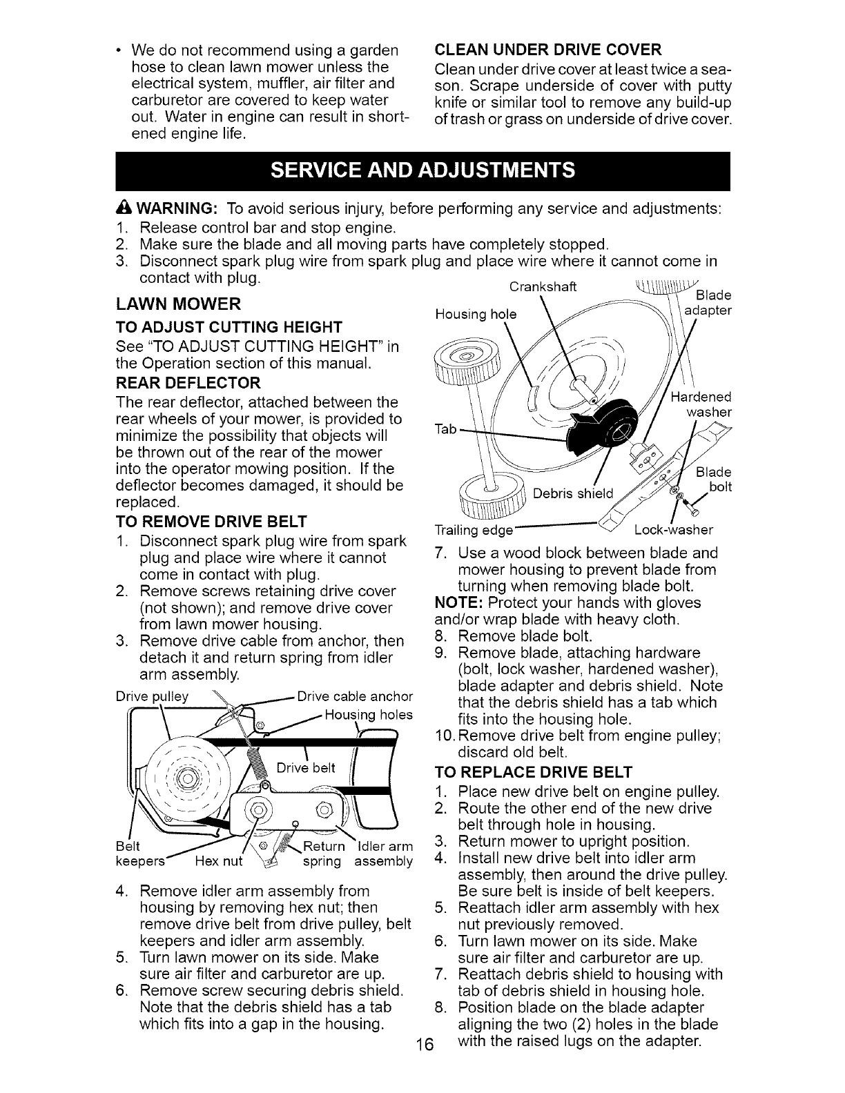
TO REMOVE DRIVE BELT
1. Disconnect spark plug wire from spark
plug and place wire where it cannot
come in contact with plug.
2. Remove screws retaining drive cover
(not shown); and remove drive cover
from lawn mower housing.
3. Remove drive cable from anchor, then
detach it and return spring from idler
arm assembly.
Drive ulley _ _ Drive cable anchor
ir- n .ous es
222, \
II ', N Drivebe,t // /
e,t . eturo , ,erar
keepers Hex nut _ spring assembly
4. Remove idler arm assembly from
housing by removing hex nut; then 5.
remove drive belt from drive pulley, belt
keepers and idler arm assembly. 6.
5. Turn lawn mower on its side. Make
sure air filter and carburetor are up. 7.
6. Remove screw securing debris shield.
Note that the debris shield has a tab 8.
which fits into a gap in the housing.
16
C_nksha_
Housing hole adapter
Hardened
washer
Blade
bolt
Trailing edge-- Lock-washer
7. Use a wood block between blade and
mower housing to prevent blade from
turning when removing blade bolt.
NOTE: Protect your hands with gloves
and/or wrap blade with heavy cloth.
8. Remove blade bolt.
9. Remove blade, attaching hardware
(bolt, lock washer, hardened washer),
blade adapter and debris shield. Note
that the debris shield has a tab which
fits into the housing hole.
10. Remove drive belt from engine pulley;
discard old belt.
TO REPLACE DRIVE BELT
1. Place new drive belt on engine pulley.
2. Route the other end of the new drive
belt through hole in housing.
3. Return mower to upright position.
4. Install new drive belt into idler arm
assembly, then around the drive pulley.
Be sure belt is inside of belt keepers.
Reattach idler arm assembly with hex
nut previously removed.
Turn lawn mower on its side. Make
sure air filter and carburetor are up.
Reattach debris shield to housing with
tab of debris shield in housing hole.
Position blade on the blade adapter
aligning the two (2) holes in the blade
with the raised lugs on the adapter.
9. Be sure the trailing edgeof blade(op-
positesharp edge)is up towardthe
engineas shown.
10.Installthe bladeboltwith the lock
washer and hardenedwasher into
bladeadapterand crankshaft.
11.Useblockof woodbetween bladeand
lawnmower housingand tighten the
bladebolt,turningclockwise.
• The recommendedtighteningtorque is
35-40ft. Ibs.
IMPORTANT: Bladeboltis heat treated.
If bolt needsreplacing,replaceonly with
approvedboltshownin the RepairParts
section of this manual.
12.Return mowerto uprightposition.
13.Reattachdrive cableand returnspring
to the idlerarm assembly,then reat-
tachdrive cableto anchor.
14.Reattachdrive coverwith screw(s)
previouslyremoved.
15.Connectspark plugwire to sparkplug.
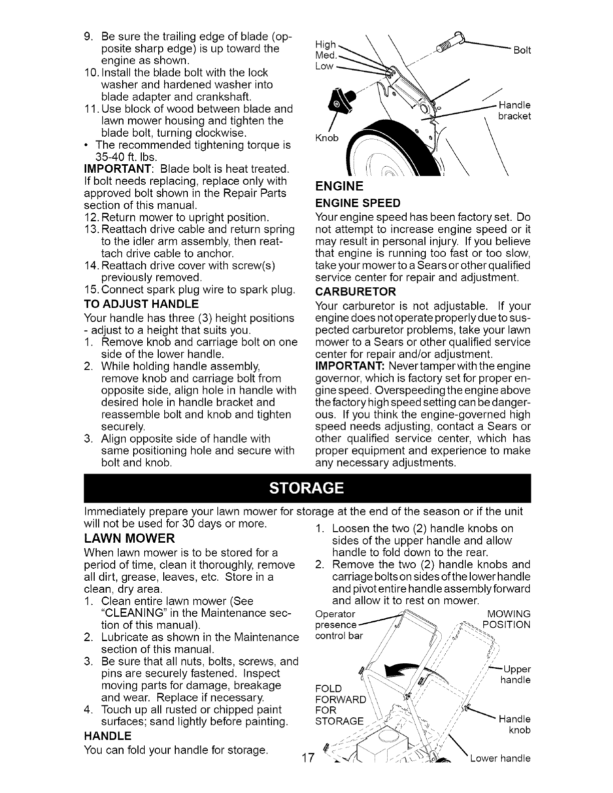
TO ADJUST HANDLE
Yourhandlehasthree(3) heightpositions
- adjustto a heightthat suitsyou.
1. Removeknob and carriage bolton one
sideof the lower handle.
2. While holdinghandleassembly,
removeknoband carriagebolt from
oppositeside,align holein handlewith
desiredhole in handlebracketand
reassembleboltand knoband tighten
securely.
3. Align oppositeside of handlewith
samepositioningholeand securewith
boltand knob.
Hic
Med.-.
Knob
ENGINE
JHandle
acket
ENGINE SPEED
Your engine speed has been factory set. Do
not attempt to increase engine speed or it
may result in personal injury. If you believe
that engine is running too fast or too slow,
take your mower to a Sears or other qualified
service center for repair and adjustment.
CARBURETOR
Your carburetor is not adjustable. If your
engine does not operate properly due to sus-
pected carburetor problems, take your lawn
mower to a Sears or other qualified service
center for repair and/or adjustment.
IMPORTANT: Never tamperwith the engine
governor, which is factory set for proper en-
gine speed. Overspeeding the engine above
the factory high speed setting can be danger-
ous. If you think the engine-governed high
speed needs adjusting, contact a Sears or
other qualified service center, which has
proper equipment and experience to make
any necessary adjustments.
Immediately prepare your lawn mower for storage at the end of the season or if the unit
will not be used for 30 days or more. 1.
LAWN MOWER
When lawn mower is to be stored for a
period of time, clean it thoroughly, remove 2.
all dirt, grease, leaves, etc. Store in a
clean, dry area.
1. Clean entire lawn mower (See
"CLEANING" in the Maintenance sec- Operator
tion of this manual). I
2. Lubricate as shown in the Maintenance control bar
section of this manual.
3. Be sure that all nuts, bolts, screws, and
pins are securely fastened. Inspect
moving parts for damage, breakage
and wear. Replace if necessary.
4. Touch up all rusted or chipped paint
surfaces; sand lightly before painting.
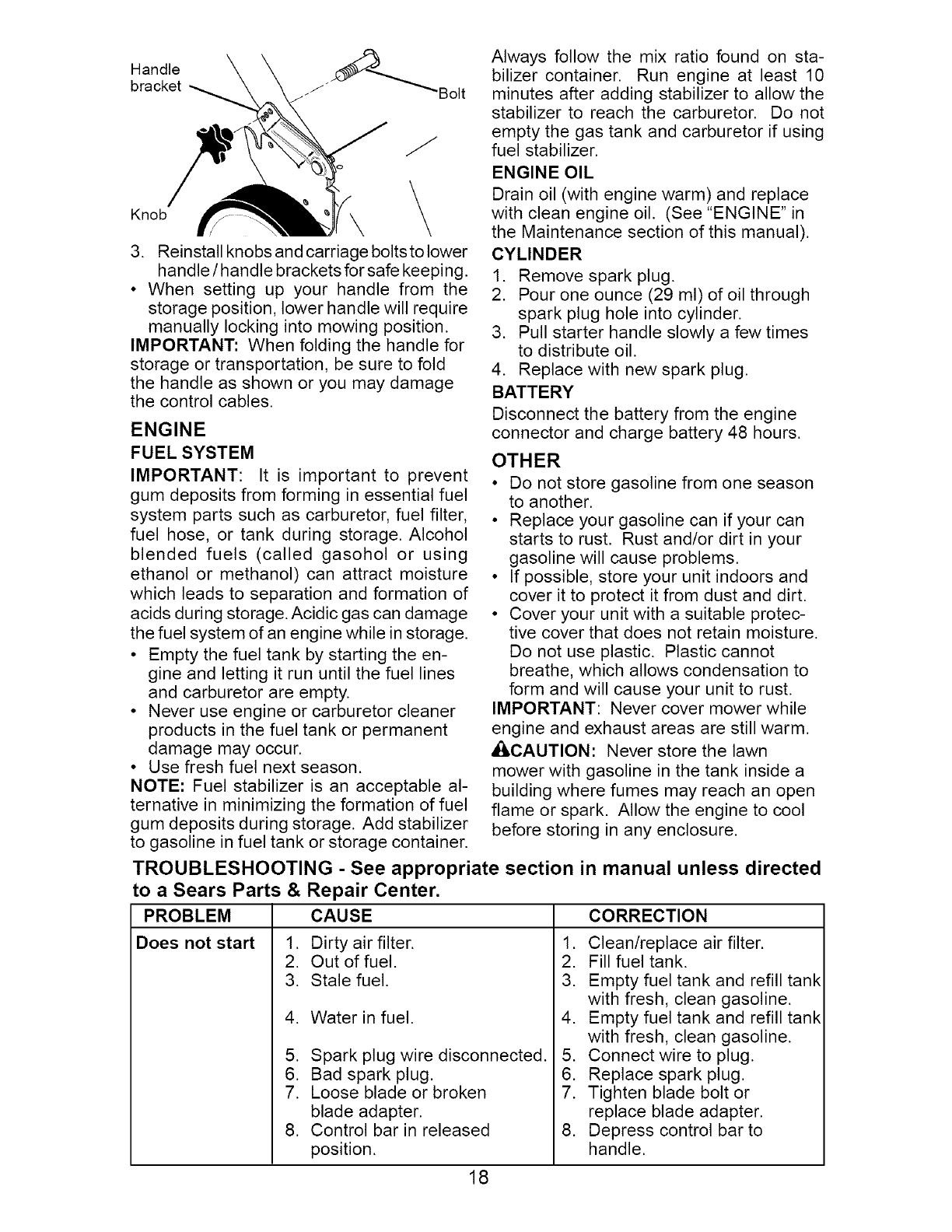
HANDLE _
You can fold your handle for storage. 17 _:
Loosen the two (2) handle knobs on
sides of the upper handle and allow
handle to fold down to the rear.
Remove the two (2) handle knobs and
carriage bolts on sides of the lower handle
and pivot entire handle assembly forward
and allow it to rest on mower.
MOWING
POSITION
FOLD
FORWARD
FOR
STORAGE
/ /
/'/_'-" Upper
/'/' handle
,///
Handle
knob
Handle __
bracket J Bolt
J
Knob \ \
3. Reinstall knobs and carriage boltsto lower
handle /handle brackets for safe keeping.
• When setting up your handle from the
storage position, lower handle will require
manually locking into mowing position.
IMPORTANT: When folding the handle for
storage or transportation, be sure to fold
the handle as shown or you may damage
the control cables.
ENGINE
FUEL SYSTEM
IMPORTANT: It is important to prevent
gum deposits from forming in essential fuel
system parts such as carburetor, fuel filter,
fuel hose, or tank during storage. Alcohol
blended fuels (called gasohol or using
ethanol or methanol) can attract moisture
which leads to separation and formation of
acids during storage. Acidic gas can damage
the fuel system of an engine while in storage.
• Empty the fuel tank by starting the en-
gine and letting it run until the fuel lines
and carburetor are empty.
• Never use engine or carburetor cleaner
products in the fuel tank or permanent
damage may occur.
• Use fresh fuel next season.
NOTE: Fuel stabilizer is an acceptable al-
ternative in minimizing the formation of fuel
gum deposits during storage. Add stabilizer
to gasoline in fuel tank or storage container.
Always follow the mix ratio found on sta-
bilizer container. Run engine at least 10
minutes after adding stabilizer to allow the
stabilizer to reach the carburetor. Do not
empty the gas tank and carburetor if using
fuel stabilizer.
ENGINE OIL
Drain oil (with engine warm) and replace
with clean engine oil. (See "ENGINE" in
the Maintenance section of this manual).
CYLINDER
1. Remove spark plug.
2. Pour one ounce (29 ml) of oil through
spark plug hole into cylinder.
3. Pull starter handle slowly a few times
to distribute oil.
4. Replace with new spark plug.
BATTERY
Disconnect the battery from the engine
connector and charge battery 48 hours.
OTHER
• Do not store gasoline from one season
to another.
• Replace your gasoline can if your can
starts to rust. Rust and/or dirt in your
gasoline will cause problems.
• If possible, store your unit indoors and
cover it to protect it from dust and dirt.
• Cover your unit with a suitable protec-
tive cover that does not retain moisture.
Do not use plastic. Plastic cannot
breathe, which allows condensation to
form and will cause your unit to rust.
IMPORTANT: Never cover mower while
engine and exhaust areas are still warm.
_ICAUTION: Never store the lawn
mower with gasoline in the tank inside a
building where fumes may reach an open
flame or spark. Allow the engine to cool
before storing in any enclosure.
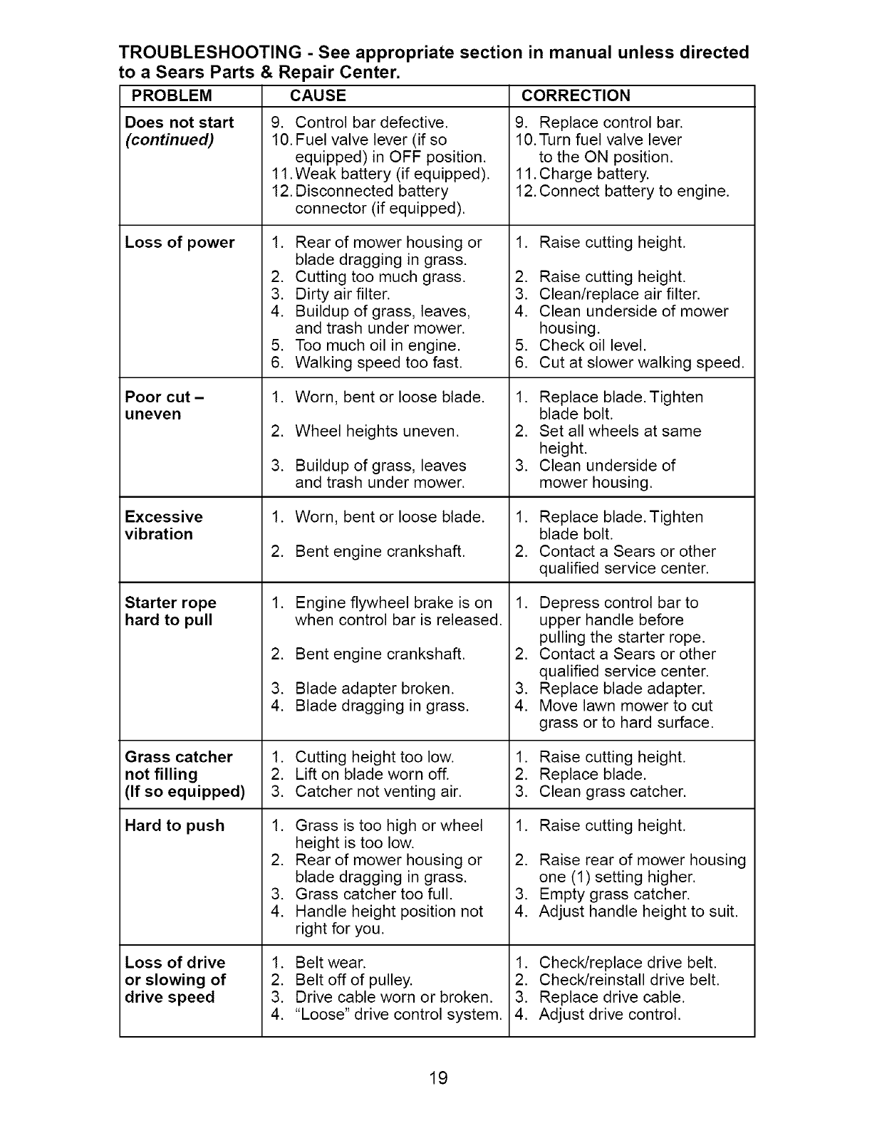
TROUBLESHOOTING - See appropriate section in manual unless directed
to a Sears Parts & Repair Center.
PROBLEM CAUSE
Dirty air filter.
Out of fuel.
Stale fuel.
Water in fuel.
Does not start 1.
2.
3.
4.
5.
6.
7.
8.
CORRECTION
1. Clean/replace air filter.
2. Fill fuel tank.
3. Empty fuel tank and refill tank
with fresh, clean gasoline.
4. Empty fuel tank and refill tank
with fresh, clean gasoline.
Spark plug wire disconnected.
Bad spark plug.
Loose blade or broken
blade adapter.
Control bar in released
position.
5. Connect wire to plug.
6. Replace spark plug.
7. Tighten blade bolt or
replace blade adapter.
8. Depress control bar to
handle.
18
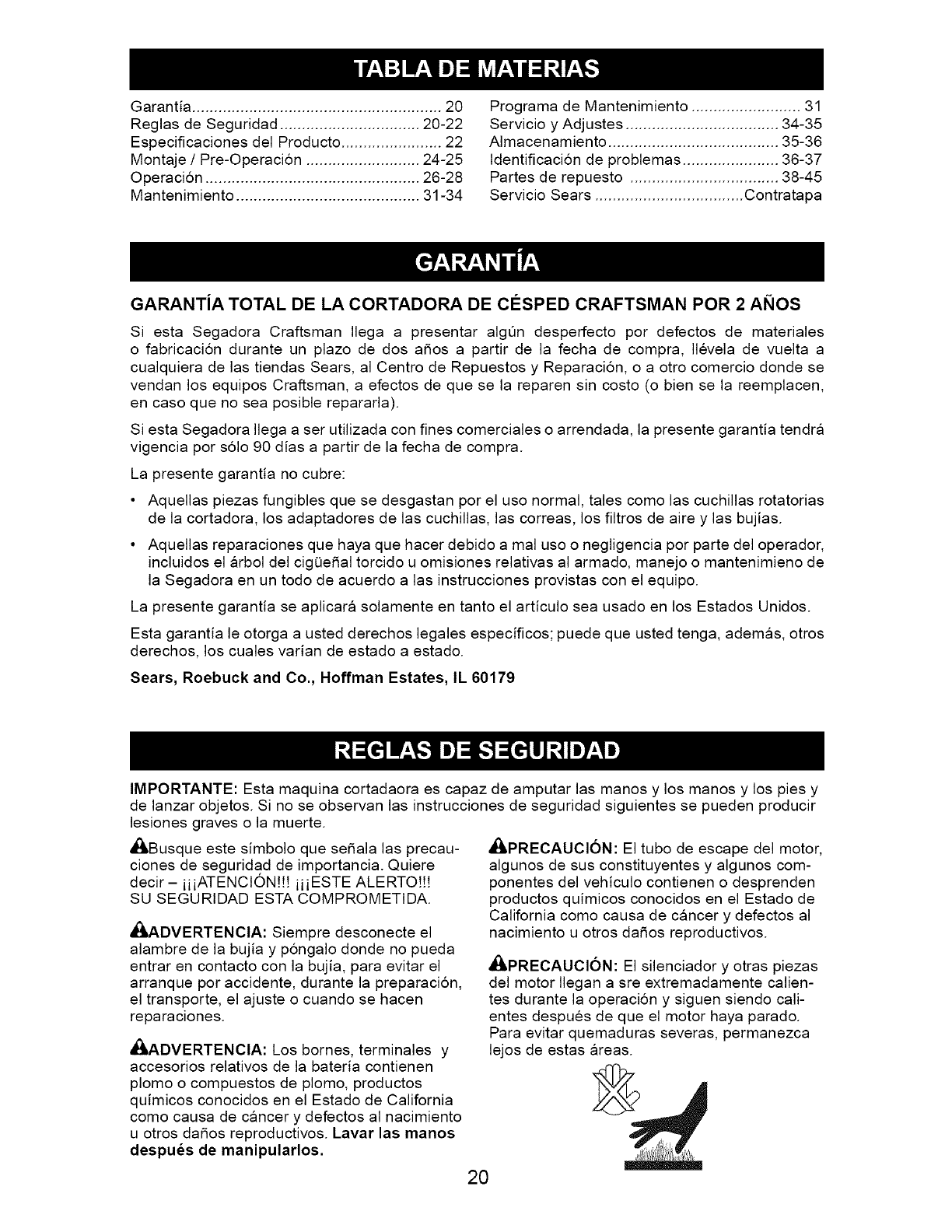
TROUBLESHOOTING - See appropriate section in manual unless directed
to a Sears Parts & Repair Center,
CAUSEPROBLEM
Does not start
(continued)
Loss of power
Poor cut -
uneven
Excessive
vibration
Starter rope
hard to pull
Grass catcher
not filling
(If so equipped)
Hard to push
Loss of drive
or slowing of
drive speed
9. Control bar defective.
10. Fuel valve lever (if so
equipped) in OFF position.
11 .Weak battery (if equipped).
12. Disconnected battery
connector (if equipped).
1. Rear of mower housing or
blade dragging in grass.
2. Cutting too much grass.
3. Dirty air filter.
4. Buildup of grass, leaves,
and trash under mower.
5. Too much oil in engine.
6. Walking speed too fast.
1. Worn, bent or loose blade.
2. Wheel heights uneven.
3. Buildup of grass, leaves
and trash under mower.
1. Worn, bent or loose blade.
2. Bent engine crankshaft.
1. Engine flywheel brake is on
when control bar is released.
2. Bent engine crankshaft.
3. Blade adapter broken.
4. Blade dragging in grass.
1. Cutting height too low.
2. Lift on blade worn off.
3. Catcher not venting air.
1. Grass is too high or wheel
height is too low.
2. Rear of mower housing or
blade dragging in grass.
3. Grass catcher too full.
4. Handle height position not
right for you.
1. Belt wear.
2. Belt off of pulley.
3. Drive cable worn or broken.
4. "Loose" drive control system.
CORRECTION
9. Replace control bar.
10. Turn fuel valve lever
to the ON position.
11. Charge battery.
12. Connect battery to engine.
1. Raise cutting height.
2. Raise cutting height.
3. Clean/replace air filter.
4. Clean underside of mower
housing.
5. Check oil level.
6. Cut at slower walking speed.
1. Replace blade. Tighten
blade bolt.
2. Set all wheels at same
height.
3. Clean underside of
mower housing.
1. Replace blade. Tighten
blade bolt.
2. Contact a Sears or other
qualified service center.
1. Depress control bar to
upper handle before
pulling the starter rope.
2. Contact a Sears or other
qualified service center.
3. Replace blade adapter.
4. Move lawn mower to cut
grass or to hard surface.
1. Raise cutting height.
2. Replace blade.
3. Clean grass catcher.
1. Raise cutting height.
2. Raise rear of mower housing
one (1) setting higher.
3. Empty grass catcher.
4. Adjust handle height to suit.
1. Check/replace drive belt.
2. Check/reinstall drive belt.
3. Replace drive cable.
4. Adjust drive control.
19
Garantia ......................................................... 20
Reglas de Seguridad ................................ 20-22
Especificaciones del Producto ....................... 22
Montaje /Pre-Operaci6n .......................... 24-25
Operaci6n ................................................. 26-28
Mantenimiento .......................................... 31-34
Programa de Mantenimiento ......................... 31
Servicio y Adjustes ................................... 34-35
Almacenamiento ....................................... 35-36
Identificacion de problemas ...................... 36-37
Partes de repuesto .................................. 38-45
Servicio Sears .................................. Contratapa
GARANTiA TOTAL DE LA CORTADORA DE ClaSPED CRAFTSMAN POR 2 ANOS
Siesta Segadora Craftsman Ilega a presentar algQn desperfecto per defectos de materiales
o fabricacion durante un plazo de dos a_os a partir de la fecha de compra, Ilevela de vuelta a
cualquiera de las tiendas Sears, al Centre de Repuestos y Reparacion, o a otro comercio donde se
vendan los equipos Craftsman, a efectos de que se la reparen sin costo (o bien se la reemplacen,
en caso que no sea posible repararla).
Siesta Segadora Ilega a ser utilizada con fines comerciales o arrendada, la presente garantia tendra
vigencia per s61o 90 dias a partir de la fecha de compra.
La presente garantia no cubre:
• Aquellas piezas fungibles que se desgastan por el uso normal, tales come las cuchillas rotatorias
de la cortadora, los adaptadores de las cuchillas, las correas, los filtros de aire y las bujias.
• Aquellas reparaciones que haya que hacer debido a mal uso o negligencia per parte del operador,
incluidos el arbol del cigQe_al torcido u omisiones relativas al armado, manejo o mantenimieno de
la Segadora en un todo de acuerdo a las instrucciones provistas con el equipo.
La presente garantia se aplicara solamente en tanto el articulo sea usado en los Estados Unidos.
Esta garantia le otorga a usted derechos legales especificos; puede que usted tenga, ademas, otros
derechos, los cuales varian de estado a estado.
Sears, Roebuck and Co., Hoffman Estates, IL 60179
IMPORTANTE: Esta maquina cortadaora es capaz de amputar las manos y los manos y los pies y
de lanzar objetos. Si no se observan las instrucciones de seguridad siguientes se pueden producir
lesiones graves o la muerte.
_JkBusque este simbolo que se_ala las precau-
ciones de seguridad de importancia. Quiere
decir- iiiATENCION!!! iiiESTE ALERTO))(
SU SEGURtDAD ESTA COMPROMETIDA.
_kADVERTENClA: Siempre desconecte el
alambre de la bujia y pongalo donde no pueda
entrar en contacto con la bujia, para evitar el
arranque per accidente, durante la preparacion,
el transporte, el ajuste o cuando se hacen
reparaciones.
_,ADVERTENClA: Los bornes, terminales y
accesorios relativos de la bateria contienen
plomo o compuestos de plomo, productos
quimicos conocidos en el Estado de California
come causa de cancer y defectos al nacimiento
u otros da_os reproductivos. Lavar las manos
despues de manipularlos.
,APRECAUCl6N: El tubo de escape del motor,
algunos de sus constituyentes y algunos com-
ponentes del vehiculo contienen o desprenden
productos quimicos conocidos en el Estado de
California come causa de cancer y defectos al
nacimiento u otros da_os reproductivos.
_PRECAUCl6N: El silenciador y otras piezas
del motor Ilegan a sre extremadamente calien-
tes durante la operaciSn y siguen siendo cali-
entes despues de que el motor haya parade.
Para evitar quemaduras severas, permanezca
lejos de estas areas.
20
I. OPERACION
•Antes de empezar, debe familiarizarse
comp]etamente con los controles y e] uso
correcto de ]a maquina. Para esto, debe leer
ycomprender todas ]as instrucciones que
aparecen en ]a maquina yen los manua]es
de operacion.
• No ponga ]as manos olos pies cerca o
debajo de ]as partes rotatorias. Mantengase
siempre lejos de ]a abertura de ]a descarga.
•Permita que so]amente ]as personas re-
sponsab]es que esten familiarizadas con las
instrucciones operen ]a m_lquina.
• Despeje e] _lrea de objetos tales como pie-
dras, juguetes, a]ambres, huesos, palos, etc.
que pueden ser recogidos y lanzados por las
cuchillas.
• Asegurese que e] _lrea no se ha]len per-
sonas, antes de segar. Pare la m_lquina si
a]guien entra el3 e] _lrea.
• No opere ]a maquina sin zapatos o con
sanda]ias abiertas. P6ngase siempre zapatos
s61idos.
• No tire de la segadora hacia atras a menos
que sea absolutamente necesario. Mire
siempre hacia abajo y hacia detras antes y
mientras que se mueve hacia atras.
• Nunca dirigir el material descargado hacia
las personas. Evitar descargar material
contra paredes o barreras. El material puede
retornar al operador. Para la cuchilla cuando
se pasa por superficies de grava.
• No opere la segadora sin los respectivos
resguardos, las placas, el recogedor de
cesped u otros aditamentos dise ados para
su protecci6n y seguridad.
• Refierase alas instrucciones del fabricante
para el funcionamiento e instalaci6n de
accesorios. Use Onicamente accesorios
aprobados por el fabricante.
• Detenga la cuchilla o las cuchillas cuando
cruce por calzadas, calles o caminos de
grava.
• Parar el motor cada vez que se abandona el
aparato, antes de limpiar la segadora o de
remover residuos del tubo.
• Apagar el motor y esperar hasta que las
cuchillas esten completamente paradas
antes de remover el receptor de hierba.
• Segar solamente con luz del dia o con una
buena luz artificial.
• No opere la m_lquina bajo la influencia del
alcohol o de las drogas.
• Nunca opere la maquina cuando la hierba
este mojada. AsegOrese siempre de tener
buena tracci6n en sus pies; mantenga el
mango firmemente y camine; nunca corra.
• Desconectar el mecanismo de propulsi6n
aut6noma o el embrague de transmisi6n en
las segadoras que Io tienen antes de poner
en marcha el motor.
• Si el equipo empezara a vibrar de una
manera anormal, pare el motor y revise de
inmediato para averiguar la causa. General-
mente la vibraci6n suele indicar que existe
alguna averia.
• Siempre use gafas de seguridad o anteojos
con proteccion lateral cuando opere la sega-
dora.
II. OPERACION SOBRE LAS CUESTAS
Los accidentes ocurren con mas frecuencia en
las cuestas. Estos accidentes ocurren debido a
resbaladas o caidas, las cuales pueden resultar
en graves lesiones. Operar la recortadora en
cuestas requiere mayor concentracion. Si se
siente inseguro en una cuesta, no la recorte.
HACER:
• Puede recortar a traves de la superficie de
la cuesta, nunca hacia arriba y hacia abajo.
Proceda con extrema precaucion cuando
cambie de direccion en las cuestas.
• Renueva todos los objetos extraSos, tales
como guijarros, ramas, etc.
• Debe prestar atencion a hoyos, baches o
protuberancias. Recuerde que la hierba alta
puede esconder obstaculos.
NO HACER:
• No recorte cerca de pendientes, zanjas o
terraplenes. El operador puede perder la
tracci6n en los pies o el equilibrio.
• No recorte cuestas demasiado inclinadas.
• No recorte en hierba mojada. La reducci6n
en la tracci6n de la pisada puede causar
resbalones.
III. NINOS
Se pueden producir accidentes tragicos si el
operador no presta atencion a la presencia
de los niSos. A menudo, los niSos se sienten
atraidos por la maquina y por la actividad de
la siega. Nunca suponga que los niSos van a
permanecer en el mismo lugar donde los vio
por Qltima vez.
• Mantenga a los niSos alejados del area de
la siega y bajo el cuidado estricto de otra
persona adulta responsable.
• Este alerta y apague la maquina si hay niSos
que entran al area.
• Antes y cuando este retrocediendo, mire
hacia atras y hacia abajo para verificar si hay
niSos peque5os.
• Nunca permita que los ni5os operen la ma-
quina.
• Tenga un cuidado extra cuando se acerque
aesquinas donde no hay visibilidad, a los
arbustos, arboles u otros objetos que pueden
interferir con su linea de vision.
IV. MANEJO SEGURO DE GASOLINA
Usar mucha atenci6n cuando se maneja gaso-
lina. La gasolina es extremamente inflamable y
los vapores son explosivos.
• Apagar todos los cigarrillos, cigarros, pipas y
otras fuentes de ignici6n.
• Usar solo un contenedor apropiado.
• Nunca quitar el tap6n de la gasolina o a5adir
carburante con el motor en marcha. Esperar
que el motor se enfrie antes de repostar la
gasolina.
21
• Nunca repostar la maquina al interior de un
local.
• Nunca guardar la maquina o el contenedor
de gasolina donde hay una llama abierta,
chispa o luz piloto como una caldera u otros
dispositivos.
• Nunca Ilenar contenedores en un vehiculo,
en un camion o caravana con un forro de
plastico. Colocar siempre los contenedores
en el suelo lejos de su vehiculo antes de
Ilenar.
• Quitar equipos que funcionan con gasolina
del camion o caravana y repostar en el suelo.
Si esto no es posible, repostar dicho equipo
con un contenedor portatil, mas bien que con
una tobera de gasolina.
• Mantener la tobera en contacto con el bordo
del dep6sito de carburante o de la apertura
del contenedor siempre hasta terminar el
abastecimiento. No usar un dispositivo de
cierre-apertura de la tobera.
• Si el carburante cae en la ropa que se Ileva,
cambiarsela inmediatamente.
• Nunca Ilenar en exceso el dep6sito de
carburante. Colocar el tap6n de la gasolina y
apretar de modo seguro.
V. SERVlClO
• Nunca haga funcionar una maquina dentro
de un area cerrada.
• Nunca haga ajustes o reparaciones mientras
el motor este en marcha. Desconecte el
cable de la bujia, y mantengalo a cierta
distancia de esta para prevenir un arranque
accidental.
• Mantenga las tuercas y los pernos, espe-
cialmente los pernos del accesorio de la
cuchilla, apretados y mantenga el equipo en
buenas condiciones.
• Nunca manipule de forma indebida los
dispositivos de seguridad. Controle regular-
mente su funcionamiento correcto.
• Mantenga la maquina libre de hierba, hojas
u otras acumulaciones de desperdicio.
Limpie los derrames de aceite o combustible.
Permita que la maquina se enfrie antes de
almacenarla.
• Pare e inspeccione el equipo si le pega a un
objeto. Reparelo, si es necesario, antes de
hacerlo arrancar.
• En ningQn caso hay que regular la altura de
las ruedas mientras el motor esta en marcha.
• Los componentes del receptor de la hierba
van sujetos a desgaste, daSos y deterioro,
que pueden exponer las partes en mov-
imiento o permitir que objetos sean dispara-
dos. Controlar frecuentemente y cuando sea
necesario sustituir con partes aconsejadas
por el fabricante.
• Las cuchillas de la segadora estan afiladas
y pueden cortar. Cubrir las hojas o Ilevar
guantes, y utilizar precauciones especiales
cuando se efectQa mantenimiento sobre las
mismas.
• No cambie el ajuste del regulador del motor
ni exceda su velocidad.
• Mantener o sustituir las etiquetas de
seguridad e instrucciones, cuando sea
necesario.
_bADVERTENClA: Este segadora viene equipado con un motor de combustion interna y no se
debe usar sobre, o cerca, de un terreno no desarrollado cubierto de bosques, de arbustos o de
cesped, o menos que el sistema de escape del motor venga equipado con un amortiguador de
chispas que cumpla con las leyes locales o estatales (si existen). Si se usa un amortiguador de
chispas, el operador debe mantenerlo en condiciones de trabajo eficientes.
En el estado de California, la ley exige Io anterior (Seccion 4442 del "California Public Re-
sources Code"). Otros estados pueden contar con otras leyes parecidas. Las leyes federales
se aplican en la tierras federales. Su centro de Servicio mas cercano tiene disponible amor-
tiguadores de chispas para el silenciador (Vea la seccion de PARTES DE REPUESTO en el
manual Ingles del dueSo).
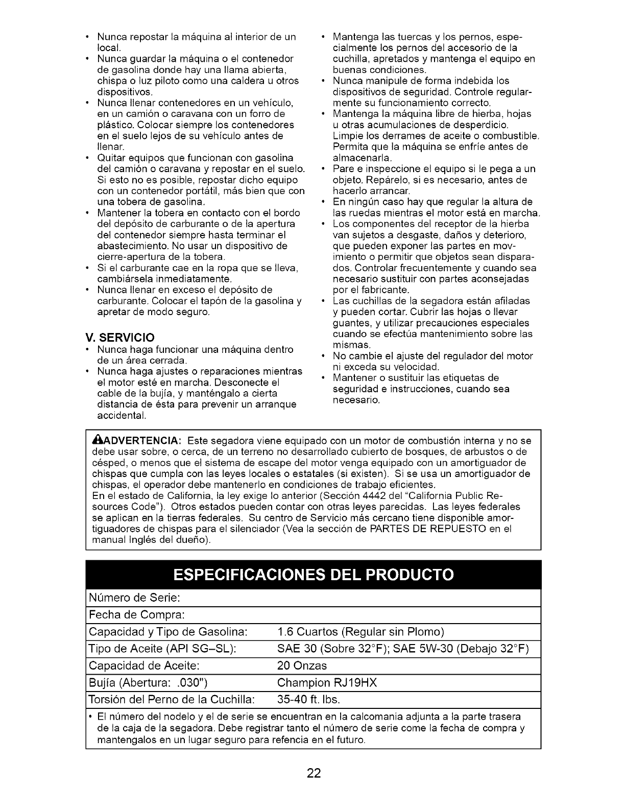
NQmero de Serie:
Fecha de Compra:
Capacidad y Tipo de Gasolina: 1.6 Cuartos (Regular sin Plomo)
Tipo de Aceite (API SG-SL): SAE 30 (Sobre 32°F); SAE 5W-30 (Debajo 32°F)
Capacidad de Aceite: 20 Onzas
Bujia (Abertura: .030") Champion RJ19HX
Torsion del Perno de la Cuchilla: 35-40 ft. Ibs.
El nQmero del nodelo y el de serie se encuentran en la calcomania adjunta a la parte trasera
de la caja de la segadora. Debe registrar tanto el nQmero de serie come la fecha de compra y
mantengalos en un lugar seguro para refencia en el futuro.
22
Acuerdos de Proteccibn para la Reparacibn
Congratulaciones por su buena compra. Su
nuevo producto Craftsman® esta disefiado
y fabricado para funcionar de modo fiable por
muchos afios. Pero como todos los productos,
puede necesitar alguna reparacion de tanto
en tanto. En este caso tener un Acuerdo de
Proteccion para la Reparacion puede hacerles
ahorrar dinero y fastidios.
Compre ahora un Acuerdo de ProtecciSn para
la ReparaciSn y protegese de molestias y gas-
tos inesperados.
Un Acuerdo incluye los puntos siguientes:
• Servicio experto de nuestros 12.000 espe-
cialistas profesionales en la reparacion.
• Servicio ilimitado sin cargo alguno para
las partes y la mano de obra sobre todas las
reparaciones garantizadas.
• Sustitucion del producto si su producto
garantizado no puede ser arreglado.
• Descuento del 10% sobre el precio cor-
riente del servicio y de las partes relativas al
servicio no cubiertas por el acuerdo; tambien
el 10% menos sobre el precio corriente de
un control de mantenimiento preventivo.
• Ayuda rapida por tel_fono - soporte tele-
f6nico por parte de un representante Sears
sobre productos que requieren un arreglo en
casa, y ademas una programacion sobre los
a reglos mas convenientes.
Cuando se ha comprado el Acuerdo, basta con
una Ilamada telef6nica para programar el servi-
cio. Puede Ilamar cuando quiera, dia y noche o
fijar en linea una cita para obtener el servicio.
Sears tiene mas de 12.000 especialistas
profesionales en la reparacion, que tienen
acceso a mas de 4.5 millones de partes y
accesorios de calidad. Este es el tipo de
profesionalidad con que puede contar para
ayudar a alargar la vida del producto que acaba
de comprar, por muchos afios, iCompre hoy su
Acuerdo de Proteccion para la Reparaci6n!
Se aplican algunas limitaciones y exclu-
siones. Para conocer los precios y tenet
m&s informaci6n, Ilame al 1-800-827-6655.
Servicio de Instalacion Sears
Para la instalacion profesional Sears de
aparatos de casa, puertas de garaje,
calentadores de agua y otros importantes
articulos para la casa, en U.S.A. Ilamar a
1-800-4-MY-HOME®.
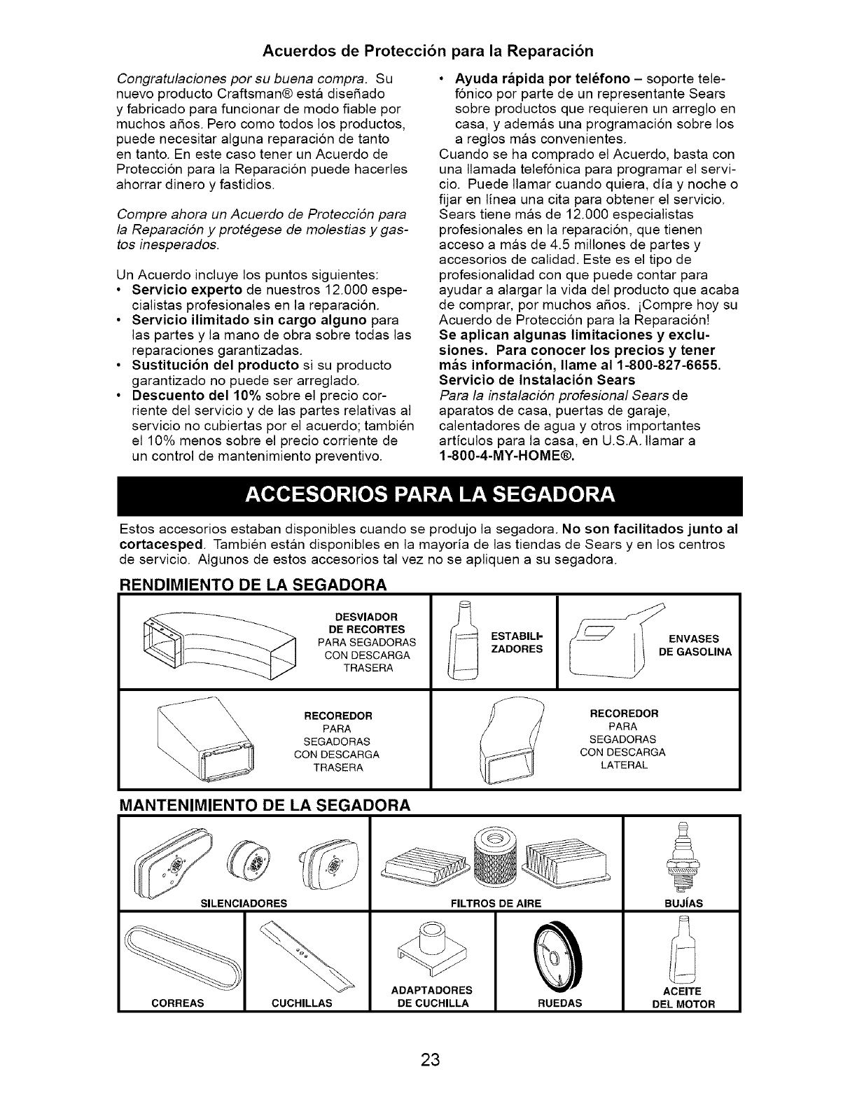
Estos accesorios estaban disponibles cuando se produjo la segadora. No son facilitados junto al
cortacesped Tambien estan disponibles en la mayoria de las tiendas de Sears yen los centros
de servicio. AIgunos de estos accesorios tal vez no se apliquen a su segadora.
RENDIMIENTO DE LA SEGADORA
DESVIADOR
DE RECORTES
PARA SEGADORAS
CON DESCARGA
TRASERA
RECOREDOR
PARA
SEGADORAS
CON DESCARGA
TRASERA
ESTABILI-
ZADORES
ENVASES
E GASOLINA
RECOREDOR
PARA
SEGADORAS
CON DESCARGA
LATERAL
MANTENIMIENTO DE LA SEGADORA
SILENCIADORES
CORREAS CUCHILLAS
FILTROS DE AIRE
ADAPTADORES
DE CUCHILLA RUEDAS
BUJiAS
ACEITE
DEL MOTOR
23
Lea estas instrucciones y el manual comple-
tamente antes de tratar de montar u operar su
segadora nueva.
IMPORTANTE: Este cortacesped viene SIN
ACEITE O GASOLtNA en el motor.
Su segadora nueva ha sido montada en la
fabrica con la excepcion de aquellas partes que
se dejaron sin montar por razones de envio.
Todas las partes como las tuercas, las arande-
las, los pernos, etc., que son necesarias para
completar el montaje han sido colocadas en la
bolsa de partes. Para asegurarse que su sega-
dora funcione en forma segura y adecuada,
todas las partes y los articulos de ferreteria que
se monten tienen que ser apretados segura-
mente. Use las herramientas correctas, como
sea necesario, para asegurar que se aprieten
adecuadamente.
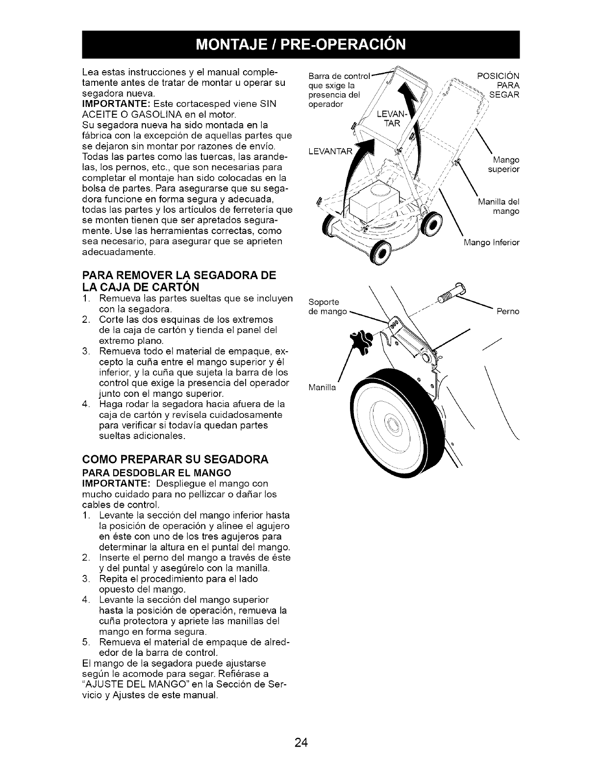
Barra de
que sxige la
presencia del
operador
LEVANTAR
PARA REMOVER LA SEGADORA DE
LA CAJA DE CARTON
1. Remueva las partes sueltas que se incluyen Soporte
con la segadora, de
2. Corte las dos esquinas de los extremos
de la caja de cart6n y tienda el panel del
extremo piano.
3. Remueva todo el material de empaque, ex-
cepto la curia entre el mango superior y el
inferior, y la curia que sujeta la barra de los
control que exige la presencia del operador Manilla
junto con el mango superior.
4. Haga rodar la segadora hacia afuera de la
caja de cart6n y revisela cuidadosamente
para verificar si todavia quedan partes
sueltas adicionales.
COMO PREPARAR SU SEGADORA
PARA DESDOBLAR EL MANGO
IMPORTANTE: Despliegue el mango con
mucho cuidado para no pellizcar o dafiar los
cables de control.
1. Levante la seccion del mango inferior hasta
la posicion de operacion y alinee el agujero
en este con uno de los tres agujeros para
determinar la altura en el puntal del mango.
2. Inserte el perno del mango a traves de este
y del puntal y asegQrelo con la manilla.
3. Repita el procedimiento para el lado
opuesto del mango.
4. Levante la seccion del mango superior
hasta la posicion de operacion, remueva la
curia protectora y apriete las manillas del
mango en forma segura.
5. Remueva el material de empaque de alred-
edor de la barra de control.
El mango de la segadora puede ajustarse
segQn le acomode para segar. Refierase a
"AJUSTE DEL MANGO" en la Seccion de Ser-
vicio y Ajustes de este manual.
POSlCION
PARA
SEGAR
Mango
superior
Manilla del
mango
Mango Inferior
J_Perno
24
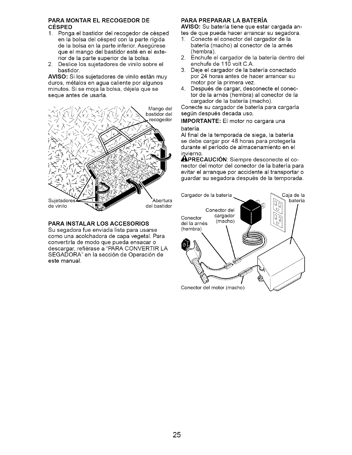
PARA MONTAR EL RECOGEDOR DE
cO:SPED
1. Ponga el bastidor del recogedor de cesped
en la bolsa del cesped con la parte rigida
de la bolsa en la parte inferior. AsegQrese
que el mango del bastidor este en el exte-
rior de la parte superior de la bolsa.
2. Deslice los sujetadores de vinilo sobre el
bastidor.
AVlSO: Si los sujetadores de vinilo estan muy
duros, metalos en agua caliente por algunos
minutos. Si se moja la bolsa, dejela que se
seque antes de usarla.
Mango del
bastidor del
recogedor
Sujetador_
de vinilo del bastidor
PARA INSTALAR LOS ACCESORIOS
Su segadora fue enviada lista para usarse
como una acolchadora de capa vegetal. Para
convertirla de modo que pueda ensacar o
descargar, refierase a "PARA CONVERTIR LA
SEGADORA" en la seccion de Operacion de
este manual.
PARA PREPARAR LA BATERJA
AVISO: Su bateda tiene que estar cargada an-
tes de que pueda hacer arrancar su segadora.
1. Conecte el conector del cargador de la
bateda (macho) al conector de la arnes
(hembra).
2. Enchufe el cargador de la bateria dentro del
enchufe de 110 volt C.A.
3. Deje el cargador de la bateda conectado
por 24 horas antes de hacer arrancar su
motor por la primera vez.
4. Despues de cargar, desconecte el conec-
tor de la arnes (hembra) al conector de la
cargador de la bateda (macho).
Conecte su cargador de bateda para cargarla
segQn despues decada uso.
IMPORTANTE: El motor no cargara una
bateda.
AI final de la temporada de siega, la bateda
se debe cargar por 48 horas para protegerla
durante el periodo de almacenamiento en el
_1_iern°-
PRECAUClON: Siempre desconecte el co-
nector del motor del conector de la bateda para
evitar el arranque por accidente al transportar o
guardar su segadora despues de la temporada.
Cargador de la bateria
Conector del
Conector cargador
della arnes (macho)
(hembra)
Caja de la
bateria
Conector del motor (macho)
25
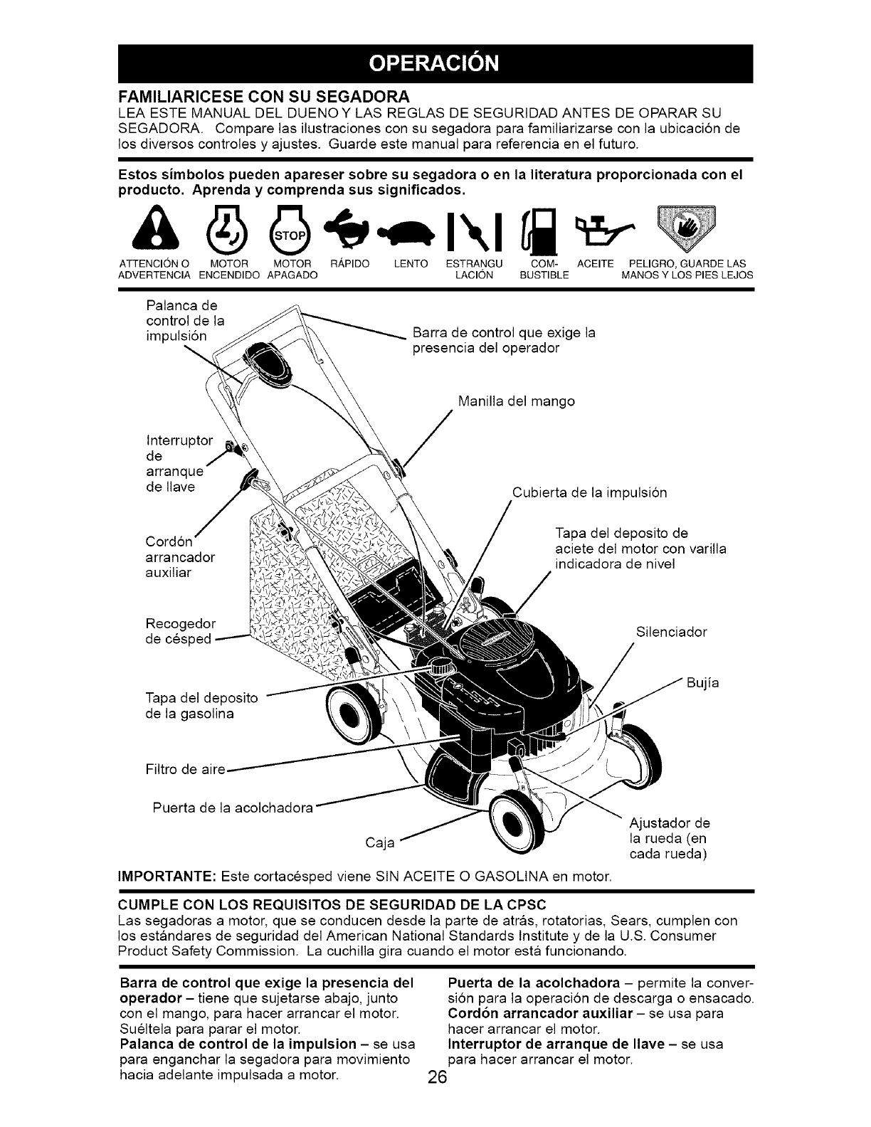
FAMILIARICESE CON SU SEGADORA
LEA ESTE MANUAL DEL DUENOY LAS REGLAS DE SEGURtDAD ANTES DE OPARAR SU
SEGADORA. Compare las ilustraciones con su segadora para familiarizarse con la ubicacion de
los diversos controles y ajustes. Guarde este manual para referencia en el futuro.
Estos simbolos pueden apareser sobre su segadora o en la literatura proporcionada con el
producto. Aprenda y comprenda sus significados.
ATTENCION O MOTOR MOTOR R_,PIDO LENTO ESTRANGU COM- ACEITE PELIGRO, GUARDE LAS
ADVERTENCIA ENCENDIDO APAGADO LACION BUSTIBLE MANOS Y LOS PIES LEJOS
Palanca de
control de la
impulsion Barra de control que exige la
presencia del operador
Manilla del mango
Interruptor
de
arranque
de Ilave Cubierta de la impulsion
Cordon
arrancador
auxiliar
Tapa del deposito de
aciete del motor con varilla
indicadora de nivel
Recogedor
de cesf
Tapa del deposito
de la gasolina
Filtro de aire
Silenciador
Bujia
Puerta de la acolchadora
Caja
IMPORTANTE: Este cortacesped viene SIN ACEtTE O GASOLINA en motor.
Ajustador de
la rueda (en
cada rueda)
CUMPLE CON LOS REQUISITOS DE SEGURIDAD DE LA CPSC
Las segadoras a motor, que se conducen desde la parte de atras, rotatorias, Sears, cumplen con
los estandares de seguridad del American National Standards Institute y de la U.S. Consumer
Product Safety Commission. La cuchilla gira cuando el motor esta funcionando.
Barra de control que exige la presencia del
operador- tiene que sujetarse abajo, junto
con el mango, para hacer arrancar el motor.
Sueltela para parar el motor.
Palanca de control de la impulsion - se usa
para enganchar la segadora para movimiento
hacia adelante impulsada a motor.
Puerta de la acolchadora - permite la conver-
sion para la operacion de descarga o ensacado.
Cord6n arrancador auxiliar- se usa para
hacer arrancar el motor.
Interruptor de arranque de Ilave - se usa
para hacer arrancar el motor.
26
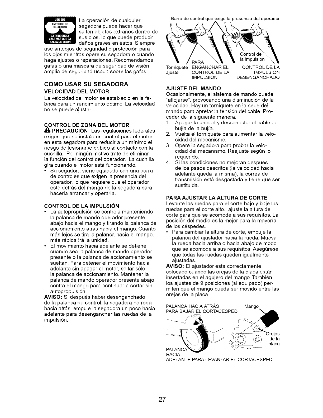
La operacion de cualquier
segadora puede hacer que
salten objetos extrafios dentro de
sus ojos, Io que puede producir
dafios graves en estos. Siempre
use anteojos de seguridad o proteccion para
los ojos mientras opere su segadora o cuando
haga ajustes o reparaciones. Recomendamos
gafas o una mascara de seguridad de vision
amplia de seguridad usada sobre las gafas.
COMO USAR SU SEGADORA
VELOCIDAD DEL MOTOR
La velocidad del motor se estableci6 en la fa-
brica para un rendimiento 6ptimo. La velocidad
no se puede ajustar.
_NTROL DE ZONA DEL MOTOR
PRECAUCION: Las regulaciones federales
exigen que se instale un control para el motor
en esta segadora para reducir a un minimo el
riesgo de lesionarse debido al contacto con la
cuchilla. Per ningQn motive trate de eliminar
la funci6n del control del operador. La cuchilla
gira cuando el motor esta funcionando.
• Su segadora viene equipada con una barra
de controles que exigen la presencia del
operador, Io que requiere que el operador
este detras del mango de la segadora para
hacerla arrancar y operarla.
CONTROL DE LA IMPULSION
• La autopropulsi6n se controla manteniendo
la palanca de mando operador presente
abajo hacia el mango y tirando la palanca de
accionamiento atras hacia el mango. Cuanto
mas lejos se tira la palanca hacia el mango,
mas rapida ira la unidad.
• El movimiento hacia adelante se detiene
cuando sea la palanca de mando operador
presente o la palanca de accionamiento se
sueltan. Para detener el movimiento hacia
adelante sin apagar el motor, soltar s61o
la palanca de accionamiento. Mantener la
palanca de mando operador presente abajo
contra el mango para continuar a cortar sin
autopropulsi6n.
AVlSO: Si despues haber desenganchado
de la palanca de control, la segadora no roda
hacia atras, empuje la segadora un poco hacia
adelante para desenganchar las ruedas de la
impulsion.
Barra de control que oresencia del operador
Torniquete ENGANCHAR EL
ajuste CONTROL DE LA
IMPULSION
Control de
la impulsi6n
CONTROL DE LA
IMPULSION
DESENGANCHADO
AJUSTE DEL MANDO
Ocasionalmente, el sistema de mando puede
"aflojarse", provocando una disminucion de la
velocidad. Hay un torniquete en la sede del
mando para apretar la tension del cable. Pro-
ceder de la siguiente manera:
1. Apagar la unidad y desconectar el cable de
bujia de la bujia.
2. Vuelta el torniquete para aumentar la velo-
cidad del mecanismo.
3. Opere la segadora para probar la velo-
cidad del mecanismo. Reajuste segQn Io
requerido.
4. Si las condiciones no mejoran despues
de los pasos descritos (la velocidad hacia
adelante queda la misma), la correa de
transmision esta desgastada y tiene que ser
sustituida.
PARA AJUSTAR LA ALTURA DE CORTE
Levante las ruedas para el corte bajo y baje las
ruedas para el corte alto., ajuste la altura de
corte para que se acomode a sus requisitos. La
posicion del medio es la mejor para la mayoria
de los cespedes.
• Para cambiar la altura de corte, empuje la
palanca del ajustador hacia la rueda. Mueva
la rueda hacia arriba o hacia abajo de mode
que se acomode a sus requisitos. AsegQrese
que todas las ruedas queden igualmente
ajustadas.
AVlSO: El ajustador esta correctamente
colocado cuando las orejas de la placa estan
insertadas en el agujero del mango. Tambien,
los ajustes de 9 posiciones (si equipado) per-
miten que el mango pueda ser movido entre las
orejas de la placa.
PALANCA HACIA ATRAS ,Mango
PARA BAJAR EL CORTACESPED _ "_
HACIA
ADELANTE PARA LEVANTAR EL CORTACESPED
27
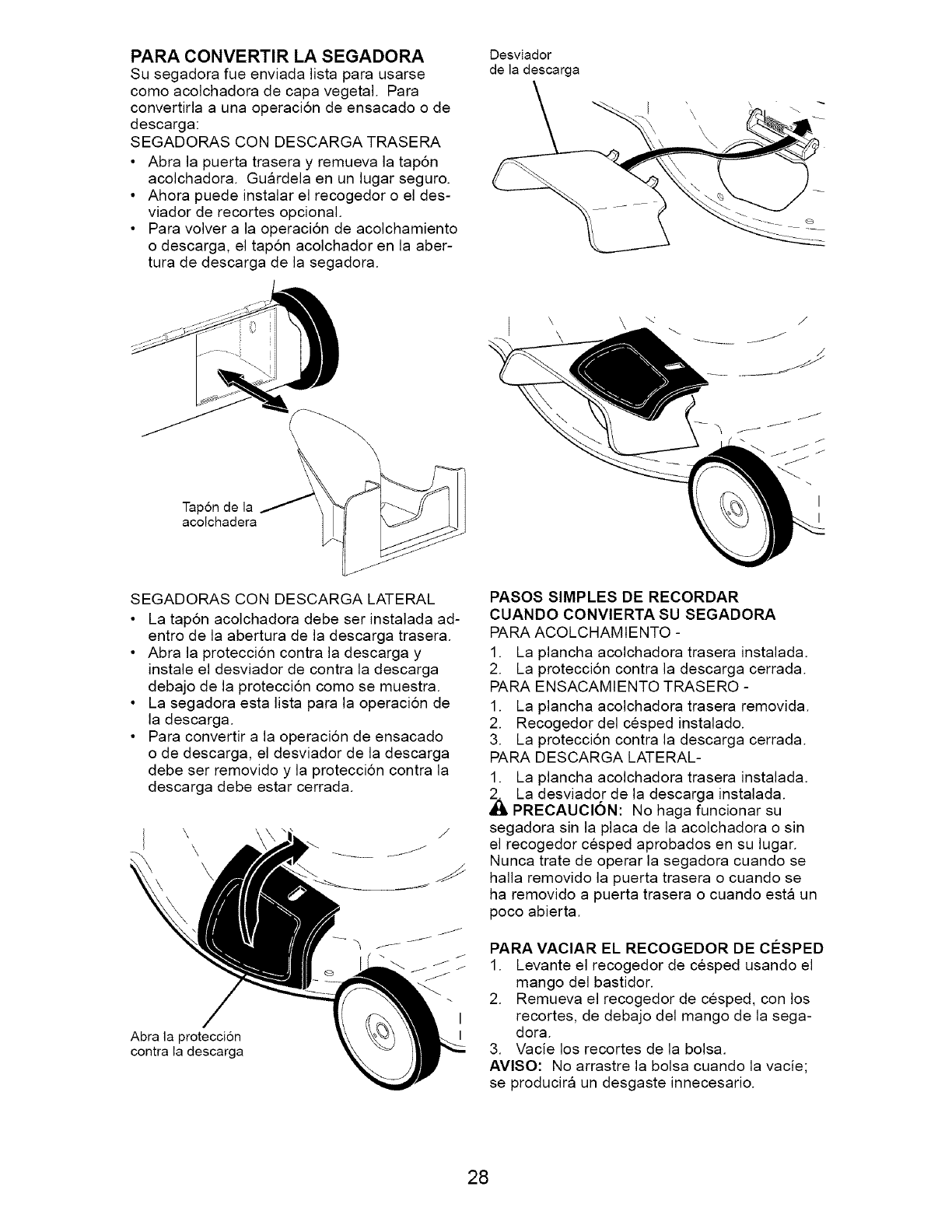
PARA CONVERTIR LA SEGADORA
Su segadora fue enviada lista para usarse
como acolchadora de capa vegetal. Para
convertirla a una operaci6n de ensacado o de
descarga:
SEGADORAS CON DESCARGA TRASERA
• Abra la puerta trasera y remueva la tap6n
acolchadora. Gu_lrdela en un lugar seguro.
• Ahora puede instalar el recogedor o el des-
viador de recortes opcional.
• Para volver a la operaci6n de acolchamiento
o descarga, el tap6n acolchador en la aber-
tura de descarga de la segadora.
Desviador
de la descarga
Tapon de la
acolchadera
SEGADORAS CON DESCARGA LATERAL
• La tap6n acolchadora debe ser instalada ad-
entro de la abertura de la descarga trasera.
• Abra la proteccion contra la descarga y
instale el desviador de contra la descarga
debajo de la proteccion como se muestra.
• La segadora esta lista para la operacion de
la descarga.
• Para convertir a la operacion de ensacado
o de descarga, el desviador de la descarga
debe ser removido y la proteccion contra la
descarga debe estar cerrada.
Abra la proteccion
contra la descarga
I
I
PASOS SIMPLES DE RECORDAR
CUANDO CONVlERTA SU SEGADORA
PARA ACOLCHAMIENTO -
1. La plancha acolchadora trasera instalada.
2. La proteccion contra la descarga cerrada.
PARA ENSACAMIENTO TRASERO -
1. La plancha acolchadora trasera removida.
2. Recogedor del cesped instalado.
3. La proteccion contra la descarga cerrada.
PARA DESCARGA LATERAL-
1. La plancha acolchadora trasera instalada.
k La desviador de la descarga instalada.
PRECAUCION: No haga funcionar su
segadora sin la placa de la acolchadora o sin
el recogedor cesped aprobados en su lugar.
Nunca trate de operar la segadora cuando se
halla removido la puerta trasera o cuando se
ha removido a puerta trasera o cuando esta un
poco abierta.
PARA VACIAR EL RECOGEDOR DE CIeSPED
1. Levante el recogedor de cesped usando el
mango del bastidor.
2. Remueva el recogedor de cesped, con los
recortes, de debajo del mango de la sega-
dora.
3. Vacie los recortes de la bolsa.
AVlSO: No arrastre la bolsa cuando la vacie;
se producira un desgaste innecesario.
28
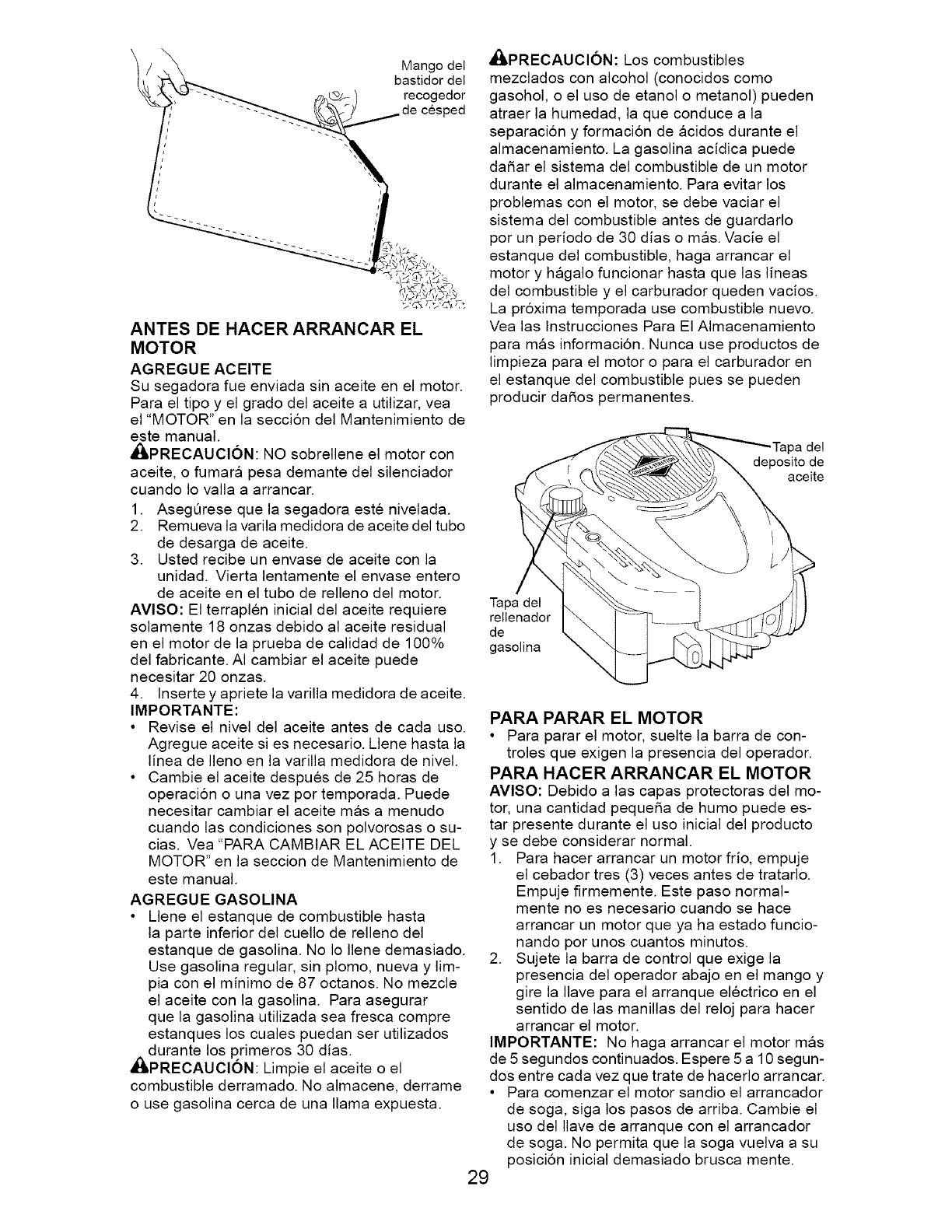
Mango del
bastidor del
recogedor
ANTES DE HACER ARRANCAR EL
MOTOR
AGREGUE ACEITE
Su segadora fue envJada sin aceJte en el motor.
Para el tipo y el grado del aceJte a utilizar, yea
el "MOTOR" en la seccion del Mantenimiento de
este manual.
,_/LPRECAUCl6N: NO sobrellene el motor con
aceite, o fumara pesa demante del silenciador
cuando Io valla a arrancar.
1. AsegQrese que la segadora este nivelada.
2. Remueva la varila medidora de aceite del tubo
de desarga de aceite.
3. Usted recibe un envase de aceite con la
unidad. Vierta lentamente el envase entero
de aceite en el tubo de relleno del motor.
AVlSO: El terraplen inicial del aceite requiere
solamente 18 onzas debido al aceite residual
en el motor de la prueba de calidad de 100%
del fabricante. AI cambiar el aceite puede
necesitar 20 onzas.
4. lnserte y apriete la varilla medidora de aceite.
IMPORTANTE:
• Revise el nivel del aceite antes de cada uso.
Agregue aceite si es necesario. Llene hasta la
linea de Ileno en la varilla medidora de nivel.
• Cambie el aceite despues de 25 horas de
operacion o una vez por temporada. Puede
necesitar cambiar el aceite mas a menudo
cuando las condiciones son polvorosas o su-
cias. Vea "PARA CAMBtAR EL ACEITE DEL
MOTOR" en la seccion de Mantenimiento de
este manual.
AGREGUE GASOLINA
• Llene el estanque de combustible hasta
la parte inferior del cuello de relleno del
estanque de gasolina. No Io Ilene demasiado.
Use gasolina regular, sin plomo, nueva y lim-
pia con el minimo de 87 octanos. No mezcle
el aceite con la gasolina. Para asegurar
que la gasolina utilizada sea fresca compre
estanques los cuales puedan ser utilizados
dl durante los primeros 30 dias.
PRECAUClON: Limpie el aceite o el
combustible derramado. No almacene, derrame
o use gasolina cerca de una llama expuesta.
_,PRECAUCl6N: Los combustibles
mezclados con alcohol (conocidos como
gasohol, o el uso de etanol o metanol) pueden
atraer la humedad, la que conduce a la
separaci6n y formacion de acidos durante el
almacenamiento. La gasolina acidica puede
daSar el sistema del combustible de un motor
durante el almacenamiento. Para evitar los
problemas con el motor, se debe vaciar el
sistema del combustible antes de guardarlo
por un periodo de 30 dias o mas. Vacie el
estanque del combustible, haga arrancar el
motor y hagalo funcionar hasta que las lineas
del combustible y el carburador queden vacios.
La pr6xima temporada use combustible nuevo.
Vea las lnstrucciones Para El AImacenamiento
para mas informaci6n. Nunca use productos de
limpieza para el motor o para el carburador en
el estanque del combustible pues se pueden
producir daSos permanentes.
Tapa del
deposito de
aceite
Tapa del
rellenador
de
gasolina
PARA PARAR EL MOTOR
• Para parar el motor, suelte la barra de con-
troles que exigen la presencia del operador.
PARA HACER ARRANCAR EL MOTOR
AVlSO: Debido alas capas protectoras del mo-
tor, una cantidad peque5a de humo puede es-
tar presente durante el uso inicial del producto
y se debe considerar normal.
1. Para Racer arrancar un motor frio, empuje
el cebador tres (3) veces antes de tratarlo.
Empuje firmemente. Este paso normal-
mente no es necesario cuando se Race
arrancar un motor que ya ha estado funcio-
nando por unos cuantos minutos.
2. Sujete la barra de control que exige la
presencia del operador abajo en el mango y
gire la Ilave para el arranque electrico en el
sentido de las manillas del reloj para Racer
arrancar el motor.
IMPORTANTE: No haga arrancar el motor mas
de 5 segundos continuados. Espere 5 a 10 segun-
dos entre cada vez que trate de hacerlo arrancar.
• Para comenzar el motor sandio el arrancador
de soga, siga los pasos de arriba. Cambie el
uso del Ilave de arranque con el arrancador
de soga. No permita que la soga vuelva a su
posici6n inicial demasiado brusca mente.
29
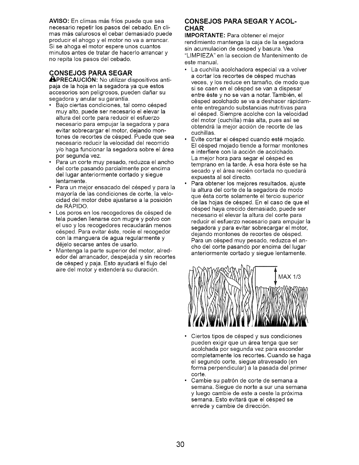
AVlSO: En climas mas fdos puede que sea
necesario repetir los pasos del cebado. En cli-
mas mas calurosos el cebar demasiado puede
producir el ahogo y el motor no va a arrancar.
Si se ahoga el motor espere unos cuantos
minutos antes de tratar de hacerlo arrancar y
no repita los pasos del cebado.
CONSEJOS PARA SEGAR
dI_PRECAUCI6N: No utilizar dispositivos anti-
paja de la hoja en la segadora ya que estos
accesorios son peligrosos, pueden daSar su
segadora y anular su garantia.
• Bajo ciertas condiciones, tal como cesped
muy alto, puede ser necesario el elevar la
altura del corte para reducir el esfuerzo
necesario para empujar la segadora y para
evitar sobrecargar el motor, dejando mon-
tones de recortes de cesped. Puede que sea
necesario reducir la velocidad del recorrido
y/o haga funcionar la segadora sobre el area
por segunda vez.
• Para un corte muy pesado, reduzca el ancho
del corte pasando parcialmente por encima
del lugar anteriormente cortado y siegue
lentamente.
• Para un mejor ensacado del cesped y para la
mayoria de las condiciones de corte, la velo-
cidad del motor debe ajustarse a la posici6n
de RAPIDO.
• Los poros en los recogedores de cesped de
tela pueden Ilenarse con mugre y polvo con
el uso y los recogedores recaudaran menos
cesped. Para evitar este, rocie el recogedor
con la manguera de agua regularmente y
dejelo secarse antes de usarlo.
• Mantenga la parte superior del motor, alred-
edor del arrancador, despejada y sin recortes
de cesped y paja. Esto ayudara el flujo del
aire del motor y extendera su duraci6n.
CONSEJOS PARA SEGAR Y ACOL-
CHAR
IMPORTANTE: Para obtener el mejor
rendimiento mantenga la caja de la segadora
sin acumulacion de cesped y basura. Vea
"LIMPIEZA" en la seccion de Mantenimento de
este manual.
• La cuchilla acolchadora especial va a volver
a cortar los recortes de cesped muchas
veces, y los reduce en tamaSo, de modo que
si se caen en el cesped se van a dispesar
entre este y no se van a notar. Tambien, el
cesped acolchado se va a deshacer rapidam-
ente entregando substancias nutritivas para
el cesped. Siempre acolche con la velocidad
del motor (cuchilla) mas alta, pues asi se
obtendra la mejor acci6n de recorte de las
cuchillas.
• Evite cortar el cesped cuando este mojado.
El cesped mojado tiende a formar montones
e interfiere con la acci6n de acolchado.
La mejor hora para segar el cesped es
temprano en la tarde. A esa hora este se ha
secado y el area recien cortada no quedara
expuesta al sol directo.
• Para obtener los mejores resultados, ajuste
la altura del corte de la segadora de modo
que esta corte solamente el tercio superior
de las hojas de cesped. En el caso de que el
cesped haya crecido demasiado, puede ser
necesario el elevar la altura del corte para
reducir el esfuerzo necesario para empujar la
segadora y para evitar sobrecargar el motor,
dejando montones de recortes de cesped.
Para un cesped muy pesado, reduzca el an-
cho del corte pasando por encima del lugar
anteriormente cortado y siegue lentamente.
MAX 1/3
• Ciertos tipos de cesped y sus condiciones
pueden exigir que un area tenga que ser
acolchada por segunda vez para esconder
completamente los recortes. Cuando se haga
el segundo corte, siegue atravesado (en
forma perpendicular) a la pasada del primer
corte.
• Cambie su patr6n de corte de semana a
semana. Siegue de norte a sur una semana
y luego cambie de este a oeste la pr6xima
semana. Esto evitara que el cesped se
enrede y cambie de direccion.
30
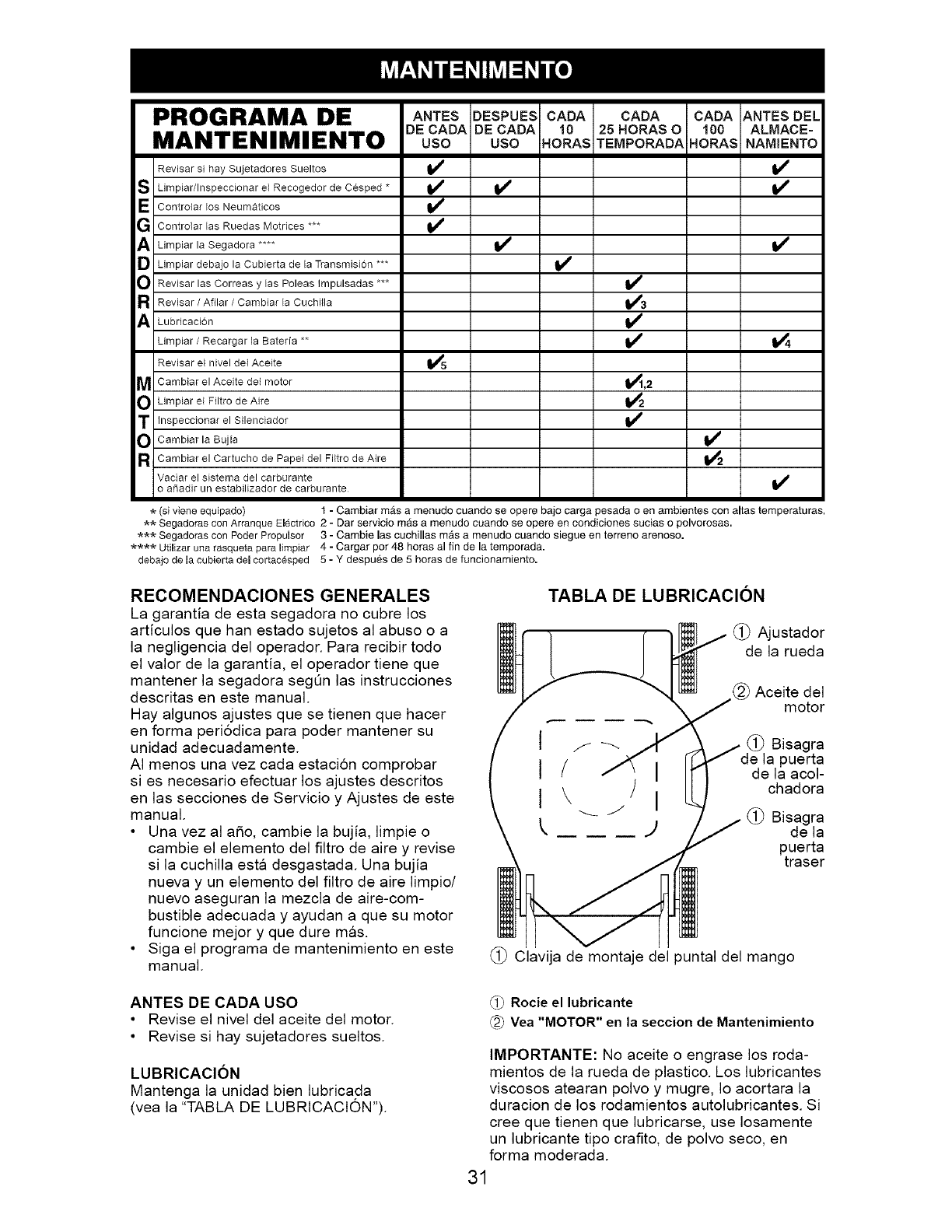
PROGRAMA DE
MANTENIMIENTO
Revisar si hay Sujetadores Sueltos
S Limpiar/Inspeccionar el Recogedor de Cesped *
EControlar los Neumaticos
G Controlar las Ruedas Motrices ***
il_ Limpiar la Segadora ....
[_ Limpiar debajo la Cubierta de la Transmision ***
O Revisar las Correas y las Poleas Impulsadas ***
R Revisar /Afllar /Cambiar la CuchHla
il_ Lubricacion
Limpiar /Recargar la Bateria **
Revisar el nivel del Aceite
MCambiar el Aceite del motor
O Limpiar el Filtro de Aire
ANTES DESPUES CADA CADA CADA ANTES DEL
DE CADA DE CADA 10 25 HORAS O 100 ALMACE=
USO USO HORAS TEMPORADA HORAS NAMIENTO
v'
_,2
T Inspeccionar el Silenciador
Cambiar la Bujia J
R Cambiar el Cartucho de Papel del FHtro de Aire
Vaciar el sistema del carburante
o aSadir un estabilizador de carburante
(si viene equipado) 1 -Cambiar mas a menudo cuando se opere bajo carga pesada o en ambientes con altas temperaturas,
_ Segadoras con Arranque EI6ctrico 2 - Dar servicio m_.s a menudo cuando se opere en condiciones sucias o polvorosas.
_ Segadoras con Poder Propulsor 3 - Gamble las cuchillas m_s a menudo cuando siegue en terreno arenoso.
**** Utilizar una rasqueta para limpiar 4 - Cargar pot 48 horas al fin de la temporada.
debajo de la cubierta del cortacesped 5 - Y despu_s de 5 horas de funcionamiento.
RECOMENDACIONES GENERALES
La garantia de esta segadora no cubre los
articulos que han estado sujetos al abuso o a
la negligencia del operador. Para recibir todo
el valor de la garantia, el operador tiene que
mantener la segadora segQn las instrucciones
descritas en este manual.
Hay algunos ajustes que se tienen que hacer
en forma periodica para poder mantener su
unidad adecuadamente.
AI menos una vez cada estacion comprobar
si es necesario efectuar los ajustes descritos
en las secciones de Servicio y Ajustes de este
manual.
• Una vez al a_o, cambie la bujia, limpie o
cambie el elemento del filtro de aire y revise
si la cuchilla esta desgastada. Una bujia
nueva y un elemento del filtro de aire limpio/
nuevo aseguran la mezcla de aire-com-
bustible adecuada y ayudan a que su motor
funcione mejor y que dure mas.
• Siga el programa de mantenimiento en este
manual.
TABLA DE LUBRICAClON
(_) Ajustador
de la rueda
Aceite del
motor
(_) Bisagra
puerta
de la acol-
chadora
(_) Bisagra
de la
puerta
traser
(_) Clavija de montaje del puntal del mango
ANTES DE CADA USO
• Revise el nivel del aceite del motor.
• Revise si hay sujetadores sueltos.
LUBRICAClON
Mantenga la unidad bien lubricada
(vea la "TABLA DE LUBRtCACION").
Rocie el lubricante
Yea "MOTOR" en la seccion de Mantenimiento
IMPORTANTE: No aceite o engrase los roda-
mientos de la rueda de plastico. Los lubricantes
viscosos atearan polvo y mugre, Io acortara la
duracion de los rodamientos autolubricantes. Si
cree que tienen que lubricarse, use Iosamente
un lubricante tipo crafito, de polvo seco, en
forma moderada.
31
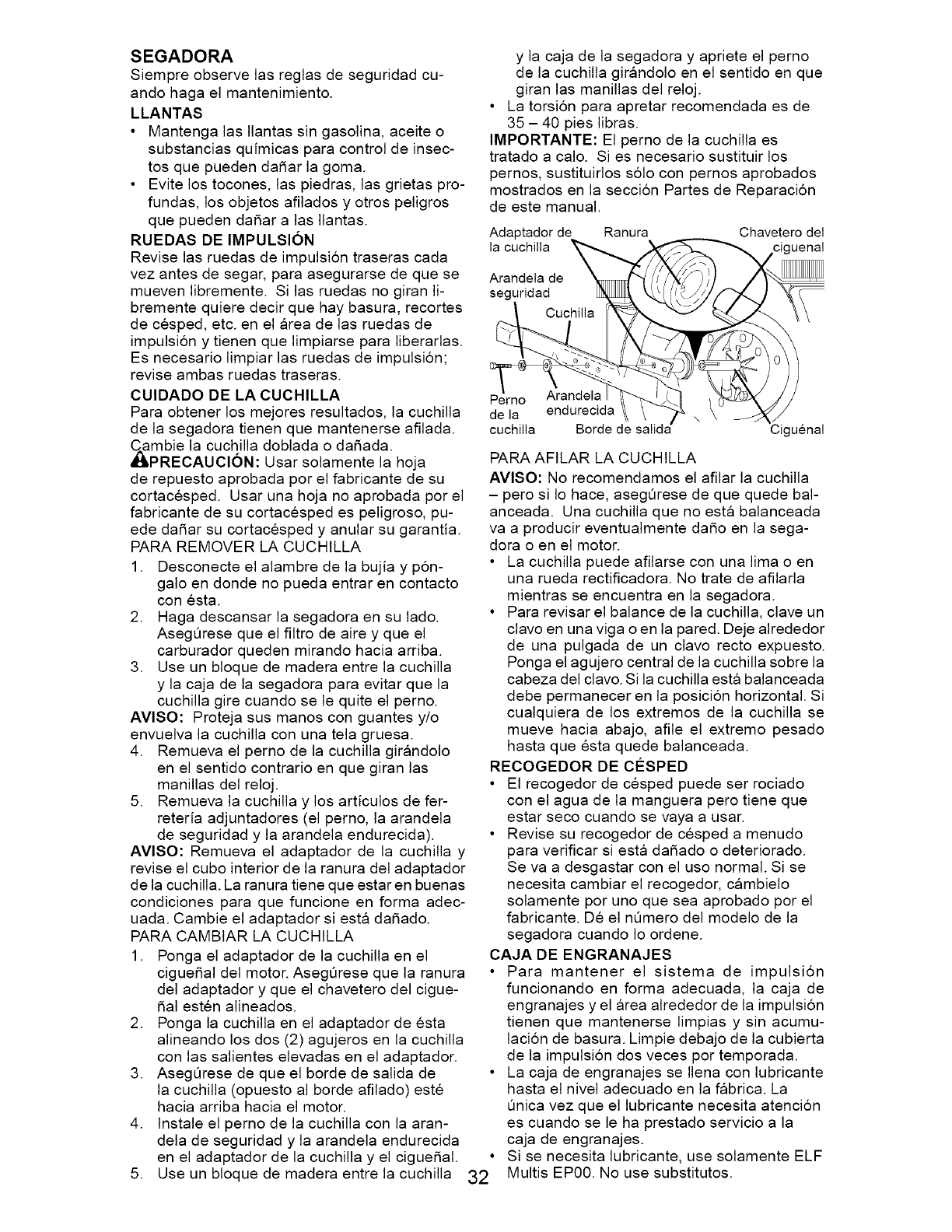
SEGADORA
Siempre observe las reglas de seguridad cu-
ando haga el mantenimiento.
LLANTAS
• Mantenga las Ilantas sin gasolina, aceite o
substancias quimicas para control de insec-
tos que pueden dafiar la goma.
• Evite los tocones, las piedras, las grietas pro-
fundas, los objetos afilados y otros peligros
que pueden dafiar alas Ilantas.
RUEDAS DE IMPULSION
Revise las ruedas de impulsi6n traseras cada
vez antes de segar, para asegurarse de que se
mueven libremente. Si las ruedas no giran li-
bremente quiere decir que hay basura, recortes
de cesped, etc. en el area de las ruedas de
impulsi6n y tienen que limpiarse para liberarlas.
Es necesario limpiar las ruedas de impulsion;
revise ambas ruedas traseras.
CUlDADO DE LA CUCHILLA
Para obtener los mejores resultados, la cuchilla
de la segadora tienen que mantenerse afilada.
_mbie la cuchilla doblada o dafiada.
PRECAUClON: Usar solamente la hoja
de repuesto aprobada por el fabricante de su
cortacesped. Usar una hoja no aprobada por el
fabricante de su cortacesped es peligroso, pu-
ede dafiar su cortacesped y anular su garantia.
PARA REMOVER LA CUCHILLA
1. Desconecte el alambre de la bujia y p6n-
galo en donde no pueda entrar en contacto
con esta.
2. Haga descansar la segadora en su lado.
AsegQrese que el filtro de aire y que el
carburador queden mirando hacia arriba.
3. Use un bloque de madera entre la cuchilla
y la caja de la segadora para evitar que la
cuchilla gire cuando se le quite el perno.
AVlSO: Proteja sus manos con guantes y/o
envuelva la cuchilla con una tela gruesa.
4. Remueva el perno de la cuchilla girandolo
en el sentido contrario en que giran las
manillas del reloj.
5. Remueva la cuchilla y los articulos de fer-
reteria adjuntadores (el perno, la arandela
de seguridad y la arandela endurecida).
AVlSO: Remueva el adaptador de la cuchilla y
revise el cubo interior de la ranura del adaptador
de la cuchilla. La ranura tiene que estar en buenas
condiciones para que funcione en forma adec-
uada. Cambie el adaptador siesta dafiado.
PARA CAMBIAR LA CUCHILLA
1. Ponga el adaptador de la cuchilla en el
ciguefial del motor. AsegQrese que la ranura
del adaptador y que el chavetero del cigue-
fial esten alineados.
2. Ponga la cuchilla en el adaptador de esta
alineando los dos (2) agujeros en la cuchilla
con las salientes elevadas en el adaptador.
3. AsegQrese de que el borde de salida de
la cuchilla (opuesto al borde afilado) este
hacia arriba hacia el motor.
4. Instale el perno de la cuchilla con la aran-
dela de seguridad y la arandela endurecida
en el adaptador de la cuchilla y el ciguefial.
5. Use un bloque de madera entre la cuchilla
y la caja de la segadora y apriete el perno
de la cuchilla girandolo en el sentido en que
giran las manillas del reloj.
• La torsion para apretar recomendada es de
35 - 40 pies libras.
IMPORTANTE: El perno de la cuchilla es
tratado a calo. Si es necesario sustituir los
pernos, sustituirlos solo con pernos aprobados
mostrados en la seccion Partes de Reparaci6n
de este manual.
32
Adaptador de Ranura Chavetero del
la cuchilla Jenal
Arandela de
seguridad
Perno Arandela
de la endurecida
cuchilla Borde de salida :iguenal
PARA AFILAR LA CUCHILLA
AVlSO: No recomendamos el afilar la cuchilla
- pero si Io hace, asegQrese de que quede bal-
anceada. Una cuchilla que no esta balanceada
va a producir eventualmente dafio en la sega-
dora o en el motor.
• La cuchilla puede afilarse con una lima o en
una rueda rectificadora. No trate de afilarla
mientras se encuentra en la segadora.
• Para revisar el balance de la cuchilla, clave un
clavo en una viga o en la pared. Deje alrededor
de una pulgada de un clavo recto expuesto.
Ponga el agujero central de la cuchilla sobre la
cabeza del clavo. Si la cuchilla esta balanceada
debe permanecer en la posicion horizontal. Si
cualquiera de los extremos de la cuchilla se
mueve hacia abajo, afile el extremo 3esado
hasta que esta quede balanceada.
RECOGEDOR DE CO:SPED
• El recogedor de cesped puede ser rociado
con el agua de la manguera pero tiene que
estar seco cuando se vaya a usar.
• Revise su recogedor de cesped a menudo
para verificar siesta dafiado o deteriorado.
Se va a desgastar con el uso normal. Si se
necesita cambiar el recogedor, cambielo
solamente por uno que sea aprobado por el
fabricante. De el nQmero del modelo de la
segadora cuando Io ordene.
CAJA DE ENGRANAJES
• Para mantener el sistema de impulsion
funcionando en forma adecuada, la caja de
engranajes y el area alrededor de la impulsi6n
tienen que mantenerse limpias y sin acumu-
lacion de basura. Limpie debajo de la cubierta
de la impulsion dos veces por temporada.
• La caja de engranajes se Ilena con lubricante
hasta el nivel adecuado en la fabrica. La
Qnica vez que el lubricante necesita atencion
es cuando se le ha prestado servicio a la
caja de engranajes.
Si se necesita lubricante, use solamente ELF
Multis EP00. No use substitutos.
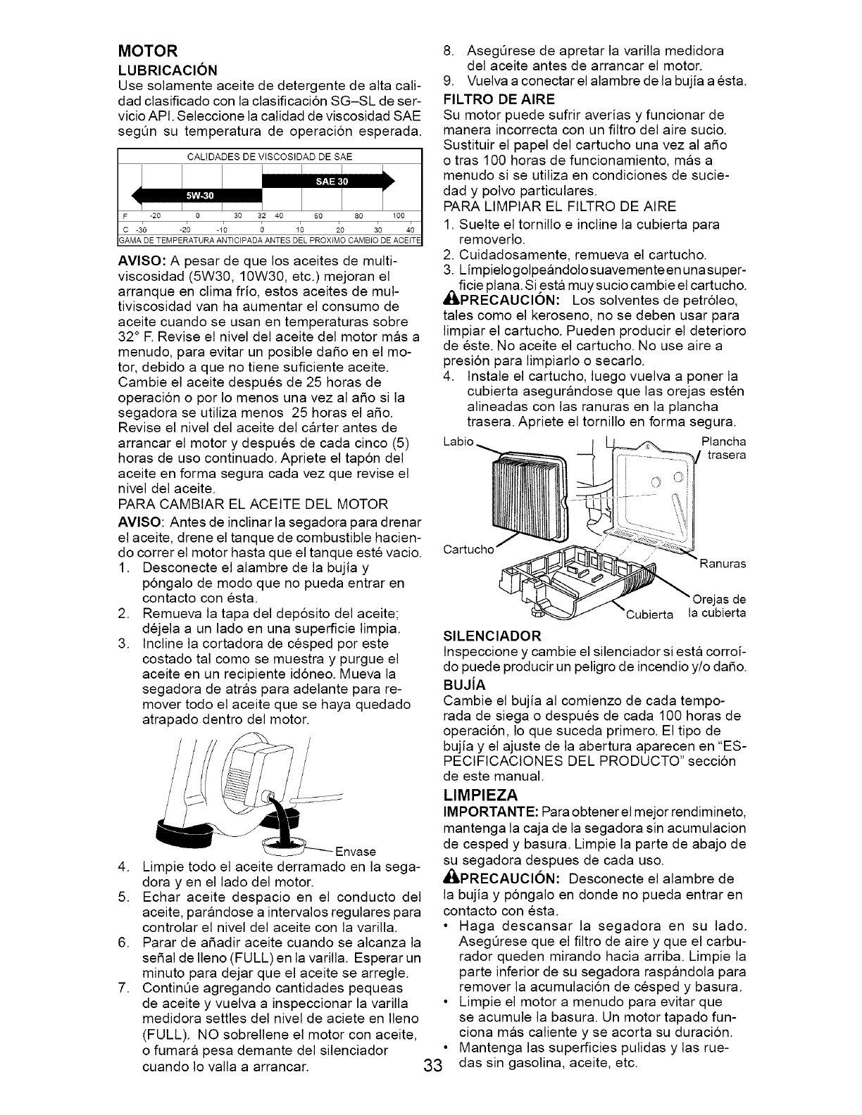
MOTOR
LUBRICACION
Use solamente aceite de detergente de alta cali-
dad clasificado con la clasificacion SG-SL de ser-
vicio API. Seleccione la calidad de viscosidad SAE
segQn su temperatura de operacion esperada.
AVlSO: A pesar de que los aceites de multi-
viscosidad (5W30, 10W30, etc.) mejoran el
arranque en clima frio, estos aceites de mul-
tiviscosidad van ha aumentar el consumo de
aceite cuando se usan en temperaturas sobre
32° E Revise el nivel del aceite del motor mas a
menudo, para evitar un posible dafio en el mo-
tor, debido a que no tiene suficiente aceite.
Cambie el aceite despues de 25 horas de
operaci6n o por Io menos una vez al afio si la
segadora se utiliza menos 25 horas el afio.
Revise el nivel del aceite del carter antes de
arrancar el motor y despues de cada cinco (5)
horas de uso continuado. Apriete el tap6n del
aceite en forma segura cada vez que revise el
nivel del aceite.
PARA CAMBtAR EL ACEITE DEL MOTOR
AVlSO: Antes de inclinar la segadora para drenar
el aceite, drene el tanque de combustible hacien-
do correr el motor hasta que el tanque este vacio.
1. Desconecte el alambre de la bujia y
p6ngalo de modo que no pueda entrar en
contacto con esta.
2. Remueva la tapa del dep6sito del aceite;
dejela a un lado en una superficie limpia.
3. Incline la cortadora de cesped por este
costado tal como se muestra y purgue el
aceite en un recipiente id6neo. Mueva la
segadora de atras para adelante para re-
mover todo el aceite que se haya quedado
atrapado dentro del motor.
4. Limpie todo el aceite derramado en la sega-
dora yen el lado del motor.
5. Echar aceite despacio en el conducto del
aceite, parandose a intervalos regulares para
controlar el nivel del aceite con la varilla.
6. Parar de afiadir aceite cuando se alcanza la
serial de Ileno (FULL) en la varilla. Esperar un
minuto para dejar que el aceite se arregle.
7. ContinQe agregando cantidades pequeas
de aceite y vuelva a inspeccionar la varilla
medidora settles del nivel de aciete en Ileno
(FULL). NO sobrellene el motor con aceite,
o fumara pesa demante del silenciador
cuando Io valla a arrancar.
8. AsegQrese de apretar la varilla medidora
del aceite antes de arrancar el motor.
9. Vuelva a conectar el alambre de la bujia a esta.
FILTRO DE AIRE
Su motor puede sufrir averias y funcionar de
manera incorrecta con un filtro del aire sucio.
Sustituir el papel del cartucho una vez al afio
o tras 100 horas de funcionamiento, mas a
menudo si se utiliza en condiciones de sucie-
dad y polvo particulares.
PARA LIMPIAR EL FtLTRO DE AIRE
1. Suelte el tornillo e incline la cubierta para
removerlo.
2. Cuidadosamente, remueva el cartucho.
3. Limpielogolpeandolosuavementeen unasuper-
Ai_ficie plan& Si esta muy sucio cambie el cartucho.
RECAUClON: Los solventes de petr61eo,
tales como el keroseno, no se deben usar para
limpiar el cartucho. Pueden producir el deterioro
de este. No aceite el cartucho. No use aire a
presion para limpiarlo o secarlo.
4. Instale el cartucho, luego vuelva a poner la
cubierta asegurandose que las orejas esten
alineadas con las ranuras en la plancha
trasera. Apriete el tornillo en forma segura.
Labio Plancha
trasera
33
Cartucho
SILENClADOR
Inspeccione y cambie el silenciador siesta corroi-
do puede producir un peligro de incendio y/o dafio.
BUJiA
Cambie el bujia al comienzo de cada tempo-
rada de siega o despues de cada 100 horas de
operacion, Io que suceda primero. El tipo de
bujia y el ajuste de la abertura aparecen en "ES-
PECIFICACIONES DEL PRODUCTO" seccion
de este manual.
LIMPIEZA
IMPORTANTE: Para obtenerel mejor rendimineto,
mantenga la caja de la segadora sin acumulacion
de cesped y basura. Limpie la parte de abajo de
su segadora despues de cada uso.
,_ilLPRECAUCl6N: Desconecte el alambre de
la bujia y pongalo en donde no pueda entrar en
contacto con esta.
• Haga descansar la segadora en su lado.
AsegOrese que el filtro de aire y que el carbu-
rador queden mirando hacia arriba. Limpie la
parte inferior de su segadora raspandola para
remover la acumulacion de cesped y basura.
• Limpie el motor a menudo para evitar que
se acumule la basura. Un motor tapado fun-
ciona mas caliente y se acorta su duracion.
Mantenga las superficies pulidas y las rue-
das sin gasolina, aceite, etc.
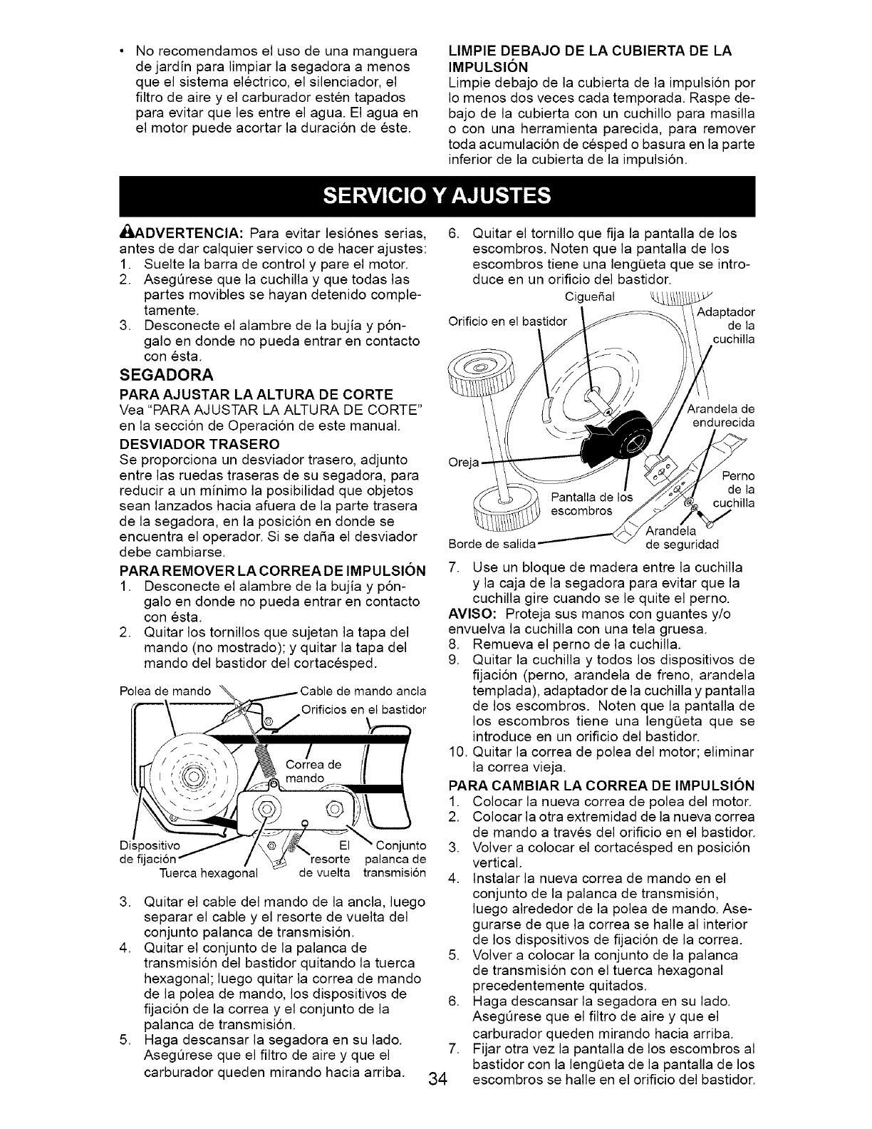
Norecomendamoselusodeunamanguera
dejardinparalimpiarlasegadoraa menos
queelsistemaelectrico,elsilenciador,el
filtrodeaireyelcarburadorestentapados
paraevitarquelesentreelagua.Elaguaen
elmotorpuedeacortarladuraci6ndeeste.
LIMPIEDEBAJODELACUBIERTADELA
IMPULSION
Limpiedebajodelacubiertadelaimpulsionpor
Iomenosdosvecescadatemporada.Raspede-
bajodela cubiertaconuncuchilloparamasilla
o conunaherramientaparecida,pararemover
todaacumulaci6ndecespedobasuraenlaparte
inferiordelacubiertadela impulsi6n.
_ADVERTENClA:Paraevitarlesi6nesserias,
antesdedarcalquierservicoodehacerajustes:
1. Sueltela barrade controly pareelmotor.
2. AsegQresequelacuchillay quetodaslas
partesmoviblessehayandetenidocomple-
tamente.
3. Desconecteelalambredelabujiay p6n-
galoendondenopuedaentrarencontacto
conesta.
SEGADORA
PARAAJUSTARLAALTURADECORTE
Vea"PARAAJUSTARLAALTURADECORTE"
enlasecci6ndeOperaci6ndeestemanual.
DESVlADORTRASERO
Seproporcionaundesviadortrasero,adjunto
entrelasruedastraserasdesusegadora,para
reducira unminimolaposibilidadqueobjetos
seanlanzadoshaciaafueradelapartetrasera
delasegadora,enlaposicionendondese
encuentraeloperador.Siseda5aeldesviador
debecambiarse.
PARAREMOVERLACORREADEIMPULSION
1. Desconecteel alambre de la bujia y p6n-
galo en donde no pueda entrar en contacto
con esta.
2. Quitar los tornillos que sujetan la tapa del
mando (no mostrado); y quitar la tapa del
mando del bastidor del cortacesped.
Polea de mando _../Cable de mando ancla
d:,i %esorte pa,an ade
Tuerca hexagonal de vuelta transmision
3. Quitar el cable del mando de la ancla, luego
separar el cable y el resorte de vuelta del
conjunto palanca de transmision.
4. Quitar el conjunto de la palanca de
transmisi6n del bastidor quitando la tuerca
hexagonal; luego quitar la correa de mando
de la polea de mando, los dispositivos de
fijacion de la correa y el conjunto de la
palanca de transmision.
5. Haga descansar la segadora en su lado.
AsegQrese que el filtro de aire y que el
carburador queden mirando hacia arriba.
6. Quitar el tornillo que fija la pantalla de los
escombros. Noten que la pantalla de los
escombros tiene una lengQeta que se intro-
duce en un orificio del bastidor.
Cigue_al
Adaptador
Orificio en el bastidor de la
cuchilia
.
34
Arandela de
endurecida
Ore
Perno
de la
cuchilla
Borde de
Arandela
de seguridad
7. Use un bloque de madera entre la cuchilla
y la caja de la segadora para evitar que la
cuchilla gire cuando se le quite el perno.
AVlSO: Proteja sus manos con guantes y/o
envuelva la cuchilla con una tela gruesa.
8. Remueva el perno de la cuchilla.
9. Quitar la cuchilla y todos los dispositivos de
fijacion (perno, arandela de freno, arandela
templada), adaptador de la cuchilla y pantalla
de los escombros. Noten que la pantalla de
los escombros tiene una lengQeta que se
introduce en un orificio del bastidor.
10. Quitar la correa de polea del motor; eliminar
la correa vieja.
PARA CAMBIAR LA CORREA DE IMPULSION
1. Colocar la nueva correa de polea del motor.
2. Colocar la otra extremidad de la nueva correa
de mando a traves del orificio en el bastidor.
3. Volver a colocar el cortacesped en posici6n
vertical.
4. Instalar la nueva correa de mando en el
conjunto de la palanca de transmisi6n,
luego alrededor de la polea de mando. Ase-
gurarse de que la correa se halle al interior
de los dispositivos de fijaci6n de la correa.
5. Volver a colocar la conjunto de la palanca
de transmisi6n con el tuerca hexagonal
precedentemente quitados.
6. Haga descansar la segadora en su lado.
AsegQrese que el filtro de aire y que el
carburador queden mirando hacia arriba.
Fijar otra vez la pantalla de los escombros al
bastidor con la lengQeta de la pantalla de los
escombros se halle en el orificio del bastidor.
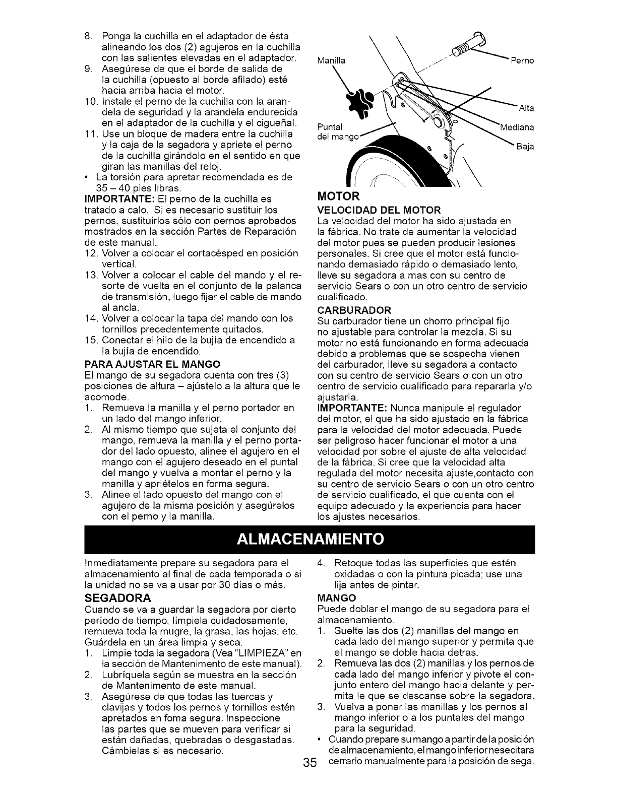
8. Pongalacuchillaeneladaptadordeesta
alineandolosdos(2)agujerosenlacuchilla
conlassalienteselevadaseneladaptador.
9. AsegQresedequeelbordedesalidade
lacuchilla(opuestoalbordeafilado)este
haciaarribahaciaelmotor.
10.Instaleelpernodelacuchillaconlaaran-
deladeseguridady laarandelaendurecida
eneladaptadordelacuchillay elcigue_al.
11.Useunbloquedemaderaentrelacuchilla
y lacajadelasegadoray aprieteel perno
delacuchillagirandoloenelsentidoenque
giranlasmanillasdelreloj.
• Latorsi6nparaapretarrecomendadaesde
35- 40pieslibras.
IMPORTANTE:Elpernodelacuchillaes
tratadoa calo.Siesnecesariosustituirlos
pernos,sustituirloss61oconpernosaprobados
mostradosenlaseccionPartesdeReparacion
deestemanual.
12.Volvera colocarelcortacespedenposicion
vertical.
13.Volvera colocarelcabledelmandoy el re-
sortedevueltaenelconjuntodelapalanca
detransmision,luegofijarelcabledemando
alancla.
14.Volvera colocarlatapadelmandoconlos
tornillosprecedentementequitados.
15.Conectarelhilodelabujiadeencendidoa
labujiadeencendido.
PARAAJUSTARELMANGO
Elmangodesusegadoracuentacontres(3)
posicionesdealtura- ajQsteloa laalturaquele
acomode.
1. Remuevala manillay el perno portador en
un lado del mango inferior.
2. AI mismo tiempo que sujeta el conjunto del
mango, remueva la manilla y el perno porta-
dor del lado opuesto, alinee el agujero en el
mango con el agujero deseado en el puntal
del mango y vuelva a montar el perno y la
manilla y aprietelos en forma segura.
3. Alinee el lado opuesto del mango con el
agujero de la misma posici6n y asegQrelos
con el perno y la manilla.
Manilla "_ Perno
Puntal
del man(
Alta
MOTOR
VELOCIDAD DEL MOTOR
La velocidad del motor ha sido ajustada en
la fabrica. No trate de aumentar la velocidad
del motor pues se pueden producir lesiones
personales. Si cree que el motor esta funcio-
nando demasiado rapido o demasiado lento,
Ileve su segadora a mas con su centro de
servicio Sears o con un otro centro de servicio
cualificado.
CARBU RADOR
Su carburador tiene un chorro principal fijo
no ajustable para controlar la mezcla. Si su
motor no esta funcionando en forma adecuada
debido a problemas que se sospecha vienen
del carburador, Ileve su segadora a contacto
con su centro de servicio Sears o con un otro
centro de servicio cualificado para repararla y/o
ajustarla.
IMPORTANTE: Nunca manipule el regulador
del motor, el que ha sido ajustado en la fabrica
para la velocidad del motor adecuada. Puede
ser peligroso hacer funcionar el motor a una
velocidad por sobre el ajuste de alta velocidad
de la fabrica. Si cree que la velocidad alta
regulada del motor necesita ajuste,contacto con
su centro de servicio Sears o con un otro centro
de servicio cualificado, el que cuenta con el
equipo adecuado y la experiencia para hacer
los ajustes necesarios.
Inmediatamente prepare su segadora para el
almacenamiento al final de cada temporada o si
la unidad no se va a usar por 30 dias o mas.
SEGADORA
Cuando se va a guardar la segadora por cierto
periodo de tiempo, limpiela cuidadosamente,
remueva toda la mugre, la grasa, las hojas, etc.
Guardela en un area limpia y seca.
1. Limpie toda la segadora (Vea "LIMPIEZA" en
la secci6n de Mantenimento de este manual).
2. Lubriquela segQn se muestra en la seccion
de Mantenimento de este manual.
3. AsegQrese de que todas las tuercas y
clavijas y todos los pernos y tornillos esten
apretados en foma segura, lnspeccione
las partes que se mueven para verificar si
estan da5adas, quebradas o desgastadas.
Cambielas si es necesario.
4. Retoque todas las superficies que esten
oxidadas o con la pintura picada; use una
lija antes de pintar.
MANGO
Puede doblar el mango de su segadora para el
almacenamiento.
1. Suelte las dos (2) manillas del mango en
cada lado del mango superior y permita que
el mango se doble hacia detras.
2. Remueva las dos (2) manillas y los pernos de
cada lado del mango inferior y pivote el con-
junto entero del mango hacia delante y per-
mita le que se descanse sobre la segadora.
3. Vuelva a poner las manillas y los pernos al
mango inferior o a los puntales del mango
para la seguridad.
Cuando prepare su mango a partir de la posicion
de almacenamiento, el mango inferior nesecitara
cerrarlo manualmente para la posici6n de sega.
35
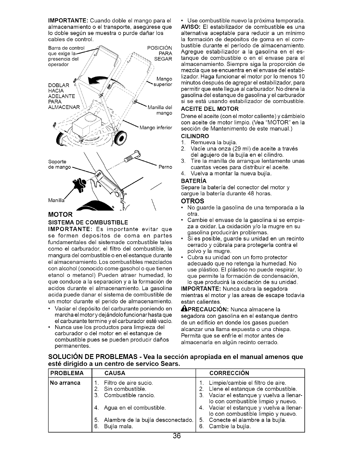
IMPORTANTE: Cuando doble el mango para el
almacenamiento o el transporte, asegOrese que
Io doble seg6n se muestra o purde da5ar los
cables de control.
Barra de control POSICION
que exige PARA
presencia del _:, SEGAR
operador //_ -,,
/
DOBLAR
HACIA
ADELANTE
PAPA ',,
ALMACENAR ',
Mango
/_superior
Manilla del
mango
/// 5,goin, rior
Soporte 3_ _J_
de mango _ erno
Manilla__
MOTOR
SISTEMA DE COMBUSTIBLE
IMPORTANTE: Es importante evitar que
se formen depositos de coma en partes
fundamentales del sistemade combustible tales
como el carburador, el filtro del combustible, la
mangura del combustible o en el estanque durante
el almacenamiento. Los combustibles mezclados
con alcohol (conocido come gasohol o que tienen
etanol o metanol) Pueden atraer humedad, Io
que conduce a la separacion y a la formacion de
acidos durante el almacenamiento. La gasolina
acida puede danar el sistema de combustible de
un motor durante el perido de almacenamiento.
• Vaciar el deposito del carburante poniendo en
marcha el motor y dejandolo funcionar hasta que
el carburante termine y el carburador este vacio.
• Nunca use los productos para limpieza del
carburador o del motor en el estanque de
combustible pues se pueden producir da_os
permanentes.
• Use combustible nuevo la pr6xima temporada.
AVlSO: El estabilizador de combustible es una
alternativa aceptable para reducir a un minimo
la formacion de depositos de goma en el com-
bustible durante el periodo de almacenamiento.
Agregue estabilizador a la gasolina en el es-
tanque de combustible o en el envase para el
almacenamiento. Siempre siga la proporcion de
mezcla que se encuentra en el envase del estabi-
lizador. Haga funcionar el motor por Io menos 10
minutos despues de agregar el estabilizador, para
permitir que este Ilegue al carburador. No drene la
gasolina del estanque de gasolina y el carburador
si se esta usando estabilizador de combustible.
ACEITE DEL MOTOR
Drene el aceite (con el motor caliente) y cambielo
con aceite de motor limpio. (Vea "MOTOR" en la
seccion de Mantenimento de este manual.)
ClLINDRO
1. Remueva la bujia.
2. Vacie una onza (29 ml) de aceite a traves
del agujero de la bujia en el cilindro.
3. Tire la manilla de arranque lentamente unas
cuantas veces para distribuir el aceite.
4. Vuelva a montar la nueva bujia.
BATERiA
Separe la bateria del conector del motor y
cargue la bateria durante 48 horas.
OTROS
• No guarde la gasolina de una temporada a la
otra.
• Cambie el envase de la gasolina si se empie-
za a oxidar. La oxidacion y/o la mugre en su
gasolina produciran problemas.
• Si es posible, guarde su unidad en un recinto
cerrado y cQbrala para protegerla contra el
polvo y la mugre.
• Cubra su unidad con un forro protector
adecuado que no retenga la humedad. No
use plastico. El plastico no puede respirar, Io
que permite la formacion de condensacion,
Io que producira la oxidacion de su unidad.
IMPORTANTE: Nunca cubra la segadora
mientras el motor y las areas de escape todavia
estan calientes.
_PRECAUCl6N: Nunca almacene la
segadora con gasolina en el estanque dentro
de un edificio en donde los gases pueden
alcanzar una llama expuesta o una chispa.
Permita que se enfrie el motor antes de
almacenarla en algOn recinto cerrado.
SOLUCION DE PROBLEMAS - Yea la seccibn apropiada en el manual amenos que
est_ dirigido a un centro de servico Sears.
PROBLEMA CAUSA
No arranca 1. Filtro de aire sucio.
2. Sin combustible.
3. Combustible rancio.
4. Agua en el combustible.
5. Alambre de la bujia desconectado.
6. Bujia mala.
36
CORRECCION
1. Limpie/cambie el filtro de aire.
2. Llene el estanque de combustible.
3. Vaciar el estanque y vuelva a Ilenar-
Io con combustible limpio y nuevo.
4. Vaciar el estanque y vuelva a Ilenar-
Io con combustible limpio y nuevo.
5. Conecte el alambre a la bujia.
6. Cambie la bujia.
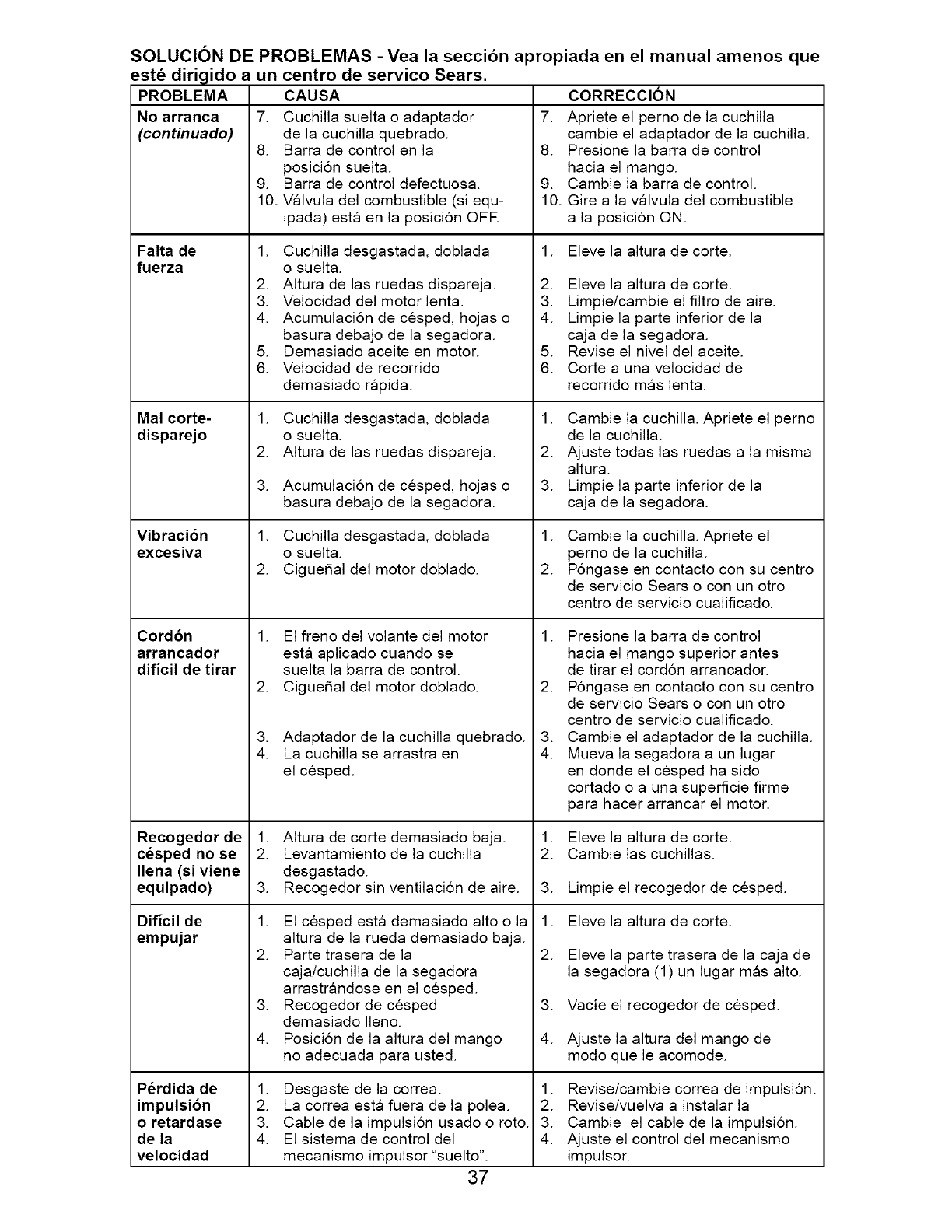
SOLUCION DE PROBLEMAS - Vea la seccibn apropiada en el manual amenos que
PROBLEMA
No arranca
(continuado)
estd dirigido a un centro de servico Sears.
CAUSA
7. Cuchilla suelta o adaptador
de la cuchilla quebrado.
8. Barra de control en la
posici6n suelta.
9. Barra de control defectuosa.
10. Valvula del combustible (si equ-
ipada) esta en la posici6n OFE
Falta de
fuerza
Mal corte-
disparejo
Vibracion
excesiva
Cord6n
arrancador
dificil de tirar
Recogedorde
cesped no se
Ilena(siviene
equipado)
Dificil de
empujar
Perdida de
impulsion
o retardase
de la
velocidad
1. Cuchilla desgastada, doblada
o suelta.
2. Altura de las ruedas dispareja.
3. Velocidad del motor lenta.
4. Acumulaci6n de cesped, hojas o
basura debajo de la segadora.
5. Demasiado aceite en motor.
6. Velocidad de recorrido
demasiado rapida.
1. Cuchilla desgastada, doblada
o suelta.
2. AItura de las ruedas dispareja.
3. Acumulacion de cesped, hojas o
basura debajo de la segadora.
1. Cuchilla desgastada, doblada
o suelta.
2. Ciguefial del motor doblado.
1. El freno del volante del motor
esta aplicado cuando se
suelta la barra de control.
2. Ciguefial del motor doblado.
3. Adaptador de la cuchilla quebrado.
4. La cuchilla se arrastra en
el cesped.
1. Altura de corte demasiado baja.
2. Levantamiento de la cuchilla
desgastado.
3. Recogedor sin ventilaci6n de aire.
1. El cesped esta demasiado alto o la
altura de la rueda demasiado baja.
2. Parte trasera de la
caja/cuchilla de la segadora
arrastrandose en el cesped.
3. Recogedor de cesped
demasiado Ileno.
4. Posici6n de la altura del mango
no adecuada para usted.
1. Desgaste de la correa.
2. La correa esta fuera de la polea.
3. Cable de la impulsion usado o roto.
4. El sistema de control del
mecanismo impulsor "suelto".
37
CORRECCION
7. Apriete el perno de la cuchilla
cambie el adaptador de la cuchilla.
8. Presione la barra de control
hacia el mango.
9. Cambie la barra de control.
10. Gire a la valvula del combustible
a la posici6n ON.
1. Eleve la altura de corte.
2. Eleve la altura de corte.
3. Limpie/cambie el filtro de aire.
4. Limpie la parte inferior de la
caja de la segadora.
5. Revise el nivel del aceite.
6. Corte a una velocidad de
recorrido mas lent&
1. Cambie la cuchilla. Apriete el perno
de la cuchilla.
2. Ajuste todas las ruedas a la misma
altura.
3. Limpie la parte inferior de la
caja de la segadora.
1. Cambie la cuchilla. Apriete el
perno de la cuchilla.
2. P6ngase en contacto con su centro
de servicio Sears o con un otro
centro de servicio cualificado.
1. Presione la barra de control
hacia el mango superior antes
de tirar el cord6n arrancador.
2. P6ngase en contacto con su centro
de servicio Sears o con un otro
centro de servicio cualificado.
3. Cambie el adaptador de la cuchilla.
4. Mueva la segadora a un lugar
en donde el cesped ha sido
cortado o a una superficie firme
para hacer arrancar el motor.
1. Eleve la altura de corte.
2. Cambie las cuchillas.
3. Limpie elrecogedorde cesped.
1. Eleve la altura de corte.
2. Eleve la parte trasera de la caja de
la segadora (1) un lugar mas alto.
3. Vacie elrecogedorde cesped.
4. Ajuste la altura del mango de
modo que le acomode.
1. Revise/cambie correa de impulsion.
2. Revise/vuelva a instalar la
3. Cambie el cable de la impulsi6n.
4. Ajuste el control del mecanismo
impulsor.
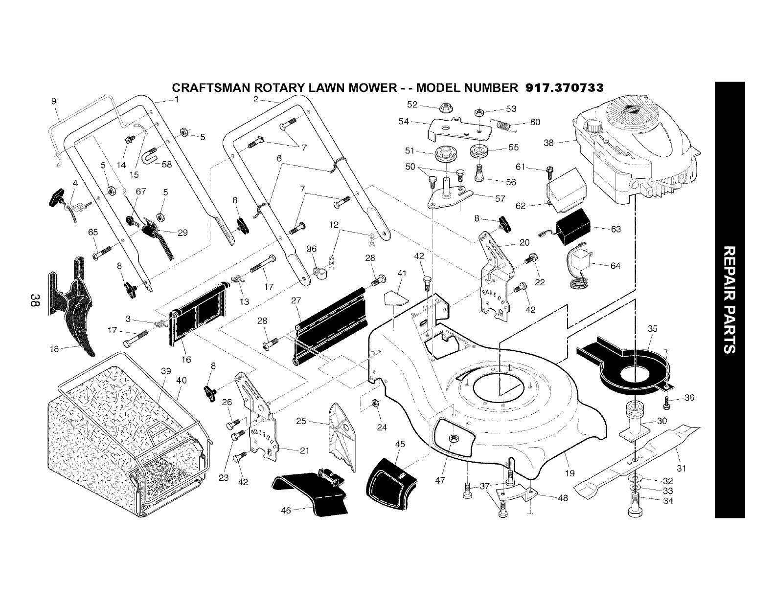
Co
OO
t8
65
8
CRAFTSMAN ROTARY LAWN MOWER - - MODEL NUMBER 917.370733
2_
52_ (_)_ 53
"'"_....\\. __5_756
39 40
42
\
24
22
I
47 19
I
I 3s
31
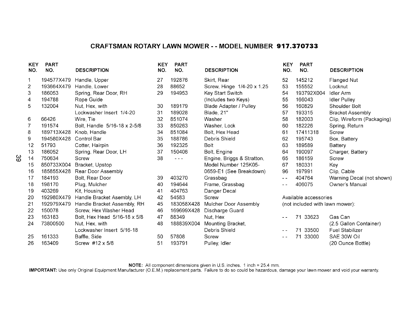
CRAFTSMAN ROTARY LAWN MOWER - - MODEL NUMBER 917.370733
GO
(.0
KEY PART
NO. NO.
1 194577X479
2 193664X479
3 186053
4 194788
5 132004
6 66426
7 191574
8 189713X428
9 194580X428
12 51793
13 186052
14 750634
15 850733X004
16 185855X428
17 184193
18 198170
19 403269
20 192980X479
21 192979X479
22 150078
23 163183
24 73800500
25 161333
26 163409
KEY PART KEY PART
DESCRIPTION NO, NO, DESCRIPTION NO, NO, DESCRIPTION
Handle, Upper 27 192876 Skirt, Rear 52 145212
Handle, Lower 28 88652 Screw, Hinge 1/4-20 x 1.25 53 155552
Spring, Rear Door, RH 29 194953 Key Start Switch 54 193792X004
Rope Guide (Includes two Keys) 55 166043
Nut, Hex, with 30 189179 Blade Adapter /Pulley 56 160829
Lockwasher Insert 1/4-20 31 189028 Blade, 21" 57 193315
Wire, Tie 32 851074 Washer 58 182003
Bolt, Handle 5/16-18 x 2-5/8 33 850263 Washer, Lock 60 182226
Knob, Handle 34 851084 Bolt, Hex Head 61 17411318
Control Bar 35 188786 Debris Shield 62 195743
Cotter, Hairpin 36 192325 Bolt 63 189589
Spring, Rear Door, LH 37 150406 Bolt, Engine 64 190097
Screw 38 - - - Engine, Briggs & Stratton, 65 186159
Bracket, Upstop Model Number 125K05- 67 180331
Rear Door Assembly 0659-E1 (See Breakdown) 96 197991
Bolt, Rear Door 39 403270 Grassbag - - 404764
Plug, Mulcher 40 194644 Frame, Grassbag - - 406075
Kit, Housing 41 404763 Danger Decal
Handle Bracket Asembty, LH 42 54583 Screw Available accessories
Handle Bracket Assembly, RH 45 183058X428 Mulcher Door Assembly (not included with lawn mower):
Screw, Hex Washer Head 46 169699X428 Discharge Guard
Bolt, Hex Head 5/16-18 x 5/8 47 88349 Nut, Hex - - 71 33623
Nut, Hex, with 48 188839X004 Mounting Bracket,
Lockwasher Insert 5/16-18 Debris Shield - - 71 33500
Baffle, Side 50 57808 Screw - - 71 33000
Screw #12 x 5/8 51 193791 Pulley, Idler
Flanged Nut
Locknut
Idler Arm
Idler Pulley
Shoulder Bolt
Bracket Assembly
Clip, Wireform (Packaging)
Spring, Return
Screw
Box, Battery
Battery
Charger, Battery
Screw
Key
Clip, Cable
Warning Decal (not shown)
Owner's Manual
Gas Can
(2.5 Gallon Container)
Fuel Stabilizer
SAE 30W Oil
(20 Ounce Bottle)
NOTE: All component dimensions given in U.S. inches. 1 inch = 25_4 mm.
IMPORTANT: Use only Original Equipment Manufacturer (O.EM.) replacement parts. Failure to do so could be hazardous, damage your lawn mower and void your warranty.
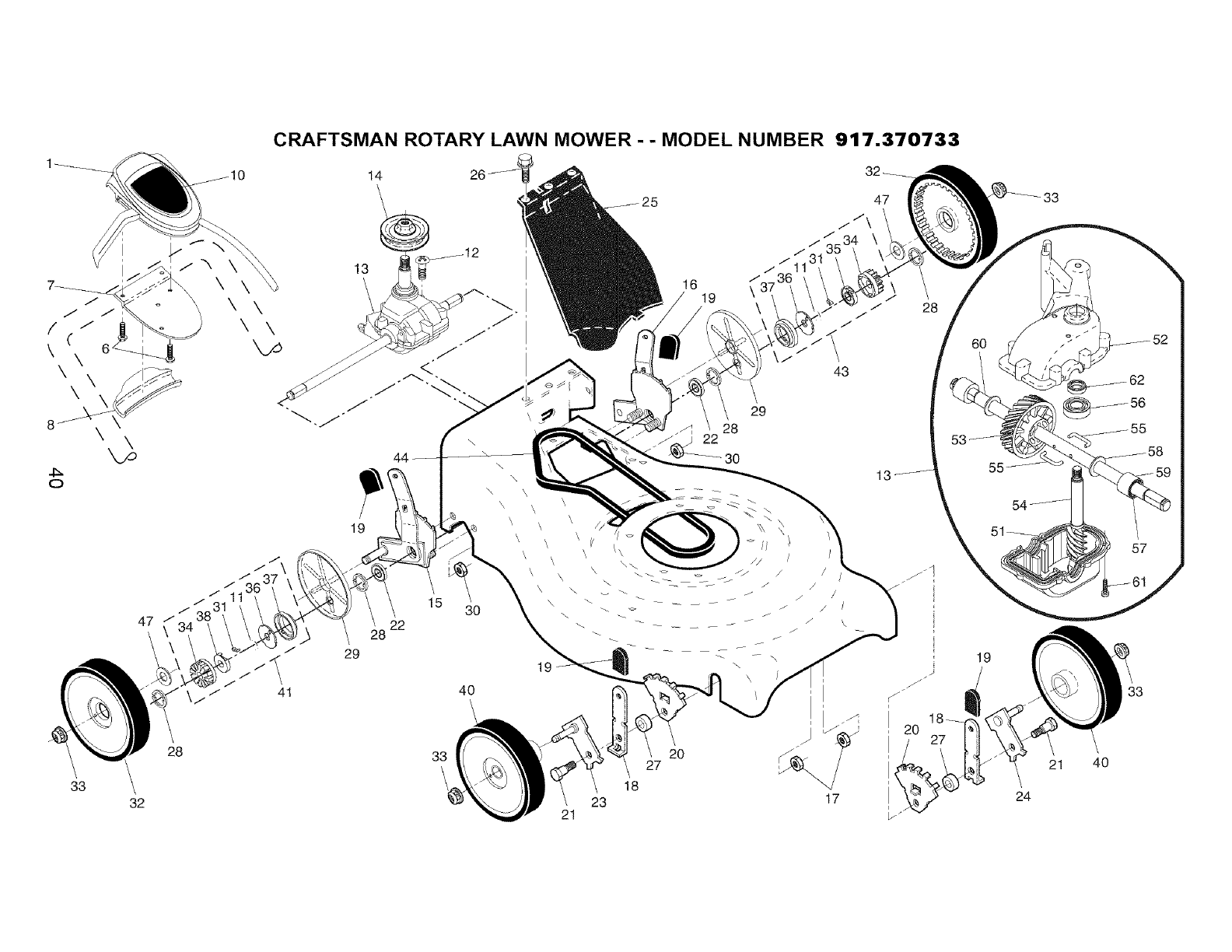
CRAFTSMAN ROTARY LAWN MOWER - - MODEL NUMBER 917.370733
8
O
47
33
32
\\\
28
19
22
29
15 30
33
\
\
\
\
\
\
\
\
\< \
\
_t
19
"i 20
27
18
21
16 19
43
29
28
30
\\
17
20
/27
60
19
24
57
33
21 40
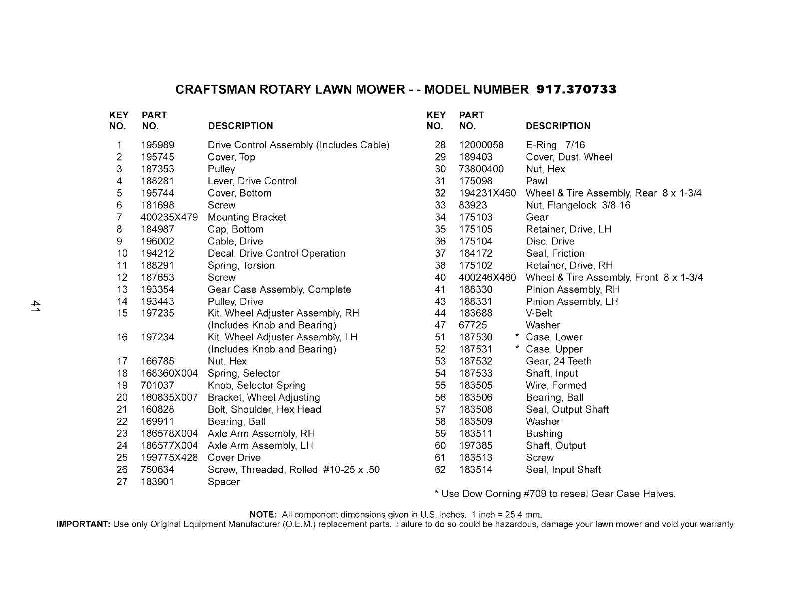
CRAFTSMAN ROTARY LAWN MOWER - - MODEL NUMBER 917.370733
KEY PART
NO. NO.
KEY PART
DESCRIPTION NO. NO. DESCRIPTION
1 195989
2 195745
3 187353
4 188281
5 195744
6 181698
7 400235X479
8 184987
9 196002
10 194212
11 188291
12 187653
13 193354
14 193443
15 197235
16 197234
17 166785
18 168360X004
19 701037
20 160835X007
21 160828
22 169911
23 186578X004
24 186577X004
25 199775X428
26 750634
27 183901
Drive Control Assembly (Includes Cable) 28 12000058
Cover, Top 29 189403
Pulley 30 73800400
Lever, Drive Control 31 175098
Cover, Bottom 32 194231 X460
Screw 33 83923
Mounting Bracket 34 175103
Cap, Bottom 35 175105
Cable, Drive 36 175104
Decal, Drive Control Operation 37 184172
Spring, Torsion 38 175102
Screw 40 400246X460
Gear Case Assembly, Complete 41 188330
Pulley, Drive 43 188331
Kit, Wheel Adjuster Assembly, RH 44 183688
(includes Knob and Bearing) 47 67725
Kit, Wheel Adjuster Assembly, LH 51 187530 *
(Includes Knob and Bearing) 52 187531 *
Nut, Hex 53 187532
Spring, Selector 54 187533
Knob, Selector Spring 55 183505
Bracket, Wheel Adjusting 56 183506
Bolt, Shoulder, Hex Head 57 183508
Bearing, Ball 58 183509
Axle Arm Assembly, RH 59 183511
Axle Arm Assembly, LH 60 197385
Cover Drive 61 183513
Screw, Threaded, Rolled #10-25 x .50 62 183514
Spacer
* Use Dow Corning
E-Ring 7/16
Cover, Dust, Wheel
Nut, Hex
Pawt
Wheel & Tire Assembly, Rear 8 x 1-3/4
Nut, Flangelock 3/8-16
Gear
Retainer, Drive, LH
Disc, Drive
Seal, Friction
Retainer, Drive, RH
Wheel & Tire Assembly, Front 8 x 1-3/4
Pinion Assembly, RH
Pinion Assembly, LH
V-Belt
Washer
Case, Lower
Case, Upper
Gear, 24 Teeth
Shaft, Input
Wire, Formed
Bearing, Ball
Seal, Output Shaft
Washer
Bushing
Shaft, Output
Screw
Seal, Input Shaft
#709 to reseal Gear Case Halves.
NOTE: All component dimensions given in U,S, inches, 1 inch = 25_4 mm,
IMPORTANT: Use only Original Equipment Manufacturer (O,E,M) replacement parts, Failure to do so could be hazardous, damage your lawn mower and void your warranty,
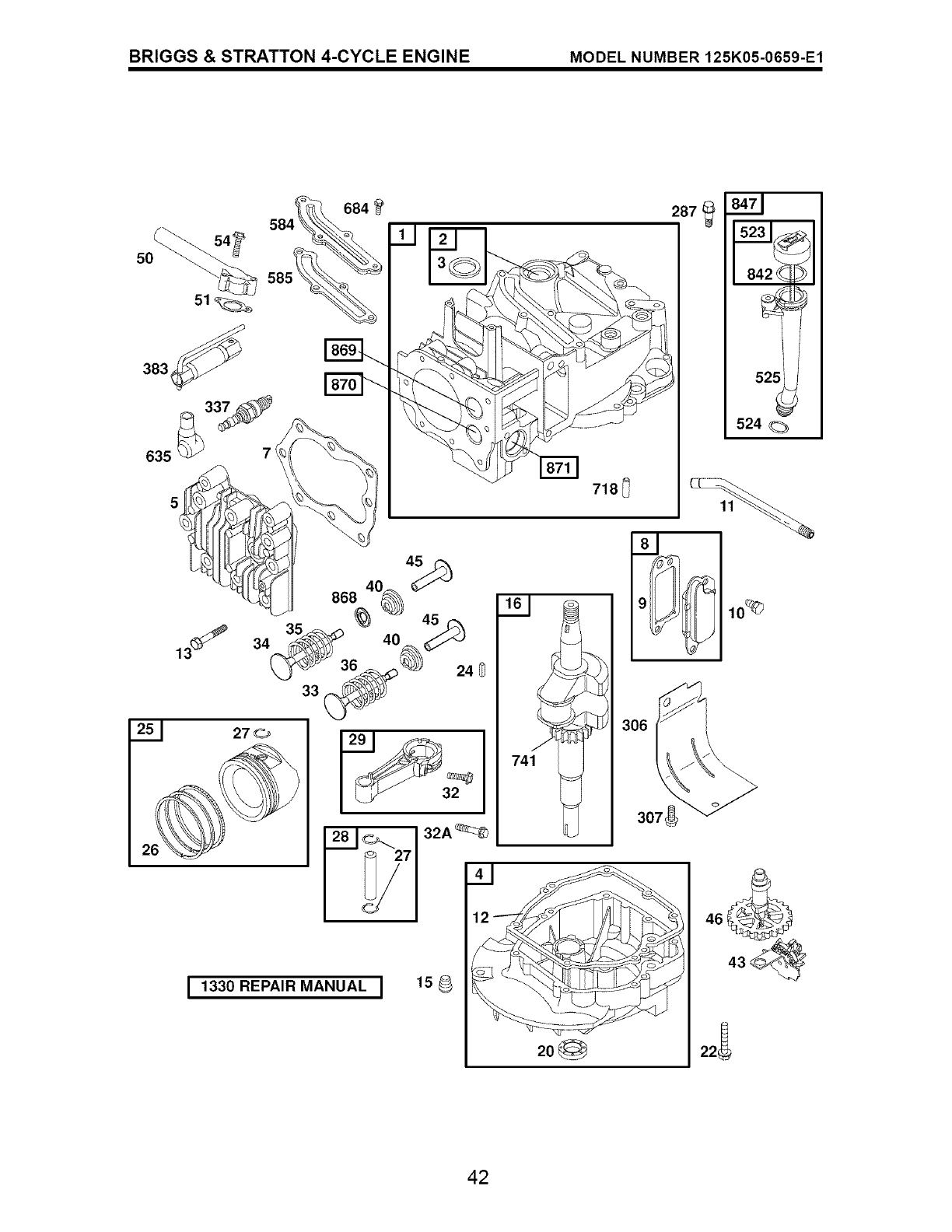
BRIGGS & STRATTON 4-CYCLE ENGINE MODEL NUMBER 125K05-0659-E1
684 287
2o_
718_
41
I 1330 REPAIR MANUAL I 15
161
306
307_
524
10_
46
22 ;
42
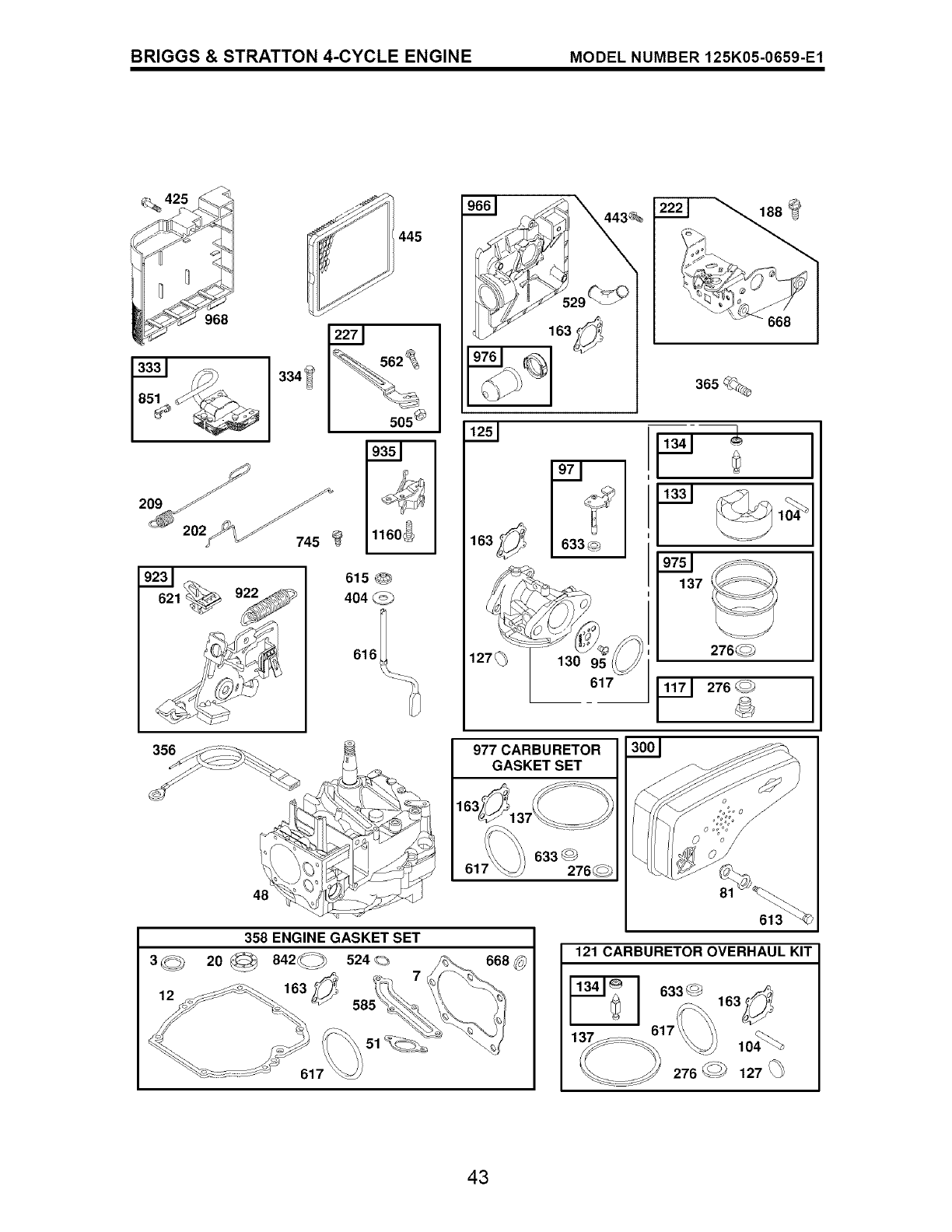
BRIGGS & STRATTON 4-CYCLE ENGINE MODEL NUMBER 125K05-0659-E1
968
445
616
505_
633 _
127_ 130 9
617
977 CARBURETOR
GASKET SET
358 ENGINE GASKET SET
3<c_ 20_a42_) 524_
51
121 CARBURETOR OVERHAUL KIT
633_
137_ _104_
43
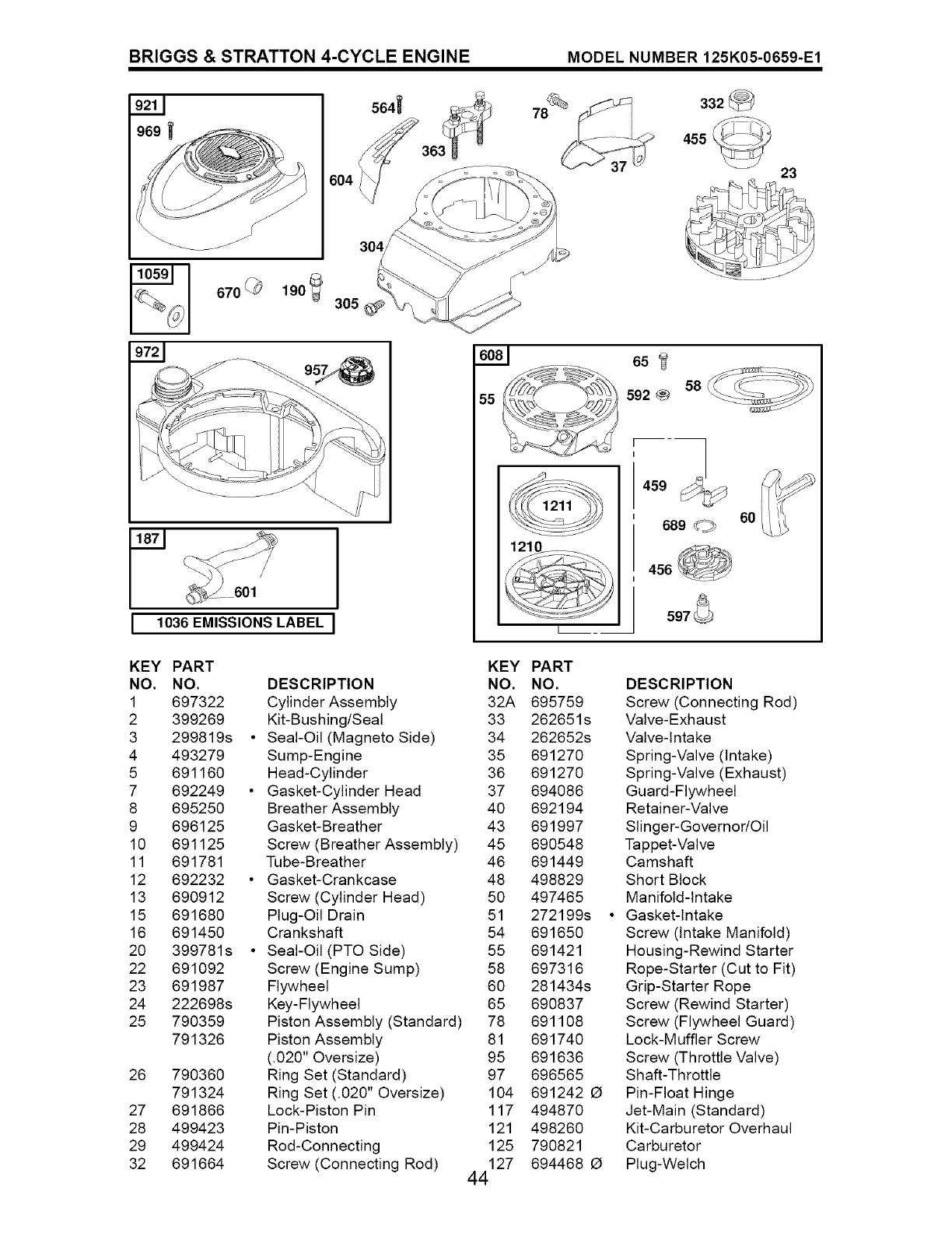
BRIGGS & STRATTON 4-CYCLE ENGINE MODEL NUMBER 125K05-0659-E1
670 _190 305
9721
564_
F601
I1036 EMISSIONS LABEL
KEY PART
NO. NO.
1 697322
2 399269
3 299819s
4 493279
5 691160
7 692249
8 695250
9 696125
10 691125
11 691781
12 692232
13 690912
15 691680
16 691450
20 399781s
22 691092
23 691987
24 222698s
25 790359
791326
26 790360
791324
27 691866
28 499423
29 499424
32 691664
55
KEY PART
DESCRIPTION NO. NO.
Cylinder Assembly 32A 695759
Kit-Bushing/Seal 33 262651s
Seal-Oil (Magneto Side) 34 262652s
Sump-Engine 35 691270
Head-Cylinder 36 691270
Gasket-Cylinder Head 37 694086
Breather Assembly 40 692194
Gasket-Breather 43 691997
Screw (Breather Assembly) 45 690548
Tube-Breather 46 691449
Gasket-Crankcase 48 498829
Screw (Cylinder Head) 50 497465
Plug-Oil Drain 51 272199s
Crankshaft 54 691650
Seal-Oil (PTO Side) 55 691421
Screw (Engine Sump) 58 697316
Flywheel 60 281434s
Key-Flywheel 65 690837
Piston Assembly (Standard) 78 691108
Piston Assembly 81 691740
(.020" Oversize) 95 691636
Ring Set (Standard) 97 696565
Ring Set (.020" Oversize) 104 691242 O
Lock-Piston Pin 117 494870
Pin-Piston 121 498260
Rod-Connecting 125 790821
Screw (Connecting Rod) 127 694468 O
44
455_ 23
65
58
592_
689 _60
597
DESCRIPTION
Screw (Connecting Rod)
Valve-Exhaust
Valve-Intake
Spring-Valve (Intake)
Spring-Valve (Exhaust)
Guard-Flywheel
Retainer-Valve
Slinger-Governor/Oil
Tappet-Valve
Camshaft
Short Block
Manifold-Intake
Gasket-Intake
Screw (Intake Manifold)
Housing-Rewind Starter
Rope-Starter (Cut to Fit)
Grip-Starter Rope
Screw (Rewind Starter)
Screw (Flywheel Guard)
Lock-Muffler Screw
Screw (Throttle Valve)
Shaft-Throttle
Pin-Float Hinge
Jet-Main (Standard)
Kit-Carburetor Overhaul
Carburetor
Plug-Welch
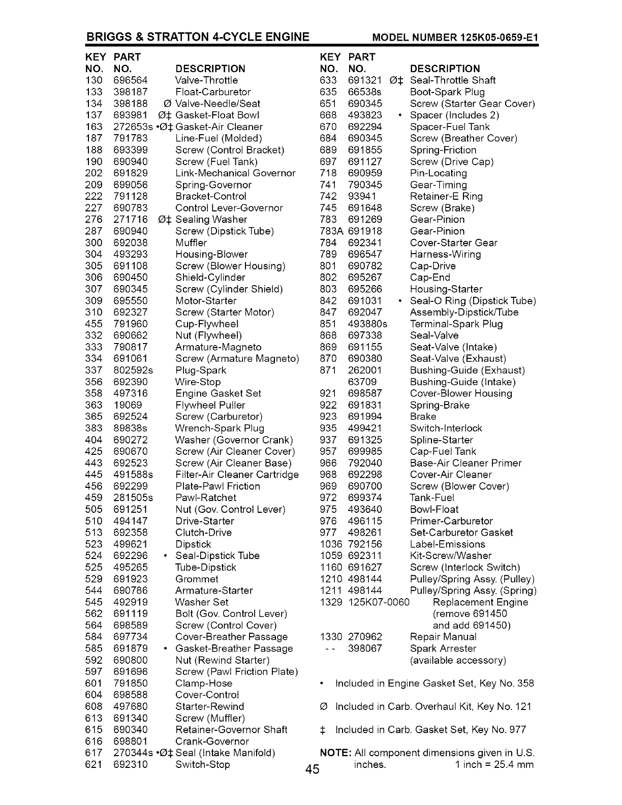
BRIGGS & STRATTON 4-CYCLE ENGINE MODEL NUMBER 125K05-0659-E1
KEY PART KEY PART
NO. NO. DESCRIPTION NO. NO.
130 696564 Valve-Throttle 633 691321 O:1:
133 398187 Float-Carburetor 635 66538s
134 398188 O Valve-Needle/Seat 651 690345
137 693981 O:1:Gasket-Float Bowl 668 493823 •
163 272653s •O:l:Gasket-Air Cleaner 670 692294
187 791783 Line-Fuel (Molded) 684 690345
188 693399 Screw (Control Bracket) 689 691855
190 690940 Screw (Fuel Tank) 697 691127
202 691829 Link-Mechanical Governor 718 690959
209 699056 Spring-Governor 741 790345
222 791128 Bracket-Control 742 93941
227 690783 Control Lever-Governor 745 691648
276 271716 O:1:Sealing Washer 783 691269
287 690940 Screw (Dipstick Tube) 783A 691918
300 692038 Muffler 784 692341
304 493293 Housing-Blower 789 696547
305 691108 Screw (Blower Housing) 801 690782
306 690450 Shield-Cylinder 802 695267
307 690345 Screw (Cylinder Shield) 803 695266
309 695550 Motor-Starter 842 691031 •
310 692327 Screw (Starter Motor) 847 692047
455 791960 Cup-Flywheel 851 493880s
332 690662 Nut (Flywheel) 868 697338
333 790817 Armature-Magneto 869 691155
334 691061 Screw (Armature Magneto) 870 690380
337 802592s Plug-Spark 871 262001
356 692390 Wire-Stop 63709
358 497316 Engine Gasket Set 921 698587
363 19069 Flywheel Puller 922 691831
365 692524 Screw (Carburetor) 923 691994
383 89838s Wrench-Spark Plug 935 499421
404 690272 Washer (Governor Crank) 937 691325
425 690670 Screw (Air Cleaner Cover) 957 699985
443 692523 Screw (Air Cleaner Base) 966 792040
445 491588s Filter-Air Cleaner Cartridge 968 692298
456 692299 Plate-Pawl Friction 969 690700
459 281505s PawI-Ratchet 972 699374
505 691251 Nut (Gov. Control Lever) 975 493640
510 494147 Drive-Starter 976 496115
513 692358 Clutch-Drive 977 498261
523 499621 Dipstick 1036 792156
524 692296 • SeaI-DipstickTube 1059 692311
525 495265 Tube-Dipstick 1160 691627
529 691923 Grommet 1210 498144
544 690786 Armature-Starter 1211 498144
545 492919 Washer Set 1329
562 691119 Bolt (Gov. Control Lever)
564 698589 Screw (Control Cover)
584 697734 Cover-Breather Passage 1330
585 691879 • Gasket-Breather Passage - -
592 690800 Nut (Rewind Starter)
597 691696 Screw (Pawl Friction Plate)
601 791850 Clamp-Hose
604 698588 Cover-Control
608 497680 Starter-Rewind
613 691340 Screw (Muffler)
615 690340 Retainer-Governor Shaft
616 698801 Crank-Governor
617 270344s •O:1:Seal (Intake Manifold)
621 692310 Switch-Stop
DESCRIPTION
Seal-Throttle Shaft
Boot-Spark Plug
Screw (Starter Gear Cover)
Spacer (Includes 2)
Spacer-Fuel Tank
Screw (Breather Cover)
Spring-Friction
Screw (Drive Cap)
Pin-Locating
Gear-Timing
Retainer-E Ring
Screw (Brake)
Gear-Pinion
Gear-Pinion
Cover-Starter Gear
Harness-Wiring
Cap-Drive
Cap-End
Housing-Starter
SeaI-O Ring (Dipstick Tube)
Assembly-Dipstick/Tube
Terminal-Spark Plug
Seal-Valve
Seat-Valve (Intake)
Seat-Valve (Exhaust)
Bushing-Guide (Exhaust)
Bushing-Guide (Intake)
Cover-Blower Housing
Spring-Brake
Brake
Switch-Interlock
Spline-Starter
Cap-Fuel Tank
Base-Air Cleaner Primer
Cover-Air Cleaner
Screw (Blower Cover)
Tank-Fuel
Bowl-Float
Primer-Carburetor
Set-Carburetor Gasket
Label-Emissions
Kit-Screw/Washer
Screw (Interlock Switch)
Pulley/Spring Assy. (Pulley)
Pulley/Spring Assy. (Spring)
125K07-0060 Replacement Engine
(remove 691450
and add 691450)
270962 Repair Manual
398067 Spark Arrester
(available accessory)
• Included in Engine Gasket Set, Key No. 358
O Included in Carb. Overhaul Kit, Key No. 121
:1: Included in Carb. Gasket Set, Key No. 977
NOTE: All component dimensions given in U.S.
45 inches. 1 inch = 25.4 mm

SERVICE NOTES
46

SERVICE NOTES
47

Your Home
For repair - in your home - of all major brand appliances,
lawn and garden equipment, or heating and cooling systems,
no matter who made it, no matter who sold it!
For the replacement parts, accessories and
owner's manuals that you need to do-it-yourself.
For Sears professional installation of home appliances
and items like garage door openers and water heaters.
1-800-4-MY-HOME ® Anytime, day or night
(1-800-469-4663) (U.S.A. and Canada)
www.sears.com www.sears.ca
Our Home
For repair of carry-in products like vacuums, lawn equipment,
and electronics, call or go on-line for the nearest
Sears Parts and Repair Center.
1-800-488-1222 Anytime, day or night (U.S.A. only)
www,sears,com
To purchase a protection agreement (U.S.A.)
or maintenance agreement (Canada) on a product serviced by Sears:
1-800-827-6655 (u.s._) 1-800-361-6665 (Canada)
Para pedir servicio de reparaci6n
a domicilio, y para ordenar piezas:
1-888-SU-HOGAR ®
(1-888-784-6427)
Au Canada pour service en franqais:
1-800-LE-FOYER Mc
(1-800-533-6937)
www.sears.ca
© SearsBrands,LLC
® Registered Trademark /TMTrademark /SMService Mark of Sears Brands, LLC
® Marca Registrada /TMMarca de F_brica /SMMarca de Servicio de Sears Brands, LLC
MCMarque de commerce /MDMarque depos6e de Sears Brands, LLC
406075 03.31.06 BY Printed in U.S.A.
