Craftsman 917377842 User Manual Gas, Walk Behind Lawnmower Manuals And Guides L0409195
CRAFTSMAN Walk Behind Lawnmower, Gas Manual L0409195 CRAFTSMAN Walk Behind Lawnmower, Gas Owner's Manual, CRAFTSMAN Walk Behind Lawnmower, Gas installation guides
User Manual: Craftsman 917377842 917377842 CRAFTSMAN Gas, Walk Behind Lawnmower - Manuals and Guides View the owners manual for your CRAFTSMAN Gas, Walk Behind Lawnmower #917377842. Home:Lawn & Garden Parts:Craftsman Parts:Craftsman Gas, Walk Behind Lawnmower Manual
Open the PDF directly: View PDF ![]() .
.
Page Count: 48

Owner's Manual
CRAFTSMAN°
ROTARY LAWN MOWER
6.5 Horsepower
Power-Propelled
21" Multi-Cut
Model No.
917.377842
•Espa_ol, p. 20
CAUTION:
Read and follow all
Safety Rules and Instructions
before operating this equipment
Sears, Roebuck and Co., Hoffman Estates, IL 60179
Visit our Craftsman website: www.sears.com/craftsman
U.S.A.

Warranty ................................................... 2
Safety Rules .......................................... 2-4
Product Specifications .............................. 4
Assembly /Pre-Operation ..................... 5-6
Operation ............................................ 7-11
Maintenance Schedule ........................... 12
Maintenance ...................................... 12-15
Service and Adjustments ................... 15-17
Storage .............................................. 17-18
Troubleshooting ................................. 18-19
Repair Parts ....................................... 38-47
Sears Service .......................... Back Cover
LIMITED TWO YEAR WARRANTY ON CRAFTSMAN POWER MOWER
For two years from date of purchase, when this Craftsman Lawn Mower is maintained,
lubricated, and tuned up according to the operating and maintenance instructions in the
owner's manual, Sears will repair free of charge any defect in material or workmanship.
If this Craftsman Lawn Mower is used for commercial or rental purposes, this warranty
applies for only 90 days from the date of purchase.
This Warranty does not cover:
• Expendable items which become worn during normal use, such as rotary mower
blades, blade adapters, belts, air cleaners and spark plug.
• Repairs necessary because of operator abuse or negligence, including bent crank-
shafts and the failure to maintain the equipment according to the instructions con-
tained in the owner's manual.
Warranty service is available by returning the Craftsman power mower to the nearest Sears
Parts & Repair Center in the United States. This warranty applies only while this product
is used in the United States.
This Warranty gives you specific legal rights, and you may also have other rights which
vary from state to state.
Sears, Roebuck And Co., D/817 WA, Hoffman Estates, IL 60179
IMPORTANT: This cutting machine is capable of amputating hands and feet and throwing ob-
jects. Failure to observe the following safety instructions could result in serious injury or death.
&Look for this symbol to point out important
safety precautions. It means CAUTION! BE-
COMEALERT!YOURSAFETY IS INVOLVED.
AWARNING: In order to prevent accidental
starting when setting up, transporting, ad-
justing or making repairs, always disconnect
spark plug wire and place wire where it cannot
come in contact with plug.
AWARNING: Engine exhaust, some of its
constituents, and certain vehicle components
contain or emit chemicals known to the State
of California to cause cancer and birth defects
or other reproductive harm.
AWARNING: Battery posts, terminals and
related accessories contain lead and lead
compounds, chemicals known to the State
of California to cause cancer and birth
defects or other reproductive harm. Wash
hands after handling.
_h, CAUTION: Muffler and
other engine parts become
extremely hot during
operation and remain hot
after engine has stopped. To
avoid severe burns on contact,
stay away from these areas.
I. GENERAL OPERATION
• Read, understand, and follow all
instructions on the machine and in the
manual(s) before starting. Be thoroughly
familiar with the controls and the proper
use of the machine before starting.
• Do not put hands or feet near or under
rotating parts. Keep clear of the dis-
charge opening at all times.
Only allow responsible individuals, familiar
with theinstructions,tooperatethe machine.
2
• Clear the area of objects such as rocks,
toys, wire, bones, sticks, etc., which
could be picked up and thrown by blade.
• Be sure the area is clear of other people
before mowing. Stop machine if anyone
enters the area.
• Do not operate the mower when bare-
foot or wearing open sandals. Always
wear substantial foot wear.
• Do not pull mower backwards unless ab-
solutely necessary. Always look down and
behind before and while moving backwards.
• Never direct discharged material toward
anyone. Avoid discharging material against
a wall or obstruction. Material may richo-
chet back toward the operator. Stop the
blade when crossing gravel surfaces.
• Do not operate the mower without
proper guards, plates, grass catcher or
other safety protective devices in place.
• See manufacturer's instructions for
proper operation and installation of
accessories. Only use accessories ap-
proved by the manufacturer.
• Stop the blade(s) when crossing gravel
drives, walks, or roads.
• Stop the engine (motor) whenever you
leave the equipment, before cleaning the
mower or unclogging the chute.
• Shut the engine (motor) off and wait until
the blade comes to complete stop before
removing grass catcher.
• Mow only in daylight /good artificial light.
• Do not operate the machine while under
the influence of alcohol or drugs.
• Never operate machine in wet grass.
Always be sure of your footing: keep a
firm hold on the handle; walk, never run.
• Disengage the self-propelled mech-
anism or drive clutch on mowers so
equipped before starting the engine.
• If the equipment should start to vibrate
abnormally, stop the engine (motor) and
check immediately for the cause. Vibra-
tion is generally a warning of trouble.
• Always wear safety goggles or safety glass-
es with side shields when operating mower.
II. SLOPE OPERATION
Slopes are a major factor related to slip &
fall accidents which can result in severe in-
jury. All slopes require extra caution. If you
feel uneasy on a slope, do not mow it.
DO:
• Mow across the face of slopes: never
up and down. Exercise extreme caution
when changing direction on slopes.
• Remove obstacles such as rocks, tree
limbs, etc.
• Watch for holes, ruts, or bumps. Tall
grass can hide obstacles.
DO NOT:
• Do not trim near drop-offs, ditches or
embankments. The operator could lose
footing or balance.
• Do not trim excessively steep slopes.
• Do not mow on wet grass. Reduced foot-
ing could cause slipping.
III. CHILDREN
Tragic accidents can occur if the operator
is not alert to the presence of children.
Children are often attracted to the machine
and the mowing activity. Never assume
that children will remain where you last
saw them.
• Keep children out of the trimming area
and under the watchful care of another
responsible adult.
• Be alert and turn machine off if children
enter the area.
• Before and while walking backwards,
look behind and down for small children.
• Never allow children to operate mower.
• Use extra care when approaching blind
corners, shrubs, trees, or other objects
that may obscure vision.
IV. SAFE HANDLING OF GASOLINE
Use extreme care in handling gasoline.
Gasoline is extremely flammable and the
vapors are explosive.
• Extinguish all cigarettes, cigars, pipes
and other sources of ignition.
• Use only an approved container.
• Never remove gas cap or add fuel with
the engine running. Allow engine to cool
before refueling.
• Never refuel the machine indoors.
• Never store the machine or fuel contain-
er where there is an open flame, spark
or pilot light such as a water heater or on
other appliances.
• Never fill containers inside a vehicle, on
a truck or trailer bed with a plastic liner.
Always place containers on the ground
away from your vehicle before filling.
• Remove gas-powered equipment from
the truck or trailer and refuel it on the
ground. If this is not possible, then
refuel such equipment with a portable
container, rather than from a gasoline
dispenser nozzle.
• Keep the nozzle in contact with the rim
of the fuel tank or container opening at
all times until fueling is complete. Do not
use a nozzle lock-open device.
• If fuel is spilled on clothing, change
clothing immediately.
• Never overfill fuel tank. Replace gas cap
and tighten securely.
V. GENERAL SERVICE
• Neverrun machineinsidea closedarea.
• Never makeadjustmentsor repairswith
theengine(motor)running.Disconnectthe
sparkplug wire, and keepthe wire away
from plug to preventaccidentalstarting.
• Keepnuts and bolts,especiallyblade
attachmentbolts,tightand keep equip-
ment ingood condition.
• Nevertamperwith safetydevices.Check
theirproperoperationregularly.
• Keep machine free of grass, leaves, or
otherdebrisbuild-up.Cleanoilorfuelspill-
age.Allowmachineto coolbeforestoring.
• Stop and inspectthe equipmentif you
strikean object.Repair,if necessary,
before restarting.
• Neverattemptto makewheel height
adjustmentswhilethe engine is running.
• Grasscatchercomponentsaresubject
to wear,damage,and deterioration,
which couldexposemovingpartsor
allowobjectsto be thrown.Frequently
checkcomponentsand replacewith
manufacturer'srecommendedparts,
when necessary.
• Mowerbladesare sharp and can cut.
Wrap the blade(s)or wear gloves,and
useextracautionwhen servicingthem.
• Do notchangethe enginegovernorset-
ting or overspeedthe engine.
• Maintainor replacesafety and instruc-
tion labels,as necessary.
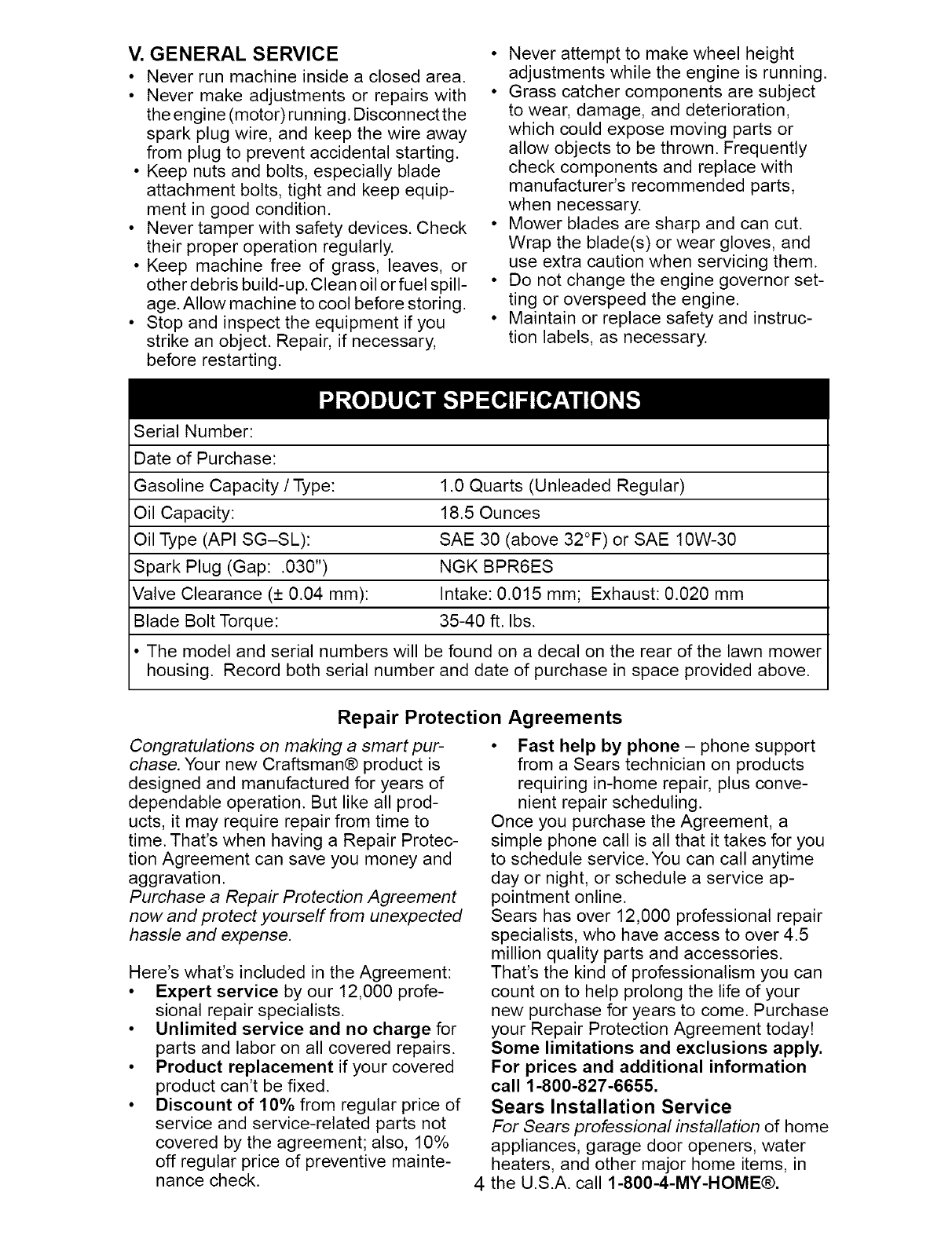
Serial Number:
Dateof Purchase:
GasolineCapacity/Type: 1.0 Quarts (Unleaded Regular)
Oil Capacity: 18.5 Ounces
Oil Type (API SG-SL): SAE 30 (above 32°F) or SAE 10W-30
Spark Plug (Gap: .030") NGK BPR6ES
Valve Clearance (+ 0.04 mm): Intake: 0.015 mm; Exhaust: 0.020 mm
Blade Bolt Torque: 35-40 ft. Ibs.
• The model and serial numbers will be found on a decal on the rear of the lawn mower
housing. Record both serial number and date of purchase in space provided above.
Repair Protection Agreements
Congratulations on making a smart pur-
chase. Your new Craftsman® product is
designed and manufactured for years of
dependable operation. But like all prod-
ucts, it may require repair from time to
time. That's when having a Repair Protec-
tion Agreement can save you money and
aggravation.
Purchase a Repair Protection Agreement
now and protect yourself from unexpected
hassle and expense.
Here's what's included in the Agreement:
• Expert service by our 12,000 profe-
sional repair specialists.
• Unlimited service and no charge for
parts and labor on all covered repairs.
• Product replacement if your covered
product can't be fixed.
• Discount of 10% from regular price of
service and service-related parts not
covered by the agreement; also, 10%
off regular price of preventive mainte-
nance check.
• Fast help by phone- phone support
from a Sears technician on products
requiring in-home repair, plus conve-
nient repair scheduling.
Once you purchase the Agreement, a
simple phone call is all that it takes for you
to schedule service. You can call anytime
day or night, or schedule a service ap-
pointment online.
Sears has over 12,000 professional repair
specialists, who have access to over 4.5
million quality parts and accessories.
That's the kind of professionalism you can
count on to help prolong the life of your
new purchase for years to come. Purchase
your Repair Protection Agreement today!
Some limitations and exclusions apply.
For prices and additional information
call 1-800-827-6655.
Sears Installation Service
For Sears professional installation of home
appliances, garage door openers, water
heaters, and other major home items, in
the U.S.A. call 1-800-4-MY-HOME®.
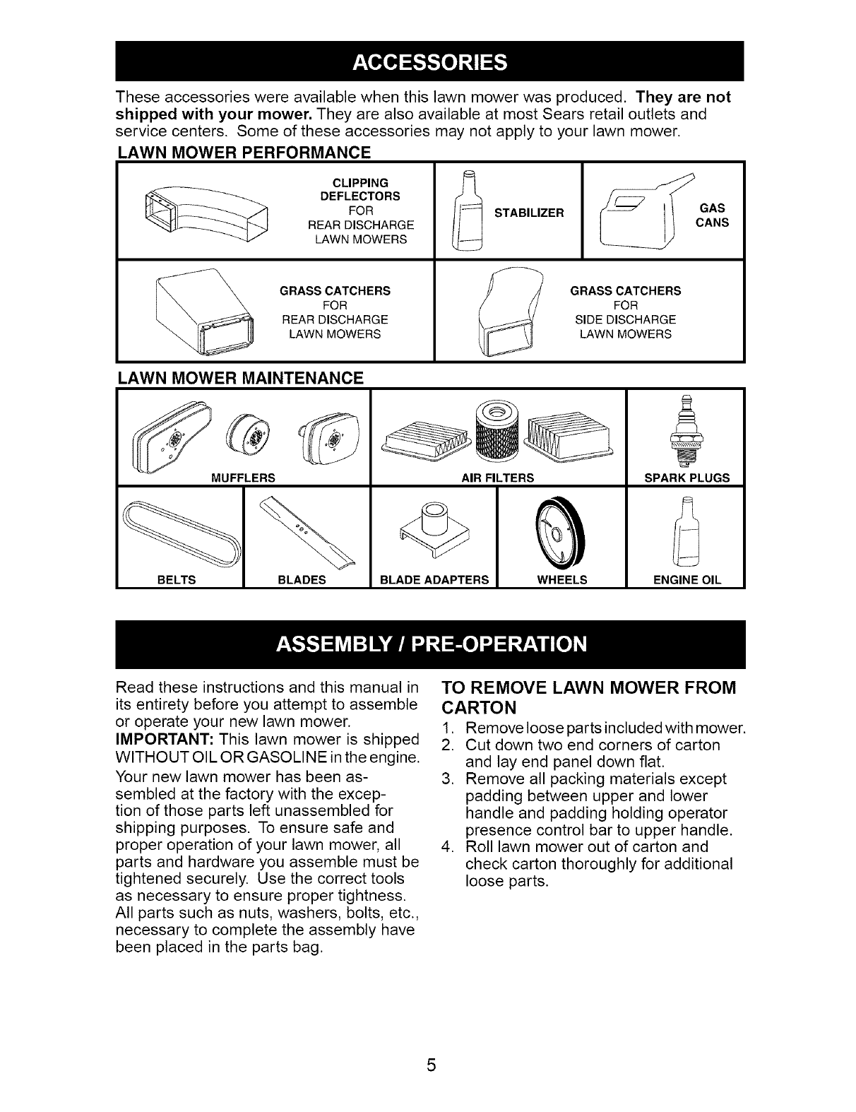
Theseaccessorieswere availablewhenthis lawnmowerwasproduced. They are not
shipped with your mower. Theyare also availableat most Sears retailoutlets and
service centers. Someof theseaccessoriesmaynot applyto yourlawn mower.
LAWN MOWER PERFORMANCE
CLIPPING
DEFLECTORS
FOR
REAR DISCHARGE
LAWN MOWERS
GRASS CATCHERS
FOR
REAR DISCHARGE
LAWN MOWERS
STABILIZER
GRASS CATCHERS
FOR
SIDE DISCHARGE
LAWN MOWERS
LAWN MOWER MAINTENANCE
MUFFLERS
BELTS BLADES BLADE ADAPTERS
AIR FILTERS
WHEELS
SPARK PLUGS
ENGINE OIL
Read these instructions and this manual in
its entirety before you attempt to assemble
or operate your new lawn mower.
IMPORTANT: This lawn mower is shipped
WITHOUT OIL OR GASOLINE in the engine.
Your new lawn mower has been as-
sembled at the factory with the excep-
tion of those parts left unassembled for
shipping purposes. To ensure safe and
proper operation of your lawn mower, all
parts and hardware you assemble must be
tightened securely. Use the correct tools
as necessary to ensure proper tightness.
All parts such as nuts, washers, bolts, etc.,
necessary to complete the assembly have
been placed in the parts bag.
TO REMOVE LAWN MOWER FROM
CARTON
1. Remove loose parts included with mower.
2. Cut down two end corners of carton
and lay end panel down flat.
3. Remove all packing materials except
padding between upper and lower
handle and padding holding operator
presence control bar to upper handle.
4. Roll lawn mower out of carton and
check carton thoroughly for additional
loose parts.
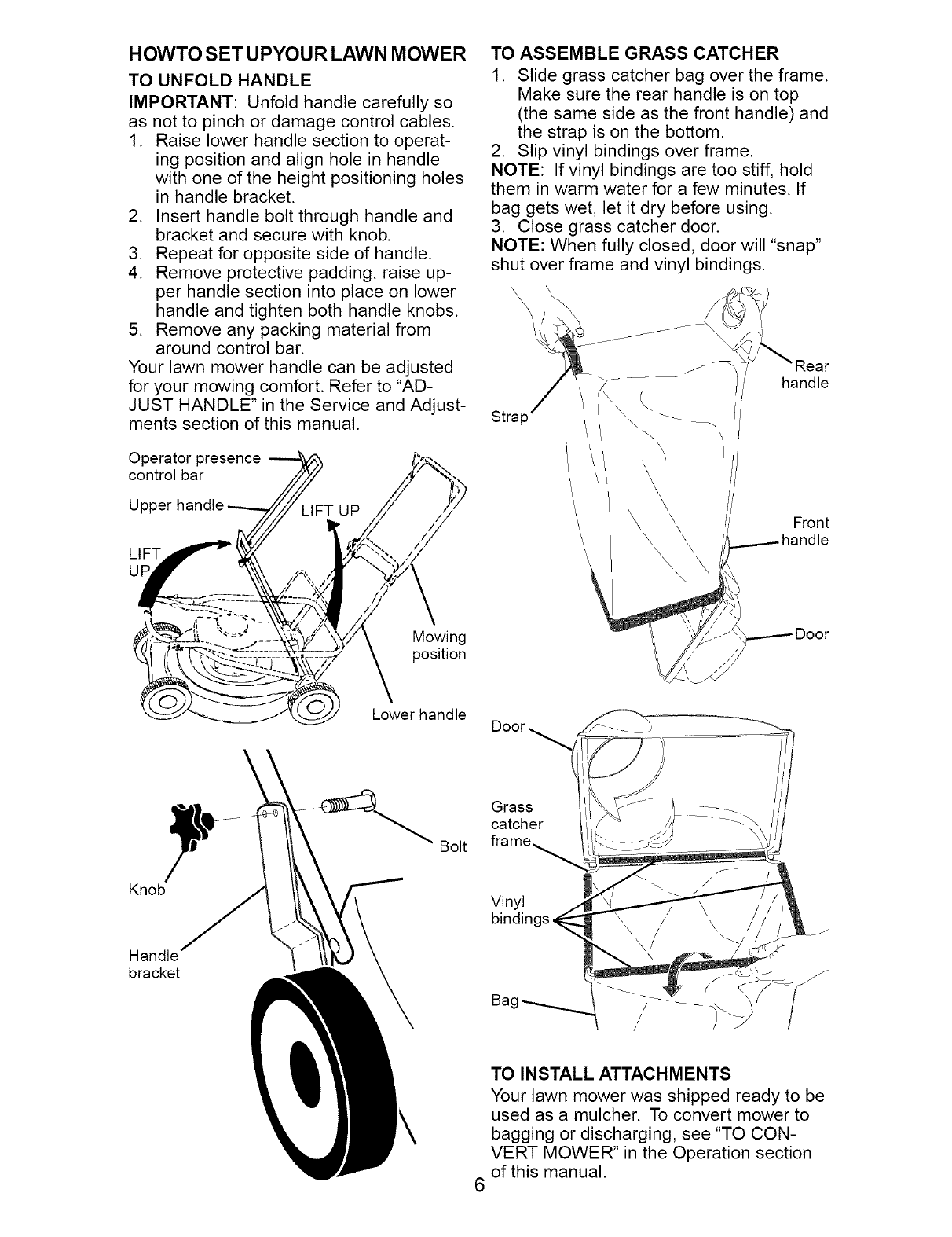
HOWTO SET UPYOU RLAWN MOWER
TO UNFOLD HANDLE
IMPORTANT: Unfold handle carefully so
as not to pinch or damage control cables.
1. Raise lower handle section to operat-
ing position and align hole in handle
with one of the height positioning holes
in handle bracket.
2. Insert handle bolt through handle and
bracket and secure with knob.
3. Repeat for opposite side of handle.
4. Remove protective padding, raise up-
per handle section into place on lower
handle and tighten both handle knobs.
5. Remove any packing material from
around control bar.
Your lawn mower handle can be adjusted
for your mowing comfort. Refer to "AD-
JUST HANDLE" in the Service and Adjust-
ments section of this manual.
Operator presence
control bar
Upl
LIFT
Mowing
position
Lower handle
TO ASSEMBLE GRASS CATCHER
1. Slide grass catcher bag over the frame.
Make sure the rear handle is on top
(the same side as the front handle) and
the strap is on the bottom.
2. Slip vinyl bindings over frame.
NOTE: If vinyl bindings are too stiff, hold
them in warm water for a few minutes. If
bag gets wet, let it dry before using.
3. Close grass catcher door.
NOTE: When fully closed, door will "snap"
shut over frame and vinyl bindings.
Stra
" /
\
\
\
\ \
\
handle
Front
handle
Door
Grass
catcher
Bolt frame
Knob
Handle
bracket
Vinyl
bindinc
Bag
TO INSTALL ATTACHMENTS
Your lawn mower was shipped ready to be
used as a mulcher. To convert mower to
bagging or discharging, see "TO CON-
VERT MOWER" in the Operation section
of this manual.
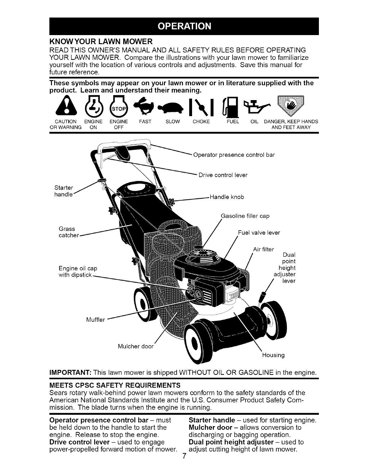
KNOWYOUR LAWN MOWER
READ THIS OWNER'S MANUAL AND ALL SAFETY RULES BEFORE OPERATING
YOUR LAWN MOWER. Compare the illustrations with your lawn mower to familiarize
yourself with the location of various controls and adjustments. Save this manual for
future reference.
These symbols may appear on your lawn mower or in literature supplied with the
product. Learn and understand their meaning.
CAUTION ENGINE ENGINE FAST SLOW CHOKE FUEL OIL DANGER, KEEP HANDS
OR WARNING ON OFF AND FEET AWAY
Operator presence control bar
Starter
handle
Grass
catcher
Engine oil cap
with dil:
Drive control lever
knob
Gasoline filler cap
Fuel valve lever
Air filter Dual
point
height
adjuster
lever
Muffler
Mulcher door
Housing
IMPORTANT: This lawn mower is shipped WITHOUT OIL OR GASOLINE in the engine.
MEETS CPSC SAFETY REQUIREMENTS
Sears rotary walk-behind power lawn mowers conform to the safety standards of the
American National Standards Institute and the U.S. Consumer Product Safety Com-
mission. The blade turns when the engine is running.
Operator presence control bar- must
be held down to the handle to start the
engine. Release to stop the engine.
Drive control lever - used to engage
power-propelled forward motion of mower.
Starter handle - used for starting engine.
Mulcher door - allows conversion to
discharging or bagging operation.
Dual point height adjuster- used to
adjust cutting height of lawn mower.
The operationof any lawn
SAFETYGLASSESmowercan resultin foreign
objectsthrown intothe
eyes,which can result in
severe eye damage. Always
wear safety glasses or eye shields while
operating your lawn mower or performing
any adjustments or repairs. We recom-
mend a standard safety glasses or wide
vision safety mask worn over spectacles.
HOW TO USE YOUR LAWN MOWER
ENGINE SPEED
The engine speed was set at the factory
for optimum performance. Speed is not
adjustable.
ENGINE ZONE CONTROL
_II,CAUTION: Federal regulations require
an engine control to be installed on this
lawn mower in order to minimize the
risk of blade contact injury. Do not under
any circumstances attempt to defeat the
function of the operator control. The blade
turns when the engine is running.
• Your lawn mower is equipped with an
operator presence control bar which
requires the operator to be positioned
behind the lawn mower handle to start
and operate the lawn mower.
DRIVE CONTROL
• Self-propelling is controlled by hold-
ing the operator presence control bar
down to the handle and pulling the drive
control lever rearward to the handle.
The farther toward the handle the lever
is pulled, the faster the unit will travel.
• Forward motion will stop when either
the operator presence control bar or
drive control lever are released. To stop
forward motion without stopping engine,
release only the drive control lever. Hold
operator presence control bar down
against handle to continue mowing
without self-propelling.
NOTE: If after releasing the drive control
the mower will not roll backwards, push
the mower forward slightly to disengage
drive wheels.
_resence control bar
Drive
control
TO lever
Adjustment ENGAGE DRIVE
button (on DRIVE CONTROL
underside) CONTROL DISENGAGED
• To keep drive control engaged when
turning corners, push down on the
handle to lift the front wheels off the
ground while turning lawn mower.
DRIVE CONTROL ADJUSTMENT
Over time, the drive control system may be-
come "loose", resulting in decreased speed.
There is a button on the underside of the drive
control housing to increase tension on the
drive cable. Proceed as follows:
1. Turn mower engine off and disconnect
spark plug wire from spark plug.
2. Pull out button on underside of drive
control, then push it back in.
3. Operate mower to see if drive speed
has increased. If there is no increase,
the drive belt is worn and needs to be
replaced.
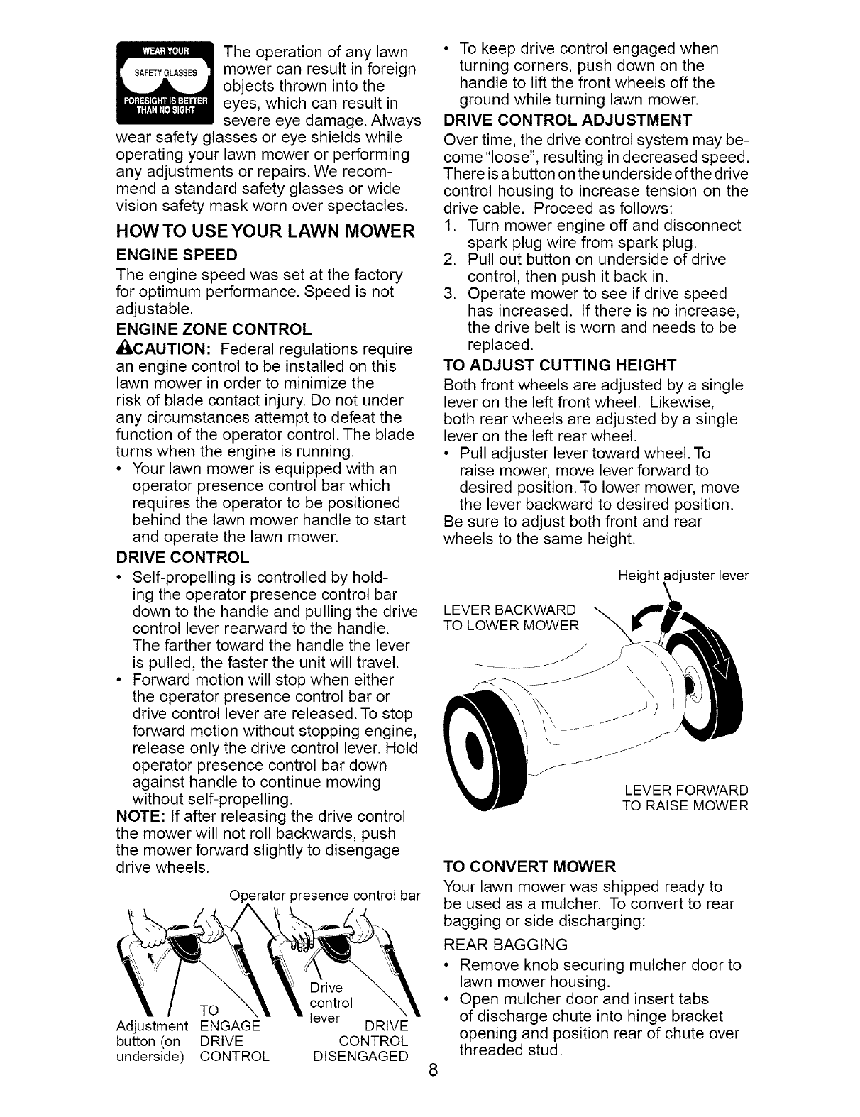
TO ADJUST CUTTING HEIGHT
Both front wheels are adjusted by a single
lever on the left front wheel. Likewise,
both rear wheels are adjusted by a single
lever on the left rear wheel.
• Pull adjuster lever toward wheel. To
raise mower, move lever forward to
desired position. To lower mower, move
the lever backward to desired position.
Be sure to adjust both front and rear
wheels to the same height.
Height _djuster lever
LEVER BACKWARD
TO LOWER MOWER
LEVER FORWARD
TO RAISE MOWER
TO CONVERT MOWER
Your lawn mower was shipped ready to
be used as a mulcher. To convert to rear
bagging or side discharging:
REAR BAGGING
• Remove knob securing mulcher door to
lawn mower housing.
• Open mulcher door and insert tabs
of discharge chute into hinge bracket
opening and position rear of chute over
threaded stud.
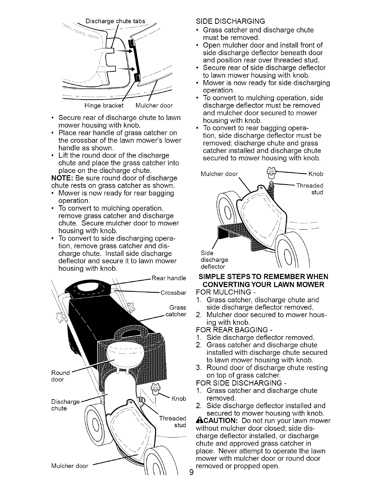
Hinge bracket Mulcher door
• Secure rear of discharge chute to lawn
mower housing with knob.
• Place rear handle of grass catcher on
the crossbar of the lawn mower's lower
handle as shown.
• Lift the round door of the discharge
chute and place the grass catcher into
place on the discharge chute.
NOTE: Be sure round door of discharge
chute rests on grass catcher as shown.
• Mower is now ready for rear bagging
operation.
• To convert to mulching operation,
remove grass catcher and discharge
chute. Secure mulcher door to mower
housing with knob.
• To convert to side discharging opera-
tion, remove grass catcher and dis-
charge chute. Install side discharge
deflector and secure it to lawn mower
housing with knob.
Crossbar
Grass
Round
door
Discharge Knob
chute
Threaded
stud
Mulcher door
SIDE DISCHARGING
• Grass catcher and discharge chute
must be removed.
• Open mulcher door and install front of
side discharge deflector beneath door
and position rear over threaded stud.
• Secure rear of side discharge deflector
to lawn mower housing with knob.
• Mower is now ready for side discharging
operation.
• To convert to mulching operation, side
discharge deflector must be removed
and mulcher door secured to mower
housing with knob.
• To convert to rear bagging opera-
tion, side discharge deflector must be
removed; discharge chute and grass
catcher installed and discharge chute
secured to mower housing with knob.
Mulcher door \Threaded
stud
Side
discharge
deflector
SIMPLE STEPS TO REMEMBER WHEN
CONVERTINGYOUR LAWN MOWER
FOR MULCHING -
1. Grass catcher, discharge chute and
side discharge deflector removed.
2. Mulcher door secured to mower hous-
ing with knob.
FOR REAR BAGGING -
1. Side discharge deflector removed.
2. Grass catcher and discharge chute
installed with discharge chute secured
to lawn mower housing with knob.
3. Round door of discharge chute resting
on top of grass catcher.
FOR SIDE DISCHARGING -
1. Grass catcher and discharge chute
removed.
2. Side discharge deflector installed and
secured to mower housing with knob.
_CAUTION: Do not run your lawn mower
without mulcher door closed; side dis-
charge deflector installed, or discharge
chute and approved grass catcher in
place. Never attempt to operate the lawn
mower with mulcher door or round door
removed or propped open.
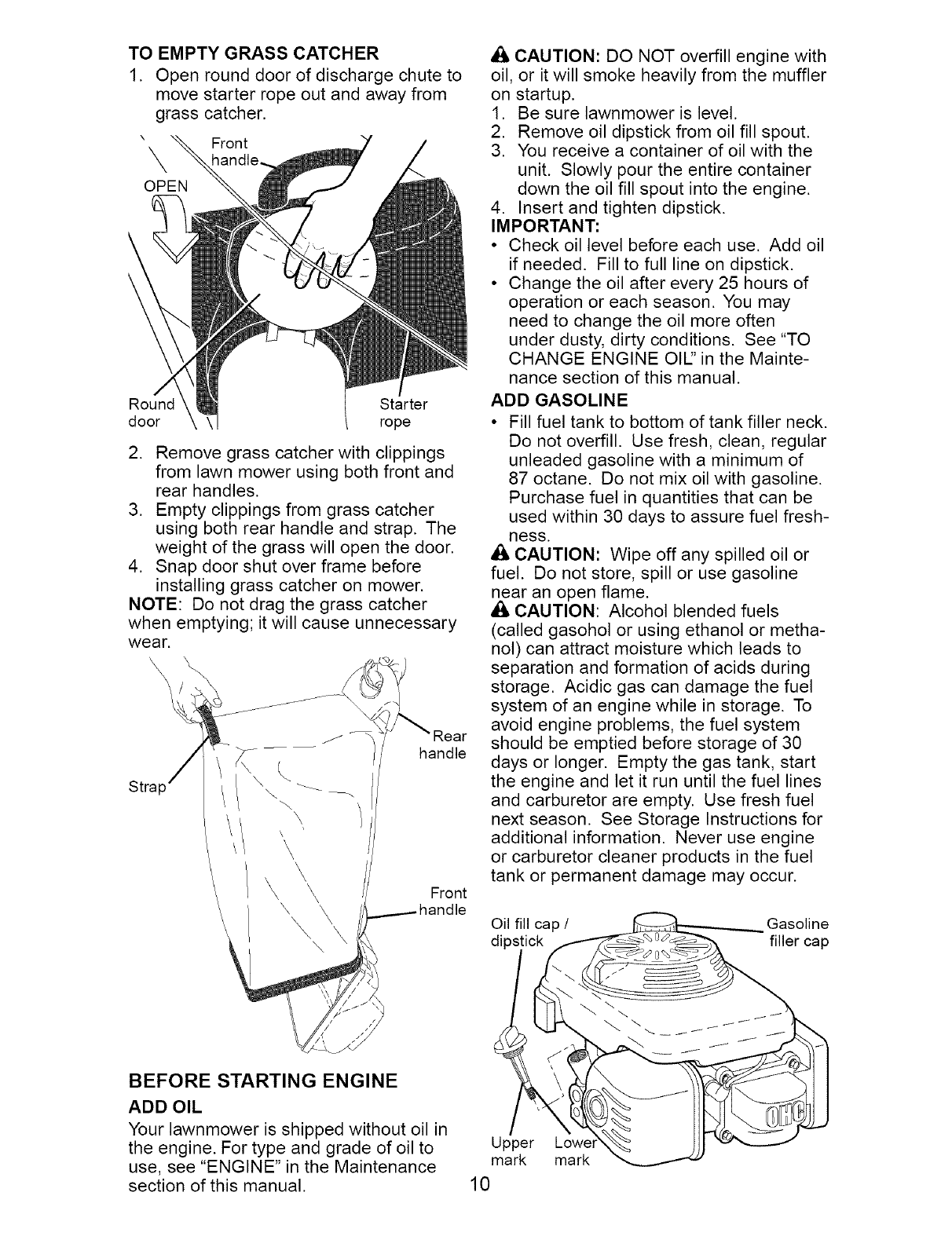
TO EMPTY GRASS CATCHER
1. Open round door of discharge chute to
move starter rope out and away from
grass catcher.
X Front
OPEN
Round Starter
door rope
2. Remove grass catcher with clippings
from lawn mower using both front and
rear handles.
3. Empty clippings from grass catcher
using both rear handle and strap. The
weight of the grass will open the door.
4. Snap door shut over frame before
installing grass catcher on mower.
NOTE: Do not drag the grass catcher
when emptying; it will cause unnecessary
wear.
Stra
\
\
\
\ \
\
handle
Front
A CAUTION: DO NOT overfill engine with
oil, or it will smoke heavily from the muffler
on startup.
1. Be sure lawnmower is level.
2. Remove oil dipstick from oil fill spout.
3. You receive a container of oil with the
unit. Slowly pour the entire container
down the oil fill spout into the engine.
4. Insert and tighten dipstick.
IMPORTANT:
•Check oil level before each use. Add oil
if needed. Fill to full line on dipstick.
• Change the oil after every 25 hours of
operation or each season. You may
need to change the oil more often
under dusty, dirty conditions. See "TO
CHANGE ENGINE OIL" in the Mainte-
nance section of this manual.
ADD GASOLINE
• Fill fuel tank to bottom of tank filler neck.
Do not overfill. Use fresh, clean, regular
unleaded gasoline with a minimum of
87 octane. Do not mix oil with gasoline.
Purchase fuel in quantities that can be
used within 30 days to assure fuel fresh-
ness.
CAUTION: Wipe off any spilled oil or
fuel. Do not store, spill or use gasoline
near an open flame.
• iLCAUTION: Alcohol blended fuels
(called gasohol or using ethanol or metha-
nol) can attract moisture which leads to
separation and formation of acids during
storage. Acidic gas can damage the fuel
system of an engine while in storage. To
avoid engine problems, the fuel system
should be emptied before storage of 30
days or longer. Empty the gas tank, start
the engine and let it run until the fuel lines
and carburetor are empty. Use fresh fuel
next season. See Storage Instructions for
additional information. Never use engine
or carburetor cleaner products in the fuel
tank or permanent damage may occur.
Oil fill cap /Gasoline
dips filler cap
BEFORE STARTING ENGINE
ADD OIL
Your lawnmower is shipped without oil in
the engine. For type and grade of oil to Upper
use, see "ENGINE" in the Maintenance mark
section of this manual. 10
mark
TO STOP ENGINE
• To stop engine, release operator pres-
ence control bar. Wait until blade and
all moving parts have stopped and turn
fuel valve to OFF position if you do not
intend to restart the engine soon.
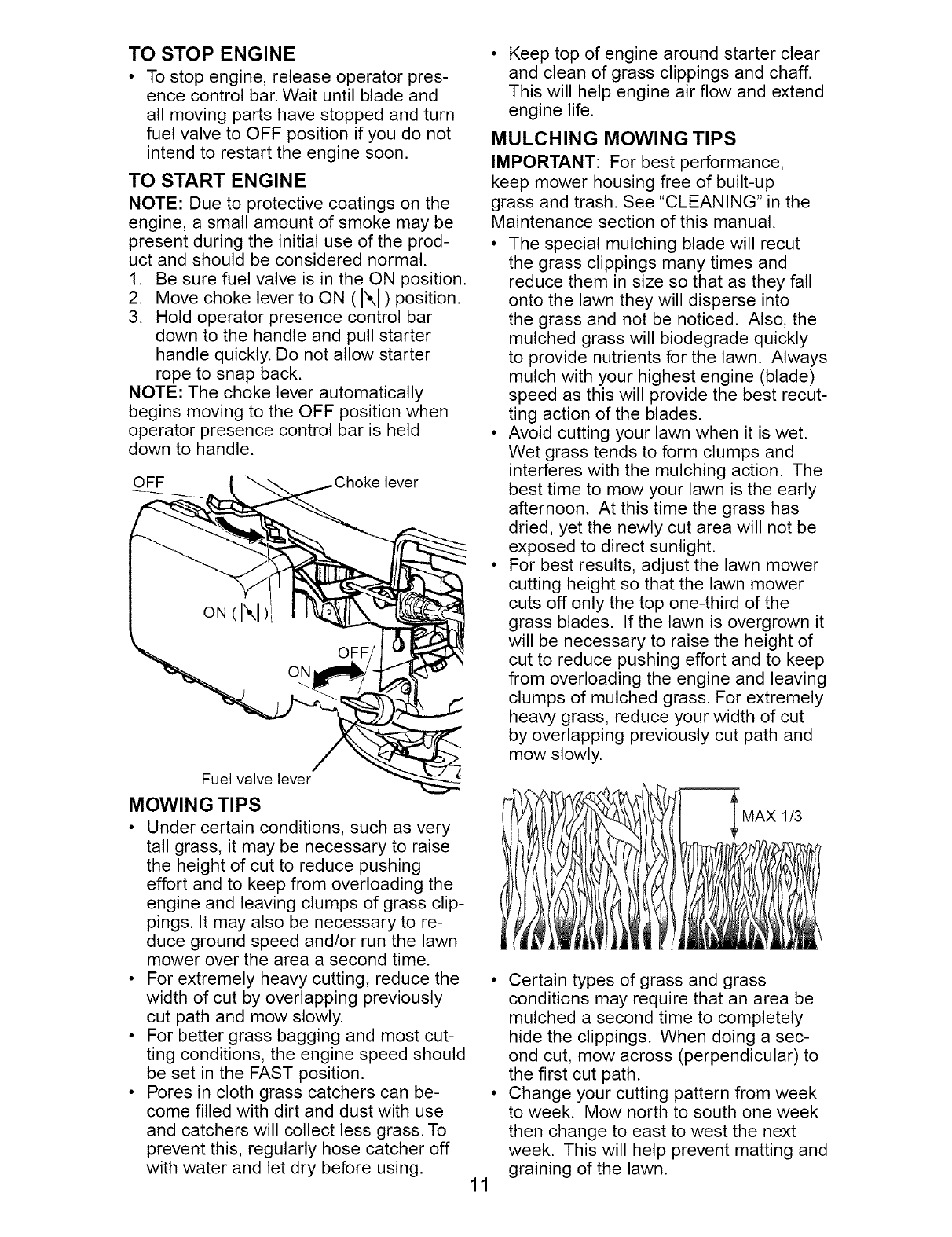
TO START ENGINE
NOTE: Due to protective coatings on the
engine, a small amount of smoke may be
present during the initial use of the prod-
uct and should be considered normal.
1. Be sure fuel valve is in the ON position.
2. Move choke lever to ON (N) position.
3. Hold operator presence control bar
down to the handle and pull starter
handle quickly. Do not allow starter
rope to snap back.
NOTE: The choke lever automatically
begins moving to the OFF position when
operator presence control bar is held
down to handle.
OFF lever
Fuel valve lever
MOWING TIPS
• Under certain conditions, such as very
tall grass, it may be necessary to raise
the height of cut to reduce pushing
effort and to keep from overloading the
engine and leaving clumps of grass clip-
pings. It may also be necessary to re-
duce ground speed and/or run the lawn
mower over the area a second time.
• For extremely heavy cutting, reduce the
width of cut by overlapping previously
cut path and mow slowly.
• For better grass bagging and most cut-
ting conditions, the engine speed should
be set in the FAST position.
• Pores in cloth grass catchers can be-
come filled with dirt and dust with use
and catchers will collect less grass. To
prevent this, regularly hose catcher off
with water and let dry before using.
Keep top of engine around starter clear
and clean of grass clippings and chaff.
This will help engine air flow and extend
engine life.
MULCHING MOWING TIPS
IMPORTANT: For best performance,
keep mower housing free of built-up
grass and trash. See "CLEANING" in the
Maintenance section of this manual.
• The special mulching blade will recut
the grass clippings many times and
reduce them in size so that as they fall
onto the lawn they will disperse into
the grass and not be noticed. Also, the
mulched grass will biodegrade quickly
to provide nutrients for the lawn. Always
mulch with your highest engine (blade)
speed as this will provide the best recut-
ting action of the blades.
• Avoid cutting your lawn when it is wet.
Wet grass tends to form clumps and
interferes with the mulching action. The
best time to mow your lawn is the early
afternoon. At this time the grass has
dried, yet the newly cut area will not be
exposed to direct sunlight.
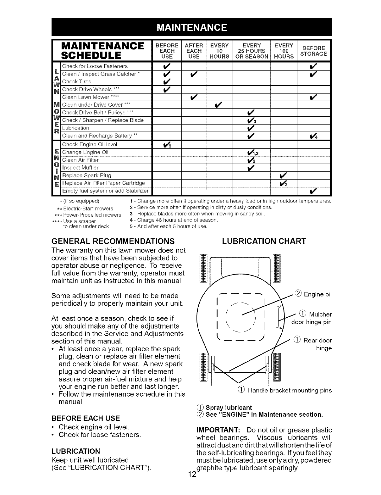
• For best results, adjust the lawn mower
cutting height so that the lawn mower
cuts off only the top one-third of the
grass blades. If the lawn is overgrown it
will be necessary to raise the height of
cut to reduce pushing effort and to keep
from overloading the engine and leaving
clumps of mulched grass. For extremely
heavy grass, reduce your width of cut
by overlapping previously cut path and
mow slowly.
1/3
11
• Certain types of grass and grass
conditions may require that an area be
mulched a second time to completely
hide the clippings. When doing a sec-
ond cut, mow across (perpendicular) to
the first cut path.
• Change your cutting pattern from week
to week. Mow north to south one week
then change to east to west the next
week. This will help prevent matting and
graining of the lawn.
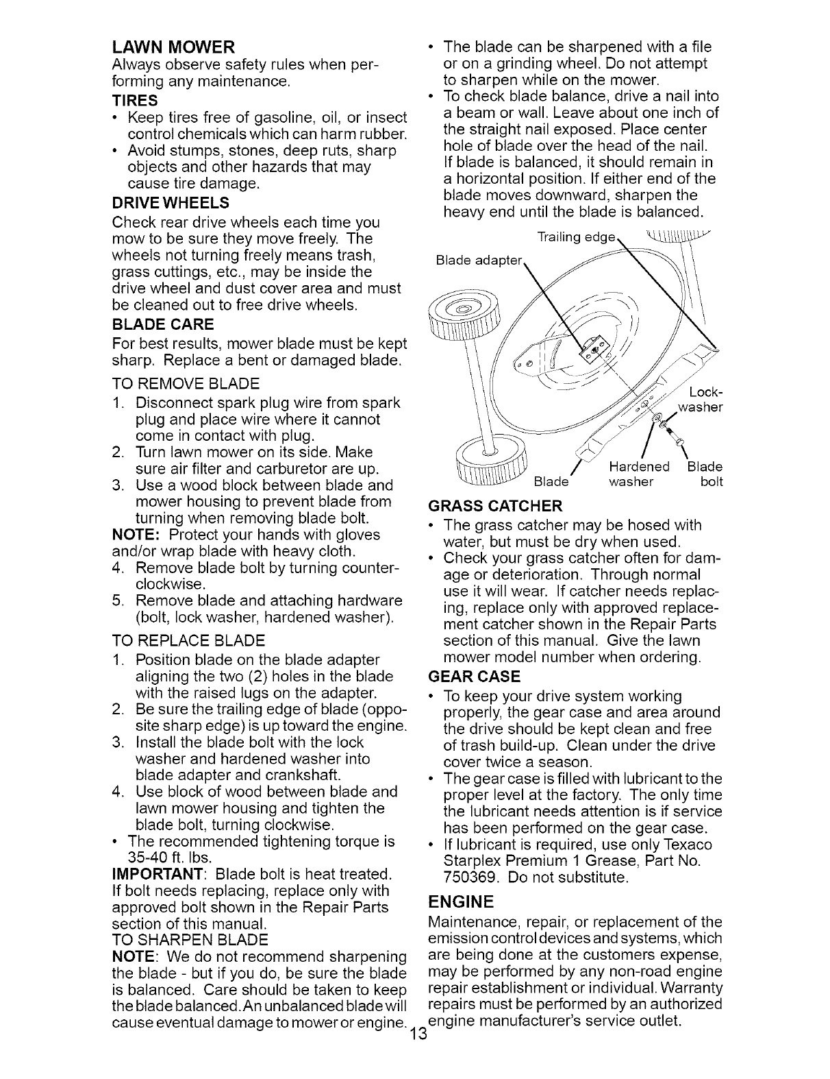
MAINTENANCE
SCHEDULE
Check for Loose Fasteners
_ Clean /Inspect Grass Catcher *
Check Tires
_ Check Drive Wheels
Clean Lawn Mower ....
M Clean under Drive Cover ***
O Check Drive Belt /Putleys ***
W Check /Sharpen /Replace Blade
_ ubrication
Clean and Recharge Battery **
Check Engine Oil level
E Change Engine Oil
N Clean Air Filter
_ Inspect Muffler
N Replace Spark Plug
E Replace Air Filter Paper Cartridge
Empty fuel system or add Stabilizer
BEFORE AFTER EVERY EVERY EVERY BEFORE
EACH EACH 10 25HOURS 100
USE USE HOURS OR SEASON HOURS STORAGE
,4
V' V'
V'
V'3
_,2
V'
,4
* (if so equipped)
** Electric-Start mowers
*** Power-Propelled mowers
**** Use a scraper
to clean under deck
1 - Change more often if operating under a heavy load or in high outdoor temperatures.
2 - Service more often if operating in dirty or dusty conditions,
3 - Replace blades more often when mowing in sandy soil,
4 - Charge 48 hours at end of season.
5 - And after each 5 hours of use.
GENERAL RECOMMENDATIONS
The warranty on this lawn mower does not
cover items that have been subjected to
operator abuse or negligence. To receive
full value from the warranty, operator must
maintain unit as instructed in this manual.
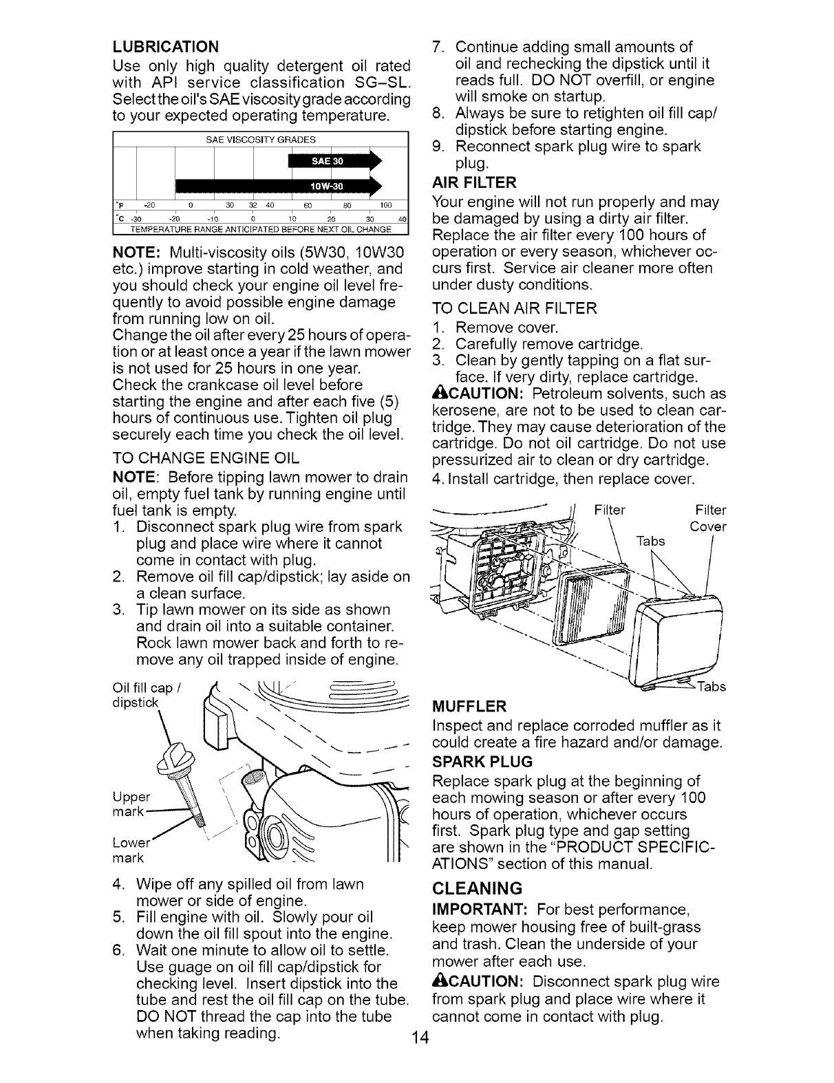
LUBRICATION CHART
Some adjustments will need to be made
periodically to properly maintain your unit.
At least once a season, check to see if
you should make any of the adjustments
described in the Service and Adjustments
section of this manual.
• At least once a year, replace the spark
plug, clean or replace air filter element
and check blade for wear. A new spark
plug and clean/new air filter element
assure proper air-fuel mixture and help
your engine run better and last longer.
• Follow the maintenance schedule in this
manual.
BEFORE EACH USE
• Check engine oil level.
• Check for loose fasteners.
LUBRICATION
Keep unit well lubricated
(See "LUBRICATION CHART").
I
I
I
Engine oil
(_) Mulcher
door hinge pin
(_) Rear door
hinge
(_) Handle bracket mounting pins
_Spray lubricant
See "ENGINE" in Maintenance section.
IMPORTANT: Do not oil or grease plastic
wheel bearings. Viscous lubricants will
attract dust and dirt that will shorten the life of
the self-lubricating bearings. If you feel they
must be lubricated, use only a dry, powdered
2graphite type lubricant sparingly.
1
LAWN MOWER
Always observe safety rules when per-
forming any maintenance.
TIRES
• Keep tires free of gasoline, oil, or insect
control chemicals which can harm rubber.
• Avoid stumps, stones, deep ruts, sharp
objects and other hazards that may
cause tire damage.
DRIVE WHEELS
Check rear drive wheels each time you
mow to be sure they move freely. The
wheels not turning freely means trash,
grass cuttings, etc., may be inside the
drive wheel and dust cover area and must
be cleaned out to free drive wheels.
BLADE CARE
For best results, mower blade must be kept
sharp. Replace a bent or damaged blade.
The blade can be sharpened with a file
or on a grinding wheel. Do not attempt
to sharpen while on the mower.
To check blade balance, drive a nail into
a beam or wall. Leave about one inch of
the straight nail exposed. Place center
hole of blade over the head of the nail.
If blade is balanced, it should remain in
a horizontal position. If either end of the
blade moves downward, sharpen the
heavy end until the blade is balanced.
Trailing
Blade adapter,
TO REMOVE BLADE
1. Disconnect spark plug wire from spark
plug and place wire where it cannot
come in contact with plug.
2. Turn lawn mower on its side. Make
sure air filter and carburetor are up.
3. Use a wood block between blade and
mower housing to prevent blade from
turning when removing blade bolt.
NOTE: Protect your hands with gloves
and/or wrap blade with heavy cloth.
4. Remove blade bolt by turning counter-
clockwise.
5. Remove blade and attaching hardware
(bolt, lock washer, hardened washer).
TO REPLACE BLADE
1. Position blade on the blade adapter
aligning the two (2) holes in the blade
with the raised lugs on the adapter.
2. Be sure the trailing edge of blade (oppo-
site sharp edge) is up toward the engine.
3. Install the blade bolt with the lock
washer and hardened washer into
blade adapter and crankshaft.
4. Use block of wood between blade and
lawn mower housing and tighten the
blade bolt, turning clockwise.
• The recommended tightening torque is
35-40 ft. Ibs.
IMPORTANT: Blade bolt is heat treated.
If bolt needs replacing, replace only with
approved bolt shown in the Repair Parts
section of this manual.
TO SHARPEN BLADE
NOTE: We do not recommend sharpening
the blade - but if you do, be sure the blade
is balanced. Care should be taken to keep
the blade balanced.An unbalanced blade will
Lock-
washer
Hardened Blade
Blade washer bolt
GRASS CATCHER
• The grass catcher may be hosed with
water, but must be dry when used.
• Check your grass catcher often for dam-
age or deterioration. Through normal
use it will wear. If catcher needs replac-
ing, replace only with approved replace-
ment catcher shown in the Repair Parts
section of this manual. Give the lawn
mower model number when ordering.
GEAR CASE
• To keep your drive system working
properly, the gear case and area around
the drive should be kept clean and free
of trash build-up. Clean under the drive
cover twice a season.
• The gear case is filled with lubricant to the
proper level at the factory. The only time
the lubricant needs attention is if service
has been performed on the gear case.
• If lubricant is required, use only Texaco
Starplex Premium 1 Grease, Part No.
750369. Do not substitute.
ENGINE
Maintenance, repair, or replacement of the
emission control devices and systems, which
are being done at the customers expense,
may be performed by any non-road engine
repair establishment or individual. Warranty
repairs must be performed by an authorized
cause eventual damage to mower or engine. 13 engine manufacturer's service outlet.
LUBRICATION
Use only high quality detergent oil rated
with API service classification SG-SL.
Selecttheoil'sSAEviscositygradeaccording
to your expectedoperatingtemperature.
SAE VISCOSITY GRADES
I,
I,
[i|',T_ <[
°F -20 0 30 32 40 60 80 100
°c -_o -_ -1_ _ _ _o _o _o
TEMPERATURE RANGE ANTICIPATED BEFORE NEXT OIL CHANGE
NOTE: Multi-viscosity oils (5W30, 10W30
etc.) improve starting in cold weather, and
you should check your engine oil level fre-
quently to avoid possible engine damage
from running low on oil.
Change the oil after every 25 hours of opera-
tion or at least once a year if the lawn mower
is not used for 25 hours in one year.
Check the crankcase oil level before
starting the engine and after each five (5)
hours of continuous use. Tighten oil plug
securely each time you check the oil level.
TO CHANGE ENGINE OIL
NOTE: Before tipping lawn mower to drain
oil, empty fuel tank by running engine until
fuel tank is empty.
1. Disconnect spark plug wire from spark
plug and place wire where it cannot
come in contact with plug.
2. Remove oil fill cap/dipstick; lay aside on
a clean surface.
3. Tip lawn mower on its side as shown
and drain oil into a suitable container.
Rock lawn mower back and forth to re-
move any oil trapped inside of engine.
Oil fill cap /
dipstick
Upper _
mark--_
Lower , z
mark
.
.
.
7. Continue adding small amounts of
oil and rechecking the dipstick until it
reads full. DO NOT overfill, or engine
will smoke on startup.
8. Always be sure to retighten oil fill cap/
dipstick before starting engine.
9. Reconnect spark plug wire to spark
plug.
AIR FILTER
Your engine will not run properly and may
be damaged by using a dirty air filter.
Replace the air filter every 100 hours of
operation or every season, whichever oc-
curs first. Service air cleaner more often
under dusty conditions.
TO CLEAN AIR FILTER
1. Remove cover.
2. Carefully remove cartridge.
3. Clean by gently tapping on a flat sur-
face. If very dirty, replace cartridge.
ACAUTION: Petroleum solvents, such as
kerosene, are not to be used to clean car-
tridge. They may cause deterioration of the
cartridge. Do not oil cartridge. Do not use
pressurized air to clean or dry cartridge.
4. Install cartridge, then replace cover.
-----__ Filter Filter
Cover
Tabs
Wipe off any spilled oil from lawn
mower or side of engine.
Fill engine with oil. Slowly pour oil
down the oil fill spout into the engine.
Wait one minute to allow oil to settle.
Use guage on oil fill cap/dipstick for
checking level. Insert dipstick into the
tube and rest the oil fill cap on the tube.
DO NOT thread the cap into the tube
when taking reading.
MUFFLER
Inspect and replace corroded muffler as it
could create a fire hazard and/or damage.
SPARK PLUG
Replace spark plug at the beginning of
each mowing season or after every 100
hours of operation, whichever occurs
first. Spark plug type and gap setting
are shown in the "PRODUCT SPECIFIC-
ATIONS" section of this manual.
CLEANING
IMPORTANT: For best performance,
keep mower housing free of built-grass
and trash. Clean the underside of your
mower after each use.
ACAUTION: Disconnect spark plug wire
from spark plug and place wire where it
cannot come in contact with plug.
14
• Cleanthe undersideof yourlawn mower
by scrapingto removebuild-upof grass
and trash.
• Cleanengineoften to keeptrashfrom
accumulating.A cloggedengine runs
hotterand shortens enginelife.
• Keepfinishedsurfacesandwheelsfree
of all gasoline,oil, etc.
• We do not recommendusing a garden
hose to cleanlawn mowerunlessthe
electricalsystem,muffler,airfilter and
carburetorarecoveredto keepwater
out. Waterin enginecan result in short-
ened enginelife.
CLEAN UNDERDRIVECOVER
Cleanunderdrive coverat least twice a
season.Scrapeundersideof coverwith
putty knifeor similartool to removeany
build-upof trashor grasson undersideof
drive cover.
_WARNING: Toavoidseriousinjury,before
performinganyservice and adjustments:
1. Releasecontrolbar and stopengine.
2. Makesure the blade and all moving
parts havecompletelystopped.
3. Disconnectspark plugwire from spark
plug and placewire where it cannot
comein contactwith plug.
LAWN MOWER
TO ADJUST CUTTING HEIGHT
See "TO ADJUST CUTTING HEIGHT" in
the Operation section of this manual.
REAR DEFLECTOR
The rear deflector, attached between the
rear wheels of your mower, is provided to
minimize the possibility that objects will be
thrown out of the rear of the mower into
the operator mowing position. If deflector
becomes damaged, it should be replaced.
TO REMOVE DRIVE BELT
1. Disconnect spark plug wire from spark
plug and place wire where it cannot
come in contact with plug.
2. Remove screws retaining drive cover
and remove drive cover from lawn
mower housing (See Figure A).
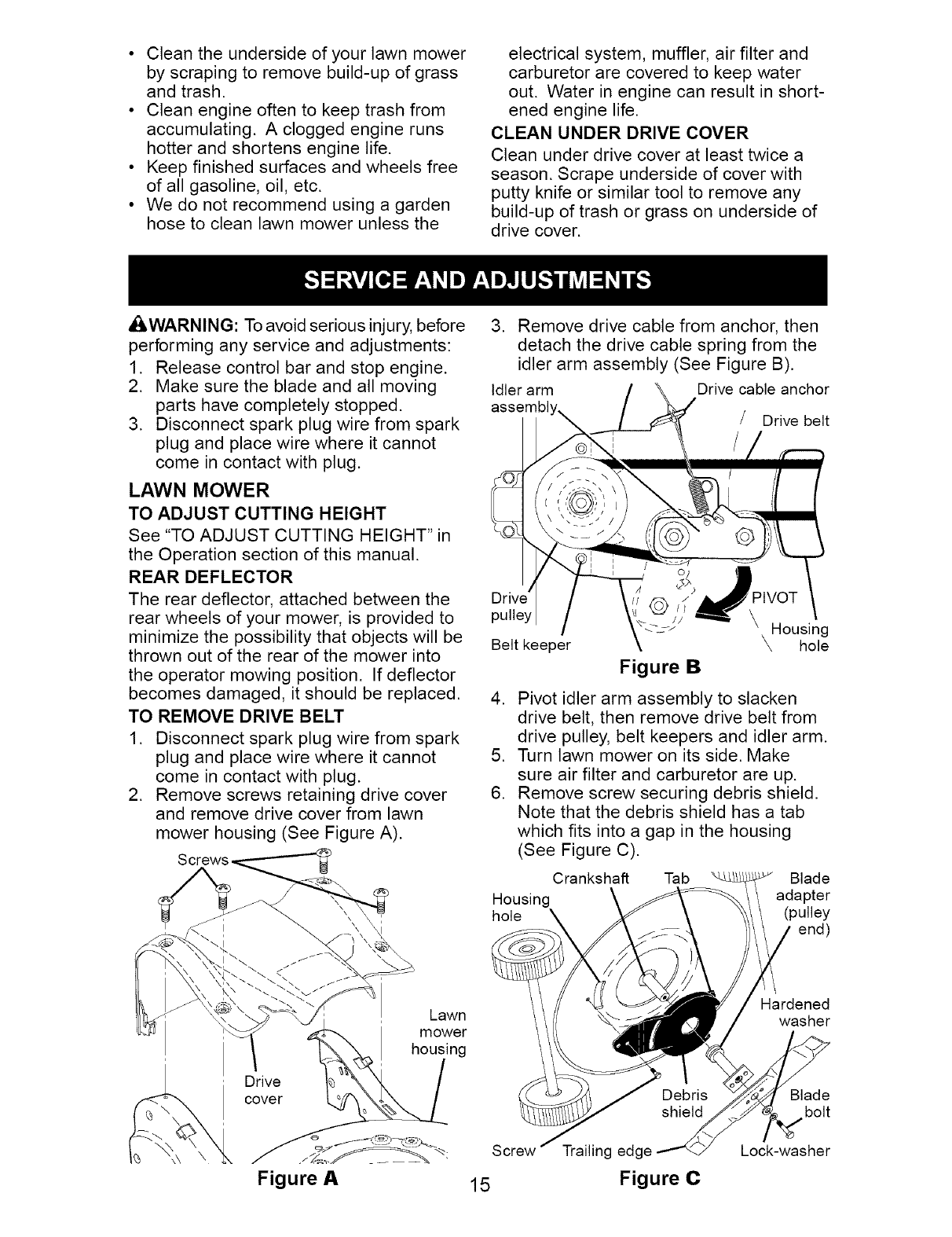
3. Remove drive cable from anchor, then
detach the drive cable spring from the
idler arm assembly (See Figure B).
Idler arm Drive cable anchor
assembl Drive belt
pulley
Belt keeper
Figure B
\ Housing
\ hole
4. Pivot idler arm assembly to slacken
drive belt, then remove drive belt from
drive pulley, belt keepers and idler arm.
5. Turn lawn mower on its side. Make
sure air filter and carburetor are up.
6. Remove screw securing debris shield.
Note that the debris shield has a tab
which fits into a gap in the housing
(See Figure C).
Crankshaft Tab Blade
Housing adapter
hole \ (pulley
end)
Drive
cover
Lawn
mower
housing
._%_._ _- Screw
Figure A 15
Trailing edge
Figure C
Hardened
washer
Blade
bolt
Lock-washer
7. Use a wood block between blade and
mower housing to prevent blade from
turning when removing blade bolt.
NOTE: Protect your hands with gloves
and/or wrap blade with heavy cloth.
8. Remove blade bolt.
9. Remove blade, attaching hardware
(bolt, lock washer and hardened wash-
er), blade adapter and debris shield as
one assembly.
10. Remove drive belt from blade adapter
and debris shield; discard old belt.
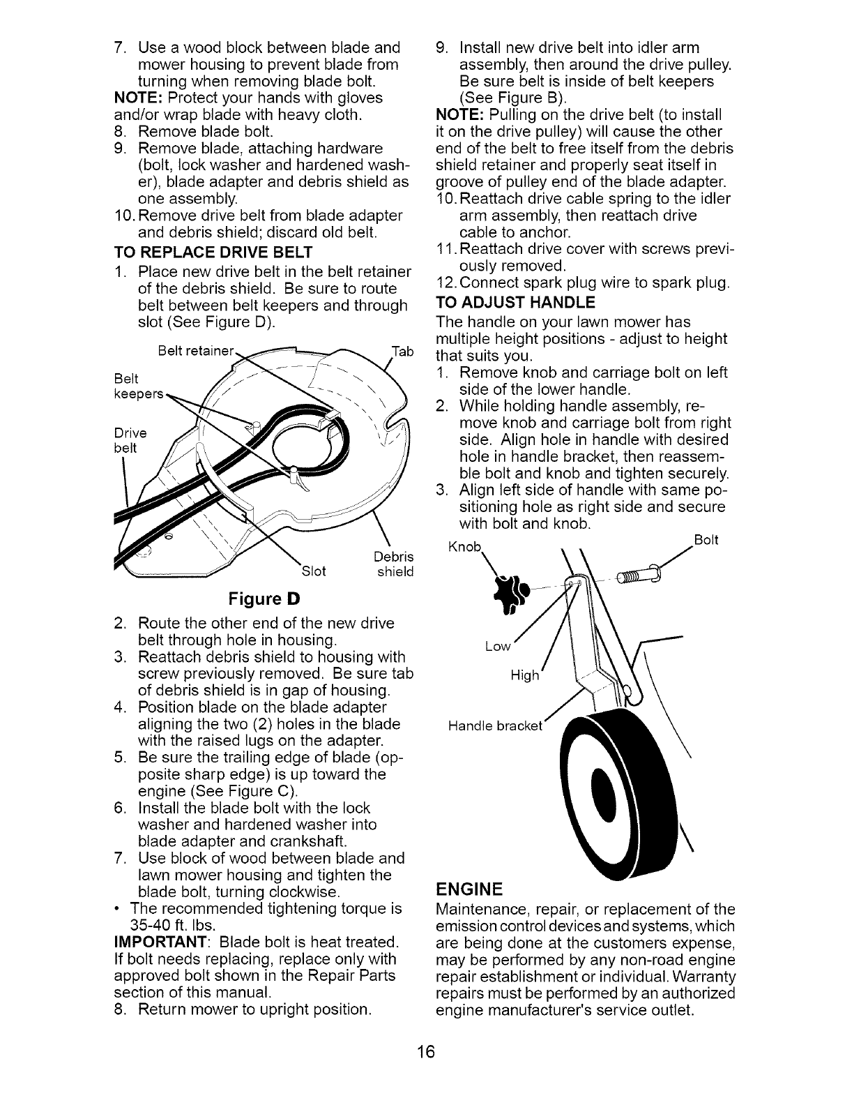
TO REPLACE DRIVE BELT
1. Place new drive belt in the belt retainer
of the debris shield. Be sure to route
belt between belt keepers and through
slot (See Figure D).
Belt Tab
Belt
kee
Drive
belt
Debris
Slot shield
Figure D
2. Route the other end of the new drive
belt through hole in housing.
3. Reattach debris shield to housing with
screw previously removed. Be sure tab
of debris shield is in gap of housing.
4. Position blade on the blade adapter
aligning the two (2) holes in the blade
with the raised lugs on the adapter.
5. Be sure the trailing edge of blade (op-
posite sharp edge) is up toward the
engine (See Figure C).
6. Install the blade bolt with the lock
washer and hardened washer into
blade adapter and crankshaft.
7. Use block of wood between blade and
lawn mower housing and tighten the
blade bolt, turning clockwise.
• The recommended tightening torque is
35-40 ft. Ibs.
IMPORTANT: Blade bolt is heat treated.
If bolt needs replacing, replace only with
approved bolt shown in the Repair Parts
section of this manual.
8. Return mower to upright position.
9. Install new drive belt into idler arm
assembly, then around the drive pulley.
Be sure belt is inside of belt keepers
(See Figure B).
NOTE: Pulling on the drive belt (to install
it on the drive pulley) will cause the other
end of the belt to free itself from the debris
shield retainer and properly seat itself in
groove of pulley end of the blade adapter.
10. Reattach drive cable spring to the idler
arm assembly, then reattach drive
cable to anchor.
11. Reattach drive cover with screws previ-
ously removed.
12. Connect spark plug wire to spark plug.
TO ADJUST HANDLE
The handle on your lawn mower has
multiple height positions - adjust to height
that suits you.
1. Remove knob and carriage bolt on left
side of the lower handle.
2. While holding handle assembly, re-
move knob and carriage bolt from right
side. Align hole in handle with desired
hole in handle bracket, then reassem-
ble bolt and knob and tighten securely.
3. Align left side of handle with same po-
sitioning hole as right side and secure
with bolt and knob.
Knob Bolt
\
Low
Hi
ENGINE
Maintenance, repair, or replacement of the
emission control devices and systems, which
are being done at the customers expense,
may be performed by any non-road engine
repair establishment or individual. Warranty
repairs must be performed by an authorized
engine manufacturer's service outlet.
16
ENGINE SPEED
Your engine speed has been factory set.
Do not attempt to increase engine speed
or it may result in personal injury. If you
believe that engine is running too fast or
too slow, take your mower to a Sears or
other qualified service center for repair
and adjustment.
CARBU RETOR
Your carburetor is not adjustable. If your
engine does not operate properly due to sus-
pected carburetor problems, take your lawn
mower to a Sears or other qualified service
center for repair and/or adjustment.
IMPORTANT: Never tamper with the
engine governor, which is factory set
for proper engine speed. Overspeeding
the engine above the factory high speed
setting can be dangerous. If you think
the engine-governed high speed needs
adjusting, contact a Sears or other
qualified service center, which has proper
equipment and experience to make any
necessary adjustments.
Immediately prepare your lawn mower for
storage at the end of the season or if the
unit will not be used for 30 days or more.
LAWN MOWER
When lawn mower is to be stored for a
period of time, clean it thoroughly, remove
all dirt, grease, leaves, etc. Store in a
clean, dry area.
1. Clean entire lawn mower (See
"CLEANING" in the Maintenance sec-
tion of this manual).
2. Lubricate as shown in the Maintenance
section of this manual.
3. Be sure that all nuts, bolts, screws, and
pins are securely fastened. Inspect
moving parts for damage, breakage
and wear. Replace if necessary.
4. Touch up all rusted or chipped paint
surfaces. Be sure to sand surface
lightly before painting.
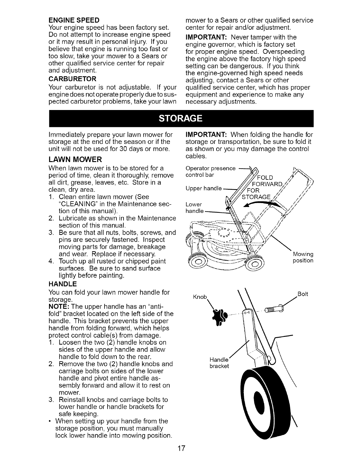
HANDLE
You can fold your lawn mower handle for
storage.
NOTE: The upper handle has an "anti-
fold" bracket located on the left side of the
handle. This bracket prevents the upper
handle from folding forward, which helps
protect control cable(s) from damage.
1. Loosen the two (2) handle knobs on
sides of the upper handle and allow
handle to fold down to the rear.
2. Remove the two (2) handle knobs and
carriage bolts on sides of the lower
handle and pivot entire handle as-
sembly forward and allow it to rest on
mower.
3. Reinstall knobs and carriage bolts to
lower handle or handle brackets for
safe keeping.
• When setting up your handle from the
storage position, you must manually
lock lower handle into mowing position.
IMPORTANT: When folding the handle for
storage or transportation, be sure to fold it
as shown or you may damage the control
cables.
Operator presence
control bar
Lower
Mowing
position
Knob \Bolt
Handle
bracket
17
ENGINE
Maintenance, repair, or replacement of the
emission control devices and systems, which
are being done at the customers expense,
may be performed by any non-road engine
repair establishment or individual. Warranty
repairs must be performed by an authorized
engine manufacturer's service outlet.
FUEL SYSTEM
IMPORTANT: It is important to prevent
gum deposits from forming in essential
fuel system parts such as carburetor, fuel
filter, fuel hose, or tank during storage.
Also, alcohol blended fuels (called gasohol
or using ethanol or methanol) can attract
moisture which leads to separation and
formation of acids during storage. Acidic
gas can damage the fuel system of an
engine while in storage.
• Empty the fuel tank by starting the en-
gine and letting it run until the fuel lines
and carburetor are empty.
• Never use engine or carburetor cleaner
products in the fuel tank or permanent
damage may occur.
• Use fresh fuel next season.
NOTE: Fuel stabilizer is an acceptable al-
ternative in minimizing the formation of fuel
gum deposits during storage. Add stabilizer
to gasoline in fuel tank or storage container.
Always follow the mix ratio found on stabilizer
container. Run engine at least 10 minutes
after adding stabilizer to allow the stabilizer to
reach the carburetor. Do not empty the gas
tank and carburetor if using fuel stabilizer.
ENGINE OIL
Drain oil (with engine warm) and replace
with clean engine oil. (See "ENGINE" in
the Maintenance section of this manual).
CYLINDER
1. Remove spark plug.
2. Pour one ounce (29 ml) of oil through
spark plug hole into cylinder.
3. Pull starter handle slowly a few times
to distribute oil.
4. Replace with new spark plug.
OTHER
• Do not store gasoline from one season
to another.
• Replace your gasoline can if your can
starts to rust. Rust and/or dirt in your
gasoline will cause problems.
• If possible, store your unit indoors and
cover it to protect it from dust and dirt.
• Cover your unit with a suitable protec-
tive cover that does not retain moisture.
Do not use plastic. Plastic cannot
breathe, which allows condensation to
form and will cause your unit to rust.
IMPORTANT: Never cover mower while
engine and exhaust areas are still warm.
ACAUTION: Never store the lawn mower
with gasoline in the tank inside a building
where fumes may reach an open flame
or spark. Allow the engine to cool before
storing in any enclosure.
TROUBLESHOOTING - See appropriate section in manual unless directed
to a Sears Parts & Repair Center.
PROBLEM CAUSE
Does not start 1. Dirty air filter.
2. Out of fuel.
3. Stale fuel.
4. Water in fuel.
5. Spark plug wire is
disconnected.
6. Bad spark plug.
7. Loose blade or broken
blade adapter.
8. Control bar in released
position.
9. Control bar defective.
10. Fuel valve lever (if so
equipped) in OFF position.
11 .Weak battery (if equipped).
12. Disconnected battery
connector (if equipped).
CORRECTION
1. Clean/replace air filter.
2. Fill fuel tank.
3. Empty fuel tank and refill tank
with fresh, clean gasoline.
4. Empty fuel tank and refill tank
with fresh, clean gasoline.
5. Connect wire to plug.
6. Replace spark plug.
7. Tighten blade bolt or
replace blade adapter.
8. Depress control bar to
handle.
9. Replace control bar.
10. Turn fuel valve lever
to the ON position.
11. Charge battery.
12. Connect battery to engine.
18
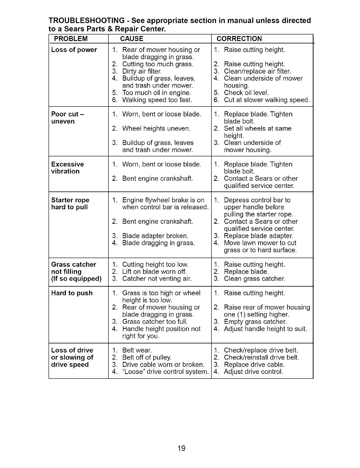
TROUBLESHOOTING - See appropriate section in manual unless directed
to a Sears Parts & Repair Center,
Loss of power
Poor cut -
uneven
Excessive
vibration
Starter rope
hard to pull
Grass catcher
not filling
(If so equipped)
Hard to push
Loss of drive
or slowing of
drive speed
PROBLEM
1.
2.
3.
4.
5.
6.
1.
2.
3.
1.
2.
1.
2.
3.
4.
1.
2.
3.
1.
2.
3.
4.
1.
2.
3.
4.
CAUSE
Rear of mower housing or
blade dragging in grass.
Cutting too much grass.
Dirty air filter.
Buildup of grass, leaves,
and trash under mower.
Too much oil in engine.
Walking speed too fast.
Worn, bent or loose blade.
Wheel heights uneven.
Buildup of grass, leaves
and trash under mower.
Worn, bent or loose blade.
Bent engine crankshaft.
Engine flywheel brake is on
when control bar is released.
Bent engine crankshaft.
Blade adapter broken.
Blade dragging in grass.
Cutting height too low.
Lift on blade worn off.
Catcher not venting air.
Grass is too high or wheel
height is too low.
Rear of mower housing or
blade dragging in grass.
Grass catcher too full.
Handle height position not
right for you.
Belt wear.
Belt off of pulley.
Drive cable worn or broken.
"Loose" drive control system.
CORRECTION
1. Raise cutting height.
2. Raise cutting height.
3. Clean/replace air filter.
4. Clean underside of mower
housing.
5. Check oil level.
6. Cut at slower walking speed.
1. Replace blade. Tighten
blade bolt.
2. Set all wheels at same
height.
3. Clean underside of
mower housing.
1. Replace blade. Tighten
blade bolt.
2. Contact a Sears or other
qualified service center.
1. Depress control bar to
upper handle before
pulling the starter rope.
2. Contact a Sears or other
qualified service center.
3. Replace blade adapter.
4. Move lawn mower to cut
grass or to hard surface.
1. Raise cutting height.
2. Replace blade.
3. Clean grass catcher.
1. Raise cutting height.
2. Raise rear of mower housing
one (1) setting higher.
3. Empty grass catcher.
4. Adjust handle height to suit.
1. Check/replace drive belt.
2. Check/reinstall drive belt.
3. Replace drive cable.
4. Adjust drive control.
19
Garantia ......................................................... 20
Reglas de Seguridad ................................ 20-22
Montaje /Pre-Operaci6n .......................... 23-24
Operaci6n ................................................. 25-29
Mantenimiento .......................................... 30-33
Programa de Mantenimiento ......................... 31
Especificaciones del Producto ....................... 22
Servicio y Adjustes ................................... 33-35
Almacenamiento ....................................... 35-36
Identificacion de problemas ...................... 36-37
Partes de repuesto .................................. 38-47
Servicio Sears .................................. Contratapa
GARANTiA LIMITADA DE DOS ANOS PARA LA SEGADORA A MOTOR CRAFTSMAN
Por dos (2) a5os, a partir de la fecha de compra, cuando esta Segadora Craftsman se mantenga,
lubrique y afine segQn las instrucciones para la operaci6n y el mantenimiento en el manual del
due5o, Sears reparara gratis todo defecto en el material y la mano de obra.
Si la Segadora Craftsman se usa para fines comerciales o de arriendo, esta garantia s61o se aplica
per noventa (90) dias a partir de la fecha de compra.
Esta Garantia no cubre:
• Articulos que se desgastan durante el use normal tales come las cuchillas segadoras rotatorias,
los adaptadores de la cuchilla, las correas, los filtros de aire y las bujias.
• Reparaciones necesarias debido al abuso o a la negligencia del operador, incluyendose a los
cigQe_ales doblados y a la falta de mantenimiento del equipo segQn las instrucciones que se
incluyen en el manual del due_o.
El servicio de garantia esta disponible al devolver la segadora a motor Craftsman al Centro de
Servicio Sears mas cercano en los Estados Unidos. Esta garantia se aplica solamente mientras el
producto este en uso en los Estados Unidos.
Esta Garantia le otorga derechos legales especificos, y puede que tambien tenga otros derechos
que varian de estado a estado.
Sears, Roebuck and Co., D/817WA, Hoffman Estates, IL 60179 USA
IMPORTANTE: Esta maquina cortadaora es capaz de amputar las manos y los manos y los pies y
de lanzar objetos. Si no se observan las instrucciones de seguridad siguientes se pueden producir
lesiones graves o la muerte.
,_kBusque este simbolo que se_ala las precau-
ciones de seguridad de importancia. Quiere
decir- iiiATENClON!!! iiiESTE ALERTO!!!
_ SEGURIDAD ESTA COMPROMETIDA.
ADVERTENClA: Siempre desconecte el alam-
bre de la bujia y p6ngalo donde no pueda entrar
en contacto con la bujia, para evitar el arranque
por accidente, durante la preparacion, el trans-
_,,_,_),el ajuste o cuando se hacen reparaciones.
VERTENClA: Los bornes, terminales y
accesorios relativos de la bateria contienen
plomo o compuestos de plomo, productos
quimicos conocidos en el Estado de California
como causa de cancer y defectos al nacimiento
u otros da5os reproductivos. Lavar las manos
,_spues de manipularlos.
PRECAUClON: El tube de escape del motor,
algunos de sus constituyentes y algunos com-
ponentes del vehiculo contienen o desprenden
productos quimicos conocidos en el Estado de
California come causa de cancer y defectos al
,_icimiento u otros da5os reproductivos.
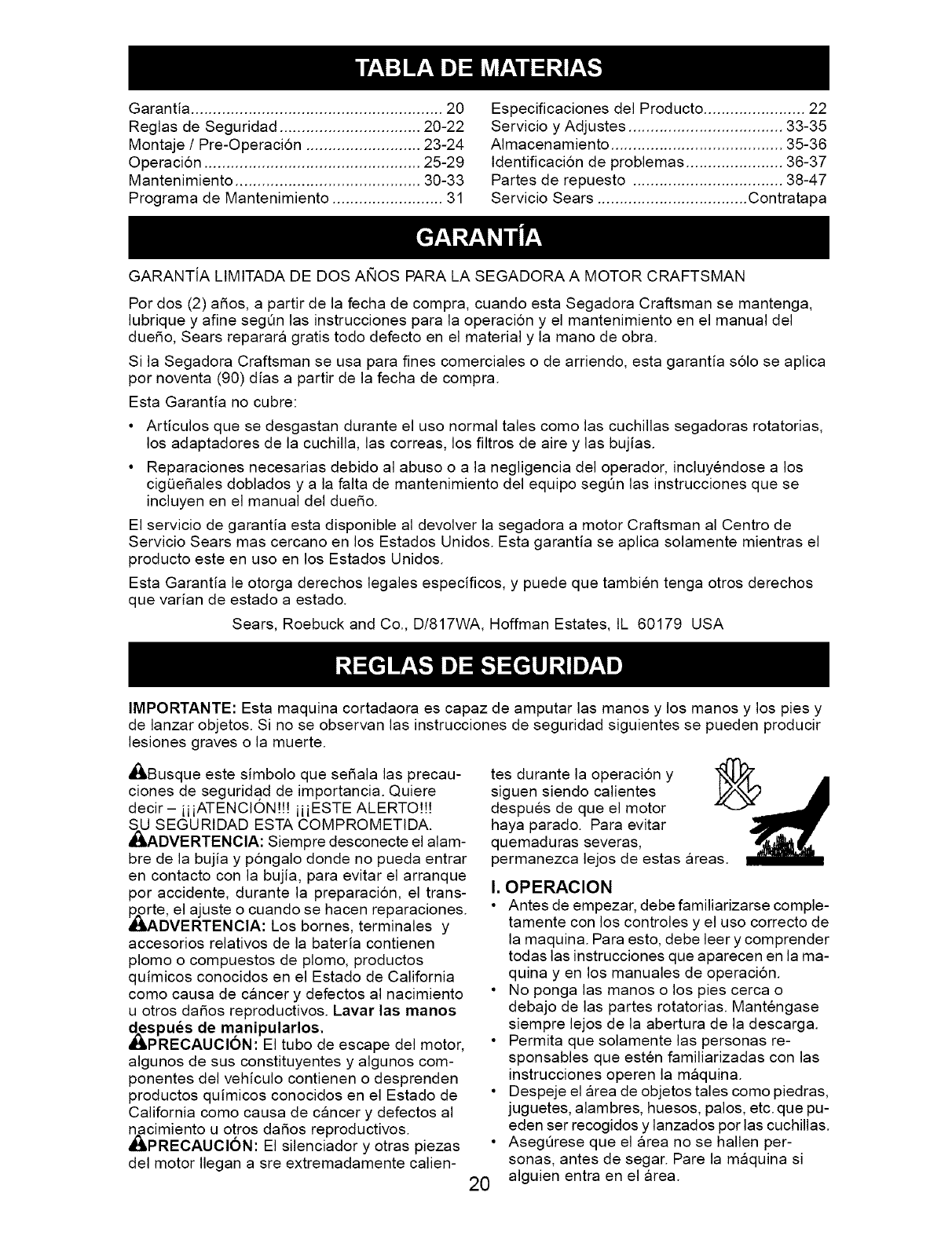
PRECAUClON: El silenciador y otras piezas
del motor Ilegan a sre extremadamente calien-
tes durante la operacion y
siguen siendo calientes
despues de que el motor
haya parado. Para evitar
quemaduras severas,
permanezca lejos de estas areas.
I. OPERACION
• Antes de empezar, debe familiarizarse comple-
tamente con los controles y el uso correcto de
la maquina. Para esto, debe leer y comprender
todas las instrucciones que aparecen en la ma-
quina yen los manuales de operacion.
• No ponga las manes o los pies cerca o
debajo de las partes rotatorias. Mantengase
siempre lejos de la abertura de la descarga.
• Permita que solamente las personas re-
sponsables que esten familiarizadas con las
instrucciones operen la mg_quina.
• Despeje el area de objetos tales como piedras,
juguetes, alambres, huesos, palos, etc. que pu-
eden ser recogidos y lanzados per las cuchillas.
• AsegQrese que el area no se hallen per-
sonas, antes de segar. Pare la maquina si
20 alguien entra en el area.
• Nooperelamaquinasinzapatosoconsanda-
liasabiertas.P6ngasesiemprezapatoss61idos.
• Notiredelasegadorahaciaatrasa menos
queseaabsolutamentenecesario.Mire
siemprehaciaabajoy haciadetrasantesy
mientrasquesemuevehaciaatras.
• Nuncadirigirelmaterialdescargadohacia
laspersonas.Evitardescargarmaterial
contraparedeso barreras.Elmaterialpuede
retornaraloperador.Paralacuchillacuando
sepasaporsuperficiesdegrava.
• Nooperelasegadorasinlosrespectivos
resguardos,lasplacas,el recogedorde
cespeduotrosaditamentosdiseadospara
suprotecci6ny seguridad.
• Refierasealas instruccionesdelfabricante
paraelfuncionamientoe instalaci6nde
accesorios.UseQnicamenteaccesorios
aprobadosporelfabricante.
• Detengalacuchillaolascuchillascuandocruce
porcalzadas,carieso caminosdegrava.
• Pararelmotorcadavezqueseabandonael
aparato,antesdelimpiarlasegadorao de
removerresiduosdeltubo.
• Apagarelmotoryesperarhastaquelas
cuchillasestencompletamenteparadas
antesderemoverelreceptordehierba.
• Segarsolamenteconluzdeldiao conuna
buenaluzartificial.
• NooperelamAquinabajolainfluenciadel
alcoholodelasdrogas.
• Nuncaoperelamaquinacuandolahierba
estemojada.AsegQresesiempredetener
buenatracci6nensuspies;mantengael
mangofirmementey camine;nuncacorra.
• Desconectarelmecanismodepropulsi6n
aut6nomaoelembraguedetransmisi6nen
lassegadorasqueIotienenantesdeponer
enmarchaelmotor.
• Sielequipoempezaraavibrardeunamanera
anormal,pareel motory revisedeinmediato
paraaveriguarlacausa.Generalmentelavi-
braci6nsueleindicarqueexistealgunaaveria.
• Siempreusegafasdeseguridadoanteojoscon
protecci6nlateralcuandooperelasegadora.
II. OPERAClONSOBRE LAS CUESTAS
Losaccidentesocurrenconmasfrecuenciaen
lascuestas.Estosaccidentesocurrendebidoa
resbaladaso caidas,lascualespuedenresultar
engraveslesiones.Operarlarecortadoraen
cuestasrequieremayorconcentraci6n.Sise
sienteinseguroenunacuesta,nolarecorte.
HACER:
• Puederecortaratravesdelasuperficiede
lacuesta,nuncahaciaarribay haciaabajo.
Procedaconextremaprecauci6ncuando
cambiededirecci6nenlascuestas.
• Renuevatodoslosobjetosextrafios,tales
comoguijarros,ramas,etc.
• Debeprestaratenci6na hoyos,bacheso
protuberancias.Recuerdequelahierbaalta
puedeesconderobstaculos.
NOHACER:
• Norecortecercadependientes,zanjaso
terraplenes.Eloperadorpuedeperderla
tracci6nenlospieso elequilibrio.
• Norecortecuestasdemasiadoinclinadas.
• Norecorteenhierbamojada.Lareducci6nenla
tracci6ndelapisadapuedecausarresbalones.
III.NINOS
Sepuedenproduciraccidentestragicossielop-
eradornoprestaatenci6na lapresenciadelos
nifios.Amenudo,losnifiossesientenatraidospor
lamaquinay porlaactividaddelasiega.Nunca
supongaquelosnifiosvana permanecerenel
mismolugardondelosvioporQltimavez.
• Mantengaa losnifiosalejadosdelAreade
lasiegay bajoelcuidadoestrictodeotra
personaadultaresponsable.
• Estealertay apaguelamaquinasihaynifios
queentranalArea.
• Antesy cuandoesteretrocediendo,mire
haciaatrasy haciaabajoparaverificarsi hay
nifiospequefios.
• Nuncapermitaquelosnifiosoperenlamaquina.
• Tengauncuidadoextracuandoseacerque
a esquinasdondenohayvisibilidad,alos
arbustos,arbolesuotrosobjetosquepueden
interferirconsulineadevisi6n.
IV.MANEJOSEGURODE GASOLINA
Usarmuchaatenci6ncuandosemanejagaso-
lina.Lagasolinaesextremamenteinflamabley
losvaporessonexplosivos.
• Apagartodosloscigarrillos,cigarros,pipasy
otrasfuentesdeignici6n.
• Usarsolouncontenedorapropiado.
• Nuncaquitareltapondelagasolinao afiadir
carburanteconelmotorenmarcha.Esperarque
elmotorseenfrieantesderepostarlagasolina.
• Nuncarepostarlamaquinaalinteriordeunlocal.
• Nuncaguardarlamaquinao elcontenedorde
gasolinadondehayunallamaabierta,chispao
luzpilotocomounacalderauotrosdispositivos.
• NuncaIlenarcontenedoresenunvehiculo,en
uncami6nocaravanaconunforrodeplastico.
Colocarsiempreloscontenedoresenelsuelo
lejosdesuvehiculoantesdeIlenar.
• Quitarequiposquefuncionancongasolina
delcami6no caravanay repostarenel suelo.
Siestonoesposible,repostardichoequipo
conuncontenedorportatil,masbienquecon
unatoberadegasolina.
• Mantenerlatoberaencontactoconel bordo
deldep6sitodecarburanteodelaapertura
delcontenedorsiemprehastaterminarel
abastecimiento.Nousarundispositivode
cierre-aperturadelatobera.
• SielcarburantecaeenlaropaqueseIleva,
cambiarselainmediatamente.
• NuncaIlenarenexcesoeldep6sitode
carburante.Colocareltap6ndelagasolinay
apretardemodoseguro.
V.SERVlClO
• Nuncahagafuncionarunamaquinadentro
deunAreacerrada.
• Nuncahagaajusteso reparacionesmientras
elmotoresteenmarcha.Desconecteelcable
delabujia,y mantengaloaciertadistanciade
estaparaprevenirunarranqueaccidental.
• Mantengalastuercasy lospernos,espe-
cialmentelospernosdelaccesoriodela
cuchilla,apretadosy mantengaelequipoen
buenascondiciones.
21
• Nunca manipule de forma indebida los
dispositivos de seguridad. Controle regular-
mente su funcionamiento correcto.
• Mantenga la maquina libre de hierba, hojas
u otras acumulaciones de desperdicio.
Limpie los derrames de aceite o combustible.
Permita que la maquina se enfrie antes de
almacenarla.
• Pare e inspeccione el equipo si le pega a un
objeto. Reparelo, si es necesario, antes de
hacerlo arrancar.
• En ningQn caso hay que regular la altura de
las ruedas mientras el motor esta en marcha.
• Los componentes del receptor de la hierba
van sujetos a desgaste, daSos y deterioro, que
pueden exponer las partes en movimiento o
permitir que objetos sean disparados. Controlar
frecuentemente y cuando sea necesario susti-
tuir con partes aconsejadas por el fabricante.
• Las cuchillas de la segadora estan afiladas y
pueden cortar. Cubrir las hojas o Ilevar guantes,
y utilizar precauciones especiales cuando se
efectQa mantenimiento sobre las mismas.
• No cambie el ajuste del regulador del motor
ni exceda su velocidad.
• Mantener o sustituir las etiquetas de seguridad
e instrucciones, cuando sea necesario.
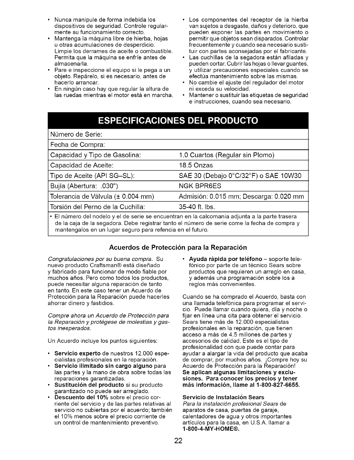
NOmero de Serie:
Fecha de Compra:
Capacidad y Tipo de Gasolina: 1.0 Cuartos (Regular sin Plomo)
Capacidad de Aceite: 18.50nzas
Tipo de Aceite (API SG-SL): SAE 30 (Debajo 0°C/32°F) o SAE 10W30
Bujia (Abertura: .030") NGK BPR6ES
Tolerancia de Valvula (+ 0.004 mm) Admision: 0.015 mm; Descarga: 0.020 mm
Torsion del Perno de la Cuchilla: 35-40 ft. Ibs.
• El nQmero del nodelo y el de serie se encuentran en la calcomania adjunta a la parte trasera
de la caja de la segadora. Debe registrar tanto el nOmero de serie come la fecha de compra y
mantengalos en un lugar seguro para refencia en el futuro.
Acuerdos de Proteccibn para la Reparacibn
Congratulaciones por su buena compra. Su
nuevo producto Craftsman® esta diseSado
y fabricado para funcionar de modo fiable por
muchos a5os. Pero como todos los productos,
puede necesitar alguna reparacion de tanto
en tanto. En este caso tener un Acuerdo de
Protecci6n para la Reparacion puede hacerles
ahorrar dinero y fastidios.
Compre ahora un Acuerdo de Protecci6n para
la Reparaci6n y protegese de molestias y gas-
tos inesperados.
Un Acuerdo incluye los puntos siguientes:
•Servicio experto de nuestros 12.000 espe-
cialistas profesionales en la reparacion.
• Servicio ilimitado sin cargo alguno para
las partes y la mano de obra sobre todas las
reparaciones garantizadas.
• Sustituci6n del producto si su producto
garantizado no puede ser arreglado.
• Descuento del 10% sobre el precio cor-
riente del servicio y de las partes relativas al
servicio no cubiertas por el acuerdo; tambien
el 10% menos sobre el precio corriente de
un control de mantenimiento preventivo.
Ayuda r&pida por telefono - soporte tele-
f6nico por parte de un tecnico Sears sobre
productos que requieren un arreglo en casa,
y ademas una programacion sobre los a
reglos mas convenientes.
Cuando se ha comprado el Acuerdo, basta con
una Ilamada telef6nica para programar el servi-
cio. Puede Ilamar cuando quiera, dia y noche o
fijar en linea una cita para obtener el servicio.
Sears tiene mas de 12.000 especialistas
profesionales en la reparacion, que tienen
acceso a mas de 4.5 millones de partes y
accesorios de calidad. Este es el tipo de
profesionalidad con que puede contar para
ayudar a alargar la vida del producto que acaba
de comprar, por muchos aSos. iCompre hoy su
Acuerdo de Proteccion para la Reparaci6n!
Se aplican algunas limitaciones yexclu-
siones. Para conocer los precios y tener
mas informaci6n, Ilame al 1-800-827-6655.
Servicio de Instalaci6n Sears
Para la instalaci6n profesional Sears de
aparatos de casa, puertas de garaje,
calentadores de agua y otros importantes
articulos para la casa, en U.S.A. Ilamar a
1-800-4-MY-HOME®.
22
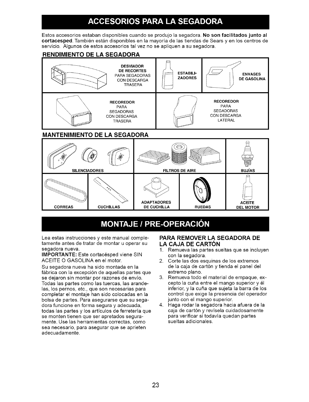
Estos accesorios estaban disponibles cuando se produjo la segadora. No son facilitados junto al
cortacesped. Tambien estan disponibles en la mayoda de las tiendas de Sears yen los centros de
servicio. AIgunos de estos accesorios tal vez no se apliquen a su segadora.
RENDIMIENTO DE LA SEGADORA
DESVIADOR
DE RECORTES
PARASEGADORAS
CON DESCARGA
TRASERA
RECOREDOR
PARA
SEGADORAS
CON DESCARGA
TRASERA
ESTABILI-
ZADORES
__D ENVASES
E GASOLINA
RECOREDOR
PARA
SEGADORAS
CON DESCARGA
LATERAL
MANTENIMIENTO DE LA SEGADORA
SILENCIADORES
CORREAS CUCHILLAS
FILTROS DE AIRE
ADAPTADORES
DE CUCHILLA
Lea estas instrucciones y este manual comple-
RUEDAS
BUJiAS
ACEITE
DEL MOTOR
tamente antes de tratar de montar u operar su
segadora nueva.
IMPORTANTE: Este cortacesped viene SIN
ACEITE O GASOLINA en el motor.
Su segadora nueva ha sido montada en la
fabrica con la excepcion de aquellas partes que
se dejaron sin montar por razones de envio.
Todas las partes como las tuercas, las arande-
las, los pernos, etc., que son necesarias para
completar el montaje han sido colocadas en la
bolsa de partes. Para asegurarse que su sega-
dora funcione en forma segura y adecuada,
todas las partes y los articulos de ferreteria que
se monten tienen que ser apretados segura-
mente. Use las herramientas correctas, como
sea necesario, para asegurar que se aprieten
adecuadamente.
PARA REMOVER LA SEGADORA DE
LA CAJA DE CARTON
1. Remueva las partes sueltas que se incluyen
con la segadora.
2. Corte las dos esquinas de los extremos
de la caja de carton y tienda el panel del
extremo piano.
3. Remueva todo el material de empaque, ex-
cepto la cuba entre el mango superior y el
inferior, y la cuba que sujeta la barra de los
control que exige la presencia del operador
junto con el mango superior.
4. Haga rodar la segadora hacia afuera de la
caja de cart6n y revisela cuidadosamente
para verificar si todavia quedan partes
sueltas adicionales.
23
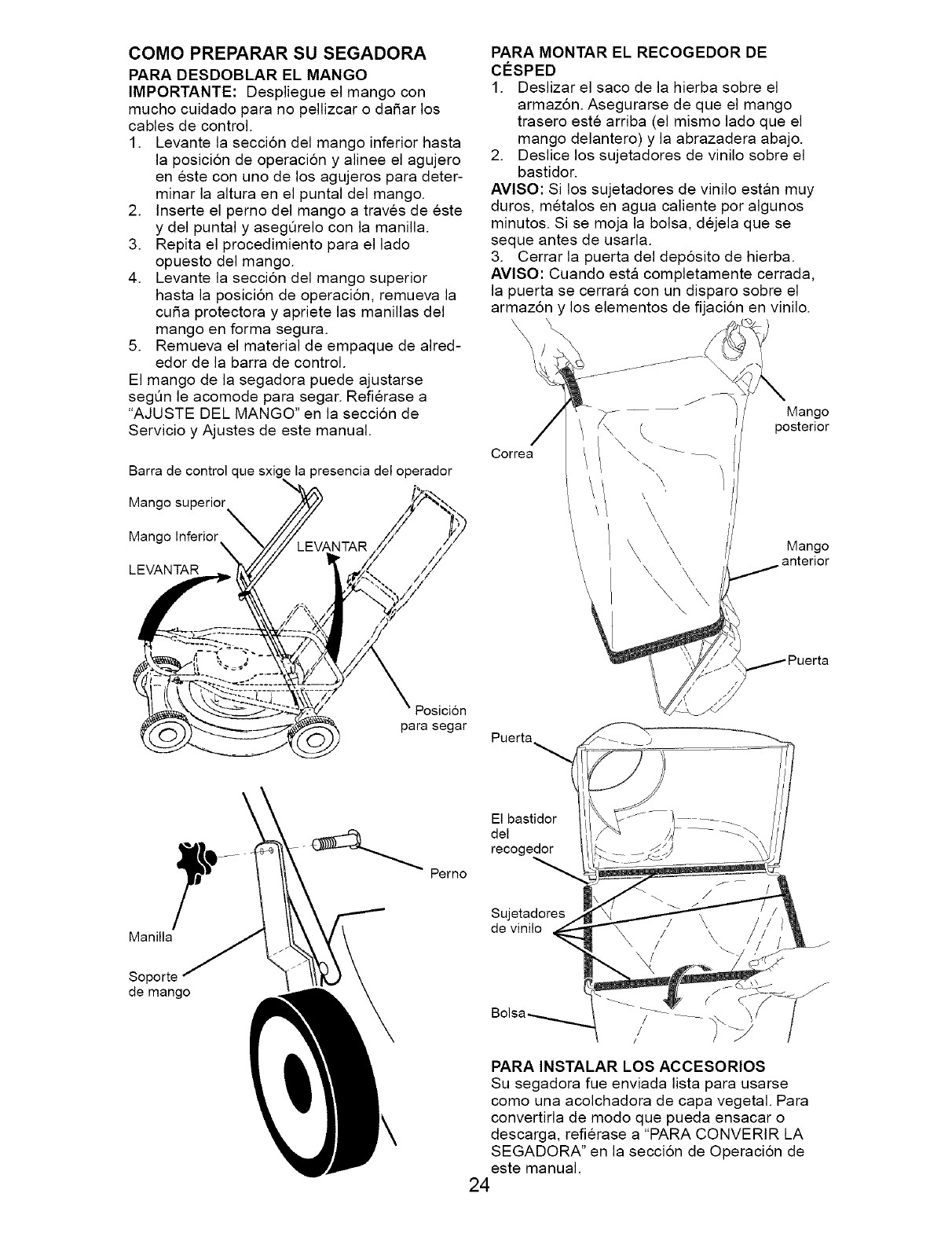
COMO PREPARAR SU SEGADORA
PARA DESDOBLAR EL MANGO
IMPORTANTE: Despliegue el mango con
mucho cuidado para no pellizcar o daSar los
cables de control.
1. Levante la seccion del mango inferior hasta
la posicion de operacion y a]inee e] agujero
en este con uno de los agujeros para deter-
minar la a]tura en e] punta] del mango.
2. Inserte el perno del mango a traves de este
y del punta] y asegQre]o con ]a manilla.
3. Repita e] procedimiento para e] ]ado
opuesto del mango.
4. Levante la seccion del mango superior
hasta la posicion de operacion, remueva la
cuSa protectora y apriete las manillas del
mango en forma segura.
5. Remueva el material de empaque de a]red-
edor de la barra de control.
El mango de la segadora puede ajustarse
segl_n le acomode para segar. Refierase a
"AJUSTE DEL MANGO" en la seccion de
Servicio y Ajustes de este manual.
Barra de control que sxig _ la presencia del operador
Mango superior
Mango Inferior //
LEVANTAR /,_
Posicion
para segar
PARA MONTAR EL RECOGEDOR DE
CO:SPED
1. Deslizar el saco de la hierba sobre el
armaz6n. Asegurarse de que el mango
trasero este arriba (el mismo lado que el
mango delantero) y la abrazadera abajo.
2. Deslice los sujetadores de vinilo sobre el
bastidor.
AVlSO: Si los sujetadores de vinilo estan muy
duros, metalos en agua caliente por algunos
minutos. Si se moja la bolsa, dejela que se
seque antes de usarla.
3. Cerrar la puerta del deposito de hierba.
AVlSO: Cuando esta completamente cerrada,
la puerta se cerrara con un disparo sobre el
armazSn y los elementos de fijacbn en vinilo.
Mango
posterior
\
Mango
anterior
Puerta_
\
Manilla
Soporte
de mango
El bastidor
del
recogedor
Perno
Sujetadores
de vinilo
PARA INSTALAR LOS ACCESORIOS
Su segadora fue enviada lista para usarse
como una acolchadora de capa vegetal. Para
convertirla de modo que pueda ensacar o
descarga, refierase a "PARA CONVERIR LA
SEGADORA" en la seccion de Operacion de
este manual.
24
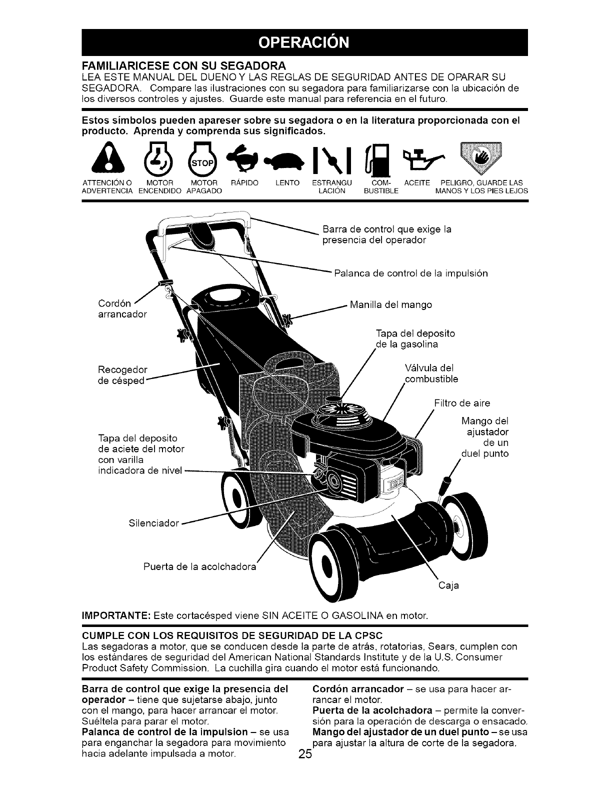
FAMILIARICESE CON SU SEGADORA
LEA ESTE MANUAL DEL DUENOY LAS REGLAS DE SEGURtDAD ANTES DE OPARAR SU
SEGADORA. Compare las ilustraciones con su segadora para familiarizarse con la ubicacion de
los diversos controles y ajustes. Guarde este manual para referencia en el futuro.
Estos simbolos pueden apareser sobre su segadora o en la literatura proporcionada con el
producto. Aprenda y comprenda sus signiflcados.
ATTENCION O MOTOR MOTOR R,&PIDO LENTO ESTRANGU COM- ACEITE PELIGRO, GUARDE LAS
ADVERTENCIA ENCENDIDO APAGADO LACION BUSTIBLE MANOS Y LOS PIES LEJOS
Barra de control que exige la
presencia del operador
Palanca de control de la impulsion
Cord6n
arrancado{
Recogedor
de cesl
Tapa del deposito
de aciete del motor
con varilla
indicadora de nivel
Manilla del mango
Tapa del deposito
de la gasolina
Valvula del
combustible
Filtro de aire
Mango del
ajustador
de un
duel punto
Silenciador
Puerta de la acolchadora
Caja
IMPORTANTE: Este cortacesped viene SIN ACEITE O GASOLINA en motor.
CUMPLE CON LOS REQUISITOS DE SEGURIDAD DE LA CPSC
Las segadoras a motor, que se conducen desde la parte de atras, rotatorias, Sears, cumplen con
los estandares de seguridad del American National Standards Institute y de la U.S. Consumer
Product Safety Commission. La cuchilla gira cuando el motor esta funcionando.
Barra de control que exige la presencia del
operador - tiene que sujetarse abajo, junto
con el mango, para hacer arrancar el motor.
Sueltela para parar el motor.
Palanca de control de la impulsion - se usa
para enganchar la segadora para movimiento
hacia adelante impulsada a motor.
Cord6n arrancador - se usa para hacer ar-
rancar el motor.
Puerta de la acolchadora - permite la conver-
sion para la operacion de descarga o ensacado.
Mango del ajustador de un duel punto - se usa
para ajustar la altura de corte de la segadora.
25
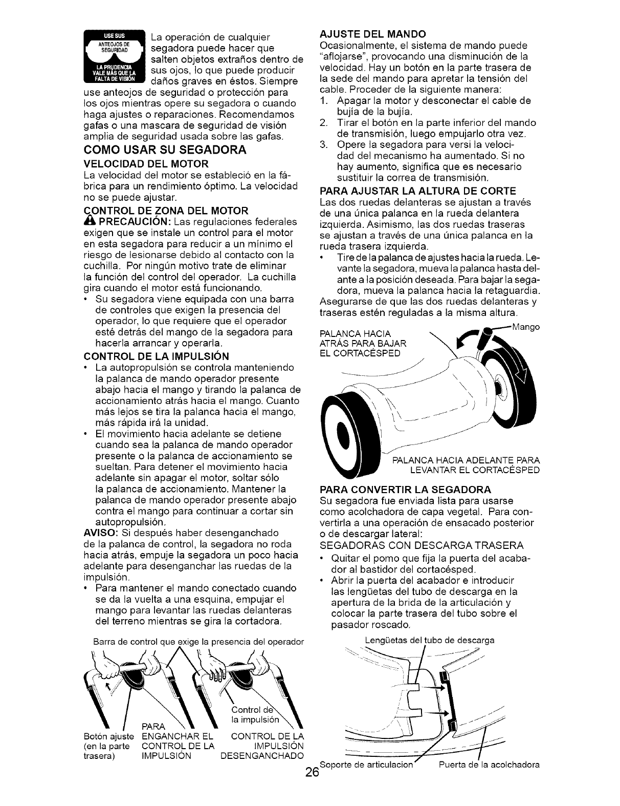
La operacion de cualquier
segadora puede hacer que
salten objetos extraSos dentro de
sus ojos, Io que puede producir
daSos graves en estos. Siempre
use anteojos de seguridad o proteccion para
los ojos mientras opere su segadora o cuando
haga ajustes o reparaciones. Recomendamos
gafas o una mascara de seguridad de vision
amplia de seguridad usada sobre las gafas.
COMO USAR SU SEGADORA
VELOCIDAD DEL MOTOR
La velocidad del motor se estableci6 en la fa-
brica para un rendimiento 6ptimo. La velocidad
no se puede ajustar.
_NTROL DE ZONA DEL MOTOR
PRECAUClON: Las regulaciones federales
exigen que se instale un control para el motor
en esta segadora para reducir a un minimo el
riesgo de lesionarse debido al contacto con la
cuchilla. Per ningQn motive trate de eliminar
la funcion del control del operador. La cuchilla
gira cuando el motor esta funcionando.
• Su segadora viene equipada con una barra
de controles que exigen la presencia del
operador, Io que requiere que el operador
este detras del mango de la segadora para
hacerla arrancar y operarla.
CONTROL DE LA IMPULSION
• La autopropulsion se controla manteniendo
la palanca de mando operador presente
abajo hacia el mango y tirando la palanca de
accionamiento atras hacia el mango. Cuanto
mas lejos se tira la palanca hacia el mango,
mas rapida ira la unidad.
• El movimiento hacia adelante se detiene
cuando sea la palanca de mando operador
presente o la palanca de accionamiento se
sueltan. Para detener el movimiento hacia
adelante sin apagar el motor, soltar s61o
la palanca de accionamiento. Mantener la
palanca de mando operador presente abajo
contra el mango para continuar a cortar sin
autopropulsion.
AVlSO" Si despues haber desenganchado
de la palanca de control, la segadora no roda
hacia atras, empuje la segadora un poco hacia
adelante para desenganchar las ruedas de la
impulsion.
• Para mantener el mando conectado cuando
se da la vuelta a una esquina, empujar el
mango para levantar las ruedas delanteras
del terreno mientras se gira la cortadora.
Barra de control que )resencia del operador
Boton ajuste
(en la parte
trasera)
PARA
ENGANCHAREL
CONTROLDELA
IMPULSION
AJUSTE DEL MANDO
Ocasionalmente, el sistema de mando puede
"aflojarse", provocando una disminucion de la
velocidad. Hay un bot6n en la parte trasera de
la sede del mando para apretar la tension del
cable. Preceder de la siguiente manera:
1. Apagar la motor y desconectar el cable de
bujia de la bujia.
2. Tirar el bot6n en la parte inferior del mando
de transmision, luego empujarlo otra vez.
3. Opere la segadora para versi la veloci-
dad del mecanismo ha aumentado. Si no
hay aumento, significa que es necesario
sustituir la correa de transmision.
PARA AJUSTAR LA ALTURA DE CORTE
Las dos ruedas delanteras se ajustan a traves
de una Onica palanca en la rueda delantera
izquierda. Asimismo, las dos ruedas traseras
se ajustan a traves de una Qnica palanca en la
rueda trasera izquierda.
• Tire de la palanca de ajustes hacia la rueda. Le-
vante la segadora, mueva la palanca hasta del-
ante a la posicion deseada. Para bajar la sega-
dora, mueva la palanca hacia la retaguardia.
Asegurarse de que las dos ruedas delanteras y
traseras esten reguladas a la misma altura.
1go
PALANCA HACIA
ATRASPARA BAJAR
EL CORTACESPED
\ \
i. J_ PALANCA HAClA ADELANTE PARA
'_' LEVANTAR EL CORTAC#SPED
PARA CONVERTIR LA SEGADORA
SU segadoFa fue enviada lista para usaFse
como acolchadoFa de capa vegetal. Para con-
vertirla a una opeFaci6n de ensacado posterior
o de descargar lateral:
SEGADORAS CON DESCARGA TRASERA
• Quitar el pomo que fija la puerta del acaba-
dor al bastidor del cortacesped.
• Abrir la puerta del acabador e introducir
las lengQetas del tube de descarga en la
apertura de la brida de la articulacion y
colocar la parte trasera del tube sobre el
pasador roscado.
LengOetas del tubo de descarga
Control d,
la impulsion
CONTROL DE LA
IMPULSION
DESENGANCHADO
26Soporte de articulacion Puerta de la acolchadora
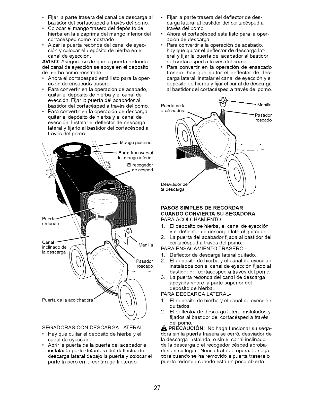
• Fijar la parte trasera del canal de descarga al
bastidor del cortacesped a traves del pomo.
• Colocar el mango trasero del dep6sito de
hierba en la alzaprima del mango inferior del
cortacesped como mostrado.
• AIzar la puerta redonda del canal de eyec-
ci6n y colocar el deposito de hierba en el
canal de eyeccion.
AVlSO" Asegurarse de que la puerta redonda
del canal de eyeccion se apoye en el dep6sito
de hierba como mostrado.
• Ahora el cortacesped esta listo para la oper-
acion de ensacado trasero.
• Para convertir en la operacion de acabado,
quitar el deposito de hierba y el canal de
eyeccion. Fijar la puerta del acabador al
bastidor del cortacesped a traves del pomo.
• Para convertir en la operacion de descarga,
quitar el dep6sito de hierba y el canal de
eyeccion, lnstalar el deflector de descarga
lateral y fijarlo al bastidor del cortacesped a
traves del pomo.
Mango posterior
Barra transversal
del mango inferior
El recogedor
de cesped
• Fijar la parte trasera del deflector de des-
carga lateral al bastidor del cortacesped a
traves del pomo.
• Ahora el cortacesped esta listo para la oper-
acion de descarga.
• Para convertir a la operacion de acabado,
hay que quitar el deflector de descarga lat-
eral y fijar la puerta del acabador al bastidor
del cortacesped a traves del pomo.
• Para convertir en la operacion de ensacado
trasero, hay que quitar el deflector de des-
carga lateral; instalar el canal de eyeccion y el
dep6sito de hierba y fijar el canal de descarga
al bastidor del cortacesped a traves del pomo.
Puerta dela Manilla
acolchadora Pasador
roscado
Desviador de
la descarga
redonda
Canal
inclinado de
la descarga
Manilla
Pasador
roscado
Puerta de la acolchadora
SEGADORAS CON DESCARGA LATERAL
• Hay que quitar el dep6sito de hierba y el
canal de eyeccion.
• Abrir la puerta de la puerta del acabador e
instalar la parte delantera del deflector de
descarga lateral debajo la puerta y colocar el
parte trasero en la esparrago fileteado.
PASOS SIMPLES DE RECORDAR
CUANDO CONVlERTA SU SEGADORA
PARA ACOLCHAMIENTO -
1. El dep6sito de hierba, el canal de eyeccion
yel deflector de descarga lateral quitados.
2. La puerta del acabador fijada al bastidor del
cortacesped a traves del pomo.
PARA ENSACAMIENTO TRASERO -
1. Deflector de descarga lateral quitado.
2. El dep6sito de hierba y el canal de eyeccion
instalados con el canal de eyeccion fijado al
bastidor del cortacesped a traves del pomo.
3. La puerta redonda del canal de descarga
apoyada sobre la parte superior del
deposito de hierba.
PARA DESCARGA LATERAL-
1. El dep6sito de hierba y el canal de eyeccion
quitados.
2. El deflector de descarga lateral instalados y
fijados al bastidor del cortacesped a traves
del pomo.
_i_ PRECAUClON: No haga funcionar su sega-
dora sin la puerta trasera se cerro, desviador de
la descarga instalada, o sin el canal inclinado
de la descarga o el recogedor cesped aproba-
dos en su lugar. Nunca trate de operar la sega-
dora cuando se ha removido a puerta trasera o
puerta redonda cuando esta un poco abierta.
27
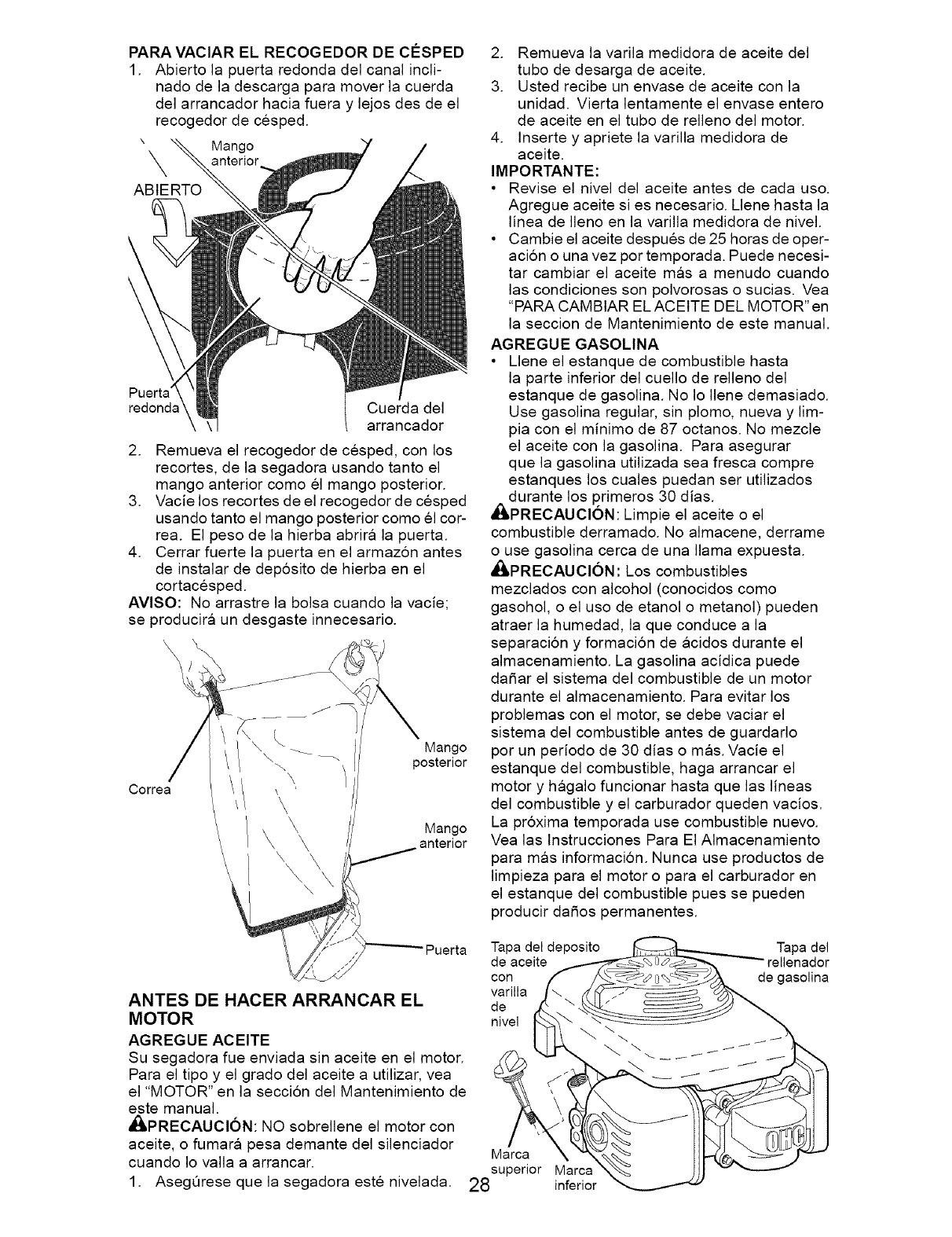
PARA VAClAR EL RECOGEDOR DE ClaSPED
1. Abierto ]a puerta redonda de] canal inc]i-
nado de ]a descarga para mover ]a cuerda
de] arrancador hacia fuera y lejos des de el
recogedor de cesped.
" Mango
X anterior
ABIERTO
Puerta
redonds Cuerda del
arrancador
2. Remueva el recogedor de cesped, con los
recortes, de la segadora usando tanto el
mango anterior como el mango posterior.
3. Vacie los recortes de el recogedor de cesped
usando tanto el mango posterior como el cor-
rea. El peso de la hierba abrira la puerta.
4. Cerrar fuerte la puerta en el armaz6n antes
de instalar de dep6sito de hierba en el
cortacesped.
AVlSO" No arrastre la bolsa cuando la vacie;
se producira un desgaste innecesario.
\\\\
Correa
\ _ _ Mango
/ \ posterior
\
\
\ \
\
Mango
anterior
Puerta
ANTES DE HACER ARRANCAR EL
MOTOR
AGREGUE ACEITE
Su segadora fue enviada sin aceite en el motor.
Para el tipo y el grado del aceite a utilizar, vea
el "MOTOR" en la seccion del Mantenimiento de
este manual.
dI_PRECAUCI6N: NO sobrellene el motor con
aceite, o fumara pesa demante del silenciador
cuando Io valla a arrancar.
1.
Tapa del deposito Tapa del
de aceite rellenador
con de gasolina
varilla
de
nivel
2. Remueva la varila medidora de aceite del
tubo de desarga de aceite.
3. Usted recibe un envase de aceite con la
unidad. Vierta lentamente el envase entero
de aceite en el tubo de relleno del motor.
4. Inserte y apriete la varilla medidora de
aceite.
IMPORTANTE:
• Revise el nivel del aceite antes de cada uso.
Agregue aceite si es necesario. Llene hasta la
linea de Ileno en la varilla medidora de nivel.
• Cambie el aceite despues de 25 horas de oper-
aci6n o una vez por temporada. Puede necesi-
tar cambiar el aceite mas a menudo cuando
las condiciones son polvorosas o sucias. Vea
"PARA CAMBIAR EL ACEITE DEL MOTOR" en
la seccion de Mantenimiento de este manual.
AGREGUE GASOLINA
• L]ene el estanque de combustible hasta
la parte inferior de] cue]lo de re]leno de]
estanque de gaso]ina. No ]o ]lene demasiado.
Use gaso]ina regular, sin p]omo, nueva y lim-
pia con el minimo de 87 octanos. No mezc]e
el aceite con ]a gaso]ina. Para asegurar
que la gaso]ina utilizada sea fresca compre
estanques los cua]es puedan ser utilizados
_lLdurante los primeros 30 dias.
PRECAUClON: Limpie el aceite o el
combustible derramado. No a]macene, derrame
o use gaso]ina cerca de una llama expuesta.
_ilLPRECAUCl6N: Los combustibles
mezc]ados con alcohol (conocidos como
gasohol, o el uso de etanol o metanol) pueden
atraer ]a humedad, ]a que conduce a ]a
separacion y formaci6n de acidos durante el
a]macenamiento. La gaso]ina acidica puede
dafiar el sistema de] combustible de un motor
durante el a]macenamiento. Para evitar los
prob]emas con el motor, se debe vaciar el
sistema de] combustible antes de guardado
por un periodo de 30 dias o mas. Vacie el
estanque de] combustible, haga arrancar el
motor y haga]o funcionar hasta que ]as ]ineas
del combustible y el carburador queden vacios.
La pr6xima temporada use combustible nuevo.
Vea ]as lnstrucciones Para El A]macenamiento
para mas informaci6n. Nunca use productos de
limpieza para el motor o para el carburador en
el estanque de] combustible pues se pueden
producir dafios permanentes.
Marca
superior Marca
AsegQrese que la segadora este nivelada. 28 inferior
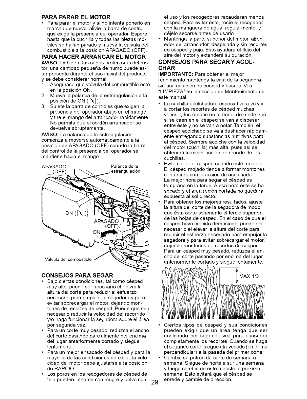
PARA PARAR EL MOTOR
* Para parar el motor y si no intenta ponerlo en
marcha de nuevo, alivie la barra de control
que exige la presencia del operador. Espere
hasta que la cuchilla y todas las piezas m6-
viles se hallan parado y mueva la valvula del
combustible a la posicion APAGADO (OFF).
PARA HACER ARRANCAR EL MOTOR
AVISO: Debido alas capas protectoras del mo-
tor, una cantidad pequefia de humo puede es-
tar presente durante el uso inicial del producto
y se debe considerar normal.
1. Asegurase que valvula del combustible este
en la posici6n ON.
2. Mueva la palanca de la estrangulaci6n a la
posici6n de ON (I",1)
3. Sujete la barra de controles que exigen la
presencia del operador abajo en el mango
y tire el mango del arrancador rapidamente.
No permita que el cord6n arrancador se
devuelva abruptamente.
AVlSO: La palanca de la estrangulaci6n
comienza a moverse automg_ticamente a la
posicion de APAGADO (OFF) cuando la barra
del control de la presencia del operador se
mantiene hacia el mango.
APAGADO Palanca de la
(OFF) ulaci6n
Valvula del combustible
el uso y los recogedores recaudaran menos
cesped. Para evitar este, rocie el recogedor
con la manguera de agua, regularmente, y
dejelo secarse antes de usarlo.
• Mantenga la parte superior del motor, alred-
edor del arrancador, despejada y sin recortes
de cesped y paja. Esto ayudara el flujo del
aire del motor y extendera su duracion.
CONSEJOS PARA SEGARY ACOL-
CHAR
IMPORTANTE: Para obtener el mejor
rendimiento mantenga la caja de la segadora
sin acumulacion de cesped y basura. Vea
"LIMPIEZA" en la seccion de Mantenimento de
este manual.
• La cuchilla acolchadora especial va a volver
a cortar los recortes de cesped muchas
veces, y los reduce en tamafio, de modo que
si se caen en el cesped se van a dispesar
entre este y no se van a notar. Tambien, el
cesped acolchado se va a deshacer rapidam-
ente entregando substancias nutritivas para
el cesped. Siempre acolche con la velocidad
del motor (cuchilla) mgls alta, pues asi se
obtendra la mejor acci6n de recorte de las
cuchillas.
• Evite cortar el cesped cuando este mojado.
El cesped mojado tiende a formar montones
e interfiere con la acci6n de acolchado.
La mejor hora para segar el cesped es
temprano en la tarde. A esa hora este se ha
secado y el area recien cortada no quedara
expuesta al sol directo.
• Para obtener los mejores resultados, ajuste
la altura del corte de la segadora de modo
que esta corte solamente el tercio superior
de las hojas de cesped. En el caso de que el
cesped haya crecido demasiado, puede ser
necesario el elevar la altura del corte para
reducir el esfuerzo necesario para empujar la
segadora y para evitar sobrecargar el motor,
dejando montones de recortes de cesped.
Para un cesped muy pesado, reduzca el an-
cho del corte pasando por encima del lugar
anteriormente cortado y siegue lentamente.
CONSEJOS PARA SEGAR
• Bajo ciertas condiciones, tal como cesped
muy alto, puede ser necesario el elevar la
altura del corte para reducir el esfuerzo
necesario para empujar la segadora y para
evitar sobrecargar el motor, dejando mon-
tones de recortes de cesped. Puede que sea
necesario reducir la velocidad del recorrido
y/o haga funcionar la segadora sobre el area
por segunda vez. •
• Para un corte muy pesado, reduzca el ancho
del corte pasando parcialmente por encima
del lugar anteriormente cortado y siegue
lentamente.
• Para un mejor ensacado del cesped y para la
mayoria de las condiciones de corte, la velo- •
cidad del motor debe ajustarse a la posici6n
de RAPIDO.
• Los poros en los recogedores de cesped de
tela pueden Ilenarse con mugre y polvo con 29
MAX 1/3
Ciertos tipos de cesped y sus condiciones
pueden exigir que un area tenga que ser
acolchada por segunda vez para esconder
completamente los recortes. Cuando se haga
el segundo corte, siegue atravesado (en forma
perpendicular) a la pasada del primer corte.
Cambie su patr6n de corte de semana a
semana. Siegue de norte a sur una semana
y luego cambie de este a oeste la pr6xima
semana. Esto evitara que el cesped se
enrede y cambie de direccion.
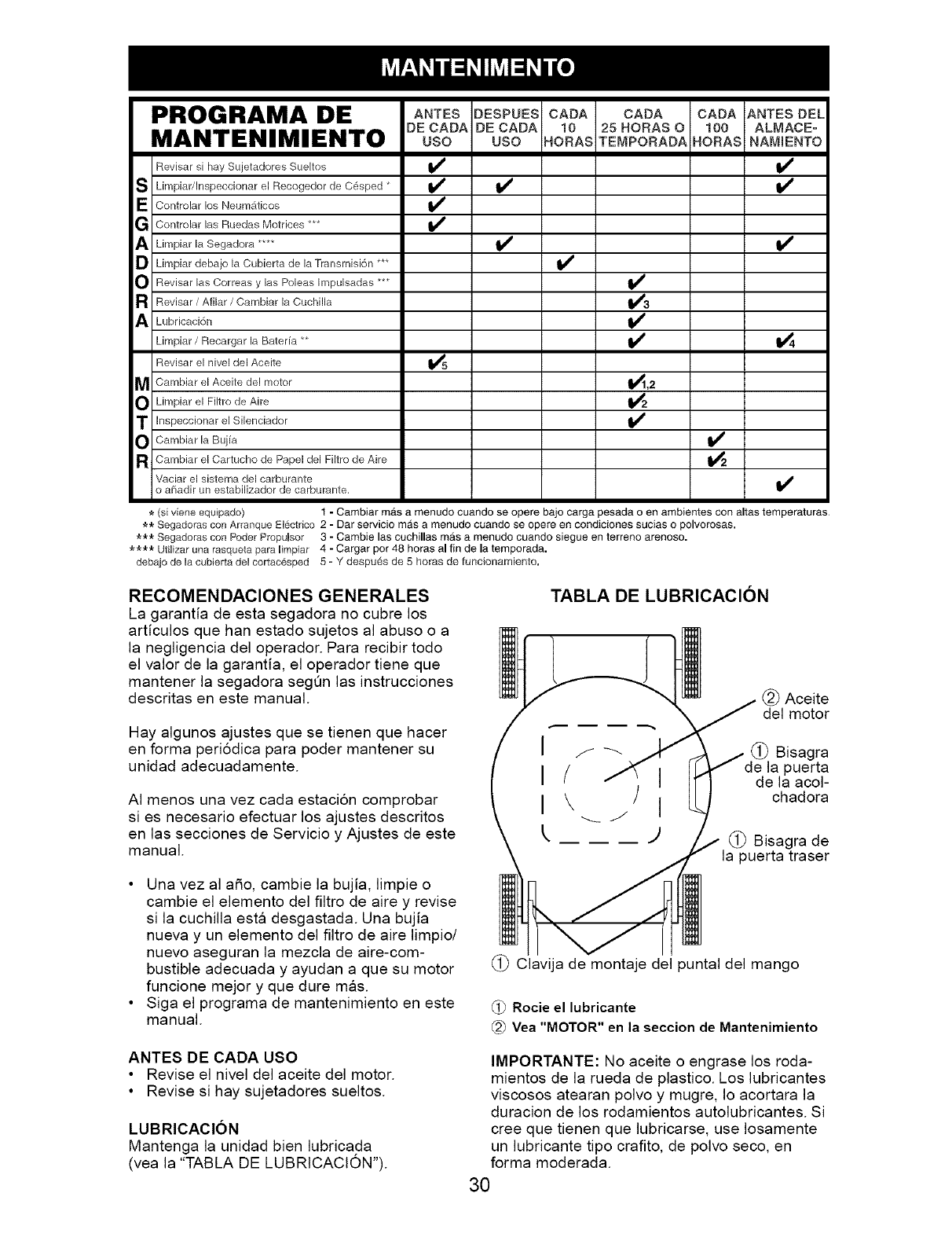
PROGRAMA DE ANTEsDESPUEScADA CADA CADAANTESDEL
DE CADA DE CADA 10 25 HORAS O 100 ALMACEo
MANTENIMIENTO uso uso .oRAsTEMPORADA,ORAS.AMmE.TO
Revisar si hay Sujetadores Sueltos
S Limpiar/Inspeccionar el Recogedor de C6sped *
E Controlar los Neum_:_ticos
G Controlar las Ruedas Motrices ***
A Limpiar la Segadora ....
O Limpiar debajo la Cubierta de la Transmisi6n ***
O Revisar las Correas y las Poleas Impulsadas ***
a Revisar /Afilar /Cambiar la Cuchilla
A Lubricaci6n
Limpiar /Recargar la Bateria **
Revisar el nivel del Aceite
MCambiar el Aceite del motor
O Limpiar el Filtro de Aire
T Inspeccionar el Silenciador
O Cambiar la Buj[a
a Cambiar el Cartucho de Papel del Filtro de Aire
Vaciar el sistema del carburante
o a[iadir un estabilizador de carburante,
v'
1_,2
14
v' I/
*(si viene equipado) 1 -Cambiar mas a menudo cuando se opere bajo carga pesada o en ambientes con altas temperaturas
** Segadoras con Arranque EI6ctrfco 2 - Dar servicio mas a menudo cuando se opere en condiciones sucias o polvorosas,
_** Segadoras con Poder PropuUsor 3 - Cambie las cuchillas mas a menudo cuando siegue en terreno arenoso.
_*_ Utilizar una rasqueta para limpiar 4 - Cargar pot 48 horas al fin de la ternporada.
debajo de la cubierta del cortac6sped 5 - Y despu6s de 5 horas de funcionamiento.
RECOMENDACIONES GENERALES
La garantia de esta segadora no cubre los
articulos que han estado sujetos al abuso o a
la negligencia del operador. Para recibir todo
el valor de la garantia, el operador tiene que
mantener la segadora segQn las instrucciones
descritas en este manual.
Hay algunos ajustes que se tienen que hacer
en forma periodica para poder mantener su
unidad adecuadamente.
AI menos una vez cada estacion comprobar
si es necesario efectuar los ajustes descritos
en las secciones de Servicio y Ajustes de este
manual.
TABLA DE LUBRICACION
(_) Aceite
del motor
(_ Bisagra
puerta
de la acol-
chadora
(_) Bisagra de
puerta traser
•Una vez al a_o, cambie la bujia, limpie o
cambie el elemento del filtro de aire y revise
si la cuchilla esta desgastada. Una bujia
nueva y un elemento del filtro de aire limpio/
nuevo aseguran la mezcla de aire-com-
bustible adecuada y ayudan a que su motor
funcione mejor y que dure mas.
• Siga el programa de mantenimiento en este
manual.
(_) Clavija de montaje del puntal del mango
Rocie el lubricante
Vea "MOTOR" en la seccion de Mantenimiento
ANTES DE CADA USO
• Revise el nivel del aceite del motor.
• Revise si hay sujetadores sueltos.
LUBRICAClON
Mantenga la unidad bien lubricada
(vea la "TABLA DE LUBRtCACION").
IMPORTANTE: No aceite o engrase los roda-
mientos de la rueda de plastico. Los lubricantes
viscosos atearan polvo y mugre, Io acortara la
duracion de los rodamientos autolubricantes. Si
cree que tienen que lubricarse, use Iosamente
un lubricante tipo crafito, de polvo seco, en
forma moderada.
30
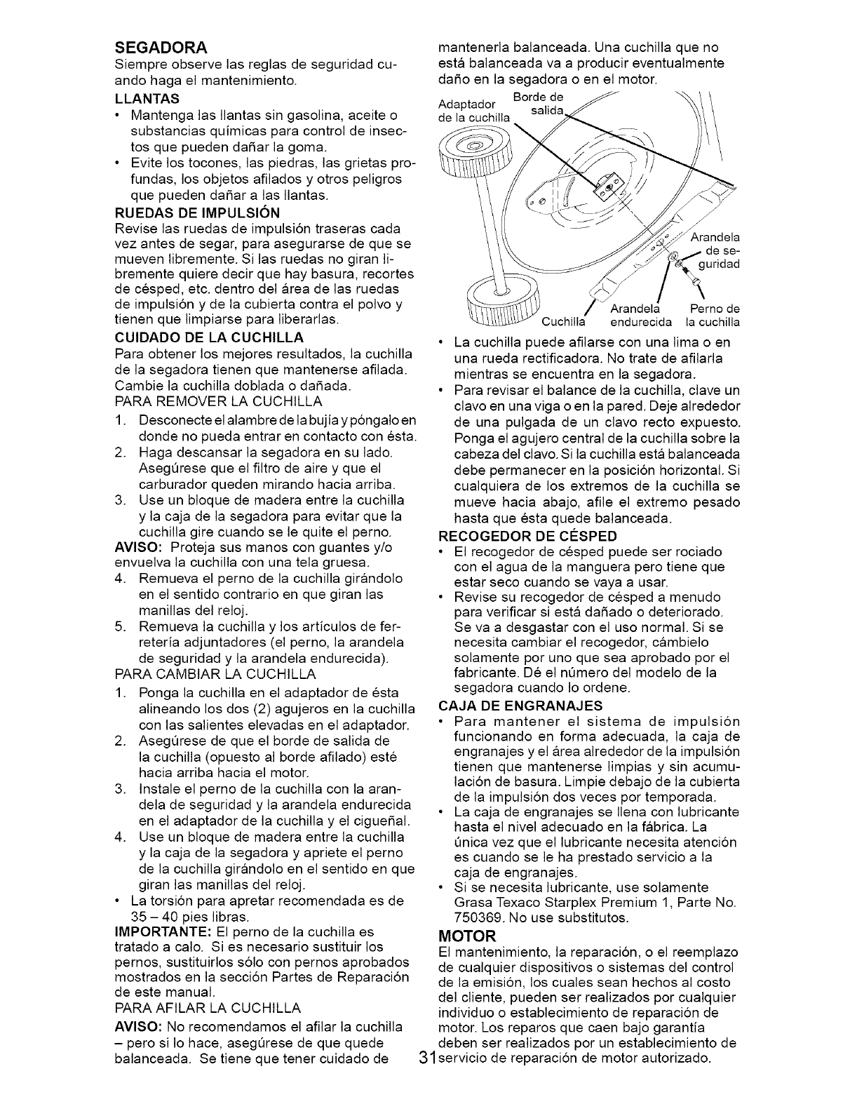
SEGADORA
Siempre observe las reglas de seguridad cu-
ando haga el mantenimiento.
LLANTAS
• Mantenga las Ilantas sin gasolina, aceite o
substancias quimicas para control de insec-
tos que pueden dafiar la goma.
• Evite los tocones, las piedras, las grietas pro-
fundas, los objetos afilados y otros peligros
que pueden dafiar alas Ilantas.
RUEDAS DE IMPULSION
Revise las ruedas de impulsi6n traseras cada
vez antes de segar, para asegurarse de que se
mueven libremente. Si las ruedas no giran li-
bremente quiere decir que hay basura, recortes
de cesped, etc. dentro del area de las ruedas
de impulsi6n y de la cubierta contra el polvo y
tienen que limpiarse para liberarlas.
CUlDADO DE LA CUCHILLA
Para obtener los mejores resultados, la cuchilla
de la segadora tienen que mantenerse afilada.
Cambie la cuchilla doblada o dafiada.
PARA REMOVER LA CUCHILLA
1. Desconecte el alambre de la bujia y p6ngalo en
donde no pueda entrar en contacto con esta.
2. Haga descansar la segadora en su lado.
AsegQrese que el filtro de aire y que el
carburador queden mirando hacia arriba.
3. Use un bloque de madera entre la cuchilla
y la caja de la segadora para evitar que la
cuchilla gire cuando se le quite el perno.
AVlSO: Proteja sus manos con guantes y/o
envuelva la cuchilla con una tela gruesa.
4. Remueva el perno de la cuchilla girandolo
en el sentido contrario en que giran las
manillas del reloj.
5. Remueva la cuchilla y los articulos de fer-
reteria adjuntadores (el perno, la arandela
de seguridad y la arandela endurecida).
PARA CAMBtAR LA CUCHILLA
1. Ponga la cuchilla en el adaptador de esta
alineando los dos (2) agujeros en la cuchilla
con las salientes elevadas en el adaptador.
2. AsegQrese de que el borde de salida de
la cuchilla (opuesto al borde afilado) este
hacia arriba hacia el motor.
3. Instale el perno de la cuchilla con la aran-
dela de seguridad y la arandela endurecida
en el adaptador de la cuchilla y el ciguefial.
4. Use un bloque de madera entre la cuchilla
y la caja de la segadora y apriete el perno
de la cuchilla girandolo en el sentido en que
giran las manillas del reloj.
• La torsi6n para apretar recomendada es de
35 - 40 pies libras.
IMPORTANTE: El perno de la cuchilla es
tratado a calo. Si es necesario sustituir los
pernos, sustituirlos s61o con pernos aprobados
mostrados en la secci6n Partes de Reparaci6n
de este manual.
PARA AFILAR LA CUCHILLA
AVlSO: No recomendamos el afilar la cuchilla
- pero si Io hace, asegQrese de que quede
balanceada. Se tiene que tener cuidado de
mantenerla balanceada. Una cuchilla que no
esta balanceada va a producir eventualmente
dafio en la segadora o en el motor.
Borde de
Adaptador
de la cuchilla
Arandela
de se-
uridad
Arandela Perno de
Cuchilla endurecida la cuchilla
• La cuchilla puede afilarse con una lima o en
una rueda rectificadora. No trate de afilarla
mientras se encuentra en la segadora.
• Para revisar el balance de la cuchilla, clave un
clavo en una viga o en la pared. Deje alrededor
de una pulgada de un clavo recto expuesto.
Ponga el agujero central de la cuchilla sobre la
cabeza del clavo. Si la cuchilla esta balanceada
debe permanecer en la posicion horizontal. Si
cualquiera de los extremos de la cuchilla se
mueve hacia abajo, afile el extremo pesado
hasta que esta quede balanceada.
RECOGEDOR DE CO:SPED
• El recogedor de cesped puede ser rociado
con el agua de la manguera pero tiene que
estar seco cuando se vaya a usar.
• Revise su recogedor de cesped a menudo
para verificar si esta dafiado o deteriorado.
Se va a desgastar con el uso normal. Si se
necesita cambiar el recogedor, cambielo
solamente por uno que sea aprobado por el
fabricante. De el nQmero del modelo de la
segadora cuando Io ordene.
CAJA DE ENGRANAJES
• Para mantener el sistema de impulsion
funcionando en forma adecuada, la caja de
engranajes y el area alrededor de la impulsion
tienen que mantenerse limpias y sin acumu-
lacion de basura. Limpie debajo de la cubierta
de la impulsion dos veces por temporada.
• La caja de engranajes se Ilena con lubricante
hasta el nivel adecuado en la fabrica. La
Qnica vez que el lubricante necesita atencion
es cuando se le ha prestado servicio a la
caja de engranajes.
• Si se necesita lubricante, use solamente
Grasa Texaco Starplex Premium 1, Parte No.
750369. No use substitutos.
MOTOR
El mantenimiento, la reparaci6n, o el reemplazo
de cualquier dispositivos o sistemas del control
de la emision, los cuales sean hechos al costo
del cliente, pueden ser realizados por cualquier
individuo o establecimiento de reparacion de
motor. Los reparos que caen bajo garantia
deben ser realizados por un establecimiento de
31 servicio de reparacion de motor autorizado.
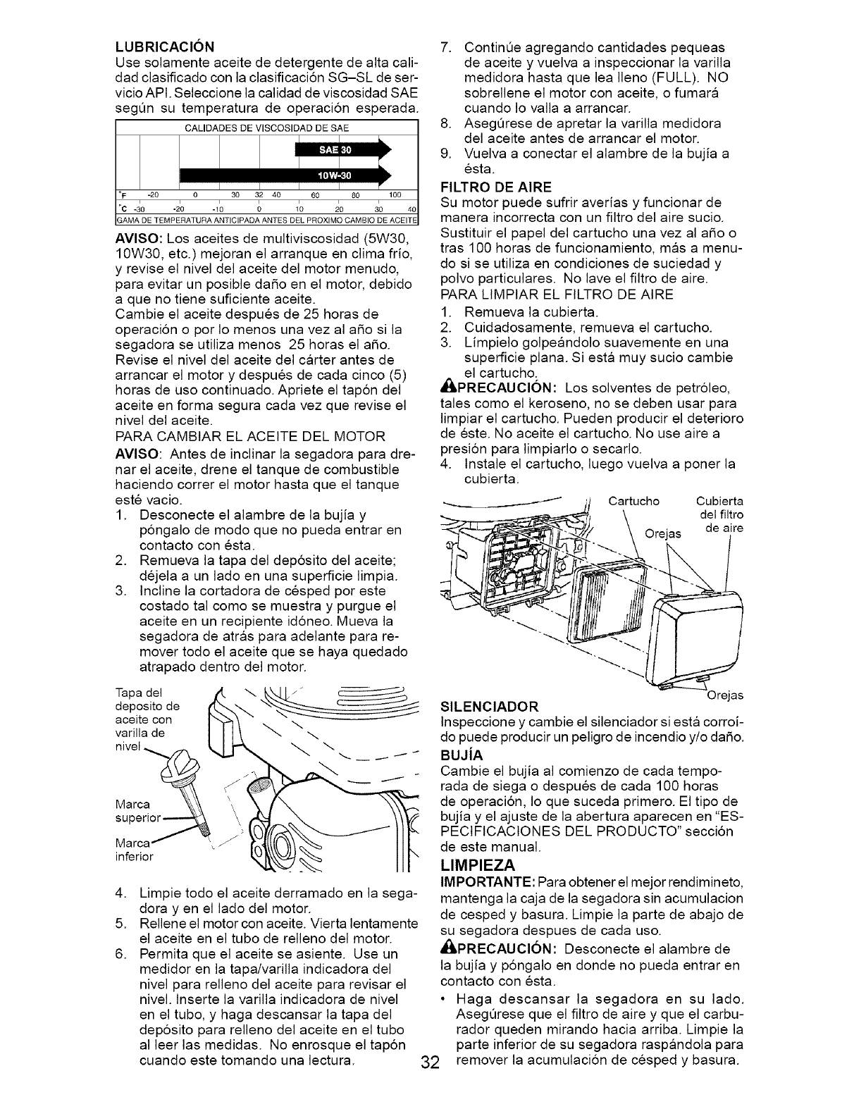
LUBRICACION
Use solamente aceite de detergente de alta call-
dad clasificado con la clasificaci6n SG-SL de ser-
vicio API. Seleccione la calidad de viscosidad SAE
segQn su temperatura de operaci6n esperada.
CALIDADES DE VISCOSIDAD DE SAE
IO0
30 40
°F -20 0 30 32 40 60 80
°c -_0 -2; -_; ;,; do
LAMA DE TEMPERATURA ANTICIPADA ANTES DEL PROXIMO CAMBIO DE ACEITE
AVISO: Los aceites de multiviscosidad (5W30,
10W30, etc.) mejoran el arranque en clima frio,
y revise el nivel del aceite del motor menudo,
para evitar un posible dado en el motor, debido
a que no tiene suficiente aceite.
Cambie el aceite despues de 25 horas de
operacion o por Io menos una vez al ado si la
segadora se utiliza menos 25 horas el ado.
Revise el nivel del aceite del carter antes de
arrancar el motor y despues de cada cinco (5)
horas de uso continuado. Apriete el tap6n del
aceite en forma segura cada vez que revise el
nivel del aceite.
PARA CAMBIAR EL ACEITE DEL MOTOR
AVlSO: Antes de inclinar la segadora para dre-
nar el aceite, drene el tanque de combustible
haciendo correr el motor hasta que el tanque
este vacio.
1. Desconecte el alambre de la bujia y
p6ngalo de modo que no pueda entrar en
contacto con esta.
2. Remueva la tapa del dep6sito del aceite;
dejela a un lado en una superficie limpia.
3. Incline la cortadora de cesped por este
costado tal como se muestra y purgue el
aceite en un recipiente id6neo. Mueva la
segadora de atras para adelante para re-
mover todo el aceite que se haya quedado
atrapado dentro del motor.
Tapa del
deposito de
aceite con
varilla de
nivel _
Marca _\\
superlor_
Marca _- '4/
inferior
.
5.
6.
Limpie todo el aceite derramado en la sega-
dora yen el lado del motor.
Rellene el motor con aceite. Vierta lentamente
el aceite en el tubo de relleno del motor.
Permita que el aceite se asiente. Use un
medidor en la tapa/varilla indicadora del
nivel para relleno del aceite para revisar el
nivel, lnserte la varilla indicadora de nivel
en el tubo, y haga descansar la tapa del
dep6sito para relleno del aceite en el tubo
al leer las medidas. No enrosque el tap6n
cuando este tomando una lectura.
7. ContinQe agregando cantidades pequeas
de aceite y vuelva a inspeccionar la varilla
medidora hasta que lea Ileno (FULL). NO
sobrellene el motor con aceite, o fumara
cuando Io valla a arrancar.
8. AsegOrese de apretar la varilla medidora
del aceite antes de arrancar el motor.
9. Vuelva a conectar el alambre de la bujia a
esta.
FILTRO DE AIRE
Su motor puede sufrir averias y funcionar de
manera incorrecta con un filtro del aire sucio.
Sustituir el papel del cartucho una vez al ado o
tras 100 horas de funcionamiento, mas a menu-
do si se utiliza en condiciones de suciedad y
polvo particulares. No lave el filtro de aire.
PARA LIMPIAR EL FILTRO DE AtRE
1. Remueva la cubierta.
2. Cuidadosamente, remueva el cartucho.
3. Limpielo golpeandolo suavemente en una
superficie plana. Siesta muy sucio cambie
el cartucho.
_PRECAUCl6N: Los solventes de petr61eo,
tales como el keroseno, no se deben usar para
limpiar el cartucho. Pueden producir el deterioro
de este. No aceite el cartucho. No use aire a
presion para limpiarlo o secarlo.
4. Instale el cartucho, luego vuelva a poner la
cubierta.
Cartucho Cubierta
del filtro
Orejas de aire
Orejas
SILENClADOR
Inspeccione y cambie el silenciador siesta corroi-
do puede producir un peligro de incendio y/o dado.
BUJiA
Cambie el bujia al comienzo de cada tempo-
rada de siega o despues de cada 100 horas
de operacion, Io que suceda primero. El tipo de
bujia y el ajuste de la abertura aparecen en "ES-
PECIFICACIONES DEL PRODUCTO" secci6n
de este manual.
LIMPIEZA
IMPORTANTE: Para obtener el mejor rendimineto,
mantenga la caja de la segadora sin acumulacion
de cesped y basura. Limpie la parte de abajo de
su segadora despues de cada uso.
,_PRECAUCl6N: Desconecte el alambre de
la bujia y p6ngalo en donde no pueda entrar en
contacto con esta.
• Haga descansar la segadora en su lado.
AsegOrese que el filtro de aire y que el carbu-
rador queden mirando hacia arriba. Limpie la
parte inferior de su segadora raspandola para
32 remover la acumulacion de cesped y basura.
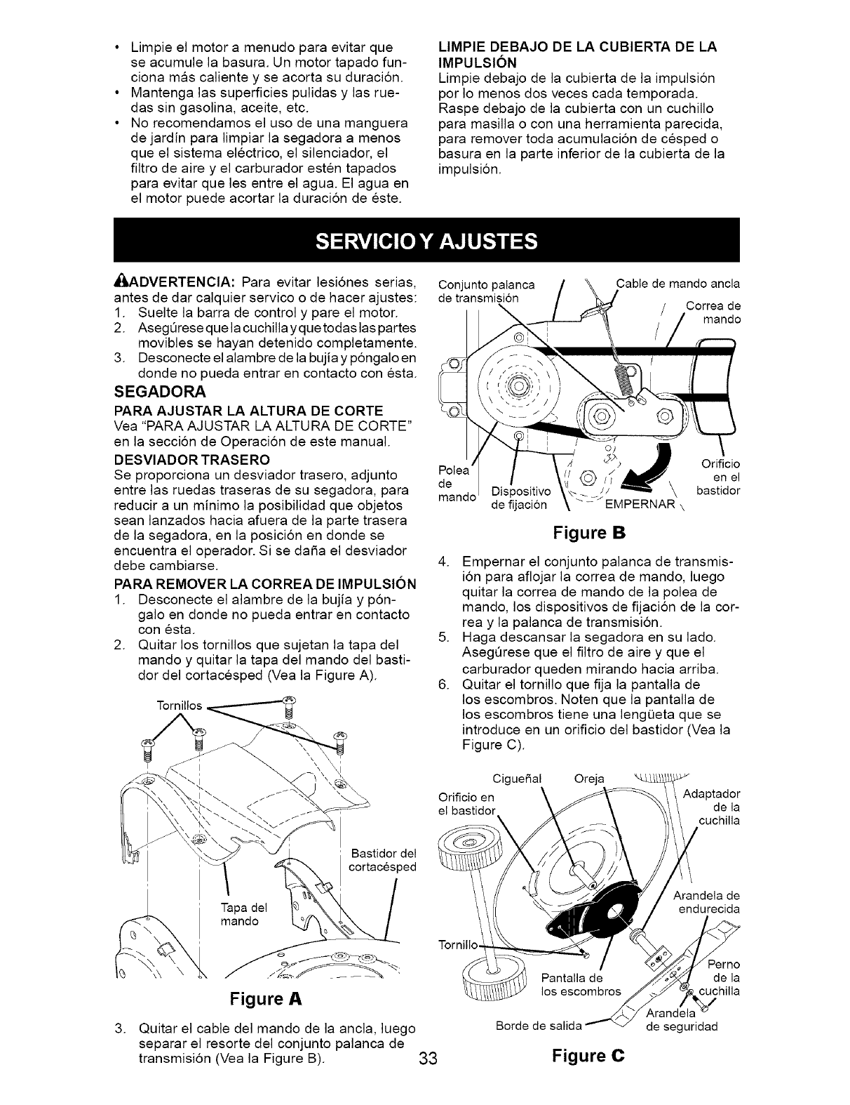
Limpieel motora menudoparaevitarque
seacumulelabasura.Unmotortapadofun-
cionamascalientey seacortasuduraci6n.
Mantengalassuperficiespulidasy lasrue-
dassingasolina,aceite,etc.
Norecomendamoselusodeunamanguera
dejardinparalimpiarlasegadoraa menos
queelsistemaelectrico,elsilenciador,el
filtrodeaireyelcarburadorestentapados
paraevitarquelesentreelagua.Elaguaen
elmotorpuedeacortarladuraci6ndeeste.
LIMPIEDEBAJODELACUBIERTADELA
IMPULSION
Limpie debajo de la cubierta de la impulsi6n
por Io menos dos veces cada temporada.
Raspe debajo de la cubierta con un cuchillo
para masilla o con una herramienta parecida,
para remover toda acumulaci6n de cesped o
basura en la parte inferior de la cubierta de la
impulsi6n.
_ADVERTENClA: Para evitar lesi6nes serias,
antes de dar calquier servico o de hacer ajustes:
1. Suelte la barra de control y pare el motor.
2. AsegQrese que la cuchilla yque todas las partes
movibles se hayan detenido completamente.
3. Desconecte el alambre de la bujia y p6ngalo en
donde no pueda entrar en contacto con esta.
SEGADORA
PARA AJUSTAR LA ALTURA DE CORTE
Vea "PARA AJUSTAR LA ALTURA DE CORTE"
en la secci6n de Operaci6n de este manual.
DESVlADOR TRASERO
Se proporciona un desviador trasero, adjunto
entre las ruedas traseras de su segadora, para
reducir a un minimo la posibilidad que objetos
sean lanzados hacia afuera de la parte trasera
de la segadora, en la posiciSn en donde se
encuentra el operador. Si se da5a el desviador
debe cambiarse.
PARA REMOVER LA CORREA DE IMPULSION
1. Desconecte el alambre de la bujia y p6n-
galo en donde no pueda entrar en contacto
con esta.
2. Quitar los tornillos que sujetan la tapa del
mando y quitar la tapa del mando del basti-
dor del cortacesped (Vea la Figure A).
Conjunto palanca
de transmisi6n
Cable de mando ancla
Correa de
mando
Orificio
de en el
Dispositivo bastidor
mando de fijacion _-_ EMPERNAR' \
Figure B
4. Empernar el conjunto palanca de transmis-
ion para aflojar la correa de mando, luego
quitar la correa de mando de la polea de
mando, los dispositivos de fijacion de la cor-
rea y la palanca de transmision.
5. Haga descansar la segadora en su lado.
AsegQrese que el filtro de aire y que el
carburador queden mirando hacia arriba.
6. Quitar el tornillo que fija la pantalla de
los escombros. Noten que la pantalla de
los escombros tiene una lengQeta que se
introduce en un orificio del bastidor (Vea la
Figure C).
Cigue5al Oreja
Orificio en Adaptador
el bastidor de la
cuchilla
.
Bastidor del
cortacesped
Tapa del
mando
Figure A
Quitar el cable del mando de la ancla, luego
separar el resorte del conjunto palanca de
transmision (Vea la Figure B).
Tornillo
33
los escombros
Borde de salida
Figure C
Arandela de
endurecida
_erno
de la
cuchilla
Arandela
de seguridad
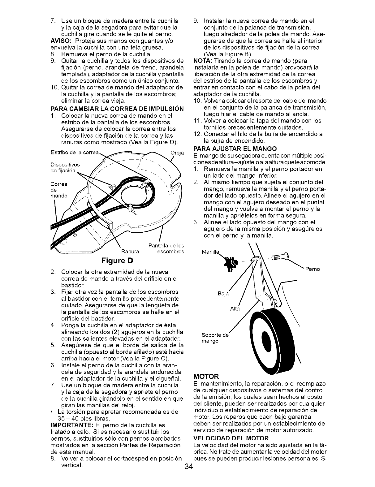
7. Use un bloque de madera entre la cuchilla
y la caja de la segadora para evitar que la
cuchilla gire cuando se le quite el perno.
AVlSO: Proteja sus manos con guantes y/o
envuelva la cuchilla con una tela gruesa.
8. Remueva el perno de la cuchilla.
9. Quitar la cuchilla y todos los dispositivos de
fijaci6n (perno, arandela de freno, arandela
templada), adaptador de la cuchilla y pantalla
de los escombros como un Qnico conjunto.
10. Quitar la correa de mando del adaptador de
la cuchilla y la pantalla de los escombros;
eliminar la correa vieja.
PARA CAMBIAR LA CORREA DE IMPULSION
1. Colocar la nueva correa de mando en el
estribo de la pantalla de los escombros.
Asegurarse de colocar la correa entre los
dispositivos de fijacion de la correa y las
ranuras como mostrado (Vea la Figure D).
Estribo de la correa_,
Dispositivos
de fi
Correa
de
mando
Pantalla de los
Ranura escombros
Figure I)
2. Colocar la otra extremidad de la nueva
correa de mando a traves del orificio en el
bastidor.
3. Fijar otra vez la pantalla de los escombros
al bastidor con el tornillo precedentemente
quitado. Asegurarse de que la lengQeta de
la pantalla de los escombros se halle en el
orificio del bastidor.
4. Ponga la cuchilla en el adaptador de esta
alineando los dos (2) agujeros en la cuchilla
con las salientes elevadas en el adaptador.
5. AsegQrese de que el borde de salida de la
cuchilla (opuesto al borde afilado) este hacia
arriba hacia el motor (Vea la Figure C).
6. Instale el perno de la cuchilla con la aran-
dela de seguridad y la arandela endurecida
en el adaptador de la cuchilla y el ciguefial.
7. Use un bloque de madera entre la cuchilla
y la caja de la segadora y apriete el perno
de la cuchilla girandolo en el sentido en que
giran las manillas del reloj.
• La torsi6n para apretar recomendada es de
35 - 40 pies libras.
IMPORTANTE: El perno de la cuchilla es
tratado a calo. Si es necesario sustituir los
pernos, sustituirlos s61o con pernos aprobados
mostrados en la seccion Partes de Reparacion
de este manual.
8. Volver a colocar el cortacesped en posicion
vertical.
9. Instalar la nueva correa de mando en el
conjunto de la palanca de transmisi6n,
luego alrededor de la polea de mando. Ase-
gurarse de que la correa se halle al interior
de los dispositivos de fijacion de la correa
(Vea la Figure B).
NOTA: Tirando la correa de mando (para
instalarla en la polea de mando) provocara la
liberacion de la otra extremidad de la correa
del estribo de la pantalla de los escombros y
entrar en contacto con el cabo de la polea del
adaptador de la cuchilla.
10. Volver a colocar el resorte del cable del mando
en el conjunto de la palanca de transmisi6n,
luego fijar el cable de mando al ancla.
11. Volver a colocar la tapa del mando con los
tornillos precedentemente quitados.
12. Conectar el hilo de la bujia de encendido a
la bujia de encendido.
PARA AJUSTAR EL MANGO
El mango de su segadora cuenta con mQItiple posi-
cionesdealtura-ajQsteloalaalturaqueleacomode.
1. Remueva la manilla y el perno portador en
un lado del mango inferior.
2. AI mismo tiempo que sujeta el conjunto del
mango, remueva la manilla y el perno porta-
dor del lado opuesto. Alinee el agujero en el
mango con el agujero deseado en el puntal
del mango y vuelva a montar el perno y la
manilla y aprietelos en forma segura.
3. Alinee el lado opuesto del mango con el
agujero de la misma posici6n y asegQrelos
con el perno y la manilla.
Manilla
Perno
aaja
Alta
Soporte de
mango
MOTOR
El mantenimiento, la reparaci6n, o el reemplazo
de cualquier dispositivos o sistemas del control
de la emision, los cuales sean hechos al costo
del cliente, pueden ser realizados por cualquier
individuo o establecimiento de reparacion de
motor. Los reparos que caen bajo garantia
deben ser realizados por un establecimiento de
servicio de reparacion de motor autorizado.
VELOClDAD DEL MOTOR
La velocidad del motor ha sido ajustada en la fa-
brica. No trate de aumentar la velocidad del motor
pues se pueden producir lesiones personales. Si
34
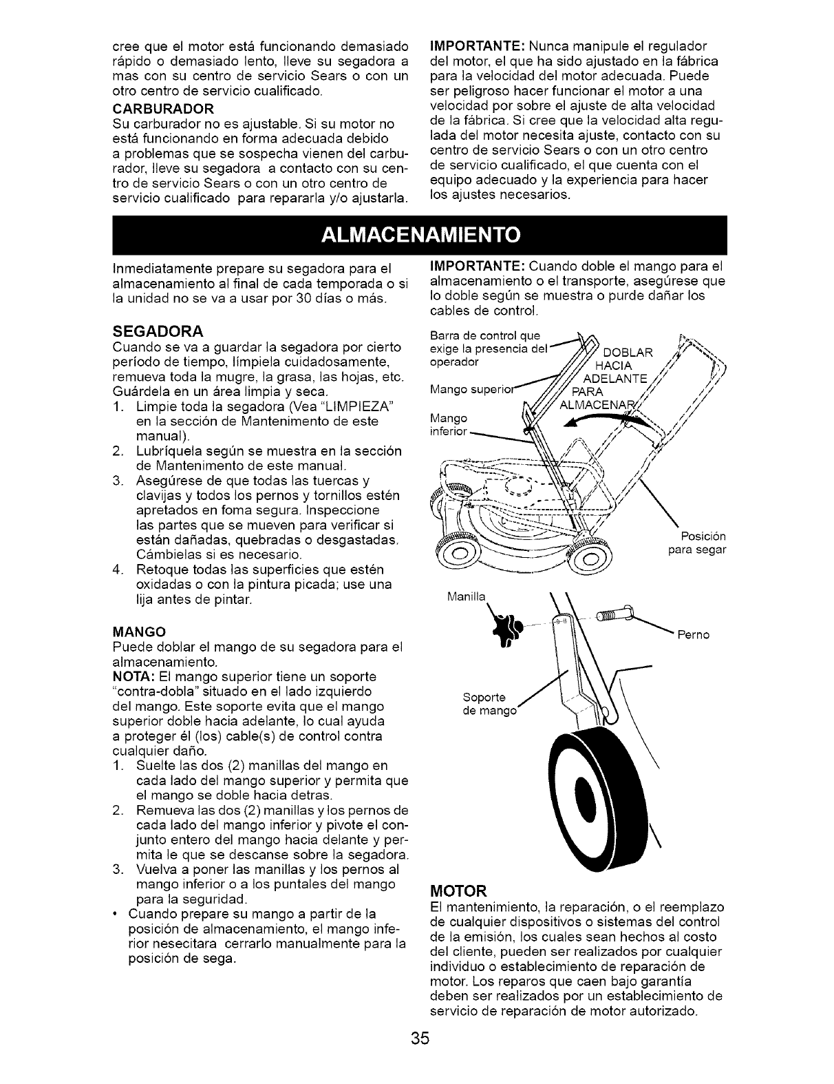
cree que el motor esta funcionando demasiado
rapido o demasiado lento, Ileve su segadora a
mas con su centro de servicio Sears o con un
otro centro de servicio cualificado.
CARBURADOR
Su carburador no es ajustable. Si su motor no
esta funcionando en forma adecuada debido
a problemas que se sospecha vienen del carbu-
rador, Ileve su segadora a contacto con su cen-
tro de servicio Sears o con un otro centro de
servicio cualificado para repararla y/o ajustarla.
IMPORTANTE" Nunca manipule el regulador
del motor, el que ha sido ajustado en la fabrica
para la velocidad del motor adecuada. Puede
ser peligroso hacer funcionar el motor a una
velocidad por sobre el ajuste de alta velocidad
de la fabrica. Si cree que la velocidad alta regu-
lada del motor necesita ajuste, contacto con su
centro de servicio Sears o con un otro centro
de servicio cualificado, el que cuenta con el
equipo adecuado y la experiencia para hacer
los ajustes necesarios.
Inmediatamente prepare su segadora para el
almacenamiento al final de cada temporada o si
la unidad no se va a usar por 30 dias o mas.
SEGADORA
Cuando se va a guardar la segadora por cierto
periodo de tiempo, limpiela cuidadosamente,
remueva toda la mugre, la grasa, las hojas, etc.
Guardela en un area limpia y seca.
1. Limpie toda la segadora (Vea "LIMPIEZA"
en la secci6n de Mantenimento de este
manual).
2. Lubriquela segQn se muestra en la secci6n
de Mantenimento de este manual.
3. AsegQrese de que todas las tuercas y
clavijas y todos los pernos y tornillos esten
apretados en foma segura, lnspeccione
las partes que se mueven para verificar si
estan dahadas, quebradas o desgastadas.
Cambielas si es necesario.
4. Retoque todas las superficies que esten
oxidadas o con la pintura picada; use una
lija antes de pintar.
MANGO
Puede doblar el mango de su segadora para el
almacenamiento.
NOTA: El mango superior tiene un soporte
"contra-dobla" situado en el lado izquierdo
del mango. Este soporte evita que el mango
superior doble hacia adelante, Io cual ayuda
a proteger el (los) cable(s) de control contra
cualquier da_o.
1. Suelte las dos (2) manillas del mango en
cada lado del mango superior y permita que
el mango se doble hacia detras.
2. Remueva las dos (2) manillas y los pernos de
cada lado del mango inferior y pivote el con-
junto entero del mango hacia delante y per-
mita le que se descanse sobre la segadora.
3. Vuelva a poner las manillas y los pernos al
mango inferior o a los puntales del mango
para la seguridad.
• Cuando prepare su mango a partir de la
posicion de almacenamiento, el mango infe-
rior nesecitara cerrarlo manualmente para la
posicion de sega.
IMPORTANTE: Cuando doble el mango para el
almacenamiento o el transporte, asegOrese que
Io doble segQn se muestra o purde da_ar los
cables de control.
Barra de control que
exl(
operador DOBLAR
Man(
Mango
Posicion
para segar
Manilla
Soporte
de mango
MOTOR
El mantenimiento, la reparacion, o el reemplazo
de cualquier dispositivos o sistemas del control
de la emision, los cuales sean hechos al costo
del cliente, pueden ser realizados por cualquier
individuo o establecimiento de reparacion de
motor. Los reparos que caen bajo garantia
deben ser realizados por un establecimiento de
servicio de reparacion de motor autorizado.
35
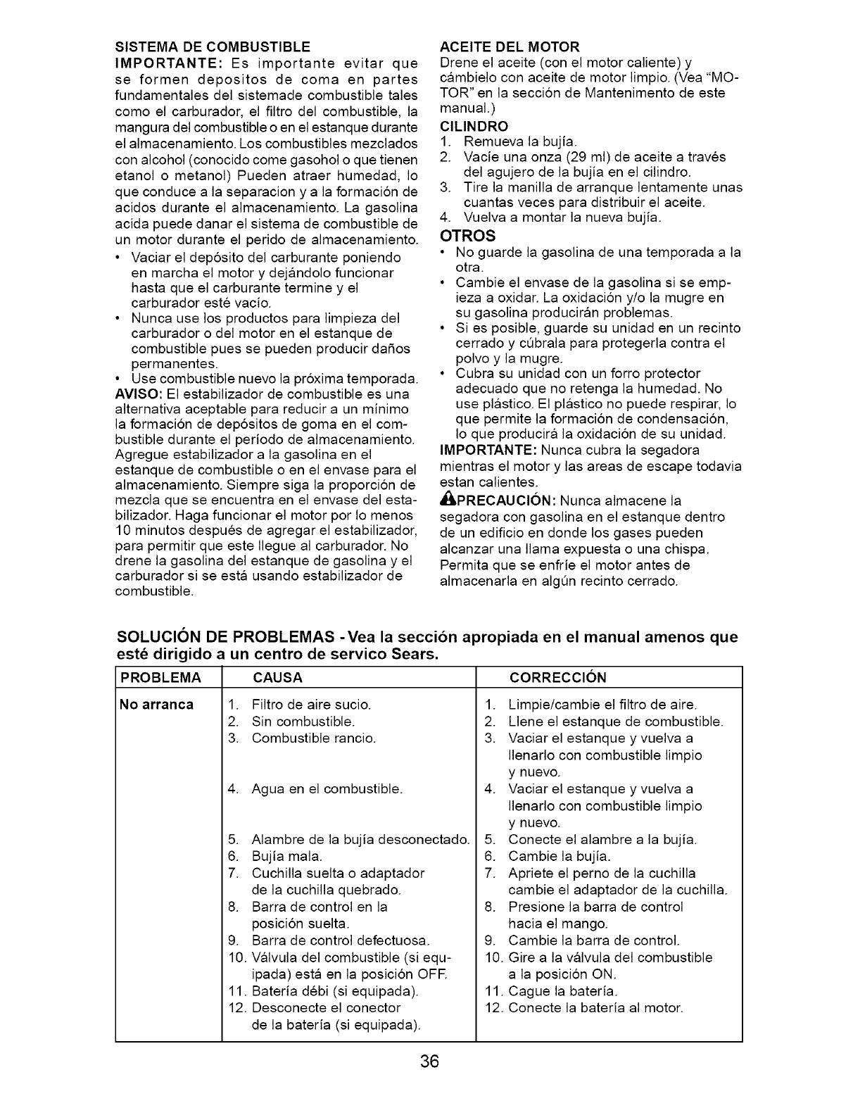
SISTEMA DE COMBUSTIBLE
IMPORTANTE: Es importante evitar que
se formen depositos de coma en partes
fundamentales del sistemade combustible tales
como el carburador, el filtro del combustible, la
mangura del combustible o en el estanque durante
el almacenamiento. Los combustibles mezclados
con alcohol (conocido come gasohol o que tienen
etanol o metanol) Pueden atraer humedad, Io
que conduce a la separacion y a la formacion de
acidos durante el almacenamiento. La gasolina
acida puede danar el sistema de combustible de
un motor durante el perido de almacenamiento.
• Vaciar el deposito del carburante poniendo
en marcha el motor y dejandolo funcionar
hasta que el carburante termine y el
carburador este vacio.
• Nunca use los productos para limpieza del
carburador o del motor en el estanque de
combustible pues se pueden producir dafios
permanentes.
• Use combustible nuevo la proxima temporada.
AVlSO: El estabilizador de combustible es una
alternativa aceptable para reducir a un minimo
la formacion de depositos de goma en el com-
bustible durante el periodo de almacenamiento.
Agregue estabilizador a la gasolina en el
estanque de combustible o en el envase para el
almacenamiento. Siempre siga la proporcion de
mezcla que se encuentra en el envase del esta-
bilizador. Haga funcionar el motor por Io menos
10 minutos despues de agregar el estabilizador,
para permitir que este Ilegue al carburador. No
drene la gasolina del estanque de gasolina y el
carburador si se esta usando estabilizador de
combustible.
ACEITE DEL MOTOR
Drene el aceite (con el motor caliente) y
cambielo con aceite de motor limpio. (Vea "MO-
TOR" en la seccion de Mantenimento de este
manual.)
ClLINDRO
1. Remueva la bujia.
2. Vacie una onza (29 ml) de aceite a traves
del agujero de la bujia en el cilindro.
3. Tire la manilla de arranque lentamente unas
cuantas veces para distribuir el aceite.
4. Vuelva a montar la nueva bujia.
OTROS
• No guarde la gasolina de una temporada a la
otra.
• Cambie el envase de la gasolina si se emp-
ieza a oxidar. La oxidacion y/o la mugre en
su gasolina produciran problemas.
• Si es posible, guarde su unidad en un recinto
cerrado y c_brala para protegerla contra el
polvo y la mugre.
• Cubra su unidad con un forro protector
adecuado que no retenga la humedad. No
use plastico. El plastico no puede respirar, Io
que permite la formacion de condensacion,
Io que producira la oxidacion de su unidad.
IMPORTANTE: Nunca cubra la segadora
mientras el motor y las areas de escape todavia
estan calientes.
_PRECAUCl6N: Nunca almacene la
segadora con gasolina en el estanque dentro
de un edificio en donde los gases pueden
alcanzar una llama expuesta o una chispa.
Permita que se enfrie el motor antes de
almacenarla en algOn recinto cerrado.
SOLUCION DE PROBLEMAS -Yea la seccibn apropiada en el manual amenos que
est_ dirigido a un centro de servico Sears.
CAUSAPROBLEMA
No arranca 1. Filtro de aire sucio.
2. Sin combustible.
3. Combustible rancio.
4. Agua en el combustible.
5. Alambre de la bujia desconectado.
6. Bujia mala.
7. Cuchilla suelta o adaptador
de la cuchilla quebrado.
8. Barra de control en la
posicion suelta.
9. Barra de control defectuosa.
10. Valvula del combustible (si equ-
ipada) esta en la posicion OFR
11. Bateria debi (si equipada).
12. Desconecte el conector
de la bateria (si equipada).
CORRECCION
1. Limpie/cambie el filtro de aire.
2. Llene el estanque de combustible.
3. Vaciar el estanque y vuelva a
Ilenarlo con combustible limpio
y nuevo.
4. Vaciar el estanque y vuelva a
Ilenarlo con combustible limpio
y nuevo.
5. Conecte el alambre a la bujia.
6. Cambie la bujia.
7. Apriete el perno de la cuchilla
cambie el adaptador de la cuchilla.
8. Presione la barra de control
hacia el mango.
9. Cambie la barra de control.
10. Gire a la valvula del combustible
a la posicion ON.
11. Cague la bateria.
12. Conecte la bateria al motor.
36
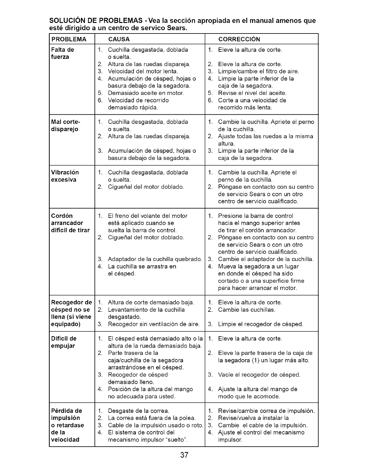
SOLUCION DE PROBLEMAS -Yea la seccibn apropiada en el manual amenos que
est_ dirigido a un centro de servico Sears.
PROBLEMA
Falta de
fuerza
Mal corte-
disparejo
Vibracion
excesiva
Cord6n
arrancador
dificil de tirar
Recogedorde
cesped no se
Ilena(siviene
equipado)
Dificil de
empujar
Perdida de
impulsion
o retardase
de la
velocidad
CAUSA
1. Cuchilla desgastada, doblada
o suelta.
2. AItura de las ruedas dispareja.
3. Velocidad del motor lenta.
4. Acumulacion de cesped, hojas o
basura debajo de la segadora.
5. Demasiado aceite en motor.
6. Velocidad de recorrido
demasiado rapida.
1. Cuchilla desgastada, doblada
o suelta.
2. AItura de las ruedas dispareja.
3. Acumulacion de cesped, hojas o
basura debajo de la segadora.
1. Cuchilla desgastada, doblada
o suelta.
2. Cigue_al del motor doblado.
1. El freno del volante del motor
esta aplicado cuando se
suelta la barra de control.
2. Cigue_al del motor doblado.
3. Adaptador de la cuchilla quebrado.
4. La cuchilla se arrastra en
el cesped.
1. AItura de corte demasiado baja.
2. Levantamiento de la cuchilla
desgastado.
3. Recogedor sin ventilacion de aire.
1. El cesped esta demasiado alto o la
altura de la rueda demasiado baja.
2. Parte trasera de la
caja/cuchilla de la segadora
arrastrandose en el cesped.
3. Recogedor de cesped
demasiado Ileno.
4. Posicion de la altura del mango
no adecuada para usted.
1. Desgaste de la correa.
2. La correa esta fuera de la polea.
3. Cable de la impulsion usado o roto.
4. El sistema de control del
mecanismo impulsor "suelto".
CORRECCION
1. Eleve la altura de corte.
2. Eleve la altura de corte.
3. Limpie/cambie el filtro de aire.
4. Limpie la parte inferior de la
caja de la segadora.
5. Revise el nivel del aceite.
6. Corte a una velocidad de
recorrido mas lenta.
1. Cambie la cuchilla. Apriete el perno
de la cuchilla.
2. Ajuste todas las ruedas a la misma
altura.
3. Limpie la parte inferior de la
caja de la segadora.
1. Cambie la cuchilla. Apriete el
perno de la cuchilla.
2. Pongase en contacto con su centro
de servicio Sears o con un otro
centro de servicio cualificado.
1. Presione la barra de control
hacia el mango superior antes
de tirar el cord6n arrancador.
2. Pongase en contacto con su centro
de servicio Sears o con un otro
centro de servicio cualificado.
3. Cambie el adaptador de la cuchilla.
4. Mueva la segadora a un lugar
en donde el cesped ha sido
cortado o a una superficie firme
para hacer arrancar el motor.
1. Eleve la altura de corte.
2. Cambie las cuchillas.
3. Limpie el recogedor de cesped.
1. Eleve la altura de corte.
2. Eleve la parte trasera de la caja de
la segadora (1) un lugar mas alto.
3. Vacie el recogedor de cesped.
4. Ajuste la altura del mango de
modo que le acomode.
1. Revise/cambie correa de impulsion.
2. Revise/vuelva a instalar la
3. Cambie el cable de la impulsion.
4. Ajuste el control del mecanismo
impulsor.
37
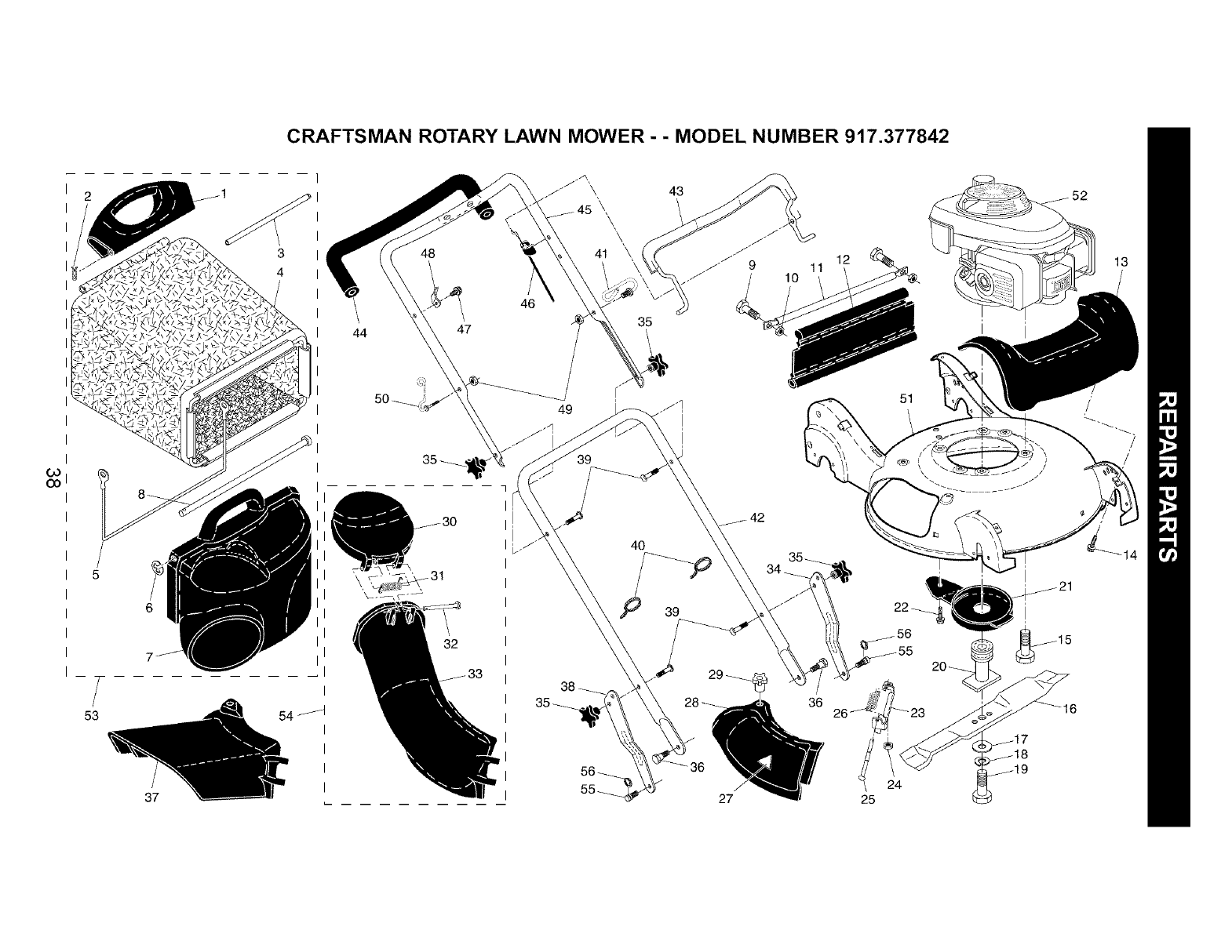
CRAFTSMAN ROTARY LAWN MOWER - - MODEL NUMBER 917.377842
GO
GO
f53
37
3
4
I
I
54 I
I
I
I
48
43
39
38
32
40
27
12
11
36
51
25

CRAFTSMAN ROTARY LAWN MOWER - - MODEL NUMBER 917.377842
Go
(.O
KEY
NO,
1
2
3
4
5
6
7
8
9
10
11
12
13
14
15
16
17
18
19
2O
21
22
23
24
25
26
27
26
29
30
31
32
33
34
35
PART
NO.
188505X428
65322
183483
189471
188506
12000014
188498X428
183479
72140405
73800400
188359X428
188503X428
183386
184572
150406
189028
851074
850263
183431
183428
188510X428
17600406
183609
751152
183445
183446
85463
188507X428
183447
188497X428
183478
183445
188504X428
187063X479
182398
KEY PART
DESCRIPTION NO. NO. DESCRIPTION
Handle, Grassbag, Rear 36 183465
Hairpin Cotter 37 183613
Rod, Rear Handle, Grassbag 38 187064X479
Grassbag 39 184568
Frame, Grassbag 40 66426
E-Ring 41 187162
Door, Grassbag 42 183464X479
Rod, Pivot 43 183474
Bolt, Carriage, Grade 5, 1/4-20 x 5!8 44 182748
Nut, Hex 45 184576
Tube, Rear Skirt 46 183473
Skirt, Rear 47 184570
Cover, Front 48 86899X004
Screw, Hex Washer Head #13-16 x 5!8 49 184569
Bolt, Engine Mounting 50 188501
Blade, 21" 51 190624
Washer, Hardened 52 ---
Washer, Lock
Screw, Hex Head, Grade 8 53 189475
Adapter, Blade
Debris Shield 54 188614
Screw, Hex Head, Serrated, Type TT 1/4-20
Mounting Bracket, Mulcher Door 55 188628
Nut, Hex, Flangelock 1/4-20 56 12000058
Rod, Hinge -- 161058
Spring, Mulcher Door - - 190881
Decal, Danger
Mulcher Door
Knob
Door, Discharge Chute - - 71 33623
Spring, Door, Discharge Chute - - 71 33500
Rod, Door, Discharge Chute - - 71 33000
Discharge Chute, Plastic
Adjustment Bracket, Lower Handle, LH
Knob, Star
Bolt, Shoulder
Deflector, Discharge
Adjustment Bracket, Lower Handle, RH
Bolt, Handle
Wire Tie
Bracket, Anti-Fold
Handle Assembly, Lower
Bail, Control
Grip, Foam
Handle Assembly, Upper (Includes Foam Grip)
Cable, Engine Zone Control
Screw
Bracket, Upstop
Nut, Hex 1/4-20
Rope Guide
Kit, Housing
Engine, Honda, Model Number
GCV190-AS3A (See Breakdown)
Grassbag Assembly, Complete
(Consists of Key Numbers 1-8)
Discharge Chute Assembly, Complete
(Consists of Key Numbers 30-33)
Stud, Shoulder, T45
E-Ring, T45
Decal, Warning (not shown)
Owner's Manual
Available accessories not included with lawn mower:
Gas Can (2.5 Gallon Container)
Fuel Stabilizer
SAE 30W Oil (20 Ounce Bottle)
NOTE: All component dimensions given in US. inches.
1 inch = 25,4 mm
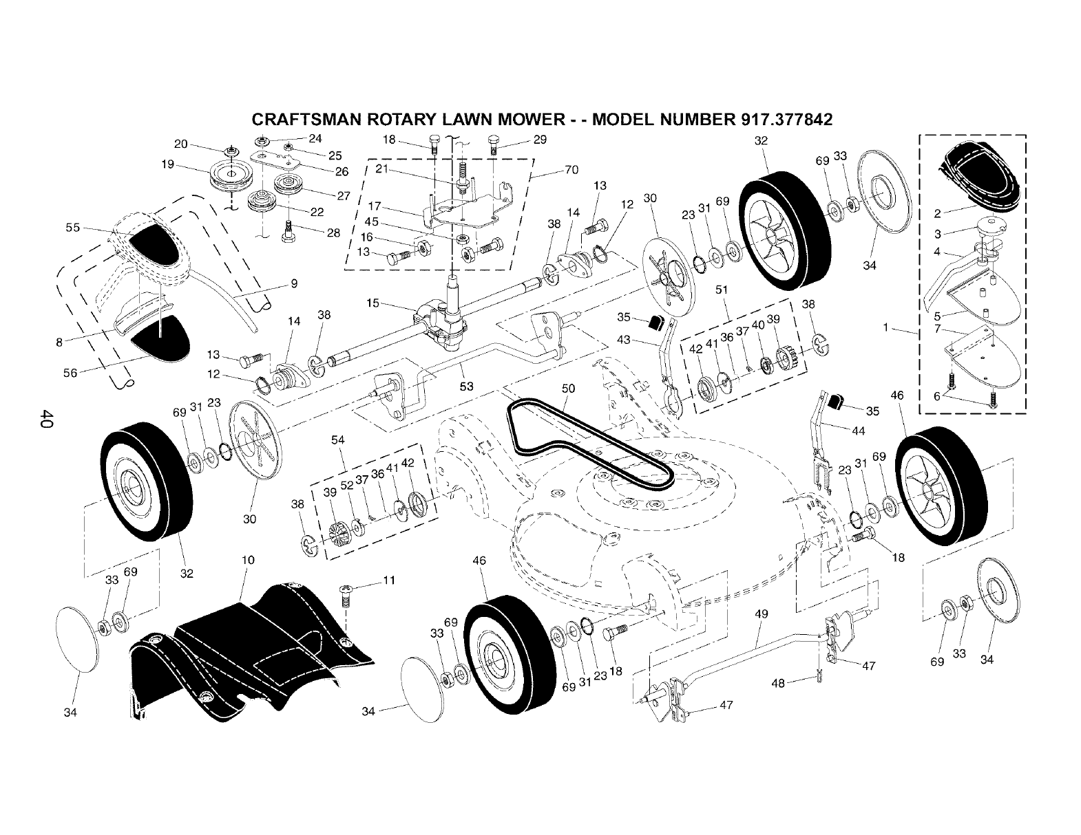
55
\
0
\\\
34
32
30
10
69
14 38
38
I
t\
34 _\
69
33
t
i
i
i
/
f
34
I
I
I
46
18
4

CRAFTSMAN ROTARY LAWN MOWER- - MODEL NUMBER 917.377842
4:_
KEY
NO.
2
3
4
5
6
7
8
9
10
11
12
13
14
15
16
17
18
19
2O
21
22
23
24
25
26
27
28
29
30
PART
NO,
183705
186297
187353
190282
188276
181698
184212X479
184987
188280
188356X428
184571
12000012
183450
187120
188294
132004
189629X004
163409
189408
132010
188611
184543
188152
145212
73930500
183700X004
166043
160829
17060410
183457
KEY PART
DESCRIPTION NO. NO. DESCRIPTION
Drive Control Assembly, Complete
(Consists of Key Numbers 2 through 7)
Cover, Drive Control, Top
Pulley, Drive Control
Lever, Drive Control (red)
Cover, Drive Control, Bottom
Screw, Torx Head #8 x 5!8
Bracket, Mounting, Drive Control
Cap, Drive Control, Bottom
Cable, Drive Control
Cover Assembly, Drive
Screw, HexWasher Head 1/4-20 x 1/2
Ring, Retaining
Screw 1/4-20
Bearing /Axle Support
Gear Case Assembly (See Breakdown)
Nut, Hex 1/4-20
Bracket, Gear Case /Drive Pulley
Screw, Hi-Lo Thread #12 x 5/8
Pulley, Drive
Nut, Hex, Flangelock, Zinc Plated 3!8-16
Bolt, Idler
Pulley Assembly, V-Groove
O-Ring
Nut, Hex, Flangelock, Special Thread
Nut, Hex, Lock
Idler Arm
Pulley, Idler
Bolt, Hex Head, Shoulder 5/16-18 x 1/2
Screw 1!4-20 x 1!16
Cover, Dust, Wheel
31 88348 Washer, Flat 3/8
32 192229 Wheel Assembly, Rear 9 x 2-1/4
33 83923 Nut, Hex, Flangelock 3/8-16
34 183442 Hubcap
35 183437 Knob
36 188291 Spring, Torsion
37 175098 Pawl
38 12000058 E-Ring
39 175103 Gear
40 175105 Retainer, Drive, LH
41 175104 Disc, Drive
42 184172 Seal, Friction
43 188508X004 Lever, Selector, Wheel Height, Rear
44 188509X004 Lever, Selector, Wheel Height, Front
45 751153 Nut, Hex, Flangelock 5/16-18
46 192232 Wheel Assembly, Front 9 x 2-1/4
47 183438 Bushing, Front Axle
48 169675 Retainer, Hairpin Cotter
49 183692X004 Torque Shaft Assembly, Front
50 183688 Belt, Drive
51 188331 Pinion Assembly, LH
52 175102 Retainer, Drive, RH
53 183698X004 Rear Axle Assembly
54 188330 Pinion Assembly, RH
55 186524 Decal, Drive Control Operation
56 185913 Decal, Drive Control Adjustment (Bottom)
69 751068 Bearing, Ball (Wheel)
70 193574 Kit, Gearcase Bracket
NOTE: All component dimensions given in U,S, inches,
1 inch = 25,4 mm
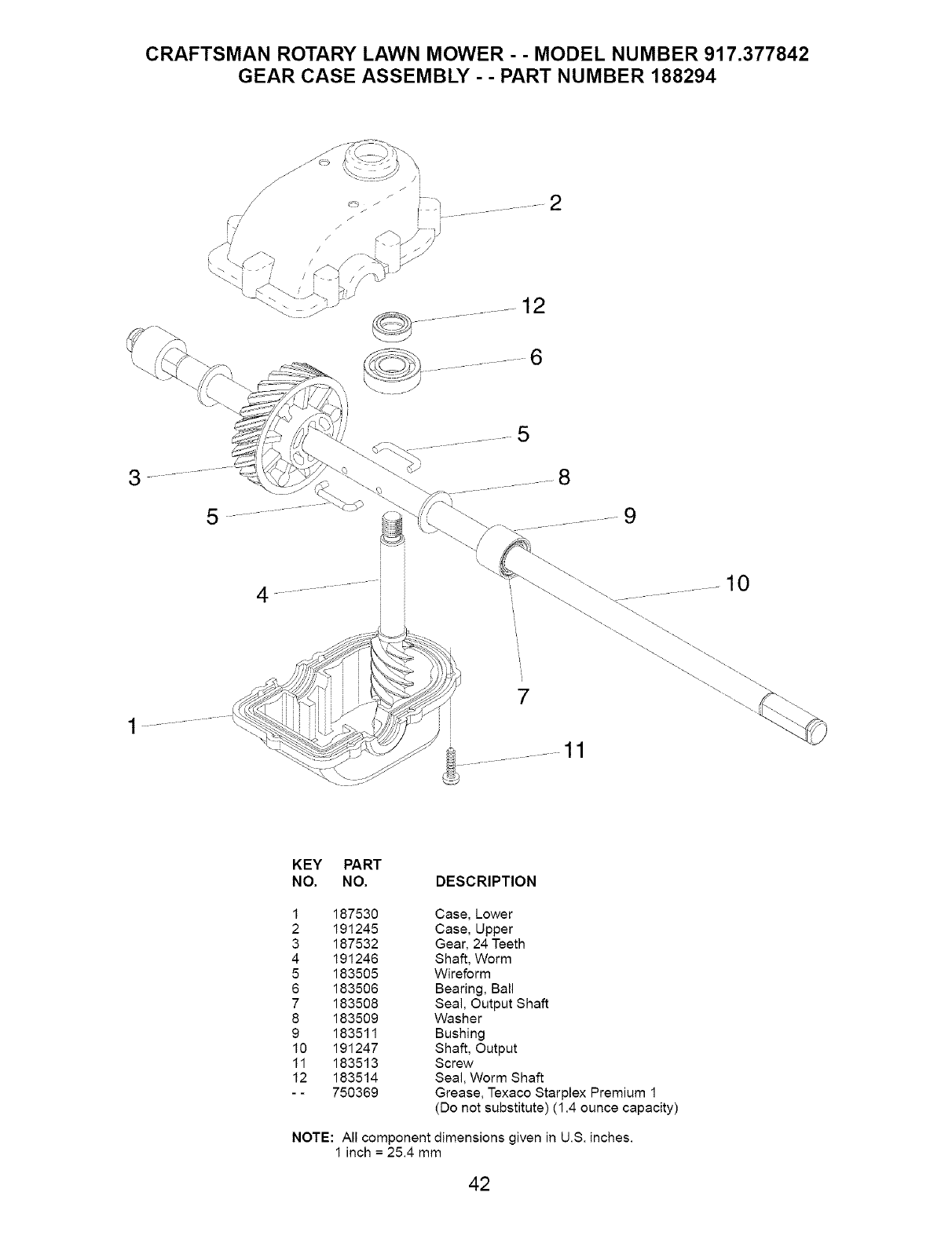
CRAFTSMAN ROTARY LAWN MOWER - - MODEL NUMBER 917.377842
GEAR CASE ASSEMBLY - - PART NUMBER 188294
....... 12
3 8
5 ............... 9
10
KEY PART
NO, NO, DESCRIPTION
1 187530 Case, Lower
2 191245 Case, Upper
3 187532 Gear, 24 Teeth
4 191246 Shaft, Worm
5 183505 Wireform
6 183506 Bearing, Ball
7 183508 Seal, Output Shaft
8 183509 Washer
9 183511 Bushing
10 191247 Shaft, Output
11 183513 Screw
12 183514 Seal, Worm Shaft
- - 750369 Grease, Texaco Starplex Premium 1
(Do not substitute) (1.4 ounce capacity)
NOTE: All component dimensions given in U.S. inches.
1 inch = 25.4 mm
42
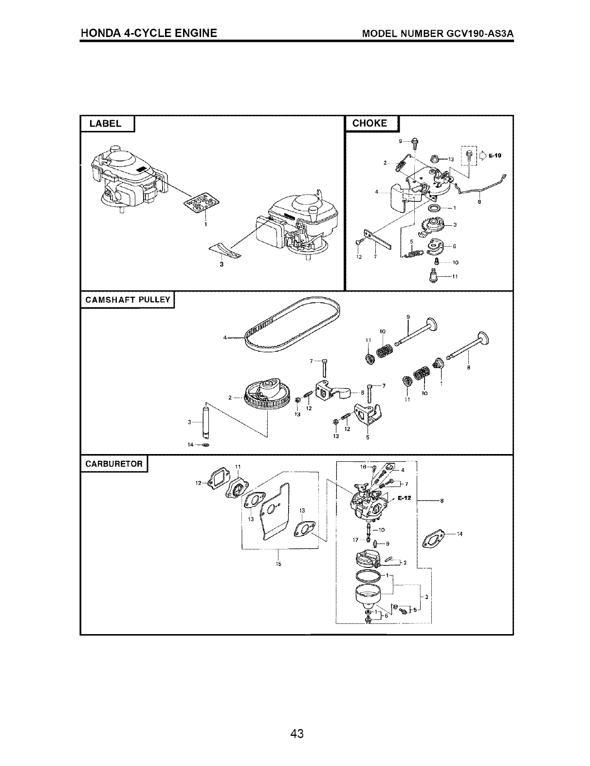
HONDA 4-CYCLE ENGINE MODEL NUMBER GCV190-AS3A
LABEL
@
1
CHOKE I
i{
CAMSHAFT PULLEY 1
CARBURETOR J
14--4_
8
9
1
15
lO
11
43
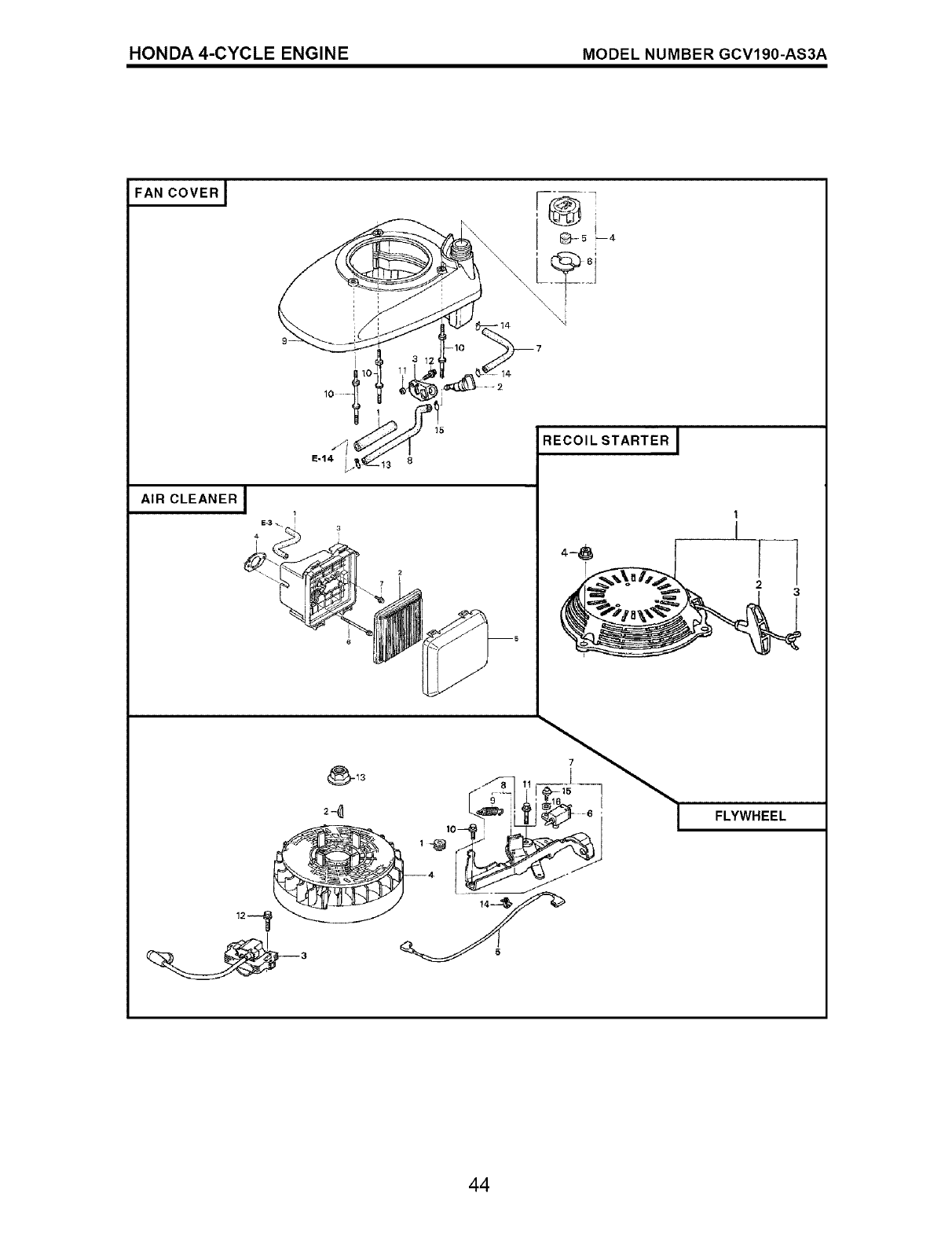
HONDA 4-CYCLE ENGINE MODEL NUMBER GCV190-AS3A
FAN COVERJ
AIR CLEANERJ
15
E-14 13 8
RECOIL STARTER J
II
3
FLYWHEEL
44
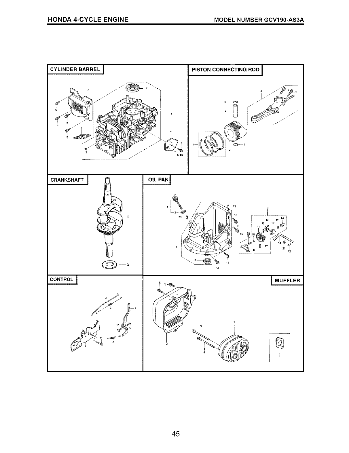
HONDA 4-CYCLE ENGINE MODEL NUMBER GCV190-AS3A
CYLINDER BARREL J PISTON CONNECTING ROD I
2
CRANKSHAFT J
CONTROL I
9
! ;°
MUFFLER
3
45
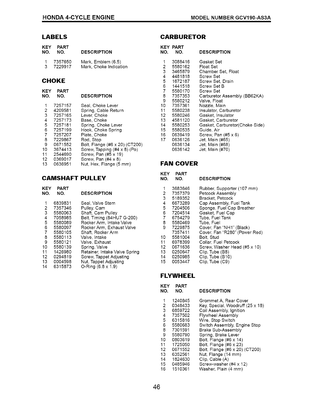
HONDA 4-CYCLE ENGINE MODEL NUMBER GCV190-AS3A
LABELS
KEY PART
NO. NO. DESCRIPTION
1 7357650 Mark, Emblem (6.5)
3 7229917 Mark, Choke Indication
CHOKE
KEY PART
NO. NO. DESCRIPTION
1 7257157 Seal, Choke Lever
2 4209581 Spring, Cable Return
3 7257165 Lever, Choke
4 7257173 Base, Choke
5 7257181 Spring, Choke Lever
6 7257199 Hook, Choke Spring
7 7257207 Plate, Choke
8 7229867 Rod, Stop
9 0671552 Bolt, Flange (#6 x 20) (CT200)
10 3674413 Screw, Tapping (#4 x 8) (Pc)
11 2544690 Screw, Pan (#5 x 19)
12 0369017 Screw, Pan (#-4 x 8)
13 0636951 Nut, Hex, Flange (5 mm)
CAMSHAFT PULLEY
KEY PART
NO. NO. DESCRIPTION
Seal Valve Stem
Pulley, Cam
Shaft, Cam Pulley
Belt, Timing (84HU7 G-200)
Rocker Arm, Intake Valve
Rocker Arm, Exhaust Valve
Shaft, Rocker Arm
Valve, Intake
Valve, Exhaust
Spring, Valve
Retainer, Intake Valve Spring
Screw, Tappet Adjusting
Nut, Tappet Adjusting
O-Ring (6.8 x 1.9)
1 6839851
2 7357346
3 5580063
4 7058985
5 5580089
6 5580097
7 5580105
8 5580113
9 5580121
10 5580139
11 1426980
12 0294819
13 0004598
14 6315873
CARBURETOR
KEY PART
NO. NO. DESCRIPTION
1 3088416
2 5580162
3 3465879
4 4481818
5 1672187
6 1441518
7 5580170
8 7357353
9 5580212
10 7357361
11 5580238
12 5580246
13 4581120
14 5580253
15 5580535
16 0639419
17 0636126
0636134
0636142
Gasket Set
Float Set
Chamber Set, Float
Screw Set
Screw Set, Drain
Screw Set B
Screw Set
Carburetor Assembly (BB62KA)
Valve, Float
Nozzle, Main
Insulator, Carburetor
Gasket, Insulator
Gasket, Carburetor
Gasket, Carburetor(Choke Side)
Guide, Air
Screw, Pan (#5 x 6)
Jet, Main (#65)
Jet, Main (#68)
Jet, Main (#70)
FAN COVER
KEY PART
NO. NO.
1 3683646
2 7357379
3 5189352
4 6673289
5 7204506
6 7204514
7 6754279
8 5580469
9 7229875
7357411
10 5581004
tl 6978399
t2 0671636
13 0250647
14 0250985
15 0053447
DESCRIPTION
Rubber, Supporter (107 ram)
Petcock Assembly
Bracket, Petcock
Cap Assembly, Fuel Tank
Sponge, Fuel Cap Breather
Gasket, Fuel Cap
Tube, Fuel Tank
Tube, Fue_
Cover, Fan "NHI" (Black)
Cover, Fan "R280" (Power Red)
Bolt, Stud
Collar, Fuel Petcock
Screw, Washer Head (#5 x 10)
Clip, Tube (B8)
Clip, Tube (B10)
Clip, Tube (C9)
FLYWHEEL
KEY PART
NO. NO.
1 1240845
2 0348433
3 6859722
4 7357502
5 6315816
6 5580683
8 7301591
9 5580790
10 0803619
11 1725050
12 0671552
13 6352561
14 1824630
15 0485946
16 1510361
DESCRIPTION
Grommet A, Rear Cover
Key, Special, Woodruff (25 x 18)
Coil Assembly, Ignition
F}ywhee} Assembly
Wire, Stop Switch
Switch Assembly, Engine Stop
Brake Sub-Assembly
Spring, Brake Lever
Bolt, Flange (#6 x 14)
Bolt, Flange (#6 x 23)
Bolt, Flange (#6 x 20) (CT20O)
Nut, Flange (14 ram)
Clip, Cable (A)
Screw-washer (#4 x 12)
Washer, Plain (4 mm)
46
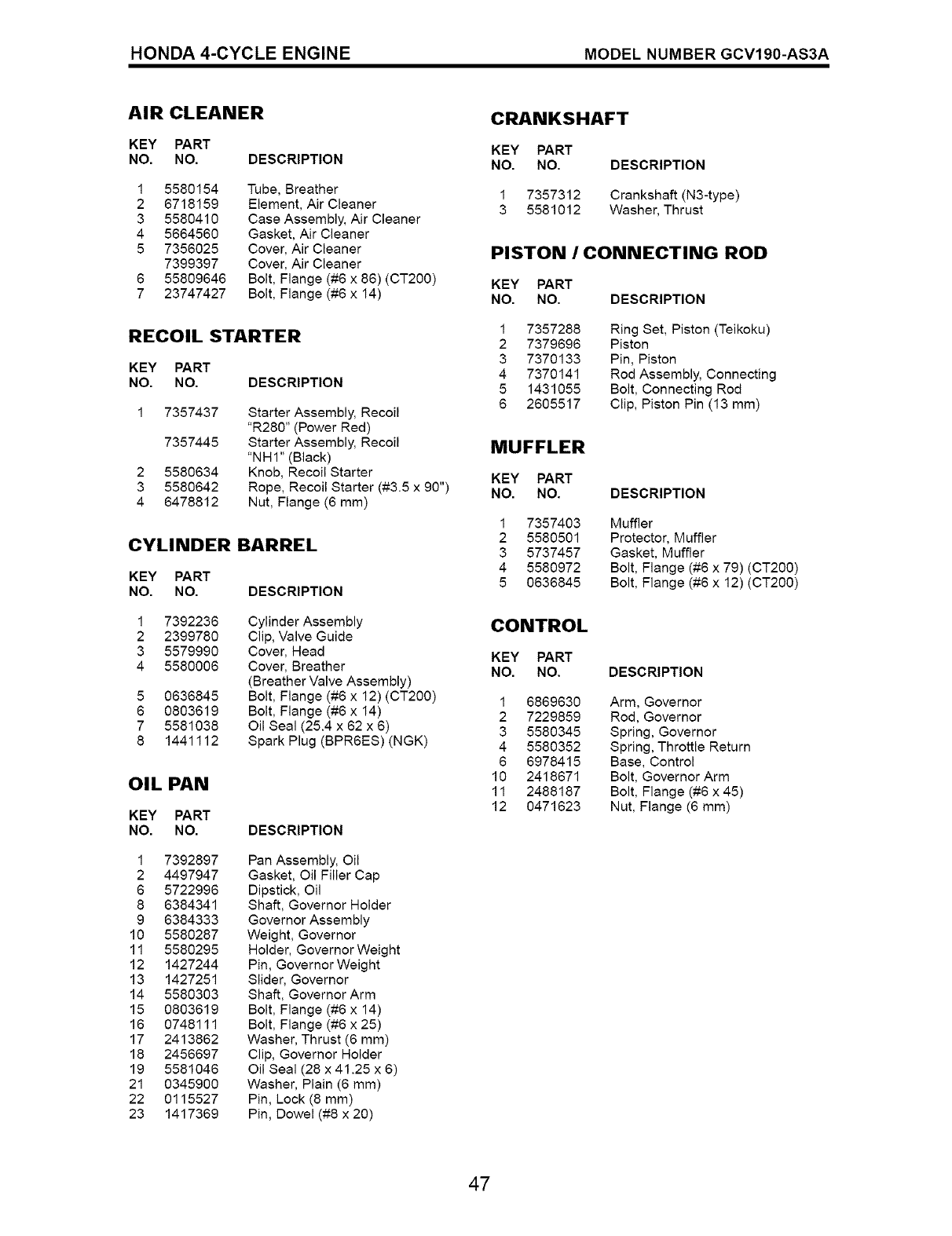
HONDA 4-CYCLE ENGINE MODEL NUMBER GCV190-AS3A
AIR CLEANER
KEY PART
NO. NO. DESCRIPTION
1
2
3
4
5
5580154
6718159
5580410
5664560
7356025
7399397
55809646
23747427
Tube, Breather
Element, Air Cleaner
Case Assembly, Air Cleaner
Gasket, Air Cleaner
Cover, Air Cleaner
Cover, Air Cleaner
Bolt, Flange (#6 x 86) (CT200)
Bolt, Flange (#6 x 14)
RECOIL STARTER
KEY PART
NO. NO. DESCRIPTION
2
3
4
7357437
7357445
5580634
5580642
6478812
Starter Assembty, Recoit
"R280" (Power Red)
Starter Assembly, Recoit
"NHI" (Black)
Knob, Recoil Starter
Rope, Recoil Starter (#3.5 x 90")
Nut, Flange (6 mm)
CYLINDER BARREL
KEY PART
NO. NO. DESCRIPTION
1
2
3
4
5
6
7
8
7392236
2399780
5579990
5580006
0636845
0803619
5581038
1441112
Cylinder Assembly
Clip, Valve Guide
Cover, Head
Cover, Breather
(Breather Valve Assembly)
Bolt, Flange (#6 x 12) (CT200)
Bolt, Flange (#6 x 14)
Oil Seal (25.4 x 62 x 6)
Spark Plug (BPR6ES) (NGK)
OIL PAN
KEY PART
NO. NO.
1 7392897
2 4497947
6 5722996
8 6384341
9 6384333
10 5580287
11 5580295
12 1427244
13 1427251
14 5580303
15 0803619
16 0748111
17 2413862
18 2456697
19 5581046
21 0345900
22 0115527
23 1417369
DESCRIPTION
Pan Assembly, Oil
Gasket, Oit Fitter Cap
Dipstick, Oil
Shaft, Governor Hotder
Governor Assembly
Weight, Governor
Holder, Governor Weight
Pin, Governor Weight
Slider, Governor
Shaft, Governor Arm
Bolt, Flange (#6 x 14)
Bolt, Flange (#6 x 25)
Washer, Thrust (6 mm)
Clip, Governor Holder
Oil Seal (28 x 41.25 x 6)
Washer, Plain (6 mm)
Pin, Lock (8 mm)
Pin, Dowel (#8 x 20)
CRANKSHAFT
KEY PART
NO. NO. DESCRIPTION
1 7357312 Crankshaft (N3-type)
3 5581012 Washer, Thrust
PISTON /CONNECTING ROD
KEY PART
NO. NO. DESCRIPTION
1
2
3
4
5
6
7357288 Ring Set, Piston (Teikoku)
7379696 Piston
7370133 Pin, Piston
7370141 Rod Assembly, Connecting
1431055 Bolt, Connecting Rod
2605517 Clip, Piston Pin (13 mm)
MUFFLER
KEY PART
NO. NO. DESCRIPTION
1 7357403 Muffler
2 5580501 Protector, Muffler
3 5737457 Gasket, Muffler
4 5580972 Bolt, Flange (#6 x 79) (CT200)
5 0636845 Bolt, Flange (#6 x 12) (CT200)
CONTROL
KEY PART
NO. NO. DESCRIPTION
1 6869630 Arm, Governor
2 7229859 Rod, Governor
3 5580345 Spring, Governor
4 5580352 Spring, Throttle Return
6 6978415 Base, Control
10 2418671 Bolt, Governor Arm
11 2488187 Bolt, Flange (#6 x 45)
12 0471623 Nut, Flange (6 mm)
47

Your Home
For repair - in your home - of all major brand appliances,
lawn and garden equipment, or heating and cooling systems,
no matter who made it, no matter who sold it!
For the replacement parts, accessories and
owner's manuals that you need to do-it-yourself.
For Sears professional installation of home appliances
and items like garage door openers and water heaters.
1-800-4-MY-HOME ®Anytime, day or night
(1-800-469-4663) (U.S.A. and Canada)
www.sears.corn www.sears.ca
Our Home
For repair of carry-in products like vacuums, lawn equipment,
and electronics, call or go on-line for the nearest
Sears Parts and Repair Center.
1-800-488-1222 Anytime, day or night (U.S.A. only)
www.sears.com
To purchase a protection agreement (U.S.A.)
or maintenance agreement (Canada) on a product serviced by Sears:
1-800-827-6655 (U.S.A.) 1-800-361-6665 (Canada)
Para pedir servicio de reparaci6n
a domicilio, y para ordenar piezas:
1-888-SU-HOGAR SM
Au Canada pour service en fran£ais:
1-800-LE-FOYER Mc
(1-800-533-6937)
© Sears, Roebuck and Co.
® Registered Trademark /TMTrademark /SMService Mark of Sears, Roebuck and Co.
® Marca Registrada /TM Marca de F&brica /SMMarca de Servicio de Sears, Roebuck and Co.
MC Marque de commerce /MDMarque depos6e de Sears, Roebuck and Co.
190881 Rev. 3 08.23.04 BY Printed in U.S.A.
