Craftsman 917773707 User Manual HIGH WHEEL WEED TRIMMER Manuals And Guides L0521896
CRAFTSMAN Line Trimmers/Weedwackers, Gas Manual L0521896 CRAFTSMAN Line Trimmers/Weedwackers, Gas Owner's Manual, CRAFTSMAN Line Trimmers/Weedwackers, Gas installation guides
User Manual: Craftsman 917773707 917773707 CRAFTSMAN HIGH WHEEL WEED TRIMMER - Manuals and Guides View the owners manual for your CRAFTSMAN HIGH WHEEL WEED TRIMMER #917773707. Home:Lawn & Garden Parts:Craftsman Parts:917773707 Craftsman Grass trimmer (weed wacker) Manual
Open the PDF directly: View PDF ![]() .
.
Page Count: 40
Owner's Manual
JCRRFTSMRN°J
WHEELED
WEEDTRIMMER
6,0 Horsepower
22 Inch Cut
Model No.
917.773707
•EspaSol, p. 17
_CAUTION:
Read and follow all
Safety Rules and Instructions
before operating this equipment.
Sears, Roebuck and Co., Hoffman Estates, IL 60179 U.S.A.
Visit our Craftsman website: www.sears.com/craftsman
Warranty ................................................... 2
Safety Rules .......................................... 2-4
Product Specifications .............................. 5
Assembly /Pre-Operation ........................ 5
Operation ............................................... 6-8
Maintenance Schedule ............................. 9
Maintenance ........................................ 9-11
Service and Adjustments ................... 12-13
Sto rage ................................................... 14
Troubleshooting ...................................... 15
Repair Parts ....................................... 31-37
Sears Service .......................... Back Cover
LIMITED TWO YEAR WARRANTY ON CRAFTSMAN WEEDTRIMMER
For two (2) years from date of purchase, when this Craftsman Weedtrimmer is main-
tained, lubricated, and tuned up according to the operating and maintenance instruc-
tions in the owner's manual, Sears will repair free of charge any defect in material or
workmanship.
if this Craftsman Weedtrimmer is used for commercial or rental purposes, this warranty
applies for only 90 days from the date of purchase.
This Warranty does not cover:
• Expendable items which become worn during normal use, such as rotating lines,
belts, air cleaners and spark plug.
• Repairs necessary because of operator abuse or negligence, including bent crank-
shafts and the failure to maintain the equipment according to the instructions con-
tained in the owner's manual.
Warranty service is available by returning the Craftsman Weedtrimmer to the nearest
Sears Parts & Repair Center in the United States. This warranty applies only while this
product is used in the United States.
This Warranty gives you specific legal rights, and you may also have other rights which
vary from state to state.
Sears, Roebuck and Co., Dept. 817 WA, Hoffman Estates, IL 60179
_i, WARNING: This trimmer is equipped with an internal combustion engine and should
not be used on or near any unimproved forest-covered, brush-covered or grass-covered
land unless the engine's exhaust system is equipped with a spark arrester meeting ap-
plicable local or state laws (if any). If a spark arrester is used, it should be maintained in
effective working order by the operator.
In the state of California the above is required by law (Section 4442 of the California
Public Resources Code). Other states may have similar laws. Federal laws apply on
federa! lands. A spark arrester for the muffler is available through your nearest Sears
service center (see the REPAIR PARTS section of this manual).
The operation of any trimmer can result in foreign objects thrown into
the eyes, which can result in severe eye damage. Always wear safety
glasses or eye shields while operating your trimmer or performing any
adjustments or repairs. We recommend standard safety glasses or a
wide vision safety mask worn over spectacles.
_Look for this symbol to point out
important safety precautions. It means
CAUTION!!! BECOME ALERT!!!
YOUR SAFETY IS INVOLVED.
_!_WARNING: In order to prevent ac-
cidental starting when setting up, trans-
porting, adjusting or making repairs,
always disconnect spark plug wire and
2 place wire where it cannot contact plug.
• I,WARNING: Engine exhaust, some
of its constituents, and certain vehicle
components contain or emit chemicals
known to the State of California to
cause cancer and birth defects or other
reproductive harm.
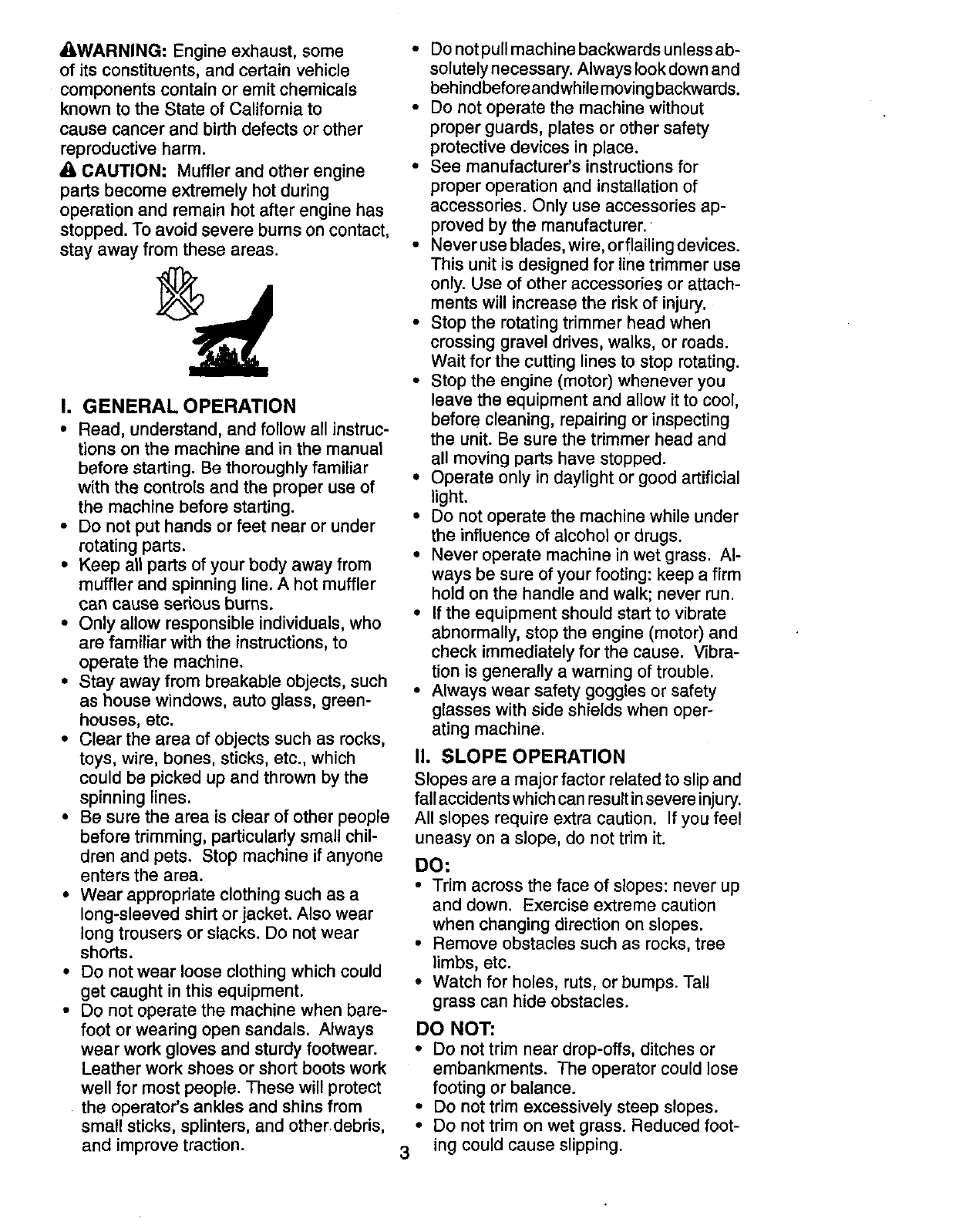
_1,CAUTION: Muffler and other engine
parts become extremely hot during
operation and remain hot after engine has
stopped. To avoid severe burns on contact,
stay away from these areas.
I. GENERAL OPERATION
•Read, understand, and follow all instruc-
tions on the machine and in the manual
before starting. Be thoroughly familiar
with the controls and the proper use of
the machine before starting.
•Do not put hands or feet near or under
rotating parts.
•Keep all parts of your body away from
muffler and spinning line. Ahot muffler
can cause serious burns.
• Only allow responsible individuals, who
are familiar with the instructions, to
operate the machine.
•Stay away from breakable objects, such
as house windows, auto glass, green-
houses, etc.
• Clear the area of objects such as rocks,
toys, wire, bones, sticks, etc., which
could be picked up and thrown by the
spinning lines.
• Be sure the area is clear of other people
before trimming, particularly small chil-
dren and pets. Stop machine if anyone
enters the area.
•Wear appropriate clothing such as a
long-sleeved shirt or jacket. Also wear
long trousers or slacks. Do not wear
shorts.
• Do not wear loose clothing which could
get caught in this equipment.
• Do not operate the machine when bare-
foot or wearing open sandals. Always
wear work gloves and sturdy footwear.
Leather work shoes or short boots work
well for most people. These will protect
the operator's ankles and shins from
small sticks, splinters, and otherdebris,
and improve traction.
• Do not pull machine backwards unless ab-
solutely necessary. Always look down and
behindbefore andwhile moving backwards.
• Do not operate the machine without
proper guards, plates or other safety
protective devices in place.
• See manufacturer's instructions for
proper operation and installation of
accessories. Only use accessories ap-
proved by the manufacturer.
• Never use blades, wire, or flailing devices.
This unit is designed for line trimmer use
only. Use of other accessories or attach-
ments will increase the risk of injury.
•Stop the rotating trimmer head when
crossing gravel drives, walks, or roads.
Wait for the cutting lines to stop rotating.
•Stop the engine (motor) whenever you
leave the equipment and allow it to cool,
before cleaning, repairing or inspecting
the unit. Be sure the trimmer head and
all moving parts have stopped.
• Operate only in daylight or good artificial
light.
• Do not operate the machine while under
the influence of alcohol or drugs.
• Never operate machine in wet grass. Al-
ways be sure of your footing: keep a firm
hold on the handle and walk; never run.
• If the equipment should start to vibrate
abnormally, stop the engine (motor) and
check immediately for the cause. Vibra-
tion is generally a warning of trouble.
•Always wear safety goggles or safety
glasses with side shields when oper-
ating machine.
II. SLOPE OPERATION
Slopes are a major factor related to slip and
fall accidents which can result in severe injury.
All slopes require extra caution. If you feel
uneasy on a slope, do not trim it.
DO:
• Trim across the face of slopes: never up
and down. Exercise extreme caution
when changing direction on slopes.
•Remove obstacles such as rocks, tree
limbs, etc.
• Watch for holes, ruts, or bumps. Tall
grass can hide obstacles.
DO NOT:
•Do not trim near drop-offs, ditches or
embankments. The operator could lose
footing or balance.
• Do not trim excessively steep slopes.
• Do not trim on wet grass. Reduced foot-
3 ing could cause slipping.

III. CHILDREN
Tragic accidents can occur if the opera-
tor is not alert to the presence of chil-
dren. Children are often attracted to the
machine and the trimming activity. Never
assume that children will remain where
you last saw them.
•Keep children out of the trimming area
and under the watchful care of another
responsible adult.
•Be alert and turn machine off if children
enter the area.
• Before and while moving backwards,
look behind & down for small children.
• Never allow children to operate the
machine.
• Use extra care when approaching blind
corners, shrubs, trees, or other objects
that may obscure vision.
IV. SERVICE
• Use extra care in handling gasoline and
other fuels. They are flammable and
vapors are explosive.
- Use only an approved container.
- Never remove gas cap or add fuel with
with the engine running. Allow engine
to cool before refueling. Don't smoke.
-Never refuel the machine indoors.
- Never store the machine or fuel
container inside where there is an
open flame, such as a water heater.
- Move away from fueling site before
starting engine.
• Never run trimmer inside a closed area.
• Never make adjustments or repairs with
the engine (motor) running. Disconnect
the spark plug wire, and keep the wire
away from the spark plug to prevent ac-
cidental starting.
• Keep nuts and bolts, especially trimmer
head and engine bolts, tight and keep
equipment in good condition.
• Never tamper with safety devices.
Check their proper operation regularly.
• Keep machine free of grass, leaves, or
other debris buildup. Clean oil or fuel
spillage. Allow machine to cool before
cleaning or storing.
• Stop and inspect the equipment if you
strike an object. Repair, if necessary,
before restarting.
• Do not change the engine governor set-
ting or overspeed the engine.
•Clean and replace safety and instruction
decals as necessary.
Repair Protection Agreements
Congratulations on making a smart pur-
chase. Your new Craftsman® product is
designed and manufactured for years of
dependable operation. But like all prod-
ucts, it may require repair from time to
time. That's when having a Repair Protec-
tion Agreement can save you money and
aggravation.
Purchase a Repair Protection Agreement
now and protect yourself from unexpected
hassle and expense.
Here's what's included in the Agreement:
•Expert service by our 12,000 profe-
sional repair specialists.
•Unlimited service and no charge for
parts and labor on all covered repairs.
• Product replacement if your covered
product can't be fixed.
•Discount of 10% from regular price of
service and service-related parts not
covered by the agreement; also, 10%
off regular price of preventive mainte-
nance check.
Fast help by phone - phone support
from a Sears technician on products
requiring in-home repair, plus conve-
nient repair scheduling.
Once you purchase the Agreement, a
simple phone call is all that it takes for you
to schedule service. You can call anytime
day or night, or schedule a service ap-
pointment online.
Sears has over 12,000 professional repair
specialists, who have access to over 4.5
million quality parts and accessories.
That's the kind of professionalism you can
count on to help prolong the life of your
new purchase for years to come. Purchase
your Repair Protection Agreement today!
Some limitations and exclusions apply.
For prices and additional information
call 1-800-827-6655.
Sears Installation Service
For Sears professional insta//ation of home
appliances, garage door openers, water
heaters, and other major home items, in
the U.S.A. call 1-800-4-MY-HOME®.
4
Serial Number:
Date of Purchase:
Gasoline Capacity /Type: 1.6 Quarts (Unleaded Regular)
Oil Type (API SG-SL): SAE 30 (above 32°F); SAE 5W-30 (below 32°F)
Oil Capacity: 20 Ounces
Spark Plug (Gap: .030") Champion RJ19LM or J19LM
Trimmer Line Length: 18.75 Inches (0.155 Inch Diameter
The model and serial numbers will be found on a decal on the rear of the trimmer.
Record both serial number and date of purchase in the space provided above.
Read these instructions and this manual in
its entirety before you attempt to assemble
or operate your new trimmer.
IMPORTANT: This trimmer is shipped WITH-
OUT OIL OR GASOLINE in the engine.
Your new trimmer has been assembled
at the factory with the exception of those
parts left unassembled for shipping
purposes. All parts such as nuts, wash-
ers, bolts, etc., necessary to complete the
assembly have been placed in the parts
bag. To ensure safe and proper operation
of your trimmer, all parts and hardware
you assemble must be tightened securely.
Use the correct tools as necessary to
ensure proper tightness.
When right hand (RH) or left hand (LH) is
mentioned in this manual, it means when
you are in the operating position (standing
behind the handle).
Loose Parts Packed Separately
Bottle of oil Trimmer Lines (2) Sets
(0.155 diameter
x 18.75 Inches long)
REMOVE TRIMMER FROM CARTON
1. Remove loosepartsincludedwithtrimmer.
2. Cut down two end corners of carton
and lay end panel down flat.
3. Remove all packing materials.
4. Roll trimmer out of carton and check car-
ton thoroughly for additional loose parts.
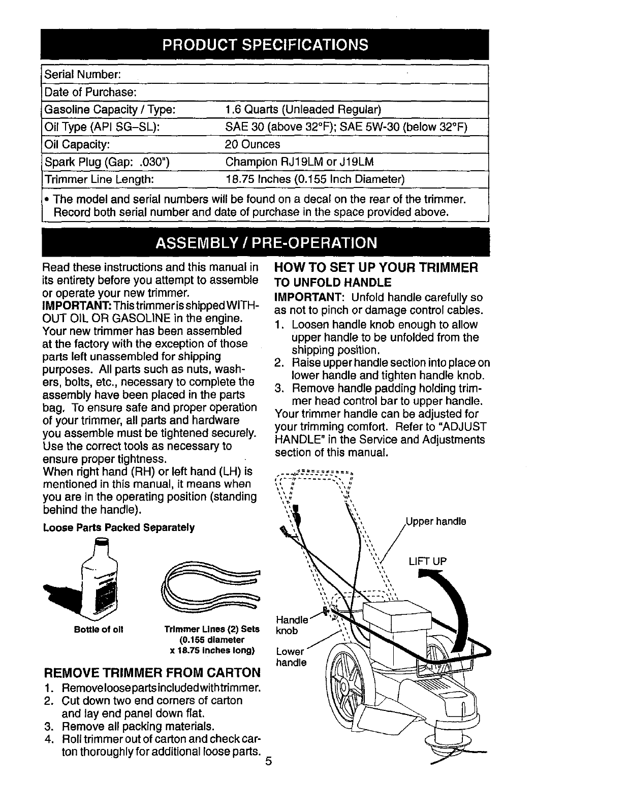
HOW TO SET UP YOUR TRIMMER
TO UNFOLD HANDLE
IMPORTANT: Unfold handle carefully so
as not to pinch or damage control cables.
1. Loosen handle knob enough to allow
upper handle to be unfolded from the
shipping position.
2. Raise upper handle section into place on
lower handle and tighten handle knob.
3. Remove handle padding holding trim-
mer head control bar to upper handle.
Your trimmer handle can be adjusted for
your trimming comfort. Refer to "ADJUST
HANDLE" in the Service and Adjustments
section of this manual.
)per handle
LIFT UP
Handle ,,
knob
Lower
handle
5
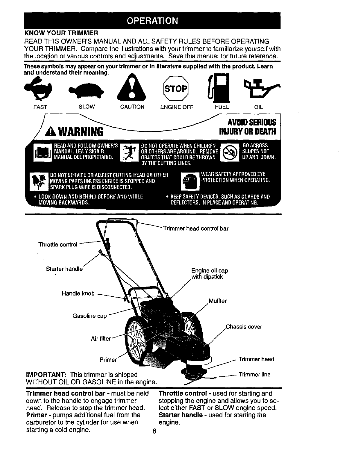
KNOW YOUR TRIMMER
READ THIS OWNER'S MANUAL AND ALL SAFETY RULES BEFORE OPERATING
YOUR TRIMMER. Compare the illustrations with your trimmer to familiarize yourself with
the location of various controls and adjustments. Save this manual for future reference.
These symbols may appear on your trimmer or in literature supplied with the product. Learn
and understand their meaning.
ENGINE OFFFAST SLOW CAUTION FUEL OIL
AVOIDSERIOUS
WA INJURYORDEATH
Trimmer head control bar
Throttle control
Starter handle Engine oil cap
with dipstick
Handle
Muffler
Gasoline cap
Chassis cover
Primer
IMPORTANT: This trimmer is shipped
WITHOUT OIL OR GASOLINE in the engine.
Trimmer head control bar -must be held
down to the handle to engage trimmer
head. Release to stop the trimmer head.
Primer - pumps additional fuel from the
carburetor to the cylinder for use when
starting a cold engine.
Throttle control - used for starting and
stopping the engine and allows you to se-
lect either FAST or SLOW engine speed.
Starter handle -used for starting the
engine.
6
The operation of any trimmer can result in
foreign objects being thrown into the eyes,
which can result in severe eye damage.
Always wear safety glasses or eye shields
while operating your trimmer or performing
any adjustments or repairs. We recom-
mend standard safety glasses or a wide
vision safety mask worn over spectacles.
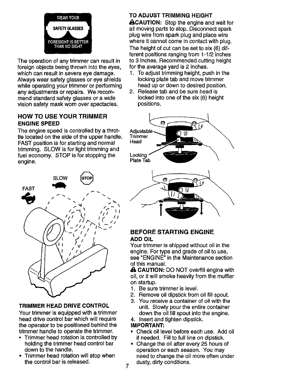
TO ADJUST TRIMMING HEIGHT
_,CAUTION: Stop the engine and wait for
all moving parts to stop. Disconnect spark
plug wire from spark plug and place wire
where it cannot come in contact with plug.
The height of cut can be set to six (6) dif-
ferent positions ranging from 1-1/2 inches
to 3 inches. Recommended cutting height
for the average yard is 2 inches.
1. To adjust trimming height, push in the
locking plate tab and move trimmer
head up or down to desired position.
2. Release tab and be sure head is
locked into one of the six (6) height
positions.
HOW TO USE YOUR TRIMMER
ENGINE SPEED
The engine speed is controlled by a throt- Adj
tie located on the side of the upper handle. Trimmer
FAST position is for starting and normal Head
trimming. SLOW is for light trimming and
fuel economy. STOP is for stopping the Locking
engine. Plate Tab
FAST
SLOW
TRIMMER HEAD DRIVE CONTROL
Your trimmer is equipped with a trimmer
head drive control bar which will require
the operator to be positioned behind the
trimmer handle to operate the trimmer.
• Trimmer head rotation is controlled by
holding the trimmer head control bar
down to the handle.
•Trimmer head rotation will stop when
the control bar is released.
BEFORE STARTING ENGINE
ADD OIL
Your trimmer is shipped without oil in the
engine. For type and grade of oil to use,
see "ENGINE" in the Maintenance section
of this manual.
_l, CAUTION: DO NOT overfill engine with
oil, or it will smoke heavily from the muffler
on startup.
1. Be sure trimmer is level.
2. Remove oil dipstick from oil fill spout.
3. You receive a container of oil with the
unit. Slowly pour the entire container
down the oil fill spout into the engine.
4. Insert and tighten dipstick.
IMPORTANT;
• Check oil level before each use. Add oil
if needed. Fill to full line on dipstick.
• Change the oil after every 25 hours of
operation or each season. You may
need to change the oil more often under
7dusty, dirty conditions.
ADD GASOLINE
•Fill fuel tank to bottom of gas tank
filler neck. Do not overfill. Use fresh,
clean, regular unleaded gasoline with a
minimum of 87 octane. Do not mix oil
with gasoline. Purchase fuel in quanti-
ties that can be used within 30 days to
assure fuel freshness.
• lbCAUTION: Wipe off any spilled oil or
fuel. Do not store, spill or use gasoline
near an open flame.
• I,CAUTION: Alcohol blended fuels
(called gasohol or using ethanol or
methanol) can attract moisture which
leads to separation and formation of acids
during storage. Acidic gas can damage
the fuel system of an engine while in
storage. To avoid engine problems, the
fuel system should be emptied before
storage of 30 days or longer. Empty
the gas tank, start the engine and let it
run until the fuel lines and carburetor
are empty. Use fresh fuel next Season.
See Storage Instructions for additional
information. Never use engine or
carburetor cleaner products in the fuel
tank or permanent damage may occur.
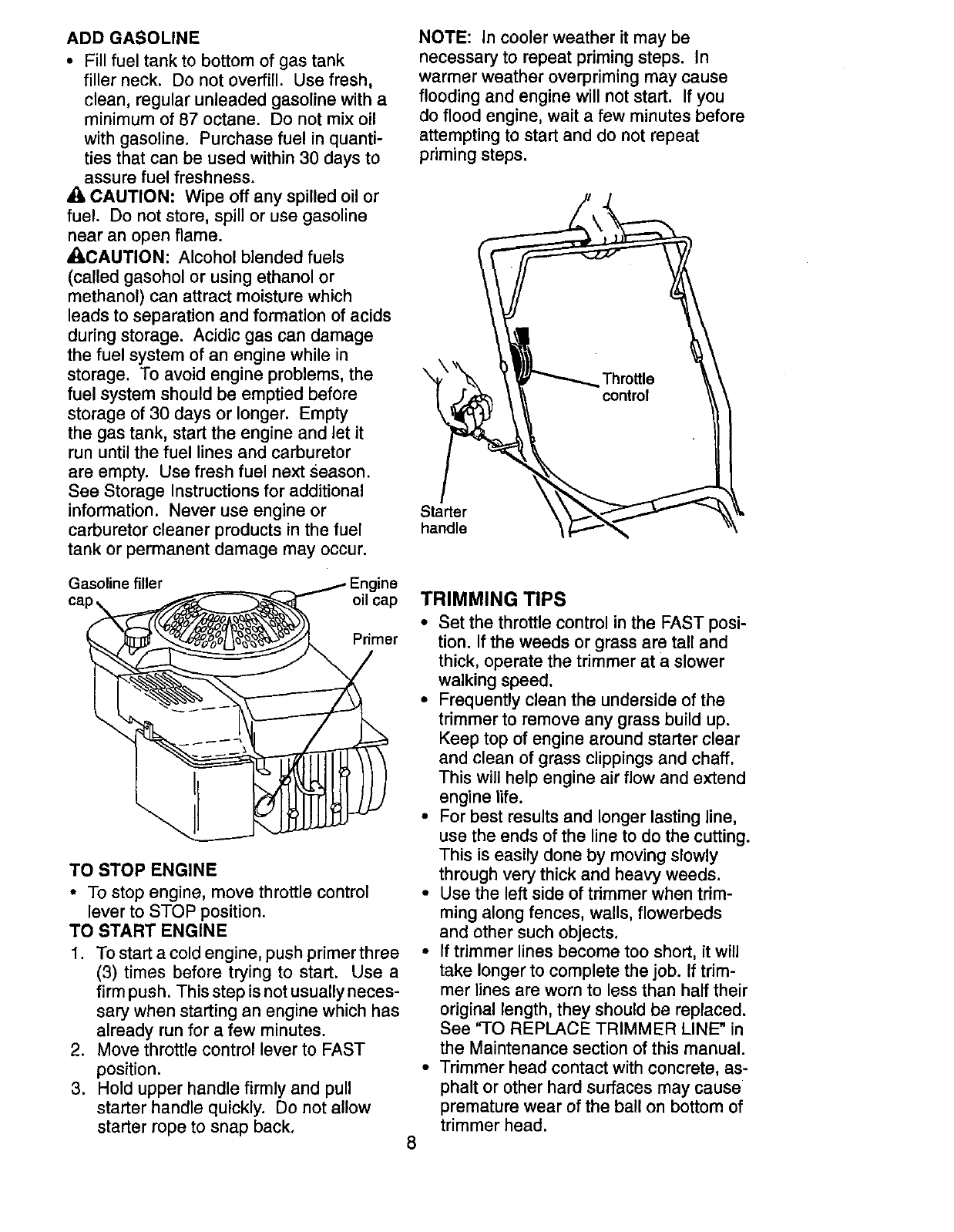
NOTE: In cooler weather it may be
necessary to repeat priming steps. In
warmer weather overpriming may cause
flooding and engine will not start. If you
do flood engine, wait a few minutes before
attempting to start and do not repeat
priming steps.
Starter
handle
Gasoline filler Engine
oil cap
Primer
TO STOP ENGINE
•To stop engine, move throttle control
lever to STOP position.
TO START ENGINE
1. To start a cold engine, push primer three
(3) times before trying to start. Use a
firm push. This step is not usually neces-
sary when starting an engine which has
already run for a few minutes.
2. Move throttle control lever to FAST
position.
3. Hold upper handle firmly and pull
starter handle quickly. Do not allow
starter rope to snap back.
TRIMMING TIPS
8
• Set the throttle control in the FAST posi-
tion. If the weeds or grass are tall and
thick, operate the trimmer at a slower
walking speed.
•Frequently clean the underside of the
trimmer to remove any grass build up.
Keep top of engine around starter clear
and clean of grass clippings and chaff.
This will help engine air flow and extend
engine life.
• For best results and longer lasting line,
use the ends of the line to do the cutting.
This is easily done by moving slowly
through very thick and heavy weeds.
• Use the left side of trimmer when trim-
ming along fences, walls, flowerbeds
and other such objects.
•If trimmer lines become too short, it will
take longer to complete the job. If trim-
mer lines are worn to less than half their
original length, they should be replaced.
See 'q-O REPLACE TRIMMER LINE" in
the Maintenance section of this manual.
• Trimmer head contact with concrete, as-
phalt or other hard surfaces may cause
premature wear of the ball on bottom of
trimmer head.
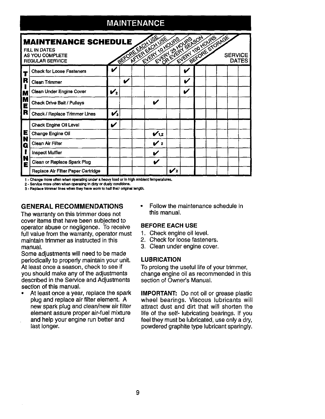
Check for Loose Fasteners _l/
_CleanTrimmer b/ V'
MI Clean Under Engine Cover ll/2 I_
Check Drive Belt /Pulleys l/
R CheckIReplaceTrimmerUnes I/a
I
Check Engine OII Level I_
Change Engine Oil b41,_
Clean Air Filter I_ 2
Inspect Muffler b/
Clean or Replace Spark Plug
Replace Air Filter Paper Cartridge V'2
1- Changemore oftenwhenopera,rigundereheavyloador Inhighambient temperatures.
2-SendcemoreoftenwhenoperatingIndim/or dustyconditions.
3- Replacekimmer lineswhen theyhave wornto halftheirodgInallength.
GENERAL RECOMMENDATIONS
The warranty on this trimmer does not
cover items that have been subjected to
operator abuse or negligence. To receive
full value from the warranty, operator must
maintain trimmer as instructed in this
manual.
Some adjustments will need to be made
periodically to properly maintain your unit.
At least once a season, check to see if
you should make any of the adjustments
described in the Service and Adjustments
section of this manual.
•At least once a year, replace the spark
plug and replace air filter element. A
new spark plug and clean/new air filter
element assure proper air-fuel mixture
and help your engine run better and
last longer.
•Followthe maintenance schedule in
this manual.
BEFORE EACH USE
1. Check engine oil level.
2. Check for loose fasteners.
3. Clean under engine cover.
LUBRICATION
To prolong the useful life of your trimmer,
change engine oil as recommended in this
section of Owner's Manual.
IMPORTANT: Do not oil or grease plastic
wheel bearings. Viscous lubricants will
attract dust and dirt that will shorten the
life of the self- lubricating bearings. If you
feel they must be lubricated, use only a dry,
powdered graphite type lubricant sparingly.
9
TRIMMER
Always observe safety rules when per-
forming any maintenance.
TIRES
•Keep tires free of gasoline, oil, or insect
control chemicals which can harm rub-
ber.
• Avoid stumps, stones, deep ruts, sharp
objects and other hazards that may
cause tire damage.
TRIMMER LINE
For best results, replace trimmer lines
when they have worn to half their original
length. Use .155 inch diameter trimmer
line. Cut new trimmer line length to 18-314
inches. After new line is installed on
trimmer head, check all lines so they do
not vary more then one (1) inch in length.
This is important to make sure the trim -
mer head is balanced and will not vibrate
abnormally.
_WARNING: Use only the specified
trimmer line. Do not use other materials
such as wire, string, rope, etc. Wire can
break off during trimming and become a
dangerous missile that can cause serious
injury.
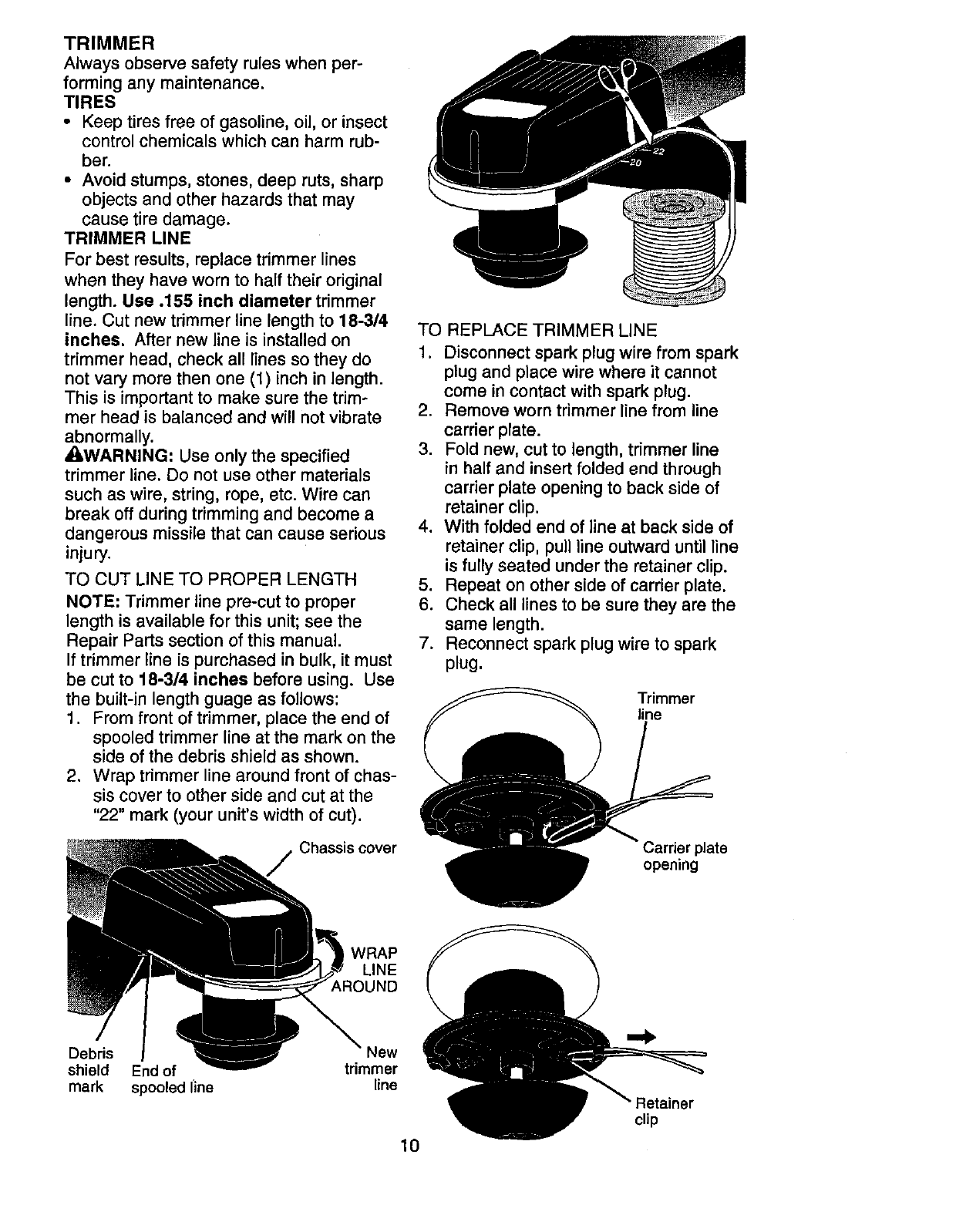
TO CUT LINE TO PROPER LENGTH
NOTE: Trimmer line pre-cut to proper
length is available for this unit; see the
Repair Parts section of this manual.
If trimmer line is purchased in bulk, it must
be cut to 18-314 inches before using. Use
the built-in length guage as follows:
1. From front of trimmer, place the end of
spooled trimmer line at the mark on the
side of the debris shield as shown.
2. Wrap trimmer line around front of chas-
sis cover to other side and cut at the
"22" mark (your unit's width of cut).
Chassis cover
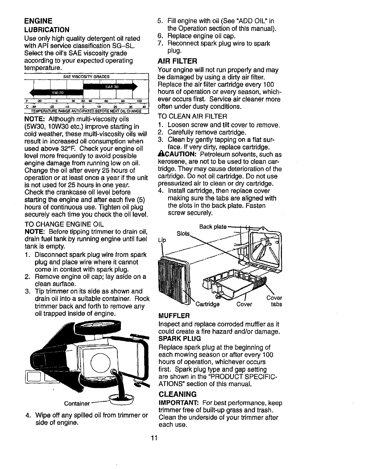
TO REPLACE TRIMMER LINE
1. Disconnect spark plug wire from spark
plug and place wire where it cannot
come in contact with spark plug.
2. Remove worn trimmer line from line
carrier plate.
3. Fold new, cut to length, trimmer line
in half and insert folded end through
carrier plate opening to back side of
retainer clip.
4. With folded end of line at back side of
retainer clip, pull line outward until line
is fully seated under the retainer clip.
5. Repeat on other side of carrier plate.
6. Check all lines to be sure they are the
same length.
7. Reconnect spark plug wire to spark
plug.
Trimmer
line
Carrier plate
opening
WRAP
LINE
_,ROUND
Debris New
shield End of trimmer
mark spooled iine line
10
Retainer
clip
ENGINE
LUBRICATION
Use only high quality detergent oil rated
with API service classification SG-SL.
Select the oil's SAE viscosity grade
according to your expected operating
temperature.
NOTE: Although multi-viscosity oils
(5W30, 10W30 etc.) improve starting in
cold weather, these multi-viscosity oils will
result in increased oil consumption when
used above 32°F. Check your engine oil
level more frequently to avoid possible
engine damage from running low on oi1.
Change the oil after every 25 hours of
operation or at least once a year if the unit
is not used for 25 hours in one year.
Check the crankcase oil level before
starting the engine and after each five (5)
hours of continuous use. Tighten oil plug
securely each time you check the oil level.
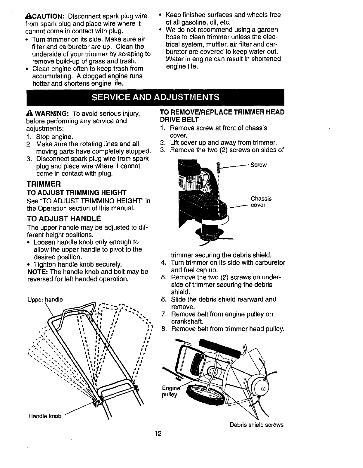
TO CHANGE ENGINE OIL
NOTE: Before tipping trimmer to drain oil,
drain fuel tank by running engine until fuel
tank is empty.
1. Disconnect spark plug wire from spark
plug and place wire where it cannot
come in contact with spark plug.
2. Remove engine oil cap; lay aside on a
clean surface.
3. Tip trimmer on its side as shown and
drain oil into a suitable container. Rock
trimmer back and forth to remove any
oil trapped inside of engine.
Container
4. Wipe off any spilled oil from trimmer or
side of engine.
5. Fill engine with oil (See "ADD OIL" in
the Operation section of this manual).
6. Replace engine oil cap.
7. Reconnect spark plug wire to spark
plug.
AIR FILTER
Your engine will not run properly and may
be damaged by using a dirty air filter.
Replace the air filter cartridge every 100
hours of operation or every season, which-
ever occurs first. Service air cleaner more
often under dusty conditions.
TO CLEAN AIR FILTER
1. Loosen screw and tilt cover to remove.
2. Carefully remove cartridge.
3. Clean by gently tapping on a flat sur-
face. If very dirty, replace cartridge.
ACAUTION: Petroleum solvents, such as
kerosene, are not to be used to clean car-
tridge. They may cause deterioration of the
cartridge. Do not oil cartridge. Do not use
pressurized air to clean or dry cartridge.
4. Install cartridge, then replace cover
making sure the tabs are aligned with
the slots in the back plate. Fasten
screw securely.
Back
Cover
Cartridge Cover tabs
MUFFLER
Inspect and replace corroded muffler as it
could create a fire hazard and/or damage.
SPARK PLUG
Replace spark plug at the beginning of
each mowing season or after every 100
hours of operation, whichever occurs
first. Spark plug type and gap setting
are shown in the "PRODUCT SPECIFIC-
ATIONS" section of this manual.
CLEANING
IMPORTANT: For best performance, keep
trimmer free of built-up grass and trash.
Clean the underside of your trimmer after
each use.
11
_CAUTION: Disconnect spark plug wire
from spark plug and place wire where it
cannot come in contact with plug.
• Turn trimmer on its side. Make sure air
filter and carburetor are up. Clean the
underside of your trimmer by scraping to
remove build-up of grass and trash.
• Clean engine often to keep trash from
accumulating. A clogged engine runs
hotter and shortens engine life.
• Keep finished surfaces and wheels free
of all gasoline, oil, etc.
• We do not recommend using a garden
hose to clean trimmer unless the elec-
trical system, muffler, air filter and car-
buretor are covered to keep water out.
Water in engine can result in shortened
engine life.
AWARNING: To avoid serious injury,
before performing any service and
adjustments:
1. Stop engine.
2. Make sure the rotating lines and all
moving parts have completely stopped.
3. Disconnect spark plug wire from spark
plug and place wire where it cannot
come in contact with plug.
TRIMMER
TO ADJUST TRIMMING HEIGHT
See "TO ADJUST TRIMMING HEIGHT" in
the Operation section of this manual.
TO ADJUST HANDLE
The upper handle may be adjusted to dif-
ferent height positions.
•Loosen handle knob only enough to
allow the upper handle to pivot to the
desired position.
•Tighten handle knob securely.
NOTE: The handle knob and bolt may be
reversed for left handed operation.
Upper handle
TO REMOVE/REPLACE TRIMMER HEAD
DRIVE BELT
1. Remove screw at front of chassis
cover.
2. Lift cover up and away from trimmer.
3. Remove the two (2) screws on sides of
Chassis
cover
.
5.
trimmer securing the debris shield.
Turn trimmer on its side with carburetor
and fuel cap up.
Remove the two (2) screws on under-
side of trimmer securing the debris
shield.
6. Slide the debris shield rearward and
remove.
7. Remove belt from engine pulley on
crankshaft.
8. Remove belt from trimmer head pulley.
pulley
Handle knob
12
Debris shield screws
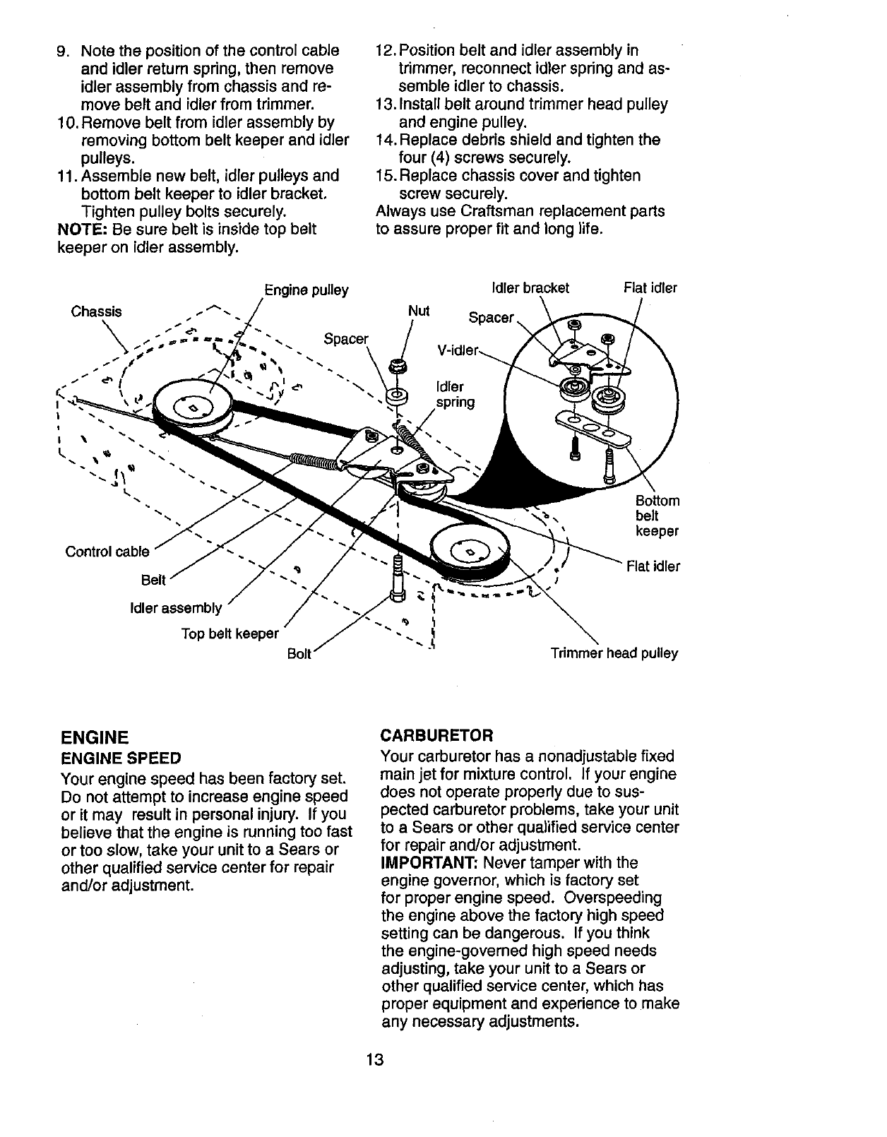
9. Note the position of the control cable
and idler return spring, then remove
idler assembly from chassis and re-
move belt and idler from trimmer.
10. Remove belt from idler assembly by
removing bottom belt keeper and idler
pulleys.
11. Assemble new belt, idler pulleys and
bottom belt keeper to idler bracket.
Tighten pulley bolts securely.
NOTE: Be sure belt is inside top belt
keeper on idler assembly.
12. Position belt and idler assembly in
trimmer, reconnect idler spring and as-
semble idler to chassis.
13. Install belt around trimmer head pulley
and engine pulley.
14. Replace debris shield and tighten the
four (4) screws securely.
15. Replace chassis cover and tighten
screw securely.
Always use Craftsman replacement parts
to assure proper fit and long life.
Engine pulley
Nut
Idler bracket Flat idler
Control cable j"" --
Id /"'-
Top belt keeper
BoSom
belt
keeper
Flat idler
I
Trimmer head pulley
ENGINE
ENGINE SPEED
Your engine speed has been factory set.
Do not attempt to increase engine speed
or it may result in personal injury. If you
believe that the engine is running too fast
or too slow, take your unit to a Sears or
other qualified service center for repair
and/or adjustment.
CARBURETOR
Your carburetor has anonadjustable fixed
main jet for mixture control. If your engine
does not operate properly due to sus-
pected carburetor problems, take your unit
to a Sears or other qualified service center
for repair and/or adjustment.
IMPORTANT: Never tamper with the
engine governor, which is factory set
for proper engine speed. Overspeeding
the engine above the factory high speed
setting can be dangerous. If you think
the engine-governed high speed needs
adjusting, take your unit to a Sears or
other qualified service center, which has
proper equipment and experience to make
any necessary adjustments.
13
Immediately prepare your trimmer for stor-
age at the end of the season or if the unit
will not be used for 30 days or more.
TRIMMER
When trimmer is to be stored for a period
of time, clean it thoroughly, remove all dirt,
grease, leaves, etc. Store in a clean, dry area.
1. Clean entire trimmer (See"CLEANING"in
the Maintenance section of this manual).
2. Lubricate as shown in the Maintenance
section of this manual.
3. Be sure that all nuts, bolts, screws, and
pins are securely fastened. Inspect
moving parts for damage, breakage
and wear. Replace if necessary.
4. Touch up all rusted or chipped paint
surfaces; sand lightly before painting.
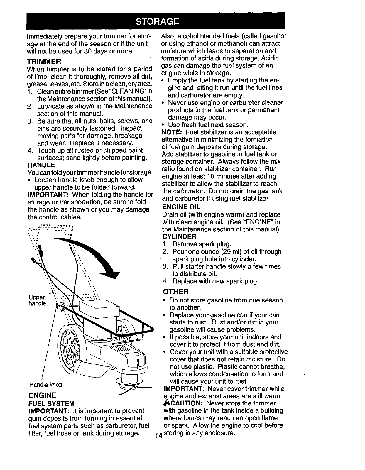
HANDLE
You can fold your trimmer handle for storage.
•Loosen handle knob enough to allow
upper handle to be folded forward.
IMPORTANT: When folding the handle for
storage or transportation, be sure to fold
the handle as shown or you may damage
the control cables.
pper ,
handle
Handle knob
ENGINE
FUEL SYSTEM
IMPORTANT: It is important to prevent
gum deposits from forming in essential
fuel system parts such as carburetor, fuel
filter, fuel hose or tank during storage.
Also, alcohol blended fuels (called gasohol
or using ethanol or methanol) can attract
moisture which leads to separation and
formation of acids during storage. Acidic
gas can damage the fuel system of an
engine while in storage.
• Empty the fuel tank by starting the en-
gine and letting it run until the fuel lines
and carburetor are empty.
•Never use engine or carburetor cleaner
products in the fuel tank or permanent
damage may occur.
•Use fresh fuel next season.
NOTE: Fuel stabilizer is an acceptable
alternative in minimizing the formation
of fuel gum deposits during storage.
Add stabilizer to gasoline in fuel tank or
storage container. Always follow the mix
ratio found on stabilizer container. Run
engine at least 10 minutes after adding
stabilizer to allow the stabilizer to reach
the carburetor. Do not drain the gas tank
and carburetor if using fuel stabilizer.
ENGINE OIL
Drain oil (with engine warm) and replace
with clean engine oil. (See =ENGINE" in
the Maintenance section of this manual).
CYLINDER
1. Remove spark plug.
2. Pour one ounce (29 ml) of oil through
spark plug hole into cylinder.
3. Pull starter handle slowly a few times
to distribute oil.
4. Replace with new spark plug.
OTHER
•Do not store gasoline from one season
to another.
• Replace your gasoline can if your can
starts to rust. Rust and/or dirt in your
gasoline will cause problems.
• If possible, store your unit indoors and
cover it to protect it from dust and dirt.
• Cover your unit with a suitable protective
cover that does not retain moisture. Do
not use plastic. Plastic cannot breathe,
which allows condensation to form and
will cause your unit to rust.
IMPORTANT: Never cover trimmer while
engine and exhaust areas are still warm.
_I_,CAUTION: Never store the trimmer
with gasoline in the tank inside a building
where fumes may reach an open flame
or spark. Allow the engine to cool before
14 storing in any enclosure.
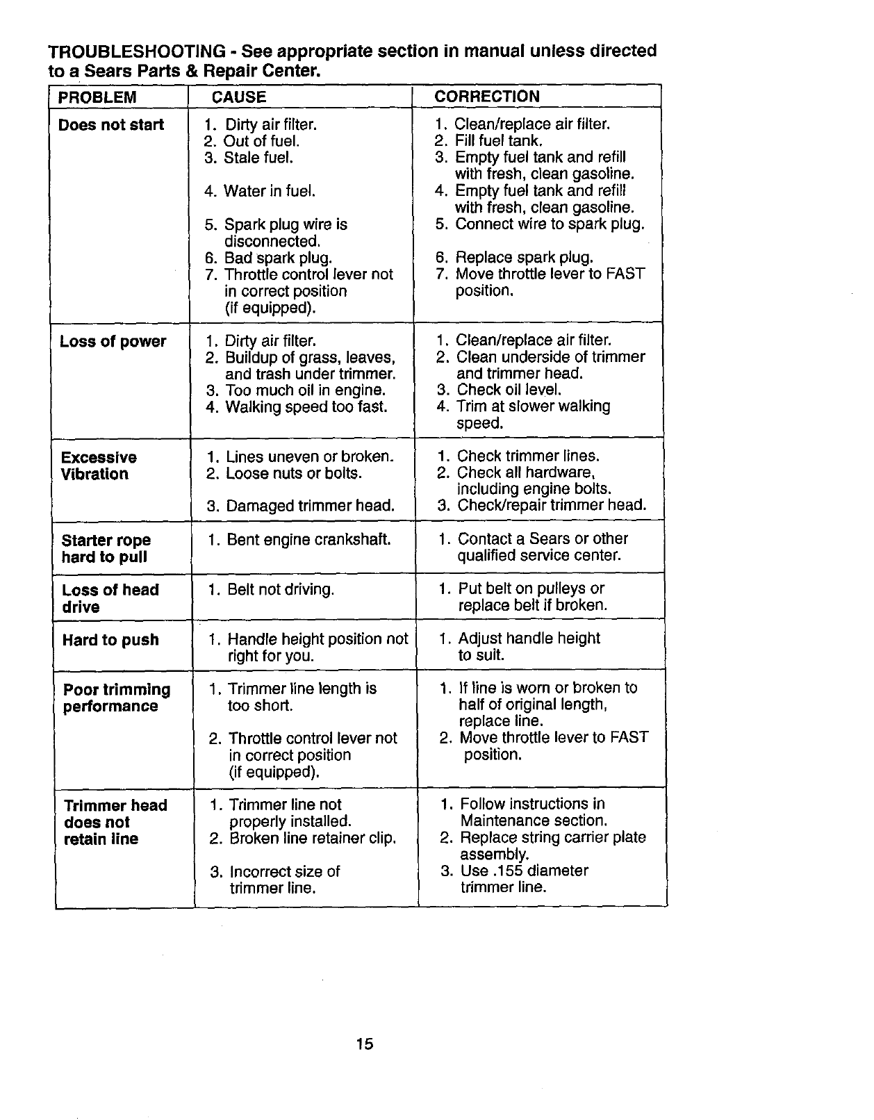
TROUBLESHOOTING -See appropriate section in manual unless directed
PROBLEM
Does not start
to a Sears Parts & Repair Center.
CAUSE
1. Dirty air filter.
2. Out of fuel,
3. Stale fuel,
Loss of power
Poor trimming
performance
4. Water in fuel.
5. Spark plug wire is
disconnected.
6. Bad spark plug.
7. Throttle control lever not
in correct position
(if equipped).
1. Dirty air filter.
2. Buildup of grass, leaves,
and trash under trimmer.
3. Too much oil in engine.
4. Walking speed too fast.
CORRECTION
1. Clean/replace air filter.
2. Fill fuel tank.
3. Empty fuel tank and refill
with fresh, clean gasoline.
4. Empty fuel tank and refill
with fresh, clean gasoline.
5. Connect wire to spark plug.
6. Replace spark plug.
7. Move throttle lever to FAST
position.
1. Clean/replace air filter.
2. Clean underside of trimmer
and trimmer head.
3. Check oil level.
4. Trim at slower walking
speed.
Excessive 1. Lines uneven or broken. 1. Check trimmer lines.
Vibration 2. Loose nuts or bolts. 2. Check all hardware,
including engine bolts.
3. Damaged trimmer head. 3. Check/repair trimmer head.
Starter rope 1. Bent engine crankshaft. 1. Contact a Sears or other
hard to pull qualified service center.
Lose of head 1. Belt not driving. 1. Put belt on pulleys or
drive replace belt if broken.
Hard to push 1. Handle height position not 1. Adjust handle height
right for you. to suit.
1. Trimmer line length is
too short.
Trimmer head
does not
retain line
2. Throttle control lever not
in correct position
(if equipped).
1. Trimmer line not
properly installed.
2. Broken line retainer clip.
3. Incorrect size of
trimmer line.
1. if line is worn or broken to
half of original length,
replace line.
2. Move throttle lever to FAST
position.
1. Follow instructions in
Maintenance section.
2. Replace string carrier plate
assembly.
3. Use .155 diameter
trimmer line.
15
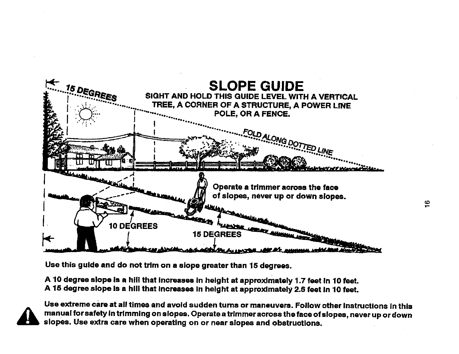
SLOPE GUIDE
SIGHT AND HOLD THIS GUIDE LEVEL WITH A VERTICAL
•,....... TREE, A CORNER OF A STRUCTURE, A POWER LINE
I "'_........... POLE, OR A FENCE.
I i .......i................ '.........
A
Operate a trimmer across the face
of slopes, never up or down slopes.
10 15 DEGREES
CO
Use this guide and do not trim on a slope greater than 15 degrees.
A 10 degree slope Is ahill that Increases In height at approximately 1.7 feet in 10 feet.
A 15 degree slope Is ahill that Increases In height at approximately 2.5 feet In 10 feet.
Use extreme care at all times and avoid sudden turns or maneuvers. Follow other InstrucUons in this
manual for safety in trimming on elopes. Operate a trimmer across the face of slopes, never up or down
slopes; Use extra care when operating on or near slopes and obstructions.
Garantfa .......................................................... 17
Reglas de Seguridad ................................. 17-19
Especificaciones del Producto ........................ 20
Montaje /Pre-Operaci6n ................................ 20
Operaci6n .................................................. 21-23
Mantenimiento ........................................... 24-26
Programa de Mantenimiento .......................... 24
Servicio y Adjustes .................................... 27-28
Almacenamiento ............................................. 29
Identificaci6n de problemas ............................ 30
Partes de repuesto ................................... 31-37
Servicio Sears ................................... Contratapa
GARANT[A LIMITADA DE DOS AI_IOS PARA LA RECORTADORA PARA MALA HIERBA CRAFTSMAN
Por dos (2) afios, a partir de la fscha de compra, cuando esta recortadora para mala hierba Crafts-
man se mantenga, lubrique y afine segOn las instrucciones para la operaoiSn y el mantenimiento
en el manual del duefio, Sears reparar& gratis todo defecto en el material y la mano de obra.
Si la recortadora para mala hierba Craftsman se usa para fines comerciales o de arriendo, esta
garant_a s61o se aplica por noventa (90) dfas a partir de la fecha de compra.
Esta Garantfa no cubre:
• ArUoulos que se desgastan durante el uso normal tales como las Ifneas rotatorias, las correas,
los filtros de aim y las bujfas.
• Reparaciones necesadas debido al abuso o a la negligencia del operador, incluy6ndose a los
cig0e_ales doblados y a la falta de mantenimianto del equipo seg0n las instrucciones que se
incluyen an el manual del duefio.
El servicio de garantia esta disponible al devolver la recortadora para mala hierba Craftsman al
Centro de Servicio Sears mas cercano en los Estados Unidos. Esta garantfa se aplica solamente
mientras el producto este en uso en los Estados Unidos.
Esta Garantfa le otorga derechos legales especificos, y puede que tambi_n tenga otros derechos
que varfan de estado a estado.
Sears, Roebuck and Co., Dept. 817 WA, Hoffman Estates, Illinois 60179 U.S.A.
4_kADVERTENCIA: Este recortadora viene equipado con un motor de combusti6n interna y no
se debe usar sobre, o cerca, de un terreno no desarrollado cubierto de bosques, de arbustos o
de c_sped, o menos que el sistema de escape del motor venga equipado con un amortiguador de
chispas que cumpla con las leyes locales o estatales (si existen). Si se usa un amortiguador de
chispas, el operador debe mantenerlo en condiciones de trabajo eficientes.
En el estado de California, la ley exige Io antedor (Secci6n 4442 del "California Public Resources
Code"). Otros estados pueden contar con otras leyes parecidas. Las leyes federales se aplican en
la tierras federales. Su Centro/Departamento de Servicio Sears m&s cercano tiene disponible am-
ortiguadores de chispas para el sUenciador. (Vea la secci6n de Partes de Repuesto en el manual
Ingl6s del dueSo.)
La operaci6n de cualquier recortadora puede hacer que salten objetos extra_os
dentro de sus ojos, Io que puede producir daSos graves en _stos. Siempre use
anteojos de seguridad o pmtecci6n para los ojos mientras opere su recortadora o
cuando haga ajustes o reparaciones. Recomendamos gafas de seguridad o una
m&scara de visi6n amplia, de seguridad usada sobre las gafas.
_kBusque este s{mbolo que seSala las precau-
ciones de seguridad de importancia. Quiere
decir- lilATENCION!llItlESTE ALERTO!!!
_ SEGURIDAD ESTA COMPROMETIDA.
ADVERTENCIA: Siempre desconecte el
alambre de la bujia y pbngalo donde no pueda
entrar en contacto con la bujfa, para evitar el
arranque por accidente, durante la preparacibn,
el transporte, el ajuste o cuando se bacon
_ILPparaciones- .
RECAUCION: El tubo de escape del motor,
algunos de sus constituyentes y algunos com-
ponentes del vehfculo contienen o desprenden 17
productos quimicos conocidos en el Estado de
California como causa de c_ncer y defectos al
,_imiento u otros da£=osreproductivos.
RECAUClON: El silenciador y otras
piezas del motor Ilegan a sre extremadamente
calientes durante la operaci6n y siguen siendo
calientes despu6s de que el motor haya parado.
Para evitar quemaduras severas, permanezca
lejos de estas &reas. _:_
I. OPERACION GENERAL
• Antes de empezar, debe familiarizarse
completamente con los controles y el uso
correcto de la maquina. Para esto, debe leer
y comprender todas las instrucciones qua
aparecen en la maquina yen los manuales
de operaci6n.
• No ponga las manos o los pies cerca o
debajo de las partes rotatorias.
•Mantener todas las partes del cuerpo lejos
del silenciador del escape y la Iinea de ro-
taci6n. El silenciador caliente puede causar
serias quemaduras.
•Permita qua solamente las personas re-
sponsables qua est6n familiarizadas con las
instrucciones operan la m_quina.
•Mantenerse lejos de objetos que pueden
romperse, como cristales de casa, oristalas
del choche, invemaderos, etc.
•Despeje el _,rea de objetos tales como pie°
dras, juguetes, alambres, huesos, palos, etc.
qua pueden ser recogidos y lanzados por las
Iineas giradoras.
•AsegDrese que el _.rea no se hallen perso-
nas, y particularmente ni_os peque_os yca-
chorros antes de recortar. Pare la m&quina
si a_guien entra en e__.rea.
•Use ropa apropaida, tal como camisa de
manga larga o chaqueta y pantalones largos.
No use pantalones cortos shorts.
•No use ropa suelta, ya que 6sta podr/a ator-
arse en el equipo.
• No opere la maquina sinzapatos o con sanda-
lias abiertas. Use siempre guantes de trabajo
y calzado fuerte. Los zapatos de trabajo de
piel obotas cortas son apropiados para la
rnayoria de las personas. Estos no s61oprote-
geri&n lostobiUosy espinellas del operador de
pequeSas ramas, astillas y otros desperdicios,
sino que adem&s mejorar_n la tracci6n.
•No tire de la m&quina hacia atr._sa menos
que sea absolutarnente necesario. Mire
siempre hacia abajo y hacia detras antes y
mientras que se mueve hacia atr_.s.
•No opera la maquina sin los respectivos
resguardos, placas u otros aditamentos
diseSados para su protecci6n y seguridad.
•Refi_rase alas instrucciones del fabricante
para el funcionamiento e instalaci6n de
accesorios. Use L_nicamente accesorios
aprobados por el fabricante.
•Nuca utilice cuchillas, cables o dispositivos
tipo mayal. Esta unidad est,. proyectada
para fucionar solamente con una Ifnea de
recortadora. La utilizaci6n de cualquier otto
material, acessorio o dispositivo seeundario
aumenta el riesgo de lesi6nes y daSos ala
prol:)iedad.
• Detenga la cabeza giratoria de la recorta-
dora cuando cruce por calzadas, calles o
caminos de grava. Espera qua las cuerdas
de corte paren de girar.
• Pare el motor siernpre qua tenga qua dejar el
equipo, antes de limpiar, reparar o inspeccio-
nar la unidad. Aseg_rese de que la cabeza
de la recortadora y todas las partes en
movimiento se hayan detenido. 18
• Opera solamente con luz del dfa ocon una
buena luz artificial.
• No opere la m_quina bajo la influencia del
alcohol o de las drogas.
• Nunca opera la maquina cuando la hierba
est6 mojada. Asegl_rese siempra de tener
buena tracoi6n en sus pies; mantenga el
mango firmemente y camine; nunca corra.
•Si el equipo empezara a vibrar de una
manera anormal, pare el motor y revise de
inrnediato para averiguar la causa. Gener-
almente la vibraci6n suele indicar que existe
alguna averfa.
• Siempre use gafas de seguridad o anteojos
con protecci6n lateral cuando opera la ma-
quina.
II. OPERACI(3N EN PENDIENTE
Los accidentes ocurren con m_.s fracuencia en
las cuestas. Estos accidentes ocurren debido a
resbaladas o cafdas, las cuales pueden resultar
en graves lesiones. Operar la recortadora en
cuestas requiere mayor concentraci6n. Si se
siente inseguro en una cuesta, no la recorte.
SI:
•Puede recortar a tray,s de la superficie de
la cuesta, nunca hacia arriba y hacia abajo.
Proceda con extrema pracauci6n cuando
cambie de direcci6n en las cuestas.
•Renueva todos los objetos axtraSos, tales
como guijarros, ramas, etc.
•Debe prestar atenci6n ahoyos, baches o
pmtuberancias. Recuerde que la hierba alta
puede esconder obst_.culos,
NO:
•No recorte cerca de pendientas, zanjas o
terraplenes. El operador puede perder la
tracoi6n en los pies o el equilibrio.
• No recorte cuestas demasiado inclinadas.
•No recorte en hiarba mojada. La reducci6n
en la traccibn de la pisada puede causar
resbalones.
II1. NII_IOS
Se pueden producir accidentes tr&gicossi el
operador no presta atenci6n a la presencia
de los niSos. Amenudo, los niSos se sienten
atrafdos pot la m_.quina y por la actividad de
la siega. Nunca suponga que los niSos van a
permanecer en el mismo lugar donde los vio
por _ltima vez.
•Mantenga a los niSos alejados dsl _.rea de
la siega y bajo el cuidado estricto de otra
persona adulta responsable.
• Est_ alerta y apague la m&quina si hay niSos
que entran al _rea.
• Antes y durante el retroceso, mire hacia
atr._sy hacia abajo para verificar si hay nifios
pequer3os.
•Nunca permita que los niSos operen la m_.-
quina.
•Tenga un cuidado extra cuando se acerqua
a esquinas donde no hay visibilidad, a los
arbustos, _.rboles u otros objetos qua pueden
interferir con su Ifnea de visi6n.
IV.SERVIClO
•Tenga cuidado extra al manejar la gasolina y
los demds combustibles. Son inflamables y
los gases son explosivos.
-Use solamente un envase aprobado.
- Nunca remueva la tapa del depbsito de
gasolina o agregue combustible con el
motor funcionando. Permita que el
motor se enfrie antes de volver a poner
combustible. No fume.
-Nunca vuelva a poner combustible en
la maquina en recintos cerrados.
- Nunca almacene la maquina o el
envase del combustible dentro de algran
lugar en donde haya una llama expues-
ta, tal como la del calentador de agua.
•Alejarse de la zona de abastecimiento del
carburante antes de poner en marcha.
•Nunca haga funcionar una mdquina dentro
de un drea cerrada.
•Nunca haga ajustes o reparaciones mientras
el motor est6 en marcha. Desconecte el
cable de la bujfa, y mant_ngalo acierta
distancia de _sta para prevenir un arranque
accidental.
•Mantenga las tuercas y los pemos, especial-
ments los pernos del motor y de la cabeza
de recortes, apretados y mantenga el equipo
en buenas condiciones,
• Nunca manipule de forrna indebida los
dispositivos de seguridad. Controle regular-
mente su funcionamiento correcto.
• Mantenga la mdquina libre de hierba, hojas u
otras acumulaciones de desperdicio. Limpie
los derrames de aceite o combustible. Per-
mita que la mdquina se refresque antes de
limpiada o almacenarla.
• Pare einspeccione el equipo si le pega aun
objeto. Repdrelo, si es necesario, antes de
hacerlo arrancar.
• No cambie el ajuste del regulador del motor
ni sxceda su velocidad.
• Limpiar y sustituir las calcomanfas relativas a
instrucciones y seguddad cuando necesario.
Acuerdos de Protecci6n para la Reparaci6n
Congratulaciones por su buena compra. Su
nuevo producto Craftsman_ estd diseSado
y fabdcado para funcionar de modo fiable por
muchos aSos. Pero como todos los productos,
puede necesitar alguna reparaci6n de tanto
en tanto. En este case tener un Acuerdo de
Protecoibn para la Reparaci6n puede hacerles
ahorrar dinero y fastidios.
Compre ahora un Acuerdo de Protecci6n para
la Reparaci6n y prot6gese de molestias y gas-
toe inesperados.
Un Acuerdo incluye los puntos sigulentes:
•Servicio experto de nuestros 12.000 espe-
cialistas profesionales en la reparaciSn.
•Servlcio illmitado sin cargo alguno para
las partes y la mano de obra sobre todas las
reparaciones garantizadas.
•Suatitucl6n del producto si su producto
garantizado no puede ser arreglado.
•Deseuento de110% sobre el precio cor-
riente del servicio y de las partes relativas al
sewicio no cubiertas por el acuerdo; tambidn
el 10% menos sobre el precio corriente de
un control de mantenimiento praventivo.
Ayuda rdpida por teldfono - soporte tele-
fOnico por parts de un t6cnico Sears sobre
productos que requiersn un arreglo en casa,
yademds una programacibn sobre los a
reglos rods convenientes.
Cuando se ha comprado el Acuerdo, basta con
una Ilamada telefbnica para programar el servi-
cio. Puede Ilamar cuando quiera, dfa y noche o
fijar en Ifnea una cita para obtener el servicio.
Sears tiene mds de 12.000 sspecialistas
profesionales en la reparaciSn, que tienen
acceso a rods de 4.5 millones de partes y
accesorios de calidad. Ests es el tipo de
profesionalidad con que puede contar para
ayudar a alargar la vida del producto que acaba
de comprar, por muchos aSos. iCompre hoy su
Acuerdo de ProtecciSn para la ReparaciSn!
Se aplican algunaa limitaclones y exclu-
clones. Para conocer los preclos y tenet
rods informaci6n, game al 1-800-827-6655.
Servicio de Instalaci6n Sears
Para la instalaci6n profesional Sears de
aparatos de casa, puertas de garaje,
calentadores de agua y otros importantes
articulos para la casa, en U.S.A. Uamar a
1-800-4-MY-HOME®.
19
Nt3mero de Serie:
Fecha de Compra:
Capacidad y Tipo de Gasolina: 1.6 Cuartos (Regular sin Plomo)
Tipo de Aceite (API SG-SL): SAE 30 (Sobre 32°F); SAE 5W-30 (Debajo 32°F)
Capacidad de Aceite: 20 Onzas
Bujia (Abertura: .030") Champion RJ19LM o J19LM
Longitud de la Ifnea de la recortadora: 18.75 Inches (0.155 Inches Di&metro)
El n_mero del modelo y el de serie se encuentran en la calcomania adjunta a la parte trasera
de la caja de la recortadora. Debe registrar tanto el nSmero de eerie come la fecha de eompra y
mantengalos en un lugar seguro para refencia en el futuro.
Lea estas instrucciones y este manual comple-
tamente antes de tratar de montar u operar su
nueva recortadora.
IMPORTANTE: Esta recortadora viene SIN
ACEITE O GASOLINA en el motor.
Su nueva recortadora ha sido montada en la
f_.brica con la exeepci6n de aquellas partes que
se dejaron sin montar por razones de envfo.
Todas las pades como las tuercas, las arande-
las, los pemos, etc., necesarias para completar
el montaje hart sido colocadas en la bolsa de
partes. Para asegurarse que su recortadora
funcione de forma segura y adecuada, todas
las partes y los articulos de ferreterfa que se
monten tienen que ser apretados firmemente.
Use las herramientas correctas adecuadas para
asegurar un apretado firme.
Cuando la mano derecha o la mano izquierda
estd.n mencionadas en este manual, significa
que usted esta situado en la posici6n de opera-
dot, detr&s del mango.
Piezas sueltas empaquetadas por separado
2 Juegosde cuerdade
Botellade recortadora(0.155 de
acelte dldmetrox 18.75)
PARA REMOVER LA RECORTADORA DE LA
CAJA DE CARTON
1. Remueva las pades sueltas que se in-
cluyen con la recodadora.
2. Corte las dos esquinas de los extremos
de la caja de oarten y tienda el panel del
extremo plane.
3. Remueva todo el material de embalaje.
4. Haga rodar la recortadora hacia afuera
de la caja de carten y revisela cuidadosa-
mente para verificar si todavia quedan
partes sueltas adicionales.
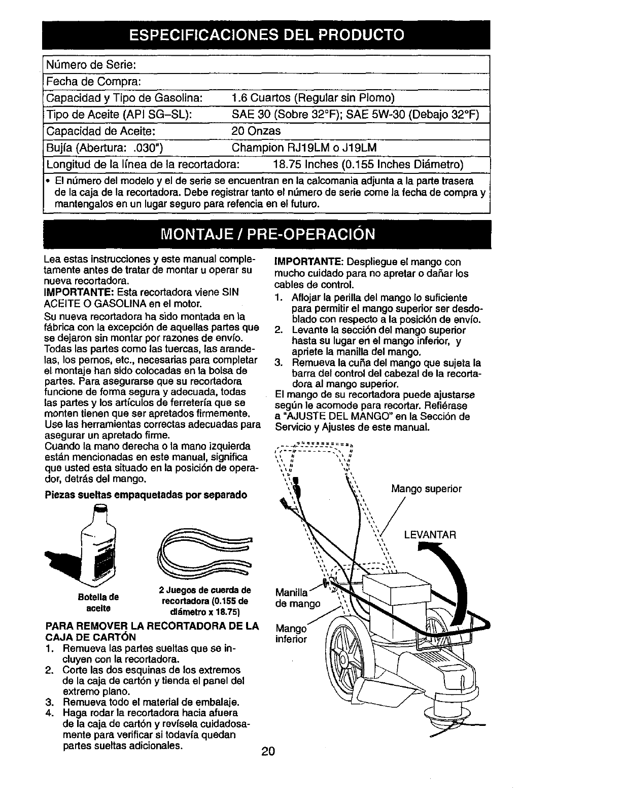
IMPORTANTE: Despliegue el mango con
mucho cuidado para no apretar o daSar los
cables de control.
1. Aflojar la perilla del mango Io suficiente
para permitir el mango superior ser desdo-
blado con respeeto a la posici6n de envl'o.
2. Levante la secci6n del mango superior
hasta su lugar en el mango inferior, y
apriete la manilla del mango.
3. Remueva la cuSa del mango que sujeta la
barra del control del cabezal de la recorta-
dora al mango superior.
El mango de su recortadora puede ajustarse
segdn le acomode para recortar. Refi6rase
a"AJUSTE DEL MANGO" en la Secci6n de
Servicio y Ajustes de este manual.
Mango supedor
LEVANTAR
de mango
Mango
infenor
20
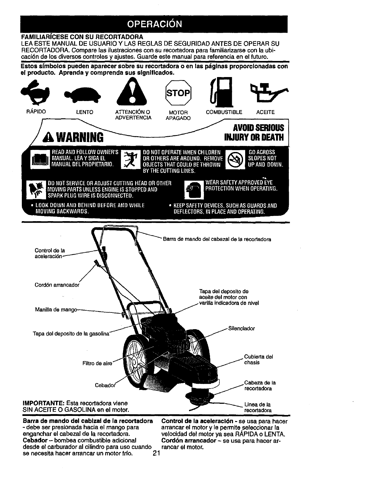
FAMILIAR|CESE CON SU RECORTADORA
LEA ESTE MANUAL DE USUARIO Y I_AS REGLAS DE SEGURIDAD ANTES DE OPERAR SU
RECORTADORA. Compare las ilustreciones con su recortadora para familiarizarsa con la ubi-
cacibn de los diversos controles y ajustes. Guarde este manual para referencia en el future.
Estos srmbolos pueden aparecer sobre su recortadora o en las pdginas proporcionadas con
el producto. Aprenda y comprenda sus slgniflcados.
LENTO ATTENCI(_N0
ADVERTENCIA
WARNING "--
MOTOR
R_PIDO COMBUSTIBLE ACEITE
APAGADO
AVOIDSERIOUS
INJURYORDEATH
Controldo la
acele
Barra de mando del cabezal de la recortadora
Cord6n arrancador
Tapadel depositode
aceitedel motor con
Tapa del deposito de
Cubierta del
Ceb Cabeza de la
IMPORTANTE: Esta recortadora viene
SIN ACEITE O GASOLINA en el motor. Linea de la
recortadora
Barra de mando del cablsal de la recortadora Control de la aceleracidn -se usa para hacer
-debe ser presionada hacia el mango para arrancar el motor y le permite seleccionar la
enganchar el cabezal de la recortadora, velocidad del motor ya sea RAPIDA o LENTA.
Cebador - bombea combustible adicional Cord6n arrancador - se usa para hacer ar-
desde el carburador al cilindro para uso cuando rancar el motor.
se necesita hacer arrancar un motor fdo. 21
La operaci6n de cualquier recodadora puede
hacer que salten objetos extraSos dentro de
sus ojos, Io que puede producir daSos graves
en _stos. Siempre use anteojos de seguridad
o protecci6n para los ojos mientras opere su
recortadora o cuando haga ajustes o reparacio-
nes. Recomendamos gafas de seguridad o una
m_.scara de visi6n amplia, de seguridad usada
sobre las gafas.
COMO UTILIZAR SU RECORTADORA
CONTROL DE LA VELOClDAD DEL MOTOR
La velocidad del motor es controlada por una
vd.lvulareguladora situada al lado del mango
superior. La posici6n RAPIDA es para comen-
zar y'para el recorte normal. LENTO es para
el recorte ligero y economizar combustible.
PARADA es para parar el motor.
CONTROL DE LA IMPULSI6N DEL CA-
BEZAL DE LA RECORTADORA
Su recortadora viene equipada con una barra
de control de la impulsi6n del cabezal de la
recortadora que requiera que el operador este
colocado detrds de la palanca de la recodadora
para operar la misma.
• La rotaci6n del cabezal de la recortadora se
contmla manteniendo la barra de control del
cabezal hacia abajo al mango.
•La mtaci6n del cabezal de la recortadora se
parard cuando la barra de control sea eoltada.
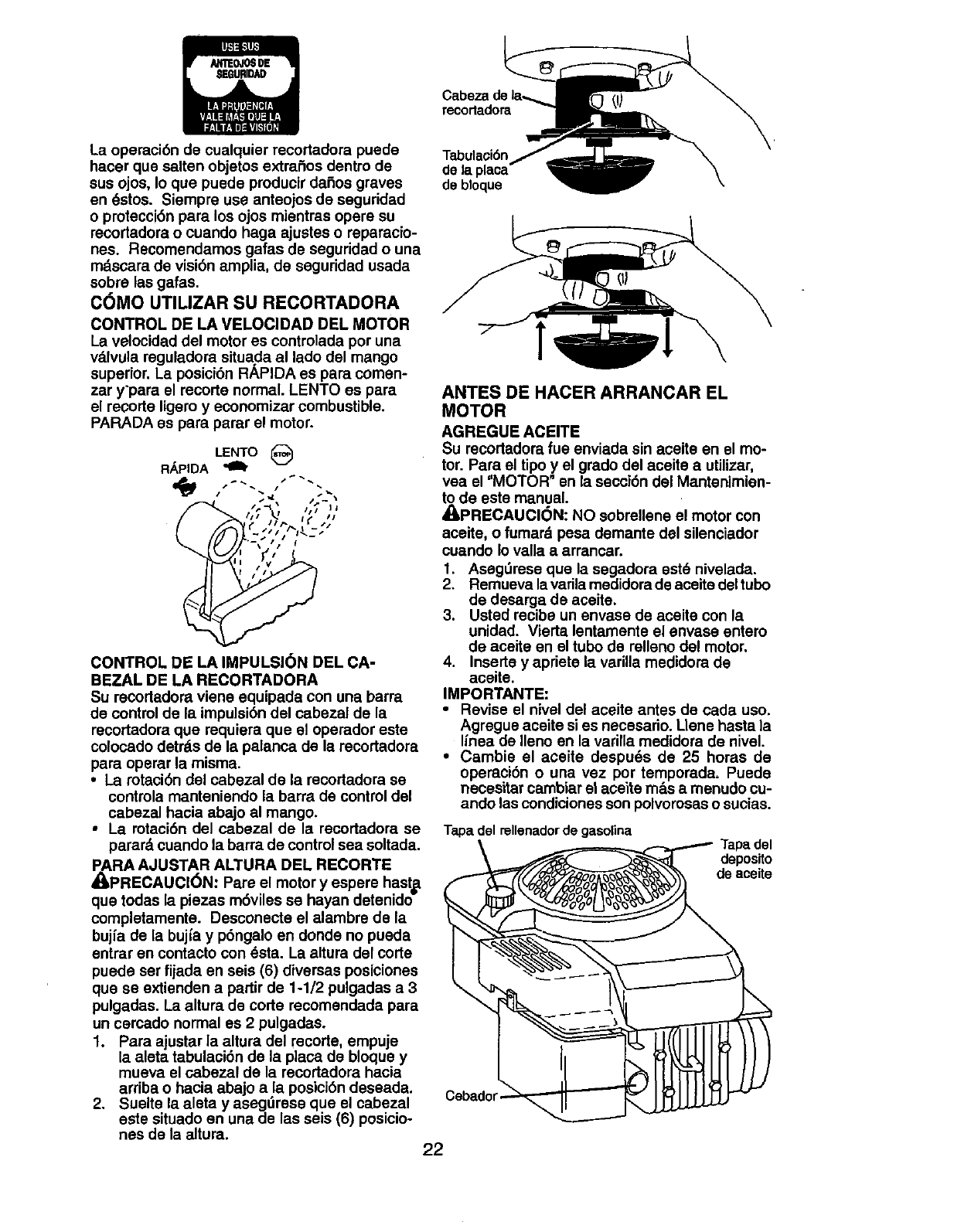
PARA AJUSTAR ALTURA DEL RECORTE
/IPRECAUCI6N: Pare el motor y espere hast=a
que todas la piezas m6viles se hayan detenidd
completamente. Desconecte el alambre de la
bujfa de la bujfa y p6ngalo en donde no pueda
entrar en contacto con _sta. La altura del corte
puede ser fijada en seis (6) diversas posiciones
que se extienden a padir de 1-1/2 pulgadas a3
pulgadas. La altura de code recomendada para
un cercado normal es 2pulgadas.
1. Para ajustar la altura del recorte, empuje
la aleta tabulaci6n de la plata de bloque y
mueva el cabezal de la recortadora hacia
arriba o hacia abajo a/a posici6n deseada.
2. Suelte la aleta y asegurese que el cabezal
este situado en una de las seis (6) posicio-
nes de la altura. 22
recortadora
Tabulaci6n
de la placa-
de btoque
1
ANTES DE HACER ARRANCAR EL
MOTOR
AGREGUE ACEITE
Su recortadora fue enviada sin aceite en el mo-
tor. Para el tipo y el grado del aceite a utilizar,
vea el "MOTOR" en la secci6n del Mantenimien-
to de este manual.
_PRECAUCI(_N: NO sobrellene el motor con
aceite, o fumard pesa demante del silenciador
cuando Iovalla a arrancar.
1. Aseg_rese que la segadora est6 nivelada.
2. Remueva la varila medidora de aceite del tubo
de desarga de aceite.
3. Usted recibe un envase de aceite con la
unidad. Vierta lentamente el envase entero
de aceite en el tubo de relleno del motor.
4. Inserts y apriete la variUa medidora de
aceite.
IMPORTANTE:
•Revise el nivel del aceite antes de cada uso.
.Agregueaceite si es necesario. Uene hasta la
hnea de Ileno en la va_lla medidora de nivel.
•Cambie el aceite despu_s de 25 horas de
operaci6n o una vez por temporada. Puede
necesitar cambiar el aceite m_.sa menudo cu-
ando las condiciones son polvorosas o sucias.
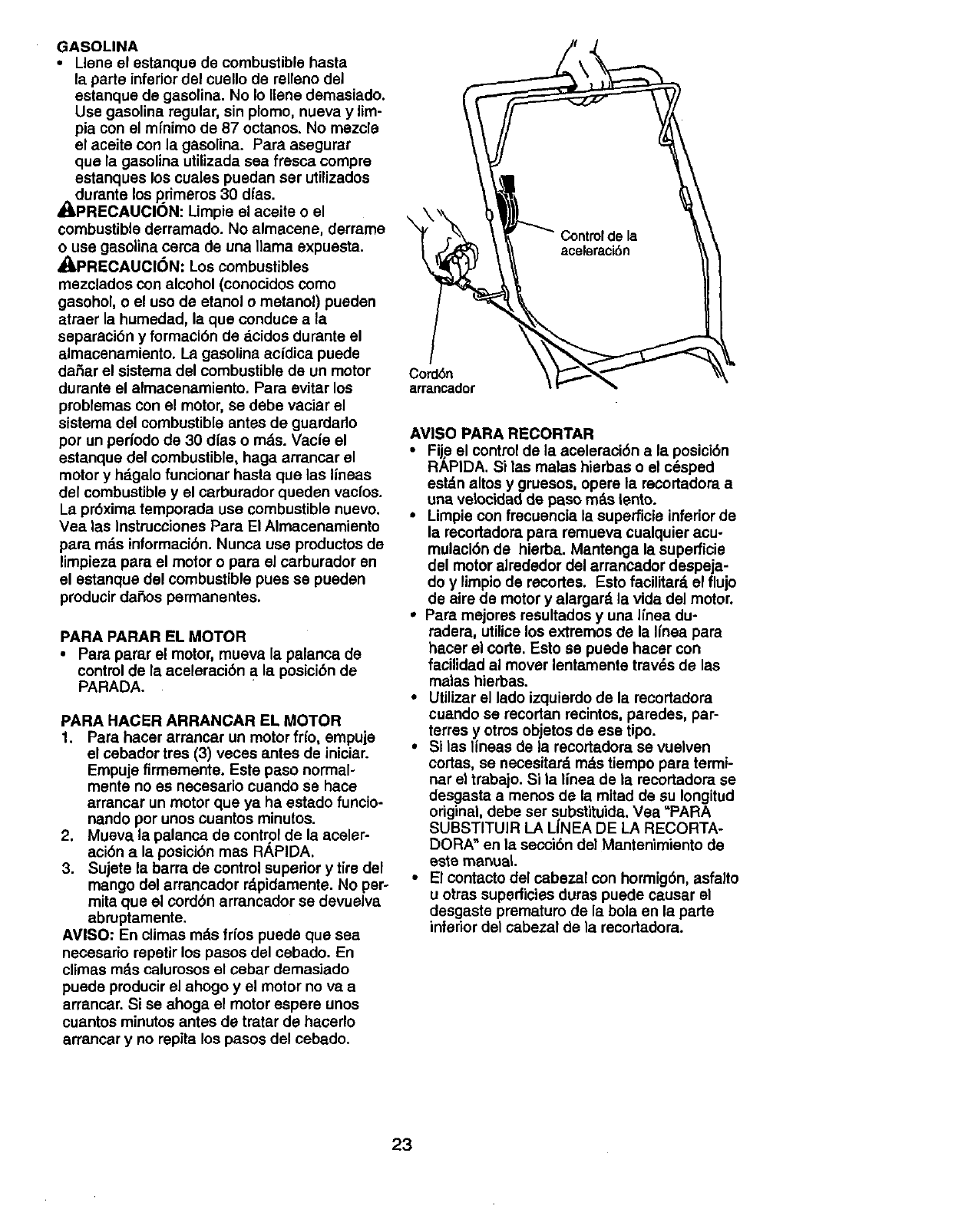
Tapa del rellenador de gasolina
deposito
de aceite
GASOLINA
•Llene el estanque de combustible hasta
la parts inferior del cuello de relleno del
estanque de gasolina. No Io Ilene demasiado.
Use gasoline regular, sin plomo, nueva y lim-
pia con el mfnimo de 87 octanes. No mezcle
el aceite con la gasolina. Para asegurar
que la gasolina utilizada sea fresca compre
estanques los cuales puedan ser utilizados
_ldurante los primeros 30 d/as.
PRECAUClON: Limpie el aceite o el
combustible derramado. No almacene, derrame
o use gasolina cerca de una llama expuesta.
_PRECAUCl6N: Los combustibles
mezclados con alcohol (conocidos come
gasohol, o el use de etanol o metanol) pueden
atraer la humedad, la que conduce ala
separaci6n y formaci6n de dcidoe durante el
almacenamiento. La gasoline acfdica puede
daSar el sistema del combustible de un motor
durante el almacenamiento. Pare evitar los
problemas con el motor, se debe vaciar el
sistema del combustible antes de guardado
per un perfodo de 30 dfas o rods. Vacie el
estanque del combustible, haga arrancar el
motor y hdgalo funcionar haste que las lineas
del combustible y el carburador queden vacfos.
La pr6xima temporada use combustible nuevo.
Vea las Instmcciones Para El Almacenamiento
pare mds informaci6n. Nunca use productos de
limpieza para el motor opara el carburador en
el estanque del combustible puss se pueden
producir daSos permanentes.
PARA PARAR EL MOTOR
•Pare parer el motor, mueva la palanca de
control de la aceleraci6n ala posici6n de
PARADA.
PARA HACER ARRANCAR EL MOTOR
1. Pare hacer arrancar un motor frfo, empuje
el cebador tres (3) veces antes de iniciar.
Empuje firmemente. Este paso normal-
mente no es necesario cuando se hace
arrancar un motor que ya ha estado funcio-
nando per unos cuantos minutes.
2. Mueva la palanca de control de la aceler-
aci6n ala posici6n mas RAPIDA.
3. Sujete la barra de control superior y tire del
mango del arrancador r_pidamente. No per-
mite que el cord6n arrancador se devuelva
abruptamente.
AVISO" En climas m&s frfos puede que sea
necesario repetir los pesos del cebado. En
climes m&s calurosos el cebar demasiado
puede producir el ahogo y el motor no va a
arrancar. Si se ahoga el motor espere unos
cuantos minutes antes de tratar de hacerlo
arrancar y no repita los pesos del cebado.
Cord6n
arrancador
AVISO PARA RECORTAR
• Fije el control de la aceleraci6n ala posici6n
RAPIDA. Si las malas hierbas o el c6sped
est_.naltos y gruesos, opere la recortadora a
una velocidad de paso m_s lento.
• Limpie con frecuencia la superficie inferior de
la recortadora pare remueva cualquier acu-
mulaci6n de hierba. Mantenga la superficie
del motor alrededor del arrancador despeja-
do y limpio de recortes. Esto facilitate, el flujo
de aire de motor y alargar_ la vida del motor.
*Para mejores resultados y una Ifnea du-
radera, utilice los extremes de la Iinea para
hacer el code. Esto se puede hacer con
facilidad al mover lentamente trav_s de las
malas hierbas.
•Utilizer el lade izquierdo de la recortadora
cuando se recortan recintos, paredes, par-
terres y otros objetos de ese tipo.
•Si las lineae de la recortadora se vuelven
cortas, se necesitar_, mg=stiempo para termi-
nar el trabajo. Si la linea de la recortadora se
desgasta a menos de la mitad de su Iongitud
original, debe ser substituida. Vea "PARA
SUBSTITUIR LA LiNEA DE LA RECORTA-
DORA" en la seccibn del Mantenimiento de
este manual
•El contacto del cabezal con hormig6n, asfalto
u otras superficies duras puede causer el
desgaste premature de la bola en la parte
inferior del cabezal de la recortadora.
23
,,O0 'MA0,
A MEDIDA QUE COMPLETE /__ _/_(P_ _._._O_ FECHAS
oo .v.o,oo ou o
IRevisar $1hay sujetadores sueltos I_
_) Llmpiar Is recortadora _
Limp_ardebaJode la cublerla dol motor V'_ ¥#
iRevisar las cormas y las poleas
Impulsadas I_
R Veriflque/reemplazarlas Ilneas ills
A de la rocortadora
Revisarel nlveldel acelte
M Camblarel acelte del motor I/1,2
OT Umplarel filtro de aim _2
O Inspecctonarel snenclader
R Limpiaro /camblarla bujla
Camblarel cartucho
de papeldel filtm de elro v'=
1-Camblarm_tsa menudocuandose operebaJocalga pesada oen amblentesconanas temperaturas.
2 - Dar servido m_s a menudocuandose opere eft €ondiclonessuclaso polvorosas.
3 - Reemplazarlas llneas de la recortadoracuando se hsyan gastadoheslaI_ mitadde su largura original.
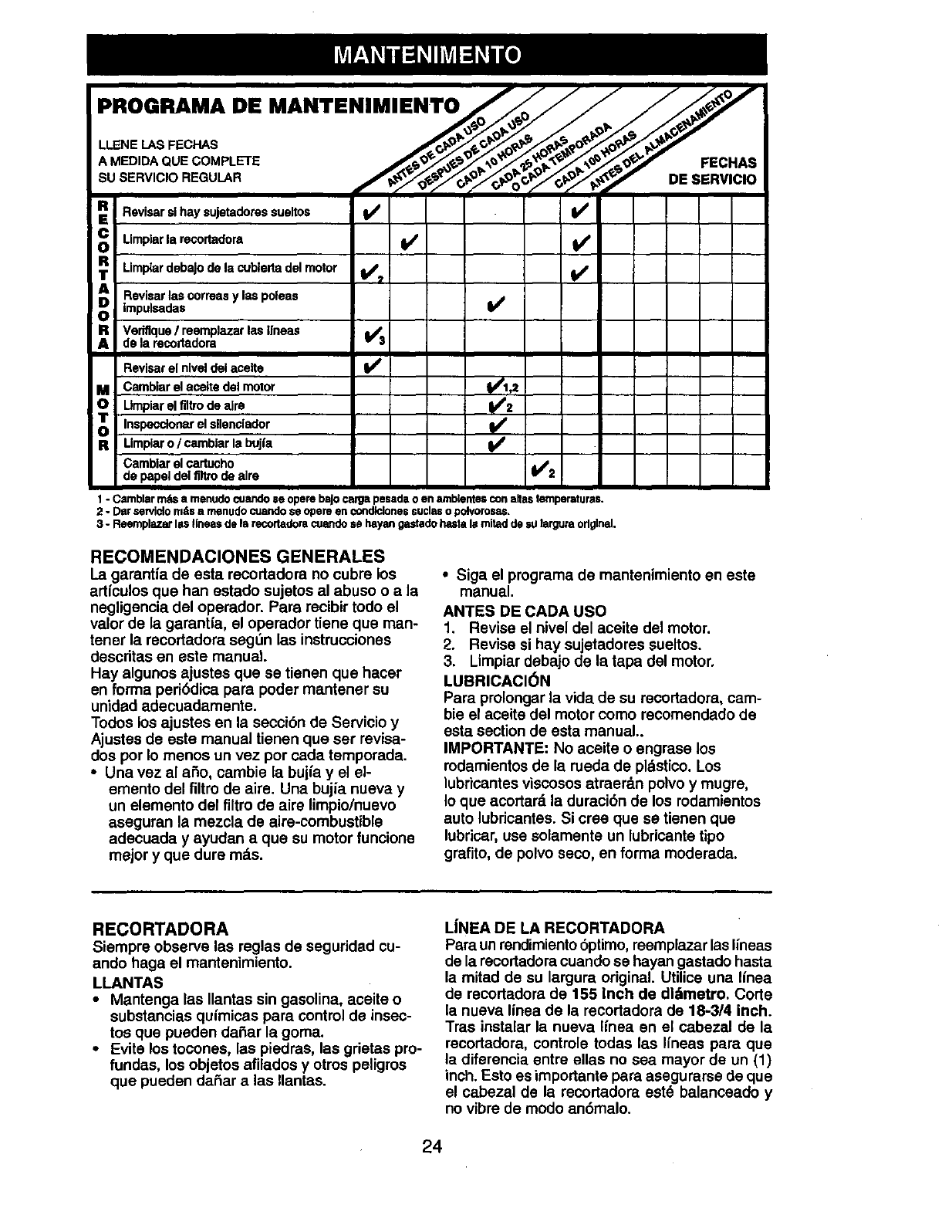
RECOMENDACIONES GENERALES
La garantfa de esta recortadora no cubra los
articulos que han estado sujetos al abuso o a la
negligencia del operador. Para recibir todo el
valor de la garantfa, el operador tiene qua man-
toner la recortadora segdn las instrucciones
descritas en este manual.
Hay algunos ajustes que se tienen que hacer
en forma peri6dica para poder mantener su
unidad adecuadamente.
Todos los ajustes en la secci6n de Servicio y
Ajustes de este manual tienen que ser revisa-
dos pot Io menos un vez por carla temporada.
• Una vez al aSo, cambie la bujfa y el el-
emento del filtro de aira. Una bujfa nueva y
un elemento del filtro de aire limpio/nuevo
aseguran la mezcla de aira-combustible
adecuada y ayudan a que su motor funcione
mejor yque dure rods.
•Siga el programa de mantenimiento en este
manual.
ANTES DE CADA USO
1. Revise el nivel del aceite del motor.
2. Revise si hay sujetadores sueltos.
3. Limpiar debajo de la tapa del motor.
LUBRICACI(_N
Para prolongar la vida de su recortadora, cam-
bie el aceite del motor como recomendado de
esta section de esta manual..
IMPORTANTE: No aceite o engrase los
rodamientos de la rueda de pl._stico. Los
lubricantes viscosos atraerd.n polvo y mugra,
Io que acortard, la duraci6n de los rodamientos
auto lubricantes. Si cree que se tienen que
lubricar, use solamente un lubricante tipo
grafito, de polvo seco, en forma moderada.
RECORTADORA
Siempre observe las reglas de seguridad cu-
ando haga el mantenimiento.
LLANTAS
•Mantenga las Ilantas sin gasolina, aceite o
substancias quimicas para control de insec-
tos que pueden da£_arla goma.
•Evite los tocones, las piedras, las grietas pro-
fundas, los objetos afilados yotros peligras
que pueden daSar alas Ilantas.
L|NEA DE LA RECORTADORA
Para un rendimientobptimo, reemplazar las Ifneas
de la recortadora cuando se hayan gastado hasta
la mitad de su largura original. Utilice una linea
de recodadora de 155 Inch de dl.'-'tmetro,Corte
la nueva linea de la recortadora de 18-3/4 inch.
Tras instalar la nueva Ilnea en el cabezal de la
recortadora, controle todas las Ifneas para que
la diferencia entre elias no sea mayor de un (1)
inch. Esto es importante para asegurarse de que
el cabezal de la recortadora est_ balanceado y
no vibre de modo an6malo.
24
_.PRECAUCI6N: Utilice s61o la linea de
recortadora recomendada. No utilice otros
rnatedales como cables, cuerdas, eintas,
etc. un cable podrfa romperse durante el
funcionamiento y volverse un peligroso cohete
que podr/a causer heridas series.
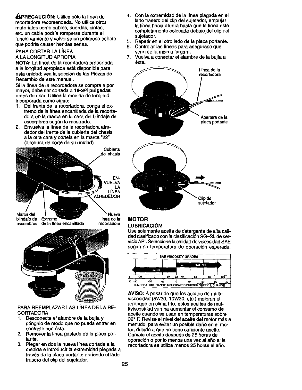
PARA CORTAR LA LiNEA
A LA LONGITUD APROPIA
NOTA: La Ifnea de la recortadora precortada
ala Iongitud apropiada esta disponible pare
esta unidad; vea la secci6n de las Piezas de
Recambio de este manual.
Si la Ifnea de la recordadora se compra a por
mayor, debe ser cortada a 18-314 pulgadas
antes de usar. Utilice la medida de Iongitud
incorporada como sigue:
1. Del frente de la recortadora, ponga el ex-
tremo de la linea encanillada de la recorta-
dora an la mama en la cara del blindaje de
escombms seg[in Io mostrado.
2. Envuelva le Ifnea de la recortadora alre-
dedor del frente de la cubierta del chasis
a la otra cara y cbrtela en la mama "22"
(anchura de corte de su unidad).
Cubierta
delchasis
4. Con la extremidad de la Ifnea plagada en el
lado trasero del clip del sujetador, empujar
la Ifnea hacia afuera basra que la linea est6
completamente colocada debajo del clipdel
sujetador.
5. Repetir en el otro lado de la place portante.
6. Controlar las Ifneas para asegurase que
sean de la misma largura.
7. Vuelva a conectar el alambre de la bujfa a
6sta.
Unea de la
recortadora
Aperturede la
placeportante
EN-
VUELVA
LA
LfNEA
ALREDEDOR
Maroa del Nueva
blindaje de Ifnea de la
escombros de la linea encanillada recortadora
)del
sujetador
MOTOR
LUBRICACI6N
Use solamente aceite de detergente de alta call-
dad clasificado con la clasificaci6n SG-SL de ser-
vicioAPL Seleccione la calidadde viscosidadSAE
seg_n su temperatura de operaci6n esperada,
SAE VISCOSITY GRADES
F-20 0 30 32 40 60 80 100
*20 .10 0 10 _ _to
TEMPERATURE RANGE ANTICIPATED BEFORE NEXT OIL CHANGE
PARA REEMPLAZAR LAS LfNEA DE LA RE-
CORTADORA
1. Desconecte el alambre de la bujfa y
p6nga;o de modo que no pueda entrar an
contacto con _sta.
2. Remover la Ifnea gastada de laplaca por-
tante.
3. Plegar an dos la nueva Ifnea cortada ala
medida e introducir la extremidad plegada a
trav6s de la place portante abriendo el lado
trasero del clip del sujetador.
AVISO: A pesar de que los aceites de multi-
viscosidad (5W30, 10W30, etc.) mejoran el
arranque en clima frio, estos aceites de mul-
tiviscosidad van ha aumentar el consumo de
aceite cuando se usan en temperaturas sobre
32 ° F. Revise el nivel del aceite del motor mds a
menudo, pare evitar un posible daSo en el mo-
tor, debido aque no tiene suficiente aceite.
Cambie el aceite despu_s de 25 horas de
operaci6n o por Io menos una vez al aSo si la
recortadora se utilize menos 25 horas el aSo.
25
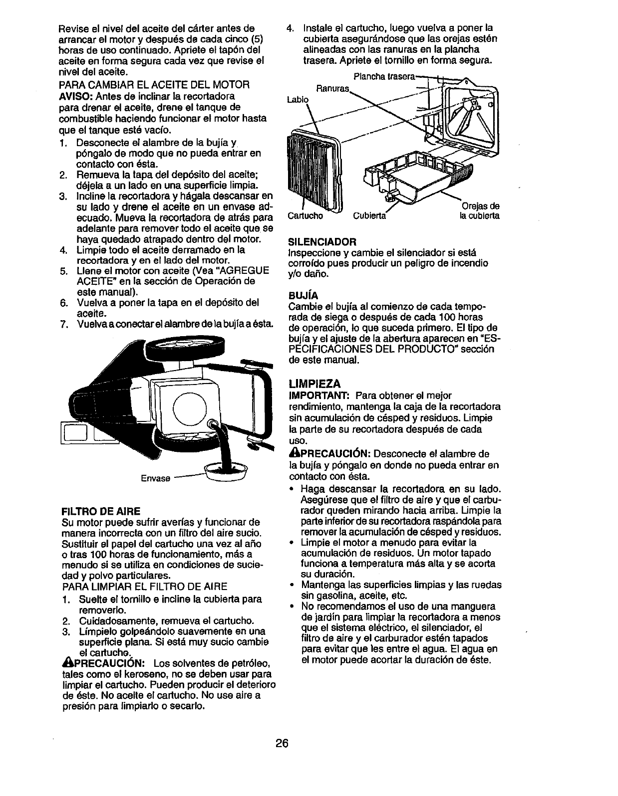
Revise el nivel del aceite del calder antes de 4.
arrancar el motor y despu_s de cada cinco (5)
horas de uso continuado. Apriete el tap6n del
aceite en forma segura cada vez que revise el
nivel del aceite.
PARA CAMBIAR EL ACEITE DEL MOTOR
AVISO: Antes de inclinar ]a recortadora Labio
para drenar el aceite, drene el tanque de
combustible haciendo funcionar el motor hasta
que el tanque eet6 vacio.
1. Desconecte el alambre de la bujfa y
p6ngalo de modo que no pueda entrar en
contecto con _sta.
2. Remueva la tape del dep6sito del aceite;
d6jela a un lado en una superficie limpia.
3. Incline la recortadora y hdgala descansar en
su lado y drone el aceite en un envase ad-
ecuado. Mueva la recortadora de atrds para Cartucho
adelante para remover todo el aceite que se
haya quedado atrapado dentro del motor.
4. Limpie todo el aceite derramado en la
recortadora yen el lado del motor.
5. Llene el motor con aceite (Vea "AGREGUE
ACEITE" en la seccibn de Operaci6n de
este manual).
6. Vuelva a poner la tapa en el dep6sito dal
aceite.
7. Vuelva aconectar el alambre de la bujia a 6eta.
Envase
FILTRO DE AIRE
Su motor puede sufrir averfas yfuncionar de
manera incorrecta con un filtro del airs sucio.
Sustituir el papal del cartucho una vez al aSo
o tras 100 horas de funcionamiento, md.sa
menudo si se utilize en condiciones de sucie-
dad y polvo particulares.
PARA LIMPIAR EL FILTRO DE AIRE
1. Suelte el tornillo e incline la cubierta pare
removerlo.
2. Cuidadosamente, remueva el cartucho.
3. Lfmpielo golpedndolo suavemente en una
superficie plana. Si estd muy sucio cambie
el cartucho.
/IPRECAUCl6N: Los solventes de petrSleo,
tales como el keroseno, no se deben usar para
limpier el cartucho. Pueden producir el deterioro
de _ste. No aceite el cartucho. No use alre a
presi6n pare limpiado o secarlo.
Instale el cartucho, luego vuelva aponer la
cubierta asegurd.ndose que las orejas est6n
alineadas con las ranuras en la plancha
trasera. Apriete el tomillo en forma segura.
Orejasde
Cubierta- la cublerta
SILENClADOR
Inspeccione y cambie el silenciador si estd
cormfdo puss pmducir un peligro de incendio
y/o daSo.
BUJIA
Cambie el bujfa al comienzo de cada tempo-
rada de siege o despuds de cada 100 horas
de operaci6n, to que suceda primero, El tipo de
bujfa y el ajuste de la abertura aparecen en "ES-
PECIFICACIONES DEL PRODUCTO" secci6n
de este manual.
LIMPIEZA
IMPORTANT: Pare obtener el mejor
rendimiento, mantenga la caja de la recortadora
sin acumulaci6n de c_sped y residuos. Limpie
la porte de su recortadora despu6s de cada
ueo,
_PRECAUCI(_N: Desconecte el alambre de
la bujfa y p6ngalo en donde no pueda entrar en
contacto con dsta.
•Haga descansar la recortadora en su lado.
Asegdrese que el filtrode alre y que el carbu-
rador queden mirando hacia arriba. I impie la
parte inferiorde su recortadora raspd.ndolapare
remover la acumulaci6n de c_sped y residuos.
•Limpie el motor a menudo para evitar la
acumulacibn de residuos. Un motor tapado
funciona a temperatura mds alta y se acorta
su duraci6n.
•Mantenga las superficies limpias y las ruedas
sin gasolina, eceite, etc.
•No recomendamos el uso de una manguera
de jardin para limpiar la recortadora a menos
que el sistema el_ctrico, el silenciador, el
filtrode aire y el carburador est_n tapados
pare evitar que los entre el agua. El agua en
el motor puede acortar la duraci6n de 6ste,
26
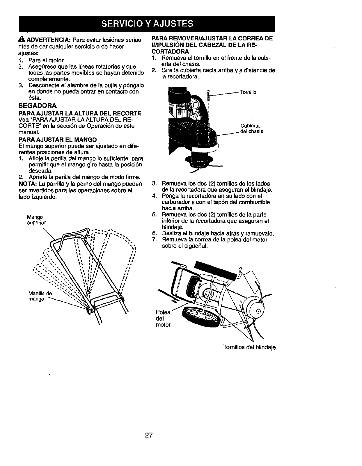
4_ ADVERTENClA: Para evitar lesi6nes serias
ntes de dar cualquier sercicio o de hacer
ajustes:
1. Pare el motor.
2. AsegL_rese que las Ifneas rotatorias y que
toclas las partes movibles se hayan detenido
completamente.
3. Desconecte el alambre de la bujfa y pbngalo
en donde no pueda entrar en contact• con
6sta.
SEGADORA
PARA AJUSTAR LA ALTURA DEL RECORTE
Yea "PARA AJUSTAR LA ALTURA DEL RE-
CORTE" en la secci6n de Operaci6n de este
manual.
PARA AJUSTAR EL MANGO
El mango superior puede set ajustado en dife-
rentes posiciones de altura
1. Afloje la perilla del mango Io suficiente para
permitir que el mango gire hasta la posici6n
deseada.
2. Apriete la periUadel mango de rood• firme.
NOTA: La parrilla y la perno del mango pueden
ser invertidos para las operaciones sobre el
lad• izquierdo.
Mango
superior
".:.?,'--.
", ;- ";,
•, ,;,.,
##
.-'.,', .._', 'V; ;/
• • • #
Mandla de _'
mango " \_
PARA REMOVEPJAJUSTAR LA CORREA DE
IMPULSION DEL CABEZAL DE LA RE-
CORTADORA
1. Remueva el tomillo en el frsnte de la cubi-
erta del chasis.
2. Gire la cubierta hacia arriba y adistancia de
la recortadora.
Cublerta
3. Remueva los dos (2) tomillos de los lados
de la recortadora que aseguran el blindaje.
4. Ponga la recortadore en su lad• con el
carburador y con el tap6n del combustible
hacia arriba.
5. Remueva los dos (2) tornillos de la parte
inferior de la recortadora que aseguran el
blindaje.
6. Desliza el blindaje hacia atr&s y remuevalo.
7. Remueva la Correa de la polsa del motor
sobre el cig0efial.
del
motor
Tomillos del blindaje
27
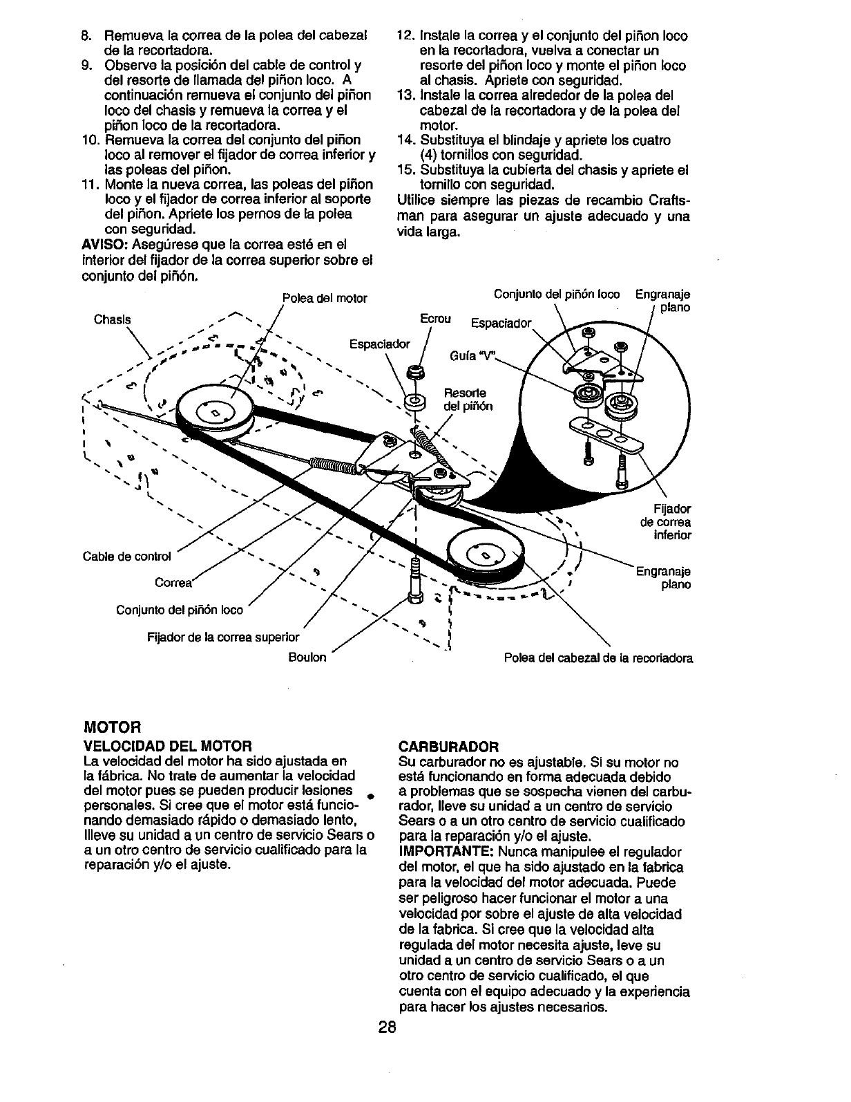
8. Remueva la correa de la polea del cabezal
de la recortadora.
9. Observe la posici6n del cable de control y
del resorte de llamada dsl piSon Ioco. A
continuaci6n remueva el conjunto del piSon
Ioco del chasis y remueva la correa y el
piSon Ioco de la recortadora.
10. Remueva la correa del conjunto del piSon
Ioco al remover el fijador de correa inferior y
las poleas del piSon.
11. Monte la nueva correa, las poleas del piSon
Ioco y el fijador de correa inferior al soporte
del piSon. Apriefe los pemos de la polea
con seguridad.
AVISO: Aseg_rese que la correa est_ en el
interior del fijador de la correa superior sobre el
conjunto del piSbn.
12. Instale la correa y el conjunto del piSon Ioco
en la recortadora, vuelva a conectar un
resode del pii=ionIoco y monte el piSon Ioco
al chasis. Apriete con seguridad.
13. Instale la correa alrededor de la polea del
cabezal de la recortadora y de la polea del
motor.
14. Substituya el blindaje y apriete los cuatro
(4) tomillos con seguridad.
15. Substituya la cubierta del chasis y apriete el
tornillo con seguridad.
Utilice siempre las piezas de recambio Crafts-
man pare asegurar un ajuste adecuado y una
vide large.
Polea del motor Conjunto del pii_6n Ioco
Ecrou Espaciador
_'_ Resorle
del pii_6n
Engranaje
piano
Fijador
",, de correa
inferior
Cable de control
Engmn_e
piano
Polea del cabezal de la recoriadora
MOTOR
VELOCIDAD DEL MOTOR
La velocidad del motor ha sido ajustada en
la fdbrica. No trate de aumentar la velocidad
del motor pues se pueden producir lesiones •
personales. Si cree que el motor estd funcio-
nando demasiado rdpido o demasiado lento,
Illeve su unidad a un centro de servicio Sears o
aun otto centro de servicio cualificado para la
reparaci6n y/o el ajuste.
CARBURADOR
Su carburador no es ajustable. Si su motor no
estd funcionando en forms adecua,da debido
e problemas que se sospecha vienen del carbu-
rador, neve su unidad aun centro de servicio
Sears o a un otro cenfro de servicio cualificado
pare la reparaci6n y/o el ajuste.
IMPORTANTE: Nunca manipulee el regulador
del motor, el que ha sido ajustado en la fabrica
pars la velocidad del motor adecuada. Puede
ser peligroso hacer funcionar el motor a una
velocidad por sobre el ajuste de alta velocidad
de la fabrica. Si cree que la velocidad alta
regulada del motor necesita ajuste, leve su
unidad a un centro de servicio Sears o a un
otro centro de servicio cualificado, el que
cuenta con el equipo adecuado y la experiencia
pars hacer los ajustes necesarios.
28
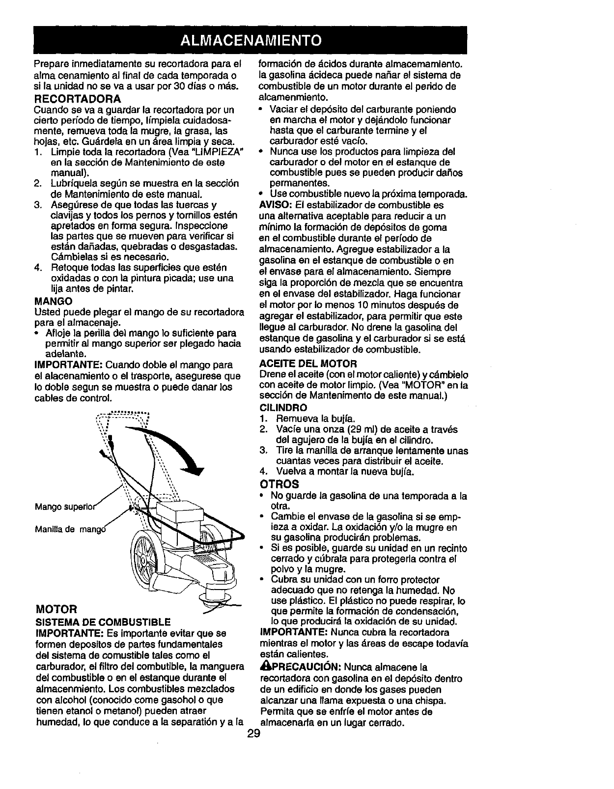
Prepare inmediatamente su recortadora para el
alma cenamiento al final de cada temporada o
si la unidad no se va a usar pot 30 dias o mas.
RECORTADORA
Cuando se va a guardar la recortadora por un
cierto perfodo de tiempo, limpiela cuidadosa-
merits, remueva toda la mugre, la grasa, las
hojas, etc. Gudrdela en un drea limpia y seca.
1. Umpie toda la recortadora (Vea "LIMPIEZA"
en la secci6n de Mantenimiento de este
manual).
2. Lubriquela segt_n se muestra en la secci6n
de Mantenimiento de este manual.
3. Asegt_rese de que todas las tuercas y
clavijas y todos los pernos y tomillos estSn
apretados en forma segura. Inspeccione
las partes que se mueven para verificar si
estdn daSadas, quebradas o desgastadas.
C&mbielas si es necesario.
4. Retoque todas las superficies que est_n
oxidadas o con ]a pintura picada; use una
lija antes de pintar.
MANGO
Usted puede plegar el mango de su recortadora
para el almacenaje.
• Afloje ]a perilla del mango Io suficiente para
permitir al mango superior ser plegado hacia
adelante.
IMPORTANTE" Cuando doble el mango para
el alacenamiento oel trasporte, asegurese que
Io doble segun se muestra o puede danar los
cables de control.
Manilla de mango
MOTOR
SISTEMA DE COMBUSTIBLE
IMPORTANTE: Es importante evitar que se
formen depositos de partes fundamentales
del sistema de comustible tales como el
carburador, el filtro del combutible, la manguera
del combustible o en el estanque durante el
almacenmiento. Los combustibles mezclados
con alcohol (conocido come gasohol o que
tienen etanol ometanol) pueden atraer
humedad, Io que conduce a la separati6n y a la
formaci6n de dcidos durante almacemamiento.
la gasolina dcideca puede naSar el sistema de
combustible de un motor durante el perido de
alcamenmiento.
• Vaciar el dep6sito del carburante poniendo
en marcha el motor y dejd.ndolo funcionar
hasta que el carburante termine y el
carburador est8 vac_o.
• Nunca use los productos para limpieza del
carburador o del motor en el estanque de
combustible pues se pueden producir daSos
permanentes.
• Use combustible nuevo la pr6xima temporada.
AVISO: El estabilizador de combustible es
una altemativa aceptable para reducir a un
minimo la formaci6n de dep6sitos de goma
en el combustible durante el perfodo de
almacenamiento. Agregue estabilizador a la
gasolina en el estanque de combustible o en
el envase para el almacenamiento. Siempre
siga la proporcibn de mezcla que se encuentra
en el envase del estabilizador. Haga funcionar
el motor por Io menos 10 minutos despu_s de
agregar el estabilizador, para permitir que este
Ilegue al carburador. No drene la gasolina del
estanque de gasolina y el carburador si se est&
usando estabilizador de combustible.
ACEITE DEL MOTOR
Drene el aceite (con el motor caliente) y cdmbielo
con aceite de motor limpio. (Vea "MOTOR" en la
secci6n de Mantenimento de este manual.)
CILINDRO
1. Remueva la buil'a.
2. Vacfe una onza (29 mi) de aceite a trav6s
dsl agujero de la bujia en el cilindro.
3. Tire la manilla de arranque lentamente unas
cuantas veces para distdbuir el aceite.
4. Vuelva a montar la nueva bujfa.
OTROS
•No guarde la gasolina de una temporada ala
otra.
• Cambie el envase de la gasolina si se emp-
ieza aoxidar. La oxidaci6n y/o la mugre en
su gasolina producird.n problemas.
• Si es posible, guards su unidad en un recinto
cerrado y c_brala para protegerla contra el
polvo y la mugre.
• Cubra su unidad con un forro protector
adecuado que no retenga la humedad. No
use pl,-'tstico. El pld.sticono puede respirar, Io
que permits la formacibn de condensaci6n,
Io que producird la oxidacibn de su unidad.
IMPORTANTE: Nunca cobra la recortadora
mientras el motor y las dreas de escape todavfa
estd.ncalientes.
,APRECAUCI(_N: Nunca almacene la
recortadora con gasolina en el dep6sito dentro
de un edificio en donde los gases pueden
alcanzar una llama expuesta o una chispa.
Permita que se enfrl'eel motor antes de
almacenarla en un lugar cerrado.
29

SOLUCI6N DE PROBLEMAS-Vea la secci6n apropiada en el manual amenos que
est6 dirigido a un centro de servico Sears.
PROBLEMA CORRECCI6N
No srranca
Pdrdida de
potencia
Vibraci6n excesiva
1
2.
3.
4.
5.
6.
7.
El cabezal de la
recortadora
mantiene la
Ifnea
CAUSA
Filtro de aire sucio.
Sin combustible.
Combustible rancio.
Ague en el combustible.
Alambre de la bujia
desconectado.
Bujfa mala.
La palanca de control de la
aceleraci6n no estd.en
posici6n correcta (si existe).
1. Filtro de aim sucio.
2. Acumulaci6n de hierba, hojas
y residuos debajo de la
recortadom.
3, Demasiado aceite en
el motor.
4. Velocidad de recorrido
demasiado rdpida,
o
2.
3.
Uneas irregulares orotes.
Tuercas o pemos sueltos.
1. Limpie/cambie el filtro de aire.
2. Llene el estanque de combus
tible.
3. Vaciar el estanque y vuelva a
Ilenarlo con combustible limpio
Ynueva.
4. Vaciar el estanque y vuelva a
Ilenarlo con combustible limpio
y nueva.
5. Conecte el alambre ala bujfa.
6. Cambie la bujia.
7. Mover la palanca de aceleraci6n
en la posici6n RAPIDA.
1. Limpie/cambie el filtro de aim.
2. Limpiar debajo de la recortadora
y del cabezal de la
recortadora.
3. Revise el nivel del aceite.
4. Cortea una velocidad de
recorrido mds lenta.
Cabezal de la recortadom
da5ado.
Cord6n 1. CigOe_al del motor plegado. 1. Pongase en contacto con un
arrancador centro de servicio Sears o con
diffcll de tlrar un otro centre de servicio
cualificado.
Pdrdida de 1. Correa que no marcha. 1. Colocar la correa en las poleas
movlmlento o reemplazar la corms si estd.
del cabezal rots.
Diflcil de empujar 1. Posici6n de la altura del 1. Ajuste la altura del mango de
mango no adecuada para mocloque le
usted, acomode.
Rendlmlento de 1. La Ifnea de la recortadora 1. Si la linea estd gastada o rots
corte escaso es demasiado corta, hasta la mitad de su largura
original, reemplazar la tines.
2. La palanca de control de la 2. Mover la palanca de
aceleraci6n no estd en acpleraci6n en la posici6n
posici6n correcta (si existe). RAPIDA.
1. Seguir las instrucciones en la
secci6n Mantenimiento.
,
2.
3.
Linea de la recortadora no
correctamente ins
talada/reemplazada.
Clip del sujetador roto.
Unea de la recortadora de
medida incorrecta.
1. Controlar las I[neas de la
recortadora.
2. Controlar toda la ferreter[a,
incluidos los pemos del motor.
3. Controladarreglar el cabezal de
la recortadora.
2. Reemplazar el conjunto de la
placa portante de la cuerda.
3. Utilizer una Ifnea de',
reecortadorede didmetm
.155 inch.
3O
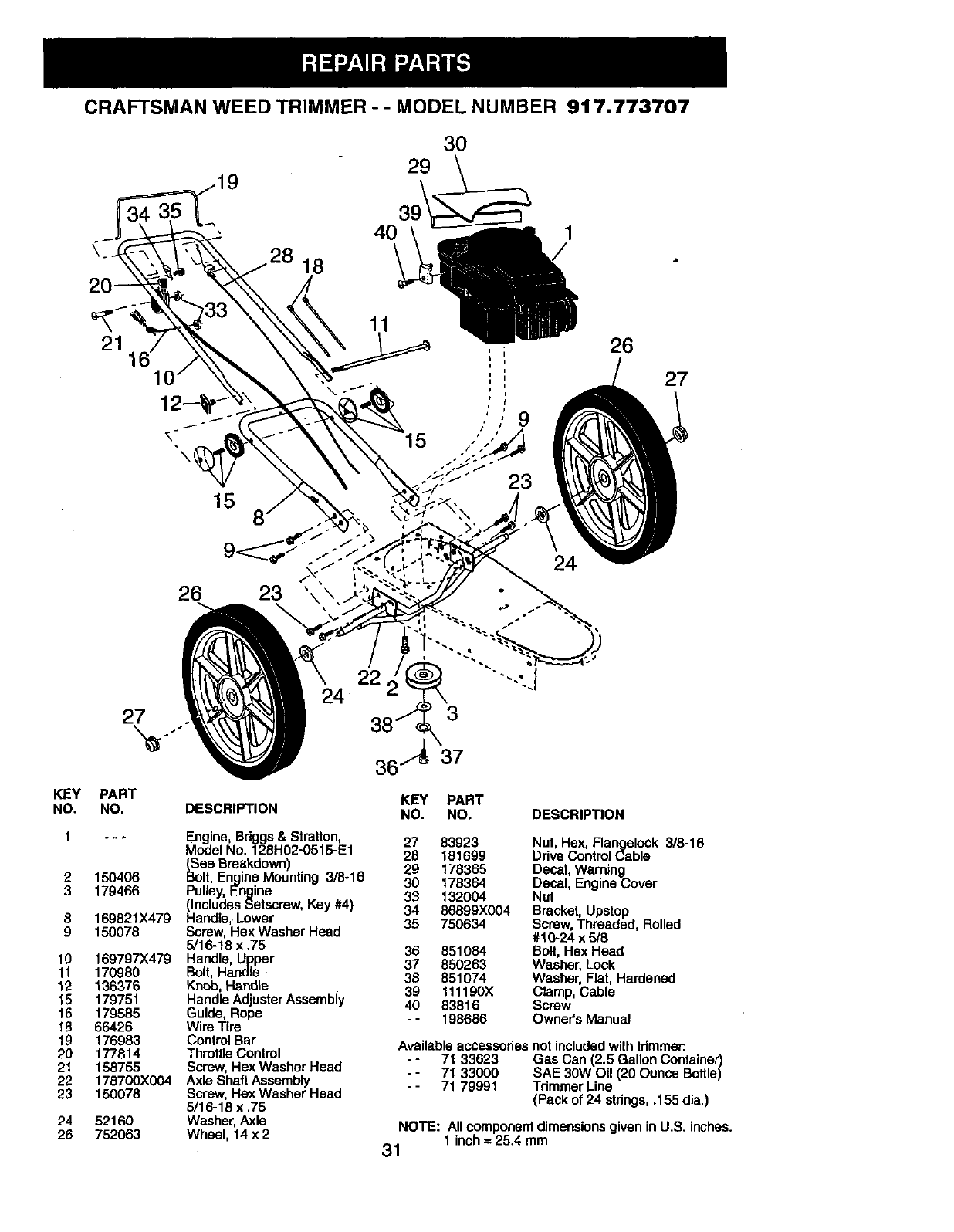
CRAFTSMAN WEED TRIMMER - -MODEL NUMBER 917.773707
3O
29
18
4O
11
21 , ;26
27
15 8
26 23
27 24
KEY
NO.
10
11
12
15
16
18
19
20
21
22
23
24
26
PART
NO.
150406
179466
169821X479
150078
169797X479
170980
136376
179751
179585
66426
176983
177814
158755
178700X004
150078
52160
752063
DESCRIPTION
Engine, Briggs & Stratton,
Model No. 128H02-0515-E1
_See Breakdown)
olt, Engine Mounting 3/8-16
Pulley, Engine
(Includes Setscrew, Key #4)
Handle, Lower
Screw, Hex Washer Head
5/16-18 x .75
Handle, Upper
Bolt, Handle
Knob, Handle
Handle Adjuster Assembly
Guide, Rope
Wire Tire
Control Bar
Throttle Control
Screw, Hex Washer Head
Axle Shaft Assembly
Screw, Hex Washer Head
5/16-18 x .75
Washer, Axle
Wheel, 14 x 2
KEY PART
NO. NO, DESCRIPTION
27 83923 Nut, Hex, Flangelock 3/6-16
28 181699 Drive Control Cable
29 178365 Decal, Warning
30 178364 Decal, Engine Cover
33 132004 Nut
34 86899X004 Bracket, Upstop
35 750634 Screw, Threaded, Rolled
#10-24 x5/8
36 851084 Bolt, Hex Head
37 850263 Washer, Lock
38 851074 Washer, Flat, Hardened
39 111190)( Clamp, Cable
40 83816 Screw
--198686 Owner's Manual
Available accessories not included with trimmer:
- - 71 33623 Gas Can (2.5 Gallon Container)
- - 71 33000 SAE 30W Oil (20 Ounce Bottle)
- - 71 79991 Trimmer Line
(Pack of 24 strings, .155 dia.)
NOTE: All component dimensions given in US. inches.
1 inch =25.4 mm
31
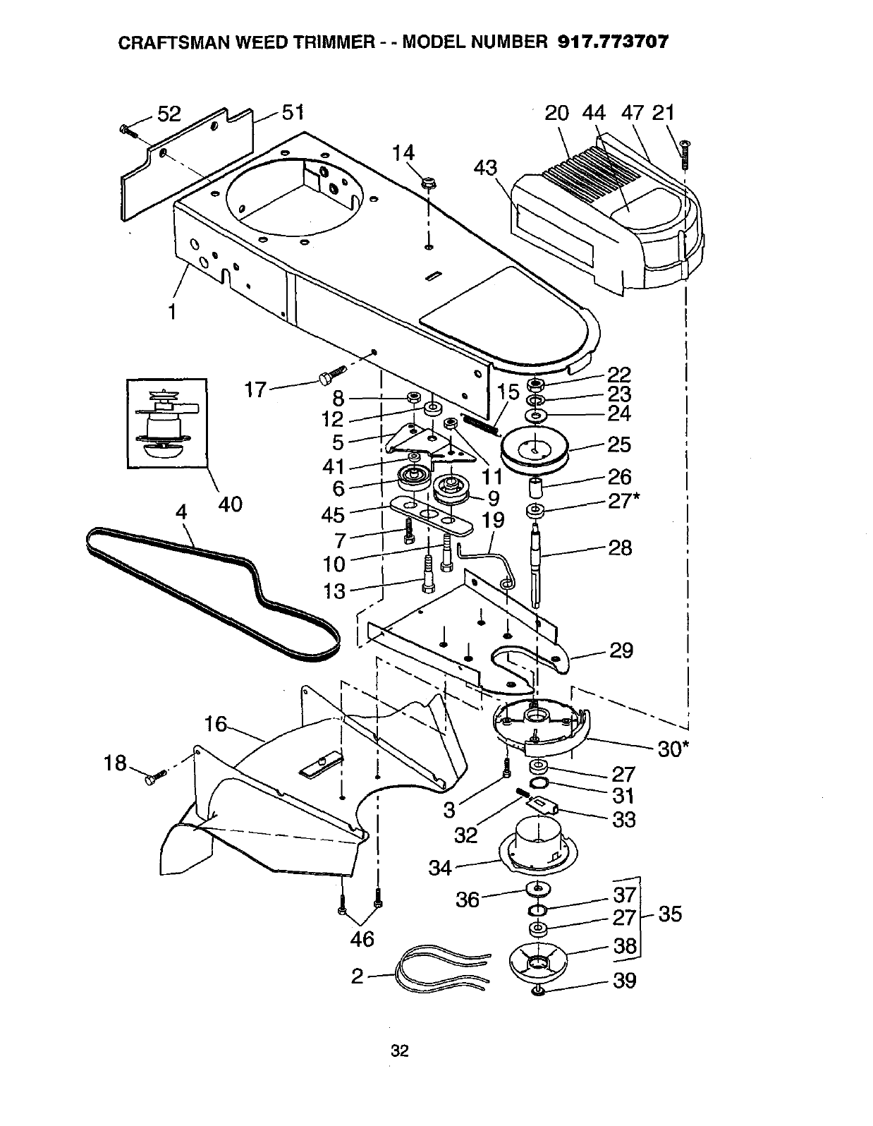
CRAFTSMAN WEED TRIMMER - - MODEL NUMBER 917.773707
14 43\
20 44 47 21
-22
17_8 23
12- 24
4 40 45
I
I
I 32 33
30*
35
32
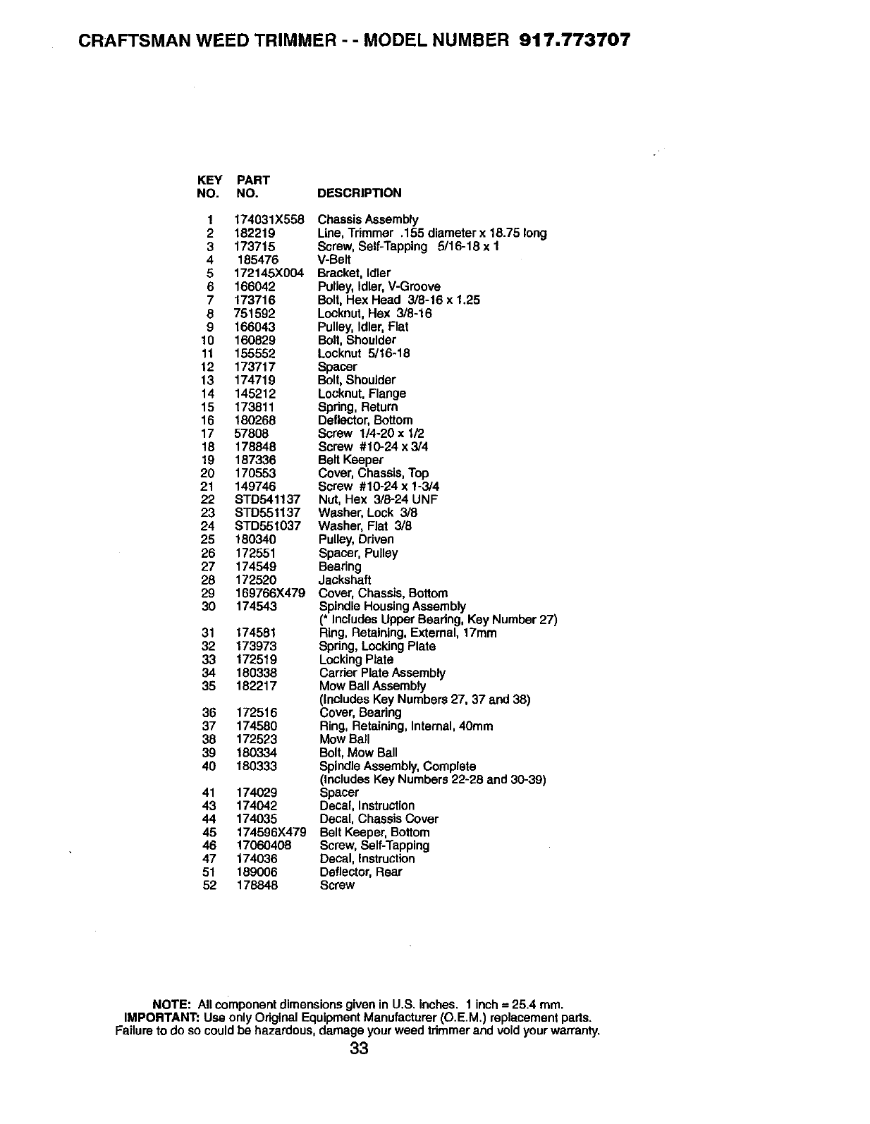
CRAFTSMAN WEED TRIMMER - -MODEL NUMBER 917.773707
KEY PART
NO. NO. DESCRIPTION
1 174031X558 Chassis Assembly
2 182219 Line, Trimmer .155 diameter x 18.75 long
3 173715 Screw, Self-Tapping 5/16-18 x 1
4 185476 V-Belt
5 172145)(004 Bracket, Idler
6 166042 Pulley, Idler, V-Groove
7173716 Bolt, Hex Head 3/8-16 x 1.25
8 751592 Locknut, Hex 3/8-16
9 166043 Pulley, Idler, Flat
10 160829 Bolt, Shoulder
11 155552 Locknut 5/16-18
12 173717 Spacer
13 174719 Bolt, Shoulder
14 145212 Locknut, Flange
15 173811 Spring, Return
16 180268 Deflector, Bottom
17 57808 Screw I/4-20 x 1/2
18 178848 Screw #10-24 x3/4
19 187336 Belt Keeper
20 170553 Cover, Chassis, Top
21 149746 Screw #10-24 x 1-3/4
22 STD541137 Nut, Hex 3/5-24 UNF
23 STD551137 Washer, Lock 3/8
24 STD551037 Washer, Flat 3/8
25 180340 Pulley, Driven
26 172551 Spacer, Pulley
27 174549 Bearing
28 172520 Jackshaft
29 169766X479 Cover, Chassis, Bottom
30 174543 Spindle Housing Assembly
(" Includes Upper Beadng, Key Number 27)
31 174581 Ring, Retaining, External, 17ram
32 173973 Spdng, Locking Plate
33 172519 Locking Plate
34 180338 Carrier Plate Assembly
35 182217 Mow Ball Assembly
(includes Key Numbers 27, 37 and 38)
36 172516 Cover, Bearing
37 174580 Ring, Retaining, Internal, 40mm
38 172523 Mow Ball
39 180334 Bolt, Mow Ball
40 180333 Spindle Assembly, Complete
(Includes Key Numbers 22-28 and 30-39)
41 174029 Spacer
43 174042 Decal, Instruction
44 174035 Decal, Chassis Cover
45 174596X479 Belt Keeper, Bottom
46 17060408 Screw, Self-Tapping
47 174036 Decal, instruction
51 189006 Deflector, Rear
52 178848 Screw
NOTE: All component dimensions given in U.S. inches. 1 inch = 25.4 ram.
IMPORTANT: Usa only Original Equipment Manufacturer (O.E.M.) replacement parts.
Failure to do so could be hazardous, damage your weed trimmer and void your warranty.
33
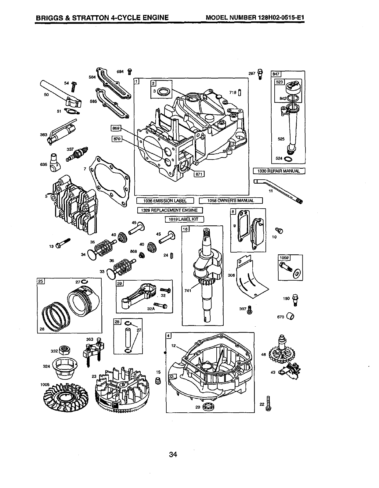
BRIGGS & STRATTON 4-CYCLE ENGINE MODEL NUMBER 128H02-0515-E1
i
524
I 1330 REPAIR MANUAL
1036 EMISSION LABEL I I 1058 OWNER S MANU
34
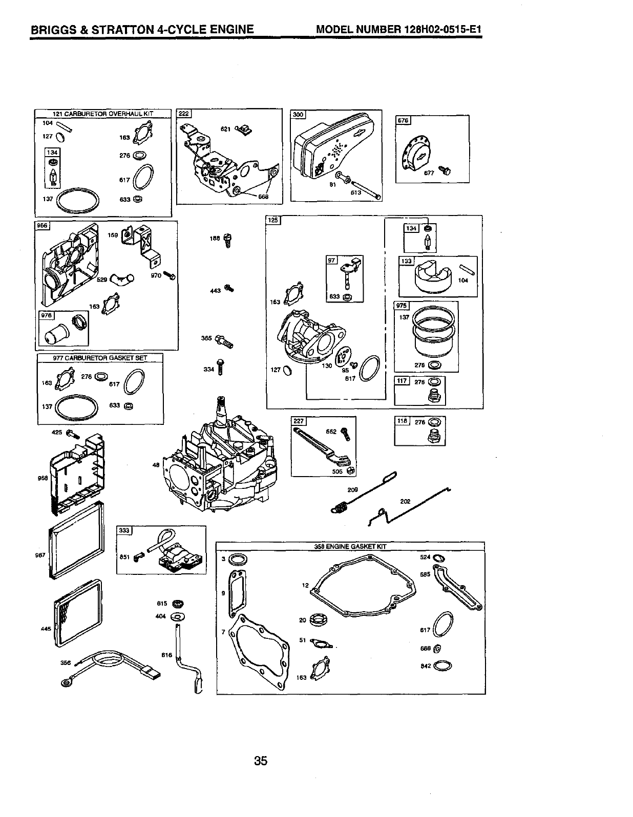
BRIGGS & STRATTON 4-CYCLE ENGINE MODEL NUMBER 128H02-0515-E1
121 CARBURETOR OVERHAUL KIT
lo4_
617
633 _
159
967
163
676
35
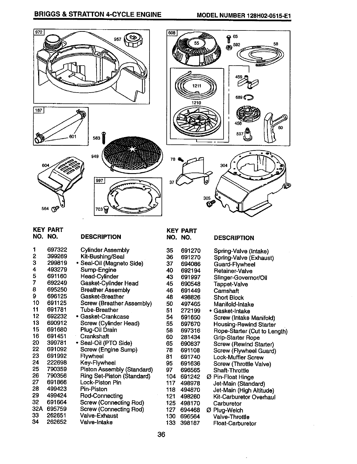
BRIGGS & STRA'I-FON 4-CYCLE ENGINE MODEL NUMBER 128H02-0515-E1
O
1210
5
iv
3O4
305
KEY PART
NO. NO.
1 697322
2 399269
3 299819
4493279
5 691160
7 692249
8 695250
9 696125
10 691125
11 691781
12 692232
13 690912
15 691680
16 691451
20 399781
22 691092
23 691992
24 222698
25 790359
26 790356
27 691866
28 499423
29 499424
32 691664
32A 695759
33 262651
34 262652
KEY PART
DESCRIPTION NO. NO.
Cylinder Assembly 35 691270
Kit-Bushing/Seal 36 691270
•Seal-Oil (Magneto Side) 37 694086
Sump-Engine 40 692194
Head-Cylinder 43 691997
Gasket-Cylinder Head 45 690548
Breather Assembly 46 691449
Gasket-Breather 48 498826
Screw (Breather Assembly) 50 497465
Tube-Breather 51 272199
•Gasket-Crankcase 54 691650
Screw (Cylinder Head) 55 697670
Plug-Oil Drain 58 697316
Crankshaft 60 281434
•Seal-Oil (PTO Side) 65 690837
Screw(Engine Sump) 78 691108
Flywheel 81 691740
Key-Flywheel 95 691636
Piston Assembly (Standard) 97 696565
Ring Set-Piston (Standard) 104 691242
Lock-Piston Pin 117 498978
Pin-Piston 118 494870
Rod-Connecting 121 498260
Screw (Connecting Rod) 125 498170
Screw (Connecting Rod) 127 694468
Valve-Exhaust 130 696564
Valve-Intake 133 398187
36
DESCRIPTION
Spring-Valve (Intake)
Spring-Valve (Exhaust)
Guard-Flywheel
Retainer-Valve
Slinger-Governor/Oil
Tappet-Valve
Camshaft
Short Block
Manifold-Intake
•Gasket-Intake
Screw (Intake Manifold)
Housing-Rewind Starter
Rope-Stader (Cut to Length)
Grip-Starter Rope
Screw (Rewind Starter)
Screw (Flywheel Guard)
Lock-Muffler Screw
Screw (Throttle Valve)
Shaft-Throttle
(_ Pin-Float Hinge
Jet-Main (Standard)
Jet-Main (High Altitude)
Kit-Carburetor Overhaul
Carburetor
1_ Plug-Welch
Valve-ThrotUe
Float-Carburetor
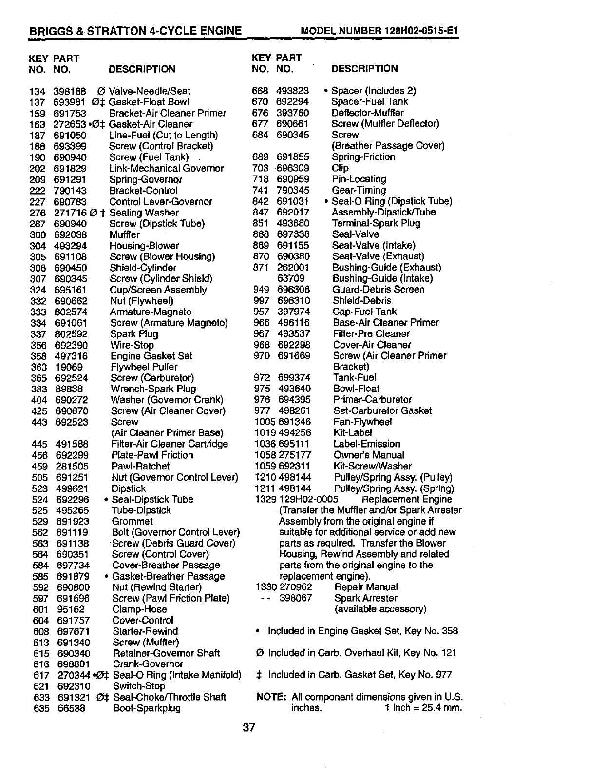
BRIGGS & STRAT'rON 4-CYCLE ENGINE MODEL NUMBER 128HO2-O515-E1
KEY PART
NO. NO. DESCRIPTION KEY PART
NO. NO. DESCRIPTION
134 398188 O Valve-Needle/Seat
137 693981 O1: Gasket-Float Bowl
159 691753 Bracket-Air Cleaner Primer
163 272653.13:l: Gasket-Air Cleaner
187 691050 Line-Fuel (Cut to Length)
188 693399 Screw (Control Bracket)
190 690940
202 691829
2O9 691291
222 790143
227 69O783
276 271716
287 690940
300 692038
304 493294
305 691108
306 690450
307 690345
324 695161
332 690662
333 802574
334 691061
337 802592
356 692390
358 497316
363 19069
365 692524
383 89838
404 690272
425 690670
443 692523
o$
445 491588
456 692299
459 281505
505 691251
523 499621
524 692296
525 495265
529 691923
562 691119
563 691138
564 690351
584 697734
585 691879
592 690800
597 691696
601 95162
604 691757
608 697671
613 691340
615 690340
616 698801
617 270344=O_
621 692310
633 6913210_
635 66538
Screw (Fuel Tank)
Link-Mechanical Governor
Spring-Governor
Bracket-Control
Control Lever-Governor
Sealing Washer
Screw (Dipstick Tube)
Muffler
Housing-Blower
Screw (Blower Housing)
Shield-Cylinder
Screw (Cylinder Shield)
Cup/Screen Assembly
Nut (Flywheel)
Armature-Magneto
Screw (Armature Magneto)
Spark Plug
Wire-Stop
Engine Gasket Set
Flywheel Puller
Screw (Carburetor)
Wrench-Spark Plug
Washer (Governor Crank)
Screw (Air Cleaner Cover)
Screw
(Air Cleaner Primer Base)
Filter-Air Cleaner Cartridge
Plate-Pawl Friction
PawI-Ratchet
Nut (Governor Control Lever)
Dipstick
•Seal-Dipstick Tube
Tube-Dipstick
Grommet
Bolt (Governor Control Lever)
-Screw (Debris Guard Cover)
Screw (Control Cover)
Cover-Breather Passage
•Gasket-Breather Passage
Nut (Rewind Starter)
Screw (Pawl Friction Plate)
Clamp-Hose
Cover-Control
Starter-Rewind
Screw (Muffler)
Retainer-Governor Shaft
Crank-Governor
SeaI-O Ring (Intake Manifold)
Switch-Stop
Seal-Choke/ThrotUe Shaft
Boot-Sparkplug
668 493823
670 692294
676 393760
677 690661
684 690345
689 691855
703 696309
718 690959
741 790345
842 691031
847 692017
851 493880
868 697338
869 691155
870 690380
871 262001
63709
949 696306
997 696310
957 397974
966 496116
967 493537
968 692298
970 691669
972 699374
975 493640
976 694395
977 498261
1005 691346
1019 494256
1036695111
1058 275177
1059 692311
1210 498144
1211 498144
•Spacer (Includes 2)
Spacer-Fuel Tank
Deflector-Muffler
Screw (Muffler Deflector)
Screw
(Breather Passage Cover)
Spring-Friction
Clip
Pin-Locating
Gear-Timing
•SeaI-O Ring (Dipstick Tube)
Assembly-Dipstick/Tube
Terminal-Spark Plug
Seal-Valve
Seat-Valve (Intake)
Seat-Valve (Exhaust)
Bushing-Guide (Exhaust)
Bushing-Guide (Intake)
Guard-Debris Screen
Shield-Debds
Cap-Fuel Tank
Base-Air Cleaner Pdmer
Filter-Pre Cleaner
Cover-Air Cleaner
Screw (Air Cleaner Pdmer
Bracket)
Tank-Fuel
Bowl-Float
Pdmer-Carburetor
Set-Carburetor Gasket
Fan-Flywheel
Kit-Label
Label-Emission
Owner's Manual
Kit-Screw/Washer
Pulley/Spring Assy. (Pulley)
Pulley/Spring Assy. (Spring)
1329 129H02-0005 Replacement Engine
(Transfer the Muffler and/or Spark Arrester
Assembly from the original engine if
suitable for additional service or add new
parts as required. Transfer the Blower
Housing, Rewind Assembly and related
parts from the odginal engine to the
replacement engine).
1330 270962 Repair Manual
-- 398067 SparkArrester
(available accessory)
•Included in Engine Gasket Set, Key No. 358
Included in Carb. Overhaul Kit, Key No. 121
:_ Included in Carb. Gasket Set, Key No. 977
NOTE: All component dimensions given in U.S.
inches. 1 inch =25.4 mm.
37

SERVICE NOTES
38
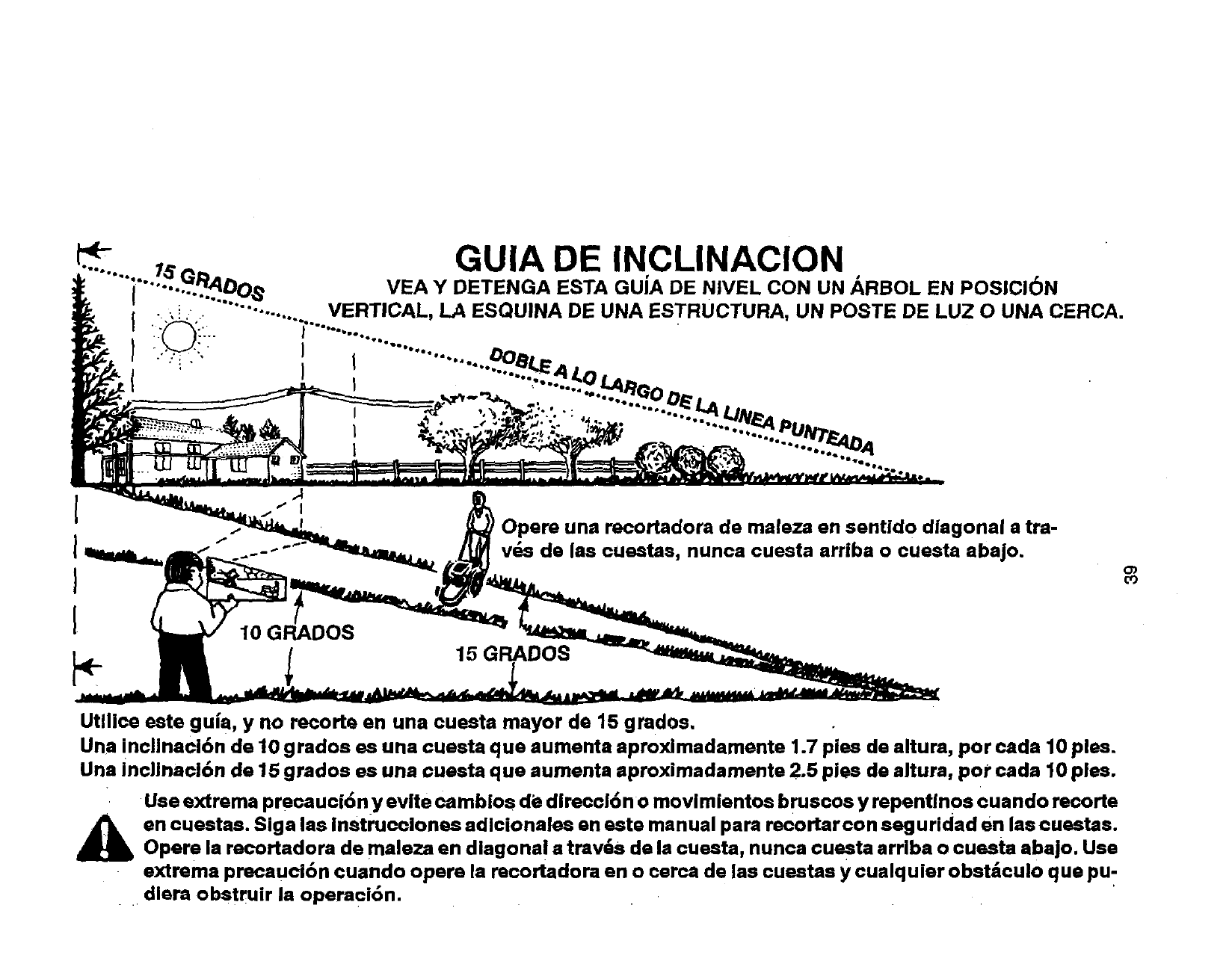
•._......+- GUIA DE INCLINACION •
Ilo _ •
...... .Q...R_DO VEA Y DETENGA ESTA GUIA DE NIVEL CON UN ARBOL EN POSICI6N
I.., i • ...... _".......... VERTICAL, LA ESQUINA DE UNA ESTRUCTURA, UN POSTE DE LUZ O UNA CERCA.
I •:/_-.. I .......... "
I ++y:+ J "'-..............
10 GRADOS
Opera una recortadora de maleza en sentido diagonal a tra-
y,s de las cuestas, nunca cuesta arriba o cuesta abajo.
15 GRADOS
o')
co
Utllice este gula, y no recorte en una eueste mayor de 15 gmdos.
Una inclinaci6n de 10 grados es una cuesta qua aumenta aproximadamente 1.7 pies de altura, por cada 10 pies.
Una inclinacl6n de 15 grados es una ouesta qua eumenta eproximadamente 2.5 pies de altura, pot cada 10 pies.
Use extrema precauci6ny evite cambios de direccl6n o movimientos bruscos y repentlnos cuando recorte
en euestes. Siga las inetrueeiones adicionalee en este manual pare recortar con seguridad en lea cuestas.
Opera la racortadora de maleza en diagonal atrav6s de la cuesta, nunca cuesta arriba o cuesta abajo. Use
extrema precauci6n cuando opera la recortadora en o carte de las ¢uestas y cualquier obst=teulo qua pu-
• dlera obstruir la operaci6n.

Your Home
For the replacement parts, accessories and
owner's manuals that you need to do-it-yourself.
For Sears professional installation of home appliances
and items like garage door openers and water heaters.
1-800-4-MY-HOME ®Anytime, day or night
(1-800-469-4663) (U.S.A. and Canada)
www.sears.com www.sears.ca
Our Home
For repair of carry-in products like vacuums, lawn equipment,
and electronics, call or go on-line for the nearest
Sears Parts and Repair Center.
1-800-488-1222 Anytime, day or night (U.S.A. only)
www.saars.com
To purchase a protection agreement (U.S.A.)
or maintenance agreement (Canada) on a product serviced by Sears:
1-800-827-6655 (u.s._) 1-800-361-6665 (Canada)
Para pedir servido de reparacibn
adomidlio, y para ordenar piezas:
1-888-SU-HOGAR sM o
(1-888-784-6427)
Au Canada pourserviceen franc,,ais:
1-800-LE-FOYER Mc
(_-800-533-6937)
www.saars.ca
alr-8 02410
©Sears,RoebuckandCo.
®Registered Trademark ITM Trademark /SMService Mark of Sears, Roebuck and Co.
®Mama Registrada /TMMama de F_bdca /SMMama de Servicio de Sears, Roebuck and Co.
MCMarque de commerce /MDMarque d_pos6e de Sears, Roebuck and Co.
198686 04.08.05 BY Printed in U.S.A.
