Craftsman 919165610 User Manual AIR COMPRESSOR Manuals And Guides L0410125
CRAFTSMAN Air compressor Manual L0410125 CRAFTSMAN Air compressor Owner's Manual, CRAFTSMAN Air compressor installation guides
User Manual: Craftsman 919165610 919165610 CRAFTSMAN AIR COMPRESSOR - Manuals and Guides View the owners manual for your CRAFTSMAN AIR COMPRESSOR #919165610. Home:Tool Parts:Craftsman Parts:Craftsman AIR COMPRESSOR Manual
Open the PDF directly: View PDF ![]() .
.
Page Count: 36
Operators Manual
I CRRFTSMRN°I
Permanently Lubricated
2 Stage
Twin Valve
Stationary
AIR COMPRESSOR
Model No.
919.165610
• Safety Guidelines
• Assembly
• Operation
• Maintenance
•Service and Adjustments
•Troubleshooting
•Espahol
CAUTION: Read the Safety Guidelines
and All Instructions Carefully Before
Operating.
Sears, Roebuck and Co., Hoffman Estates, IL 60179 U.S.A.
Visit our Craftsman website: www.sears.com/craftsman
D21879 Rev. 3 9/17/04
WARRANTY .............................. 2
SAFETY GUIDELINES .................... 3-6
GLOSSARY ............................... 7
ACCESSORIES ........................... 7
ASSEMBLY ............................... 7
Contents of Carton ...................... 7
Tools Required for Assembly .............. 7
Unpacking ............................. 7
INSTALLATION .......................... 8-9
Location of Air Compressor ............... 8
Anchoring the Air Compressor ............. 8
Wiring Instructions ...................... 8
Voltage and Circuit Protection ............. 8
Air Distribution System ................... 9
OPERATION .......................... 10-11
Know Your Air Compressor .............. 10
Description of Operation ................. 10
How to Use Your Unit ................... 11
How to Stop .......................... 11
Before Starting ........................ 11
Before Each Start-up ................... 11
How to Start .......................... 11
MAINTENANCE ........................ 12-13
Customer Responsiblilities ............... 12
To Check Saety Valve ................... 12
To Drain Tank ......................... 12
Air Filter - Inspection and Replacement ..... 12
Motor ................................ 13
Inspect Air Lines and Fittings for leaks ..... 13
Air Compressor Pump Intake and
Exhaust Valves ........................ 13
SERVICE AND ADJUSTMENTS ............. 14
To Repalce or Clean Check Valve .......... 14
STORAGE ............................... 15
TROUBLESHOOTING GUIDE ............ 16-18
ESPAI_IOL ............................ 19-37
HOW TO ORDER REPAIR PARTS ..... back cover
FULL ONE YEAR WARRANTY
AIR COMPRESSOR
If this air compressor fails due to a defect in material or workmanship within one year from the date of
purchase, RETURN IT TO THE NEAREST SEARS REPAIR CENTER THROUGHOUT THE UNITED STATES
AND SEARS WILL REPAIR IT, FREE OF CHARGE. If purchased from Orchard Supply Hardware, return to
the nearest Orchard Store and Orchard will repair it, free of charge.
If this air compressor is used for commercial or rental purposes, the warranty will apply for ninety days
from the date of purchase.
This warranty gives you specific legal rights and you may have other rights which vary from state to state.
Sears, Robebuck and Co., Dept. 817WA, Hoffman Estates, II 60179
D21879 2- ENG
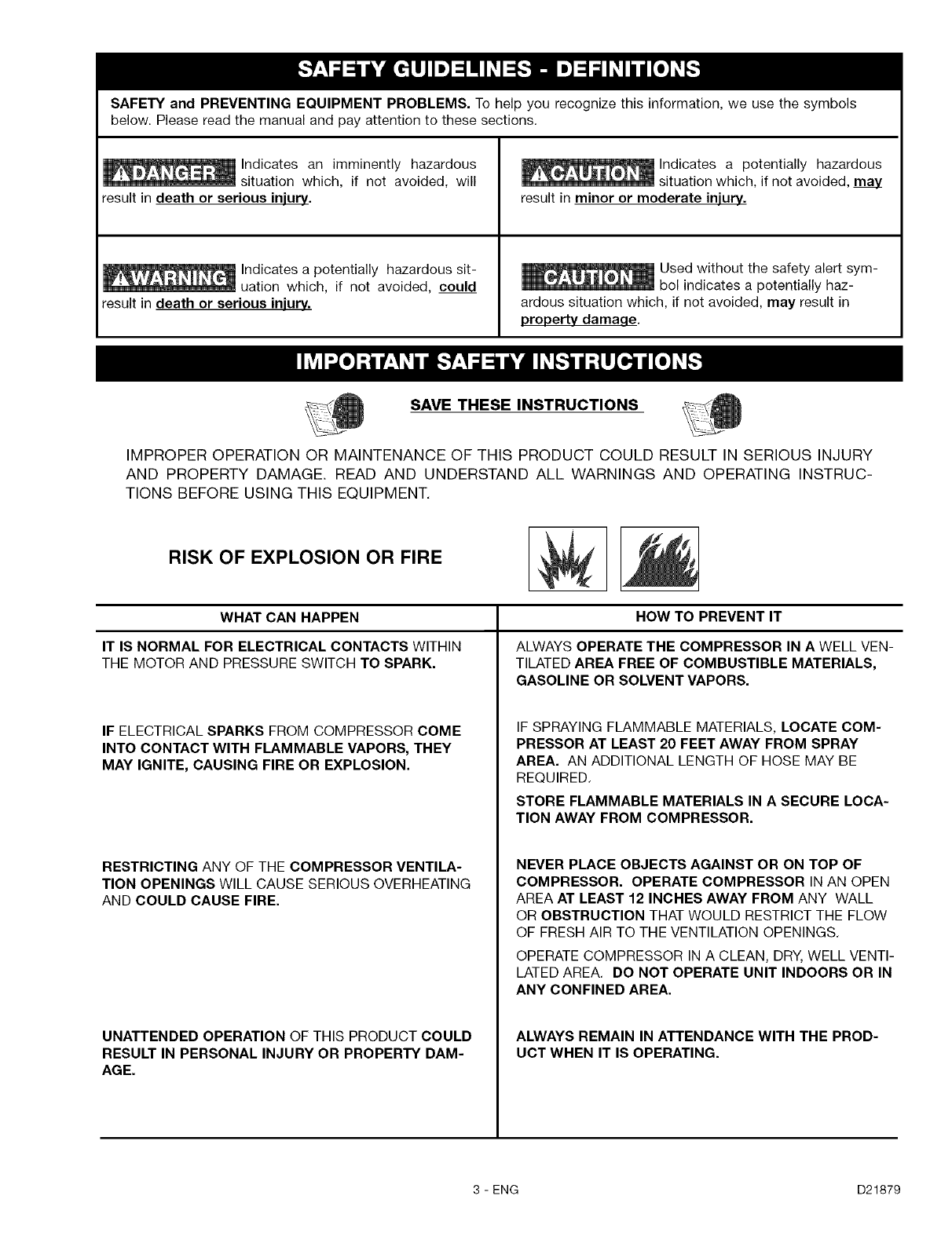
SAFETY and PREVENTING EQUIPMENT PROBLEMS. To help you recognize this information, we use the symbols
below. Please read the manual and pay attention to these sections.
Indicates an imminently hazardous
situation which, if not avoided, will
result in death or serious injury.
Indicates a potentially hazardous sit-
uation which, if not avoided, could
result in death or serious injury.
Indicates a potentially hazardous
situation which, if not avoided, may
result in minor or moderate injury.
Used without the safety alert sym-
bol indicates a potentially haz-
ardous situation which, if not avoided, may result in
property damaqe.
SAVE THESE INSTRUCTIONS
IMPROPER OPERATION OR MAINTENANCE OF THIS PRODUCT COULD RESULT IN SERIOUS INJURY
AND PROPERTY DAMAGE. READ AND UNDERSTAND ALL WARNINGS AND OPERATING INSTRUC-
TIONS BEFORE USING THIS EQUIPMENT.
RISK OF EXPLOSION OR FIRE
WHAT CAN HAPPEN
IT IS NORMAL FOR ELECTRICAL CONTACTS WITHIN
THE MOTOR AND PRESSURE SWITCH TO SPARK.
IF ELECTRICAL SPARKS FROM COMPRESSOR COME
INTO CONTACT WITH FLAMMABLE VAPORS, THEY
MAY IGNITE, CAUSING FIRE OR EXPLOSION.
RESTRICTING ANY OF THE COMPRESSOR VENTILA-
TION OPENINGS WILL CAUSE SERIOUS OVERHEATING
AND COULD CAUSE FIRE.
UNATTENDED OPERATION OF THIS PRODUCT COULD
RESULT IN PERSONAL INJURY OR PROPERTY DAM-
AGE.
HOW TO PREVENT IT
ALWAYS OPERATE THE COMPRESSOR IN A WELL VEN-
TILATED AREA FREE OF COMBUSTIBLE MATERIALS,
GASOLINE OR SOLVENT VAPORS.
IF SPRAYING FLAMMABLE MATERIALS, LOCATE COM-
PRESSOR AT LEAST 20 FEET AWAY FROM SPRAY
AREA. AN ADDITIONAL LENGTH OF HOSE MAY BE
REQUIRED.
STORE FLAMMABLE MATERIALS IN A SECURE LOCA-
TION AWAY FROM COMPRESSOR.
NEVER PLACE OBJECTS AGAINST OR ON TOP OF
COMPRESSOR. OPERATE COMPRESSOR IN AN OPEN
AREA AT LEAST 12 INCHES AWAY FROM ANY WALL
OR OBSTRUCTION THAT WOULD RESTRICT THE FLOW
OF FRESH AIR TO THE VENTILATION OPENINGS.
OPERATE COMPRESSOR IN A CLEAN, DRY, WELL VENTI-
LATED AREA. DO NOT OPERATE UNIT INDOORS OR IN
ANY CONFINED AREA.
ALWAYS REMAIN IN ATTENDANCE WITH THE PROD-
UCT WHEN IT IS OPERATING.
3 - ENG D21879
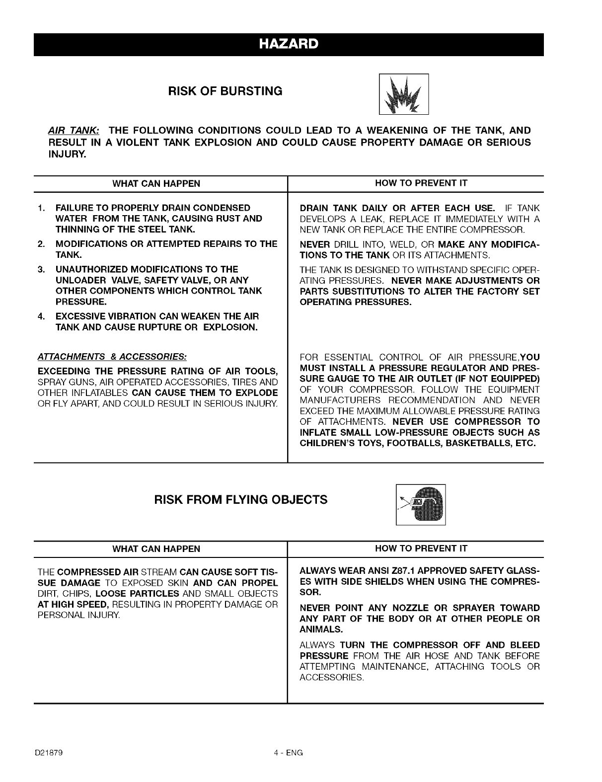
RISK OF BURSTING
AIR TANK: THE FOLLOWING CONDITIONS COULD LEAD TO A WEAKENING OF THE TANK, AND
RESULT IN A VIOLENT TANK EXPLOSION AND COULD CAUSE PROPERTY DAMAGE OR SERIOUS
INJ URY.
WHAT CAN HAPPEN HOW TO PREVENT IT
1. FAILURE TO PROPERLY DRAIN CONDENSED
WATER FROM THE TANK, CAUSING RUST AND
THINNING OF THE STEEL TANK.
2. MODIFICATIONS OR ATTEMPTED REPAIRS TO THE
TANK.
3. UNAUTHORIZED MODIFICATIONS TO THE
UNLOADER VALVE, SAFETY VALVE, OR ANY
OTHER COMPONENTS WHICH CONTROL TANK
PRESSURE.
4. EXCESSIVE VIBRATION CAN WEAKEN THE AIR
TANK AND CAUSE RUPTURE OR EXPLOSION.
ATTACHMENTS & ACCESSORIES:
EXCEEDING THE PRESSURE RATING OF AIR TOOLS,
SPRAY GUNS, AIR OPERATED ACCESSORIES, TIRES AND
OTHER INFLATABLES CAN CAUSE THEM TO EXPLODE
OR FLY APART, AND COULD RESULT IN SERIOUS INJURY.
DRAIN TANK DALLY OR AFTER EACH USE. IF TANK
DEVELOPS A LEAK, REPLACE IT IMMEDIATELY WITH A
NEW TANK OR REPLACE THE ENTIRE COMPRESSOR.
NEVER DRILL INTO, WELD, OR MAKE ANY MODIFICA-
TIONS TO THE TANK OR ITS ATTACHMENTS.
THE TANK IS DESIGNED TO WITHSTAND SPECIFIC OPER-
ATING PRESSURES. NEVER MAKE ADJUSTMENTS OR
PARTS SUBSTITUTIONS TO ALTER THE FACTORY SET
OPERATING PRESSURES.
FOR ESSENTIAL CONTROL OF AIR PRESSURE,YOU
MUST INSTALL A PRESSURE REGULATOR AND PRES-
SURE GAUGE TO THE AIR OUTLET (IF NOT EQUIPPED)
OF YOUR COMPRESSOR. FOLLOW THE EQUIPMENT
MANUFACTURERS RECOMMENDATION AND NEVER
EXCEED THE MAXIMUM ALLOWABLE PRESSURE RATING
OF ATTACHMENTS. NEVER USE COMPRESSOR TO
INFLATE SMALL LOW-PRESSURE OBJECTS SUCH AS
CHILDREN'S TOYS, FOOTBALLS, BASKETBALLS, ETC.
RISK FROM FLYING OBJECTS
WHAT CAN HAPPEN HOW TO PREVENT IT
THE COMPRESSED AIR STREAM CAN CAUSE SOFT TIS-
SUE DAMAGE TO EXPOSED SKIN AND CAN PROPEL
DIRT, CHIPS, LOOSE PARTICLES AND SMALL OBJECTS
AT HIGH SPEED, RESULTING IN PROPERTY DAMAGE OR
PERSONAL INJURY.
ALWAYS WEAR ANSI Z87.1 APPROVED SAFETY GLASS-
ES WITH SIDE SHIELDS WHEN USING THE COMPRES-
SOR.
NEVER POINT ANY NOZZLE OR SPRAYER TOWARD
ANY PART OF THE BODY OR AT OTHER PEOPLE OR
ANIMALS.
ALWAYS TURN THE COMPRESSOR OFF AND BLEED
PRESSURE FROM THE AIR HOSE AND TANK BEFORE
ATTEMPTING MAINTENANCE, ATTACHING TOOLS OR
ACCESSORIES.
D21879 4-ENG
RISK OF ELECTRICAL SHOCK
WHAT CAN HAPPEN
YOUR AIR COMPRESSOR IS POWERED BY ELECTRICI-
TY. LIKE ANY OTHER ELECTRICALLY POWERED DEVICE,
IF IT IS NOT USED PROPERLY IT MAY CAUSE ELECTRIC
SHOCK.
REPAIRS ATTEMPTED BY UNQUALIFIED PERSONNEL
CAN RESULT IN SERIOUS INJURY OR DEATH BY ELEC-
TROCUTION.
ELECTRICAL GROUNDING: FAILURE TO PROVIDE ADE-
QUATE GROUNDING TO THIS PRODUCT COULD
RESULT IN SERIOUS INJURY OR DEATH FROM ELEC-
TROCUTION. SEE GROUNDING INSTRUCTIONS,
HOW TO PREVENT IT
NEVER OPERATE THE COMPRESSOR OUTDOORS WHEN
IT IS RAINING OR IN WET CONDITIONS.
NEVER OPERATE COMPRESSOR WITH PROTECTIV-
COVERS REMOVED OR DAMAGED,
ANY ELECTRICAL WIRING OR REPAIRS REQUIRED ON
THIS PRODUCT SHOULD BE PERFORMED BY AUTHO-
RIZED SERVICE CENTER PERSONNEL IN ACCORDANCE
WITH NATIONAL AND LOCAL ELECTRICAL CODES.
MAKE CERTAIN THAT THE ELECTRICAL CIRCUIT TO
WHICH THE COMPRESSOR IS CONNECTED PROVIDES
PROPER ELECTRICAL GROUNDING, CORRECT VOLT-
AGE AND ADEQUATE FUSE PROTECTION.
RISK TO BREATHING
WHAT CAN HAPPEN HOW TO PREVENT IT
THE COMPRESSED AIR DIRECTLY FROM YOUR COM-
PRESSOR IS NOT SAFE FOR BREATHING. THE AIR
STREAM MAY CONTAIN CARBON MONOXIDE, TOXIC
VAPORS, OR SOLID PARTICLES FROM THE TANK.
BREATHING THESE CONTAMINANTS CAN CAUSE
SERIOUS INJURY OR DEATH.
SPRAYED MATERIALS SUCH AS PAINT, PAINT SOL-
VENTS, PAINT REMOVER, INSECTICIDES, WEED
KILLERS, CONTAIN HARMFUL VAPORS AND POISONS.
AIR OBTAINED DIRECTLY FROM THE COMPRESSOR
SHOULD NEVER BE USED TO SUPPLY AIR FOR HUMAN
CONSUMPTION. IN ORDER TO USE AIR PRODUCED BY
THIS COMPRESSOR FOR BREATHING, SUITABLE FIL-
TERS AND IN-LINE SAFETY EQUIPMENT MUST BE
PROPERLY INSTALLED, IN-LINE FILTERS AND SAFETY
EQUIPMENT USED IN CONJUNCTION WITH THE COM-
PRESSOR MUST BE CAPABLE OF TREATING AIR TO ALL
APPLICABLE LOCAL AND FEDERAL CODES PRIOR TO
HUMAN CONSUMPTION.
WORK IN AN AREA WITH GOOD CROSS-VENTILATION.
READ AND FOLLOW THE SAFETY INSTRUCTIONS PRO-
VIDED ON THE LABEL OR SAFETY DATA SHEETS FOR
THE MATERIAL YOU ARE SPRAYING. USE A
NIOSH/MSHA APPROVED RESPIRATOR DESIGNED FOR
USE WITH YOUR SPECIFIC APPLICATION,
5 - ENG D21879
RISK OF BURNS
WHAT CAN HAPPEN
TOUCHING EXPOSED METAL SUCH AS THE COMPRES-
SOR HEAD OR OUTLET TUBES, CAN RESULT IN
SERIOUS BURNS.
HOW TO PREVENT IT
NEVER TOUCH ANY EXPOSED METAL PARTS ON
COMPRESSOR DURING OR IMMEDIATELY AFTER OPER-
ATION. COMPRESSOR WILL REMAIN HOT FOR SEVERAL
MINUTES AFTER OPERATION.
DO NOT REACH AROUND PROTECTIVE SHROUDS OR
ATTEMPT MAINTENANCE UNTIL UNIT HAS BEEN
ALLOWED TO COOL.
RISK FROM MOVING PARTS
WHAT CAN HAPPEN HOW TO PREVENT IT
MOVING PARTS SUCH AS THE PULLEY, FLYWHEEL AND
BELT CAN CAUSE SERIOUS INJURY IF THEY COME
INTO CONTACT WITH YOU OR YOUR CLOTHING,
ATTEMPTING TO OPERATE COMPRESSOR WITH DAM-
AGED OR MISSING PARTS OR ATTEMPTING TO REPAIR
COMPRESSOR WITH PROTECTIVE SHROUDS REMOVED
CAN EXPOSE YOU TO MOVING PARTS AND CAN
RESULT IN SERIOUS INJURY.
NEVER OPERATE THE COMPRESSOR WITH GUARDS
OR COVERS WHICH ARE DAMAGED OR REMOVED.
ANY REPAIRS REQUIRED ON THIS PRODUCT SHOULD
BE PERFORMED BY AUTHORIZED SERVICE CENTER
PERSONNEL.
RISK OF FALLING
WHAT CAN HAPPEN HOW TO PREVENT IT
A PORTABLE COMPRESSOR CAN FALL FROM A TABLE,
WORKBENCH OR ROOF CAUSING DAMAGE TO THE
COMPRESSOR AND COULD RESULT IN SERIOUS
INJURY OR DEATH TO THE OPERATOR.
ALWAYS OPERATE COMPRESSOR IN A STABLE
SECURE POSITION TO PREVENT ACCIDENTAL MOVE-
MENT OF THE UNIT. NEVER OPERATE COMPRESSOR
ON A ROOF OR OTHER ELEVATED POSITION. USE
ADDITIONAL AIR HOSE TO REACH HIGH LOCATIONS.
RISK OF PROPERTY DAMAGE WHEN TRANSPORTING
COMPRESSOR
(Fire, Inhalation, Damage to Vehicle Surfaces)
For units requiring oil in pump or gasoline engines
WHAT CAN HAPPEN HOW TO PREVENT IT
OIL CAN LEAK OR SPILL AND COULD RESULT IN FIRE
OR BREATHING HAZARD, SERIOUS INJURY OR DEATH
CAN RESULT. OIL LEAKS WILL DAMAGE CARPET, PAINT
OR OTHER SURFACES IN VEHICLES OR TRAILERS,
ALWAYS PLACE COMPRESSOR ON A PROTECTIVE MAT
WHEN TRANSPORTING TO PROTECT AGAINST DAMAGE
TO VEHICLE FROM LEAKS. REMOVE COMPRESSOR
FROM VEHICLE IMMEDIATELY UPON ARRIVAL AT YOUR
DESTINATION.
D21879 6-ENG
Become familiar with these terms before operating the
unit.
CFM: Cubic feet per minute.
SCFM: Standard cubic feet per minute; a unit of
measure of air delivery.
PSlG: Pounds per square inch gauge; a unit of meas-
ure of pressure.
ASME: American Society of Mechanical Engineers;
made, tested, inspected and registered to meet the
standards of the ASME.
Code Certification: Products that bear one or more
of the following marks: UL, CUL, ETL, CETL, have
been evaluated by OSHA certified independent safety
laboratories and meet the applicable Underwriters
Laboratories Standards for Safety.
Cut-In Pressure: While the motor is off, air tank
pressure drops as you continue to use your accesso-
ry. When the tank pressure drops to a certain low
level the motor will restart automatically. The low
pressure at which the motor automatically restarts is
called "cut-in" pressure.
Cut-Out Pressure: When an air compressor is
turned on and begins to run, air pressure in the air
tank begins to build. It builds to a certain high pres-
sure before the motor automatically shuts off - pro-
tecting your air tank from pressure higher than its
capacity. The high pressure at which the motor shuts
off is called "cut-out" pressure.
Branch Circuit: Circuit carrying electricity from elec-
trical panel to outlet.
The accessories and tools are available through the current Power and Hand Tool Catalog or full-line Sears
stores.
Accessories
• In Line Filter
• Tire Air Chuck
• Quick Connector Sets
(various sizes)
• Air Pressure Regulators
• Oil Fog Lubricators
• Air Hose:
1/4", 3/8" OR 1/2" I.D.
in various lengths
Refer to the selection chart located on the unit to select the tools this unit is capable of powering.
Contents of Carton
1 - Air Compressor
1 - Parts bag containing:
1 - Operator's Manual
1 - Parts Manual
4 - 5/8" Washers
Tools Required for Assembly
1 - 9/16" socket or open end wrench
Electric drill
Unpacking
Remove all packaging.
It may be necessary to
brace or support one side
of the outfit when removing the pallet
because the air compressor will have a
tendency to tip.
2. Remove and discard the (4) screws and washers
holding the compressor to the pallet.
3. With the help of another person carefully remove
air compressor from pallet and place on a level
surface.
7 - ENG D21879
HOW TO SET UP YOUR UNIT
Location of the Air Compressor
• Locate the air compressor in a clean, dry, and well
ventilated area.
• Located the air compressor at least 12" away
from the wall or other obstructions that will inter-
fere with the flow of air.
• Locate the air compressor as close to the main
power supply as possible to avoid using long
lengths of electrical wiring. NOTE: Long lengths of
electrical wiring could cause power loss to the
motor.
• The air filter must be kept clear of obstructions
which could reduce air flow to the air compressor.
Anchoring of the Air Compressor
Excessive Vibration can
weaken the air tank and
cause an explosion. The compressor must be
properly mounted.
The air compressor MUST be bolted to a solid, level
surface.
Hardware needed:
.
2.
3.
4.
5.
4 - Concrete anchors
4 - 3/8" Lag screw to fit concrete anchors
(not supplied)
4 - 5/8" Washer (found in parts bag)
shims (if needed)
Place the air compressor on on a solid, level sur-
face.
Mark the surface using the holes in the air com-
pressor feet as a template.
Drill holes in the surface for the concrete anchors.
Install concrete anchors.
Line-up holes in surface with holes in air com-
pressor feet.
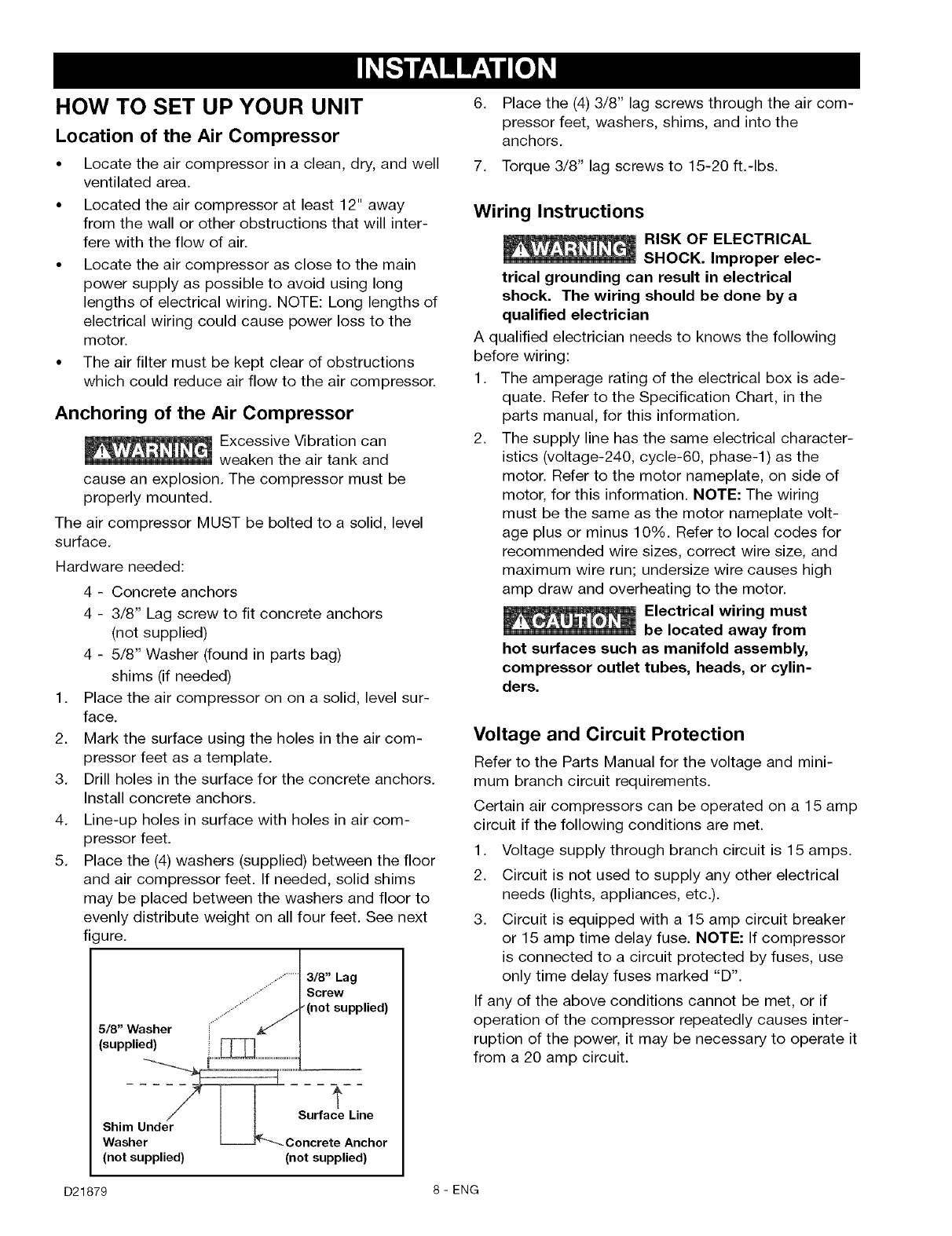
Place the (4) washers (supplied) between the floor
and air compressor feet. If needed, solid shims
may be placed between the washers and floor to
evenly distribute weight on all four feet. See next
figure.
3/8" Lag
Screw
(not supplied)
,++++'
5/8" Washer
(supplied)
Surfa Line
Shim
Washe. _-'---_ Concrete Anchor
(not supplied) (not supplied)
.Place the (4) 3/8" lag screws through the air com-
pressor feet, washers, shims, and into the
anchors.
7. Torque 3/8" lag screws to 15-20 ft.-Ibs.
Wiring Instructions
RISK OF ELECTRICAL
SHOCK. Improper elec-
trical grounding can result in electrical
shock. The wiring should be done by a
qualified electrician
A qualified electrician needs to knows the following
before wiring:
1. The amperage rating of the electrical box is ade-
quate. Refer to the Specification Chart, in the
parts manual, for this information.
2. The supply line has the same electrical character-
istics (voltage-240, cycle-60, phase-l) as the
motor. Refer to the motor nameplate, on side of
motor, for this information. NOTE: The wiring
must be the same as the motor nameplate volt-
age plus or minus 10%. Refer to local codes for
recommended wire sizes, correct wire size, and
maximum wire run; undersize wire causes high
amp draw and overheating to the motor.
Electrical wiring must
be located away from
hot surfaces such as manifold assembly,
compressor outlet tubes, heads, or cylin-
ders.
Voltage and Circuit Protection
Refer to the Parts Manual for the voltage and mini-
mum branch circuit requirements.
Certain air compressors can be operated on a 15 amp
circuit if the following conditions are met.
1. Voltage supply through branch circuit is 15 amps.
2. Circuit is not used to supply any other electrical
needs (lights, appliances, etc.).
3. Circuit is equipped with a 15 amp circuit breaker
or 15 amp time delay fuse. NOTE: If compressor
is connected to a circuit protected by fuses, use
only time delay fuses marked "D".
If any of the above conditions cannot be met, or if
operation of the compressor repeatedly causes inter-
ruption of the power, it may be necessary to operate it
from a 20 amp circuit.
D21879 8-ENG
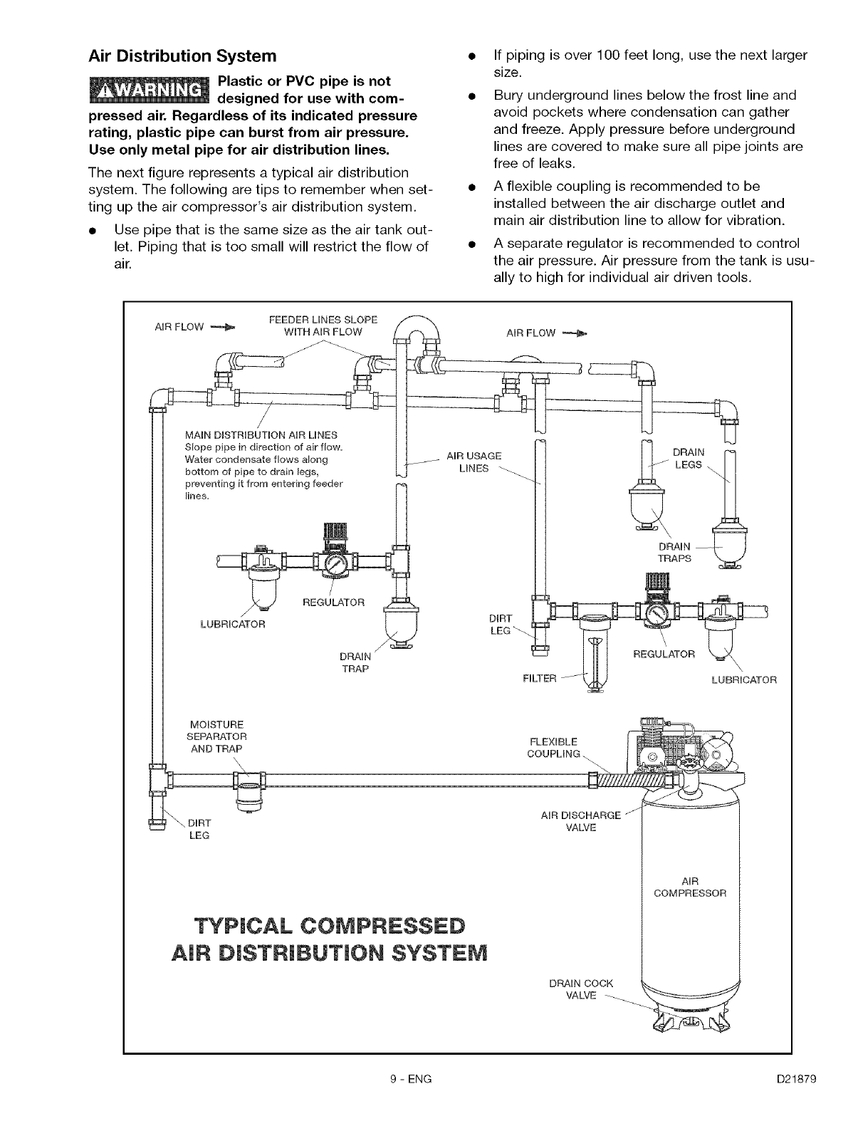
Air Distribution System
Plastic or PVC pipe is not
designed for use with com-
pressed air. Regardless of its indicated pressure
rating, plastic pipe can burst from air pressure.
Use only metal pipe for air distribution lines.
The next figure represents a typical air distribution
system. The following are tips to remember when set-
ting up the air compressor's air distribution system.
•Use pipe that is the same size as the air tank out-
let. Piping that is too small will restrict the flow of
air.
If piping is over 100 feet long, use the next larger
size.
Bury underground lines below the frost line and
avoid pockets where condensation can gather
and freeze. Apply pressure before underground
lines are covered to make sure all pipe joints are
free of leaks.
A flexible coupling is recommended to be
installed between the air discharge outlet and
main air distribution line to allow for vibration.
A separate regulator is recommended to control
the air pressure. Air pressure from the tank is usu-
ally to high for individual air driven tools.
LEG
TYPICAL COMPRESSED
AiR DiSTRiBUTiON SYSTEM
AUR DISCHARGE J
VALVE
DRAUN COCK
VALVE __
AUR
COMPRESSOR
9 - ENG D21879
Know Your Air Compressor
READ THIS OWNER'S MANUAL AND SAFETY RULES BEFORE OPERATING YOUR UNIT. Compare the illustra-
tions with your unit to familiarize yourself with the location of various controls and adjustments. Save this manual
for future reference.
Description of Operation
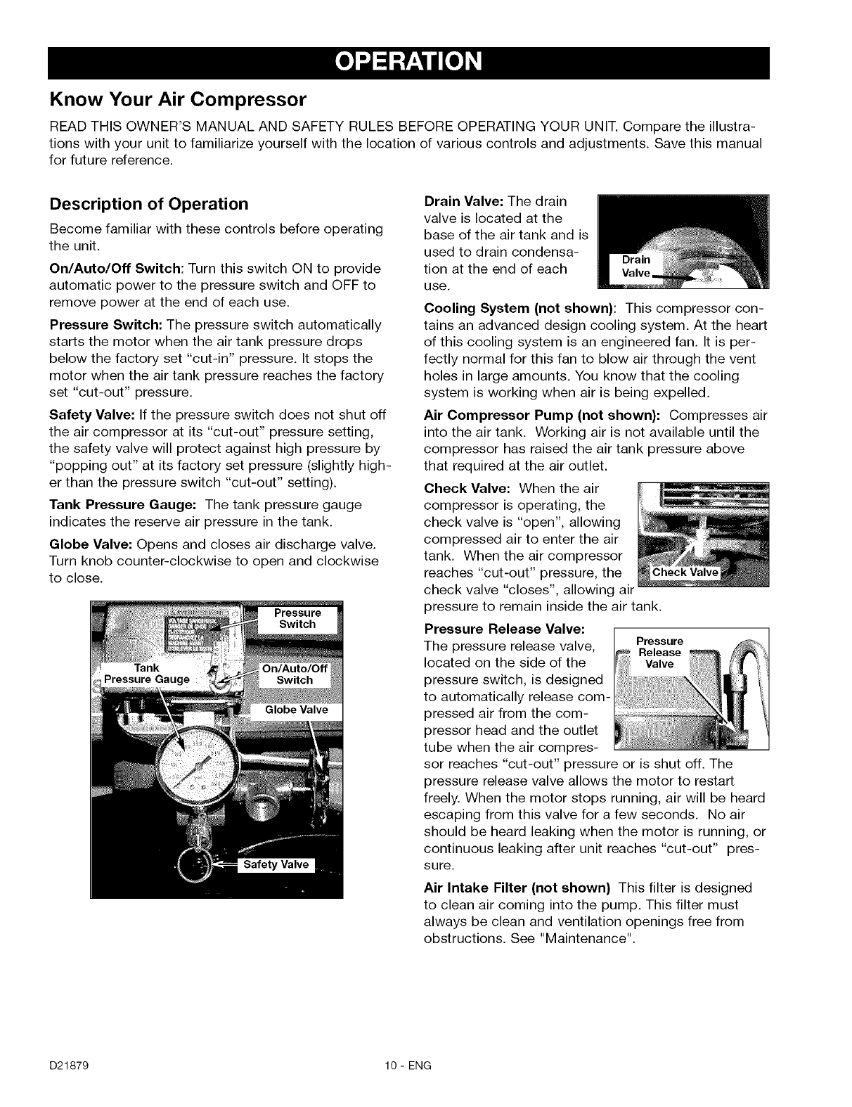
Become familiar with these controls before operating
the unit.
On/Auto/Off Switch: Turn this switch ON to provide
automatic power to the pressure switch and OFF to
remove power at the end of each use.
Pressure Switch: The pressure switch automatically
starts the motor when the air tank pressure drops
below the factory set "cut-in" pressure. It stops the
motor when the air tank pressure reaches the factory
set "cut-out" pressure.
Safety Valve: If the pressure switch does not shut off
the air compressor at its "cut-out" pressure setting,
the safety valve will protect against high pressure by
"popping out" at its factory set pressure (slightly high-
er than the pressure switch "cut-out" setting).
Tank Pressure Gauge: The tank pressure gauge
indicates the reserve air pressure in the tank.
Globe Valve: Opens and closes air discharge valve.
Turn knob counter-clockwise to open and clockwise
to close.
Drain Valve: The drain
valve is located at the
base of the air tank and is
used to drain condensa-
tion at the end of each
use.
Cooling System (not shown): This compressor con-
tains an advanced design cooling system. At the heart
of this cooling system is an engineered fan. It is per-
fectly normal for this fan to blow air through the vent
holes in large amounts. You know that the cooling
system is working when air is being expelled.
Air Compressor Pump (not shown): Compresses air
into the air tank. Working air is not available until the
compressor has raised the air tank pressure above
that required at the air outlet.
Check Valve: When the air
compressor is operating, the
check valve is "open", allowing
compressed air to enter the air
tank. When the air compressor
reaches "cut-out" pressure, the
check valve "closes", allowing air
pressure to remain inside the air tank.
Pressure Release Valve:
The pressure release valve, Pressure
Release
located on the side of the Valve
pressure switch, is designed
to automatically release com-
pressed air from the com-
pressor head and the outlet
tube when the air compres-
sor reaches "cut-out" pressure or
pressure release valve allows the motor to restart
freely. When the motor stops running, air will be heard
escaping from this valve for a few seconds. No air
should be heard leaking when the motor is running, or
continuous leaking after unit reaches "cut-out" pres-
sure.
is shut off. The
Air Intake Filter (not shown) This filter is designed
to clean air coming into the pump. This filter must
always be clean and ventilation openings free from
obstructions. See "Maintenance".
D21879 10 - ENG
How to Use Your Unit
How to Stop:
1. Set the On/Auto/Off lever to "OFF".
Before Starting
Break-in Procedure
_ Serious damage may result if the
following break-in instructions are
not closely followed.
This procedure is required before the air compressor
is put into service and when the check valve or a
complete compressor pump has been replaced.
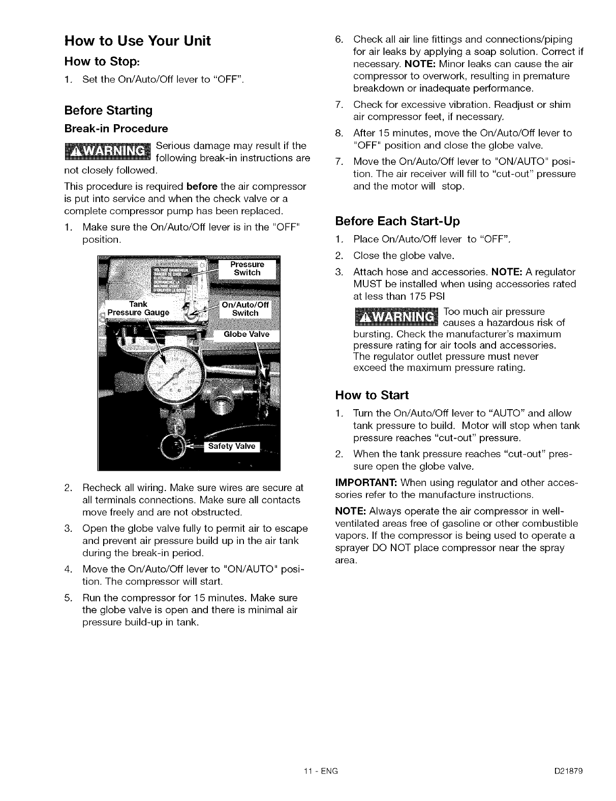
1. Make sure the On/Auto/Off lever is in the "OFF"
position.
2. Recheck all wiring. Make sure wires are secure at
all terminals connections. Make sure all contacts
move freely and are not obstructed.
3. Open the globe valve fully to permit air to escape
and prevent air pressure build up in the air tank
during the break-in period.
4. Move the On/Auto/Off lever to "ON/AUTO" posi-
tion. The compressor will start.
5. Run the compressor for 15 minutes. Make sure
the globe valve is open and there is minimal air
pressure build-up in tank.
6. Check all air line fittings and connections/piping
for air leaks by applying a soap solution. Correct if
necessary. NOTE: Minor leaks can cause the air
compressor to overwork, resulting in premature
breakdown or inadequate performance.
7. Check for excessive vibration. Readjust or shim
air compressor feet, if necessary.
8. After 15 minutes, move the On/Auto/Off lever to
"OFF" position and close the globe valve.
7. Move the On/Auto/Off lever to "ON/AUTO" posi-
tion. The air receiver will fill to "cut-out" pressure
and the motor will stop.
Before Each Start-Up
1. Place On/Auto/Off lever to "OFF".
.
3.
Close the globe valve.
Attach hose and accessories. NOTE: A regulator
MUST be installed when using accessories rated
at less than 175 PSI
Too much air pressure
causes a hazardous risk of
bursting. Check the manufacturer's maximum
pressure rating for air tools and accessories.
The regulator outlet pressure must never
exceed the maximum pressure rating.
How to Start
1. Turn the On/Auto/Off lever to "AUTO" and allow
tank pressure to build. Motor will stop when tank
pressure reaches "cut-out" pressure.
2. When the tank pressure reaches "cut-out" pres-
sure open the globe valve.
IMPORTANT: When using regulator and other acces-
sories refer to the manufacture instructions.
NOTE: Always operate the air compressor in well-
ventilated areas free of gasoline or other combustible
vapors. If the compressor is being used to operate a
sprayer DO NOT place compressor near the spray
area.
11 - ENG D21879
Customer Responsibilities
Before Daily or
after Frequently Yearly
each use each use
Check Safety Valve •
Drain Tank •
Air Filter (inspect and replace) •
Inspect air lines and fittings for leaks •
Air compressor pump intake and exhaust valves •
Unit cycles automatically when power is on. When performing maintenance, you may
be exposed to voltage sources, compressed air, or moving parts. Personal injuries
can occur. Before performing any maintenance or repair, disconnect power source from the compressor
and bleed off all air pressure.
To ensure efficient operation and longer life of the air compressor outfit, a routine maintenance schedule should
be prepared and followed. The following routine maintenance schedule is geared to an outfit in a normal working
environment operating on a daily basis. If necessary, the schedule should be modified to suit the conditions
under which your compressor is used. The modifications will depend upon the hours of operation and the work-
ing environment. Compressor outfits in an extremely dirty and/or hostile environment will require a greater fre-
quency of all maintenance checks.
NOTE: For the location of controls see "Discription of Operation" in the "Operation" section of this manual.
To Check Safety Valve
If the safety valve does
not work properly, over-
pressurization may occur, causing air tank
rupture or an explosion. Before starting com-
pressor, pull the ring on the safety valve to
make sure that the safety valve operates
freely. If the valve is stuck or does not operate
smoothly, it must be replaced with the same
type of valve.
To Drain Tank
1. Set the On/Auto/Off lever to "OFF".
2. Close the globe valve.
3. Remove the air tool or accessory.
4. Open the globe valve and allow the air to slowly
bleed from the air tank until tank pressure is
approximately 20 psi.
5. Drain water from air tank by opening drain valve
(counter-clockwise) on bottom of tank.
Water will condense in
the air tank. If not
drained, water will corrode and weaken the air
tank causing a risk of air tank rupture.
6. After the water has been drained, close the drain
valve (clockwise). The air compressor can now
be stored.
NOTE: If drain valve is plugged, release all air pres-
sure. The valve can then be removed, cleaned, then
reinstalled.
Air Filter -Inspection and Replacement
Hot surfaces. Risk of
burn. Compressor heads
are exposed when filter cover is removed.
Allow compressor to cool prior to servicing.
A dirty air filter will not allow the compressor to oper-
ate at full capacity. Keep the air filter clean at all
times.
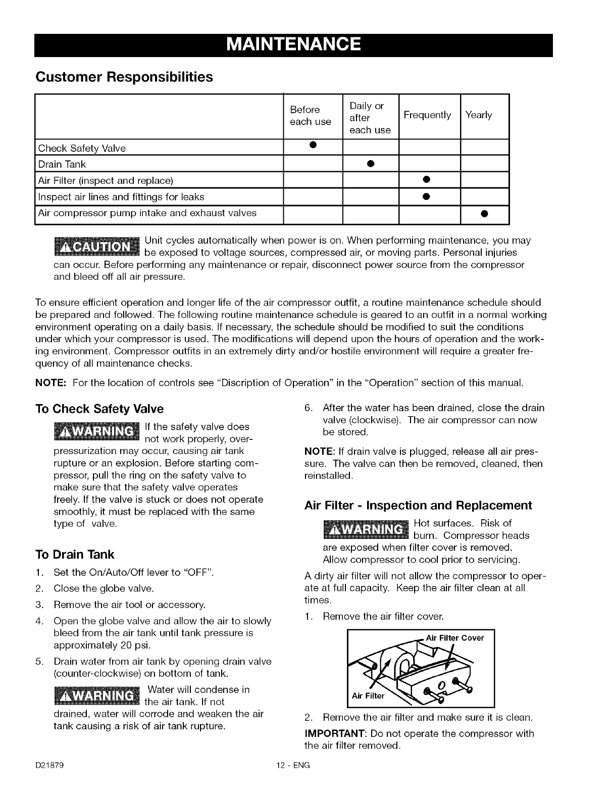
1. Remove the air filter cover.
_ver I
2. Remove the air filter and make sure it is clean.
IMPORTANT: Do not operate the compressor with
the air filter removed.
D21879 12- ENG
3. If dirty, rinse air filter with warm water and
squeeze dry.
4. Replace air filter and air filter cover.
NOTE: If the air filter is extremely dirty it will need to
be replaced. Refer to the "Parts Manual" for the cor-
rect part number.
Motor
The motor has an automatic reset thermal overload
protector. If the motor overheats for any reason, the
overload protector will shut off the motor. The motor
must be allowed to cool down before restarting. The
compressor will automatically restart after the motor
cools.
If the overload protector shuts the motor off frequent-
ly, check for a possible voltage problem. Low voltage
can also be suspected when:
1. The motor does not get up to full power or speed.
2. Fuses blow out when starting the motor; lights
dim and remain dim when motor is started and is
running.
Inspect Air Lines and Fittings for Leaks
1. Turn the air compressor on to inspect for air
leaks.
2. Apply a soap solution to all air line fittings and
connections/piping.
3. Correct any leaks found.
IMPORTANT: Even minor leaks can cause the air
compressor to overwork, resulting in premature
breakdown or inadequate performance.
Air Compressor Pump Intake and Exhaust
Valves
Once a year have a Trained Service Technician check
the air compressor pump intake and exhaust valves.
13-ENG D21879
automatically when power is on. When doing Maintenance, you may be exposed
sources, compressed air or moving parts. Personal injuries can occur. Before per-
forming any Maintenance or repair, unplug the compressor and bleed off all air pressure.
ALL MAINTENANCE AND REPAIR OPERATIONS NOT LISTED MUST BE PERFORMED BY
TRAINED SERVICE TECHNICIAN.
Before servicing: 6.
°Unplug or disconnect electrical supply to the
air compressor.
° Bleed tank of pressure.
° Allow the air compressor to cool.
To Replace or Clean Check Valve
1. Release all air pressure from air tank. See "To
Drain Tank" in the Maintenance section.
2. Unplug outfit.
3. Using a phillips screwdriver remove the air filter
cover.
4. Remove the rear shroud using I-20 torx wrench.
7.
8.
Using an adjustable wrench loosen pressure relief
tube nut at air tank and pressure switch. Carefully
move pressure relief tube away from check valve.
Unscrew the check valve (turn counterclockwise)
using a 7/8" open end wrench. Note the orienta-
tion for reassembly.
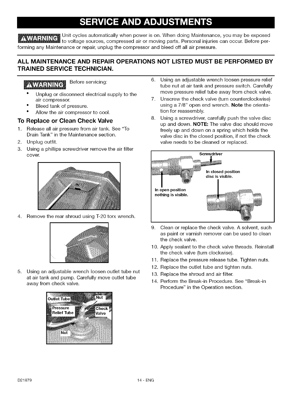
Using a screwdriver, carefully push the valve disc
up and down. NOTE: The valve disc should move
freely up and down on a spring which holds the
valve disc in the closed position, if not the check
valve needs to be cleaned or replaced.
Screwdriver
In closed position
disc is visible.
In open position
nothing is visible.
5. Using an adjustable wrench loosen outlet tube nut
at air tank and pump. Carefully move outlet tube
away from check valve.
9. Clean or replace the check valve. A solvent, such
as paint or varnish remover can be used to clean
the check valve.
10. Apply sealant to the check valve threads. Reinstall
the check valve (turn clockwise).
11. Replace the pressure release tube. Tighten nuts.
12. Replace the outlet tube and tighten nuts.
13. Replace the shroud and air filter.
14. Perform the Break-in Procedure. See "Break-in
Procedure" in the Operation section.
D21879 14- ENG
Before you store the air compressor, make sure you
do the following:
1. Review the "Maintenance" section on the preced-
ing pages and perform scheduled maintenance as
necessary.
2. Set the On/Auto/Off lever to "OFF".
3. Close the globe valve.
4. Remove the air tool or accessory.
5. Open the globe valve and allow the air to slowly
bleed from the air tank until tank pressure is
approximately 20 psi.
6. Drain water from air tank by opening drain valve
(counter-clockwise) on bottom of tank.
Water will condense in the
air tank. If not drained,
water will corrode and weaken the air tank
causing a risk of air tank rupture.
7. After the water has been drained, close the drain
valve.
NOTE: If drain valve is plugged, release all air pres-
sure. The valve can then be removed, cleaned, then
reinstalled.
8. Protect the air hose from damage (such as being
stepped on or run over).
15-ENG D21879
Performing repairs may expose voltage sources, moving parts or compressed air sources,
moving parts or compressed air sources. Personal injury may occur. Prior to attempting any
repairs, unplug the air compressor and bleed off all air tank air pressure.
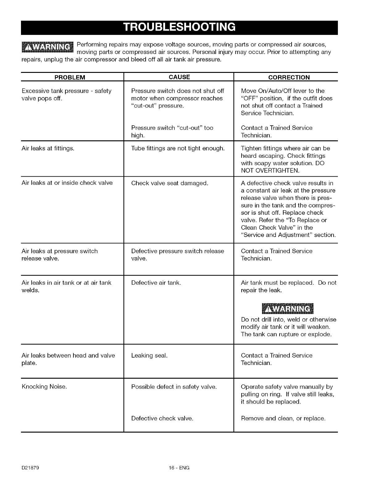
PROBLEM
Excessive tank pressure - safety
valve pops off.
Air leaks at fittings.
Air leaks at or inside check valve
Air leaks at pressure switch
release valve.
Air leaks in air tank or at air tank
welds.
Air leaks between head and valve
plate.
Knocking Noise.
CAUSE
Pressure switch does not shut off
motor when compressor reaches
"cut-out" pressure.
Pressure switch "cut-out" too
high.
Tube fittings are not tight enough.
Check valve seat damaged.
Defective pressure switch release
valve.
Defective air tank.
Leaking seal.
Possible defect in safety valve.
Defective check valve.
CORRECTION
Move On/Auto/Off lever to the
"OFF" position, if the outfit does
not shut off contact a Trained
Service Technician.
Contact a Trained Service
Technician.
Tighten fittings where air can be
heard escaping. Check fittings
with soapy water solution. DO
NOT OVERTIGHTEN.
A defective check valve results in
a constant air leak at the pressure
release valve when there is pres-
sure in the tank and the compres-
sor is shut off. Replace check
valve. Refer the "To Replace or
Clean Check Valve" in the
"Service and Adjustment" section.
Contact a Trained Service
Technician.
Air tank must be replaced. Do not
repair the leak.
Do not drill into, weld or otherwise
modify air tank or it will weaken.
The tank can rupture or explode.
Contact a Trained Service
Technician.
Operate safety valve manually by
pulling on ring. If valve still leaks,
it should be replaced.
Remove and clean, or replace.
D21879 16 - ENG
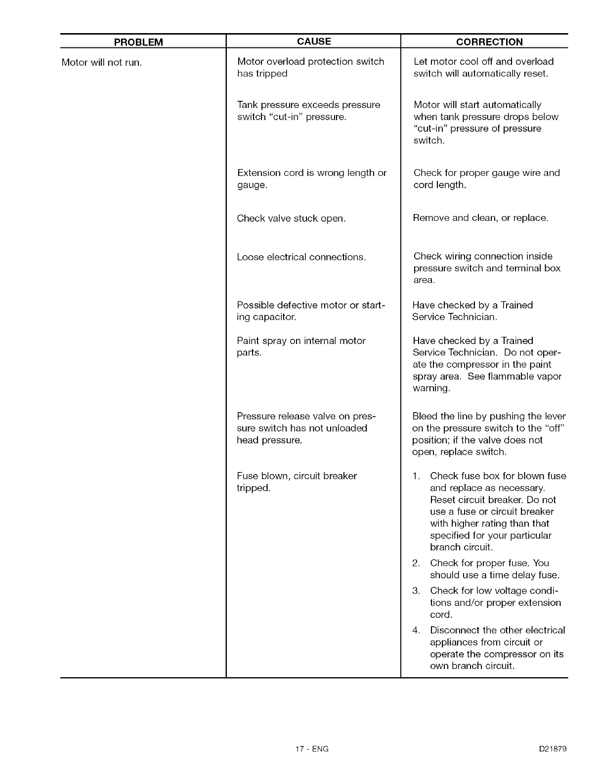
PROBLEM
Motor will not run.
CAUSE
Motor overload protection switch
has tripped
Tank pressure exceeds pressure
switch "cut-in" pressure.
Extension cord ts wrong length or
gauge.
Check valve stuck open.
Loose electrical connections.
Possible defective motor or start-
ing capacitor.
Paint spray on internal motor
parts.
Pressure release valve on pres-
sure switch has not unloaded
head pressure.
Fuse blown, circuit breaker
tripped.
CORRECTION
Let motor cool off and overload
switch will automatically reset.
Motor will start automatically
when tank pressure drops below
"cut-in" pressure of pressure
switch.
Check for proper gauge wire and
cord length.
Remove and clean, or replace.
Check wiring connection inside
pressure switch and terminal box
area.
Have checked by a Trained
Service Technician.
Have checked by a Trained
Service Technician. Do not oper-
ate the compressor in the paint
spray area. See flammable vapor
warning.
Bleed the line by pushing the lever
on the pressure switch to the "off"
position; if the valve does not
open, replace switch.
1. Check fuse box for blown fuse
and replace as necessary.
Reset circuit breaker. Do not
use a fuse or circuit breaker
with higher rating than that
specified for your particular
branch circuit.
2. Check for proper fuse. You
should use a time delay fuse.
3. Check for low voltage condi-
tions and/or proper extension
cord.
4. Disconnect the other electrical
appliances from circuit or
operate the compressor on its
own branch circuit.
17-ENG D21879
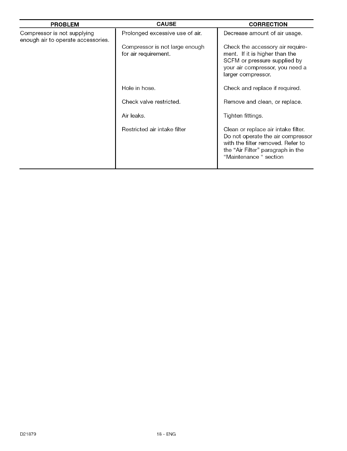
PROBLEM
Compressor is not supplying
enough air to operate accessories.
CAUSE
Prolonged excessive use of air.
Compressor is not large enough
for air requirement.
Hole in hose.
Check valve restricted.
Air leaks.
Restricted air intake filter
CORRECTION
Decrease amount of air usage.
Check the accessory air require-
ment. If it is higher than the
SCFM or pressure supplied by
your air compressor, you need a
larger compressor.
Check and replace if required.
Remove and clean, or replace.
Tighten fittings.
Clean or replace air intake filter.
Do not operate the air compressor
with the filter removed. Refer to
the "Air Filter" paragraph in the
"Maintenance " section
D21879 18 - ENG
GARANTIA .............................. 19
NORMAS DE SEGURIDAD .............. 20-23
GLOSARIO .............................. 24
ACCESORIOS ........................... 24
ENSAMBLADO ........................... 24
Contenido de la caja .................... 24
C6mo extraer el compresor de aire
de la caja ............................. 24
Desembalaje .......................... 24
INSTALAClON ........................... 25
Ubicaci6n del compresor de aire .......... 25
Instrucciones para conectar a tierra ....... 25
Extensiones el@ctricas .................. 25
Protecci6n del voltaje y del circuito ........ 25
Sistema de distribuci6n de aire ........... 26
PROCEDIMIENTOS OPERATIVOS ........ 27-28
Conozca su compresor de aire ............ 27
Descripci6n de operaciones .............. 27
Como usar su unidad ................... 28
Como detenerla ....................... 28
Antes de poner en marcha ............... 28
Procedimiento para el asentamiento ....... 28
Antes de cada puesta en marcha .......... 28
C6mo ponder en marcha ................ 28
MANTENIMIENTO ..................... 29-30
C6mo verificar la v6.1vulade seguridad ..... 29
C6mo drenar el tanque .................. 29
Filtro de Aire - Inspecci6n y reemplazo ..... 29
Motor ................................ 30
Inspecci6n de las caSerias de aire y las
conexiones para detectar fugas ........... 30
V_.lvulas de entrada y escape de la
bomda del compessor de aire ............ 30
SERVIClOS Y REGULAClONES ............. 31
Para reemplazo o limpiar la v_.lvula
de retenci6n .......................... 31
ALMACENAJE ........................... 32
GU[A DE DIAGNOSTICO DE PROBLEMAS .33-35
COMO SOLICITAR PIEZAS
PARA REPARACION ............... contratapa
GARANTiA COMPLETA POR UN AI_IO
COMPRESOR DE AIRE
Si este compresor de aire fallara por defectos en materiales o mano de obra dentro del lapso de un aSoa partir de la
fecha de su compra, DEVUC:LVALOAL CENTRO DE REPARACIONESSEARS MAS CERCANO DENTRODE LOS
ESTADOSUNIDOS, Y SEARS LO REPARARA,LIBREDE CARGO. Si se hubiese comprado a Orchard Supply
Hardware, devu@lvaloal comercio Orchard mas cercano y Orchard Io reparara, libre de cargo.
Si este compresor de aire fuese utilizado para prop6sitos comerciales o de alquiler, la garantia solo tendra validez
por noventa dias a partir de la compra.
Esta garantia le otorga derechos legales especificos, aunque usted podrA tener otros derechos que podrian variar
entre estados.
Sears, Roebuck and Co., Dept. 817WA, Hoffman Estates, II 60179
19- SP D21879
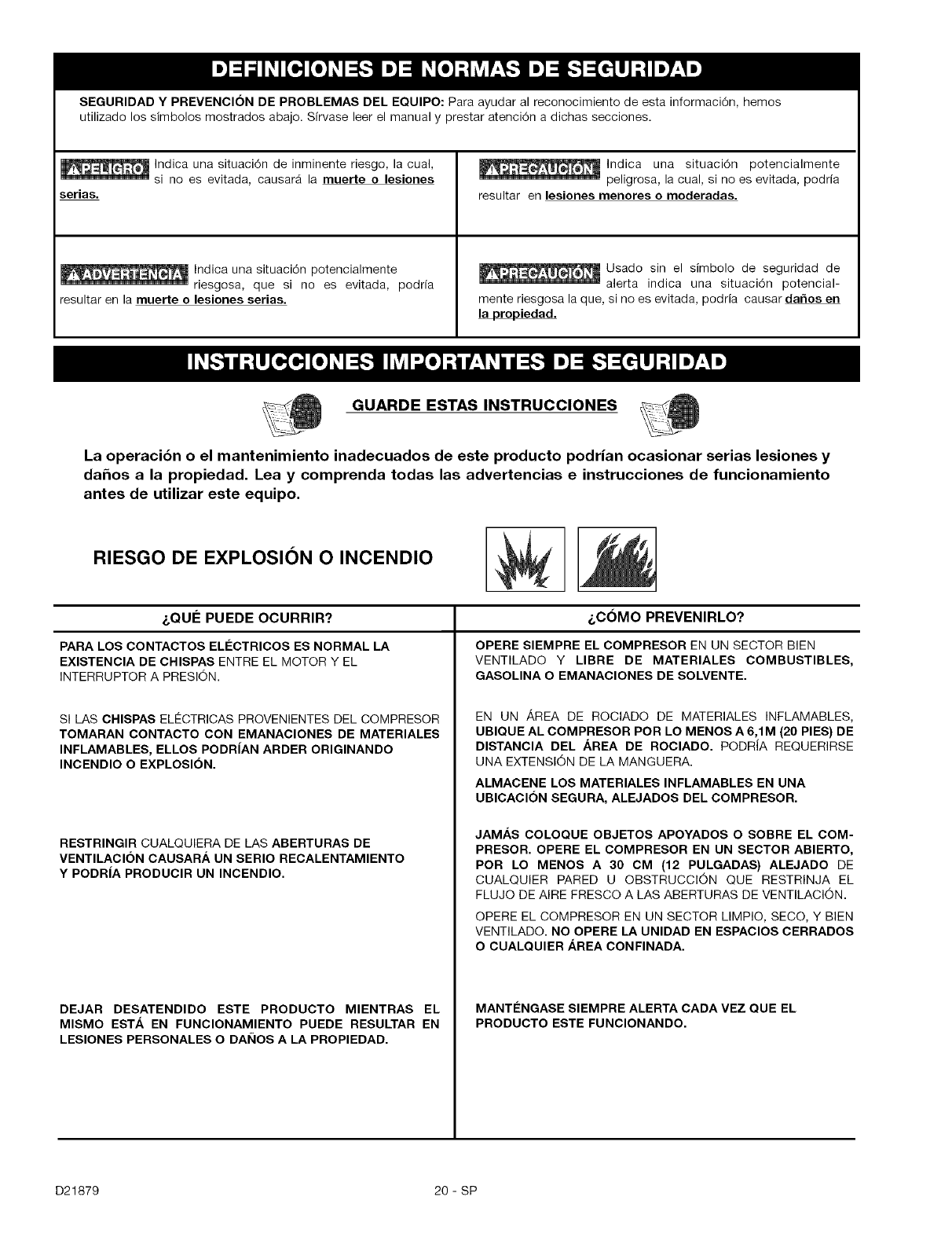
SEGURIDAD Y PREVENCION DE PROBLEMAS DEL EQUIPO: Para ayudar al reconocimiento de esta informaci6n, hemos
utilizado los sfmbolos mostrados abajo. Sfrvase leer el manual y prestar atenci6n a dichas secciones.
In.dica una situaci6n de inminente riesgo, la cual,
sl no es evitada, causarA la muerte o lesiones
serias.
Indica una situaci6n potencialmente
riesgosa, que si no es evitada, podrfa
resultar en la muerte o lesiones serias.
_lndica una situaci6n potencialmente
peligrosa, la cual, si no es evitada, podrfa
resultar en lesiones menores o moderadas.
Usado sin el simbolo de seguridad de
alerta indica una situaci6n potencial-
mente riesgosa la que, si no es evitada, podria causar da_os en
la propiedad.
GUARDE ESTAS INSTRUCClONES
La operacibn o el mantenimiento inadecuados de este producto podrian ocasionar serias lesiones y
dahos a la propiedad. Lea y comprenda todas las advertencias e instrucciones de funcionamiento
antes de utilizar este equipo.
RIESGO DE EXPLOSION O INCENDIO
&QUI_ PUEDE OCURRIR?
PARA LOS CONTACTOS ELI_CTRICOS ES NORMAL LA
EXISTENCIA DE CHISPAS ENTRE EL MOTOR Y EL
INTERRUPTOR A PRESION.
SI LAS CHISPAS ELECTRICAS PROVENIENTES DEL COMPRESOR
TOMARAN CONTACTO CON EMANACIONES DE MATERIALES
INFLAMABLES, ELLOS PODRIAN ARDER ORIGINANDO
INCENDIO O EXPLOSION.
RESTRINGIR CUALQUIERA DE LAS ABERTURAS DE
VENTILACION CAUSARh. UN SERIO RECALENTAMIENTO
Y PODRIA PRODUCIR UN INCENDIO.
DEJAR DESATENDIDO ESTE PRODUCTO MIENTRAS EL
MISMO ESTA EN FUNCIONAMIENTO PUEDE RESULTAR EN
LESIONES PERSONALES O DAI_IOS A LA PROPIEDAD.
&C6MO PREVENIRLO?
OPERE SIEMPRE EL COMPRESOR EN UN SECTOR BEN
VENTILADO Y LIBRE DE MATERIALES COMBUSTIBLES,
GASOLINA O EMANACIONES DE SOLVENTE.
EN UN AREA DE ROCIADO DE MATERIALES INFLAMABLES,
UBIQUE AL COMPRESOR POR LO MENOS A 6,1M (20 PIES) DE
DISTANCIA DEL h.REA DE ROCIADO. PODRJA REQUERIRSE
UNA EXTENSION DE LA MANGUERA.
ALMACENE LOS MATERIALES INFLAMABLES EN UNA
UBICAClON SEGURA, ALEJADOS DEL COMPRESOR.
JAMAS COLOQUE OBJETOS APOYADOS O SOBRE EL COM-
PRESOR. OPERE EL COMPRESOR EN UN SECTOR ABIERTO,
POR LO MENOS A 30 CM (12 PULGADAS) ALEJADO DE
CUALQUIER PARED U OBSTRUCCION QUE RESTRINJA EL
FLUJO DE AIRE FRESCO A LAS ABERTURAS DE VENTILACION.
OPERE EL COMPRESOR EN UN SECTOR LIMPIO, SECO, Y BEN
VENTILADO. NO OPERE LA UNIDAD EN ESPACIOS CERRADOS
O CUALQUlER AREA CONFINADA.
MANTI_NGASE SIEMPRE ALERTA CADA VEZ QUE EL
PRODUCTO ESTE FUNCIONANDO.
D21879 20-SP
RIESGO DE EXPLOSION
TANQUE DE AIRE: LAS SIGUIENTES CONDICIONES PUEDEN DETERMINAR EL DEBILITAMIENTO
DEL TANQUE, Y ORIGINAR UNA VIOLENTA EXPLOSION DEL MISMO, SIENDO CAUSA DE DAKIOS A
LA PROPIEDAD 0 LESIONES SERIAS.
2.
3.
&QU¢: PUEDE OCURRIR? _,C6MO PREVENIRLO?
DRENAJE INADECUADO DEL AGUA CONDENSADA EN
EL TANQUE, SlENDO LA CAUSA DEL 0XIDO QUE REDUCE
EL ESPESOR DEL TANQUE DE ACERO.
MODIFICACIONES O INTENTO DE REPARACIONES AL
TANQUE.
MODIFICACIONES NO AUTORIZADAS A LA VALVULA DE
DESCARGA, VALVULA DE SEGURIDAD O CUALQUIER
OTRO COMPONENTE QUE CONTROLE LA PRESION DEL
TANQUE.
LA VIBRACION EXCESIVA PUEDE DEBILITAR EL TANQUE
DE AIRE Y CAUSAR SU RUPTURA O EXPLOSION.
AGREGADOS Y ACCESORIOS
EL EXCESO A LOS VALORES DE PRESION ESTABLECIDOS
PARA LAS HERRAMIENTAS NEUMATICAS, PISTOLAS ROCIADO-
RAS, ACCESORIOS ACTIVADOS POR AIRE, CUBIERTAS Y OTROS
OBJETOS INFLABLES, PUEDE CAUSAR SU EXPLOSION O SER
ARROJADOS, PUDIENDO OCASlONAR SERIAS LESlONES.
DRENE EL TANQUE DIARIAMENTE O DESPUleS DE CADA USO.
Sl EL TANQUE GENERA UNA PCRDIDA, REEMPLACELO
INMEDIATAMENTE CON UN NUEVO TANQUE O REEMPLACE EL
COMPRESOR COMPLETO.
JAMAS PERFORE, SUELDE, O EFECTUE MODIFICACION ALGUNA
AL TANQUE O SUS ACCESORIOS.
EL TANQUE ESTA DISENADO PARA RESISTIR PRESIONES
OPERATIVAS ESPECiFICAS. JAMAS EFECTUE AJUSTES O
SUSTITUYA PARTES QUE ALTEREN LAS REGULACIONES DE
PRESION ORIGINALES DE FABRICA.
PARA UN CONTROL ESENCIAL DE LA PRESION, DEBE USTED
INSTALAR UN REGULADOR Y UN MEDIDOR DE PRESlON A LA
SALIDA DEL AIRE DE SU COMPRESOR. (SI NO ESTUNIER
EQUIPADO) SIGA LAS RECOMENDACIONES DE LOS
FABRICANTES DE SU EQUIPO Y JAMAS EXCEDA LOS VALORES
Mi_XIMOS DE PRESION PERMITIDOS PARA LOS ACCESORIOS.
JAMAS USE EL COMPRESOR PARA INFLAR OBJETOS QUE
REQUIEREN POOA O BAJA PRESlON, TALES COMO
JUGUETES PARA LOS NII_IOS, PELOTAS DE FUTBOL, PELOTAS
DE BASQUET, ETC.
RIESGO DE OBJETOS ARROJADOS POR EL AIRE.
&QUEPUEDE OCURRIR?
EL CHORRO DE AIRE COMPRIMIDO PUEDE CAUSAR DAI_IOS
SOBRE LOS TEJIDOS BLANDOS DE LA PIEL EXPUESTA, Y
PUEDE PROPULSAR SUCIEDAD, ASTILLAS, PARTJCULAS
SUELTAS Y PEQUE_IOSOBJETOS A ALTA VELOClDAD, OCASIONANDO
DANOS A LA PROPIEDAD O LESIONES PERSONALES.
i,C6MO PREVENIRLO?
AL UTILIZAR EL COMPRESOR, USE SlEMPRE ANTEOJOS DE
SEGURIDAD ANSI Z87.1 APROBADOS, CON PROTEOCION
LATERAL.
JAMAS APUNTE NINGUNA BOQUlLLA O PULVERIZADOR
HAOIA PARTES DEL OUERPO, A OTRAS PERSONAS O
ANIMALES.
APAGUE SIEMPRE EL COMPRESOR Y PURGUE LA PRESION
DE LA MANGUERA DEL AIRE Y DEL TANQUE, ANTES DE INTENTAR
EL MANTENIMIENTO, EL AOOPLE DE HERRAMIENTAS O
ACCESORIOS.
21 - SP D21879
RIESGO DE DESCARGA ELECTRICA
_,QU¢: PUEDE OCURRIR?
SU COMPRESOR DE AIRE ESTIk ACCIONADO POR ELECTRICIDAD.
COMO CUALQUIER OTRO DISPOSITIVO ELt_CTRICO IMPULSADO
EL¢CTRICAMENTE, Sl NO SE LO UTILIZA ADECUADAMENTE,
PODRIA CAUSARLE UNA DESCARGA ELleCTRICA.
LAS REPARAClONES INTENTADAS POR PERSONAL NO
CALIFICADO PODRIAN OCASlONAR SERIAS LESlONES O LA
MUERTE POR ELECTROCUCION.
CONEXION A TIERRA: DEJAR DE PROVEER UNA ADECUADA
CONEXlON A TIERRA A ESTE PRODUCTO PODRIA OCASlONAR
LESlONES SERIAS O LA MUERTE POR ELECTROCUCION. VER
INSTRUCCIONES PARA LA PUESTA A TERRA.
&COMO PREVENIRLO?
JAM/kS OPERE EL COMPRESOR A LA INTEMPERIE CUANDO
ESTIk LLOVlENDO O EN CONDICIONES DE HUMEDAD.
NUNCA OPERE EL COMPRESOR SIN SUS DEFENSAS O SUS
CUBIERTAS REMOVIDAS O DAI_IADAS.
CUALQUIER CONEXION ELleCTRICA OREPARACION
REQUERIDA POR ESTE PRODUCTO DEBE SER EFECTUADA
POR PERSONAL AUTORIZADO DE LOS SERVICENTROS DE
ACUERDO A LOS CODIGOS ELt_CTRICOS NACIONALES Y
LOCALES.
ASEGORESE QUE EL ClRCUlTO ELleCTRICO AL CUAL ESTIk
CONECTADO EL COMPRESOR, SUMINISTRA APROPIADA
CONEXlON A TIERRA, TENSION CORRECTA Y UNA ADECUADA
PROTECCION DE FUSlBLES.
RIESGO DE INHALACION
_,QU¢: PUEDE OCURRIR? &COMO PREVENIRLO?
EL AIRE COMPRIMIDO PROVENIENTE DEL COMPRESOR NO
ES SANO PARA RESPIRAR. EL CHORRO DE AIRE PUEDE
CONTENER MONOXlDO DE CARBONO, VAPORES T(_XlCOS O
PARTJCULAS SOLIDAS PROVENIENTES DEL TANQUE. LA
INHALACION DE DICHOS CONTAMINANTES PUEDE LLEGAR A
CAUSAR SERIAS LESlONES O LA MUERTE.
EL ROCIADO DE MATERIALES TALES COMO PINTURA,
SOLVENTES, REMOVEDORES DE PINTURA, INSECTICIDAS, MATA
HIERBAS, CONTIENEN EMANACIONES DANINAS Y VENENOSAS.
EL AIRE OBTENIDO DIRECTAMENTE DEL COMPRESOR JAMAS
DEBERA SER UTILIZADO PARA PROVEER AIRE PARA CONSUMO
HUMANO. PARA PODER UTILIZAR EL AIRE PRODUCIDO POR
ESTE COMPRESOR Y HACERLO RESPIRABLE, DEBERAN
INSTALARSE UN FILTRO ADECUADO Y UN EQUIPO DE
SEGURIDAD INTERCALADO. LOS FILTROS INTERCALADOS
TANTO COMO EL EQUIPO DE SEGURIDAD UTILIZADO EN
CON JUNTO CON EL COMPRESOR, DEBERAN SER CAPACES
DE PROCESAR EL TRATAMIENTO DEL AIRE DE ACUERDO A
TODOS LOS CODIGOS LOCALES Y FEDERALES, PREVIO AL
CONSUMO HUMANO.
TRABAJE EN UN AREA CON BUENA VENTILACION CRUZADA.
LEA YSIGA LAS INSTRUCCIONES DE SEGURIDAD PROVISTAS
EN EL ROTULO O EN LOS DATOS DE LAS HOJAS DE SEGURIDAD
DEL MATERIAL QUE EsTA PULVERIZANDO. USE EL RESPIRADOR
APROBADO NIOSH/MSHA DESIGNADO PARA UTILIZARSE CON
SU APLICACION ESPECiFICA.
D21879 22- SP
RIESGO DE QUEMADURAS
_QUEPUEDE OCURRIR?
TOCAR EL METAL EXPUESTO TAL COMO EL CABEZAL DEL
COMPRESOR O LOS TUBOS DE SALIDA DEL ESCAPE, PUEDE
OCASlONARLE SERIAS QUEMADURAS.
&COMO PREVENIRLO?
JAMAS TOQUE PARTES DE METAL EXPUESTAS EN EL
COMPRESOR DURANTE O INMEDIATAMENTE DESPUES DE LA
OPERACION. EL COMPRESOR PERMANECERA CALIENTE
POR VARIOS MINUTOS LUEGO DE LA OPERACION.
NO LO CUBRA CON FUNDAS PROTECTORAS O INTENTE EL
MANTENIMIENTO HASTA OUE LA UNIDAD HAY,&.ALCANZADO
SU ENFRIAMIENTO.
RIESGO DE PARTES MOVILES
_QUEPUEDE OCURRIR?
PARTES MOVIBLES TALES COMO LA POLEA, EL VOLANTE Y LA
CORREA PODRiAN SER LA OAUSA DE SERIAS LESlONES SI
ELLAS ENTRARAN EN CONTACTO CON USTED O SUS ROPAS.
INTENTAR OPERAR EL OOMPRESOR CON SUS PARTES
DAI_IADAS O FALTANTES, O LA REPARACION DEL OOMPRESOR
CON SUS PROTECOIONES REMOVIDAS, PUEDE EXPONERLO
A USTED A PARTES MOVIBLES, OUE PODRiAN RESULTAR EN
LESlONES SERIAS.
&COMO PREVENIRLO?
NUNCA OPERE EL COMPRESOR SIN SUS DEFENSAS O SUS
CUBIERTAS REMOVIDAS O DANADAS.
CUALQUIER REPARACION REQUERIDA POR ESTE PRODUCTO
DEBE SER EFECTUADA POR PERSONAL AUTORIZADO DE
LOS SERVICENTROS.
RIESGO DE CAIDA
&QU¢: PUEDE OCURRIR? &COMO PREVENIRLO?
UN COMPRESOR PORTATIL PUEDE CAERSE DE LA MESA, EL
BANCO DE TRABAJO O DEL TECHO DAI_IANDO AL COMPRESOR Y
PUDIENDO RESULTAR EN SERIAS LESlONES O LA MUERTE
DEL OPERADOR.
OPERE SlEMPRE EL COMPRESOR EN UNA POSlClON
ESTABLE Y SEGURA A FIN DE PREVENIR EL MOVIMIENTO
ACCIDENTAL DE LA UNIDAD. JAMAS OPERE EL OOMPRESOR
SOBRE UN TEOHO U OTRA POSlClON ELEVADA. UTILICE
MANGUERAS ADICIONALES DE AIRE PARA ALCANZAR
POSlCIONES ALTAS.
RIESGO DE DAI_IOS A LA PROPIEDAD AL TRANSPORTAR
EL COMPRESOR
(Fuego, inhalacion, daho a la superficie de vehiculos}
Para unidades que requieran aceite en la bomba o motores agasofina.
&QUI_ PUEDE OCURRIR? &COMO PREVENIRLO?
EL ACEITE PUEDE DERRAMARSE Y ELLO PODRiA RESULTAR
EN SERIAS LESIONES O LA MUERTE DEBIDO AL RIESGO DE
INCENDIO O INHALACION. EL DERRAME DE ACEITE DANA
ALFOMBRAS, PINTURAS U OTRAS SUPERFICIES DE VEHiCULOS
O REMOLQUES.
DEPOSlTE EL COMPRESOR SOBRE UNA ALFOMBRILLA PRO-
TEOTORA OUANDO LO TRANSPORTE. A FIN DE PROTEGER AL
VEHiCULO DE PERDIDAS POR GOTEO, RETIRE EL COMPRESOR
DEL VEHiCULO INMEDIATAMENTE DESPUES DE SU ARRIBO AL
DESTINO.
23 - SP D21879
Familiar[cese con los siguientes terminos, antes de operar la
unidad:
Cfm: (Cubic feet per minute) Pies cObicos per minute.
SCFM: (Stardard cubic feet per minute) Pies cQbicos estandar
por minuto; una unidad de medida que permite medir la canti-
dad de entrega de aire.
PSIG: (Pound per square inch) Ubras por pulgada cuadrada.
ASME: American Society of Mechanical Engineers
(Sociedad Americana de Ingenieros Mecanicos); hecho
probado inspeccionado y registrado en cumplimiento de los
estandares de la ASME.
Cbdigo de certificacibn: Los productos que usan una o
mas de las siguientes marcas: UL, CUL, ETL, CETL, han
sido evaluados por OSHA, laboratorios independientes cer-
tificados en seguridad, y reOnen los estandares suscriptos
por los laboratorios dedicados a la certificaci6n de la
seguridad.
Presibn minima de corte: Cuando el motor esta apagado,
la presi6n del tanque de aire baja a medida que usted con-
tinQa usando su accesorio. Cuando la presi6n del tanque
baja al valor fijado en fabrica come punto bajo, el motor
volvera a arrancar automaticamente. La presi6n baja a la
cual el motor arranca automaticamente, se llama presidn
"minima de corte".
Presi6n maxima de corte: Cuando un compresor de aire
se enciende y comienza a funcionar, la presi6n de aire en el
tanque comienza a aumentar. Aumenta hasta un valor de
presi6n alto fijado en fabrica antes de que el motor
automaticamente se apague protegiendo a su tanque de
aire de presiones mas altas que su capacidad. La presi6n
alta a la cual el motor se apaga se llama presi6n "mAxima
de "corte".
Ramal: Circuito electrico que transporta electricidad desde
el panel de control hasta el tomacorriente.
Los accesorios y las herramientas se encuentran disponibles a trav6s del cat_.logo actual de Herramientas el6c-
tricas y de mano, o la linea completa en los comercios Sears.
Accesorios
• Filtro en I[nea
• Entrada de aire a neumaticos
• Juegos de conectores rapidos (varios tama5os)
• Reguladores de presi6n de aire
• Lubricadores de niebla de aceite
• Manguera de aire:
W', 3/8" o 1/2" D.I. en varias medidas
Refi6rase al grafico de selecci6n ubicado sobre la unidad, para elegir el tipo de herramienta que esta unidad es
capaz de hacer funcionar.
Contenido de la Caja
1 - Compresor de aire
1 - Bolsa de piezas conteniendo Io siguiente:
1 - Manual del operador
1 - Manual de piezas
4 - Arandelas de 5/8"
Herramientas requeridas para el
Ensamblado
1 - Llave de tubo 9/16" o Ilave mec_.nica de boca
abierta
Desembalaje
1. Extraiga todo el embalaje
2,
3.
Podra ser necesario
apuntalar o soportar un lado del equipo al extraer la
plataforma, porque el compresor de aire tendera a
inclinarse.
Extraiga y descarte los (4) tornillos y arandelas que
sujetan el compresor a la plataforma.
Con la ayuda de otra persona, remueva cuidadosa-
mente el compresor de aire de su plataforma y
col6quelo sobre una plataforma nivelada.
D21879 24-SP
COMO PREPARAR LA UNIDAD
Ubicacion del compresor de aire
•Instale el compresor de aire en una zona limpia, seca y
bien ventilada.
• Instale el compresor de aire a una distancia no menor
de 30 cm (12") de la pared u otras obstrucciones que
pudiesen interferir con el flujo del aire.
•Instale el compresor de aire Io mas cerca posible del
sitio de alimentaci6n electrica, a fin de evitar el use de
largas extensiones de cableado electrico. NOTA: Las
extensiones electricas demasiado largas pueden causar
una caida de tensi6n perjudicial para la alimentaci6n
del motor.
• El filtro de aire debe mantenerse libre de obstrucciones
que pudiesen reducir el flujo del aire al compresor.
Anclaje del compresor de aire
La vibraci6n excesiva
puede debilitar al tanque
de aire y causar su
explosi6n. El compresor debe estar montado ade-
cuadamente.
El compresor de aire DEBE estar abulonado a una
superficie s61ida y nivelada.
Elementos necesarios:
4 - Tarugos para anclajes en cemento
4 - Tornillos tirafondo de 3/8" capaces de Ilenar los
tarugos para anclaje en cemento (no provistos)
4 - Arandelas 5/8" (en la bolsa de piezas)
Cu_as (en case de ser necesario)
1. Instale el compresor de aire sobre una superficie s61ida
y nivelada.
2. Marque la superficie utilizando como plantilla, los orificios
existentes en el compresor de aire.
3. Perfore la superficie, a fin de penetrar los tarugos para
anclaje en el cemento. Coloque los tarugos en el cemento.
4. Haga coincidir la alineaci6n de los orificios de la
superficie, con el de las patas del compresor de aire.
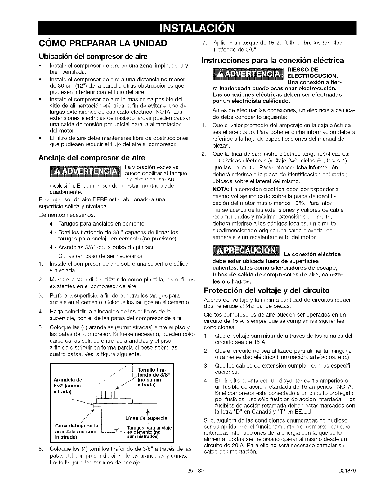
5. Coloque las (4) arandelas (suministradas) entre el piso y
las patas del compresor. Si fuese necesario, pueden cole-
carse cu_as s61idas entre las arandelas y el piso
a fin de distribuir en forma pareja el peso sobre las
cuatro patas. Vea la figura siguiente.
7. Aplique un torque de 15-20 ft-lb, sobre los tornillos
tirafondo de 3/8".
Instrucciones para la conexion el_ctrica
RIESGO DE
ELECTROCUCION.
Una conexi6n a tier-
ra inadecuada puede ocasionar electrocucibn.
Las conexiones el_ctricas deben ser efectuadas
por un electricista calificado.
Antes de efectuar las conexiones, un electricista califica-
do debe conocer Io siguiente:
1. Que el valor promedio del amperaje en la caja electrica
sea el adecuado. Para obtener dicha informaci6n debera
referirse a la hoja de especificaciones del manual de
piezas.
2. Que la Ifnea de suministro electrico tenga identicas car-
acterfsticas electricas (voltaje-240, ciclos-60, fases-1)
que las del motor. Para obtener dicha informaci6n
debera referirse a la placa de identificaci6n del motor,
ubicada sobre el lateral del mismo.
NOTA: La conexi6n electrica debe corresponder al
mismo voltaje indicado sobre la placa de identifi-
caci6n del motor mas o menos 10%. Para infor-
marse acerca de las extensiones y calibres de cable
recomendadas y maxima extensi6n del circuito,
debera referirse a los c6digos locales; un circuito
subdimensionado origina una ca[da elevada del
amperaje y un recalentamiento del motor.
La conexi6n electrica
debe estar ubicada fuera de superficies
calientes, tales como silenciadores de escape,
tubos de salida de compresores de aire, cabeza-
les o cilindros.
Proteccion del voltaje y del circuito
Acerca del voltaje y la minima cantidad de circuitos requeri-
dos, refierase al Manual de piezas.
Ciertos compresores de aire pueden ser operados en un
circuito de 15 A, siempre que se cumplan las siguientes
condiciones:
1. Que el voltaje suministrado a traves de los ramales del
circuito sea de 15 A.
Tornillo tira-
fondo de 3/8"
Arandela de ......
5/8" (sumin- •...... istrado)
istrada)
Linea de supercie
Cuna debalo de la
lebajo de la IL Tarugospara anclaje
arandela (no sum- _en cemento (no
inistrada) suministrados)
Coloque los (4) tornillos tirafondo de 3/8" a traves de las
patas del compresor de aire; de las arandelas y cu_as,
hasta Ilegar a los tarugos de anclaje.
25 - sP
2. Que el circuito no sea utilizado para alimentar ninguna
otra necesidad electrica (iluminaci6n, artefactos, etc.)
3. Que los cables de extensi6n cumplan con las especifi-
caciones.
4. El circuito cuenta con un disyuntor de 15 amperios o
un fusible de acci6n retardada de 15 amperios. NOTA:
Si el compresor esta conectado a un circuito protegido
per fusibles, use s61o fusibles de acci6n retardada. Los
fusibles de acci6n retardada deben estar marcados con
la letra "D" en Canada y "T" en EE.UU.
Si cualquiera de las condiciones enumeradas no pudiese
set cumplida, o si el funcionamiento del compresocausara
reiteradas interrupciones de la energ[a con la que se Io
alimenta, podr[a set necesario operar al mismo desde un
circuito de 20 A. Para ello no sera necesario cambiar su
cable de limentaci6n.
D21879
Sistema de distribucion de aire
o _ o _ Los tubos de
pl&stico o PVC no
han sido disehados para usarlos con aire
comprimido. Independientemente de Io
que est6 indicado como especificacibn de
presibn, las caherias de pl&stico pueden
explotar debido a la presibn del aire. Utilice
solamente cahos de metal para los
ramales de distribucibn.
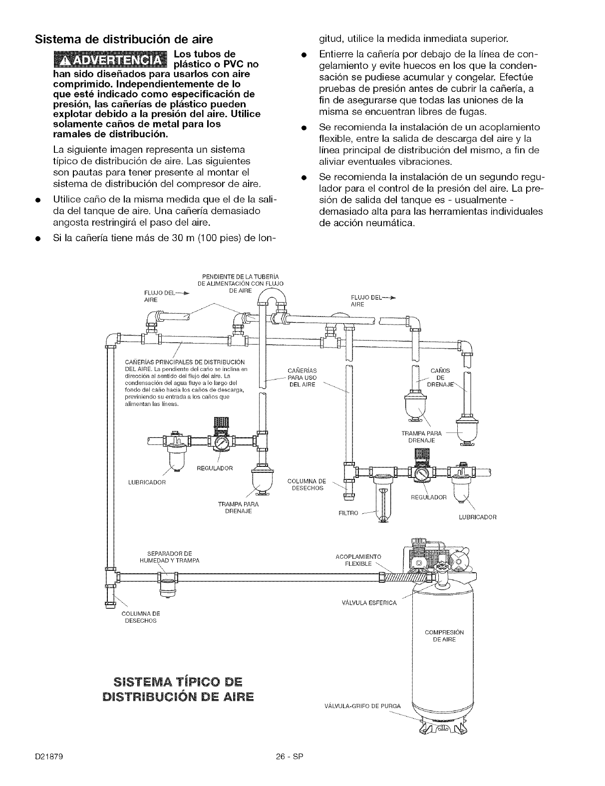
La siguiente imagen representa un sistema
tipico de distribuci6n de aire. Las siguientes
son pautas para tener presente al montar el
sistema de distribuci6n del compresor de aire.
Utilice caSo de la misma medida que el de la sali-
da del tanque de aire. Una caSerfa demasiado
angosta restringir_, el paso del aire.
Si la caSeria tiene m_.s de 30 m (100 pies) de Ion-
gitud, utilice la medida inmediata superior.
•Entierre la caSerfa por debajo de la linea de con-
gelamiento y evite huecos en los que la conden-
saci6n se pudiese acumular y congelar. Efect0e
pruebas de presi6n antes de cubrir la caSerfa, a
fin de asegurarse que todas las uniones de la
misma se encuentran libres de fugas.
• Se recomienda la instalaci6n de un acoplamiento
flexible, entre la salida de descarga del aire y la
linea principal de distribuci6n del mismo, a fin de
aliviar eventuales vibraciones.
• Se recomienda la instalaci6n de un segundo regu-
lador para el control de la presi6n del aire. La pre-
si6n de salida del tanque es - usualmente -
demasiado alta para las herramientas individuales
de acci6n neum_.tica.
PEND_ENTE DE LA TUBERiA
DE AUMENTAC_ON CON FLUJO
FLUJO DEL_--_ ._ DE AIRE
ARE FLUJO DEL_--€ ,_
AIRE
CANERiAS PRINC_PALES DE DISTR_BUCION
DEL A_RE, La pendiente del cairo se inclirla en GANGS
direcci6n al sentido del flujo del aire, La DE
condensaci6n del agua fluye a Io largo del DRENAJ
fondo del cailo hacia los cailos de descarga,
previniendo su entrada a los cailos que
alimentan las lineas,
TRAMPA PARA
LUBRICADOR COLUMNA DE
TRAMPA PARA
DRENAJE FILTRO LUBRICADOR
SEPARADOR DE ACOPLAMIENTO
HUMEDAD Y TRAMPA FLEXIBLE
COLUMNA DE
DESECHOS
SISTEMA TiPICO DE
DISTRIBUCI6N DE AIRE
V,&LVULA-GRIFO DE PURGA
COMPRBSION
DE AIRE
D21879 26-SP
Conozca su compresor de aire
LEA ESTE MANUAL DEL PROPIETARIO Y SUS NORMAS DE SEGURIDAD ANTES DE OPERAR LA UNIDAD.
Compare las ilustraciones contra su unidad a fin de familiarizarse con la ubicaci6n de los distintos controles y
regulaciones. Conserve este manual para referencias futuras.
Descripcion de operaciones
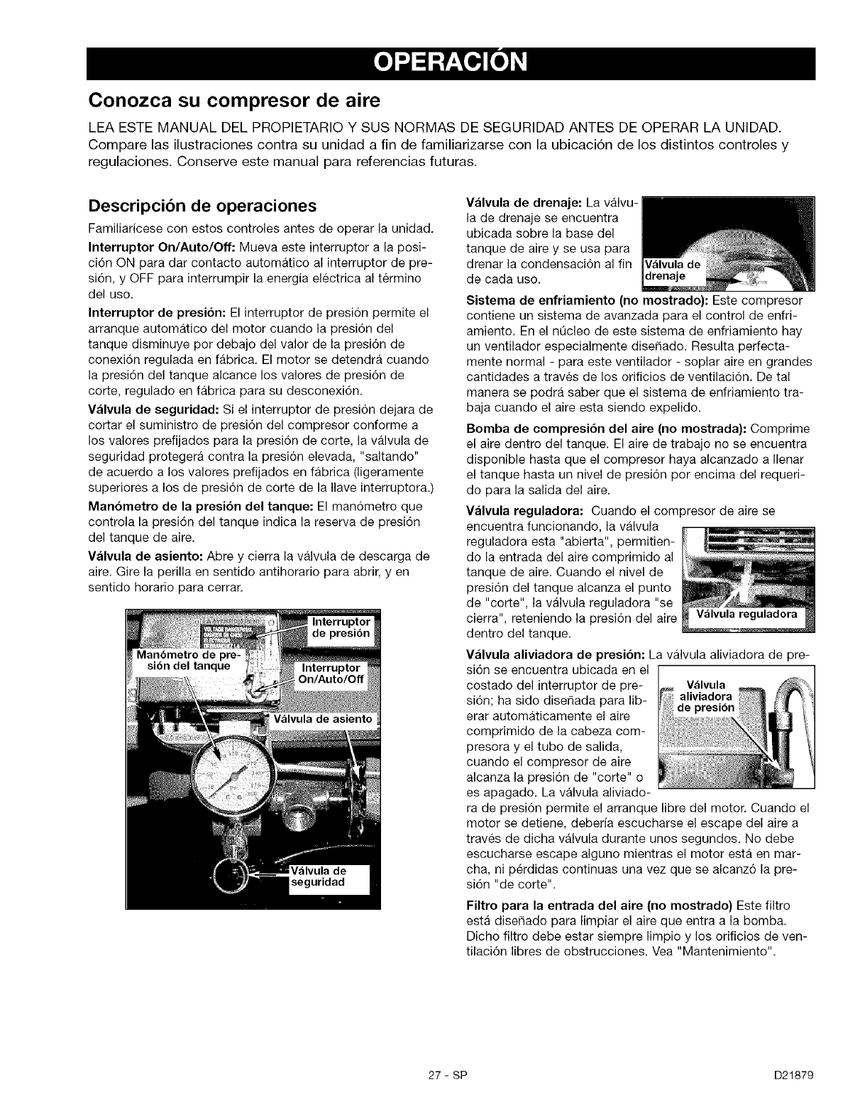
Familiaricese con estos controles antes de operar la unidad.
Interruptor On/Auto/Off: Mueva este interruptor a la posi-
ci6n ON para dar contacto automatico al interruptor de pre-
si6n, y OFF para interrumpir la energia electrica al termino
del uso.
Interruptor de presibn: El interruptor de presi6n permite el
arranque automatico del motor cuando la presi6n del
tanque disminuye por debajo del valor de la presi6n de
conexi6n regulada en fabrica. El motor se detendra cuando
la presi6n del tanque alcance los valores de presi6n de
corte, regulado en fabrica para su desconexi6n.
Valvula de seguridad: Si el interruptor de presi6n dejara de
cortar el suministro de presi6n del compresor conforme a
los valores prefijados para la presi6n de corte, la valvula de
seguridad protegera contra la presi6n elevada, "saltando"
de acuerdo a los valores prefijados en fabrica (ligeramente
superiores a los de presi6n de corte de la Ilave interruptora.)
Man6metro de la presi6n del tanque: El man6metro que
controla la presi6n del tanque indica la reserva de presi6n
del tanque de aire.
Valvula de asiento: Abre y cierra la valvula de descarga de
aire. Gire la perilla en sentido antihorario para abrir, yen
sentido horario para cerrar.
seguridad
Valvula de drenaje: La valvu-
la de drenaje se encuentra
ubicada sobre la base del
tanque de aire y se usa para
drenar la condensaci6n al fin
de cada uso.
Sistema de enfriamiento (no mostrado): Este compresor
contiene un sistema de avanzada para el control de enfri-
amiento. En el nOcleo de este sistema de enfriamiento hay
un ventilador especialmente dise_ado. Resulta perfecta-
mente normal - para este ventilador - soplar aire en grandes
cantidades a traves de los orificios de ventilaci6n. De tal
manera se podra saber que el sistema de enfriamiento tra-
baja cuando el aire esta siendo expelido.
Bomba de compresi6n del aire (no mostrada): Comprime
el aire dentro del tanque. El aire de trabajo no se encuentra
disponible hasta que el compresor haya alcanzado a Ilenar
el tanque hasta un nivel de presi6n por encima del requeri-
do para la salida del aire.
Valvula reguladora: Cuando el compresor de aire se
encuentra funcionando, la valvula
reguladora esta "abierta", permitien-
do la entrada del aim comprimido al
tanque de aire. Cuando el nivel de
presi6n del tanque alcanza el punto
de "corte", la valvula reguladora "se
cierra", reteniendo la presi6n del aire
dentro del tanque.
Valvula aliviadora de presibn: La valvula aliviadora de pre-
si6n se encuentra ubicada en el
costado del interruptor de pre- Valvula
si6n; ha sido diser_ada para lib- aliviadora
de presibn
erar automaticamente el aire
comprimido de la cabeza com-
presora y el tubo de salida,
cuando el compresor de aire
alcanza la presi6n de "corte" o
es apagado. La valvula aliviado-
ra de presi6n permite el arranque libre del motor. Cuando el
motor se detiene, deber[a escucharse el escape del aire a
traves de dicha valvula durante unos segundos. No debe
escucharse escape alguno mientras el motor esta en mar-
cha, ni p_rdidas continuas una vez que se alcanz6 la pre-
si6n "de corte".
Filtro para la entrada del aire (no mostrado} Este filtro
esta diser_ado para limpiar el aire que entra a la bomba.
Dicho filtro debe estar siempre limpio y los orificios de ven-
tilaci6n libres de obstrucciones. Vea "Mantenimiento".
27- SP D21879
Cbmo utilizar su unidad
Como detenerla:
1. Coloque la posici6n de la Ilave interruptora
On/Auto/Off en la posici6n "OFF".
Antes de poner en marcha
Procedimiento para el asentamiento
Si las siguientes instrucciones
no fuesen seguidas estricta-
mente, podr_.n ocurrir serios da_os.Este procedimiento es
necesario antes de poner en servicio al compresor de aire,
y cuando la valvula reguladora o la bomba completa del
compresor haya sido reemplazada.
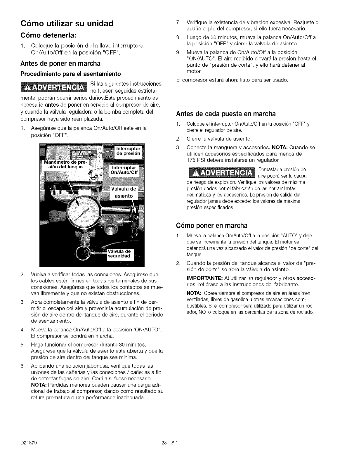
1. AsegQrese que la palanca On/Auto/Off est6 en la
posici6n "OFF".
seguridad
2. Vuelva a verificar todas las conexiones. AsegQrese que
los cables esten firmes en todas los terminales de sus
conexiones. AsegQrese que todos los contactos se mue-
van libremente y que no existan obstrucciones.
3. Abra completamente la valvula de asiento a fin de per-
mitir el escape del aire y prevenir la acumulaci6n de pre-
si6n de aire dentro del tanque de aire, durante el periodo
de asentamiento.
4. Mueva la palanca On/Auto/Off a la posici6n 'ON/AUTO".
El compresor se pondra en marcha.
5. Haga funcionar el compresor durante 30 minutos.
AsegQrese que la valvula de asiento este abierta y que la
presi6n de aire dentro del tanque sea minima.
6. Aplicando una soluci6n jabonosa, verifique todas las
uniones de las ca_er[as y las conexiones /ca_erias a fin
de detectar fugas de aire. Corrija si fuese necesario.
NOTA: Perdidas menores pueden causar una carga adi-
cional de trabajo al compresor, dando como resultado su
rotura prematura o una performance inadecuada.
7. Verifique la existencia de vibraci6n excesiva. Reajuste o
acute el pie del compresor, si ello fuera necesario.
8. Luego de 30 minutos, mueva la palanca On/Auto/Off a
la posici6n "OFF" y cierre la valvula de asiento.
9. Mueva la palanca de On/Auto/Off a la posici6n
"ON/AUTO". El aire recibido elevara la presi6n hasta el
punto de "presi6n de corte", y ello hara detener al
motor.
El compresor estara ahora listo para ser usado.
Antes de cada puesta en marcha
1. Coloque el interruptor On/Auto/Off en la posici6n "OFF" y
cierre el regulador de aire.
2. Cierre la valvula de asiento.
3. Conecte la manguera y accesorios. NOTA: Cuando se
utilicen accesorios especificados para menos de
175 PSI debera instalarse un regulador.
Demasiada presion de
aire podra ser la causa
de riesgo de explosi6n. Verifique los valores de maxima
presi6n dados por el fabricante de las herramientas
neum_ticas y los accesorios. La presion de salida del
regulador jamas debe exceder los valores de maxima
presi6n especificados.
C6mo poner en marcha
1. Mueva la palanca On/Auto/Off a la posici6n "AUTO" y deje
que se incremente la presion del tanque. El motor se
detendra una vez alcanzado el valor de presi6n "de corte" del
tanque.
2. Cuando la presi6n del tanque alcanza el valor de "pre-
si6n de corte" se abre la valvula de asiento.
IMPORTANTE: AI utilizar un regulador y otros acceso-
rios, refierase alas instrucciones del fabricante.
NOTA: Opere siempre el compresor de aire en areas bien
ventiladas, libres de gasolina u otras emanaciones com-
bustibles. Si el compresor sera utilizado para utilizar un roci-
ador, NO Io coloque en las cercanias de la zona de rociado.
D21879 28-SP
Responsabilidades del cliente
Verifique la valvula de seguridad
Drenaje del tanque
Filtro de aire (inspecci6n y reemplazo)
Inspeccion de eventuales tugas en las caherias de aire y
las conexiones.
Valvulas de entrada y escape de la bomba del compresor
de aire
Antes de
cada uso
Diariamente
o luego de
cada uso Frecuentemente Anualmente
La unidad funciona automaticamente en ciclos cuando esta conectada a la energia
electrica. Cuando se realizan trabajos de mantenimiento, usted puede estar expuesto
a fuentes de voltaje, aire comprimido o piezas en movimiento. Pueden ocurrir lesiones
personales. Antes de realizar cualquier trabajo de mantenimiento o reparaci6n, desconecte la fuente de energfa del
compresor y purgue toda la presi6n de aire.
Para asegurar una operaci6n eficiente y una vida Otil mas prolongada del compresor de aire debe prepararse y seguirse un
programa de mantenimiento de rutina. El siguiente programa de mantenimiento de rutina esta diser_ado para un equipo funcionan-
do diariamente en un ambiente normal de trabajo. Si fuese necesario, el programa debe ser modificado para adaptarse alas
condiciones bajo las cuales se usa su compresor. Las modificaciones dependeran de las horas de operaci6n y del ambiente
de trabajo. Los equipos de compresi6n funcionando en un ambiente sumamente sucio y hostil requeriran mayor frecuencia
de todas las verificaciones de mantenimiento.
NOTA: Para poder ubicar los controles lea "Descripci6n de la operaci6n", en la secci6n "Operaci6n" de este manual.
Como verificar la valvula de seguridad
Si la valvula de
seguridad no trabaja
adecuadamente, ello
podra determinar la sobrepresi6n del tanque, cre-
ando el riesgo de su ruptura o explosi6n. Antes de
poner en marcha el motor, tire del anillo de la
valvula de seguridad para confirmar la seguridad
de que la misma opera libremente, si la valvula
quedase trabada o no trabajara cdmodamente,
debera ser reemplazada por el mismo tipo de
valvula.
Como drenar el tanque
1. Coloque la palanca On/Auto/Off en la posici6n "OFF".
2. Cierre la valvula de asiento.
3. Remueva la herramienta neumatica o el accesorio.
4. Abra la valvula de asiento y lentamente deje purgar el
aire del tanque de aire, hasta que la presi6n del mismo
Ilegue aproximadamente a 20 PSI.
5. Drene el agua contenida en el tanque de aire, abriendo
la valvula de drenaje ubicada en la base del tanque
(en sentido contrario alas agujas de reloj).
Dentro del tanque se pro-
ducira condensaci6n de
agua. Si no drena, el agua
Io corroera y debilitara causando un riesgo de ruptura
del tanque de aire.
6. Una vez drenada el agua, cierre la valvula de drenaje
(girando en sentido horario). Ahora el compresor de
aire podra set guardado.
NOTA: Si la valvula de drenaje fuera del tipo enchufe,
elimine toda la presi6n de aire. La valvula podra entonces
set extraida, limpiada y finalmente reinstalada.
Filtro de Aire - Inspeccion y reemplazo
Superficies calientes.
Riesgo de que-
maduras. Las
cabezas del compresor estan expuestas cuando se
retira la cubierta del filtro. Deje enfriar al compre-
sor antes de darle servicio.
Un filtro de aire sucio no permitira que el compresor opere a
plena capacidad. Mantenga el filtro de aire limpio en todo
momento.
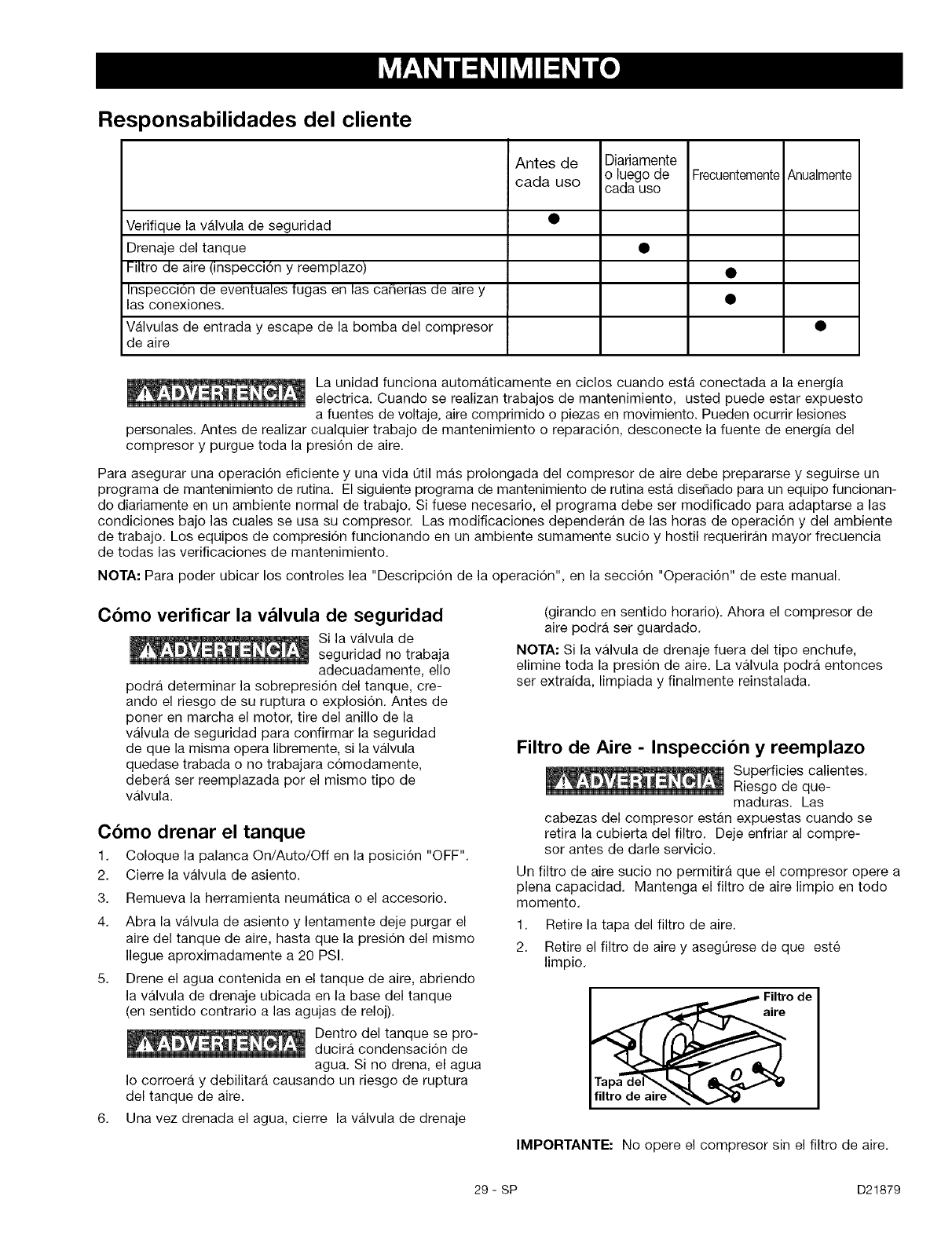
1. Retire la tapa del filtro de aire.
2. Retire el filtro de aire y asegQrese de que este
limpio.
Filtrode
aire
filtro de aire'_._,_
IMPORTANTE: No opere el compresor sin el filtro de aire.
29- SP D21879
3. Siesta sucio enjuague el filtro de aire con agua tibia y
expr[malo hasta que seque.
4. Vuelva a colocar el filtro de aire y su cubierta.
NOTA: Si el filtro de aire esta sumamente sucio necesitara
ser reemplazado. Consuite ia secci6n "Repuestos"
para obtener el nQmero correcto de la pieza.
Motor
El motor tiene un protector termico de sobrecarga de
reposici6n automatica. Si el motor se sobrecalienta por
alguna raz6n, el protector de sobrecarga apagara el motor.
Debe dejar enfriar el motor antes de voiverlo a arrancar. El
compresor arrancara automaticamente despues que se
enfrie el motor.
Si el protector de sobrecarga apaga el motor con mucha
frecuencia, verifique si hay algQn posible problema de voltaje.
Tambien se puede sospechar de bajo voitaje cuando:
1. El motor no alcanza toda su potencia o velocidad.
2. Los fusibles se queman cuando se arranca el motor;
las luces se atent]an y siguen atenuadas cuando al
motor se le da arranque mientras esta funcionando.
Inspeccion de las cafierias de aire y las
conexiones para detectar fugas.
1. Ponga en marcha el compresor de aire para permitir
inspeccionar ia existencia de fugas de aire.
2. Aplique una soluci6n jabonosa a todos los acoplamien-
tos de aire y las conexiones /cafierias.
3. Corrija cuaiquier perdida encontrada.
IMPORTANTE: Incluso perdidas menores, pueden causar
una carga adicional de trabajo al compresor, dando como
resultado su rotura prematura o una performance
inadecuada.
Valvulas de entrada y escape de la bomba
del compresor de aire
Una vez al a_o haga que un tecnico capacitado de servicio
inspeccione las valvulas de entrada y escape de la bomba
del compresor de aire.
D21879 30- SP
La unidad cicla automaticamente en cuanto la energ[a electrica es conectada. AI efectuar el
mantenimiento, usted quedara expuesto a tensi6n viva, aire comprimido o partes en
movimiento. Debido a tales circunstancias, podrian ocurrirle lesiones personales. Antes de
efectuar mantenimiento o reparaci6n alguna, desenchufe el compresor y purgue cualquier presi6n de aire.
TODO TIPO DE MANTENIMIENTO Y OPERACIONES DE REPARACIC)N NO MENCIONADOS,
DEBERAN SER EFECTUADOS POR PERSONAL TI_CNICO ESPECIALIZADO.
6.
Antes de dar servicio:
Desenchufe o desconecte el suministro
electrico al compresor de aire.
Purgue la presi6n del tanque.
Deje enfriar el compresor de aire.
Para reemplazar o limpiar la valvula de
retencion
1. Libere toda la presi6n del tanque de aire. Vea "C6mo
Drenar el Tanque" en la secci6n "Mantenimiento".
2. Desenchufe el equipo.
3. Usando un destornillador Phillips retire la cubierta del
filtro de aire.
4. Extraiga la cubierta trasera utilizando una Ilave de
punta Torx T-20
7,
8,
Utilizando una Ilave regulable, afloje la tuerca del tubo
aliviador del tanque de aire y la valvula de retenci6n.
Retire cuidadosamente la tuberia de alivio de presi6n
de la valvula de retenci6n.
Desenrosque la valvula de retenci6n girandola hacia la
izquierda usando una Ilave de boca de 7/8". Tome nota
de la orientaci6n para volverla a ensamblar.
Usando un destornillador, empuje con cuidado el disco
de la valvula hacia arriba y hacia abajo. NOTA: El
disco de la valvula debe moverse libremente hacia
arriba y hacia abajo sobre un resorte que detiene el
disco de la valvula en la posicidn cerrada. Si no Io
hace, la valvula de retenci6n necesita ser limpiada o
reemplazada.
Destornillador
En posicibn abierta
nada es visible
Utilizando una Ilave regulable, afloje la tuerca del tubo
del tanque de aire a la bomba. Extraiga cuidadosa-
mente la tuberfa de salida de la valvula de retenci6n.
9. Limpie o reemplace la valvula de retenci6n. Un
solvente, tal como un removedor de pintura o de barniz
puede usarse para limpiar la valvula de retenci6n.
10. Aplique sellador alas roscas de la valvula de retenci6n.
Vuelva a instalar la valvula de retenci6n (gire a la
derecha).
11. Vuelva a instalar la tuberia de alivio de presi6n. Ajuste
las tuercas.
12. Reponga el tubo de salida y ajuste las tuercas.
13. Vuelva a colocar la cubierta y el filtro de aire.
14. Ejecute el procedimiento de puesta en marcha. Vea
"Procedimiento de Puesta en Marcha" en la secci6n
"Operaci6n".
31 - SP D21879
Antes de guardar su compresor de aire, asegQrese de hacer
Io siguiente:
1. Revise la secci6n "Mantenimiento" de las paginas
precedentes y ejecute el mantenimiento programado de
acuerdo a la necesidad.
2. Coloque la palanca On/Auto/Off en la posici6n "OFF".
3. Cierre la valvula de asiento
4. Extraiga la herramienta neumatica o el accesorio.
5. Abra la valvula de asiento y lentamente deje purgar el
aire del tanque de aire, hasta que la presi6n del
mismo Ilegue aproximadamente a 20 PSI.
6. Drene el agua del tanque de aire abriendo la valvula de
drenaje ubicada en el fondo del tanque.
El agua se condensa
dentro del tanque de
aire. Si no se drena, ella corroera debilitando las
paredes del tanque de aire, originando un riesgo
de ruptura de sus paredes.
7. Una vez que el agua haya side drenada, cierre la valvu-
la de drenaje.
NOTA: Si la valvula de drenaje estuviese enchufada, libere
toda la presi6n de aire. La valvula podra ser extraida,
limpiada y luego reinstalada.
8. Proteja la manguera del aire de daSos (tales como ser
pisoteada o caminar per encima).
Almacene el compresor de aire en un sitio limpio y seco.
D21879 32- SP
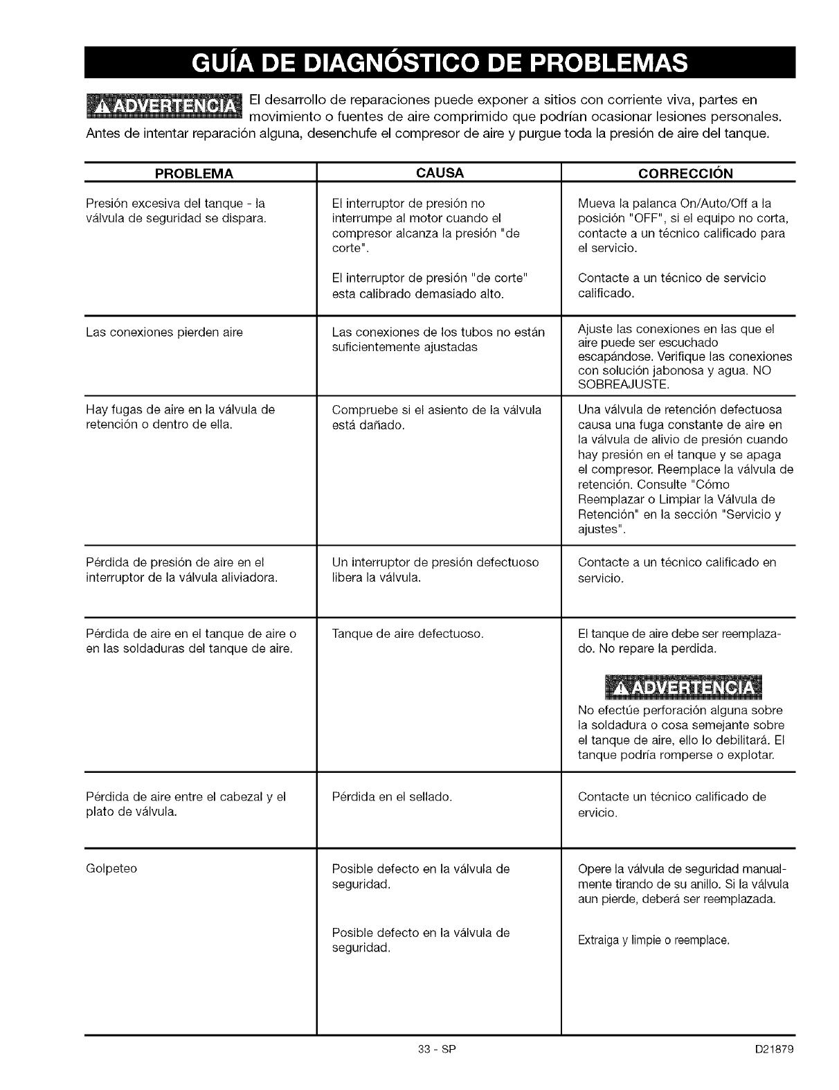
El desarrollo de reparaciones puede exponer a sitios con corriente viva, partes en
movimiento o fuentes de aire comprimido que podrian ocasionar lesiones personales.
Antes de intentar reparaci6n alguna, desenchufe el compresor de aire y purgue toda la presi6n de aire del tanque.
PROBLEMA
Presi6n excesiva del tanque - la
valvula de seguridad se dispara.
Las conexiones pierden aire
Hay fugas de aire en la valvula de
retenci6n o dentro de ella.
Perdida de presi6n de aire en el
interruptor de la valvula aliviadora.
Perdida de aire en el tanque de aire o
en las soldaduras del tanque de aire.
Perdida de aire entre el cabezal y el
plato de valvula.
Golpeteo
CAUSA CORRECClON
El interruptor de presi6n no
interrumpe al motor cuando el
compresor alcanza la presi6n "de
oorte".
El interruptor de presi6n "de corte"
esta calibrado demasiado alto.
Las conexiones de los tubos no estan
suficientemente ajustadas
Compruebe si el asiento de la valvula
esta daSado.
Un interruptor de presi6n defectuoso
libera la valvula.
Tanque de aire defectuoso.
Perdida en el sellado.
Posible defecto en la valvula de
seguridad.
Posible defecto en la valvula de
seguridad.
Mueva la palanca On/Auto/Off a la
posici6n "OFF", si el equipo no corta,
contacte a un tecnico calificado para
el servicio.
Contacte a un tecnico de servicio
calificado.
Ajuste las conexiones en las que el
aire puede ser escuchado
escapandose. Verifique las conexiones
con soluci6n jabonosa y agua. NO
SOBREAJUSTE.
Una valvula de retenci6n defectuosa
causa una fuga constante de aire en
la valvula de alivio de presi6n cuando
hay presi6n en el tanque y se apaga
el compresor. Reemplace la valvula de
retenci6n. Consulte "C6mo
Reemplazar o Limpiar la Valvula de
Retenci6n" en la secci6n "Servicio y
ajustes".
Contacte a un tecnico calificado en
servicio.
El tanque de aire debe set reemplaza-
do. No repare la perdida.
No efectQe perforaci6n alguna sobre
la soldadura o cosa semejante sobre
el tanque de aire, ello Io debilitara. El
tanque podrfa romperse o explotar.
Contacte un tecnico calificado de
ervicio.
Opere la valvula de seguridad manual-
mente tirando de su anillo. Si la valvula
aun pierde, debera ser reemplazada.
Extraiga y limpie o reemplace.
33 - SP D21879
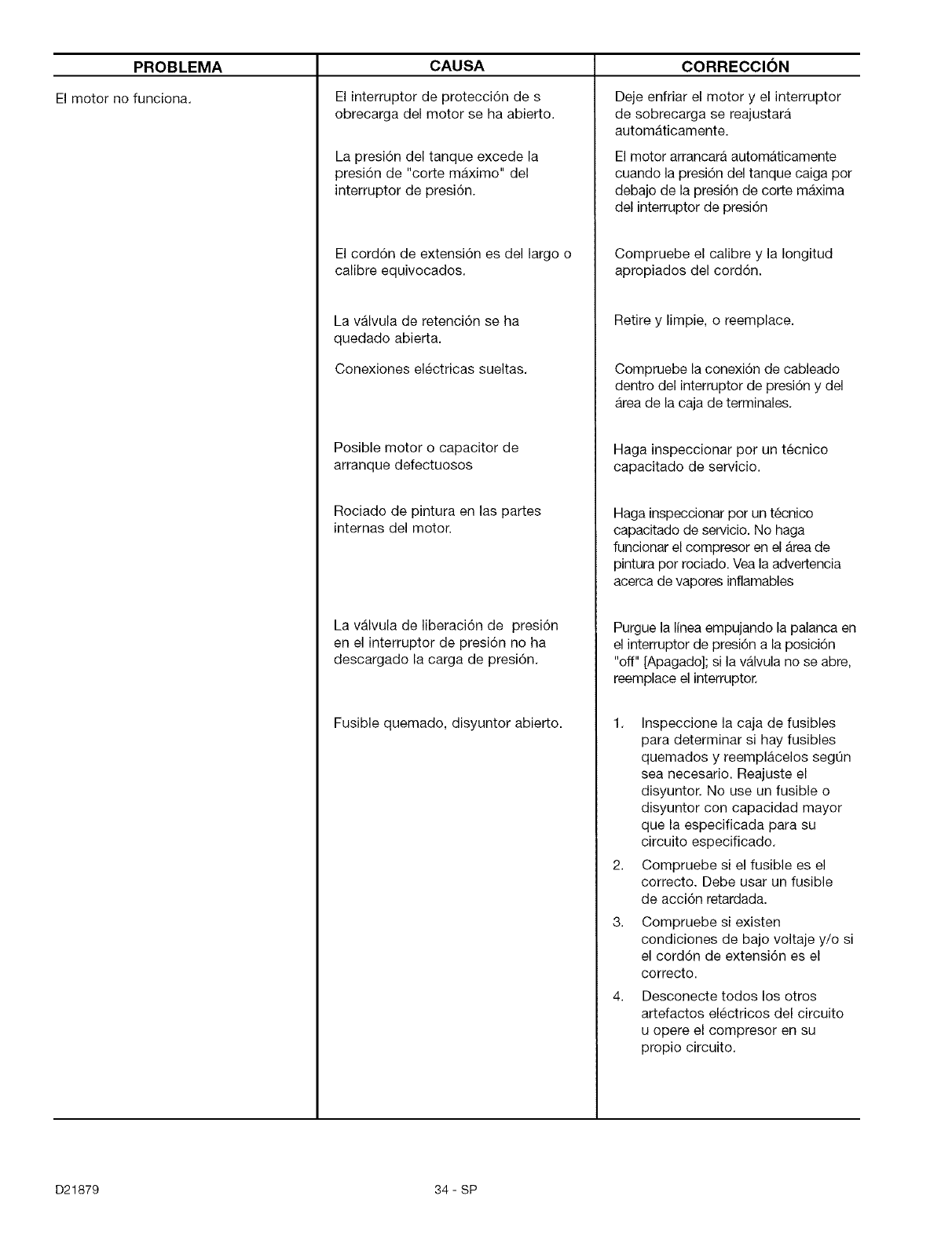
PROBLEMA
El motor no funciona.
CAUSA
El interruptor de protecci6n de s
obrecarga del motor se ha abierto.
La presi6n del tanque excede la
presi6n de "corte maximo" del
interruptor de presi6n.
El cord6n de extensi6n es del largo o
calibre equivocados.
La valvula de retenci6n se ha
quedado abierta.
Conexiones electricas sueltas.
Posible motor o capacitor de
arranque defectuosos
Rociado de pintura en las partes
internas del motor.
La valvula de liberaci6n de presi6n
en el interruptor de presi6n no ha
descargado la carga de presi6n.
Fusible quemado, disyuntor abierto.
CORRECClON
Deje enfriar el motor y el interruptor
de sobrecarga se reajustara
automaticamente.
El motor arrancara automaticamente
cuando la presi6n del tanque caiga pot
debajo de la presi6n de corte maxima
del interruptor de presi6n
Compruebe el calibre y la Iongitud
apropiados del cord6n.
Retire y limpie, o reemplace.
Compruebe la conexi6n de cableado
dentro del interruptor de presi6n y del
Area de la caja de terminales.
Haga inspeccionar por un tecnico
capacitado de servicio.
Haga inspeccionar por un tecnico
capacitado de servicio. No haga
funcionar el compresor en el Area de
pintura por rociado. Vea la advertencia
acerca de vapores inflamables
Purgue la linea empujando la palanca en
el interruptor de presi6n a la posici6n
"off" [Apagado]; si la valvula no se abre,
reemplace el interruptor.
1. Inspeccione la caja de fusibles
para determinar si hay fusibles
quemados y reemplacelos segQn
sea necesario. Reajuste el
disyuntor. No use un fusible o
disyuntor con capacidad mayor
que la especificada para su
circuito especificado.
2. Compruebe si el fusible es el
correcto. Debe usar un fusible
de acci6n retardada.
3. Compruebe si existen
condiciones de bajo voltaje y/o si
el cord6n de extensi6n es el
correcto.
4. Desconecte todos los otros
artefactos electricos del circuito
u opere el compresor en su
propio circuito.
D21879 34 - SP
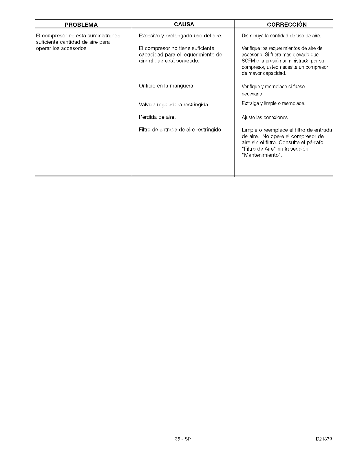
PROBLEMA CORRECCION
El compresor no esta suministrando
suficiente cantidad de aire para
operar los accesorios.
CAUSA
Excesivo y prolongado uso del aire,
El compresor no tiene suficiente
capacidad para el requerimiento de
aire al que esta sometido.
Orificio en la manguera
VMvula reguladora restringida.
Perdida de aire.
Filtro de entrada de aire restringido
Disminuya la cantidad de uso de aire.
Verifique los requerimientos de aire del
accesorio. Si fuera mas elevado que
SCFM o la presion suministrada por su
compresor, usted necesita un compresor
de mayor capacidad.
Verifique y reemplace si fuese
necesario.
Extraiga y limpie o reemplace.
Ajuste las conexiones.
Limpie o reemplace el filtro de entrada
de aire. No opere el compresor de
aire sin el filtro. Consulte el parrafo
"Filtro de Aire" en la secci6n
"Mantenimiento".
35- SP D21879
!i!i!i!i!i!i!i!i!i!i!i!i!i!i!ili'
Your Home
For repair - in your home - of all major brand appliances,
lawn and garden equipment, or heating and cooling systems,
no matter who made it, no matter who sold it!
For the replacement parts, accessories and
owner's manuals that you need to do-it-yourself.
For Sears professional installation of home appliances
and items like garage door openers and water heaters.
1-800-4-MY-HOME _ Anytime, day or night
(1-800-469-4663) (U.S.A. and Canada)
www.sears.com www.sears.ca
Our Home
For repair of carry-in products like vacuums, lawn equipment,
and electronics, call or go on-line for the nearest
Sears Parts and Repair Center.
1-800-488-1222 Anytime, day or night (U.S.A. only)
www.sears.com
" , iiiiiiiiiiiiiiiiiiiiiiiiiiiiiiiiiiiiiiiiiiiiiiiiiiiiiiiiiiiiiiii
_!i!i!i!i!i!i!i!i!i!i!i!i!i!i!i!i!i!i!i_ii_
iiiiiiiiiiiiiiiiiiii:i
iiiiiiiiiiiiiiiiiiii:i
iiiiiiiiiiiiiiiiiiii:i
iiiiiiiiiiiiiiiiiiii:i
iiiiiiiiiiiiiiiiiiii:i
iiiiiiiiiiiiiiiiiiii:i
iiiiiiiiiiiiiiiiiiii:i
iiiiiiiiiiiiiiiiiiii:i
iiiiiiiiiiiiiiiiiiii:i
iiiiiiiiiiiiiiiiiiii:i
iiiiiiiiiiiiiiiiiiii:i
iiiiiiiiiiiiiiiiiiii:i
iiiiiiiiiiiiiiiiiiii:i
iiiiiiiiiiiiiiiiiiii:i
iiiiiiiiiiiiiiiiiiii:i
iiiiiiiiiiiiiiiiiiii:i
iiiiiiiiiiiiiiiiiiii:i
iiiiiiiiiiiiiiiiiiii:i
iiiiiiiiiiiiiiiiiiii:i
iiiiiiiiiiiiiiiiiiii:i
iiiiiiiiiiiiiiiiiiii:i
iiiiiiiiiiiiiiiiiiii:i
iiiiiiiiiiiiiiiiiiii:i
iiiiiiiiiiiiiiiiiiii:i
iiiiiiiiiiiiiiiiiiii:i
iiiiiiiiiiiiiiiiiiii:i
iiiiiiiiiiiiiiiiiiii:i
iiiiiiiiiiiiiiiiiiii:i
iiiiiiiiiiiiiiiiiiii'i
To purchase a protection agreement (U.S.A.)
or maintenance agreement (Canada) on a product serviced by Sears:
1-800-827-6655 (U.S.A.) 1-800-361-6665 (Canada)
Para pedir servicio de reparacion Au Canada pour service en fran£;ais:
a domicilio, y para ordenar piezas: 1.800.LE.FOYERMC
1-888-SU-HOGAR Su (1-800-533-6937)
www.sears.ca
© Sears,Roebuck andCo.
TM SM
® Registered Trademark /Trademark/' Service Mark of Sears, Roebuck and Co.
® Marca Registrada /TMMarca de F_.brica /SMMarca de Servicio de Sears, Roebuck and Co.
MCMarque de commerce /MDMarque deposee de Sears, Roebuck and Co.
