Craftsman 944609900 User Manual LAWN TRACTOR Manuals And Guides 99020013
CRAFTSMAN Lawn, Tractor Manual 99020013 CRAFTSMAN Lawn, Tractor Owner's Manual, CRAFTSMAN Lawn, Tractor installation guides
User Manual: Craftsman 944609900 944609900 CRAFTSMAN LAWN TRACTOR - Manuals and Guides View the owners manual for your CRAFTSMAN LAWN TRACTOR #944609900. Home:Lawn & Garden Parts:Craftsman Parts:Craftsman LAWN TRACTOR Manual
Open the PDF directly: View PDF ![]() .
.
Page Count: 60
SEARS
OWNER'S
MANUAL
MODEL NO.
944.609900
Caution:
Read and follow
all Safety Rules
and Instructions
Before Operating
This Equipment
CRRFTSMU
20.0 HP
ELECTRIC START
46" MOWER
AUTOMATIC
GARDEN TRACTOR
• Assembly
•Operation
•Customer Responsibilities
•Service and Adjustments
•Repair Parts
Sears Canada, Inc., Toronto, Ontario M5B 2B8
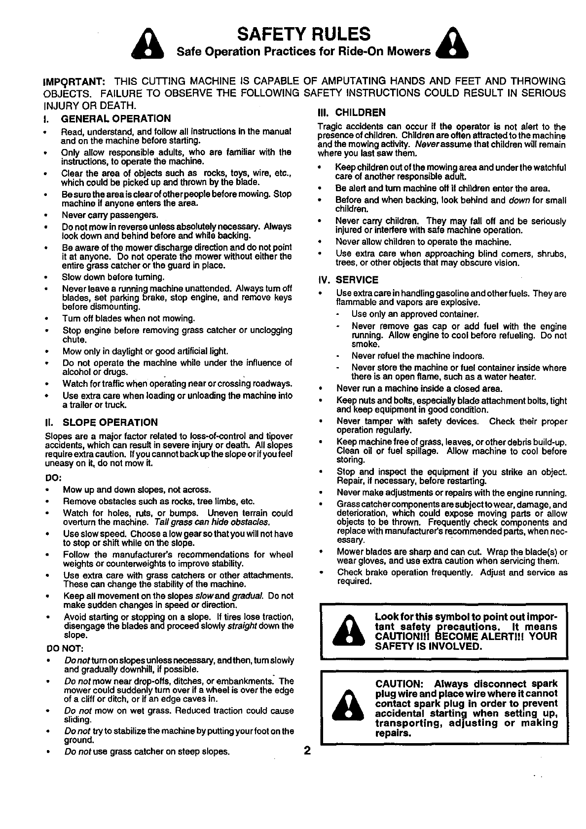
SAFETY RULES A
Safe Operation Practices for Ride-On Mowers
IMP_)RTANT: THIS CU']-FING MACHINE IS CAPABLE OF AMPUTATING HANDS AND FEET AND THROWING
OBJECTS. FAILURE TO OBSERVE THE FOLLOWING SAFETY INSTRUCTIONS COULD RESULT IN SERIOUS
INJURY OR DEATH.
I. GENERAL OPERATION
Read, understand, and follow all instructions in the manual
and on the machine before starting.
Only allow responsible adults, who are familiar with the
instructions, to operate the machine.
•Clear the area of ob acts such as recks, toys, wire, etc.,
which could be picked up and thrown by the bade.
•Be sure the areais clear of other people before mowing. Stop
machine if anyone enters the area.
Never carry passengers.
Do not mow in reverse unless absolutely necessary. Always
look down and behind before and while backing.
Be aware of the mower discharge direction and do not point
it at anyone. Do not operate the mower without either the
entire grass catcher or the guard in place.
Slow down before turning.
Never leave a running machine unattended. Always turn off
blades, set parking brake, stop engine, and remove keys
before dismounting.
Tum off blades when not mowing.
Stop engine before removing grass catcher or unclogging
chute,
Mow only in daylight or good artificial light.
Do not operate the machine while under the influence of
alcohol or drugs.
Watch for traffic when operating near or crossing roadways.
• Use extra care when loading or unloading the machine into
a trailer or truck.
II. SLOPE OPERATION
Slopes are a major factor related to loss-of-control and tipover
accidents, which can result in severe injury or death. All slopes
require extra caution. If you cannot back upthe slope or ifyoufeel
uneasy on it, do not mow it.
DO:
Mow up and down slopes, not across.
Remove obstacles such as recks, tree limbs, etc.
Watch for holes, ruts, or bumps. Uneven terrain could
overturn the machine. Tall grass can hide obstacles.
•Use slow speed. Choose a low gear so that you will not have
to stop or shift while on the slope.
Follow the manufacturer's recommendations for wheel
weights or counterweights to improve stability.
Usa extra care with grass catchers or other attachments.
These can change the stability of the machine.
Keep all movement on the slopes slowand gradual. Do not
make sudden changes in speed or direction.
Avoid starting or stopping on a slope. If tires lose traction,
disengage the blades and proceed slowly straight down the
slope.
DO NOT:
Do not turn on slopes unless necessary, end then, turnslowly
and gradually downhill, ifpossible.
Do not mow near drop-offs, ditches, or embankments. The
mower could suddenly turn over if a wheel is over the edge
of a cliff or ditch, or it an edge caves in.
Do not mow on wet grass. Reduced traction could cause
sliding•
•Do not try to stabilize the machine by puttingyour foot on the
ground.
Do not use grass catcher on steep slopes.
IlL CHILDREN
Tragic accidentscan occur if the operator is not alert to the
presenceofchildren.Childrenare oftenattracted tothe machine
andthe mowingactivity. Neverassumethat childrenwillremain
whereyoulastsawthem.
•Kaspchildranoutofthe mowingarea andunderthewatchful
care of anotherresponsibleadult.
Be alertand tum machineoft i| childrenenterthe area.
Beforeand when backing,lookbehind and downforsmall
children.
Never carrychildren. They may fall off and be seriously
injuredorintederewithsafemachineoperation.
•Neverallowchildrento operatethe machine.
Use extra care when approachingblind comers, shrubs,
trees,or otherobjectsthat may obscurevision.
IV. SERVICE
•Usaextracareinhandlinggasolineandotherfuels. Theyare
flammable and vaporsare explosive.
Use onlyan approvedcontainer.
Never remove gas cap or add fuel with the engine
running. Allowengineto cool beforerefueling. Do not
smoke.
Neverrefuelthe machineindoors.
Neverstorethe machineorfuel containerinsidewhere
thereis an openflame, suchas awater heater.
•Neverruna machineinsidea closedarea.
•Keepnutsandbolts,especiallybladeattachmentbolts,tight
and keepequipmentingoodcondition.
Never tamper with safety devices. Check their proper
operationregularly.
Keepmachinefree of grass,leaves,orotherdebrisbuild-up.
Clean oil or fuel spillage. Allow machine to cool before
storing.
Stop and inspectthe equipmentif you strike an object.
Repair,if necessary,beforerestarting.
Nevermakeadjustmentsor repairswiththe enginerunning.
•Grasscatchercomponentsaresubecttowear,damage,and
deterioration,which could expose mov ng parts or a ow
objectsto be thrown. Frequentlycheck componentsand
replacewithmanufacturer'srecommendedparts,whennec-
essary.
•Mowerbladesare sharpandcan cut. Wrap the blade(s)or
weargloves,and usa extracautionwhenservicingthem.
Check brake operationfrequently. Adjustand serviceas
required.
2
A
Look for this symbol to point out impor-
tant safety precautions. It means
CAUTIONI!! BECOME ALERT!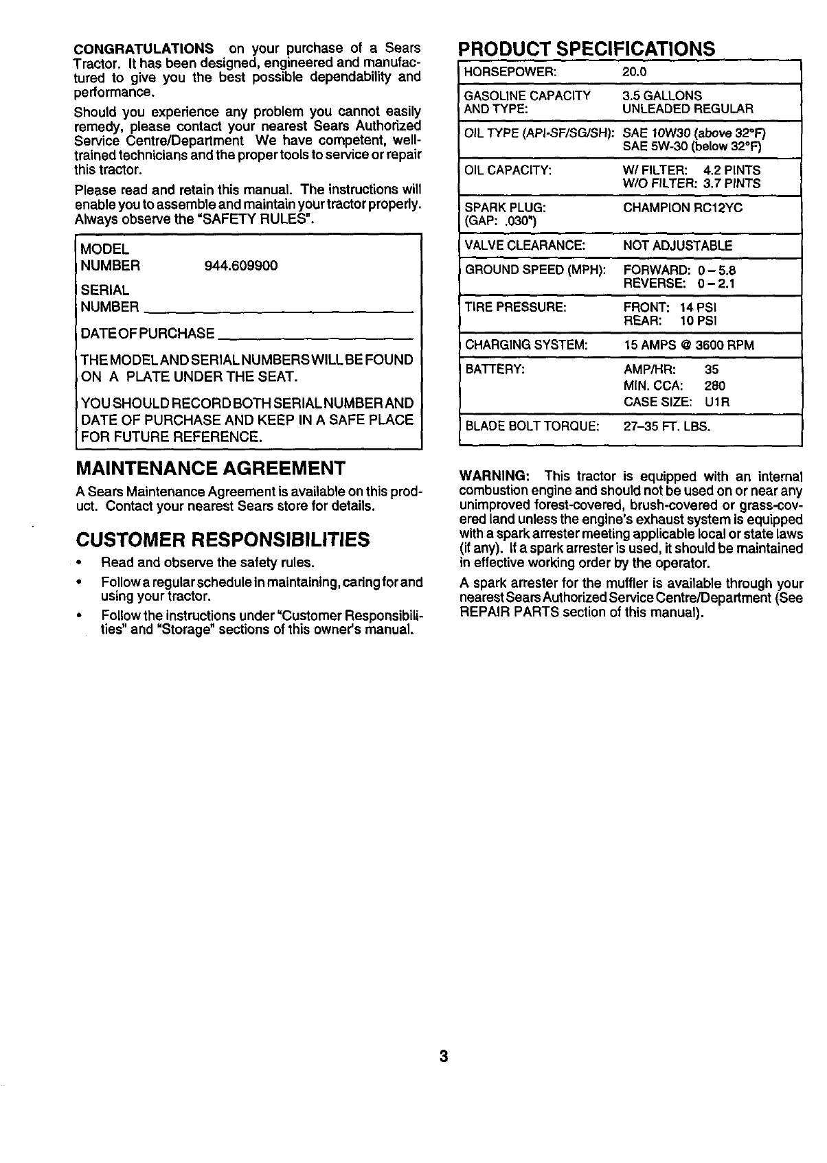
CONGRATULATIONS on your purchase of aSears
Tractor. It has been designed, engineered and manufac-
tured to give you the best possible dependability and
pedormance.
Should you experience any problem you cannot easily
remedy, please contact your nearest Sears Authorized
Service Centre/Department We have competent, well-
trained technicians and the proper tools to service or repair
this tractor.
Please read and retain this manual. The instructions will
enable you to assemble and maintain your tractor properly.
Always observe the "SAFETY RULES",
MODEL
NUMBER 944.609900
SERIAL
NUMBER
DATEOFPURCHASE
THE MODEL AND SERIAL NUMBERS WILL BE FOUND
ON A PLATE UNDER THE SEAT.
YOU SHOULD RECORD BOTH SERIAL NUMBER AND
DATE OF PURCHASE AND KEEP IN A SAFE PLACE
FOR FUTURE REFERENCE.
MAINTENANCE AGREEMENT
A Sears Maintenance Agreement is available on this prod-
uct. Contact your nearest Sears store for details.
CUSTOMER RESPONSIBILITIES
•Read and observe the safety rules.
•Follow a regular schedule inmaintaining, cadng for and
using your tractor.
•Follow the instructions under"Customer Responsibili-
ties" and =Storage" sections of this owner's manual.
PRODUCT SPECIFICATIONS
HORSEPOWER: 20.0
GASOLINECAPACITY 3.5 GALLONS
AND TYPE: UNLEADED REGULAR
iOIL TYPE (API-SF/SG/SH): SAE t0W30 (above 32°F'/
SAE 5W-30 (below 32°F)
OIL CAPACITY: W/FILTER: 4.2 PINTS
W/O FILTER: 3.7 PINTS
SPARK PLUG: CHAMPION RC12YC
3AP: .030")
VALVE CLEARANCE: NOT ADJUSTABLE
GROUND SPEED (MPH): FORWARD: 0- 5,8
REVERSE: 0-2.1
TIRE PRESSURE: FRONT: 14 PSI
REAR: 10 PSI
CHARGING SYSTEM: t 5 AMPS @ 3600 RPM
BATTERY: AMP/HR: 35
MIN. CCA: 280
CASE SIZE: U1R
BLADE BOLT TORQUE: 27-35 FT. LBS.
WARNING: This tractor is equipped with an internal
combustionengine and should not be used on or near any
unimproved forest-covered, brush-covered or grass-cov-
ered land unless the engine's exhaust system is equipped
witha spark arrester meeting applicable local or state laws
(if any). If a spark arrestar is used, it should be maintained
in effective working order by the operator.
A spark arrester for the muffler is available through your
nearest Sears Authorized Service Centre/Depadment (See
REPAIR PARTS section of this manual).
3
TABLE OF CONTENTS
SAFETY RULES ............................................................ 2
PRODUCT SPECIFICATIONS ...................................... 3
CUSTOMER RESPONSIBILITIES ..................... 3, 16-19
WARRANTY .................................................................. 4
ASSEMBLY .......................................................... ,.... 6-9
OPERATION ........................................................... 10-15
MAINTENANCE SCHEDULE ...................................... 16
SERVICE AND ADJUSTMENTS ............................ 20-26
STORAGE ................................................................... 27
TROUBLESHOOTING ............................................ 28-29
REPAIR PARTS -TRACTOR ................................. 32-49
REPAIR PARTS -ENGINE .................................... 50-57
PARTS ORDERING/SERVICE ................ BACK COVER
LIMITED TWO (2) YEAR WARRANTY ON CRAFTSMAN TRACTOR (RIDING EQUIPMENT)
For two (2) years from date of purchase Sears Canada, Inc. will repair or replace at Sears option free of charge parts which are
defective as a result of matedal or workmanship.
FULL ONE (1) YEAR WARRANTY ON BAI-I'ERY
For one (t) year from date of purchase, if any battery included with this riding equipment proves defective in matedal or
workmanship and our testing determines the battery will not hold a charge, Sears will replace the battery at no charge.
COMMERCIAL OR RENTAL USE
Warranty on Riding Equipment used for commercial or rental purposes is limited to ninety (90) days.
This Warranty does NOT cover:
1. Pre-delivery set-up.
2. Tire replacement or repair caused by punctures from outside objects (such as nails, thorns, stumps, or glass).
3. Expendable items which become worn dudng normal use, such as blades, spark plug, air cleaners and belts.
4. Repairs necessary because of operator abuse or negligence, including damaged jackshaft or mandrel and the
failure to operate and maintain the equipment according to the instructions contained In the Owner's Manual.
5. In Home service.
Warranty service is available by returning the Craftsman Riding Equipment to the nearest Sears Service Centre/Department in
Canada. This warranty applies only while this product is in use in Canada.
This warranty is in addition to any statutory warranty and does not exclude or limit legal dghts you may have but shall run
concurrently with applicable provincial legislation. Furthermore, some provinces do NOT allow limitation on how long an implied
warranty will last so the above limitationsmay not apply to you.
SEARS CANADA, INC., TORONTO, ONTARIO M5B 2B8
4
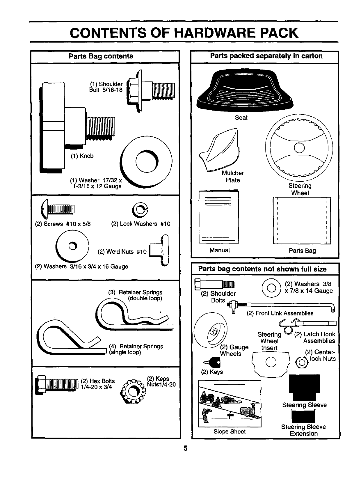
CONTENTS OF HARDWARE PACK
Parts Bag contents
m
(1) Shoulder
Bolt 5/16-18
(1) Knob
(1) Washer 17/32
1-3/16 x 12 Gauge
©
(2) Screws #10 x518 (2) Lock Washers #10
(2)Weld Nuts #10_
(2) Washers 3/16 x 3/4 x 16 Gauge
(3) Retainer Springs
_ _ J 14) Retainer Springs
I (single loop)
_(2) Hex Bolts _(2) Keps
1/4-20 x 3/4 Nuts114-20
Parts packed separately in carton
Seat
Mulcher
Plate Steering
Wheel
I
Manual Parts Bag
Parts bag contents not shown full size
_(2)Washers 3/8
(2) Shoulder _x 7/8 x 14 Gauge
Bolts _J (2) Front Link Assemblies
¢" L_% ii
Steering'-O--((2) Latch Hook
Wheel Assemblies
Gauge Insert
Wheels /-----------3 (2) Center-
,4= @,ookNuts
(2) Keys
Slope Sheet
Steering Sleeve
Steering Sleeve
Extension
5
ASSEMBLY
Your new tractor has been assembled at the factory with exception of those parts left unassembled for shipping purposes.
To ensgre safe and proper operation of your tractor all parts and hardware you assemble must be tightened securely. Use
the correct tools as necessary to insure proper tightness.
TOOLS REQUIRED FOR ASSEMBLY
A socket wrench set will make assembly easier. Standard
wrench sizes are listed.
(2) 7/16" wrenches (1) Tire pressure gauge
(1) 9/16" wrench (1) Utility knife
(1) 1/2" wrench (1) 3/4" socket w/drive ratchet
(1) Pliers (1) PhillipsScrewddver
When right or left hand is mentioned in this manual, it
means when you are in the operating position (seated
behind the steering wheel).
TO REMOVE TRACTOR FROM CARTON
UNPACK CARTON
•Remove all accessible loose parts and parts cartons
from carton (See page 5).
•Cut, from top to bottom, along lines on all four corners
of carton, and lay panels flat.
•Remove mower and packing materials.
•Check for any additional loose parts or cartons and
remove.
BEFORE ROLLING TRACTOR OFF SKID
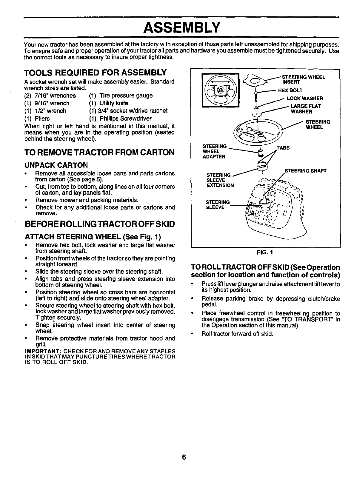
ATTACH STEERING WHEEL (See Fig. 1)
•Remove hex bolt, lock washer and large flat washer
from steering shaft.
•Positionfront wheels of the tractor so they are pointing
straight forward.
•Slide the steering sleeve over the steering shaft.
•Align tabs and press steering sleeve extension into
bottom of steering wheel.
•Position steering wheel so cross bars are horizontal
(left to right) and slide onto steering wheel adapter.
•Secure steering wheel to steering shaft with hex bolt,
lockwasher and large flat washer previously removed.
Tighten securely.
•Snap steedng wheel insert into center of steering
wheel.
•RemoVe protective materials from tractor hood and
grill.
IMPORTANT: CHECKFORAND REMOVEANY STAPLES
IN SKID THAT MAY PUNCTURE TIRES WHERE TRACTOR
IS TO ROLL OFF SKID.
I_1 _/STEEr'NGWHEEL
_..___F._ INSERT
_,._--.--- HEX BOLT
_LOCK WASHER
@_ TEERING
WHEEL
STEERING
WHEEL ----.........,,_ JABS
ADAPTER _
STEERING SHAFT
STEERING _- I
SLEEVE
EXTENSION
%\*1
STEERING
SLEEVE
FIG. 1
TO ROLLTRACTOR OFF SKID (See Operation
section for location and function of controls)
•Press lift leverplunger and raise attachment lift lever to
its highest position.
• Release parking brake by depressing clutch/brake
pedal.
• Place freewheel control in freewheelingposition to
disengage transmission (See "TO TRANSPORT" in
the Operation section of this manual).
Roll tractor forward off skid.
6
ASSEMBLY
HOW TO SET UP YOUR TRACTOR
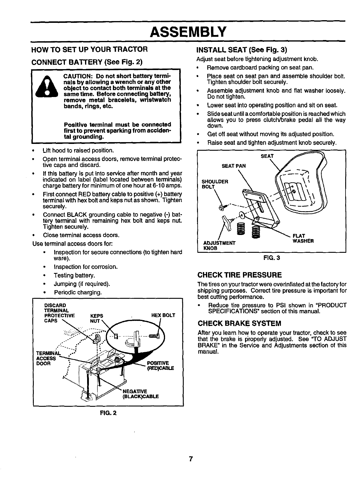
CONNECT BATTERY (See Fig. 2)
CAUTION: Do not short battery termi-
nals by allowing a wrench or any other
object to contact both terminals at the
same time. Before connecting battery,
remove metal bracelets, wristwatch
bands, rings, etc.
Positive terminal must be connected
first to prevent sparking from acciden-
tal grounding.
•Lift hood to raised position.
•Open terminal access doors, remove terminal protec-
tive caps and discard.
•If this battery is put into service after month and year
indicated on label (label located between terminals)
charge battery for minimum of one hour at 6-10 amps.
•First connect RED battery cable to positive (+) battery
terminal with hex bolt and keps nut as shown. Tighten
securely,
•Connect BLACK grounding cable to negative (-) bat-
tery terminal with remaining hex bolt and keps nut.
Tighten securely.
•Close terminal access doors.
Use terminal access doors for:
•Inspection for secure connections (to tighten hard
ware).
•Inspection for corrosion.
•Testing battery.
• Jumping (if required).
•Periodic charging.
DISCARD
TERMINAL
PROTECTIVE KEPS HEX BOLT
.... _,,:y , o"
TERM,N;,i.:J i
ACCESS
DOOR .: _ _'F_.mm_ posrrlvs
2'_'%"-..., j
. GATIVE
INSTALL SEAT (See Fig. 3)
Adjust seat before tightening adjustment knob.
•Remove cardboard packing on seat pan.
•Place seat on seat pan and assemble shoulder bolt.
Tighten shoulder bolt securely.
•Assemble adjustment knob and flat washer Ioossty.
Do not tighten.
•Lower seat into operating position and sit on seat.
•Slide seat untila comfortable positionis reached which
allows you to press clutch/brake pedal all the way
down.
•Get off seat without moving its adjusted position.
•Raise seat and tighten adjustment knob securely.
SEAT
SEATPAN
SHOULDER
BOLT
ADJUSTMENT
KNOB
FIG. 3
.FLAT
WASHER
CHECK TIRE PRESSURE
The tires on your tractor were ovefinflated at the factoryfor
shipping purposes. Correct tire pressure is important for
best cutting performance.
• Reduce tire pressure to PSI shown in "PRODUCT
SPECIFICATIONS" section of this manual.
CHECK BRAKE SYSTEM
After you learn how to operate your tractor, check to see
that the brake is properly adjusted. See "TO ADJUST
BRAKE" in the Service and Adjustments section of this
manual.
FIG. 2
7
ASSEMBLY
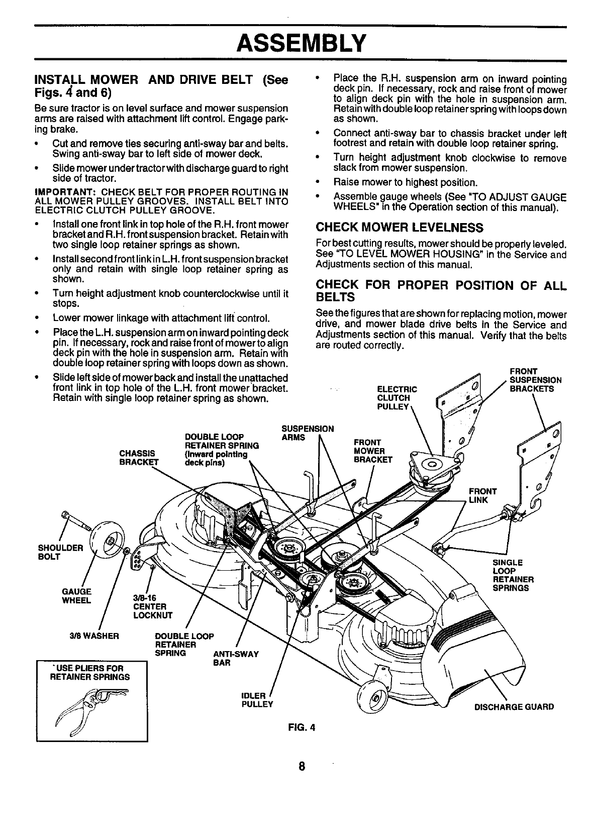
INSTALL MOWER AND DRIVE BELT (See
Figs. 4and 6)
Be sure tractor is on level surface and mower suspension
arms are raised with attachment liftcontrol. Engage park-
ing brake.
•Cut and remove ties securing anti-sway bar and belts.
Swing anti-sway bar to left side of mower deck.
•Slide mower undertractorwith discharge guard to right
side of tractor.
IMPORTANT: CHECK BELT FOR PROPER ROUTING IN
ALL MOWER PULLEY GROOVES. INSTALL BELT INTO
ELECTRIC CLUTCH PULLEY GROOVE.
•Install one front link in top hole of the R.H. front mower
bracket and R.H. front suspension bracket. Retain with
two single loop retainer springs as shown.
•Installsecond front linkin L.H. front suspension bracket
only and retain with single loop retainer spring as
shown.
•Turn height adjustment knob counterclockwise until it
stops.
•Lower mower linkage with attachment liftcontrol.
•Place the L.H. suspension arm on inward pointing deck
pin. If necessary, rockand raise front of mower to align
deck pin with the hole in suspension arm. Retain with
double loop retainer spring with loops down as shown.
•Slide left side of mower back and installthe unattached
front link in top hole of the LH. front mower'bracket.
Retain with single loop retainer spring as shown.
DOUBLE LOOP
RETAINER SPRING
CHASSIS (Inward pointing
BRACKET deck plns)
Place the R.H. suspension arm on inward pointing
deck pin. If necessary, rock and raise front of mower
to align deck pin with the hole in suspension arm.
Retain withdouble loop retainer springwithloopsdown
as shown.
•Connect anti-sway bar to chassis bracket under left
footrest and retain with double loop retainer spring.
•Turn height adjustment knob clockwise to remove
slack from mower suspension.
•Raise mower to highest position.
•Assemble.gauge wheels (See "TO ADJUST GAUGE
WHEELS in the Operation section of this manual).
CHECK MOWER LEVELNESS
For best cutting results, mower should be properly leveled.
See "TO LEVEL MOWER HOUSING" in the Service and
Adjustments section of this manual.
CHECK FOR PROPER POSITION OF ALL
BELTS
See the figures that are shown for replacing motion, mower
drive, and mower blade drive belts in the Service and
Adjustments section of this manual. Verify that the belts
are routed correctly.
SUSPENSION
ARMS
ELECTRIC
CLUTCH
PULLEY'
FRONT
MOWER
BRACKET
FRONT
SUSPENSION
BRACKETS
SHOULDER
BOLT
GAUGE
WHEEL
3_WASHER
"USE PLIERS FOR
RETAINERSPRINGS
3/8-16
CENTER
LOCKNUT
DOUBLELOOP
RETAINER
SPRING ANTI-SWAY
BAR
IDLER
PULLEY
FIG. 4
SINGLE
LOOP
RETAINER
SPRINGS
DISCHARGE GUARD
8
ASSEMBLY
DEFLECTOR
SHIELD
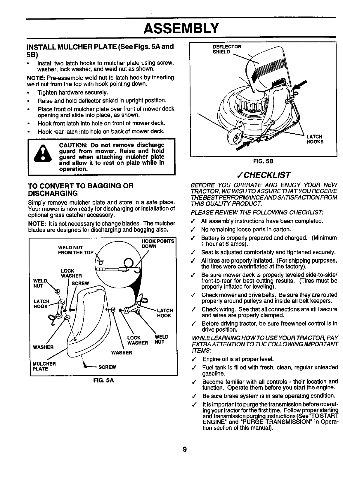
INSTALL MULCHER PLATE (See Figs. 5A and
5B)
•Install two latch hooks to mulcher plate using screw,
washer, lock washer, and weld nut as shown.
NOTE: Pre-assemble weld nut to latch hook by inserting
weld nut from the top with hook pointing down.
•Tighten hardware securely.
• Raise and hold deflector shield in upright position.
•Place front of mulcher plate over front of mower deck
opening and slide into place, as shown.
•Hook front latch into hole on front of mower deck.
•Hook rear latch into hole on back of mower deck.
&CAUTION: Do not remove discharge
guard from mower. Raise and hold
guard when. attaching mulcher p.late.
and allow it to rest on plate while m
operation.
TO CONVERT TO BAGGING OR
DISCHARGING
Simply remove mulcher plate and store in asafe place.
Your mower is now ready for discharging or installation of
optional grass catcher accessory.
NOTE: It is not necessaryto change blades. The mulcher
blades are designed for discharging and bagging also.
WELD NUT
FROM THE TOP
HOOK POINTS
DOWN
LOCK
WASHER
ISCREW
LATCH
HOOK
WASHER
MULCHER
PLATE
LOCK
WASHER
WASHER
'_'_SCREW
WELD
NUT
FIG. 5A
LATCH
HOOKS
FIG. 5B
,/CHECKLIST
BEFORE YOU OPERATE AND ENJOY YOUR NEW
TRACTOR, WE WISH TO ASSURE THAT YOU RECEIVE
THE BEST PERFORMANCE AND SATISFA CTION FROM
THIS QUALITY PRODUCT.
PLEASE REVIEW THE FOLLOWING CHECKLIST:
/All assembly instructions have been completed.
/No remaining loose parts in carton.
,,1 Battery is properly prepared and charged. (Minimum
1 hour at 6 amps).
,/ Seat is adjusted comfortably and tightened securely.
,/ All tires are properly inflated. (For shipping purposes,
the tires were ovednflated at the factory).
/Be sure mower deck is properly leveled side-to-side/
front-to-rear for best cutting results. (Tires must be
properly inflated for leveling).
,/ Check mower and drive belts. Be sure they are routed
properly around pulleys and inside all belt keepers.
,/ Check wiring. See that all connections are stillsecure
and wires are properly clamped.
,/ Before drivingtractor, be sure freewheel control is in
drive position.
WHILE LEARNING HOW TO USE YOUR TRACTOR, PAY
EXTRA ATTENTION TO THE FOLLOWING IMPORTANT
ITEMS:
/Engine oil is at proper level.
,/ Fuel tank is filled with fresh, clean, regular unleaded
gasoline.
/Become familiar with all controls -their location and
function. Operate them before you start the engine.
,/ Be sure brake system is in safe operating condition.
,/ It is important to purge the transmission before operat-
ingyour tractorfor the firsttime. Followproper starting
and transmissionpurging instructions(See"TO START
ENGINE' and "PURGE TRANSMISSION" in Opera-
tion section of this manual).
9

OPERATION
These symbols may appear on your tractor or in literature supplied withthe product. Learn and understand their meaning.
BATTERY CAUTION OR REVERSE FORWARD FAST SLOW
WARNING
ENGINE ON ENGINE OFF OIL PRESSURE CLUTCH LIGHTS ON OVER TEMP
LIGHT
FUEL
CHOKE MOWER HEIGHT DIFFERENTIAL PARKING BRAKE UNLOCKED
LOCK LOCKED
! R N H L
_1_ REVERSE NEUTRAL HIGH LOW PARKING BRAKE
MOWER LIFT
ATTACHMENT
CLUTCH ENGAGED
ATTACHMENT KEEP AREA CLEAR SLOPE HAZARDS
CLUTCH DISENGAGED (SEE SAFETY RULES SECTION)
DANGER, KEEP HANDS AND FEET AWAY IGNITION FREEWHEEL
(Automatic Models only)
10
OPERATION
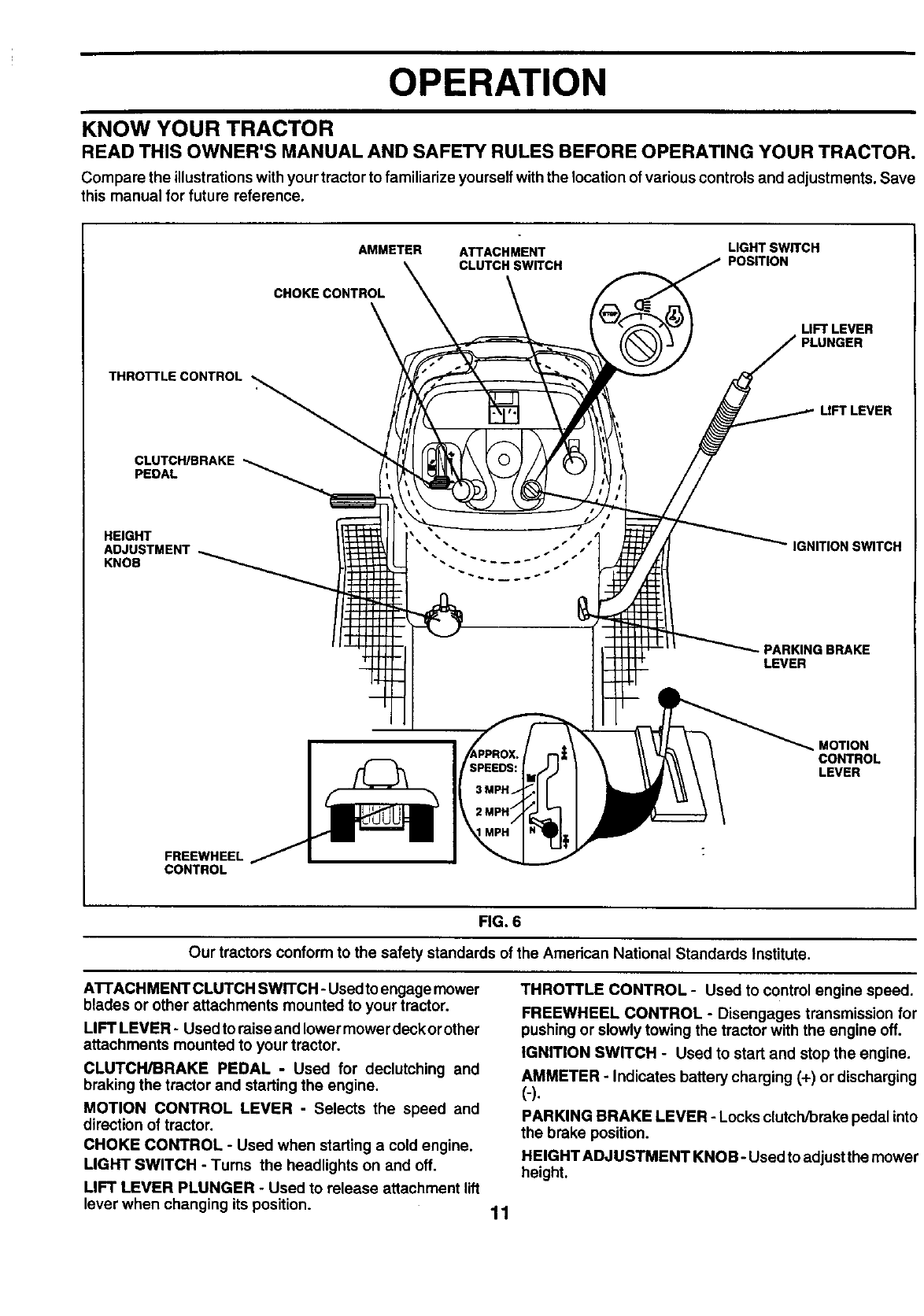
KNOW YOUR TRACTOR
READ THIS OWNER'S MANUAL AND SAFETY RULES BEFORE OPERATING YOUR TRACTOR.
Compare the illustrationswith your tractor to familiarize yourselfwith the location of various controls and adjustments. Save
this manual for future reference.
THROI-I'LECONTROL
AMMETER ATTACHMENT LIGHT SWITCH
CLUTCH SWITCH POSITION
CHOKE CONTROL
LIFT LEVER
PLUNGER
LIFT LEVER
CLUTCH/BRAKE
PEDAL
HEIGHT
ADJUSTMENT
KNOB
IGNITION SWITCH
- PARKING BRAKE
LEVER
MOTION
CONTROL
LEVER
FREEWHEEL
CONTROL
FIG. 6
Our tractors conform to the safety standards of the American National Standards Institute.
A'B'ACHMENT CLUTCH SWITCH -Used toengage mower
blades or other attachments mounted to your tractor.
LIFT LEVER - Used to raise and lower mower deck or other
attachments mounted to your tractor.
CLUTCH/BRAKE PEDAL -Used for declutching and
braking the tractor and starting the engine.
MOTION CONTROL LEVER -Selects the speed and
direction of tractor.
CHOKE CONTROL - Used when starting a cold engine.
LIGHT SWITCH - Turns the headlights on end off.
LIFT LEVER PLUNGER - Used to release attachment lift
lever when changing its position.
THROTTLE CONTROL - Used to control engine speed.
FREEWHEEL CONTROL - Disengages transmission for
pushing or slowly towing the tractor with the engine off.
IGNITION SWITCH - Used to start and stop the engine.
AMMETER - Indicates battery charging (+) or discharging
(-).
PARKING BRAKE LEVER - Locks clutch/brake pedal into
the brake position.
HEIGHT ADJUSTMENT KNOB- Used to adjust the mower
height.
11
OPERATION
IThe operation of any tractor can result in foreign objects thrown into the eyes, which can result I
in severe eye damage. Always wear safety glasses or eye shields while operating your tractor I
or performing any adjustments or repairs. We recommend a wide vision safety mask over
spectacles or standard safety glasses.
HOW TO USE YOUR TRACTOR
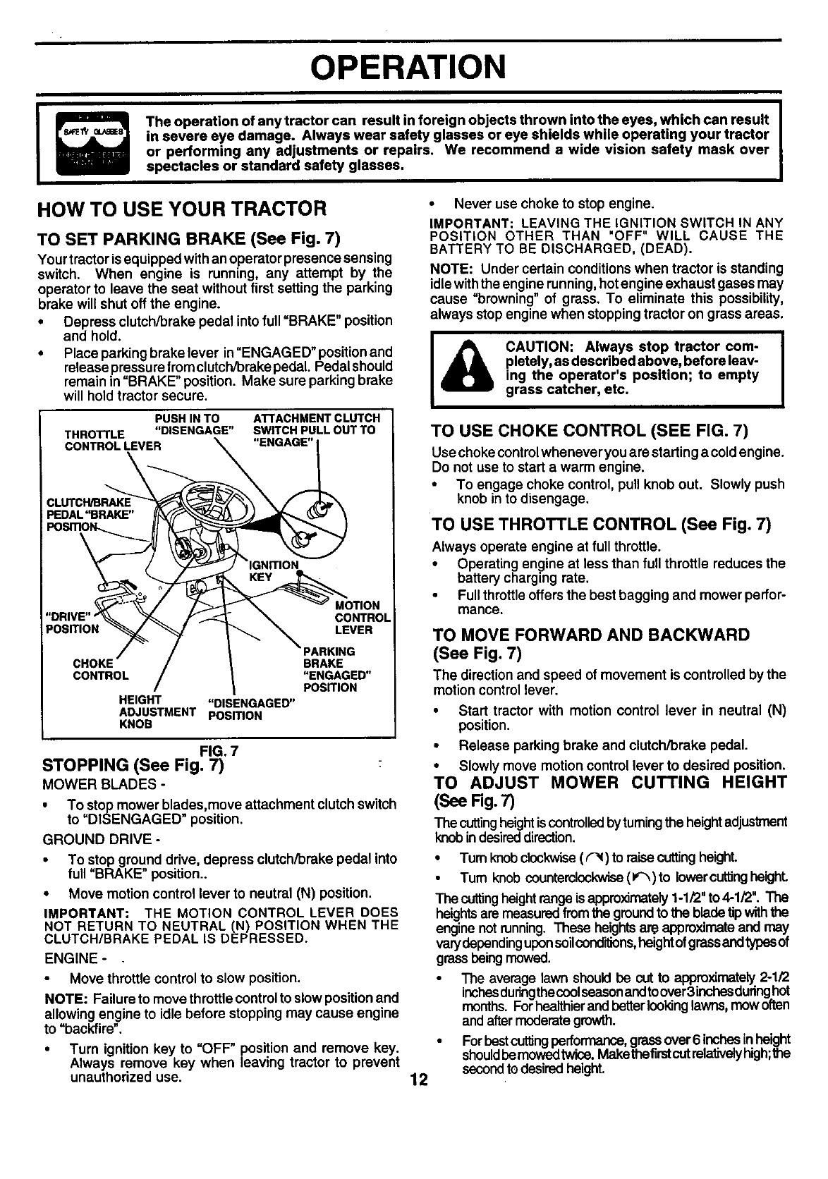
TO SET PARKING BRAKE (See Fig. 7)
Your tractor isequipped with an operator presence sensing
switch. When engine is running, any attempt by the
operator to leave the seat without first setting the parking
brake will shut off the engine.
•Depress clutch/brake pedal into full =BRAKE" position
and hold.
•Place parking brake lever in=ENGAGED" positionand
release pressure fromclutch/brake pedal. Pedal should
remain in =BRAKE" position. Make sure parking brake
will hold tractor secure,
PUSHINTO
THROTrLE "DISENGAGE"
CONTROLLEVER
\
ATTACHMENT CLUTCH
SWITCH PULL OUT TO
"ENGAGE"
CONTROL
PosmoN LEVER
CHOKE BRAKE
CONTROL "ENGAGED"
PosmoN
HEIGHT "DISENGAGED"
ADJUSTMENT POSITION
KNOB
FIG. 7
STOPPING (See Fig. 7)
MOWER BLADES -
• To stop mower blades,move attachment clutch switch
to "DISENGAGED" position.
GROUND DRIVE -
• To stop ground drive, depress clutch/brake pedal into
full =BRAKE" position..
•Move motion control lever to neutral (N) position.
IMPORTANT: THE MOTION CONTROL LEVER DOES
NOT RETURN TO NEUTRAL (N) POSITION WHEN THE
CLUTCH/BRAKE PEDAL IS DEPRESSED.
ENGINE -
•Move throttle control to slow position.
NOTE: Failure to move throttle controlto slow positionand
allowing engine to idle before stopping may cause engine
to =backfire".
• Turn ignition key to =OFF" position and remove key.
Always remove key when leaving tractor to prevent
unauthorized use.
•Never use choketo stop engine.
IMPORTANT: LEAVING THE IGNITION SWITCH IN ANY
POSITION OTHER THAN "OFF" WILL CAUSE THE
BATTERY TO BE DISCHARGED, (DEAD).
NOTE: Under certain conditions when tractor is standing
idle withthe engine running,hotengine exhaust gases may
cause =browning" of grass. To eliminate this possibility,
always stopengine when stopping tractor on grass areas.
&!
CAUTION: Always stop tractor com- |
pletely, as described above, before leav- I
ing the operator's position; to empty
grass catcher, etc.
TO USE CHOKE CONTROL (SEE FIG. 7)
Use chokecontrolwhenever you are starting a cold engine.
Do not use to start a warm engine.
•To engage choke control, pull knob out. Slowly push
knob in to disengage.
TO USE THROTTLE CONTROL (See Fig. 7)
Always operate engine at full throttle.
•Operating engine at less than full throttle reduces the
battery charging rate.
•Fullthrottle offersthe best bagging and mower perfor-
mance.
TO MOVE FORWARD AND BACKWARD
(See Fig. 7)
The direction and speed of movement is controlled by the
motion control lever.
12
• Start tractor with motion control lever in neutral (N)
position.
•Release parking brake and clutch/brake pedal.
•Slowly move motion control lever to desired position.
TO ADJUST MOWER CUTTING HEIGHT
(See Rg. 7)
The cuttingheightis controlledbytumingthe heightadjustment
knobin desireddirection.
•Turnknobclockwise(r'_) to raisecuttingheight.
Turn knob counterclockwise(1_) to lower cuttingheight.
The cuttingheight range isappro)dmately1-1/2" to 4-1/2". The
heights are measuredfrom the ground to the blade tipwith
engine not running. These heights are approximate and may
varydepending upon soil conditions,height of grass andtypes of
grass being mowed.
• The average lawn should be cut to approximately2-1/2
inchesduringthecoolseasonandtoover3inchesduringhot
months. Forhealthierand betterlookinglawns, mow often
and aftermoderategrowth.
•ForbestcutlJngperformance,grassover6 inchesin height
shouldbemowedtwice.Makethefirstcutrelativelyhigh;the
secondto desiredheight.
OPERATION
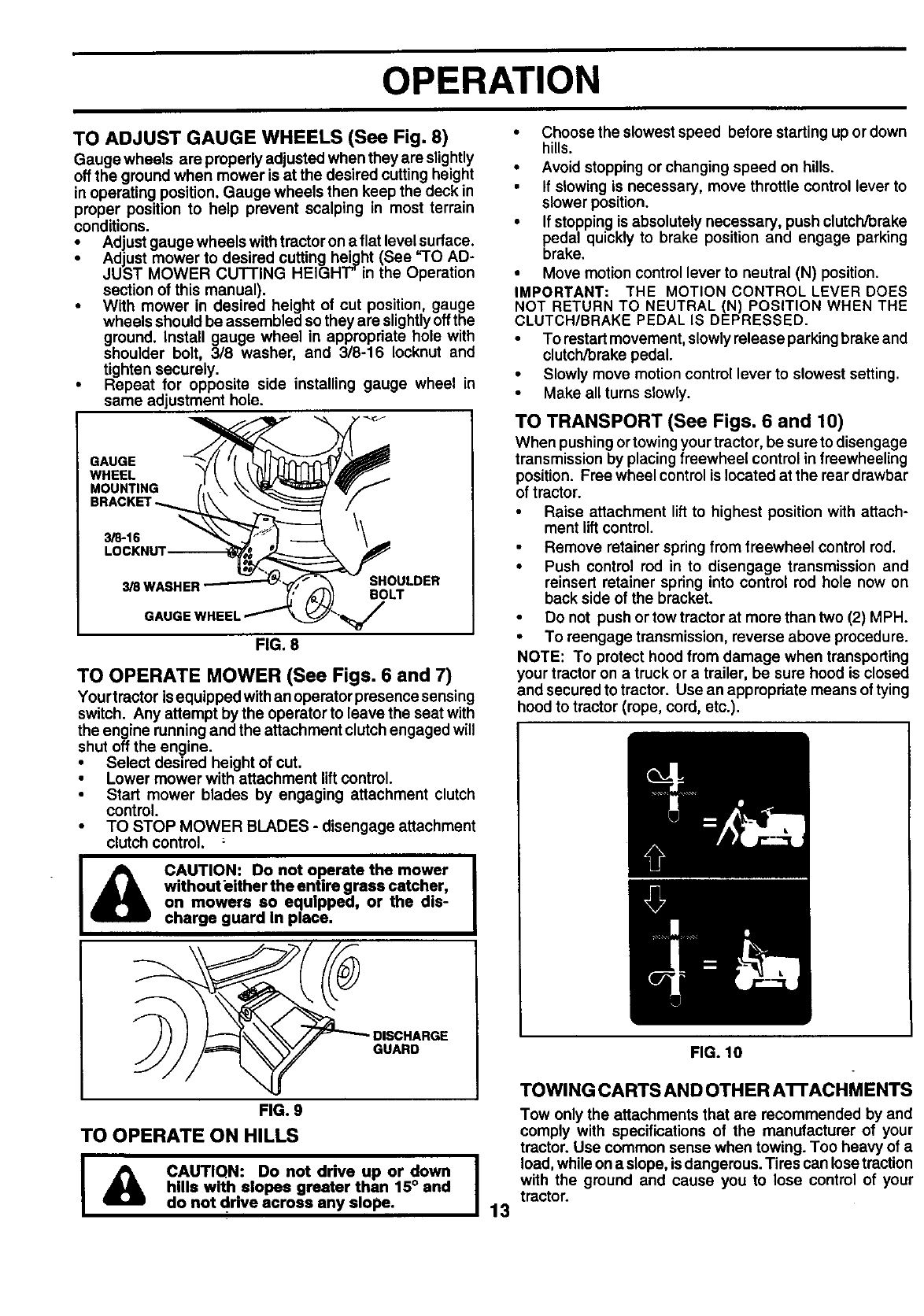
TO ADJUST GAUGE WHEELS (See Fig. 8)
Gauge wheels are properly adjusted when they are slightly
off the ground when mower is at the desired cutting height
in operating position. Gauge wheels then keep the deck in
proper position to help prevent scalping in most terrain
conditions.
• Adjust gauge wheels withtractor on a flat level surface.
•Adjust mower to desired cutting height (See =TO AD-
JUST MOWER CUTTING HEIGHT"in the Operation
section of this manual).
•With mower in desired height of cut position, gauge
wheels should be assembled so they are slightlyoff the
ground. Install gauge wheel in appropdate hole with
shoulder bolt, 3/8 washer, and 3/8-16 Iocknut and
tighten securely.
• Repeat for opposite side installing gauge wheel in
same adjustment hole.
GAUGE
WHEEL
MOUNTING
3/8-16
LOCKNU1
SHOULDER
BOLT
FIG. 8
TO OPERATE MOWER (See Figs. 6 and 7)
Yourtractor isequipped with an operator presence sensing
switch. Any attempt by the operator to leave the seat with
the engine running and the attachment clutch engaged will
shut off the engine.
•Select desired height of cut.
•Lower mower with attachment liftcontrol.
•Start mower blades by engaging attachment clutch
control.
•TO STOP MOWER BLADES - disengage attachment
clutch control. :
CAUTION: Do not operate the mower
withouteither the entire grass catcher,
on mowers so equipped, or the dis-
charge guard in place.
GUARD
FIG. 9
TO OPERATE ON HILLS
I& CAUTIQN: Donotdriveupordown I
hills with elopes greater than 15° and
do not drive across any slope. 13
• Choose the slowest speed before starting up or down
hills.
•Avoid stopping or changing speed on hills.
• If slowing is necessary, move throttle control lever to
slower position.
•If stopping is absolutely necessary, push clutch/brake
pedal quickly to brake position and engage parking
brake.
•Move motion control lever to neutral (N) position.
IMPORTANT: THE MOTION CONTROL LEVER DOES
NOT RETURN TO NEUTRAL (N) POSITION WHEN THE
CLUTCH/BRAKE PEDAL IS DEPRESSED.
•To restartmovement, slowly release parking brake and
clutch/brake pedal.
•Slowly move motion control lever to slowest setting.
•Make all turns slowly.
TO TRANSPORT (See Figs. 6 and 10)
When pushing ortowingyour tractor, be sure to disengage
transmission by placing freewheel control in freewheeling
position. Free wheel control is located at the roar drewbar
of tractor.
Raise attachment liftto highest position with attach-
ment lift control.
•Remove retainer spring from freewheel control rod.
•Push control rod in to disengage transmission and
reinsert retainer spring into control rod hole now on
back side of the bracket.
Do not push or tow tractor at more than two (2) MPH.
•To reengage transmission, reverse above procedure.
NOTE: To protect hood from damage when transporting
your tractor on a truck or a trailer, be sure hood is closed
and secured to tractor. Use an appropriate means of tying
hood to tractor (rope, cord, etc.).
FIG. 10
TOWING CARTS AND OTHER ATrACHMENTS
Tow only the attachments that are recommended by and
comply with specifications of the manufacturer of your
tractor. Use common sense when towing. Too heavy of a
load,while ona slope, is dangerous. Tires can losetraction
with the ground and cause you to lose control of your
tractor.
OPERATION
BEFORE STARTING THE ENGINE
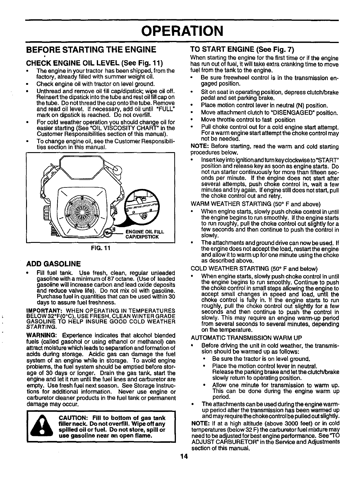
CHECK ENGINE OIL LEVEL (See Fig. 11)
•The engine in your tractor has been shipped, from the
factory, already filled with summer weight oil.
•Check engine oil with tractor on level ground.
•Unthread and remove oil flUcap/dipstick; wipe oil off.
Reinsert the dipstick intothe tube end rest oilfillcap on
the tube. Do notthread the cap onto the tube. Remove
and read oil level. If necessary, add oil until "FULL"
mark on dipstick is reached. Do not overfill.
• For cold weather operation you should change oil for
easier starting (See "OIL VISCOSITY CHART" in the
Customer Responsibilities section of this manual).
• To change engine oil, see the Customer Responsibili-
ties section in this manual.
ENGINE OIL FILL
CAP/DIPSTICK
FIG. 11
ADD GASOLINE
•Fill fuel tank. Use fresh, clean, regular unleaded
gasoline with a minimum of 87 octane. (Use of leaded
gasoline will increase carbon and lead oxide deposits
and reduce valve life). Do not mix oil with gasoline.
Purchase fuel in quantities that can be used within 30
days to assure fuel freshness.
IMPORTANT: WHEN OPERATING IN TEMPERATURES
BELOW 32°F(0°C), USE FRESH, CLEAN WINTER GRADE
GASOLINE TO HELP INSURE GOOD COLD WEATHER
STARTING.
WARNING: Experience indicates that alcohol blended
fuels (called gasohol or using ethanol or methanol) can
attract moisture which leads to separation and formation of
acids during storage. Acidic gas can damage the fuel
system of an engine while in storage. To avoid engine
problems, the fuel system should be emptied before stor-
age of 30 days or longer. Drain the gas tank, start the
engine and let it run until the fuel lines and carburetor are
empty. Use fresh fuel next season. See Storage Instruc-
tions for additional information. Never use engine or
carburetor cleaner products in the fuel tank or permanent
damage may occur.
I& CAUTION: Fill to bottom of gas tank I
i
filler neck. Do not overfill, Wipe off any I
spilled oil or fuel. Do not store, spill or
use gasoline near an open flame.
14
TO START ENGINE (See Fig. 7)
When starting the engine for the first time or if the engine
has run out of fuel, it will take extra cranking time to move
fuel from the tank to the engine,
Be sure freewheel control is in the transmission en-
gaged position.
•Sit on seat in operating position, depress clutch/brake
pedal and set parking brake.
•Place motion control lever in neutral (N) position.
•Move attachment clutch to'DISENGAGED" position.
•Move throttlecontrol to fast position
•Pull choke control out for acold engine start attempt.
For a warm engine start attempt the choke control may
not be needed.
NOTE: Before starting, read the warm and cold starting
procedures below.
•Insertkeyinto ignitionandturnkeyclockwise to=START,,
position and release key as soon as engine starts. Do
not run starter continuously for more than fifteen sec-
onds per minute. If the engine does not start after
several attempts, push choke control in, wait a few
minutes and try again. If engine stilldoes notstart, pull
the choke control out and retry.
WARM WEATHER STARTING (50° F and above)
•When engine starts, slowly push choke control in until
the engine begins to run smoothly. If the engine starts
to run roughly, pullthe choke control out slightly for a
few seconds and then continue to push the control in
slowly.
•The attachments and grounddrive can now be used. If
the engine does notaccept the load, restart the engine
and allow ittowarm up forone minute usingthe choke
as described above.
COLD WEATHER STARTING (50° F and below)
•When engine starts, slowly push choke control in until
the engine begins to run smoothly. Continue to push
the choke control in small steps allowing the engine to
accept small changes in speed and load, until the
choke control is fully in. If the engine starts to run
roughly, pull the choke control out slightly for afew
seconds and then continue to push the control in
slowly. This may require an engine warm-up period
from several seconds to several minutes, depending
on the temperature.
AUTOMATIC TRANSMISSION WARM UP
•Before driving the unit in cold weather, the transmis-
sion should be warmed up as follows:
•Be sure the tractor is on level ground.
•Place the motion control lever in neutral.
Release the parking brake and let the clutch/brake
slowly return to operating position.
•Allow one minute for transmission to warm up.
This can be done dudng the engine warm up
period.
•The attachments can be usedduring the engine warm-
up pedod after the transmission has been warmed up
and may requirethe choke controlbe pulled out slightly.
NOTE: If at ahigh altitude (above 3000 feet) or in cold
temperatures (below 32 F) the carburetor fuel mixture may
need to be adjustedfor best engine performance. See "TO
ADJUST CARBURETOR" inthe Service and Adjustments
section of this manual.
OPERATION
PURGE TRANSMISSION •
CAUTION: Never engage or disengage [
AI freewheel lever while the engine is run- I
I ning. I
To ensure proper operation and performance, it is recom-
mended that the transmission be purged before operating
tractor for the first time. This procedure will remove any
trapped air inside the transmission which may have devel-
oped during shipping of your tractor.
IMPORTANT: SHOULDYOURTRANSMISSION REQUIRE
REMOVAL FOR SERVICE OR REPLACEMENT, IT
SHOULD BE PURGED AFTER REINSTALLATION
BEFORE OPERATING THE TRACTOR.
•Place tractor safely on level surface withengine off and
parking brake set.
Disengage transmission by placing freewheel control
in freewheeling position (See "TO TRANSPORT" in
this section of manual).
Sitting inthe tractor seat, start engine. After the engine
is running, move throttle control to slow position. With
motion control lever in neutral (N) position, slowly
disengage clutch/brake pedal.
•Move motion control lever to full forward position and
hold for five (5) seconds. Move lever to full reverse
position and hold for five (5) seconds. Repeat this
procedure three (3) times.
NOTE: Duringthis procedure there will be no movement of
drive wheels. The air is being removed from hydraulicdrive
system.
•Move motioncontrolleverto neutral (N) position. Shut-
off engine and set parking brake.
•Engage transmission by placing freewheel control in
drivingposition(See "TO TRANSPORT" inthis section
of manual).
•Sittinginthe tractor seat, start engine. Afterthe engine
is running, move throttle control to half (1/2) speed.
With motion control lever in neutral (N) position, slowly
disengage clutch/brake pedal.
•Slowly move motion control lever forward, after the
tractor moves approximately five (5) feet, slowly move
motion control lever to reverse position. After the
tractor moves approximately five(5) feet return the
motioncontrol lever to the neutral (N) position. Repeat
this procedure with the motion control lever three (3)
times.
•Your tractor is now purged and now ready for normal
operation.
MOWING TIPS
•Tire chains cannot be used when the mower housingis
attached to tractor.
•Mower should be properly leveled for best mowing
performance. See "TO LEVEL MOWER HOUSING" in
the Service and Adjustments section of this manual.
•The left hand side of mower should be used for trim-
ming.
•Drive so that clippings are discharged onto the area
that has been cut. Have the cut area to the right of the
tractor. This will result in amore even distribution of
clippings and more uniform cutting.
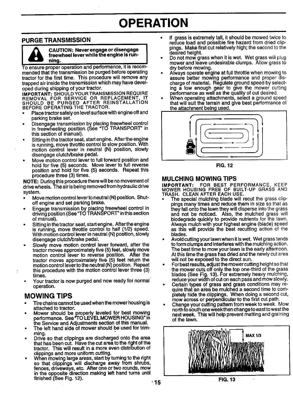
•When mowinp large areas, start by turning to the right
so that clippings will discharge away from shrubs,
fences driveways, etc. After one or two rounds, mow
in the opposite direction making left hand tums unt
finished (See Fig. 12). :15
If grass is extremely tall, it should be mowed twice to
reduce load and possible fire hazard from dried clip-
pings. Make first cut relatively high; the second to the
desired height.
Do not mow grass when it is wet. Wet grass will plug
mower and leave undesirable clumps. Allow grass to
dry before mowing.
Always operate eng.ine at full throttle when mowing to
assure better mowing performance and proper dis-
charge of material. Regulate ground speed by select-
ing a low enough gear to give the mower cutting
_ehrformance as well as the quality of cut desired.
en operating attachments, select a ground speed
that will suit the terrain and give best performance of
the attachment bein 9 used.
FIG. 12
MULCHING MOWING TIPS
IMPORTANT: FOR BEST PERFORMANCE, KEEP
MOWER HOUSING FREE OF BUILT-UP GRASS AND
TRASH. CLEAN AFTER EACH USE.
•The special mulching blade will recut the grass clip-
pings many times and reduce them in size so that as
they fall onto the lawn they will disperse into the grass
and not be noticed. Also, the mulched grass will
biodegrade quickly to provide nutrients for the lawn.
Always mulch with your highest engine (blade) speed
as this will provide the best recutting action of the
blades.
•Avoidcuttingyour lawn when it iswet. Wet grass tends
to form clumps and interferes with the mulching action.
The best time to mow your lawn is the early afternoon.
At this time the grass has dried and the newly cut area
will not be exposed to the direct sun.
•For best results, adjust the mower cuttingheight so that
the mower cuts off only the top one-third of the grass
blades (See Fig. 13). For extremely heavy muIching,
reduce your width of cut on each pass and mow slowly.
•Certain types of grass and grass conditions may re-
quire that an area be mulched a second time to com-
pletely hide the clippings. When doing a second cut,
mow across or perpendicular to the first cut path.
•Change your cutting pattern from week to week. Mow
northto south one weekthen change to east to west the
next week. This will help prevent matting and graining
of the lawn.
FIG. 13
CUSTOMER RESPONSIBILITIES
MAINTENANCE SCHEDULE ,*_ _ _. ,_,_ ,_'_ c,_
AS YOU COMPLETE ,_.'_ _,'_._,'_._O_-_
REGULARSERVICE _'/_/¢_'/_/¢t_//_-//_"_/T/_'-_**'S ERVICEDATES
cC:::: BTir:; rOsP:ur_:'°n _
Check Operator Presence and
TIntedock Systems
RCheck for Loose Fasteners I_ 1_7
ASharperdReplece Mower Blades II,/'=
ic Lu.deat,onC.a. ,/
0 Check Battery Level
RClean Battery and Terminals
Check Transaxle Cocting
Adjust Blade Belt(s) Tension tfs
Adjust Motion Drive Belt(s) Tension k/s
Check Engine Oil Level if V'
I Change Engine Oil _,2.3 If
EClean Air Filter VP2
NClean Air Screen V'2
Inspect Muffler/Spark Arrester If
N Replace Oil Filter (If equipped) 11_1,;
Clean Engine Cooling Fins 11_'2
Replace Spark Plug _2 I#1
Replace Air Filter Paper Cadddge
Replace Fuel Filter ¥1
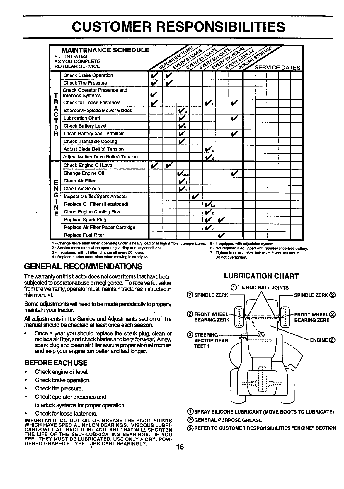
1 -Chartgemomoftenwhenoperafingunderaheavytoadorinhighambienttemperatures. 5-1fequippedwfihadjustablesyotem.
2-Service more often when operatingin dirty or dusty cor_ifions. 6 - Not required if equipped with maintenance-free battery.
3 - If equipped with oil filter, change oil every 50 hours. 7 - Tighten front Bxle pk_otholt to 35 fi.-Ibs, maximum.
4 - Reptace blades mote often when mowing Insandy soil. Do not overtighlen.
GENERAL RECOMMENDATIONS
The warranty onthistractordoes notcover items that havebeen
subjected to operatorabuse ornegligence. To receivefull value
fromthe warranty,operator must maintaintractor as instructedin
this manual.
LUBRICATION CHART
(_)TIE ROD BALL JOINTS
_) SPINDLE ZEI (_
@ ®
BEARING ZERK BEARING ZERK
Some adjustmentswillneed tobe made periodicallyto properly
maintainyourtractor.
All adjustmentsin the Service and Adjustmentssectionof this
manualshouldbe checked at leastonce each season..
Once a year you should replacethe sparkplug, clean or
replaceairfilter,andcheckblades andbeltsforwear_A new
sparkplug anddean airfilterassureproperair-fuelmixture
and helpyour enginerun betterand lastlonger.
®STEERING
SECTOR GEAR "ENGINE ®
TEETH
BEFORE EACH USE
•Checkengineoillevel.
• Check brakeoperation.
•Checktire pressure.
•Checkoperatorpresenceand
interlocksystemsfor properoperation.
•Checkfor loose fasteners.
IMPORTANT: DO NOT OIL OR GREASE THE PIVOT POINTS
WHICH HAVE SPECIAL NYLON BEARINGS. VISCOUS LUBRI-
CANTS WILL ATTRACT DUST AND DIRT THAT WILL SHORTEN
THE LIFE OF THE SELF-LUBRICATING BEARINGS. IF YOU
FEEL THEY MUST BE LUBRICATED, USE ONLY A DRY, POW-
DERED GRAPHITE TYPE LUBRICANT SPARINGLY.
(_)SPRAY SILICONE LUBRICANT (MOVE BOOTS TO LUBRICATE)
• (_GENERAL PURPOSE GREASE
(_REFER TO CUSTOMER RESPONSIBILITIES "ENGINE" SECTION
16
CUSTOMER RESPONSIBILITIES
TRAILING EDGE UP STAR MANDREL
ASSEMBLY
BLADE
TRACTOR
Always observe safety rules when performing any mainte-
nance.
BRAKE OPERATION
If tractor requires more than six (6) feet stopping distance
at highspeed in highest gear, then brake must be adjusted.
(See "TO ADJUST BRAKE" in the Service and Adjust-
ments section of this manual).
TIRES
•Maintain proper air pressure in all tires (See =PROD-
UCT SPECIFICATIONS" section of this manual).
•Keep tires free of gasoline, oil,or insectcontrol chemi-
cals which can harm rubber.
• Avoid stumps, stones, deep ruts, sharp objects and
other hazards that may cause tire damage.
NOTE: To seal tire punctures and prevent flat tires due to
slow leaks, tire sealant may be purchased from your local
parts dealer. Tire sealant also prevents tire dry rot and
corrosion.
OPERATOR PRESENCE SYSTEM
Be sure operator presence and interlock systems are
working properly. If your tractor does not function as
described, repair the problem immediately.
•The engine should not start unless the clutch/brake
pedal isfully depressed and attachement clutch control
is in the disengaged position.
• When the engine is running, any attempt bythe opera-
tor to leave the seat without first setting the parking
brake should shut off the engine.
•When the engine is running and the attachment clutch
is engaged, any attempt by the operator to leave the
seat should shut off the engine.
•The attachment clutch should never operete unless the
operator is in the seat.
BLADE CARE
For best results mower blades must be kept sharp. Re-
place bent or damaged blades.
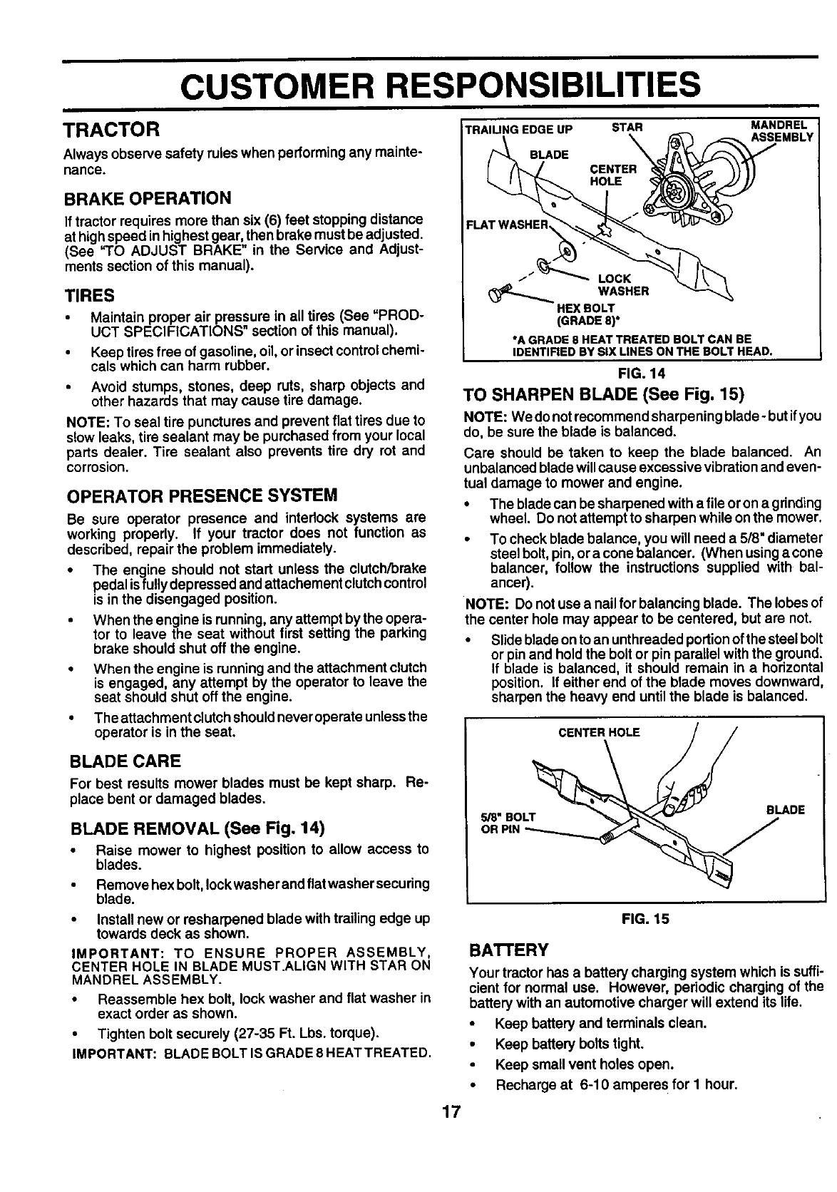
BLADE REMOVAL (See Fig. 14)
•Raise mower to highest position to allow access to
blades.
•Remove hex bolt,lockwasher and flat washer securing
blade.
• Install new or resharpened blade with trailing edge up
towards deck as shown.
IMPORTANT: TO ENSURE PROPER ASSEMBLY,
CENTER HOLE IN BLADE MUST.ALIGN WITH STAR ON
MANDREL ASSEMBLY.
•Reassemble hex bolt, lock washer and flat washer in
exact order as shown.
• Tighten bolt securely (27-35 Ft. Lbs. torque).
IMPORTANT: BLADE BOLT IS GRADE 8 HEAT TREATED.
HOLE
FLAT WASHEI_
iLOCK
WASHER
HEX BOLT
(GRADE 8)*
*A GRADE 8 HEAT TREATED BOLT CAN BE
IDENTIFIED BY SIX LINES ON THE BOLT HEAD.
FIG. 14
TO SHARPEN BLADE (See Fig. 15)
NOTE: We donot recommend sharpening blade- butifyou
do, be sure the blade is balanced.
Care should be taken to keep the blade balanced. An
unbalanced blade willcause excessive vibration and even-
tual damage to mower and engine.
•The blade can be sharpened with a file or on a gdnding
wheel. Do not attempt to sharpen while on the mower.
•To check blade balance, you will need a 5/8" diameter
steel bolt, pin, oracone balancer. (When usingacone
balancer, follow the instructions supplied with bal-
ancer).
NOTE: Do not use a nail for balancing blade. The lobes of
the center hole may appear to be centered, but are not.
•Slide blade on to an unthreaded portionof the steel bolt
or pin and hold the bolt or pin parallel with the ground.
If blade is balanced, it should remain in a horizontal
position. If either end of the blade moves downward,
sharpen the heavy end until the blade is balanced.
FIG. 15
17
BATrERY
Your tractor has a battery charging system which is suffi-
cient for normal use. However, periodic charging of the
battery with an automotive charger will extend its life.
• Keep battery and terminals clean.
•Keep battery bolts tight.
Keep small vent holes open.
Recharge at 6-10 ampere s for I hour.
CUSTOMER RESPONSIBILITIES
NOTE: The original equipment battery on your tractor is
maintenance free. Do not attempt to open or remove caps
or covers. Adding or checking level of electrolyte is not
necessary.
TO CLEAN BATI'ERY AND TERMINALS
Corrosion and dirt on the battery and terminals can cause
the battery to "leak" power.
•Remove terminal guard.
•Disconnect BLACK battery cable first then RED bat-
tery cable and remove battery from tractor.
•Rinse the battery with plain water and dry.
TRANSAXLE COOLING
The fan and cooling fins of transmission should be kept
clean to assure proper cooling.
Do notattempt to clean fan or transmission while engine is
running or while the transmission is hot. To prevent
possible damage to seals, no not use high pressure water
or steam to clean transaxle.
•Inspect coolingfan to be surefan blades are intactand
clean.
• Inspect cooling fins for dirt, grass clippings and other
materials. To prevent damage to seals, do not usa
compressed air or high pressure sprayer to clean
cooling fins.
TRANSAXLE PUMP FLUID
The transaxle was sealed at the factory and fluid mainte-
nance is not required for the life of the transaxle. Should
the transaxle ever leak or require servicing, contact your
nearest authorized service center/department.
V-BELTS
Check V-belts for deterioration and wear after 100 hoursof
operation and replace if necessary. The belts are not
adjustable. Replace belts if they begin to slip from wear.
ENGINE
LUBRICATION
Only use high quality detergent oil rated with API service
classification SF, SG, or SH. Select the oirs SAE viscosity
grade according to your expected operating temperature.
SAE VISCOSITY GRADES
-20"
-30" -20" *10" 0_10" 20" 30'
TEMPERATURE RANGE ANTICIPATED BEFORE NEXT OIL CHANGE
Change the oil after every 50 hours of operation or at least
once ayear ifthetractor is not usedfor 50 hours inone year.
Check the crankcase oil level before starting the engine
and after each eight (8) hours of operation. Tighten oil fill
cap/dipstick securely each time you check the oil level.
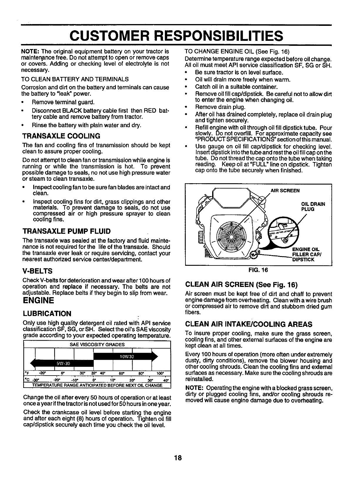
TO CHANGE ENGINE OIL (See Fig. 16)
Determine temperature range expected before oil change.
All oil must meet API service classification SF, SG or SH.
• Be sure tractor is on level surface.
• Oil will drain more freely when warm.
• Catch oil in a suitable container.
• Remove oil fill cap/dipstick. Be careful not to allow dirt
to enter the engine when changing oil.
• Remove drain plug.
• After oil has drained completely, replace oil drain plug
and tighten securely.
Refill engine with oil through oil fill dipstick tube. Pour
slowly. Do not overfill. For approximate capacity see
"PRODUCT SPECIFICATIONS" section of this manual.
•Use gauge on oil fill cap/dipstick for checking level.
Insert dipstick into the tube and rest the oil fill cap on the
tube. Do not thread the cap onto the tube when taking
reading. Keep oil at "FULL" line on dipstick. Tighten
cap onto the tube securely when finished.
AIR SCREEN
OIL DRAIN
PLUG
ENGINE OIL
FILLER CAP/
FIG. 16
CLEAN AIR SCREEN (See Fig. 16)
Air screen must be kept free of dirt and chaff to prevent
engine damage from overheating. Clean with a wire brush
or compressed air to remove dirt and stubborn dried gum
fibers.
CLEAN AIR INTAKE/COOLING AREAS
To insure proper cooling, make sure the grass screen,
coolingfins, and other external surfaces of the engine are
kept clean at all times.
Every 100 hours of operation (more often under extremely
dusty, dirty conditions), remove the blower housing and
other cooling shrouds. Clean the cooling fins and external
surfaces as necessary. Make sure the cooling shrouds are
reinstalled.
NOTE: Operating the engine with a blocked grass screen,
dirty or plugged cooling fins, and/or cooling shrouds ra-
moved will cause engine damage due to overheating.
18
CUSTOMER RESPONSIBILITIES
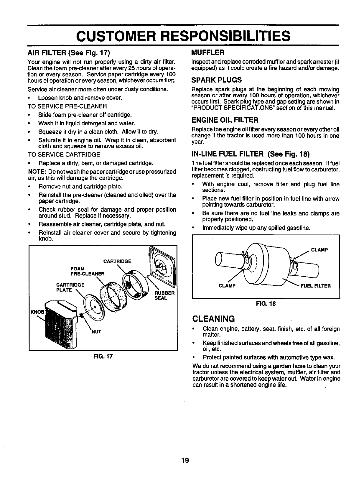
AIR FILTER (See Fig. 17)
Your engine will not run properly using a dirty air filter.
Clean the foam pre-cleaner after every 25 hours of opera-
tion or every season. Service paper cartridge every 100
hoursof operation or every season, whichever occurs first.
Service air cleaner more often under dusty conditions.
•Loosen knob and remove cover.
TO SERVICE PRE-CLEANER
•Slide foam pre-cleaner off cartridge.
Wash it in liquid detergent and water.
• Squeeze it dry in a clean cloth. Allow it to dry.
•Saturate it in engine oil. Wrap it in clean, absorbent
cloth and squeeze to remove excess oil
TO SERVICE CARTRIDGE
Replace a dirty, bent, or damaged cartridge.
NOTE; Do notwash the paper cartridge or use pressurized
air, as this will damage the cartridge.
Remove nut and cartridge plate.
•Reinstall the pre-cleaner (cleaned and oiled) over the
paper cartridge.
•Check rubber seal for damage and proper position
around stud. Replace if necessary.
•Reassemble air cleaner, cartridge plate, and nut.
•Reinstall air cleaner cover and secure by tightening
knob.
CARTRIDGE
FOAM
PRE-CLEANER
CARTRIDGE
PLATE RUBBER
SEAL
FIG. 17
MUFFLER
Inspect and replace corroded muffler and spark arrester (if
equipped) as it could create a fire hazard and/or damage.
SPARK PLUGS
Replace spark plugs at the beginning of each mowing
season or after every 100 hours of operation, whichever
occurs first. Spark plugtype and gap setting are shown in
"PRODUCT SPECIFICATIONS" section of this manual.
ENGINE OIL FILTER
Replace the engine oil filter every season or every other oil
change if the tractor is used more than 100 hours in one
year.
IN-LINE FUEL FILTER (See Fig. 18)
The fuel filter should be replaced once each season. Iffuel
filter becomes clogged, obstructing fuel flow to carburetor,
replacement is required.
•With engine cool, remove filter and plug fuel line
sections.
•Place new fuel filter in position in fuel line with arrow
pointing towards carburetor.
•Be sure there are no fuel line leaks and clamps are
properly positioned.
•Immediately wipe up any spilled gasoline.
CLAMP
CLAMP FUEL RLTER
FIG. 18
CLEANING
• Clean engine, battery, seat, finish, etc. of all foreign
matter.
•Keep finished surfaces and wheels free ofall gasoline,
oil, etc.
•Protect painted surfaces with automotive type wax.
We do not recommend using agarden hose to clean your
tractor unless the electdcal system, muffler, air filter and
carburetor are covered to keep water out. Water in engine
can result in a shortened engine life.
19
SERVICE AND ADJUSTMENTS
&CAUTION: BEFORE PERFORMING ANY SERVICE OR ADJUSTMENTS:
•Depress clutch/brake pedal fully and set parking brake.
Place motion control lever in neutral (N) position.
Place attachment clutch in "DISENGAGED" position.
Turn ignition key "OFF" and remove key.
•Make sure the blades and all moving parts have completely stopped.
•Disconnect spark plug wire from spark plug and place wire where It cannot come in contact with
plug.
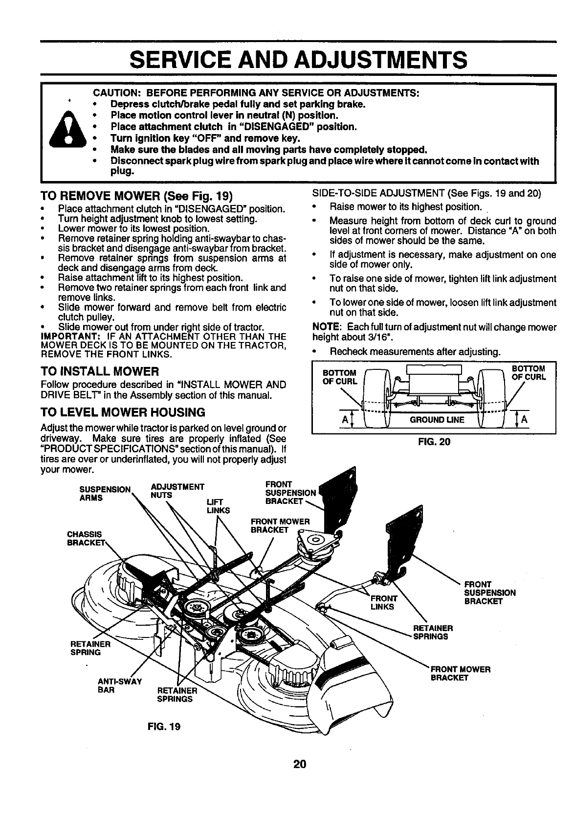
TO REMOVE MOWER (See Fig. 19)
•Place attachment clutch in =DISENGAGED" position.
•Turn height adjustment knob to lowest setting.
•Lower mower to its lowest position.
•Remove retainer spdng holding anti-swaybar to chas-
sis bracket and disengage anti-swaybar from bracket.
•Remove retainer springs from suspension arms at
deck and disengage arms from deck.
•Raise attachment liftto its highest position.
•Remove two retainer springs from each front link and
remove links.
•Slide mower forward and remove belt from electric
clutch pulley.
•Slide mower out from under right side of tractor.
IMPORTANT: IF AN ATTACHMENT OTHER THAN THE
MOWER DECK IS TO BE MOUNTED ON THE TRACTOR,
REMOVE THE FRONT LINKS.
TO INSTALL MOWER
Follow procedure described in =INSTALL MOWER AND
DRIVE BELT" in the Assembly section of this manual.
TO LEVEL MOWER HOUSING
Adjustthe mower while tractor is parked on level ground or
driveway. Make sure tires are properly inflated (See
=PRODUCT SPECIFICATIONS" section ofthis manual). If
tires are over or undednflated, you will not properly adjust
your mower.
ARMS
ADJUSTMENT FRONT I
NUTS SUSPENSION!
LIFT BRACKE
LINKS
SIDE-TO-SIDE ADJUSTMENT (See Figs. 19 and 20)
• Raise mower to its highest position.
•Measure height from bottom of deck curl to ground
level at front comers of mower. Distance =A" on both
sides of mower should be the same.
•If adjustment is necessary, make adjustment on one
side of mower only.
•To raise one side of mower, tighten lift link adjustment
nut on that side.
To lower one side of mower, loosen lift link adjustment
nut on that side.
NOTE: Each fullturn of adjustment nutwill change mower
height about 3/16".
•Recheck measurements after adjusting.
BOTTOM BOTTOM
FIG. 20
CHASSIS BRACKET
FRONT
SUSPENSION
BRACKET
SPRING
ANTI-SWAY
BAR SPRINGS
RETAINER
'SPRINGS
FRONT MOWER
BRACKET
FIG. 19
2O
SERVICE AND ADJUSTMENTS
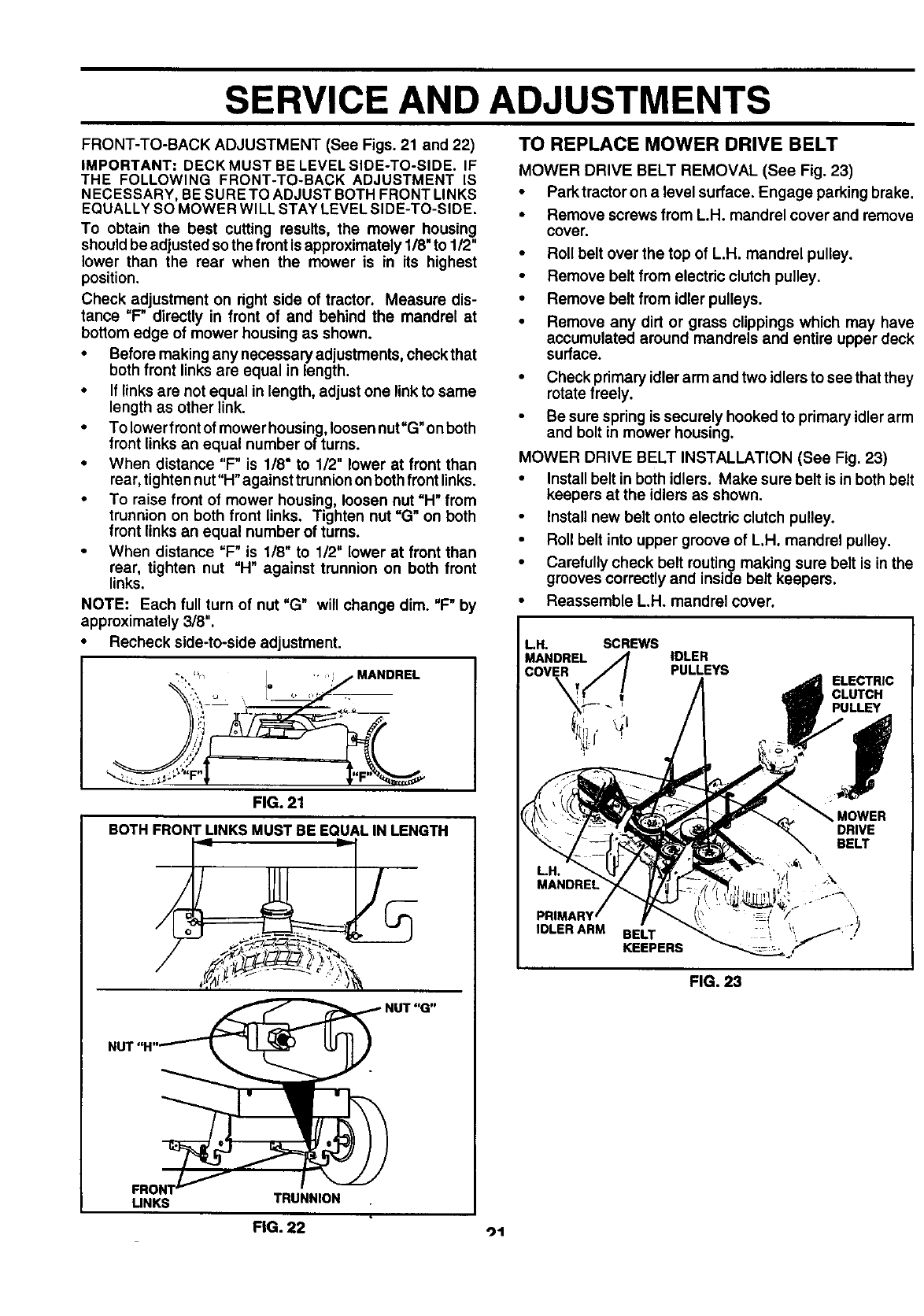
FRONT-TO-BACK ADJUSTMENT (See Figs. 21 and 22)
IMPORTANT= DECK MUST BE LEVEL SIDE-TO-SIDE. IF
THE FOLLOWING FRONT-TO-BACK ADJUSTMENT IS
N ECESSARY, BE SURE TO ADJUST BOTH FRONT LINKS
EQUALLY SO MOWER WILL STAY LEVEL SIDE-TO-SIDE.
To obtain the best cutting results, the mower housing
should be adjusted sothe front isapproximately 118"to 112"
lower than the rear when the mower is in its highest
position.
Check adjustment on dght side of tractor. Measure dis-
tance "F" directly in front of and behind the mandrel at
bottom edge of mower housing as shown.
• Before making any necessaryadjustments, checkthat
both front links are equal in length.
•If links are not equal in length, adjust one link to same
length as other link.
•To lower front of mower housing, loosen nut"G" onboth
front links an equal number of turns.
•When distance "F" is 1/8" to 1/2" lower at front than
rear, tighten nut"H" against trunnion onboth front links.
•To raise front of mower housing, loosen nut "H" from
trunnion on both front links. Tighten nut "G" on both
front links an equal number of turns.
•When distance "F" is 1/8" to 1/2" lower at front than
rear, tighten nut "H" against trunnion on both front
links.
NOTE: Each full turn of nut =G" will change dim. "F" by
approximately 3/8".
•Recheck side-to-side adjustment.
,-, ,,,n " 'i Y MANDREL
%,.
,._ -- _-_----_-.
r! ,,
FIG. 21
BOTH FRONT LINKS MUST BE EQUAL IN LENGTH
/_,_l . _
NUT "G"
NUT "H"_
FRON1.J.._ "_
UNKS TRUNNION
TO REPLACE MOWER DRIVE BELT
MOWER DRIVE BELT REMOVAL (See Fig. 23)
•Parktractor on a level surface, Engage parking brake.
•Remove screws from L.H. mandrel cover and remove
cover,
•Roll belt over the top of L.H. mandrel pulley,
•Remove belt from electric clutch pulley,
•Remove belt from idler pulleys.
•Remove any dirt or grass clippings which may have
accumulated around mandrels and entire upper deck
surface.
•Check primary idler arm and two idlers to see thatthey
rotate freely.
Be sure spring is securely hooked to primary idler arm
and bolt in mower housing.
MOWER DRIVE BELT INSTALLATION (See Fig. 23)
•Installbelt in both idlers. Make sure belt is in both belt
keepers at the idlers as shown.
Install new belt onto electric clutch pulley.
•Roll belt into upper groove of L.H. mandrel pulley.
•Carefully check belt routing making sure belt isin the
grooves correctly and inside belt keepers.
•Reassemble L.H. mandrel cover.
I LH. SCREWS
MANDREL IDLER
=COVER PULLEYS ELECTRIC
CLUTCH
PULLEY
MOWER
DRIVE
BELT
IDLER ARM BELT
KEEPERS
FIG. 23
FIG. 22 ot
SERVICE AND ADJUSTMENTS
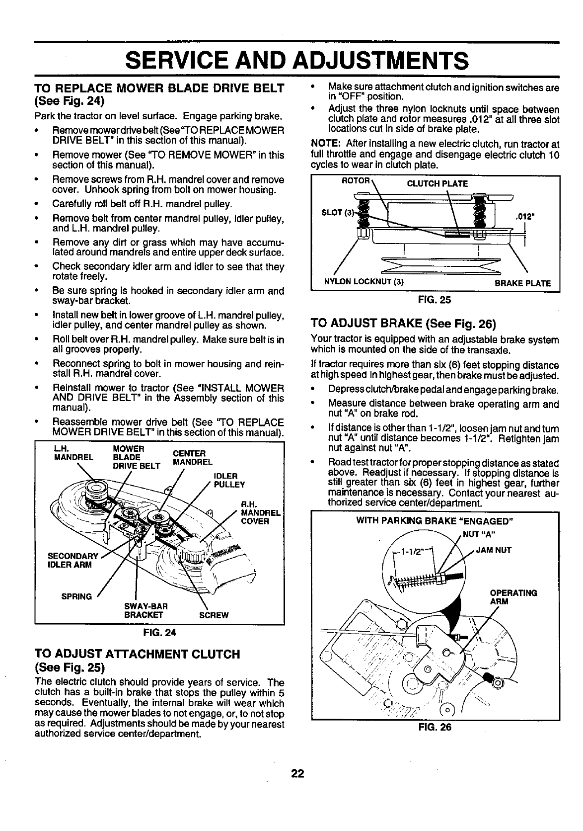
TO REPLACE MOWER BLADE DRIVE BELT
(See Rg. 24)
Park the tractor on level surface. Engage parking brake.
•Remove mower ddve belt(See "TO REPLACE MOWER
DRIVE BELT" in this section of this manual).
•Remove mower (See"TO REMOVE MOWER" in this
section of this manual).
•Remove screws from R.H. mandrel cover and remove
cover. Unhook spring from bolt on mower housing.
•Carefully roll belt off R.H. mandrel pulley.
•Remove belt from center mandrel pulley, idler pulley,
and L.H. mandrel pulley.
Remove any dirt or grass which may have accumu-
lated around mandrels and entire upper deck surface.
Check secondary idler arm and idler to see that they
rotate freely.
•Be sure spring is hooked in secondary idler arm and
sway-bar bracket.
•Install new belt in lower groove of L.H. mandrel pulley,
idler pulley, and center mandrel pulley as shown.
•Roll belt over R.H. mandrel pulley. Make sure belt is in
all grooves properly.
•Reconnect spring to bolt in mower housing and rein-
stall R.H. mandrel cover.
•Reinstall mower to tractor (See "INSTALL MOWER
AND DRIVE BELT" in the Assembly section of this
manual).
•Reassemble mower drive belt (See "TO REPLACE
MOWER DRIVE BELT" inthis section of this manual).
LH. MOWER
MANDREL BLADE CENTER
DRIVE BELT MANDREL
IDLER
R.H°
MANDREL
COVER
\
IDLERARM
SPRING SWAY-BAR
BRACKET SCREW
FIG. 24
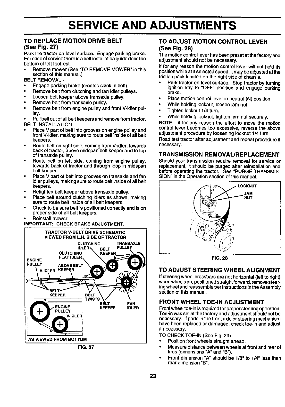
TO ADJUST A'n'ACHMENT CLUTCH
(See Fig. 25)
The electric clutch should provide years of service. The
clutch has a built-in brake that stops the pulley within 5
seconds. Eventually, the internal brake will wear which
may cause the mower blades to not engage, or, to notstop
as required. Adjustments should be made by your nearest
authorized service center/department.
•Make sure attachment clutch and ignition switches are
in "OFF" position.
•Adjust the three nylon Iocknuts until space between
clutch plate and rotor measures .012" at all three slot
locations cut in side of brake plate.
NOTE: After installinga new electric clutch, run tractor at
full throttle and engage and disengage electric clutch 10
cycles to wear in clutch plate.
ROTOR CLUTCH PLATE
.012"
NYLON LOCKNUT(3)
FIG. 25
BRAKE PLATE
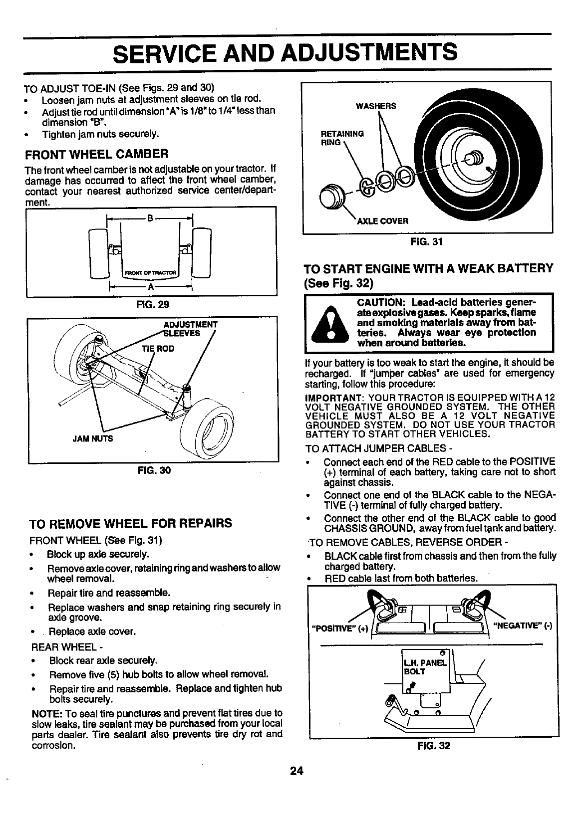
TO ADJUST BRAKE (See Fig, 26)
Your tractor is equipped with an adjustable brake system
which is mounted on the side of the transaxle.
If tractor requires more than six (6) feet stopping distance
at highspeed inhighest gear, then brake must be adjusted.
•Depressclutch/brake pedal and engage parking brake.
Measure distance between brake operating arm and
nut "A" on brake rod.
If distance is other than 1-1/2", loosen jam nut and turn
nut "A" untildistance becomes 1-1/2". Retightenjam
nut against nut "A".
Road test tractor for proper stopping distance as stated
above. Readjust if necessary. If stopping distance is
still greater than six (6) feet in highest gear, further
maintenance is necessary. Contact your nearest au-
thorized service center/department.
WITH PARKING BRAKE "ENGAGED"
,NUT "A"
OPERATING
ARM
22
SERVICE AND ADJUSTMENTS
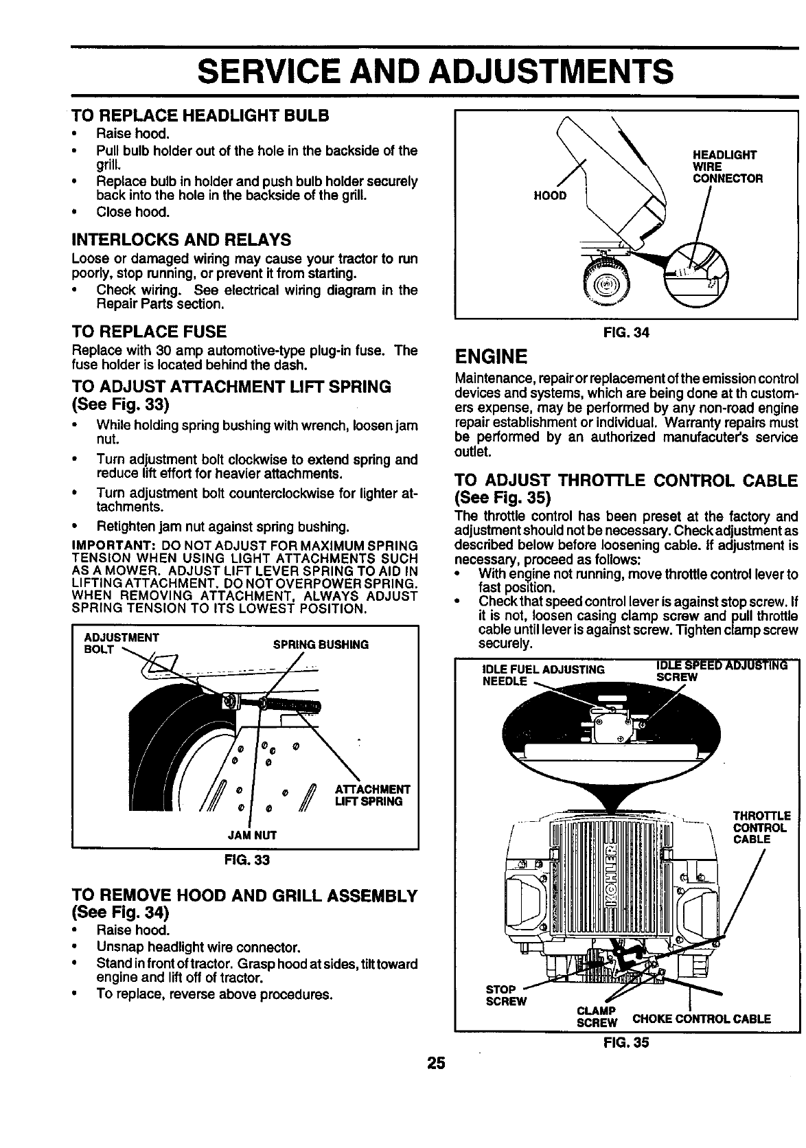
TO REPLACE MOTION DRIVE BELT
(See Fig. 27)
Park the tractor on level surface. Engage parking brake.
For ease of service there is a belt installationguide decal on
bottom of left footrest.
• Remove mower (See "TO REMOVE MOWER" in this
section of this manual.)
BELT REMOVAL -
•Engage parking brake (creates slack in belt).
•Remove belt from clutching and fan idler pulleys.
•Loosen belt keeper above transaxle pulley.
•Remove belt from transaxle pulley.
•Remove belt from engine pulley and front V-idler pul-
ley.
• Pull belt out of all belt keepers and remove from tractor.
BELT INSTALLATION -
• Place V part of belt into grooves on engine pulley and
front V-idler, making sure to route belt inside of all belt
keepers.
• Route belt on right side, coming from V-idler, towards
back of tractor, above midspan belt keeper and to top
of transaxle pulley.
• Route belt on left side, coming from engine pulley,
towards back of tractor and through loop in midspan
belt keeper.
Place V part of belt into grooves on transaxle and fan
idler pulleys, making sure to route belt inside of all belt
keepers.
Retighten belt keeper above transaxle pulley.
•Place belt around clutching idlers as shown, making
sure to route belt inside of all belt keepers.
Check to be sure belt is positioned correctly and is on
proper side of all belt keepers.
•Reinstall mower.
IMPORTANT= CHECK BRAKE ADJUSTMENT.
TRACTOR V-BELT DRIVE SCHEMATIC
VIEWED FROM LH. SIDE OF TRACTOR
CLUTCHING TRANSAXLE
BELT PULLEY
KEEPER
ENGINE
PULLEY
V-IDLER KEEP!
BEL
KEEPER
O
AS VIEWED FROM BOTTOM
BELT
TWISTS
BELT FAN
KEEPER IDLER
FIG. 27
TO ADJUST MOTION CONTROL LEVER
(See Fig. 28)
The motioncontrol lever has been preset at the factory and
adjustment should not be necessary.
If for any reason the motion control lever will not hold its
positionwhile at aselected speed, it may be adjusted at the
friction pack located on the right side of chassis.
•Park tractor on level surface. Stop tractor by turning
ignition key to OFF position and engage parking
brake.
•Place motion control lever in neutral (N) position.
•While holding Iocknut, loosen jam nut
•Tighten Iocknut 1/4turn.
•While holding Iocknut, tighten jam nut securely.
NOTE: if for any reason the effort to move the motion
control lever becomes too excessive, reverse the above
adjustment procedure by loosening Iocknut 1/4 turn.
Road test tractor after adjustment and repeat procedure if
necessary.
TRANSMISSION REMOVAL/REPLACEMENT
Should your transmission require removal for service or
replacement, it should be purged after reinstallation and
before operating the tractor. See =PURGE TRANSMIS-
SION" inthe Operation section of this manual,
JAM
/
FIG. 28
TO ADJUST STEERING WHEEL ALIGNMENT
If steering wheel crossbars are not horizontal (left to right)
when wheels are positioned straightforward, removesteer-
ingwheel and reassemble per instructions inthe Assembly
section of this manual.
FRONT WHEEL TOE-IN ADJUSTMENT
Frontwheel toe-in is required forproper steering operation.
Toe-in was set at the factory and adjustment should not be
necessary. If parts inthe front axle or steering mechanism
have been replaced or damaged, check toe-in End adjust
if necessary.
TO CHECK TOE-IN (See Fig. 29)
•Position front wheels straight ahead.
•Measure distance between wheels at front and rear of
tires (dimensions "A" and =B").
•Front dimension =A" should be 1/8" to 1/4" less than
rear dimension =B".
23
SERVICE AND ADJUSTMENTS
TO ADJUST TOE-IN (See Figs. 29 and 30)
• Loosen jam nuts at adjustment sleeves on tie rod.
•Adjusttie rod untildimension =A"is 1/8 =to 1/4" less than
dimension "B".
•Tighten jam nuts securely.
FRONT WHEEL CAMBER
The front wheel camber is notadjustable on your tractor. If
damage has occurred to affect the front wheel camber,
contact your nearest authodzed service center/depart-
ment.
_A _
FIG. 29
ADJUSTMENT
JAM NUTS
FIG. 30
TO REMOVE WHEEL FOR REPAIRS
FRONT WHEEL (See Fig. 31)
•Block up axle securely.
•Remove axle cover, retainingdng andwashers to all0w
wheel removal.
•Repair tire and reassemble.
•Replace washers and snap retaining ring securely in
axle groove.
•Replace axle cover.
REAR WHEEL -
•Block rear axle securely.
•Remove five (5) hub bolts to allow wheel removal.
•Repairtireandreassemble. Replace and tighten hub
bolts securely.
NOTE: To seal tire punctures and prevent flat tires due to
slow leaks, tire sealant may be purchased from your local
parts dealer. Tire sealant also prevents tire dry rot and
corrosion.
WASHERS
RETAINING
FIG. 31
TO START ENGINE WITH A WEAK BATTERY
(See Fig, 32)
l& CAUTION: Lead-acid batteries gener-
ateexplosive gases. Keep sparks, flame
and smoking materials away from bat-
teries. Always wear eye protection
when around batteries.
If your battery is too weak to start the engine, it should be
recharged. If =jumper cables" are used for emergency
starting, followthis procedure:
IMPORTANT: YOUR TRACTOR IS EQUIPPED WITH A 12
VOLT NEGATIVE GROUNDED SYSTEM. THE OTHER
VEHICLE MUST ALSO BE A 12 VOLT NEGATIVE
GROUNDED SYSTEM. DO NOT USE YOUR TRACTOR
BATTERY TO START OTHER VEHICLES.
TO ATTACH JUMPER CABLES -
• Connect each end of the RED cable to the POSITIVE
(+) terminal of each battery, taking care not to short
against chassis.
•Connect one end of the BLACK cable to the NEGA-
TIVE (-) terminal of fully charged battery.
•Connect the other end of the BLACK cable to good
CHASSIS GROUND, away from fuel t6nk and battery.
TO REMOVE CABLES, REVERSE ORDER -
•BLACK cable first from chassis and then from the fully
charged battery.
RED cable last from both batteries.
,,POSlTIVE_(,)__ __'NEGATIVE" (-)
r"
FIG. 32
24
SERVICE AND ADJUSTMENTS
TO REPLACE HEADLIGHT BULB
• Raise hood.
•Pull bulb holder out of the hole in the backside of the
grill.
•Replace bulb in holder and push bulb holder securely
back into the hole in the backside of the grill
• Close hood.
INTERLOCKS AND RELAYS
Loose or damaged wiring may cause your tractor to run
poorly, stop running, or prevent it from starting.
•Check wiring. See electdcal wiring diagram in the
Repair Parts section.
TO REPLACE FUSE
Replace with 30 amp automotive-type plug-in fuse. The
fuse holder is located behind the dash.
TO ADJUST ATTACHMENT LIFT SPRING
(See Fig. 33)
•While holding spring bushing with wrench, loosen jam
nut.
•Turn adjustment bolt clockwise to extend spring and
reduce lifteffort for heavier attachments.
•Turn adjustment bolt counterclockwise for lighter at-
tachments.
•Retighten jam nut against spring bushing.
IMPORTANT: DO NOT ADJUST FOR MAXIMUM SPRING
TENSION WHEN USING LIGHT ATTACHMENTS SUCH
AS A MOWER. ADJUST LIFT LEVER SPRING TO AID IN
LIFTING ATTACHMENT. DO NOT OVERPOWER SPRING.
WHEN REMOVING ATTACHMENT, ALWAYS ADJUST
SPRING TENSION TO ITS LOWEST POSITION.
ADJUSTMENT
BOLT SPRING BUSHING
/ATFACHMENT
LIFT SPRING
JAM NUT
FIG. 33
TO REMOVE HOOD AND GRILL ASSEMBLY
(See Fig. 34)
•Raise hood.
•Unsnap headlight wire connector.
•Stand infront of tractor. Grasp hoodat sides, tilttoward
engine and liftoff of tractor.
•To replace, reverse above procedures.
HOOD
HEADLIGHT
WIRE
CONNECTOR
FIG. 34
ENGINE
Maintenance, repair or replacement of the emission control
devices and systems, which are being done at th custom-
ers expense, may be performed by any non-road engine
repair establishment or individual. Warranty repairs must
be performed by an authorized manufacuter's service
outlet.
TO ADJUST THROI-rLE CONTROL CABLE
(See Fig. 35)
The throttle control has been preset at the factory and
adjustment should not be necessary. Check adjustment as
described below before loosening cable, if adjustment is
necessary, proceed as follows:
•With engine not running, move throttle control lever to
fast position.
•Check that speed control lever is against stop screw. If
it is not, loosen casing clamp screw and pull throttle
cable untillever is against screw. Tighten clamp screw
securely.
IDLE FUELADJUSTING
NEEDLE ....
IDLE SPEED ADJUSTING
SCREW
THROTTLE
CONTROL
CABLE
25
STOP
SCREW CLAMP
SCREW CHOKE CONTROL CABLE
FIG. 35
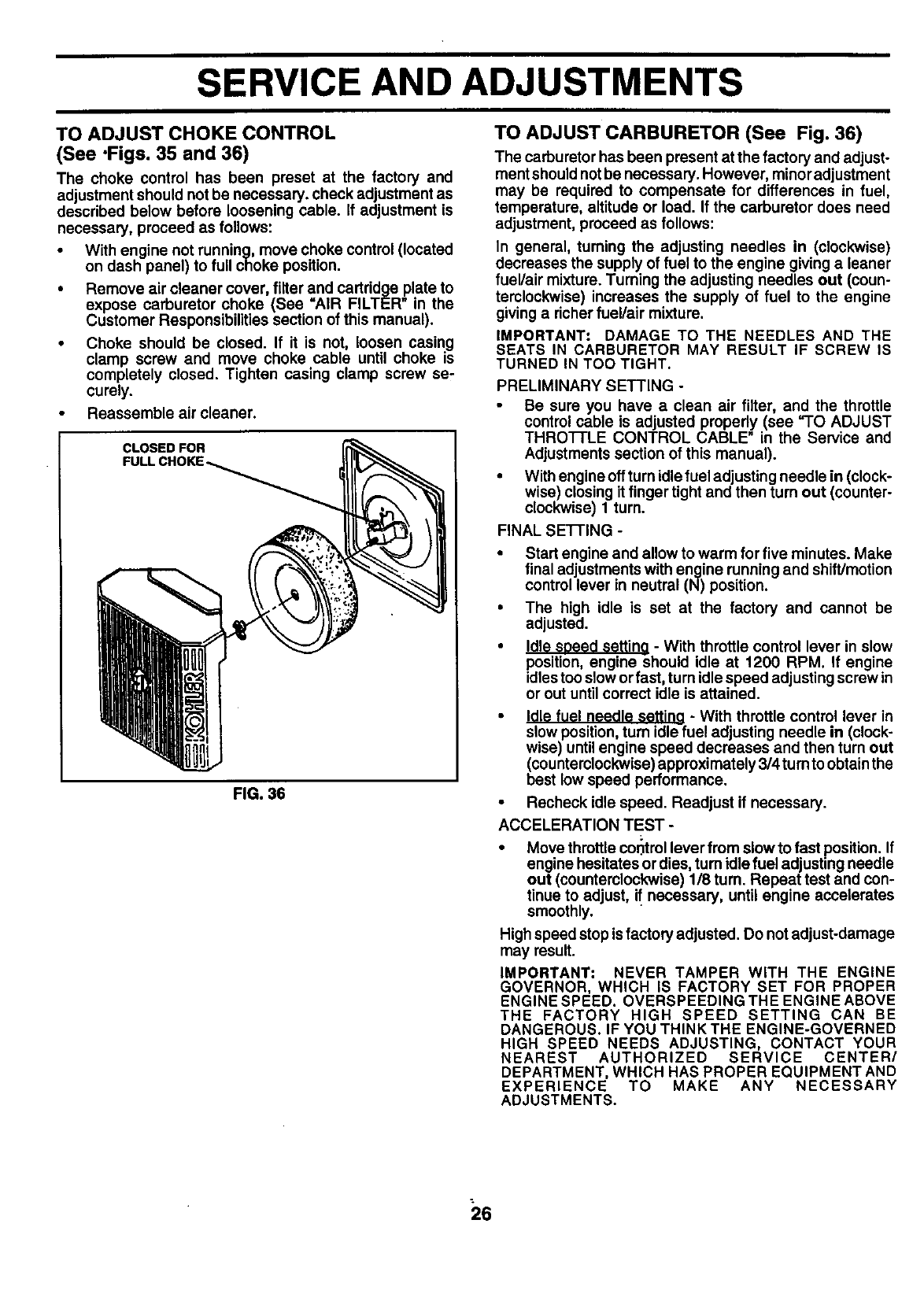
SERVICE AND ADJUSTMENTS
TO ADJUST CHOKE CONTROL
(See .Figs. 35 and 36)
The choke control has been preset at the factory and
adjustment should not be necessary, check adjustment as
described below before loosening cable. If adjustment is
necessary, proceed as follows:
• With engine not running, move choke control (located
on dash panel) to full choke position.
•Remove air cleaner cover, filter and cartddge plate to
expose carburetor choke (See "AIR FILTER" in the
Customer Responsibilities section of this manual).
•Choke should be closed. If it is not, loosen casing
clamp screw and move choke cable until choke is
completely closed. Tighten casing clamp screw se-
curely.
•Reassemble air cleaner.
CLOSED FOR
FULLCHOKE_
FIG. 36
TO ADJUST CARBURETOR (See Fig. 36)
The carburetor has been present at the factory and adjust-
ment should not be necessary. However, minor adjustment
may be required to compensate for differences in fuel,
temperature, altitude or load. If the carburetor does need
adjustment, proceed as follows:
In general, turning the adjusting needles in (clockwise)
decreases the supply of fuel to the engine giving a leaner
fuel/air mixture. Turning the adjusting needles out (coun-
terclockwise) increases the supply of fuel to the engine
giving a richer fuel/air mixture.
IMPORTANT: DAMAGE TO THE NEEDLES AND THE
SEATS IN CARBURETOR MAY RESULT IF SCREW IS
TURNED IN TOO TIGHT.
PRELIMINARY SETTING -
Be sure you have a clean air filter, and the throttle
control cable is adjusted properly (see "TO ADJUST
THROTTLE CONTROL CABLE" in the Service and
Adjustments section of this manual).
•With engine off turn idle fuel adjusting needle in (clock-
wise) closing it finger tight and then turn out (counter-
clockwise) 1 turn.
FINAL SE3-rlNG -
•Start engine and allow to warm for five minutes. Make
final adjustments with engine running and shift/motion
control lever in neutral (N) position.
•The high idle is set at the factory and cannot be
adjusted.
•Idle seeed settino - With throttle control lever in slow
position, engine §hould idle at 1200 RPM. If engine
idles tooslow orfast, turn idle speed adjusting screw m
or out until correct idle is attained.
•Idle fuel needle settino -With throttle control lever in
slow position, tum idle fuel adjusting needle in (clock-
wise) untilengine speed decreases and then turn out
(counterclockwise)approximately 3/4 tum to obtain the
best low speed performance.
•Recheck idle speed. Readjust if necessary.
ACCELERATION TEST -
•Move throttlecor_trollever from slow to fast position. If
engine hesitates or dies, tum idle fuel adjusting needle
out (countemlockwise) 1/8 tum. Repeat test and con-
tinue to adjust, i! necessary, until engine accelerates
smoothly.
High speed stop isfactory adjusted. Do not adjust-damage
may result.
IMPORTANT: NEVER TAMPER WITH THE ENGINE
GOVERNOR, WHICH IS FACTORY SET FOR PROPER
ENGINE SPEED. OVERSPEEDING THE ENGINE ABOVE
THE FACTORY HIGH SPEED SETTING CAN BE
DANGEROUS. IF YOU THINK THE ENGINE-GOVERNED
HIGH SPEED NEEDS ADJUSTING, CONTACT YOUR
NEAREST AUTHORIZED SERVICE CENTER/
DEPARTMENT, WHICH HAS PROPER EQUIPMENT AND
EXPERIENCE TO MAKE ANY NECESSARY
ADJUSTMENTS.
26
STORAGE
ENGINE
Immediately prepare your tractor for storage at the end of
the season or if the tractor will not be used for 30 days or
more.
CAUTION: Never store the tractor with
gasoline in the tank inside a building
where fumes may reach an open flame
or spark. Allow the engine to cool
before storing in any enclosure.
TRACTOR
Remove mower from tractor for winter storage. When
mower is to be stored for a period of time, clean it thor-
oughly, remove all dirt, grease, leaves, etc. Store in a
clean, dry area.
•Clean entire tractor (See =CLEANING" inthe Customer
Responsibilities section of this manual).
•Inspect and replace belts, if necessary (See belt re-
placement instructions inthe Service and Adjustments
section of this manual).
•Lubricate as shown in the Customer Responsibilities
section of this manual.
•Be sure that all nuts, bolts and screws are securely
fastened. Inspect moving parts for damage, breakage
and wear. Replace if necessary.
• Touch up all rusted or chipped paint surfaces; sand
lightly before painting.
BA'I-rERY
Fully charge the battery for storage.
After a period of time in storage, battery may require
recharging.
To help prevent corrosion and power leakage dudng
long periods of storage, battery cables should be
disconnected and batterycleaned thoroughly(see =TO
CLEAN BATTERY AND TERMINALS" in the Cus-
tomer Responsibilities section of this manual).
After cleaning, leave cables disconnected and place
: cables where they cannot come incontact with battery
terminals.
If battery is removed from tractor for storage, do not
store battery directly on concrete or damp surfaces.
FUEL SYSTEM
IMPORTANT: IT IS IMPORTANT TO PREVENT GUM
DEPOSITS FROM FORMING IN ESSENTIAL FUEL
SYSTEM PARTS SUCH AS CARBURETOR, FUEL FILTER,
FUEL HOSE, OR TANK DURING STORAGE. ALSO,
EXPERIENCE INDICATES THAT ALCOHOL BLENDED
FUELS (CALLED GASOHOL OR USING ETHANOL OR
METHANOL) CAN ATTRACT MOISTURE WHICH LEADS
TO SEPARATION AND FORMATION OF ACIDS DURING
STORAGE. ACIDIC GAS CAN DAMAGE THE FUEL
SYSTEM OF AN ENGINE WHILE IN STORAGE.
•Drain the fuel tank.
•Start the engine and let it run until the fuel lines and
carburetor are empty.
•Never use engine or carburetor cleaner products inthe
fuel tank or permanent damage may occur.
•Use fresh fuel next season.
NOTE: Fuel stabilizer is an acceptable aifemative in
minimizing the formation of fuel gum deposits during stor-
age. Add stabilizer to gasoline in fuel tank or storage
container. Always follow the mix ratio found on stabilizer
container. Run engine at least 10 minutes after adding
stabilizer to allow the stabilizer to reach the carburetor. Do
notdrainthe gas tank and carburetor ifusing fuel stabilizer.
ENGINE OIL
Drain oil (with engine warm) and replace with clean engine
oil. (See =ENGINE" in the Customer Responsibilities
section of this manual).
CYLINDER(S)
•Remove spark plug(s).
•Pour one ounce of oil through spark plug hole(s) into
cylinder(s).
•Turn ignitionkeyto"START" positionfor a few seconds
to distribute oil,
•Replace with new spark plug(s).
OTHER
•Do not store gasoline from one season to another.
•Replace your gasoline can if your can starts to rust.
Rust and/or dirt in your gasoline will cause problems.
•If possible, store your tractor indoors and cover it to
give protection from dust and dirt.
• Cover your tractor with a suitable protective cover that
does not retain moisture. Do not use plastic. Plastic
cannot breathe which allows condensation to form and
will cause your tractor to rust.
IMPORTANT: NEVER COVER TRACTOR WHILE ENGINE
AND EXHAUST AREAS ARE STILL WARM.
27
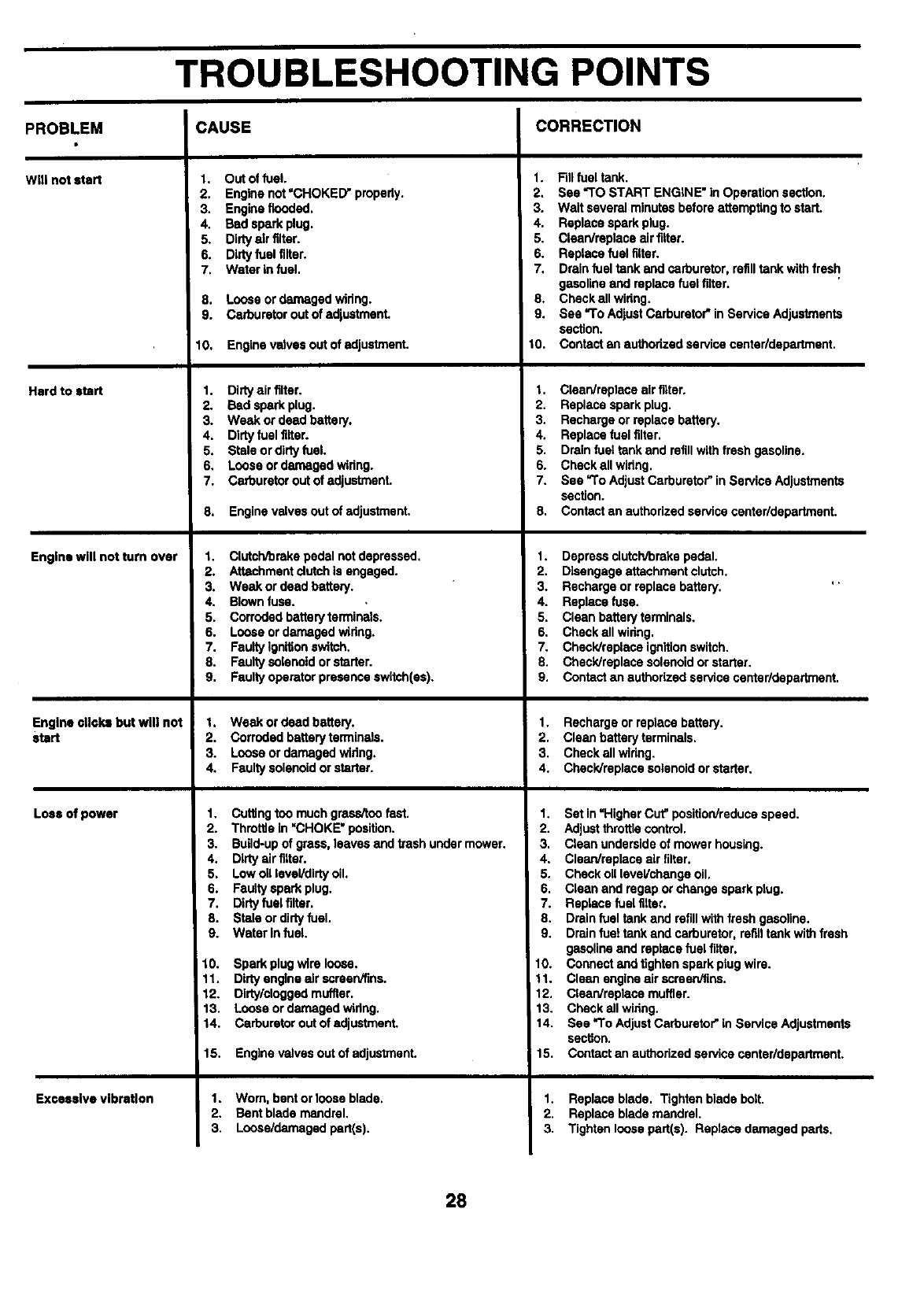
TROUBLESHOOTING POINTS
PROBLEM
Will not start
Hard to start
Engine will not turn over
Engine cticlesbut will not
start
Lees of power
Excessive vibration
CAUSE
1. Out offuel,
2. Enginenot=CHOKED"pmpedy,
3. Engineflooded,
4. Badsparkplug.
5. Dirtyair filter.
6. Dirtyfueltilter.
7. Water infuel.
8. Looseordamagedwidng.
9. Carburetorout of ad]ustmant.
I0. Enginevalvesoutof adjustment.
1. Dirty air filter.
2. Bad spark plug.
3. Weak or dead battery.
4. Dirty fuel filter.
5. Stale or dirty fuel.
6. Loose or damaged wiring.
7. Carburetor out of adjustmenL
8. Enginevalvesoutof adjustment,
1. Clutch/arakepedalnotdepressed.
2. Attachmentdutch is engaged.
3. Weak ordead bedery.
4. Blownfuse.
5. Corrodedbatteryterminals.
6. Looseordamagedwldng.
7. Faultyignitionswitch.
8. Faultysolenoidor starter.
9. Faultyoperatorpresenceswitch(as).
1. Weak ordead battery.
2. Corrodedbatteryterminals.
3. Looseor damagedwidng.
4. Faultysolenoidorstarter.
1. Cuttingtoo muchgresaitoofast.
2. Throttle in "CHOKE" position.
3. BuUd-upof grass, leavesandtrashundermower.
4. Dirtyair filter.
5. Lowoillevel/dirtyoil.
6. Faultysparkplug.
7. Dirtyfuelfilter.
8. Staleordirtyfuel.
9. Water Infuel.
10. Sparkplug wire loose.
11. Dirtyengineairscreen/fins.
12. Dirty/cloggedmuffler.
13. Looseordamagedwidng.
14. Carburetorout of edjustmenL
15. Engine valves out of adjustment.
1. Worn, bent or loose blade.
2. Bent blade mandrel.
3. Loose/damaged part(s).
CORRECTION
1. Fillfuel tank.
2. See "TO START ENGINE" in Operationsection.
3. Wait several minutesbeforeattemptingto start.
4. Replacesparkplug.
5. Clean/replacaair filler.
6. Replacefuel tilter.
7. Drainfuel tankand carburetor,refilltank with fresh
gasolineand replacefuel tilter.
8. Checkallwidng.
9. See =ToAdjustCarburetor"in ServiceAdjustments
section.
10. Contactan authorizedservicecenterldepartment.
1. Clean/replaceairtilter.
2. Replacesparkplug.
3. Rechargeorreplacebattery.
4. Replacefuelfilter.
5. Drainfuettank and refillwithfresh gasoline.
6. Checkallwidng.
7. See =ToAdjustCarburetor"inServiceAdjustments
section.
8. Contactan authorizedservicecenter/department.
1. Depressclutch/brakepedal.
2. Disengageattachmentclutch.
3. Rechargeor replacebattery. '
4. Replacefuse.
5. Cleanbatteryterminals,
6, Checkall widng.
7. Chsck/raptsceignitionswitch.
8. Check/replacesolenoidorstarter.
9. Contactan authorized servicecentar/departmant.
1. Rechargeor replacebattery.
2. Cleanbatteryterminals.
3. Checkallwidng.
4. Check/replecesolenoidor starter.
1. Set in =HigherCut"position/reducespeed.
2. Adjustthrottle control.
3. Clean undersideof mowerhousing.
4. Cleon/replaceair filter,
5. Checkoil level/changeoil.
6. Cleanand regaporchangesparkplug.
7. Replacefuel filter.
8. Drainfuel tankand refillwithfreshgasoline.
9, Drainfuel tank and carburetor, refilltankwith fresh
gasolineand replacefuel filter.
10. Connectand tightensparkplug wire.
11. Cleanengineairscreen/tins.
12. Clean/replasemuffler.
13. Checkall widng.
14. See =ToAdjustCarburetot"inServiceAdjustments
section.
15. Contactan authorizedservicecentarldepartment.
1. Replace blade. Tighten blade bait.
2. Replace blade mandrel.
3. Tighten loose part(s). Replace damaged parts.
28
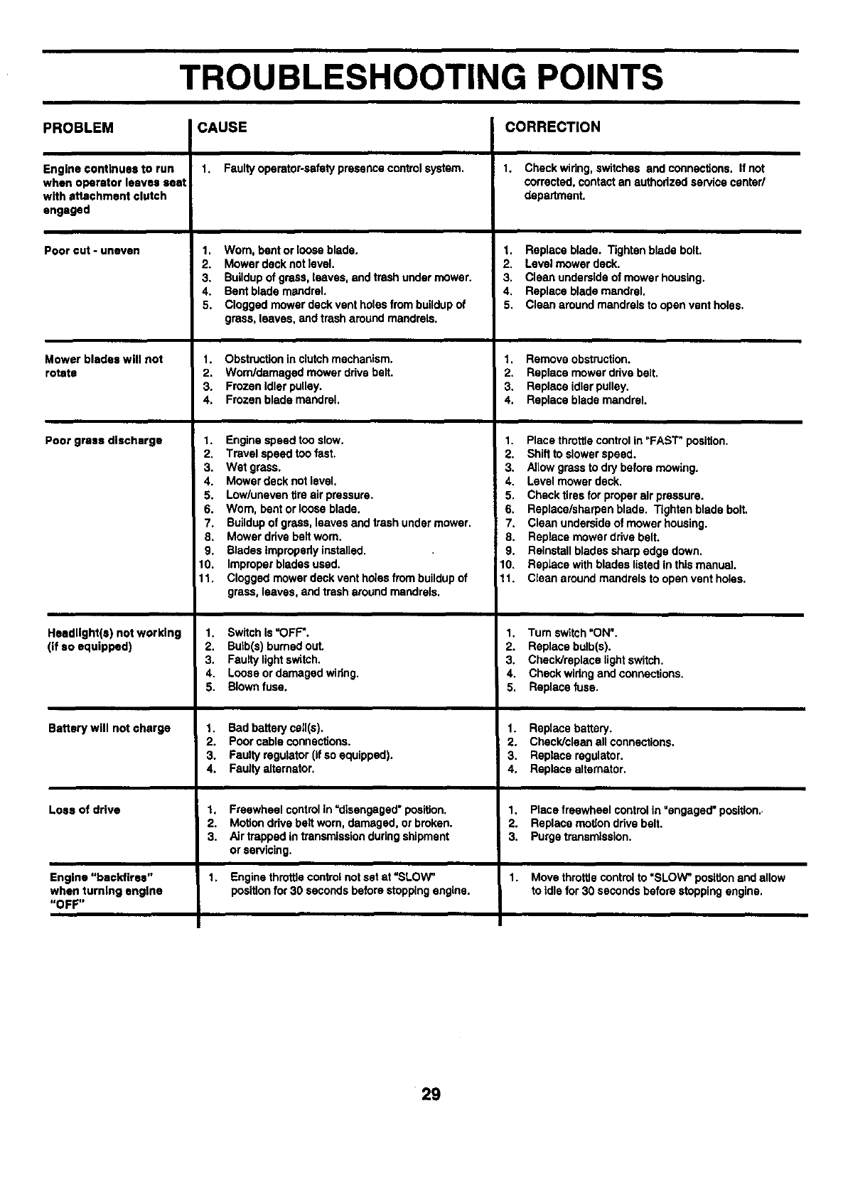
TROUBLESHOOTING POINTS
PROBLEM CAUSE CORRECTION
Engine continues to run
when operator leaves seat
with attachment clutch
engaged
Pooront-uneven
Mower blapeswltl not
rotate
Poor grass discharge
Hosdltght(s) not working
(if so equipped)
Battery will not charge
Loss of drive
Engine "backfires"
when turning engine
"OFF"
1. Faultyoperator-safetypresencecontrolsystem.
1. Worn, bent orloose blade.
2. Mowerdeck notlevel.
3. Buildupof grass,leaves, andtrashundermower.
4. Bentblade mandrel.
5. Cloggedmower deckvent holesfrom buildupof
grass,leaves, and trasharoundmandrels.
1. Obstruction in clutch mechanism.
2. Worn/damaged mower drive belt.
3. Frozen idler pulley.
4, Frozen blade mandrel,
1. Enginespeedtoo slow.
2. Travelspeedtoo fast.
3. Wet grass.
4. Mowerdecknot level.
5. Low/uneventire air pressure.
6. Worn, bentor looseblade.
7. Buildupof grass,leavesand trashundermower.
8. Mower ddvebeltworn.
9. Bladestmpmpedy installed.
10. Improperbladesused.
11. Cloggedmower deckventholesfrom buildupof
grass,leaves, andtrasharoundmandrels.
1. Switchis "OFF".
2. Bulb(s)bumedout.
3. Faultylightswitch.
4. Looseor damagedwidng.
5. Blownfuse.
1. Bad bafterycall_).
2. Poorcableconnections.
3. Faul_regulator(ifso equipped).
4. Faulty=_mator.
1, Freewheelcontrolin=disengaged"position.
2. Motionddve beltworn,damaged,or broken.
3. Airtrappedintransmissionduringshipment
or servicing.
Enginethrottlecontrolnotset at "SLOW_
positionfor 30 secondsbeforestoppingengine.
1. Checkwidng,switchesandcennections. Ifnot
corrected,contactan authorized servicecenter/
department.
1. Replaceblade. Tightenbladebolt.
2. Levelmower deck.
3, Cleanundemldeof mowerhousing,
4. Replaceblademandrel.
5. Cleanaroundmandrelsto openvent holes,
1. Removeobstruction.
2. Replace mowerdrivebelt.
3. Replace idlerpulley.
4. Replace blademandrel.
1. Placethrottlecontrolin"FAST"position.
2. Shiftto slowerspeed.
3. Allowgrassto drybeforemowing.
4. Levelmowerdeck.
5. Checktires for properair pressure.
6. Replace/sharpenblade. Tighten bladebolt.
7. Cleanundersideof mower housing.
8. Replace mowerdrivebelt.
9. Reinstallbladessharpedge down.
10. Replacewithbladeslistedinthismanua].
t 1. Clean aroundmandrelsto open ventholes.
1. Tum switch =ON".
2. Replace bulb(s).
3. Check/replace light switch.
4, Check widng and connections.
5. Replace fuse.
1. Replacebattery.
2. Check/cleanallconnections.
3. Replaceregulator.
4. Replace alternator.
1, Place freewheel control in =engaged" position..
2. Replace motion ddve belt.
3. Purge transmission.
1. Move throttle control to "SLOW" position and allow
to Idle for 30 seconds before stopping engine.
29

SERVICE NOTES
30
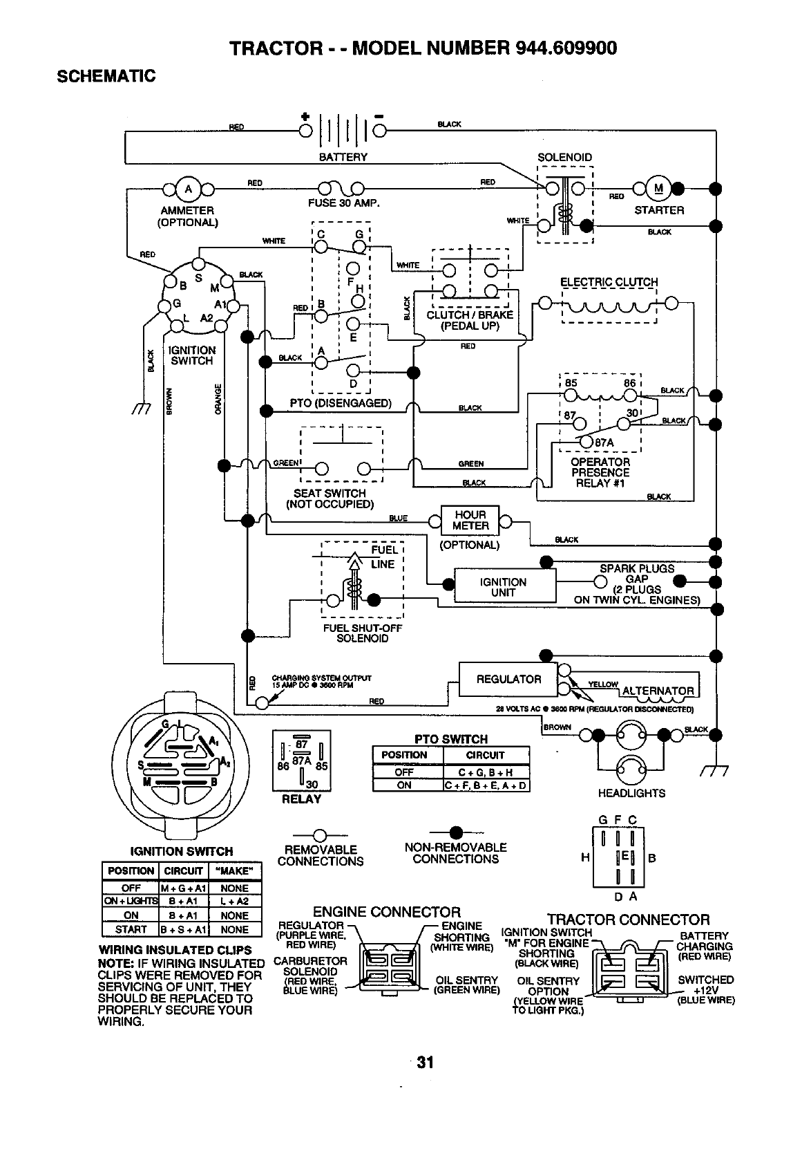
SCHEMATIC
TRACTOR --MODEL NUMBER 944.609900
FUEL SHUT-OFF
SOLENOID
REGULATOR
28 VOLTS AC •3800 RPM (REGULATOR 04SCONNECTED)
PTO SWITCH
POSITION CIRCUIT "
OFF C÷G,B+H
ON C + F, B+ E, A + D HEADLIGHTS
GFC
IGNITION SWITCH REMOVABLE NON-REMOVABLE
CONNECTIONS CONNECTIONS H B
ENGINE CONNECTOR TI_A(_T(_I_ t_'_klMl::a'_Tt_l:l
REGULATOR ENGINE ......... _ ..........
(PURPLEWIRE.-_ _SHORTING I.GMN.ITIONSWITCH BATTERY
REDWIRE) _0_ ITEWIR ORENGINE-'_I_FP.HA (_
WIRING INSULATED CLIPS 0NH E) ___R_ING
SHORTING (REDWIRE)
NOTE: IFWIRING INSULATED CARBURETOR _BLACKWIRB I1_ _II
CLIPS WERE REMOVED FOR SOLENOID I1_11 ( "II _ =-'---' II
(REDWIRE, _OILSENTRY OILSENTRY II-_L_ 1_311 SWITCHED
SERVICING OF UNIT, THEY BLUEWIRE) __ (GREENWIRE) OPTION iI_ _1 _ +12V
SHOULD BE REPLACED TO (YELLOWWIRE_T -_ (BLUEWIRE)
PROPERLY SECURE YOUR TO LIGHTPKG.)
WIRING,
31
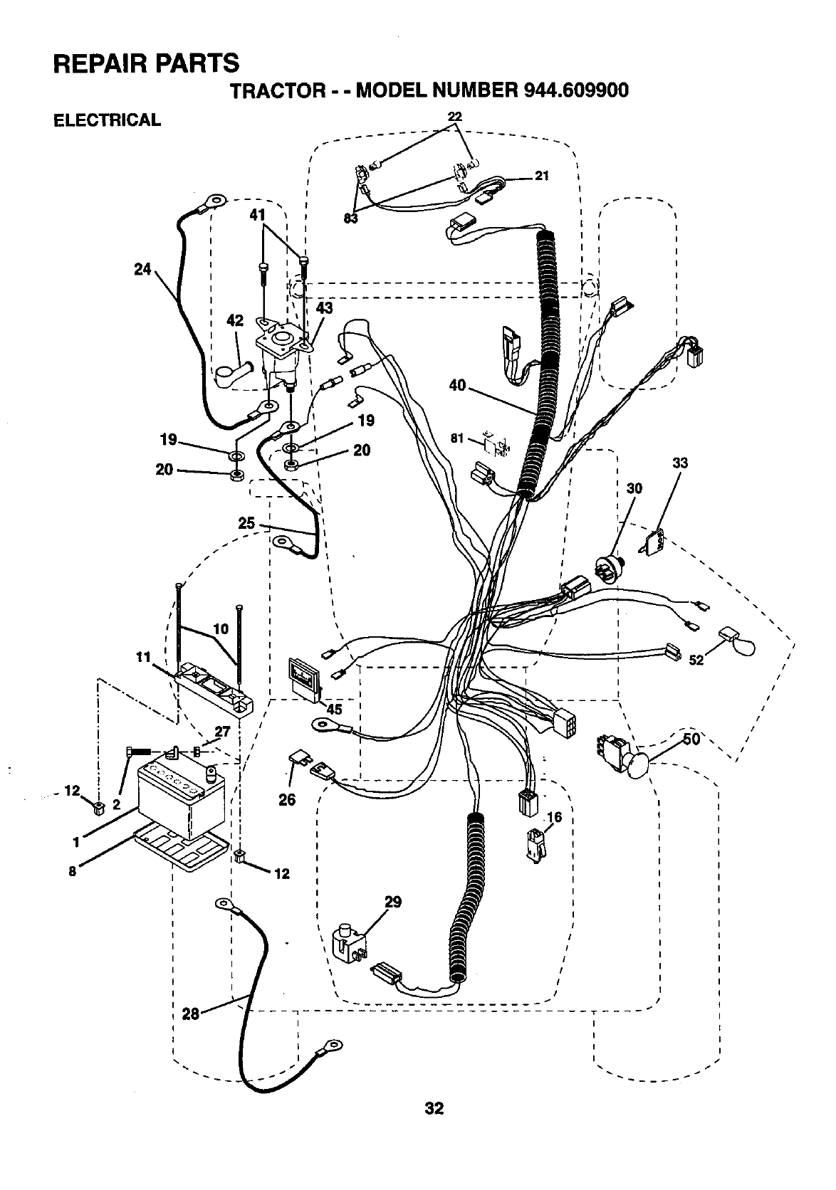
REPAIR PARTS
TRACTOR --MODEL NUMBER 944.609900
ELECTRICAL 22
/
!
I
I
I
I
42
1
8
20
/
/
12
81 _
20 "_._._., 33
T
I
52° _/
/
/
I
I
/
I
/
29
-i
I
I
I
I
32
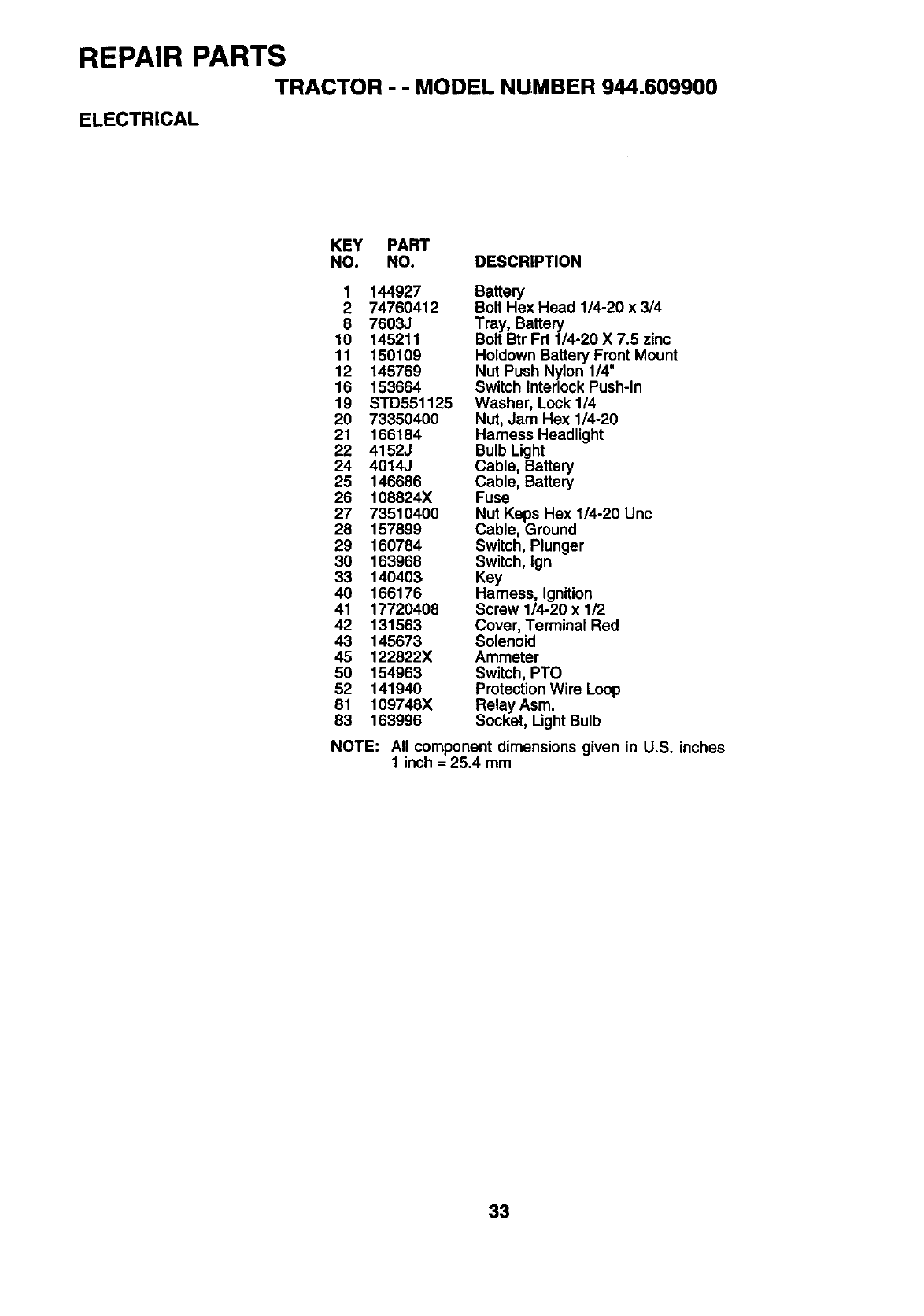
REPAIR PARTS
TRACTOR --MODEL NUMBER 944.609900
ELECTRICAL
KEY PART
NO. NO. DESCRIPTION
1 144927 Battery
2 74760412 Bolt Hex Head 1/4-20 x 3/4
8 7603J Tray, Battery
10 145211 Bolt Btr Frt 1/4-20 X 7.5 zinc
11 150109 Holdown Battery Front Mount
12 145769 Nut Push Nylon 1/4"
16 153664 Switch Interlock Push-In
19 STD551125 Washer, Lock 1/4
20 73350400 Nut, Jam Hex 1/4-20
21 166184 Harness Headlight
22 4152J Bulb Light
24 4014J Cable, Battery
25 146686 Cable, Battery
26 108824X Fuse
27 73510400 Nut Keps Hex 1/4-20 Unc
28 157899 Cable, Ground
29 160784 Switch, Plunger
30 163968 Switch, Ign
33 140403, Key
40 166176 Harness, Ignition
41 17720408 Screw 1/4-20 x 1/2
42 131563 Cover, Terminal Red
43 145673 Solenoid
45 122822X Ammeter
50 154963 Switch, PTO
52 141940 Protection Wire Loop
81 109748X Relay Asm.
83 163996 Socket, Light Bulb
NOTE: All component dimensions given in U.S. inches
1 inch =25.4 mm
33
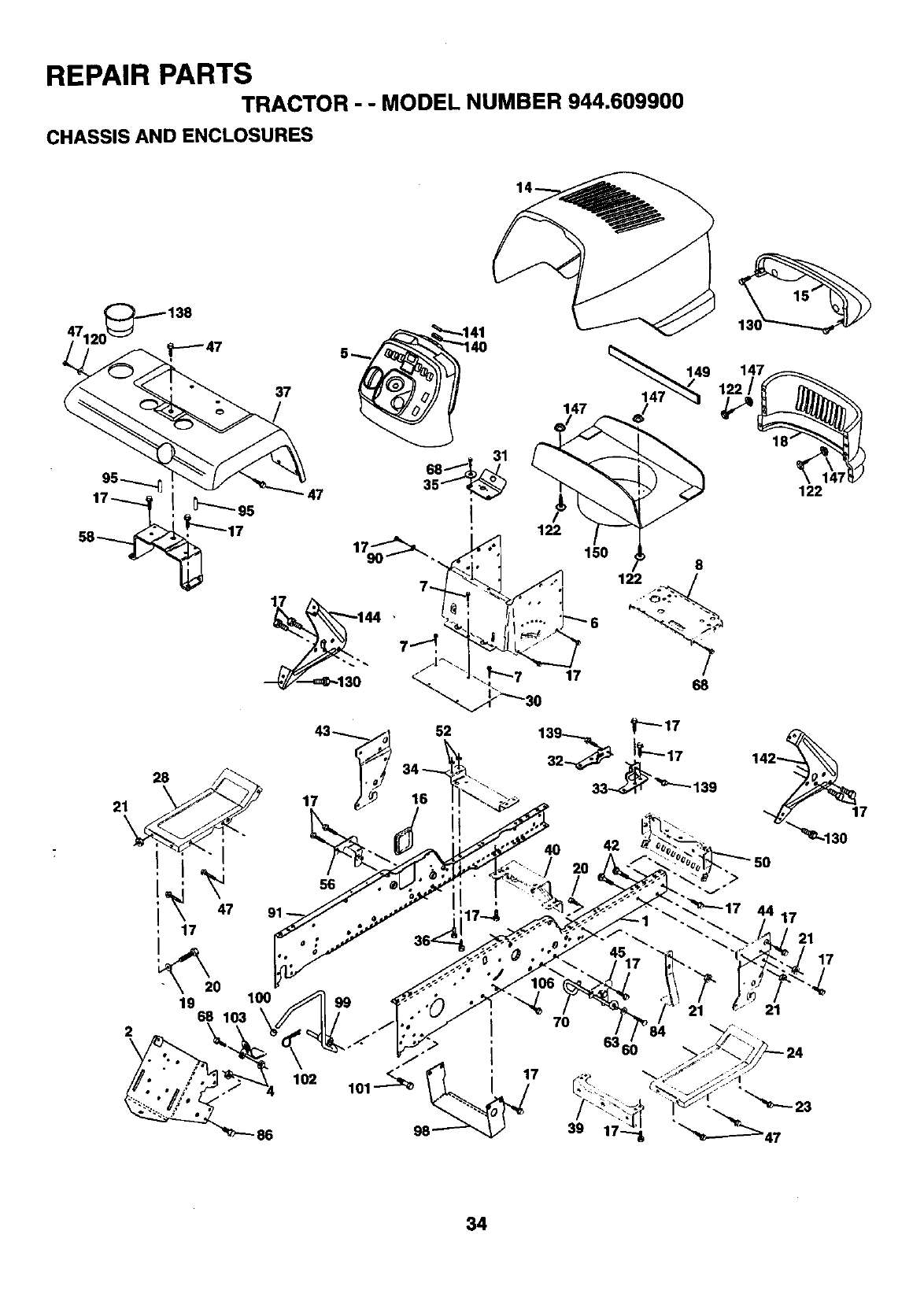
REPAIR PARTS
TRACTOR --MODEL NUMBER 944.609900
CHASSIS ANDENCLOSURES
95
37
149
122
21
2
28
I I
I47
17
19 68
102
86
17
34
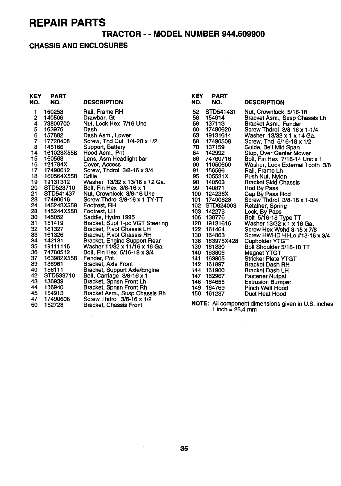
REPAIR PARTS
TRACTOR --MODEL NUMBER 944,609900
CHASSIS AND ENCLOSURES
KEY PART KEY PART
NO. NO. DESCRIPTION NO. NO. DESCRIPTION
1 150253
2 140506
473800700
5163976
6157882
7 17720408
8 145166
14 161023X558
15 160568
16 121794X
17 17490612
18 160564X558
19 19131312
20 STD523710
21 STD541437
23 17490616
24 145243X558
28 145244X558
30 145052
31 161419
32 161327
33 161326
34 142131
35 19111116
36 74780512
37 163982X558
39 136961
40 156111
42 STD533710
43 136939
44 136940
45 154913
47 17490608
50 152728
Rail, Frame RH 52 STD541431
Drawbar, Gt 56 154914
Nut, Lock Hex 7/16 Unc 58 137113
Dash 60 17490620
Dash Asm., Lower 63 19131614
Screw, Thd Cut 1/4-20 x 1/2 68 17490508
Support, Battery 70 137159
Hood Asm., Pnt 84 142992
Lens, Asm Headlight bar 86 74760716
Cover, Access 90 11050600
Screw, Thdrol 3/8-16 x 3/4 91 156586
Grille 95 105531X
Washer 13/32 x 13/16 x 12 Ga. 98 140503
Bolt, Fin Hex 3/8-16 x 1 99 140871
Nut, Crownlock 3/8-16 Unc 100 124236X
Screw Thdrol 3/8-16 x 1 TY-TT 101 17490628
Footrest, RH 102 STD624003
Footrest, LH 103 142273
Saddle, Hydro 1995 106 138776
Bracket, Supt 1-pc VGT Steering 120 19131616
Bracket, Pivot Chassis LH 122 161464
Bracket, Pivot Chassis RH 130 164863
Bracket, Engine Support Rear 138 163975X428
Washer 11/32 x 11/16 x 16 Ga. 139 161330
Bolt, Fin Hex 5/16-18 x 3/4 140 163806
Fender, Pnt. 141 163805
Bracket, Axle Front 142 161897
Brecket, Support Axle/Engine 144 161900
Bolt, Carriage 3/8-16 x I 147 162967
Bracket, Spnsn Front Lh 148 164655
Bracket, Spnsn Front Rh 149 164769
Bracket Asm., Susp Chassis Rh 150 161237
Screw Thdrol 3/8-16 x 1/2
Bracket, Chassis Front
Nut, Crownlock 5/16-18
Bracket Asm., Susp Chassis Lh
Bracket Asm., Fender
ScrewThdrol 3/8-16 x 1-1/4
Washer 13/32 x I x 14 Ga.
Screw, Thd 5/16-18 x 1/2
Guide, Belt Mid Span
Stop, Over Center Mower
Bolt, Fin Hex 7/16-14 Unc x 1
Washer, Lock External Tooth 3/8
Rail, Frame Lh
Push Nut, Nylon
Bracket SkidChassis
Rod By Pass
Cap By Pass Rod
Screw Thdrol 3/8-16 x 1-3/4
Retainer, Spring
Lock, By Pass
Bolt 5/16-18 Type TT
Washer 13/32 x 1 x 16 Ga.
Screw Hex Wshd 8-18 x 718
Screw HWHD Hi-Lo #13-16 x 3/4
Cupholder YTGT
Bolt Shoulder 5/16-18 TT
Magnet YTGT
Stricker Plate YTGT
Bracket Dash RH
Bracket Dash LH
Fastener Nutpal
Extrusion Bumper
Pinch Welt Hood
Duct Heat Hood
NOTE: All component dimensions given in U.S. inches
1 inch = 25,4 mm
35
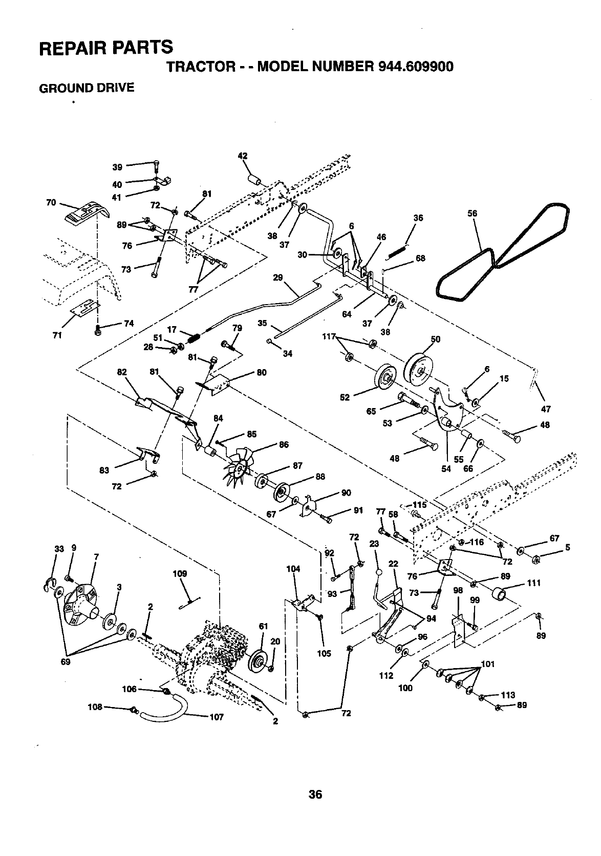
REPAIR PARTS
GROUND DRIVE TRACTOR " " MODEL NUMBER 944.609900
33 9
I09
/
/
107 2
6 36 58
46
37 38
90
36
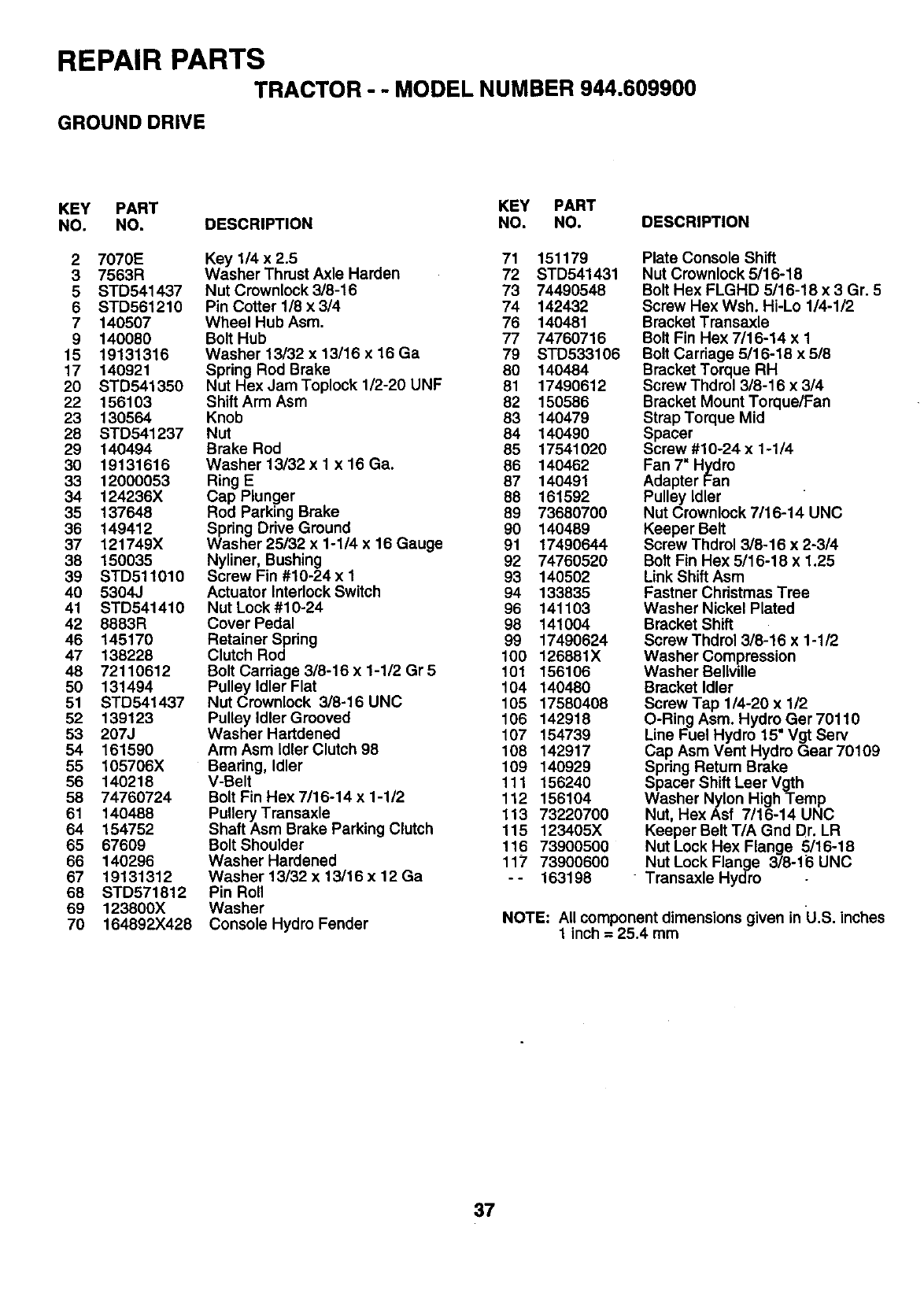
REPAIR PARTS
TRACTOR -- MODEL NUMBER 944.609900
GROUND DRIVE
KEY PART KEY PART
NO. NO. DESCRIPTION NO. NO. DESCRIPTION
2 7070E Key 114x2.5 71 151179
3 7563R Washer Thrust Axle Harden 72 STD541431
5 STD541437 Nut Crownlock 3/8-16 73 74490548
6 STD561210 Pin Cotter 1/8 x 3/4 74 142432
7 140507 Wheel Hub Asm. 76 140481
9 140080 Bolt Hub 77 74760716
15 19131316 Washer 13/32 x 13/16 x 16 Ga 79 STD533106
17 140921 Spring Rod Brake 80 140484
20 STD541350 Nut Hex JamToplock 1/2-20 UNF 81 17490612
22 156103 Shift Arm Asm 82 150586
23 130564 Knob 83 140479
28 STD541237 Nut 84 140490
29 140494 Brake Rod 85 17541020
30 19131616 Washer 13/32 x 1 x 16 Ga. 86 140462
33 12000053 Ring E 87 140491
34 124236X Cap Plunger 88 161592
35 137648 Rod Parking Brake 89 73680700
36 149412 Spring Drive Ground 90 140489
37 121749X Washer 25/32 x 1-1/4 x 16 Gauge 91 17490644
38 150035 Nyliner, Bushing 92 74760520
39 STD511010 Screw Fin #10-24x I 93 140502
40 5304J Actuator Interlock Switch 94 133835
41 STD541410 Nut Lock#10-24 96 141103
42 8883R Cover Pedal 98 141004
46 145170 Retainer Spring 99 17490624
47 138228 Clutch Rod 100 126881X
48 72110612 Bolt Carriage 3/8-16 x 1-1/2 Gr 5 101 156106
50 131494 Pulley Idler Flat 104 140480
51 STD541437 Nut Crownlock 3/8-16 UNC 105 17580408
52 139123 Pulley Idler Grooved 106 142918
53 207J Washer Hartdened 107 154739
54 161590 Arm Asm Idler Clutch 98 108 142917
55 105706X Beadng, Idler 109 140929
56 140218 V-Belt 111 156240
58 74760724 Bolt Fin Hex 7/16-14 x 1-1/2 112 156104
61 140488 Pullery Transaxle 113 73220700
64 154752 Shaft Asm Brake Parking Clutch 115 123405X
65 67609 Bolt Shoulder 116 73900500
66 140296 Washer Hardened 117 73900600
67 19131312 Washer 13/32 x 13/16 x 12 Ga -- 163198
68 STD571812 Pin Roll
69 123800X Washer
70 164892X428 Console Hydro Fender
Plate Console Shift
Nut Crownlock 5/16-18
Bolt Hex FLGHD 5116-18 x 3 Gr. 5
Screw Hex Wsh. Hi-Lo 1/4-1/2
Bracket Transaxle
Bolt Fin Hex 7/16-14 x 1
Bolt Carriage 5/16-18 x 5/8
Bracket Torque RH
Screw Thdrol 3/8-16 x 314
Bracket Mount Torque/Fan
Strap Torque Mid
Spacer
Screw #10-24 x 1-1/4
Fan 7" Hydro
Adapter Fan
Pulley Idler
Nut Crownlock 7/16-14 UNC
Keeper Belt
Screw Thdrol 3/8-16 x 2-3/4
Bolt Fin Hex 5/16-18 x 1.25
Link Shift Asm
Fastner Christmas Tree
Washer Nickel Plated
Bracket Shift
Screw Thdrol 3/8-16 x 1-1/2
Washer Compression
Washer Bellville
Bracket Idler
Screw Tap 1/4-20 x 1/2
O-Ring Asm. Hydro Ger 70110
Line Fuel Hydro 15" Vgt Serv
Cap Asm Vent Hydro Gear 70109
Spdng Return Brake
Spacer Shift Leer Vgth
Washer Nylon High Temp
Nut, Hex Asf 7116-14 UNC
Keeper Belt T/A Grid Or. LR
Nut Lock Hex Flange 5116-18
Nut Lock Flange 3/8-16 UNC
Transaxle Hydro
NOTE: All component dimensions given in U.S. inches
1 inch = 25.4 mm
37
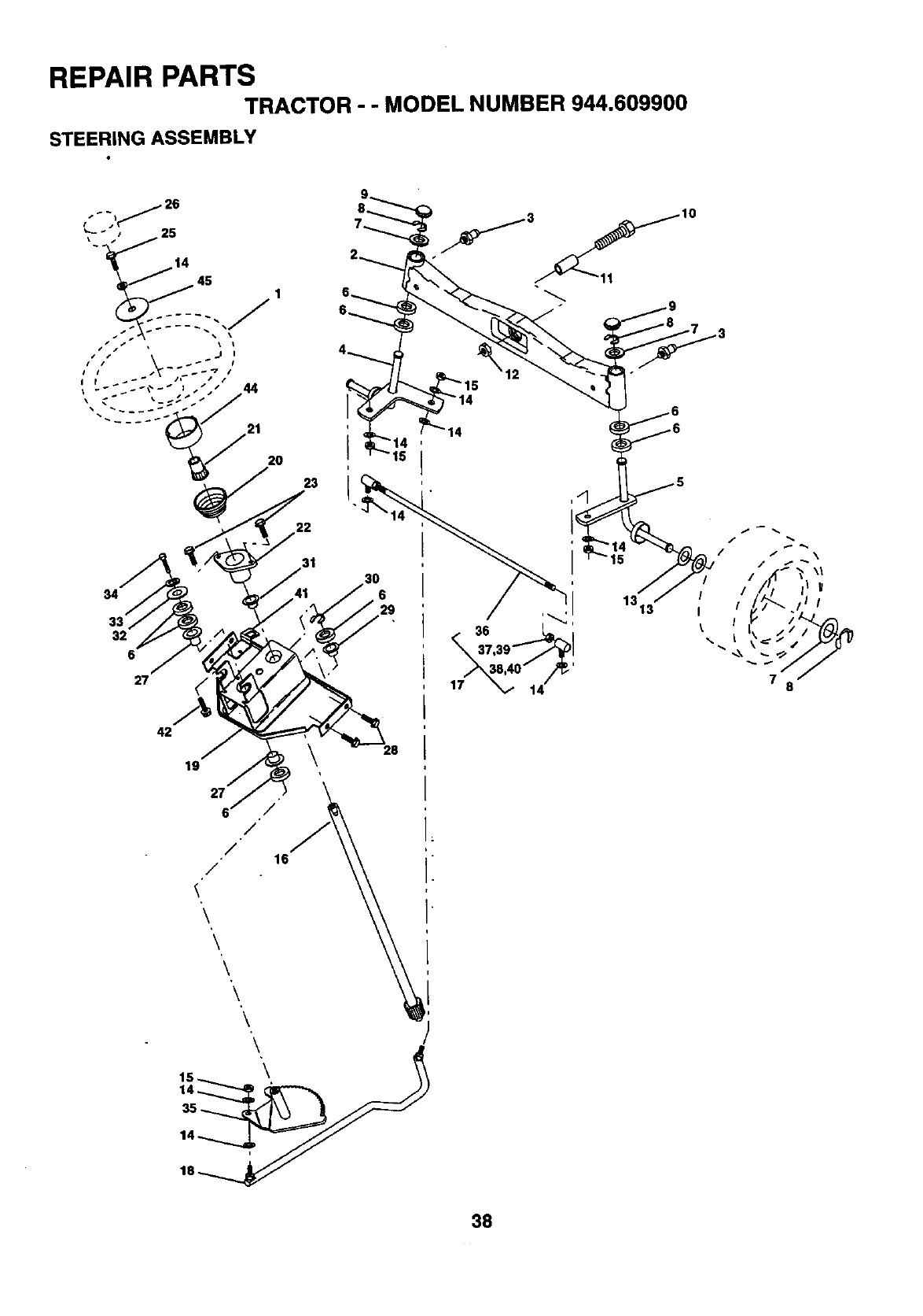
REPAIR PARTS
TRACTOR --MODEL NUMBER 944.609900
STEERING ASSEMBLY
--i_ 26
1_ 45
21
2O
23
22
34
32
6
27 (,
42
19
27 .
///1
/" 6
'\
\
\
'\
\\
14
,40" //_'
14
1313 I
I
/ / \
/V
/ I
I
78
38
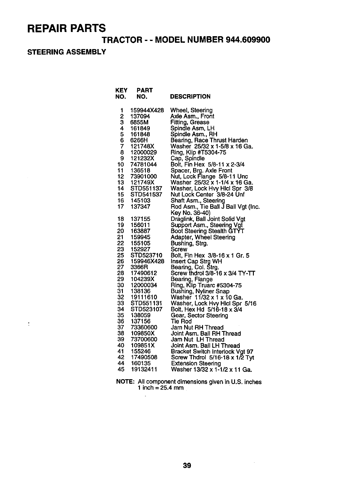
REPAIR PARTS
TRACTOR - -MODEL NUMBER 944.609900
STEERING ASSEMBLY
KEY PART
NO. NO. DESCRIPTION
1 159944X428
2137094
3 6855M
4 161849
5161848
6 6266H
7 121748X
8 12000029
9 121232X
10 74781044
11 136518
12 73901000
13 121749X
14 STD551137
15 STD541537
16 145103
17 137347
18 137155
19 156011
20 163887
21 159945
22 155105
23 152927
25 STD523710
26 t59946X428
27 3366R
28 17490612
29 104239X
30 12000034
31 138136
32 19111610
33 STD551131
34 STD523107
35 138059
36 137156
37 73360600
38 109850X
39 73700600
40 109851X
41 155246
42 17490508
44 160135
45 19132411
Wheel, Steering
Axle Asm., Front
Fitting, Grease
Spindle Asm, LH
Spindle Asm., RH
Bearing, Race Thrust Harden
Washer 25/32 x 1-5/8 x 16 Ga.
Ring, Klip #T5304-75
Cap, Spindle
Bolt, Fin Hex 5/8-11 x 2-3/4
Spacer, Brg. Axle Front
Nut, Lock Flange 5/8-11 Unc
Washer 25/32 x 1-114x 16 Ga.
Washer, Lock Hvy Hlcl Spr 318
Nut Lock Center 3/8-24 Unf
Shaft Asm., Steering
Rod Asm., Tie Ball J Ball Vgt (Inc.
Key No. 36-40)
Draglink, Ball Joint Solid Vgt
Support Asm., Steering Vgt
Boot Steering Stealth GTYT
Adapter, Wheel Steering
Bushing, Strg.
Screw
Bolt, Fin Hex 3/8-16 x 1 Gr. 5
Insert Cap Strg WH
Bearing, Col. Strg.
Screw thdrol 318-16 x 314 TY-'I-I"
Bearing, Flange
Ring, Klip Truarc #5304-75
Bushing, Nyliner Snap
Washer 11/32x 1 xl0Ga.
Washer, Lock Hvy Hlcl Spr 5116
Bolt, Hex Hd 5/16-18 x 3/4
Gear, Sector Steering
Tie Rod
Jam Nut RH Thread
Joint Asm. Ball RH Thread
Jam Nut LH Thread
Joint Asm. Ball LH Thread
Bracket Switch Interlock Vgt 97
Screw Thdrol 5/16-18 x 1/2 Tyt
Extension Steering
Washer 13/32 x 1-1/2 x 11 Ga.
NOTE: All component dimensions given in U.S. inches
1 inch = 25.4 mm
39
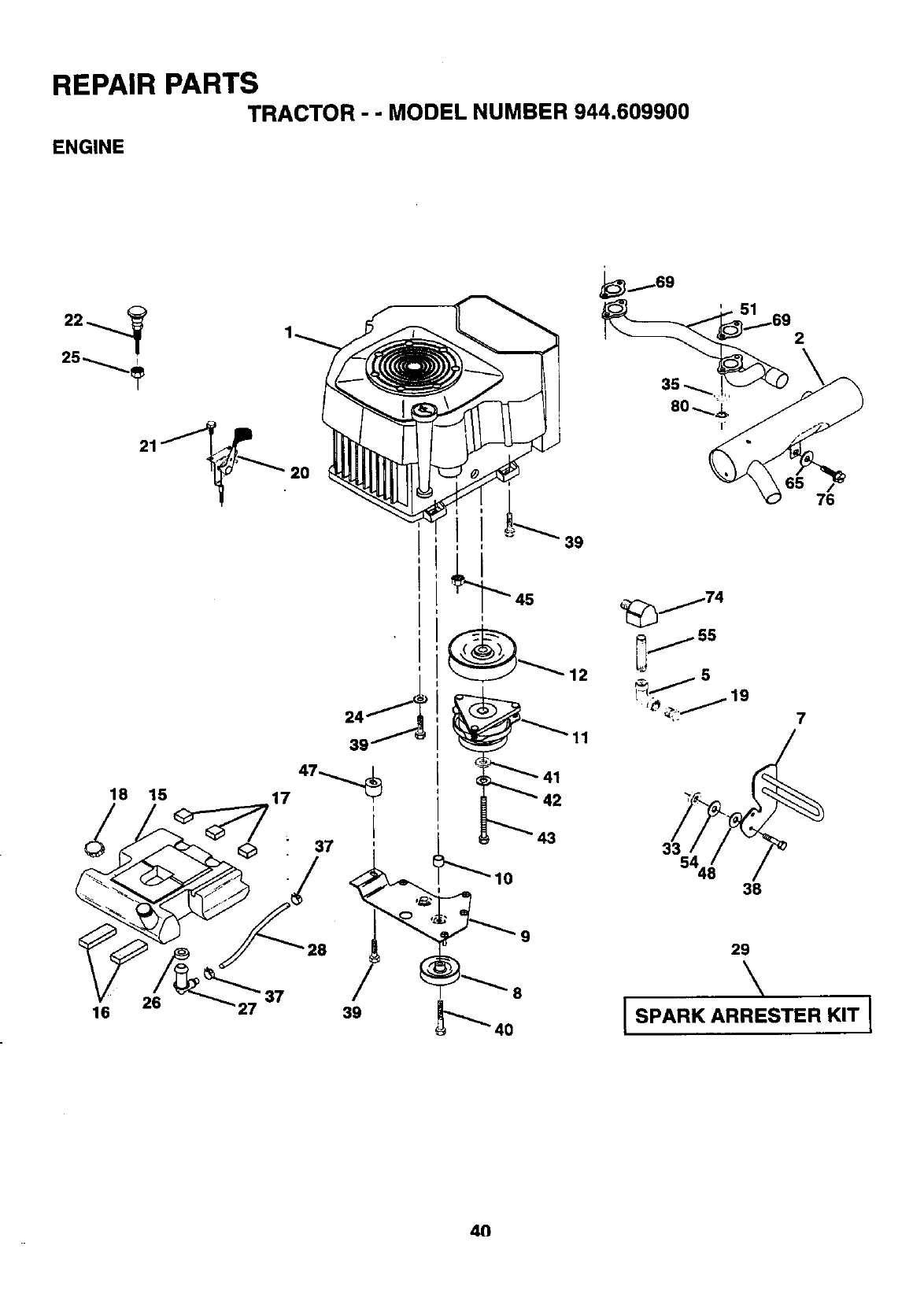
REPAIR PARTS
TRACTOR - - MODEL NUMBER 944.609900
ENGINE
25
18 15
20
11
76
_j74
_j s
,,_._ _ 19
",: 7
33/_//_
s4, 38
16 26 37
27
28
39
29
\
[ SPARK ARRESTER KIT I
4O
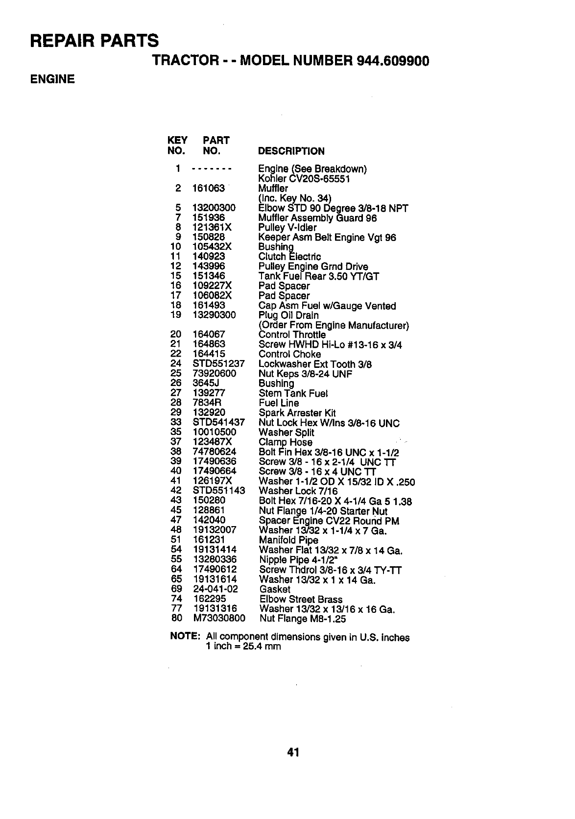
REPAIR PARTS
TRACTOR --MODEL NUMBER 944.609900
ENGINE
KEY PART
NO. NO. DESCRIPTION
2 161063
5 13200300
7 151936
8 121361X
9 150828
10 105432X
11 140923
12 143996
15 151346
16 109227X
17 106082X
18 161493
19 13290300
20 164067
21 164863
22 164415
24 STD551237
25 73920600
26 3645J
27 139277
28 7834R
29 132920
33 STD541437
35 10010500
37 123487X
38 74780624
39 17490838
40 17490664
41 126197X
42 STD551143
43 150280
45 128861
47 142040
48 19132007
51 161231
54 19131414
55 13280336
64 17490612
65 19131614
69 24-041-02
74 162295
77 19131316
80 M73030800
Engine (See Breakdown)
Kohler CV20S°65551
Muffler
(Inc. Key No. 34)
Elbow STD 90 Degree 3/8-18 NPT
Muffler Assembly Guard 96
Pulley V°ldler
Keeper Asm Belt Engine Vgt 96
Bushing
CrutchEtectdo
Pulley Engine Grad Ddve
Tank Fuel Rear 3.50 YT/GT
Pad Spacer
Pad Spacer
Cap Asm Fuel w/Gauge Vented
Plug Oil Drain
(Order From Engine Manufacturer
Control Throttle
Screw HWHD Hi-Lo #13-16 x 3/4
Control Choke
Lockwasher Ext Tooth 3/8
Nut Keps 3/8-24 UNF
Bushing
Stem Tank Fuel
Fuel Line
Spark Arrester Kit
Nut Lock Hex W/Ins 3/8-16 UNC
Washer Split
Clamp Hose
Bolt Fin Hex 3/8-16 UNC x 1-1/2
Screw 3/8 - 16 x 2-1/4 UNC 37"
Screw 3/8 - 16 x 4 UNC "l-r
Washer 1-1/20D X 15_32 ID X .250
Washer Lock 7/16
Bolt Hex 7/16-20 X 4-1/4 Ga 5 1,38
Nut Flange 1/4-20 Starter Nut
Spacer Engine CV22 Round PM
Washer 13/32 x 1-1/4 x 7 Ga.
Manifold Pipe
Washer Flat 13/32 x 718 x 14 Ga.
Nipple Pipe 4-1/2"
Screw Thdrol 3/8-16 x 3/4 TY-TT
Washer 13/32 x 1x 14 Ga.
Gasket
Elbow Street Brass
Washer 13/32 x 13/16 x 16 Ga.
Nut Flange M8-1.25
NOTE: All component dimensions given in U.S. inches
1 inch =25.4 mm
41
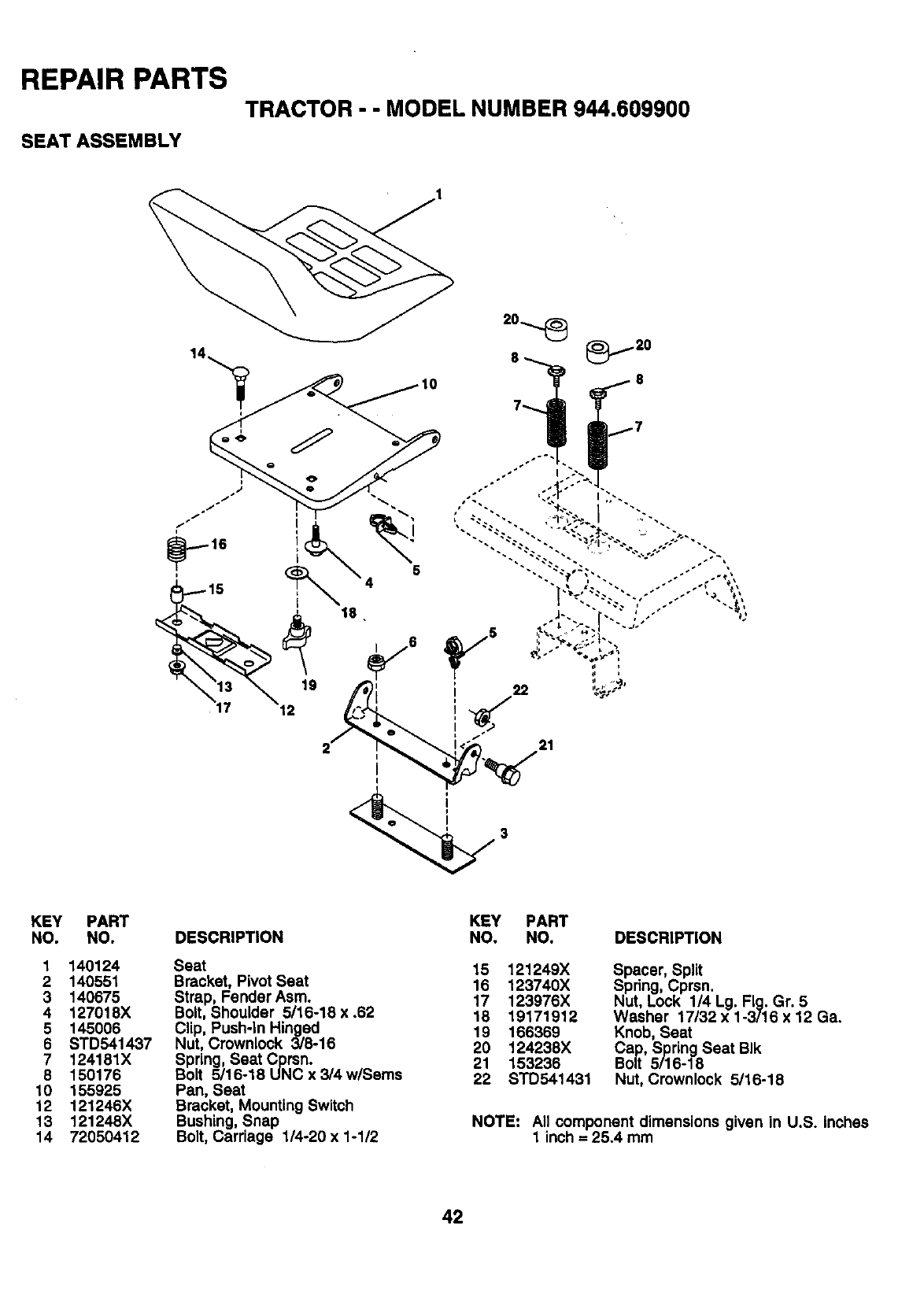
REPAIR PARTS
TRACTOR - - MODEL NUMBER 944.609900
SEAT ASSEMBLY
_....-- 16
t2
21
KEY
NO.
1
2
3
4
5
6
7
8
10
12
13
14
PART
NO.
140124
140551
140675
127018X
145006
STD541437
124181X
150176
155925
121246X
121248X
72050412
DESCRIPTION
Seat
Bracket, Pivot Seat
Strap, Fender Asm.
Bolt, Shoulder 5/16-18 x .62
Clip, Push-In Hinged
Nut, Crownlock 3/8-16
Spring, Seat Cprsn.
Bolt 5116-18 UNC x 3/4 w/Sems
Pan, Seat
Bracket, Mounting Switch
Bushing, Snap
Bolt, Carriage 1/4-20 x 1-1/2
KEY PART
NO. NO.
15 121249X
16 123740X
17 123976X
18 19171912
19 166369
20 124238X
21 153236
22 STD541431
DESCRIPTION
Spacer, Split
Spring, Cprsn.
Nut, Lock 114 Lg. Fig. Gr. 5
Washer 17/32 x 1-3/16 x 12 Ga.
Knob, Seat
Cap, Spring Seat BIk
Bolt 5/16-18
Nut, Crownlock 5/16-18
NOTE: All component dimensions given in U.S. inches
1 inch = 25,4 mm
42
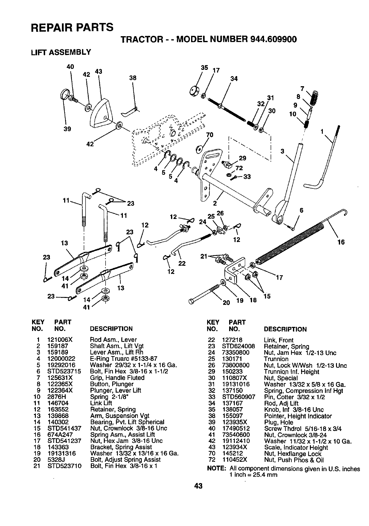
REPAIR PARTS
TRACTOR --MODEL NUMBER 944.609900
LIFT ASSEMBLY
34
32 31
72
4
23
13
23
12
22
12
2
\
12
7
8
9
10
6
16
KEY
NO.
1
2
3
4
5
6
7
8
9
10
11
12
13
14
15
16
17
18
19
20
21
PART
NO. DESCRIPTION
121006X
159187
159189
12000022
19292016
STD523715
125631X
122365X
122364X
2876H
146704
163552
139868
140302
STD541437
674A247
STD541237
143363
19131316
5328J
STD523710
Rod Asm., Lever
Shaft Asm., LiftVgt
Lever Asm., Lift Rh
E-Ring Truarc #5133-87
Washer 29132 x 1-1/4 x 16 Ga.
Bolt, Fin Hex 3/8-16 x 1-112
Grip, Handle Fluted
Button, Plunger
Plunger, Lever Lift
Spring 2-118"
Link Lift
Retainer, Spring
Arm, Suspension Vgt
Bearing, Pvt. Lift Spherical
Nut, Crownlock 3/8-16 Unc
Spring Asm., Assist Lift
Nut, Hex Jam 3/8-16 Unc
Bracket, Spring Assist
Washer 13132 x 13116 x 16 Ga.
Bolt, Adjust Spring Assist
Bolt, Fin Hex 318-16 x 1
15
20 19 18
43
KEY PART
NO. NO. DESCRIPTION
22 127218
23 STD624008
24 73350800
25 130171
26 73800800
29 150233
30 110807X
31 19131016
32 137150
33 STD560907
34 137167
35 138057
38 155097
39 123935X
40 17490512
41 73540600
42 19112410
43 123934X
70 145212
72 110452X
Link, Front
Retainer, Spring
Nut, Jam Hex 1/2-13 Unc
Trunnion
Nut, Lock W/Wsh 1/2-13 Unc
Trunnion Inf. Height
Nut, Special
Washer 13/32 x 5/8 x 16 Ga.
Spring, Compression Inf Hgt
Pin, Cotter 3/32 x 112
Rod, Adj Lift
Knob, Inf 3/8-16 Unc
Pointer, Height Indicator
Plug, Hole
Screw Thdrol 5/16-18 x 314
Nut, Crownlock 3/8-24
Washer 11/32 x 1-1/2 x 10 Ga.
Scale, Indicator Height
Nut, Hexflange Lock
Nut, Push Phos & Oil
NOTE: All component dimensions given in U.S. inches
1 inch = 25.4 mm
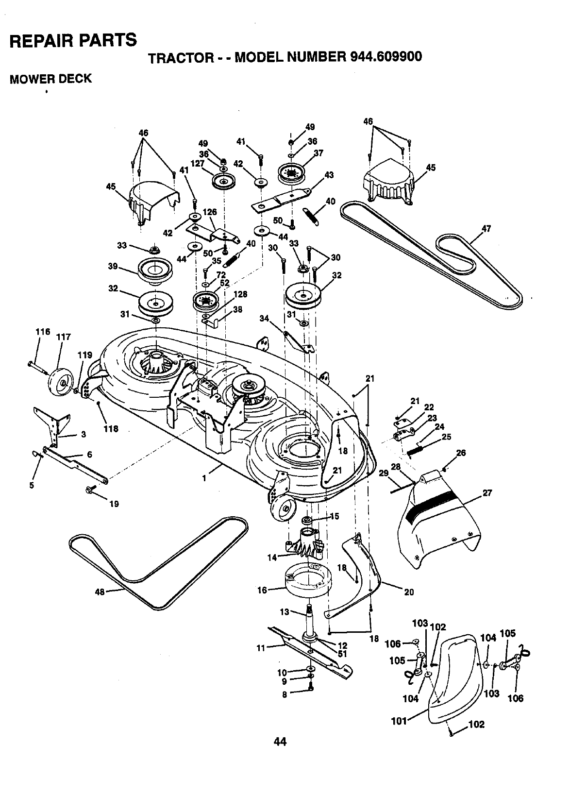
REPAIR PARTS
MOWER DECK
TRACTOR - - MODEL NUMBER 944.609900
116 117
46
45\
I i
31
21
21
3
24
._ 25
26
103102
18 106 --_,
105
44
104
101' ._,,,,102
106
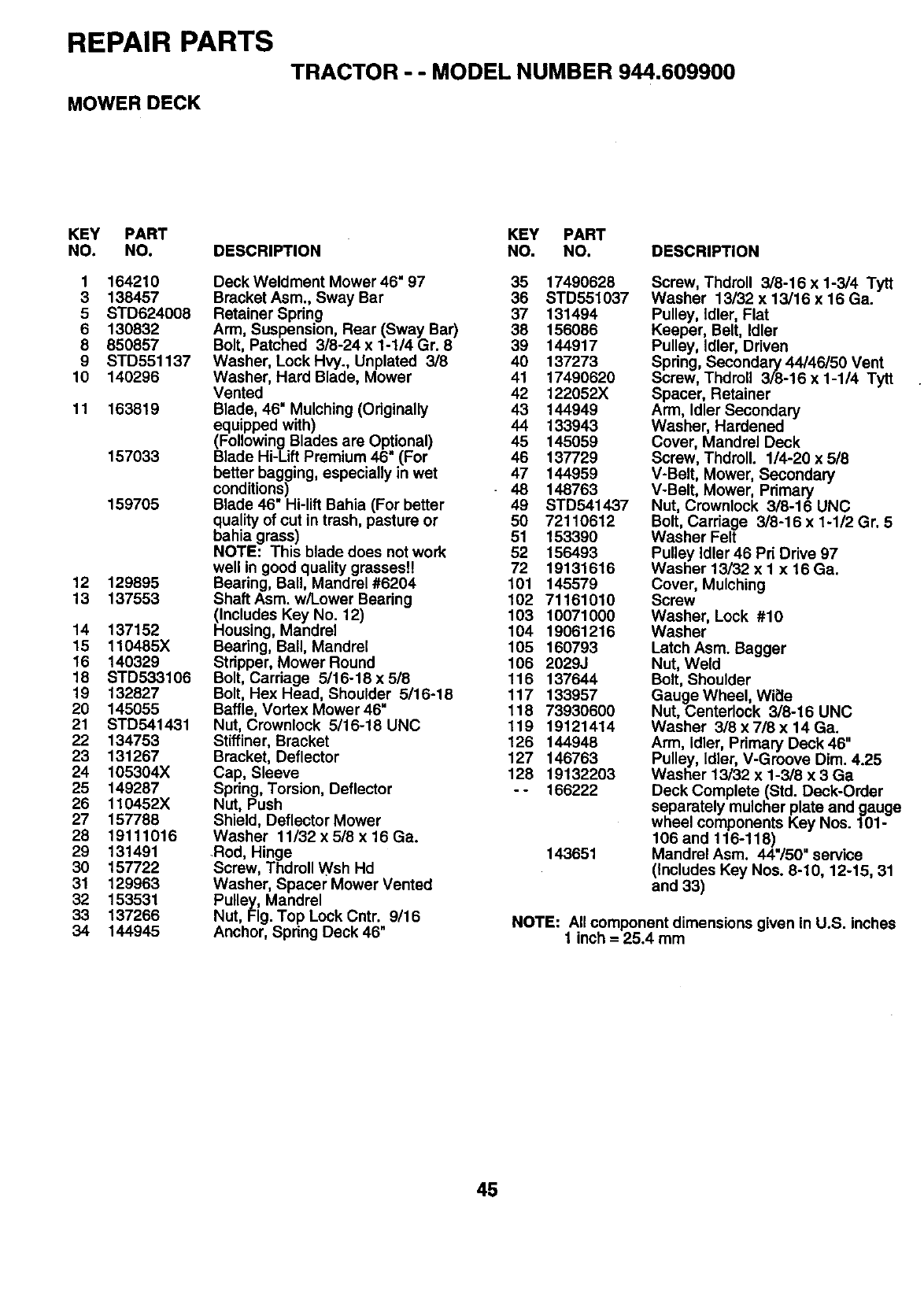
REPAIR PARTS
TRACTOR - - MODEL NUMBER 944.609900
MOWER DECK
KEY PART KEY PART
NO. NO. DESCRIPTION NO. NO. DESCRIPTION
1 164210
3 138457
5 STD624008
6 130832
8 850857
9 STD551137
10 140296
11 163819
157033
159705
12 129895
13 137553
14 137152
15 110485X
16 140329
18 STD533106
19 132827
20 145055
21 STD541431
22 134753
23 131267
24 105304X
25 149287
26 110452X
27 157788
28 19111016
29 131491
30 157722
31 129963
32 153531
33 137266
34 144945
Deck Weldment Mower 46" 97 35 17490628
Bracket Asm., Sway Bar 36 STD551037
Retainer Spring 37 131494
Arm, Suspension, Rear (Sway Bar) 38 156086
Bolt, Patched 3/8-24 x 1-114 Gr. 8 39 144917
Washer, Lock Hvy., Unplated 3/8 40 137273
Washer, Hard Blade, Mower 41 17490620
Vented 42 122052X
Blade, 46" Mulching (Originally 43 144949
equipped with) 44 133943
(Following Blades are Optional) 45 145059
Blade Hi-Lift Premium 46" (For 46 137729
better bagging, especially in wet 47 144959
conditions) 48 148763
Blade 46" Hi-lift Bahia (For better 49 STD541437
quality of cut in trash, pasture or 50 72110612
bahia grass) 51 153390
NOTE: This blade does not work 52 156493
well in good quality grasses!! 72 19131616
Bearing, Ball, Mandrel #6204 101 145579
Shaft Asm. w/Lower Bearing 102 71161010
(Includes Key No. 12) 103 10071000
Housing, Mandrel 104 19061216
Bearing, Ball, Mandrel 105 160793
Stripper, Mower Round 106 2029J
Bolt, Carriage 5/16-18 x 518 116 137644
Bolt, Hex Head, Shoulder 5/16-18 117 133957
Baffle, Vortex Mower 46" 118 73930600
Nut, Crownlock 5/16-18 UNC 119 19121414
Stiffiner, Bracket 126 144948
Bracket, Deflector 127 146763
Cap, Sleeve 128 19132203
Spring, Torsion, Deflector - - 166222
Nut, Push
Shield, Deflector Mower
Washer 11/32 x 518 x 16 Ga.
Rod, Hinge 143651
Screw, Thdroll Wsh Hd
Washer, Spacer Mower Vented
Pulley, Mandrel
Nut, Fig. Top Lock Cntr. 9/16
Anchor, Spring Deck 46"
Screw, Thdroll 3/8-16 x 1-3/4 Tytt
Washer 13/32 x 13/16 x 16 Ga.
Pulley, Idler, Flat
Keeper, Belt, Idler
Pulley, Idler, Driven
Spring, Secondary 44/46/50 Vent
Screw, ThdroU 3/8-16 x 1-1/4 Tytt
Spacer, Retainer
Arm, Idler Secondary
Washer, Hardened
Cover, Mandrel Deck
Screw, Thdroll. 1/4-20 x 5/8
V-Belt, Mower, Secondary
V-Belt, Mower, Pdmary
Nut, Crownlock 3/8-16 UNC
Bolt, Carriage 3/8-16 x 1-1/2 Gr. 5
Washer Felt
Pulley Idler 46 Pri Drive 97
Washer 13/32 x I x 16 Ga.
Cover, Mulching
Screw
Washer, Lock #10
Washer
Latch Asm. Bagger
Nut, Weld
Bolt, Shoulder
Gauge Wheel, Wi_le
Nut, Centerlock 318-16 UNC
Washer 3/8 x 718 x 14 Ga.
Arm, Idler, Primary Deck 46"
Pulley, Idler, V-Groove Dim. 4.25
Washer 13/32 x 1-3/8 x 3 Ga
Deck Complete (Std. Deck-Order
separately mulcher plate and gauge
wheel components Key Nos. 101-
106 and 116-118)
Mandrel Asm. 44"/50" service
(Includes Key Nos. 8-10, 12-15, 31
and 33)
NOTE: All component dimensions given in U.S. inches
1 inch = 25.4 mm
45
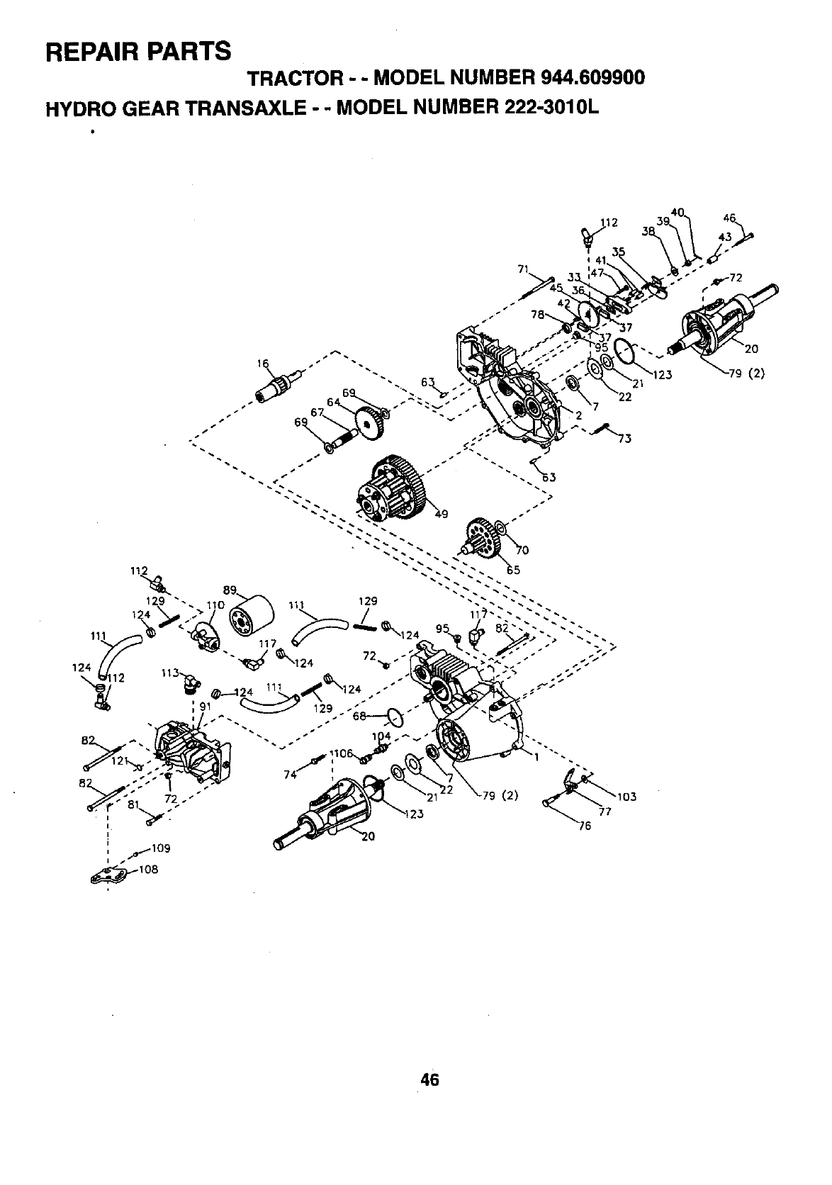
REPAIR PARTS
TRACTOR - - MODEL NUMBER 944.609900
HYDRO GEAR TRANSAXLE - - MODEL NUMBER 222'3010L
7
(2)
4B
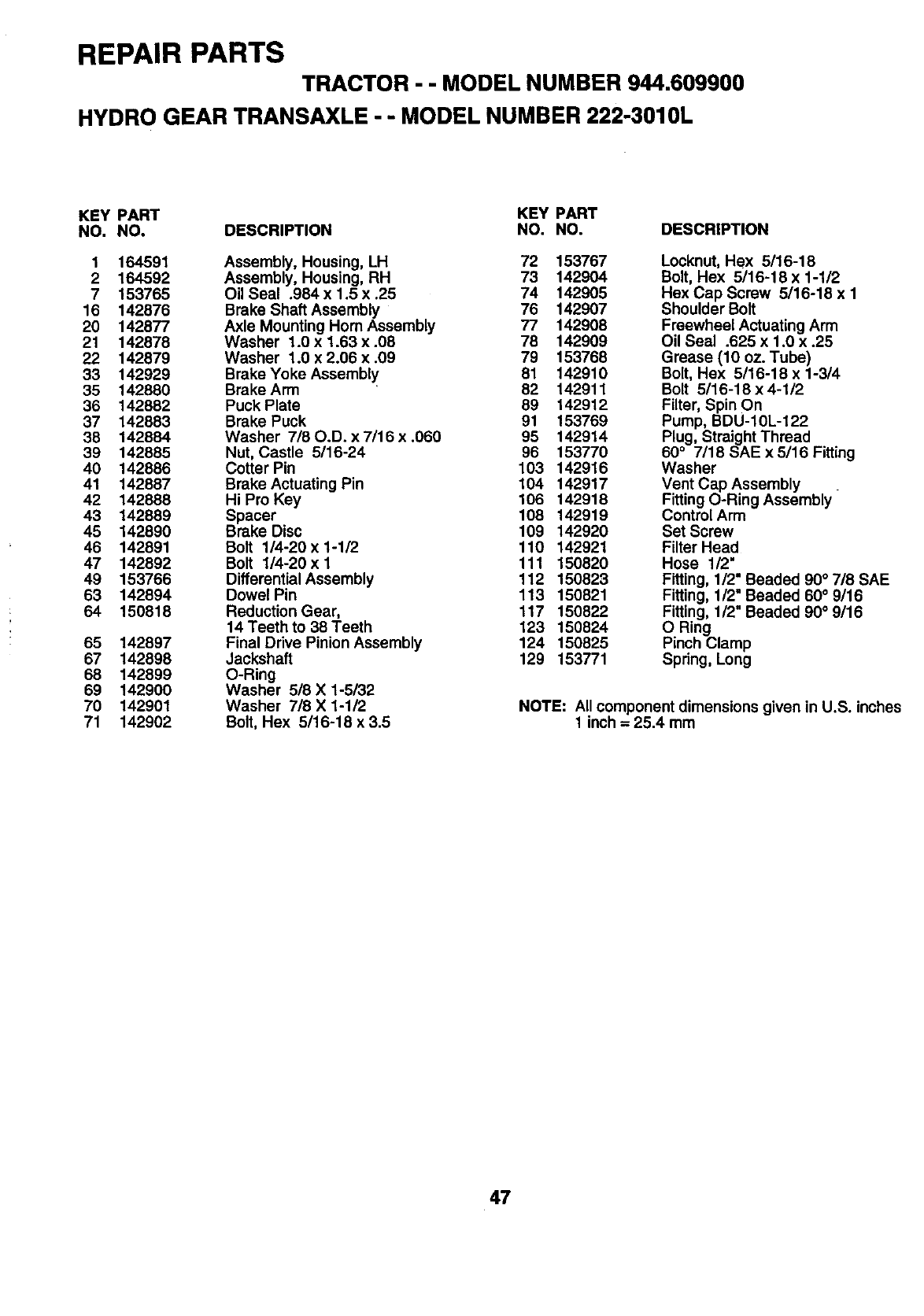
REPAIR PARTS
TRACTOR --MODEL NUMBER 944.609900
HYDRO GEAR TRANSAXLE --MODEL NUMBER 222-3010L
KEY PART KEY PART
NO. NO. DESCRIPTION NO. NO. DESCRIPTION
1 164591 Assembly, Housing, LH 72 153767
2 164592 Assembly, Housing, RH 73 142904
7 153765 Oil Seal .984 x 1.5 x .25 74 142905
16 142876 Brake Shaft Assembly 76 142907
20 142877 Axle Mounting Horn Assembly 77 142908
21 142878 Washer 1.0 x 1.63 x .08 78 142909
22 142879 Washer 1.0 x 2.06 x .09 79 153768
33 142929 Brake Yoke Assembly 81 142910
35 142880 Brake Arm 82 142911
36 142882 Puck Plate 89 142912
37 142883 Brake Puck 91 153769
38 142884 Washer 7/80°D. x 7/16 x .060 95 142914
39 142885 Nut, Castle 5/16-24 96 153770
40 142886 Cotter Pin 103 142916
41 142887 Brake Actuating Pin 104 142917
42 142888 Hi Pro Key 106 142918
43 142889 Spacer 108 142919
45 142890 Brake Disc 109 142920
46 142891 Bolt 1/4-20 x 1-1/2 110 142921
47 142892 Bolt 1/4-20xl 111 150820
49 153766 DifferentialAssembly 112 150823
63 142894 Dowel Pin 113 150821
64 150818 Reduction Gear, 117 150822
14 Teeth to 38 Teeth 123 150824
65 142897 Final Drive Pinion Assembly 124 150825
67 142898 Jackshaft 129 153771
68 142899 O-Ring
69 142900 Washer 518 X 1-5/32
70 142901 Washer 7/8 X 1-1/2
71 142902 Bolt, Hex 5/16-18 x 3.5
Locknut, Hex 5/16-18
Bolt, Hex 5/16-18 x 1-1/2
Hex Cap Screw 5/16-18 x 1
Shoulder Bolt
Freewheel Actuating Arm
Oil Seal .625 x 1.0 x .25
Grease (10 oz. Tube)
Bolt, Hex 5/16-18 x 1-3/4
Bolt 5/16-18 x 4-1/2
Filter, Spin On
Pump, BDU-10L-122
Plug, Straight Thread
60 ° 7/18 SAE x5/16 Fitting
Washer
Vent Cap Assembly
Fitting O-Ring Assembly
Control Arm
Set Screw
Filter Head
Hose 1/2"
Fitting, 1/2" Beaded 90° 718 SAE
Fitting, 1/2" Beaded 60°9/16
Fitting, 1/2" Beaded 90° 9/16
O Ring
Pinch Clamp
Spring, Long
NOTE: All component dimensions given in U.S. inches
1 inch = 25.4 mm
47
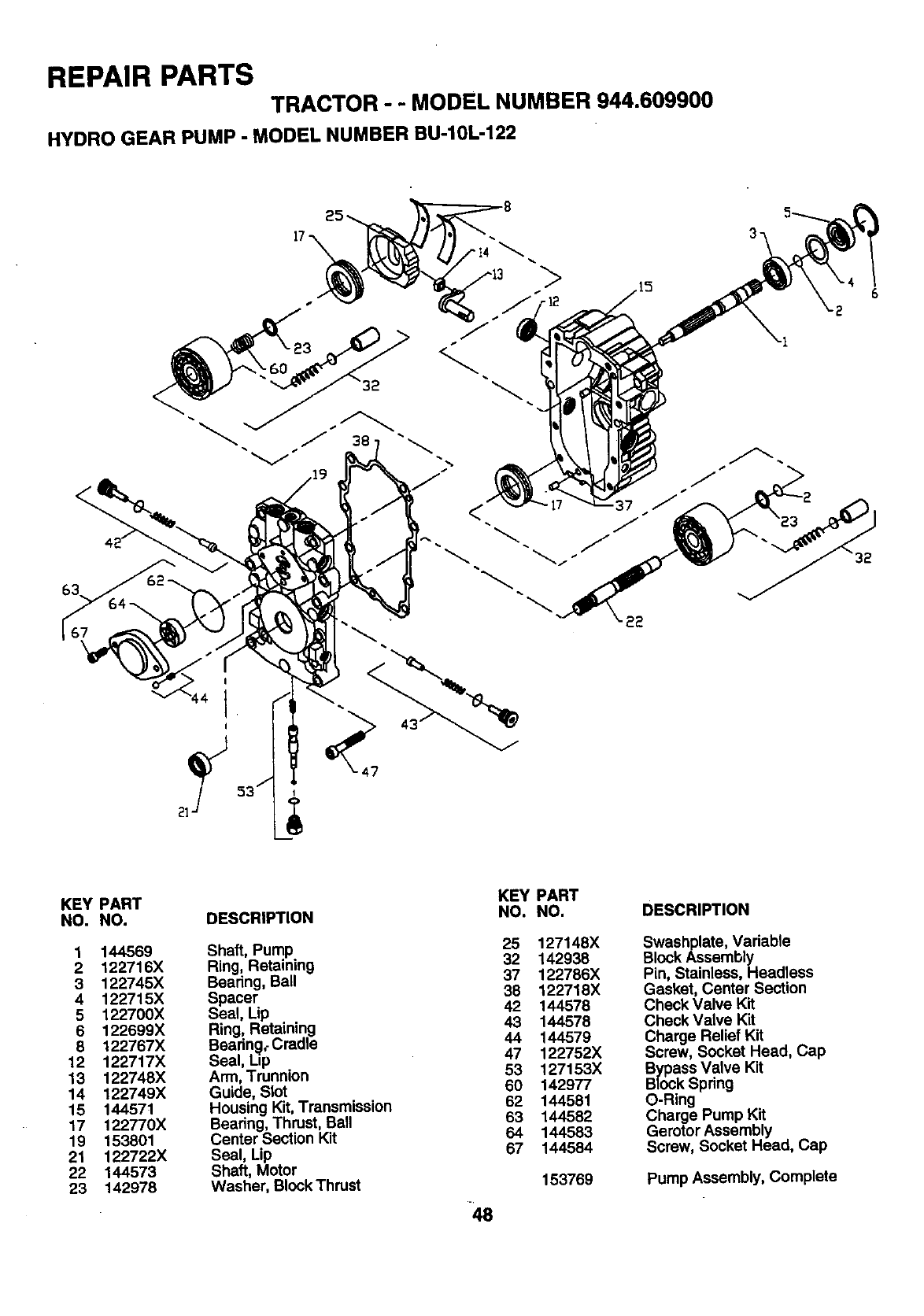
REPAIR PARTS
TRACTOR --MODEL NUMBER 944.609900
HYDRO GEAR PUMP - MODEL NUMBER BU-10L-122
KEY
NO.
1
2
3
4
5
6
8
12
13
14
15
17
19
21
22
23
PART
NO.
144569
122716X
122745X
122715X
122700X
122699×
122767X
122717X
122748X
122749X
144571
122770X
153801
122722X
144573
142978
DESCRIPTION
Shaft, Pump
Ring, Retaining
Bearing, Ball
Spacer
Seal, Lip
Ring, Retaining
Beadn_lt Cradle
Seal, L=p
Arm, Trunnion
Guide, Slot
Housing Kit, Transmission
Bearing, Thrust, Ball
Center Section Kit
Seal, Lip
Shaft, Motor
Washer, Block Thrust 48
KEY PART
NO. NO.
25 127148X
32 142938
37 122786X
38 122718X
42 144578
43 144578
44 144579
47 122752X
53 127153X
60 142977
62 144581
63 144582
64 144583
67 144584
153769
DESCRIPTION
Swashplate, Variable
Block Assembly
Pin, Stainless, Headless
Gasket, Center Section
Check Valve Kit
Check Valve Kit
Charge Relief Kit
Screw, Socket Head, Cap
Bypass Valve Kit
Block Spring
O-Ring
Charge Pump Kit
Gerotor Assembly
Screw, Socket Head, Cap
Pump Assembly, Complete
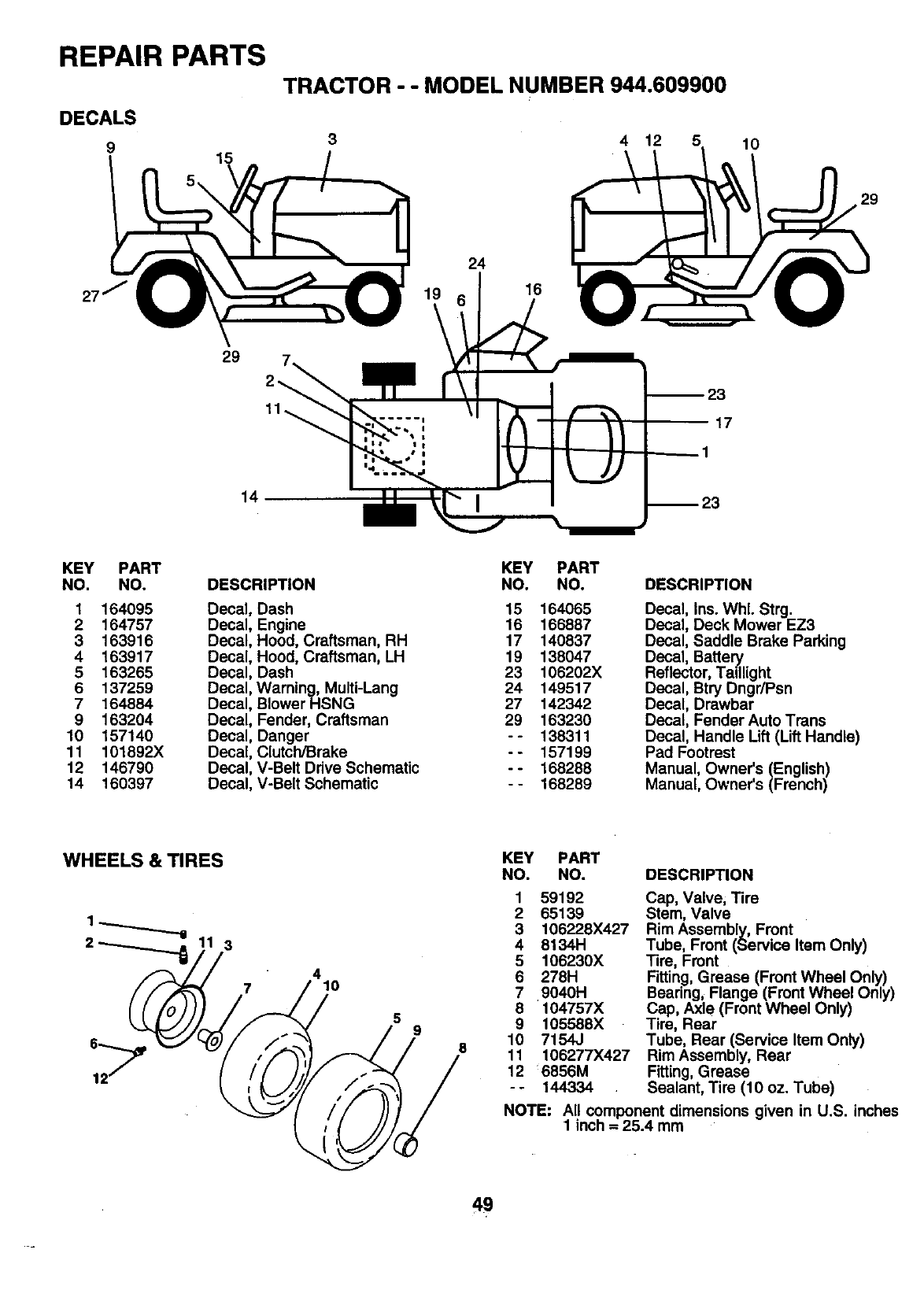
REPAIR PARTS
DECALS
915
TRACTOR - - MODEL NUMBER 944.609900
3 4 12 5 lO
29
29
14
24
16
17
KEY PART
NO. NO.
1164095
2 164757
3 163916
4 163917
5 163265
6 137259
7 164884
9 163204
10 157140
11 101892X
12 146790
14 160397
DESCRIPTION
Decal, Dash
Decal, Engine
Decal, Hood, Craftsman, RH
Decal, Hood, Craftsman, LH
Decal, Dash
Decal, Warning, Multi-Lang
Decal, Blower HSNG
Decal, Fender, Craftsman
Decal, Danger
Decal, Clutch/Brake
Decal, V-Belt Drive Schematic
Decal, V-Belt Schematic
KEY PART
NO. NO.
15 164065
16 166887
17 140837
19 138047
23 106202X
24 149517
27 142042
29 163230
-- 138311
-- 157199
-- 168288
-- 168289
DESCRIPTION
Decal, Ins. WhL Strg.
Decal, Deck Mower EZ3
Decal, Saddle Brake Parking
Decal, Batte_
Reflector, Tadlight
Decal, Btry Dngr/Psn
Decal, Drawbar
Decal, Fender Auto Trans
Decal, Handle Lift (Lift Handle)
Pad Footrest
Manual, Owner's (English)
Manual, Owner's (French)
WHEELS & TIRES
3
7410
59
8
PART
NO. DESCRIPTION
KEY
NO.
1 59192
2 65139
3 106228X427
4 8134H
5 106230X
6 278H
7 9040H
8+104757X
9 105588X
10 7154J
11 106277X427
12 6856M
--144334
Cap, Valve, Tire
Stem, Valve
Rim Assembly, Front
Tube, Front (Service Item Only)
Tire, Front
Fitting, Grease (Front Wheel Only)
Bearing, Flange (Front Wheel Only)
Cap, Axle (Front Wheel Only)
Tire, Rear
Tube, Rear (Service Item Only)
Rim Assembly, Rear
Fitting, Grease
Sealant, Tire (10 oz. Tube)
NOTE: All component dimensions given in U.S. inches
1 inch = 25.4 mm
49
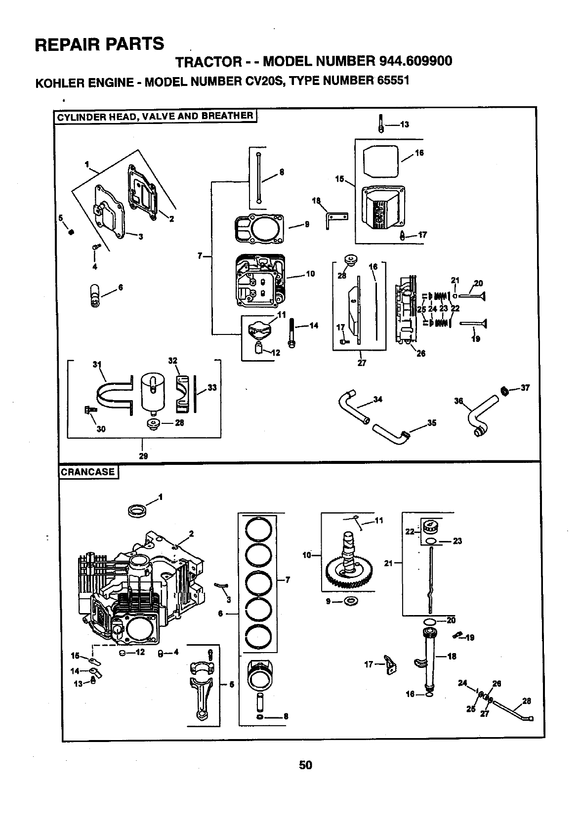
REPAIR PARTS TRACTOR - - MODEL NUMBER 944.609900
KOHLER ENGINE - MODEL NUMBER CV20S, TYPE NUMBER 65551
i
2g
CRANCASEJ
.,.,j i
€"%i
_,..J L
_...J i
OB8
1(
28 n 21
O_20
5O
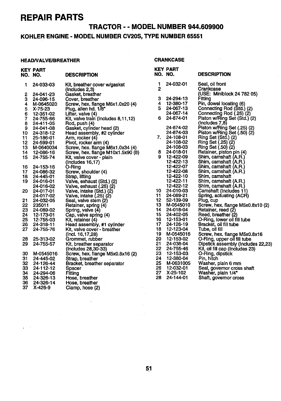
REPAIR PARTS
TRACTOR --MODEL NUMBER 944.609900
KOHLER ENGINE -MODEL NUMBER CV20S, TYPE NUMBER 65551
HEADNALVE/BREATHER CRANKCASE
KEY PART KEY PART
NO, NO. DESCRIPTION NO. NO. DESCRIPTION
2 24-041-23
3 24-096-15
4 M-0645020
5 X-75-23
6 12-351-02
7 24-755-66
8 24-411-05
9 24-041-08
10 24-318-12
11 25-186-01
12 24-599-01
13 M-0640034
14 12-086-16
15 24-755-74
16 24-153-16
17 24-086-32
18 24-445-01
19 24-016-01
24-016-02
20 24-017-01
24-017-02
21 24-032-05
22 235011
23 24-089-02
24 12-173-01
25 12-755-03
26 24-318-11
27 24-755-76
28 25-313-02
29 24-755-57
24-033-03 Kit, breather cover w/gasket 1 24-032-01
(Includes 2,3) 2
Gasket, breather
Cover, breather
Screw, hex. flange M6xl.0x20 (4)
Plug, allen hd. 1/8"
Lifter, valve (4)
Kit, valve train (Includes 8,11,12)
Rod, push (4)
Gasket, cylinder head (2)
Head assembly, #2 cylinder
Arm, rocker (4)
Pivot, rocker arm (4)
Screw, hex. flange M6x1.0x34 (4)
Screw, hex. flange M10x1.5x90 (8)
Kit, valve cover -plain
_ncludes 16,17)
-Ring
Screw, shoulder (4)
Strap, lifting
Valve, exhaust (Std.) (2)
Valve, exhaust (.25) (2)
Valve, intake (Std.) (2)
Valve, intake (.25) (2)
Seal, valve stern (2)
Retainer, spring (4)
Spdng, valve (4)
Cap, valve spring (4)
Kit, retainer (4)
Head assembly, #1 cylinder
Kit, valve cover -breather
(Incl. 16,17,26)
Grommet, rubber
Kit, breather separator
_ncludes 28,30-33)
crew, hex. flange M5x0.Sx16 (2)
Strap, breather
Bracket, breather separator
Spacer
Fitting
Hose, breather
Hose, breather
Clamp, hose (2)
30 M-0545016
31 24-445-02
32 24-126-44
33 24-112-12
34 24-294-06
35 24-326-13
36 24-326-14
37 X-426-9
3 24-294-13
4 12-380-17
5 24-067-13
24-067-14
6 24-874-01
24-874-02
24-874-03
7. 24-108-01
24-108-02
24-108-03
8 24-018-01
9 12-422-09
12-422-13
12-422-07
12-422-08
12-422-10
12-422-11
12-422-12
10 24-010-03
11 24-089-21
12 52-139-09
13 M-0545010
14 24-018-04
15 24-402-05
16 12-153-01
17 24-126-19
18 12-123-04
19 M-0545016
20 12-153-02
21 24-038-04
22 24-755-46
23 12-153-03
24 12-380-04
25 M-0631005
26 12-032-01
27 X-25-102
28 24-144-01
Seal, oil front
Crankcase
(USE: Miniblock 24 782 05)
Fitting
Pin, dowel locating (6)
Connecting Rod (Std.) (2)
Connecting Rod (.25) (2)
Piston wiRing Set (Std.) (2)
(Includes 7,8)
Piston w/Ring Set (.25) (2)
Piston w/Ring Set (.50) (2)
Ring Set (Std.) (2)
Ring Set (.25) (2)
Ring Set (.50) (2)
Retainer, piston pin (4)
Shim, camshaft (A.R.)
Shim, camshaft (A.R.)
Shim, camshaft (A.R.)
Shim, camshaft (A.R.)
Shim, camshaft
Shim, camshaft (A.R.)
Shim, camshaft (A.R.)
Camshaft (Includes 11)
Spring, actuating (ACR)
Plug, cup
Screw, hex. flange M5x0.8xl0 (2)
Retainer, reed (2)
Reed, breather (2)
O-Ring, lower oil fill tube
Bracket, oil fill tube
Tube, oil fill
Screw, hex. flange M5x0.8x16
O-Ring, upper oil fill tube
Dipstick assembly (Includes 22,23)
Kit, oil fill cap (Includes 23)
O-Ring, dipstick
Pin, hitch
Washer, plain 6 mm
Seal, governor cross shaft
Washer, plain 1/4"
Shaft, govemor cross
s!
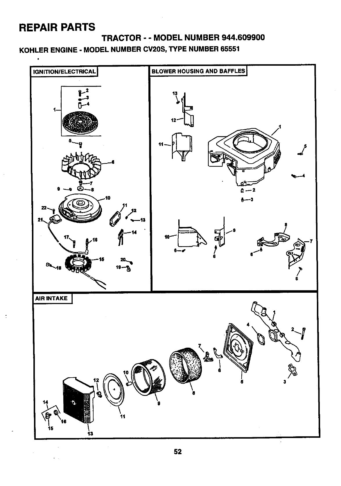
REPAIR PARTS
TRACTOR ' "MODEL NUMBER 944.609900
KOHLER ENGINE -MODEL NUMBER CV20S, TYPE NUMBER 65551
IGNITIONIELECTRICAL I
AIR INTAKE J
14
11
16 /
t3
BLOWER HOUSING AND BAFFLES J
12""L_ J
1t'_
6
/
J
q_---4
iF--=
8
6/t)
6
6 3
52
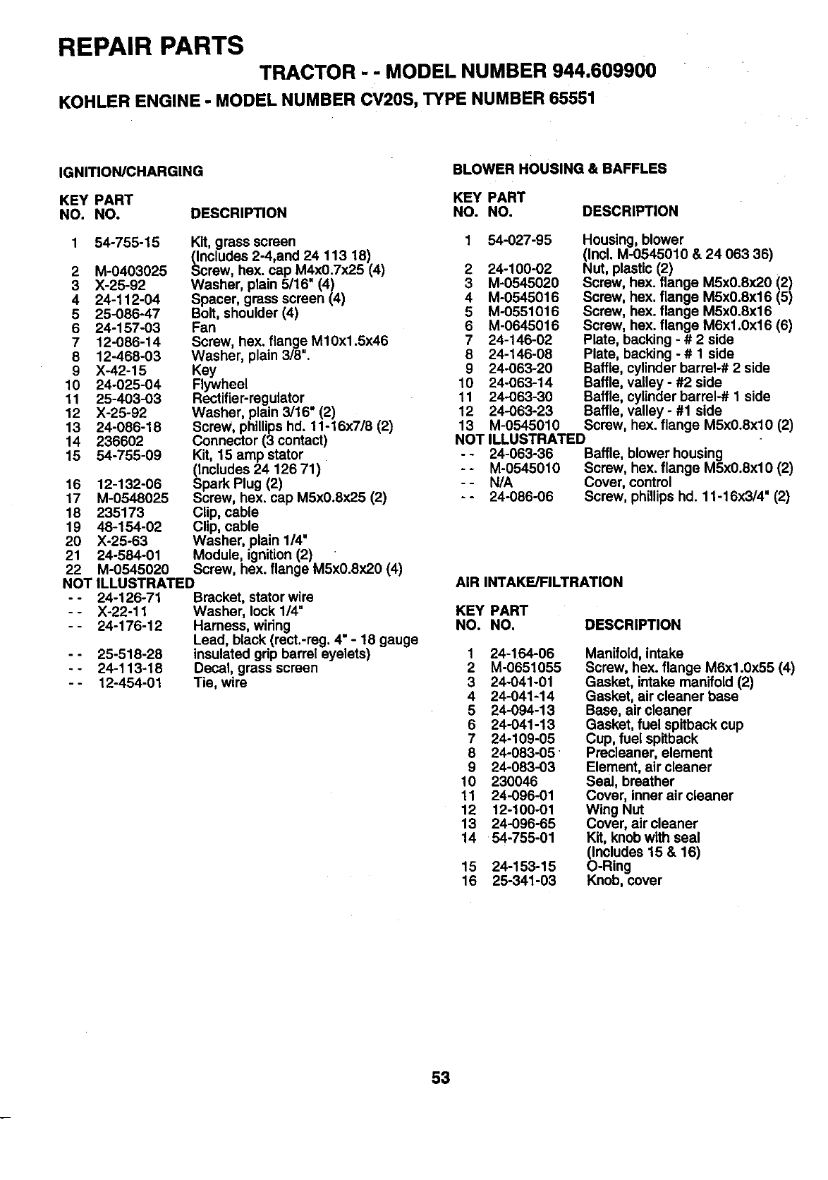
REPAIR PARTS TRACTOR - - MODEL NUMBER 944.609900
KOHLER ENGINE -MODEL NUMBER CV2OS, TYPE NUMBER 65551
IGNITION/CHARGING BLOWER HOUSING & BAFFLES
KEY PART KEY PART
NO. NO. DESCRIPTION NO. NO.
1 54-755-15 1 54-027-95
Kit, grass screen
(Includes 2-4,and 24 f 13 18)
2 M-0403025 Screw, hex. cap M4x0.7x25 (4) 2 24-100-02
3 X-25-92 Washer, plain 5/16" (4) 3 M-0545020
4 24-112-04 Spacer, grass screen (4) 4 M-0545016
5 25-086-47 Bolt, shoulder (4) 5 M-0551016
6 24-157-03 Fan 6 M-0645016
7 12-086-14 Screw, hex. flange M10x1.5x46 7 24-146-02
8 12-468-03 Washer, plain 3/8". 8 24-146-08
9 X-42-15 Key 9 24-063-20
10 24-025-04 Flywheel 10 24-063-14
11 25-403-03 Rectifier-regulator 11 24-063-30
12 X-25-92 Washer, plain 3/16" (2) 12 24-063-23
13 24-086-18 Screw, phillips hd. 11-16x7/8 (2) 13 M-0545010
14 236602 Connector (3 contact)
15 54-755-09 Kit, 15 amp stator
_ncludes 24 126 71)
park Plug (2)
Screw, hex. cap MSx0.8x25 (2)
Clip, cable
Clip, cable
Washer, plain 1/4"
Module, ignition (2)
Screw, hex. flange M5x0.8x20 (4)
16 12-132-06
17 M-0548025
18 235173
19 48-154-02
20 X-25-63
21 24-584-01
22 M-0545020
NOT ILLUSTRATED
- - 24-126-71 Bracket, stator wire
--X-22-11 Washer, lock 1/4 =
- - 24-176-12 Harness, wiring
Lead, black (rect.-reg. 4" - 18 gauge
- - 25-518-28 insulated gdp barrel eyelets)
--24-113-18 Decal, grass screen
- - 12-454-01 Tie, wire
DESCRIPTION
Housing, blower
(Incl. M-0545010 & 24 063 36)
Nut, plastic (2)
Screw, hex. flange M5x0.8x20 (2)
Screw, hex. flange M5x0.8x16 (5)
Screw, hex. flange M5x0.8x16
Screw, hex. flange M6xf .0x16 (6)
Plate, backing - #2 side
Plate, backing - # 1 side
Baffle, cylinder barrel-# 2 side
Baffle, valley - #2 side
Baffle, cylinder barrel-# 1 side
Baffle, valley - #1 side
Screw, hex. flange M5x0.8xlO (2)
NOT ILLUSTRATED
--24-063-36 Baffle, blower housing
-- M-0545010 Screw, hex. flange M5x0.8xl0 (2)
- - N/A Cover, control
--24-086-06 Screw, phillips hd. 11-16x3/4" (2)
AIR INTAKE/FILTRATION
KEY PART
NO. NO. DESCRIPTION
1 24-154-06
2 M-0651055
3 24-041-01
4 24-041-14
5 24-094-13
6 24-041-13
7 24-109-05
8 24-083-05
9 24-083-03
10 230046
11 24-096-01
12 12-100-01
13 24-096-65
14 54-755-01
15 24-153-15
16 25-341-03
Manifold, intake
Screw, hex. flange M6x1.0x55 (4)
Gasket, intake manifold (2)
Gasket, air cleaner base
Base, air cleaner
Gasket, fuel spitback cup
Cup, fuel spitback
Precleaner, element
Element, air cleaner
Seal, breather
Cover, inner air cleaner
Wing Nut
Cover, air cleaner
Kit, knob with seal
(Includes 15 & 16)
O-Ring
Knob, cover
53
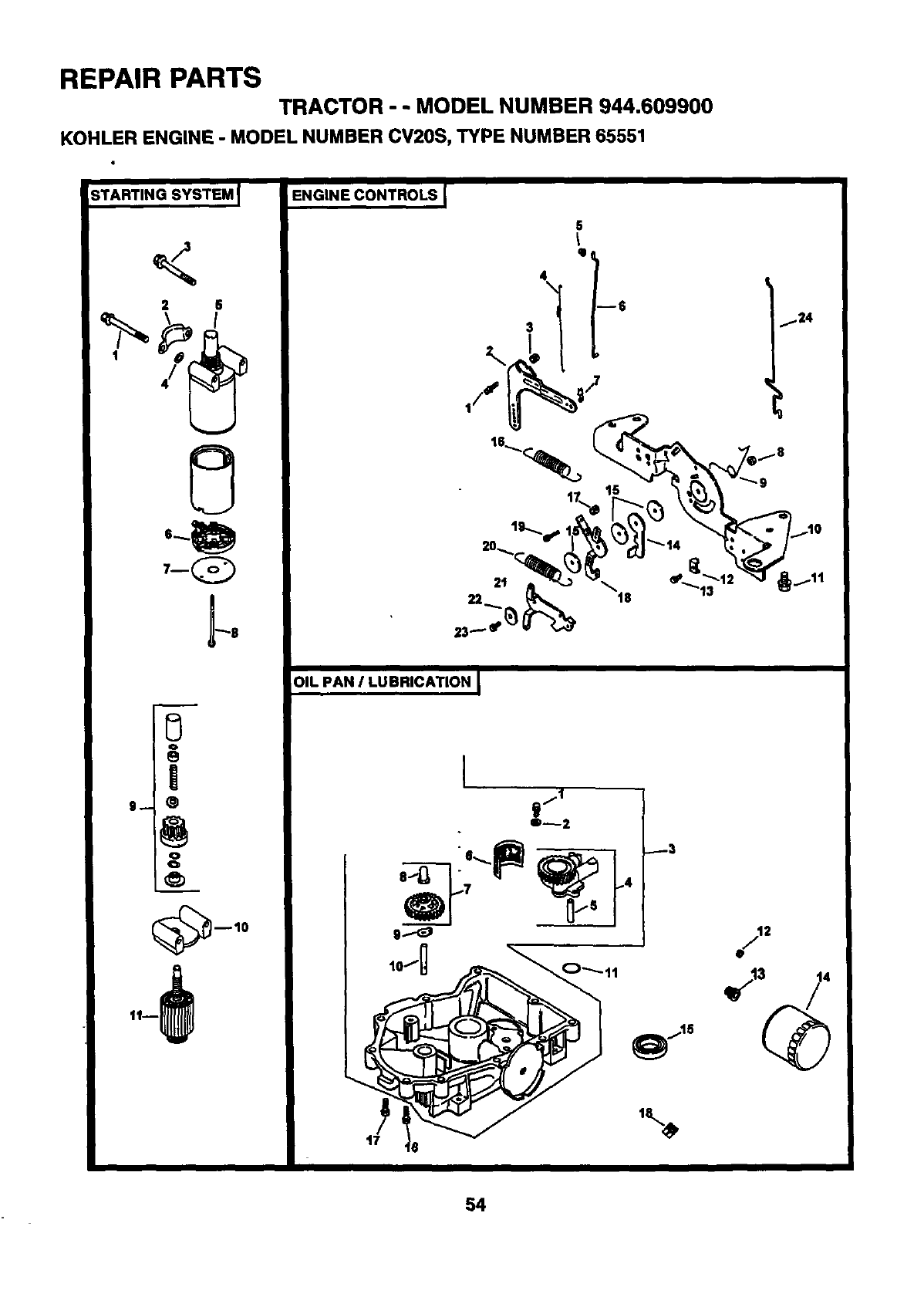
REPAIR PARTS
TRACTOR --MODEL NUMBER 944.609900
KOHLER ENGINE -MODEL NUMBER CV20S, TYPE NUMBER 65551
;TARTING SYSTEM _I
<
2 6
I
4/
_.-.$
ENGINE CONTROLS I
OIL PAN ILUBRICATION I
o_2
g..-_
_3
f24
2
_13 4
54
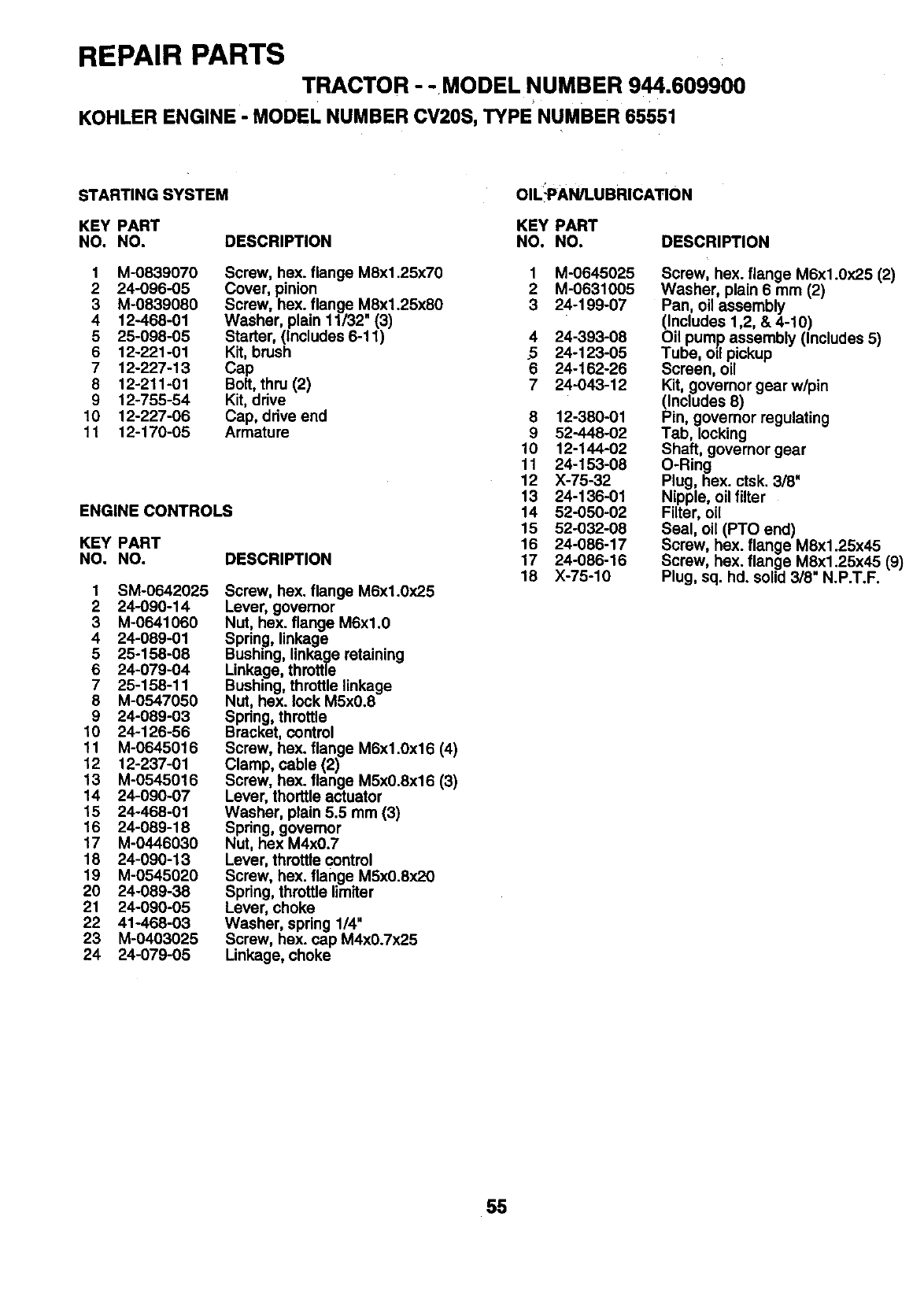
REPAIR PARTS
TRACTOR - -MODEL NUMBER 944.609900
KOHLER ENGINE - MODEL NUMBER CV20S, TYPE NUMBER 65551
STARTING SYSTEM OIL!PAN/LUBRICATION
KEY PART KEY PART
NO. NO. DESCRIPTION NO. NO. DESCRIPTION
1 M-0839070 Screw, hex. flange M8x1.25x70
2 24-096-05 Cover, pinion
3 M-0839080 Screw, hex. flange M8x1.25x80
4 12-468-01 Washer, plain 11/32" (3)
5 25-098-05 Starter, (Includes 6-11)
6 12-221-01 Kit, brush
7 12-227-13 Cap
8 12-211-01 Bolt, thru (2)
9 12-755-54 Kit, drive
10 12-227-06 Cap, ddve end
11 12-170-05 Armature
ENGINE CONTROLS
KEY PART
NO. NO. DESCRIPTION
1 SM-0642025
2 24-090-14
3 M-0641060
4 24-089-01
5 25-158-08
6 24-079-04
7 25-158-11
8 M-0547050
9 24-089-03
10 24-126-56
11 M-0645016
12 12-237-01
13 M-0545016
14 24-090-07
15 24-468-01
16 24-089-18
17 M-0446030
18 24-090-13
19 M-0545020
20 24-089-38
21 24-090-05
22 41-468-03
23 M-0403025
24 24-079-05
Screw, hex. flange M6x1.0x25
Lever, governor
Nut, hex. flange M6xl.0
Spdng, linkage
Bushing, linkage retaining
Linkage, throttle
Bushing, throttle linkage
NUt, hex. lock M5x0.8
Spdng, throttle
Bracket, control
Screw, hex. flange M6x1.0x16 (4)
Clamp, cable (2)
Screw, hex. flange M5x0.8x16 (3)
Lever, thorttle actuator
Washer, plain 5.5 mm (3)
Spdng, govemor
Nut, hex M4x0.7
Lever, throttle control
Screw, hex. flange M5x0.8x20
Spring, throttle limiter
Lever, choke
Washer, spring 1/4"
Screw, hex. cap M4x0.7x25
Linkage, choke
1
2
3
4
5
6
7
M-0645025
M-0631005
24-199-07
24-393-08
24-123-05
24-162-26
24-043-12
8 12-380-01
9 52-448-02
10 12-144-02
11 24-153-08
12 X-75-32
13 24-136-01
14 52-050-02
15 52-032-08
16 24-086-17
17 24-086-16
18 X-75-10
Screw, hex. flange M6x1.0:(25 (2)
Washer, plain 6 mm (2)
Pan, oil assembly
(Includes 1,2, & 4-10)
Oil pump assembly (Includes 5)
Tube, oil pickup
Screen, oil
Kit, govemor gear w/pin
(Includes 8)
Pin, governor regulating
Tab, locking
Shaft, governor gear
O-Ring
Plug, hex. ctsk. 318"
Nipple, oil filter
Filter, oil
Seal, oil (PTO end)
Screw, hex. flange M8x1.25x45
Screw, hex. flange M8x1.25x45 (9)
Plug, sq. hd. solid 3/8" N.P.T.F.
55
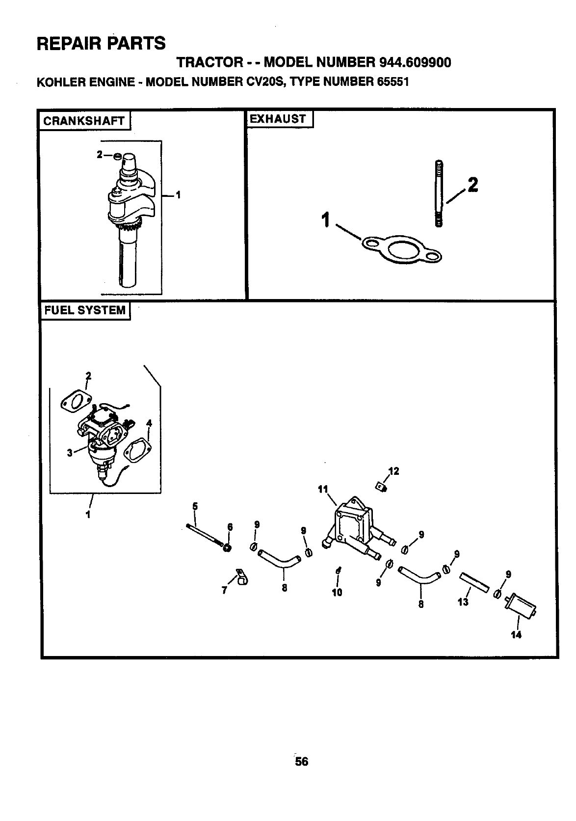
REPAIR PARTS
TRACTOR -- MODEL NUMBER 944.609900
KOHLER ENGINE - MODEL NUMBER CV20S, TYPE NUMBER65551
CRANKSHAFT___I EXHAUST [
2 1 1/2
4_
FUEL SYSTEM [ "
/
1
7 8
11\
o
I
to
2
/9
14
S6
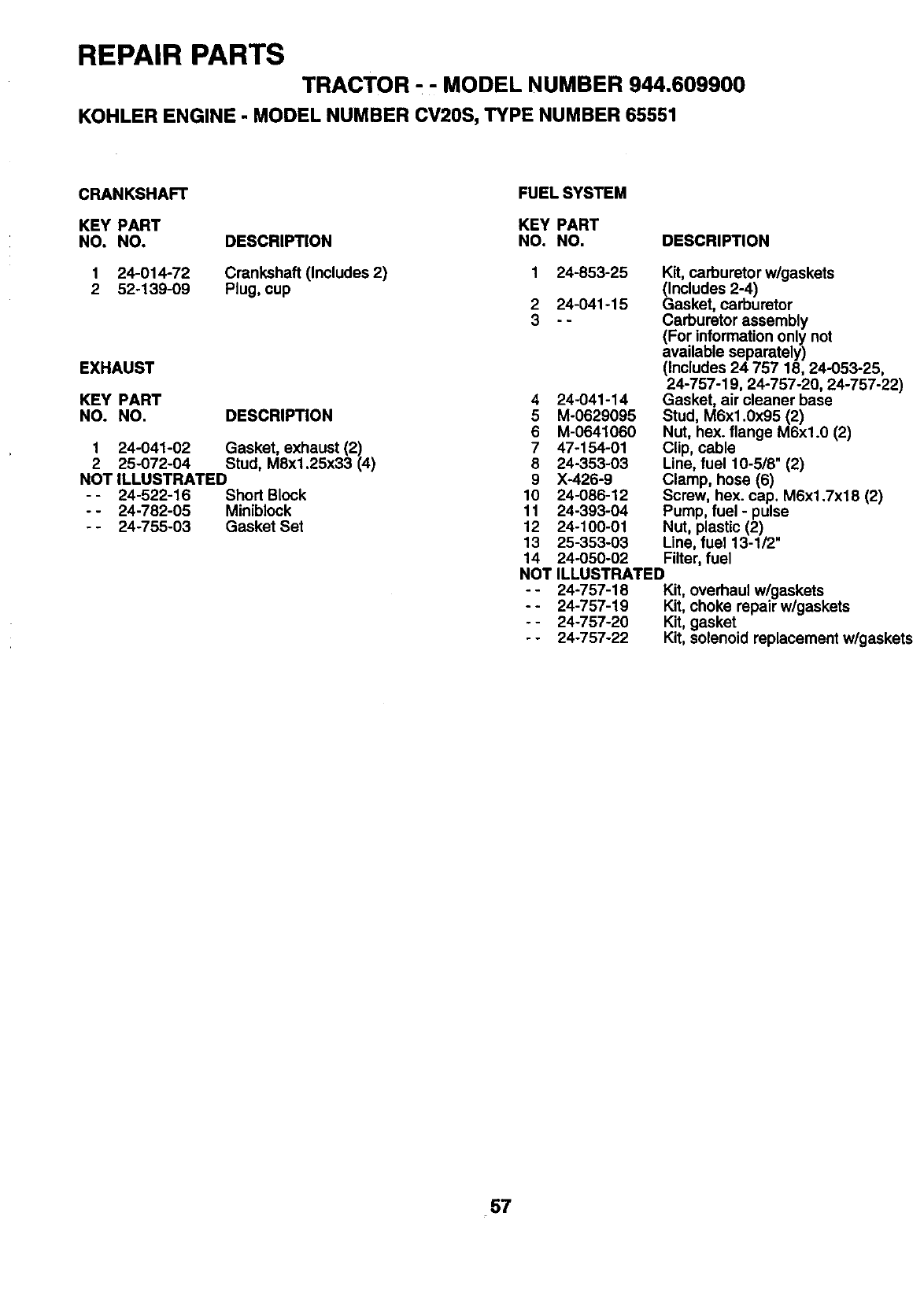
REPAIR PARTS
TRACTOR, -MODEL NUMBER 944.609900
KOHLER ENGINE - MODEL NUMBER CV20S, TYPE NUMBER 65551
CRANKSHAFT
KEY PART
NO, NO. DESCRIPTION
1 24-014-72 Crankshaft (Includes 2)
2 52-139-09 Plug, cup
EXHAUST
KEY PART
NO. NO. DESCRIPTION
1 24-041-02 Gasket, exhaust (2)
2 25-072-04 Stud, M8x1.25x33 (4)
NOT ILLUSTRATED
- - 24-522-16 Short Block
- - 24-782-05 Miniblock
- - 24-755-03 Gasket Set
FUEL SYSTEM
KEY PART
NO. NO. DESCRIPTION
124-853-25 Kit, carburetor w/gaskets
(Includes 2-4)
2 24-041-15 Gasket, carburetor
3 - - Carburetor assembly
(For information only not
available separately)
(Includes 24 757 18, 24-053-25,
24-757-19, 24-757-20, 24-757-22)
4 24-041-14 Gasket, air cleaner base
5 M-0629095 Stud, M6x1.0x95 (2)
6 M-0641060 Nut, hex. flange M6xl.0 (2)
7 47-154-01 Clip, cable
8 24-353-03 Line, fuel 10-518" (2)
9 X-426-9 Clamp, hose (6)
10 24-086-12 Screw, hex. cap. M6x1.7x18 (2)
11 24-393-04 Pump, fuel - pulse
12 24-100-01 Nut, plastic (2)
13 25-353-03 Line, fuel 13-1/2"
14 24-050-02 Filter, fuel
NOT ILLUSTRATED
- - 24-757-18 Kit, overhaul w/gaskets
- - 24-757-19 Kit, choke repair w/gaskets
--24-757-20 Kit, gasket
--24-757-22 Kit, solenoid replacement w/gaskets
57

SERVICE NOTES
58
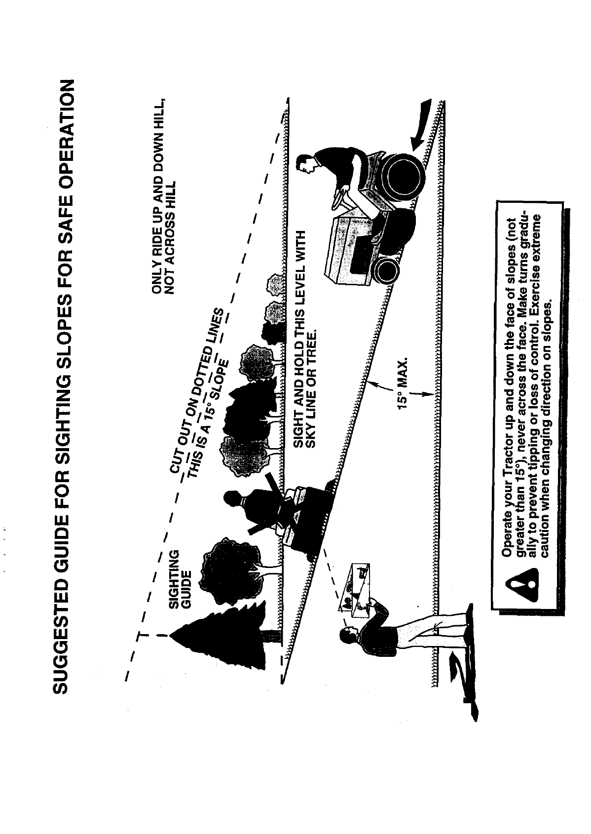
,_o_
m.., 0,_
_1_,1 ,,,_ ,

SEARS
OWNER'S
MANUAL
MODEL NO.
944.609900
HOW TO ORDER
REPAIR PARTS
[RI:IFTSMI:IN
20.0 HP
ELECTRIC START
46" MOWER
AUTOMATIC
GARDEN TRACTOR
Each tractor has its own model number. Each engine has its own model
number.
The model number for your tractor will be found on the model plate
located under the seat.
The model number for your engine will be found on the blower housing of
the engine.
All parts listed herein may be ordered from any Sears Canada, Inc. Ser-
vice Centre/Department and most Retail Stores.
WHEN ORDERING REPAIR PARTS, ALWAYS GIVE THE FOLLOWING
INFORMATION:
• PRODUCT - TRACTOR
•MODEL NUMBER -944.609900
•ENGINE MODEL NUMBER - CV20S, TYPE NUMBER 65551
•PART NUMBER
•PART DESCRIPTION
Your Sears memhandise has added value when you consider Sears has
service units nationwide staffed with Sears trained technicians.., profes-
sional technicians speciticallytrained to insure that we meet our pledge to
you, we service what we sell.
NEED A PART?
SEARS HAS ACCESS TO OVER 800,000 PARTS
WHETHER IT'S A SPARK PLUG OR LAWNMOWER BLADE.
SEARS PARTS AND SERVICE CAN SUPPLY YOU WITH
TOP QUALITY REPAIR PARTS FOR ALL YOUR PRODUCTS.
JUST CALL ONE OF THE FOLLOWING NUMBERS TO PLACE YOUR
ORDER. IF CALLING LOCALLY:
Regina -566-5124 Montreal - 333-5740
Toronto -744-4900 Halifax - 454-2444
Kitchener - 894-7590 Ottawa -738-4440
Vancouver -420-8211
ALL OTHER AREAS CALL 1-800-665-4455
Sears Canada, Inc., Toronto, Ontario M5B 2B8
PRINTED IN U.S.A.
168288 01.05.99 SV
