Craftsman C950 52948 0 User Manual SNOW THROWER Manuals And Guides 1101263L
User Manual: Craftsman C950-52948-0 C950-52948-0 CRAFTSMAN SNOW THROWER - Manuals and Guides View the owners manual for your CRAFTSMAN SNOW THROWER #C950529480. Home:Lawn & Garden Parts:Craftsman Parts:Craftsman SNOW THROWER Manual
Open the PDF directly: View PDF ![]() .
.
Page Count: 112 [warning: Documents this large are best viewed by clicking the View PDF Link!]
Model
C950-52948-0
13.5 T.P. 30 inch
CAUTION:
You must read and
understand this owner's
manual before operating
unit,
Serial No.
AL TAGE
SNOW TH ROWE R
Sears Canada inc., Toronto, Ontario M5B 2C3
Visit our Craftsman website: www.sears.ca/craftsman
173817O
Revision-
Rev.Date07/2009
Thankyou for purchasingthis quality-built Craftsman snow thrower. We're pleasedthat you've placedyour confidence inthe Craftsman
brand. When operated and maintained according to the instructionsinthis manual,your Craftsman product will provide many years of
dependableservice.
This manual contains safety information to makeyou aware of the hazardsand risks associatedwith snow throwers and how to avoid
them. This snow thrower is designed and intendedonly for snow throwing and is not intendedfor any other purpose, it is important that
you readand understandthese instructions throroughiy before attempting to start or operatethis equipment. This snow thrower
requires final assembly before use. Referto the Assembly section for instructions on final assembly procedures. Follow the instruc-
tions completely. Save these instructionsfor future reference.
Snow Thrower:
Model Number
Revision
Serial Number
Engine:
Model Number
Revision
Serial Number
Date Purchased:
Store Where Purchased:
City:
Province:
Telephone:
NOTICE:Record this informationabout your snowthrowerso that youwiii be able to provideit in case of lossor theft.
TABLEOFCONTENTS
OPERATORSAFETY.................................................................................... 4
ASSEMBLY.............................................................................................. 10
TOOLSREQUIREDFORASSEMBLY..........................................................................................................10
CONTENTSOFSHiPPiNGCARTON..........................................................................................................10
PARTSBAGCONTENTS............................................................................................................................10
UNPACKING..............................................................................................................................................11
UPPERHANDLEANDCRANKASSEMBLY................................................................................................12
CHECKTHECABLES................................................................................................................................12
SETTHELENGTHOFTHECABLES..........................................................................................................12
SPEEDSELECTLEVERASSEMBLY..........................................................................................................13
SNOWCHUTEASSEMBLY........................................................................................................................14
FEATURESANDCONTROLS.......................................................................... 15
OPERATION............................................................................................. 17
BEFOREOPERATINGSNOWTHROWER................................................................................. 17
OPERATETHESNOWTHROWER..............................................................................................................17
STOPTHESNOWTHROWER....................................................................................................................18
TRACTIONLOCKPINS.............................................................................................................................18
CHECKTHEOIL(BEFORESTARTINGENGINE)........................................................................................18
FILLTHEFUELTANK................................................................................................................................19
STARTTHEENGINE..................................................................................................................................19
STOPTHEENGINE....................................................................................................................................20
CLEARA CLOGGEDDISCHARGECHUTE.................................................................................................21
OPERATINGTIPS......................................................................................................................................21
MAINTENANCE......................................................................................... 22
SERVICERECOMMENDATIONS...............................................................................................................22
LUBRICATEAUGERGEARBOX.................................................................................................................23
LUBRICATEAUGERSHAFTFiTTiNGS......................................................................................................23
LUBRICATECHUTEROTATIONGEAR.......................................................................................................23
ENGINEMAINTENANCE...........................................................................................................................24
CHANGETHESPARKPLUG......................................................................................................................25
ADJUSTSKIDHEIGHT..............................................................................................................................26
BELTADJUSTMENT..................................................................................................................................27
BELTGUIDEADJUSTMENT......................................................................................................................28
CHECKANDADJUSTTHECABLES..........................................................................................................28
AUGERSHEARPINREPLACEMENT.........................................................................................................30
CHECKTHETIRES.................................................................................................................. 30
STORAGE................................................................................................ 31
OFFSEASONSTORAGE............................................................................................................................31
LUBRICATEHEXSHAFTANDCHAINS.....................................................................................................31
REMOVEFROMSTORAGE........................................................................................................................31
TROUBLESHOOTING................................................................................... 32
WARRANTIES........................................................................................... 34
SPECIFICATIONS....................................................................................... 37
OPERATORSAFETY
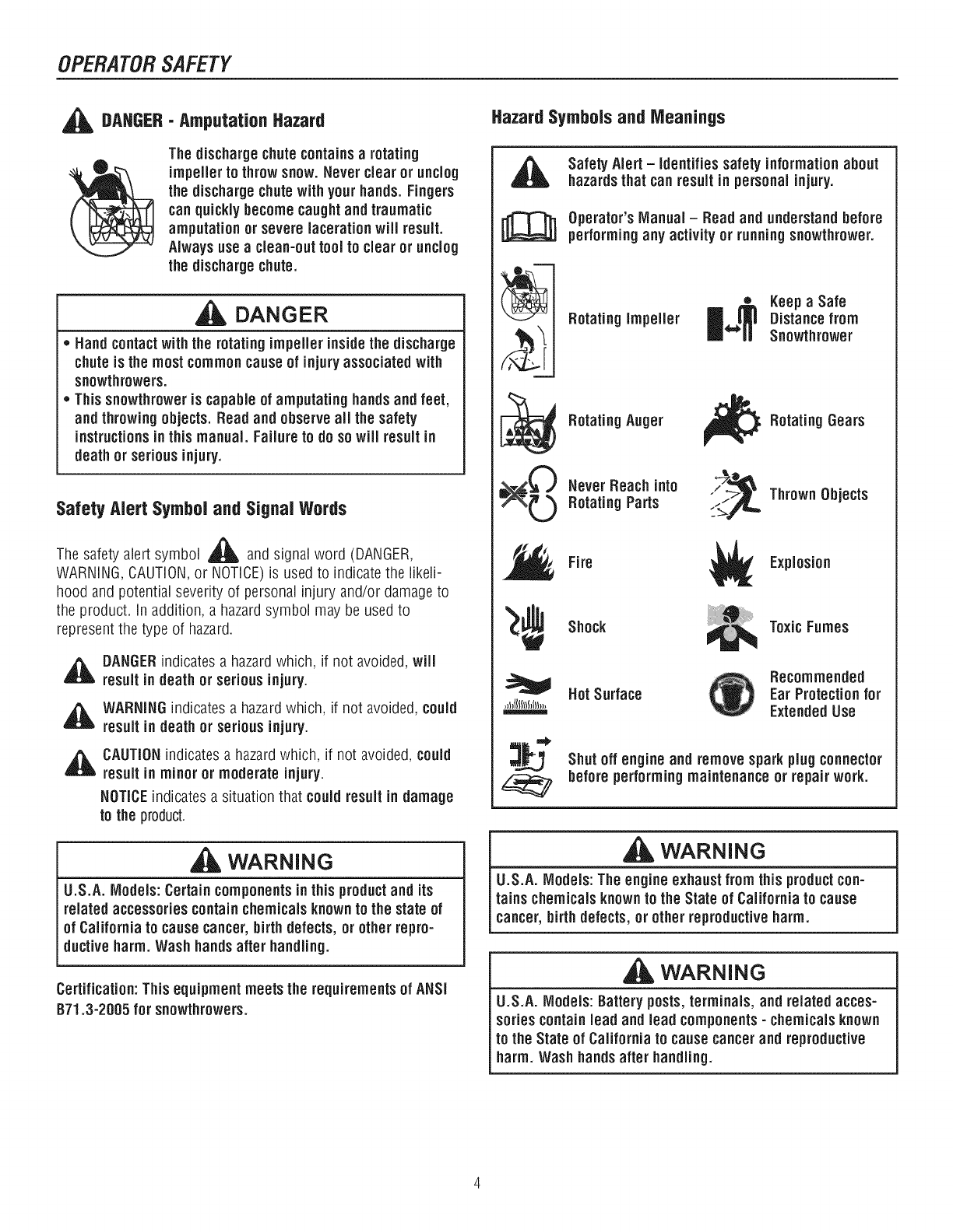
DAHGER- Amputation Hazard
The dischargechutecontainsarotating
impeller to throwsnow. Never clear or unclog
the dischargechutewith your hands.Fingers
can quickly becomecaughtand traumatic
amputation or severe lacerationwill result.
Alwaysuseaclean-outtool to clear or unclog
the dischargechute.
DANGER
,, Hand contactwith the rotating impeller insidethe discharge
chuteis the most commoncause of injury associated with
snowthrowers.
* Thissnowthroweris capable of amputating handsand feet,
and throwingobjects. Read and observeall the safety
instructionsin this manual. Failure to do so will result in
deathor serious injury.
SafetyAlert Symboland SignalWords
A
The safety alert symbol _ and signal word (DANGER,
WARNING,CAUTION,or NOTICE)is used to indicate the likeli-
hood and potential severity of personal injuryand/or damage to
the product. In addition, a hazardsymbol may be used to
represent the type of hazard.
_ ANGERindicates a hazard which, if not avoided,will
result in death or serious injury.
,_ WARNINGindicates a hazardwhich, if not avoided, could
result in death or serious injury.
_ AUTIONindicates a hazardwhich, if not avoided,could
result in minor or moderate injury.
NOTICEindicates a situation that couldresult in damage
to the product.
WARNING
U.S.A. Models: Certain componentsinthis productand its
related accessories containchemicalsknown to the state of
of California to causecancer,birth defects, or other repro-
ductive harm. Wash hands after handling.
Certification: This equipmentmeets the requirements of ANSI
B71.3-2005 for snowthrowers.
Hazard Symbols and Meanings
t_
f _'%£,,,,,_1
Safety Alert -identifies safety informationabout
hazardsthat can result in personal injury.
Operator's IVlanual- Read and understand before
performingany activity or running snowthrower.
Rotating Impeller
_ Rotating Auger
_(_ Never Reach into
L) Rotating Parts
•Keepa Safe
Distance from
Snowthrower
_ Rotating Gears
t_,_ Thrown Objects
Fire Explosion
Shock ToxicFumes
HotSurface Recommended
Ear Protection for
ExtendedUse
Shut off engine and remove sparkplug connector
beforeperformingmaintenance or repairwork.
WARNING
U.S.A. Models: The engine exhaust from this productcon-
rains chemicalsknown to the State of California to cause
cancer, birthdefects, or other reproductiveharm.
WARNING
U.S.A. Models: Batteryposts,terminals, and related acces-
sories containlead and lead components- chemicalsknown
to the State of California to causecancerand reproductive
harm. Wash hands after handling.
OPERATORSAFETY
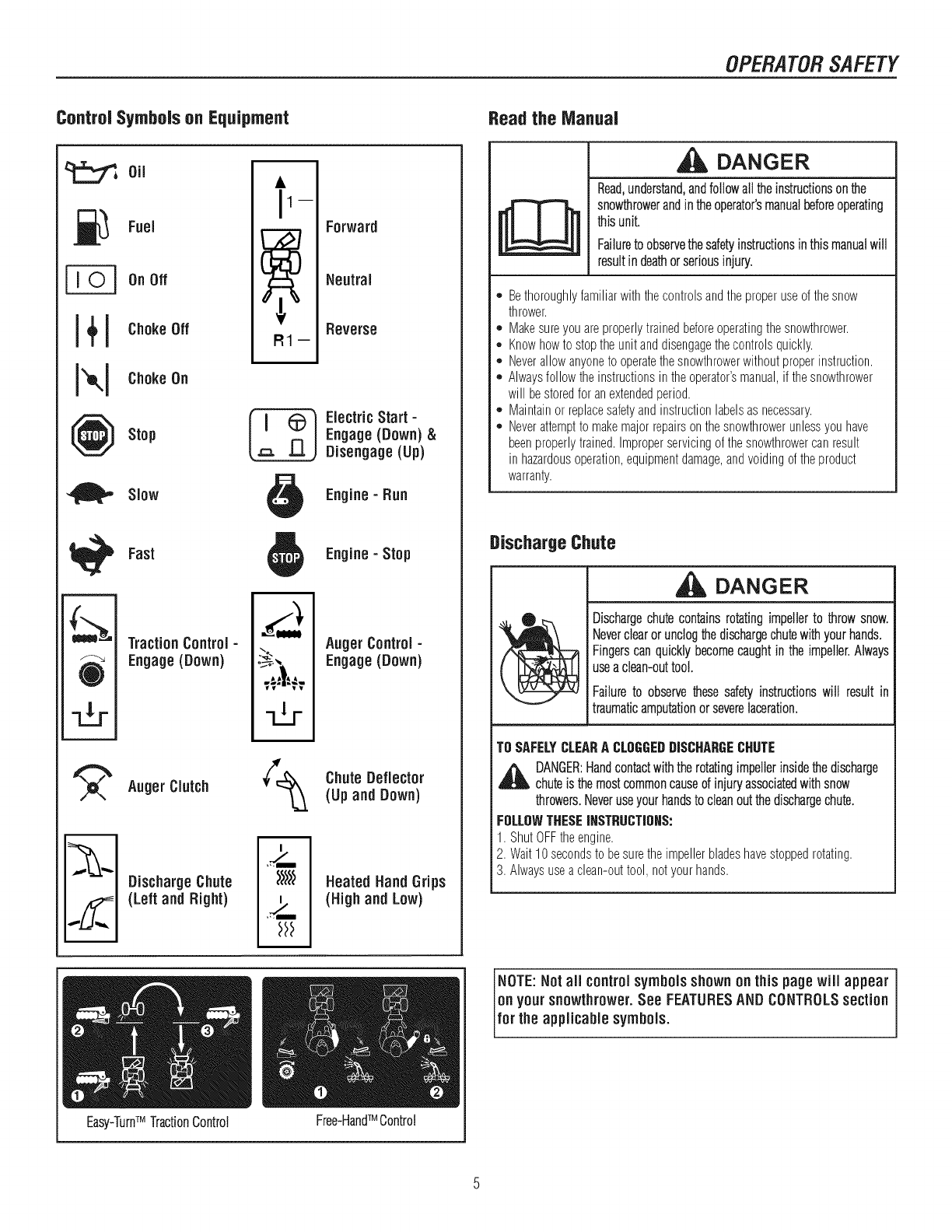
Control Symbols on Equipment
._ Fuel
On Off
J+J Choke 0ff
NI °"°"°°°
Stop
Slow
R1--
Forward
Neutral
Reverse
ElectricStart -
Engage(Down) &
Disengage (Up)
Engine- Run
w
O
Fast
TractionControl -
Engage(Down)
AugerClutch
[_ ischargeChute
(Left and Right)
='_'-m
-dr
Engine -Stop
Auger Control -
Engage(Down)
¢_ Chute Deflector
(Up and Down)
Heated HandGrips
(High and Low)
Easy-TurnTM TractionControl TM
Free-HandControl
Readthe Manual
[
DANGER
Read,understand,andfollowalltheinstructionsonthe
snowthrowerandintheoperator'smanualbeforeoperating
thisunit.
Failuretoobservethesafetyinstructionsinthismanualwill
resultindeathorseriousinjury.
,, Bethoroughlyfamiliarwith thecontrolsandtheproperuseofthesnow
thrower.
,, Makesureyouareproperlytrainedbeforeoperatingthesnowthrower.
,, Knowhowto stoptheunit anddisengagethecontrolsquickly.
,, Neverallowanyoneto operatethesnowthrowerwithoutproperinstruction.
,, Alwaysfollow theinstructionsin theoperator'smanual,if thesnowthrower
will bestoredfor anextendedperiod.
,, Maintainor replacesafetyandinstructionlabelsasnecessary.
,, Neverattemptto makemajorrepairson thesnowthrowerunlessyouhave
beenproperlytrained.Improperservicingof thesnowthrowercan result
in hazardousoperation,equipmentdamage,andvoidingof theproduct
warranty.
Discharge Chute
DANGER
Dischargechutecontainsrotatingimpellerto throwsnow.
Neverclearorunclogthedischargechutewithyourhands.
Fingerscanquicklybecomecaughtintheimpeller.Always
useaclean-outtool.
Failureto observethesesafetyinstructionswill resultin
traumaticamputationorseverelaceration.
TOSAFELYCLEARACLOGGEDDISCHARGECHUTE
,_ DANGER:Handcontactwiththerotatingimpellerinsidethedischarge
chuteis themostcommoncauseof injuryassociatedwithsnow
throwers.Neveruseyourhandstocleanoutthedischargechute.
FOLLOWTHESEIHSTRUCTIOHS:
1 ShutOFFtheengine
2 Wait10secondstobesuretheimpellerbladeshavestoppedrotating
3.Alwaysuseaclean-outtool,notyourhands.
NOTE:Not all controlsymbols shownon this pagewill appear
on your snowthrower.See FEATURESANDCONTROLSsection
for the applicable symbols.
OPERATORSAFETY
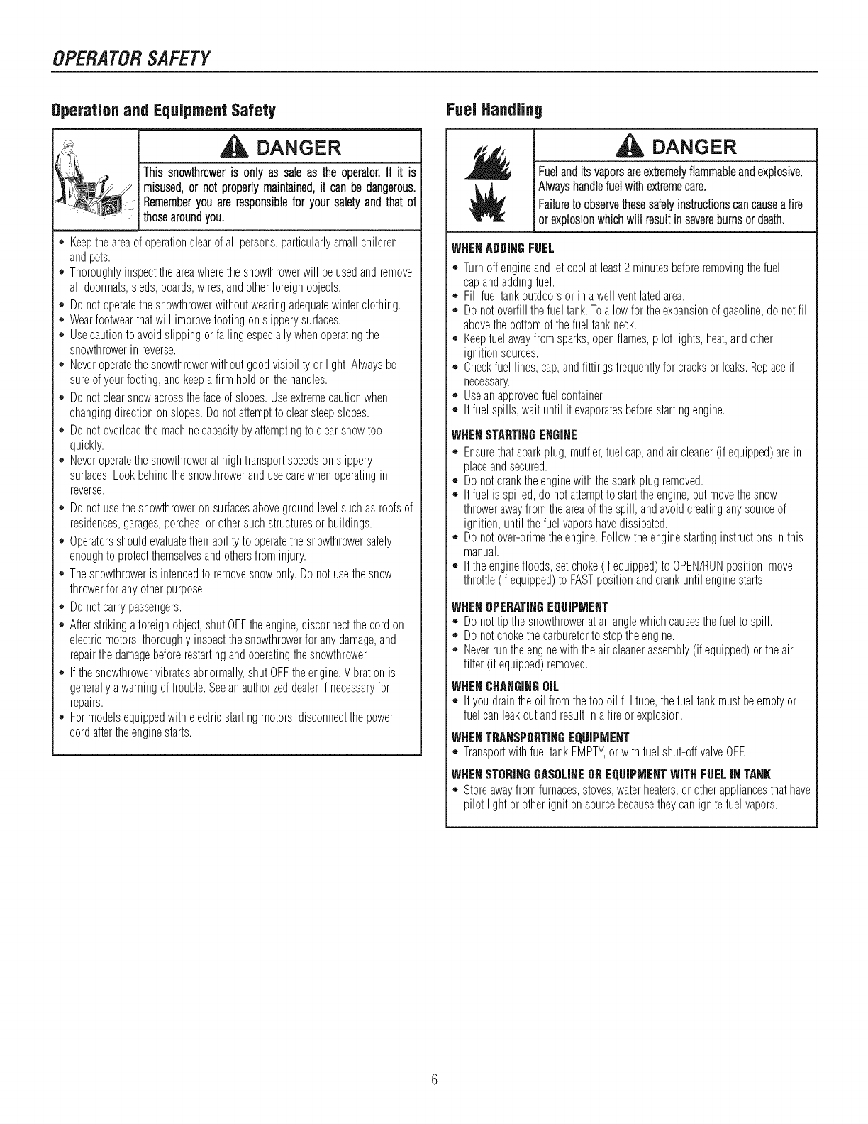
Operationand EquipmentSafety
GDANGER
Thissnowthroweris only assafeas theoperator.If it is
misused,or notproperlymaintained,it canbedangerous.
i Rememberyouareresponsiblefor yoursafetyandthatof
thosearoundyou.
*Keeptheareaof operationclearof all persons,particularlysmallchildren
andpets.
. Thoroughlyinspecttheareawherethesnowthrowerwill beusedand remove
all doormats,sleds,boards,wires,andotherforeignobjects.
. Do notoperatethesnowthrowerwithoutwearingadequatewinterclothing.
. Wearfootwearthatwill improvefootingonslipperysurfaces.
. Usecautionto avoidslippingorfalling especiallywhenoperatingthe
snowthrowerin reverse.
*, Neveroperatethesnowthrowerwithoutgoodvisibility orlight.Alwaysbe
sureof yourfooting,andkeepafirm hold onthehandles.
. Do notclearsnowacrossthefaceof slopes.Useextremecautionwhen
changingdirectiononslopes.Donotattemptto clearsteepslopes.
. Do notoverloadthemachinecapacitybyattemptingto clearsnowtoo
quickly.
. Neveroperatethesnowthrowerat hightransportspeedson slippery
surfaces.Lookbehindthesnowthrowerandusecarewhenoperatingin
reverse.
*Do notusethesnowthroweronsurfacesabovegroundlevelsuchas roofsof
residences,garages,porches,or othersuchstructuresor buildings.
. Operatorsshouldevaluatetheirabilityto operatethesnowthrowersafely
enoughto protectthemselvesandothersfrominjury.
. Thesnowthroweris intendedto removesnowonly.Do not usethesnow
throwerforanyotherpurpose.
. Do notcarrypassengers.
*, Afterstrikinga foreignobject,shutOFFtheengine,disconnectthecordon
electricmotors,thoroughlyinspectthesnowthrowerforanydamage,and
repairthedamagebeforerestartingandoperatingthesnowthrower.
*, If thesnowthrowervibratesabnormally,shutOFFtheengine.Vibrationis
generallyawarningof trouble.Seeanauthorizeddealerif necessaryfor
repairs.
. Formodelsequippedwithelectricstartingmotors,disconnectthepower
cordaftertheenginestarts.
FuelHandling
DANGER
Fuelanditsvaporsareextremelyflammableandexplosive,
Alwayshandlefuel withextremecare.
Failureto observethesesafetyinstructionscancausea fire
Ior explosionwhichwill resultin severeburnsor death.
WHENADDINGFUEL
*Turnoff engineandletcool at least2 minutesbeforeremovingthefuel
capandaddingfuel.
o Fill fueltankoutdoorsor ina wellventilatedarea.
o Donotoverfillthefuel tank.Toallowfor the expansionof gasoline,do notfill
abovethe bottomof thefuel tankneck.
o Keepfuel awayfromsparks,openflames,pilot lights,heat,andother
ignitionsources.
o Checkfuel lines,cap,andfittingsfrequentlyfor cracksor leaks.Replaceif
necessary.
o Useanapprovedfuelcontainer.
o If fuelspills, wait until it evaporatesbeforestartingengine.
WHENSTARTINGENGINE
*, Ensurethatsparkplug, muffler,fuelcap,andair cleaner(if equipped)are in
placeandsecured.
. Donotcranktheenginewiththesparkplug removed.
. If fuel isspilled,do not attemptto starttheengine,but movethesnow
throwerawayfrom theareaof thespill, andavoidcreatinganysourceof
ignition,until thefuelvaporshavedissipated.
*, Donotover-primetheengine.Followtheenginestartinginstructionsin this
manual.
. If theenginefloods,setchoke(if equipped)to OPEN/RUNposition,move
throttle(if equipped)to FASTpositionandcrankuntil enginestarts.
WHENOPERATINGEQUIPMENT
*Donottip thesnowthrowerat ananglewhichcausesthefuelto spill.
. Donotchokethecarburetorto stoptheengine.
. Neverruntheenginewiththeair cleanerassembly(if equipped)or theair
filter (if equipped)removed.
WHENCHANGINGOIL
*If youdraintheoilfrom thetopoil fill tube,thefueltankmustbeemptyor
fuelcanleakoutandresultin afire orexplosion.
IWNENTRANSPORTINGEQUIPMENT
*, TransportwithfueltankEMPTY,orwithfuelshut-offvalveOFE
I WNENSTORINGGASOLINEOREQUIPMENTWiTHFUELIN TANK
*, Storeawayfromfurnaces,stoves,waterheaters,or otherappliancesthathave
pilot light or otherignitionsourcebecausetheycan ignitefuelvapors.
OPERATORSAFETY
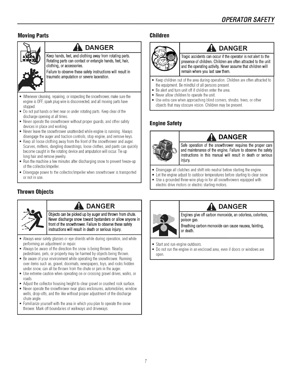
Moving Parts
DANGER
Keephands,feet,andclothingawayfromrotatingparts.
Rotatingpartscancontactorentanglehands,feet,hair,
clothing,oraccessories.
Failuretoobservethesesafetyinstructionswill resultin
traumaticamputationorseverelaceration.
*Whenevercleaning,repairing,or inspectingthesnowthrower,makesurethe
engineisOFF,sparkplugwireisdisconnected,andallmovingpartshave
stopped.
. Donotputhandsorfeetnearor underrotatingparts.Keepclearofthe
dischargeopeningat alltimes.
. Neveroperatethesnowthrowerwithoutproperguards,andothersafety
devicesin placeandworking.
. Neverleavethesnowthrowerunattendedwhileengineis running.Always
disengagetheaugerandtractioncontrols,stopengine,andremovekeys.
. Keepall looseclothingawayfrom thefrontof thesnowthrowerandauger.
Scarves,mittens,danglingdrawstrings,looseclothes,andpantscanquickly
becomecaughtin therotatingdeviceandamputationwill occur.Tieup
longhairandremovejewelry.
. Runthemachineafewminutesafterdischargingsnowto preventfreeze-up
of thecollector/impeller.
. Disengagepowerto the collector/impellerwhensnowthroweris transported
or notin use.
Thrown Objects
DANGER
Objectscanbepickedupbyaugerandthrownfromchute.
Neverdischargesnowtowardbystandersorallowanyonein
frontofthesnowthrower.Failureto observethesesafety
instructionswillresultindeathorseriousinjury.
*Alwayswearsafetyglassesor eyeshieldswhileduringoperation,andwhile
performinganadjustmentor repair.
,, Alwaysbeawareof thedirectionthe snowis beingthrown.Nearby
pedestrians,pets,or propertymaybeharmedby objectsbeingthrown.
,, Beawareof yourenvironmentwhileoperatingthesnowthrower.Running
overitemssuchas,gravel,doormats,newspapers,toys,androckshidden
undersnow,canall bethrownfromthechuteor jam intheauger.
,, Useextremecautionwhenoperatingon or crossinggraveldrives,walks,or
roads.
,, Adjustthecollectorhousingheightto cleargravelorcrushedrocksurface.
,, Neveroperatethesnowthrowernearglassenclosures,automobiles,window
wells,drop-otis,andthe likewithoutproperadjustmentof thedischarge
chuteangle.
,, Familiarizeyourselfwiththeareain whichyouplanto operatethesnow
thrower.Markoffboundariesof walkwaysanddriveways.
Children
DANGER
Tragicaccidentscanoccurif theoperatoris notalertto the
presenceofchildren,Childrenareoftenattractedtotheunit
andtheoperatingactivity.Neverassumethatchildrenwill
remainwhereyoulastsawthem.
o Keepchildrenout of theareaduringoperation.Childrenareoftenattractedto
theequipment.Bemindfulof all personspresent.
,, Bealertandturnunit off if childrenenterthearea.
,, Neverallowchildrento operatetheunit.
,, Useextracarewhenapproachingblindcorners,shrubs,trees,or other
objectsthatmayobscurevision.Childrenmaybepresent.
Engine Safety
DANGER
Safeoperaiionoithe nowihiowerr<u ie ihepiopercare
and maintenanceof theengine.Failureto observethesafety
instructionsin this manualwill result in deathor serious
injury.
,, Disengageallclutchesandshift into neutralbeforestartingtheengine.
,, Lettheengineadjustto outdoortemperaturesbeforestartingto clearsnow.
,, Usea groundedthree-wireplug-infor all snowthrowersequippedwith
electricdrivemotorsor electricstartingmotors.
DANGER
Enginesgiveoffcarbonmonoxide,an odorless,colorless,
poisongas.
Breathingcarbonmonoxidecancausenausea,fainting,
or death.
o Startandrun engineoutdoors.
o Donotruntheenginein anenclosedarea,evenif doorsorwindowsare
open.
OPERATORSAFETY
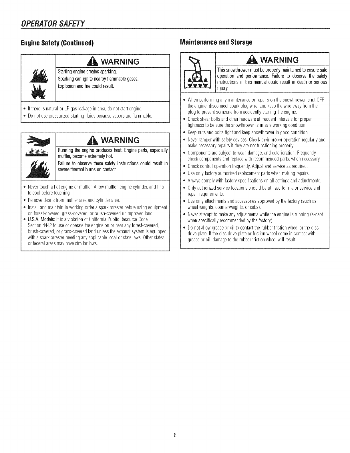
Engine Safety (Continued)
WARNING
jStartingenginecreatessparking.
jSparkingcanignitenearbyflammablegases.
Explosionandfire couldresult.
*Ifthereisnaturalor LPgasleakagein area,donotstartengine.
,, Donotusepressurizedstartingfluids becausevaporsareflammable.
WARNING
,_l_((l(I}(_(ll,, Runningthe engineproducesheat.Engineparts,especially
i muffler,becomeextremelyhot.
Failureto observethesesafetyinstructionscould result in
i severethermalburnsoncontact.
*Nevertoucha hotengineormuffler.Allow muffler,enginecylinder,andfins
to coolbeforetouching.
,, Removedebrisfrommufflerareaandcylinderarea.
,, Installandmaintaininworkingorderasparkarresterbeforeusingequipment
onforest-covered,grass-covered,orbrush-coveredunimprovedland.
,, U.S.A.Models:It is a violationof CaliforniaPublicResourceCode
Section4442to useor operatetheengineonor nearanyforest-covered,
brush-covered,or grass-coveredlandunlesstheexhaustsystemis equipped
with asparkarrestermeetingany applicablelocalor statelaws.Otherstates
orfederalareasmayhavesimilarlaws.
Maintenanceand Storage
WARNING
Thissnowthrowermustbeproperlymaintainedto ensuresafe
operationand performance.Failure to observethe safety
instructionsin this manualcould resultin deathor serious
injury.
*Whenperforminganymaintenanceor repairsonthesnowthrower,shutOFF
theengine,disconnectsparkplugwire,andkeepthewire awayfrom the
plugto preventsomeonefrom accidentlystartingtheengine.
,, Checkshearboltsandotherhardwareatfrequentintervalsfor proper
tightnessto besurethesnowthroweris in safeworkingcondition.
,, Keepnutsandboltstight andkeepsnowthrowerin goodcondition.
,, Nevertamperwith safetydevices.Checktheir properoperationregularlyand
makenecessaryrepairsif theyarenotfunctioningproperly.
,, Componentsaresubjectto wear,damage,anddeterioration.Frequently
checkcomponentsandreplacewith recommendedparts,whennecessary.
,, Checkcontroloperationfrequently.Adjustandserviceas required.
,, Useonly factoryauthorizedreplacementpartswhenmakingrepairs.
,, Alwayscomplywithfactoryspecificationsonall settingsandadjustments.
,, Onlyauthorizedservicelocationsshouldbeutilizedfor majorserviceand
repairrequirements.
,, Useonly attachmentsandaccessoriesapprovedby thefactory(suchas
wheelweights,counterweights,or cabs).
,, Neverattemptto makeanyadjustmentswhiletheengineis running(except
whenspecificallyrecommendedbythefactory).
,, Donotallowgreaseor oilto contacttherubberfrictionwheelor thedisc
driveplate.If thediscdriveplateorfrictionwheelcomein contactwith
greaseoroil, damageto therubberfrictionwheelwill result.
OPERATORSAFETY
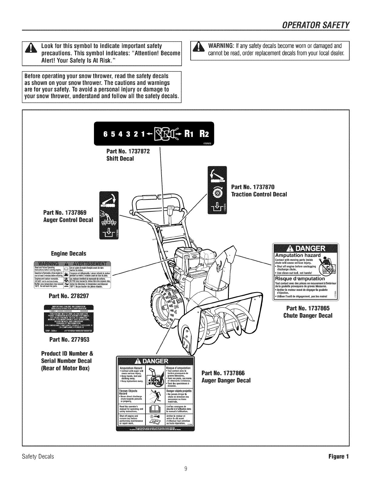
Lookfor this symbol to indicateimportantsafety
precautions.This symbolindicates:"Attention! Become
Alert! Your Safety is At Risk."
Before operatingyour snow thrower, readthe safetydecals
as shown on yoursnowthrower. The cautionsand warnings
are for yoursafety. To avoid a personalinjuryor damageto
yoursnow thrower, understandand fo ow al the safety decals.
Part Ho. 1737872 I
I
Shift Decal
_ARNING:Ifanysafetydecalsbecomewornor damagedand J
cannotberead,orderreplacementdecalsfromyourlocaldealer. I
Part He. 1737870
TractionControlDecal
Part He. 1737868
AugerControJDecal
EngineDecals Amputation hazard
Contact with moving parts inside
chute wiJJ Cause serious injury,
Shut off engine before unclogging
discharge chute.
Use clean-out tool, not hands!
Risque d,amputation
de la gouiotteprovoqueradegraveshiessures.
ArrOterJemoteuravantded_gager la gouiotte
d'_jection.
=UtiJiserI'outiJded_gagement,pas Jesmains!
Part Ho. 1737865
ChuteDanger Decal
Part Ho. 277953
ProductID Humber&
Serial Humber Decal
(Rearof Motor Box) Amputation Hazard _ Risque d'amputaRon
-Ce_t_t with a_her w_ll _ • Tout contact avec la
cause seri{}es injury, tafldre provoqeera de
•Eeep hands, leer and graves hlessures.
_lothing away. • Tenir vos plods, vos mares
•Keep hys_an{Jers away. et vgtemen_s _ _is_ance.
°Tenh les spect_teurs
dislance.
Thrown Objects i_ Danger objets p_ojet_s
Hazard . _e j_ma_s d_r_er _a
=Heve_ direct ffischarge chute en dire_tio_ des
chute towards persons pe_sonnes oubiefls
_r proper_y, matdtiels.
Read the _perator's _ Lireiles co_s_es de
manual _or operating and s_r._ritdet d'_tiiisation duns
surely instructions, le manuel _r_iJ_s_io_.
Shut off engine a_d _-_ _,_ Arrg_er le moteur et
remove key before retirer la cld avant
pertorming maintenance _ d'e+fect_e_ t_ot e_tretien
or repair work. _ou toute tdparation. ,,,_,_
Part Ho. 1737866
AugerDanger Decal
Safety Decals Figure I
ASSEMBLY
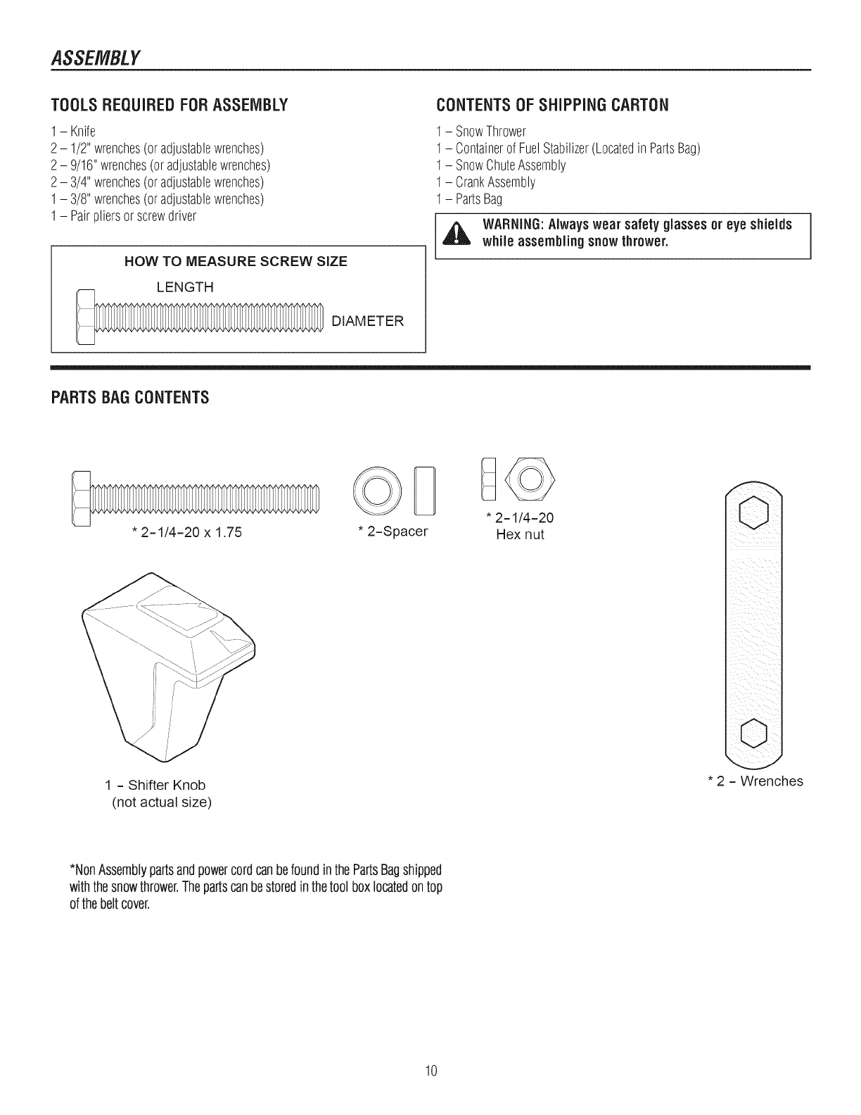
TOOLSREQUIREDFORASSEMBLY
1- Knife
2- 1/2"wrenches(oradjustablewrenches)
2- 9/16"wrenches(oradjustablewrenches)
2- 3/4"wrenches(oradjustablewrenches)
1- 3/8"wrenches(oradjustablewrenches)
1- Pairpliersorscrewdriver
HOW TO MEASURE SCREW SiZE
LENGTH
DIAMETER
CONTENTSOF SHiPPiNGCARTON
1- SnowThrower
1- Containerof FuelStabilizer(Locatedin PartsBag)
1- SnowChuteAssembly
1- CrankAssembly
1- PartsBag
WARNING:Alwayswear safety glasses or eye shields
while assembling snow thrower. I
PARTSBAGCONTENTS
* 2-1/4=20 x 1.75
1 - Shifter Knob
(not actual size)
* 2=Spacer * 2-1/4=20
Hex nut
* 2 = Wrenches
*NonAssemblypartsandpowercordcanbefoundinthe PartsBagshipped
withthesnowthrower.Thepartscanbestoredinthetool boxlocatedontop
of thebeltcover.
10
ASSEMBLY
NOTE:Referenceto rightandlefthandsideof thesnowthroweris fromthe
operator'spositionatthe handle.
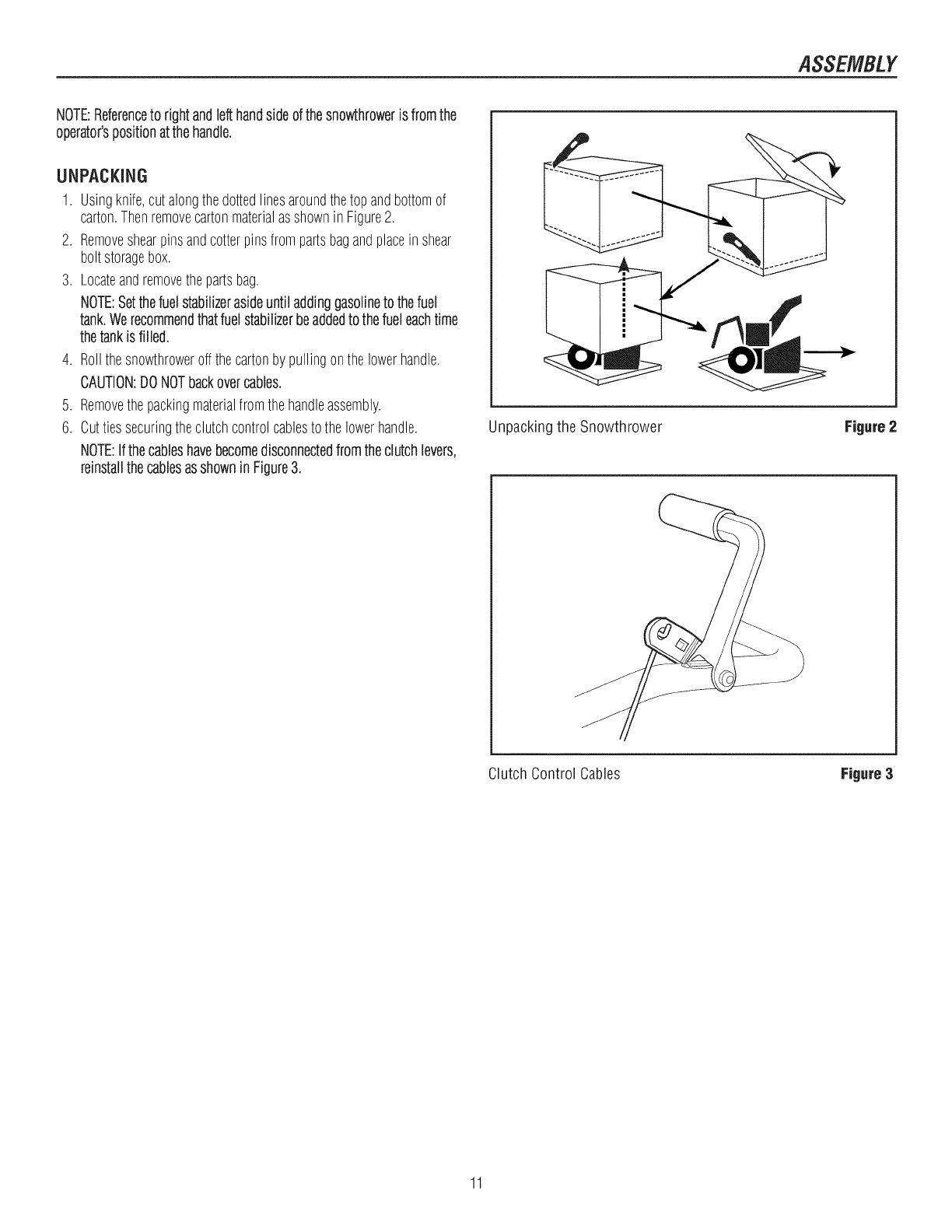
UNPACKING
1. Usingknife,cutalongthedottedlinesaroundthetop andbottomof
carton.Thenremovecartonmaterialasshownin Figure2.
2. Removeshearpinsandcotterpinsfrompartsbagandplacein shear
boltstoragebox.
3. Locateandremovethepartsbag.
NOTE:Setthefuelstabilizerasideuntiladdinggasolineto thefuel
tank.Werecommendthatfuel stabilizerbeaddedto thefueleachtime
thetankis filled.
4. Rollthesnowthroweroffthecartonby pullingonthelowerhandle.
CAUTION:DONOTbackovercables.
5. Removethepackingmaterialfromthehandleassembly.
6. Cuttiessecuringtheclutchcontrolcablesto the lowerhandle.
NOTE:Ifthecableshavebecomedisconnectedfromtheclutchlevers,
reinstallthecablesasshowninFigure3.
Unpackingthe Snowthrower Figure 2
Clutch Control Cables Figure3
11
ASSEMBLY
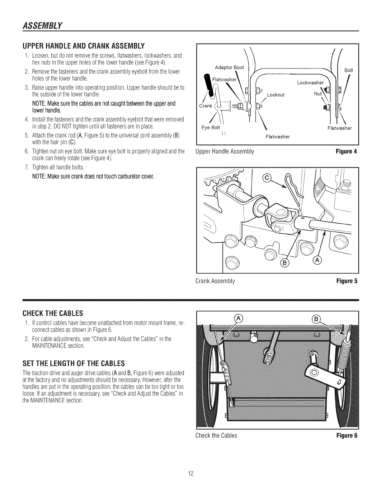
UPPERHANDLEANDCRANKASSEMBLY
1. Loosen,butdonot removethescrews,flatwashers,Iockwashers,and
hexnutsin theupperholesof thelowerhandle(seeFigure4).
2. Removethefastenersandthecrankassemblyeyeboltfromthelower
holesofthe lowerhandle.
3. Raiseupperhandleintooperatingposition.Upperhandleshouldbeto
theoutsideof thelowerhandle.
NOTE:Makesurethecablesarenotcaughtbetweentheupperand
lowerhandle.
4. Installthefastenersandthecrankassemblyeyeboltthatwereremoved
instep2. DONOTtightenuntil allfastenersare in place.
5. Attachthecrankrod(A, Figure5)to theuniversaljointassembly(B)
withthehairpin(C).
6. Tightennutoneyebolt.Makesureeyebolt is properlyalignedandthe
crankcanfreelyrotate(seeFigure4).
7. Tightenall handlebolts.
NOTE:Makesurecrankdoesnottouchcarburetorcover.
Adaptor Boot
Eye Bolt
Locknut
_/
\
Flatwasher
_I ;olt
.oc w shT !
l!lat!!her
Upper HandleAssembly Figure4
//
CrankAssembly Figure5
CHECKTHECABLES
1. Ifcontrolcableshavebecomeunattachedfrommotormountframe,re-
connectcablesasshownin Figure6.
2. Forcableadjustments,see"CheckandAdjusttheCables"inthe
MAINTENANCEsection.
SET THE LENGTH OF THE CABLES
Thetractiondriveandaugerdrivecables(AandB, Figure6) wereadjusted
atthefactoryandnoadjustmentsshouldbenecessary.However,afterthe
handlesareput intheoperatingposition,thecablescanbetootightortoo
loose.Ifanadjustmentis necessary,see"CheckandAdjusttheCables"in
theMAINTENANCEsection.
Checkthe Cables
12
Figure6

ASSEMBLY
SPEED SELECT LEVER ASSEMBLY
1. Cutplastictie(A,Figure7) securingspeedselectleverassembly(B)
to theshifterbracket(C).
2. RemoveIocknut(A, Figure8),washer(B),spring(C),andbolt (D).
NOTE:Viewis fromright sideof unit standingin operator'sposition.
3. Positionspeedselectorleverassemblyas shownin Figure9.
4. Reinstallbolt(D,Figure8), spring(C),washer(B)andIocknut(A).
5. TightenIocknutuntil1/8 to 3/16 inchof theboltthreadsprotrudepast
the Iocknut.
6. Threadthe3/8-16" hexjamnut(E)ontothelever(F) untilthenut
reachestheendof thethread.
7. Threadthe plasticknob(G)asfaras possibleandensurethattheknob
pointsforward.
8. Tightenthe3/8-16"hexjamnutagainsttheknobsecurely.
9. Moveshifterthroughall speedsto ensurepropertensionofthespring.
Ifshifterleversticksin anyof thenotches,loosenIocknut1/2 turnata
timeuntilshifterlevermovesmorefreely.
Shifter Handle
1/8to3/8inchof
expostedthread
Figure 8
Shifter Bracket
Control Panel
Shift Lever and Bracket Figure7 Control Paneland Shifter Bracket Figure 9
13
ASSEMBLY
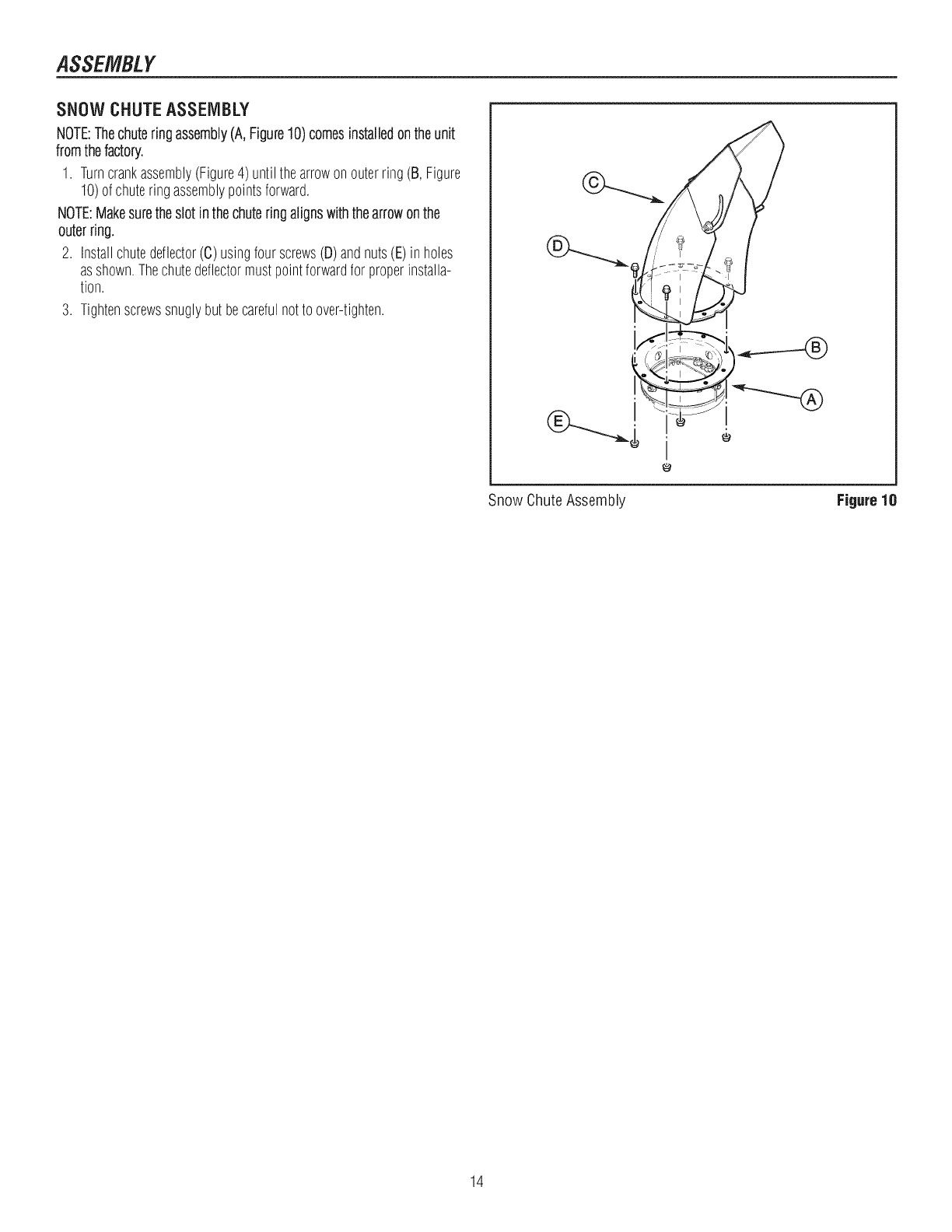
SNOW CHUTEASSEMBLY
NOTE:Thechuteringassembly(A,Figure10)comesinstalledontheunit
fromthefactory.
1. Turncrankassembly(Figure4) untilthearrowonouterring(B, Figure
10)of chuteringassemblypointsforward.
NOTE:Makesuretheslot inthechuteringalignswiththearrowonthe
outerring.
2. Installchutedeflector(C) usingfourscrews(D)andnuts(E)in holes
asshown.Thechutedeflectormustpointforwardfor properinstalla-
tion.
3. Tightenscrewssnuglybutbecarefulnotto over-tighten.
Snow ChuteAssembly Figure 18
14
FEATURESANDCONTROL$
®(
©
®
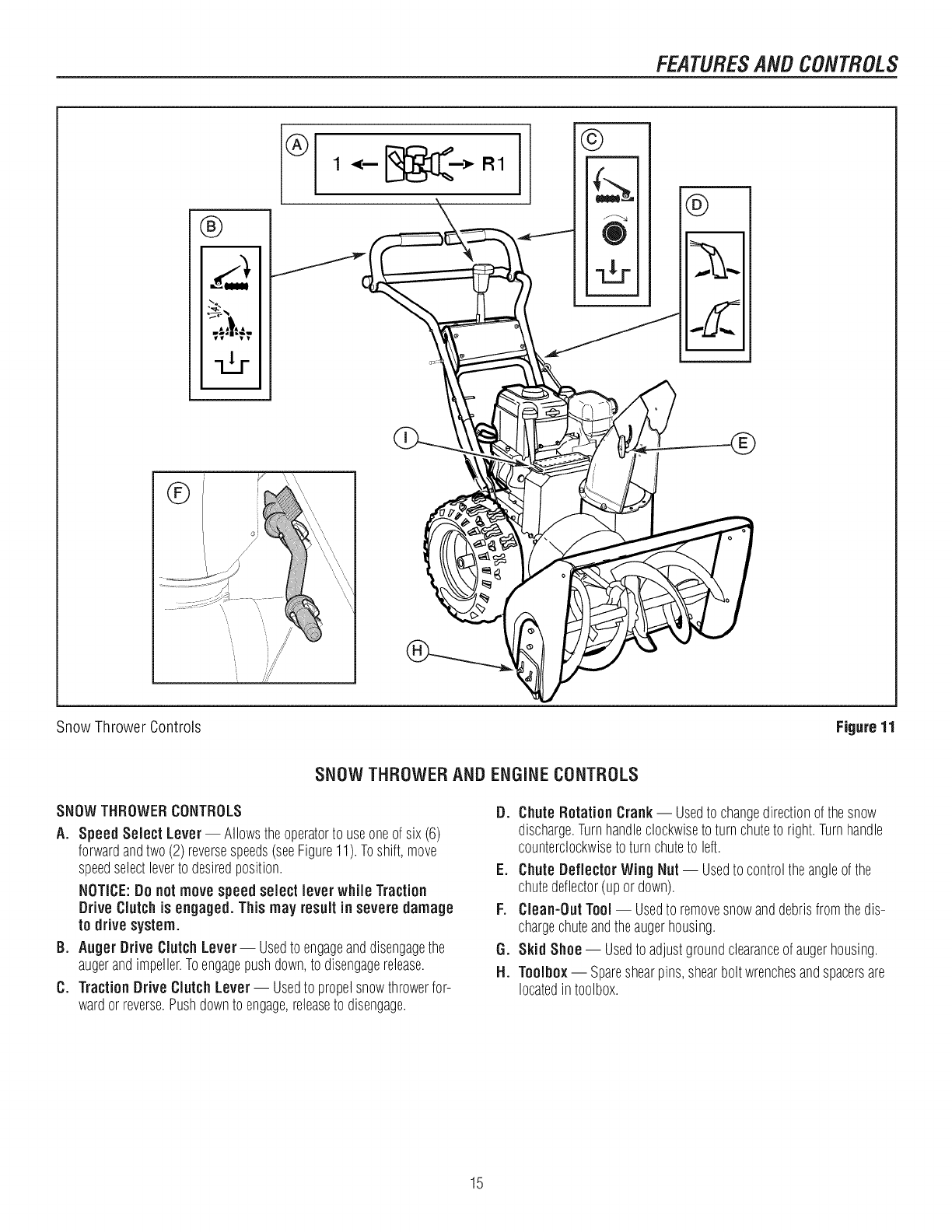
Snow Thrower 6ontrols Figure11
SNOW THROWER AND ENGINE CONTROLS
SNOWTHROWERCONTROLS
A. SpeedSelect Lever- Allowstheoperatorto useoneof six(6)
forwardandtwo(2)reversespeeds(seeFigure11).Toshift,move
speedselectleverto desiredposition.
NOTICE:Do notmove speedselect lever while Traction
Drive Clutch is engaged. This may result in severe damage
to drive system.
B. AugerDrive ClutchLever-- Usedto engageanddisengagethe
augerandimpeller.Toengagepushdown,to disengagerelease.
C. Traction Drive Clutch Lever-- Usedto propelsnowthrowerfor-
wardor reverse.Pushdownto engage,releaseto disengage.
D. ChuteRotation Crank-- Usedto changedirectionofthesnow
discharge.Turnhandleclockwiseto turnchuteto right.Turnhandle
counterclockwiseto turnchuteto left.
E. ChuteDeflectorWing Nut -- Usedto controltheangleof the
chutedeflector(upor down).
F. Clean-Out Tool -- Usedto removesnowanddebrisfromthedis-
chargechuteandtheaugerhousing.
G. SkidShoe-- Usedto adjustgroundclearanceofaugerhousing.
H. Toolbox-- Spareshearpins,shearboltwrenchesandspacersare
locatedin toolbox.
15
FEATURESANDCONTROLS
®I÷1I×1 /®
®
®
®
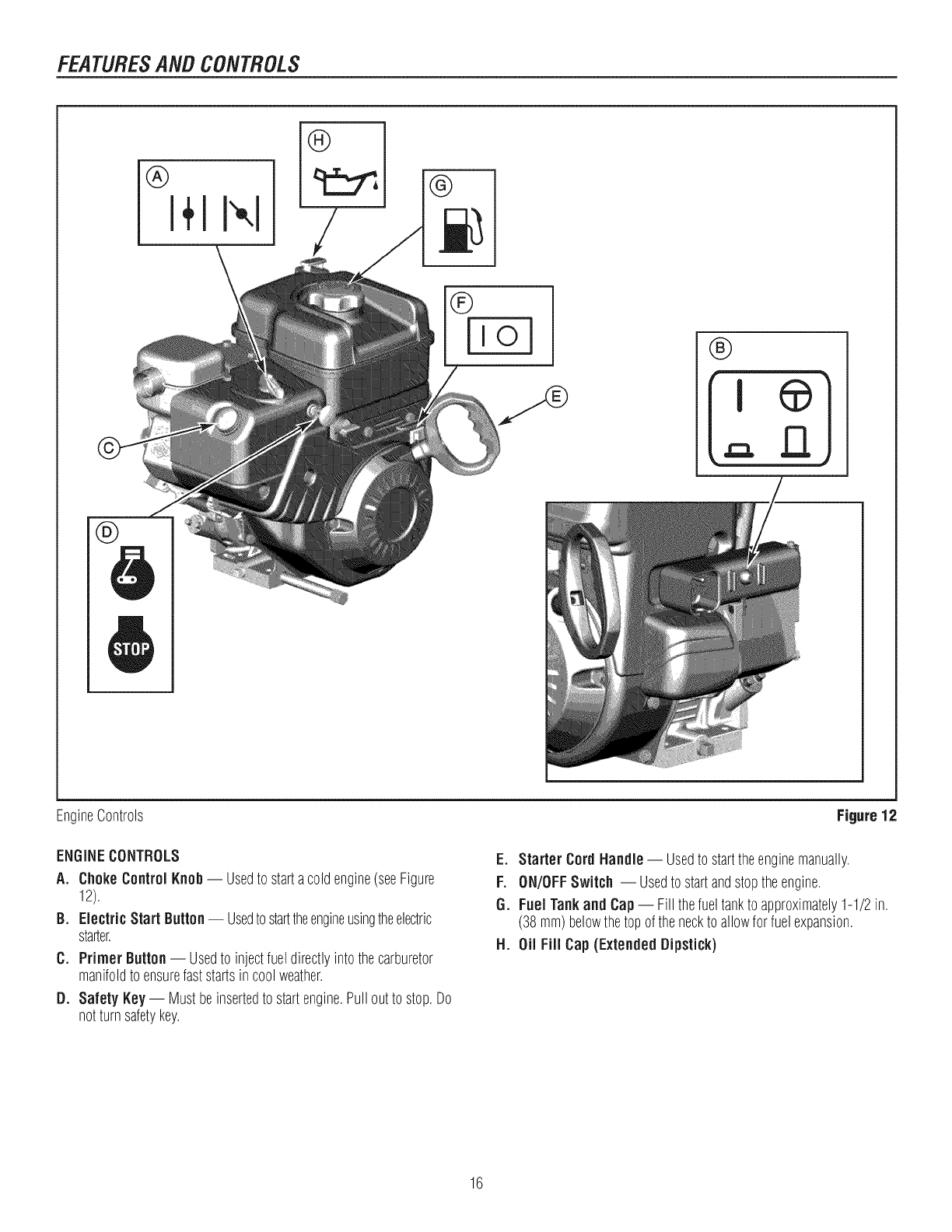
EngineControls
ENGINECONTROLS
A. Choke Control Knob-- Usedto startacold engine(seeFigure
12).
B. Electric Start Button-- Usedto starttheengineusingtheelectric
starter.
C. Primer Button -- Usedto injectfueldirectlyintothecarburetor
manifoldto ensurefaststartsin coolweather.
D. Safety Key-- Mustbeinsertedto startengine.Pullout to stop.Do
notturnsafetykey.
Figure 12
E. Starter Cord Handle -- Usedto starttheenginemanually.
F. ON/OFFSwitch -- Usedto startandstoptheengine,
G. Fuel Tankand Cap-- Fill thefueltankto approximately1-1/2 in.
(38mm)belowthetopof theneckto allowfor fuelexpansion,
H. Oil Fill Cap (ExtendedDipstick)
16
OPERATION
BEFOREOPERATING SNOW THROWER
Checkthefasteners.Makesureall fastenersare tight.
ReadthisOPERATOR'SMANUALand OPERATORSAFETYbefore
operatingyoursnowthrower. Comparethe illustrationswithyour
SNOWTHROWERtofamiliarize yourselfwiththe locationofvar-
iouscontrolsandadjustments. Savethismanual for future refer-
once.
NOTE: This snow thrower was shipped WiTH OiL in the
engine. See "Before Starting Engine" instructions in the
OPERATIONsection of this manual before startingengine.
WARNING:The operation of any snow throwercan result in foreign objects beingthrowninto the eyes, which can result in
severe eye damage. Alwayswear safety glasses or eye shields beforebeginningsnowthroweroperation. We recommend
standard safety glasses or Wide Vision Safety Mask over spectacles.
OPERATETHESNOWTHROWER
Themosteffectiveuseof thesnowthrowerwill beestablishedbyexperi-
ence,takinginto considerationtheterrain,windconditions,andbuilding
locationwhichwill determinethedirectionof thedischargechute.
NOTICE:Do not throwsnowtoward abuildingas hiddenobjects
couldbe thrownwith sufficient force to causedamage.
1. Starttheengine.See"ToStartEngine"inthis section.
2. Rotatethecrank(A, Figure12)to setthedirection(leftor right)of the
dischargechute.
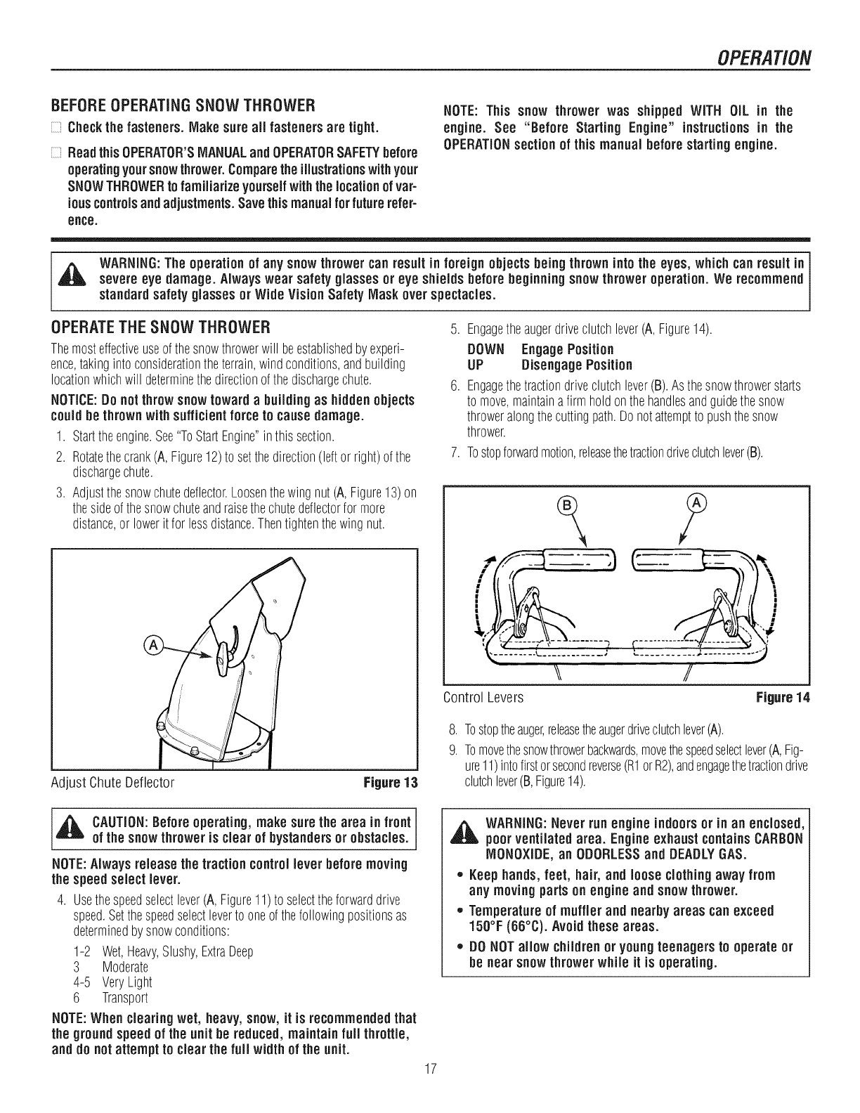
3. Adjustthesnowchutedeflector.Loosenthewingnut (A,Figure13)on
thesideof thesnowchuteandraisethechutedeflectorfor more
distance,or lowerit for lessdistance.Thentightenthewing nut.
Adjust ChuteDeflector Figure 13
5. Engagetheaugerdriveclutchlever(A,Figure14).
DOWN EngagePosition
UP DisengagePosition
6. Engagethetractiondriveclutchlever(B).Asthesnowthrowerstarts
to move,maintainafirm holdonthehandlesandguidethesnow
throweralongthecuttingpath.Donotattemptto pushthesnow
thrower.
7. Tostopforwardmotion,releasethetractiondriveclutchlever(B).
\\ //
Control Levers Figure14
8. Tostoptheauger,releasetheaugerdriveclutchlever(A).
9. Tomovethesnowthrowerbackwards,movethespeedselectlever(A,Fig-
ure11)intofirstorsecondreverse(R1orR2),andengagethetractiondrive
clutchlever(B,Figure14).
_ AUTION:Beforeoperating, make sure the area in front
of the snow throweris clear of bystandersor obstacles.
NOTE:Always releasethe tractioncontrol lever beforemoving
the speed select lever.
4. Usethespeedselectlever(A, Figure11)to selecttheforwarddrive
speed.Setthespeedselectleverto oneof thefollowingpositionsas
determinedby snowconditions:
1-2 Wet,Heavy,Slushy,ExtraDeep
3 Moderate
4-5 VeryLight
6 Transport
NOTE:When clearing wet, heavy,snow, it is recommended that
the ground speedof the unit be reduced, maintain full throttle,
and do notattempt to clear the full width of the unit.
_ WARNING:Never run engine indoorsor in an enclosed,
poorventilated area. Engineexhaust containsCARBON
MONOXIDE,an ODORLESSand DEADLYGAS.
,, Keephands,feet, hair, and loose clothingaway from
any movingparts on engine and snowthrower.
,, Temperatureof muffler and nearby areas can exceed
150°F (66°C). Avoid these areas.
,, DONOTallow childrenor youngteenagers to operate or
be near snowthrowerwhile it is operating.
17
OPERATION
,_ WARNING:Read Operator's Manual before operating
machine. This machine can be dangerousif used
carelessly.
,, Never operatethe snowthrower without all guards,covers,
shields in place.
,, Never direct dischargetowards windowsor allow
bystandersnear machine while engine is running.
,, Stop the engine whenever leaving the operating
position.
,, Disconnectspark plug beforeuncloggingthe impeller
housingor the dischargechute and before making
repairs or adjustments.
,, Whenleavingthe machine, removethe safety key. To
reducethe riskof fire, keep the machine cleanand free
from spilled gas, oil, anddebris.
STOPTHESNOWTHROWER
1. Releasethetractiondriveclutchlever(B,Figure14).
2. PushtheON/OFFswitch(A,Figure21)totheOFFpositionandpulloutthe
safetykey(B).
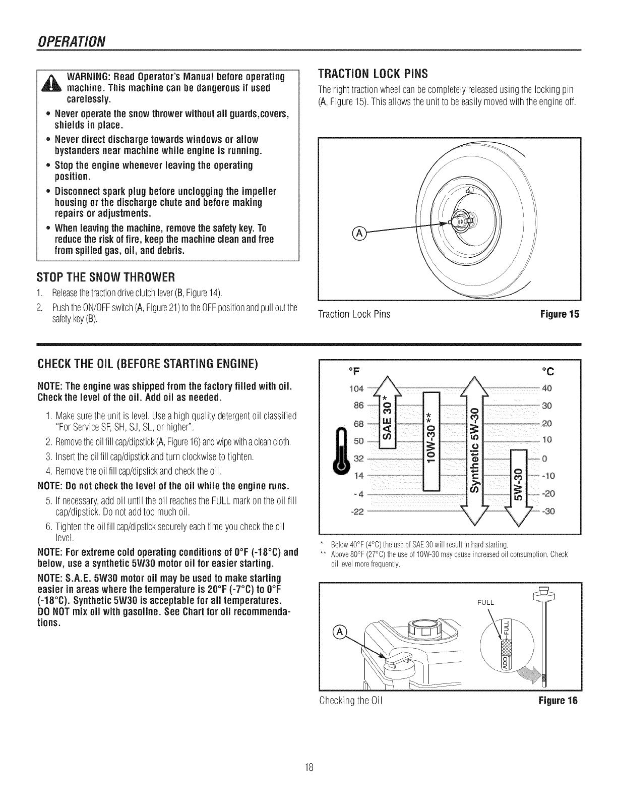
TRACTIONLOCKPiNS
Therighttractionwheelcanbecompletelyreleasedusingthe lockingpin
(A,Figure15).Thisallowstheunit to beeasilymovedwiththeengineoff.
Traction Lock Pins Figure 15
CHECKTHE OiL (BEFORESTARTING ENGINE)
NOTE:The engine was shippedfrom the factory filled with oil.
Check the level of the oil Add oil as needed.
1. Makesuretheunit is level.Useahighqualitydetergentoil classified
"ForServiceSF,SH,SJ, SL,or higher".
2. Removetheoilfill cap/dipstick(A,Figure16)andwipewithacleancloth.
3. Insertthe oilfill cap/dipstickandturnclockwiseto tighten.
4. Removetheoilfillcap/dipstickandchecktheoil.
NOTE:Do notcheckthe level of the oil while the engineruns.
5. If necessary,addoil until theoil reachestheFULLmarkontheoil fill
cap/dipstick.Donotaddtoo muchoil.
6. Tightentheoilfillcap/dipsticksecurelyeachtimeyouchecktheoil
level.
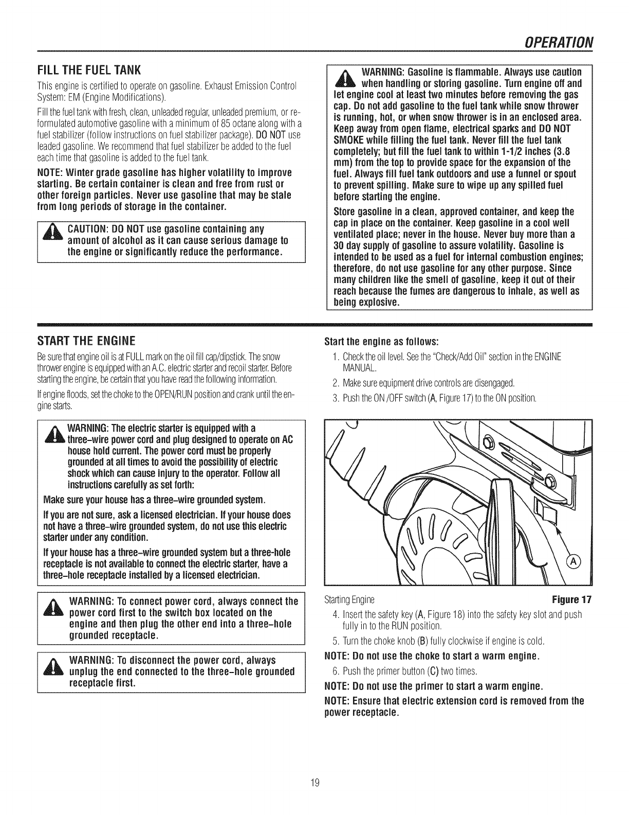
NOTE:For extreme cold operating conditionsof O°F(-18°C) and
below, use asynthetic5W30 motor oil for easierstarting.
NOTE:S.A.E. 5W30 motoroil may be used to makestarting
easier in areas where the temperature is 20°F (-7°C) to O°F
(-18°C). Synthetic 5W30 is acceptable for all temperatures.
DO NOTmix oil with gasoline. See Chartfor oil recommenda-
tions.
oF
!04 _ _'-'-'"
86
6a N
b32
_4
-22
°C
_ _0
..-..------...----,--.-so
' .........,...............................20
0
_'_ 0
.L z...--so
Below40°F(4°C)the useofSAE30will resultin hardstarting.
** Above80°F (27°C)the useof 10W-30maycauseincreasedoil consumption=Check
oil levelmorefrequently.
FULL
Checkingthe Oil Figure 16
18
OPERATION
FiLL THE FUEL TANK
Thisengineis certifiedto operateongasoline.ExhaustEmissionControl
System:EM(EngineModifications).
Fillthefueltankwithfresh,clean,unleadedregular,unleadedpremium,orre-
formulatedautomotivegasolinewitha minimumof 85octanealongwitha
fuelstabilizer(followinstructionsonfuelstabilizerpackage).DONOTuse
leadedgasoline.Werecommendthatfuelstabilizerbeaddedto thefuel
eachtimethatgasolineis addedtothefueltank.
NOTE:Winter grade gasoline has higher volatility to improve
starting. Be certain containeris clean and free from rustor
other foreign particles. Never use gasoline that may be stale
from longperiodsof storagein the container.
,_b CAUTION:DO NOTuse gasoline containingany
amount of alcohol as it cancauseserious damageto
the engineor significantly reducethe performance.
_ ARNING:Gasolineis flammable. Always use caution
whenhandlingor storinggasoline. Turnengineoff and
let enginecoolat least two minutes beforeremovingthe gas
cap. Donot add gasoline tothe fueltankwhile snowthrower
is running,hot, or when snow throweris inan enclosed area.
Keep awayfromopen flame, electricalsparksandDONOT
SMOKEwhilefilling the fuel tank. Neverfiil the fuel tank
completely;butfill thefuel tankto within1-1/2 inches(3.8
ram) fromthetopto providespaceforthe expansionof the
fuel. Alwaysfill fueltankoutdoors and usea funnel or spout
to preventspilling. Makesure to wipe up any spilled fuel
before starting the engine.
Store gasoline inaclean, approvedcontainer,and keep the
cap in placeon the container.Keepgasoline in acoolwell
ventilatedplace;neverin the house.Never buy more thana
30 day supply of gasoline to assurevolatility.Gasolineis
intendedto be usedas a fuelfor internalcombustionengines;
therefore,do notuse gasoline for any other purpose. Since
many childrenlikethe smell of gasoline, keep it out of their
reachbecausethe fumesare dangerousto inhale, as well as
beingexplosive.
START THE ENGINE
BesurethatengineoilisatFULLmarkontheoilfill cap/dipstick.Thesnow
throwerengineisequippedwithanA.C.electricstarterandrecoilstarter.Before
startingtheengine,becertainthatyouhavereadthefollowinginformation.
Ifenginefloods,setthechoketotheOPEN/RUNpositionandcrankuntiltheen-
ginestarts.
,_ WARNING:Theelectric starteris equippedwith a
three-wirepowercordand plugdesignedto operateonAC
householdcurrent.Thepowercordmust beproperly
groundedat all times toavoid thepossibilityof electric
shockwhichcancauseinjuryto theoperator.Followall
instructionscarefullyas setforth:
Makesureyourhousehasathree-wiregroundedsystem.
Ifyouarenotsure,aska licensedelectrician.If yourhousedoes
nothavea three-wire groundedsystem,donotusethis electric
starterunderanycondition.
Ifyourhousehas athree-wiregroundedsystembut a three-hole
receptacleis notavailabletoconnectthe electricstarter,havea
three-holereceptacleinstalledbya licensedelectrician.
_jh ARNING:Toconnectpower cord, always connectthe
power cordfirst to the switch box located on the
engine and then plugthe other end into athree-hole
grounded receptacle.
WARNING:Todisconnectthe power cord, always
unplug the end connectedto the three-hole grounded
receptacle first.
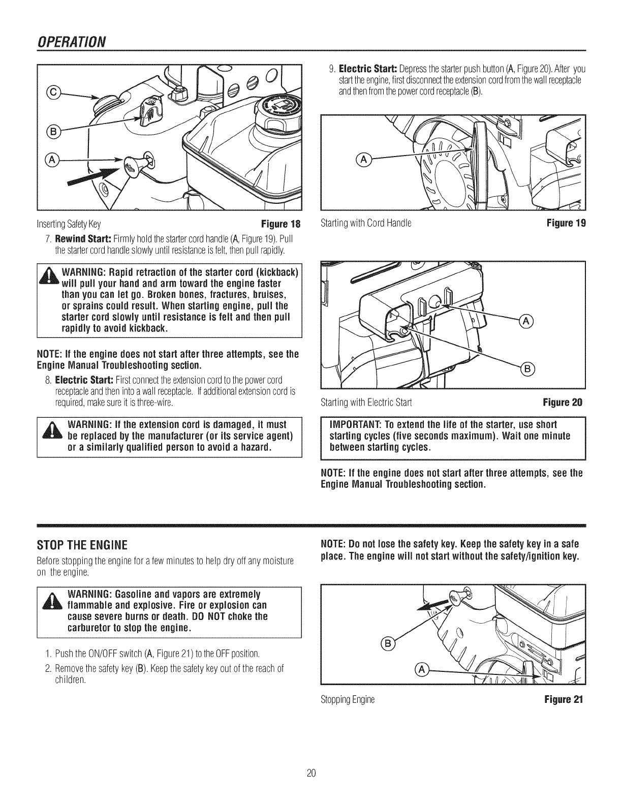
Start the engine as follows:
1. Checktheoillevel.Seethe"Check/AddOil"sectionintheENGINE
MANUAL.
2. Makesureequipmentdrivecontrolsaredisengaged.
3. PushtheON/OFFswitch(A,Figure17)totheONposition.
StartingEngine Figure17
4. Insertthesafetykey(A, Figure18)intothesafetykeyslotandpush
fullyin to theRUNposition.
5. Turnthechokeknob(B)fully clockwiseif engineis cold.
NOTE:Do not use the choketo start a warm engine.
6. Pushtheprimerbutton(C)twotimes.
NOTE:Donot usethe primerto start a warm engine.
NOTE:Ensurethat electric extension cordis removedfromthe
power receptacle.
19
OPERATION
9. Electric Start: Depressthestarterpushbutton(A,Figure20).Afteryou
starttheengine,firstdisconnecttheextensioncordfromthewallreceptacle
andthenfromthepowercordreceptacle(B).
InsertingSafetyKey Figure 18
7. Rewind Start: Firmlyholdthestartercordhandle(A,Figure19).Pull
thestartercordhandleslowlyuntilresistanceisfelt,thenpullrapidly.
_ARNING:Rapidretraction of the startercord (kickback)
will pull your hand and arm toward the engine faster
thanyou can let go. Brokenbones, fractures, bruises,
or sprains couldresult. When startingengine, pull the
starter cordslowly until resistanceis felt and then pull
rapidlyto avoid kickback.
NOTE:if the enginedoes notstart after three attempts, see the
Engine Manual Troubleshootingsection.
8. Electric Start: Firstconnecttheextensioncordtothepowercord
receptacleandthenintoawallreceptacle.Ifadditionalextensioncordis
required,makesureit is three-wire.
41_ WARNING:If the extension cord is damaged, it must
be replaced bythe manufacturer(or its service agent)
or asimilarly qualified personto avoid a hazard.
StartingwithCordHandle Figure 19
StartingwithElectricStart Figure20
IMPORTANT:Toextend the life of the starter, use short
startingcycles(five secondsmaximum). Wait one minute
between startingcycles.
NOTE:if the engine does notstart after three attempts, see the
Engine Manual Troubleshootingsection.
STOP THE ENGINE
Beforestoppingtheenginefor afewminutesto helpdry offanymoisture
on theengine.
NOTE:Donot losethe safety key. Keepthe safety key in a safe
place. Theenginewill notstart withoutthe safety/ignitionkey.
,_ WARNING:Gasolineandvaporsare extremely
flammable and explosive. Fire or explosion can
cause severe burns or death. DO NOTchokethe
carburetorto stopthe engine.
1. PushtheON/OFFswitch(A,Figure21)totheOFFposition.
2. Removethesafetykey(B).Keepthesafetykeyoutof the reachof
children.
StoppingEngine Figure 21
20
OPERATION
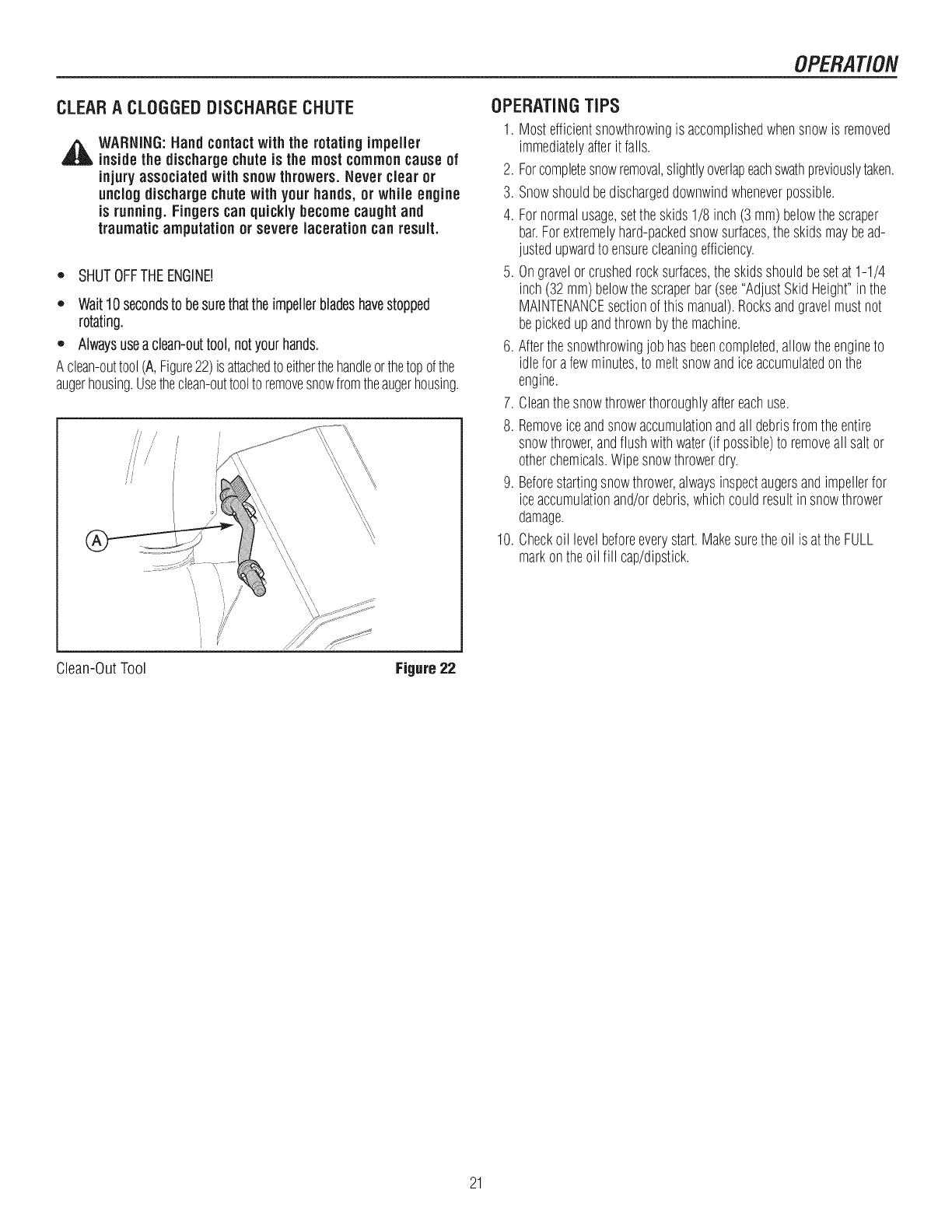
CLEARA CLOGGEDDISCHARGECHUTE
,_ WARNING:Handcontactwith the rotating impeller
insidethe dischargechuteis the most common cause of
injury associated with snow throwers. Never clear or
unclog dischargechutewith your hands, or while engine
is running.Fingers can quickly becomecaughtand
traumatic amputation or severe lacerationcan result.
o SHUTOFFTHEENGINE!
,, Wait10secondsto besurethatthe impellerbladeshavestopped
rotating.
,' Alwaysuseaclean-outtool,notyourhands.
Aclean-outtool(A,Figure22)isattachedto eitherthehandleorthetopofthe
augerhousing.Usetheclean-outtooltoremovesnowfromtheaugerhousing.
//' /
'i
\\'\
OPERATINGTIPS
1. Mostefficientsnowthrowingis accomplishedwhensnowis removed
immediatelyafterit falls.
2. Forcompletesnowremoval,slightlyoverlapeachswathpreviouslytaken.
3. Snowshouldbedischargeddownwindwheneverpossible.
4. Fornormalusage,setthe skids1/8 inch(3 mm)belowthe scraper
bar.Forextremelyhard-packedsnowsurfaces,the skidsmaybead-
justedupwardto ensurecleaningefficiency.
5. Ongravelorcrushedrocksurfaces,theskidsshouldbesetat 1-1/4
inch(32mm)belowthescraperbar(see"AdjustSkidHeight"inthe
MAINTENANCEsectionof this manual).Rocksandgravelmustnot
bepickedupandthrownbythemachine.
6. Afterthesnowthrowingjobhasbeencompleted,allowtheengineto
idlefor afewminutes,to meltsnowandiceaccumulatedonthe
engine.
7. Cleanthesnowthrowerthoroughlyaftereachuse.
8. Removeiceandsnowaccumulationandall debrisfromtheentire
snowthrower,andflushwithwater(if possible)toremoveall saltor
otherchemicals.Wipesnowthrowerdry.
9. Beforestartingsnowthrower,alwaysinspectaugersandimpellerfor
iceaccumulationand/ordebris,whichcouldresultin snowthrower
damage.
10. Checkoil levelbeforeeverystart.Makesurethe oil is attheFULL
markontheoil fill cap/dipstick.
Clean-OutTool Figure22
21
MAINTENANCE
SERVICERECOMMENDATIONS
FIRST BEFORE AFTER EVERY EVERY EVERY BEGINNING BEFORE
PROCEDURE 5 EACH EACH 5 10 25 EACH STORAGE
HOURS USE USE HOURS HOURS HOURS SEASON
Checkto MakeSure
AugerBladeStopsWithin
5 SecondsAfterRight v"
SAFETY ControlLeveris Released
LubricateControlLevers ,/ ,/ ,/
andLinkages
CheckSnowthrowerfor
LooseHardware v" ,,,"
LubricateHexShaftand
Chains v" v"
LubricateAugerShaft
Fittings v" v"
SNOWTHROWER LubricateChuteRotation
GearandDeflector v"
Mechanism
RemoveAll Snowand
SlushoffSnowthrowerto
PreventFreezingof Auger
or Controls
v"
CheckTirePressure ,/
L_______ i i ,,,,, i
Oil,Check ,/ v" ,/ v"
Oil,Change ,/ v"
ENGINE CheckandReplace
SparkPlug v" v"
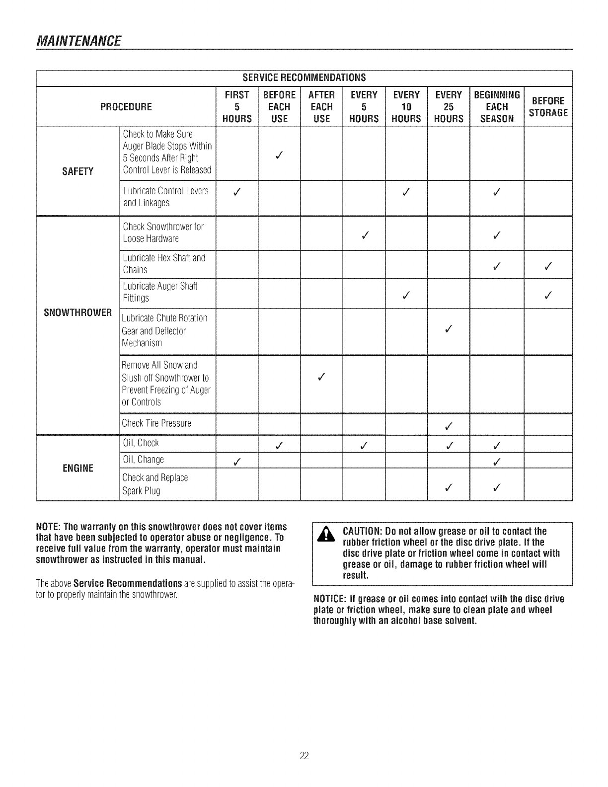
NOTE:The warrantyon this snowthrower does not coveritems
that have beensubjectedto operator abuse or negligence.To
receivefull value from the warranty, operator mustmaintain
snowthroweras instructedin this manual.
TheaboveService Recommendations aresuppliedto assisttheopera-
tor to properlymaintainthesnowthrower.
ACAUTION:Do notallow grease or oil to contactthe
rubberfriction wheel or the disc drive plate, if the
disc drive plate or friction wheel come in contactwith
grease or oil, damage to rubberfriction wheel will
result.
NOTICE:if grease or oil comesinto contactwith the disc drive
plate or friction wheel, makesureto clean plate and wheel
thoroughlywith an alcohol base solvent.
22
MAINTENANCE
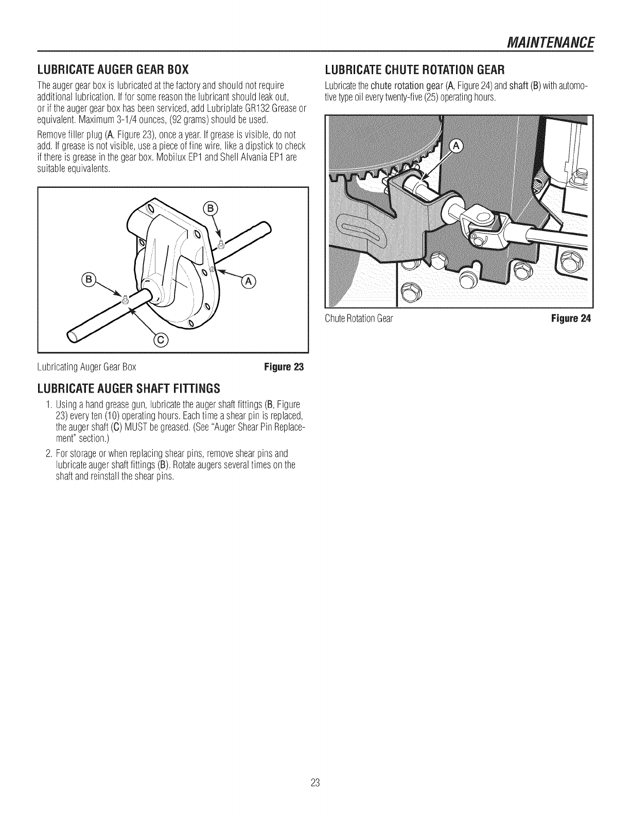
LUBRICATEAUGERGEARBOX
Theaugergearboxis lubricatedatthefactoryandshouldnotrequire
additionallubrication.If for somereasonthelubricantshouldleakout,
or if theaugergearboxhasbeenserviced,addLubriplateGR132Greaseor
equivalent.Maximum3-1/4 ounces,(92grams)shouldbeused.
Removefiller plug(A,Figure23),onceayear.Ifgreaseis visible,donot
add.Ifgreaseis notvisible,usea pieceoffinewire,likeadipstickto check
if thereis greaseinthegearbox.MobiluxEP1andShellAIvaniaEP1are
suitableequivalents.
LUBRICATECHUTEROTATIONGEAR
Lubricatethechuterotationgear(A,Figure24)andshaft (B)withautomo-
tivetypeoileverytwenty-five(25)operatinghours.
ChuteRotationGear Figure 24
LubricatingAugerGearBox Figure 23
LUBRICATEAUGERSHAFTFITTINGS
1. Usingahandgreasegun, lubricatetheaugershaftfittings(B,Figure
23)everyten (10)operatinghours.Eachtimea shearpinis replaced,
theaugershaft(C) MUSTbegreased.(See"AugerShearPinReplace-
ment"section.)
2. Forstorageorwhenreplacingshearpins,removeshearpinsand
lubricateaugershaftfittings(B).Rotateaugersseveraltimesonthe
shaftandreinstalltheshearpins.
23
MAINTENANCE
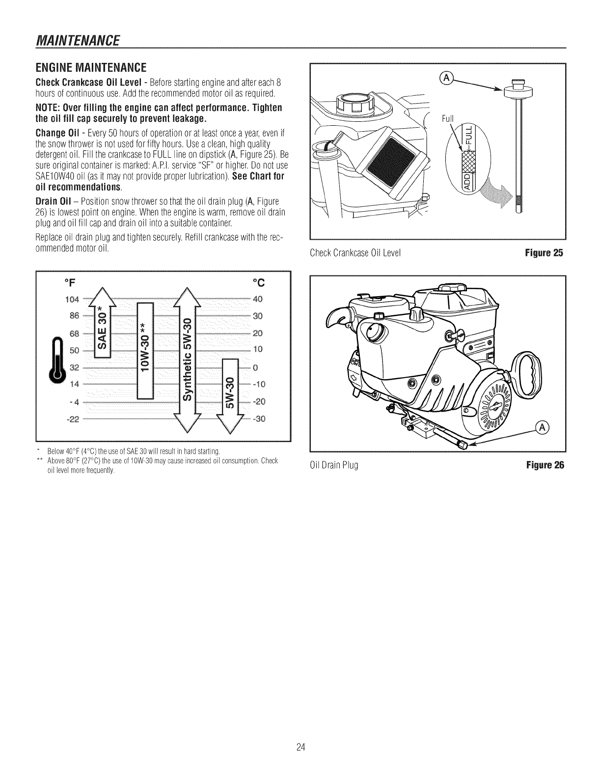
ENGINEMAINTENANCE
Check Crankcase Oil Level - Beforestartingengineandaftereach8
hoursof continuoususe.Addtherecommendedmotoroil asrequired.
NOTE:Over filling the engine can affect performance.Tighten
the oil fill cap securely to prevent leakage.
Change Oil - Every50 hoursof operationor atleastonceayear,evenif
thesnowthroweris not usedfor fiftyhours.Usea clean,highquality
detergentoil. Fill thecrankcaseto FULLlineondipstick(A, Figure25). Be
sureoriginalcontaineris marked:A.P.I.service"SF"orhigher.Do notuse
SAEIOW40oil (asit maynotprovideproperlubrication).See Chart for
oil recommendations.
Drain Oil - Positionsnowthrowersothattheoil drainplug(A, Figure
26)is lowestpointonengine.Whentheengineis warm,removeoil drain
plugandoil fill capanddrainoil intoasuitablecontainer.
Replaceoil drainplugandtightensecurely.Refillcrankcasewiththe rec-
ommendedmotoroil.
Full
CheckCrankcaseOil Level Figure 25
oF
!04
86
68
50
_ 32
14,
_4
°22
°C
Below40°F (4°C)the useof SAE30will result in hardstarting.
** Above80°F (27°C)the useof 10W-30maycauseincreasedoil consumption,Check
oil levelmorefrequently= OilDrainPlug Figure 26
24
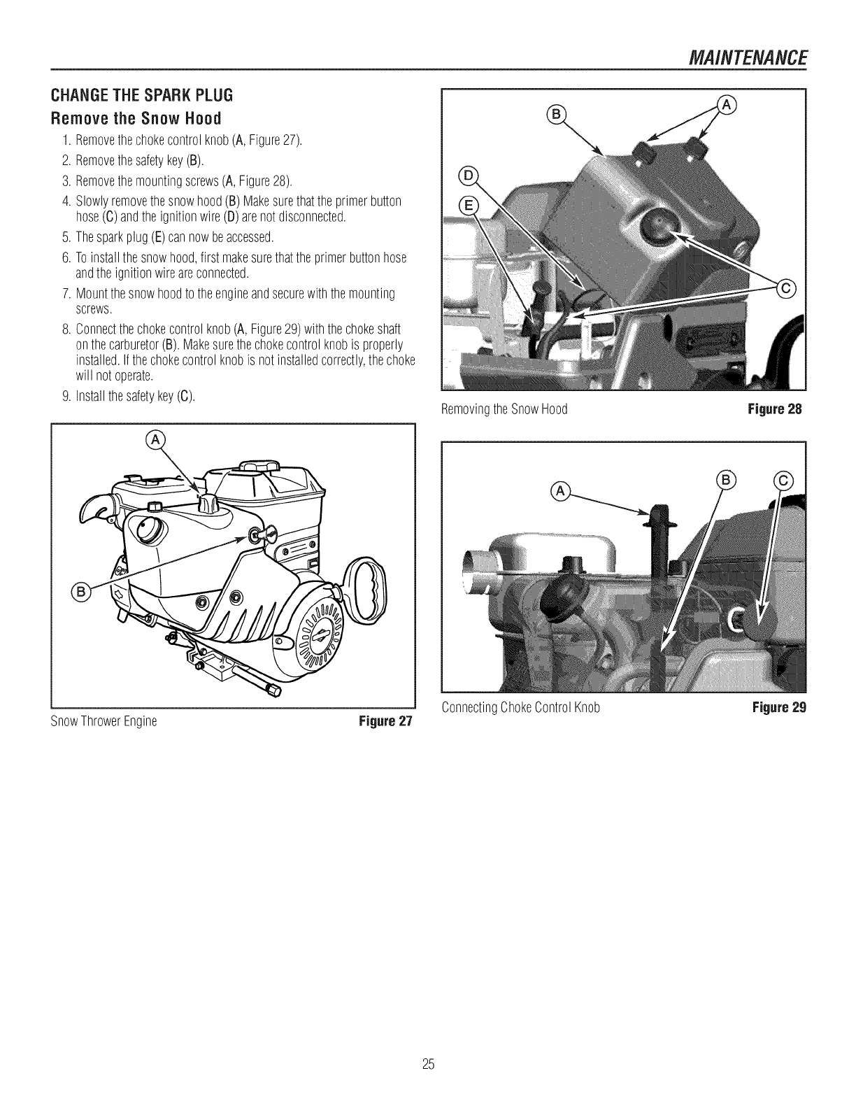
CHANGETHESPARKPLUG
Remove the SnowHood
1. Removethechokecontrolknob(A,Figure27).
2. Removethesafetykey(B).
3. Removethemountingscrews(A, Figure28).
4. Slowlyremovethesnowhood(B)Makesurethattheprimerbutton
hose(C)andtheignitionwire(D)arenotdisconnected.
5. Thesparkplug(E)cannowbeaccessed.
6. Toinstallthe snowhood,first makesurethatthe primerbuttonhose
andtheignitionwireareconnected.
7. Mountthesnowhoodto theengineandsecurewiththemounting
screws.
8. Connectthechokecontrolknob(A,Figure29)withthechokeshaft
onthecarburetor(B).Makesurethechokecontrolknobis properly
installed.Ifthechokecontrolknobis notinstalledcorrectly,thechoke
will notoperate.
9. Installthesafetykey(C).
i
SnowThrowerEngine Figure 27
RemovingtheSnowHood
ConnectingChokeControlKnob
MAINTENANCE
Figure 28
Figure 29
25
MAINTENANCE
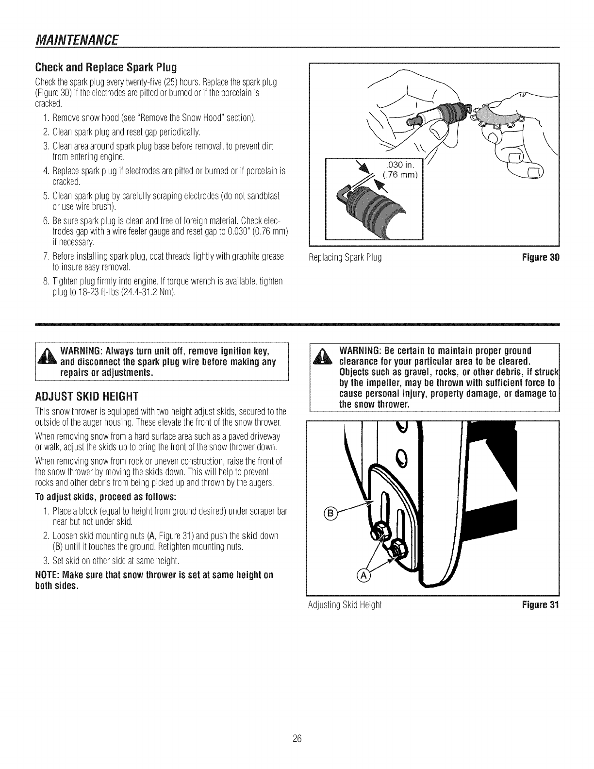
CheckandReplaceSpark Plug
Checkthesparkplugeverytwenty-five(25)hours.Replacethesparkplug
(Figure30)if theelectrodesarepittedorburnedorif theporcelainis
cracked.
1. Removesnowhood(see"RemovetheSnowHood"section).
2. Cleansparkplugandresetgapperiodically.
3. Cleanareaaroundsparkplugbasebeforeremoval,to preventdirt
fromenteringengine.
4. Replacesparkplugif electrodesarepittedor burnedor if porcelainis
cracked.
5. Cleansparkplugby carefullyscrapingelectrodes(donotsandblast
orusewirebrush).
6. Besuresparkplugis cleanandfreeof foreignmaterial.Checkelec-
trodesgapwithawirefeelergaugeandresetgapto 0.030"(0.76ram)
if necessary.
7. Beforeinstallingsparkplug,coatthreadslightlywithgraphitegrease
to insureeasyremoval.
8. Tightenplugfirmlyinto engine.Iftorquewrenchis available,tighten
plugto 18-23ft-lbs (24.4-31.2Nm).
\
ReplacingSparkPlug Figure 30
,_ WARNING:Always turn unit off, remove ignitionkey,
and disconnectthe sparkplugwire before making any
repairs or adjustments.
ADJUSTSKiD HEIGHT
Thissnowthroweris equippedwithtwoheightadjustskids,securedto the
outsideoftheaugerhousing.Theseelevatethefrontofthesnowthrower.
Whenremovingsnowfromahardsurfaceareasuchasa paveddriveway
orwalk,adjusttheskidsupto bringthefrontofthesnowthrowerdown.
Whenremovingsnowfromrockor unevenconstruction,raisethefrontof
thesnowthrowerbymovingtheskidsdown.Thiswill helpto prevent
rocksandotherdebrisfrombeingpickedupandthrownbytheaugers.
To adjustskids, proceedas follows:
1. Placeablock(equalto heightfromgrounddesired)underscraperbar
nearbutnotunderskid.
2. Loosenskidmountingnuts(A, Figure31)andpushtheskid down
(B)until it touchestheground.Retightenmountingnuts.
3. Setskidonothersideatsameheight.
NOTE:Make surethat snowthroweris set at same heighton
both sides.
WARNING:Be certain to maintainproper ground
clearance for your particulararea to be cleared.
Objects suchas gravel, rocks, or other debris, if struck
by the impeller, may be thrownwith sufficientforce to
cause personalinjury, propertydamage, or damageto
the snowthrower.
AdjustingSkidHeight Figure 31
26
MAINTENANCE
BELTADJUSTMENT
TractionDriveBelt
Thetractiondrivebelthasconstantspringpressureanddoesnotrequire
anadjustment.Ifthetractiondrivebelt is slipping,replacethebelt.Seeau-
thorizeddealer.
Auger Drive Belt
Ifyoursnowthrowerwill notdischargesnow,checkthecontrolcableadjust-
ment.Ifit iscorrect,thenchecktheconditionoftheaugerdrivebelt.Ifit is
damagedor loose,replaceit (seeauthorizeddealer).
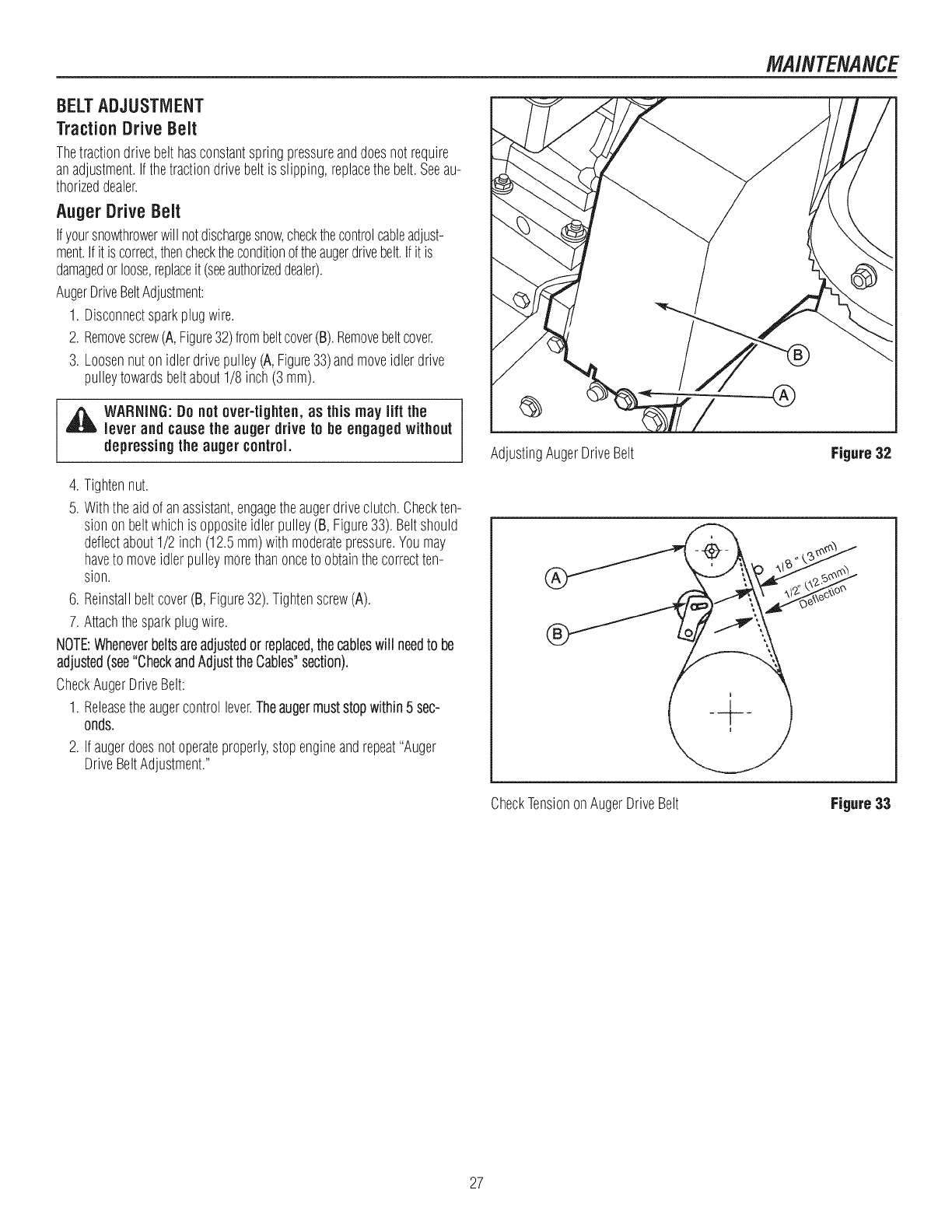
AugerDriveBeltAdjustment:
1. Disconnectsparkplugwire.
2. Removescrew(A,Figure32)frombeltcover(B).Removebeltcover.
3. Loosennutonidlerdrivepulley(A,Figure33)andmoveidlerdrive
pulleytowardsbeltabout1/8inch(3 mm).
WARNING: Donot over-tighten, as this may lift the
lever and causethe auger drive to be engagedwithout
depressingthe auger control.
4. Tightennut.
5. Withtheaidof anassistant,engagetheaugerdriveclutch.Checkten-
sionon beltwhichis oppositeidlerpulley(B,Figure33).Beltshould
deflectabout1/2 inch(12.5mm)withmoderatepressure.Youmay
haveto moveidlerpulleymorethanonceto obtainthecorrectten-
sion.
6. Reinstallbeltcover(B, Figure32).Tightenscrew(A).
7. Attachthesparkplugwire.
NOTE:Wheneverbeltsareadjustedor replaced,thecableswill needto be
adjusted(see"CheckandAdjusttheCables"section).
CheckAugerDriveBelt:
1. Releasetheaugercontrollever.Theaugermuststopwithin5 sec-
onds.
2. Ifaugerdoesnotoperateproperly,stopengineandrepeat"Auger
DriveBeltAdjustment."
AdjustingAugerDriveBelt Figure32
CheckTensiononAugerDriveBelt Figure33
27
MAINTENANCE
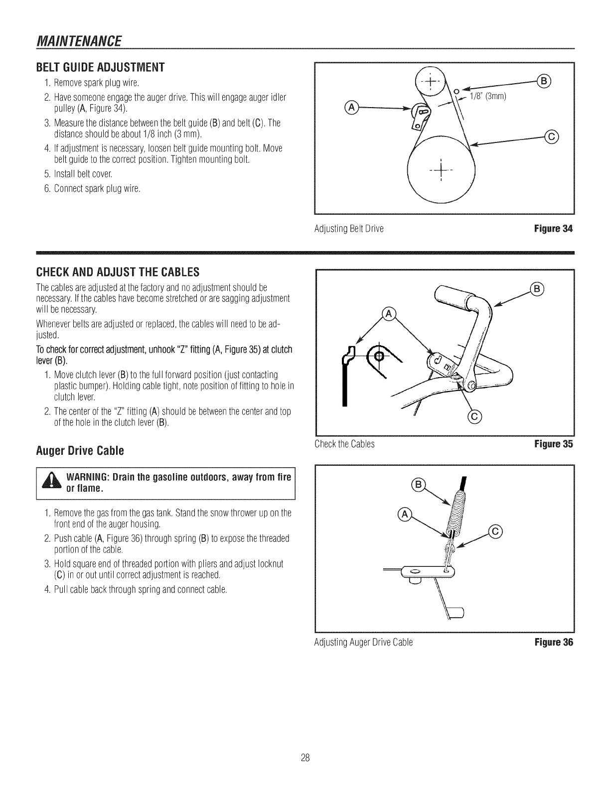
BELT GUIDE ADJUSTMENT
1. Removesparkplugwire.
2. Havesomeoneengagetheaugerdrive.Thiswill engageaugeridler
pulley(A, Figure34).
3. Measurethedistancebetweenthe beltguide(B)andbelt(C).The
distanceshouldbeabout1/8inch(3 ram).
4. Ifadjustmentis necessary,loosenbeltguidemountingbolt.Move
beltguideto thecorrectposition.Tightenmountingbolt.
5. Installbeltcover.
6. Connectsparkplugwire.
®
AdjustingBeltDrive Figure34
CHECKANDADJUSTTHECABLES
Thecablesareadjustedatthefactoryandnoadjustmentshouldbe
necessary.Ifthecableshavebecomestretchedoraresaggingadjustment
will benecessary.
Wheneverbeltsareadjustedor replaced,thecableswill needto bead-
justed.
Tocheckfor correctadjustment,unhook"Z" fitting (A,Figure35)at clutch
lever(B).
1. Moveclutchlever(B)to thefull forwardposition(justcontacting
plasticbumper).Holdingcabletight, notepositionof fittingto holein
clutchlever.
2. Thecenterof the"Z"fitting (A)shouldbebetweenthecenterandtop
of theholein theclutchlever(B). ©
Auger Drive Cable
[,_ ARNING: Drain the gasoline outdoors, away from fire
or flame.
1. Removethegasfromthegastank.Standthesnowthrowerupon the
frontendof theaugerhousing.
2. Pushcable(A,Figure36)throughspring(B)to exposethethreaded
portionof thecable.
3. Holdsquareendofthreadedportionwith pliersandadjustIocknut
(C) inor outuntil correctadjustmentis reached.
4. Pullcablebackthroughspringandconnectcable.
i
ChecktheCables Figure35
AdjustingAugerDriveCable Figure36
28
MAINTENANCE
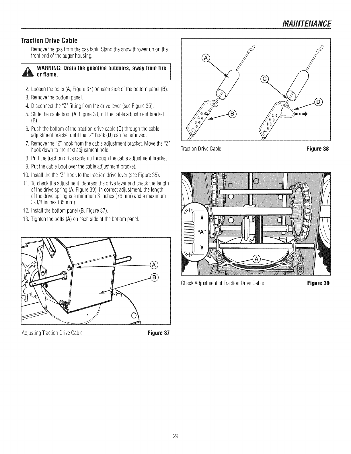
TractionDriveCable
1. Removethegasfromthegastank.Standthesnowthrowerupon the
frontendof theaugerhousing.
,_ WARNING:Drainthe gasoline outdoors, away from fire
or flame.
2. Loosenthebolts(A,Figure37)on eachsideof thebottompanel(B).
3. Removethebottompanel.
4. Disconnectthe"Z"fittingfromthedrivelever(seeFigure35).
5. Slidethecableboot(A, Figure38)offthecableadjustmentbracket
(B) I
6. Pushthebottomofthetractiondrivecable(C)throughthecable
adjustmentbracketuntilthe "Z"hook(D)canberemoved.
7. Removethe"Z"hookfromthecableadjustmentbracket.Movethe"Z"
hookdownto thenextadjustmenthole.
8. Pullthetractiondrivecableupthroughthecableadjustmentbracket.
91Putthecablebootoverthecableadjustmentbracket.
10. Installthethe"Z"hookto thetractiondrivelever(seeFigure35)1
11. Tochecktheadjustment,depressthedriveleverandcheckthelength
of thedrivespring(A,Figure39). Incorrectadjustment,thelength
of thedrivespringis aminimum3 inches(76mm)anda maximum
3-3/8 inches/85mm).
12. Installthebottompanel(B,Figure37)1
13. Tightenthebolts(A)oneachsideof thebottompanel.
TractionDriveCable
CheckAdjustmentofTractionDriveCable
Figure 38
P
n
Figure 38
AdjustingTractionDriveCable Figure 37
29
MAINTENANCE
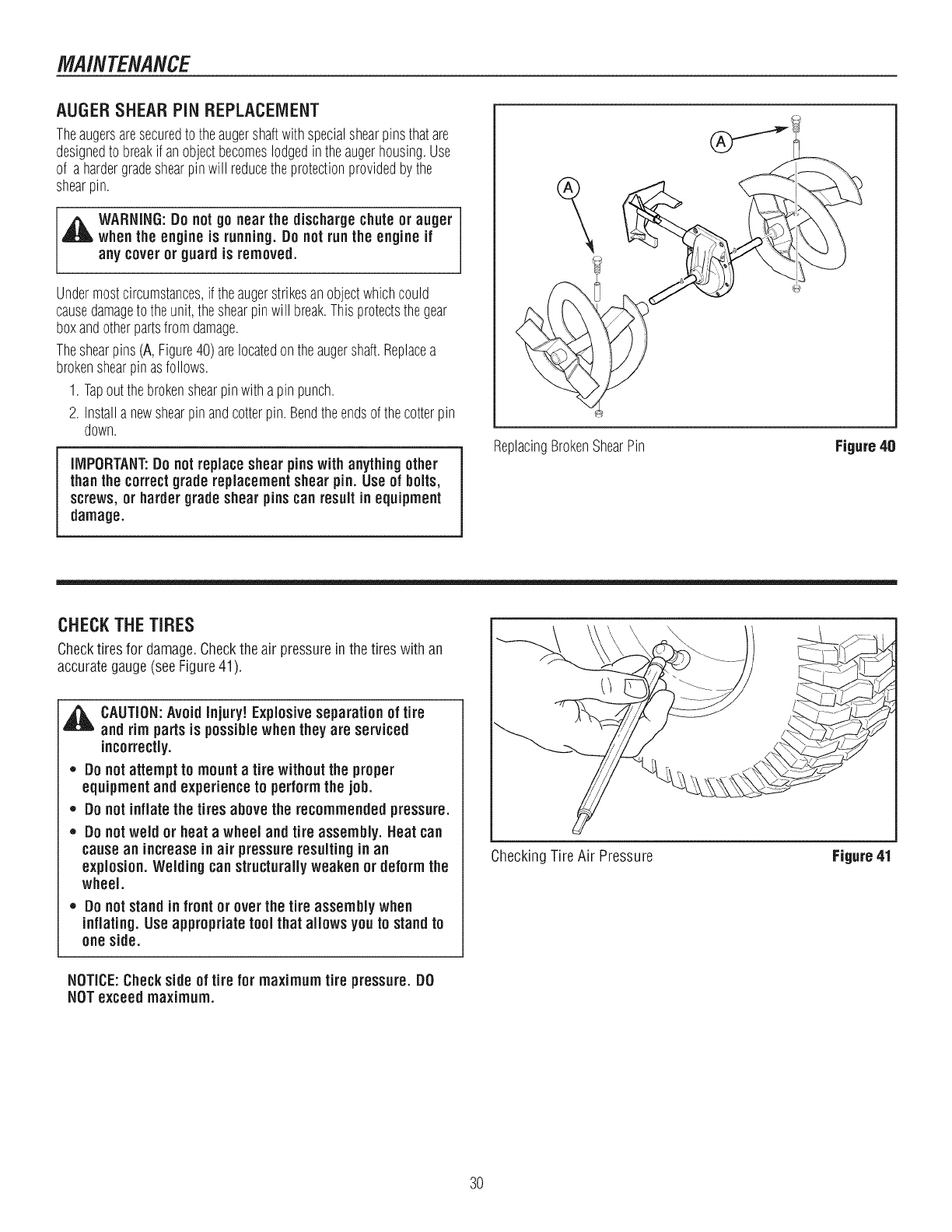
AUGERSHEARPiN REPLACEMENT
Theaugersaresecuredtotheaugershaftwithspecialshearpinsthatare
designedto breakif anobjectbecomeslodgedin theaugerhousing.Use
of a hardergradeshearpinwill reducetheprotectionprovidedbythe
shearpin.
,_ WARNING:Do not go nearthe dischargechuteor auger
whenthe engine is running.Do notrun the engine if
any coveror guard is removed.
Undermostcircumstances,if theaugerstrikesanobjectwhichcould
causedamageto theunit,theshearpinwill break.Thisprotectsthegear
boxandotherpartsfromdamage.
Theshearpins(A, Figure40)arelocatedontheaugershaft.Replacea
brokenshearpinasfollows.
1. Tapoutthebrokenshearpinwitha pinpunch.
2. Installa newshearpinandcotterpin.Bendtheendsofthecotterpin
down.
iMPORTANT:Do not replaceshearpins with anything other
thanthe correctgrade replacementshearpin. Useof bolts,
screws,or harder grade shearpins can result in equipment
damage.
ReplacingBrokenShearPin Figure 40
CHECKTHETIRES
Checktires for damage.Checkthe air pressurein the tires with an
accurategauge(seeFigure41).
,_ CAUTION:Avoid Injury! Explosiveseparation of tire
and rim parts is possible when they are serviced
incorrectly.
,, Do notattempt to mounta tire without the proper
equipment and experience to perform the job.
,, Do notinflate the tires above the recommended pressure.
,, Do notweld or heat a wheel and tire assembly. Heat can
causean increasein air pressureresulting in an
explosion. Welding can structurally weaken or deformthe
wheel.
,, Do not stand in front or over the tire assembly when
inflating. Useappropriate tool that allows you to standto
one side.
NOTICE:Check side of tire for maximum tire pressure. DO
NOTexceed maximum.
CheckingTire Air Pressure Figure 41
30
OFFSEASONSTORAGE
WARNING:Never storethe engine, withfuel in the tank,
indoorsor in apoorventilated enclosurewherefuel
fumes could reachan open flame, sparkor pilot light
as on afurnace,water heater, clothes dryer, etc.
Handle gasoline carefully, it is highlyflammable and
carelessuse could result in seriousfire damage to your
personand/or property.
Drain fuel into approvedcontainers outdoors, away from
open flame.
If thesnowthrowerwill bestoredforthirty (30)daysor moreatthe endof
thesnowseason,thefollowingstepsarerecommendedto prepareyour
snowthrowerfor storage.
NOTE:Gasoline must be removedor treated to prevent gum
depositsfrom forming inthe tank, filter, hose, and carburetor
duringstorage.
1. Removegasoline,by runningengineuntil tankis emptyandengine
stops.Ifyoudonotwantto removethegasoline,addfuelstabilizer
to anygasolineleftin thetankto minimizegumdepositsandacids.
Ifthetankis almostempty,mixstabilizerwithfreshgasolinein a
separatecontainerandaddsomeofthemixtureto thetank.ALWAYS
FOLLOWINSTRUCTIONSONSTABILIZERCONTAINER.THENRUN
ENGINEATLEAST10MINUTESAFTERSTABILIZERISADDEDTO
ALLOWMIXTURETOREACHCARBURETOR.STORESNOW
THROWERINSAFEPLACE.
2. Youcanhelpkeepyourengine(4-cyclesonly)in goodoperating
conditionby changingoil beforestorage.
3. Lubricatethe piston/cylinderarea.Thiscanbedonebyfirst removing
thesparkplugandsquirtingcleanengineoil intothe sparkplughole.
Thencoverthesparkplugholewitharagto absorboil spray.Next,
rotatetheengineby pullingthestartertwoorthreetimes.Finally,
reinstallsparkplugandattachsparkplugwire.
4. Thoroughlycleanthe snowthrower.
5. Lubricateall lubricationpoints(see"Lubrication"topicsinthe
MAINTENANCEsection).
6. Makesureall nuts,bolts,andscrewsaresecurelyfastened.Inspect
allvisiblemovingpartsfor damage,breakage,andwear.Replaceif
necessary.
7. Touchupall rustedorchippedpaintsurfaces;sandlightlybefore
painting.
8. Coverthebaremetalpartsof thesnowthrowerhousingauger,and
theimpellerwithrustpreventative.
9. If possible,storeyoursnowthrowerindoorsandcoverit to give
protectionfromdustanddirt.
10. Onmodelswithfolding handles,loosentheknobsthatsecurethe
upperhandle.Rotatetheupperhandleback.
11. Ifthemachinemustbestoredoutdoors,blockupthesnowthrower
andensuretheentiremachineis offtheground.Coverthesnow
throwerwithaheavytarpaulin.
STORAGE
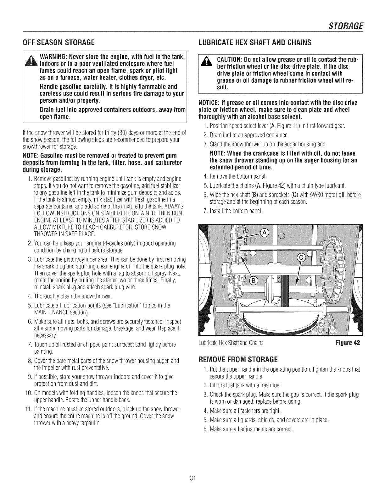
LUBRICATEHE×SHAFTAND CHAINS
CAUTION:Do notallow grease or oil to contactthe rub-
ber friction wheel or the discdrive plate, if the disc
drive plate or frictionwheel come in contactwith
grease or oil damageto rubberfriction wheel will re-
suit.
NOTICE:if grease or oil comesinto contactwith the discdrive
plate or frictionwheel, makesureto clean plate and wheel
thoroughlywith an alcohol base solvent.
1. Positionspeedselectlever(A,Figure11)in first forwardgear.
2. Drainfuelto anapprovedcontainer.
3. Standthesnowthrowerupontheaugerhousingend.
NOTE:When the crankcaseis filled with oil, do not leave
the snowthrowerstandingup on the auger housingfor an
extended periodof time.
4. Removethebottompanel.
5. Lubricatethechains(A, Figure42)witha chaintypelubricant.
6. Wipethehexshaft(B)andsprockets(C)with5W30motoroil, before
storageandatthebeginningof eachseason.
7. Installthebottompanel.
LubricateHexShaftandChains Figure42
REMOVEFROMSTORAGE
1. Puttheupperhandleintheoperatingposition,tightentheknobsthat
securetheupperhandle.
2. Fill thefueltankwithafreshfuel.
3. Checkthesparkplug.Makesurethegapis correct.Ifthesparkplug
is wornordamaged,replacebeforeusing.
4. Makesureall fastenersaretight.
5. Makesureall guards,shields,andcoversarein place.
6. Makesureall adjustmentsarecorrect.
31
TROUBLESHOOT/NG
PROBLEM LOOKFOR REMEDY
Free-HandTM controlisACTIVE. Releasebothaugercontrolandtraction/Free-HandTM controlleversto stopauger.
Augerdoes notstopwithin Augerdrivebeltout of Adjustaugerbelt.
j5 secondsafter right adjustment.
controllever is released. Augerbeltguideoutof Adjustaugerbeltguide.
adjustment.
Discharge chuteor Electricalfailure. Seeauthorizeddealer.
deflectordoes notwork
(electric).
Dischargechuteor Dischargechuteor deflectorout Adjustand/orlubricatecontrollinkage.
ideflectordoes notwork ofadjustmentor needs
i(remote-manual). lubrication.
Drive fails to move Tractioncontrolout of Readjustdrive,orselectspeedleversettingonespeedfaster.
snowthrowerat slow adjustment.
speeds.
Keyis off. Pushkeyinto theONposition.
Failureto primea coldengine. Pressprimerbuttontwiceandrestart.
Fuelshut-offvalveis in CLOSEDTurnvalveto OPENposition.
position.
Outof fuel. Fill fueltank.
Enginefalls to start. ChokeOFF- coldengine. TurnchokeON,setthrottleto FAST.
Engineflooded. Turnchoketo OFF;try starting.
Nospark. Checkgap.Gapsparkplug,cleanelectrode,or replaceplugas necessary.
Waterin fuel,oroldfuel. Draintank.(Disposeof fuel atanauthorizedhazardouswastefacility.)Fillwith
freshfuel.
Cordnot pluggedin or Plugin cordor replacedefectivecord.
malfunctions(ElectricStart
models).
Enginestarts hard or runs Fuelmixturetoo rich. Movechoketo OFFposition.
poorly. Sparkplugfaulty,fouled,or Cleanandgapsparkplug,or replace.
gappedimproperly.
Fuelcapventis blocked. Clearvent.
Excessive vibration. Loosepartsordamaged Stopengineimmediately.Tightenall hardware.Ifvibrationcontinues,havethe unit
impeller/auger, servicedby anauthorizeddealer.
Snowthrower does not Tractioncontrolout of Adjusttractioncontrollinkage.
stopwhen tractioncontrol adjustment.
lever is released.
Tirepressurenotequal. Checktire pressure.
Snowthrower veers to Onewheelis setinfree- Makesurethelefttractionlockpinis in theINNERholes(to engagethetraction
oneside. wheelingmode.(Tractionlock drive).
pinis in theOUTERhole.)
32
TROLIBLESHOOT/NG
PROBLEM LOOKFOR REMEDY
Scraper bar doesnot clean Skidshoesimproperlyadjusted. Raiseor lowerskidshoes.
hard surface.
Drivebelt looseor damaged. Replacedrivebelt.Seeauthorizeddealer.
Unit fails to propel itself. Incorrectadjustmentof traction Adjusttractioncontrolcable.Referto "CheckandAdjusttheCables"in the
drivecable. MAINTENANCEsectionof this manual.
Wornordamagedfrictiondisc. Replacefrictiondisc.Seeauthorizeddealer.
Augerdrivebelt looseor Replaceoradjustaugerdrivebelt.Referto "BeltAdjustment"in the
damaged. MAINTENANCEsectionof this manual,or seeauthorizeddealer.
Unit fails to discharge Augercontrolcablenotadjusted Adjustaugercontrolcable.Referto "CheckandAdjusttheCables"in the
snow. correctly. MAINTENANCEsectionof this manual.
Brokenshearpin. Replaceshearpin.Referto "AugerShearPinReplacement"inthe MAINTENANCE
sectionof thismanual.
Dischargechuteclogged. Stopengineimmediately.Alwaysusetheclean-outtoolto cleara clogged
dischargechute,notyour hands.Cleandischargechuteandinsideof auger
housing.Referto WARNINGSin OPERATORSAFETYsection.
Foreignobjectlodgedinauger. Stopengineimmediately.Alwaysusetheclean-outtoolto cleara cloggedchute,
notyourhands.Removeobjectfromauger.Referto WARNINGSin OPERATOR
SAFETYsection.
33
WARRANTIES
Craftsman Limited Warranty
General: Craftsman products are warranted to be free from defects in materials or workmanship for a specific time period
as set-out below (the "Warranty Period"). Warranties extend to the original purchaser of a Craftsman product only. Pur-
chases made through an online auction or through any website other than www.sears.ca are excluded. The relevant War-
ranty Period commences on the original date of purchase. Within this period, Sears Canada, Inc. will, at its sole option,
repair or replace any products or components which fail in normal use. Such repairs or replacement will be made at no
charge to the customer for parts or labor, provided that the customer shall be responsible for any transportation cost.
Exclusions: This warranty does not cover failures due to normal wear, abuse, misuse, neglect (including but not limited to
the use of stale fuel, dirt, abrasives, moisture, rust, corrosion, or any adverse reaction due to improper storage or use
habits), improper maintenance or failure to follow maintenance guidelines and/or instructions, failure to operate the prod-
uct in accordance with the owner's manual or any additional instructions or information provided at the time of purchase or
in subsequent communications with the original purchaser, accident or unauthorized alterations or repairs made or at-
tempted by others. Also excluded from warranty coverage - except as provided below - are the following: maintenance,
adjustments, components subject to wear including but not limited to: cosmetic components, belts, blades, blade adapters,
bulbs, tires, filters, guide bars, lubricants, seats, grips, recoil assemblies, saw chains and bars, trimmer lines and spools,
spark plugs, starter topers and tines, and discoloration resulting from ultraviolet light. Any product missing the model
and/or serial number identification label will be disqualified from coverage under this warranty.
Repairs: Repairs have a 90 day warranty. If the defective product is still within the Warranty Period, then the new warranty
is 90 days from the date of repair or to the end of the original Warranty Period, whichever period is longer.
Disclaimers: THE WARRANTIES AND REMEDIES CONTAINED HEREIN ARE EXCLUSIVE AND IN LIEU OF ALL
OTHER WARRANTIES, WHETHER ORAL OR WRITTEN (OTHER THAN AS STATED HEREIN), AND WHETHER EX-
PRESS, IMPLIED OR STATUTORY, INCLUDING BUT NOT LIMITED TO ANY. THIS WARRANTY GIVES YOU SPECIFIC
LEGAL RIGHTS, WHICH MAY VARY FROM PROVINCE TO PROVINCE.
IN NO EVENT SHALL SEARS BE LIABLE FOR ANY INCIDENTAL, SPECIAL, INDIRECT OR CONSEQUENTIAL DAM-
AGES, WHETHER RESULTING FROM THE USE, MISUSE OR INABILITY TO USE THE PRODUCT OR FROM DE-
FECTS IN THE PRODUCT. THE EXCLUSIONS IN THIS PARAGRAPH SHALL NOT APPLY IN JURISDICATIONS
WHERE APPLICABLE LAW DOES NOT ALLOW FOR THE EXCLUSION OF INCIDENTAL OR CONSEQUENTIAL DAM-
AGES. IN SUCH JURISDICTIONS, THIS PARAGRAPH SHALL NOT APPLY, BUT THE REMAINING PROVISIONS OF
THIS DOCUMENT SHALL REMAIN VALID.
Sears retains the exclusive right to repair or replace the product or offer a full refund of the purchase price at its sole dis-
cretion. SUCH REMEDY SHALL BE YOUR SOLE AND EXCLUSIVE REMEDY FOR ANY BREACH OF WARRANTY.
Customer Responsibilities: In additional to complying with all suggested maintenance guidelines and instructions, cus-
tomers' obligations shall include but shall not be limited to: operating the product in accordance with the owner's manual or
any additional instructions or information provided at the time of purchase or in subsequent communications to the pur-
chaser from time to time, exhibit reasonable care in the use, operation, maintenance, general upkeep and storage of the
product. Failure to comply with these requirements will void any applicable warranty.
List of Applicable Warranty Periods: The following list contains the applicable Warranty Period for your Craftsman prod-
uct and is based on a combination of the type of product or component and the intended and actual use of the product or
component:
1. 90 days: Craftsman products intended for use or actually used for commercial, institutional, professional or income-
producing purposes.
,2 years: Craftsman riding lawn mowers, yard and garden tractors, walk behind mowers, tillers, brush cutters, snow
blowers, handheld blowers, backpack blowers, hedge trimmers and electrical products for noncommercial, nonprofes-
sional, non-institutional, or non-income-producing use, except for those components which are part of engine systems
manufactured by third party engine manufacturers for which the purchase has received an separate warranty with
product information supplied at the time of purchase.
34
WARRANT/ES
3. I year: Craftsman power cutters, stump grinders, pole pruners, gas chain saws, electric chain saws, trimmer attach-
ments, baggers and pole saws for noncommercial, nonprofessional, non-institutional, or non-income-producing use.
4. 90 days: All defective batteries, which will be replaced during this 90-day Warranty Period.
,60 days: Additional Warranty Period of 60 days will apply to adjustments and worn products or components BUT
DOES NOT INCLUDE WEAR OR ADJUSTMENTS for products used for commercial, institutional, professional or in-
come-producing purposes. Wear items include but are not limited to: belts, blades, tires, spark plugs, air filters,
chains, shear bolts, skid plates, scraper bars, drift cutters, ropes, tines, collection bags and pulleys.
As the Warranty Period runs from the date of purchase and NOT from the date that a product is delivered, opened, as-
sembled or first used, please ensure during this time period that your product or component has been assembled and
tested for correction operation regardless of when you intend to actually use it. Claims made after the Warranty Period
has expired will not be honored.
Proof of Purchase/Documentation: Warranty coverage is conditioned upon the original purchaser furnishing Sears
Canada or its authorized third party service provider if applicable, with the original sales receipt or other adequate written
proof of the original purchase date and identification of the product. In the event that the original purchaser is unable to
provide a company of the original sales receipt, Sears Canada Inc. reserves the right to determine in its sole discretion
what other written proof of the original purchase date and identification of the product is acceptable.
Revision: 03/13/2009
Maintenance Agreement
The Craftsman Warranty plus a Maintenance Agreement, provide maximum value for Sears products. Contact your near-
est Sears store for details.
35
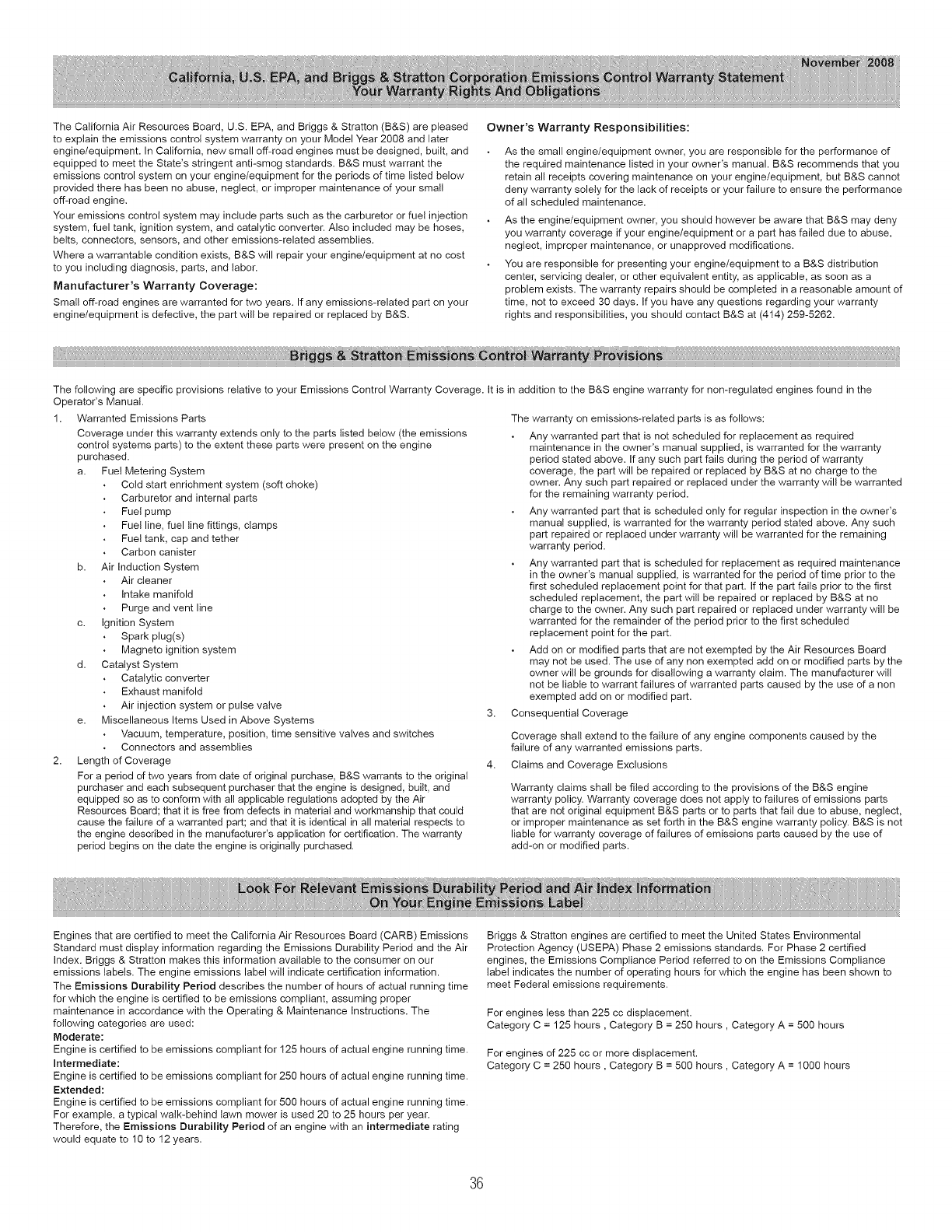
The California Air Resources Board, U.S. EPA, and Briggs & Stratton (B&S) are pleased
to explain the emissions controt system warranty on your Model Year 2008 and later
engine/equipment. In California, new small off-road engines must be designed, built, and
equipped to meet the State's stringent anti-smog standards. B&S must warrant the
emissions control system on your engine/equipment for the periods of time listed below
provided there has been no abuse, neglect, or improper maintenance of your small
off-road engine.
Your emissions controt system may include parts such as the carburetor or fuel injection
system, fuel tank, ignition system, and catalytic converter. Also included may be hoses,
belts, connectors, sensors, and other emissions-related assemblies.
Where a warrantable condition exists, B&S will repair your engine/equipment at no cost
to you including diagnosis, parts, and labor.
Manufacturer's Warranty Coverage:
Small off-road engines are warranted for two years. If any emissions-related part on your
engine/equipment is defective, the part will be repaired or replaced by B&S.
Owner's Warranty Responsibitities:
As the small engine/equipment owner, you are responsible for the performance of
the required maintenance listed in your owner's manual. B&S recommends that you
retain all receipts covering maintenance on your engine/equipment, but B&S cannot
deny warranty solely for the lack of receipts or your failure to ensure the performance
of all scheduled maintenance.
As the engine/equipment owner, you should however be aware that B&S may deny
you warranty coverage if your engine/equipment or a part has failed due to abuse,
neglect, improper maintenance, or unapproved modifications.
You are responsible for presenting your engine/equipment to a B&S distribution
center, servicing dealer, or other equivalent entity, as applicable, as soon as a
problem exists. The warranty repairs should be completed in a reasonable amount of
time, not to exceed 30 days. If you have any questions regarding your warranty
rights and responsibilities, you should contact B&S at (414) 259-5262.
The following are specific provisions relative to your Emissions Control Warranty Coverage. It is in addition to the B&S engine warranty for non-regulated engines found in the
Operator's Manual.
1. Warranted Emissions Parts
Coverage under this warranty extends only to the parts listed below (the emissions
control systems parts) to the extent these parts were present on the engine
purchased.
a. Fue! Metering System
Cold start enrichment system (soft choke)
Carburetor and internal parts
Fuel pump
Fuel line, fuel line fittings, clamps
Fuel tank, cap and tether
Carbon canister
b. Air Induction System
Air cleaner
Intake manifold
Purge and vent line
c. Ignition System
Spark plug(s)
Magneto ignition system
d. Catalyst System
Catalytic converter
Exhaust manifold
Air injection system or pulse valve
e. Miscellaneous Items Used in Above Systems
Vacuum, temperature, position, time sensitive valves and switches
Connectors and assemblies
2. Length of Coverage
For a period of two years from date of original purchase, B&S warrants to the original
purchaser and each subsequent purchaser that the engine is designed, built, and
equipped so as to conform with all applicable regulations adopted by the Air
Resources Board; that it is free from defects in material and workmanship that could
cause the failure of a warranted part; and that it is identical in all material respects to
the engine described in the manufacturer's application for certification. The warranty
period begins on the date the engine is originally purchased.
4.
The warranty on emissions-related parts is as follows:
Any warranted part that is not scheduled for replacement as required
maintenance in the owner's manual supplied, is warranted for the warranty
period stated above. If any such part fails during the period of warranty
coverage, the part will be repaired or replaced by B&S at no charge to the
owner. Any such part repaired or replaced under the warranty will be warranted
for the remaining warranty period.
Any warranted part that is scheduled only for regular inspection in the owner's
manual supplied, is warranted for the warranty period stated above. Any such
part repaired or replaced under warranty will be warranted for the remaining
warranty period.
Any warranted part that is scheduled for replacement as required maintenance
in the owner's manual supplied, is warranted for the period of time prior to the
first scheduled replacement point for that part. If the part fails prior to the first
scheduled replacement, the part wilt be repaired or replaced by B&S at no
charge to the owner. Any such part repaired or replaced under warranty will be
warranted for the remainder of the period prior to the first scheduled
replacement point for the part.
Add on or modified parts that are not exempted by the Air Resources Board
may not be used. The use of any non exempted add on or modified parts by the
owner will be grounds for disallowing a warranty claim. The manufacturer wilt
not be liable to warrant failures of warranted parts caused by the use of a non
exempted add on or modified part.
Consequential Coverage
Coverage shall extend to the failure of any engine components caused by the
failure of any warranted emissions parts.
Claims and Coverage Exclusions
Warranty claims shall be filed according to the provisions of the B&S engine
warranty policy. Warranty coverage does not apply to failures of emissions parts
that are not original equipment B&S parts or to parts that fail due to abuse, neglect,
or improper maintenance as set forth in the B&S engine warranty policy. B&S is not
liable for warranty coverage of failures of emissions parts caused by the use of
add-on or modified parts.
Engines that are certified to meet the California Air Resources Board (CARB) Emissions
Standard must display information regarding the Emissions Durability Period and the Air
Index. Briggs & Stratton makes this information available to the consumer on our
emissions labels. The engine emissions label will indicate certification information.
The Emissions Durability Period describes the number of hours of actual running time
for which the engine is certified to be emissions compliant, assuming proper
maintenance in accordance with the Operating & Maintenance Instructions. The
following categories are used:
Moderate:
Engine is certified to be emissions compliant for 125 hours of actual engine running time.
Intermediate:
Engine is certified to be emissions compliant for 250 hours of actual engine running time.
Extended:
Engine is certified to be emissions compliant for 500 hours of actual engine running time.
For example, a typical walk-behind lawn mower is used 20 to 25 hours per year.
Therefore, the Emissions Durability Period of an engine with an intermediate rating
would equate to 10 to 12 years.
Briggs & Stratton engines are certified to meet the United States Environmental
Protection Agency (USEPA) Phase 2 emissions standards. For Phase 2 certified
engines, the Emissions Compliance Period referred to on the Emissions Compliance
label indicates the number of operating hours for which the engine has been shown to
meet Federal emissions requirements.
For engines less than 225 cc displacement.
Category C = 125 hours, Category B = 250 hours, Category A = 500 hours
For engines of 225 cc or more displacement.
Category C = 250 hours, Category B = 500 hours, Category A = 1000 hours
36
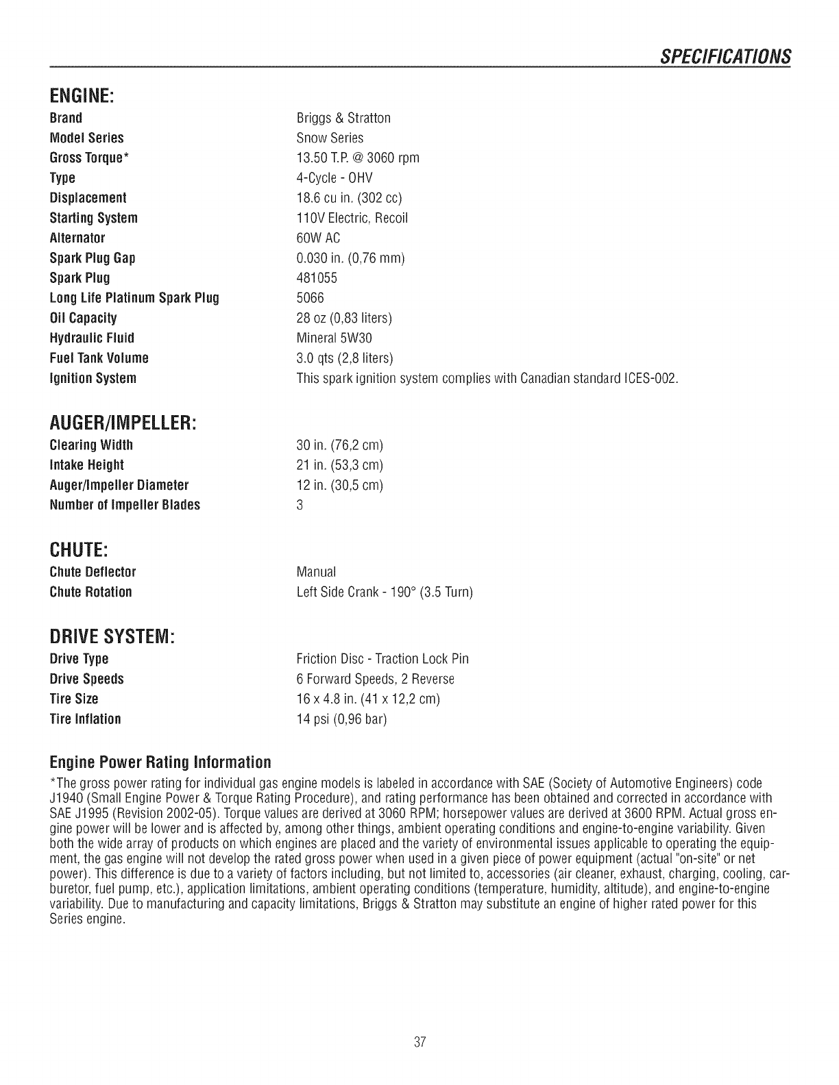
SPECIFICAT/ONS
ENGINE:
Brand
IVlodelSeries
GrossTorque*
Type
Displacement
Starting System
Alternator
SparkPlug Gap
Spark Ping
LongLife PlatinumSpark Ping
Oil Capacity
HydraulicFluid
Fuel TankVolume
ignition System
Briggs & Stratton
Snow Series
13.50 T.P.@3060 rpm
4-Cycle - OHV
18.6 cu in. (302 cc)
110V Electric, Recoil
60W AC
0.030 in. (0,76 ram)
481055
5066
28 oz (0,83 liters)
Mineral 5W30
3.0 qts (2,8 liters)
This spark ignition system complies with Canadianstandard ICES-002.
AUGER/IMPELLER:
Clearing Width
Intake Height
Auger/ImpellerDiameter
Number of Impeller 8lades
30 in. (76,2 cm)
21 in. (53,3 cm)
12 in. (30,5 cm)
3
CHUTE:
Chute Deflector
Chute Rotation
Manual
Left SideCrank- 190° (3.5 Turn)
DRIVESYSTEM:
Drive Type
DriveSpeeds
Tire Size
Tire Inflation
Friction Disc - Traction Lock Pin
6 ForwardSpeeds,2 Reverse
16 x 4.8 in. (41 x 12,2 cm)
14 psi (0,96 bar)
EnginePowerRating Information
*The gross power rating for individual gas engine models is labeledin accordancewith SAE(Society of Automotive Engineers) code
J1940 (Small Engine Power & Torque Rating Procedure),and rating performance has beenobtained and corrected in accordancewith
SAEJ1995 (Revision 2002-05). Torquevalues are derived at 3060 RPM; horsepower valuesare derived at 3600 RPM. Actual gross en-
gine power will be lower and is affected by, among other things, ambient operating conditions and engine-to-engine variability. Given
both the wide array of products on which engines areplaced and the variety of environmental issues applicableto operating the equip-
ment, the gas enginewill not develop the rated gross powerwhen used in a given piece of power equipment (actual"on-site" or net
power). This difference is due to avariety of factors including, but not limited to, accessories (air cleaner,exhaust,charging, cooling, car-
buretor, fuel pump, etc.), application limitations, ambient operating conditions (temperature, humidity, altitude), and engine-to-engine
variability. Dueto manufacturing and capacity limitations, Briggs & Stratton maysubstitute an engine of higher rated power for this
Series engine.
37

38

RepairParts
PTS - 1
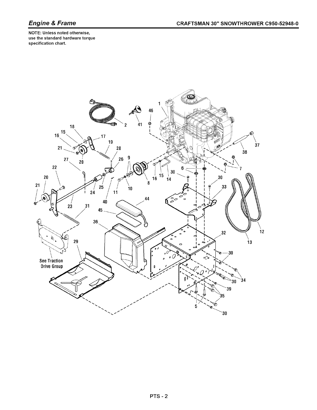
Engine & Frame CRAFTSMAN 30" SNOWTHROWER C950-52948-0
NOTE: Unless noted otherwise,
use the standard hardware torque
specification chart.
2O
21
/
/
I
/
I24
25 \8
10
1
44
40
23 31
29
46
/
I
I
37
_12
\13
SeeTraction
DriveGroup
/
PTS -2
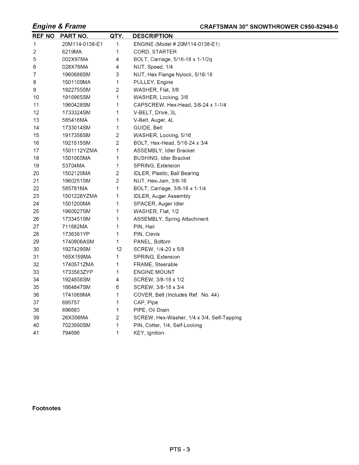
Engine & Frame
REF NO PART NO. QTY.
1 20M114-0138-E1 1
2 6219MA 1
5 002X97MA 4
6 028X76MA 4
7 1960686SM 3
8 1501109MA 1
9 1922755SM 2
10 1916965SM 1
11 1960428SM 1
12 1733324SM 1
13 585416MA 1
14 1733014SM 1
15 1917356SM 2
16 1921515SM 2
17 1501112YZMA 1
18 1501065MA 1
19 53704MA 1
20 1502120MA 2
21 1960251SM 2
22 585781MA 1
23 1501226YZMA 1
24 1501200MA 1
25 1960027SM 1
26 1733451SM 1
27 711682MA 1
28 1736381YP 1
29 1740906ASM 1
30 1927429SM 12
31 165X159MA 1
32 1740571ZMA 1
33 1733583ZYP 1
34 1924856SM 4
35 1664847SM 6
36 1741069MA 1
37 695757 1
38 696683 1
39 26X306MA 2
40 7023590SM 1
41 794696 1
CRAFTSMAN 30" SNOWTHROWER C950-52948-0
DESCRIPTION
ENGINE (Model # 20M114-0138-E1 )
CORD, STARTER
BOLT, Carriage, 5/16-18 x 1-1/2q
NUT, Speed, 1/4
NUT, Hex Flange Nylock, 5/16-18
PULLEY, Engine
WASHER, Fiat, 3/8
WASHER, Locking, 3/8
CAPSCREW, Hex-Head, 3/8-24 x 1-1/4
V-BELT, Drive, 3L
V-Belt, Auger, 4L
GUIDE, Belt
WASHER, Locking, 5/16
BOLT, Hex-Head, 5/16-24 x 3/4
ASSEMBLY, Idler Bracket
BUSHING, Idler Bracket
SPRING, Extension
IDLER, Plastic, Bail Bearing
NUT, Hex-Jam, 3/8-16
BOLT, Carriage, 3/8-16 x 1-1/4
IDLER, Auger Assembly
SPACER, Auger Idler
WASHER, Fiat, 1/2
ASSEMBLY, Spring Attachment
PIN, Hair
PIN, Clevis
PANEL, Bottom
SCREW, 1/4-20 x 5/8
SPRING, Extension
FRAME, Steerable
ENGINE MOUNT
SCREW, 3/8-18 x 1/2
SCREW, 3/8-18 x 3/4
COVER, Belt (Includes Ref. No. 44)
CAP, Pipe
PIPE, Oil Drain
SCREW, Hex-Washer, 1/4 x 3/4, Self-Tapping
PIN, Cotter, 1/4, Self-Locking
KEY, Ignition
Footnotes
PTS -3

Engine & Frame CRAFTSMAN 30" SNOWTHROWER C950-52948-0
NOTE: Unless noted otherwise,
use the standard hardware torque
specification chart.
2O
21
/
/
I
/
I24
25 \8
10
1
44
40
23 31
29
46
/
I
I
37
_12
\13
SeeTraction
DriveGroup
/
PTS -4

Engine & Frame
REF NO PART NO.
44 760539MA
45 761187MA
46 2831277SM
QTY.
1
1
1
CRAFTSMAN 30" SNOWTHROWER C950-52948-0
DESCRIPTION
LID, Toolbox
PAD, Foam
NUT, Hex Flange, 5/16-18 Whiz Lock Small
Footnotes
PTS - 5
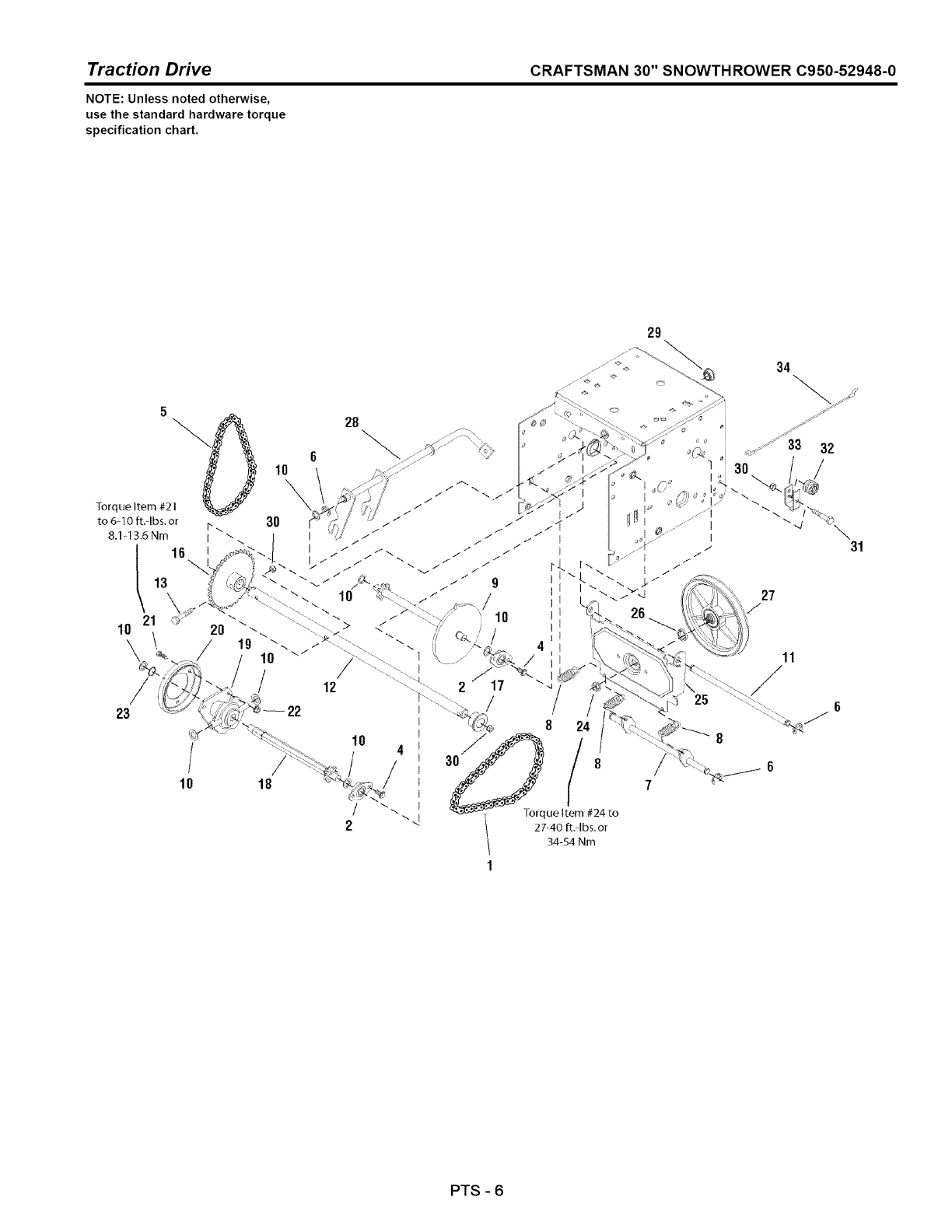
Traction Drive CRAFTSMAN 30" SNOWTHROWER C950-52948-0
NOTE: Unless noted otherwise,
use the standard hardware torque
specification chart.
29
/
10
/
22
18
12
10
/
2
I
/_
"- _ -lo_que Item #24 to
" "< \ 27-40 ft.-Ibs.o_
34-54 Nm
1
23
11
F6
6
7
PTS -6
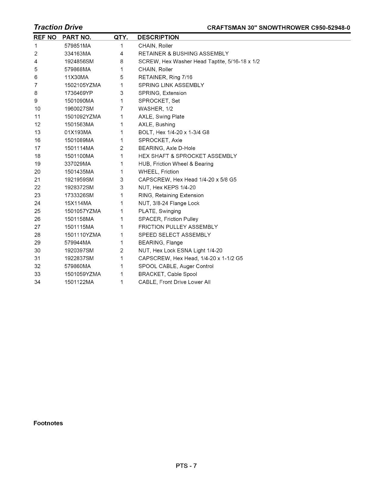
Traction Drive
REF NO PART NO. QTY.
1 579851MA 1
2 334163MA 4
4 1924856SM 8
5 579868MA 1
6 11X30MA 5
7 1502105YZMA 1
8 1736469YP 3
9 1501090MA 1
10 1960027SM 7
11 1501092YZMA 1
12 1501563MA 1
13 01X193MA 1
16 1501089MA 1
17 1501114MA 2
18 1501100MA 1
19 337029MA 1
20 1501435MA 1
21 1921959SM 3
22 1928372SM 3
23 1733326SM 1
24 15X114MA 1
25 1501057YZMA 1
26 1501158MA 1
27 1501115MA 1
28 1501110YZMA 1
29 579944MA 1
30 1920397SM 2
31 1922837SM 1
32 579860MA 1
33 1501059YZMA 1
34 1501122MA 1
CRAFTSMAN 30" SNOWTHROWER C950-52948-0
DESCRIPTION
CHAIN, Roller
RETAINER & BUSHING ASSEMBLY
SCREW, Hex Washer Head Taptite, 5/16-18 x 1/2
CHAIN, Roller
RETAINER, Ring 7/16
SPRING LINK ASSEMBLY
SPRING, Extension
SPROCKET, Set
WASHER, 1/2
AXLE, Swing Plate
AXLE, Bushing
BOLT, Hex 1/4-20 x 1-3/4 G8
SPROCKET, Axle
BEARING, Axle D-Hole
HEX SHAFT & SPROCKET ASSEMBLY
HUB, Friction Wheel & Bearing
WHEEL, Friction
CAPSCREW, Hex Head 1/4-20 x 5/8 G5
NUT, Hex KEPS 1/4-20
RING, Retaining Extension
NUT, 3/8-24 Flange Lock
PLATE, Swinging
SPACER, Friction Pulley
FRICTION PULLEY ASSEMBLY
SPEED SELECT ASSEMBLY
BEARING, Flange
NUT, Hex Lock ESNA Light 1/4-20
CAPSCREW, Hex Head, 1/4-20 x 1-1/2 G5
SPOOL CABLE, Auger Control
BRACKET, Cable Spool
CABLE, Front Drive Lower All
Footnotes
PTS - 7
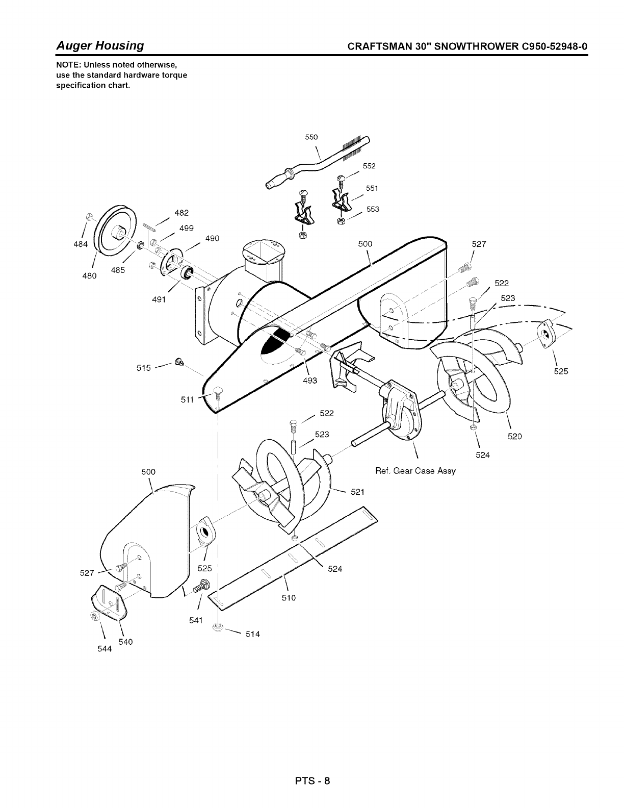
Auger Housing CRAFTSMAN 30" SNOWTHROWER C950-52948-0
NOTE: Unless noted otherwise,
use the standard hardware torque
specification chart.
/
484 /
480 485
491
482
499
490 527
522
523
J
500
493
522
J
523 \
Ref. Gear Case Assy
\
524
\
525
52O
527
\
525' 524
\
544
\
540
541
514
510
PTS -8
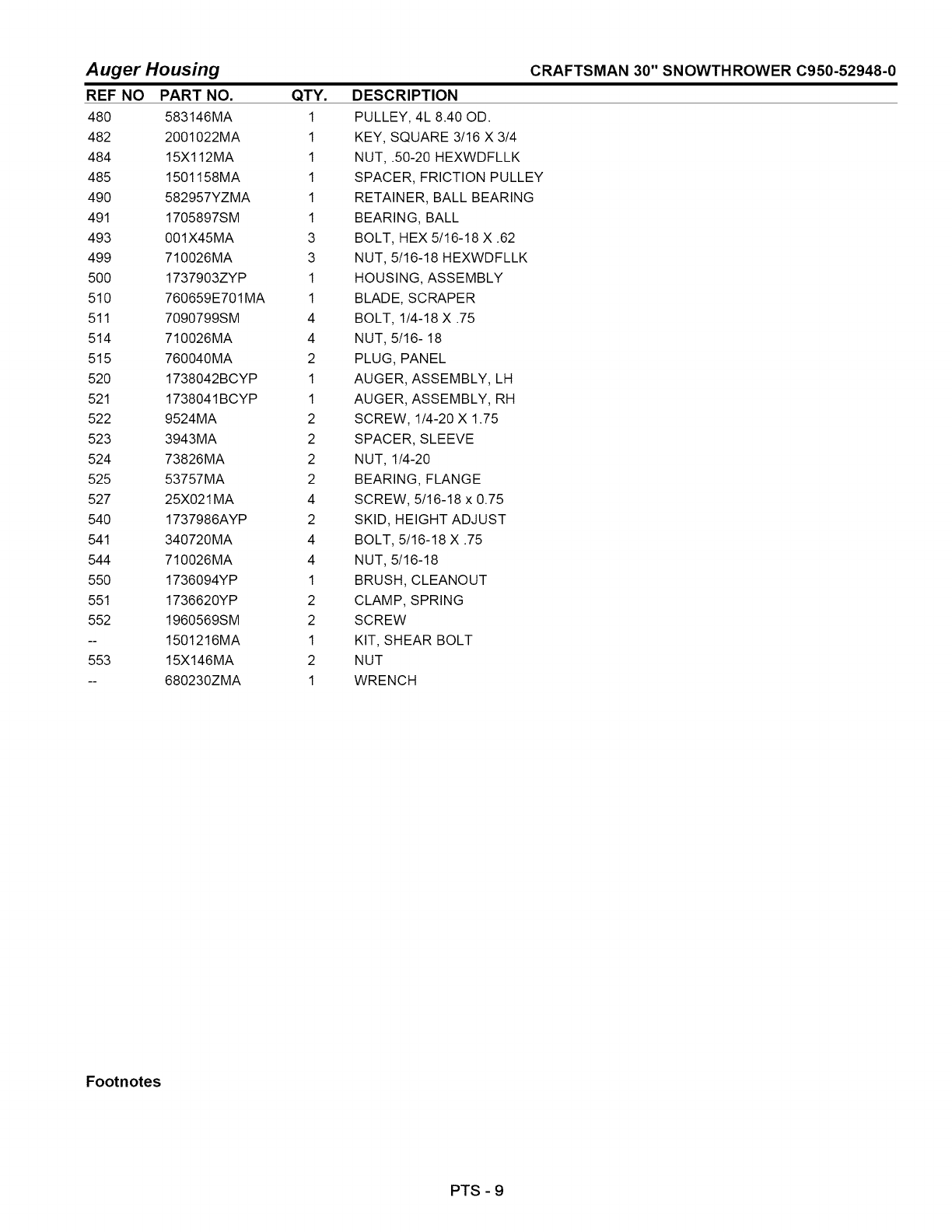
Auger Housing CRAFTSMAN 30" SNOWTHROWER C950-52948-0
REF NO
48O
482
484
485
49O
491
493
499
5OO
510
511
514
515
520
521
522
523
524
525
527
540
541
544
550
551
552
553
PART NO. QTY.
583146MA 1
2001022MA 1
15X112MA 1
1501158MA 1
582957YZMA 1
1705897SM 1
001X45MA 3
710026MA 3
1737903ZYP 1
760659E701MA 1
7090799SM 4
710026MA 4
760040MA 2
1738042BCYP 1
1738041BCYP 1
9524MA 2
3943MA 2
73826MA 2
53757MA 2
25X021 MA 4
1737986AYP 2
340720MA 4
710026MA 4
1736094YP 1
1736620YP 2
1960569SM 2
1501216MA 1
15X146MA 2
680230ZMA 1
DESCRIPTION
PULLEY, 4L 8.40 OD.
KEY, SQUARE 3/16 X 3/4
NUT, .50-20 HEXWDFLLK
SPACER, FRICTION PULLEY
RETAINER, BALL BEARING
BEARING, BALL
BOLT, HEX 5/16-18 X .62
NUT, 5/16-18 HEXWDFLLK
HOUSING, ASSEMBLY
BLADE, SCRAPER
BOLT, 1/4-18 X .75
NUT, 5/16- 18
PLUG, PANEL
AUGER, ASSEMBLY, LH
AUGER, ASSEMBLY, RH
SCREW, 1/4-20 X 1.75
SPACER, SLEEVE
NUT, 1/4-20
BEARING, FLANGE
SCREW, 5/16-18 x 0.75
SKID, HEIGHT ADJUST
BOLT, 5/16-18 X .75
NUT, 5/16-18
BRUSH, CLEANOUT
CLAMP, SPRING
SCREW
KIT, SHEAR BOLT
NUT
WRENCH
Footnotes
PTS - 9
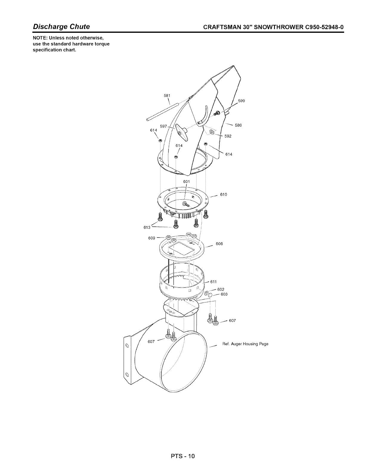
Discharge Chute CRAFTSMAN 30" SNOWTHROWER C950-52948-0
NOTE: Unless noted otherwise,
use the standard hardware torque
specification chart.
581
\599
614
\,
580
592
614
606
602
Ref. Auger Housing Page
PTS -10
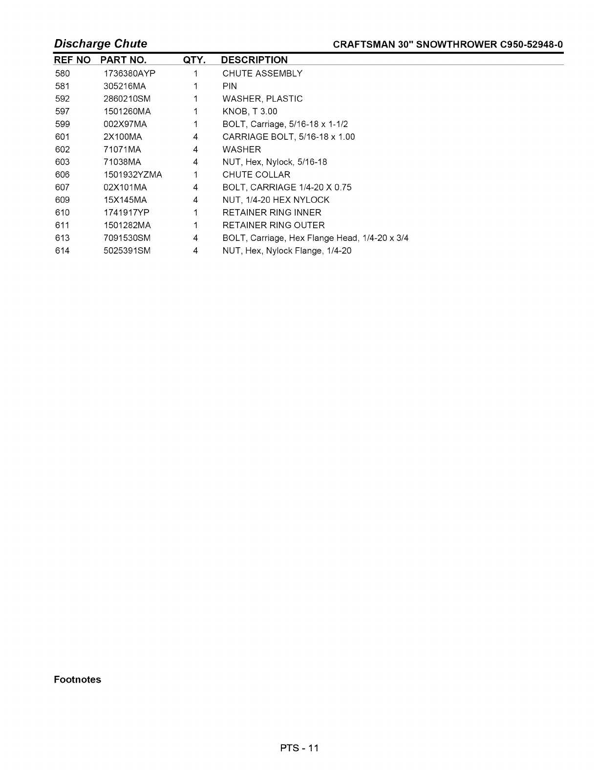
Discharge Chute
REF NO PART NO. QTY.
580 1736380AYP 1
581 305216MA 1
592 2860210SM 1
597 1501260MA 1
599 002X97MA 1
601 2X100MA 4
602 71071MA 4
603 71038MA 4
606 1501932YZMA 1
607 02X101 MA 4
609 15X145MA 4
610 1741917YP 1
611 1501282MA 1
613 7091530SM 4
614 5025391SM 4
CRAFTSMAN 30" SNOWTHROWER C950-52948-0
DESCRIPTION
CHUTE ASSEMBLY
PIN
WASHER, PLASTIC
KNOB, T 3.00
BOLT, Carriage, 5/16-18 x 1-1/2
CARRIAGE BOLT, 5/16-18 x 1.00
WASHER
NUT, Hex, NyIock, 5/16-18
CHUTE COLLAR
BOLT, CARRIAGE 1/4-20 X 0.75
NUT, 1/4-20 HEX NYLOCK
RETAINER RING INNER
RETAINER RING OUTER
BOLT, Carriage, Hex Flange Head, 1/4-20 x 3/4
NUT, Hex, NyIock Flange, 1/4-20
Footnotes
PTS - 11
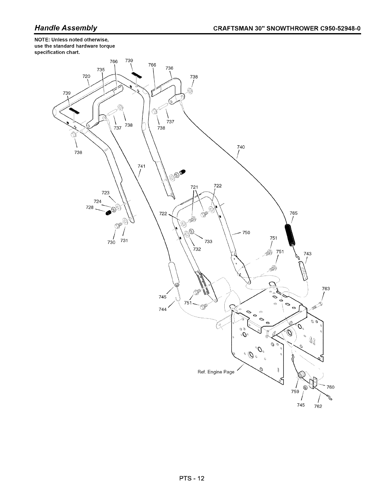
Handle Assembly CRAFTSMAN 30" SNOWTHROWER C950-52948-0
NOTE: Unless noted otherwise,
use the standard hardware torque
specification chart.
766
735
720
\
739
739
\766
738
\
738
740
723
724 _'x
728
/
730
/
731
721 722
Ref. Engine Page
751
/
_) 751
765
/
743
f
/
759
745
763
/
762
PTS -12
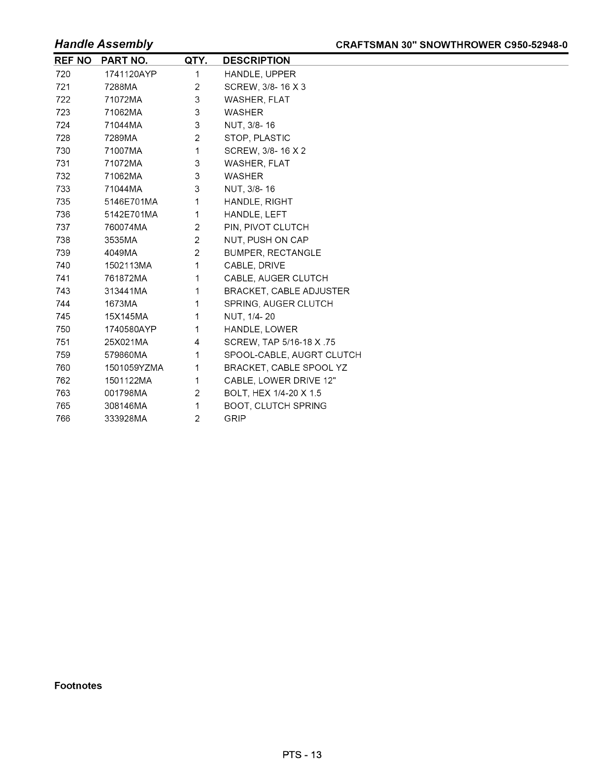
Handle Assembly
REF NO PART NO. QTY.
720 1741120AYP 1
721 7288MA 2
722 71072MA 3
723 71062MA 3
724 71044MA 3
728 7289MA 2
730 71007MA 1
731 71072MA 3
732 71062MA 3
733 71044MA 3
735 5146E701MA 1
736 5142 E701 MA 1
737 760074MA 2
738 3535MA 2
739 4049MA 2
740 1502113MA 1
741 761872MA 1
743 313441 MA 1
744 1673MA 1
745 15X145MA 1
750 1740580AYP 1
751 25X021 MA 4
759 579860MA 1
760 1501059YZMA 1
762 1501122MA 1
763 001798MA 2
765 308146MA 1
766 333928MA 2
CRAFTSMAN 30" SNOWTHROWER C950-52948-0
DESCRIPTION
HANDLE, UPPER
SCREW, 3/8- 16 X 3
WASHER, FLAT
WASHER
NUT, 3/8- 16
STOP, PLASTIC
SCREW, 3/8- 16 X 2
WASHER, FLAT
WASHER
NUT, 3/8- 16
HANDLE, RIGHT
HANDLE, LEFT
PIN, PIVOT CLUTCH
NUT, PUSH ON CAP
BUMPER, RECTANGLE
CABLE, DRIVE
CABLE, AUGER CLUTCH
BRACKET, CABLE ADJUSTER
SPRING, AUGER CLUTCH
NUT, 1/4- 20
HANDLE, LOWER
SCREW, TAP 5/16-18 X .75
SPOOL-CABLE, AUGRT CLUTCH
BRACKET, CABLE SPOOL YZ
CABLE, LOWER DRIVE 12"
BOLT, HEX 1/4-20 X 1.5
BOOT, CLUTCH SPRING
GRIP
Footnotes
PTS - 13
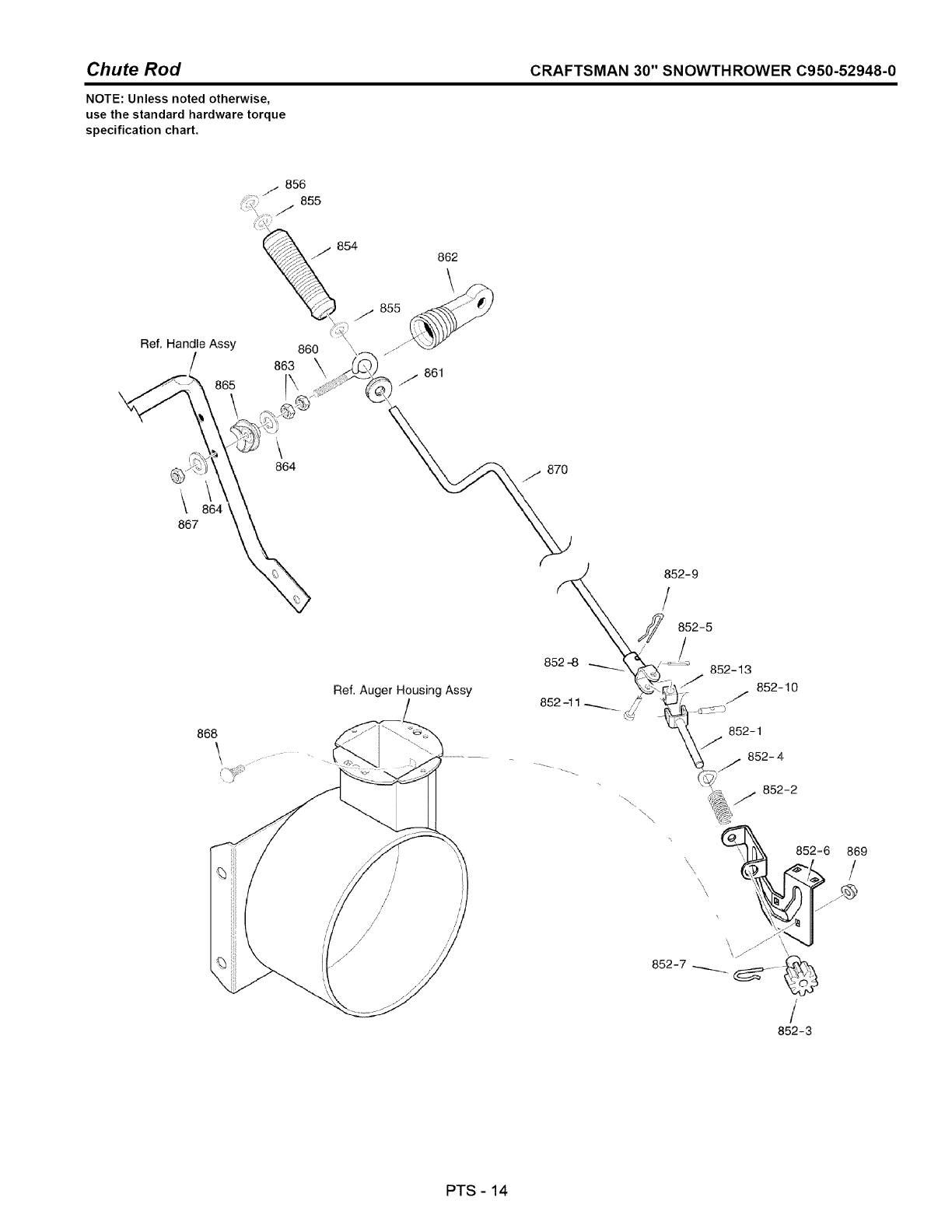
Chute Rod CRAFTSMAN 30" SNOWTHROWER C950-52948-0
NOTE: Unless noted otherwise,
use the standard hardware torque
specification chart.
Ref. Handle Assy
/
865
867
\
864
862
\
861
/870
Ref. Auger Housing Assy
868
\, ,% 852=6 869
852-7__._ _._
b--.,,
/
852-3
PTS - 14
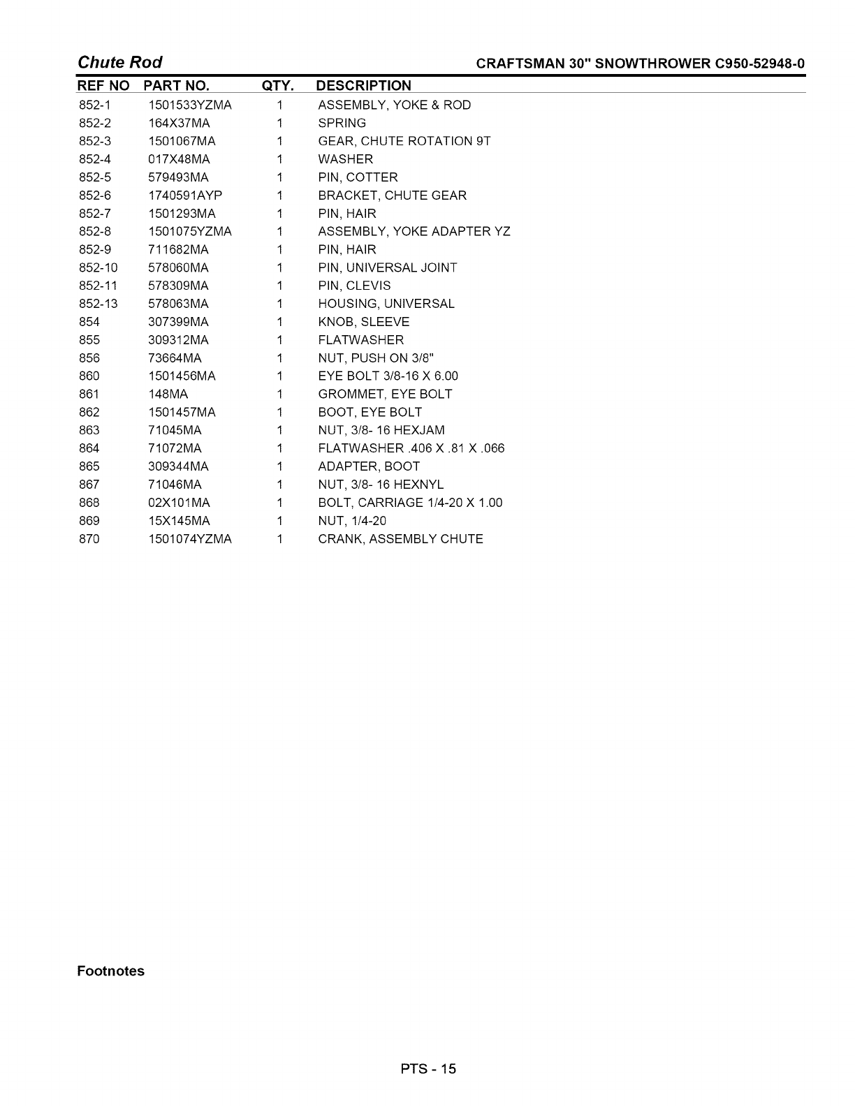
Chute Rod
REF NO PART NO.
852-1 1501533YZMA
852-2 164X37MA
852-3 1501067MA
852-4 017X48MA
852-5 579493MA
852-6 1740591AYP
852-7 1501293MA
852-8 1501075YZMA
852-9 711682MA
852-10 578060MA
852-11 578309MA
852-13 578063MA
854 307399MA
855 309312MA
856 73664MA
860 1501456MA
861 148MA
862 1501457MA
863 71045MA
864 71072MA
865 309344MA
867 71046MA
868 02X101 MA
869 15X145MA
870 1501074YZMA
QTY.
1
1
1
1
1
1
1
1
1
1
1
1
1
1
1
1
1
1
1
1
1
1
1
1
1
CRAFTSMAN 30" SNOWTHROWER C950-52948-0
DESCRIPTION
ASSEMBLY, YOKE & ROD
SPRING
GEAR, CHUTE ROTATION 9T
WASHER
PIN, COTTER
BRACKET, CHUTE GEAR
PIN, HAIR
ASSEMBLY, YOKE ADAPTER YZ
PIN, HAIR
PIN, UNIVERSAL JOINT
PIN, CLEVIS
HOUSING, UNIVERSAL
KNOB, SLEEVE
FLATWAS H ER
NUT, PUSH ON 3/8"
EYE BOLT 3/8-16 X 6.00
GROMMET, EYE BOLT
BOOT, EYE BOLT
NUT, 3/8- 16 HEXJAM
FLATWASHER .406 X .81 X .066
ADAPTER, BOOT
NUT, 3/8- 16 HEXNYL
BOLT, CARRIAGE 1/4-20 X 1.00
NUT, 1/4-20
CRANK, ASSEMBLY CHUTE
Footnotes
PTS -15
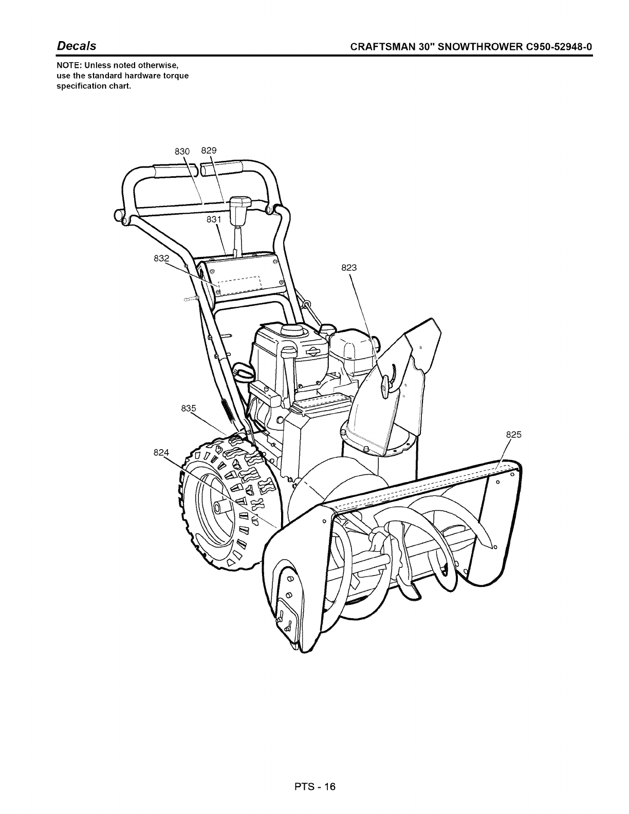
Decals CRAFTSMAN 30" SNOWTHROWER C950-52948-0
NOTE: Unless noted otherwise,
use the standard hardware torque
specification chart.
830 829
835 '_
824
823
\
825
PTS -16

Decals
REF NO
823
824
825
829
830
831
832
835
PART NO.
1737865YP
1737866YP
1741434MA
1739118YP
1739117YP
1739120YP
48X5565MA
QTY.
1
1
1
1
1
1
1
1
DESCRIPTION
DECAL
DECAL
DECAL
DECAL
DECAL
DECAL
DECAL
DECAL
CRAFTSMAN 30" SNOWTHROWER C950-52948-0
DANGER CHUTE HAND
DANGER FOOT
CRAFTSMAN 1550/30
DRIVE CLUTCH
AUGER CLUTCH
GEAR SELECTOR
CRAFTSMAN
ID PLATE
Footnotes
PTS - 17
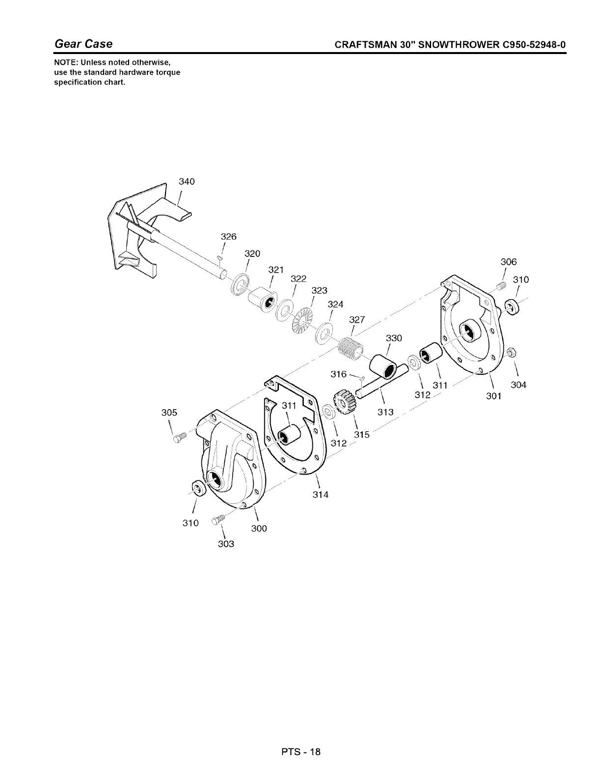
Gear Case CRAFTSMAN 30" SNOWTHROWER C950-52948-0
NOTE: Unless noted otherwise,
use the standard hardware torque
specification chart.
340
305
326
/320
/321
322
323
/324
/
311
327 •
330
311
\ 312 .....
313
/.//
306
/310
\
304
301
/
310
303
300
\
314
PTS - 18
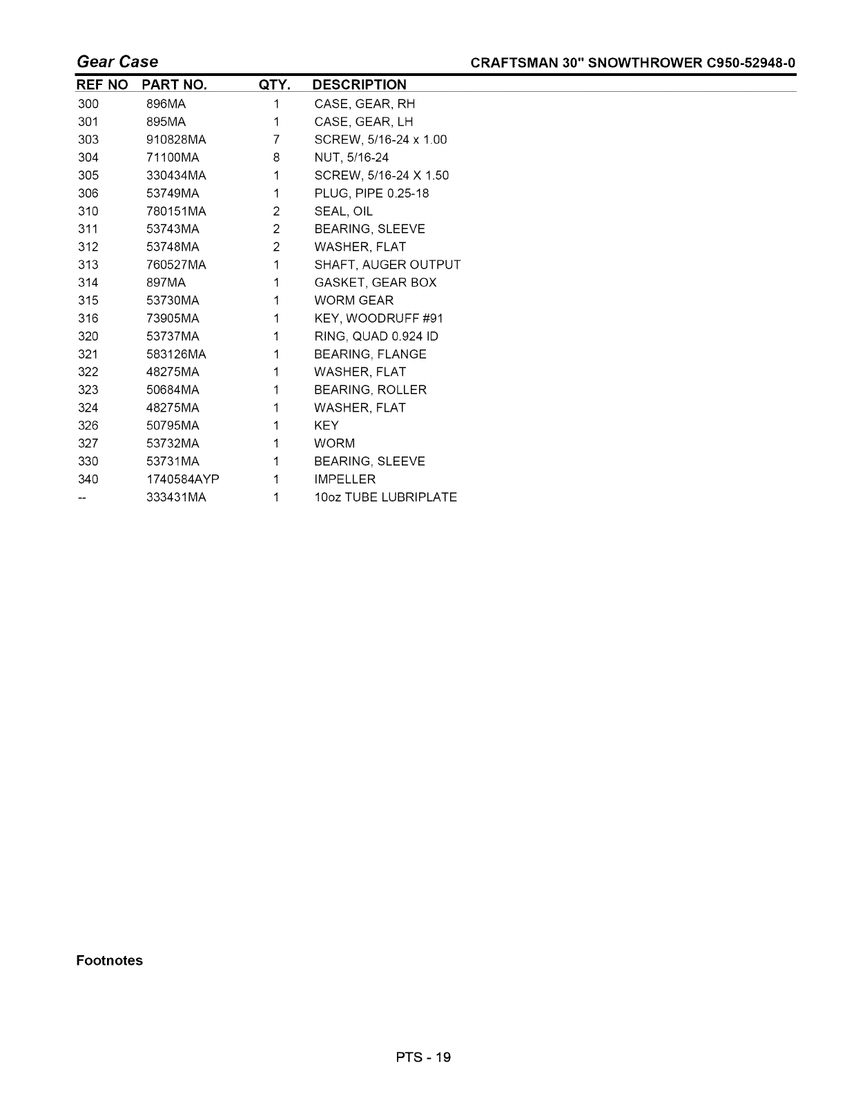
Gear Case CRAFTSMAN 30" SNOWTHROWER C950-52948-0
REF NO
300
301
303
304
305
306
310
311
312
313
314
315
316
32O
321
322
323
324
326
327
33O
34O
PART NO.
896MA
895MA
910828MA
71100MA
330434MA
53749MA
780151MA
53743MA
53748MA
760527MA
897MA
53730MA
73905MA
53737MA
583126MA
48275MA
50684MA
48275MA
50795MA
53732MA
53731MA
1740584AYP
333431 MA
QTY.
1
1
7
8
1
1
2
2
2
1
1
1
1
1
1
1
1
1
1
1
1
1
1
DESCRIPTION
CASE, GEAR, RH
CASE, GEAR, LH
SCREW, 5/16-24 x 1.00
NUT, 5/16-24
SCREW, 5/16-24 X 1.50
PLUG, PIPE 0.25-18
SEAL, OIL
BEARING, SLEEVE
WASHER, FLAT
SHAFT, AUGER OUTPUT
GASKET, GEAR BOX
WORM GEAR
KEY, WOODRUFF #91
RING, QUAD 0.924 ID
BEARING, FLANGE
WASHER, FLAT
BEARING, ROLLER
WASHER, FLAT
KEY
WORM
BEARING, SLEEVE
IMPELLER
10oz TUBE LUBRIPLATE
Footnotes
PTS - 19
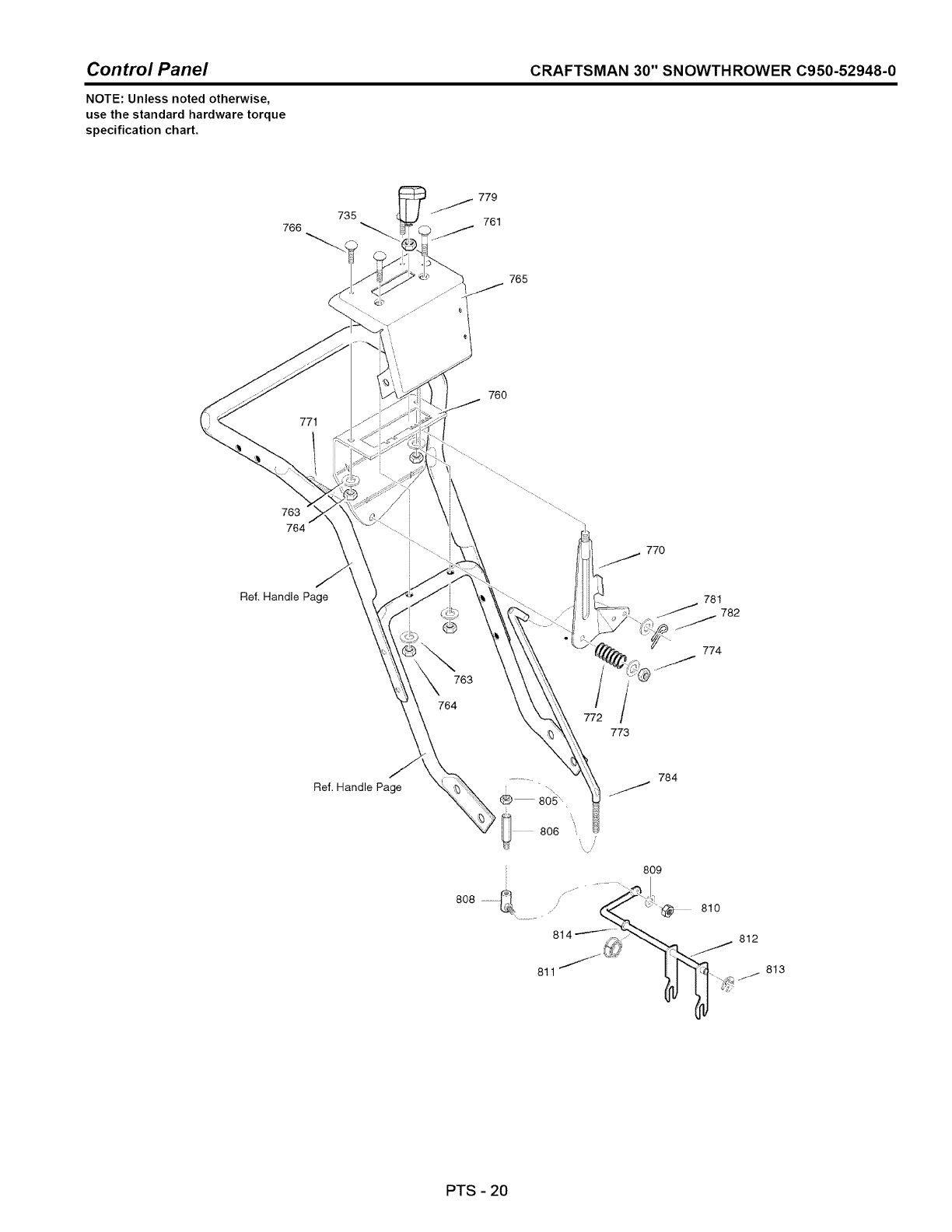
Control Panel CRAFTSMAN 30" SNOWTHROWER C950-52948-0
NOTE: Unless noted otherwise,
use the standard hardware torque
specification chart.
766
735
765
77t
760
763
764
770
Ref. Handle Page
763
764
/
/
773
78!
782
774
Ref. Handle Page
811 "
784
809
810
812
813
PTS - 20
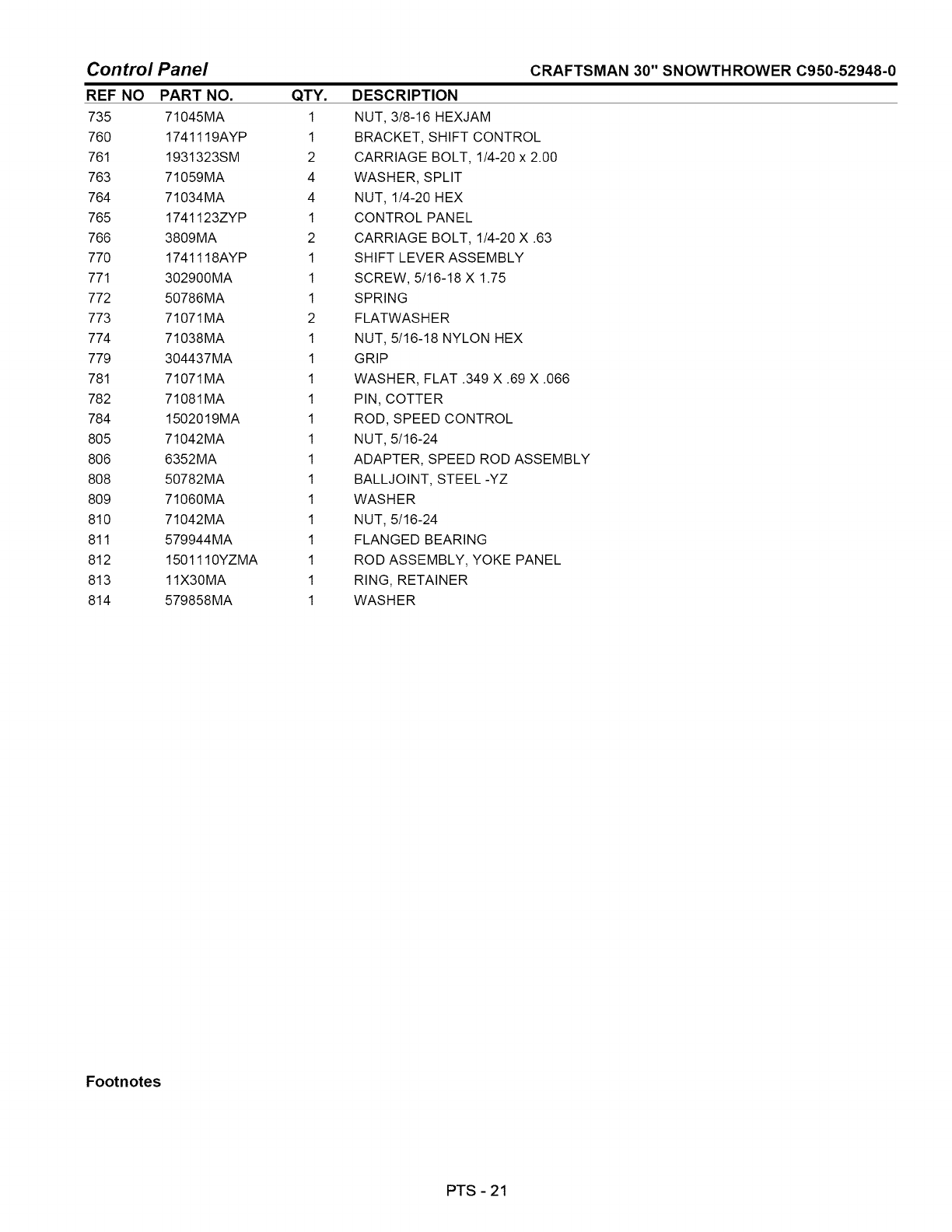
Control Panel
REF NO PART NO. QTY.
735 71045MA 1
760 1741119AYP 1
761 1931323SM 2
763 71059MA 4
764 71034MA 4
765 1741123ZYP 1
766 3809MA 2
770 1741118AYP 1
771 302900MA 1
772 50786MA 1
773 71071MA 2
774 71038MA 1
779 304437MA 1
781 71071MA 1
782 71081 MA 1
784 1502019MA 1
805 71042MA 1
806 6352MA 1
808 50782MA 1
809 71060 MA 1
810 71042MA 1
811 579944MA 1
812 1501110YZMA 1
813 11X30MA 1
814 579858MA 1
CRAFTSMAN 30" SNOWTHROWER C950-52948-0
DESCRIPTION
NUT, 3/8-16 HEXJAM
BRACKET, SHIFT CONTROL
CARRIAGE BOLT, 1/4-20 x 2.00
WASHER, SPLIT
NUT, 1/4-20 HEX
CONTROL PANEL
CARRIAGE BOLT, 1/4-20 X .63
SHIFT LEVER ASSEMBLY
SCREW, 5/16-18 X 1.75
SPRING
FLATWAS H ER
NUT, 5/16-18 NYLON HEX
GRIP
WASHER, FLAT .349 X .69 X .066
PIN, COTTER
ROD, SPEED CONTROL
NUT, 5/16-24
ADAPTER, SPEED ROD ASSEMBLY
BALL JOINT, STEEL-YZ
WASHER
NUT, 5/16-24
FLANGED BEARING
ROD ASSEMBLY, YOKE PANEL
RING, RETAINER
WASHER
Footnotes
PTS -21
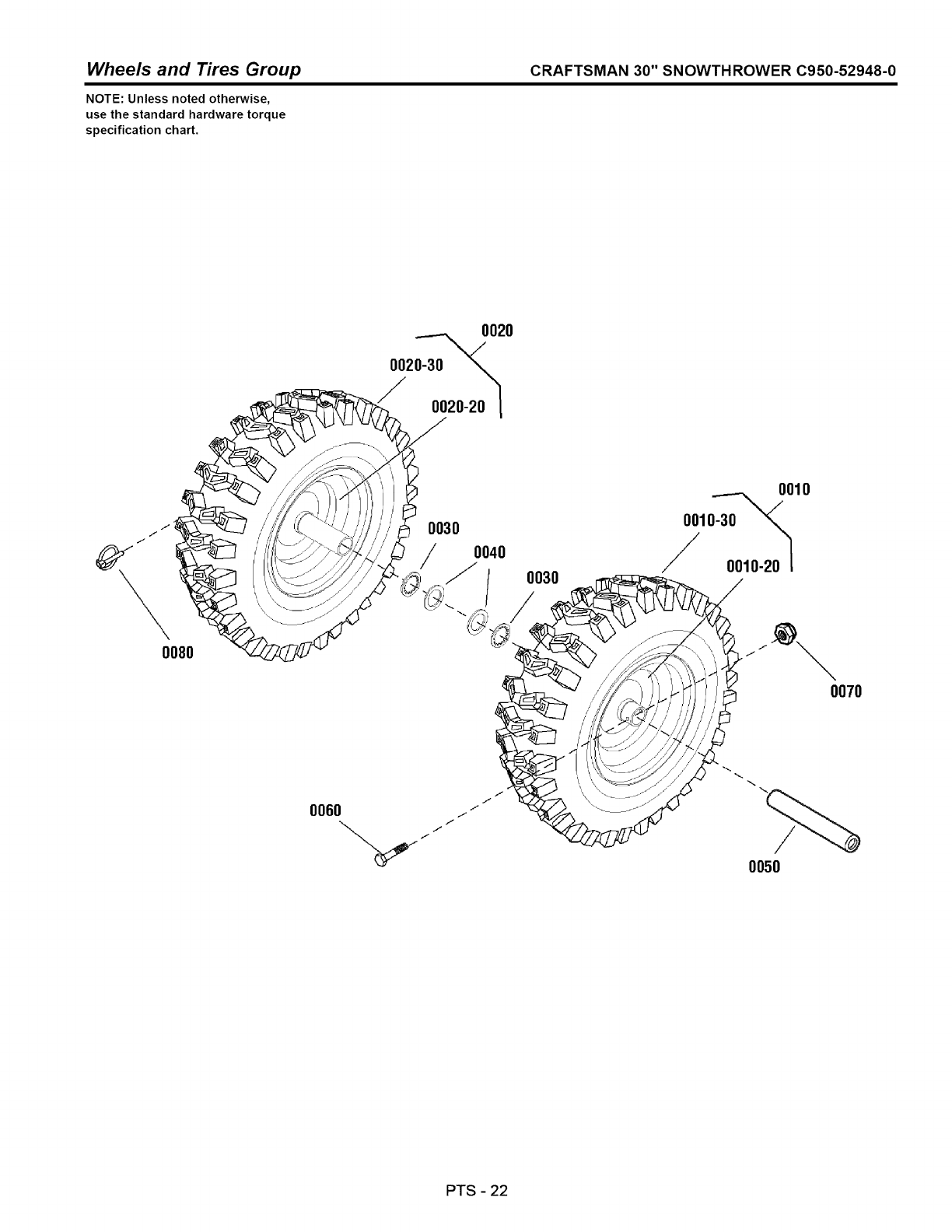
Wheels and Tires Group CRAFTSMAN 30" SNOWTHROWER C950-52948-0
NOTE: Unless noted otherwise,
use the standard hardware torque
specification chart.
0020
002_20_
f/
/
0080
0030
OO40
ij 0030
0010
0010-30_
Y0010-20 I
0070
/
0050
PTS -22
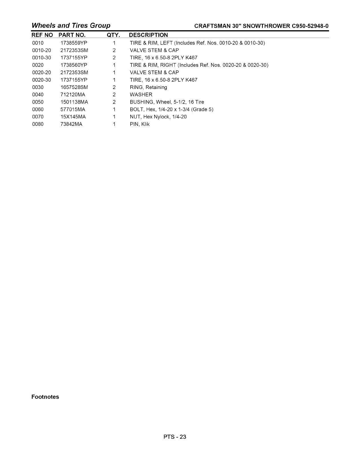
Wheels and Tires Group
REF NO PART NO. QTY.
0010 1738559YP 1
0010-20 2172353SM 2
0010-30 1737155YP 2
0020 1738560YP 1
0020-20 2172353SM 1
0020-30 1737155YP 1
0030 1657528SM 2
0040 712120MA 2
0050 1501138MA 2
0060 577015MA 1
0070 15X145MA 1
0080 73842MA 1
CRAFTSMAN 30" SNOWTHROWER C950-52948-0
DESCRIPTION
TIRE & RIM, LEFT (Includes Ref. Nos. 0010-20 & 0010-30)
VALVE STEM & CAP
TIRE, 16 x 6.50-8 2PLY K467
TIRE & RIM, RIGHT (Includes Ref. Nos. 0020-20 & 0020-30)
VALVE STEM & CAP
TIRE, 16 x 6.50-8 2PLY K467
RING, Retaining
WASHER
BUSHING, Wheel, 5-1/2, 16 Tire
BOLT, Hex, 1/4-20 x 1-3/4 (Grade 5)
NUT, Hex NyIock, 1/4-20
PIN, KIik
Footnotes
PTS - 23
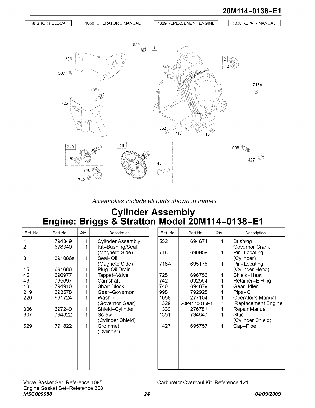
20M114-0138-E1
4=SHORTB,OOKI I 105=OPE_TOR'SMANUA,] I 1329_EP,AO_M_NT_G,_] I 1330_EP_,__U_, I
306 ;y "_ :_'::: :_)y--_ (i} 'i
i '/ /
307 _ ......./........_" /
1351
529
718A
46
I.......................
Assemblies include all parts shown in frames.
Cylinder Assembly
Engine: Briggs & Stratton Model 20M114-0138-E1
Ref. No. Part No. Qty.
1 794849 1
2 698340 1
3 391086s
15 691686
45 690977
46 795697
48 794910
219 693578
220 691724
306 697240
307 794822
529 791822
Description
1
1
1
1
1
1
1
1
Cylinder Assembly
Kit-Bushing/Seal
(Magneto Side)
Seal-Oil
(Magneto Side)
Plug-Oil Drain
Tappet-Valve
Camshaft
Short Block
Gear-Governor
Washer
(Governor Gear)
Shield-Cylinder
Screw
(Cylinder Shield)
Grommet
(Cylinder)
Ref. No.
552
Part No. Qty. Description
694674
718 690959
718A 695178
725 696756 1
742 692564 1
746 694679 1
998 792928 1
1058 277104 1
1329 20P4140015E1 1
1330 276781 1
1351 794847 1
1427 695757
Bushing-
Governor Crank
Pin-Locating
(Cylinder)
Pin-Locating
(Cylinder Head)
Shield-Heat
Retainer-E Ring
Gear-Idler
Pipe-Oil
Operator's Manual
Replacement Engine
Repair Manual
Stud
(Cylinder Shield)
Cap-Pipe
Valve Gasket Set-Reference 1095
Engine Gasket Set-Reference 358
MSC000058
Carburetor Overhaul Kit-Reference 121
24 04/09/2009
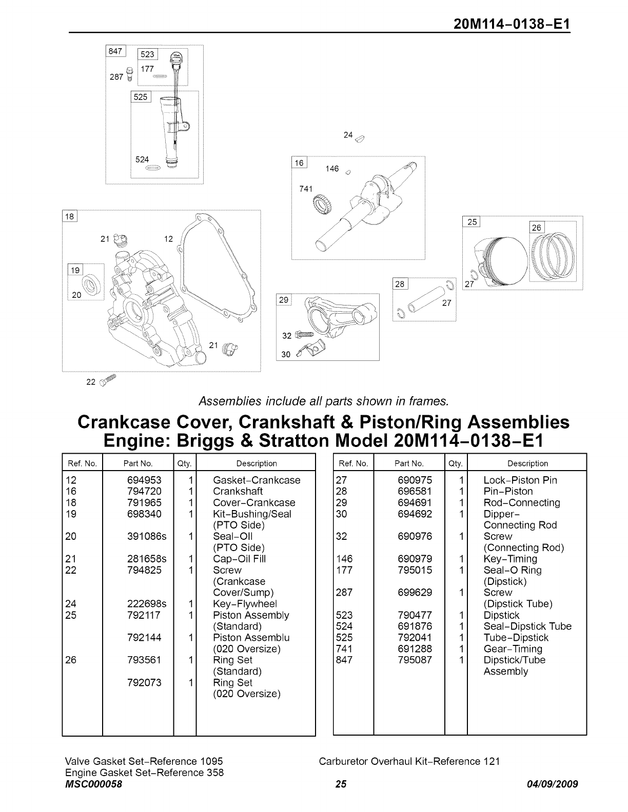
20M114-O138-E1
_ 177
287
524
741
24 <_
22
Assemblies include all parts shown in frames.
Crankcase Cover, Crankshaft & Piston/Ring Assemblies
Engine: Briggs & Stratton Model 20Ml14-0138-E1
Ref. No. Part No. Qty. Description
12 694953
16 794720
18 791965
19 698340
20 391086s
21 281658s
22 794825
24 222698s
25 792117
792144
26 793561
792073
1
1
1
1
1
1
1
1
1
1
1
Gasket-Crankcase
Crankshaft
Cover-Crankcase
Kit-Bushing/Seal
(PTO Side)
Seal-Oil
(PTO Side)
Cap-Oil Fill
Screw
(Crankcase
Cover/Sump)
Key-Flywheel
Piston Assembly
(Standard)
Piston Assemblu
(020 Oversize)
Ring Set
(Standard)
Ring Set
(020 Oversize)
Ref. No. Part No. Qty. Description
27 690975
28 696581
29 694691
30 694692
32 690976
146 690979
177 795015
287 699629
523 790477
524 691876
525 792041
741 691288
847 795087
1
1
1
1
1
1
1
1
1
1
1
Lock-Piston Pin
Pin-Piston
Rod-Connecting
Dipper-
Connecting Rod
Screw
(Connecting Rod)
Key-Timing
SeaI-O Ring
(Dipstick)
Screw
(Dipstick Tube)
Dipstick
Seal-Dipstick Tube
Tube-Dipstick
Gear-Timing
Dipstick/Tube
Assembly
Valve Gasket Set-Reference 1095
Engine Gasket Set-Reference 358
MSC000058
Carburetor Overhaul Kit-Reference 121
25 04/09/2009
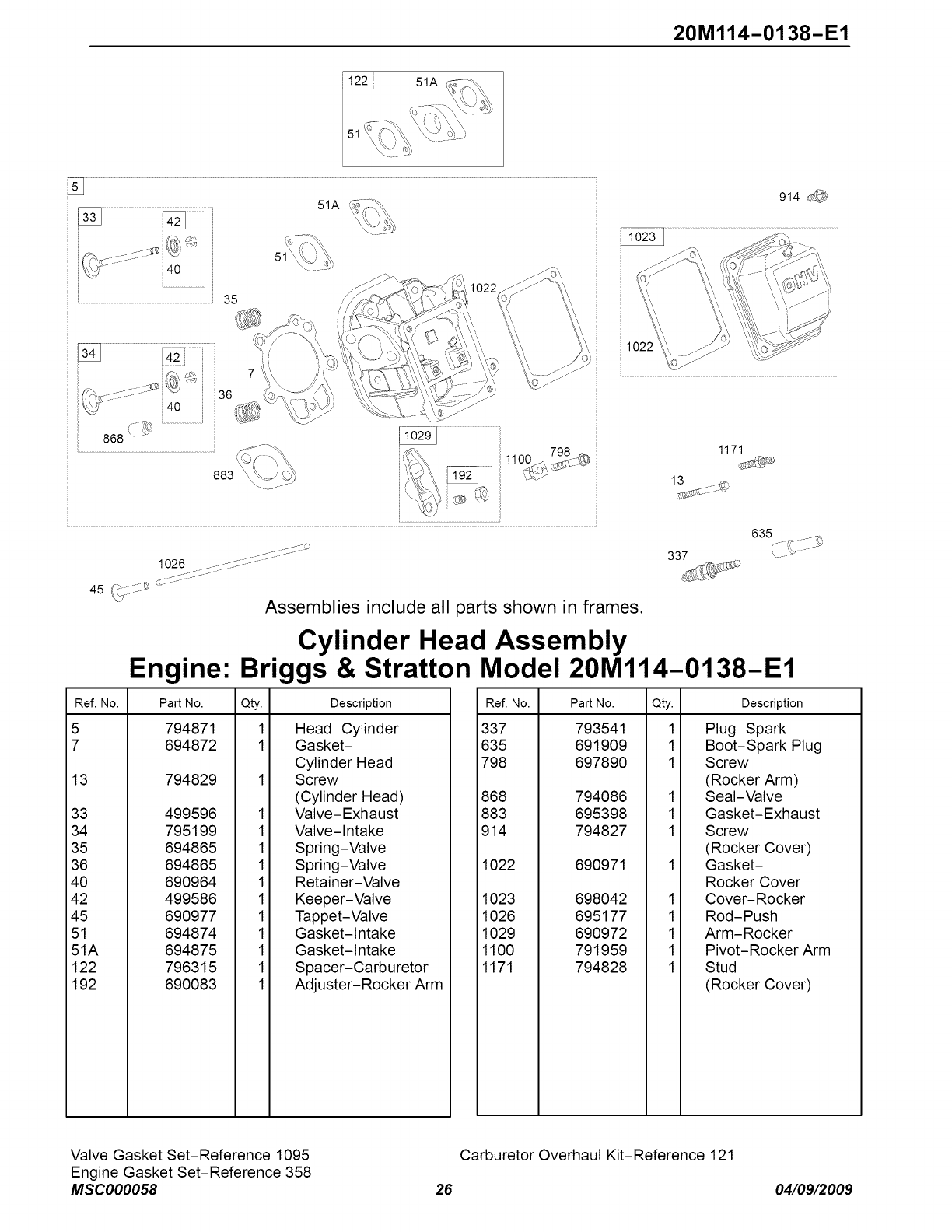
20M114-0138-E1
51A
......................................................................................................................35
51A
1171
914 ,_
1026 _- _::::::::::S:: -.......
45 (> _ <:::..........
\) Assemblies include all parts shown in frames.
Cylinder Head Assembly
635
337
Engine: Briggs & Stratton Model 20M114-0138-E1
Ref. No. Part No. Qty.
5 794871 1
7 694872 1
13 794829
33 499596
34 795199
35 694865
36 694865
40 690964
42 499586
45 690977
51 694874
51A 694875
122 796315
192 690083
Description
1
1
1
1
1
1
1
1
1
1
1
Head-Cylinder
Gasket-
Cylinder Head
Screw
(Cylinder Head)
Valve-Exhaust
Valve-Intake
Spring-Valve
Spring-Valve
Retainer-Valve
Keeper-Valve
Tappet-Valve
Gasket-Intake
Gasket-Intake
Spacer-Carburetor
Adjuster-Rocker Arm
Ref. No. Part No. Qty.
337 793541 1
635 691909 1
798 697890 1
868 794086
883 695398
914 794827
1022 690971
1023 698042
1026 695177
1029 690972
1100 791959
1171 794828
1
1
1
1
1
1
1
1
Description
Plug-Spark
Boot-Spark Plug
Screw
(Rocker Arm)
Seal-Valve
Gasket-Exhaust
Screw
(Rocker Cover)
Gasket-
Rocker Cover
Cover-Rocker
Rod-Push
Arm-Rocker
Pivot-Rocker Arm
Stud
(Rocker Cover)
Valve Gasket Set-Reference 1095
Engine Gasket Set-Reference 358
MSC000058
Carburetor Overhaul Kit-Reference 121
26 04/09/2009
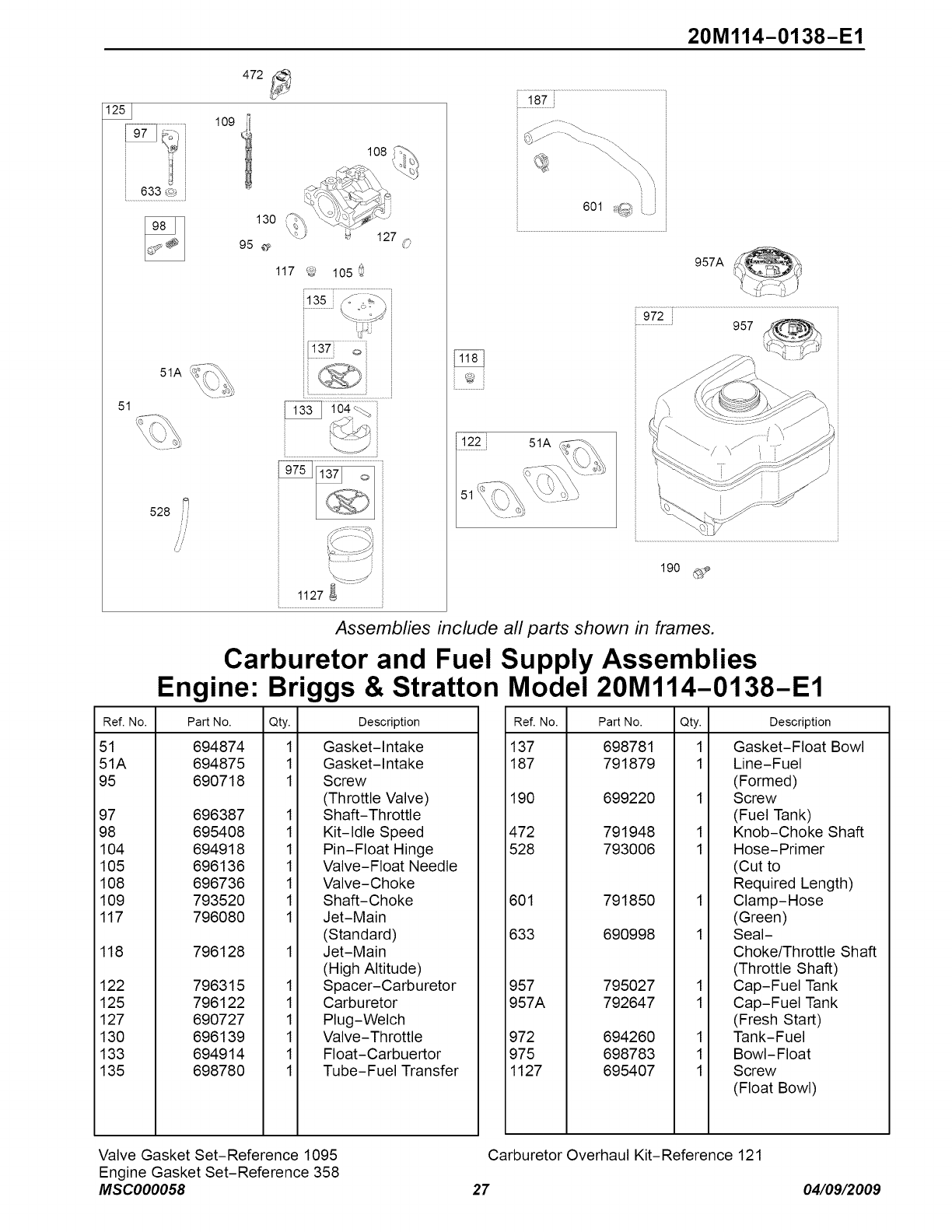
51A
51
528 /
Engine:
20M114-O138-E1
472
1°9i
130 \
95 _
117 _57 105
O8
127 O
....................................
1127
187
601 ,_
957A
............................ 957
122
51
51A
190 _,:_
Assemblies include all parts shown in frames.
Carburetor and Fuel Supply Assemblies
Briggs & Stratton Model 20Ml14-0138-E1
Ref. No. Part No.
51 694874
51A 694875
95 690718
97 696387
98 695408
104 694918
105 696136
108 696736
109 793520
117 796080
118 796128
122 796315
125 796122
127 690727
130 696139
133 694914
135 698780
Qty.
1
1
1
1
1
1
1
1
1
1
1
1
1
1
1
1
Description
Gasket-Intake
Gasket-Intake
Screw
(Throttle Valve)
Shaft-Throttle
Kit-Idle Speed
Pin-Float Hinge
Valve-Float Needle
Valve-Choke
Shaft-Choke
Jet-Main
(Standard)
Jet-Main
(High Altitude)
Spacer-Carburetor
Carburetor
Plug-Welch
Valve-Throttle
Float-Carbuertor
Tube-Fuel Transfer
Ref. No. Part No. Qty.
137 698781 1
187 791879 1
190 699220 1
472 791948 1
528 793006 1
601 791850
633 690998
957 795027
957A 792647
972 694260
975 698783
1127 695407
Description
1
1
1
1
1
1
1
Gasket-Float Bowl
Line-Fuel
(Formed)
Screw
(Fuel Tank)
Knob-Choke Shaft
Hose-Primer
(Cut to
Required Length)
Clamp-Hose
(Green)
Seal-
Choke/Throttle Shaft
(Throttle Shaft)
Cap-Fuel Tank
Cap-Fuel Tank
(Fresh Start)
Tank-Fuel
Bowl-Float
Screw
(Float Bowl)
Valve Gasket Set-Reference 1095
Engine Gasket Set-Reference 358
MSC000058
Carburetor Overhaul Kit-Reference 121
27 04/09/2009
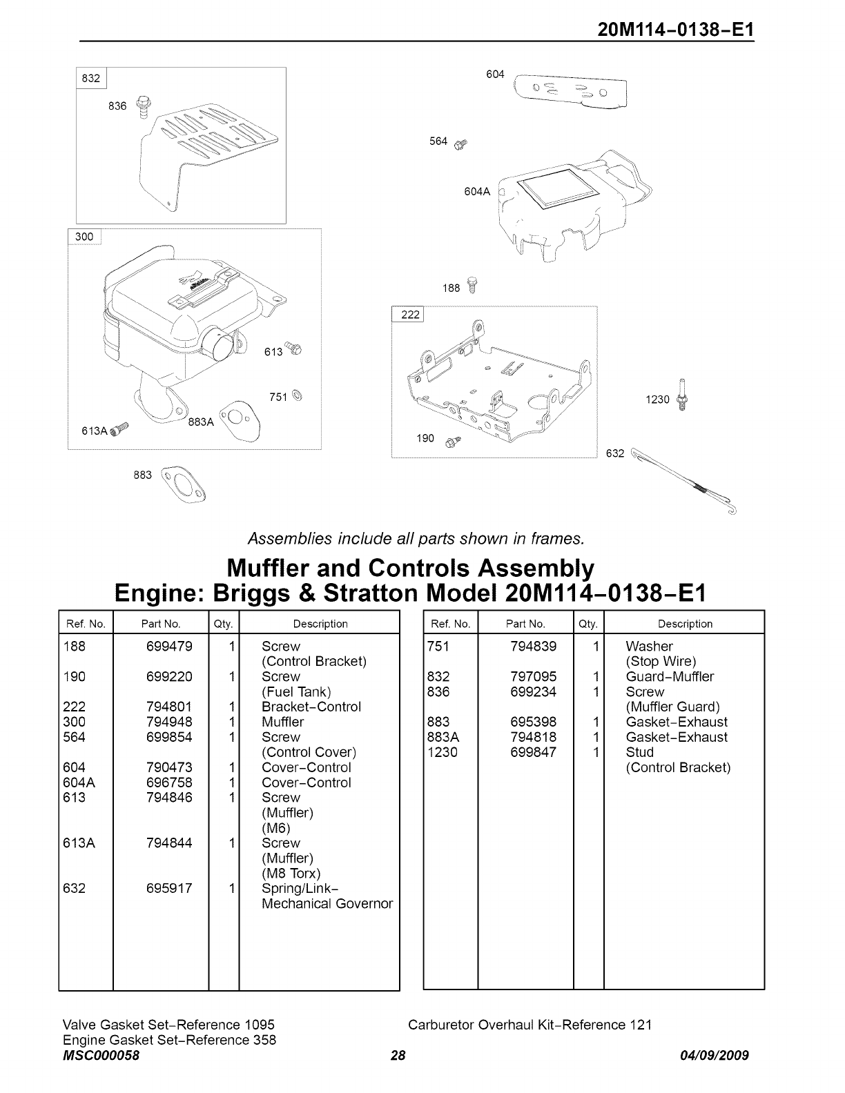
20M114-0138-E1
836
i
i
\\
604 r-..................................................
564
604A F_
i
300
613A_ 883A
751
883
188_
1230
190 _
..............................................................................................................................................................................................................632_.
Assemblies include all parts shown in frames.
Muffler and Controls Assembly
Engine: Briggs & Stratton Model 20M114-0138-E1
Ref. No. Part No. Qty.
188 699479 1
190 699220
222 794801
300 794948
564 699854
604 790473
604A 696758
613 794846
613A 794844
632 695917
1
1
1
1
1
1
Description
Screw
(Control Bracket)
Screw
(Fuel Tank)
Bracket-Control
Muffler
Screw
(Control Cover)
Cover-Control
Cover-Control
Screw
(Muffler)
(M6)
Screw
(Muffler)
(M8 Torx)
Spring/Link-
Mechanical Governor
Ref. No. Part No. Qty.
751 794839 1
832 797095
836 699234
883 695398
883A 794818
1230 699847
1
1
1
1
1
Description
Washer
(Stop Wire)
Guard-Muffler
Screw
(Muffler Guard)
Gasket-Exhaust
Gasket-Exhaust
Stud
(Control Bracket)
Valve Gasket Set-Reference 1095
Engine Gasket Set-Reference 358
MSC000058
Carburetor Overhaul Kit-Reference 121
28 04/09/2009
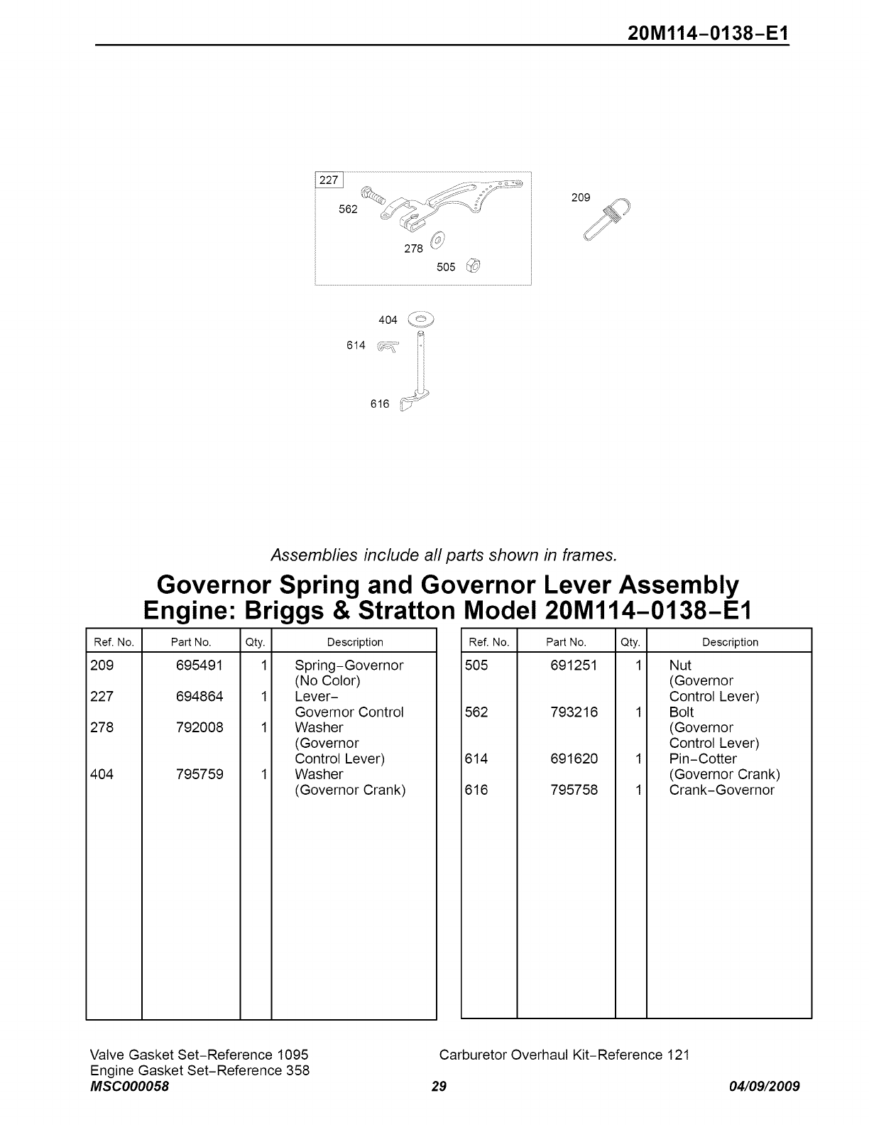
20M114-0138-E1
562
278 @
505
404 \,,_j
614 (_;_'
Assemblies include all parts shown in frames.
Governor Spring and Governor Lever Assembly
Engine: Briggs & Stratton Model 20M114-0138-E1
Ref. No. Part No. Qty. Description
209 695491 1 Spring-Governor
(No Color)
227 694864 1 Lever-
Governor Control
278 792008 1 Washer
(Governor
Control Lever)
404 795759 1 Washer
(Governor Crank)
Ref. No. Part No. Qty.
505 691251 1
562 793216
614 691620
616 795758
Description
1
1
Nut
(Governor
Control Lever)
Bolt
(Governor
Control Lever)
Pin-Cotter
(Governor Crank)
Crank-Governor
Valve Gasket Set-Reference 1095
Engine Gasket Set-Reference 358
MSC000058
Carburetor Overhaul Kit-Reference 121
29 04/09/2009
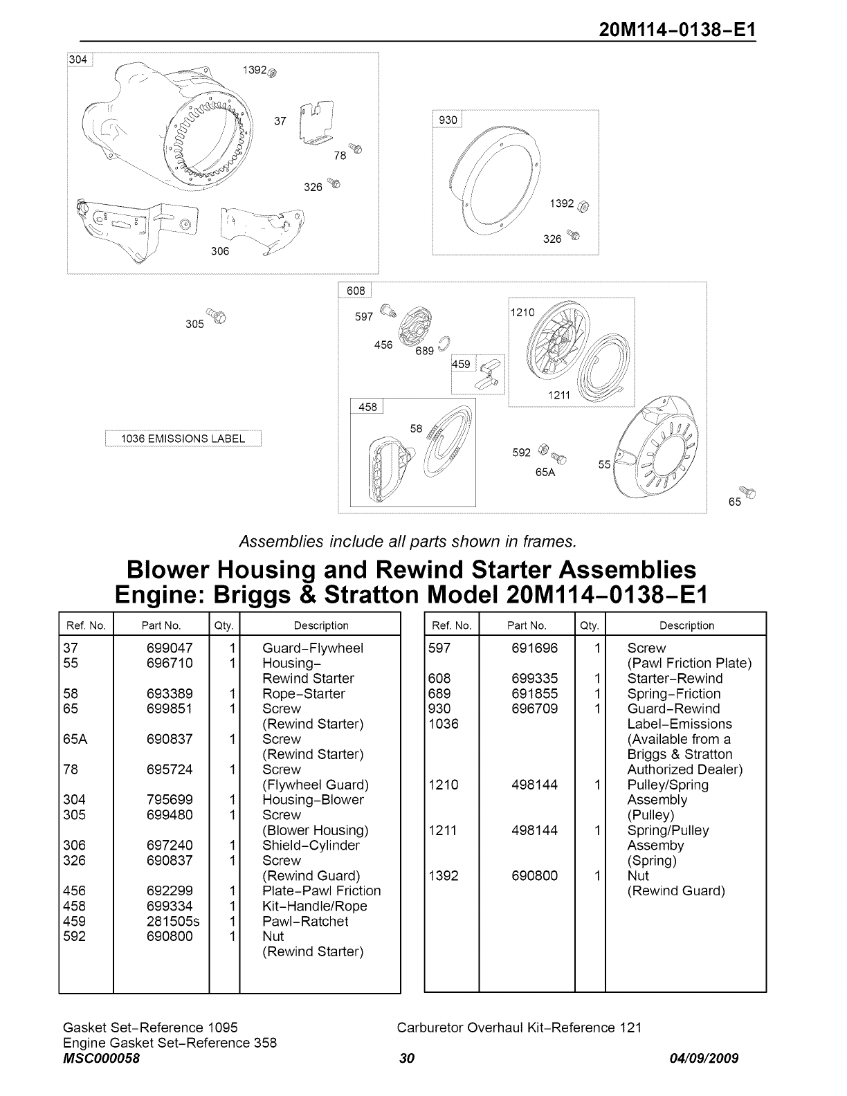
20M114-O138-E1
37
78
326 _
%
305
1392
326 _
4583
6_
Assemblies include all parts shown in frames.
Blower Housing and Rewind Starter Assemblies
Engine: Briggs & Stratton Model 20Ml14-0138-E1
Ref. No. Part No. Qty.
37 699047 1
55 696710 1
58 693389
65 699851
65A 690837
78 695724
304 795699
305 699480
306 697240
326 690837
456 692299
458 699334
459 281505s
592 690800
Description
1
1
1
1
1
1
1
1
1
1
Guard-Flywheel
Housing-
Rewind Starter
Rope-Starter
Screw
(Rewind Starter)
Screw
(Rewind Starter)
Screw
(Flywheel Guard)
Housing-Blower
Screw
(Blower Housing)
Shield-Cylinder
Screw
(Rewind Guard)
Plate-Pawl Friction
Kit-Handle/Rope
PawI-Ratchet
Nut
(Rewind Starter)
Ref. No.
597
Part No. Qty. Description
691696
608 699335
689 691855
930 696709
1036
1210 498144
1211 498144
1392 690800
1
1
1
Screw
(Pawl Friction Plate)
Starter-Rewind
Spring-Friction
Guard-Rewind
Label-Emissions
(Available from a
Briggs & Stratton
Authorized Dealer)
Pulley/Spring
Assembly
(Pulley)
Spring/Pulley
Assemby
(Spring)
Nut
(Rewind Guard)
Gasket Set-Reference 1095
Engine Gasket Set-Reference 358
MSC000058
Carburetor Overhaul Kit-Reference 121
30 04/09/2009
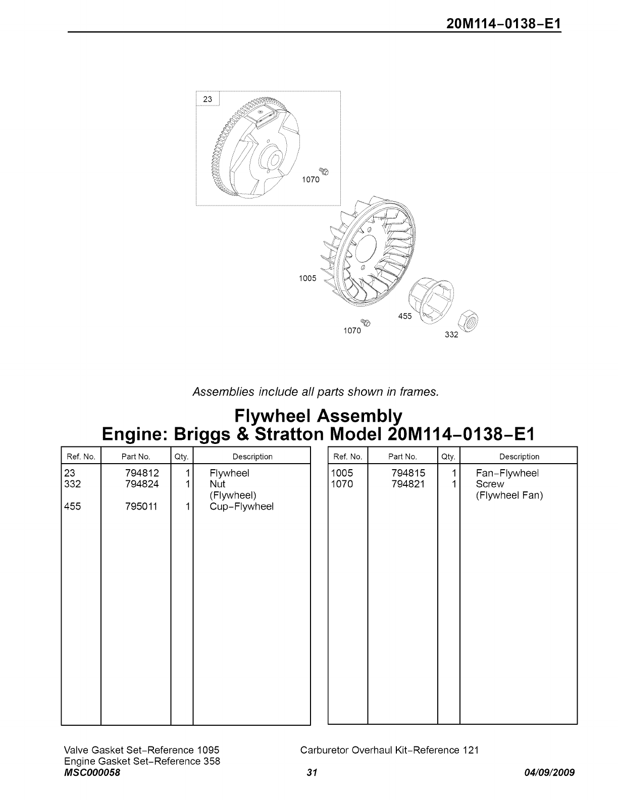
20M114-0138-E1
23
\
/
%
1070
1005 '_ _ i
%
1070
x
455
332
Engine:
Assemblies include all parts shown in frames.
Flywheel Assembly
Briggs & Stratton Model 20M114-0138-E1
Description
Flywheel
Nut
(Flywheel)
Cup- Flywheel
Ref. No. Part No. Qty.
23 794812 1
332 794824 1
455 795011 1
Ref. No. Part No. Qty. Description
1005 794815 1 Fan-Flywheel
1070 794821 1 Scow
(Flywheel Fan)
Valve Gasket Set-Reference 1095
Engine Gasket Set-Reference 358
MSC000058
Carburetor Overhaul Kit-Reference 121
31 04/09/2009
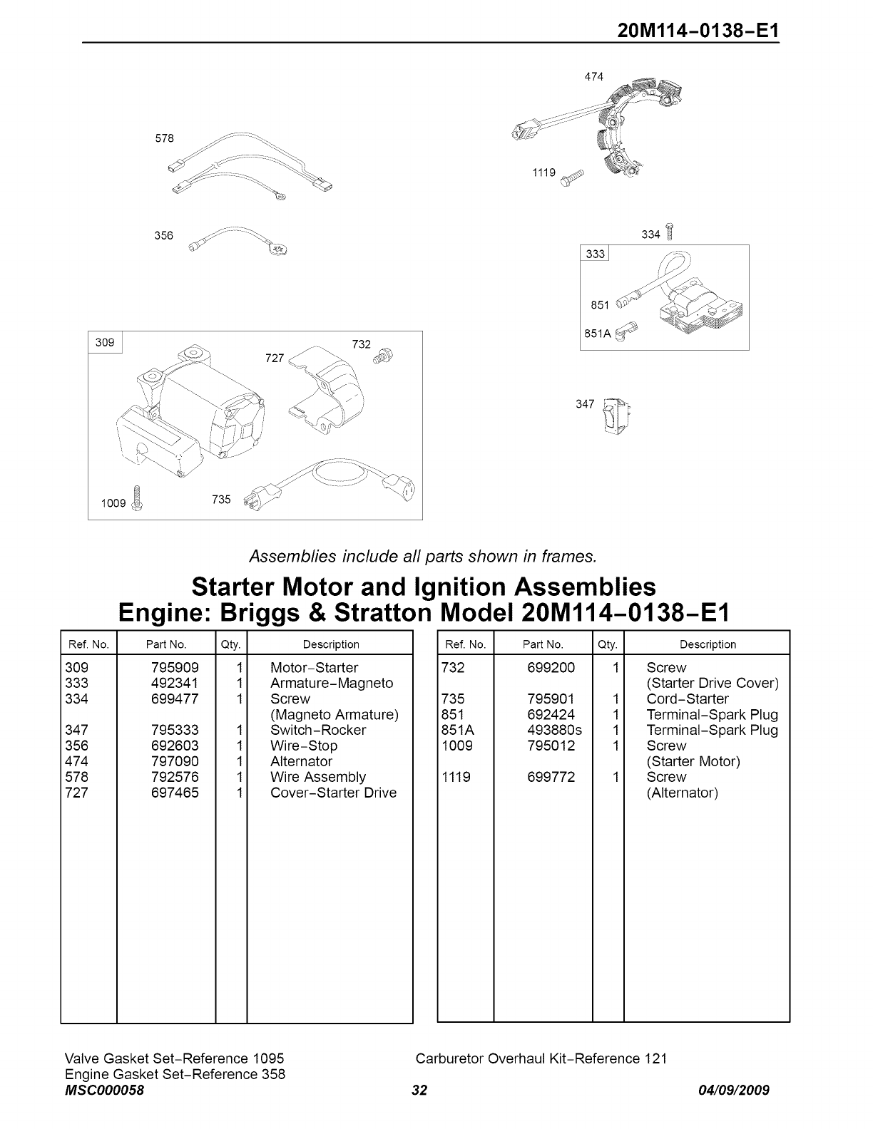
20M114-0138-E1
474
578
1009
356
727_ .....
735
851
851A_
347
Assemblies include all parts shown in frames.
Starter Motor and Ignition Assemblies
Engine: Briggs & Stratton Model 20M114-0138-E1
Ref. No. Part No. Qty.
309 795909 1
333 492341 1
334 699477 1
347 795333
356 692603
474 797090
578 792576
727 697465
1
1
1
1
1
Description
Motor-Starter
Armature-Magneto
Screw
(Magneto Armature)
Switch-Rocker
Wire-Stop
Alternator
Wire Assembly
Cover-Starter Drive
Ref. No. Part No. Qty.
732 699200 1
735 795901
851 692424
851A 493880s
1009 795012
1119 699772
1
1
1
1
Description
Screw
(Starter Drive Cover)
Cord-Starter
Terminal-Spark Plug
Terminal-Spark Plug
Screw
(Starter Motor)
Screw
(Alternator)
Valve Gasket Set-Reference 1095
Engine Gasket Set-Reference 358
MSC000058
Carburetor Overhaul Kit-Reference 121
32 04/09/2009

20M114-O138-E1
1196_
976
1288 '_
1318_i
11 163
610
668_4
731
1230_
1251
1252 1251A
\
1352_
Engine:
Ref. No. Part No.
11 696750
53 795017
163 692277
528 793006
610 794541
668 794539
731 794540
731A 793621
892 791944
976 793382
990 794696
1196 696692
Assemblies include all parts shown in frames.
Snow Hood Assemblies
Briggs & Stratton Model 20Ml14-0138-E1
Qty.
1
1
1
1
1
1
1
1
1
1
1
1
Description
Tube-Breather
Stud
(Carburetor)
Gasket-Air Cleaner
Hose-Primer
(Cut to
Required Length)
Arrester-lntake
Spacer
(Snow Hood)
Hood-Snow
Hood-Snow
Switch-Key
Primer-Carburetor
Key Set
Screw
(Snow Hood)
Ref. No. Part No. Qty. Description
1230 699847 1 Stud
(Control Bracket)
1251 696762 1 Shield-Snow
1251A 790471 1 Shield-Snow
1252 699480 1 Screw
(Snow Shield)
1288 794838 1 Nut
(Snow Hood)
1318 698111 1 Nut
(Snow Hood)
1352 795016 1 Nut
(Spark Plug Shield)
Valve Gasket Set-Reference 1095
Engine Gasket Set-Reference 358
MSC000058
Carburetor Overhaul Kit-Reference 121
33 04/09/2009
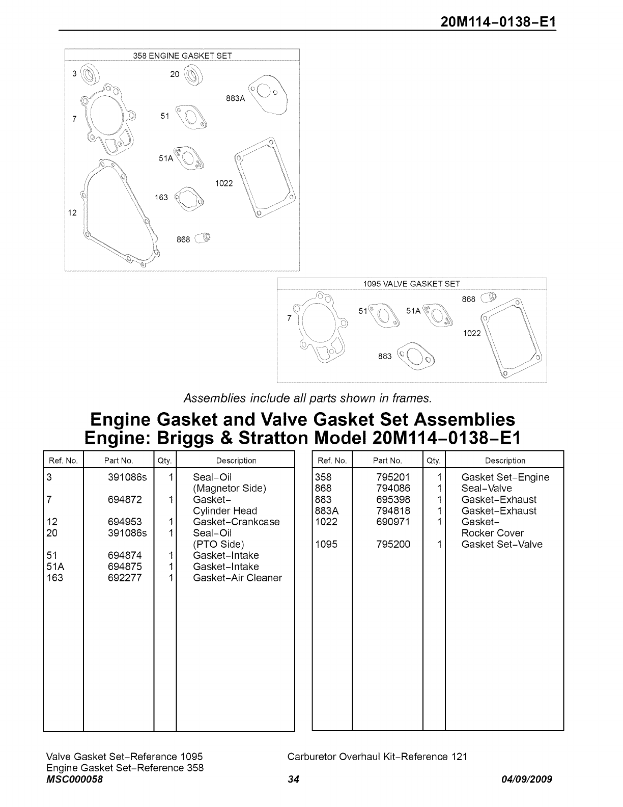
20M114-0138-E1
358 ENGINE GASKET SET
2O
51
1022
163
1095 VALVE GASKET SET
868 ¢-_
1
883
Assemblies include all parts shown in frames.
Engine Gasket and Valve Gasket Set Assemblies
Engine: Briggs & Stratton Model 20M114-0138-E1
Ref. No. Part No. Qty. Description
3 391086s 1 Seal-Oil
(Magnetor Side)
7 694872 1 Gasket-
Cylinder Head
12 694953 1 Gasket-Crankcase
20 391086s 1 Seal-Oil
(PTO Side)
51 694874 1 Gasket-Intake
51A 694875 1 Gasket-Intake
163 692277 1 Gasket-Air Cleaner
Ref. No. Part No. Qty. Description
358 795201 1 Gasket Set-Engine
868 794086 1 Seal-Valve
883 695398 1 Gasket-Exhaust
883A 794818 1 Gasket-Exhaust
1022 690971 1 Gasket-
Rocker Cover
1095 795200 1 Gasket Set-Valve
Valve Gasket Set-Reference 1095
Engine Gasket Set-Reference 358
MSC000058
Carburetor Overhaul Kit-Reference 121
34 04/09/2009
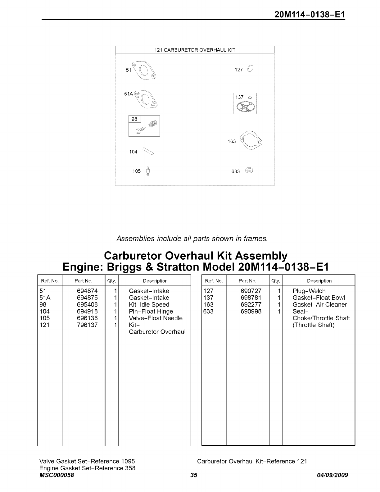
20M114-0138-E1
121 CARBURETOR OVERHAUL KIT
127 _/
51A
163
105 633 ___J
Engine:
Ref. No. Part No.
51 694874
51A 694875
98 695408
104 694918
105 696136
121 796137
Assemblies include all parts shown in frames.
Carburetor Overhaul Kit Assembly
Briggs & Stratton Model 20M114-0138-E1
Qty. Description
1 Gasket-Intake
1 Gasket-Intake
1 Kit-Idle Speed
1 Pin-Float Hinge
1 Valve-Float Needle
1 Kit-
Carburetor Overhaul
Ref. No. Part No. Qty. Description
127 690727 1 Plug-Welch
137 698781 1 Gasket-Float Bowl
163 692277 1 Gasket-Air Cleaner
633 690998 1 Seal-
Choke/Throttle Shaft
(Throttle Shaft)
Valve Gasket Set-Reference 1095
Engine Gasket Set-Reference 358
MSC000058
Carburetor Overhaul Kit-Reference 121
35 04/09/2009
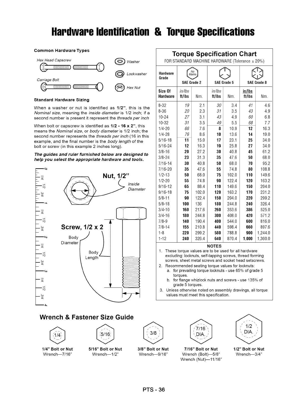
Hardwareidentification& TorqueSpecifications
Common Hardware Types
Hex Head Capscrew
Carriage Bolt
[(((((((((((((((((((O
Washer
Lockwasher
OHex Nut
Standard Hardware Sizing
When a washer or nut is identified as 1/2", this is the
Nominal size, meaning the inside diameter is 1/2 inch; if a
second number is present it represent the threads per inch
When bolt or capscrew is identified as 1/2 - 16 x 2", this
means the Nominal size, or body diameter is 1/2 inch; the
second number represents the threads per inch (16 in this
example, and the final number is the body length of the
bolt or screw (in this example 2 inches long).
The guides and ruler furnished below are designed to
help you select the appropriate hardware and tools.
m_
m_
m_
m_
m_
m_
m_
m_
Nut, 1/2"
Inside
Diameter
Screw, 1/2 x2_- I
o0yj I
Oa eter("/
__@
Torque Specification Chart
FOR STANDARD MACHINE HARDWARE (Tolerance + 20%)
_raarddeware G 0 Q
SAEGrade2 SAEGrade5 SAEGrade8
Size Of in/Ibs
Hardware ft/I bs ft/I bs Nm.
8-32
8-36
10-24
10-32
1/4-20
1/4-28
5/16-18
5/16-24
3/8-16
3/8-24
7/16-14
7/16-20
1/2-13
1/2-20
9/16-12
9/16-18
5/8-11
5/8-18
3/4-10
3/4-16
7/8-9
7/8-14
1-8
1-12
19
20
27
31
66
76
11
12
20
23
30
35
50
55
65
75
90
100
160
180
140
155
220
240
in/Ibs
Nm. ft/Ibs Nm.
2.1 30 3.4
2.3 31 3.5
3.1 43 4.9
3.5 49 5.5
7.6 8 10.9
8.6 18 13.6
15.0 17 23.1
16.3 19 25.8
27.2 38 40.8
31.3 35 47.6
40.8 50 68.0
47.6 55 74.8
68.0 75 102.0
74.8 98 122.4
88.4 118 149.6
102.0 120 163.2
122.4 150 204.0
136 188 244.8
217.6 260 353.6
244.8 300 408.0
190.4 400 544.0
210.8 440 598.4
299.2 588 788.8
326.4 648 870.4
41 4.6
43 4.9
60 6.8
68 7.7
12 16.3
14 19.0
25 34.0
27 34.0
45 61.2
58 68.0
70 95.2
88 108.8
118 149.6
128 163.2
158 204.0
178 231.2
228 299.2
248 326.4
386 525.0
428 571.2
688 816.0
668 897.6
988 1,244.0
1,888 1,360.0
NOTES
1. These torque values are to be used for all hardware
excluding: Iocknuts, self-tapping screws, thread forming
screws, sheet metal screws and socket head setscrews.
2. Recommended seating torque values for Iocknuts:
a. for prevailing torque Iocknuts - use 65% of grade 5
torques.
b. for flange whizlock nuts and screws - use 135% of
grade 5 torques.
3. Unless otherwise noted on assembly drawings, all torque
values must meet this specification.
Wrench & Fastener Size Guide
1/4" Bolt or Nut
Wrench--7/16"
5/16" Bolt or Nut
Wrench--I/2"
3/8" Bolt or Nut
Wrench--9/16"
7/16" Bolt or Nut
Wrench (Bolt)--5/8"
Wrench (Nut)--11/16"
1/2" Bolt or Nut
Wrench--3/4"
PTS - 36
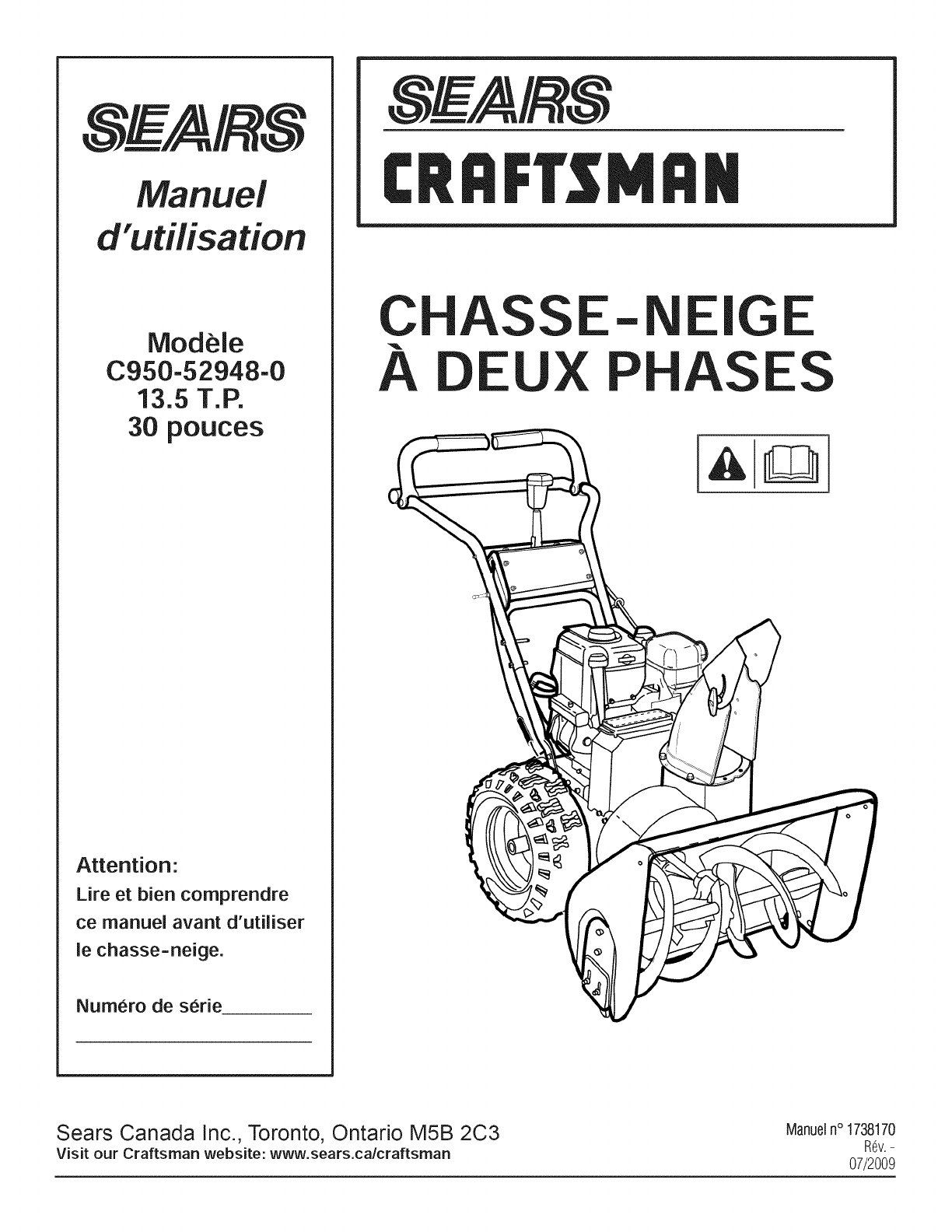
Manuel
d'utHisation
Modele
C950-52948-0
13.5 T.P.
30 pouces
Attention-
Life et bien comprendre
ce manuel avant d'utiliser
le chasse-neige.
Numero de serie
iVll;iN
CHASSE- IGE
A EUX PHAS S
Sears Canada Inc., Toronto, Ontario M5B 2C3
Visit our Craftsman website: www.sears.calcraftsman
Manueln° 1738170
Rev.-
07/2009
Merci d'avoir achet6cette souffleuse _ neigeCraftsman. Noussommes heureux que vous ayezplac6 votre confiance dans la marque
Craftsman. Si vous utiHsezet entretenezce produit Craftsman conform6ment aux instructions du manuel, vous _ourrezI'utiHser pendant
de nombreuses ann6es.
Ce manuel contient des informations relatives9.la s6curit6 afin que vous connaissiez les dangers et risques qu=sont li6s aux souffleuses
J.neigeet lafa?on de les 6viter. Cette souffleuse_ neigeest con?ueet est destin6 uniquement pour 61iminerla neige et ne peut_tre
utiHs6epour aucune autre raison, il est important que vous Hsiezet compreniez ces instructions en profondeur avant de tenter de
d6marrer ou d'utiliser 1'6quipement.Unassemblage de finition est necessaireavant d'utiliser la souffleuse _ neige. Veuillezvous
reporter 9.la rubrique Assemblageafin d'obtenir ies directives pour I'assemblagede finition. Veuillez suivreattentivement les directives.
Sauvegardez cosinstructionspourvotrer6f_rence.
Souffleuse _ neige:
Num6ro de modele
R6vision
Num6ro de s6rie
JVJo|eur:
Num6ro de modele
R6vision
Num6ro de s6rie
Dale d'achal:
Adressedu magasin d'achal:
Ville:
Province:
T_l_phone:
REMARQUE:Noter los renseignementsci--dessouspourI'identification de la machineen casde perle ou de vol.
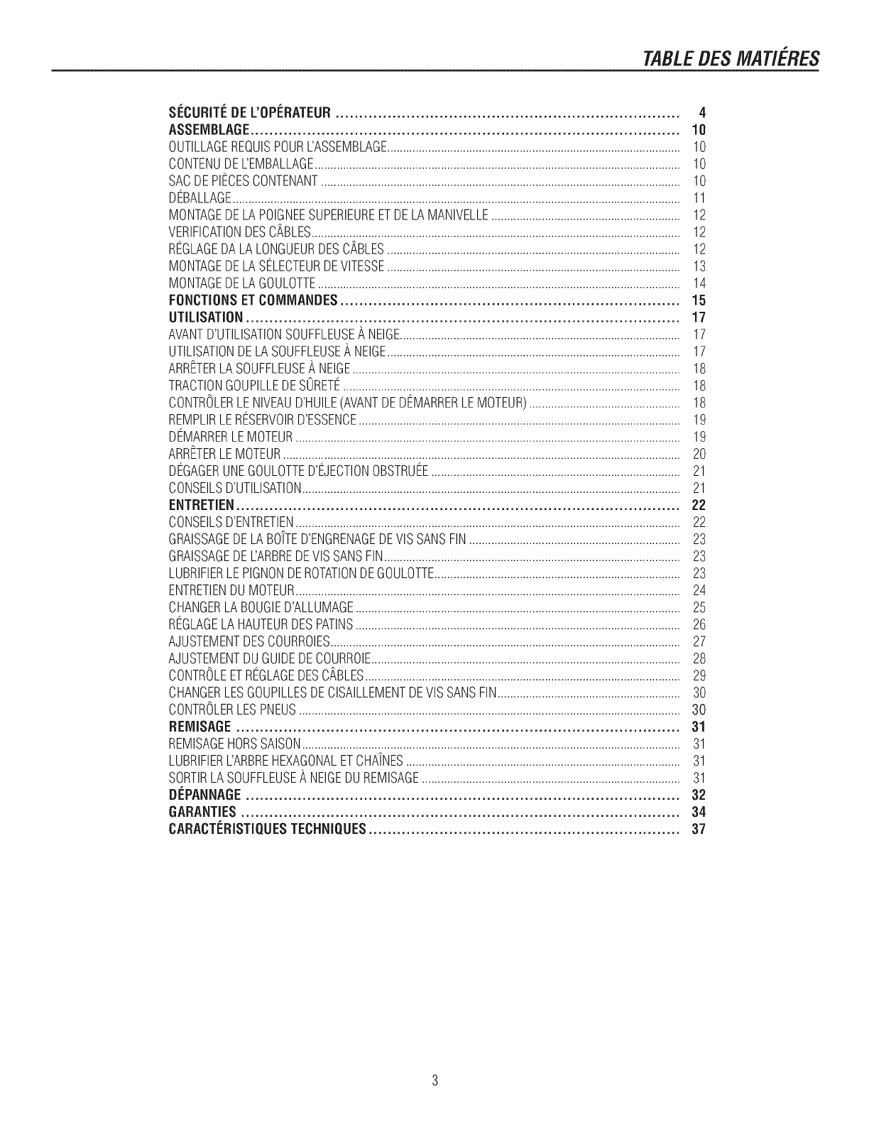
TABLEDESMAT/ERES
SI_CURITI_DE L'OPI_RATEUR......................................................................... 4
ASSEMBLAGE........................................................................................... 10
OUTILLAGEREQUISPOURL'ASSEMBLAGE.............................................................................................10
CONTENUDEL'EMBALLAGE....................................................................................................................10
SACDEPIECESCONTENANT..................................................................................................................10
DBALLAGE..............................................................................................................................................11
MONTAGEDELAPOIGNEESUPERIEUREETDELAMANIVELLE............................................................12
VERIFICATIONDESCABLES.....................................................................................................................12
REGLAGEDALALONGUEURDESCABLES.............................................................................................12
MONTAGEDELASELECTEURDEVlTESSE.............................................................................................13
MONTAGEDELAGOULOTTE...................................................................................................................14
FONCTIONSETCOIVllViANDES........................................................................ 15
UTILISATION............................................................................................ 17
AVANTD'UTILISATIONSOUFFLEUSE_,NEIGE.........................................................................................17
UTILISATIONDELASOUFFLEUSEANEIGE.............................................................................................17
ARRETERLASOUFFLEUSEANEIGE........................................................................................................18
TRACTIONGOUPILLEDESORETE...........................................................................................................18
CONTROLERLENIVEAUD'HUILE(AVANTDEDEMARRERLEMOTEUR)................................................18
REMPLIRLERESERVOIRD'ESSENCE......................................................................................................19
DEMARRERLEMOTEUR..........................................................................................................................19
ARRETERLEMOTEUR..............................................................................................................................20
DEGAGERUNEGOULOTTED'EJECTIONOBSTRUEE...............................................................................21
CONSEILSD'UTILISATION........................................................................................................................21
ENTRETIEN.............................................................................................. 22
CONSEILSD'ENTRETIEN..........................................................................................................................22
GRAISSAGEDELABO'[TED'ENGRENAGEDEVlSSANSFIN...................................................................23
GRAISSAGEDEL'ARBREDEVlSSANSFIN..............................................................................................23
LUBRIFIERLEPIGNONDEROTATIONDEGOULOTTE..............................................................................23
ENTRETIENDUMOTEUR..........................................................................................................................24
CHANGERLABOUGIED'ALLUMAGE.......................................................................................................25
REGLAGELAHAUTEURDESPATINS.......................................................................................................26
AJUSTEMENTDESCOURROIES...............................................................................................................27
AJUSTEMENTDUGUIDEDECOURROIE..................................................................................................28
CONTROLEETREGLAGEDESC,_BLES....................................................................................................29
CHANGERLESGOUPILLESDECISAILLEMENTDEVlSSANSFIN..........................................................30
CONTROLERLESPNEUS.........................................................................................................................30
REIVIISAGE.............................................................................................. 31
REMISAGEHORSSAISON........................................................................................................................31
LUBRIFIERL'ARBREHEXAGONALETCHA/NES.......................................................................................31
SORTIRLASOUFFLEUSE_,NEIGEDUREMISAGE..................................................................................31
DI_PANNAGE............................................................................................ 32
GARANTIES............................................................................................. 34
CARACTI_RISTIQUESTECHNIQUES.................................................................. 37
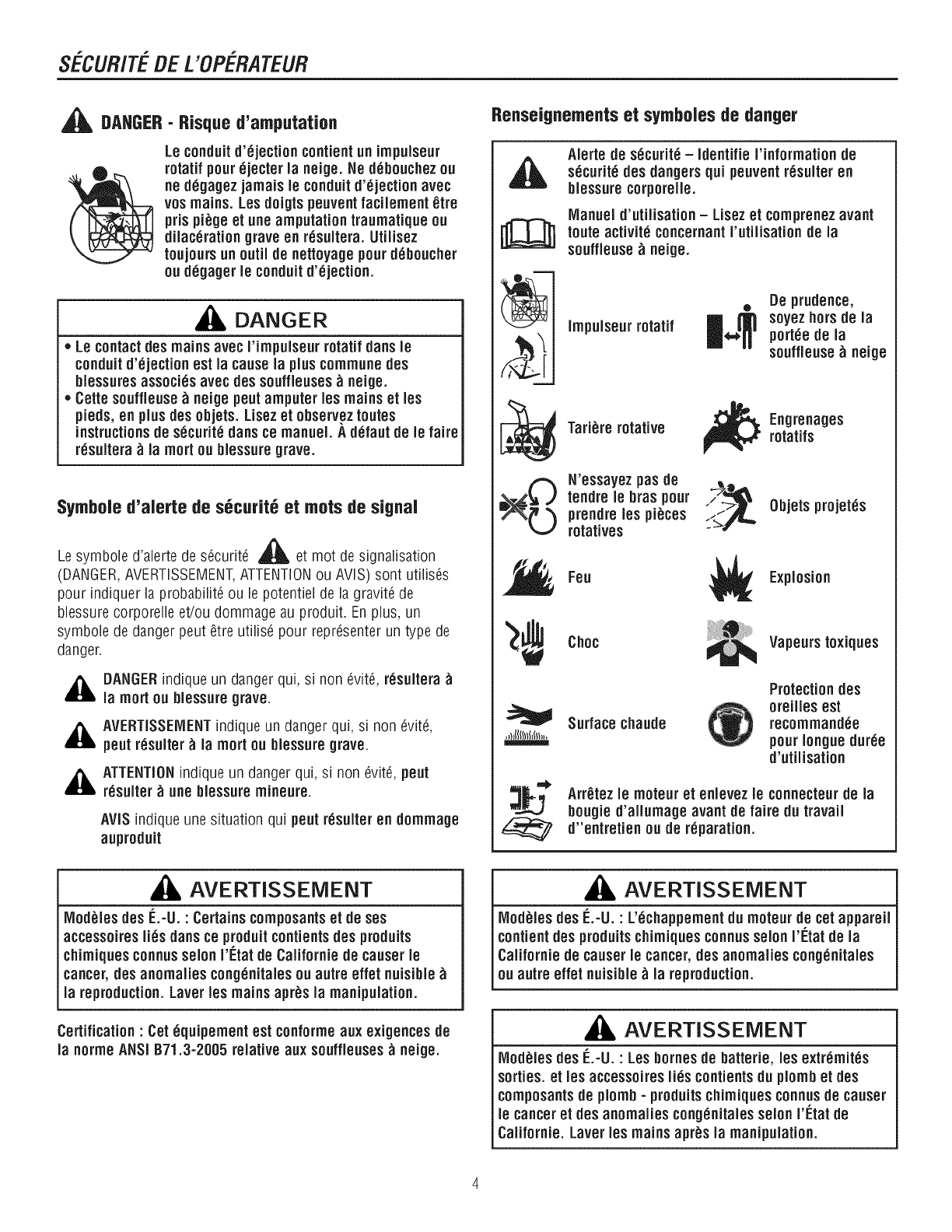
SECUR/TEBE L'OPERATEUR
,_ DAHGER- Risque d'amputatien
Le conduitd'6jection cont[entun irnpuJseur
rotatif pour_jecter Janeige. Ne d_bouchezou
ne d_gagezjarnaisle conduitd'_jection avec
vos mains. Les doigts peuventfacilernent _tre
pris pi_ge et une amputation tranrnatique ou
dilac_rat[on grave en r_suitera. Utilisez
toujours nnoutil de nettoyagepourd6boucher
ou d6gager le conduitd'6jection.
, DANGER
,, Le contactdes mainsavec I'irnpuJseurrotatif dans Je
conduitd'6jectionest la causela pluscommunedes
biessuresassoci_s avec des souffieuses_neige.
,, Cette souffleuse _ neige pentarnputer les mains et les
pieds, en plus des objets. L[sezet observez routes
instructionsde s_curit_ dansce manuel. A d6faut de Jefaire
r6suitera _ la mortou bJessuregrave.
Symboled'alerte de s_curit6 et rootsde signal
A
Le symbole d'alerte de s_curit6 _ et mot de signalisation
(DANGER,AVERTiSSEMENT,ATTENTIONou AVIS) sent utilis_s
pour indiquer la probabilit6 ou le potentiel de la gravit6 de
blessure corporelle et/ou dommage au produit. En plus, un
symbole de danger peut _tre utilis_ pour representer un type de
danger.
,_ DANGERindique un danger qui, si non _vit6, r6sultera
la mortou blessuregrave.
,_k AVERTISSEiVlENTindique un danger qui, si non _vit6,
pent r6suiter _ ia mort ou biessuregrave.
,_ ATTENTIONindiqueun danger qui, si non _vit6, pent
r6sulter _ nne blessurernineure.
AViS indique une situation qui pentr6sulter en dornrnage
auprodnit
Renseignementset symbolesde danger
m
Alerte de s_curit_ - Identifie I'inforrnationde
s_curit_ des dangers qni peuventr6sulter en
blessurecorporelle.
IVlanueld'utilisation - Lisezet cornprenez avant
route activit_ concernantI'ntilisation de la
souffleuse _ neige.
Irnpulseurrotatif
ODe prudence,
soyez hersde la
pottle de la
souffleuse _ neige
Tari_re rotative
N'essayez pas de
tendre le bras pour
prendrelos pi_ces
rotatives
_F ngrenages
rotatifs
___,_ Objets projet6s
Fen Explosion
Choc Vapeurstoxiqnes
Surface chaude
Protection des
oreilles est
recomrnand_e
pourIongue dnr_e
d'ntilisation
Arr_tez le rnoteuret enlevez le connecteur de la
bougie d'allurnage avant de faire dn travail
d"entretien ou de r_paration.
AVERTISSEMENT
IVlod_lesdes IL-U. : Certains cornposantset de sos
accessoires li_s dans ce prodnitcontients des produits
chirniquesconnus solon I'Etat de Californie de causerle
cancer,des anomalies cong_nitalesou autre effet nuisible
la reproduction. Laver les mains apr_s la manipulation.
Certification "Cot _quipernent est conforrne aux exigences de
la norrneANSi B71.3-2005 relative aux souffleuses _ neige.
AVERTISSEMENT
IVlod_lesdes E.-U. : L'_chappementdu moteur de cotappareil
contientdes prodnitschirniques connussolon I'[_tatde la
Californie de causerle cancer, des anomalies cong_nitales
ou autre offer nuisible_ la reproduction.
AVERTISSEMENT
IVlod_lesdes IL-U. :Les bornesde batterie, los extr_rnit_s
sorties, et los accessoires li_s contientsdu plornbet des
cornposantsde plornb-produitschirniquesconnusde causer
le canceret des anomalies cong_nitalessolonI'l_tat de
CaHfornie.Laver les mains apr_s la manipulation.
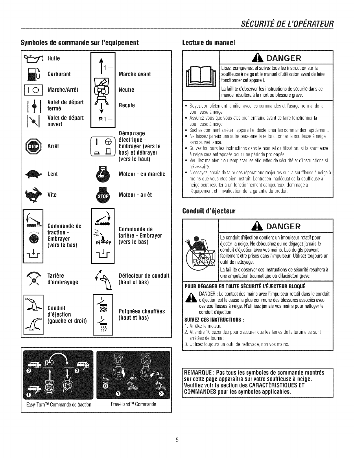
SECUR/TEBE L'OPERATELIR
Symbolesde commandesur Yequipement
l+!
i×i
Huile
Carburant
Marche/Arr_t
Voletde d6part
ferrn_
Voletde d6part
ouvert
Arr_t
uu
R1--
Marche avant
Neutre
Recuie
D_rnarrage
61ectrique -
Ernbrayer(vers le
bas) et d_brayer
(vers le haut)
Lent Moteur =en rnarche
D
Vite
Cornrnande de
traction-
Ernbrayer
(vers le bas)
Tari_re
d'embrayage
Conduit
d'6jection
(gauche et droit)
J--
=_"m
o_
-dr
IVloteur- arr_t
Cornmande de
tari_re - Ernbrayer
(vers le has)
D_fiecteurde conduit
(haut et has)
Poign6es chauff_es
(haut et has)
Easy-TurnTM Commandedetraction TM
Free-Hand Commande
Lecturedu manuel
DANGER
Lisez,comprenez,etsuiveztousleeinstructionsurla
souffleuse&neigeet le manueld'utilisationavantde faire
fonctionnereetappareil.
Lafaillite d'observerleeinstructionsdesdcuritddansce
manuelrdsultera&lamortoublessuregrave.
. Soyezcompletementfamilieraveclescommandeset I'usagenormaldela
souffleusea neige.
. Assurez-vousquevous _tesbienentra'in_avantdefairefonctionnerla
souffleusea neige.
*Sachezcommentarr_terI'appareilet @clencherlescommandesrapidement.
. Nelaissezjamaisuneautrepersonnefairefonctionnerlasouffeuse_ neige
sanssurveillance.
o Suiveztoujoursles instructionsdansle manueld'utilisation,si lasouffleuse
neigeseraentrepos_epourunep6riodeprolong@.
o Veuillezmaintenirouremplacerles6tiquettesdes_curit_etd'instructionssi
n_cessaire.
o N'essayezjamaisdefairedesr@arationsmajeuressur lasouffleusea neige
moinsquevous_tesbieninstruit.L'entretienina@quatdelasouffleuse
neigepeutr_sultera un fonctionnementdangeureux,dommage
1'6quipementet I'invalidationdela garantieduproduit.
Conduitd'6jecteur
_, DANGER
Leconduitd'djectioncontientunimpulseurrotatifpour
djecterla neige.Neddbouchezou neddgagezjamaisle
conduitd'djectionavecvosmains.Lesdoigtspeuvent
facilement@e prisesdansrimpulseur.Utiliseztoujoursun
outil de nettoyage.
Lafaillited'observerces instructionsdesdcuritdrdsultera
uneamputationtraumatiqueoudilacdratongrave.
POURDEGAGERENTOUTESr:CURITEL'[:JECTEURBLOQUr:
AANGER' Lecontactdes mainsavecl'impulseurrotatifdansleconduit
d'djectionestlacausela pluscommunedes blessuresassocidsavec
dessouffleuses_ neige.N'utilisezjamaisvos mainspournettoyerle
conduitd'djection.
SUIVEZCESINSTRUCTIONS:
1. Arretezle moteur.
2. Attendre10secondespours'assurerqueleslamesdelaturbinesesont
arr_t@sde tourner.
3. Utiliseztoujoursun outil denettoyage,nonvosmains.
REMARQUE:Pas tous les syrnboles de cornrnandernontr_s
surcette pageappara'itra sur votresouffleuse_neige.
Veuillez voir la section des CARACTERISTIQUESET
COMMANDESpourles symbolesappiicables.
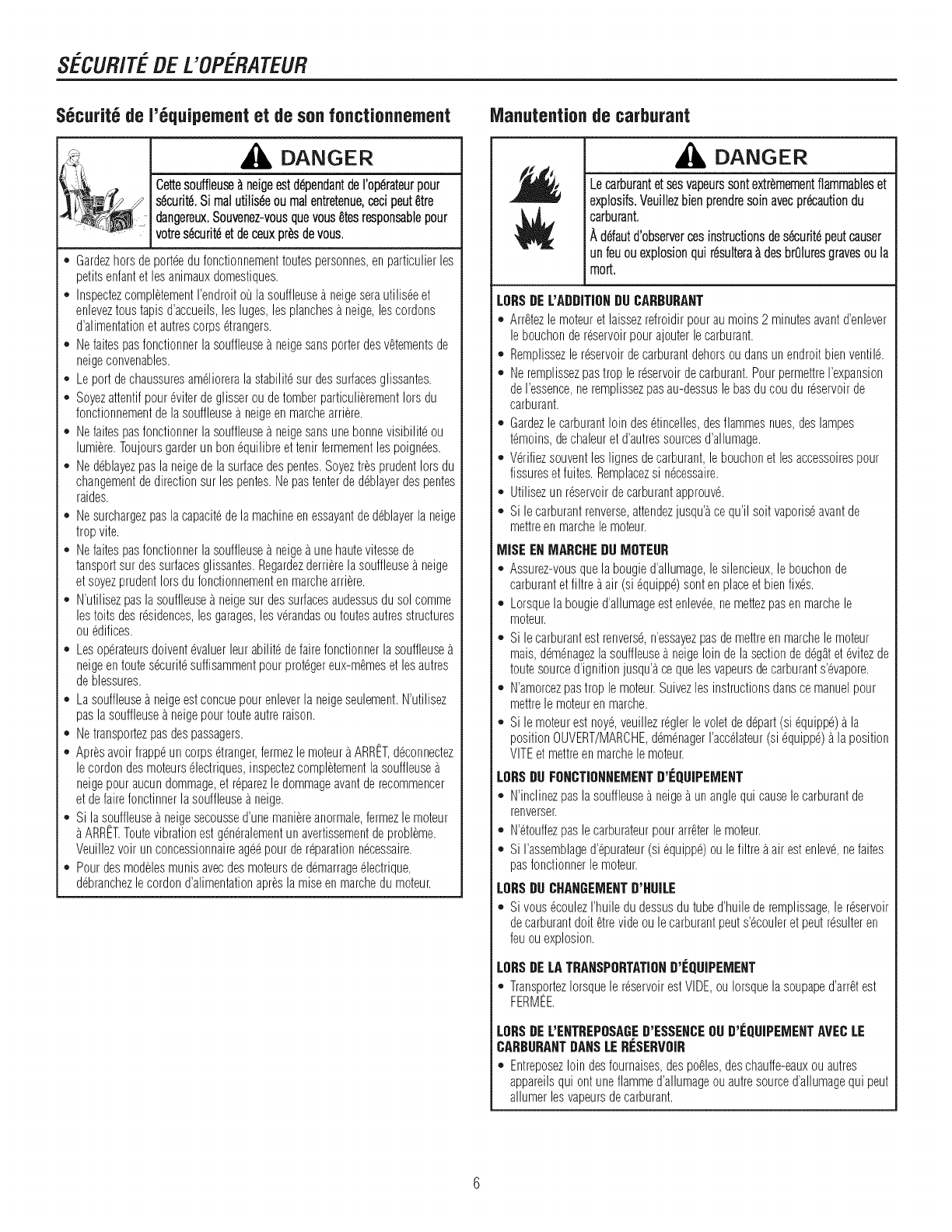
SECURITEDEL'OPERATEUR
S6curit6de 1'6quipementet de son fonctionnement
DANGER
',Y Cettesoufiieu_ neigeestd@endantdei;op6rateurpoui
___ s6curit6.Si malutilis6eou malentretenue,cecipeut_tre
-dangereux.Souvenez-vousquevous_tesresponsablepour
votres6curit6et deceuxpr6sdevous.
o Gardezhorsde porteedu fonctionnementtoutespersonnes,enparticulierles
petitsenfantet lesanimauxdomestiques.
,, InspectezcompletementI'endroitoula souffleusea neigeserautilis@et
enleveztoustapisd'accueils,les luges,lesplanchesa neige,lescordons
d'alimentationetautrescorps6trangers.
,, Nefaitespasfonctionnerlasouffleusea neigesansporterdesvetementsde
neigeconvenables.
,, Leportdechaussuresam61ioreralastabilit6sur dessurfacesglissantes.
,, Soyezattentifpour6viterdeglisserou detomberparticulierementIorsdu
fonctionnementdelasouffleusea neigeen marchearriere.
,, Nefaitespasfonctionnerlasouffleusea neigesansunebonnevisibilit6ou
lumiere.Toujoursgarderun bon6quilibreet tenirfermementlespoign6es.
,, Ne@blayezpasla neigede lasurfacedespentes.SoyeztresprudentIorsdu
changementde directionsur lespentes.Nepastenterde@blayerdespentes
raides.
,, Nesurchargezpasla capacit6dela machineenessayantde@blayerla neige
tropvite.
,, Nefaitespasfonctionnerlasouffleusea neigea unehautevitessede
tansportsur dessurfacesglissantes.Regardezderrierelasouffleuse_ neige
etsoyezprudentIorsdu fonctionnementenmarchearriere.
,, N'utilisezpaslasouffleusea neigesur dessurfacesaudessusdusolcomme
lestoits desresidences,lesgarages,lesverandasou toutesautresstructures
ouedifices.
o Lesop6rateursdoivent@aluerleurabilit6defairefonctionnerlasouffleuse
neigeentoutes6curit6suffisammentpourprot6gereux-m_meset lesautres
deblessures.
. Lasouffleusea neigeestconcuepourenleverla neigeseulement.N'utilisez
pasla souffleuse_ neigepourtouteautreraison.
o Netransportezpasdespassagers.
o Apr_savoirfrappeun corps6tranger,fermezle moteuraARRttT,@connectez
lecordondesmoteurs61ectriques,inspectezcompletementlasouffleuse
neigepouraucundommage,et r@arezledommageavantde recommencer
et defairefonctinnerlasouffleusea neige.
o Si lasouffleusea neigesecoussed'unemaniereanormale,fermezlemoteur
ARRttT.Toutevibrationestg@6ralementunavertissementdeprobleme.
Veuillezvoir unconcessionnaireag@pourdereparationn6cessaire.
o Pourdesmodelesmunisavecdesmoteursde @marrage61ectrique,
@branchezlecordond'alimentationapr_sla miseenmarchedumoteur.
iVlanutentionde carburant
,DANGER
Lecarburantetsesvapeurssontextremementflammableset
explosifs.Veuillezbienprendresoinavecpr_autiondu
carburant.
Ad6fautd'observercesinstructionsdes6curit6peutcauser
unfeuouexplosionquir6sultera&desbrOluresgravesoula
mort.
LOBSDEL'ADDITIONDUCABBUBANT
,' Arr_tezlemoteuret laissezrefroidirpourau moins2 minutesavantd'enlever
lebouchondereservoirpourajouterlecarburant.
,, Remplissezlereservoirdecarburantdehorsou dansunendroitbienventil6.
,, Neremplissezpastrop le reservoirdecarburant.PourpermettreI'expansion
deI'essence,neremplissezpasau-dessusle basducou dureservoirde
carburant.
,, Gardezlecarburantloin des6tincelles,desflammesnues,deslampes
t6moins,dechaleuret d'autressourcesd'allumage.
,, V6rifiezsouventleslignesdecarburant,lebouchonet lesaccessoirespour
fissureset fuites.Remplacezsi n6cessaire.
,, Utilisezun reservoirdecarburantapprouv6.
,, Sile carburantrenverse,attendezjusqu'_ce qu'ilsoit vaporis6avantde
mettreenmarchele moteur.
MISE ENMABCHEDUMOTEUB
,' Assurez-vousquela bougied'allumage,lesilencieux,le bouchonde
carburantet filtre a air (si 6quipp6)sonten placeet bienfixes.
,, Lorsquela bougied'allumageestenlev6e,nemettezpasenmarchele
moteur.
,, Sile carburantest renvers6,n'essayezpasde mettreen marchelemoteur
mais,@m@agezlasouffleusea neigeloin de lasectionded6gatet@itezde
toutesourced'ignitionjusqu'_cequelesvapeursdecarburants'@apore.
,, N'amorcezpastrop le moteur.Suivezlesinstructionsdansce manuelpour
mettrele moteuren marche.
,, Sile moteurest noy6,veuillezr@lerlevoletde depart(si 6quipp6)a la
positionOUVERT/MARCHE,@m@agerI'ac@lateur(si 6quipp6)a laposition
VITEet mettreen marchelemoteur.
LOBSDU FO_CTIO_NEMENTD'EQUIPEMENT
,' N'inclinezpaslasouffleusea neige_ unanglequi causelecarburantde
renverser.
,, N'6touffezpas lecarburateurpourarr_terlemoteur.
,, SiI'assemblaged'@urateur(si 6quipp6)oule filtre_air estenlev6,nefaites
pasfonctionnerlemoteur.
LOBSDU CHA_GEMENTD'HUILE
,, Sivous6coulezI'huiledudessusdutubed'huilederemplissage,lereservoir
decarburantdolt etrevideoule carburantpeuts'6couleret peutr6sulteren
feuouexplosion.
LOBSDELATBANSPOBTATIOND'EQUIPEME_T
,, TransportezIorsquele reservoirestVIDE,ouIorsquelasoupaped'arretest
FERMEE.
LOBSDEL'ENTBEPOSABED'ESSENCEOUD'g:QUiPEMENTAVECLE
CABBUBA_TDA_SLEB[:SEBVOIB
,' Entreposezloin desfournaises,despo_les,deschauffe-eauxou autres
appareilsqui ontuneflammed'allumageou autresourced'allumagequi peut
allumerlesvapeursdecarburant.
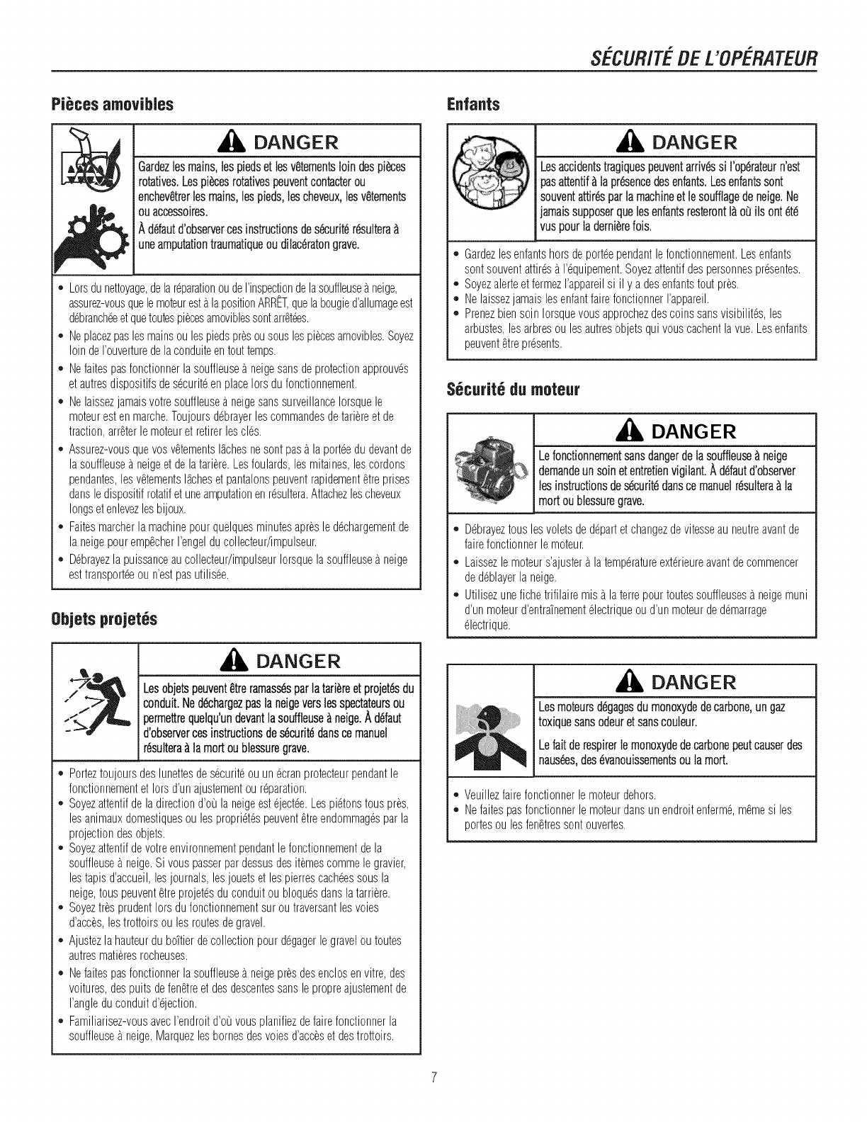
SECUR/TEBE L'OPERATEUR
Pi_ces amovibles
DANGER
Gardezlesmains,tespie@et lesv_tementsloin despi_ces
rotatives.Lespi_cesrotativespeuventcontacterou
enchev_trerlesmains,lespieds,lescheveux,lesv_tements
ouacceesoires.
A d6fautd'observercesinstructionsdes_curit_r_ultera
uneamputationtraumatiqueou dilaceratongrave.
o Lorsdunettoyage,delar@arationoudeI'inspectiondelasouffleuseaneige,
assurez-vousquelemoteuresta lapositionARRItT,quelabougied'alhmageest
d6branch@et quetoutespi@esamoviblessontarretees.
,, Neplacezpaslesmainsou lespiedspresousouslespi@esamovibles.Soyez
loindeI'ouverturedelaconduiteentouttemps.
,, Nefaitespasfonctionnerlasouffleusea neigesansdeprotectionapprouves
et autresdispositifsde s@uriteen placeIorsdufonctionnement.
,, Nelaissezjamaisvotresouffleusea neigesanssurveillanceIorsquele
moteurest en marche.Toujoursdebrayerlescommandesdeta@reet de
traction,arreterlemoteuret retirerlescles.
,, Assurez-vousquevosv_tementslachesnesontpasa laporteedu devantde
lasouffleusea neigeet de lata@re.Lesfoulards,lesmitaines,lescordons
pendantes,lesv_tementslacheset pantalonspeuventrapidement_treprises
dansledispositifrotatifetuneamputationenresultera.Attachezlescheveux
longset enlevezlesbijoux.
,, Faitesmarcherla machinepourquelquesminutesapresle d@hargementde
la neigepouremp_cherI'engelducollecteur/impulseur.
,, Debrayezla puissanceaucollecteur/impulseurIorsquelasouffleusea neige
est transport@ou n'estpasutilis@.
0bjets projet6s
DANGER
Lesobjetspeuvent_treramass6sparlatari_reetprojetesdu
conduit.Nedechargezpaslaneigeverslesspectateursou
permettrequelqu'undevantlasouffleuseAneige.Adefaut
d'observercesinstructionsdes6curitedanscemanuel
resulteraAlamortoublessuregrave.
o Porteztoujoursdeslunettesdes@uriteouunecranprotecteurpendantle
fonctionnementet Iorsd'un ajustementou reparation.
,, Soyezattentifdela directiond'ou laneigeesteject@.Lespietonstouspres,
lesanimauxdomestiquesou lesproprietespeuventetreendommagespar la
projectiondesobjets.
,, Soyezattentifdevotreenvironnementpendantlefonctionnementdela
souffleuse_ neige.Sivous passerpardessusdesitemescommele gravier,
lestapisd'accueil,lesjournals,lesjouetset lespierrescach@ssousla
neige,touspeuventetreprojetesdu conduitou bloquesdanslatar@re.
,, SoyeztresprudentIorsdu fonctionnementsuroutraversantlesvoles
d'ac@s,lestrottoirsoulesroutesdegravel.
,, Ajustezla hauteurdu bottlerdecollectionpourdegagerle gravelou toutes
autresma%resrocheuses.
,, Nefaitespasfonctionnerlasouffleusea neigepresdesenclosen vitre,des
voitures,despuitsdefenStreet desdescentessanslepropreajustementde
I'angledu conduitd'ejection.
,, Familiarisez-vousavecI'endroitd'ou vousplanifiezdefairefonctionnerla
souffleuse_ neige.Marquezlesbornesdesvolesd'acceset destrottoirs.
Enfants
DANGER
Lesaccidentstragiquespeuventarriv&ssi l'operateurn'est
pasattentif_lapresencedesenfants.Lesenfantssont
souventattir_ parlamachineetlesoufflagedeneige.Ne
jamaissupposerquelesenfantsresteront1_oBilsontete
vuspourladerni_,relois.
o Gardezlesenfantshorsdeporteependantlefonctionnement.Lesenfants
sontsouventattiresa I'@uipement.Soyezattentifdespersonnespresentes.
,, Soyezalerteet fermezI'appareilsi il y a desenfantstoutpres.
,, NelaissezjamaislesenfantfairefonctionnerI'appareil.
,, Prenezbiensoin Iorsquevousapprochezdescoinssansvisibilites,les
arbustes,lesarbresou lesautresobjetsqui vouscachentlavue.Lesenfants
peuventetrepresents.
S6curit6de moteur
DANGER
Lefonctionnementsansdangerde lasouffleuse_ neige
@man@un soin et entretienvigilant,A defautd'observer
lesinstructionsdesecuritedansce manuelresultera_ la
mortou blessuregrave.
o Debrayeztousles voletsde departet changezdevitesseau neutreavantde
fairefonctionnerle moteur.
,, Laissezlemoteurs'ajustera latemperatureexterieureavantdecommencer
dedeblayerla neige.
,, Utilisezunefichetrifilairemisa laterrepourtoutessouffleusesa neigemuni
d'unmoteurd'entra'_nementelectriqueou d'unmoteurdedemarrage
electrique.
DANGER
Lesmoteursdegagesdumonoxydedecarbone,ungaz
toxiquesansodeuretsanscouleur.
Lefar derespirerlemonoxydedecarbonepeutcauserdes
naus_s,desevanouissementsoulamort.
o Veuillezfairefonctionnerlemoteurdehors.
,, Nefaitespasfonctionnerle moteurdansunendroitenferme,memesi les
portesou lesfen@essontouvertes.
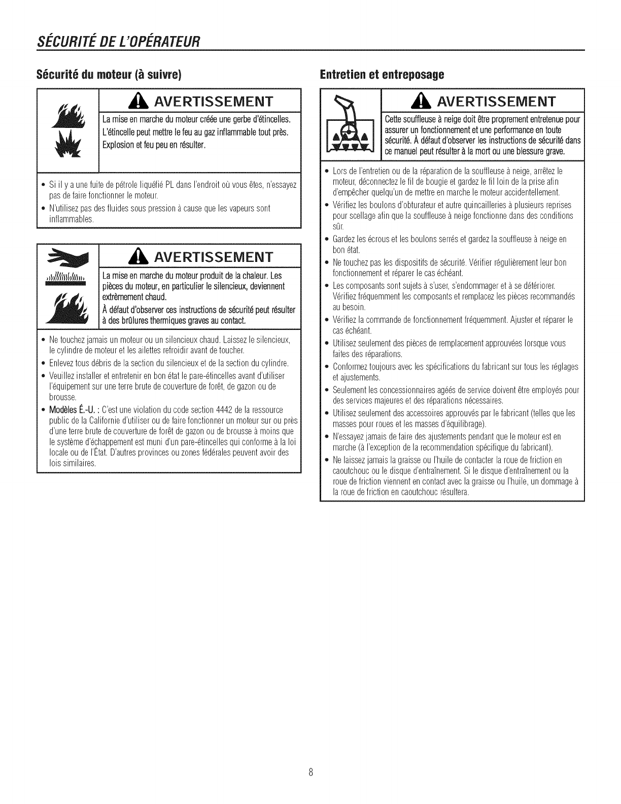
SECUR/TEBE L'OPERATEUR
S6curit6dumoteur suivre)
AVERTISSEMENT
Laraiseenmarchedumoteurcr66eunegerbed'6tincelles.
L'6tincellepeutmettrelefeuaugazinflammabletoutpr_s.
Explosionetfeupeuenr6sulter.
*Si il y a unefuitede p6troleliqudi_ PLdansI'endroitou vousetes,n'essayez
pasdefairefonctionnerlemoteur.
,, N'utilisezpasdesfhides sous pressionacausequelesvapeurssont
inflammables.
,_hlllll!f_f!l,,
AVERTISSEMENT
Lamiseenmarchedumoteurproduitdelachaleur.Les
pi_cesdumoteur,enparticulierlesilencieux,deviennent
extr_.mementchaud.
Ad6fautd'observercesinstructionsdes6curit6peutr6sulter
desbr01uresthermiquesgravesaucontact.
*Netouchezjamaisun moteurou unsilencieuxchaud.Laissezlesilencieux,
lecylindrede moteuret lesailettesrefroidiravantde toucher.
,, Enleveztousd6brisdela sectiondusilencieuxet de lasectionducylindre.
,, Veuillezinstalleret entretenirenbon6tatlepare-6tincellesavantd'utiliser
1'6quipementsur uneterrebrutedecouverturedeforet,degazonou de
brousse.
,, Mod_.les(:.-U.: C'estuneviolationducodesection4442 delaressource
publicdela Californied'utiliserou defairefonctionnerun moteursuroupres
d'uneterrebrutedecouverturedeforetdegazonoudebroussea moinsque
lesystemed'6chappementestmunid'un pare-6tincellesqui conformea la Ioi
localeoude I'l_tat.D'autresprovincesouzonesf6d6ralespeuventavoirdes
loissimilaires.
Entretienet entreposage
AVERTISSEMENT
Cettesouffleuse_ neigedolte"trepropremententretenuepour
assurerunfonctionnementet uneperformanceen toute
s6curit6.A d6fautd'observerlesinstructionsdes6curit6dans
ce manuelpeutr6sulter_ la mortouunebleesuregrave.
*LorsdeI'entretienou dela r6parationde lasouffleusea neige,arr_tezle
moteur,d6connectezlefil debougieet gardezlefil loin de la priseafin
d'empScherquelqu'undemettreenmarchele moteuraccidentellement.
,, V6rifiezlesboulonsd'obturateuretautrequincailleriesa phsieurs reprises
pourscellageafinquela souffleuseb neigefonctionnedansdesconditions
s0r.
,, Gardezles6crouset lesboulonsserr6set gardezlasouffleuseb neigeen
bon6tat.
,, Netouchezpaslesdispositifsdes6curit6.V6rifierr6gulierementleurbon
fonctionnementet r6parerle cas6ch6ant.
,, Lescomposantssontsujetsa s'user,s'endommagereta se d6t6riorer.
V6rifiezfr6quemmentlescomposantset remplacezlespiecesrecommand6s
aubesoin.
,, V6rifiezlacommandede fonctionnementfr6quemment.Ajusteret r6parerle
cas6ch6ant.
,, Utilisezseulementdespiecesderemplacementapprouv6esIorsquevous
faitesdesr6parations.
,, Conformeztoujoursaveclessp6cificationsdufabricantsurtousles r6glages
et ajustements.
,, Seulementlesconcessionnairesag66sdeservicedoiventetreemploy6spour
desservicesmajeureset desr6parationsn6cessaires.
,, Utilisezseulementdesaccessoiresapprouv6sparlefabricant(tellesqueles
massespourroueset lesmassesd'6quilibrage).
,, N'essayezjamaisdefairedesajustementspendantquele moteuresten
marche(aI'exceptiondela recommendationsp6cifiquedufabricant).
,, Nelaissezjamaisla graisseou I'huiledecontacterla rouedefrictionen
caoutchoucoule disqued'entra_nement.Si ledisqued'entra_nementou la
rouedefrictionviennentencontactaveclagraisseou I'huile,un dommage
la rouede frictionencaoutchoucr6sultera.
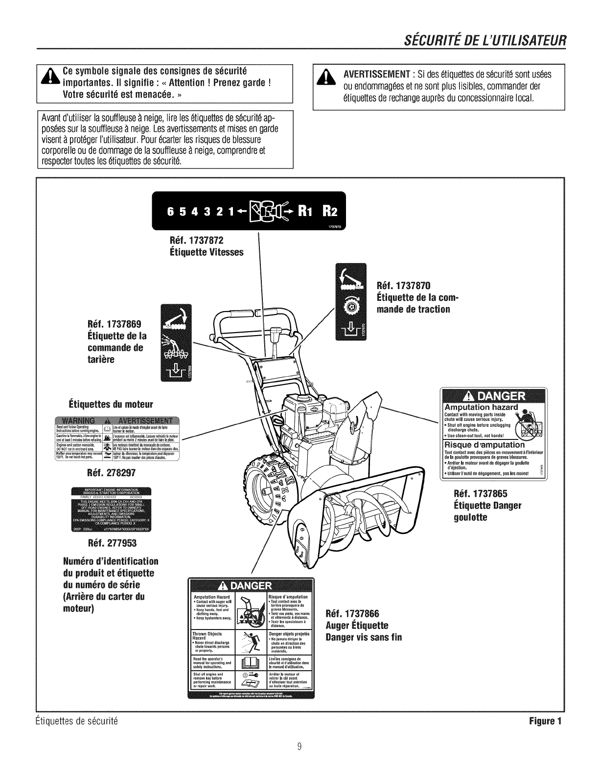
SECUR/TEDEWUT/USATEUR
,_i Ce symbolesignaledes consignesde s_curit_
irnportantes.II signifie" <<Attention!Prenezgarde !
Votres_curit_est menac_e. >>
Avantd'utiliserlasouffleuse_ neige,tireles6tiquettesdes6curitdap-
pos6essurlasouffleuse_neige.Lesavertissementset misesengarde
visent_ prot6gerrutiNsateur.Pour6carterlesrisquesdeblessure
corporeNeoudedommagedelasouffleuse_neige,comprendreet
respectertoutesies6tiquettesdesdcurit6.
R6f. 1737872
_=tiquetteVitesses
,& AVERTISSEIVlENT: Si des6tiquettesdes6curit6sontus6es
ou endommag6eset nesontplusNsibies,commanderder
etiquettesderechangeaupr_sduconcessionnairelocal.
R_f. 1737869
g:tiquettede la
commandede
tari_re
R6f. 1737870
g:tiquettede la com-
mandede traction
Etiquettes du moteur
fAMILY×××XXXX××XX ××××××
Ampulation hazard
Contact with moving parts inside
chute will c_use serious injury.
* Shut off engine before unclogging
discharge chute.
= Use clean=outtool, not hands!
Risque d'amputation
dela gouiotteprovoqueradegraves biessures.
• A_bter le mote,_ avant de d_gage_ la goulotte
d'bjection.
Utiliser I'outilde d_gagement, pus les mains!
Hum_rod'identification
du produitet _tiquette
du num_rode s_rie
(Arri_re du carter du
moteur)
Thrown Objects
Hazard
•Never_irectdischar_e
ch_tet_wardsgersons
orpropefly.
Readtheogerato_'s
manu_llo_ope_atin_and
safetyinstruetions.
Shul elf e_gine and
remove key het_re
peflorming maintenance
_t_ep_irwork,
l Isuedmua°n
•Contact with ae_er will • Tout contact avec I_
cause serious Ini_y. tariKre provoquera de
.Keep hands, feet and _r_ves blessures.
ci_lhi_h aw_y. •Te_ir Yes pie_s, vos mains
=Keep _yslanders away. el v_teme_ls K distance.
Te_ir les sgect_teurs
distance.
._ Dangerobjets projet_s
....... • Ne amais _iri_er la
....:> chute e_ direction _es
pe_onnes ou biefls
mal_riels.
LireJles consignes de
s_c_rit_ et d'utIKsation duns
Ar_ler I_ mote_ el
d'eifectuer t_at entretien
R_f. 1737866
AugerEtiquette
Dangervis sansfin
Etiquettesde s6curit6 Figure I
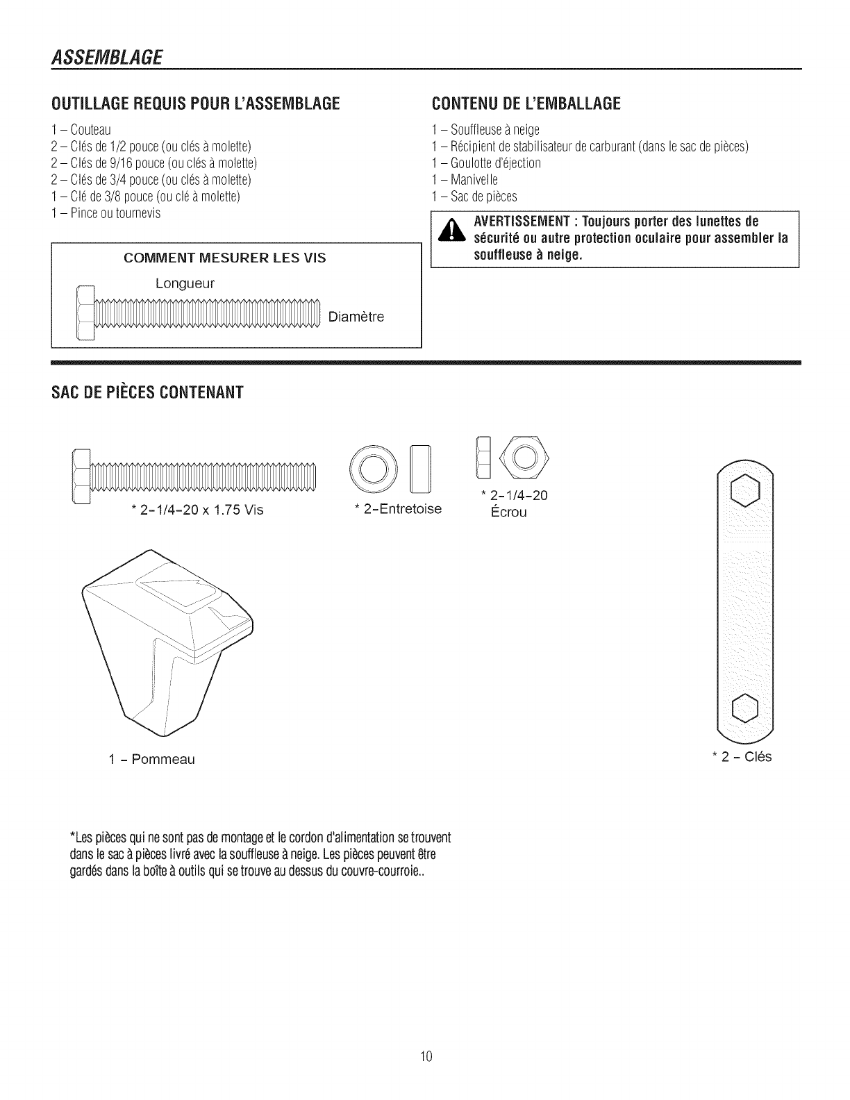
ASSEMBLAGE
OUTILLAGE REQUIS POUR L'ASSEIVIBLAGE
1- Couteau
2 - Clesde1/2 pouce(oudes amolette)
2 - Clesde9/16pouce(ouclesa molette)
2 - Clesde3/4 pouce(ouclesamolette)
1- Clede3/8 pouce(ouol5a molette)
1- Pinceoutournevis
COMMENT MESURER LES VIS
Longueur
Diametre
CONTENUDE L'EIVIBALLAGE
1- Souffleuseaneige
1- Recipientdestabilisateurdecarburant(danslesacdepieces)
1- Goulotte@ejection
1- Manivelle
1- Sacdepieces
,_ AVERTISSEIVlENT"Toujoursporterdes lunettes de
s_curit_ou autre protectionocuiaire pourassembler la
souffieuse_ neige.
SACDEPI#CESCONTENANT
* 2-1/4-20 x 1.75 Vis * 2-Entretoise
D©
* 2-1/4-20
Ecrou
I
I
!
I
I
I
1 - Pommeau * 2 -CI6s
*Lespiecesquinesontpasdemontageet lecordond'alimentationsetrouvent
danslesac_pieceslivr6aveclasouffieuse_neige.Lespiecespeuvent8tre
gard6sdanslabo_e_outilsquisetrouveaudessusducouvre-courroie_
10
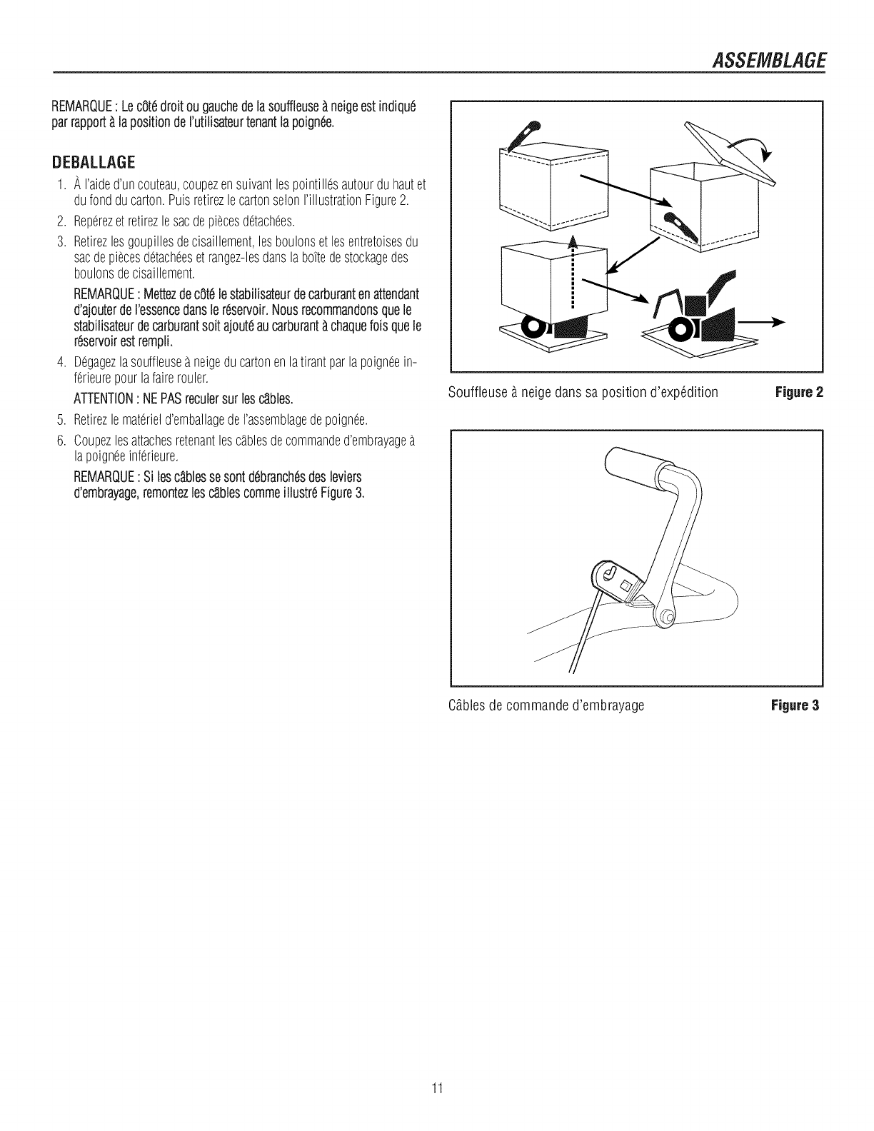
ASSEMBLAGE
REMARQUE: Lec8t6droitougauchede lasouffleuse_neigeestindiqu6
parrapport_ iapositionderutiiisateurtenantiapoign6e.
DEBALLAGE
1. A I'aided'uncouteau,coupezensuivantlespointill6sautourduhautet
dufondducarton.PuisretirezlecartonselonI'illustrationFigure2.
2. Rep6rezet retirezlesacdepiecesd6tach6es.
3. Retirezlesgoupillesdecisaillement,lesboulonset lesentretoisesdu
sacdepiecesd6tach6eset rangez-lesdanslaboTtedestockagedes
boulonsdecisaillement.
REMARQUE: Mettezdec8t6lestabilisateurdecarburantenattendant
d'ajouterdeI'essencedansier6servoir.Nousrecommandonsquele
stabiiisateurdecarburantsoitajout6aucarburant_chaquefoisquele
r6servoirestrempli.
4. D6gagezlasouffleusea neigedu cartonenlatirantparlapoign6ein-
f6rieurepourlafairefouler.
ATTENTION: NEPASrecuiersur lesc_bies.
5. Retirezlemat6rield'emballagedeI'assemblagedepoign6e.
6. Coupezlesattachesretenantlesc_blesdecommanded'embrayage
lapoign6einf6rieure.
REMARQUE: Si lesc_iblessesontd6branch6sdesleviers
d'embrayage,remontezlesc_blescommeillustr6Figure3.
Souffleuse 9 neigedans sa position d'exp6dition Figure 2
Cgblesde commande d'embrayage Figure3
11
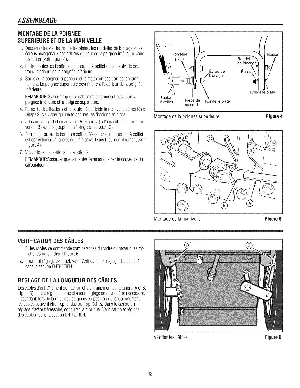
ASSEMBLAGE
MONTAGEDELAPOIGNEE
SUPERIEUREET DELAIViANIVELLE
1. Desserrerlesvis, lesrondellesplates,lesrondellesdeblocageet les
ecroushexagonauxdesorificesduhautdelapoigneeinferieure,sans
lesretirer(voir Figure4).
2. Retirertouteslesfixationsetleboulonaoeilletdelamanivelledes
trousinferieursdela poigneeinf6rieure.
3. Souleverlapoigneesuperieureetlamettreenpositiondefonction-
nement.Lapoigneesuperieuredevrait@rea I'exterieurdela poignee
inf6rieure.
REMARQUE:S'assurerqueiesc_biesnese prennentpasentreia
poigndeinferieureet lapoigneesuperieure.
4. Remonterlesfixationset leboulonaoeilletdela manivelledemontes
I'@ape2. Nevisserqu'unefoisrouteslesfixationsenplace.
5. Attacherlatigedela manivelle(A,Figure5) aI'ensembledujoint uni-
versel(B)aveclagoupilleenepingleacheveux(C).
6. SetterI'ecrousur leboulona oeillet.S'assurerqueleboulona oeillet
estcorrectementaligneet quelamanivellepeuttournerlibrement(volt
Figure4).
7. Vissertousles boulonsdela poignee.
REMARQUE:S'assurerquela manivellenetoucheparlecouverciedu
carburateur.
Maniveile
Rondelle
plate
Ecrou de
//biocage
de blocac
\
Boulon
ceillet Piece de Rondelle plate
raccord
Rondelle plate
Montagede la poigneesuperieure
//
_oulon
Figure 4
Montagede la manivelle Figure5
VERIFICATIONDESCABLES
1. Siles@blesdecommandesontdetachesducadredumoteur,lesrat-
tachercommeindiqueFigure6.
2. Pourtout@@ageeve@u@,voir "Verificationet@@agedes@bles"
danslasectionENTRETIEN.
RI_.GLAGEDE LA LONGUEUR DES CABLES
Les@blesd'entratnementdetractionet d'entratnementdelatariere(AetB,
Figure6) ontete@gleenusineet aucun@@agededevrait@renecessaire.
Cependant,lotsdelamisedespoigneesenpositiondefonctionnement,
les@blespeuvent@retroptendusoutrop I_ches.Danslecasoi un
@@ages'averenecessaire,consulterlarubrique"Verificationet @@age
des@bles"danslasectionENTRETIEN.
V_rifier les cgbles
12
FigureB
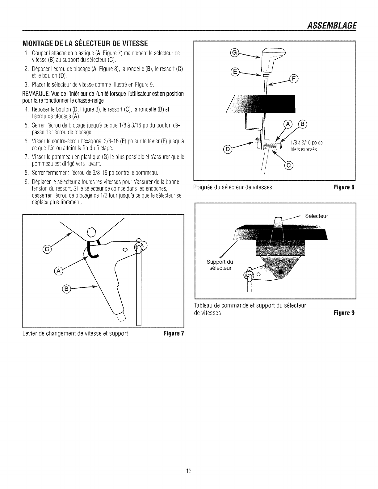
ASSEMBLAGE
MONTAGEDELASI_LECTEURDEVITESSE
1. CouperI'attacheenplastique(A, Figure7)maintenantleselecteurde
vitesse(B)ausupportduselecteur(C).
2. %poserI'ecroudeblocage(A, Figure8), larondelle(B), leressort(C)
etleboulon(D).
3. PlacerleselecteurdevitessecommeillustreenFigure9.
REMARQUE:VuedeI'int6rieurdeI'unit6IorsqueI'utilisateurestenposition
pourfairefonctionnerlechasse-neige
4. Reposerleboulon(D,Figure8), leressort(C),larondelle(B)et
I'ecroudeblocage(A).
5. SerrerI'ecroudeblocagejusqu'aceque1/8a3/16 poduboulonde-
passedeI'ecroudeblocage.
6. Visserlecontre-ecrouhexagonal3/8-16(E)posur lelevier(F)jusqu'a
cequeI'ecrouatteintlafin dufiletage.
7. Visserlepommeauenplastique(G)lepluspossibleet s'assurerquele
pommeauestdirigeversI'avant.
8. SerrerfermementI'ecroude3/8-16pocontrelepommeau.
9. Deplacerleselecteuratouteslesvitessespours'assurerdelabonne
tensionduressort.Si les61ecteursecoincedanslesencoches,
desserrerI'ecroudeblocagede1/2 tourjusqu'acequeleselecteurse
deplacepluslibrement.
1/8a 3/16pode
filetsexposes
Poign_edu s_lecteur devitesses Figure8
Selecteur
Support du
selecteur
Tableaude commande et support du s_lecteur
devitesses Figure9
Levier de changement de vitesse et support Figure 7
13
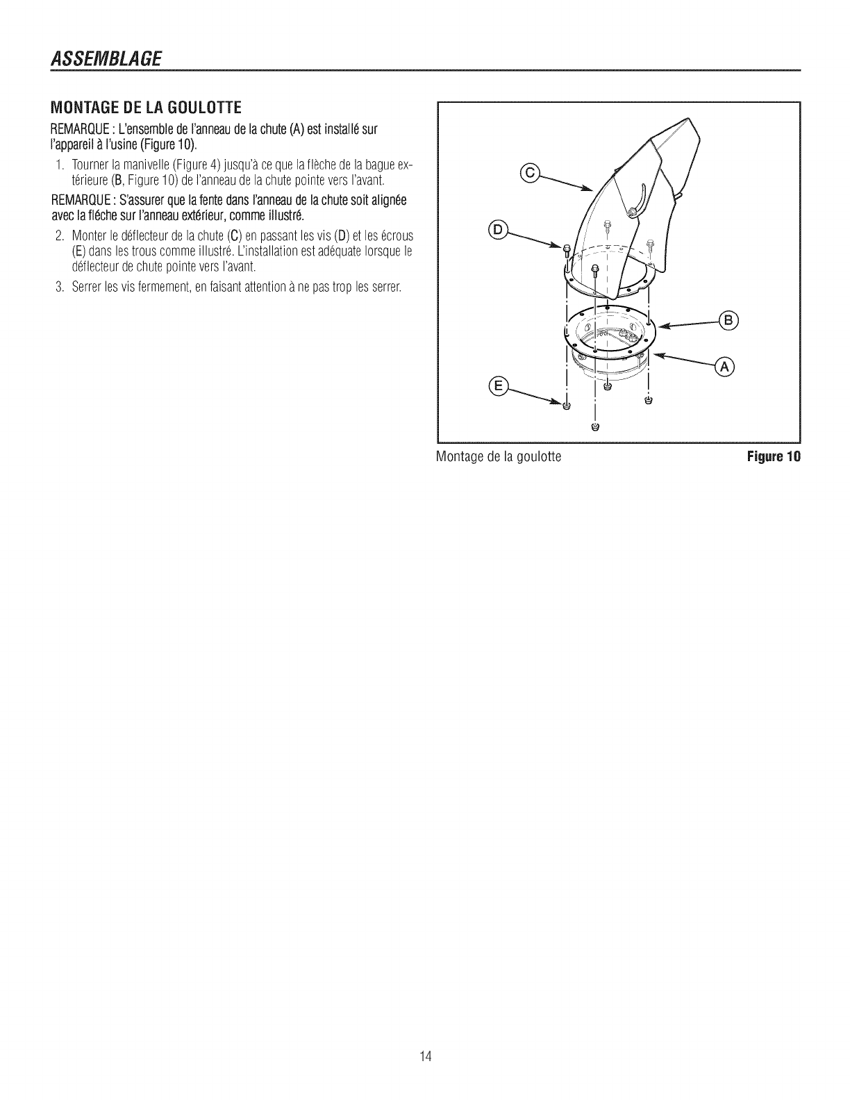
ASSEMBLAGE
MONTAGE DE LA GOULOTTE
REMARQUE: L'ensemblede I'anneaudelachute(A)estinstall6sur
I'appareN_ I'usine(Figure10).
1. Tournerla manivelle(Figure4)jusqu'acequela%chedelabagueex-
terieure(B,Figure10)deI'anneaudelachutepointeversravant.
REMARQUE:S'assurerqueiafentedansranneaudelachutesoitalign6e
aveciafiechesur i'anneauext6rieur,commeiNustr6.
2. Monterledeflecteurdelachute(C)enpassantlesvis(D) etlesecrous
(E)danslestrouscommeillustr6.L'installationestadequateIorsquele
deflecteurdechutepointeversI'avant.
3. Setterlesvis fermement,enfaisantattentionanepastrop lessetter.
Montagede la goulotte Figure 10
14
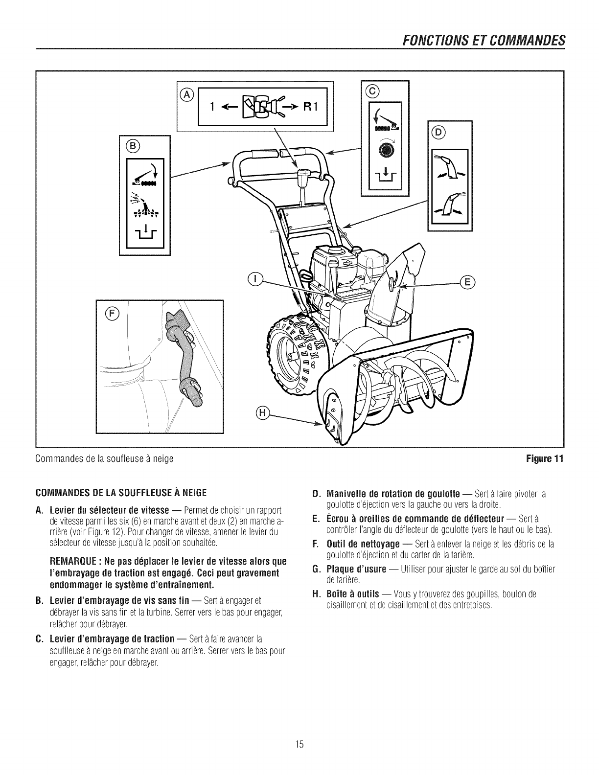
FONCTION$ETCOMMANDES
®
E,.,"
©
®
Commandesde ia soufieuse _ neige Figure 11
COIVllVlANDESDELASOUFFLEUSEA NEiGE
A. Levier duselecteurde vitesse-- Permetdechoisirunrapport
devitesseparmilossix(6)enmarcheavantetdeux(2)enmarchea-
rriere(voir Figure12).Pourchangerdevitesse,amenerlelevierdu
selecteurdevitessejusqu'alapositionsouhaitee.
Bo
Co
REMARQUE: He pusd_placerle levier de vitesse aiors que
rembrayage de traction est engage. Ceci poutgravement
endornrnagerle syst_',med'entraTnement.
Levier d'embrayagede vis sansfin -- Sortaengageret
debrayerlavissansfin et laturbine.Serrerverslebaspourengager,
rel_cherpourdebrayer.
Levier d'ernbrayagede traction-- Sortafaireavancerla
souffleusea neigeenmarcheavantouarriere.Serrerverslebaspour
engager,rel_cherpourdebrayer.
D. Manivelle de rotationde goulotte-- Sortafairepivoterla
goulotted'ejectionverslagaucheouversladroite.
E. I_crou_oreilles de comrnandede d_flecteur-- Sort
contrOlerI'angleduddlecteurdegoulotte(verslehautoulebas).
F. Outii de nettoyage-- Sortaenleverlaneigeet losdebrisdela
goulotted'ejectionetdu carterde latariere.
G. Plaque d'usure-- Utiliserpourajusterlegardeausol dubottier
detariere.
H. Bo'ite_ outils -- Vousy trouverezdesgoupilles,boulonde
cisaillementetdecisaillementetdesentretoises.
15
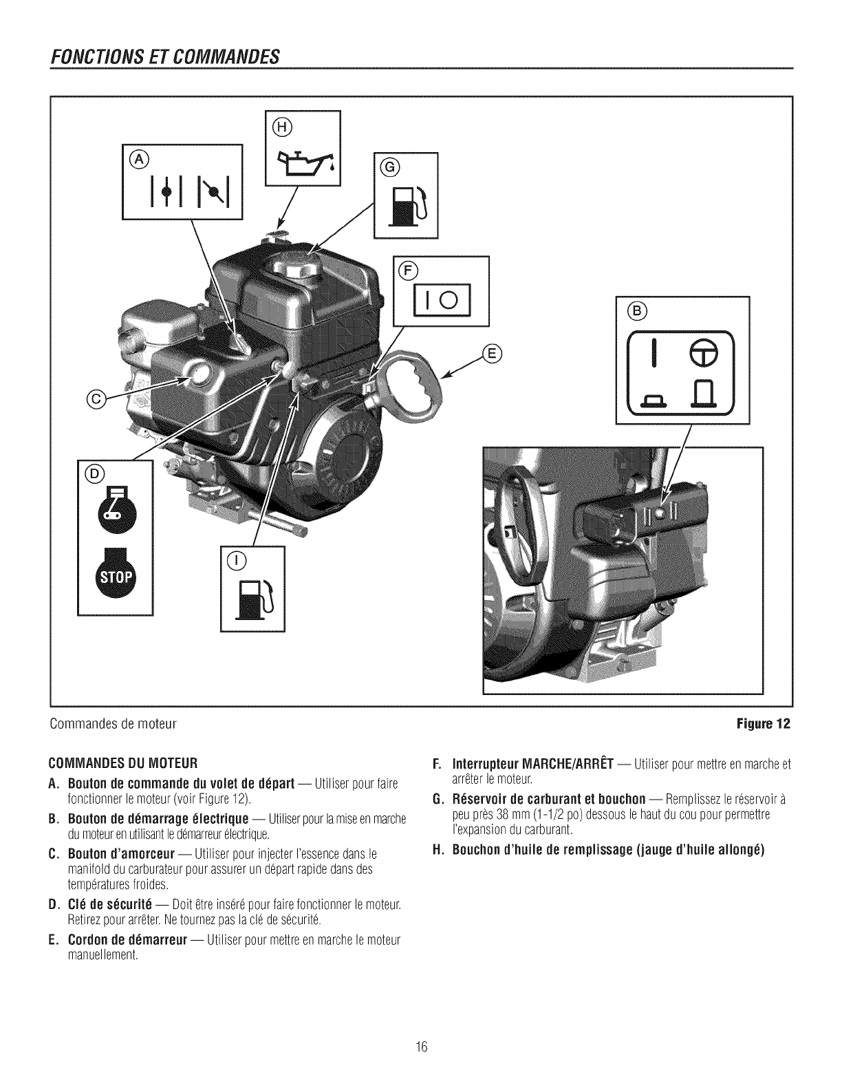
FONCTION$ETCOMMANDES
®I÷1I×l /®
®
®
®
Commandesde moteur Figure 12
COlVllVlANDESDU IVIOTEUR
A. Boutonde cornrnandeduvolet de depart -- Utiliserpourfaire
fonctionnerlemoteur(voirFigure12).
B. Beuten de dernarrageeleclrique -- Utiliserpourlamiseenmarche
dumoteurenutilisantledemarreurelectrique.
C. Beuten d'amerceur-- UtiliserpourinjecterI'essencedansle
manifoldducarburateurpourassurerundepartrapidedansdes
temperaturesfroides.
D. Ole de securite -- Doitetreinserepourfairefonctionnerlemoteur.
Retirezpourarreter.Netournezpaslacledesecurite.
E. Cordon de dernarreur-- Utiliserpourmettreenmarchelemoteur
manuellement.
F°
6.
H°
InterrupteurMARCHE/ARRf:T-- Utiliserpourmettreenmarcheet
arreterlemoteur.
Reservoirde carburantet bouchon-- Remplissezlereservoir
peupres38 mm(1-1/2 po)dessouslehautducoupourpermettre
I'expansionducarburant.
Bouchond'huilede rernpiissage(jauge d'huiie allong_)
16
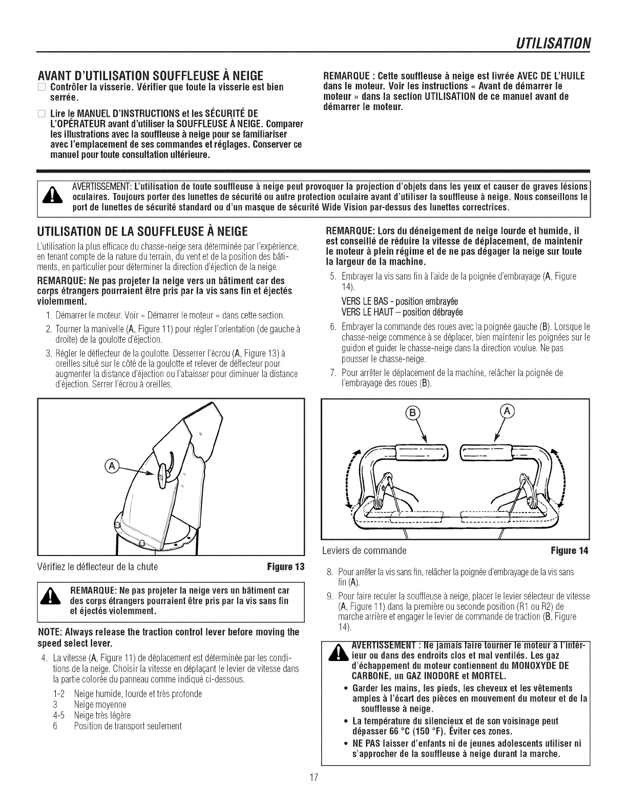
UTILISATION
AVANT D'UTILiSATiON SOUFFLEUSE A NEiGE
Contrgler ia visserie.V_rifierquerouteia visserieestbien
serr_e.
Lirele MANUELD'iNSTRUCTIONSet iesS[_CURIT[_DE
L'OPERATEURavantd'utiiiser ia SOUFFLEUSE,_NEiGE.Comparer
iesillustrationsavecia souffieuse_ neigepoursefamiiiariser
avecrempiacementdesescommaudesetr_giages.Conserverce
manuelpourrouteconsultationuit6rieure.
REMARQUE: Cette souffieuse _ neigeest iivr_eAVECDEL'HUiLE
dans ie moteur. Voir les instructions_,Avantde d_marrer le
moteur ,, dans ia sectionUTILISATIONde ce manuel avantde
d_marrer ie moteur.
AVERTISSEMENT:L'utilisationderoute souffleuse_neigepoutprovoqueria projectiond'objets dartslosyeuxet causerde gravesI_sions
ocuiaires.Toujoursporterdesiunettesdes_curit_ouautreprotectionocuiaireavantd'utiliser ia souffieuse_neige.Nousconseillonsie
portde iunettesdes_curit_standardoud'un masquede s_curit_WideVisionpar-dessusdes iunettescorrectrices.
UTILISATIONDELASOUFFLEUSEA NEiGE REMARQUE:Lorsdu ddneigementde neigeiourdeet humide,il
L'utilisationlaplusefficaceduchasse-neigeserad@ermin6eparI'exp6rience,
entenantcomptedelanatureduterrain,duventetdelapositiondesb_ti-
ments,enparticulierpourd@erminerladirectiond'@ectiondelaneige.
REIVlARQUE:Nepasprojeterla neigeversun b_timentcar des
corps6trangerspourraient _tre pris par ia vissansfin et _ject_s
violemment.
1. D6marrerlemoteur.Voir_D6marrerlemoteur,, dartscettesection.
2. Tournerlamanivelle(A,Figure11)pour@glerI'orientation(degauche
droite)delagoulotted'@ection.
3. R6glerleddlecteurdelagoulotte.DesserrerI%rou(A,Figure13)
oreillessitu6surlec0t6delagoulotteetreleverdeddlecteurpour
augmenterladistanced'@ectionouI'abaisserpourdiminuerladistance
d'@ection.SerrerI%rou_oreilles.
estconseill_de r_duire ia vitessede d_placement, de maintenir
ie moteur_ pieinr_gime et de ne pasd_gageria neigesur route
ia iargeurde ia machine.
5. Embrayerlavissansfin _I'aidedelapoign6ed'embrayage(A,Figure
14).
VERSLEBAS- positionernbray6e
VERSLEHAUT- positionddbray6e
6. Embrayerlacommandodesrouesaveclapoign6egauche(B).Lorsquele
chasse-neigecommence_sed6placer,bienmaintenirlospoign6essurle
guidonetguiderlechasse-neigedansladirectionvoulue.Nepas
pousserlechasse-neige.
7. Pourar@terled6placementdelamachine,rel_cherlapoign6ede
I'embrayagedesroues(B).
V6rifiezled6flecteurdelachute Figure13
,_ REiVlARQUE:Ne pas projeteria neige vers un b_timent car
des corps_trangers pourraient_tre pris par ia vis sansfin
et _ject_s violemment.
NOTE: Always release the traction control lever before moving the
speed select lever.
4. Lavitesse(A, Figure11) ded6placementest d@ermin6epar lescondi-
tions dela neige.Ohoisir lavitesseend6pla_antle levierdevitessedans
la partiecolo@edu panneaucommeindiqu6ci-dessous.
1-2 Neigehumide,Iourdeet t@sprofonde
3 Neigemoyenne
4-5 Neiget@s16g_re
6 Position detransportseulement
Leviersde commande Figure14
.
9.
Pourar@terlavissansfin,rel_cherlapoign_ed'embrayagedelavissans
fin(A).
Pourfairereculerlasouffleuse_ neige,placerleleviers@ecteurdevitesse
(A,Figure11)danslapremiereousecondeposition(R1ouR2)de
marcheartisteetengagerlelevierdecommandodetraction(B,Figure
14).
_e jamais taire tourner le moteur a I'_
ieur ou darts des endroits clos et mai ventil_s. Les gaz
d'_chappement du moteur contiennentdu IViONO×YDEDE
CARBONE,un GAZ INODOREet IVIORTEL.
* Garderies mains, les pieds, les cheveuxet les v_tements
ampies _i'_cart des pi_ces en mouvement du moteur et de ia
souffieuse_neige.
,, La temperature du silencieux et de sonvoisinagepout
d_passer 66 °C (150 °F). Evitercos zones,
,, NEPASiaisser d'enfants ni de jeunes adolescentsutiiiser ni
s'approcher de ia souffieuse_neige durant ia marche.
17
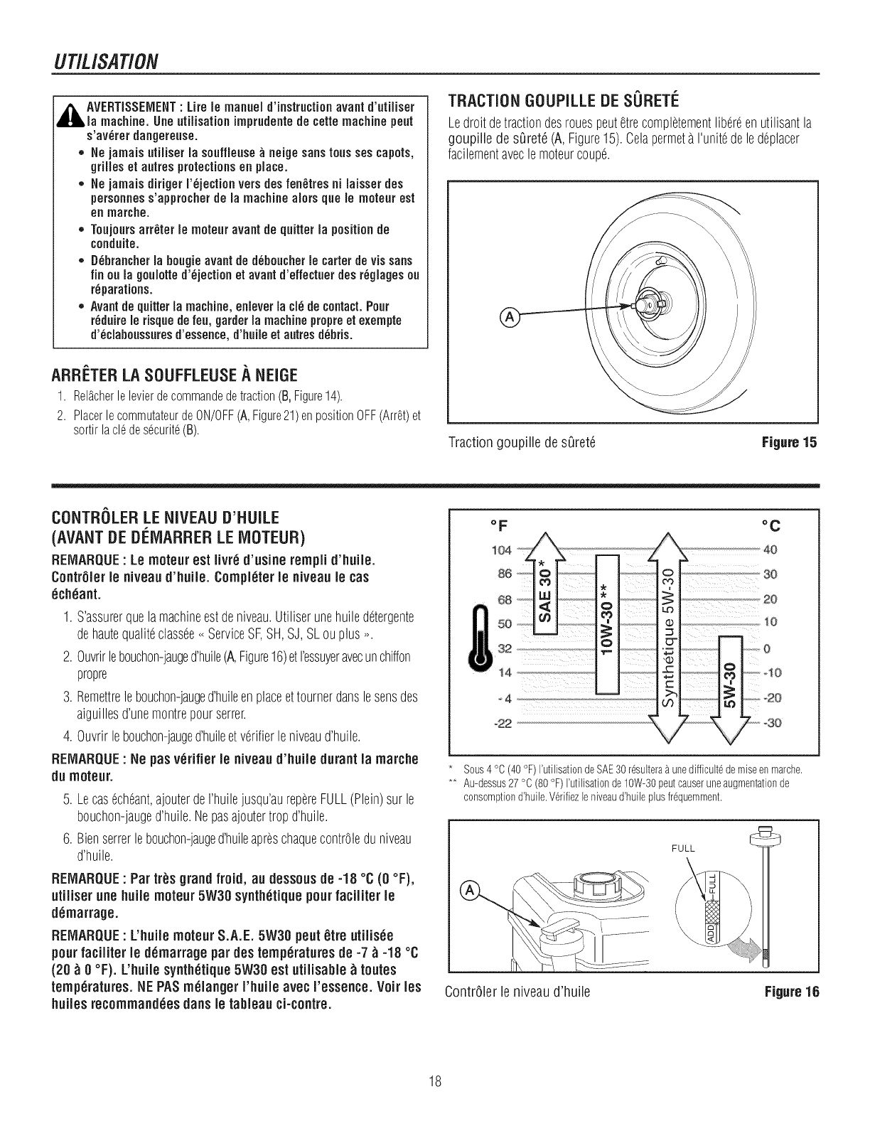
UTILISATION
,_k AVERTISSEIVlENT: Lifele manueld'instructionavantd'utiliser
la machine.Uneutilisation imprudentede cettemachinepeut
s'av_rerdangereuse.
*Nejamaisutiliser la souffleuse_neigesanstoussescapers,
grilleset autresprotectionsen place.
*NejamaisdirigerI'_jectionversdesfen_tresni laisserdes
personness'approcherde la machinealorsquele moteurest
en marche.
* Toujoursarr_ter le moteuravantde quitterla positionde
conduite.
* D_hrancherla hougieavantded_houcherle carterdeviesans
finoula goulotted'_jectionet avantd'effectuerdesr_glagesou
r_parations.
* Avantdequitterla machine,enleverla el6decontact.Pour
r_duirele risquedefeu,garderla machinepropreet exempte
d'_clahoussuresd'essence,d'huileet autresd_hris.
TRACTION GOUPILLE DE SORETI_.
Ledroit detractiondesrouespeutetrecompletementlib6reenutilisantla
goupille de sOrete(A, Figure15).Celapermeta I'unitedeledeplacer
facilementaveclemoteurcoupe.
ARRETER LA SOUFFLEUSEA NEIGE
1. Rel_cherlelevierdecommandedetraction(B,Figure14).
2. PlacerlecommutateurdeON/OFF(A,Figure21)enpositionOFF(Arret)et
sortirlacl6des6curit6(B). Traction goupille desOret6 Figure 15
CONTROLERLENIVEAUD'NUILE
(AVANTDEDi_IVlARRERLEIVlOTEUR)
REIVlARQUF: Le rnoteurest Iivr_ d'usine rernplid'huile.
ContrSler le niveaud'huile. Completerle niveaule cas
6chaunt.
1. S'assurerquelamachineestdeniveau.Utiliserunehuiledetergente
dehautequaliteclassee<<ServiceSF,SH,SJ, SLouplus _.
2. Ouvrirlebouchon-jauged'huile(A,Figure16)etI'essuyeravecunchiffon
propre
3. Remettrelebouchon-jauged'huileenplaceettournerdanslesensdes
aiguillesd'unemontrepourserrer.
4. Ouvrirlebouchon-jauged'huileetverifierleniveaud'huile.
REIVlARQUE:Ne pas v_rifier le niveaud'huile durantla rnarche
du rnoteur.
5. Lecasecheant,ajouterdeI'huilejusqu'aurepereFULL(Plein)sur le
bouchon-jauged'huile.Nepasajoutertropd'huile.
6. Bienserrerlebouchon-jauged'huileapreschaquecontrOledu niveau
d'huile.
REIVlARQUE: Par tr_s grand froid, au dessousde -18 °C (0 °F),
utiiiser une huile rnoteur5W30 synth_tiquepourfaciJiterle
d6marrage.
REIVlARQUE: L'huiJernoteurS.A.E. 5W30 peut_tre utiiisee
pourfaciiiter le d_rnarragepar des temperaturesde -7 _-18 °C
(20 _ 0 °F). L'huiie synth_tique5W30 est utiiisabie _toutes
temperatures.HE PASrn_iangerI'huiie avec I'essence. Voir lee
huiJesrecornrnand6es danele tableau ci-contre.
_2
°C
Sous4 °C (40 °F) I'utilisationdeSAE30 r_sultera_ unedifficult6demiseen marche.
** Au-dessus27 °C (80°F) I'utilisationde10W-30peutcauseruneaugmentationde
consomptiond'huile.V_rifiezleniveaud'huile plusfr_quemment.
ContrOlerle niveau d'huile Figure 16
18
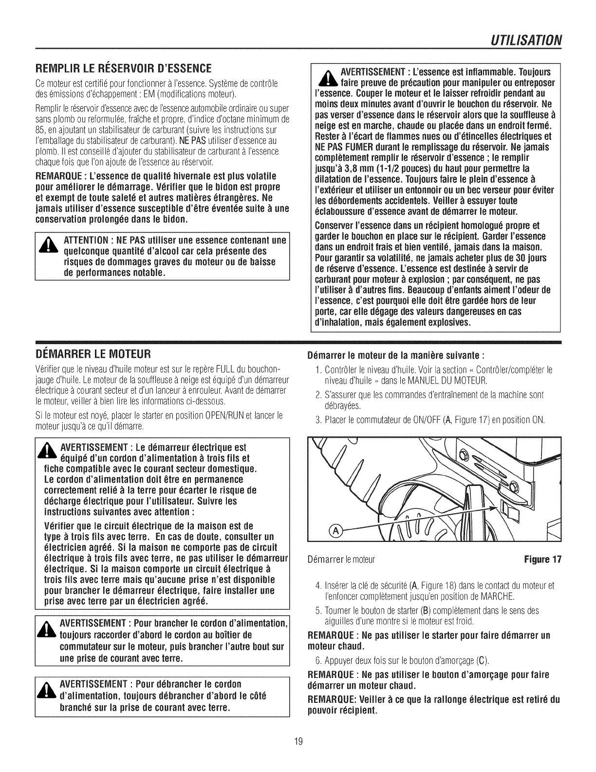
UT/L/SAT/ON
REIVlPLIRLE Ri_SERVOIRD'ESSENCE
Cemoteurestcertifiepourfonctionnera I'essence.SystemedecontrOle
desemissionsd'echappement: EM(modificationsmoteur).
Remplirlereservoird'essenceavecdeI'essenceautomobileordinaireousuper
sansplomboureformulee,fratcheet propre,d'indiced'octaneminimumde
85,enajoutantunstabilisateurdecarburant(suivrelos instructionssur
I'emballagedustabilisateurdecarburant).NEPASutiliserd'essenceau
plomb.II estconseilled'ajouterdustabilisateurdecarburanta I'essence
chaquefoisqueI'onajoutedeI'essenceaureservoir.
REMARQUE: L'essence(le qualite hivernale est plus volatile
pour ameliorer le (lemarrage. Verifier que le hi(ion est propre
et exempt (le routesalete et autres mati_res etrang_res. Ne
jamais utiliser (l'essence susceptible(l'_tre eventee suite_ une
conservationproiongeeclansle hi(ion.
,_ ATTENTION• HE PASutiiiser une essencecontenantune
quelconque quantite (l'alcool car cola presente(los
risques de (lommages graves(lu moteur ou (le baisse
(le performances notable.
AVERTISSEIVlENT"L'essenceest inflammable, Toujours
fake preuve (le precautionpourmanipuler ou entreposer
ressence. Couperle moteuret le laisserrefroi(lir pen(lantau
racine (leux minutesavant (l'ouvrir le bouchon(lu reservoir. He
pusverser(l'essence(fansle reservoir alors que la souffleuse
neiqeest en marche, chau(leou piaceeclansun en(lroit ferme.
Rester_ recart (le flammeshUeSou (l'etinceiies electriques et
HEPASFUIVlER(lurant le remplissage(lu r_servoir. He jamais
compl_tementremplirle r6servoir (l'essence ; le remplir
jusqu'_3,8 mm (1-1/2 pouces)(lu hautpourpermettrela
(liJatation(le ressence. Toujoursfake le pJein(l'essence
rexterieur et utiiiser un entonnoir ou un bec verseurpoureviter
los (iChor(fomentsacci(lentels. Veiiler_ essuyerroute
eclaboussure(l'essenceavant (le (lemarrer le moteur.
Conserverressence (fansun recipienthomoJoguepropreet
gar(lerle bouchonen placesurle recipient. Gar(lerressence
clansunen(lroit fraiset bienventiie, jamaisclansla maison.
PourgarantirsavoJatilite,ne jamaisacheterplus(le 30 jours
(le reserve(l'essence. L'essenceest (lestinee _ servir(le
carburantpourmoteur _ explosion ; parconsequent,ne pus
rutiiiser _ (l'autresfins. Beaucoup(l'enfants aiment I'o(leur (le
ressence, c'estpourquoielle (loit 0tre 0ar(leehors(le leur
porte,car elle (legage(leevaleurs(langereusesen cas
(l'inhalation, mais egalementexplosives.
DEIVlARRERLEiVIOTEUR
Verifierqueleniveaud'huilemoteurestsur lerepereFULLdubouchon-
jauged'huile.Lemoteurdelasouffleuseaneigeestequiped'undemarreur
electriqueacourantsecteuretd'un lanceuraenrouleur.Avantdedemarrer
lemoteur,veillerabienlirelosinformationsci-dessous.
Sile moteurestnoye,placerlestarterenpositionOPEN/RUNet lancerle
moteurjusqu'acequ'ildemarre.
[)emarrer Jemoteur (le Jamani_re suJvante :
1. ContrOlerleniveaud'huile.Voirlasection<<ContrOler/completerle
niveaud'huile_ dansleMANUELDUMOTEUR.
2. S'assurerqueloscommandosd'entratnementdelamachinesont
debrayees.
3. PlacerlecommutateurdeON/OFF(A, Figure17)enpositionON.
_k AVERTISSEIVlENT"Le (lemarreur eJectrique est
equipe (l'un cot(ion(l'alimentation _ trois file et
fiche compatibleavec le courantsecteur(lomestique.
Le cot(ion(l'aiimentation (loit 0tre en permanence
correctementrelic _ la torte pourecarter le risque(le
(lecharge eJectrique pourI'utilisateur. Suivre los
instructionssuivantesavec attention :
Verifier que le circuiteJectrique (le la maison est (le
type _trois ills avec torte. Encas (le (loute,consulterun
electricien agree. Si la maison ne comportepus(le circuit
electrique _ trois fiis avec torte, ne pusutiJiser le (lemarreur
electrique. Si la maison comporteun circuitelectrique
trois fiJs avec terre mais qu'aucune prise n'est (lisponible
pourbrancher le (lemarreur electrique, fake installer une
prise avec torte par un electricien agree.
_,_ AVERTISSEiVlENT: Pourbrancher le cot(ion(l'alimentation,]
toujoursraccor(ler(l'abor(lle cot(ionau bo'itier (le J
commutateursurle moteur, puisbrancher I'autre boutsur J
une prise (le courantavec torte. J
_'_ AVERTISSEiVlENT' Pour (lebrancher le cot(ion
(l'alimentation, toujours(lebrancher (l'abor(l le cote
branche sur la prise (le courantavec torte.
D6marrerlemoteur Figure 17
4. Insererlacledesecurite(A,Figure18)danslecontactdumoteuret
renfoncercompletementjusqu'enpositiondeMARCHE.
5. Tournerleboutondestarter(B)completementdanslesonsdes
aiguillesd'unemontresile moteurestfroid.
REIVlARQUE:Ne pusutiliser le starterpourfake (lemarrer un
moteur chau(l.
6. Appuyerdeuxfoissur leboutond'amorcage(C).
REIVIARQUE: Ne pus utiliser le bouton (l'amor(;age pourfake
(lemarrer un moteur chau(l.
REiVIARQUE:Veiiier _ce que la rallonge eJectrique est retire (lu
pouvoirrecipient.
19
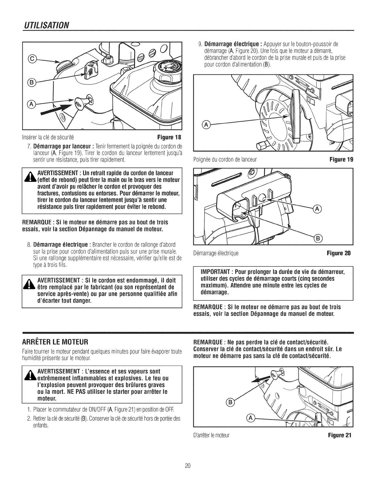
UT/USAT/ON
9. Demarrage electrique :Appuyersurle bouton-poussoirde
demarrage(A,Figure20). Unefois quelemoteura demarre,
debrancherd'abordlecordondelaprisemuraleetpuisdelaprise
pourcordond'alimentation(B).
Insererlacle desecurite Figure18
7. Demarrage par lanceur : Tenirfermementlapoigneeducordonde
lanceur(A, Figure19). Tirer lecordondu lanceurlentementjusqu'a
sentiruneresistance,puistirer rapidement.
,_AVERTISSEMENT : Unretraitrapidedu cordonde lanceur
(effet de rebond)peuttirer la mainou le bras versle moteur
avantd'avoir purel_cher le cordonet provoquerdes
fractures,contusionsou entorses. Pourd_marrer le moteur,
tirer le cordondu lanceurlentement jusqu'_sentirune
r_sistancepuistirer rapidementpour_viter le rebond.
REMARQUE: Si le moteur ne d_marre pasau boutde trois
essais, voir la sectionD6pannagedu manuelde moteur.
8. D_marrage electrique : Brancherlecordonderallonged'abord
sur la prisepourcordond'alimentationpuis sur uneprisemurale.
Si unerallongesupplementaireestnecessaire,verifierqu'elleestde
typeatrois fils.
AVERTiSSEIVlENT: Si le cordonest endommag_, ii dolt
_tre remplac_ par le lubricant(ou sonrepr_sentant de
serviceapr_s-vente) ou par une personnequalifi_e afin
d'6carter tout danger.
Poigneeducordondelanceur
Demarrageelectrique
Figure 19
Figure 20
iMPORTANT: Pourprolongerla dur_e de vie du d6marreur,
utiiiser des cyclesde d_marrage courts(cinqsecondes
maximum). Attendre une minute entreles cyclesde
demurrage.
REIVlARQUE: Si le moteur ne d_marre pus au bout de trois
essais, voir la sectionD_pannage du manuel de moteur.
ARRETER LE MOTEUR
Fairetournerlemoteurpendantquelquesminutespourfaireevaporertoute
humiditepresentesurlemoteur.
REIVlARQUE: Ne pusperdre la cJ_de contact/s_curit_.
Conserver la cl_ de contact/s_curit_duns un endroit sDr. Le
moteur ne d6marre pussansla cl_ de contact/s_curit_.
,_AVERTISSEIVlENT : L'essenceet ses vapeurssont
extr_mement inflammableset explosives. Le feu ou
I'explosion peuventprovoquerdes br01uresgraves
ou ia mort. HE PASutiliser le starter pourarr_ter le
moteur.
1. Placerle commutateurdeON/OFF(A,Figure21)enpositionde0%
2. Retirerlacledesecurite(B).Conserverlacledesecuritehorsdeporteedes
enfants.
D'arreterlemoteur Figure21
20
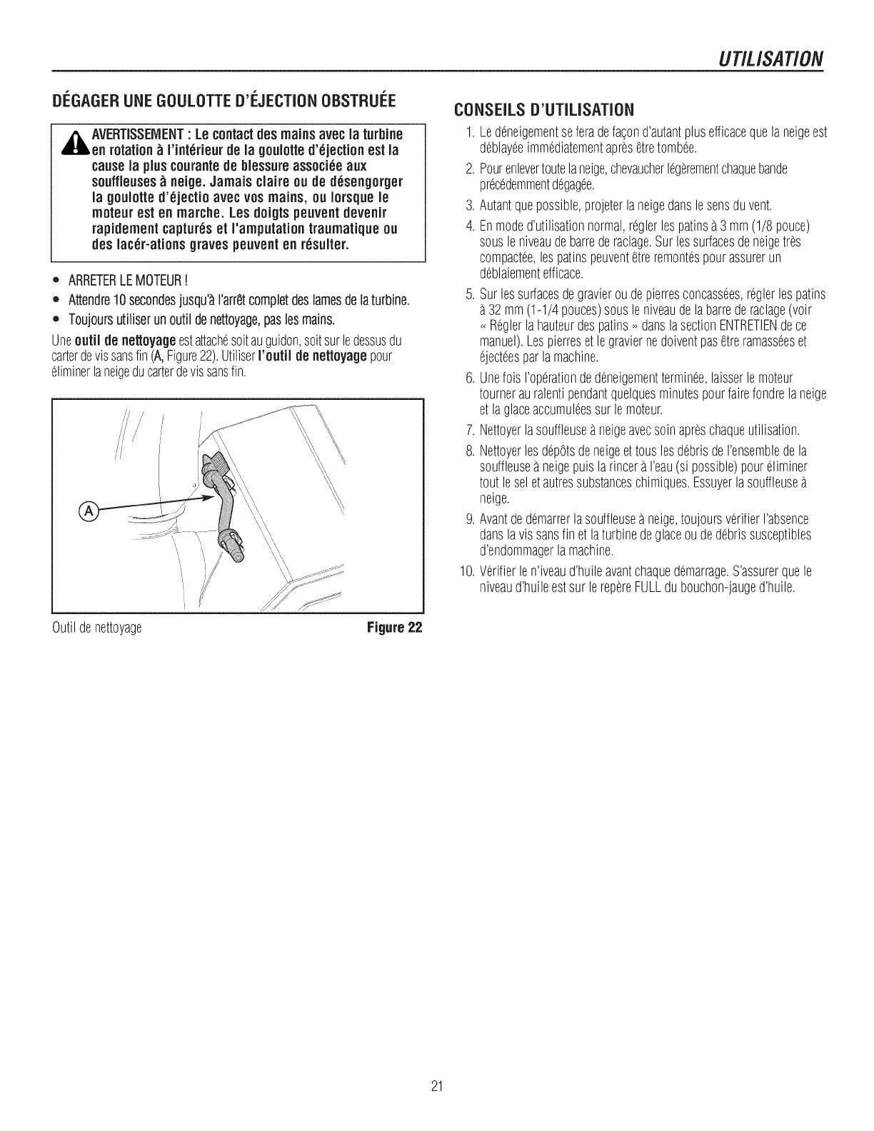
Di_GAGERUNE GOULOTTED'i_JECTIONOBSTRUi_E
,_AVERTISSEIVlENT : Le contactdes mainsavec la turbine
en rotation_I'int_rieurde la goulotte d'_jection est la
causela pluscourantede blessure associ_e aux
souffleuses _ neige. Jamais claire ou de d_sengorger
ia gouiotte d'_jectio avec vos mains, ou iorsque ie
moteur est en marche. Losdoigtspeuventdevenir
rapidement captureset I'amputationtraumatiqueou
des lac_r-ationsgraves peuventen r_suiter.
,, ARRETERLEMOTEUR!
,, Attendre10secondesjusqu'_i'arr_,tcompletdeslamesdelaturbine. 5.
= Toujoursutiliser unoutil denettoyage,paslesmains.
Uneoutii de netloyageestattachesoitauguidon,soitsurledessusdu
carterdevissansfin(A,Figure22).UtiliserI'outil de nettoyagepour
diminerlaneigeducarterdevissansfin. 6.
UT/L/SAT/ON
\\\\\\\\\\\\
Outildenettoyage Figure22
CONSEILSD'UTILISATION
1. Ledeneigementseferadefacond'autantplusefficacequelaneigeest
deblayeeimmediatementapresetretombee.
2. Pourenleverroutelaneige,chevaucherlegerementchaquebande
precedemmentdegagee.
3. Autantquepossible,projeterlaneigedanslesensduvent.
4. Enmoded'utilisationnormal,ropierlespatinsa 3mm(1/8 pouce)
sousleniveaudebarrederaclage.Surlessurfacesdeneigetres
compactee,lespatinspeuventetreremontespourassurerun
deblaiementefficace.
Surlessurfacesdegravieroudepierresconcassees,ropierlespatins
32mm(1-1/4 pouces)sousleniveaudelabarrederaclage(volt
_ ROpierla hauteurdespatins_ danslasectionENTRETIENdece
manuel).Lespierreset legraviernedoiventpasetreramasseeset
ejecteesparlamachine.
Unefois I'operationdedeneigementterminee,laisserlemoteur
tournerauralentipendantquelquesminutespourfairefondrelaneige
etlaplaceaccumuleessur lemoteur.
7. Nettoyerlasouffleuseaneigeavecsoinapreschaqueutilisation.
8. Nettoyerlesdepotsdeneigeettousles debrisdeI'ensembledela
souffleusea neigepuislarincera I'eau(si possible)poureliminer
tout leseletautressubstanceschimiques.Essuyerlasouffleuse
neige.
9. Avantdedemarrerlasouffleuseaneige,toujoursverifierI'absence
danslavissansfin et laturbinedeplaceoudedebrissusceptibles
d'endommagerlamachine.
10.Verifierlen'iveaud'huileavantchaquedemarrage.S'assurerquele
niveaud'huileestsur lerepereFULLdubouchon-jauged'huile.
21
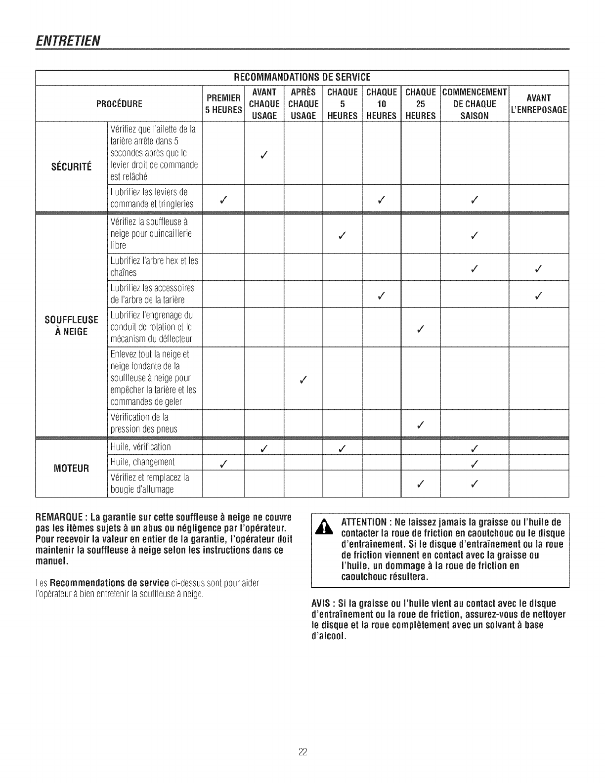
ENTRETIEN
SF:CURITE
SOUFFLEUSE
A NEIGE
MOTEUR
PROCEDURE
VerifiezqueI'ailettedela
tarierearr_,tedans5
secondesapresquele
levierdroitdecommande
estrel_che
Lubrifiezlosleviersde
commandoettringleries
Verifiezlasouffleuse
neigepourquincaillerie
libre
LubrifiezI'arbrehexet les
chatnes
Lubrifiezlosaccessoires
deI'arbredelatariere
LubrifiezI'engrenagedu
conduitderotationet le
mecanismdu ddlecteur
Enleveztoutlaneigeet
neigefondantedela
souffleusea neigepour
empecherlatariereet les
commandesdegeler
Verificationdela
pressiondespneus
Huile,verification
Huile,changement
Verifiezet remplacezla
bougied'allumage
RECOIVlMANDATIONSDESERVICE
PREMIER
5HEURES
AVANT APRES CHAQUECHAQUE CHAQUE
CHAQUECHAQUE 5 10 25
USAGE USAGE HEURES HEURES HEURES
V"
V" V"
,/
,/
V"
,/
,/ ,/
V"
V"
V"
COMMENCEMENT
DECHAQUE
SAISON
¢
¢
¢
,/
,/
¢"
AVANT
L'ENREPOSAGE
V"
,/
REMARQUE: La garantie surcette souffleuse _ neige ne couvre
pas les it_mes sujets _ un abusou ndgligencepar I'op_rateur.
Pour recevoirla valouren entier de la garantie, I'op_rateur dolt
maintenir la souffieuse _ neige solon los instructionsdans ce
manuel.
LosRecommendationsde serviceci-dessussontpouraider
I'operateura bienentretenirlasouffleuseaneige.
,& ATTENTION"Ne laissez jamais la graisse ou I'huile de
contacter la rouede friction en caoutchoucou le disque
d'entrainement. Sile disque d'entra'inement ou la roue
de friction viennenten contactavec la graisse ou
I'huile, un dommage _ la roue de friction en
caoutchoucr_sultera.
AVIS : Si la graisse ou I'huile vient au contact avec le disque
d'entra'inement ou la roue de friction, assurez-vous de nettoyer
le disque et la roue compl_tement avec un solvant_base
d'alcool.
22
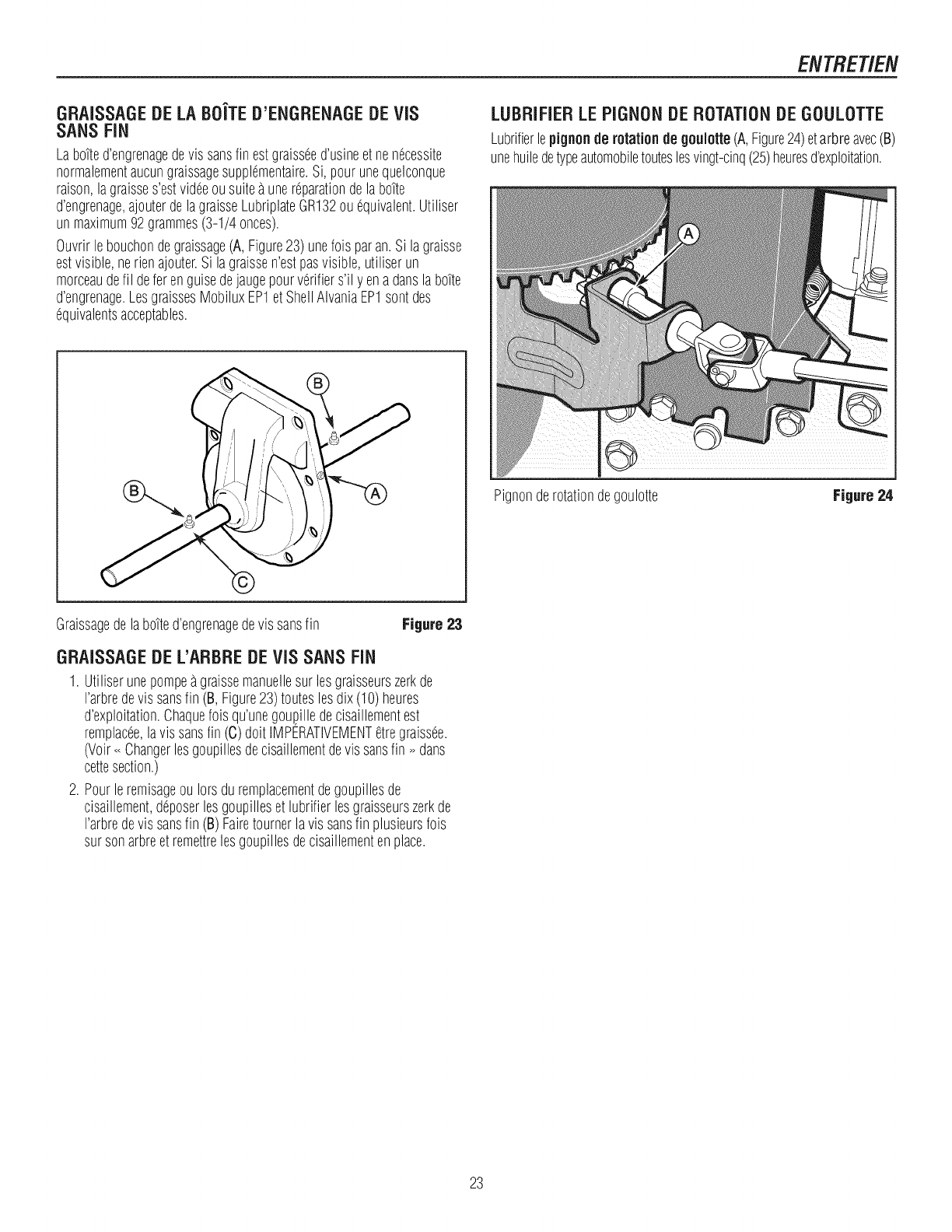
ENTRET/EN
GRAISSAGEDELABO'iTED'ENGRENAGEDEVIS
SANSFiN
Labo?ted'engrenagedevis sansfin estgraisseed'usineetnenecessite
normalementaucungraissagesupplementaire.Si, pourunequelconque
raison,lagraisses'estvideoousuiteaunereparationdelabotte
d'engrenage,ajouterdelagraisseLubriplateGR132ouequivalent.Utiliser
unmaximum92grammes(3-1/4 onces).
Ouvrirlebouchondegraissage(A, Figure23) unefois paran.Si lagraisse
estvisible,nerienajouter.Si lagraissen'estpasvisible,utiliserun
morceaudefil deforenguisedejaugepourverifiers'il yen adanslabotte
d'engrenage.LosgraissesMobiluxEP1et ShellAIvaniaEP1sontdes
equivalentsacceptables.
LUBRIFIERLEPIGNONDEROTATIONDEGOULOTTE
Lubrifierlepignonde rotation degouiotte(A,Figure24)etarbreavec(B)
unehuiledetypeautomobiletouteslosvingt-cinq(25)heuresd'exploitation.
Pignonderotationdegoulotte Figure 24
Graissagedelabo?ted'engrenagedevis sansfin Figure 23
GRAISSAGEDEL'ARBREDEVIS SANSFIN
1. Utiliserunepompeagraissemanuellesurlosgraisseurszerkde
I'arbredevis sansfin (B, Figure23)touteslosdix (10)heures
d'exploitation.Chaquefoisqu'unegoupilledecisaillementest
remplacee,lavissansfin (C)dolt IMPERATIVEMENTetregraissee.
(Voir<<Changerlosgoupillesdecisaillementdevissansfin >>dans
cettesection.)
2. Pourleremisageou Iorsduremplacementdegoupillesde
cisaillement,deposerlosgoupilleset lubrifierlosgraisseurszerkde
I'arbredevis sansfin (B)Fairetournerlavis sansfin plusieursfois
sursonarbreet remettrelosgoupillesdecisaillementenplace.
23
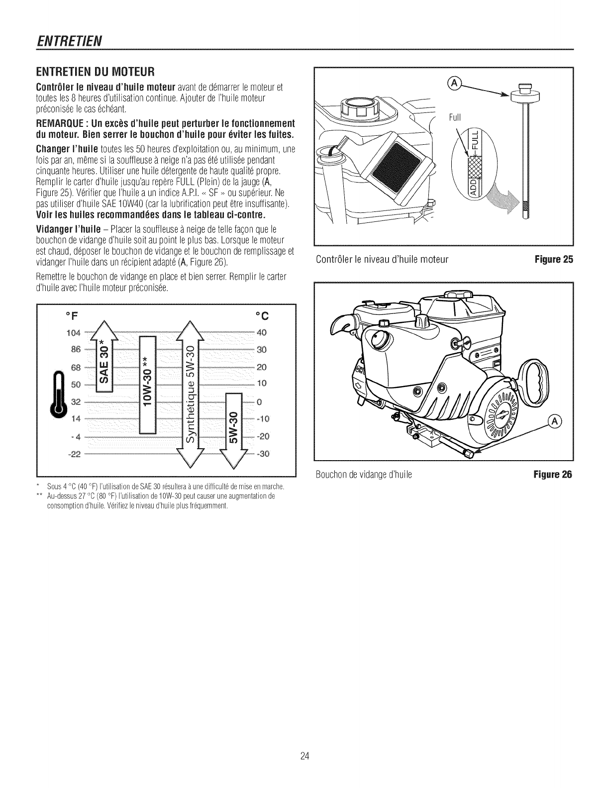
ENTRET/EN
ENTRETiENDUiVIOTEUR
ContrSlerle niveaud'huile rnoteur avantdedemarrerlemoteuret
toutesles8 heuresd'utilisationcontinue.AjouterdeI'huilemoteur
preconiseelecasecheant.
REIVlARQUE: Unexc_',sd'huiie pentperturberle fonctionnement
du rnoteur.Bien serrer le bouchon d'huiie pour6viter les fuites.
Changer rhuiie toutesles50 heuresd'exploitationou,auminimum,une
foisparan,memesi lasouffleuseaneigen'apaseteutiliseependant
cinquanteheures.Utiliserunehuiledetergentedehautequalitepropre.
Remplirlecarterd'huilejusqu'aurepereFULL(Plein)delajauge(A,
Figure25).VerifierqueI'huileaunindiceA.RI.<<SF>>ou superieur.Ne
pasutiliserd'huileSAE10W40(carlalubrificationpeutetreinsuffisante).
Voir les huilesrecornrnand6es dans le tableau ci-contre.
VidangerI'huile - Placerlasouffleuseaneigedetellefaconquele
bouchondevidanged'huilesoitaupointleplusbas.Lorsquelemoteur
estchaud,d@oserlebouchondevidangeet lebouchonderemplissageet
vidangerI'huiledansunrecipientadapte(A,Figure26).
Remettrelebouchondevidangeenplaceetbienserrer.Remplirlecarter
d'huileavecI'huilemoteurpreconisee.
i
i'1
/
°C
............._ SO
1o
Sous4 °C (40 °F) I'utilisationdeSAE30 r6sultera_ unedifficult6de miseenmarche.
** Au-dessus27 °C (80 °F) I'utilisationde 10W-30peutcauseruneaugmentationde
consomptiond'huile.V6rifiezleniveaud'huile plusfr6quemment.
ContrOlerle niveaud'huile moteur Figure25
Bouchondevidanged'huile Figure26
24
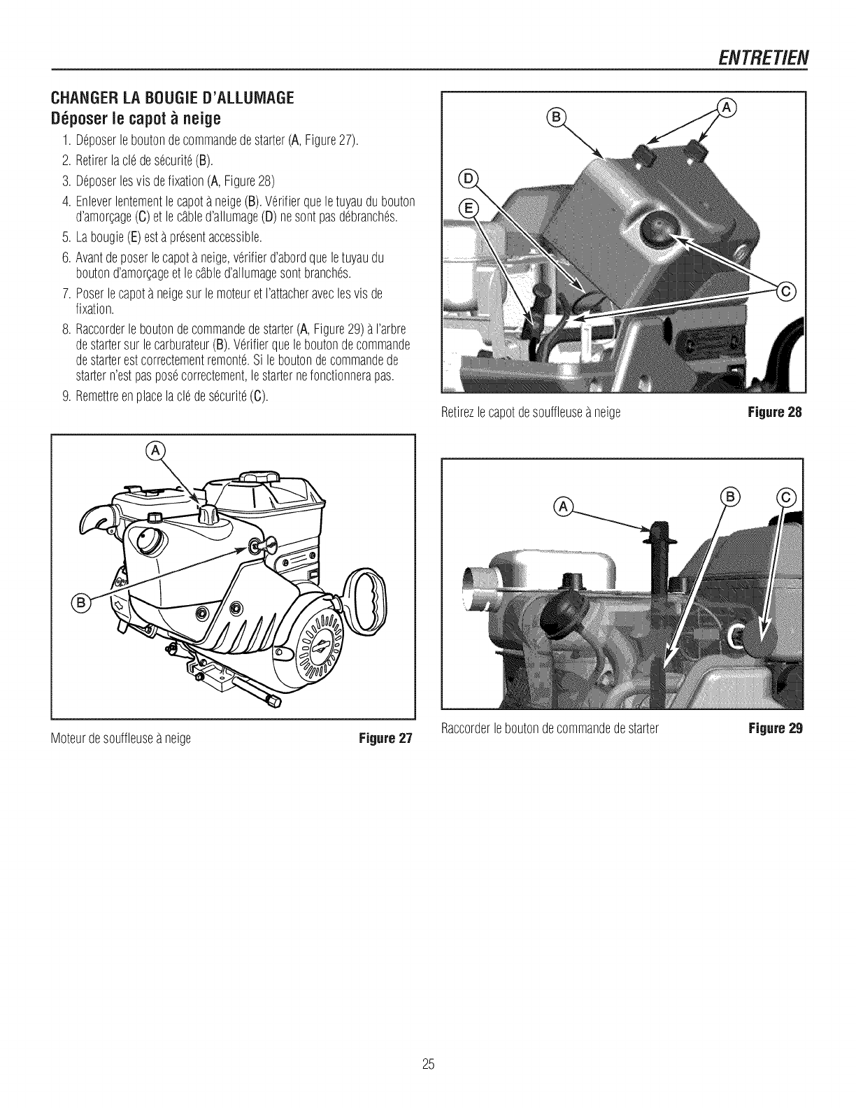
CHANGERLABOUGIED'ALLUIVlAGE
D6poserle capot_neige
1. %poser leboutondecommandedestarter(A,Figure27).
2. Retirerlacle desecurite(B).
3. Deposerlesvisdefixation(A,Figure28)
4. Enleverlentementlecapota neige(B).Verifierqueletuyaudubouton
d'amoLcage(C)et lecabled'allumage(D) nesontpasdebranches.
5. Labougie(E)estapresentaccessible.
6. Avantdeposerlecapotaneige,verifierd'abordqueletuyaudu
boutond'amoLcageet lecabled'allumagesontbranches.
7. Poserlecapota neigesur lemoteuret I'attacheraveclesvis de
fixation.
8. Raccorderleboutondecommandedestarter(A,Figure29)a I'arbre
destartersur lecarburateur(B).Verifierqueleboutondecommande
destarterestcorrectementremonte.Si leboutondecommandede
startern'estpasposecorrectement,lestarternefonctionnerapas.
9. Remettreenplacelacledesecurite(C).
Retirezlecapotdesouffleusea neige
ENTRETIEN
Figure 28
Moteurdesouffleusea neige Figure 27 Raccorderleboutondecommandedestarter Figure29
25
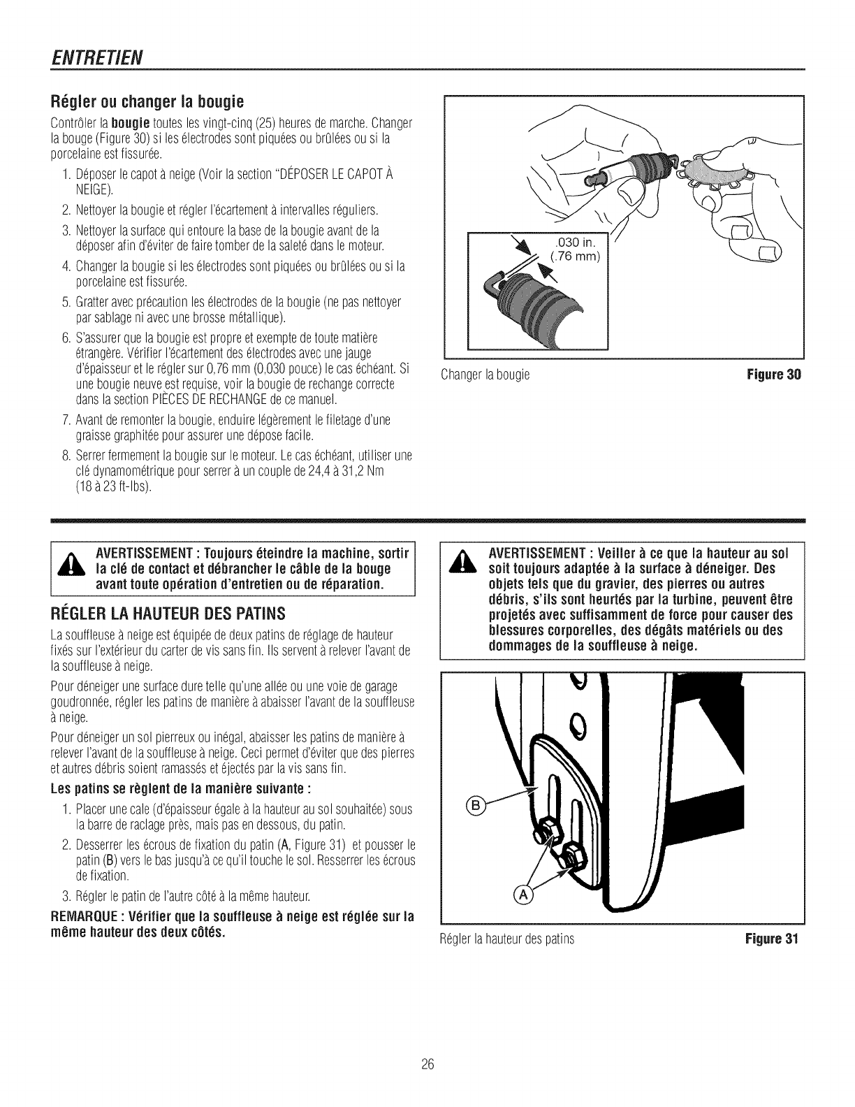
ENTRETIEtV
R_gler ou changerla bougie
ContrOlerla bougie routeslesvingt-cinq(25)heuresdemarche.Changer
la bouge(Figure30)si leselectrodessentpiqueesou brOleesousi la
porcelaineestfissuree.
1. %poser lecapeta neige(Voirlasection"DEPOSERLECAPOTA
NEIGE).
2. NettoyerlabougieetreglerI'ecartementaintervallesreguliers.
3. Nettoyerlasurfacequientourela basedelabougieavantdela
deposerafind'eviterdefairetomberdelasaletedanslemoteur.
4. Changerlabougiesi leselectrodessentpiqueesoubrOleesousi la
porcelaineestfissuree.
5. Gratteravecprecautionleselectrodesdelabougie(nepasnettoyer
parsablageni avecunebrossemetallique).
6. S'assurerquelabougieestpropreetexemptedetoutematiere
etrangere.VerifierI'ecartementdeselectrodesavecunejauge
d'epaisseuretle reglersur 0,76mm(0,030pouce)lecasecheant.Si
unebougieneuve,estrequise,voir labougiederechangecorrecte
danslasectionPIECESDERECHANGEdecemanuel.
7. Avantderemonterlabougie,enduirelegerementlefiletaged'une
graissegraphiteepourassurerunedeposefacile.
8. Serrerfermementlabougiesurlemoteur.Lecasecheant,utiliserune
cledynamometriquepourserrera uncouplede24,4a 31,2Nm
(18a23ft-lbs).
\
Changerlabougie Figure 30
,_ AVERTISSEIVlEHT' Toujourseteindre la machine,sortir
la cie de contactet debrancherle c_ble de la bouge
avant route operation d'entretienou de r_paration.
Ri._GLERLAHAUTEURDESPATINS
Lasouffleusea neigeestequipeededeuxpatinsdereglagedehauteur
fixessur I'exterieurducarterdevissansfin. IIs serventareleverI'avantde
lasouffleusea neige.
Pourdeneigerunesurfaceduretellequ'unealiceouunevoiedegarage
goudronnee,reglerlespatinsdemaniereaabaisserI'avantdelasouffleuse
neige.
Pourdeneigerunsol pierreuxouinegal,abaisserlespatinsdemaniere
releverI'avantdelasouffleusea neige.Cecipermetd'eviterquedespierres
etautresdebrissoientramassesetejectesparlavissansfin.
Les patins sereglent de la mani_re suivante :
1. Placerunecale(d'epaisseuregaleala hauteurausol souhaitee)sous
la barrederaclagepres,maispasendessous,dupatin.
2. Desserrerlesecrousdefixationdu patin(A, Figure31) et pousserle
patin(B)verslebasjusqu'acequ'iltouchelesol.Resserrerlesecrous
defixation.
3. ReglerlepatindeI'autrecotea lamemehauteur.
REIVlARQUE: V_rifier que la souffleuse_ neige est r6gl_e sur la
m_me hauteur des deuxc0t_s.
,& AVERTISSEIVlEHT: VeiJJer_ce que la hauteur au sot
soit toujours adapt_e _ la surface_d_neiger.Des
objets tels que du gravier, des pierres ou autres
d_bris, s'ils sent heurt_s par la turbine, peuvent _tre
projet_s avec suffisammentde force pour causerdes
blessures corporelles,des d_g_tsmateriels ou des
dommagesde la souffleuse_ neige.
Reglerlahauteurdespatins Figure31
26
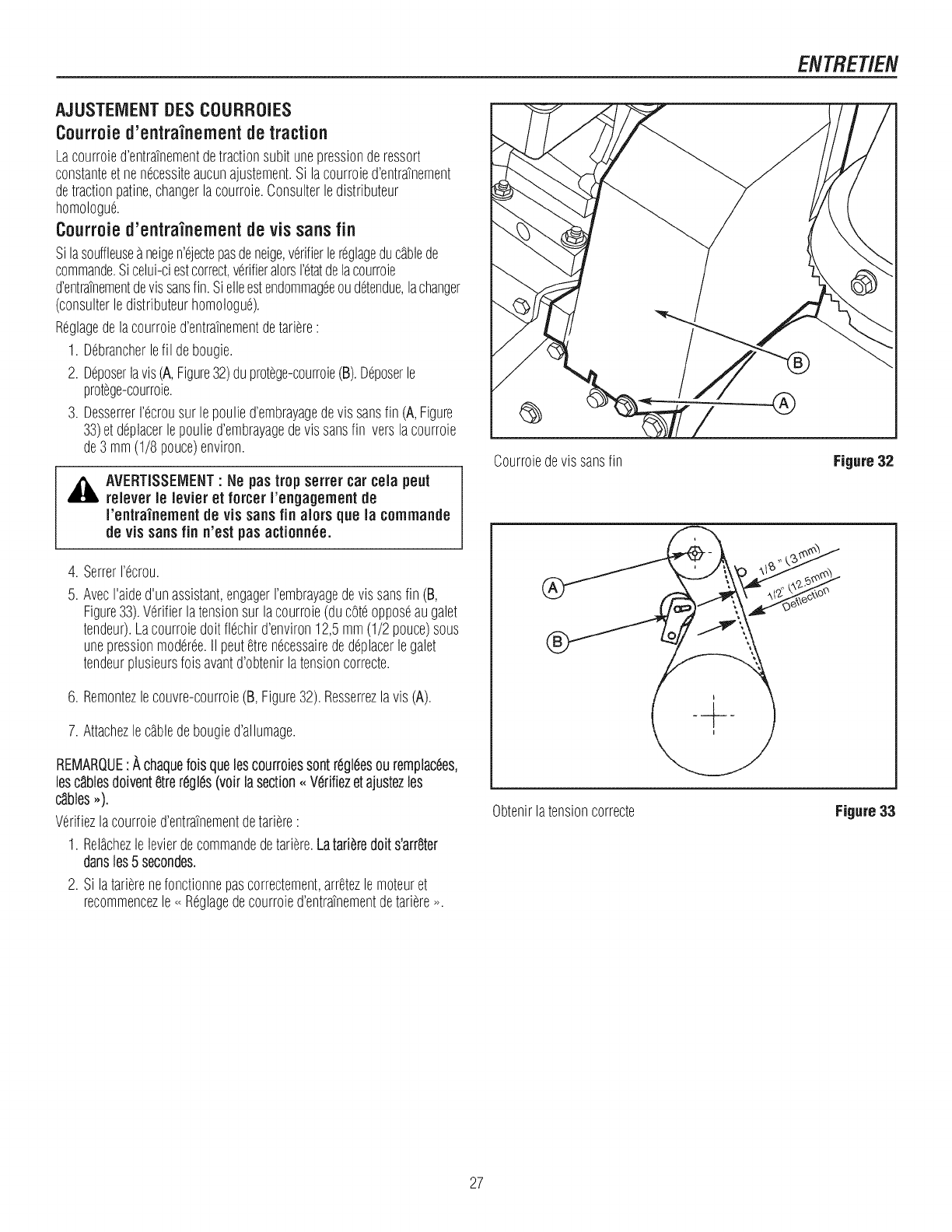
ENTRET/EN
AJUSTEIVlENTDESCOURROIES
Courroie d'entra'inementde traction
Lacourroied'entratnementdetractionsubitunepressionderessort
constanteetnenecessiteaucunajustement.Si lacourroied'entratnement
detractionpatine,changerlacourroie.Consulterledistributeur
homologue.
Courroie d'entrainementde vis sansfin
Silasouffleusea neigen'ejectepasdeneige,verifierlereglageducgblede
commande.Sicelui-ciestcorrect,verifieralorsI'etatdelacourroie
d'entratnementdevissansfin.Sielleestendommageeoudetendue,lachanger
(consulterledistributeurhomologue).
Reglagedelacourroied'entratnementdetariere:
1. Debrancherlefil debougie.
2. %poserlavis(A,Figure32)duprotege-courroie(B).Deposerle
protege-courroie.
3. DesserrerI'ecrousur lepoulied'embrayagedevis sansfin (A,Figure
33)et deplacerlepoulied'embrayagedevissansfin verslacourroie
de3 mm(1/8 pouce)environ.
,_k AVERTISSEMENT"Ne pastrop serrer car ceia peut
reiever le levier et forcer I'engagementde
I'entra'inement de vis sansfin alors que la commande
de vis sansfin n'est pas actionnee.
4. SerrerI'ecrou.
5. AvecI'aided'unassistant,engagerrembrayagedevissansfin (B,
Figure33).Verifierlatensionsur lacourroie(ducoteopposeaugalet
tendeur).Lacourroiedoit flechird'environ12,5mm(1/2 pouce)sous
unepressionmoderee.II peutetrenecessairededeplacerlegalet
tendeurplusieursfoisavantd'obtenirlatensioncorrecte.
6. Remontezlecouvre-courroie(B,Figure32).Resserrezlavis(A).
7. Attachezlecgbledebougied'allumage.
REMARQUE:A chaquefoisquelescourroiessontr6gl(_esouremplacees,
lesc,lblesdoivent8trereglds(voir lasection- Verifiezetajustezles
c_ibles,,).
Verifiezlacourroied'entratnementdetariere:
1. Rel_chezle levierdecommandedetariere.Latari_,redoits'arrSter
dansies5 secondes.
2. Silatarierenefonctionnepascorrectement,arretezlemoteuret
recommencezle<<Reglagedecourroied'entratnementdetariere_.
Courroiedevissansfin Figure 32
Obtenirlatensioncorrecte Figure 33
27
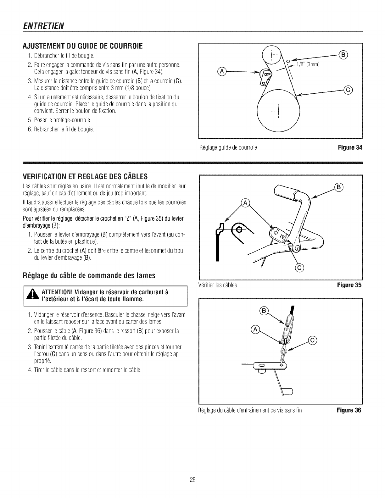
ENTRET/EN
AJUSTEIVlENTDU GUIDEDECOURROIE
1. Debrancherlefil debougie.
2. Faireengagerlacommandedevis sansfin paruneautrepersonne.
Celaengagerlagalettendeurdevissansfin (A,Figure34).
3. Mesurerladistanceentreleguidedecourroie(B)et lacourroie(C).
Ladistancedoltetrecomprisentre3 mm(1/8 pouce).
4. Si unajustementestnecessaire,desserrerleboulondefixationdu
guidedecourroie.Placerleguidedecourroiedanslapositionqui
convient.Serrerleboulondefixation.
5. Poserleprotege-courroie.
6. Rebrancherlefil debougie.
®
Reglageguidedecourroie Figure34
VERIFICATIONET REGLAGEDESCABLES
Lescgblessontreglesenusine.IIestnormalementinutiledemodifierleur
reglage,saufencasd'etirementoudejeutropimportant.
IIfaudraaussieffectuerlereglagedescgbleschaquefoisquelescourroies
sontajusteesouremplacees.
Pourvdrifierlerdglage,detacherlecrocheten"Z"(A,Figure35)du levier
d'embrayage(B):
1. Pousserlelevierd'embrayage(B)completementversI'avant(aucon-
tactdela buteeenplastique).
2. Lecentreducrochet(A)dolt etreentrelecentreet lesommetdutrou
du levierd'embrayage(B).
R6glage du ¢_ble de commande des lames
,_ ATTENTION!Vidanger ie r_servoir de carburant
I'ext_rieur et _ I'_cart de routefiamme.
1. Vidangerlereservoird'essence.Basculerlechasse-neigeversravant
enlelaissantreposersur lafaceavantducarterdeslames.
2. Pousserlecgble(A,Figure36)dansleressort(B)pourexposerla
partiefileteeducgble.
3. TenirI'extremitecarreedelapartiefileteeavecdespincesettourner
I'ecrou(C) dansunsensoudansI'autrepourobtenirlereglageap-
proprie.
4. Tirerlecgbledansleressortet remonterlecgble.
©
Verifierlesc_bles Figure 35
Reglageduc_bled'entraTnementdevissansfin Figure36
28
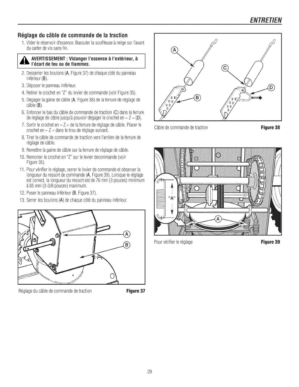
ENTRET/EN
Reglagedu c_ble decorflrnandede la traction
1. Viderlereservoird'essence.Basculerlasouffleusea neigesurravant
ducarterdevissansfin.
_k AVERTISSEiVlENT"Vidanger J'esseflce_J'ext_rieur,
r_cart de feu ou de fJarnrnes.
2. Desserrerlesboulons(A, Figure37)dechaquecotedu panneau
inferieur(B).
3. Deposerlepanneauinferieur.
4. Retirerlecrocheten"Z"dulevierdecommande(voir Figure35).
5. Degagerlagainedecgble(A,Figure38)delaferruredereglagede
cgble(B).
6. Enfoncerlebasdu cgbledecommandedetraction(C) danslaferrure
dereglagedecgblejusqu'apouvoirdegagerlecrocheten<<Z _ (D).
7. Sortirlecrocheten<<Z _delaferruredereglagedecgble.Placerle
crocheten<<Z _ dansletrou dereglagesuivant.
8. TirerlecgbledecommandedetractionversI'arrieredelaferrurede
reglagedecgble.
9. Remettrelagainedecgblesur laferruredereglagedecgble.
10. Remonterlecrocheten"Z" surlelevierdecommande(voir
Figure35).
11. Pourverifierle reglage,serrerlelevierdecommandeetobserverla
Iongueurdu ressortdecommande(A,Figure39).Lorsquelereglage
estcorrect,laIongueurdu ressortestde76mm(3 pouces)minimum
85 mm(3-3/8pouces)maximum.
12. Poserlepanneauinferieur(B, Figure37).
13. Serrerlesboulons(A)dechaquecotedupanneauinferieur.
®
Cgbledecommandedetraction
Pourverifierle reglage
Figure38
P
n
Figure39
Reglageducgbledecommandedetraction Figure 37
29
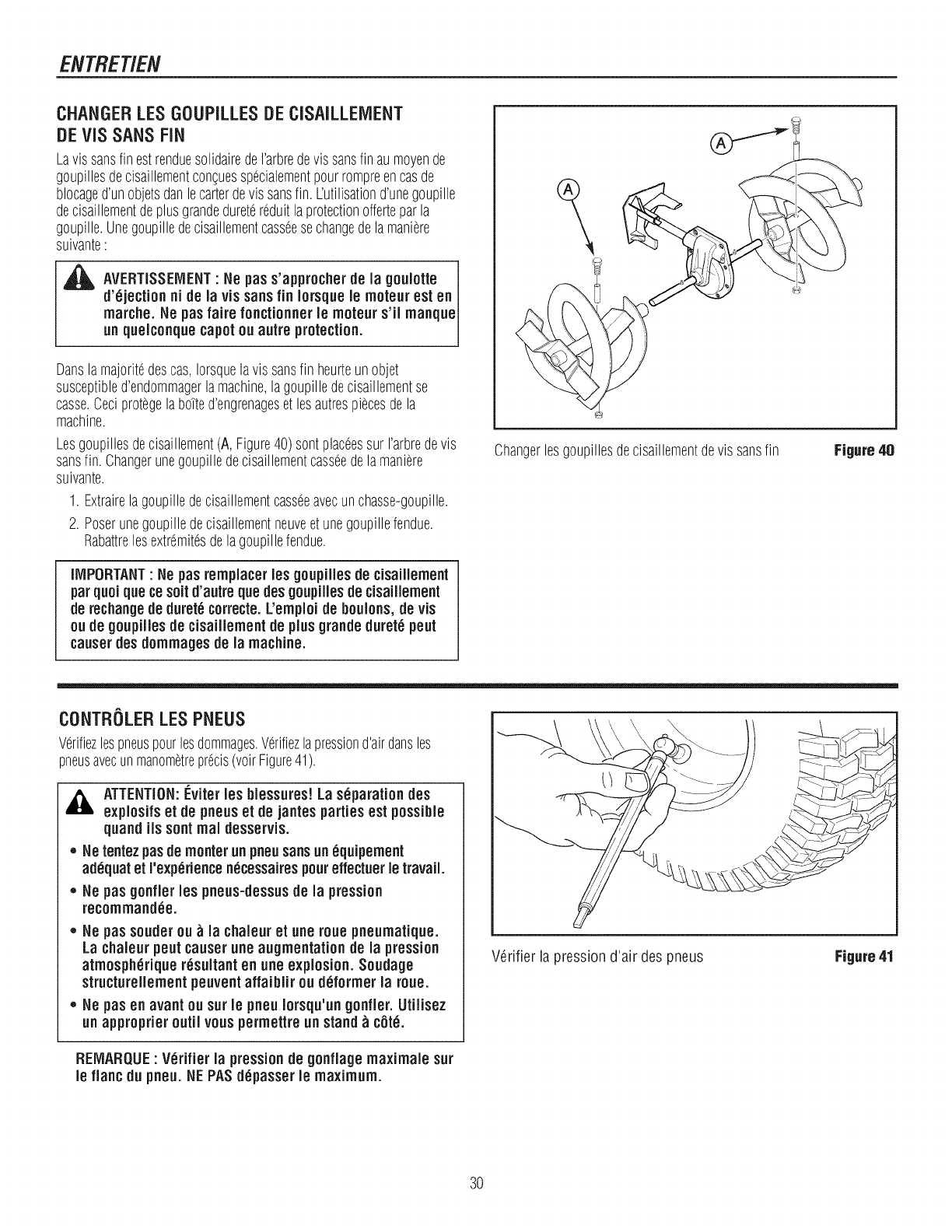
ENTRET/EN
CHANGERLESGOUPILLESDECISAILLEIVlENT
DEVIS SANSFiN
Lavissansfin estrenduesolidairedeI'arbredevissansfin aumoyende
goupillesdecisaillementcon%essp6cialementpourrompreencasde
blocaged'unobjetsdanlecarterdevis sansfin. L'utilisationd'unegoupille
decisaillementdeplusgrandeduretereduitlaprotectionofferteparla
goupille.Unegoupilledecisaillementcasseesechangedela maniere
suivante:
,_ AVERTISSEMENT: Ns pas s'approchsrde la goulotts
d'ejectionni de la vis sans fin Iorsqus Is motsur sst en J
marche. He pas fairs fonctionner Is moteur s'il manqusJ
un qusiconqus capotou autrs protection.
Dansla majoritedescas,Iorsquelavissansfin heurteunobjet
susceptibled'endommagerlamachine,lagoupilledecisaillementse
casse.Ceciprotegelabotted'engrenageset lesautrespiecesdela
machine.
Lesgoupillesdecisaillement(A, Figure40)sontplaceessur I'arbredevis
sansfin. Changerunegoupilledecisaillementcasseedela maniere
suivante.
1. Extrairelagoupilledecisaillementcasseeavecunchasse-goupille.
2. Poserunegoupilledecisaillementneuveetunegoupillefendue.
Rabattrelesextremitesdelagoupillefendue.
iMPORTANT: Ns pas rsmplacsrIss goupiiies ds cisaillement
parquoique cssoitd'autrs quedes goupiliss de cisailisment
de rechangede durstecorrscte. L'emploide boulons,de vis
ou de goupilles de cisaillsmentde plusgrands durste psut
causerdss dommages ds ia machine.
Changerlesgoupillesdecisaillementdevissansfin Figure40
CONTRgLER LES PNEUS
Verifiezlespneuspourlesdommages.Verifiezlapressiond'airdunsles
pneusavecunmanometreprecis(voirFigure41).
,_ ATTENTION:I:_'vitsrIss blessurss! La separation des
sxplosifs st de pneusst de jantss partiessst possible
quand ils sontreal dssssrvis.
*Ns tsntezpusde montsr unpneusansun equipsment
adequatst I'sxperisncs necsssairss poursffsctusr Is travail.
*Ns pas gonfier iss pneos-dsssusde ia prsssion
rscommandes.
*Ns pas soudsr ou _ ia chaieurst one roue pnsumatique.
La chaieurpeut causerune augmentationde la prsssion
atmospheriqus resultanten one explosion. Soudags
structursiiementpsuvsntaffaiblir ou deformsr la rous.
*He pas sn avant ou surIs pflsu Iorsqu'ungonfler. Utiiissz
unapproprisr outil vouspermsttrsun stand_cote.
V_rifier la pression d'air des pneus Figure41
REMARQUE: Verifier la pressionde gonfiage maximale sot
Is flanc du pneu. NEPASdepasser Is maximum.
30
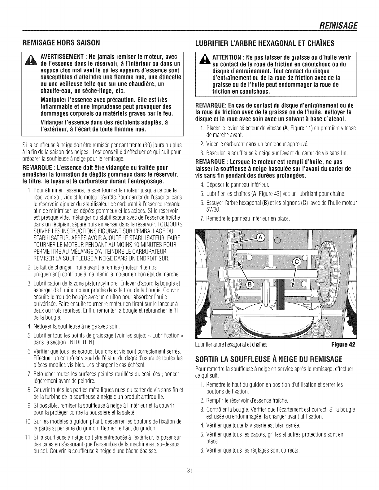
REIVUSAGEHORSSAISON
AVERTiSSEIVlENT"Ne jamais remiser ie moteur, avec
de I'essence darts ie rGservoir, _ I'int_rieur ou darts un
espace clos real ventil_ oiJ les vapeursd'essence sent
susceptiblesd'atteindre ,he fiamme hue, une _tiuceile
ou ,he veilleuse telle que sur,he chaudi_re, ,n
chauffe=ea,, ,n s_che=linge,etc.
lVlanipulerI'essenceavec precaution.Elle est tr_s
inflammable et une imprudencepeut provoquer des
dommages corporelsou materiels gravespar le feu.
Vidanger I'essencedartsdes r_cipientsadapt_s,
I'ext_rieur, _ r_cart de route fiamme hue.
Si lasouffleusea neigedoitetreremiseependanttrente(30)joursouplus
lafin delasaisondesneiges,il estconseilled'effectuercequisuit pour
preparerlasouffleusea neigepourleremisage.
REIViARQUE: L'essencedolt _tre vidang_eou trait_e pour
emp_cher la formation de d_pOtsgommeux duns le r_servoir,
ie filtre, ie tuyauet le carburateurdurant rentreposage.
1. PoureliminerI'essence,laissertournerlemoteurjusqu'acequele
reservoirsoitvideetle moteurs'arrete.PourgarderdeI'essencedans
le reservoir,ajouterdustabilisateurdecarburantaI'essencerestante
afindeminimiserlesdepGtsgommeuxet lesacides.Sile reservoir
estpresquevide,mGlangerdustabilisateuravecdeI'essencefratche
dunsunrecipientsepareputsenverserdanslereservoir.TOUJOURS
SUIVRELESINSTRUCTIONSFIGURANTSURL'EMBALLAGEDU
STABILISATEUR.APRESAVOIRAJOUTELESTABILISATEUR,FAIRE
TOURNERLEMOTEURPENDANTAUMOINS10MINUTESPOUR
PERMETTREAU MELANGED'ATTEINDRELECARBURATEUR.
REMISERLASOUFFLEUSEA NEIGEDANSUNENDROITSOR.
2. LefairdechangerI'huileavantleremise(moteur4temps
uniquement)contribueamaintenirlemoteurenbonetatdemarche.
3. Lubrificationdelazonepiston/cylindre.Enleverd'abordlabougieet
aspergerdeI'huilemoteurprochedansletroudelabougie.Couvrir
ensuiteletrou debougieavecunchiffonpourabsorberI'huile
pulverisee.Faireensuitetournerlemoteurentirantsur lelanceur
deuxoutroisreprises.Enfin,remonterlabougieetrebrancherlefil
delabougie.
4. Nettoyerlasouffleusea neigeavecsoin.
5. Lubrifiertouslespointsdegraissage(volt lessujets_ Lubrification_
danslasectionENTRETIEN).
6. Verifierquetousles ecrous,boulonsetvissont correctementserres.
EffectueruncontrOlervisueldeI'etatet dudegred'usurederoutesles
piecesmobilesvisibles.Leschangerlecasecheant.
7. Retoucherrouteslessurfacespeintesrouilleesouecaillees; poncer
legerementavantdepeindre.
8. Couvrirrouteslespartiesmetalliquesnuesdu carterdevis sansfin et
delaturbinedelasouffleuseaneiged'unproduitantirouille.
9. Si possible,remiserlasouffleusea neigeaI'interieuret lacouvrir
pourlaprotegercontrelapoussiereet lasalete.
10. Surlesmodelesaguidonpliant,desserrerlesboutonsdefixationde
la pattiesuperieureduguidon.Replierlehautduguidon.
11. Si lasouffleusea neigedoltetreentreposeea I'exterieur,laposersur
descalesens'assurantqueI'ensembledela machineestau-dessus
dusol.Couvrirlasouffleusea neiged'uneb_cheepaisse.
REMISAGE
LUBRIFIER L'ARBREHEXAGONALET CHA'iNES
_ ATTENTION"Ne pus iaisser de graisse ou d'huile venir
au contactde la roue de friction en caoutchoucou du
disque d'entra'inement. Tout contactdu disque
d'entra'inement ou de la roue de friction avec de ia
graisse ou de i'huile pout endommager ia roue de
friction en caoutchouc.
REIVlARQUE:Encas de contact du disque d'entra'inement ou de
ia roue de friction avec de ia graisse ou de i'huile, nettoyer le
disque et la roue avec soin avec un solvant_based'alcool.
1. Placerle levierselecteurdevitesse(A, Figure11)enpremierevitesse
demarcheavant.
2. Viderlecarburantdansunconteneurapprouve.
3. Basculerlasouffleusea neigesur I'avantducarterdevis sansfin.
REIVlARQUE: Lorsqueie moteur est rempii d'huile, ne pus
iaisser la souffieuse _ neige bascul_esur i'avant du carter de
vis sansfin pendantdes duties prolong_es.
4. %poser lepanneauinferieur.
5. Lubrifierleschatnes(A, Figure43)vecunlubrifiantpourchatne.
6. EssuyerI'arbrehexagonal(B)et lespignons(C) avecdeI'huilemoteur
5W30.
7. Remettrelepanneauinferieurenplace.
Lubrifierarbrehexagonaletchatnes Figure 42
SORTIR LA SOUFFLEUSEA NEiGE DU REiViISAGE
Pourremettrelasouffleusea neigeenserviceapresleremisage,effectuer
cequisuit.
1. Remettrelehautduguidonenpositiond'utilisationetsetterles
boutonsdefixation.
2. Remplirlereservoird'essencefratche.
3. ContrGlerlabougie.VerifierqueI'ecartementestcorrect.Si labougie
estuseeouendommagee,lachangeravantutilisation.
4. Verifierqueroutelavisserieestbiensettee.
5. Verifierquetouslescapots,grillesetautresprotectionssonten
place.
6. Verifierquetouslesreglagessontcorrects.
31
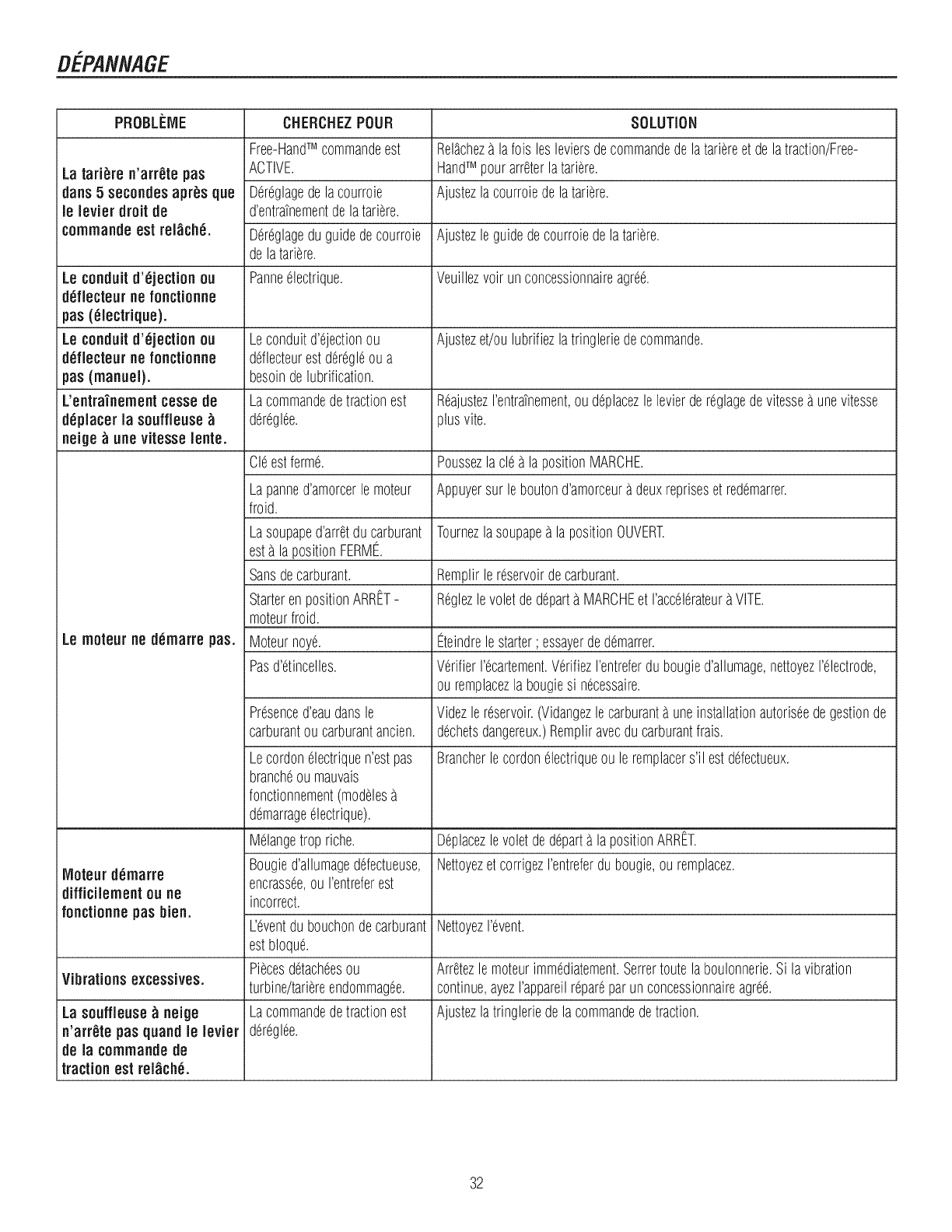
DEPANNAGE
PROBLi:ME CHERCHEZPOUR SOLUTION
Free-HandTM commandeest Rel_cheza lafois lesleviersdecommandedelatariereet delatraction/Free-
La tari_re n'arr_te pus ACTIVE. HandTM pourarreterlatariere.
duns 5 secendes apr_s que Dereglagedelacourroie Ajustezla courroiedelatariere.
le levier droit de d'entratnementdelatariere.
icommandeest rel_chd. Dereglageduguidedecourroie Ajustezle guidedecourroiedela tariere.
delatariere.
Le conduit d'_jection ou Panneelectrique. Veuillezvoir unconcessionnaireagree.
i dCfiecteur ne fonctionne
pus(_lectrique).
Le conduitd'_jeclion ou Leconduitd'ejectionou Ajustezet/oulubrifiezlatringleriedecommande.
dCfiecteur ne fonctionne ddlecteurestderegleoua
pus(manuel}. besoindelubrification.
L'entra'inement cesse de Lacommandedetractionest ReajustezI'entratnement,oudeplacezlelevierdereglagedevitessea unevitesse
d_placer la souffleuse_ dereglee, plusvite.
neige _unevitesse iente.
Cleestferme. Poussezlacle a lapositionMARCHE.
Lapanned'amorcerlemoteur Appuyersur leboutond'amorceuradeuxrepriseset redemarrer.
froid.
Lasoupaped'arretducarburant Tournezlasoupapea la positionOUVERT.
esta lapositionFERME.
Sansdecarburant. Remplirlereservoirdecarburant.
StarterenpositionARRET- Reglezle voletdedeparta MARCHEet I'accelerateuraVITE.
moteurfroid.
Le moteur ne d_marre pus. Moteurnoye. Eteindrelestarter; essayerdedemarrer.
Pasd'etincelles. VerifierI'ecartement.VerifiezI'entreferdu bougied'allumage,nettoyezI'electrode,
ouremplacezlabougiesi necessaire.
Presenced'eaudansle Videzle reservoir.(Vidangezlecarburanta uneinstallationautoriseedegestionde
carburantou carburantancien, dechetsdangereux.)Rempliravecducarburantfrais.
Lecordonelectriquen'estpas Brancherlecordonelectriqueou leremplacers'il estddectueux.
brancheou mauvais
fonctionnement(modeles
demarrageelectrique).
Melangetrop fiche. Deplacezlevoletdedeparta la positionARRET.
Moteur dCmarre Bougied'allumageddectueuse, Nettoyezet corrigezI'entreferdubougie,ou remplacez.
encrassee,ou I'entreferest
i difficilement ou ne incorrect.
fonctionne pusbien. L'eventdu bouchondecarburant NettoyezI'event.
estbloque.
Piecesdetacheesou Arretezlemoteurimmediatement.Setterroutelaboulonnerie.Si lavibration
Vibrationsexcessives, turbine/tariereendommagee, continue,ayezI'appareilrepareparun concessionnaireagree.
La souffleuse _ neige Lacommandedetractionest Ajustezlatringleriedelacommandedetraction.
n'arr_tepus quand le levier dereglee.
de la commandede
itraction esl rel_chd.
32
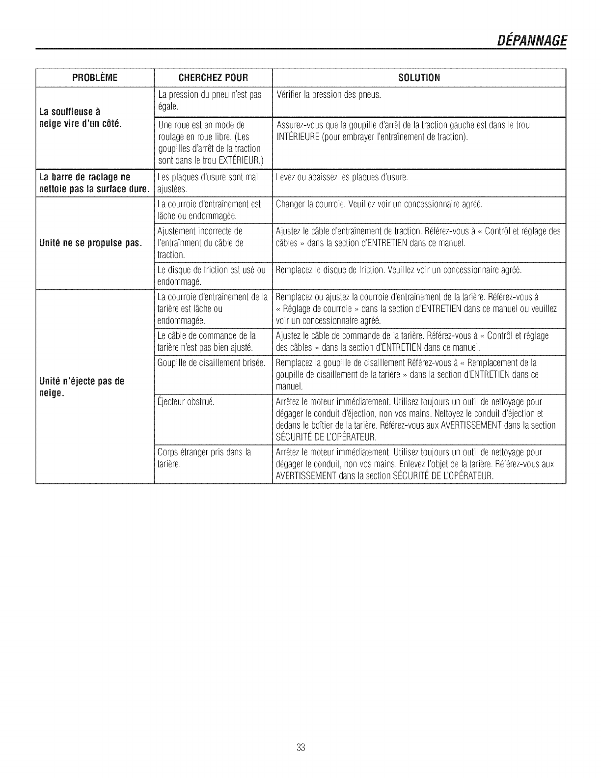
DEPANNAGE
PROBLF:IVlE CNERCNEZPOUR SOLUTION
Lapressiondu pneun'estpas Verifierla pressiondespneus.
ta souffleuse_ egale.
neige vire d'un c0t6. Uneroueestenmodede Assurez-vousquelagoupilled'arretdelatractiongaucheestdansletrou
roulageenrouelibre.(Les INT%IEURE(pourembrayerI'entratnementdetraction).
goupillesd'arretdelatraction
sontdansletrou EXTERIEUR.)
La barre de raclage ne Lesplaquesd'usuresontmal Levezouabaissezlesplaquesd'usure.
netteie pas la surface(lure. ajustees.
Lacourroied'entratnementest Changerlacourroie.Veuillezvoir unconcessionnaireagree.
I_cheouendommagee.
Ajustementincorrectede Ajustezle c_bled'entratnementdetraction.%ferez-vousa <<ContrOletreglagedes
Unite ne se propulsepas. rentratnmentducSblede cSbles_danslasectiond'ENTRETIENdanscemanuel.
traction.
Ledisquedefrictionestuseou Remplacezledisquedefriction.Veuillezvoir unconcessionnaireagree.
endommage.
Lacourroied'entratnementde la Remplacezouajustezlacourroied'entratnementdelatariere.%ferez-vous
tariereestI_cheou <<Reglagedecourroie_ danslasectiond'ENTRETIENdanscemanuelouveuillez
endommagee, voir un concessionnaireagree.
LecSbledecommandedela Ajustezle cSbledecommandedelatariere.%ferez-vousa<<ContrOlet reglage
tarieren'estpasbienajuste, descSbles_ danslasectiond'ENTRETIENdansce manuel.
Goupilledecisaillementbrisee. Remplacezlagoupilledecisaillement%ferez-vousa<<Remplacementdela
goupilledecisaillementdelatariere_ danslasectiond'ENTRETIENdansce
Unit6 n'_jecte pas de manuel.
neige. Ejecteurobstrue. Arretezle moteurimmediatement.Utiliseztoujoursunoutil denettoyagepour
degagerleconduitd'ejection,nonvosmains.Nettoyezleconduitd'ejectionet
dedansle boTtierdelatariere.%ferez-vousauxAVERTISSEMENTdanslasection
S%URITEDEL'OP%ATEUR.
Corpsetrangerprisdansla Arretezle moteurimmediatement.Utiliseztoujoursunoutil denettoyagepour
tariere, degagerleconduit,nonvosmains.EnlevezI'objetdelatariere.Rderez-vousaux
AVERTISSEMENTdanslasectionS%URITEDEL'OPERATEUR.
33
GARAtVT/ES
Garantie Jimitee de Craftsman
Generalites :Les produits Craftsman sont garantis contre tout d6faut de mat6riaux ou de fabrication pendant une p6riode
de temps pr6cise, telle qu'6tablie ci-dessous (la <<p6riode de garantie >>).En outre, cette garantie est offerte uniquement
I'acheteur initial du produit Craftsman. Les achats effectu6s par I'entremise d'un encan en ligne ou sur tout site Web
autre que www.sears.ca sont exclus. La p6riode de garantie d6bute a la date de I'achat initial. Au cours de cette p6riode,
Sears Canada, Inc. s'engage, a sa seule discr6tion, a r6parer ou a remplacer tout produit ou composant de produit d6-
fectueux dans des conditions d'utilisation normale. La r6paration ou le remplacement sera effectu6 pour le client sans
frais de pieces ni de main-d'oeuvre, a condition que le client prenne a sa charge les frais de transport.
Exclusions: La pr6sente garantie ne couvre pas les d6fectuosit6s dues & I'usure normale, I'utilisation inappropri6e ou
abusive, la n6gligence (y compris, mais sans s'y restreindre, I'utiNsation d'essence 6vent6e, la poussi_re, les abrasifs,
I'humidit6, la rouille, la corrosion ou tout autre effet ind6sirable, imputable a un entreposage ou a des habitudes
d'utilisation inappropri6s), un mauvais entretien, le non-respect des consignes ou directives d'entretien, I'utilisation de
I'appareil contrairement aux instructions fournies dans le manuel d'entretien ou aux consignes ou informations donn6es
I'acheteur initial, au moment de I'achat ou au cours de communications subs6quentes avec lui, un accident ou encore une
modification ou des r6parations non autoris6es, effectu6es ou tent6es par d'autres. Sont 6galement exclus de la couver-
ture de la garantie - sauf indication fournie ci-dessous - les 616ments suivants : travaux d'entretien, r6glages, composants
sujets a I'usure, y compris mais sans s'y restreindre :les composants esth6tiques, courroies, lames, adaptateurs de lame,
ampoules, pneus, filtres, barres de guidage, lubrifiants, si_ges, poign6es, Iogements de cordon de d6marrage, chafnes et
barres de scie, bobines et ills de tondeuse a fouet, bougies, cordes de d6marrage et dents, ainsi que les d6colorations
r6sultant de I'exposition aux rayons ultraviolets. Tout produit ne portant pas son 6tiquette d'identification avec son num6ro
de module ou de s6rie sera exclu de la protection offerte par la pr6sente garantie.
Reparations : Les r6parations sont garanties pendant une p6riode de 90 jours. Si le produit d6fectueux est toujours cou-
vert par la garantie, la nouvelle garantie est de 90 jours & compter de la date de la r6paration ou jusqu'a la fin de la p6ri-
ode de garantie initiale, selon la plus Iongue des deux 6ch6ances.
Restrictions : LES GARANTIES ET RECOURS De:FINIS DANS LES PR#SENTES SONT EXCLUSIFS ET REMPLA-
CENT TOUTE AUTRE GARANTIE, QU'ELLE SOIT VERBALE OU ECRITE (AUTRE QUE CELLES #NONC#ES DANS
LES PR#SENTES) OU QU'ELLE SOIT EXPRESSE, IMPLICITE OU PR#VUE PAR LA LOI, SANS SE RESTREINDRE ,A,
AUCUNE. LA PR#SENTE GARANTIE VOUS CONF#RE DES DROITS JURIDIQUES PR#CIS, POUVANT DIFFC:RER
D'UNE PROVINCE ,A,!2AUTRE.
SEARS NE POURRA EN AUCUN CAS #TRE TENUE RESPONSABLE DE TOUT DOMMAGE ACCESSOIRE, SPC:ClAL,
INDIRECT OU CONS#CUTIF, QUI R#SULTERAIT DE EUTILISATION, DU MC:SUSAGE OU DE !21NCAPACIT#
D'UTILISER LE PRODUIT OU QUI DC:COULERAIT DE D#FECTUOSITES DU PRODUIT. LES EXCLUSIONS DU
PR#SENT PARAGRAPHE NE S'APPLIQUENT PAS DANS LES TERRITOIRES O0 LA LOI NE PERMET PAS
UEXCLUSION DES DOMMAGES ACCESSOIRES OU CONS#CUTIFS. DANS CES TERRITOIRES, LE PR#SENT
PARAGRAPHE SERA SANS EFFET, MAIS LES AUTRES DISPOSITIONS DU PR#SENT DOCUMENT DEMEURERONT
VALIDES.
Sears conserve le droit exclusif de r6parer ou de remplacer le produit ou encore d'offrir un remboursement complet de
son prix d'achat, a sa seule discr6tion. CE RECOURS SERA LE SEUL ET UNIQUE RECOURS DONT VOUS DIS-
POSEREZ EN CAS D'INEX#CUTION QUELLE QU'ELLE SOIT DE LA GARANTIE.
Responsabilites du client : En plus d'observer toutes les consignes et directives d'entretien, le client dolt s'acquitter,
entre autres, des obligations suivantes : utiliser le produit conform6ment aux consignes de la notice d'entretien et aux di-
rectives ou informations additionnelles fournies a I'acheteur au moment de I'achat ou a I'occasion de communications
subs6quentes; faire preuve d'un soin raisonnable pour I'utilisation, le fonctionnement, I'entretien g6n6ral, le maintien en
bon 6tat et I'entreposage du produit. Le manquement aces obligations entrafnera une annulation de la garantie applica-
ble.
34
GARANT/ES
LJste des perJodes de garantie applicabJes : La liste ci-dessous indique la p@iode de garantie applicable aux divers
produits Craftsman qu'elle couvre; la periode accordee tient compte du type de produit ou de composants et du type
d'utilisation prevue ou effective de I'appareil ou du composant :
1. 90jours - Produits Craftsman devant etre ou 6tant effectivement utilises a des fins commerciales, institutionnelles,
professionnelles ou lucratives.
,2 arts - Les produits de marque Craftsman suivants : tondeuses & conducteur porte, tracteurs de jardin, tondeuses
contr61e arri@e, motob_ches, debroussailleurs, souffleuses a neige, souffleuses portatives, souffleuses dorsales,
taille-bordures et produits electriques a usage non commercial, non professionnel, non institutionnel ou non lucratif,
sauf les composants faisant pattie de systemes de moteur fabriques par des tiers pour lesquels I'acheteur a regu une
garantie separee ainsi que des renseignements sur le produit, au moment de I'achat.
3. 1 an - Produits de marque Craftsman suivants : couteaux 61ectriques, broyeuses de souches, ebranchoirs, scies &
chafne a essence, scies a chafne 61ectriques, accessoires de taille-bordures, sacs et scies a long manche utilisees
des fins non commerciales, non professionnelles, non institutionnelles et non lucratives.
4. 90jours - Toutes les batteries defectueuses, qui seront remplacees pendant une p@iode de garantie de 90 jours.
,60jours -Une periode de garantie additionnelle de 60 jours s'appliquera pour le reglage ou I'usure de produits ou de
composants MAIS CETTE GARANTIE EXCLUT EUSURE ET LE R#GLAGE de produits utilises a des fins commer-
ciales, institutionnelles, professionnelles ou lucratives. Les articles sujets a I'usure englobent, sans s'y restreindre :
les courroies, lames, pneus, bougies, filtres a air, chafnes, boulons de cisaillement, plaques de protection, barres de
raclage, coupe-cong@es, cordons, dents, sacs collecteurs et poulies.
E_tantdonne que la p@iode de garantie debute a la date d'achat et NON a la date a laquelle le produit est livre,
I'emballage ouvert et I'appareil assemble ou utilis6 la premiere fois, assurez-vous que votre produit ou composant est as-
semble et mis a I'essai pour en verifier le bon fonctionnement, quel que soit le moment oQ vous prevoyez commencer
I'utiliser reellement. Les reclamations presentees apres I'expiration de la garantie ne seront pas acceptees.
Preuve d'achat et documents : La protection de la garantie est conditionnelle & la presentation par I'acheteur initial, &
Sears Canada ou & son fournisseur de service autoris6 s'il y a lieu, de la facture ou de toute autre preuve d'achat appro-
priee indiquant la date de I'achat et designant le produit. Dans le cas oQ I'acheteur initial serait dans I'impossibilit6 de
fournir une copie de sa facture, Sears Canada Inc. se reserve le droit d'etablir, a sa seule discretion, quelle autre preuve
6crite de la date d'achat initial et de la designation du produit est acceptable.
Rev. 03/13/2009
Contrat d'entretien
La Garantie Craftsman, plus un contrat d'entretien sont la meilleure protection des produits Sears. Consulter
le magasin Sears le plus proche pour tous les details.
35
Le California Air Resources Board (CARB), I'U.S. EPA et Briggs & Stratton (B&S) ont le
plaisir de vous exptiquer ta garantie du syst&me de contr61e des &missions pour votre
moteur/&quipement fabriqu& depuis 2008. En Californie, les petits moteurs neufs
usage non routier doivent &tre congus, fabriqu&s et &quip&s pour r&pondre aux normes
s&v@es anti-effet de serre de I'Etat. B&S dolt garantir te syst&me de contr61e des
&missions de votre moteur/&quipement pendant les dur&es indiqu&es ci-apr&s, en
supposant que le moteur neuf a usage non routier n'ait pas fait I'objet d'abus, de
n&gligence ou d'un mauvais entretien.
Le syst&me de contr61e des 6missions peut comprendre des pi&ces comme te
carburateur ou le syst&me d'injection de carburant, le r&servoir de carburant, le syst&me
d'allumage et le convertisseur catalytique. Des durites, des courroies, des connecteurs,
des capteurs et d'autres assemblages impliqu&s dans les &missions peuvent aussi en
faire partie.
Si la condition de garantie est remplie, B&S reparera gratuitement votre
moteur/&quipement y compris te diagnostic, les pi&ces et la main-d'ceuvre.
Couverture de la garantie du fabricant:
Les petits moteurs _ usage non routier sont garantis pendant une p&riode de deux (2)
ans. Si une pi&ce li&e aux &missions de votre moteur/&quipement est d&fectueuse, B&S
la reparera ou la remplacera.
Responsabilites du proprietaire au titre de la garantie:
En tant que proprietaire d'un moteur/&quipement, vous &tes responsable de
I'entretien obligatoire mentionn& dans te manuel d'utilisation. B&S recommande de
conserver toutes les factures de maintenance de votre moteur moteur/equipement
mais B&S ne peut renier la garantie uniquement a cause de I'absence de factures ou
parce que tousles entretiens n'ont pas et6 effectu&s en temps pr&vu.
En tant que proprietaire d'un moteur/equipement, vous devez n&anmoins savoir que
B&S peut refuser d'appliquer la garantie si la d&fectuosit& de votre
moteur/equipement ou d'une partie de celui-ci est due _ un abus, une n&gligence,
un entretien non correct ou des modifications non approuv&es.
Vous avez la responsabilit& de confier votre moteur/&quipement a un centre de
distribution, un R¶teur Agr&& ou toute entite equivalente de B&S, selon la
solution applicable, d&s que te probl&me apparaft. Les r¶tions effectu&es sous
garantie doivent t'&tre enun temps raisonnable qui ne dolt pas exc&der trente (30)
jours. Si vous avez des questions concernant vos droits et vos responsabilit&s au
titre de la garantie, contactez B&S au (414) 259-5262.
Suivent les dispositions particuli@es de la couverture de la garantie du syst&me de contr61e des &missions. Elles viennent en compl&ment de la garantie des moteurs B&S pour les
moteurs non r&glement&s qui se trouve dans te manuel d'utilisation.
1. Pi&ces relatives au contr6te des &missions garanties
La couverture au titre de cette garantie ne s'&tend qu'aux pi&ces &num&r&es
ci-dessous (celles du syst&me de contr61e des &missions) dans la mesure o4 ces
pi&ces &talent pr&sentes dans le moteur au moment de I'achat.
a. Syst&me de dosage du carburant
Syst&me d'enrichissement pour demarrages a froid (starter)
Carburateur et pi&ces internes
Pompe a carburant
Durit et raccords de carburant, colliers
R&servoir de carburant, bouchon et c_ble d'attache
R&servoir _ charbon activ&
b. Syst&me d'admission d'air
Filtre a air
Collecteur d'admission
Conduite de vidange et de mise a I'air
c. Syst&me d'altumage
Bougie(s)
Syst&me d'altumage par volant magn&tique
d. Syst&me catalytique
Convertisseur catalytique
Collecteur d'&chappement
Syst&me d'injection d'air ou soupape d'impulsion
e. Pi&ces diverses utilisees dans les syst&mes ci-dessus
Soupapes et contacteurs de d&pression, de temp@ature, de position et de
dur&e
Raccords et assemblages
2. Dur&e de la couverture
Pendant une p&riode de deux (2) ans _ compter de ta date de t'achat initial, B&S
garantit a I'acheteur initial et _ chaque acheteur suivant que te moteur est con cu,
fabriqu& et equip& de mani&re a &tre en conformit& avec toutes les rTglementations
applicables adoptees par FAir Resources Board, qu'il est exempt de tout d&faut de
mati@e ou de construction susceptible d'entratner ta d&faillance d'une pi&ce garantie
et qu'il est matTriellement identique en tous points au moteur d&crit dans la demande
de certification du fabricant. La p@iode de garantie demarre _ la date de l'achat
initial du moteur.
La garantie sur les pi&ces li&es aux emissions est comme suit:
Toute pi&ce garantie dont le remplacement n'est pas pr&vu dans le cadre de ta
maintenance obligatoire indiquee dans te manuel d'utitisation fourni est garantie
pendant la p@iode susmentionn&e. Si cette pi&ce se r&vTlait &tre d&fectueuse
au cours de la p@iode de garantie, elle serait r&par&e ou remplacTe par B&S
sans aucun frais pour le propri&taire. La pi&ce ainsi reparTe ou remplacee sera
garantie pour la p@iode restante.
Toute pi&ce garantie dont seule une inspection r&guli&re est prevue dans le
manuel d'utilisation fourni est garantie pendant ta p&riode susmentionn&e. La
pi&ce r&paree ou remplacee dans le cadre de la garantie sera garantie pour la
periode restante.
Toute pi&ce garantie dont le remplacement est pr&vu dans le cadre de la
maintenance obligatoire indiquee dans te manuel d'utilisation fourni est garantie
pendant ta p@iode pr&cTdant te premier remplacement pr&vu de cette pi&ce. Si
cette pi&ce se rTvelait &tre d&fectueuse avant le premier remplacement pr&vu,
e!le serait rTparee ou remplacee par B&S sans aucun frais pour le proprietaire.
La pi&ce ainsi r&par&e ou remplacTe sera garantie pour la p@iode restante
pr&c&dant te premier remptacement pr&vu de tadite pi&ce.
Les pi&ces ajout&es ou modifi&es qui ne sont pas exemptees par I'Air
Resources Board ne peuvent 6tre utilis&es. L'utilisation par le propri&taire de
pi&ces ajout&es ou modifi&es non exempt&es sera un motif de rejet de toute
r&ctamation. Le fabricant ne peut en aucun cas &tre tenu de garantir les
defaillances de pi&ces garanties dues a l'utilisation de pi&ces non exempt&es
ajout&es ou modifi&es.
Couverture des consequences
La presente couverture s'etend _ la defaillance de tout composant du moteur due
la d&faillance d'une pi&ce ti&e aux &missions garantie.
RTclamations et exclusions de garantie
Les rTclamations sous garantie seront prTsent&es selon les dispositions de la
police de garantie des moteurs de B&S. La garantie ne couvre pas les d&faillances
de pi&ces li&es aux &missions qui ne sont pas des pi&ces B&S d'origine ou les
d&faitlances de pi&ces qui ont fait I'objet d'abus, de nTgligence ou d'un mauvais
entretien ainsi qu'indique dace la police de garantie des moteurs de B&S. B&S n'est
pas tenu de couvrir la garantie des dTfaitlances des pi&ces li&es aux &missions
dues a I'utilisation de pi&ces rajout&es ou modifi&es.
Les moteurs qui sont certifi&s conformes _ la norme d'&missions du California Air
Resources Board (CARB) doivent afficher I'information concernant la p&riode de
durabilit& des emissions et t'indice d'air. Cette information est indiqu&e sur les etiquettes
apposees sur tes moteurs par Briggs & Stratton. L'&tiquette du moteur indique les
informations de certification.
La period& de durabJlJte des emissions indique le nombre d'heures d'utilisation
normale pour lequel le moteur est certifi& conforme aux normes d'&missions sous
reserve d'un entretien appropri& tel qu'indiqu& dans le manue! d'utilisation et d'entretien.
Les cat&gories suivantes sont utilis&es:
Modere:
le moteur est certifi& conforme pour 125heures d'utilisation normale.
IntermedJaJre:
le moteur est certifi& conforme pour 250heures d'utilisation normale.
Ctendu:
le moteur est certifi& conforme pour 500heures d'utitisation normale. Par exemple, une
tondeuse a conducteur marchant classique est utilis&e 20 _ 25heures par an. Par
cons&quent, ia period& de durabilJte des emissions d'un moteur de cat&gorie
JnterrnedJaJre equivaudrait a une douzaine d'annees.
Les moteurs Briggs & Stratton sont certifi&s conformes aux normes environnementales
d'&missions de ta United States Environmental Protection Agency (U.S. EPA) Phase 2.
Pour les moteurs certifies Phase 2, ta periode de conformit& d'emissions mentionn&e sur
les &tiquettes indique le nombre d'heures d'utilisation pour leque! le moteur est en
conformit& avec les normes f&dTrales.
Pour les moteurs de cylindree inferieure a 225cm3.
Cat&gorie C = 125heures, cat&gorie B = 250heures et cat&gorie A = 500heures.
Pour les moteurs de plus de 225cm3.
Cat&gorie C = 250heures, cat&gorie B = 500heures et cat&gorie A = 1000heures.
36
CARACT -R/ST/QUESTECHNIQUES
iViOTEUR:
Marque
S_ries dumodule
Couple de serrage brut*
Type
Cylindric
D_marrage dusyst_me
Alternateur
I':'cartementdes _lectrodes
8ougie _ r_sistance
Bougieen piatineIongue dur6e
Capacit_ d'huile
Liquidehydraulique
Volumedu r6servoir de carburant
Dispositif d'allumage
Briggs & Stratton
S@ieneige
13,50 T.R @3060 rpm
4-Cycle - 0HV
302 cc (18,6 po3)
Lanceur electrique 110V
60W CA
0,76 mm (0,030 in.)
491055
5066
0,83 litre (28 oz)
Mineral 5W30
2,8 litres (3,0 qts)
Cedispositif d'allumage par etincelleest conforme 9 la norme canadienneICEA-002.
TARIERE/TURBINE•
Largeurde 06gagement
Hauteurd'entr_e
Diam_tre de la tari_re/turbine
Hombre de lames de tari_re
76,2 cm (30 po)
53,3 cm (21 po)
30,5 cm (12 po)
3
GOULOTTE:
D_flecteur de goulotte
Rotationde la goulotte
SYSTEMED'ENTRAJNElViENT•
Typed'entraTnement
Vitessesd'entra'inement
Dimensionsdes pneus
Gonfiagedes phons
Manuel
Manivelle _ gauche 190° (tour 3,5)
Disque de friction -Goupillede verrouillage detraction
6 vitesses marcheavant, 2 vitesses marche arri@e
41 x 12,2 cm (16 x 4,8)
0,96 bar (14 psi)
Inforrnations concernantla puissanceth_oriquedu moteur
*La puissance brute pour chaque Mo@le de moteur _ essenceest indiqu@ conformement au code 31940 (procedure de calcul de ia
puissance et du couple des petits moteurs) de la SAE(Society of Automotive Engineers) et les performances theoriques ont ete obtenues
et corrig@s selon SAEJ1995 (revision 2002-05). Les valeurs de couple sont calcul@ssur la base de 3060 tr/min et celles de puissance
sur la basede 3600 tr/min. La puissance brute reelledu moteur peut etre plus faible notamment _ causedes conditions de fonction-
nement et des variations d'un moteur 9 I'autre. Compte tenu de la grandevariete de machines sur lesquellesnos moteurs sont utilises et
du nombre de problemes environnementauxapplicablesau fonctionnement des equipements, il se peut que le moteur _ essencene
d@eloppe passa puissancetheorique unefois qu'il est monte dans une machine particuli@e(puissance netteou reelle <<sur site >>).
Cette difference s'explique par un grand nombre de facteurs, tels que les suivants (liste non limitative) : accessoires (filtre _ air, echappe-
ment, admission, refroidissement, carburateur, pompe 9 essence,etc.), limites d'utilisation, conditions ambiantes d'utilisation (tempera-
ture, humidite, altitude) et variations d'un moteur _ I'autre. Pourdes raisons de fabrication et de capacite limit@s, Briggs & Stratton est
susceptible de remplacer ce Mo@le par un moteur plus puissant.
37

Your Home
For expert troubleshooting and home solutions advice:
manage home
www.managemyhome.com
For repair - in your home - of all major brand appliances,
lawn and garden equipment, or heating and cooling systems,
no matter who made it, no matter who sold it!
For the replacement parts, accessories and
owner's manuals that you need to do-it-yourself.
For Sears professional installation of home appliances
and items like garage door openers and water heaters.
1-800-4-MY-HOME ®(1-800-469-4663)
Call anytime, day or night (U.S.A. and Canada)
www,sears,com www,sears,ca
Our Home
For repair of carry-in items like vacuums, lawn equipment,
and electronics, call anytime for the location of your nearest
Sears Parts & Repair Service Center
1-800-488-1222 (U.S.A.) 1-800-469-4663 (Canada)
www.sears.com www.sears.ca
To purchase a protection agreement on a product serviced by Sears:
1-800-827-6655 (U.S.A.) 1-800-361-6665 (Canada)
Para pedir servicio de reparaci6n
a domicilio, y para ordenar piezas:
1-888-SU-HOGAR ®
(1-888-784-6427)
Au Canada pour service en fran£ais:
1-800-LE-FOYER Mc
(1-800-533-6937)
® Registered Trademark /TMTrademark /SMService Mark of Sears Brands, LLC
SM
® Marca Registrada /TM Marca de F&brica /Marca de Servicio de Sears Brands, LLC
UD
MCMarque de commerce /Marque d6pos6e de Sears Brands, LLC © Sears Brands, LLC
