Craftsman C950 60901 0 User Manual SEARS/CANADA 10HP REAR ENGINE RIDER Manuals And Guides L9120211
CRAFTSMAN Lawn, Tractor Manual L9120211 CRAFTSMAN Lawn, Tractor Owner's Manual, CRAFTSMAN Lawn, Tractor installation guides
User Manual: Craftsman C950-60901-0 C950-60901-0 CRAFTSMAN CRAFTSMAN SEARS/CANADA 10HP REAR ENGINE RIDER - Manuals and Guides View the owners manual for your CRAFTSMAN CRAFTSMAN SEARS/CANADA 10HP REAR ENGINE RIDER #C950609010. Home:Lawn & Garden Parts:Craftsman Parts:Craftsman CRAFTSMAN SEARS/CANADA 10HP REAR ENGINE RIDER Manual
Open the PDF directly: View PDF ![]() .
.
Page Count: 36
SEARS
owner's
manual
Model No.
C950-60901-0
CAUTION:
Read And Follow
All Safety Rules
And Instructions
Before Operating
This Equipment.
10 HP. ELECTRIC START
30" MOWER /MULCHER
5 SPEED
REAR ENGINE RIDER
• Assembly
•Operation
•Customer Responsibilities
• Service And Adjustment
F-99635 Sears Canada Inc., Toronto, Ontario M5B 2B8 PrintedinU.SA
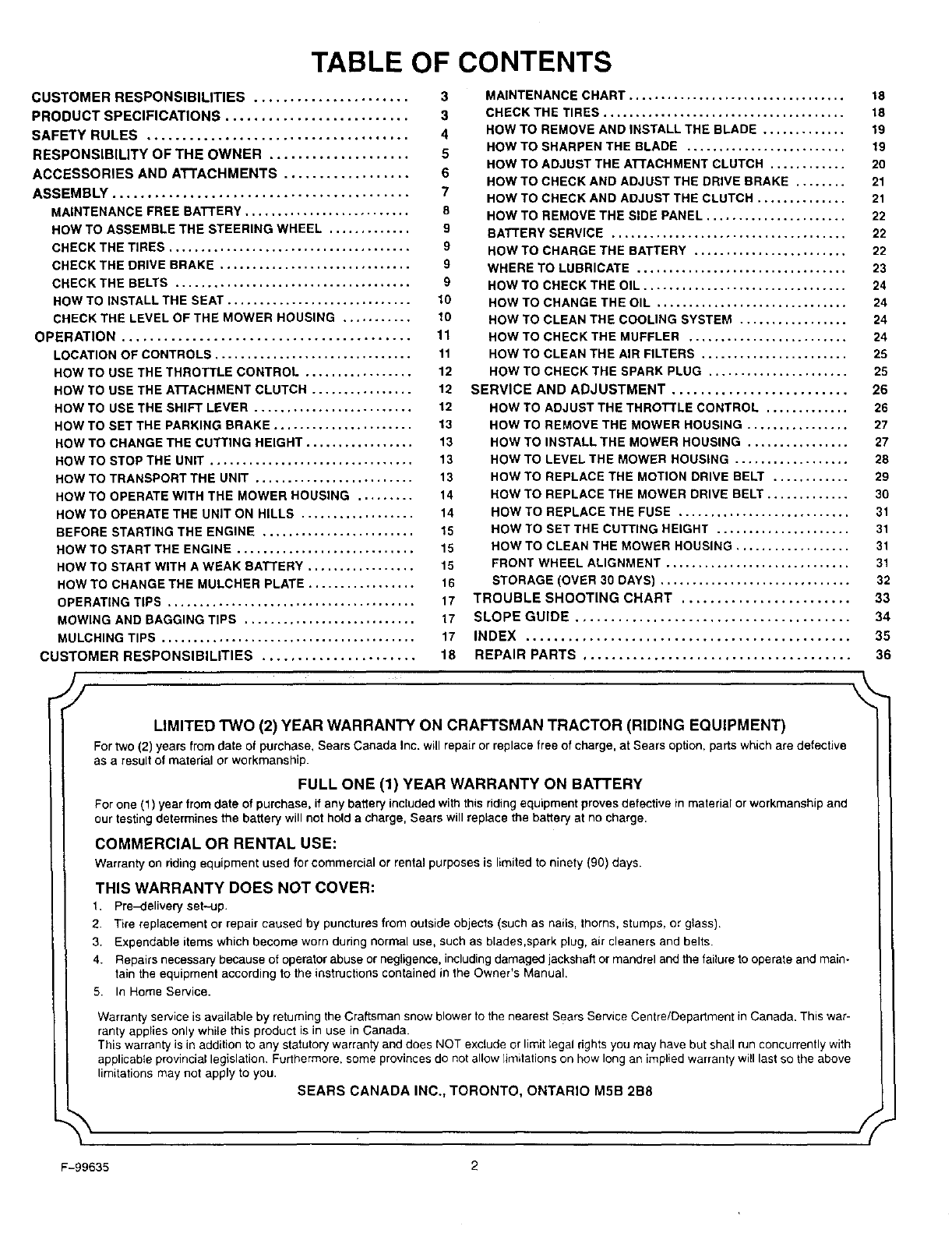
TABLE OF CONTENTS
CUSTOMER RESPONSIBILITIES ...................... 3
PRODUCT SPECIFICATIONS .......................... 3
SAFETY RULES ..................................... 4
RESPONSIBILITY OF THE OWNER .................... 5
ACCESSORIES AND ATTACHMENTS .................. 6
ASSEMBLY .......................................... 7
MAINTENANCE FREE BATTERY.......................... 8
HOW TO ASSEMBLE THE STEERING WHEEL ............. 9
MAINTENANCE CHART .................................. 18
CHECK THE TIRES ...................................... 18
HOW TO REMOVE AND INSTALL THE BLADE ............. 19
HOW TO SHARPEN THE BLADE ......................... 19
HOW TO ADJUST THE ATTACHMENT CLUTCH ............ 20
HOW TO CHECK AND ADJUST THE DRIVE BRAKE ........ 21
HOW TO CHECK AND ADJUST THE CLUTCH .............. 21
HOW TO REMOVE THE SIDE PANEL ...................... 22
BATTERY SERVICE ..................................... 22
CHECK THE TIRES ...................................... 9
CHECK THE DRIVE BRAKE .............................. 9
CHECK THE BELTS ..................................... 9
HOW TO INSTALL THE SEAT ............................. 10
CHECK THE LEVEL OF THE MOWER HOUSING ........... 10
OPERATION ......................................... 11
LOCATION OF CONTROLS ............................... 11
HOW TO CHARGE THE BATTERY ........................ 22
WHERE TO LUBRICATE ................................. 23
HOW TO CHECK THE OIL ................................ 24
HOW TO CHANGE THE OIL .............................. 24
HOW TO CLEAN THE COOLING SYSTEM ................. 24
HOW TO CHECK THE MUFFLER ......................... 24
HOW TO CLEAN THE AIR FILTERS ....................... 25
HOW TO USE THE THROTTLE CONTROL ................. 12
HOW TO USE THE ATTACHMENT CLUTCH ................ 12
HOW TO USE THE SHIFT LEVER ......................... 12
HOW TO SET THE PARKING BRAKE ...................... 13
HOW TO CHANGE THE CUTTING HEIGHT ................. 13
HOW TO STOP THE UNIT ................................ 13
HOW TO TRANSPORT THE UNIT ......................... 13
HOW TO OPERATE WITH THE MOWER HOUSING ......... 14
HOW TO OPERATE THE UNIT ON HILLS .................. 14
BEFORE STARTING THE ENGINE ........................ 15
HOW TO START THE ENGINE ............................ 15
HOW TO START WITH A WEAK BATTERY ................. 15
HOW TO CHANGE THE MULCHER PLATE ................. 16
OPERATING TIPS ....................................... 17
MOWING AND BAGGING TIPS ........................... 17
MULCHING TIPS ........................................ 17
CUSTOMER RESPONSIBILITIES ...................... 18
HOW TO CHECK THE SPARK PLUG ...................... 25
SERVICE AND ADJUSTMENT ......................... 26
HOW TO ADJUST THE THROTTLE CONTROL ............. 26
HOW TO REMOVE THE MOWER HOUSING ................ 27
HOW TO INSTALL THE MOWER HOUSING ................ 27
HOW TO LEVEL THE MOWER HOUSING .................. 28
HOW TO REPLACE THE MOTION DRIVE BELT ............ 29
HOW TO REPLACE THE MOWER DRIVE BELT ............. 30
HOW TO REPLACE THE FUSE ........................... 31
HOW TO SET THE CUTTING HEIGHT ..................... 31
HOW TO CLEAN THE MOWER HOUSING .................. 31
FRONT WHEEL ALIGNMENT ............................. 31
STORAGE (OVER 30 DAYS) .............................. 32
TROUBLE SHOOTING CHART ........................ 33
SLOPE GUIDE ....................................... 34
INDEX .............................................. 35
REPAIR PARTS ...................................... 36
LIMITED TWO (2) YEAR WARRANTY ON CRAFTSMAN TRACTOR (RIDING EQUIPMENT)
For two (2) years from date of purchase, Sears Canada Inc. will repair or replace free of charge, at Sears option, parts which are defective
as a result of material or workmanship
FULL ONE (1) YEAR WARRANTY ON BATTERY
For one (1) year from date of purchase, if any battery included with this riding equipment proves defective in material or workmanship and
our testing determines the battery will not hold a charge, Sears will replace the battery at no charge.
COMMERCIAL OR RENTAL USE:
Warranty on riding equipment used for commercial or rental purposes is limited to ninety (90) days.
THIS WARRANTY DOES NOT COVER:
1. Pre-delivery set-up.
2 Tire replacement or repair caused by punctures from outside objects (such as nails, thorns, stumps, or glass).
3. Expendable items which become worn during normal use, such as blades,spark plug, air cleaners and belts
4. Repairs necessary because of operator abuse or negligence, includingdamaged jackshafl or mandrel and the failure to operate and main-
tain the equipment according to the instructions contained in the Owner's Manual.
9 In Home Service.
Warranty service is available by returning the Craftsman snow blower to the nearest Sears Service Centre/Department in Canada. This war-
ranty applies only white this product is in use in Canada.
This warranty is in addition to any statutory warranty and does NOT exclude or limit legal rights you may have but shall run concurrently with
applicable provincial legislation. Furthermore, some provinces do not allow limitations on how long an implied warranty will last so the above
limitations may not apply to you.
SEARS CANADA INC., TORONTO, ONTARIO M5B 2B8
\
F-99635 2
Congratulations on your purchase of a Sears Rider. It has been
designed, engineered and manufactured to give you the best
possible dependability and performance.
if you experience any problems you cannot easily remedy, please
see your nearest Sears Service Department. We have competent,
well trained technicians and the proper tools to service or repair this
unit.
Please read and keep this manual. The instructions will enable you
to assemble and maintain your unit properly. Always observe the
"Safety Rules".
NOTE: This unit is equipped with an intemal combustion engine and
must not be used on or near any unimproved forest-covered,
brush-covered or grass-covered land unless the engine's exhaust
system is equipped with a spark arrester meeting applicable local
or state laws (if any). If a spark arrester is used, it must be
maintained in effective working order by the operator.
In the State of California, the above is required by law (Section 4442
of the California Public Resources Code). Other states may have
similar laws. Federal laws apply on federal lands. See an Authorized
Service Center for a spark arrester for the muffler.
CUSTOMER RESPONSIBILITIES
Carefully read and follow the rules for safe operation. Inspect
the unit.
Follow all the assembly instructions. Carefully adjust the unit.
Know how to operate all standard and accessary equipment on
the unit. Make sure the operator can correctly operate the unit.
Operate the unit only with guards, shields and other safety
items in place and working correctly.
Complete all maintenance on the unit. Service the unit only with
authorized or approved replacement parts.
See the Maintenance Chart.
MAINTENANCE AGREEMENT
ASears Maintenance Agreement is available on this unit. See the
nearest Sears Store for information.
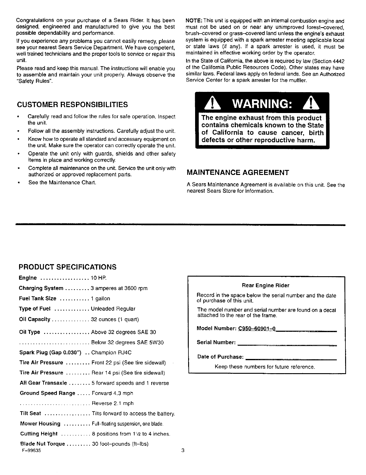
PRODUCT SPECIFICATIONS
Engine .................. 10 HI:'.
Charging System ......... 3 amperes at 3600 rpm
Fuel Tank Size ........... 1 gallon
Type of Fuel ............. Unleaded Regular
Oil Capacity .............. 32 ounces (1 quart)
Oil Type ................. Above 32 degrees SAE 30
.......................... Below 32 degrees SAE 5W30
Spark Plug (Gap 0.030") .. Champion RJ4C
Tire Air Pressure ......... Front 22 psi (See tire sidewall)
Tire Air Pressure ......... Rear 14 psi (See tire sidewall)
All Gear Transaxle ........ 5 forward speeds and 1 reverse
Ground Speed Range ..... Forward 4.3 mph
.......................... Reverse 2.1 mph
Tilt Seat ................. Tilts forward to access the battery.
Mower Housing .......... Full-floatingsuspension,one blade.
Cutting Height ........... 8 positions from 1_/2to 4 inches.
Blade Nut Torque ......... 30 foot-pounds (ft-lbs)
F-99635
Rear Engine Rider
Record in the space below the serial number and the date
el purchase of this unit.
The model number and serial number are found on a decal
attached to the rear of the frame.
Model Number: 0950-60901-0
Serial Number:
Date of Purchase:
Keep these numbers for future reference.
OWNER'S INFORMATION
SAFETY RULES
Safe Operation Practices for Ride-on Mowers
WARNING: This cutting machine is capable of amputating hands and feet and throwing objects, Failure to observe the
following safety instructions could result in serious injury or death.
I. General operation
1. Read, understand and follow all instructions in the InstructionBook, onthe machine, the engine and with any attachments before starting.
2. Only allow responsible adults, who are familiar with the instructions, to operate the machine.
3. Clear the area of objects such as rocks, toys, wire, etc., which could be picked up and thrown by the blade.
4. Be sure the area is clear of other people before mowing. Stop the machine if anyone enters the area.
5. Never carp/passengers.
6. Turn off power to the blades or any attachments before backing up. Do not mow in reverse unless absolutely necessary. Always look
down and behind before and while backing.
7. Be aware of the mower discharge direction and do not point it at anyone. Do not operate the mower without either the entire grass bagger
or the mower guard in place.
8. Slow down before turning.
9. Never leave a machine unattended with the engine running. Always turn off the blade(s), set the parking brake, stop the engine and
remove the key before dismounting.
10. Turn off power to attachment(s) when transporting or not in use. Turn off the blade(s) when not mowing.
11. Stopthe engine before removing the grass bagger or unclogging the chute.
12. Mow only in daylight or good artificial light.
13. Do not operate the machine while under the influence of alcohol or drugs or when very tired.
14. Watch for traffic when operating near or crossing roadways.
t5, Use extra caution when loading or unloading the machine into a trailer or truck.
16. Always wear goggles, safety glasses, or an eye shield when you operate the unit to protect your eyes from foreign objects that can be
thrown from the unit. Always wear eye protection when you make an adjustment or repair to the machine.
17. Use care when pulling loads or using heavy equipment.
a. Use only approved drawbar hitch points.
b. Limit loads to those you can safely control.
c, Do not turn sharply. Use care when backing.
d. Use counterweights or wheel weights when suggested in the Instruction Book.
18. Do not operate this machine if you are taking drugs or other medication which can cause drowsiness or affect your ability to operate
this machine.
19. Do not use this machine if you are mentally or physically unable to operate this machine safely.
II. Slope operation
Slopes and rough terrain are major factors related to loss-of-control and tip-over accidents, which can result in severe injury
or death. ALL slopes require extra caution. If you cannot back up the slope or if you feel uneasy on the slope, do not mow it. See
the "Slope Guide" in the back of this book to check for safe operation.
DO
1. Mow up and down slopes, not across.
2. Remove obstacles such as rocks, limbs, etc...
3. Watch for holes, ruts or bumps. Uneven terrain could overturn the machine. Tall grass can hide obstacles.
4. Follow the manufacturer's recommendations for wheel weights or counterweights to improve stability.
5. Use extra care with grass baggers or other attachments, they can change the stability of the machine.
6. Keep all movement on the slopes slow and gradual. Do not make sudden changes in speed or direction.
7. Avoid starting or stopping on a slope. If tires lose traction, turn off the blades and proceed slowly straight down the slope.
DO NOT
1. Do not turn on slopes unless absolutely necessary, then only turn slowly and gradually downhill, if possible.
2. Do not mow drop-offs, ditches or embankments. A wheel over the edge or an edge caving in could cause a sudden overturn and an
injury or death.
3. Do not mow on wet grass. Reduced traction could cause sliding.
4. Do not try to stabilize the machine by putting your foot on the ground.
5. Do not use a grass bagger or other rear mounted accessories on steep slopes (greater than 10 degrees).
III. Children
Tragic accidents can occur if the operator is not alert to the presence of children. Children are often attracted to the machine and
the mowing activity. NEVER assume that children will remain where you last saw them.
1. Keep children out of the mowing area and in the watchful care of another responsible adult.
2. Be alert and turn the engine off if children enter the area.
3. Before and when backing, look behind and down for small children.
F-99635 4
OWNER'S INFORMATION
4. Never carry children or any passengers, even with the blades off. They may fall off and be seriously injured or interfere with the safe
operation of the machine.
5. Never allow children to operate the machine. Instruct children in the potential dangers of the machine.
6. Use extra care when approaching blind corners, shrubs, trees or other objects that may obscure vision.
IV. Service
1. Use extra care when handling gasoline and other fuels. Fuels are flammable and the vapors are explosive.
a. Use only an approved container.
b. Never remove the gas cap or add fuel with the engine running. Allow the engine to cool for several minutes before refueling. Do
not smoke.
c. Never refuel the machine indoors.
d. Never store the machine with fuel in the tank or fuel container inside where there is an open flame, such as a water heater.
2. Never start or run the engine inside a closed area.
3. Keep all nuts and bolts, especially the blade attachment nuts tight. Frequently check the blade(s) for wear or damage such as cracks
and nicks. A blade that is bent or damaged must be immediately replaced with an originalequipment blade from an authorized service
dealer. For safety, replace the blade every two years. Keep the equipment in good condition.
4. Never tamper with the safety devices. Check their proper operation regularly.
5. To reduce fire hazards, keep the machine free of grass, leaves or other debris build-up. Clean up oil or fuel spills. Allow the machine
to cool before storing.
6. Stop and inspect the equipment if you strike an object. Repair, if necessary, before restarting.
7. Never make adjustments or repairs with the engine running. The carburetor can be adjusted with the engine running. Do not change
the engine governor settings or over-speed the engine.
8. Grass bagger components are subject to wear, damage and deterioration, which could expose moving parts or allow objects to be
thrown. For storage, always make sure the grass bag is empty. Frequently check components and replace with manufacturer's recom-
mended parts when necessary.
9. Mower blade(s) are sharp and can cut. Wrap the blade(s) or wear gloves and use extra caution when servicing them or the blade housing
area.
10. Check the brake operation frequently. Adjust and service as required.
11. Wait for all movement to stop before servicing any part of the unit.
RESPONSIBILITY OF THE OWNER
Environmental Awareness
Do not fill the engine's fuel tank completely full.
Drain fuel for off-season storage.
Use only unleaded gasoline.
Service the air cleaner regularly.
Change oil regularly. Use 30W oil in summer.
Tune-up the engine regularly.
Keep equipment in efficient operating condition.
Dispose of used engine oil properly.
Look for this symbol to indicate important safety
precautions, This symbol indicates: "Attention!
Become Alert! Your Safety Is At Risk,"
F-99635 5
ACCESSORIES AND ATTACHMENTS
ACCESSORIES AND A'I-rACHMENTS
These accessories and attachments were available when the unit was purchased. They are also available at most Sears retail outlets,
catalog and service centers. Most Sears stores can order these items for you when you provide the model number of your riding mower.
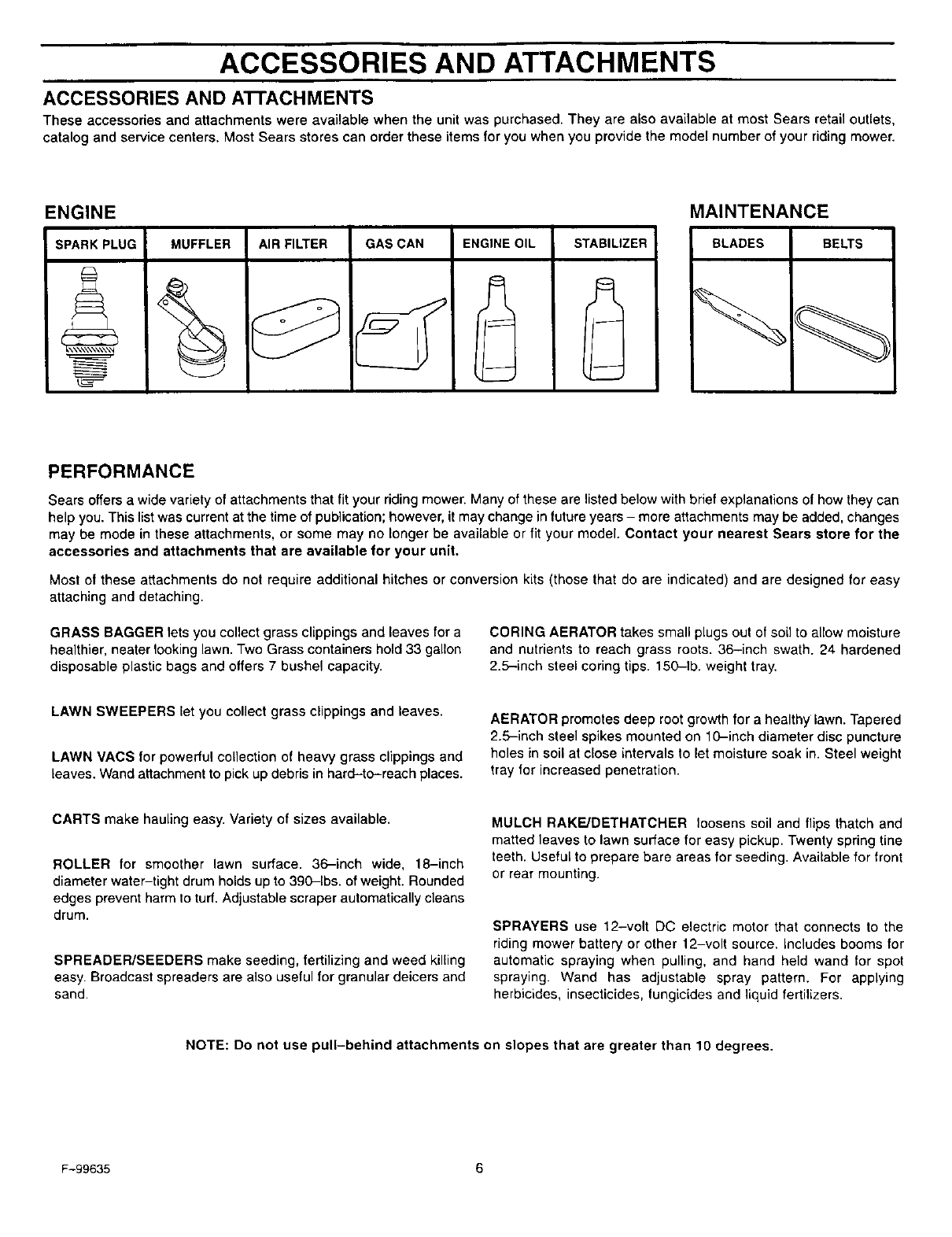
ENGINE
SPARK PLUG MUFFLER AIR FILTER GAS CAN STABILIZERENGINE OIL
A
l_
MAINTENANCE
BLADES BELTS
PERFORMANCE
Sears offers awide variety of attachments that fit your riding mower. Many of these are listed below with brief explanations of how they can
help you. This list was current at the time of publication; however, it may change in future years - more attachments may be added, changes
may be mode in these attachments, or some may no longer be available or fit your model. Contact your nearest Sears store for the
accessories and attachments that are available for your unit.
Most of these attachments do not require additional hitches or conversion kits (those that do are indicated) and are designed for easy
attaching and detaching.
GRASS BAGGER lets you collect grass clippings and leaves for a
healthier, nearer looking lawn. Two Grass containers hold 33 gallon
disposable plastic bags and offers 7 bushel capacity.
CORING AERATOR takes small plugs out of soil to allow moisture
and nutrients to reach grass roots. 36-inch swath. 24 hardened
2.5-inch steel coring tips. 150-1b. weight tray.
LAWN SWEEPERS let you collect grass clippings and leaves.
LAWN VACS for powerful collection of heavy grass clippings and
leaves. Wand attachment to pick up debris in hard-to-reach places.
AERATOR promotes deep root growth for a healthy lawn. Tapered
2.5-inch steel spikes mounted on 10-inch diameter disc puncture
holes in soil at close intervals to let moisture soak in. Steel weight
tray for increased penetration.
CARTS make hauling easy. Variety of sizes available.
ROLLER for smoother lawn surface. 36-inch wide, 18-inch
diameter water-tight drum holds up to 390-1bs. of weight. Rounded
edges prevent harm to tud. Adjustable scraper automatically cleans
drum.
SPREADER/SEEDERS make seeding, fertilizing and weed killing
easy. Broadcast spreaders are also useful for granular deicers and
sand.
MULCH RAKE/DETHATCHER loosens soil and flips thatch and
matted leaves to lawn surface for easy pickup. Twenty spring fine
teeth. Useful to prepare bare areas for seeding. Available for front
or rear mounting.
SPRAYERS use 12-volt DC electric motor that connects to the
riding mower battery or other 12-volt source, includes booms for
automatic spraying when pulling, and hand held wand for spot
spraying. Wand has adjustable spray pattern. For applying
herbicides, insecticides, fungicides and liquid fertilizers.
NOTE: Do not use pull-behind attachments on slopes that are greater than 10 degrees.
F-99635 6
ASSEMBLY
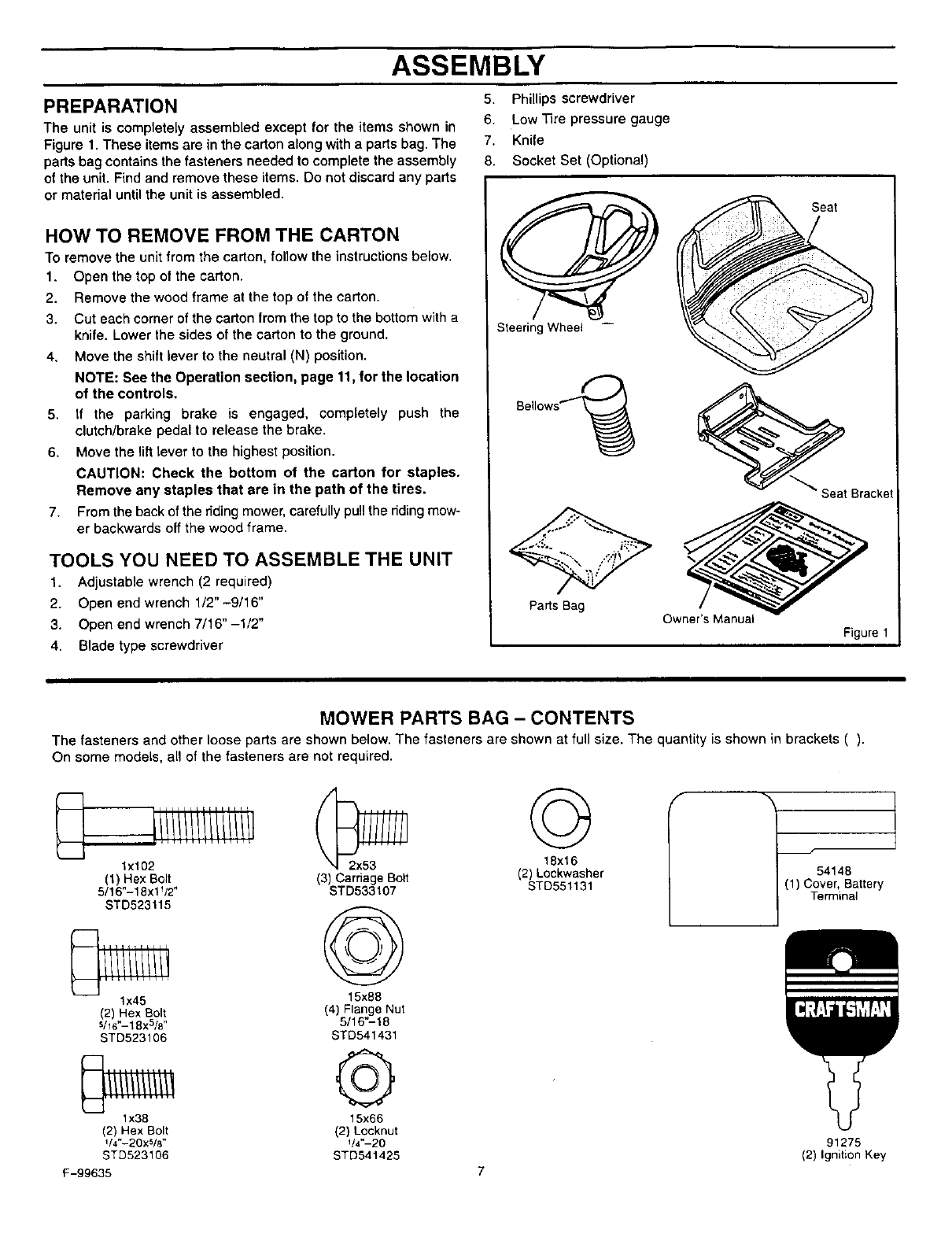
PREPARATION
The unit is completely assembled except for the items shown in
Figure 1. These items are in the carton along with a parts bag. The
parts bag contains the fasteners needed to complete the assembly
of the unit. Find and remove these items. Do not discard any parts
or material until the unit is assembled.
HOW TO REMOVE FROM THE CARTON
To remove the unit from the carton, follow the instructions below.
1. Open the top of the carton.
2. Remove the wood frame at the top of the carton.
3. Cut each corner of the carton from the top to the bottom with a
knife. Lower the sides of the carton to the ground.
4. Move the shift lever to the neutral (N) position.
NOTE: See the Operation section, page 11. for the location
of the controls.
5. If the parking brake is engaged, completely push the
clutch/brake pedal to release the brake.
6. Move the lilt lever to the highest position.
CAUTION: Check the bottom of the carton for staples.
Remove any staples that are in the path of the tires.
7. From the back of the dding mower, carefully pull the nding mow-
er backwards off the wood frame.
TOOLS YOU NEED TO ASSEMBLE THE UNIT
1. Adjustable wrench (2 required)
2. Open end wrench 1/2"-9/16"
3. Open end wrench 7/16" -1/2"
4. Blade type screwdriver
5. Phillips screwdriver
6. Low Tire pressure gauge
7. Knife
8. Socket Set (Optional)
Steering Wheel --
Bellows_
Parts Bag Owner's Manual
Figure 1
MOWER PARTS BAG - CONTENTS
The fasteners and other loose parts are shown below. The fasteners are shown at full size. The quantity is shown in brackets ().
On some models, all of the fasteners are not required.
_j,iiiiiiiiiiiiii ©
lx102 18x16
(1) Hex Bolt (3) Carriage Bolt (2)Lockwasher
5/16"-18x1_/2• STD533107 STD551131
STD523115 ©
lx45 15x88
(2) Hex Bolt (4) Flange Nut
s/16"-18x5/8" 5/16"-18
STD523106 STD541431
1x38 15x66
(2) Hex Bolt (2) Locknut
U4"-20X_/8" 1t4"-20
STD523106 STD541425
F-99635
54148
(1) Cover, Battery
Terminal
91275
(2) Ignition Key

ASSEMBLY
MAINTENANCE FREE BA'n'ERY
IMPORTANT: Before you attach the battery cables to the
battery, check the battery date. The battery date tells if the
battery must be charged.
1. Check the battery date on top of the battery (Figure 2).
2. If the battery is put into service before the battery date, the
battery cables can be attached without charging the battery.
See "How To Install The Battery Cables".
3. If the battery is put into service after the battery date, the
battery must be charged. See "How To Charge The
Maintenance Free Battery".
HOW TO CHARGE THE MAINTENANCE FREE BA'n'ERY
,_ WARNING: When you charge the battery, do not
smoke. Keep the battery away from any sparks. The
fumes from the battery acid can cause an explosion.
1. Remove the battery. See "How To Remove The Battery" in the
Customer Responsibilities section.
2. Remove the protective caps from the battery terminals.
3, Use a 12 volt battery charger to charge the battery. Charge at
a rate of 6 amperes for one hour. If you do not have a battery
charger, have an authorized service center charge the battery.
4. Install the battery. See "How To Install The Battery" in the
Customer Responsibilities section.
HOW TO INSTALL THE BA'rFERY CABLES
,_ WARNING: To prevent sparks, fasten the red cable to
the positive (+) terminal before you connect the black
cable.
NOTE: Before you attach the battery cables, make sure the
battery is fully charged. This will extend the life of the battery
and provide the necessary power to start the engine.
Use the fasteners shown below to install the battery cables. The
fasteners are shown at full size.
(A) Q(B)
lx38 15x66
1.
2.
Remove the protective caps from the battery terminals.
If equipped, slide the terminal cover onto the red cable
(Figure 2). Fasten the red cable to the positive (+) terminal
with the fasteners as shown. Push the terminal cover onto the
battery terminal.
3. Fasten the black cable to the negative (-) terminal with the
fasteners as shown.
Positive (+)
Terminal
Battery Date Black Cable
A
Battery Clamp
Figure 2
F-99635 8
ASSEMBLY
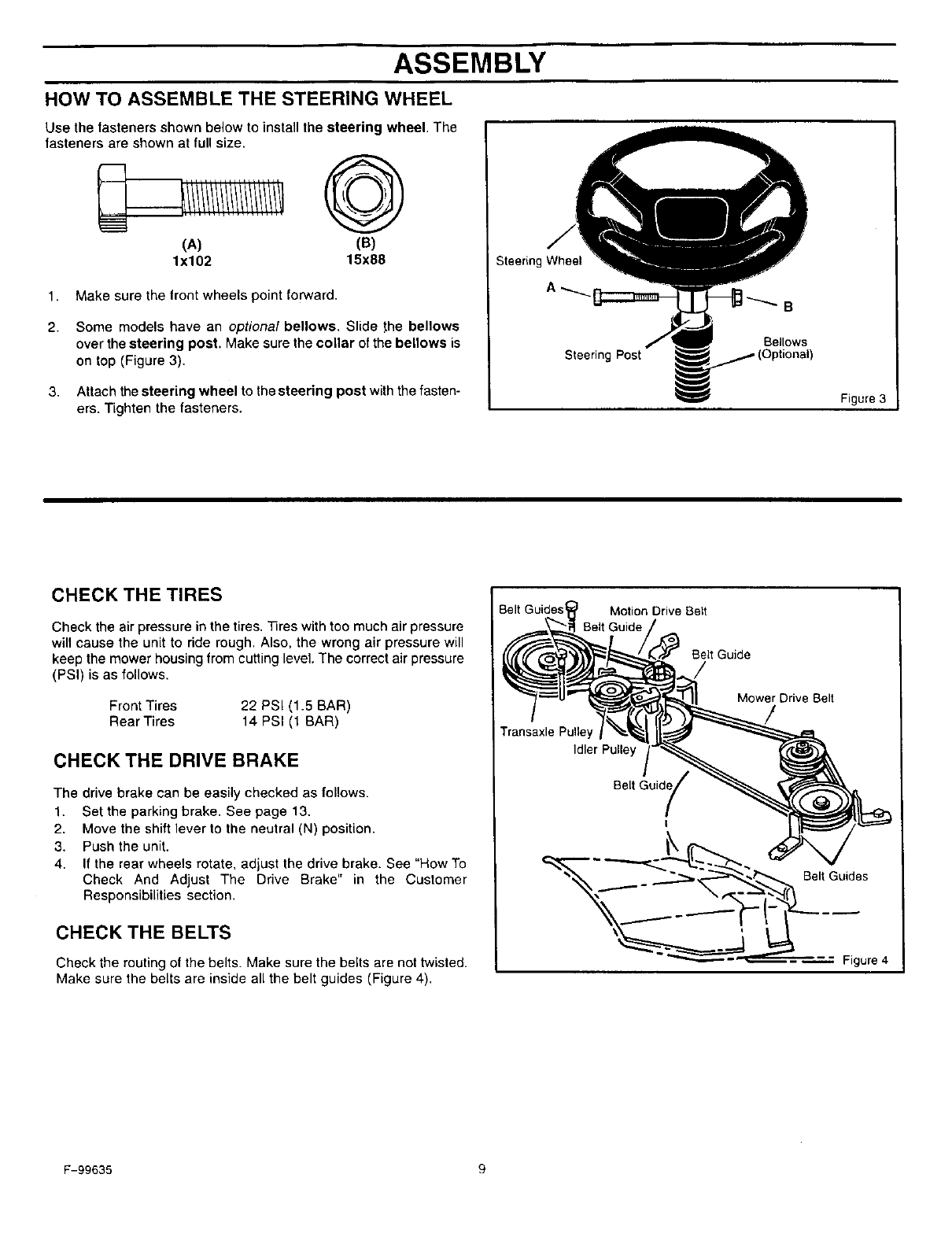
HOW TO ASSEMBLE THE STEERING WHEEL
Use the fasteners shown below to install the steering wheel. The
fasteners are shown at full size.
(A) (B)
lx102 15x88
1. Make sure the front wheels point forward.
2.
3,
Some models have an optional bellows, Slide _he bellows
over the steering post. Make sure the collar of the bellows is
on top (Figure 3).
Attach the steering wheel to the steering post with the fasten-
ers. Tighten the fasteners.
Steering Wheel
Steering Post
B
Bellows
Figure 3
CHECK THE TIRES
Check the air pressure in the tires, _res with too much air pressure
will cause the unit to ride rough. Also, the wrong air pressure will
keep the mower housing from cutting level. The correct air pressure
(PSI) is as follows,
Front Tires 22 PSI (1.5 BAR)
Rear Tires 14 PSI (1 BAR)
CHECK THE DRIVE BRAKE
The drive brake can be easily checked as follows.
1. Set the parking brake, See page 13,
2. Move the shift lever to the neutral (N) position.
3. Push the unit.
4. If the rear wheels rotate, adjust the drive brake. See "How To
Check And Adjust The Drive Brake" in the Customer
Responsibilities section.
CHECK THE BELTS
Check the routing of the belts. Make sure the belts are not twisted.
Make sure the belts are inside all the belt guides (Figure 4).
Belt Guides I
Transaxle Pulle
Motion Drive Belt
Belt Guide
Idler Pulley
Belt
I
Mower Drive Belt
Belt Guides
Figure 4
F-99635 9
ASSEMBLY
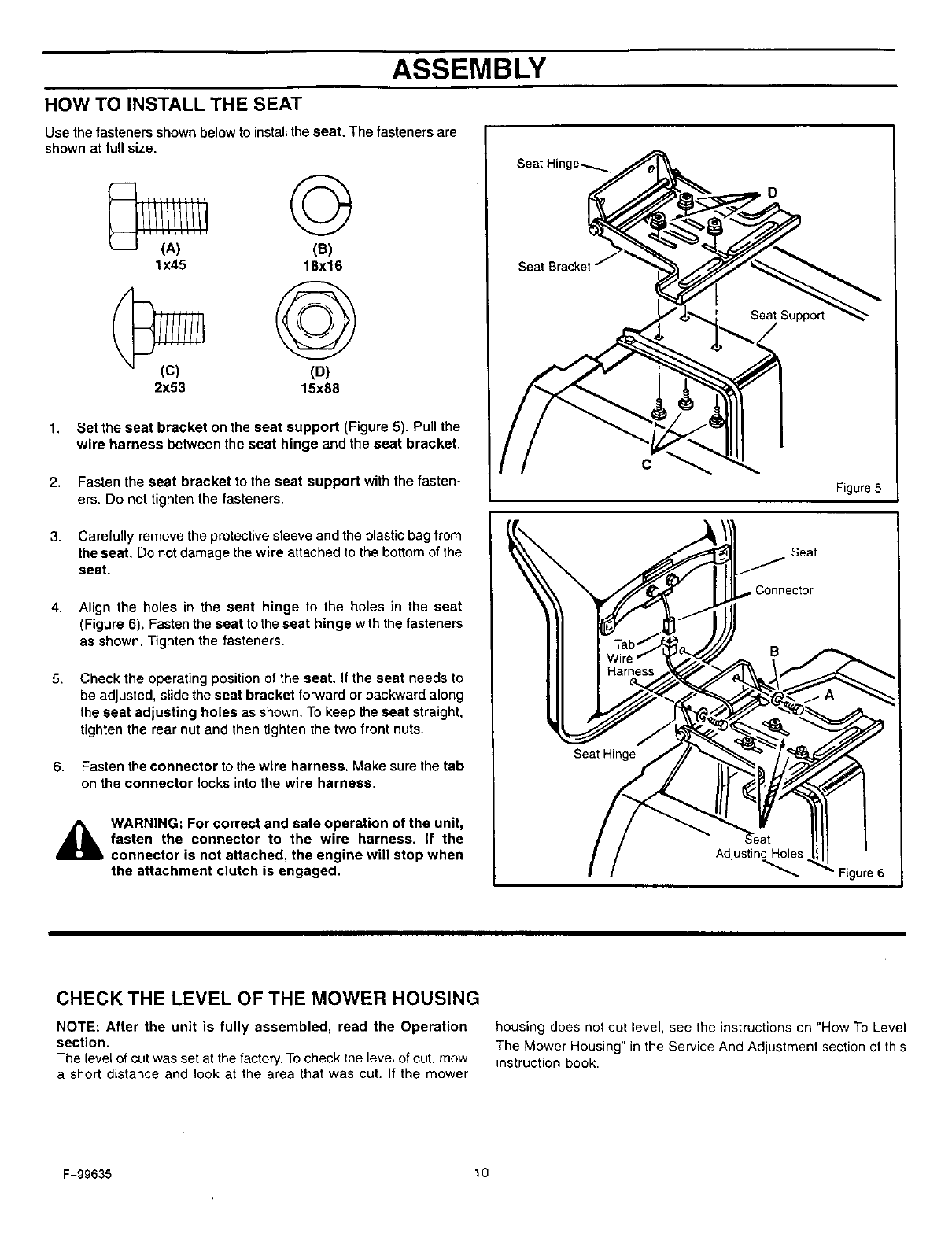
HOW TO INSTALL THE SEAT
Use the fasteners shown below to install the seat. The fasteners are
shown at full size.
©
(B)
lx45 18x16
(D)
2x53 15x88
1,
2.
Set the seat bracket on the seat support (Figure 5). Pull the
wire harness between the seat hinge and the seat bracket.
Fasten the seat bracket to the seat support with the fasten-
ers. Do not tighten the fasteners.
Seat Bracket
C
D
3.
4.
5.
6.
Carefully remove the protective sleeve and the plastic bag from
the seat. Do not damage the wire attached to the bottom of the
seat.
Align the holes in the seat hinge to the holes in the seat
(Figure 6). Fasten the seat to the seat hinge with the fasteners
as shown. Tighten the fasteners.
Check the operating position of the seat. If the seat needs to
be adjusted, slide the seat bracket forward or backward along
the seat adjusting holes as shown. To keep the seat straight,
tighten the rear nut and then tighten the two front nuts.
Fasten the connector to the wire harness. Make sure the tab
on the connector locks into the wire harness.
WARNING: For correct and safe operation of the unit,
fasten the connector to the wire harness, if the
connector is not attached, the engine will stop when
the attachment clutch is engaged.
Seat Hinge
Seat
Figure 5
Adjustin_es Figure 6
CHECK THE LEVEL OF THE MOWER HOUSING
NOTE: After the unit is fully assembled, read the Operation
section.
The level of cut was set at the factory. To check the level of cut, mow
ashort distance and look at the area that was cut. If the mower
housing does not cut level, see the instructions on "How To Level
The Mower Housing" in the Service And Adjustment section of this
instruction book.
F-99635 t 0
OPERATION
Clutch
Clutch /Brake
(_ _ _ Thro_le Control
Lever
Ignition Switch Parking Brake
Lever
Shift Lever
Lift Lever
I
I
Figure 7
The operation of any lawn mower can result in foreign objects thrown in the eyes, which can result in severe eye
damage. Always wear safety glasses or eye shields before starting your lawn mower and while mowing. We recom-
mend the Wide Vision Safety Mask for over the spectacles or standard safety glasses, available at Sears Retail or
Catalog Stores.
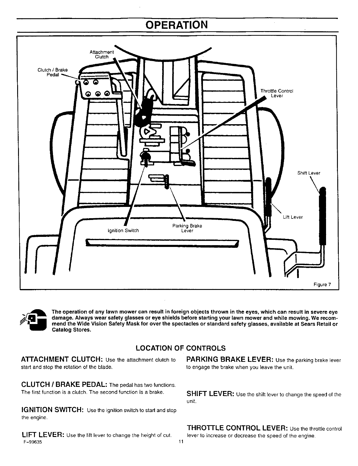
LOCATION OF CONTROLS
ATTACHMENT CLUTCH: Use the attachment clutch to PARKING BRAKE LEVER: Use the parking brake lever
start and stop the rotation of the blade, to engage the brake when you leave the unit.
CLUTCH /BRAKE PEDAL: The pedal has two functions.
The first function is a clutch. The second function is a brake.
IGNITION SWITCH: use the ignition switch to start and stop
the engine,
SHIFT LEVER: Use the shift lever to change the speed of the
unit.
THROTTLE CONTROL LEVER: Use the throttle control
LIFT LEVER: Use the lift lever to change the height of cut. lever to increase or decrease the speed of the engine.
F-99635 11
OPERATION
HOW TO USE THE THRO'I-rLE CONTROL 2.
Use the throttle control to increase or decrease the speed of the
engine. 3.
The FAST position is marked with adetent. For normal opera-
tion and when using a grass bagger, move the throttle control
to the FAST position. For maximum charging of the battery and
also for a cooler running engine, operate the engine in the FAST
position.
2. For transport and to tow pull behind attachments, move the
throttle control to the SLOW position.
4.
Move the attachment clutch to the ENGAGE position to ro-
tate the blade(s).
Move the attachment clutch to the DISENGAGE position to
stop the blade(s). Before you leave the operator's position,
make sure the blade(s) has stopped rotating.
Before you ride the unit across a sidewalk or a road, move the
attachment clutch to the DISENGAGE position.
_lb WARNING: Always keep your hands and feet away
from the blade, deflector opening, and the mower
housing when the engine runs.
3. The engine governor is set at the factory for maximum perform-
ance. Do not adjust the governor to increase the speed of the
engine.
HOWTO USE THE ATTACHMENTCLUTCH
Note: If the engine stops when you engage the blade(s), the
seat switch is not activated. Make sure you sit in the middle of
the seat. Also, make sure the wire is connected to the seat
switch,
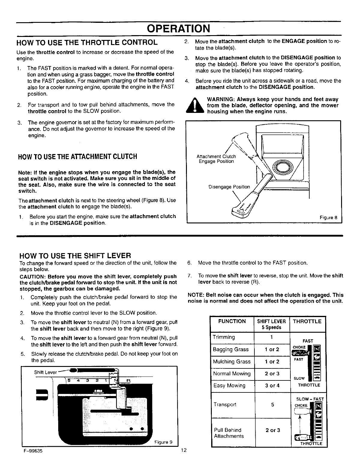
The attachment clutch is next to the steering wheel (Figure 8). Use
the attachment clutch to engage the blade(s).
1. Before you start the engine, make sure the attachment clutch
is in the DISENGAGE position.
Attachment Clutch
Engage Position
Disengage Position
Figure 8
HOW TO USE THE SHIFT LEVER
TOchange the forward speed or the direction of the unit, follow the
steps below.
CAUTION: Before you move the shift lever, completely push
the clutch/_rake pedal forward to stop the unit. If the unit is not
stopped, the gearbox can be damaged.
1. Completely push the clutch/brake pedal forward to stop the
unit. Keep your foot on the pedal.
2. Move the throttle control lever to the SLOW position.
3. To move the shift lever to neutral (N) from a forward gear, pub
the shift lever back and then move to the right (Figure 9).
4. To move the shift lever to a fonNard gear from neutral (N), pull
the shift lever to the left and then push the shift lever forward.
5. Slowly release the clutch/brake pedal. Do not keep your foot on
the pedal.
Shift Lever
R
6. Move the throttle control to the FAST position.
7. To move the shift lever to reverse, stop the unit. Move the shift
lever back to reverse (R).
NOTE: Belt noise can occur when the clutch is engaged. This
noise is normal and does not affect the operation of the unit.
FUNCTION
Trimming
Bagging Grass
Mulching Grass
Normal Mowing
Easy Mowing
Transpod
Pull Behind
Attachments
SHIFTLEVER
5 Speeds
1
1 or2
1 or2
2or3
3or4
5
2or3
THRO'I-rLE
FAST
FAST _'J
SLOW
THROTrLE
SLOW- FAS]
CHOKE
I -
THROrrT-EFigure 9
F-99635 12
OPERATION
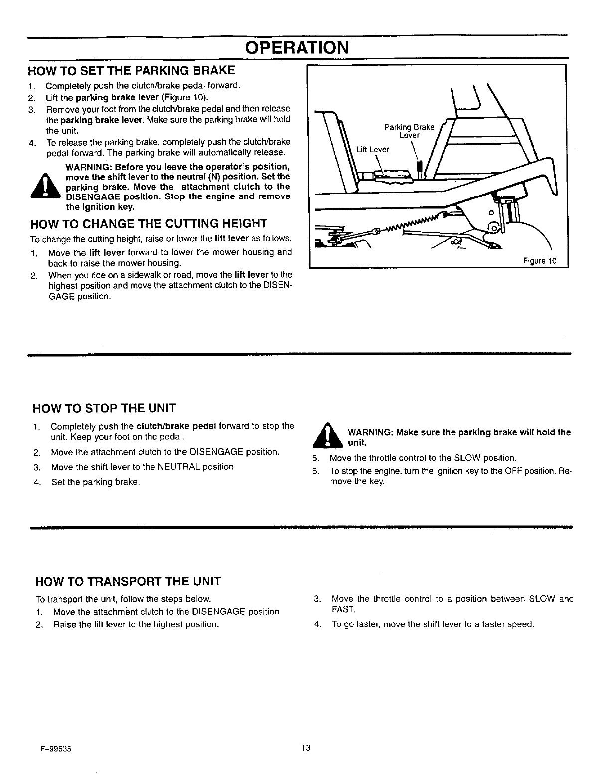
HOW TO SET THE PARKING BRAKE
1.
2.
3.
4.
Completely push the clutchYorake pedal forward.
Lift the parking brake lever (Figure 10).
Remove your foot from the clutch/Drakepedal and then release
the parking brake lever. Make sure the parkingbrake will hold
the unit.
To release the parking brake, completely push the clutch/Drake
pedal forward. The parking brake will automatically release.
WARNING: Before you leave the operator's position,
move the shift lever to the neutral (N) position. Set the
parking brake. Move the attachment clutch to the
DISENGAGE position. Stop the engine and remove
the ignition key.
HOW TO CHANGE THE CUTTING HEIGHT
To change the cutting height, raise or lower the lift lever as follows.
1, Move the lift lever forward to lower the mower housing and
back to raise the mower housing.
2. When you ride on a sidewalk or road, move the lift lever to the
highest position and move the attachment clutch to the DISEN-
GAGE position.
Parking Brake
Lever
Lift Lever
Figure 10
HOW TO STOP THE UNIT
1. Completely push the clutch/brake pedal forward to stop the
unit. Keep your foot on the pedal.
2. Move the attachment clutch to the DISENGAGE position.
3. Move the shift lever to the NEUTRAL position.
4. Set the parking brake.
_b ARNING: Make sure the parking brake will hold the
unit.
5. Move the throttle control to the SLOW position.
6. To stop the engine, turn the ignition key to the OFF position. Re-
move the key.
HOW TO TRANSPORT THE UNIT
To transport the unit, follow the steps below.
1. Move the attachment clutch to the DISENGAGE position
2. Raise the lift lever to the highest position.
3. Move the throttle control to a position between SLOW and
FAST.
4. To go faster, move the shift lever to a faster speed.
F-99635 13
OPERATION
HOW TO OPERATEWITH THE MOWER HOUSING
WARNING: The deflector is a safety device. Do not re-
move the deflector. The deflector forces the dis-
d_lb charged material toward the ground. Always keep the
deflector in the down position, if the deflector is dam-
aged, replace the deflector with an original equipment
part from an authorized sen/ice center.
1. Start the engine,
2. Move the lift lever to a height of cut position. In high or thick
grass, cut the grass in the highest position first and then lower
the mower housing to a lower position.
3. Move the throttle control to the SLOW position.
4. Move the attachment clutch to the ENGAGE position.
5. Push the clutch/brake peda_ completely forward.
6. Move the shift lever to one of the speed settings.
7.
8.
9,
NOTE: When you mow in heavy grass or mow with a
bagger, put the shift lever in the slowest speed.
Slowly release the clutch/brake pedal.
Move the throttle control to the FAST position. If you need to go
faster or slower, stop the unit and move the shift lever to another
speed setting.
Make sure the level of cut is still correct. After you mow a short
distance, look at the area that was cut. If the mower housing
does not cut level, see the instructions on "How To Level The
Mower Housing" in the Service And Adjustment section.
_IL ARNING: For better control of the unit, always
select asafe speed.
HOW TO OPERATE THE UNIT ON HILLS
WARNING: Do not ride up or down slopes that are too
steep to back straight up. Never ride the unit across
a slope. See the "Slope Guide" in the back of this
book for information on how to check slopes.
1. Before you ride up or down a hill, move the shift lever to the
slowest speed.
2. Do not stop or change speed settings on a hill. If you must stop,
quickly push the clutch/brake pedal forward and set the parking
brake.
3.
4.
5.
To start again, make sure the shift lever is in the slowest speed.
Move the throttle control to the SLOW position. Slowly release
the pedal.
If you must stop or start on a hill, always have enough space
for the unit to roll when you release the brake and engage the
clutch.
Be very careful when you change directions on a hill. When on
a slope or in a turn on a hill, move the throttle control to the
SLOW position to help prevent an accident.
F-99635 14
OPERATION
BEFORE STARTING THE ENGINE
CHECK THE OIL
NOTE: The engine was shipped from the factory filled with SAE
30 weight oil. Check the level of the oil. Add oil as needed.
1. Make sure the unit is level.
NOTE: Do not check the level of the oil while the engine
runs.
2. Clean the area around the dipstick. Remove the dipstick. Wipe
the oil from the dipstick.
3. Insert the dipstick into the oil fill tube. Turn the dipstick clock-
wise until it is tight. Remove the dipstick. Check the oil level on
the dipstick. The oil level must reach the FULL mark on the
dipstick.
4. If necessary, add oil until the oil reaches the FULL mark on the
dipstick. The quantity of oil needed from ADD to FULL is shown
on the dipstick. Do not add too much oil
ADD GASOLINE
WARNING: Always use a safety gasoline container.
i_ Do not smoke when adding gasoline to the fuel tank.
Do not add gasoline when you are inside an enclo-
sure. Before you add gasoline, stop the engine and
let the engine cool for several minutes.
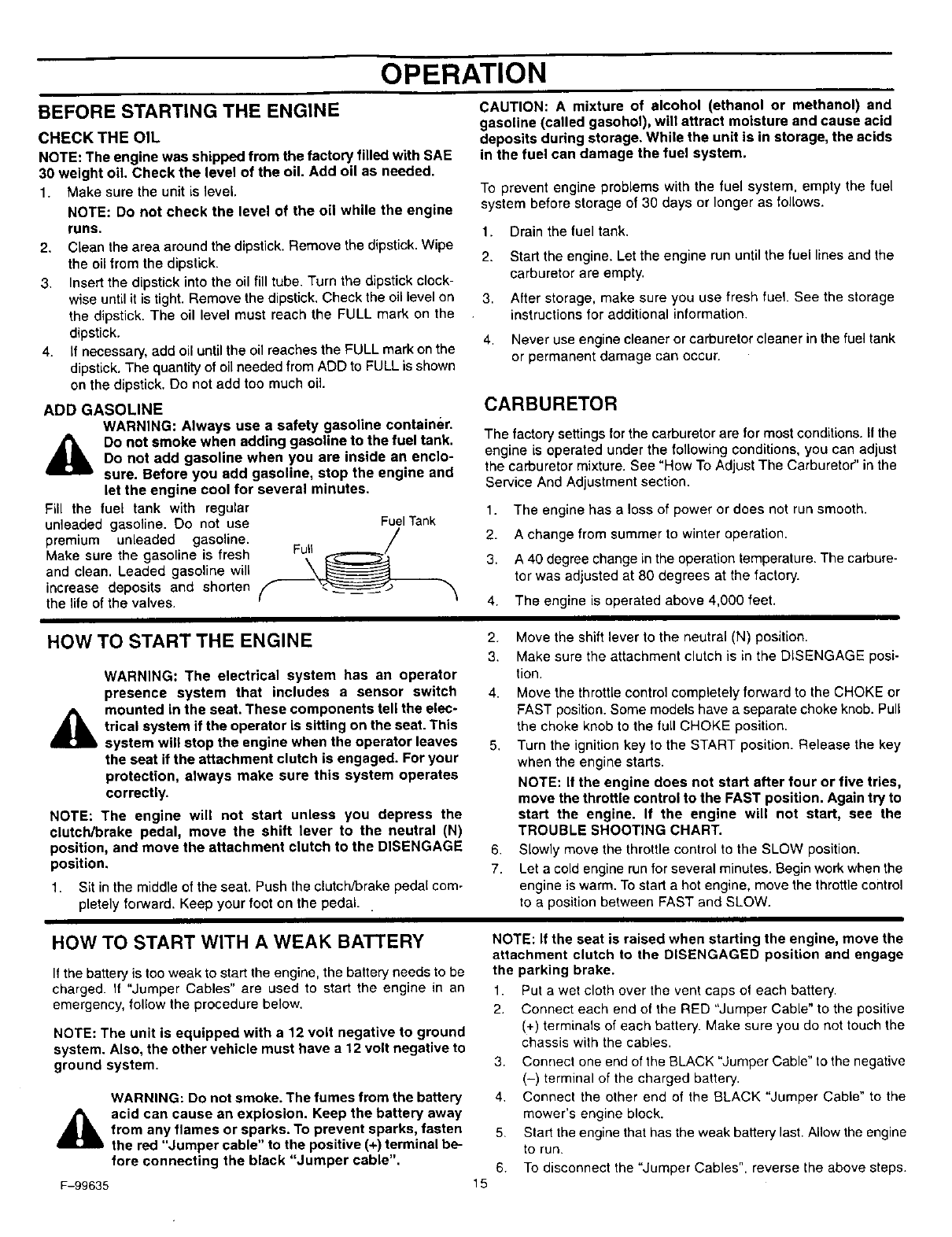
Fill the fuel tank with regular
unleaded gasoline. Do not use Fuel Tank
premium unleaded gasoline. Full _/
Make sure the gasoline is fresh S_
and clean. Leaded gasoline will
increase deposits and shorten
the life of the valves.
CAUTION: A mixture of alcohol (ethanol or methanol) and
gasoline (called gasohol), will attract moisture and cause acid
deposits during storage. While the unit is in storage, the acids
in the fuel can damage the fuel system.
To prevent engine problems with the fuel system, empty the fuel
system before storage of 30 days or longer as follows.
1. Drain the fuel tank.
2. Stad the engine. Let the engine run until the fuel lines and the
carburetor are empty.
3. After storage, make sure you use fresh fuel. See the storage
instructions for additional information.
4. Never use engine cleaner or carburetor cleaner in the fuel tank
or permanent damage can occur.
CARBURETOR
The factory settings for the carburetor are for most conditions, ifthe
engine is operated under the following conditions, you can adjust
the carburetor mixture. See "How To Adjust The Carburetor" in the
Service And Adjustment section.
1. The engine has a loss of power or does not run smooth.
2. A change from summer to winter operation.
3. A 40 degree change in the operation temperature. The carbure-
tor was adjusted at 80 degrees at the factory.
4. The engine is operated above 4,000 feet.
HOW TO START THE ENGINE
WARNING: The electrical system has an operator
presence system that includes a sensor switch
,_ mounted in the seat. These components tell the elec-
trical system if the operator is sitting on the seat. This
system will stop the engine when the operator leaves
the seat if the attachment clutch is engaged. For your
protection, always make sure this system operates
correctly.
NOTE: The engine will not start unless you depress the
clutch/brake pedal, move the shift lever to the neutral (N)
position, and move the attachment clutch to the DISENGAGE
position.
1. Sit in the middle of the seat. Push the clutch/brake pedal com-
pletely forward. Keep your foot on the pedal..
2. Move the shift lever to the neutral (N) position.
3. Make sure the attachment clutch is in the DISENGAGE posi-
tion.
4. Move the throttle control completely forward to the CHOKE or
FAST position. Some models have a separate choke knob. Pull
the choke knob to the full CHOKE position.
5, Turn the ignition key to the START position. Release the key
when the engine starts.
NOTE: If the engine does not start after four or five tries,
move the throttle control to the FAST position. Again try to
start the engine. If the engine will not start, see the
TROUBLE SHOOTING CHART.
6. Slowly move the throttle control to the SLOW position.
7. Let a cold engine run for several minutes. Begin work when the
engine is warm. To start a hot engine, move the throttle control
to a position between FAST and SLOW.
HOW TO START WITH A WEAK BATTERY
If the battery is too weak to start the engine, the battery needs to be
charged. I1 "Jumper Cables" are used to start the engine in an
emergency, follow the procedure below.
NOTE: The unit is equipped with a 12 volt negative to ground
system. Also, the other vehicle must have a 12 volt negative to
ground system.
WARNING: Do not smoke. The fumes from the battery
acid can cause an explosion. Keep the battery away
from any flames or sparks. To prevent sparks, fasten
the red "Jumper cable" to the positive (+) terminal be-
fore connecting the black "Jumper cable".
F-99635 15
NOTE: If the seat is raised when starting the engine, move the
attachment clutch to the DISENGAGED position and engage
the parking brake.
1. Put a wet cloth over the vent caps ol each battery.
2, Connect each end of the RED "Jumper Cable" to the positive
(+) terminals of each battery. Make sure you do not touch the
chassis with the cables.
3. Connect one end of the BLACK "Jumper Cable" to the negative
(-) terminal of the charged battery.
4. Connect the other end of the BLACK "Jumper Cable" to the
mower's engine block.
5. Start the engine that has the weak battery last. Allow the engine
to run.
6. To disconnect the "Jumper Cables", reverse the above steps.
OPERATION
HOW TO CHANGE THE MULCHER PLATE
_lb WARNING: To prevent the engine from starting, dis-
connect the wire from the spark plug. Make sure the
attachment clutch is in the DISENGAGE position.
The mulcher plate lets you mulch the grass for a clean, fine cut. To
discharge the grass out the side or into a grass bagger, remove the
mulcher plate as follows.
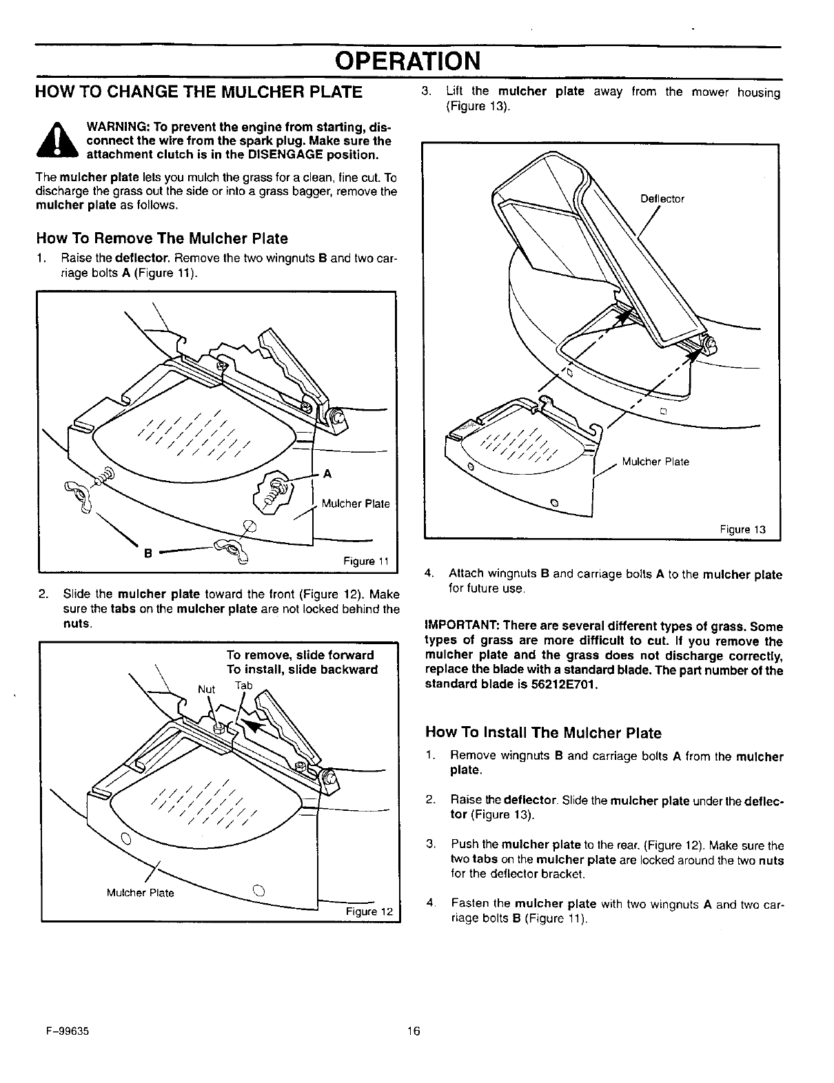
How To Remove The Mulcher Plate
1. Raise the deflector. Remove the two wingnuts B and two car-
riage bolts A (Figure 11).
\Mulcher Plate
BFigure 11
2. Slide the mulcher plate toward the front (Figure 12). Make
sure the tabs on the mulcher plate are not locked behind the
nuts.
To remove, slide forward
To install, slide backward
Nut
Mulcher Plate
Figure 12
3. Lift the mulcher plate away from the mower housing
(Figure 13).
Deflector
Figure 13
4. Attach wingnuts Band carriage bolts Ato the mulcher plate
for future use,
IMPORTANT: There are several different types of grass. Some
types of grass are more difficult to cut. If you remove the
mulcher plate and the grass does not discharge correctly,
replace the blade with a standard blade. The part number of the
standard blade is 56212E701.
How To Install The Mulcher Plate
1. Remove wthgnuts Band carriage bolts A fromthe mulcher
plate.
2. Raise the deflector. Slide the mulcher plate under the deflec-
tor (Figure 13).
3. Push the mulcher plate to the rear, (Figure 12). Make sure the
two tabs on the mulcher plate are locked around the two nuts
for the deflector bracket.
4. Fasten the mulcher plate with two wingnuts A and two car-
riage bolts B(Figure 11).
F-99635 16
OPERATING TIPS
OPERATION
1,
2,
3.
4.
Check the attachment clutch for correct adjustment. For the
blade(s) to disengage correctly, the adjustment must be cor-
rect.
Before you use the unit, check the oil in the engine and add oil
if necessary.
If the engine will not start, first make sure the wire is attached
to the spark plug.
Make sure all the belts are inside all the belt guides. See the in-
structions on how to remove and install the motion drive and
mower drive belts.
5.
6,
7.
8.
9.
Before you make an inspection, adjustment (except for the car-
buretor) or repair, make sure the wire from the spark plug is dis-
connected.
Make sure the seat switch wire is connected. If the wire is not
connected, the engine will not start.
For longer life of the battery, charge the battery every three
months.
Use the shift lever to change the ground speed, not the throttle
control.
Belt noise can occur when the blade or clutch is engaged. This
noise is normal and does not affect the operation of the unit.
MOWING AND BAGGING TIPS
1. For a lawn to look better, check the cutting level of the mower
housing. See "How To Level The Mower Housing" in the Ser-
vice And Adjustment section.
2,
3.
For the mower housing to cut level, make sure the tires have
the correct amount of air pressure (PSI).
Every time you use the unit, check the blade. If the blade is bent
or damaged, immediately replace the blade. Also, make sure
the nut for the blade is tight.
4. Keep the blade(s) sharpened. Worn blades will cause the ends
of the grass to turn brown.
5. Do not cut or bag grass that is wet. Wet grass will not discharge
correctly. Let the grass dry before cutting.
6.
7.
8.
g.
Use the left side of the mower housing to trim near an object.
Discharge the cut grass onto the mowed area. The result is a
more even discharge of cut grass.
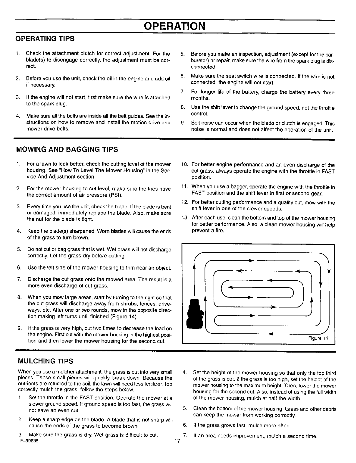
When you mow large areas, start by turning to the right so that
the cut grass will discharge away from shrubs, fences, drive-
ways, etc. After one or two rounds, mow in the opposite direc-
tion making left turns until finished (Figure 14).
If the grass is very high, cut two times to decrease the load on
the engine. First cut with the mower housing in the highest posi-
tion and then lower the mower housing for the second cut.
10.
11.
12.
13.
For better engine performance and an even discharge of the
cut grass, always operate the engine with the throttle in FAST
position.
When you use a bagger, operate the engine with the throttle in
FAST position and the shift lever in first or second gear.
For better cutting performance and a quality cut, mow with the
shift lever in one of the slower speeds.
After each use, clean the bottom and top of the mower housing
for better performance. Also, a clean mower housing will help
prevent a fire.
f
}1
,11 Figure 14
MULCHING TIPS
When you use a mulcher attachment, the grass is cut into very small
pieces. These small pieces will quickly break down. Because the
nutrients are returned to the soil, the lawn will need less fertilizer. Too
correctly mulch the grass, follow the steps below.
1. Set the throttle in the FAST position. Operate the mower at a
slower ground speed. If ground speed is too fast, the grass will
not have an even cut.
2. Keep a sharp edge on the blade. A blade that is not sharp will
cause the ends of the grass to become brown.
4,
5.
6,
7.
17
Set the height of the mower housing so that only the top third
of the grass is cut. If the grass is too high, set the height of the
mower housing to the maximum height. Then, lower the mower
housing for the second cut. Also, instead of using the full width
of the mower housing, mulch at half the width.
Clean the bottom of the mower housing. Grass and other debris
can keep the mower from working correctly.
If the grass grows fast, mulch more often.
3. Make sure the grass is dry. Wet grass is difficult to cut. If an area needs improvement, mulch a second time.
F-99635
CUSTOMER RESPONSIBILITIES
M
O
W
E
R
EVERY
100
HOURSPROCEDURE
Blade, Inspect and Sharpen
Attachment Clutch, Check
Brake, Check
Clutch, Check
Tires, Check
Battery, Check and Charge
Battery, Clean
Lubrication
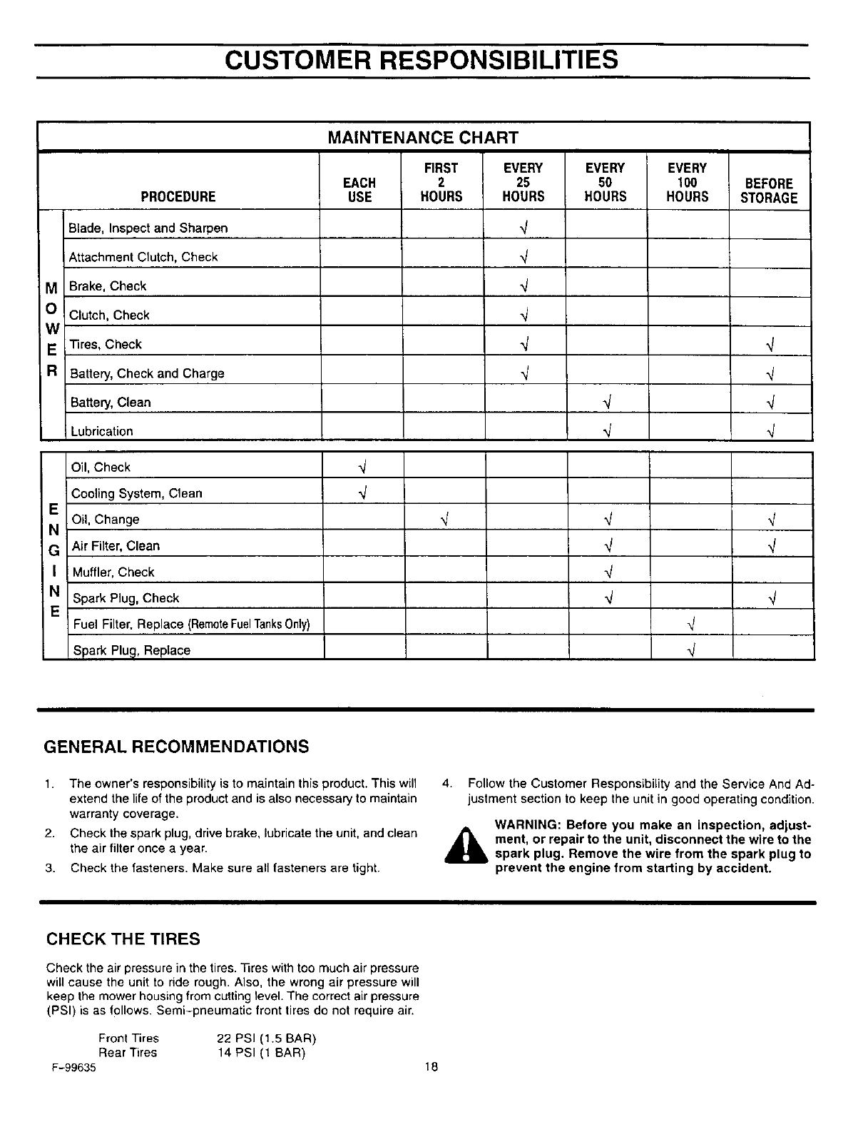
MAINTENANCE CHART
FIRST EVERY
EACH 2 25
USE HOURS HOURS
q
EVERY
50
HOURS
,j
,j .j
BEFORE
STORAGE
Oil, Check ",,/
Cooling System, Clean _/
EOil, Change _ "_ q
N
G Air Filter, Clean _
I Muffler, Check
NSpark Plug, Check _
EFuel Filter, Replace (RemoteFuelTanks0nly) _j
Spark Plug, Replace _/
GENERAL RECOMMENDATIONS
1. The owner's responsibility is to maintain this product. This will
extend the life of the product and is also necessary to maintain
warranty coverage.
2. Check the spark plug, drive brake, lubricate the unit, and clean
the air filter once a year.
3. Check the fasteners. Make sure all fasteners are tight.
4. Follow the Customer Responsibility and the Service And Ad-
justment section to keep the unit in good operating condition.
WARNING: Before you make an inspection, adjust-
ment, or repair to the unit, disconnect the wire to the
spark plug. Remove the wire from the spark plug to
prevent the engine from starting by accident.
CHECK THE TIRES
Check the air pressure in the tires. "Gres with too much air pressure
will cause the unit to ride rough. Also, the wrong air pressure will
keep the mower housing from cutting level. The correct air pressure
(PSI) is as follows. Semi-pneumatic front tires do not require air.
Front Tires 22 PSI (1.5 BAR)
Rear Tires 14 PSI (1 BAR)
F-99635 18
CUSTOMER RESPONSIBILITIES
INSPECT BLADE
WARNING: Before you inspect or remove the blade,
_lb disconnect the wire to the spark plug. If the blade hits
an object, stop the engine. Check the unit for dam-
age. The blade has sharp edges. When you hold the
blade, use gloves or cloth material to protect your
hands.
ifyou keep the blade sharp and inspect the blade for damage, the
blade will cut better and be more safe to operate. Frequently check
the blade for excessive wear, cracks, or other damage. Frequently
check the nut that holds the blade. Keep the nut tight. If the blade
hits an object, stop the engine. Disconnect the wire to the spark plug.
See if the blade is bent or damaged. Check the blade adapter for
damage. Before you operate the unit, replace damaged parts with
original equipment parts. See the authorized service center in your
area. Every three years, have an authorized service person inspect
the blade or replace the old blade with an original equipment part.
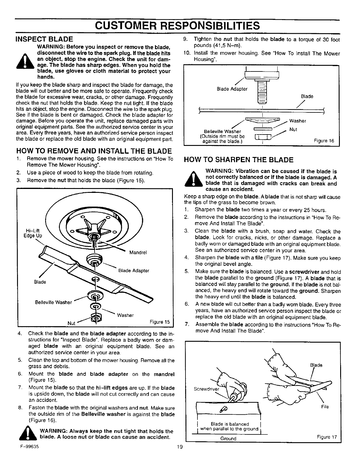
9. Tighten the nut that holds the blade to a torque of 30 foot
pounds (41,5 N-m).
10. Install the mower housing. See "How To Install The Mower
Housing".
Blade Adapt
Blade
/
i I
asher
Belleville Washer _ r4ul
(Outsiderim must be
against the blade.) i Figure 16
HOW TO REMOVE AND INSTALL THE BLADE
1. Remove the mower housing. See the instructions on "How To
Remove The Mower Housing".
2. Use apiece of wood to keep the blade from rotating.
3. Remove the nut that holds the blade (Figure t 5).
Edge
el
Blade Adapter
Blade
Washer
Figure 15
4,
5,
6.
7.
8.
Check the blade and the blade adapter according to the in-
structions for "Inspect Blade". Replace a badly worn or dam-
aged blade with an original equipment blade. See an
authorized service center in your area.
Clean the top and bottom of the mower housing. Remove all the
grass and debris.
Mount the blade and blade adapter on the mandrel
(Figure 15).
Mount the blade so that the hi-lift edges are up. If the blade
is upside down, the blade will not cut correctly and can cause
an accident.
Fasten the blade with the original washers and nut. Make sure
the outside rim of the Belleville washer is against the blade
(Figure 16).
WARNING: Always keep the nut tight that holds the
blade. A loose nut or blade can cause an accident.
HOW TO SHARPEN THE BLADE
WARNING: Vibration can be caused if the blade is
_lb not correctly balanced or if the blade is damaged. A
blade that is damaged with cracks can break and
cause an accident.
Keep a sharp edge on the blade. A blade that is not sharp willcause
the tips of the grass to become brown.
1. Sharpen the blade two times a year or every 25 hours.
2. Remove the blade according to the instructions in "How To Re-
move And Install The Blade".
3. Clean the blade with a brush, soap and water. Check the
blade. Look for cracks, nicks, or other damage. Replace a
badly worn or damaged blade with an onginal equipment blade.
See an authorized service center in your area.
4. Sharpen the blade with a file (Figure 17). Make sure you keep
the original bevel angle.
5. Make sure the blade is balanced. Use a screwdriver and hold
the blade parallel to the ground (Figure 17). A blade that is
balanced will stay parallel to the ground. If the blade is not bal-
anced, the heavy end will rotate toward the ground. Sharpen
the heavy end until the blade is balanced.
6. A new blade will cut better than a badly worn blade. Every three
years, have an authorized service person inspect the blade or
replace the old blade with an original equipment blade.
7. Assemble the blade according to the instructions "How To Re-
move And Install The Blade".
Screwdr_v__
IBlade is balanced
I when parallel to he ground I
Ground Figure 17
F-99635 19
CUSTOMER RESPONSIBILITIES
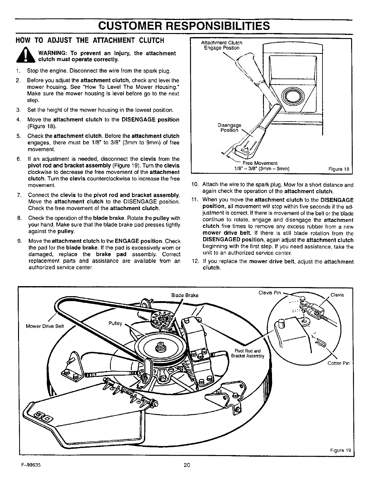
HOW TO ADJUST THE ATTACHMENT CLUTCH
,_ WARNING: To prevent an injury, the attachment
clutch must operate correctly.
1,
2.
3.
4.
5.
Stop the engine. Disconnect the wire from the spark plug.
Before you adjust the attachment clutch, check and level the
mower housing. See "How To Level The Mower Housing."
Make sure the mower housing is level before go to the next
step.
Set the height of the mower housing in the lowest position.
Move the attachment clutch to the DISENGAGE position
(Figure 18).
Check the attachment clutch. Before the attachment clutch
engages, there must be 1/8" to 3/8" (3mm to 9mm) of free
movement.
8, If an adjustment is needed, disconnect the clevis from the
pivot rod and bracket assembly (Figure 19). Turn the clevis
clockwise to decrease the free movement of the attachment
clutch. Turn the clevis counterclockwise to increase the free
movement.
7, Connect the clevis to the pivot rod and bracket assembly,
Move the attachment clutch to the DISENGAGE position.
Check the free movement of the attachment clutch.
8.
9.
Check the operation of the blade brake. Rotate the pulley with
your hand. Make sure that the blade brake pad presses tightly
against the pulley.
Move the attachment clutch to the ENGAGE position. Check
the pad for the blade brake. If the pad is excessively worn or
damaged, replace the brake pad assembly. Correct
replacement parts and assistance are available from an
authorized service center.
10.
11.
12.
AttachmentClutch
Engage Postion
Disengage ..-'_
Positio_,_/
_Movement
1/8"- 318"(3mm - 9mm) Figure 18
Attach the wire to the spark plug. Mow for a short distance and
again check the operation of the attachment clutch.
When you move the attachment clutch to the DISENGAGE
position, all movement will stop within five seconds if the ad-
justment is correct. If there is movement of the belt or the blade
continue to rotate, engage and disengage the attachment
clutch five times to remove any excess rubber from a new
mower drive belt. If there is still blade rotation from the
DISENGAGED position, again adjust the attachment clutch
beginning with the first step. If you need assistance, take the
unit to an authorized service center.
If you replace the mower drive belt, adjust the attachment
clutch.
Blade Brake
Mower Drive Belt
Pin
Figure 19
i
F-99635 20
CUSTOMER RESPONSIBILITIES
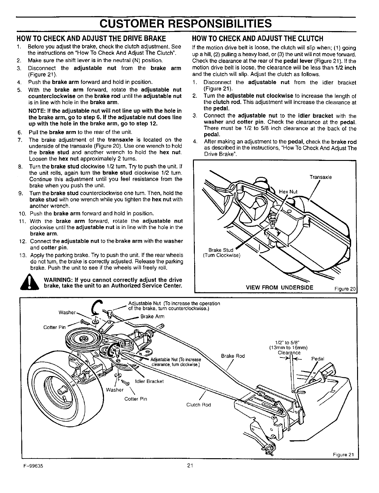
HOWTO CHECK AND ADJUST THE DRIVE BRAKE
1, Before you adjust the brake, check the clutch adjustment. See
the instructions on =How To Check And Adjust The Clutch".
2. Make sure the shift lever is in the neutral (N) position.
3. Disconnect the adjustable nut from the brake arm
(Figure 21).
4. Push the brake arm forward and hold in position.
5. With the brake arm forward, rotate the adjustable nut
counterclockwise on the brake rod until the adjustable nut
is in line with hole in the brake arm.
NOTE: If the adjustable nut will not line up with the hole in
the brake arm, go to step 6. If the adjustable nut does line
up with the hole in the brake arm, go to step 12.
6. Pull the brake arm to the rear of the unit.
7. The brake adjustment of the transaxle is located on the
underside of the transaxle (Figure 20). Use one wrench to hold
the brake stud and another wrench to hold the hex nut.
Loosen the hex nut approximately 2 turns.
8. Turn the brake stud clockwise 1/2 turn. Try to push the unit. If
the unit rolls, again turn the brake stud clockwise 1/2 turn.
Continue this adjustment until you feel resistance from the
brake when you push the unit.
9. Turn the brake stud counterclockwise one turn. Then, hold the
brake stud withone wrench while you tighten the hex nut with
another wrench.
10. Push the brake arm forward and hold in position.
11. With the brake arm forward, rotate the adjustable nut
clockwise until the adjustable nut is in line with the hole inthe
brake arm.
12. Connect the adjustable nut to the brake arm withthe washer
and cotter pin.
13. Apply the parking brake. Try to push the unit. If the rear wheels
do not turn, the brake is correctly adjusted. Release the parking
brake. Push the unit to see if the wheels will freely roll.
,,_ WARNING: If you cannot correctly adjust the drive
brake, take the unit to an Authorized Service Center.
HOWTO CHECK AND ADJUST THE CLUTCH
If the motion drive belt is loose, the clutch will slip when; (1) going
up a hill, (2) pulling a heavy load, or (3) the unit will not move forward.
Check the clearance at the rear of the pedal lever (Figure 21). If the
motion drive belt is loose, the clearance will be less than 1/2 inch
and the clutch will slip. Adjust the clutch as follows.
1. Disconnect the adjustable nut from the idler bracket
(Figure 21).
2. Turn the adjustable nut clockwise to increase the length of
the clutch rod. This adjustment will increase the clearance at
the pedal.
3. Connect the adjustable nut to the idler bracket with the
washer and cotter pin. Check the clearance at the pedal.
There must be 1/2 to 5/8 inch clearance at the back of the
pedal.
4. After making an adjustment to the pedal, check the brake rod
as described in the instructions, "How To Check And Adjust The
Drive Brake".
Transaxle
Hex Nut
Brake Stud
(Turn Clockwise)
VIEW FROM UNDERSIDE Figure
Adjustable Nut (To increase the operation
of the brake, turn counterclockwise.)
Arm
Cotter Pin
Brake Rod
1/2" to 5/8"
(13mm to 16mm)
Pedal
Idler Bracket
Washer _
Cotter Pin
Clutch Rod
Figure 21
F-99635 21
CUSTOMER RESPONSIBILITIES
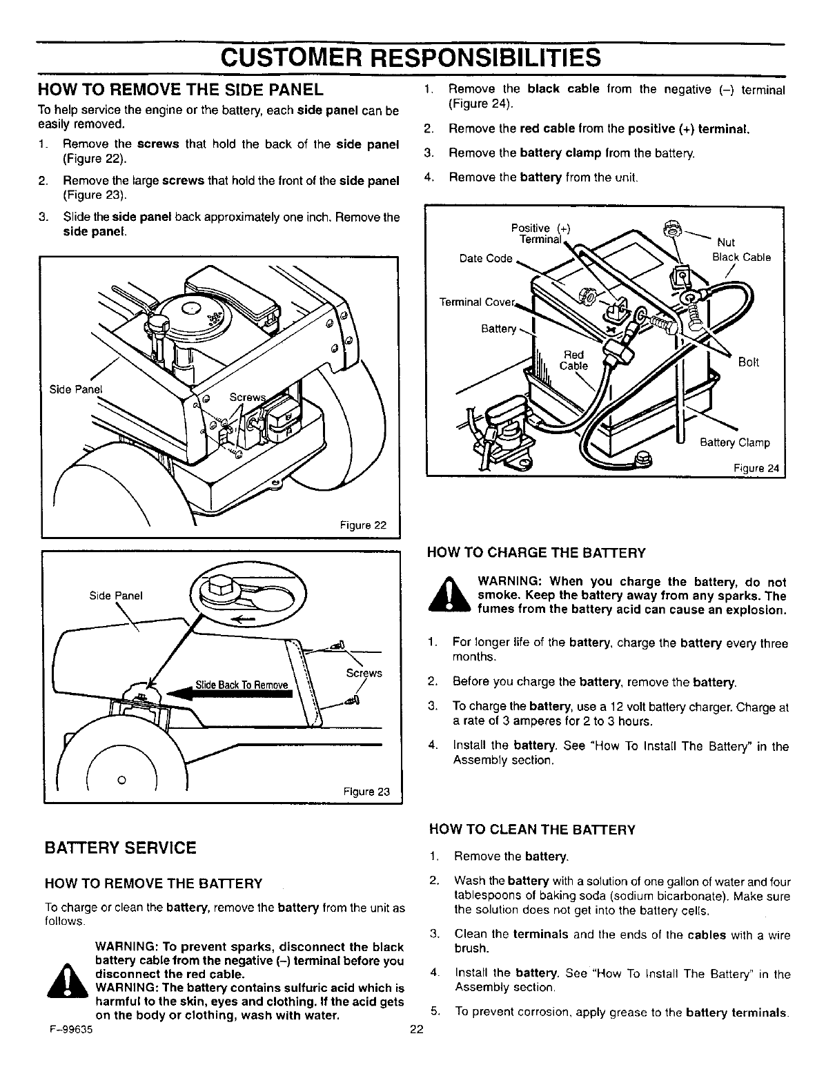
1.
HOW TO REMOVE THE SIDE PANEL
To help service the engine or the battery, each side panel can be
easily removed.
1. Remove the screws that hold the back of the side panel
(Figure 22).
2. Remove the large screws that hold the front of the side panel
(Figure 23).
3. Slide the side panel back approximately one inch. Remove the
side panel.
Side Panel
Figure 22
Remove the black cable from the negative (-) terminal
(Figure 24).
2. Remove the red cable from the positive (+) terminal.
3. Remove the battery clamp from the battery.
4. Remove the battery from the unit.
Positive (+) t_
Terminal Nut
Date Code _ Black Cable
/
Terminal Cove=
Red Bolt
Battery Clamp
Figure 24
S-L
HOW TO CHARGE THE BATTERY
,_ WARNING: When you charge the battery, do not
smoke. Keep the battery away from any sparks. The
fumes from the battery acid can cause an explosion.
1. For longer life of the battery, charge the battery every three
months.
2. Before you charge the battery, remove the battery.
3. To charge the battery, use a 12 volt battery charger. Charge at
a rate of 3 amperes for 2 to 3 hours.
4. Install the battery. See "How To Install The Battery" in the
Assembly section.
BATTERY SERVICE
HOW TO REMOVE THE BA'I-FERY
To charge or clean the battery, remove the battery from the unit as
follows.
WARNING: To prevent sparks, disconnect the black
battery cable from the negative (-) terminal before you
,_ disconnect the red cable.
WARNING: The battery contains sulfuric acid which is
harmful to the skin, eyes and clothing. If the acid gets
on the body or clothing, wash with water.
F-99635
HOW TO CLEAN THE BATTERY
1.
2.
3.
Remove the battery.
Wash the battery with a solution of one gallon of water and four
tablespoons of baking soda (sodium bicarbonate). Make sure
the solution does not get into the battery cells.
Clean the terminals and the ends of the cables with a wire
brush.
22
4. Install the battery. See "How To Install The Battery" in the
Assembly section.
5. To prevent corrosion, apply grease to the battery terminals.
CUSTOMER RESPONSIBILITIES
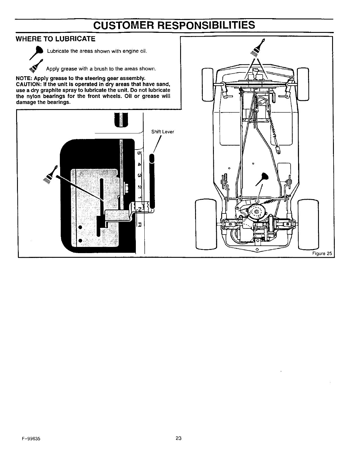
WHERE TO LUBRICATE
Lubricate the areas shown with engine oil.
Apply grease with a brush to the areas shown.
NOTE: Apply grease to the steering gear assembly.
CAUTION: if the unit is operated in dry areas that have sand,
use adry graphite spray to lubricate the unit. Do not lubricate
the nylon bearings for the front wheels. Oil or grease will
damage the bearings.
Shift Lever
/
°d
W_- 1__21'_._ _
L_
i
L_._. Figure 25
F-99635 23
CUSTOMER RESPONSIBILITIES
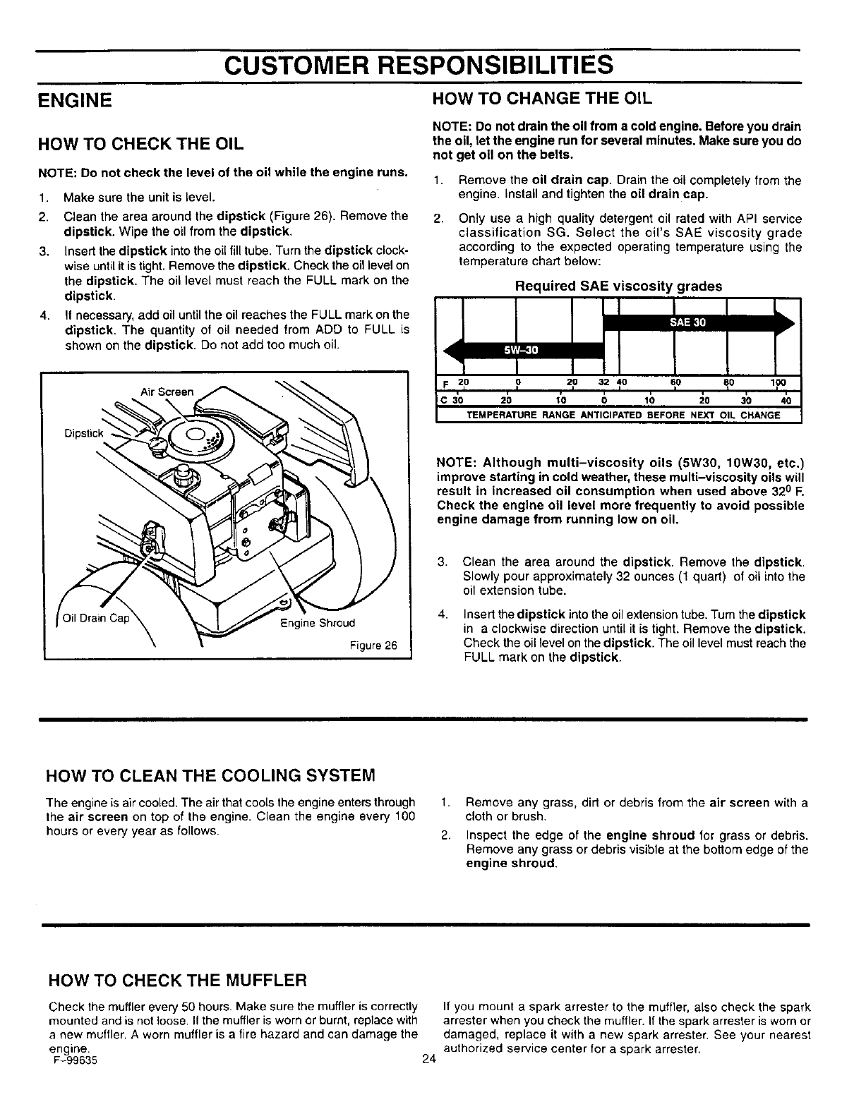
ENGINE HOW TO CHANGE THE OIL
HOW TO CHECK THE OIL
NOTE: Do not check the level of the oil while the engine runs.
1.
2.
Make sure the unit is level.
Clean the area around the dipstick (Figure 26). Remove the
dipstick. Wipe the oil from the dipstick.
3. Insert the dipstick into the oil fill tube. Turn the dipstick clock-
wise until it is tight. Remove the dipstick. Check the oil level on
the dipstick. The oil level must reach the FULL mark on the
dipstick.
4. If necessary, add oil until the oil reaches the FULL mark on the
dipstick. The quantity of oil needed from ADD to FULL is
shown on the dipstick. Do not add too much oil.
Air Screen
Oil Drain Engine Shroud
Figure 26
NOTE: Do not drain the oil from a cold engine. Before you drain
the oil, let the engine run for several minutes. Make sure you do
not get oil on the belts.
1. Remove the oil drain cap. Drain the oil completely from the
engine. Install and tighten the oil drain cap.
2. Only use a high quality detergent oil rated with API service
classification SG. Select the oil's SAE viscosity grade
according to the expected operating temperature using the
temperature chart below:
Required SAE viscosity grades
20 0 20 32 40 60 80
30 20 10 0 10 20 30 40
"tEMPERATURE RANGE ANTICIPATED BEFORE NEXT OIL CHANGE
NOTE: Although multi-viscosity oils (5W30, 10W30, etc.)
improve starting in cold weather, these multi-viscosity oils will
result in increased oil consumption when used above 320 R
Check the engine oil level more frequently to avoid possible
engine damage from running low on oil.
3.
4.
Clean the area around the dipstick. Remove the dipstick.
Slowly pour approximately 32 ounces (1 quart) of oil into the
oil extension tube.
Insert the dipstick into the oil extension tube. Turn the dipstick
in a clockwise direction until it is tight. Remove the dipstick.
Check the oil level on the dipstick. The oil level must reach the
FULL mark on the dipstick.
HOW TO CLEAN THE COOLING SYSTEM
The engine is air cooled. The air that cools the engine enters through 1.
the air screen on top of the engine. Clean the engine every 100
hours or every year as follows. 2.
Remove any grass, dirt or debris from the air screen with a
cloth or brush.
Inspect the edge of the engine shroud for grass or debris.
Remove any grass or debris visible at the bottom edge of the
engine shroud.
HOW TO CHECK THE MUFFLER
Check the muffler every 50 hours. Make sure the muffler is correctly
mounted and is not loose. If the muffler is worn or burnt, replace with
a new muffler. A worn muffler is a fire hazard and can damage the
engine.
F-99635 24
If you mount a spark arrester to the muffler, also check the spark
arrester when you check the muffler. If the spark arrester is worn Dr
damaged, replace it with a new spark arrester. See your nearest
authorized service center for a spark arrester.
CUSTOMER RESPONSIBILITIES
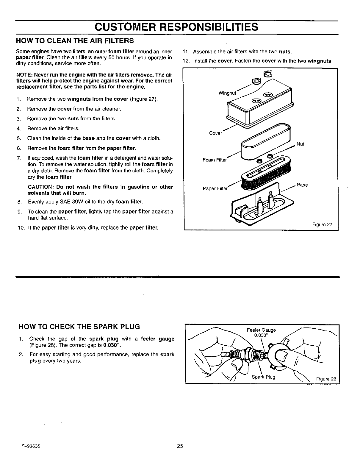
HOW TO CLEAN THE AIR FILTERS
Some engines have two filters, an outer foam filter around an inner
paper filter. Clean the air filters every 50 hours. If you operate in
dirty conditions, service more often.
NOTE: Never run the engine with the air filters removed. The air
filters will help protect the engine against wear. For the correct
replacement filter, see the parts list for the engine.
t. Remove the two wingnuts from the cover (Figure 27).
2. Remove the cover from the air cleaner.
3. Remove the two nuts from the filters.
4. Remove the air filters.
5. Clean the inside of the base and the cover with a cloth.
6. Remove the foam filter from the paper filter.
7. If equipped, wash the foam filter in a detergent and water solu-
tion. To remove the water solution, tightly roll the foam filter in
adry cloth. Remove the foam filter from the cloth. Completely
dry the foam filter.
CAUTION: Do not wash the filters in gasoline or other
solvents that will burn.
0. Evenly apply SAE 30W oil to the dry foam filter.
9. To clean the paper filter, lightly tap the paper filter against a
hard flat surface.
10. If the paper filter is very dirty, replace the paper filter.
11. Assemble the air filters with the two nuts.
12. Install the cover. Fasten the cover with the two wingnuts.
Wingnut
Cover
Nut
jBase
Figure 27
HOW TO CHECK THE SPARK PLUG
1,
2.
Check the gap of the spark plug with a feeler gauge
(Figure 28). The correct gap is 0.030".
For easy starting and good performance, replace the spark
plug every two years.
,__ Feeler Gauge
O.03O"
Spark Plug Figure 28
F-99635 25
SERVICE AND ADJUSTMENT
HOW TO ADJUST THE THROTTLE CONTROL
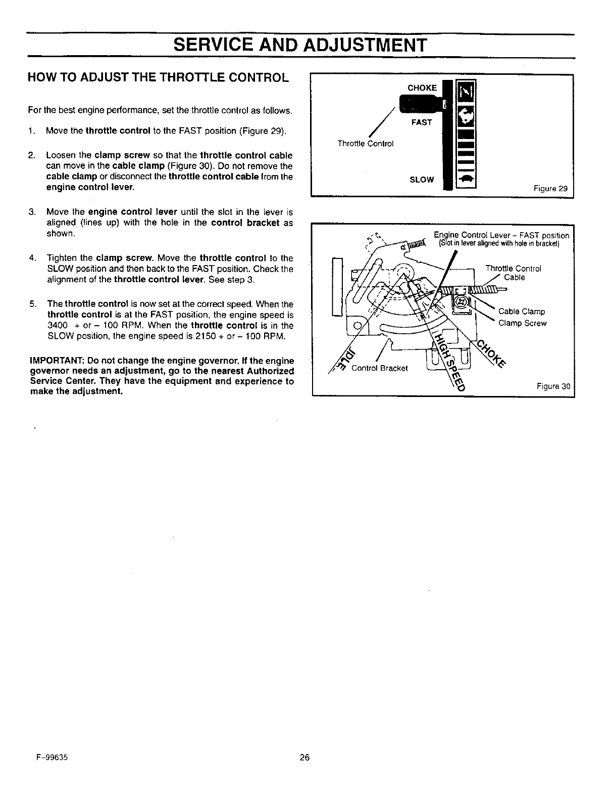
For the best engine performance, set the throttle control as follows.
1. Move the throttle control to the FAST position (Figure 29).
2. Loosen the clamp screw so that the throttle control cable
can move in the cable clamp (Figure 30). Do not remove the
cable clamp or disconnect the throttle control cable from the
engine control lever.
3. Move the engine control lever until the slot in the Lever is
aligned (lines up) with the hole in the control bracket as
shown.
4. Tighten the clamp screw. Move the throttle control to the
SLOW position and then back to the FAST position. Check the
alignment of the throttle control lever. See step 3.
5. The throttle control is now set at the correct speed. When the
throttle control is at the FAST position, the engine speed is
3400 + or - 100 RPM. When the throttle control is in the
SLOW position, the engine speed is 2150 + or- 100 RPM.
IMPORTANT: Do not change the engine governor. If the engine
governor needs an adjustment, go to the nearest Authorized
Service Center. They have the equipment and experience to
make the adjustment.
/
Throttle Control
CHOKE
FAST
SLOW
Figure 29
I
EnQine Control Lever - FAST posi ion I
(S'[otin leveralignedwith holein bracket)
Throttle Control
Cable
Control Bracket
Cable Clamp
Clamp Screw
Figure 30
F-99635 26
SERVICE AND ADJUSTMENT
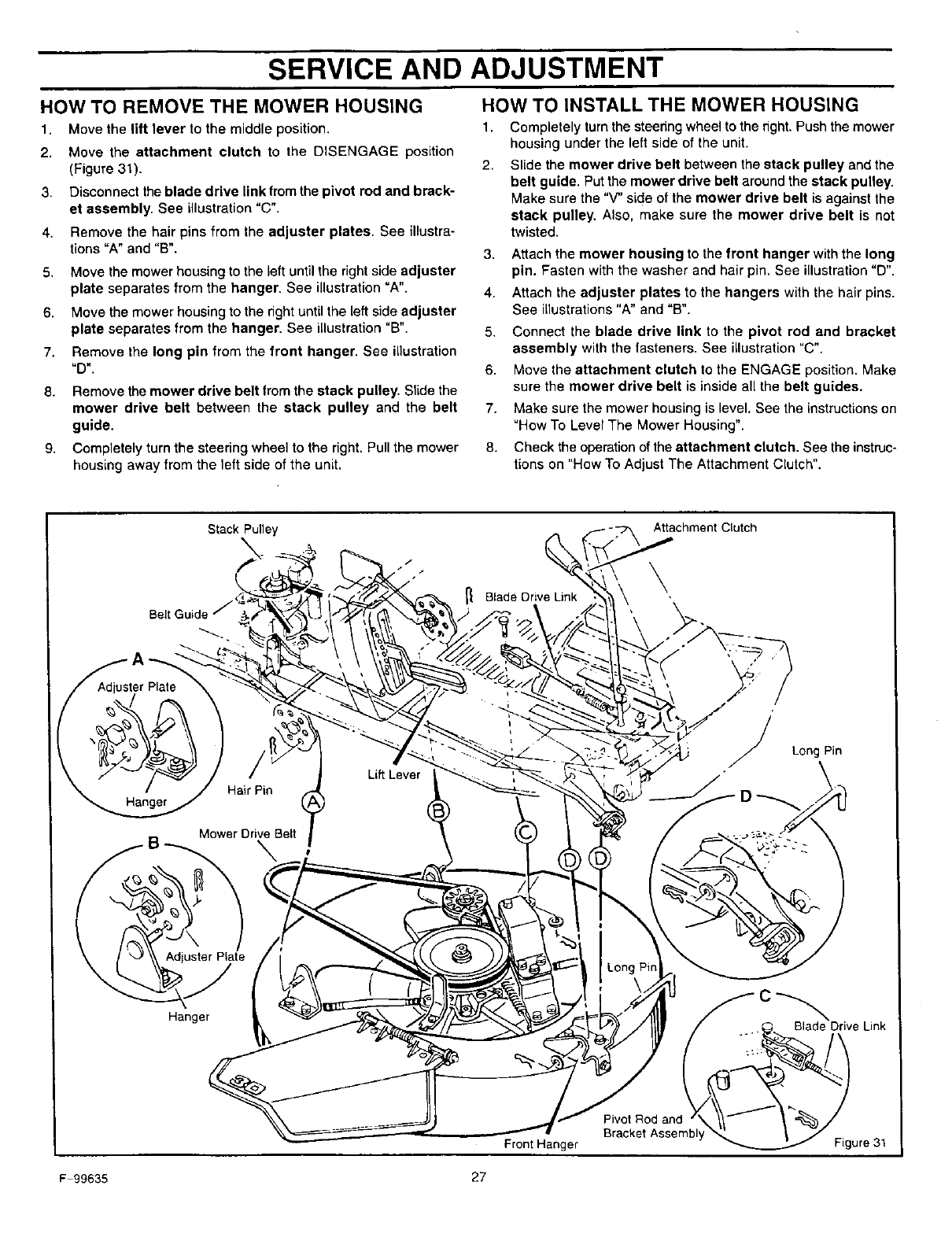
HOW TO REMOVE THE MOWER HOUSING
1. Move the lift lever to the middle position.
2. Move the attachment clutch to the DISENGAGE position
(Figure 31).
3. Disconnect theblade drive link from the pivot rod and brack-
et assembly. See illustration "C".
4. Remove the hair pins from the adjuster plates. See illustra-
tions "A" and "B".
5. Move the mower housing to the left until the right side adjuster
plate separates from the hanger. See illustration "A".
6. Move the mower housing to the right until the left side adjuster
plate separates from the hanger. See illustration "B".
7. Remove the long pin from the front hanger. See illustration
='O _,"
8. Remove the mower drive belt from the stack pulley. Slide the
mower drive belt between the stack pulley and the belt
guide.
9. Completely turn the steering wheel to the right. Pull the mower
housing away from the left side of the unit.
HOW TO INSTALL THE MOWER HOUSING
1. Completely turn the steedng wheel to the right. Push the mower
housing under the left side of the unit.
2. Slide the mower drive belt between the stack pulley and the
belt guide. Putthe mower drive belt around the stack pulley.
Make sure the "V" side of the mower drive belt is against the
stack pulley. Also, make sure the mower drive belt is not
twisted.
3. Attach the mower housing to the front hanger with the long
pin. Fasten with the washer and hair pin. See illustration "D".
4. Attach the adjuster plates to the hangers with the hair pins.
See illustrations "A" and "B".
5. Connect the blade drive link to the pivot rod and bracket
assembly with the fasteners. See illustration "C".
6. Move the attachment clutch to the ENGAGE position. Make
sure the mower drive belt is inside all the belt guides.
7. Make sure the mower housing is level. See the instructions on
"How To Level The Mower Housing".
8. Check the operation of the attachment clutch. See the instruc-
tions on "How To Adjust The Attachment Crutch".
Stack Pulley Attachment Clutch
Blade Drive Link
Jster Plats ,
Hair Pin
Hanger
LiftLever
Mower Drive Belt
\
:Long Pin
Adjuster Plate
Hanger
Front Hanger
-C
Pivot Rod and
BracketAssembl
Blade Drive Link
Figure 31
F99635 27
SERVICE AND ADJUSTMENT
HOW TO LEVEL THE MOWER HOUSING t.
If the mower housing is level, the blade will cut easier and the lawn
will look better.
WARNING: Before you make an inspection, adjust-
_hb ment, or repair to the unit, disconnect the wire to the
spark plug. Remove the spark plug wire to prevent
the engine from starting by accident.
2.
3.
4.
1. Make sure the unit is on a hard level surface.
2. Check the air pressure in the tires. If the air pressure is incor-
rect, the mower housing will not cut level. Make sure the rear
tires are inflated to 14 psi. (1 BAR) and the front tires to 22 psi.
(1.5 BAR).
3. Move the lever for the attachment clutch to the ENGAGE posi-
tion. Move the lift lever to the middle position.
4. There are two adjustment procedures below that will level the
mower housing.
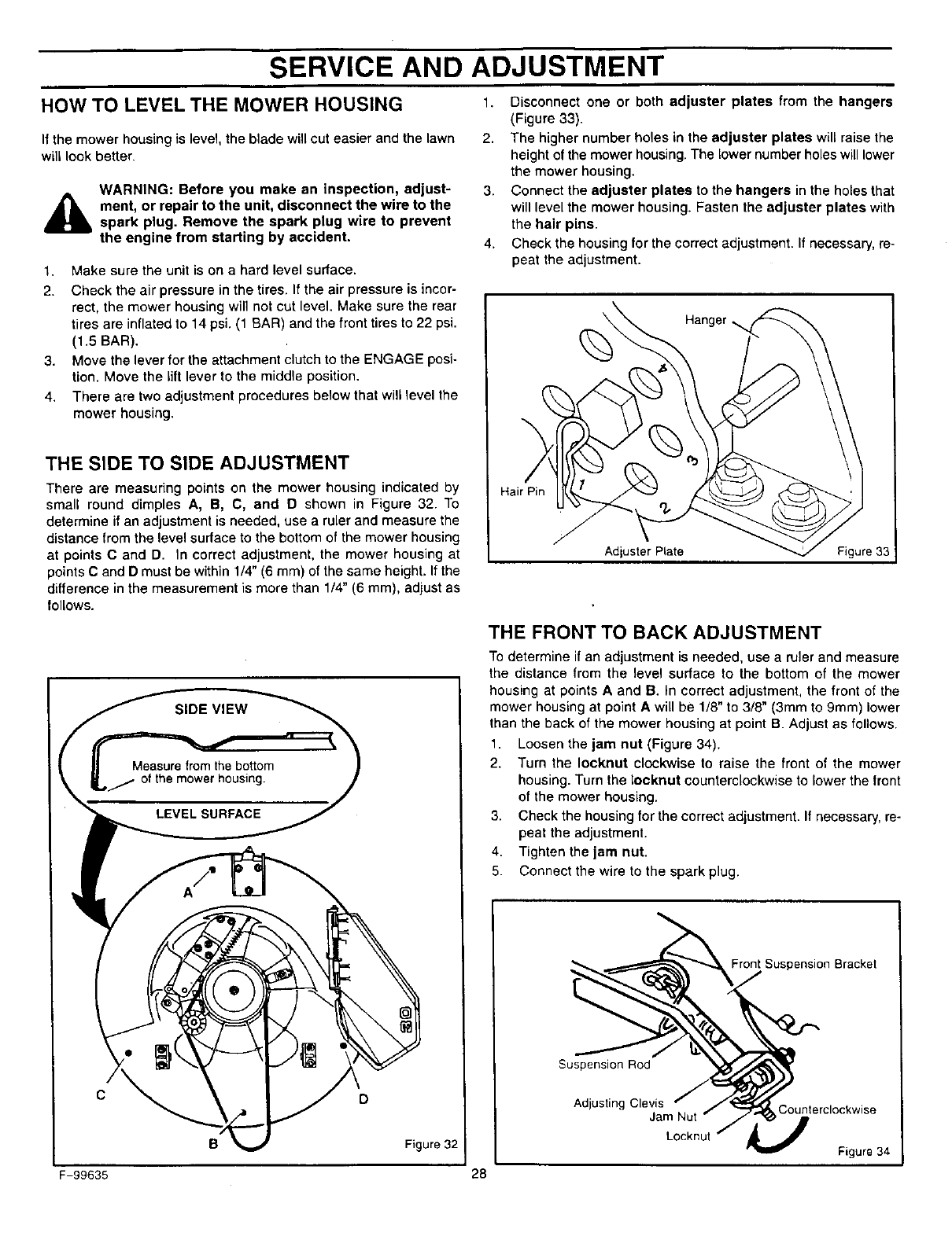
THE SIDE TO SIDE ADJUSTMENT
There are measuring points on the mower housing indicated by
small round dimples A, B, C, and D shown in Figure 32. To
determine if an adjustment is needed, use a ruler and measure the
distance from the level surface to the bottom of the mower housing
at points C and D. In correct adjustment, the mower housing at
points C and Dmust be within 1/4" (6 ram) of the same height. If the
difference in the measurement is more than 1/4" (6 ram), adjust as
follows.
Disconnect one or both adjuster plates from the hangers
(Figure 33).
The higher number holes in the adjuster plates will raise the
height of the mower housing. The lower number holeswill lower
the mower housing.
Connect the adjuster plates to the hangers in the holes that
will level the mower housing. Fasten the adjuster plates with
the hair pins.
Check the housing for the correct adjustment. If necessary, re-
peat the adjustment.
\ Hanger .,,
Hair Pin
Adjuster Plate Figure 33
F-99635
D
Figure 32
THE FRONT TO BACK ADJUSTMENT
To determine ifan adjustment is needed, use a ruler and measure
the distance from the level surface to the bottom of the mower
housing at points A and B. In correct adjustment, the front of the
mower housing at point A will be 1/8" to 3/8" (3mm to 9mm) lower
than the back of the mower housing at point B. Adjust as follows.
1. Loosen the jam nut (Figure 34).
2. Turn the Iocknut clockwise to raise the front of the mower
housing. Turn the Iocknut counterclockwise to lower the front
of the mower housing.
3. Check the housing for the correct adjustment. If necessary, re-
peat the adjustment.
4. Tighten the jam nut.
5. Connect the wire to the spark plug.
Suspension Bracket
28
Suspension Rod
Adjusting Clevis Counterclockwise
Jam Nut
Loeknut
Figure 34
SERVICE AND ADJUSTMENT
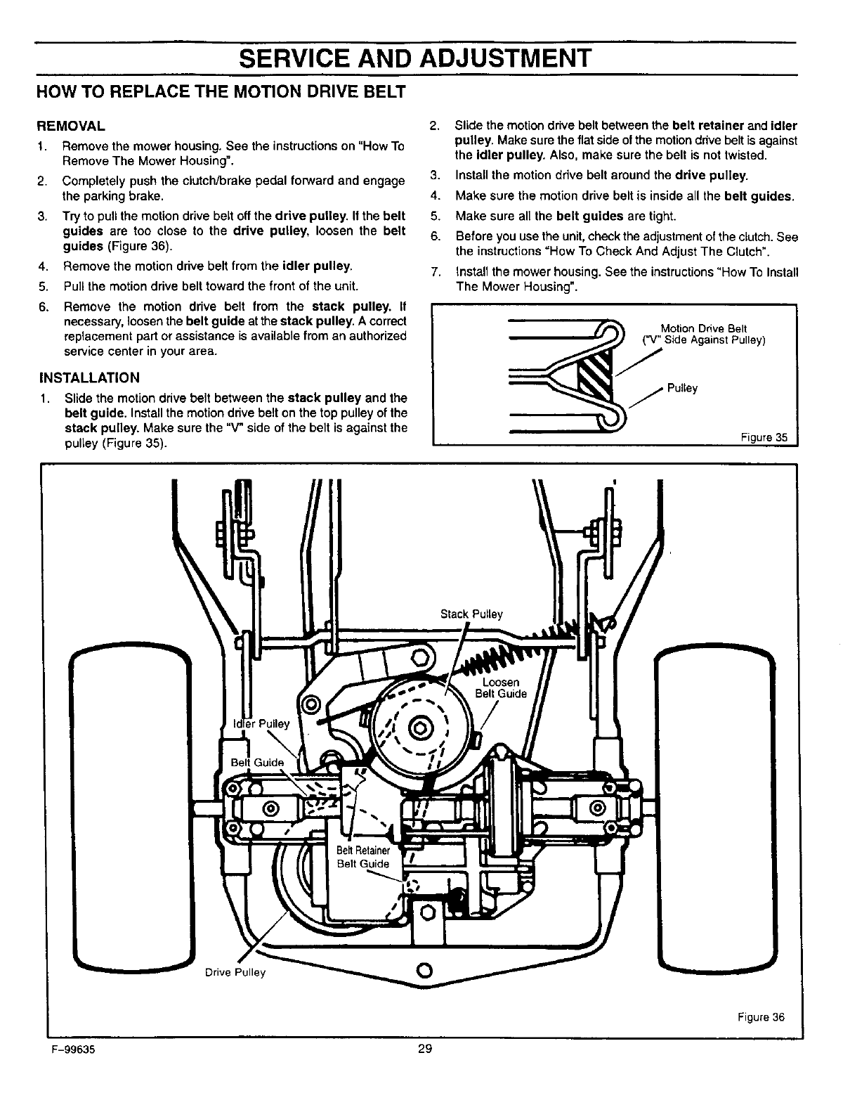
HOW TO REPLACE THE MOTION DRIVE BELT
REMOVAL
1. Remove the mower housing. See the instructions on "How To
Remove The Mower Housing".
2.
3.
4.
5.
6.
Completely push the clutch/brake pedal forward and engage
the parking brake.
Try to pull the motion drive belt off the drive pulley. If the belt
guides are too close to the drive pulley, loosen the belt
guides (Figure 36).
Remove the motion drive belt from the idler pulley.
Pull the motion drive belt toward the front of the unit.
Remove the motion drive belt from the stack pulley. If
necessary, loosen the belt guide at the stack pulley. A correct
replacement part or assistance is available from an authorized
service center in your area.
INSTALLATION
1. Slide the motion drive belt between the stack pulley and the
belt guide. Install the motion drive belt on the top pulley of the
stack pulley. Make sure the "V" side of the belt is against the
pulley (Figure 35).
2. Slide the motion drive belt between the belt retainer and idler
pulley. Make sure the flat side of the motion drive belt is against
the idler pulley. Also, make sure the belt is not twisted.
3. Install the motion drive belt around the drive pulley.
4. Make sure the motion drive belt is inside all the belt guides.
5. Make sure all the belt guides are tight.
6. Before you use the unit,check the adjustment of the clutch. Bee
the instructions "How To Check And Adjust The Clutch".
7. Install the mower housing. See the instructions"How To Install
The Mower Housing".
_ Motion Drive Belt
Side Against Pulley)
j PuUey
Figure 35
Stack Pultey
Loosen
Belt Guide
Belt Guide
Be_ Retainer
Belt Guide
I
Drive Pulley O
Figure 36
F-99635 29
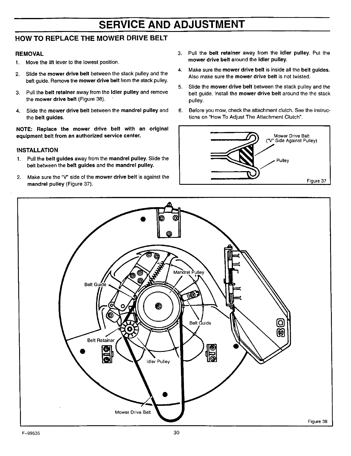
SERVICE AND ADJUSTMENT
HOW TO REPLACE THE MOWER DRIVE BELT
REMOVAL 3.
1. Move the lift lever to the lowest position.
4.
2. Slide the mower drive belt between the stack pulley and the
belt guide. Remove the mower drive belt from the stack pulley. 5.
3. Pull the belt retainer away from the idler pulley and remove
the mower drive belt (Figure 38).
4. Slide the mower drive belt between the mandrel pulley and 6.
the belt guides.
NOTE: Replace the mower drive belt with an original
equipment belt from an authorized service center.
INSTALLATION
1. Pull the belt guides away from the mandrel pulley. Slide the
belt between the belt guides and the mandrel pulley.
2. Make sure the "V" side of the mower drive belt is against the
mandrel pulley (Figure 37).
Pull the belt retainer away from the idler pulley. Put the
mower drive belt around the Idler pulley.
Make sure the mower drive belt is inside all the belt guides.
Also make sure the mower drive belt is not twisted.
Slide the mower drive belt between the stack pulley and the
belt guide. Install the mower drive belt around the the stack
pulley.
Before you mow, check the attachment clutch. See the instruc-
tions on "How To Adjust The Attachment Clutch".
jPulley
Figure 37
@
Mower Drive Belt
F-99635 30
Figure 38
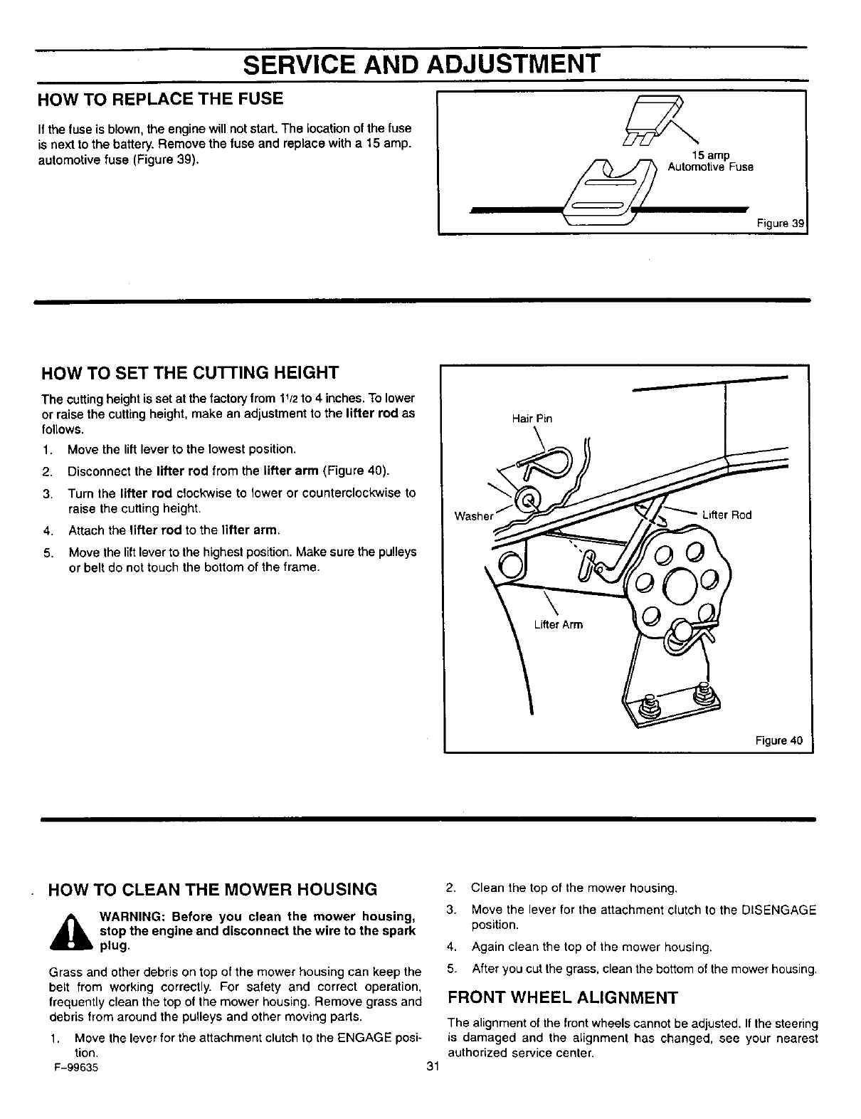
SERVICE AND ADJUSTMENT
HOW TO REPLACE THE FUSE
Ifthe fuse is blown, the engine will not start. The location of the fuse
is next to the battery. Remove the fuse and replace with a 15 amp.
automotive fuse (Figure 39). 15 amp
_ Automotive Fuse
Figure 39
HOW TO SET THE cu'rrlNG HEIGHT
The cutting height is set at the factory from 1_/2to 4 inches. To lower
or raise the cutting height, make an adjustment to the lifter rod as
follows.
1. Move the lift lever to the lowest position.
2. Disconnect the lifter rod from the lifter arm (Figure 40).
3. Turn the lifter rod clockwise to lower or counterclockwise to
raise the cutting height.
4. Attach the lifter rod to the lifter arm.
5. Move the lift lever to the highest position. Make sure the pulleys
or belt do not touch the bottom of the frame.
Hair Pin
Lifter Rod
Figure 40
HOW TO CLEAN THE MOWER HOUSING
_lb WARNING: Before you clean the mower housing,
stop the engine and disconnect the wire to the spark
plug.
Grass and other debris on top of the mower housing can keep the
belt from working correctly. For safety and correct operation,
frequently clean the top of the mower housing. Remove grass and
debris from around the pulleys and other moving parts.
1. Move the lever for the attachment clutch to the ENGAGE posi-
tion.
F-99635 31
2. Clean the top of the mower housing.
3. Move the lever for the attachment clutch to the DISENGAGE
position.
4. Again clean the top of the mower housing.
5. After you cut the grass, clean the bottom of the mower housing.
FRONT WHEEL ALIGNMENT
The alignment of the front wheels cannot be adjusted. If the steering
is damaged and the alignment has changed, see your nearest
authorized service center.
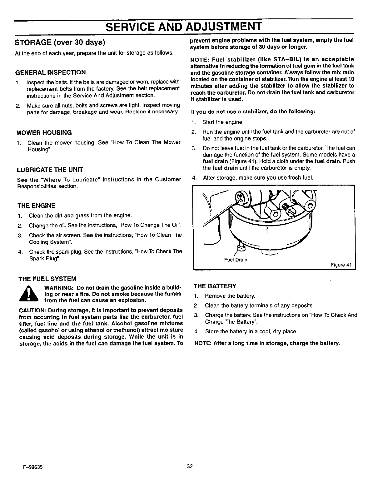
SERVICE AND ADJUSTMENT
STORAGE (over 30 days)
At the end of each year, prepare the unit for storage as follows.
GENERALINSPECTION
1. Inspect the belts. If the belts are damaged or worn, replace with
replacement belts from the factory. See the belt replacement
instructions in the Service And Adjustment section.
2. Make sure all nuts, bolts and screws are tight. Inspect moving
parts for damage, breakage and wear. Replace if necessary.
MOWER HOUSING
1. Clean the mower housing. See "How To Clean The Mower
Housing".
LUBRICATE THE UNIT
See the "Where To Lubricate" instructions in the Customer
Responsibilities section.
THE ENGINE
1. Clean the dirt and grass from the engine.
2. Change the oil. See the instructions,"Row To Change The Oil".
3. Check the air screen. See the instructions,"How To Clean The
Cooling System".
4. Check the spark plug. See the instructions, "How To Check The
Spark Plug".
prevent engine problems with the fuel system, empty the fuel
system before storage of 30 days or longer.
NOTE: Fuel stabilizer (like STA-BIL) is an acceptable
alternative in reducing the formation of fuel gum in the fuel tank
and the gasoline storage container. Always follow the mix ratio
located on the container of stabilizer. Run the engine at least 10
minutes after adding the stabilizer to allow the stabilizer to
reach the carburetor. Do not drain the fuel tank and carburetor
if stabilizer is used.
If you do not use a stabilizer, do the following:
1. Start the engine.
2. Run the engine until the fuel tank and the carburetor are out of
fuel and the engine stops.
3. Do not leave fuet in the fuel tank or the carburetor. The fuel can
damage the function of the fuel system. Some models have a
fuel drain (Figure 41). Hold a cloth under the fuel drain. Push
the fuel drain until the carburetor is empty.
4. After storage, make sure you use fresh fuel.
Fuel Drain
Figure 41
THE FUEL SYSTEM
,_ WARNING: Do not drain the gasoline inside a build-
ing or near a fire. Do not smoke because the fumes
from the fuel can cause an explosion.
CAUTION: During storage, it is important to prevent deposits
from occurring in fuel system parts like the carburetor, fuel
filter, fuel line and the fuel tank. Alcohol gasoline mixtures
(called gasohol or using ethanol or methanol) attract moisture
causing acid deposits during storage. While the unit is in
storage, the acids in the fuel can damage the fuel system. To
THE BATi'ERY
1. Remove the battery.
2. Clean the battery terminals of any deposits.
3. Charge the battery. See the instructions on "How To Check And
Charge The Batter_'.
4. Store the battery in a cool, dry place.
NOTE: After a long time in storage, charge the battery.
F-99635 32
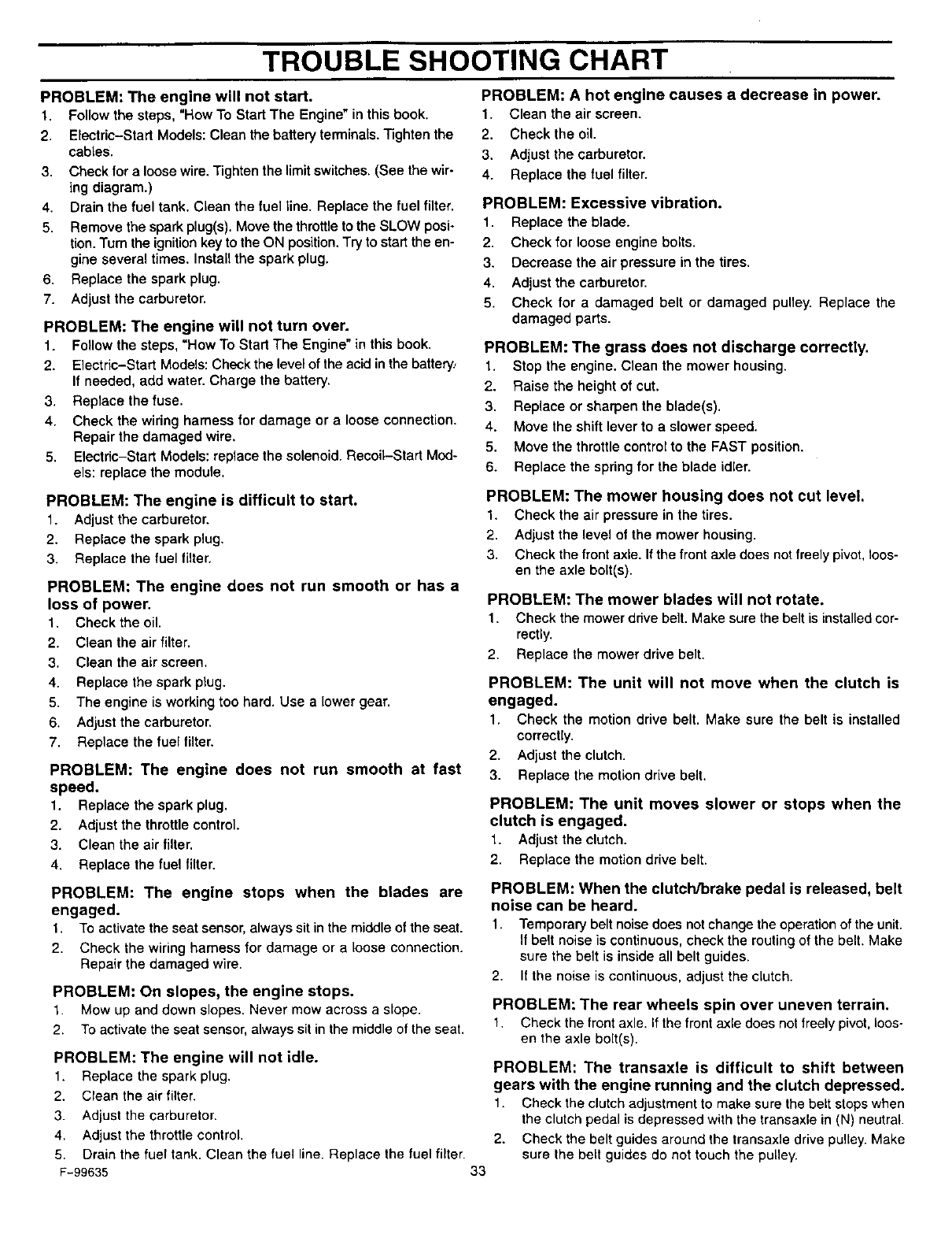
TROUBLE SHOOTING CHART
PROBLEM: The engine will not start.
1. Follow the steps. "How To Start The Engine" in this book.
2. Electric-Start Models: Clean the battery terminals. Tighten the
cables.
3. Check for a loose wire. Tighten the limit switches. (See the wir-
ing diagram.)
4. Drain the fuel tank. Clean the fuel line. Replace the fuel filter.
5. Remove the spark plug(s). Move the throttle to the SLOW posi-
tion. Turn the ignitionkey to the ON position.Try to start the en-
gine several times. Install the spark plug.
6. Replace the spark plug.
7. Adjust the carburetor.
PROBLEM: The engine will not turn over.
1. Follow the steps, =How To Start The Engine" in this book.
2. Electric-Start Models: Check the level of the acid inthe battery.,
If needed, add water. Charge the battery.
3. Replace the fuse.
4. Check the wiring harness for damage or a loose connection.
Repair the damaged wire,
5. Electric-Start Models: replace the solenoid. Recoil-Start Mod-
els: replace the module,
PROBLEM: The engine is difficult to start.
1. Adjust the carburetor.
2. Replace the spark plug.
3. Replace the fuel filter.
PROBLEM: The engine does not run smooth or has a
loss of power,
1, Check the oil.
2. Clean the air filter.
3. Clean the air screen,
4. Replace the spark plug.
5. The engine is working too hard. Use a lower gear.
6, Adjust the carburetor.
7. Replace the fuel filter.
PROBLEM: The engine does not run smooth at fast
speed.
1. Replace the spark plug.
2. Adjust the throttle control.
3. Clean the air filter.
4. Replace the fuel filter.
PROBLEM: The engine stops when the blades are
engaged.
1. To activate the seat sensor, always sit in the middleof the seat.
2. Check the wiring harness for damage or a loose connection.
Repair the damaged wire.
PROBLEM: On slopes, the engine stops.
1. Mow up and down slopes. Never mow across a slope.
2. To activate the seat sensor, always sit in the middle of the seat.
PROBLEM: The engine will not idle.
1. Replace the spark plug.
2. Clean the air filter.
3. Adjust the carburetor,
4. Adjust the throttle control,
5. Drain the fuel tank. Clean the fuel line. Replace the fuel filter.
F-99635 33
PROBLEM: A hot engine causes a decrease in power.
1. Clean the air screen.
2, Check the oil.
3, Adjust the carburetor.
4. Replace the fuel filter,
PROBLEM: Excessive vibration.
1. Replace the blade.
2, Check for loose engine bolts,
3. Decrease the air pressure in the tires.
4, Adjust the carburetor,
5. Check for a damaged belt or damaged pulley. Replace the
damaged parts.
PROBLEM: The grass does not discharge correctly.
1. Stop the engine. Clean the mower housing.
2. Raise the height of cut.
3. Replace or sharpen the blade(s).
4. Move the shift lever to a slower speed.
5. Move the throttle control to the FAST position.
6. Replace the spring for the blade idler.
PROBLEM: The mower housing does not cut level.
1. Check the air pressure in the tires.
2. Adjust the level el the mower housing.
3. Check the front axle. If the front axle does not freely pivot,loos-
en the axle bolt(s).
PROBLEM: The mower blades will not rotate.
1. Check the mower drive belt. Make sure the belt is installedcor-
rectly.
2. Replace the mower drive belt.
PROBLEM: The unit will not move when the clutch is
engaged.
1. Check the motion drive belt. Make sure the belt is installed
correctly.
2. Adjust the clutch.
3. Replace the motion drive belt.
PROBLEM: The unit moves slower or stops when the
clutch is engaged,
1, Adjustthe clutch,
2. Replace the motion drive belt.
PROBLEM: When the clutch/brake pedal is released, belt
noise can be heard.
1. Temporary belt noise does not change the operation of the unit.
If belt noise is continuous, check the routing of the belt. Make
sure the belt is inside all belt guides.
2. If the noise is continuous, adjust the clutch.
PROBLEM: The rear wheels spin over uneven terrain.
1. Check the front axle. If the front axle does not freely pivot, loos-
en the axle bolt(s).
PROBLEM: The transaxle is difficult to shift between
gears with the engine running and the clutch depressed.
1. Check the clutch adjustment to make sure the belt stops when
the clutch pedal is depressed with the transaxle in (N) neutral.
2. Check the belt guides around the transaxle drive pulley. Make
sure the belt guides do not touch the pulley.
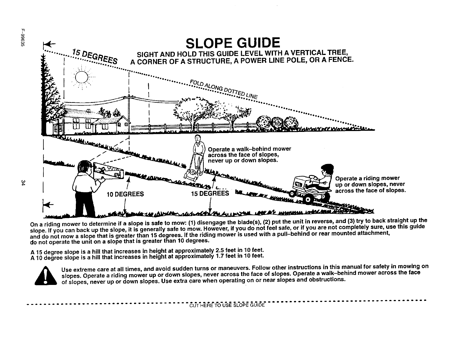
11
I
_o
03
u1
1
I10 DEGREES
Operate a walk-behind mower
across the face of slopes,
never up or down slopes.
15 DEGREES
Operate a riding mower
up or down slopes, never
across the face of slopes.
On a riding mower to determine if a slope is safe to mow: (1) disengage the blade(s), (2) put the unit in reverse, and (3) try to back straight up the
slope. If you can back up the slope, it is generally safe to mow. However, if you do not feel safe, or if you are not completely sure, use this guide
and do not mow a slope that is greater than 15 degrees. If the riding mower is used with apull-behind or rear mounted attachment,
do not operate the unit on a slope that is greater than 10 degrees.
A15 degree slope is ahill that increases in height at approximately 2.5 feet in 10 feet.
A 10 degree slope is a hill that increases in height at approximately 1.7 feet in 10 feet.
Use extreme care at all times, and avoid sudden turns or maneuvers. Follow other instructions in this manual for safety in mowing on
slopes. Operate a riding mower up or down slopes, never across the face of slopes. Operate a walk-behind mower across the face
of slopes, never up or down slopes. Use extra care when operating on or near slopes and obstructions.

INDEX
A
Adjustments
Attachment Clutch, 20
Clutch, 21
Drive Brake, 21
Mower Housing
Cutting Height, 31
Level, 28
Air Screen, 24
Attachment Clutch
Adjust, 20
Location, 11
Operation, 12
Attachments, 6
B
Battery
Charge, 22
Check, 8
Check Acid Level, 22
Clean, 22
Emergency Start, 15
Install, 8
Removal, 22
Belt
Motion Drive
Adjust, 21
Replace, 29
Routing, 9
Mower Drive
Adjust, 20
Replace, 30
Routing, 9
Blade
Inspect, 19
Remove And Install, 19
Sharpen, 19
C
Clutch
Adjust, 21
Check, 21
Clutch /Brake Pedal, Location, 11
Customer Responsibilities
Attachment Clutch, 20
Battery
Charge, 22
Check Acid, 22
Clean, 22
Blade, 19
Clutch, 21
Drive Brake, 21
Filter, Air, 25
Lubrication, 23
Maintenance Chart, 18
Muffler, 24
Spark Plug, 25
Cutting Height
Adjust, 28, 31
Change, 13
F-99635
D
Drive Brake
Adjust, 21
Check, 21
E
Engine
Cooling System, 24
Fuel, 15
Lubrication, 24
Muffler, 24
Oil, 15, 24
Spark Arrester, 24
Starting, 15
Throttle Control, 12
F
Filter, Air, 25
Fuel, Type, 15
Fuse, 31
I
ignition Switch, Location, 11
L.
Lift Lever
Location, 11
Operation, 13
Lubrication
Engine, 24
Mower, 23
M
Maintenance Chart, 18
Motion Drive Belt
Adjust, 21
Replace, 29
Mower Drive Belt
Adjust, 20
Replace, 30
Mower Housing
Clean, 31
Cutting Height, 13, 31
Install, 27
Level Adjustment, 28
Operation, 14
Remove, 27
Muffler, 24
Spark Arrester, 24
Mulcher
Install, 16
Operation, 17
Remove, 16
0
Oil
Change, 24
Check, 15, 24 35
Type, 15
Operation
Attachment Clutch, 11, 12
Clutch /Brake Pedal, 11
Emergency Start, 15
Ignition Switch, 11
Lift Lever, 11, 13
Location Of Controls, 11
Mower Housing, 14
Mowing And Bagging, 17
Mulching, 17
Operate On Hills, 14
Parking Brake, 11, 13
Shift Lever, 11, 12
Start The Engine, 15
Stop The Unit, 13
Throttle Control, 11, 12
Transport, 13
P
Parking Brake
Location, 11
Operation, 13
S
Safety Rules, American National
Standard Institute, 4-5
Seat, Install, 10
Service And Adjustment
Belt
Motion Drive, 29
Mower Drive, 30
Fuse, 31
Mower Housing
Clean, 31
Cutting Height, 31
Install, 27
Level, 28
Remove, 27
Storage, 32
Carburetor, 26
Shift Lever
Location, 11
Operation, 12
Side Panel, 22
Slope Guide, 34
Spark Arrester, 24
Spark Plug, 25
Steering Wheel, 9
Storage, 32
T
Throttle Control
Location, 11
Operation, 12
Tire Pressure, 9, 18, 28
Trouble Shooting Chart, 33
W
Wheel Alignment, 31
SEARS
owner's
manual
Model No.
C950-60901-0
Serial No.
Model and Senal Number are on
the number plate.
Record both the Model and the
Serial Number and keep in a
safe place for future reference.
CRRFTSMRN
10 HP. ELECTRIC START
30" MOWER /MULCHER
5 SPEED
REAR ENGINE RIDER
The Model Number for the mower is found on a decal attached to the back of
the frame. The Model Number for the engine is found on the blower housing
above the spark plug. Always give the Model Number when you call for service
or order repair parts for your unit.
Repair parts can be ordered from any Sears Service Centre/Department and
most Sears Stores.
WHEN ORDERING REPAIR PARTS, ALWAYS HAVE THE FOLLOWING
INFORMATION AS SHOWN IN THIS LIST.
•PRODUCT- REAR ENGINE RIDER
• MODEL NUMBER- C950-60901-0
• ENGINE MODEL NO. 143.981002
• PART NUMBER
• PART DESCRIPTION
Your Sears merchandise has added value when you consider Sears has service units
nationwide staffed with Sears trained technicians. Sears technicians have the necessary
parts, tools and equipment to meet the Sears pledge, "We Service What We SelF.
F-99635 Sears Canada Inc., Toronto, Ontario M5B 2B8 Printedin US A.
