Craftsman 10 Compound Miter Saw 21236 Owners Manual M2500RC3(212360) English A5 022409
Craftsman-137-21236-Users-Manual-161122 craftsman-137-21236-users-manual-161122
Triton Tools Saw DOUBLE BEVEL SIDE COMPOUND MITRE SAW 00921236e
13721236 90ffa734-e261-4094-819b-c54f2c562770 Craftsman Saw 137.21236 User Guide |
2015-03-28
: Craftsman Craftsman-10-Compound-Miter-Saw-21236-Owners-Manual-661105 craftsman-10-compound-miter-saw-21236-owners-manual-661105 craftsman pdf
Open the PDF directly: View PDF ![]() .
.
Page Count: 29
1 1
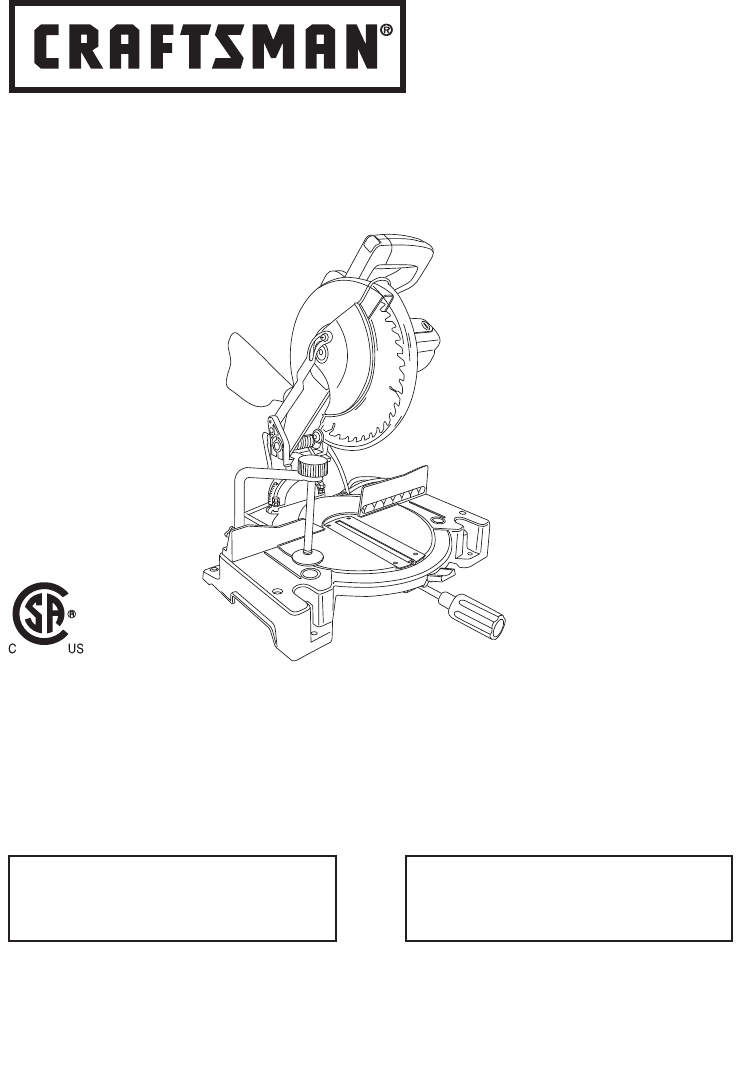
Operator’s Manual
10 in. COMPOUND MITER SAW
WITH LASER TRAC®
Model No. 137.212360
CAUTION:
Before using this Miter Saw,
read this manual and follow
all its Safety Rules and
Operating Instructions
● Safety Instructions
● Installation
● Operation
● Maintenance
● Parts List
Sears, Roebuck and Co., Hoffman Estates, IL60179 USA
Visit our Craftsman website: www.sears.com/craftsman
Part No. 13721236001 Printed in China
Customer Help Line
For Technical Support
1-800-843-1682
Sears Parts &
Repair Center
1-800-469-4663
2 3
2 3
TABLE OF CONTENTS
SECTION PAGE SECTION PAGE
Warranty ............................................... 2 Know Your Compound Miter Saw .......... 10
Product Specifications .......................... 2 Glossary of Terms ................................. 11
Symbols ................................................ 3 Assembly and Adjustments ................... 12
Power Tool Safety ................................. 4 Operation ............................................... 18
Compound Miter Saw Safety ................. 6 Maintenance .......................................... 23
Electrical Requirements and Safety ...... 7 Troubleshooting Guide .......................... 24
Accessories and Attachments ............... 8 Parts List ................................................ 25
Tools Needed for Assembly .................. 8 Repair Protection Agreement.................. 28
Carton Contents .................................... 9
WARRANTY
WARNING
!
Some dust created by using power tools contains chemicals known to the state of California to cause
cancer and birth defects or other reproductive harm. Some examples of these chemicals are:
● Lead from lead-based paints
● Crystalline silica from bricks, cement and other masonry products
● Arsenic and chromium from chemically treated lumber
Your risk from these exposures varies, depending on how often you do this type of work. To reduce
your exposure to these chemicals, work in a well ventilated area and work with approved safety
equipment such as dust masks that are specially designed to filter out microscopic particles.
PRODUCT SPECIFICATIONS
MOTOR Cutting Capacity:
Power Source................ 120V AC, 60Hz, 15 Amp Crosscut ........................... 2-5/8 in. x 5-1/2 in.
Arbor Shaft Size............ 5/8 in. Miter 45° R & L ................. 2-5/8 in. x 3-7/8 in.
Speed ........................... 4800 RPM (No load) Bevel 45° L ....................... 1-1/2 in. x 5-1/2 in.
Brake ............................ Electric 45° Miter and 45° Bevel .... 1-1/2 in. x 3-7/8 in.
Double Insulated .......... No
MITER SAW BLADE
Rotating Table: Diameter ........................... 10 in.
Miter Detent Stops ....... 0°, 15°, 22.5°, 31.6°, 45° R & L Arbor ................................. 5/8 in.
Bevel Positive Stops .... 0°, 45° L
WARNING
!
To avoid electrical hazards, fire hazards or damage to the tool, use proper circuit protection.
This tool is wired at the factory for 110-120 Volt operation. It must be connected to a 110-120
Volt / 15 Ampere time delay fuse or circuit breaker. To avoid shock or fire, replace power cord
immediately if it is worn, cut or damaged in any way.
Before using your tool, it is critical that you read and understand these safety rules. Failure to
follow these rules could result in serious injury to you or damage to the tool.
2009/03
CRAFTSMAN ONE YEAR FULL WARRANTY
If this Craftsman tool fails due to a defect in material or workmanship within one year from the
date of purchase, call 1-800-4-MY-HOME to arrange for free repair (or replacement if repair
proves impossible).
This warranty applies for only 90 days from the date of purchase if this product is ever used for
commercial or rental purposes.
This warranty does not include expendable parts, such as lamps, batteries, bits or blades.
This warranty gives you specific legal rights, and you may also have other rights which vary from
state to state.
Sears, Roebuck and Co., Hoffman Estates, IL 60179
R
2 3
2 3
WARNING ICONS
Your power tool and its Operator’s Manual may contain “WARNING ICONS” (a picture symbol
intended to alert you to, and/or instruct you how to avoid, a potentially hazardous condition).
Understanding and heeding these symbols will help you operate your tool better and safer.
Shown below are some of the symbols you may see.
SYMBOLS
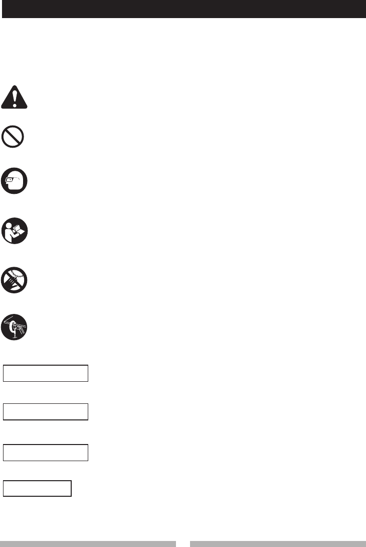
SAFETY ALERT: Precautions that involve your safety.
PROHIBITION
WEAR EYE PROTECTION: Always wear safety goggles or safety glasses with side
shields.
READ AND UNDERSTAND INSTRUCTION MANUAL: To reduce the risk of injury,
user and all bystanders must read and understand instruction manual before using this
product.
SUPPORT AND CLAMP WORK
KEEP HANDS AWAY FROM BLADE: Failure to keep your hands away from the blade
will result in serious personal injury.
DANGER
!
WARNING
!
CAUTION
!
CAUTION
DANGER: indicates an imminently hazardous situation which, if not
avoided, will result in death or serious injury.
WARNING: indicates a potentially hazardous situation which, if not
avoided, could result in death or serious injury.
CAUTION: indicates a potentially hazardous situation which, if not
avoided, may result in minor or moderate injury.
CAUTION: used without the safety alert symbol indicates a potentially
hazardous situation which, if not avoided, may result in property
damage.

4 5
4 5
POWER TOOL SAFETY
GENERAL SAFETY INSTRUCTIONS
BEFORE USING THIS POWER TOOL
Safety is a combination of common sense,
staying alert and knowing how to use your power
tool.
To avoid mistakes that could cause serious
injury, do not plug the tool in until you have
read and understood the following.
1. READ and become familiar with the
entire Operator’s Manual. LEARN
the tool’s application, limitations and
possible hazards.
2. KEEP GUARDS IN PLACE and in working
order.
3. REMOVE ADJUSTING KEYS AND
WRENCHES. Form the habit of checking to
see that keys and adjusting wrenches are
removed from the tool before turning ON.
4. KEEP WORK AREA CLEAN. Cluttered areas
and benches invite accidents.
5. DO NOT USE IN DANGEROUS
ENVIRONMENTS. Do not use power tools
in damp locations, or expose them to rain or
snow. Keep work area well lit.
6. KEEP CHILDREN AWAY. All visitors and
bystanders should be kept a safe distance
from work area.
7. MAKE WORKSHOP CHILD PROOF with
padlocks, master switches or by removing
starter keys.
8. DO NOT FORCE THE TOOL. It will do the job
better and safer at the rate for which it was
designed.
9. USE THE RIGHT TOOL. Do not force the tool
or an attachment to do a job for which it was
not designed.
10.USE PROPER EXTENSION CORDS. Make
sure your extension cord is in good condition.
When using an extension cord, be sure to use
one heavy enough to carry the current your
product will draw. An undersized cord will
result in a drop in line voltage and in loss of
power which will cause the tool to overheat.
The table on page 7 shows the correct
size to use depending on cord length and
nameplate ampere rating. If in doubt, use the
next heavier gauge. The smaller the gauge
number, the heavier the cord.
11.WEAR PROPER APPAREL. Do not wear
loose clothing, gloves, neckties, rings,
bracelets or other jewelry which may get
caught in moving parts. Nonslip footwear is
recommended. Wear protective hair covering
to contain long hair.
12.ALWAYS WEAR EYE PROTECTION. Any
power tool can throw foreign objects
into the eyes and could cause
permanent eye damage. ALWAYS
wear Safety Goggles (not glasses)
that comply with ANSI Safety standard Z87.1.
Everyday eyeglasses have only impact–
resistant lenses. They ARE NOT safety
glasses. Safety Goggles are available at
Sears. NOTE: Glasses or goggles not in
compliance with ANSI Z87.1 could seriously
injure you when they break.
13.WEAR A FACE MASK OR DUST MASK.
Sawing operation produces dust.
14.SECURE WORK. Use clamps or a vise to
hold work when practical. It is safer
than using your hand and it frees
both hands to operate the tool.
15.DISCONNECT TOOLS FROM POWER
SOURCE before servicing, and when
changing accessories such as blades, bits
and cutters.
16.REDUCE THE RISK OF UNINTENTIONAL
STARTING. Make sure switch is in the OFF
position before plugging the tool in.
17.USE RECOMMENDED ACCESSORIES.
Consult this Operator’s Manual for
recommended accessories. The use of
improper accessories may cause risk of injury
to yourself or others.
18.NEVER STAND ON THE TOOL. Serious
injury could occur if the tool is tipped or if the
cutting tool is unintentionally contacted.
19.CHECK FOR DAMAGED PARTS. Before
further use of the tool, a guard or other part
that is damaged should be carefully checked
WARNING
!

4 5
4 5
POWER TOOL SAFETY
to determine that it will operate properly and
perform its intended function – check for
alignment of moving parts, binding of moving
parts, breakage of parts, mounting and any
other conditions that may affect its operation.
A guard or other part that is damaged should
be properly repaired or replaced.
20.NEVER LEAVE THE TOOL RUNNING
UNATTENDED. TURN THE POWER “OFF”.
Do not walk away from a running tool until the
blade comes to a complete stop and the tool
is unplugged from the power source.
21. DO NOT OVERREACH. Keep proper footing
and balance at all times.
22.MAINTAIN TOOLS WITH CARE. Keep
tools sharp and clean for best and safest
performance. Follow instructions for
lubricating and changing accessories.
23.WARNING: Dust generated from certain
materials can be hazardous to your health.
Always operate saw in well-ventilated area
and provide for proper dust removal.
24.
People with electronic devices, such as
pacemakers, should consult their physician(s)
before using this product. Operation of
electrical equipment in close proximity to a
heart pacemaker could cause interference or
failure of the pacemaker.
DANGER
!

6 7
6 7
COMPOUND MITER SAW SAFETY
SPECIFIC SAFETY INSTRUCTIONS FOR THIS
COMPOUND MITER SAW
1. DO NOT USE THIN KERF BLADES they
can deflect and contact guard and can cause
possible injury to the operator.
2. DO NOT operate the miter saw until it
is completely assembled and installed
according to these instructions.
3. IF YOU ARE NOT thoroughly familiar with
the operation of miter saws, seek guidance
from your supervisor, instructor or other
qualified person.
4. ALWAYS hold the work firmly against the
fence and table. DO NOT perform any
operation free hand (use clamp wherever
possible).
5. KEEP HANDS out of the path of the saw
blade. If the workpiece you are cutting would
cause your hands to be within 6-3/4 in. of the
saw blade, the workpiece should be clamped
in place before making the cut.
6. BE SURE the blade is sharp, runs freely and
is free of vibration.
7. ALLOW the motor to come up to full speed
before starting a cut.
8. KEEP THE MOTOR AIR SLOTS CLEAN
and free of chips or dust.
9. ALWAYS MAKE SURE all handles are tight
before cutting, even if the table is positioned
in one of the positive stops.
10. BE SURE both the blade and the collar are
clean and the arbor bolt is tightened securely.
11. USE only blade collars specified for your saw.
12. NEVER use blades larger in diameter than
10 inches.
13. NEVER apply lubricants to the blade when it
is running.
14. ALWAYS check the blade for cracks or
damage before operation. Replace a cracked
or damaged blade immediately.
15. NEVER use blades recommended for
operation at less than 4800 RPM.
16. ALWAYS keep the blade guards in place and
use at all times.
17. NEVER reach around the saw blade.
18. MAKE SURE the blade is not contacting the
workpiece before the switch is turned ON.
19. IMPORTANT: After completing the cut,
release the trigger and wait for the blade to
stop before returning the saw to the raised
position.
20. MAKE SURE the blade has come to a
complete stop before removing or securing
the workpiece, changing the workpiece angle
or changing the angle of the blade.
21. NEVER cut metals or masonry products with
this tool. This miter saw is designed for use
on wood and wood-like products.
22. NEVER cut small pieces. If the workpiece
being cut would cause your hand or fingers
to be within 6-3/4 in. of the saw blade the
workpiece is too small.
23. PROVIDE adequate support to the sides of
the saw table for long work pieces.
24. NEVER use the miter saw in an area with
flammable liquids or gases.
25. NEVER use solvents to clean plastic parts.
Solvents could possibly dissolve or otherwise
damage the material.
26. SHUT OFF the power before servicing or
adjusting the tool.
27. DISCONNECT the saw from the power
source and clean the machine when finished
using.
28. MAKE SURE the work area is clean before
leaving the machine.
29. SHOULD any part of your miter saw be
missing, damaged, or fail in any way, or any
electrical component fail to perform properly,
lock the switch and remove the plug from
the power supply outlet. Replace missing,
damaged, or failed parts before resuming
operation.
POWER SUPPLY AND MOTOR
SPECIFICATIONS
The AC motor used in this saw is a universal,
nonreversible type. See “MOTOR” in the
“PRODUCT SPECIFICATIONS” section on
page 2.
To avoid electrical hazards, fire hazards,
or damage to the tool, use proper circuit
protection. Your saw is wired at the factory
for 120 V operation. Connect to a 120 V, 15
A circuit and use a 15 A time delay fuse or
circuit breaker. To avoid shock or fire, if
power cord is worn or cut, or damaged in any
way, have it replaced immediately.
ELECTRICAL REQUIREMENTS
WARNING
!
6 7
6 7
ELECTRICAL REQUIREMENTS AND SAFETY
GROUNDING INSTRUCTIONS
IN THE EVENT OF A MALFUNCTION OR
BREAKDOWN, grounding provides a path of
least resistance for electric currents and reduces
the risk of electric shock. This tool is equipped
with an electrical cord that has an equipment-
grounding conductor and a grounding plug. The
plug must be plugged into a matching receptacle
that is properly installed and grounded in
accordance with all local codes and ordinances.
DO NOT MODIFY THE PLUG PROVIDED.
If it will not fit the receptacle, have the proper
receptacle installed by a qualified electrician.
IMPROPER CONNECTION of the equipment
grounding conductor can result in risk of electric
shock. The conductor with the green insulation
(with or without yellow stripes) is the equipment
grounding conductor. If repair or replacement of
the electrical cord or plug is necessary, do not
connect the equipment grounding conductor to a
live terminal.
CHECK with a qualified electrician or service
person if you do not completely understand the
grounding instructions, or if you are not certain
the tool is properly grounded.
USE only three-wire extension cords that have
three-pronged grounding plugs with three-pole
receptacles that accept the tool’s plug. Repair or
replace damaged or worn cords immediately.
GUIDELINES FOR EXTENSION
CORDS
USE THE PROPER EXTENSION CORD. Make
sure your extension cord is in good condition.
Use an extension cord heavy enough to carry
the current your product will draw. An undersized
cord will cause a drop in line voltage resulting
in loss of power, overheating and burning out
of the motor. The table on the right shows the
correct size to use depending on cord length
and nameplate ampere rating. If in doubt, use
the next heavier gauge. The smaller the gauge
number, the heavier the cord.
Make sure your extension cord is properly
wired and in good condition. Always replace a
damaged extension cord or have it repaired by a
qualified technician before using it. Protect your
extension cords from sharp objects, excessive
heat and
damp or wet areas.
Use a sep
arate electrical circuit for your tool. This
circuit must not be less than #12 wire with a 20 A
time-lag fuse or a #14 wire with a 15 A time-lag
fuse.
NOTE: When using an extension cord on a
circuit with a #14 wire, the extension cord must
not exceed 25 feet in length. Before connecting
the motor to the power line, make sure the switch
is in the off position and the electric current is
rated the same as the current stamped on the
motor nameplate. Running at a lower voltage
will damage the motor. This tool is intended for
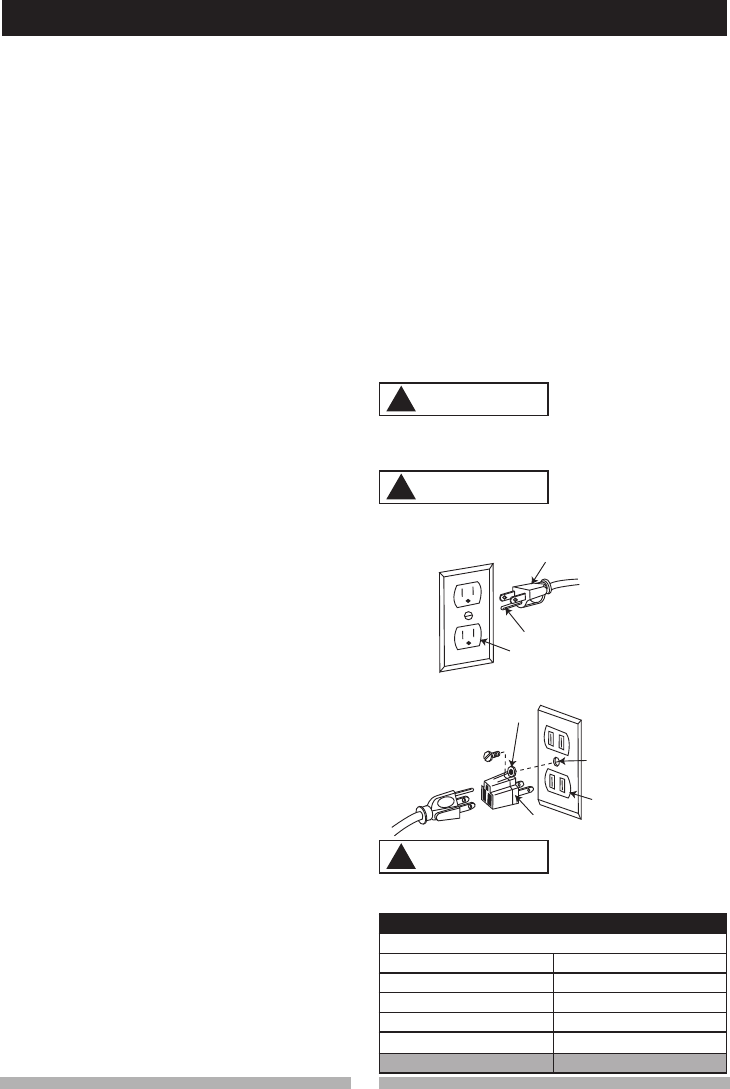
use on a circuit that has a receptacle like the one
illustrated in Fig. 1.
Fig. 1 shows a three-pronged electrical plug and
receptacle that has a grounding conductor. If a
properly grounded receptacle is not available,
an adapter (Fig. 2) can be used to temporarily
connect this plug to a two-contact grounded
receptacle. The adapter (Fig. 2) has a rigid lug
extending from it that MUST be connected to
a permanent earth ground, such as a properly
grounded receptacle box.
In all cases, make certain the receptacle is
properly grounded. If you are not sure, have a
qualified electrician check the receptacle.
This tool is for indoor use only. Do not
expose to rain or use in damp locations.
Fig. 1
Fig. 2
Three-Pronged Plug
Grounding Prong
Properly Grounded
Three-Pronged
Receptacle
Grounding Lug Make sure this
is connected
to a known
ground.
Two-Pronged
Receptacle
Adapter
This tool must be grounded while in use to
protect the operator from electric shock.
MINIMUM GAUGE FOR EXTENSION CORDS (AWG)
(When using 120 volts only)
Ampere Rating Total length of Cord
More Than Not More Than 25ft. 50ft. 100ft. 150ft.
0 6 18 16 16 14
6 10 18 16 14 12
10 12 16 16 14 12
12 16 14 12 Not Recommended
!
!
!
WARNING
!
WARNING
!
WARNING
!
8 9
8 9
ACCESSORIES AND ATTACHMENTS TOOLS NEEDED FOR ASSEMBLY
RECOMMENDED ACCESSORIES
● Use only accessories recommended for
this miter saw. Follow instructions that
accompany accessories. Use of improper
accessories may cause hazards.
● The use of any cutting tool except 10 in.
saw blades which meet the requirements
under recommended accessories is
prohibited. Do not use accessories such
as shaper cutters or dado sets. Ferrous
metal cutting and the use of abrasive
wheels is prohibited.
● Do not attempt to modify this tool or
create accessories not recommended for
use with this tool. Any such alteration or
modification is misuse and could result in
a hazardous condition leading to possible
serious injury.
ACCESSORIES
Visit your Sears Hardware Department or see the
Sears Power and Hand Tool Catalog to purchase
recommended accessories for this power tool.
● To avoid the risk of personal injury, do not
modify this power tool or use accessories
not recommended by Sears.
● Read warnings and conditions on your
CARBIDE TIPPED SAW BLADE. Do not
operate the saw without the proper saw
blade guard in place. Carbide is a very
hard but brittle material. Care should be
taken while mounting, using, and storing
carbide tipped blades to prevent accidental
damage. Slight shocks, such as striking
the tip while handling, can seriously
damage the blade. Foreign objects in the
workpiece, such as wire or nails, can also
cause tips to crack or break off. Before
using, always visually examine the blade
and tips for bent blade, cracks, breakage,
missing or loose tips, or other damage. Do
not use if damage is suspected. Failure to
heed safety instructions and warnings can
result in serious bodily injury.
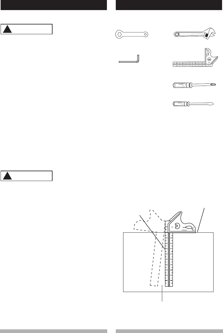
COMBINATION SQUARE MUST BE TRUE
Should not gap or overlap when square is flipped
over (see dotted figure).
WARNING
!
WARNING
!
Draw light line on
board along this
edge.
Straight edge or
a 3/4 in. board,
this edge must be
perfectly straight.
Gap from untrue square when
flipped over.
SUPPLIED NOT SUPPLIED
Adjustable Wrench
Combination Square
Philips Screwdriver
Slotted Screwdriver
Blade Wrench
Hex Key
8 9
8 9
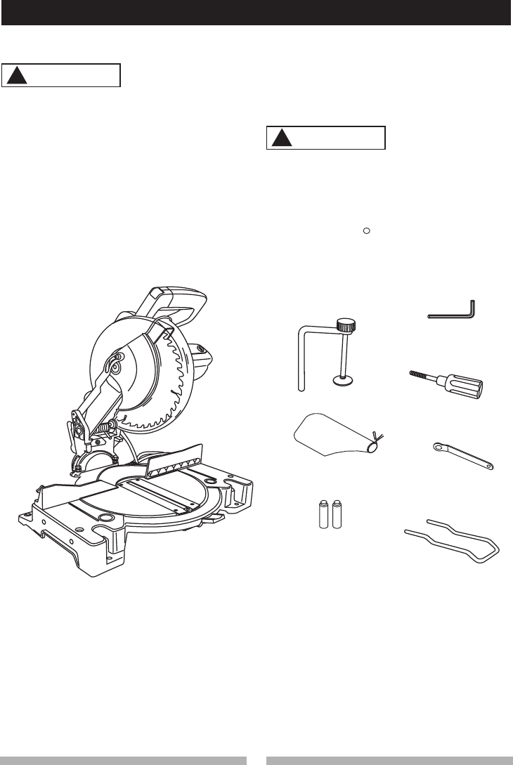
CARTON CONTENTS
UNPACKING YOUR MITER SAW
To avoid injury from unexpected starting or
electrical shock, do not plug the power cord
into a source of power during unpacking and
assembly. This cord must remain unplugged
whenever you are working on the saw.
1. Remove the miter saw from the carton.
IMPORTANT: Do not lift miter saw by
the trigger switch handle. It may cause
misalignment. Lift machine by the built-in
carry handle.
2. Place the saw on a secure stationary work
surface.
3. Separate all parts from the packing material.
Check each of the illustrations shown below
to make certain all items are accounted for,
before discarding any packing material.
If any part is missing or damaged, do not
attempt to assemble the miter saw, or plug in
the power cord until the missing or damaged
part is correctly replaced. To avoid electric
shock, use only identical replacement parts
when servicing double insulated tools. Call
1-800-4-MY-HOME for replacement parts.
WARNING
!
WARNING
!
Hold-Down Clamp
Dust Bag
Miter Saw
Miter Table Handle
Blade Wrench
R
Rear Extension Stay
Batteries
Hex Key

10 11
10 11
KNOW YOUR COMPOUND MITER SAW
Cover Plate
Lower Blade Guard
Hold-down Clamp
Base
Upper Plate Guard
Miter Lock Handle
Positive Stop Locking Lever
Dust Bag
Motor
Bevel Scale
Hand Hold for
Transportation
Miter Angle
Pointer
Safety Lock-Off Button
Fence
Table
Table Insert
Hand Hold for
Transportation
Bevel Lock Handle
Laser On/Off Switch
Switch Handle
Arbor Lock
Hold-down Latch
Miter Scale
ON/OFF Trigger Switch
Laser Guide
Rear Extension Stay

10 11
10 11
GLOSSARY OF TERMS
COMPOUND MITER SAW TERMS
ARBOR LOCK – Allows the user to keep the
blade from rotating while tightening or loosening
the arbor bolt during blade replacement or
removal.
BASE – Supports the table, holds accessories
and allows for workbench or leg set mounting.
BEVEL LOCKING HANDLE – Locks the miter
saw at a desired bevel angle.
BEVEL SCALE – To measure the bevel angle of
the saw blade 0° to 45° left.
COVER PLATE SCREW – Loosen this screw
and rotate the plate for access to the blade arbor
bolt.
FENCE – Helps to keep the workpiece from
moving when sawing. Scaled to assist with
accurate cutting.
LOWER BLADE GUARD – Helps protect your
hands from the blade in the raised position, it
retracts as the blade is lowered.
MITER HANDLE – Used to rotate the table, and
to rotate the saw to a right or left cutting position.
MITER SCALE – Measures the miter angle 0° to
45° left and right.
MOUNTING HOLES – To mount the miter saw to
a stable surface.
ON/OFF TRIGGER SWITCH – To start the tool,
squeeze the trigger. Release the trigger to turn
off the miter saw.
POSITIVE STOP LOCKING LEVER – Locks the
miter saw at a preset positive stop for the desired
miter angle.
STOP LATCH – Locks the miter saw in the
lowered position for compact storage and
transportation.
SWITCH HANDLE – The switch handle contains
the trigger switch and the laser on/off switch. The
blade is lowered into the workpiece by pushing
down on the handle. The saw will return to its
upright position when the handle is released.
WARNING LABELS – Read and understand for
your own safety. Make sure all labels are present
on machine and legible.
WRENCH STORAGE – Convenient storage to
prevent misplacing the blade wrench.
WOODWORKING TERMS
ARBOR – The shaft on which a blade is
mounted.
BEVEL CUT – An angle cut made through the
face of the workpiece.
COMPOUND CUT – A simultaneous bevel and
miter cut.
CROSS CUT – A cut made across the width of
the workpiece.
FREEHAND – Performing a cut without using a
fence (guide), hold down or other proper device
to prevent the workpiece from twisting during the
cutting operation.
GUM – A sticky sap from wood products.
HEEL – Misalignment of the blade.
KERF – The amount of material removed by
blade cut.
MITER CUT – An angle cut made across the
width of the workpiece.
RESIN – A sticky sap that has hardened.
REVOLUTIONS PER MINUTE (RPM) – The
number of turns completed by a spinning object
in one minute.
SAW BLADE PATH – The area of the workpiece
or table top directly in line with the travel of the
blade or the part of the workpiece which will be
cut.
SET – The distance between two saw blade tips,
bent outward in opposite directions to each other.
The further apart the tips are, the greater the set.
WORKPIECE – The item being cut. The surfaces
of a workpiece are commonly referred to as
faces, ends and edges.
12 13
12 13
ASSEMBLY AND ADJUSTMENTS
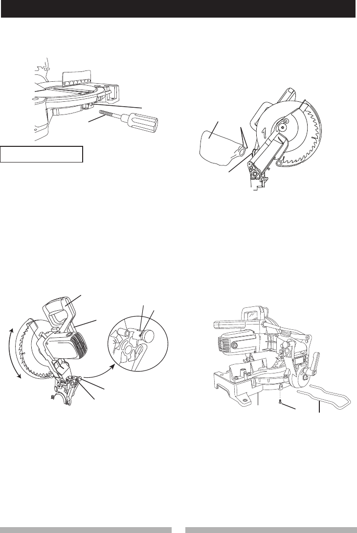
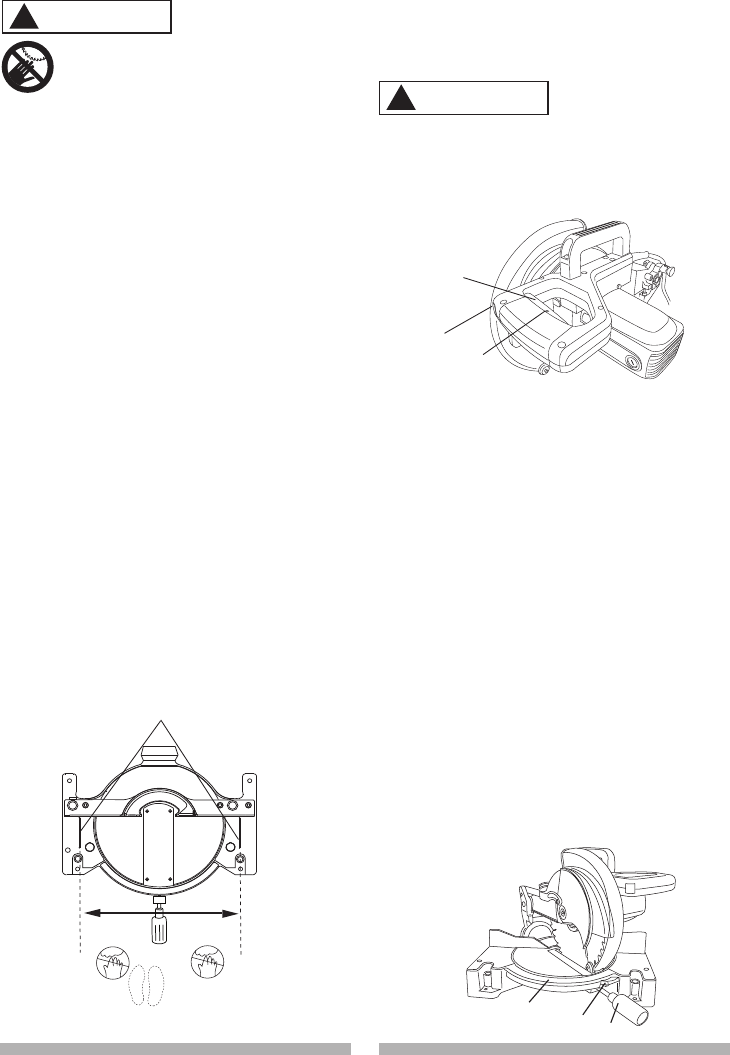
INSTALLING THE MITER HANDLE (FIG. A)
1. Thread the miter handle (1) into the hole (2)
located at the front of the miter table.
Fig. A
CUTTING HEAD (FIG. B)
Raising the Cutting Head
1. Push down slightly on the switch handle (1).
2. Pull the hold-down latch (2) out of the long slot (5)
of locking hole (3) and turn 90º to insert into the
short slot (6).
3. Pull up the switch handle (1) to raise to the up
position.
1
2
3
1
2
WARNING
!
Locking Cutting Head in Down Position
When transporting or storing the miter saw, the
cutting head should always be locked in the
down position.
1. Push the switch handle (1) down to its lowest
position.
2. Pull the hold-down latch (2) out of the short slot
(6) of the locking hole (3) and turn 90º to insert
into the long slot (5).
IMPORTANT: To avoid damage, never carry
the miter saw by the switch handle, the cutting
arm or the miter handle. ALWAYS use the
designated carrying handle (4).
12
3
Fig. B
INSTALLING THE DUST BAG (FIG. C)
1. Squeeze the metal collar wings (2) of the dust
bag (1).
2. Place the dust bag neck opening around the
exhaust port (3), and release the metal collar
wings.
Fig. C
4
213
To avoid injury and damage to the saw,
transport or store the miter saw with the
cutting head locked in the down position.
Never use the stop latch to hold the cutting
head in a down position for cutting
operations.
56
INSTALLING THE REAR EXTENSION STAY
(FIG. D)
1. Loosen the extension stay locking screw (1)
under the saw base (2).
2. Place the rear extension stay (3) into the
holes provided in the miter saw base. Make
sure the angle of stay is in the down position
(as shown in Fig. D) for maximum support.
3. Insert the extension stay locking screw back
to hole and tighten to hold the extension.
Fig. D
INSTALLING THE HOLD-DOWN CLAMP
ASSEMBLY (FIG. E)
1. Loosen the lock knob (3) from the rear side of
the saw base (4).
2. Place the hold-down clamp assembly (1) in
one of the mounting holes (2).
3. Tighten the lock knob (3).
12 13
12 13
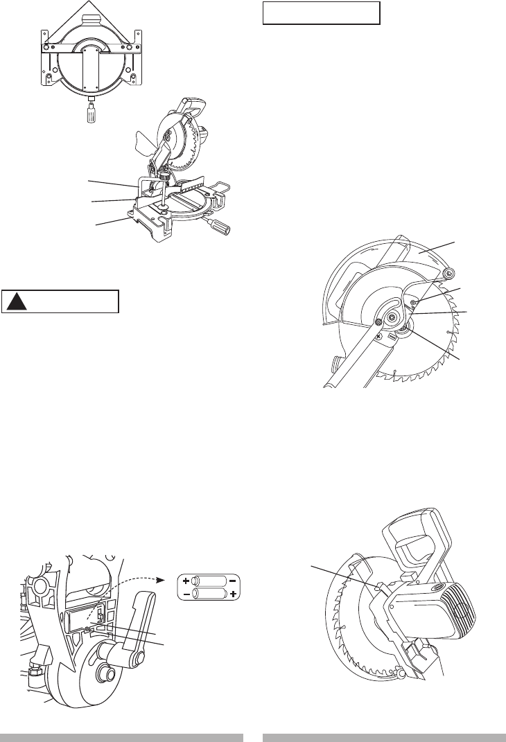
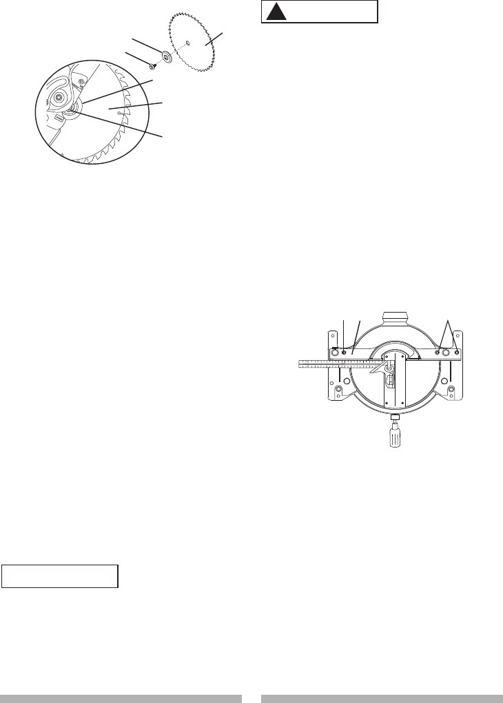
REMOVING OR INSTALLING THE BLADE
Only use a 10-inch diameter blade.
To avoid injury from an accidental start, make
sure the switch is in the OFF position and
plug is not connected to the power source
outlet.
Removing Blade (Fig. G, H, I)
1. Unplug the saw from the outlet.
2. Allow the cutting head to rise to the upright
position. Raise the lower blade guard (1) to
the up position. (Fig. G)
3. Loosen the cover plate screw (2) with a
Phillips screwdriver.
WARNING
!
4
3
1
2
Fig. E
INSERTING AND REPLACING THE LASER
BATTERIES (FIG. F)
• Unplug your miter saw.
Failure to unplug your tool could result in
accidental starting causing possible serious
personal injury.
1. Remove the locking screw (1) on the
battery cover (2) with a Phillips screwdriver,
and open the cover.
2. Insert the two supplied AAA batteries in the
case as per the diagram below. If replacing
the batteries, take out the old batteries and
place with new AAA batteries. Dispose of old
batteries properly.
3. Put on the battery cover, replace the
locking screw and tighten it securely.
NOTE: Replace the batteries with batteries that
have a rating of 1.5 volts (Number 4 series and
AAA size or equivalent).
Fig. F
WARNING
!
1
2
3
4
4. Rotate the cover plate (3) towards the rear of
the tool to expose the arbor bolt (4).
5. Place the blade wrench over the arbor bolt.
Fig. G
6. Locate the arbor lock (5) on the motor, below
the switch handle. (Fig. H)
7. Press the arbor lock, holding it in firmly
while turning the blade wrench clockwise.
The arbor lock will engage after turning the
wrench. Continue to hold the arbor lock in to
keep it engaged, while turning the wrench
clockwise to loosen the arbor bolt.
Fig. H
8. Remove the arbor bolt (8), outer blade collar
(6), and the blade (7). Do not remove the
inner blade collar. (Fig. I)
5
AAA Battery
AAA Battery
1
2
14 15
14 15
Installing Blade (Fig. G, H, I)
1. Install a 10 in. blade with a 5/8 in. arbor
making sure the rotation arrow on the blade
matches the clockwise rotation arrow on the
upper guard, and the blade teeth are pointing
downward.
2. Place the blade collar (6) against the blade
and on the arbor. Thread the arbor bolt (4)
onto the arbor in a counterclockwise direction.
(Fig. G) IMPORTANT: Make sure the flats of
the blade collars are engaged with the flats on
the arbor shaft. Also, the flat side of the blade
collar must be placed against the blade.
3. Place the blade wrench on the arbor bolt.
4. Press the arbor lock (5), holding it in firmly
while turning the blade counterclockwise.
When arbor lock engages, continue to press it
in while tightening the arbor bolt securely.
(Fig. H)
5. Rotate the cover plate (3) back to its original
position until the slot in the cover plate
engages with the cover plate screw (2). While
holding the lower blade guard, tighten the
screw with a Phillips screwdriver. (Fig. G)
NOTE: The lower blade guard must be raised
to the upright position to access the cover
plate screw.
6. Lower the blade guard (1) and verify that the
operation of the guard does not bind or stick.
7. Be sure the arbor lock is released so the
blade turns freely.
● To avoid injury, never use the saw
without the cover plate secure in place. It
keeps the arbor bolt from falling out if it
accidentally loosens, and helps prevent
the spinning blade from coming off the
saw.
● Make sure the collars are clean and
properly arranged. Lower the blade into
WARNING
!
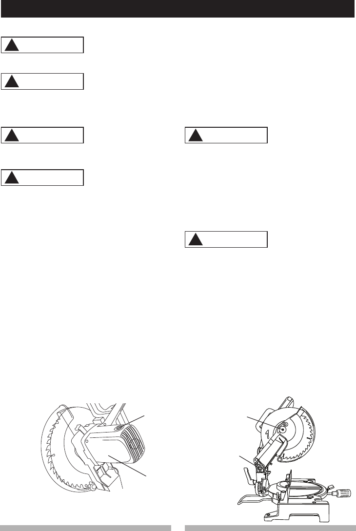
MITER SCALE (FIG. K)
The miter scale assists the user in setting
the desired miter angles from 45° left to 45°
right. The miter saw table has nine of the most
common angle setttings with positive stops at
0°, 15°, 22.5°, 31.6°, and 45°. These positive
stops position the blade at the desired angle
quickly and accurately.
To Adjust the Angle:
1. Unlock the miter table by turning the miter
handle (1) counterclockwise.
2. Press down the positive stop locking lever (2)
while holding the miter handle, and rotate the
table left or right to the desired angle.
3. Release positive stop locking lever. Tighten
miter handle.
4. If the desired angle is one of the nine positive
stops, release the positive stop locking lever,
making sure the lever snaps into position,
To avoid injury from an accidental start, make
sure the switch is in the OFF position and the
plug is not connected to the power source
outlet.
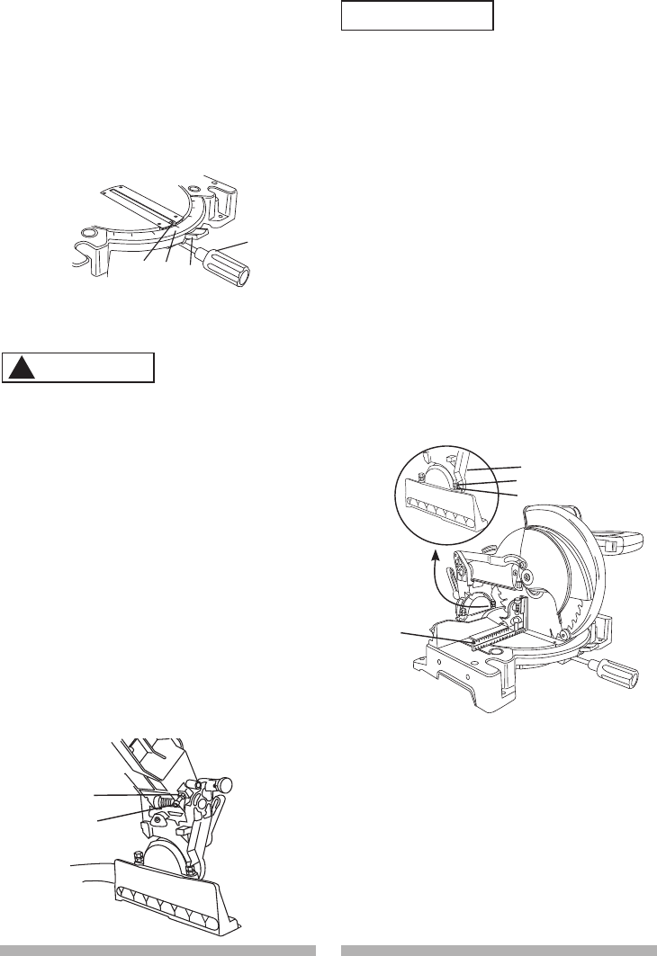
ADJUSTING FENCE SQUARENESS (FIG. J)
1. Loosen the three fence locking bolts (1).
2. Lower the cutting arm and lock in position.
3. Using a square, lay the heel of the square
against the blade, and the rule agaist the
fence(2) as shown.
Check to see if the fence is 90° to the blade.
4. If not, adjust fence 90° to the blade and
tighten the fence locking bolts.
CAUTION: If the saw has not been used
recently, recheck blade squareness to the
fence and readjust if needed.
5. After fence has been aligned, using a scrap
piece of wood, make a cut at 90o then
check squareness on the piece. Readjust if
necessary.
Fig. J
NOTE: Pay attention to the pieces removed,
noting their position and direction they face.
Wipe the blade collars clean of any sawdust
before installing the new blade.
Fig. I
6
7
8
8
67
the table and check for any contact with
the metal base or the turn table.
ADJUSTMENT INSTRUCTIONS
11
2
WARNING
!
14 15
14 15
5. If the miter angle desired is not one of the
nine positive stops, simply lock the miter
table into position by turning the miter handle
in the clockwise direction.
To Adjust the Indicator:
(1) Adjust the indicator (3) to the 0 ° mark on
the miter scale (4) to position the miter
table.
(2) Release positive stop locking lever (2).
Tighten miter handle.
Fig. K
and then secure by tightening the miter
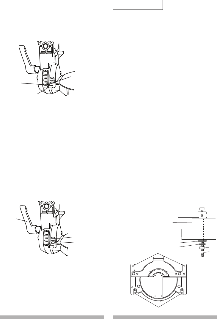
CUTTING ARM TRAVEL
Cutting Arm Downward Travel Adjustment
(Fig. L)
To avoid injury from unexpected starting
or electrical shock, turn the switch OFF
and remove the power cord from the power
source.
NOTE
: Before each cutting operation, check the
position of the blade to make sure it does not
contact any metal surface. If the blade contacts
any metal surface, the depth of travel must be
adjusted.
1. Lower the blade as far as possible.
2. Loosen the locknut (3).
3. Turn the adjustment bolt (4) out
(counterclockwise) to decrease the cutting
depth or in (clockwise) to increase the cutting
depth.
4. Carefully rotate the blade manually to check
for contact. Avoid touching blade points or
edges.
5. Repeat until adjusted properly, and tighten
the locknut to secure the adjustment bolt into
position.
Fig. L
1
2
4
3
3
4
WARNING
!
BEVEL STOP ADJUSTMENT (FIG. M, N, O)
To avoid injury from unexpected starting
or electrical shock, make sure the trigger is
released and remove the power cord from the
power source.
WARNING
!
90° Bevel Adjustment (Fig. M)
1. Loosen bevel lock handle (1) and tilt the
cutting arm completely to the right. Tighten
the bevel lock handle. Lower blade.
2. Place a combination square (2) on the miter
table with the rule against the table and the
heel of the square against the saw blade.
3. If the blade is not 90° square with the miter
table, loosen the bevel lock handle, tilt the
cutting head completely to the left, loosen
the locknut (4) on the bevel angle adjustment
bolt (3) and use a 13 mm wrench to adjust
the bolt (3) in or out to increase or decrease
the bevel angle.
4. Tilt the cutting arm to back to the right at 90°
bevel and recheck for alignment.
5. Repeat steps 1 through 4 if further
adjustment is needed.
6. Tighten bevel lock handle and locknut (4)
when alignment is achieved.
Fig. M
3
2
4
1
16 17
16 17
90° Bevel Indicator (Fig. N)
1. When the blade is exactly 90° to the table,
loosen the bevel indicator screw (5) using a
#2 Phillips screwdriver.
2. Adjust bevel indicator (6) to the “0” mark (7)
on the bevel scale and retighten the screw.
Fig. N
45° Bevel Adjustment (Fig. O)
1. Unlock the bevel lock handle (1) and tilt the
cutting arm as far to the left as possible.
2. Using a combination square, check to see if
the blade angle is 45° to the table.
3. If the blade is not at 45° to the miter table,
tilt the cutting arm to the right, loosen the
locknut (5) on the bevel angle adjustment
bolt (4) and use a 13 mm wrench to adjust
the bolt (4) in or out to increase or decrease
the bevel angle.
4. Tilt the cutting arm to the left to 45° bevel and
recheck for alignment.
5. Repeat steps 1 through 4 until the blade is at
45° to the miter table.
6. Tighten bevel lock handle and locknut (5)
when alignment is achieved.
Fig. O
4
5
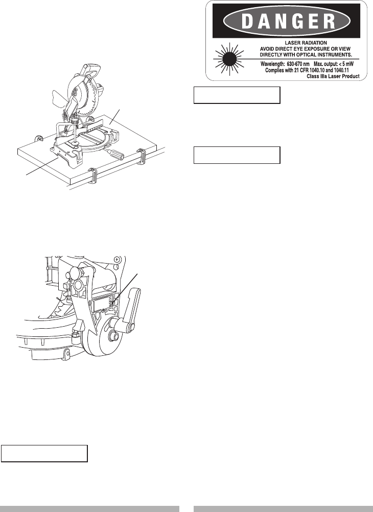
MOUNTING THE MITER SAW (FIG. P, Q)
To avoid injury from unexpected saw
movement:
● Before moving the saw, disconnect the power
cord from the outlet, and lock the cutting arm
in the lower position using the stop latch.
NOTE: The stop latch is for carrying or
storing the tool. It is not to be used for holding
the saw while cutting. Lower blade and press
in stop latch to secure saw for transport or
storage.
● Never carry the miter saw by the power cord
or by the switch handle. Carrying the tool by
the power cord could cause damage to the
insulation or wire connections resulting in
electric shock or fire.
● To avoid injury from flying debris, do not
allow visitors to stand behind the saw.
● Place the saw on a firm, level work-surface
where there is room for handling and properly
supporting the workpiece.
● Support the saw on a level work surface.
● Bolt or clamp the saw to its support.
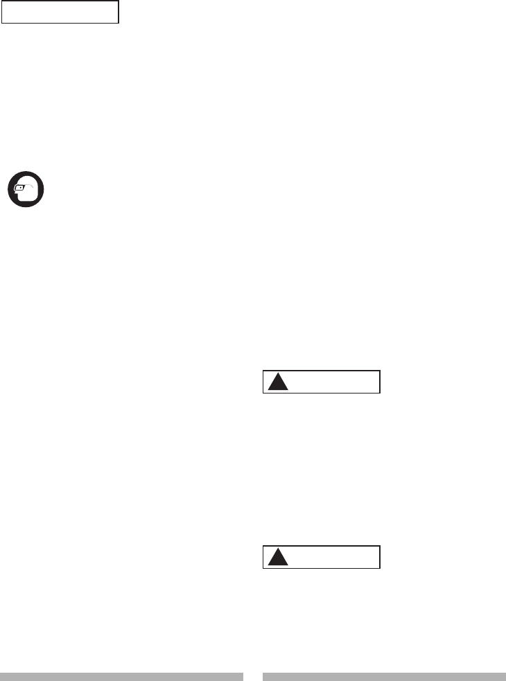
Place the saw in the desired location, either on a
work bench or recommended leg set. The base
of the saw has four mounting holes (10). (Fig. P)
Mounting instructions
1. For stationary use, place the saw in the
desired location, directly on a workbench
where there is room for handling and proper
support of the workpiece. The base of the
saw has four mounting holes. Bolt the base
of the miter saw (1) to the work surface (5),
using the fastening method as shown in Fig P.
Fig. P
1. Miter saw base
2. Hex head bolt
3. Rubber washer
4. Flat washer
5. Workbench
6. Flat washer
7. Lockwasher
8. Hex nut
9. Jam nut
WARNING
!
1
2
3
4
5
6
78
9
10
10
6
5
7
1
16 17
16 17
NOTE: Mounting hardware is not included with
this tool. Bolts, nuts, washers, and screws must
be purchased separately.
2. For portable use, place the saw on a 3/4 in.
thick piece of plywood. Bolt the base of the
miter saw securely to the plywood using the
mounting holes on the base. Use C-clamps
to clamp this mounting board to a stable work
surface at the worksite.
Fig. Q
3/4 Inch Plywood
Hand Hold for
Transportation
THE LASER GUIDE (FIG. R)
1. To turn laser on, turn switch (1) to “I” position.
2. To turn laser off, turn switch to “O” position.
Fig. R
Your tool is equipped with the Laser Guide
using a Class III laser beam. The laser beam will
enable you to preview the saw blade path on
the stock to be cut before starting the miter saw.
This laser guide is powered by two AAA 1.5 volt
batteries.
AVOID DIRECT EYE CONTACT
● Laser is radiated when laser guide is
turned on. Avoid direct eye contact.
Always un-plug the miter saw from power
source before making any adjustments.
● Laser Warning Label:
Max output <1mW DIODE LASER:
630-670nm, Complies with 21CFR 1040.10
and 1040. 11.
● Use of controls or adjustments or
performance of procedures other than
those specified herein may result in
hazardous radiation exposure.
● The use of optical instruments with this
product will increase eye hazard.
● Do not attempt to repair or disassemble
the laser. If unqualified persons attempt
to repair this laser product, serious injury
may result. Any repair required on this
laser product should be performed by a
Sears or other qualified service center.
NOTE: All the adjustments for the
operation of this machine have been
completed at the factory.
1
WARNING
!
WARNING
!
WARNING
!

18 19
18 19
OPERATION
SAFETY INSTRUCTIONS FOR BASIC SAW
OPERATION
BEFORE USING THE MITER SAW
To avoid mistakes that could cause serious,
permanent injury, do not plug the tool in until
the following steps are completed:
● Completely assemble and adjust the saw,
following the instructions. (ASSEMBLY AND
ADJUSTMENTS)
● Learn the use and function of the ON/OFF
switch, lock-off switch, upper and lower blade
guards, hold down latch, bevel lock handle
and cover plate screws.
● Review and understand all safety instructions
and operating procedures in this Operator’s
Manual. (SAFETY & OPERATIONS)
● Review the MAINTENANCE and
TROUBLESHOOTING GUIDE for your miter
saw.
● To avoid injury or possible death from
electrical shock:
Make sure your fingers do not touch the
plug’s metal prongs when plugging or
unplugging your miter saw. (ELECTRICAL
EQUIREMENTS AND SAFETY)
BEFORE EACH USE INSPECT YOUR SAW.
● Disconnect the miter saw. To avoid injury
from accidental starting, unplug the saw
before any adjustments, including set-up and
blade changes.
● Compare the direction of rotation arrow
on the guard to the direction arrow on the
blade. The blade teeth should always point
downward at the front of the saw.
● Tighten the arbor bolt.
● Tighten the cover plate screw.
● Check for damaged parts. Check for:
● Alignment of moving parts
● Damaged electric cords
● Binding of moving parts
● Mounting holes
● Function of arm return spring and lower
guard: Push the cutting arm all the way
down, then let it rise until it stops. The
lower guard should fully close. Follow
instructions in TROUBLESHOOTING
GUIDE for adjustment if necessary.
● Other conditions that may affect the way
the miter saw works.
● Keep all guards in place, in working order and
proper adjustment. If any part of this miter
saw is missing, bent, damaged or broken in
any way, or any electrical parts don’t work,
turn the saw off and unplug it.
● Replace bent, damaged, missing or defective
parts before using the saw again.
● Maintain tools with care. Keep the miter
saw clean for best and safest performance.
Follow instructions for lubricating. Do not put
lubricants on the blade while it is spinning.
● Remove adjusting wrench from the tool before
turning it on.
● To avoid injury from jams, slips, or thrown
pieces, use only recommended accessories.
● Check the dust bag before you work. Empty
the bag if it is more than half-full.
RECOMMENDED ACCESSORIES
● Consult the ACCESSORIES and
ATTACHMENTS section of this Operators
Manual for recommended accessories. Follow
the instructions that come with the accessory.
The use of improper accessories may cause
risk of injury to persons.
● Choose the correct 10 in. diameter blade for
the material and the type of cutting you plan
to do. Do not use thin kerf blades.
● Make sure the blade is sharp, undamaged
and properly aligned. With the saw
unplugged, push the cutting arm all the way
down. Manually spin the blade and check for
clearance. Tilt the power-head to a 45° bevel
and repeat the test.
● Make sure the blade and arbor collars are
clean.
● Make sure all clamps and locks are tight and
there is no excessive play in any parts.
KEEP YOUR WORK AREA CLEAN
Cluttered areas and benches invite accidents.
To avoid burns or other fire damage, never
use use the miter saw near flammable liquids,
vapors, or gases.
● Plan ahead to protect your eyes, hands, face
and ears.
● Know your miter saw. Read and understand
this Operator’s Manual and labels affixed to
this tool. Learn its application and limitations
as well as the specific potential hazards
peculiar to this tool. To avoid injury from
accidental contact with moving parts, do not
do layout, assembly, or setup work on the
miter saw while any parts are moving.
● Avoid accidental starting, make sure the
trigger switch is disengaged before plugging
the miter saw into a power outlet.
WARNING
!
WARNING
!
18 19
18 19
PLAN YOUR WORK
● Use the right tool. Don’t force a tool or
attachment to do a job it was not designed
to do. Use a different tool for any workpiece
that can’t be held in a solidly braced, fixed
position.
This machine is not designed for cutting
masonry, masonry products, ferrous metals
(steel, iron, and iron-based metals.) Use
this miter saw to cut only wood, wood-
like products, or non-ferrous metals. Other
material may shatter, bind the blade, or create
other dangers. Remove all nails that may be
in the workpiece to prevent sparking that
could cause a fire. Remove dust bag when
cutting non-ferrous metals.
DRESS FOR SAFETY
Any power tool can throw foreign
objects into the eyes. This can result in
permanent eye damage. Everyday
eyeglasses have only impact resistant lenses and
are not safety glasses. Glasses or goggles not
in compliance with ANSI Z87.1 could seriously
injure you when they break.
● Do not wear loose clothing, gloves, neckties
or jewelry (rings, watches). They can get
caught and draw you into moving parts.
● Wear non-slip footwear.
● Tie back long hair.
● Roll long sleeves above the elbow.
● Noise levels vary widely. To avoid possible
hearing damage, wear ear plugs when using
any miter saw.
● For dusty operations, wear a dust mask along
with safety goggles.
INSPECT YOUR WORKPIECE
Make sure there are no nails or foreign objects in
the part of the workpiece being cut.
Plan your work to avoid small pieces that may
bind, or that are too small to clamp and get a
solid grasp on.
Plan the way you will grasp the workpiece from
start to finish. Avoid awkward operations and
hand positions. A sudden slip could cause your
fingers or hand to move into the blade.
DO NOT OVER-REACH
Keep good footing and balance. Keep your face
and body to one side, out of the line of a possible
kickback. NEVER stand in the line of the blade.
Never cut freehand:
● Brace your workpiece firmly against the fence
and table stop so it will not rock or twist during
the cut.
● Make sure there is no debris between the
workpiece and the table or fence.
● Make sure there are no gaps between the
workpiece, fence and table that will let the
workpiece shift after it is cut.
● Keep the cut off piece free to move sideways
after it is cut off. Otherwise, it could get
wedged against the blade and thrown
violently.
● Only the workpiece should be on the saw
table.
● Secure work. Use clamps or a vise to help
hold the work when it’s practical.
USE EXTRA CAUTION WITH LARGE OR ODD
SHAPED WORKPIECES.
● Use extra supports (tables, sawhorses,
blocks, etc.) for workpieces large enough to
tip.
● Never use another person as a substitute for
a table extension, or as an additional support
for a workpiece that is longer or wider than
the basic miter saw table, or to help feed,
support, or pull the workpiece.
● Do not use this saw to cut small pieces. If the
workpiece being cut would cause your hand
or fingers to be within 6-3/4 inches of the saw
blade the workpiece is too small. Keep hands
and fingers out of the “no hands zone” area
marked on the saw table.
● When cutting odd shaped workpieces, plan
your work so it will not bind in the blade and
cause possible injury. Molding, for example,
must lie flat or be held by a fixture or jig that
will not let it move when cut.
● Properly support round material such as
dowel rods, or tubing, which have a tendency
to roll when cut, causing the blade to “bite”.
To avoid injury, follow all applicable safety
instructions, when cutting non-ferrous
metals:
● Use only saw blades specifically
recommended for non-ferrous metal cutting.
● Do not cut metal workpieces that must be
hand held. Clamp workpieces securely.
● Cut non-ferrous metals only if you are under
the supervision of an experienced person and
the dust bag has been removed from the saw.
WHEN SAW IS RUNNING
Do not allow familiarity from frequent use of
your miter saw to result in a careless mistake.
A careless fraction of a second is enough to
cause a severe injury.
Before cutting, if the saw makes an unfamiliar
noise or vibrates, stop immediately. Turn the
saw OFF. Unplug the saw. Do not restart until
finding and correcting the problem.
WARNING
!
WARNING
!
CAUTION
!
20 21
20 21
TURNING SAW ON (FIG. T)
To reduce the likelihood of accidental starting, a
thumb activated lock-OFF switch is located on
top of the switch handle. The lock-OFF switch (1)
must be pushed in before the trigger switch (2)
can be activated and the miter saw started.
Make the switch child-proof. Insert a padlock
through the hole (3) in the trigger switch and
lock it. This will prevent children and other
unauthorized users from engaging the trigger
switch ON.
Fig. T
BEFORE LEAVING THE SAW
● Never leave tool running unattended. Turn
power OFF. Wait for all moving parts to stop
and unplug unit from power source.
● Make workshop child- proof. Lock the shop.
Disconnect master switches. Store tool away
from children and other unqualified users.
BODY AND HAND POSITION (FIG. S)
Never place hands near the cutting
area. Proper positioning of your body
and hands when operating the miter
saw will make cutting easier and
safer. Keep children away. Keep all visitors
at a safe distance from the miter saw. Make
sure bystanders are clear of the saw and
workpiece. Don’t force the saw. It will do the
job better and safer at its designed rate.
Starting a cut:
● Place hands at least 6-3/4 in. away from the
path of the blade – out of the “no-hands zone”
(1). (Fig. S)
● Hold workpiece firmly against the fence to
prevent movement toward the blade.
● With the power switch OFF, bring the saw
blade down to the workpiece to see the
cutting path of the blade.
● Press in lock-off switch in trigger switch
handle.
● Squeeze trigger switch to start saw.
● Lower blade into workpiece with a firm
downward motion.
Finishing a cut:
● Hold the cutting arm in the down position.
● Release trigger switch and wait for all moving
parts to stop before moving your hands and
raising the cutting arm.
● If the blade doesn’t stop within 6 seconds,
unplug the saw and follow the instructions in
TROUBLESHOOTING GUIDE section.
Before freeing jammed material:
● Release trigger switch.
● Wait for all moving parts to stop.
● Unplug the miter saw.
Fig. S
WARNING
!
6-3/4 in. 6-3/4 in.
1
WARNING
!
1
2
3
MITER CUT (FIG. U)
1. When a miter cut is required, unlock the
miter table by turning the miter handle (1)
counterclockwise.
2. While holding the miter handle, press down
on the positive stop locking lever (2) to
disengage the positive stop locking lever.
3. Rotate the miter table to the right or left with
the miter handle.
4. When the table is in the desired position as
shown on the miter scale (3), release the
positive stop locking lever handle and tighten
the miter handle. The table is now locked at
the desired angle. Positive stops are provided
at 0°,15°, 22.5°, 31.6° and 45°.
IMPORTANT: ALWAYS TIGHTEN the miter
table lock handle before cutting.
1
2
3
Fig. U

20 21
20 21
1
2
3
COMPOUND CUT (FIG. W)
A compound cut is the combination of a miter
and a bevel cut simultaneously.
1. Loosen the bevel lock handle (1) and position
the cutting head at the desired bevel position.
Lock the bevel lock handle.
2. Loosen the miter table lock handle (2). Press
down the positive stop locking lever (3)
and position the table at the desired angle.
Release the positive stop locking lever and
lock the miter handle.
Fig. W
CUTTING BOWED MATERIAL (FIG. X)
A bowed workpiece must be positioned against
the fence and secured with a clamping device as
shown before cutting. Do not position workpiece
incorrectly or try to cut the workpiece without the
support of the fence. This will cause the blade to
bind and could result in personal injury.
1
2
BEVEL CUT (FIG. V)
1. When a bevel cut is required, loosen the bevel
lock handle (1).
2. Tilt the cutting head to the desired angle as
shown on the bevel scale (2). The blade can
be positioned at any angle, from a 90° straight
cut (0° on the scale) to a 45° left bevel.
3. Tighten the bevel lock handle (1) to lock the
cutting head in position.
4. Positive stops are provided at 0° and 45°.
Fig. V
Fig. X
CUTTING BASE MOLDING (FIG. Y)
Base moldings and many other moldings can
be cut on a compound miter saw. The setup of
the saw depends on molding characteristics and
application, as shown.
Perform practice cuts on scrap material to
achieve best results:
1. Always make sure moldings rest firmly against
fence and table. Use hold-down or C-clamps,
whenever possible, and place tape on the
area being clamped to avoid marks.
2. Reduce splintering by taping the cut area prior
to making cut. Mark cut line directly on the
tape.
3. Splintering typically happens due to wrong
blade application and thinness of the material.
Fig. Y
NOTE: Always perform a dry run cut so you can
determine if the operation being attempted is
possible before power is applied to the saw.
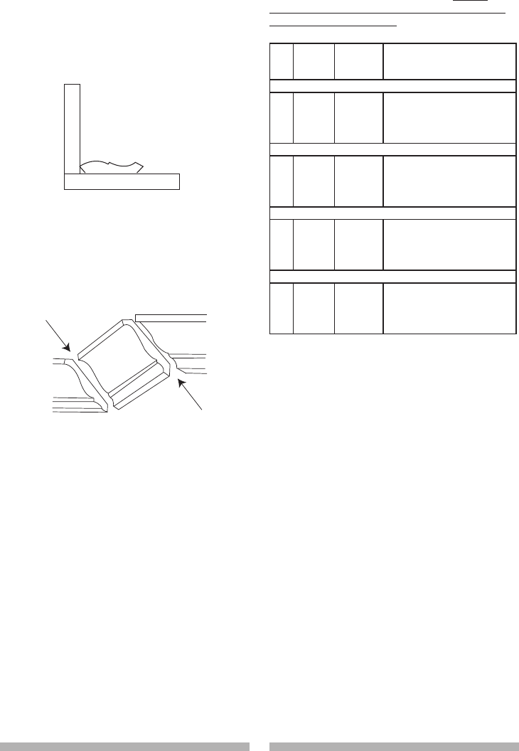
CUTTING CROWN MOLDING (FIG. Z, AA )
Your compound miter saw is suited for the
difficult task of cutting crown molding. To fit
properly, crown molding must be compound-
miterd with extreme accuracy.
The two surfaces on a piece of crown molding
that fit flat against the ceiling and wall are at
angles that, when added together equal exactly
90°.
Most crown molding has a top rear angle (the
section that fits flat against the ceiling) of 52°
and a bottom rear angle (the section that fits flat
against the wall) of 38°.
miter at 450, bevel at 00miter at 00, bevel at 450
Workpiece Workpiece
F
e
n
c
e
F
e
n
c
e
Miter Saw Table Miter Saw Table
Hold-Down
Clamp Workpiece
22 23
22 23
Fig. Z
Bevel/Miter Settings
Fig. AA
Settings for standard crown molding lying flat on
compound miter saw table
Miter Saw Table
F
e
n
c
e
IL IR
OL OR
Outside Corner
Inside Corner
In order to accurately cut crown molding for
a 90° inside or outside corner, lay the molding
with its broad back surface flat on the saw table.
When setting the bevel and miter angles for
compound miters, remember that the settings are
interdependent; changing one changes the other,
as well.
NOTE: The chart below references a
compound cut for crown molding ONLY
WHEN THE ANGLE BETWEEN THE WALLS
EQUALS EXACTLY 90°.
KEY BEVEL
SETTING
MITER
SETTING TYPE OF CUT
Inside corner-Left side
IL 33.9° 31.6° Right 1. Position top of molding against
fence.
2. Miter table set at RIGHT 31.6°.
3. LEFT side is finished piece.
Inside corner-Right side
IR 33.9° 31.6° Left 1. Position bottom of molding
against fence.
2. Miter table set at LEFT 31.6°.
3. LEFT side is finished piece.
Outside corner-Left side
OL 33.9° 31.6° Left 1. Position bottom of molding
against fence.
2. Miter table set at LEFT 31.6°.
3. RIGHT side is finished piece.
Outside corner-Right side
OR 33.9° 31.6° Right 1. Position top of molding against
fence.
2. Miter table set at RIGHT 31.6°.
3. RIGHT side is finished piece.
22 23
22 23
MAINTENANCE
MAINTENANCE
To avoid injury, never put lubricants on the
blade while it is spinning.
To avoid fire or toxic reaction, never use
gasoline, naphtha acetone, lacquer thinner or
similar highly volatile solvents to clean the
miter saw.
To avoid injury from unexpected starting
or electrical shock, unplug the power cord
before working on the saw.
For your safety, this saw is double-insulated.
To avoid electrical shock, fire or injury, use
only parts identical to those identified in the
parts list. Reassemble exactly as the original
assembly to avoid electrical shock.
REPLACING CARBON BRUSHES (FIG. BB)
Replace both carbon brushes when either has
less than 1/4 in. length of carbon remaining, or
if the spring or wire is damaged or burned. To
inspect or replace brushes, first unplug the saw.
Then remove the black plastic cap (1) on the
side of the motor (2). Remove the cap cautiously,
because it is springloaded. Then pull out the
brush and replace. Replace for the other side.
To reassemble reverse the procedure. The ears
on the metal end of the assembly go in the same
hole the carbon part fits into. Tighten the cap
snugly, but do not overtighten.
NOTE: To reinstall the same brushes, first make
sure the brushes go back in exactly the way they
came out. This will avoid a break-in period that
reduces motor performance and increases wear.
Fig. BB
LOWER BLADE GUARD
Do not use the saw without the lower blade
guard. The lower blade guard is attached to the
saw for your protection. Should the lower guard
become damaged, do not use the saw until the
damaged guard has been replaced. Develop a
regular check to make sure the lower guard is
working properly. Clean the lower guard of any
dust or buildup with a damp cloth.
CAUTION: Do not use solvents on the guard.
They could make the plastic “cloudy” and brittle.
When cleaning the lower guard, unplug the
saw from the power source receptacle to
avoid unexpected startup.
EMPTYING SAWDUST BAG
Periodically, sawdust will accumulate under the
work table and base. This could cause difficulty
in the movement of the worktable when setting
up a miter cut. Frequently blow out or vacuum up
the sawdust.
If blowing sawdust, wear proper eye
protection to keep debris from blowing into
eyes.
LUBRICATION (FIG. CC)
All the motor bearings in this tool are lubricated
with a sufficient amount of high grade lubricant
for the life of the unit under normal operating
conditions; therefore, no further bearing
lubrication is required.
Lubricate the following as necessary:
Chop pivot: Apply light machine oil to points
indicated in illustration.
Chop and Central pivot: Apply light machine oil
to points indicated in illustration.
Fig. CC
DANGER
!
WARNING
!
WARNING
!
WARNING
!
WARNING
!
WARNING
!
1
2
Chop pivot
Central pivot
of plastic guard

24 25
24 25
TROUBLESHOOTING GUIDE
To avoid injury from accidental starting, always turn switch OFF and unplug the tool before
moving, replacing the blade or making adjustments.
TROUBLESHOOTING GUIDE - MOTOR
PROBLEM PROBLEM CAUSE SUGGESTED CORRECTIVE ACTION
Brake does not
stop the blade
within 6 seconds.
1. Motor brushes not sealed or lightly
sticking.
2. Motor brake overheated from use
of defective or wrong size blade
or rapid ON/OFF cycling.
3. Arbor bolt loose.
4. Brushes cracked, damaged, etc.
5. Other.
1. Inspect/clean/replace brushes. See
MAINTENANCE section.
2. Use a recommended blade. Let cool
down. See REMOVING OR INSTALLING
THE BLADE section.
3. Retighten. See REMOVING OR
INSTALLING THE BLADE section.
4. Replace brushes.
5. Contact Sears Service Center.
Motor does not
start
1. Limit switch failure
2. Brush worn.
3. Fuse blown or circuit breaker
tripped on home panel.
1. Replace limit switch.
2. Replace brushes. See MAINTENANCE
section.
3. Verify there is electrical power at the
outlet.
Brush spark
when switch
released.
1. Brush worn.
2. Other.
1. Replace Brushes. See MAINTENANCE
section.
2. Contact Sears Service Center.
TROUBLESHOOTING GUIDE - SAW OPERATION
PROBLEM PROBLEM CAUSE SUGGESTED CORRECTIVE ACTION
Blade hits table. 1. Misalignment. 1. See ADJUSTMENT - Cutting Head
Downward Travel Adjustment section.
Angle of cut not
accurate. Can
not adjust miter.
1. Miter table unlocked.
2. Sawdust under table.
1. See OPERATION - Miter Angle
Adjustment section.
2. Vacuum or blow out dust. WEAR EYE
PROTECTION.
Cutting arm
wobbles.
1. Loose pivot points. 1. Contact Sears Service Center.
Cutting arm will
not fully raise,
or blade guard
won’t fully close.
1. Pivot bolt too tight.
2. Pivot spring not replaced properly
after service.
3. Sawdust build-up.
1. Loosen pivot bolt lock nut (see adjustment
section).
2. Contact Sears Service Center.
3. Clean and lubricate moving parts.
Blade binds,
jams, burns
wood.
1. Improper operation.
2. Dull or warped blade.
3. Improper blade size.
4 Wood is moving during cut.
1. See BASIC SAW OPERATION section.
2. Replace or sharpen blade.
3. Replace with 10 in. diameter blade.
4. Use hold down clamp to secure workpiece
to table.
Saw vibrates or
shakes.
1. Saw blade not round / damaged /
loose.
2. Arbor bolt loose.
1. Replace blade.
2. Tighten arbor bolt.
WARNING
!
TROUBLESHOOTING GUIDE - LASER GUIDE
PROBLEM PROBLEM CAUSE SUGGESTED CORRECTIVE ACTION
The laser guide
fails to turn on.
1. The batteries are dead.
2. The battery contacts need
adjustment.
1. Replace with new AAA batteries.
2. Reload the batteries and make certain
that they make solid contact to the battery
spring.

24 25
24 25
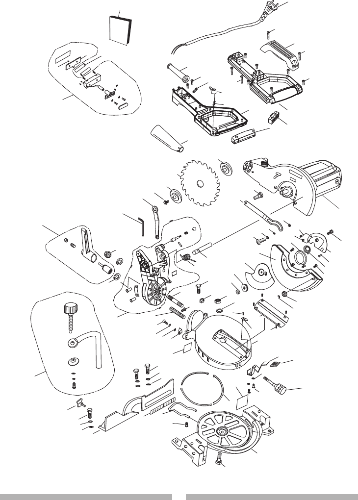
10 in. COMPOUND MITER SAW MODEL NO. 137.212360
When servicing use only CRAFTSMAN replacement parts. Use of any other parts many create
a HAZARD or cause product damage. Any attempt to repair or replace electrical parts on this
Miter Saw may create a HAZARD unless repair is done by a qualified service technician. Repair
service is available at your nearest Sears Service Centre.
PARTS LIST FOR SAW SCHEMATIC
PARTS LIST
WARNING
!
I.D. Description Size QTY I.D. Description Size QTY
X3P1 COMPRESSION SPRING 1 X3RT COIL SPRING 1
X3P2 BUTTON SWITCH 1 X3RU PLASTIC SLEEVE 1
X3P4 BATTERY 2 X3RV LOCK NUT M10 1
X3P9 POWER CABLE 1 X3S0 FLAT WASHER ø10 2
X3PA SEGMENT HANDLE 1 X3S2 POINTER 1
X3PC MOTOR HANDLE (TOP) 1 X3S6 CR. RE. PAN HD. SCREW M4*10 3
X3PD MOTOR HANDLE (DOWN) 1 X3S7 SPRING WASHER ø4 1
X3PE CORD CLAMP 1 X3S8 POINTER 1
X3PG CORD GUARD 1 X3SD REAR EXTENSION STAY 1
X3PH LIMIT SWITCH 1 X3SE CR. RE. PAN HD. SCREW M6*16 1
X3PJ HEX. HD. BOLT M6*14 1 X3SF BOLT CLAMP M6*14 1
X3PY CUTTER SHAFT GUARD 1 X3SG FLAT WASHER ø8 3
X3Q0 CR. RE. COUNT HD. SCREW M6*10 1 X3SH SPRING WASHER ø8 3
X3Q1 SPRING GUARD 1 X3SJ FENCE 1
X3Q3 CR. RE. PAN HD. SCREW M5*6 4 X3SK MITER LOCK HANDLE 1
X3Q4 CR. RE. COUNT HD. SCREW M6*12 1 X3SM FLAT WASHER ø4 1
X3Q5 RUBBER BLOCK 1 X3SN SPRING WASHER ø5 2
X3Q6 COLLAR 1 X3SP CR. RE. PAN HD. SCREW M5*12 2
X3Q7 LOWER BLADE GUARD 1 X3SQ SLIDE PLATE 3
X3Q8 BRACING PLATE 1 X3SS BASE 1
X3Q9 COLLAR 1 X3ST HEX. HD. BOLT M8*30 4
X3QA LOCK NUT M6 1 X3T0 MOTOR ASS’Y 1
X3QB CR. RE. PAN HD. SCREW M6*12 1 X3T1 LASER ASS’Y 1
X3QC COLLAR 1 X3T2 BEVEL LOCK HANDLE ASS’Y 1
X3QD FLAT WASHER ø6 2 X3T3 ANGLE REGULATOR ASS’Y 1
X3QW CR. RE. COUNT HD. SCREW 1 X3T4 HOLD DOWN CLAMP ASS’Y 1
X3R7 TRIGGER 1 X3T6 INSTRUCTION MANUAL 1
X3R8 BLADE 1 X3T8 BEVEL BOLT M10*50 1
X3R9 ARBOR COLLAR 2 X3T9 ROLLER 2
X3RA ARBOR BOLT M8*20 1 X3TA CR. RE. PAN HD. TAPPING SCREW M6*18 2
X3RB BLADE WRENCH 1 X3TB CR. RE. PAN HD. TAPPING SCREW M4*16 8
X3RG SHAFT 1 X3TC CR. RE. PAN HD. SCREW M5*40 2
X3RH TORSION SPRING 1 X3TF RETAINING RING 2
X3RK CR. RE. PAN HD. SCREW M5*10 1 X3TG DUST BAG 1
X3RL HEX. HD. BOLT M8*20 2 X3TH LEVER 1
X3RM NUT M8 2 X3TJ PIVOT SHAFT M10*55 1
X3RN LOCK NUT M8 1 X3TL CR. RE. PAN HD. SCREW M4*8 1
X3RP FLAT WASHER ø8 1 X3W4 LABEL 1
X3RQ TABLE INSERT 1 X3W9 SCALE 1
X3RR CR. RE. COUNT HD. SCREW M4*8 4 X3WA LABEL 1
X3RS TABLE 1 X3WB HEX KEY 1
26 27
26 27
10 in. COMPOUND MITER SAW MODEL NO. 137.212360
SCHEMATIC FOR SAW
X3PJ
X3RQ
X3S6
X3SG
X3SH X3SJ
X3SF
X3ST
X3SM X3S8
X3S7
X3SH
X3ST
X3SE
X3SD
X3SG
X3SS
X3ST
X3RR
X3RS
X3SP
X3SN
X3SQ
X3RU
X3SK
X3RT
X3RH
X3RK
X3RV
X3S0 X3TJ
X3T8
X3TG
X3RA
X3RB
X3R9
X3R8
X3QD
X3QC X3Q4
X3S2
X3Q7
X3RL
X3RP
X3RN
X3RG
X3RM
X3QA
X3Q9
X3Q8
X3TL
X3QB
X3Q6
X3Q5
X3Q0
X3Q1
X3TF
X3T9
X3Q3
X3PY
X3QW
X3TH
X3R9
X3QD
X3PG
X3P4
X3TC
X3TB
X3PE
X3P2
X3P1 X3PD
X3TB
X3PA
X3PH
X3PC
X3TA
X3R7
X3P9
X3TA
X3WB
X3T6
OPERATOR’S
MANUAL
X3T4
X3T1
X3T2
X3T0
X3W4
X3WA
X3W9
X3T3
6
2
2
2
2
4
2
2
2
4
2
2
3
2
2
2
3
2
X3P3
X3W2
X3PK
2
2
2
4
2
2
X3PV
26 27
26 27
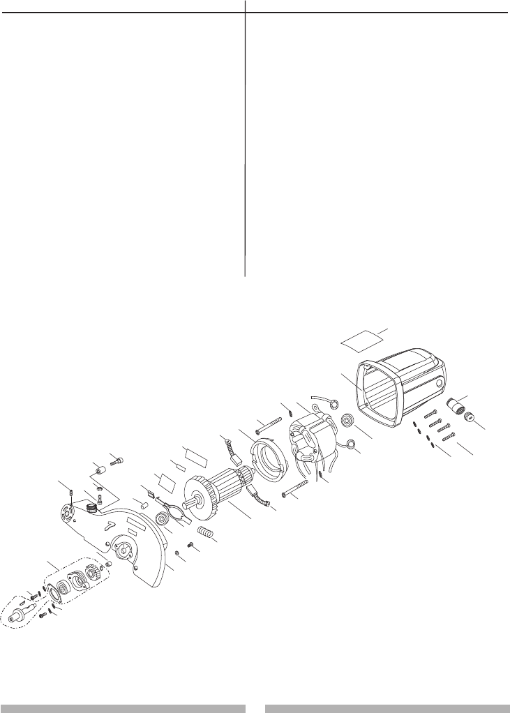
10 in. COMPOUND MITER SAW MODEL NO. 137.212360
PARTS LIST AND SCHEMATIC FOR MOTOR
X3PK
2
2
2
4
2
2
X3PV
I.D. Description Size QTY I.D. Description Size QTY
X3P0 HEX. SOC. HD. CAP SCREW 1 X3QJ LABEL 1
X3PK LABEL 1 X3QK BRUSH ASS’Y 2
X3PL BRUSH HOLDER ASS’Y 2 X3QL FLOW GUIDE 1
X3PM BRUSH COVER 2 X3QM CR. RE. PAN HD. TAPPING SCREW ST5*65 2
X3PQ MOTOR HOUSING 1 X3QN FIELD ASS’Y 1
X3PR BEARING 1 X3QU HEX. SOC. HD. CAP SCREW M6*25 1
X3PS SPRING 1 X3QR HEX. SOC. HD. CAP SCREW 1
X3PT ARMATURE ASS’Y 1 X3QS ANCHOR BLOCK 1
X3PU COMPRESSION SPRING 1 X3QY NEEDLE BEARING 1
X3PV ARBOR LOCK 1 X3R3 CR. RE. PAN HD. SCREW M5*16 2
X3PW BEARING 1 X3SB FLAT WASHER ø5 2
X3PX ARM 1 X3SN SPRING WASHER ø5 4
X3PZ FLAT WASHER ø6 4 X3TD CR. RE. PAN HD. SCREW M6*35 4
X3QE RUBBER INSERT 1 X3TE TOOTH WASHER ø4.2 1
X3QF CAP 1 X3TM CR. RE. PAN HD. SCREW M4*10 1
X3QG LABEL 1 X3WC CUTTER SHAFT ASS’Y 1
X3QH LABEL 1

28 29
28 29
REPAIR PROTECTION AGREEMENTS
Congratulations on making a smart purchase.
Your new Craftsman
®
product is designed and
manufactured for years of dependable operation. But like all products, it may require repair
from time to time. That’s when having a Repair Protection Agreement can save you money and
aggravation.
Here’s what the Repair Protection Agreement* includes:
Expert service by our 10,000 professional repair specialists
Unlimited service and no charge for parts and labor on all covered repairs
Product replacement up to $1500 if your covered product can’t be fixed
Discount of 10% from regular price of service and related installed parts not covered by the
agreement; also, 10% off regular price of preventive maintenance check
Fast help by phone – we call it Rapid Resolution – phone support from a Sears representative.
Think of us as a “talking owner’s manual.”
Once you purchase the Repair Protection Agreement, a simple phone call is all that it takes for you
to schedule service. You can call anytime day or night, or schedule a service appointment online.
The Repair Protection Agreement is a risk-free purchase. If you cancel for any reason during the
product warranty period, we will provide a full refund. Or, a prorated refund anytime after
the product warranty period expires. Purchase your Repair Protection Agreement today!
Some limitations and exclusions apply. For prices and additional information in the U.S.A.
call 1-800-827-6655.
*Coverage in Canada varies on some items. For full details call Sears Canada at
1-800-361-6665.
Sears Installation Service
For Sears professional installation of home appliances, garage door openers, water heaters, and
other major home items, in the U.S.A. or Canada call 1-800-4-MY-HOME®.
® Registered Trademark / TM Trademark / SM Service Mark of Sears Brands, LLC
® Marca Registrada / TM Marca de Fábrica / SM Marca de Servicio de Sears Brands, LLC
MC Marque de commerce / MD Marque déposée de Sears Brands, LLC
Get it fixed, at your home or ours!
Your Home
For expert troubleshooting and home solutions advice:
www.managemyhome.com

28 29
28 29
® Registered Trademark / TM Trademark / SM Service Mark of Sears Brands, LLC
® Marca Registrada / TM Marca de Fábrica / SM Marca de Servicio de Sears Brands, LLC
MC Marque de commerce / MD Marque déposée de Sears Brands, LLC
Get it fixed, at your home or ours!
Your Home
For expert troubleshooting and home solutions advice:
www.managemyhome.com
For repair – in your home – of all major brand appliances,
lawn and garden equipment, or heating and cooling systems,
no matter who made it, no matter who sold it!
For the r
eplacement parts, accessories and
owner’s
manuals that you need to do-it-yourself.
For Sears professional installation of home appliances
and items like garage door openers and water heaters.
1-800-4-MY-HOME® Call anytime, day or night
(1-800-469-4663) (U.S.A. and Canada)
www.sears.com www.sears.ca
Our Home
For repair of carry-in items like vacuums, lawn equipment,
and electronics, call anytime for the location of the nearest
Sears Parts & Repair Service Center
1-800-488-1222 (U.S.A.) 1-800-469-4663 (Canada)
www.sears.com www.sears.ca
To purchase a protection agreement on a product serviced by Sears:
1-800-827-6655 (U.S.A.) 1-800-361-6665 (Canada)
Para pedir servicio de reparación Au Canada pour service en français:
a domicilio, y para ordenar piezas: 1-800-LE-FOYERMC
1-888-SU-HOGAR® (1-800-533-6937)
(1-888-
784-6427) www.sears.ca
© Sears Brands, LLC
