Craftsman 113 298721 298761 Owners Manual
113298721 113298721 CRAFTSMAN TABLE SAW - Manuals and Guides L0804004 View the owners manual for your CRAFTSMAN TABLE SAW #113298721. Home:Tool Parts:Craftsman Parts:Craftsman TABLE SAW Manual
CRAFTSMAN Saw Table Manual L0804004 CRAFTSMAN Saw Table Owner's Manual, CRAFTSMAN Saw Table installation guides
298721 470042ee-31be-4023-a83d-f832ffeaa7f0
113298721 470042ee-31be-4023-a83d-f832ffeaa7f0 Craftsman Saw 113.298721, 113.298761 User Guide |
2015-01-05
: Craftsman Craftsman-113-298721-113-298761-Owners-Manual-161077 craftsman-113-298721-113-298761-owners-manual-161077 craftsman pdf
Open the PDF directly: View PDF ![]() .
.
Page Count: 56
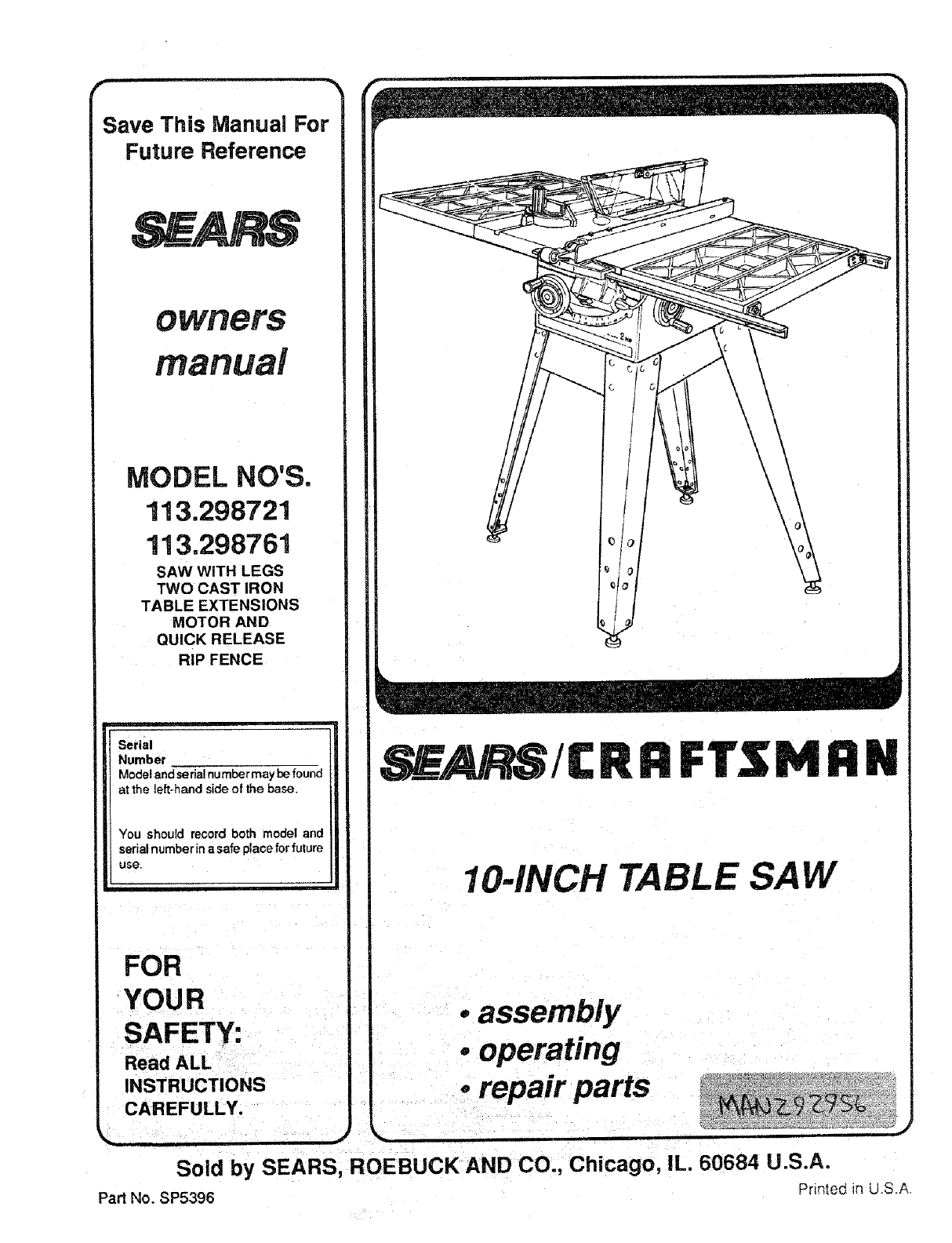
Save This Manual For
Future Reference
OWBeTS
manual
MODEL NO'S.
113,298721
113.298761
SAW WITH LEGS
TWO CAST IRON
TABLE EXTENSIONS
MOTOR AND
QUICK RELEASE
RIP FENCE
Serial
Number
Model and serial number may be found
at the left-hand side of the base
You should record both model and
serial number in a safe place for future
use,
FOR
YOUR
SAFETY:
Read ALL
INSTRUCTIONS
CAREFULLY.
SE/ RS/C R R FTSM RN
10-INCH _BLE SAW
oassembly
.operating
orepair parts
Sold by SEARS, ROEBUCK AND CO., Chicago, IL. 60684 U.S.A.
Part No. SP5396 Printed in U.S.A.
FULL ONE YEAR WARRANTY ON CRAFTSMAN TABLE SAW
if within one year from the date of purchase, this CraftsmanTable Saw fail= due to a defect In
material or workmanship, Sears will repair it, freeo! charge. This warranty applies only while this
product is In use Inthe United States.
WARRANTY SERVICE IS AVAILABLE BY SIMPLY CONTACTINGTHE NEAREST SEARSSERVICE
CENTER/DEPARTMENTTHROUGHOUT THE UNITED STATES.
THIS WARRANTY APPUES ONLY WHILE THIS PRODUCT IS USEDIN THE UNITED STATES.
This warranty gives you specific legal righte, and you mayalso have other rights which vary from
state to state.
SEARS, ROEBUCKAND CO., D/817WA HoffmanEstates, IL 60195
safety instructions for table saw
Safety is a combination of common sense, staying alert 4, GROUND THE SAW- This saw has an approved 3-
and knowing how your table saw works. Read this
manual to understand this saw.
BEFORE USING THE SAW
WARNING: To avoid mistakes that could cause
serious, permanent Injury, do not plug the saw in
until the following steps have been satisfactorily
completed.
1. Assembly and Alignment (See pages 10- 24).
2. Learn the use and function ofthe ON-OFF Switch,
Guard, Spreader, Anti-Kickbackdevice, MiterGauge,
Fence, Table Insert and Blade Elevation and Bevel
Controls. (See page 25)
3. Review and understanding of all safety instructions
conductor cord and a 3-prong grounding type plug.
The plug fitsgrounding type outlets designed for 120
volt 15 amp circuits. The green conductor inthe cord
lethe grounding wire. To avoid electrocution. NEVER
connect the green wire to a live terminal.
5. To avoid injuryfrom electrical shock, make sure your
fingers do not touch the plug's metal prongs when
plugging in or unplugging the saw.
6. To avoid back injury, get help or use recommended
casterswhen you needto move the saw. Always get
help if you need to lilt the saw. Hold the saw close to
yourbody. Bend yourknees so you can liftwithyour
legs, not your back.
7. NEVER STAND ON TOOL. Serious injury could
and operating procedures in this manual. occur it the tool tips or you accidentally hit the cutting
4. Review of the maintenance methods for this saw.
(See page 43)
Read the following DANGER label found on the front of
the saw:
WHEN INSTALLING OR MOVING THE SAW
1. AVOID DANGEROUS ENVIRONMENT. Use the
saw in a dry place protected from rain. Keep work
area well lighted.
tool. Do not store anything above or near the tool
where anyone might stand on the tool to reach them.
BEFORE EACH USE:
4. Inspect your saw.
A. To avoid injuryfrom accidental starting, unplugthe
saw, turn the switch off and remove the switch key
before raising or removing the Guard, changing
the cutting tool, changing the setup or adjusting
2. To avoid injury from unexpected saw movement: anything.
A. Put the saw on a firm level surface where there is B. Check for alignment of moving parts, binding of
B. Suppod the saw so thetable is level and the saw
does not rock.
C. Bolt the sawto the floorifit tends to slip walk,or
slide during normal use.
works. If any part is missing, bent, or broken inany
way, or any electrical parts don't work properly,
turn the saw off and unplug the saw.
C. Replace damaged, n_ssing, or failed parts before
D. When using table extensions over 24 inches wide using the saw again.
on any side of the saw, boltthe saw to the flooror D Use the Sawblade Guard, Spreader, and Anti-
PrOP up the outer end of the extension from the KickbackPawlsforany thru-sawing(wheneverthe
floor to keep the saw from tipping, blade comes though the top of the workpiece).
Make surethe Pawls work properly. Make surethe
3. Put the saw where neither operators nor bystanders Spreader is n line with the sawblade.
must stand in line with the saw blade.
1PaeBd_tzeroee 4. ' ' and_
_DANGER
_j ._5. DG not do freehand cuts. ,tdade, I_ween _2 and 2 _from _rv_mg
3._reach_ouridofovefsaw 6, Kee_hat_dsoutctfp_-th_ttsaw _.Knowhowto_edw¢_f_eriskof _ade.Oonotrtlakeripcutsblade, kicld0ack. S_e i_ for ri_, nam_wer titan _2 in¢_l. !
2
E, REMOVE ADJUSTING KEYS AND WRENCHES.
Form habit of checking for and removing keys and
adjusting wrenches from tool before turning it on.
F. To avoid injury from jams, slips or thrown pieces
(kickback and throwback):
1. USE ONLY "RECOMMENDED ACCESSO-
RIES" (See page 43). Follow the instructions
that come with the accessories. Using other ac-
cessories may be dangerous.
2. Choose the right blade or cutting accessory for
the material and the type of cutting you plan to
do.
3. Never use gdnding wheels, abrasive cut-off
wheels, friction wheels (metal slitting blades)
wire wheels or buffingwheeL They canfly apart
explosively.
4. Choose and inspect your cutting tool carefully.
a. To avoid cutting tool failure and thrown shrap-
nel (broken pieces of blade), use only 10" or
Smaller blades or other cutting tools marked
for speeds of 3450 rpm or higher.
b. Always use unbroken, balanced blades
designed to fit this saw's 5/8 inch arbor.
c. When thru-sawing (making cuts where the
blade comes through the workpiece top),
always use a 10 inch diameter blade. This
keeps the spreader in closest to the blade.
d. Do not overtighten arbor nut. Use arbor
wrenches to "snug" it securely.
e. Use only sharp blades with properly set teeth.
Consult a professional blade sharpenerwhen
in doubt.
f. Keep blades clean of gum and resin.
5..Adjust table inserts flush with the table top.
NEVER use the saw without the proper insert.
6. Make sure all clamps and locks are tight and no
parts have any excessive play.
_.Keep work area clean
A Cluttered areas and benches invite accidents.
Floor must not be slippery from wax or sawdust.
B. To avoid burnsor other firedamage, never usethe
saw near flammable liquids, vapors or gases.
C. To avoid injury,don't do layout, assembly, or setup
work on the table while the blade is spinning. It
could cut or throw anything hitting the blade.
Plan ahead to protectyour eyes, hands, face, ears.
AVOID ACCIDENTAL STARTING -Make sure
switch is "OFF" before plugging saw in.
LPlan your work
A. USE THE RIGHT TOOL -Don't force tool or
attachment to do a job it was not designed for.
B. Dress for safety:
1. Do not wear loose clothing, gloves, neckties or
jewelry (rings, wristwatches). They can get
caught and draw you into moving parts.
2. Wear nonslip footwear.
3. Tie back long hair.
4. Roll long sleeves above the elbow.
5. Noise levels vary widely. To avoid possible
hearing damage, wear ear plugs or muffs when
using saw for long periods of time.
6. Any power saw can throw foreign objects into
the eyes. This can cause permanent eye
damage. Wear safety goggles (not glasses)
that comply with ANSI Z87.1 (shown on pack-
age). Everyday eyeglasses have only impact
resistant lenses. They are not safety glasses.
Safety goggles are available at Sears retail
catalog stores. Glasses or goggles not in com-
pliance with ANSI Z87.1 could seriously hurt
you when they break.
WEAR YOUR
7. For dusty operations, wear a dust mask along
with the safety goggles.
C. Inspect your workpiece. Make sure there are no
nails or foreign objects in the part of the workpiece
to be cut.
D. Plan your cut to avoid KICKBACKS and THROW-
BACKS -when a part or al! of the workpiece binds
on the blade and is thrown violently back toward
the front of the saw.
1. Never cut FREEHAND: Always use either a
Rip Fence, Miter Gauge or fixture to position
and guide the work, so it won't twist, bind on the
blade and kickback.
2. Make sure there's no debris between the work-
piece and its supports.
3. When cutting irregularly shaped workpieces,
plan your work so it will not slip and pinch the
blade:
a. A piece of molding, for example, must tie flat
or be held by a fixture or jig that will not let it
twist, rock or slip while being cut. Use jigs or
fixtures where needed to prevent workpiece
shifting.
b. Use a different, better suited type of tool for
work that can't be made stable.
4. Use extra caution with large, very small or
awkward workpieces:
a. Use extra supports (tables, saw horses,
b!ocks,etc.) for anyworkpieces large enough
totip when not held down to the table top.
NEVER use another personas a substitute
for atable extension, or as additional support
for a workpiece that is longer or wider than
the basic saw table, or to help feed, support
or pull the workpiece.
b. Nevercontinethepiecebeingcutoff. Thatis,
the piece NOTagainstthe fence, mitergauge
or fixture. Never hold it, clamp it, touch it, or
use length stopsagainst it. It must be free to
move. If confined, itcouldget wedged against
the blade and cause a kickback or throw-
back.
c. Never cut more than oneworkpiece at atime.
d. Never turn your table saw "ON" before clear-
ing everything except the workpiece and
related support devices off the table.
4. Plan the way youwill pushthe workplecethrough.
A. NEVER pull the workplece through. Start and
finish the cut from the front of the table saw.
B. NEVER put your fingers or hands in the path of
the sawblade orother cutting tool.
C. NEVER reach in back ofthe cuttingtool with either
hand to hold down or support the workpiece,
remove wood scraps, orfor any other reason.
D. AvoU hand positions where a sudden sl;p could
cause fingers or hand to move into a sawblade or
other cutting tool.
E. DON'T OVERREACH. Always keep good footing
and balance.
F. Push the workpiece against the rotation of the
blade. NEVER feed material into the cutting tool
from the rear of the saw.
G. Always push the workpiece all the way past the
sawblade.
H. As much as possible, keep your face and body to
one side of the sawblade,out of linewith apossible
kickback or throwback.
LNEVERtumthesaw"ON"beforeclearingthetable
of all tools, wood scraps, etc., except the work-
piece and related feed or support devices for the
cut planned.
WHENEVER SAW BLADE IS SPINNING
second is enough to cause a severe Injury.
1. Before actually cutting with the saw, watch it while it
runs for ashort while. If itmakes an unfamiliar noise
or vibrates a lot, stop immediately. Turn the saw off.
Unplug the saw. Do notrestart untilfinding andfixing
the problem.
2. Make sL=rethe top of the arbor or cutting tool turns
toward the front of the saw.
3. Set the cutting tool as low as possible for the cut
you're planning.
4. KEEP CHILDREN AWAY, All visitorsshould be kept
asafedistancefrornwork. Make surebystanders are
clear of the saw and workpiece.
5. Let the blade reach full speed before cutting.
6. DON'T FORCE TOOL. It will do the job better and
saferat itsdesigned rate. Feed theworkpiece intothe
blade only fast enough to let it cut without bogging
down or binding.
7. Before freeing any jammed material:
A. Turn switch "OFF",
B. Unplug the saw.
C. Wait for all moving parts to stop.
D. Check blade, Spreader and Fencefor proper align-
rnent before starting, again.
8. To avoid throwback of cut off pieces;
A, Use the Guard assembly.
B To remove loose pieces beneath ortrapped inside
the guard:
1. rum saw "OFF".
2. Remove switch key.
3. Wait for blade to stop before lifting the Guard.
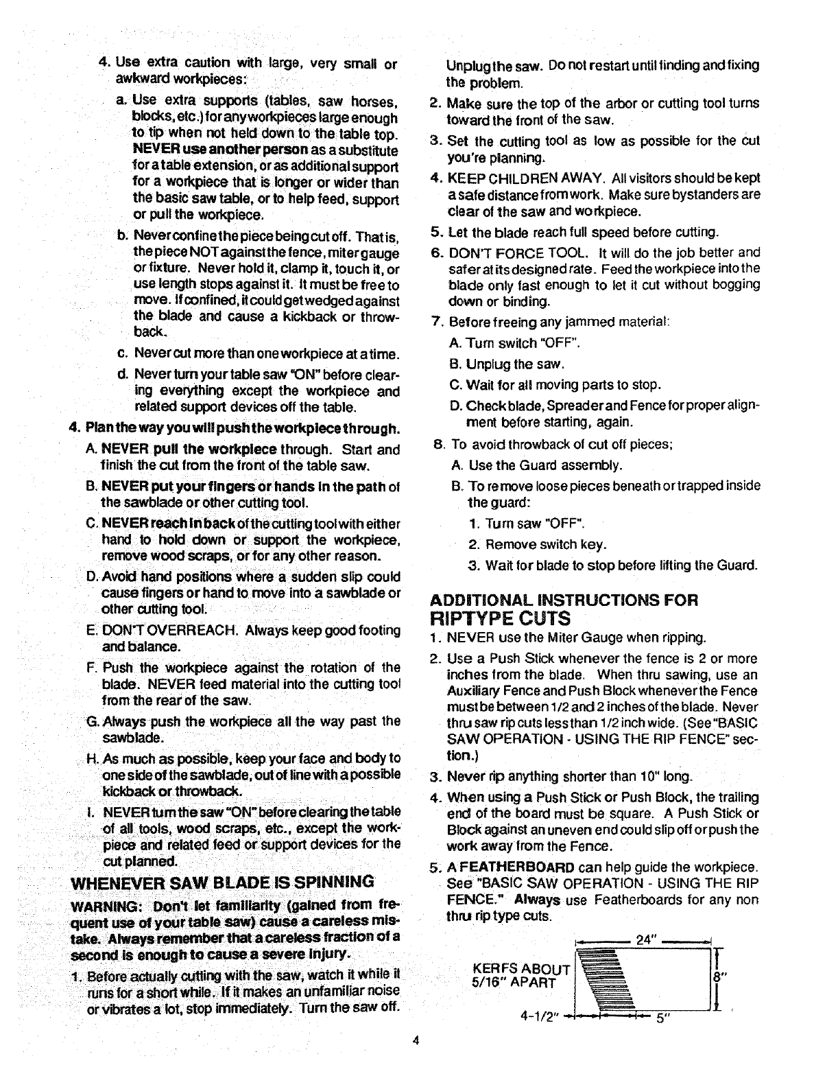
ADDiTiONAL INSTRUCTIONS FOR
RIPTYPE CUTS
1. NEVER use the Miter Gauge when ripping.
2. Use a Push Stick whenever the fence is 2 or more
inches from the blade. When thru sawing, use an
Auxiliary Fence and Push Block whenever the Fence
must be between 1/2 and 2 inches ofthe blade. Never
thru saw ripcuts lessthan 1/2 inchwide. (See"BASIC
SAW OPERATION - USING THE RIP FENCE" sec-
tion.)
3. Never rip anything shorter than 10" long.
4. When using aPush Stick or Push Block, the trailing
end of the board must be square. A Push Stick or
Block against an uneven end couldslip off orpushthe
work away from the Fence.
5. A FEATHERBOARD can help guide the workpiece.
See "BASIC SAW OPERAT{ON - USING THE RIP
FENCE." Always use Featherboards for any non
thru riptype cuts.
KERFS ABOUT
5/16" APART
_...-------- 24"
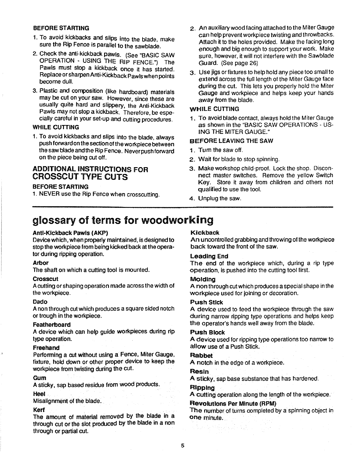
BEFORE STARTING
1. TO avoid kickbacks and slips into the blade, make
sure the Rip Fence is parallel to the sawblade.
2. Check the anti-kickback pawls. (See "BASIC SAW
OPERATION - USING THE RIP FENCE.") The
Pawls must stop a kickback once it has started.
Replace or sharpen Anti-Kickback Pawls when points
become dull.
3. Plastic and composition (like hardboard) materials
may be cut on your saw. However, since these are
usually quite hard and slippery, the Anti-Kickback
Pawls may not stop a kickback. Therefore, be espe-
cially careful in your set-up and cutting procedures.
WHILE CUTTING
1. To avoid kickbacks and slips into the blade, always
push forward on the section of the wo rkpiece between
the saw blade andthe Rip Fence. Never push forward
on the piece being cut off.
ADDITIONAL iNSTRUCTIONS FOR
CROSSCUT TYPE CUTS
BEFORE STARTING
1. NEVER use the Rip Fence when crosscutting.
2. An auxiliary wood facing attached to the Miter Gauge
can help prevent workpiece twisting and throwbacks.
Attach itto the holes provided. Make the facing long
enough and big enough to support your work. Make
sure, however, it will not interfere with the Sawblade
Guard. (See page 26)
3. Use jigs or fixtures to help hold any piece too small to
extend across the full length of the Miter Gauge face
during the cut. This lets you properly hold the Miter
Gauge and workpiece and helps keep your hands
away from the blade.
WHILE CUTTING
1. To avoid blade contact, always hold the Miter Gauge
as shown in the "BASIC SAW OPERATIONS -US-
ING THE MITER GAUGE."
BEFORE LEAVING THE SAW
1. Turn the saw off.
2. Wait for blade to stop spinning.
3. Make workshop child-proof. Lock the shop. Discon-
nect master switches. Remove the yellow Switch
Key. Store _ away from children and others not
qualified to use the tool.
4. Unplug the saw.
glossary of terms for woodworking
Anti-Kickback Pawls (AKP)
Device which, when properly maintained, is designed to
stopthe workpiece from being kicked back at the opera-
tor during dpping operation.
Arbor
The shaft on which acutting tool is mounted.
Crosscut
A cutting or shaping operation made acrossthe width of
the workpiece.
Dado
A non through cut which produces a square sided notch
or trough in the workpiece.
Featherboard
A device which can help guide workpieces during rip
type operation.
Freehand
Performing a cut without using aFence, Miter Gauge,
fixture, hold down or other proper device to keep the
workpiece from twisting during the cut.
Gum
A sticky, sap based residue tram wood products.
Heel
Misalignment of the blade.
Kerr
The amount of material removed by the blade in a
Kickback
An uncontrolled grabbing and throwing of the workpiece
back toward the front of the saw.
Leading End
The end of the workpiece which, during a rip type
operation, is pushed into the cutting tool first.
Molding
A non through cut which produces a special shape inthe
workpiece used for joining or decoration.
Push Stick
Adevice used to feed the workpiece through the saw
during narrow ripping type operations and helps keep
the operator's hands well away from the blade.
Push Block
A device used for ripping type operations too narrow to
allow use of a Push Stick.
Rabbet
Anotch inthe edge of a workpiece.
Resin
A sticky, sap base substance that has hardened.
Ripping
Acutting operation along the length of the workpiece.
Revolutions Per Minute (RPM)
The number of turns completed by aspinning object in
one minute.
through cut or the slot produced by the blade in a non
through or partial cut.
glossary of terms for woodworking
Sawblade Path
The area ofthe workpiece ortable topdirectly in linewith
the partof the workpiece which will be, or has been, cut
by the blade.
Set
The distance thatthe tip ofthe sawblade tooth isbent (or
set) outward from the face of the blade.
Throw-BaCk
Throwing of pieces in a manner similar to a kickback.
Thru-Sawing
Any cutting operation where the blade extends com-
pletely though the thickness of the workpiece.
Trailing End
The workpiece end last cut by the blade in aripping
operation.
Workpiece
The item on which the cutting operation is being done.
The surfaces of a workpiece are commonly referred to
as faces, ends, and edges.
motor specifications and electrical requirements
This saw is designed to use a 3450 RPM motoronly. Do
not use any motor that runs faster than 3450 RPM. It is
wired for operation on 120 volts. 60 Hz., alternating
current. IT MUST NOT BE CONVERTED TO OPER-
ATE ON 230 VOLTS.
CAUTION: Do not use blower or washing machine
motors or any motor with an automatic reset over-
load protector as their use may be hazardous. For
replacement motor, refer to parts list in this manual,
CONNECTING TO POWER SOURCE
OUTLET
This saw must be grounded while in use to protect the
operator from electrical shock.
Itpower cord isworn or cut,of damaged inany way, have
it replaced immediately.
Your saw is wired for 120 volts and has a plug that looks
like the one shown below.
3-PRONG PLUG
occurs, there isthe potential of a secondary hazard,
such as your hands contacting the sawblade.
This saw is equipped with a 3-conductor cord and
grounding type plug which has agrounding prong,
approved by UndenNriters' Laboratories and the Cana-
dian Standards Association. The ground conductor has
agreen lug and isattached to the tool housing atone end
and to the ground prong in the attachment plug at the
other end.
This plug requires amating 3-conductor grounding type
outlet as shown.
If the outlet you are planning to use for this saw is of the
two prong type, DO NOT REMOVE OR ALTER THE
GROUNDING PRONG IN ANY MANNER. Use an
adapter as shownbelow and always connect the ground-
ing lug to a known ground.
It is recommended that you have a qualified electrician
replace the TWO prong outlet with aproperly grounded
THREE prong outlet.
GROUNDING LUG
I_ MAKE SURE THIS IS
3-PRONG _'_ L_ _.-_= CONNECTED TO A
PLUG _ :._ "l___ II KNOWN GROUND
/.EC,.T,C'E
ADAPTER
Atemporary adapter, as shown, is available for connect-
ing plugs to 2-prong receptacles. The green grounding
lug extending from the adapter must be connected to a
perrnanent ground such asto aproperlygrounded outlet
box. This adapter should be used only until a properly
If you are not sure that
te
plug
can incur the
plumbing,
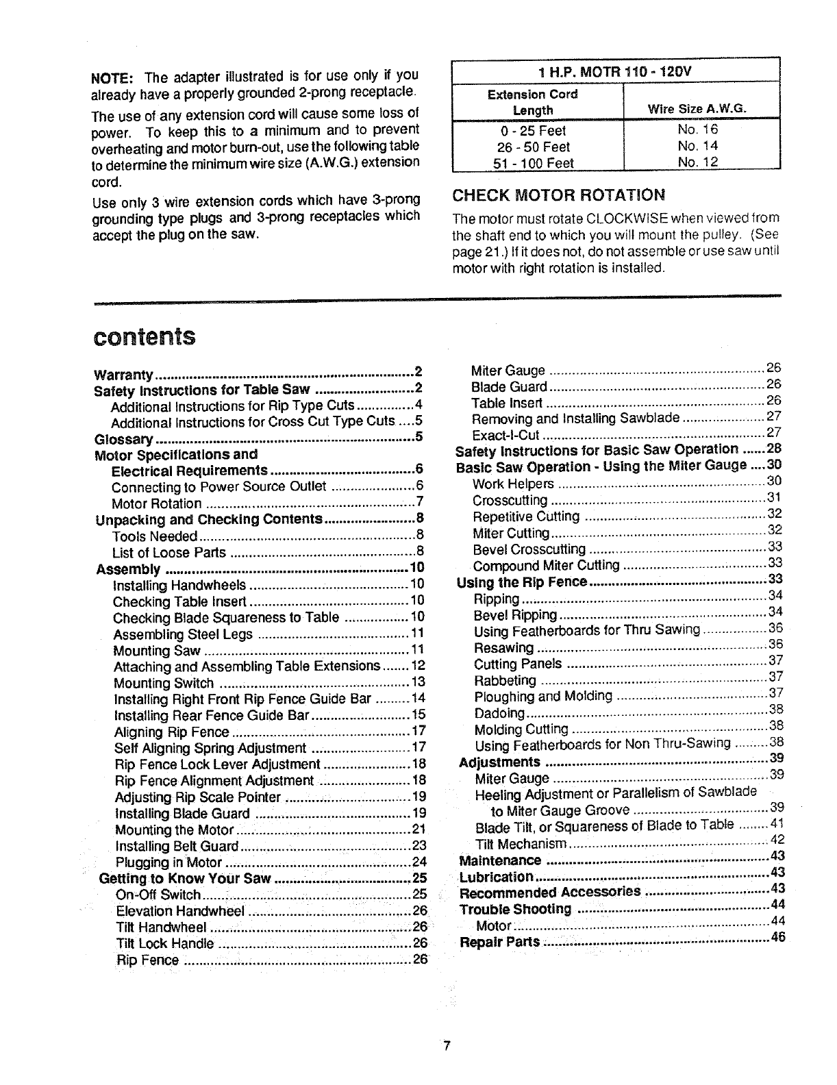
NOTE: The adapter illustrated is for use only if you
already have a properly grounded 2-prong receptacle.
The use of any extension cord will cause some loss of
power. To keep this to a minimum and to prevent
overheating and motor bum-out, use the following table
to determine the minimum wire size (A.W.G.) extension
cord.
Use only 3 wire extension cords which have 3-prong
grounding type plugs and 3-prong receptacles which
accept the plug on the saw.
contents
Warranty .................................................................... 2
Safety instructions for Table Saw .......................... 2
Additional Instructionsfor Rip Type Cuts ............... 4
Additional Instructionsfor Cross Cut Type Cuts .... 5
Glossary .................................................................... 5
Motor Specifications and
Electrical Requirements ...................................... 6
Connecting to Power Source Outlet ...................... 6
Motor Rotation ....................................................... 7
Unpacking and Checking Contents ........................ 8
Tools Needed ......................................................... 8
List of Loose Parts ................................................. 8
Assembly ................................................................ 10
Installing Handwheels .......................................... 10
Checking Table insert .......................................... 10
Checking Blade Squareness to Table ................. 10
Assembling Steel Legs ........................................ 11
Mounting Saw ...................................................... 11
Attaching and Assembling Table Extensions ....... 12
Mounting Switch .................................................. 13
Installing Right Front Rip Fence Guide Bar ......... 14
Installing Rear Fence Guide Bar .......................... 15
Aligning Rip Fence ............................................... 17
Self Aligning Spring Adjustment .......................... 17
Rip Fence Lock Lever Adjustment ....................... 18
Rip Fence Alignment Adjustment ........................ !8
Adjusting Rip Scale Pointer ................................. 19
installing Blade Guard ......................................... 19
Mounting the Motor .............................................. 21
Installing Belt Guard ............................................. 23
Plugging in Motor ................................................. 24
Getting to Know Your Saw .................................... 25
On.Off Switch ....................................................... 25
Elevation Handwheel ........................................... 26
Tilt Handwheel ..................................................... 26
Tilt Lock Handle ................................................... 26
Rip Fence ............................................................. 26
1H.P. MOTR 110 -120V
Extension Cord
Length Wire Size A.W.G.
0 - 25 Feet No. 16
26 - 50 Feet No. 14
51 - 100 Feet No. 12
CHECK MOTOR ROTATION
The motor must rotate CLOCKWISE when viewed from
the shaft end to which you wilt mount the pulley. (See
page 21 .) If it does not, do not assemble or use saw until
motor with right rotation is installed.
Miter Gauge ......................................................... 26
Blade Guard ......................................................... 26
Table Insert .......................................................... 26
Removing and Installing Sawblade ...................... 27
Exact-I-Cut ........................................................... 27
Safety instructions for Basic Saw Operation ...... 28
Basic Saw Operation -Using the Miter Gauge .... 30
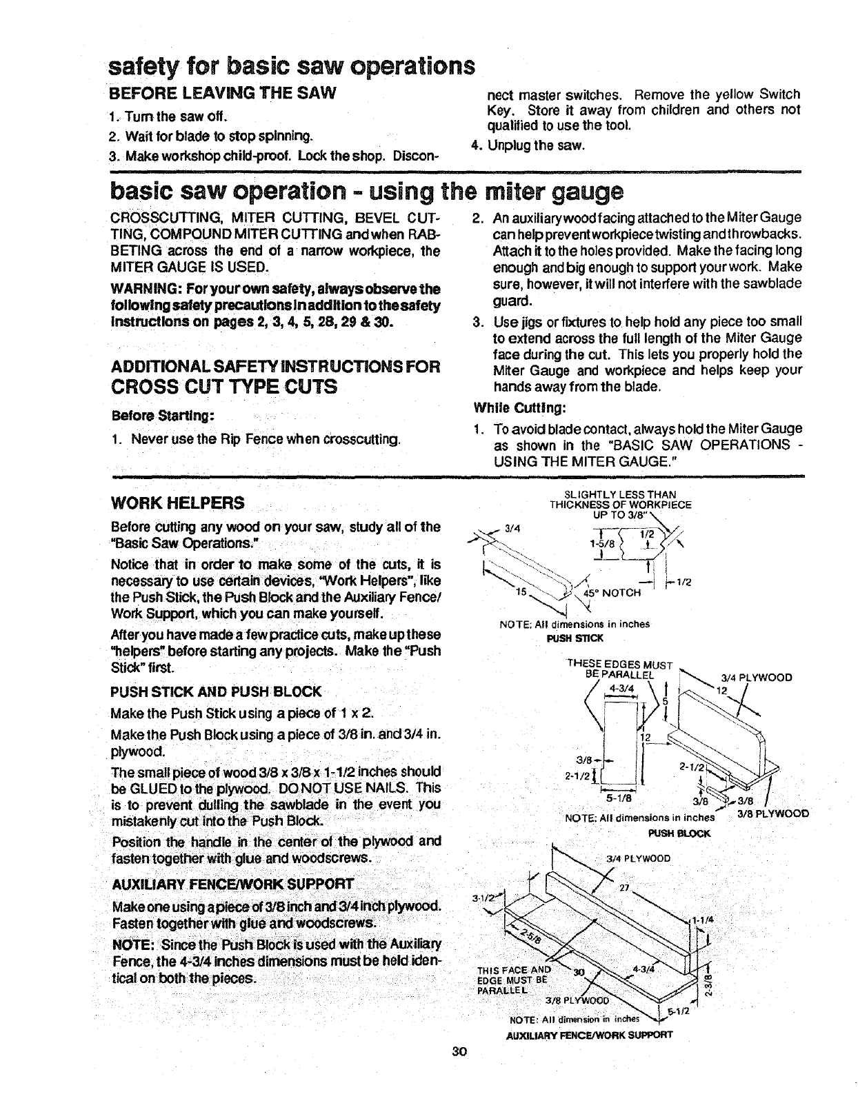
Work Helpers ....................................................... 30
Crosscutting ......................................................... 31
Repetitive Cutting ................................................ 32
Miter Cutting ......................................................... 32
Bevel Crosscutting ............................................... 33
Compound Miter Cutting ...................................... 33
Using the Rip Fence ............................................... 33
Ripping ................................................................ 34
Bevel Ripping ....................................................... 34
Using Featherboards for Thru Sawing ................. 36
Resawing ............................................................. 36
Cutting Panels ..................................................... 37
Rabbeting ............................................................ 37
Ploughing and Molding ........................................ 37
Dadoing ................................................................ 38
Molding Cutting .................................................... 38
Using Featherboards for Non Thru-Sawing ......... 38
Adjustments ........................................................... 39
Miter Gauge ......................................................... 39
Heeling Adjustment or Parallelism of Sawblade
to Miter Gauge Groove .................................... 39
Blade Tilt, or Squareness of Blade to Table ........ 41
Tilt Mechanism ..................................................... 42
Maintenance ........................................................... 43
Lubrication .............................................................. 43
Recommended Accessories ................................. 43
Trouble Shooting ................................................... 44
Motor .................................................................... 44
Repair Parts ........ .................................................... 46
7
M
unpacking and checking contents
TOOLS NEEDED
Phillips Screwdriver
Combination Square
Wrenches
7116 in. 112 In. 9/16 In.
Medium Screwdriver
Small Screwdriver
SIZE
Sot Screw Wrenches
3/32 In.
118 in.
5/32 in.
COMBINATION SQUARE MUST BE TRUE.
DRAW LIGHT LINE ON
BOARD ALONG THIS EDGE, *_-,
I
STRAIGHT EDGE OF BOARD
3/4" THICK. THIS EDGE MUST
BE PERFECTLY STRAIGHT.
SHOULD BE NO GAP OR OVERLAP
HERE WHEN SQUARE IS FLIPPED
OVER IN DOTTED POSITION,
Separate all parts from packing materials and check
each one with the illustratbn and the listof Loose Parts
to make certain all items are accounted for, before
discarding any packing material.
WARNING: If any parts are missing, do not attempt
to assemblethe table saw, plug in the power cord or
turn the switch or= until the missing parts are ob-
tained and are Installed correctly.
Remove the protective oilthat is applied to the table top
andedgesof thetable. Use anyordinary household type
grease and spot remover.
WARNING: Toavoidfireor health hazard, never use
gasoline, naptha, or similar highly volatile solvents.
Apply acoat of automobile wax to the table.
Wipe all parts thoroughly with aclean, dry cloth.
WARNING: Foryour own safety, neverconnect plug
to power source outlet until a, assembly steps are
complete, and you have read and understand the
safety and operational Instructions.
ffEM PART NAME QTY.
A Blade Guard and Spreader ........................... 1
B Rip Fence ...................................................... 1
C Owner's Manual ............................................ 1
D Cast Iron Table Extensions ........................... 2
E Miter Gauge .................................................. 1
H Rip Fence Guide Bar with Rip Scale (Front). 1
M Support, Motor Base ..................................... 1
Q Rip Fence Guide Bar (Rear) ......................... 1
R Side Stiffener ................................................. 2
S Leg ................................................................ 4
T End Stiffener ................................................. 2
U Motor ............................................................. 1
Bag of Loose Parts
(Containing the following items)
G Outlet, On/Off with Key ................................. 1
J Handwheel .................................................... 2
AM Bracket, "L" Mounting (Model 113298721)... 1
Bag of Loose Parts ........................................ 3
Bag of Loose Parts
(Containing the following items)
FWrench .......................................................... 1
K Belt, "V" 1/2 x 41 ........................................... 1
L Pulley, 1/2 dia. with 5/8 Bore ......................... 1
N Spreader, Rod ............................................... 1
0 Blade Guard Support .................................... 1
P Spreader Support .......................................... 1
S
u
(MODEL 113.298761)
(MODEL 113.298721)
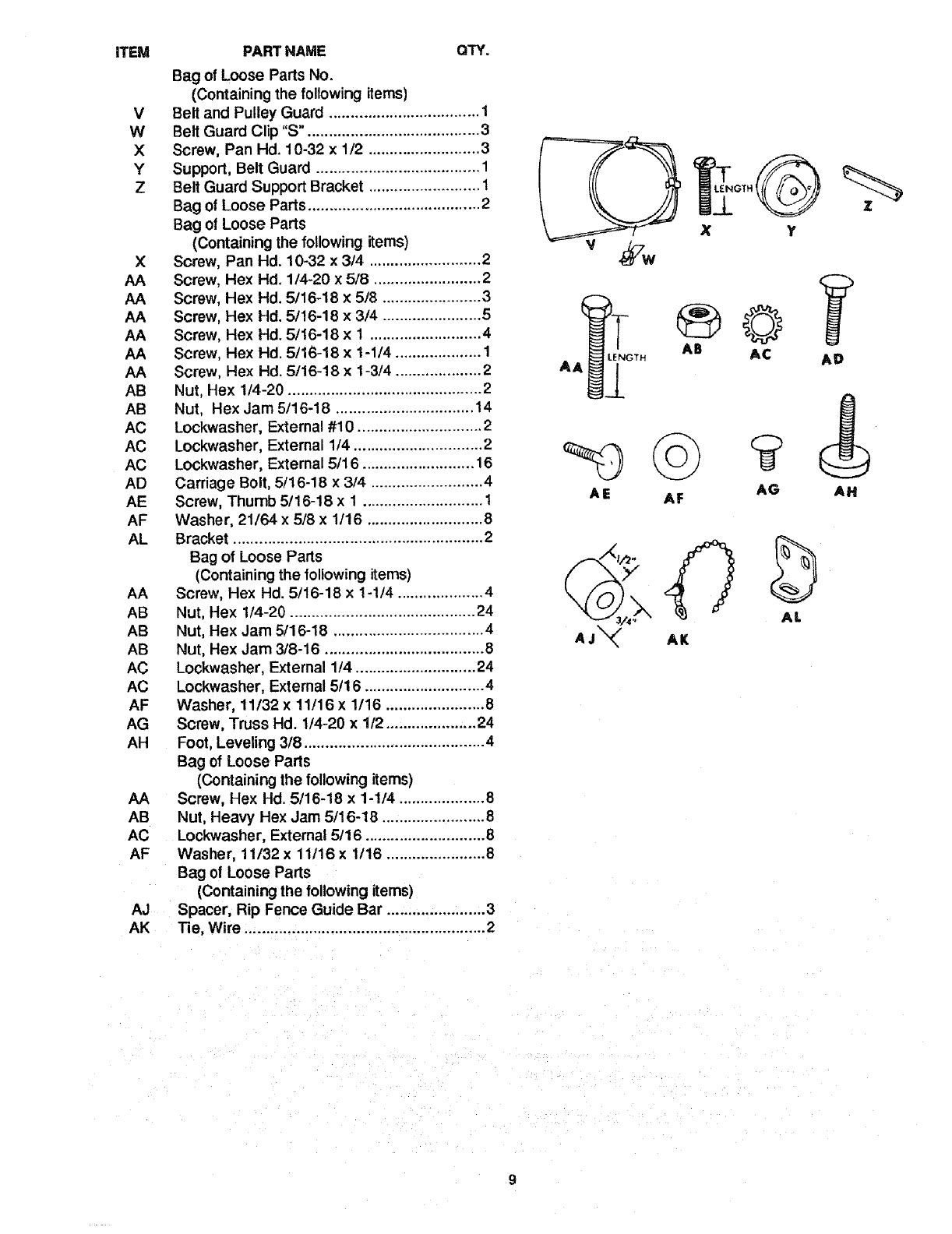
ITEM PART NAME QTY.
Bag of Loose Parts No.
(Containing the following items}
V Belt and Pulley Guard ................................... 1
W Belt Guard Clip "S". ....................................... 3
X Screw, Pan Hd. 10-32 x 1/2 .......................... 3
Y Support, Belt Guard ...................................... 1
Z Belt Guard Support Bracket .......................... 1
Bag of Loose Parts ........................................ 2
Bag of Loose Parts
(Containing the following items)
X Screw, Pan Hd. 10-32 x 3/4 .......................... 2
AA Screw, Hex Hd. 1/4-20 x 5/8 ......................... 2
AA Screw, Hex Hd. 5/16-18 x5/8 ....................... 3
AA Screw, Hex Hd. 5/16-18 x 3/4 ....................... 5
AA Screw, Hex Hd. 5/16-18 x 1 .......................... 4
AA Screw, Hex Hd. 5/16-18 x 1-1/4 .................... 1
AA Screw, Hex Hd. 5/16-18 x 1-3/4 .................... 2
AB Nut, Hex 1/4-20 ............................................. 2
AB Nut, Hex Jam 5/16-18 ................................ 14
AC Lockwasher, External #10 ............................. 2
AC Lockwasher, External 1/4 .............................. 2
AC Lockwasher, External 5/16 .......................... 16
AD Carriage Bolt, 5/16-18 x 3/4 .......................... 4
AE Screw, Thumb 5/16-18 x 1 ............................ 1
AF Washer, 21164 x 5/8 x 1/16 ........................... 8
AL Bracket .......................................................... 2
Bag of Loose Parts
(Containing the following items)
AA Screw, Hex Hd. 5/16-18 x 1-1/4 .................... 4
AB Nut, Hex 1/4-20 ........................................... 24
AB Nut, Hex Jam 5/16-18 ................................... 4
AB Nut, Hex Jam 3/8-16 ..................................... 8
AC Lockwasher, External 1!4 ............................ 24
AC Lockwasher, External 5/16 ............................ 4
AF Washer, 11/32 x 11/16 x 1/16 ....................... 8
AG Screw, Truss Hd. 1/4-20 x 1/2 ..................... 24
AH Foot, Leveling 318.......................................... 4
Bag of Loose Parts
(Containing the following items)
AA Screw, Hex Hd. 5/16-18 x 1-1/4 .................... 8
AB Nut, Heavy Hex Jam 5/16-18 ........................ 8
AC Lockwasher, External 5/16 ............................ 8
AF Washer, 11t32 x 11/16 x 1/16 ....................... 8
Bag of Loose Parts
(Containing the following items)
AJ Spacer, Rip Fence Guide Bar ....................... 3
AK Tie, Wire ........................................................ 2
AE AF
AB AC AD
AG AH
0
AJ_ AK
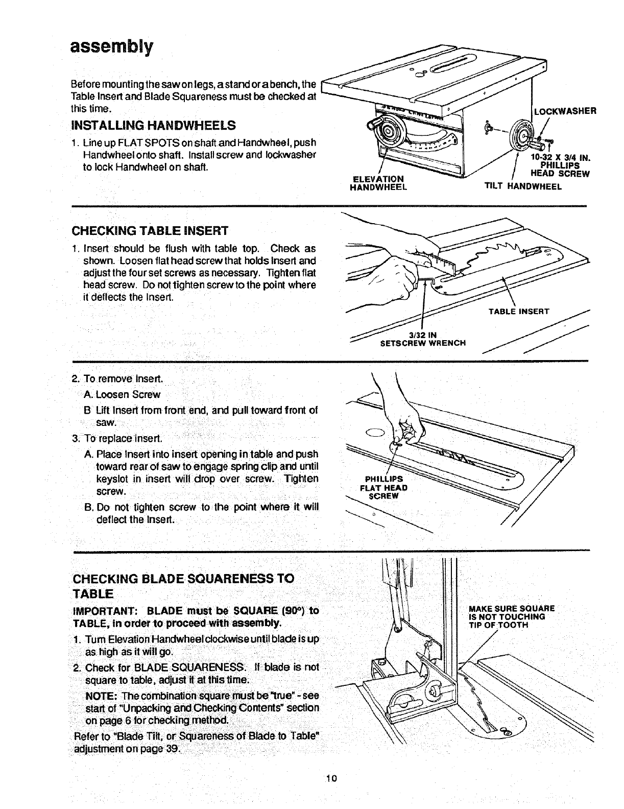
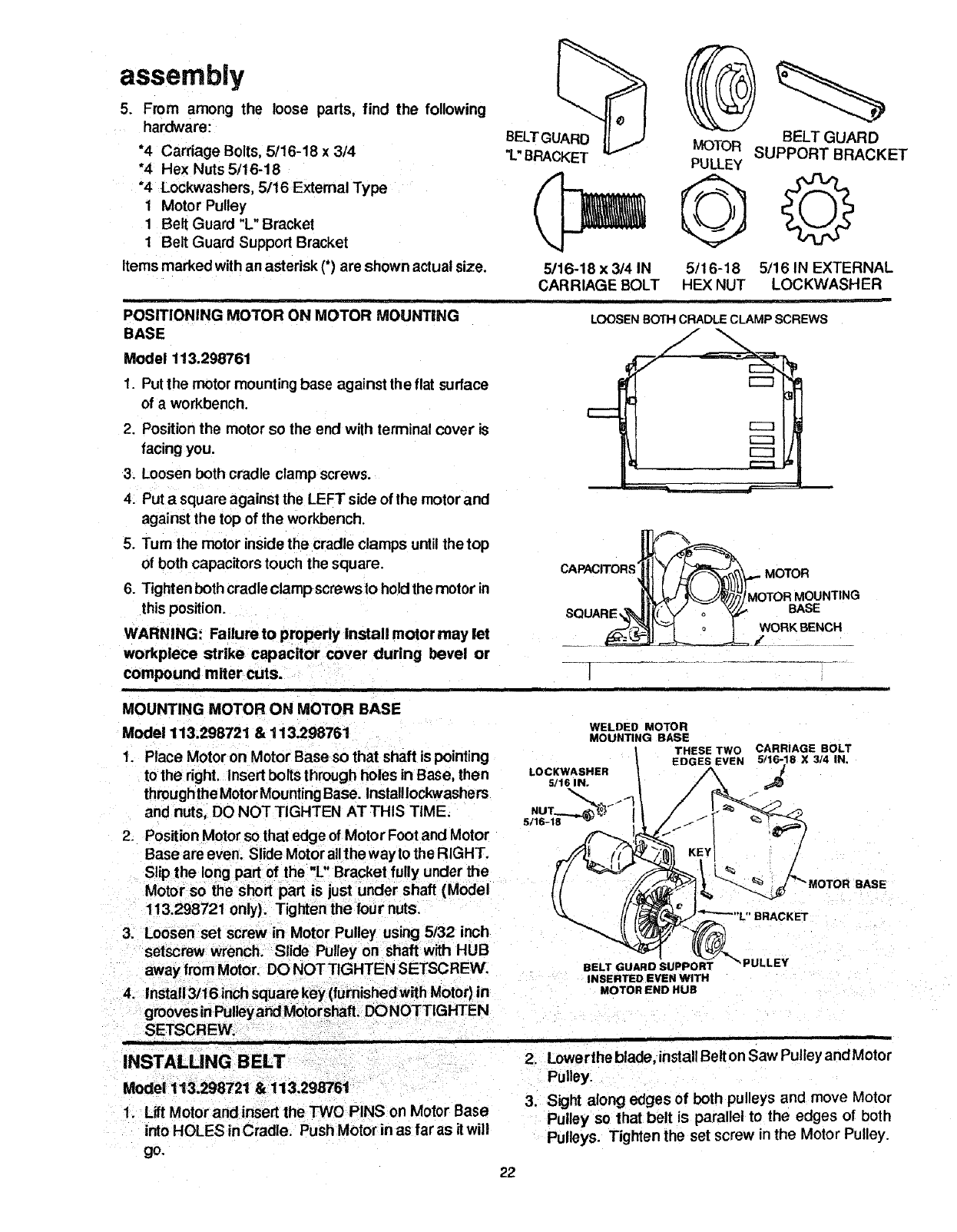
assembly
Before mountingthe saw on legs, astand ora bench, the
Table Insert and Blade Squareness must be checked at
this time.
INSTALLING HANDWHEELS
1. Line up FLAT SPOTS onshaft and Handwheel, push
Handwheel onto shaft. Installscrew and Iockwasher
to lock Handwheel on shaft.
ELEVATION
HANDWHEEL
LOCKWASHER
10-32 X 314 IN.
PHILLIPS
HEAD SCREW
TILT HANDWHEEL
CHECKING TABLE INSERT
1. Insert should be flush with table top, Check as
shown. Loosen flat head screw that holds Insert and
adjust the four set screws as necessary. -tighten flat
head screw. Do nottighten screw to the pointwhere
it deflects the Insert.
3/32 IN
SETSCREW WRENCH
2. To remove Insert.
A. Loosen Screw
B Lift Insert from front end, and pulltoward front of
saw,
3, To replaceinsert.
A. Place Insert into insert opening in table and push
toward rear of saw to engage spring clip and until
keyslot in insert will drop over screw. Tighten
screw.
B. Do not tighten screw to the point where it will
deflect the Insert.
CHECKING BLADE SQUARENESS TO
TABLE
IMPORTANT: BLADE must be SQUARE (90°) to
TABLE, in order to proceed with assembly.
1. "rum Elevation Handwheelclockwise untilblade isup
2. Check for BLADE SQUARENESS. If blade is not
square to table, adjust it at this time,
Contents" section
Refer to "Blade Tilt, or Squareness of Blade to Table"
adjustment on page 39.
MAKESURESQUARE
ISNOTTOUCHING
TIPOFTOOTH
/
/
10
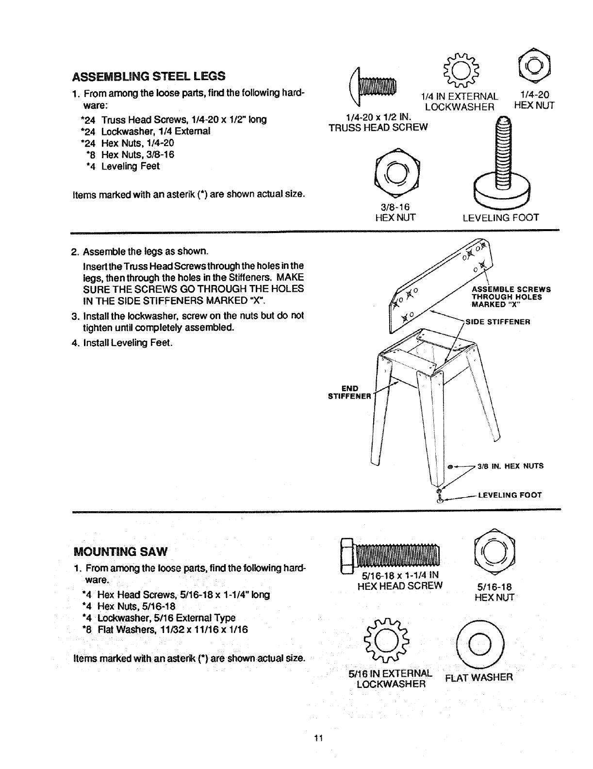
ASSEMBUNG STEEL LEGS
1. From among the loose parts, find the following hard-
ware:
*24 Truss Head Screws, 1/4-20 x 1/2" long
*24 Lockwasher, 1/4 External
*24 Hex Nuts, 1/4-20
*8 Hex Nuts,318-16
*4 Leveling Feet
Items marked with an asterik (*) are shown actual size.
1/4-20 x1/2 IN.
TRUSS HEAD SCREW
3/8 -16
HEX NUT
©
1/4 IN EXTERNAL
LOCKWASH ER
@
1/4-20
HEX NUT
LEVELING FOOT
2. Assemble the legs as shown.
Insert the Truss Head Screws throughthe holes inthe
legs, then through the holes inthe Stiffeners. MAKE
SURE THE SCREWS GO THROUGH THE HOLES
IN THE SIDE STIFFENERS MARKED "X".
3. Install the lockwasher, screw on the nuts but do not
tighten until completely assembled.
4. Install Leveling Feet.
ASSEMBLE SCREWS
THROUGH HOLES
MARKED "X"
SIDE STIFFENER
END
STIFFENER
\
HEX NUTS
_LEVELING FOOT
MOUNTING SAW
1. From among the loose parts, find the following hard-
ware.
*4 Hex Head Screws, 5/16-18 x 1-1/4" long
*4 Hex Nuts, 5/16-18
*4 Lockwasher, 5/16 External Type
*8 Flat Washers, 11/32 x 11/16 x 1/16
Items marked with an astenl_(*) are shown actual size.
HEX HEAD SCREW
5/16 IN EXTERNAL
LOCKWASHER
5/16-18
HEX NUT
FLAT WASHER
11
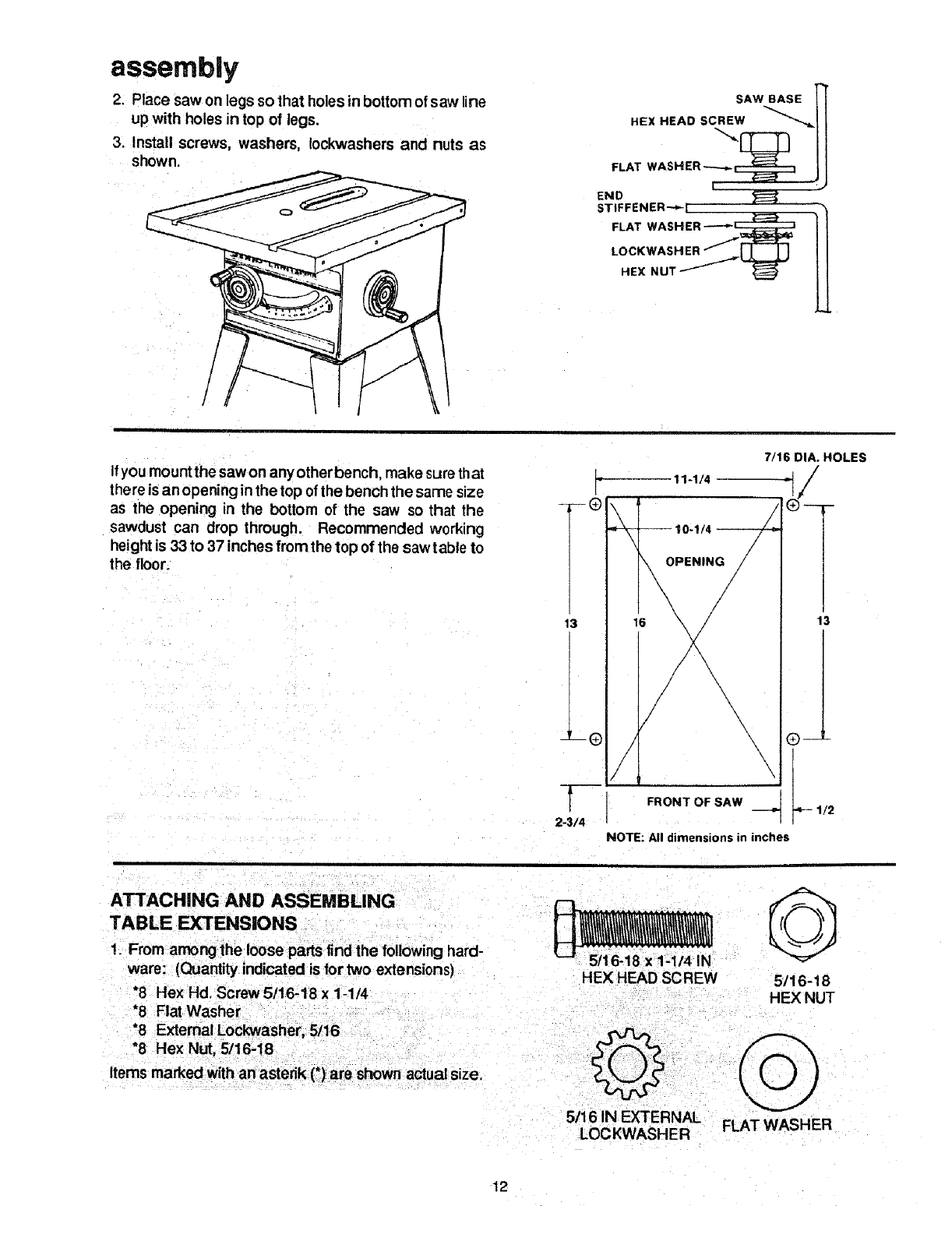
assembly
2. Place saw on legs so that holes in bottom of saw line
up with holes in top of legs.
3. Install screws, washers, Iockwashers and nuts as
shown.
/
SAW BASE !
FLAT WASHER ..----_ _ I
!
END
STIFFENER'_ k i
FLAT WASHER -----'_
LOCKWASHER
Ifyou mount the saw on any other bench, make surethat
there isan opening inthe top ofthe bench the same size
as the opening in the bottom of the saw so that the
sawdust can drop through. Recommended working
heightis 33 to 37 inches from the top of the saw table to
the floor.
7/16 DIA. HOLES
L
F
T®
OPENING_ 7_
13 16 \
/\
t \
2-3/4
NOTE: All dimensions in inches
11-1/4
13
1t2
ATTACHING AND ASSEMBLING
TABLE EXTENSIONS
1. From among the loose parts findthe following hard-
ware: (Quantity indicated is for two extensions)
*8 Hex Hd. Screw 5/16-18 x 1-1/4
*8 Flat Washer
*8 External Lockwasher, 5/16
*8 Hex Nut, 5/16;18
Items marked with an asterik (*) are shown actual size.
HEX HEAD SCREW G
5/16-18
HEX NUT
,5/16 IN EXTERNAL
LOCKWASHER FLAT WASHER
12
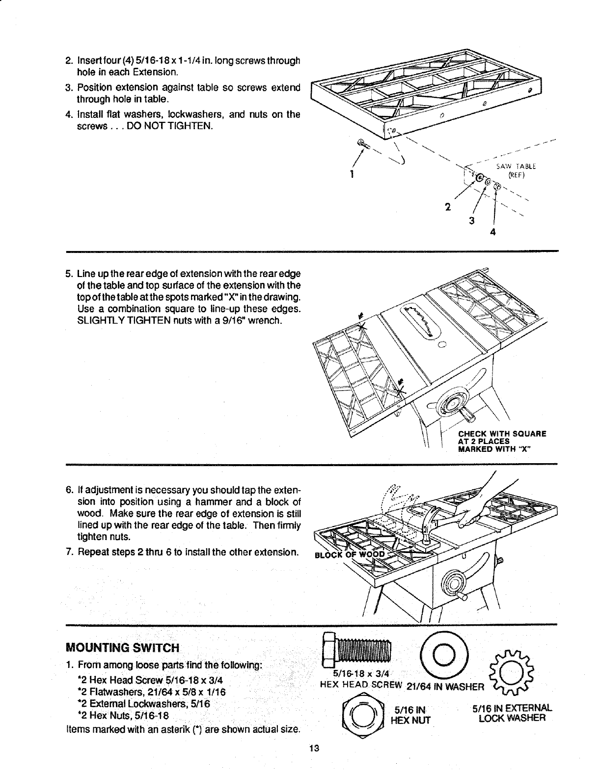
2. Insert four (4) 5/16-18 x 1-1/4 in. long screws through
hole in each Extension.
3. Position extension against table so screws extend
through hole in fable.
4. Install flat washers, Iockwashers, and nuts on the
screws... DO NOT TIGHTEN.
SAW TABLE
1 (REF)
2 \
34
5. Line up the rear edge of extension with the rear edge
of the table and top surface of the extension with the
top of the table at the spots marked"X" inthe drawing.
Use a combination square to line-up these edges.
SLIGHTLY TIGHTEN nuts with a 9/16" wrench.
CHECK WITH SQUARE
AT 2 PLACES
MARKED WITH "X"
6. If adjustment is necessary you should tap the exten-
sion into position using a hammer and a block of
wood. Make sure the rear edge of extension is still
lined up with the rear edge of the table. Then firmly
tighten nuts.
7. Repeat steps 2 thru 6 to install the other extension.
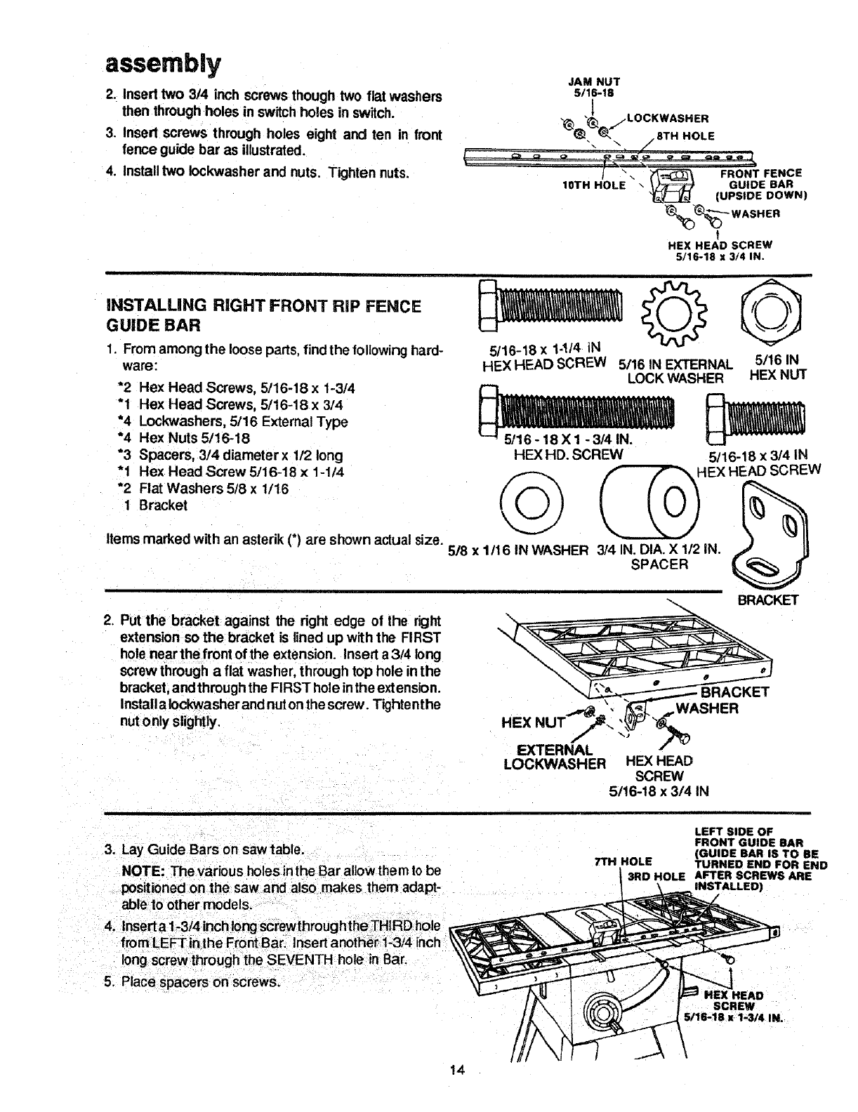
MOUNTING SWITCH
1. From among loose parts find the following:
*2 Hex Head Screw 5/16-18 x 3/4
*2 Flatwashers, 21/64 x 5/8 x 1/16
*2 External Lockwashers, 5/16
*2 Hex Nuts, 5/16-18
Items marked with an asterik (*) are shown actual size.
/
/
5/16-18 x 3/4
HEX HEAD SCREW 2t/64 tN WASHER
13
5/16 IN 5/16 IN EXTERNAL
HEX NUT LOCK WASHER
assembly
2. Insert two 3/4 inch screws though two flat washers
then through holes in switch holes in switch.
3. Insert screws through holes eight and ten in front
fence guide bar as illustrated.
4. Install two Iockwasher and nuts. Tighten nuts. J".
IOTH HOLE
JAM NUT
5/16-18
LOCKWASHER
•.u,_.,, "_,.._ /8TH HOLE
FRONT FENCE
\GUIDE BAR
(UPSIDE DOWN)
%%'--- WASHER
t
HEX HEAD SCREW
5/16-18 x 3/4 IN.
INSTALUNG RIGHT FRONT RiP FENCE
GUIDE BAR
1. From among the loose parts, find the following hard-
ware; 5/16-18 x1-!/4 iN
HEX HEAD SCREW 5/16 IN EXTERNAL
*2 Hex Head Screws, 5/16-18 x 1-3/4
"1 Hex Head Screws, 5/16-18 x 3/4
*4 Lockwashers, 5/16 External Type
*4 Hex Nuts 5/16-18
*3 Spacers, 3/4 diameter x 1/2 long
"1 Hex Head Screw 5/16-18 x 1-1/4
*2 Flat Washers 5/8 x1/16
1 Bracket
Items marked with an asterik (*) are shown actual size.
2. Put the bracket against the right edge of the right
extension so the bracket is lined up with the FIRST
hole near the front of the extension. Insert a 3/4 long
screw through a flat washer, through top hole in the
bracket, and through the FIRST hole in the extension.
Install a Iockwasher and nut on the screw. Tighten the
nutonly slightly.
5/16 IN
LOCK WASHER HEX NUT
HEX HD. SCREW 5/16-18 x 3/4 IN
5/8 X 1/16 IN WASHER 3/4 IN, DIA. X 1/2 IN. .,_/ II
SPACER
BRACKET
HEX NU
EXTERNAL
LOCKWASHER HEX HEAD
SCREW
5116-18 x 3/4 IN
3. Lay Guide Bars on saw table.
NOTE: The various holes inthe Bar allow them to be
positioned on the saw and also makes them adapt-
able to other models.
4. Insert a 1-3t4 inch/ong screwthrough the THIRDhole
LEFT SIDE OF
FRONT GUIDE BAR
(GUIDE BAR I$ TO BE
TTH HOLE TURNED END FOR END
3RD HOLE AFTER SCREWS ARE
INSTALLED)
5. Place spacers on screws.
SCREW
S/16-18 x 1-3/4 IN.
\
14
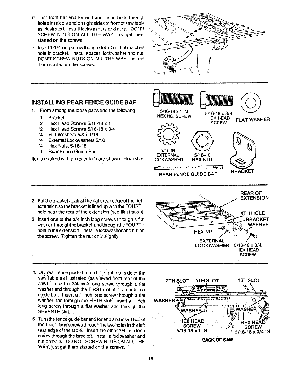
6. Turn front bar end for end and insert bolts through
holes in middle and on right sides of front of saw table
as illustrated. Install Iockwashers and nuts. DON'T
SCREW NUTS ON ALL THE WAY, just get them
started on the screws.
7. Insert 1-1/4 long screwthough slot in bar that matches
hole in bracket. Install spacer, Iockwasher and nut.
DON'T SCREW NUTS ON ALL THE WAY, just get
them started on the screws.
iNSTALLING REAR FENCE GUIDE BAR
1. From among the loose parts find the following:
1 Bracket
*2 Hex Head Screws 5/16-18 x 1
*2 Hex Head Screws 5/16-18 x 3/4
*4 Flat Washers 5/8 x 1116
*4 External Lockwashers 5/16
*4 Hex Nuts, 5/16-18
1 Rear Fence Guide Bar
Items marked with an asterik (*) are shown actual size.
5/16-18 x 1 IN
HEX HD. SCREW
5/16 IN
EXTERNAL 5/16-18
LOCKWASHER HEX NUT
5/16-18 x 3/4
HEx HEAD
SCREW
REAR FENCE GUIDE BAR
FLAT WASHER
BRACKET
2. Put the bracket against the right rear edge of the right
extension sothe bracket is lined up with the FOURTH
hole near the rear of the extension (see illustration).
3. Insert one of the 3/4 inch long screws through a flat
washer, through the bracket, andthrough the FOU RTH
hole inthe extension. Install a Iockwashe rand nut on
the screw. Tighten the nut only slightly.
\
HEX NUT
EXTERNAL
LOCKWASH ER
REAR OF
EXTENSION
4TH HOLE
IKET
WASHER
5/16-18 x 3/4
HEX HEAD
SCREW
4. Lay rear fence guide bar on the right rear side of the
saw table as illustrated (as viewed from rear of the
saw). Insert a 3/4 inch long screw through a flat
washer and through the FIRST slot of the rear fence
guide bar. Insert aI inch long screw through a flat
washer and through the FIFTH slot. Insert a I inch
long screw through a flat washer and through the
SEVENTH slot.
5. Turn the fence guide bar end for end and inserttwo of
the 1 inch long screwsthrough thetwo holes inthe left
rear edge of the table. Insert the other 3/4 inch long
screw through the bracket. Instal] a tockwasher and
nut on bolts. DO NOT SCREW NUTS ON ALL THE
WAY. just get them started on the screws.
7TH SLOT 5TH SLOT
HEX HEAD
SCREW
5/16-18 x 1IN
BACK OF SAW
1ST SLOT
I
HEX HEAD
SCREW
5/16-18 x 3/4 IN,
15

assembly
6. Slide the Barssothat screwsare inthe MIDDLE ofthe
slotted holes.
7. PositionRipFenceoverMiterGaugeGroove, holding
up the rear end while engaging front end with Bar.
Lower Fence onto table.
8. Raise blade all the way up.
9. Carefully move Fence against blade.
10. Move Front Bar until "0" mark on Rip Scale is
approximately in line with tip of Pointer.
11. Move Front Bar upwards until Fence is approxi-
mately 1/32 inch above table. l-_Jhten screw at left
end of Bar.
NOTE: Fold a piece of newspaper making 8 thick-
nesses and place between Rip Fence and table to
act as a spacer. This will hold the Fence off of the
table approximately 1/32 inch.
12. Adjust Rear Bar so that the Fence is approximately
1/32 inch above table, make sure it is square with
Miter Gauge Groove. Tighten screw at end of Bar.
8THICKNESSES
OF PAPER
13. Move Fenceto RIGHTedge of table. Make sure it is
approximately 1/32 inch above table at front and
rear and tighten screws.
8 THICKNESSES
16
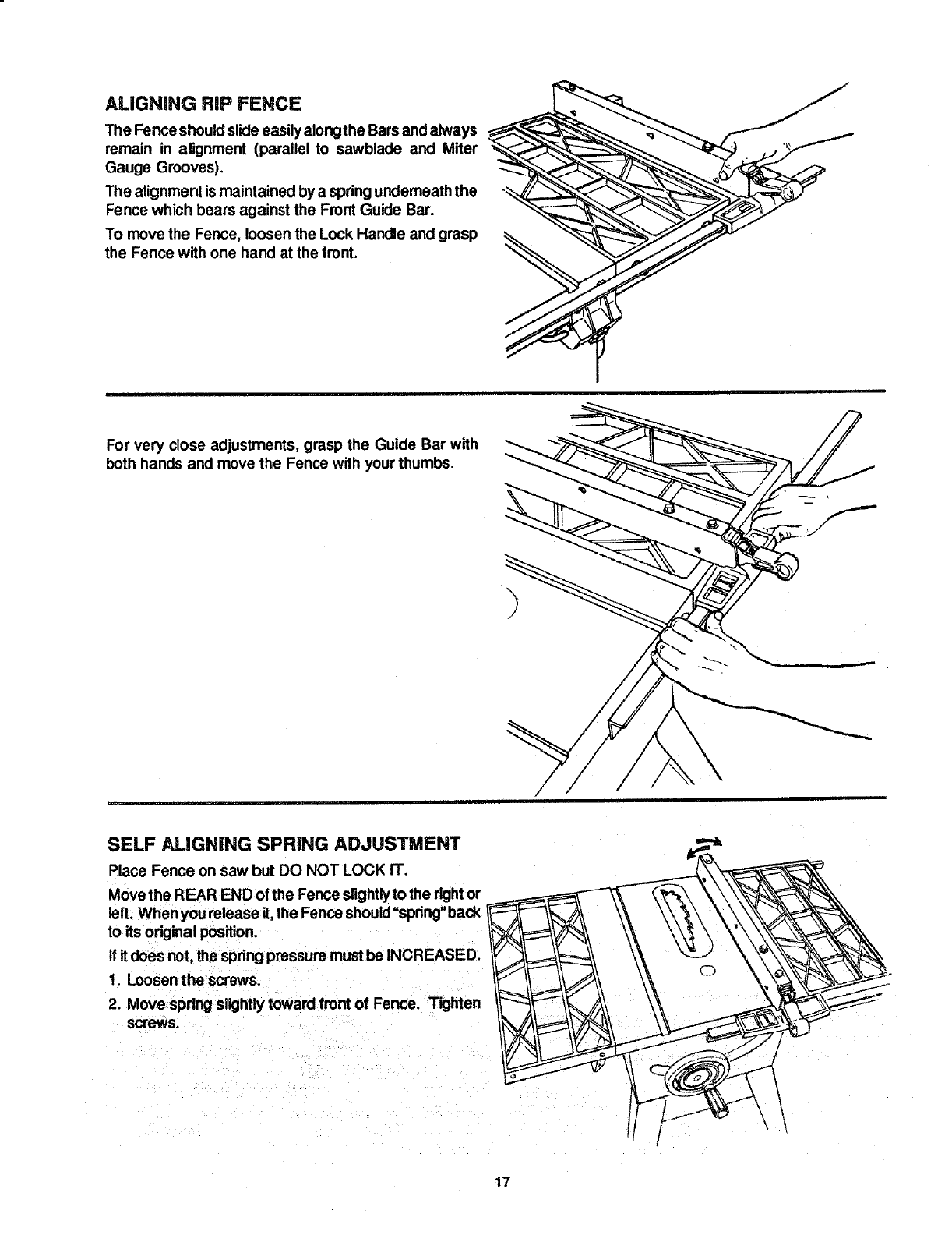
ALIGNING RiP FENCE
The Fence should slide easilyalongthe Bareand always
remain in alignment (parallel to sawblade and Miter
Gauge Grooves).
The alignment is maintained by a spring underneath the
Fence which bears against the Front Guide Bar.
To move the Fence, loosen the Lock Handle and grasp
the Fence with one hand at the trent.
For very close adjustments, grasp the Guide Bar with
both hands and move the Fence with your thumbs. "_"
/
SELF ALIGNING SPRING ADJUSTMENT
Place Fence on saw but DO NOT LOCK IT.
Move the REAR END of the Fence slightlyto the rightor
left. When you release it,the Fence should=spring" back
to its original position.
If itdoes not, the spring pressure must be INCREASED.
1. Loosen the screws.
2. Move spring slightly toward front of Fence. Tighten
screws.
\
17
assembly
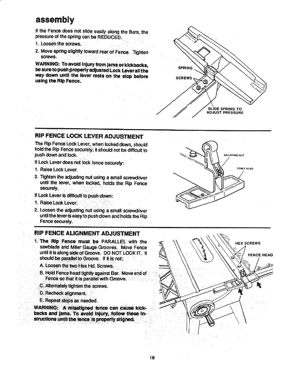
If the Fence does not slide easily along the Bars, the
pressure of the spring can be REDUCED.
1. Loosen the screws.
2. Move spring slightly toward rear of Fence. Tighten
screws.
WARNING: Toavoid Injury from jarnsorklckbacks,
be sure to push properly adjusted Lock Lever all the
way down until the lever rests on the stop before
using the Rip Fence.
SPRING
SLIDE SPRING TO
ADJUST PRESSURE
RiP FENCE LOCK LEVER ADJUSTMENT
The Rip Fence Lock Lever, when locked down, should
holdthe Rip Fence securely, it should not be difficultto
push down and lock.
If Lock Lever does not lock fence securely:
1. Raise Lock Lever.
2. Tighten the adjusting nut using a small screwdriver
until the lever, when locked, holds the Rip Fence
securely.
If Lock Lever is difficult to push down:
1. Raise Lock Lever.
2. Loosen the adjusting nut using a small screwdriver
untilthe lever is easy to push down and holdsthe Rip
Fence securely.
ADJUSTING NUT
FENCE HEAD
RiP FENCE ALIGNMENT ADJUSTMENT
1. The Rip Fence must be PARALLEL with the
sawblade and Miter Gauge Grooves. Move Fence
until it is along side of Groove. DO NOT LOCK IT. It
should be parallel to Groove. ff it is not;
A. Loosen the two Hex Hd. Screws.
B. Hold Fence head tightlyagainst Bar. Move end of
Fence so that it is parallel with Groove.
C. Alternately tighten the screws.
D. Recheck alignment.
E. Repeat steps as needed.
WARNING: A misallgned fence can cause kick-
backs and jams. To avoid Injury, follow these irv
structlons until the fence is properly aligned.
HEXSCREWS
FENCE HEAD
18
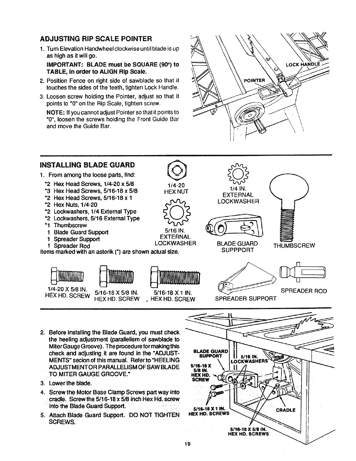
ADJUSTING RiP SCALE POINTER
1. Turn Elevation Handwheel clockwise untilblade is up
as high as it will go.
IMPORTANT: BLADE must be SQUARE (90°) to
TABLE, in order to ALIGN Rip Scale.
2. Position Fence on right side of sawblade so that it
touches the sides of the teeth, tighten Lock Handle.
3. Loosen screw holding the Pointer, adjust so that it
pointsto "0" on the Rip Scale, tighten screw.
NOTE: If you cannot adjust Pointer so that it points to
"0", loosen the screws holding the Front Guide Bar
and move the Guide Bar.
LOCK HANDLE
INSTALLING BLADE GUARD
1. From among the loose parts, find:
*2 Hex Head Screws, 1/4-20 x 5/8
*3 Hex Head Screws, 5/16-18 x5!8
*2 Hex Head Screws, 5/16-18 x 1
*2 Hex Nuts, 1/4-20
*2 Lockwashers, 1/4 Extemal Type
*2 Lockwashers, 5/16 ExternalType
"1 Thumbscrew
1 Blade Guard Support
1 Spreader Support
1Spreader Rod
@
1/4-20
HEX NUT
Q
_161N.
EXTERNAL
LOCKWASHER
Items marked with an astedk (*) are shown actual size.
1/4-20 X 5/8 IN.
HEX HD. SCREW 5/16-18 X 5/8 IN.
HEX HD. SCREW 5/16-18 X 1 IN.
,HEX HD. SCREW
©
1/4 IN.
EXTERNAL
LOCKWASH ER
BLADE GUARD
SUPPPORT THUMBSCREW
SPREADER ROD
SPREADER SUPPORT
2. Before installing the Blade Guard, you must check
the heeling adjustment (parallelism of sawblade to
Miter Gauge Groove). The procedure for making this
check and adjusting it are found in the "ADJUST-
MENTS" secion of this manual. Refer to "HEELING
ADJUSTMENTOR PARALLELISM OF SAW BLADE
TO MITER GAUGE GROOVE."
3. Lower the blade.
4. Screw the Motor Base Clamp Screws part way into
cradle. Screw the 5/16-18 x 5/8 inch Hex Hd. screw
into the Blade Guard Support.
5. Attach Blade Guard Support. DO NOT TIGHTEN
SCREWS.
BLADE (
SUPPORT
\
5/16-18 X
5/8 IN.
HEX HD.
SCREW
5/16.18X1 IN. ]
HEX HD. SCREWS
5116-18 X 5/8 IN
HEX HD. SCREWS
19
assemb|y
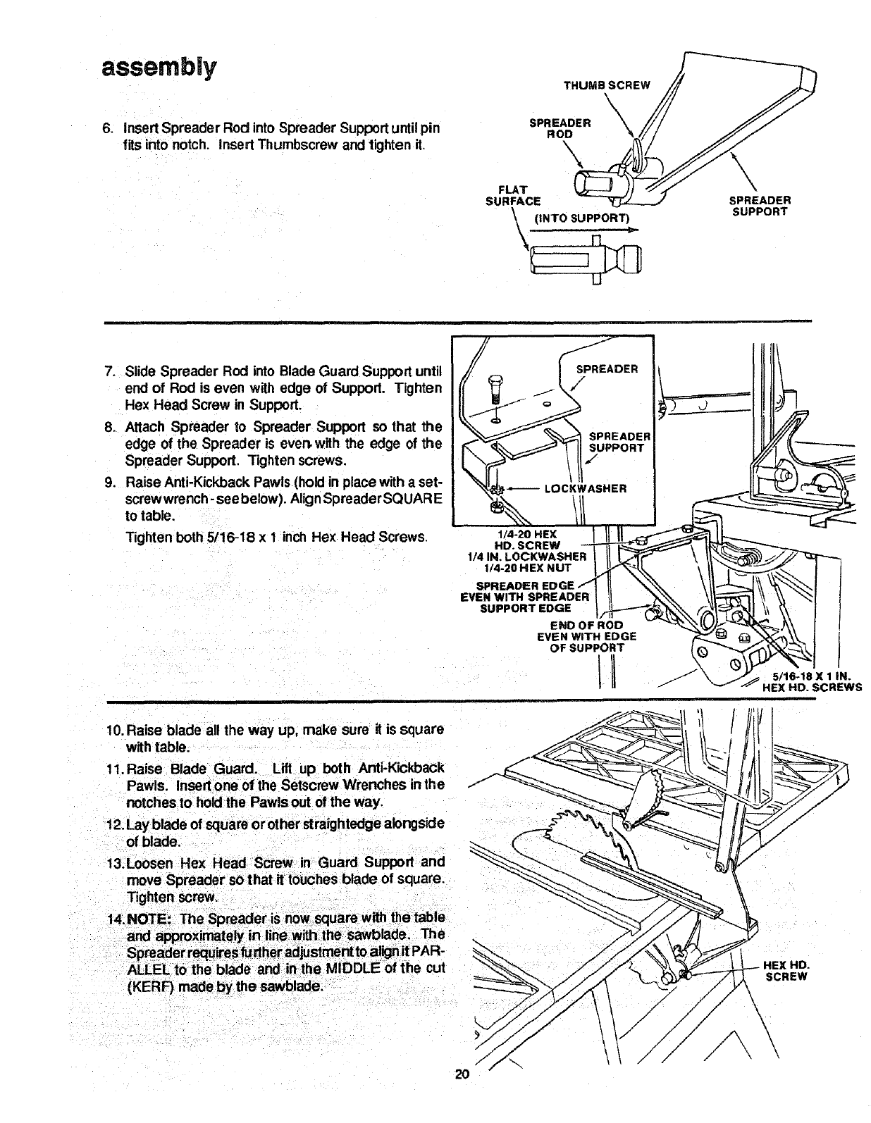
6. Insert Spreader Rod into Spreader Support until pin
fits into notch. Insert Thumbscrew and tighten it.
THUMB SCREW
\\
SPREADER
ROD
\\
FLAT
SURFACE
\(INTO SUPPORT)
17 "
U
SPREADER
SUPPORT
7. Slide Spreader Rod into Blade Guard Support until
end of Rod is even with edge of Support. Tighten
Hex Head Screw in Support.
8. Attach Spreader to Spreader Support so that the
edge of the Spreader is ever_with the edge of the
Spreader Support. Tighten screws.
9. Raise Anti-Kickback Pawls (hold in place with a set-
screw wrench -see below). AlignSpreader SQUARE
to table,
Tighten both 5/16-18 x 1 inch Hex Head Screws. 1/-2ONE\ I II II _L-""-.-.._
HD. SCREW ___\ I_'__
114 IN. LOCKWASHER _II I.j'_Trr'" \ /l_";) _J/.i/"
,,,-,O.EX.UT '/I It
SPREADER EDGE fIII "_.%'_ , _t_J \\ v_l I
EVEN WITH SPREADER I U _h_'_ \/_--II \\ \\ _1 I
EmDOFROD - _,J,/_-'<'-"_---_A\ I I
EVEN WiTH EDGE _ _._=1 _ _.._._ I [
10. Raise blade all the way up, make sure it is square
with table.
11. Raise Blade Guard. Lift up both Anti-Kickback
Pawls. Insert one of the Setscrew Wrenches inthe
notches to hold the Pawlsout of the way.
13.Loosen Hex Head Screw in Guard Support and
move Spreader so that it touches blade of square.
Tighten screw.
HE\ HD.
SCREW
15.IMPORTANT: To work properly, the Spreader
must always be PARALLEL to the sawblade and
adjusted so the cut workplece will pass on either
side at the Spreader without binding or skewing
to the side.
NOTE: The Spreader is thinner than the width of the
cut (KERF) by approximately six thicknesses of
paper.
KERF WOOD
SPREADER ..__ -- . ....
LOOKING DOWN ON SAW
16. Make two folds ina small piece (6 x 6 inch)of ordinary
NEWSPAPER making three thicknesses.
The folded paper will be used as a "spacing gauge". /
17.Place RipFence on table, CAREFULLY move it
against blade so that it is parallel to the blade, and
just TOUCHEStips of sawteeth. Tighten Rip Fence
Lock Lever.
18. Insert folded paper between Spreader and Fence.
19.Using 7/16 wrench loosen the 1/4-20 hex head
screws so the Spreader can slide sideways.
20. Hold Spreader flat against Fence. Tighten screws
using 7/16 inch wrench.
21.To remove Blade Guard and Spreader, loosen 7/16IN. WRENCH
Thumbscrew. DO NOT LOOSEN OTHER SCREWS.
This lets you remove and replace the Guard without
disturbing the Spreader alignment.
FOLDED PAPER
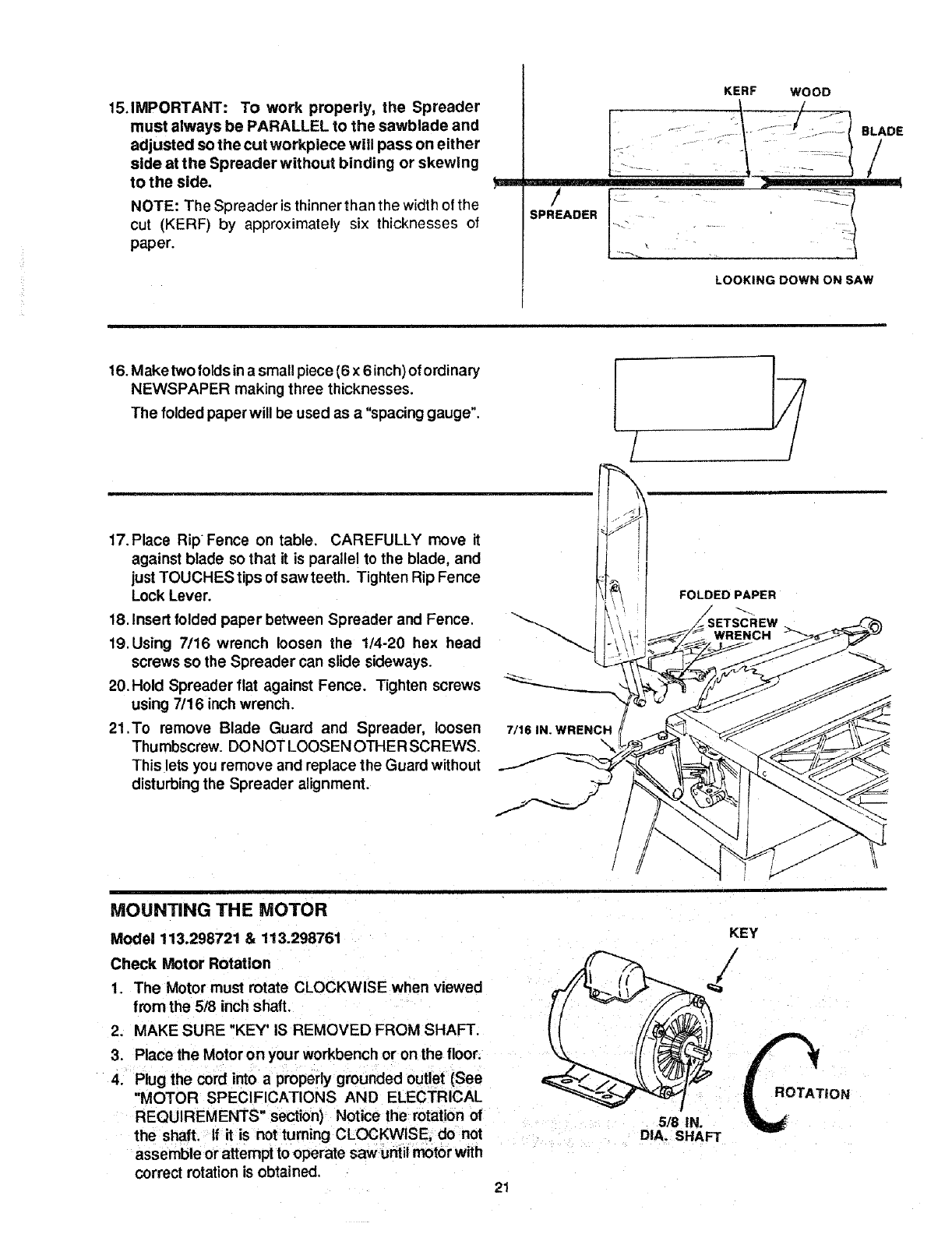
MOUNTING THE MOTOR
Model 113.298721 & 113.298761
Check Motor Rotation
1. The Motor must rotate CLOCKWISE when viewed
from the 5/8 inch shaft.
2. MAKE SURE "KEY' IS REMOVED FROM SHAFT.
3. Place the Motor on your workbench or on the floor.
4. Plug the cord into a properly grounded outlet (See
"MOTOR SPECIFICATIONS AND ELECTRICAL
REQUIREMENTS" section) Notice the rotation of
the shaft. If it is not turning CLOCKWISE, do not
assemble or attempt to operate saw until motor with
correct rotation is obtained,
KEY
518 IN.
DIA, SHAFT
21
TION
assembly
5. From among the loose parts, find the following
hardware:
*4 Carriage Bolts, 5/16-18 x3/4
*4 Hex Nuts 5t16-18
*4 Lockwashers, 5/16 External Type
1 Motor Pulley
1 Belt Guard "L" Bracket
1 Belt Guard Support Bracket
Items marked with an asterisk (*) are shown actual size.
= == i ,=,,,,,H i ,i= ,1=
POSITIONING MOTOR ON MOTOR MOUNTING
_BELT GUARdeD
BELTGUARD MOTOR SUPPORT BRACKET
"L_BRACKET PULLEY
5/16-18 x 3/4 IN
CARRIAGE BOLT
LOOSEN BOTH CRADLE CLAMP SCREWS
5/16-18 5/16 IN EXTERNAL
HEX NUT LOCKWASHER
BASE
Model 113.298761
1. Put the motor mounting base against the flat surface
of a workbench.
2. Positionthe motor so the end with terminal cover is
facing you.
3. Loosen both cradle clamp screws.
4. Put asquare against the LEFT side of the motor and
against the top of the workbench.
r.---
5. Turn the motor inside the cradle clamps untilthe top
of both capacitors touch the square
6. Tighten bothcradle clamp screwsIo holdthe motor in
this position.
WARNING: Failure to properly Install motor may let
workplece strike capacitor cover during bevel or
compound miter cuts.
=l
CAPACITORS"
SQUARE
MOTOR
MOTOR MOUNTING
BASE
WORK BENCH
MOUNTING MOTOR ON MOTOR BASE
Model 113.298721 & 113.298761
1. Place Motoron MotorBase so that shaft is pointing
to the right. Insert bolts through holes in Base, then
throughthe MotorMountingBase. Installlockwashers
and nuts, DO NOT TIGHTEN AT THIS TIME.
2. Position Motor so that edge of Motor Foot and Motor
Base are even. Slide Motor allthe way tothe RIGHT.
Slip the long part of the "L" Bracket fully under the
Motor so the short part is just under shaft (Model
113.298721 only). Tighten the fournuts.
WELDED MOTOR
MOUNTING BASE
THESE TWO
EDGES EVEN
LOCKWASHER
5/16 IN.
5/16-18
CARRIAGE BOLT
5116-18 X 3/4 iN.
away from Motor. DO NOTTIGHTEN SETSCREW.
4. Install 3116 inchsquare key (furnished with Motor) in
groovesin PulleyandMotorshaft. DONOTTIGHTEN
SETSCREW.
,= =
INSTALUNG BELT
Model 113.298721 & 113.298761
1. Lift Motor and insert the TWO PINS on Motor Base
into HOLES in Cradle. Push Motor in as far as itwill
go.
BELT GUARD SUPPORT "" PULLEY
INSERTED EVEN WITH
MOTOR END HUB
2. Lowerthe blade, installBelt on Saw Pulley and Motor
Pulley.
3. Sight along edges of both pulleys and move Motor
Pulley so that belt is parallel to the edges of bol
Pulleys. Tighten the set screw in the Motor Pulley.
22
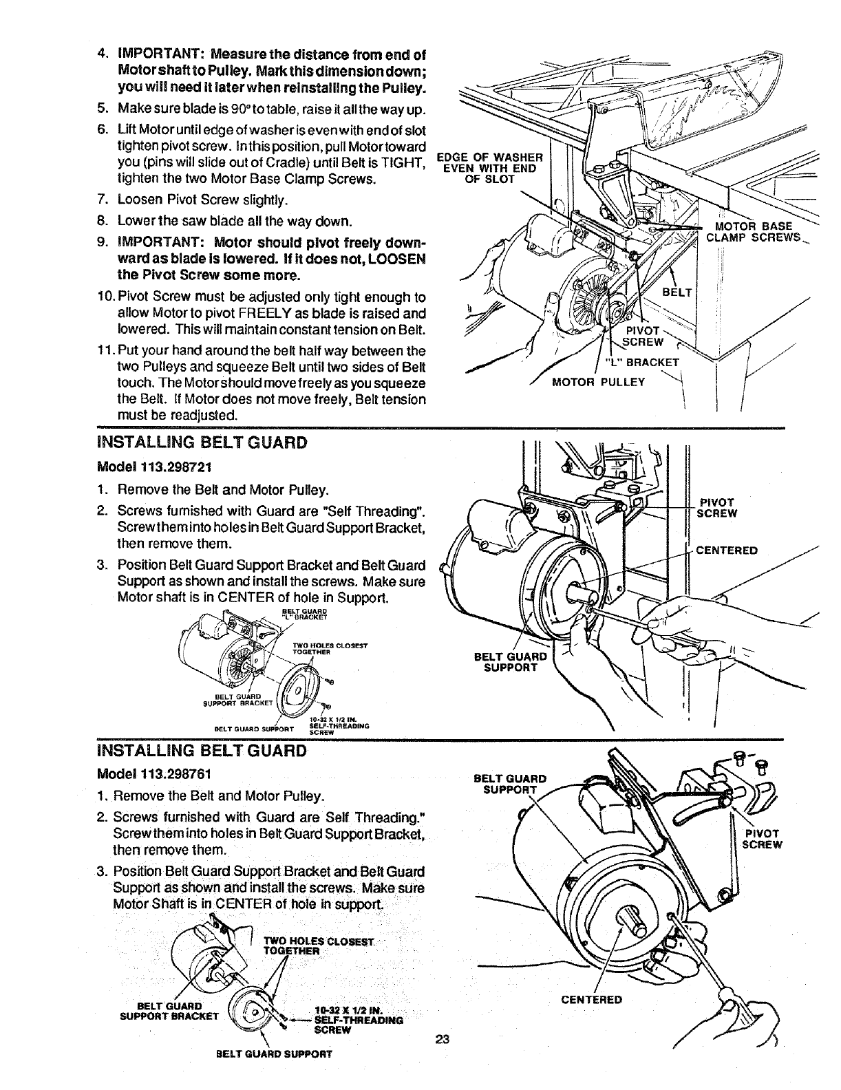
4. iMPORTANT:Measurethe distance from end of
Motor shaftto Pulley, Mark this dimension down;
you will need it later when reinstalling the Pulley.
5. Make sure blade is 90°totable, raise it allthe way up.
6. Lift Motor untiledge ofwasher isevenwith endof slot
tighten pivotscrew. Inthis position, pullMotortoward
you (pins will slide out of Cradle) until Belt is TIGHT,
tighten the two Motor Base Clamp Screws.
7. Loosen Pivot Screw slightly.
8. Lower the saw blade all the way down.
9. iMPORTANT: Motor should pivot freely down-
ward as blade is lowered. If it does not, LOOSEN
the Pivot Screw some more.
EDGE OF WASHER
EVEN WITH END
OF SLOT
10. Pivot Screw must be adjusted only tight enough to
allow Motor to pivot FREELY as blade is raised and
lowered. This will maintain constant tension on Belt.
11. Put your hand around the belt half way between the
two Pulleys and squeeze Belt until two sides of Belt
touch, The Motorshould move freely as you squeeze
the Belt. If Motor does not move freely, Belt tension
must be readjusted.
=
INSTALUNG BELT GUARD
SCREW
/"L"BRACKET
MOTOR PULLEY
Model 113.298721
1. Remove the Belt and Motor Pulley.
2. Screws furnished with Guard are "Self Threading".
Screwthem into holesin BeltGuard SupportBracket,
then remove them.
3. Position BeltGuard Support Bracket and Belt Guard
Support as shown and installthe screws. Make sure
Motor shaft is in CENTER of hole in Support.
BELT GUARD
"L" BRACKET
TWO HOLES CLOSEST
TOGETHER
oEL,oo,°o
SUPPO.T..ACKET
SELF-THRSADING
BELT GUARD SUPPORT SCREW
INSTALLING BELT GUARD
Model 113.298761
1. Remove the Belt and Motor Pulley.
2. Screws furnished with Guard are Serf Threading."
Screw them into holes in Belt Guard Support Bracket,
then remove them,
3. Position BeltGuard Support Bracket and Belt Guard
Support as shown and installthe screws. Make sure
Motor Shaft is in CENTER of hole insupport.
BELT GUARD
SUPPORT BRACKET
BELT GUARD
SUPPORT
BELT GUARD
'1 TWO HOLES CLOSEST
TOGETHER
BELT GUARD SUPPORT
/
CENTERED
kMOTOR BASE
CLAMP SCREWS_
PIVOT
-SCREW
\
PIVOT
SCREW
assembly
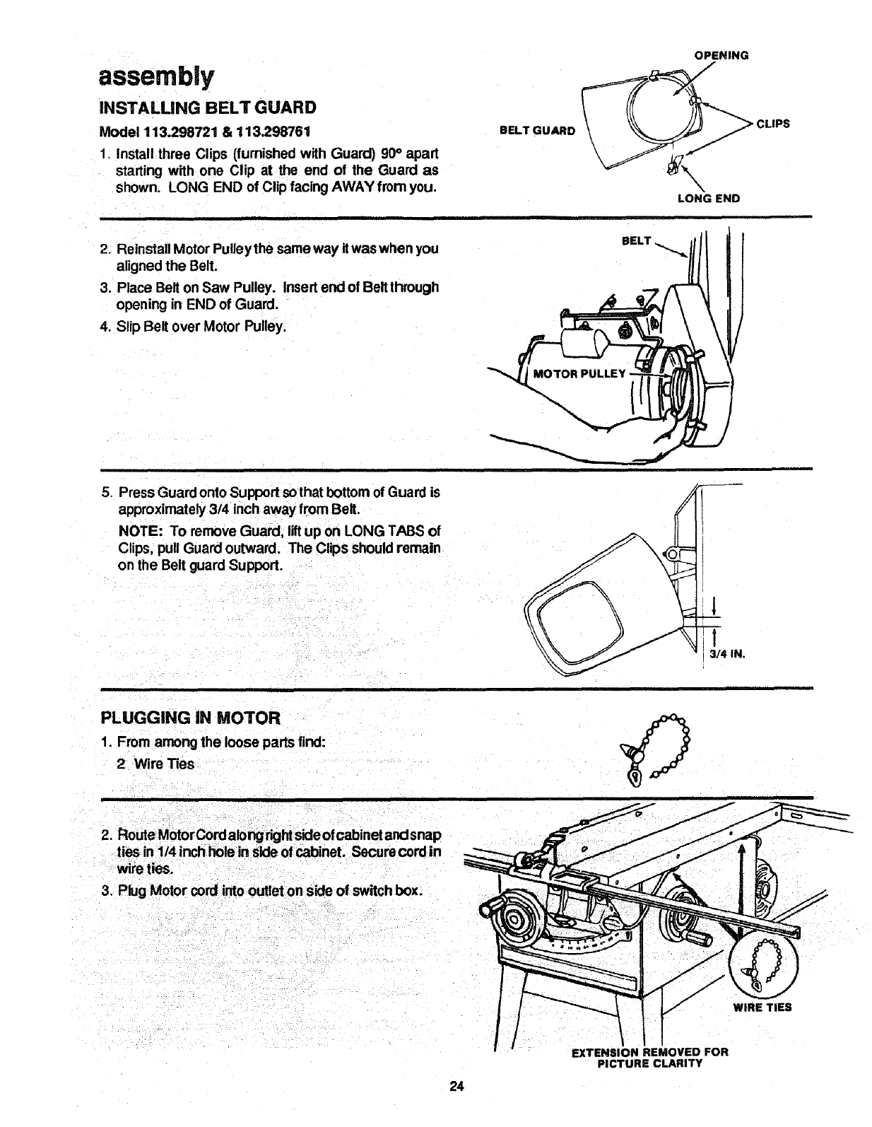
iNSTALLiNG BELT GUARD
Model 113.298721 & 113.298761
1. install three Clips (furnished with Guard) 90° apart
starting with one Clip at the end of the Guard as
shown. LONG END of Clip facing AWAY from you.
BELT GUARD
OPENING
_CLIPS
N
LONG END
2. Reinstall Motor Pulley the same way it waswhen you
aligned the Belt,
3. Place Belt on Saw Pulley. Insert end of Bell through
opening in END of Guard.
4. Slip Belt over Motor Pulley.
BELT
5. Press Guard onto Support sothat bottom of Guard is
approximately 3/4 inch away from Belt.
NOTE: To remove Guard, lift up on LONG TABS of
Clips, pull Guard outward. The Clips should remain
on the Belt guard Support.
3/4 iN.
PLUGGING iN MOTOR
1. From among the loose parts find:
2 Wire Ties
2. Route Motor Cord along dghtside ofcabinet and snap
ties in 1/4 inch bole in side of cabinet. Secure cord in
wire ties,
3. Plug Motor cord into outlet on side of switch box.
WIRE TIES
24
EXTENSION REMOVED FOR
PICTURE CLARITY
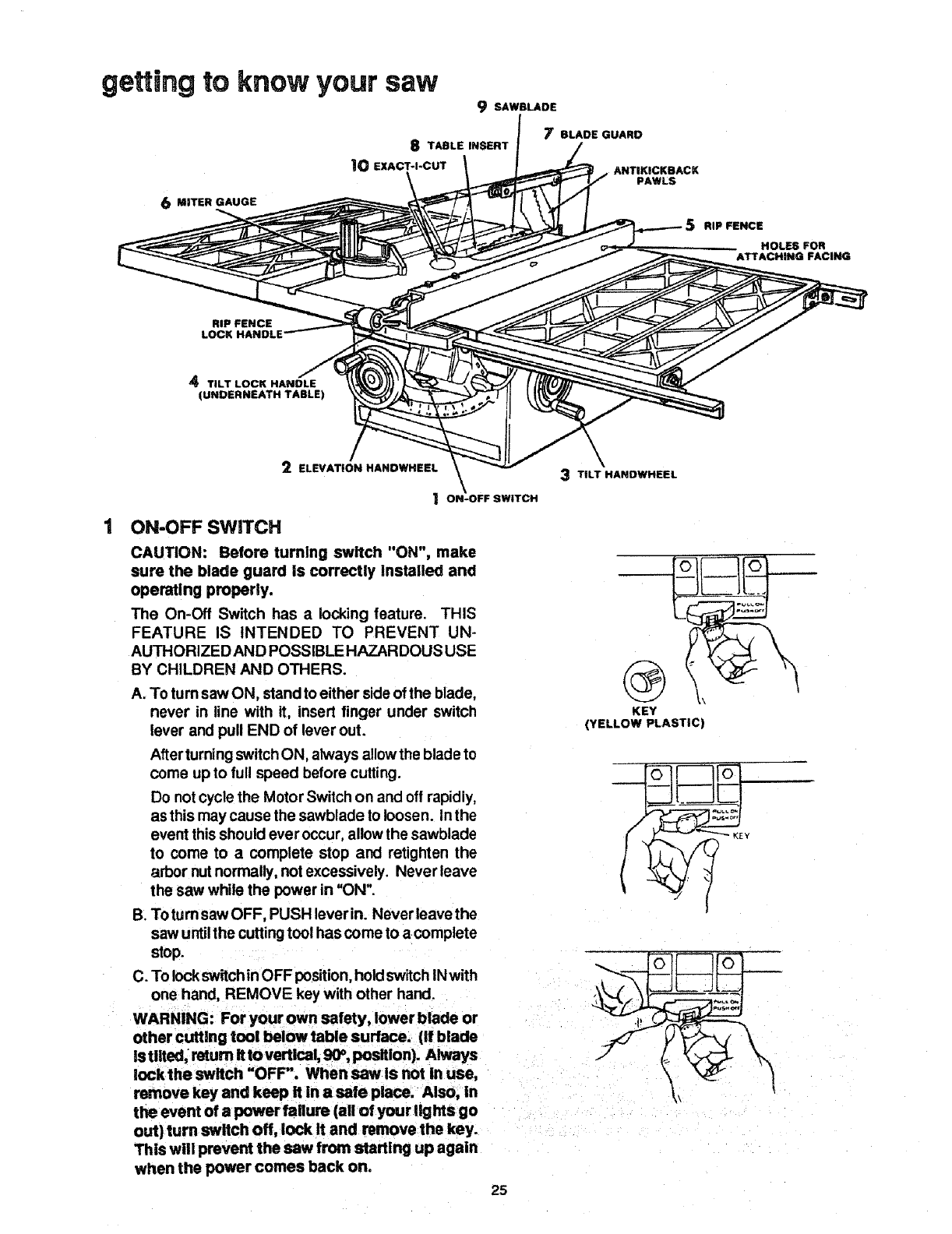
getting to know your saw 9 SAWBLADE
J7BLADE GUARD
S TABLE INSERT
|0 EXACT-I-CUT ANTIKICKBACK
PAWLS
6MITER GAUGE
RiP FENCE
HOLES; FOR
ATTACHING FACING
RiP FENCE
LOCK HANDLE
4TILT LOCK HANDLE
(UNDERNEATH TABLE)
2ELEVATION HANDWHEEL 3TiLT HANDWHEEL
1 ON-OFF SWITCH
ON-OFF SWITCH
CAUTION: Before turning switch "ON", make
sure the blade guard Is correctly Installed and
operaUng properly.
The On-Off Switch has alocking feature. THIS
FEATURE IS INTENDED TO PREVENT UN-
AUTHORIZEDAND POSSIBLE HAZARDOUS USE
BY CHILDREN AND OTHERS.
A. To turn saw ON, stand to either sideot the blade,
never in line with it, insert finger under switch
lever and pull END of lever out.
Afterturning switchON, always allow the blade to
come up to full speed before cutting.
Do notcycle the Motor Switch on and oft rapidly,
as this may cause the sawblade to loosen. Inthe
event this should ever occur, allow the sawblade
to come to a complete stop and retighten the
arbor nutnormally, not excessively. Never leave
the saw while the power in =ON",
B. Totum saw OFF, PUSH leverin. Never leave the
saw untilthe cutting tool has come to a complete
stop.
C. To lockswitchinOFF position, hold switch IN with
one hand, REMOVE key with other hand.
WARNING: For your own safety, lower blade or
other cutting tool below table surface. (If blade
Is Ulted. return It to vertical, 90°, position). Always
lock the switch "OFF". When saw Is not in use,
remove key and keep it in a safe place. Also, in
the event of a power failure (all ofyour,ghts go
out) turn switch off, lock It and remove the key.
This will prevent the saw from starting up again
when the power comes back on,
KEY
(YELLOW PLASTIC)
25
getting to know your saw
2
3
4
5
ELEVATION HANDWHEEL ... elevates or
Iowersthe blade, Turnclockwiseto elevate, counter-
clockwise to lower.
TILT HANDWHEEL...tilts the blade for bevel
cutting. Turn clockwise to tilt toward left,counter-
clockwise to tilt toward dght.
When the blade is tilted to the LEFT as far as itwill
go, it should be at 45" to the table and the bevel
pointer should point 45°.
NOTE: There are LIMIT STOPS inside the saw
which prevent the blade from tilting beyond 45°to
the LEFT and 90° to the RIGHT. ( See "ADJUST-
MENT,<;AND ALIGNMENTS"section"BLADE TILT,
OR SQUARENESS OF BLADE TO TABLE").
TILT LOCK HANDLE... locks the blade inthe
desired tilt position. To loosen, turn counterclock-
wise. Push handle in and turn it to another position
if necessary in order to tighten or loosen.
RIP FENCE... islocked inplace by pushingthe
Lock Lever down untilthe lever rests onthe stop. To
move the Fence, lift the Lock Lever and grasp the
Fence with one hand at the front.
Holes are provided inthe Rip Fence for attaching a
wood facing when using the Dado Head, or Molding
Head.
Select a piece of smooth straight wood approxi-
mately 3/4 inch thick, and the same size as the Rip
Fence.
Attach it to the Fence with three Round Head #10
Wood Screws, 2 inches long. TO removethe facing,
loosen the screws, slide the facing forward and pull
the screws through the round holes.
WOOD FACING
t
6 MITER GAUGE .., headislockedin positionfor
crosscuttingorrnitedngby tighteningthe LockKnob.
ALWAYS LOCK IT SECURELY WHEN IN USE.
If necessary, the Miter Gauge head can then be
swiveled slightlyto compensate and then locked.
Slots are provided in the Miter Gauge for attaching
an Auxiliary Facing to make it easier to cut long
pieces. Be positive Facing does not interfere with
the proper operation of the Sawblade Guard.
Select a suitable piece of smooth straight wood, ddll
two holes through it and attach it with screws.
NOTE: When bevel crosscutting, attach Facing so
that it extendsto the dght of the Miter Gauge and use
the Miter Gauge in the groove to the righl of the
blade.
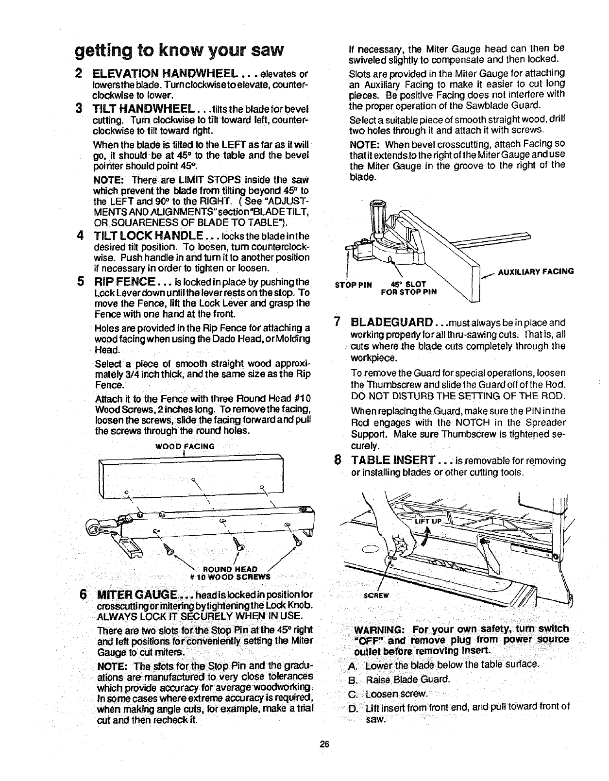
STb.PI. +s+soT \ I I-
FO.STO..,.
FACING
7BLADEGUARD...must always be in place and
working properlyfor all thru-sawing cuts. That is, all
cuts where the blade cuts completely through the
workpiece.
To remove the Guard for special operations, loosen
the Thumbscrew and slide the Guard off of the Rod.
DO NOT DISTURB THE SETTING OF THE ROD.
When replacingthe Guard, make sure the PIN inthe
Rod engages with the NOTCH in the Spreader
Support. Make sure Thumbscrew is tightened se-
curely.
8 TABLE INSERT... is removable for removing
or installing blades or other cutting tools.
\\
/
SCREW
Gauge to cut miters.
NOTE: The slotsfor the Stop Pin and the gradu-
ations are manufactured to very close tolerances
which provide accuracy for average woodworking.
In some cases where extreme accuracy is required,
when making angle cuts. forexample, make a trial
cut and then recheck it.
A, Lower the blade below the table surface.
B. F_aiseBlade Guard.
C. Loosen screw.
D. Lift insert from front end, and pull toward front of
saw.
26
NEVER OPERATE THE SAW WITHOUT THE
PROPER INSERT IN PLACE. USE THE SAW-
BLADE INSERT WHEN SAWING. USE THE
COMBINATION DADO MOLDING INSERT WHEN
USING A DADO OR MOLDING HEAD.
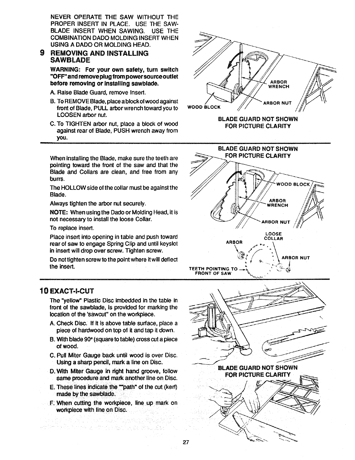
REMOVING AND iNSTALLiNG
SAWBLADE
WARNING: For your own safety, turn switch
"OFF"and remove plug from power sourceoutlet
before removing or installing sawblade.
A. Raise Blade Guard, remove Insert.
B; TO REMOVE Blade, place ablockofwood against
front of Blade, PULL arbor wrench toward youto
LOOSEN arbor nut.
C. To TIGHTEN arbor nut, place ablock of wood
against rear of Blade, PUSH wrench away from
you.
WOOD BLOCK NUT
BLADE GUARD NOT SHOWN
FOR PICTURE CLARITY
When installingthe Blade, make sure the teeth are
pointing toward the front of the saw and that the
Blade and Collars are clean, and free from any
burrs.
The HOLLOW side of the collar must be against the
Blade.
Always tighten the arbor nut securely.
NOTE: When using the Dado or Molding Head, it is
not necessary to install the loose Collar.
To replace insert.
Place insert into opening in table and push toward
rear of saw to engage Spring Clip and until keyslot
in insert will drop over screw. Tighten screw.
Do nottighten screw to the point where itwill deflect
the insert.
10 EXACT-I-CUT
The "yellow" Plastic Disc imbedded in the table En
front of the sawblade, is provided for marking the
location of the 'sawcut" on the workpiece.
A. Check Disc. If it is above table surface, place a
piece of hardwood on top of it and tap it down.
B. With blade 90° (square to table) crosscut a piece
of wood.
C. Pull Miter Gauge back until wood is over Disc.
Using a sharp pencil, mark aline on Disc.
D. With Miter Gauge in fight hand groove, follow
same procedure and mark another line on Disc.
E. These lines indicate the -path" of the cut (ken')
made by the sawblade.
F. When cutting the workpiece, line up mark on
workpiece with line on Disc.
BLADE GUARD NOT SHOWN
PICTURE CLARIFY
ICH
OR NUT
LOOSE
COLLAR
ARBOR ._ ,_.._
<3 ._ _' _ :\ ARBORI NUT
TEETH POINTING TO ---._, , _.:?__._
FRONT OF SAW
BLADE GUARD NOT SHOWN
FOR PICTURE CLARITY
27
safety instructions for basic saw operations
BEFORE EACH USE:
1. Inspect your saw.
A. To avoid injuryfrom accidental starting, unplugthe
saw, turn the switch off and remove the Switch Key
before raising or removing the Guard, changing
the cutting tool, changing the setup or adjusting
anything.
B. Check for alignment of moving pads, binding of
moving pads, breakage of pads, mounting, and
any other conditions that may affect the way it
works. If any partis missing, bent, or broken inany
way, or any electrical parts don't work properly,
turn the saw off and unplug the saw.
C. Replace damaged, missing, or failed parts before
using the saw again.
D. Use the Sawblade Guard, Spreader, and Anti-
Kickback Pawls forany thin-sawing (whenever the
blade comes through the top of the workpiece).
Make sure the Pawlswork properly. Makesurethe
Spreader is in line with the sawblade.
E. REMOVE ADJUSTING KEYS AND WRENCH ES.
Form habit of checking forand removing keys and
adjusting wrenches from tool before turning it on.
F. To avoid injury from jams, slips or thrown pieces
(kickback and throwback):
1. USE ONLY RECOMMENDED ACCESSORIES
(See page 44). Follow the instructions that
come withthe accessories. Using other acces-
sories may be dangerous.
2. Choose"the right blade or cutting accessory for
the material and the type of cutting you plan to
do.
3. Never use grinding wheels, abrasive cut-off 6.
wheels, friction wheels (metal slitting blades)
wire wheels orbuffing wheel. Theycan fly apart
explosively.
4. Choose and inspect your cutting tool carefully.
a. To avoid cuttingtoolfailure and thrownshrap-
nel (broken pieces of blade), use only 10" or
smaller blades or other cutting tools marked
for speeds of 3450 rpm or higher.
b. Always use unbroken, balanced blades
designed to fit this saw's 5t8 inch arbor.
c. When thru-sawing (making cuts where the
blade comes through the workpiece top),
always use a t 0 inch diameter blade. This
keeps the Spreader in closest to the bade.
d. Donor overtighten arbor nuL Use arbor
5. Adjust table inserts flush with the table top.
NEVER use the saw without the proper insert.
6. Make sure all clamps and locks are tight and no
parts have any excessive play.
2. Keep work area clean
A. Cluttered areas and benches invite accidents.
Floor must not be slippery from wax or sawdust.
B. To avoid burns orother fire damage, never use the
saw near flammable liquids, vapors or gases.
C. To avoid injury frorn accidental blade contact, don't
do layout, assembly, or setup work on the table
while the blade is spinning. It could cut or throw
anything hitting the blade.
Plan aheadto protect your eyes, hands, face, ears.
AVOID ACCIDENTAL STARTING - Make sure
switch is "OFF" before plugging saw in.
3. Plan your work
A. USE THE RIGHT TOOL - Don't force tool or attach-
ment to do a job it was not designed for.
B. Dress for safety:
1. Do not wear loose clothing, gloves, neckties or
jewelry (rings, wristwatches). They can get
caught and draw you into moving pads.
2. Wear nonslip footwear.
3, Tie back long hair.
4. Roll long sleeves above the elbow.
5. Noise levels vary widely. To avoid possible
head ng damage, wear ear plugs or muffs when
using saw for long periods of time.
Any power saw can throw foreign objects into
the eyes. This can cause permanent eye
damage. Wear safety goggles (not glasses)
that comply with ANSI Z87.1 (shown on pack-
age). Everyday eyeglasses have only impact
resistant lenses. They are not safety glasses.
Safety goggles are available at Sears retail
catalog stores. Glasses or goggles not in com-
pliance with ANSI Z87.1 could seriously hurt
you when they break.
JR
enches to snug it securely. 7. For dusty operations, wear adust mask along
e; Use onlysharp blades with properlyset teeth, with the safety goggles.
Consult aprofessionalblade sharpenerwhen C. Inspect your workpiece. Make sure there are no
in doubt, nails or foreign objects in the part of the workpiece
f. Keep blades clean of gum and resin, to be cut.
28
D. Plan your cut to avoid KICKBACKS and THROW-
BACKS -when apartor allof the workpiece binds
on the blade and is thrown violently back toward
the front of the saw.
f. Never cut FREEHAND: Always use either a
Rip Fence, Miter Gauge or fixture to position
and guide the work, so it won't twist,bind onthe
blade and kickback.
2. Make sure there's no debris between the work-
piece and its supports.
3. Whencutting irregularlyshapedworkpieces,
plan your work so it will not slip and pinch the
blade:
a. A piece of molding, for example, must lie flat
or be held by a fixture or jig that will not let it
twist, rock or slip while being cut. Use jigs or
fixtures where needed to prevent workpiece
shifting.
b. Use a different, better suited type of tool for
work that can't be made stable.
4. Use extra caution with large, very small or
awkward workpieces:
a. Use extra supports (tables, saw horses
blocks,etc.) for any workpieces large enough
to tip when not held down to the table top.
NEVER useanother person as a substitute
for a Table Extension, or as additional sup-
port for aworkpiece that is longer or wider
than the basic saw table, or to help feed,
support or pull the workpiece.
b. Neverconfinethepiecebeingcutoff. That is,
the pieceNOT againstthe Fence, MiterGauge
or fixture. Never hold it, clamp it, touch it, or
use lengthstops against it. It must be free to
move. Ifconfined, itcouldgetwedged against
the blade and cause a kickback or throw-
back.
c. Never cut more than one workpiece at atime.
d. Never turn your table saw "ON" before clear-
ing everything except the workpiece and
related support devices off the table.
4. Planthewayyouwill pushtheworkplecethrough.
A. NEVER pug the workpiece through. Start and
finishthe cut from the front of the table saw.
B. NEVER put your fingers or hands in the path of
the sawblade or other cutting tool.
C. NEVER reach in back of the cuttingtoolwith either
hand to hold-down or support the workpiece,
remove wood scraps, or for any other reason.
D. Avoid awkward operations and hand positions
where a suddenslip couldcause fingers or hand to
move into a sawblade or other cutting tool.
E. DONq" OVERREACH. Always keep good footing
and balance.
F. Push the workpiece against the rotation of the
blade. NEVER feed material into the cutting tool
from the rear of the saw.
G.Always push the workpiece all the way past the
sawblade.
H. As much as possible, keep your face and body to
one sideof the sawblade, out of line with a possible
kickback or throwback.
I. NEVER turn the saw"ON"before clearing the table
of all tools, wood scraps, etc., except the work-
piece and related feed or support devices for the
cut planned.
WHENEVER SAW BLADE IS SPINNING
WARNING: Don't let familiarity (gained from fre-
quent use of your table saw) cause a careless mis-
take. Always remember that a careless fraction of a
second is enough to cause a severe injury.
1. Before actually cutting with the saw, watch it while it
runs for a short while. If it makes an unfamiliar noise
or vibrates a lot, stop immediately. Turn the saw off.
Unplugthe saw. Do not restart untiltinding andfixing
the problem.
2. Make sure the top of the arbor or cutting tool turns
toward the front of the saw.
3. Set the cutting tool as low as possible for the cut
you're planning.
4. KEEP CHILDREN AWAY. All visitors should be kept
a safe distance from work. Make sure bystanders are
clear of the saw and workpiece.
5. Let the blade reach full speed before cutting.
6. DON'T FORCE TOOL. It will do the ._obbetter and
safer at its designed rate. Feed the workpiece intothe
blade only fast enough to let it cut without bogging
down or binding.
7. Before freeing any jammed material:
A. Turn switch "OFF".
B. Unplug the saw.
C. Wait for all moving parts to stop.
D. Checkblade, Spreader and Fence for proper align-
ment before starting, again.
8. To avoid throwback of cut off pieces;
A. Use the Guard Assembly.
B. To remove loose pieces beneath ortrapped inside
the Guard:
1; Turn saw "OFF".
2. Remove Switch Key.
3. Wait for blade to stop before lifting the Guard.
29
safety for basic saw operations
BEFORE LEAVING THE SAW
1. Turn the saw off,
2. Wait for blade to stop spinning.
3. Make workshop child-proof. Lock the shop. Discon-
i i,,i
basic saw operation - using the miter gauge
CROSSCUTTING, MITER CUTTING, BEVEL CUT- 2.
TING, COMPOUND MITER CUI-rlNG and when RAB-
BETING across the end of a narrow workpiece, the
MITER GAUGE IS USED.
WARNING: For your own safety, aNvays observe the
following safety precautions in addition to the safety
instructions on pages 2, 3, 4, 5, 28, 29 & 30. 3.
ADDITIONAL SAFETY INSTRUCTIONS FOR
CROSS CUT TYPE CUTS
Before S_rting:
1. Never use the Rip Fence when crosscutting,
nect master switches. Remove the yellow Switch
Key. Store it away from children and others not
qualified to use the tool.
4. Unplug the saw.
An auxiliarywoodfacing attached to the Miter Gauge
can help preventworkpiece twistingand throwback s.
Attach it to the holes provided. Make the facing long
enough andbig enough to support yourwork. Make
sure, however, itwill not interfere with the sawblade
guard.
Use jigs or fixtures to help hold any piece too small
to extend across the full length of the Miter Gauge
face during the cut. This lets you properly hold the
Miter Gauge and workpiece and helps keep your
hands away from the blade.
While Cutting:
1. To avoid blade contact, always holdthe Miter Gauge
as shown in the "BASIC SAW OPERATIONS -
USING THE MITER GAUGE."
i iii
WORK HELPERS
Before cutting any wood on your saw, study all of the
"Basic Saw Operations."
Notice that in order to make some of the cuts, it is
necessary to use certain devices, "Work Helpers", like
the Push Stick, the Push Blockandthe Auxiliary Fence/
Work Support, which you can make yourself.
Afteryou have made afew practice cuts, make up these
"helpers"before starting any projects. Make the "Push
Stick"first.
SLIGHTLY LESS THAN
THICKNESS OF WORKPIECE
uP TO 3/8" %.
-'F--'C 1/2_ _
1-5/8 _' i </\
45 ° NOTCH
NOTE: All dimensions in inches
PUSH STICK
PUSH STICK AND PUSH BLOCK
Make the Push Stick using a piece of 1x 2.
Make the Push Blockusing apiece of 3/8 in. and 3/4 in.
plywood.
The small piece of wood 3/8 x 3/8 x 1-1!2 inches should
be GLUED tothe plywood. DO NOT USE NAILS. This
is to prevent dulling the sawblade in the event you
mistakenly cut intothe Push Block.
Position the handle in the center of the plywood and
fastentogetherwith glue and woodscrews.
THESE EDGES MUST
BE PARALLEL
\
3/8
5-1/8 3/8
NOTE: All dimensions in inches
FUSH BLOCK
3/4 PLYWOOD
3/8 PLYWOOD
AUXILIARY FENCE/WORK SUPPOFIT
NOTE: Since the Push BloCkis used with the Auxiliary
Fence, the 4-3/4 inches dimensions must be held iden-
tical on both the pieces.
3O
5-,1!2
NOTE
AUXILIARY FENCE/WORK SUPPORT
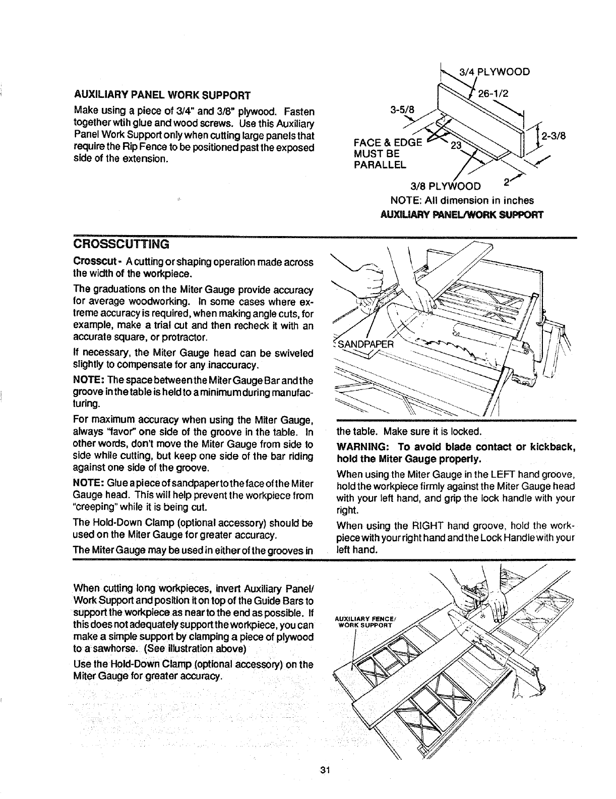
.YWOOD
AUXILIARY PANEL WORK SUPPORT
Make using a piece of 3/4" and 3/8" plywood. Fasten
together wtihglue and wood screws. Use this Auxiliary
Panel Work Support only when cutting large panels that
require the Rip Fence to be positioned past the exposed
side of the extension.
3-5/8
FACE & EDGE
MUST BE
PARALLEL
3/8 PLYWOOD
NOTE: All dimension in inches
AUXILIARY PANEL/WORK SUPPORT
CROSSCUTTING
Crosscut- A cuttingor shaping operation made across
the width of the workpiece.
The graduations on the Miter Gauge provide accuracy
lor average woodworking. In some cases where ex-
treme accuracy is required, when making angle cuts, for
example, make a trial cut and then recheck it with an
accurate square, or protractor.
If necessary, the Miter Gauge head can be swiveled
slightly to compensate for any inaccuracy.
NOTE: The space betweenthe Miter Gauge Bar andthe
groove inthe table isheld to a minimum dudng manufac-
turing.
For maximum accuracy when using the Miter Gauge,
always '1avor"one side of the groove in the table. In
other words, don't move the Miter Gauge from side to
side while cutting, but keep one side of the bar riding
against one side of the groove.
NOTE: Glue apiece of sandpaperto the face ofthe Miter
Gauge head. This will help prevent the workpiece from
"creeping" while it is being cut.
The Hold-Down Clamp (optional accessory) should be
used on the Miter Gauge for greater accuracy.
The Miter Gauge may be used in either of the grooves in
._SANDPAPER
the table. Make sure it is locked.
WARNING: To avoid blade contact or kickback,
hold the Miter Gauge properly.
When using the Miter Gauge inthe LEFT hand groove,
hold the workpiece firmly against the Miter Gauge head
with your left hand, and grip the lock handle with your
right.
When using the RIGHT hand groove, hold the work-
piece with yourright hand andthe Lock Handle with your
left hand.
When cutting long workpieces, invert Auxiliary Panel/
Work Support and position it on top of the Guide Bars to
support the workpiece as near to the end as possible. If
thisdoes not adequately supportthe workpiece, youcan
make a simple support by clamping a piece of plywood
to a sawhorse. (See illustrationabove)
Use the Hold-Down Clamp (optional accessory) on the
Miter Gauge for greater accuracy.
AUXILIARY FENCE/
WORK SUPPORT
\\
31
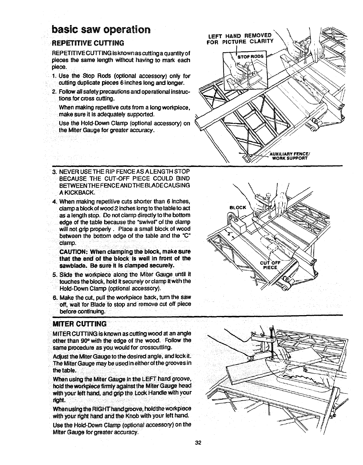
basic saw operation
REPETITIVE CUTTING
REPETITIVE CUTTING is known as cutting a quantityof
pieces the same length without having to mark each
piece.
1. Use the Stop Rods (optional accessory) only for
cutting duplicate pieces 6 inches long and longer.
2. Foitowall safety precautions and operational instruc-
tions for cross cutting.
When making repetitive cuts from a long workpiece,
make sure it is adequately suppoded.
Use the Hold-Down Clamp (optional accessory) on
the Miter Gauge for greater accuracy.
i i
3. NEVER USE THE RIP FENCE AS A LENGTH STOP
BECAUSE THE CUT-OFF PIECE COULD BIND
BETWEEN THE FENC EAN D THE BLADE CA USIN G
A KICKBACK.
4. When making repetitive cuts shorter than 6 inches,
clamp a block ofwood 2 inches long to the table to act
as a length stop. Do not clamp directly to the bottom
edge of the table because the "swivel" of the clamp
will not grip properly. Place a small block of wood
between the bottom edge of the table and the "C"
clamp,
CAUTION: When clamping the block, make sure
that the end of the block Is well In front of the
sawblade. Be sure it is clamped securely.
5. SrK:lethe workpiece along the Miter Gauge unt_ it
touches the block, hold itsecurely orclamp itwith the
Hold-Down Clamp (optional accessory).
6. Make the cut, pull the workpiece back, turn the saw
off, wait for Blade to stop and remove cut off piece
before continuing.
=
MITER cu'ri'ING
MITER CUTTING is known as cutting wood at an angle
other than 90°with the edge of the wood. Follow the
same procedure as you would for crosscutting.
Adjustthe Miter Gauge to the desired angle, and lock it.
The Miter Gauge may be used in either ofthe grooves in
the table.
When using the Miter Gauge in the LEFT hand groove,
hold the wo_ece firmly against the Miter Gauge head
with your left hand, and gdp the Lock Handle with your
right.
Whenusing the RIGHThandgroove, holdthe workplece
with your right hand and the Knob with your lefl hand.
Use the Hold-Down Clamp (optional accesson/) on the
Miter Gauge for greater accuracy.
LEFT HAND REMOVED "\
FOR PICTURE CLARITY \
WORK SUPPORT
32
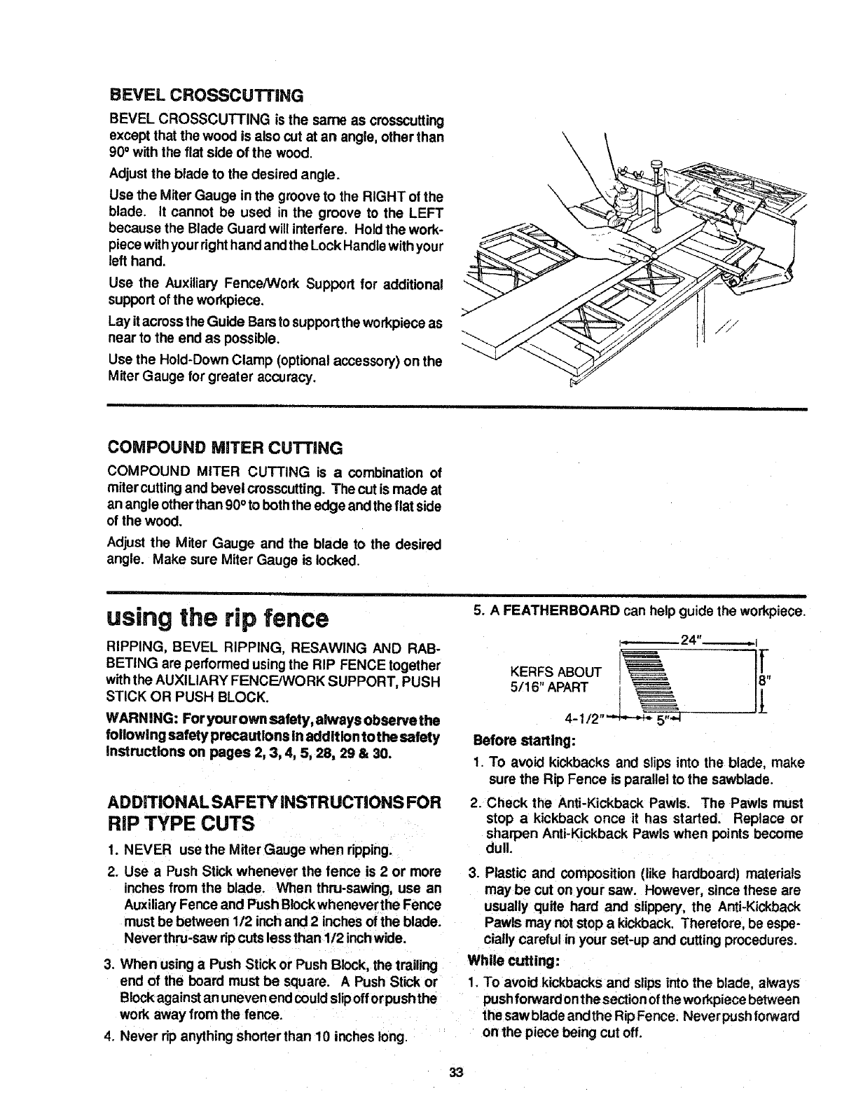
BEVEL CROSSCUTTING
BEVEL CROSSCUTTING is the same as crosscutting
except that the wood is also cut at an angle, other than
90° with the flat side of the wood.
Adjustthe blade to the desired angle.
Use the Miter Gauge in the groove to the RIGHT of the
blade. It cannot be used in the groove to the LEFT
because the Blade Guard will interfere. Hold the work-
piece with your righthand andthe Lock Handlewith your
left hand.
Use the Auxiliary FenceNVork Support for additional
support of the workpiece,
Lay itacross the Guide Barsto support the workpiece as
near to the end as possible,
Use the Hold-Down Clamp (optional accessory) on the
Miter Gauge for greater accuracy.
COMPOUND MITER CUTTING
COMPOUND MITER CUTTING is a combination of
miter cuttingand bevel crosscutting. The cut is made at
an angle other than 90° to boththe edge and the flat side
of the wood.
Adjust the Miter Gauge and the blade to the desired
angle. Make sure Miter Gauge is locked.
using the rip fence
RIPPING, BEVEL RIPPING, RESAWlNG AND RAB-
BETING are performed usingthe RIP FENCE together
withthe AUXILIARY FENCE/WORK SUPPORT, PUSH
STICK OR PUSH BLOCK.
WARNING: Foryourown safety, always observe the
following safety precautions in addition to the safety
instructions on pages 2, 3, 4, 5, 28, 29 & 30.
ADDmONAL SAFETY INSTRUCTIONS FOR
RiP TYPE CUTS
1. NEVER use the Miter Gauge when ripping.
2. Use a Push Stick whenever the fence is 2 or more
inches from the blade. When thru-sawing, use an
Auxiliary Fence and Push Biockwhenever the Fence
must be between 1/2 inch and 2 inches of the blade.
Never thru-saw ripcuts less than 1/2 inchwide.
3. When using aPush Stick or Push Block, the trailing
end of the board must be square. A Push Stick or
Block againstan uneven end couldslipoff orpush the
work away from the fence.
4. Never rip anything shorter than 10 inches long.
5. A FEATHERBOARD can help guide the workpiece.
KERFS ABOUT
5/16" APART
4-1/'
Before staring:
1. To avoid kickbacks and slips into the blade, make
sure the Rip Fence is parallel to the sawblade,
2. Check the Anti-Kickback Pawls. The Pawls must
stop a kickback once it has started. Replace or
sharpen Anti-Kickback Pawls when points become
dull.
3. Plastic and composition (like hardboard) materials
may be cut on your saw. However, since these are
usually quite hard and slippery, the Anti-Kickback
Pawls may not stop a kickback. Therefore, be espe-
cially careful in your set-up and cutting procedures.
While cutting:
1. To avoid kickbacks and slips into the blade, a_ways
push forward onthe section of the wo rkpiece between
the saw blade and the Rip Fence. Never pushforward
on the piece being cut off.
33
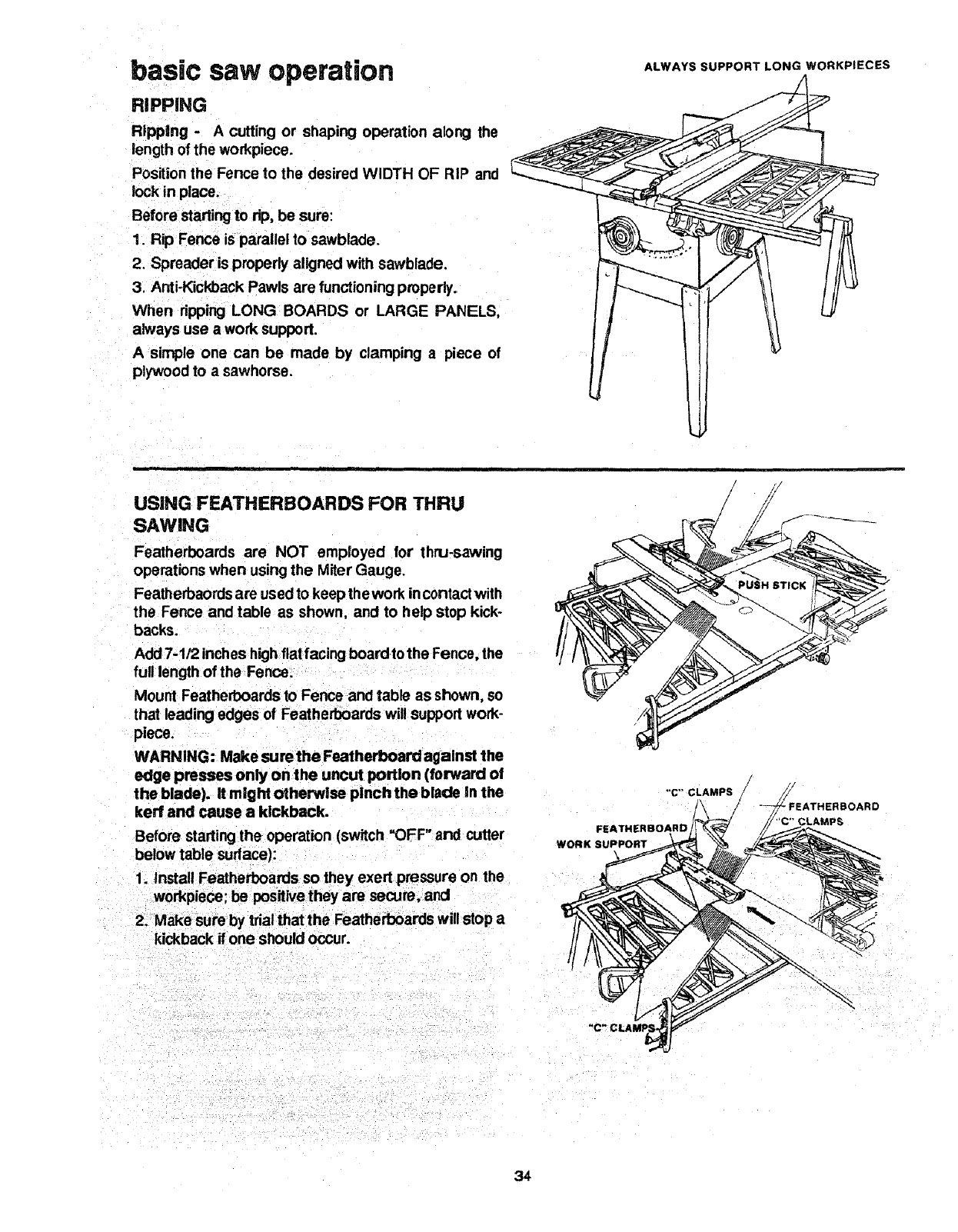
basic saw operation
RIPPING
Ripping -A cutting or shaping operation along the
length of the workpiece.
Position the Fence to the desired WIDTH OF RiP and
lock in place.
Before starting to alp,be sure:
1. Rip Fence is parallel to sawblade.
2. Spreader is properly aligned with sawblade.
3. Anti-Kickback Pawls are functioning properly.
When ripping LONG BOARDS or LARGE PANELS,
always use awork support.
A simple one can be made by clamping a piece of
plywood to a sawhorse.
ALWAYS SUPPORT LONG WORKPIECES
USING FEATHERBOARDS FOR THRU
SAWING
Featherboards are NOT employed for thru-sawing
operations when using the Miter Gauge.
Featherbaords are used to keep the work incontact with
the Fence and table as shown, and to help stop kick-
backs.
Add 7-1/2 inches highflat facing board to the Fence, the
full length of the Fence.
Mount Featherboards to Fence and table as shown, so
that leading edges of Featherboards will supporl work-
piece.
WARNING: Make surethe Featherboard against the
edge presses only onthe uncut portion (forward o!
the blade), it might otherwise pinch the blade In the
kerr and cause a kickback.
Before starting the operation (switch =OFF" and cutter
below table sudace):
1, Install Featherboards so they exert pressure on the
workpieoe; be positive they are secure, and
2. Make sure by trial that the Featherboards will stop a
kickback if one should occur.
"C" CLAMPS
FEATHERBOARD
WORK SUPPORT
FEATHERBOARD
CLAMPS
34
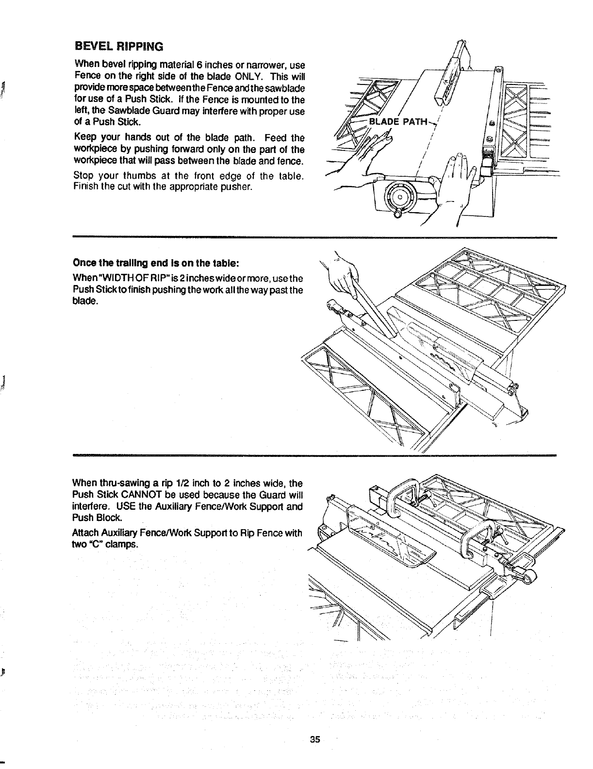
BEVEL RiPPiNG
When bevel ripping material 6 inches or narrower, use
Fence on the right side of the blade ONLY. This will
provide morespace betweentheFence andt he sawblade
for use of a Push Stick. If the Fence is mounted to the
left, the Sawblade Guard may interfere with proper use
of a Push Stick.
Keep your hands out of the blade path. Feed the
workpiece by pushing forward only on the part of the
workpiece that will pass between the blade and fence.
Stop your thumbs at the front edge of the table.
Finishthe cut with the appropriate pusher.
Once the tralUng end is on the table:
When"WI DTH OF RiP" is 2incheswide ormore, use the
PushStick to finishpushing the work allthe way past the
blade.
When thru-sawing arip 1/2 inch to 2 inches wide, the
Push Stick CANNOT be used because the Guard will
interfere. USE the Auxiliary Fence/Work Support and
Push Block.
AttachAuxiliary Fence/Work Support to Rip Fence with
two "C" clamps.
35
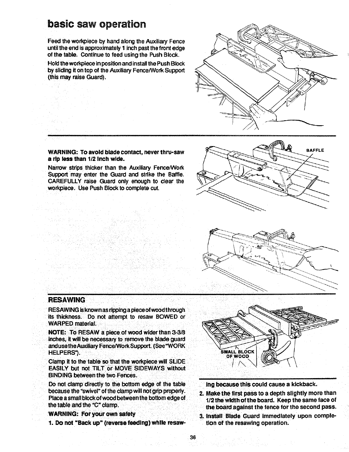
basic saw operation
Feed the work,piece by hand along the Auxiliary Fence
untilthe end is approximately I inch past thefront edge
of the table. Continue to feed using the Push Block.
Hold the workpiece inpositionand installthe Push Block
by sliding it on top of the Auxiliary Fence/Work Support
(this may raise Guard).
WARNING: Toavoid blade contact, never thru-saw
a rip less than 112Inch wide.
Narrow strips thicker than the Auxiliary Fence/Work
Support may enter the Guard and strike the Baffle.
CAREFULLY raise Guard only enough to clear the
workpiece. Use Push Block to complete cut.
BAFFLE
RESAWlNG
RESAWlNG isknown as ripping a piece of wood through
its thickness. Do not attempt to resaw BOWED or
WARPED material.
NOTE: To RESAW a piece of wood wider than 3_/8
inches, it will be necessawto remove the blade guard
andusethe AuxiliaryFence/Work Support. (See _WORK
HELPERS').
Clamp it to the table so that the workpiece will SLIDE
EASILY but not TILT or MOVE SIDEWAYS without
BINDING between the two Fences.
SMALL BLOCK
OF WOOD
!
Do not clamp directly to the bottom edge of the table
because the "swivel"of the clampw!ll notgrip properly.
Place a small block ofwoodbetweenthe bottom edge of
the table and the "(;"clamp.
WARNING: For your own safety
1. Do not "Back up" (reverse feeding) while resaw-
ing because this could cause akickback.
2. Make the first pass to a depth slightly more than
1/2the width ofthe board. Keep the same face of
the board against the fence for the second pass,
3. Install Blade Guard immediately upon comple-
tion of the resawlng operation.
36
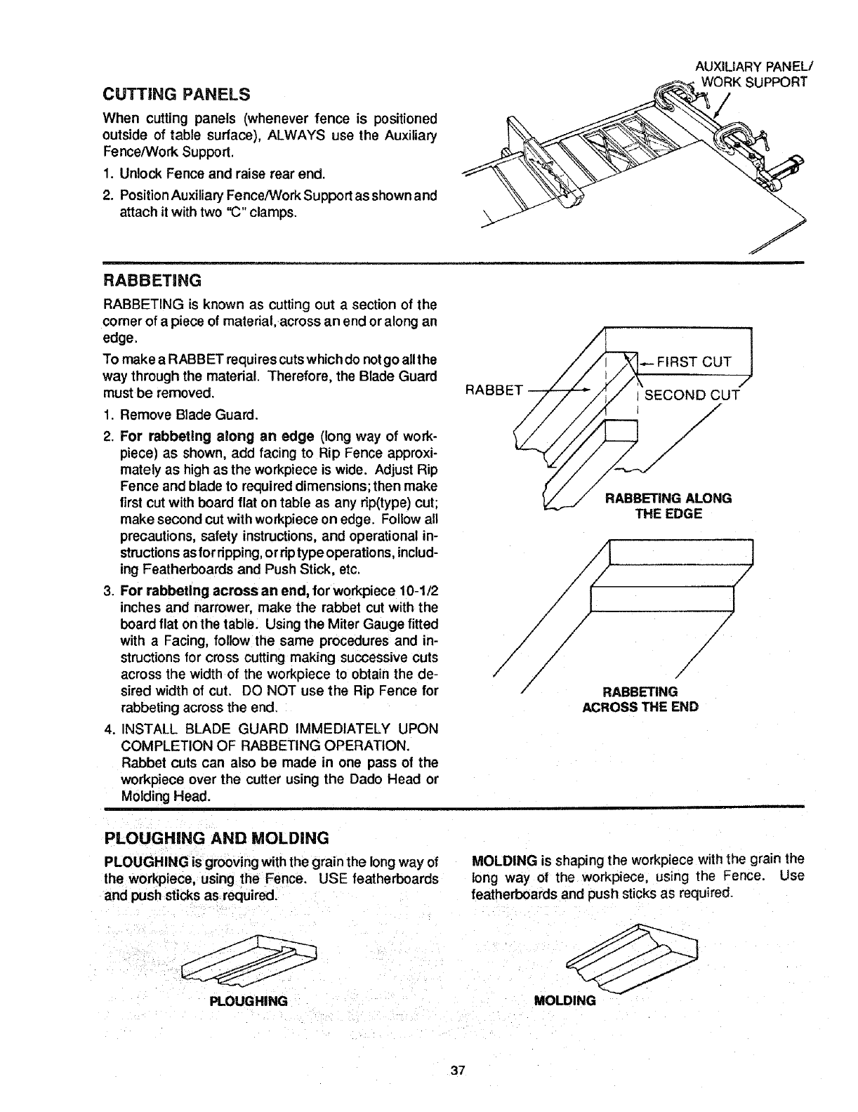
CUTTING PANELS
When cutting panels (whenever fence is positioned
outside of table surface), ALWAYS use the Auxiliary
Fence/Work Support.
1. Unlock Fence and raise rear end.
2. PositionAuxiliary Fence/Work Support as shown and
attach it with two "C" clamps.
RABBETING
AUXILIARY PANEL/
RABBETING is known as cutting out a section of the
comer of a piece of material, across an end or along an
edge.
To make a RABBET requires cuts which do not go allt he
way through the material. Therefore, the Blade Guard
must be removed.
1. Remove Blade Guard.
RABBET
FIRST CUT 1
I SECOND CUT
t
2. For rabbeting along an edge (long way of work-
piece) as shown, add facing to Rip Fence approxi-
mately as highas the workpiece is wide. Adjust Rip
Fence and blade to required dimensions; then make
first cut with board flat on table as any rip(type) cut;
make second cut with workpiece on edge. Follow all
precautions, safety instructions,and operational in-
structions as for dpping, or riptype operations, includ-
ing Featherboards and Push Stick, etc.
3. For rabbeting across an end, for workpiece 10-1/2
inches and narrower, make the rabbet cut with the
board flat on the table. Using the Miter Gauge fitted
with a Facing, follow the same procedures and in-
structions for cross cutting making successive cuts
across the width of the workpiece to obtain the de-
sired width of cut. DO NOT use the Rip Fence for
rabbeting across the end.
4. INSTALL BLADE GUARD IMMEDIATELY UPON
COMPLETION OF RABBETING OPERATION.
Rabbet cuts can also be made in one pass of the
workpiece over the cutter using the Dado Head or
Molding Head.
RABBETING ALONG
THE EDGE
/
/
/
./
RABBETING
ACROSS THE END
J
/
J
/
/
PLOUGHING AND MOLDING
PLOUGHING is grooving withthe grain the long way of
the workpiece, using the Fence, USE featherboards
and push sticks as required.
MOLDING is shaping the workpiece with the grain the
long way of the workpiece, using the Fence. Use
featherboards and push sticks as required.
PLOUGHING MOLDING
37
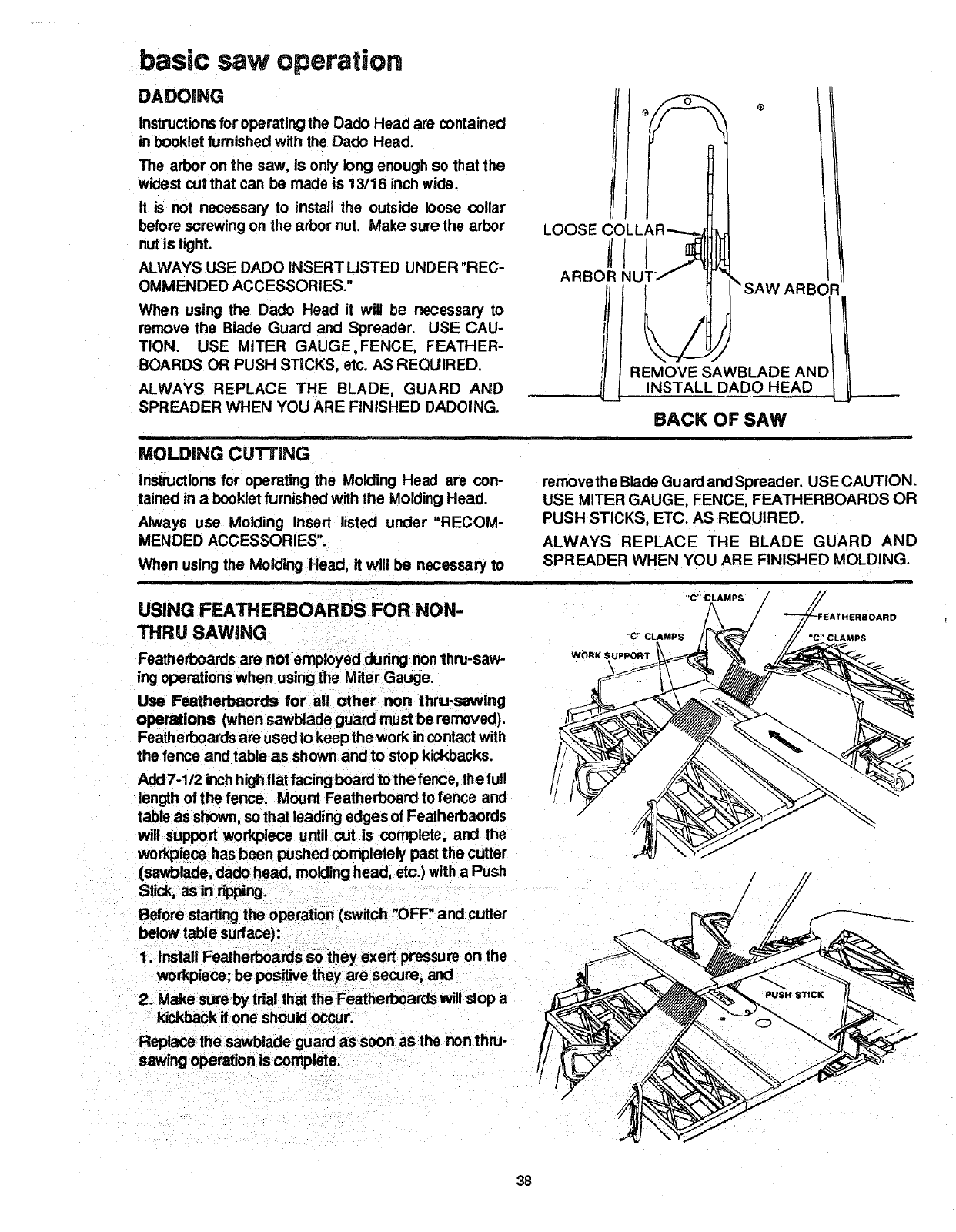
basic saw operation
DADOING
Instructionsfor operating the Dado Head are contained
in booklet furnished with the Dado Head.
The arbor on the saw, is only long enough so that the
widest cut that can be made is 13/16 inch wide.
It is not necessary to install the outside loose collar
before screwing on the arbor nut. Make sure the arbor
nutis tight.
ALWAYS USE DADO INSERT LISTED UNDER "REC-
OMMENDED ACCESSORIES."
When using the Dado Head it will be necessary to
remove the Blade Guard and Spreader. USE CAU-
TION. USE MITER GAUGE,FENCE, FEATHER-
BOARDS OR PUSH STICKS, etc. AS REQUIRED.
ALWAYS REPLACE THE BLADE, GUARD AND
SPREADER WHEN YOU ARE FINISHED DADOING.
LOOSE CC
ARBOR NU
MOLDING CUTTING
Instructions for operating the Molding Head are con-
tained in a bookletfurnished with the Molding Head.
Always use Molding Insert listed under "RECOM-
MENDED ACCESSORIES".
When using the Molding Head, it will be necessary to
i
USING FEATHERBOARDS FOR NON-
THRU SAWING
Featherboards are not employed dudng nonthru-saw-
ing operations when using the Miter Gauge.
Use Featherbaords for all other non thru-sawing
operations (when sawblade guard must be removed).
Featherboards are used to keep the work incontact with
the fence and table as shown andto stop kickbacks.
Add 7-1/2 inch highflat facing board to the fence, the full
length of the fence. Mount Featherboard tofence and
table as shown, so that leading edges of Featherbaords
will support work,piece until cut is complete, and the
workplace has been pushed completely past the cutter
(sav/olade, dado head, molding head, etc.) with a Push
Stick, as in dpping;
Before starting the operation (switch "OFF" and cutter
below table surface):
)LL
PT_f t "_ SAW ARBO
workplace; be pesitive they are secure, and
2. Make sum by trial that the Featherboards will stop a
kickback itone should occur.
Replace the sawb|ade guard as soon as the non thru-
sawing operation is complete.
REMOVE SAWBLADE ANC
INSTALL DADO HEAD
BACK OF SAW
removethe Blade Guard and Spreader. USE CAUTION.
USE MITER GAUGE, FENCE, FEATHERBOARDS OR
PUSH STICKS, ETC. AS REQUIRED.
ALWAYS REPLACE THE BLADE GUARD AND
SPREADER WHEN YOU ARE FINISHED MOLDING.
"'C" CLAMPS
FEATHI:RBOARD
CLAMPS
38
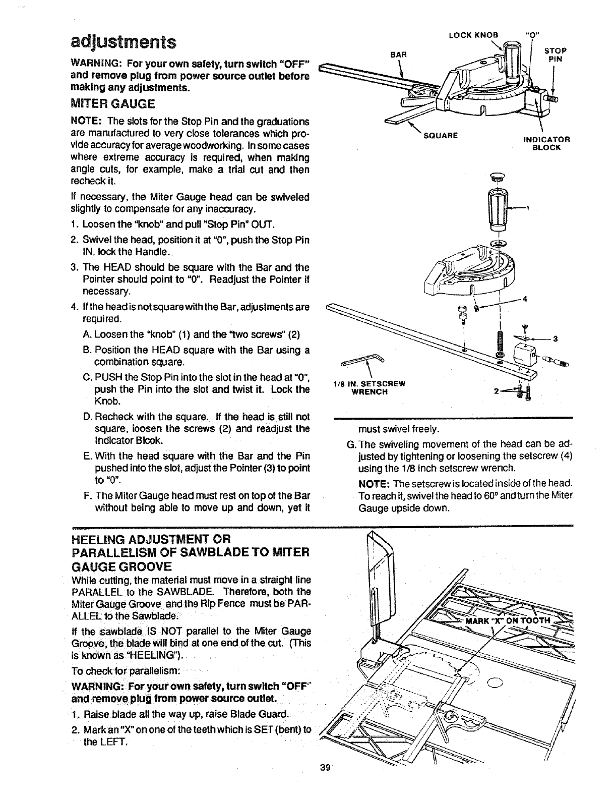
adjustments
WARNING: For your own salety, turn switch "OFF"
and remove plug from power source outlet before
making any adjustments.
MITER GAUGE
NOTE: The Slotsfor the Stop Pin and the graduations
are manufactured to very close tolerances which pro-
vide accuracy for average woodworking. In some cases
where extreme accuracy is required, when making
angle cuts, for example, make atrial cut and then
recheck it.
If necessary, the Miter Gauge head can be swiveled
slightlyto compensate for any inaccuracy.
1. Loosen the "knob" and pull "Stop Pin" OUT.
2. Swivel the head, position it at "0%push the Stop Pin
IN, lockthe Handle.
3. The HEAD should be square with the Bar and the
Pointer should point to "0". Readjust the Pointer if
necessary.
4. Ifthe headis not squarewith the Bar, adjustmentsare
required.
A. Loosen the "knob"(t) and the "two screws"(2)
B. Position the HEAD square with the Bar using a
combination square.
C. PUSH the Stop Pin into the slot in the head at "0",
push the Pin into the slot and twist it. Lock the
Knob.
D. Recheck with the square. If the head is still not
square, loosen the screws (2) and readjust the
Indicator Blcok.
E. With the head square with the Bar and the Pin
pushed intothe slot, adjust the Pointer (3) to point
to "0".
F. The Miter Gauge head must rest on top of the Bar
without being able to move up and down, yet it
LOCK KNOB
\
BAR STOP
PIN
SQUARE INDICATOR
BLOCK
!
WRENCH 2"_
must swivel freely.
G.The swiveling movement of the head can be ad-
justed by tightening or loosening the setscrew (4)
using the 1/8 inch setscrew wrench,
NOTE: The setscrew is located inside of the head.
To reach it, swivel the head to 60 ° andturn the Miter
Gauge upside down,
HEELING ADJUSTMENT OR
PARALLELISM OF SAWBLADE TO MITER
GAUGE GROOVE
While cuffing, the material must move in a straight line
PARALLEL to the SAWBLADE. Therefore, both the
Miter Gauge Groove andthe Rip Fence must be PAR-
ALLEL to the Sawblade_
If the sawblade IS NOT parallel to the Miter Gauge
Groove, the blade will bind at one end of the cut. (This
is known as "HEELING").
To check for parallelism:
WARNING: For your own safety, turn switch "OFP"
and remove plug from power source outlet.
1. Raise blade all the way up, raise Blade Guard.
2. Markan"X" on one of the teeth which isSET (bent) to
the LEFT.
!
39
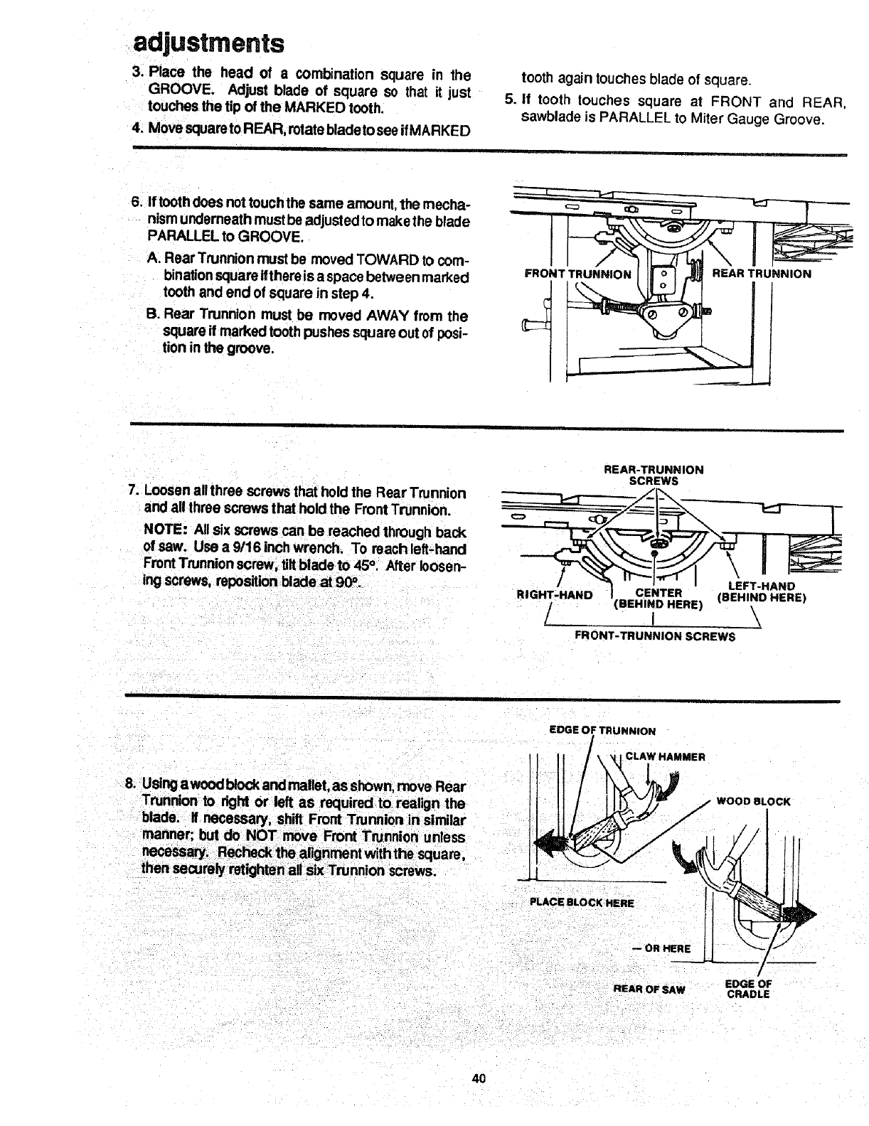
adjustments
3. Place the head of a combination square in the
GROOVE. Adjust blade of square so that it just
touches the tip of the MARKED tooth.
4. Move squareto REAR, rotate blade to see if MARKED
tooth again touches blade of square.
5. If tooth touches square at FRONT and REAR.
sawblade is PARALLEL to Miter Gauge Groove.
6. If tooth does not touch the same amount, the mecha-
nism underneath must be adjusted to make the blade
PARALLEL to GROOVE.
A. Rear Trunnion must be moved TOWARD to com-
binationsquare Ifthere is a space between marked
tOOthand end of square in step 4.
B. Rear Trunnion must be moved AWAY from the
square if marked tooth pushes square out of posi-
tion in the groove.
FRONT TRUNNION REAR TRUNNION
....
7. Loosen all three screws that hold the Rear Trunnion
and all three screws that hold the Front Trunnion.
NOTE: All six screws can be reached through back
of saw. Use a9/16 inch wrench. To reachleft-hancl
FrontTrunnion screw, tilt blade to 45°. After loosen-
ing screws, reposition blade at 90 a.
REAR-TRUNNION
SCREWS
RI|GHT-/HAND lCENTER LEFT-HAND
• (BEHIND HERE) (BEHIND HERE)
/! \,
FRONT-TRUNNION SCREWS
8. Usingawoodblock and mallet, as shown, move Rear
Trunnion to right or left as required to realign the
blade, if necessary, shift Front Trunnion in similar
manner; but do NOT move Front Trunnion unless
EDGE OF TRUNNION
CLAW HAMMER
WOOD BLOCK
PLACE BLOCK HERE
-- OR HERE
I
EDGE OF
REAR OFSAW CRADLE
40
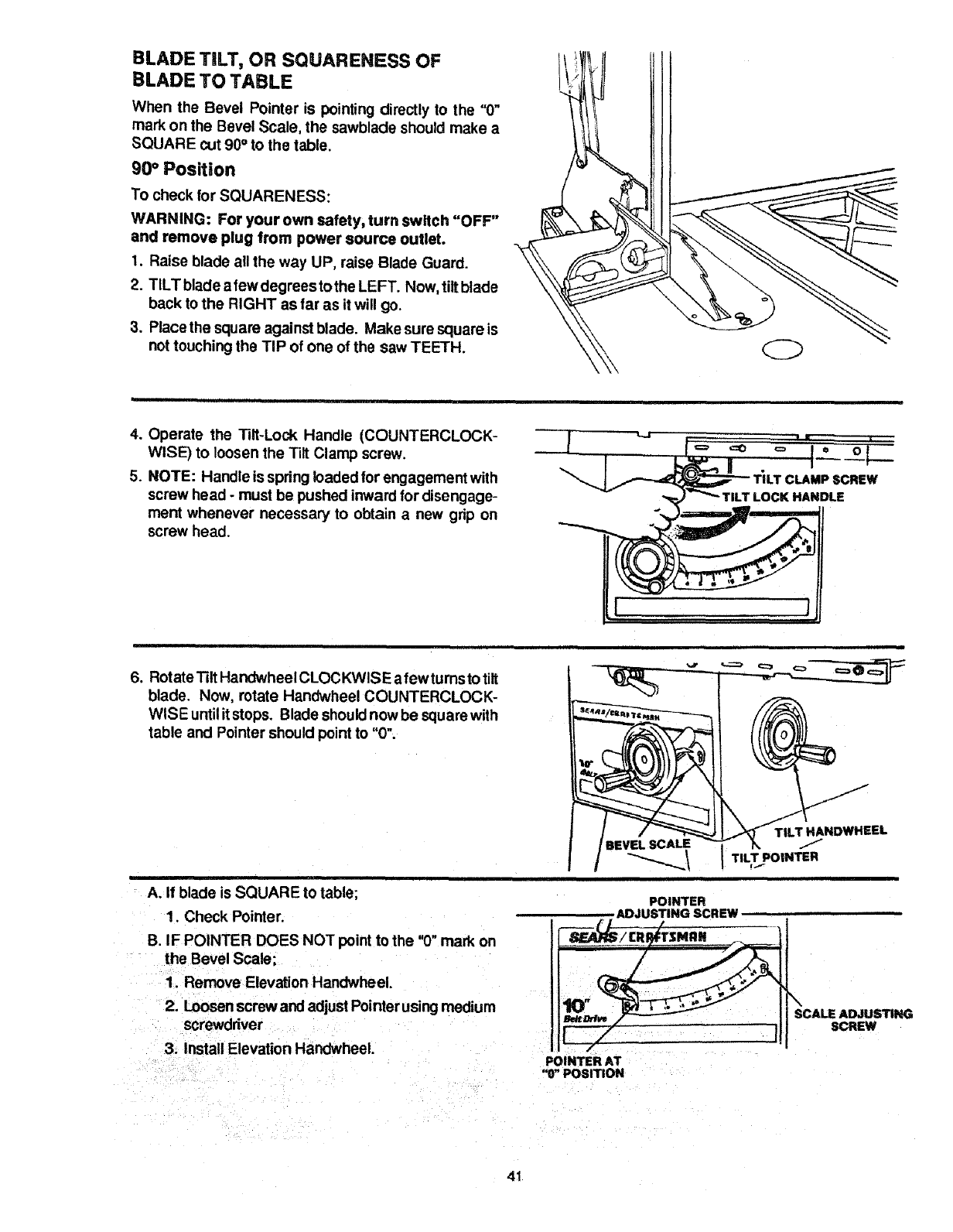
BLADE TILT, OR SQUARENESS OF
BLADE TO TABLE
When the Bevel Pointer is pointing directly to the "0"
mark on the Bevel Scale, the sawblade should make a
SQUARE cut 90°to the table.
90° Position
To check for SQUARENESS:
WARNING: For your own safety, turn switch "OFF"
and remove plug from power source outlet.
1. Raise blade all the way UP, raise Blade Guard.
2. TILTblade afewdegreestothe LEFT. Now, tiltblade
back to the RIGHT as far as it will go.
3. Place the square against blade. Make sure square is
not touching the TIP of one of the saw TEETH.
4. Operate the 131t-Lock Handle (COUNTERCLOCK-
WISE) to loosen the Tilt Clamp screw.
5. NOTE: Handle is spring loaded for engagement with
screw head - must be pushed inward for disengage-
ment whenever necessary to obtain anew grip on
screw head.
__---'_ TILT CLAMP SCREW
.'_ -'_ TIL_T LOCK HANDLE
6. Rotate "131tHandwheelCLOCKWlSE afew tumsto tilt
blade. Now, rotate Handwheel COUNTERCLOCK-
WISE untilit stops. Blade should now be square with
table and Pointer should point to "0".
A. If blade is SQUARE to table;
1. Check Pointer.
B. IF POINTER DOES NOT point to the "(3"mark on
the Bevel Scale;
1. Remove Elevation Handwheel.
2. Loosenscrewand adjust Pointerusing medium
screwdriver
3. Install Elevation Handwheel.
TILT HANDWHEEL
BEVEL SCALE 1"/
I TIL,T °,NisR
POINTER
,ADJUSTING SCREW
\SCALE ADJUSTING
SCREW
POINTER AT
"0" POSITION
41
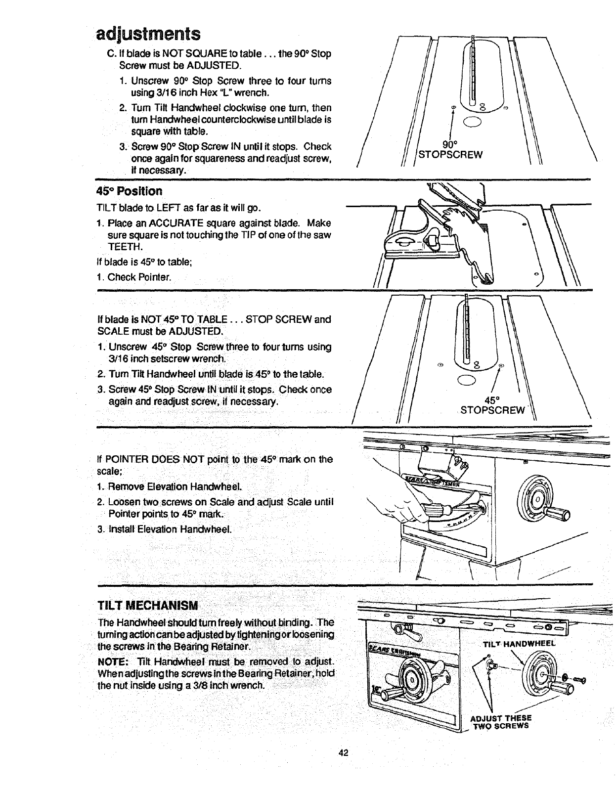
ad ustments
C. If blade is NOT SQUARE to table.., the 90• Stop
Screw must be ADJUSTED.
1. Unscrew 90° Stop Screw three to four turns
using 3/16 inch Hex "L" wrench.
2. Turn Tilt Handwheel clockwise one turn, then
turn Handwheel counterclockwise untilblade is
square with table.
3. Screw 90° Stop Screw IN until it stops. Check
once again for squareness and readjust screw,
if necessary.
i=
45" Position
TILT blade to LEFT as far as it will go.
1. Place an ACCURATE square against blade. Make
sure square is not touchingthe TIP of one of the saw
TEETH.
If blade is 45° to table;
1. Check Pointer.
........ i
//
\
\\\\\
If blade is NOT 45' TO TABLE... STOP SCREW and
SCALE must be ADJUSTED.
1. Unscrew 45° Stop Screw three to four turns using
3/16 inch setscrew wrench.
2. Tum Tilt Handwheel until blade is 45 _to the table.
3. Screw 45°Stop Screw IN until it stops. Check once
again and readjust screw, if necessary. !
/©/
45 °
STOPSCREW
\\\\\\
If POINTER DOES NOT point to the 45 ° mark on the
scale;
1. Remove Elevation Handwheel.
2. Loosen two screws on Scale and adjust Scale until
Pointer points to 45° mark.
3. Install Elevation Handwheel.
TILT MECHANISM
the nut inside using a 3/8 inch wrench.
42
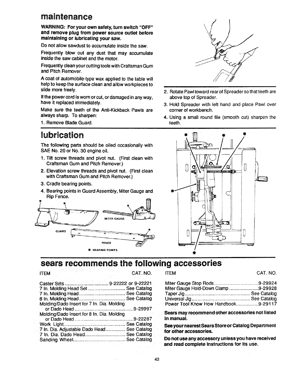
maintenance
WARNING: For your own safety, turn switch "OFF"
and remove plug from power source outlet before
maintaining or lubricating your saw.
Do not allow sawdust to accumulate inside the saw.
Frequently blow out any dust that may accumulate
inside the saw cabinet and the motor,
Frequently clean your cuttingtoolswith Craftsman Gum
and Pitch Remover.
A coat of automobile-type wax applied to the table will
help to keep the surface clean and allow workpieces to
slide more freely.
If the power cord is worn or cut, ordamaged inany way,
have it replaced immediately.
Make sure the teeth of the Anti-Kickback Pawls are
always sharp. To sharpen:
1. Remove Blade Guard.
\\
2. Rotate Pawl toward rear of Spreader so that teeth are
above top of Spreader.
3. Hold Spreader with left hand and place Pawl over
corner of workbench.
4. Using a small round file (smooth cut) sharpen the
teeth.
mubrication
The following parts should be oiled occasionally with
SAE No. 20 or No. 30 engine oil.
1. Tilt screw threads and pivot nut. (First clean with
Craftsman Gum and Pitch Remover.)
2. Elevation screw threads and pivot nut. (First clean
with Craftsman Gum and Pitch Remover.)
3. Cradle bearing points.
4. Bearing points in Guard Assembly, Miter Gauge and
Rip Fence.
GUARD
tBEARING POINTS
sears recommends the following accessories
ITEM CAT. NO. ITEM CAT. NO,
Caster Sets ............................... 9-22222 or 9-22221
7 In. Molding Head Set ........................... See Catalog
7 In. Molding Head ................................. See Catalog
8 In. Molding Head ................................. See Catalog
Molding/Dado Insert for 7 In. Dia. Molding
or Dado Head .......................................... 9-29997
Molding/Dado Insert for 8 In. Dia. Molding
or Dado Head .......................................... 9-22287
Work Light ............................................. See Catalog
7 In. Dia. Adjustable Dad0 Head .............. See Catalog
7 In. Dia. Dado Head ............................... See Catalog
Sanding Wheel ...................................... See Catalog
Miter Gauge Stop Rods ................................ 9-29924
Miter Gauge Hold-Down Clamp ..................... 9-29928
Taper Jig ............................................... See Catalog
Universal Jig .......................................... See Catalog
Power Tool Know How Handbook ................. 9-29117
Sears may recommend other accessories not listed
in manual.
See your nearest Sears Store or Catalog Department
for other accessories.
Do not use any accessory unless you have received
and read complete instructions for its use.
43
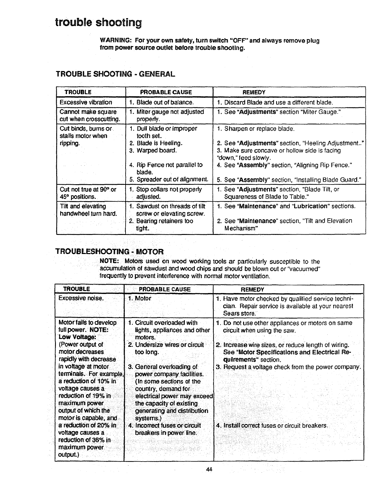
trouble shooting
WARNING: For your own safety, turn switch "OFF" and always remove plug
from power source outlet before trouble shooting.
TROUBLE SHOOTING - GENERAL
TROUBLE
i
Excessive vibration
Cannot make square
cut when crosscutting.
Cut binds, burnsor
stalls motor when
ripping. 2.
3.
4.
5.
Cut nottrue at 90° or 1.
45° positions.
Tilt and elevating I.
handwheel turn hard.
PROBABLE CAUSE
i
1. Blade out of balance.
1. Miter gauge not adjusted
properly,
1. Dull blade or improper
i
tooth set.
Blade is Heeling.
Warped board.
Rip Fence not parallel to
blade.
Spreader out of alignment.
Stop collars not properly
adjusted.
Sawdust on threads of tilt
screw or elevating screw.
2. Bearing retainers too
tight.
REMEDY
1. Discard Blade and use a different blade.
1. See "Adjustments" section "Miter Gauge."
1. Sharpen or replace blade.
2. See "Adjustments" section, "Heeling Adjustment.."
3. Make sure concave or hollow side is facing
"down," feed slowly.
4. See "Assembly" section, "Aligning Rip Fence."
5. See "Assembly" section, "installing Blade Guard."
1. See "Adjustments" section, "Blade Tilt, or
.
.
Squareness of Blade to Table."
See "Maintenance" and "Lubrication" sections.
See "Maintenance" section, "Tilt and Elevation
Mechanism"
TROUBLESHOOTING - MOTOR
NOTE: Motors used on wood working tools ar particularly susceptible to the
accumulation of sawdust and wood chips and should be blown out or "vacuumed"
frequently to prevent interference with normal motor ventilation.
TROUBLE _ PROBABLE CAUSE
Excessive noise. 1. Motor
I
I
Motor fails to develop 1. Circuit overloaded with
full power. NOTE: lights, appliances and other
LOW Voltage: motors.
(Power output of
motor decreases too long.
rapidly with decrease .
REMEDY
1. Have motor checked by qualified service techni-
cian. Repair service is available at your nearest
Sears store,
1. Do not use other appliances or motors on same
circuit when using the saw.
2. Increase wire sizes, or reduce length of wiring.
See "Motor Specifications and Electrical Re-
quirements" section.
44
TROUBLESHOOTING - MOTOR (Cont'd)
TROUBLE
Motor starts slowly
or fails to come up
to full speed
Motor overheats
Starting switch in
motor will not
operate
Motor stalls. 1.
(resulting in blown
fuses or tripped 2.
circuit breakers)
Frequent opening o!
fuses or circuit
breakers
PROBABLE CAUSE
1. Low voltage.
2. Windings burned out
or open.
3. Starting switch not
operating.
1. Motor overloaded
2. improper cooling. (Air
circulation restricted
through motor due to
sawdust, accumulating
inside of saw.)
1. Burned switch contacts
(due to extended hold-in
periods caused by low line
voltage, etc.)
2. Shorted capacitor
(when equipped)
3. Loose or broken
connections.
Starting switch not
operating.
Voltage too low to permit
motor to reach operating
speed.
3. Fuses or circuit breakers
do not have sufficient
capacity.
1. Motor overloaded
2. Fuses or circuitbreakers
do not have sufficient
capacity.
3. Starting switchnot
operating (motor does not
reach speed.)
REMEDY
1. Request voltage check from the power company.
2. Have motor repaired or replaced.
3. Have switch replaced.
.
2. Feed work slower into blade,
Clean out sawdust to provide normal air circulation
through motor. See "Maintenance" and
"Lubrication" section.
1. Have switch replaced and request a voltage check
from the power company.
2. Have capacitor tested and replace if defective.
3. Have wiring checked and repaired.
1. Have switch replaced.
2. Request voltage check from the power company.
3. Install proper size fuses or circuit breakers.
1. Feed work slower into blade.
2. Install proper size fuses or circuit breakers.
3. Have switch replaced.
45
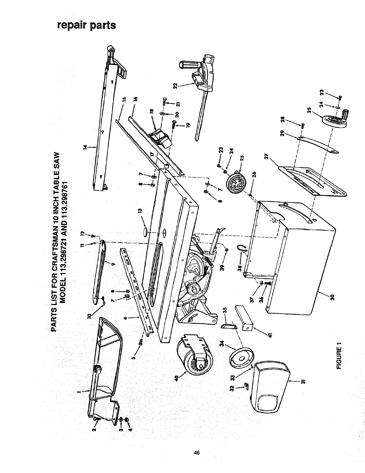
repair parts
\
r
//
/
!
I
!
I
N
46

5
18
I'-.
,T-
O
Z
m
0
Z
Z
n-
O
r,..
0
_L
,,,,,,I
F-,
t,O
O)
u
ZR
.,. n,"
O')
1£
_L
.,J
uJ
a
0
r,-
O_ 0 0 0 _
____ _ O0
__o_o___oo
[
8
13
t-
t_
O_
a::_>,
"0 0
'_ o
>
._(2
Eo
oE
t-
O. __
-.a o
..(3 0
mt""
_r_. __
.___
.._ r-
_d
.._. "0 0
._: -_
=g$
47
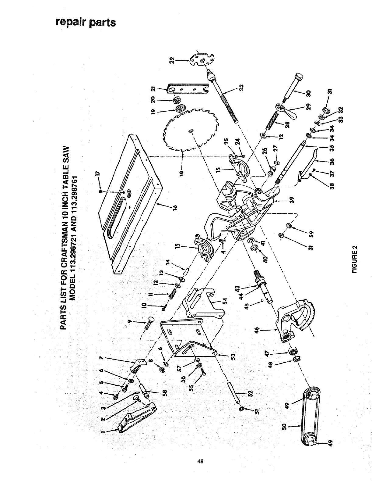
repair parts
IN
W
It,"
48

E
Q
_o
_ 0
0
o
€-
3
0.
m
i
E
-r
N
49
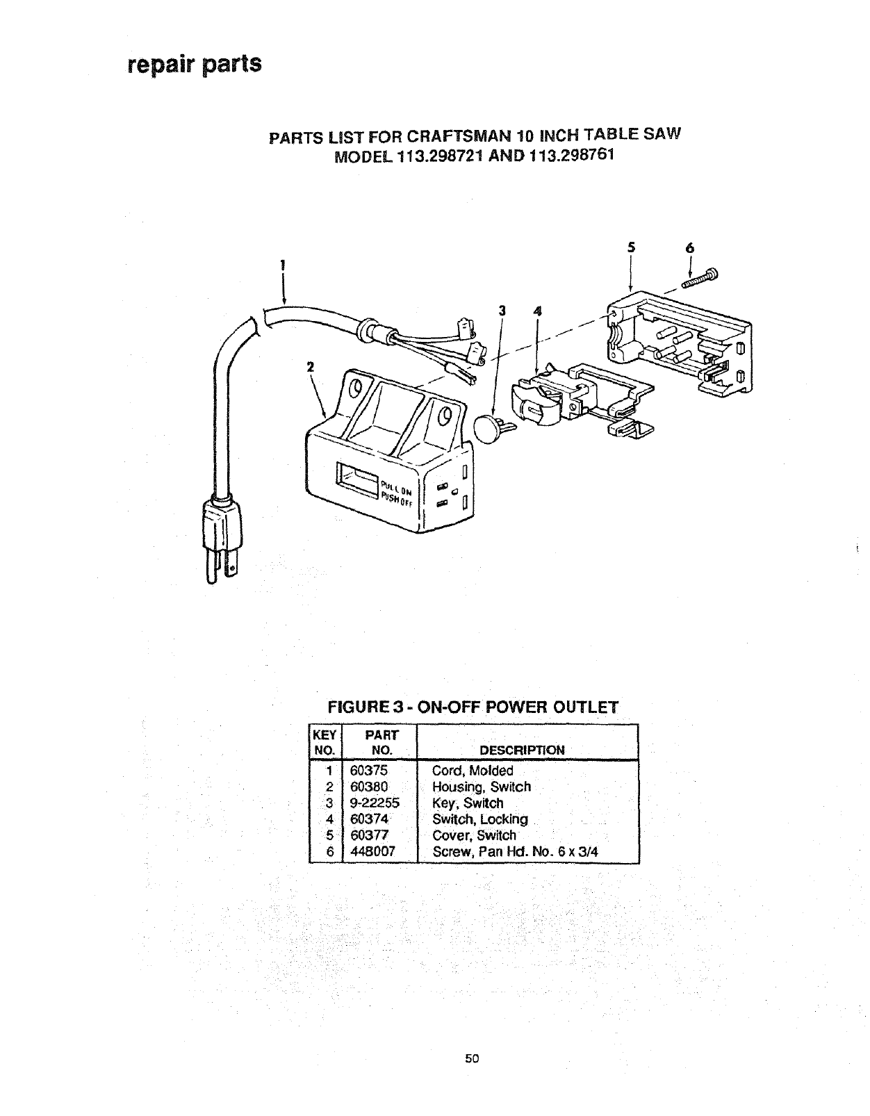
repair parts
PARTS LiST FOR CRAFTSMAN 10 INCH TABLE SAW
MODEL 113.298721 AND 113.298761
!
L
FIGURE 3- ON-OFF POWER OUTLET
KEY PART
NO. NO. DESCRIPTION
.fi=
60375 Cord, Molded
60380 Housing, Switch
9-22255 Key, Switch
60374 Switch, Locking
60377 Cover, Switch
448007 Screw, Pan Hd. No. 6 x 3/4
5O
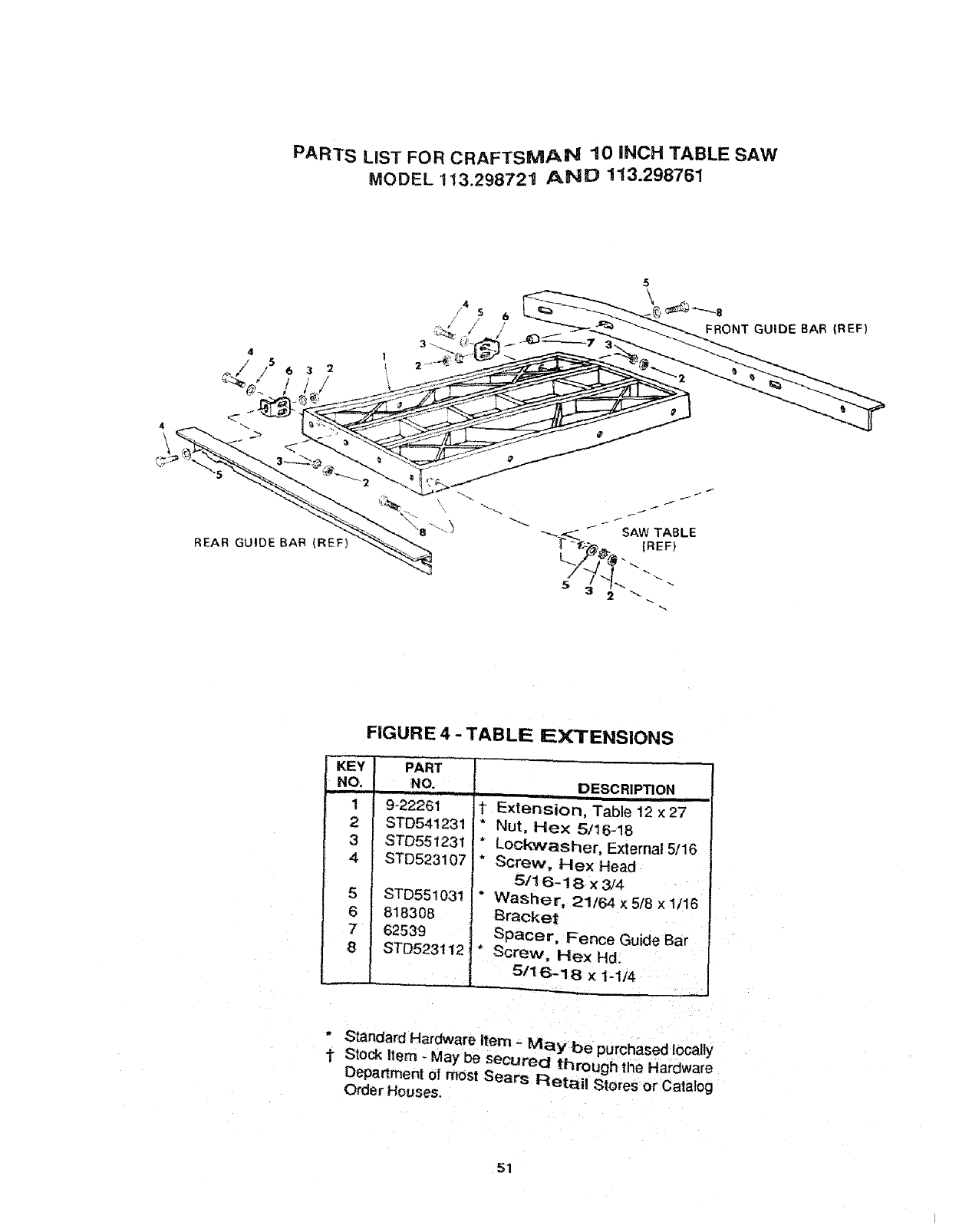
PARTs LiST FOR CRAFTSMA_ 10 iNCH TABLE SAW
MODEL 113.298721 A_E) 113.298761
FIGURE 4 - TABLE EXTENSIONS
["KIEY PART --
INO. NO.
i1 9-22261
2STD541231
3STD551231
4 STD523t07
5 STD551031
6 818308
7 62539
8 STD523112
DESCRIPTION
1 Extension, Table 12 x27
"Nut, Hex 5/16-18
* Lockwasher, External 5/16
" Screw, Hex Head
5/16-18 x3/4
* Washer, 21t64 x 5/8 x 1/16
Bracket
Spacer, Fence Guide Bar
" Screw, Hex Hd.
5/16-18 x 1-1t4
*Standard Hardware Item - May be purchased locally
t Stock Item - May be secured through the Hardware
Department of most Sears Retail Stores or Catalog
Order Houses.
51
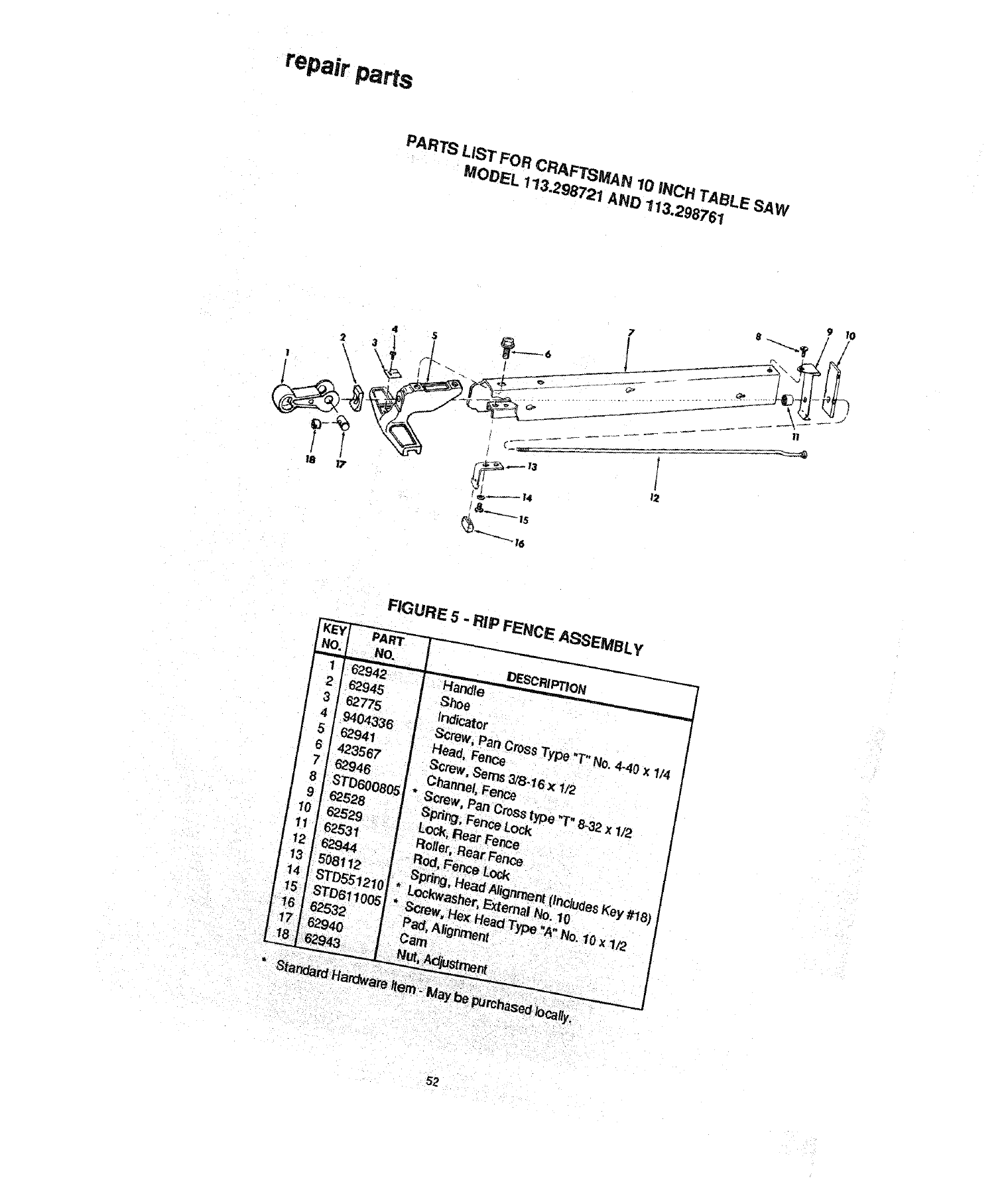
repair Parts
PARTs L'IST FOR CRAFTSMAN 10 iNCH TABLE. SAW
MODEL 173.2S872_AND _l,_.2987S_
2\
/
12
N°- 4-40 x1/4 /
x 1/2 I
52
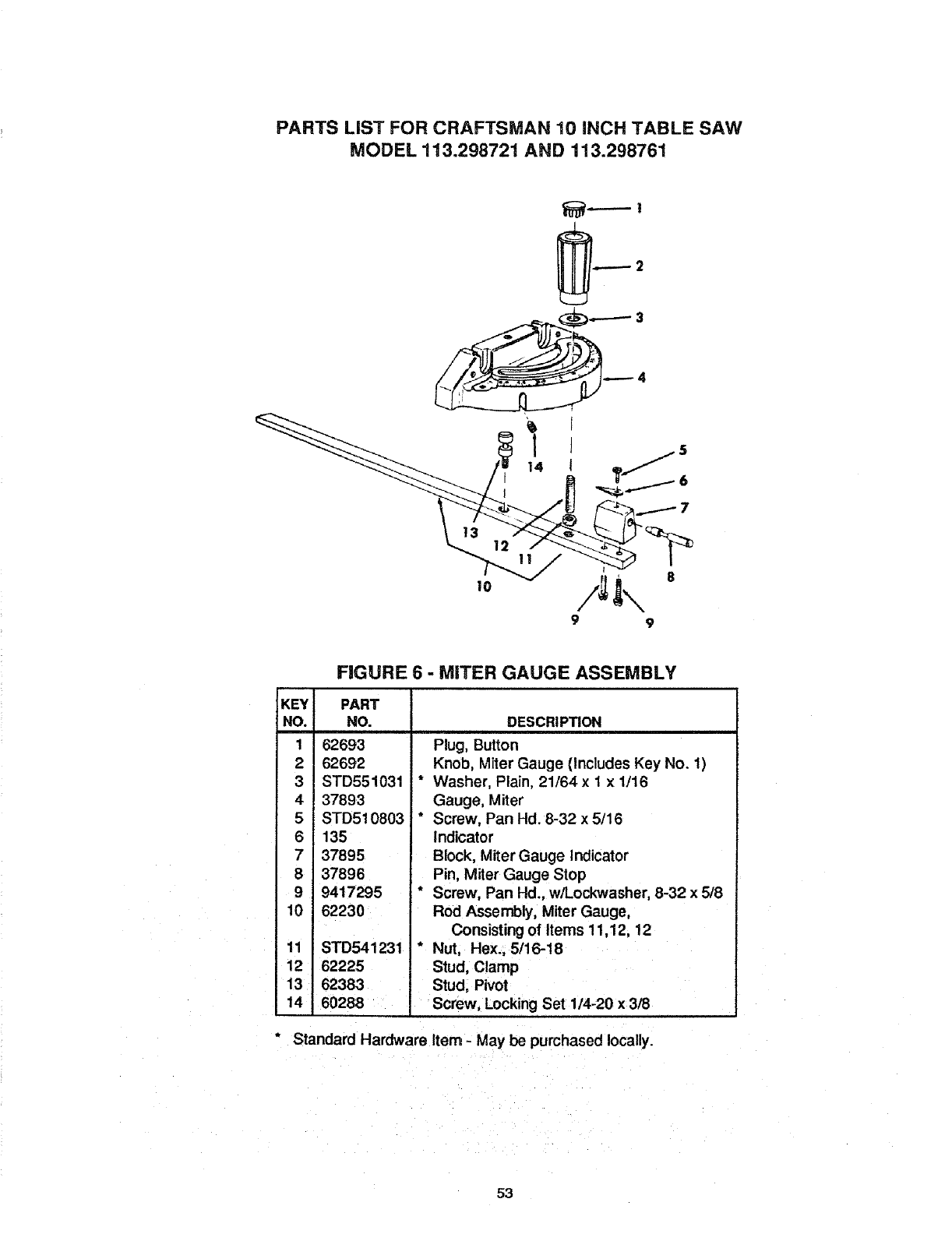
PARTS LIST FOR CRAFTSMAN 10 INCH TABLE SAW
MODEL "!13.298721 AND 113.298761
FIGURE 6 - MITER GAUGE ASSEMBLY
KEY PART
NO. NO.
1 62693
262692
3 STD551031
4 37893
5 STD510803
6 135
737895
8 37896
9 9417295
10 62230
11 STD541231
12 62225
13 62383
14 60288
DESCRIPTION
Plug, Button
Knob, Miter Gauge (Includes Key No. 1)
* Washer, Plain, 21/64 x 1 x 1/16
Gauge, Miter
* Screw, Pan Hd. 8-32 x 5/16
Indicator
Block, Miter Gauge Indicator
Pin, Miter Gauge Stop
* Screw, Pan Hd., w/Lockwasher, 8-32 x 5/8
Rod Assembly, Miter Gauge,
Consisting of Items 11,12, 12
* Nut, Hex., 5/16-18
Stud, Clamp
Stud, Pivot
Screw, Locking Set 114-20 x 3/8
°Standard Hardware Item - May be purchased locally.
53
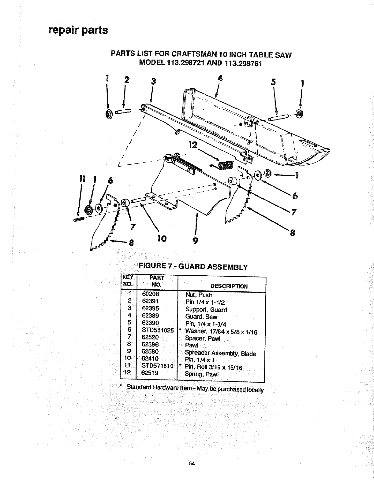
repair parts
PARTS LiST FOR CRAFTSMAN 10 INCH TABLE SAW
MODEL 113.298721 AND 113.298761
I23
_) _::::::_ - /
/
/
/
/
/
/
6
12
45!
10 /
9
FIGURE 7 -GUARD ASSEMBLY
DESCRIPTION
Nut, Push
Pin 1/4 x 1-1/2
Support, Guard
Guard, Saw
Pin, 1/4x 1-3/4
* Washer, 17/64 x 5/8 x 1/16
KEY, PART ,
NO,, NO.
1 60208
2 62391
3 62395
4 62389
5 62390
6 STD551025
7
8 62396
9
10 62410
11 STD571810
12 62519
62520 •Spacer, Pawl
Pawl
Spreader Assembly, Blade
Pin, 1/4x 1
• Pin, Roll 3/16 x 15/16
Spring, Pawl
" Standard Hardware Item -May be purchased locally
54
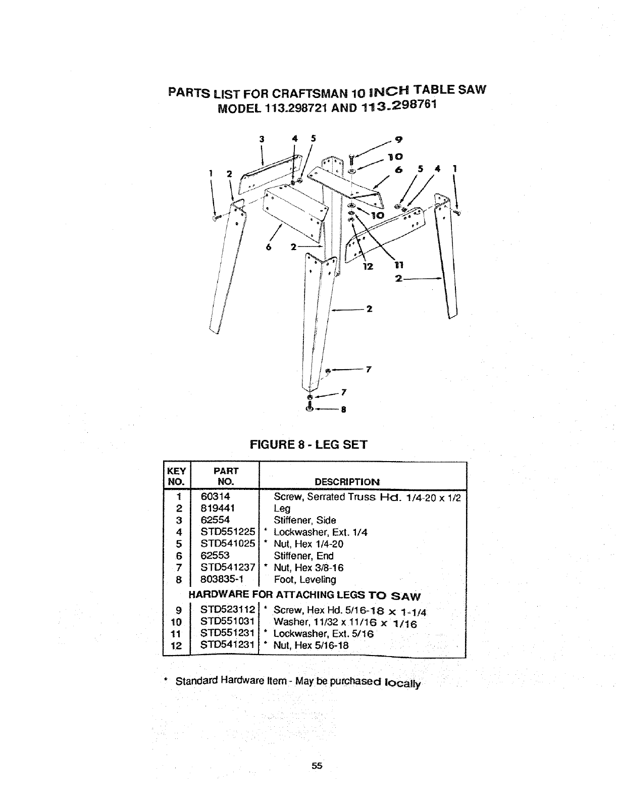
PARTS LiST FOR CRAFTSMAN 10 iNCH TABLE SAW
MODEL 113.298721 AND 11:3.298761
345
1541
f12 11
2_
2
/
,/
KEY
NO.
1
2
3
4
5
6
7
8
PART
NO.
60314
819441
62554
STD551225i
STD541025
62553
STD541237,
803835-t
FIGURE 8 - LEG SET
9
10
11
12
DESCRIPTION
Screw, Serrated Truss HcI. 1/4-20 x 1/2
Leg
Stiffener, Side
*Lockwasher, Ext. 1/4
*Nut, Hex 1/4-20
Stiffener, End
* Nut, Hex 3/8-16
Foot, Leveling
HARDWARE FOR ATTACHING LEGS TO SAW
STD5231121 * Screw, Hex Hd. 5/16-18 x 1-1/4
STD551031 Washer, 11/32 x 11/16 ×1/16
STD551231 * Lockwasher, Ext. 5/16
STD541231 * Nut, Hex 5/16-18
*Standard Hardware Item -May' be purchased locally
55
SERVICE
MODEL NO'S,
113.298721
113.298761
HOW TO ORDER
REPAIR PARTS
10-iNCH TABLE SAW
Now that you have purchased your 10 inch Table
Saw, should a need ever exist for repair parts or
service, simply contact any Sears Service Center and
most Sears, Roebuck and Co. stores. Be sure to
provide all pertinent facts when you call or visit.
The model number of your Table Saw will be found at
the left-hand side of the base.
WHEN ORDERING REPAIR PARTS, ALWAYS GIVE
THE FOLLOWING INFORMATION:
PART NUMBER PART DESCRIPTION
MODEL NUMBER
113.298721
113:298761
NAME OF ITEM
10 Inch Table Saw
All parts listed may be ordered from any Sears Service
Center and most Sears stores. If the parts you need
are not stocked locally, your orderwilt be electronically
transmittedto a Sears Repair Parts Distribution Center
for handling.
Sold by SEARS, ROEBUCK AND CO., Chicago, IL 60684 U.S.A.
Part No. SP5396 Form No. SP5396-2 Printed in U.S.A. 8/92
