Craftsman 137 24884 Users Manual
137248840 137248840 CRAFTSMAN TABLE SAW - Manuals and Guides L0511163 View the owners manual for your CRAFTSMAN TABLE SAW #137248840. Home:Tool Parts:Craftsman Parts:Craftsman TABLE SAW Manual
CRAFTSMAN Saw Table Manual L0511163 CRAFTSMAN Saw Table Owner's Manual, CRAFTSMAN Saw Table installation guides
13724884 924caa41-205b-42ed-8658-f744e7070dff Craftsman Saw 137.24884 User Guide |
2015-01-05
: Craftsman Craftsman-137-24884-Users-Manual-161117 craftsman-137-24884-users-manual-161117 craftsman pdf
Open the PDF directly: View PDF ![]() .
.
Page Count: 30
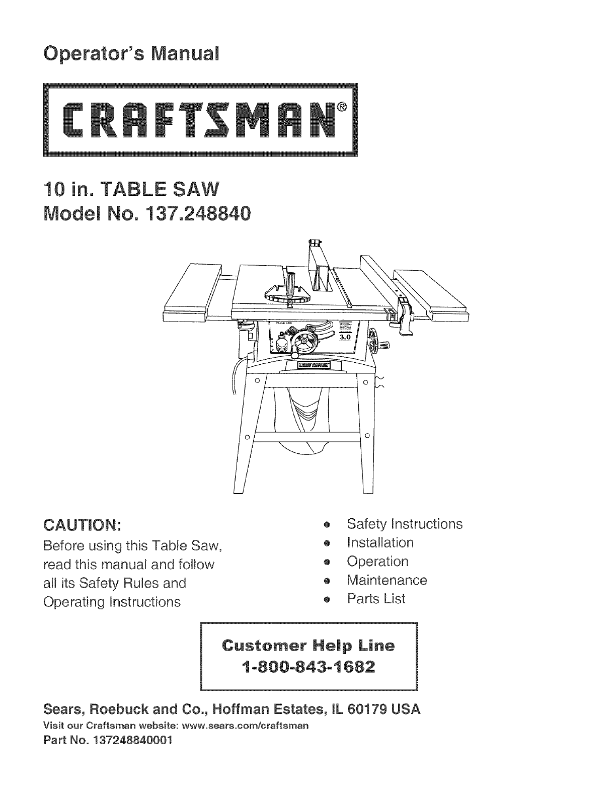
Operator's Manual
®
10 in. TABLE SAW
Model No. 137.248840
CAUTION:
Before using this Table Saw,
read this manual and follow
all its Safety Rules and
Operating Instructions
® Safety Instructions
® Installation
® Operation
® Maintenance
® Parts List
Customer Help Line
1 o800o843ol 682
Sears, Roebuck and Co., Hoffman Estates, IL 60179 USA
Visit our Craftsman website: www.sears.com/craftsman
Part No. 137248840001

SECTION PAGE
Warranty ............................................................. 2
Product Specifications ........................................ 2
Power Tool Safety .............................................. 3
Table Saw Safety ................................................ 4
Electrical Requirements and Safety .................... 5
Accessories and Attachments ............................ 6
Tools Needed for Assembly ................................ 6
Carton Contents .................................................. 6
SECTION PAGE
Know Your Table Saw ........................................ 8
Glossary of Terms ............................................... 9
Assembly and Adjustments ................................. 10
Operation ............................................................ 17
Maintenance ....................................................... 22
Troubleshooting Guide ........................................ 23
Parts List ............................................................. 24
ONE-YEAR FULL WARRANTY ON CRAFTSMAN TOOL
If this Craftsman tool fails due to a defect in material or workmanship within one year from the date of purchase,
CALL 1-800-4-MY-HOME ®TO ARRANGE FOR FREE REPAIR.
If this toot is used for commercial or rental purposes, this warranty wi!l apply for only ninety days from the date of
purchase. This warranty applies only while this tool is in the United States.
This warranty gives you specific legal rights, and you may also have other rights, which vary, from state to state.
Sears, Roebuck & Co., Dept. 817 WA, Hoffman Estates, IL 60179
IA WARNING I
Some duct erected by power sending, sewing, grinding, drilling end other construction activities conteins
chemicals known to cause cancer, birth defects or other reproductive herin. Some exemples of these
chemicets ere:
® Leed from leed-besed peints
® Cryctelline silice from bricks, cement end other mesonry products
®Arsenic end chromium from chemicelly treeted lumber
Your risk from these exposures veries, depending on how often you do this type of work. To reduce your
exposure to these chemicelc, work in e welt ventileted eree end work with epproved sefety equipment such ec
dust meekc thet ere epecieHy decigned to filter out microecopie perticlec.
I_ WARNING I
SAW
Blade Size ...................................... 10 in.
Arbor Size ...................................... 5/8 in.
Rip Fence ...................................... YES
Miter Gauge ................................... YES
Maximum Cut Depth @90° ............ 3 in.
Maximum Cut Depth @45° ............ 2=1/2 in.
Maximum Dado Cut Width ............. 1/2 in.
To evoid electricel hezerds, fire hezerds or demege to the toot, uce proper circuit protection.
This tool is wired et the rectory for 110-120 Volt operation. It must be connected to e 110-120 Volt /15 Ampere
time deley fuse or circuit breeker. To evoid shock or fire, replete power cord immedietely if it is worn, cut or
demeged in eny wey.
Before using your too!, it is criticel thet you teed end understend these cefety rules. Feilure to follow these
rules could result in ceriouc injury to you or demege to the toot.

la,WARNINGn
Before using your tabJe saw, it is critical that you read and understand these safety rules. Failure to follow
these rules couJd result in serious injury or damage to the table saw.
Good safety practices are a combination of common 16. REMOVE ADJUSTING KEYS AND WRENCHES.
sense, staying alert and understanding how to use your
power tool. To avoid mistakes that could cause serious
injury, do not plug in your power tool until you have read
and understood the following safety rules:
1. READ and become familiar with the entire Operator's
Manual. LEARN the tool's application, limitations and
possible hazards.
m
2. l,_ WARNING Look for this symbol that identifies
important safety precautions. It means CAUTION!
Become alert, your safety is involved if you do not
follow the safety instructions.
3. I '& DANGER ]Lookforthis symbolthat identifies
important safety precautions. It means CAUTION!
Become alert, your safety is involved if you do not
foflow the safety instructions.
Form the habit of checking to see that keys and
adjusting wrenches are removed from the tool before
turning ON.
17. NEVER LEAVE TOOL RUNNING UNATTENDED.
TURN THE POWER "OFF". Do not leave the tool
before it comes to a complete stop.
l& NEVER STAND ON TOOL Serious injury could
occur if the too! is tipped or if the cutting tool is
unintentionally contacted.
19. DO NOT OVERREACH Keep proper footing and
balance at all times.
20. MAINTAIN TOOLS WITH CARE Keep tools sharp
and clean for most efficient and safest performance.
Follow instructions for lubricating and changing
accessories.
4. NEVER OPERATE THIS MACHINE WITHOUT THE
SAFETY GUARD IN PLACE FOR ALL THROUGH°
SAWING OPERATIONS.
5.
6.
DO NOT USE iN A DANGEROUS ENWRONMENT
such as damp or wet locations or exposure to rain.
Keep work area well lighted.
DO NOT use power tools in the presence of
flammable liquids or gases.
21. CHECK FOR DAMAGED OR LOOSE PARTS.
Before further use of the too!, a guard or other
part that is damaged should be carefully checked
to ensure it will operate properly and perform its
intended function. Check for alignment of moving
parts, binding of moving parts, loose mounting
and any other conditions that may affect its safe
operation. A guard or other part that is loose or
damaged should be properly adjusted repaired or
replaced.
7. KEEP WORK AREA CLEAN. Cluttered areas and
benches invite accidents. 22. MAKE WORKSHOP CHILD PROOF with padlocks,
master switches or by removing starter keys.
8. KEEP CHILDREN AWAY. All visitors should be kept
at a safe distance from the work area.
9. DO NOT FORCE THE TOOL. it will do the job better
and safer at the rate for which it was designed.
10 USE THE RIGHT TOOL. Do not force the tool or
attachment to do a job for which it is not designed.
11. WEAR PROPER APPAREL DO NOT wear loose
clothing, gloves, neckties, rings, bracelets or other
jewelry that may get caught in moving parts. Non-
slip footwear is recommended. Wear protective hair
covering to contain long hair.
12. WEAR A FACE MASK OR DUST MASK. Sawing,
cutting and sanding operations produce dusL
l& DISCONNECT TOOLS before servicing and when
changing accessories such as blades, cutters, etc.
23.
24.
25.
DO NOT operate the tool if you are under the
influence of any drugs, alcohol or medication that
could impair your ability to use the tool safely.
USE A DUST COLLECTION SYSTEM wherever
possible. Dust generated from certain materials can
be hazardous to your health and in some cases, a
fire hazard. Always operate the power tool in a well-
ventilated area with adequate dust removal
ALWAYS WEAR EYE PROTECTION Any power
too! can throw foreign objects into your eyes which
could cause permanent eye damage. ALWAYS
wear safety goggles (not glasses) that comply with
ANSi safety standard Z87.1. Everyday glasses
have only impact resistant bnses. They ARE NOT
safety glasses. Safety Goggles are available at
Sears. NOTE: Glasses or goggles not in
compliance with ANSI Z87.1 could cause serious
injury when they break.
14. REDUCE THE RISK OF UNINTENTIONAL
STARTING. Make sure the switch is in the OFF
position before plugging into the power supply.
26. DIRECTION OF FEED. Feed work into a blade or
cutter against the direction of rotation of the blade or
cutter only.
15. USE ONLY RECOMMENDED ACCESSORIES.
Consult the Operator's Manual for recommended
accessories. The use of improper accessories may
cause injury to you or damage to the tool
27. DO NOT AUTHORZE ADDiTiONAL USERS to
operate this power tool without the accompanying
operators manual for which the user must read and
understand.

1. ALWAYSUSESAWBLADEGUARD,splitterand
anti-kickbackpawlsforeveryoperationforwhich
theycanbeused,includingthrough-sawing.
Through-sawingoperationsarethoseinwhichthe
bladecutscompletelythroughtheworkpiecewhen
rippingorcross-cutting.
2. ALWAYSHOLDWORKFIRMLYagainstthemiter
gaugeorripfence.
functioning.Donotreleaseworkbeforeithas
passeda!lthewaypastthesawbladeandisoffthe
table.Donotripworkthatistwisted,warpedor
doesnothaveastraightedgetoguideitalongthe
fence.
14.AVOIDAWKWARDOPERATIONSandhand
positionswhereasuddenslipcouldcauseyour
handto moveintothesawblade.
3. USE A PUSH STICK when required. Always use a
push stick when ripping narrow stock. Refer to
ripping instructions in this Operator's Manual where
the push stick is covered in detail. A pattern for
making your own push stick is included on page 28.
4. NEVER PERFORM ANY OPERATION "FREE
HAND", which means using only your hands to
support or guide the workpiece. Always use either
the fence or the miter gauge to position and guide
the work.
[A DANGER]
FREEHAND CUTTING iS THE MAJOR CAUSE OF
KICK-BACK & FINGER/HAND AMPUTATIONS.
5. NEVER STAND or have any part of your body in
line with the path of the saw blade. Keep your
hands out of the saw blade path.
6. NEVER REACH behind or over the cutting tool for
any reason.
7. NEVER use a rip fence when cross cutting.
8. DO NOT USE a molding head with this saw.
9. FEED WORK iNTO THE BLADE against the
direction of rotation only.
10. NEVER use the rip fence as a cut-off gauge when
cross-cutting.
15. NEVER USE SOLVENTS to clean plastic parts.
Solvents could possibly dissolve or otherwise
damage the material. Only a soft damp cloth
should be used to clean plastic parts.
16. MOUNT your table saw on a bench or stand before
performing any cutting operations. Refer to
ASSEMBLY AND ADJUSTMENTS on page 10.
17. NEVER CUT METALS or materials which may
make hazardous dust.
18. ALWAYS USE tN WELL-VENTILATED AREA.
Remove sawdust frequently. Clean out sawdust
from the interior of the saw to prevent a potential
fire hazard. Attach a vacuum to the dust port for
additiona! sawdust removal.
19. NEVER LEAVE THE SAW running unattended. Do
not leave the saw unti! it comes to a complete stop.
20. FOR proper operation fotlow the instructions in this
Operator's Manual. Failure to provide sawdust fag
through and removal hole win allow sawdust to
build up in the motor area resulting in a fire hazard
and potentia! motor damage (see page 11 for
details).
21. DO NOT AUTHORIZE ADDITIONAL USERS to
operate this power tool without the accompanying
operators manual for which the user must read and
understand.
11. NEVER ATTEMPT TO FREE A STALLED SAW
BLADE without first turning the saw OFF. Turn
power switch OFF and disconnect the plug from the
power source immediately to prevent motor
damage & before removing material.
12. PROVIDE ADEQUATE SUPPORT to the rear and
the sides of the saw table for long or wide
workpieces.
22. THE REAR OF THE TABLE INSERT MUST BE
FLUSH TO THE TABLE during all sawing
operations. A rubber adjusting spacer is provided
under the rear of the insert for this purpose.
23. DO NOT USE A DADO BLADE LARGER THAN
6 inches in diameter and Y2inch in width. Only
use a stackable dado blade. Do not use adjustable
or wobble dadoes.
13. AVOID KICKBACKS (work thrown back towards
you) by keeping the blade sharp, the rip fence
parallel to the saw blade and by keeping the splitter,
anti-kickback pawls and guards in place and
24. NEVER PERFORM A CUTTING OPERATION
USING BOTH the rip fence and the miter gauge at
the same time. This may cause kickback and
serious injury to the operator.
GROUND(NG (NSTRUCT(ONS
IN THE EVENT OF A MALFUNCTION OR
BREAKDOWN, grounding provides a path of least
resistance for electric currents and reduces the risk of
electric shock. This tool is equipped with an electrical
cord that has an equipmentogrounding conductor
and a grounding p(ug. The p(ug must be plugged
into a matching receptac(e that is proper(y instal(ed
and grounded in accordance with al! local codes and
ordinances.
DO NOT MODIFY THE PLUG PROVIDED. if it will not
fit the receptacle, have the proper receptac(e insta((ed
by a qualified electrician.
IMPROPER CONNECTION of the equipment grounding
conductor can result in risk of electric shock. The
conductor with the green insulation (with or without
yellow stripes) is the equipment grounding conductor.
(f repair or replacement of the e(ectric cord or plug is
necessary, do not connect the equipment grounding
conductor to a live terminal
CHECK with a qualified electrician or service person
if you do not comp(ete(y understand the grounding
instructions, or if you are not certain the too( is properly
grounded.
motor to the power line, make sure the switch is in the
off position and the e(ectric current is rated the same as
the current stamped on the motor nameplate. Running
at a lower voltage wi(( damage the motor. This too( is
intended for use on a circuit that has a receptacle like
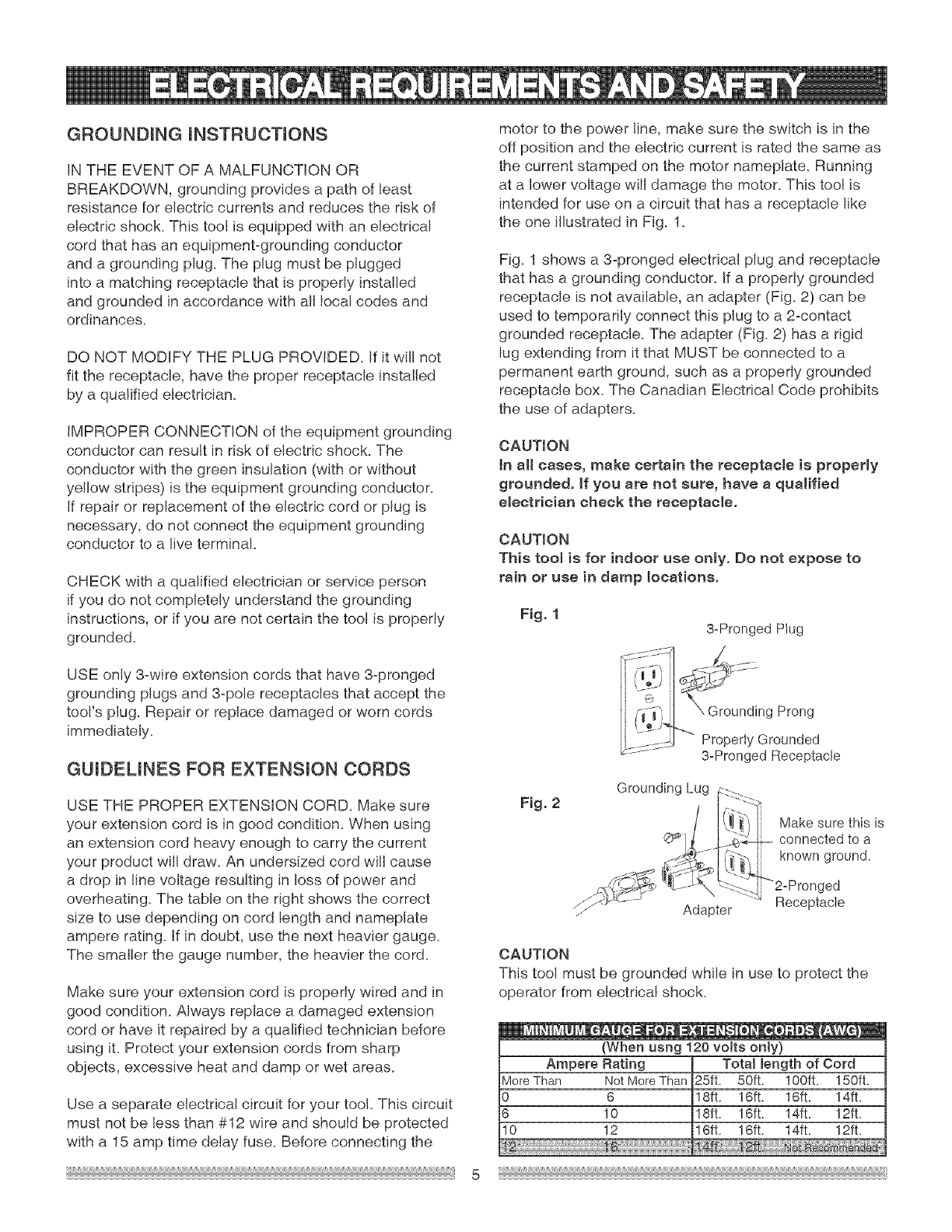
the one i(Justrated in Fig. 1.
Fig. 1 shows a 3-pronged electrical plug and receptacle
that has a grounding conductor. If a properly grounded
receptac(e is not avai(abJe, an adapter (Fig. 2) can be
used to temporarily connect this plug to a 2ocontact
grounded receptacle. The adapter (Fig. 2) has a rigid
(ug extending from it that MUST be connected to a
permanent earth ground, such as a properly grounded
receptacle box. The Canadian EJectrica( Code prohibits
the use of adapters.
CAUT)ON
tn a(( cases, make certain the receptac(e is proper(y
grounded. If you are not sure, have a qua)ified
e(ectHc)an check the receptac)e.
CAUT(ON
This too( is for indoor use on)y. Do not expose to
rain or use in damp locations.
Fig. 1 3_Pronged Plug
USE only 3°wire extension cords that have 3°pronged
grounding p(ugs and 3°pole receptac(es that accept the
too('s plug. Repair or rep(ace damaged or worn cords
immediate(y.
GU(DELINES FOR EXTENS(ON CORDS
USE THE PROPER EXTENS(ON CORD. Make sure
your extension cord is in good condition. When using
an extension cord heavy enough to carry the current
your product will draw. An undersized cord wiil cause
a drop in (ine vo(tage resu(ting in (oss of power and
overheating. The table on the right shows the correct
size to use depending on cord (ength and namep(ate
ampere rating. )f in doubt, use the next heavier gauge.
The smaller the gauge number, the heavier the cord.
Make sure your extension cord is properly wired and in
good condition. Always rep(ace a damaged extension
cord or have it repaired by a qualified technician before
using it. Protect your extension cords from sharp
objects, excessive heat and damp or wet areas.
Use a separate e(ectrica( circuit for your too(. This circuit
must not be (ess than #12 wire and should be protected
with a 15 amp time de(ay fuse. Before connecting the
Fig. 2
g Prong
Property Grounded
3-Pronged Receptacle
Grounding Lug
Make sure this is
connected to a
known ground.
Adapter Receptacle
CAUTION
This tool must be grounded while in use to protect the
operator from electrical shock.
(When usng 120 vo(ts on(y)
Ampere Rating Tota( (eogth of Cord
MoreThan NotMoreThan 25ft. 50ft. 100ft. 150ft.
0 6 8ft. 16ft. 16ft. 14ft.
6 10 8ft. 16ft. 14ft. 12ft.
10 12 6ft. 16ft. 14ft. 12ft.
RECOMMENDED ACCESSORIES
IA WARNINGI
Visit your Scars Hardware Department or see the
Scars Power and Hand TooJ Catalog to purchase
recommended accessories for this power tool
IA WARNINGn
To avoid the risk of personal injury, do not
modify this power tool or use accessories not
recommended by Sears.
To avoid the risk of personal injury:
o Do not use adjustable (wobble) type dadoes or
carbide tipped dado blades; maximum dado width is
1/2 in.
® Do not use a dado with a diameter larger than 6 in.
o Do not use molding head set with this saw.
® Do not modify this power tool or use accessories not
recommended by Sears.
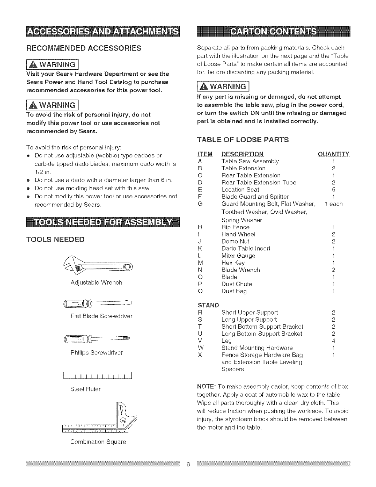
TOOLS NEEDED
Adjustable Wrench
Fiat Blade Screwdriver
Phflips Screwdriver
I Illllllllll ]
Steel Ruler
Combination Square
Separate all parts from packing materials. Check each
part with the illustration on the next page and the "Table
of Loose Parts" to make certain all items are accounted
for, before discarding any packing material
[_ WARNING 1
ff any part is missing or damaged, do not attempt
to assemble the table saw, plug in the power cord,
or turn the switch ON until the missing or damaged
part is obtained and is installed correctly.
TABLE OF LOOSE PARTS
ITEM DESCRIPTION QUANTITY
A Table Saw Assembly 1
B Table Extension 2
C Rear Table Extension 1
D Rear Table Extension Tube 2
E Location Seat 5
F Blade Guard and Splitter 1
G Guard Mounting Bolt, Fiat Washer, 1 each
Toothed Washer, Oval Washer,
Spring Washer
H Rip Fence 1
I Hand Wheel 2
J Dome Nut 2
K Dado Table insert 1
L Miter Gauge 1
M Hex Key 1
N Blade Wrench 2
O Blade 1
P Dust Chute 1
Q Dust Bag 1
STAND
R
S
T
U
V
W
X
Short Upper Support 2
Long Upper Support 2
Short Bottom Support Bracket 2
Long Bottom Support Bracket 2
Leg 4
Stand Mounting Hardware 1
Fence Storage Hardware Bag 1
and Extension Table Leveling
Spacers
NOTE: To make assembly easier, keep contents of box
together. Apply a coat of automobile wax to the table.
Wipe ali parts thoroughly with a clean dry cloth. This
will reduce friction when pushing the workiece. To avoid
injury, the styrofoam block should be removed between
the motor and the table.
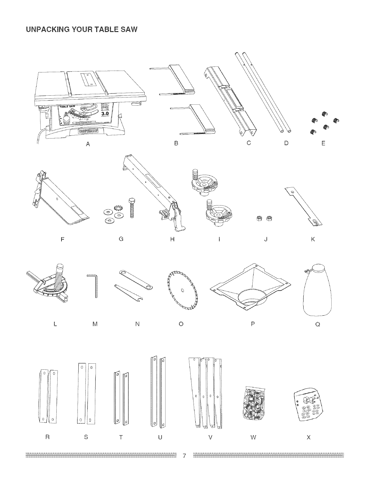
UNPACKING YOUR TABLE SAW
AB
G H
C D
®®
M O P Q
o0 0
UR S V W X
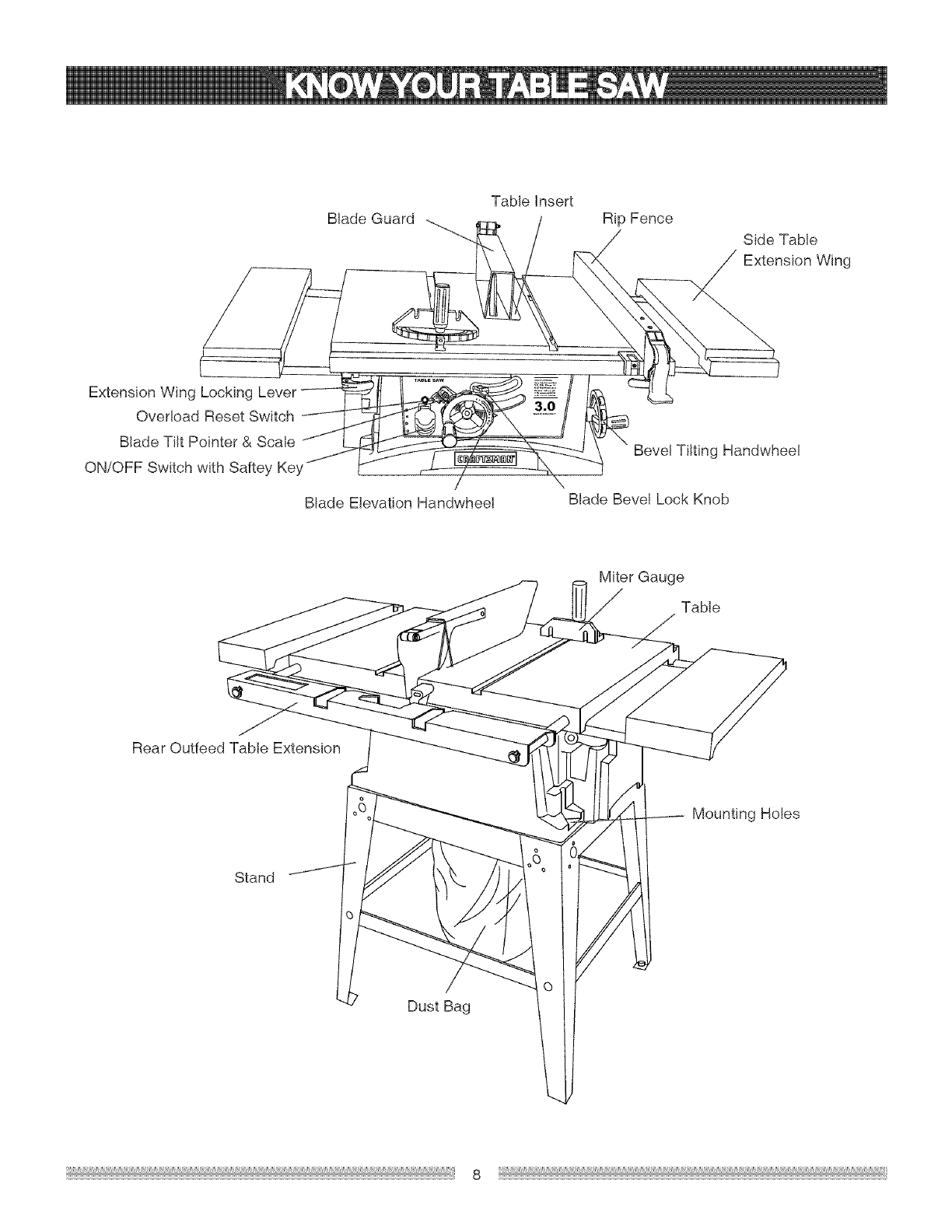
BladeGuard
#
Extension Wing Locking
Overload Reset Switch
Blade Tilt Pointer & Scale
ON/OFF Switch with Saftey Key
Blade Elevation Handwheel
Table insert
Rip Fence
Side Table
Extension Wing
Bevel Tilting Handwheel
BladeBevelLock Knob
Miter Gauge
Table
Rear Outfeed Table Extension
Mounting Holes
Stand
Dust Bag
ANTFKICKBACKPAWLS= Preventstheworkpiece
frombeingkickedupwardorbacktowardthefrontof the
tablesawbythespinningblade.
ON/OFFSWITCH= Containsa built-insafetyswitch
key.TolocktheswitchintheOFFposition,removethe
switchkeyfromtheswitch.
ARBOR=Theshaftonwhichthebladeordadois
mounted.
BEVELCUT= Ananglecutmadethroughthefaceof
theworkpiece.
BLADEBEVELSCALE= Measurestheangletheblade
istiltedwhensetfora bevelcut.
BLADEELEVATIONHANDWHEEL= Raisesand
lowerstheblade.
BLADEGUARD= Clearplasticcoverthatpositions
itselfoverthebladewhilecutting.
BLADETILTINGBANDWHEEL=Tiltsthebladetoany
anglebetween0oand45° forbevelcuts.
COMPOUNDCUT=A simultaneousbevelandmiter
cut.
CROSSCUT= Acutmadeacrossthewidthofthework
piece.
DADO= Specialcuttingbladesthatareusedtocut
groovesinaworkpiece.
OVERLOADRESETSWITCH= Resetsthe
thermocoupleandprovidesa wayto restartthesaw
motorifit overloadsoroverheats.
PUSHSTICK= Specialwoodenaccessorythatisused
topusha smallworkpiecewhenworkingclosetothe
sawblade.
RESIN= Astickysapthathashardened.
REVOLUTIONSPERMINUTE(RPWI)=Thenumberof
turnscompletedbya spinningobjectinoneminute.
RIPFENCE= Aguideusedforripcuttingthatclampsto
thetabletop. Itallowstheworkpieceto cutstraight.
RIPPING=Cuttingwiththegrainofthesolidwoodor
alongthelengthoftheworkpiece.
SAWBLADEPATH= Theareaof theworkpieceor
tabletopdirectlyinlinewiththetravelofthebladeorthe
partoftheworkpiecethatwil!becut.
SET= Thedistancebetweentwosawbladetips,bent
outwardinoppositedirectionstoeachother.The
furtherapartthetipsare,thegreatertheset.
DUSTPORT= Holeinbackofsawbaseforattachment
ofvacuumhose.
FREEHAND= Performingacutwithoutusinga rip
fence,mitergauge,holddownorotherproperdeviceto
preventtheworkpiecefromtwistingduringthecutting
operation.
GUM= Astickysapfromwoodproducts.
HEEL= MisaiignmentoftheMade.
SPLITTER= Keepstheworkpiecesplitapartafter
beingcutto preventbindingonthebladeandwork
piece.
TABLEINSERT= Metalinsertthatisremovedfromthe
tabletoinstall/remove blades, it is also removed for
dado cutting. When dado cutting, a dado insert plate
must be used.
THROUGH- SAWING = Making a cut completely
through the length or width of a work piece.
JAM NUT = Nut used to lock another nut in place on a
threaded rod or bolt.
WORK PIECE = Material to be cut.
KERF = The amount of material removed by the blade
cut+
MITER CUT = An angle cut made across the width of
the work piece+
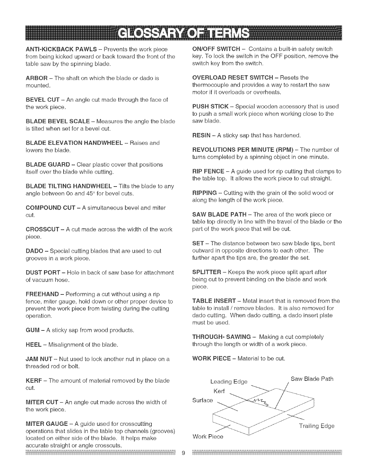
Leading Edge
Kerf
Surface
Saw Blade Path
MITER GAUGE = A guide used for crosscutting
operations that slides in the table top channels (grooves)
located on either side of the blade. It helps make
accurate straight or angle crosscuts.
Work Piece
Trailing Edge
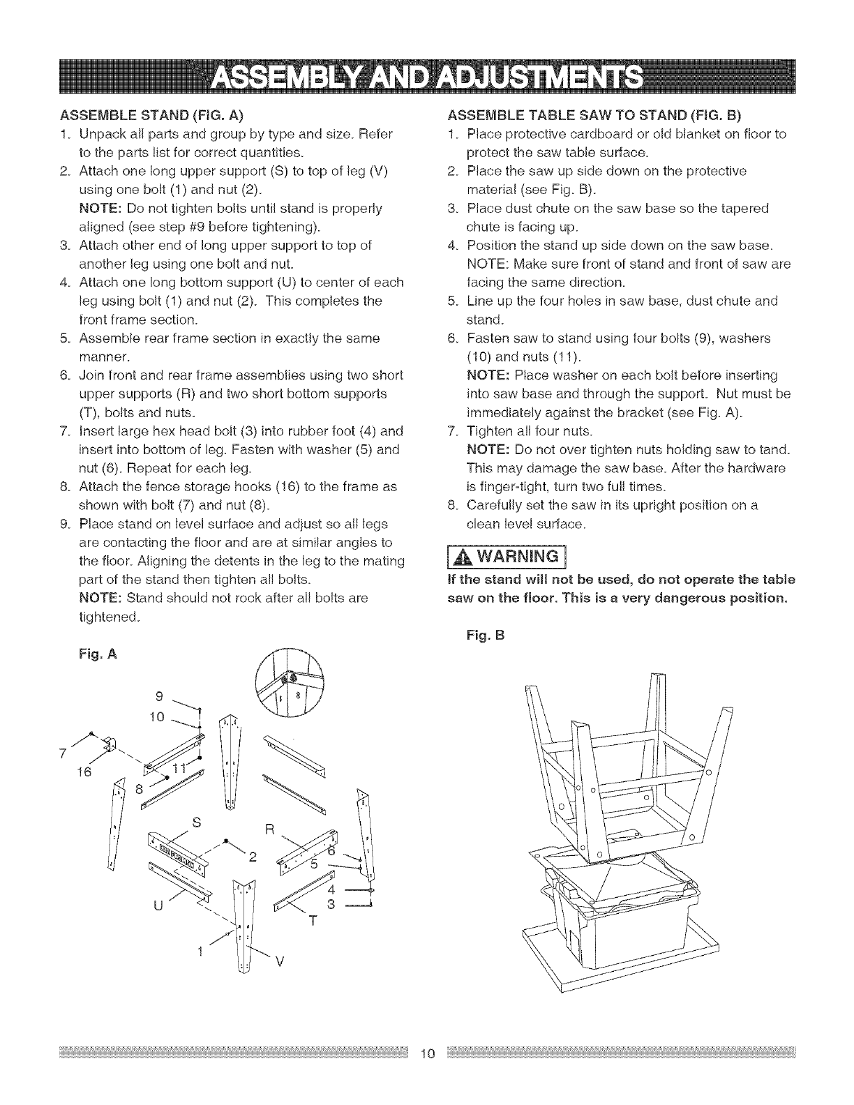
ASSEMBLESTAND(FIG.A)
1 Unpackallpartsandgroupbytypeandsize Refer
totheparts!istforcorrectquantities
2 Attachonelonguppersupport(S)totopofleg(V)
usingonebolt(1)andnut(2)
NOTE:Donottightenboltsuntilstandisproperly
aligned(seestep#9beforetightening)
3 Attachotherendof Io%uppersupporttotopof
anotherlegusingoneboltandnuL
4 Attachonelongbottomsupport(U)tocenterofeach
legusingbolt(1)andnut(2) Thiscompletesthe
frontframesection
5 Assemblerearframesectioninexactlythesame
manner
6 Joinfrontandrearframeassembliesusingtwoshort
uppersupports(R)andtwoshortbottomsupports
(T),boltsandnuts
7 Insertlargehexheadbolt(3)intorubberfoot(4)and
insertintobottomof leg Fastenwithwasher(5)and
nut(6) Repeatforeachleg
8 Attachthefencestoragehooks(16)totheframeas
shownwithbolt(7)andnut(8)
9 Placestandonlevelsurfaceandadjustsoalllegs
arecontactingthefloorandareat similaranglesto
thefloorAligningthedetentsinthelegtothemating
partofthestandthentightenal!bolts
NOTE:Standshouldnotrockafteral!boltsare
tightened
Fig.A
J
16
T
1 V
ASSEMBLE TABLE SAW TO STAND (FIG. B)
1 Place protective cardboard or old blanket on floor to
protect the saw table surface
2 Place the saw up side down on the protective
materia! (see Fig B)
3 Place dust chute on the saw base so the tapered
chute is facing up
4 Position the stand up side down on the saw base
NOTE: Make sure front of stand and front of saw are
facing the same direction
5 Line up the four holes in saw base, dust chute and
stand
6 Fasten saw to stand using four bolts (9), washers
(10) and nuts (11)
NOTE: Place washer on each bolt before inserting
into saw base and through the supporL Nut must be
immediately against the bracket (see Fig A)
7 Tighten all four nuts
NOTE: Do not over tighten nuts holding saw to tand
This may damage the saw base After the hardware
is finger-tight, turn two full times
8 Carefully set the saw in its upright position on a
clean level surface
[,& WARNING]
if the stand will not be used, do not operate the table
saw on the fmoor. This is a very dangerous position.
Fig. B
10
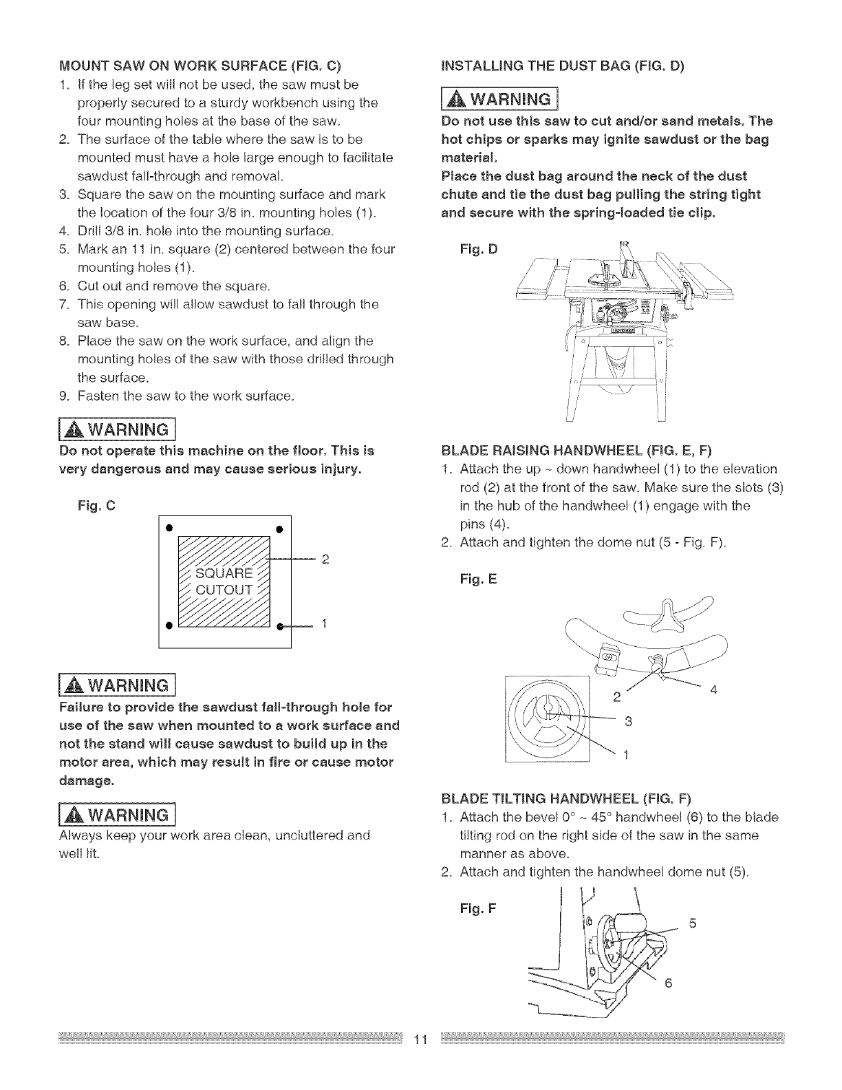
MOUNTSAWONWORKSURFACE(FIG.C)
1. Ifthelegsetwillnotbeused,thesawmustbe
properlysecuredtoasturdyworkbenchusingthe
fourmountingholesat thebaseofthesaw.
2. Thesurfaceofthetablewherethesawistobe
mountedmusthavea holelargeenoughtofacilitate
sawdust%Fthroughandremoval
& Squarethesawonthemountingsurfaceandmark
thelocationofthefour3/8in.mountingholes(1).
4. Drill3/8in.holeintothemountingsurface.
& Markan11in.square(2)centeredbetweenthefour
mountingholes(1).
& Cutoutandremovethesquare.
7. Thisopeningwillallowsawdusttofal!throughthe
sawbase.
& Placethesawontheworksurface,andalignthe
mountingholesofthesawwiththosedrilledthrough
thesurface.
9. Fastenthesawtotheworksurface.
IA WARNINGI
Do not operate this machine on the floor. This is
very dangerous and may cause serious injury.
Fig. C
IA WARNINGI
Failure to provide the sawdust fall-through hole for
use of the saw when mounted to a work surface and
not the stand will cause sawdust to build up in the
motor area, which may result in fire or cause motor
damage.
IA WARNINGI
Always keep your work area clean, uncluttered and
well lit.
INSTALLING THE DUST BAG (FIG. D)
[_ WARNING]
Do not use this saw to cut and/or sand metals. The
hot chips or sparks may ignite sawdust or the bag
material
Place the dust bag around the neck of the dust
chute and tie the dust bag pulling the string tight
and secure with the spring4oaded tie clip.
Fig. D
BLADE RNSJNG HANDWHEEL (FIG. E, F)
1. Attach the up .- down handwheel (1) to the elevation
rod (2) at the front of the saw. Make sure the slots (3)
in the hub of the handwhee! (1) engage with the
pins (4).
2. Attach and tighten the dome nut (5 - Fig. F).
Fig. E
BLADE TILTING HANDWHEEL (FIG. F)
1. Attach the bevel 0° .- 45° handwheel (6) to the blade
tilting rod on the right side of the saw in the same
manner as above.
2. Attach and tighten the handwhee! dome nut (5).
Fig. F
11
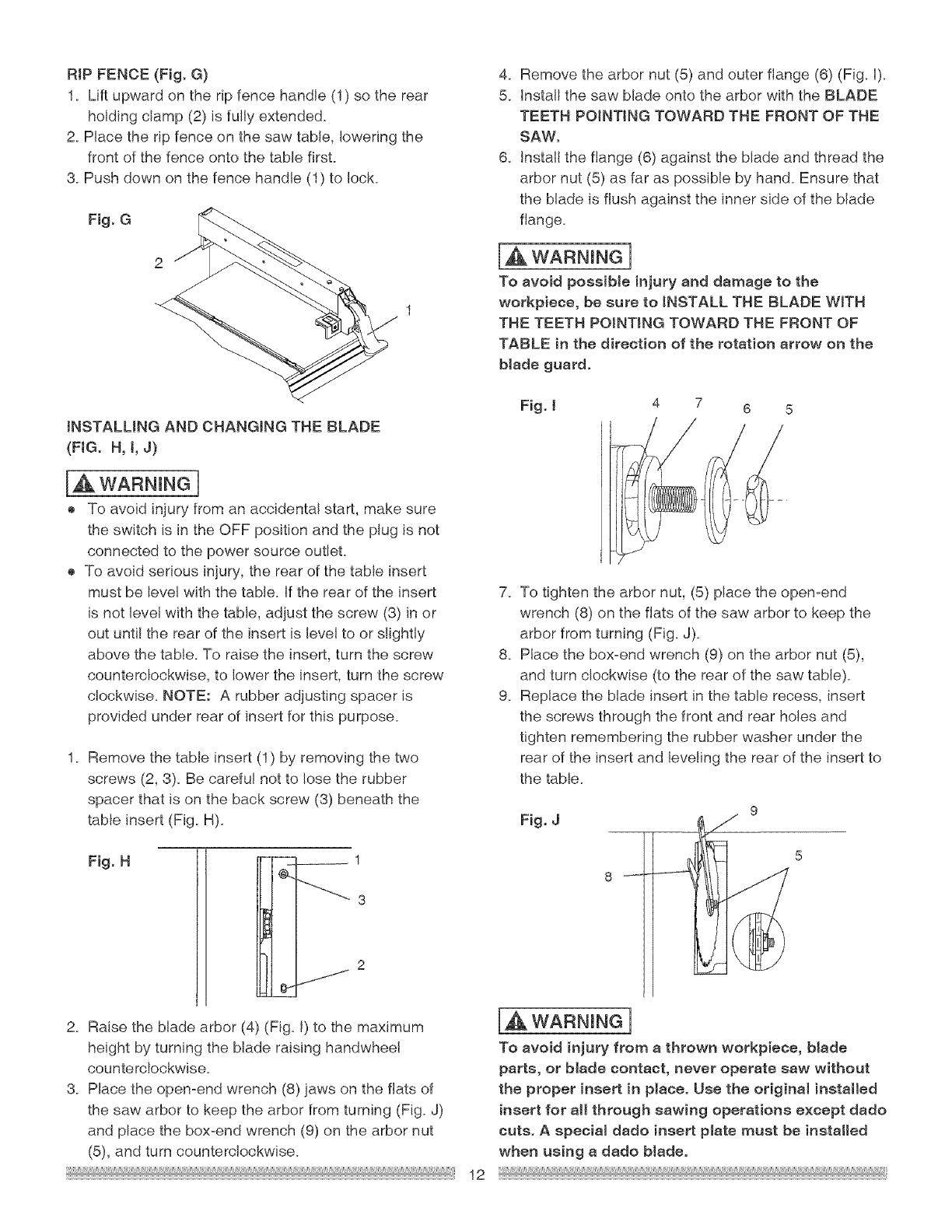
RIPFENCE(Fig,G)
1. Liftupwardontheripfencehandle(1)sotherear
holdingclamp(2)is fully extended.
2. Place the rip fence on the saw table, lowering the
front of the fence onto the table first.
3. Push down on the fence handle (1) to lock.
Fig. G
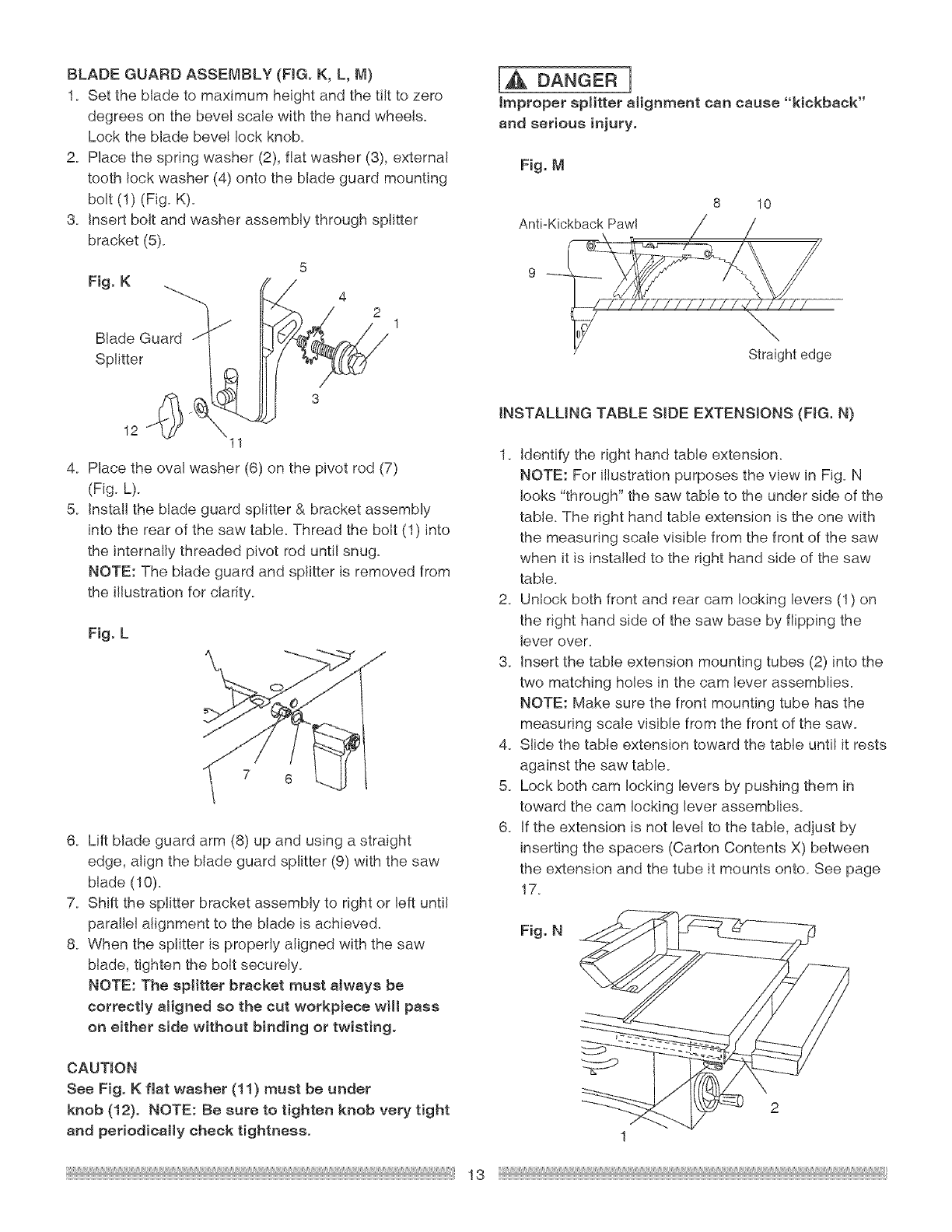
4. Remove the arbor nut (5) and outer flange (6) (Fig. I).
5. install the saw blade onto the arbor with the BLADE
TEETH POINTING TOWARD THE FRONT OF THE
SAW.
6. Install the flange (6) against the blade and thread the
arbor nut (5) as far as possible by hand. Ensure that
the blade is flush against the inner side of the blade
flange.
[a,WARNING]
To avoid possible injury and damage to the
workpiece, be sure to INSTALL THE BLADE WITH
THE TEETH POINTING TOWARD THE FRONT OF
TABLE in the direction of the rotation arrow on the
blade guard.
INSTALLING AND CHANGING THE BLADE
(FIG. H, t, J)
IAWARNINGn
o To avoid injury from an accidenta! start, make sure
the switch is in the OFF position and the plug is not
connected to the power source outlet.
o To avoid serious injury, the rear of the table insert
must be level with the table. If the rear of the insert
is not level with the table, adjust the screw (3) in or
out until the rear of the insert is level to or slightly
above the table. To raise the insert, turn the screw
counterclockwise, to lower the insert, turn the screw
clockwise. NOTE: A rubber adjusting spacer is
provided under rear of insert for this purpose.
1. Remove the table insert (1) by removing the two
screws (2, 3). Be careful not to lose the rubber
spacer that is on the back screw (3) beneath the
table insert (Fig. H).
Fig. H
2
2. Raise the blade arbor (4) (Fig. I) to the maximum
height by turning the blade raising handwheel
counterclockwise.
3. Place the open-end wrench (8) jaws on the flats of
the saw arbor to keep the arbor from turning (Fig. J)
and place the box-end wrench (9) on the arbor nut
(5), and turn counterc!ockwise.
12
Fig. t 4 7
7. To tighten the arbor nut, (5) place the open-end
wrench (8) on the flats of the saw arbor to keep the
arbor from turning (Fig. J).
8. Place the box-end wrench (9) on the arbor nut (5),
and turn clockwise (to the rear of the saw table).
9. Replace the blade insert in the table recess, insert
the screws through the front and rear holes and
tighten remembering the rubber washer under the
rear of the insert and leveling the rear of the insert to
the table.
Fig. J
8
[,& WARNmN¢]
To avoid injury from a thrown workpiece, blade
parts, or blade contact, never operate saw without
the proper insert in place. Use the originat installed
insert for all through sawing operations except dado
cuts. A special dado insert plate must be installed
when using a dado bJade°
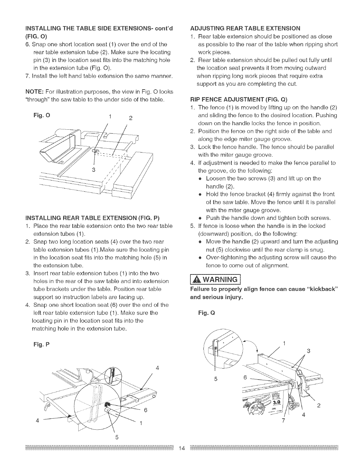
BLADEGUARDASSEMBLY(FIG.K, L, M)
1. Setthebladetomaximumheightandthetilttozero
degreesonthebevelscalewiththehandwheels.
Lockthebladebevellockknob.
2. Placethespringwasher(2),flatwasher(3),external
toothlockwasher(4)ontothebladeguardmounting
bolt(1)(Fig.K).
3. Insertboltandwasherassemblythroughsplitter
bracket(5).
Fig.K
BladeGuard/-
Splitter
5
J 1
\11
4. Place the oval washer (6) on the pivot rod (7)
(Fig. L).
5. Install the blade guard splitter & bracket assembly
into the rear of the saw table. Thread the bolt (1) into
the internally threaded pivot rod until snug.
NOTE: The blade guard and splitter is removed from
the illustration for clarity.
Fig. L
J
7 6
6. Lift blade guard arm (8) up and using a straight
edge, align the blade guard splitter (9) with the saw
blade (10).
7. Shift the splitter bracket assembly to right or left until
parafle! alignment to the blade is achieved.
8. When the splitter is properly aligned with the saw
blade, tighten the bolt securely.
NOTE: The splitter bracket must always be
correctly aligned so the cut workpiece will pass
on either side without binding or twisting.
CAUTION
See Fig. K fiat washer (11} must be under
knob (12}. NOTE: Be sure to tighten knob very tight
and periodically check tightness.
[_ DANGER]
Improper splitter alignment can cause "kickback"
and serious injury.
Fig. M
8 10
Anti-Kickback Pa_I / //
9
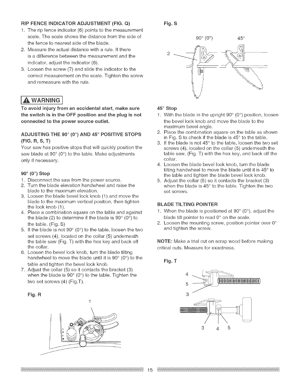
INSTALLING TABLE SIDE EXTENS!ONS (FIG. N)
1. Identify the right hand table extension.
NOTE: For illustration purposes the view in Fig. N
looks "through" the saw table to the under side of the
table. The right hand table extension is the one with
the measuring scale visible from the front of the saw
when it is installed to the right hand side of the saw
table.
2. Unlock both front and rear cam locking levers (1) on
the right hand side of the saw base by flipping the
lever over.
3. insert the table extension mounting tubes (2) into the
two matching holes in the cam lever assemblies.
NOTE: Make sure the front mounting tube has the
measuring scale visible from the front of the saw.
4. Slide the table extension toward the table until it rests
against the saw table.
5. Lock both cam locking levers by pushing them in
toward the cam locking lever assemblies.
6. If the extension is not level to the table, adjust by
inserting the spacers (Carton Contents X) between
the extension and the tube it mounts onto. See page
17.
Fig. N
2
1
13
iNSTALLiNGTHE TABLE SIDE EXTENS!ONS- cont'd
(FIG. O}
6. Snap one short location seat (1) over the end of the
rear table extension tube (2). Make sure the locating
pin (3) in the location seat fits into the matching hole
in the extension tube (Fig. O).
7. install the left hand table extension the same manner.
NOTE: For i!tustration purposes, the view in Fig. O looks
"through" the saw table to the under side of the table.
Fig. O 1 2
iNSTALLING REAR TABLE EXTENSION (FIG. P)
1. Place the rear table extension onto the two rear table
extension tubes (1).
2. Snap two long location seats (4) over the two rear
table extension tubes (1).Make sure the locating pin
in the location seat fits into the matching hole (5) in
the extension tube.
3. Insert rear table extension tubes (1) into the two
holes in the rear of the saw table and into extension
tube brackets under the table. Position rear table
support so instruction labels are facing up.
4. Snap one short location seat (6) over the end of the
left rear table extension tube (1). Make sure the
locating pin in the location seat fits into the
matching hole in the extension tube.
ADJUSTING REAR TABLE EXTENSION
1. Rear table extension should be positioned as close
as possible to the rear of the table when ripping short
work pieces.
2. Rear table extension should be pulled out fully until
the location seat prevents it from moving outward
when ripping long work pieces that require extra
support as you are completing the cut.
RIP FENCE ADJUSTMENT (FIG. Q)
1. The fence (1) is moved by lifting up on the handle (2)
and sliding the fence to the desired location. Pushing
down on the handle locks the fence in position.
2. Position the fence on the right side of the table and
along the edge miter gauge groove.
3. Lock the fence handle. The fence should be parallel
with the miter gauge groove.
4. If adjustment is needed to make the fence parallel to
the groove, do the following:
o Loosen the two screws (3) and lift up on the
handle (2).
o Hold the fence bracket (4) firmly against the front
of the saw table. Move the fence until it is parallel
with the miter gauge groove.
o Push the handle down and tighten both screws.
5. If fence is loose when the handle is in the locked
(downward) position, do the following:
o Move the handle (2) upward and turn the adjusting
nut (5) clockwise until the rear clamp is snug.
o Over4ightening the adjusting screw will cause the
fence to come out of alignment.
[A WARNING]
Failure to properly atign fence can cause "kickback"
and serious injury.
Fig. Q
Fig. P
6
1
1
3
6
7
5
14
RiPFENCEiNDiCATORADJUSTMENT(FIG.Q)
1_Theripfenceindicator(6)pointstothemeasurement
scale.Thescaleshowsthedistancefromthesideof
thefencetonearestsideoftheblade.
2_Measuretheactualdistancewitha rule.if there
isadifferencebetweenthemeasurementandthe
indicator, adjust the indicator (6)_
3_ Loosen the screw (7) and slide the indicator to the
correct measurement on the scale. Tighten the screw
and remeasure with the rule.
IA WARNINGn
To avoid injury from an accidental start, make sure
the switch is in the OFF position end the plug is not
connected to the power source outtet.
ADJUSTING THE 90° (0°) AND 45 °POSiTiVE STOPS
(FIG. R, S, T}
Your saw has positive stops that will quickly position the
saw blade at 90 ° (0°) to the taNe. Make adjustments
only if necessary.
O0° (0°) Stop
1. Disconnect the saw from the power source.
2. Turn the blade elevation handwheel and raise the
blade to the maximum elevation.
3. Loosen the blade bevel lock knob (1) and move the
blade to the maximum vertical position, then tighten
the lock knob (1).
4. Place a combination square on the table and against
the blade (2) to determine if the blade is 90° (0°) to
the table. (Fig. S)
5. If the blade is not 90° (0°) to the table, loosen the two
set screws (4), located on the collar (5) underneath
the table saw (Fig. T) with the hex key and back off
the collar.
6. Loosen the bevel lock knob, turn the blade tilting
handwheel to move the blade until it is 90° (0°) to the
table and tighten the bevel lock knob.
7. Adjust the collar (5) so it contacts the bracket (3)
when the blade is 90° (0°) to the table. Tighten the
two set screws (4) (Fig.T).
Fig. R
o
Fig. S
9o° (0o) 45 °
45° Stop
1. With the blade in the upright 90° (0°) position, loosen
the bevel lock knob and move the blade to the
maximum bevel angle.
2. Place the combination square on the table as shown
in Fig. S to check if the blade is 45° to the table.
3. If the blade is not 45 ° to the table, loosen the two set
screws (4), located on the collar (5) underneath the
table saw, (Fig. T) with the hex key, and back off the
collar.
4. Loosen the bJade bevel lock knob, turn the blade
tilting handwheel to move the blade until it is 45° to
the table and tighten the blade beve! lock knob.
5. Adjust the collar (5) so it contacts the bracket (3)
when the blade is 45° to the table. Tighten the two
set screws.
BLADE TILTING POINTER
1. When the blade is positioned at 90° (0°), adjust the
blade tilt pointer to read 0° on the scale.
2. Loosen the mounting screw, position pointer over 0°
and tighten the screw.
NOTE: Make a trial cut on scrap wood before making
critical cuts. Measure for exactness.
Fig. T
4
5
3
3 4 5
15
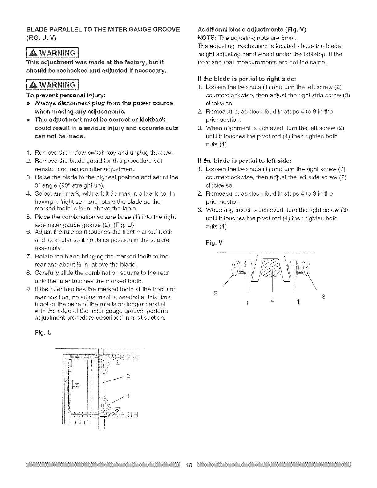
BLADEPARALLELTOTHEMITERGAUGEGROOVE
(FIG.U,V)
I_WARNiNG
This adjustment was made at the factory, but it
should be rechecked and adjusted if necessary.
IA waRninGn
To prevent personal injury:
o Always disconnect plug from the power source
when making any adjustments.
o This adjustment must be correct or kickback
could result in a serious injury and accurate cuts
can not be made.
1. Remove the safety switch key and unplug the saw.
2. Remove the blade guard for this procedure but
reinstal! and realign after adjustment.
3. Raise the blade to the highest position and set at the
0° angle (90° straight up).
4. Select and mark, with a felt tip maker, a blade tooth
having a "right set" and rotate the blade so the
marked tooth is Y2in. above the table.
5. Place the combination square base (1) into the right
side miter gauge groove (2). (Fig. U)
6. Adjust the rule so it touches the front marked tooth
and lock ruler so it holds its position in the square
assembly.
7. Rotate the blade bringing the marked tooth to the
rear and about 1/2in. above the blade.
8. Carefully slide the combination square to the rear
until the ruler touches the marked tooth.
9. If the ruler touches the marked tooth at the front and
rear position, no adjustment is needed at this time.
If not or the base of the rule is no longer parallel
with the edge of the miter gauge groove, perform
adjustment procedure described in next section.
Fig. U
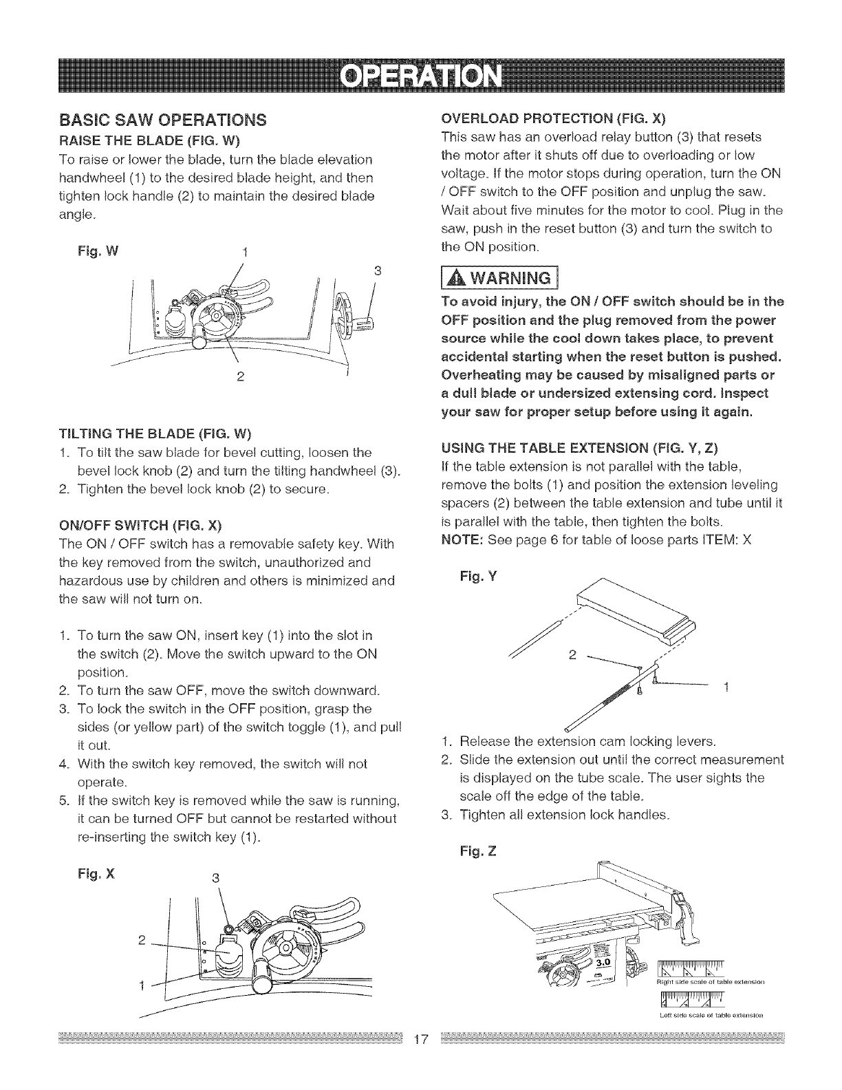
Additional blade adjustments (Fig. V)
NOTE: The adjusting nuts are 8ram.
The adjusting mechanism is located above the blade
height adjusting hand whee! under the tabletop. If the
front and rear measurements are not the same.
if the blade is partial to right side:
1. Loosen the two nuts (1) and turn the left screw (2)
counterclockwise, then adjust the right side screw (3)
clockwise.
2. Remeasure, as described in steps 4 to 9 in the
prior section.
3. When alignment is achieved, turn the left screw (2)
unti! it touches the pivot rod (4) then tighten both
nuts (1)_
ff the blade is partial to left side:
1. Loosen the two nuts (1) and turn the right screw (3)
counterclockwise, then adjust the left side screw (2)
clockwise.
2. Remeasure, as described in steps 4 to 9 in the
prior section.
3. When alignment is achieved, turn the right screw (3)
unti! it touches the pivot rod (4) then tighten both
nuts (1).
Fig, V
2
1
16
8ASmC SAW OPERATmONS
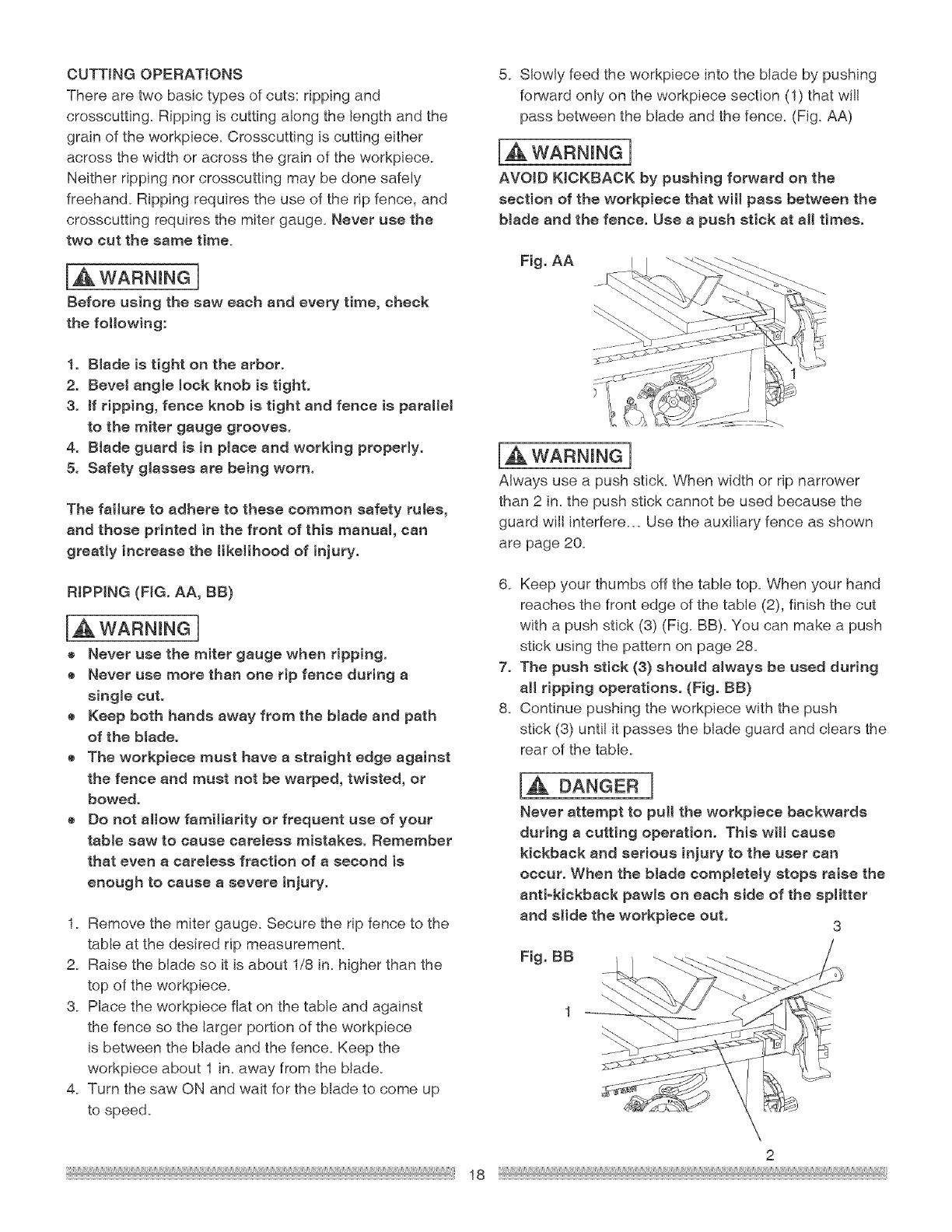
RAISE THE BLADE (FIG. W)
To raise or lower the blade, turn the blade elevation
handwheel (1) to the desired blade height, and then
tighten lock handle (2) to maintain the desired blade
angle.
Fig. W
2
TILTING THE BLADE (FIG. W)
1. To tilt the saw blade for bevel cutting, loosen the
bevel lock knob (2) and turn the tilting handwheel (3).
2. Tighten the bevel Iock knob (2) to secure.
ON/OFF SWITCH (FIG. X)
The ON /OFF switch has a removable safety key. With
the key removed from the switch, unauthorized and
hazardous use by children and others is minimized and
the saw wil! not turn on.
1. To turn the saw ON, insert key (1) into the slot in
the switch (2). Move the switch upward to the ON
position.
2. To turn the saw OFF, move the switch downward.
3. To lock the switch in the OFF position, grasp the
sides (or yel!ow part) of the switch toggle (1), and pul!
it out.
4. With the switch key removed, the switch will not
operate.
5. If the switch key is removed while the saw is running,
it can be turned OFF but cannot be restarted without
re-inserting the switch key (1).
Fig. X 3
lJ
/
17
OVERLOAD PROTECTION (FIG. X)
This saw has an overload relay button (3) that resets
the motor after it shuts off due to overloading or low
voltage. If the motor stops during operation, turn the ON
/OFF switch to the OFF position and unplug the saw.
Wait about five minutes for the motor to coo!. Plug in the
saw, push in the reset button (3) and turn the switch to
the ON position.
[,_. WARNING]
To avoid injury, the ON tOFF switch should be in the
OFF position and the plug removed from the power
source while the coot down takes place, to prevent
accidental starting when the reset button is pushed.
Overheating may be caused by misaligned parts or
a dull blade or undersized extensing cord. inspect
your saw for proper setup before using it again.
USING THE TABLE EXTENSION (FIG. Y, Z}
If the table extension is not paraflei with the table,
remove the bolts (1) and position the extension leveling
spacers (2) between the table extension and tube unti! it
is parallel with the table, then tighten the bolts.
NOTE: See page 6 for table of loose parts iTEM: X
Fig. Y
1. Release the extension cam locking levers.
2. Slide the extension out until the correct measurement
is displayed on the tube scale. The user sights the
scale off the edge of the table.
3. Tighten all extension lock handles.
Fig. Z
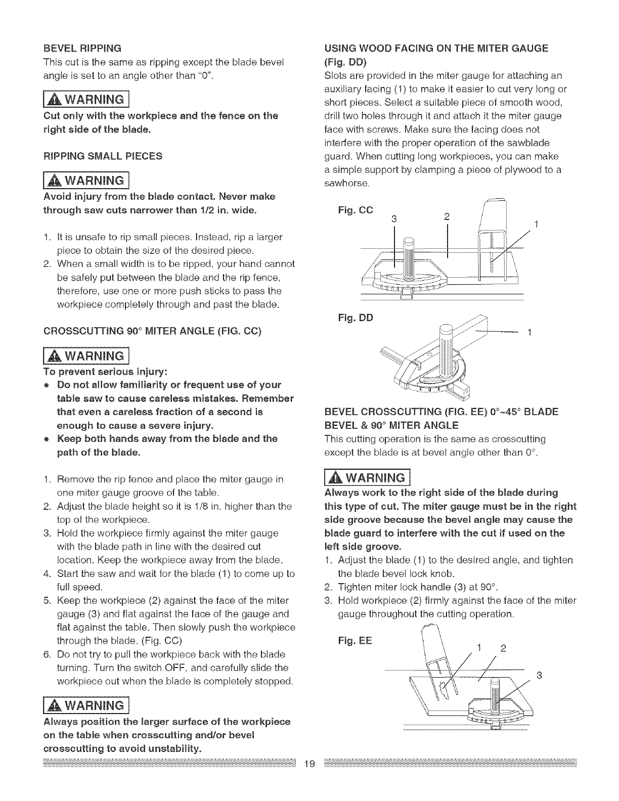
CUTTINGOPERATIONS
Therearetwobasictypesofcuts:rippingand
crosscutting.Rippingiscuttingalongthelengthandthe
grainoftheworkpiece.Crosscuttingiscuttingeither
acrossthewidthoracrossthegrainoftheworkpiece.
Neitherrippingnorcrosscuttingmaybedonesafely
freehand.Rippingrequirestheuseoftheripfence,and
crosscuttingrequiresthemitergauge.Neverusethe
twocut thesametime.
IA WARNINGI
Before using the saw each and every time, check
the following:
1. Blade is tight on the arbor.
2. Bevel angle lock knob is tight.
3. if ripping, fence knob is tight and fence is paraIM
to the miter gauge grooves.
4. Blade guard is in place and working properly.
5. Safety glasses are being worn.
The failure to adhere to these common safety rules,
and those printed in the front of this manual, can
greatly increase the likelihood of injury.
RiPPiNG (FIG. ,CA, BB)
la,WARNINGI
® Never use the miter gauge when ripping.
e Never use more than one rip fence during a
single cut.
e Keep both hands away from the blade and path
of the blade.
® The workpiece must have a straight edge against
the fence and must not be warped, twisted, or
bowed.
e Do not allow familiarity or frequent use of your
table saw to cause careless mistakes. Remember
that even a careless fraction of a second is
enough to cause a severe injury.
1. Remove the miter gauge. Secure the rip fence to the
table at the desired rip measurement.
2. Raise the blade so it is about 1/8 in. higher than the
top of the workpiece.
3. Place the workpiece fiat on the table and against
the fence so the larger portion of the workpiece
is between the blade and the fence. Keep the
workpiece about 1 in. away from the blade.
4. Turn the saw ON and wait for the blade to come up
to speed.
5. Slowly feed the workpiece into the blade by pushing
forward only on the workpiece section (1) that will
pass between the blade and the fence. (Fig. AA)
[,&WARNING]
AVOID KICKBACK by pushing forward on the
section of the workpiece that will pass between the
blade and the fence. Use a push stick at all times.
Fig. AA
[,& WARNING ]
Always use a push stick. When width or rip narrower
than 2 in. the push stick cannot be used because the
guard will interfere.=. Use the auxiliary fence as shown
are page 20.
6. Keep your thumbs off the table top. When your hand
reaches the front edge of the table (2), finish the cut
with a push stick (3) (Fig. BB). You can make a push
stick using the pattern on page 2&
7. The push stick (3) should always be used during
all ripping operations. (Fig. BB)
8. Continue pushing the workpiece with the push
stick (3) until it passes the blade guard and clears the
rear of the table.
[A& DANGER]
Never attempttopulltheworkpiece backwards
during a cutting operation. This will cause
kickback and serious injury to the user can
occur. When the blade completely stops raise the
anti-kickback pawls on each side of the splitter
and slide the workpiece out. 3
Fig. BB
2
18
REVELRiPPiNG
Thiscutisthesameasrippingexceptthebladebevel
angleis set to an angle other than "0".
la,WARNINGn
Cut only with the workpiece and the fence on the
right aide of the blade.
RiPPiNG SMALL PIECES
IA wAR.I.Gn
Avoid injury from the blade contact. Never make
through saw cuts narrower than 1/2 in. wide.
1. it is unsafe to rip small pieces, instead, rip a larger
piece to obtain the size of the desired piece.
2. When a small width is to be ripped, your hand cannot
be safely put between the blade and the rip fence,
therefore, use one or more push sticks to pass the
workpiece completely through and past the blade.
CROSSCUTTING 90 ° MITER ANGLE (FIG. CO)
IA wAR.I.Gn
To prevent serious injury:
® Do not allow familiarity or frequent use of your
table saw to cause careless mistakes. Remember
that even a careless fraction of a second is
enough to cause a severe injury.
e Keep both hands away from the blade and the
path of the blade.
1. Remove the rip fence and place the miter gauge in
one miter gauge groove of the table.
2. Adjust the blade height so it is 1/8 in. higher than the
top of the workpiece.
3. Hold the workpiece firmly against the miter gauge
with the blade path in line with the desired cut
location. Keep the workpiece away from the blade.
4. Start the saw and wait for the blade (1) to come up to
fullspeed.
5. Keep the workpiece (2) against the face of the miter
gauge (3) and flat against the face of the gauge and
fiat against the table. Then slowly push the workpiece
through the blade. (Fig. CC)
6. Do not try to pull the workpiece back with the blade
turning. Turn the switch OFF, and carefully slide the
workpiece out when the blade is completely stopped.
IAwAR.I.GI
Always position the larger surface of the workpiece
on the table when crosscutting and/or bevet
crosscutting to avoid unstabHity.
USING WOOD FACING ON THE MITER GAUGE
(Fig. RD)
Slots are provided in the miter gauge for attaching an
auxiliary facing (1) to make it easier to cut very long or
short pieces. Select a suitable piece of smooth wood,
drill two holes through it and attach it the miter gauge
face with screws. Make sure the facing does not
interfere with the proper operation of the sawblade
guard. When cutting long workpieces, you can make
a simple support by clamping a piece of plywood to a
sawhorse.
Fig. DD
-- 1
BEVEL CROSSCUTTING (FIG. EE) 00~45 ° BLADE
BEVEL & 90° MITER ANGLE
This cutting operation is the same as crosscutting
except the blade is at bevel angle other than 0%
[_ WARNmNG ]
Always work to the right side of the blade during
this type of cut. The miter gauge must be in the right
side groove because the beveJ angle may cause the
blade guard to interfere with the cut if used on the
left side groove.
1. Adjust the blade (1) to the desired angle, and tighten
the blade bevel lock knob.
2. Tighten miter lock handle (3) at 90°.
3. Hold workpiece (2) firmly against the face of the miter
gauge throughout the cutting operation.
Fig. EE
19
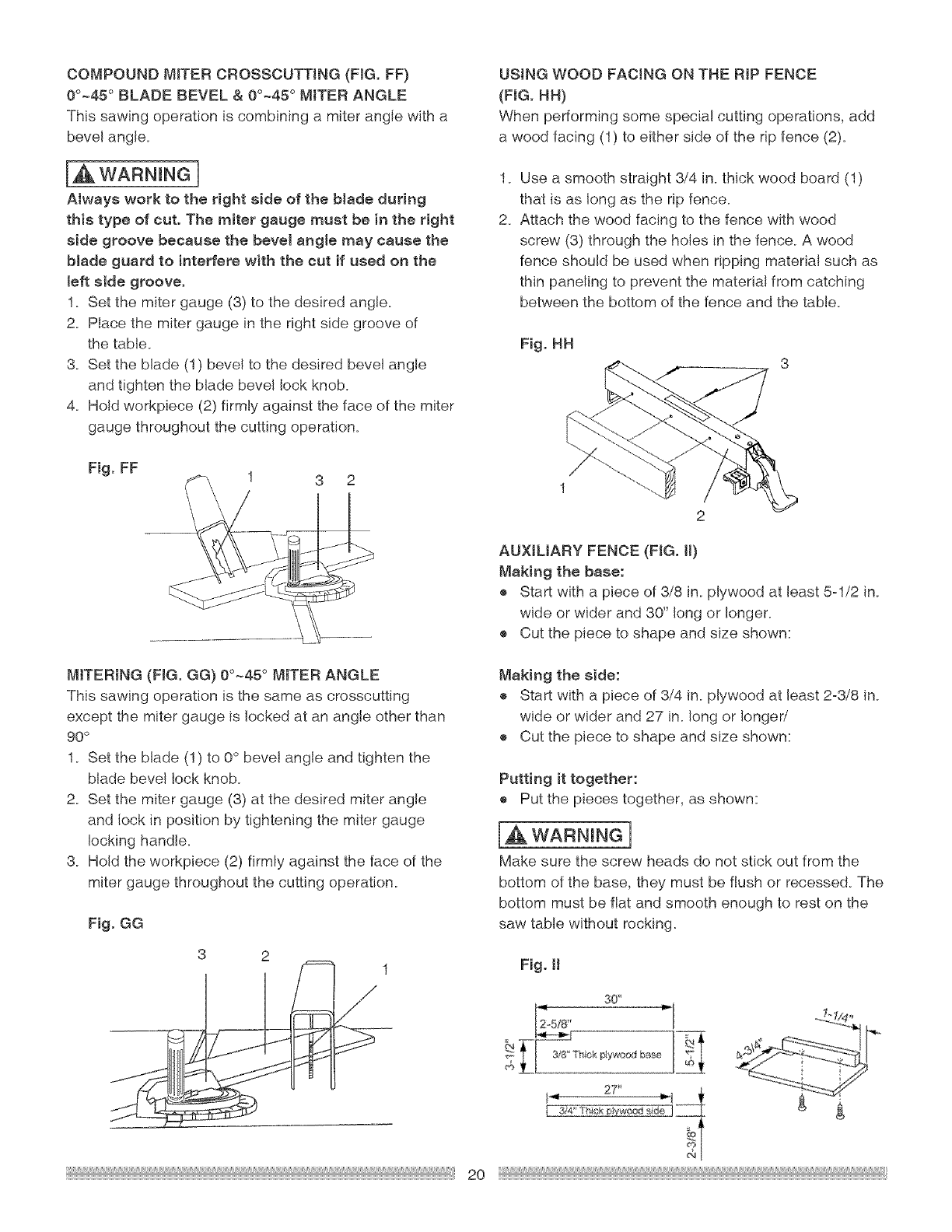
COMPOUNDMITERCROSSCUTTING(FIG.FF)
0°~45°BLADE BEVEL & 00~45 °MITER ANGLE
This sawing operation is combining a miter angle with o
bevel angle.
IA WARNINGn
Always work to the right side of the blade during
this type of cut. The miter gauge must be in the right
side groove because the beveJ angle may cause the
blade guard to interfere with the cut if used on the
left side groove.
1. Set the miter gauge (3) to the desired angle.
2. Place the miter gauge in the right side groove of
the table.
3. Set the blade (1) bevel to the desired bevel angle
and tighten the blade bevel lock knob.
4. Hold workpiece (2) firmly against the face of the miter
gauge throughout the cutting operation.
Fig. FF
MiTERiNG (FIG. GG) 00~45 ° MITER ANGLE
This sowing operation is the same as crosscutting
except the miter gauge is locked at on angle other than
90°
1. Set the blade (1) to 0° bevel angle and tighten the
blade bevel lock knob.
2. Set the miter gauge (3) at the desired miter angle
and lock in position by tightening the miter gauge
locking handle.
3. Hold the workpiece (2) firmly against the face of the
miter gauge throughout the cutting operation.
Fig. GG
3 2
USING WOOD FACING ON THE RIP FENCE
(FIG. HN}
When performing some specio! cutting operations, odd
a wood facing (1) to either side of the rip fence (2).
2_
Use a smooth straight 3/4 in. thick wood board (1)
that is as long as the rip fence.
Attach the wood facing to the fence with wood
screw (3) through the holes in the fence. A wood
fence should be used when ripping material such as
thin paneling to prevent the material from catching
between the bottom of the fence and the table.
Fig. HH
1
2
AUXIUARY FENCE (FIG. H)
Making the bose:
® Start with o piece of 3/8 in. plywood at least 5=1/2 in.
wide or wider and 30" long or longer.
o Cut the piece to shape and size shown:
Making the side:
® Start with o piece of 3/4 in. plywood at least 2=3/8 in.
wide or wider and 27 in. long or longer/
® Cut the piece to shape and size shown:
Putting it together:
o Put the pieces together, as shown:
WARNING ]
Make sure the screw heads do not stick out from the
bottom of the base, they must be flush or recessed. The
bottom must be flat and smooth enough to rest on the
saw table without rocking.
1 Fig. II
30'
_[ 38" Thick piywoc_J bae
2O
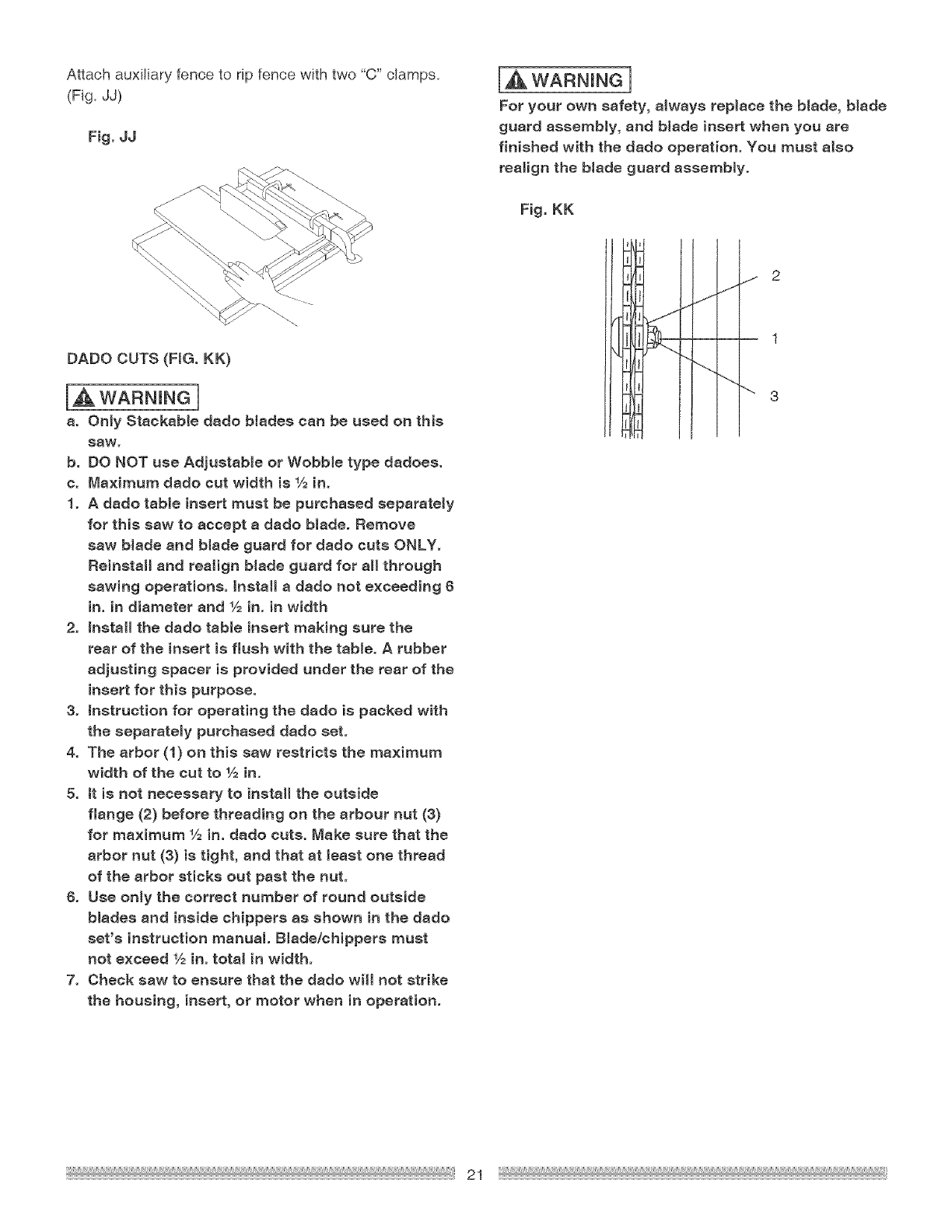
Attachauxiliaryfenceto ripfencewithtwo"C"clamps.
(Fig.dd)
Fig.JJ
DADO CUTS (FIG. KK)
IAWARNINGn
a. Only Stackabledado blades can be used on this
SaW.
b. DO NOT use Adjustable or Wobble type dadoes.
c. Maximum dado cut width is 1/2in.
1. A dado table insert must be purchased separately
for this saw to accept a dado blade. Remove
saw blade and blade guard for dado cuts ONLY.
Reinstall and realign blade guard for all through
sawing operations. Install a dado not exceeding 6
in. in diameter and 1/2in. in width
2. install the dado table insert making sure the
rear of the insert is flush with the table. A rubber
adjusting spacer is provided under the rear of the
insert for this purpose.
3. instruction for operating the dado is packed with
the separately purchased dado set.
4. The arbor (1) on this saw restricts the maximum
width of the cut to 1/=in.
5. tt is not necessary to install the outside
flange (2) before threading on the arbour nut (3)
for maximum 1/=in. dado cuts. Make sure that the
arbor nut (3) is tight, and that st least one thread
of the arbor sticks out past the nut.
6. Use only the correct number of round outside
blades and inside chippers as shown in the dado
set's instruction manual. Blade/chippers must
not exceed 1/2in. total in width.
7. Check saw to ensure that the dado will not strike
the housing, insert, or motor when in operation.
[,_ WARNING 1
For your own safety, always replace the blade, blade
guard assembly, and btade insert when you are
finished with the dado operation. You must atso
realign the blade guard assembly.
Fig. KK
'l
i j2
J
_J
"_ 3
{
21
GENERAL MAINTENANCE
IA WARNINGn
For your own safety, turn the switch OFF and
remove the switch kay. Remove the plug from
the power source outlet before maintaining or
lubricating your saw.
1. Clean out al! sawdust that has accumulated inside
the saw cabinet and the motor.
2. Polish the saw table with an automotive wax to keep
it clean and to make it easier to slide the work piece.
3. Clean cutting blades with pitch and gum remover.
4. A worn, cut, or damaged power cord should be
replaced immediately.
IA WARN Nen
All electrical or mechanical repairs should be
attempted only by a trained repair technician.
Contact the nearest Seers Service Center for
service. Use only identical replacement parts. Any
other parts may create a hazard.
5. Use liquid dish washing detergent and water to clean
al! plastic part&
NOTE: Certain cleaning chemicals can damage
plastic parts.
6. Avoid use of the following cleaning chemicals or
solvents, ammonia and household detergents
containing ammonia_
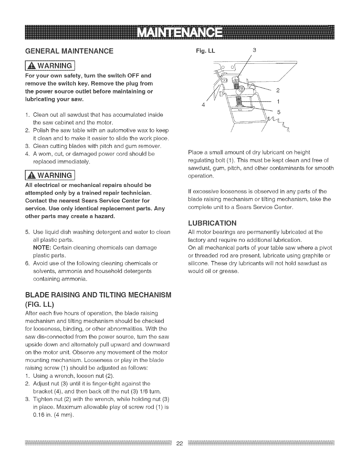
BLADE RAISmNG AND TmLTmNGMECHANmSM
(FIGo LL)
After each five hours of operation, the blade raising
mechanism and tilting mechanism should be checked
for looseness, binding, or other abnormalities. With the
saw dis-connected from the power source, turn the saw
upside down and alternately pull upward and downward
on the motor unit. Observe any movement of the motor
mounting mechanism. Looseness or play in the blade
raising screw (1) should be adjusted as follows:
1. Using a wrench, loosen nut (2).
2. Adjust nut (3) until it is finger=tight against the
bracket (4), and then back off the nut (3) 1/6 turn.
3. Tighten nut (2) with the wrench, while holding nut (3)
in place. Maximum allowable play of screw rod (1) is
0.16 in. (4 mm).
Fig. LL
2
1
5
Place a small amount of dry lubricant on height
regulating bolt (1). This must be kept clean and free of
sawdust, gum, pitch, and other contaminants for smooth
operation.
If excessive looseness is observed in any parts of the
blade raising mechanism or tilting mechanism, take the
complete unit to a Sears Service Center.
LUBRICATmON
All motor bearings are permanently lubricated at the
factory and require no additional lubrication.
On all mechanical parts of your table saw where a pivot
or threaded rod are present, lubricate using graphite or
silicone. These dry lubricants wi!! not hold sawdust as
would oil or grease.
22

IAWARNmNGn
To avoidinjuryfrom an accidentalstart,turntheswitch"OFF" and always remove theplugfromthepower source
before making any adjustments_
® Consult your !ocal Sears Service Center if for any reason the motor wil! not run.
SYMPTOM
Saw will not starL
iDoes not make accurate 45°
_nd 90° rip cuts.
iMateria! pinched blade when
ripping.
2_
3_
4_
2_
2_
Material binds on splitter.
Saw makes unsatisfactory 1.
3uts. 2.
POSSIBLE CAUSES
Saw not plugged in.
Fuse blown or circuit breaker tripped.
Cord damaged.
Switch key not installed.
Positive stop not adjusted correctly.
Bevel angle pointer not set accurately.
Rip fence not aligned with blade.
Warped wood, edge against fence is not
straight.
Splitter not aligned correctly with blade.
Du!l blade.
Blade mounted backwards.
CORRECTIVE ACT!ON
1. Plug in saw.
2. Replace fuse or reset circuit breaker.
3. Have cord replaced by a Sears Service
Center.
4. Refer to page 17, Figure X.
1. Check blade with square and adjust
positive stop.
2. Position straight edge of wood against
fence.
1. Check and adjust rip fence.
2. Select another piece of wood.
1. Check and align splitter with blade.
1. Replace blade.
2. Blade teeth must face forward.
3_
4_
5_
Gum or pitch on blade.
Incorrect blade for work being done.
Gum or pitch on blade causing erratic
feed.
3. Remove blade and clean with
turpentine and coarse steel wool
4. Change the blade.
5. Clean table with turpentine and steel
wool.
Material kicked back from 1.
lblade. 2.
Blade does not raise or tilt
ifreely.
iBlade does not come up to
speed_
Machine vibrates excessively.
Does not make accurate 45°
_nd 90° cross cuts.
Rip fence out of adjustment.
Splitter not aligned with blade.
3. Feeding stock without rip fence.
4_ Dull blade.
5. Operator is letting go of material before
is past saw blade.
7. Miter angle lock handle is not tight.
2_
2_
3_
Sawdust and dirt in raising and tilting
mechanisms.
1. Align rip fence with miter gauge sloL
2. Align splitter with blade.
3_ Instatl and use rip fence_
4. Instal! and use splitter. (with guard)
5. Replace blade.
6. Push material all the way past saw
blade before releasing work.
7. Tighten handle.
1. Brush or blow out loose dust and dirt.
Extension cord too light or too long. 1. Replace with adequate size cord.
Low house voltage. 2. Contact your electric company.
Saw not mounted securely to workbench. 1. Tighten a!l mounting hardware.
Stand not level 2. Adjust stand level to floor.
Damaged saw blade. 3. Replace blade.
Miter gauge out of adjustmenL 1. Square miter gauge to 90%
23

t0 in. TABLE SAW MODEL NO. t37.248840
[A WAR.I.G[
When servicing use only CRAFTSMAN replacement parts. Use of any other parts many create a HAZARD or cause
product damage. Any attempt to repair or replace electrical parts on this Table Saw may create a HAZARD unless
repair is done by a qualified service technician. Repair service is available at your nearest Sears Service Center.
PARTS LIST FOR SAW SCHEMATIC
[,D, NO Description Size Qty
08VH CLAMP-CeRE}
09JK WRENCH
0AW4 BODY SHELL
0BlW HANDLF BAR ASS'Y
0B23 SADDLE
0B24 SPRING
0B27 PC)INTER BRACKET
0B2B NEFDLE PeINTFR
0B2E SWITCH BOX
0B3K INSERT #23
0B3R WRENCH
0B48 WARNING LABEL
0B84 WASHER [)=@18
0B8A WARNING STICK LABEL
0B99 SFIACER
0B9C PLUNGFR HO JSING
0B9K ANGLE ROD
0B9P CLAMP
0B9W BRACKET
0BA9 SFIACER
0BAB SHiM
0BAC SET NUT
0BAE ARBeR CELLAR @45
0BAT NUT
0BAU SIJPPeRTING PLATE
0BC2 LOCATION SEAT
0BCW UF'ER TUBE
0BCX EXTENTIC)N WING
0BPA LOCK KNOB
033U WRENCH HEX,
034F FLAT WASHER @8X16-2.5
034H FLAT WASHER @10*30-0.2
035L FLAT WASHER @510-03 10
036T FLAT WASHER 3/16"3/4-1/]6
036U FLAT WASHFR 3/16"1/2-3/64
036V FLAT WASHER 3/16"3/8-0.022
0370 FLAT WASHER 1/4"3/4-7/64
0376 FLAT WASHER 1/4"3/4d/16
0380 FLAT WASHFR 5/32"13/32-3/64
038D FLAT WASHER 3/8 3/4-5/64
0395 SPRING WASHER @6
03AA WASHER @8
03AE EXTERNAL TeOTH LOCK WASHER @4
03AF EXTERNAL TeOTH LeCK WASHER c_5
0JE7 (}-RING
0gEE} (}-RING
03XL HEX, SOC. BET SCREW M]01.5-12
0KOZ HEX, HD. SCREW AND WASHER ME*] 25-16
0K16 HEX, HD. SCRFW AND WASHER M8*] 25-16
0K25 HEX,SeCKET H[),C AP SCREWS M5*0 8-20
0K3G CR.RE, PAN HD. SCREW & WASHER M5*0 8-12
0K7K CR. RE, RO ;NE} WASHER HD. SCREW M6*] 0-12
0KEC CR, RE,CeUNT HE), TAPPING SCREW M4"]8-10
0K9T HEX, HD. TAPPING SCREW M5"]6-16
0KgU HEX, HF). TAPPING SCREW M5*] 6-25
0KA4 CR.RE, PAN HD. TAPPING SCREW M4"16-16
0KAP CR.RE, PAN HD. TAPPING SCREW M5*0 8-10
0KC8 (}R. RE, TRUSS HD. TAPPING SCREW M4*] 6-16
0KCH CR.RE, PAN HEAD TAPPING & WASHER SCREW M5"0.8-12
0KCX CR, RE, PAN HE} PLAIN WASHFR TAPPING SCREW M5"0,8-10
I.D. NO Descripfior_ Size
0KE)R CR RE. PAN HE) SCREW M5*0 8-10
0KF6 CR RF. PAN HE). SCREW M4*0 7-8
0KHZ CAP HE), SQ.NFC K BOLT M6*] 0-12
0K J4 CAP HE), SQ.NEC K BOLT M6"1,0-35
0K J5 CAP HE}, SQ.NFC K BeLT M6X1.0-80
0KMR HEX. NUT M5"08 T=4
0KMS HEX. NUT M6*l 0 T=5
0KMV HEX. NUT MI01.5 T=8
0KMW HEX. NUT M101,5 T=4
0KMY HFX. NUT MEal 25 T=6.5
0KQJ CROWN NUT ME*I 25 T=12.5
0KRX HFX. NUT AND FlAT WASHER M6"1.0
0KSW STRAIN RELIEF
0KWZ LEAD WIRE ABS'Y
0LMG LOCKING (}ABLE TIE
OLSL CIRC liT BREAKER SWffCH
0LVJ SWITCH KEY
0LWG R(X KER SWITCH
0©EF MOTOR
0S45 Rec KER SWITCH ELEMENT
OSTF HFIGHT RFGULATING BeLT ASS'Y
0STF PARR/E RING ASS'Y
0SWY HAND WHEEL ASSY
0SZY SLIDING BASE ASS'Y
0SZZ SLIDING BASE ASS'Y
0TO0 SLIDING BASE ASS'Y
0TO3 SLIDING BASE ASS'Y
0TO4 CLAMP ASS'Y
10GN UPPER TUBE
10GP UPPER TUBE
10GO PARALLFL BRACKET ASS'Y
10GZ SPACER
10H4 UPPER TUBE
10H5 UPPER TUBE
10H7 POWER (}ABLE ASS'Y
20KA SCALE
20KC SCALE
20KD SCALE
20PM DUST COLLECTOR
2009 BAG-E} JST
20WQ HFX. HE}, BOLT M6"1.0-50
20Z7 BLADE GIJARD ASS'Y
2178 EXTFNTleN WING (RIGHT) #AW
2179 EXTENTleN WiNG (LEFT) #AW
211(_ SCALE
211R SCALE
21BN BRACKET GReUP ASS'Y
21HH MITFR GAUGF ASS'Y
23PP BLADE
27©V DEFLEC TeR
287H RETAIN NG CLIP
29R2 WARNING LABEL
2AE5 WARNING LABEL
2AE6 WARNING LABEL
2ATR TABLE #AW
2CWN INSTRUCTIONS MANUAL
2CXG LABEL
2CZK BEVEL ANGLE ADtJSTMFNT ASSY
2D6G TRAE}E-MARK LABFL
Z()Ot J INSERT ASS'Y
Qty
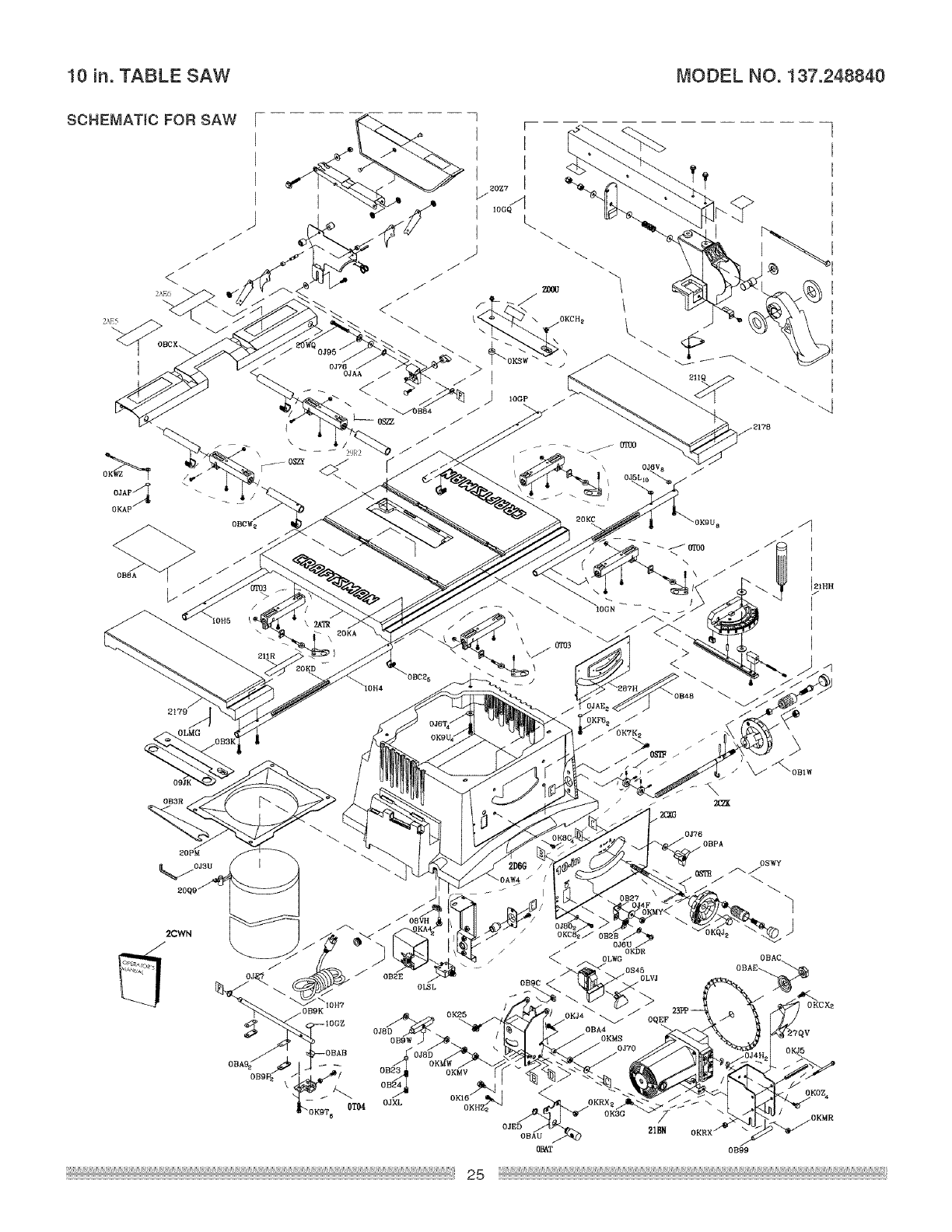
10 in. TABLE SAW MODEL NO. 137.248840
SCHEMATIC FOR SAW [
[
[
OKAP
OBCW 2
2179
09JK
OB3R
0J76
0JAA _"
IOGP /
V
20KA
\
\
2CWN
0J76
OBPA
OBAE_
0B99
OKMR
10 in. TABLE SAW MODEL NO. 137.248840
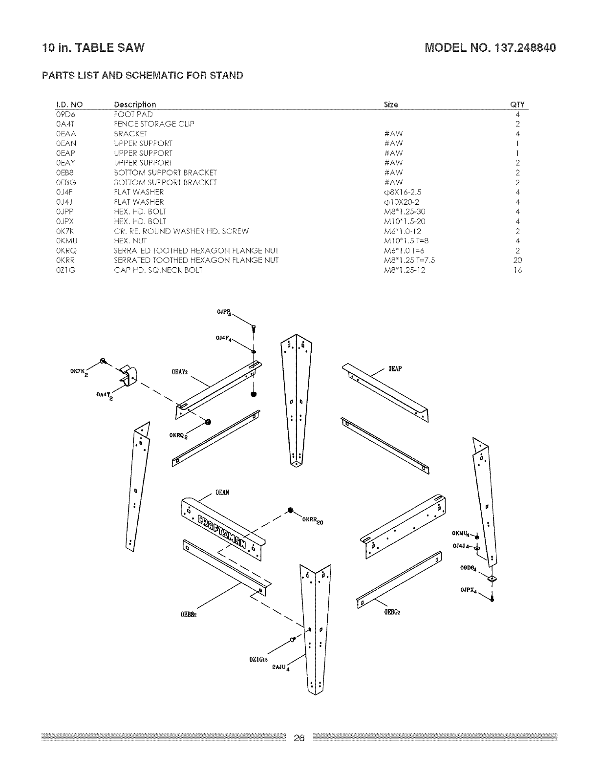
PARTS LIST AND SCHEMATIC FOR STAND
I.D. NO DescripJJon Size
09D6 FOOT PAD
0A4T FENCE STORAGE CLiP
0EAA BRACKET #AW
0EAN UPPER SUPPORT #AW
0EAP UPPER SUPPORT #AW
0EAY UPPER SUPPORT #AW
0EBB BOTTOM SUPPORT BRACKET #AW
0EBG BOTTOM SUPPORT BRACKET #AW
0J4F FLAT WASHER (pSX16=2_5
0J4J FLAT WASHER cp10X20-2
0JPP HEX. HD. BOLT M8_1.25-30
0JPX HEX. HD. BOLT M10"1.5-20
0K7K CR. RE. ROUND WASHER HD_ SCREW M6_1.0-12
0KMU HEX. NUT M10"1.5 T=8
0KRQ SERRATED TOOTHED HEXAGON FLANGE NUT M6'1 _0 T=6
0KRR SERRATED TOOTHED HEXAGON FLANGE NUT M8_1 _25 T=7.5
0Z1G CAP HD. S©.NECK BOLT M8Sl _25-12
QTY
4
2
4
1
1
2
2
2
4
4
4
4
2
4
2
2O
16
OZIGI6
2AJU
26
10 in. TABLE SAW MODEL NO. 137.248840
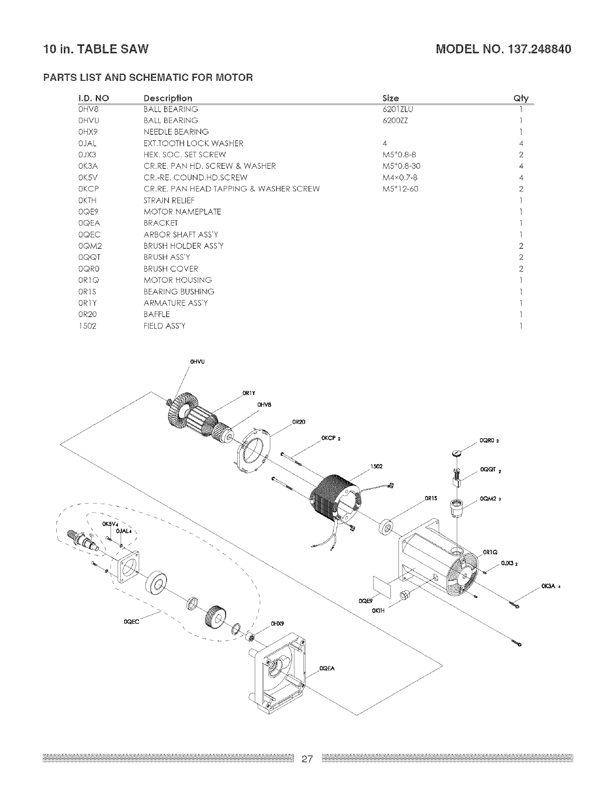
PARTS LIST AND SCHEMATIC FOR MOTOR
i.D. NO Descdp_ion
0HV8 BALL BEARING
0HVU BALL BEARING
0HXg NEEDLE BEARING
0JAL EXT.TOOTH LOCK WASHER
0JX3 HEX. SOC. SETSCREW
0K3A CR,RE. PAN HD. SCREW & WASHER
0KSV CR,-RE. COUND.HDSCREW
0KCP CRRE. PAN HEAD TAPPING & WASHER SCREW
0KTH STRAIN RELIEF
0QEg MOTOR NAMEPLATE
0QEA BRACKET
0QEC ARBOR SHAFTASS'Y
0QM2 BRUSH HOLDER ASS'Y
0QQT BRUSH ASS'Y
0OR0 BRUSH COVER
0R1Q MOTOR HOUSING
0R1S BEARING BUSHING
OR1Y ARMATU RE ASS'Y
0R20 BAFFLE
1502 FIELD ASS'Y
Size
6201ZLU
6200ZZ
4
M5'0.8-8
M5_,0.8-30
M4x0.7-8
M5* 12-60
Qfy
OHVU
OQEC OHX9
1502
OR1S
0QEA
0QL=9
OKTH
OQRO2
0QQT 2
/0R1Q
/OJX3 2
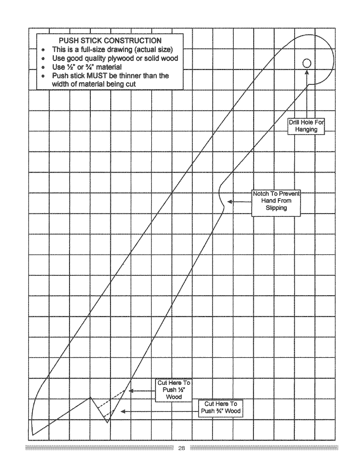
PUSH STICK CONSTRUCTION
® This is a full°size drawing (actual size)
®Use good quality plywood or sotidwood
® Use %" or ¾" material
ePush stick MUST be thinner than the
width of materiat being cut /
/
/ /
!
J
i
I
Cut Here To
P_h ½"
Wood Cut Here To
Push ¾" Wood
Jotch To Prevent
Hand From
Slipping


Your Home
For repair - in your home - of all major brand appliances,
lawn and garden equipment, or heating and cooling systems,
no matter who made it, no matter who soJd it!
For the replacement parts, accessories and
Operator's Manuals that you need to do-it-yourself.
For Sears professional installation of home appliances
and items like garage door openers and water heaters.
1-800-4-MY-HOME ® (1-800-469-4663)
Call anytime, day or night (U.S.A. and Canada)
wwwosesrsooom searsoo8
Our Home
For repair of carry-in items like vacuums, lawn equipment,
and electronics, cal! or go ondine for the location of your nearest
Sears Parts & Repair Center.
1-800-488-1222
Call anytime, day or night (U.S.A. only)
wwwosearsooom
To purchase a protection agreement on a product serviced by Sears:
1-800-827-6655 (U.S.A.) 1-800-361-6665 (Canada)
Para pedir servicio de reparaci6n
a domicilio, y para ordenar piezas:
1-888-SU-HOGAR _
(1 =888=784-6427)
Au Canada pour service en fran(_ais:
1-800-LE-FOYER _°
(1-800-533-8937)
sears.ca
® Registered Trademark /TM Trademark /SM Service Mark of Sears, Roebuck and Co.
® Marca Registrada /TM Marca de F_bfica /SM Mama de Servicio de Sears, Roebuck and Co.
MC Marque de commerce /MD Marque d6pos_e de Sears, Roebuck and Co. © Sears, Roebuck and Co.
2005.07. REV 2
