Craftsman 139 53677Srt1 Users Manual
13953661SRT1 13953661SRT1 CRAFTSMAN GARAGE DOOR OPENER - Manuals and Guides 99020189 View the owners manual for your CRAFTSMAN GARAGE DOOR OPENER #13953661SRT1. Home:Garage Door & Opener Parts:Craftsman Parts:Craftsman GARAGE DOOR OPENER Manual
CRAFTSMAN Garage Door Opener Manual 99020189 CRAFTSMAN Garage Door Opener Owner's Manual, CRAFTSMAN Garage Door Opener installation guides
139.53673srt1 99020189
13953674srt bc49110d-3614-42d0-8cf7-bf946fe8635e Craftsman Garage Door Opener 139.53674SRT User Guide |
2015-01-05
: Craftsman Craftsman-139-53677Srt1-Users-Manual-160424 craftsman-139-53677srt1-users-manual-160424 craftsman pdf
Open the PDF directly: View PDF ![]() .
.
Page Count: 40
Owner's
Manual
Model No.
139.53661SRT1
139.53671SRT1
139.53672SRT1
139.53673SRT1
139.53674SRT
139.53677SRT1
For Residential Use
Only
Caution:
Read and follow all
safety rules and
operating instructions
before first use of this
product.
Fasten the manual
near the garage door
after installation.
Complies wib_ UL 325
regulations effective
January 1, 199:3
/
CRAFTSMRN®
GARAGE DOOR OPENER
• Safety Precautions
•Assembly
•Installation
•Adjustment
•Care and Maintenance
•Operation
•Troubleshooting
•Parts List
Sears, Roebuck and Co., Hoffman Estates, IL 60179 U.S.A.
Contents Page
A review of safety alert symbols ................................. 2
You'll need tools.......................................................... 3
Safety informationregarding garage door locks
and ropes .................................................................. 3
Testing your garage door for sticking,binding
and balance............................................................... 3
Illustretionof sectionaldoor installaUon..................... 4
Illustration of one-piece door installation...................5
Carton inventory.......................................................... 6
Hardware inventory.:................................................... 7
Assembly section - pages 8 - 11
Assemble T-rail ......................................................... 8
Attach cable pulleybracket....................................... 8
Instail trolley...?......................................................... 9
Fasten T-reJlto opener ............................................. g
Install chin/cable ................................................... 10
Attach sprocketcover ............................................. 10
Tighten b_echain and cable ................................... 11
Installation section - pages 11 - 27
Installationsafety inetmctions................................. 11
Determine header bracket location
Sectional door....................................................... 12
One-piece door..................................................... 13
Installthe header bracket ....................................... 14
Attach the T-raJ1to header bracket ......................... 15
Position the opener................................................. 16
Hang the opener..................................................... 17
Installthe doorcontrol............................................ 18
Contents Page
Install the lightand lens................................................. 19
Attach emergency release rope and handle ................. 19
Electrical requirememts................................................. 20
Safety reversing sensor information.............................. 21
Installthe safety reversing sensor........................... 22, 23
Fasten door bracket (sectional door) ............................ 24
F:asten door bracket (one-piece door)........................... 25
Connect door arm to trolley (sectional door)................. 26
Connect door arm to trolley (one-piece door) ............... 27
Adjustment section - pages 28- 30
Travel limit adjustments................................................. 28
Force adjustments ......................................................... 29
Test the safety reversingsensor ................................... 30
Test the safety reverse system .................................... 30
Operation safety instructions............................. ;.............31
Care of your opener......................................................... 31
Maintenance schedule .................................................... 31
Operation of your opener ................................................ 32
Receiver and remote control programming .................... 33
Having a problem? .................................................... 34, 35
Repair parts, rail assembly.............................................. 36
Repair parts, installat_t .................................................. 36
Repair parts, opener assembly ....................................... 37
Accessories......................................................................38
Index ................................................................................ 39
How to order repair parts................................................. 40
Maintenance agreement .................................................. 40
Warranty .......................................................................... 40
Start by reviewing these important safety alert symbols
Mechanical Electrical
When you see this Safety Symbol on the following pages, It will alert you to the possibility of damage
to your garage door and/or the garage door opener If you do not comply with the corresponding
instructions. Read the instructions carefully.
This garage door opener is designed and tested to offer safe service provided it Is Installed, operated,
maintained and tested in strict accordance with the safety instructions contained in this manual.
2
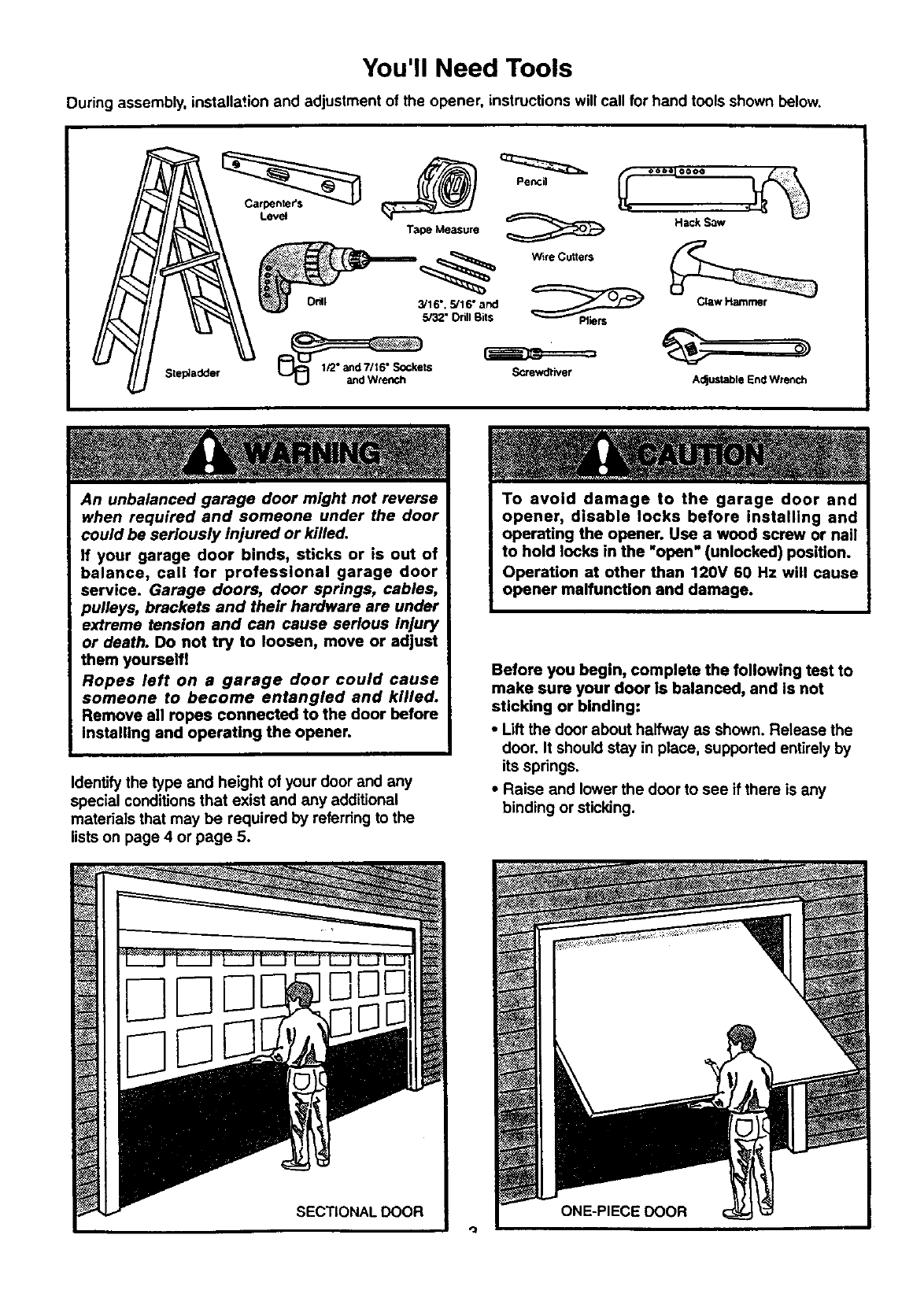
You'll Need Tools
During assembly, installation and adjustment of the opener, instructions will call for hand tools shown below.
Step_adder
Lev_
Pencil
Ta_e Measure
3116", 5116" awJ
5/32" Drill Bits
W3re Cutters
Oooel OOO O
Hack Saw
_rewdl'iver
ClawHammer
Adjustable End Wrench
An unbalanced garage door might not reverse
when required and someone under the door
could be seriously injured or killed.
If your garage door binds, sticks or is out of
balance, call for professional garage door
service. Garage doors, door springs, cables,
pulleys, brackets and their hardware are under
extreme tension and can cause serious Injury
or death. Do not try to loosen, move or adjust
them yourself!
Ropes left on a garage door could cause
someone to become entangled and killed.
Remove all ropes connected to the door before
installing and operating the opener.
Identify the type and height of your door and any
special conditions that exist and any additional
materials that may be required by referring to the
lists on page 4 or page 5.
To avoid damage to the garage door and
opener, disable locks before installing and
operating the opener. Use a wood screw or nail
to hold locks in the "open" (unlocked) position.
Operation at other than 120V 60 Hz will cause
opener malfunction and damage.
Before you begin, complete the following test to
make sure your door is balanced, and is not
sticking or binding:
•Lift the door about halfway as shown. Release the
door. It should stay in place, supported entirely by
its springs.
•Raise and lower the door to see if there is any
binding or sticking.
,.,j
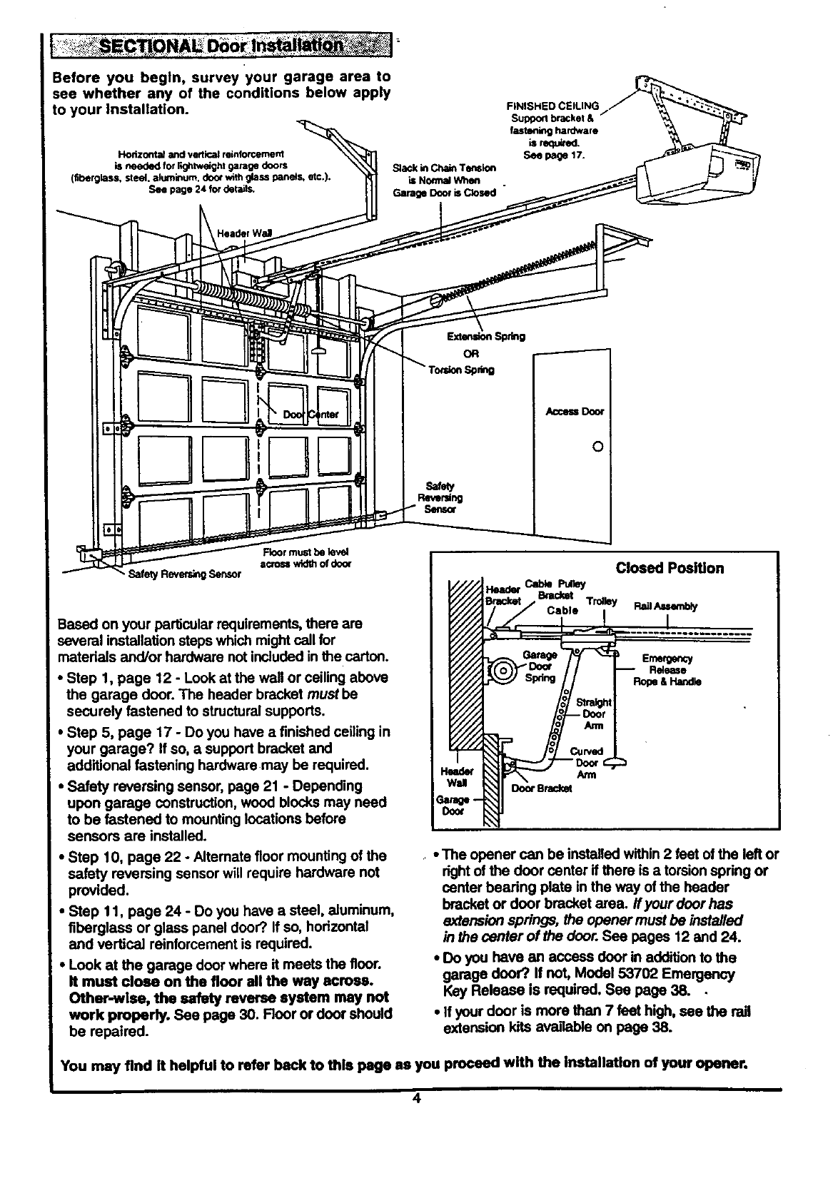
Before you begln, survey your garage area to
see whether any of the conditions below apply
to your installation.
Horizontal and vertical reinforcement
iS needed to_'llghtw_ght _doors
(fiberglass. steel, akJminum, door v_th glass panels, etc.).
See page 24 for details.
FINISHED CEILING
SuI_ bracket &
fastlminghardware
Seg page 17.
Slackin ChainTen6ion
is NormalWhen
Garage Dooris Closed "
AccellDoor
o
Based on your particular requirements, there are
several installation steps which might call for
matedals and/or hardware not included in the carton.
•Step 1, page 12 -Look at the wall or ceiling above
the garage door. The header bracket must be
securely fastened to structural supports.
•Step 5, page 17 -Do you have a finished ceiling in
your garage? If so, a support bracket and
additional fastening hardware may be required.
•Safety reversing sensor, page 21 -Depending
upon garage construction, wood blocks may need
to be fastened to mounting locations before
sensors are installed.
•Step 10, page 22 - Alternate floor mounting of the
safety reversing sensor will require hardware not
provided.
•Step 11, page 24 - Do you have a steel, aluminum,
fiberglass or glass panel deer?.If so, horizontal
and vertical reinforcement is required.
• Look at the garage door where it meets the floor.
It must close on the floor all the way across.
Other-wise, the safety reveree system may not
work properly. See page 30. Floor or door should
be repaired.
Closed PeeWon
Cab_ Puny
Bracket Troaey
Cable Rail Assembly
I
Emergency
Release
Roge&Hand_
, • The opener can be installed within 2 feet of the left or
rightof the door center if there is a torsion spdng or
center bearing plate in the way of the header
bracket or door bracket area. If your door has
extension springs, the opener must be installed
in the center of the door. See pages 12 and 24.
•Do you have an access door in addition to the
garage door? If not, Model 53702 Emergency
Key Release is required. See page 38.
•If your door is more than 7 feet high, see the rail
extension kits avaJlable on page 38.
You may find It helpful to refer back to this page as you proceed with the Installation of your opener.
4
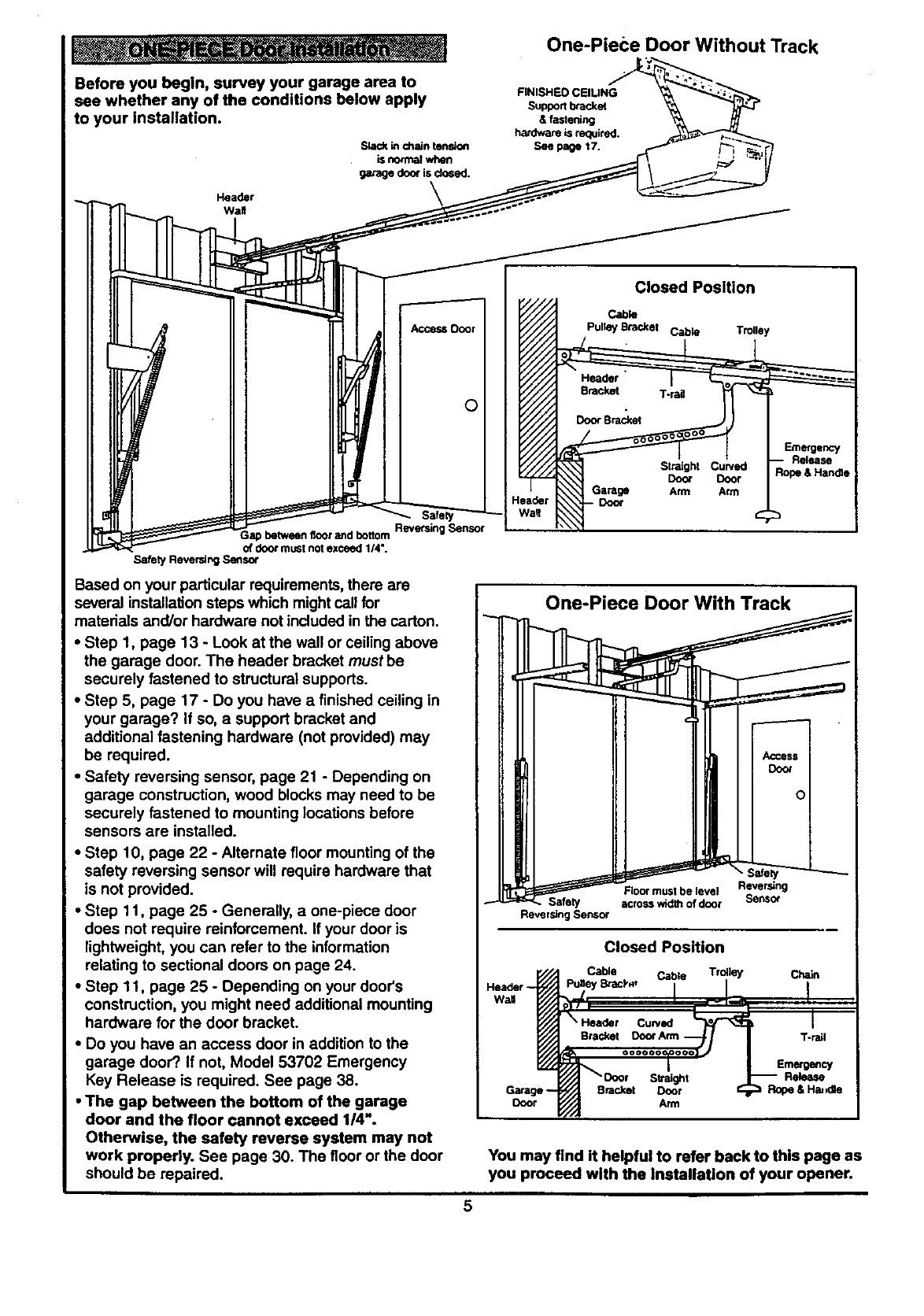
Before you begin, survey your garage ares to
see whether any of the conditions below apply
to your installation.
in chain thns_on
is normal when
garage door is dosed.
Header
Wa!l
One-Piece Door Without Track
FINISHED CEILING
Support bracket
& faslening
hardware is required.
See page t7.
O
) betweenfloorand bottom ReversingSensor
of doormustnotexceed I/4".
Safety Reversir_ Sensor
Based on your particular requirements, there are
several installation steps which might call for
materials and/or hardware not included in the carton.
• Step 1, page 13 - Look at the wall or ceiling above
the garage door. The header bracket must be
securely fastened to structural supports.
•Step 5, page 17 - Do you have afinished ceiling in
your garage? If so, a support bracket and
additional fastening hardware (not provided) may
be required.
•Safety reversing sensor, page 21 - Depending on
garage construction, wood blocks may need to be
securely fastened to mounting locations before
sensors are installed.
•Step 10, page 22 - Alternate floor mounting of the
safety reversing sensor will require hardware that
is not provided.
•Step 11, page 25 - Generally, aone-piece door
does not require reinforcement. If your door is
lightweight, you can refer to the information
relating to sectional doors on page 24.
•Step 11, page 25 - Depending on your door's
construction, you might need additional mounting
hardware for the door bracket.
•Do you have an access door in addition to the
garage door?. If not, Model 53702 Emergency
Key Release is required. See page 38.
•The gap between the bottom of the garage
door and the floor cannot exceed 1/4".
Otherwise, the safety reverse system may not
work properly. See page 30. The floor or the door
should be repaired.
Closed Position
Cable
Pultey Bracket Cable Trolley
/
Bracket T-rail
DoorSrac_xet
Coot
Door
Arm
Release
One-Piece Door With Track
Revering
Floormust be level
Safety acrosswidthof door
ReversingSensor
Garage--
Door
Closed Position
Cable Cable Trolley Chain
I mL"
_'//.I "saor s_ig_t _P,ele=se
You may find it helpful to refer back to this page as
you proceed with the Installation of your opener.
5
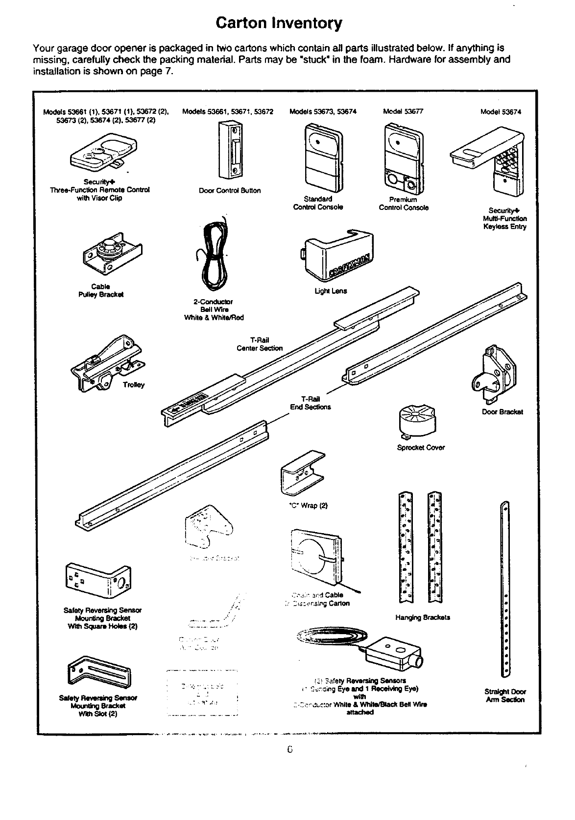
Carton Inventory
Your garage door opener is packaged in two cartons which contain all pads illustrated below. If anything is
missing, carefully check the packing material. Parts may be "stuck" in the foam. Hardware for assembly and
installation is shown on page 7.
Models 5366t (1), 53671 (1), 53672 (2).
53673 (2), 53674 (2). 53677 (2)
Security+
Three-Function Remote Control
with Visor Clip
Cable
PulleyBmc_
Safety Reversing Sensor
MountingBcacket
w_ Squa_Ho_ t2)
Sa_etyRe_n¢_ Seesor
Mount_gBraCka
W_ Sk_(2)
Models 53661, 53671, 53672
2-Conductor
Bell Wire
White &Whi_e/l:_ed
T.P.ail
CenterSection
Models 53673, 53674 Model 53677 Model 53674
Standard
ContmlConsole Premium
Control Console
Do<_Bracket
Sprod_etCover
T-Rail
EndSec.ons
"C"Wrap (2)
¸7¸'¸ -- __
i: ::_s_si,_g Carton
Hanging Brackets
_' _¢;ng Eye and 1 ReceivingEye)
::.3*_r=_c:or',_nitO& WhJle/t_ackBellWhl
attad'md
Stra_ Door
Am_Set,on
6
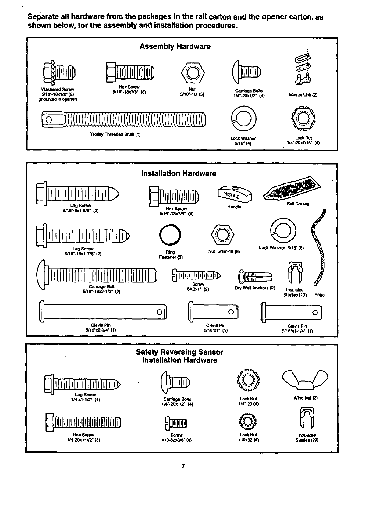
Sel_arate all hardware from the packages in the rail carton and the opener carton, as
shown below, for the assembly and installation procedures.
Assembly Hardware
Washered Screw Hex Sorew Nut Carriage Bolts
5/16"-183(1/2"(2) 5/16".18xTir (3) 5/16".18 (5) 114--20xl/2" (4) Master Unk (2)
(mounted in opener)
Trolley'i_maded Shaft II1 Lock Washer Lock NUt
5/16" (4) 1/4"-20_7/16" (4)
Hex Screw
5/16"-18x7/8" (4)
installation Hardware
_Gma_
Handle
Nut 5/16"-18(6) L_JcWa_,her 5/16"(6)
0
5/16"-18xi-7/8" (2) Ring
Fastener (3)
Carriage Boit
IIIIIIIIIIIIIIIIIIIIIIIIIIIIIIIIIII0
5/16"-18x2-1FZ' 121 6ABxl" (2) Dry Wall Anchors (2) Insulated
Staples (I0) Rope
o,
Clevis Fm Clevis Pin
5/16"x2-3/4" (1) 5/16°xl" (1) Cle_s Pin
5/16"x1-114"(1)
1/4xl-lt2" (4)
_llllllllllllllltllllllllllllllllllliO
114-20x1-1/2" (2)
Safety Reversing Sensor
installation Hardware
Carr_ge Bo_ts
1/4"-20xl/2" (4)
#10-3_(3/_" (4I
©
Lock Nut
1/4"-20 (4)
@
WingNut(2)
7
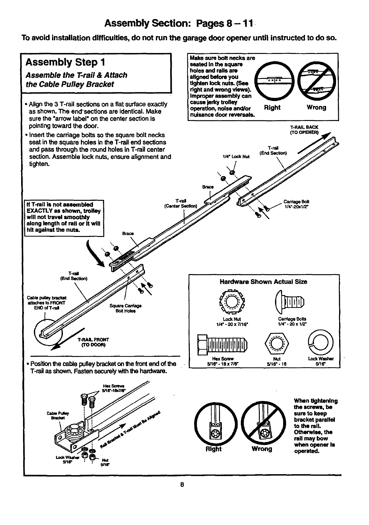
Assembly Section: Pages 8- 11
To avoid installation difficulties, do not run the garage door opener until instructed to do so.
Assembly Step I
Assemble the T.rail & Attach
the Cable Pulley Bracket
• Align the 3 T-rail sections on afiat surface exactly
as shown. The end'sections are identical. Make
sure the "arrow label" on the center section is
pointing toward the door.
•Insert the carriage bolts so the square bolt necks
seat in the square holes in the T-rail end sections
end pass through the round holes in T-rail center
section. Assemble lock nuts, ensure alignment and
tighten.
If T-rail is not assembled
EXACTLY as shown, trolley I
will not travel smoothly ]
along length of rail or it will
hit against the nuts. I Brace
Make sure bolt necks are
seated In the square _
holes end rails are _ _k A_P'-"-"-'_I'--_
aligned beforeyou _ _ t
•• I •
.omenlo (Sas __ . | / •
iright and wrong views). '_k J'_
iImproper assembly can _
cause ]edo/trolley
operation,noise and/or Right Wrong
nuisancedoor reversals.
TRAIL BACK
(TO OPENER)
T.rail
(End Sec_on)
1/4"LockNut
Brace
T-raU
Cab_p._/brackst
attachestoFRONT
ENDofT-ral SquareCarthage
B_tHole=
(TOsoon)
•Positionthe cable pufley bracketon the front end of the .•
T-r_q as shown. Fasten sscurely with_e hardware.
cab*,Pamy
Brad_
L=_Wuhw
5/16"
s
Hardware Shown Actual Size
©
Lod_Nut CardageSob
114"* 20 x 7116" 1/4" -20 x 1/2"
Hex Scrow Nut L_:k W_ner
5/16"- 18 x 7/8" 5/16" - 18 5/16"
Qhen tightening
the scraws, be
sure to keep
bracket parallel
to the mllo
Otherwlas, the
rail may bow
when opener is
Right Wrong operated.
8
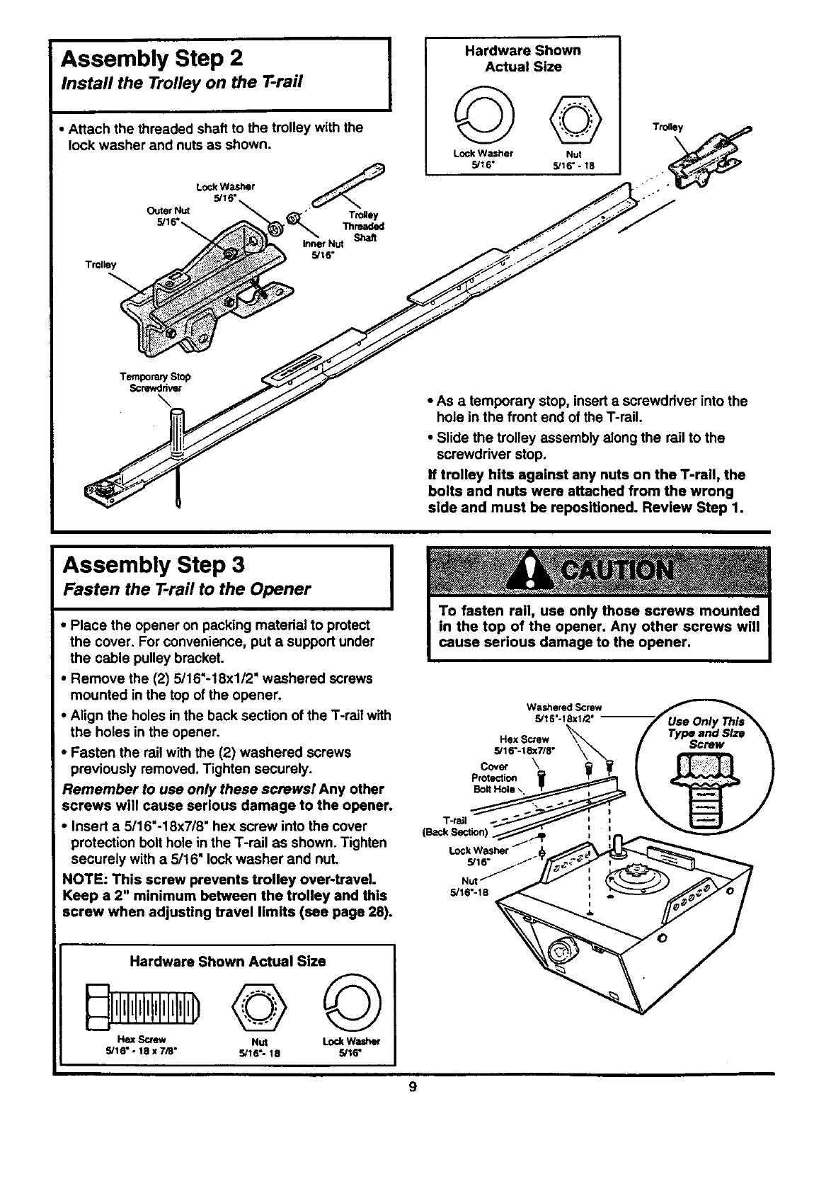
Assembly Step 2
Install the Trolley on the T-rail
•Attach the threaded shaft to the trolley with the
lock washer and nuts as shown.
Trolley
LockWasher
5/16"
Outer Nut
5/16"_
Tro!ley
Threaded
Shaft
InnerNut
5/16"
Hardware Shown
Actual Size
©©
Lock Washer Nut
5/16" 5/16" -18
TemporarySlop
Screwdriver
• As a temporary stop, insert ascrewdriver into the
hole in the front end of the T-rail.
• Slide the trolley assembly along the rail to the
screwdriver stop.
If trolley hits against any nuts on the T-rail, the
bolts and nuts were attached from the wrong
side and must be reposltioned. Review Step 1.
Assembly Step 3 I
Fasten the T-rail to the Opener I
•Place the opener on packing material to protect
the cover. For convenience, put a support under
the cable pulley bracket.
•Remove the (2) 5/16"-18xl/2 =washered screws
mounted in the top of the opener.
•Align the holes in the back section of the T-rail with
the holes in the opener.
•Fasten the rail with the (2) washered screws
previously removed. Tighten securely.
Remember to use only these screws! Any other
screws will cause serious damage to the opener.
•Insert a 5/16"-18x7/8" hex screw into the cover
protection bolt hole in the T-rail as shown. Tighten
securely with a 5/16" lock washer and nuL
NOTE: This screw prevents trolley over-travel.
Keep a 2" minimum between the trolley and this
screw when adjusting travel limits (see page 28).
WasheredScrew
5/16".18xl/2"
Hex Screw
5/16"-18x7/8"
Cover \
Protection
Bolt Hole \,
T..raJl
(B=ckSection).
5/16"
NUt"
5/16"-18
Hardware Shown Actual Size
5/16" - 18 x7/8" 5/16; 18 5/16"
9
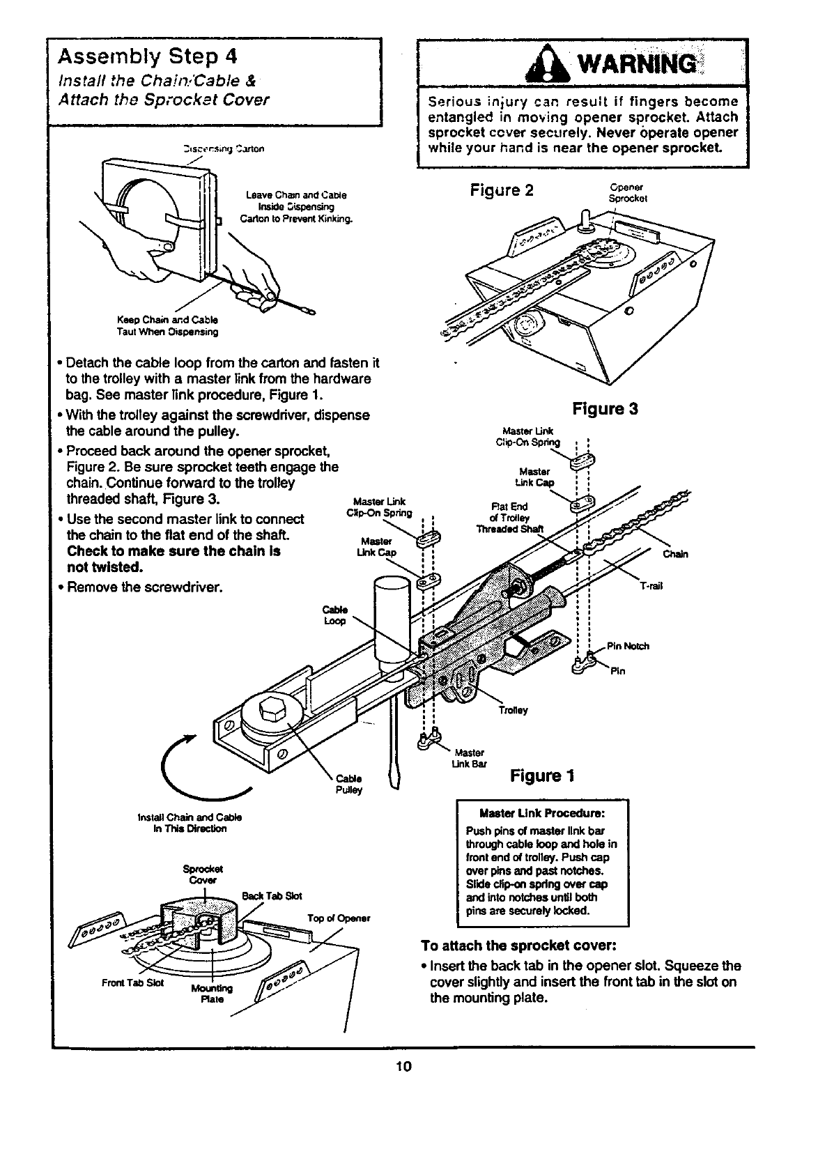
Assembly Step 4
Install the Chain/Cable &
Attach the Sprocket Cover
KeepChain and Cable
Taut When Dispensing
•Detach the cable loop from the carton and fasten it
to the trolley with a master link from the hardware
bag. See master link procedure, Figure 1.
•With the trolley against the screwdriver, dispense
the cable around the pulley.
•Proceed back around the opener sprocket,
Figure 2. Be sure sprocket teeth engage the
chain. Continue forward to the trolley
threaded shaft, Figure 3.
•Use the second master link to connect
the chain to the flat end of the shaft.
Check to make sure the chain Is
not twisted.
• Remove the screwdriver.
Master Link
C_p-On Spring , ,
Master
Link
u
WARNINQi
i i i i i •i
Serious injury can result if fingers become
entangled in moving opener sprocket. Attach
sprocket cover securely. Never operate opener
while your hand is near the opener sprocket.
Figure 2 c._.,.
Sprockel
Figure 3
Rat End
of Trolley
ThreadedShaft
Chain
T-rail
Install Chain and Cadle
In This Direction
Spmckat
Cov_
Front Tab Slot Mortaring
Plate
Cable
PuJley
Trolley
m
t
_Master
LinkBat Figure I
M_ Unk Procedure:
Pushpinsof masterlink bar
throughcable loopand hole in
frontend oftrolley.Push cap
overpinsandpast notches.
Slidedip-on spdngover cap
and intonotchesunUIboth
pinsare securelyIo_ked.
To attach the sprocket cover:
•Insert the back tab in the opener slot. Squeeze the
cover slightly and insert the front tab in the slot on
the mounting plate.
lO
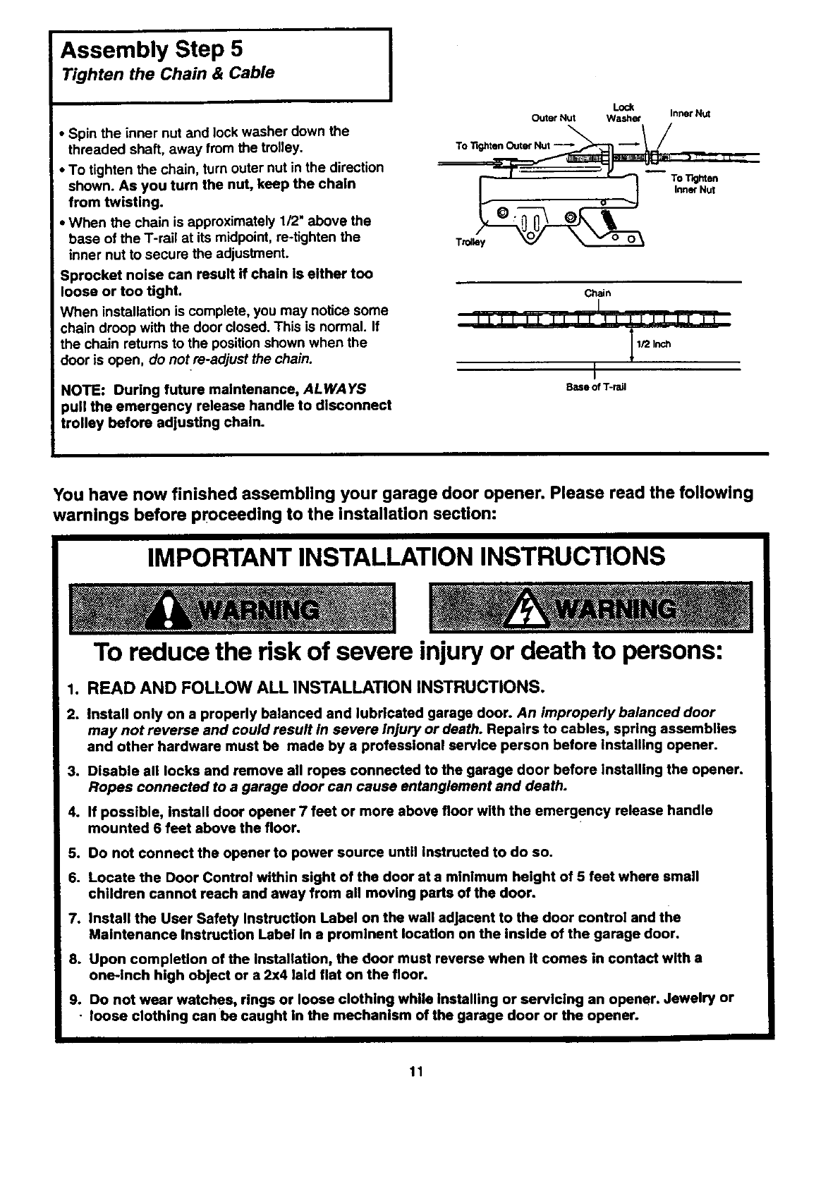
Assembly Step 5
Tighten the Chain & Cable
•Spin the inner nut and lock washer down the
threaded shaft, away from the trolley.
•To tighten the chain, turn outer nut in the direction
shown. As you turn the nut, keep the chain
from twisting.
•When the chain is approximately 1/2" above the
base of the T-rail at its midpoint, re-tighten the
inner nut to secure the adjustment.
Sprocket noise can result if chain is either too
loose or too tight.
When installation is complete, you may notice some
chain droop with the door closed. This is normal. If
the chain returns to the position shown when the
door is open, do not re-adjust the chain.
I
NOTE: During future maintenance, ALWAYS
)ull the emergency release handle to disconnect
trolley before adjusting chain.
Lock
Outer Nut Washer Inner Nut
TO "ilghten Outer Nut --'_"_ -- lJ __
T_olle_ InnerNut
Chin
1/2 Inch
Base of T-rail
You have now finished assembling your garage door opener. Please read the following
warnings before proceeding to the installation section:
IMPORTANT INSTALLATION INSTRUCTIONS
To reduce the risk of severe injury or death to persons:
1. READ AND FOLLOW ALL INSTALLATION INSTRUCTIONS,
2. Install only on a properly balanced and lubricated garage door. An improperly balanced door
may not reverse and could result in severe Injury or death. Repairs to cables, spring assemblies
and other hardware must be made by a professional service person before Installing opener.
3. Disable all locks and remove all ropes connected to the garage door before Installing the opener.
Ropes connected to a garage door can cause entanglement and death.
4. If possible, Install door opener 7 feet or more above floor with the emergency release handle
mounted 6 feet above the floor.
5. Do not connect the opener to power source until Instructed to do so.
6. Locate the Door Control within sight of the door at a mlnlmum height of 5 feet where small
children cannot reach and away from all moving parts of the door.
7. Install the User Safety Instruction Label on the wall adjacent to the door control and the
Maintenance Instruction Label in a prominent location on the inside of the garage door.
8. Upon compleUon of the Installation, the door must reverse when it comes in contact with a
one-inch high object or a 2x4 laid flat on the floor.
9. Do not wear watches, rings or loose clothing while installing or servlclng an opener. Jewelry or
•loose clothing can be caught in the mechanism of the garage door or the opener.
11
Installation Section: Pages 12- 27
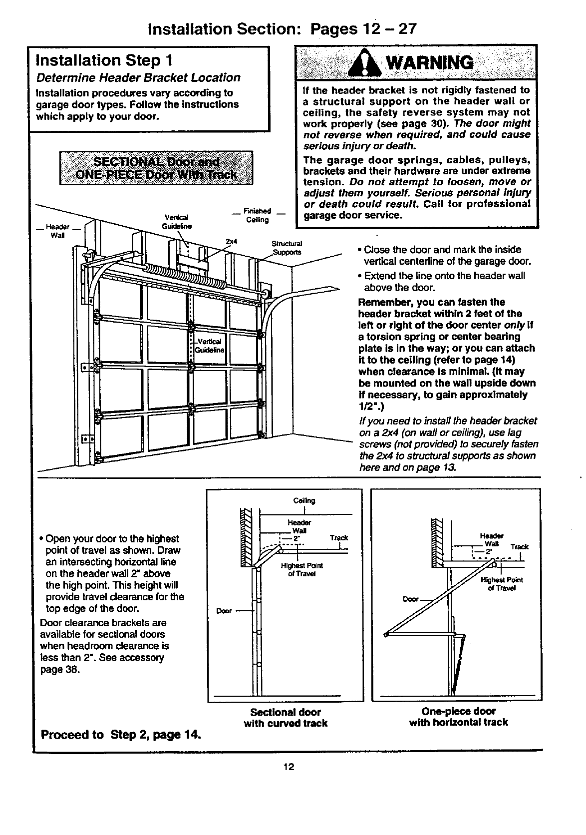
Installation Step I
Determine Header Bracket Location
Installation procedures vary according to
garage door types. Follow the instructions
which apply to your door.
-- Header --
Wal
Verlical
Guideline
2X4
WARN
If the header bracket is not rigidly fastened to
a structural support on the header wall or
ceiling, the safety reverse system may not
work properly (see page 30). The door might
not reverse when required, and could cause
serious injury or death.
The garage door springs, cables, pulleys,
brackets and their hardware are under extreme
tension. Do not attempt to loosen, move or
adjust them yourself. Serious personal injury
or death could result. Call for professional
garage door service.
Structural •Close the door and mark the inside
vertical centedine of the garage door.
•Extend the line onto the header wall
above the door.
Remember, you can fasten the
header bracket within 2 feet of the
left or right of the door center onlyif
a torsion spring or center bearing
plate is in the way; or you can attach
it to the ceiling (refer to page 14)
when clearance is minimal. (It may
be mounted on the wall upside down
if necessary, to gain approximately
1/2".)
If you need to install the header bracket
on a 2x4 (on wall or ceiling), use lag
screws (not provided) to securely fasten
the 2x4 to structural supports as shown
here and on page 13.
• Open your door to the highest
point of travel as shown. Draw
an intersecting horizontal line
on the header wall 2" above
the high point. This height will
provide travel clearance for the
top edge of the door.
Door clearance brackets are
available for sectional doors
when headroom clearance is
less than 2". See accessory
page 38.
Proceed to Step 2, page 14.
Ceiling
Wal
N_ Point
Sectional door
with curved track
Tra_
IHeader
Track
HighestPoint
olTravel
One-piece door
with horizontal track
12
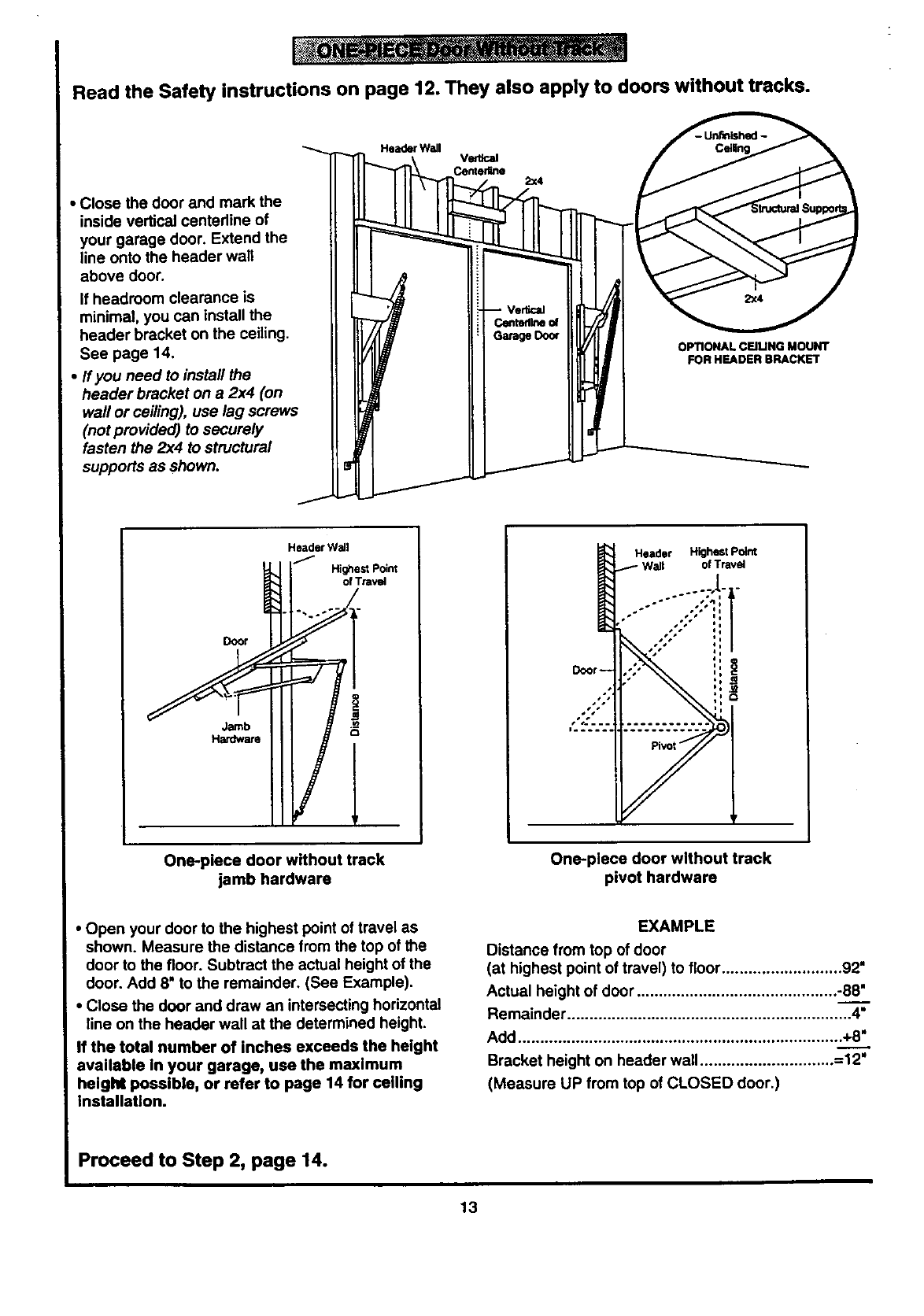
Read the Safety instructions on page 12. They also apply to doors without tracks.
• Close the door and mark the
inside vertical centedine of
your garage door. Extend the
line onto the header wall
above door.
If headroom clearance is
minimal, you can install the
header bracket on the ceiling.
See page 14.
•If you need to install the
header bracket on a 2x4 (on
wall or ceiling), use lag screws
(not provided) to securely
fasten the 2x4 to structural
supports as shown.
Header Wall
2x4
OPTIONAL CEIUNG MOUNT
FOR HEADER BRACKET
Door
Jamb
Hardware
Header Wall
_,_1 I _ Highest point
of Trawd
One-piece door without track
jamb hardware
Header Highestioint
1Wall of Travel
ii
One-piece door without track
pivot hardware
•Open your door to the highest point of travel as
shown. Measure the distance from the top of the
door to the floor. Subtract the actual height of the
door. Add 8" to the remainder. (See Example),
•Close the door and draw an intersecting horizontal
line on the header wall at the determined height.
If the total number of inches exceeds the height
available in your garage, use the maximum
height possible, or refer to page 14 for ceiling
installation.
EXAMPLE
Distance from top of door
(at highest point of travel) to floor ........................... 92"
Actual height of door ............................................. -88.____."
Remainder ................................................................ 4"
Add ......................................................................... +8"
Bracket height on header wall............................... 12"
(Measure UP from top of CLOSED door.)
Proceed to Step 2, page 14.
13
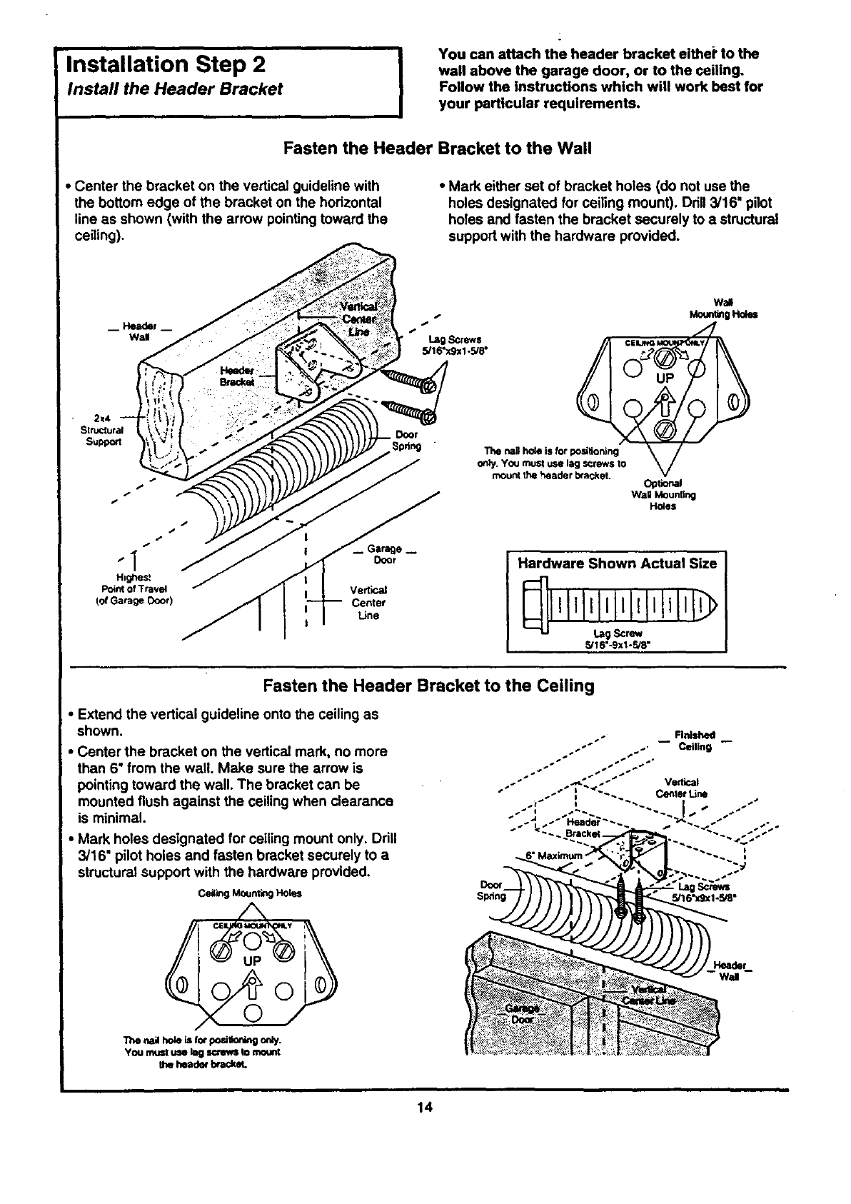
Installation Step 2 I
Install the Header Bracket
i
You can attach the header bracket either to the
wall above the garage door, or to the ceiling.
Follow the Instructions which will work best for
your particular requirements,
Fasten the Header Bracket to the Wall
• Center the bracket on the vertical guideline with
the bottom edge of the bracket on the horizontal
line as shown (with the arrow pointing toward the
ceiling).
•Mark either set of bracket holes (do not use the
holes designated for ceiling mount). Drill 3/16" pilot
holes and fasten the bracket securely to a structural
support with the hardware provided.
Wall
Mount_ Holes
"" "*Lag Screws f
Spring "The nailho_ is for posilioning \//
only. y_J must use lag scrk=e_ts 1o V
mounithe headerb'acket. opt_lal
Wall Mounting
Ho_es
le_
Door
Vertical
Center
Line
Hardware Shown Actual Size
_16"-9XI-_"
Fasten the Header Bracket to the Ceiling
•Extend the vertical guideline onto the ceiling as
shown.
•Center the bracket on the vertical mark, no more
than 6" from the wall. Make sure the arrow is
pointing toward the wall. The bracket can be
mounted flush against the ceiling when clearance
is minimal.
•Mark holes designated for ceiling mount only• Drill
3/16" pilot holes and fasten bracket securely to a
structural support with the hardware provided.
Ceil!rigMountingHoles
"n_naJho_L_forpo=_k_ngonly.
You rnust use kRgscrews to motml_
the headerbtackel.
Door
Spdng
14
ii
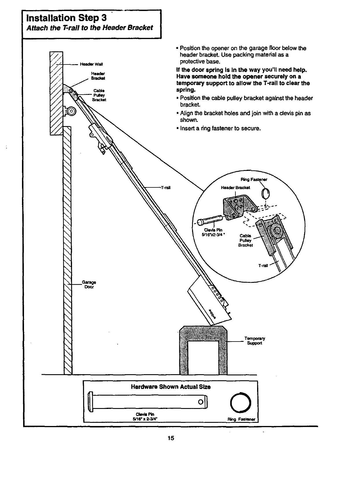
Installation Step 3 [
Attach the T-rail to the Header Bracket
Header
BW
//
//
//
//
//
Garage
Door
•Position the opener on the garage floor below the
header bracket. Use packing material as a
protective base.
If the door spring is In the way you'll need help.
Have someone hold the opener securely on a
temporary support to allow the T-rail to clear the
spring.
•Position the cable pulley bracket against the header
bracket.
•Align the bracket holes and join with a clevis pin as
shown.
•Insert a ring fastener to secure.
Ring Fastener
Header Bracket
i
Clevis Pin
5/I 6"x2-3/4 • Cable
Pulley
Bracket
Temporary
Support
Hardware Shown Actual Size
0
Ckr_s P_
5/16" x 2-3/4"
©
Ring Fastener
15
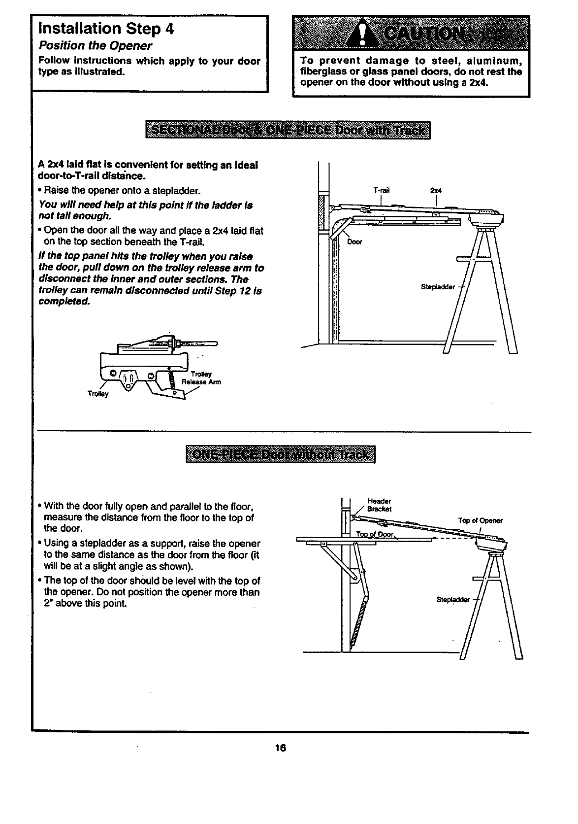
Installation Step 4
Position the Opener
Follow instructions which apply to your door
type as Illustrated.
i
A 2x4 laid flat is convenient for setting an Ideal
door-toT-rail distance.
• Raise the opener onto astepladder.
You will need help at this point ff the ladder is
not tall enough.
•Open the door all the way and place a 2x4 laid flat
on the top section beneath the T-rail.
ff the top panel hits the trolley when you raise
the door, pull down on the trolley release arm to
disconnect the Inner and outer sections. The
trolley can remain disconnected until Step 12 Is
completed.
Door
T-ra_ 2x4
I
ReleaseAnn
T_ley
•With the door fully open and parallel to the floor,
measure the distance from the floor to the top of
the door.
•Using a stepladder as a support, raise the opener
to the same distance as the door from the floor (it
will be at a slight angle as shown).
•The top of the door should be level with the top of
the opener. Do not position the opener more than
2' above this point.
Header
16
Installation Step 5
Hang the Opener I
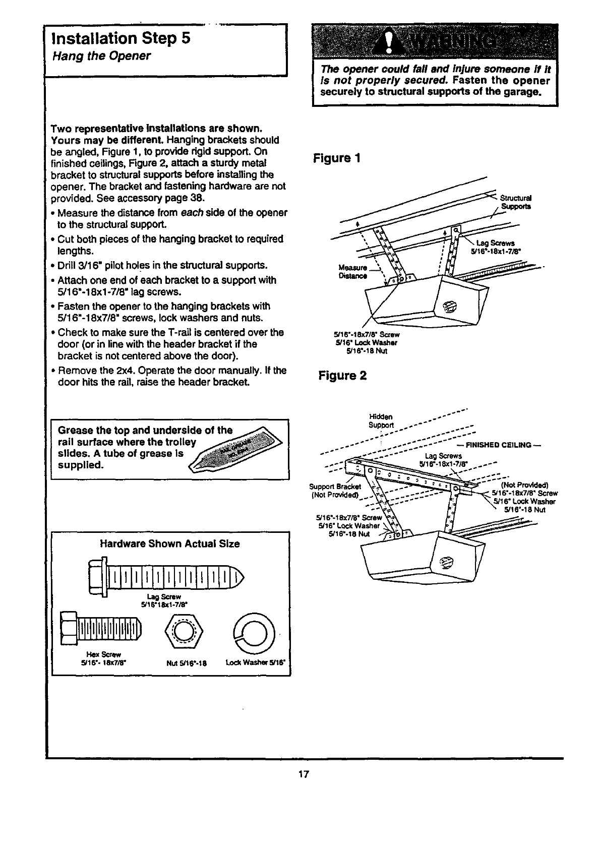
Two representative Installations are shown.
Yours may be different. Hanging brackets should
be angled, Figure 1, to provide dgid support. On
finished ceilings, Figure 2, attach a sturdy metal
bracket to structural supports before installing the
opener. The bracket and fastening hardware are not
provided. See accessory page 38.
• Measure the distance from each side of the opener
to the structural support.
•Cut both pieces of the hanging bracket to required
lengths.
• Drill 3/16" pilotholes in the structural supports.
•Attach one end of each bracket to a support with
5/16"-18xl -7/8" lag screws.
•Fasten the opener to the hanging brackets with
5/16"-18x7/8" screws, lock washers and nuts.
•Check to make sure the T-rail is centered over the
door (or in line with the header bracket if the
bracket is not centered above the door).
•Remove the 2x4. Operate the door manually. If the
door hits the rail, raise the header bracket.
Figure I
_StructuraJ
5/16 -18xl -7/8"
Measure .__,
5/16"-18x7/8" Screw
5/16" Lock Washer
5/16".18 Nut
Figure 2
Grease the top and underside of the
rail surface where the trolley __,_
slides. A tube of grease is _-__
supplied.
Hardware Shown Actual Size
5/16"18xl-7/8"
11111111111111111,llD
5/16"- 18X7/8" Nut 5/16"-18 LockWasher 5/16"
Hidden . o....° o-"" "'"
SupDort .
o,..- ...;-:::-
..... "" _..;-;'.;;"'°"--_.0SH=OCSlU,G--
"" °- "".'.. - ° "" Lag Screws •
..-'_ 5/16"-18X1-?/8 ..-"
SupportSra_dxet_ _ _'" 5/ (Not Prodded)
Not Provided) _.\_, ..°-:.°- _16"-18x7/8 Screw
5/I 6"-I 8X7/8" Scte_ _ _---_..-
17
Installation Step 6
Install the Door Control
Locate the door control within sight of the door
at a minimum height of 5 feet where small
children cannot reach, and away from all moving
)arts of the door and door hardware.
The door control is typically attached directly to the
wail. If installing into drywall, drill 5/32" holes and
use the anchors provided. For pre-wired installations
(as in new home construction), Console models
may be mounted to a.standard single gang box
(Figure 2).
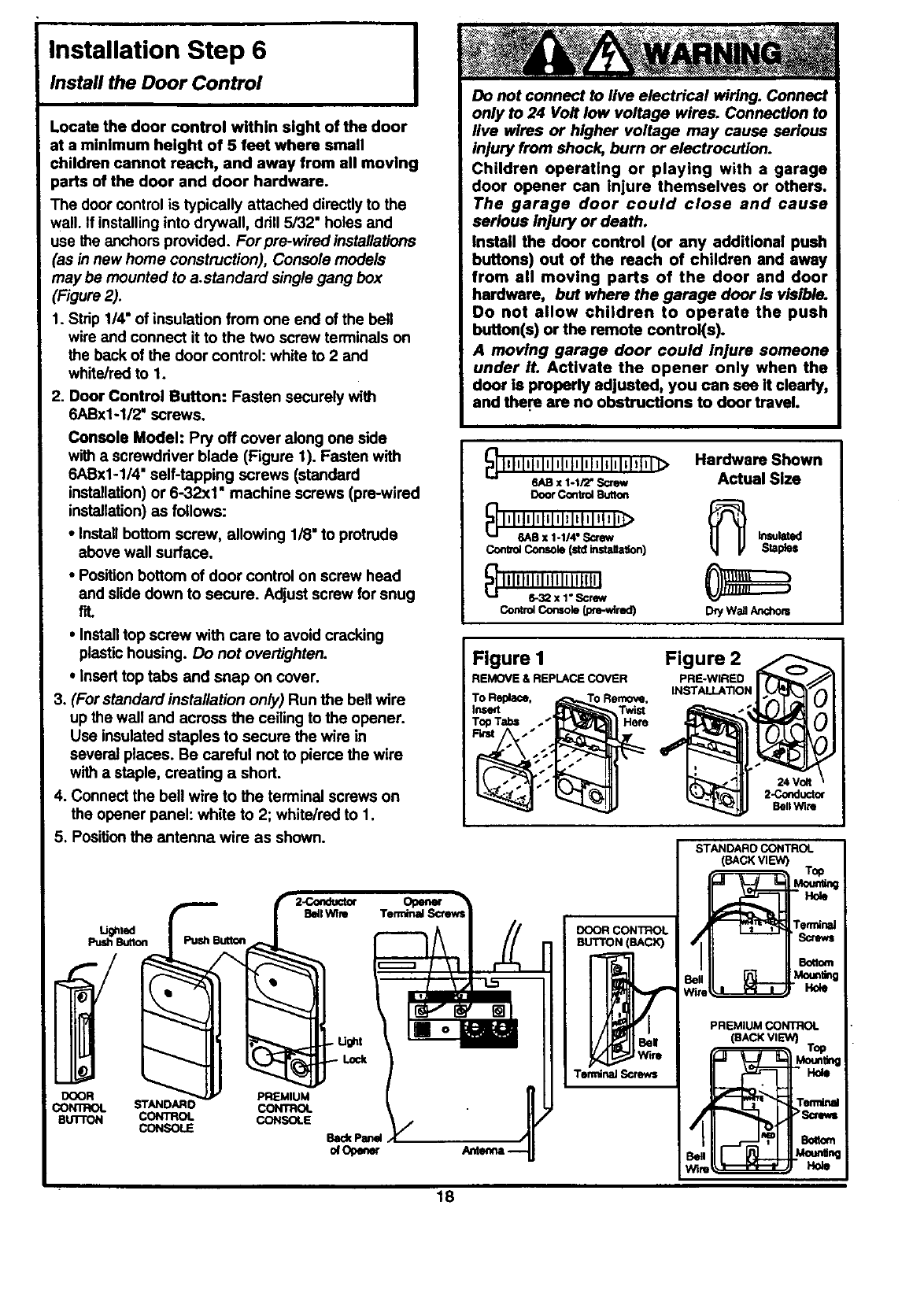
1. Strip 1/4" of insulation from one end of the bell
wire and connect it to the two screw terminals on
the back of the door control: white to 2 and
white/red to 1.
2. Door Control Button: Fasten securely with
6ABx1-1/2" screws.
Console Model: Pry off cover along one side
with a screwdriver blade (Figure 1). Fasten with
6ABx1-1/4" self-tapping screws (standard
installation) or 6-32x1" machine screws (pre-wired
installation) as follows:
• Install bottom screw, allowing 1/8" to protrude
above wall surface.
•Position bottom of door control on screw head
and slide down to secure. Adjust screw for snug
fit.
•Install top screw with care to avoid cracking
plastic housing. Do not overtighten.
•Insert top tabs and snap on cover.
3. (For standard insta/lation only) Run the bell wire
up the wall and across the ceiling to the opener.
Use insulated staples to secure the wire in
several places. Be careful not to pierce the wire
with a staple, creating a short.
4. Connect the bell wire to the terminal screws on
the opener panel: white to 2; white/red to 1.
5. Positionthe antenna wire as shown.
DOOR
CONTROL
BuTroN
STANDARO
CONTROL
CONSOLE
PREMIUM
CONTROL
CONSOLE
BackPanel
orOpener
IDo not connect to live electrical widng. Connect
only to 24 Volt low voltage wires. Connection to
live wires or higher voltage may cause serious
injury from shock, burn or electrocution.
Children operating or playing with a garage
door opener can injure themselves or others.
The garage door could close and cause
serious injury or death.
Install the door control (or any additional push
buttons) out of the reach of children and away
from all moving parts of the door and door
hardware, but where the garage door is visible.
Do not allow children to operate the push
button(s) or the remote control(s).
A moving garage door could injure someone
under it. Activate the opener only when the
door is properly adjusted, you can see It clearly,
and the.re are no obstructions to door travel.
6ABx 1-1/2"Screw
DoorControlButton
Contxo4Console(std instaltadon) Staples
ControlConsoleLore-wired) DryWa_Anchom
Hardware Shown
Actual Size
Figure 1
REMOVE & REPLACECOVER
Figure 2
PRE-WIRED
INSTALLA'RON
24 Volt
2-Conducto¢
BellWire
18
DOOR CONTROL
BUTTON (BACK)
Wire
TerminalScrews
STANDARD CONTROL
(BACKVIEW) Top
T_nal
PREMIUM CONTROL
(BACKVIEW) Top
_Te_Nnal
_1 ''_=_ >scfewt
Be.. [.__ .Mou_ng
W'ffm _. HO_
6. Attach the User Safety Instruction label to the wall
neat the door control, and the Maintenance
Instruction label in a prominent location on the
inside of the garage door.
Page 32 explains how to use the door control.
,r
Do NOT connect the power and operate the
openerat this time. The trolley will travel to the
full open position but wilt not return to the
close position until the sensor beam is
connected and properly aligned.
See Safety Reversing Sensor instructions
beginning on page 21.
Installation Step 7
Install the Light and the Lens
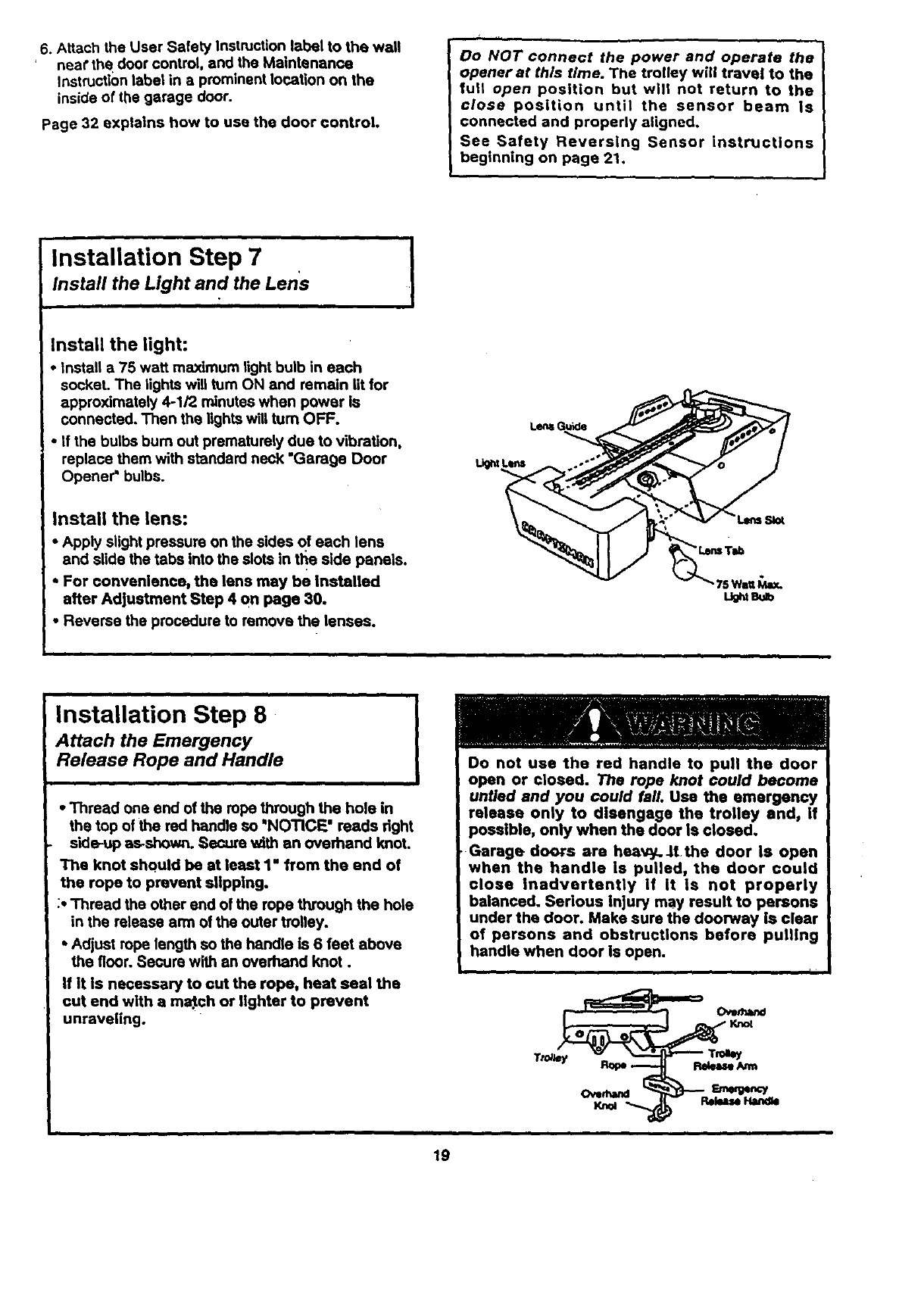
Install the light:
•Install a75 watt maximum light bulb in each
socket. The lights will turn ON and remain lit for
approximately 4-1/2 minutes when power is
connected. Then the lights will turn OFF.
• If the bulbs bum out prematurely due to vibration,
replace them with standard neck "Garage Door
Opener =bulbs.
Install the lens:
•Apply slight pressure on the sides of each lens
and slide the tabs into the slots in the side panels.
', For convenience, the lens may be Installed
after Adjustment Step 4 on page 30.
•Reverse the procedure to remove the lenses.
Installation Step 8
Attach the Emergency
Release Rope and Handle IDo not use the red handle to pull the door
open or closed. The rope knot could become
untied and you could fall. Use the emergency
•Thread one end of the rope through the hole in release only to disengage the trolley and, if
the top of the red handle so "NOTICE" reads dght possible, only when the door Is closed.
side-up a_shown. Secme with an overhand knot. Garage doors are heavy. _t the door is open
The knot should be at least 1" from the end of
the rope to prevent slipping.
:• Thread the other end of the rope through the hole
in the release arm of the outer trolley.
•Adjust rope length so the handle is 6 feet above
the floor. Secure with an overhand knot.
If it is necessary to cut the rope, heat seal the
cut end with a ma_ch or lighter to prevent
unraveling.
when the handle is pulled, the door could
close inadvertently if it Is not properly
balanced. Serious Injury may result to persons
under the door. Make sure the doorway is clear
of persons and obstructions before pulling
handle when door is open.
r
P.ekmseAnn
Rem Handle
19
Installation Step 9
Electrical Requirements
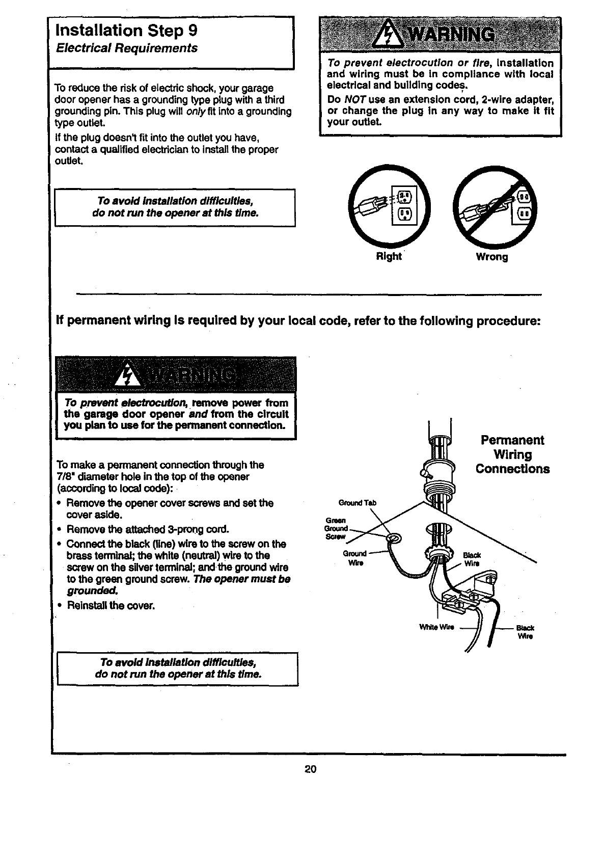
To reduce the risk of electric shock, your garage
door opener has a grounding type plug with a third
grounding pin. This plug will onlyfit into a grounding
type outlet.
If the plug doesn't fit into the outlet you have,
contact a qualified electrician to install the proper
outlet.
To avoid installation difficulties,
do not run the opener at this time.
To prevent electrocution or fire, installation
and wiring must be In compliance with local
electrical and building codes.
Do NOT use an extension cord, 2-wire adapter,
or change the plug In any way to make it fit
your outleL
OQ
Right Wrong
If permanent wiring Is required by your local code, refer to the following procedure:
To prevent e/ecfrocut/on, remove power from
the garage door opener and from the circuit
To make a permanent connection through the
7/8" diameter hole in the top of the opener
(according to local code):
• Remove the opener cover screws and set the
cover aside.
•Remove the attached 3-pmag cord.
•Connect the black (line) wire to the screw on the
brass terminal; the white (neutral) wire to the
screw on the silver terminal; andthe ground wire
to the green ground screw. The opener must be
grounded.
•Reinstall the cover.
i,
To avoid installation difficulties,
do not run the opener at this time.
GroundTab
Gresn
S_ew
Wire
Wh.e W_I
Permanent
Wiring
Connections
Back
Winl
Wire
2O
The Safety Reversing System
Information you'll need before you begin the installation of the safety reversing sensor,
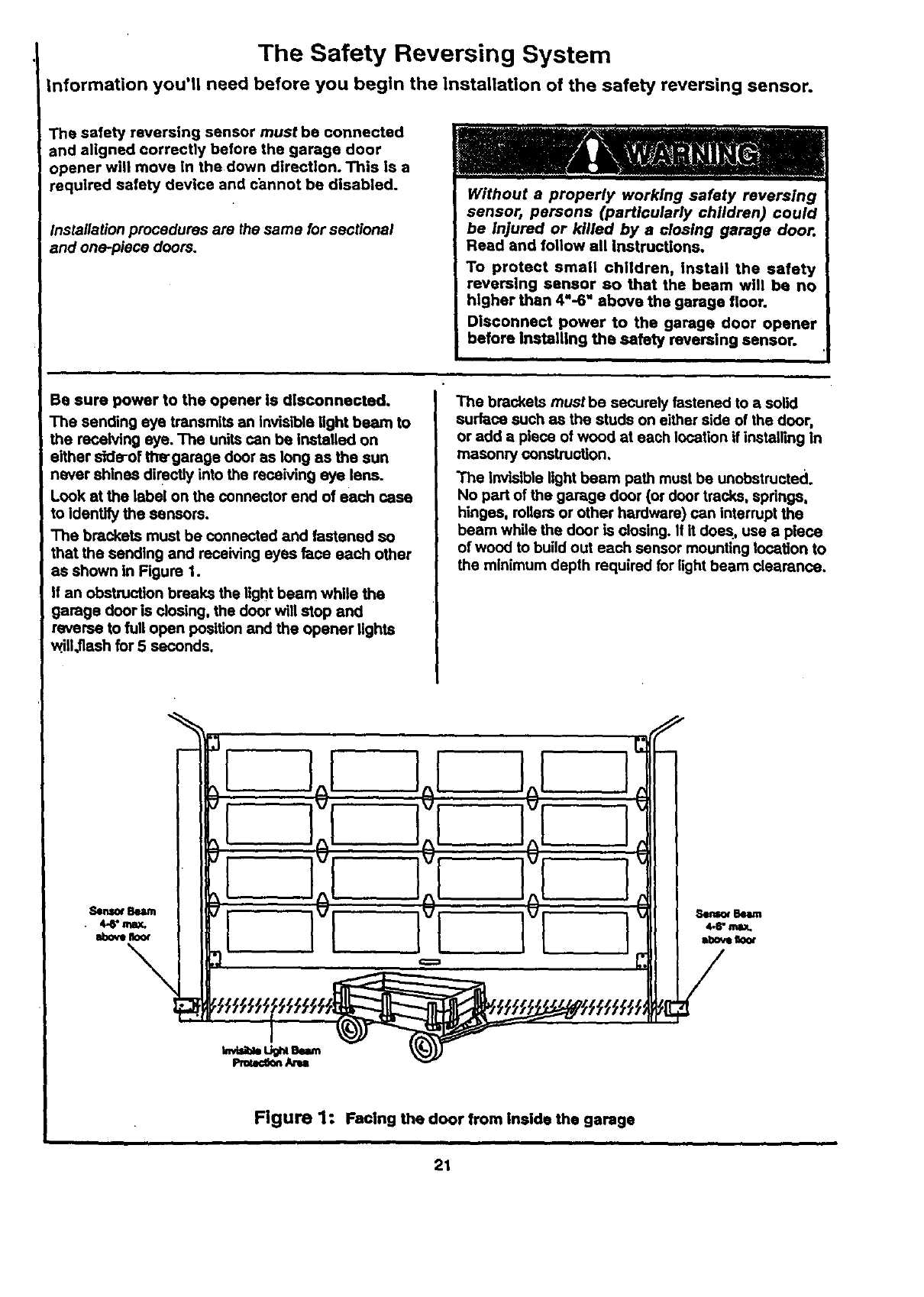
The safety reversing sensor must be connected
and aligned correctly before the garage door
opener will move In the down direction. This is a
required safety device and cannot be disabled.
Installation procedures are the same for sectional
and one-piece doors. Read and follow all Instructions.
To protect small children, install the safety
reversing sensor so that the beam will be no
higher than 4"-6" above the garage floor.
Disconnect power to the garage door opener
before Installing the safety reversing sensor.
Be sure power to the opener is disconnected.
The sending eye transmits an invisible light beam to
the receiving eye. The units can be Installed on
either slde-of the'garage door as long as the sun
never shines directly into the receiving eye lens.
Look at the label on the connector end of each case
to identify the sensors.
The brackets must be connected and fastened so
that the sending and receiving eyes face each other
as shown in Rgure 1.
If an obstruction breaks the light beam while the
garage door is closing, the door will stop and
reverse to full open position and the opener lights
will,flash for 5 seconds.
The brackets mustbe securely fastened to asolid
surlace such as the studs on either side of the door,
or add a piece of wood at each location if installing in
masonry construction.
The invisible light beam path must be unobstructe(_l.
No part of the garage door (or door tracks, spdngs,
hinges, rollers or other hardware) can interrupt the
beam while the door is closing. If it does, use a piece
of wood to build out each sensor mounting location to
the minimum depth required for light beam clearance.
Sensor Beam
=bore n_x
[
Figure 1: Facing the door from inside the garage
21
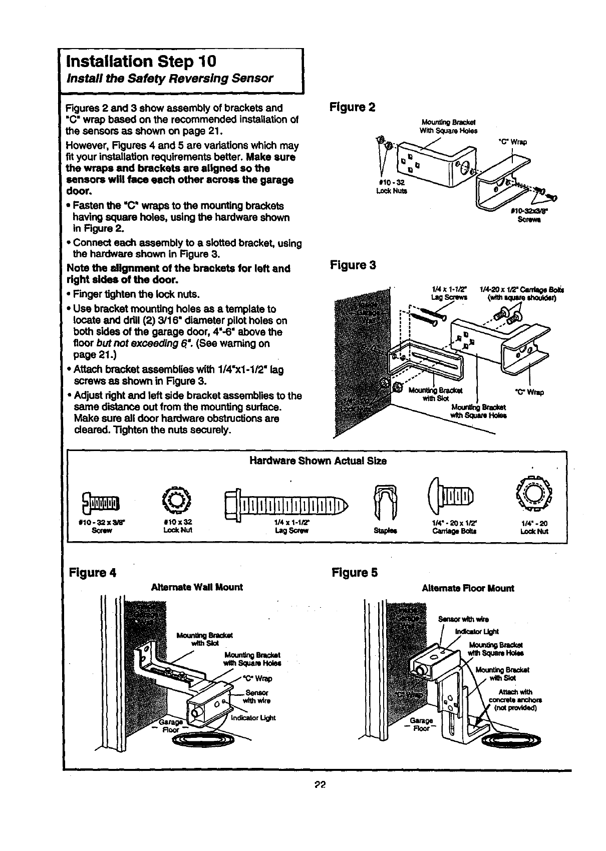
Installation Step 10
Install the Safety Reversing Sensor
' Figures 2 and 3 show assembly of brackets and
i "C" wrap based on the recommended installation of
the sensors as shown on page 21.
However, Figures 4 and 5 are vadetions which may
fit your installation requirements better. Make sure
the wraps end brackets are aligned so the
sensors will face each other across the garage
door,
•Fasten the "C" wraps to the mounting brackets
having square holes, using the hardware shown
in Figure 2.
•Connect each assembly to a slotted bracket, using
the hardware shown in Figure 3.
Note the alignment of the brackets for left and
right aides of the door.
•Finger tighten the lock nuts.
•Use bracket mounting holes as a template to
locate and ddll (2) 3/16' diameter pilot holes on
both sides of the garage door, 4"-6" above the
floor but not exceeding 6: (See warning on
page 21.)
•Attach bracket assemblies with 1/4"x1-1/2" lag
screws as shown in Figure 3.
•Adjust dght and left side bracket assemblies to the
same distance out from the mounting surface.
Make sure all door hardware obstructions are
dealed. Tighten the nuts securely.
I
Figure 2
#10-32
Lo<:kNuts
Figure 3
Mo_ Brac_l
W'dhSquareHoles
©
#10 o_12x :_gS" #10x32
SOtew LockNut
Hardware Shown Actual Size
Lag_St=paB 114"-20 x 1i'Z'
©
114"-20
LockNut
Figure 4
Alternate Wall Mount Figure 5
Alternate Floor Mount
withSlot
--Floor--
_2
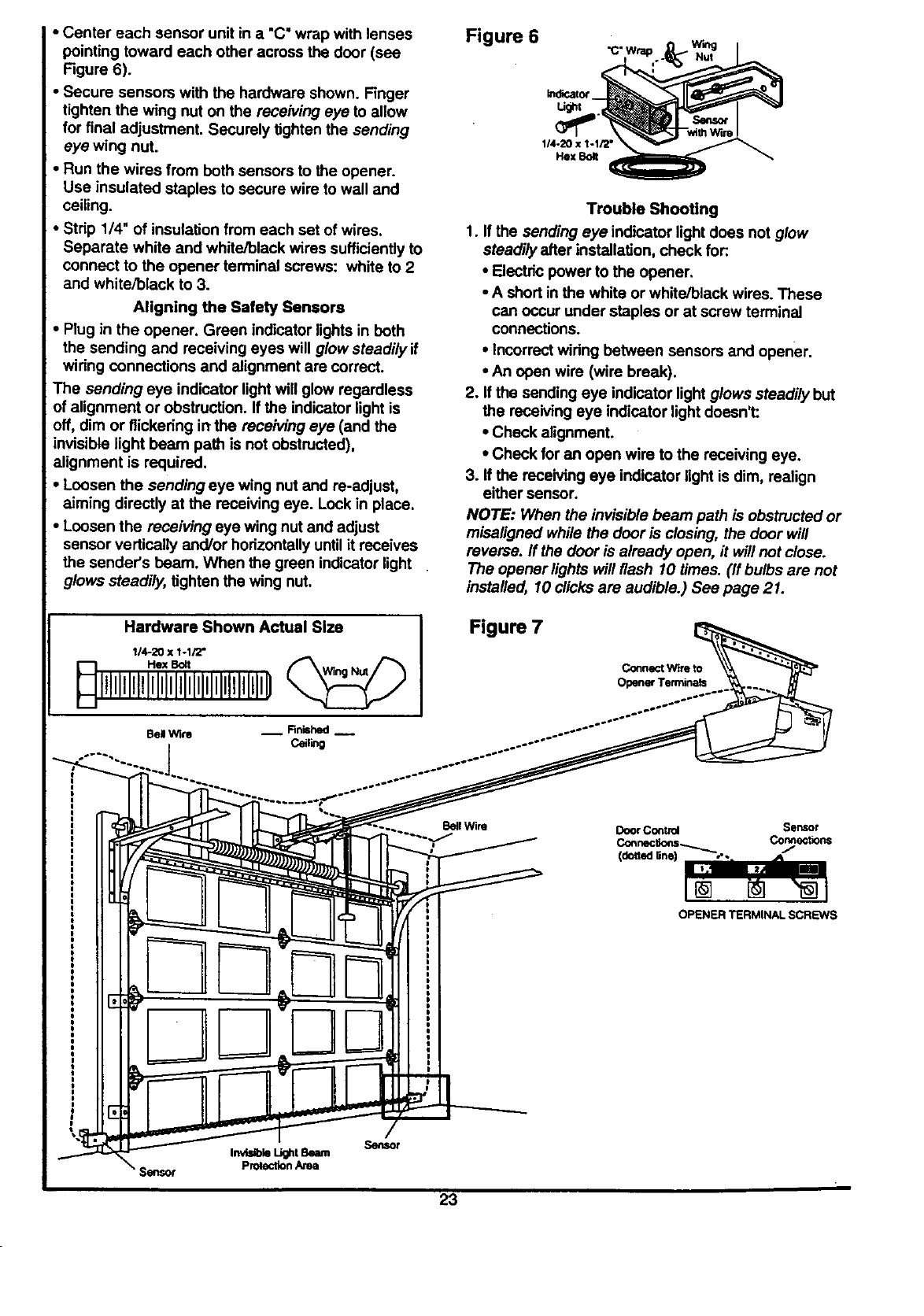
•Center each sensor unit in a "C" wrap with lenses
pointing toward each other across the door (see
Figure 6).
•Secure sensors with the hardware shown. Finger
tighten the wing nut on the receiving eye to allow
for final adjustment. Securely tighten the sending
eye wing nut.
•Hun the wires from both sensors to the opener.
Use insulated staples to secure wire to wall and
ceiling.
•Strip 1/4" of insulation from each set of wires.
Separate white and white/black wires sufficiently to
connect to the opener terminal screws: white to 2
and white/black to 3.
Aligning the Safety Sensors
•Plug in the opener. Green indicator lights in both
the sending and receiving eyes will glow steadily if
wiring connections and alignment are correct.
The sending eye indicator lightwill glow regardless
of alignment or obstruction. If the indicator light is
off dim or flickering in the receiving eye (and the
invisible light beam path is not obstructed),
alignment is required.
•Loosen the sending eye wing nut and re-adjust,
aiming directly at the receiving eye. Look in place.
•Loosen the receiving eye wing nut and adjust
sensor vertically and/or horizontally until it receives
the sender's beam. When the green indicator light
glows steadily, tighten the wing nut.
Hardware Shown Actual Slze
1/4-20 x 1-I/2"
HI,II,l,l,I;liiI,%II,I,I,I,D
Bel Wire __ Rn_'md --
Ceiling
Figure 6
114-20x 1-1/2°
FlexBoat
Trouble Shooting
1. If the sending eye indicator light does not glow
steadily after installation, check for:.
•Electric power to the opener.
•A short in the white or white/black wires. These
can occur under staples or at screw terminal
connections.
•Incorrect wiring between sensors and opener.
•An open wire (wire break).
2. If the sending eye indicator light glows steadily but
the receiving eye indicator light doesn't:
•Check alignment.
•Check for an open wire to the receiving eye.
3. If the receiving eye indicator light is dim, realign
either sensor.
NOTE: When the invisible beam path is obstructed or
miseligned while the door is closing, the door will
reverse. If the door is already open, it will not close.
The opener lights will flash 10 times. (If bulbs are not
installed, 10 clicks are audible.) See page 21.
Figure 7
ConnectWire to
OpenerTerminals
BellWire DoorControl Sensor
Connectloes_ Con_ections
(dottedline) .-.
[]
OPENER TERMINAL SCREWS
Sensor
InvisibleLightBum
ProtectionArea
23
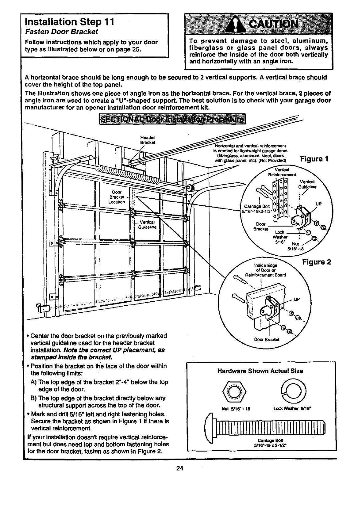
Installation Step 11
Fasten Door Bracket
Follow instructions which apply to your door
type as illustrated below or on page 25.
To prevent damage to steel, aluminum,
fiberglass or glass panel doors, always
reinforce the inside of the door both vertically
and horizontally with an angle iron.
A horizontal brace should be long enough to be secured to 2 vertical supports. A vertical brace should
cover the height of the top panel.
The illustration shows one piece of angle iron as the horizontal brace. For the vertical brace, 2 pieces of
angle iron are used to create a "U"-shaped support. The best solution is to check with your garage door
manufacturer for an opener installation door reinforcement kit.
I I! _-_---tTIJ"___.etc)-_,Pr°_) t-igure 1
r
""---- Carriage Bolt. UP
II\H =*
!i_ .P.-i=_
•Center the door bracket on the previously marked
vertical guideline used for the header bracket
installation. Note the correct UP placement, as
stamped inside the bracket.
•Position the bracket on the face of the door within
the following limits:
A) The top edge of the bracket 2'-4" below the top
edge of the door.
S) The top edge of the bracket directly below any
structural support across the top of the door.
• Mark and ddll 5/16" left and right fastening holes.
Secure the bracket as shown in Figure I if there is
vertical reinforcement.
If your installation doesn't require vertical reinforce-
ment but does need top and bottom fastening holes
for the door bracket, fasten as shown in Figure 2.
_.=deEd_ Figure 2
of Door ot
Reinforcement Board
Door Bracket
Hardware Shown Actual Size
©
Nut 5/16--18 l.ockWasher 5/16"
IIIIIIIIIIIII11IIIllll111111111111
5/16--18 x 2-1/2"
24
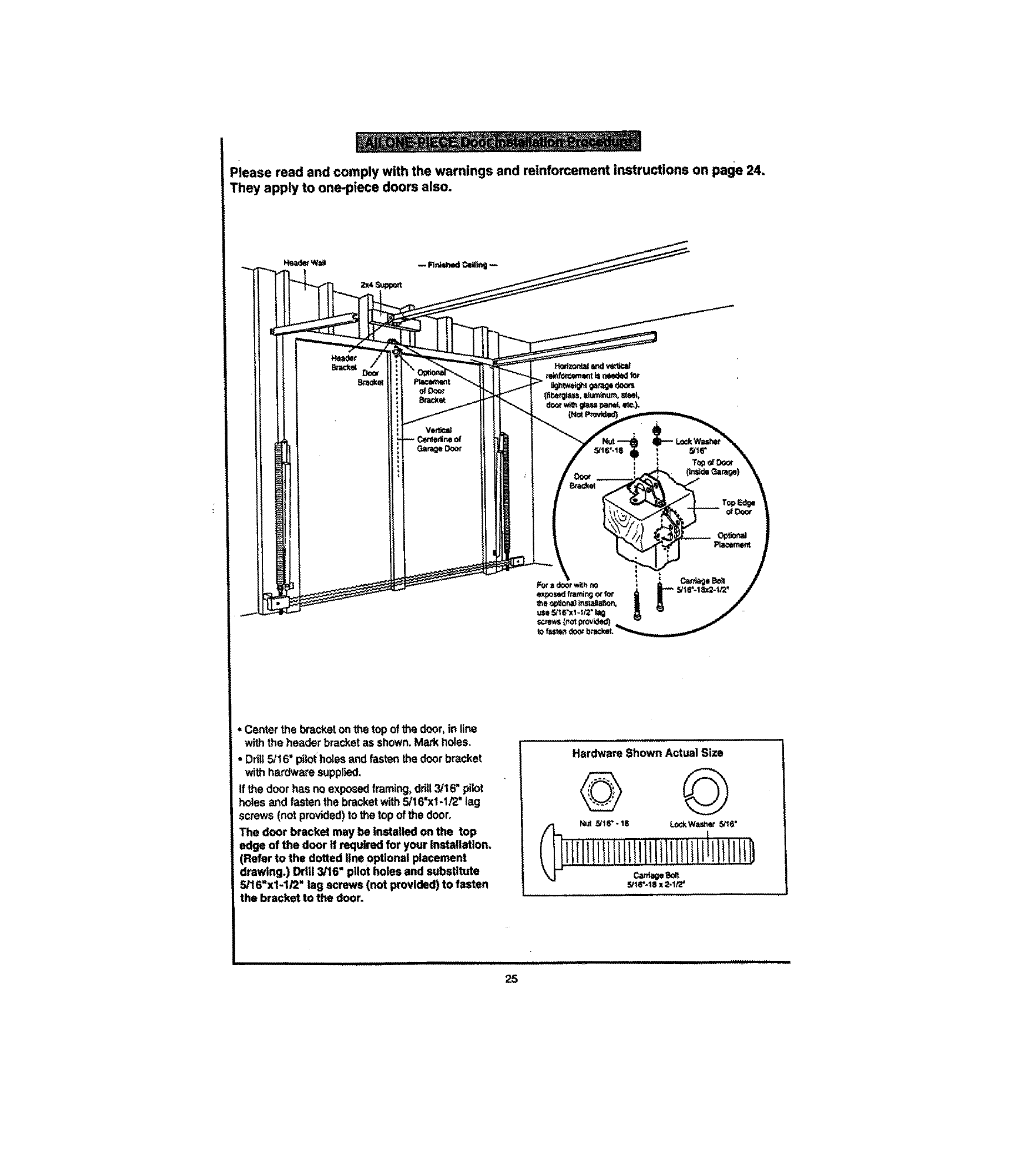
Please read and comply with the warnings and reinforcement instructions on page 24.
They apply to one-piece doors also.
• Center the bracket on the top of the door, in line
with the header bracket as shown. Mark holes
• Ddl! 5/16" pilot holes and fasten the door bracket
with hardware supplied,
If the door has no exposed framing, drill 3/16" pilot
holes and fasten the bracket with 5/16=x1-I/2" lag
screws (not provided) to the top of the door.
The door bracket may be installed on the top
edge of the door if required for your installation.
(Refer to the dotted line optional placement
drawing.) Drill 3/16" pilot holes and substitute
5/16"x1-1/2" lag screws (not provided) to fasten
the bracket to the door.
Hardware Shown Actual Size
©
I_.< _16"-18 LockWashe_ 5/_6"
5/1_'-1_t X 2-1/2 =
k
25
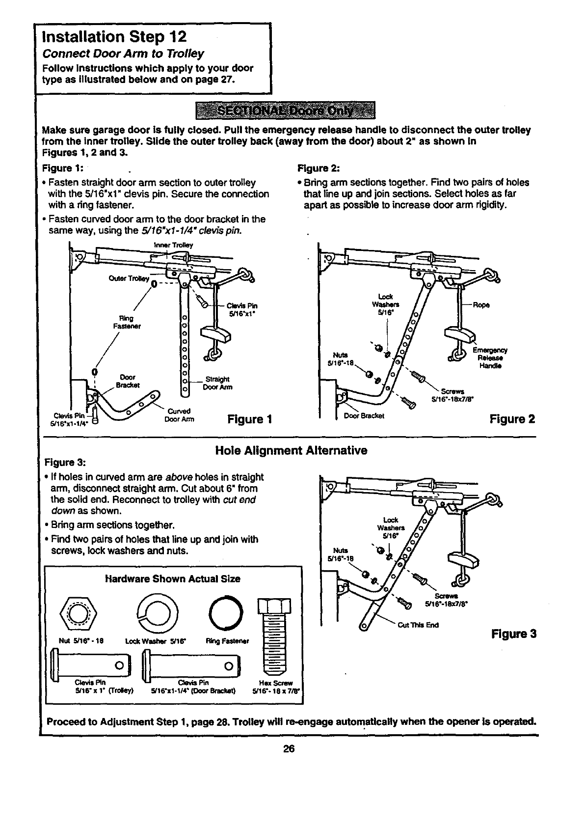
Installation Step 12
Connect Door Arm to Trolley
Follow Instructions which apply to your door
type as illustrated below and on page 27.
Make sure garage door is fully closed. Pull the emergency release handle to disconnect the outer trolley
from the inner trolley. Slide the outer trolley back (away from the door) about 2" as shown in
Figures 1, 2 and 3.
Figure 1:
Fasten straight door arm section to outer trolley
with the 5/16"x1" clevis pin. Secure the connection
with a ring fastener.
Fasten curved door arm to the door bracket in the
same way, using the 5/16 "xI -1/4" clevis pin.
Figure 2:
• Bring arm sections together. Find two pairs of holes
that line up and join sections. Select holes as far
apart as possible to increase door arm rigidity.
Inner Trolley
Ring
Fastener
/
/
0 Ooor
', BPac_et
5/16"x1-1/4" vDoor Arm
5/16"x1"
Do_ Am1
"_ S116"-18xTi8"
Figure I ooo,e._t Figure 2
Hole Alignment Alternative
Figure 3:
•If holes in curved arm are above holes in straight
arm, disconnect straight arm. Cut about 6" from
the solid end. Reconnect to trolley with cut end
down as shown.
Bring arm sections togeg_er.
Find two pairs of holes that line up and join with
screws, lock washers and nuts.
Hardware Shown Actual Size
Nut 5/16" - 18 Lock Washer 5/16" r
_Pg'l C_Nn
sit6"x 1"(Tfot_ey) He_ Screw
5/16"x1-114" (Door B_lcket) 5/16"- 18 x7/_"
•5/16"
Figure 3
Proceed to Adjustment Step 1, page 28. Trolley will re-engage automatically when the opener is operated.
26
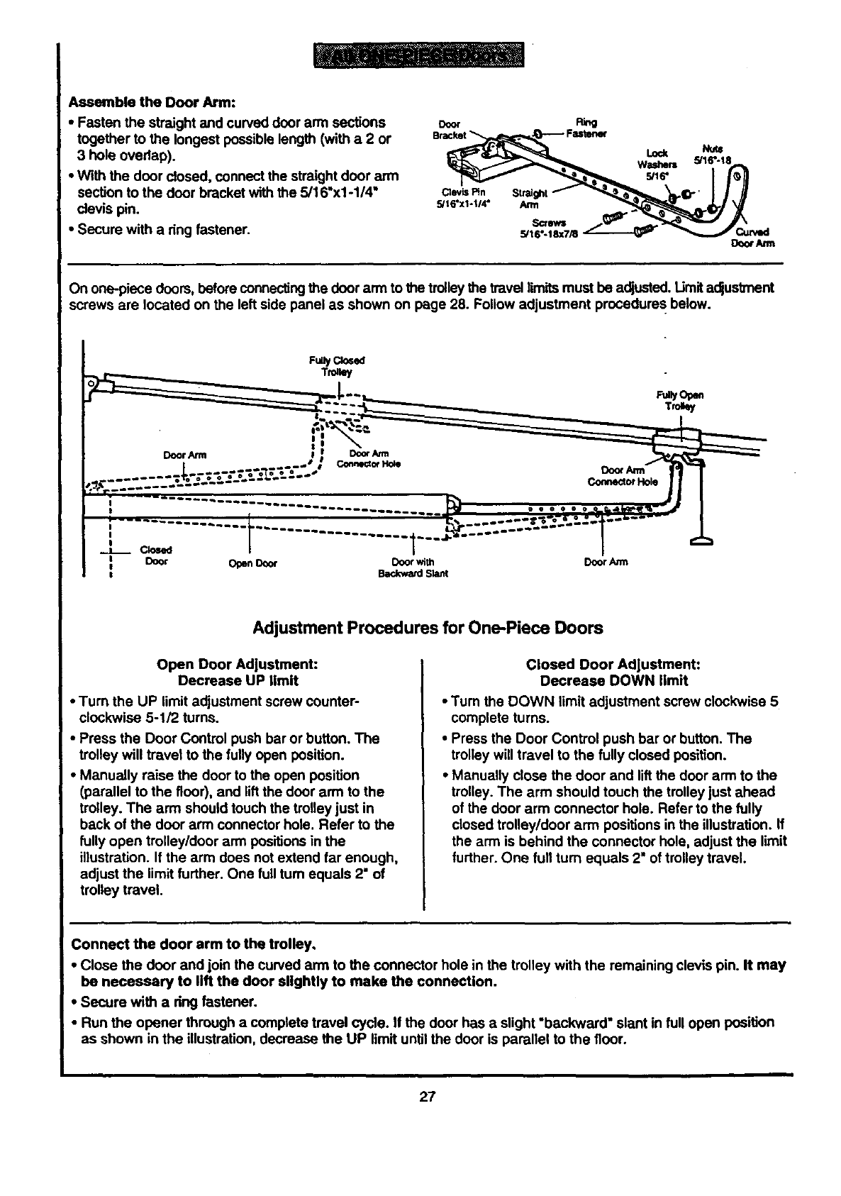
AssembletheDoorArm:
•Fasten the straight and curved door arm sections ooor
together to the longest possible length (with a 2 or
3 hole ovedap).
•With the door closed, connect the straight door arm
section to the door bracket with the 5/16"xl -1/4" cle_sF_n
clevis pin. _ls'xl.t/4"
•Secure with a ring fastener.
PJ_
SctN
5/16"-18X7/8
On one-piece doors, before connectingthe door arm to _trolleythe travel limits must be adjusted. Limit adjustment
screws are located on the left side panel as shown on page 28. Follow adjustment procedure s below.
FuUyClosed
Trolley
.._ _,.,A' _Conne_of Hole
.......... .....
....... •-_ oo°. Do(x Ann
................ .:22222JJ I
....... t .....--'°l......
I
Adjustment Procedures for One-Piece Doors
Open Door Adjustment:
Decrease UP limit
• Turn the UP limit adjustment screw counter-
clockwise 5-1/2 turns.
•Press the Door Control push bar or button. The
trolley will travel to the fully open position.
•Manually raise the door to the open position
(parallel to the floor), and lift the door arm to the
trolley. The arm should touch the trolley just in
back of the door arm connector hole. Refer to the
fully open trolley/door arm positions in the
illustration. If the arm does not extend far enough,
adjust the limit further. One full tum equals 2" of
trolley travel.
Closed Door Adjustment:
Decrease DOWN limit
•Turn the DOWN limit adjustment screw clockwise 5
complete turns.
•Press the Door Control push bar or button. The
trolley will travel to the fully closed position.
•Manually close the door and liftthe door arm to the
trolley. The arm should touch the trolley just ahead
of the door arm connector hole. Refer to the fully
closed trolley/door arm positions in the illustration. If
the arm is behind the connector hole, adjust the limit
further. One full turn equals 2" of trolley travel.
Connect the door arm to the trolley,
•Close the door and join the curved arm to the connector hole in the trolley with the remaining clevis pin. It may
be necessary to lift the door slightly to make the connection.
•Secure with a dng fastener.
•Run the opener through a complete travel cycle. If the door has aslight "backward" slant in full open position
as shown in the illustration, decrease the UP limit until the door is parallel to the floor.
27
Adjustment Section: Pages 28 - 30
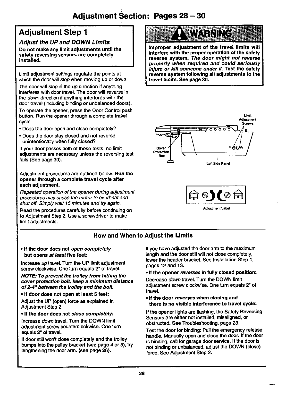
Adjustment Step 1
Adjust the UP and DOWN Limits
Do not make any limit adjustments until the
safety reversing sensors are completely
installed.
Limit adjustment settings regulate the points at
which the door wilt stopwhen moving up or down.
The door will stop i6the up direction if anything
interferes with door travel. The door will reverse in
the down direction if anything interferes with the
door travel (including binding or unbalanced doors).
To operate the opener, press the Door Control push
button. Run the opener through a complete tra,_el
cycle.
•Does the door open and close completely?
Does the door stay closed and not reverse
unintentionally when fully closed?
fyour door passes both of these tests, no limit
adjustments are necessary unless the reversing test
fails (See page 30).
Adjustment procedures are outlined below. Run the
opener through a complete travel cycle after
each adjustment.
Repeated operation of the opener during adjustment
)rocedures may cause the motor to overheat and
shut off. Simp/y wait 15 minutes and try again.
Read the procedures carefully before continuing on
to Adjustment Step 2. Use ascrewdriver to make
limit adjustments.
Cover /
Protection
Bo_t
Umit
Adju=lr_.mt
Screws
LeftSidePanel
Adjustment Label
How and When to Adjust the Limits
• If the door does not open completely
but opens at least five feet:
Increase up travel. Turn the UP limit adjustment
screw clockwise. One turn equals 2" of travel.
NOTE: To prevent the trolley from hitting the
cover protection bolt, keep a minimum distance
of 2-4" between the trolley and the bolt.
•If door does not open at least 5 feet:
Adjust the UP (open) force as explained in
Adjustment Step 2.
• If the door does not close completely:
Increase down travel. Turn the DOWN limit
adjustment screw counterclockwise. One turn
equals 2" of travel.
If door still won't close completely and the trolley
bumps into the pulley bracket (see page 4 or 5), try
lengthening the door arm. (see page 26).
If you have adjusted the door arm to the maximum
length and the door still will not close completely,
lower the header bracket. See Installation Step 1,
pages 12 and 13.
•If the opener reverses In fully closed position:
Decrease down travel. Turn the DOWN limit
adjustment screw clockwise. One turn equals 2" of
travel.
•If the door reverses when closing and
there is no visible Interference to travel cycle:
If the opener lights are flashing, the Safety Reversing
Sensors are either not installed, misaligned, or
obstructed. See Troubleshooting, page 23.
Test the door for binding: Pull the emergency release
handle. Manually open and close the door. If the door
is binding, call for garage door service. If the door is
not binding or unbalanced, adjust the DOWN (close)
force. See Adjustment Step 2.
28
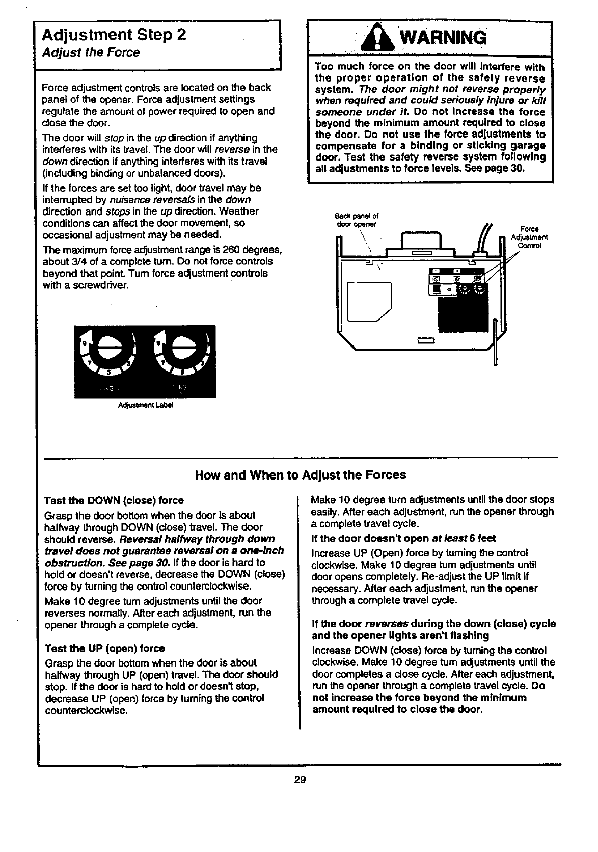
Adjustment Step 2
Adjust the Force
Force adjustment controls are located on the back
_anel of the opener. Force adjustment settings
regulate the amount of power required to open and
close the door.
The door will stop in the up direction if anything
interferes with its travel The door will reverse in the
down direction if anything interferes with its travel
(including binding or unbalanced doors).
If the forces are set too light, door travel may be
interrupted by nuisance reversals in the down
direction and stops in the up direction. Weather
conditions can affect the door movement, so
occasional adjustment may be needed.
The maximum force adjustment range is 260 degrees,
about 3/4 of acomplete turn. Do not force controls
beyond that point. Turn force adjustment controls
with a screwdriver.
AdjusUnentLabel
WARNING
I
Too much force on the door will interfere with
the proper operation of the safety reverse
system. The door might not reverse properly
when required and could seriously injure or kill
someone under iL Do not increase the force
beyond the minimum amount required to close
the door. Do not use the force adjustments to
compensate for a binding or sticking garage
door. Test the safety reverse system following
all adjustments to force levels. See page 30.
Backpanel of
dooropener " Force
\Ad|uslmlmt
How and When to Adjust the Forces
Test the DOWN (close) force
Grasp the door bottom when the door is about
halfway through DOWN (close) travel. The door
should reverse. Reversal halfway through down
travel does not guarantee reversal on aone-inch
obstruction. See page 30. If the door is hard to
hold or doesn't reverse, decrease the DOWN (close)
force by turning the control counterclockwise.
Make 10 degree turn adjustments until the door
reverses normally. After each adjustment, run the
opener through acomplete cycle.
Test the UP (open) force
Grasp the door bottom when the door is about
halfway through UP (open) travel. The door should
stop. If the door is hard to hold or doesn't stop,
decrease UP (open) force by tuming the control
counterclockwise.
Make 10 degree turn adjustments untilthe door stops
easily. After each adjustment, run the opener through
a complete travel cycle.
If the door doesn't open at least 5 feet
Increase UP (Open) force by turningthe control
clockwise. Make 10 degree turn adjustments until
door opens completely. Re-adjust the UP limit if
necessary. After each adjustment, run the opener
through a complete travel cycle.
If the door reverses during the down (close) cycle
and the opener lights aren't flashing
Increase DOWN (close) force by turning the control
clockwise. Make 10 degree turn adjustments until the
door completes a close cycle. After each adjustment,
run the opener through a complete travel cycle. Do
not increase the force beyond the minimum
amount required to close the door.
29
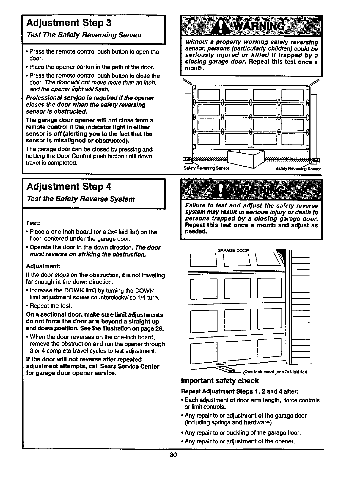
Adjustment Step 3
Test The Safety Reversing Sensor
• Press the remote control push buttonto open the
door.
•Place the opener carton in the path of the door.
• Press the remote control push button to close the
door. The door will not move more than an inch,
and the opener light will flash.
Professional serv.lce is required if the opener
closes the door when the safety reversing
sensor is obstructed.
The garage door opener will not close from a
remote control if the Indicator light In either
sensor is off(alerting you to the fact that the
sensor is mlseligned or obstructed).
The garage door can be dosed by pressing and
holding the Door Control push button untildown
travel is completed.
Adjustment Step 4
Test the Safety Reverse System
I
I
Test:
•Place a one-inch board (or a 2x4 laid flat) on the
floor, centered under the garage door.
•Operate the door in the down direction. The door
must reverse on striking the obstruction.
Adjustment:
If the door stops on the obstruction, it is not traveling
far enough in the down direction.
• Increase the DOWN limit by turningthe DOWN
limit adjustment screw counterclockwise 1/4 turn.
• Repeat the test.
On a sectional door, make sure limit adjustments
do not force the door arm beyond a straight up
and down position. See the illustration on page 26.
•When the door reverses on the one-inch board,
remove the obstruction and run the opener through
3 or 4 complete travel cycles to test adjustment.
If the door will not reverse after repeated
adjustment attempts, call Sears Service Center
for garage door opener service.
L_
-
Important safety check
Repeat Adjustment Steps 1, 2 and 4 after:
• Each adjustment of door arm length, force controls
or limit controls.
• Any repair to or adjustment of the garage door
(including springs and hardware).
•Any repair to or buckling of the garage floor.
• Any repair to or adjustment of the opener.
3O
IMPORTANT SAFETY INSTRUCTIONS
' ':-, ;,.i ! WARNING
f.. , , , , , i i
To reduce the risk of severe injury or death to persons:
1. READ AND FOLLOW ALL INSTRUCTIONS.
2. Do not permit children either to operate or to
play with the opener. Keep remote control In a
location inaccessible to children.
3. Operate opener only when the door is in full
view and free from any obstruction. Keep the
door in sight until it is completely closed. NO
ONE SHOULD CROSS THE PATH OF THE
MOVING DOOR.
4. Check safety reversal system monthly. See
page 30. The garage door MUST reverse on
contact with a one-inch (or a 2x4 board I.ald
flat) object placed on the floor. If an adjustment
is made to either the force or the limit of travel,
both adjustments may be needed and the
safety reversal system must be checked.
Failure to properly adjust the opener may
result in severe injury or death.
5. If possible, use the emergency release only
when the deer is in a closed position. Caution
should be taken whenever the disconnect cord
is actuated with the door open. Weak or broken
springs may cause the door to fall rapidly,
causing injury or death to persons.
6. KEEP GARAGE DOORS PROPERLY
BALANCED. See page 3. An improperly
balanced door may not reverse when required
and could result in severe injury or death.
Repairs to cables, spring assemblies and other
hardware must be made by a professional
garage door person.
7. Disconnect the electric power to the garage
door opener before making any repairs or
removing the covers.
s.SAVE THESE INSTRUCTIONS.
Care of Your Opener
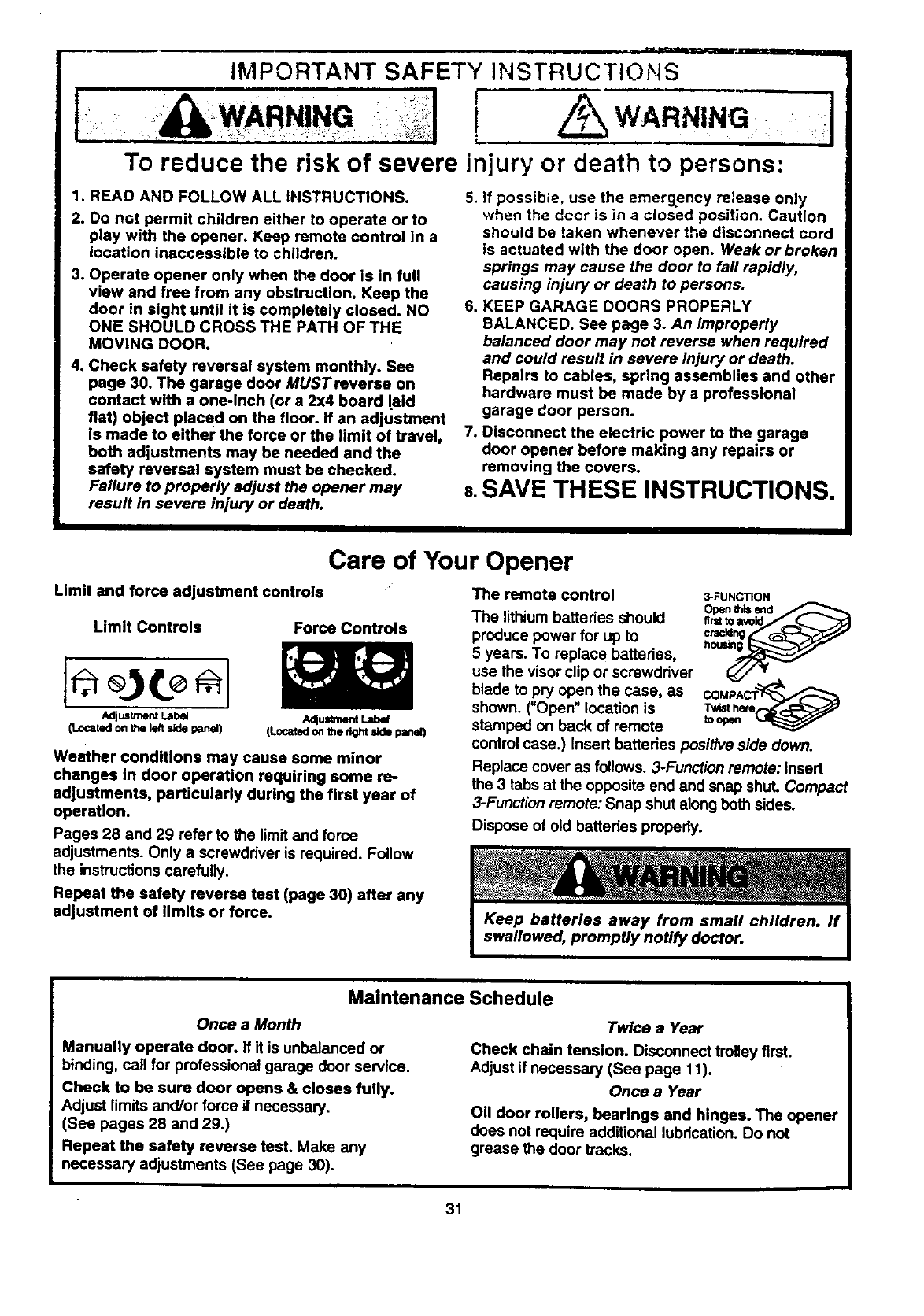
Limit and force adjustment controls
Limit Controls Force Controls
AdjustmentLabel AdJu_at_mtLabe/
(Locatedon the le/tsidepanel] (Locatedon the rightside panel)
Weather conditions may cause some minor
changes In door operation requiring some re-
adjustments, particularly during the first year of
operation.
Pages 28 and 29 refer to the limit and force
adjustments. Only a screwdriver is required. Follow
the instructions carefully.
Repeat the safety reverse test (page 30) after any
adjustment of limits or force.
The remote control
The lithium batteries should
produce power for up to
5 years. To replace batteries,
use the visor clip or screwdriver
blade to pry open the case, as
shown. (UOpen"location is
stamped on back of remote
3-FUNCTION
Openthls end
COMPAC
Twist hem
to oden
control case.) Insert batteries positive side down.
Replace cover as follows. 3-Function remote: insert
the 3 tabs at the opposite end and snap shut. Compact
3-Function remote: Snap shut along both sides.
Dispose of old batteries properly.
Maintenance Schedule
Once a Month
Manually operate door. if it is unbalanced or
binding, call for professional garage door service.
Check to be sure door opens & closes fully.
Adjust limits and/or force it necessary.
(See pages 28 and 29.)
Repeat the safety reverse test. Make any
necessary adjustments (See page 30).
Twice a Year
Check chain tension. Disconnect trolley first.
Adjust if necessary (See page 11).
Once a Year
Oil door rollers, bearings and hinges. The opener
does not require additional lubrication. Do not
grease the door tracks.
31
Operation of Your Opener
Activate the opener with any of the following:
• The Remote Control: Hold push button down until
the door starts to move.
•The Door Control: Hold push button down until the
door starts to move.
• The Outdoor Key Switch or Keyless Entry.
(See Accessories)
When the opener is activated with the safety
reversing sensor installed and correcUy aligned:
1. If open, the door will close. If closed, the door will
open.
2. If closing, the door will reverse.
3. If opening, the door will stop (allowing space for
entry and exit of pets and for fresh air).
4. If the door has been stopped in a partially open
position, it will close.
5. If obstructed while closing, the door will reverse.
6. if obstructed while opening, the door will stop.
7. The garage door will reverse in the closingcycle when
the invisiblebeam is broken, if fullyopen, the door will
notclose when the beam is broken. The sensor has
no effect in the opening cycle.
If the sensor is not installed or not aligned correctly,
the door won't close from any remote control. You can
close the door with the Door Control, the Outdoor Key
Switch, or Keyless Entry, however, if you activate
them until down travel is complete. If you release them
too soon, the door will reverse.
The opener lights will blink for 5 seconds when the
safety reversing sensor causes the door to reverse.
The Opener Lights will turn on under the following
conditions: When the opener is initiallyplugged in; when
the power is interrupted; when the opener is activated.
They will turn off automatically after 4-1/2 minutes or
provide constant light when the Light feature on the
Premium Control Console is activated. SECURITY,I,
models: Lights will also turn on when someone walks
through the open garage door. Bulb size is 75 watts
maximum.
Weak or broken springs could allow an open
door to fall (either rapidly or unexpectedly),
resulting in serious injury, death or property
damage. If possible, use the emergency
release rope and handle only when the door is
fully closed.
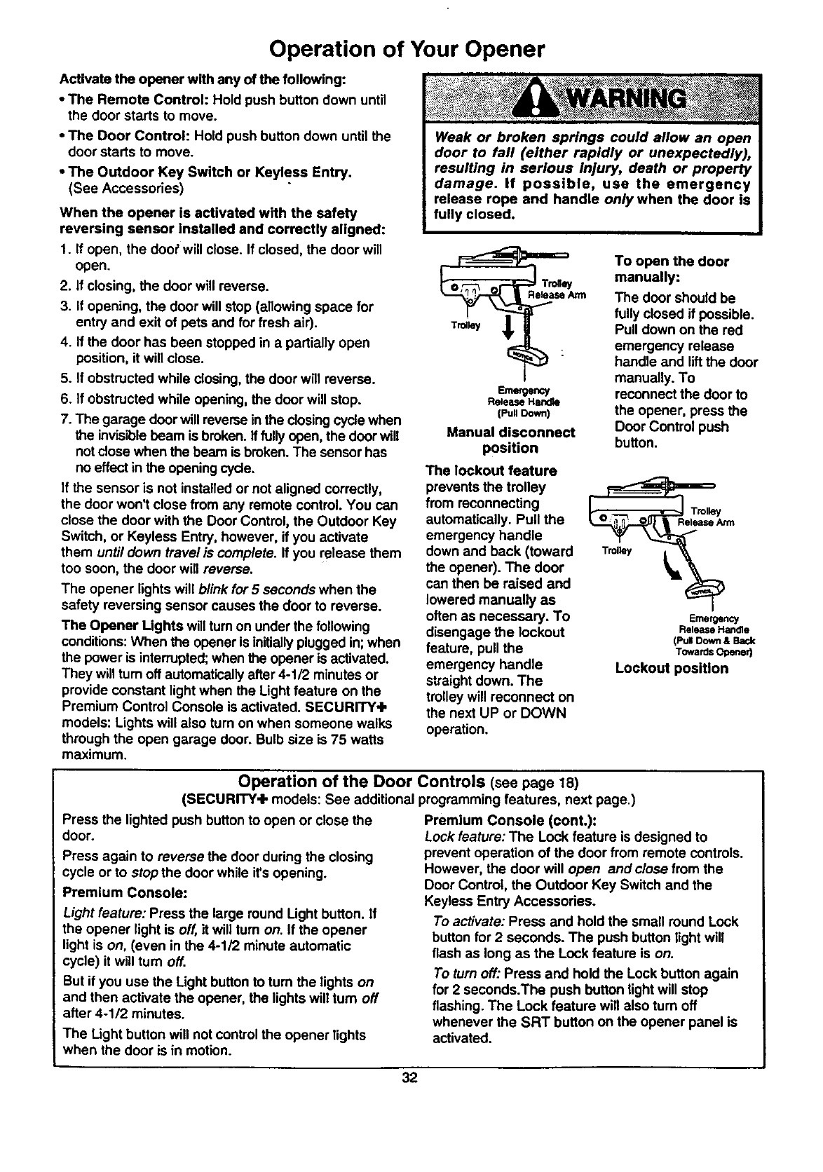
Emergency
Release Handle
(Pull Down)
Manual disconnect
position
The lockout feature
prevents the trolley
from reconnecting
automatically. Pull the
emergency handle
down and back (toward
the opener). The door
can then be raised and
lowered manually as
often as necessary. To
disengage the lookout
feature, pull the
emergency handle
straight down. The
trolley will reconnect on
the next UP or DOWN
operation.
To open the door
manually:
The door should be
fully closed if possible.
Pull down on the red
emergency release
handle and liftthe door
manually. To
reconnect the door to
the opener, press the
Door Control push
button.
O_. Trolley
Release Arm
Emergency
Release Handle
(PullDoom& Back
Towards Opener)
Lockout position
Operation of the Door Controls (see page 18)
(SECURITY.I, models: See additional programming features, next page.)
Press the lighted push button to open or close the
door.
Press again to reverse the door during the closing
cycle or to stop the door while it'sopening.
Premium Console:
Light feature: Press the large round Light button, if
the opener light is off, it will tum on. If the opener
light is on, (even in the 4-1/2 minute automatic
cycle) it will turn off.
But if you use the Light button to turn the lights on
and then activate the opener, the lights will turn off
after 4-1/2 minutes.
The Light button will not control the opener lights
when the door is in motion.
Premium Console (cont.):
Lock feature: The Lock feature is designed to
prevent operation of the door from remote controls.
However, the door will open and close from the
Door Control, the Outdoor Key Switch and the
Keyless Entry Accessories.
To activate: Press and hold the small round Lock
button for 2 seconds. The push button light will
flash as long as the Lock feature is on.
To turn off: Press and hold the Lock button again
for 2 seconds.The push button light will stop
flashing. The Lock feature will also turn off
whenever the SRT button on the opener panel is
activated.
32
Receiver and Remote Control Programming
SECURITY To comply with FCO roles, adjustment or modifications of _s receiver and/or
I_ilter are ptohlbited, except for changing the code setling or ,_placing
Ihe battery. THERE ARE NO OTHER USER SERVICEABLE PARTS.
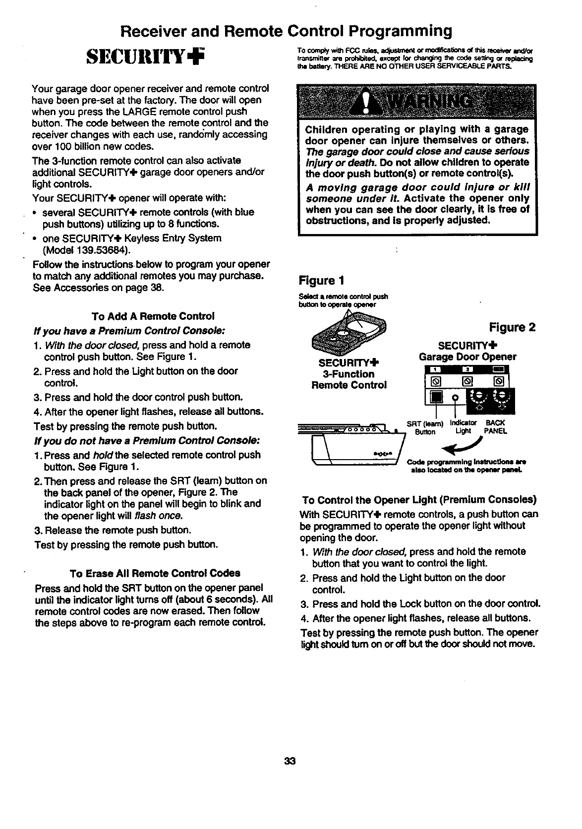
Your garage door opener receiver and remote control
have been pre-set at the factory. The door will open
when you press the LARGE remote control push
button. The code between the remote control and the
receiver changes with each use, randomly accessing
over 100 billion new codes.
The 3-function remote control can also activate
additional SECURITY+ garage door openers and/or
light controls.
Your SECURITY+ opener will operate with:
• several SECURITY+ remote controls (with blue
push buttons) utilizing up to 8 functions.
• one SECURITY+ Keyless Entry System
(Model 139.53684).
Follow the instmctionsbelow to program your opener
to match any additional remotes you may purchase.
See Accessories on page 38.
To Add A Remote Control
If you have aPremium Control Console:
1. With the door closed, press and hold a remote
control push button. See Figure 1.
2. Press and hold the Light button on the door
control.
3. Press and hold the door control push button.
4. After the opener lightflashes, release all buttons.
Test by pressing the remote push button.
ff you do not have a Premium Control Console:
1. Press and holdthe selected remote control push
button. See Figure 1.
2.Then press and release the SRT (leam) button on
the back panel of the opener, Figure 2. The
indicator light on the panel will begin to blink and
the opener light will flash once.
3. Release the remote push button.
Test by pressing the remote push button.
To Erase All Remote Control Codes
Press and hold the SRT button on the opener panel
until the indicator light turns off (about 6 seconds). All
remote control codes are now erased. Then follow
the steps above to re-program each remote control.
Children operating or playing with a garage
door opener can injure themselves or others.
The garage door could close and cause serious
injury or death. Do not allow children to operate
the door push button(s) or remote control(s).
A moving garage door could injure or kill
someone under it. Activate the opener only
when you can sea the door clearly, it is free of
obstructions, and is properly adjusted.
Rgure I
Select =remotecontrolpush
buttonto o_emlo opener
SECURITY'I"
3-Function
Remote Control
.,._O0000tl_ •SRT(leam) Indicator BACK
Button Ught PANEL
IISO tocatod OIt the opllner _
Figure 2
SECURITY,I,
Garage Door Opener
To Control the Opener Light (Premium Consoles)
With SECURITY.Ik remote controls, a push button can
be programmed to operate the opener lightwithout
opening the door.
1. With the door closed, press and hold the remote
button that you want to control the light.
2. Press and hold the Light button on the door
control.
3. Press and hold the Lock button on the door control.
4. After the opener light flashes, release all buttons.
Test by pressing the remote push button. The opener
lightshould turn on or off but the door should not move.
33
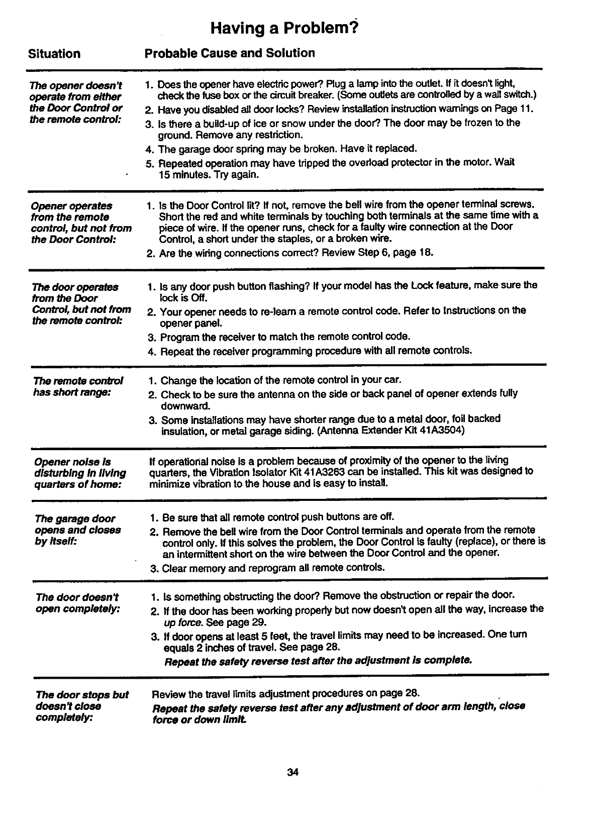
Situation
Having a Problem?
Probable Cause and Solution
The opener doesn't
operate from either
the Door Control or
the remote control:
1. Does the opener have electric power?. Plug a lamp intothe outlet, ffit doesn'tlight,
check the fuse box or the cimuit breaker. (Some outlets are controlled by a wail switch.)
2. Have you disabled all door locks? Review installation instructionwamings on Page 11.
3. Is there a build-up of ice or snow under the door?.The door may be frozen to the
ground. Remove any restriction.
4. The garage door spring may be broken. Have it replaced.
5. Repeated operation may have tripped the overload protector in the motor. Wait
15 minutes. Try again.
Opener operates
from the remote
control, but not from
the Door Control:
1. Is the Door Control lit? If not, remove the bell wire from the opener terminal screws.
Short the red and white terminals by touching both terminals at the same time with a
piece of wire. If the opener runs, check for a faulty wire connection at the Door
Control, a short under the staples, or a broken wire.
2. Are the wiring connections correct? Review Step 6, page 18.
The door operates
from the Door
Control, but not from
the remote control:
1. Is any door push button flashing? If your model has the Lock feature, make sure the
lock is Off.
2. Your opener needs to re-learn a remote control code. Refer to instructions on the
opener panel.
3. Program the receiver to match the remote control code.
4. Repeat the receiver programming procedure with all remote controls.
The remote control
has short range:
1. Change the location of the remote control in your car.
2. Check to be sure the antenna on the side or back panel of opener extends fully
downward.
3. Some installations may have shorter range due to a metal door, foil backed
insulation, or metal garage siding. (Antenna Extender Kit 41A3504)
Opener noise Is
disturbing in living
quarters of home:
If operational noise is a problem because of proximity of the opener to the living
quarters, the Vibration Isolator Kit 41A3263 can be installed. This kit was designed to
minimize vibration to the house and is easy to install
The garage door
opens and closes
by Itself:
The door doesn't
open completely:
1. Be sure that all remote control push buttons are off.
2. Remove the bell wire from the Door Control terminals and operate from the remote
control only. If this solves the problem, the Door Control is faulty (replace), or there is
an intermittent short on the wire between the Door Control and the opener.
3. Clear memory and reprogram all remote controls.
1. Is something obstructing the door?.Remove the obstruction or repair the door.
2. If the door has been working propedy but now doesn't open all the way, increase the
up force. See page 29.
3. If door opens at least 5 feet, the travel limits may need to be increased. One turn
equals 2 inches of travel. See page 28.
Repeat the safely reverse test after the adjustment is complete.
The door stops but
doesn't close
completely:
Review the travel limits adjustment procedures on page 28.
Repeat the safely reverse test after any adjustment of door arm length, close
force or down IimlL
34
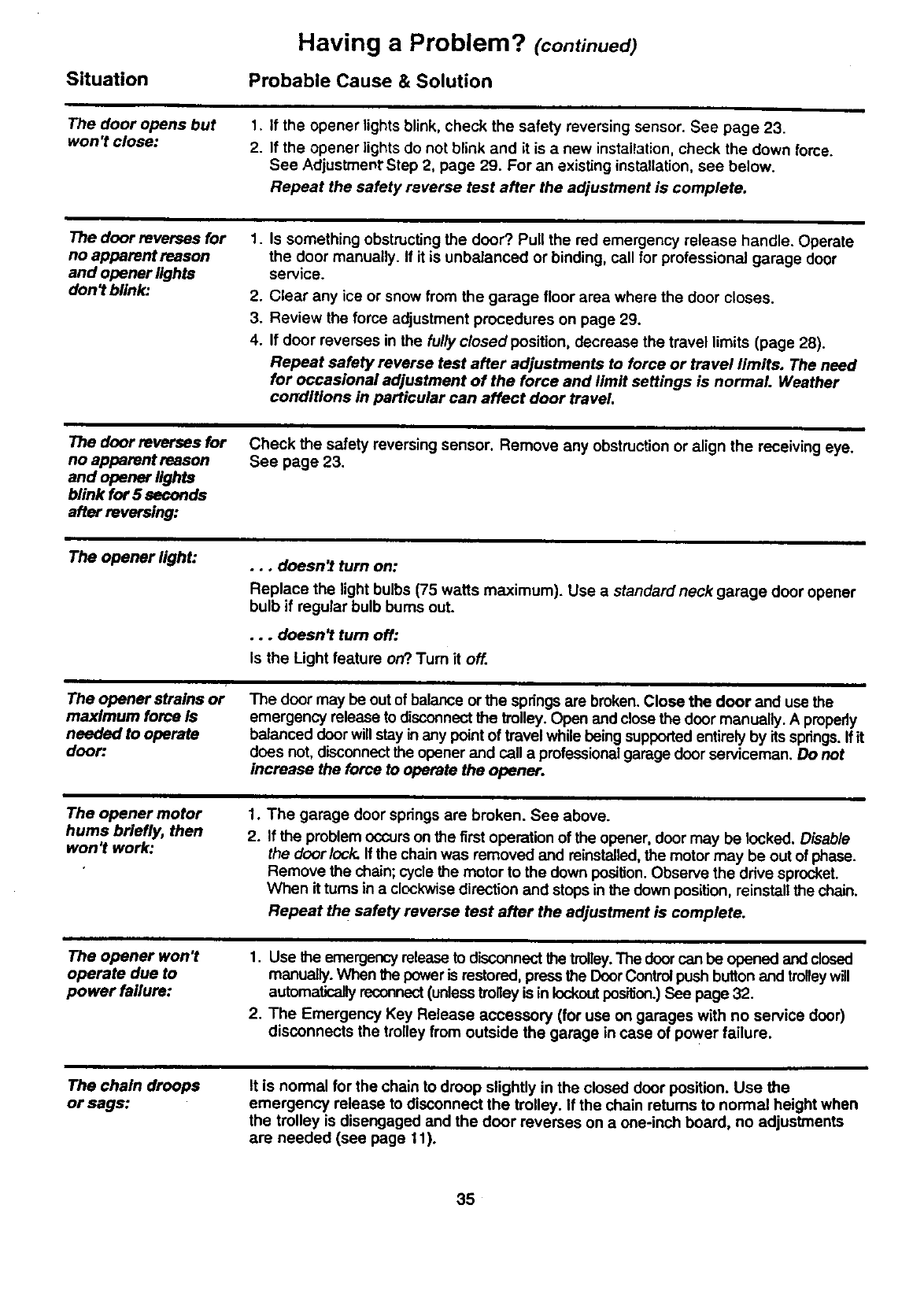
Situation
Having a Problem? (continued)
Probable Cause & Solution
The door opens but
won't close:
1.
2. If the opener lights blink, check the safety reversing sensor. See page 23.
If the opener lights do not blink and it is anew installation, check the down force.
See Adjustmenr Step 2, page 29. For an existing installation, see below.
Repeat the safety reverse test after the adjustment is complete.
The door reverses for
no apparent reason
and opener lights
don _blink:
1.
.
3.
4.
Is something obstructing the door? Pull the red emergency release handle. Operate
the door manually. If it is unbalanced or binding, call for professional garage door
service.
Clear any ice or snow from the garage floor area where the door closes.
Review the force adjustment procedures on page 29.
If door reverses in the fully closed position, decrease the travel limits (page 28).
Repeat safety reverse test after adjustments to force or travel limits. The need
for occasional adjustment of the force and limit settings is normal Weather
conditions in particular can affect door travel.
The door reverses for
no apparent reason
and opener lights
blink for 5 seconds
after reversing:
Check the safety reversing sensor. Remove any obstruction or align the receiving eye.
See page 23.
The opener light:
The opener strains or
maximum force is
needed to operate
door:
... doesn,t turn on:
Replace the light bulbs (75 watts maximum). Use a standard neck garage door opener
bulb if regular bulb bums out.
•.. doesn_ turn off:
Is the Light feature on? Turn it off.
The door may be outof balance or the springsare broken. Close the door and use the
emergency release to disconnectthe trolley. Open and close the door manually. A properly
balanced door will stayin any pointof travel while being supportedentirely by its springs.If it
does not, disconnect the opener and call a professional garage door serviceman. Do not
increase the force to operate the opener.
The opener motor
hums briefly, then
won't work:
1. The garage door springs are broken. See above.
2. If the problem occurs on the first operation of the opener, door may be locked. Disable
the doorlock. If the chain was removed and reinstalled,the motor may be out of phase.
Remove the chain; cycle the motor to the down position.Observe the drive sprocket.
When itturns in a clockwisedirection and stops in the down position, reinstall the chain.
Repeat the safety reverse test after the adjustment is complete.
The opener won't
operate due to
power failure:
1. Use the emergency release to disconnect the trolley.The doorcan be opened and dosed
manually.When the power is restored, pr_ the DoorControlpush button and trolleywill
automaticallyreconnect(unlesstrolley is in lockoutpes_on.)See page 32.
2. The Emergency Key Release accessory (for use on garages with no service door)
disconnects the trolley from outside the garage in case of power failure.
The chain droops
or sags: It is normal for the chain to droop slightly in the closed doer position. Use the
emergency release to disconnect the trolley. If the chain returns to normal height when
the trolley is disengaged and the door reverses on a one-inch board, no adjustments
are needed (see page I t).
35
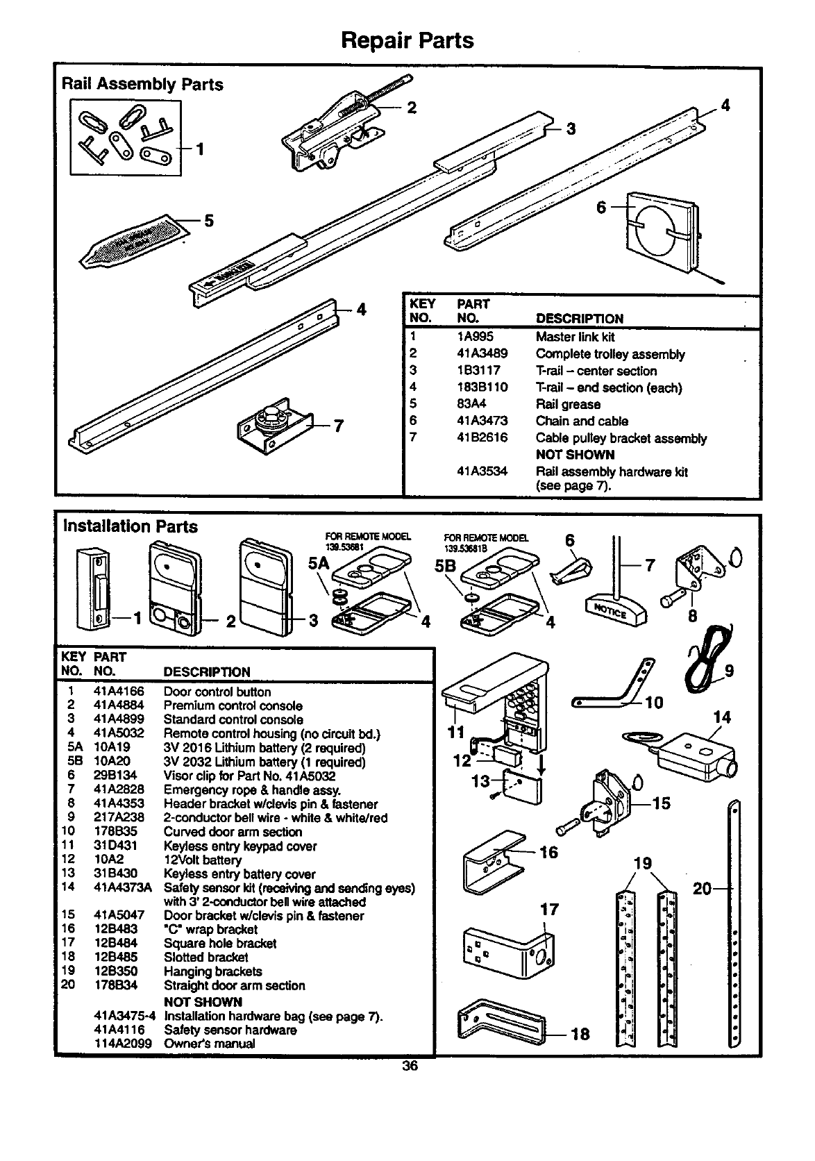
Repair Parts
Rail Assembly Parts
KEY PART
NO. NO. DESCRIPTION
1 1A995 Master link kit
2 41A3489 Complete trolley assembly
3 1B3117 T-rail - center section
4 183Bt 10 T-rail - end section (each)
5 83A4 Rail grease
6 41A3473 Chain and cabts
7 41 B2616 Cable pulley bracket assembly
NOT SHOWN
41A3534 Rail assembly hardware kit
(see page 7),
Installation Parts
2
FORREMOTEM00EL
139._I
KEY PART
NO. NO. DESCRIPTION
1 41A4166
2 41A4884
3 41A4899
4 41A5032
5A 10A19
5B 10A20
6 29S134
7 41A2828
8 41A4353
9 217A238
10 178B35
11 31D431
12 10A2
13 31B430
14 41A4373A
15 41A5047
16 12B483
17 12B484
18 12B485
19 12B350
20 178B34
41A3475-4
41A4116
114A2099
I
Doorcontrolbutton
Premiumcontrolconsole
Standardcontrolconsole
Remotecontrol housing(nocircuitbd.)
3V 2016 Lithiumbattery(2 required)
3V 2032 Lithiumbattery (1 required)
Visor clipfor Part No.41A5032
Emergencyrope& handleassy.
Header bracketw/clevispin & fastener
2-conductorbellwire- white& white]red
Curveddoorarm section
Keylsesentrykeypadcover
12Voltbattery
Keylessentrybatterycover
SafetysensorIdt(receivingandsendingeyes)
with3' 2-conductorball wireattached
Doorbracketw/clevispin & fastener
"C"wrap bracket
Square hole bracket
Slottedbracket
Hangingbrackets
Straightdoorarm section
NOT SHOWN
Installationhardwarebag (see page 7).
Safetysensorhardware
Owner'smanual
36
14
17
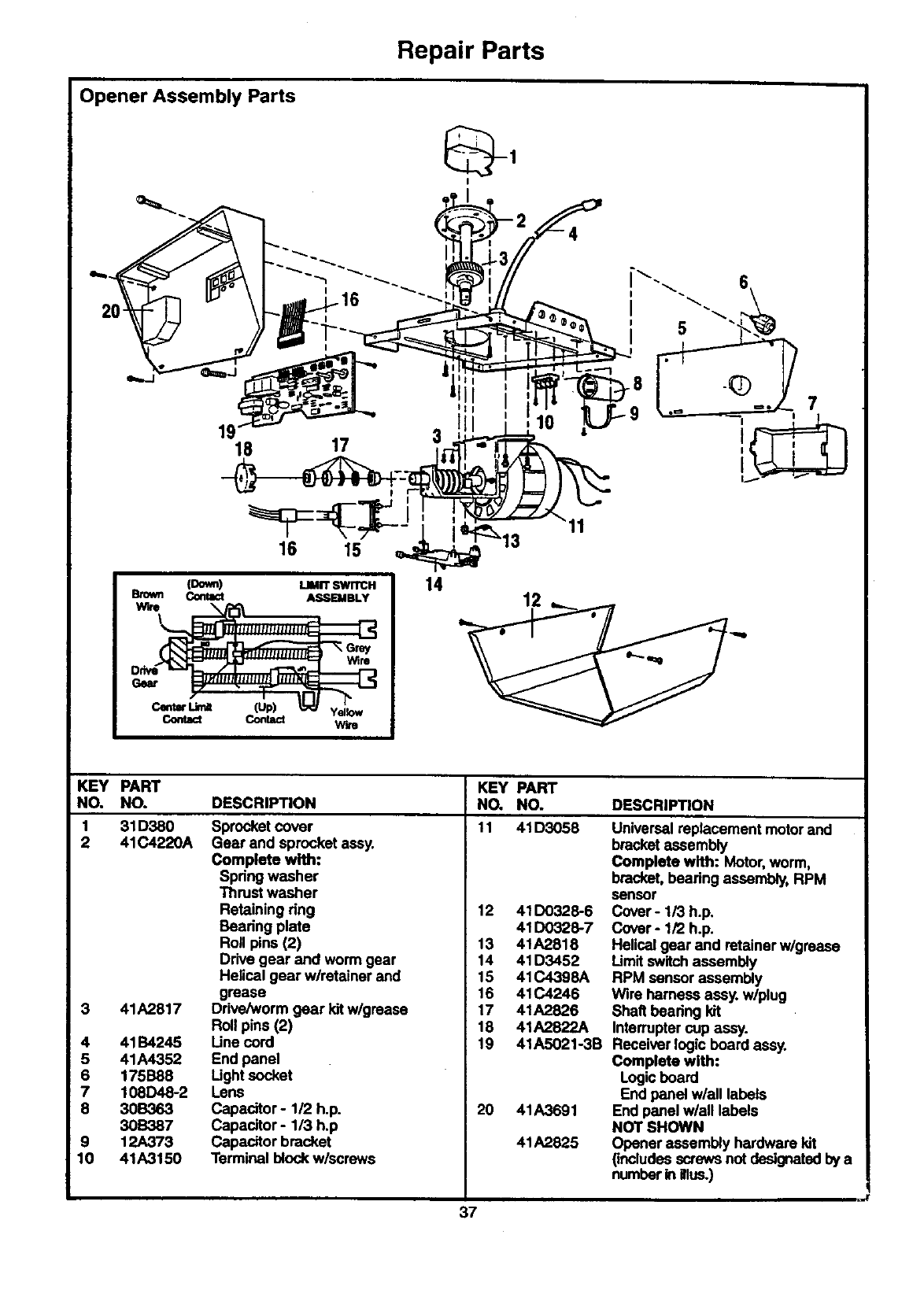
Repair Parts
Opener Assembly Parts
I
""_ ,'_ _ -G, "---.-. _i_i_,,-- '"--.. 6_
,ok 1 1" "--...
18 17 3 .' .. [
116 yS'_e'--_];i_'_:_13 "
LIMITSWITCH
__
"_ G_
Centre" Lim_ (Up) _yellow
CoaU_ Co_a_ wh
KEY PART KEY PART
NO. NO. DESCRIPTION NO, NO. DESCRIPTION
1 31D380 11 41D3058
2 41C4220A
3 41A2817
4 41B4245
5 41A4352
6 175B88
7 108D48-2
8 30B363
30B387
9 12A373
10 41A3150
Sprocket cover
Gear and sprocket assy.
Complete with:
Spring washer
Thrust washer
Retaining ring
Bearing plate
Roll pins (2)
Drive gear and worm gear
Helical gear w/retainer and
grease
Drive/worm gear kit w/grease
Roll pins (2)
Une cord
End panel
Ught socket
Lens
Capacitor- 1/2 h.p.
Capacitor- 113h.p
Capacitor bracket
Terminal block w/screws
12 41D0328-6
41130328-7
13 41A2818
14 41D3452
15 41C4398A
16 41C4246
17 41A2826
18 41A2822A
19 41A5021-3B
20 41A3691
41A2825
Universalreplacement motor and
bracketassembly
Complete with: Motor,worm,
bracket, bearing assembly, RPM
sensor
Cover- 1/3 h.p.
Cover- 1/2 h.p.
Helicalgear and retainer w/grease
Limitswitchassembly
RPM sensor assembly
Wire harness assy. w/plug
Shaft bearing kit
Interruptercup assy.
Receiver logic board assy.
Complete with:
Logicboard
End panel w/all labels
End panel w/all labels
NOT SHOWN
Opener assembly hardware kit
(includesscrews not designatedby a
numberin illus.)
37
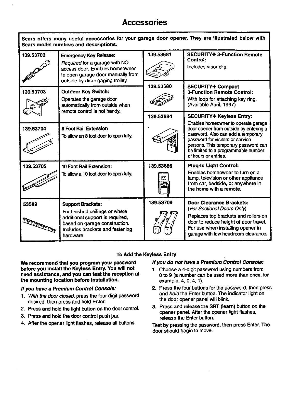
Accessories
Sears offers many useful accessories for your garage door opener. They are illustrated below with
Sears model numbers and descriptions.
139.53703
139.53704
139.53705
53589
Emergency Key Release:
Required for a garage with NO
access door. Enables homeowner
to open garage door manually from
outside by disengaging trolley.
Outdoor Key Switch:
Operates the garage door
automatically from outside when
iremote control is not handy.
8 Foot Rail Extension
Toallowan 8 footdoorto openfu_
10 Foot Rail Extension:
Toallowa 10 footdoorto opan fu_.
Support Brackets:
For finished ceilings or where
additional support is required,
based on garage construction.
Includes brackets and fastening
hardware.
139.53681
139.53680
139.53684
• I
139.53686
139.53709
SECURITY.Ik 3-FuncUon Remote
Control:
Includes visor clip.
SECURITY+ Compact
3-Function Remote Control:
With loop for attaching key ring.
(Available April, 1997)
SECURITY+ Keylees Entry:
Enables homeownerto operate garage
dooropener from outsideby entering a
password.Also can add a temporary
passwordfor visitorsor service
persons.This temporary passwordcan
be limitedto a programmable number
of hoursor entries.
Plug-In Light Control:
Enables homeowner to turn on a
lamp, television or other appliance
from car, bedside, or anywhere in
the home with a remote.
Door Clearance Brackets:
(For Sectional Doors Only)
Replaces top brackets and rollers on
door to reduce height of door travel.
For use when installing opener in
garage with low headroom clearance.
To Add the Keyless Entry
We recommend that you program your password
before you install the Keyless Entry. You will not
need assistance, and you can test the reception at
the mounting location before installation.
If you have a Premium Control Console:
1. With the door closed, press the four digit password
desired, then press and hold Enter.
2. Press and hold the light button on the door control.
3. Press and hold the door control pushbar.
4. After the opener light flashes, release all buttons.
If you do not have a Premium Control Console:
1. Choose a 4-digit password using numbers from
0 to 9 (a number can be used more than once, for
example, 4, 0, 4, 1).
2. Press the four buttons for the password, then press
and hold the Enter button. The indicator light on
the door opener panel will blink.
3. Press and release the SRT (learn) button on the
opener panel. After the opener light flashes,
release the Enter button.
Test by pressing the password, then press Enter. The
door should begin to move.
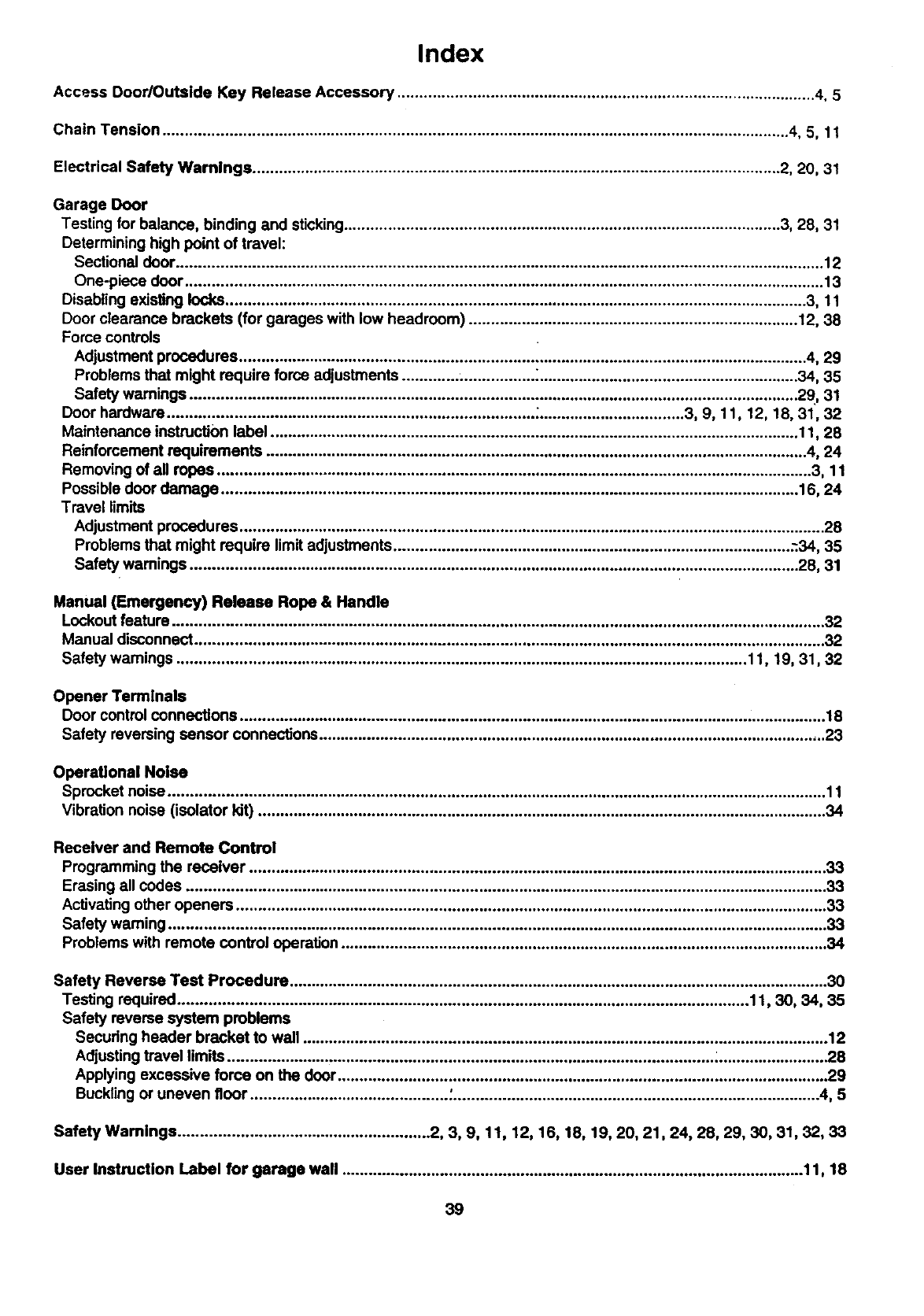
Index
Access Door/Outside Key Release Accessory ............................................................................................... 4, 5
Chain Tension .............................................................................................................................................. 4, 5, 11
Electrical Safety Warnings ........................................................................................................................ 2, 20, 31
Garage Door
Testing for balance, binding and sticking................................................................................................... 3, 28, 31
Determining high point of travel:
Sectional door................................................................................................................................................... 12
One-piece door ................................................................................................................................................. 13
Disabling existing locks.................................................................................................................................... 3, 11
Door clearance brackets (for garages with low headroom) ........................................................................... 12, 38
Force controls
Adjustment procedures ................................................................................................................................. 4, 29
Problems that might require force adjustments .............................. :........................................................... 34, 35
Safety warnings .......................................................................................................................................... 29, 31
Door hardware ................................................................................... ;................................. 3, 9, 11, 12, 18, 31, 32
Maintenance instruction label ........................................................................................................................ 11, 28
Reinforcement requirements ........................................................................................................................... 4, 24
Removing of all ropes ....................................................................................................................................... 3, 11
Possible door damage ................................................................................................................................... 16. 24
Travel limits
Adjustment procedures ..................................................................................................................................... 28
Problems that might require limit adjustments .......................................................................................... -34, 35
Safety warnings .......................................................................................................................................... 28, 31
Manual (Emergency) Release Rope & Handle
Lockout feature .................................................................................................................................................... 32
Manual disconnect ............................................................................................................................................... 32
Safety wamings ................................................................................................................................. 11, 19, 31, 32
Opener Termlnals
Door control connections ..................................................................................................................................... 18
Safety reversing sensor connections ................................................................................................................... 23
Operational Noise
Sprocket noise ..................................................................................................................................................... 11
Vibration noise (isolator kit) ................................................................................................................................. 34
Receiver and Remote Control
Programming the receiver ................................................................................................................................... 33
Erasing all codes ................................................................................................................................................. 33
Activating other openers ...................................................................................................................................... 33
Safety warning ..................................................................................................................................................... 33
Problems with remote control operation .............................................................................................................. 34
Safety Reverse Test Procedure .......................................................................................................................... 30
Testing required................................................................................................................................. 11, 30, 34, 35
Safety reverse system problems
Securing header bracket to wall ....................................................................................................................... 12
Adjusting travel limits .............................................................................................................. _........................ .28
Applying excessive force on the door............................................................................................................... 29
Buckling or uneven floor ............................................. :................................................................................... 4, 5
Safety Warnings ......................................................... 2, 3, 9, 11, 12, 16, 18, 19, 20, 21,24, 28, 29, 30, 31, 32, 33
User Instruction Label for garage wall ........................................................................................................ 11, 18
39

For professional installation
Call 24 hours a day, 7 days a week
1-800-865-6500
For the repair or replacement parts you need
Call 7 am - 7 pm, 7 days a week
t-800-366-PART
(1-800-366-7278)
For in-home major brand repair service
Call 24 hours aday, 7 days a week
t-8OO-4-REPAIR
(1-800473-7247)
For the location of a Sears Repair Service Center in your area
Call 24 hours a day, 7 days a week
1-8OO-488-1222
For Information on purchasing a Sears Maintenance Agreement or to inquire
about an existing Agreement
Call 9 am - 5 pm, Monday-Saturday
1-800-827-6655
The model number label is located under the light lens on the front end
panel of your opener. When requesting service or ordering parts, always
give the following information:
• Product Type
•Model Number
• Part Number
•Part Description
To obtain this Owner's Manual in
Spanish, please ask your
sales associate or call
1-800-959-7007
Pare obtener este Manual del
proplatario en espa_ol, sfrvase
solicitario a su vendedor o Ilamar al
1-800-959-7007
@
SEARS
America's Repair Specla_ts
SEARS WARRANTY
FULL 90-DAY WARRANTY ON GARAGE DOOR OPENER
For90 daysfromthe date of purchase,Searswillrepairthis Garage DoorOpener, free of charge,if defectiveIn materialor workmenshlp.
LIMITED WARRANTY
Fromthe 91stday unt, oneyear from the date of purchase,Searswill fumishreplacementpartsfor anydefectiveparts, free of charge.
You pay for labor. LIMITED WARRANTY ON MOTOR
1/2HP MOTOR: After 1year and through 5 years,ifthe motoren this Garage Door Opener is dafectJve,Searswillfurnisha replacement
motor, free of charge.You pay for labor.
1/3HP MOTOR: After 1 year and through 3 years,if the motoronthis Garage Door Openeris defective,Sears willfurnisha replacement
motor,free of charge.You pay for labor. MMITATION ON MABILn'Y
SEARS WILL NOT BE LIABLE FOR LOSS OR DAMAGE TO PROPERTY OR ANY INCIDENTAL OR CONSEQUENTIAL LOSS OR
EXPENSE FROM PROPERTY DAMAGE DUE DIRECTLYOR INDIRECTLY FROM THE USE OFTHIS PRODUCT. Some statesde
not allow the exclusionorfimitationof inck:lentaior consequentialdamages,so the abovelimitationorexclusionmay not applyto you.
This warrantydoes notcover lightbulbsor repairpada necessa_jbecause of operatorabuseor negligence,includingthe failureto
install,adjustand operatethis garage dooropener accordingtoinstructionscontainedinthe owner'smanual.
WARRANTY SERVICE IS AVAILABLE BY SIMPLYCONTACTING THE NEAREST SEARS CENTER/DEPARTMENT IN THE UNITED
STATES.
This warrantyapses onlywhile this productis inuseinthe UnitedStates.
This warrantygivesyou specificlegalr;ghte,andyoumay alsohaveother dghtswhich vat'/from state to state.
Sears, Roebuck and Co., DepL 817WA, Hoffman Estates, IL 60179
114A2099E @1997, All Rights Reserved Printed in Mexico
