Craftsman 28911 Operators Manual
!! Craftsman-48 Craftsman Lawn Mower Manuals - Lawn Mower Manuals – The Best Lawn Mower Manuals Collection
24728911 8e7b3384-e1d3-48fe-bee0-c4dbc25d375e Craftsman Lawn Mower 247.28911 User Guide |
2015-01-05
: Craftsman Craftsman-28911-Operators-Manual-160558 craftsman-28911-operators-manual-160558 craftsman pdf
Open the PDF directly: View PDF ![]() .
.
Page Count: 92
perator's
I:RAFrSMAN°
LAWN TRACTOR
17.5 HP
7 Speed, Shift-on=the=Go
42" Deck
Model No. 247.28911
•Espanol, P. 59
This product has a low emission engine which operates differently
from previously built engines. Before you start the engine, read and
understand this Operator's Manual.
Before using this equipment,
read this manual and follow
all safety rules and operating
instructions.
For answers to your questions about
this product, Call:
1-800=659=5917
CraftsmanTractorHelp Line
7am = 7pm CT, Mort. =Sun.
Sears Brands Management Corporation, Hoffman Estates, IL 60179 U.S.A.
Visit our website: www.craftsman.com FormNo.769-05757A
(February15,2010)
Off-Season Storage ........................................................ 27
Trou bleshooting .............................................................. 28
Labels ............................................................................. 29
Parts List ......................................................................... 30
Espafiol ............................................................................ 59
Service Numbers ............................................. Back Cover
CRAFTSMAN FULL WARRANTY
Whenoperatedand maintainedaccordingto allsuppliedinstructions,ifany non-expendablepartof thisridingequipmentfailsdueto a defectin
materialor workmanshipwithintwo yearsfromthedate orpurchase,call 1-800-659-5917to arrangefor free in-homerepair.
Theframeandfrontaxle will be repairedfreeof chargefor fiveyearsfromthe dateof purchaseif defectiveinmaterialor workmanship.
Allof the abovewarrantycoverageappliesfor only90 daysfromthe dateof purchaseifthis ridingequipmentiseverusedfor commercialor
rentalpurposes.
In allcases,if repairprovesimpossible,the ridingequipmentwill be replacedfree of chargewiththe sameoran equivalentmodel.
The batterywill be replacedfree of chargefor 90 daysfromthe dateof purchaseifdefectiveinmaterialorworkmanship(ourtestingprovesthat it
will notholda charge).
Thiswarranty coversONLYdefects in material andworkmanship. Sears will NOTpayfor:
o
o
o
o
Expendableitemsthatbecomewornduringnormaluse,includingbutnot limitedto blades,sparkplugs,aircleaners,belts,
andoilfilters.
Standardmaintenanceservicing,oilchanges,or tune-ups.
Tire replacementor repaircausedby puncturesfromoutsideobjects,suchas nails,thorns,stumps,or glass.
Tireor wheelreplacementor repairresultingfromnormalwear,accident,orimproperoperationor maintenance.
Repairsnecessarybecauseof operatorabuse,includingbutnot limitedto damagecausedby towingobjectsbeyondthe
capabilityof the ridingequipment,impactingobjectsthatbendtheframeorcrankshaft,or over-speedingthe engine.
Repairsnecessarybecauseof operatornegligence,includingbut not limitedto,electricalandmechanicaldamagecaused
by improperstorage,failureto use the propergradeandamountof engineoil, failureto keepthe deckclear of flammable
debris,orfailureto maintainthe ridingequipmentaccordingto the instructionscontainedinthe operator'smanual.
Engine(fuelsystem)cleaningor repairscausedbyfuel determinedto becontaminatedoroxidized(stale).In general,fuel
shouldbeusedwithin30daysof itspurchasedate.
Normaldeteriorationandwearof the exteriorfinishes,or productlabelreplacement.
Thiswarrantyappliesonly whilethisproductiswithinthe UnitedStates.
Thiswarrantygivesyou specificlegalrights,andyou mayalso haveotherrightswhichvaryfromstateto state.
Sears Brands ManagementCorporation, HoffmanEstates, IL 60179
GrossHP: 17.5
EngineOil: SAE30
Fuel: UnleadedGasoline
SparkPlug: Champion®RC12YC
Engine: Briggs& StrattonI/C®
Model Number:
Serial Number:
Dateof Purchase:
Recordthe modelnumber,serialnumber,
anddateof purchaseabove.
© KCDIRLLC 2
Thissymbolpointsout importantsafetyinstructionswhich,if not
followed,couldendangerthepersonalsafetyand/orpropertyof
yourselfandothers. Readandfollowall instructionsin thismanual
beforeattemptingto operatethismachine.Failureto complywith
theseinstructionsmayresultin personalinjury.Whenyou seethis
symbol,HEEDITSWARNING!
CALIFORNIA PROPOSITION 65
EngineExhaust,someof itsconstituents,andcertainvehicle
componentscontainoremitchemicalsknownto Stateof California
to causecancerandbirthdefectsorother reproductiveharm.
Batteryposts,terminals,and relatedaccessoriescontainleadand
leadcompounds,chemicalsknownto the Stateof Californiato
causecancerandreproductiveharm.Washhandsafterhandling.
Thismachinewasbuiltto beoperatedaccordingto the safeopera-
tion practicesinthis manual.As withanytypeof powerequipment,
carelessnessorerroron the partof the operatorcan resultin serious
injury.Thismachineis capableof amputatingfingers,hands,toes
andfeetandthrowingdebris.Failureto observethe followingsafety
instructionscouldresultin seriousinjuryor death.
Your Responsibility--Restrict the useof this powermachineto
personswho read,understandandfollowthewarningsand instruc-
tionsin thismanualandon the machine.
SAVE THESE INSTRUCTIONS!
GENERAL OPERATION
•Read,understand,andfollowall instructionson the machineand
in themanual(s)beforeattemptingto assembleandoperate.
Keepthis manualina safeplacefor futureand regularreference
andfor orderingreplacementparts.
• Befamiliarwithall controlsandtheir properoperation.Knowhow
to stopthe machineanddisengagethemquickly.
• Neverallowchildrenunder14yearsoldto operatethis machine.
Children14yearsoldandover shouldreadandunderstandthe
operationinstructionsandsafetyrulesinthismanualandshould
betrainedandsupervisedbya parent.
• Neverallowadultsto operatethis machinewithoutproper
instruction.
• Tohelpavoidbladecontactor a thrownobjectinjury,keep
bystanders,helpers,childrenandpetsat least75feetfromthe
machinewhile it is in operation.Stopmachineif anyoneenters
the area.
• Thoroughlyinspectthe areawherethe equipmentis to be used.
Removeallstones,sticks,wire,bones,toys,andotherforeign
objectswhichcouldbe pickedupandthrownby the blade(s).
Thrownobjectscan causeseriouspersonalinjury.
• Planyour mowingpatternto avoiddischargeof materialtoward
roads,sidewalks,bystandersandthe like.Also,avoiddischarg-
ingmaterialagainstawall orobstructionwhichmaycause
dischargedmaterialto ricochetbacktowardthe operator.
• Alwayswear safetyglassesor safetygogglesduringoperation
andwhile performingan adjustmentor repairto protectyoureyes.
Thrownobjectswhichricochetcancauseseriousinjuryto the
eyes.
• Wearsturdy,rough-soledworkshoesandclose-fittingslacksand
shirts.Loosefittingclothesandjewelrycanbe caughtin movable
parts.Neveroperatethismachineinbarefeetorsandals.
• Beawareof the mowerandattachmentdischargedirectionand
do not pointit at anyone.Donot operatethe mowerwithoutthe
dischargecoverorentiregrasscatcherin its properplace.
Donot put handsor feetnearrotatingpartsor underthe cutting
deck. Contactwiththe blade(s)can amputatehandsandfeet.
A missingor damageddischargecovercan causebladecontact
or thrownobjectinjuries.
• Stoptheblade(s)whencrossinggraveldrives,walks,or roads
andwhile notcuttinggrass.
• Watchfor trafficwhenoperatingnearorcrossingroadways.This
machineis not intendedfor useonany public roadway.
• Donot operatethe machinewhile underthe influenceof alcohol
or drugs.
• Mowonly indaylightorgoodartificiallight.
Nevercarrypassengers.
• Disengageblade(s)beforeshiftinginto reverse.Backup slowly.
Alwayslookdownandbehindbeforeandwhile backingto avoida
back-overaccident.
3
• Slowdownbeforeturning.Operatethe machinesmoothly.Avoid
erraticoperationandexcessivespeed.
Disengageblade(s),setparkingbrake,stopengineandwaituntil
the blade(s)cometo a completestopbeforeremovinggrass
catcher,emptyinggrass,uncloggingchute,removinganygrassor
debris,or makinganyadjustments.
Neverleavea runningmachineunattended.Alwaysturnoff
blade(s),setparkingbrake,stopengineandremovekeybefore
dismounting.
Useextracare whenloadingorunloadingthe machineintoa
trailerortruck.Thismachineshouldnot bedrivenupor down
ramp(s),becausethe machinecouldtip over,causingserious
personalinjury.The machinemustbe pushedmanuallyon
ramp(s)to loador unloadproperly.
Mufflerandenginebecomehotandcan causea burn.Do not
touch.
Checkoverheadclearancescarefullybeforedrivingunderlow
hangingtree branches,wires,dooropeningsetc.,wherethe
operatormaybestruckor pulledfromthe machine,whichcould
resultinseriousinjury.
Disengageallattachmentclutchesanddepressthe brakepedal
completelybeforeattemptingto start engine.
Yourmachineisdesignedto cutnormalresidentialgrassof a
heightnomorethan 10".Do not attemptto mowthroughunusually
tall,dry grass(e.g.,pasture)orpiles of dry leaves.Drygrassor
leavesmaycontactthe engineexhaustand/or builduponthe
mowerdeckpresentinga potentialfire hazard.
Useonlyaccessoriesandattachmentsapprovedfor this machine
by the machinemanufacturer.Read,understandandfollowall
instructionsprovidedwiththe approvedaccessoryor attachment.
Fora list of approvedaccessoriesandattachments,call 1-800-
659-5917.
Dataindicatesthatoperators,age60yearsandabove,are
involvedin a largepercentageof ridingmower-relatedinjuries.
Theseoperatorsshouldevaluatetheirabilityto operatethe riding
mowersafelyenoughto protectthemselvesandothersfrom
seriousinjury.
If situationsoccurwhicharenot coveredinthismanual,usecare
andgoodjudgment.Contact1-800-659-5917for informationand
assistance.
SLOPE OPERATION
Slopesarea majorfactorrelatedto lossof controlandtip-over
accidentswhichcan resultinsevereinjuryor death.Allslopesrequire
extracaution.Ifyoucannotbackupthe slopeor if youfeel uneasyon
it, do not mowit.
Foryoursafety,use the SlopeGuideincludedas partof this manual
to measureslopesbeforeoperatingthis machineona slopedor hilly
area. Ifthe slopeis greaterthan15degreesas shownonthe Slope
Guide,do notoperatethis machineonthatareaor seriousinjurycould
result.
Do:
oMowupanddown slopes,not across.Exerciseextremecaution
whenchangingdirectionon slopes.
• Watchfor holes,ruts,bumps,rocks,orother hiddenobjects.
Uneventerraincouldoverturnthe machine.Tallgrasscan hide
obstacles.
Useslowspeed.Choosea lowenoughspeedsettingso that
you will nothaveto stopor shiftwhileon the slope.Tiresmay
lose tractionon slopeseventhoughthe brakesarefunctioning
properly.Alwayskeepmachinein gearwhen goingdownslopes
to takeadvantageof enginebrakingaction.
• Followthe manufacturer'srecommendationsfor wheelweights
or counterweightsto improvestability.Forrecommendations,call
1-800-659-5917.
• Useextracarewithgrasscatchersor otherattachments.These
can changethe stabilityof the machine.
Keepallmovementonthe slopesslowandgradual.Do not make
suddenchangesinspeedor direction.Rapidengagementor
brakingcouldcausethe frontof the machineto lift andrapidlyflip
overbackwardswhichcouldcauseseriousinjury.
• Avoidstartingorstoppingona slope.Iftireslosetraction,disen-
gagethe blade(s)andproceedslowlystraightdownthe slope.
DoNot:
• Donot turnon slopesunlessnecessary;then,turnslowlyand
graduallydownhill,if possible.
• Donot mowneardrop-offs,ditchesor embankments.The mower
could suddenlyturnover if a wheelis overthe edgeof a cliff,
ditch,or if an edgecavesin.
• Donot try to stabilizethe machineby puttingyourfooton the
ground.
• Donot usea grasscatcheron steepslopes.
• Donot mowon wetgrass.Reducedtractioncouldcausesliding.
• Donot attemptto coastdownhill.Over-speedingmaycausethe
operatorto lose controlof the machineresultingin seriousinjury
or death.
• Donot towheavypull behindattachments(e.g.loadeddumpcart,
lawn roller,etc.)on slopesgreaterthan5 degrees.Whengoing
down hill,the extraweighttendsto pushthe tractorandmay
causeyou to loosecontrol(e.g.tractormayspeedup, brakingand
steeringabilityarereduced,attachmentmayjack-knifeandcause
tractorto overturn).
4
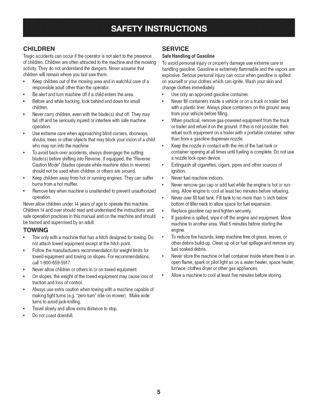
CHILDREN
Tragicaccidentscanoccurifthe operatoris notalert to the presence
of children.Childrenareoftenattractedto the machineandthe mowing
activity.Theydo notunderstandthe dangers.Neverassumethat
childrenwill remainwhereyou lastsawthem.
• Keepchildrenout of the mowingareaand inwatchfulcare of a
responsibleadultotherthanthe operator.
• Bealert andturnmachineoff ifa childentersthe area.
• Beforeandwhilebacking,lookbehindanddownfor small
children.
Nevercarrychildren,evenwiththe blade(s)shutoff.Theymay
fall offandbe seriouslyinjuredorinterferewithsafemachine
operation.
• Useextremecarewhenapproachingblindcorners,doorways,
shrubs,treesorotherobjectsthatmayblockyourvisionof a child
whomayrunintothe machine.
Toavoidback-overaccidents,alwaysdisengagethe cutting
blade(s)beforeshiftingintoReverse.Ifequipped,the "Reverse
CautionMode"(bladesoperatewhilemachineridesinreverse)
shouldnotbe usedwhenchildrenor othersarearound.
Keepchildrenawayfromhotor runningengines.Theycansuffer
burnsfroma hotmuffler.
• Removekeywhenmachineisunattendedto preventunauthorized
operation.
Neverallowchildrenunder14yearsof ageto operatethis machine.
Children14andovershouldreadandunderstandthe instructionsand
safeoperationpracticesinthismanualandon the machineandshould
betrainedandsupervisedbyan adult.
TOWING
Towonlywitha machinethathasa hitchdesignedfor towing.Do
not attachtowedequipmentexceptat the hitchpoint.
Followthe manufacturersrecommendationforweightlimitsfor
towedequipmentandtowingonslopes.For recommendations,
call 1-800-659-5917.
Neverallowchildrenor othersinoron towedequipment.
Onslopes,theweightof thetowedequipmentmaycauselossof
tractionandlossof control.
Alwaysuseextracautionwhentowingwitha machinecapableof
makingtightturns(e.g."zero-turn"ride-onmower). Makewide
turnsto avoidjack-knifing.
Travelslowlyandallowextradistanceto stop.
Do notcoastdownhill.
SERVICE
SafeHandlingof Gasoline
Toavoidpersonalinjuryorpropertydamageuse extremecarein
handlinggasoline.Gasolineisextremelyflammableandthe vaporsare
explosive.Seriouspersonalinjurycanoccurwhengasolineis spilled
on yourselforyour clotheswhichcan ignite.Washyourskinand
changeclothesimmediately.
• Useonly anapprovedgasolinecontainer.
Neverfill containersinsidea vehicleoron a truckortrailer bed
witha plasticliner.Alwaysplacecontainerson the groundaway
fromyourvehiclebeforefilling.
Whenpractical,removegas-poweredequipmentfromthe truck
or trailerandrefueliton theground.Ifthis isnot possible,then
refuelsuchequipmentona trailerwitha portablecontainer,rather
than froma gasolinedispensernozzle.
Keepthe nozzleincontactwiththe rim of the fueltankor
containeropeningat all timesuntilfuelingiscomplete.Donot use
a nozzlelock-opendevice.
Extinguishall cigarettes,cigars,pipesandothersourcesof
ignition.
• Neverfuel machineindoors.
Neverremovegascap or addfuelwhilethe engineis hotor run-
ning.Allowengineto coolat leasttwominutesbeforerefueling.
Neveroverfill fuel tank. Filltankto no morethan 1/2inchbelow
bottomof filler neckto allowspaceforfuel expansion.
• Replacegasolinecap andtightensecurely.
• Ifgasolineis spilled,wipeitoff the engineandequipment.Move
machineto anotherarea.Wait5 minutesbeforestartingthe
engine.
• To reducefire hazards,keepmachinefree of grass,leaves,or
otherdebrisbuild-up.Cleanup oilor fuel spillageandremoveany
fuel soakeddebris.
• Neverstorethe machineor fuelcontainerinsidewherethere isan
openflame,sparkor pilotlight as ona waterheater,spaceheater,
furnace,clothesdryeror othergasappliances.
Allowa machineto coolat leastfiveminutesbeforestoring.
GeneralService
• Neverrunanengineindoorsorinapoorlyventilatedarea.Engine
exhaustcontainscarbonmonoxide,anodorless,anddeadlygas.
• Beforecleaning,repairing,orinspecting,makecertainthe
blade(s)andallmovingpartshavestopped.Disconnectthespark
plugwireandgroundagainsttheenginetopreventunintended
starting.
• Periodicallychecktomakesurethebladescometocomplete
stopwithinapproximately(5)fivesecondsafteroperatingthe
bladedisengagementcontrol.Ifthebladesdonotstopwithinthe
thistimeframe,yourmachineshouldbeservicedprofessionally
byaSearsorotherqualifiedservicedealer.
• Checkbrakeoperationfrequentlyasitissubjectedtowearduring
normaloperation.Adjustandserviceasrequired.
• Checktheblade(s)andenginemountingboltsatfrequent
intervalsforpropertightness.Also,visuallyinspectblade(s)
fordamage(e.g.,excessivewear,bent,cracked).Replacethe
blade(s)withtheoriginalequipmentmanufacturer's(O.E.M.)
blade(s)only,listedinthismanual.Useofpartswhichdonot
meettheoriginalequipmentspecificationsmayleadtoimproper
performanceandcompromisesafety!
• Mowerbladesaresharp.Wrapthebladeorweargloves,anduse
extracautionwhenservicingthem.
• Keepallnuts,bolts,andscrewstighttobesuretheequipmentis
insafeworkingcondition.
• Nevertamperwiththe safetyinterlocksystemor othersafety
devices.Checktheir properoperationregularly.
• Afterstrikinga foreignobject,stopthe engine,disconnectthe
sparkplugwire(s)andgroundagainstthe engine.Thoroughly
inspectthe machinefor anydamage.Repairthe damagebefore
startingandoperating.
• Neverattemptto makeadjustmentsor repairsto the machine
whilethe engineis running.
• Grasscatchercomponentsandthe dischargecoverare subject
to wearanddamagewhichcouldexposemovingpartsor allow
objectsto bethrown.Forsafetyprotection,frequentlycheck
componentsand replaceimmediatelywithoriginalequipment
manufacturer's(O.E.M.)partsonly,listedinthis manual.Useof
partswhichdo not meetthe originalequipmentspecificationsmay
leadto improperperformanceandcompromisesafety!
• Donot changethe enginegovernorsettingsorover-speedthe
engine.The governorcontrolsthe maximumsafeoperatingspeed
of the engine.
Maintainor replacesafetyandinstructionlabels,as necessary.
• Observeproperdisposallawsandregulationsfor gas,oil, etc.to
protecttheenvironment.
• Accordingto the ConsumerProductsSafetyCommission(CPSC)
andthe U.S.EnvironmentalProtectionAgency(EPA),this product
has anAverageUsefulLifeof seven(7)years,or 270hours
of operation.At the endof the AverageUsefulLife,buy anew
machineor havethe machineinspectedannuallybya Searsor
otherqualifiedservicedealerto ensurethatall mechanicaland
safetysystemsareworkingproperlyandnot wornexcessively.
Failureto doso can resultinaccidents,injuriesor death.
DO NOT MODIFY ENGINE
Toavoid seriousinjuryor death,do notmodifyengineinanyway.
Tamperingwiththe governorsettingcanleadto a runawayengineand
causeit to operateat unsafespeeds.Nevertamperwithfactorysetting
of enginegovernor.
NOTICE REGARDING EMISSIONS
Engineswhicharecertifiedto complywithCaliforniaandfederal
EPAemissionregulationsfor SORE(SmallOffRoadEquipment)are
certifiedto operateon regularunleadedgasoline,andmayinclude
the followingemissioncontrolsystems:EngineModification(EM)and
ThreeWayCatalyst(TWO)if so equipped.
SPARK ARRESTOR
Thismachineis equippedwithan internalcombustionengineand
shouldnotbe usedonor nearanyunimprovedforest-covered,
brushcoveredorgrass-coveredlandunlessthe engine'sexhaust
systemisequippedwitha sparkarrestermeetingapplicablelocalor
statelaws(if any).
Ifa sparkarresteris used,it shouldbe maintainedin effectiveworking
orderby the operator.Inthe Stateof Californiatheaboveis required
by law (Section4442of the CaliforniaPublicResourcesCode).Other
statesmayhavesimilarlaws.Federallawsapplyonfederallands.
A sparkarresterfor the mufflerisavailablethroughyournearestSears
PartsandRepairServiceCenter.
6
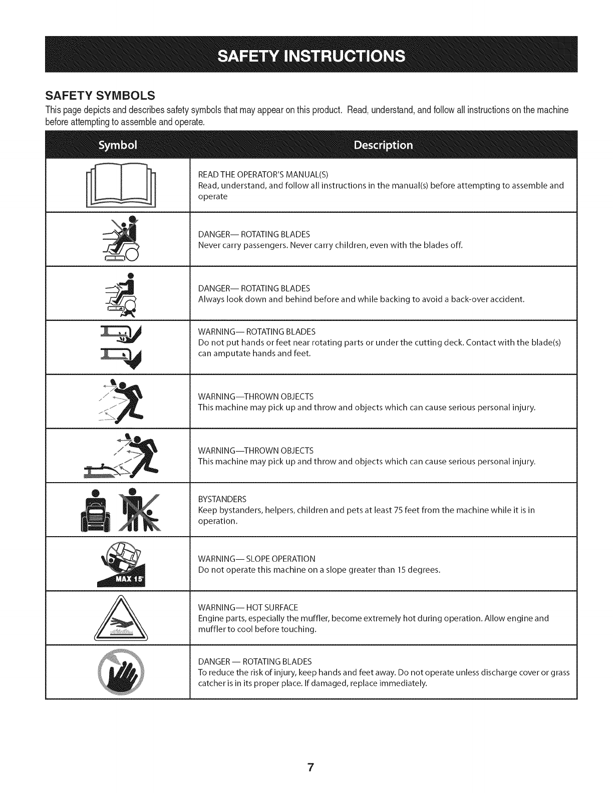
SAFETY SYMBOLS
Thispagedepictsanddescribessafetysymbolsthatmayappearonthis product. Read,understand,andfollowallinstructionson the machine
beforeattemptingto assembleandoperate.
0
A
READ THE OPERATOR'S MANUAL(S)
Read, understand, and follow all instructions in the manual(s) before attempting to assemble and
operate
DANGER-- ROTATING BLADES
Never carry passengers. Never carry children, even with the blades off.
DANGER-- ROTATING BLADES
Always look down and behind before and while backing to avoid a back-over accident.
WARNING-- ROTATING BLADES
Do not put hands or feet near rotating parts or under the cutting deck. Contact with the blade(s)
can amputate hands and feet.
WARNING--THROWN OBJECTS
This machine may pick up and throw and objects which can cause serious personal injury.
WARNING--THROWN OBJECTS
This machine may pick up and throw and objects which can cause serious personal injury.
BYSTANDERS
Keep bystanders, helpers, children and pets at least 75 feet from the machine while it is in
operation.
WARNING-- SLOPE OPERATION
Do not operate this machine on a slope greater than 15 degrees.
WARNING-- HOT SURFACE
Engine parts, especially the muffler, become extremely hot during operation. Allow engine and
muffler to cool before touching.
DANGER-- ROTATING BLADES
To reduce the risk of injury, keep hands and feet away. Do not operate unless discharge cover or grass
catcher is in its proper place. If damaged, replace immediately.
7
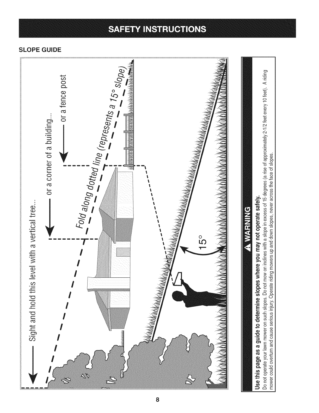
SLOPE GUIDE
}=.==
m
(=)
}====
G.)
1>
0_3
_==
(3)
OO
_==
C:)
_=
_==
0_3
=,F=_
03
_==
c_3
%,==,==
C)
}===
(1)
_==
}==,==
C)
(=3
c_3
}====
C)
_r
Or)
C;)
(=)
(==
CL)
%,==,=
c_3
}====
C)
_r
I
I
I
I
I
I
I
Dm m_
I
Ii
II
II
!I
ll
l
ll
ll
l
0c
E
Q
8
o
(....
"'O
C3,
(1)
(1)
&
1>-.
03
E
x
o
cL (1)
03 cL
o co
"_--- (D
03 O
v_
_2
--_ o
cz o
03 "o
o
_E
(-" 03
o_
CZ3cL
o__
_._o
o
8
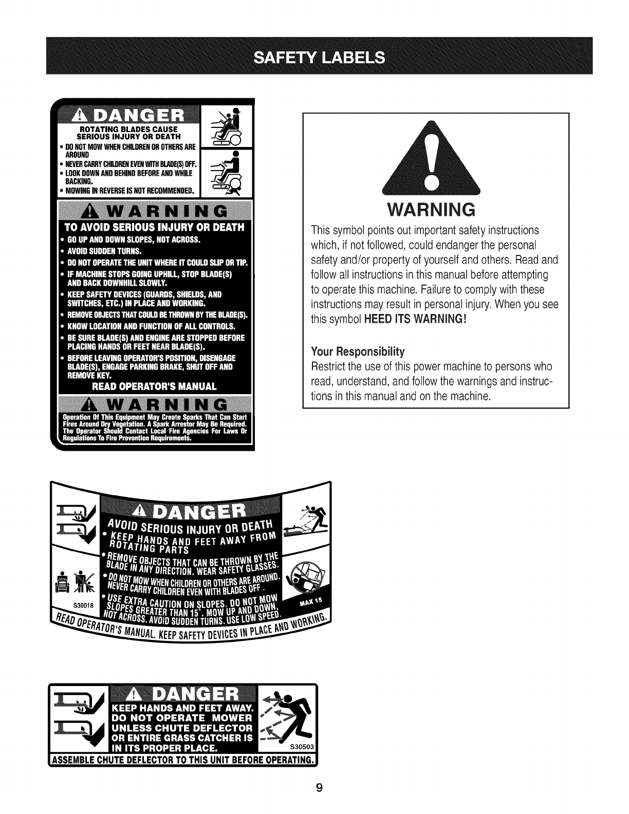
ROTATING BLADES CAUSE
SERIOUS INJURY OR DEATH
DONOTMOWWHENCHILDRENOROTHERSARE
AROUND
NEVERCARRYCHILDRENEVENWITHBLADE(S)OFF.
LOOKDOWNANDBEHINDBEFOREANDWHILE
BACKING.
MOWINGINREVERSEISNOTRECOMMENDED.
WARNING
This symbol points out important safety instructions
which, if notfollowed, could endangerthe personal
safety and/or property of yourself and others. Readand
follow all instructions inthis manual before attempting
to operatethis machine. Failureto comply with these
instructions may result in personal injury.When you see
this symbol HEED ITS WARNING!
Your Responsibility
Restrictthe use of this power machineto persons who
read, understand,and follow the warnings and instruc-
tions in this manual and on the machine.
9
IMPORTANT:Yourtractoris shippedwithmotoroil in theengine.
However,you MUSTcheckthe oil levelbeforeoperating.Referto the
Service& Maintenancesectionfor instructionson checkingtheoil
level.
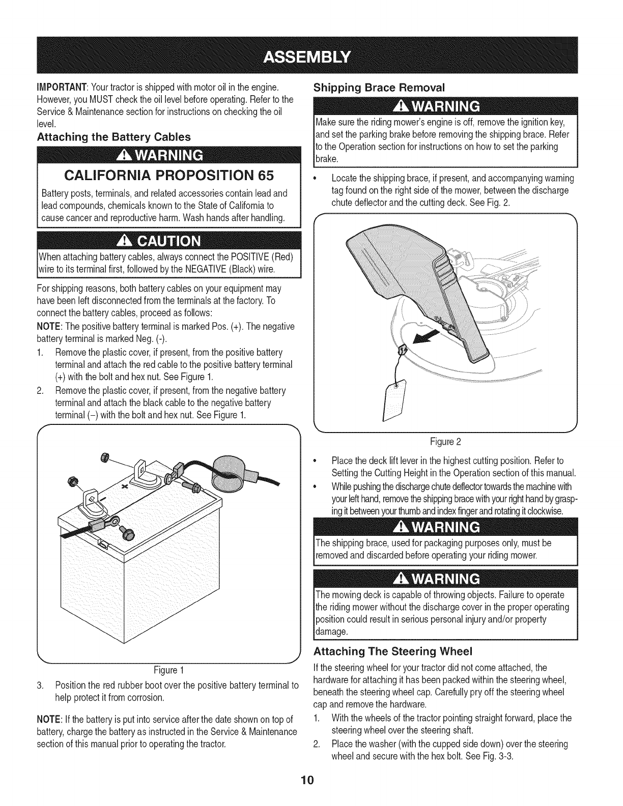
Attaching the Battery Cables
CALIFORNIA PROPOSITION 65
Batteryposts,terminals,andrelatedaccessoriescontainleadand
leadcompounds,chemicalsknownto the Stateof Californiato
causecancerandreproductiveharm.Washhandsafterhandling.
Whenattachingbatterycables,alwaysconnectthe POSITIVE(Red)
wireto its terminalfirst,followedby the NEGATIVE(Black)wire.
Forshippingreasons,bothbatterycablesonyourequipmentmay
havebeenleftdisconnectedfromthe terminalsat the factory.To
connectthe batterycables,proceedasfollows:
NOTE:Thepositivebatteryterminalis markedPos.(+).The negative
batteryterminalis markedNeg.(-).
1. Removethe plasticcover,if present,fromthe positivebattery
terminaland attachthe redcableto the positivebatteryterminal
(+)withthe bolt andhexnut.See Figure1.
2. Removethe plasticcover,if present,fromthe negativebattery
terminaland attachthe blackcableto the negativebattery
terminal(-) withthe bolt andhex nut.SeeFigure1.
f
J
Figure1
3. Positionthe redrubberboot over the positivebatteryterminalto
helpprotectit fromcorrosion.
NOTE:If thebatteryis put into serviceafterthe dateshownon topof
battery,chargethe batteryas instructedinthe Service& Maintenance
sectionof this manualpriorto operatingthe tractor.
Shipping Brace Removal
Makesurethe ridingmower'sengineis off, removetheignitionkey,
andset the parkingbrakebeforeremovingthe shippingbrace.Refer
Itothe Operationsectionfor instructionsonhowto setthe parking
lbrake.
• Locatethe shippingbrace,if present,andaccompanyingwarning
tag foundonthe rightsideof the mower,betweenthe discharge
chutedeflectorandthe cuttingdeck. SeeFig.2.
//
Figure2
Placethe decklift leverinthe highestcuttingposition.Referto
SettingtheCuttingHeightin the Operationsectionof thismanual.
Whilepushingthedischargechuteddlectortowardsthemachinewith
yourlefthand,removetheshippingbracewithyourrighthandbygrasp-
ingitbetweenyourthumbandindexfingerandrotatingitclockwise.
The shippingbrace,usedfor packagingpurposesonly,mustbe
removedand discardedbeforeoperatingyour ridingmower.
The mowingdeck iscapableof throwingobjects.Failureto operate
the ridingmowerwithoutthe dischargecoverin the properoperating
Ipositioncould resultin seriouspersonalinjuryand/orproperty
ldamage.
Attaching The Steering Wheel
Ifthe steeringwheelfor yourtractordid notcomeattached,the
hardwarefor attachingit has beenpackedwithinthe steeringwheel,
beneaththe steeringwheelcap.Carefullypry off the steeringwheel
cap andremovethe hardware.
1. Withthe wheelsof the tractorpointingstraightforward,placethe
steeringwheeloverthe steeringshaft.
2. Placethe washer(withthe cuppedsidedown)overthe steering
wheeland securewiththe hex bolt.SeeFig.3-3.
10
f
\
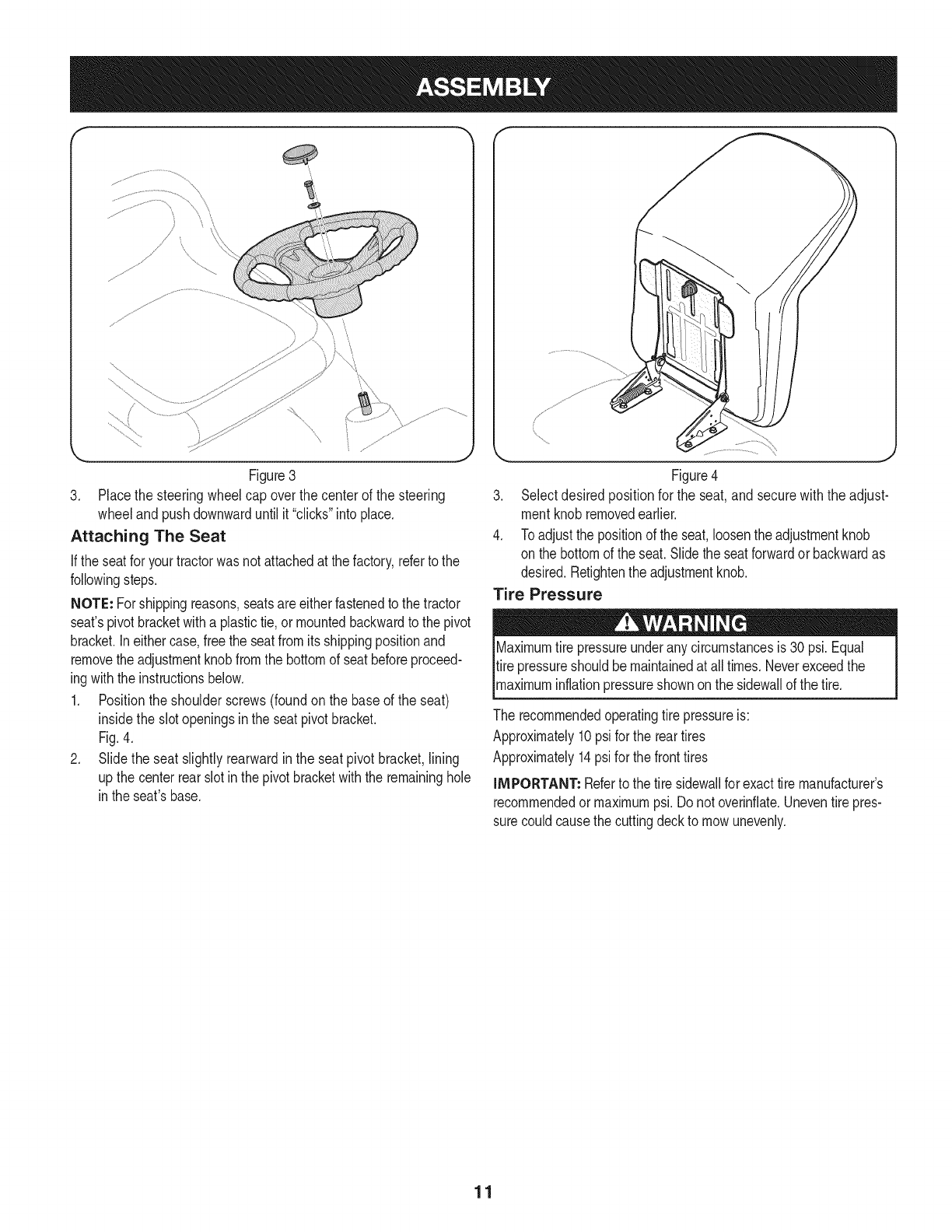
Figure3
3. Placethe steeringwheelcap overthe centerof the steering
wheeland pushdownwarduntilit "clicks"intoplace.
Attaching The Seat
If the seatfor yourtractorwasnotattachedat thefactory,refertothe
followingsteps.
NOTE: Forshippingreasons,seatsareeitherfastenedto the tractor
seat'spivotbracketwitha plastictie,or mountedbackwardto the pivot
bracket.Ineithercase,free the seatfromits shippingpositionand
removethe adjustmentknobfromthe bottomof seatbeforeproceed-
ingwith the instructionsbelow.
1. Positionthe shoulderscrews(foundon the baseof the seat)
insidethe slotopeningsinthe seatpivotbracket.
Fig.4.
2. Slidethe seat slightlyrearwardin the seatpivot bracket,lining
up the centerrearslotin thepivotbracketwiththe remaininghole
in theseat'sbase.
Figure4
3. Selectdesired positionfor the seat,and securewiththe adjust-
mentknobremovedearlier.
4. Toadjustthe positionof the seat,loosenthe adjustmentknob
on the bottomof the seat.Slidethe seatforwardor backwardas
desired.Retightenthe adjustmentknob.
Tire Pressure
X
Maximumtire pressureunderany circumstancesis 30 psi.Equal
tire pressureshouldbe maintainedat all times.Neverexceedthe
_maxmum nfat onpressureshownonthe s dewa of thet re.
The recommendedoperatingtire pressureis:
Approximately10psi forthe reartires
Approximately14psifor the fronttires
IMPORTANT: Referto the tire sidewallfor exacttire manufacturer's
recommendedormaximumpsi.Donot overinfiate.Uneventirepres-
surecouldcausethe cuttingdeckto mowunevenly.
11
B
14
A
C
G
D
F
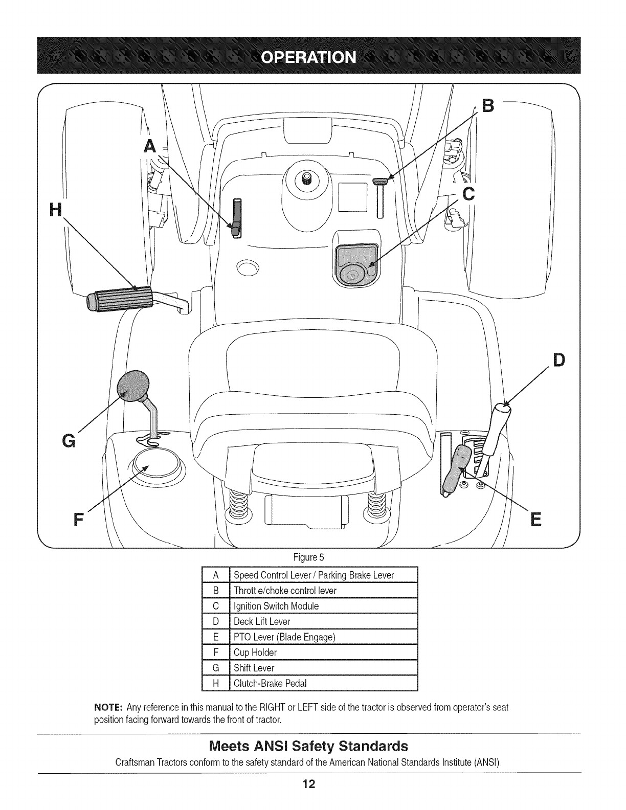
Figure5
A SpeedControlLever/ParkingBrakeLever
B Throttle/chokecontrollever
C IgnitionSwitchModule
D Deck LiftLever
E PTO Lever(BladeEngage)
F Cup Holder
G ShiftLever
H Clutch-BrakePedal
NOTE: Any referencein thismanualto the RIGHTor LEFTsideof the tractoris observedfromoperator'sseat
positionfacingforwardtowardsthe frontof tractor.
Meets ANSi Safety Standards
CraftsmanTractorsconformto the safetystandardof theAmericanNationalStandardsInstitute(ANSI).
E
J
12
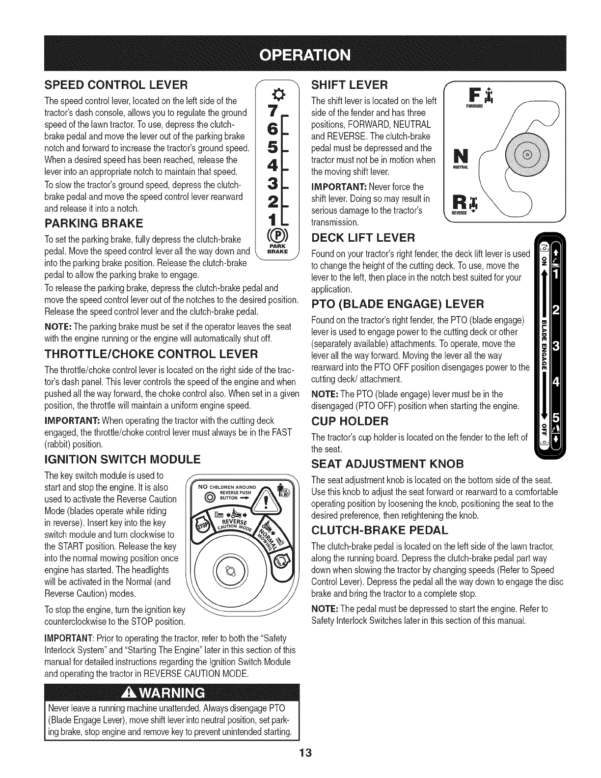
SPEED CONTROL LEVER
Thespeedcontrollever,locatedonthe left sideof the
tractor'sdashconsole,allowsyouto regulatethe ground
speedof the lawntractor.Touse,depressthe clutch-
brakepedalandmovethe leverout of the parkingbrake
notchandforwardto increasethetractor'sgroundspeed.
Whenadesiredspeedhasbeenreached,releasethe
leverintoanappropriatenotchto maintainthatspeed.
Toslowthetractor'sgroundspeed,depressthe clutch-
brakepedalandmovethe speedcontrollever rearward
andreleaseit intoa notch.
PARKING BRAKE
Tosetthe parkingbrake,fullydepressthe clutch-brake _._J
PARK
pedal.Movethe speedcontrolleverall the waydownand BRAKE
intothe parkingbrakeposition.Releasethe clutch-brake
pedalto allowthe parkingbraketo engage.
Toreleasethe parkingbrake,depressthe clutch-brakepedaland
movethe speedcontrolleveroutof the notchestothe desiredposition.
Releasethe speedcontrolleverandthe clutch-brakepedal.
NOTE: The parkingbrakemustbe setif the operatorleavesthe seat
withthe enginerunningor the enginewill automaticallyshutoff.
THROTTLE/CHOKE CONTROL LEVER
Thethrottle/chokecontrolleveris locatedon the rightsideof thetrac-
tor'sdash panel.This levercontrolsthe speedof the engineandwhen
pushedall thewayforward,the chokecontrolalso.Whensetin a given
position,the throttlewillmaintaina uniformenginespeed.
iMPORTANT: Whenoperatingthe tractorwiththe cuttingdeck
engaged,thethrottle/chokecontrollevermustalwaysbein the FAST
(rabbit)position.
IGNITION SWITCH MODULE
Thekeyswitchmoduleis usedto
startand stopthe engine.Itis also
usedto activatethe ReverseCaution
Mode(bladesoperatewhileriding
in reverse).Insertkeyinto the key
switchmoduleandturn clockwiseto
the STARTposition.Releasethe key
intothe normalmowingpositiononce
enginehas started.Theheadlights
will beactivatedin the Normal(and
ReverseCaution)modes.
Tostopthe engine,turnthe ignitionkey
counterclockwiseto the STOPposition.
CHILDREN AROUND
@
IMPORTANT:Priorto operatingthe tractor,referto boththe "Safety
InterlockSystem"and"StartingThe Engine"laterinthissectionof this
manualfor detailedinstructionsregardingthe IgnitionSwitchModule
andoperatingthe tractorinREVERSECAUTIONMODE.
Neverleavea runningmachineunattended.AlwaysdisengagePTO
(BladeEngageLever),moveshiftleverintoneutralposition,setpark-
ingbrake,stopengineandremovekeyto preventunintendedstarting.
SHIFT LEVER
The shift leveris locatedonthe left
sideof the fenderand hasthree
positions,FORWARD,NEUTRAL
and REVERSE.Theclutch-brake
pedalmustbedepressedandthe
tractormustnot be inmotionwhen
the movingshift lever.
iMPORTANT: Neverforcethe
shiftlever.Doingso mayresultin
seriousdamageto the tractor's
transmission.
DECK LIFT LEVER
Foundonyour tractor'srightfender,the deckliftleveris used
to changethe heightof the cuttingdeck.To use,movethe
leverto the left, thenplacein the notchbestsuitedfor your
application.
PTO (BLADE ENGAGE) LEVER
Foundonthe tractor'srightfender,the PTO(bladeengage)
leveris usedto engagepowerto the cuttingdeckorother
(separatelyavailable)attachments.Tooperate,movethe
leverall thewayforward.Movingthe leverallthe way
rearwardinto the PTOOFFpositiondisengagespowerto the
cuttingdeck/attachment.
NOTE: The PTO(bladeengage)levermustbe inthe
disengaged(PTOOFF)positionwhenstartingthe engine.
CUP HOLDER
The tractor'scup holderis locatedon the fenderto the left of
the seat.
SEAT ADJUSTMENT KNOB
The seatadjustmentknob is locatedonthe bottomsideof the seat.
Usethisknob to adjustthe seatforwardor rearwardto a comfortable
operatingpositionby looseningthe knob,positioningthe seatto the
desiredpreference,thenretighteningthe knob.
CLUTCH-BRAKE PEDAL
The clutch-brakepedalis locatedonthe left sideof the lawntractor,
alongthe runningboard.Depressthe clutch-brakepedalpart way
downwhenslowingthe tractorbychangingspeeds(Referto Speed
ControlLever).Depressthe pedalall the waydownto engagethe disc
brakeandbringthe tractorto a completestop.
NOTE: The pedalmustbe depressedto startthe engine.Referto
SafetyInterlockSwitcheslaterin thissectionof thismanual.
13
Gas and Oil Fill=up
0il
iMPORTANT: Yourtractorisshippedwithmotoroil inthe engine.
However,you MUSTcheckthe oil levelbeforeoperating.Becareful
notto overfill.
Forinstructionsonhowto checkthe engineoil, referto CheckingThe
EngineOilin the ServiceandMaintenancesectionof this manual.
Gasoline
Thegasolinetankis locatedunderthe hood.Do notoverfill.
Useextremecarewhenhandlinggasoline.Gasolineis extremely
flammableandthe vaporsareexplosive.Neverfuel machineindoors
orwhilethe engineis hotor running.Extinguishcigarettes,cigars,
[ppes,andothersourcesof gn t on.
NOTE : Purchasegasolineinsmallquantities.Do notuse gasolineleft
overfromthe previousseason,to minimizegumdepositsin the fuel
system.
• Thisengineis certifiedto operateon unleadedgasoline.For best
results,fill the fueltankwithonlyclean,fresh,unleadedgasoline
witha pumpstickeroctaneratingof 87or higher.
• Gasohol(upto 10%ethylalcohol,90%unleadedgasolineby
volume)is anapprovedfuel.Othergasoline/alcoholblends,such
as E85,arenot approved.
• MethylTertiaryButylEther(MTBE)andunleadedgasolineblends
(upto a maximumof 15%MTBEby volume)are approvedfuels.
Othergasoline/etherblendsare notapproved.
• Fillfuel tankoutdoorsorin well-ventilatedarea.
• Do notoverfillfuel tank. Filltankto no morethan 1/2inch below
bottomof filler neckto allowspacefor fuel expansion.
• Neverremovegas capor addfuel whilethe engineis hot or run-
ning.Allowengineto cool at leasttwo minutesbeforerefueling.
• Ifgasolineis spilled,wipe it off theengineandequipment.Move
machineto anotherarea.Wait5 minutesbeforestartingthe
engine.
To Add Gasoline
1. Turnthe engineoff andlet enginecool at least2 minutesbefore
removingthe fuelcap.The gasolinetankis underthe rearfender,
withthefuel fill cap locatedinthe centerof the rearfender.
Thefuel cap is tetheredto the tractorto preventitsloss. Donot
attemptto removethe cap fromthe tractor.
2. Fillthe fuel tankwithgasoline.
3. Reinstallthe fuelcap.
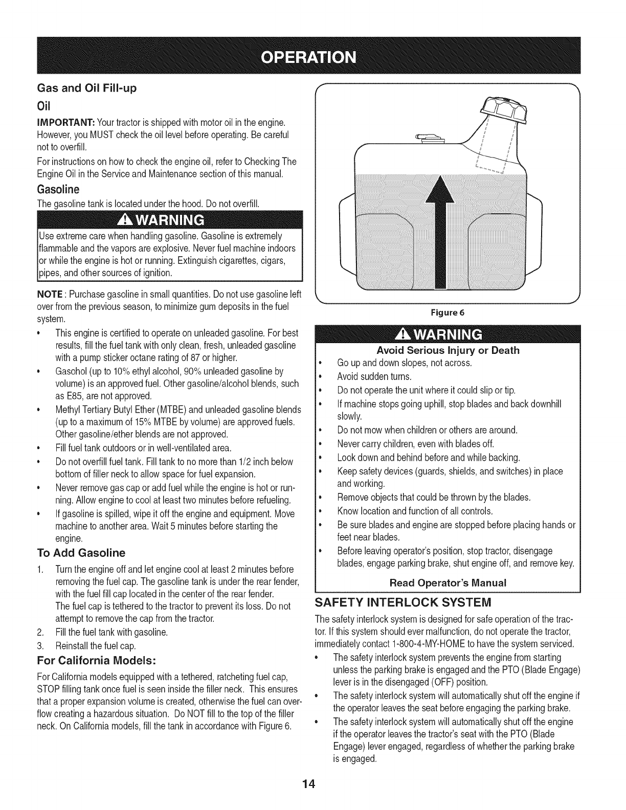
For California Models:
ForCaliforniamodelsequippedwitha tethered,ratchetingfuelcap,
STOPfillingtankonce fuelis seeninsidethe filler neck. Thisensures
thata properexpansionvolumeis created,otherwisethefuel canover-
flowcreatinga hazardoussituation. Do NOTfill to the top of the filler
neck.On Californiamodels,fill thetank inaccordancewith Figure6.
Figure6
Avoid Serious injury or Death
• Go upanddownslopes,notacross.
•Avoidsuddenturns.
•Donot operatethe unitwhereit could slipor tip.
• Ifmachinestopsgoinguphill,stopbladesand backdownhill
slowly.
• Donot mowwhenchildrenorothersare around.
• Nevercarrychildren,evenwith bladesoff.
• Lookdownand behindbeforeandwhilebacking.
• Keepsafetydevices(guards,shields,and switches)inplace
andworking.
• Removeobjectsthat couldbethrownby the blades.
• Knowlocationandfunctionof all controls.
• Besurebladesandenginearestoppedbeforeplacinghandsor
feetnearblades.
• Beforeleavingoperator'sposition,stoptractor,disengage
blades,engageparkingbrake,shutengineoff, and removekey.
Read Operator's Manual
SAFETY INTERLOCK SYSTEM
The safetyinterlocksystemis designedfor safeoperationof the trac-
tor.If thissystemshouldevermalfunction,donot operatethe tractor,
immediatelycontact1-800-4-MY-HOMEto havethe systemserviced.
• The safetyinterlocksystempreventsthe enginefromstarting
unlessthe parkingbrakeis engagedandthe PTO(BladeEngage)
leveris inthe disengaged(OFF)position.
• The safetyinterlocksystemwill automaticallyshutoffthe engineif
the operatorleavesthe seatbeforeengagingthe parkingbrake.
• The safetyinterlocksystemwill automaticallyshutoffthe engine
if theoperatorleavesthe tractor'sseatwiththe PTO(Blade
Engage)leverengaged,regardlessof whetherthe parkingbrake
is engaged.
14
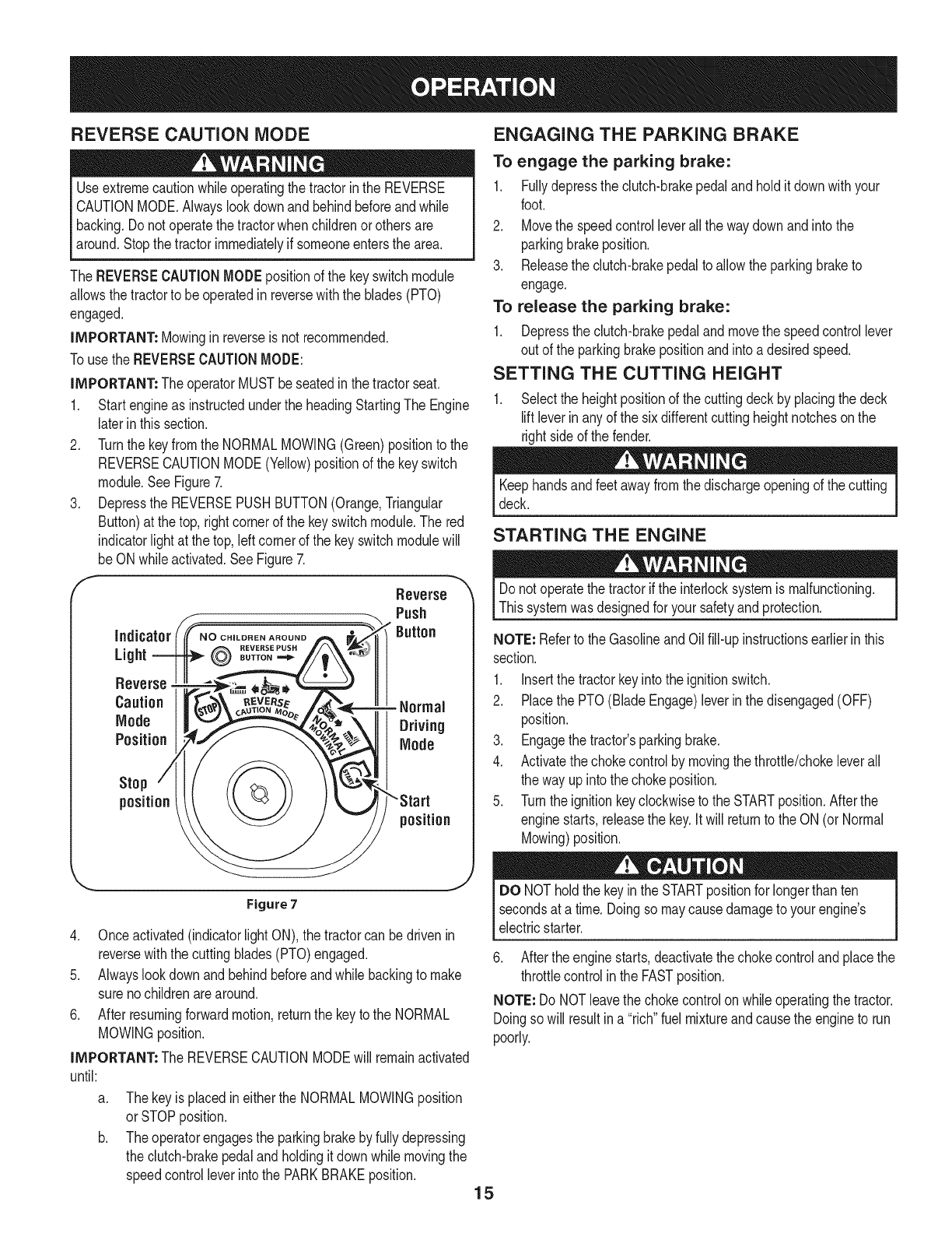
REVERSE CAUTION MODE
Useextremecautionwhileoperatingthetractorinthe REVERSE
CAUTIONMODE.Alwayslookdownand behindbeforeandwhile
backing.Do notoperatethe tractorwhenchildrenor othersare
around.Stopthe tractorimmediatelyif someoneentersthe area.
The REVERSECAUTIONMODEpositionof the keyswitchmodule
allowsthe tractorto beoperatedinreversewiththe blades(PTO)
engaged.
iMPORTANT: Mowinginreverseisnot recommended.
Touse the REVERSECAUTIONMODE:
iMPORTANT: The operatorMUSTbeseatedinthe tractorseat.
1. Startengineas instructedunderthe headingStartingThe Engine
laterinthissection.
2. Turnthe keyfromthe NORMALMO%NG (Green)positionto the
REVERSECAUTIONMODE(Yellow)positionof the keyswitch
module.SeeFigure7.
3. Depressthe REVERSEPUSHBUTTON(Orange,Triangular
Button)at the top,rightcornerof the keyswitchmodule.The red
indicatorlight at the top,leftcornerof the keyswitchmodulewill
beON whileactivated.SeeFigure7.
f Reverse
Push
Button
indicator
REVERSE PUSH
Light BUTTON--'_
Reverse
Caution - Normal
Mode Driving
Position Mode
Stop
position
position
Figure 7
4. Onceactivated(indicatorlightON),the tractorcan bedrivenin
reversewiththe cuttingblades(PTO)engaged.
5. Alwayslookdownand behindbeforeandwhilebackingto make
surenochildrenarearound.
6. Afterresumingforwardmotion,returnthe keyto the NORMAL
MO%NG position.
iMPORTANT: The REVERSECAUTIONMODEwill remainactivated
until:
a. Thekeyisplacedineitherthe NORMALMO%NGposition
orSTOPposition.
Theoperatorengagesthe parkingbrakeby fullydepressing
the clutch-brakepedalandholdingit downwhilemovingthe
speedcontrolleverintothe PARKBRAKEposition.
ENGAGING THE PARKING BRAKE
To engage the parking brake:
1. Fullydepressthe clutch-brakepedaland holditdownwithyour
foot.
2. Movethe speedcontrolleverall the waydownandintothe
parkingbrakeposition.
3. Releasethe clutch-brakepedalto allowthe parkingbraketo
engage.
To release the parking brake:
1. Depressthe clutch-brakepedaland movethe speedcontrollever
out of the parkingbrakepositionandintoadesiredspeed.
SETTING THE CUTTING HEIGHT
1. Selectthe heightpositionof the cuttingdeckby placingthe deck
liftleverin anyof the sixdifferentcutting heightnotchesonthe
rightsideof the fender.
Keephandsandfeetawayfromthe dischargeopeningof the cutting
deck.
STARTING THE ENGINE
Donot operatethe tractorif the interlocksystemis malfunctioning.
Thissystemwasdesignedfor yoursafetyand protection.
NOTE: Referto the GasolineandOilfill-up instructionsearlierin this
section.
1. Insertthe tractorkeyintothe ignitionswitch.
2. Placethe PTO(BladeEngage)leverin thedisengaged(OFF)
position.
3. Engagethe tractor'sparkingbrake.
4. Activatethechokecontrolby movingthethrottle/chokeleverall
the wayupinto thechokeposition.
5. Turnthe ignitionkeyclockwiseto the STARTposition.Afterthe
enginestarts,releasethe key.Itwill returnto the ON(or Normal
Mowing)position.
DO NOTholdthe keyinthe STARTpositionfor longerthan ten
secondsat a time. Doingso maycausedamageto your engine's
electricstarter.
6. Afterthe enginestarts,deactivatethe chokecontrolandplacethe
throttlecontrolin the FASTposition.
NOTE: Do NOTleavethe chokecontrolon whileoperatingthe tractor.
Doingso will resultina "rich"fuel mixtureandcausetheengineto run
poorly.
15
STOPPING THE ENGINE
If youstrikea foreignobject,stopthe engine,disconnectthe spark
plugwire(s)andgroundagainstthe engine.Thoroughlyinspectthe
machinefor anydamage.Repairthe damagebeforerestartingand
operating
1. Ifthe bladesareengaged,placethe PTO(BladeEngage)leverin
thedisengaged(OFF)position.
2. Turnthe ignitionkeycounterclockwiseto the STOPposition.
3. Removethe keyfromthe ignitionswitchto preventunintended
starting.
DRIVING THE TRACTOR
Avoidsuddenstarts,excessivespeedandsuddenstops.
Do notleavethe seatof thetractorwithoutfirstplacingthe PTO
(BladeEngage)leverinthe disengaged(OFF)position,depressing
I the brakepedalandengagingthe parkingbrake.Ifleavingthe tractor
[ unattended,alsoturn the ignitionkeyoffand removethe key.
Alwayslookdownandbehindbeforeandwhilebackingupto avoida
back-overaccident.
1. Depressthe clutch-brakepedalto releasethe parkingbrakeand
thenlet the pedalup.
2. Movethe throttleleverintothe FAST(rabbit)position.
3. Placethe shiftleverineitherthe FORWARDor REVERSE
position.
IMPORTANT: Do NOTusethe shift leverto changethe directionof
travelwhenthe tractorisin motion.Alwaysusethe clutch-brakepedal
to bringthetractorto a completestopbeforeshifting.
4. Releasethe parkingbrakeby depressingthe clutch-brakepedal
andpositioningthe speedcontrolleverinthe desiredposition.
IMPORTANT: First-timeoperatorsshouldusespeedpositions1or
2. Becomecompletelyfamiliarwiththe tractor'soperationandcontrols
beforeoperatingthe tractorinhigherspeedpositions.
5. Releaseclutch-brakepedalslowlyto put unit intomotion.
6. The lawntractoris broughtto a stopbydepressingthe clutch-
brakepedal.
NOTE: Whenoperatingthe unit initially,therewill be littledifference
betweenthe highesttwospeedsuntil afterthe beltshaveseated
themselvesintothe pulleysduringthe break-inperiod.
WARNING!Beforeleavingthe operator'spositionfor any reason,
disengagethe blades,placethe shift leverinneutral,engagethe
parkingbrake,shutengineoff andremovethe key.
IMPORTANT: Whenstoppingthe tractorfor any reasonwhileona
grasssurface,always:
1. Placethe shift leverinneutral,
2. Engagethe parkingbrake,
3. Shutengineoffand removethe key.Doingso will minimizethe
possibilityof havingyour lawn"browned"byhot exhaustfrom
yourtractor'srunningengine.
Ifunit stallswithspeedcontrolinhighspeed,orif unitwill not operate
withspeedcontrolleverin a lowspeedposition,proceedas follows:
1. Placeshift leverinNEUTRAL.
2. Restartengine.
3. Placespeedcontrolleverinhighestspeedposition.
4. Releaseclutch-brakepedalfully.
5. Depressclutch-brakepedal.
6. Placespeedcontrolleverindesiredposition.
7. Placeshift leverineither FORWARDor REVERSE,andfollow
normaloperatingprocedures.
DRIVING ON SLOPES
Referto the SLOPEGAUGEinthe SafetyInstructionssectionof the
manualto helpdetermineslopeswhereyoumayoperatethistractor
safely.
Donot mowon inclineswitha slopeinexcessof 15degrees(a rise
of approximately2-1/2feetevery10feet).The tractorcouldoverturn
andcauseseriousinjury.
• Mowupanddown slopes,NEVERacross.
• Exerciseextremecautionwhenchangingdirectionon slopes.
• Watchfor holes,ruts,bumps,rocks,orother hiddenobjects.
Uneventerraincouldoverturnthe machine.Tallgrasscan hide
obstacles.
• Avoidturnswhendrivingon a slope.If a turnmustbe made,turn
downthe slope.Turningupa slopegreatlyincreasesthe chance
of a rollover.
• Avoidstoppingwhendrivingup a slope.If itis necessaryto stop
whiledrivingupa slope,start upsmoothlyandcarefullyto reduce
the possibilityof flippingthe tractoroverbackward.
ENGAGING THE BLADES
Engagingthe PTO(BladeEngage)transferspowerto the cuttingdeck
or other(separatelyavailable)attachments.To engagethe blades,
proceedasfollows:
1. Movethethrottle/chokecontrolleverto the FAST(rabbit)position.
2. Graspthe PTO(BladeEngage)leverandpivotit all theway
forwardinto theengaged(ON) position.
3. Keepthethrottleleverinthe FAST(rabbit)positionfor the most
efficientuseof the cuttingdeckorother(separatelyavailable)
attachments.
NOTE: The enginewill automaticallyshutoff if the PTOisengaged
withthe shift leverinpositionfor reversetravelwiththe ignitionkeyin
the NORMALMOWINGposition.
MULCHING
A mulch kit isavailableasan attachment.Mulching isa processof
recirculating grass clippings repeatedly beneath the cutting deck.
The ultra-fineclippings are then forcedbackinto the lawnwhere
they act asa naturalfertilizer.
16
A mulchkit canbe purchased,Seethe ReplacementParts& Attach-
mentssectionof this manualfor moreinformation.
USING THE DECK LIFT LEVER
Toraisethe cuttingdeck,movethe decklift levertothe left,then place
it in the notchbestsuitedfor yourapplication.Referto SettingThe
CuttingHeightearlierinthis Operationsection.
MOWING
Tohelpavoidbladecontactor a thrownobjectinjury,keepbystand-
ers,helpers,childrenandpetsat least75feetfromthe machine
whileit is inoperation.Stop machineif anyoneentersthearea.
Thefollowinginformationwill behelpfulwhenusingthe cuttingdeck
withyourtractor:
Planyour mowingpatternto avoiddischargeof materialstoward
roads,sidewalks,bystandersandthe like.Also,avoiddischarging
materialagainsta wallor obstructionwhichmaycausedischarged
materialto ricochetbacktowardthe operator.
HEADLIGHTS
•The lampsare ONwheneverthe tractor'sengineis running.
• The lampsturn OFFwhenthe ignitionkeyis movedto the STOP
position.
• Do not mowat highgroundspeed,especiallyif a mulchkitor
grasscollectoris installed.
• For bestresultsit is recommendedthatthe firsttwolaps becut
withthe dischargethrowntowardsthe center.Afterthe first two
laps,reversethe directionto throwthe dischargeto the outside
for the balanceof cutting.Thiswill givea betterappearanceto the
lawn.
• Do notcut thegrasstoo short.Shortgrassinvitesweedgrowth
andyellowsquicklyindry weather.
• Mowingshouldalwaysbedonewiththe engineat full throttle.
• Underheavierconditionsit may benecessaryto go backoverthe
cutareaa secondtimeto geta cleancut.
• Do NOTattemptto mowheavybrushandweedsandextremely
tall grass.Yourtractoris designedto mowlawns,NOTclear
brush.
• Keepthe bladessharpandreplacethe bladeswhenworn.Refer
to CuttingBladesin the Servicesectionof this manualfor proper
bladesharpeninginstructions.
17
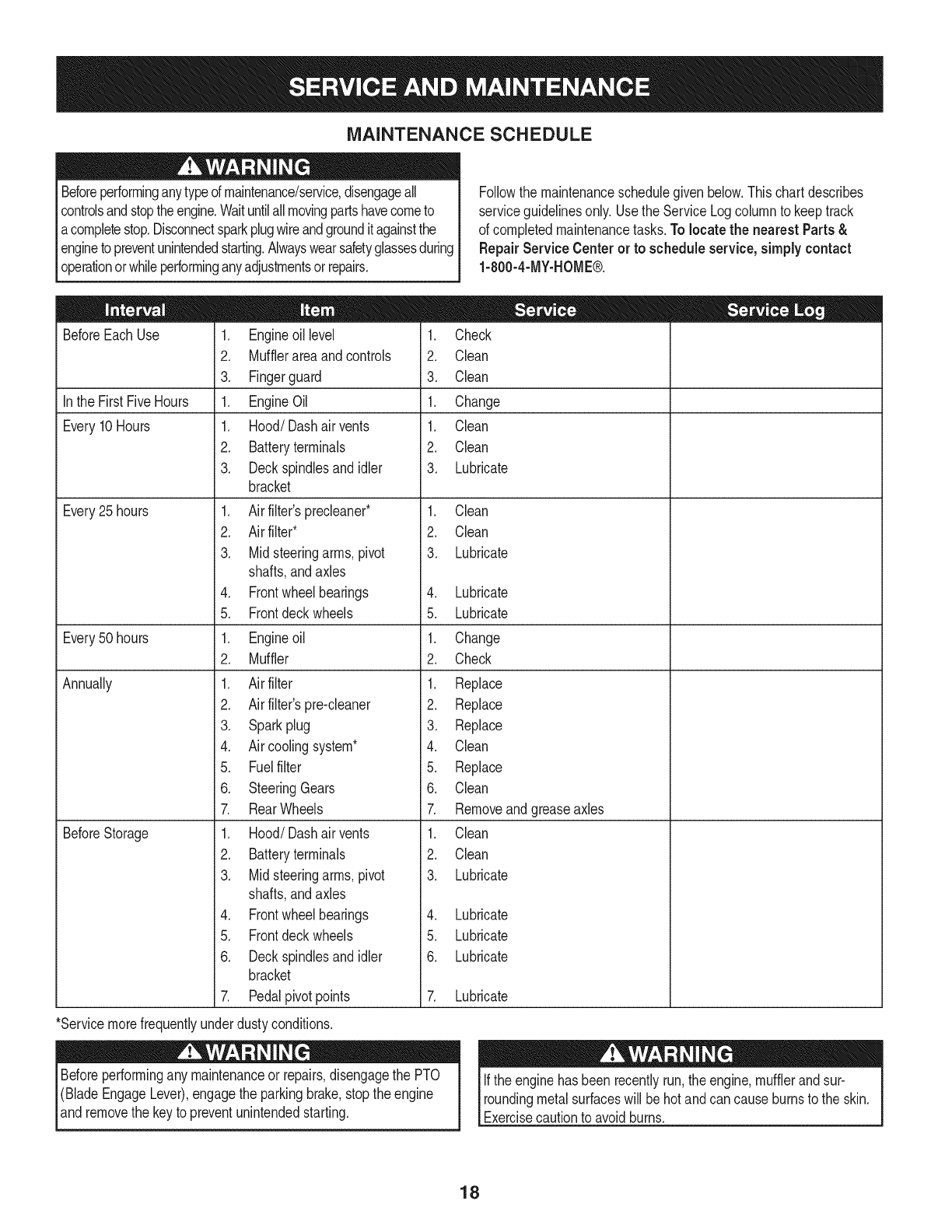
MAINTENANCE SCHEDULE
Beforeperforminganytypeof maintenance/service,disengageall
controlsandstoptheengine.Waituntilallmovingpartshavecometo
acompletestop.Disconnectsparkplugwireandgrounditagainstthe
enginetopreventunintendedstarting.Alwayswearsafetyglassesduring
operationor whileperforminganyadjustmentsor repairs.
Followthe maintenanceschedulegivenbelow.Thischartdescribes
serviceguidelinesonly.Usethe ServiceLogcolumnto keeptrack
of completedmaintenancetasks.To locate the nearest Parts&
Repair Service Centeror to scheduleservice,simplycontact
1-800-4-MY-HOME®.
BeforeEachUse
In the FirstFiveHours
Every10Hours
Every25 hours
Every50 hours
Annually
BeforeStorage
1. Engineoil level
2. Mufflerareaandcontrols
3. Fingerguard
1. EngineOil
1. Hood/Dashairvents
2. Batteryterminals
3. Deckspindlesand idler
bracket
1. Air filter'sprecleaner*
2. Air filter*
3. Midsteeringarms,pivot
shafts,andaxles
4. Frontwheelbearings
5. Frontdeckwheels
1. Engineoil
2. Muffler
1. Air filter
2. Air filter'spre-cleaner
3. Sparkplug
4. Air coolingsystem*
5. Fuelfilter
6. SteeringGears
7. RearWheels
1. Hood/Dashairvents
2. Batteryterminals
3. Midsteeringarms,pivot
shafts,andaxles
4. Frontwheelbearings
5. Frontdeckwheels
6. Deckspindlesand idler
bracket
7. Pedalpivotpoints
1. Check
2. Clean
3. Clean
1. Change
1. Clean
2. Clean
3. Lubricate
1. Clean
2. Clean
3. Lubricate
4. Lubricate
5. Lubricate
1. Change
2. Check
1. Replace
2. Replace
3. Replace
4. Clean
5. Replace
6. Clean
7. Removeandgreaseaxles
1. Clean
2. Clean
3. Lubricate
4. Lubricate
5. Lubricate
6. Lubricate
7. Lubricate
*Servicemorefrequentlyunderdustyconditions.
Beforeperformingany maintenanceor repairs,disengagethe PTO
(BladeEngageLever),engagethe parkingbrake,stopthe engine
and removethe keyto preventunintendedstarting.
Ifthe enginehasbeen recentlyrun,the engine,mufflerandsur-
roundingmetalsurfaceswill behotand cancauseburnsto the skin.
Exercisecautionto avoidburns.
18
ENGINE MAINTENANCE
Checking the Engine Oil
Onlyuse highqualitydetergentoil ratedwithAPIserviceclassification
SF,SG,SH,or SJ, Selectthe oil's SAEviscositygradeaccordingto
the expectedoperatingtemperature.Followthe chartbelow.
Althoughmulti-viscosityoils (5W20,10W30,etc.)improvestarting
in coldweather,theywill resultinincreasedoil consumptionwhen
usedabove32°RCheckyour engineoillevelmorefrequentlyto avoid
possibleenginedamagefromrunninglowonoil.
f'_older 32°F _Warmer_
,_. Oil Viscosity Chart j
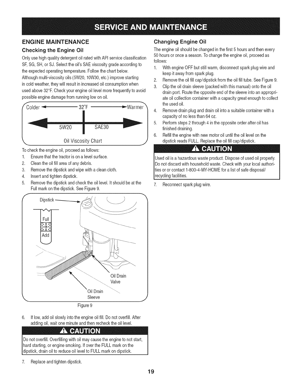
Tocheckthe engineoil, proceedas follows:
1. Ensurethatthe tractoris ona levelsurface.
2. Cleantheoil fill areaof anydebris.
3. Removethedipstickandwipe withaclean cloth.
4. Insertandtightendipstick.
5. Removethedipstickandcheckthe oil level.It shouldbeat the
Fullmarkonthe dipstick.SeeFigure9.
f
Dipstick_
Changing Engine Oil
The engineoil shouldbechangedinthe first 5 hoursand thenevery
50 hoursoronce a season.Tochangethe engineoil, proceedas
follows:
1. WithengineOFFbut stillwarm,disconnectsparkplugwireand
keepit awayfromsparkplug.
2. Removethe oilfill cap/dipstickfromtheoil fill tube.SeeFigure9.
3. Clipthe oildrainsleeve(packedwiththis manual)ontothe oil
drainport. Routethe oppositeendof the sleeveintoanappropri-
ate oilcollectioncontainerwitha capacitygreatenoughto collect
the usedoil.
4. Removedrainpluganddrainoil intoa suitablecontainerwitha
capacityof nolessthan64 oz.
5. Performsteps2 through4 inthe oppositeorderafteroil has
finisheddraining.
6. Refillthe enginewithnewmotoroil untilthe oil levelonthe
dipstickreadsFULL.Replacetheoil fill cap/dipstick.
Usedoil isa hazardouswasteproduct.Disposeof usedoil properly.
Do notdiscardwithhouseholdwaste.Checkwithyour localauthori-
ties oror contact1-800-4-MY-HOMEfor alist of safedisposal/
recyclingfacilities.
7. Reconnectsparkplugwire.
OilDrain
Valve
Oil Drain
Sleeve
Figure9
6. If low,addoil slowlyintothe engineoilfill. Do notoverfill.After
addingoil, waitone minuteand then recheckthe oil level.
Donotoverfill.Overfillingwithoil maycausethe engineto not start,
hardstarting,orenginesmoking.If overthe FULLmarkonthe
dipstick,drainoil to reduceoil levelto FULLmarkondipstick.
7. Replaceandtightendipstick.
19
Fuel Filter Air Cleaner
Gasolineand itsvaporsareextremelyflammableandexplosive.Fire
orexplosioncan causesevereburnsor death.
• Keepgasolineawayfromsparks,openflames,pilotlights,heat,
andotherignitionsources.
• Checkfuel lines,tank,cap,andfittingsfrequentlyforcracksor
leaks.Replaceif necessary.
• Beforereplacingthe fuelfilter,drainthe fueltankas perthe
instructionsbelow.
• Do notdrainfuel whenthe engineishot.Allowthe engine
adequatetimeto cool. Drainfuel intoan approvedcontainer
outdoors,awayfromopenflame.
• Drainanylargevolumeof fuelfromthe tankby disconnectingthe
fuel linefromthe in-linefuelfilterneartheengine.
• Removethe fuel linefromthe In-lineside (sidetowardsthe fuel
tank)of thefuel filter.
• Replacementpartsmustbethe sameand installedin the same
positionas theoriginalparts.
• Iffuel spills,waituntil itevaporatesbeforestartingengine.
• Beforereplacingthe fuelfilter,drainthe fueltank. Otherwisefuel
can leakout andcausea fireor explosion.
ToDrainthe fuel:
1. Locatethefuelfilter,whichis routedonthe leftsideofthe engine
betweenthe fueltankandthe carburetor,andmaybeattachedto
theenginewitha tie strap.Cutthetie strap,ifpresent,then pinch
thein-lineclamponthefuelfilterwitha pairof pliers,slidethe
clampupthefuelline.Pullthe fuellinefreefromthefilterandplace
theopenendof the lineintoanapprovedcontainerto drainthefuel.
Tochangethe fuel filter:
1. Usepliersto squeezethe tabsonthe otherclamp(theout-line
sideof the fuel filter),thenslidethe clampawayfromthe fuel filter.
Twistandpull the fuellineoff of the fuelfilter.SeeFigure10.
2. Checkthe fuel linesfor cracksor leaks.Replaceif necessary.
3. Replacethe fuel filterwithan originalequipmentreplacement
filter.Call1-800-4-MY-HOME®to purchasethe originalequip-
mentreplacementfilter.
4. Securethe fuel lineswiththe clamps.
Iffilters,or coversare notinstalledcorrectlyseriousinjuryordeath
could resultfrombackfire.Do notattemptto startthe enginewith
themremoved.
Donot use pressurizedairor solventsto cleantheair cleaner
cartridge.
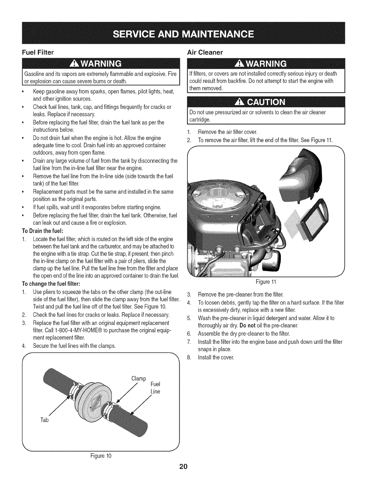
1. Removethe airfiltercover.
2. To removethe airfilter,liftthe endof thefilter.SeeFigure11.
f
Figure11
3. Removethe pre-cleanerfromthe filter.
4. To loosendebris,gentlytapthe filteron a hardsurface.If thefilter
is excessivelydirty,replacewitha newfilter.
5. Washthe pre-cleanerinliquiddetergentandwater.Allowitto
thoroughlyair dry.Donot oilthe pre-cleaner.
6. Assemblethe dry pre-cleanerto the filter.
7. Installthe filterintothe enginebaseand pushdown untilthe filter
snapsin place.
8. Installthe cover.
Tab
Clamp Fuel
Line
Figure10
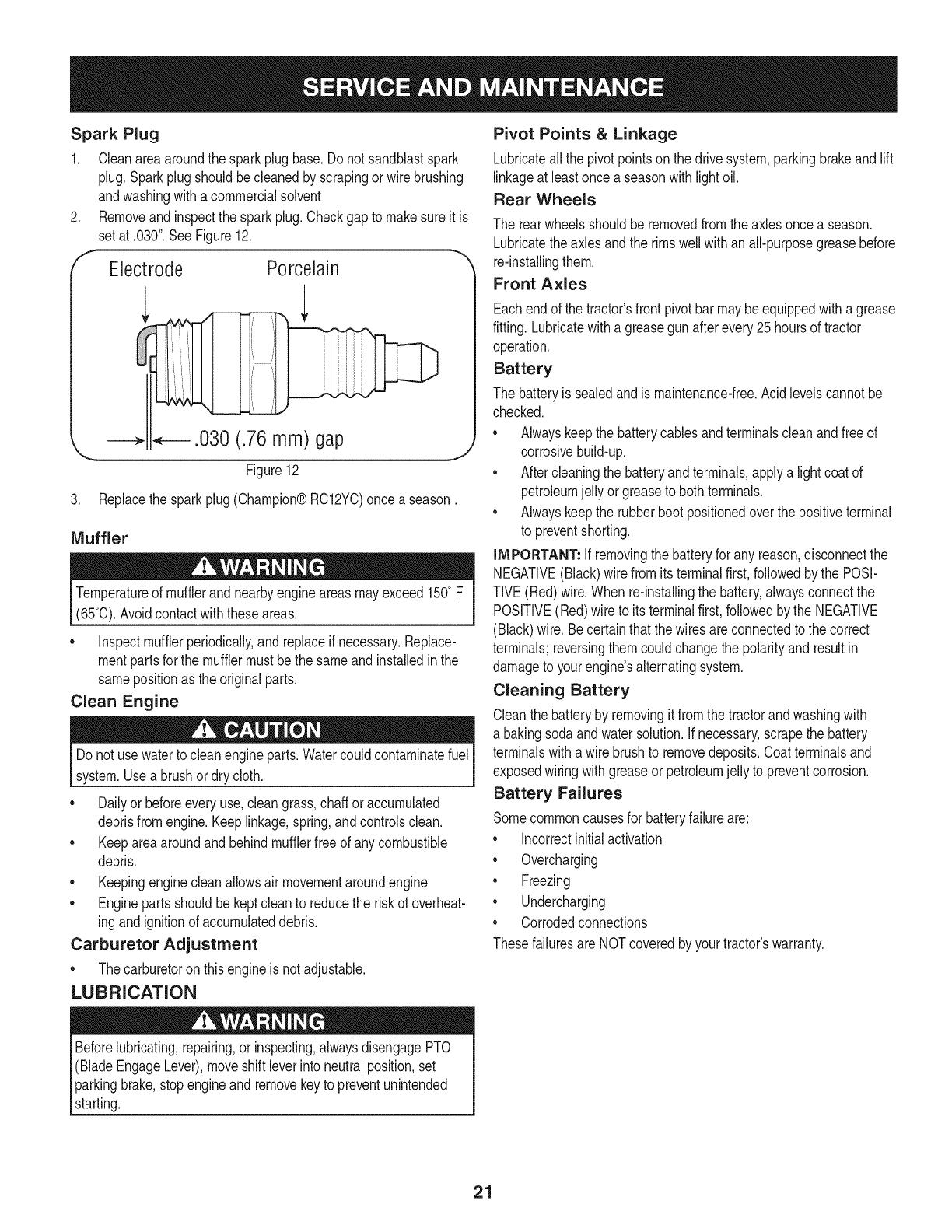
Spark Plug
1. Cleanareaaroundthe sparkplugbase.Do notsandblastspark
plug,Sparkplugshouldbecleanedby scrapingorwire brushing
andwashingwitha commercialsolvent
Removeandinspectthe sparkplug.Checkgap to makesureit is
setat .030".See Figure12.
Electrode Porcelain
_.030 (.76 mm) gap
\
Figure12
3. Replacethesparkplug(Champion®RC12YC)once a season.
Muffler
Temperatureof mufflerandnearbyengineareasmayexceed150° F
(65°0).Avoidcontactwiththeseareas.
•inspectmufflerperiodically,and replaceif necessary.Replace-
mentpartsfor the mufflermustbethe sameand installedin the
samepositionas the originalparts.
Clean Engine
Do notuse waterto cleanengineparts.Watercouldcontaminatefuel
system.Usea brushordry cloth.
Dailyor beforeeveryuse,cleangrass,chaff oraccumulated
debrisfromengine.Keeplinkage,spring,andcontrolsclean.
Keepareaaroundandbehindmufflerfreeof any combustible
debris.
Keepingenginecleanallowsair movementaroundengine.
• Enginepartsshouldbe keptcleanto reducethe riskof overheat-
ingandignitionof accumulateddebris.
Carburetor Adjustment
• Thecarburetoron thisengineis not adjustable.
LUBRICATION
Beforelubricating,repairing,or inspecting,alwaysdisengagePTO
(BladeEngageLever),moveshift leverinto neutralposition,set
parkingbrake,stopengineand removekeyto preventunintended
starting.
Pivot Points &Linkage
Lubricateallthe pivotpointsonthe drivesystem,parkingbrakeandlift
linkageat leastonce a seasonwithlightoil.
Rear Wheels
The rearwheelsshouldberemovedfromtheaxlesoncea season.
Lubricatetheaxlesandthe rimswellwithan all-purposegreasebefore
re-installingthem.
Front Axles
Eachend of thetractor'sfrontpivotbar maybeequippedwitha grease
fitting.Lubricatewitha greasegunafterevery25hoursof tractor
operation.
Battery
The batteryis sealedandis maintenance-free.Acidlevelscannotbe
checked.
Alwayskeepthe batterycablesandterminalscleanandfree of
corrosivebuild-up.
Aftercleaningthe batteryandterminals,applya lightcoatof
petroleumjelly orgreaseto bothterminals.
Alwayskeepthe rubberbootpositionedoverthe positiveterminal
to preventshorting.
iMPORTANT: if removingthe batteryfor any reason,disconnectthe
NEGATIVE(Black)wirefromitsterminalfirst,followedby the POSi-
TIVE(Red)wire.When re-installingthe battery,alwaysconnectthe
POSITIVE(Red)wire to its terminalfirst,followedbythe NEGATIVE
(Black)wire.Becertainthatthe wiresareconnectedto the correct
terminals;reversingthemcouldchangethe polarityandresultin
damageto yourengine'salternatingsystem.
Cleaning Battery
Cleanthe batteryby removingit fromthe tractorandwashingwith
a bakingsodaandwatersolution.Ifnecessary,scrapethe battery
terminalswitha wirebrushto removedeposits.Coatterminalsand
exposedwiringwithgreaseor petroleumjellyto preventcorrosion.
Battery Failures
Somecommoncausesfor batteryfailureare:
incorrectinitialactivation
Overcharging
Freezing
Undercharging
Corrodedconnections
Thesefailuresare NOTcoveredbyyourtractor'swarranty.
21
CLEANING THE ENGINE AND DECK
Anyfuel oroil spilledonthe machineshouldbewipedoff promptly.Do
NOTallowdebristo accumulatearoundthe coolingfinsof the engine
oron anyother partof the machine.
IMPORTANT: The useof a pressurewasherto cleanyourtractoris
NOTrecommended.It maycausedamageto electricalcomponents,
spindles,pulleys,bearingsorthe engine.
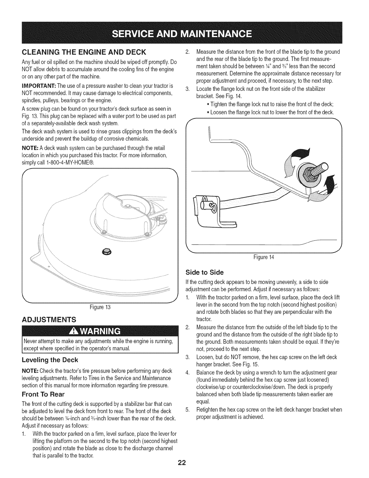
A screwplugcan befoundon yourtractor'sdecksurfaceas seenin
Fig. 13.Thisplugcan bereplacedwitha waterport to be usedas part
of a separately-availabledeckwashsystem.
Thedeckwash systemis usedto rinsegrassclippingsfromthe deck's
undersideandpreventthe buildupof corrosivechemicals.
NOTE: A deckwashsystemcan bepurchasedthroughthe retail
locationinwhichyoupurchasedthistractor.For moreinformation,
simplycall 1-800-4-MY-HOME®.
/'
/
Figure13
ADJUSTMENTS
Neverattemptto makeanyadjustmentswhilethe engineis running,
exceptwherespecifiedin the operator'smanual.
Leveling the Deck
NOTE: Checkthe tractor'stire pressurebeforeperforminganydeck
levelingadjustments.Referto Tiresinthe Serviceand Maintenance
sectionof this manualfor moreinformationregardingtire pressure.
Front To Rear
Thefrontof the cuttingdeckissupportedby a stabilizerbarthatcan
beadjustedto levelthe deckfromfrontto rear.Thefrontof the deck
shouldbebetween1A-inchand3A-inchlowerthan the rearof thedeck.
Adjustif necessaryas follows:
1. Withthe tractorparkedon a firm,levelsurface,placethe leverfor
liftingthe platformon the secondto the top notch(secondhighest
position)androtatethe bladeas closeto the dischargechannel
thatis parallelto the tractor. 22
2. Measurethedistancefromthe frontof the bladetip to the ground
andthe rearof the bladetip to theground.Thefirst measure-
menttakenshouldbe between1A"and3A"lessthanthe second
measurement.Determinethe approximatedistancenecessaryfor
properadjustmentandproceed,if necessary,to the nextstep.
3. Locatethe flangelocknut onthe frontsideof the stabilizer
bracket.SeeFig.14.
• Tightenthe flangelocknut to raisethe frontof thedeck;
•Loosentheflange locknutto lowerthe frontof the deck.
f
Figure14
Side to Side
Ifthe cuttingdeckappearsto be mowingunevenly,a sideto side
adjustmentcan beperformed.Adjustif necessaryas follows:
1. Withthe tractorparkedona firm, levelsurface,placethe decklift
leverin the secondfromthe top notch(secondhighestposition)
and rotatebothbladessothat theyare perpendicularwiththe
tractor.
2. Measurethedistancefromthe outsideof the left bladetip to the
groundandthe distancefromthe outsideof the rightbladetip to
the ground.Bothmeasurementstakenshouldbeequal.Ifthey're
not, proceedto the nextstep.
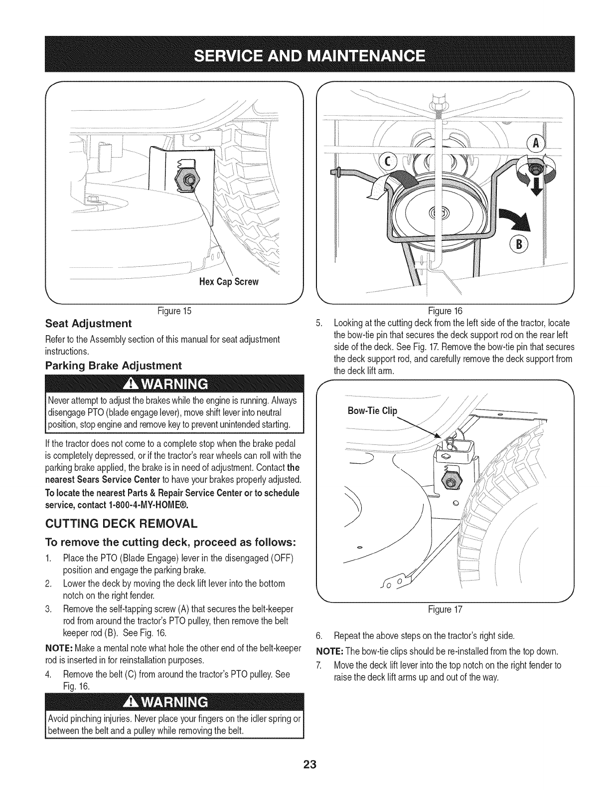
3. Loosen,but do NOTremove,the hexcap screwonthe leftdeck
hangerbracket.SeeFig. 15.
4. Balancethedeckby usinga wrenchto turn theadjustmentgear
(foundimmediatelybehindthehex cap screwjust loosened)
clockwise/uporcounterclockwise/down.Thedeckis properly
balancedwhen bothbladetip measurementstakenearlierare
equal.
5. Retightenthe hexcap screwon the leftdeckhangerbracketwhen
properadjustmentis achieved.
He× Cap Screw
'_. ._
Figure15
Seat Adjustment
Referto the Assemblysectionof thismanualfor seatadjustment
instructions.
Parking Brake Adjustment
Neverattemptto adjustthe brakeswhiletheengineis running.Always
disengagePTO(bladeengagelever),moveshiftleverintoneutral
position,stopengineandremovekeyto preventunintendedstarting.
If thetractordoes notcometo acompletestopwhenthe brakepedal
is completelydepressed,or if the tractor'srearwheelscan rollwiththe
parkingbrakeapplied,the brakeis in needof adjustment.Contactthe
nearest Sears Service Centerto haveyourbrakesproperlyadjusted.
Tolocatethe nearest Parts& Repair ServiceCenteror to schedule
service,contact 1-800-4-MY-HOME®.
CUTTING DECK REMOVAL
To remove the cutting deck, proceed as follows:
1. Placethe PTO(Blade Engage)leverin the disengaged(OFF)
positionandengagethe parkingbrake.
2. Lowerthe deck by movingthe deck lift lever intothe bottom
notchon the rightfender.
3. Removetheself-tappingscrew(A) thatsecuresthe belt-keeper
rodfromaroundthe tractor'sPTOpulley,thenremovethe belt
keeperrod(B). SeeFig. 16.
NOTE: Makea mentalnotewhatholethe otherendof the belt-keeper
rodisinsertedinfor reinstallationpurposes.
4. Removethebelt (C) fromaroundthetractor'sPTOpulley.See
Fig.16.
Figure16
5. Lookingat thecuttingdeckfromthe leftside of the tractor,locate
the bow-tiepinthat securesthedecksupportrodonthe rearleft
sideof the deck.SeeFig. 17.Removethe bow-tiepinthatsecures
the decksupportrod,andcarefullyremovethe decksupportfrom
the decklift arm.
f
/
/
Bow-TieClip jj
\
//
/ /
/
/
/
f
\
.... j
Figure 17
6. Repeatthe abovestepson the tractor'srightside.
NOTE: The bow-tieclipsshouldbe re-installedfromthe top down.
7. Movethe decklift leverintothe top notchon the rightfenderto
raisethe decklift armsupandout of the way.
Avoidpinchinginjuries.Neverplaceyourfingersonthe idlerspringor
betweenthe belt anda pulleywhile removingthe belt.
23
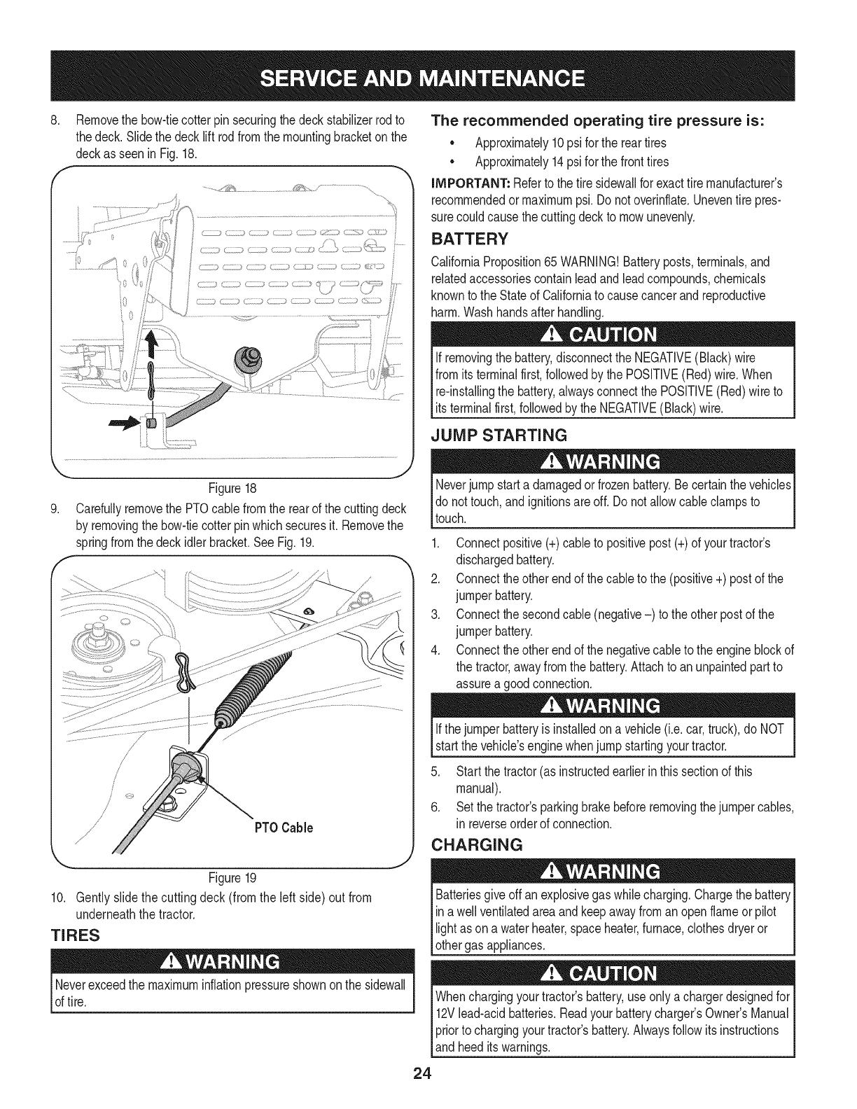
8, Removethe bow-tiecotterpin securingthe deckstabilizerrodto
thedeck. Slidethe decklift rodfromthe mountingbracketon the
deckasseen in Fig.18.
f
...........,,_i_,_'_ _%_L_,;::,/..............................
;k v_ ,_;_Z_ ¸,
Figure18
9. Carefullyremovethe PTOcablefromthe rearof the cuttingdeck
by removingthe bow-tiecotterpinwhichsecuresit. Removethe
springfromthe deckidler bracket.SeeFig.19.
f
PTOCable
Figure19
10. Gentlyslide the cuttingdeck (fromthe left side) out from
underneaththe tractor.
TIRES
Neverexceedthe maximuminflationpressureshownonthe sidewall
of tire.
The recommended operating tire pressure is:
• Approximately10psi for the reartires
• Approximately14psi for the fronttires
IMPORTANT: Referto the tire sidewaNfor exacttire manufacturer's
recommendedormaximumpsi.Donot overinflate.Uneventire pres-
surecould causethe cuttingdeckto mowunevenly.
BATTERY
CaliforniaProposition65 WARNING!Batteryposts,terminals,and
relatedaccessoriescontainleadandleadcompounds,chemicals
knownto the Stateof Californiato causecancerandreproductive
harm.Washhandsafter handling.
If removingthe battery,disconnectthe NEGATIVE(Black)wire
fromits terminalfirst,followedbythe POSITIVE(Red) wire.When
re-installingthe battery,alwaysconnectthe POSITIVE(Red)wire to
Its termna f rst,fo owedby the NEGATVE (Back) w re.
JUMP STARTING
Neverjump starta damagedorfrozenbattery.Becertainthevehicles
do not touch,and ignitionsareoff. Do notallowcable clampsto
touch.
1. Connectpositive(+)cableto positivepost(+)of yourtractor's
dischargedbattery.
2. Connecttheotherendof thecableto the (positive+) postof the
jumperbattery.
3. Connectthesecondcable (negative-) to theother postof the
jumperbattery.
4. Connecttheotherendof thenegativecableto the engineblockof
the tractor,awayfromthe battery.Attachto anunpaintedpartto
assurea goodconnection.
Ifthejumper batteryis installedona vehicle(i.e.car,truck),do NOT
startthe vehicle'senginewhenjump startingyourtractor.
5. Startthe tractor(as instructedearlierin thissectionof this
manual).
6. Set the tractor'sparkingbrakebeforeremovingthejumpercables,
in reverseorderof connection.
CHARGING
give offan explosivegas whilecharging.Chargethe batteryI
Batteries
ina wellventilatedareaandkeepawayfroman openflameor pilot
ght as ona waterheater,spaceheater,furnace,c othesdryeror |
othergas appliances. J
Whenchargingyourtractor'sbattery,useonlya chargerdesignedfor I
12Vlead-acidbatteries.Readyourbatterychargers Owners Manual
priorto chargingyourtractors battery.Alwaysfollowits instructions I
land heed ts warnngs. j
24
If yourtractorhasnot beenputinto usefor anextendedperiodof time,
chargethe batteryas follows:
1. Setyour batterychargerto delivera maxof 10amperes.
If yourbatterychargeris automatic,chargethe batteryuntilthe
chargerindicatesthatchargingis complete.Ifthe chargeris not
automatic,chargefor nofewerthaneight hours.
FUSE
One20AMPfuseis installedin yourtractor'swiringharnessto protect
the tractor'selectricalsystemfromdamagecausedbyexcessive
amperage.
If theelectricalsystemdoesnot function,or yourtractor'senginewill
not crank,first checkto be certainthatthe fusehasnot blown.It can
befoundat the rearof the unit,underneaththefenderlocatedby the
battery.
Alwaysusea fusewiththe sameamperagecapacityfor replacement.
CUTTING BLADES
Shutthe engineoff andremoveignitionkeybeforeremovingthe
cuttingblade(s)for sharpeningor replacement.Protectyourhands
by usingheavygloveswhengraspingthe blade.
Periodicallyinspectthe bladeand/or spindlefor cracksordamage,
especiallyafter you'vestrucka foreignobject. Donot operatethe
machineuntil damagedcomponentsare replaced.
Toremovethe blades,proceedas follows.
1. Removethedeckfrombeneaththe tractor,(referto CuttingDeck
Removalearlierinthis section)thengentlyflip thedeckoverto
exposeitsunderside.
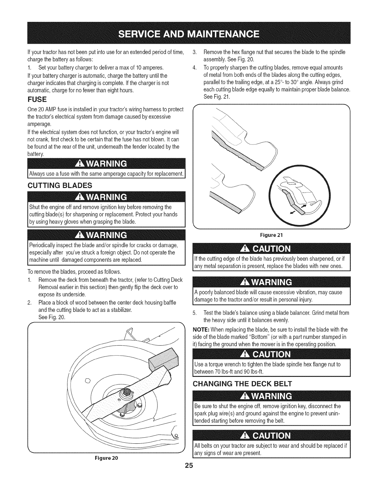
2. Placea blockof woodbetweenthe centerdeckhousingbaffle
andthe cuttingbladeto actas a stabilizer.
SeeFig.20.
f
©
Figure20
.
4.
Removethe hexflangenut thatsecuresthe bladeto the spindle
assembly.SeeFig.20.
To properlysharpenthe cuttingblades,removeequalamounts
of metalfrombothendsof the bladesalongthe cuttingedges,
parallelto the trailingedge,at a250.to 300angle.Alwaysgrind
eachcutting bladeedgeequallyto maintainproperbladebalance.
SeeFig.21.
Figure 21
Ifthe cuttingedgeof the bladehas previouslybeensharpened,or if
any metalseparationis present,replacethe bladeswith newones.
A poorlybalancedbladewill causeexcessivevibration,maycause
damageto the tractorand/or resultin personalinjury.
5. Testthe blade'sbalanceusinga bladebalancer.Grindmetalfrom
the heavysideuntil it balancesevenly.
NOTE: Whenreplacingthe blade,be sureto installthe bladewiththe
sideof the blademarked"Bottom"(orwitha part numberstampedin
it)facingthe groundwhenthe moweris inthe operatingposition.
Usea torquewrenchto tightenthe bladespindlehexflangenut to
between70Ibs-ftand 90Ibs-ft.
CHANGING THE DECK BELT
Besureto shutthe engineoff, removeignitionkey,disconnectthe
Isparkplugwire(s)andgroundagainstthe engineto preventunin-
ltended startingbeforeremovingthe belt.
25
All beltsonyourtractoraresubjectto wearandshouldbereplacedif
any signsof wearare present.
iMPORTANT: The V-beltfoundon yourtractoris speciallydesigned
to engageanddisengagesafely.A substitute(non-OEM)V-beltcan
bedangerousby notdisengagingcompletely.Fora properworking
machine,useidenticalequipmentbeltsas listedinthe partspagesof
thisOperator'sManual.
Tochangeor replacethe deckbelt onyourtractor,proceedas follows:
1. Removethe deckas instructedearlierinthis section.
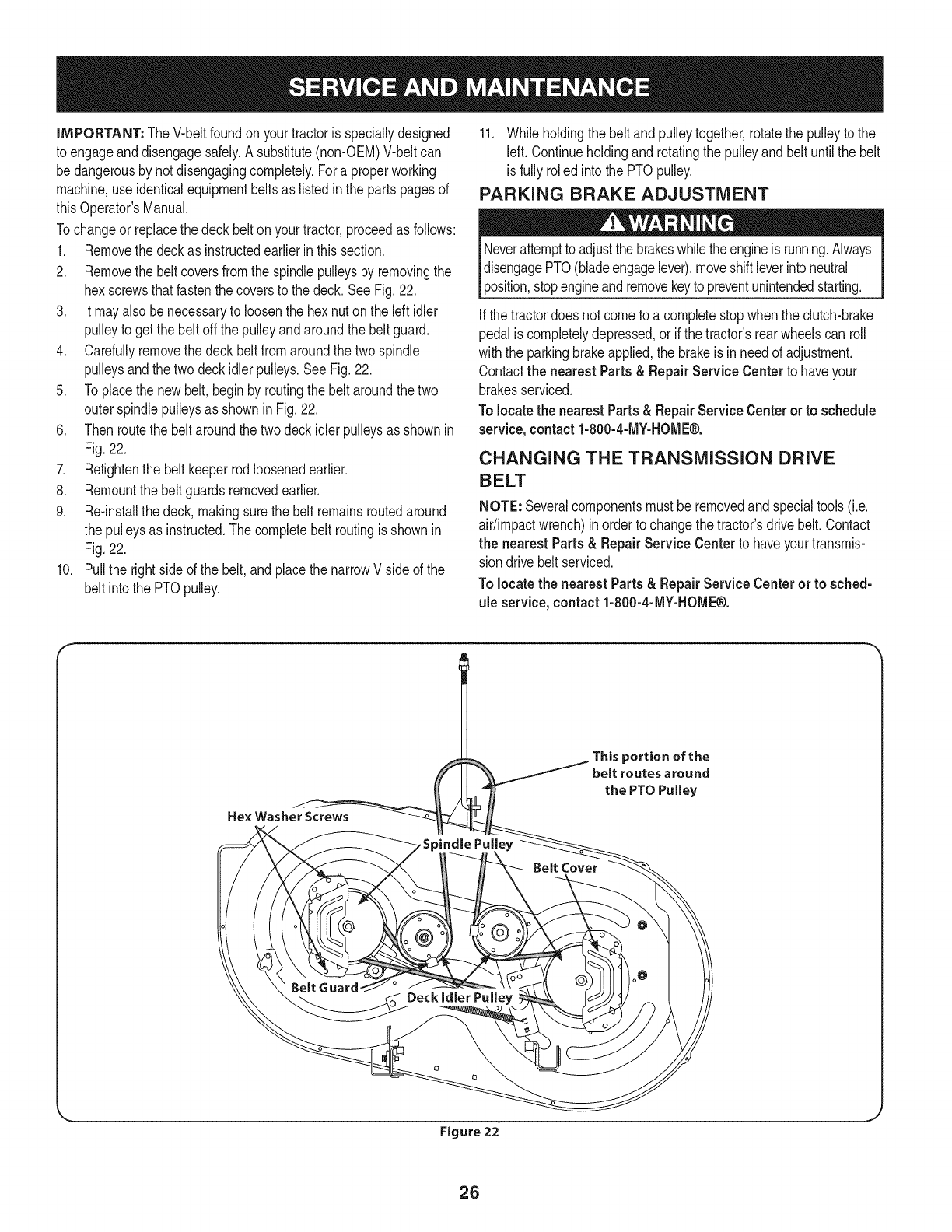
2. Removethe beltcoversfromthe spindlepulleysby removingthe
hexscrewsthatfastenthecoversto the deck.SeeFig.22,
3. It mayalso benecessaryto loosenthe hex nuton the leftidler
pulleyto getthe belt offthe pulleyandaroundthe beltguard.
4. Carefullyremovethe deckbeltfromaroundthe twospindle
pulleysandthetwo deckidlerpulleys,SeeFig,22,
5. Toplacethe newbelt,beginby routingthe belt aroundthe two
outerspindlepulleysas showninFig,22,
6. Thenroutethe beltaroundthe twodeckidlerpulleysas shownin
Fig.22.
7. Retightenthe belt keeperrodloosenedearlier.
8. Remountthebelt guardsremovedearlier,
9. Re-installthedeck, makingsurethe belt remainsroutedaround
the pulleysas instructed.Thecompletebelt routingisshownin
Fig.22.
10. Pullthe rightside ofthe belt,and placethe narrowVside of the
belt intothe PTOpulley.
11. Whileholdingthe belt andpulleytogether,rotatethe pulleyto the
left. Continueholdingand rotatingthe pulleyandbelt untilthe belt
is fullyrolledinto the PTOpulley.
PARKING BRAKE ADJUSTMENT
Neverattemptto adjustthe brakeswhiletheengineis running.Always
disengagePTO(bladeengagelever),moveshift leverintoneutral
position,stopengineandremovekeyto preventunintendedstarting.
Ifthe tractordoesnot cometo a completestopwhenthe clutch-brake
pedalis completelydepressed,or if the tractor'srearwheelscan roll
withthe parkingbrakeapplied,the brakeis inneedof adjustment.
Contactthe nearestParts& RepairService Centerto haveyour
brakesserviced.
Tolocatethe nearestParts& RepairServiceCenteror to schedule
service,contact1-800-4-MY-HOME®.
CHANGING THE TRANSMISSION DRIVE
BELT
NOTE: Severalcomponentsmust beremovedandspecialtools(i.e.
air/impactwrench)inorderto changethetractor'sdrivebelt.Contact
the nearest Parts& Repair Service Centerto haveyourtransmis-
sion drivebelt serviced.
Tolocatethe nearestParts& Repair Service Centeror to sched-
ule service, contact 1-800-4-MY-HOME®.
JThisportion of the
belt routesaround
Figure 22
26
Neverstorelawntractorwithfuel intankindoorsor in poorly
ventilatedareaswherefuel fumesmayreachan openflame,spark,
orpilot lightas ona furnace,waterheater,clothesdryer,or gas
appliance.
PREPARING THE ENGINE
IMPORTANT:Fuelleftin thefuel tankduringwarmweatherdeterio-
ratesandwill causeseriousstartingproblems.
To preventgumdepositsfromforminginsidethe engine'scarburetor
andcausingpossiblemalfunctionof theengine,thefuel systemmust
be eithercompletelyemptied,orthe gasolinemustbe treatedwitha
stabilizerto preventdeterioration.
1. Ifusingafuel stabilizer:
a. Readthe productmanufacturer'sinstructionsandrecom-
mendations.
b. Addto clean,freshgasolinethe correctamountof stabilizer
for the capacityof the fuel system.
c. Fillthe fueltankwithtreatedfuel andrunthe enginefor 2-3
minutesto get stabilizedfuel intothe carburetor.
2. Ifemptyingthe fuel system:
a. Donot drainfuel whenthe engineis hot.Allowthe engine
adequatetimeto cool.Drainfuelinto anapprovedcontainer
outdoors,awayfromopenflame.
b. Drainany largevolumeof fuel fromthetank bydisconnect-
ing thefuel linefromthe in-linefuel filternearthe engine.
Seethe completeinstructionsfor DrainingThe Fuellaterin
this section.
Gasolineis extremelyflammableandcan beexplosiveundercertain
conditions.Draingasolinebeforestoringthe equipmentfor extended
periods.Drainfuel only intoanapprovedcontaineroutdoors,away
froman openflame.Allowengineto cool.Extinguishcigarettes,
cigars,pipes,andothersourcesof ignitionpriorto drainingfuel.
Storegasolineinan approvedcontainerinsafelocation.
c. Reconnectthe fuel lineandrunthe engineuntil it startsto
falter,thenuse thechoketo keeptheenginerunninguntilall
fuel in thecarburetorhas beenexhausted.
d. Disconnectthefuel lineanddrainany remaininggasoline
fromthe system.
DRAiNiNG THE FUEL
1. Locatethe fuel filter,whichis locatedonthe leftsideof the
engine,andmaybe attachedto the enginewitha tie strap.
2. Cutthe tie strap,if present,then pinchthe in-lineclamponthe
fuel filterwitha pairof pliers,slidethe clampupthe fuel line.
3. Pullthe fuel linefreefromthe filterandplacethe openendof the
lineintoanapprovedcontainerto drainthe fuel.
PREPARING THE LAWN TRACTOR
1. Cleanandlubricatetractorthoroughlyas describedinthe lubrica-
tion instructions.
2. Donot usea pressurewasheror gardenhoseto cleanyour unit.
3. Storemowerin a dry,cleanarea. Do notstorenextto corrosive
materials,suchas fertilizer.
Gasolineis a toxicsubstance.Disposeof gasolineproperly.Contact
your localauthoritiesfor approveddisposalmethods.
3. Removethe sparkplugandpourone(1)ounceof engineoil
throughthe sparkplugholeintothe cylinder.Cranktheengine
severaltimesto distributethe oil. Replacethe sparkplug.
27
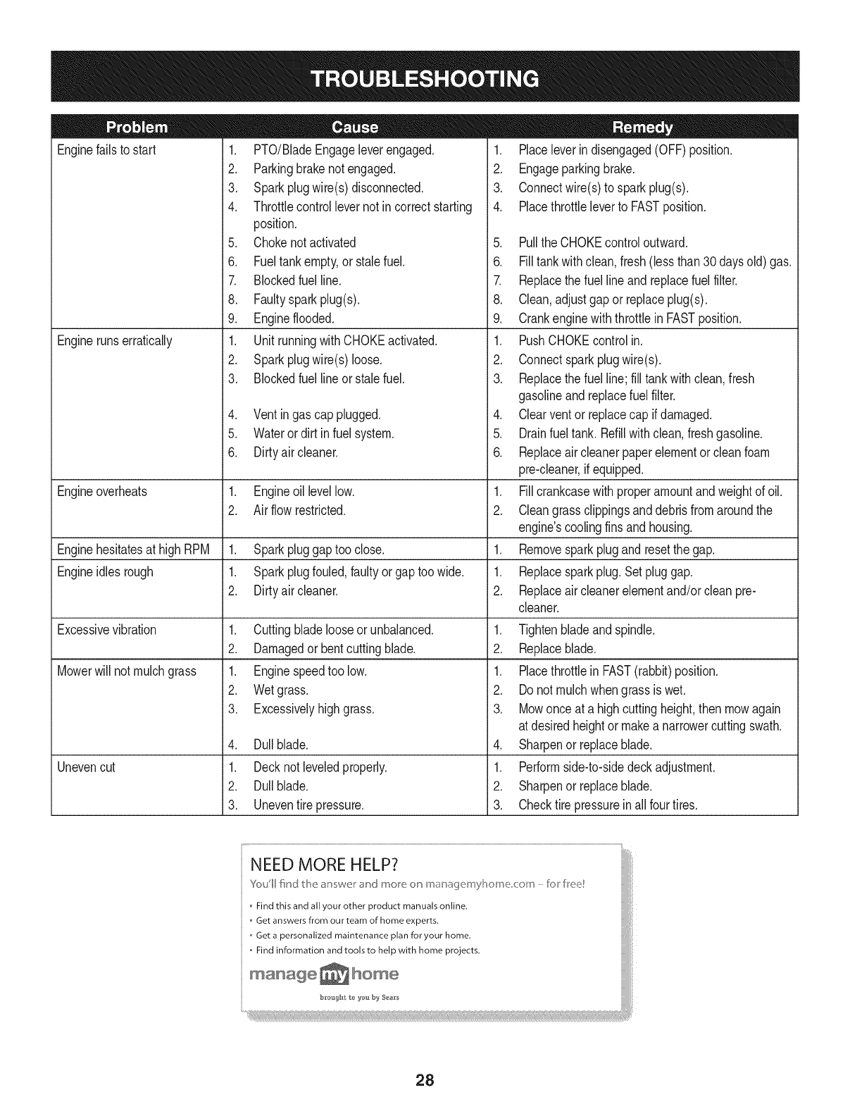
Enginefailsto start
Enginerunserratically
1. PTO/BladeEngageleverengaged.
2. Parkingbrakenotengaged.
3. Sparkplugwire(s)disconnected.
4. Throttlecontrollevernot in correctstarting
position.
5. Chokenotactivated
6. Fueltankempty,or stalefuel.
7. Blockedfuel line.
8. Faultysparkplug(s).
9. Engineflooded.
1. UnitrunningwithCHOKEactivated.
2. Sparkplugwire(s)loose.
3. Blockedfuel lineor stalefuel.
4. Ventingas cap plugged.
5. Waterordirt in fuel system.
6. Dirtyair cleaner.
Engineoverheats 1. Engineoillevellow. 1.
2. Airflowrestricted. 2.
Enginehesitatesat highRPM 1. Sparkpluggaptoo close. 1.
Engineidles rough 1. Sparkplugfouled,faultyor gaptoo wide. 1.
2. Dirtyair cleaner. 2.
Excessivevibration
Mowerwill not mulchgrass
Unevencut
1. Cuttingbladelooseor unbalanced.
2. Damagedor bentcuttingblade.
1. Enginespeedtoo low.
2. Wetgrass.
3. Excessivelyhighgrass.
4. Dullblade.
1. Decknot leveledproperly.
2. Dullblade.
3. Uneventire pressure.
1. Placeleverindisengaged(OFF)position.
2. Engageparkingbrake.
3. Connectwire(s)to sparkplug(s).
4. Placethrottleleverto FASTposition.
5. PulltheCHOKEcontroloutward.
6. Filltankwithclean,fresh(lessthan30 daysold) gas.
7. Replacethe fuel lineandreplacefuel filter.
8. Clean,adjustgapor replaceplug(s).
9. Crankenginewiththrottlein FASTposition.
1. PushCHOKEcontrolin.
2. Connectsparkplugwire(s).
3. Replacethe fuel line;fill tankwithclean,fresh
gasolineandreplacefuel filter.
4. Clearventor replacecap if damaged.
5. Drainfueltank. Refillwithclean,freshgasoline.
6. Replaceair cleanerpaperelementor cleanfoam
pre-cleaner,if equipped.
Fillcrankcasewith properamountandweightof oil.
Cleangrassclippingsanddebrisfromaroundthe
engine'scoolingfinsandhousing.
Removesparkplugandresetthe gap.
Replacesparkplug.Set pluggap.
Replaceair cleanerelementand/orclean pre-
cleaner.
1. Tightenbladeandspindle.
2. Replaceblade.
1. Placethrottlein FAST(rabbit)position.
2. Do notmulchwhengrassis wet.
3. Mowonce at a highcuttingheight,then mowagain
at desiredheightor makea narrowercuttingswath.
4. Sharpenor replaceblade.
1. Performside-to-sidedeckadjustment.
2. Sharpenor replaceblade.
3. Checktire pressureinall fourtires.
NEED MORE HELP?
Youll fkld t_e answe_ _"ct mo_e o_ maoage_nyl]o_ne co_n - br kee!
Find this and all your other product manuals online.
Get answers from our team of home experts.
,, Get a personalized maintenance plan for your home.
,, Find information and tools to help with home projects.
maoage _ home
b_*oug_t t_ _'ou by Sea_'s
28
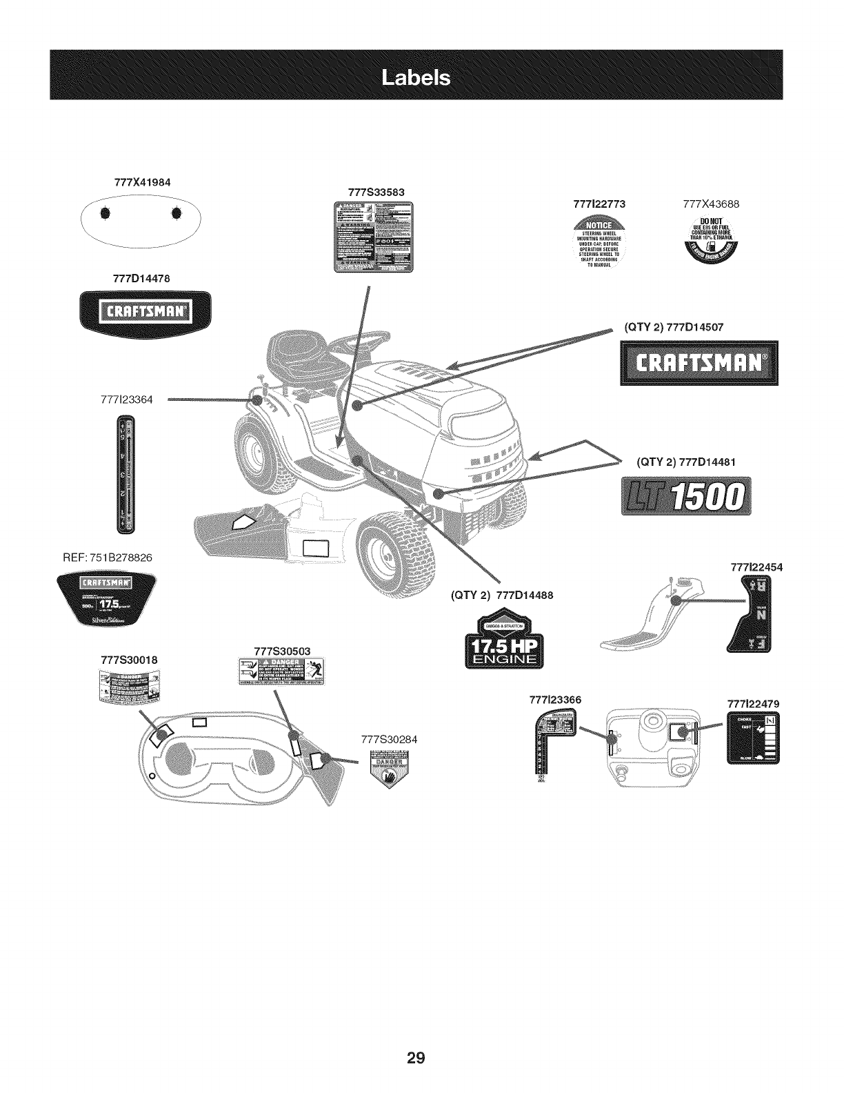
777X41984
777D14478
777S33583 777122773 777X43688
DONOT
USE US50B FUEL
STEERIN6 WHEEL CONTNNiNG MQ_E
MOUNTING HARDWARE THAN 18% USHANQI
UNDER CAP, BEFORE _ _ _
OPERATION SECURE
STEERING WHEEL TO
SHAFTACCORDING
TOM_HUAL
777123364
REF: 751 B278826
(QTY 2) 777D14488
(QTY 2) 777D14507
(QTY 2) 777D14481
777122454
777S30018 777S30503
777123366 777122479
29
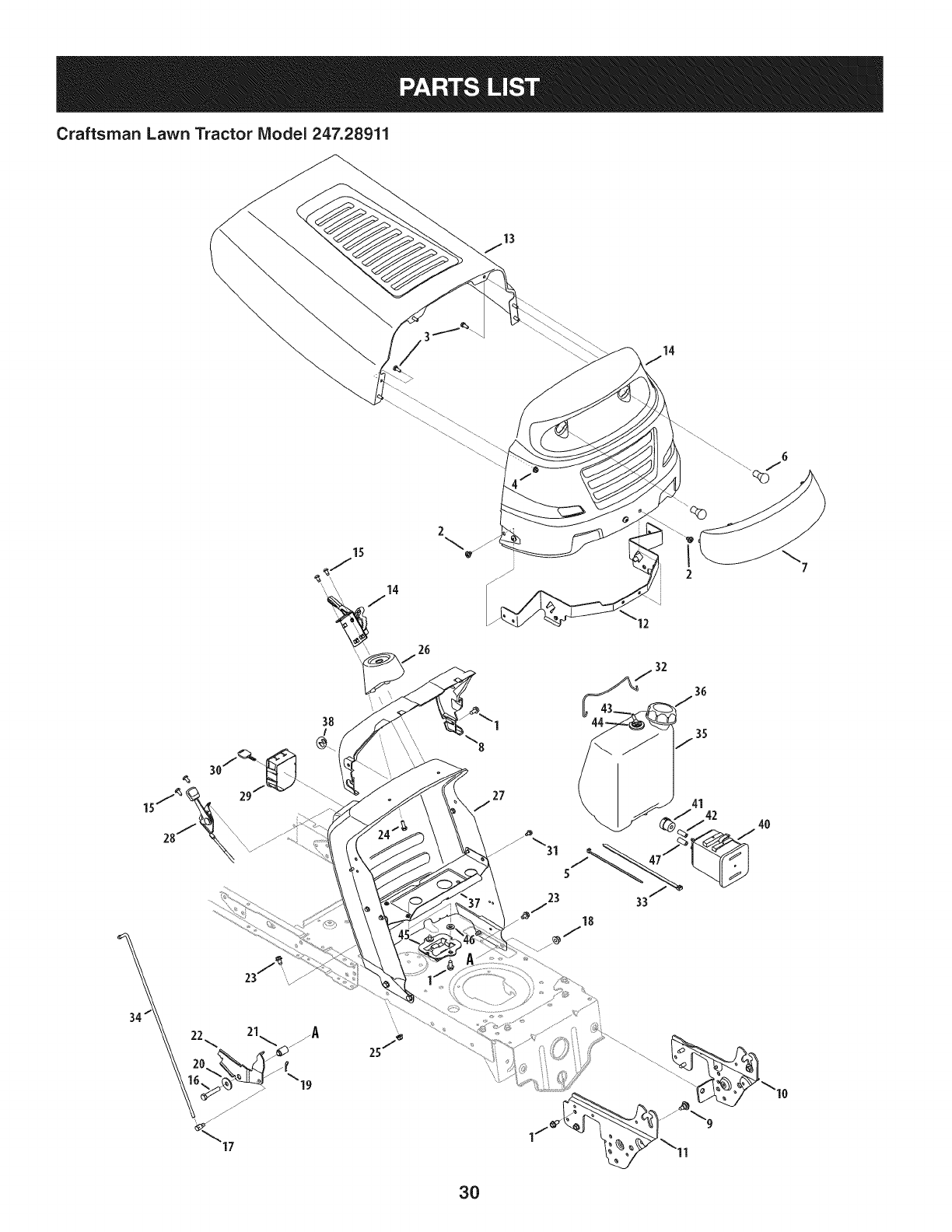
Craftsman Lawn Tractor IViodel 247.28911
15
38
I
2
5
23 33
32
3O

Craftsman Lawn Tractor Model 247.28911
Ref, [
No,
1 710-04484
2 710-04593
3 710-0751
4 712-04064
5 725-0157
6 925-0963
7 731-04949A
8 731-05078C
9 738-04091A
10 783-05327B-0637
II 783-05328A-0637
12 783-05454-0637
13 783-05684-4043
14 983-04216
15 710-04483
16 710-3144
17 711-0736
18 712-04065
19 714-04040
20 936-0133
21 750-04465
22 783-04862
23 710-0604A
24 710-0895
Part No, Description
Screw, 5/16-18 x .750
Screw, 5/16-18 x .375
Hex Screw, 1/4-20 x .620
Nut, Hex Flange Insert Lock, 1/4-20
Cable Tie, 3/16 x .05 x 7.4
Lamp
Grill Lens, 1 Style
Dash Collar
Shoulder Screw, 5/16-18
Left Support Pivot Bracket
Right Support Pivot Bracket
Hood Pivot Bracket
Hood Assembly, 1 Style
Speed Selector, 7-Speed
Self-Tap Screw, 1/4-20
Hex Head Screw, 3/8-16
Ferrule, 1/4-20 x 1.00
Nut, Hex Flange Insert Lock, 3/8-16
Hair Pin Clip
Flat Washer, .411 x 1.25 x .lO0
Flange Spacer
Speed latch
Self-Tap Screw, 5/16-18
Hex Screw, 1/4-15
Ref, [
No,
25 712-04063
26 731-04945
27 783-04892B-0637
28 746-04364
29 725-04992
30 925-1745A
31 710-0599
32 683-04448-0637
33 726-0230
34 747-04430
35 751-10782
36 751-10947
37 783-04584A-0637
38 731-05265
39 783-05685-4043
40 751-10589
41 751-10590
42 751-10749
43 751-10441
44 735-04081
45 751-10610
46 736-3008
47 751-10750
Part No, Description
Nut, Hex Flange Ins. Lock, 5/16-18
Steering Support
Dash
Throttle/Choke Assembly
Key Switch Module
Key
Screw, Hd. Tapp, 1/4-20 x .5
Assembly Rod
Cable Tie
Speed Selector Control Rod
1.36 Gallon CARB Fuel Tank
Fuel Cap
Gas Tank Support Bracket
Choke Plug
Grill
Carbon Cannister
Filter Vent
Low Perm Fuel Line 3/16 White
Rollover Valve
Rubber Grommet
Cannister Bracket
Flat Washer, .344 x.750 x .120
Low Perm Fuel Line 7/32 Yellow
31
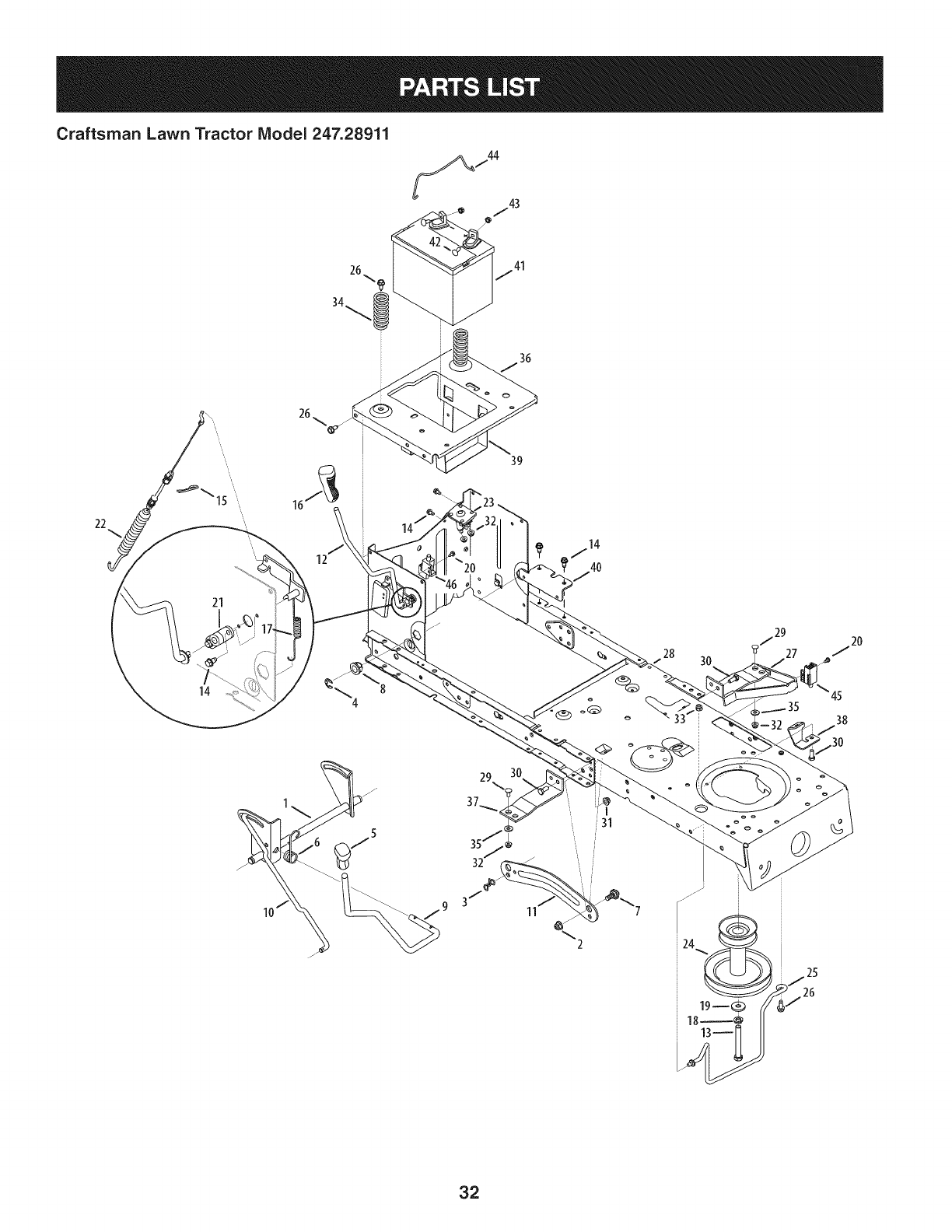
Craftsman Lawn Tractor Model 247.28911
22
21
14
39
3O
45
38
11 %2
32
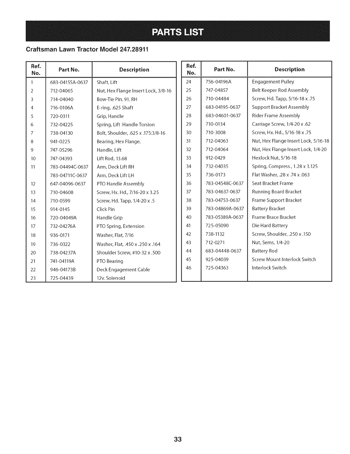
Craftsman Lawn Tractor Model 247.28911
Ref, [
No,
1 683-04155A-0637
2 712-04065
3 714-04040
4 716-0106A
5 720-0311
6 732-04225
7 738-04130
8 941-0225
9 747-05296
10 747-04393
11 783-04494C-0637
783-04711C-0637
12 647-04096-0637
13 710-04608
14 710-0599
15 914-0145
16 720-04049A
17
18
19
20
21
22
23
Part No. Description
Shaft, Lift
Nut, Hex Flange Insert Lock, 3/8-16
Bow-Tie Pin, 91, RH
E-ring, .625 Shaft
Grip, Handle
Spring, Lift Handle Torsion
Bolt, Shoulder, .625 x .175:3/8-16
Bearing, Hex Flange,
Handle, Lift
Lift Rod, 13.68
Arm, Deck Lift RH
Arm, Deck Lift LH
PTO Handle Assembly
Screw, Hx. Hd., 7/16-20 x 3.25
Screw, Hd. Tapp, 1/4-20 x .5
Click Pin
Handle Grip
732-04276A
936-0171
736-0322
738-04237A
741-04119A
946-04173B
725-04439
PTO Spring, Extension
Washer, Flat, 7/16
Washer, Flat, .450 x .250 x .164
Shoulder Screw, #10-32 x .500
PTO Bearing
Deck Engagement Cable
12v. Solenoid
Ref, I
No,
24 756-04196A
25 747-04857
26 710-04484
27 683-04195-0637
28 683-04601-0637
29 710-0134
30 710-3008
31 712-04063
32 712-04064
33 912-0429
34 732-04035
35 736-0173
36 783-04548C-0637
37 783-04637-0637
38 783-04753-0637
39 783-04869A-0637
40 783-05389A-0637
41 725-05090
42 738-1132
43 712-0271
44 683-04448-0637
45 925-04039
46 725-04363
Part No, Description
Engagement Pulley
Belt Keeper Rod Assembly
Screw, Hd. Tapp, 5/16-18 x .75
Support Bracket Assembly
Rider Frame Assembly
Carriage Screw, 1/4-20 x .62
Screw, Hx. Hd., 5/16-18 x .75
Nut, Hex Flange Insert Lock, 5/16-18
Nut, Hex Flange Insert Lock, 1/4-20
Hexlock Nut, 5/16-18
Spring, Compress., 1.28 x 3.125
Flat Washer, .28 x .74 x .063
Seat Bracket Frame
Running Board Bracket
Frame Support Bracket
Battery Bracket
Frame Brace Bracket
Die Hard Battery
Screw, Shoulder, .250 x .150
Nut, Seres, 1/4-20
Battery Rod
Screw Mount Interlock Switch
Interlock Switch
33
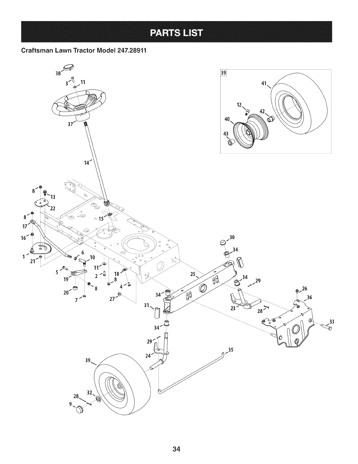
Craftsman Lawn Tractor IViodel 247.28911
41\
25
29
33
34
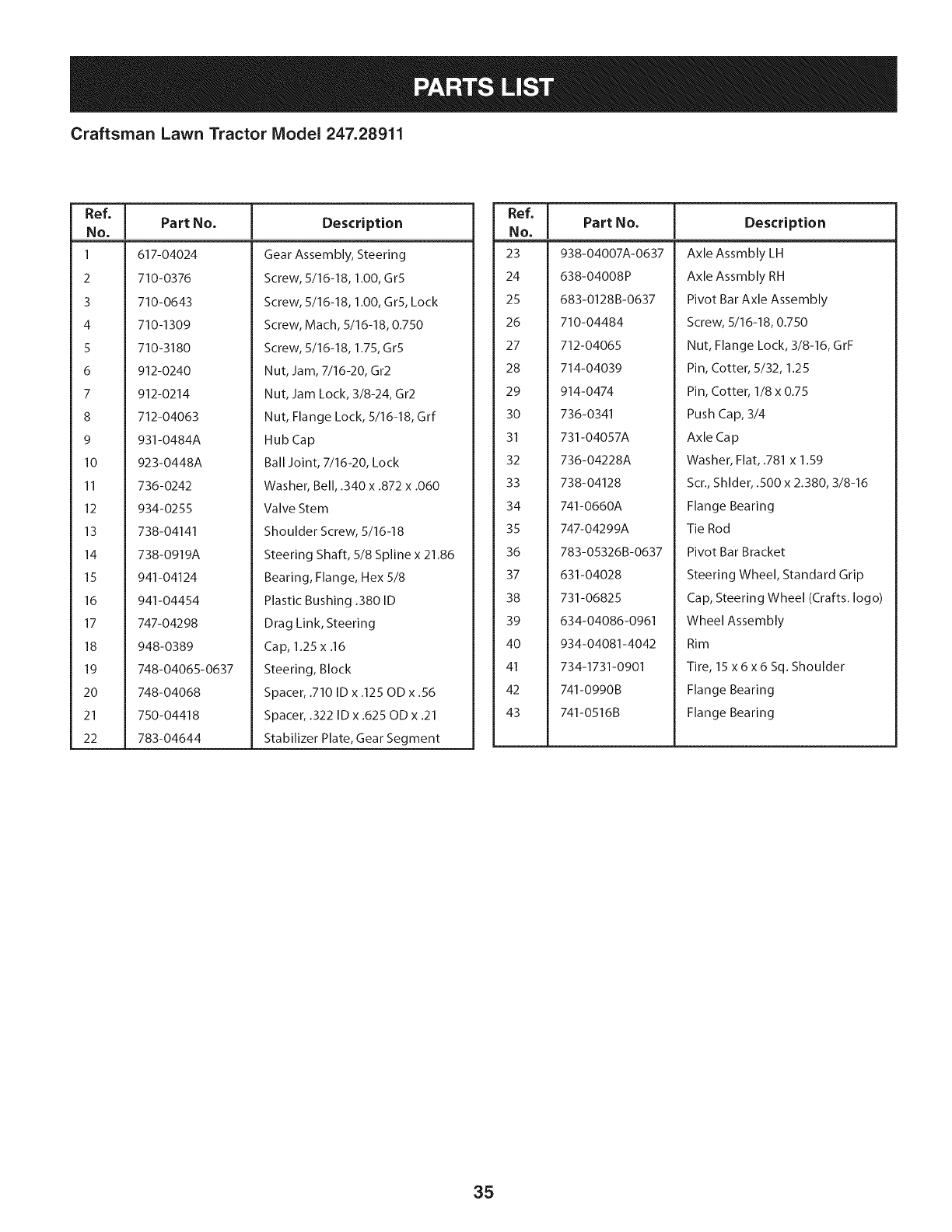
Craftsman Lawn Tractor Model 247.28911
Ref, [
No,
1 617-04024
2 710-0376
3 710-0643
4 710-1309
5 710-3180
6 912-0240
7 912-0214
8 712-04063
9 931-0484A
I0 923-0448A
II 736-0242
12 934-0255
13 738-04141
14 738-0919A
15 941-04124
16 941-04454
17 747-04298
18 948-0389
19 748-04065-0637
20 748-04068
21 750-04418
22 783-04644
Part No. Description
Gear Assembly, Steering
Screw, 5/16-18, 1.00, Gr5
Screw, 5/16-18, 1.00, Gr5, Lock
Screw, Mach, 5/16-18, 0.750
Screw, 5/16-18, 1.75, Gr5
Nut, Jam, 7/16-20, Gr2
Nut, Jam Lock, 3/8-24, Gr2
Nut, Flange Lock, 5/16-18, Grf
Hub Cap
Ball Joint, 7/16-20, Lock
Washer, Bell, .340 x .872 x .060
Valve Stem
Shoulder Screw, 5/16-18
Steering Shaft, 5/8 Spline x 21.86
Bearing, Flange, Hex 5/8
Plastic Bushing .380 ID
Drag Link, Steering
Cap, 1.25 x .16
Steering, Block
Spacer, .710 ID x .125 OD x .56
Spacer, .322 ID x .625 OD x .21
Stabilizer Plate, Gear Segment
I
Ref, IPart No,
No, I
23 938-04007A-0637
24 638-04008P
25 683-0128B-0637
26 710-04484
27 712-04065
28 714-04039
29 914-0474
30 736-0341
31 731-04057A
32 736-04228A
33 738-04128
34 741-0660A
35 747-04299A
36 783-05326B-0637
37 631-04028
38 731-06825
39 634-04086-0961
40 934-04081-4042
41 734-1731-0901
42 741-0990B
43 741-0516B
Description
Axle Assmbly LH
Axle Assmbly RH
Pivot Bar Axle Assembly
Screw, 5/16-18, 0.750
Nut, Flange Lock, 3/8-16, GrF
Pin, Cotter, 5/32, 1.25
Pin, Cotter, 1/8 x 0.75
Push Cap, 3/4
Axle Cap
Washer, Flat, .781 x 1.59
Scr., Shlder, .500 x 2.380, 3/8-16
Flange Bearing
Tie Rod
Pivot Bar Bracket
Steering Wheel, Standard Grip
Cap, Steering Wheel (Crafts. logo)
Wheel Assembly
Rim
Tire, 15 x 6 x 6 Sq. Shoulder
Flange Bearing
Flange Bearing
35
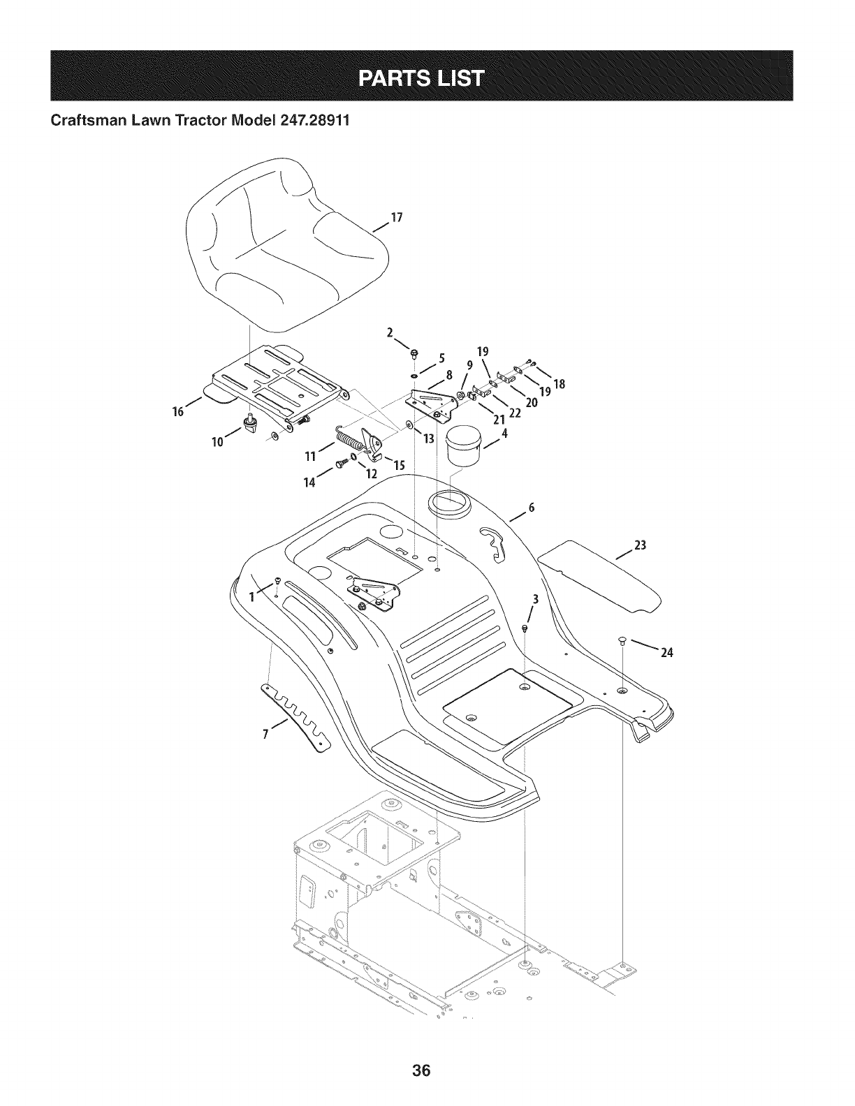
Craftsman Lawn Tractor Model 247.28911
17
16
12
22
21
J
18
20
36
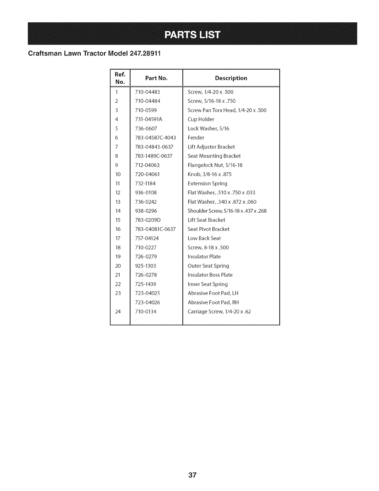
Craftsman Lawn Tractor Model 247.28911
Ref, [
No,
1 710-04483
2 710-04484
3 710-0599
4 731-04591A
5 736-0607
6 783-0458704043
7 783-04843-0637
8 783-148900637
9 712-04063
10 720-04061
II 732-1184
12 936-0108
13 736-0242
14 938-0296
15 783-0209D
16 783-04081C-0637
17 757-04124
18 710-0227
19 726-0279
20 925-1303
21 726-0278
22 725-1439
23 723-04025
723-04026
24 710-0134
Part No. Description
Screw, 1/4-20 x .500
Screw, 5/16-18 x .750
Screw Pan Torx Head, 1/4-20 x .500
Cup Holder
Lock Washer, 5/16
Fender
Lift Adjuster Bracket
Seat Mounting Bracket
Flangelock Nut, 5/16-18
Knob, 3/8-16 x .875
Extension Spring
Flat Washer, .510 x .750 x .033
Flat Washer, .340 x .872 x .060
Shoulder Screw, 5/16-18 x .437 x .268
Lift Seat Bracket
Seat Pivot Bracket
Low Back Seat
Screw, 8-18 x .500
Insulator Plate
Outer Seat Spring
Insulator Boss Plate
Inner Seat Spring
Abrasive Foot Pad, LH
Abrasive Foot Pad, RH
Carriage Screw, 1/4-20 x .62
37
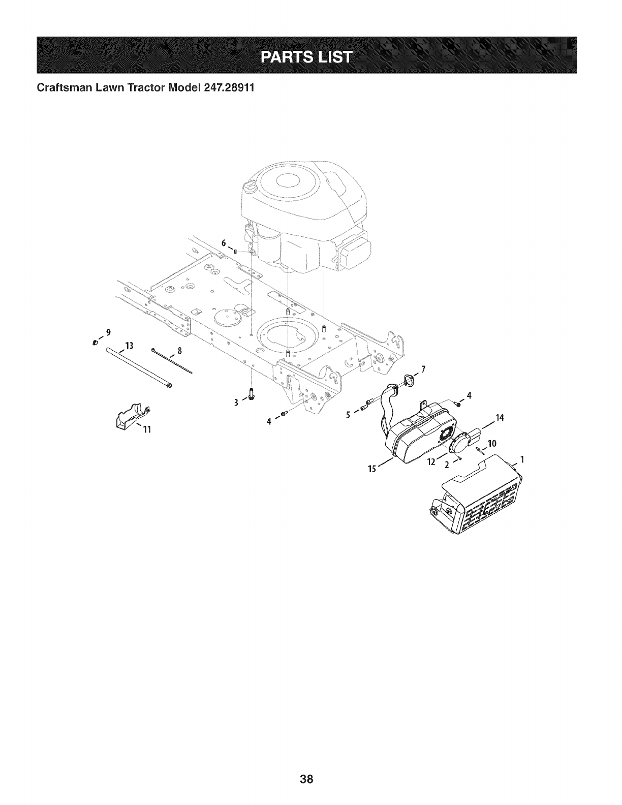
Craftsman Lawn Tractor IViodel 247.28911
9
/
4
14
10
38
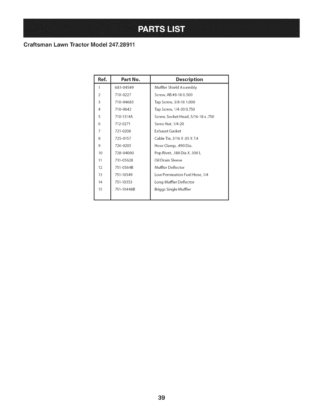
Craftsman Lawn Tractor Model 247.28911
I
Ref, IPart No.
1 683-04549
2 710-0227
3 710-04683
4 710-0642
5 710-1314A
6 712-0271
7 721-0208
8 725-0157
9 726-0205
10 728-04000
11 731-05628
12 751-0564B
13 751-I 0349
14 751-I0353
15 751-I0448B
Description
Muffler Shield Assembly
Screw, AB #8-18 0.500
Tap Screw, 3/8-16 1.000
Tap Screw, 1/4-20 0.750
Screw, Socket Head, 5/16-18 x .750
Sems Nut, 1/4-20
Exhaust Gasket
Cable Tie, 3/16 X .05 X 7.4
Hose Clamp, .490 Dia.
Pop Rivet, .188 Dia X .300 L
Oil Drain Sleeve
Muffler Deflector
Low Permeation Fuel Hose, 1/4
Long Muffler Deflector
Briggs Single Muffler
39
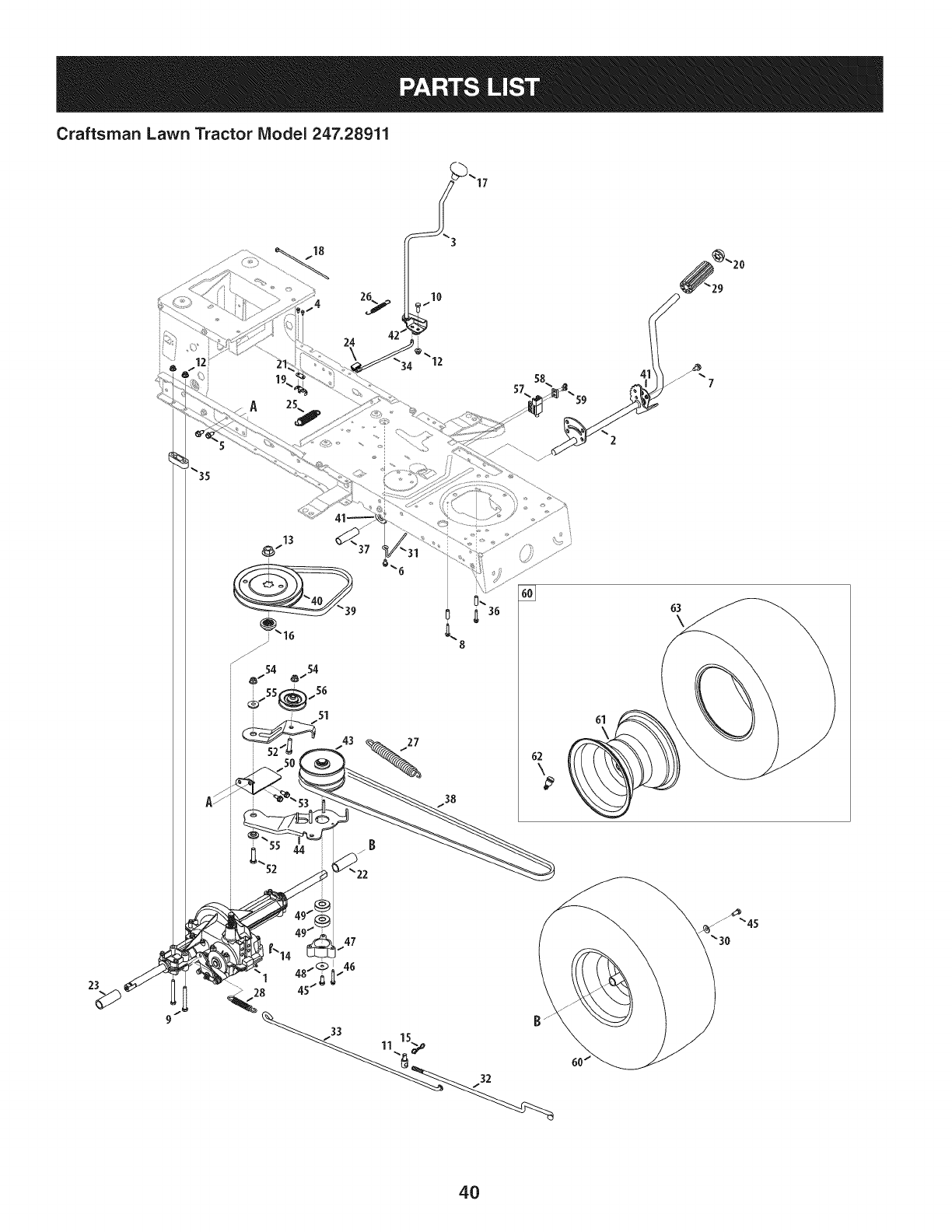
Craftsman Lawn Tractor IViodel 247.28911
24
27
38
63
\
61
23
4O
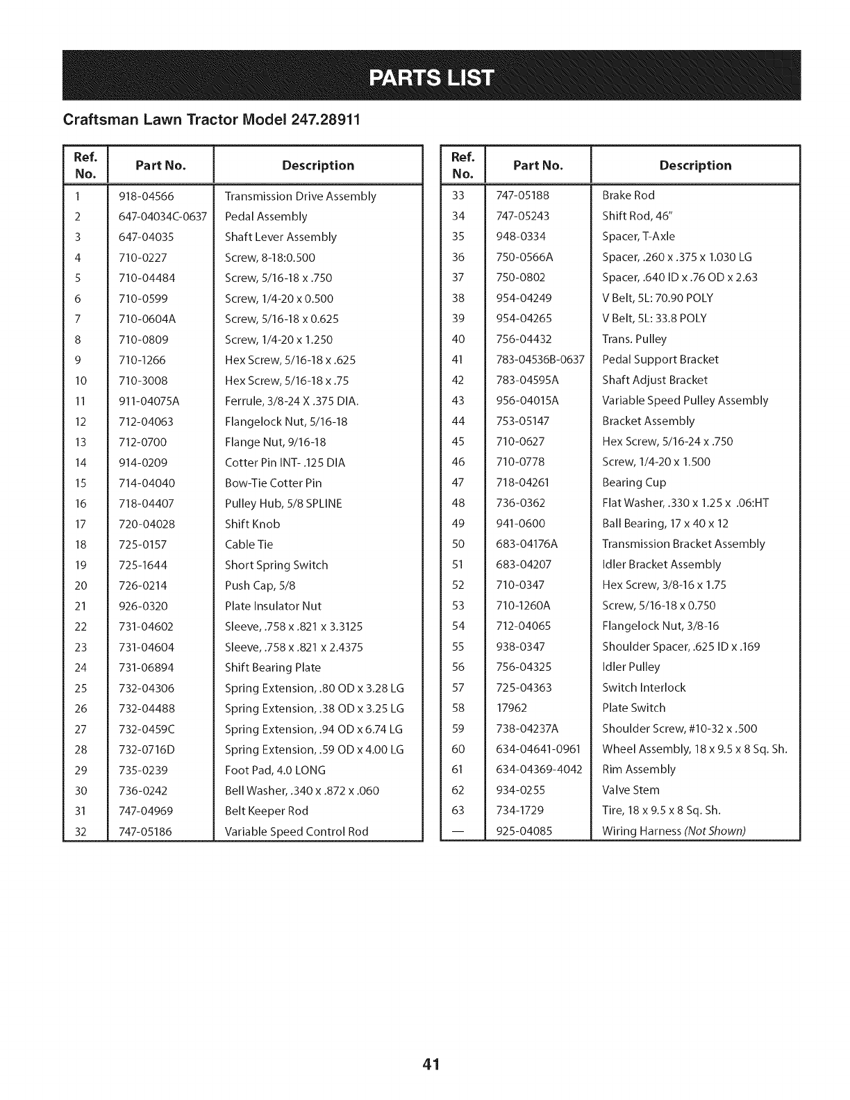
Craftsman Lawn Tractor Model 247.28911
Ref, ]
No,
1 918-04566
2 647-0403400637
3 647-04035
4 710-0227
5 710-04484
6 710-0599
7 710-0604A
8 710-0809
9 710-1266
10 710-3008
II 911-04075A
12 712-04063
13 712-0700
14 914-0209
15 714-04040
16 718-04407
17 720-04028
18 725-0157
19 725-1644
20 726-0214
21 926-0320
22 731-04602
23 731-04604
24 731-06894
25 732-04306
26 732-04488
27 732-0459C
28 732-0716D
29 735-0239
30 736-0242
31 747-04969
32 747-05186
Part No, Description
Transmission Drive Assembly
Pedal Assembly
Shaft Lever Assembly
Screw, 8-18:0.500
Screw, 5/16-18 x .750
Screw, 1/4-20 x 0.500
Screw, 5/16-18 x 0.625
Screw, 1/4-20 x 1.250
Hex Screw, 5/16-18 x .625
Hex Screw, 5/16-18 x .75
Ferrule, 3/8-24 X .375 DIA.
Flangelock Nut, 5/16-18
Flange Nut, 9/16-18
Cotter Pin INT- .125 DIA
Bow-Tie Cotter Pin
Pulley Hub, 5/8 SPLINE
Shift Knob
Cable Tie
Short Spring Switch
Push Cap, 5/8
Plate Insulator Nut
Sleeve, .758 x .821 x 3.3125
Sleeve, .758 x .821 x 2.4375
Shift Bearing Plate
Spring Extension, .80 OD x 3.28 LG
Spring Extension, .38 OD x 3.25 LG
Spring Extension, .94 OD x 6.74 LG
Spring Extension, .59 OD x 4.00 LG
Foot Pad, 4.0 LONG
Bell Washer, .340 x .872 x .060
Belt Keeper Rod
Variable Speed Control Rod
Ref, [
NO,
33 747-05188
34 747-05243
35 948-0334
36 750-0566A
37 750-0802
38 954-04249
39 954-04265
40 756-04432
41 783-04536B-0637
42 783-04595A
43 956-04015A
44 753-05147
45 710-0627
46 710-0778
47 718-04261
48 736-0362
49 941-0600
50 683-04176A
51 683-04207
52 710-0347
53 710-1260A
54 712-04065
55 938-0347
56 756-04325
57 725-04363
58 17962
59 738-04237A
60 634-04641-0961
61 634-04369-4042
62 934-0255
63 734-1729
-- 925-04085
Part No, Description
Brake Rod
Shift Rod, 46"
Spacer, T-Axle
Spacer, .260 x .375 x 1.030 LG
Spacer, .640 ID x .76 OD x 2.63
V Belt, 5L: 70.90 POLY
V Belt, 5L: 33.8 POLY
Trans. Pulley
Pedal Support Bracket
Shaft Adjust Bracket
Variable Speed Pulley Assembly
Bracket Assembly
Hex Screw, 5/16-24 x .750
Screw, 1/4-20 x 1.500
Bearing Cup
Flat Washer, .330 x 1.25 x .06:HT
Ball Bearing, 17 x 40 x 12
Transmission Bracket Assembly
Idler Bracket Assembly
Hex Screw, 3/8-16 x 1.75
Screw, 5/16-18 x 0.750
Flangelock Nut, 3/8-16
Shoulder Spacer, .625 ID x .169
Idler Pulley
Switch Interlock
Plate Switch
Shoulder Screw, #10-32 x .500
Wheel Assembly, 18 x 9.5 x 8 Sq. Sh.
Rim Assembly
Valve Stem
Tire, 18 x 9.5 x 8 Sq. Sh.
Wiring Harness (Not Shown)
41
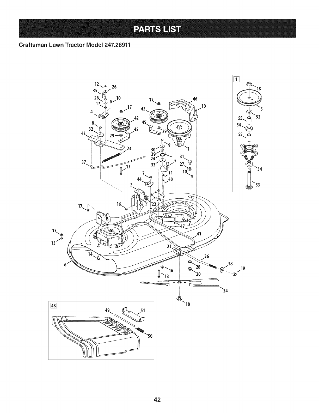
Craftsman Lawn Tractor IViodel 247.28911
[]
55_ \52
54\_
55_
3
[]
49\ _<sl so
34
42

Craftsman Lawn Tractor Model 247.28911
Ref, [
No,
1 918-04822A
2 683-0254B-0637
3 956-1227
4 983-04511
5 983-04525
6 983-04570-0637
7 710-04484
8 710-0514
9 710-0528
I0 710-0599
II 710-0778
12 710-0809
13 710-3144
14 710-3178
15 712-0229
16 712-04063
17 712-04065
18 712-0417A
19 712-04243
20 912-0641
21 714-04043
22 917-04074
23 932-0384
24 732-04727
25 936-0119
26 936-0176
27 736-0187
28 736-0225
Part No, Description
Spindle Pulley Assembly
Deck Hanger Bracket Assembly
Spindle Pulley
Brake Assembly
Brake Assembly
Deck
Screw, 5/16-18 x .750
Screw, 3/8-16 x 1.00
Hex Screw, 5/16-18 x 1.25
Screw, 1/4-20 x .500
Screw, 1/4-20 x 1.50
Screw, 1/4-20 x 1.250
Hex Head Screw, 3/8-16
Carriage Bolt, 3/8-16 x .75
Push Nut, 3/8
Flangelock Nut, 5/16-18
Flangelock Nut, 3/8-16
Flange Nut, 5/8-18
Flangelock Nut, 1/2-13
Hex Nut, M16- 1.5
Cotter Pin, Bow-Tie
Deck Adjuster Gear
Extension Spring, .62 x 6.12
Torsion Spring, 1.Ox 1.17
Lock Washer, 5/16
Flat Washer, .265 x 9.38 x .120
Flat Washer, .64 x 1.24 x .06
Flat Washer, .5/8 Int. Tth.
Ref, I
No,
29 736-0262
30 736-0362
31 738-04146
32 738-04162A
33 738-04166
34 942-04308
35 747-04530
36 747-04944B
37 747-05105
38 748-04069
39 750-0258
40 750-0566A
41 954-04060B
42 756-04129B
43 783-05946
44 783-06243-0637
45 783-06368-0637
46 783-06424A-0637
47 783-06643-0637
48 631-04460
49 711-04847A
50 732-04372
51 783-06074A
52 936-0351
53 738-1186A
54 941-0919
55 750-04936
Part No, Description
Flat Washer, .385 x .870 x .092
Flat Washer, .330 x 1.25 x .06
Bolt Plug, M16 x 1.5
Shoulder Spacer, .8840 x .190
Shoulder Spacer, .5000 x .1475
Cutting Blade, 21.23": 2 in 1
Belt Keeper Rod
Deck Lift Rod
Brake Control Rod
Deck Lift Pivot Cup
Spacer
Spacer
V-Type Belt, 96.5
Idler Pulley, 4.25 Diameter
Idler Pivot Bracket
Deck Cable Engagement Bracket
Belt Pulley Guard
Deck Belt Cover
Deck Support Bracket
Chute Deflector Assembly
Hinge Pin
Torsion Spring, .44 x 2.0
Chute Bracket
Flat Washer, .760 x 1.50
Spindle Shaft
Ball Bearing, .787 x 1.85 x .551
Spacer, .792 x 1.060 x 1.860
43
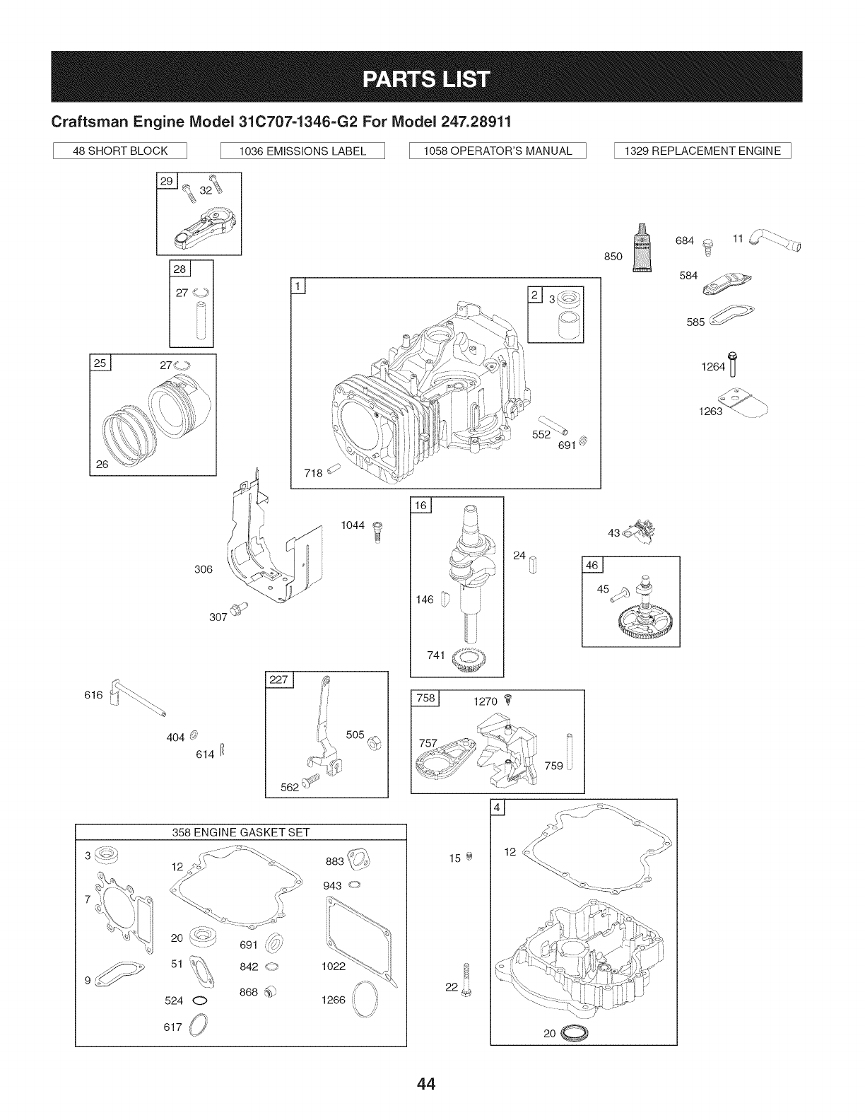
Craftsman Engine IViodel 31C707=1346=G2 For IViodel 247.28911
48 SHORT BLOCK 1036 EMiSSiONS LABEL 1058 OPERATOR'S MANUAL 1329 REPLACEMENT ENGINE I
306
q
616 _f
_f
505
358 ENGINE GASKET SET
12
20:,_
51 {_'_,,
.....\,%
524 0
617 ¢.j
691 _:///
842 <-_
868 _'_'
943 _""
1022
1266 ,!_
85O
741
1270
[i
759
15÷
22
200
684 _ 11 _ ......
584 _/_,_
585_
1264
44
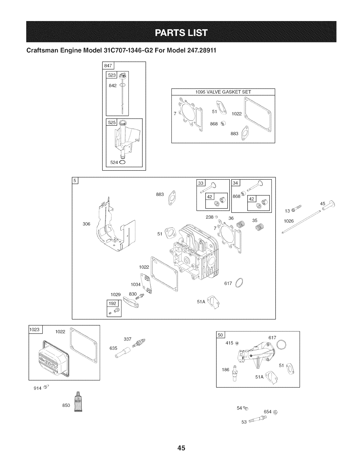
Craftsman Engine IViodel 31C707-1346-G2 For IViodel 247.28911
842 q_
524 0
1095 VALVE GASKET SET
51
868 _
1022
883
d
i
i
306
i
/
1029
1022
1034"_,,_
830
883
51
36 35
13J
1023_ 1022
337 617
914 _
85O 54% 654 I_
53 _- -SJ;_'_m:'
45
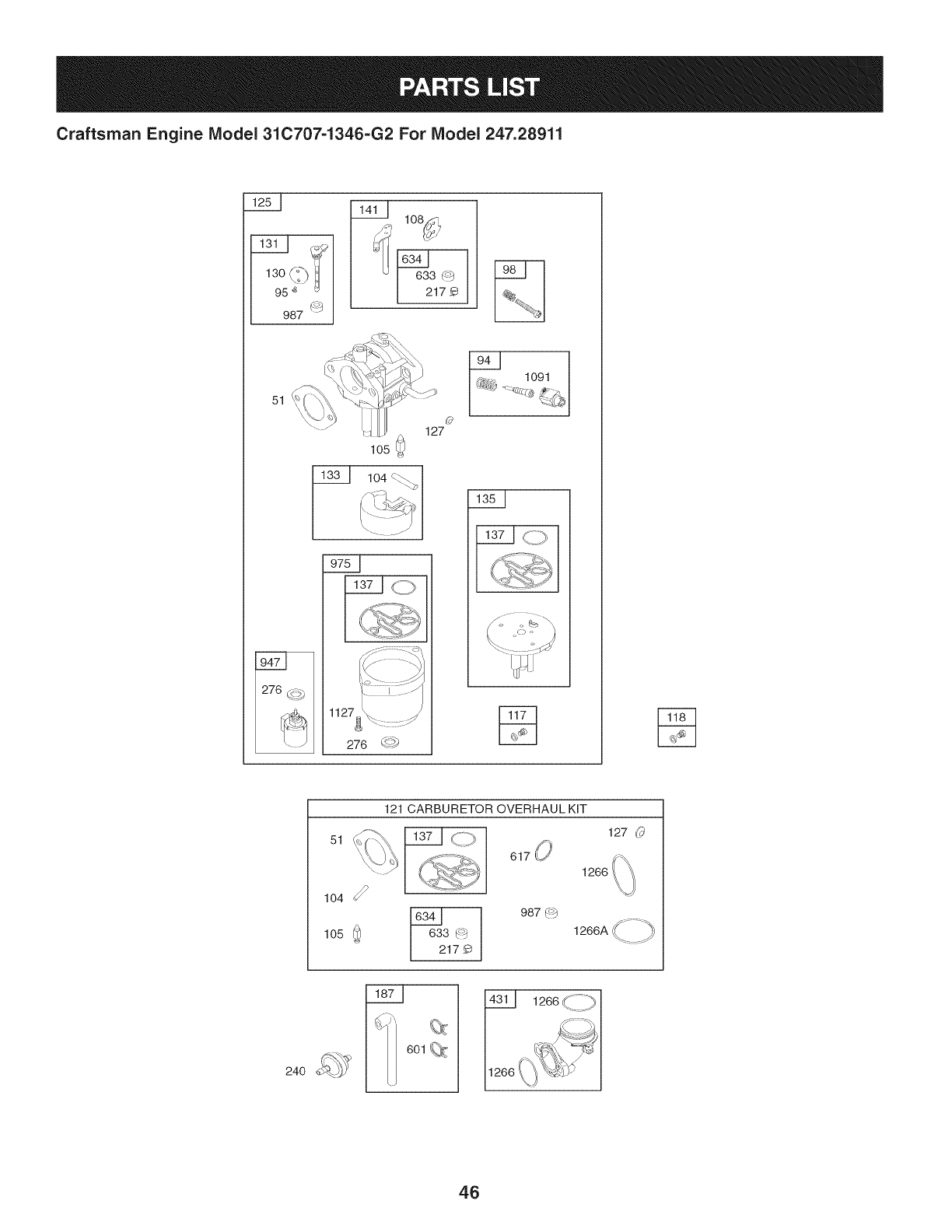
Craftsman Engine IViodel 31C707=1346=G2 For IViodel 247.28911
' 130_'_") I 633 (_
95_ _ I 217_
987 (_:_
51
o
127
276 _-?_
1091
%
51
121 CARBURETOR OVERHAUL KiT
617 LJ
127 (_
1266 I
987 (_
633 _
217._
601
46
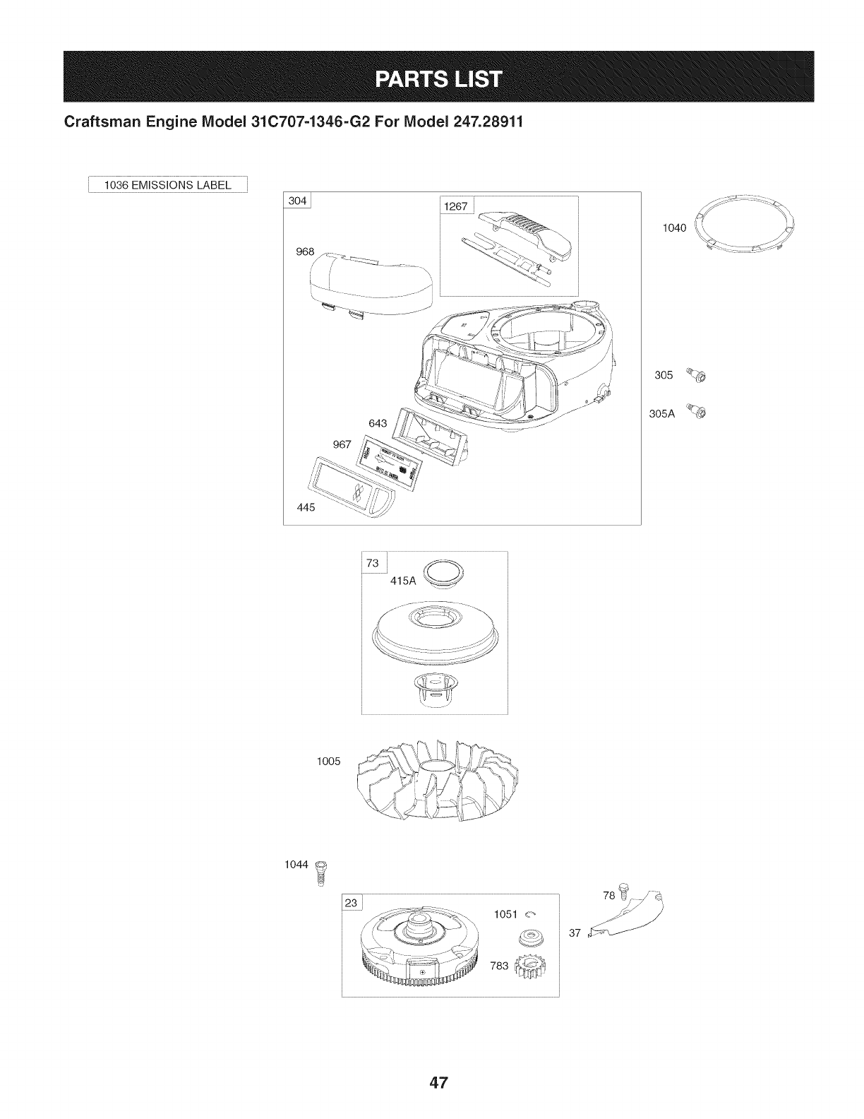
Craftsman Engine IViodel 310707-1346-G2 For IViodel 247.28911
1036 EMiSSiONS LABEL
i 1267 _
968 z, i
967
643
1040
305
305A
73i _,,
415A
1005
=_ i ,,',1 _, _¢_,_.
X '_i i_ ",:,,]J
_ X ,, !_v i /%-'%
1044
23 1051 <_'
783 ,i:I!3,1_S
78 _!, _ _'_
_:_ ....
47
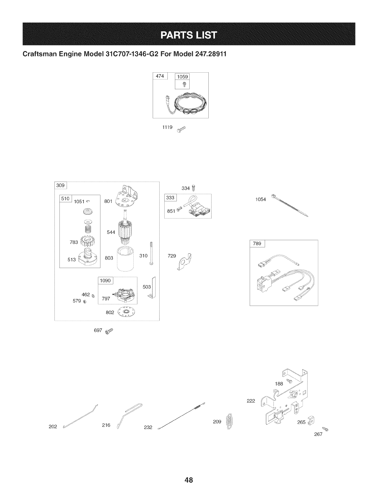
Craftsman Engine IViodel 31C707-1346-G2 For IViodel 247.28911
1119
3o9i
1051 _" 801
783
513
544
803 310
i ¸
462 _i 797 'L._9
579 _2
802 £L:_.J
697 _
729
334 _
1054
2O2 216 232
2O9
222
48
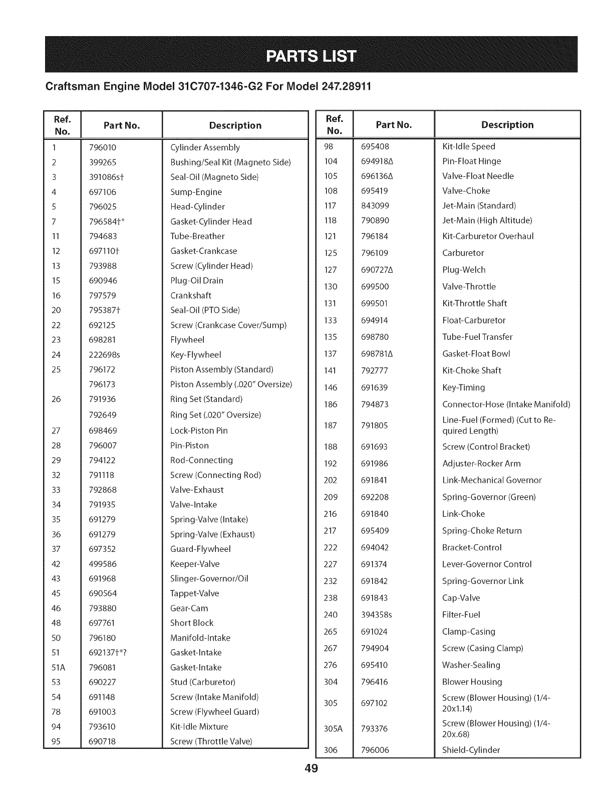
Craftsman Engine Model 31C707-1346-G2 For Model 247.28911
Ref, I
No,
1
2
3
4
5
7
II
12
13
15
16
2O
22
23
24
25
26
27
28
29
32
33
34
35
36
37
42
43
45
46
48
50
51
51A
53
54
78
94
95
Part No. Description
796010
399265
391086s1
697106
796025
7965841 _
794683
6971101
793988
690946
797579
7953871
692125
698281
222698s
796172
796173
791936
792649
698469
796007
794122
791118
792868
791935
691279
691279
697352
499586
691968
690564
793880
697761
796180
6921371_?
796081
690227
691148
691003
793610
690718
Cylinder Assembly
Bushing/Seal Kit (Magneto Side)
Seal-Oil (Magneto Side)
Sump-Engine
Head-Cylinder
Gasket-Cylinder Head
Tube-Breather
Gasket-Cra nkcase
Screw (Cylinder Head)
Plug-Oil Drain
Crankshaft
Seal-Oil (PTO Side)
Screw (Crankcase Cover/Sump)
Flywheel
Key-Flywheel
Piston Assembly (Standard)
Piston Assembly (.020" Oversize)
Ring Set (Standard)
Ring Set (.020" Oversize)
Lock-Piston Pin
Pin-Piston
Rod-Connecting
Screw (Connecting Rod)
Valve-Exhaust
Valve-Intake
Spring-Valve (Intake)
Spring-Valve (Exhaust)
Guard-Flywheel
Keeper-Valve
Slinger-Governor/Oil
Tappet-Valve
Gear-Cam
Short Block
Manifold-Intake
Gasket-Intake
Gasket-Intake
Stud (Carburetor)
Screw (Intake Manifold)
Screw (Flywheel Guard)
Kit-Idle Mixture
Screw (Throttle Valve)
49
Ref, Part No,
NO,
98 695408
104 694918&
105 696136&
108 695419
117 843099
118 790890
121 796184
125 796109
127 690727&
130 699500
131 699501
133 694914
135 698780
137 698781&
141 792777
146 691639
186 794873
187 791805
188 691693
192 691986
202 691841
209 692208
216 691840
217 695409
222 694042
227 691374
232 691842
238 691843
240 394358s
265 691024
267 794904
276 695410
304 796416
305 697102
305A 793376
306 796006
Description
Kit-Idle Speed
Pin-Float Hinge
Valve-Float Needle
Valve-Choke
Jet-Main (Standard)
Jet-Main (High Altitude)
Kit-Carburetor Overhaul
Carburetor
Plug-Welch
Va Ive-Th rottle
Kit-Throttle Shaft
Float-Carburetor
Tube-Fuel Transfer
Gasket-Float Bowl
Kit-Choke Shaft
Key-Timing
Connector-Hose (Intake Manifold)
Line-Fuel (Formed) (Cut to Re-
quired Length)
Screw (Control Bracket)
Adjuster-Rocker Arm
Link-Mechanical Governor
Spring-Governor (Green)
Link-Choke
Spring-Choke Return
Bracket-Control
Lever-Governor Control
Spring-Governor Link
Cap-Valve
Filter-Fuel
Clamp-Casing
Screw (Casing Clamp)
Washer-Sealing
Blower Housing
Screw (Blower Housing) (1/4-
20x1.14)
Screw (Blower Housing) (1/4-
20x.68)
Shield-Cylinder
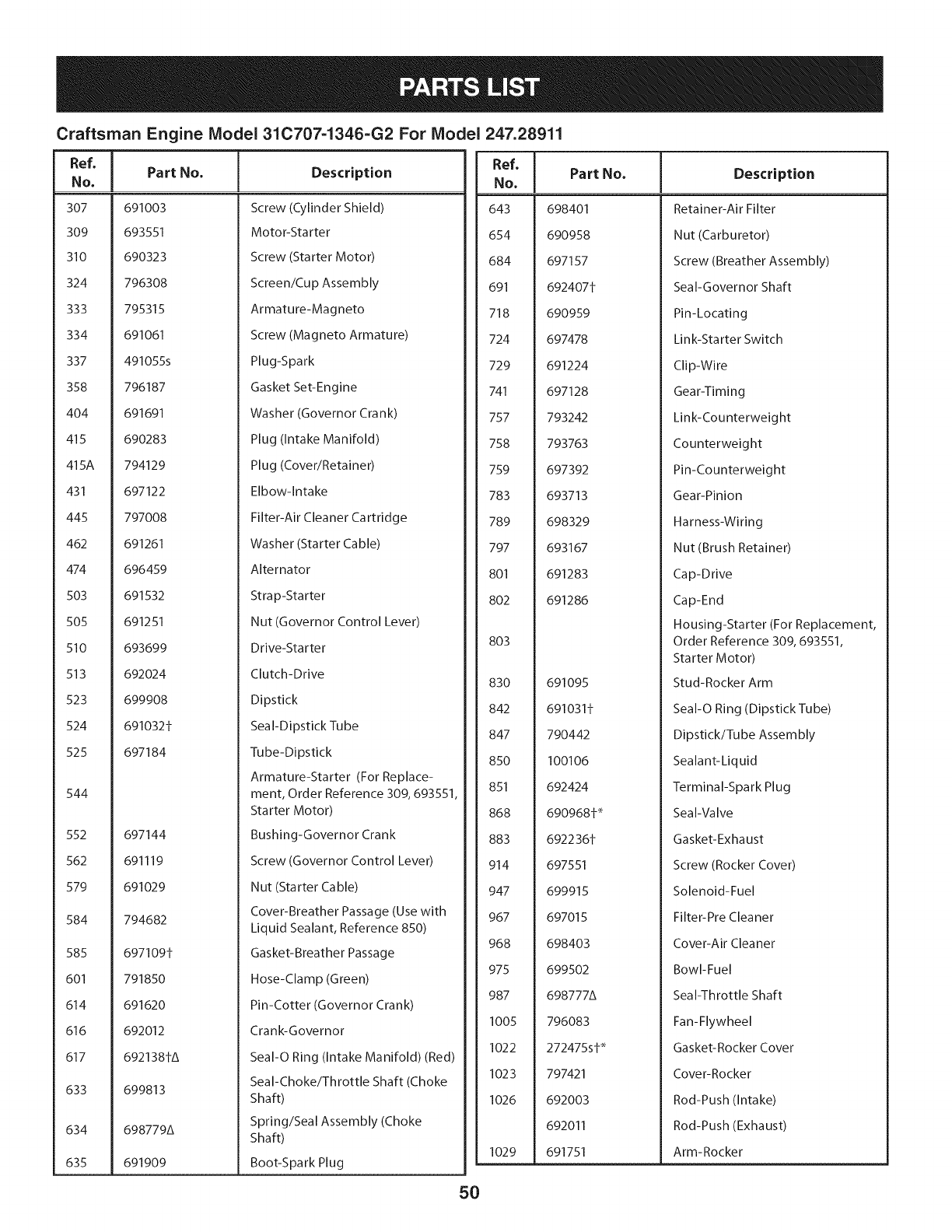
Craftsman Engine Model 31C707-1346=G2 For Model 247.28911
Ref,
No,
307 691003
309 693551
310 690323
324 796308
333 795315
334 691061
337 491055s
358 796187
404 691691
415 690283
415A 794129
431 697122
445 797008
462 691261
474 696459
503 691532
505 691251
510 693699
513 692024
523 699908
524 691032±
525 697184
544
552 697144
562 691119
579 691029
584 794682
585 697109±
601 791850
614 691620
616 692012
617 692138±A
633 699813
634 698779A
635 691909
Part No. Description
Screw (Cylinder Shield)
Motor-Starter
Screw (Starter Motor)
Screen/Cup Assembly
Armature-Magneto
Screw (Magneto Armature)
Plug-Spark
Gasket Set-Engine
Washer (Governor Crank)
Plug (Intake Manifold)
Plug (Cover/Retainer)
Elbow-Intake
Filter-Air Cleaner Cartridge
Washer (Starter Cable)
Alternator
Strap-Starter
Nut (Governor Control Lever)
Drive-Starter
Clutch-Drive
Dipstick
Seal-Dipstick Tube
Tube-Dipstick
Armature-Starter (For Replace-
ment, Order Reference 309, 693551,
Starter Motor)
Bushing-Governor Crank
Screw (Governor Control Lever)
Nut (Starter Cable)
Cover-Breather Passage (Use with
Liquid Sealant, Reference 850)
Gasket-Breather Passage
Hose-Clamp (Green)
Pin-Cotter (Governor Crank)
Crank-Governor
Seal-O Ring (Intake Manifold) (Red)
Seal-Choke/Throttle Shaft (Choke
Shaft)
Spring/Seal Assembly (Choke
Shaft)
Boot-Spark Plug
Ref, [
No,
643 698401
654 690958
684 697157
691 692407±
718 690959
724 697478
729 691224
741 697128
757 793242
758 793763
759 697392
783 693713
789 698329
797 693167
801 691283
802 691286
803
830 691095
842 691031±
847 790442
850 100106
851 692424
868 690968± _
883 692236±
914 697551
947 699915
967 697015
968 698403
975 699502
987 698777A
1005 796083
1022 272475s± _
1023 797421
1026 692003
692011
1029 691751
Part No. Description
Retainer-Air Filter
Nut (Carburetor)
Screw (Breather Assembly)
Seal-Governor Shaft
Pin-Locating
Lin k-Sta rte r Switch
Clip-Wire
Gear-Timing
Link-Counterweight
Counterweight
Pin-Counterweight
Gear-Pinion
Harness-Wiring
Nut (Brush Retainer)
Cap-Drive
Cap-End
Housing-Starter (For Replacement,
Order Reference 309, 693551,
Starter Motor)
Stud-Rocker Arm
Seal-O Ring (Dipstick Tube)
Dipstick/Tube Assembly
Sealant-Liquid
Terminal-Spark Plug
Seal-Valve
Gasket-Exhaust
Screw (Rocker Cover)
Solenoid-Fuel
Filter-Pre Cleaner
Cover-Air Cleaner
Bowl-Fuel
Seal-Throttle Shaft
Fan-Flywheel
Gasket-Rocker Cover
Cover-Rocker
Rod-Push (Intake)
Rod-Push (Exhaust)
Arm-Rocker
5O
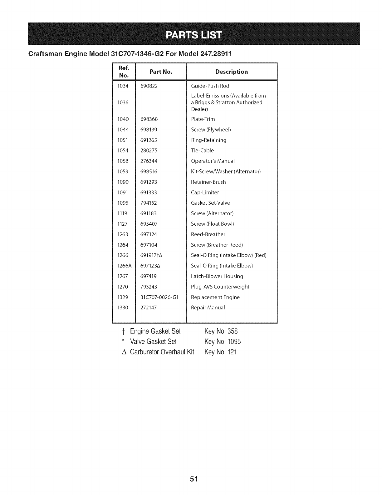
Craftsman Engine Model 31C707-1346-G2 For Model 247.28911
I
Ref, I Part No.
No, I
1034 690822
1036
1040 698368
1044 698139
1051 691265
1054 280275
1058 276344
1059 698516
1090 691293
1091 691333
1095 794152
1119 691183
I127 695407
1263 697124
1264 697104
1266 691917fA
1266A 697123A
1267 697419
1270 793243
1329 31C707-0026-GI
1330 272147
Description
Guide-Push Rod
Label-Emissions (Available from
a Briggs & Stratton Authorized
Dealer)
Plate-Trim
Screw (Flywheel)
Ring-Retaining
Tie-Cable
Operator's Manual
Kit-Screw/Washer (Alternator)
Retainer-Brush
Cap-Limiter
Gasket Set-Valve
Screw (Alternator)
Screw (Float Bowl)
Reed-Breather
Screw (Breather Reed)
Seal-O Ring (Intake Elbow) (Red)
Seal-O Ring (Intake Elbow)
Latch-Blower Housing
Plug-AVS Counterweight
Replacement Engine
Repair Manual
1 EngineGasket Set Key No.358
* ValveGasket Set Key No. 1095
A CarburetorOverhaul Kit Key No. 121
51

This page intentionally left blank. Use this page to make any notes regarding your tractor.
52

This page intentionally left blank. Use this page to make any notes regarding your tractor.
53
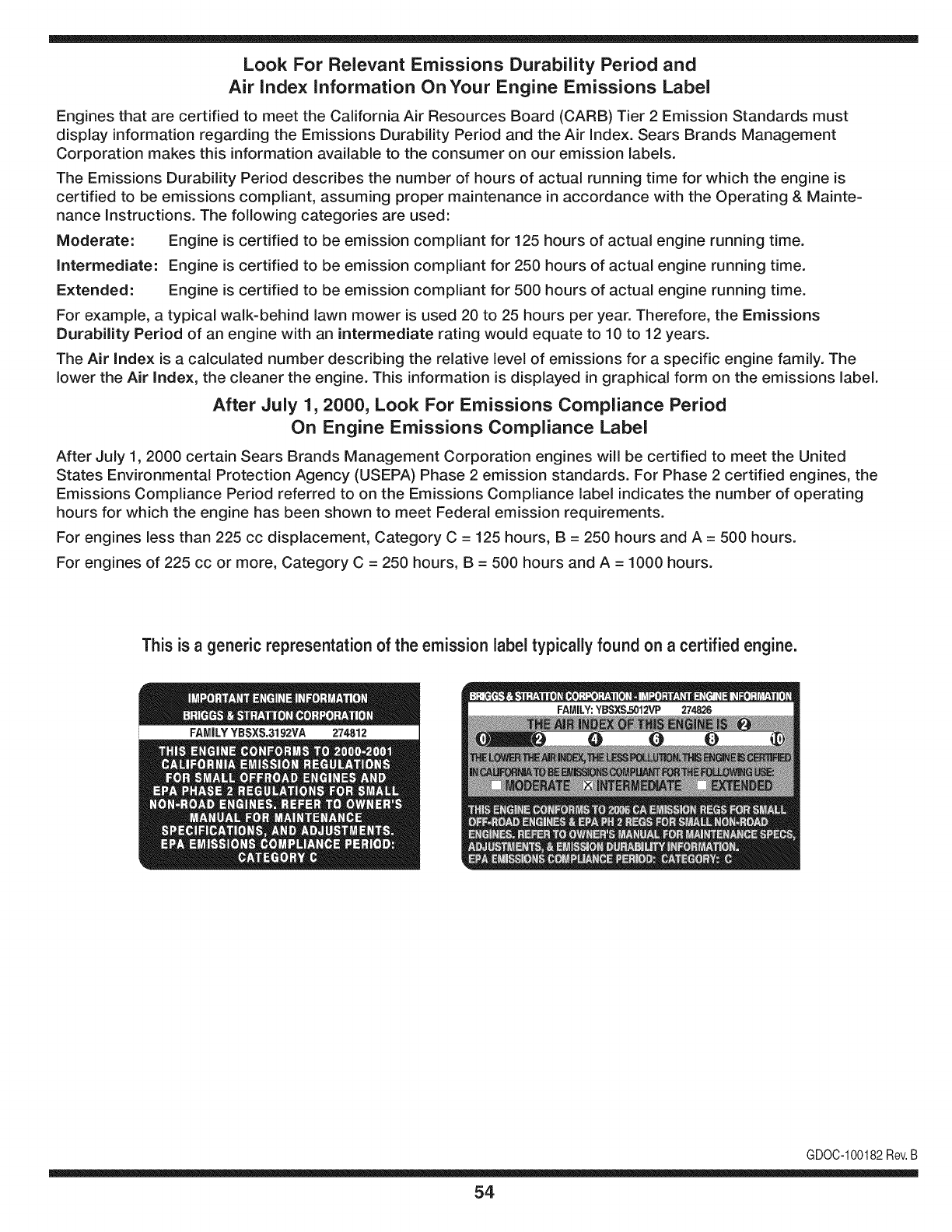
Look For Relevant Emissions Durability Period and
Air index information On Your Engine Emissions Label
Engines that are certified to meet the California Air Resources Board (CARB) Tier 2 Emission Standards must
display information regarding the Emissions Durability Period and the Air Index. Sears Brands Management
Corporation makes this information available to the consumer on our emission labels.
The Emissions Durability Period describes the number of hours of actual running time for which the engine is
certified to be emissions compliant, assuming proper maintenance in accordance with the Operating & Mainte-
nance Instructions. The following categories are used:
Moderate: Engine is certified to be emission compliant for 125 hours of actual engine running time.
Intermediate: Engine is certified to be emission compliant for 250 hours of actual engine running time.
Extended: Engine is certified to be emission compliant for 500 hours of actual engine running time.
For example, a typical walk-behind lawn mower is used 20 to 25 hours per year. Therefore, the Emissions
Durability Period of an engine with an intermediate rating would equate to 10 to 12 years.
The Air index is a calculated number describing the relative level of emissions for a specific engine family. The
lower the Air Index, the cleaner the engine. This information is displayed in graphical form on the emissions label.
After July 1,2000, Look For Emissions Compliance Period
On Engine Emissions Compliance Label
After July 1, 2000 certain Sears Brands Management Corporation engines will be certified to meet the United
States Environmental Protection Agency (USEPA) Phase 2 emission standards. For Phase 2 certified engines, the
Emissions Compliance Period referred to on the Emissions Compliance label indicates the number of operating
hours for which the engine has been shown to meet Federal emission requirements.
For engines less than 225 cc displacement, Category C = 125 hours, B = 250 hours and A = 500 hours.
For engines of 225 cc or more, Category C = 250 hours, B = 500 hours and A = 1000 hours.
This is ageneric representation of the emission label typically found on a certified engine.
FAMILYYBSXS.3192VA 274812
GDOC-100182Rev.B
54
(Thispageapplicableinthe U.S.A.and Canadaonly.)
Sears Brands Management Corporation (Sears), the California Air Resources Board (CARD)
and the United States Environmental Protection Agency (U.S. EPA)
Emission Control System Warranty Statement (Owner's Defect Warranty Rights and Obligations)
EMISSIONCONTROLWARRANTYCOVERAGEISAPPLICABLETOCERTI-
FIEDENGINESPURCHASEDINCALIFORNIAIN1995ANDTHEREAF-
TER,WHICHARE USEDINCALIFORNIA,ANDTOCERTIFIEDMODEL
California and United States Emission
The CaliforniaAir ResourcesBoard(CARD),U.S.EPAand Searsare pleased
to explainthe EmissionControlSystemWarrantyonyour modelyear2000and
latersmalloff-roadengine(SORE).InCalifornia,newsmall off-roadengines
mustbe designed,builtand equippedto meettheState'sstringentanti-smog
standards.Elsewherein theUnitedStates,newnon-road,spark-ignition
enginescertifiedfor modelyear 1997and latermustmeetsimilarstandardsset
forthbythe U.S.EPA.Searsmustwarranttheemissioncontrolsystemonyour
YEAR1997ANDLATERENGINESWHICHARE PURCHASEDAND USED
ELSEWHEREINTHEUNITEDSTATES(ANDAFTERJANUARY1,2001 IN
CANADA).
Control Defects Warranty Statement
enginefor theperiodsoftime listedbelow,providedtherehas beennoabuse,
neglector impropermaintenanceof your smalloff-roadengine.Youremis-
sion controlsystemincludespartssuch as thecarburetor,air cleaner,ignition
system,mufflerand catalyticconverter.Also includedmaybe connectorsand
otheremissionrelatedassemblies.Wherea warrantableconditionexists,Sears
will repairyour smalloff-roadengineat no costto you includingdiagnosis,parts
and labor.
Sears Emission Control Defects Warranty Coverage
Smalloff-roadenginesarewarrantedrelativeto emissioncontrolpartsdefects
fora periodof one year,subjectto provisionsset forthbelow.Ifanycovered
Owner's Warranty
Asthe smalloff-roadengineowner,youare responsiblefor theperformanceof
therequiredmaintenancelistedin yourOperatingand MaintenanceInstruc-
tions.Searsrecommendsthatyouretainallyourreceiptscoveringmaintenance
onyoursmalloff-roadengine,butSearscannotdenywarrantysolelyfor the
lackof receiptsorfor yourfailureto ensuretheperformanceof allscheduled
maintenance.As the smalloff-roadengineowner,youshouldhoweverbe
awarethat Searsmaydenyyouwarrantycoverageifyour smalloff-roadengine
ora part hasfaileddueto abuse,neglect,impropermaintenanceor unap-
parton yourengineis defective,the partwillbe repairedorreplacedbySears.
Responsibilities
provedmodifications.Youare responsiblefor presentingyour smalloff-road
engineto anAuthorizedSearsServiceDealeras soonas a problemexists.The
undisputedwarrantyrepairsshouldbecompletedina reasonableamountof
time,notto exceed30 days.Ifyou haveanyquestionsregardingyourwarranty
rightsand responsibilities,youshouldcontacta SearsService Representative
at 1-800-469-4663.The emissionwarrantyis a defectswarranty.Defectsare
judgedon normalengineperformance.Thewarrantyis notrelatedto an in-use
emissiontest.
Sears Emission Control Defects Warranty Provisions
ThefollowingarespecificprovisionsrelativetoyourEmissionControlDefectsWarrantyCoverage.ItisinadditiontotheSearsenginewarrantyfornon-regulated
enginesfoundin theOperatingand MaintenanceInstructions.
1. WarrantedParts
Coverageunderthis warrantyextendsonly to the parts listedbelow (the
emissioncontrolsystemsparts)to the extentthese partswere presenton
the enginepurchased.
a. FuelMeteringSystem
•Cold start enrichmentsystem
•Carburetorand internalparts
•FuelPump
b. AirlnductionSystem
•Aircleaner
•Intakemanifold
c. IgnitionSystem
•Sparkplug(s)
•Magnetoignitionsystem
d. CatalystSystem
•Catalyticconverter
•Exhaustmanifold
•Air injectionsystemor pulsevalve
e. MiscellaneousItemsUsedin AboveSystems
•Vacuum,temperature,position,timesensitivevalves
andswitches
•Connectorsandassemblies
2. Lengthof Coverage
Searswarrantsto the initialownerand eachsubsequentpurchaserthat
the WarrantedParts shallbefree fromdefects in materialsandworkman-
shipwhich causedthefailure of the WarrantedPartsfor a periodof one
yearfromthe datethe engineis deliveredto a retailpurchaser.
3. NoCharge
Repairor replacementof anyWarrantedPartwill be performedat no
chargeto the owner,includingdiagnosticlaborwhichleadsto the
determinationthata WarrantedPartis defective,ifthe diagnosticworkis
performedat an AuthorizedSears ServiceDealer.Foremissionswarranty
servicecontact yournearestAuthorizedSears ServiceDealeras listed in
the "YellowPages"under"Engines,Gasoline,""GasolineEngines,""Lawn
Mowers,"orsimilarcategory.
4. Claimsand CoverageExclusions
Warrantyclaimsshall be filed in accordancewiththe provisionsof the
SearsEngineWarrantyPolicy.Warrantycoverageshall beexcludedfor
failuresof WarrantedPartswhichare notoriginal Searspartsor because
of abuse,neglector impropermaintenanceas setforth inthe Sears
EngineWarrantyPolicy.Searsisnotliableto coverfailuresof Warranted
Partscausedby theuse of add-on,non-original,or modifiedparts.
5. Maintenance
Any WarrantedPart whichis notscheduledfor replacementas required
maintenanceor whichis scheduledonly for regularinspectionto the effect
of "repairor replaceas necessary"shallbe warrantedasto defectsfor the
warrantyperiod.AnyWarrantedPartwhich is scheduledfor replacement
as requiredmaintenanceshallbe warrantedasto defectsonly forthe
periodof time up to the first scheduledreplacementfor that part. Any
replacementpart that isequivalentin performanceand durabilitymay
be usedin the performanceof any maintenanceor repairs.Theowneris
responsibleforthe performanceof allrequiredmaintenance,as definedin
the SearsOperatingand MaintenanceInstructions.
6. ConsequentialCoverage
Coveragehereundershallextendto thefailure of any enginecomponents
caused bythe failureof anyWarrantedPartstill underwarranty.
Inthe USAandCanada,a 24hourhotline, 1-800-469-4663,has a menuof pre-recordedmessagesofferingyou enginemaintenanceinformation.
GD0C-100188Rev.B
55
FEDERAL and/or CALIFORNIA EMISSION CONTROL WARRANTY STATEMENT
YOUR WARRANTY RIGHTS AND OBLIGATIONS
MTDConsumerGroupInc,the UnitedStatesEnvironmentalProtectionAgency (EPA),and, forthose productscertifiedfor sale in the stateof California,the
CaliforniaAir ResourcesBoard(CARB)are pleasedto explainthe emission(evaporativeand/or exhaust)controlsystem(ECS) warrantyonyouroutdoor2006
andlater smalloff-roadspark-ignitedengineandequipment(outdoorequipmentengine)In California,new outdoorequipmentenginesmustbe designed,built and
equippedto meetthe State'sstringentanti-smogstandards(inotherstates, 1997andlater modelyear equipmentmustbedesigned,built,and equippedto meet
theU.S. EPAsmalloff-road,sparkignitionengineregulations.MTDConsumerGroupInc mustwarrantthe ECSonyour outdoorequipmentenginefor the periodof
timelisted belowprovidedtherehas been noabuse, neglector impropermaintenanceof outdoorequipmentengine.
YourECSmayincludeparts such as thecarburetor,fuel-injectionsystem,the ignitionsystem,catalyticconverter,fuel tanks,fuel lines,fuelcaps,valves,canisters,
filters,vaporhoses,clamps,connectors,andotherassociatedemission-relatedcomponents.
Wherea warrantableconditionexists, MTDConsumerGroupIncwill repairyouroutdoorequipmentengineat no cost to you includingdiagnosis,parts and labor.
MAN UFACTURER'S WARRANTY COVERAGE:
Thisemissioncontrolsystemiswarrantedfor two years. If anyemission-relatedparton your outdoorequipmentengineis defective,the part will be repairedor
replacedby MTDCONSUMERGROUPINC.
OWNER'S WARRANTY RESPONSIBILITIES:
Asthe outdoorequipmentengineowner,you are responsiblefor performanceof the requiredmaintenancelisted inyour owner'smanual.MTDConsumerGroup
Inc recommendsthat you retainallreceiptscoveringmaintenanceon youroutdoorequipmentengine,butMTDConsumerGroupInc cannotdeny warrantysolely
forthe lackof receipts.
Asthe outdoorequipmentengineowner,you shouldhoweverbe awarethat MTDConsumerGroupInc maydenyyou warrantycoverageifyour outdoorequipment
engineor a part hasfaileddue toabuse,neglect,or impropermaintenanceor unapprovedmodifications.
Youare responsiblefor presentingyouroutdoorequipmentengineto MTDConsumerGroupInc'sdistributioncenterorservicecenteras soon asthe problem
exists.Thewarrantyrepairsshouldbecompletedin a reasonableamountoftime, notto exceed30 days.If youhavea questionregardingyour warrantycoverage,
you shouldcontactthe MTDConsumerGroupIncService Departmentat 1-800-800-7310orvia emailat http://support.mtdproducts.com
GENERAL EMISSIONS WARRANTY COVERAGE:
MTDConsumerGroupIncwarrantsto the ultimatepurchaserand eachsubsequentpurchaserthat theoutdoorequipmentengineis: Designed,built and equipped
so asto conformwithall applicableregulations;and freefromdefects in materialsand workmanshipthatcausethe failureof a warrantedpart to be identicalin all
materialrespectsto that part as describedin MTDConsumerGroup Inc'sapplicationfor certification.
The warrantyperiodbeginsonthedate theoutdoorequipmentengineis deliveredto anultimatepurchaserorfirst placedinto service.The warrantyperiodis two
years.
Subjectto certainconditionsand exclusionsasstated below,the warrantyonemission-relatedparts is asfollows:
1. Any warrantedpart that is notscheduledfor replacementas requiredmaintenancein thewritten instructionssupplied, iswarrantedforthe warrantyperiod
statedabove. Ifthe part fails duringthe periodof warrantycoverage,thepart will be repairedor replacedbyMTDConsumerGroupInc accordingto subsection
(4)below.Anysuchpart repairedor replacedunderwarrantywillbewarrantedfor the remainderof the period.
2. Any warrantedpartthat isscheduledonlyfor regularinspectionin the writteninstructionssuppliedis warrantedforthe warrantyperiodstatedabove.Anysuch
partrepairedor replacedunderwarrantywill bewarrantedforthe remainingwarrantyperiod.
3. Any warrantedpartthat is scheduledfor replacementas requiredmaintenancein thewritten instructionssuppliediswarrantedfor the periodof timebeforethe
firstscheduledreplacementdatefor that part.If the partfails beforethefirst scheduledreplacement,the part will be repairedor replacedby MTDConsumer
GroupInc accordingto subsection(4)below.Any suchpart repairedor replacedunderwarrantywill be warrantedfor the remainderof the periodprior to the
firstscheduledreplacementpointfor the part.
4. Repairor replacementof any warrantedpart underthe warrantyprovisionshereinmustbe performedat a warrantystationat no chargeto the owner.
5. Notwithstandingthe provisionsherein,warrantyservicesor repairswill be providedat all of our distributioncentersthatare franchisedto servicethe subject
enginesor equipment.
6. The outdoorequipmentengineownerwill notbe chargedfor diagnosticlaborthat is directlyassociatedwithdiagnosisof a defective,emission-relatedwar-
rantedpart, providedthat suchdiagnosticwork is performedat a warrantystation.
7. MTDConsumerGroupInc is liablefor damagesto otherengineor equipmentcomponentsproximatelycausedby a failure underwarrantyof any warranted
part.
8. Throughoutthe off-roadengineand equipmentwarrantyperiodstatedabove,MTDConsumerGroupInc will maintaina supplyof warrantedparts sufficientto
meetthe expecteddemandfor suchparts.
9. Any replacementpart maybe usedinthe performanceof anywarrantymaintenanceor repairsand mustbeprovidedwithoutchargeto the owner.Suchuse will
notreducethe warrantyobligationsof MTDConsumerGroupInc.
10.Add-onor modifiedpartsthat are notexemptedbythe Air ResourcesBoardmaynot beused.The useof any non-exemptedadd-onor modifiedpartsby the
ultimatepurchaserwill begroundsfor disallowinga warrantyclaims. MTDConsumerGroup Incwill not be liableto warrantfailuresof warrantedparts caused
bythe useof a non-exemptedadd-onor modifiedpart.
WARRANTED PARTS:
The repairor replacementof any warrantedpart otherwiseeligiblefor warrantycoveragemaybe excludedfromsuch warrantycoverageif MTDConsumerGroup
Inc demonstratesthatthe outdoor equipmentenginehas beenabused,neglected,orimproperlymaintained,and thatsuch abuse,neglect,or impropermainte-
nancewasthe direct causeof the needfor repairor replacementof the part.Thatnotwithstanding,anyadjustmentofa componentthat hasa factoryinstalled,
andproperlyoperating,adjustmentlimitingdeviceis still eligible for warrantycoverage.Further,the coverageunderthis warrantyextendsonly to partsthat were
presentonthe off-roadengineand equipmentpurchased.
Thefollowing emissionwarrantypartsare covered(if applicable):
(1)FuelMeteringSystem
• Cold start enrichmentsystem(softchoke)
• Carburetorand internalparts (orfuel injectionsystem)
• Fuelpump
• Fueltank
(2)Air InductionSystem
• Aircleaner
• Intakemanifold
(3) IgnitionSystem
• Sparkplug(s)
• Magnetoignitionsystem
(4) ExhaustSystem
• Catalyticconverter
• SAI(Reed valve)
(5) MiscellaneousItemsUsedin AboveSystem
• Vacuum,temperature,position,timesensitivevalvesand switches
• Connectorsandassemblies
(6) EvaporativeControl
• Fuelhose
• Fuelhoseclamps
• Tetheredfuel cap
• Carboncanister
• Vapor lines
GDOC-100223Rev.A

Congratulationson makinga smartpurchase.YournewCraftsman@
productis designedandmanufacturedfor yearsof dependableopera-
tion.But likeall products,it mayrequirerepairfromtimeto time.That's
whenhavinga RepairProtectionAgreementcansaveyoumoneyand
aggravation.
Here'swhatthe RepairProtectionAgreement*includes:
* Expert service byour 10,000professionalrepairspecialists
oUnlimitedserviceand no chargefor partsand laboron all
coveredrepairs
o Product replacementupto $1500if yourcoveredproductcan't be
fixed
•Discountof 10%from regularprice of serviceand relatedinstalled
partsnotcoveredby theagreement;also,10%off regularpriceof
preventivemaintenancecheck
• Fast help by phone- we call it RapidResolution- phonesupport
froma Searsrepresentative.Thinkof usas a "talkingowner's
manual."
Onceyou purchasethe Agreement,a simplephonecall is all thatit
takesfor youto scheduleservice.Youcan call anytimedayor night,or
schedulea serviceappointmentonline.
The RepairProtectionAgreementis a risk-freepurchase.If youcancel
for any reasonduringthe productwarrantyperiod,wewill provideafull
refund.Or,a proratedrefundanytimeafterthe productwarrantyperiod
expires.Purchaseyour RepairProtectionAgreementtoday!
Somelimitationsand exclusionsapply. For pricesand additional
informationin the U.S.A.call 1-800-827-6655.
*Coverage inCanadavaries on some items.Forfull details call
Sears Canadaat 1-800-361-6665.
Sears Installation Service
ForSearsprofessionalinstallationof homeappliances,garagedoor
openers,waterheaters,andothermajorhomeitems,in the U.S.A.or
Canadacall 1-800-4-MY-HOME®.
58
Operaci6n segura Practicas .......... Paginas 58 Fuera de temporada de almacenamiento .. Page 83
Etiquetas De Seguridad ................ Page 58 Solucion de problemas ................ Page 84
Asamblea ........................... Page 65 Lista de piezas ..................... Paginas 30
Operacion de ...................... Paginas 67 Reparaci6n de Acuerdo de Proteccion .... Page 89
De Servicio y Mantenimiento de ....... Paginas 74 Servicio de nOmeros ............ atrasados Page
Artesano Garantia completa
Cuandose explotany mantienendeacuerdocon todaslasinstruccionessuministradas,encasodecualquierparte nofungiblesde esteequipo
demontarfalla debidoa undefectode materialo manode obradurantedosa_osa partirde la fechao la compra,Ilameal 1-800-659-5917para
organizarde formagratuitareparaci6nen el hogar.
Elmarcoy eleje delanteroser_reparadode formagratuitadurantecincoa_os a partirdela fechade comprasi est_defectuosoenel materialo
manode obra.
Todala coberturade la garantiaanteriorse aplicas61odurante90dias desdela fechadecomprasi el equipodeconducci6nes cadavez
utilizadocon finescomercialeso dealquiler.
Entodosloscasos,si la reparaci6nresultaimposible,el equipode montara caballoserAsustituidodeformagratuitaconel mismomodeloo uno
equivalente.
Labateriase sustituyede formagratuitadurante90 d[asa partirdela fechade comprasi estAdefectuosoenel materialo manode obra
(nuestroan_lisisdemuestraquenova a mantenerunacarga).
Estagarantias61ocubrelos defectosde materialy manodeobra. Searsnopagar_por:
• Loselementosconsumiblesquese desgastandurantesu usonormal,incluyendoperonolimitadoalas hojas,bujias,filtrosde aire,correas
y filtrosde aceite.
• Prestaci6nde serviciosde mantenimientonormal,cambiosdeaceite,o puestasa punto.
Lasustituci6no reparaci6nde neumAticoscausadaporpinchazosde los objetosexternos,talescomoclavos,espinas,troncos,o devidrio.
• O reemplazode Ilantasde laruedao de reparaci6nque resultendeldesgastenormal,accidentes,u operaci6no mantenimientoinadec-
uado.
• Reparacionesnecesariasdebidoalabusodeloperador,incluyendoperonolimitadoada_oscausadosporobjetosde arrastrem_sall_de
lacapacidadde los equiposde equitaci6n,queafectanlosobjetosque sedoblanel marcoo el cigOe_al,o excesode velocidaddel motor.
• Reparacionesnecesariasdebidoa lanegligenciadeloperador,incluyendoperonolimitadoa, da_osel_ctricosy mec_nicoscausadospor
unalmacenamientoinadecuado,faltade utilizaci6nde lacategoriaapropiaday lacantidaddeaceitedelmotor,faltade mantenimientodela
cubiertaclarade los residuosinflamables,o faltade mantenimientode lacabalgataequipode acuerdoa las instruccionescontenidasenel
manualdeloperador.
• Del motor(sistemade combustible),lalimpiezao reparacionescausadasporcombustibledeterminadadecontaminaci6no oxidado
(rancio).Engeneral,el combustibledebe serutilizadadentrode 30dias de sufechadecompra.
• Eldeterioroy desgastenormaldelos acabadosexteriores,o la sustituci6netiquetadelproducto.
• Estagarantiase aplicas61ocuandoesteproductose encuentradentrode los EstadosUnidos.
Estagarantialeotorgaderechoslegalesespecificos,y ustedtambi_npuedetenerotrosderechosquevariandeestadoa estado.
• Eldeterioroy desgastenormaldelos acabadosexteriores,o la sustituci6netiquetadelproducto.
Estagarantiaseaplica s61ocuandoeste productose encuentradentrode los EstadosUnidos.
Estagarantialeotorgaderechoslegalesespecificos,y ustedtambi_npuedetenerotrosderechosque variandeestadoa estado.
Sears, Roebuck and Co. Hoffman Estates, IL 60179
BrutoHP: 17.5
Aceitedel motor: SAE30
Combustible: Gasolinasinplomo
Bujia: Champion®RC12YC
Motor: Briggs& StrattonI/C®
N_mero de modelo ..........................................................
N_rnero de serie ..............................................................
Fechade compra .............................................................
Registrearribael nOmerodel modelo,el nOmerode seriey la fecha
de compra
©SearsBrands,LLC
59
Lapresenciade estesirnboloindicaque setratade instrucciones
irnportantesde seguridadquese debenrespetarparaevitar
ponerenpeligrosu seguridadpersonaly/o materialy lade otras
personas.Leay sigatodaslasinstruccionesdeestemanualantes
de poneren funcionarnientoestarn_.quina.Si no respetaestas
instruccionespodriaprovocarlesionespersonales.Cuandoveaeste
sirnbolo,ipresteatenci6na la advertencia!
PROPOSICION 65 DE CALIFORNIA
Elescapedel motorde esteproducto,algunosdesuscornponentes
y algunoscornponentesdelvehiculocontieneno liberansustancias
quirnicasqueelestadode Californiaconsideraque puedenproducir
c_.ncer,defectosde nacirnientouotrosproblernasreproductivos.
Losbornesdela bateriay losaccesoriosdines contienenplornoy
cornpuestosde plorno,sustanciasqdrnicas quesegQnIoestableci-
do pot el EstadodeCaliforniacausanc_.ncery da_osenel sisterna
reproductivo.Ldveselas manos despu_sde estaren contacto
con estoscomponentes.
Estarn_.quinarueconstruidaparaseroperadadeacuerdocon
las reglasde seguridadcontenidasenestemanual.AI igualque
concualquiertipo deequipornotorizado,undescuidoo errorpor
partedeloperadorpuedeproducirlesionesgraves.Estarn_.quina
es capazde arnputarrnanosy piesy dearrojarobjetoscon gran
fuerza.De norespetarlas instruccionesde seguridadsiguientesse
puedenproducirlesionesgraveso la rnuerte.
Su responsabilidad--Restrinja el usode estarn_.quina
rnotorizadaalas personasque lean,cornprendany respetenlas
advertenciase instruccionesqueaparecenenestemanualyen la
rn_.quina.
iGUARI)E ESTASINSTRUCCIONES!
FUNCIONAIVIIENTO GENERAL
• Lea,entienday curnplatodaslas instruccionesincluidasen
la rn_.quinayen los rnanualesantesde rnontarlay utilizarla.
Guardeestemanualenun lugarseguroparaconsultasfuturasy
peri6dicas,asi cornoparasolicitarrepuestos.
•Farniliaricesecontodoslos controlesy con el usoadecuado
de losrnisrnos.Sepac6rnodetenerlarn_.quinay desactivarlos
controlesr_.pidarnente.
•No perrnitanuncaque losni_os rnenoresde 14a_osutilicen
estarn_.quina.Los ni_osde 14a_osenadelantedebenleery
entenderlas instruccionesde operaci6ny norrnasdeseguridad
contenidasen estemanual,yen la rn_.quinay debenser
entrenadosy supervisadosporun adulto.
•Nuncaperrnitaquelos adultosoperenestarn_.quinasin recibir
antesla instrucci6napropiada.
•Paraayudara evitarelcontactocon las cuchillaso unalesi6npor
algQnobjetoqueseaarrojado,rnantengaa los observadores,a
los ayudantes,ni_osy rnascotasalejadosal rnenos25 metrosde
la rn_.quinarnientrasest,.en funcionarniento.Detengala rn_.quina
si alguienentraen lazona.
•Inspeccionerninuciosarnenteel Areadondeutilizar_,el equipo.
Retiretodaslas piedras,palos,cables,huesos,juguetesy otros
objetosextra_osquepodrianser recogidosy arrojadosporla
acci6nde lascuchillas.Losobjetosarrojadosporla rn_.quina
puedenproducirlesionesgraves.
•Planifiqueel patr6nde cortedelc_spedque hadeseguirpara
evitarla descargade materialhacialoscarninos,lasveredas,los
observadores,etc. Eviteadern_.sdescargarmaterialcontralas
paredesy obstruccionesquepodrianprovocarqueel material
descargadorebotecontrael operador.
•Paraprotegerselos ojosutilicesiernpreanteojoso antiparras
de seguridadrnientrasoperalarn_.quinao rnientraslaajusta
o repara.Losobjetosarrojadosque rebotanpuedenproducir
lesionesocularesgraves.
• Utilicezapatosde trabajoresistentes,desuelafuerte,asi corno
pantalonesy carnisasajustados.Lasprendassueltaso las
alhajaspuedenquedaratrapadasen las piezasrnovibles.Nunca
operela rn_.quinadescalzoo con sandalias.
• Est_atentoa lacortadoray a la direcci6ndela descargade
los aditarnentosy noapuntea nadie.Nuncaoperela cortadora
de cespedsin queest_nen su lugarapropiadola cubiertade
descargao elcolectorde recortesde c_sped.
• Nopongalas rnanoso los piescercade las piezasrotatoriaso
debajode la plataforrnadecorte. Elcontactocon las cuchillas
puedeproducirlaarnputaci6ndernanosy pies.
• Unacubiertadedescargafaltanteoda_adapuedeprovocarel
contactoconla cuchillao lesionesporobjetosarrojados.
• Detengala(s)cuchilla(s)cuandoatraviesesenderos,sendaso
carninosdegravay cuandonoest_cortandoel c_sped.
• Vigileeltr_.nsitovehicularcuandoest_operandocercadeoen
crucesde carninos.Estarn_.quinanodebeutilizarseenlavia
pQblica.
• Noopereestarn_.quinabajolosefectosdelalcoholode drogas.
• Corteelcespedsolarnentecon luzdediao con unabuenaluz
artificial.
• Nuncatransportepasajeros.
• Desenganchela(s)cuchilla(s)antesdecolocarlarnarchaatrAs.
Retrocedalentarnente.Siernpremirehaciaabajoy haciaatr_.santes
y rnientrasretrocede,paraevitaraccidentes.
• Reduzcalavelocidadantesdedarlavuelta.Operelarn_.quina
suavernente.Evitelaoperaci6nerr_.ticay la velocidadexcesiva.
• Desenganchela(s)cuchilla(s),coloqueelfrenodeestaciona-
rniento,detengael motory esperehastaquela(s)cuchilla(s)se
detenga(n)pot cornpletoantesderetirarelcolectorde cesped,
vaciarlos recortes,destaparelcanal,retirarrestosdec_spedo
desechos,ohacercualquierajuste.
6O
• Nuncadejelarn_.quinaenfuncionarnientosinvigilancia.Apague
siernprelascuchillas,coloqueelfrenodernano,detengaelmotory
retirela Ilaveantesdebajarsedelvehiculo.
• Tengasurnocuidadoalcargaro descargarla rn_.quinaen un
rernolqueocarni6n.Estaunidadnodebeconducirseenascensoo
descensoderarnpas,porquepodrialadearsey provocarlesiones
personalesgraves.Enlas rarnpasla rn_.quinase debeernpujar
rnanualrnenteparacargarlao descargarlacorrectarnente.
• Elsilenciadory elmotorse calientany puedencausarquernaduras.
No lostoque.
• Reviseelespaciolibrepot encirnade lacabezaantesdeconducir
bajolas rarnasbajasde_.rboles,cables,cerrarnientosde puertas,
etc.enloscualeseloperadorpodriaatorarseo seternpujadofuera
dela rn_.quina,Ioquepodriaresultarenlesionesgraves.
• Desenganchetodoslosernbraguesde losaccesoriosy presione
totalrnenteel pedaldelfrenoantesdeintentararrancarel motor.
• Larn_.quinaest,.dise_adaparacortarc_spedresidencialnormal,
conunaalturanomayora 10".Nointentecortarcespeddernasiado
crecido,seco(porej.,pastura)nipilasde hojassecas.Elc_sped
y las hojassecaspuedenentrarencontactocon elescapedel
motory/o acurnularseenla plataforrnadelacortadoradecesped,
convirti_ndoseen unpeligrodeincendio
• Utilicesolarnenteaccesoriosy aditarnentosaprobadosparaesta
rn_.quinapot elfabricantedelarnisrna.Lea,cornprenday siga
todaslasinstruccionesproporcionadascon losaccesorioso
aditarnentosaprobados.Paraobtenerunalistadelos accesorios
aprobadosy losarchivosadjuntos,Ilarne1-800-659-5917.
• Losdatosestadfsticosrnuestranquelosoperadoresde60 a_os
y rnayoresseven involucradosenunaltoporcentajedelesiones
relacionadascontractorescortacesped.Estosoperadoresdeben
evaluarsu capacidadparaoperareltractorcortac_spedenforrna
suficienternenteseguraparaprotegersea ellosrnisrnosy a los
dern_.scontralesionesgraves.
Si se presentansituacionesqueno est_.nprevistaseneste
manualsea cuidadosoy use el sentidocornOn.Contacto1-800-
659-5917parainforrnaci6ny asistencia.
FUNCIONAMIENTO EN PENDIENTES
Las pendientesson unfactorirnportanterelacionadoconaccidentes
porderrapey vuelcosquepuedenproducirlesionesgravese incluso
la rnuerte.Laoperaci6nen pendientesrequiemmayorprecauci6n.
Si nopuederetrocederen lapendienteo si no se sienteseguro,no
realiceningunaoperaci6ndecorte.
Parasuseguridad,use el indicadorde pendientesquese incluye
cornoparte deestemanualpararnedirla pendienteantesde operarla
rn_.quinaenunazonainclinada.Si lapendientees mayorde 15grados
segOnelrnedidor,noopereestarn_.quinaenese sector,puespodria
causarlesionesgraves.
HagaIo siguiente:
•Podehaciaarribay abajode laspendientes,node forrnatrans-
versal.Tengacuidadocuandocarnbiededirecci6nal operaren
pendiente.
•Est_atentoa loshoyos,surcos,baches,rocas,uotrosobjetos
ocultos.Elterrenodesniveladopuedevoltearla rn_.quina.Elcesped
altopuedeocultarobst_.culos.
Vayaa bajavelocidad.ElijaunavelocidadIosuficienternentebaja,
de rnodoquenotengaquedetenerseo hacercarnbiosrnientras
est,.sobrela pendiente.Losneurn_.ticospodrianperdertracci6n
sobrelaspendientesa[3ncuandolos frenosfuncionaranapro-
piadarnente.Siernprernantengala rn_.quinaen carnbiornientras
desciendelaspendientes,parapoderfrenarconel motor.
• Sigalas recornendacionesdelfabricanteparalos pesoso contra-
pesosdelas ruedas,pararnejorarlaestabilidaddela rn_.quina.
Pararecornendaciones,Ilarneal 1-800-659-5917.
•Tengaespecialcuidadocon loscolectoresdec_speduotros
aditarnentos.Losrnisrnospuedenrnodificarlaestabilidaddela
rn_.quina.
• Hagaquetodoslosrnovirnientosenlas pendientesseanlentosy
graduales.Nocarnbierepentinarnentelavelocidadniladirecci6n.
Unfrenadoo carnbiodevelocidadrepentinospuedencausarque
el frentede larn_.quinase levantey d_ unavolteretahaciaatr_.s,Io
quepodriaproducirlesionesgraves.
• Evitearrancaro detenerseenunapendiente.Silosneurn_.ticos
pierdenlatracci6n,desenganchelascuchillasy descienda
lentarnentelapendiente.
No hagaIo siguiente:
•Nogiresobrelaspendientesa rnenosqueseanecesario.Sies
posible,girelentarnentey gradualrnenteduranteeldescenso.
•Nocorteelc_spedcercadepozos,hundirnientoso terraplenes.La
cortadoradec_spedpuedevolcarserepentinarnentesiunadelas
ruedasest,.sobreel hordedeunacantilado,zanjao siunhordese
desrnorona.
•Nointenteestabilizarlarn_.quinaponiendoelpieenelsuelo.
•Noutiliceuncolectordecespeden pendientesernpinadas.
•NopodeelcespedhOrnedo.Unarnenortracci6npodriacausar
derrapes.
•Noparadescender.Elexcesodevelocidadpuedehacerqueel
operadorpierdaelcontroldelarn_.quina,ocasionandolesiones
graveseinclusolarnuerte.
•Norernolquecargaspesadasdetr_.sdelosaditarnentos(carritode
basuracargado,podadoraderodillos,etc)en pendientesrnayores
de5 grados.Cuandosedesplazapendienteabajo,elpesoadicional
tiendeaernpujareltractory puedehacerquese pierdaelcontrol
delmisrno(porejernplo,eltractorsepuedeacelerar,se reducela
capacidadparafrenary rnaniobrar,losaccesoriospuedenplegarse
cornouncortaplurnasy hacerqueeltractorvuelque).
NINOS
Puedenocurriraccidentestr_.gicossi el operadorno est,.atentoa la
presenciade ni_os.PotIo general,los ni_osse sientenatraidospor
estetipo dern_.quinasy su funcionarniento.Noentiendenlos riesgos
nilos peligros.Nuncaasurnaquelos ni_osperrnanecer_.nen el rnisrno
lugardondelos vio porQltirnavez.
Mantengaalosni_osfueradel_readetrabajoy bajoestricta
vigilanciadeunadultoresponsableadern_.sdelpropiooperador.
Est_alertay apaguelarn_.quinasiunni_oingresaal_.rea.
Antesy rnientrasest,.retrocediendo,mirehaciaatr_.sy cuidequeno
hayani_os.
Nuncatransporteni_os,aQnconlacuchillaapagada.Podriancaerse
y resultarseverarnenteheridoso interferirconlaoperaci6nsegurade
larn_.quina.
Tengaextrernaprecauci6ncuandoseaproxirnea esquinasciegas,
portales,arbustos,_.rbolesuotrosobjetosquepuedanirnpedirlever
a unni_oquesecruceenel recorridodelarn_.quina.
61
• Paraevitaraccidentesaloperarenrnarchaatr_.s,siernpredesengan-
chelascuchillasantesdecolocarrnarchaatr_.s.Siest,.instalado,
el"ModoPrecauci6nMarchaAtr_.s"(hojasdeoperarlarn_.quina,
rnientrasquelospaseosala inversa)nodebeutilizarsecuandohay
ni_osuotraspersonaspresentes.
• Mantengaa losni_osalejadosdelosrnotoresenrnarchao calientes.
Puedensufrirquernadurasconunsilenciadorcaliente.
• RetirelaIlavecuandodejelarn_.quinasinvigilancia,evitequeuna
personasinautorizaci6nlarnaneje.
No perrnitanuncaque losni_os rnenoresde 14a_os utilicenesta
rn_.quina.Los ni_osde 14a_osen adelantedebenleery entenderlas
instruccionesdeoperaci6ny norrnasde seguridadcontenidasen este
manual,yen la rn_.quinay debenserentrenadosy supervisadospor
unadulto.
REIVIOLQUE
• Rernolque_nicarnenteconunarn_.quinaquecuenteconun
enganchedise_adopararernolcar.Noacopleequiporernolcado
exceptoenelpuntodeenganche.
• SigalasrecornendacionesdelfabricanteenIoquerespectaalos
lirnitesdepesodelosequiposa rernolcary al rernolqueenpendien-
tes.Pararecornendaciones,Ilarneal 1-800-659-5917.
• Nuncaperrnitalapresenciadeni_osu otraspersonasdentroo sobre
losequiposrernolcados.
• Enlaspendientes,elpesodelequiporernolcadopuedecausar
p_rdidadetracci6ny perdidadecontroldela rn_.quina.
• Siernpreuseextralaprecauci6nrernolcandoconunarn_.quina
capazdehacervueltasapretadas(p.ejpaseo"devueltacero"-enel
cortac_sped).Hagaarnpliasvueltasparaevitaralgato-knifing.
• Despl_.ceselentarnentey dejedistanciaadicionalparafrenado.
• Noparadescender.
SERVIClO
Manejo seguro de la gasolina
Paraevitarlesionespersonaleso daSosrnaterialessea surnarnente
cuidadosoal rnanipularla gasolina.Lagasolinaes surnarnente
inflarnabley susvaporespuedencausarexplosiones.Sepuede
lesionargravernentesi derrarnagasolinasobreustedo sobrela ropa,
ya que_stase puedeincendiar.L_.vesela piely c_.rnbiesede ropade
inrnediato.
• Utilices61olos recipientesparagasolinaautorizados.
• NuncaIlenelos recipientesenel interiordeunvehiculoo carni6n
ocaja de rernolquecon recubrirnientopl_.stico.Coloquesiernpre
los recipientesenel piso y lejosdel vehiculoantesde realizarla
carga.
• Cuandosea factible,retireel equipoa gasolinadelcarni6no
rernolquey II_neloen el suelo.Siestonoes posible,Ileneel
equipoen unrernolqueconun contenedorport_.til,envezde
hacerlocon unaboquilladispensadoradegasolina.
• Mantengala boquillade Ilenadoencontactocon elhordedel
dep6sitode combustibleo con la aberturadel recipienteentodo
rnornento,hastaterrninarlacarga.No utiliceundispositivode
boquilladeapertura/cierre.
Apaguetodosloscigarrillos,cigarros,pipasy otrasfuentesde
cornbusti6n.
• Nuncacarguecombustibleenla rn_.quinaen unespaciocerrado.
• Nuncasaquelatapadel combustibleniagreguecombustible
rnientrasel motorest,.calienteo enrnarcha.Dejequeelmotor
se enfrie porIo rnenosdos rninutosantesdevolvera cargar
combustible.
• NuncaIleneen excesoel dep6sitode combustible.Lleneel
tanqueno rn_.sde 1/2pulgadapordebajode labasedelcuello
del tap6ndecarga,paradejarespacioparalaexpansi6ndel
combustible.
• Vuelvaa colocarlatapade la gasolinay ajQstelabien.
• Lirnpieel combustibleque sehayaderrarnadosobreel motory el
equipo.Trasladelarn_.quinaa otrazona.Espere5 rninutosantes
de encenderel motor.
• Parareducirel riesgode incendio,rnantengala rn_.quinalirnpia
de pasto,hojasy deacurnulaci6nde otrosresiduos.Lirnpielos
derrarnesde aceiteo combustibley saquetodoslos residuos
ernbebidosde combustible.
• Nuncaguardela rn_.quinao el recipientedecombustibleen un
espaciocerradodondehayafuego,chispaso luz piloto,corno
por ejernplodecalentadoresdeagua,calefactoresde arnbientes,
hornos,secadoresde ropau otrosaparatosagas.
• Dejeque la rn_.quinase enfriecincorninutosporIo rnenosantes
de guardarla.
Servicio general
• Nuncaenciendaelmotorenespacioscerradoso en unazona
con pocaventilaci6n.Elescapedel motorcontienernon6xidode
carbono,ungas inodoroy letal.
• Antesde lirnpiar,repararo inspeccionarlarn_.quina,cornpruebe
que la(s)cuchilla(s)y todaslas partesen rnovirnientose hayan
detenido.Desconecteelcablede la bujfay p6ngalohaciendo
rnasacontrael motorparaevitarquese enciendaaccidental-
rnente.
• Reviseperi6dicarnenteparaasegurarsequelascuchillasse
detenganpot cornpletoenaproxirnadarnentecinco(5)segundos
despu_sdeaccionarel controldedesenganchedela(s)
cuchilla(s).Si lascuchillasnose detienendentrodeestelapso
de tiernpo,su unidaddeber_,ser reparadapor sudistribuidorde
servicioautorizadoMTD.
• Reviseconfrecuenciael funcionarnientodel sisternade frenos
ya queest,.sujetoa desgasteporla operaci6nnormal.Ajustey
efectQernantenirnientosegQnse requiera.
62
• Reviselos pernosdernontajede la(s)cuchilla(s)y delmotora
intervalosfrecuentesparaverificarqueest_nbienapretados.
Adern_.s,inspeccionevisualrnentela(s) cuchilla(s)enbuscade
da_os(porejernplo,desgasteexcesivo,abolladuras,rajaduras,
etc.). Reernplacela(s) cuchilla(s)Onicarnenteconlas cuchillas
defabricantesdeequiposoriginales(O.E.M.)listadasen este
manual.Elusode piezasqueno curnplencon lasespecifi-
cacionesdelequipooriginalpodriatenercornoresultadoun
rendirnientoincorrectoy adern_.sponeren riesgola seguridad.
Lascuchillasdelas podadorassonrnuyafiladas.Envuelvala
cuchillao utiliceguantesy extremelas precaucionescuando
efectOernantenirniento.
Mantengatodoslospernos,tuercasy tornillosbienajustados
paraasegurarsede quela rn_.quinaseencuentraen condiciones
segurasde operaci6n.
Nuncaaltereel sisternade enclavarnientode seguridadni
otrosmecanisrnosde seguridad.Controleperi6dicarnenteque
funcionencorrectarnente.
Despu_sdegolpearcon algQnobjetoextra_o,detengael motor,
desconecteelcablede la bujfay conecteel motora rnasa.
Inspeccionerninuciosarnentela rn_.quinaparaver si est,.da_ada.
Repareel da_oantesdearrancary utilizarla rn_.quina.
Nuncatratede hacerajusteso reparacionesala rn_.quina
rnientrasel motorest,.enrnarcha.
Loscornponentesdel colectordecespedy la cubiertade
descarga,est_.nsujetosa desgastey da_osque podriandejar
expuestaspartesen rnovirnientoo perrnitirquesearrojenobjetos.
Paraprotegersu seguridad,verifiquefrecuenternentetodoslos
cornponentesy reernpl_.celosinrnediatarnentes61ocon piezasde
los fabricantesdel equipooriginal,listadosenestemanual.Eluso
depiezasque nocurnplenconlas especificacionesdel equipo
originalpodriatenercornoresultadounrendirnientoincorrectoy
adern_.sponeren riesgola seguridad.
No carnbielaconfiguracidndel reguladordelmotorni Io opere
a sobrevelocidad.El reguladordel motorcontrolalavelocidad
rn_.xirnaseguradefuncionarnientodelmotor.
Mantengao reernplacelasetiquetasde seguridade instrucciones
segQnseanecesario.
Respetelas norrnasreferentesa ladisposici6ncorrectay las
reglarnentacionessobregasolina,aceite,etc. paraprotegerel
medicarnbiente.
SegOnla Cornisidnde Seguridadde Productosparael Consu-
rnidordelos EstadosUnidos(CPSC)y laAgenciade Proteccidn
Arnbientalde los EstadosUnidos(EPA),esteproductotiene una
vida Qtilmediade siete(7) a_os,6 270horasde funcionarniento.
AIfinalizarla vida [3tilmedia,adquieraunarn_.quinanuevao haga
inspeccionaranualrnente_staSearsporunou otrodistribuidorde
serviciosparacerciorarsedequetodoslos sisternasrnec_.nicos
y de seguridadfuncionancorrectarnentey notienenexcesivo
desgaste.Si noIo hace,puedenproducirseaccidentes,lesiones
o rnuerte.
NO MODIFIQUE EL MOTOR
Paraevitarlesionesgraveso larnuerte,nornodifiqueel motorbajo
ningunacircunstancia.Si carnbiala configuracidndel reguladordel
motorelmotorpuededescontrolarsey operara velocidadesinsegu-
ras.Nuncacarnbielaconfiguracidndef_.bricadelreguladordel motor.
AVISO REFERIDO A EMISIONES
Losrnotoresqueest&ncertificadosy curnplencon las regulaciones
de ernisionesfederalesEPAy de CaliforniaparaSORE(Equipos
peque_ostodoterreno)est_.ncertificadosparaoperarcon gasolina
cornOnsinplornoy puedenincluirlossiguientessisternasde control
de ernisiones:Modificacidndemotor(EM) ycatalizadorde tresvias
(TWO)si est_.nequipadosde esa rnanera.
GUARDACHISPAS
Estarn&quinaest,.equipadacon unmotorde cornbusti6ninternay
nodebeser utilizadaen o cercade unterrenoagrestecubiertopor
bosque,rnalezaso hierbaexceptosi el sisternade escapedelmotor
est,.equipadocon unarnortiguadorde chispasquecurnplaconlas
leyeslocaleso estatalescorrespondientes,encasodehaberlas.
Sise utilizaun arnortiguadordechispasel operadorIo debernantener
en condicionesde usoadecuadas.Enel Estadode Californialas
rnedidasanteriorrnenternencionadassonexigidasporley (Arficulo
4442del C6digode RecursosPOblicosde California).Es posible
queexistanleyessirnilaresenotrosestados.Lasleyesfederalesse
aplicanenterritoriosfederales.
Puedeconseguirelarnortiguadorde chispasparael silenciadora
travesde sudistribuidorautorizadode rnotoreso poni_ndoseen
contactocon elcentrode servicioSears.
63
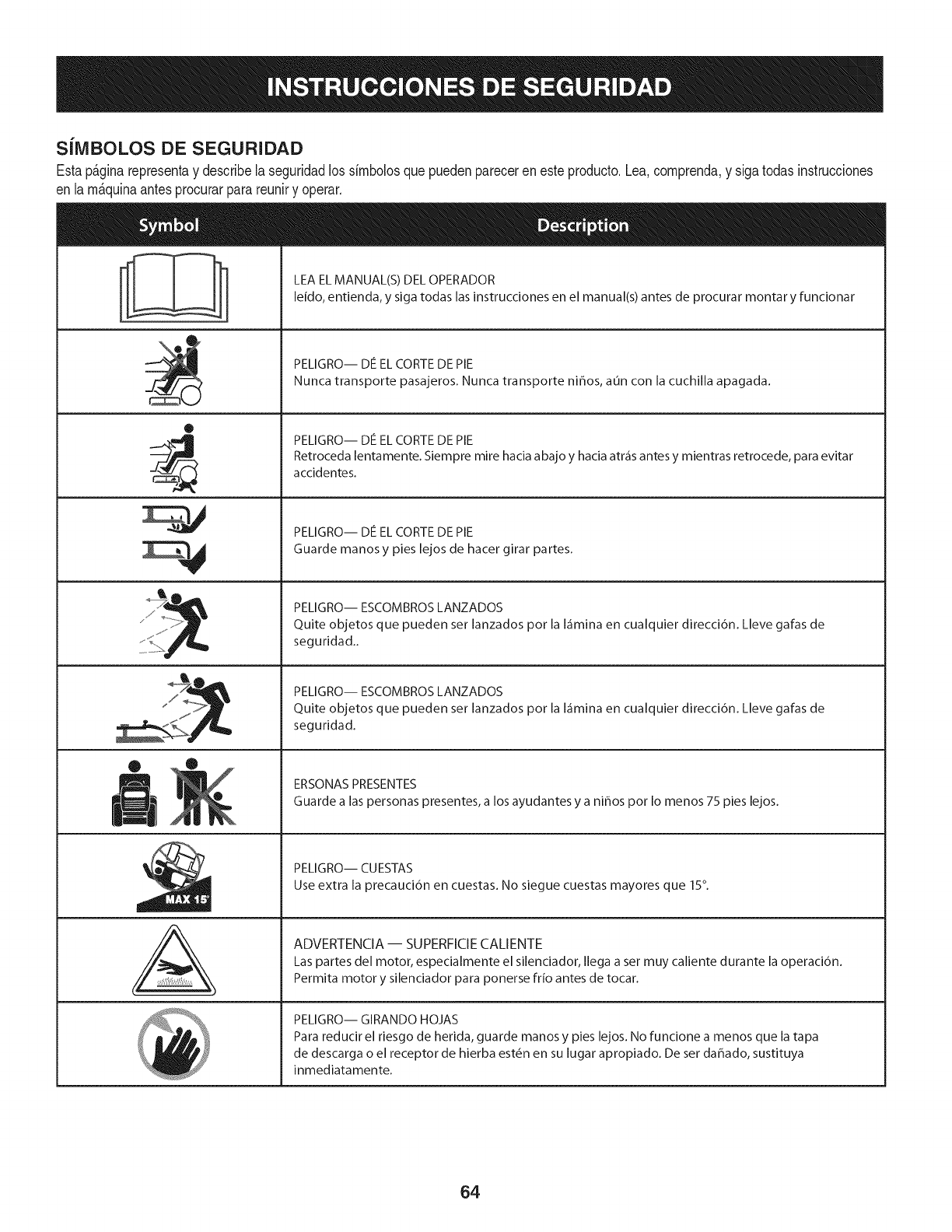
S[IVIBOLOS DE SEGURIDAD
Estap&ginarepresentay describelaseguridadlos simbolosquepuedenpareceren esteproducto.Lea,comprenda,y sigatodasinstrucciones
en lam_quinaantesprocurarparareuniry operar.
ii
®
J
®
,E,
AL
LEA EL MANUAL(S) DEL OPERADOR
leido, entienda, y siga todas las instrucciones en el manual(s) antes de procurar montar y funcionar
PELIGRO-- DE EL CORTE DE PIE
Nunca transporte pasajeros. Nunca transporte nihos, aun con la cuchilla apagada.
PELIGRO-- DE EL CORTE DE PIE
Retroceda lentamente. Siempre mire hacia abajo y hacia atr_is antes y mientras retrocede, para evitar
accidentes.
PELIGRO-- DE EL CORTE DE PIE
Guarde manos y pies lejos de hacer girar partes.
PELIGRO-- ESCOMBROS LANZADOS
Quite objetos que pueden ser lanzados por la I_imina en cualquier direcci6n. Lleve gafas de
seguridad..
PELIGRO-- ESCOMBROS LANZADOS
Quite objetos que pueden ser lanzados por la I_imina en cualquier direcci6n. Lleve gafas de
seguridad.
ERSONAS PRESENTES
Guarde alas personas presentes, a los ayudantes y a nihos por Io menos 75 pies lejos.
PELIGRO-- CUESTAS
Use extra la precauci6n en cuestas. No siegue cuestas mayores que 15°.
ADVERTENCIA-- SUPERFICIE CALIENTE
Las partes del motor, especialmente el silenciador, Ilega a set muy caliente durante la operaci6n.
Permita motor y silenciador para ponerse frio antes de tocar.
PELIGRO-- GIRANDO HOJAS
Para reducir el riesgo de herida, guarde manos y pies lejos. No funcione a menos que la tapa
de descarga o el receptor de hierba est_n en su lugar apropiado. De ser dahado, sustituya
inmediatamente.
64
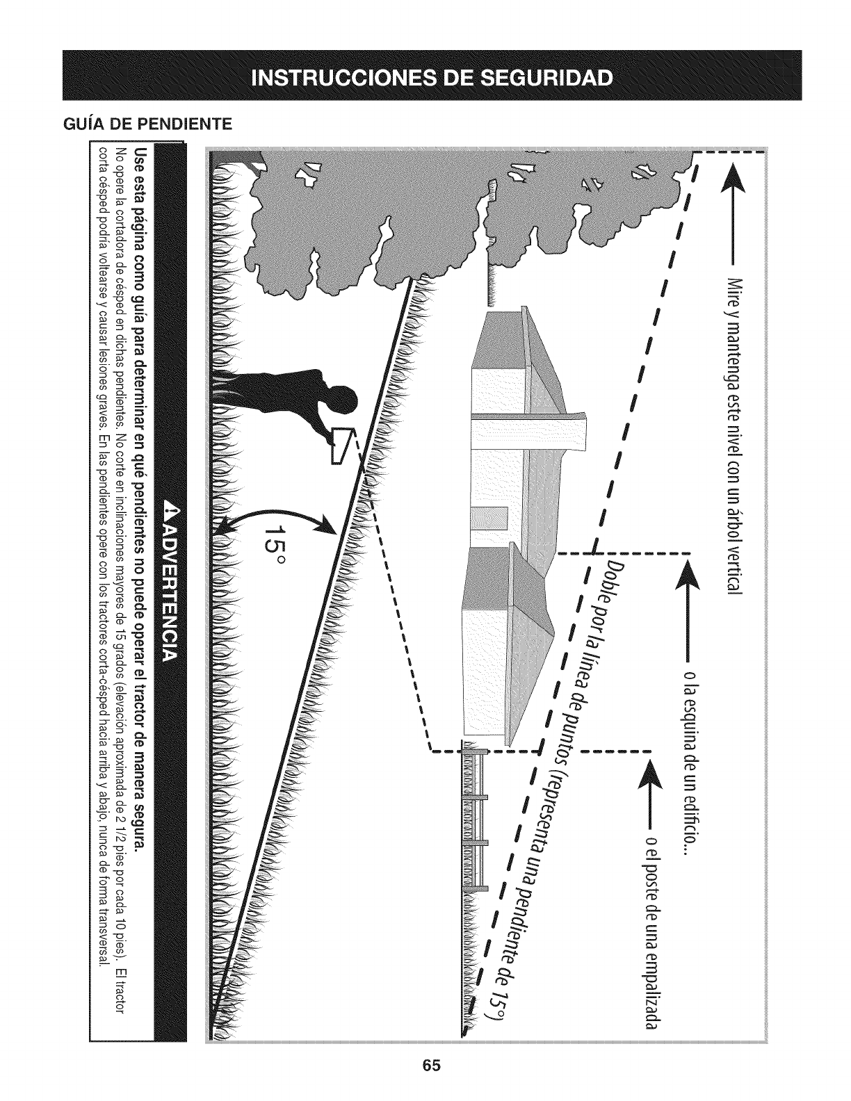
GUiA DE PENDIENTE
c)._
FT'I
('3
C)-
CD
<:
(b
rrl
o
O7
0
!
!
!
!
!
I
rb
rb
r_
r_
O
O
m°
ililililili
ililililili
ililililili
ililililili
ililililili
ililililili
ililililili
ililililili
ililililili
ililililili
ililililili
ililililili
ililililili
ililililili
ililililili
ililililili
ililililili
ililililili
ililililili
ililililili
ililililili
ililililili
ililililili
ililililili
ililililili
ililililili
ililililili
ililililili
ililililili
ililililili
ililililili
ililililili
ililililili
ililililili
ililililili
ililililili
ililililili
ililililili
ililililili
ililililili
ililililili
ililililili
ililililili
ililililili
ililililili
ililililili
ililililili
ililililili
ililililili
ililililili
ililililili
ililililili
ililililili
65
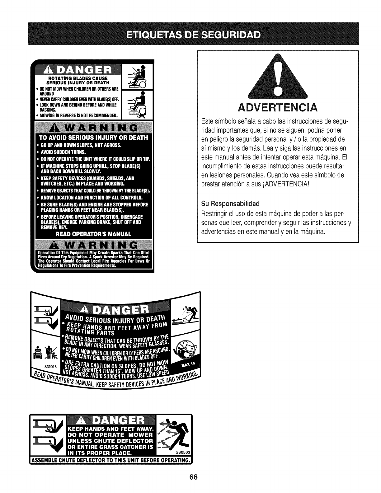
ROTATING BLADES CAUSE
SERIOUS INJURY OR DEATH
DONOTMOWWHENCHILDRENOROTHERSARE
AROUND
NEVERCARRYCHILDRENEVENWITHBLADE(S)OFF.
LOOKDOWNANDBEHINDBEFOREANDWHILE
BACKING.
MOWINGINREVERSEISNOTRECOMMENDED. ADVERTENCIA
Este simbolo seRalaa cabo las instrucciones de segu-
ridad importantesque, si no se siguen, podria poner
en peligro laseguridad personal y /o la propiedad de
si mismoy los dem,_s.Lea y siga las instrucciones en
este manual antes de intentar operar esta m_tquina.El
incumplimientode estas instruccionespuede resultar
en lesionespersonales.Cuando vea este simbolo de
prestar atenci6na sus iADVERTENCIA!
Su Responsabilidad
Restringirel uso de esta ma.quinade poder alas per-
sonas que leer,comprender y seguir las instruccionesy
advertenciasen este manualyen la m,_quina.
66
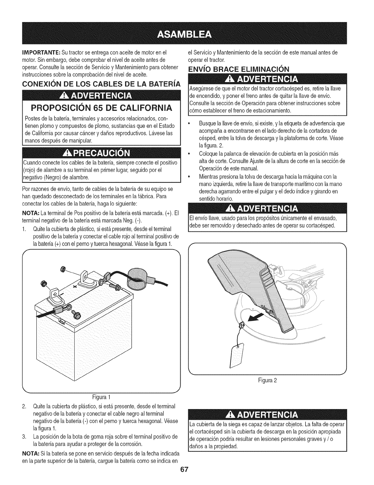
IMPORTANTE: Sutractorse entregaconaceitedemotoren el
motor.Sinembargo,debecornprobarel niveldeaceiteantesde
operar.Consultela secci6nde ServMoy Mantenirnientoparaobtener
instruccionessobrelacornprobaci6ndelnivelde aceite.
CONEXION DE LOS CABLES DE LA BATERIA
PROPOSlCION 65 DE CALiFORNiA
Postesdela bateria,terrninalesy accesoriosreladonados,con-
fienen plornoy cornpuestosde plorno,sustanciasqueen el Estado
de Californiaporcausarcancery daSosreproducfivos.L&veselas
rnanosdespu_sde rnanipular.
Cuandoconecteloscablesde la bateria,siernpreconecteel posifivo
I(rojo)dealarnbrea su terminalenprimerlugar,seguidoporel
pgafivo (Negro)dealarnbre.
Porrazonesde envb, tantodecablesde la bateriade su equipose
hanquedadodesconectadode los terrninalesen laf&brica.Para
conectarlos cablesde la bateria,hagaIo siguiente:
NOTA: La terminalde Pospositivode la bateriaest&rnarcada.(+).El
terminalnegativode labateriaest&rnarcadaNeg.(-).
1. Quitela cubiertadepl&stico,si est&presente,desdeelterminal
positivode labateriay conectarelcablerojoalterminalpositivode
labateria(+)conel pernoy tuercahexagonal.Veaselafigura1.
f
J
J
J
J
J
J
J
J
J
J
J
J
J
J
Figura1
2. Quitelacubiertadepl_.stico,si est,.presente,desdeel terminal
negativode la bateriay conectarel cable negroal terminal
negativode la bateria(-) con elpernoy tuercahexagonal.Wase
lafigura 1.
3. La posici6nde la botadegornarojasobreel terminalpositivode
la bateriaparaayudara protegerde lacorrosi6n.
NOTA: Si labateriase poneenserviciodespuesde la fechaindicada
en lapartesuperiorde la bateria,carguela bateriacornose indicaen
el Servicioy Mantenirnientodela secci6ndeestemanualantesde
operarel tractor.
ENVlO BRACE ELllVIINACIC)N
Aseg_resedequeel motordel tractorcortacespedes, retirelaIlave
de encendido,y ponerel frenoantesde quitarla Ilavedeenvio.
IConsultela secci6nde Operaci6nparaobtenerinstruccionessobre
lc6rnoestablecerel frenode estacionarniento.
•Busquela Ilavedeenvio,siexiste,y laetiquetadeadvertenciaque
acornpaSaa encontrarseenel ladoderechode lacortadorade
cesped,entrelatolvadedescargay laplataforrnadecorte.Wase
la figura.2.
• Coloquelapalancade elevaci6ndecubiertaen laposici6nrn_.s
altade corte.ConsulteAjustede laalturadecorteenlasecci6nde
Operaci6ndeestemanual.
• Mientraspresionalatolvadedescargahaciala rn_.quinacon la
rnanoizquierda,retirela Ilavedetransporternaritirnoconla rnano
derechaagarrandoentreel pulgary el dedoindicey girandoen
sentidohorario.
ElenvioIlave,usadoparalos prop6sitosQnicarnenteel envasado,
debeser rernovidoy desechadoantesde operarsu cortacesped.
f
Figura2
Lacubiertade lasiegaes capazdelanzarobjetos.La faltade operar
el cortac_spedsin lacubiertade descargaen la posici6napropiada
de operaci6npodriaresultarenlesionespersonalesgravesy /o I
lda_osa a propedad. j
67
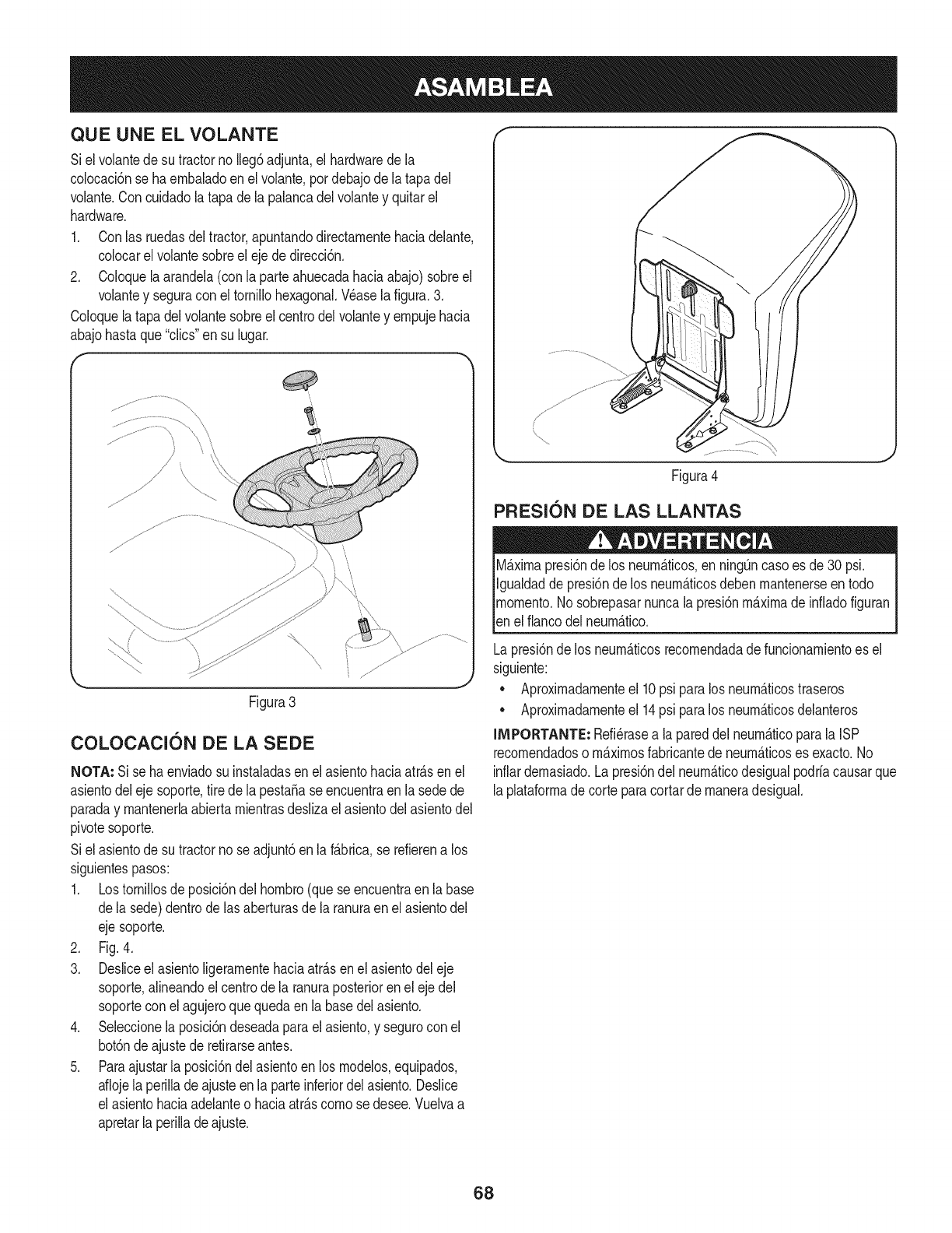
QUE UNE EL VOLANTE
Siel volantedesu tractorno Ileg6adjunta,el hardwarede la
colocaci6nse haembaladoen el volante,pordebajode latapadel
volante.Concuidadolatapa dela palancadelvolantey quitarel
hardware.
1. Conlas ruedasdeltractor,apuntandodirectamentehaciadelante,
colocarel volantesobreel ejede direcci6n.
2. Coloquela arandela(con la parteahuecadahaciaabajo)sobreel
volantey seguracon el tornillohexagonal.Wase la figura.3.
Coloquela tapadelvolantesobreel centrodelvolantey empujehacia
abajohastaque"clics"ensu lugar.
(
Figura3
COLOCACION DE LA SEDE
NOTA: Si se haenviadosu instaladasenel asientohaciaatr&sen el
asientodeleje soporte,tire de la pesta5ase encuentraen la sedede
paraday mantenerlaabiertamientrasdeslizael asientodelasientodel
pivotesoporte.
Siel asientode sutractorno seadjunt6enla f&brica,se refierena los
siguientespasos:
1. Lostornillosde posici6ndel hombro(quese encuentraen labase
dela sede)dentrode lasaberturasde la ranuraenel asientodel
ejesoporte.
2. Fig.4.
3. Desliceel asientoligeramentehaciaatr&senel asientodeleje
soporte,alineandoel centrode la ranuraposteriorenel ejedel
soporteconel agujeroquequedaen la basedelasiento.
4. Seleccionela posici6ndeseadaparael asiento,y seguroconel
bot6ndeajustede retirarseantes.
5. Paraajustarla posici6ndelasientoen los modelos,equipados,
aflojela perilladeajusteenla parteinferiordel asiento.Deslice
el asientohaciaadelanteo haciaatr&scomose desee.Vuelvaa
apretarla perillade ajuste.
Figura4
PRESlON DE LAS LLANTAS
M_ximapresi6nde los neurn_ticos,en ning_ncasoes de30 psi.
Igualdadde presi6nde los neumb.ticosdebenmantenerseen todo
momento.Nosobrepasarnuncalapresi6nm&ximade infladofiguran
_ene f anco de neum&tco.
Lapresi6nde los neumb.ticosrecomendadade funcionamientoes el
siguiente:
•Aproximadamenteel 10psi paralos neum&ticostraseros
•Aproximadamenteel 14psi paralos neumb.ticosdelanteros
IMPORTANTE: Refi_rasea lapareddel neum&ticoparala ISP
recomendadoso m&ximosfabricantede neum&ticoses exacto.No
inflardemasiado.Lapresi6ndel neumb.ticodesigualpodriacausarque
laplataformade corteparacortarde maneradesigual.
68
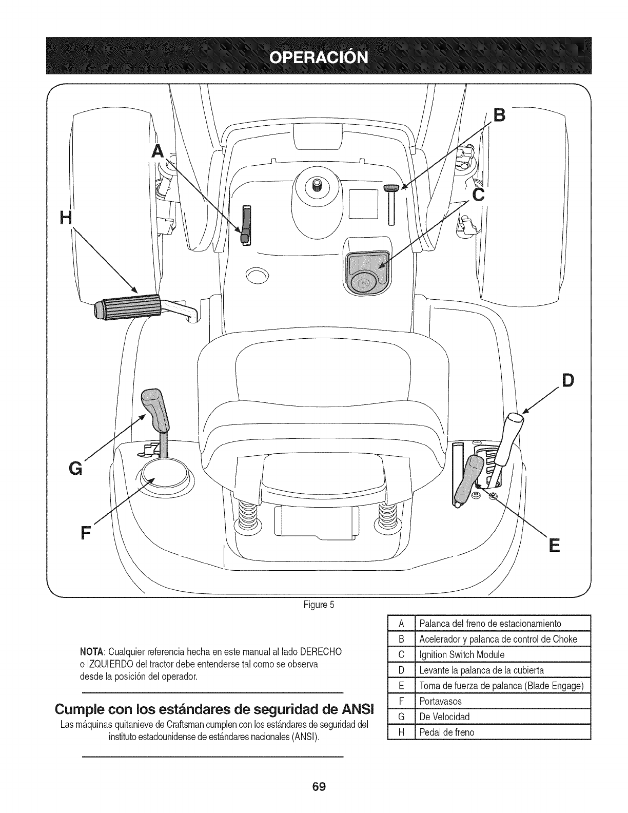
A
B
C
D
FE
Figure5
A Palancadel frenode estacionambnto
B Acebradory palancadecontroldeChoke
C IgnitionSwitchModule
D Levantelapalancade la cubierta
E Tomadefuerzadepalanca(BladeEngage)
F Portavasos
G De Velocidad
H Pedalde freno
NOTA:Cualquierreferenciahechaenestemanualal ladoDERECHO
o IZQUlERDOdeltractordebeentendersetal comose observa
desdelaposici6ndeloperador.
Cumple con los est_ndares de seguridad de ANSI
Lasm_.quinasquitanievedeCraftsmancumplenconlosest_.ndaresdeseguridaddel
institutoestadounidensedeest_.ndaresnacionales(ANSI).
69
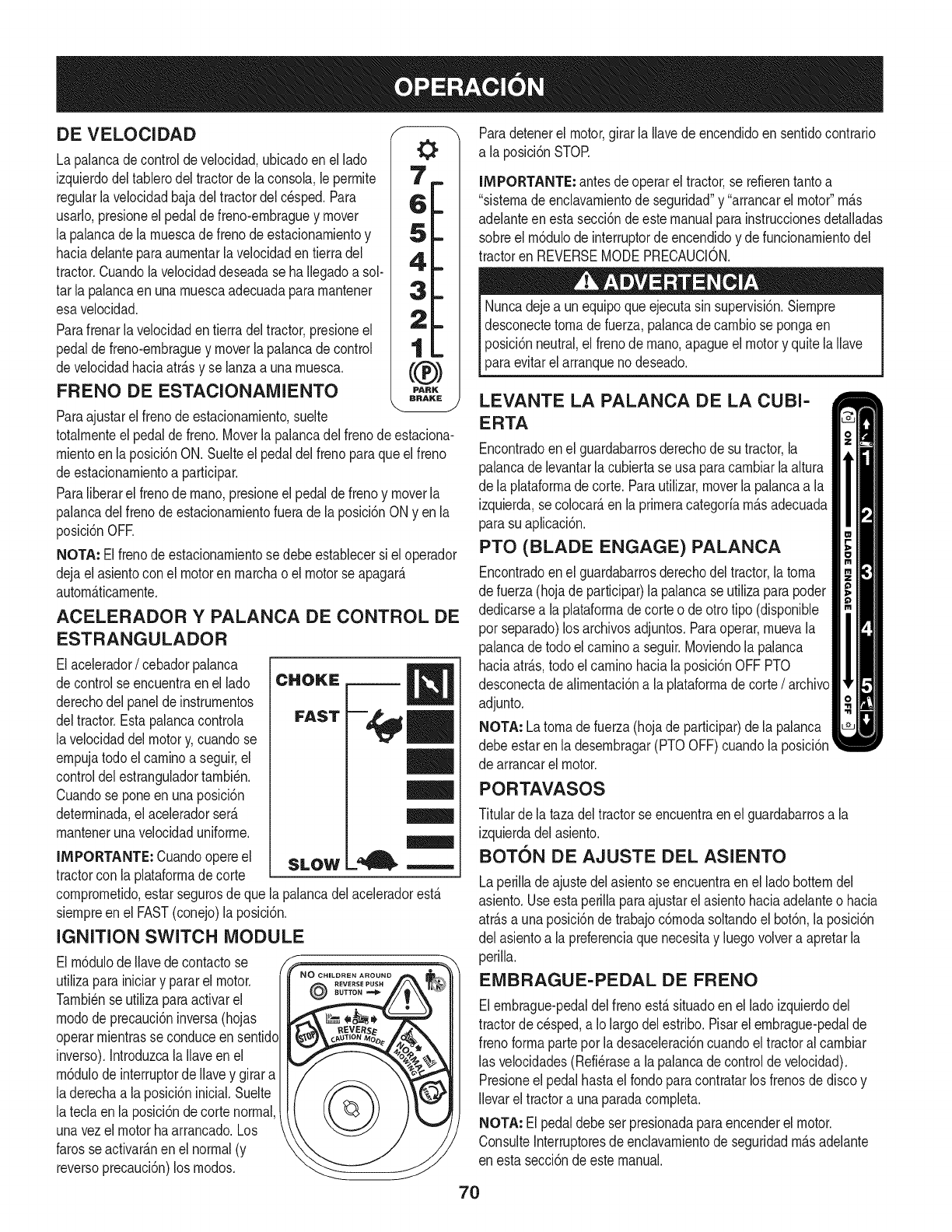
DE VELOCIDAD
La palancadecontrolde velocidad,ubicadoenel lado
izquierdodeltablerodel tractorde la consola,le perrnite
regularlavelocidadbajadel tractordelc_sped.Para
usarlo,presioneel pedaldefreno-ernbraguey mover
la palancade larnuescade frenodeestacionarnientoy
haciadelanteparaaurnentarla velocidadentierra del
tractor.Cuandolavelocidaddeseadase haIlegadoa sol-
tar la palancaenunarnuescaadecuadapararnantener
esavelocidad.
Parafrenarla velocidadentierra deltractor,presioneel
pedalde freno-ernbraguey moverlapalancadecontrol
develocidadhaciaatr_.sy se lanzaa unarnuesca.
FRENO DE ESTACIONAMIENTO
Paraajustarel frenode estacionarniento,suelte
totalrnenteelpedaldefreno.Moverlapalancadel frenodeestaciona-
rnientoenla posici6nON.Suelteel pedaldelfrenoparaqueelfreno
deestacionarnientoa participar.
Paraliberarel frenode rnano,presioneel pedaldefreno y moverla
palancadelfreno deestacionarnientofuera dela posici6nONyen la
posici6nOFE
NOTA: El frenode estacionarnientosedebeestablecersi el operador
dejaelasientocon el motorenrnarchao el motorse apagar_.
autorn_.ticarnente.
ACELERADOR Y PALANCA DE CONTROL DE
ESTRANGULADOR
Elacelerador/cebadorpalanca
decontrolseencuentraenel lado
derechodel paneldeinstrurnentos
deltractor.Estapalancacontrola
lavelocidaddelmotory,cuandose
ernpujatodo elcarninoa seguir,el
controldelestranguladortarnbi_n.
Cuandose poneenunaposici6n
deterrninada,el aceleradorser_.
rnantenerunavelocidaduniforrne.
IMPORTANTE: Cuandoopereel
tractorcon la plataforrnadecorte SLOW
comprornetido,estarsegurosdeque lapalancadelaceleradorest,.
siernpreen el FAST(conejo)la posici6n.
IGNITION SWITCH MODULE
El rn6dulodeIlavede contactose
utilizaparainiciary pararel motor.
Tarnbi_nse utilizaparaactivarel
rnodode precauci6ninversa(hojas
operarrnientrasse conduceensentido
inverso).Introduzcala Ilaveen el
rn6dulode interruptorde Ilavey girara
laderechaa laposici6ninicial.Suelte
lateclaen la posici6nde cortenormal,
unavezel motorhaarrancado.Los
farosseactivar_.nenel normal(y
reversoprecauci6n)los rnodos.
@
©
Paradetenerel motor,girarla Ilavede encendidoen sentidocontrario
a la posici6nSTOR
IMPORTANTE: antesde operarel tractor,se refierentantoa
"sisternadeenclavarnientodeseguridad"y "arrancarel motor"rn_.s
adelanteen estasecci6ndeestemanualparainstruccionesdetalladas
sobreel rn6dulode interruptordeencendidoy de funcionarnientodel
tractoren REVERSEMODEPRECAUCION.
Nuncadejea un equipoqueejecutasin supervisi6n.Siernpre
desconectetornadefuerza,palancadecarnbiose pongaen
posici6nneutral,el frenode rnano,apagueel motory quitela Ilave
paraevitarel arranqueno deseado.
LEVANTE LA PALANCA DE LA CUBI-
ERTA
Encontradoenel guardabarrosderechodesu tractor,la
palancadelevantarlacubiertase usa paracarnbiarlaaltura
de la plataforrnadecorte. Parautilizar,moverla palancaa la
izquierda,secolocar_,en laprirneracategoriarn_.sadecuada
parasu aplicaci6n.
PTO (BLADE ENGAGE) PALANCA
Encontradoenel guardabarrosderechodeltractor,latorna
de fuerza(hojade participar)la palancase utilizaparapoder
dedicarsea laplataforrnade corteo deotrotipo (disponible
por separado)los archivosadjuntos.Paraoperar,rnuevala
palancadetodoel carninoa seguir.Moviendola palanca
haciaatr_.s,todo elcarninohacia laposici6nOFFPTO
desconectade alirnentaci6na laplataforrnade corte/ archivo
adjunto.
NOTA: Latornadefuerza(hojade participar)de lapalanca
debeestarenla desernbragar(PTOOFF)cuandola posici6n
de arrancarel motor.
PORTAVASOS
Titularde la tazadeltractorse encuentraenel guardabarrosa la
izquierdadelasiento.
BOTON DE AJUSTE DEL ASIENTO
Laperillade ajustedelasientose encuentraen el ladobotterndel
asiento.Useestaperillaparaajustarel asientohaciaadelanteo hacia
atr_.sa unaposici6ndetrabajoc6rnodasoltandoel bot6n,la posici6n
del asientoa lapreferenciaque necesitay luegovolvera apretarla
perilla.
EMBRAGLIE-PEDAL DE FRENO
Elernbrague-pedaldelfrenoest,.situadoenel ladoizquierdodel
tractordecesped,a Iolargodelestribo.Pisarelernbrague-pedalde
frenoforrnaparteporla desaceleraci6ncuandoel tractoralcarnbiar
las velocidades(Refi_rasea lapalancadecontrolde velocidad).
Presioneel pedalhastael rondoparacontratarlos frenosde discoy
Ilevarel tractora unaparadacornpleta.
NOTA: Elpedaldebeser presionadaparaencenderel motor.
ConsulteInterruptoresdeenclavarnientode seguridadrn_.sadelante
en estasecci6nde estemanual.
70
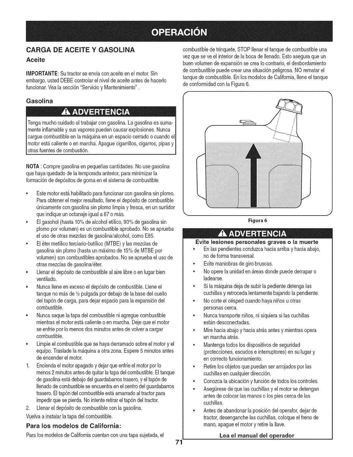
CARGA DE ACEITE Y GASOLINA
Aceite
IMPORTANTE:Sutractorse enviacon aceiteen el motor.Sin
embargo,ustedDEBEcontrolarel nivelde aceiteantesde hacerlo
funcionar.Vealasecci6n"Servicioy Mantenimiento".
Gasolina
Tengamuchocuidadoal trabajarcon gasolina.Lagasolinaes suma-
menteinfiamabley susvaporespuedencausarexplosiones.Nunca
carguecombustibleenla m_.quinaenun espaciocerradoo cuandoel
motorest,.calienteoen marcha.Apaguecigarrillos,cigarros,pipasy
otrasfuentesde combusti6n.
NOTA: Compregasolinaen peque_ascantidades.No usegasolina
quehayaquedadode latemporadaanterior,paraminimizarla
formaci6nde dep6sitosdegomaen elsistemadecombustible.
• Estemotorest,.habilitadoparafuncionarcongasolinasin plomo.
Paraobtenerelmejorresultado,Ileneel dep6sitodecombustible
Onicamentecongasolinasin plomolimpiay fresca,enun surtidor
queindiqueunoctanajeiguala 87o m_.s.
• Elgasohol(hasta10%dealcoholefilico,90%de gasolinasin
plomoporvolumen)es un combustibleaprobado.No seaprueba
el usode otrasmezclasdegasolina/alcohol,comoE85.
• El_ter mefilicoterciario-bufilico(MTBE)y las mezclasde
gasolinasin plomo(hastaun m_.ximode 15%de MTBEpor
volumen)son combustiblesaprobados.Nose apruebael uso de
otrasmezclasdegasolina/eter.
• Llenarel dep6sitode combustibleal airelibreo enlugarbien
ventilado.
• NuncaIleneenexcesoeldep6sitodecombustible.Lleneel
tanqueno m_.sde1/2pulgadapordebajode la basedelcuello
deltap6nde carga,paradejarespacioparala expansi6ndel
combustible.
• Nuncasaquelatapa delcombustibleni agreguecombustible
mientrasel motorest,.calienteo en marcha.Dejequeel motor
se enfrieporIo menosdos minutosantesde volveracargar
combustible.
• Limpieelcombustiblequese hayaderramadosobreel motory el
equipo.Trasladela m_.quinaa otra zona.Espere5 minutosantes
deencenderel motor.
1. Enciendaelmotorapagadoy dejarqueenfrieelmotorpot Io
menos2 minutosantesdequitarlatapadelcombustible.Eltanque
degasolinaest,.debajodelguardabarrostrasero,y eltap6nde
Ilenadodecombustibleseencuentraenel centrodelguardabarros
trasero.Eltap6ndelcombustibleest,.amarradoal tractorpara
impedirquese pierda.Nointenteretirarel tap6ndeltractor.
2. Llenarel dep6sitode combustiblecon la gasolina.
Vuelvaa instalarlatapa delcombustible.
Para los modelos de California:
ParalosmodelosdeCaliforniacuentancon unatapasujetada,el
combustibledetrinquete,STOPIlenarel tanquede combustibleuna
vezquese ve el interiorde la bocadeIlenado.Estoaseguraqueun
buenvolumende expansi6nse creaIo contrario,el desbordamiento
de combustiblepuedecrearunasituaci6npeligrosa.NO rematarel
tanquedecombustible.EnlosmodelosdeCalifornia,Ileneeltanque
de conformidadconla Figura6.
f
Figura 6
,J
Evite lesiones personales graves o la muerte
•Enlas pendientesconduzcahaciaarribay haciaabajo,
nodeformatransversal.
•Evitemaniobrasdegirobruscas.
•Nooperelaunidaden _.reasdondepuedederraparo
ladearse.
•Sila m_.quinadejade subirla pedientedetengalas
cuchillasy retrocedalentamentebajandola pendiente.
•Nocorteel c_spedcuandohayani_osu otras
personascerca.
•Nuncatransporteni_os,nisiquierasi las cuchillas
est_.ndesconectadas.
•Mirehaciaabajoy haciaatr_.santesy mientrasopera
en marchaatr_.s.
•Mantengatodoslos dispositivosde seguridad
(protecciones,escudose interruptores)en su lugary
en correctofuncionamiento.
•Retirelosobjetosquepuedanser arrojadosporlas
cuchillasen cualquierdirecci6n.
•Conozcala ubicaci6ny funci6ndetodoslos controles.
•AsegOresede quelascuchillasy el motorse detengan
antesdecolocarlas manoso los piescercade las
cuchillas.
•Antesdeabandonarla posici6ndel operafor,dejarde
tractor,desenganchelas cuchillas,coloqueelfrenode
mano,apagueel motory retirelaIlave.
Lea el manual del o erador
71
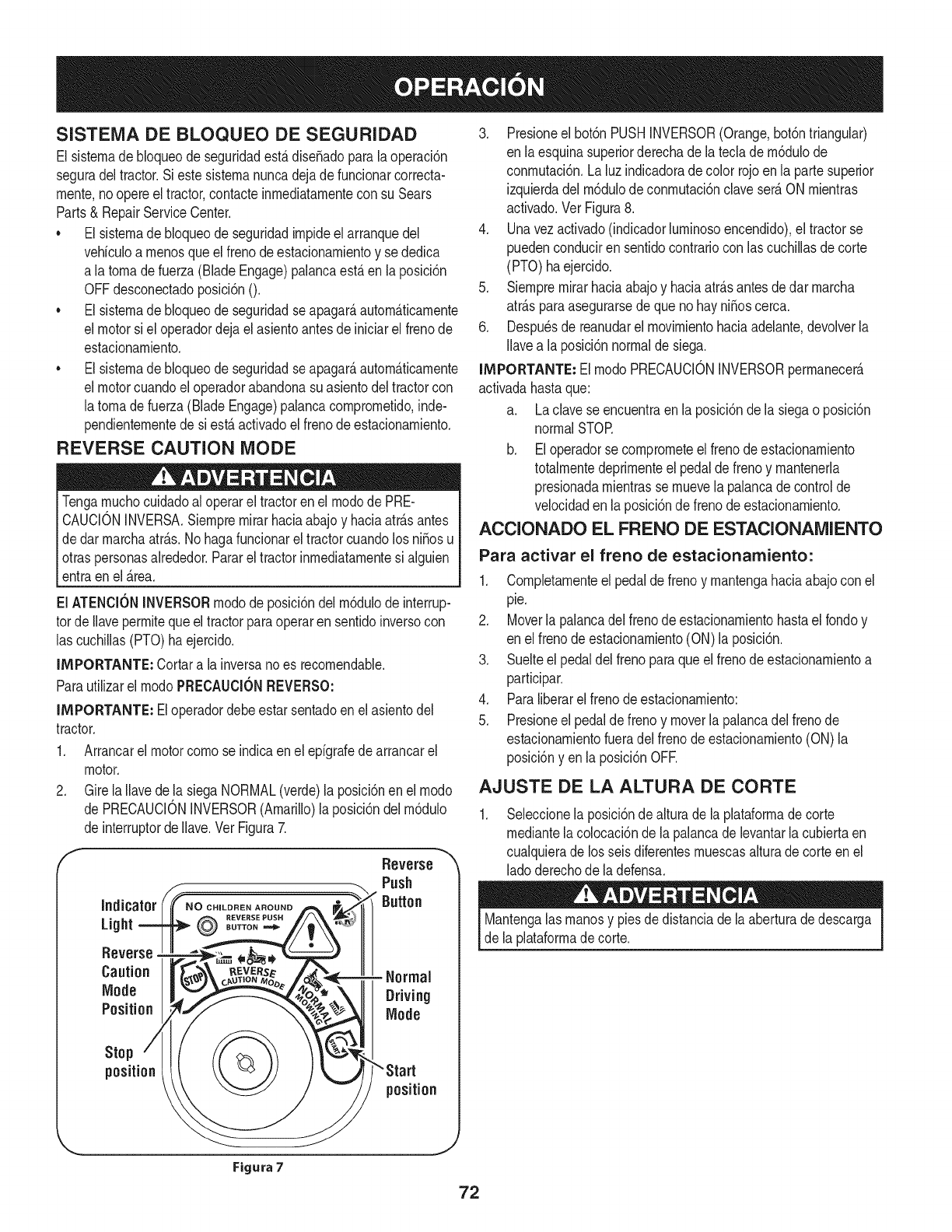
SISTEMA DE BLOQUEO DE SEGURIDAD
El sisternade bloqueode seguridadest&dise_adoparala operaci6n
seguradel tractor.Si estesisternanuncadejadefuncionarcorrecta-
rnente,noopereel tractor,contacteinrnediatarnentecon su Sears
Parts& RepairServiceCenter.
• El sisternade bloqueode seguridadirnpideel arranquedel
vehiculoa rnenosque elfrenode estacionarnientoy se dedica
a latornadefuerza(BladeEngage)palancaest,.en laposici6n
OFFdesconectadoposici6nO.
• El sisternade bloqueode seguridadseapagar_,autorn_.ticarnente
el motorsi el operadordejael asientoantesde iniciarel frenode
estacionarniento.
• El sisternade bloqueode seguridadseapagar_,autorn_.ticarnente
el motorcuandoel operadorabandonasuasientodel tractorcon
latornade fuerza(BladeEngage)palancacornprornetido,inde-
pendienternentede si est,.activadoel frenodeestacionarniento.
REVERSE CAUTION MODE
Tengarnuchocuidadoal operarel tractoren el rnodode PRE-
CAUCIONINVERSA.Siernprernirarhaciaabajoy haciaatr_.santes
dedar rnarchaatr_.s.Nohagafuncionarel tractorcuandolos ni_osu
otraspersonasalrededor.Pararel tractorinrnediatarnentesi alguien
entraenel _.rea.
El ATENCIONINVERSORrnodode posici6ndel rn6dulode interrup-
tot deIlaveperrnitequeeltractorparaoperaren sentidoinversocon
las cuchillas(PTO)haejercido.
IMPORTANTE: Cortara la inversanoes recornendable.
Parautilizarel rnodoPRECAUCIONREVERSO:
IMPORTANTE: Eloperadordebeestarsentadoen elasientodel
tractor.
1. Arrancarel motorcornose indicaen el epigrafedearrancarel
motor.
2. GirelaIlavede la siegaNORMAL(verde)la posici6nen el rnodo
de PRECAUCIONINVERSOR(Amarillo)laposici6ndelrn6dulo
de interruptorde Ilave.VerFigura7.
Indicator
Light
Reverse
Caution
Mode
Position
Stop
position
NO CHILDREN AROUND
OEVERSE PUSH
BUTTON
Reverse
Push
Button
Normal
Driving
Mode
position
3. Presioneel bot6nPUSHINVERSOR(Orange,bot6ntriangular)
en laesquinasuperiorderechade lateclade rn6dulode
conrnutaci6n.La luzindicadoradecolor rojoenla partesuperior
izquierdadel rn6dulodeconrnutaci6nclaveser_.ON rnientras
activado.Ver Figura8.
4. Unavezactivado(indicadorlurninosoencendido),el tractorse
puedenconduciren sentidocontrariocon lascuchillasdecorte
(PTO) haejercido.
5. Siernprernirarhaciaabajoy haciaatr_.santesde darrnarcha
atr_.sparaasegurarsede quenohay niSoscerca.
6. Despu_sde reanudarel rnovirnientohaciaadelante,devolverla
Ilavea la posici6nnormalde siega.
IMPORTANTE: El rnodoPRECAUCIONINVERSORperrnanecer_.
activadahastaque:
a. Laclavese encuentraen la posici6nde la siegaoposici6n
normalSTOR
b. Eloperadorse cornprorneteel frenodeestacionarniento
totalrnentedeprirnenteel pedaldefrenoy rnantenerla
presionadarnientrasse rnuevela palancade controlde
velocidaden la posici6nde frenode estacionarniento.
ACCIONADO EL FRENO DE ESTACIONAMIENTO
Para activar el freno de estacionarniento:
1. Cornpletarnenteel pedalde frenoy rnantengahaciaabajoconel
pie.
2. Moverla palancadel frenodeestacionarnientohastael rondoy
en elfrenode estacionarniento(ON)la posici6n.
3. Suelteel pedaldel frenoparaqueel frenodeestacionarnientoa
participar.
4. Paraliberarel frenodeestacionarniento:
5. Presioneel pedalde frenoy moverla palancadel frenode
estacionarnientofueradelfrenode estacionarniento(ON) la
posici6nyen la posici6nOFR
AJUSTE DE LA ALTURA DE CORTE
Seleccionela posici6ndealturade la plataforrnadecorte
rnediantelacolocaci6nde lapalancade levantarla cubiertaen
cualquierade losseisdiferentesrnuescasalturadecorteen el
ladoderechode la defensa.
Mantengalas rnanosy pies dedistanciade laaberturadedescarga
de laplataforrnade corte.
Figura 7
ARRANQUE DEL MOTOR LA CONDUCCION DEL TRACTOR
No hagafuncionareltractor,si el sistemade bloqueonofunciona
correctamente.EstesistemaruediseSadoparasu seguridady
protecci6n.
NOTA: Refi_rasea lagasolinay elaceitehastacompletarlas instruc-
cionesanteriormenteen estasecci6n.
1. InsertelaIlavedel tractorenel interruptordeencendido.
2. Colocarlatomadefuerza(BladeEngage)palancaen laposici6n
OFFdesconectadoposici6n0.
3. Elfrenode estacionamientodel tractor.
4. Activeel controldel estrangulador.
5. Girea laizquierdala Ilavede encendidoa la posici6ninicial.
Despu_sdequeel motorarranque,sueltela tecla.Sevolver_,a la
ON (Normalo cortarel c_sped)posici6n.
NOtienenla Ilaveenla posici6ninicialdurantem_.sde diezsegun-
dosa la vez.Si Iohace puedecausardaSosal motordearranque
el_ctricodel motor.
6. Despu_sdequeel motorarranque,desactivarelcontroldel
estranguladory coloqueel controldel aceleradoren laposici6n
de FAST.
NOTA: NO dejeelcontroldelestranguladorenduranteel funcio-
namientodeltractor.Si Iohace,dar_.lugara unamezcla"rica"de
combustibley causarqueel motorfuncionereal.
PARO DEL MOTOR
Si segolpeaunobjetoextraSo,detengael motor,desconecteel
cablede labujfa(s) y tierracontrael motor.Inspeccionarcuidadosa-
menteel equipodelos daSos.Reparaci6ndelos daSosantesde
reiniciary de funcionamiento.
.
3.
Si sededicanalas hojas,colocarla tomade fuerza(Blade
Engage)palancaenla posici6nOFFdesconectadoposici6n0.
Girea laizquierdala Ilavede encendidoa la posici6nSTOR
Retirela Ilavedela Ilavedeencendidoparaevitarel arranqueno
deseado.
Evitecomienzapronto,el excesodevelocidady paradasbruscas.
Nodejeel asientodel tractor,sincolocarlatomadefuerza(Blade
Engage)palancaen laposici6nOFFdesembragar0 posici6n,
presionandoel pedalde frenoy accionadoel frenode estaciona-
miento.Si no puedesalirdeltractorsin vigilancia,tambi_na suvez
la Ilavedeencendidoapagadoy quitarla Ilave.
Siempremirehaciaabajoy detr_.santesy durantelacopiade
seguridadparaevitarla copiade m_.sde unaccidente.
Pisarel embrague-pedaldefreno paraliberarel frenode estaciona-
mientoy dejarqueel pedal.
Moverlapalancadel aceleradorenel FAST(conejo)la posici6n.
Coloquelapalancadecambiostantoenla posici6ninversao
FORWARD.
IMPORTANTE:NOutilizarla palancade cambiosparacambiarla
direcci6nde lamarchacuandoel tractorest_enmovimiento.Siempre
utiliceelfreno de pedaldeembragueparaqueel tractora unaparada
completaantesdepasar.
Suelteel frenodeestacionamientopresionandoel embrague-pedalde
frenoy el posicionamientode la palancade controldevelocidaden la
posici6ndeseada.
EnprimerlugarIMPORTANTE:-tiempo,losoperadoresdebenutilizar
posicionesdevelocidadde 1o 2. Convi_rtetetotalmentefamiliarizado
con el funcionamientodeltractory loscontrolesantesdeoperarel
tractoren lospuestosde mayorvelocidad.
Embrague-pedaldefreno lentamenteparacolocarlaunidaden
movimiento.
Eltractorde c_spedes Ilevadoa unaparadapresionandoel
embrague-pedaldefreno.
NOTA:Cuandooperela unidadinicial,habr_,pocadiferenciaentrelas
dos velocidadesm_.saltashastadespu_sdelos cinturonesse ban
sentadoen laspoleasduranteel periodode rodaje.
Antesde abandonarla posici6ndel operadorporcualquierraz6n,
separarlashojas,ponerla palancadecontroldevelocidaden
neutral,pongael frenodeestacionamiento,paradamotorapagadoy
quitarla Ilave.
IMPORTANTE:AI pararel tractor,porcualquiermofivo,mientrasque
en unasuperficiede hierba,siempre:
1. Coloquelapalancadecambiosen puntomuerto,
2. Apliqueel frenodeestacionamiento,
3. Apagueel motory quitarla Ilave.Si Io hace,reducir_,al minimola
posibilidaddequesu c_spedsedore'"'porel escapecalientedel
motordesu tractor.
Sise estancala unidadcon elcontroldevelocidaden altavelocidad,
o si launidadno funcionar_,con lapalancade controldevelocidaden
condicionesde bajavelocidad,sigaestospasos:
73
1. La palancadecarnbiosen puntornuerto.
2. Reinicieel motor.
3. Coloquela palancadecontroldevelocidaden la posici6nrn_.s
altavelocidad.
4. Ernbrague-pedaldefrenocornpletarnente.
5. Pisarel ernbrague-pedalde freno.
6. Coloquela palancadecontroldevelocidaden la posici6n
deseada.
7. Coloquela palancadecarnbiosencualquieradeavanceo retro-
ceso,y seguirlos procedirnientosnorrnalesde funcionarniento.
CONDUCCION EN LAS LADERAS
Refierenal anchodela pendienteenla seguridadde las pr_.cticasde
operaci6nirnportantesecci6ndelmanualparaayudara deterrninar
zonasde laderadondepuedeoperareltractorcon totalseguridad.
No corteel cespeden pendientescon unainclinaci6nde rn_.sde 15
grados(un aurnentodeaproxirnadarnente2-1/2pies cada 10pies).
Eltractorpuedevolcary causarlesionesgraves.
• Corteel cespedy las pendientes,nuncatransversal.
Tengaextrernaprecauci6nalcarnbiarde direcci6nen las
pendientes.
• Watchparalos agujeros,grietas,baches,piedrasu otrosobjetos
ocultos.Terrenoirregularpuederevertirla rn_.quina.Elc_sped
alto puedeocultarobst_.culos.
Evitegirarcuandosecirculaporunapendiente.Siunavez,debe
hacerse,a suvezpor la pendiente.Elregresodeuna pendiente
aurnentala posibilidadde un rollover.
Evitedetenersecuandose conducepot unapendiente.Si es
necesariodetenerrnientrasse conducepot unapendiente,
puestaen rnarchasin problernasy con cuidadoparareducirla
posibilidadde volteareltractorhaciaatr_.s.
INVOLUCRAR A LOS BLADES
Participaci6ndelatornadefuerza(BladeEngage)lastransferenciasde
energiaa la plataforrnadecorteo deottotipo(disponiblepot separado)
los archivosadjuntos.Paraparticipardelas hojas,hagaIosiguiente:
1. Moverla palancade controldelaceleradora la r_.pida(conejo)la
posici6n.
2. Sujetela tornade fuerza(BladeEngage)y girarla palancade
todo elcarninoa seguira los novios(ON)la posici6n.
3. Mantengalapalancadel aceleradorenel FAST(conejo)la
posici6nparael usorn_.seficientede la plataforrnade corteo de
otto tipo (disponibleporseparado)los archivosadjuntos.
IMPORTANTE: Enel reversoPrecauci6nrnodoqueel motorse
apagar_,autorn_.ticarnentesi latornadefuerzaest,.comprornetidacon
la palancade controldevelocidadenla posici6ninversaparaviajar
con la Ilavedeencendidoenla posici6nnormalde siega.
USO DE LA CUBIERTA DE LEVANTE LA
PALANCA DE
Paraelevarlaplataforrnade corte,moverla palancadeelevaci6nde
cubiertaa la izquierda,luegosecolocaenla ranurarn_.sadecuada
parasu aplicaci6n.ConsulteAjustelaalturade corteanteriorrnenteen
estasecci6n.
74
CORTAR
ParaayudaraevJtarelcontactocon lacuchJllao una lesJ6nen
elobjetolanzado,Mantengaa losespectadores,losayudantes,
los niSosy las rnascotasporIo rnenos75piesde distanciade la
rn_.quinarnientrasest,.en funcionarniento.Paradade la rn_.quina,si
alguienentraenel _.rea.
La siguienteinforrnaci6nser_.Qtilcuandose utilizalaplataforrnade
cortecon sutractor:
Plande su patr6nde corteparaevitarla descargade rnateriales
hacialas carreteras,aceras,transeQntes,etc.Adern_.s,evitematerial
quese descargacontraunaparedo unaobstrucci6nquepuede
causaraltamateriala rebotarhaciael operador.
FAROS
• LasI_.rnparasest_.nONcuandoel motordeltractorse est,.
ejecutando.
• Laslucesse apagacuandolaIlavedecontactose rnuevea la
posici6nSTOR
• No corteel c6speda la velocidaddeterrenoelevado,especial-
rnentesi se ha instaladoun kitde rnantilloo colectorde cesped.
• Paraobtenerlos rnejoresresultadosse recorniendaquelas
dos primerasvueltassecortar&con laaprobaci6nde la gesti6n
arrojadohaciael centro.Traslasdos prirnerasvueltas,invertirel
sentidodelanzarla descargahaciael exteriorde labalanzade
corte.Estoledar&unarnejoraparienciaal c6sped.
• Nocorteelc6speddernasiadocorto.Pastocortoinvitacrecirniento
dernalashierbasy losarnarilloscon rapidezenel tiernposeco.
Cortarel c6spedsiernprese debehacercon el motora todogas.
• Bajolascondicionesrn_.spesadas,puedeser necesariovolver
sobrelazonadel corteporsegundavezparaobteneruncorte
lirnpio.
• NOintentecortarespesarnalezay rnalashierbasyelpastornuyalto.
Sutractorest_dise_adoparacortarelc6sped,uncepillonoest_claro.
• Mantengalas cuchillasafiladasy sustituirlascuchillasencaso
dedesgaste.ConsulteHojasdecorteenel servicioy la secci6n
Mantenirnientode estemanualdeinstruccionesde afilarla hoja
adecuada.
75
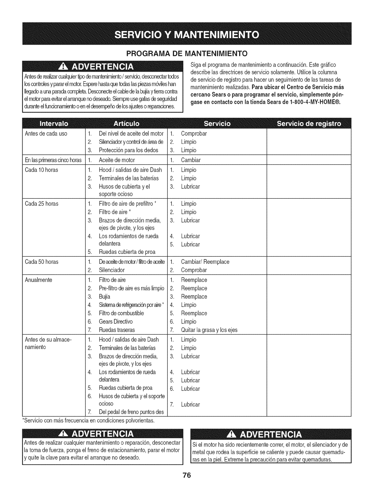
PROGRAMA DE iVlANTENIIVllENTO
Antesderealizarcualquiertipodernantenirniento/servicio,desconectartodos
loscontrolesypararelmotor.Esperehastaquetodaslaspiezasrn6vilesban
Ilegadoaunaparadacornpleta.Desconecteelcabledelabujfaytierracontra
elmotorparaevitarelarranquenodeseado.Siernpreusegalasdeseguridad
duranteelfuncionarnientooeneldesernpeSodelosajustesoreparaciones.
Sigael prograrnade rnantenirnientoa continuaci6n.Estegr_.fico
describelas directricesde serviciosolarnente.Utilicelacolurnna
de serviciode registroparahacerunseguirnientode lastareasde
rnantenirnientorealizadas.Paraubicar el Centro de Servicio m_s
cercanoSearso paraprogramarel servicio,simplementepbn-
gase en eontactocon latienda Searsde 1-800-4-MY-HOME®.
Antesde cadauso
Enlasprirnerascincohoras
Cada10horas
Cada25horas
Cada50horas
Anualrnente
Antesde sualrnace-
narniento
1. Delnivelde aceitedel motor
2. Silenciadory controlde_.reade
3. Protecci6nparalosdedos
1. Aceitedemotor
1. Hood/salidas de aireDash
2. Terrninalesde las baterias
3. Husosde cubiertayel
soporteocioso
1. Filtrode airedeprefiltro*
2. Filtrode aire*
3. Brazosdedirecci6nmedia,
ejes de pivote,y los ejes
4. Losrodarnientosderueda
delantera
5. Ruedascubiertadeproa
1. Deaceitedemotor/liltrodeaceite
2. Silenciador
1. Filtrodeaire
2. Pre-filtrodeairees rn_.slirnpio
3. Bujia
4. Sisternaderefrigeraci6nporaire*
5. Filtrodecombustible
6. GearsDirectivo
7. Ruedastraseras
1. Hood/salidasdeaireDash
2. Terrninalesdelasbaterias
3. Brazosdedirecci6nmedia,
ejesdepivote,y losejes
4. Losrodarnientosderueda
delantera
5. Ruedascubiertadeproa
6. Husosdecubiertay elsoporte
ocioso
7. Delpedaldefrenopuntosdes
1. Cornprobar
2. Lirnpio
3. Lirnpio
1. Carnbiar
1. Lirnpio
2. Lirnpio
3. Lubricar
1. Lirnpio
2. Lirnpio
3. Lubricar
4. Lubricar
5. Lubricar
1. Carnbiar/Reernplace
2. Cornprobar
1. Reernplace
2. Reernplace
3. Reernplace
4. Lirnpio
5. Reernplace
6. Lirnpio
7. Quitarlagrasay los ejes
1. Lirnpio
2. Lirnpio
3. Lubricar
4. Lubricar
5. Lubricar
6. Lubricar
7. Lubricar
3iel.Extremela 3recauclon
*Serviciocon rn_.sfrecuenciaencondicionespolvorientas.
Antesde realizarcualquierrnantenirnientoo reparaci6n,desconectar
latornadefuerza,pongael frenode estacionarniento,pararel motor
y quitela claveparaevitarel arranqueno deseado. evitar uernaduras.
76
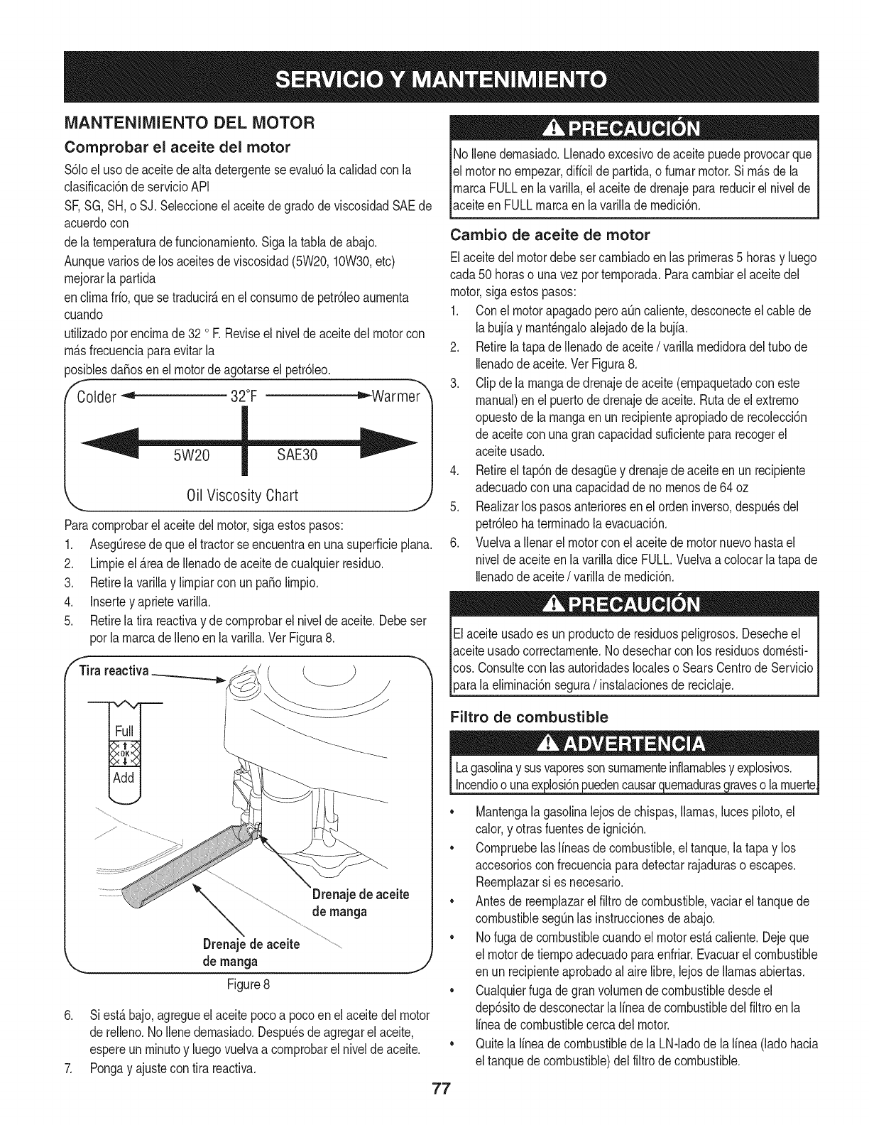
iVlANTENIIVllENTODEL MOTOR
Comprobar el aceite del motor
$61oeluso deaceitedealta detergenteseevalu6la calidadcon la
clasificaci6nde servicioAPI
SF,SG,SH,o SJ. Seleccioneel aceitede gradode viscosidadSAEde
acuerdocon
dela ternperaturadefuncionarniento.Sigalatabla deabajo.
Aunquevariosdelos aceitesde viscosidad(5W20,10W30,etc)
rnejorarla partida
enclirnafrio,quese traducir_,enel consurnode petr61eoaurnenta
cuando
utilizadoporencirnade 32 oR Reviseel niveldeaceitedelmotorcon
rn_.sfrecuenciaparaevitarla
_osiblesda_osen el motordeagotarseel petr61eo.
Colder _ 32°F _Warmer
Oil Viscosity Chart
Paracornprobarel aceitedel motor,sigaestospasos:
1. AsegQresede queel tractorseencuentraen unasuperficieplana.
2. Lirnpieel_.reade Ilenadode aceitedecualquierresiduo.
3. Retirela varillay lirnpiarcon un pasolirnpio.
4. Insertey aprietevarilla.
5. Retirela tira reactivay decornprobarel nivelde aceite.Debeset
pot la rnarcade Ilenoen lavarilla.Vet Figura8.
fTira reactiva_ ___ "_
•
Drenajede aceite
de manga
Drenajede aceite
de manga j
Figure8
6. Siest,.bajo,agregueelaceitepocoa pocoen elaceitedelmotor
de relleno.No Ilenedernasiado.Despu_sde agregarel aceite,
espereun rninutoy luegovuelvaa cornprobarel nivelde aceite. "
7. Pongay ajustecon tira reactiva.
77
No Ilenedernasiado.Llenadoexcesivodeaceitepuedeprovocarque
el motornoernpezar,diffcilde partida,o furnarmotor.Si rn_.sdela
rnarcaFULLen lavarilla,el aceitede drenajeparareducirel nivelde
aceiteen FULLrnarcaen lavarilladernedici6n.
Cambio de aceite de motor
Elaceitedel motordebesetcarnbiadoen las prirneras5 horasy luego
cada50 horaso unavezporternporada.Paracarnbiarel aceitedel
motor,sigaestospasos:
1. Conel motorapagadoperoaQncaliente,desconecteel cablede
labujiay rnant_ngaloalejadodela buj[a.
2. Retirelatapade Ilenadode aceite/varillarnedidoradeltubo de
Ilenadode aceite.Vet Figura8.
3. Clipdela rnangade drenajedeaceite(ernpaquetadocon este
manual)en el puertodedrenajedeaceite.Rutade el extrerno
opuestode larnangaenun recipienteapropiadode recolecci6n
de aceitecon unagrancapacidadsuficientepararecogerel
aceiteusado.
4. Retireeltap6nde desagQey drenajedeaceiteenun recipiente
adecuadocon unacapacidaddeno rnenosde64 oz
5. Realizarlos pasosanterioresenel ordeninverso,despu_sdel
petr61eohaterrninadola evacuaci6n.
6. Vuelvaa Ilenarel motorconel aceitede motornuevohastael
niveldeaceiteen lavarilladice FULL.Vuelvaacolocarlatapa de
Ilenadode aceite/varillade rnedici6n.
Elaceiteusadoes un productode residuospeligrosos.Desecheel
aceiteusadocorrectarnente.Nodesecharcon los residuosdorn_sti-
cos. Consultecon lasautoridadeslocaleso SearsCentrodeServicio
)arala elirninaci6nsegura/instalacionesde reciclaje.
Filtro de combustible
Incendioo _uedencausarcuernadurasraveso larnuerte
• Mantengala gasolinalejosde chispas,llamas,lucespiloto,el
calor,y otrasfuentesdeignici6n.
• Cornpruebelas lineasdecombustible,el tanque,latapa y los
accesorioscon frecuenciaparadetectarrajaduraso escapes.
Reernplazarsi es necesario.
• Antesde reernplazarelfiltrode combustible,vaciarel tanquede
combustiblesegQnlas instruccionesde abajo.
• Nofuga decombustiblecuandoel motorest,.caliente.Dejeque
el motorde tiernpoadecuadoparaenfriar.Evacuarel combustible
en un recipienteaprobadoal airelibre, lejosdellamasabiertas.
• Cualquierfugade granvolurnendecombustibledesdeel
dep6sitodedesconectarla lineadecombustibledelfiltroen la
lineade combustiblecercadel motor.
Quitelalineadecombustiblede la LN-ladodela linea(ladohacia
el tanquedecombustible)delfiltrodecombustible.
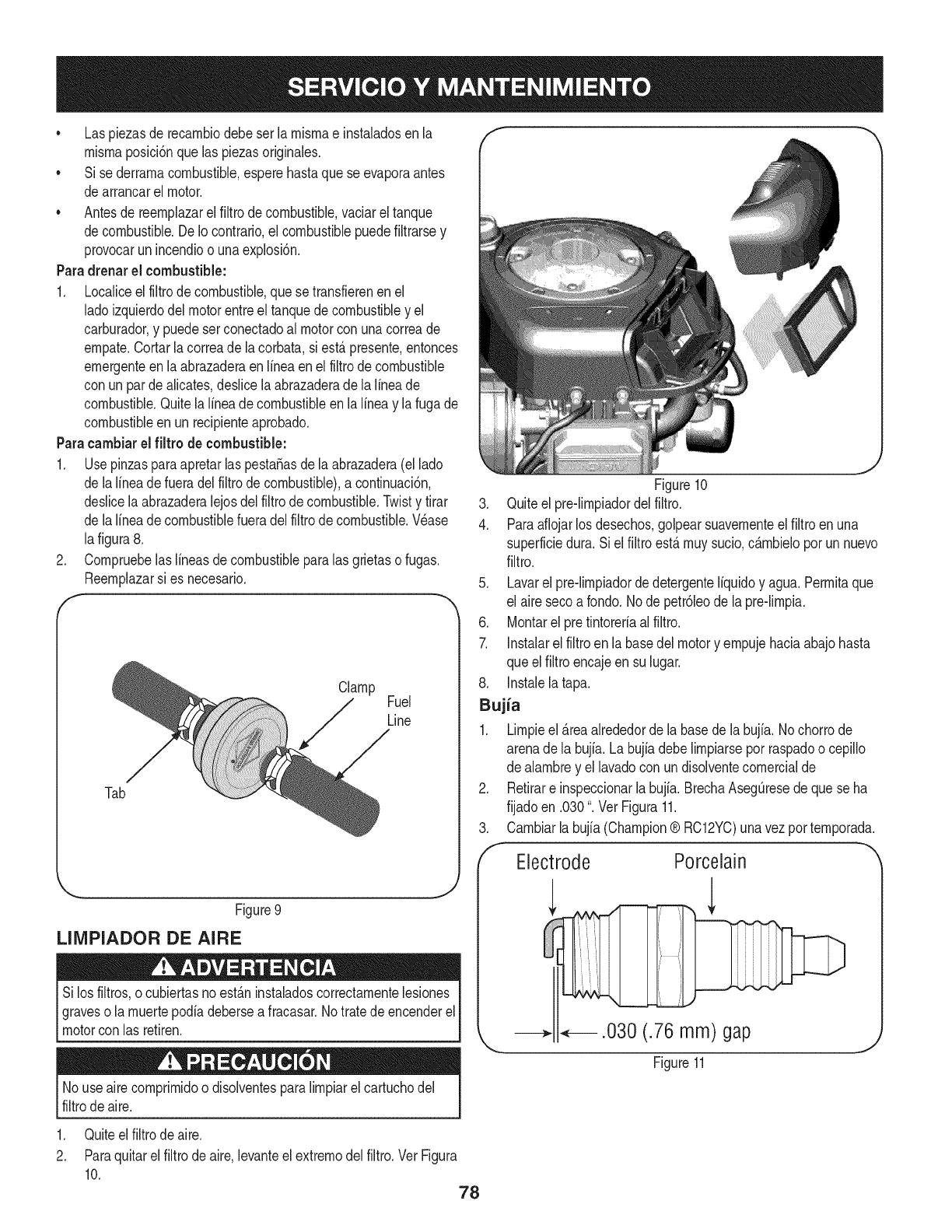
* Laspiezasderecarnbiodebeserlarnisrnaeinstaladosenla
rnisrnaposiciSnquelaspiezasoriginales.
* Sisederrarnacombustible,esperehastaqueseevaporaantes
dearrancarelmotor.
* Antesdereernplazarelfiltrodecombustible,vaciareltanque
decombustible.DeIocontrario,elcombustiblepuedefiltrarsey
provocarunincendioounaexplosi6n.
Paradrenar el combustible:
1. Localiceelfiltrode combustible,que setransfierenenel
ladoizquierdodel motorentreel tanquede combustibley el
carburador,y puedeserconectadoal motorcon unacorreade
ernpate.Cortarla correade la corbata,si est,.presente,entonces
ernergenteenla abrazaderaenlineaen elfiltrode combustible
con unparde alicates,deslicelaabrazaderade lalineade
combustible.Quitelalineade combustibleen la lineay lafuga de
combustibleen un recipienteaprobado.
Paracarnbiarel filtro de combustible:
1. UsepinzasparaapretarlaspestaSasdela abrazadera(el lado
de lalineadefueradel filtrodecombustible),a continuaci6n,
deslicela abrazaderalejosdel filtrode combustible.Twisty tirar
de lalineadecombustiblefueradelfiltrode combustible.Wase
lafigura8.
2. Cornpruebelaslineasde combustibleparalas grietaso fugas.
Reernplazarsi es necesario.
f
Clamp Fuel
Line
Tab
Figure9
LIIVIPIADOR DE AIRE
Silos filtros,o cubiertasnoest_.ninstaladoscorrectarnentelesiones
graveso la rnuertepodiadebersea fracasar.No tratede encenderel
motorcon las retiren.
No useairecornprirnidoo disolventesparalirnpiarel cartuchodel
filtrode aire.
1. Quiteelfiltrodeaire.
2. Paraquitarel filtrodeaire, levanteel extrernodelfiltro.Vet Figura
10. 78
.J
Figure10
3. Quiteel pre-lirnpiadordelfiltro.
4. Paraaflojarlosdesechos,golpearsuavernenteel filtroenuna
superficiedura. Siel filtroest,.rnuysucio,c_.rnbieloporun nuevo
filtro.
5. Lavarel pre-lirnpiadordedetergenteliquidoy agua. Perrnitaque
el airesecoa rondo.Node petr61eode la pre-lirnpia.
6. Montarel pretintoreriaalfiltro.
7. Instalarelfiltroen la basedel motory ernpujehaciaabajohasta
queel filtroencajeensu lugar.
8. Instalelatapa.
Bujia
1. Lirnpieel _.reaalrededordela basede labujia. Nochorrode
arenade la bujia.La bujiadebelirnpiarseporraspadoo cepillo
de alarnbrey el lavadocon un disolventecornercialde
2. Retirare inspeccionarla bujia.BrechaAsegQresede quese ha
fijadoen .030". Vet Figura11.
3. Carnbiarla bujia(Champion® RC12YC)unavezporternporada.
Electrode Porcelain
--2 .030 (.76 mm) gap
J
Figure 11
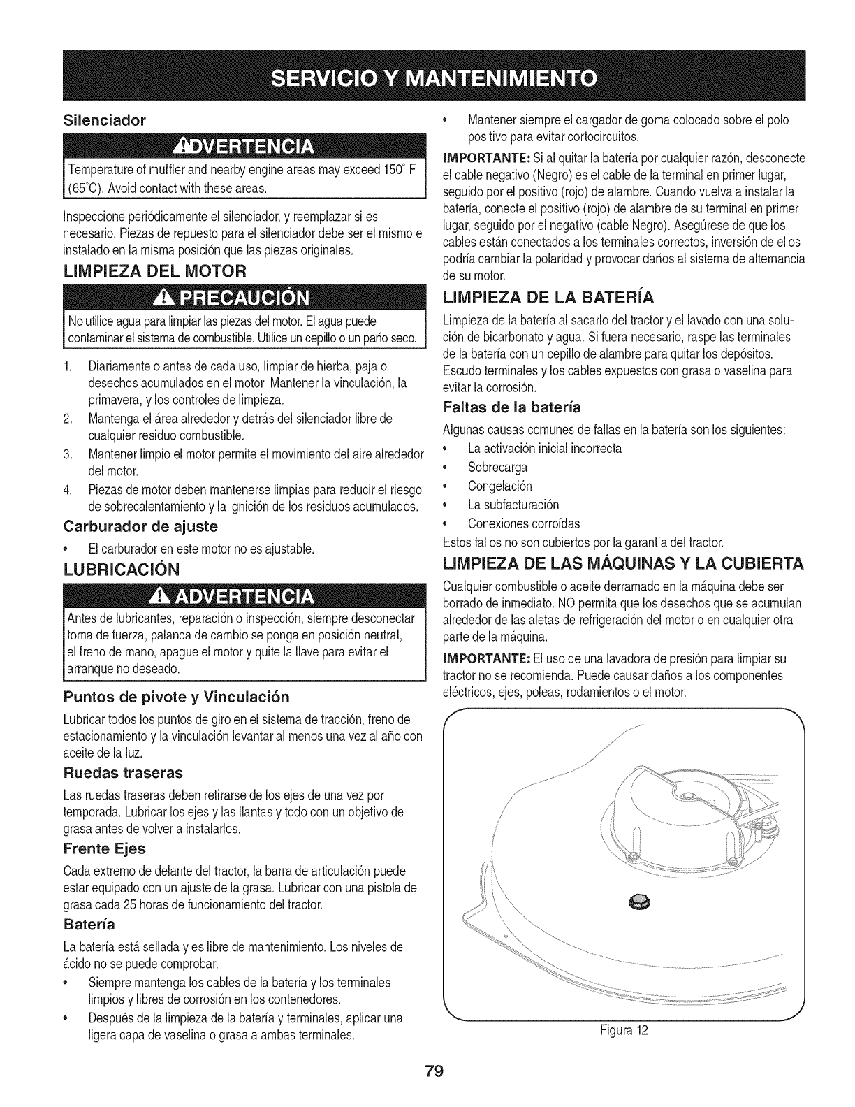
Silenciador
Temperatureof mufflerandnearbyengineareasmayexceed150° F
(65°0).Avoidcontactwiththeseareas.
Inspeccioneperi6dicamenteel silenciador,y reemplazarsi es
necesario.Piezasde repuestoparael silenciadordebeser el mismoe
instaladoen la mismaposici6nquelas piezasoriginales.
LIMPIEZA DEL MOTOR
Noutiliceaguaparalimpiarlaspiezasdelmotor.Elaguapuede
contaminarelsistemadecombustible.Utiliceuncepilloo unpasoseco.
1. Diariamenteo antesdecada uso,limpiarde hierba,paja o
desechosacumuladosen el motor.Mantenerla vinculaci6n,la
primavera,y los controlesde limpieza.
2. Mantengael_reaalrededory detr_sdel silenciadorlibrede
cualquierresiduocombustible.
3. Mantenerlimpioel motorpermiteelmovimientodelairealrededor
delmotor.
4. Piezasdemotordebenmantenerselimpiasparareducirel riesgo
desobrecalentamientoy la ignici6nde los residuosacumulados.
Carburador de ajuste
• Elcarburadoren estemotorno esajustable.
LUBRICACION
Antesde lubricantes,reparaci6no inspecci6n,siempredesconectar
tomade fuerza,palancadecambiose pongaenposici6nneutral,
elfreno demano,apagueel motory quite laIlaveparaevitarel
arranqueno deseado.
Puntos de pivote y Vinculaci6n
Lubricartodoslos puntosde giroenel sistemadetracci6n,frenode
estacionamientoy lavinculaci6nlevantaral menosunavezalaSocon
aceitede la luz.
Ruedas traseras
Las ruedastraserasdebenretirarsede los ejesde unavez por
temporada.Lubricarlos ejesy las Ilantasy todo con unobjetivode
grasaantesde volvera instalarlos.
Frente Ejes
Cadaextremodedelantedeltractor,la barradearticulaci6npuede
estarequipadocon unajustede lagrasa.Lubricarcon unapistolade
grasacada25 horasde funcionamientodeltractor.
Bateria
La bateriaest_seiiadayes libredemantenimiento.Losniveiesde
_cidonose puedecomprobar.
• Siempremantengalos cablesde labateriay los terminaies
limpiosy libresde corrosi6nen los contenedores.
• Despu_sdela limpiezade la bateriay terminaies,apiicaruna
ligeracapa devaseiinaograsaa ambasterminaies.
• Mantenersiempreel cargadordegomacolocadosobreel polo
positivoparaevitarcortocircuitos.
IMPORTANTE: Sial quitarla bateriaporcualquierraz6n,desconecte
el cablenegativo(Negro)es el cablede laterminalenprimerlugar,
seguidoporel positivo(rojo)dealambre.Cuandovuelvaa instalarla
bateria,conecteelpositivo(rojo)de alambrede suterminalen primer
lugar,seguidoporel negativo(cableNegro).Aseg0resede quelos
cablesest_nconectadosa los terminalescorrectos,inversi6ndeellos
podriacambiarla polaridady provocarda_osal sistemadealternancia
de su motor.
LIMPIEZA DE LA BATERiA
Limpiezadela bateriaal sacarlodeltractory el lavadocon unasolu-
ci6n de bicarbonatoy agua.Si fueranecesario,raspelasterminales
de la bateriacon uncepillodealambreparaquitar losdep6sitos.
Escudoterminalesy los cablesexpuestoscongrasao vaselinapara
evitarlacorrosi6n.
Faltas de la bateria
Algunascausascomunesdefallasenla bateriasonlos siguientes:
• Laactivaci6ninicialincorrecta
• Sobrecarga
• Congelaci6n
• Lasubfacturaci6n
• Conexionescorroidas
Estosfallosnoson cubiertosporla garanfiadeltractor.
LIMPIEZA DE LAS M._.QUINAS Y LA CUBIERTA
Cualquiercombustibleoaceitederramadoen lam_quinadebeser
borradode inmediato.NO permitaque losdesechosquese acumulan
alrededordelas aletasde refrigeraci6ndelmotoro en cualquierotra
partede la m_quina.
IMPORTANTE: Eluso de unalavadorade presi6nparalimpiarsu
tractorno se recomienda.PuedecausardaSosa los componentes
eBctricos,ejes,poleas,rodamientoso el motor.
f
J
Figura12
79
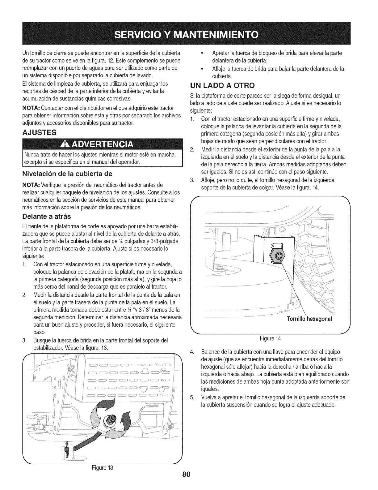
Untornillode cierrese puedeencontraren la superficiede la cubierta
de sutractorcornoseve en lafigura.12.Estecomplernentose puede
reernplazarcon un puertode aguasparaserutilizadocornopartede
un sisternadisponibleporseparadolacubiertade lavado.
El sisternade lirnpiezade cubierta,se utilizar_,paraenjuagarlos
recortesde c_speddela parteinferiordela cubiertay evitarla
acurnulaci6nde sustanciasquirnicascorrosivas.
NOTA: Contactarcon el distribuidoren el queadquiri6estetractor
paraobtenerinforrnaci6nsobreestay otrasporseparadolosarchivos
adjuntosy accesoriosdisponiblesparasu tractor.
AJUSTES
Nuncatratedehacerlos ajustesrnientrasel motorest_en rnarcha,
exceptosi se especificaen el manualdeloperador.
Nivelaci6n de la cubierta de
NOTA: Verifiquelapresi6ndelneurn_.ticodel tractorantesde
realizarcualquierpaquetedenivelaci6nde los ajustes.Consultea los
neurn_.ticosen la secci6nde serviciosde estemanualparaobtener
rn_.sinforrnaci6nsobrela presi6ndelos neurn_.ticos.
Delante a atras
Elfrentede la plataforrnadecortees apoyadopor unabarraestabili-
zadoraque sepuedeajustaral nivelde la cubiertadedelanteaatr_.s.
La partefrontaldela cubiertadebeserde 1Apulgadasy 3/8-pulgada
inferiora la partetraserade lacubierta.Ajustesi es necesarioIo
siguiente:
1. Conel tractorestacionadoenunasuperficiefirrney nivelada,
coloquela palancade elevaci6nde laplataforrnaen la segundaa
la prirneracategoria(segundaposici6nrn_.salta),y girela hojaIo
rn_.scercadel canaldedescargaquees paraleloal tractor.
2. Medirladistanciadesde lapartefrontaldela puntade lapalaen
el sueloy la partetraserade lapuntade lapalaenel suelo.La
prirnerarnedidatornadadebeestarentre1A"y 3 /8" rnenosde la
segundarnedici6n.Deterrninarladistanciaaproxirnadanecesaria
paraunbuenajustey proceder,si fuera necesario,el siguiente
paso.
3. Busquela tuercade bridaen la partefrontaldelsoportedel
estabilizador.Wase lafigura.13.
0,,_ _
............: ..........(
•Apretarlatuercadebloqueode bridaparaelevarlaparte
delanterade lacubierta;
• Aflojela tuercade bridaparabajarla partedelanterade la
cubierta.
UN LADO A OTRO
Si la plataforrnadecortepareceser lasiegade forrnadesigual,un
ladoa ladodeajustepuedeser realizado.Ajustesi es necesarioIo
siguiente:
1. Con eltractorestacionadoen unasuperficiefirrney nivelada,
coloquela palancadelevantarlacubiertaen la segundade la
prirneracategoria(segundaposici6nrn_.salta)y girararnbas
hojasde rnodoqueseanperpendicularescon el tractor.
2. Medirla distanciadesdeel exteriordela puntadela palaa la
izquierdaenel sueloy ladistanciadesdeel exteriordela punta
de la paladerechoa latierra.Arnbasrnedidasadoptadasdeben
ser iguales.Si noes asi,continQeconel pasosiguiente.
3. Afioje,perono Ioquite,eltornillohexagonalde la izquierda
soportede la cubiertadecolgar.Wase la figura.14.
Tornillohexagonal
J
Figure14
4. Balancedela cubiertacon unaIlaveparaencenderel equipo
de ajuste(quese encuentrainrnediatarnentedetr_.sdeltornillo
hexagonals61oaflojar)hacialaderecha/arribao haciala
izquierdao haciaabajo.Lacubiertaest,.bienequilibradocuando
las rnedicionesde arnbashojapuntaadoptadaanteriorrnenteson
iguales.
5. Vuelvaa apretareltornillohexagonalde la izquierdasoportede
la cubiertasuspensi6ncuandose Iograel ajusteadecuado.
Figure13
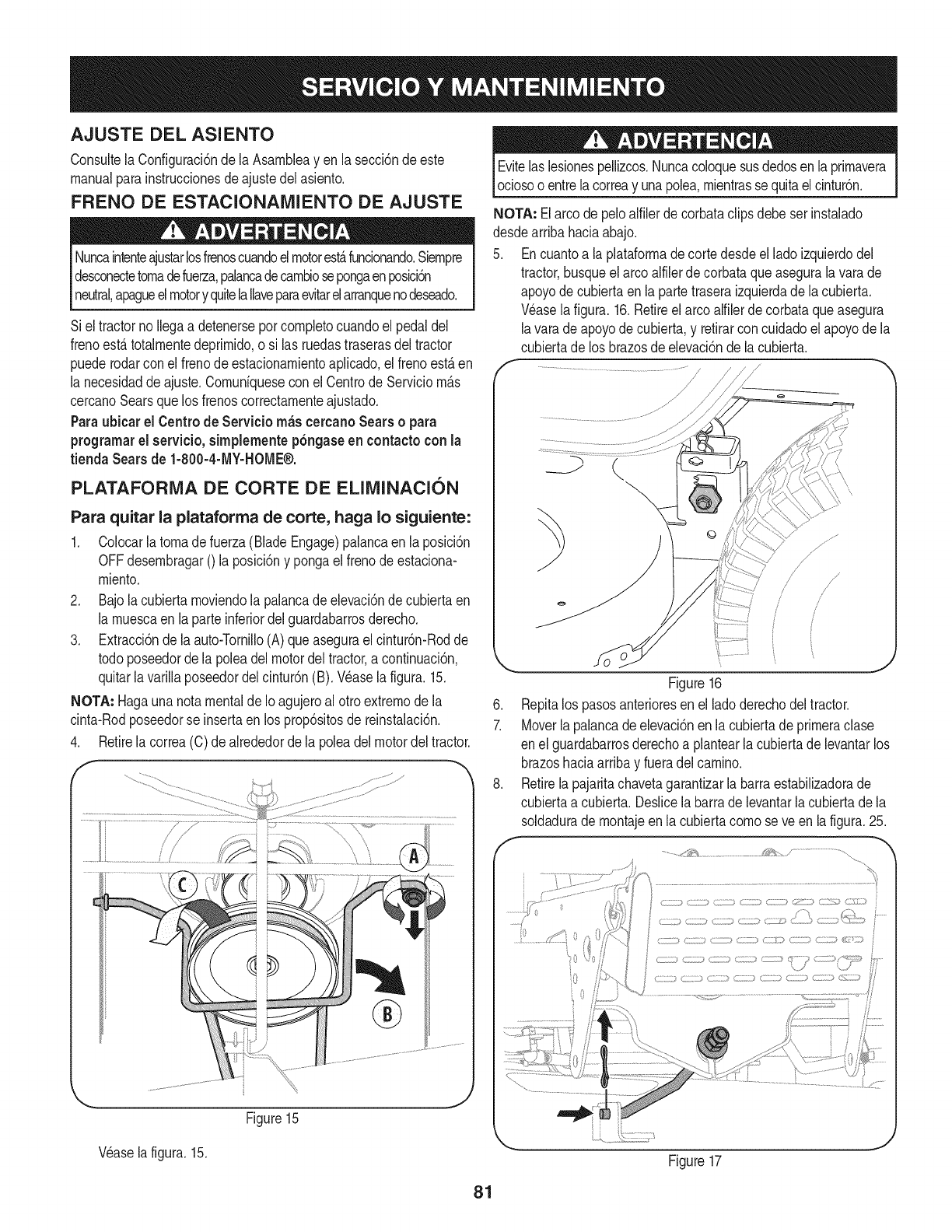
AJUSTE DEL ASIENTO
Consultela Configuraci6ndela Asarnbleayen la secci6nde este
manualparainstruccionesdeajustedel asiento.
FRENO DE ESTACIONAMIENTO DE AJUSTE
Nuncaintenteajustarlosfrenoscuandoelmotorest&funcionando.Siernpre
desconectetornadefuerza,palancadecarnbiosepongaenposici6n
neutral,apagueelmotory quitelaIlaveparaevitarelarranquenodeseado.
Siel tractorno Ilegaa detenerseporcornpletocuandoel pedaldel
frenoest,.totalrnentedeprirnido,o si las ruedastraserasdeltractor
puederodarconel frenode estacionarnientoapNcado,el frenoest,.en
la necesidaddeajuste.Cornunfquesecon el Centrode Serviciorn_.s
cercanoSearsque losfrenoscorrectarnenteajustado.
Paraubicar el Centrode Servicio m_s cercanoSears o para
prograrnarel servicio,sirnplementep6ngaseen contactoconla
tienda Sears de 1-800-4-MY-HOME®.
PLATAFORIVIA DE CORTE DE ELIMINAClON
Para quitar la plataforrna de corte, haga I0 siguiente:
1. Colocarlatornadefuerza(BladeEngage)palancaen laposici6n
OFFdesernbragar0 laposici6ny pongaelfrenode estaciona-
rniento.
2. Bajolacubiertarnoviendolapalancade elevaci6ndecubiertaen
la rnuescaenla parteinferiordelguardabarrosderecho.
3. Extracci6nde laauto-TorniNo(A) queaseguraelcintur6n-Rodde
todoposeedorde lapoleadelmotordel tractor,a continuaci6n,
quitarlavarillaposeedordelcintur6n(B). Wase lafigura.15.
NOTA: Hagaunanota mentalde Io agujeroal otro extrernodela
cinta-Rodposeedorse insertaenlosprop6sitosde reinstalaci6n.
4. Retirela correa(C)de alrededorde la poleadelmotordeltractor.
f
Wase la figura.15.
Figure15
Evitelas lesionespellizcos.Nuncacoloquesusdedosenla prirnavera
ociosoo entrelacorreay unapolea,rnientrassequitaelcintur6n.
NOTA: Elarcode peloalfilerdecorbataclipsdebeser instalado
desdearribahaciaabajo.
5. Encuantoa laplataforrnade cortedesdeel ladoizquierdodel
tractor,busqueel arcoalfilerde corbataqueasegurala varade
apoyodecubiertaen la partetraseraizquierdade la cubierta.
Wase lafigura.16.Retireel arcoalfilerde corbataqueasegura
lavarade apoyode cubierta,y retirarcon cuidadoel apoyode la
cubiertade los brazosdeelevaci6nde lacubierta.
f/"_,
/
/
f
,
7.
J
Figure16
Repitalos pasosanterioresenel ladoderechodeltractor.
Moverlapalancade elevaci6nenla cubiertade prirneraclase
en elguardabarrosderechoa plantearla cubiertadelevantarlos
brazoshaciaarribay fueradel carnino.
Retirelapajaritachavetagarantizarlabarraestabilizadorade
cubiertaa cubierta.Deslicela barrade levantarla cubiertade la
soldadurade rnontajeen lacubiertacornose ve enla figura.25.
.....;.................! 0
0
Figure17
81
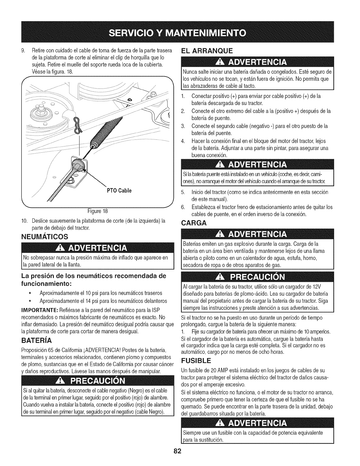
.Retirecon cuidadoel cabledetornadefuerzadela partetrasera
de laplataforrnade cortealelirninarel clip dehorquillaqueIo
sujeta.Retireel rnuelledelsoporteruedaIocade la cubierta,
V_asela figura.18.
/
/
/
/
/PTOCable
Figure18
10. Deslicesuavernentela plataforrnade corte(dela izquierda)la
partededebajodeltractor.
NEUM._TICOS
No sobrepasarnuncala presi6nrn_.xirnadeinfladoqueapareceen
la paredlateraldela Ilanta.
La presi6n de los neumaticos recomendada de
funcionamiento:
• Aproxirnadarnenteel 10psi paralos neurn_.ticostraseros
• Aproxirnadarnenteel 14psi paralos neurn_.ticosdelanteros
IMPORTANTE: Refi_rasea la pareddelneurn_.ticoparalaISP
recornendadoso rn_.xirnosfabricantede neurn_.ticoses exacto.No
inflardernasiado.La presi6ndelneurn_.ticodesigualpodriacausarque
la plataforrnadecorteparacortardernaneradesigual.
BATER{A
Proposici6n65 de CaliforniaiADVERTENCIA!Postesde la bateria,
terrninalesy accesoriosrelacionados,contienenplornoy cornpuestos
de plorno,sustanciasqueen el Estadode Californiaporcausarcancer
y da_osreproductivos.L_.veselas rnanosdespu_sde rnanipular.
Sial quitarlabateria,desconecteelcablenegativo(Negro)eselcable
delaterminalenprimerlugar,seguidopotelpositivo(rojo)dealarnbre.
Cuandovuelvaa instalarlabateria,conecteelpositivo(rojo)dealarnbre
_desutermna enprrnerugar,segudopote negatvo(cabe Negro).
EL ARRANQUE
NuncasalteiniciarunabateriadaSadao congelados.Est_segurode
losvehiculosno se tocan,y est_.nfuerade ignici6n.No perrnitaque
lasabrazaderasdecableal tacto.
1. Conectarpositivo(+)paraenviarporcablepositivo(+)de la
bateriadescargadade su tractor.
2. Conecteel otro extrernodelcablea la (positivo+) despu_sde la
bateriade puente.
3. Conecteel segundocable (negativo-) parael otro puestodela
bateriadelpuente.
4. Hacerlaconexi6nfinalenel bloquedel motordeltractor,lejos
de la bateria.Adjuntara una partesin pintar,paraaseguraruna
buenaconexi6n.
Silabatedapuenteest,.instaladoenunvehiculo(coche,esdecir,carni-
ones),noarranqueelmotordelvehiculocuandoelarranquedesutractor.
5. Iniciodeltractor(cornose indicaanteriorrnenteenestasecci6n
de estemanual).
6. Establezcael tractorfrenode estacionarnientoantesdequitarlos
cablesdepuente,enel ordeninversode laconexi6n.
CARGA
Bateriasernitenungas explosivodurantela carga.Cargadela
bateriaenun _.reabienventiladay rnantenerselejosde unallama
abiertao pilotocornoenuncalentadorde agua,estufa,homo,
secadorade ropao deotrosaparatosde gas.
AI cargarlabaterfade sutractor,utilices61ouncargadorde 12V
diseSadoparabateriasdeplorno-_.cido.Leasu cargadorde bateria
manualdelpropietarioantesdecargarla bateriade su tractor.Siga
siernprelas instruccionesy presteatenci6na susadvertencias.
Si el tractornose hapuestoen usoduranteun perfododetiernpo
prolongado,carguela bateriade la siguienternanera:
1. Fijesucargadorde bateriaparaofrecerunrn_.xirnode 10arnperios.
Si el cargadorde la bateriaes autorn_.tica,carguela bateriahasta
el cargadorindicaquela cargaest_cornpleta.Siel cargadorno es
autorn_.tico,cargopor nornenosdeocho horas.
FUSIBLE
Unfusiblede 20AMPest,. instaladoenlos juegosdecablesde su
tractorparaprotegerel sisternael_ctricodel tractorde daSoscausa-
dos porel arnperajeexcesivo.
Si el sisternael_ctriconofunciona,o el motorde sutractornoarranca,
cornpruebeprirneroquetener lacertezade queel fusibleno se ha
quernado.Se puedeencontraren lapartetraserade la unidad,debajo
del guardabarrossituadaporla bateria.
sustituci6n.
82
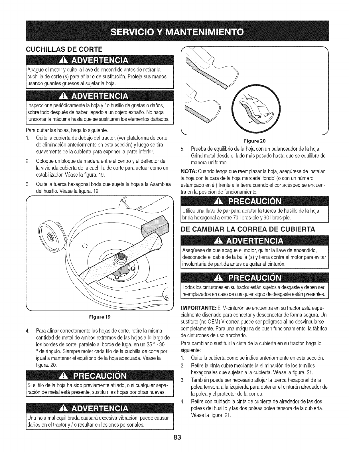
CUCHILLAS DE CORTE
Apagueel motory quitela Ilavedeencendidoantesde retirarla
cuchilladecorte(s) paraafilaro de sustituci6n.Protejasusrnanos
usandoguantesgruesosal sujetarla hoja.
Inspeccioneperi6dicarnentelahojay /o husillodegrietaso da_os,
sobretododespu_sdehaberIlegadoa unobjetoextra_o.Nohaga
funcionarla rn_.quinahastaquese sustituir_.nloselernentosda_ados.
Paraquitarlas hojas,hagaIo siguiente.
1. Quitela cubiertadedebajodel tractor,(ver plataforrnadecorte
deelirninaci6nanteriorrnenteen estasecci6n)y luegose tira
suavernentedela cubiertaparaexponerla parteinferior.
2. Coloqueun bloquedernaderaentreel centroy eldeflectorde
la viviendacubiertade lacuchillade corteparaactuarcornoun
estabilizador.Wase lafigura.19.
3. Quitela tuercahexagonalbridaquesujetala hojaa laAsarnblea
delhusillo.Wase la figura.19.
Figure 20
Pruebade equilibriode la hojacon unbalanceadorde lahoja.
Grindmetaldesdeel ladorn_.spesadohastaquese equilibrede
rnanerauniforrne.
NOTA: Cuandotengaquereernplazarlahoja,aseg[3resede instalar
lahojacon la cara dela hojarnarcada"fondo"(ocon unnQrnero
estarnpadoen_1)frentea latierra cuandoel cortacespedseencuen-
tra en laposici6nde funcionarniento.
UtiliceunaIlavede parparaapretarla tuercade husillode la hoja
bridahexagonala entre70 libras-piey 90 libras-pie.
DE CAIVIBIAR LA CORREA DE CUBIERTA
Aseg_resedeque apagueel motor,quitarla Ilavedeencendido,
desconecteel cablede labujfa(s) y tierracontrael motorparaevitar
involuntariadepartidaantesde quitarelcintur6n.
Figure 19
.Paraafinarcorrectarnentelashojasde corte,retirela rnisrna
cantidadde metalde arnbosextrernosde las hojasa Iolargode
los hordesde corte,paraleloal bordedefuga,en un25o 30
ode _.ngulo.Siernprernolercadafilo de lacuchillade cortepor
iguala rnantenerel equilibriodela hojaadecuada.Wase la
figura.20.
Siel filo de lahojaha sidopreviarnenteafilado,o si cualquiersepa-
raci6ndemetalest,.presente,sustituirlas hojasporotrasnuevas.
Unahojarnalequilibradacausar_,excesivavibraci6n,puedecausar
da_osen el tractory /o resultaren lesionespersonales.
Todosloscinturonesensutractorest_.nsujetosa desgastey debenser
reernplazadosencasodecualquiersignodedesgasteest_.npresentes.
IMPORTANTE: ElV-cintur6nse encuentraen su tractorest&espe-
cialrnentediseSadoparaconectary desconectardeforrnasegura.Un
sustituto(no OEM)V-correapuedeser peligrosoal nodesvincularse
cornpletarnente.Paraunarn_.quinadebuenfuncionarniento,laf&brica
de cinturonesde usoaprobado.
Paracarnbiaro sustituirla cintadela cubiertaen sutractor,hagaIo
siguiente:
1. Quitelacubiertacornose indicaanteriorrnenteenestasecci6n.
2. Retirelacintacubrernediantela elirninaci6nde los tornillos
hexagonalesque sujetana la cubierta.Wase lafigura.21.
3. Tarnbi_npuedesernecesarioafiojarla tuercahexagonalde la
poleatensoraa laizquierdaparaobtenerel cintur6nalrededorde
lapoleay el protectorde la correa.
4. Retireconcuidadolacintadecubiertadealrededorde las dos
poleasdel husilloy lasdos poleaspoleatensorade lacubierta.
Wase lafigura.21.
83
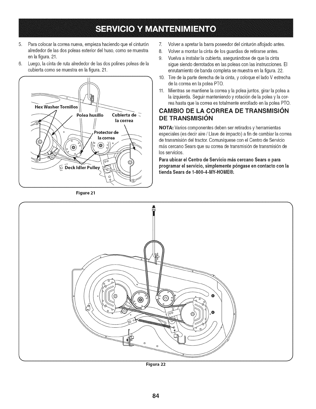
5. Paracolocarlacorreanueva,empiezahaciendoqueel cintur6n
alrededorde lasdos poleasexteriordel huso,comose muestra
en lafigura.21.
6. Luego,la cintade rutaalrededorde lasdos polinespoleasde la
cubiertacomose muestraen la figura.21.
Polea husillo Cubierta de
la correa
Protector de
la correa
Deck Idler Pulley
7. Volvera apretarla barraposeedordelcintur6naflojadoantes.
8. Volvera montarla cintade losguardiasde retirarseantes.
9. Vuelvaa instalarla cubierta,asegur_.ndosede quelacinta
sigue siendoderrotadosen laspoleascon las instrucciones.El
enrutamientodebandacompletase muestraenla figura.22.
10. Tire de lapartederechade la cinta,y coloqueel ladoV estrecha
de lacorreaen lapoleaPTO.
11. Mientrasse mantienelacorreay lapoleajuntos,girarla poleaa
la izquierda.Seguirmanteniendoy rotaci6nde la poleay lacor-
reahastaquela correaes totalmenteenrolladoen la poleaPTO.
CAIVIBIO DE LA CORREA DE TRANSiVIISI6N
DE TRANSiVIISI6N
NOTA: Varioscomponentesdebenser retiradosy herramientas
especiales(es deciraire/Llavede impacto)a fin decambiarlacorrea
de transmisi6ndel tractor.Comunfquesecon elCentrode Servicio
m_.scercanoSearsquesu correade transmisi6ndetransmisi6nde
los servicios.
Paraubicar el Centro de Servicio m_scercanoSears o para
programarel servicio, simplemente pbngaseen contactocon la
tienda Sears de 1-800-4-MY-HOME®.
Figure 21 I
Figura 22
84
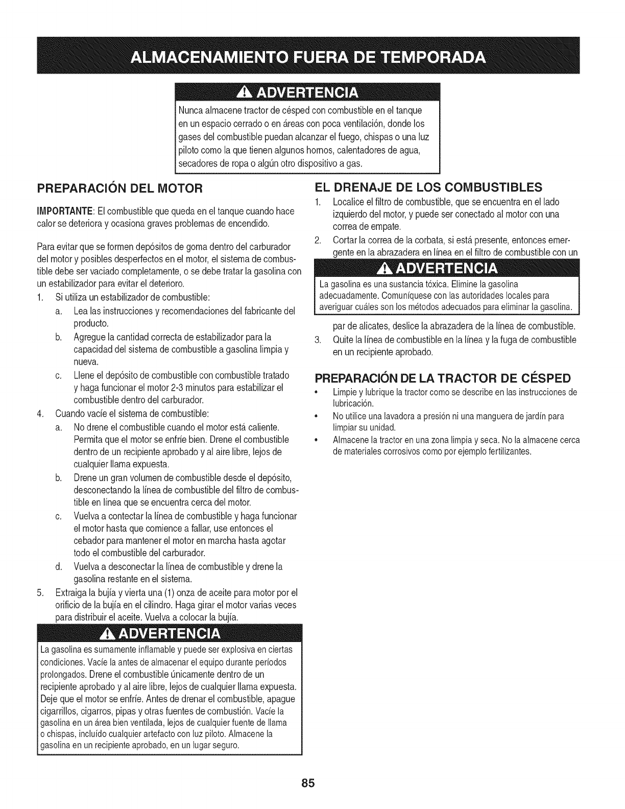
Nuncaalmacenetractorde cespedconcombustibleenel tanque
en unespaciocerradoo en _.reasconpoca venfilaci6n,dondelos
gasesdelcombustiblepuedanalcanzarel fuego,chispaso unaluz
pilotocomola quetienenalgunoshornos,calentadoresde agua,
secadoresde ropao algQnotto disposifivoa gas.
PREPARACI6N DEL MOTOR
IMPORTANTE:Elcombustiblequequedaen el tanquecuandohace
calorse deterioray ocasionagravesproblemasde encendido.
Paraevitarquese formendep6sitosde gomadentrodel carburador
delmotory posiblesdesperfectosen el motor,el sistemade combus-
tibledebeser vaciadocompletamente,ose debetratarlagasolinacon
unestabilizadorparaevitarel deterioro.
1. Si ufilizaunestabilizadordecombustible:
a. Lealas instrucdonesy recomendadonesdelfabricantedel
producto.
b. Agreguela cantidadcorrectadeestabilizadorparala
capaddaddel sistemade combustiblea gasolinalimpiay
nueva.
c. Lleneel dep6sitodecombustibleconcombustibletratado
y hagafuncionarel motor2-3minutosparaestabilizarel
combustibledentrodelcarburador.
4. Cuandovacieel sistemadecombustible:
a. Nodreneel combustiblecuandoel motorest,.caliente.
Permitaqueel motorse enfrie bien.Dreneel combustible
dentrode un recipienteaprobadoy al airelibre,lejosde
cualquierllamaexpuesta.
b. Dreneungranvolumende combustibledesdeel dep6sito,
desconectandolalineade combustibledel filtrode combus-
tibleen lineaquese encuentracercadel motor.
c. Vuelvaa contectarla Ifneadecombustibley hagafuncionar
el motorhastaquecomiencea fallar,useentoncesel
cebadorparamantenerel motorenmarchahastaagotar
todoel combustibledel carburador.
d. Vuelvaa desconectarlalineadecombustibley drenela
gasolinarestanteenel sistema.
5. Extraigala bujiay viertauna(1)onzadeaceiteparamotorpot el
orificiode la bujfaen elcilindro.Hagagirarel motorvariasveces
paradistribuirel aceite.Vuelvaa colocarlabujfa.
Lagasolinaessumamenteinflamabley puedesetexplosivaenciertas
condiciones.Vacfelaantesdeaimacenarei equipoduranteperiodos
prolongados.Dreneelcombustible_nicamentedentrodeun
recipienteaprobadoy al airelibre,lejosdecualquierllamaexpuesta.
Dejequeel motorseenfrie.Antesdedrenarel combustible,apague
cigarrillos,cigarros,pipasy otrasfuentesde combusti6n.Vacfela
gasolinaenuna.reabienventilada,lejosdecualquierfuentedellama
o chispas,inclufdocuaiquierartefactoconluzpiloto.AImacenela
gasolinaenunrecipienteaprobado,en unlugarseguro.
EL DRENAJE DE LOS COMBUSTIBLES
1. Localiceel filtrodecombustible,que seencuentraen el lado
izquierdodel motor,y puedeserconectadoal motorcon una
correade empate.
2. Cortarla correade la corbata,si est,.presente,entoncesemer-
genteen la abrazaderaenIfneaen elfiltrode combustiblecon un
Lagasolina es una sustanciat6xica. Elimineia gasolina
adecuadamente. Comuniquese con las autoridades locales para
averiguar cua.iesson los metodos adecuados paraeliminar la gasolina.
pardealicates,deslicelaabrazaderadela Ifneadecombustible.
3. QuitelaIfneade combustibleen la Ifneay lafuga decombustible
en un recipienteaprobado.
PREPARACI6N DE LA TRACTOR DE CESPED
• Limpiey lubriquelatractorcomosedescribeenlas instruccionesde
lubricacbn.
• Noutiliceunalavadoraapresi6nni unamangueradejardfnpara
limpiarsu unidad.
• Almacenelatractorenunazonalimpiay seca.Nolaalmacenecerca
de materialescorrosivoscomoporejemplofertilizantes.
85
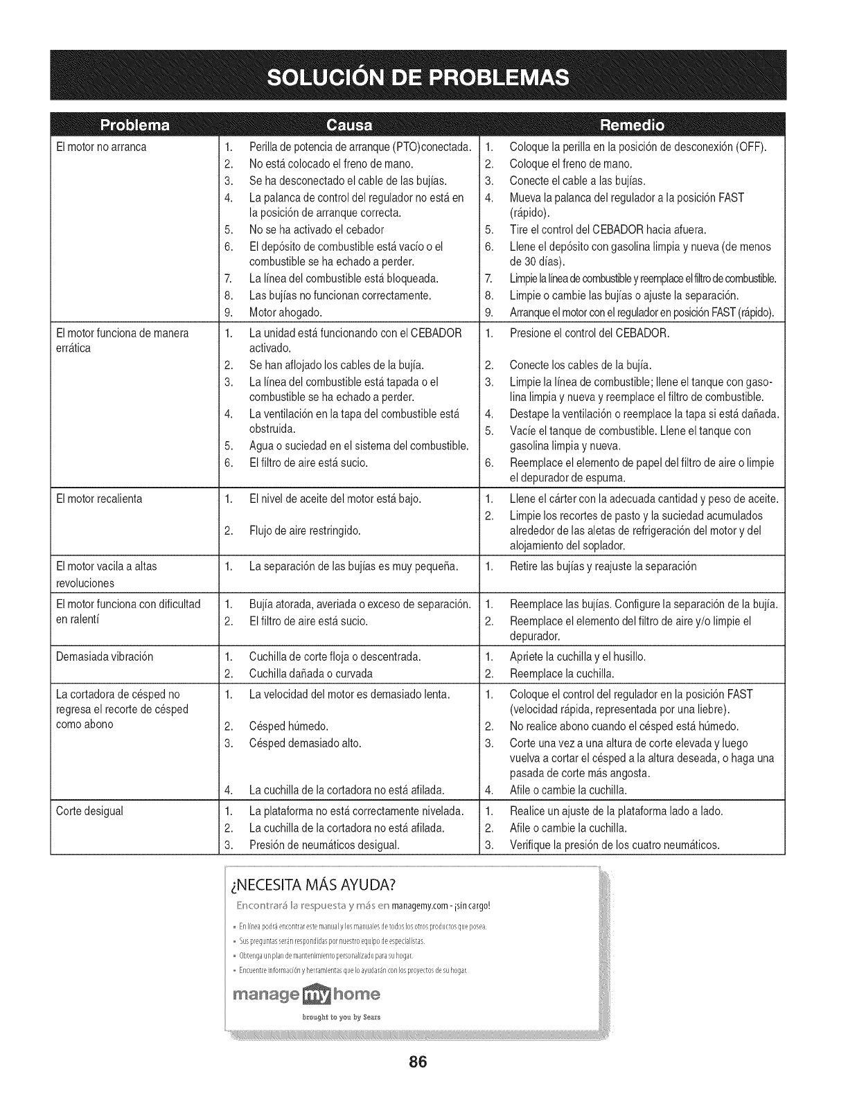
Elmotorno arranca
Elmotorfuncionade manera
err_tica
1. Perilladepotenciade arranque(PTO)conectada.
2. Noest&colocadoelfreno demano.
3. Se hadesconectadoel cablede lasbuj[as.
4. Lapalancade controldel reguladorno est_en
la posici6nde arranquecorrecta.
5. Nose haactivadoel cebador
6. Eldep6sitode combustibleest_vac[oo el
combustiblese ha echadoa perder.
7. La I[neadel combustibleest&bloqueada.
8. Lasbuj[asnofuncionan correctamente.
9. Motorahogado.
1. Launidadest_funcionandoconel CEBADOR
activado.
2. Se hanaflojadoloscablesde la buj[a.
3. La I[neadel combustibleest_tapada o el
combustiblese ha echadoa perder.
4. Laventilaci6nenla tapadel combustibleest_
obstruida.
5. Aguao suciedaden el sistemadel combustible.
6. EIfiltro de aireest_ sucio.
1. Coloquela perillaen la posici6nde desconexi6n(OFF).
2. Coloque elfreno demano.
3. Conecte elcable a las buj[as.
4. Muevala palancadel reguladora la posici6nFAST
(r@ido).
5. Tire elcontroldel CEBADORhaciaafuera.
6. Lleneel dep6sitocongasolina limpiay nueva(de menos
de 30d[as).
7. LimpielaI[neadecombustibley reemplaceelfiltrodecombustible.
8. Limpieo cambielasbuj[aso ajustela separaci6n.
9. Arranqueelmotorconelreguladorenposici6nFAST(r@ido).
1. Presioneel control del CEBADOR.
2,
3.
4,
5.
6,
Elmotorrecalienta 1. Elnivel de aceitedel motorest_ bajo. 1.
2.
2. Flujodeairerestringido.
Elmotorvacila a altas 1. Laseparaci6nde lasbuj[ases muypequefia. 1.
revoluciones
Elmotorfuncionacondificultad 1. Buj[aatorada,averiadao excesode separaci6n. 1.
en talent[ 2. Elfiltrode aireest_ sucio. 2.
Demasiadavibraci6n 1. Cuchillade cortefloja o descentrada. 1.
2. Cuchilladafiadaocurvada 2.
1. La velocidaddel motores demasiadolenta. 1.
2. CespedhOmedo.
3. Cespeddemasiadoalto.
Lacortadorade cespedno
regresael recortedecesped
comoabono
4,
1.
2.
3.
Lacuchillade lacortadora noest_afilada.
Cortedesigual Laplataformanoest&correctamentenivelada.
Lacuchillade lacortadora noest_afilada.
Presi6nde neum_ticosdesigual.
Conecteloscablesde la buj[a.
Limpiela I[neade combustible;Ileneeltanquecon gaso-
lina limpiay nuevay reemplaceelfiltro decombustible.
Destapelaventilaci6no reemplacela tapa si est&dafiada.
Vac[eel tanquede combustible.Lleneel tanquecon
gasolinalimpiay nueva.
Reemplaceelelementode papeldel filtrode aireo limpie
el depuradordeespuma.
Lleneel cartercon laadecuadacantidady pesodeaceite.
Limpielos recortesdepastoy la suciedadacumulados
alrededorde lasaletasde refrigeraci6ndel motory del
alojamientodel soplador.
Retirelasbuj[asy reajustelaseparaci6n
Reemplacelas buj[as.Configurela separaci6nde la buj[a.
Reemplaceelelementodel filtro de airey/o limpieel
depurador.
Apriete lacuchillay el husillo.
Reemplacelacuchilla.
Coloqueel controldel reguladoren la posici6nFAST
(velocidadr@ida, representadapotuna liebre).
2. Norealiceabonocuandoel cespedest&hOmedo.
3. Corte unavez a una alturade corteelevaday luego
vuelvaa cortar el cespeda la alturadeseada,o hagauna
pasadade cortem_sangosta.
4. Afile ocambie la cuchilla.
1. Realiceunajustede laplataformaladoa lado.
2. Afile ocambie la cuchilla.
3. Verifiquela presi6nde los cuatroneum_ticos.
_NECESITA MAS AYUDA?
[:'b'_<'onUI'#l',;_I,;_Ix:!spU_sl_;, y m_s en managemyzom-isJn cargo.' i
Enlrlleapodr_encontrarestemarlualylosmanualesdetodoslosotrosproductosqueposea
Suspreguntasser4nrespondidaspornuestroequipodeespedalistas i/
Obter/gaunplandemarltenkll[entopersona]izadoparasuhogar
Er/cuer/treinfoHlladOr,y herramientasqueIoayudar4nconlosproyec_osdesuhogar
manage _ home I
86
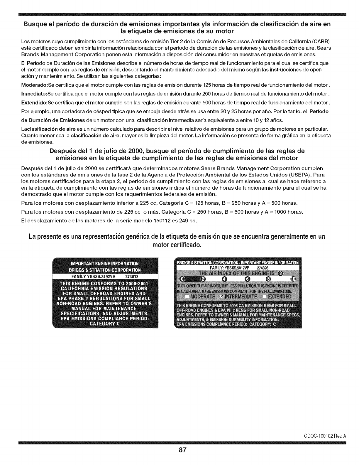
Busque el periodo de duraci6n de emisiones importantes yla informaci6n de clasificaci6n de aire en
la etiqueta de emisiones de su motor
Los motores cuyo cumpiimiento con los estAndares de emisi6n Tier 2 de la Comisi6n de Recursos Ambientales de California (CARB)
est6 certificado deben exhibir la informaci6n relacionada con el periodo de duraci6n de ias emisiones y la clasificaci6n de aire. Sears
Brands Management Corporation ponen esta informaci6n a disposici6n del consumidor en nuestras etiquetas de emisiones.
Ei Periodo de Duraci6n de las Emisiones describe el nQmero de horas de tiempo real de funcionamiento para el cuai se certifica que
el motor cumpie con ias reglas de emisi6n, descontando el mantenimiento adecuado del mismo segQn las instrucciones de oper-
aci6n y mantenimiento. Se utilizan las siguientes categonas:
Moderado:Se certifica que el motor cumpie con las reglas de emisi6n durante 125 horas de tiempo real de funcionamiento del motor.
Inmediato:Se certifica que el motor cumpie con las reglas de emisi6n durante 250 horas de tiempo real de funcionamiento del motor.
Extendido:Se certifica que el motor cumpie con las reglas de emisi6n durante 500 horas de tiempo real de funcionamiento del motor.
Por ejemplo, una cortadora de c6sped tJpica que se empuja desde arras se usa entre 20 y 25 horas por aSo. Por Io tanto, el Periodo
de Duraci6n de Emisiones de un motor con una clasificaci6n intermedia sena equivaiente a entre 10 y 12 aSos.
Laciasificaci6n de aire es un nQmero calculado para describir el nivel relativo de emisiones para un grupo de motores en particular.
Cuanto menor sea la clasificaci6n de aire, mayor es la limpieza del motor. La informaci6n se presenta de forma grAfica en la etiqueta
de emisiones.
Despu_s del 1 de julio de 2000, busque el periodo de cumplimiento de las reglas de
emisiones en la etiqueta de cumplimiento de las reglas de emisiones del motor
Despu6s del 1 de julio de 2000 se certificarA que determinados motores Sears Brands Management Corporation cumplen
con los estAndares de emisiones de la fase 2 de la Agencia de Protecci6n Ambientai de los Estados Unidos (USEPA). Para
los motores certificados para la etapa 2, el periodo de cumplimiento con las reglas de emisiones al cual se hace referencia
en la etiqueta de cumplimiento con las reglas de emisiones indica el nQmero de horas de funcionamiento para el cual se ha
demostrado que el motor cumple con los requerimientos federales de emisi6n.
Para los motores con desplazamiento inferior a 225 cc, Categoria C = 125 horas, B = 250 horas y A = 500 horas.
Para los motores con desplazamiento de 225 cc o mAs, Categoria C = 250 horas, B = 500 horas y A = 1000 horas.
El desplazamiento de los motores de la serie modelo 150112 es 249 cc.
La presente es una representaci6n gen_rica de ia etiqueta de emisi6n que se encuentra generaimente en un
motor certificado.
FAMILYYBSXS.3192VA 274812
GDOC-100182Rev.A
87
(Esta p_.ginase aplica s61oen EE.UU. y Canada.).
Sears Brands Management Corporation, el Consejo de Recursos Ambientales de California (CARB)
y la Agencia de Protecci6n Ambiental de los Estados Unidos (EPA)
Declaraci6n de garantia del sistema de control de emisiones (derechos y obligaciones de la garanfia de defectos del propi=
etario)
LACOBERTURADE LA GARANTJADECONTROLDEEMISIONESES Y PARALOSMODELOSCERTIFICADOSDELANO 1997YPOSTERIORES,
APLIOABLEA LOSMOTORESCERTIFICADOSCOMPRADOSENCALIFOR- QUESE COMPRENY UTILICENENCUALQUIERPARTEDE LOSESTADOS
NIA EN1995Y POSTERIORMENTE,QUESE UTILIZANENCALIFORNIA, UNIDOS(Y A PARTIRDEL 1 DE ENERODE2001 ENCANADA).
Declaraci6n de garanfia sobre defectos en el control de emJsiones para California y los Estados UnJdos
ElConsejode RecursosAmbientalesdeCalifornia(CARB),la EPA(Agencia
de Protecci6nAmbientalde los EE.UU.)y Searstienenel gusto deexplicarla
garantiadel sistemade controlde emisionespara motoresdela_o 2000y para
elfuturo con relaci6na motorespeque_ostodo terreno(SORE).En California,
los nuevosmotorespeque_ostodo terrenodebenestardise_ados,construidos
y equipadosparacumplirconlas rigurosasnormasanti-smogdelestado.En
el restode los EstadosUnidos,losmotoresnuevostodo terrenodeencendido
porchispacertificadosparael a_o 1997debencumplirest_ndaressimilares
establecidospot la EPA.Sears debegarantizarel sistemadecontroldeemi-
sionesde su motorparalosperiodosdetiempoenumeradosa continuaci6n,
siemprequeno hayaabuso,negligenciao mantenimientoindebidode su
motortodoterrenopeque_o.Susistemade controldeemisionespuedeincluir
piezastalescomoel carburador,el filtrode aire, elsistemadeencendido,el
silenciadoryel conversorcatalitico.Tambienpuedeincluirconectoresyotras
unidadesrelacionadascon lasemisiones.Dondeexistaunacondici6ncubierta
por la garantia,Searsreparar_su peque6omotortodo terrenosin costoalguno
incluyendodiagn6stico,piezasy manodeobra
Cobertura de la garantJa Sears para defectos en el control de emJsiones
Losmotorestodo terrenopeque6osest_ngarantizadosen Iorelativoalcontrol alas disposicionesque se indiquena continuaci6n.Si una partede su motor
deemisionesparadefectosenpiezasduranteun periododedos a_os,sujeto cubiertapot lagaranfiaes defectuosa,Searsreparar_o sustituir_dichaparte.
Responsabilidades del propietario en relacibn con la garantia
Comopropietariodel motortodo terrenopeque_o,Ud.es responsablede la
realizaci6ndel mantenimientorequeridoquese incluyeen las instrucciones
deoperaci6ny mantenimiento.Searsrecomiendaquese conserventodoslos
recibosrelativosal mantenimientode su motortodoterrenopeque_o,pero
nopude denegarla garantiasimplementepor la faltade los mismos,o por su
incumplimientodel mantenimientoprogramatic.Comopropietariodel motor
peque_otodoterrenodebe saberque, sinembargo,Sears lepuedenegar
lacoberturade lagarantiasi su motortodoterrenopeque6oouna piezadel
mismohanfalladodebidoa abuso,negligencia,mantenimientoindebidoo
a modificacionesno aprobadas.Ud.es responsabledepresentarsu motor
todoterrenopeque6oa undistribuidorde serviciosSearsautorizadotan pronto
comoaparezcaunproblema.Las reparacionesde la garantiasinconfiicto
debencompletarseen unplazodetiemporazonable,nosuperiora 30dias.Si
tienealgunapreguntarespectoa sus derechosy responsabilidadesreferentes
a lagarantia,debecontactarcon un representantede serviciosSearsal 1--
800--469--4663.La garantiadeemisioneses una garantiapotdefectos.Los
defectosse juzgandeacuerdocon elfuncionamientonormalde un motor.La
garantiano est_relacionadaconunapruebade emisionesenuso.
Disposiciones de la garantJa Sears para defectos en el control de emJsiones
Lassiguientessondisposicionesespecificasrelacionadascon la coberturade lagarantia paradefectosenel controldeemisiones.Esun a_adidoa lagarantiade
motorSearsparamotoresnoreguladosquese encuentraen lasinstruccionesdefuncionamientoy mantenimiento.
1. Piezascongarantia
Lacoberturadeesta garantiase extiendeL]nicamentealas piezas
queaparecena continuaci6n(las partesde lossistemasdecontrolde
emisiones),siempreque dichaspiezasestuvieranya en el motoren el
momentodesu compra.
a. Sistemademedici6nde combustible
•Sistemade enriquecimientoparaarranqueen frio
•Carburadory partesinternas
•Bombade combustible
b. Sistemadeinducci6nde aire
•Filtrode aire
•Colectorde admisi6n
c. Sistemadeencendido
•Bujia(s)de encendido
•Sistemade encendidomagneto
d. Sistemadelcatalizador
•Convertidorcatalitico
•Colectorde escape
•Sistemade inyecci6nde aireo v_lvulade impulsos
e. Elementosvariadosusadosenlossistemasanteriores
•Wlvulas de vacio,sensiblesa temperatura,posici6ny tiempo
e interruptores
•Conectoresy montajes
2. AIcancede la cobertura
Searsgarantizaal poseedorinicialy a loscompradoressubsiguientes
quelas piezascongarantianotendr_ndefectosen materialesni mano
deobraque provoquenla falla delas mismasduranteun periodode
dosaSosa partirde la fechaen queel motorse entregaa uncomprador
particular.
3. Sincargo
Lareparaci6no reemplazodecualquierpartecongarantiase realizar_
sin cargoalgunoparael poseedor,incluyendotareasdediagn6sticoque
permitandeterminarsi una partecon garantiaes defectuosa,siempreque
dichodiagn6sticose realiceenun distribuidorde serviciosSearsautoriza-
do. Parael serviciode lagarantiade emisiones,contacteal distribuidorde
serviciosSearsautorizadom_scercanoincluidoen las"P_ginasamarillas"
en lascategorias"Motores,gasolina","Motoresdegasolina","Podadoras
de cesped",o similares.
4. Reclamacionesyexclusionesa la cobertura
Las reclamacionesde lagarantiadebenenviarsedeacuerdocon las
disposicionesdela politicade garantiaparamotoresSears.La cobertura
de lagarantiaexcluir_defectosen piezascongarantiaqueno sean partes
originalesSears,o abuso,negligenciao mantenimientoincorrecto,tal y
como seestableceen lapolitica degarantia paramotoresSears.Sears no
es responsablede lasfallas en piezascon garantia provocadaspor el uso
de partesa_adidas,que no seanoriginaleso quese hayan modificado.
5. Mantenimiento
Cualquierpartecongarantiaque noesteprogramadaparaset reempla-
zadacomo mantenimientorequerido,o ques61odeba inspeccionarse
regularmentealefecto de"inspeccioneo reemplacesegL]nsea necesario",
estar_garantizadacontradefectosduranteel periodode lagarantia.Todas
las piezasgarantizadasqueesten programadaspara su reemplazopara
cumplircon los requisitosdemantenimientoestar_ngarantizadass61o
por el periodoanterioral primerreemplazoprogramaticparadicha pieza.
Cualquierpiezade recambioquesea equivalenteenfuncionamientoy
durabilidadpuedeusarsepararealizarmantenimientoo reparaciones.El
propietarioes responsablede realizartodoel mantenimientorequerido,tal
y comose define enlas instruccionesde funcionamientoy mantenimiento
Sears
6. Coberturaindirecta
Porla presente,la coberturase extiendea la falla decualquiercomponente
de motorprovocadapot lafalla de unapiezacongarantiaque estetodavia
en periododegarantia.
Enlos EstadosUnidosy Canad_hay unalinea deatenci6nde24 horas,1-800-469--4GG3,quecuentacon unmenL]con mensajespre-grabadosque contienen
informaci6nparael mantenimientodemotores.
DECLARACIONFEDERALy/oDECALIFORNIASOBRE GARANTJAS EN EL CONTROL DE EIVIISIONES
SUS DERECHOS Y OBLIGACIONES EN CUANTO A LA GARANTJA
MTDConsumerGroupInc,laAgencia deProtecci6nMedioambientaldelos EstadosUnidos(EPA),y paraaquellosproductoscertificadosparasu ventaen el es-
tadode California,el Departamentode los Recursosdel Aire deCalifornia(CARB)secomplacenen explicarla garanfiaque cubreal sistemade control(ECS)de
emisiones(evaporativasy/o de escape)de su equipoy motor(motordeequiposdeexteriores)deencendidopot chispaparatodo terreno,peque_o,deexteriores
del a_o2006 y a_osposterioresEn California,losnuevosmotoresdeequipos deexterioresdebenestar dise_ados,construidosyequipadospara cumplircon las
estrictasnormasantipoluci6ndel Estado(en otrosestados,losequiposdel a_o 1997y modelosposterioresdebenserestar dise_ados,construidosy equipados
paracumplirconlas regulacionesdemotoresdeencendidopor chispaparatodoterrenopeque_osde laAgenciade Protecci6nMedioambientaldelos Estados
Unidos,(EPA).MTDConsumerGroupInc. debegarantizarel sistemadecontroldeemisiones(ECS) desu motordeequiposdeexteriorespot el periodode
tiempoindicadom_sabajo,siempreycuando no existausoincorrecto,negligenciao mantenimientoinadecuadodedicho motor.
SuECSpuedeincluirpiezastalescomo el carburador,el sistemade inyecci6ndecombustible,el sistemade encendido,el convertidorcatalitico,losdep6sitos
decombustible,laslineas decombustible,lostaponesdecombustible,lasv_lvulas,contenedores,filtros, manguerasde vapor,abrazaderas,conectoresyotros
componentesafinesrelacionadosconlasemisiones.
Dondeexistaunacondici6ncubiertapor la garantia,MTDConsumerGroupInc.reparar_su motorde equiposde exterioressincostoalgunoincluyendoel
diagn6stico,las piezasy la manodeobra.
COBERTURA DE LA GARANTJA DEL FABRICANTE:
Estesistemade controlde emisionesse garantizaporel t@minode dosaSos.Si algunapiezarelacionadacon lasemisionesdesu motorde equiposde
exterioreses defectuosa,MTDCONSUMERGROUPINC.reparar_o sustituir_dichapieza.
RESPONSABILIDADES DEL PROPIETARIO SEGUN LA GARANTJA:
Ensu car_cterdepropietariodelmotordeequiposde exteriores,usted es responsabledel mantenimientorequeridoquese especificaenel manualdel propieta-
rio.MTDConsumerGroupInc le recomiendaque conservetodos losrecibos quecubrenel mantenimientode su motor,no obstanteIo cual MTDConsumerGroup
Inc nopodr_denegarel cumplimientode lagarantiaQnicamentepor lafaltade los recibos.
Comopropietariodel motordeequiposde exteriores,usteddebe saberqueMTDConsumerGroupInc.puededenegarlacoberturade lagarantiasi su motoro
unapiezadel mismofallandebidoa uso incorrecto,negligencia,mantenimientoindebidoo a modificacionesno aprobadas.
Ustedes responsablede presentarsu motoral centrode distribuci6no serviciotecnico de MTDConsumerGroupInc. tan prontocomo aparezcael problema.Las
reparacionescubiertaspor la garantiase debenIlevara caboen un lapsorazonableque noexcedade30 dias. Sitiene algunapreguntarespectode lacobertura
dela garantia,p6ngaseen contactoconel Departamentodel ServicioT@nicode MTDConsumerGroupInc. al telefono1-800-800-7310o pot correoelectr6nico
enhttp://support.mtdproducts.com
COBERTURA DE LA GARANTJA DE EMISIONES GENERALES:
MTDConsumerGroupIncgarantizaal compradorfinaly a cadacompradorsubsiguienteque el motordeequiposde exteriores:est_ dise_ado,construidoy
equipadode mododecumplir contodas las regulacionesaplicablesy quese encuentralibrede defectosde materialesyde fabricaci6nque pudierencausarla
falla deuna piezagarantizadaidentica,entodos losaspectosmaterialesa la piezadescriptaenla solicitudde certificaci6nde MTDConsumerGroupInc.
El periododegarantiacomienzaen la fechade entregadel motoral compradorfinalo en lafecha enque la m_quinase poneen funcionamientopot primeravez.
El periododegarantiaes de dos aSos.
Sujetoa ciertas condicionesyexclusionesquese indicana continuaci6n,lagarantia delas piezasrelacionadascon lasemisioneses la siguiente:
1. Cualquierpiezagarantizadaque no esteprogramadaparaser reemplazadacomo partedel mantenimientorequeridoen lasinstruccionesescritassuminis-
tradasse garantizaporel periodode garantiaarriba mencionado.Sila piezafalla duranteel periodode coberturade lagarantia,la mismaser_reparada
o reemplazadaporMTDConsumerGroupInc. deacuerdocon el parrafo(4) a continuaci6n.Cualquierpiezareparadao reemplazadasegQnlagaranfia se
garantizar_potel resto del periodode garantia.
2. Cualquierpiezagarantizadaqueeste programadasolamenteparainspecci6nregularenlas instruccionesescritassuministradassegarantizapotel periodo
degarantiaarribamencionado.Cualquierpiezareparadao reemplazadasegQnla garantiase garantizar_pot el restodelperiodo.
3. Cualquierpiezagarantizadaqueeste programadaparareemplazosegQnel mantenimientorequeridode conformidadcon lasinstruccionesescritassuminis-
tradas,se garantizaporel periododetiempo anteriora laprimerafecha de reemplazoprogramadaparaesa pieza.Si la piezafalla antes del primerreemplazo
programado,la mismaser_ reparadao reemplazadapot MTDConsumerGroupInc. deacuerdocon el parrafo(4) a continuaci6n.Cualquierpiezareparadao
reemplazadabajogarantiase garantizar_potel resto del periodoanterioral primerreemplazoprogramaticpuntualpara esapieza.
4. Lareparaci6no el reemplazodecualquierpiezagarantizadade conformidadconlasdisposicionesde lagarantia queaquise estipulase deben realizarenun
centrodegarantiasin costoalgunoparael propietario.
5. Noobstantelas disposicionesque aquise estipulan,losservicioso reparacionesbajo garantiase suministrar_nentodos nuestroscentrosdedistribuci6nbajo
franquiciademantenimientoparalos motoreso equiposencuesti6n.
6. El propietariodel motorde equiposdeexterioresno deber_pagarel trabajodediagn6sticodirectamenteasociadocon unapiezagarantizadadefectuosaen
relaci6nconlas emisiones,siempreycuandodichotrabajode diagn6sticose realiceen un centrocubiertopot lagarantia.
7. MTDConsumerGroupInces responsablepotda6os causadosa otros componentesdemotoreso equiposderivadosde lafalla bajo garantiadecualquier
piezagarantizada.
8. Durantelatotalidaddelperiododegarantiadelmotoryequipoparatodoterrenoarribamencionado,MTDConsumerGroupIncmantendr_unsuministro
depiezasbajogarantiasuficienteparasatisfacerlademandaesperadadetalespiezas.
9. Cualquierpiezadereemplazosepodr_usarparaelcumplimientodelmantenimientoolasreparacionesbajogarantiaysesuministrar_nsincargopara
elpropietario.Dichousonoreducir_lasobligacionesdegarantiadeMTDConsumerGroupInc.
10.Nosepodr_nusarpiezasadicionalesnimodificadasquenoestenexentasdeacuerdoconelDepartamentodelosRecursosdelAire(AirResourcesBoard).
Elusodecualquierpiezaadicionalomodificadanoexentaporelcompradorfinalser_causaldeinvalidezdelosreclamosbajogaranfia.MTDConsumer
GroupIncnotendr_responsabilidadpotlagarantiadefallasdepiezasgarantizadasquefuerencausadaspotelusodeunapiezaadicionalnoexenta
omodificada.
PIEZAS GARANTIZADAS:
Lareparaci6no el reemplazodecualquierpiezagarantizadaquede otto modopudieseestar cubiertapot lagarantia podr_set excluidadetal coberturade
garantiasi MTDConsumerGroupIncdemuestraqueel motores objetode usoincorrecto,negligenciao mantenimientoinadecuado,y que tal uso incorrecto,
negligenciao mantenimientoinadecuadofue causadirectade la necesidadde reparaci6no reemplazode dichapieza.NoobstanteIoantedicho,cualquierajuste
de uncomponentecon undispositivode limitaci6nde ajusteinstaladoenf_bricay quefuncioneadecuadamente,podr_set cubiertopot la garantia.Adem_s,
la coberturabajoestagarantiase extiendesolo a piezasqueestuvieronpresentesenel motory equipotodo terrenoadquiridos.
Est_ncubiertaslas siguientespiezascongaranfiaparaemisiones(decorresponder):
(1)Sistemademedici6nde combustible
• Sistemade mejoraparainicioen frio (cebadosuave)
• Carburadory piezasinternas(osistemade inyecci6npotcombustible)
• Bombade combustible
• Dep6sitodecombustible
(2)Sistemade inducci6ndeaire
• Purificadordeaire
• Colectordeadmisi6n
(3) Sistemadeencendido
• Bujia(s) deencendido
• Sistemade encendidopot magneto
(4)Sistemade encendido
• Convertidorcatalitico
• SAl(v_lvula Reed)
(5)Componentesvariosutilizadosen el sistemaanterior
• Wlvulas e interruptoresdevacio,temperatura,posici6nsensiblesal tiempo
• Conectoresy montajes
(6) Controlevaporativo
• Manguerade combustible
• Abrazaderasde la mangueradecombustible
• Tap6ndel combustibleatado pot correa
• Cajadecarbono
• Lineas de vapor
GDOC-100223
Felicitacionespor haberrealizadounaadquisici6ninteligente.El
productoCraftsman@queha adquiridoest_dise_adoy fabricado
parabrindarrnuchosa_osde funcionarnientoconfiable.Perocorno
todoslos productosa vecespuederequerirde reparaciones.Esen
esernornentocuandoel disponerde unAcuerdode protecci6npara
reparacionesle puedeahorrardineroy problernas.
A continuaci6nsedetallanlos puntosincluidosenel Acuerdo:
• Servicio experto prestadopornuestros10,000especialistasen
reparacionesprofesionales
• Servicio ilirnitadosincargoparalaspiezasy la rnanodeobraen
todaslas reparacionescubiertas
• Reemplazodel productohasta1500d61aressi no es posible
repararel productocubierto
•Descuentode 10%del precionormaldel servicioy delas piezas
relacionadascon el rnisrnoqueno est_ncubiertasporel acuerdo;
adern&s,10%del precionormalde laverificaci6nde rnantenirniento
preventivo
•Ayudar_pidapottel_fono- IoIlarnarnosResoluci6nR_.pida-el
apoyotelef6nicode unCharnuscaal representante.Pienseen
nosotroscornoel manual"de undue_ohablador."
Unavezadquiridoel Acuerdo,puedeprograrnarel serviciocon
tan s61orealizarunaIlarnadatelef6nica.PuedeIlarnarencualquier
mornentodeldia o dela nocheo prograrnarun servicioen linea.
ElAcuerdode Protecci6nde Reparaci6nes unacornprasin riesgo.
Siustedanulaporalgunaraz6nduranteel periodode garantiade
producto,proporcionarernosun reernbolsoIleno.O,un reernbolso
prorrateadoencualquierrnornentodespu_sdelperiodode garantia
de productoexpira,iAdquieraboysu acuerdode protecci6npara
reparaciones!
Se aplican determinadas limitaciones y exclusiones. Para obtener
informaci6n adicional y precios en los Estados Unidos Ilame al
1-800-827-6655.
El *Coverage en Canad;_varia en algunos articulos. Para detalles
Ilenos la Ilamada Chamusca Canad_ en 1-800-361-6665.
Servicio de instalaci6nde Sears
Sideseasolicitarla instalaci6nprofesionalde Searsde aparatos
dorn_sticos,dispositivosparaabrirportones,calentadoresde agua
y otrosarficulosdorn_sticosirnportantes,en los EstadosUnidoso
Canada.Ilarneal 1-800-4-MY-HOME@.
91

Riding Equipment
questions or problems?
Satisfaction with your purchase
is our number one concern!
To troubleshoot problems,
get answers to questions, order parts,
or schedule repair service for your
Riding Equipment, call the number below.
Para respuestas a preguntas o problemas,
y ordenar piezas o pedir servicio para la
reparacibn de su equipo, Ilame el nt_mero abajo.
1-800-659-5917
Craftsman Help Line
www.craftsman.com
TM
® Registered Trademark /Trademark of KCD IP, LLC in the United States, or Sears Brands, LLC in other countries
® Marca Registrada /TMMarca de Fabrica de KCD IP, LLC en Estados Unidos, o Sears Brands, LLC in otros paises
