Craftsman Table Saw 315 21829 Owners Manual
315218290 315218290 CRAFTSMAN 10 TABLE SAW - Manuals and Guides L0520316 View the owners manual for your CRAFTSMAN 10 TABLE SAW #315218290. Home:Tool Parts:Craftsman Parts:Craftsman 10 TABLE SAW Manual
CRAFTSMAN Saw Table Manual L0520316 CRAFTSMAN Saw Table Owner's Manual, CRAFTSMAN Saw Table installation guides
31521829 bdaf21ae-9d53-43bb-9e65-20d316ad36e9 Craftsman Saw 315.21829 User Guide |
2015-01-05
: Craftsman Craftsman-Table-Saw-315-21829-Owners-Manual-161069 craftsman-table-saw-315-21829-owners-manual-161069 craftsman pdf
Open the PDF directly: View PDF ![]() .
.
Page Count: 58
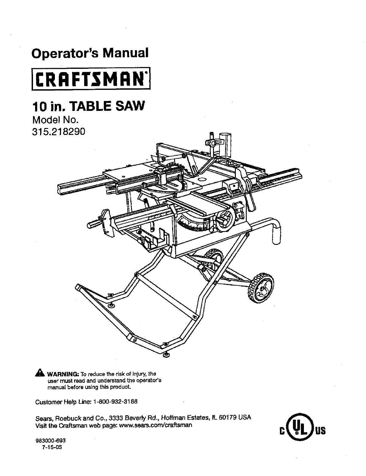
Operator's Manual
10 in. TABLE SAW
Model No,
315.218290
_k WARNING: To reduce the risk of injury,the
user must read and understandthe operator's
manual before usingthis product.
Customer Help Line: 1-800-932-3188
Seam, Roebuck and Co., 3333 BeverPy Rd., Hoffman Estates, IL 60179 USA
Visit the Craftsman web page: www.seam.com!cmffsman
983000-693
7-15-05

Warranty ............................................................................................................................................................................ 2
Introduction....................................................................................................................................................................... 2
GenareJSafety Rules......................................................... ............................................................................................ S--4
Specific Sat°styRules.................................... ................................................................................................................. 4-5
Symbols......................................................................................................................................................................... 6-7
EIac_ca( ............................................................................................................................................................................ 6
Glossary of Tsn'ns.............................................................................................................................................................. g
Features..................................................................................................................................................................... 10-13
ToolsNeeded ................................................................................................................................................................. 13
Loose Parts ............................................................................................................................................................... 14-15
Assembly................................................................................................................................................................... 16-22
Operation................................................................................................................................................................... 22-39
Adjustments .............................................................................................................................................................. 40-44"
Maintenance................................................................................................................................................................... 45
Accessories.................................................................................................................................................................... 46
Troubleshooting......................................................................................................................................................... 46-47
Exploded View ........................................................................................................................................................... 4-8-57
Parts Ordering/Service...................................................................................................................................... Back Page
ONE YEAR FULL WARRANTY ON CRAFTSMAN TOOL
If this Craftsman tool fails due to a defect in material or workmanshipwithinone year from the date of purchase,Call
1-B00-4-MY-I-IOME Oto arrangefor free repalr.If thlstool is used for commercial or rental purposes, thiswarranty will
apply for only ninety days from the date of purohass.This warranty appilesonly while this product is in the United States.
This warranty givesyou specific legal rights, and you may eJso hays other rightswhich vary from stats to state.
Seam, Roebuck and Co., Dept. 8t7WA, Hoffman Estates, IL 60179
This tool has many featuresfor makingits use more pleasant and enjoyable.Safety,performance,and dependability
have been giventop priorityin the design of this productn'_.kingit easy to maintain and operate.
2

_k WARNING." Reed and understand all insb'ue-
tions, Failureto re[low all instruckions{istadbelow,
may resuttin electric shock, fire andlor serious
personal injury.
READ ALL iNSTRUCTIONS
•KNOW YOUR POWER TOOL. Read the operator's
manual carefully.Learn the saw's applicationsand
Iimftationsaswet[es the specific potenti_ hazards
related to thistool.
•GUARD AGAINST ELECTRICAL SHOCK BY PRE-
VENTING BODY CONTACT WITH GROUNDED
SURFACES- For examp}e,pipes, radiators,ranges,
refrigeratorenclesures.
•KEEP GUARDS IN PLACE and ingood working order.
•REMOVE ADJUSTING KEYS AND WRENCHES.
Form habit of checkingto see that keysand adjusting
wrenches are removedfrom tool before turningit on.
• KEEP WORK AREA CLEAN. Cluttered areas and
benches inviteaceidents. DO NOT leave tools or
pieces ot wood onthe sawwhile it is inoperation.
•DO NOT USE IN DANGEROUS ENVIRONMENTS.
Do not usepower tools in damp or wet locationsor
exposeto rain.Keep the work areaweI_s_.
•KEEP CHILD REN AND VISITORS AWAY.All visitors
shouldwear safetyg_aesasand be kept a safe
distancefromwork ares. Do not let visitorsosntact
tool or extensioncord while operating.
•MAKE WORKSHOP CHILDPROOF with padlocksand
master switches, orby removings_,_'terkeys.
•DON'T FORCE TOOL. Itwilldo the job better and
safer at the feed rote for which it was designed.
•USE RIGHT TOOL, Don't rome the tool or attachment
to do a job it was not designedfor. Don't use it for a
purposenot intended.
•USE THE PROPER EXTENSION CORD. Make sure
your extensioncord is in good condition.Use on[ya
cordheavyenoughtocarrythecurrentyourprodu_
will draw. An undersizedcord will cause a drop inline
voltage resultingin_oesof power and overheating.A
wire gauges'_e (A.W.G.)of at least 14 is recommended
for an extensioncord 25 feet or less in length. If in
doubt, use thenext heavier gauge.The smallerthe
gauge number, the heavierthe cord.
•DRESS PROPERLY.Do not wear loose clothing,
gloves,neckties, orjewelry.They can get caught
and draw you intomoving parts. Rubber glovesand
nonskidfoo[wser are recommendedwhen working
outdoors.Alse wear protecl:'Nehair osver;ng to contain
long hak.
•ALWAYSWEAR SAFETYG_ESWITI-I SIDE
SHIELDS. Everyday eyeglasseshave onlyimpact-
resistantlenses, they are NOT safety gtaseas.
•SECURE WORK, Use clamps oravise to hold work
when pc_ctical._fs safert_n using your han_ an
_ees both hands to operate tool.
•DON'T OVERREACH. Keep properfootingand
ba_nco at sit times.
•MAINTAIN TOOLS WITH CARE. Kesptools sherp
and clean for better and safer performanca.FoJiow
instructionsfor lubricatingand changingaccessories.
•DISCONNECT TOOLS. When notin use, before
servicing,or when changingaLl_chmants,blades, bits,
cutters, etc., an tools should be disconnected.
•AVOID ACCIDENTAL STARTING. Be sureswitchis off
when plugging in any tooL
•USE RECOMMENDED ACCESSORIES. Consult the
operator'smanual for recommendedaccessories.The
use of improperaccessoriesmay riskinjury.
• NEVER STAND ON TOOL, Seriousinjurycouldoccur
if the tool is tipped or if the cuttingtoo[ is unintention-
_lly con_.cted.
•CHECK DAMAGED PARTS. Before further use of
the toot,a guard or other part that is damaged should
be carefuttychecked to determinethat it will operate
propedyand performits intendedfunction. Check for
al{gnn_ntof movingparts, b(n_ingot movingparts,
breakageof parts, mountingand anyother conditioP.s
that may affect its oparatien.A guardor o_er part _at
is damaged must be properlyrepairedor replaced by
_.nau'thofized service centerto avoid risk of personal
ir_u_
•USE THE RIGHT DIRECTION OF FEED. Feed work
into a blade or cutler against the directionot rotation of
bladeor cutter only.
•NEVER LEAVE TOOL RUNNING UNATTENDED.
TURN THE POWER OFF. Don't leave tool untilit
comes to acomplete stop,
•PROTECT YOUR LUNGS. Wear a face or dust mask if
the cuttingoperationis dusty.
•PROTECT YOUR HEARING.Wear'hearing protection
dorJng exte_de_ periodsofopera,on,
•DO NOT ABUSE CORD. Neveryank cord to discon-
nect from receptacle. Keep cord from heat, oil,and
sharp edges.
•USE OUTDOOR EXTENSION CORDS, When tool
is usedou_oore, use onlyextensbn cordswith
approved ground osnne_ion tha_are intended for use
outdoors and so m_rked.
•ALWAYS KEEP THE BLADE GUARD AND RIVING
KNIFE/SPREADER/SPLITTER IN PLACE and in
working order.
•KEEP BLADES CLEAN, SHARP, ANDWITH
SUFFICIENT SET. Sharp blades minimize stalling
and kickback.
•KEEP HANDS AWAY FROM CLrt-r|NG AREA. Keep
hands away from blades. Do notreach underneath
work or around or overthe blade while blade is
rotating.Do not attempt to removecut material when
blade is moving.
•BLADE COASTS AFTER BEING TURNED OFF,
•NEVER USE IN AN EXPLOSIVE ATMOSPHERE.
Normal sparking of the motor Gould ignite fumes.
•INSPECT TOOL CORDS PERIODICALLY. If damaged,
have repaired by a qualified servicetechnicianat
an authorizedservicefacility.The conductorwith
insulationhavingan outer surfasethat is green with
or without yellow sl:ipes is the equipment-ground-
[ng conductor.If repair or replacementof the electric
cord or plugis necessary,do not connect the equip-
ment-grounding conductor to a live terminal.Repair
or replace a damaged orworn cord immediately.Stay
constant_jaware of cord location and keep itwen away
from the rotatingblade.
•INSPECT EXTENSION CORDS PERIODICALLY and
replace if damaged.
•GROUND ALL TOOLS. if tool is equippedwith three-
prong plug, it should be pluggedinto a thrse-ho_e
electricalrace,oracle.
•CHECKWlTH AQUALIFIED ELECTRICIAN or service
personnelif the 9rounding instructionsare not com-
pletely understoodor if in doubt as to whether the tool
is properly 9rounded.
•USE ONLY CORRECT ELECTRICAL DEVICES: 3-wira
e0_.tansioncords that have 3-prong groundingplugs and
3-pole receptaclesthat accept the tool's plug.
•DO NOT MODIFYthe plugprovided. If it will not fit the
outlet, have the proper outlet installed by a quatified
etectndan.
•KEEP TOOL DRY, CLEAN, AND FREE FROM OIL
AND GREASE. Alwaysuse a c_eancloth when clean-
ing. Never use brake fluids, gasoline,pe_'oleum-based
products,or any soWantsto clean tool.
•STAYALERT AND EXERCISE CONTROL. Watch
what you are doing and use common sense.Do not
operate tool when you are tired. Do not rush.
•DO NOT USE TOOL IFSWlTCH DOES NOT TURN IT
ON AND OFF. Have defective switchesreplaced by an
authorizedservtce center.
•USE ONLY CORRECT BLADES. Do not use blades
with incorrect sizeholes. Neveruse blade washers or
blade bo{Lsthat ere defective or incorrect.The maxi-
mum blade capacity of your saw is 10 in. {254 ram).
•BEFORE MAKING ACUT, BE SURE ALL ADJUST-
MENTS ARE SECURE.
•BE SURE BLADE PATH IS FREE OF NAILS. inspect
for and remove allnails from lumber before cutting.
•NEVER TOUCH BLADE or other movingparts during
USe.
• NEVER STARTA TOOL WNEN ANY ROTATING COM-
PONENT IS IN CONTACT WITH THE WORKPIECE.
•DO NOT OPERATE A TOOL WHILE UNDER THE
INFLUENCE OF DRUGS, ALCOHOL, OR ANY
MEDICATION.
•WHEN SERVICING use only identica]replacement
parts. Use of any other partsmay create ahazard or
cause product damage.
•USE ONLY RECOMMENDED ACCESSORIES listed
in this manual or addendums. Use of accessories
that are not listed may cause the risk of personal
injury. Instructions for safe use of aecsseorias are
Inciuded with the accessory.
•DOUBLE CHECK ALL SETUPS. Make sure blade is
tight and not trek(rig contact with saw or workpieca
before connecting to power supply.
•GUARD AGAINST KICKBACK. Kickback occurs
when the blade stalls rapidly and workplace is driven
beck tow_ds the o_arator. It can pullyour h_nd (nto
the blade resultingin seriouspersonalinjury.Stay out
oi blade path andturn switch off immedi_ely if blade
bindsors_iis,
•USE RIP FENCE. Alwaysuse a fence orstraight edge
guidewhen Hpping.
•SUPPORT LARGE PANELS. Tominimize riskof blade
pinchingand kickback, always support large panels.
•REMOVE ALL RENCES AND AUXILIARY TABLES
before transpo_ng saw. Failureto do so can result in
an accidsn.tcausingpose_le seriouspersonalinjury.
• ALWAYS USE BLADE GUARD, RMNG KNIFE/
SPREADEPJSPLrl-rER, AND ANTI-KICKBACK
PAWLS on 81[=through-sawing =operations. Through-
sawing operationsare those Inwhich the blade outs
completely throughthe work.pieceas in rippingor
crass out_r,g. Keep the b_de gu_-d down, th_ _nti-
kickback pawls down, and the rivingkrdfe/spreader/
splitterproperlyalignedto '_e saw blade.
•ALWAYS,RECURF.WORK firmly against rip fence,
miter fence, or mitergauge.
• ALWAYS USE APUSH STICK FOR RIPPING NAR-
ROW STOCK. A push stick is a device used to push
a workplace through the blade instead of using your
hands. Size and shape canvary butthe pushstick must
always be narrowerthan the work,piece to prevent the
push stick from contacting th_ saw blade. When ripping
narrowstock,always usaapushstick,so yourhand does
not come closeto ths sew blade. Use afea_herbeard and
push blocks for non-throughouts.
4

• NEVER perform any operation =freehand"which
means using onlyyour hands to support or guidethe
workplace. AJwaysuse either the rip fence or miter
fence to positionand guidethe work.
•NEVER stand or have any part of your body in line
with the path of the saw blade.
• NEVER reach behind, over,or withinthree inches of
the blade orcutter with either hand for any reason.
•MOVE THE RIP FENCE cut of the waywhen cruse
cutting.
•NEVER use rip fence as cutoff gauge when cross
cutting,
• NEVER attempt to free astalled saw blade without
first turningthe saw OFF and disconnectingthe saw
from the power source.
•PROVIDE ADEQUATE SUPPORT to the rearend
sides of the saw table for wide or longwork pisces.
Use a sturdy "outrigger" support if a table extension
more than 24 inches tong 'Isattached to the saw.
• AVOID KICKBACKS (work thrown back toward you)
b_r.
a) Keeping bladesharp.
b} Keeping r{pfence parallelto the saw blade.
c) Keeping riving knife/spreader/splitter,ant_-kickback
pawls, and blade guard In plaseand operating.
d) Not retsasingthe work before it is pushed a_lthe
way past the saw blade usingapushstick.
e) Not tippingwork that is twisted orwarped or does
not have astraightedge to guidealongthe fence.
•AVOID AWKWARD OPERATIONS AND HAND
POSITIONS where a suddenslip couldcause your
hand to move into the cuttingtool.
•USE ONLY RECOMMENDED ACCESSORIES listed
inthis manual or addendums. Use of accessoriesthat
are not listed may causethe risk of personal in'fury.
Instructionsfor safe use of accessoriesareinc(uded
with the accessory.
•MAKE SURE THE WORK AREA HAS AMPLE LIGHT-
ING to see the work end that no obstructionswill
interferewith safe operationBEFORE performingany
work usingthe table saw.
IALWAYS TURN OFF SAW before disconnectingit,to
avoid accidentalstarting whenreconnectingto power
supply.
ROUTER ACCESSORY SAFETY RULES
•ALWAYS DISCONNECT SAW FROM POWER SUP-
PLY BEFORE MAKING ADJUSTMENTS OR ADDING
ACCESSORIES. Make surethe switch is off when
reconnecting to power supply.
•ALWAYS FEED WORKPIECE AGAINST THE ROTA-
TKIN OF THE CUTTER.
•DO NOT USE AWKWARD HAND POSITIONS.
• KEEP FINGERS AWAY f_omtherevolving cutter,and
use fixtureswhen necessary.
•ALWAYS USE THE DUST COVER for overhead
guarding.
•DO NOT REMOVE JAMMED CUTOFFPIECES until
cutter or blade has stopped and tool has been
disconnected frompower source.
•HOLD THE WORKPIECE FIRMLY AGAINST THE
TABLE.,
• ALWAYS USE THE SAW'S MASTER SWITCH TO
TURN TIlE ROUTER ON AND OFR
•THIS TOOL shouldhave the fo2low'_ngmarkings:
a) Weareye protection.
b) Use saw bla.deguard and rivingknife/sprsadsd
splitterfor every operation for which it can be
used, including all through sawing.
c) Keep hands out of the line of saw blade.
d) Use a pushstickwhen required.
e) Pay particular attentionto instructions on reducing
Iisk otkickback.
f) Do notperformany operationfreehand.
g) Neverreacharound orover the saw blade.
•SAVE THESE INSTRUCTIONS. Refer to them
frequently and useto instructother users. If you loan
someone thLstool, Joanthem these instructJona also.
_WARNING: Some dustcreated by power sanding, sawing, grinding,drilling,and otherconstructionactiv_ies
containschemicals known to cause cancer, birth defects or other reproductiveharm. Some examplesof these
chemicals are:
•lead from Isad-based paints,
* crystallinesilica from bricks and cement and other masonryproducts,and
= arsenic and chromiumfrom chsmicatly-_'satedlumber.
Your riskfrom these exposures varies,depending on how oftenyou do this type of work. Toreduce your exposure
to these chemicals:work ina well ventilatedarea, and work with approved safetyequipment,such as thosedust
masks that are specialtydesignedto f_lterout microscopicparticles.
5

Some of the following symbolsmay be used on thistool. Please studythem and learn their meaning. Proper
interpretationof these symbolswill allow you to operate the tool better and safer.
SYMBOL NAME DESIGNATION/EXPLANATIO N
V Volta Voltage
A Amp_es CuTrent
Hz Hertz Frequency(cyclesper second)
W Watt Power
rain Minutes Time
"x., AffematingCurrent Type ofcurrent
_, DirectCurrent Type or a characteristicof current
no No Load Speed Rotationalspeed, at noload
[] Class UConstruction Double-insulatedconstruction
•.Jmin Per Minute Revolutions,strokes,surface speed, orbitsetc., par minute
(_ Alert Do not exposeto rain or use in damp locations.
Wet Conditions
To reduce the risk of injury,user must read and understandRead The Operator's Manual operator'smanual before usingthis product,
O Alwayswear safetygoggles or safetyg_Lqseswith aide
Eye Protection shields and a full face shieldwhen operatingthis product,
Sa_e_ Precautionsthat involve yoursafety.
Alert
Failureto keepyour hands away from the blade wi|i result inNo Hands Symbol serious personalinjury.
(_ Alwayswatch for movement payingexVa attentionto
Pinch Warning potential areas where pinchingcould occur.
ii
To reduce the riskof injuryor damage, avoid contactwith
Hot Surface any hot sudaoa.
6
The following signetwords and meanings are intendedto explainthe levels of riskassociated withthis product.
SYMBOL SIGNAL MEANING
DANGER: Indicatesan imminentlyhazardoussituation,which, if not avoided,will
result indeath or seriousinjury.
A WARNING: Indi_at_apotentiallyhazardoussituation, which, if not avoided, could
result in death or seriousin}ury.
CAUTION: Indir_tas spotentisl{y hazardoussituation,which, if not avoided, may
result in minor or moderate injwy.
CAI_'ION: (Without Safety AlertSymbot)Indicaies asituationthe.tmay resultin
property damage.
SERVICE
Servicingrequires extreme care and knowledge and
should be performed only by aqualified service tech-
nician. For servicewe suggest you returnthe product to
your nearest AUTHORIZED SERVICE CENTER for repair.
When servicing, use on}yidenticalreplacement parts.
_k WARNING" Toavoid seriouspersonal injury,do not
attempt to use this product until youread,thoroughty
andunderstand completely the operator's manual.
Save this operator'smanual and reviewh'equentty for
continuingsafe oparat_onand instructing otherswh_
may use thisproduct.
WARNING:
The operation of any power tool can resultinforeign objects being thrown intoyour eyes, which can
result insevere eye damage. Before beginning power tool operaf3on,aJwayswear safetygoggles or
safety glasseswith side shieldsand a full face shieldwhen needed, We recommendWide VisionSafety
Mask for use overeyeglassesor standardsafetyglasseswith side shields,Always use eye protection
which is marked to comply withANSI Z87.1.
SAVE THESE INSTRUCTIONS
EXTENSION CORDS
Use oniy3-wirs extensioncords t_et have 3-prong ground-
ing plugsand 3-pole receptaclesthat accept the tool's plug.
When usinga powertoolat a considerabledistancefromthe
powersource,use an extensioncordheavy enoughto carry
the current that the tool will draw. An undersizedextension
cord will cause a drop in line voltage,resulting in elossof
power and causingthe motor to overheat. Use the chart
providedbelow to determine the minimum wiresizerequired
in an extension cord. Only round jacketed cords listed by
Underwriters Laboratories(UL)should be used.
•"Ampere re,ling(on tool dab= plate)
0-2.0 2.1-3.4 3.5-5.0 5.1-7.0 7.1-12.0 12.1-16.0
Cord Length Wire Size (A.W.G.)
25' "_6 16 "_6 t6 14 14
50' 16 16 16 14 14 12
100' 1'6 1'6 1'4 1'2 10 --
-Used on 12 gauge- 20 amp circuPL
NOTE: AWG =American Wire Gauge
When workingwith the too] outdoors, use an extension
cord that is designed for outside use.This is indicated by
the letters "WA"on the cord'sjacket.
Before using an extensionoord, inspect it for loose or
exposed wiresand cut or worn insulation.
WARNING: Keep the extensioncord deer of the
working arcs. Position the cord so that it will not get
caught on lumber,tools or otherobstructionswhile
you are workingwi.itna power toot. Failureto doso
can resultin seriouspersonal injury.
•_WARNING: Check extensioncordsbel:oreeach use.
If damaged replaceimmediately.Neverusetool witha
damaged cordsincetouchingthe damagedarea could
cause electricalshock resultinginsedous injury.
,_ WARMING: The saw's motor cord must only be
pluggedintothe receptacle providedonthe sawwhich
is controlledby the saw's master switch. Never plug
the motor cord d_'ectty"intoan extensioncord as this
wi_ stop the saw's motor from turningOFF.
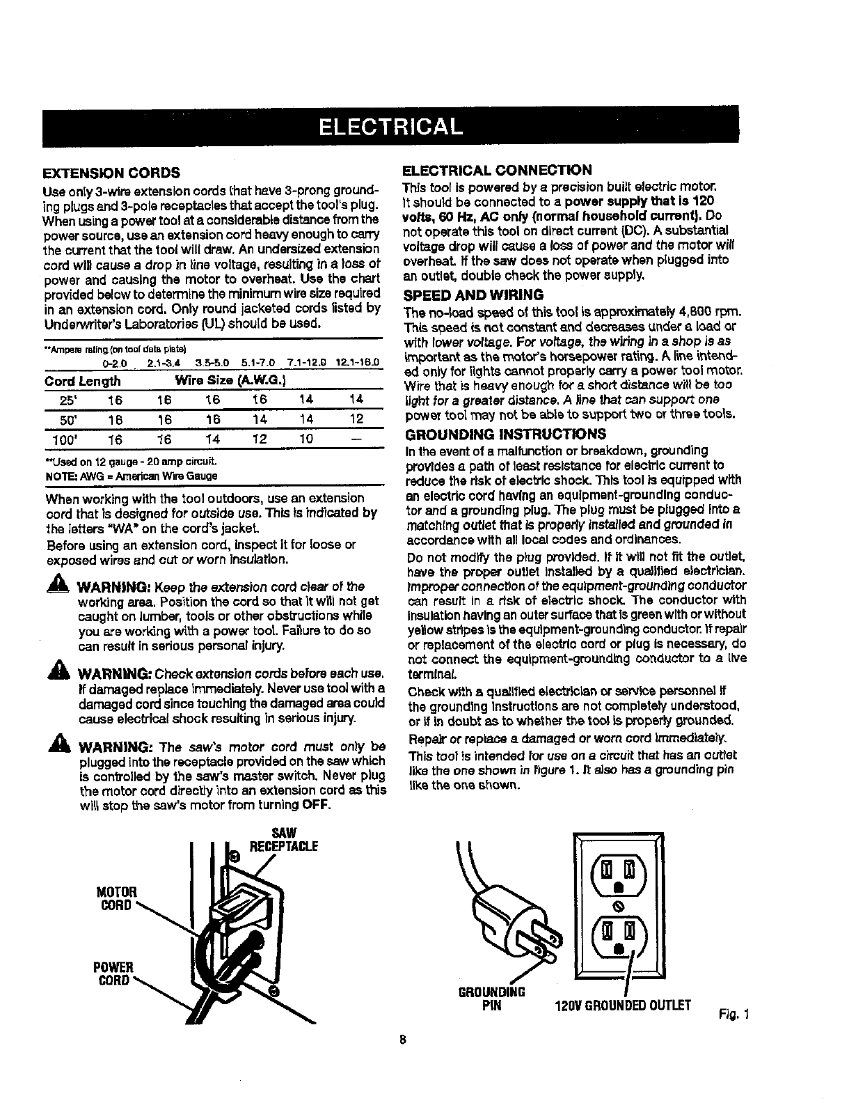
SAW
RECEPTACLE
MOTOR
POWER
ELECTRICAL CONNECTION
This too[ is powered by a precisionbuiltelectricrootor.
It shouldbe connected to a power supply t_at is 120
volts, 60 Hz, A¢ only (normal household currentJ. Do
not operate this toot on directcurrent(DC). A substantial
voltage drop will cause a loss of power and the motor will
overheat, fftha saw does not operatewhen pluggedinto
an outlet, double check the power supply.
SPEED AND WIRING
The no-load speed of this tool is approximately 4,800 rpm.
Thissbeed is not constant and decreasesundera load or
with lower voltage. For voltage, the wiringin a shop is as
important as the motor'shorsepowerratlt_. A Lineintend-
ed only for lightsoannot properly carryapower tool motor.
Wire that is heavy enough for a shortdis_nce wi!!be too
lightforagreater distance.Ailne that can support one
power tool _ay not bs able to support two or three tools.
GROUNDING INSTRUCTIONS
Inthe eventof a malfunctionor breakdown,grounding
providesa path of least raslstanoefor electriccurrent to
reduce the riskof electric shook.]his tool is equippedwith
an electriccord havingan equipment-groundingconduc-
tor and a groundingplug. The plug must be plugged intoa
matching outlet that is properlyinstalledand groundedin
accordancewith all localcodes and ordinances.
Do not modifythe ptug provided. It It will not fit the outlet,
have the proper outlet installed by e qualified alectrlalan.
_mpropercanneot_onof theequipment-groundingconductor
can result in a dsk st electric shock. ]'he conductor with
Insulationhavingan outersurfacethatIs greenwithorwithout
ye,ow stripesis theequ|pment-groundlngconductor.It repair
or replacementof the electric cord or plug is necessary,do
not connect the equipment-groundingconductorto a live
terminal
Checkwith a qualifiedelectrlc_n or s_rvicepersonnelff
the groundingInstructionsare notcompletelyunderstood,
or it in doubt as to whetherthe tool Lsproperbjgrot_nded.
Repair or rsplacaa damaged orworn cord Imroedtately.
This tool is intended foruse on ach'cuitthat has an outtet
like the one shown in figure 1. It also has a groundingpin
llketheone shown.
8
PIN 120VGROUNDEDOUTLET FJG.1
Anti-Kickback Pawla (radial arm and table saws)
Adevice which, when properlyinstalledand maintained,
is designed to stopthe wcrkpisee frombeingkicked back
toward the front of the saw duringarippingoperation.
Arbor
"Theshaft on which a brads or cu_}ng tool is mountsd.
Bevel Cut
A cutting operationmade w]th the blade at any angle
other than 90°to the table surPace.
Chamfer
Acut removing a wedge from a blockso the end (or part
of the and) is angled ratherthan at go°_
Compound Cut
Acrossout made with bert1a miter and a bevelangle.
Cross Cut
Acuttingor shap]ngoperationmade acrossthe grain or
the width of the workpisce.
Cutter Head (planers and Jointera|
Arotatingpiece of ad}ustabla blades. The cutter head
removesmaterial from the warkpiece.
Dedo Cut
A non-throughcut which producesa square-sidednotch
or bough inthe workplece (requiresa special blade).
Featharboard
A device used to help centre]the workplessby guidingit
securelyagainst the table orfence duringany ripping
operation.
FPM or $PM
Feetperminute(orstrokesperminute),usedinreference
toblademovement.
Freehand
Performinga cut without the workpiecebeingguided by a
fence, miter gauge, or other aide.
Gum
Astick'34,sap-based residuefrom wood products.
Heel
Alignmentof the blade to the fence.
Karl
The material removed by the blade In a throughcut or the
slot producedby the b!adein a non-throughor partialcut.
Kickback
A hazard that can occur when the blade bindsor stalls,
throwingthe workplaceback toward operator.
Leading End
"Theend of the workp'lecepushed into the tool first.
Mltar Cut
A cuttingoperationmade with the workplaceat any angle
to the blade other than 90°.
Non-Through Cuts
Any cutting operationwherethe blade does not extend
completelythrough the thickness of the workplace,
Push Blocks and Push8ticks
Devices used to feed the workpiecethroughthe saw
biade duringcutting operations.A push stick (not apush
Mock) should be usedfor narrowripping operations.
These aids help keep the operator'shands w_l away frccn
the blade.
Pilot Hole (drill presses)
Asmallhole drilledin aworkpie_ that serves as a guide
for drillinglarge holes accurately.
Reeaw
A cuttingoperetiento reduoathe thickness of the work-
piece to make thinnerpieces,
Resin
A sticky,sap-based substancethat has hardened.
Revolutions Par Minute {RPM)
The number ofturnscompletedby a spinningobjectin
one minute.
Ripping or Rip Cut
Acutting operationalongme length of the work.piece.
Riving Knifa/_prsader/Splittar (table saws}
A metal piece, slightly thinnerthan the blade, which helps
keep the kerropen anda{sa helpsto prevent k.Jckback.
Saw Blade Path
The area over, under,behind, or infront of the blade. As
it applies to the workplece,that area which will be or has
been cut by the blade.
Sat
The distancethat the tip of the saw blade tooth is bent(or
set:}outwardfrom the face of the blade.
Snipe (planers)
Depression made at e_her end ofaworkplace by cutter
blades when the workplace is not properlysupported.
Throw-Back
The throwing back of a worl(plece usuallycaused by the
workplace beingdroppedinto the blade orbeing placed
inadvertentlyincontactwith the blade.
Through SaWing
Any cuttingoperationwhere the blade extends completely
through the thickness of the workplace.
Workplace or Materiel
The item On which the operationis beingdone.
Worktabta
Surfacewhere the work.piecerests whiteperforminga
cutting, drilling,planbg, orsanding operation.
g
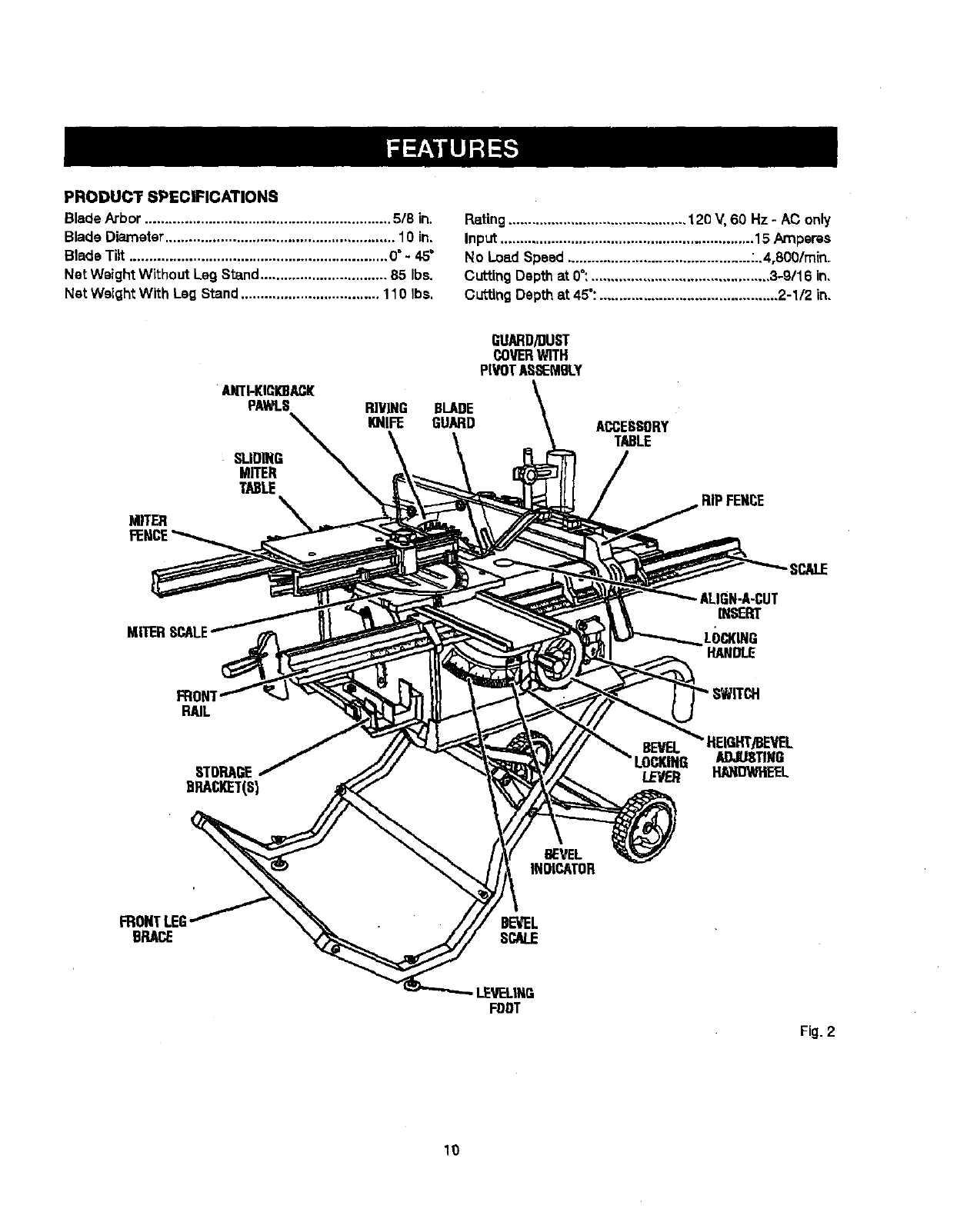
PRODUCT SPECFICATIONS
Blade Arbor .............................................................. 5/8 in.
Blade Diameter.......................................................... 10 in.
Blade Tilt ................................................................. 0° - 45"
Net Weight Without Leg Stand ................................ 85 Ibs.
Net Weight With Lag Stand................................... 110 Ibs.
Rating ............................................. 120 V, 60 Hz -AC only
Input ................................................................ 15 Amperes
No Losd Speed .............................................. -..4,800/rain,
Cutting Depth at 0":............................................. 3-9116 in,
Cutting Depth at 45":............................................. 2-1/2 in,
•AHTI-KICK)BACI[
PAWI.S
SI.IOING
MITER
TABLE
BLADE
GUARD
GUARD/DUST
COVERWITH
PIVOTASSEMBLY
ACCESSORY
TABLE
RIPFENCE
SCALE
ALIGN-A-CUT
INSERT
LOCKING
HANDLE
FRONT
RAIL
STORAGE
DRACI_T(S}
HEIGHT/BEVEL
ADJUSTING
HANDWI_EL
BEVEL
INDICATOR
BRACE
LEVEL|NE
FDDT
Fig.2
10
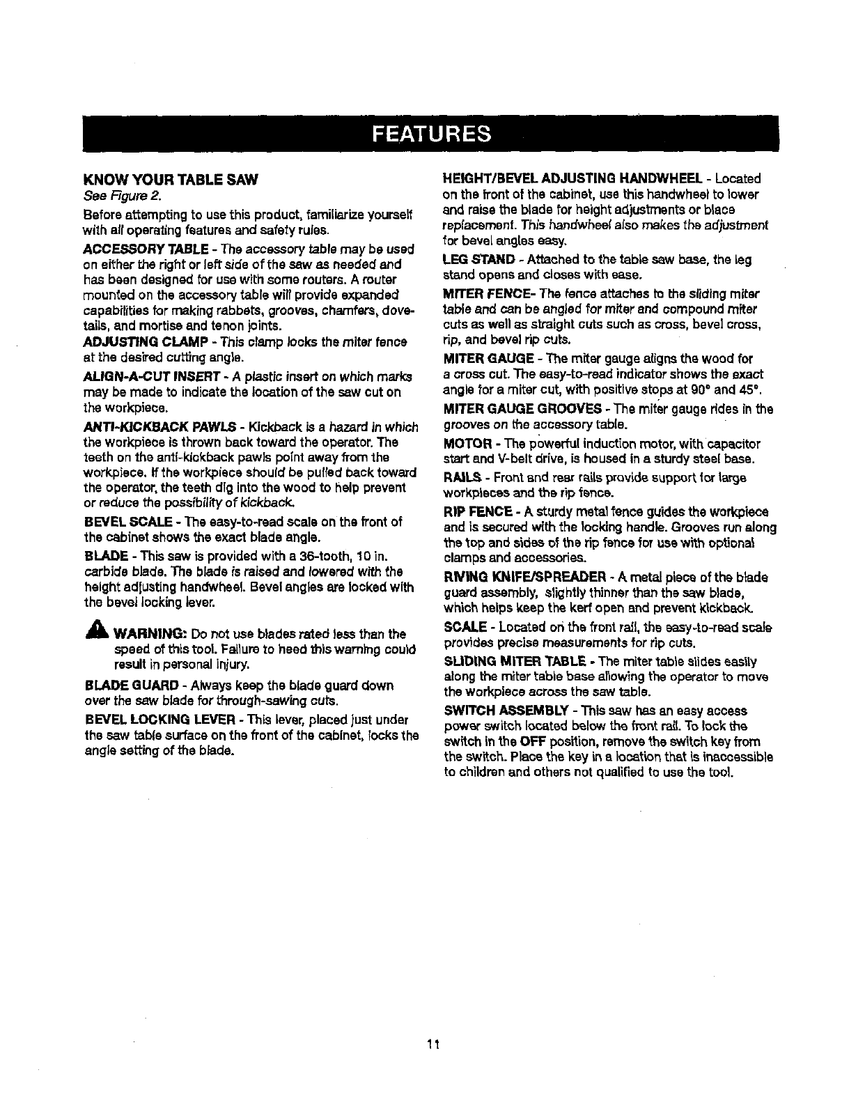
KNOW YOUR TABLE SAW
See Figure 2.
Before attempting to usethis product,familiarize yourself
with air operatingfeaturesand safety rules.
ACCESSORY TABLE - The accessorytable may be used
on either the rightor left side of the saw as needed and
has been designedfor use withsome reuters.A router
mounted on the accessorytable wilrprovide expanded
capabilitiesfor making rabbets, grooves, chamfers,dove-
tails, and mortiseand tenon joints.
ADJUSTING CLAMP -This clamp looksthe miter fence
stthedesiredcuringangla.
ALIGN-A-CUT INSERT - A plastic insert onwhich marks
may be made to indicatethe locationof the sawcut on
the workplace.
ANTI-KICKBACK PAWLS - Kickback is a hazard in which
the workplace is thrownback toward the operator.The
teeth on the anti-kickback pawls point away _om the
workpiece. If the workpiecsshould be putisdback toward
the operator,the teeth dlg intothe wood to help prevent
or reduce the possibility of kickback.
BEVEL SCALE -The easy-to-raad scale on the frontof
the cabinet showsthe exact blade angle.
BLADE -This saw is provided with a36-tooth, 10 in.
carbideblade.The blade is raised and lowered with the
heightadlustinghandwheeLBevelangles are lockedwith
the bevel lockinglever.
AWARNING: Do not use blades rated _easthan the
speed of this tool. Failureto heed thiswarning could
resultin personalinjury.
BLADE GUARD - Always keep the blade guard down
over the saw blade for through-sawing cuts.
BEVEL LOCKING LEVER -This lever,placed just under
the saw tablesurfaceon the frontof the cabinet, {coke the
angle setting of the blade.
HEIGHT/BEVEL ADJUSTING HANDWHEEL - Located
on the front of the cabinet, use thishandwheal to lower
and raisethe blade for heightadjustmentsor blase
replacement. This f_ndwhea( also makes the adjustment
for bevel ang[as easy.
LEG STAND - Attached to the table saw base, the leg
stand opens and closeswith ease.
MITER FENCE- The fence attaches to the slidingmiter
table and can be angled for miterand compound miter
cuts as wall as straightcuts suchas cross, bevel cross,
rip,and bevelrip cuts.
MITER GAUGE -The miter gaugealigns the wood for
across cut. The easy-to-read indicatorshows the exact
angle for amiter cut, with positivestopsat 90°and 45°.
MITER GAUGE GROOVES -The miter gauge rides inthe
grooveson the accessory table.
MOTOR - The powerful inductionmotor,withcapacitor
start and V-belt drive, is housedina sturdysteel base.
RA]L_ - Frontend rear railsprovide support forlarge
workpiecas and the rip fence.
RIP FENCE - Asturdy metal fence guidesthe workplace
and is securedwith the locking handle.Grooves runalong
the top and sides of the rip fence for use with optional
clamps and accessories.
RIVING KNIFE/SPREADER - A metal piece of the blade
guard assembly, slightly thinner than the saw blade,
which helps keep the ked open and prevent kickback.
SCALE - Located on the front rail, the easy-to-readst;ale
provides precisemeasurements for dp cuts.
SLIDING MITER TABLE -The mitertable slideseasily
along the miter table base ailowlng the operator to move
the warkpiece acrossthe saw table.
SWITCH/_SEMBLY - This saw has an easy access
powar switch located below the front rm_.To lock the
switch inthe OFF position,removethe switch keyfrom
the sw_tch.Place the key in e location that is inaccessible
to childrenand others not qualifiedto use the tool
11
OPERATINGCOMPONENTS
The upper portion of the blade projectsup throughthe
table and is surroundedby an insertcalled the throat
prate.The height of the blade is sat with a handwhsel on
the front of the cabinet.To accommodate wide panels,
the saw table has rails on each side. Detailedinstructions
are providedinthe Opera,on section of thisrnanualfor
the basic cuts: crosscuts, miter cuts, bevelcuts, and
compound ¢U_l
The slidingmitertableaseemblyisused forcrosscutting
operatfens.The miterfenceiseasilyadjustedtocutwood
at an angle by looseningthe adjustingclamp, setting the
fence to the miterscale, and retightening the clamp. The
stlding miter table, which restson a base mountedon the
rails,can be repositfehedalong the milsforwide work. _t
can be reversed so the projectingbase is in the back and
can be moved from the left side to the rightsideas need-
ed. With _a miter fence removed, the miter table offers
additions]support"for other operationssuchas ripping.
The rip fence is usedto positionwork for lengthwisecuts.
A scale on the front rail shows the distance between the
ripfence and the blade.
it is very importantto use the blade guardassemblyfor all
through-sewing operations.The blade guardassembly
includes:riving knife/spreader/splitter, anti-kickback
pawls, and plastic blade guard.
The saw features areceptacle on the rightsideof the
cabinet that permitsuse of accessories. Use onlyacces-
sories that are listed for use with thistool When usinga
listed accessory, unplugthe saw motor cord and usa the
receptacle and the saw'-, power switchto operate the
accessory.
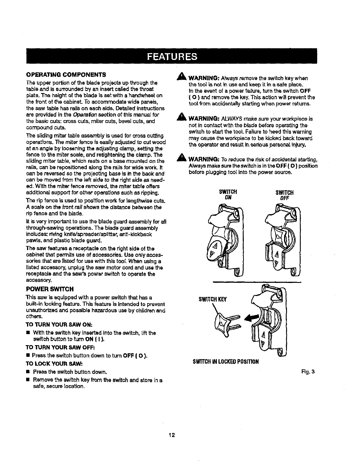
POWER SWITCH
This saw is equipped with apower switchthat has a
built-in locking feature. This feature is intendedto prevent
unauthorizedand possible hazardoususe by chUdrenand
others.
TO TURN YOUR SAW ON:
•With the switch kay inserted into the switch, tiltthe
switch bu_tonto turn ON ( I ),
TO TURN YOUR SAW OFF:
•Press the switch button down to turn OFF ( O).
TO LOCK YOUR SAW:
• Press the switch button down.
•Remove the switch kay from the switchand storein a
safe, secure location.
Am, WARNING: Atwaysremove the switchkay when
the tool L_not m use and keep it in a sate ptsce.
In the event of a power f_zLlure,turn the switchOFF
( O ) 8.ridremovethe key.This action will preventthe
tool _rom aoc_dsntalty st_tln 9when power returns.
_' WARNING: ALWAYSmake sureyour workpisce is
not in contactwith the b(adebefore opsrat(ng the
switchto startthe tool. Faitureto heed this warning
may cause the workpiecato be kicked back toward
theoperatoraridresultit_serious_rsor_iinjury.
_lz WARNING: Toreduce the riskof accidental starting,
Alwaysmakesurethe switchis inthe OFF ( O ) position
before pIuggingtool into the power source.
SWTfCH SWITCH
ON OFF
SWITCHKEY
SWITCHINLOCKEDPOSITION
Fig. 3
12
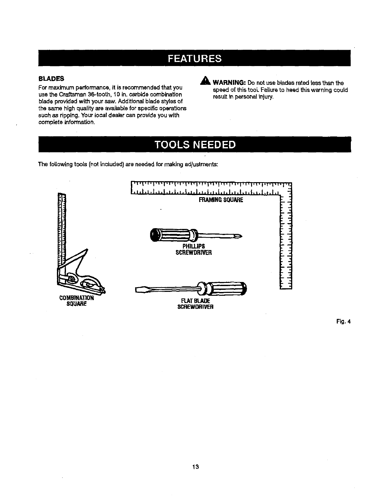
BLADES
Formaximum performance,it is recommendedthat you
use the Craftsman 36-tooth, 10 in. carbide combination
blade providedwith your saw. Additionalblade stylesof
the same high qualityare availablefor specific operations
suchas ripping.Your local dealer can provideyouwith
complete information.
AWARNING: Do notuse blades rated less than the
speed of thistool. Faitureto heed this warning could
resultin personalinjury.
The f#,lowing toots (notinoLudsd)are needed,for makingadiustments:
COMBINATION FLATBLADE
SQUARE SCREWDRIVER
Fig. 4
13
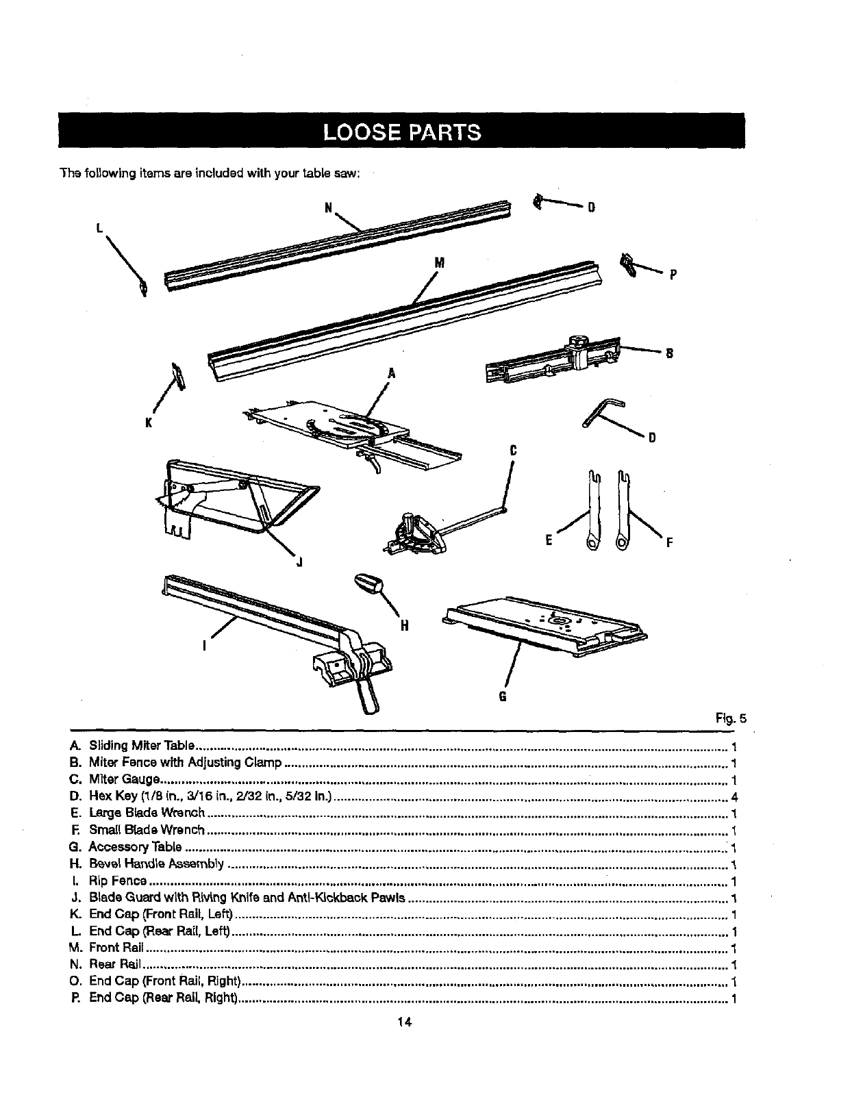
Thefollowing items are includedwith your table saw:
G
Fig. 5
i
A. SlidingMiterTable....................................................................................................................................................... 1
B. Miter Fancewith AdjustingClamp .............................................................................................................................. 1
C. Miter Gauge......................................................................................................................... ........................................ 1
D. Hex Key (1/8 In., 3/16 in., 2/32 (n.,5/32 In.)................................................................................................................ 4
E. Large BtadaWrench.................................................................................................................................................... 1
E Small B[adeWrench ....................................................................................................................................................
G. AccessoryTable .......................................................................................................................................................... 1
H. I_vel HartdleAssembly.............................................................................................................................................. 1
I. Rip Fence .................................................................................................................................................................... 1
J. Blade Guard with RivingKnife and Anti-Kickback Pawls ........................................................................................... 1
K. EndCap {Front Rail, Left)............................................................................................................................................ 1
L End Cap (Roar Rail,Left)............................................................................................................................................. 1
M. FrontRail..................................................................................................................................................................... 1
N. Rsar Rail..................................................................................................................................................................... 1
O. EndCap (FrontRail,Right).......................................................................................................................................... 1
P. EndCap (Rear Rail, Right)........................................................................................................................................... 1
14-
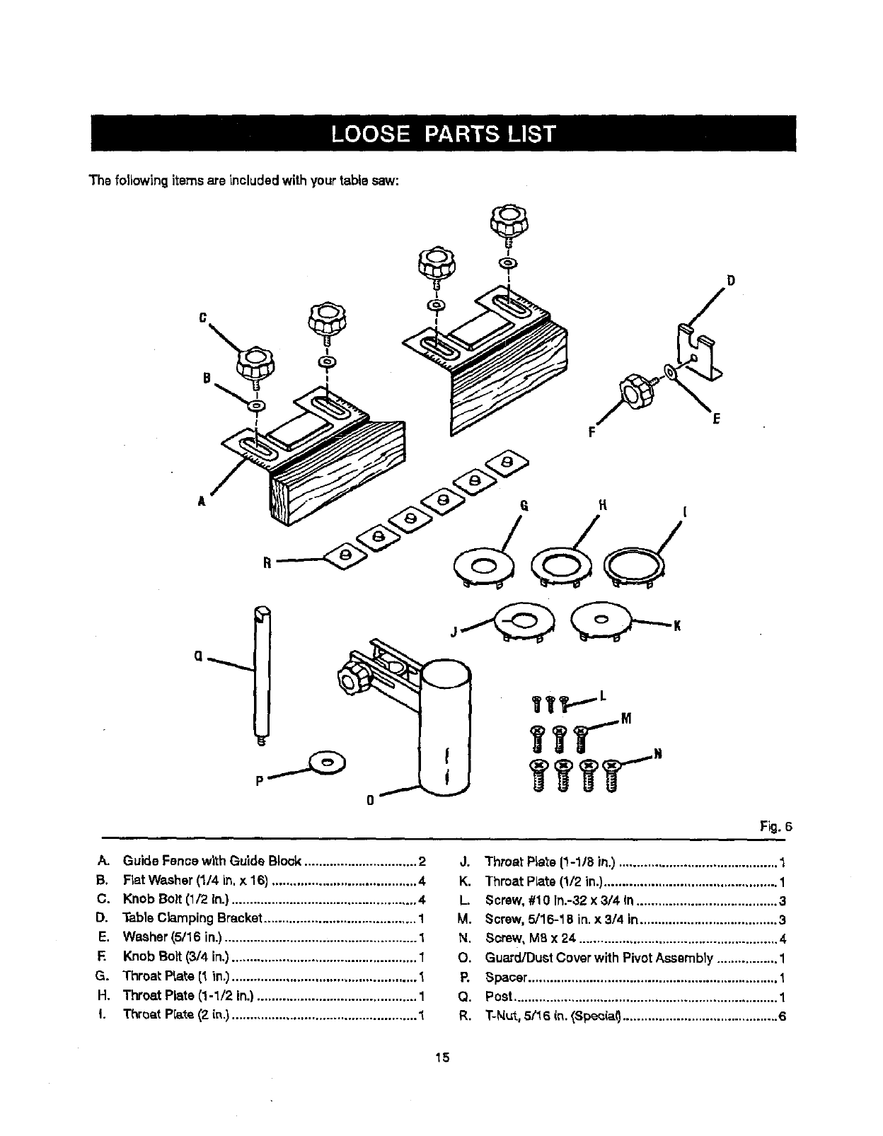
Thefolidwing items are includedwith your tablesaw:
@D
F
d
Fig. 6
A. Guide Fence w_thGuide Block............................... 2
B. FlatWasher (1/4 in. x 16) ........................................ 4
C. Knob Bolt (1/2 In.) ................................................... 4
D. Table ClampingBracket.......................................... 1
E. Washer(5/16 in.)..................................................... 1
F. Knob Bolt (3/4 in.)................................................... 1
G. Throat Prate (1 in._................................................... 1
H. Throat Plate (1-1/2 in.)............................................ 1
I. Throat Prate(2 its.)................................................... 1
J. Throat PLate[1-1/8 in.) ............................................ 1
K. Throat Plats (1/2 in.)................................................ 1
L. Screw,#10 In.-32 x 3/4 In ....................................... 3
M. Screw, 5/16-18 in. x 3/4 in...................................... 3
N. Screw, M8 x 24 ....................................................... 4
O. Guard/DustCoverwith PivotAssembly................. 1
P. Spacer..................................................................... t
Q. Post......................................................................... 1
R. T-N_t, 5(16 in. _Spec(a0........................................... 6
15
UNPACKING
Thisproduct requiresassembly.
• Carefully liftthe asw from the carton and place it on a
level work surface.
NOTE=This tool is heavy.To avoid back injury,keep
your knees bent and liftwithyour legs, notyour back,
and do not liftsaw without help.
•Inspect the tool carefullyto make sure no breakage or
darnags occurred duringshipping.
•Do not discardthe packingmaterial untilyou have
caref_Jttyinspected and sstistacto_tyoperated the too_.
•The _aw is factory setfar accurate cutt'_ng.After
assembling it, check for accuracy.If shipping has
influenced _e settings,referto specificprocedures
expta'medin _is manual.
•If any parts are damaged or missing, plasea call
1-800-932-3188 for ass]stance.
_" WARNING: if any parts are missing, do not operate
th_stoo_ unt_the missing parts are replaced. Failure
to do so could rssultin possibleseriouspersonal
injury.
_1= WARNING: Do not attempt to modify this tool
or create accessories not recommendedfor use
with this tool. Anysuch aiteratlonor modification is
misuseand could resultin a hazardouscondition
leading to possible se_oL;spersonalin)ury.
AWARNING: Do not connectto power supplyuntil
assembly is complete. Fa(lursto comply couldresult
in accidentalstarting and possible seriouspersonal
injury.
_1= WARNING: Do not liftthe saw without help. Hold
it close to your body.Keep your knees bent and
(iftwith yourlegs, not your back. Ignoringthese
precautionscan resultin back injury.
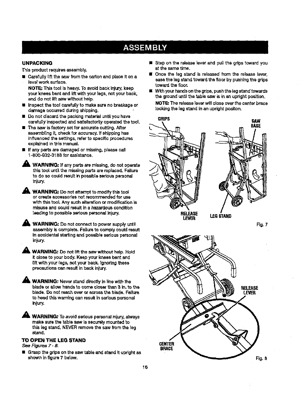
•Step on the release]everand pull the gripstoward you
at the sametime.
•Once the leg stand is released from the release lever,
easethe leg s_n rttoward the _ocr by pashlngth_ grips
toward the floor.
•Withyourhandsonthegr_ps, pushthslegstand_owards
the ground untilthe _.bis saw is in an uprightpos'_tion.
NOTE: The releaseleverwill close overthe centerbrace
lockingthe legstand in an uprightposlton.
GRIPS SAW
BASE
RELEASE LEG,STAND
LEVER
Fig. 7
A
Am, WARNING: Never stand d}rs_')yinline with the
blade or allow hands to corns closer than 3 in. to the
blade. Do not reach over or across the blade. Failure
to heed this warning can resultin seriouspersonal
iniury.
A
me, WARNING" Toavoid seriouspersonal injury, always
make sure the table saw is securely mountedto
this leg stand. NEVERremove the saw from the 1eg
stand.
TO OPEN THE LEG STAND
See Figures 7- 8.
•Grasp the gripson the saw table and s_and it uprightas
shown infigure 7 be(ow.
cENTER
BRACE
Fig,8
16
TOSECURE/LEVELTHESAW
See F-igum9.
With the leg stand open and the table saw restingona
fiat, levelsurface, the saw shou]dnotmove or rook fl'om
side to side.
ffthe sew rests onthe wheels and roils, [oosaneach
wheel stop by turning counterclockwise.The legstand
should met on each stop only slightly.If the wheel stop is
turnedtoo much, the stop will interferewiththe opening
and closing motionof the leg stand.
if the saw rocks fromside to side, the levelingfeet need
adiustlnguntilthe leg stand is balanced.
• Loosen both the top and bottomwing nuts.
•Liftthe saw slightlyso that you may turn the kiveiin9
foot untilthe leg stand no longerrocks.
• Turning ctookwise wilt lower thefoot
•Turning countarclockwisaw_llra'lsathe fog
WINGNUT
FOOT
Fig. g
TO S'fORE THE TABLE SAW ACCESSORIES
See Figures 10. -11
The table saw has two convenientstorage areas specifi-
callydesigned for the saw's accessories. Theseaccesso-
ries must be sooure_ystored priorto closing the legstand
and moving the saw.
The rip fence, miter fence, and miter gauge shouldbe
stored in the bracketslocated on the sideof the saw
cabinet. Simply snap each accessoryin place to hold_t
securely.
Storage hooks for the slidingmiter tableare located on
the back of the saw cabinet. This storagearea is to be
used onlyfor movingthe saw orwhen the saw is not
being used.
NOTE: Duringoperationof the saw, the slidingmitertable
must be mounted onthe mile. NEVER operate the sew
with the slidingmiter table in the storage positionbecause
it blocksthe dust exhaustport.
MZTER
RIPFENCE
Fig. 10
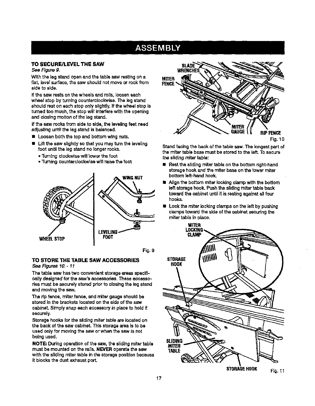
Stand facing the back of the table saw. The longestpart of
the miter table base must be stored to the left.Tosecure
the slidingmiter table:
•Restthe slidingmiter table onthe bottom right-hand
storage hook and +,hemiter base on the lower miter
bottom left-hand hook.
I Alignthe bottom miterlookingcfe_npwith the bottom
left storage hock. Pushthe slidingm'rtertable back
toward the cabinet _zntilit is restingagainst allfour
hooks.
• Look the miter lookingclampson the left by pushing
clampstoward the sideof the oabinst securingthe
mitertable in place.
MI'IER
STORAGE
HOOK
SLIDING
MITER
TABLE
STOP,ABEHDDK F_g;11
17
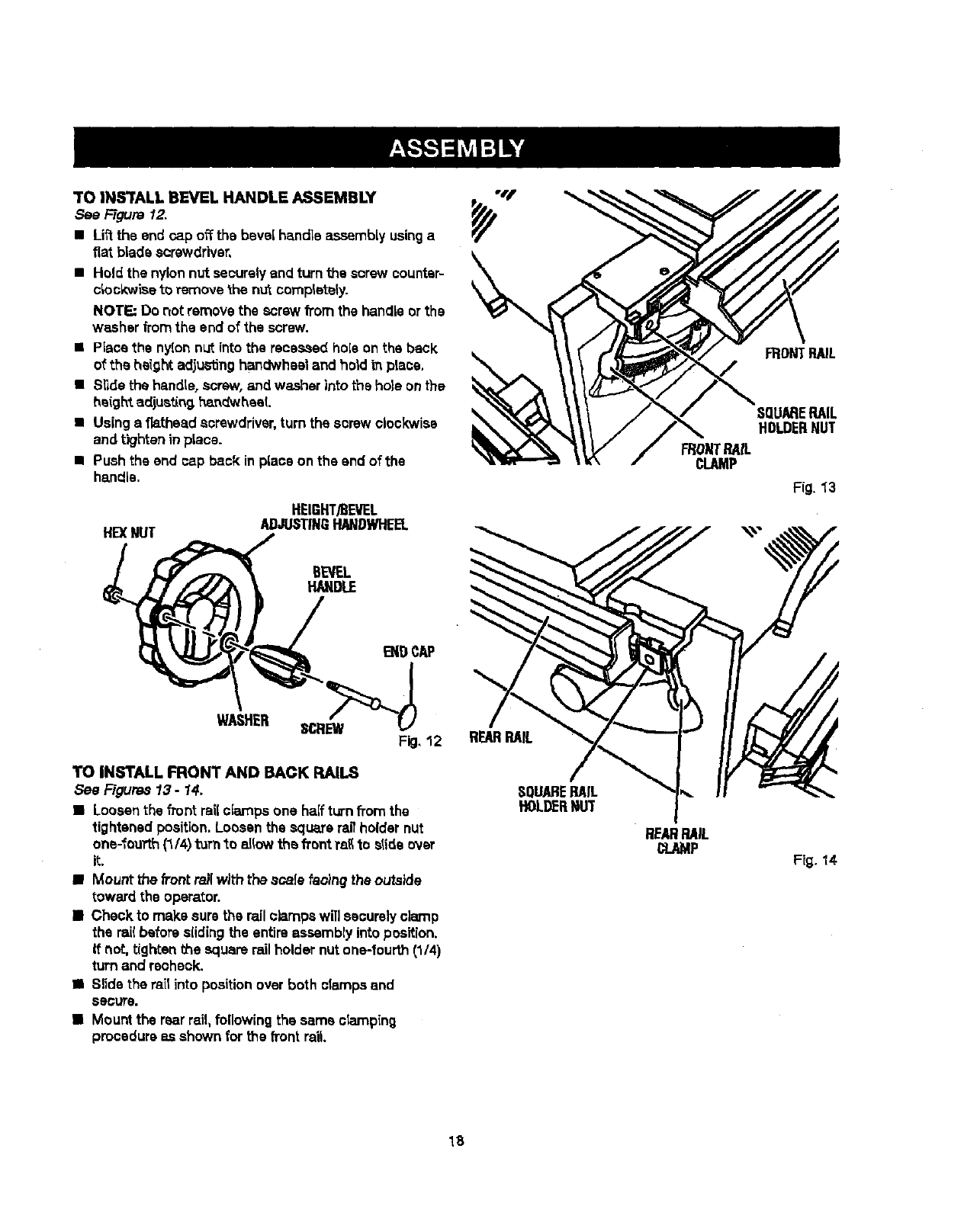
TO IN_rALL BEVEL HANDLE ASSEMBLY
See F-t_re 12.
• Liftthe end rap offthe bevel handle assembly usinga
fiat b|ade screwdriver,
•Hold the nylonnut securelyand turn the screw counter-
clockwise toremove thenutcompletely.
NOTE: Do not remove the screw from the handleor the
washer fromthe end of the screw.
•Place the nylonnut into the recessed holeon the back
of the height adjustinghandwheel and hold in place,
•Slide the handle,screw, and washer into the hole onthe
he(ghtadjustln9l_n_'_heaL
•Usinga fiathead screwdriver, turn the screw clockwise
and tighteninplace.
•Pushthe end cap back inplace on the end of the
handle.
HEXNUT
HEIGHT/BEVEL
ADJUSTINGRANDWHEEL
WONTRAIL
cLAMP
FRONTPAIL
SQUARERAIL
HOLDERNUT
Fig. 1"3
BEVEL
HANDLE
WASHER
TO INSTALL FRONT AND BACK RAILS
See Figures 13 - 14,
•Loosenthe frontrail ciarnps one halfturn fi'omthe
tightened position. Loosenthe square ragholder nut
one-fourth(1/4)turn"_oallowthe front ra_to slide ovsr
it.
• Mount the _ontrailwith thescale faoincj the outside
toward the operator.
•Check to make sure the rail clamps will securelyclamp
the rai(before slidingthe entire assembly into position.
If not, tighten the square rail holder nutone-fourth(1/4)
turn and recheck.
•Slide the rail into position over both clampsand
secure.
•Mount the rearrail,following the same ciamping
procedureas shown for the front rail
SQUARERAIL
HOLDERNUT
REARRAIL
CLAMP Fig. 14
18
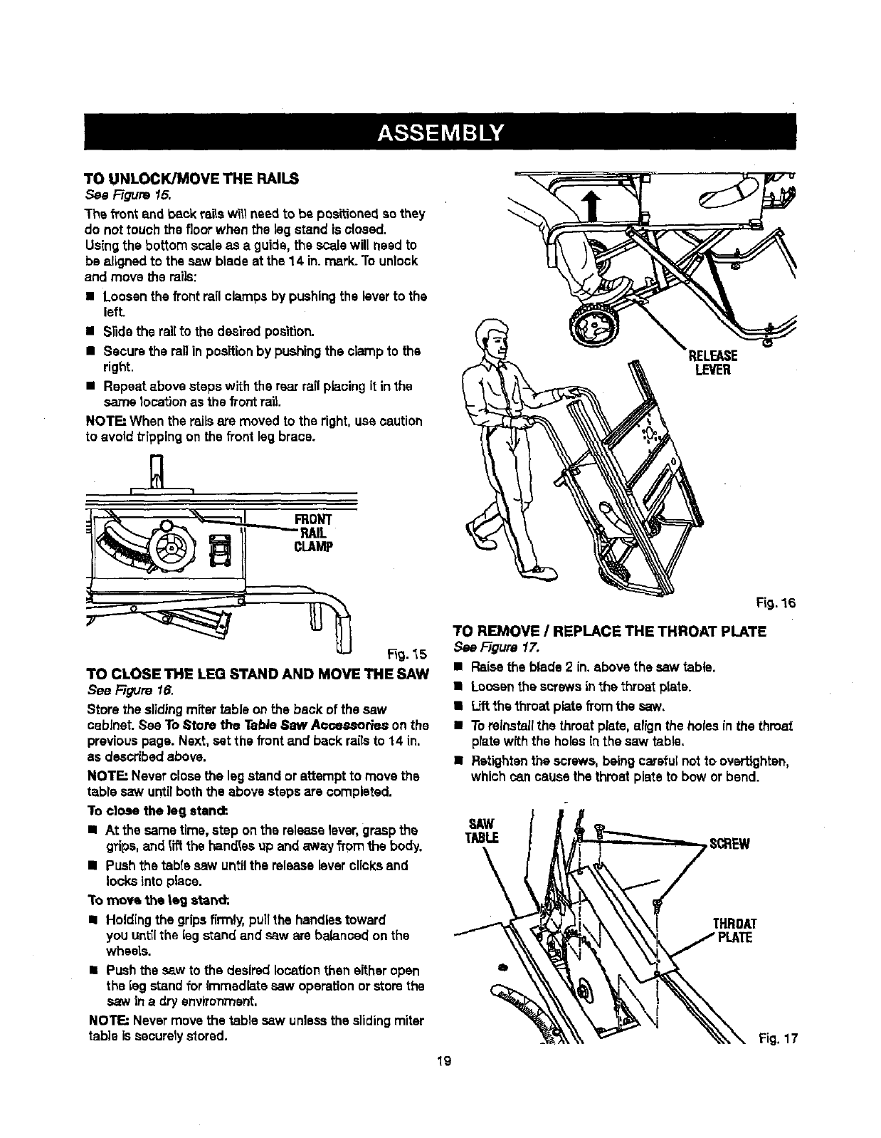
TOUNLOCK/MOVETHERAILS
See Figure 15.
The front and back rails will needto be positionedso they
do not touch the floor when the Sagstand isclosed.
Usingthe bottom scale as a guide, the scalewill need to
be aligned to the saw blade at the 14 in. mark.To unlock
and move t_e mils:
•Loosenthe front rali clampsby pushingthe leverto the
left.
•Slide the ra'dto the desired position.
•Securethe ragin positionby pushingthe clampto the
right.
•Repeat shove steps with the rear rail plscingit inthe
same locationas the front rail.
NOTI:-' When the rails are moved to the right, use caution
to avoid trippingon the front legbrace.
RELEASE
LEVER
IL
CLAMP
_g. 15
TO CLOSE THE LEG STAND AND MOVE THE SAW
See Figure 16.
Store the slidingmiter table on the back of the saw
cabinet. See To Store the Tab/e Saw A_ssories on the
previouspage. Next, set the frontand back ransto 14 in.
as described above.
NOTE: Never closethe legstand orattempt to move the
table saw untilboth the above steps are complsted.
To cfoae the leg stand:.
•At the same time, step onthe releaselever,grasp the
grips, and t_ the handlesop and away fromthe body.
• Push the table saw untilthe releaseleverclicksand
locks into place.
To moYa the |eg s_and;
•Holding the gripsfirmly,pu(tthe handlestoward
you untUthe lag stand and saw are balanced on the
wheels.
•Push the saw to the desiredlocationthen either open
the lag standfor immediate saw operationor storethe
saw in a dry environTnent.
NOTE: Never movethe table saw unlessthe slidingmiter
table issecurely stored.
Fig.16
TO REMOVE /REPLACE THE THROAT PLATE
,..%eFigure 1.7,
•Raisethe blade 2 in. above the saw table.
• Loosentha screws inthe throat prate.
•Liftthe throat plate from the saw,
•Toreinstallthe threatplate, af(gn the holes in the throat
platewiththe holes in the saw table.
•Ratightenthe screws, beingcarefulnot to overt_ghtan,
which can cause the throat plate to bow or bend.
19
Fig.17
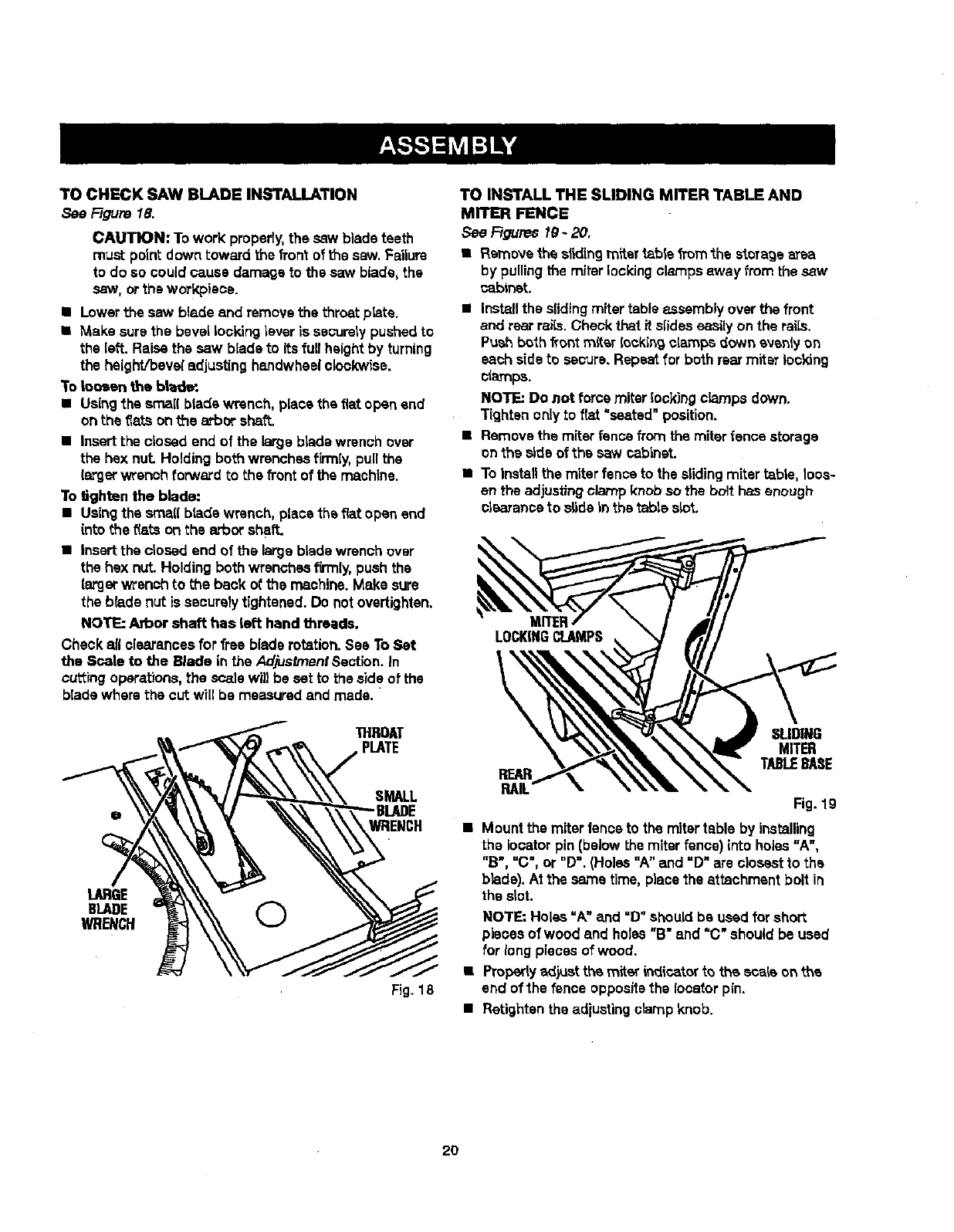
TOCHECKSAWBLADEINSTALLATION
See Figure 18.
CAUTION: Towork:properly,the saw blade teeth
must pointdown toward the front of t'nesaw. Failure
to do so could cause damage to the saw blade,the
saw, orthe workpisce.
•Lowerthe saw blade and remove the throat p_te.
• Make surethe bevel Locking lever is securely pushed to
the left. Raise the saw blade to its fu[I height by turning
the height/bevel adjusting hsndwheel clockwise.
To Loosen the blade.
•Using';hesmall blade wrench, place the flat open and
on the fiats on the arbor shat'_.
•Insert the closed end of the large blade wrench over
the hex nut Holding both wrenches firmly, pull the
largerwrench forward to the front of the machine.
To *dghtenthe blade:
•Usingthe srnaflbradswrench, placethe flat open end
(rite the _(atson the arbor shaft.
• Insert the closed end of the large blade wrench over
the hex nut. Holding both wrenches firmly,push the
{argerwrench to the back of the machine.Make sure
the blade nut is securelytightened. Do notovsrtighten.
NOTE: Arbor shaft has left hand threads.
Check all clearancesfor free blade rotation.See ToSet
the Scale to the Blade in the AdjustmentSection. In
cutting operations,the scale wil} be set to the sideof the
blade where the cut will be measured and made.
THROAT
PLATE
SMALL
WRENCH
LARGE
BLADE O
WRENCH
Fig. 18
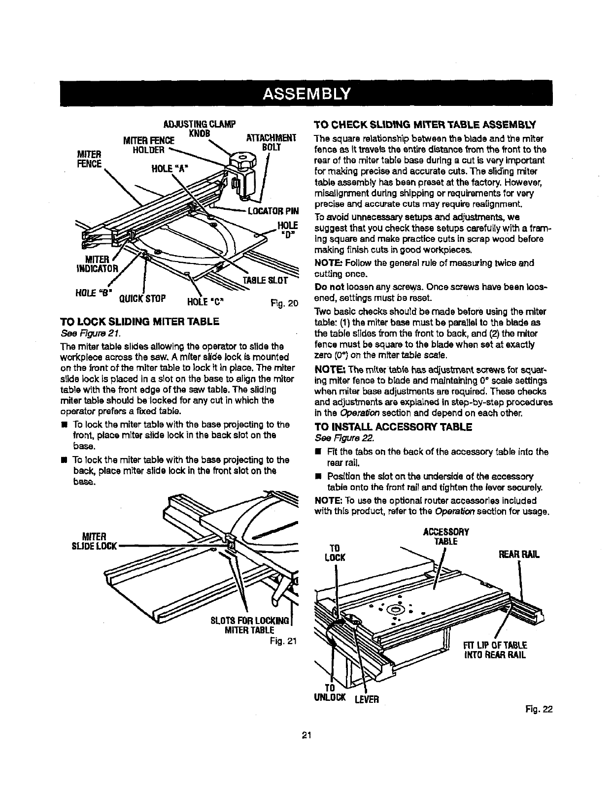
TO INSTALL THE SLIDING MITER TABLE AND
MITER FENCE
See Figures fg -20,
•Removethe slidingrofter table from the storage area
by pullingthe miter lockingclampsaway from the saw
¢ablnst
• Installthe slidingmitertable assembly overthe front
and rear rails. Checkthat it slides easilyon the rsi[s.
Push both front miter looking clamps down evenlyon
each sideto secure, Repeat for both rear miter locking
_arnps.
NOTE: Do not force miter look}rig clamps down.
Tighten only to f_t "seated" position.
•Remove the miter fence from the miter fence storage
onthe side of the saw cabinet.
•To installthe miterfence to the slidingmiter table, Ices-
en the adjustingclamp knobso the bolt hasenough
olsaranoa to slide _nthe table slot,
LOCKINGCLAMPS
REAR
RAIL
SUDII_
MITER
TABt.EBASE
Fig. 19
Mount the miter fence to the mitertable by installing
the locater pin (below the miter fence) into holes =A",
"B", =C", or "D". (Holes "A" and =D" are closest1othe
b}ade).At the same time, placethe attachment bolt in
the s_ot.
NOTE: Holes =A" and "D"should be used for short
pieces of wood and holes"B" and "C" should be used
for long piecesof wood.
•Property a_}ustthe miter indicatorto the scale on the
end of the fence oppositethe locater pin.
•Retightan the adiustingctarnp knob.
2O
I!_STIIIG CI_II,N[P
MITERFENCE KNOB ATI'ACHMEN'T
MITER HOLDER BOLT
FENCE HOLE"A"
\ ,
LOCATORPiN
INDICATOR TABLESLOT
HOLE=B" QUICKSTOP HOLE"C" Fig.20
TO LOCK SLIDING MITER TABLE
See Flours21.
The mitertable elides allowingthe operatorto elide the
workplsce acrossthe saw, A miterslide lock is mounted
on the front of the miter table to lock it inplace. The miter
slide lock is placed inaslot on the base to align the miter
tabla with the h'ont edge of the saw table. The sliding
miter table shouldbe locked for any cut inwhich the
operator prefersa fixed table.
•To lock the miter table with the base projectingto the
front, place miterslide lockin the back slot onthe
base.
• To lockthe miter table with the base projectingto the
back, place miter slide lockin the front slot on the
base.
MITER
SLIDELOCK
TO CHECK SL|D|NG M_'ER TABLE ASSEMB!3/'
The square relationshipbetween the blade and the miter
fence as it travels the entire distancefrom the frontto the
rear of the miter table base duringa cut is very important
for m_ng preciseand accurate cuts.The slidingmiter
table assemblyhas been presetat the factory. However,
misallgnment duringshippingor requirementsfor very
precise and accurate cuts may requirerce[ignment.
To avoid unnecessarysetups arid ad.iuatments,we
suggest that you check these setups carefullywith a fram-
ing square and make practicecuts inscrapwood before
making finishcuts ingood workpisces.
NOTE: Followthe generalrule of measuring twice and
cuttingonce.
Do not loosen any screws.Once screws have been loos-
ened, settings must be reset.
Two basic checks should be made before usingthe miter
table"(1) the miter base must be parallelto the blade as
the table slides fTomthe front to back, and (2)the miter
fence must be squareto the blade when set at exactly
zero (0") on the rafter table scats.
NOT_ The miter tablehas adjus_ant screws for squar-
ing miter fence tc blade and maintaining0° scale settings
when miterbase adjustments are rsc,uired.These checks
and adjus't_entsare exp_ined in step-by-step procedures
inthe Opera#onsectionend depend on each other.
TO INSTALL ACCESSORY TABLE
See Figure22.
•Fit the tabs on the back of the accessorytable into the
rear rail.
•Posi_onthe sloton the undersideof the accesaory
table ontothe frontrail and tightenthe lever securely.
NOTE: To use the optionalrouteraccessories included
with this product, referto the Operationsectionfor usage.
ACDESSORY
TABLE
TO
LOCK REARRNL
SLOT8FORLOCKING
MITERTABLE
Fig. 21
\
TO
UNLOCK LEVER
FITUP OFT_B,LE
IKTOREARRAIL
Fig. 22
21
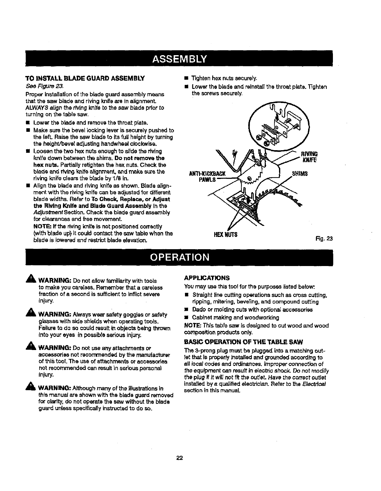
TOINS'i'ALLBLADEGUARDASSEMBLY
See Figure 23.
Proper installationof the blade guardassemblymeans
that the saw blade and rivingknifeare in alignment.
ALWAYSalign the rivingknife to the saw b/ade priorto
turning on the table saw.
• Lower the blade and removethe throat plate.
• Make sure the bevellooldng leveris securelypushedto
the (eft. Raise the saw blade to its full heightby turning
the height/bevel adjustinghandwheelclockwise.
•Loosen the two hex nutsenoughto slide the riving
knife down between the shims. Do not remove the
he]<nuts. Partially retightenthe hex nuts,Check the
blade and r(vin9knife alignment, _nd mska surethe
rlving knifeclears the blade by 1/8 in.
•Align the blade and rivingknife as shown. Blade align-
merit with the rivingknife can be adjustedfor diffarard
blade widths.Refer 1oTo Cheek, Replace, or Adjust
the Riving Knife and Blade Guard Assembly inthe
AdjusO'nentSection, Check the blade guardeseambiy
for clearances and free movemanL
NOTE: If the rivingknife is notpositionedcorrectly
lwtth blade up) it couldcontact the saw table when the
blade is lowered znd rastJ'ictblade elevation.
•Tighten hex nutssecurely.
•Lowerthe blade and reinstaflthe throat plate. Tighten
the screws securely.
RIW_
ANTI-KICKBACK SHIMS
H_N_S Fig. 23
A
41L WARNING: Do not allow familiaritywith tools
to make you careless. Remember that a sarelese
fraction of a second is suf_cfentto inflictsevere
injury.
A
i WARNING; Ah_,ayswest safety gogglesor safer7
gbsses with side shieldswhen operatingtools.
Failureto do so could resultin objects being thrown
into your eyes in posaibieserious injury.
_lk WARNING: Do not usa any attachments or
accessories not recommended by the manufacturer
of'ibis tool. The use of attachments oraccessories
not recommended can resultin serious personal
injury.
AWARNING: Aifhough many of the illustrat;ons in
this manual are shown with the blade guard removed
for clarity, do not operate the saw without the blade
guard unless specifically instxucted to do so.
APPLICATIONS
Youmay usethistool for the purposeslisted below:.
• Straight line cuttingoperationssuchas cross cutting,
r_pping,mitering,beveling,and compound cutting
•Dado ormolding outs with optionalaccessories
•Cabinet making and woodworking
NOl'F.: This table saw Jsdesigned to cut wood and wood
compoe_i_nl:_mdu_sonly,
BASIC OPERATION OF THE TABLE SAW
The 3-prong p[ug must be plugged into a matchingout-
let that is propertylnst_fled and groundedaccording to
all focalcodesand ordinances.Improper connectionof
the equipmentcan resultin elec_c shock. Do not modify
the plugif it will not.fit the cuber.Have the correct outlet
inst_led bye qus)ified electrician.Refer to the E}ectric_
section in this manual.
22
CAUSES OF KICKBACK
Kickback can occur when the blade stallsor binds, kick-
ing the workpieca back toward youwith greatforce and
speed. If your handsare near the saw blade, they may
be jerked loosefromthe workpieceand may contactthe
blade. Kickback can cause seriousinjury.Use precautions
to avoidthe risks.
Kickback can be caused by any action that pinchesthe
blade in the wood such as:
• Making a cut with incorrect blade depth
•Sawlng into knots or nailsin the workpiece
•Twistingthe wood while makinga out
•Failingto supportwork
•Forcinga cut
•Cutting warped orwet lumber
•Us{ngthe wrong blade for the type of cut
• Not following oorrect operatingprocedures
•Misusingthe saw
•Failingto use the an_-kick.baokpawls
•Cutting with a dull, gummed-up, or h'npmperiy set
b_ad_
AVOIDING KICKBACK
•Always use the correct blade depth setting.The top of
the blade teeth shouldclearthe workpieceby 1/8 in. to
114in.
•Inspect the work for knotsor nailsbefore beginninga
cut KnocY,out any loose knotsw_thahamme_'.Never
saw into aloose knot orna|(.
•Always use the rip fence when rip cuttingand the miter
gauge when crosscutting.This helps preventtwisting
the wood inthe cut.
•Always use cLsan,sharp, and properly-setblades,
Never make outs with dullblades.
•TOavoid pinchingthe blade, supportthe work properly
before beginningacut,
•When making a cut. usesteady,even pressure. Never
force outs.
•Do not cut wet orwarped lumber.
•Always herdyour workplece fLrmtywith both hands or
with push sticks.Keep your body in a balanoed posi-
tion to be ready to resist kickbackshould it occur.
Never stand direc_y in line withthe blade.
•Use the righttype of blade for the cut being made.
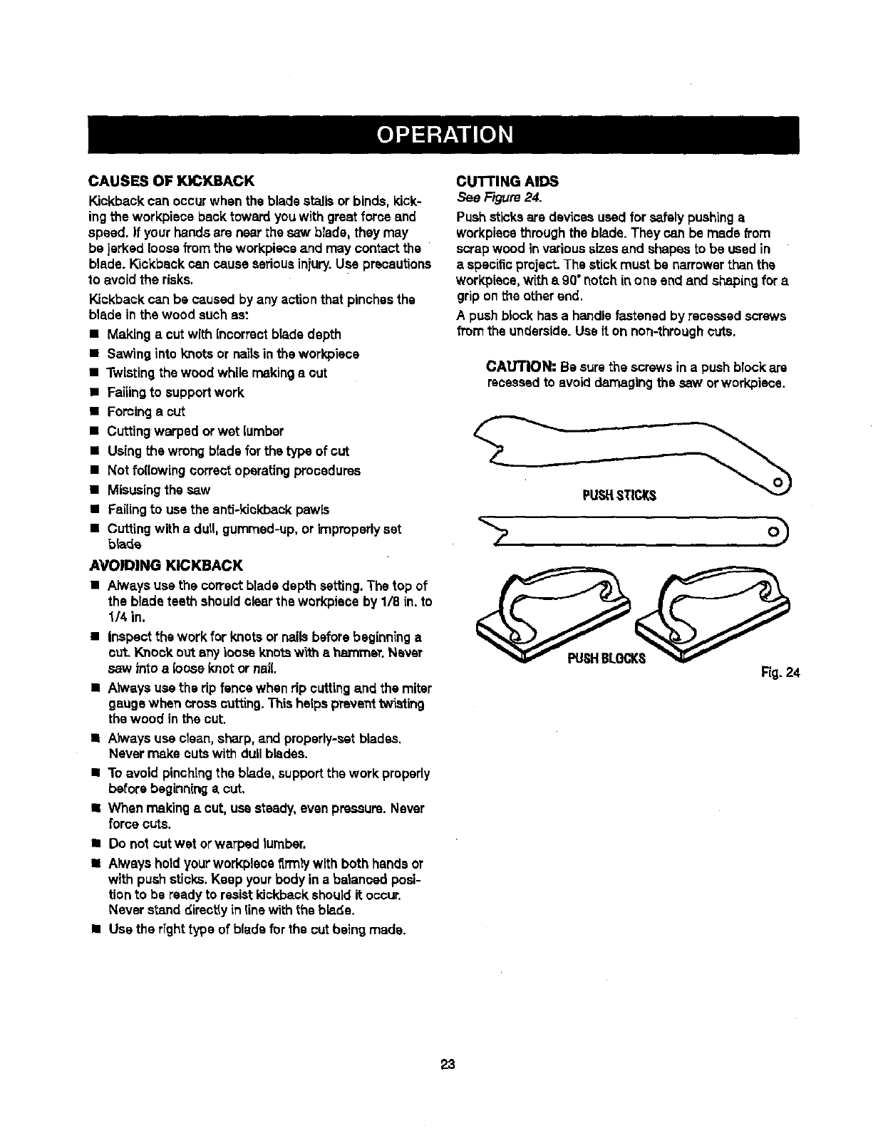
CUTTING AIDS
See Figure 24.
Pushsticksare devicesused for safelypushinga
workpLscethroughthe blade.They can be made _'orn
scrapwood invarioussizes and shapesto be usedin
a specific project.The stick must be narrowerthan the
workpieoe,with s g0°notchin one end and shapingfor a
gripon the other end.
A push block has ahandle fastened by recessed screws
from the underside. Use it on non-throughcuts.
CAUTION: Be surethe screws in a push blockare
recessedto avoid damagingthe saw orworkpiece.
PUStlSTICKS
Rg. 24
23
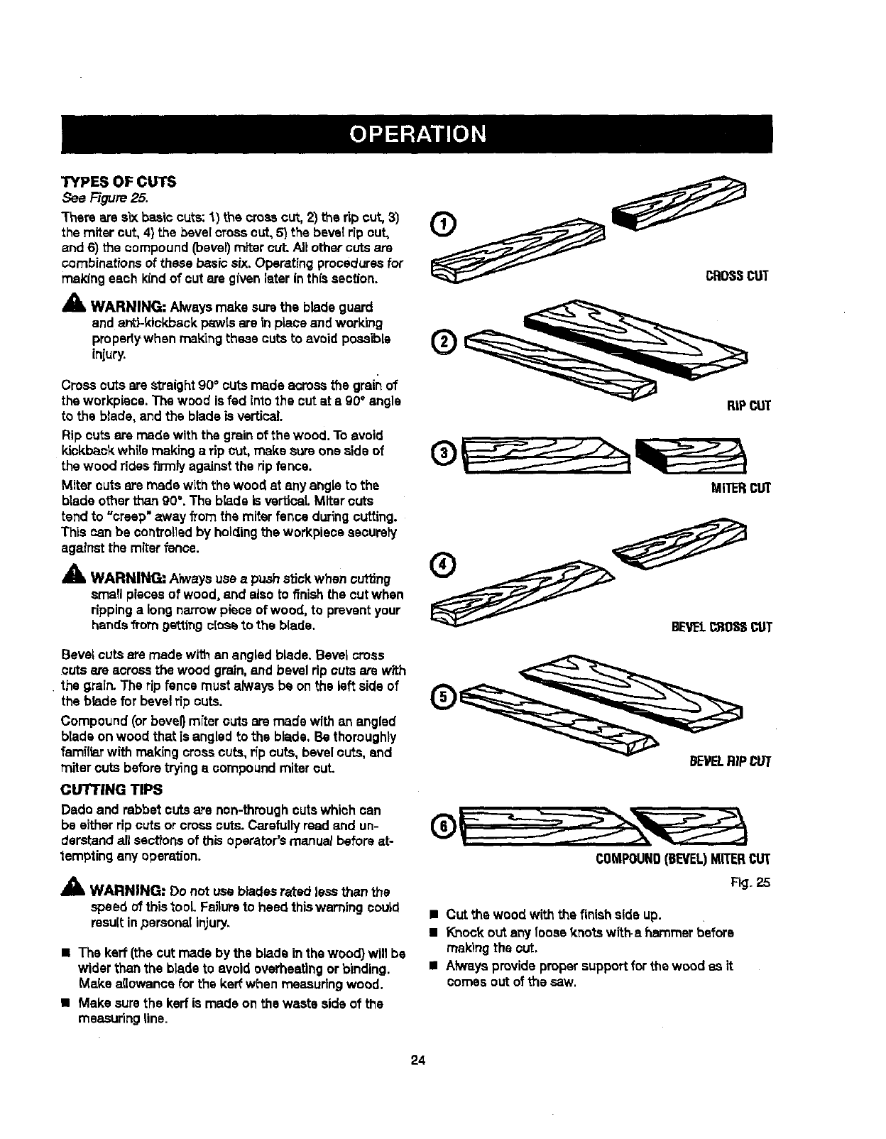
TYPES OF CUTS
See Figure25.
There are six bas;c cuts: 1) the crosscut, 2) the rip cut, 3)
the miter cut, 4} the bevelcross cut, 5) the beveldp cut,
and 6) the compound(bevel}mitercut. Altother cuts are
combinationsof these basic six,Operating proceduresfor
making each kind of cut are given later inthissection.
_k WARNING: Alwaysmake surethe blade guard
and anti-kickback p_wIs are in place and work'rng
proparty when making these cuts to avoid possible
iniury.
Cross cuts are straight90° cuts rr_ds acrossthe grain of
the workpiaos.The wood is fed into the outat a 90° angle
to the blade, and the blade is vertical.
Rip cuts are made withthe grain of the wood. To avoid
kickbackwhile making a rip cut, make sure one side of
the wood rides firmly againstthe rip fence.
Miter cuts are made with the wood at any angle to ths
blade other than 90°. The blade is verticaLMiter cuts
tend to "creep" away from the miterfence during cutting.
This can be controlledby holdingthe workplace astutely
against the miter fence.
_" WARNING; Always use apushstick when cutting
small pieces of wood, and atsoto finishthe cut when
ripping a long narrowpiece of wood, to preventyour
hands from ge'_t.ingo{ossto the blade.
Bevel cuts are made with an angled blade. Bevel cross
cuts are acrossthe wood grain,and bevelrip Gutsare with
the grain.The rip fence must always be on the left sideof
the blade for bevelrip cuts.
Compound (or bevel} miter cuts are made with an angled
blade on wood that is angled to the blade, Be thoroughly
familiarwith making crosscuts, rip cuts, bevelcuts, and
miter cuts beforetryinga compound mitercuL
CUTTING TIPS
Dado and rabbet cuts are non-throughcutswhich can
be either rip outsor cross cuts.Carefullyread and un-
derstandall sections of this operator'smanual before at-
tempting any operation.
AWARNING= Do not use btadasrated lessthan the
speed of thistool Fa_urato heed thiswarning could
result inpersonal in}ury,
•The kerr (the cut made by the blade in the wood) will be
wider than the blade to avoid overheatingor binding.
Make a(iowance for the keff when measuringwood.
•Make surethe kerf is made on the waste side of the
measuring line.
RIPCUT
MITERCUT
COMPOUND(BEVEL)MITERCUT
Fig. 25
•Cut the wood with the finish side up.
•Knock out any looas knots witf_a hammer before
makingthe cut.
•Alwaysprovide proWsupportfor the wood as it
comes out of the saw.
24
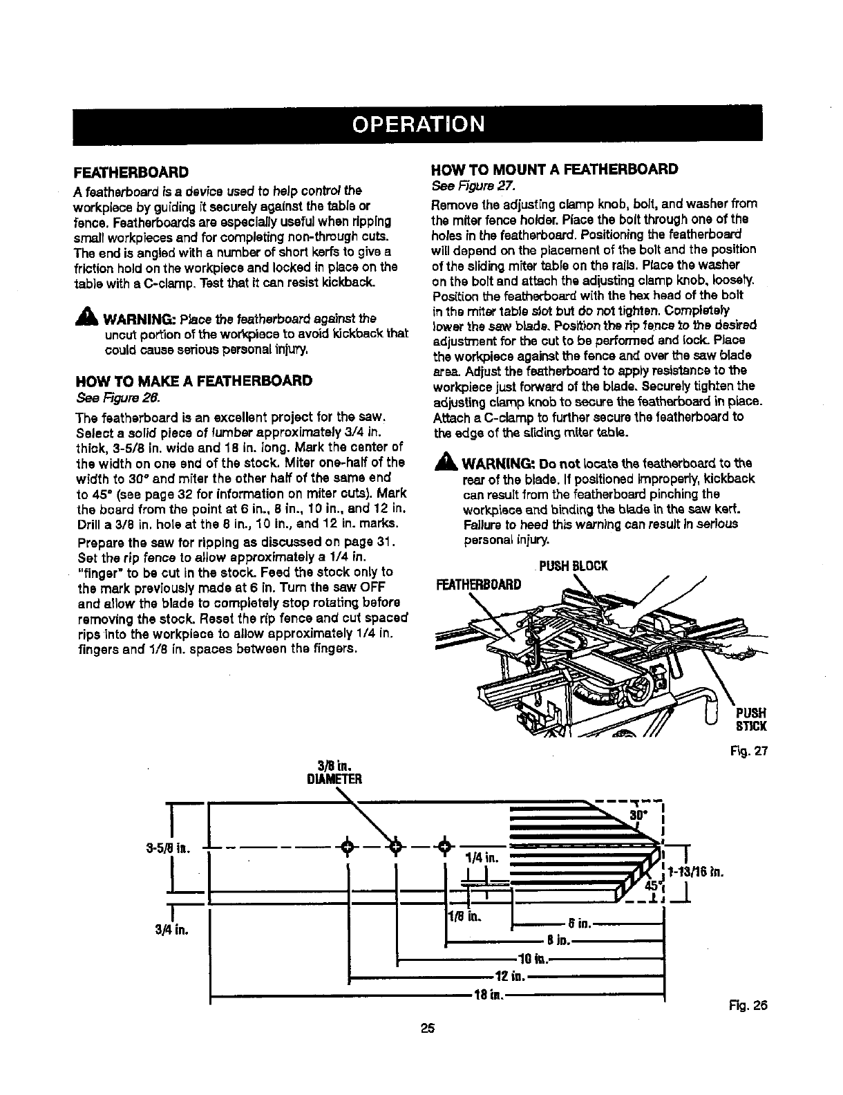
FEATHERBOARD
A fsatherboard is a device usedto heJpcontroithe
workpisce by guidingit securelyagainst the table or
fence. Faatharboardsare especially usefulwhen ripping
small workpiecesand for completingnon-throughcuts.
The end is angled with a numberof short kerfsto givea
friction hold on the workplaceand locked in place on the
table witheC-clamp, Test that it can resistkickback.
AWARNING: Place the featharboardagainstthe
uncut portionof the wor_oieceto avoidkickback that
could cause seriouspersonal iniury.
HOW TO MAKE A FEATHERBOARD
See F/gum26.
The featherboard is an excellent project for the saw.
Select s solid piece of lumber approximately 3/4 in.
thick, 3-5/8 in. wide and 18 in. long. Mark the center of
the width on one end of the stock. Miter one-half of the
width to 30@and miter the other half of the same end
to 45°(see page 32 for information on miter cuts). Mark
the board from the point at 6 in., 8 in., 10 in., and 12 in.
Drill a 3/8 in. hoteat the 8 in., 10 in., and 12 in. marks.
Prepare the saw for ripping as discussed on page 31.
Set the rip fence to allow approximately a 1/4 in.
"finger" to be cut in the stock. Feed the stock only to
the mark previouslymade st 6 in. Turn the saw OFF
and allow the blade to completety stop rotating before
removing the stock. Reset the rip fence and cut spaced
rips into the workpisce 1o allow approximately 1/4 in.
fingers and 1/8 in. spaces between the fingers.
HOW TO MOUNT A FEATHERBOARD
See Figure 27.
Removethe adjustingclamp knob, bolt,and washerfrom
the miter fence holder.Place the boltthroughone of the
holes inthe featherboard. Positioningthe fsatherboard
will depend on the placement of the bolt and the position
of the slidingmTtartable on the mils. Placethe washer
on the bolt and attach the adiustingclamp knob, Ioosety.
Pos{tionthe featherboard with the hex headof the bolt
inthemitertableslotbutdo nottighten.Completely
lower the saw blade. Positionthe rip fence _othe desired
edjusb_ant for the cut to be performed and lock. Place
the workpiece againstthe fence and over the saw blade
area. Adiust the featherbsard to applyresistanceto the
workplacejust forwardof the blade. Securely tightenthe
adjustingclamp knob to securethe featherboardin plane.
Attach aC-clamp to furthersecurethe fsatherboardto
the edge of the slidingmiter table.
_, WARN[NG" 0o not locate the featherboa_dto the
rearof the blade. If positionedimproperly,kickback
can result fromthe featherboard pinchingthe
workpiecaand binding the blade inthesaw kerr.
Failureto heed thiswarning can result inserious
personal iniury.
PUSHBLOCK
FEATHERBOARD
STICK
I
3-5/9 in.
I
I
3/4 in.
3/8 in.
DIAMETER
\-"-,--;o--,'
1OiL
12 is.
18in,
Fig.27
Fig. 26
25
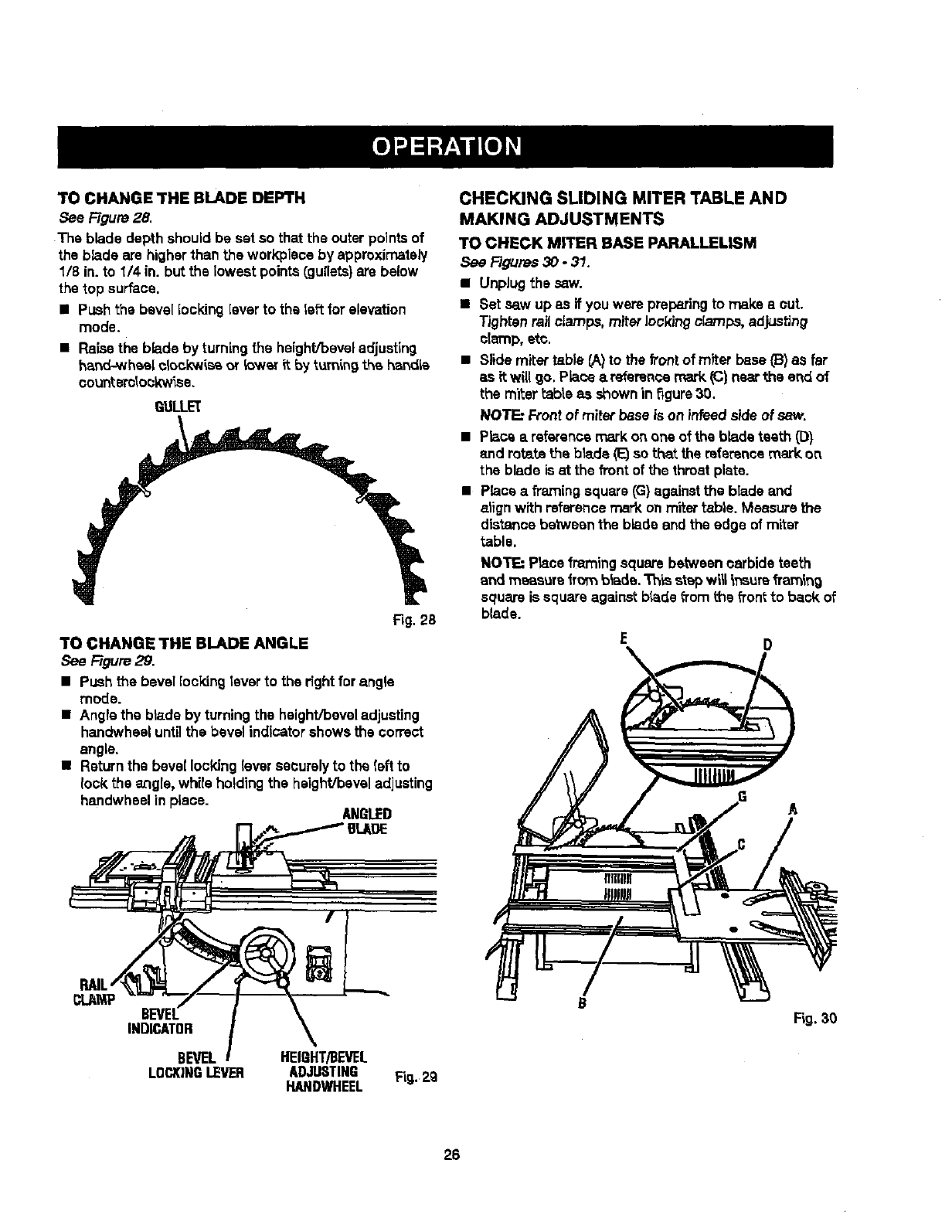
TOCHANGETHEBLADEDEPTH
See Rgure 28.
The blade depth should be set so that the outer pointsof
the blade are higherthan the workpisce by approximately
1/8 in. to 1/4 in. but the lowest points(gullets)are below
the top surface.
• Push the bevel locking [everto the left forelevation
mode.
• Raisethe blade byturning the height/beveladjusting
hand-whe,s[ck>ck'wissor !ower it by turning the hendLs
oo_nterdo_k'w_se.
QULLL='(
Fig. 28
TO CHANGE THE BLADE ANGLE
See Figure 29.
• Push the bevel [ocVdngleverto the rightfor angle
mode.
•Angle the blade by turningthe height/beveladjusting
handwheal untilthe bevel indicatorshowsthe correct
angle.
• Returnthe bevel locking leversecurelyto the (eft to
lock the angle, whirs holdingthe height/beveladjusting
handwheal in piece. AN_I.ED
CHECKING SLIDING MITER TABLE AND
MAKING ADJUSTMENTS
TO CHECK MITER BASE PARALLELISM
See Figures 30 - 31.
•Unplug the saw.
•Set saw up as if youwere preparing to make a out.
Tighten railclamps, miter lockingclamps, adjusting
clamp, etc.
•Slide miter table CA)to the frontof miter base _) as far
as it will go, Place areference mark (C) nearthe end of
the miter _abteas shown in figure30.
NOT_ Frontof miter base is on infead s'_e of saw.
•Place a reference mark on one of the b_ds teeth (D)
and rotstathe blade (1_so that the referencemark on
the blade is at the front of the throat plate.
•Place aframingsquare (G)againstthe blade and
alignwith referencemark onmiter fable. Measure the
distance between the blade end the edge of miter
table.
NOTE: Place framing square between carbide teeth
and measure fro_ b_ade.Th_sstepw_ _nsurefTan_ng
squareissquareagainstbladefromthsfronttoback of
blade,
E 0
A
INDICATOR
BEVEL
LOCKINGIFVER HEIgHT/BEVEL
ADJUSTING Fig,.2g
HANDWHEEL
Fig.30
26
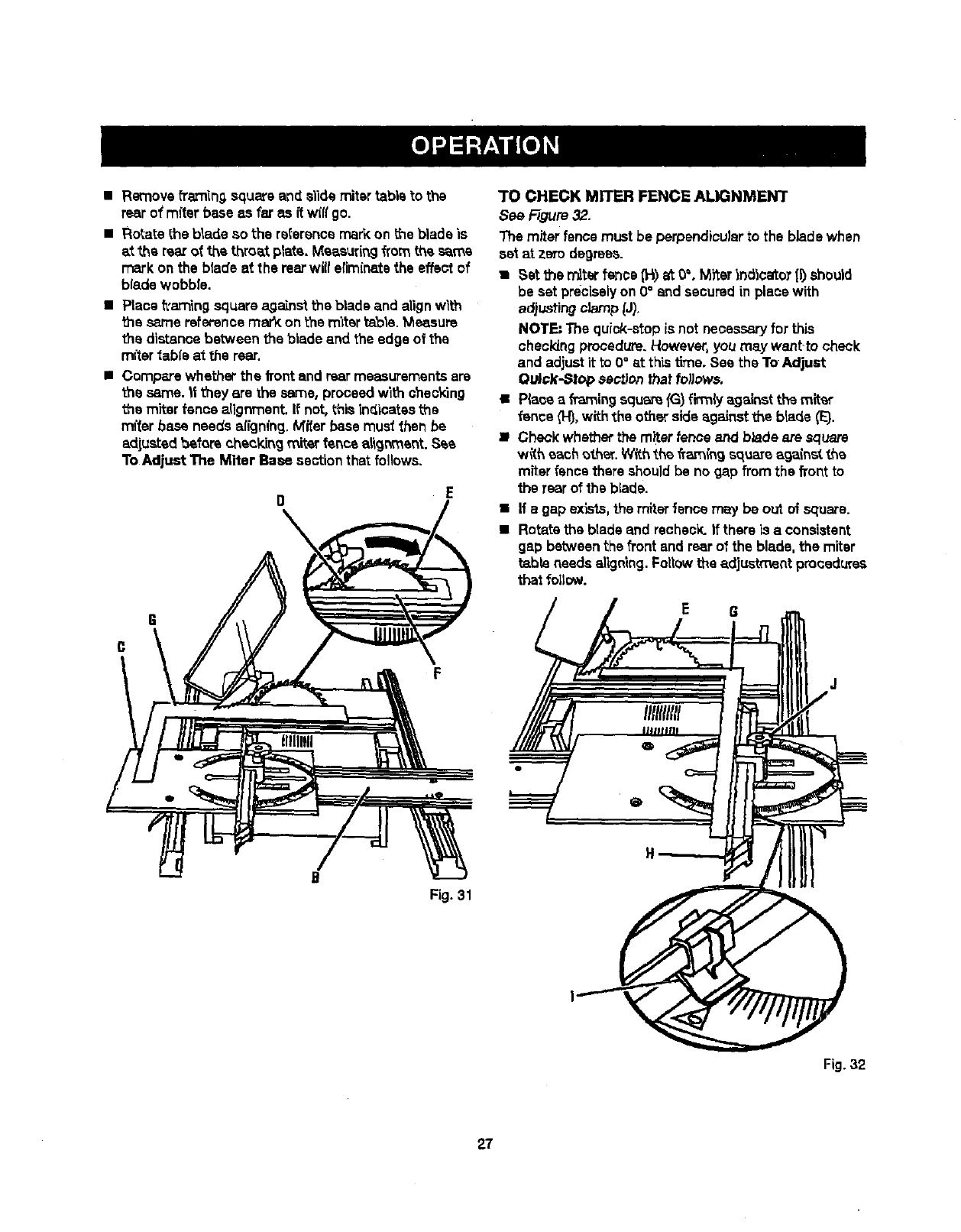
•Remove framinQ,square and slide miter table to the
rear o1rafterbase as far as ftw(fl go.
• Rotate the blade so the reference markon the blade is
at the rearof the throat plate. Measuringfrom the s_ms
mark on the blade at the rearwiiferiminatsthe effect of
blade wobble.
•Place framing square againstthe blade and alignwith
the same reference marY:on the mitsrtable. Measure
the distance between the blade and the edge of the
miter table at the rear.
•Compare whether the front and rearmeasurementsare
the same. It they are the same, proceed with shecking
ths miter fence alignment, If not, this inc{icatasthe
miter base needs afign(ng. Mi!sr base musl then be
adjustedbmforecheckingmiterfencealig_'nent.S_e
To Adjust The Miter Base sectionthat follows,
I] E
\
F
I
B
Fig. 31
3"0 CHECK MITER FENCE ALIGNMENT
See Figure 32,
The miter fence must be perpendicularto the blade when
set at zero degrees.
•Set _e miterfanes (H) at 0%M_er indicatoT (I) should
be set preciselyon 0° end securedin place with
adjustingclamp _J).
NOTE" The quick-atopis not necessaryfor this
checkingprocedure.However,you may want.to check
and adjustit to 0°at this time. See the ToAdjust
Ou_k-Sl_> sent/on thaf fo_ows.
•Plaea aframingsqu_ {G) flnmiya_}_'_sttl_ miter
fence (H),withthe other side against the blade (E}.
•Check whetherthe miterfence and blade ate square
with each other. W#.hthe freLrn{n9 squmeage{net the
miterfence there shouldbe no gap fromthe front to
the rear of the blade,
•Ha gap exists,the miterfence may be out of square.
•Rotate the blade and recheck.If there is a consistent
gap betweenthe front and rearof the blade, the miter
table needs a|ignlng.Followthe adjustment procedures
that follow.
Fig. 32
27
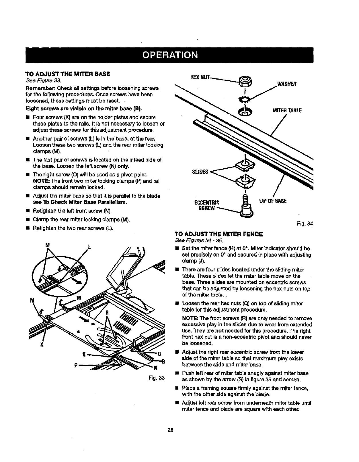
TO ADJUST THE MITER BASE
See Figure 33.
Remember: Check all settings before looseningscrews
for the foflowfng procedures.Once screws have bean
toosened, these settingsmust be reset.
Eight screws ere visible on the miter base (B).
•Four screws (k")o_eon the holderplates and secure
these platesto the rails. It is not necessaryto loosenor
adjust these screws forthis adjustment procedure.
•Another pair of screws (L)is in the base, at the rear.
Loosen these two screws(I-) end the rear miter (ocking
o[amps (M).
•The last paZrof screws is located on the infesdside of
the base. Loosenthe left screw (N) only,
•The right screw (O)will be usedas a pivot point.
NOTE: The fTonttWOmiter locking c(amps (P)and rail
clarnps shouldrem_n locked.
•Adjustthe miter base so that it is parallelto the blade
see To Check Miter Base Parsltellm'n.
•Retighten the [eftfi'ont screw (N).
•Clamp the rearmiter Lockingclamps (M).
•Retighten the two rear screws (L).
M L
M
K
MITERTABLE
SLIDES
Fig. 34
TO ADJUST THE MITER FENCE
See F_Jras 34 - 35.
II Set the miter fence (H) at 0°. Miter indicatorshould be
set preciselyon 0° and secured in place with adjusting
cl_¢np(J).
•Ther_ are four slideslocated underthe s_dingmiter
ta,ble. These slideslet the miter table move onthe
base. Three slidesare mounted on eccentricscrews
that can be adjustedby looseningthe hex nutson top
of the mitertable.,
•Loosenthe rearhex nuts (Q)on top of slidingmiter
table for thisadjustmentprocadure.
NOTE: The front screws (R)are ontyneeded to remove
excessive play in the slides due to wear from extended
use. They are not neededfor this procedure.The right
front hex nutis a non-eocantricpivot and should never
be ;oasened.
•Adjustthe rightrear eccantrJcscrew fromthe lower
side of the miter table so that maximum play exists
betweenthes_ideand m'ftarbase.
K•Pushleft rear of miter table snugly against miterbase
Fig.33 as shown by the arrow (S) in figure 35 and secure,
•P_ca a fi_'nlng square firmlyagainst the miterfence,
with the other ,rideagainstthe blade.
•Adjust left rear screw from undern_th mitertable until
miter fence end brads are square with each other,
28
• Tightenhex nut securely.
• Adjust rightrear screw fromunderneathmitertable to
remove excessiveplay.
•Tighten hex nutsecurely.
•Recheckyour setups carefully.Alse make surea[[
screws, hex nu_s,etc., h_ve been tightened securely.
•If slidingmitertable assemblyis still notsquare with
the blade, repeat the above proceduresas needed.
•Make surethat sfidss remainsquareto miter base
edo,eto preve_ =oookir=_=which will resultin excessive
play in miter table.
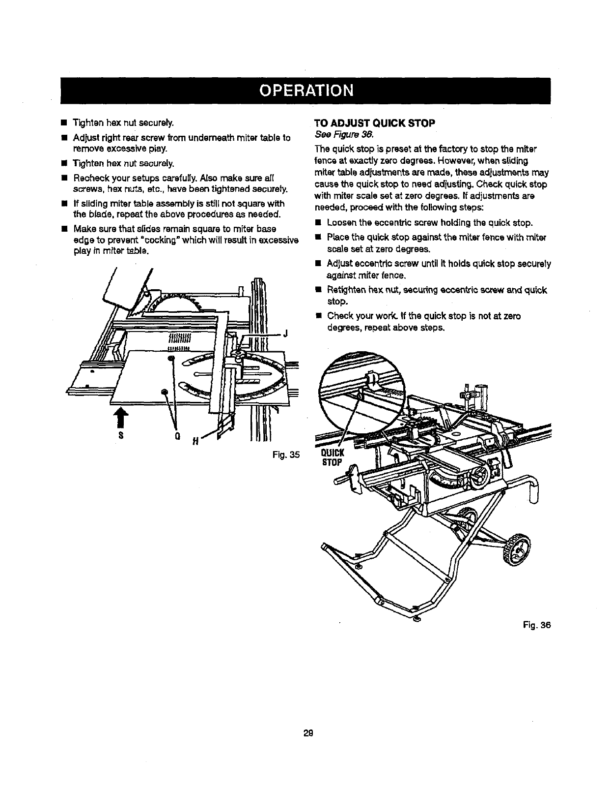
TO ADJUST QUICK STOP
See Figure 38.
The quick stopis preset at the factoryto stop the miter
fence at sxactiy zero degrees. However,when sliding
miter table adjustmentsare made, these adiustmentsmay
cause the quick stop to need adiusting.Check qu(ck stop
withmiterscale set at zero degrees.If adjustmentsare
needed,proceedwith the followingsteps:
•Loosenthe eccentric screw holding the quick stop.
•Piecethe quick stop againstthe miter fence with miter
scale set at zero degrees.
•Adjusteccentricscrew untilit holdsquick stop securely
a_]aJnstmiter fence.
• Rstk..lhtenhe);nut, secur{ngeccentric screw and q,qck
stop.
•Check yourwork. If the quickstop is notat zero
degrees,repeat above steps.
tQ
Fig. 35 QUICK
STOP
Fig. 36
29
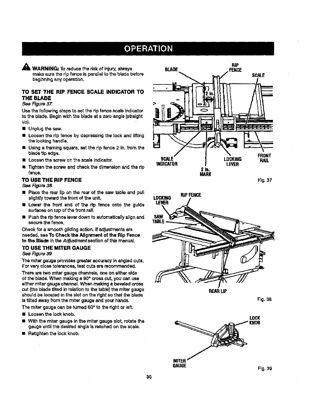
&WARNING: "1"oreduce the r_k of injury, always
make surethe rip fence is parallel to the b_adebefore
b_innfng any opar_t'_o_.
TO SET THE RIP FENCE SCALE INDICATOR TO
THE BLADE
See Figure 37.
Use the following steps to set the rip fence scale indicator
to the blade. Beginwith the blade at a zero angle (sVaight
up).
• Unplugthesaw.
• Loosen the rip fence by depressing the lock and lifting
the rooking handle.
•Using sframingsquare, set the rip fence 2 in. from the
bride tipedge.
• Loosenthe screw on the scale indicator.
•Tighten the screw and check the dimensionand the rip
fence.
TO USE THE RIP FENCE
Figure 38.
• Place the mar lip on the rear of the saw table and pull
slighttytoward the front of the unit.
•Lower the front end of the rip fence onto the guide
surfacesontop ofthe front rail.
•Pushthe rip fence lever down to automaticaflyalign and
securethe fence.
Cheek fora smooth glidingaction. If adjustmentsare
needed, see To Check the Alignment of the Rip Fence
to the Blade in the Adjusfrnenfsectionof this manual.
TO USE THE MITER GAUGE
See F=Jgure39.
The miter gauge providesgreater accuracyin angHd cuts.
For very close tolerances, test cuts are recommended.
Them aretwo miter gauge channels, one on either side
of the blade.When maldng a 90°crosscut, you can use
either miter gauge channel. When making abeveled cross
cut (the blade tilted in relationto the table)the miter gauge
sheutd be located in the slot on the right so that the blade
is tilted away from the miter gauge and your hands.
The miter gauge can be turned60°to the rightor left.
•Loosenthe lock knob.
•With the miter gauge inthe miter gauge slot, rotate the
gauge untilthe desired angteis reached on the scale.
•Retighten the lock knob.
BLADE
E
INDICATOR 2 in.
MARl(
LOCKING RiPFENCE
LEVER
SAW
RiP
FENCE SCALE
LOCKING RA]L
LEVER
Fig. 37
RE_ L|P
Fig.38
LOCK
MITER
GAUGE Fig.39
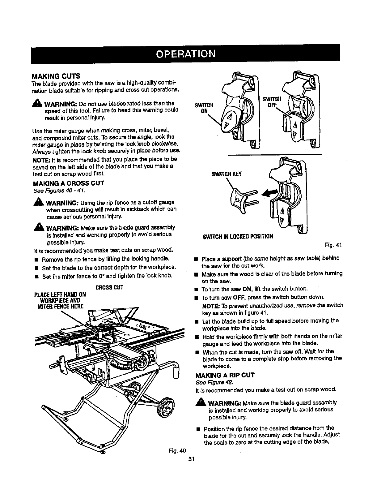
MAKINGCUTS
Thebladeprovidedwiththe saw is a high-quality combi-
nationblade sultabTefor ripping and crossout operations.
_1, WARNING: Do not use blades rated less thanthe
speed of this tool. FaiKureto heed this warningcould
resultin perscnalinjury.
Use the miter gauge when making cross, miter,bevel,
and compoundmiter cuts.To securethe angle, lock the
miter gauge in place by twisting the lockknob clockwise.
Always tightenthe lock knobsecurely in pJaoebefore use.
NOTE=It is recommended that you place the pieceto be
saved on the left side of the blade and that youmake a
test cut on scrapwood first.
MAKING A CROSS CUT
See Figures40 -41.
WARNING: Usingthe rip fence as acutoffgauge
when crosscuttingwit1resultin kickback which can
cause seriouspersonatinjury.
WARNING=: Make sure the blade guardassembly
is installed and working properlyto avoid serious
possible injury.
It is recommended you make test cuts on scrapwood.
• Removethe rip fence by liftingthe lockinghandle.
•Set the blade to the correct depth for the workpiece.
•Set the miter fence to 0°and tightenthe lockknob.
CROSSCUT
PLACELEFTHANDON
WORKPIECEAND
MITERFENCEHERE
Fig. 40
31
SWITCH
ON
\
SV//T_H
°?
SWITCHKEY
'8WITCHINLOCI_DPOSITION
Rg. 41
•Place a support (the same height as saw table)behind
the saw for the cut work.
•Make sure the wood is clear of the blade beforeturning
onthe saw.
•To turn the saw ON, liftthe switchbutton.
• Toturn saw OFF, pressthe switch buttondown.
NOTE: Toprevent unauthorizeduse,remove the switch
keyas shown in figure41.
•Let the blade build up to fullspeed before movingthe
wot_piece _ntothe b_ade.
•Hold the workpiecafirmlywith both hands on the miter
gauge and feed the workpieceinto the blade.
•When the cut_ made, turn the saw off. Wait for the
blade to come to a complete Hop betore removing the
workpiese.
MAKING A RiP CUT
See Figure 42.
It is recommendedyou make atest cut on scrapwood.
,_ WARNING: Make sure the blade guardassembly
is installedand working proper(y to avoid serious
possibleinjLIry.
•Positionthe rip fence the desired distance from the
blade for the out and sasurstylook the handle. Adjust
the scale to zero at the cuttingedge of the blade.
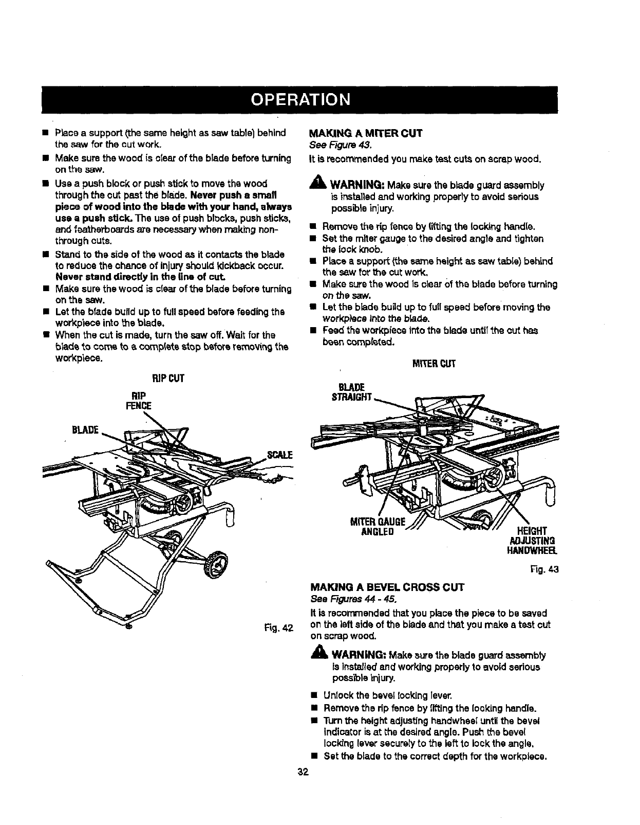
• P_aceasupport/,thesameheight as saw tablel behind
the .saw for the cut work.
• Make sure the wood is clear of the blade before turning
on ti'_e ,_Lw.
•Use a push block or push stick to move the wood
throughthe out past the bla_de.Never push aemafl
piece of wood into the blade with your hand, always
use a push stick. The use of push blocks,push sticks,
and feathathoards are necessarywhen ma_rngnon-
throughcuts.
•Stand to the side of the wood as it contacts the blade
to reduce the chance of injuryshould kickback occur.
Never stand directly in the line of cut.
•Make sure thewood iss[ear of the blade beforeturning
onthe saw.
•Let the blade b_Jildup to full speed before feeding the
workplece into the blade.
•When the cut is made, turn the saw off.Wait for the
bladeto come to a completestop before reme_ng the
wo_pieoe.
RiPCUT
RiP
FENCE
MAKING AMITER CUT
See F-agure43.
It is recommendedyou rnsketest outs on scrap wood.
_k WARNING: Make sure the blade guard assembly
is installedand working pmper]y to avoid serious
poes_is injury.
•Remove the rip fence by liftingthe locking handle.
•Set the miter gauge to the desiredangle and tightsn
the lock knob.
•Place asupport(the same height as saw table) bah'rod
the saw forthe cut work.
•Make surethe wood is clear 0f the blade before turning
on the saw.
•Let the blade bugd up to full speed before moving the
work,piece intotheb_ade.
•Feed the work:pieceintothe blade untilthe outhas
been completed.
MITERCUT
BLADE
MITERGAUGE
ANGLED HEIGHT
AOJUSTING
HANDWHEB.
Fig.43
MAKING A BEVEL CROSS CUT
See Ffeures44 -45.
It is recommendedthat you place the pieceto be saved
on the leftside of the bladeand that you make s test cut
on scrapwood.
XWARNING: Make surethe blade guardassambly
is instsJlsdand workingpmpedy to avoid serious
pose'lois_n)ury.
•Untookthe bevel Iocking 1ever.
•Removethe rip fence by liftingthe [o,_kinghandle.
•Turnthe heightadjustinghandwhesl untilthe bevel
indicatoris at the desiredangle. Pushthe beve(
lockingleversecurelyto the left to lockthe angle.
•Set the blade to the correctdepth for the workpiece.
32
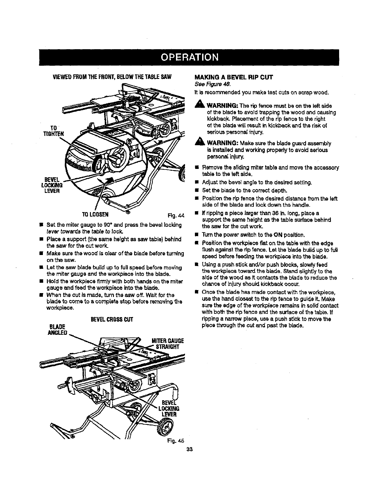
VIEWEDFROMTHEFRONT,BELOWTHETABLESAW
TO
TIGHTEN
BEVEL,
LOCKING
LEVER
TOLOOSEN Rg. 44
• Set the miter gauge to g0°and pressthe bevel Iocldng
tevar towards the tabte to Iosk.
• Place a support (the same heightas saw table) behind
the saw for the cut work.
•Make sure the wood is olaar of the blade beforeturning
onthe sew.
•Let the saw blade build up to fullspeed before moving
the miter gauge and the workplace into the blade.
• Hold the workplacefirmlywith both hands on the miter
gauge and feed the workpieoe intothe blade.
•When the cut _smade, turn the saw off. Waitfor the
blade to corns to a complata stop before rsmov_ngAs
workpisce.
BEVELCROSSCUT
BLADE
ANGLED
MITERGAUGE
STRAIGHT
MAKING A BEVEL RIP CUT
See Rgure 48.
It is recommended you make test cuts on scrapwood.
A
AWARNING: The rip f_ce must be on the left side
of the blade to avoid _apping the wood and causing
kiokback.Plaoementof the tip fence to the right
of the blade will resultin k_ckbackarid the riskof
_fiouspersonalinjury.
_1_ WARNING: Make surethe blade guardassembly
is installedand workingproperlyto avoidserious
persona{injury.
•Removethe slidingmitertable and move the accessory
tableto the left side.
•Adjustthe bevel angteto the desired setting.
•Set the blade to the correct depth.
•Positionthe r_pfence the desireddistance fromthe left
sideof the blade and lock down the handle.
• If rippinga piece largerthan36 in. long, place a
supportthe sameheight asthe _.ble surfacebehind
the saw forthe cut work.
•Turnthe power switchto the ON position.
•Positionthe workpisce fiat on the tabis with the edge
flush against therip fence. Let the bisde buii_ up to full
speed before feeding the workplace into the blade.
•Usingapush stick and/or push blocks, slowlyfeed
the workplacetoward the bb.de. Standslightlyto the
sl_e of the wood as it contactsthe blade to reduce the
chance of injury shouldkickt_k occur.
•Once the blade has made contactwith the workplace,
use the hand closestto the rip fence to guideit. Make
surethe edge of the workplaceremains insolidcontact
with both the rip fence and the surfaceof the table. If
rippinga narrowpiece, use a push stickto movethe
piece throughthe cut and past the blade.
LEVER
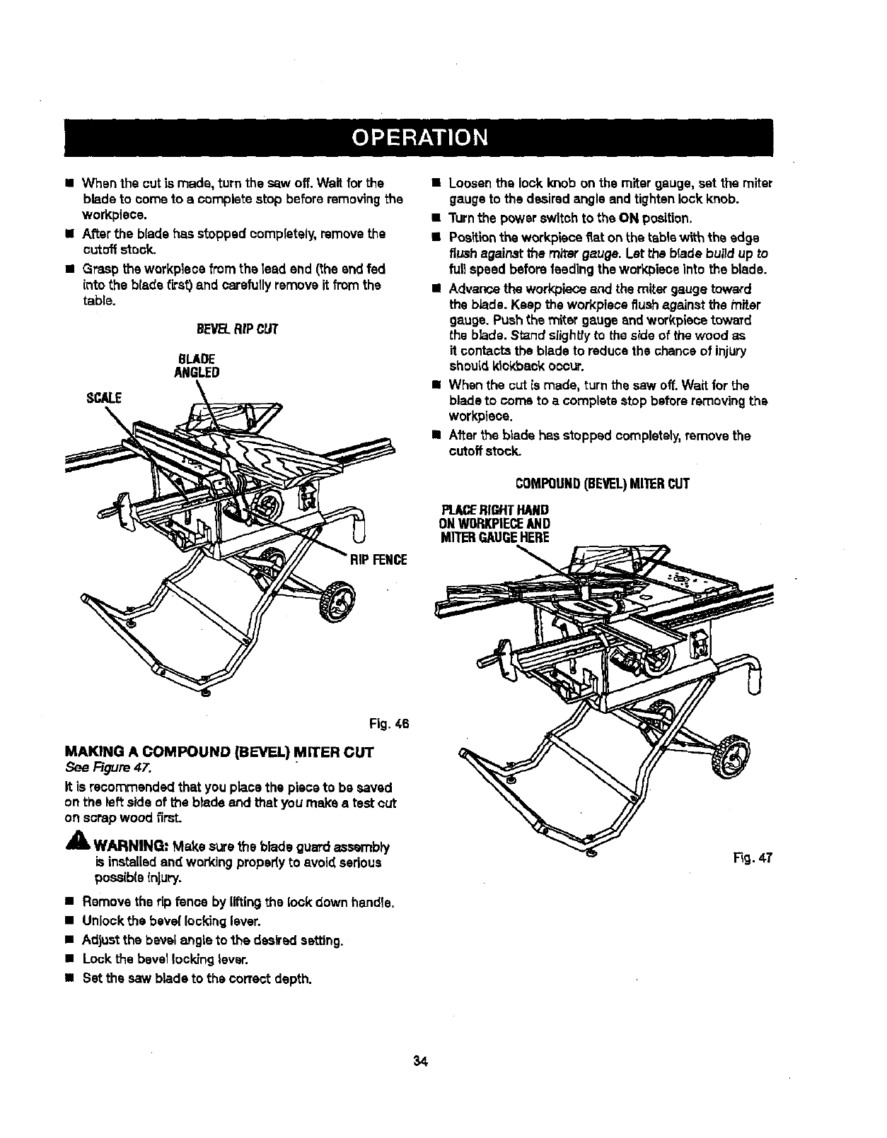
=When the outla made, turn the saw off.Wait forthe
blade to come to a complete stop before removingthe
workplace.
•After the blade has stopped oomplateiy, removethe
cutoffstock.
•Grasp the workplece from the lead end (the and fed
into the b{ade first) and carefullyremove it from the
table.
BEVEL.RiPCUT
8LADE
ANGLED
SCALE
\
•Loosenthe lock knob on the miter gauge, set the miter
gaugeto the desiredangle and tightenlock knob.
•Turnthe power switch to the ON position.
•Positionthe workpiece fiat on the tablewith the edge
flushagainst the miter gauge. Let the blade build up to
full speed before feedingthe workplace Into the blade.
• Advance the workplaceand the miter gauge toward
the blade. Keep the workpieceflushagainst the miter
gauge. Pushthe miter gauge and workplacetoward
the blade. Stand slightlyto the sideof the wood as
it contactsthe blade to reduosthe chance of injury
should kickback occur.
II When the out Is made, turn the saw off. Wait for the
blade to come to acomplete stop beforeremovingthe
workplace.
•Afterthe blade has stopped completely,remove the
cutoffstock.
COMPOUND(BEVEL)MITERCUT
PL_ RIGHTHAND
ONWORKPIECEAND
MR'ERGAUGEHERE
Fig. 46
MAKING A COMPOUND (BEVEL) MITER CUT
See Figure 47.
It is recommended that you place the piece to be saved
on the left side of the blade and that you make atest cut
on scrapwood firsL
_1, WARNING: Make surethe blade guardass_"nbly
is installedand working propedy to avoid sadoue
posaiblainjury.
•Remove the rip fence by liftingthe lock down handle,
•Unlock:he bevel locking lever.
•Adjustthe bevel angle to the desiredsetting.
• Lock the bevellocking lever.
•Set the saw blade to the correct depth.
34
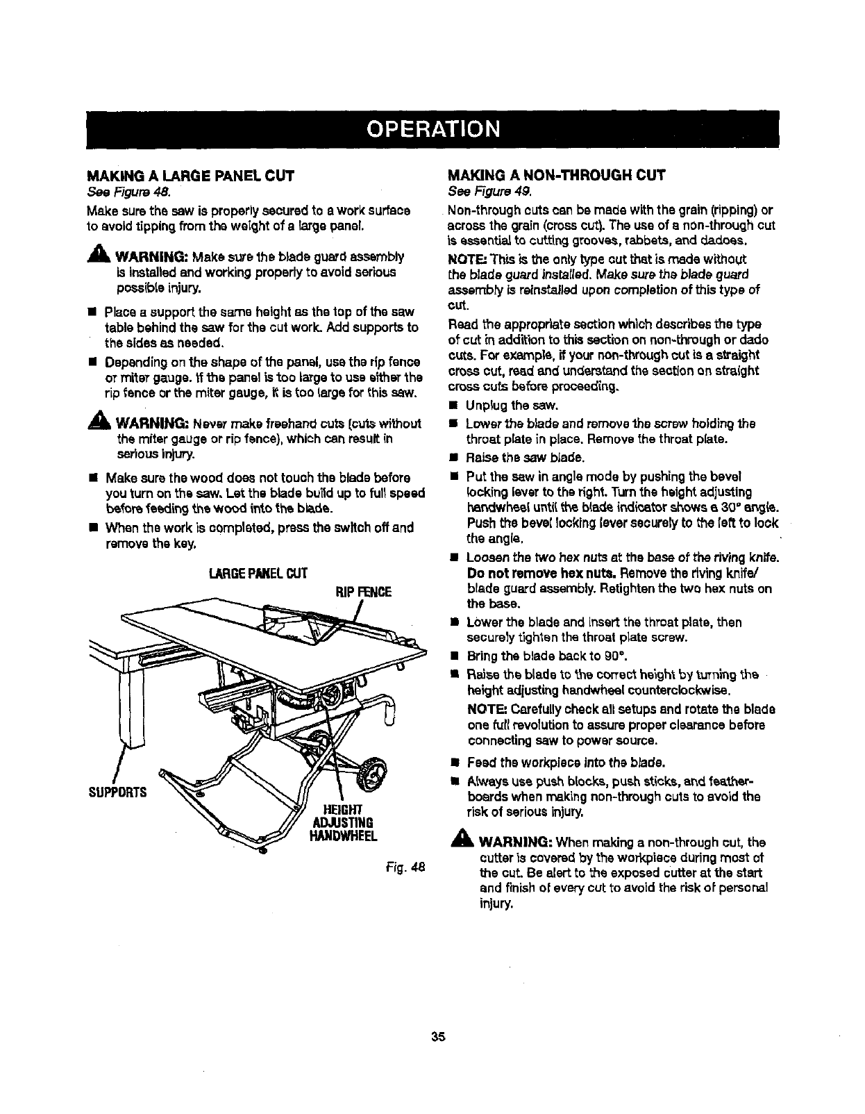
MAKING A LARGE PANEL CUT
See Figure48.
Make surethe sew is properlysecuredto e work surface
to avoidtippingfrom the weight of a large panel
_, WARNING: Make surethe b_adeguardassembly
is installedand working properlyto avoidserious
pessibteinjury.
• Place asupportthe same heightas the top of the saw
table behind the saw for the cut work. Add supportsto
the sidesas needed.
•Depending on the shape of the pansl, use the rip fence
or miteTgauge, ffthe panel is too largeto use s_'herthe
rip {once or the miter gauge, it is too {argofor this saw.
_IL WARNING: Nsvsr make freehand cuts {cutswithout
the mitergauge or rip fence),which can resultin
seriousinjury.
•Make sure thewood does not touch the blade before
you turn on the saw, Let the blade bu_d up to full speed
beforefoeding the wood _,ntothe blade.
•When the work is oemplstod, pressthe switch offand
removethe key.
lARGEPN(ELCUT
RIPFENCE
HEIGHT
ADJUSTING
HANDWHEEL
Fig. _-8
MAKING A NON-THROUGH CUT
See Figure4g.
Non-through cuts can be made with the grain(ripping)or
acrossthe grain (crosscut}.The use of a nOn-throughcut
is essentialto cuttinggrooves,rabbets,and d,ad.oes.
NOTE: TtT_sis the onlytype outthat is made without
the blade guardinstsIled.Make surethe blade guard
assembly la reinstalleduponcompletion of thistype of
cut.
Read the appropriate sectionwhich describesthe type
of cut inaddition to this section on non-throughor dado
cuts. For example, if yournon-throughcut is a straight
cross cut, read and understandthe sectionon straight
cross cuts before procaed{ng.
•Unplug the saw.
•Lower the blade and removethe screw holdingthe
throat plate in place. Removethe throat plate.
•RaLsethe saw blade.
•Put the sew inangle mode by pushingthe bevel
locking lavar to the right. Turnthe heightadjusting
hsndwheel until the b(adeindicster showsa30" ar_jis.
Push the bevel locking{eversecurelyto the [eftto lock
the angle,
•Loosenthe two hex nutsst the base of the riving knife.
Do not remove hex nuts. Removethe rivingknife/
blade guard assembly.Retightanthe two hex nuts on
the base,
•Lower the blade and insert the throat plate, then
securelytighten the throat plate screw.
• Bring the blade backto gO°.
• Raise the blade _othe correcthaigh'tby tuTningthe
height ad{ustinghandwheelcounterclockwise.
NOTE: Carefullycheckall setupsand rctsta the blade
one fur{revolutionto assureproperclearance before
connecting saw to power source.
•Feed the workpiscs into the blade.
• Always use push blocks, push sticks,and feather-
boards when makingnon-throughcuts to avoid the
risk of seriousinjury,
_1= WARNING: When making a non-through cut, the
cutter is covered by the warY,piece duringmost ot
the cut. Be alert to the exposed cutter at the start
and finishof everycut to avoid the risk of personal
injury.
35
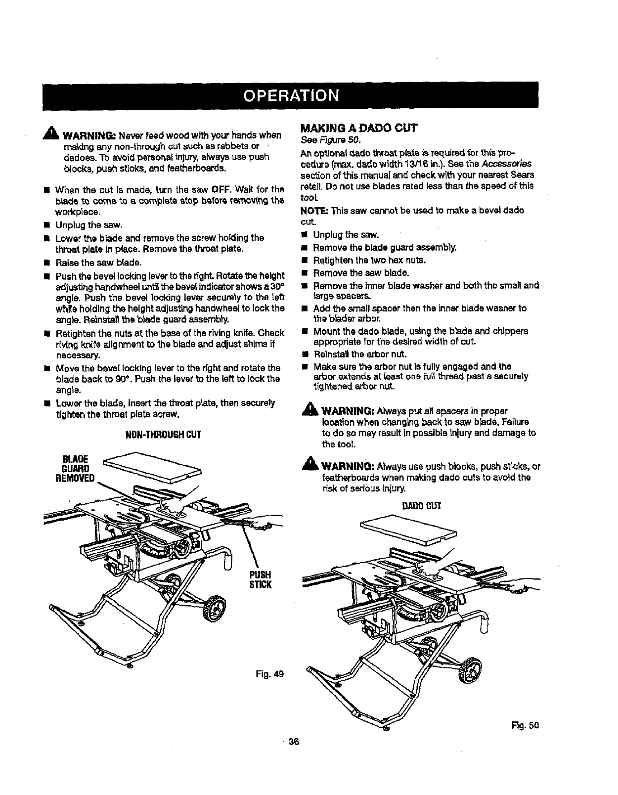
,_ WARNING: Never feed wood with your handswhen
ma_dngany non-throughcut suchas rabbets or
dadoes. To avoid personal injury, aJways use push
blocks, push sticks,and featherboards.
•When the cut is made, turn the saw OFF. Wait for the
blade to come to acomplete stop before removingthe
workpieca.
•Unplugthe saw.
•Lower the blade and removethe screw holding the
throat plate in place. Remove the throat plate.
•Raise the saw b(ade.
• Push the beveilockingleveeto the right.Rotatethe height
adjustinghandwheelunUithe bevelindicatorshowsa 30+
angle. Push the bevel Iocldng leveesecurelyto the left
while holdingthe heightadjustinghandwheelto lockthe
angle. Reinsta_the b_adeguardassembly.
•Retighten the nuts at the base of the riving knife.Check
riving kni_'ealignment to the blade and adjust shimsif
necessary.
•Move the bevel locking [everto the right and rotatethe
blade back to 90%Push the leverto the left to lock the
angle.
•Lower the blade, insert the throat plate, then securely
tighten the throat plate screw.
NON-THROUGHCUT
BLADE
GUARD
REMOVED
MAKING A DADO CUT
See _gurs 50.
An optior_l _Ladothroat plate _sreq_drsdfor this pro-
cadurs (max. dado wirtth _3/16 in.). See the Accessorles
sectionof this manua! and check with your nearestSears
retsil.Do not use blades rated less than the speed of this
tooL
NOTE: This saw cannot be used to make a bevel dado
CUt.
•Unplugthe saw.
•Remove the blade guard aseembly.
•Ratlghtanthe two hex nuts.
•Remove the saw blade.
•Remove_heinnerblade washer and both the sma_and
_eegespacers.
•Add the smellspacer thenthe innerb]adewasher to
the bladesarbor.
•Mount the dado blade, usingthe blade and chippers
appropriatefor the desired width of cut.
•Reinstallthe arbor nut.
•Make sure the arbor nut Is fullyengaged and the
eebor extends at loast one fiJll_rsad past a sacurely
tightened arbornut.
_k WARNING; Alwaysput all spacersin proper
locationwhen changingback to saw blade. Failure
to do so may resultinpossible injuryand damage to
the tool.
AWARNING: Akvays use push blocks, push stlc_, or
fsatharbcardswhen making dado cuts to avoid the
risk of seriousinjury.
9J_l}0CUT
PUSH
STICK
Fig.4g
• 36
F_g.50
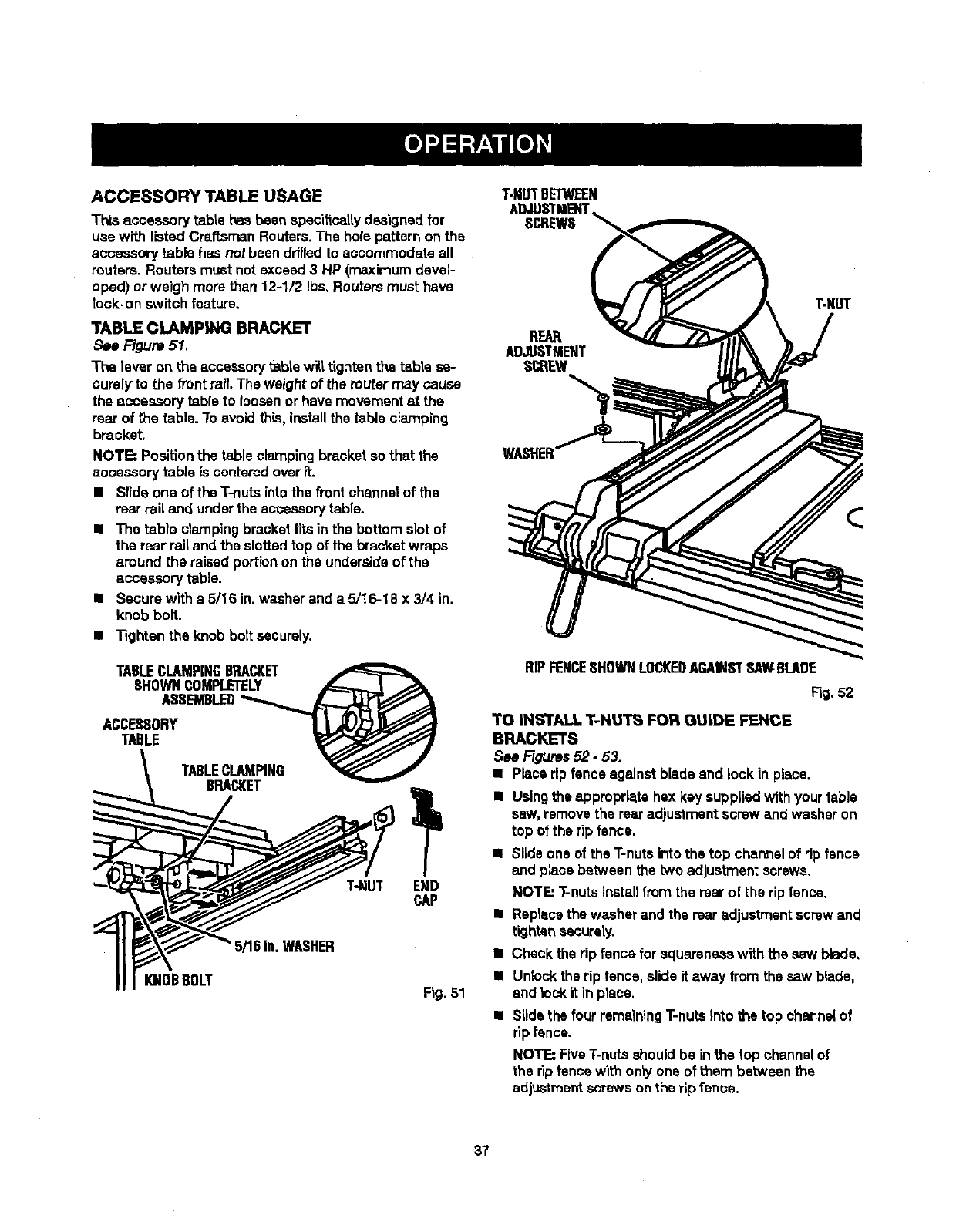
ACCESSORY TABLE USAGE
Th|s accessory table has been spec'dtcaltydesignedfor
use with listed Craftsmen Routars.The hole pattern on the
accessory table has notbeen drffladto accommodate all
reuters. Reuters must notexceed 3 HP (maximumdevel-
oped) or weigh morethan 12-1/2 Ibs. Reutersmust have
took-onswitch feature.
TABLE CLAMP|NG BRACKET
See Figure 51.
The lever on the accessory table wilt.tighten the table se-
curelyto the front rail.The weight of the muter may cause
the accessory table to loosenorhave movementst the
rearof the table. To avoid this, installthe table clamping
bracket.
NOTE: Positionthe table clampingbracket so that the
accessorytable is centeredover it.
II Slide one of the T-nuts into the front channelof the
rearrail and underthe aooeseorytable.
•The table clamping bracketfits in the bottom slot of
the rear railand the slotted top of the bracketwraps
around the raised portion on the undersideof the
accessorytable.
•Secure wlth a 5/16 in. washer and a 5/16-18 x 3/4 in.
knob bolt.
•Tighten the knob bolt securely.
TABLECLAMPINGBRACKET
SHOWNCOMPLETELY _
ASSEMBLED__,._
ACCESSORY L L_L)_
T.,ETABLECLAMPING
BRACKET
T-NUT
_/'16in.WASHER
KNOBBOLT
END
CAP
Fig. 51
T-NUTBETWEEN
ADJUSTMENT
SCREWS
REAR
ADJUSTMENT
SCREW
RIPFENCESHOWNLOCKEDAGAINSTSAWBLADE
Fig, 52
TO INSTALL T-NU'£_ FOR GUIDE FENCE
BRACKETS
See Figures52.53.
•Place rip fence against blade and lock in place,
•Usingthe appropriate hex key suppliedwithyour table
saw, remove the rearadjustmentscrew and washeron
top of the rip fence.
•Slide one of the T-nutsintothe top channelof ripfence
and placebetween the two adjustmentscrews.
NOTE: T-nutsinstallfrom the rearof the rip fence.
•Replacethe washer and the rearadjustmentscrew and
tighten securely.
•Checkthe rip fsncs for squarsnesswith ths saw blade,
• Unlockthe rip fence, slide it away from the saw blade,
and lockit in place,
Slidethe four remainingT-nuts into the top channelof
ripfence.
NOTE: FiveT-nuts shouldbe inthe top channelof
the rip fencewith only one of them between the
adjustmentscrews on the rip fence.
37
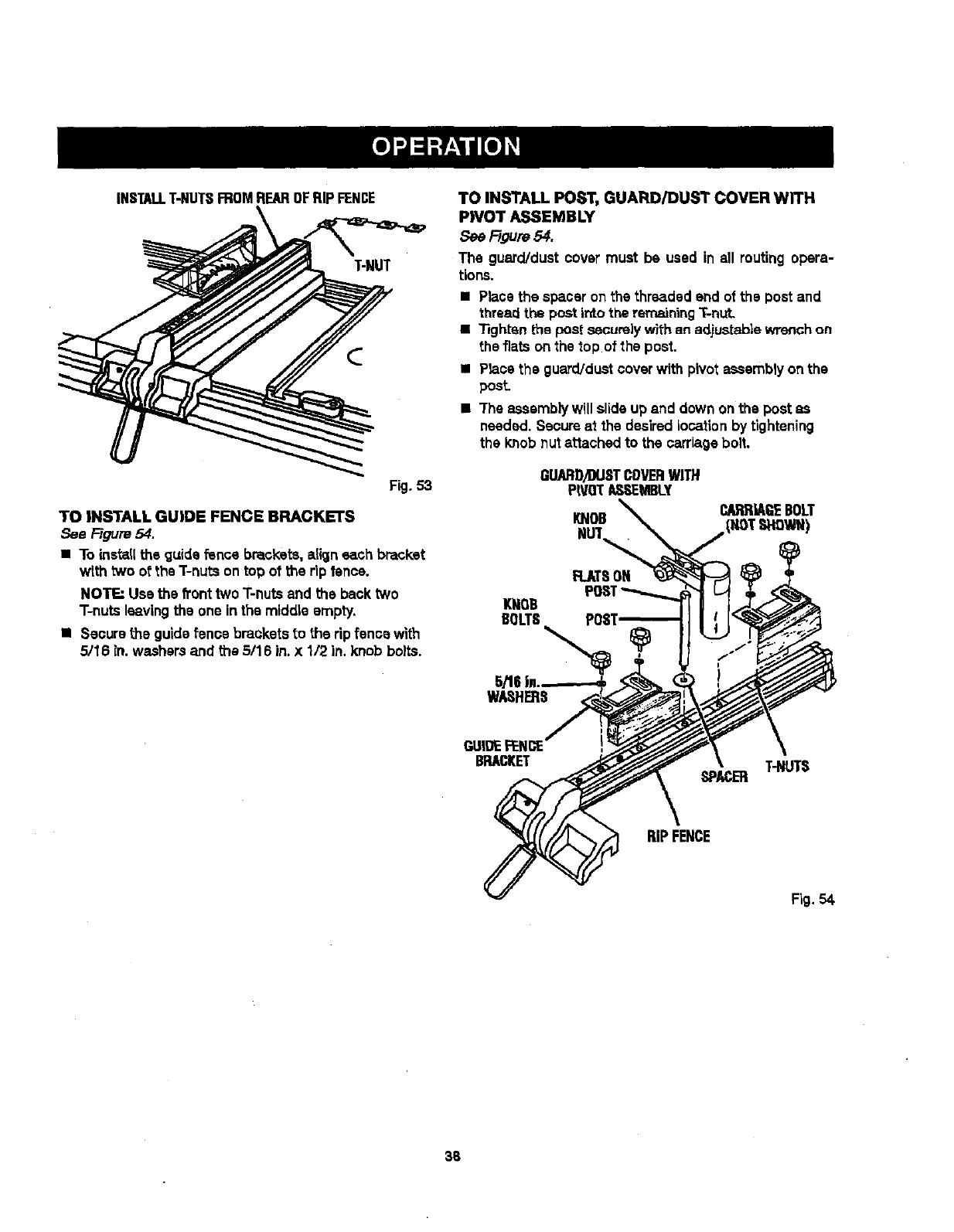
INSTALLT-NUTSFROMREAROFRIPFENCE
T-NUT
Fig.53
TOINSTALLGUIDEFENCEBRACKETS
See F/gum 54.
•To install the guidefence brackets, align each bracket
with two of the T-nuts on top of the rip fence.
NOTE=Usa the hnt two T-nuts and the back two
T-nuts leavingthe one inthe middle empty.
•Securethe guide fence brackets to the rip fence with
5/16 in. washersand the 5/16 in. x 1/2 in. knob bolts.
TO INSTALL POST, GUARD/DUST COVER WITH
PIVOT ASSEMBLY
See F/gum54.
The guard/dust cover must be used in all routing opera-
tions.
• Place the spaceron the threaded end of the post and
thread the post into the remaining"i-nut.
•Tightsn the postsecurelywith an ad.iustab|ewrench on
the fiats on the top of the post.
•Planethe guard/dust coverwith pivot assemblyon the
pesL
•"Theassemblywill slide up and down on the post as
needed. Scours at the desired location by tightening
the knob nut attached to the carriagebolt.
GUARD)DUSTCOVERWITH
P|VO_ASEMBLY
KNOB
FLAT8ON
KNOB
BOLTS
5/tll i.
WASHERS
CARRIAGEBOLT
GUIDE FENCE
BRACKET T-NUTS
SPACER
RIPFENCE
Fig. 54.
38
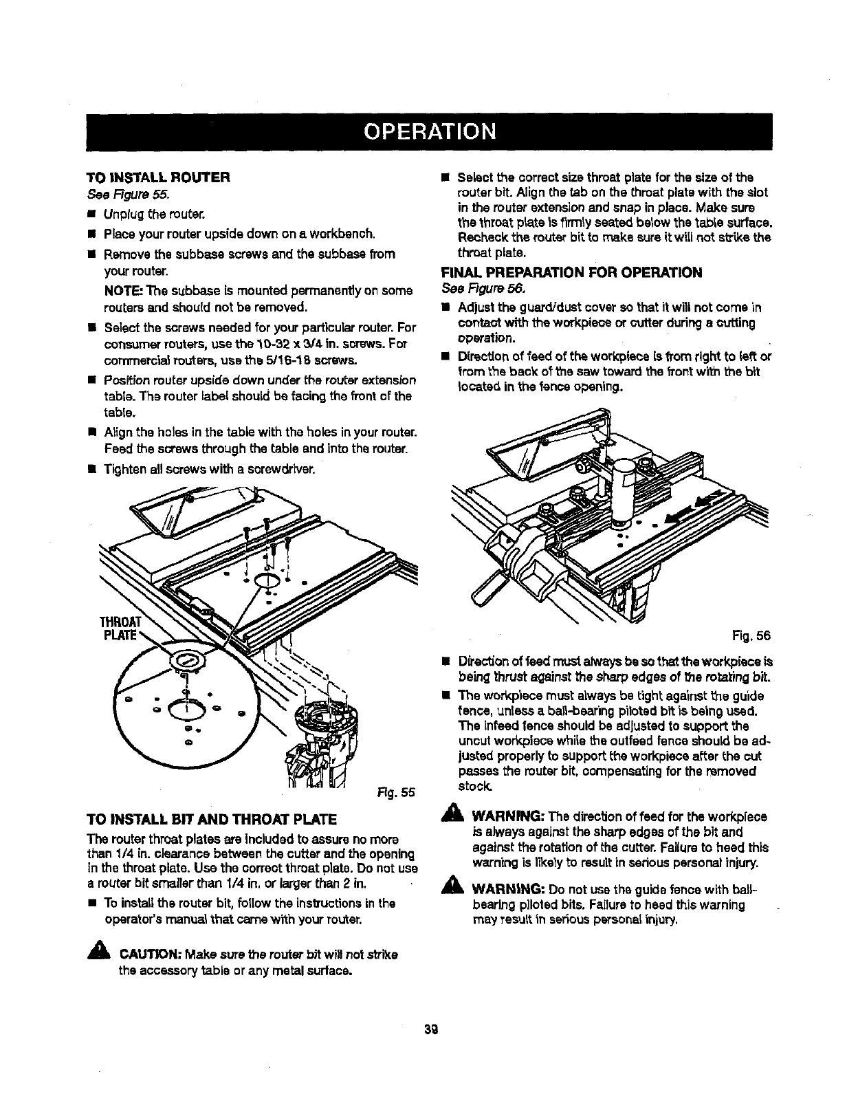
TOINSTALLROUTER
See Ftgure55.
• Unptugthe router.
• Place your router upsidedown onaworkbench.
•Remove the subbase screws and the subbasefrom
your router.
NOTE: The subbase is mounted permanentlyonsome
routereand should not be removed.
•Select the screws needed for yourparticularrouter.For
consumerreuters, use the 10-32 x 3/4 in. screws.For
eommerc'la_Pouters,use the 5/16-18 screws.
•Positionrouterupside down underthe routerextension
tabie. The routerlabel should be facingthe front of the
table.
•Atignthe holes in the tablewith the holes inyourrouter.
Feed the screws throughthe table and intothe router.
•Tighten allscrews with a screwdriver.
•Select the correctsizethroat platefor the sizeof the
routerbit. Align the tab on the throat platewith the slot
in the muter extension and snap inplace. Make sure
the throat plateis firmly seated below the _able surface.
Recheck the router bit to make sureit will not s_ke the
throat plate.
FINAL PREPARATION FOR OPERATION
See Figure 56.
•Adjustthe guard/dustcover so that it will notcorns in
conta_ with the workplaceor cutter duringa cutting
operation.
•D[rectionof feed of the workplace is fromright to left or
from the back of t'nesaw toward the frontwith the bit
located inthe fence opening.
\
i
Rg. 55
TO INSTALL BIT AND THROAT PLATE
The routerthroat plates are includedto assure nomore
than1/4 in.eisarance between the cutter and the opening
in the throat plate. Use the correct throat plate.Do not use
a routerbitsmaller than I/4 in, or largerthan2 in.
• To installthe routerbit, fotlow the instructionsinthe
operator'smanua_that camewith yourrouter.
_" CAIN: Make sure the router bitwill not strike
the accessory table orany metal surface.
Fig.56
•Directionof feed mustalw,_ysbe so thatthe workpieceis
beingthrust againstthe sharp edges of the foraying bit.
• The workp'lecemust alwaysbe tight against _e guide
fence, unlessa ba_-bearing pilotedbit is being used.
The Infeed fence shouldbe adjustedto support the
uncutworkpiees whi_ethe outfeed fence should be ad-
justed properlyto supportthe workpisce after the cut
passes the routerbit, compensatingfor the removed
stock.
41_ WARNING: The directionof feed for the workpiece
is always againstthe sharp edges of the bit and
againstthe rotationof the cutter.Fai(uroto heed this
warning is I_ely to resultin sedous personalinjury.
_i, WARNING: Do notuse the guidefencewith ball--
bearing pilotedbits. Failureto heed thiswarning
may TesuRin seriouspeTsonalinjury.
3g
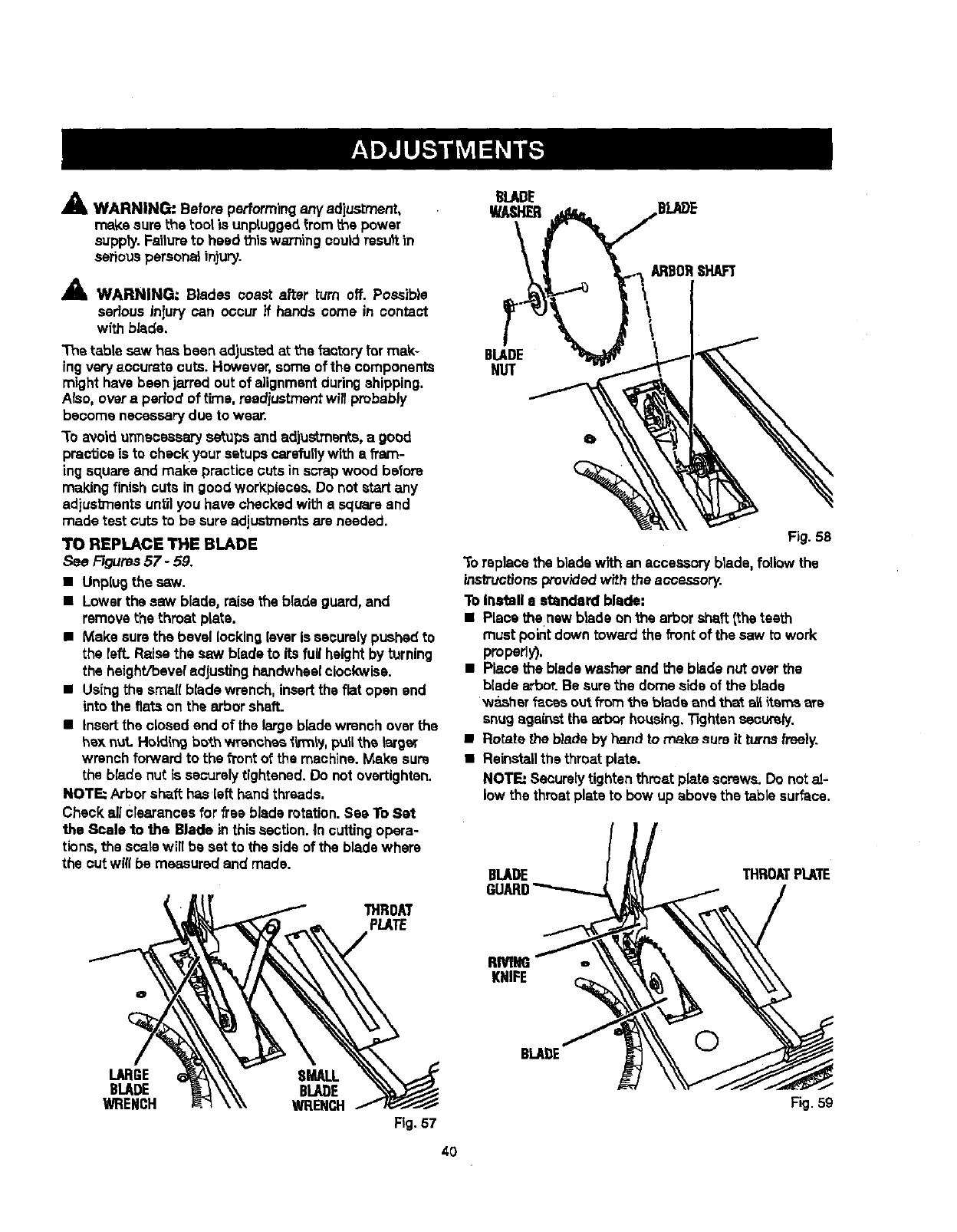
AWARNING." Before performing any adjustment,
make sure the tool is unpluggedfrom the power
suppty.Failureto heed thiswaTn'lngcoutdresu)tin
seriouspersona_injury.
AWARNING: Blades coast after turn off. Possib}e
serious injury can occur if hands come in contact
with blade.
The table sew has been adjusted at the factoryfor mak-
ingvery accurate cuts. However,some of the components
might have been jarred out of alignmentduringshipping.
ALso,overa period of t'rne, rsediustmentwill probably
become necessary due to wear.
3"0avoid unnecessary setups and adjustmen*.s,a good
practice is to check your setupscarefullywith a fram-
ing square and make practice cuts in scrapwood before
making finishcuts in goodworkpiaces. Do not start any
adjustments untilyou have checked with a square and
made test cuts to be sure adjustments are needed.
TO REPLACE THE BLADE
See Figures57 - 59.
•Unplugthe saw.
•Lowerthe saw blade, raisethe blade guard, and
remove the throet plate.
• Make surethe bevel lockingleveris securelypushed to
the felt. Raise the sew bladeto its full heightby turning
the haight/beve_ adjusting handwheelclockwise.
•Usingthe smallblade wrench, insertthe flat open and
into the fiats on the arbor shaft.
•Insertthe closed and of the largeblade wrench overthe
hax nut. Holding bo_.hwrenches li_nly, pull_.h_larger
wrench forward to the f1"ontof the machine.Make sure
the blade nut is securelytightened. De not overtighten.
NOTE: Arbor shaft hasleft hand threads.
Check allcrearancesfor free blade rotation.See ToSet
the Scale to the Blade in thissection.In cutting opera-
tions,the scarewilt be set to the side of the blade where
the cut will be measured and made.
THROM
PLATE
BLADE
NUT
Fig. 58
To replace the blade with an accessoryblade, followthe
instructionsprov'_ed with the accessory.
To Inatall e standard blade:
•Place thenew blade onthe arbor shaft (the teeth
must pointdown toward the fi'ontof the saw to work
properly),
•Place the blade washer and the blade nut over the
blade arbor.Be surethe dome side of the blade
washer f_cas ou_.from _a blade and that all items ere
snugagainst the arbor housing,13ghtensecurely.
•Rotate the blade by hand to make sure it turnsfreely.
•Reinstallthe throat plate.
NOTE: Seaurelytightenthroat plate screws. Do notal-
low the throat plate to bow up above the table surface.
BLADE THROATPLATE
RMNG
KNIFE
LARGE SMALL
BLADE BLADE
WRENCH WRENCH
Fig.57
40
BLAI)E ©
Fig. 59
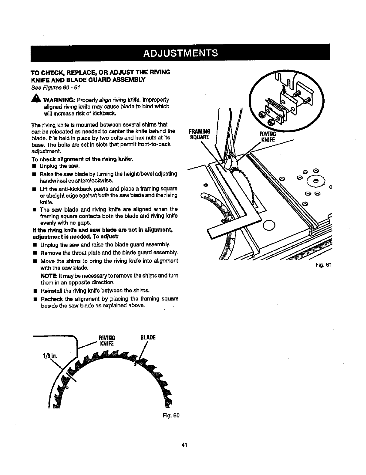
TOCHECK,REPLACE,ORADJUSTTHERIVING
KNIFEANDBLADEGUARDASSEMBLY
See Figures 60 -61.
A
AlL WARNING: Propertyalignriving knits. |mproperiy
atignedrivingknifemay cause blade to btndwhich
will increaserisk of kickback.
The rivingknifeis mounted betweenseveral shims that
can be relocatedas needed to center the knife behind the
blade. It is held in place by two bolts and hex nutsat its
base. The bolts are set inslots that permit front-to-back
adjusb'nent.
"Tocheck a_gnment of the _vin 9 knife:
• Unplugthe saw.
• Raisethe saw blade byturningthe height/beveladiuating
har_twheel¢ountsml_ckwisa.
•Liftthe anti-kickback pawlsand place a framingsquare
ors'_mightedge againstboththe saw bladeandthe riving
knife.
•The saw blade and riving knife are aligned when the
framing square contacts both the biade and rh/ingknife
eventy with no gaps.
If the dvthg knife and saw blade am not In alignment,
adjustment is needed. To adjust:.
•Unplug the saw and raisethe b_adeguard assambly.
•Remove the throat plateand the blade guardassembly.
•Move the shimsto bring the riving knife into alignment
with the saw blade.
NOTE"It maybe necessaryto removethe shimsandturn
them in an opposite direction.
•Ralnstaflthe rivingknifebetween the shims.
•Recheck the atignmentby placing the framing square
beside the saw blade as explained above.
FRAMING
SQUARE
Fig. 61
1/8 in.
RIVING BLADE
KNIFE
R_. 60
41
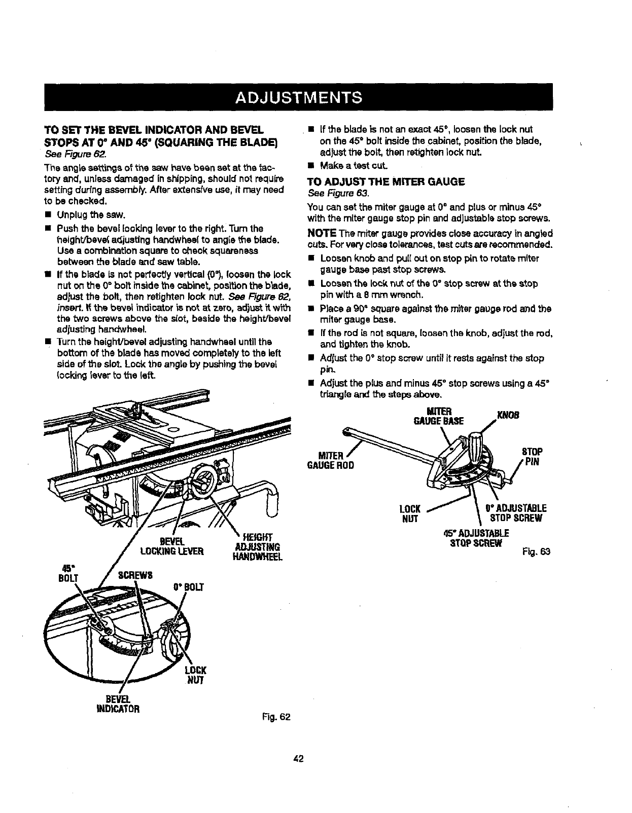
TO SET THE B_VEL INDICATOR AND BEVEL
STOPS AT 0_AND 45 ° (SQUARING THE BLADE)
Figure 62.
The angle sa_mgs oFthe saw have been set at the _ac-
tory and, unlessdamaged inshipping,should not require
setting duringassembly. After extensive use, it may need
to be checked.
•Unplugthe saw.
•Pushthe bevellooking lever to the right.Turnthe
t_eight/beve{ adjustinghandwhsel to angle L'heblade.
Use • combinationsquare to check squareness
between the blade and saw table.
•If the blade is not perfectly vertical (0_),loosenthe lock
nut on the 0° bolt _nside the cabinet, positionthe blade,
adjust the bolt, then retighten lock nut. See Figure 62,
insall, if the banal indicatoris not at zero, adjust_tw_.h
the "twoscrews above the slot, beside the heighVbevel
adjusting handwheel.
•Turn the heighVbeveladjustingha.ndwhesluntilthe
bottom of the blade has moved completelyto the left
side of the slot. Lock the angle by pushing the bevel
_ockinglever to the left.
BOLT
BEVEL HEIGHT
ADJUSTING
LOCKINGLEVEE[ HANDWHEEL
O"BOLT
BEVEL
INDICATOR
LOCK
NUT
Fig. 62
• If the blade is not an exact 45°, loosenthe lock nut
on the 45°bolt insidethe cabinet, positionthe blade,
adjust the bolt, then retighten lock nut.
•Make a test cut.
TO ADJUST THE MITER GAUGE
See Figure 63.
You can setthe miter gauge at O° and plus or minus 45°
with the mitergauge stop pin andadjustablestop screws.
NOTE The miter gauge providescloseaccuracy inangled
cuts.Forvery closetolerances,testcutsare recommended.
•Loosenknob and pull out on stoppin to rotate miter
gauge base paststop screws.
•Loosenthe lockn_t of the 0° stop screw st the stop
pinwith a 8 rnmwrench.
•Place a 90" squareagainstthe m_ar gauge rod and the
miter gauge base.
•If the rod is notsquare, loosenthe knob, adjust the rod,
and tightenthe knob.
•Adjustthe 0°atop screw untilit restsagainst the stop
pin.
•Adjustthe plus end minus 45°stop screws usinga 45°
triangle and the stepsabove.
MITER
GAUGEBASE
MITER_
GAUGEROD
LOCK/
NUT
m
O"ADJUSTABLE
STOPSCREW
45"ADJUSTABLE
STOPSCREW Fig. 63
42
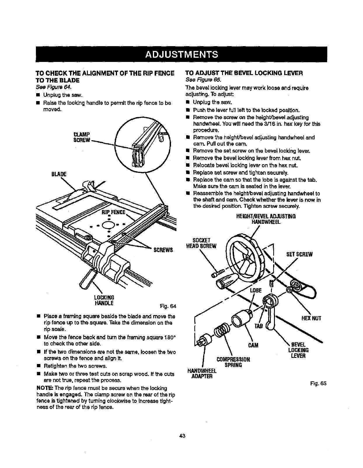
TOCHECKTHEALIGNMENTOFTHERIPFENCE
TOTHEBLADE
SeeFigure 64.
• UnpLugthe saw.
•Raisethe (ooking handleto permitthe rip fence to be
moved.
BLADE
SCREWS
TO ADJUST THE BEVEL LOCKING LEVER
See FTgura65.
"Fhebevel lookinglevermay work loose and require
adjusting. Toadjust:
•Unplug the saw.
•Push the leverfull left to the fecked position.
•Remove the screw on t_e heighS_beveladjusting
handwhaeLYouwritneed the 3/16 in, hex keyfor this
procedure.
•Removethe height/bevel adjustinghandwhseland
cam. Pullout the cam.
•Remove the set screw onthe bevel lockinglever.
•Remove the bevellockingleverfrom hex nut,
II Relocate bevel locking leveron the hsx nut.
• Replace set screw andtighten securely.
•Replace the cam so that the lobe is againstthe tab.
Make surethe cam is seated inthe lever.
•Reaseemb)sthe height/bevel adjustinghandwheelto
the shaft and cam. Checkwhether the leveris now in
the desiredposition.Tightenscrew securely.
HEIGHT/BEVELADJUSTING
HANOWHEEL
SOCKET
H_DS_EW
SETSCREW
LOCKING
HANDLE Fig.64
•Place aframing square beside the blade and move the
rLpfence up to the square. Take the dimensiononthe
rip scale.
• Move the fence back and turn the framing square180°
to check the other aide.
•If the two dimensionsare not the same, loosenthe two
s_'ewa on_s fence end alignit.
•Retightenthe two screws.
•Make two or three test cuts on scrapwood. it the cuts
are not true, repeat the process.
NOTE: The rip fence must be securewhen the locking
handle is engaged. The clamp screwon the rearof the rip
fence istightened by turning clockwiseto increasetight-
nessof the rearof the rip fence.
CAM
COMPRESSION
SPRING
HANDWHEEL
ADAPTER
HEXNUT
,BEVEL
LOCKING
LEVER
Fig.65
43
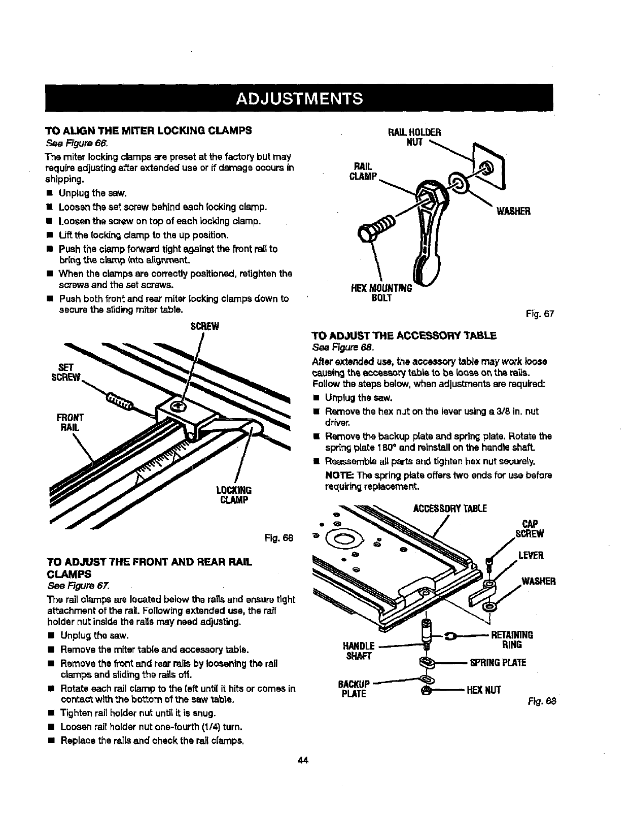
TOAUGNTHEMITERLOCKINGCLAMPS
See Figure 66.
The miter locking clamps are preset at the factory but may
requireadjustingafter extended use or if damage occursin
shipping.
•Unplug the saw.
•Loosen the set screw behind each lockingclamp.
• Loosen the screw on top of each Iockingclamp.
• Uft the locldng clamp to the up position,
•Push the clamp forward tight against the front railto
bringthe c_p into aiigr_'_ent.
•When the clamps are correctlypositioned,retightenthe
scows and the setscrews.
•Push both front and rearmiter lockingclampsdown to
securethe s|idingmiter table.
SCREW
Fig. 66
TO ADJUST THE FRONT AND REAR RAIL
CLAMPS
See Rgure 67.
The rail crampsate located below the raUsand ensure tight
attachment of the rail.Followrngextended use, the rail
holder nutinsidethe rails may need adjusting.
• Unplug the saw.
• Remove the miter table and accessorytabla.
•Remove the _ont emdrear rails by looseningthe rail
crampsand dlding the rai_soff.
•Rotate each rail clamp to the {sft unti{it hits orcomes in
correct with the bo'_om ot the saw table.
•Tighten raitholder nut untilit is snug.
•Loosen rail holder nutone-fourth (1/4) turn.
•Replace the rails and check the rail clamps.
44
RAILHOLOER
NUT
RAIL
CLAMP
WASHER
HE)(MOUNTING
BOLT
Fig. 67
TO ADJUST THE ACCESSORY TABLE
See Rgure 68.
After extended use, the acce..-_, tab/emay workloose
caus(_ th_ accessorytable to be {oos_ o_ the ra'_s.
Foi(owthe steps below,when adjustmentsare required:
•Unplugthe saw.
•Removethe hex nut on the leverusings 3/8 in. nut
driver.
•Removet_e backup p{ateand spring plate. Rotate the
springplate 180°and reinstallon the handleshaft.
• Reassemble allparts end tightenhex nut securely.
NOTE; The spring plate offerstwo endsfor use before
re_[uiringreplacement.
ACCESSORYTABLE
LEVER
HAl RING
_"IAFT SPRINGPLATE
BACKUP
PLATE HEXNUT F_.68
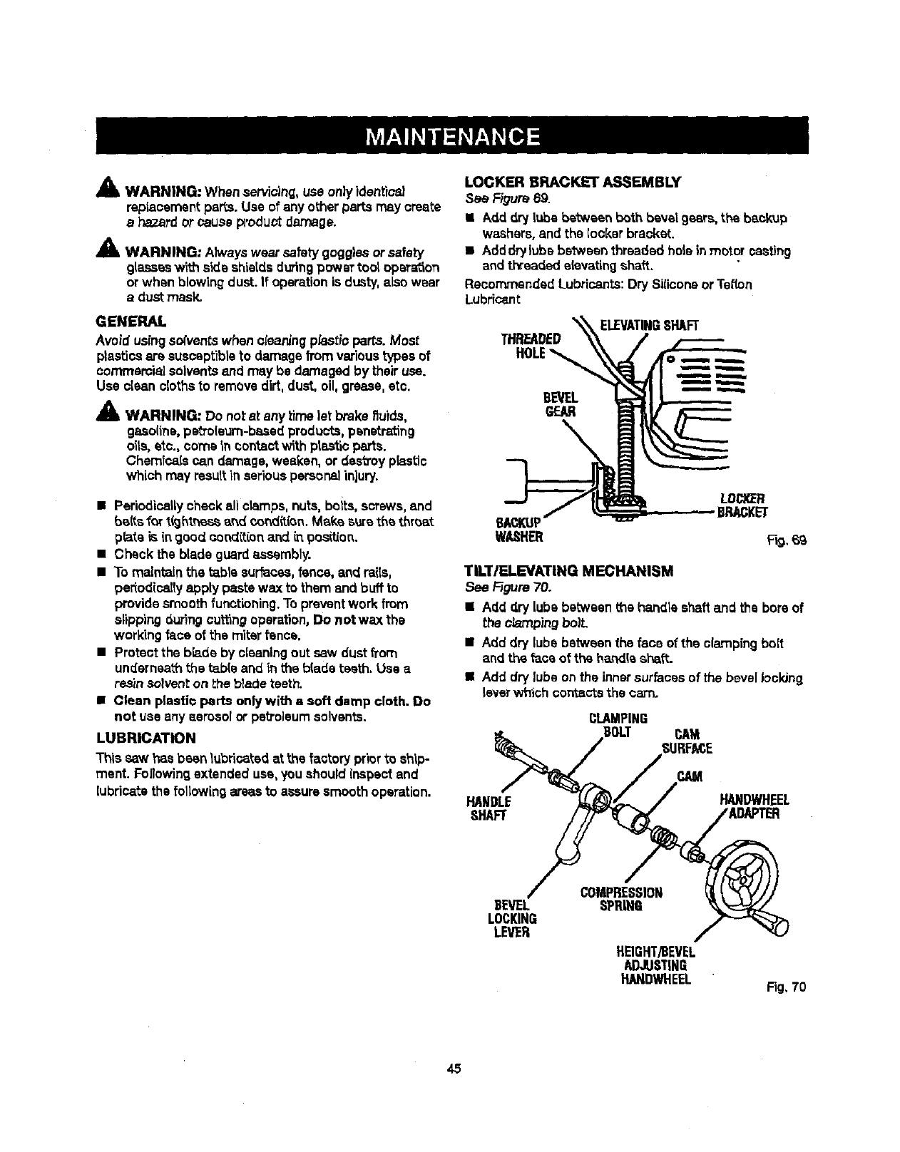
A
Am, WARNING: When servicing,use only identice_
repianementpaps. Use of any other parts m_y create
ahazardorcause product damage.
A
Am. WARNING: A_vays wear safetygoggles orsafety
glasses with side shietdsduringpower too_opera,on
or when blowing dust. If operationis dusty,also wear
a dust mask.
GENERAL
Avoid usingso(ventswhen cteaning p_,stioparts. Most
plasticsare suscsptibteto damage fromvarioustypes of
commercialsolventsend may be damaged by their use.
Use clean clothsto removedirt,dust, o11,grease, etc.
_1_ WARNING: Do not at any Limelet brake fluids,
gaso(ine,petro(eum-basedproducts,penetrating
oils, etc., come In ¢on_actwith pta_'=oparts.
Chemicatscan damage, weaken, or destroyp_stic
which may resuttIn seriouspersonalinjury.
•Periodicallycheck allclamps, nuts, boits, screws,and
_{ts _art_hl.r_ss and cond_,_n,Make sure the t_roat
p_te is (ngood cond(t(on a.nd_. position.
• Check the blade guardassembty.
• To maintain the t_bte sur_css, fence, and raits,
pedodice]Iyapply paste wax to them and buff to
providesmooth functioning. Topreventwork from
slipping duringcuttingoperation,Do not wax the
working face of the miter fence.
•Protect the bb.de by cleaningout saw dustfrom
underneaththe _b(e and in the b{ade teeth. Use a
reamsolvent on _heb_adeteeth.
•Clean plastio parts only with asoft damp cloth. Do
not use any aerosol or petroleumsolvents.
LUBRICATION
This saw has been lubricatedatthe factory priorto ship-
ment. Foflowingextended use,you should inspectand
lubricate the following areasto assure smooth operation.
LOCKER BRACKET ASSEMBLY
See Figure69.
• Add dry lube between both bevel gears, theb_ckup
washers,and the locker braoket..
• Adddrylubs be_:weenthreaded hole in motor casting
andthreaded elevatingshaft.
Recommended Lubricants:Dry Siliconeor Tenon
Lubricant
THREADED
HOLE
BEVEL
GEAR
ELEVATINGSHAFT
TILT/ELEVATING MECHANISM
See _gure 70.
•Add dry [ubebetween me handle shaft and the boreof
the P.,bmpingboil
• Add dry lube between the face of the clampingbolt
and theface of the handle sh_ft.
•Add dry lube on the innersurfacesof the bevel Ioclong
lever which corr_sctsthe cam.
CLAMPING
BOLT CAM
SURFACE
HANDLE
SHAFT
CAM
HANDWHEEL
BEVEL
LOCKING
LEVER
COMPRESSION
SPRING
HEIGHT/BEVEL
ADJUSTING
HANDWHEEL Fig. 70
45
Lookfortheseaccessories at Sears rata'd:
Item No. 9-22212
4070331
Item No. 9-22214
Item No. 9-22215
Item No. 9-22217
Item No. 9-22220
Zero ClearanceThroat Plate
Dado Throat Plate
Micro-Position Rip-Fence Accessory
Quick FoldTable
Long Miter/Rip Fence
Miter Clamp Kit
A
41& WARNING; To avoid riskof injury,use recommended
dado and zero clearance throat platawhen amp}eying
adado accessory.
IONLY USE 6 IN. STACK DADOES.
',= NEVER BEVEL DAJDO.
•NEVER USE ADJUSTABLE DADOES ON THIS SAW,
PROBLEM CAUSE SOLUTION ]
Excessvibration. Blade is out of balance, Replace blade.
Blade is damaged. Replace blade.
Saw is notmounted securely. Tightenall hardware.
Work surfaceis uneven. Repositionon flat surface.
Rip fence does not move
smoothly.
Rip fence does not lock at
rear.
Adjustlegs of op_onsl stand.
Check Saw Blade Inst_la_on. Replace blade
if necessary
Remounttherip fence.
Clean and wax mils.
Adjustclamp screw counterclockwise,
Adiustclamps_ew clockwise.
Cutting binds or burnswork,
Bladeis warped.
Rip fence not mounted c,on'e_tLy.
Rails are dirtyor sticky.
Clamp screw isout of adjustment.
Clamp screw isout of adjustment.
Blade is dull.
Blade is heeling.
Work is fed too fast
Rip fence ismisaUgned.
Riving knifeis misaligced.
Wood iswarped.
Replace orsharpen blade,
Align miterbase.
Slowthe feed rats.
Align the _lpfence.
Adiust the dvlng knife with shimsprovided.
Replacethe wood. Alwayscut with convex
sideto table surface.
46
IPROBLEM CAUSE SOLUTION !
Wood edges away fromrip Rip fence is misaligned. Check and adjustthe rip fence.
fence when ripping. Blade not properlyeh,_rpenedor Reeharpenor set blade.
set,
Slidingmiter table aSSembly Miter base orslides improperly See page 26 for adjustments to sliding
does not move smoothly, adjusted, miter table assembLy.
Saw does not make accurate 90 Posltlvestops insidecabinet need Adjustpositivestops.
or 45 degree cuts. adiusting(BevelCuts):
Miter gauge is misaligned(Miter Adjustthe mitergauge.
Cuts).
Blade adjustinghandleis hard Gears or Screw Post inside Clean the gears or screw poet.
to turn, cabinet are ckiggsd with
dust.
Saw does notstart. Motor cord or wall cord is not Plug in motor cord or wall cord.
pluggedin.
Cirouitfuse is blown.
Circuitbreaker is tripped.
Cordor switch is damaged.
Replace circu'_fuse.
Reset circuitbreaker.
Have the cord or switchreplacedat your
Sears ServiceCenter/Department.
Blade makes poor cuts. Blade is dull ordirty.
Blade is wrongtype for cut being
made.
Blade is mounted backwards.
Clean, sharpen, or replace blade.
Replacewith correcttype.
Remountblade.
Blade does not lowerwhen
turning blade adjustinghandle.
Back side of rivingknifehas
come in contact wff.hsaw table.
Lockinglever is notat full left
position.
Realignand adjust the rivingknife.
Move _ockingleverto left.
Motor taborsinrip cut, BJadenotproper for rip cut. Change blade; rip blade typicallyhas fewer
teeth.
47
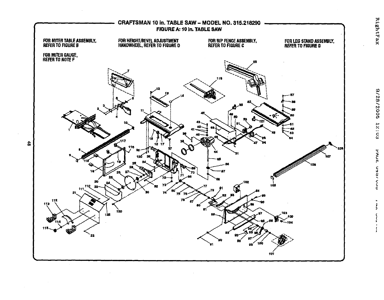
FORMITERTABLEASSEMBLY,
REFERTDRRUREB
FORMITERGAUGE,
REFERTONOTEF
CRAFTSMAN 10 in. TABLE SAW - MODEL NO. 315.218290 ,
FIGURE A"10 in. TABLESAW
FORHEIGHT/BEVELADJUSTMENT
HANDWHEEL,REFERTORGURE0 FORRIPFENCEASSEMBLY,
REFERTORGUREC
11
ld 12
44
120
8O 81
i
FORlEG STANDASSEMBLY,
REFERTORGURBG
107
F)
0
o
0:
r_
¢
c
Q
(
(
F
€
107
#
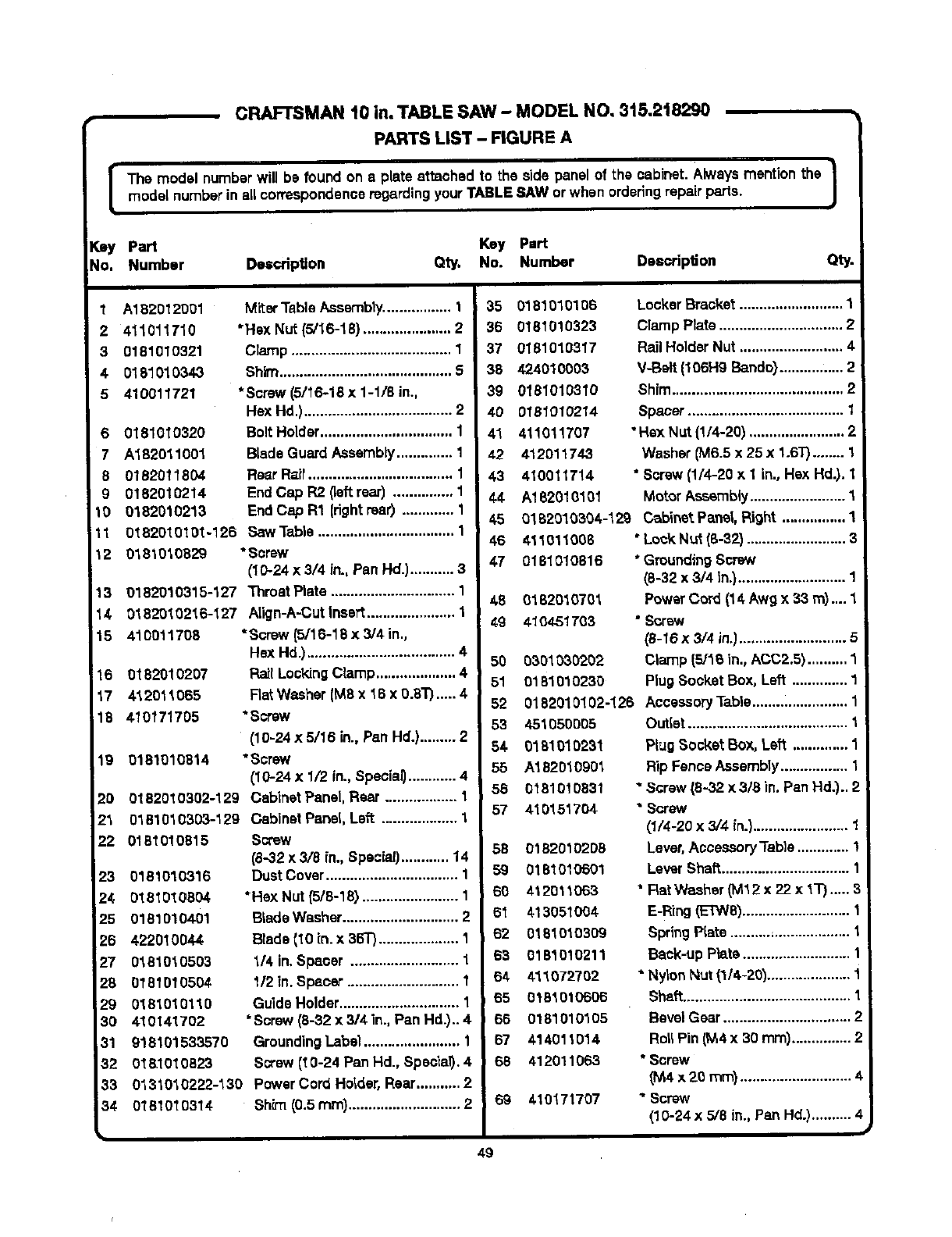
[
CRAFTSMAN 10 in. TABLE SAW - MODEL NO, 3t5.2t8290
PARTS LIST - FIGURE A
The model numberwill be found on aplate attached to the side panel of the cabinet. Alwaysmention the |
model numberin allcorrespondenceregardingyour TABLESAW orwhen orderingrepairparts. J
Key Part Key Part
No. Number Description Qty, No. Number Deacrlp6on Qty
1A182012001
2 411O1171O
3 0181010321
40181010343
5 410011721
6 0181010320
7 A182011001
80182011804
g0182010214
10 0182010213
1t 0182010101-126
Miter TableAssembly................. 1
"Hax Nut (5/16-18) ...................... 2
Clamp ........................................ 1
Shim........................................... 5
*Screw (5/16-18 x 1-1/8 in.,
Hex Hd.) ..................................... 2
Bolt Holder................................. 1
Blade Guard Assembly.............. 1
Rear Raft.................................... 1
End Cap R2 (leftrear) ............... 1
End Cap R1 (rightreef) ............. 1
Saw Table .................................. 1
12
13
14
15
16 0182010207
17 412011065
18 410171705
19 0181010514
20 0182010302-129
23 0381010303-129
22 0181010815
23 0181010316
24 0181016504
25 0181010401
26 422010044
27 0181010503
28 0181010504
29 0181010110
30 410141702
31 918101533570
32 O181O1O823
33
34
018t 0_,0329 *Screw
(10-24 x 3/4 in., Pan Hd.)........... 3
0182010315-127 Thmat Plate ............................... 1
0182010216-127 Atign-A.-Cutinsert...................... 1
410011708 * Screw (5/16-18 x 3/4 in.,
Hex Hd.) ..................................... 4
Rail LockingClamp .................... 4
Rat Washer (M8 x 16 x o.8"r)..... 4
•screw
(10-24 x 5/16 in.,Pan Hd.)......... 2
"Screw
(10-24 x 1/2 in.,Special)............ 4
Cabinet Panel, Rear .................. 1
Cabinet Panel, Left ................... 1
Screw
(8-32 x 3/8 in., Specia0............ 14
Dust Cover................................. 1
• He}(Nut {5/6-18) ........................ 1
B_adeWasher............................. 2
Blade (10 in. x 36T) .................... 1
1/4 in. Spacer ........................... 1
112in. Spacer ............................ 1
Guide Holder.............................. 1
•Screw (8-32 x 314in., Pan Hd.).. 4
GroundingLabel ........................ 1
Screw (t0-24 Pan Hd., Special). 4
01310"t0222-130 PowerCord Holder,Rear........... 2
0181010514 ShPn(0.5 ram)............................ 2
35 0181010106
36 0181010323
37 0181010317
38 424010003
39 0181010310
40 0181010214
41 411011707
42 412011743
43 410011714
44 A182010101
45
46
47
Locker Bracket.......................... 1
Clamp Plate ............................... 2
Rail Holder Nut .......................... 4
V-Belt (106H9 Bando}................ 2
Shim........................................... 2
Spacer....................................... 1
• Hsx Nut {1/4-201........................ 2
Washer (M6.5 x 25 x 1.6T)........ 1
* Screw (1/4-20 x 1 in.,Hex Hal.).1
Motor Assembly........................ 1
0182010304-129 Cabinet Pa_l, Right ................ 1
411011006 "Lock Nut (8-32) ......................... 3
0181010816 * GroundingScrew
(8-32 x 3/4 tn.)........................... 1
48 01820'_0701 PowerCord (14 Awg x 33 m).... 1
49 410451703 *Screw
(8-t6 x 3/4 in.)........................... 5
50 0301030202 Clamp (5/16 in., ACC2,5).......... 1
51 0181010230 PlugSocket Box, Left .............. 1
52 0182010102-126 AccessoryTable........................ 1
49
53 451050005
54 0181010231
55 A182010901
56 O181O10831
57 410151704
58 01820102D8
59 0181010501
60 412011063
61 413051004
62 0181010309
63 0181010211
04 411072702
65 0181010606
66 0181010105
67 414011014
68 412011063
, 69 410171707
Duffer........................................ 1
PtugSocket Box, Left .............. 1
Rip Fence Assembly ................. 1
"Screw (8-32 x 3/3 in. Pan Hal.)..2
SGrew
(1/4-20 x 3/4 in.)........................ 1
Lever,Accessory "fable............. 1
Lever Shaft................................
*Rat Washer _Vll2 x 22 x I"P)..... 3
E-Ring(ETW8)........................... 1
SpringPIate ..........=................... 1
Back-up Plate........................... 1
* NylonNut (1/4-20)..................... 1
Shaft.......................................... 1
BevelGear ................................ 2
Rot;Pin (M,4x 30 mm)............... 2
* Screw
_4x2o ram)............................4
" Screw
(10-24 x 5/8 in., Pan Hd.).......... 4
#
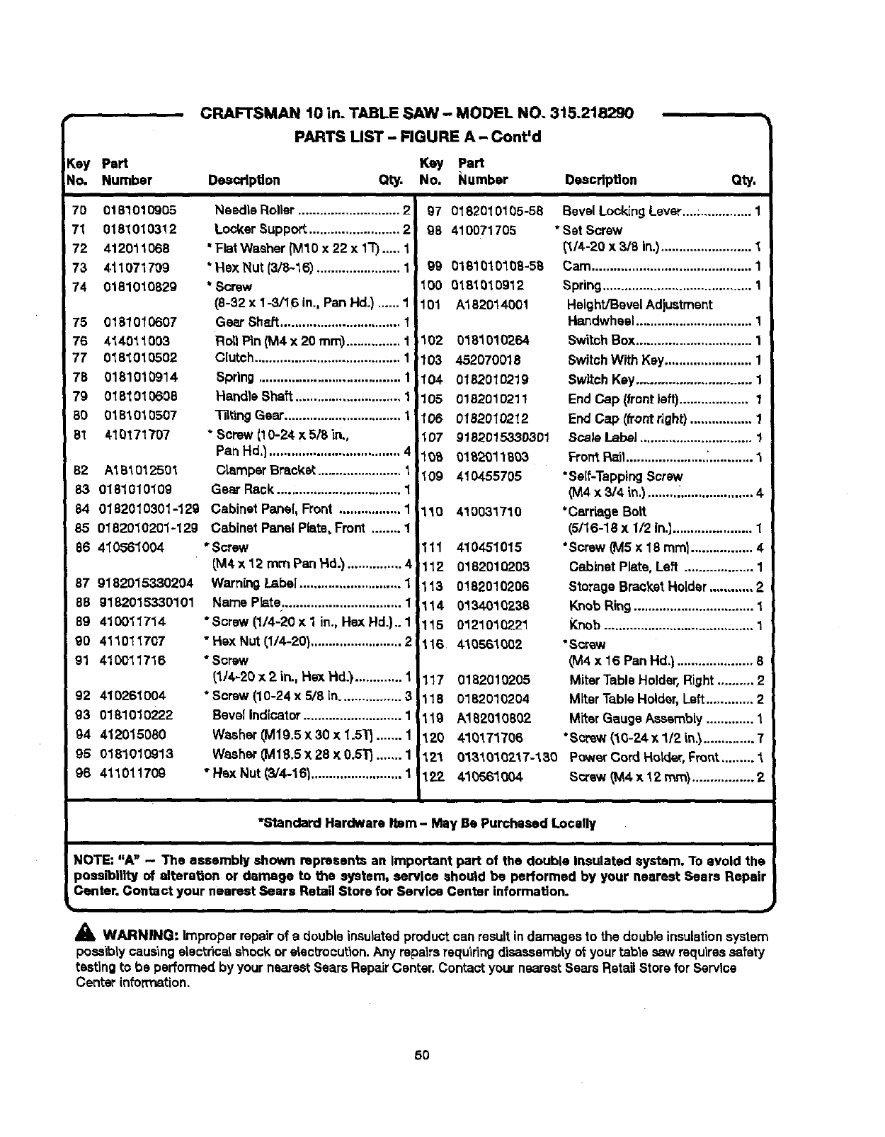
p_
Key Part
No, Number
CRAFTSMAN 10 in. TABLE SAW - MODEL NO. 3t5.218290
PARTS LIST - FIGURE A - Cont'd
Key Part
Description Qty. No. Number Description Qty.
70 0181010905
71 0181010312
72 412011O68
73 411071709
74 0181010829
75 0181010607
76 414011003
77 018_010502
78 0181010914
79 0181010608
80 0181010507
81 410171707
82 A181012501
83 0181010109
84 0182010301-129
85 0182010201-129
86 4_0561004
87 9182015330204
88 9182015330101
89 410011714
90 411011707
91 410011716
92 410261004
93 0181010222
94 412O15O80
95 0181010913
96 411011709
Needle Roller ............................ 2
Locker Support ......................... 2
' Flat Washer (IV110x 22 x 1"1")._.. 1
*Hex Nut (3/8-16) ....................... 1
* Screw
(8-32 x 1-3/16 in., Pan Hd.) ...... 1
Gear Sh_t ................................. 1
Roll P_n(M4 x 20 ram)............... 1
Clutch........................................ 1
Spring ....................................... 1
Handle Shaft ............................. 1
"131_ingGear................................ 1
* Screw (t 0-24 x 5/8 in.,
Pan Hd.) .................................... 4
Clamper Bracket ....................... 1
Gem Reek ................................. 1
Cabinet Panel, Front ................. 1
Cabinet Panel Plate, Front ........ 1
*Screw
(M4 x 12 mm Pan Hd.')............... 4
WarningLabel ............................ 1
Name Pb,te ................................. 1i
*Screw (1/4-20 x 1 in., Hex Hd.),. 1 ]
"Hex Nut (1/4-20) ......................... 21
* Scow
(114-20x 2 in.. Hex Hd.) ............. 1
* Screw (10-24 x 5/8 in................. 3
Bevel Indicator ........................... 1
Washer _M19.5x 30 x 1.5"1_....... 1
Washer _M18,5x 28 x 0.5_ ....... 1
• Hsx Nut (3/4-16) ......................... 1
97 0182010105-58
98 410071705
99 0181010108-58
100 0181010912
101 A182014001
102 0181010264
103 452070018
104 0182010219
105 0182010211
106 0182010212
107 9182015330301
108 0182011803
109 4104-55705
110 410031710
111 410451015
112 0182010203
113 0182010206
114 0134010238
115 0121010221
116 410561002
117 0182010205
118 0182010204
119 A1820!0802
120 410171706
121 0131010217-130
122 410561004
Bevel LockingLever....;.............. 1
*Sat Screw
(1/4-20 x 3/8 in.)......................... 1
Cam............................................ 1
Spdng......................................... 1
Height/BevelAdjustment
Handwhesl................................ 1
SwitchBox................................ 1
SwitchWith Kay........................ 1
Switch Key............................... 1
End Cap (front }aft)................... 1
End Cap (front right)................. 1
Sca/e Label ............................... !
Fro_ Rail......................:............ "_
*Self-TappingScrew
(M4 x 3/4 in.) ............................. 4
*Cerria0s Bolt
(5/16-18 x 1/2 in,]...................... 1
"Screw (MS x 18 mini ................. 4
Cabinet Plate, Left ................... 1
Storage BmcY,eI Holder ............ 2
KnobRing................................. 1
Knob ......................................... 1
•Screw
(M4 x 16 Pan Hd.) ..................... 8
Miter Table Holder,Right.......... 2
Miter Table Holder,Left............. 2
Miter Gauge Asssmbly............. 1
*Screw (10-24 x 112in,_.............. 7
Power Cord Holder, Fmr_t.......... "t
Screw _M4x12 ram}................. 2
*Standard Hardware Item - May Be Purchased Locally
NOTE: "A" - The assembly shown represents an Important part of the double Insulated system. To avoid the
possibility of alteration or damage to ttte system, service should be performed by your nearest Sears Repair
Center. Contact your nearest Sears Retail Store for Service Center information.
b
_1, WARNING: Improper repairof a double insulatedproduct can resultin damagesto the double insulationsystem
possiblyceus'lng electricalshock or eLactrocu(ion.Any repairsrequiringdisaessm'o_yot your table saw requiressafety
testing to be performed by your nearestSears RepairCenter. Contact your nearestSears RatanStorefor Service
Center information.
5O
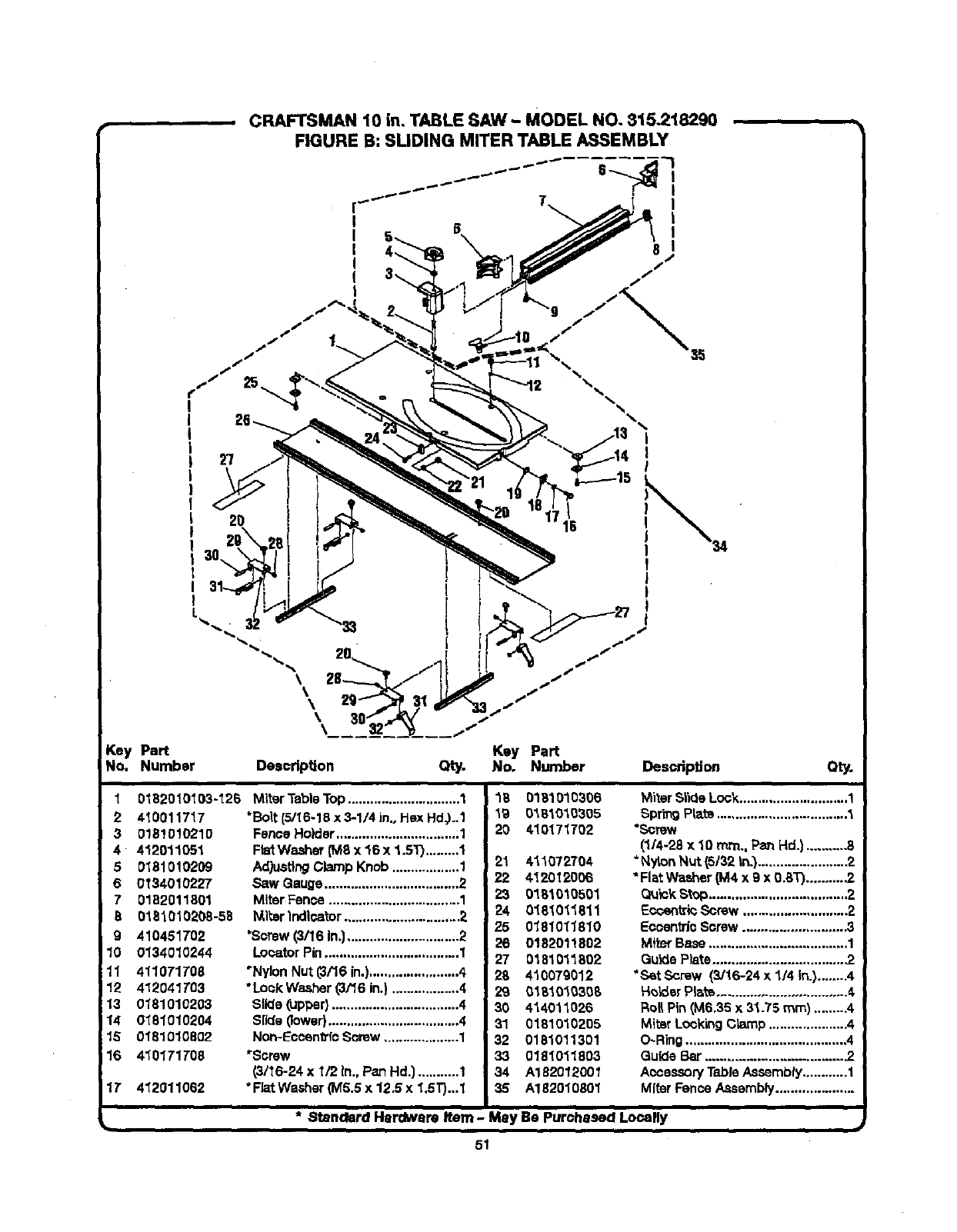
CRAFTSMAN 10 in. TABLE SAW- MODEL NO. 815.218290
FIGURE B: SLIDING MITER TABLE ASSEMBLY
I
I
I
I
I
I
%I
I
l
2o
k ,
\
\
\
\
Key Part
No. Number Deecdptlon
j-
Key Part
Qty. No. Number Description Qty.
1
2 410011717
30181010210
4 412011051
50181010209
60134010227
70182011801
80181010208-58
g 410451702
10 0134010244
11 4110TIT08
12 412041T03
13 0181010203
14 0181010204
15 0181010802
16 410171708
1T 412011062
0182010103-126 Miter Table "l'op.............................. 1
*Boll:(5/I6-18 x 3-1/4 in., Hex Hd_..1
Fence Holder ................................. 1
Fb_ Washer (M8 x 16 x 1.5T) ......... 1
Adjusting Clamp Knob .................. 1
Saw Gauge .................................... 2
Miter Fence ................................... 1
_l_er Indicator ............................... 2
'Screw (3/16 In.).............................. 2
Locator Pin .................................... 1
"Nylon Nut (3/16 in.)........................ 4
°Lock Washer (3/16 in.) .................. 4
Slkla (upper} .................................. 4
Slide (lower)................................... 4
Non-Eccen_'fo Sorew .................... 1
_Screw
(3/16-24 x_/2 In., Psn Hd.) ........... 1
*Flat Washer (M5.5 x 12.5 x 1.5T)...1
18 0181010306
19 0161010305
20 410171702
21 411072704
22 4120120C6
23 0181010601
24 018_011811
25 0181011810
26 0182011802
27 0181011802
28 410079012
29 01810_6308
30 414011026
31 0181010205
32 0181011301
33 0181011803
34 A182012001
35 A182010801
Miter Slide Loc_ ............................. 1
Spring PI;_ts................................... 1
*Screw
(1/4-28 x 10 rrcn., Pan Hd.) ......... -8
"N_on Nut (5/32 In.) ....................... 2
"Flat Washer (M4 x 9 x 0.BT).......... .2
Quick Stop.....................................2
Eocentric Screw ............................ 2
Eccentric Screw ........................... 3
Miter Base ..................................... 1
Guide Plate................................... .2
"SetScrew (3/16-24 x 114 In.) ........4
HoLder Plate ................................... 4,
Roll Pin (M6.35 x 31.75 ram) ......... 4
MitBr Locking Cbmp ..................... 4
O-Ring ........................................... 4
Guide Bar .................................... .2
Aocsesory Table Assembly............ 1
Miter Fence Assembly.....................
*Standard Hardware Item - Mey Be Purchased Locally
51
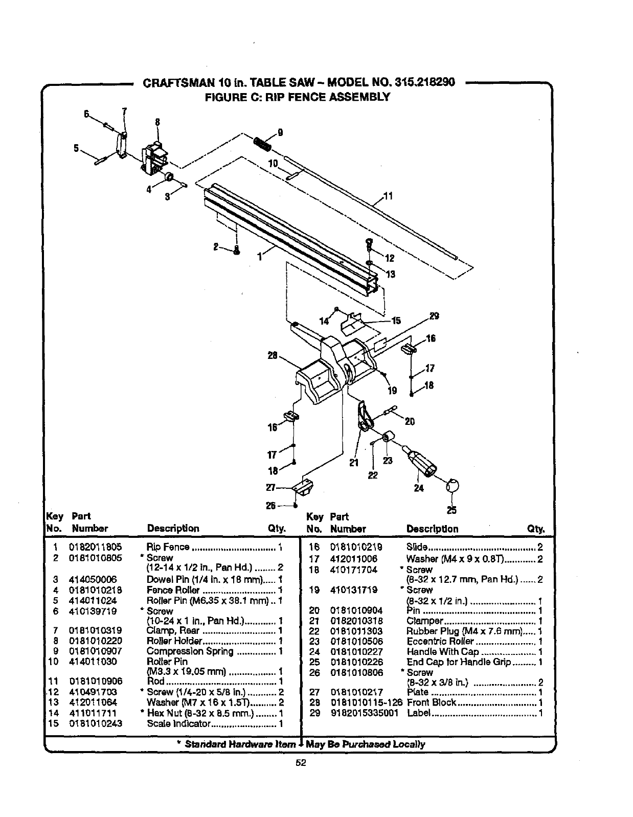
, CRAFTSMAN 10 in. TABLE SAW -MODEL NO. 315.218290
FIGURE C: RIP FENCE ASSEMBLY
8
[ey Part
No. Number
"L 0182011805
2 0181010805
3 414050006
40181010218
5 414O11024
6 410139719
7 0181010319
8 0181010220
g018101O9O7
10 414011030
11 0181010906
12 4104.91703
13 412011064
14 411011711
15 0181010243
Description
Key Part
Qty. No. Number Description Qty.
Rip Fence................................ t
* Screw
(12-14 x 1/2 in., Pen Hd.) ........ 2
Dowel Pin(1/4 in. x 18 ram).....1
FenceRoller ............................ 1
RollerPin(M6.35 x 38.1 ram) .. 1
* Screw
{10-24 x 1 in., Pe.nHd.}............ 1
Clamp, Rear ............................ 1
Roller Holder............................ 1
CompressionSpring ............... 1
RollerPin
(M3.3 x 19.05 ram) .................. 1
Rod .......................................... 1
* Screw (1/4-20 x 5/8 in.)........... 2
Washer CM7x 16 x 1.5_ .......... 2
* Hex Nut (8-32 x 8.5 ram.)........ 1
16 0181010219
17 412011006
18 410171704
19 410131719
20 0181010904
21 0182010318
22 0181011303
23 0181010506
24 0181010227
25 0181010228
26 0181010806
27
28
29
0181010217
S_ide......................................... 2
Washer {M4x 9 x 0.8T)............ 2
•Screw
(8-32 x 12.7 turn, Pan Hd.) ...... 2
"Screw
(8-32 x 1/2 in.) ......................... 1
Pin ........................................... 1
Clamper................................... I
Rubber Plug _14 x7.6 mini..... 1
Eccen_i¢ Rol{er....................... 1
HandleWith Cap ..................... 1
End Cap for Handle Grip......... 1
* Screw
_p8-32x 3/8 in.) ........................ 2
_ate........................................ 1
0181010115-126 Front Block.............................. 1
9182015335001 Labe_........................................ 1
Scale indicator ......................... 1 I
I
*._tandard Hardware Item JLMay Be Purdnaaed Locally
52
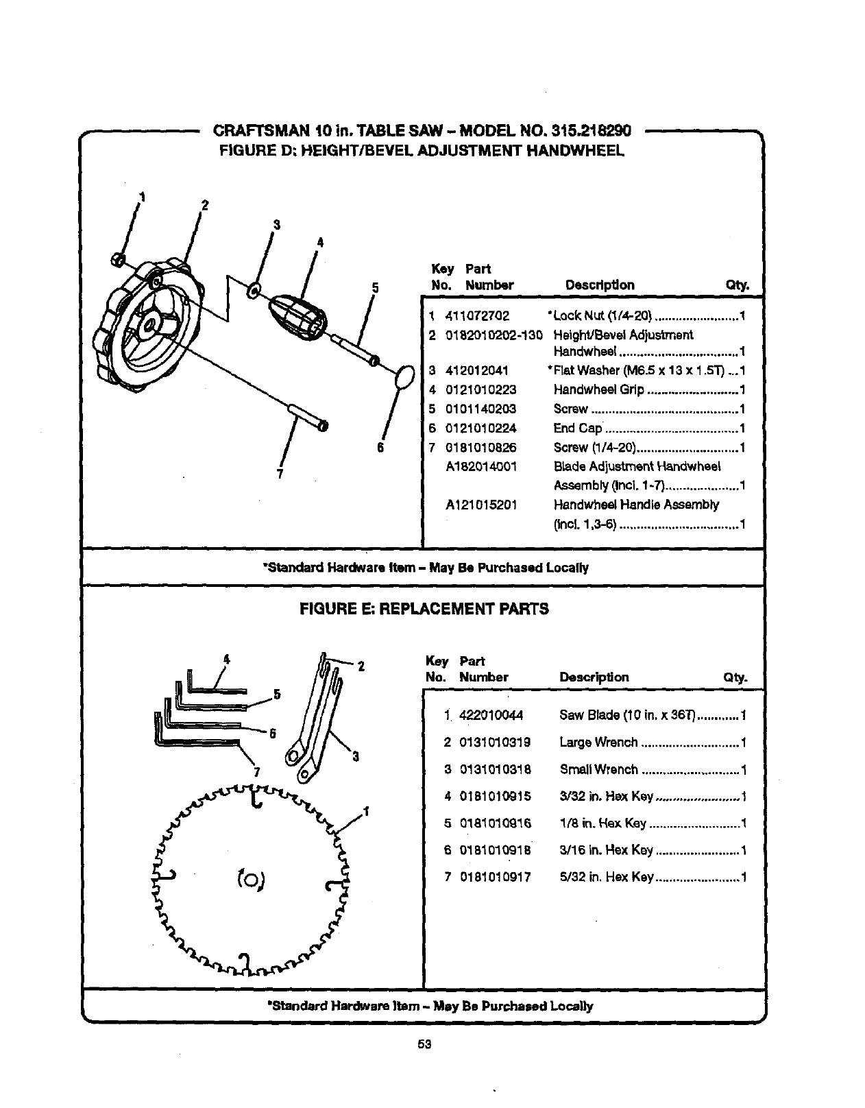
CRAFTSMAN t0 in. TABLE SAW -MODEL NO. 3t5.218290
FIGURE D: HEIGHT/BEVEL ADJUSTMENT HANDWHEEL
1
/I'p,
5 No, Number
3412012041
4 0121010223
5 0101140203
6 0121010224
7 0181010826
A182014001
A121015201
Oescdpgon Qty.
1411072702 *Lock Nut (1/4-20) ........................ 1
2 0182910202-!30 HeighVBevelAdjustment
Handwheel.................................. 1
*Rat Washer (M6.5 x 13 x 1.5"r) ...1
Handwheel Grip.......................... 1
Screw .......................................... I
EndCap. ..................................... 1
Screw (1/4-20)............................. 1
Bride AdiustmentHandwheel
Assembly(.Incl.1-7)..................... 1
Handwheel HandleAssembly
(Incl. 1,3-6) .................................. 1
"Standard Hardware Item - May Be Purchased Locally
FIGURE E: REPLACEMENT PARTS
\
1
Key Part
No. Number
2
3
4
5
6
7
DescripSon Q_.
422010044
0131010319
0131010318
0181010915
0181010916
0181010918
0181010917
Saw Blade (10 in. x36"i_............ 1
Large Wrench............................ 1
SmallWrench ............................ 1
3/32 in. Hax Key ........................ 1
1(8 in. Hex Key .......................... 1
3/16 in. Hex Key ........................ 1
5/32 in, Hex Key ........................ 1
"Standard Hardware ]tam - May Be Purchased Locally
tl
53
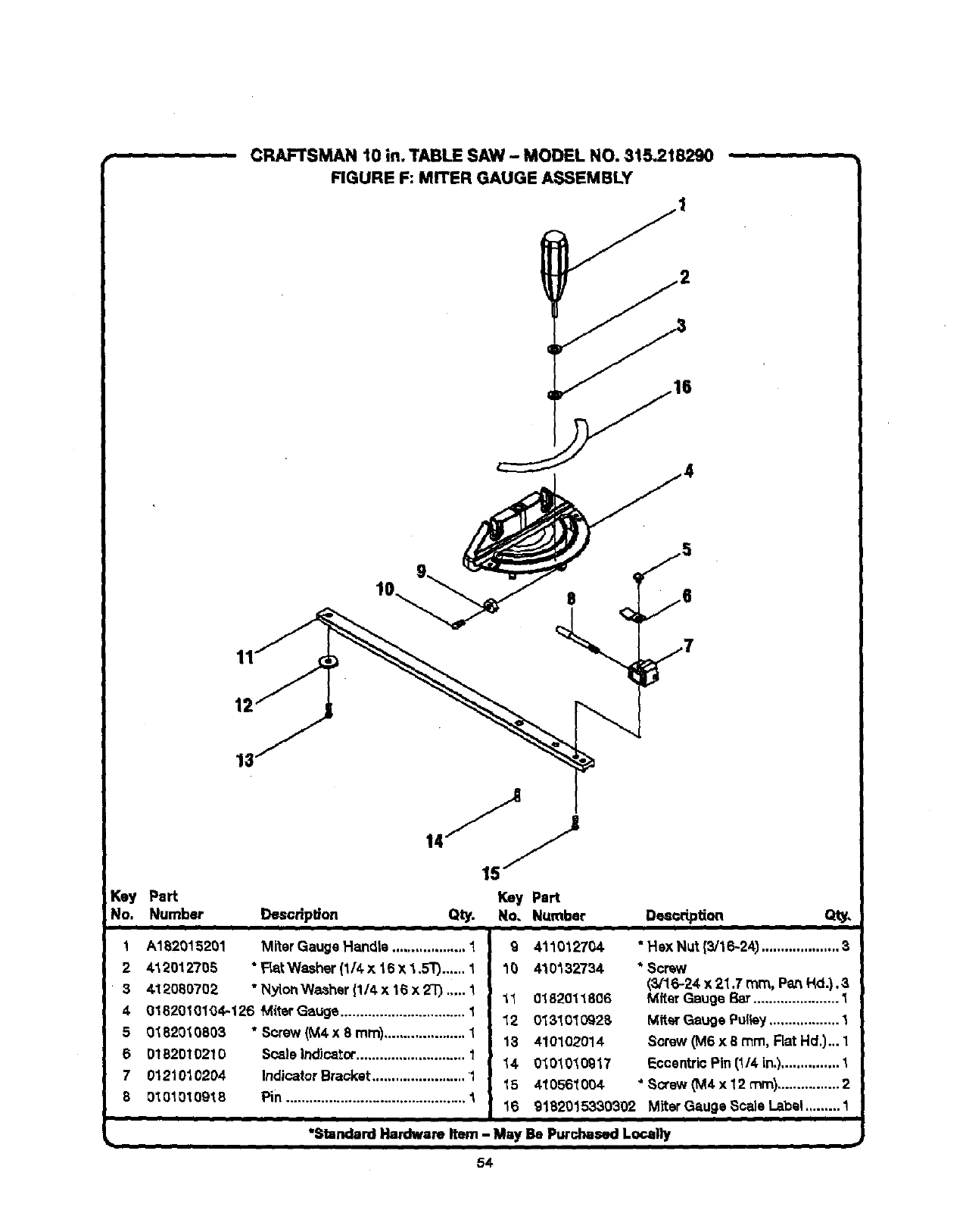
CRAFTSMAN 10 in. TABLE SAW -MOOEL NO. 815.218290
FIGURE F: MITER GAUGE ASSEMBLY
11
12
_ey Pert
No. Number Desoripl_on Key Part
Qty. No. Number Des_dptian
1 A182015201 Miter Gauge Handle ................... 1
2 4_,2012705 * FLa_Washer (1/4 x 16 x4,.5T)...... 1
3&12080702 "Nylon Washer {1/4 x 18 x 2"0 .,... 1
4 01820101_4-126 M{terGauge ................................ I
5 0182010803 "Screw (M4 x 8 mm)..................... 1
6 01B2010210 Scale Indicator............................ 1
7 01210_,0204 Indicator Bracket........................ 1
801010t09t 8 Pin .............................................. 1
Q411012704
10 410132734
11 01820118O6
12 0131010928
13 410102014
14 0101010917
15 410561004
16
• Hex Nut {3/16-24) .................... 3
* Sorew
(3/16-24 x 21,7 ram, PartHd.).3
Mfter Gauge Bar...................... 1
Miter Gauge Pulley.................. 1
Screw (M6 x 8 ram, Flat Hd.)... 1
Eccentric Pin (1/4 in.)............... 1
* Scow _M4x 12 ram)................ 2
glB2015330302 Miter Gauge Scale Label ......... 1
"Standard Hardware Item - May Be Purchased Locally
54
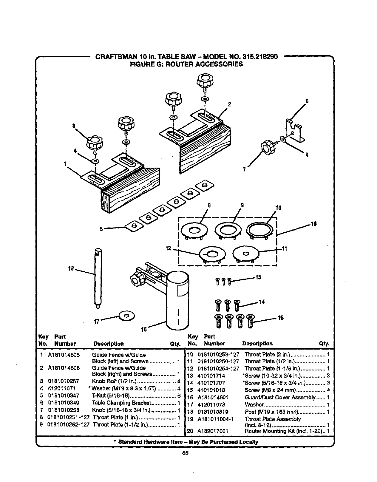
CRAFTSMAN 10 in. TABLE SAW - MODEL NO. 315.218290
FIGURE G: ROUTER ACCESSORIES
r_ey Part Key Part
No. Number Description Qty. No. Number DeaoripUon Qty.
1A181014605 Guide Fence w/Guide
Block (left)and Screws................. 1
2 A181014606 Guide Fence wlGutde
Block (right)and Screws............... 1
Knob Bott (1/2 in.)......................... 4
*Washer (Mlg x 8.3 x 1.5T) ............ 4
"[-Nut(5/16-18) .............................. 6
"l'ableClampingBracket................ 1
Knob {5/16-18 x 3/4 _n.)................ 1
8 0161010251-127 Throat Plate (1 in.) ........................ 1
9 0161010252-127 Throat Plate (1-1/2 in.).................. 1
30181010257
4 4120110T1
5 0161010347
50161010349
7 0161010258
10 018101025a-127
11 0161010250-127
12 0181010254-127
13 410101714
14 410101707
15 410101013
16 A181014601
17 412011073
18 0181010819
'19 A181011004-1
20 A182017001
Throat Plate (2 in.)....................... 1
Throat Plate (1/2 in.).................... 1
Throat Plate (1-1/8 in.) ................ 1
•Screw (10-32 x 3/4 in.)................ 3
•Screw (5/16-18 x 3/4 in.)............. 3
Screw (MS x 24 rnm)................... 4
Guerd/Dusf.Cover AssembJ¥...... 1
Washer........................................ 1
Post (M19X 163 ram).................. 1
ThroatPlate Assembly
(Inci,8-12) ................................. 1
RouterMounting Kit (IncL1-20).. 1
* Standard Hardware Item - May Be Purchased Loca)ly
b
55
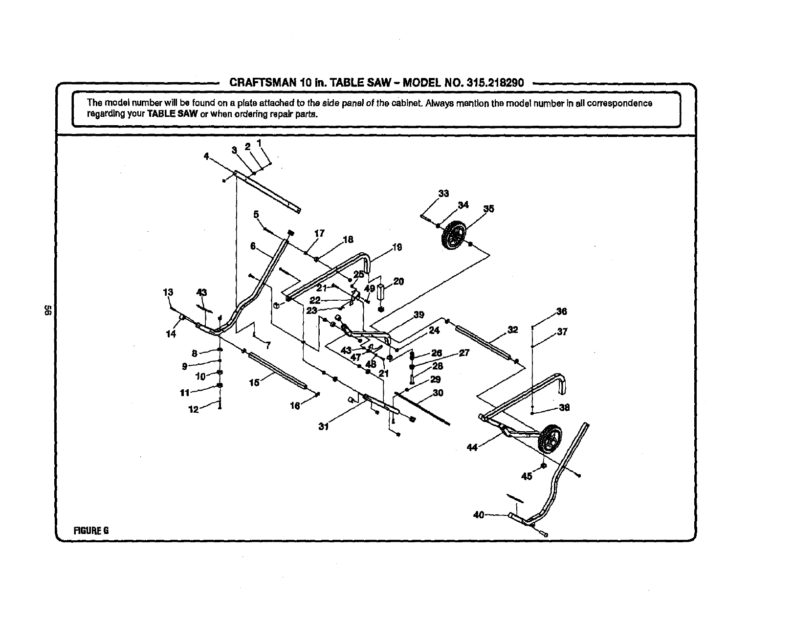
CRAFTSMAN t0 in. TABLE SAW - MODEL NO. 315.218290
IThe model numberwill be foundon aplateattached to the side panel of the cabinet.Always mention the model numberinall correspondence J
%
regardingyour TABLESAW orwhen orderingrepairparts. ]
13
14
17
FIGUREG
CRAFTSMAN 10 in. TABLE SAW - MODEL NO. 315.218290
lhe model numberwill be found one plateattaohed to the sidepanel of the cabinet.Alwaysmentionthe model numberin all correspondence
regardingyourTABLESAW or whenorderingrepairparts.
i
PARTS LIST FOR FIGURE G
Key Part Key Part
NO. Number DescdpUon Qty. No, Number Description
1 4101717O6
2 412011020
3016101O201
4 0182010317-126
5 410031717
60182010307-126
7 410031718
8 411171703
9411061704
10 0182010305
11 0182011301
12 0182010802
13 410491704
14 0182010215
15 01820t0311-126
16 0182010313
17 411071705
18 0182010209
19 0182010309-32
20 0182011302
21 410151019
22 0182010314
23 0182010901
24 411071006
25 411071001
26 0131010918
• Screw {10-24x 1/2') ......................................... 2
* Washer (M5.2 x 14 x 1T) ................................... 2
Feet Plug (M34 x 8,4 x 14)................................2
UpperSupport Plate......................................... I
* Carriage Bolt (5/16 x 80 ram)............................ 10
Leg Frame,Right(30 mm) ................................ I
* CarriageBolt (5/16 x 40 ram)............................4
• Wing Nut (5/16 in.)............................................ 4
• Wing Nut (3/8 in.).............................................. 2
Plug................................................................... 2
LegFrameFoot Plug,Right..............................2
Foot Plug Screw (3/8 x 80 ram) ........................2
* Screw,Hax Hd. (5/16-18 x 57 ram)................... 2
EndCap, Leg Frame......................................... 14
FrontConnectingTube ..................................... t
Tooth Plate........................................................ 4
• NylonNut (5/16 in.)........................................... 20
ConnectingRing............................................... 8
Leg FrameHandle............................................ 2
Grip................................................................... 2
* Hex SooketScrew (MSx 50 mm)..................... 2
ReleaseLever................................................... 1
ReleaseLeverSpring........................................ t
* NylonNut (Ms).................................................. t
Nylon NUt.......................................................... t
Adjusting Spring............................................... 2
27 0131010232
28 410031714
29 411071705
30 0182010316-126
31 0182010310-126
32 0182010312-126
33 0182010801
34 412011088
35 0182010217-130
36 410151714
37 412011003
38 0000110812
39 0182010308-126
40 0182010306-126
41 0000120915
42 412011067
43 9182015335701
44 0182010320-126
45 0182010319
46 412011116
47 0182010321
48 412011080
49 410151021
50 411071001
A132011301
983000693
AdjustingHandle............................................... 2
• Carriage Bolt (5/8-11 x 88.9 turn) ..................... 2
*Nylon Nut (5/16 In.)........................................... 4
Down Support Plate.......................................... 1
Lag Support (30 ram)........................................ 2
ConnectingTube, Rear (30ram) ....................... 1
Wheel Screw (5/16 in.)...................................... 2
* Washer (IV113x 32 x 1.5TJ................................. 4
Wheel, 8 in........................................................ 2
* Sooket Hex Head Screw (1/4x 40 rnm)............4
* Washer (M6.5 x 16 x 21) ................................... 8
NylonNut (1/4_20)............................................. 4
Center Leg Frame............................................. 2
Leg Frame, Left................................................. 1
* LookWaahar (5/16 In,).............,........................ 2
• Washer (M8 x 18 x 1.51) ................................... 2
Leg Stand Label................................................ 2
Short Leg, Right................................................ 1
Square Nut........................................................ 2
Washer (D8.2 x 23 x31").................................... 1
Latch................................................................. 1
Washer (138.26x 21.9 x 1.5T)............................ 1
Hax Socket Screw (M6 x 15 ram)..................... 1
NylonNut .......................................................... 1
Leg StandAssembly (Inol.1-49)....................... 1
Operator'sManual
* Standard Hardware Item -May Be Purchased LoP.ally

Your Home
For repair-in your home-of all major brand appliances,
lawn and garden equipment, or heating and cooling systems,
no matter who made it, no matter who sold it]
For the replacement parts, accessories and
owners manuals that you need to do-it-yourself.
For Sears professional installation of home appliances
and items like garage door openers and water heaters.
1-800-4-MY-HOME e(l-s0o-4ss-4_s3)
Call anytime, day or night(U.S.A. and Canada)
www._ar_¢oM www.sears.¢a
i ill i. i,i
Our Home
For repair of carry-in items like vacuums, lawn equipment,
and electronics, call or go on-line for the location of your nearest
Sears Parts & Repair Center.
1-800488-1222
Call anytime, day or night (U.S.A. only)
To purchase a protectionagreement (U.S.A.)
or maintenance agreement (Canada) on a productserviced by Sears:
1-800-827-8655 (U.S.A.) 1-800-361-8665 (Canada)
Pare pedir servicto de repamcibn
a domidlio, y pare ordenar piezas:
1-888-SU-HOGAR s"
(1-888-784-6427)
Au Canada pour service en fmnr_rais:
1-800-LE-FOYER _
www.sears.ca
Sears
O I_ "l_rademarkI_ _ I=4Set_k_ Markof Sere, Roebuckand Co.
®Mllrca Re_mlradaI_Marca deF_brk_ /_Marcade _wMdo =It 5clips, _ _ _.
_Mmrquode€ommn_ Im Malqu_ d0pos4_ ds StoPs, Rmlbud(alndCo. € Sur=, Roelmud(snd Co.
