Cranesmart Systems LAB110 Load Moment Indicator User Manual CS LMI Manual 1 0b9b rev
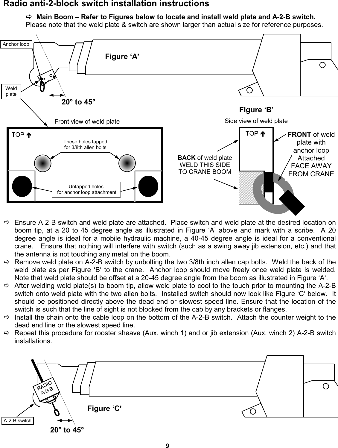
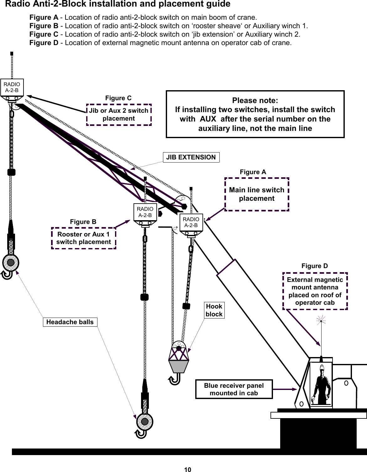
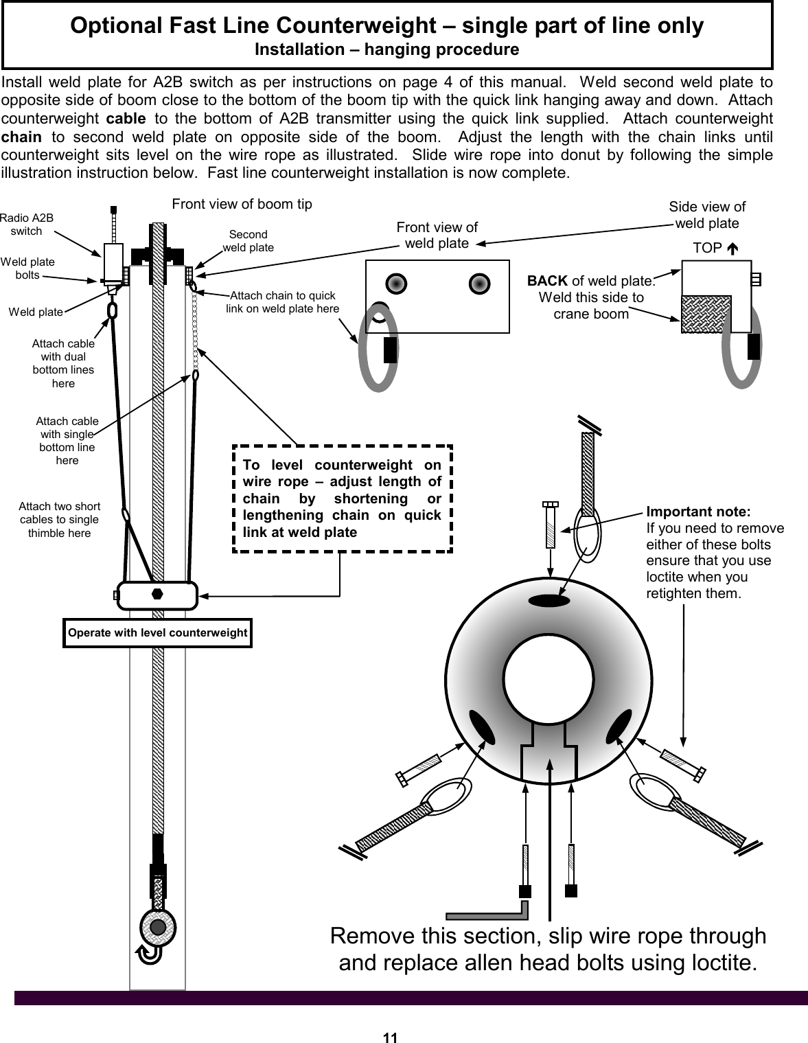
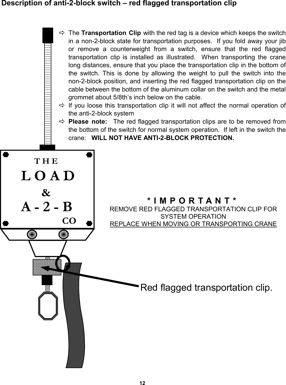
Load & A-2-B Company Inc, The Load Moment Indicator CS LMI Manual 1 0b9b rev
UserManual.wiki
>
Cranesmart Systems
>
LAB110 User Manual
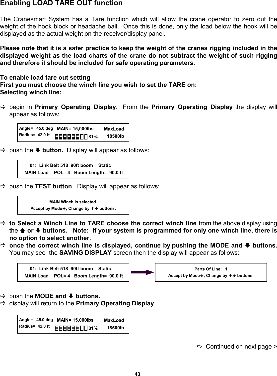
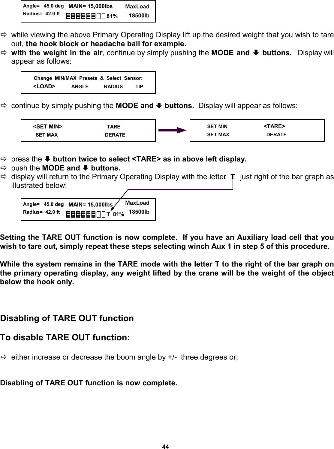
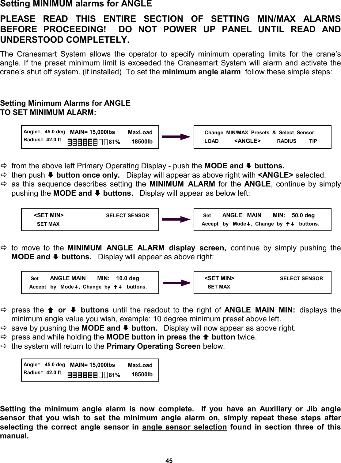
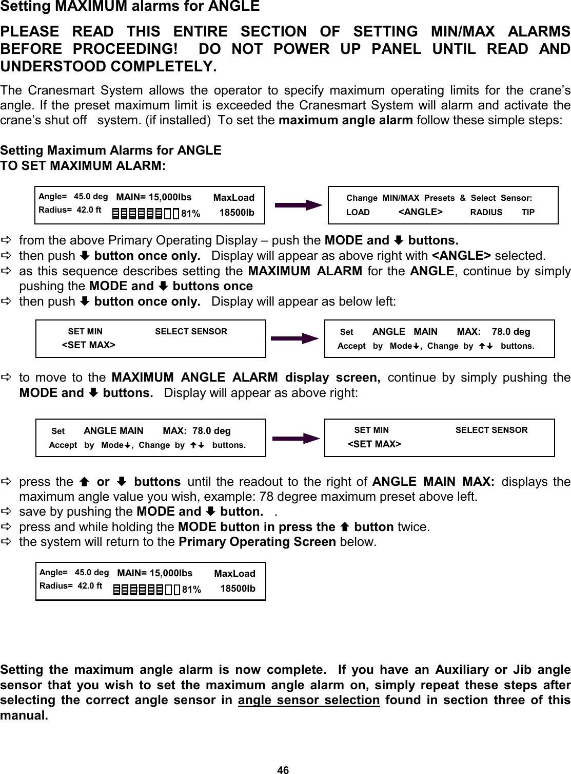
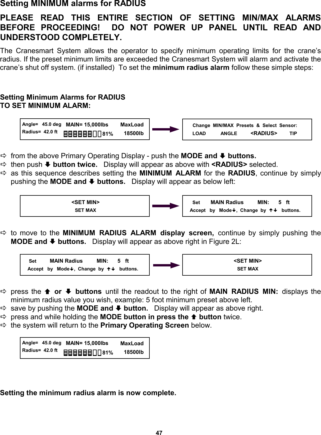
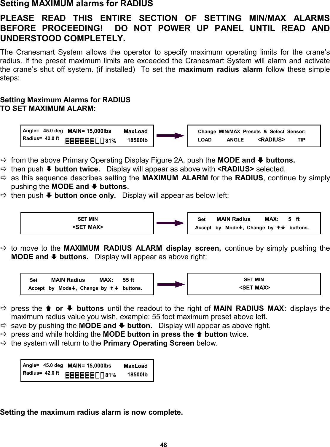
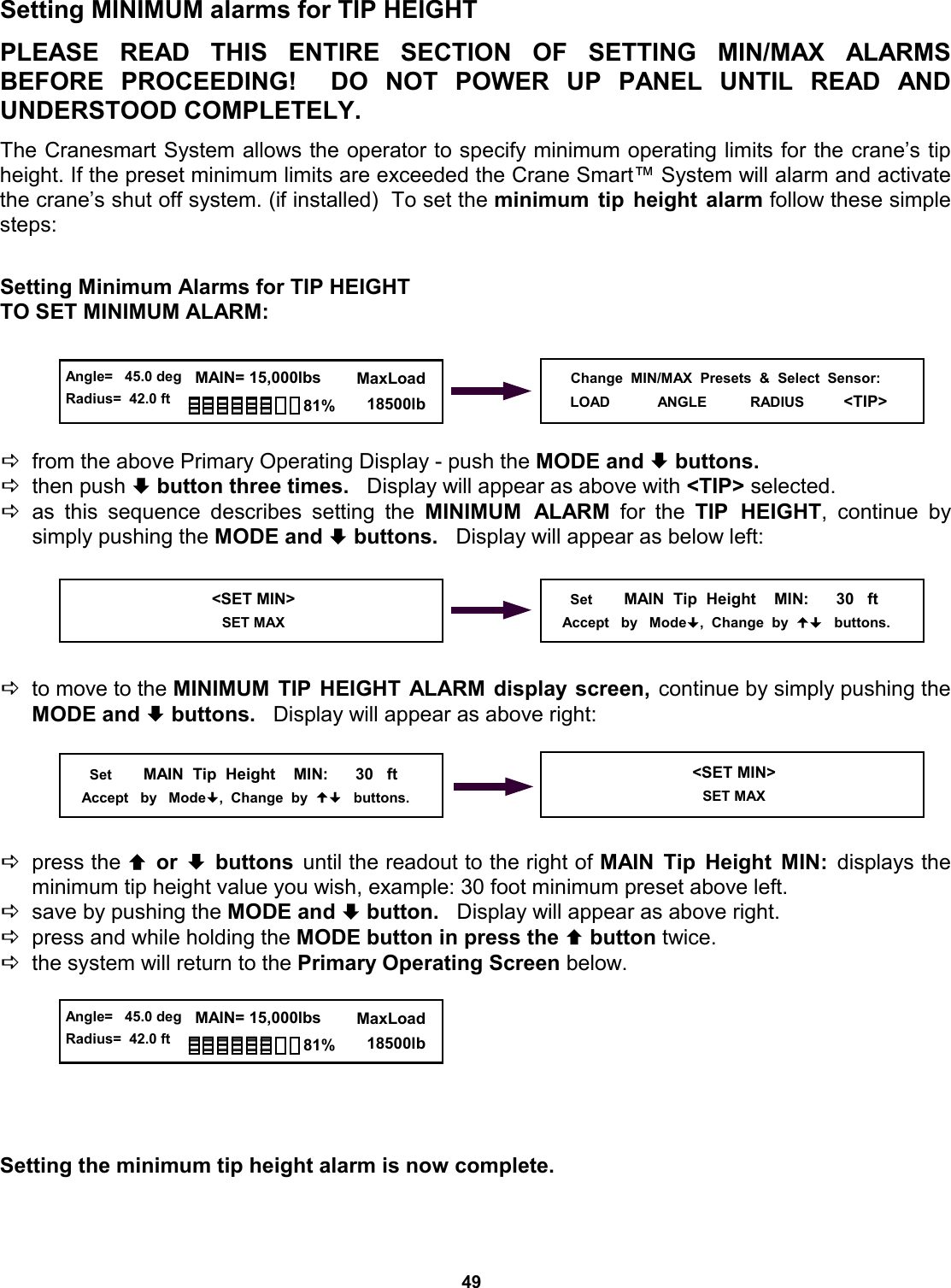
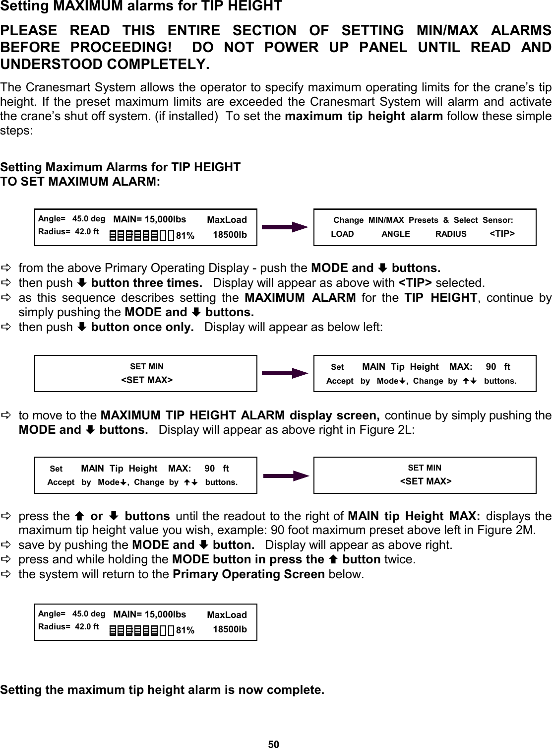
Operators Manual
Navigation menu
Upload a User Manual
Namespaces
Wiki Guide
HTML
PDF
Info
Views
User Manual
Discussion / Help
Navigation