Cranesmart Systems LAB110 Load Moment Indicator User Manual CS LMI Manual 1 0b9b rev
Load & A-2-B Company Inc, The Load Moment Indicator CS LMI Manual 1 0b9b rev
Operators Manual

1
The LOAD & A-2-B Company Inc.
Cranesmart™
LMI System
Installation and Operating Manual
“Congratulations! You have invested in the industry’s
leading technology in crane safety equipment.
Thank you very much for your business”
The contents of this manual must be read
and thoroughly understood before operating the
crane with this equipment installed
For sales, service or assistance:
1-888-562-3222 / (780) 437-2986
www.cranesmart.com
Please have the serial number of your system handy before calling to purchase batteries or to ask for
technical assistance. You can find the serial number on either the receiver panel or the transmitters.
Please see page 54 for FCC Compliance
Revision March 18, 2003 – 1.09A

2
Foreword – Installation guidelines, tools required 4
Section One Contents 5
– LOAD CELL installation 6-8
– ANTI-2-BLOCK installation and explanation 9-13
– ANGLE SENSOR installation 14
– RECEIVER/DISPLAY PANEL installation 15
– ALARM HUB installation and explanation 16
– SHUT OFF configuration 17
– ANTENNA installation 17
Section Two Contents 19
– Cranesmart™ Load Moment Indicator panel functions 20
– PANEL BUTTON definitions and use 20
– FIRST TIME system start up, LOAD CHART information 21
– Correct WINCH in use selection 21
– Correct CHART in use selection 21
– Correct PARTS-OF-LINE selection 22
– PRIMARY OPERATING DISPLAY explained 22
– SECONDARY OPERATING DISPLAY explained 23
Section Three Contents 25
– LOAD CELL calibration – KNOWN WEIGHTS explained 26-29
– ANGLE SENSOR SIDE selection 30-32
– ANGLE ZERO calibration 33-35
– ANGLE SENSOR SELECTION for use (main or jib) 36-38
Table of Contents 1

3
Table of Contents 2
Section Four Contents 39
– Selecting WINCH LINE in use 40
– Setting LOAD MINIMUM alarms 41
– Setting LOAD MAXIMUM alarms 42
– To ENABLE TARE OUT function 43-44
– To DISABLE TARE OUT function 44
– Setting ANGLE MINIMUM alarms 45
– Setting ANGLE MAXIMUM alarms 46
– Setting RADIUS MINIMUM alarms 47
– Setting RADIUS MAXIMUM alarms 48
– Setting TIP HEIGHT MINIMUM alarms 49
– Setting TIP HEIGHT MAXIMUM alarms 50
Section Five Contents – Bypass key instructions 51
– Trouble-shooting for panel, battery and system lights 52
– No communication between transmitters and panel 53
– System technical component specifications 54
– Warranty 54
Warranty
The Load & A-2-B Company Inc. warrants to the purchaser of each new Cranesmart™ System that any part thereof
which proves to be defective in material or workmanship within two (2) years from date of delivery will be repaired or
replaced at no charge, if the system is returned to us in Edmonton, Alberta with all freight charges prepaid. If a
performance problem should occur, contact our office in Edmonton, Alberta at 1-888-562-3222.
This warranty does not cover defects resulting from accident, alteration, improper use, or failure of the purchaser to
follow normal operating procedures as outlined in this instruction manual. PLEASE NOTE: OPENING THE BLUE
RECEIVER PANEL VOIDS WARRANTY.
THIS WARRANTY IS IN LIEU OF ANY WARRANTY OR MERCHANTABILITY AND OF ALL OTHER WARRANTIES,
EXPRESSED OR IMPLIED, ALL OF WHICH ARE HEREBY EXCLUDED.
The Load & A-2-B Company Inc. shall in no event be liable for any special, indirect, or consequential damages
whatsoever and neither assumes nor authorizes any person to assume for it any other obligation or liability.

4
THIS LOAD MOMENT INDICATOR ***DOES NOT***
REQUIRE CALIBRATION.
IT IS CALIBRATED AT THE FACTORY.
ATTENTION
DO NOT CONSIDER THIS SYSTEM
A SUBSTITUTE FOR GOOD JUDGMENT, EXPERIENCE
AND ACCEPTED, SAFE CRANE OPERATING PRACTICES.
————————————————————
THE CONTENTS OF THIS
MANUAL MUST BE READ AND THOROUGHLY
UNDERSTOOD BEFORE OPERATING THE CRANE.
———————————————————
THIS SYSTEM UTILIZES A
SERIES OF ELECTRICAL AND MECHANICAL
COMPONENTS AND CANNOT BE 100% FAIL SAFE.
Installation guidelines
Read all of these instructions completely prior to beginning
D 12 volt application only. Check voltage as a step down converter will be required if
voltage is other than 12VDC
D Mount the load cells, anti-2-block switches and or angle transducers first
D Plan the installation
D Have the necessary tools available
D Mount the display panel second
D Test the system
Tools required
D Man basket – to reach the boom, rooster sheave and or jib tip
D Pliers for removing and bending cotter pins
D Electric drill with various drill bits
D Welder for attaching weld plated to boom/jib tips
D Wire crimping tools – for the display power and ground connections
D Screw drivers and or socket set
D Clear silicone

5
Section One
This section provides
information for placement
and installation of the following components:
DLoad cells
DAnti-2-block switches
DAngle sensors
DReceiver/display panel
DAlarm Hub panel
DAntennae
6
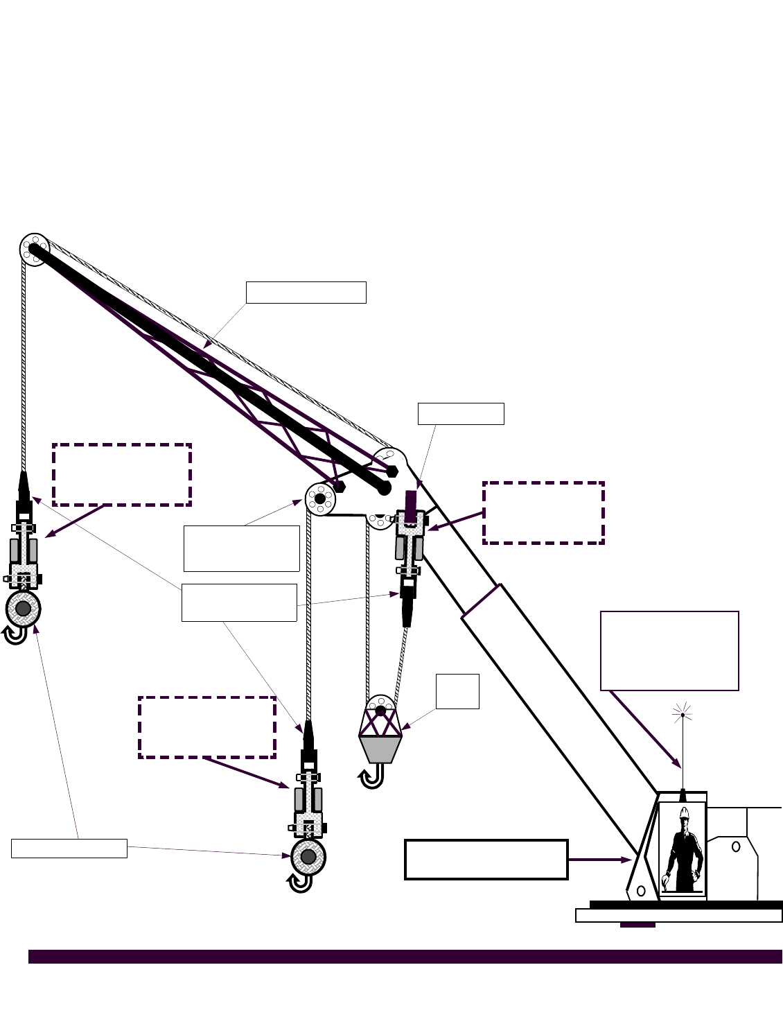
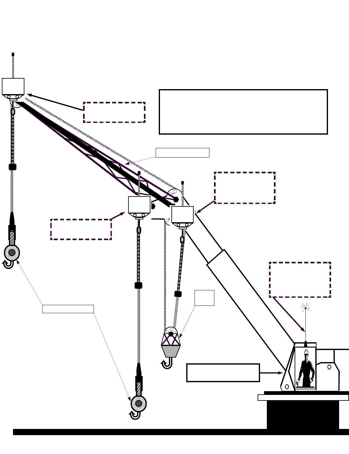
Load cell installation and placement guide for load cell links
Figure ‘A’ - Pin the BLUE load cell between the wire rope socket (becket) and the dead end on the main
boom of the crane. >MAIN<
Figure ‘B’- Pin the YELLOW load cell between the wire rope socket (becket) and the headache ball on the
auxiliary sheave (rooster) on the cranes boom tip. >AUX 1< (Note: for two line load systems only)
Figure ‘C’- Pin the ORANGE load cell between the wire rope socket (becket) and the headache ball on the
jib extension. >AUX 2< (Note: for three line load systems only)
Auxiliary 2
ORANGE Load cell
placement
Auxiliary 1
YELLOW Load cell
placement
Rooster sheave
whip/fast line
MAIN
BLUE Load cell
placement
DEAD END
Blue receiver panel
mounted in cab
JIB EXTENSION
Figure ‘A’
Figure ‘B’
Figure ‘C’
Headache balls
Hook
block
Becket or wire
rope socket
External mount
antenna placed on
roof of
operator cab
7
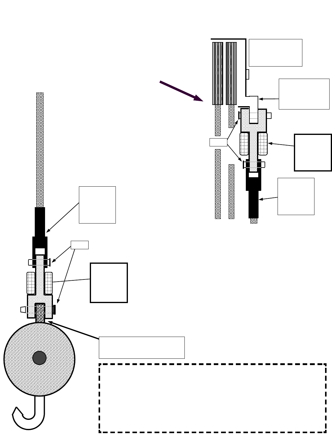
Male – Female - Load cell link
Placement on BOOM TIP DEAD END
Even part-of-line operation
For even parts-of-line, the load cell link is simply pinned
between the wire rope (wedge) socket and the dead end on the
boom tip as illustrated.
Male – Female - Load cell link
Placement on HEADACHE BALL
Single part-of-line
For single part-of-line, the load cell link is pinned
between the wire rope (wedge) socket and the
‘headache ball’ or traveling block.
LOAD
CELL
LINK
BECKET
OR WIRE
ROPE
SOCKET
PINS
IMPORTANT SERVICE NOTE: THE COLORED BLOCKS ON THE LOAD
CELLS CONTAIN TRANSMITTERS, LITHIUM BATTERY PACKS, INTERNAL
STRAIN GAUGES IN ADDITION TO VARIOUS MODERN TECHNOLOGY
ELECTRONICS. VISUALLY INSPECT THE SEALS WHERE THE COLORED
BLOCKS ATTACH TO THE LOAD CELL. IF A SEAL IS BROKEN DUE TO
MIS-USE, AND EVEN IF IT CONTINUES TO WORK, SHIP THE SYSTEM IN
FOR SERVICE IMMEDIATELY. THIS WILL PREVENT MOISTURE FROM
TURNING A $100 REPAIR INTO A $700 REPAIR.
LOAD
CELL
LINK
BECKET
OR WIRE
ROPE
SOCKET
DEAD END/
TERMINATION
POINT
FRONT VIEW OF
SHEAVES AND
BOOM TIP
PINS
15,000 - 25,000 lb. SLP load cell installation instructions
DEAD END /
TOP OF SWIVEL BEARING
8
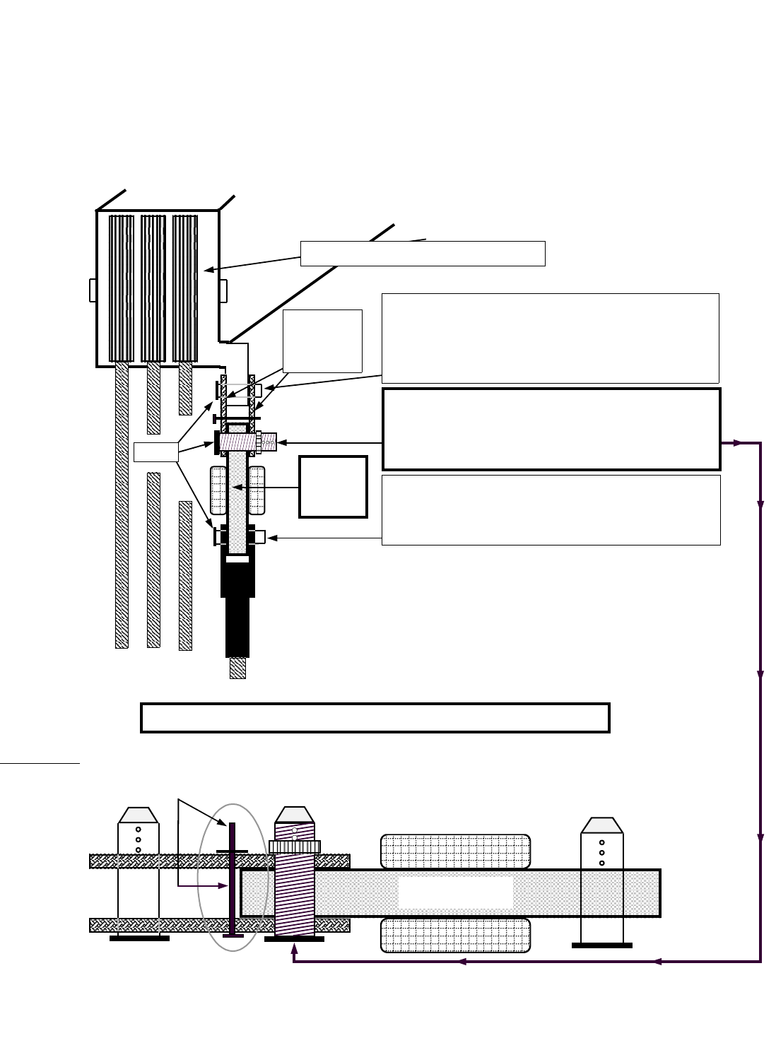
40,000 - 50,000 - 80,000 lb. SLP load cell installation instructions
Male – Male - Load Cell Link
Placement on BOOM TIP DEAD END
Even part-of-line
DFor even parts-of-line, the load cell link is simply pinned between the wire rope socket (becket)
and the dead end on the boom tip. Please follow the diagram below which illustrates the correct
use of the 'sandwich link' rigging attachment for this load cell.
Sandwich
link
2 sides
LOAD
CELL
Front view of boom tip and sheaves
This pin has three cotter pin holes which allow
for different dead end widths. Select the cotter
pin hole which provides the tightest fit, then
secure with washers and new cotter pins.
Pin the becket to the bottom end of the load
cell. If becket pin diameter is too big, a
properly rated C-shackle can be used.
Threaded Locking Pin:
MUST BE INSTALLED HERE.
ATTENTION: THIS PIN PREVENTS DAMAGE TO THE LOAD CELL BY KEEPING THE SANDWICH LINK FROM
FOLDING AGAINST THE LOAD CELL IN A TWO BLOCK SITUATION. SUCH DAMAGE WILL NOT BE COVERED
UNDER WARRANTY. CHECK THIS PIN REGULARLY TO ENSURE THAT IT IS SECURE & IN PLACE.
Sandwich Link Stabilization Pin
Load Cell
PINS
9
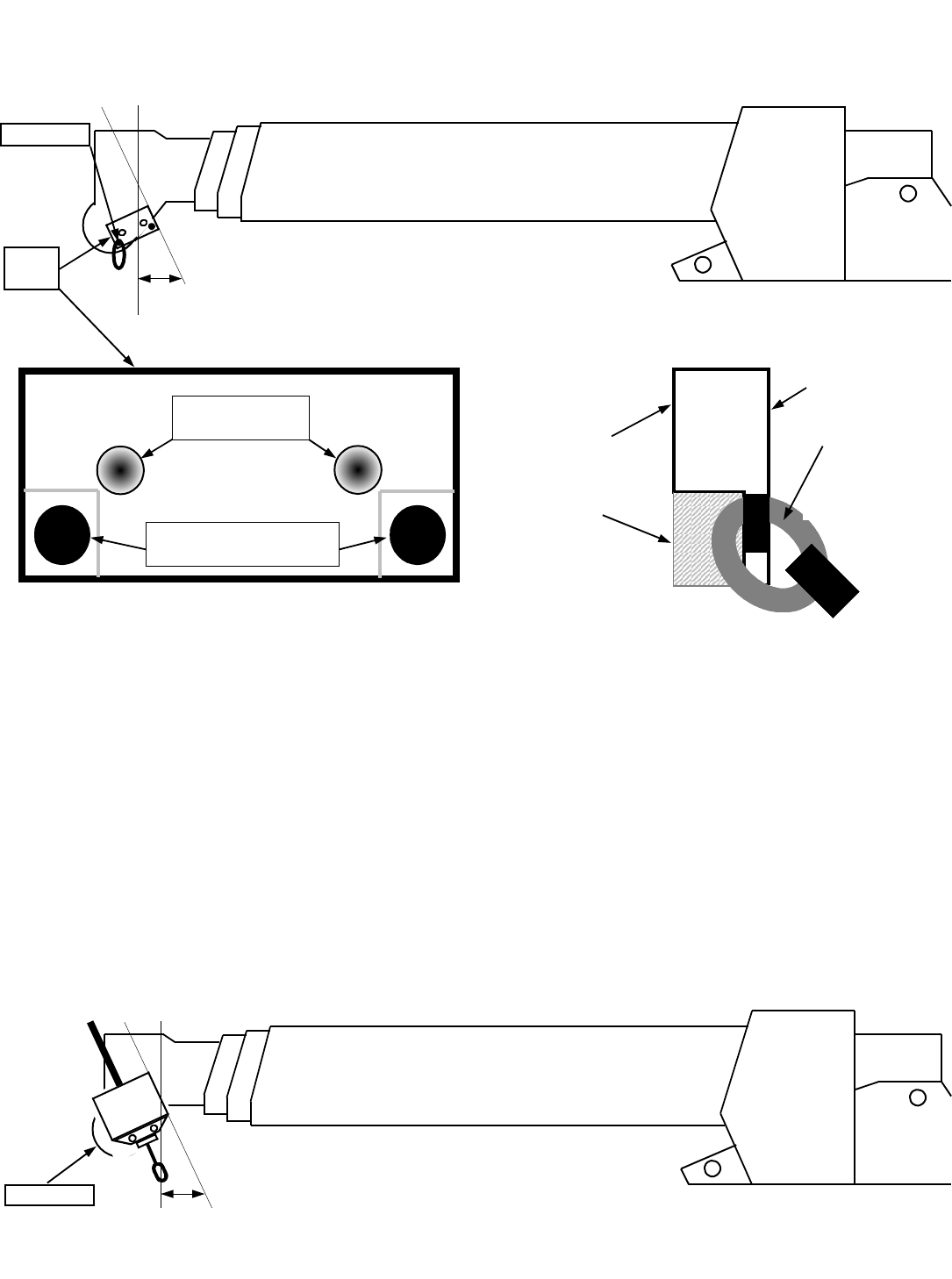
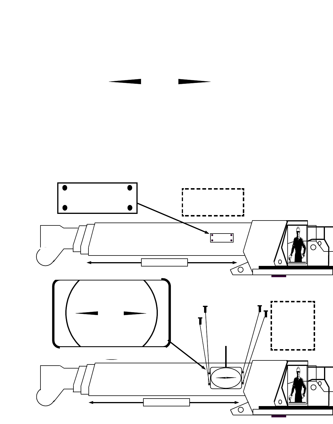
Radio anti-2-block switch installation instructions
D Main Boom – Refer to Figures below to locate and install weld plate and A-2-B switch.
Please note that the weld plate & switch are shown larger than actual size for reference purposes.
DEnsure A-2-B switch and weld plate are attached. Place switch and weld plate at the desired location on
boom tip, at a 20 to 45 degree angle as illustrated in Figure ‘A’ above and mark with a scribe. A 20
degree angle is ideal for a mobile hydraulic machine, a 40-45 degree angle is ideal for a conventional
crane. Ensure that nothing will interfere with switch (such as a swing away jib extension, etc.) and that
the antenna is not touching any metal on the boom.
DRemove weld plate on A-2-B switch by unbolting the two 3/8th inch allen cap bolts. Weld the back of the
weld plate as per Figure ‘B‘ to the crane. Anchor loop should move freely once weld plate is welded.
Note that weld plate should be offset at a 20-45 degree angle from the boom as illustrated in Figure ‘A‘.
DAfter welding weld plate(s) to boom tip, allow weld plate to cool to the touch prior to mounting the A-2-B
switch onto weld plate with the two allen bolts. Installed switch should now look like Figure ‘C‘ below. It
should be positioned directly above the dead end or slowest speed line. Ensure that the location of the
switch is such that the line of sight is not blocked from the cab by any brackets or flanges.
DInstall the chain onto the cable loop on the bottom of the A-2-B switch. Attach the counter weight to the
dead end line or the slowest speed line.
DRepeat this procedure for rooster sheave (Aux. winch 1) and or jib extension (Aux. winch 2) A-2-B switch
installations.
Figure ‘A’
Weld
plate
Figure ‘C’
A-2-B switch
RADIO
A-2-B
These holes tapped
for 3/8th allen bolts
Untapped holes
for anchor loop attachment
Front view of weld plate Side view of weld plate
FRONT of weld
plate with
anchor loop
Attached
FACE AWAY
FROM CRANE
BACK of weld plate
WELD THIS SIDE
TO CRANE BOOM
Figure ‘B’
TOP Ï
TOP Ï
Anchor loop
20° to 45°
20° to 45°
10
Radio Anti-2-Block installation and placement guide
Blue receiver panel
mounted in cab
JIB EXTENSION
Main line switch
placement
Figure A
Rooster or Aux 1
switch placement
Figure B
Headache balls
Hook
block
Jib or Aux 2 switch
placement
Figure C
External magnetic
mount antenna
placed on roof of
operator cab
Figure D
RADIO
A-2-B
RADIO
A-2-B
RADIO
A-2-B
Please note:
If installing two switches, install the switch
with AUX after the serial number on the
auxiliary line, not the main line
Figure A - Location of radio anti-2-block switch on main boom of crane.
Figure B - Location of radio anti-2-block switch on ‘rooster sheave‘ or Auxiliary winch 1.
Figure C - Location of radio anti-2-block switch on ‘jib extension’ or Auxiliary winch 2.
Figure D - Location of external magnetic mount antenna on operator cab of crane.
11
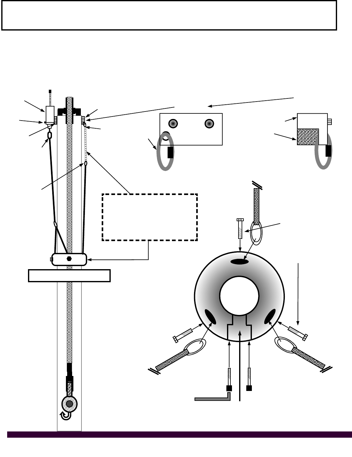
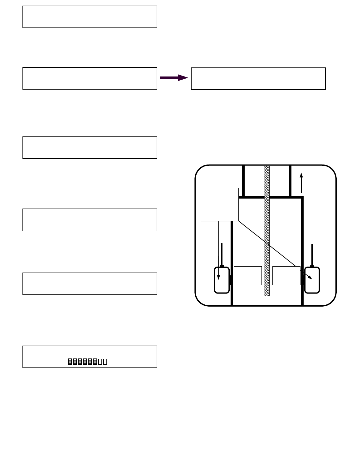
Optional Fast Line Counterweight – single part of line only
Installation – hanging procedure
Radio A2B
switch
Weld plate
bolts
Weld plate
Attach cable
with dual
bottom lines
here
Second
weld plate
Attach chain to quick
link on weld plate here
Attach cable
with single
bottom line
here
Attach two short
cables to single
thimble here
Front view of
weld plate
Front view of boom tip
Install weld plate for A2B switch as per instructions on page 4 of this manual. Weld second weld plate to
opposite side of boom close to the bottom of the boom tip with the quick link hanging away and down. Attach
counterweight cable to the bottom of A2B transmitter using the quick link supplied. Attach counterweight
chain to second weld plate on opposite side of the boom. Adjust the length with the chain links until
counterweight sits level on the wire rope as illustrated. Slide wire rope into donut by following the simple
illustration instruction below. Fast line counterweight installation is now complete.
BACK of weld plate.
Weld this side to
crane boom
Side view of
weld plate
TOP Ï
Remove this section, slip wire rope through
and replace allen head bolts using loctite.
Important note:
If you need to remove
either of these bolts
ensure that you use
loctite when you
retighten them.
To level counterweight on
wire rope – adjust length of
chain by shortening or
lengthening chain on quick
link at weld plate
Operate with level counterweight
12
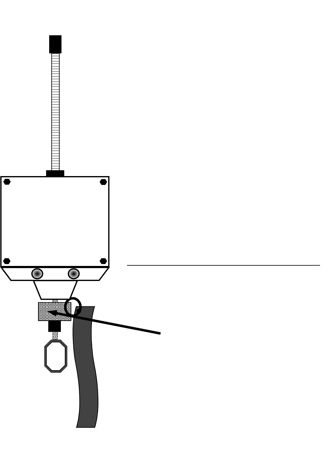
DThe Transportation Clip with the red tag is a device which keeps the switch
in a non-2-block state for transportation purposes. If you fold away your jib
or remove a counterweight from a switch, ensure that the red flagged
transportation clip is installed as illustrated. When transporting the crane
long distances, ensure that you place the transportation clip in the bottom of
the switch. This is done by allowing the weight to pull the switch into the
non-2-block position, and inserting the red flagged transportation clip on the
cable between the bottom of the aluminum collar on the switch and the metal
grommet about 5/8th’s inch below on the cable.
DIf you loose this transportation clip it will not affect the normal operation of
the anti-2-block system
DPlease note: The red flagged transportation clips are to be removed from
the bottom of the switch for normal system operation. If left in the switch the
crane: WILL NOT HAVE ANTI-2-BLOCK PROTECTION.
L O A D
T H E
&
A - 2 - B
CO
Description of anti-2-block switch – red flagged transportation clip
*IMPORTANT*
REMOVE RED FLAGGED TRANSPORTATION CLIP FOR
SYSTEM OPERATION
REPLACE WHEN MOVING OR TRANSPORTING CRANE
Red flagged transportation clip.
13
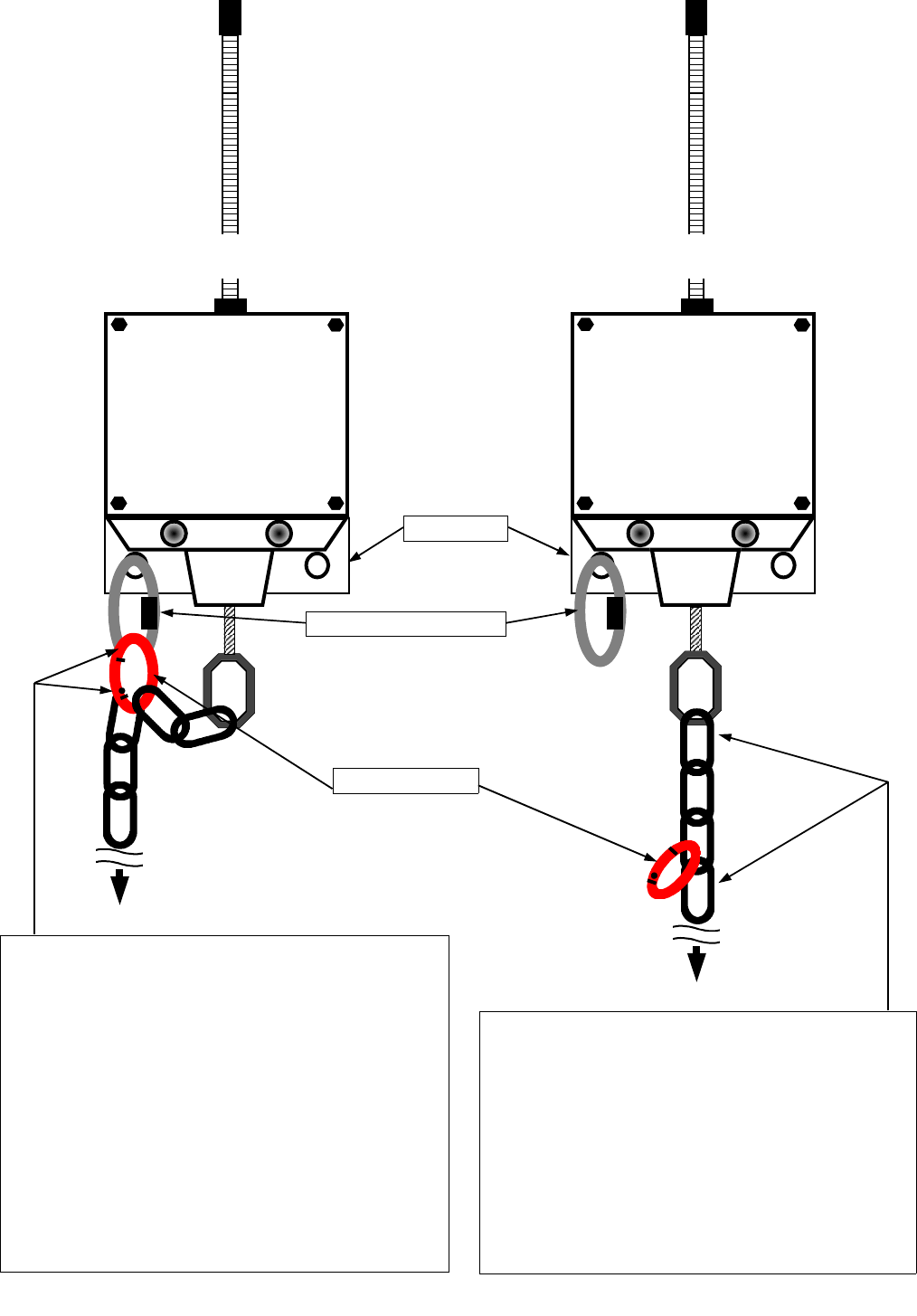
L O A D
T H E
&
A - 2 - B
C O
To counterweight
To counterweight
Figure ‘A’ Figure ‘B’
Transportation Position
Ensure the chain is clipped by the snap link to
the anchor loop on the weld plate when
transporting the crane. See Figure ‘A’. This will
prevent damage and/or premature wearing of the
cable at the bottom of the anti-2-block switch.
Use the snap link to attach the chain to the
anchor loop on the weld plate. Chain assembly
should look like Figure ‘A’. Please note: The
A-2-B system will report a TWO-BLOCK
ALARM when the blue receiver panel is
powered up to remind the crane operator to
unclip the chain for operation.
Anchor loop on weld plate
Snap link on chain
Operating Position
Ensure the chain is not clipped to the anchor
loop by the snap link when operating the crane.
The snap link should be hanging freely.
(as illustrated in above Figure ‘B’).
Chain assembly should look like Figure ‘B’.
Please note: Test the system daily by lifting
the counterweight and confirm an audio and
visual alarm on the blue receiver panel.
Weld plate
L O A D
T H E
&
A - 2 - B
C O
14
Radio boom angle sensor installation instructions
DThe angle sensor must be installed on the boom at a minimum distance of ten feet from the antenna on the
cab of the crane. The sensor can be mounted on either side of the boom however the default setting is
for installation on the LEFT SIDE of the boom. If you determine that the right side of the boom is a more
desirable location for the sensor you must program the panel for right boom operation – see section 3 of
this manual after you have installed the angle sensor on the boom. Line of sight between sensor antenna
and antenna should exist in all positions. Do not mount sensor on the top or bottom of the boom. Position
the sensor weld plate assembly parallel with the boom line. Use the illustration on the Sensor label as an
alignment aid.
DExact alignment is preferred but not necessary. Small alignment error can be zeroed out at the panel in the
cab of the crane. Mark or scribe the boom where the weld plate will be mounted. Unbolt the weld plate
from the angle sensor and lightly tack weld, do not permanently weld the plate yet. (see figure A below)
PLEASE NOTE: Lightly tack weld plate where you think it should go, leaving the opportunity to move, adjust
and re-weld if necessary, before testing the system for operation. Make certain that the antenna on the
boom angle sensor will not be touching any metal once mounted. DO NOT ATTEMPT TO WELD THE
WELD PLATE WHILE ATTACHED TO THE SENSOR. THE SENSOR WILL BE PERMANENTLY
DAMAGED. Once the weld has cooled, mount the sensor to the weld plate (see figure B below) using the
bolts and lock washers supplied.
DNow you will need to raise your boom to a minimum of a 45 degree angle then return it to level. Now you
should proceed to zeroing the angle. You will find these simple instructions on page 33-35 of this manual.
BOOM LINE
RADIO BOOM ANGLE INDICATOR
Mount on base section of boom – see manual
For sales or service call:
THE LOAD & A-2-B COMPANY INC.
1-888-562-3222
BOOM LINE
Figure ‘A’
STEP 1:
Attach weld plate to
boom as illustrated
Weld plate
LINE OF BOOM
Figure ‘B’
STEP 2:
Bolt angle
sensor to weld
plate on boom
as illustrated
LINE OF BOOM
Use screws
and lock
washers
provided
Boom Angle
Indicator
15
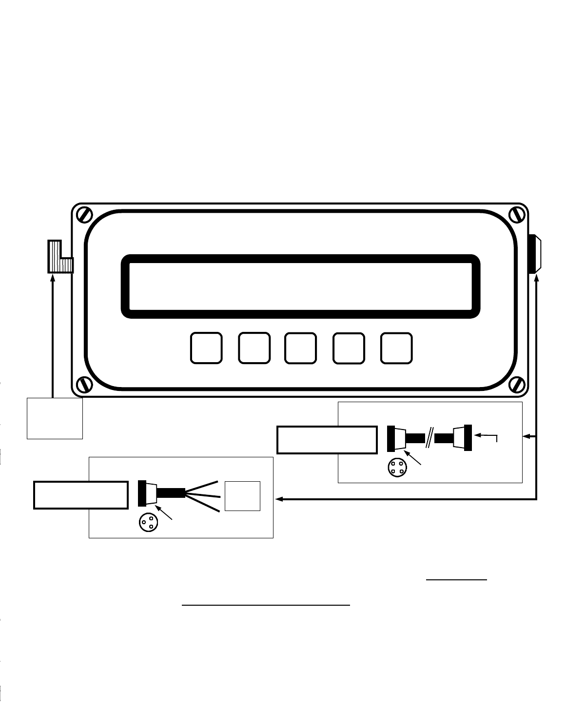
Display panel installation instructions
DDisplay panel mounting: The installation of the display panel consists of drilling two holes for mounting in
the operator cab. First find a suitable location in the cab on the dash where the crane operator has an
unobstructed view of the display. Using the removable bottom portion of the mounting bracket align, mark and
drill two holes in the cab of the crane. Securely attach the bottom portion of the mounting bracket
assembly to the dash. Place panel into the carriage holes of the lower mounting bracket and with the two
fluted knobs and star washers, securely attach panel with the front of the display facing the operator.
DWITH ALARM HUB – Display panel power: is provided to the panel using the four (4) pin interconnect cable
included The interconnect cable joins the alarm hub and the display panel together. When attaching either
end of the interconnect cable to the alarm hub and or the display panel, align the groove in the plug
head with the groove in the panel or hub plug receptacle and insert gently – do not force. Lock plug
on by gently rotating the collar of the plug a half turn clockwise.
Dalarm hub wiring and alarm output instructions on next page.
DDisplay panel power with NO ALARM HUB: is provided to the panel using the three conductor cable
included. Connect the red wire to a positive (+12VDC) terminal and the black wire to a solid ground on the
crane. The third white wire is for optional shut offs or to sound external horns. ATTENTION: Ensure that a
continuous +12 VDC (11 volts minimum and typically 13.25 VDC with the engine running) is available
to the panel at all times while the crane is in operation. Otherwise the system will not operate
correctly. When attaching power cable to panel gently push male end of plug into female panel
receptacle. Slide plug neck back towards panel and tighten clockwise ½ turn.
PLEASE NOTE: If you have ordered your Cranesmart with classified area approvals such as
Class I, Division II, for example – you must ‘lock on’ each end of the interconnect cable and
alarm ports. Use the allen key provided to lock/unlock the cabling.
CRANE SMART SYSTEM
CRANE SMART LOAD MOMENT INDICATOR
The Load & A-2-B Company Inc.
©
TEST BY
PASS MODE
©
Attach antenna
lead here
Attach 3 pin power cable here
1 Red
1 White
1 Black
3 Pin
to base
Non – ALARM HUB
power cable
Attach 4 pin interconnect cable
4 Pin
to alarm hub
With ALARM HUB
power cable 4 Pin
to display
panel
16
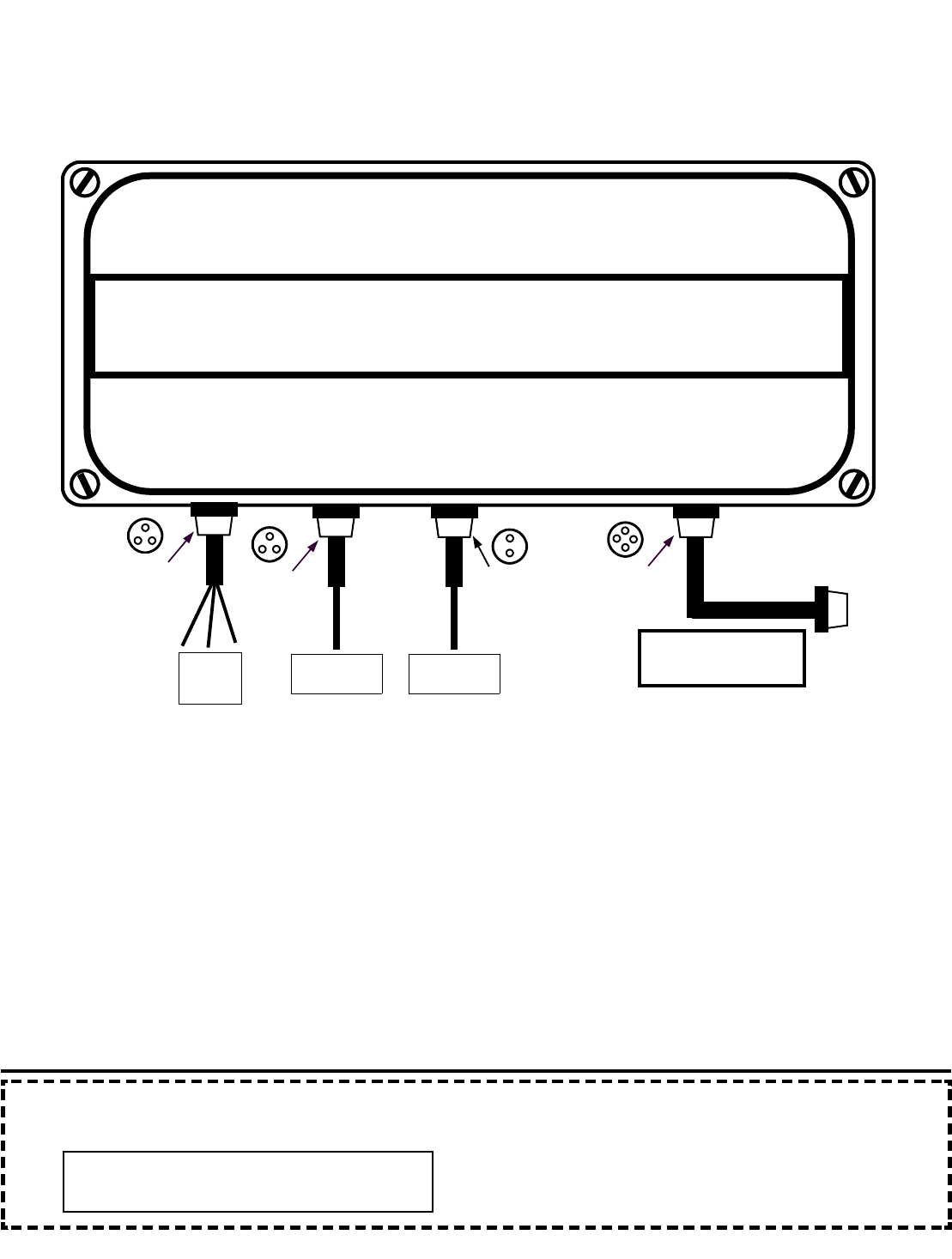
Display panel installation instructions – With ALARM HUB
The alarm hub is an outboard extension of the Cranesmart display which allows up to three 12V 7.5A alarm
outputs to be added to the Cranesmart system according to customer specifications. The alarm hub has an on
board microcontroller which supervises the alarm relays for proper operation, hot or cold. The alarm hub
communicates with the Cranesmart via an RS232 serial connection. You may mount this component out of the
way, under the dash or on the side of the cab for example. It does not have to be visible by the operator.
Wiring instructions – four easy steps: please take care when plugging in the finished connections. You must
align the slot of the plug in the hole and then press together gently before locking.
1. ALARM OUTS: Plug the 3 pin connector tagged Alarm Outs into the plug hole immediately below the ALARM
OUTS label. The other end of the cable will have up to three wires. You will find a tag on the cable itself
which will identify what output (load, angle or A-2-B) is signaled on each wire.
2. 12V POWER: Plug the 3 pin connector tagged 12V POWER into the plug hole immediately below the 12V
POWER label. The other end of the cable will have a single wire to attach to power.
3. GROUND: Plug the 2 pin connector tagged GROUND into the plug hole immediately below the GROUND
label. The other end of the cable will have a single wire to attach to ground.
4. SERIAL or INTERCONNECT cable: Locate the power cable with a 4 pin plug on either end. To power the
Cranesmart display panel you will need to plug one end of the 4 pin cable into the port labeled SERIAL on the
ALARM HUB and the other into the Cranesmart display panel. This will provide both power and ground to the
Cranesmart panel, while supporting the output relays for your crane shut-offs.
CRANE SMART SYSTEM
The LOAD & A-2-B CO., INC. 1-888-562-3222
ALARM HUB
ALARM OUTS
12V 7.5A 12V POWER GROUND SERIAL
1 Red
1 White
1 Black
3 Pin
to base 3 Pin
to base
Single wire
to 12V power
2 Pin
to base
Single wire
to ground
4 Pin
to base
Plug this 4 pin connector
to the right side of
Crane Smart Panel
PLEASE NOTE: When a Cranesmart system is programmed for use with an alarm hub, the alarm hub must
be present and working or the display will indicate an error condition as follows:
* * * ALARM HUB MALFUNCTION * * *
Please Correct

17
Shut off configurations for your system:
Normally each wire is identified with a tag to make installation of the shut-off circuits
simple. If the tags are missing or if you are unsure – call our service department. Due
to the many possible shut down configurations which your system may operate with,
please consult THE LOAD & A-2-B Company for your particular crane. Please have
the serial number of your system handy when you call 1-888-562-3222 or
1-780-437-2986.
——————————————————————————————————————
Antenna installation
Depending on the length or type of boom, four antenna installations and placements are possible.
With your system you may have received:
(A) One ten inch rubber antenna.
(B) One ten inch rubber antenna with an external magnetic mount base, attachment cable and plug.
(C) One metal whip antenna with an external magnetic mount base, attachment cable and plug.
(D) Marine specific antenna kit.
(A) Outside operator cab – up to 150 feet of boom: Where the receiver panel is installed outside a cab
simply install the 10 inch rubber antenna directly onto the blue receiver panel. Attach the base of the
rubber antenna to the side of the receiver panel by inserting it GENTLY with a simple half turn.
(B) Inside operator cab – up to 150 feet of boom: For installations inside the operator cab and where your
boom is less than 150 feet of length, place the magnetic mount base with the 10 inch rubber antenna on
the top of the operator cab and attach the antenna lead to the side of the receiver panel.
(C) Inside operator cab – more than 150 feet of boom: For installations inside the operator cab and where
your boom is more than 150 feet of length, place the magnetic mount base with the metal whip antenna
on the top of the operator cab and attach the antenna lead to the side of the receiver panel. Please
ensure the small allen screw for holding the whip antenna to the magnetic base is firmly tightened.
(D) Any MARINE application: attach base with the metal whip antenna on the top of the operator cab on the
crane attaching the antenna lead to the side of the receiver panel.
At all times ensure that the lines of sight between the load cells, anti-2-block
switches, angle transducers and the antenna on the cab of the crane are
unobstructed. It is important that the receiver antenna NOT be touching glass
or metal.

18

19
Section Two
The load cell, anti-2-block switch, angle transducer and panel
must all be installed
before proceeding past this point of the manual.
This section provides information for:
DCranesmart™ Load Moment Indicator panel functions
DDefinitions of panel button controls and use
DSystem start up
DLoad chart information
DFirst time system start up
DCorrect load chart in use selection
DCorrect winch in use selection
DCorrect parts-of-line selection
DPrimary Operating Display explained
DSecondary Operating Display explained
20
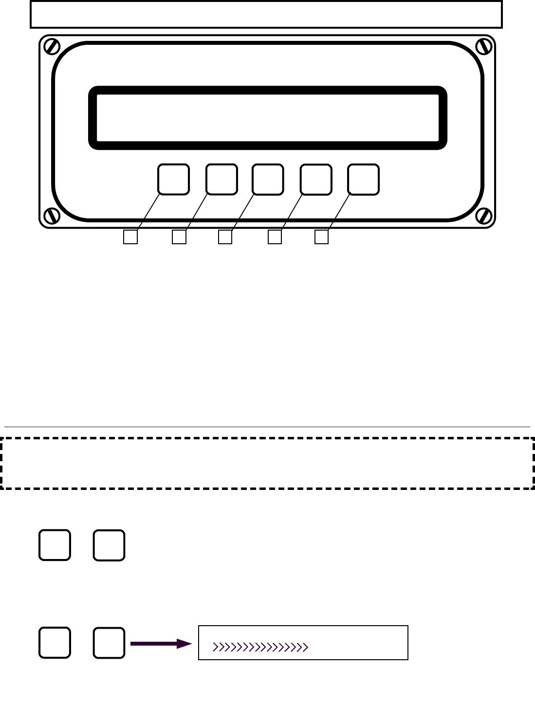
Cranesmart™ Load Moment Indicator Panel Functions
CRANE SMART SYSTEM
CRANE SMART LOAD MOMENT INDICATOR
The Load & A-2-B Company Inc.
©
TEST BY
PASS MODE
©
1 2 3 4 5
Definitions of panel button controls and use
1. TEST button is used to test alarm and reset menu.
2. BY PASS button is used to temporarily stop alarm and override the crane function shut off system
(if installed). When the “BYPASS” button is pressed, the system is disabled for thirty seconds.
The Bypass Function should be used with discretion as excessive use of it to override the crane
function shut off could result in loss of life, destruction of property and damage to the crane. The
Bypass can be used to override the system in case of emergency or malfunction. Sound
judgement must be used when using the bypass function.
3. MODE button is used with the buttons below to select functions as well as to page up and down
through the menus.
4. © button is used to move up through information.
5. ª button is used to move down through information.
IMPORTANT NOTE: When you are using the MODE button in conjunction with the © or ª
buttons, you must hold the MODE button first, and while holding the MODE button in, press
either of © or ª buttons.
Dpressing the MODE and © button at the same time (Page Up function) is used to move UP
through the menus without saving changes.
Dpressing the MODE and ª button at the same time (Page Down function) is used to move
DOWN through the menus and is used for saving changes. Figure 1-1 below is the
Saving Display screen which will appear each time you make an input change and save it
by pressing the MODE and ª buttons.
MODE ©
+
MODE +
©
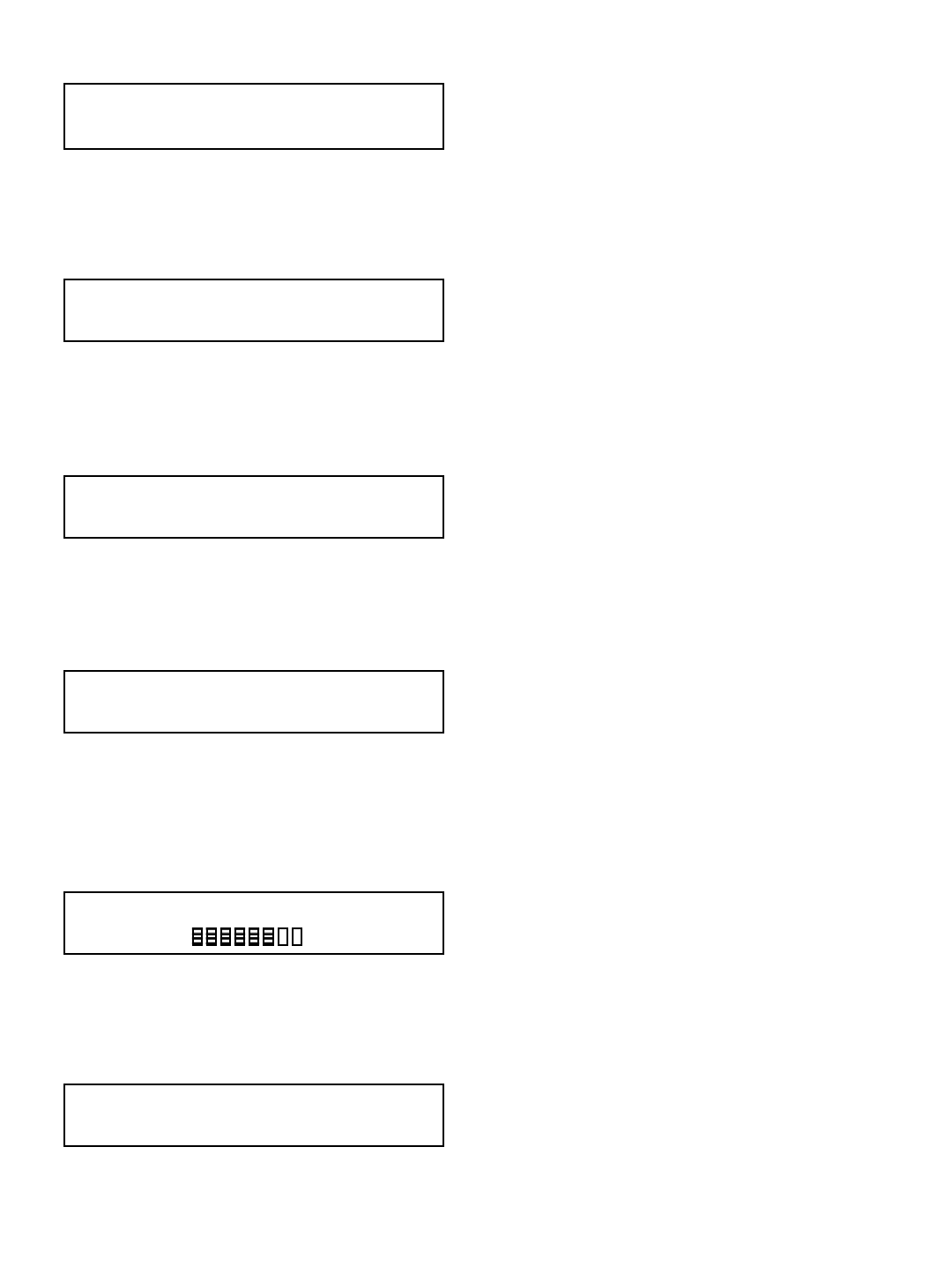
SAVING…
Figure 1-1
21
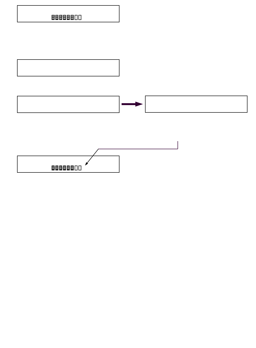
System start up
Deach and every time the receiver panel is powered up (example: each time the crane is started)
the system will require operator input before it can be used.
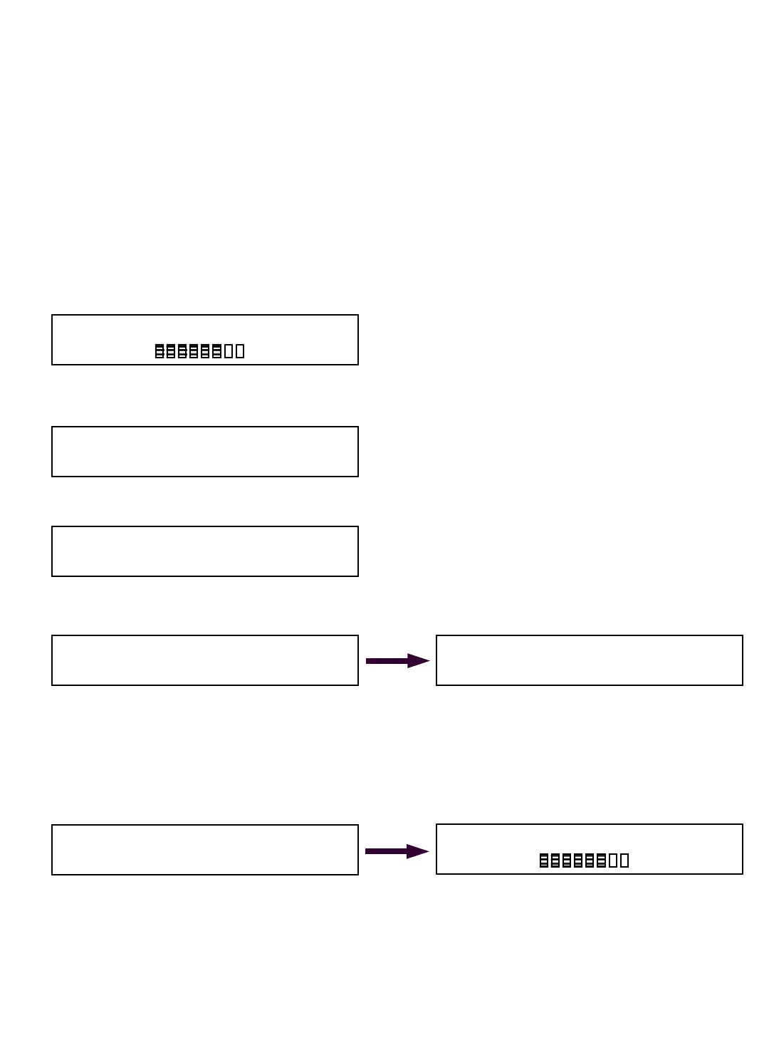
Don power up the panel will display the following 4 screens (FIG 1A – 1D) before operator input is
required:
Winch line selection
Dthe system may indicate MAIN winch is selected as above (FIG 1D).
Dif you wish to change winch line selected, simply push either the © or ª button on the panel
until the winch line (Main, Aux. 1, Aux. 2) to be used is displayed on the screen.
Donce the correct winch line in use is displayed on the screen, accept by pressing and holding the
MODE button, then press the ª button once.
Dthe saving screen will appear for a few seconds. Proceed to load chart in use selection below.
Please note that you will have a different load chart for your main and auxiliary winches. It is
vital that you select the correct winch line in use as it will relate directly to its individual load
chart.
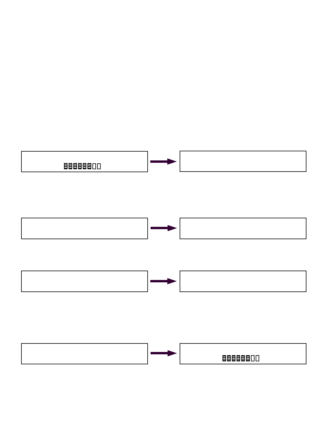
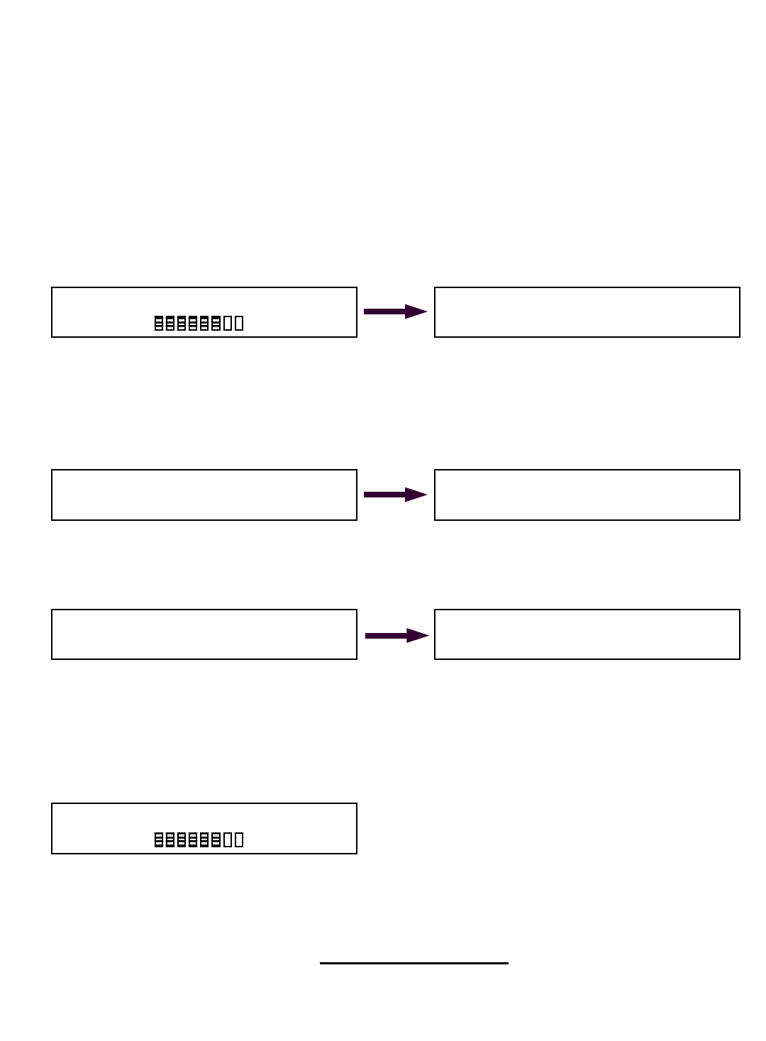
Correct load chart in use selection
Dafter you select and accept your winch line is use the Cranesmart system will prompt you to
confirm which load chart you are using, such as static or dynamic, ABS, or API for some
examples, as your system may be programmed with various load charts. You must select and
accept the correct load chart with the correct parts-of-line each time you use the crane and this
system. This is vital.
Dif you do not know what load chart or parts-of-line to select, ask your Foreman.
Don every start up the – after you accept the winch line in use in the above step – the last used
load chart will appear in the display screen – an example below:
Dif you wish to select a different load chart other that what appears in the load chart selection
display screen (above) simply push either the © or ª button on the panel until the correct load
chart is displayed.
Donce the correct load chart is displayed accept by pushing the MODE button and while holding
it, push the ª button once. The saving screen will appear briefly.
DProceed to next page
CRANE SMART LOAD MOMENT INDICATOR
The Load & A-2-B Company Inc.
Figure 1A
FIRMWARE VERSION 1.0b5
© 2002 The Load & A-2-B Company Inc.
Figure 1B
Programmed for: Nautilus 70-2-90 Marine Crane
-Your Crane Will Appear Here-
Figure 1C
01: Nautilus 70-2-90 Marine Static
Accept by Mode, Change by buttons.
MAIN Winch is selected
Accept by Mode, Change by buttons.
Figure 1D
22
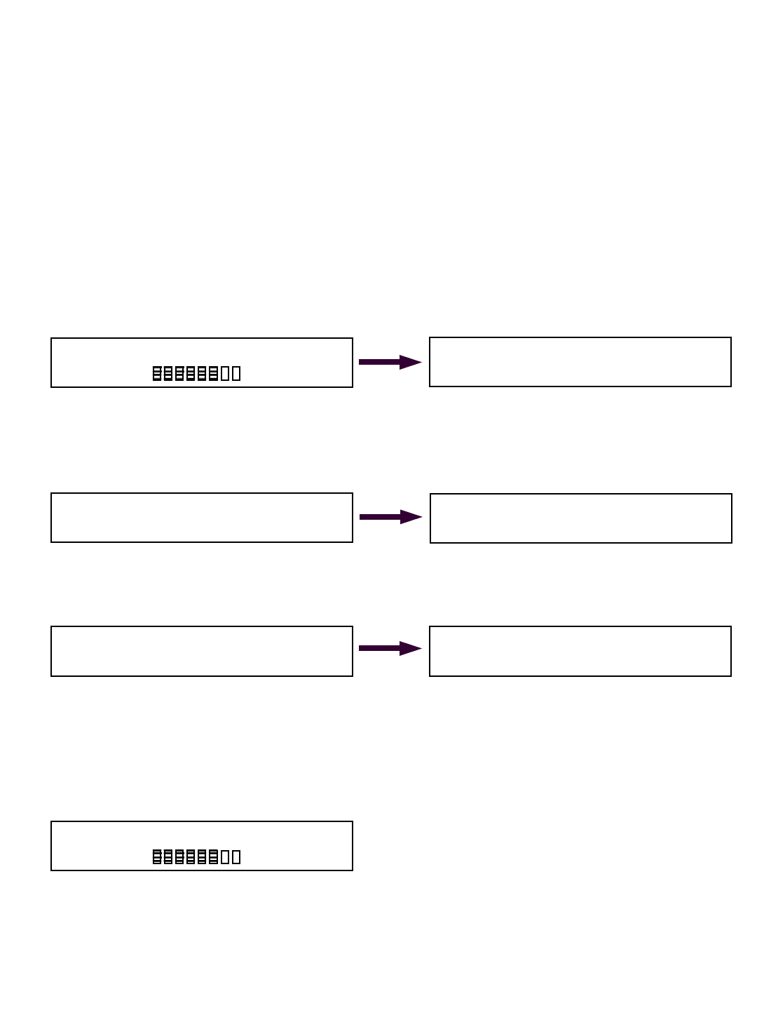
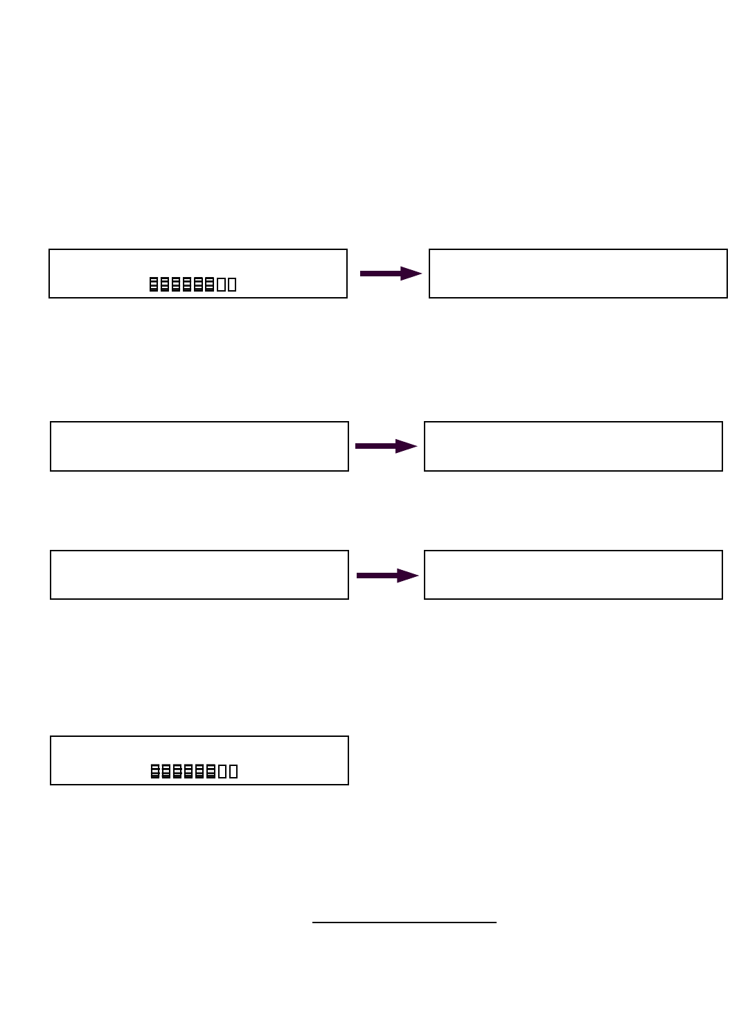
Correct parts-of-line selection:
Dall load charts programmed into this system are indexed to match with parts-of-line as per each
load chart. This means that if you select a parts-of-line where there is no chart programmed for
that specific parts-of-line, the system will not operate until you match POL with a programmed
load chart.
Dto change the parts-of-line in use setting simply push either the © or ª button on the panel
until the correct parts-of-line in use on your crane is displayed on the screen.
Donce the correct parts-of-line on the winch in use is displayed on the screen, accept by pressing
and holding the MODE button, then press the ª button once. The Saving Display screen will
appear for a few seconds. The Primary Operating Display will then appear on the screen
similar to the display screen below.
Dyou are now ready to operate the crane.
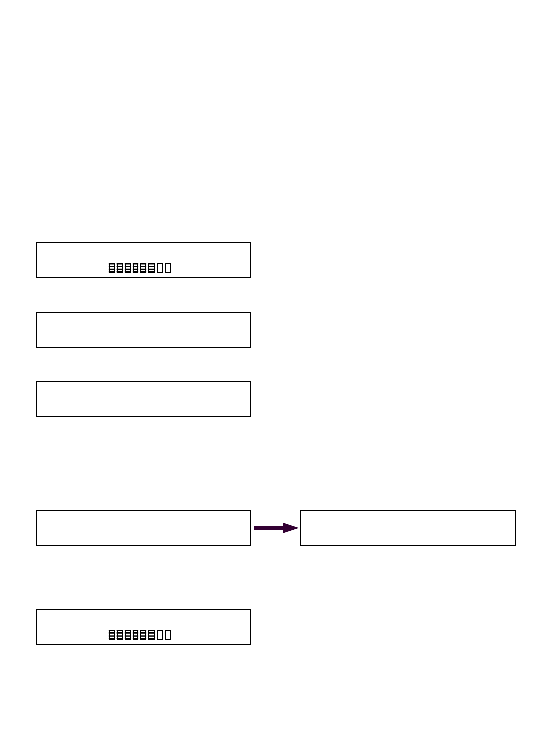
Operating displays and information:
DDuring normal operation the Cranesmart has four display screens defaulting to with the Primary
Operating display shown below. You may move from screen to screen with a simple push or
either the up or down arrow button. After approximately ten seconds the system will always
default to the Primary Operating display. This function can not be changed.
Parts Of Line: 6
Accept by Mode, Change by buttons.
Angle= 45.0 deg
Radius= 42.0 ft
MAIN= 15,000lbs MaxLoad
18500lb
81%
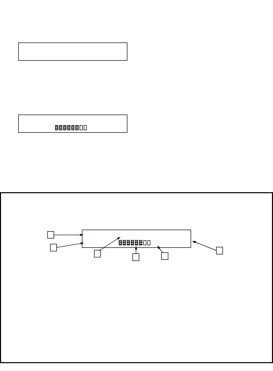
Primary operating display is the main operating display for the system.
After selecting the correct winch line in use, correct load chart and number of parts-of-line, the
Crane Smart System will show the Primary Operating Display below:
The top row displays the operator with the following functions as read from left to right:
1. Angle= is the actual live angle of the of the boom in degrees base section to the horizontal
ground.
2. Radius= is the actual radius in feet as measured from the crane center of rotation to the center
of the load.
3. MAIN is actual load on the hook. MAIN or AUX1 will alternate continuously with Load on the
this portion of the display to identify which winch line is currently selected for display.
4. A BAR GRAPH The shaded portion of the bar graph fills in from left to right as the load
increases towards maximum chart. Blank with no load - completely filled in at 100% of chart.
5. The percentage of permitted load as per capacity charts is displayed.
6. MaxLoad is the actual maximum load (at 100%) allowed by the capacity charts and crane
configuration.
2
3 6
Angle= 45.0 deg
Radius= 42.0 ft
MAIN= 15,000lbs MaxLoad
18500lb
81%
5
1
4
23
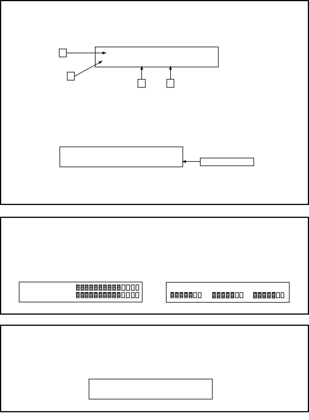
Check your load chart in use – display screen
The following information is displayed when the ª button is pressed once from the Primary
Operating Display. (bottom of last page) This display indicates current load chart and parts-of-line
information. It will return to the Primary Operating screen in about ten seconds.
1. 01: The top row displays details of the load chart in currently selected
2. MAIN is the selected winch. (may also be AUX1 or AUX2)
3. Pol= indicates the actual parts-of-line in use on the selected winch (1-60).
4. Boom Length= should reflect the total length in feet of boom in use.
If you have an active anti-2-block switch or switches with your Cranesmart LMI system, you will see
the A2B=OKAY information in the bottom right of this display as illustrated above.
01: Link Belt 518 90ft boom Static
MAIN Load POL= 4 Boom Length= 90.0 ft
1
2
4 3
01: Link Belt 518 90ft boom Static
MAIN Load POL= 4 Boom Length= 90.0 ft A2B=OKAY Present with A2B
Check your transmitter(s) signal strength display
The following information is displayed when the ª button is pressed twice from the Primary
Operating Display (bottom of last page). This indicates the live signal strength of your boom
mounted transmitters as received at the panel. The display will return to the Primary Operating
screen in about ten seconds.
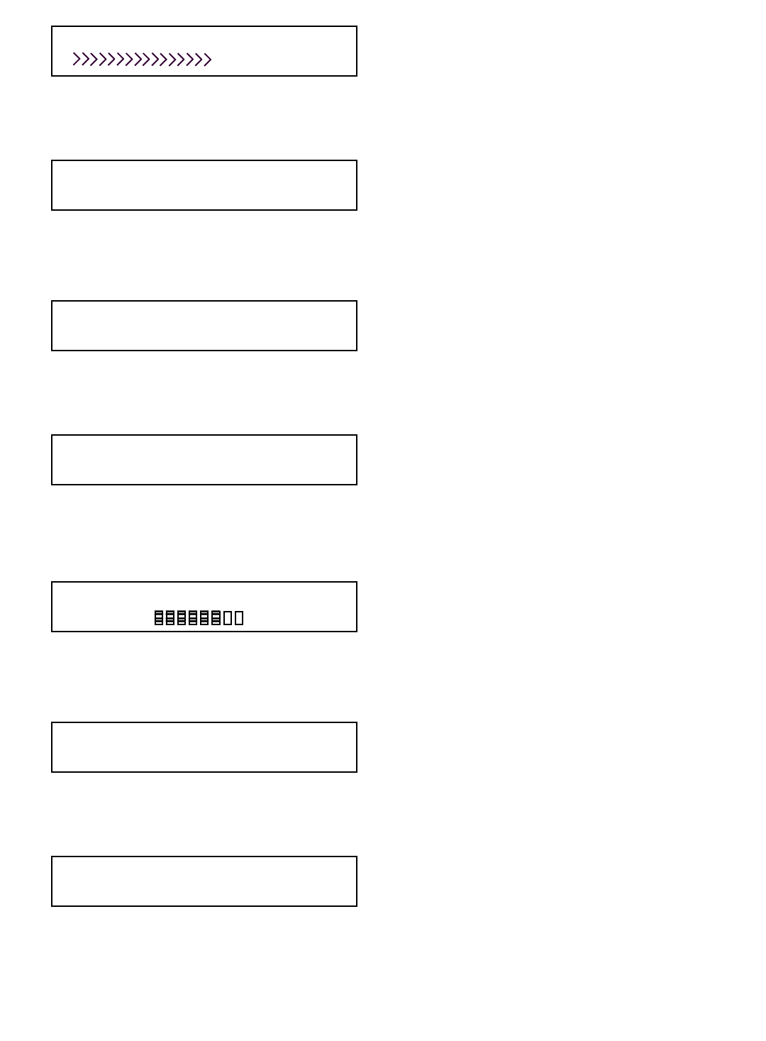
LOADm Signal 70%>
ANGm Signal 70%>
Load and angle only
LOADm Sig 70% A2Bm Sig 90% ANGm 70%
>
>
>
>
>
>
Load, angle and A2B
Check your radius, live boom angle and tip height
The following information is displayed when the © button is pressed once from the Primary
Operating Display (bottom of last page). This indicates the radius in feet, the live boom angle in
degrees and the current tip height of the boom. The display will return to the Primary Operating
screen in about ten seconds.
Radius Angle = 10.0 degrees Tip
0.0ft -10.0> - █- - - - - - -< 90.0 5.0ft

24

25
Section Three
The load cell, anti-2-block switch, angle transducer and panel
must all be installed
before proceeding past this point of the manual.
Please note:
You will require a permissions code to complete the following sequences:
This section provides information for:
DLoad cell calibration
DWeight adjustment information
DRestoring factory calibration
DAngle side selection
DAngle zero calibration
DAngle sensor selection
26
PLEASE READ THIS ENTIRE SECTION OF RE-CALIBRATION BEFORE
PROCEEDING! DO NOT POWER UP PANEL UNTIL READ AND UNDERSTOOD
COMPLETELY.
Dload cell calibration. You must follow each of these steps in the sequence following to calibrate
for each load cell, example Main, Auxiliary 1 and or Auxiliary 2.
Dplease note that the system is calibrated from factory and does not normally require
re-calibration before use.
Dset the ZERO value first and the SPAN value second.
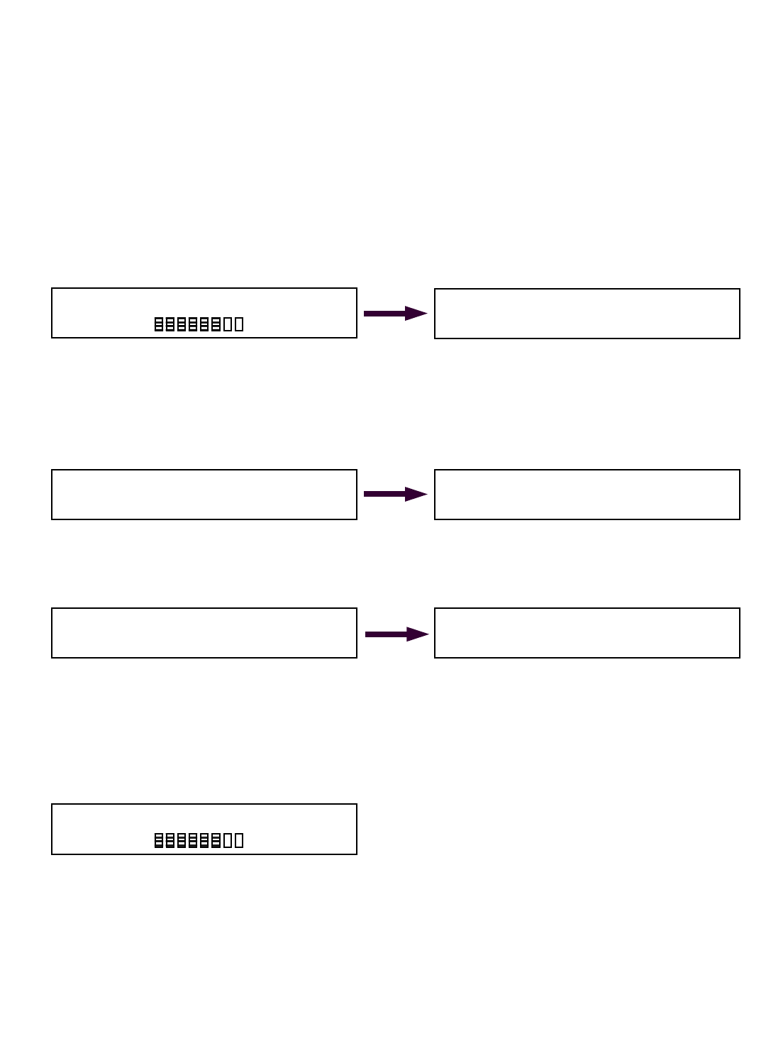
Steps to selecting winch prior to re-calibrating load cells – Each of these steps must be
repeated for each load cell if you have a multi-line system.
Dstart with the panel displaying the Primary Operating screen below:
Dpush the ª button once to display your load chart information display screen below:
Dpush and hold the MODE button in. While holding in the MODE button, push the TEST button
once. The following display screen will appear:
Dproceed to the top of the next page.
Calibration options:
1. Calibration can be restored over the telephone in a matter of minutes as the load cells
are designed to self-calibrate. Call our service department at 1-888-562-3222 and ask
for the load cell self calibration instructions. Have the serial number of your system
handy. OR
2. Follow the detailed calibration procedures detailed below.
Before you start this calibration procedure, you must have a known weight. The minimum
weight amount will depend on the load cells single line pull rating.
For calibration a known weight of 50% or greater of the single line pull of the load cell is best. The
weights used for calibration must be known weights. This is vital.
Examples:
DUsing a 15,000 pound SLP load cell and when running 4 parts-of-line, the ideal known
weight required for calibration purposes would be 30,000 pounds.
DUsing a 25,000 pound SLP load cell and when running 6 parts-of-line, the ideal known
weight required for calibration purposes would be 75,000 pounds.
DUsing a 40,000 pound SLP load cell and when running 8 parts-of-line, the ideal known
weight required for calibration purposes would be 160,000 pounds.
The simple formula is:
D(Single line pull of load cell X parts-of-line ÷ 2 = minimum known weight required for
calibration purposes) Higher or lower weights may be used however the accuracy of the
calibration may be affected.
Select Permission Code: 127
Accept by Mode, Change by buttons.
Angle= 45.0 deg
Radius= 42.0 ft
MAIN= 15,000lbs MaxLoad
18500lb
81%
01: Link Belt 518 90ft boom Static
MAIN Load POL= 4 Boom Length= 90.0 ft
27
Dpressing the © or ª buttons select 111 for permission code until display screen appears as
follows:
Dsave by pushing the MODE and ª button.
Dthe Saving Screen will then appear.
Dthe following screen with then be displayed:
Dselect the winch you wish to calibrate by pressing the © or ª buttons.
Dif correct winch for calibration is already displayed, save by pushing the MODE and ª buttons.
Dthe following display will then appear:
Dselect correct load chart in use by pressing the © or ª buttons. When the display indicates
the correct load chart is use save by pushing the MODE and ª buttons.
Dthe following display will then appear:
Dif necessary change the parts-of-line by pressing the © or ª buttons until the correct number of
parts-of-line is displayed on the screen in above. Save by pushing the MODE and ª buttons.
Dafter the Saving Screen press the © button once to return to the Primary Operating Display.
This is an example of that display:
Dfrom the above Primary Operating Display page down by pushing the MODE and ª buttons.
Display screen will appear below:
DProceed to next page
01: Static or your make and model of crane
Accept by Mode, Change by buttons.
MAIN Winch is selected.
Accept by Mode, Change by buttons.
Parts Of Line: 4
Accept by Mode, Change by buttons.
Change Cal or Presets. BOOM LOGGER
<LOAD> ANG A2B LOCK RADIUS TIP RF
Select Permission Code: 111
Accept by Mode, Change by buttons.
Angle= 45.0 deg
Radius= 42.0 ft
MAIN= 15,000lbs MaxLoad
18500lb
81%
28
Ddisplay will appear as above, continue by pushing the MODE and ª buttons once.
Ddisplay will appear as follow:
Dcontinue by pushing the MODE and ª buttons. Display will appear as above:
Dwith no load on the hook adjust the ZERO SETTING by pushing the © or ª buttons until the
number displayed to the right of ZERO: is as close to your known weight of hook block or the
headache ball. For example a 1,200 pound block would be displayed as above:
DContinued on next page
IMPORTANT CALIBRATION / WEIGHT ADJUSTMENT INFORMATION:
Please note:
In the system calibration modes the actual weight (resolution in pounds) changed by a single push
of an © or ª button during these calibration sequences is in 100 pound increments up to 16
parts-of-line.
If you require 17+ parts-of-line the resolution will begin with 100 pounds increments of change for
each push of the button. The resolution will then change to 200 pound increments for every push
of the © or ª button during the calibration sequences.
Calibrate LOAD MAIN ZERO: 1,200 lb
Accept by Mode, Change by buttons.
<SET ZERO> SET MIN TARE RESTORE
SET SPAN SET MAX DISABLE
Calibrate LOAD MAIN ZERO: 000 lb
Accept by Mode, Change by buttons.
Change Cal or Presets. BOOM LOGGER
<LOAD> ANG A2B LOCK RADIUS TIP RF
29
Dwith below left display still on the display screen, push the MODE and ª buttons to save. After
the saving screen the display will return to appear as follows below right:
Dnext pick up a known certified weight (see top of page 30 for definition and examples)
Dwith the known weight in the air push ª button once until <SET SPAN> is selected as
displayed below:
Dwith the above display screen above continue by pushing the MODE and ª buttons. Display
will appear as follows with an example of a known weight (40,000 lbs.) :
Dadjust the weight display right of SPAN: to read the same as your known weight. (Please
read Weight Adjustment Information at the bottom of page 32 of this manual). Once you have
adjusted the weight to as close to your known weight as possible, save by pushing the MODE
and ª buttons. Display will return to appear as below:
Dpress MODE and © buttons.
Dpress MODE and © buttons once again.
Dthe system will return to the Primary Operating Screen as below:
To verify settings pick up the same known weight. If correct calibration is complete, repeat
each step of the load cell calibration process with each load cell of each winch, example:
main, auxiliary one, etc. If you wish to calibrate another load cell of the system, repeat these
steps selecting the load cell in step 4 (Selecting correct winch line) of this sequence.
<SET ZERO> SET MIN TARE RESTORE
SET SPAN SET MAX DISABLE
Calibrate LOAD MAIN ZERO: 1,200 lb
Accept by Mode, Change by buttons.
<SET ZERO> SET MIN TARE RESTORE
<SET SPAN> SET MAX DISABLE
Calibrate LOAD MAIN SPAN: 40,000 lb
Accept by Mode, Change by buttons.
<SET ZERO> SET MIN TARE RESTORE
<SET SPAN> SET MAX DISABLE
Angle= 45.0 deg
Radius= 42.0 ft
MAIN= 15,000lbs MaxLoad
18500lb
81%
Change Cal or Presets. BOOM LOGGER
<LOAD> ANG A2B LOCK RADIUS TIP RF
30
Angle sensor side selection instructions – for RIGHT SIDE installation only.
PLEASE READ THIS ENTIRE SECTION OF ZERO ANGLE CALIBRATION
BEFORE PROCEEDING! DO NOT POWER UP PANEL UNTIL READ AND
UNDERSTOOD COMPLETELY.
Please reference page 13 of this manual for installation of the angle sensor which must be on the
crane before proceeding with these instructions.
The angle sensor can be mounted on either side of the boom however the default setting is to install
it on the LEFT SIDE of the boom. If you determine that the right side of the boom is a more
desirable location for the angle sensor, you must program the blue receiver panel for right boom
operation while keeping line of sight. This section will show you how to program the panel to work
with an angle sensor mounted on the RIGHT SIDE of the boom.
If you have mounted the angle sensor on the left side of the boom – proceed with zeroing angle
calibration in the next section of this manual. If you have mounted the angle sensor on either the top
or bottom of the boom, the system will not function. These steps will describe how to program the
right operating side for the angle sensor.
Angle transducer side selection
DYou must follow each of these steps in this sequence for angle side selection
Dstart with the panel displaying the Primary Operating screen below:
Dpush the ª button once to display your load chart information display screen below:
Dpush and hold the MODE button in. While holding in the MODE button, push the TEST button
once. The following display screen will appear:
Dpressing the © or ª buttons select 111 for permission code until display screen appears as
follows:
DProceed to next page >
Select Permission Code: 127
Accept by Mode, Change by buttons.
Angle= 45.0 deg
Radius= 42.0 ft
MAIN= 15,000lbs MaxLoad
18500lb
81%
01: Link Belt 518 90ft boom Static
MAIN Load POL= 4 Boom Length= 90.0 ft
Select Permission Code: 111
Accept by Mode, Change by buttons.
31
Dthe Saving Screen will then appear as above. Please note that anytime a change is made this
Saving Screen will appear as the system saves the last input.
Dthe following display will then appear:
Dmove to next display screen by pushing the MODE and ª buttons.
Dthe following display will then appear:
Dmove to next display screen by pushing the MODE and ª buttons.
Dthe following display will then appear:
Dmove to next display screen by pushing the MODE and ª buttons.
Dat this step the system will automatically return to the Primary Operating Display. This is an
example of that display:
Dfrom the above Primary Operating Display page down by pushing the MODE and ª buttons.
Ddisplay screen will appear as follows:
Dwhile viewing the above display screen press the ª button once to select <ANG>.
Dthe display should now appear as below:
DContinued on next page >
01: Static or your make and model of crane
Accept by Mode, Change by buttons.
MAIN Winch is selected.
Accept by Mode, Change by buttons.
Parts Of Line: 4
Accept by Mode, Change by buttons.
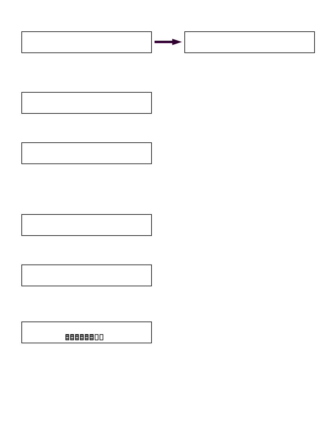
SAVING…
Angle= 45.0 deg
Radius= 42.0 ft
MAIN= 15,000lbs MaxLoad
18500lb
81%
Change Cal or Presets. BOOM LOGGER
<LOAD> ANG A2B LOCK RADIUS TIP RF
Change Cal or Presets. BOOM LOGGER
LOAD <ANG> A2B LOCK RADIUS TIP RF
32
Dfrom the above display screen, move to the next screen by pushing the MODE and ª button.
The display screen will appear as follows in Figure 2G below left:
Dchoose SELECT SIDE by pushing ª button once until <SELECT SIDE> appears as above in
Figure 2H.
Dsave by pushing the MODE and ª button. Display will appear as follows:
Dselect either RIGHT or LEFT using the © or ª
buttons. Save by pushing the MODE and ª
button. After the saving screen Display will ap-
pear as follows:
Dpress MODE and © buttons. The system will
display the screen as below:
Dpress MODE and © buttons once again.
Dthe system will return to the Primary Operating
Screen as below:
Angle side selection is now complete.
Select ANGLE MAIN SIDE: right
Accept by Mode, Change by buttons.
SET ZERO SET MIN SELECT SENSOR
<SELECT SIDE> SET MAX DISABLE
Figure 2G
<SET ZERO> SET MIN SELECT SENSOR
SELECT SIDE SET MAX DISABLE
Figure 2H
SET ZERO SET MIN SELECT SENSOR
<SELECT SIDE> SET MAX DISABLE
Figure A
left side
Mount angle
sensor on
either side of
boom
To boom tip
Base section of boom
Figure B
right side
Change Cal or Presets. BOOM LOGGER
LOAD <ANG> A2B LOCK RADIUS TIP RF
Change Cal or Presets. BOOM LOGGER
LOAD <ANG> A2B LOCK RADIUS TIP RF
Angle= 45.0 deg
Radius= 42.0 ft
MAIN= 15,000lbs MaxLoad
18500lb
81%
33
ANGLE ZERO display read out instructions:
PLEASE READ THIS ENTIRE SECTION OF ZERO ANGLE CALIBRATION
BEFORE PROCEEDING! DO NOT POWER UP PANEL UNTIL READ AND
UNDERSTOOD COMPLETELY.
Once the boom angle sensor is installed, you will likely need to zero the angle value in the receiver/
display panel. These steps will describe how to zero the angle when your BOOM/LUFFING JIB is as
close to horizontal as possible, with the angle sensor installed on the boom/luffing jib as level as
possible. Please reference page 14 of this manual for installation of the angle sensor which must be
on the crane before proceeding with these instructions.
ANGLE ZERO display read out
DYou must follow each of these steps in this sequence to zero the angle sensor only.
Steps to zeroing of angle display read out – angle sensor:
Dstart with the panel displaying the Primary Operating screen below:
Dpush the ª button once to display your load chart information display screen below:
Dpush and hold the MODE button in. While holding in the MODE button, push the TEST button
once. The following display screen will appear:
Drelease the two buttons. Pressing the © or ª buttons select 111 for permission code until
display screen appears as follows:
Dsave by pushing the MODE and ª button.
DContinued on next page >
Select Permission Code: 127
Accept by Mode, Change by buttons.
Angle= 45.0 deg
Radius= 42.0 ft
MAIN= 15,000lbs MaxLoad
18500lb
81%
01: Link Belt 518 90ft boom Static
MAIN Load POL= 4 Boom Length= 90.0 ft
Select Permission Code: 111
Accept by Mode, Change by buttons.
34
Dthe Saving Screen will then appear as above. Please note that anytime a change is made this
Saving Screen will appear as the system saves the last input.
Dthe following display will then appear:
Dmove to next display screen by pushing the MODE and ª buttons.
Dthe following display will then appear:
Dmove to next display screen by pushing the MODE and ª buttons.
Dthe following display will then appear:
Dmove to next display screen by pushing the MODE and ª buttons.
Dat this step the system will automatically return to the Primary Operating Display. This is an
example of that display:
Dfrom the above Primary Operating Display page down by pushing the MODE and ª buttons.
Ddisplay screen will appear below:
Dwhile viewing the above display screen press the ª button once to select <ANG>.
Dthe display should now appear as below:
DContinued on next page >
01: Static or your make and model of crane
Accept by Mode, Change by buttons.
MAIN Winch is selected.
Accept by Mode, Change by buttons.
Parts Of Line: 1
Accept by Mode, Change by buttons.
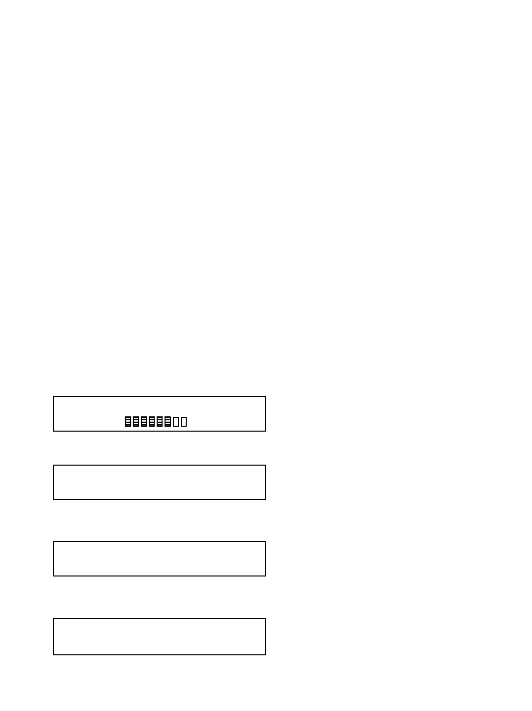
SAVING…
Angle= 45.0 deg
Radius= 42.0 ft
MAIN= 15,000lbs MaxLoad
18500lb
81%
Change Cal or Presets. BOOM LOGGER
<LOAD> ANG A2B LOCK RADIUS TIP RF
Change Cal or Presets. BOOM LOGGER
LOAD <ANG> A2B LOCK RADIUS TIP RF
35
Dfrom the above display screen, move to the next screen by pushing the MODE and ª button.
Dthe display screen will appear as follows:
Dmove to next screen by pushing the MODE and ª button. Display will appear as follows:
Dyour boom should be pre-positioned to zero degrees using a carpenters level if possible.
Donce you have positioned the boom to as close to zero degrees as possible, press the © or ª
buttons until the readout to the right of ANGLE MAIN ZERO: displays the actual boom angle,
example below:
Dsave by pushing the MODE and ª button. After the saving screen the Display will appear as
follows:
Dpress MODE and © buttons. The system will display the screen as below:
Dpress MODE and © buttons once again.
Dthe system will return to the Primary Operating Screen as below:
Zeroing of angle is now complete. If you wish to select another angle sensor to zero, such
as an angle sensor on the jib of your crane, proceed to the next page.
<SET ZERO> SET MIN SELECT SENSOR
SELECT SIDE SET MAX DISABLE
Calibrate ANGLE MAIN ZERO: 20.0 deg
Accept by Mode, Change by buttons.
Calibrate ANGLE MAIN ZERO: 00.0 deg
Accept by Mode, Change by buttons.
<SET ZERO> SET MIN SELECT SENSOR
SELECT SIDE SET MAX DISABLE
Change Cal or Presets. BOOM LOGGER
LOAD <ANG> A2B LOCK RADIUS TIP RF
Change Cal or Presets. BOOM LOGGER
LOAD <ANG> A2B LOCK RADIUS TIP RF
Angle= 45.0 deg
Radius= 42.0 ft
MAIN= 15,000lbs MaxLoad
18500lb
81%
36
Angle sensor selection instructions:
PLEASE READ THIS ENTIRE SECTION OF ANGLE SENSOR SELECTION
BEFORE PROCEEDING! DO NOT POWER UP PANEL UNTIL READ AND
UNDERSTOOD COMPLETELY.
If your system utilizes two angle sensors, one on the main boom and another on the luffing jib for
example, you will need to select the correct angle sensor prior to zeroing the angle calibration as
described in the previous section. These steps will describe how to select the angle sensor prior to
zeroing the angle display.
Angle sensor selection
DYou must follow each of these steps in the sequence following to select angle sensors.
Steps to selecting angle sensors:
Dstart with the panel displaying the Primary Operating screen below:
Dpush the ª button once to display your load chart information display screen below:
Dpush and hold the MODE button in. While holding in the MODE button, push the TEST button
once. The following display screen will appear:
Drelease the two buttons. Pressing the © or ª buttons select 111 for permission code until
display screen appears as follows:
Dsave by pushing the MODE and ª button.
DContinued on next page >
Select Permission Code: 127
Accept by Mode, Change by buttons.
Angle= 45.0 deg
Radius= 42.0 ft
MAIN= 15,000lbs MaxLoad
18500lb
81%
01: Link Belt 518 90ft boom Static
MAIN Load POL= 4 Boom Length= 90.0 ft
Select Permission Code: 111
Accept by Mode, Change by buttons.
37
Dthe Saving Screen will then appear as above. Please note that anytime a change is made this
Saving Screen will appear as the system saves the last input.
Dthe following display will then appear:
Dmove to next display screen by pushing the MODE and ª buttons.
Dthe following display will then appear:
Dmove to next display screen by pushing the MODE and ª buttons.
Dthe following display will then appear:
Dmove to next display screen by pushing the MODE and ª buttons.
Dat this step the system will automatically return to the Primary Operating Display below.
Dfrom the above Primary Operating Display page down by pushing the MODE and ª buttons.
display screen will appear below:
Dwhile viewing the above display screen press the ª button once to select <ANG>.
Dthe display should now appear as below:
Continued on next page >
01: Static or your make and model of crane
Accept by Mode, Change by buttons.
MAIN Winch is selected.
Accept by Mode, Change by buttons.
Parts Of Line: 1
Accept by Mode, Change by buttons.
SAVING…
Angle= 45.0 deg
Radius= 42.0 ft
MAIN= 15,000lbs MaxLoad
18500lb
81%
Change Cal or Presets. BOOM LOGGER
<LOAD> ANG A2B LOCK RADIUS TIP RF
Change Cal or Presets. BOOM LOGGER
LOAD <ANG> A2B LOCK RADIUS TIP RF
38
Dfrom the above display screen, move to the next screen by pushing the MODE and ª button.
The display screen will appear as follows below left:
Dchoose SELECT SENSOR by pushing © button twice until <SELECT SENSOR> appears as
above in Figure 2H.
Dsave by pushing the MODE and ª button. Display will appear as follows:
Dif necessary press the ª button until ANGLE JIB appears as above in the display.
Dsave by pushing the MODE and ª button. Display will appear as follows:
Dpress MODE and © buttons. The system will display the screen as below:
Dpress MODE and © buttons once again.
Dthe system will return to the Primary Operating Screen as below:
Selection of ANGLE SENSOR is now complete.
<SET ZERO> SET MIN SELECT SENSOR
SELECT SIDE SET MAX DISABLE
SET ZERO SET MIN <SELECT SENSOR>
SELECT SIDE SET MAX DISABLE
Select Angle Sensor: ANGLE JIB
Accept by Mode, Change by buttons.
SET ZERO SET MIN <SELECT SENSOR>
SELECT SIDE SET MAX DISABLE
Angle= 45.0 deg
Radius= 42.0 ft
MAIN= 15,000lbs MaxLoad
18500lb
81%
Change Cal or Presets. BOOM LOGGER
LOAD <ANG> A2B LOCK RADIUS TIP RF
Change Cal or Presets. BOOM LOGGER
LOAD <ANG> A2B LOCK RADIUS TIP RF

39
Section Four
The load cell, anti-2-block switch, angle transducer and panel
must all be installed
before proceeding past this point of the manual.
This section provides information for:
DSelecting LOAD WINCH LINE
DSetting LOAD MINIMUM alarms
DSetting LOAD MAXIMUM alarms
DTo ENABLE TARE OUT function
DTo DISABLE TARE OUT function
DSetting ANGLE MINIMUM alarms
DSetting ANGLE MAXIMUM alarms
DSetting RADIUS MINIMUM alarms
DSetting RADIUS MAXIMUM alarms
DSetting TIP HEIGHT MINIMUM alarms
DSetting TIP HEIGHT MAXIMUM alarms
NOTE: Your system must be enabled to set and change alarms. If you
are asked for a permissions code at any step in this sequence – your
system was ordered with this function locked out. Simply call the
service department at 1-888-562-3222 for information on how to unlock
the system.
40
Selecting winch line
The Cranesmart System allows the operator to specify minimum and maximum operating limits for
the crane’s load. Before you enter the minimum or maximum alarm preset information, you will need
to choose which winch line, if you have a multi-line Cranesmart System. Once you have set the
MIN/MAX alarms for your Main winch, you should also set the MIN/MAX alarms for your other winch
lines, either Auxiliary 1 and/or Auxiliary 2. If any of the preset maximum limits are exceeded or the
minimum limits are broken the Cranesmart System will alarm and activate the crane’s shut off
system. (if installed) To select the correct winch line follow these simple steps:
Selecting winch line:
Dbegin in Primary Operating Display. From the Primary Operating Display the display will
appear as follows:
Dpush the ª button. Display will go to display as follows:
Dpush the TEST button. Display will appear as follows:
Dpush the MODE and ª buttons. Display will appear as follows:
Dto Select a Winch Line for Load Alarm Programming choose the correct winch line from
the above display using the © or ª buttons.
Donce the correct winch line is displayed, continue by pushing the MODE and ª buttons.
You will see the SAVING DISPLAY screen then the display will appear as follows:
Dpush the MODE and ª buttons.
Ddisplay will return to the Primary Operating Display.
Selecting winch line is now complete. You may now continue with programming the
Minimum and Maximum load alarms by following the detailed steps on the following pages.
MAIN Winch is selected.
Accept by Mode, Change by buttons.
AUX1 Winch is selected.
Accept by Mode, Change by buttons.
Parts Of Line: 1
Accept by Mode, Change by buttons.
Angle= 45.0 deg
Radius= 42.0 ft
MAIN= 15,000lbs MaxLoad
18500lb
81%
01: Link Belt 518 90ft boom Static
MAIN Load POL= 4 Boom Length= 90.0 ft
MAIN Winch is selected.
Accept by Mode, Change by buttons.
Angle= 45.0 deg
Radius= 42.0 ft
MAIN= 15,000lbs MaxLoad
18500lb
81%
41
Setting MINIMUM alarms for LOAD
PLEASE READ THIS ENTIRE SECTION OF SETTING MIN/MAX ALARMS
BEFORE PROCEEDING! DO NOT POWER UP PANEL UNTIL READ AND
UNDERSTOOD COMPLETELY.
NOTE: Your system must be enabled to set and change alarms. If you are asked for
a permissions code at any step in this sequence – your system was ordered with this
function locked out. Simply call the service department at 1-888-562-3222 for
information on how to unlock the system.
The Cranesmart System allows the operator to specify minimum operating limits for the crane’s load.
If the preset minimum limit is exceeded the Cranesmart System will alarm and activate the crane’s
shut off system. (if installed) To set the minimum load alarm follow these simple steps:
Setting Minimum Alarms for LOAD
TO SET MINIMUM ALARM:
Dfrom the above left Primary Operating Display, push the MODE and ª buttons. Display will
appear as above right.
Das this sequence describes setting the MINIMUM ALARM for the LOAD, continue by simply
pushing the MODE and ª buttons. Display will appear as below left:
Dto move to the MINIMUM LOAD ALARM display screen, continue by simply pushing the MODE
and ª buttons. Display will appear as above right:
Dpress the © or ª buttons until the readout to the right of LOAD MAIN MIN: displays the
minimum load value you wish, example: a 400 pound minimum preset above left.
Dsave by pushing the MODE and ª button. Display will appear as above right.
Dpress MODE and © buttons. The system will display the screen as below left:
Dpress MODE and © buttons once again.
Dthe system will return to the Primary Operating Screen.
Setting the minimum load alarm is now complete. If you have an Auxiliary load cell that you
wish to set the minimum load alarm on, simply repeat these steps selecting winch Aux1 in
selecting winch line instructions at the beginning of this section.
Change MIN/MAX Presets & Select Sensor:
<LOAD> ANGLE RADIUS TIP
<SET MIN> TARE
SET MAX DERATE
Set LOAD MAIN MIN: 000 LB
Accept by Mode, Change by buttons.
Set LOAD MAIN MIN: 400 lb
Accept by Mode, Change by buttons.
<SET MIN> TARE
SET MAX DERATE
Change MIN/MAX Presets & Select Sensor:
<LOAD> ANGLE RADIUS TIP
Angle= 45.0 deg
Radius= 42.0 ft
MAIN= 15,000lbs MaxLoad
18500lb
81%
Angle= 45.0 deg
Radius= 42.0 ft
MAIN= 15,000lbs MaxLoad
18500lb
81%
42
Setting MAXIMUM alarms for LOAD
PLEASE READ THIS ENTIRE SECTION OF SETTING MIN/MAX ALARMS
BEFORE PROCEEDING! DO NOT POWER UP PANEL UNTIL READ AND
UNDERSTOOD COMPLETELY.
NOTE: Your system must be enabled to set and change alarms. If you are asked for
a permissions code at any step in this sequence – your system was ordered with this
function locked out. Simply call the service department at 1-888-562-3222 for
information on how to unlock the system.
The Cranesmart System allows the operator to specify maximum operating limits for the crane’s
load. If the preset maximum limit is exceeded the Cranesmart System will alarm and activate the
crane’s shut off system. (if installed) To set the maximum load alarm follow these simple steps:
Setting Maximum Alarms for LOAD
TO SET MAXIMUM ALARM:
Dfrom the above left Primary Operating Display, push the MODE and ª buttons. Display will
appear as above right.
Das this sequence describes setting the MAXIMUM ALARM for the LOAD, continue by simply
pushing the MODE and ª buttons. Display will appear as below left:
Dcontinue by simply pushing the ª button once to select <SET MAX> as above right. Accept by
pressing the MODE and ª buttons once. Display will appear as below left.
Dpress the © or ª buttons until the readout to the right of LOAD MAIN MAX: displays the
maximum load value you wish, example: a 4000 pound maximum preset above left.
Dsave by pushing the MODE and ª button. The saving screen will appear briefly.
Dpress and while holding the MODE button in press the © button twice.
Dthe system will return to the Primary Operating Screen.
Setting the maximum load alarm is now complete. If you have an Auxiliary load cell that you
wish to set the maximum load alarm on, simply repeat these steps selecting winch Aux1 in
selecting winch line instructions at the beginning of this section.
<SET MIN> TARE
SET MAX DERATE
Set LOAD MAIN MAX: 000 LB
Accept by Mode, Change by buttons.
Set LOAD MAIN MIN: 4000 lb
Accept by Mode, Change by buttons.
Change MIN/MAX Presets & Select Sensor:
<LOAD> ANGLE RADIUS TIP
Angle= 45.0 deg
Radius= 42.0 ft
MAIN= 15,000lbs MaxLoad
18500lb
81%
Angle= 45.0 deg
Radius= 42.0 ft
MAIN= 15,000lbs MaxLoad
18500lb
81%
SET MIN TARE
<SET MAX> DERATE
43
Enabling LOAD TARE OUT function
The Cranesmart System has a Tare function which will allow the crane operator to zero out the
weight of the hook block or headache ball. Once this is done, only the load below the hook will be
displayed as the actual weight on the receiver/display panel.
Please note that it is a safer practice to keep the weight of the cranes rigging included in the
displayed weight as the load charts of the crane do not subtract the weight of such rigging
and therefore it should be included for safe operating parameters.
To enable load tare out setting
First you must choose the winch line you wish to set the TARE on:
Selecting winch line:
Dbegin in Primary Operating Display. From the Primary Operating Display the display will
appear as follows:
Dpush the ª button. Display will appear as follows:
Dpush the TEST button. Display will appear as follows:
Dto Select a Winch Line to TARE choose the correct winch line from the above display using
the © or ª buttons. Note: If your system is programmed for only one winch line, there is
no option to select another.
Donce the correct winch line is displayed, continue by pushing the MODE and ª buttons.
You may see the SAVING DISPLAY screen then the display will appear as follows:
Dpush the MODE and ª buttons.
Ddisplay will return to the Primary Operating Display.
DContinued on next page >
MAIN Winch is selected.
Accept by Mode, Change by buttons.
Angle= 45.0 deg
Radius= 42.0 ft
MAIN= 15,000lbs MaxLoad
18500lb
81%
01: Link Belt 518 90ft boom Static
MAIN Load POL= 4 Boom Length= 90.0 ft
Parts Of Line: 1
Accept by Mode, Change by buttons.
01: Link Belt 518 90ft boom Static
MAIN Load POL= 4 Boom Length= 90.0 ft
Angle= 45.0 deg
Radius= 42.0 ft
MAIN= 15,000lbs MaxLoad
18500lb
81%
44
Dwhile viewing the above Primary Operating Display lift up the desired weight that you wish to tare
out, the hook block or headache ball for example.
Dwith the weight in the air, continue by simply pushing the MODE and ª buttons. Display will
appear as follows:
Dcontinue by simply pushing the MODE and ª buttons. Display will appear as follows:
Dpress the ª button twice to select <TARE> as in above left display.
Dpush the MODE and ª buttons.
Ddisplay will return to the Primary Operating Display with the letter T just right of the bar graph as
illustrated below:
Setting the TARE OUT function is now complete. If you have an Auxiliary load cell that you
wish to tare out, simply repeat these steps selecting winch Aux 1 in step 5 of this procedure.
While the system remains in the TARE mode with the letter T to the right of the bar graph on
the primary operating display, any weight lifted by the crane will be the weight of the object
below the hook only.
Disabling of TARE OUT function
To disable TARE OUT function:
Deither increase or decrease the boom angle by +/- three degrees or;
Disabling of TARE OUT function is now complete.
Change MIN/MAX Presets & Select Sensor:
<LOAD> ANGLE RADIUS TIP
<SET MIN> TARE
SET MAX DERATE
SET MIN <TARE>
SET MAX DERATE
Angle= 45.0 deg
Radius= 42.0 ft
MAIN= 15,000lbs MaxLoad
18500lb
81%
Angle= 45.0 deg
Radius= 42.0 ft
MAIN= 15,000lbs MaxLoad
18500lb
81%
T
45
© The LOAD & A-2-B Company Inc. – Crane Smart System – Stiff Boom Manual / last revised November 2001 / specifications subject to change
Setting MINIMUM alarms for ANGLE
PLEASE READ THIS ENTIRE SECTION OF SETTING MIN/MAX ALARMS
BEFORE PROCEEDING! DO NOT POWER UP PANEL UNTIL READ AND
UNDERSTOOD COMPLETELY.
The Cranesmart System allows the operator to specify minimum operating limits for the crane’s
angle. If the preset minimum limit is exceeded the Cranesmart System will alarm and activate the
crane’s shut off system. (if installed) To set the minimum angle alarm follow these simple steps:
Setting Minimum Alarms for ANGLE
TO SET MINIMUM ALARM:
Dfrom the above left Primary Operating Display - push the MODE and ª buttons.
Dthen push ª button once only. Display will appear as above right with <ANGLE> selected.
Das this sequence describes setting the MINIMUM ALARM for the ANGLE, continue by simply
pushing the MODE and ª buttons. Display will appear as below left:
Dto move to the MINIMUM ANGLE ALARM display screen, continue by simply pushing the
MODE and ª buttons. Display will appear as above right:
Dpress the © or ª buttons until the readout to the right of ANGLE MAIN MIN: displays the
minimum angle value you wish, example: 10 degree minimum preset above left.
Dsave by pushing the MODE and ª button. Display will now appear as above right.
Dpress and while holding the MODE button in press the © button twice.
Dthe system will return to the Primary Operating Screen below.
Setting the minimum angle alarm is now complete. If you have an Auxiliary or Jib angle
sensor that you wish to set the minimum angle alarm on, simply repeat these steps after
selecting the correct angle sensor in angle sensor selection found in section three of this
manual.
<SET MIN> SELECT SENSOR
SET MAX
Set ANGLE MAIN MIN: 50.0 deg
Accept by Mode, Change by buttons.
Set ANGLE MAIN MIN: 10.0 deg
Accept by Mode, Change by buttons.
<SET MIN> SELECT SENSOR
SET MAX
Change MIN/MAX Presets & Select Sensor:
LOAD <ANGLE> RADIUS TIP
Angle= 45.0 deg
Radius= 42.0 ft
MAIN= 15,000lbs MaxLoad
18500lb
81%
Angle= 45.0 deg
Radius= 42.0 ft
MAIN= 15,000lbs MaxLoad
18500lb
81%
46
© The LOAD & A-2-B Company Inc. – Crane Smart System – Stiff Boom Manual / last revised November 2001 / specifications subject to change
Setting MAXIMUM alarms for ANGLE
PLEASE READ THIS ENTIRE SECTION OF SETTING MIN/MAX ALARMS
BEFORE PROCEEDING! DO NOT POWER UP PANEL UNTIL READ AND
UNDERSTOOD COMPLETELY.
The Cranesmart System allows the operator to specify maximum operating limits for the crane’s
angle. If the preset maximum limit is exceeded the Cranesmart System will alarm and activate the
crane’s shut off system. (if installed) To set the maximum angle alarm follow these simple steps:
Setting Maximum Alarms for ANGLE
TO SET MAXIMUM ALARM:
Dfrom the above Primary Operating Display – push the MODE and ª buttons.
Dthen push ª button once only. Display will appear as above right with <ANGLE> selected.
Das this sequence describes setting the MAXIMUM ALARM for the ANGLE, continue by simply
pushing the MODE and ª buttons once
Dthen push ª button once only. Display will appear as below left:
Dto move to the MAXIMUM ANGLE ALARM display screen, continue by simply pushing the
MODE and ª buttons. Display will appear as above right:
Dpress the © or ª buttons until the readout to the right of ANGLE MAIN MAX: displays the
maximum angle value you wish, example: 78 degree maximum preset above left.
Dsave by pushing the MODE and ª button. .
Dpress and while holding the MODE button in press the © button twice.
Dthe system will return to the Primary Operating Screen below.
Setting the maximum angle alarm is now complete. If you have an Auxiliary or Jib angle
sensor that you wish to set the maximum angle alarm on, simply repeat these steps after
selecting the correct angle sensor in angle sensor selection found in section three of this
manual.
SET MIN SELECT SENSOR
<SET MAX>
Set ANGLE MAIN MAX: 78.0 deg
Accept by Mode, Change by buttons.
Set ANGLE MAIN MAX: 78.0 deg
Accept by Mode, Change by buttons.
SET MIN SELECT SENSOR
<SET MAX>
Change MIN/MAX Presets & Select Sensor:
LOAD <ANGLE> RADIUS TIP
Angle= 45.0 deg
Radius= 42.0 ft
MAIN= 15,000lbs MaxLoad
18500lb
81%
Angle= 45.0 deg
Radius= 42.0 ft
MAIN= 15,000lbs MaxLoad
18500lb
81%
47
© The LOAD & A-2-B Company Inc. – Crane Smart System – Stiff Boom Manual / last revised November 2001 / specifications subject to change © The LOAD & A-2-B Company Inc. – Crane Smart System – Stiff Boom Manual / last revised November 2001 / specifications subject to change
Setting MINIMUM alarms for RADIUS
PLEASE READ THIS ENTIRE SECTION OF SETTING MIN/MAX ALARMS
BEFORE PROCEEDING! DO NOT POWER UP PANEL UNTIL READ AND
UNDERSTOOD COMPLETELY.
The Cranesmart System allows the operator to specify minimum operating limits for the crane’s
radius. If the preset minimum limits are exceeded the Cranesmart System will alarm and activate the
crane’s shut off system. (if installed) To set the minimum radius alarm follow these simple steps:
Setting Minimum Alarms for RADIUS
TO SET MINIMUM ALARM:
Dfrom the above Primary Operating Display - push the MODE and ª buttons.
Dthen push ª button twice. Display will appear as above with <RADIUS> selected.
Das this sequence describes setting the MINIMUM ALARM for the RADIUS, continue by simply
pushing the MODE and ª buttons. Display will appear as below left:
Dto move to the MINIMUM RADIUS ALARM display screen, continue by simply pushing the
MODE and ª buttons. Display will appear as above right in Figure 2L:
Dpress the © or ª buttons until the readout to the right of MAIN RADIUS MIN: displays the
minimum radius value you wish, example: 5 foot minimum preset above left.
Dsave by pushing the MODE and ª button. Display will appear as above right.
Dpress and while holding the MODE button in press the © button twice.
Dthe system will return to the Primary Operating Screen below.
Setting the minimum radius alarm is now complete.
Change MIN/MAX Presets & Select Sensor:
LOAD ANGLE <RADIUS> TIP
<SET MIN>
SET MAX
Set MAIN Radius MIN: 5 ft
Accept by Mode, Change by buttons.
Set MAIN Radius MIN: 5 ft
Accept by Mode, Change by buttons.
<SET MIN>
SET MAX
Angle= 45.0 deg
Radius= 42.0 ft
MAIN= 15,000lbs MaxLoad
18500lb
81%
Angle= 45.0 deg
Radius= 42.0 ft
MAIN= 15,000lbs MaxLoad
18500lb
81%

48
© The LOAD & A-2-B Company Inc. – Crane Smart System – Stiff Boom Manual / last revised November 2001 / specifications subject to change
Setting MAXIMUM alarms for RADIUS
PLEASE READ THIS ENTIRE SECTION OF SETTING MIN/MAX ALARMS
BEFORE PROCEEDING! DO NOT POWER UP PANEL UNTIL READ AND
UNDERSTOOD COMPLETELY.
The Cranesmart System allows the operator to specify maximum operating limits for the crane’s
radius. If the preset maximum limits are exceeded the Cranesmart System will alarm and activate
the crane’s shut off system. (if installed) To set the maximum radius alarm follow these simple
steps:
Setting Maximum Alarms for RADIUS
TO SET MAXIMUM ALARM:
Dfrom the above Primary Operating Display Figure 2A, push the MODE and ª buttons.
Dthen push ª button twice. Display will appear as above with <RADIUS> selected.
Das this sequence describes setting the MAXIMUM ALARM for the RADIUS, continue by simply
pushing the MODE and ª buttons.
Dthen push ª button once only. Display will appear as below left:
Dto move to the MAXIMUM RADIUS ALARM display screen, continue by simply pushing the
MODE and ª buttons. Display will appear as above right:
Dpress the © or ª buttons until the readout to the right of MAIN RADIUS MAX: displays the
maximum radius value you wish, example: 55 foot maximum preset above left.
Dsave by pushing the MODE and ª button. Display will appear as above right.
Dpress and while holding the MODE button in press the © button twice.
Dthe system will return to the Primary Operating Screen below.
Setting the maximum radius alarm is now complete.
Change MIN/MAX Presets & Select Sensor:
LOAD ANGLE <RADIUS> TIP
SET MIN
<SET MAX>
Set MAIN Radius MAX: 5 ft
Accept by Mode, Change by buttons.
Set MAIN Radius MAX: 55 ft
Accept by Mode, Change by buttons.
SET MIN
<SET MAX>
Angle= 45.0 deg
Radius= 42.0 ft
MAIN= 15,000lbs MaxLoad
18500lb
81%
Angle= 45.0 deg
Radius= 42.0 ft
MAIN= 15,000lbs MaxLoad
18500lb
81%
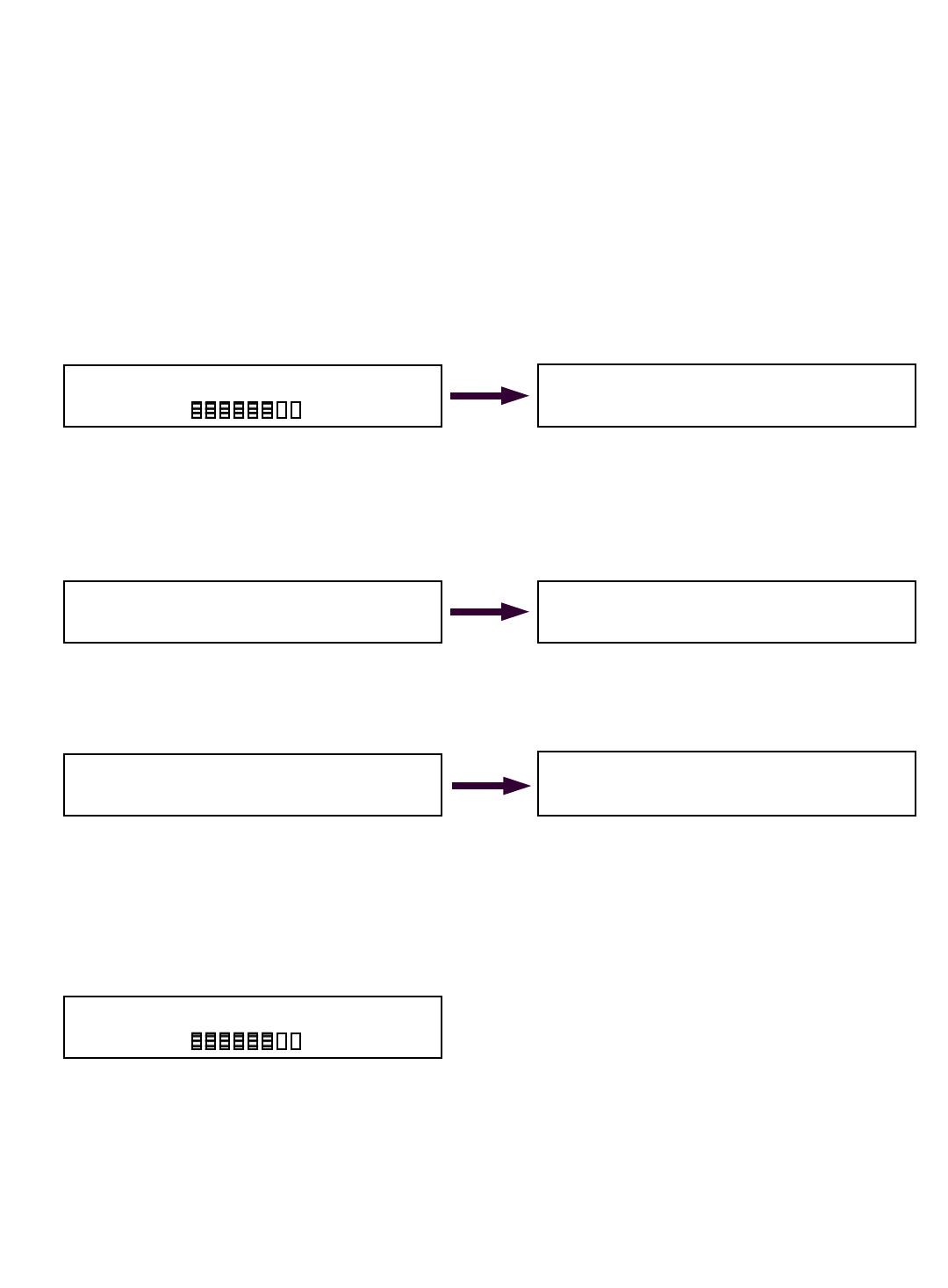
49
© The LOAD & A-2-B Company Inc. – Crane Smart System – Stiff Boom Manual / last revised November 2001 / specifications subject to change © The LOAD & A-2-B Company Inc. – Crane Smart System – Stiff Boom Manual / last revised November 2001 / specifications subject to change
Setting MINIMUM alarms for TIP HEIGHT
PLEASE READ THIS ENTIRE SECTION OF SETTING MIN/MAX ALARMS
BEFORE PROCEEDING! DO NOT POWER UP PANEL UNTIL READ AND
UNDERSTOOD COMPLETELY.
The Cranesmart System allows the operator to specify minimum operating limits for the crane’s tip
height. If the preset minimum limits are exceeded the Crane Smart™ System will alarm and activate
the crane’s shut off system. (if installed) To set the minimum tip height alarm follow these simple
steps:
Setting Minimum Alarms for TIP HEIGHT
TO SET MINIMUM ALARM:
Dfrom the above Primary Operating Display - push the MODE and ª buttons.
Dthen push ª button three times. Display will appear as above with <TIP> selected.
Das this sequence describes setting the MINIMUM ALARM for the TIP HEIGHT, continue by
simply pushing the MODE and ª buttons. Display will appear as below left:
Dto move to the MINIMUM TIP HEIGHT ALARM display screen, continue by simply pushing the
MODE and ª buttons. Display will appear as above right:
Dpress the © or ª buttons until the readout to the right of MAIN Tip Height MIN: displays the
minimum tip height value you wish, example: 30 foot minimum preset above left.
Dsave by pushing the MODE and ª button. Display will appear as above right.
Dpress and while holding the MODE button in press the © button twice.
Dthe system will return to the Primary Operating Screen below.
Setting the minimum tip height alarm is now complete.
Change MIN/MAX Presets & Select Sensor:
LOAD ANGLE RADIUS <TIP>
<SET MIN>
SET MAX
Set MAIN Tip Height MIN: 30 ft
Accept by Mode, Change by buttons.
Set MAIN Tip Height MIN: 30 ft
Accept by Mode, Change by buttons.
<SET MIN>
SET MAX
Angle= 45.0 deg
Radius= 42.0 ft
MAIN= 15,000lbs MaxLoad
18500lb
81%
Angle= 45.0 deg
Radius= 42.0 ft
MAIN= 15,000lbs MaxLoad
18500lb
81%
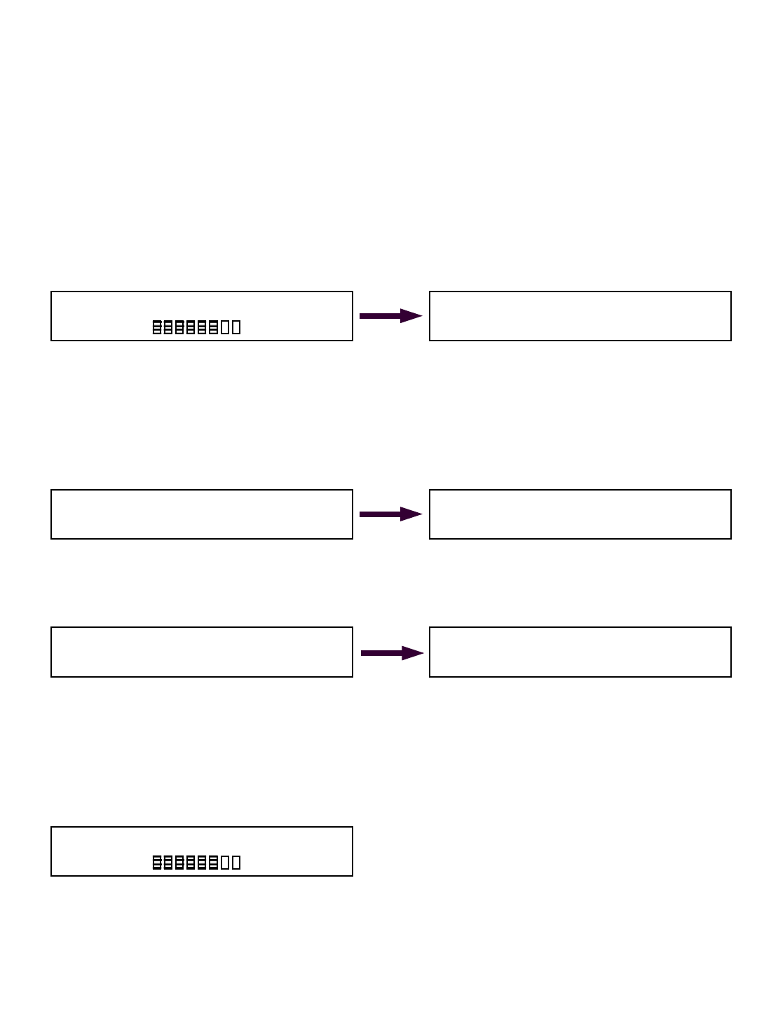
50
© The LOAD & A-2-B Company Inc. – Crane Smart System – Stiff Boom Manual / last revised November 2001 / specifications subject to change
Setting MAXIMUM alarms for TIP HEIGHT
PLEASE READ THIS ENTIRE SECTION OF SETTING MIN/MAX ALARMS
BEFORE PROCEEDING! DO NOT POWER UP PANEL UNTIL READ AND
UNDERSTOOD COMPLETELY.
The Cranesmart System allows the operator to specify maximum operating limits for the crane’s tip
height. If the preset maximum limits are exceeded the Cranesmart System will alarm and activate
the crane’s shut off system. (if installed) To set the maximum tip height alarm follow these simple
steps:
Setting Maximum Alarms for TIP HEIGHT
TO SET MAXIMUM ALARM:
Dfrom the above Primary Operating Display - push the MODE and ª buttons.
Dthen push ª button three times. Display will appear as above with <TIP> selected.
Das this sequence describes setting the MAXIMUM ALARM for the TIP HEIGHT, continue by
simply pushing the MODE and ª buttons.
Dthen push ª button once only. Display will appear as below left:
Dto move to the MAXIMUM TIP HEIGHT ALARM display screen, continue by simply pushing the
MODE and ª buttons. Display will appear as above right in Figure 2L:
Dpress the © or ª buttons until the readout to the right of MAIN tip Height MAX: displays the
maximum tip height value you wish, example: 90 foot maximum preset above left in Figure 2M.
Dsave by pushing the MODE and ª button. Display will appear as above right.
Dpress and while holding the MODE button in press the © button twice.
Dthe system will return to the Primary Operating Screen below.
Setting the maximum tip height alarm is now complete.
Change MIN/MAX Presets & Select Sensor:
LOAD ANGLE RADIUS <TIP>
SET MIN
<SET MAX>
Set MAIN Tip Height MAX: 90 ft
Accept by Mode, Change by buttons.
Set MAIN Tip Height MAX: 90 ft
Accept by Mode, Change by buttons.
SET MIN
<SET MAX>
Angle= 45.0 deg
Radius= 42.0 ft
MAIN= 15,000lbs MaxLoad
18500lb
81%
Angle= 45.0 deg
Radius= 42.0 ft
MAIN= 15,000lbs MaxLoad
18500lb
81%

51
Section Five
This section provides information for:
DTroubleshooting the Cranesmart System
DTechnical Specifications
DWarranty
Emergency shut-off by-pass plug – for use on system where NO
ALARM HUB IS USED
When shut offs are wired from the receiver panel and the Cranesmart system is overcome by
user damage, extremely high RF, or system malfunction, remove the plug with the yellow tag
found in your panel mounting assembly.
Next remove power cable from the panel by twisting the coupling 1/2 turn counter-clockwise
and pull away from the panel. Insert this by-pass plug into the end of the power cable – not
the panel - and turn plug 1/2 turn clockwise.
This will over-ride the shut off power signal enabling the continued uninterrupted use of your
crane. Please note that you will not have anti-2-block protection, once the power cable is
removed from the blue receiver panel. Call the service department of The Load & A-2-B
Company for further assistance.

52
Troubleshooting guide
Please do not attempt to open any components of this system.
Read this section completely and then contact
The Load & A-2-B Company service department at 1-888-562-3222.
Problem description Possible solution
1. Panel does not power up A. Power cable may be disconnected.
B. Verify that there is +12VDC going to the panel.
C. Check power cable for damage. (cuts, nicks, etc.)
2. Panel powers up but does not run
through the full start up sequence
e.g. Lights burnt out, missing
numbers, etc.
A. Verify that there is +12VDC going to the panel.
B. Power the panel directly with +12VDC from the cranes battery bypassing
any fuse panels and connections or on a separate 12 volt battery to ensure
that it is not a crane power problem.
C. Call the service department @ 1-888-562-3222.
3. Panel gets extremely hot to the
touch
A. If the panel is installed in a cab remove the black dust cover and improve
the air circulation around the panel.
4. Battery warning light is on A. Battery needs to be replaced. Please refer to the Battery Replacement
section of this manual.
5. System warning light is flashing A. Loss of communication with load cell, anti-2-block switch or angle sensor.
Refer to the No Communication section of this troubleshooting guide.
B. Interference from other radio frequency sources in the area. (e.g. radio
towers, high power TV antennae, satellite transmissions, etc.)
6. Display always shows the same
weight or stuck on same weight
even after turning the power on and
off
A. Loss of communication with load cell, anti-2-block switch or angle sensor.
The panel will display the last weight picked if communication is lost and it
will look like the weight is stuck. Refer to the No Communication section of
this troubleshooting guide.
7. Display is slow to update weight
changes
A. Intermittent communication with load cell, anti-2-block switch or angle
sensor. Refer to the No Communication section of this troubleshooting
guide.
B. Interference from other radio frequency sources in the area. (e.g. radio
towers, high power TV antennae, satellite transmissions, etc.)
8. Fluctuating weights Boom & load need to be stabilized. Try the following steps if you are still
having problems;
A. Raise the load as high as possible and stop until the motion of the load is
minimized. Note if the fluctuation on the readout stops or is reduced.
B. Lower the load & release. The readout should go back to indicating the
block weight.
C. If fluctuation is reduced in step A and the readout returns to the block weight
in step B, the sheaves on the rigging may require cleaning and lubrication.
If fluctuation is not reduced in step A or readout does not return to block
weight in step B, contact the service department of The Load & A-2-B
Company.
Error message: Load Chart Exceeded, Reduce Load Moment
Action: Reduce weight of lift or select correct parts-of-line as per load charts

53
Problem description Possible solution
1. Possible Installation
Problem
A. Thoroughly review the Installation Procedures at the front of this
manual
B. Verify that there is +12VDC going to the panel.
C. Power the panel directly with +12VDC from the cranes battery by-passing
any fuse panels and connections or on a separate 12 volt battery to
assure that it is not a crane power problem.
D. You should have a direct line of sight between the panel and the cell.
If the load cell is dead ended up inside the boom, this may interfere with
the radio signal.
E. If your boom length is over 200 feet the display panel may need to have
an external metal whip antenna.
2. Possible Antenna Problem A. Verify that you have the right antenna for the particular installation set up.
If you are not sure, please call 1-888-562-3222.
B. Check the antenna connectors for signs of corrosion, dirt and moisture.
Clean if necessary.
C. For the 10” panel mount antenna:
a. Panel should be mounted so that the antenna is free from any and all
metal.
b. The antenna should not be touching any glass or metal.
c. Make sure the antenna is not damaged.
D. For both types of external antenna (metal whip and rubber whip):
a. Make sure the antenna or the cable is not damaged.
b. The antenna should be free of any metal and there should be a good
line of sight to the load cell.
c. Never cut the length or otherwise modify the antenna without
contacting the service department at 1-888-562-3222.
3. Possible Dead Battery A. Please call our service department at 1-888-562-3222
before attempting to test or replace a battery.
B. The battery pack can be tested with a multi-meter and should read
between 6.6 VDC and 7.3 VDC. The batteries have internal fuses so
care must be taken not to short them out while testing.
C. A 9 volt battery can be installed in the load cell to verify operation of the
system and can be used for a short time while waiting for the replacement
battery.
4. Damage to load cell, anti-
2-block switch or angle
sensor
A. If the load cell, anti-2-block switch or angle sensor has been damaged
please call our service department immediately.
B. If the plastic cases are mis-aligned, broken or cracked call our service
department immediately.
C. If the gasket seal has been damaged or broken it will allow moisture to
damage the electronics and strain gauges. Please call the service
department immediately.
No communication between transmitters and blue receiver panel
If you have a suspected communication problem between the transmitters (load cell, A2B switch or
angle transducer) and the receiver panel, please use the following steps in troubleshooting.
Important: All main components of the system, such as the load cells, anti-2-block switches,
angle transducer and the blue receiver panel must be shipped together for any service work.
Check serial numbers to ensure matched system components are shipped together.

54
Cranesmart System Technical Component Specifications
Load cell SLP = maximum single line pull of the cranes winch in pounds
transmit range to 1000 feet
response time 0.1 second
weight 15/25,000 SLP - (40,000 SLP) 14 pounds - (33 pounds)
length 15/25,000 SLP - (40,000 SLP) 14 inches - (22 inches)
width 15/25,000 SLP - (40,000 SLP) 5 inches by 5 inches - (5 inches by 5½ inches)
antenna inner coil
operating temp in ºF -40 to 122 ºF (-40 to 50 ºC)
battery lithium ion
battery life two years
FCC compliance ID* NFBLAB777
Angle sensor
response time 0.8 second
weight (with weld plate) 10 pounds
length x height 10.5 inches by 4¾ inches
width 3¾ inches
operating temperature -40 to 122 ºF (-40 to 50 ºC)
battery lithium ion
battery life two years
FCC compliance ID* NFBLAB939SW
Anti-2-block switch
transmit range to 1000 feet
response time 0.1 second
weight (marine version) 3 pounds (8 pounds)
length 5½ inches
width 4 inches by 2 inches
antenna 7 inch (rubber flexible)
weld plate 2 x 4 x 1 inches
operating temp in ºF -40 to 122 ºF (-40 to 50 ºC)
battery lithium ion
FCC compliance ID* NFBLAB939SW
Receiver / Display panel
panel rating designed to meet NEMA 4X rating
optional rating available Class 1, Div 2
display type vacuum fluorescent display
operating temperature in ºF –50 to 150 ºF (-46 to 66 ºC)
panel width 11½ inches
panel depth 3½ inches
panel height 6 inches with base mounting bracket
weight 4 pounds
power requirements 12 volts
antenna stainless steel whip
Alarm Hub Standard/Dry contact
panel rating designed to meet NEMA 4X rating
hazardous location compliance class available Class 1, Div 2
operating temperature in ºF -40 to 140 ºF (-40 to 60ºC)
panel width 8¾ inches
panel depth 3½ inches
panel height 6 inches with base mounting bracket
weight 4.3 pounds
power requirements 12 volts, 0.5 amps (plus alarm current)
communication via RS232 cable at 9600 baud
Laser Emitter Component
panel rating designed to meet NEMA 4X rating
hazardous location compliance class N/A
operating temperature in ºF -40 to 122 ºF (-40 to 50ºC)
panel width 14 inches
panel depth 4⅞ inches
panel height 4¾ inches
weight 17.6 pounds with mounting plate and weld plate
power requirements 12 volts, @ 1.5 amps
communication via RS232 cable at 9600 baud
*FCC Compliance: Please note - Changes or modifications not expressly approved by The Load & A-2-B Company Inc. for FCC compliance could void the user’s authority to operate the equipment.