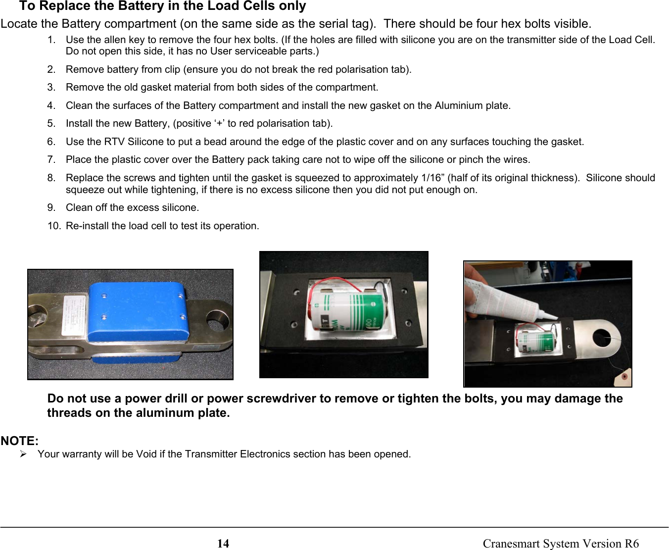
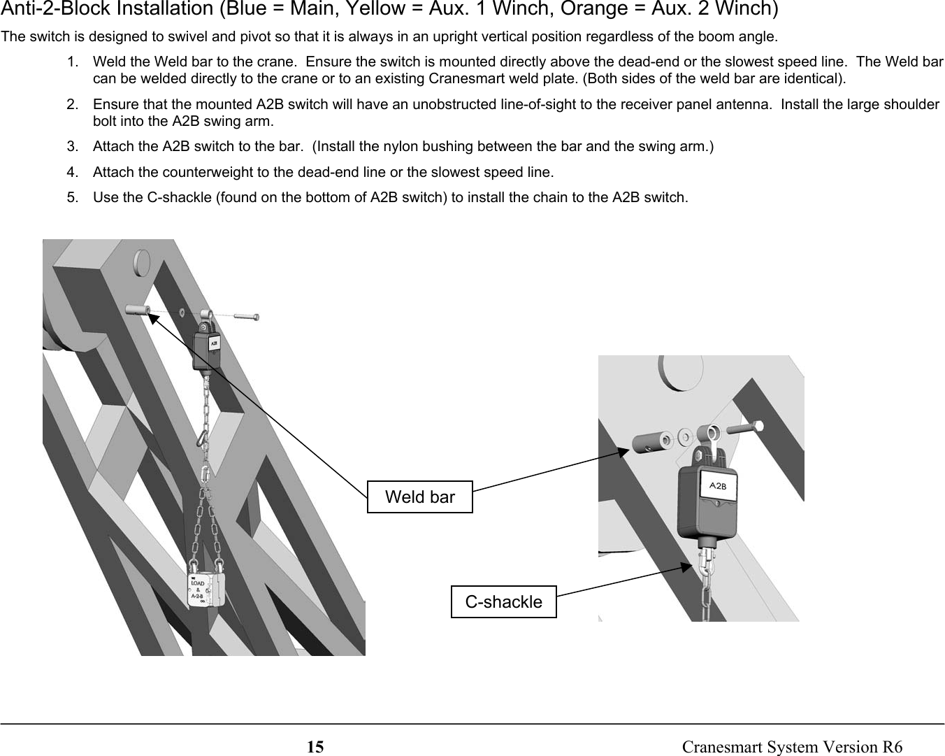
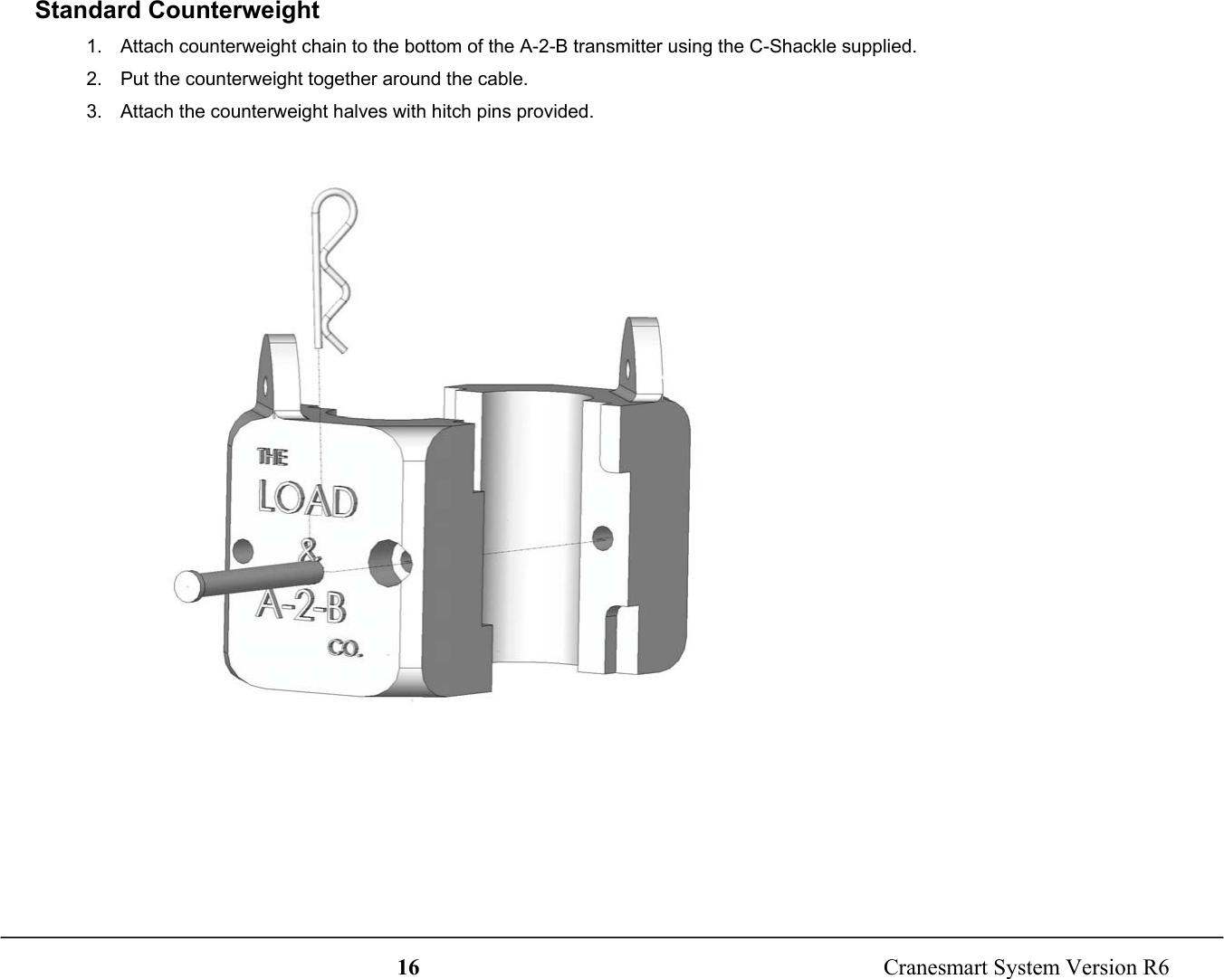
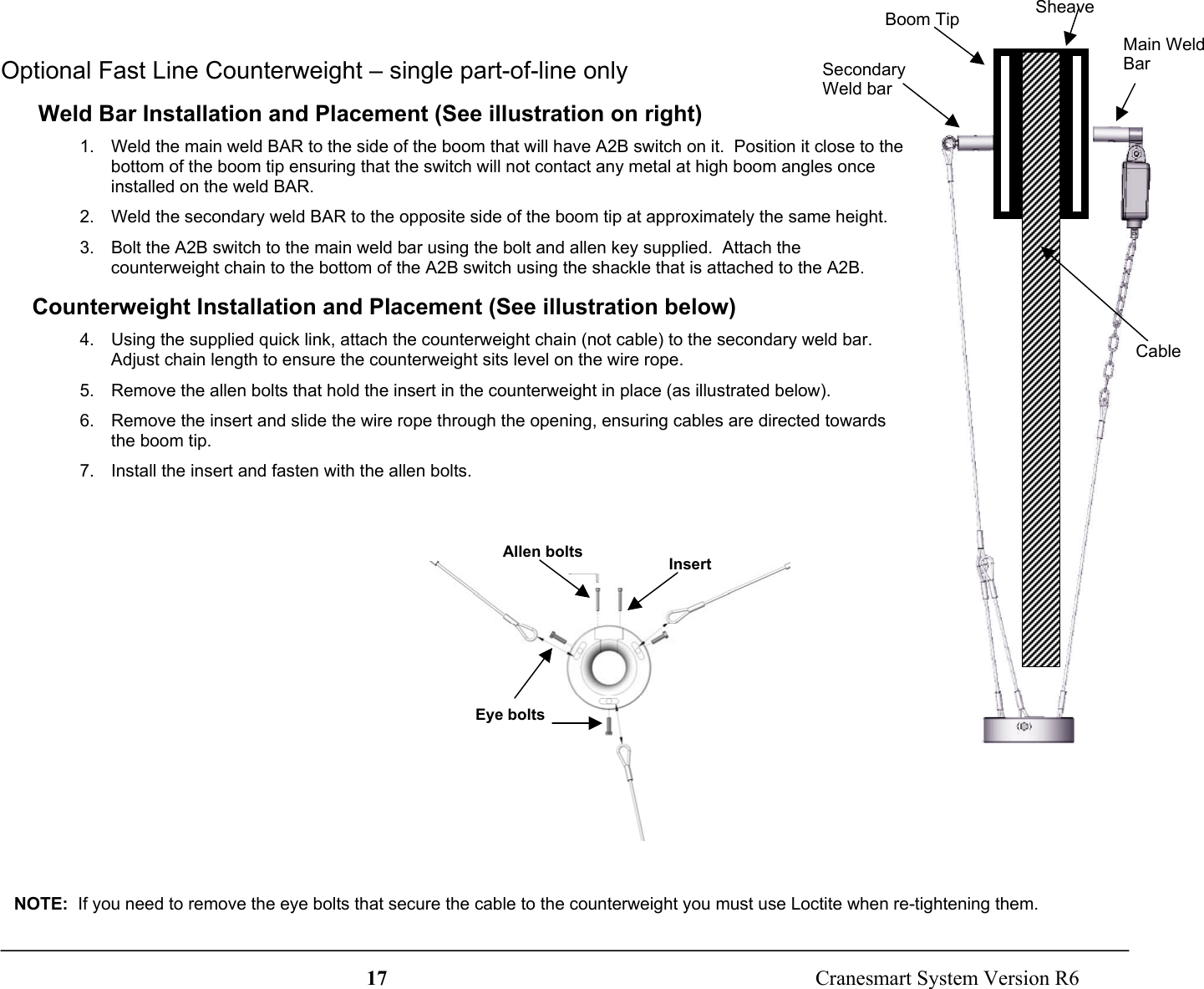
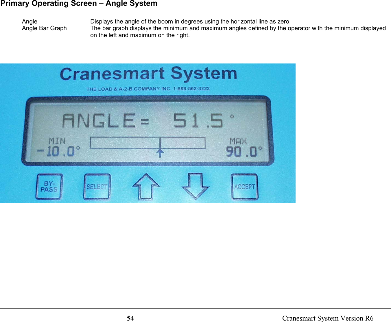
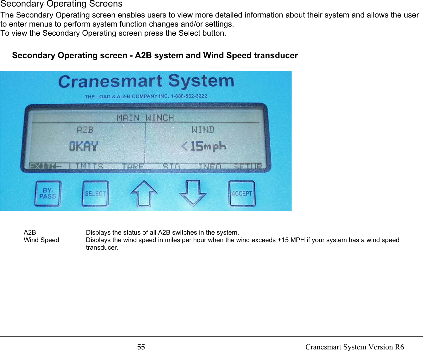
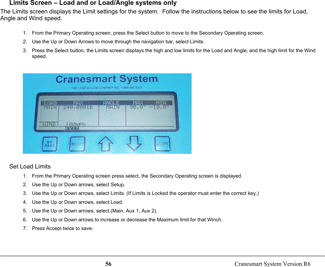
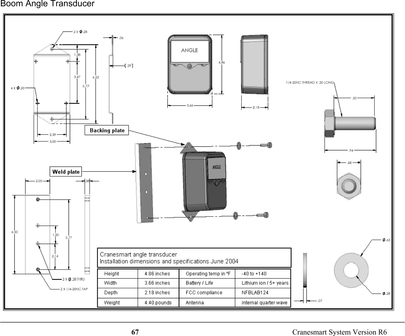
Cranesmart Systems LAB124 Wireless Boom Angle Transducer User Manual 900 Cranesmart Universal R1

Load & A-2-B Company Inc, The Wireless Boom Angle Transducer 900 Cranesmart Universal R1

User Manual

1  Cranesmart System Version R6Cranesmart SystemsThe Cranesmart SystemCongratulations!“You have invested in the industry’s leading technology in crane safety equipment.”This manual covers the installation and operation of all Cranesmart load monitors, anti-2-blocksystems, angle indicators, wind speed indicators and or any combination system.For sales, service or assistance: 1-888-562-3222 / 1-780-437-2986Load cell transmitter FCC compliance identification NFBLAB123Angle transducer FCC compliance identification NFBLAB124FCC Compliance: Please note - Changes or modifications not expressly approved by CranesmartSystems for FCC compliance could void the user’s authority to operate the equipment.This manual to be used with code version:4.202
2  Cranesmart System Version R6WarrantyCranesmart Systems warrants to the purchaser of each new Cranesmart System that any part thereof which proves to bedefective in material or workmanship within two (2) years from date of delivery will be repaired or replaced at no charge, ifthe system is returned to us in Edmonton, Alberta with all freight charges prepaid.  If a performance problem should occur,contact our office in Edmonton, Alberta at 1-888-562-3222 or (780) 437-2986.This warranty does not cover defects resulting from accident, alteration, improper use, or failure of the purchaser to follownormal operating procedures as outlined in this instruction manual.PLEASE NOTE:•  OPENING THE DISPLAY PANEL VOIDS WARRANTY.•  NO COMPONENTS OF THE SYSTEM ARE TO BE SUBMERGED IN WATER.•  THIS WARRANTY IS IN LIEU OF ANY WARRANTY OR MERCHANTABILITY AND OF ALL OTHER WARRANTIES,EXPRESSED OR IMPLIED, ALL OF WHICH ARE HEREBY EXCLUDED.Cranesmart Systems shall in no event be liable for any special, indirect, or consequential damages whatsoeverand neither assumes nor authorizes any person to assume for it any other obligation or liability.
3  Cranesmart System Version R6Table of ContentsINSTALLATION INSTRUCTIONS.......................................................................................................................................7Guidelines ......................................................................................................................................................................7Tools Required...............................................................................................................................................................7Male/Female Load Cell Link Installation......................................................................................................................8SLP Load Cell Installation (15,000 – 25,000 lbs.)...................................................................................................8SLP Load Cell Installation (40,000, 50,000 or 80,000 lbs.) ..................................................................................10Load Cell Battery Replacement...................................................................................................................................13Tools and Equipment for battery replacement: ......................................................................................................13To Replace the Battery in the Load Cells only ......................................................................................................14Anti-2-Block Installation.............................................................................................................................................15Standard Counterweight .........................................................................................................................................16Optional Fast Line Counterweight – single part-of-line only .....................................................................................17 Weld Bar Installation and Placement (See illustration on right)...........................................................................17Counterweight Installation and Placement (See illustration below)......................................................................17Boom Angle Transducer Installation...........................................................................................................................18To Install the Transducer........................................................................................................................................18Anti-2-Block and Angle Transducer Battery Replacement ........................................................................................19To Replace the Battery: ..........................................................................................................................................19Wind Speed Transducer Installation ...........................................................................................................................20To Install the Wind Speed Indicator.......................................................................................................................20To Install the Wind Speed Indicator with Swivel Mount ......................................................................................21Level Smart Sensor Installation Instructions...............................................................................................................22Level Smart Error Messages........................................................................................................................................24DISPLAY PANEL INSTALLATION...................................................................................................................................25Mounting the Display Panel ...................................................................................................................................25Wiring Instructions ......................................................................................................................................................26
4  Cranesmart System Version R6Display Panel..........................................................................................................................................................26Alarm Shut-offs – (White Output Wire): ...............................................................................................................26Antenna Installation.....................................................................................................................................................27Antenna types .........................................................................................................................................................27Outside Operator Cab OR no cab on Crane – 100 feet of Boom or less ...............................................................28Inside Operator Cab................................................................................................................................................29Marine Installation..................................................................................................................................................30Shut-off Bypass Plug – with yellow tag....................................................................................................................31DISPLAY PANEL – SYSTEM START-UP.........................................................................................................................32DISPLAY PANEL – QUICK WINCH SWITCHING – FOR SYSTEMS WITH LOAD CELLS ONLY..........................33To View the Auxiliary Winches.............................................................................................................................33DISPLAY PANEL NAVIGATION ......................................................................................................................................34Panel Buttons ...............................................................................................................................................................34Panel Navigation..........................................................................................................................................................35Secondary Operating Screen Navigation Bar.........................................................................................................35Setup Menus ...........................................................................................................................................................36DISPLAY PANEL – OPERATOR FUNCTIONS ................................................................................................................37Configure Menu – systems with load cells only .........................................................................................................37Select Winch, POL (Parts-of-line) .........................................................................................................................37Limits Menu.................................................................................................................................................................37Load Limits.............................................................................................................................................................37Angle Limits ...........................................................................................................................................................38Wind Limits............................................................................................................................................................38Level Smart Sensor Limits .....................................................................................................................................39System Menu ..........................................................................................................................................................40About ......................................................................................................................................................................40
5  Cranesmart System Version R6LCD Contrast..........................................................................................................................................................40Permissions.............................................................................................................................................................40Tare Out Function – systems with load cells only ......................................................................................................41To Enable Tare Out: ...............................................................................................................................................41To Disable Tare Out ...............................................................................................................................................41DISPLAY PANEL– SUPERVISOR FUNCTIONS..............................................................................................................43Permissions Level........................................................................................................................................................43To Set the Permission Level...................................................................................................................................43To Exit the Supervisor Menu .................................................................................................................................43Load Cell Calibration ..................................................................................................................................................44Factory Restore of Calibration ....................................................................................................................................44Set Span .......................................................................................................................................................................44Set Load Zero ..............................................................................................................................................................44Set Angle Zero........................................................................................................................................................45Level Smart Sensor Angle Zeroes..........................................................................................................................46To Set Angle Zero: .................................................................................................................................................46Known Weights ...........................................................................................................................................................47Important Calibration/Weight Adjustment Information ........................................................................................47Supervisor Options Menu............................................................................................................................................48Limits Lock – such as max load, high angle, etc. ..................................................................................................48By-pass button - DISABLE....................................................................................................................................48External Audible Alarm .........................................................................................................................................48External Relay – Output for shut-offs/Horn/Indicator ...........................................................................................49System Menu ...............................................................................................................................................................49About – Provides information on the software version, etc...................................................................................49LCD Contrast..........................................................................................................................................................49Display Timer .........................................................................................................................................................50Restricted Menu......................................................................................................................................................50
6  Cranesmart System Version R6Permission Level ....................................................................................................................................................50Checksum Repair....................................................................................................................................................50Supervisor Enable/Disable Menu ................................................................................................................................51DISPLAY PANEL – OPERATING SCREENS ...................................................................................................................52Primary Operating Screens..........................................................................................................................................52Primary Operating screen - Load and Angle Transducer.......................................................................................52Primary Operating Screen – Load, angle and A2B system....................................................................................53Primary Operating Screen – Angle System............................................................................................................54Secondary Operating Screens......................................................................................................................................55Secondary Operating screen - A2B system and Wind Speed transducer ..............................................................55Limits Screen – Load and or Load/Angle systems only ........................................................................................56Signal Strength Screen ...........................................................................................................................................58Info Screen – Cranesmart System information ......................................................................................................59DISPLAY PANEL ALARMS ...............................................................................................................................................60Function Shut Offs.......................................................................................................................................................61APPENDIX A – TECHNICAL SPECIFICATIONS ............................................................................................................6215,000 single line pull load cell...................................................................................................................................6225,000lb single line pull load cell................................................................................................................................6340,000 pound single line pull load cell........................................................................................................................6450,000 pound single line pull load cell........................................................................................................................6580,000 pound single line pull load cell........................................................................................................................66Anti-2-Block Switch................................................................................................... Error! Bookmark not defined.Boom Angle Transducer..............................................................................................................................................67Display panel ...............................................................................................................................................................68Alarm Hub .................................................................................................................. Error! Bookmark not defined.Wind speed transducer................................................................................................ Error! Bookmark not defined.
7  Cranesmart System Version R6Installation InstructionsGuidelinesRead these instructions before beginning installation procedures.If the power available is not 12 to 24 (28VDC Maximum) Cranesmart Systems Inc. will supply the necessaryadapters.  Please call our sales department at 1-888-562-3222 or (780) 437-2986.Have the necessary tools availableMount the transducers (Load Cell, A-2-B, and windspeed), panel, then antennaThen mount the alarm hubTest the systemTools RequiredMan basket if the boom cannot be lowered – to reach the boom, rooster sheave and/or jibPliers – for removing and bending cotter pinsElectric drill with bitsWelder not required for LOAD CELL installation – for attaching weld plates to boom/jib tips – if installing A2B, windspeed or angle systemWire crimping tools – for the display panel power and ground connectionsScrew drivers and/or socket set
8  Cranesmart System Version R6Male/Female Load Cell Link Installation (Blue = Main, Yellow = Aux. 1 Winch, Orange = Aux. 2 Winch)1.  Pin the Blue load cell between the wire rope socket (becket) and the dead end on the main boom of the crane.2.  Pin the Yellow load cell between the wire rope socket (becket) and the headache ball or the auxiliary sheave (rooster) on thecrane’s boom tip.  (Orange is used for Aux. 2, if applicable.) SLP Load Cell Installation (15,000 – 25,000 lbs.)Your system is factory calibrated.  If you have any questions please call our sales department at 1-888-562-3222 or (780)437-2986.Male – Female Load Cell link Placement on BOOM TIP DEAD-END – for Even Parts-of-Line:1.  Pin the load cell link between the wire rope (wedge) socket and the boom tip dead end. Secure the pins with washers and cotterpins provided. Cranesmart systems provides bushings when required to match odd size pin holes on crane.  Call for assistance.NOTE: ENSURE THE LOAD CELL DOES NOT CONTACT THE BOOM AT ANY ANGLE DURING NORMALOPERATION.Dead endLoad cellPinsBecket or wirerope socket
9  Cranesmart System Version R6Male – Female Load Cell Link Placement on HEADACHE BALL – for Single Part-of-Line:Pin the load cell link on the top swivel between the wire rope (wedge) socket and the “Headache Ball” or hook block asillustrated below.NOTE:¾  Custom links are available, if necessary; to help fit the load cell on the ball. Call for assistance.Becket or wirerope socketHeadache ballLoad cellPinsTop swivel
10  Cranesmart System Version R6 SLP Load Cell Installation (40,000, 50,000 or 80,000 lbs.)Sandwich Link Stabilization Pin – Male/Male flat link load cell onlyThe Sandwich Link Stabilization Pin prevents the sandwich links from folding against, and damaging the load cell whenthe headache ball or hook block is laid on the ground or when the crane is two-blocked.  Check the pin regularly to ensurethat it is securely in place.  Also ensure that the locking center pin is located in place as illustrated below.Load cellCenter threaded locking pinmust be installed hereStabilization pin mustbe installed hereDead end or swivelon headache ballBecket or wirerope socketSandwich linksRound edges of links faceaway from load cell towardsdead end or headache ball
11  Cranesmart System Version R6Male – Male Load Cell Link Placement on Boom Tip Dead-end - for Even Parts-of-Line:Use the “Sandwich Links” to pin the load cell link between the wire rope socket (becket) and the dead end boom tip asillustrated below.Sandwich linksDead end on boomStabilization pinLocking threaded center pinLoad cellPin securedwith washersand cotter pinPin securedwith washersand cotter pinRound edges of links faceaway from load cell towardsdead end or headache ball
12  Cranesmart System Version R6Male – Male Load Cell Link Placement on HEADACHE BALL – for Single Part-of-Line:Pin the load cell link on the top swivel between the wire rope (wedge) socket and the “Headache Ball” or hook block asillustrated below.Load cellStabilization pinTop swivelHeadache ballBecket or wirerope socketLocking threadedcenter pinSandwich links
13  Cranesmart System Version R6Load Cell Battery ReplacementThe display panel will indicate a low battery for approximately three (3) weeks.Before replacing the batteries call the service department at 1-888-562-3222 or (780) 437-2986.  Once you have verifiedthat it is a dead battery follow the steps below.Please have the serial number of your system handy before calling to purchase batteries or to ask fortechnical assistance.  You can find the serial number on either the display panel or the load cell itself.Tools and Equipment for battery replacement:Battery replacement kit (purchased from Cranesmart Systems) contains:¾  One 3.6 volt Lithium Ion D-cell battery¾  One battery cover gasket¾  One tube of RTV silicone¾  One 5/32” allen keyNOTE:¾  You may also buy a 3.6V Lithium battery from a local battery store.  Ensure that you take the existing battery with you if possible forcorrect size matching.
14  Cranesmart System Version R6To Replace the Battery in the Load Cells onlyLocate the Battery compartment (on the same side as the serial tag).  There should be four hex bolts visible.1.  Use the allen key to remove the four hex bolts. (If the holes are filled with silicone you are on the transmitter side of the Load Cell.Do not open this side, it has no User serviceable parts.)2.  Remove battery from clip (ensure you do not break the red polarisation tab).3.  Remove the old gasket material from both sides of the compartment.4.  Clean the surfaces of the Battery compartment and install the new gasket on the Aluminium plate.5.  Install the new Battery, (positive ‘+’ to red polarisation tab).6.  Use the RTV Silicone to put a bead around the edge of the plastic cover and on any surfaces touching the gasket.7.  Place the plastic cover over the Battery pack taking care not to wipe off the silicone or pinch the wires.8.  Replace the screws and tighten until the gasket is squeezed to approximately 1/16” (half of its original thickness).  Silicone shouldsqueeze out while tightening, if there is no excess silicone then you did not put enough on.9.  Clean off the excess silicone.10.  Re-install the load cell to test its operation.Do not use a power drill or power screwdriver to remove or tighten the bolts, you may damage thethreads on the aluminum plate.NOTE:¾  Your warranty will be Void if the Transmitter Electronics section has been opened.
15  Cranesmart System Version R6Anti-2-Block Installation (Blue = Main, Yellow = Aux. 1 Winch, Orange = Aux. 2 Winch)The switch is designed to swivel and pivot so that it is always in an upright vertical position regardless of the boom angle.1.  Weld the Weld bar to the crane.  Ensure the switch is mounted directly above the dead-end or the slowest speed line.  The Weld barcan be welded directly to the crane or to an existing Cranesmart weld plate. (Both sides of the weld bar are identical).2.  Ensure that the mounted A2B switch will have an unobstructed line-of-sight to the receiver panel antenna.  Install the large shoulderbolt into the A2B swing arm.3.  Attach the A2B switch to the bar.  (Install the nylon bushing between the bar and the swing arm.)4.  Attach the counterweight to the dead-end line or the slowest speed line.5.  Use the C-shackle (found on the bottom of A2B switch) to install the chain to the A2B switch.Weld barC-shackle
16  Cranesmart System Version R6Standard Counterweight1.  Attach counterweight chain to the bottom of the A-2-B transmitter using the C-Shackle supplied.2.  Put the counterweight together around the cable.3.  Attach the counterweight halves with hitch pins provided.
17  Cranesmart System Version R6Optional Fast Line Counterweight – single part-of-line only Weld Bar Installation and Placement (See illustration on right)1.  Weld the main weld BAR to the side of the boom that will have A2B switch on it.  Position it close to thebottom of the boom tip ensuring that the switch will not contact any metal at high boom angles onceinstalled on the weld BAR.2.  Weld the secondary weld BAR to the opposite side of the boom tip at approximately the same height.3.  Bolt the A2B switch to the main weld bar using the bolt and allen key supplied.  Attach thecounterweight chain to the bottom of the A2B switch using the shackle that is attached to the A2B.Counterweight Installation and Placement (See illustration below)4.  Using the supplied quick link, attach the counterweight chain (not cable) to the secondary weld bar.Adjust chain length to ensure the counterweight sits level on the wire rope.5.  Remove the allen bolts that hold the insert in the counterweight in place (as illustrated below).6.  Remove the insert and slide the wire rope through the opening, ensuring cables are directed towardsthe boom tip.7.  Install the insert and fasten with the allen bolts.Main WeldBarSecondaryWeld barCableSheaveBoom TipNOTE:  If you need to remove the eye bolts that secure the cable to the counterweight you must use Loctite when re-tightening them.Allen bolts InsertEye bolts
18  Cranesmart System Version R6 Boom Angle Transducer InstallationThe boom angle transducer must be installed on the boom at least five (5) feet from where the antenna will be mountedon the crane; and must maintain line of sight with the antenna in all positions.  The transducer can be mounted on eitherside of the boom but cannot be installed on the top or bottom.To Install the Transducer1.  Remove the weld plate from the Angle transducer.2.  Align and mark the installation position.  Use the illustration on the transducer label to position the transducer parallel with the boomline.3.  Tack weld the weld plate before testing the system.4.  Mount the transducer to the weld plate.5.  Raise the boom to a minimum of 45o degree angle and return it to level. (This will set the transducer for the proper side of the boombefore calibration).
19  Cranesmart System Version R6PositiveAnti-2-Block and Angle Transducer Battery ReplacementBefore replacing the batteries call the service department at 1-888-562-3222 or (780) 437-2986.  Once you have verified that it is a batteryproblem follow the steps below.NOTE:¾  Please have the serial number of your system handy before calling to purchase batteries or to ask for technical assistance.  You can findthe serial number on either the Display Panel or the Transducer.Tools and Equipment needed for battery replacement:¾  One Battery Replacement Kit – purchased from Cranesmart Systems or you may buy a 3.6V Lithium battery from your local battery store.The kit contains:¾  One 3.6 volt Lithium Ion D-cell Battery¾  One 1/8th Allen keyNOTE:¾  We suggest you remove the transmitter from the boom of the crane; however, battery replacement can be done with the transmitter on theboom.  If it is humid, raining or snowing – DO NOT OPEN THE TRANSMITTER.  Remove the transmitter and perform the batteryreplacement indoors or undercover.To Replace the Battery:1.  Remove the cap screw from the battery compartment lid and remove the lid.2.  Remove the battery from the holder.  (Ensure you do not break the red polarisation tab located on the positive ‘+’ side of the batteryclip).3.  Insert the new battery, positive ‘+’ side to the red polarisation tab.4.  Secure the lid.
20  Cranesmart System Version R6Wind Speed Transducer InstallationThere are two types of mounts for the wind speed indicator; a fixed mount and a swivel mount.  Wind Speed Indicatorswith a fixed mount must be installed vertically on or near the cab of the crane.  Swivel mounts should be used wheninstalling the wind speed indicator on the boom tip of the crane.To Install the Wind Speed Indicator1.  Loosen and remove the two bolts that hold the weld plate on the side of the blue transmitter box.2.  Tack weld the plate to a flat surface on or near the cab of the crane and use a carpenter’s level to ensure the wind speed indicator isvertical.3. Finish the weld.4.  Reattach the wind speed indicator to the weld plate and tighten.
21  Cranesmart System Version R6To Install the Wind Speed Indicator with Swivel MountStep A – Attach the Swivel Mount to the Boom Tip1.  Remove the swivel mount from the weld plate.2.  Tack weld the weld plate to the boom tip end (ensure the wind speed indicator will be able to swing freely).3. Finish the weld4.  Remove the U-bolts from the swivel assembly and attach the assembly to the weld plate.Step B – Attach the Wind Speed Indicator to the Swivel Mount5.  Use the U-bolts to secure the wind speed indicator to the swivel mount.6.  Leave the wind speed indicator’s weld plate attached for balance.NOTE:¾  The Wind Speed Indicator must be able to swing freely without obstruction.
22  Cranesmart System Version R6 Level Smart Sensor Installation Instructions1.  The Level Smart Sensor should have a clear line of sight to the Cranesmart system’s antenna and be kept free of all obstructions.2.  The Level Smart Sensor can be mounted to the deck (label facing up) or onto a post (see Figure 2 on page 23).  The higher theLevel Smart Sensor is from the deck the better the radio transmission will be.3.  The mounting position needs to be stable during operation as vibration may cause the unit to jitter.4.  The Level Smart Sensor should be made as level as possible but it is NOT critical that the Level Smart Sensor be perfectly level.The unit will be calibrated after installation.5.  The correct mounting position of the Level Smart Sensor is critical.  The top and the bottom of the Level Smart Sensor box must beparallel to the beam of the boat and the sides of the Level Smart Sensor box must be parallel to the keel line (see figure 1 on page23).6.  Verify communication with receiver panel before permanently mounting the sensor (see page 58).7.  The barge deck MUST be level during the calibration process.8.  DO NOT weld the weld plate with the Level Smart Sensor attached.
23  Cranesmart System Version R6BowBeamSternKeel LineFigure 1Positive Roll Negative RollPositive ListNegative ListFigure 2 – Example of Mounting
24  Cranesmart System Version R6Level Smart Error MessagesDuring installation or operation of a system with a Level Smart Sensor installed, the system may give various error messages relating to the LevelSmart Sensor.If a LIST ABOVE PRESET message is displayed it means that the sensor is tilted sideways from its calibrated zero past the number of degreesset in the LIMITS screen.  Press SELECT from the main operating screen to view the current list value.  If the value is positive then the sensor istilted too far to the right (Starboard).  If the value is negative then the sensor is tilted too far to the left (Port).If a ROLL ABOVE PRESET message is displayed it means that the sensor is tilted frontward or backwards from its calibrated zero past thenumber of degrees set in the LIMITS screen. Press SELECT from the main operating screen to view the current list value.  If the value is positivethen the sensor is tilted too far forward.  If the value is negative then the sensor is tilted too far backward.If a LIST & ROLL ABOVE PRESET message is displayed it means that the sensor is tilted both too far sideways and too far forward or backward.Follow the instructions above to fix this problem.If these messages are displayed while the sensor is level you may need to re-calibrate your sensor via the CALIBRATE screen (see page 44).  Ifthe error messages are displayed during normal operation while the crane is operating in a safe configuration in the allowable range it may need tobe changed in the LIMITS screen (see page 39).LIST ABOVE PRESET72ROLL ABOVE PRESET71LIST & ROLL ABOVE PRESET70
25  Cranesmart System Version R6Display Panel InstallationMounting the Display Panel1.  Mount the display panel where the operator has an unobstructed view of the display.2.  Remove the bottom portion of the mounting bracket.3.  Align, mark and drill mounting holes using the mounting bracket as a guide.4.  Attach the bottom portion of the mounting bracket assembly to the dash using the bolts provided.5.  Align mounting horns with mounting bracket and tighten securely.NOTE:¾  Tilt the top of the panel away from you to make connections easier.¾  Reduce strain on the cables by attaching them to the unused mounting holes with zip strips or twist ties.MountingBracket MountingBracketEars
26  Cranesmart System Version R6Wiring InstructionsDisplay PanelPower to the Display Panel is supplied through the three-conductor cable labeled Power, included in the kit, which plugsinto the back of the panel.1.  Connect the Red wire to a positive (12 to 24 (28VDC Maximum)) terminal.2.  Connect the Black wire to a solid ground on the crane.3.  OPTIONAL:  Connect the White wire to an optional ‘Shut off’ or to sound external horns. (Maximum output is 7.5 amps).NOTE:¾  For the system to work properly ensure that a continuous 12 to 24 (28VDC Maximum) is available to the panel at all times while the craneis in operation. If the voltage drops below 11.7 VDC the panel will shut down and not function.¾  When attaching the power cable to the panel, align and gently push the plug into the receptacle, then slide the plug neck back towards thepanel and turn clockwise ½ turn to tighten.Alarm Shut-offs – (White Output Wire):Normally the Cranesmart system will be shipped with a three conductor wiring harness, which includes a black, red andwhite wire. The white wire may be used in conjunction with external alarm horns, lights or shut-offs if you have theminstalled.•  When you are powering (supply power to) the Cranesmart System with +12 VDC the white wire is normally hot(energized) with a +12 VDC in a non-alarm condition.  If you do not wish to use the white wire for any of the above,please ensure that the exposed end of the white wire remains sealed to prevent grounding and damage to the displaypanel.•  When you are powering (supply power to) the Cranesmart System with +24 VDC the white wire is normally hot(energized) with a +24 VDC in a non-alarm condition.  If you do not wish to use the white wire for any of the above,please ensure that the exposed end of the white wire remains sealed to prevent grounding and damage to the displaypanel.
27  Cranesmart System Version R6Antenna InstallationThere are three types of antennas; installation and placement depend on the length and type of boom on your crane.Antenna types1.  Panel Mount – For a crane without a cab, with booms up to100 Feet2.  External Mount – For all cranes with cabs, with booms to 300 feet3.  Marine – For all marine applicationsNOTE:¾  Ensure that the lines of sight between the Load cells, Anti-2-block switches, Angle transducers and the antenna are not obstructed.¾  Do not let the antenna touch glass or metal.
28  Cranesmart System Version R6Display Panel Antenna/No Cab – 100 feet of Boom or lessWhen the display panel is mounted outside of the cab, or there is no cab on the crane, and the boom is 100 feet or less,use the panel mount antenna. This antenna is normally installed at the factory, if it is not installed, do the following:1.  Clean the top of the panel with the alcohol pad included in the installation kit.2.  Peel off the paper from the two tabs on the underside of the antenna.3.  Place the antenna on the top of the panel.4.  Using the P-clamp and machine screw included in the installation kit, strain relief the cable as shown below.5.  Attach the antenna connector to the panel and secure.6.  Determine the best position for the antenna; check the signal quality while moving it around.7.  Check the quality of the signal using the “SIG” option in the Secondary Operating screen (see page 58). (This menu displays foreight seconds). For a permanent display use the signal viewer in the Diagnostics menu.Antenna ontop of panelAttach antennaconnector hereSecure antennawire relief hereAttach PowerCable here
29  Cranesmart System Version R6Display Panel External Antenna/Inside Operator CabWhen the display panel is mounted inside the cab of the crane use the external magnetic mount antenna.  This antennawill be included in the system packaging.  Installation varies between cranes but use the following as a guideline.For optimum performance, the antenna should be installed horizontally as shown below.To confirm the best position for the antenna; check the signal quality while moving it around (see page 58)Examples of possible antenna locations –use the signal strength meter (page 60) todetermine which location is most suitable.
30  Cranesmart System Version R6Marine InstallationWhen the Cranesmart system is used in a marine environment use the external marine antenna included in the kit.Installation varies between cranes but use the following as a guideline.For optimum performance, the antenna should be installed at a 45 degree angle as shown below.Determine the best position for the antenna; check the signal quality by using the signal display screen on (see page 58)changing the angle, etc.
31  Cranesmart System Version R6Shut-off Bypass Plug – with yellow tagWhere the white output wire is integrated into crane shut-offs (kick outs) and the Cranesmart system is over come by userdamage or system malfunction this wire can be bypassed using a bypass plug included with the kit.  When this plug isinstalled as follows, it will allow your function kick outs to be re-energized.Remove the power cable from the back of the panel by twisting the coupling ½ turn counter clockwise and pull away fromthe panel.  Insert the plug (By-pass plug) into the end of the power cable (lower illustration) – not the panel – and turn theplug ½ turn clockwise.  This will restore crane functions, however, the Cranesmart System is no longer monitoring cranefunctions.Power Cable Attachedto By-pass Plug
32  Cranesmart System Version R6Display Panel – System Start-upWhen the Cranesmart System starts the Cranesmart systems logo is displayed.  The panel then displays the PrimaryOperating Screen showing the last winch setting – in a Load System for example.PrimaryOperatingScreenPart-of-line
33  Cranesmart System Version R6Display Panel – Quick Winch Switching – for systems with Load Cells onlyQuick Winch Switching enables operators to quickly change the display to show the load on the auxiliary winch line.NOTE:¾  A winch can only be selected if a load cell is enabled on that winch.To View the Auxiliary Winches1.  Press the Up or Down arrows.2.  Press Accept to Change (the configuration screen for the new winch will be displayed).3.  Press Select to Cancel.NOTE:¾  When the Quick winch prompt is being displayed, the Main Operating screen will not update with new information.¾  To change POL for winch being displayed operators must use the Config menu, (see Display Panel – Operator Functions).¾  The Up and Down arrows move to a different winch depending on the winch the operator is viewing:  MAIN Winch UP KEY   to AUX1 Winch.DOWN KEY   to AUX2 Winch.  AUX1 Winch UP KEY   to AUX2 Winch.DOWN KEY   to MAIN Winch.  AUX2 Winch UP KEY   to MAIN Winch.DOWN KEY   to AUX1 Winch.
34  Cranesmart System Version R6Display Panel NavigationPanel ButtonsBy-pass The By-pass button enables the operator to bypass any existing alarms.  It enables the operator to override anyshut-offs and restore crane functions while the system is in alarm.The By-pass works for 30 seconds and displays the remaining time periodically before returning to normalfunctioning.The By-pass works for 30 seconds and displays the remaining time periodically before returning to normalfunctioning.  Sound judgement must be used when using the By-pass function (see page 31).The By-pass function can be disabled – call our service department for details.Select The Select key enables the operator to enter any highlighted field.When a Menu is selected a new screen is displayed.When a Value is selected the operator can change the Value.When an Operation is selected the operation is performed.Up In Menu mode is used to move through the menus and to change winch in Primary Operating Display.In Selector mode is used to increase Values.Down In Menu mode is used to move through the menus and to change winch in Primary Operating Display.In Selector mode is used to decrease Values.Accept The Accept key enables operators to accept and save any adjusted setting.Sound judgement must be used when using the By-pass function.The By-pass function can be disabled – call our service department for details.
35  Cranesmart System Version R6Panel NavigationThe Cranesmart System uses a menu system to lead you through its functions.  In normal operating mode the systemprovides a general level menu of functions to which operators have access.  In supervisor mode the system providesaccess to more functions for supervisors to configure the system to match their needs.The Cranesmart System displays the Primary Operating screen on startup; users press the Select button to enter theSecondary Operating screen to access the Navigation bar.  From the Secondary Operating screen users press the up ordown arrows to select Setup to enter the menu system.Secondary Operating Screen Navigation BarThe Secondary Operating Screen has a navigation line on the bottom of the display to enable users to move through therest of the Cranesmart system.Exit Returns the user to the Primary Operating screen.Limits Displays the Limit settings for the system, i.e. the Max or Min Angle or Max Load settings.Tare Enables the operator to Tare out the current load value and return to the Primary Operating screen.Sig Displays the signal strength for the transducers in the system and counts the packets of information being received.Info Displays information about the system and the status of transducers in the system.Setup Displays menu options to reconfigure system settings and diagnostic information.
36  Cranesmart System Version R6Setup MenusThe Setup screen displays menus to enable operators to configure settings for the system.1.  From the Primary Operating screen, press the Select button to move to the Secondary Operating screen.2.  Use the Up or Down Arrows to move through the navigation bar, select Setup.3.  Press the Select button, the Setup screen displays access to the following menus. (The supervisor menu is accessed by using theproper permission code).General Permission Level – Top MenuConfigure Enables users to select the Winch and Parts-of-line to be displayed. (Not in A2B only systems.)Limits Enables users to set limits for Load and Angle indicators.  This function will not work if the LIMITS IS LOCKED.(Not in A2B only systems)Diagnostic Enables users to view the signal strength and RF signal from the transducers.  Also enables users to view the IDSof the components of the system.System Enables users to display the serial number of the system or change the permission level.TOP MENULIMITSCONFIGURE SYSTEM DIAGNOSTICANGLELOADWINDTILTABOUTLCD CONTRASTPERMISSIONSIGNALSVIEWERPANEL RELAYIDSLOADOpen Standard Setup Mode
37  Cranesmart System Version R6Display Panel – Operator FunctionsConfigure Menu – systems with load cells onlyThe Configure Menu enables users to select the winch in use and set parts-of-line.Select Winch, POL (Parts-of-line)1.  From the Primary Operating screen press select, the Secondary Operating screen is displayed.2.  Use the Up or Down arrows, select Setup.3.  Use the Up or Down arrows, select Configure4.  Use the Up or Down arrows, select (Main, Aux 1, Aux 2).5.  Press Accept twice to save.6.  Use the Up or Down arrows, select Main POL7.  Use the Up or Down arrows choose the number of POL.8.  Press Accept twice to save.9.  Select Exit to return to Primary Operating Screen or Select Back to return to the top menu.Limits MenuThe Limits menu enables users to set the limits at which alarms will sound and shut-offs will occur.Load Limits1.  From the Primary Operating screen press select, the Secondary Operating screen is displayed.2.  Use the Up or Down arrows, select Setup.3.  Use the Up or Down arrows, select Limits. (If Limits is Locked the operator must enter the correct key.)4.  Use the Up or Down arrows, select Load.5.  Use the Up or Down arrows, select (Main, Aux 1, Aux 2).6.  Use the Up or Down arrows to increase or decrease the Maximum limit for that Winch.7.  Press Accept twice to save.8.  Select Exit to return to Primary Operating Screen or Select Back to return to the top menu.
38  Cranesmart System Version R6Angle Limits1.  From the Primary Operating screen press select, the Secondary Operating screen is displayed.2.  Use the Up or Down arrows, select Setup.3.  Use the Up or Down arrows, select Limits.4.  Use the Up or Down arrows, select Angle.5.  Use the Up or Down arrows, select Max.6.  Use the Up or Down arrows to increase or decrease the Maximum limit for that Angle Sensor.7.  Press Accept twice to save.8.  Use the Up or Down arrows, select Min.9.  Use the Up or Down arrows to increase or decrease the Minimum limit for that Angle Sensor.10.  Select Exit to return to Primary Operating Screen, Select Back to return to the Limits menu or Select Top Menu to return to the TopMenu.Wind Limits1.  From the Primary Operating screen press select, the Secondary Operating screen is displayed.2.  Use the Up or Down arrows, select Setup.3.  Use the Up or Down arrows, select Limits.4.  Use the Up or Down arrows, select Wind.5.  Select Max Wind.6.  Use the Up or Down arrows to increase or decrease the Maximum Wind speed.  Minimum wind speed setting is defaulted at 15MPH and can not be set to a lesser value.7.  Press Accept twice to save.
39  Cranesmart System Version R6Level Smart Sensor Limits1.  From the Primary Operating screen press select until the Secondary Operating screen is displayed.2.  Use the Up or Down arrows, to highlight Setup.  Press select.3.  Use the Up or Down arrows, to highlight Limits.  Press select.4.  Use the Up or Down arrows, to highlight List-Roll. Press select.5.  You will be defaulted to Max Roll Angle.  Press select.6.  Use the Up or Down arrows to adjust the Maximum limit for the Roll Angle.7.  Press Accept twice to save.8.  Use Up or Down arrows to highlight Max List Angle.  Press Select.9.  Use the Up or Down arrows to adjust the Maximum limit for the List Angle.10.  Press Accept twice to save.11.  Highlight Exit and press select to return to Primary Operating Screen, Select Back to return to the Limits menu or Select Top Menuto return to the Top Menu.
40  Cranesmart System Version R6System MenuThe system menu provides information about the system in use on the crane and enables users to set Access Permissions.About1.  From the Primary Operating screen press select, the Secondary Operating screen is displayed.2.  Use the Up or Down arrows, select Setup.3.  Use the Up or Down arrows, select System.4.  Use the Up or Down arrows, select About.5.  Select Exit to return to Primary Operating Screen or; Select Back or Top Menu to return to the top menuLCD ContrastLCD Contrast allows you to adjust your panel display to be lighter or darker for easier viewing.1.  From the Top Menu screen, use the Up or Down arrows to select System.2.  Use the Up or Down arrows to select LCD Contrast.3.  Press Select on LCD Contrast, then use the Down arrow to make the display darker, or the Up arrow to make it lighter.  Thecontrast will change immediately.4.  When you are satisfied with your display contrast press Accept twice to save.5.  Select Exit to return to Primary Operating Screen or; Select Back or Top Menu to return to the top menu.Permissions1.  From the Primary Operating screen press select, the Secondary Operating screen is displayed.2.  Use the Up or Down arrows, select Setup.3.  Use the Up or Down arrows, select System.4.  Use the Up or Down arrows, select Permission.5.  Use the Up or Down arrows, set the Permission Access Code.6.  Press Accept twice to save.7.  Use the Up or Down arrows to select Top Menu to continue with changed permission or, Select Exit to return to Primary OperatingScreen and Operator Permission level.
41  Cranesmart System Version R6Tare Out Function – systems with load cells onlyThe Cranesmart system has a Tare function, which enables the operator to zero out the weight of the hook block orheadache ball and rigging.  Once the tare function has been enabled only the weight below the hook will be displayed asthe actual weight on the Primary Display screen.To Enable Tare Out:1.  From the Primary Operating screen press the Select button, the Secondary Operating screen is displayed.2.  Use the Up or Down arrows select Tare. The Primary Operating screen will be displayed with a “T” displayed at the end of the bargraph.To Disable Tare OutIf the system has an Angle transducer the Tare Out function is automatically disabled when the crane’s angle is changed.For a system without Angle transducers:1.  From the Primary Operating screen press the Select button, the Secondary Operating screen is displayed.2.  Use the Up or Down arrows select Tare.NOTE:¾  The amount of weight deducted with the Tare Out function must also be deducted from your load chart amount in most cases. It is safer tokeep the weight of the cranes rigging included in the displayed weight to stay within safe operating parameters.For example: If you Tare Out 2,500 lbs. for Block and rigging you must subtract this amount from the rated capacity on theChart.SUPERVISOR PERMISSION LEVEL – TOP MENU
42  Cranesmart System Version R6Configure Enables users to select the Winch and Parts-of-line to be displayed. (Not in A2B only systems.)Limits Enables users to set limits for Load and Angle indicators.  (Not in A2B only systems.)Calibrate Enables supervisors to calibrate the Load or Angle.Options Enables supervisors to Lock or Unlock the Limits, Bypass button or set External Alarms.System Enables users to display the serial number of the system or change the permission level.Diagnostic Enables users to view the signal strength and RF signal from the transducers.  Also enables users to view theIDS of the components of the system.Enable/Disable Enables supervisors to Enable or Disable transducers in the system.Supervisor Setup ModeTOP MENULIMITSCONFIGURE SYSTEMLOADANGLEWINDLEVELABOUTLCD CONTRASTPERMISSIONCALIBRATE OPTIONSLOADANGLELEVELALARM HUBMOREENABLE/DISABLEAUTOENABLEAUTODISABLEMANUALCHKSM REPAIRDISPLAY TIMERRESTRICTEDDIAGNOSTICSIGNALSVIEWERPANEL RELAYIDSLOADRF METER
43  Cranesmart System Version R6Display Panel– Supervisor FunctionsPermissions LevelSupervisors must set the permission level to perform any of the functions in this chapter.  This requires that you have thePermission code.  If you do not, call our service department at 1-888-562-3222 or (780) 437-2986.To Set the Permission Level1.  From the Primary Operating screen press select, the Secondary Operating screen is displayed.2.  Use the Up or Down arrows, select Setup.3.  Use the Up or Down arrows, select System.4.  Use the Up or Down arrows, select Permission.5.  Press Select button and use the Up or Down arrows to scroll to the proper permission code.6.  Press Accept twice to save.7.  Use the Up or Down arrows to select Top Menu to continue with Supervisor permission or, Select Exit to return to Primary OperatingScreen and Operator Permission level.To Exit the Supervisor Menu1.  If you select Exit a message will be displayed to verify that you want to exit.2.  Press Accept to Exit.  If you press Select a message will be displayed to Press Accept to Exit.NOTE:¾  If the Accept key is pressed the system will return to the Primary Operating Screen and return to the Operator permission level.¾  If the supervisor does not want to exit pressing the Up or Down arrows will cancel the exit.
44  Cranesmart System Version R6Load Cell CalibrationFactory Restore of CalibrationTo restore the systems factory settings:1.  From the Top Menu screen, use the Up or Down arrows select Calibrate.2.  Use the Up or Down arrows, select Load.3.  Use the Up or Down arrows, select Factory Cal.4.  Use the Up or Down arrows, select Factory Cal. (The system will ask if you are sure you want to restore the Factory Calibration).5.  Use the Up or Down arrows to select Top Menu to continue with Supervisor permission or, Select Exit to return to Primary OperatingScreen and Operator Permission level.Set Span1.  Pick up a Known Weight.2.  From the Top Menu screen, use the Up or Down arrows select Calibrate.3.  Use the Up or Down arrows, select Load.4.  Use the Up or Down arrows, select (Main, Aux 1, Aux 2), the display at the top of the screen will change to show your selection.5.  Use the Up or Down arrows, select Set Span.6.  Use the Up or Down arrows to set the known weight being lifted.7.  Press Accept twice to save.8.  Use the Up or Down arrows to select Top Menu to continue with Supervisor permission or, Select Exit to return to Primary OperatingScreen and Operator Permission level.Set Load Zero1.  Ensure there is no load or rigging on the hook.2.  From the Top Menu screen use the Up or Down arrows to select Calibrate.3.  Use the Up or Down arrows, select Load.4.  Use the Up or Down arrows, select (Main, Aux 1, Aux 2), the display at the top of the screen will change to show your selection.5.  Use the Up or Down arrows, select Set Zero.6.  Use the Up or Down arrows to set the Zero weight for the winch.7.  Press Accept twice to save.
45  Cranesmart System Version R68.  Use the Up or Down arrows to select Top Menu to continue with Supervisor permission or, Select Exit to return to Primary OperatingScreen and Operator Permission level.NOTE:¾  The weight should read block or ball weight to the nearest 100lbs.  For example, if the ball is 160 lbs. the display should read 200 lbs.Set Angle ZeroWhen the Boom Angle transducer is installed it will be necessary to zero the angle value in the display panel.  Thefollowing steps describe how to set the angle to zero when your boom/luffing Jib and the installed angle transducer are asclose to horizontal as possible.To set angle zero:1.  Install Boom Angle transducer.2.  Use a carpenter’s level to position the Boom as close as possible to Zero degrees.3.  Raise boom to 45-degree angle.4.  Lower boom to 0-degree angle.5.  From the Primary Operating screen press select, the Secondary Operating screen is displayed.6.  Set permissions (see above).7.  Use the Up or Down arrows, select Calibrate.8.  Use the Up or Down arrows, select Angle, you will be defaulted to Zero.9. Select Zero.10.  Use the Up or Down arrows to set the Zero Angle, (zero angle can be set between -20o and 90o).11.  Press Accept twice to save.12.  Use the Up or Down arrows to select Top Menu to continue with Supervisor permission, Back to return to the Calibrate menu or,Select Exit to return to Primary Operating Screen and Operator Permission level.
46  Cranesmart System Version R6Level Smart Sensor Angle ZeroesWhen the Level Smart Sensor is installed, it will be necessary to calibrate the unit. To do this you must Zero the List Angle and Roll Angle valuesin the Display Panel.  The following steps describe how to set the angles to zero.Please note: you should calibrate the Level Smart Sensor when the crane is perfectly level.To Set Angle Zero:1.  Install Level Smart Sensor (see pages 22 and 23).2.  Position the crane so that it is level.3.  To perform calibration you will need to access the permission codes section in the panel (see page 43).4.  Once you have entered the correct permission code, use the following steps to calibrate the Level Smart Sensor.5.  Use the Up or Down arrows to highlight Top Menu.  Press Select to continue with Supervisor permission.6.  Use the Up or Down arrows, highlight Calibrate.  Press Select.7.  Use the Up or Down arrows, highlight List-Roll.  Press Select.8.  Use the Up or Down arrows to adjust the Zero Angle.9.  Press Accept twice to save.10.  Use Up or Down arrows to highlight the List Zero.  Press Select.11.  Use the Up or Down arrows to adjust the Zero Angle.12.  Press Accept twice to save.13.  Highlight Top Menu and Press Select to continue with Supervisor permission, Back to return to the Calibrate menu or, Exit to returnto Primary Operating Screen and Operator Permission level.
47  Cranesmart System Version R6Self Calibration – Load CellYou can re-calibrate the system yourself using the steps below; however, you must have a known weight.  Once you havethe known weight, use the following steps to re-calibrate the Load Cells.Calibrating the Load Cells is a two-step process; first, ensure you have selected the correct Winch and Parts-of-line forthe Load Cell, and then calibrate Load Zero and Span for that Load Cell.  Repeat these steps for each Load Cell on thecrane.Known WeightsThe minimum weight to be used for Load cell calibration depends on the Load Cell’s single line pull rating.  A knownweight of 50% or more of the single line pull capacity is best for re-calibrating the load cells.Important Calibration/Weight Adjustment InformationIn the system calibration modes a single push of the Up or Down arrows changes the increments by 100 pounds for up to16 parts-of-line.If you require 17 or more parts-of-line, the increments for a single push of the Up or Down arrows, change by 100 poundsto start and change to 200 pounds.Sheave friction can be a factor in Load system calibration.  The Load cell measures force on one part-of-line (POL) andmultiplies it by the number of parts-of-line.  If you are running 10 POL this may affect load calibration by 10%.For best results always make sure Sheave bearings are clean and well lubricated.When the Calibration is complete, repeat the steps with each load cell on each winch, i.e. Main, Auxiliary One, etc.Formula for known weights(Maximum single line pull of winch X parts-of-line) ÷ 2 = minimum known weight requiredExamples of Known WeightsUsing a 15,000 lb SLP load cell and running 4 parts-of-line, the ideal known calibration weight would be 30,000.Using a 25,000 lb SLP load cell and running 6 parts-of-line, the ideal known calibration weight would be 75,000.Using a 40,000 lb SLP load cell and running 8 parts-of-line, the ideal known calibration weight would be 160,000.
48  Cranesmart System Version R6Supervisor Options MenuLimits Lock – such as max load, high angle, etc.Limits Lock enables you to restrict access to the Limits menu.1.  From the Top Menu screen, use the Up or Down arrows select Options.2.  Use the Up or Down arrows, select Limits.3.  Use the Up or Down arrows, select Locked/Unlock.4.  Press Accept twice to save.5.  Use the Up or Down arrows to select Top Menu to continue with Supervisor permission or, Select Exit to return to Primary OperatingScreen and Operator Permission level.By-pass button - DISABLEThis option enables you to disable the by-pass button, leaving the by-pass button with no effect.1.  From the Top Menu screen, use the Up or Down arrows select Options.2.  Use the Up or Down arrows, select Bypass.3.  Use the Up or Down arrows, select Enable/Disable.4.  Press Accept twice to save.5.  Use the Up or Down arrows to select Top Menu to continue with Supervisor permission or, Select Exit to return to Primary OperatingScreen and Operator Permission level.External Audible AlarmExt Alarm enables you to select to enable or disable the External Alarm.1.  From the Top Menu screen, use the Up or Down arrows select Options.2.  Use the Up or Down arrows, select Ext Alarm.3.  Use the Up or Down arrows, select Enable/Disable.4.  Press Accept twice to save.5.  Use the Up or Down arrows to select Top Menu to continue with Supervisor permission or, Select Exit to return to Primary OperatingScreen and Operator Permission level.
49  Cranesmart System Version R6External Relay – Output for shut-offs/Horn/IndicatorThe Ext Relay setting enables you to change the normal state of the alarm output wire (the White lead from the powerharness).  Usually this setting is shipped in the “Normally Hot” state, indicating that the alarm output wire is powered whenno alarms are occurring.  If required, the setting can be changed to “Normally Cold”, indicating that the alarm output wireis not powered when no alarms are occurring.1.  From the Top Menu screen, use the Up or Down arrows select Options.2.  Use the Up or Down arrows, select Ext Relay.3.  Use the Up or Down arrows, select Norm Hot/Norm Cold.4.  Press Accept twice to save.5.  Use the Up or Down arrows to select Top Menu to continue with Supervisor permission or, Select Exit to return to Primary OperatingScreen and Operator Permission level.System MenuAbout – Provides information on the software version, etc.1.  From the Primary Operating screen press select, the Secondary Operating screen is displayed.2.  Use the Up or Down arrows, select Setup.3.  Use the Up or Down arrows, select System.4.  Used the Up or Down arrows, select About.5.  Select Exit to return to Primary Operating screen or; Select Back or Top Menu to return to the top menu.LCD ContrastLCD Contrast allows you to adjust your panel display to be lighter or darker for easier viewing.1.  From the Top Menu screen, us the Up or Down arrows to select LCD Contrast.2.  Use the Up or Down arrows to select LCD Contrast.3.  Press Select on LCD Contrast, then use the Down arrow to make the display darker, or the Up arrow to make it lighter.  Thecontrast will change immediately.4.  When you are satisfied with your display contrast press Accept to save.
50  Cranesmart System Version R65.  Select Exit to return to Primary Operating Screen or; Select Back or Top Menu to return to the top menu.Display TimerTo set the time for alternate Operate displays to appear on the screen.1.  From the Top Menu screen, use the Up or Down arrows select System.2.  Use the Up or Down arrows, select Display Timer.3.  Use the Up or Down arrows, select Timer.4.  Use the Up or Down arrows to change Display Time.5.  Press Accept twice to save.6.  Use the Up or Down arrows to select Top Menu to continue with Supervisor permission or, Select Exit to return to Primary OperatingScreen and Operator Permission level.Restricted MenuUsers must call the service department to gain access to the restricted menu.Permission Level1.  From the Primary Operating screen press select, the Secondary Operating screen is displayed.2.  Use the Up or Down arrows, select Setup.3.  Use the Up or Down arrows, select System.4.  Use the Up or Down arrows, select Permission.5.  Use the Up or Down arrows, set the Permission Access Code.6.  Select Exit to return to Primary Operating Screen or; Select Back or Top Menu to return to the top menu.Checksum Repair1.  From the Top Menu screen, use the Up or Down arrows select System.2.  Used the Up or Down arrows, select CHKSM Repair.3.  Use the Up or Down arrows, select Repair/Cancel.  The screen will display “Repairing Checksum Error”.4.  You will be returned to the System menu.5.  Select Exit to return to Primary Operating Screen or; Select Back or Top Menu to return to the top menu.
51  Cranesmart System Version R6Supervisor Enable/Disable Menu1.  From the Top Menu screen, use the Up or Down arrows select Enable/Disable.2.  Use the Up or Down arrows, select the Auto Enable, Auto Disable or Manual.For Auto Enable/Disable the system steps through the transducers in the system until all transducers have beenlocated.For Manual Enable/Disable use the Up or Down arrows to select the transducers to enable/disable.
52  Cranesmart System Version R6Display Panel – Operating ScreensPrimary Operating ScreensThe Primary Operating screen enables users to view the current displayed values, the screen changes depending on theconfiguration of the system purchased.  Displays for load only, A2B only, angle only, wind speed only or any combinationare illustrated shown below.Primary Operating screen - Load and Angle TransducerWinch Displays the actual load on the winch in pounds. (Main, Aux 1, Aux 2)Percentage BarGraphDisplays the percentage of the permitted load as defined by the Operator, 100% is the maximum.The Bar Graph displays the amount of the load.  If there is no load the graph is blank.Max Load Displays the maximum load as defined by the operator.Angle Displays the angle of the boom in degrees using the horizontal line as zero.Parts-of-Line(POL)Displays the Parts-of-line in use on the selected winch.
53  Cranesmart System Version R6Primary Operating Screen – Load, angle and A2B systemWinch Displays the actual load on the hook in pounds. (Main, Aux 1, Aux 2)Percentage Bar Graph Displays the percentage of the permitted load as defined by the Operator, 100% is the maximum.The Bar Graph displays the amount of the load.  If there is no load the graph is blank.Max Load Displays the maximum load as defined by the operator.Parts-of-Line (POL) Displays the Parts-of-line in use on the selected winch.Alarm state screen for an A2B system. When the counterweight of the Anti-2-block system is lifted by the headache ball ortravelling block - the following alarm is displayed. If you have a main and auxiliary A2B system, when the auxiliary switchis activated, by lifting the counterweight, the alarm will read AUX A2B, TWO BLOCK.
54  Cranesmart System Version R6Primary Operating Screen – Angle SystemAngle Displays the angle of the boom in degrees using the horizontal line as zero.Angle Bar Graph The bar graph displays the minimum and maximum angles defined by the operator with the minimum displayedon the left and maximum on the right.
55  Cranesmart System Version R6Secondary Operating ScreensThe Secondary Operating screen enables users to view more detailed information about their system and allows the userto enter menus to perform system function changes and/or settings.To view the Secondary Operating screen press the Select button.Secondary Operating screen - A2B system and Wind Speed transducerA2B Displays the status of all A2B switches in the system.Wind Speed Displays the wind speed in miles per hour when the wind exceeds +15 MPH if your system has a wind speedtransducer.
56  Cranesmart System Version R6Limits Screen – Load and or Load/Angle systems onlyThe Limits screen displays the Limit settings for the system.  Follow the instructions below to see the limits for Load,Angle and Wind speed.1.  From the Primary Operating screen, press the Select button to move to the Secondary Operating screen.2.  Use the Up or Down Arrows to move through the navigation bar, select Limits.3.  Press the Select button, the Limits screen displays the high and low limits for the Load and Angle, and the high limit for the Windspeed.Set Load Limits1.  From the Primary Operating screen press select, the Secondary Operating screen is displayed.2.  Use the Up or Down arrows, select Setup.3.  Use the Up or Down arrows, select Limits. (If Limits is Locked the operator must enter the correct key.)4.  Use the Up or Down arrows, select Load.5.  Use the Up or Down arrows, select (Main, Aux 1, Aux 2).6.  Use the Up or Down arrows to increase or decrease the Maximum limit for that Winch.7.  Press Accept twice to save.
57  Cranesmart System Version R6Set Angle Limits1.  From the Primary Operating screen press select, the Secondary Operating screen is displayed.2.  Use the Up or Down arrows, select Setup.3.  Use the Up or Down arrows, select Limits.4.  Use the Up or Down arrows, select Angle.5.  Use the Up or Down arrows, select (Max/Min).6.  Use the Up or Down arrows to increase or decrease the Maximum limit for that Angle Sensor.7.  Press Accept twice to save.Wind Limits1.  From the Primary Operating screen press select, the Secondary Operating screen is displayed.2.  Use the Up or Down arrows, select Setup.3.  Use the Up or Down arrows, select Limits.4.  Use the Up or Down arrows, select Wind.5.  Select Max Wind.6.  Use the Up or Down arrows to increase or decrease the Maximum Wind speed.7.  Press Accept twice to save.
58  Cranesmart System Version R6Signal Strength ScreenThe Signal Strength screen displays the strength of the signals from any enabled transducers on the boom.  This screenshould be used when installing boom mounted transmitters to help ensure antenna placement for best signal.  It is alsoused to aid in trouble shooting by the Cranesmart service department.1.  From the Primary Operating screen, press the Select button to move to the Secondary Operating screen.2.  Use the Up or Down arrows to move through the navigation bar, select Sig.3.  Press the Select button, the Signal Strength screen is displayed.4.  Press Select to return to the Primary Operating Display.Load Indicated the Load transducer signal strengthA2B Indicates the A2B transducer signal strength.Ang Indicates the Boom Angle transducer signal strength.Wind Indicates the Wind speed signal strength.
59  Cranesmart System Version R6Info Screen – Cranesmart System informationThe Info screen displays Cranesmart system information.  This information is used for troubleshooting by the Cranesmartservice department.1.  From the Primary Operating screen, press the Select button to move to the Secondary Operating screen.2.  Use the Up or Down arrows to move through the navigation bar, select Info.3.  Press the Select button, the Information screen is displayed.Ver The Version of the Software in use.Load Digital Identification Information.A2B Digital Identification Information.Angle Digital Identification Information.S/N and Frequency code Digital Identification Information.
60  Cranesmart System Version R6Display Panel AlarmsThe panel has built-in audible and visual alarms.  The alarm screens shown below alternate with the primary operatingscreen to notify the operator of unsafe crane conditions while continuing to provide load and positional information.  Thealarms are accompanied by an audible alarm provided within the panel.When the display panel is installed and powered you may see system error screens and hear alarms.  The alarms mayindicate which component (load cell, anti-2-block, wind speed or angle transducer) signal is not being received.The alarms are normal until all parts of the system are installed and there is a clear line of sight to the antenna.  If all theparts of the system are correctly installed and the alarms are still sounding, check your signal strength display (page 58)to see if your boom mounted transmitters are sending a clear signal.  You may also try moving your cab mounted antennafor better reception.If neither of these solutions solves the problem call our service department at 1-888-562-3222 or (780) 437-2986.NOTE:The audible alarm generated by the display panel is intended for the operator to hear.  If you require a louder alarmwhich can be heard above the ambient noise, Cranesmart Systems can provide a louder horn which automaticallyincreases in loudness according on the ambient noise.MAIN A2BTWO BLOCK
61  Cranesmart System Version R6Function Shut OffsCranesmart Systems provide outputs for function shut-offs.  For example, the panel can be configured to interrupt thewinch up function to prevent the operator from damaging the crane.  Overload, A2B, angle and wind speed can also beused to shut the crane down in unsafe conditions.  Outputs for the system are normally configured at the time of purchaseto integrate into the crane’s existing system or to match the shut-offs provided with the system.If you have specific requirements for alarms, displays or function shut-offs call our sales department at 1-888-562-3222 or(780) 437-2986.
62  Cranesmart System Version R6Appendix A – Technical Specifications15,000 single line pull load cellHeight 13.63 inches Operating temp in degrees F -40 to+140Width 5.05 inches Batter / Life lithium ion / 5+ yearsDepth 2.95 inches FCC Compliance NFBLAB123C. pin to c. pin 10.68 inches Pin Hole Diameter 1.395 inches or lessWeight 14 pounds Antenna Internal quarter waveCranesmart 15,000 pound single line pull rated load cellsInstallation dimensions and specifications – June 2005
63  Cranesmart System Version R625,000lb single line pull load cellHeight 13.63 inches Operating temp in degrees F -40 to+140Width 5.05 inches Batter / Life lithium ion / 5+ yearsDepth 2.95 inches FCC Compliance NFBLAB123C. pin to c. pin 10.68 inches Pin Hole Diameter 1.645 inches or lessWeight 14 pounds Antenna Internal quarter waveCranesmart 25,000 pound single line pull rated load cellsInstallation dimensions and specifications – June 2005
64  Cranesmart System Version R640,000 pound single line pull load cell
65  Cranesmart System Version R650,000 pound single line pull load cell
66  Cranesmart System Version R680,000 pound single line pull load cell
67  Cranesmart System Version R6Boom Angle Transducer
68  Cranesmart System Version R6Display panel

Navigation menu