Cranesmart Systems LAB124 Wireless Boom Angle Transducer User Manual 900 Cranesmart Universal R1
Load & A-2-B Company Inc, The Wireless Boom Angle Transducer 900 Cranesmart Universal R1
User Manual
1 Cranesmart System Version R6
Cranesmart Systems
The Cranesmart System
Congratulations!
“You have invested in the industry’s leading technology in crane safety equipment.”
This manual covers the installation and operation of all Cranesmart load monitors, anti-2-block
systems, angle indicators, wind speed indicators and or any combination system.
For sales, service or assistance: 1-888-562-3222 / 1-780-437-2986
Load cell transmitter FCC compliance identification NFBLAB123
Angle transducer FCC compliance identification NFBLAB124
FCC Compliance: Please note - Changes or modifications not expressly approved by Cranesmart
S
y
stems for FCC com
p
liance could void the user’s authorit
y
to o
p
erate the e
q
ui
p
ment.
This manual to be used with code version:
4.202

2 Cranesmart System Version R6
Warranty
Cranesmart Systems warrants to the purchaser of each new Cranesmart System that any part thereof which proves to be
defective in material or workmanship within two (2) years from date of delivery will be repaired or replaced at no charge, if
the system is returned to us in Edmonton, Alberta with all freight charges prepaid. If a performance problem should occur,
contact our office in Edmonton, Alberta at 1-888-562-3222 or (780) 437-2986.
This warranty does not cover defects resulting from accident, alteration, improper use, or failure of the purchaser to follow
normal operating procedures as outlined in this instruction manual.
PLEASE NOTE:
• OPENING THE DISPLAY PANEL VOIDS WARRANTY.
• NO COMPONENTS OF THE SYSTEM ARE TO BE SUBMERGED IN WATER.
• THIS WARRANTY IS IN LIEU OF ANY WARRANTY OR MERCHANTABILITY AND OF ALL OTHER WARRANTIES,
EXPRESSED OR IMPLIED, ALL OF WHICH ARE HEREBY EXCLUDED.
Cranesmart Systems shall in no event be liable for any special, indirect, or consequential damages whatsoever
and neither assumes nor authorizes any person to assume for it any other obligation or liability.

3 Cranesmart System Version R6
Table of Contents
INSTALLATION INSTRUCTIONS.......................................................................................................................................7
Guidelines ......................................................................................................................................................................7
Tools Required...............................................................................................................................................................7
Male/Female Load Cell Link Installation......................................................................................................................8
SLP Load Cell Installation (15,000 – 25,000 lbs.)...................................................................................................8
SLP Load Cell Installation (40,000, 50,000 or 80,000 lbs.) ..................................................................................10
Load Cell Battery Replacement...................................................................................................................................13
Tools and Equipment for battery replacement: ......................................................................................................13
To Replace the Battery in the Load Cells only ......................................................................................................14
Anti-2-Block Installation.............................................................................................................................................15
Standard Counterweight .........................................................................................................................................16
Optional Fast Line Counterweight – single part-of-line only .....................................................................................17
Weld Bar Installation and Placement (See illustration on right)...........................................................................17
Counterweight Installation and Placement (See illustration below)......................................................................17
Boom Angle Transducer Installation...........................................................................................................................18
To Install the Transducer........................................................................................................................................18
Anti-2-Block and Angle Transducer Battery Replacement ........................................................................................19
To Replace the Battery: ..........................................................................................................................................19
Wind Speed Transducer Installation ...........................................................................................................................20
To Install the Wind Speed Indicator.......................................................................................................................20
To Install the Wind Speed Indicator with Swivel Mount ......................................................................................21
Level Smart Sensor Installation Instructions...............................................................................................................22
Level Smart Error Messages........................................................................................................................................24
DISPLAY PANEL INSTALLATION...................................................................................................................................25
Mounting the Display Panel ...................................................................................................................................25
Wiring Instructions ......................................................................................................................................................26

4 Cranesmart System Version R6
Display Panel..........................................................................................................................................................26
Alarm Shut-offs – (White Output Wire): ...............................................................................................................26
Antenna Installation.....................................................................................................................................................27
Antenna types .........................................................................................................................................................27
Outside Operator Cab OR no cab on Crane – 100 feet of Boom or less ...............................................................28
Inside Operator Cab................................................................................................................................................29
Marine Installation..................................................................................................................................................30
Shut-off Bypass Plug – with yellow tag....................................................................................................................31
DISPLAY PANEL – SYSTEM START-UP.........................................................................................................................32
DISPLAY PANEL – QUICK WINCH SWITCHING – FOR SYSTEMS WITH LOAD CELLS ONLY..........................33
To View the Auxiliary Winches.............................................................................................................................33
DISPLAY PANEL NAVIGATION ......................................................................................................................................34
Panel Buttons ...............................................................................................................................................................34
Panel Navigation..........................................................................................................................................................35
Secondary Operating Screen Navigation Bar.........................................................................................................35
Setup Menus ...........................................................................................................................................................36
DISPLAY PANEL – OPERATOR FUNCTIONS ................................................................................................................37
Configure Menu – systems with load cells only .........................................................................................................37
Select Winch, POL (Parts-of-line) .........................................................................................................................37
Limits Menu.................................................................................................................................................................37
Load Limits.............................................................................................................................................................37
Angle Limits ...........................................................................................................................................................38
Wind Limits............................................................................................................................................................38
Level Smart Sensor Limits .....................................................................................................................................39
System Menu ..........................................................................................................................................................40
About ......................................................................................................................................................................40

5 Cranesmart System Version R6
LCD Contrast..........................................................................................................................................................40
Permissions.............................................................................................................................................................40
Tare Out Function – systems with load cells only ......................................................................................................41
To Enable Tare Out: ...............................................................................................................................................41
To Disable Tare Out ...............................................................................................................................................41
DISPLAY PANEL– SUPERVISOR FUNCTIONS..............................................................................................................43
Permissions Level........................................................................................................................................................43
To Set the Permission Level...................................................................................................................................43
To Exit the Supervisor Menu .................................................................................................................................43
Load Cell Calibration ..................................................................................................................................................44
Factory Restore of Calibration ....................................................................................................................................44
Set Span .......................................................................................................................................................................44
Set Load Zero ..............................................................................................................................................................44
Set Angle Zero........................................................................................................................................................45
Level Smart Sensor Angle Zeroes..........................................................................................................................46
To Set Angle Zero: .................................................................................................................................................46
Known Weights ...........................................................................................................................................................47
Important Calibration/Weight Adjustment Information ........................................................................................47
Supervisor Options Menu............................................................................................................................................48
Limits Lock – such as max load, high angle, etc. ..................................................................................................48
By-pass button - DISABLE....................................................................................................................................48
External Audible Alarm .........................................................................................................................................48
External Relay – Output for shut-offs/Horn/Indicator ...........................................................................................49
System Menu ...............................................................................................................................................................49
About – Provides information on the software version, etc...................................................................................49
LCD Contrast..........................................................................................................................................................49
Display Timer .........................................................................................................................................................50
Restricted Menu......................................................................................................................................................50

6 Cranesmart System Version R6
Permission Level ....................................................................................................................................................50
Checksum Repair....................................................................................................................................................50
Supervisor Enable/Disable Menu ................................................................................................................................51
DISPLAY PANEL – OPERATING SCREENS ...................................................................................................................52
Primary Operating Screens..........................................................................................................................................52
Primary Operating screen - Load and Angle Transducer.......................................................................................52
Primary Operating Screen – Load, angle and A2B system....................................................................................53
Primary Operating Screen – Angle System............................................................................................................54
Secondary Operating Screens......................................................................................................................................55
Secondary Operating screen - A2B system and Wind Speed transducer ..............................................................55
Limits Screen – Load and or Load/Angle systems only ........................................................................................56
Signal Strength Screen ...........................................................................................................................................58
Info Screen – Cranesmart System information ......................................................................................................59
DISPLAY PANEL ALARMS ...............................................................................................................................................60
Function Shut Offs.......................................................................................................................................................61
APPENDIX A – TECHNICAL SPECIFICATIONS ............................................................................................................62
15,000 single line pull load cell...................................................................................................................................62
25,000lb single line pull load cell................................................................................................................................63
40,000 pound single line pull load cell........................................................................................................................64
50,000 pound single line pull load cell........................................................................................................................65
80,000 pound single line pull load cell........................................................................................................................66
Anti-2-Block Switch................................................................................................... Error! Bookmark not defined.
Boom Angle Transducer..............................................................................................................................................67
Display panel ...............................................................................................................................................................68
Alarm Hub .................................................................................................................. Error! Bookmark not defined.
Wind speed transducer................................................................................................ Error! Bookmark not defined.

7 Cranesmart System Version R6
Installation Instructions
Guidelines
Read these instructions before beginning installation procedures.
If the power available is not 12 to 24 (28VDC Maximum) Cranesmart Systems Inc. will supply the necessary
adapters. Please call our sales department at 1-888-562-3222 or (780) 437-2986.
Have the necessary tools available
Mount the transducers (Load Cell, A-2-B, and windspeed), panel, then antenna
Then mount the alarm hub
Test the system
Tools Required
Man basket if the boom cannot be lowered – to reach the boom, rooster sheave and/or jib
Pliers – for removing and bending cotter pins
Electric drill with bits
Welder not required for LOAD CELL installation – for attaching weld plates to boom/jib tips – if installing A2B, wind
speed or angle system
Wire crimping tools – for the display panel power and ground connections
Screw drivers and/or socket set
8 Cranesmart System Version R6
Male/Female Load Cell Link Installation (Blue = Main, Yellow = Aux. 1 Winch, Orange = Aux. 2 Winch)
1. Pin the Blue load cell between the wire rope socket (becket) and the dead end on the main boom of the crane.
2. Pin the Yellow load cell between the wire rope socket (becket) and the headache ball or the auxiliary sheave (rooster) on the
crane’s boom tip. (Orange is used for Aux. 2, if applicable.)
SLP Load Cell Installation (15,000 – 25,000 lbs.)
Your system is factory calibrated. If you have any questions please call our sales department at 1-888-562-3222 or (780)
437-2986.
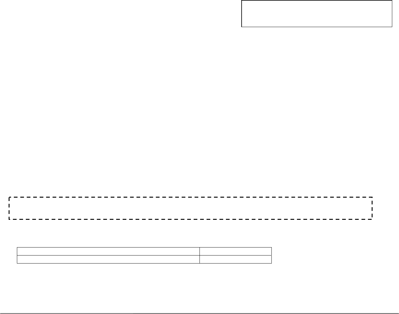
Male – Female Load Cell link Placement on BOOM TIP DEAD-END – for Even Parts-of-Line:
1. Pin the load cell link between the wire rope (wedge) socket and the boom tip dead end. Secure the pins with washers and cotter
pins provided. Cranesmart systems provides bushings when required to match odd size pin holes on crane. Call for assistance.
NOTE: ENSURE THE LOAD CELL DOES NOT CONTACT THE BOOM AT ANY ANGLE DURING NORMAL
OPERATION.
Dead end
Load cell
Pins
Becket or wire
rope socket
9 Cranesmart System Version R6
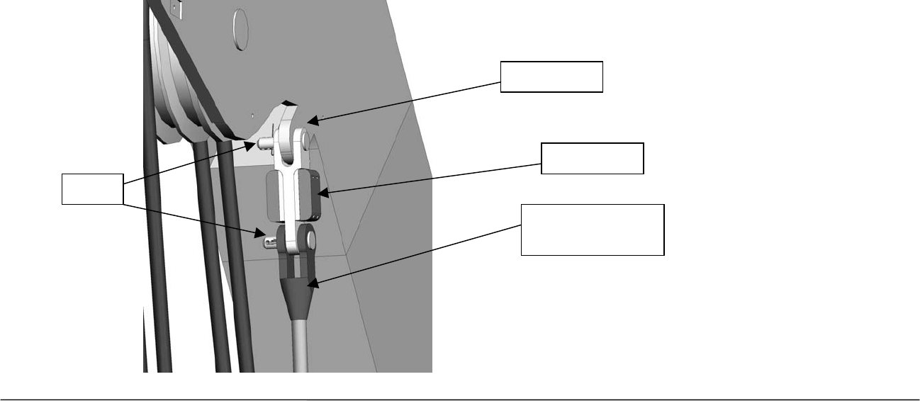
Male – Female Load Cell Link Placement on HEADACHE BALL – for Single Part-of-Line:
Pin the load cell link on the top swivel between the wire rope (wedge) socket and the “Headache Ball” or hook block as
illustrated below.
NOTE:
¾ Custom links are available, if necessary; to help fit the load cell on the ball. Call for assistance.
Becket or wire
rope socket
Headache ball
Load cell
Pins
Top swivel
10 Cranesmart System Version R6
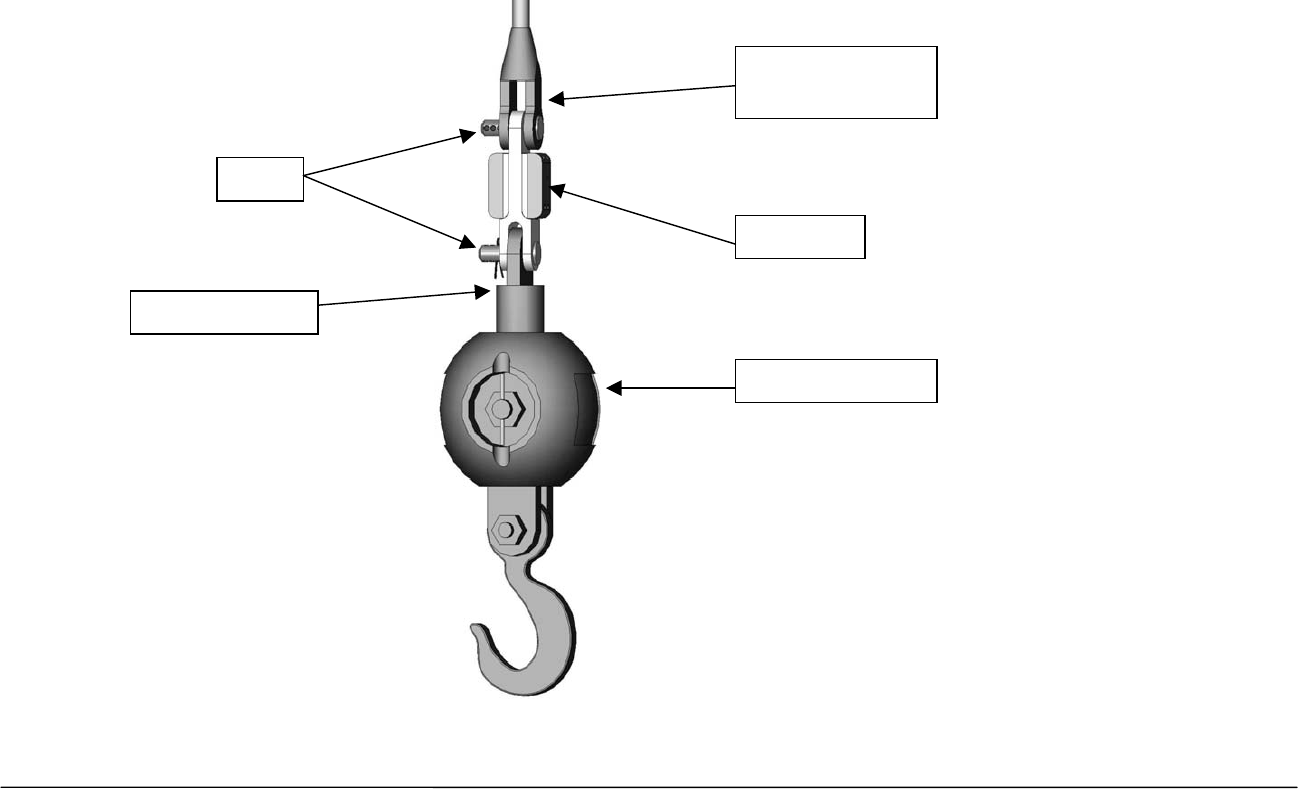
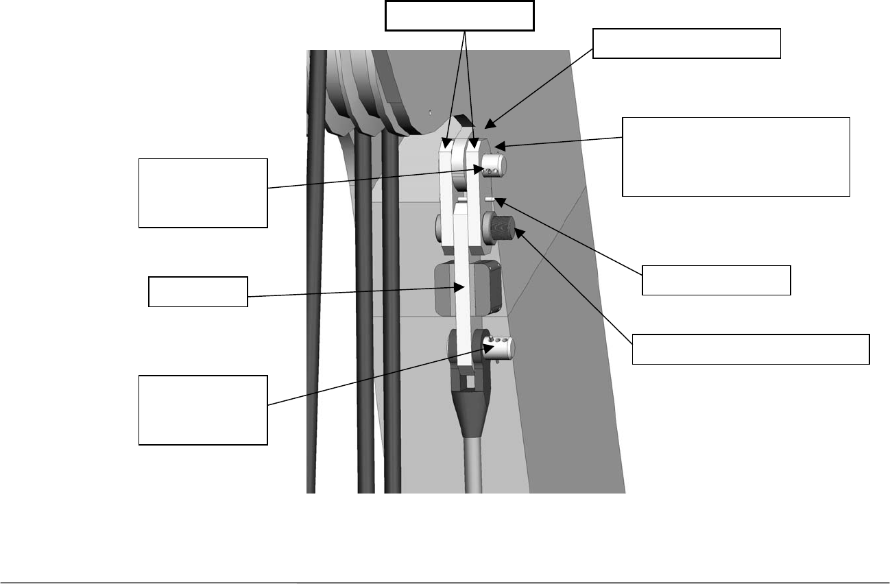
SLP Load Cell Installation (40,000, 50,000 or 80,000 lbs.)
Sandwich Link Stabilization Pin – Male/Male flat link load cell only
The Sandwich Link Stabilization Pin prevents the sandwich links from folding against, and damaging the load cell when
the headache ball or hook block is laid on the ground or when the crane is two-blocked. Check the pin regularly to ensure
that it is securely in place. Also ensure that the locking center pin is located in place as illustrated below.
Load cell
Center threaded locking pin
must be installed here
Stabilization pin must
be installed here
Dead end or swivel
on headache ball
Becket or wire
rope socket
Sandwich links
Round edges of links face
away from load cell towards
dead end or headache ball
11 Cranesmart System Version R6
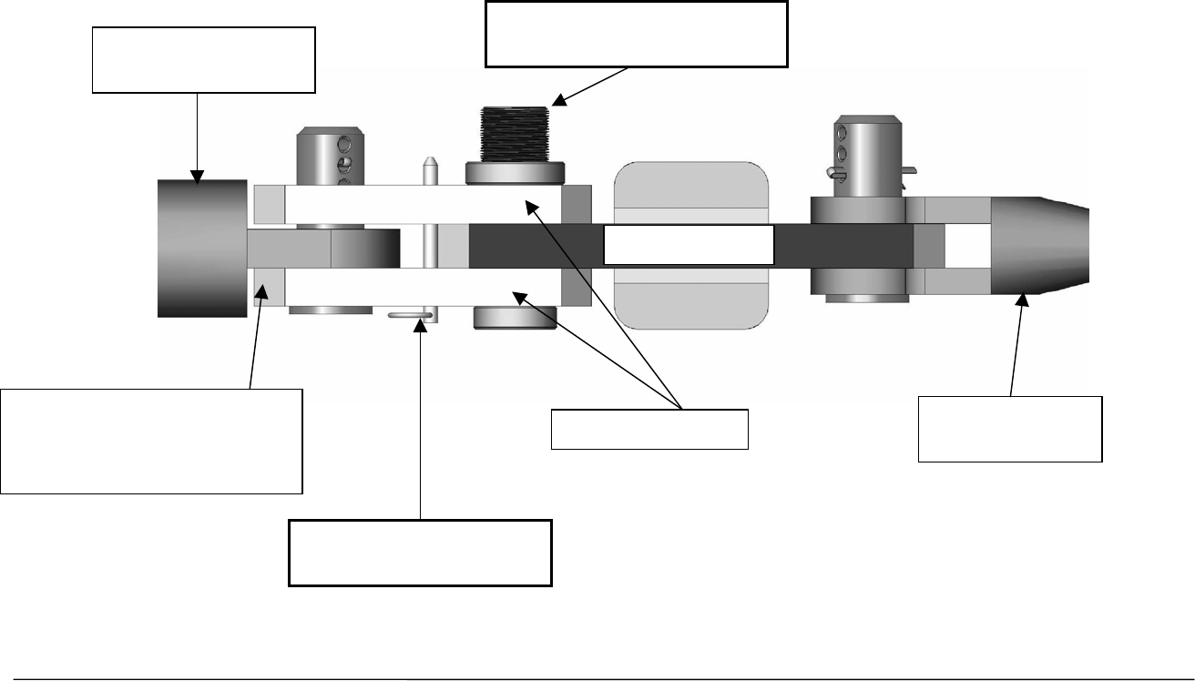
Male – Male Load Cell Link Placement on Boom Tip Dead-end - for Even Parts-of-Line:
Use the “Sandwich Links” to pin the load cell link between the wire rope socket (becket) and the dead end boom tip as
illustrated below.
Sandwich links
Dead end on boom
Stabilization pin
Lockin
g
threaded center pin
Load cell
Pin secured
with washers
and cotter pin
Pin secured
with washers
and cotter pin
Round edges of links face
away from load cell towards
dead end or headache ball
12 Cranesmart System Version R6
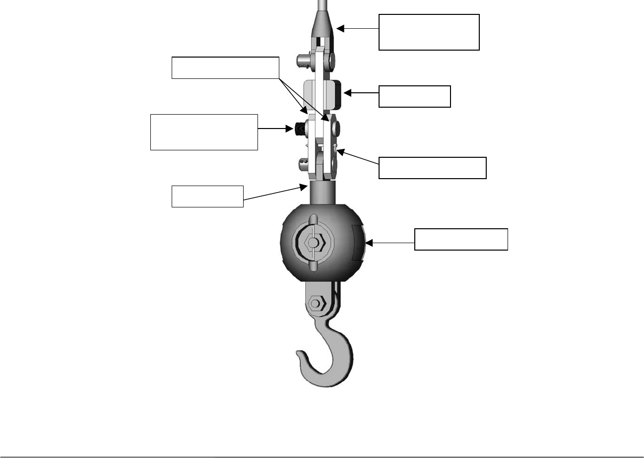
Male – Male Load Cell Link Placement on HEADACHE BALL – for Single Part-of-Line:
Pin the load cell link on the top swivel between the wire rope (wedge) socket and the “Headache Ball” or hook block as
illustrated below.
Load cell
Stabilization pin
Top swivel
Headache ball
Becket or wire
rope socket
Locking threaded
center pin
Sandwich links

13 Cranesmart System Version R6
Load Cell Battery Replacement
The display panel will indicate a low battery for approximately three (3) weeks.
Before replacing the batteries call the service department at 1-888-562-3222 or (780) 437-2986. Once you have verified
that it is a dead battery follow the steps below.
Please have the serial number of your system handy before calling to purchase batteries or to ask for
technical assistance. You can find the serial number on either the display panel or the load cell itself.
Tools and Equipment for battery replacement:
Battery replacement kit (purchased from Cranesmart Systems) contains:
¾ One 3.6 volt Lithium Ion D-cell battery
¾ One battery cover gasket
¾ One tube of RTV silicone
¾ One 5/32” allen key
NOTE:
¾ You may also buy a 3.6V Lithium battery from a local battery store. Ensure that you take the existing battery with you if possible for
correct size matching.
14 Cranesmart System Version R6
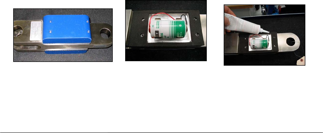
To Replace the Battery in the Load Cells only
Locate the Battery compartment (on the same side as the serial tag). There should be four hex bolts visible.
1. Use the allen key to remove the four hex bolts. (If the holes are filled with silicone you are on the transmitter side of the Load Cell.
Do not open this side, it has no User serviceable parts.)
2. Remove battery from clip (ensure you do not break the red polarisation tab).
3. Remove the old gasket material from both sides of the compartment.
4. Clean the surfaces of the Battery compartment and install the new gasket on the Aluminium plate.
5. Install the new Battery, (positive ‘+’ to red polarisation tab).
6. Use the RTV Silicone to put a bead around the edge of the plastic cover and on any surfaces touching the gasket.
7. Place the plastic cover over the Battery pack taking care not to wipe off the silicone or pinch the wires.
8. Replace the screws and tighten until the gasket is squeezed to approximately 1/16” (half of its original thickness). Silicone should
squeeze out while tightening, if there is no excess silicone then you did not put enough on.
9. Clean off the excess silicone.
10. Re-install the load cell to test its operation.
Do not use a power drill or power screwdriver to remove or tighten the bolts, you may damage the
threads on the aluminum plate.
NOTE:
¾ Your warranty will be Void if the Transmitter Electronics section has been opened.
15 Cranesmart System Version R6
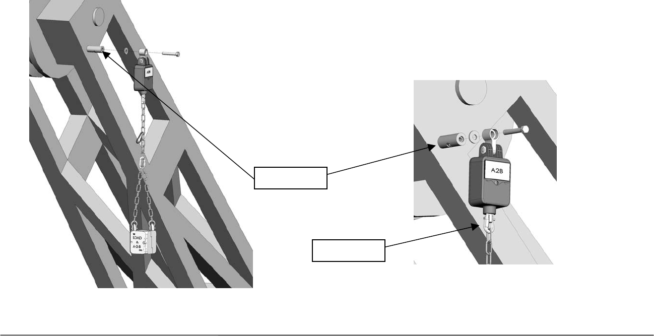
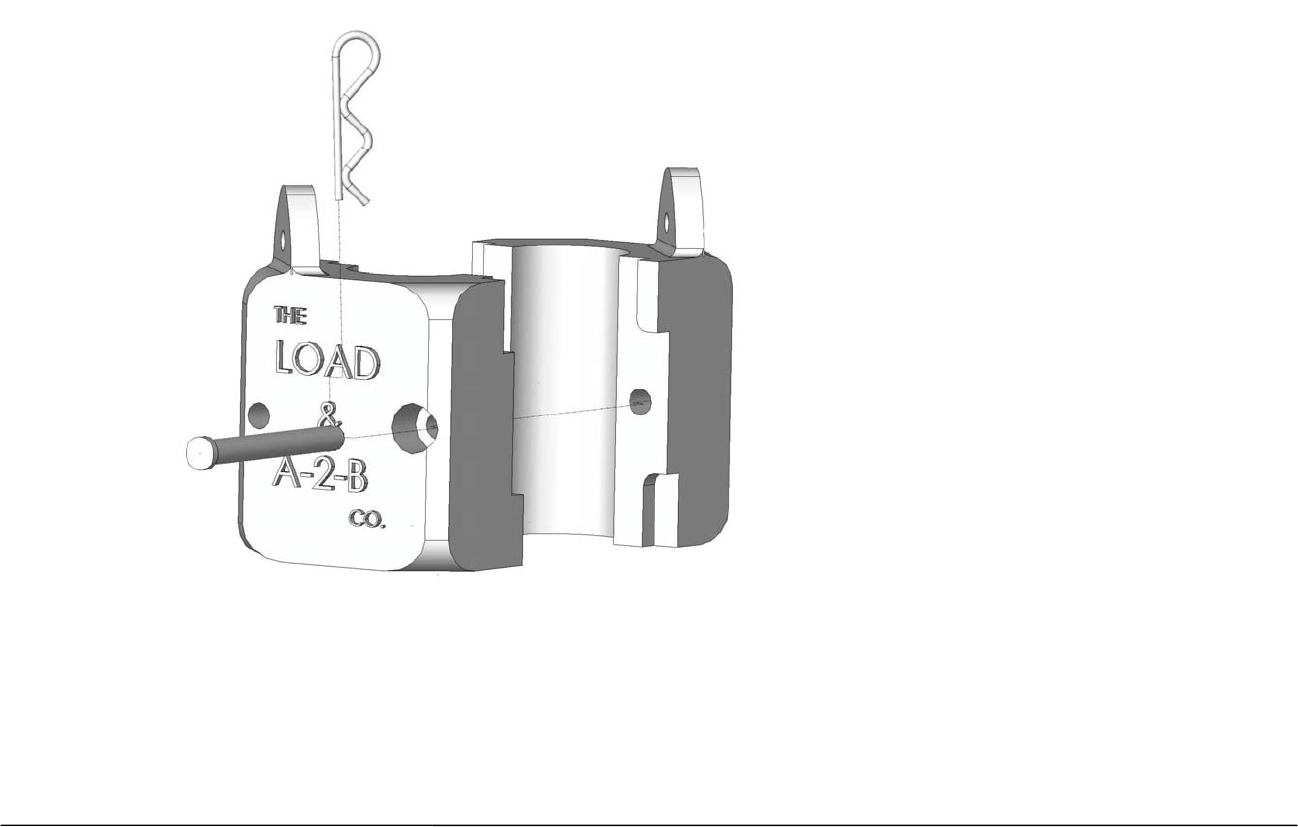
Anti-2-Block Installation (Blue = Main, Yellow = Aux. 1 Winch, Orange = Aux. 2 Winch)
The switch is designed to swivel and pivot so that it is always in an upright vertical position regardless of the boom angle.
1. Weld the Weld bar to the crane. Ensure the switch is mounted directly above the dead-end or the slowest speed line. The Weld bar
can be welded directly to the crane or to an existing Cranesmart weld plate. (Both sides of the weld bar are identical).
2. Ensure that the mounted A2B switch will have an unobstructed line-of-sight to the receiver panel antenna. Install the large shoulder
bolt into the A2B swing arm.
3. Attach the A2B switch to the bar. (Install the nylon bushing between the bar and the swing arm.)
4. Attach the counterweight to the dead-end line or the slowest speed line.
5. Use the C-shackle (found on the bottom of A2B switch) to install the chain to the A2B switch.
Weld ba
r
C-shackle
16 Cranesmart System Version R6
Standard Counterweight
1. Attach counterweight chain to the bottom of the A-2-B transmitter using the C-Shackle supplied.
2. Put the counterweight together around the cable.
3. Attach the counterweight halves with hitch pins provided.
17 Cranesmart System Version R6
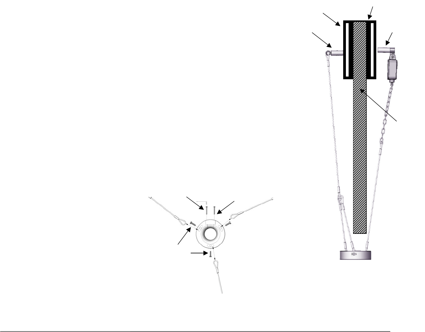
Optional Fast Line Counterweight – single part-of-line only
Weld Bar Installation and Placement (See illustration on right)
1. Weld the main weld BAR to the side of the boom that will have A2B switch on it. Position it close to the
bottom of the boom tip ensuring that the switch will not contact any metal at high boom angles once
installed on the weld BAR.
2. Weld the secondary weld BAR to the opposite side of the boom tip at approximately the same height.
3. Bolt the A2B switch to the main weld bar using the bolt and allen key supplied. Attach the
counterweight chain to the bottom of the A2B switch using the shackle that is attached to the A2B.
Counterweight Installation and Placement (See illustration below)
4. Using the supplied quick link, attach the counterweight chain (not cable) to the secondary weld bar.
Adjust chain length to ensure the counterweight sits level on the wire rope.
5. Remove the allen bolts that hold the insert in the counterweight in place (as illustrated below).
6. Remove the insert and slide the wire rope through the opening, ensuring cables are directed towards
the boom tip.
7. Install the insert and fasten with the allen bolts.
Main Weld
Bar
Secondary
Weld bar
Cable
Sheave
Boom Tip
NOTE: If you need to remove the eye bolts that secure the cable to the counterweight you must use Loctite when re-tightening them.
Allen bolts Insert
Eye bolts
18 Cranesmart System Version R6
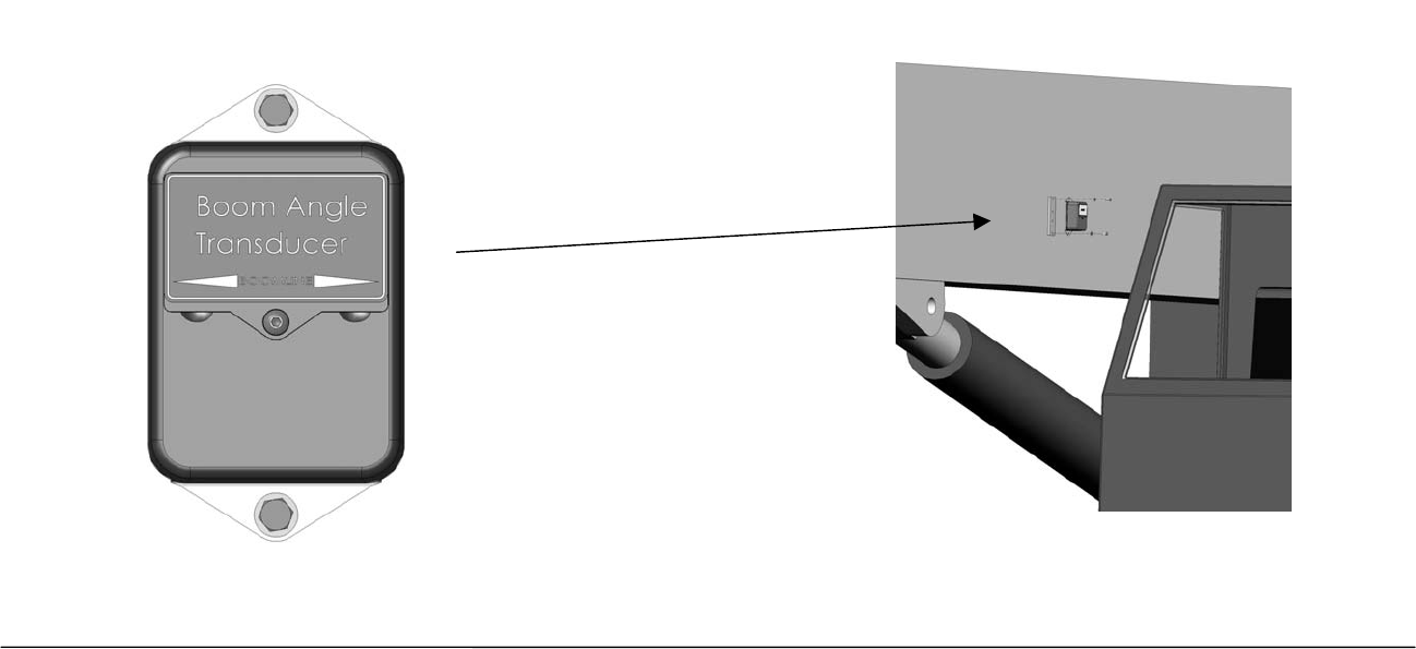
Boom Angle Transducer Installation
The boom angle transducer must be installed on the boom at least five (5) feet from where the antenna will be mounted
on the crane; and must maintain line of sight with the antenna in all positions. The transducer can be mounted on either
side of the boom but cannot be installed on the top or bottom.
To Install the Transducer
1. Remove the weld plate from the Angle transducer.
2. Align and mark the installation position. Use the illustration on the transducer label to position the transducer parallel with the boom
line.
3. Tack weld the weld plate before testing the system.
4. Mount the transducer to the weld plate.
5. Raise the boom to a minimum of 45o degree angle and return it to level. (This will set the transducer for the proper side of the boom
before calibration).
19 Cranesmart System Version R6
Positive
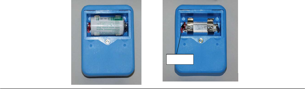
Anti-2-Block and Angle Transducer Battery Replacement
Before replacing the batteries call the service department at 1-888-562-3222 or (780) 437-2986. Once you have verified that it is a battery
problem follow the steps below.
NOTE:
¾ Please have the serial number of your system handy before calling to purchase batteries or to ask for technical assistance. You can find
the serial number on either the Display Panel or the Transducer.
Tools and Equipment needed for battery replacement:
¾ One Battery Replacement Kit – purchased from Cranesmart Systems or you may buy a 3.6V Lithium battery from your local battery store.
The kit contains:
¾ One 3.6 volt Lithium Ion D-cell Battery
¾ One 1/8th Allen key
NOTE:
¾ We suggest you remove the transmitter from the boom of the crane; however, battery replacement can be done with the transmitter on the
boom. If it is humid, raining or snowing – DO NOT OPEN THE TRANSMITTER. Remove the transmitter and perform the battery
replacement indoors or undercover.
To Replace the Battery:
1. Remove the cap screw from the battery compartment lid and remove the lid.
2. Remove the battery from the holder. (Ensure you do not break the red polarisation tab located on the positive ‘+’ side of the battery
clip).
3. Insert the new battery, positive ‘+’ side to the red polarisation tab.
4. Secure the lid.
20 Cranesmart System Version R6
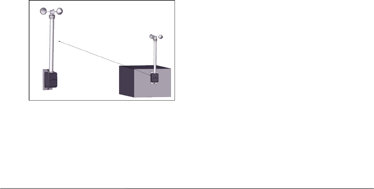
Wind Speed Transducer Installation
There are two types of mounts for the wind speed indicator; a fixed mount and a swivel mount. Wind Speed Indicators
with a fixed mount must be installed vertically on or near the cab of the crane. Swivel mounts should be used when
installing the wind speed indicator on the boom tip of the crane.
To Install the Wind Speed Indicator
1. Loosen and remove the two bolts that hold the weld plate on the side of the blue transmitter box.
2. Tack weld the plate to a flat surface on or near the cab of the crane and use a carpenter’s level to ensure the wind speed indicator is
vertical.
3. Finish the weld.
4. Reattach the wind speed indicator to the weld plate and tighten.
21 Cranesmart System Version R6
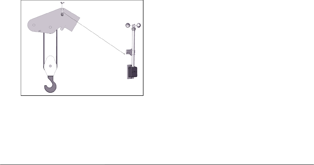
To Install the Wind Speed Indicator with Swivel Mount
Step A – Attach the Swivel Mount to the Boom Tip
1. Remove the swivel mount from the weld plate.
2. Tack weld the weld plate to the boom tip end (ensure the wind speed indicator will be able to swing freely).
3. Finish the weld
4. Remove the U-bolts from the swivel assembly and attach the assembly to the weld plate.
Step B – Attach the Wind Speed Indicator to the Swivel Mount
5. Use the U-bolts to secure the wind speed indicator to the swivel mount.
6. Leave the wind speed indicator’s weld plate attached for balance.
NOTE:
¾ The Wind Speed Indicator must be able to swing freely without obstruction.

22 Cranesmart System Version R6
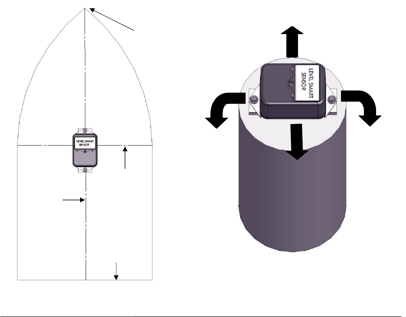
Level Smart Sensor Installation Instructions
1. The Level Smart Sensor should have a clear line of sight to the Cranesmart system’s antenna and be kept free of all obstructions.
2. The Level Smart Sensor can be mounted to the deck (label facing up) or onto a post (see Figure 2 on page 23). The higher the
Level Smart Sensor is from the deck the better the radio transmission will be.
3. The mounting position needs to be stable during operation as vibration may cause the unit to jitter.
4. The Level Smart Sensor should be made as level as possible but it is NOT critical that the Level Smart Sensor be perfectly level.
The unit will be calibrated after installation.
5. The correct mounting position of the Level Smart Sensor is critical. The top and the bottom of the Level Smart Sensor box must be
parallel to the beam of the boat and the sides of the Level Smart Sensor box must be parallel to the keel line (see figure 1 on page
23).
6. Verify communication with receiver panel before permanently mounting the sensor (see page 58).
7. The barge deck MUST be level during the calibration process.
8. DO NOT weld the weld plate with the Level Smart Sensor attached.
23 Cranesmart System Version R6
Bow
Beam
Stern
Keel Line
Figure 1
Positive Roll Ne
g
ative Roll
Positive List
Ne
g
ative List
Figure 2 – Example of Mounting

24 Cranesmart System Version R6
Level Smart Error Messages
During installation or operation of a system with a Level Smart Sensor installed, the system may give various error messages relating to the Level
Smart Sensor.
If a LIST ABOVE PRESET message is displayed it means that the sensor is tilted sideways from its calibrated zero past the number of degrees
set in the LIMITS screen. Press SELECT from the main operating screen to view the current list value. If the value is positive then the sensor is
tilted too far to the right (Starboard). If the value is negative then the sensor is tilted too far to the left (Port).
If a ROLL ABOVE PRESET message is displayed it means that the sensor is tilted frontward or backwards from its calibrated zero past the
number of degrees set in the LIMITS screen. Press SELECT from the main operating screen to view the current list value. If the value is positive
then the sensor is tilted too far forward. If the value is negative then the sensor is tilted too far backward.
If a LIST & ROLL ABOVE PRESET message is displayed it means that the sensor is tilted both too far sideways and too far forward or backward.
Follow the instructions above to fix this problem.
If these messages are displayed while the sensor is level you may need to re-calibrate your sensor via the CALIBRATE screen (see page 44). If
the error messages are displayed during normal operation while the crane is operating in a safe configuration in the allowable range it may need to
be changed in the LIMITS screen (see page 39).
LIST
ABOVE PRESET
72
ROLL
ABOVE PRESET
71
LIST & ROLL
ABOVE PRESET
70
25 Cranesmart System Version R6
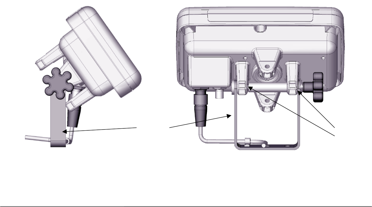
Display Panel Installation
Mounting the Display Panel
1. Mount the display panel where the operator has an unobstructed view of the display.
2. Remove the bottom portion of the mounting bracket.
3. Align, mark and drill mounting holes using the mounting bracket as a guide.
4. Attach the bottom portion of the mounting bracket assembly to the dash using the bolts provided.
5. Align mounting horns with mounting bracket and tighten securely.
NOTE:
¾ Tilt the top of the panel away from you to make connections easier.
¾ Reduce strain on the cables by attaching them to the unused mounting holes with zip strips or twist ties.
Mounting
Bracket Mounting
Bracket
Ears

26 Cranesmart System Version R6
Wiring Instructions
Display Panel
Power to the Display Panel is supplied through the three-conductor cable labeled Power, included in the kit, which plugs
into the back of the panel.
1. Connect the Red wire to a positive (12 to 24 (28VDC Maximum)) terminal.
2. Connect the Black wire to a solid ground on the crane.
3. OPTIONAL: Connect the White wire to an optional ‘Shut off’ or to sound external horns. (Maximum output is 7.5 amps).
NOTE:
¾ For the system to work properly ensure that a continuous 12 to 24 (28VDC Maximum) is available to the panel at all times while the crane
is in operation. If the voltage drops below 11.7 VDC the panel will shut down and not function.
¾ When attaching the power cable to the panel, align and gently push the plug into the receptacle, then slide the plug neck back towards the
panel and turn clockwise ½ turn to tighten.
Alarm Shut-offs – (White Output Wire):
Normally the Cranesmart system will be shipped with a three conductor wiring harness, which includes a black, red and
white wire. The white wire may be used in conjunction with external alarm horns, lights or shut-offs if you have them
installed.
• When you are powering (supply power to) the Cranesmart System with +12 VDC the white wire is normally hot
(energized) with a +12 VDC in a non-alarm condition. If you do not wish to use the white wire for any of the above,
please ensure that the exposed end of the white wire remains sealed to prevent grounding and damage to the display
panel.
• When you are powering (supply power to) the Cranesmart System with +24 VDC the white wire is normally hot
(energized) with a +24 VDC in a non-alarm condition. If you do not wish to use the white wire for any of the above,
please ensure that the exposed end of the white wire remains sealed to prevent grounding and damage to the display
panel.

27 Cranesmart System Version R6
Antenna Installation
There are three types of antennas; installation and placement depend on the length and type of boom on your crane.
Antenna types
1. Panel Mount – For a crane without a cab, with booms up to100 Feet
2. External Mount – For all cranes with cabs, with booms to 300 feet
3. Marine – For all marine applications
NOTE:
¾ Ensure that the lines of sight between the Load cells, Anti-2-block switches, Angle transducers and the antenna are not obstructed.
¾ Do not let the antenna touch glass or metal.
28 Cranesmart System Version R6
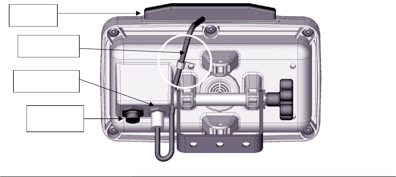
Display Panel Antenna/No Cab – 100 feet of Boom or less
When the display panel is mounted outside of the cab, or there is no cab on the crane, and the boom is 100 feet or less,
use the panel mount antenna. This antenna is normally installed at the factory, if it is not installed, do the following:
1. Clean the top of the panel with the alcohol pad included in the installation kit.
2. Peel off the paper from the two tabs on the underside of the antenna.
3. Place the antenna on the top of the panel.
4. Using the P-clamp and machine screw included in the installation kit, strain relief the cable as shown below.
5. Attach the antenna connector to the panel and secure.
6. Determine the best position for the antenna; check the signal quality while moving it around.
7. Check the quality of the signal using the “SIG” option in the Secondary Operating screen (see page 58). (This menu displays for
eight seconds). For a permanent display use the signal viewer in the Diagnostics menu.
Antenna on
top of panel
Attach antenna
connector here
Secure antenna
wire relief here
Attach Power
Cable here
29 Cranesmart System Version R6
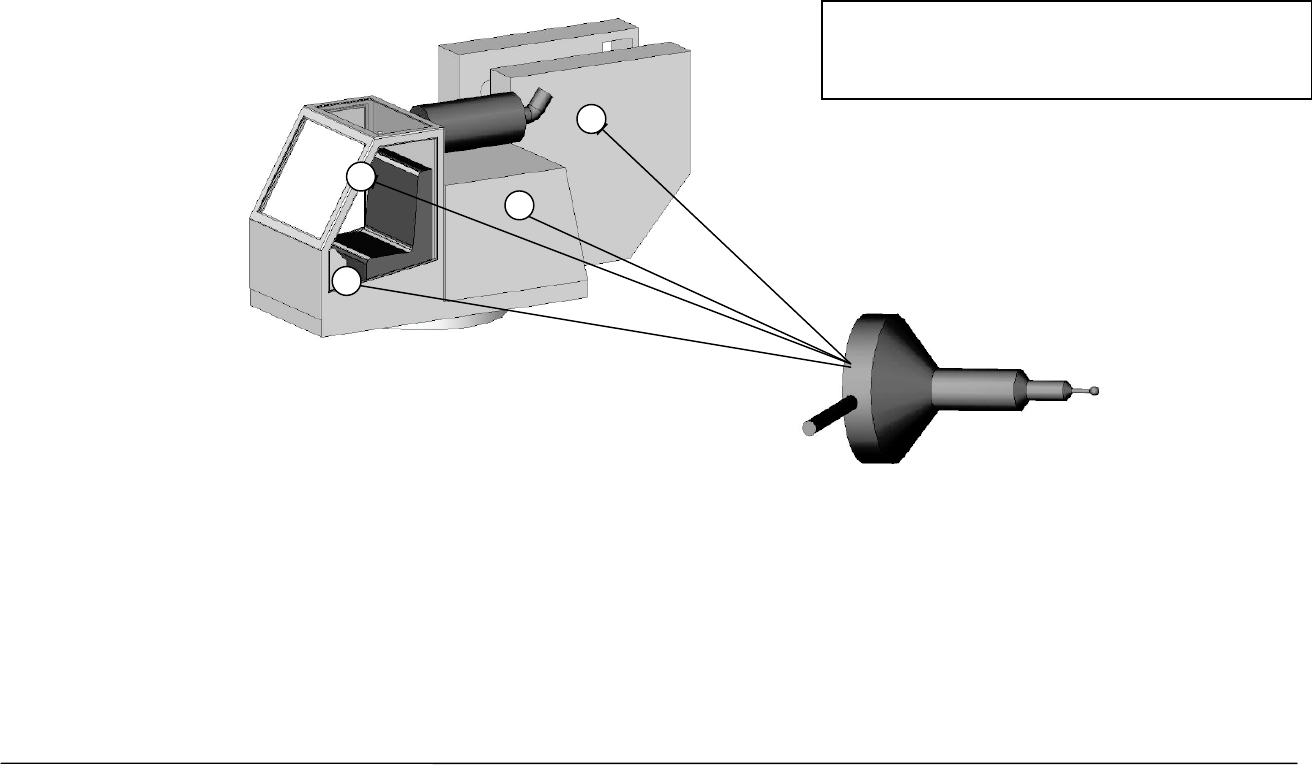
Display Panel External Antenna/Inside Operator Cab
When the display panel is mounted inside the cab of the crane use the external magnetic mount antenna. This antenna
will be included in the system packaging. Installation varies between cranes but use the following as a guideline.
For optimum performance, the antenna should be installed horizontally as shown below.
To confirm the best position for the antenna; check the signal quality while moving it around (see page 58)
Examples of possible antenna locations –
use the signal strength meter (page 60) to
determine which location is most suitable.
30 Cranesmart System Version R6
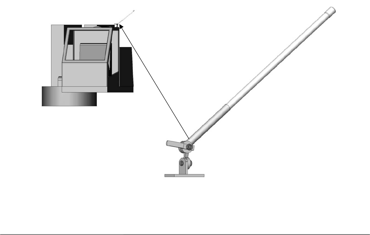
Marine Installation
When the Cranesmart system is used in a marine environment use the external marine antenna included in the kit.
Installation varies between cranes but use the following as a guideline.
For optimum performance, the antenna should be installed at a 45 degree angle as shown below.
Determine the best position for the antenna; check the signal quality by using the signal display screen on (see page 58)
changing the angle, etc.
31 Cranesmart System Version R6
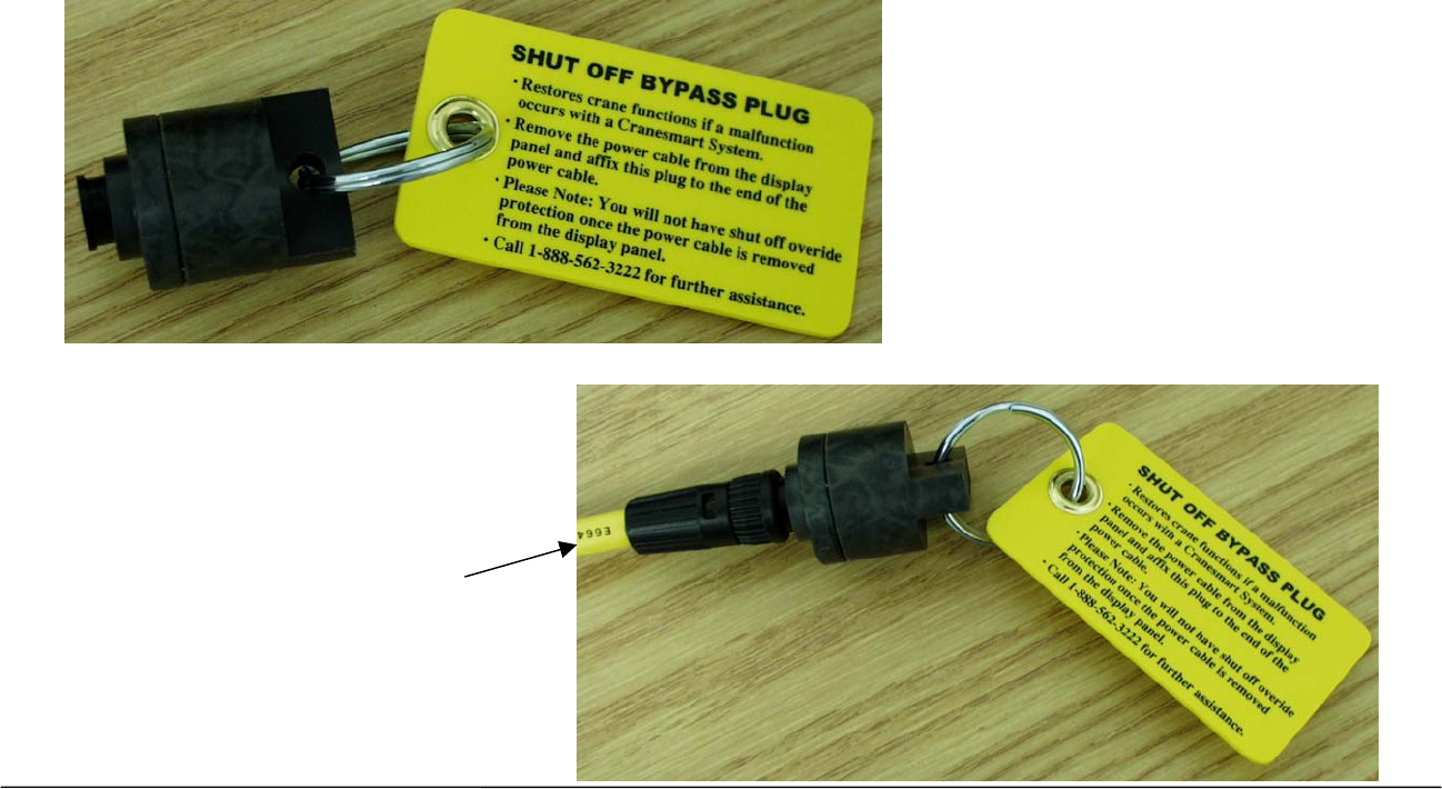
Shut-off Bypass Plug – with yellow tag
Where the white output wire is integrated into crane shut-offs (kick outs) and the Cranesmart system is over come by user
damage or system malfunction this wire can be bypassed using a bypass plug included with the kit. When this plug is
installed as follows, it will allow your function kick outs to be re-energized.
Remove the power cable from the back of the panel by twisting the coupling ½ turn counter clockwise and pull away from
the panel. Insert the plug (By-pass plug) into the end of the power cable (lower illustration) – not the panel – and turn the
plug ½ turn clockwise. This will restore crane functions, however, the Cranesmart System is no longer monitoring crane
functions.
Power Cable Attached
to By-pass Plug
32 Cranesmart System Version R6
Display Panel – System Start-up
When the Cranesmart System starts the Cranesmart systems logo is displayed. The panel then displays the Primary
Operating Screen showing the last winch setting – in a Load System for example.
Primary
Operating
Screen
Part-of-line
33 Cranesmart System Version R6
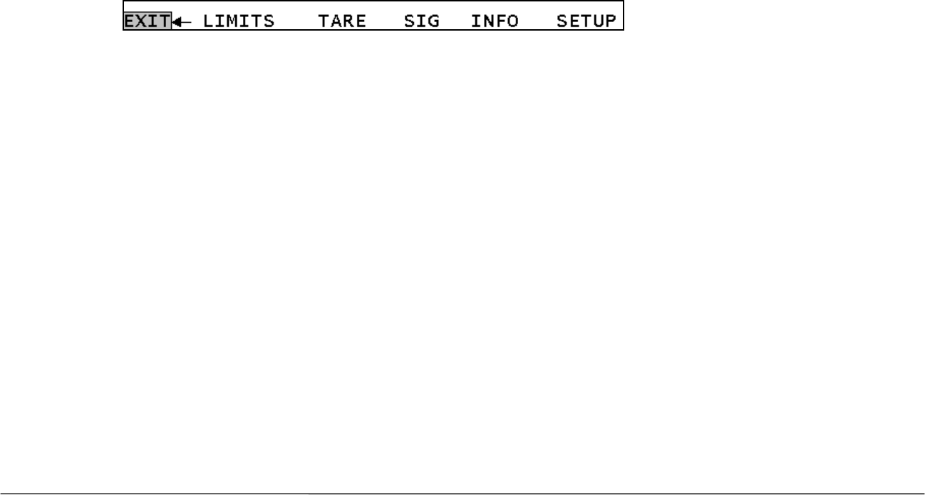
Display Panel – Quick Winch Switching – for systems with Load Cells only
Quick Winch Switching enables operators to quickly change the display to show the load on the auxiliary winch line.
NOTE:
¾ A winch can only be selected if a load cell is enabled on that winch.
To View the Auxiliary Winches
1. Press the Up or Down arrows.
2. Press Accept to Change (the configuration screen for the new winch will be displayed).
3. Press Select to Cancel.
NOTE:
¾ When the Quick winch prompt is being displayed, the Main Operating screen will not update with new information.
¾ To change POL for winch being displayed operators must use the Config menu, (see Display Panel – Operator Functions).
¾ The Up and Down arrows move to a different winch depending on the winch the operator is viewing:
MAIN Winch UP KEY to AUX1 Winch.
DOWN KEY to AUX2 Winch.
AUX1 Winch UP KEY to AUX2 Winch.
DOWN KEY to MAIN Winch.
AUX2 Winch UP KEY to MAIN Winch.
DOWN KEY to AUX1 Winch.

34 Cranesmart System Version R6
Display Panel Navigation
Panel Buttons
By-pass The By-pass button enables the operator to bypass any existing alarms. It enables the operator to override any
shut-offs and restore crane functions while the system is in alarm.
The By-pass works for 30 seconds and displays the remaining time periodically before returning to normal
functioning.
The By-pass works for 30 seconds and displays the remaining time periodically before returning to normal
functioning. Sound judgement must be used when using the By-pass function (see page 31).
The By-pass function can be disabled – call our service department for details.
Select The Select key enables the operator to enter any highlighted field.
When a Menu is selected a new screen is displayed.
When a Value is selected the operator can change the Value.
When an Operation is selected the operation is performed.
Up In Menu mode is used to move through the menus and to change winch in Primary Operating Display.
In Selector mode is used to increase Values.
Down In Menu mode is used to move through the menus and to change winch in Primary Operating Display.
In Selector mode is used to decrease Values.
Accept The Accept key enables operators to accept and save any adjusted setting.
Sound judgement must be used when using the By-pass function.
The By-pass function can be disabled – call our service department for details.
35 Cranesmart System Version R6
Panel Navigation
The Cranesmart System uses a menu system to lead you through its functions. In normal operating mode the system
provides a general level menu of functions to which operators have access. In supervisor mode the system provides
access to more functions for supervisors to configure the system to match their needs.
The Cranesmart System displays the Primary Operating screen on startup; users press the Select button to enter the
Secondary Operating screen to access the Navigation bar. From the Secondary Operating screen users press the up or
down arrows to select Setup to enter the menu system.
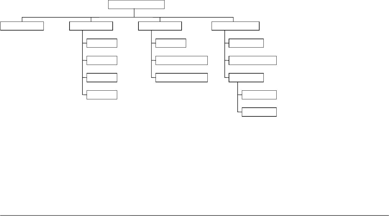
Secondary Operating Screen Navigation Bar
The Secondary Operating Screen has a navigation line on the bottom of the display to enable users to move through the
rest of the Cranesmart system.
Exit Returns the user to the Primary Operating screen.
Limits Displays the Limit settings for the system, i.e. the Max or Min Angle or Max Load settings.
Tare Enables the operator to Tare out the current load value and return to the Primary Operating screen.
Sig Displays the signal strength for the transducers in the system and counts the packets of information being received.
Info Displays information about the system and the status of transducers in the system.
Setup Displays menu options to reconfigure system settings and diagnostic information.
36 Cranesmart System Version R6
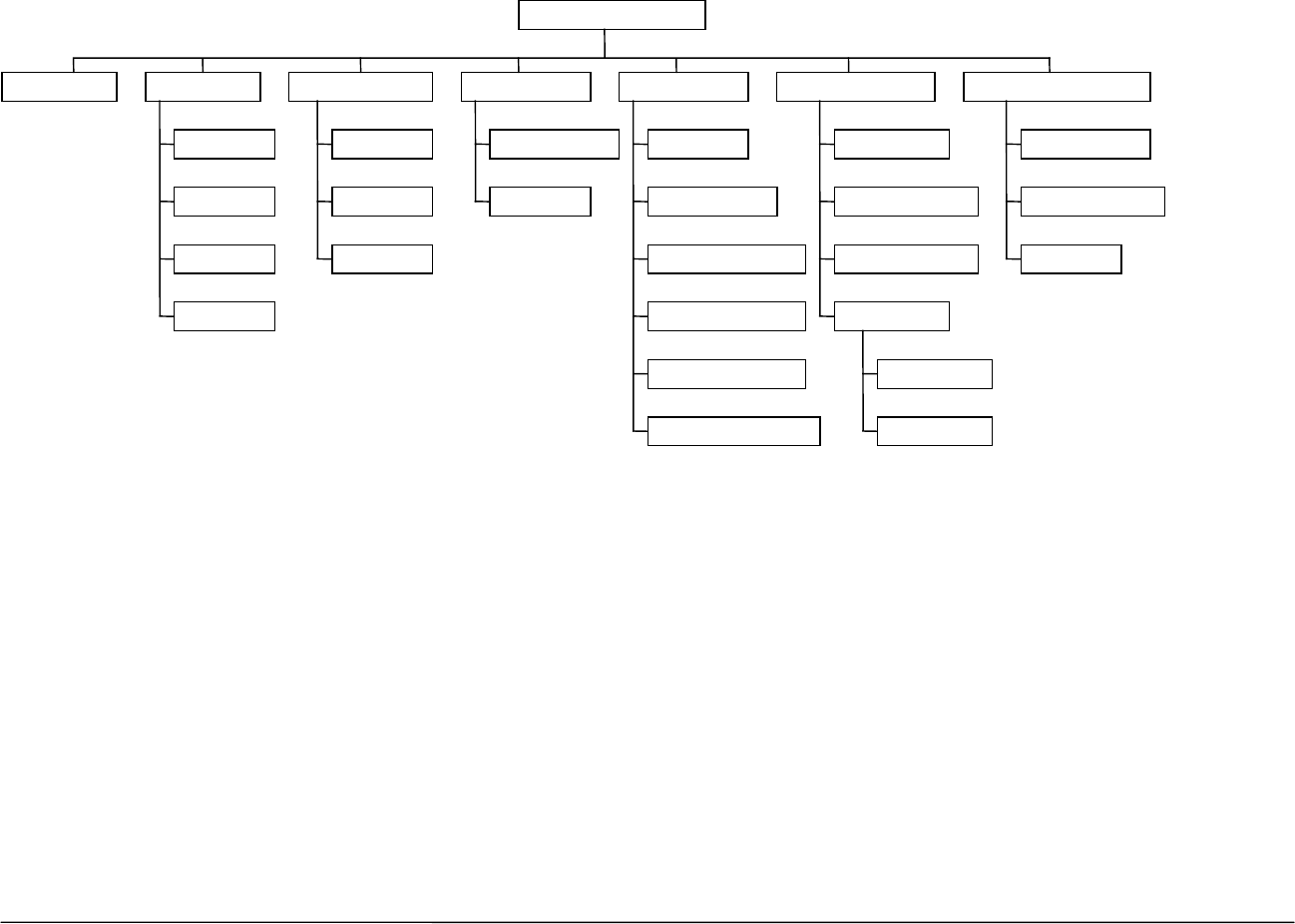
Setup Menus
The Setup screen displays menus to enable operators to configure settings for the system.
1. From the Primary Operating screen, press the Select button to move to the Secondary Operating screen.
2. Use the Up or Down Arrows to move through the navigation bar, select Setup.
3. Press the Select button, the Setup screen displays access to the following menus. (The supervisor menu is accessed by using the
proper permission code).General Permission Level – Top Menu
Configure Enables users to select the Winch and Parts-of-line to be displayed. (Not in A2B only systems.)
Limits Enables users to set limits for Load and Angle indicators. This function will not work if the LIMITS IS LOCKED.
(Not in A2B only systems)
Diagnostic Enables users to view the signal strength and RF signal from the transducers. Also enables users to view the IDS
of the components of the system.
System Enables users to display the serial number of the system or change the permission level.
TOP MENU
LIMITSCONFIGURE SYSTEM DIAGNOSTIC
ANGLE
LOAD
WIND
TILT
ABOUT
LCD CONTRAST
PERMISSION
SIGNALS
VIEWER
PANEL RELAY
IDS
LOAD
Open Standard Setup Mode

37 Cranesmart System Version R6
Display Panel – Operator Functions
Configure Menu – systems with load cells only
The Configure Menu enables users to select the winch in use and set parts-of-line.
Select Winch, POL (Parts-of-line)
1. From the Primary Operating screen press select, the Secondary Operating screen is displayed.
2. Use the Up or Down arrows, select Setup.
3. Use the Up or Down arrows, select Configure
4. Use the Up or Down arrows, select (Main, Aux 1, Aux 2).
5. Press Accept twice to save.
6. Use the Up or Down arrows, select Main POL
7. Use the Up or Down arrows choose the number of POL.
8. Press Accept twice to save.
9. Select Exit to return to Primary Operating Screen or Select Back to return to the top menu.
Limits Menu
The Limits menu enables users to set the limits at which alarms will sound and shut-offs will occur.
Load Limits
1. From the Primary Operating screen press select, the Secondary Operating screen is displayed.
2. Use the Up or Down arrows, select Setup.
3. Use the Up or Down arrows, select Limits. (If Limits is Locked the operator must enter the correct key.)
4. Use the Up or Down arrows, select Load.
5. Use the Up or Down arrows, select (Main, Aux 1, Aux 2).
6. Use the Up or Down arrows to increase or decrease the Maximum limit for that Winch.
7. Press Accept twice to save.
8. Select Exit to return to Primary Operating Screen or Select Back to return to the top menu.

38 Cranesmart System Version R6
Angle Limits
1. From the Primary Operating screen press select, the Secondary Operating screen is displayed.
2. Use the Up or Down arrows, select Setup.
3. Use the Up or Down arrows, select Limits.
4. Use the Up or Down arrows, select Angle.
5. Use the Up or Down arrows, select Max.
6. Use the Up or Down arrows to increase or decrease the Maximum limit for that Angle Sensor.
7. Press Accept twice to save.
8. Use the Up or Down arrows, select Min.
9. Use the Up or Down arrows to increase or decrease the Minimum limit for that Angle Sensor.
10. Select Exit to return to Primary Operating Screen, Select Back to return to the Limits menu or Select Top Menu to return to the Top
Menu.
Wind Limits
1. From the Primary Operating screen press select, the Secondary Operating screen is displayed.
2. Use the Up or Down arrows, select Setup.
3. Use the Up or Down arrows, select Limits.
4. Use the Up or Down arrows, select Wind.
5. Select Max Wind.
6. Use the Up or Down arrows to increase or decrease the Maximum Wind speed. Minimum wind speed setting is defaulted at 15
MPH and can not be set to a lesser value.
7. Press Accept twice to save.

39 Cranesmart System Version R6
Level Smart Sensor Limits
1. From the Primary Operating screen press select until the Secondary Operating screen is displayed.
2. Use the Up or Down arrows, to highlight Setup. Press select.
3. Use the Up or Down arrows, to highlight Limits. Press select.
4. Use the Up or Down arrows, to highlight List-Roll. Press select.
5. You will be defaulted to Max Roll Angle. Press select.
6. Use the Up or Down arrows to adjust the Maximum limit for the Roll Angle.
7. Press Accept twice to save.
8. Use Up or Down arrows to highlight Max List Angle. Press Select.
9. Use the Up or Down arrows to adjust the Maximum limit for the List Angle.
10. Press Accept twice to save.
11. Highlight Exit and press select to return to Primary Operating Screen, Select Back to return to the Limits menu or Select Top Menu
to return to the Top Menu.

40 Cranesmart System Version R6
System Menu
The system menu provides information about the system in use on the crane and enables users to set Access Permissions.
About
1. From the Primary Operating screen press select, the Secondary Operating screen is displayed.
2. Use the Up or Down arrows, select Setup.
3. Use the Up or Down arrows, select System.
4. Use the Up or Down arrows, select About.
5. Select Exit to return to Primary Operating Screen or; Select Back or Top Menu to return to the top menu
LCD Contrast
LCD Contrast allows you to adjust your panel display to be lighter or darker for easier viewing.
1. From the Top Menu screen, use the Up or Down arrows to select System.
2. Use the Up or Down arrows to select LCD Contrast.
3. Press Select on LCD Contrast, then use the Down arrow to make the display darker, or the Up arrow to make it lighter. The
contrast will change immediately.
4. When you are satisfied with your display contrast press Accept twice to save.
5. Select Exit to return to Primary Operating Screen or; Select Back or Top Menu to return to the top menu.
Permissions
1. From the Primary Operating screen press select, the Secondary Operating screen is displayed.
2. Use the Up or Down arrows, select Setup.
3. Use the Up or Down arrows, select System.
4. Use the Up or Down arrows, select Permission.
5. Use the Up or Down arrows, set the Permission Access Code.
6. Press Accept twice to save.
7. Use the Up or Down arrows to select Top Menu to continue with changed permission or, Select Exit to return to Primary Operating
Screen and Operator Permission level.

41 Cranesmart System Version R6
Tare Out Function – systems with load cells only
The Cranesmart system has a Tare function, which enables the operator to zero out the weight of the hook block or
headache ball and rigging. Once the tare function has been enabled only the weight below the hook will be displayed as
the actual weight on the Primary Display screen.
To Enable Tare Out:
1. From the Primary Operating screen press the Select button, the Secondary Operating screen is displayed.
2. Use the Up or Down arrows select Tare. The Primary Operating screen will be displayed with a “T” displayed at the end of the bar
graph.
To Disable Tare Out
If the system has an Angle transducer the Tare Out function is automatically disabled when the crane’s angle is changed.
For a system without Angle transducers:
1. From the Primary Operating screen press the Select button, the Secondary Operating screen is displayed.
2. Use the Up or Down arrows select Tare.
NOTE:
¾ The amount of weight deducted with the Tare Out function must also be deducted from your load chart amount in most cases. It is safer to
keep the weight of the cranes rigging included in the displayed weight to stay within safe operating parameters.
For example: If you Tare Out 2,500 lbs. for Block and rigging you must subtract this amount from the rated capacity on the
Chart.
SUPERVISOR PERMISSION LEVEL – TOP MENU
42 Cranesmart System Version R6
Configure Enables users to select the Winch and Parts-of-line to be displayed. (Not in A2B only systems.)
Limits Enables users to set limits for Load and Angle indicators. (Not in A2B only systems.)
Calibrate Enables supervisors to calibrate the Load or Angle.
Options Enables supervisors to Lock or Unlock the Limits, Bypass button or set External Alarms.
System Enables users to display the serial number of the system or change the permission level.
Diagnostic Enables users to view the signal strength and RF signal from the transducers. Also enables users to view the
IDS of the components of the system.
Enable/Disable Enables supervisors to Enable or Disable transducers in the system.
Supervisor Setup Mode
TOP MENU
LIMITSCONFIGURE SYSTEM
LOAD
ANGLE
WIND
LEVEL
ABOUT
LCD CONTRAST
PERMISSION
CALIBRATE OPTIONS
LOAD
ANGLE
LEVEL
ALARM HUB
MORE
ENABLE/DISABLE
AUTOENABLE
AUTODISABLE
MANUAL
CHKSM REPAIR
DISPLAY TIMER
RESTRICTED
DIAGNOSTIC
SIGNALS
VIEWER
PANEL RELAY
IDS
LOAD
RF METER
43 Cranesmart System Version R6
Display Panel– Supervisor Functions
Permissions Level
Supervisors must set the permission level to perform any of the functions in this chapter. This requires that you have the
Permission code. If you do not, call our service department at 1-888-562-3222 or (780) 437-2986.
To Set the Permission Level
1. From the Primary Operating screen press select, the Secondary Operating screen is displayed.
2. Use the Up or Down arrows, select Setup.
3. Use the Up or Down arrows, select System.
4. Use the Up or Down arrows, select Permission.
5. Press Select button and use the Up or Down arrows to scroll to the proper permission code.
6. Press Accept twice to save.
7. Use the Up or Down arrows to select Top Menu to continue with Supervisor permission or, Select Exit to return to Primary Operating
Screen and Operator Permission level.
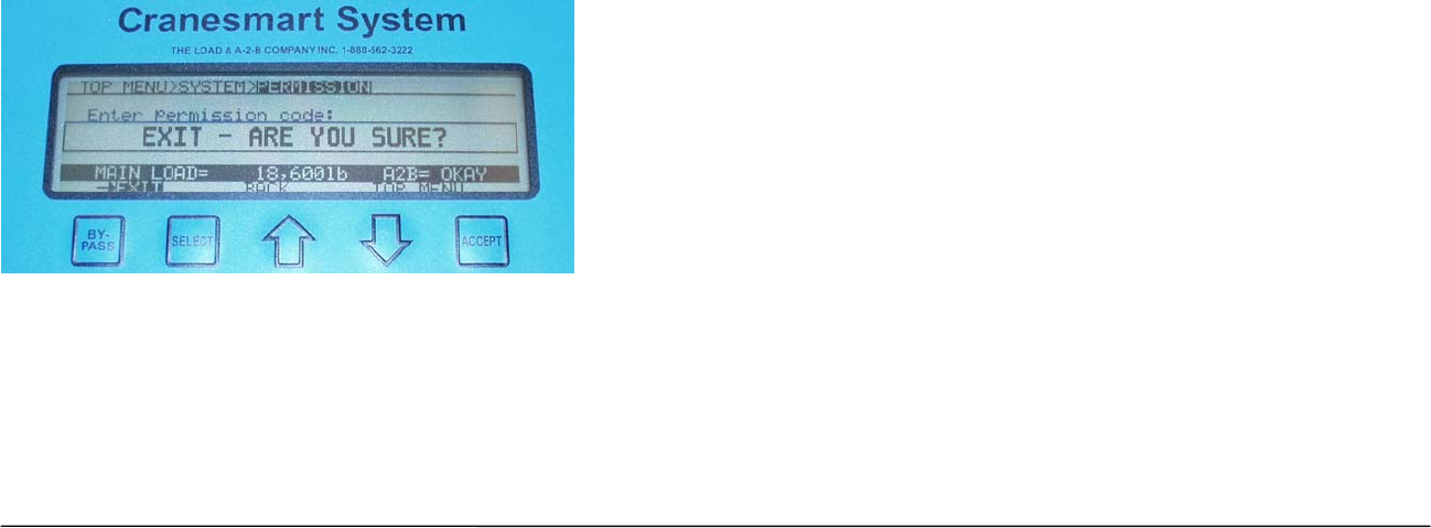
To Exit the Supervisor Menu
1. If you select Exit a message will be displayed to verify that you want to exit.
2. Press Accept to Exit. If you press Select a message will be displayed to Press Accept to Exit.
NOTE:
¾ If the Accept key is pressed the system will return to the Primary Operating Screen and return to the Operator permission level.
¾ If the supervisor does not want to exit pressing the Up or Down arrows will cancel the exit.

44 Cranesmart System Version R6
Load Cell Calibration
Factory Restore of Calibration
To restore the systems factory settings:
1. From the Top Menu screen, use the Up or Down arrows select Calibrate.
2. Use the Up or Down arrows, select Load.
3. Use the Up or Down arrows, select Factory Cal.
4. Use the Up or Down arrows, select Factory Cal. (The system will ask if you are sure you want to restore the Factory Calibration).
5. Use the Up or Down arrows to select Top Menu to continue with Supervisor permission or, Select Exit to return to Primary Operating
Screen and Operator Permission level.
Set Span
1. Pick up a Known Weight.
2. From the Top Menu screen, use the Up or Down arrows select Calibrate.
3. Use the Up or Down arrows, select Load.
4. Use the Up or Down arrows, select (Main, Aux 1, Aux 2), the display at the top of the screen will change to show your selection.
5. Use the Up or Down arrows, select Set Span.
6. Use the Up or Down arrows to set the known weight being lifted.
7. Press Accept twice to save.
8. Use the Up or Down arrows to select Top Menu to continue with Supervisor permission or, Select Exit to return to Primary Operating
Screen and Operator Permission level.
Set Load Zero
1. Ensure there is no load or rigging on the hook.
2. From the Top Menu screen use the Up or Down arrows to select Calibrate.
3. Use the Up or Down arrows, select Load.
4. Use the Up or Down arrows, select (Main, Aux 1, Aux 2), the display at the top of the screen will change to show your selection.
5. Use the Up or Down arrows, select Set Zero.
6. Use the Up or Down arrows to set the Zero weight for the winch.
7. Press Accept twice to save.

45 Cranesmart System Version R6
8. Use the Up or Down arrows to select Top Menu to continue with Supervisor permission or, Select Exit to return to Primary Operating
Screen and Operator Permission level.
NOTE:
¾ The weight should read block or ball weight to the nearest 100lbs. For example, if the ball is 160 lbs. the display should read 200 lbs.
Set Angle Zero
When the Boom Angle transducer is installed it will be necessary to zero the angle value in the display panel. The
following steps describe how to set the angle to zero when your boom/luffing Jib and the installed angle transducer are as
close to horizontal as possible.
To set angle zero:
1. Install Boom Angle transducer.
2. Use a carpenter’s level to position the Boom as close as possible to Zero degrees.
3. Raise boom to 45-degree angle.
4. Lower boom to 0-degree angle.
5. From the Primary Operating screen press select, the Secondary Operating screen is displayed.
6. Set permissions (see above).
7. Use the Up or Down arrows, select Calibrate.
8. Use the Up or Down arrows, select Angle, you will be defaulted to Zero.
9. Select Zero.
10. Use the Up or Down arrows to set the Zero Angle, (zero angle can be set between -20o and 90o).
11. Press Accept twice to save.
12. Use the Up or Down arrows to select Top Menu to continue with Supervisor permission, Back to return to the Calibrate menu or,
Select Exit to return to Primary Operating Screen and Operator Permission level.

46 Cranesmart System Version R6
Level Smart Sensor Angle Zeroes
When the Level Smart Sensor is installed, it will be necessary to calibrate the unit. To do this you must Zero the List Angle and Roll Angle values
in the Display Panel. The following steps describe how to set the angles to zero.
Please note: you should calibrate the Level Smart Sensor when the crane is perfectly level.
To Set Angle Zero:
1. Install Level Smart Sensor (see pages 22 and 23).
2. Position the crane so that it is level.
3. To perform calibration you will need to access the permission codes section in the panel (see page 43).
4. Once you have entered the correct permission code, use the following steps to calibrate the Level Smart Sensor.
5. Use the Up or Down arrows to highlight Top Menu. Press Select to continue with Supervisor permission.
6. Use the Up or Down arrows, highlight Calibrate. Press Select.
7. Use the Up or Down arrows, highlight List-Roll. Press Select.
8. Use the Up or Down arrows to adjust the Zero Angle.
9. Press Accept twice to save.
10. Use Up or Down arrows to highlight the List Zero. Press Select.
11. Use the Up or Down arrows to adjust the Zero Angle.
12. Press Accept twice to save.
13. Highlight Top Menu and Press Select to continue with Supervisor permission, Back to return to the Calibrate menu or, Exit to return
to Primary Operating Screen and Operator Permission level.

47 Cranesmart System Version R6
Self Calibration – Load Cell
You can re-calibrate the system yourself using the steps below; however, you must have a known weight. Once you have
the known weight, use the following steps to re-calibrate the Load Cells.
Calibrating the Load Cells is a two-step process; first, ensure you have selected the correct Winch and Parts-of-line for
the Load Cell, and then calibrate Load Zero and Span for that Load Cell. Repeat these steps for each Load Cell on the
crane.
Known Weights
The minimum weight to be used for Load cell calibration depends on the Load Cell’s single line pull rating. A known
weight of 50% or more of the single line pull capacity is best for re-calibrating the load cells.
Important Calibration/Weight Adjustment Information
In the system calibration modes a single push of the Up or Down arrows changes the increments by 100 pounds for up to
16 parts-of-line.
If you require 17 or more parts-of-line, the increments for a single push of the Up or Down arrows, change by 100 pounds
to start and change to 200 pounds.
Sheave friction can be a factor in Load system calibration. The Load cell measures force on one part-of-line (POL) and
multiplies it by the number of parts-of-line. If you are running 10 POL this may affect load calibration by 10%.
For best results always make sure Sheave bearings are clean and well lubricated.
When the Calibration is complete, repeat the steps with each load cell on each winch, i.e. Main, Auxiliary One, etc.
Formula for known weights
(Maximum single line pull of winch X parts-of-line) ÷ 2 = minimum known weight required
Examples of Known Weights
Using a 15,000 lb SLP load cell and running 4 parts-of-line, the ideal known calibration weight would be 30,000.
Using a 25,000 lb SLP load cell and running 6 parts-of-line, the ideal known calibration weight would be 75,000.
Using a 40,000 lb SLP load cell and running 8 parts-of-line, the ideal known calibration weight would be 160,000.

48 Cranesmart System Version R6
Supervisor Options Menu
Limits Lock – such as max load, high angle, etc.
Limits Lock enables you to restrict access to the Limits menu.
1. From the Top Menu screen, use the Up or Down arrows select Options.
2. Use the Up or Down arrows, select Limits.
3. Use the Up or Down arrows, select Locked/Unlock.
4. Press Accept twice to save.
5. Use the Up or Down arrows to select Top Menu to continue with Supervisor permission or, Select Exit to return to Primary Operating
Screen and Operator Permission level.
By-pass button - DISABLE
This option enables you to disable the by-pass button, leaving the by-pass button with no effect.
1. From the Top Menu screen, use the Up or Down arrows select Options.
2. Use the Up or Down arrows, select Bypass.
3. Use the Up or Down arrows, select Enable/Disable.
4. Press Accept twice to save.
5. Use the Up or Down arrows to select Top Menu to continue with Supervisor permission or, Select Exit to return to Primary Operating
Screen and Operator Permission level.
External Audible Alarm
Ext Alarm enables you to select to enable or disable the External Alarm.
1. From the Top Menu screen, use the Up or Down arrows select Options.
2. Use the Up or Down arrows, select Ext Alarm.
3. Use the Up or Down arrows, select Enable/Disable.
4. Press Accept twice to save.
5. Use the Up or Down arrows to select Top Menu to continue with Supervisor permission or, Select Exit to return to Primary Operating
Screen and Operator Permission level.

49 Cranesmart System Version R6
External Relay – Output for shut-offs/Horn/Indicator
The Ext Relay setting enables you to change the normal state of the alarm output wire (the White lead from the power
harness). Usually this setting is shipped in the “Normally Hot” state, indicating that the alarm output wire is powered when
no alarms are occurring. If required, the setting can be changed to “Normally Cold”, indicating that the alarm output wire
is not powered when no alarms are occurring.
1. From the Top Menu screen, use the Up or Down arrows select Options.
2. Use the Up or Down arrows, select Ext Relay.
3. Use the Up or Down arrows, select Norm Hot/Norm Cold.
4. Press Accept twice to save.
5. Use the Up or Down arrows to select Top Menu to continue with Supervisor permission or, Select Exit to return to Primary Operating
Screen and Operator Permission level.
System Menu
About – Provides information on the software version, etc.
1. From the Primary Operating screen press select, the Secondary Operating screen is displayed.
2. Use the Up or Down arrows, select Setup.
3. Use the Up or Down arrows, select System.
4. Used the Up or Down arrows, select About.
5. Select Exit to return to Primary Operating screen or; Select Back or Top Menu to return to the top menu.
LCD Contrast
LCD Contrast allows you to adjust your panel display to be lighter or darker for easier viewing.
1. From the Top Menu screen, us the Up or Down arrows to select LCD Contrast.
2. Use the Up or Down arrows to select LCD Contrast.
3. Press Select on LCD Contrast, then use the Down arrow to make the display darker, or the Up arrow to make it lighter. The
contrast will change immediately.
4. When you are satisfied with your display contrast press Accept to save.

50 Cranesmart System Version R6
5. Select Exit to return to Primary Operating Screen or; Select Back or Top Menu to return to the top menu.
Display Timer
To set the time for alternate Operate displays to appear on the screen.
1. From the Top Menu screen, use the Up or Down arrows select System.
2. Use the Up or Down arrows, select Display Timer.
3. Use the Up or Down arrows, select Timer.
4. Use the Up or Down arrows to change Display Time.
5. Press Accept twice to save.
6. Use the Up or Down arrows to select Top Menu to continue with Supervisor permission or, Select Exit to return to Primary Operating
Screen and Operator Permission level.
Restricted Menu
Users must call the service department to gain access to the restricted menu.
Permission Level
1. From the Primary Operating screen press select, the Secondary Operating screen is displayed.
2. Use the Up or Down arrows, select Setup.
3. Use the Up or Down arrows, select System.
4. Use the Up or Down arrows, select Permission.
5. Use the Up or Down arrows, set the Permission Access Code.
6. Select Exit to return to Primary Operating Screen or; Select Back or Top Menu to return to the top menu.
Checksum Repair
1. From the Top Menu screen, use the Up or Down arrows select System.
2. Used the Up or Down arrows, select CHKSM Repair.
3. Use the Up or Down arrows, select Repair/Cancel. The screen will display “Repairing Checksum Error”.
4. You will be returned to the System menu.
5. Select Exit to return to Primary Operating Screen or; Select Back or Top Menu to return to the top menu.

51 Cranesmart System Version R6
Supervisor Enable/Disable Menu
1. From the Top Menu screen, use the Up or Down arrows select Enable/Disable.
2. Use the Up or Down arrows, select the Auto Enable, Auto Disable or Manual.
For Auto Enable/Disable the system steps through the transducers in the system until all transducers have been
located.
For Manual Enable/Disable use the Up or Down arrows to select the transducers to enable/disable.
52 Cranesmart System Version R6
Display Panel – Operating Screens
Primary Operating Screens
The Primary Operating screen enables users to view the current displayed values, the screen changes depending on the
configuration of the system purchased. Displays for load only, A2B only, angle only, wind speed only or any combination
are illustrated shown below.
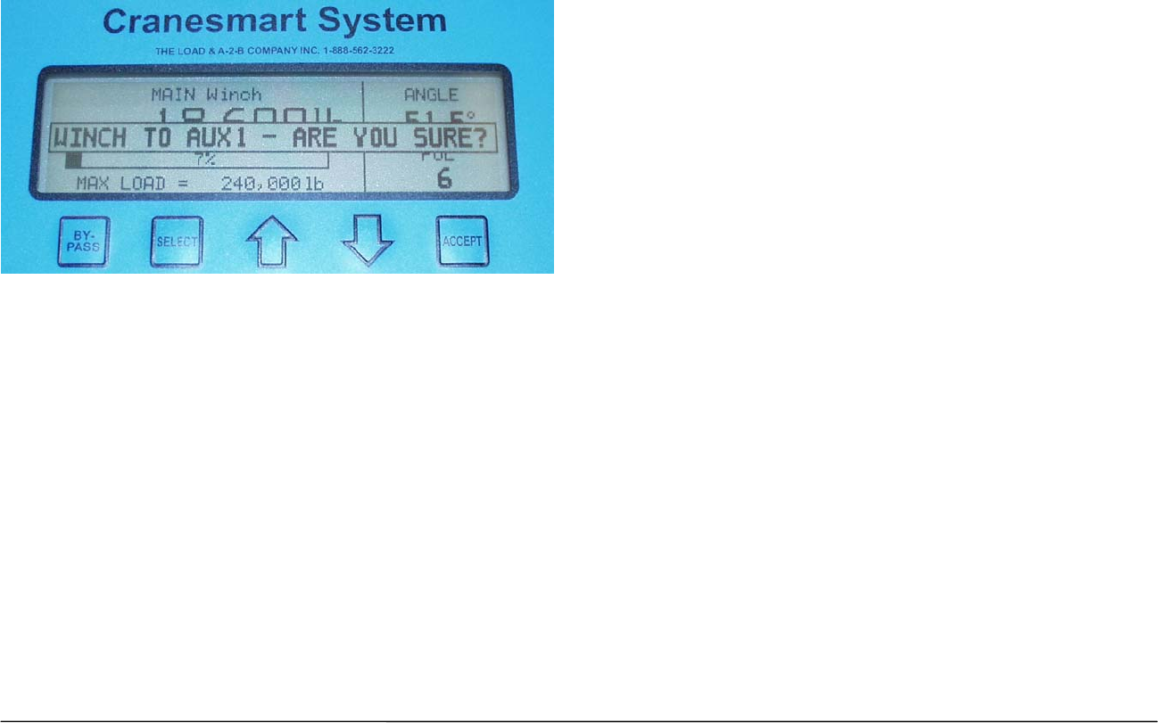
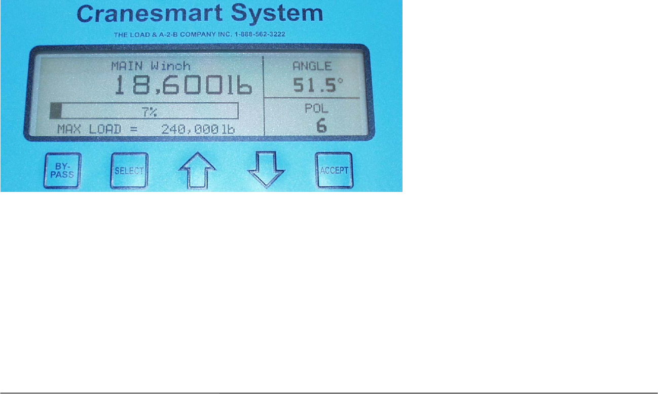
Primary Operating screen - Load and Angle Transducer
Winch Displays the actual load on the winch in pounds. (Main, Aux 1, Aux 2)
Percentage Bar
Graph
Displays the percentage of the permitted load as defined by the Operator, 100% is the maximum.
The Bar Graph displays the amount of the load. If there is no load the graph is blank.
Max Load Displays the maximum load as defined by the operator.
Angle Displays the angle of the boom in degrees using the horizontal line as zero.
Parts-of-Line
(POL)
Displays the Parts-of-line in use on the selected winch.
53 Cranesmart System Version R6
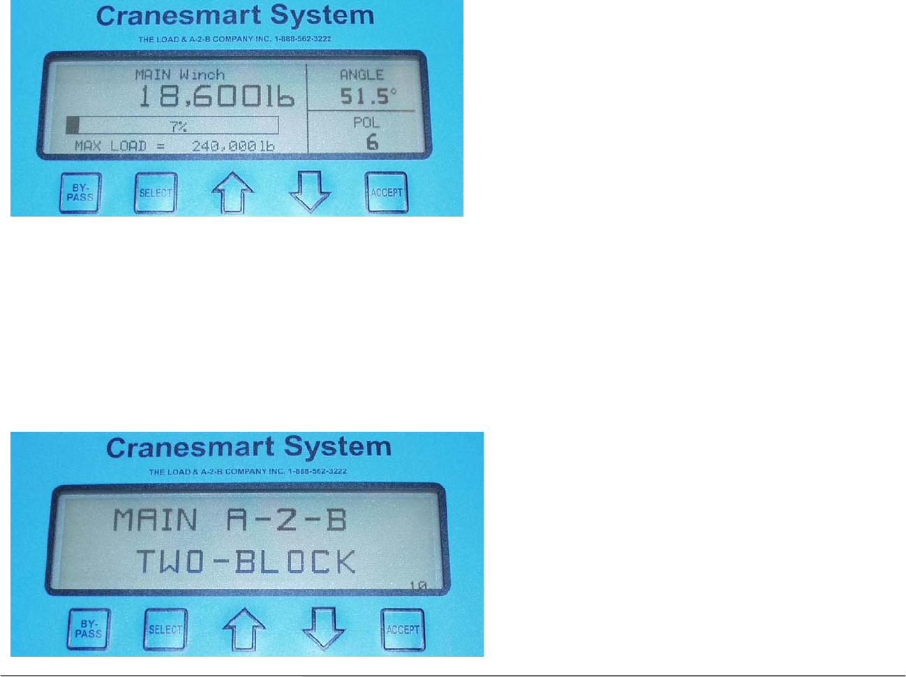
Primary Operating Screen – Load, angle and A2B system
Winch Displays the actual load on the hook in pounds. (Main, Aux 1, Aux 2)
Percentage Bar Graph Displays the percentage of the permitted load as defined by the Operator, 100% is the maximum.
The Bar Graph displays the amount of the load. If there is no load the graph is blank.
Max Load Displays the maximum load as defined by the operator.
Parts-of-Line (POL) Displays the Parts-of-line in use on the selected winch.
Alarm state screen for an A2B system. When the counterweight of the Anti-2-block system is lifted by the headache ball or
travelling block - the following alarm is displayed. If you have a main and auxiliary A2B system, when the auxiliary switch
is activated, by lifting the counterweight, the alarm will read AUX A2B, TWO BLOCK.
54 Cranesmart System Version R6
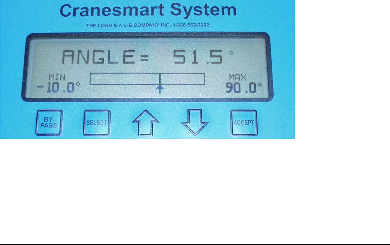
Primary Operating Screen – Angle System
Angle Displays the angle of the boom in degrees using the horizontal line as zero.
Angle Bar Graph The bar graph displays the minimum and maximum angles defined by the operator with the minimum displayed
on the left and maximum on the right.
55 Cranesmart System Version R6
Secondary Operating Screens
The Secondary Operating screen enables users to view more detailed information about their system and allows the user
to enter menus to perform system function changes and/or settings.
To view the Secondary Operating screen press the Select button.
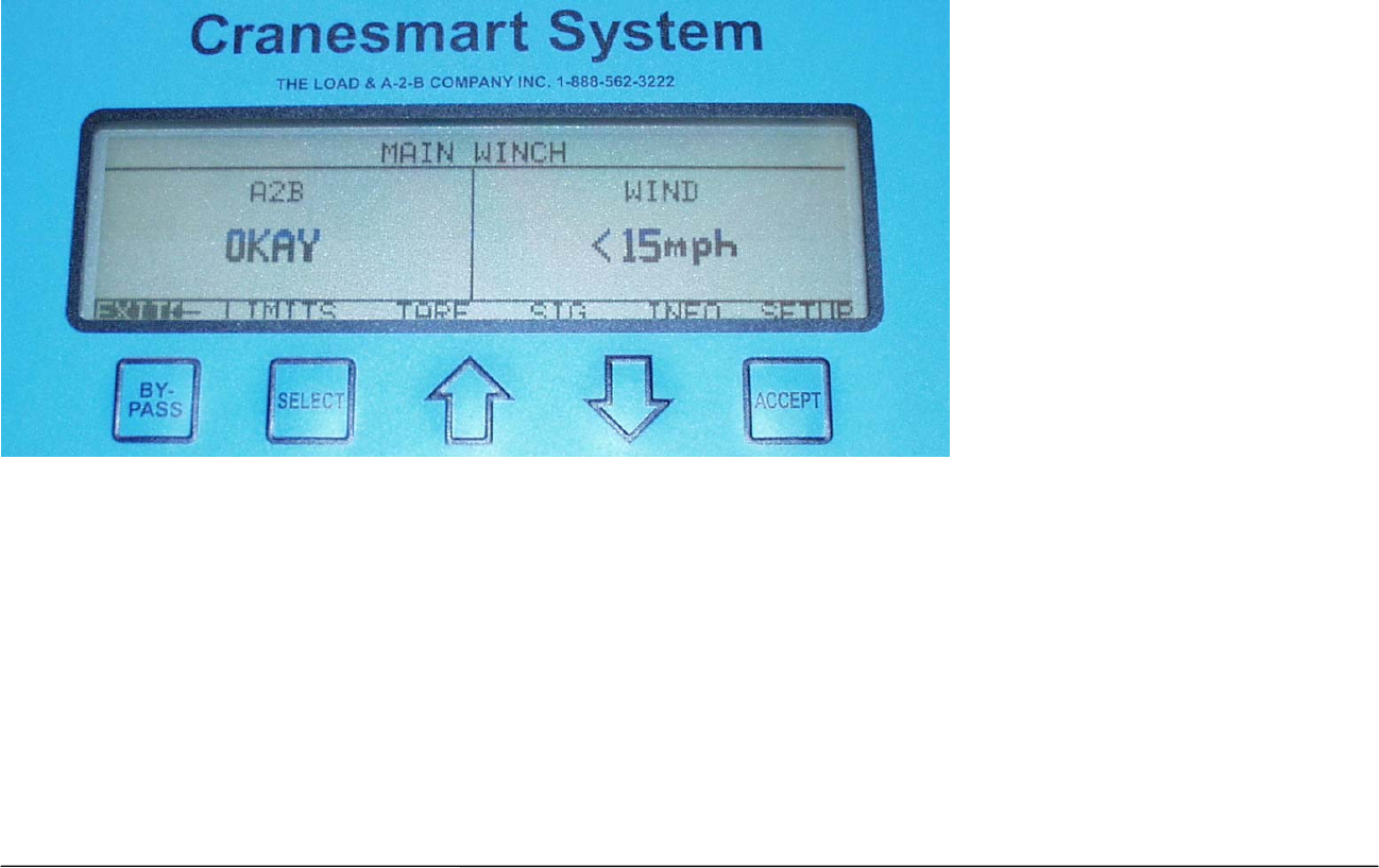
Secondary Operating screen - A2B system and Wind Speed transducer
A2B Displays the status of all A2B switches in the system.
Wind Speed Displays the wind speed in miles per hour when the wind exceeds +15 MPH if your system has a wind speed
transducer.
56 Cranesmart System Version R6
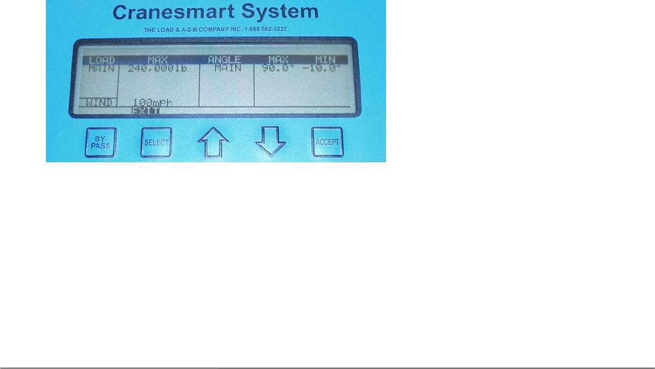
Limits Screen – Load and or Load/Angle systems only
The Limits screen displays the Limit settings for the system. Follow the instructions below to see the limits for Load,
Angle and Wind speed.
1. From the Primary Operating screen, press the Select button to move to the Secondary Operating screen.
2. Use the Up or Down Arrows to move through the navigation bar, select Limits.
3. Press the Select button, the Limits screen displays the high and low limits for the Load and Angle, and the high limit for the Wind
speed.
Set Load Limits
1. From the Primary Operating screen press select, the Secondary Operating screen is displayed.
2. Use the Up or Down arrows, select Setup.
3. Use the Up or Down arrows, select Limits. (If Limits is Locked the operator must enter the correct key.)
4. Use the Up or Down arrows, select Load.
5. Use the Up or Down arrows, select (Main, Aux 1, Aux 2).
6. Use the Up or Down arrows to increase or decrease the Maximum limit for that Winch.
7. Press Accept twice to save.

57 Cranesmart System Version R6
Set Angle Limits
1. From the Primary Operating screen press select, the Secondary Operating screen is displayed.
2. Use the Up or Down arrows, select Setup.
3. Use the Up or Down arrows, select Limits.
4. Use the Up or Down arrows, select Angle.
5. Use the Up or Down arrows, select (Max/Min).
6. Use the Up or Down arrows to increase or decrease the Maximum limit for that Angle Sensor.
7. Press Accept twice to save.
Wind Limits
1. From the Primary Operating screen press select, the Secondary Operating screen is displayed.
2. Use the Up or Down arrows, select Setup.
3. Use the Up or Down arrows, select Limits.
4. Use the Up or Down arrows, select Wind.
5. Select Max Wind.
6. Use the Up or Down arrows to increase or decrease the Maximum Wind speed.
7. Press Accept twice to save.
58 Cranesmart System Version R6
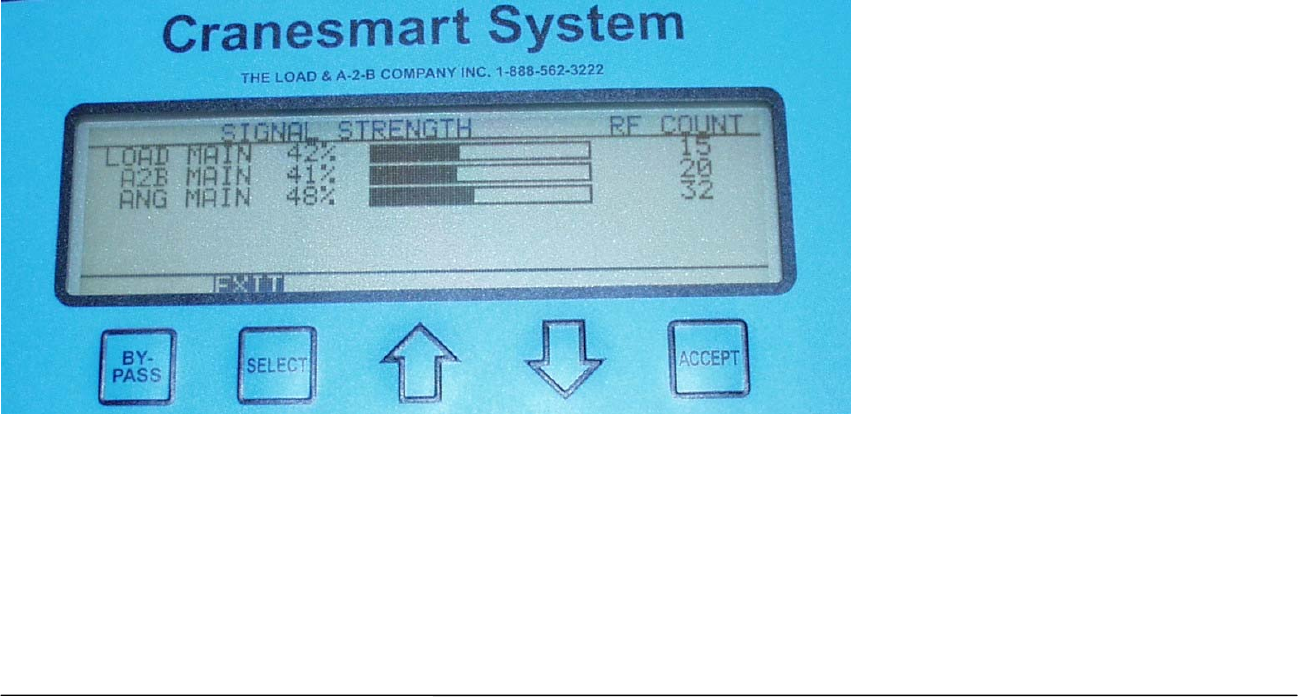
Signal Strength Screen
The Signal Strength screen displays the strength of the signals from any enabled transducers on the boom. This screen
should be used when installing boom mounted transmitters to help ensure antenna placement for best signal. It is also
used to aid in trouble shooting by the Cranesmart service department.
1. From the Primary Operating screen, press the Select button to move to the Secondary Operating screen.
2. Use the Up or Down arrows to move through the navigation bar, select Sig.
3. Press the Select button, the Signal Strength screen is displayed.
4. Press Select to return to the Primary Operating Display.
Load Indicated the Load transducer signal strength
A2B Indicates the A2B transducer signal strength.
Ang Indicates the Boom Angle transducer signal strength.
Wind Indicates the Wind speed signal strength.
59 Cranesmart System Version R6
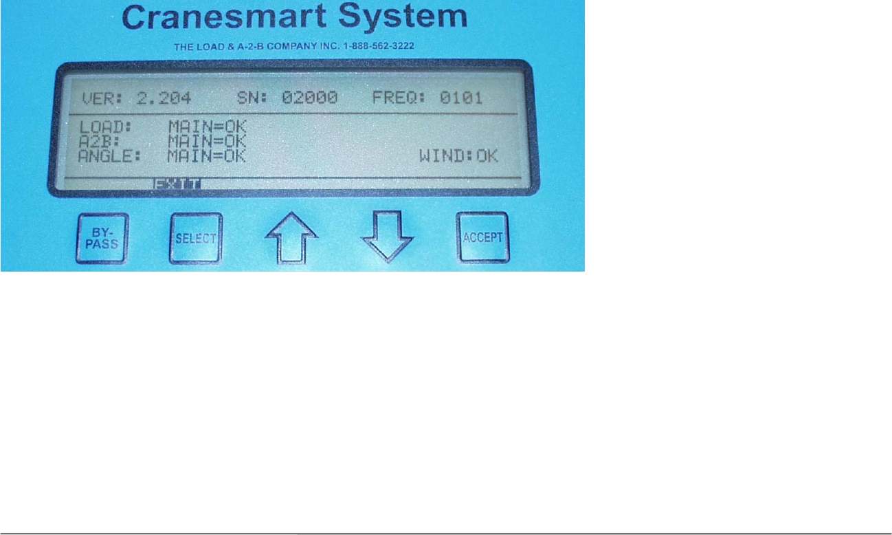
Info Screen – Cranesmart System information
The Info screen displays Cranesmart system information. This information is used for troubleshooting by the Cranesmart
service department.
1. From the Primary Operating screen, press the Select button to move to the Secondary Operating screen.
2. Use the Up or Down arrows to move through the navigation bar, select Info.
3. Press the Select button, the Information screen is displayed.
Ver The Version of the Software in use.
Load Digital Identification Information.
A2B Digital Identification Information.
Angle Digital Identification Information.
S/N and Frequency code Digital Identification Information.
60 Cranesmart System Version R6
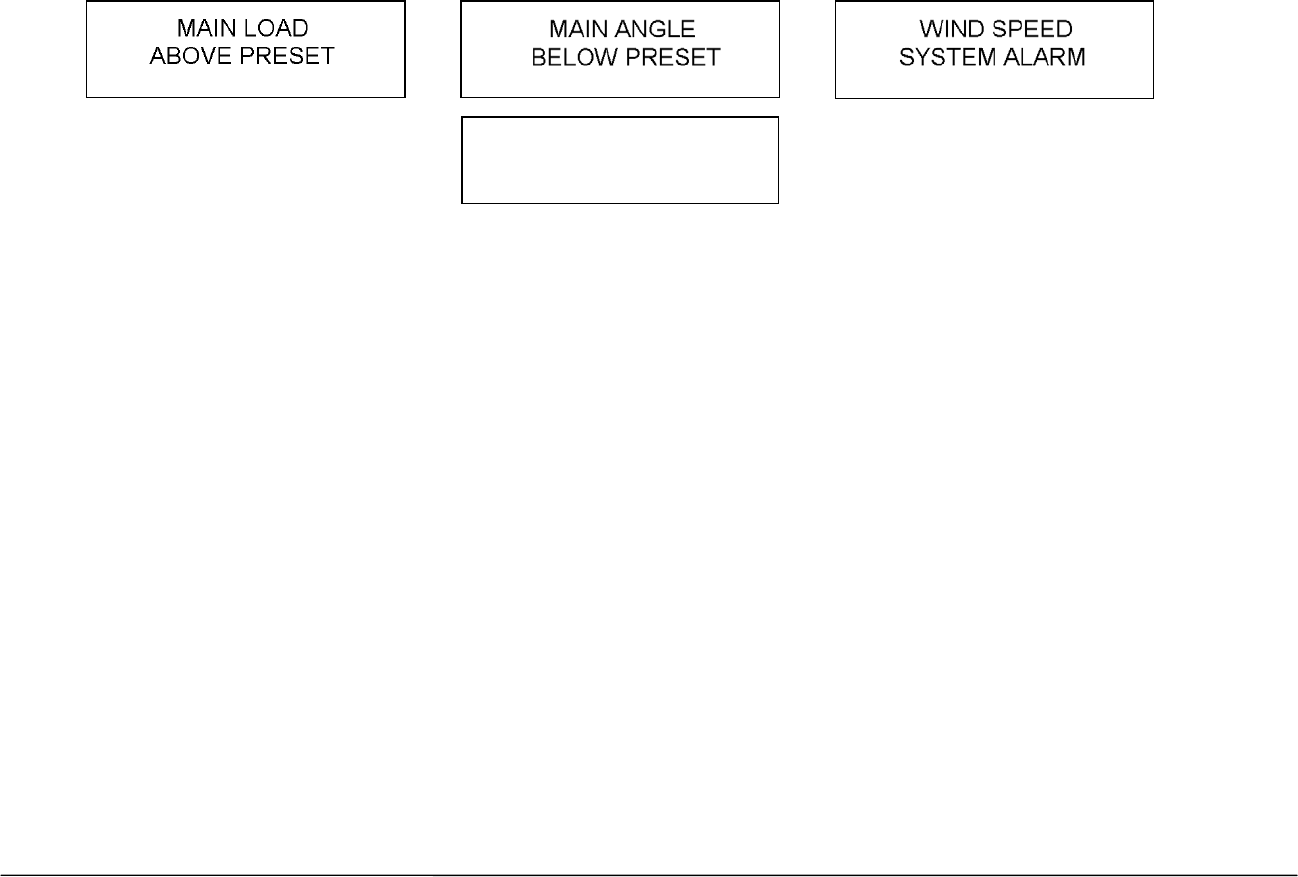
Display Panel Alarms
The panel has built-in audible and visual alarms. The alarm screens shown below alternate with the primary operating
screen to notify the operator of unsafe crane conditions while continuing to provide load and positional information. The
alarms are accompanied by an audible alarm provided within the panel.
When the display panel is installed and powered you may see system error screens and hear alarms. The alarms may
indicate which component (load cell, anti-2-block, wind speed or angle transducer) signal is not being received.
The alarms are normal until all parts of the system are installed and there is a clear line of sight to the antenna. If all the
parts of the system are correctly installed and the alarms are still sounding, check your signal strength display (page 58)
to see if your boom mounted transmitters are sending a clear signal. You may also try moving your cab mounted antenna
for better reception.
If neither of these solutions solves the problem call our service department at 1-888-562-3222 or (780) 437-2986.
NOTE:
The audible alarm generated by the display panel is intended for the operator to hear. If you require a louder alarm
which can be heard above the ambient noise, Cranesmart Systems can provide a louder horn which automatically
increases in loudness according on the ambient noise.
MAIN A2B
TWO BLOCK

61 Cranesmart System Version R6
Function Shut Offs
Cranesmart Systems provide outputs for function shut-offs. For example, the panel can be configured to interrupt the
winch up function to prevent the operator from damaging the crane. Overload, A2B, angle and wind speed can also be
used to shut the crane down in unsafe conditions. Outputs for the system are normally configured at the time of purchase
to integrate into the crane’s existing system or to match the shut-offs provided with the system.
If you have specific requirements for alarms, displays or function shut-offs call our sales department at 1-888-562-3222 or
(780) 437-2986.
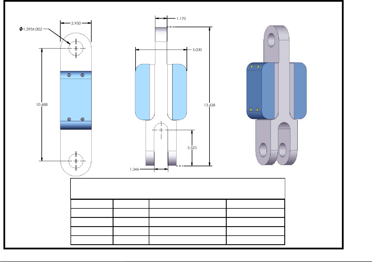
62 Cranesmart System Version R6
Appendix A – Technical Specifications
15,000 single line pull load cell
Height 13.63 inches Operating temp in degrees F -40 to+140
Width 5.05 inches Batter / Life lithium ion / 5+ years
Depth 2.95 inches FCC Compliance NFBLAB123
C. pin to c. pin 10.68 inches Pin Hole Diameter 1.395 inches or less
Weight 14 pounds Antenna Internal quarter wave
Cranesmart 15,000 pound single line pull rated load cells
Installation dimensions and specifications – June 2005
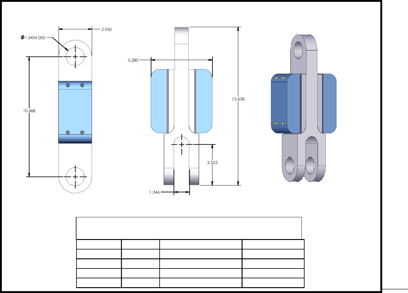
63 Cranesmart System Version R6
25,000lb single line pull load cell
Height 13.63 inches Operating temp in degrees F -40 to+140
Width 5.05 inches Batter / Life lithium ion / 5+ years
Depth 2.95 inches FCC Compliance NFBLAB123
C. pin to c. pin 10.68 inches Pin Hole Diameter 1.645 inches or less
Weight 14 pounds Antenna Internal quarter wave
Cranesmart 25,000 pound single line pull rated load cells
Installation dimensions and specifications – June 2005
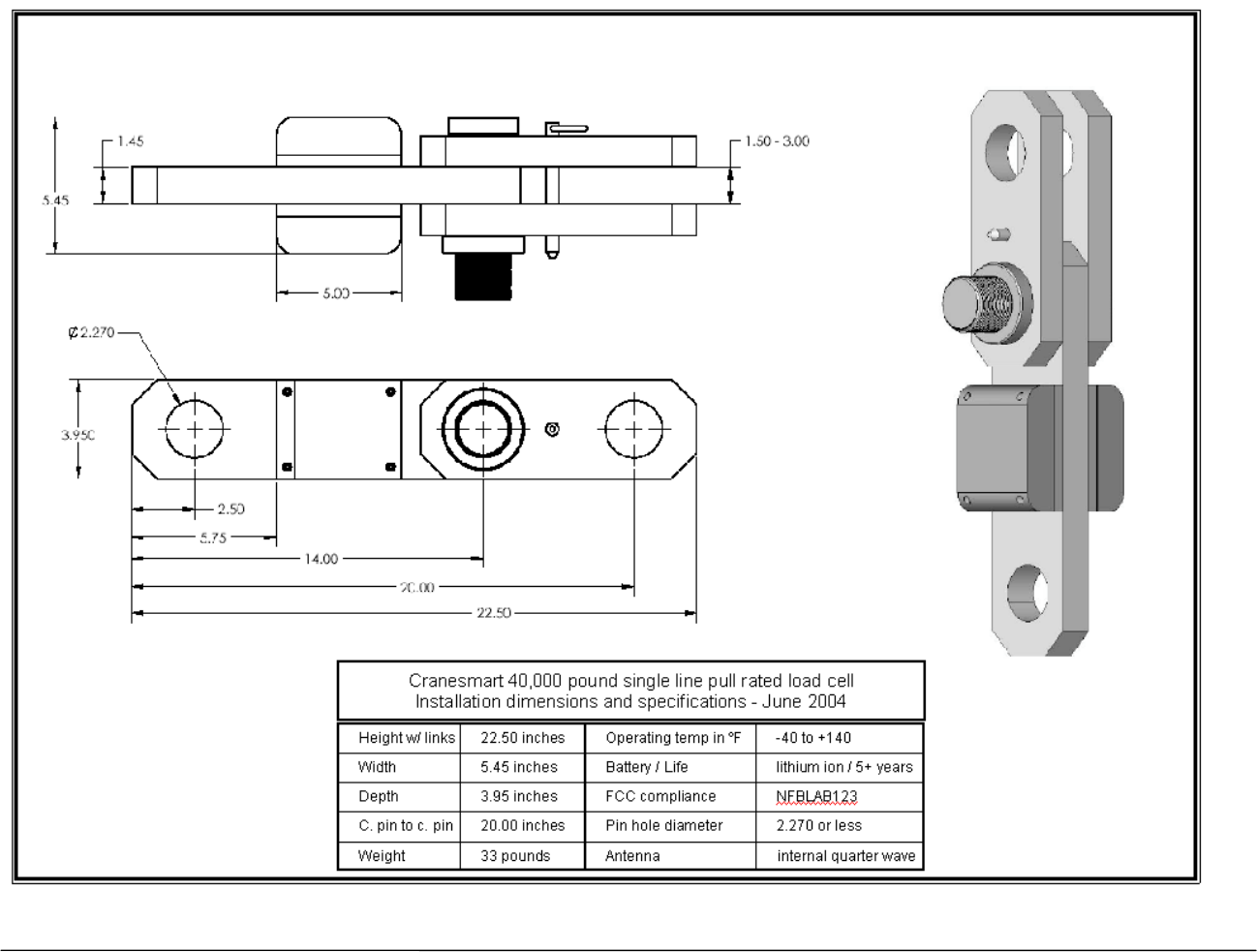
64 Cranesmart System Version R6
40,000 pound single line pull load cell
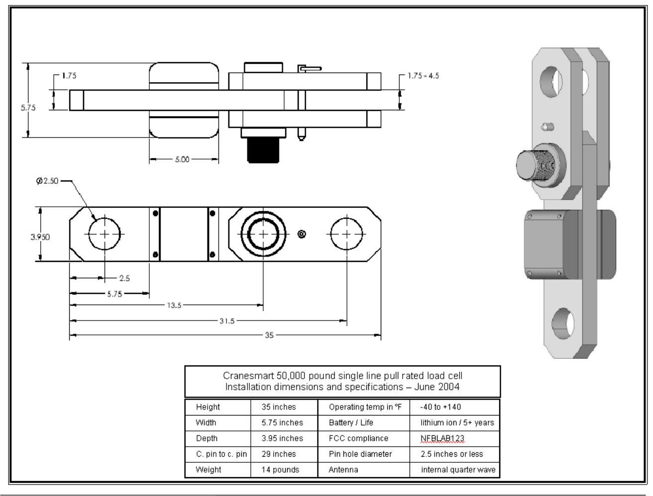
65 Cranesmart System Version R6
50,000 pound single line pull load cell
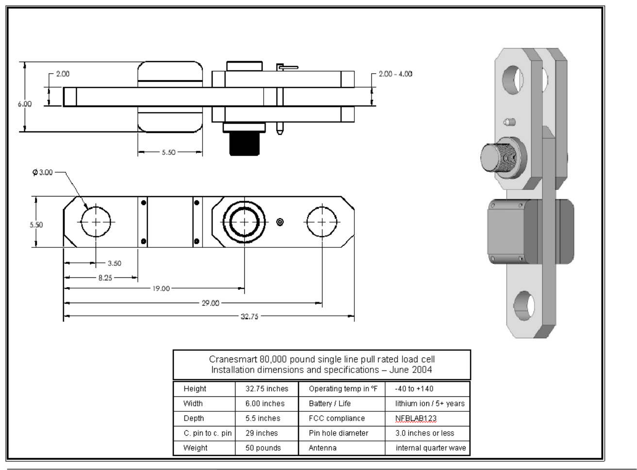
66 Cranesmart System Version R6
80,000 pound single line pull load cell
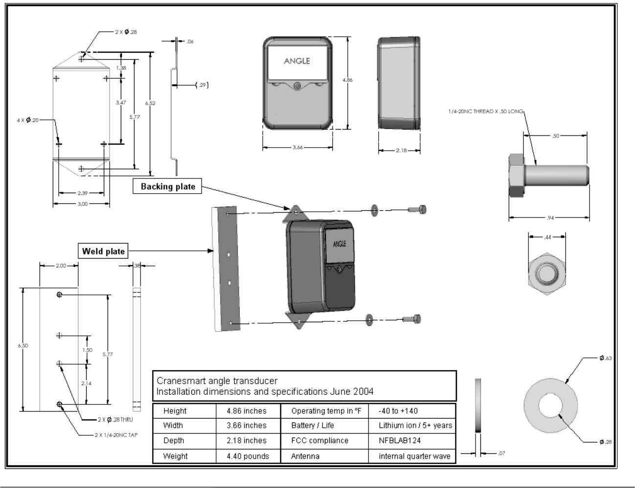
67 Cranesmart System Version R6
Boom Angle Transducer
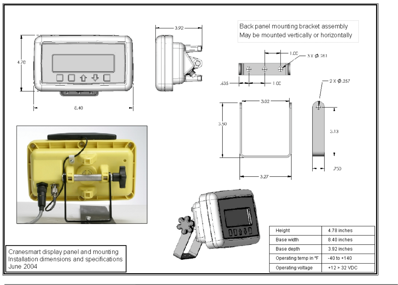
68 Cranesmart System Version R6
Display panel