Crestron Electronics CWD1013 Wireless Network Thermostat User Manual Operations Guide DOC 6260
Crestron Electronics Inc Wireless Network Thermostat Operations Guide DOC 6260
UserManual.wiki
>
Crestron Electronics
>
CWD1013 User Manual
Manual
Navigation menu
Upload a User Manual
Namespaces
Wiki Guide
HTML
PDF
Info
Views
User Manual
Discussion / Help
Navigation
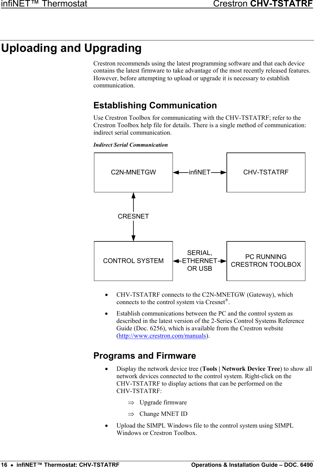
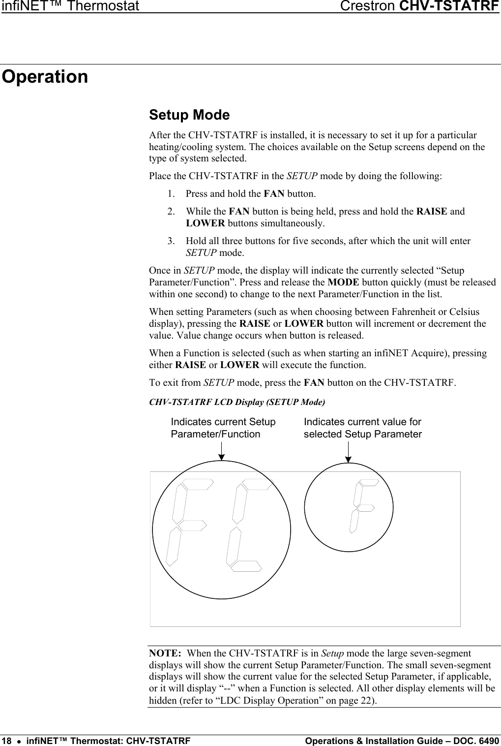
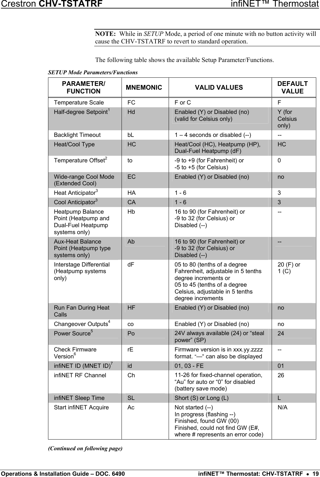
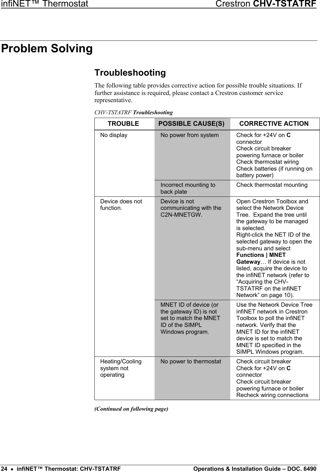
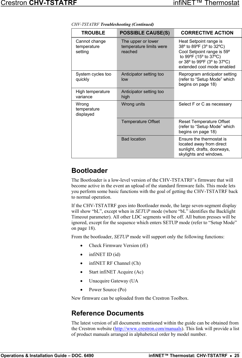
![infiNET™ Thermostat Crestron CHV-TSTATRF List of Related Reference Documents DOCUMENT TITLE 2-Series Control Systems Reference Guide C2N-MNETGW infiNET Gateway/Transceiver Further Inquiries If you cannot locate specific information or have questions after reviewing this guide, please take advantage of Crestron's award winning customer service team by calling the Crestron corporate headquarters at 1-888-CRESTRON [1-888-273-7876]. For assistance in your local time zone, refer to the Crestron website (http://www.crestron.com/) for a listing of Crestron worldwide offices. You can also log onto the online help section of the Crestron website to ask questions about Crestron products. First-time users will need to establish a user account to fully benefit from all available features. Future Updates As Crestron improves functions, adds new features and extends the capabilities of the CHV-TSTATRF, additional information may be made available as manual updates. These updates are solely electronic and serve as intermediary supplements prior to the release of a complete technical documentation revision. Check the Crestron website periodically for manual update availability and its relevance. Updates are identified as an “Addendum” in the Download column. 26 • infiNET™ Thermostat: CHV-TSTATRF Operations & Installation Guide – DOC. 6490](https://usermanual.wiki/Crestron-Electronics/CWD1013/User-Guide-748798-Page-30.png)