Crestron Electronics CWD1016 Transceiver Module User Manual Operations Guide DOC 5811A
Crestron Electronics Inc Transceiver Module Operations Guide DOC 5811A
Manual

Crestron CWD1016
Two-Way RF Transceiver Module
Hardware Guide

This document was prepared and written by the Technical Documentation department at:
Crestron Electronics, Inc.
15 Volvo Drive
Rockleigh, NJ 07647
1-888-CRESTRON
All brand names, product names and trademarks are the property of their respective owners.
©2008 Crestron Electronics, Inc.

Crestron CWD1016 Two-Way RF Transceiver Module
Hardware Guide - DOC. Contents • i
Contents
Two-Way RF Transceiver Module: CWD1016 .......................................2
Introduction ...............................................................................................................................2
Functions and Features................................................................................................2
Specifications ..............................................................................................................3
Physical Description....................................................................................................3
Industry Compliance ...................................................................................................5
Setup ..........................................................................................................................................6
Hardware Hookup .......................................................................................................6
Antenna .......................................................................................................................6
Mounting .....................................................................................................................6
End Product Labeling..................................................................................................6
Documentation ............................................................................................................6

Crestron Electronics, Inc. Hardware Guide - DOC. 6351
15 Volvo Drive Rockleigh, NJ 07647 02.28
Tel: 888.CRESTRON INTERNAL USE ONLY
Fax: 201.767.7576 Specifications subject to
www.crestron.com change without notice.
• Two-way RF transceiver
− 2.4 GHz frequency band, IEEE 802.15.4 specification
− Range from 3 feet to 150 ft.
− Range is effectively increased with the use of additional I
N
ET devices
or repeaters
− Operates on one of sixteen available channels to establish optimal
signal quality
Two-Way RF Transceiver Module:
CWD1016
Introduction
Functions and Features
The CWD1016 (hereafter referred to as “module”) is a two-way radio frequency
(RF) module that utilizes the 2.4 GHz frequency band to communicate with other
devices.
The module operates according to the IEEE 802.15.4 specification and can be
configured to minimize the possibility of interference with other devices.
The module receives RF signals from one or more Crestron INET devices and can
transmit these signals over the air or over a cable run for further processing
(depending on the application).
Functional Summary
The transceiver produces a 100 milliwatt signal that can travel up to approximately
150 feet indoors. The range is dependent on the construction of the building,
obstructions, and RF interference from other devices. Adding more modules will
increase the range of transmission. The location of the module and the orientation of
its antenna are also important factors in determining RF performance.
Crestron CWD1016 Two-Way RF Transceiver Module
Hardware Guide - DOC. Contents • 3
Specifications
The table below is a summary of specifications for the CWD1016.
Specifications of the CWD1016
SPECIFICATION DETAILS
Power Requirements
Sleep
Receive
Transmit
Typical <5uA Max 11uA
Typical 28mA Max 35mA
Typical 150mA Max 165mA
Operating Frequency 2400 MHz to 2483.5 MHz (802.15.4 compliant)
Operating Ranges¹
Minimum Distance
Maximum Distance Indoors
(without repeater device)
3 ft
150 ft
Available Channels 16 (numbered 11 through 26 per 802.15.4)
RF Output Power 100 mW
Serial Communications TTL Level, 38400 Baud, 8 data bits, 1 stop
bit, no parity, software flow control
Antenna
Board mounted chip
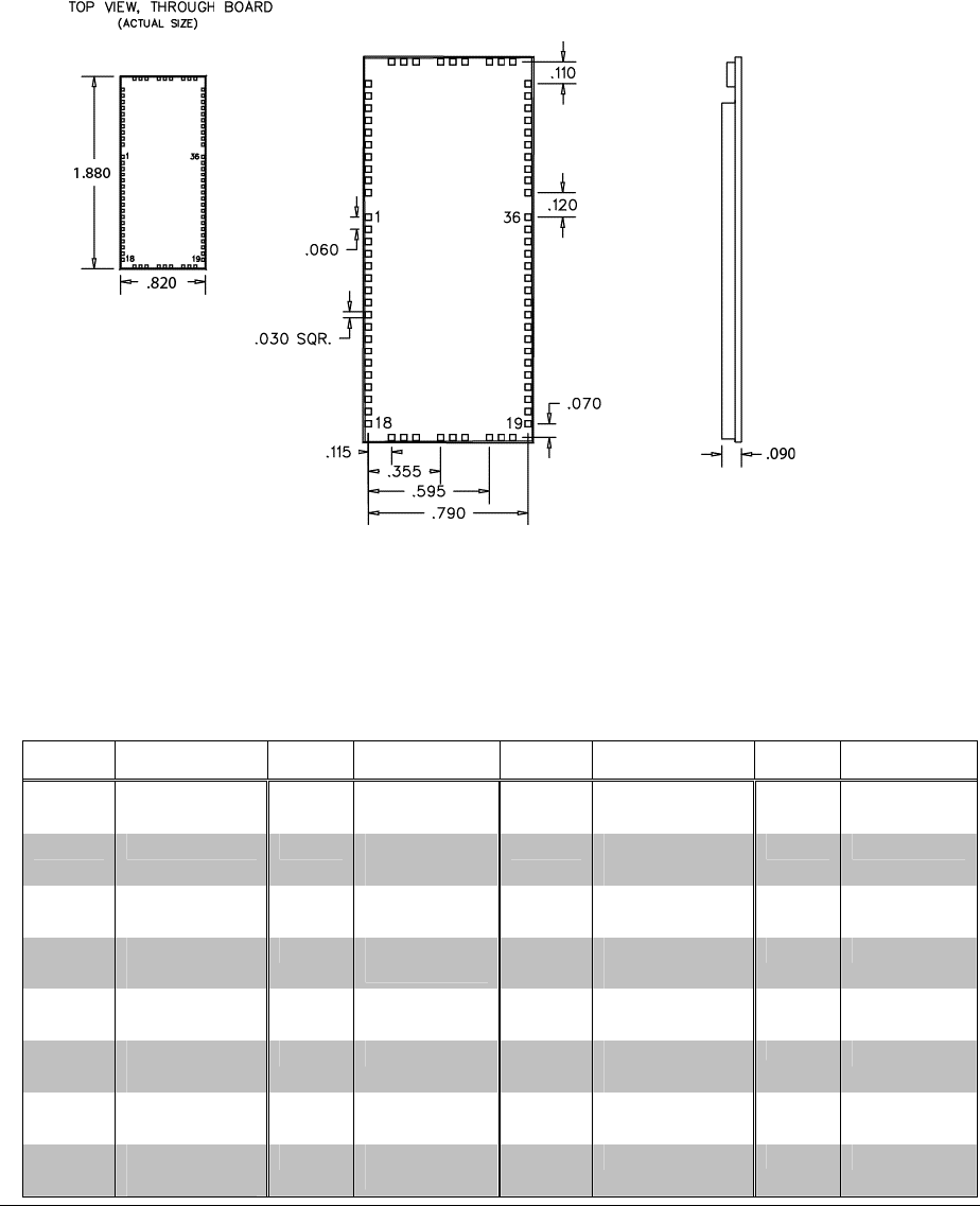
Dimensions Width: 1.88 in (0.477 cm)
Height: 0.82 in (0.208 cm)
Depth: 0.100 in (0.254 cm)
1. The location of the module and the orientation of the antenna are important factors in the RF
performance. The range is dependent on its placement and the building in which it is used. The
construction of the building, obstructions, and RF interference from other devices are factors
determining the effective range of the unit. To prevent unit-to-unit RF interference, multiple
modules operating at the same frequencies should not be installed within 3-5 feet of each other.
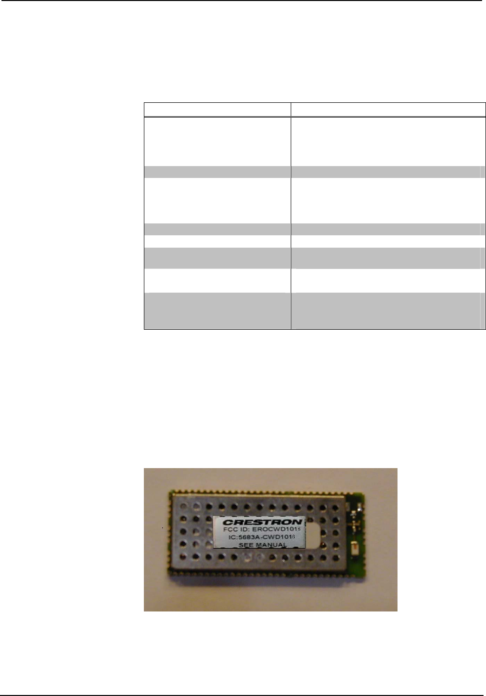
Physical Description
The module, shown below, consists of various components attached to a printed
circuit board. A chip antenna port is located at the right edge of the circuit board,
while a 38-pin interface is located on the edges of the circuit board.
Physical View of CWD1016
Crestron Electronics, Inc. Hardware Guide - DOC. 6351
15 Volvo Drive Rockleigh, NJ 07647 02.28
Tel: 888.CRESTRON INTERNAL USE ONLY
Fax: 201.767.7576 Specifications subject to
www.crestron.com change without notice.
CWD1016 Detail Views
.
Power/I-O
An edge connector provides power to the module as well as serial communications between the module and
wired devices. Refer to the following table for pin assignments of the module interface connector.
/I-O Pinout Signals
Pin # Signal Pin # Signal Pin # Signal Pin # Signal
1 +5v 9 Reserved
GPIO
24 RESET 32 MISO
2 GND 10 Reserved
GPIO
25 Reserved
ADC1
33 GND
3 Reserved
PWMA
11 GND 26 Reserved
ADC2
34 GND
4 Reserved
PWMB
12-16 Reserved
27 Reserved
ADC3
35 PA2
5 Reserved
GPIO
17-20 GND 28 GND 36 GND
6 Reserved
GPIO
21 UART RX 29 Reserved
PA1
62 GND
7 Reserved
GPIO
22 UART TX 30 SCLK 63 +5v
8 Reserved
GPIO
23 Reserved
PA0
31 MOSI

Crestron CWD1016 Two-Way RF Transceiver Module
Hardware Guide - DOC. Contents • 5
Antenna
The board mounted chip antenna port is located at edge of the circuit board.
Industry Compliance
Labeling Requirements
If the FCC ID on the CWD1016 is not visible when the module is installed inside
another device, then the outside of the device into which the module is installed must
also display a label referring to the enclosed module. This exterior label can use
wording such as the following: “Contains Transmitter Module FCC ID:
EROCWD1016” or “Contains FCC ID: EROCWD1016.” Any similar wording that
expresses the same meaning may be used.
Compliance Statement (Part 15.19 )
This device complies with Part 15 of the FCC Rules. Operation is subject to the
following two conditions:
1. This device may not cause harmful interference, and
2. This device must accept any interference received, including interference
that may cause undesired operation.
Warning (Part 15.21 )
Changes or modifications not expressly approved by the party responsible for
compliance could void the user’s authority to operate the equipment.
RF Exposure (OET Bulletin 65 )
To comply with FCC RF exposure requirements for mobile transmitting devices, this
transmitter should only be used or installed at locations where there is at least 20 cm
separation distance between the antenna and all persons. This device must not be co-
located or operating in conjunction with any other antenna or transmitter within the
host device it is installed into.
Industry Canada Statement
Section 7.1.5 of RSS-GEN
Operation is subject to the following two conditions:
1) this device may not cause interference, and
2) this device must accept any interference, including interference that may cause
undesired operation of the device.
OEM Integration :
OEM Responsibility to the FCC Rules and Regulations
The CWD1016 Module has been certified per FCC Part 15 rules for integration into
products without further testing or certification.
To fulfill the FCC certification requirements the OEM of the CWD1016 Module
must ensure that the information provided on the CWD1016 label is placed on the
outside of the final product.
The CWD1016 Module is labeled with its own FCC ID Number. If the FCC ID is
not visible when the module is installed inside another device, then the outside of the
device into which the module is installed must also display a label referring to the
enclosed module.
This exterior label can use wording such as the following:

Crestron Electronics, Inc. Hardware Guide - DOC. 6351
15 Volvo Drive Rockleigh, NJ 07647 02.28
Tel: 888.CRESTRON INTERNAL USE ONLY
Fax: 201.767.7576 Specifications subject to
www.crestron.com change without notice.
“Contains Transmitter Module FCC ID: EROCWD1016”
or
“Contains FCC ID: EROCWD1016”
The OEM of the CWD1016 Module must only use the approved antenna, which has
been certified with this module.
The OEM of the CWD1016 Module must test their final product configuration to
comply with Unintentional Radiator Limits before declaring FCC compliance per
Part 15 of the FCC rules.
IMPORTANT NOTE: In the event that these conditions cannot be met (for
example co-location with another transmitter), then the FCC authorization is no
longer considered valid and the FCC ID cannot be used on the final product. In these
circumstances, the OEM integrator will be responsible for reevaluating the end
product (including the transmitter) and obtaining a separate FCC authorization.
Setup
Hardware Hookup
Refer to the /I-O Pinout Signals table which shows the connections made to the
module.
NOTE: To prevent unit-to-unit RF interference, multiple modules operating at the
same frequencies should not be installed within three to five feet of each other.
Antenna
The module is provided with an internal antenna.
Mounting
The module has an edge connector for surface mounting to a printed circuit board
(PCB).
End Product Labeling
The final end product must be labeled in a visible area with the following: “Contains
FCC ID: EROCWD1016 .
Documentation
The OEM integrator has to be aware not to provide information to the end user
regarding how to install or remove this RF module in the users manual of the end
product which integrate this module.
The users manual for OEM integrators must include the following information in a
prominent location

Crestron CWD1016 Two-Way RF Transceiver Module
Hardware Guide - DOC. Contents • 7
“IMPORTANT NOTE: To comply with FCC RF exposure
compliance requirements, only the antenna provide with this
transmitter may be installed and this device must not be co-
located or operating in conjunction with any other antenna or
transmitter.”
Compliance Statement (Part 15.19)
This device complies with Part 15 of the FCC Rules.
Operation is subject to the following two conditions:
1. This device may not cause harmful interference, and
2. This device must accept any interference received,
including interference that may cause undesired operation.
Warning (Part 15.21)
Changes or modifications not expressly approved by the party
responsible for compliance could void the user’s authority to
operate the equipment.
FCC Interference Statement (Part 15.105 (b))
This equipment has been tested and found to comply with the
limits for a Class B digital device, pursuant to Part 15 of the
FCC Rules. These limits are designed to provide reasonable
protection against harmful interference in a residential
installation. This equipment generates uses and can radiate
radio frequency energy and, if not installed and used in
accordance with the instructions, may cause harmful
interference to radio communications. However, there is no
guarantee that interference will not occur in a particular
installation. If this equipment does cause harmful interference
to radio or television reception, which can be determined by
turning the equipment off and on, the user is encouraged to try
to correct the interference by one of the following measures:
- Reorient or relocate the receiving antenna.
- Increase the separation between the equipment and receiver.
- Connect the equipment into an outlet on a circuit different
from that to which the receiver is connected.
- Consult the dealer or an experienced radio/TV technician
for help

Crestron Electronics, Inc. Hardware Guide - DOC. 6351
15 Volvo Drive Rockleigh, NJ 07647 02.28
Tel: 888.CRESTRON INTERNAL USE ONLY
Fax: 201.767.7576 Specifications subject to
www.crestron.com change without notice.
This page intentionally left blank

Crestron CWD1016 Two-Way RF Transceiver Module
Hardware Guide - DOC. Contents • 9