Crestron Electronics CWD6894 2-Way RF Transceiver Module User Manual Manual CWD6894 Doc7180A
Crestron Electronics Inc 2-Way RF Transceiver Module Manual CWD6894 Doc7180A
Manual

Crestron CWD6894
Two-Way RF Transceiver Module
Operations Guide

This document was prepared and written by the Technical Documentation department at:
Crestron Electronics, Inc.
15 Volvo Drive
Rockleigh, NJ 07647
1-888-CRESTRON
Regulatory Compliance
Federal Communications Commission (FCC) Compliance Statement
This device complies with part 15 of the FCC Rules. Operation is subject to the following conditions:
(1) This device may not cause harmful interference and (2) this device must accept any interference received,
including interference that may cause undesired operation.
CAUTION: Changes or modifications not expressly approved by the manufacturer responsible for compliance
could void the user’s authority to operate the equipment.
NOTE: This equipment has been tested and found to comply with the limits for a Class B device, pursuant to part
15 of the FCC Rules. These limits are designed to provide reasonable protection against harmful interference in a
residential installation. This equipment generates, uses and can radiate radio frequency energy and if not installed
and used in accordance with the instructions, may cause harmful interference to radio communications. However,
there is no guarantee that interference will not occur in a particular installation. If this equipment does cause
harmful interference to radio or television reception, which can be determined by turning the equipment off and
on, the user is encouraged to try to correct the interference by one or more if the following measures:
Reorient or relocate the receiving antenna
Increase the separation between the equipment and receiver
Connect the equipment into an outlet on a circuit different from that to which the receiver is connected
Consult the dealer or an experienced radio/TV technician for help
Industry Canada (IC) Compliance Statement
Operation is subject of the following two conditions:
1. This device may not cause interference, and
2. This device must accept any interference, including interference that may cause undesired operation of the
device.
To satisfy RF exposure requirements, this device and its antenna must operate with a separation distance of at least
20 centimeters from all persons and must not be colocated or operating in conjunction with any other antenna or
transmitter.
All brand names, product names and trademarks are the property of their respective owners.
©2011 Crestron Electronics, Inc.

Crestron CWD6894 Two-Way RF Transceiver Module
Operations Guide - DOC. 7180A Contents i
Contents
Two-Way RF Transceiver Module: CWD6922 .............................................. 1
Functions and Features .............................................................................................................. 1
Specifications ............................................................................................................................. 2
Physical Description .................................................................................................................. 2
Setup .......................................................................................................................................... 5
Labeling ..................................................................................................................................... 5
Documentation ........................................................................................................................... 6

Crestron CWD6894 Two-Way RF Transceiver Module
Operations Guide - DOC. 7180A Two-Way RF Transceiver Module: CWD6894 1
2.4 GHz frequency band, IEEE 802.15.4 specification
Range from 3 feet to 550 ft.
Operates on one of sixteen available channels to establish optimal
signal quality
Two-Way RF Transceiver Module:
CWD6894
Functions and Features
The CWD6894 (hereafter referred to as “module”) is a two-way radio frequency (RF) module that
utilizes the 2.4 GHz frequency band to communicate with other devices.
The module operates according to the IEEE 802.15.4 specification and can be configured to minimize
the possibility of interference with other devices.
The module receives RF signals from one or more Crestron devices and can transmit these signals over
the air for further processing (depending on the application).
Functional Summary

Two-Way RF Transceiver Module Crestron CWD6894
2 Two-Way RF Transceiver Module: CWD6894 Operations Guide - DOC. 7180A
Specifications
The table below is a summary of specifications for the CWD6894.
Specifications of the CWD6894-1 & -2
SPECIFICATION DETAILS
Operating Frequency 2400 MHz to 2483.5 MHz (802.15.4 compliant)
Operating Ranges*
Minimum Distance
Maximum Distance Outdoors
(without repeater device)
3 ft
550 ft
Available Channels 16 (numbered 11 through 26 per 802.15.4)
Power Requirements 0.66 Watts (3.3VDC @ 0.20A)
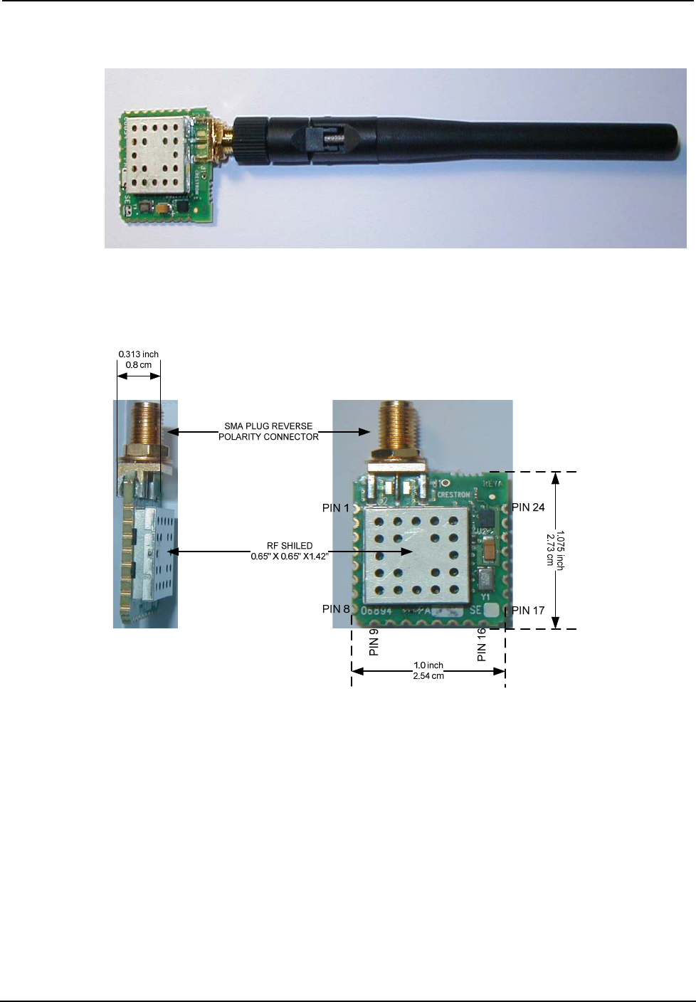
Dimensions (CWD6894-1) Width: 1.000 in (2.54 cm)
Height: 1.075 in (2.73 cm)
Depth: 0.313 in (0.8 cm)
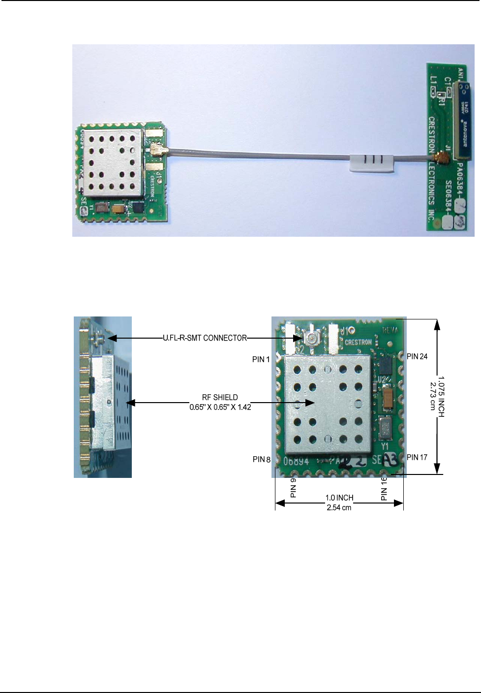
Dimensions (CWD6894-2) Width: 1.000 in (2.54 cm)
Height: 1.075 in (2.73 cm)
Depth: 0.217 in (0.55 cm)
Antenna (CWD6894-1) Gain: 2.0±0.5 dBi max.
Type: Sleeve Dipole Antenna
Frequency: 2.4GHz to 2.5 GHz
Connector Type: SMA Plug Reverse Polarity
Connector with ¼-36 UNS2B Screw
Antenna (CWD6894-2) Max. Gain: 1.8 dBi
Average Gain: -1.9 dBi
Type: Intended for SMD Mounting
Frequency: 2.4GHz to 2.5 GHz
* The location and orientation of the module are important factors in the RF performance. With the unit located outside
of any metal enclosures, the antenna is adjusted to achieve the best range. The range is dependent on its placement and
the building in which it is used. The construction of the building, obstructions, and RF interference from other devices
are factors determining the effective range of the unit. To prevent unit-to-unit RF interference, multiple modules
operating at the same frequencies should not be installed within 3-5 feet of each other.
Physical Description
The module, shown after this paragraph, consists of various components attached to a printed circuit
board. It is designed with two types of antennas: a dipole antenna (refers to CWD6894-1) and a SMD
antenna (refers to CWD6894-2). An antenna port is located at the edge of the circuit board. For the
CWD6894-1, the antenna port is equipped with a SMA reverse polarity female connector. For the
CWD6894-2, the antenna port is equipped with an U.FL connector.
Crestron CWD6894 Two-Way RF Transceiver Module
Operations Guide - DOC. 7180A Two-Way RF Transceiver Module: CWD6894 3
Physical View of CWD6894-1
CWD6894-1 Detail Views
SIDE TOP
TOP VIEW. THROUGH BOARD
(ACTUAL SIZE)
Two-Way RF Transceiver Module Crestron CWD6894
4 Two-Way RF Transceiver Module: CWD6894 Operations Guide - DOC. 7180A
Physical View of CWD6894-2
CWD6894-2 Detail Views
SIDE TOP
TOP VIEW. THROUGH BOARD
(ACTUAL SIZE)
Crestron CWD6894 Two-Way RF Transceiver Module
Operations Guide - DOC. 7180A Two-Way RF Transceiver Module: CWD6894 5
Power/I-O
Edge connectors provide power to the module as well as the communication between the module and
wired devices. Refer to the following table for pin assignments of the module interface connector.
Power/I-O Pinout Signals
Pin # Signal Pin # Signal Pin # Signal Pin # Signal
1 GND1 7 GPIO1 13 SPICLK 19 GPIO6
2 RXEN 8 RST_N 14 SPI_MOSI 20 GPIO7
3 TXEN 9 PAEN 15 SPI_MISO 21 GND8
4 GPIO4 10 RXTXEN 16 SPI_CE_N 22 GND9
5 GPIO3 11 ATTN_N 17 IRQ_N 23 VCC (+3.3VDC)
6 GPIO2 12 CLKO 18 GPIO5 24 GND7
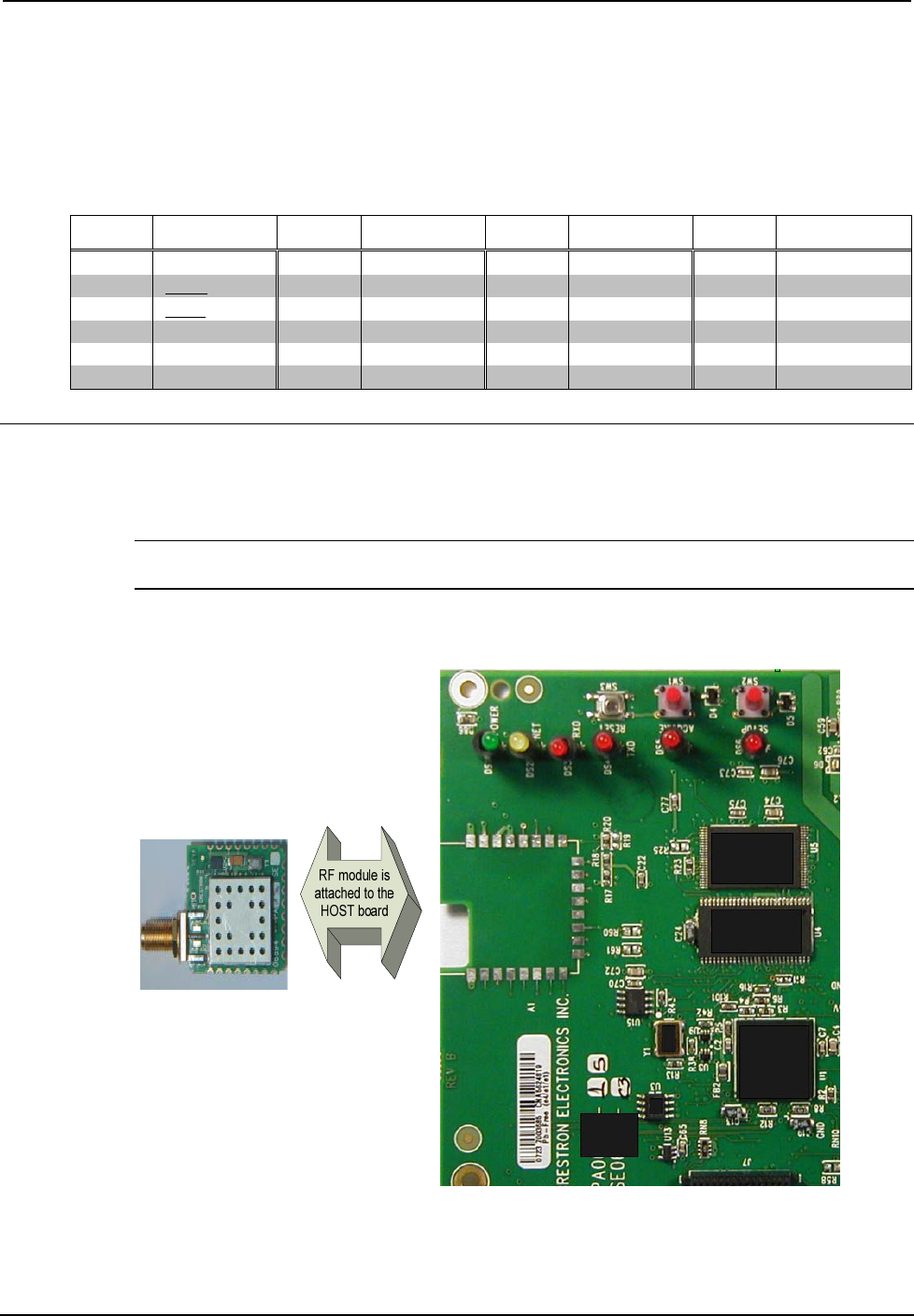
Setup
Refer to the hookup diagram below, which shows the connections made to the module. Complete the
connections in any order.
NOTE: To prevent unit-to-unit RF interference, multiple modules operating at the same frequencies
should not be installed within three to five feet of each other.
Hardware Hookup

Two-Way RF Transceiver Module Crestron CWD6894
6 Two-Way RF Transceiver Module: CWD6894 Operations Guide - DOC. 7180A
Labeling
If the FCC identification number is not visible when the module is installed inside another device, then
the outside of the device into which the module is installed must also display a label referring to the
enclosed module. This exterior label can use wording such as the following: “Contains Transmitter
Module FCC ID: EROCWD6894” or “Contains FCC ID: EROCWD6894.” Any similar wording that
expresses the same meaning may be used.
Documentation
The OEM integrator has to be aware not to provide information to the end user regarding how to install
or remove this RF module in the users manual of the end product.
The users manual for OEM integrators must include the following information in a prominent location
“IMPORTANT NOTE: To comply with FCC RF exposure compliance
requirements, the antenna used for this transmitter must be installed to provide a
separation distance of at least 20 cm from all persons and must not be co-located
or operating in conjunction with any other antenna or transmitter.”

Crestron CWD6894 Two-Way RF Transceiver Module
Operations Guide - DOC. 7180A Two-Way RF Transceiver Module: CWD6894 7
This page is intentionally left blank.

Crestron Electronics, Inc. Operations Guide – DOC. 7180A
15 Volvo Drive Rockleigh, NJ 07647
Tel: 888.CRESTRON 02.11
Fax: 201.767.7576 Specifications subject to
www.crestron.com change without notice.