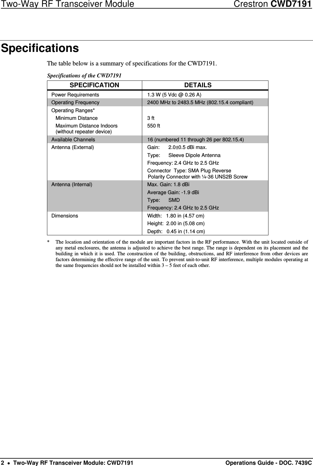
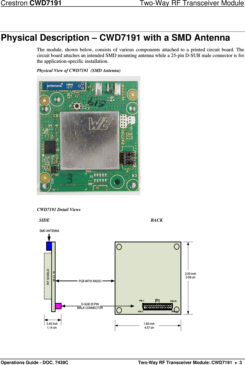
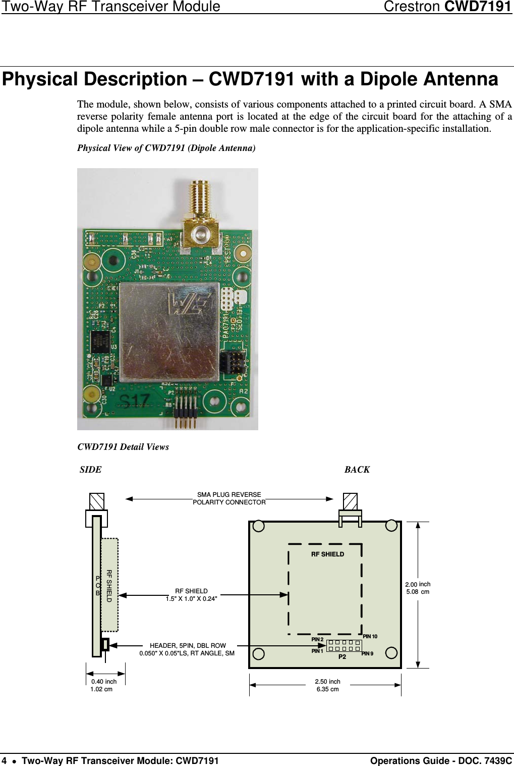
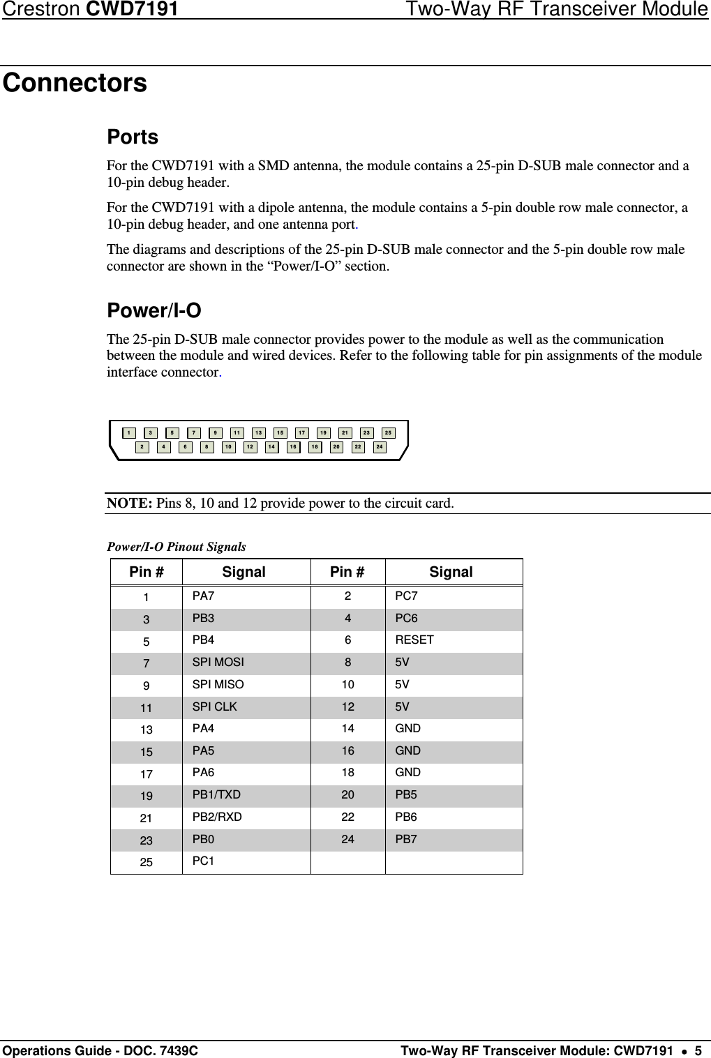
Crestron Electronics CWD7191 2.4GHz two-way RF transceiver module User Manual CWD7191 Doc 7439C

Crestron Electronics Inc 2.4GHz two-way RF transceiver module CWD7191 Doc 7439C

Manual

Crestron CWD7191 Two-Way RF Transceiver Module Operations Guide
                                                                    This document was written by the Technical Publications department at Crestron. ©2013 Crestron Electronics, Inc.  Regulatory Compliance Federal Communications Commission (FCC) Compliance Statement CAUTION:  Changes or modifications not expressly approved by the manufacturer responsible for compliance could void the user’s authority to operate the equipment. NOTE:  This equipment has been tested and found to comply with the limits for a Class B digital device, pursuant to part 15 of the FCC Rules. These limits are designed to provide reasonable protection against harmful interference in a residential installation. This equipment generates, uses and can radiate radio frequency energy and, if not installed and used in accordance with the instructions, may cause harmful interference to radio communications. However, there is no guarantee that interference will not occur in a particular installation. If this equipment does cause harmful interference to radio or television reception, which can be determined by turning the equipment off and on, the user is encouraged to try to correct the interference by one or more of the following measures:  Reorient or relocate the receiving antenna  Increase the separation between the equipment and receiver  Connect the equipment into an outlet on a circuit different from that to which the receiver is connected  Consult the dealer or an experienced radio/TV technician for help  Industry Canada (IC) Compliance Statement This device complies with Industry Canada license-exempt RSS standard(s). Operation is subject to the following two conditions: (1) this device may not cause interference and (2) this device must accept any interference, including interference that may cause undesired operation of the device. Under Industry Canada regulations, this radio transmitter may only operate using an antenna of a type and maximum (or lesser) gain approved for the transmitter by Industry Canada. To reduce potential radio interference to other users, the antenna type and its gain should be so chosen that the equivalent isotropically radiated power (e.i.r.p.) is not more than that necessary for successful communication. This radio transmitter, IC: 5683C-CWD7191, has been approved by Industry Canada to operate with the antenna types listed below with the maximum permissible gain and required antenna impedance for each antenna type indicated.  Antenna types not included in this list, having a gain greater than the maximum gain indicated for that type, are strictly prohibited for use with this device. Antenna Type: Dipole, Maximum permissible antenna gain: 2.5 dBi, Impedance: 50 Ohms Industrie Canada (IC) Déclaration de conformité Le présent appareil est conforme aux CNR d'Industrie Canada applicables aux appareils radio exempts de licence. L'exploitation est autorisée aux deux conditions suivantes : (1) l'appareil ne doit pas produire de brouillage, et (2) l'utilisateur de l'appareil doit accepter tout brouillage radioélectrique subi, même si le brouillage est susceptible d'en compromettre le fonctionnement. Conformément à la réglementation d'Industrie Canada, le présent émetteur radio peut fonctionner avec une antenne d'un type et d'un gain maximal (ou inférieur) approuvé pour l'émetteur par Industrie Canada. Dans le but de réduire les risques de brouillage radioélectrique à l'intention des autres utilisateurs, il faut choisir le type d'antenne et son gain de sorte que la puissance isotrope rayonnée équivalente (p.i.r.e.) ne dépasse pas l'intensité nécessaire à l'établissement d'une communication satisfaisante. Le présent émetteur radio , IC: 5683C-CWD7191, a été approuvé par Industrie Canada pour fonctionner avec les types d'antenne énumérés ci-dessous et ayant un gain admissible maximal et l'impédance requise pour chaque type d'antenne. Les types d'antenne non inclus dans cette liste, ou dont le gain est supérieur au gain maximal indiqué, sont strictement interdits pour l'exploitation de l'émetteur. Type d'antenne: Dipole, Gain admissible maximal: 2.5 dBi, Impédance: 50 Ohms   To satisfy RF exposure requirements, this device and its antenna must operate with a separation distance of at least 20 centimeters from all persons and must not be collocated or operating in conjunction with any other antenna or transmitter.
Crestron CWD7191  Two-Way RF Transceiver Module Operations Guide - DOC. 7439C  Contents    i Contents Two-Way RF Transceiver Module: CWD7191 .............................................. 1Functions and Features .............................................................................................................. 1Specifications ............................................................................................................................. 2Physical Description – CWD7191 with a SMD Antenna .......................................................... 3Physical Description – CWD7191 with a Dipole Antenna ........................................................ 4Connectors ................................................................................................................................. 5Ports ............................................................................................................................. 5Power/I-O .................................................................................................................... 5Setup .......................................................................................................................................... 7Labeling ..................................................................................................................................... 7Documentation ........................................................................................................................... 7
Crestron CWD7191  Two-Way RF Transceiver Module Operations Guide - DOC. 7439C   Two-Way RF Transceiver Module: CWD7191    1  2.4 GHz frequency band, IEEE 802.15.4 specification  Range from 3 feet to 550 ft.  Operates on one of sixteen available channels to establish optimal signal quality Two-Way RF Transceiver Module: CWD7191 Functions and Features The CWD7191 (hereafter referred to as “module”), with a dipole antenna or an integrated SMD antenna, is a two-way radio frequency (RF) module that utilizes the 2.4 GHz frequency band to communicate with other devices. The module operates according to the IEEE 802.15.4 specification and can be configured to minimize the possibility of interference with other devices. The module receives RF signals from one or more Crestron devices and can transmit these signals over the air for further processing (depending on the application). Functional Summary
Two-Way RF Transceiver Module  Crestron CWD7191 2    Two-Way RF Transceiver Module: CWD7191  Operations Guide - DOC. 7439C  Specifications The table below is a summary of specifications for the CWD7191. Specifications of the CWD7191 SPECIFICATION DETAILS Power Requirements  1.3 W (5 Vdc @ 0.26 A) Operating Frequency  2400 MHz to 2483.5 MHz (802.15.4 compliant) Operating Ranges*  Minimum Distance   Maximum Distance Indoors    (without repeater device)  3 ft 550 ft  Available Channels  16 (numbered 11 through 26 per 802.15.4)  Antenna (External)  Gain:  2.0±0.5 dBi max. Type:  Sleeve Dipole Antenna Frequency: 2.4 GHz to 2.5 GHz Connector  Type: SMA Plug Reverse Polarity Connector with ¼-36 UNS2B Screw Antenna (Internal)  Max. Gain: 1.8 dBi Average Gain: -1.9 dBi Type: SMD Frequency: 2.4 GHz to 2.5 GHz Dimensions  Width:   1.80 in (4.57 cm) Height:  2.00 in (5.08 cm) Depth:   0.45 in (1.14 cm) *  The location and orientation of the module are important factors in the RF performance. With the unit located outside of any metal enclosures, the antenna is adjusted to achieve the best range. The range is dependent on its placement and the building in which it is used. The construction of the building, obstructions, and RF interference from other devices are factors determining the effective range of the unit. To prevent unit-to-unit RF interference, multiple modules operating at the same frequencies should not be installed within 3 – 5 feet of each other.
Crestron CWD7191  Two-Way RF Transceiver Module Operations Guide - DOC. 7439C   Two-Way RF Transceiver Module: CWD7191    3 Physical Description – CWD7191 with a SMD Antenna The module, shown below, consists of various components attached to a printed circuit board. The circuit board attaches an intended SMD mounting antenna while a 25-pin D-SUB male connector is for the application-specific installation. Physical View of CWD7191  (SMD Antenna)    CWD7191 Detail Views            SIDE               BACK PCBRF SHIELDSMD ANTENNAD-SUB 25 PINMALE CONNECTORPCB WITH RADIO1.80 inch4.57 cm2.00 inch5.08 cm0.45 inch1.14 cmPIN 1 PIN 25PIN 24PIN 2P1
Two-Way RF Transceiver Module  Crestron CWD7191 4    Two-Way RF Transceiver Module: CWD7191  Operations Guide - DOC. 7439C  Physical Description – CWD7191 with a Dipole Antenna The module, shown below, consists of various components attached to a printed circuit board. A SMA reverse polarity female antenna port is located at the edge of the circuit board for the attaching of a dipole antenna while a 5-pin double row male connector is for the application-specific installation. Physical View of CWD7191 (Dipole Antenna)  CWD7191 Detail Views             SIDE                           BACK  PCBRF SHIELDSMA PLUG REVERSEPOLARITY CONNECTORRF SHIELD1.5" X 1.0" X 0.24"2.50 inch6.35 cminch5.08 cm0.40 inch1.02 cmPIN 1PIN 10PIN 9PIN 2RF SHIELDP2HEADER, 5PIN, DBL ROW0.050" X 0.05"LS, RT ANGLE, SM2.00
Crestron CWD7191  Two-Way RF Transceiver Module Operations Guide - DOC. 7439C   Two-Way RF Transceiver Module: CWD7191    5 Connectors Ports For the CWD7191 with a SMD antenna, the module contains a 25-pin D-SUB male connector and a 10-pin debug header. For the CWD7191 with a dipole antenna, the module contains a 5-pin double row male connector, a 10-pin debug header, and one antenna port. The diagrams and descriptions of the 25-pin D-SUB male connector and the 5-pin double row male connector are shown in the “Power/I-O” section.  Power/I-O The 25-pin D-SUB male connector provides power to the module as well as the communication between the module and wired devices. Refer to the following table for pin assignments of the module interface connector. 11089765432171513111823211916141225242220  NOTE: Pins 8, 10 and 12 provide power to the circuit card. Power/I-O Pinout Signals Pin #  Signal  Pin #  Signal 1  PA7 2 PC7 3  PB3  4  PC6 5  PB4 6 RESET 7  SPI MOSI  8  5V 9  SPI MISO  10  5V 11  SPI CLK  12  5V 13  PA4 14 GND 15  PA5  16  GND 17  PA6 18 GND 19  PB1/TXD  20  PB5 21  PB2/RXD 22 PB6 23  PB0  24  PB7 25  PC1
Two-Way RF Transceiver Module  Crestron CWD7191 6    Two-Way RF Transceiver Module: CWD7191  Operations Guide - DOC. 7439C  The 5-pin double row male connector provides power to the module as well as the communication between the module and wired devices. Refer to the following table for pin assignments of the module interface connector. 246810P213579                 (Top View) NOTE: Pin 3 provides power to the circuit card. Power/I-O Pinout Signals Pin #  Signal  Pin #  Signal 1  PB2/RXD 2 PB1/TXD 3  5V  4  GND 5  SPI MISO  6  GND 7  SPI MOSI  8  GND 9  RESET 10 SPI CLK
Crestron CWD7191  Two-Way RF Transceiver Module Operations Guide - DOC. 7439C   Two-Way RF Transceiver Module: CWD7191    7 Setup Refer to the hookup diagram below, which shows the connections made to the module. Complete the connections in any order. NOTE: To prevent unit-to-unit RF interference, multiple modules operating at the same frequencies should not be installed within three to five feet of each other. Hardware Hookup PIN 1 PIN 25PIN 24PIN 2HOST PCBPIN 1PIN 24PIN 25PIN 2+5VCONTROLP1J5CWD7191RADIO MODULE HOST PCBPIN 1PIN 10PIN 9PIN 2PIN 1PIN 10PIN 9PIN 2RF SHIELDP2J3CABLE ASSY, 2.5 INCH5 PIN DBL ROWFEMALE, CONNC. Labeling Requirements for the Host Device The host device shall be properly labeled to identify the modules within the host device.  The FCC and Industry Canada certification label of a module shall be clearly visible at all times when installed in the host device, otherwise the host device must be labeled to display the FCC and Industry Canada certification numbers of the module, proceeded by the words “Contains Transmitter Module”, or the word “Contains”, or similar wording expressing the same meaning as follows: Contains FCC ID: EROCWD7191 Contains IC: 5683C-CWD7191
Two-Way RF Transceiver Module  Crestron CWD7191 8    Two-Way RF Transceiver Module: CWD7191  Operations Guide - DOC. 7439C  Documentation The OEM integrator has to be aware not to provide information to the end user regarding how to install or remove this RF module in the user manual of the end product.  The user manual for OEM integrators must include the following information in a prominent location.  “IMPORTANT NOTE: To comply with FCC RF exposure compliance requirements, the antenna used for this transmitter must be installed to provide a separation distance of at least 20 cm from all persons and must not be co-located or operating in conjunction with any other antenna or transmitter.”
Crestron CWD7191  Two-Way RF Transceiver Module Operations Guide - DOC. 7439C   Two-Way RF Transceiver Module: CWD7191    9                                                                 This page is intentionally left blank.
 Crestron Electronics, Inc.  Operations Guide – DOC. 7439C  15 Volvo Drive   Rockleigh, NJ 07647   Tel: 888.CRESTRON 03.13 Fax: 201.767.7576  Specifications subject to www.crestron.com  change without notice.

Navigation menu