Crestron Electronics ST-1550C SmarTouch Remote Control User Manual Image2
Crestron Electronics Inc SmarTouch Remote Control Image2
User manual

Crestron ST-1550 & ST-1550C SmarTouch STS Touchpanels
Operations Guide - DOC. 5803 Contents •• i
Contents
SmarTouch STS: Touchpanels 1
Introduction ...............................................................................................................................................1
Software......................................................................................................................................2
Leading Specifications.............................................................................................................2
Configuring the Touchpanel (Advanced Settings Screen).................................................................3
Daylight Savings.......................................................................................................................4
Power Up On Last Page...........................................................................................................4
Interface......................................................................................................................................4
Internal Scheduler .....................................................................................................................................5
Button Sequence Development ..............................................................................................5
Scheduling a Sequence/Button Press ....................................................................................6
The Schedule System Display ................................................................................................8
Touchpanel as Part of SmarTouch STS ................................................................................................8
Touchpanel as Part of Cresnet System..................................................................................................9
Programming with SIMPL™ Windows............................................................................9
How the Program Works.........................................................................................................9
How to Create the Program...................................................................................................10
Loading a Program..................................................................................................................12
Reserved Join Numbers .........................................................................................................13
Problem Solving......................................................................................................................................15
Troubleshooting......................................................................................................................15
Further Inquiries......................................................................................................................16
Return and Warranty Policies...............................................................................................................17
Merchandise Returns / Repair Service ................................................................................17
CRESTRON Limited Warranty ...........................................................................................17
Crestron ST-1550 & ST-1550C SmarTouch STS Touchpanels
Operations Guide - DOC. 5803 SmarTouch STS: Touchpanels •• 1
SmarTouch STS: Touchpanels
Introduction
This Operations Guide supports and addresses the attributes of the SmarTouch STS
Touchpanels (herein referred to as the touchpanel) that are beyond the scope of the
SmarTouch STS Touchpanel User’s Operations Guide (latest revision of Doc. 5804).
The two guides combined provide details of the touchpanel whether it is used in
either a Cresnet remote control system or as part of the SmarTouch STS. Peruse the
information in the User’s Guide, before furnishing it to the end user.
NOTE: It is not necessary to provide this Operations Guide to the end user.
SmarTouch STS Touchpanels Crestron ST-1550 & ST-1550C
2 •• SmarTouch STS: Touchpanels Operations Guide - DOC. 5803
Software
Have a comment about
Crestron software?
Direct software related suggestions
and/or complaints to Crestron via
email (software@crestron.com).
Do not forward any queries to this
address. Instead refer to “Further
Inquiries” on page 16 for assistance.
Unlimited control screen variations incorporating two and three-dimensional
graphics and text are possible and can be created with VisionTools™ Pro (VT Pro),
a design and programming Windows-based software. A set of pages which make
up a project can be designed for each application. Each touchpanel can be organized
with the ideal, color-oriented control environment with custom control graphics:
icons, two and three-dimensional buttons, and floor plans. The project is uploaded to
the touchpanel and programmed into the flash PROM. The touchpanel uses the
programmed project until another is uploaded from the PC. The PC may be
disconnected from the control processor except when loading a program.
For additional software information, refer to the help file provided with the software.
A copy of the software can be obtained from the Software Downloads page
(Touchpnl Library) of the Crestron website (www.crestron.com). A tutorial is
provided as a guide for the novice programmer.
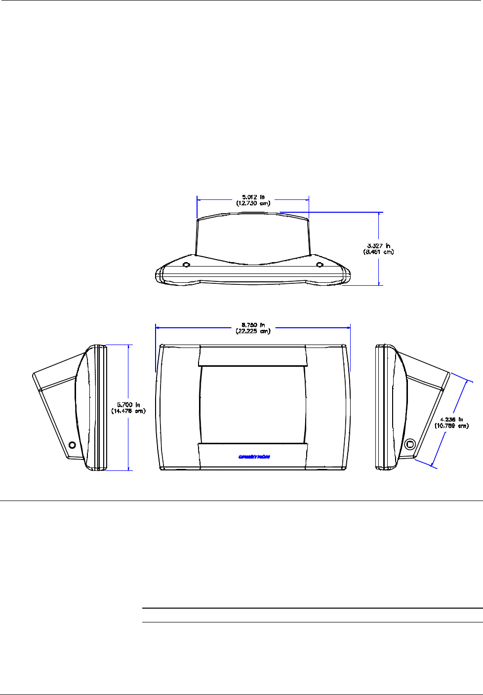
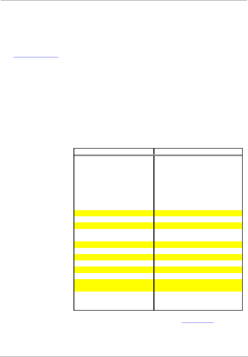
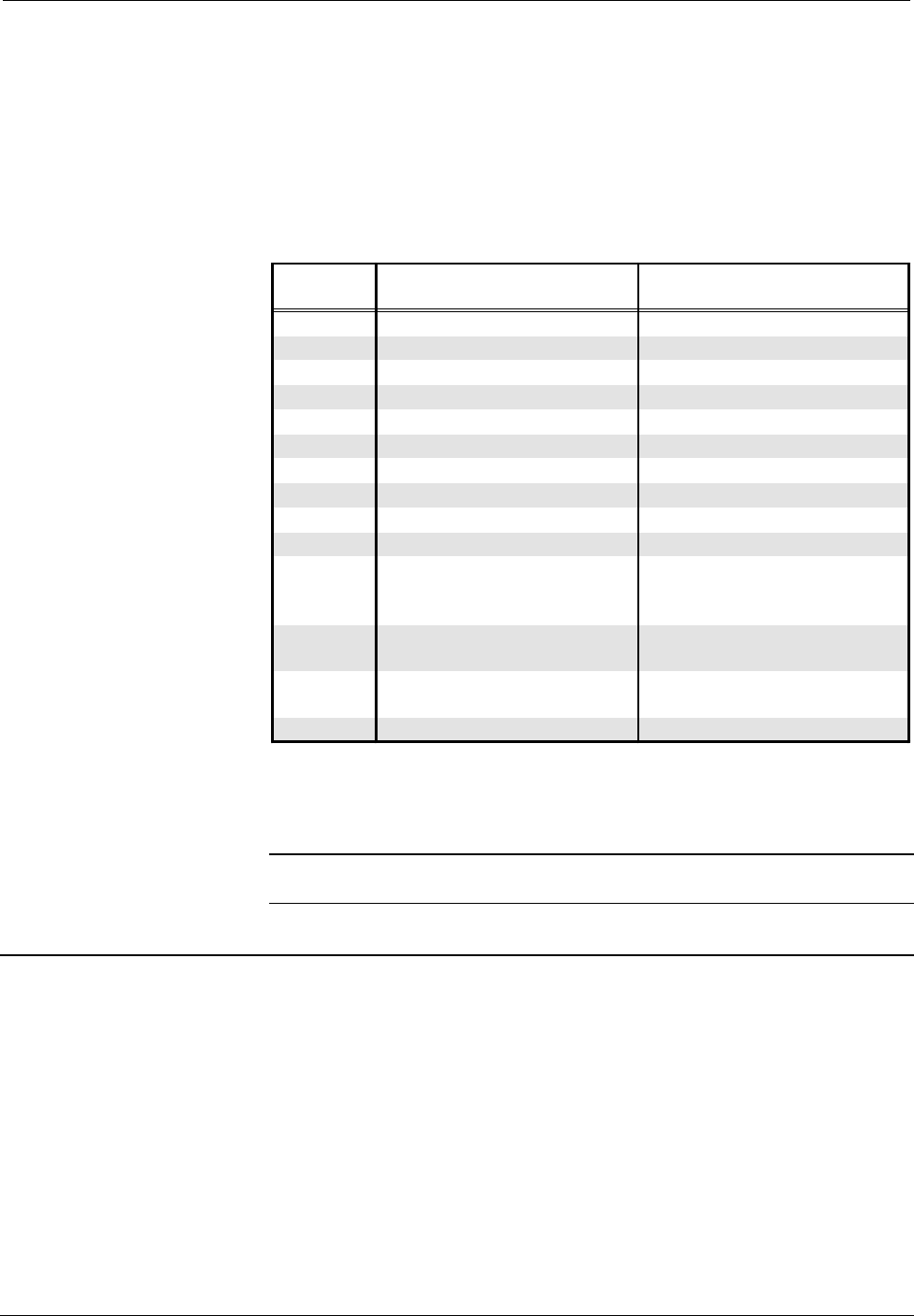
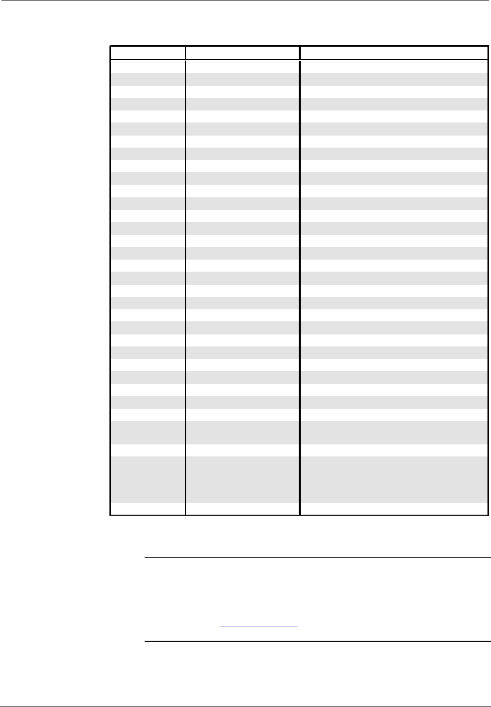
Leading Specifications
The table below provides a summary of leading specifications for the SmarTouch
STS touchpanels. Dimensions and weight are rounded to the nearest hundredth unit.
Leading Specifications of the SmarTouch STS Touchpanels
SPECIFICATION
DETAILS
Power Options
ST-BTP Rechargeable NiCad power pack (Fully
charged battery, 2800 mAh capacity, can
last up to 10 days depending on
touchpanel settings and usage.)
AC: Domestic External Adapter
12V DC, 1.0A, 120V Input
(P/N PW-1210 or equivalent)
AC: International External Adapter
12V DC, 1.0A, 230V Input
(P/N PWI-1210 or equivalent)
SIMPL™ Windows®
Version 1.30 or later (Note 1 and 2)
CNX Operating System
Version 5.01.09x or later
CNX Monitor
Version 2.00 or later
CNMS, CNRACK, CNLCOMP
Version 3.16.08 or later
Operating System
ST-CP Operating System
Version 1.29 or later
ST-CP Monitor
Version 1.29 or later
VisionTools™ Pro
Version 1.2 or later (Note 1)
Crestron Database
Version 11.7.211 or later (Note 1)
Default Network ID
03
Default RF ID
10
Default Timeouts
1 minute for standby
2 minutes for powerdown
Touchpanel Dimensions
Height: 5.70 in (14.48 cm)
(without battery and power pack)
Width: 8.75 in (22.23 cm)
Depth: 3.33 in (8.45 cm)
Note 1 The latest software versions can be obtained from the Software Downloads page (Simplwin,
Touchpnl, and Cresdb Libraries) of the Crestron website (www.crestron.com). New users are
required to register in order to obtain access to the FTP site.
Note 2 When programming the ST-1550 with SIMPL v1.30.01 and earlier, select ST-1500 from the
Device Library.
Crestron ST-1550 & ST-1550C SmarTouch STS Touchpanels
Operations Guide - DOC. 5803 SmarTouch STS: Touchpanels •• 3
Leading Specifications of the SmarTouch STS Touchpanels (Continued)
SPECIFICATION
DETAILS
Touchpanel Weight Weight: 1.85 lb (0.84 kg)
Touchpanel Memory 768 Kbytes flash memory
(available for user programming)
View Screen Dimensions Height: 3.550 in (9.017 cm)
Width: 4.700 in (11.938 cm)
View Screen Resolution
320 x 240 pixels
View Screen LCD STN color, dot matrix type for ST-1550C
FSTN Transmissive mode, dot matrix
type for ST-1550
View Screen Illumination Backlit fluorescent
View Screen Touch Screen Resistive Membrane
As of the date of manufacture, the unit has been tested and found to comply with
specifications for CE marking.
NOTE: This equipment has been tested and found to comply with the limits for a
Class B digital device, pursuant to part 15 of the FCC Rules. These limits are
designed to provide reasonable protection against harmful interference in a
residential installation. The equipment generates, uses and can radiate radio
frequency energy and, if not installed and used in accordance with the instructions,
may cause harmful interference to radio communications. However, there is no
guarantee that interference will not occur in a particular installation. If this
equipment does cause harmful interference to radio or television reception, which
can determined by turning the equipment off and on, the user is encouraged to try to
correct the interference by one or more of the following measures:
n Reorient or relocate the receiving antenna.
n Increase the separation between the equipment and receiver.
n Connect the equipment into an outlet on a circuit different from that to which the
receiver is connected.
n Consult the dealer or an experienced radio/TV technician for help.
Configuring the Touchpanel (Advanced Settings Screen)
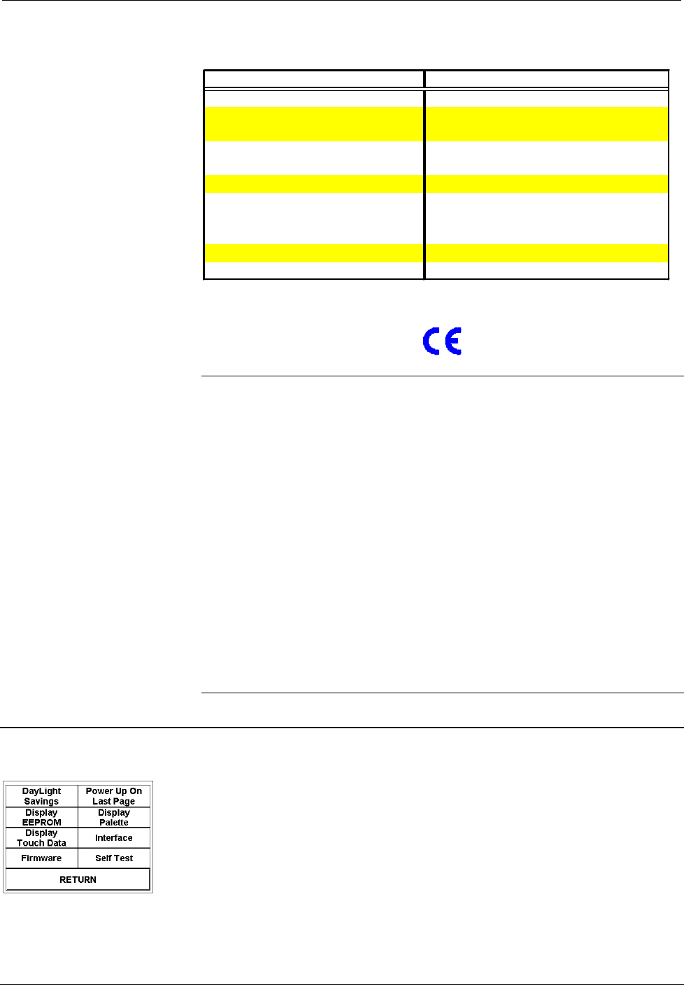
Advanced Settings Screen It may be necessary to make adjustments or configure the touchpanel to
accommodate the personal lifestyle of the end user. Descriptions for preferences and
power management settings of the touchpanel are provided in the latest revision of
the SmarTouch STS Touchpanel User’s Operations Guide (Doc. 5804). The
Advanced Settings button from the Preferences and Settings Menu opens the
Advanced Settings Screen, shown to the left of this paragraph.
The Advanced Settings Screen contains diagnostic buttons (Display EEPROM,
Display Touch Data, Firmware, Display Palette (Colorbar for ST-1550), and Self
SmarTouch STS Touchpanels Crestron ST-1550 & ST-1550C
4 •• SmarTouch STS: Touchpanels Operations Guide - DOC. 5803
Test) and buttons for special settings (DayLight Savings, Power Up On Last Page,
and Interface). Diagnostic buttons should only be used under supervision of a
Crestron technical support representative during telephone support. These options
are numeric in nature and their interpretation is beyond the scope of this Operations
Guide. Details of the special settings buttons are discussed in the following
paragraphs. Touch the RETURN button, located at the bottom of the screen, to
display the Preferences and Settings Menu.
Daylight Savings
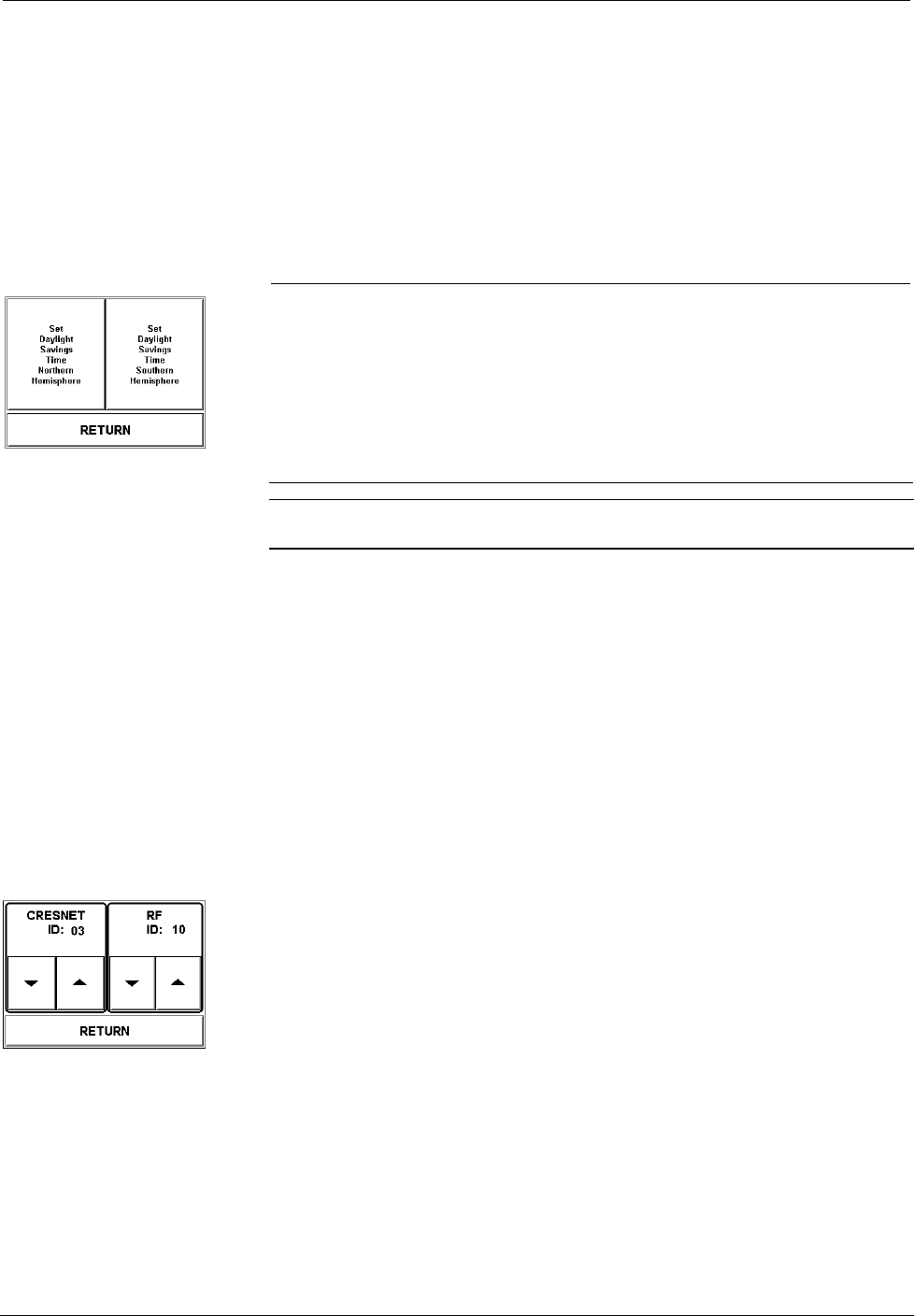
Daylight-Savings Screen To obtain the Daylight-Savings Screen, shown to the left of this paragraph, touch the
DayLight Savings button from the Advanced Settings Screen. Two options are
available: Set Daylight Savings Time Northern Hemisphere and Set Daylight
Savings Time Southern Hemisphere. Each button can be toggled (ON/OFF states).
Activating one of these buttons causes the real time clock to automatically adjust on
the appropriate dates for daylight-saving time. An activated button is indicated by a
changing the button’s background color to blue (black for ST-1550). After verifying
the setting, touch the RETURN button, located at the bottom of the screen, to
display the Advanced Settings Screen.
NOTE: If you wish to completely deactivate the daylight-saving time feature, verify
that both buttons are not activated (both assume a background color of gray).
Power Up On Last Page
The state of the Power Up On Last Page button determines which screen appears
after a power down timeout. The ON state is indicated by changing the button’s
background color to blue (black for ST-1550). As a result, the last screen to be
displayed reappears and restores all feedback when the touchpanel is activated after a
power down timeout. If desired, touch the button to turn it OFF; the button’s text
assumes the same shade as all the other buttons on the screen. The OFF state
signifies that the first page of the project appears when the touchpanel is activated
after a power down timeout.
Interface
Interface Screen The touchpanel communicates with a ST-CP (for SmarTouch STS) or Cresnet
master computer (for Cresnet System). The communication interface must be
correctly specified or communication does not occur. These communication
parameters must match those assigned in the software project. To set communication
parameters select the Interface button from the Advanced Settings Screen and
display the Interface Screen, shown to the left of this paragraph. After
communication parameters have been verified, touch the RETURN button, located
at the bottom of the screen, to save the setting and display the Advanced Settings
Screen.
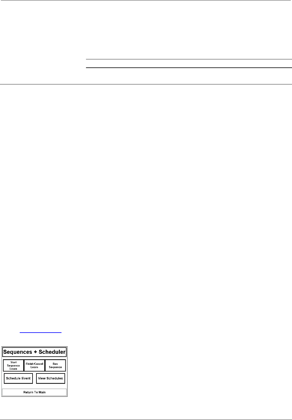
The CRESNET network identity number (NET ID) is displayed in the top left corner
of the Interface Screen. NET ID is only used during screen uploads to the touchpanel
and is identified by the two-digit hexadecimal number. “03” is shown as an example
in the illustration and happens to be the default. The down and up arrow buttons
decrease and increase the NET ID by one, respectively.
The radio frequency identity number (RF ID) is displayed in the top right corner of
the Interface Screen. This ID code is necessary to secure RF communications such
that controls can be activated from the touchpanel. The RF ID must match the
Crestron ST-1550 & ST-1550C SmarTouch STS Touchpanels
Operations Guide - DOC. 5803 SmarTouch STS: Touchpanels •• 5
identity code in the software program and is identified by the two-digit hexadecimal
number (i.e., 10, 20, 30, …, F0). “10” is shown as an example in the illustration and
happens to be the default. The down and up arrow buttons decrease and increase the
RF ID most significant digit by one, respectively. For more information for use with
Cresnet System, refer to “Touchpanel as Part of Cresnet System” on page 9.
NOTE: Crestron recommends that 00 not be selected as a valid RF ID.
Internal Scheduler
Crestron offers an internal scheduler feature built into the touchpanel. There are
actually two parts to the internal scheduler: developing a button sequence and
scheduling a button sequence/function. Each part can be utilized independently of
the other or combined. A sequence differs from the macros created from the Control
pull-down menu, because the end user can assign actions to the buttons. With proper
and careful project design, the end-user can easily make adjustments to the system to
better suit his personal needs and way of life. Furthermore, the end-user can schedule
an event so that it can begin at any given date and time and reoccur as programmed.
An event is defined as the actions initiated by one sequence or a single button
function.
DEFINITIONS:
Function: A single button press (join number 1 through 999) which typically triggers
one or more commands to be sent from the control system.
Sequence: A series of button presses that can be recorded and played back in real
time.
Event: A scheduleable action, that is, either a sequence of button presses or a direct
button press (function).
Schedule: A list of events that have been designated to run on specific dates at a
specific time.
Button Sequence Development
The purpose of developing a button sequence is to build a consecutive order of
preselected buttons that run in real time when a single programmed button is
touched. You determine and assign the join number for the programmed button from
a range of reserved join numbers. The buttons in the sequence can be chosen from
any page in the project.
Obtain the latest version of VT Pro
from the Software Downloads page
(Touchpnl Library) of the Crestron
website (www.crestron.com).
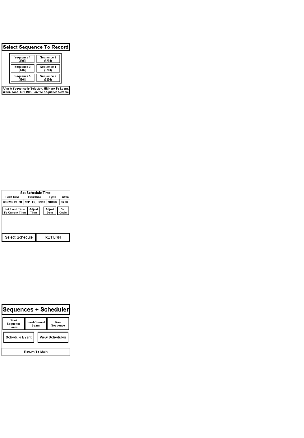
Sequences + Scheduler Page
There are two buttons with reserved join numbers that must be touched when
developing a sequence. These buttons exist on the Sequences + Scheduler page in
the SmarTouch Wizard templates, “st-1550/c basic template.vtp” (included with the
Crestron database), shown to the left of this paragraph. Copy or redraw these buttons
to another page so that the end user can use them as needed. One button, “Start
Sequence Learn”, initiates the “learning” function and the other, “Finish/Cancel
Learn”, terminates it. Complete the following steps to assign a programmable button
to a button sequence. It is assumed that the “Start Sequence Learn”, “Finish/Cancel
Learn”, and programmable buttons as well as the buttons to be included in the
sequence exist in the project available to the end user.
SmarTouch STS Touchpanels Crestron ST-1550 & ST-1550C
6 •• SmarTouch STS: Touchpanels Operations Guide - DOC. 5803
1. Touch the Start Sequence Learn button (reserved join number =
3072).
Learn Sequence #1 Page 2. Touch the programmable button. Its join number must be within the
reserved join number range from 3200 to 3327. In “st-1550/c basic
template.vtp”, a number of programmable buttons with reserved join
numbers were grouped onto a single page, Learn Sequence #1, as
shown to the left of this step.
3. Touch the Hit Here to Learn button at the bottom of the screen. The
opening menu of the project appears so that you can select buttons to
add to the sequence.
4. Touch the buttons in the sequence at the same speed that you would
like to be replicated. These buttons can be from any page in the project.
5. Each page in In “st-1550/c basic template.vtp” has a SEQ + SCHED
button. Use this button to return to the Sequences + Scheduler page
after touching all the buttons in the sequence.
6. Touch the Finish/Cancel Learn button (reserve join number = 3073)
from the Sequences + Scheduler page.
Scheduling a Sequence/Button Press
Schedule Event #2 Page The purpose of scheduling a sequence or button is to initiate an event at a
programmed date and time. The programmed date and time is defined as the
activation time. It is assumed that the sequence has been developed as described in
the previous paragraph or the preferred button initiates a function. A Schedule
Event button (found on the Sequences + Scheduler page in “st-1550/c basic
template.vtp”) has a reserved join number (3424) and must be touched prior to
pressing the button to be scheduled. A “scratch” schedule laid out on the Schedule
Event #2 page, shown to the left of this paragraph, is made available so that the time,
date, and cycle of the event can be entered.
There are a number of fields on this page that can be set by selecting the Adjust
Time, Adjust Date, or Set Cycle buttons. Each of these buttons opens another page.
Once the “scratch” schedule information is assigned, it must be transferred to one of
thirty possible scheduled events. The Select Schedule button on the Schedule Event
#2 page opens the Schedule Event #3A page and permits the end-user to save the
schedule. Complete the following steps to schedule a sequence or button.
Sequences + Scheduler Page 1. Touch the Schedule Event button (reserve join number = 3424) from
the Sequences + Scheduler page, shown to the left of this step.
Crestron ST-1550 & ST-1550C SmarTouch STS Touchpanels
Operations Guide - DOC. 5803 SmarTouch STS: Touchpanels •• 7
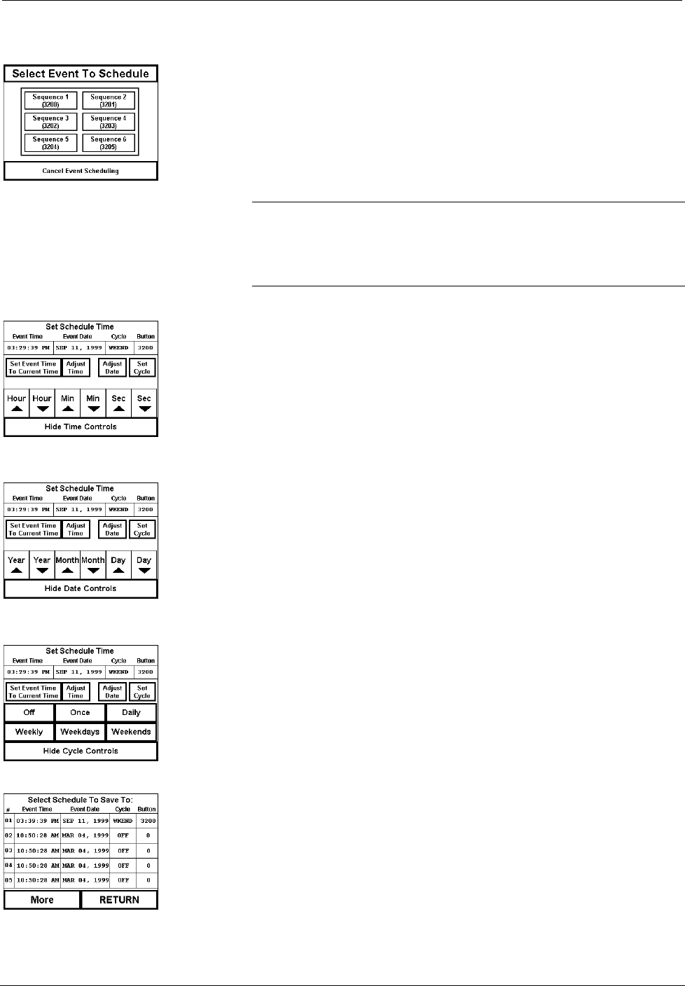
Schedule Event #1 Page 2. Touch any button with a digital join number. Button may be one that
has a programmed sequence or one that initiates a specific function
(join number 1 through 999). In this example, the available buttons are
sequence buttons that are available from the Schedule Event #1 page,
shown to the left of this step.
NOTE: If the activation time is close to the current time, touch the Set
Event Time To Current Time button (join number 3360) to set the
“scratch” schedule time and date to the current time. Then use the
increment/decrement buttons as described in the next step to make
adjustments.
Schedule Event #2A Page with Time
Adjust Subpage Open 3. To set the activation time for the event, touch the Adjust Time button
to open a subpage titled Time Adjust on the Schedule Event #2A page,
shown below. Use the increment/decrement buttons to increase and
decrease the hours, minutes, and seconds of the event. Each of these
buttons have reserved join numbers.
4. Touch the Hide Time Controls button to close the subpage when the
activation time for the event is set.
Schedule Event #2A Page with Date
Adjust Subpage Open 5. To set the activation date for the event, touch the Adjust Date button
to open a subpage titled Date Adjust on the Schedule Event #2A page,
shown to the left of this step. Use the increment/decrement buttons to
increase and decrease the year, month, and day of the event. Each of
these buttons have reserved join numbers.
6. Touch the Hide Date Controls button to close the subpage when the
activation date for the event is set.
Schedule Event #2A Page with Cycle
Adjust Subpage Open 7. The cycle of the event determines how often it occurs. To set the cycle
for the event, touch the Set Cycle button to open a subpage titled Cycle
Adjust on the Schedule Event #2A page, shown to the left of this step.
Available options for how often an event can occur are: Off (never
occurs), Once, Daily, Weekly, Weekdays, and Weekends. Each of
these buttons have reserved join numbers.
8. Touch the Hide Cycle Controls button to close the subpage when the
activation cycle for the event is set.
Schedule Event #3A Page 9. The event time and date have been properly set up in the “scratch”
schedule. Touch the Select Schedule button to open the Schedule
Event #3A page, shown to the left of this step. Notice that this page has
five schedules defined on the screen. To gain access to five more
schedules, touch the “More” button.
10. Determine the schedule that you want to use and touch that line. The
new schedule time, date, cycle, and join number appear automatically.
The event is now scheduled.
SmarTouch STS Touchpanels Crestron ST-1550 & ST-1550C
8 •• SmarTouch STS: Touchpanels Operations Guide - DOC. 5803
The Schedule System Display
The schedule system display appears because of the command text specifier “N”.
This command text is written in a border or button in the following format:
`N{Schedule Number},{Specifier}
The available schedule numbers are 0 through 31, where schedule 0 is the “scratch”
schedule. Refer to the table below for a description of the specifiers.
Table of Specifiers
SPECIFIER MEANING NOTES
0
Seconds
0 to 59
1
Minutes
0 to 59
2
Hours
24 Hour Time, 0 to 23
3
Day of the Month
1 to 31
4
Month
1 to 12
5
Year
4 Digit, i.e., 1996
6
Weekday
0 to 6
7
Day of the Year
0 to 365
8
Hours
12 Hour Time, 1 to 12
9
12 Hour Time Type
AM or PM
10 Month 3 Characters: JAN, FEB, MAR,
APR, MAY, JUN, JUL, AUG, SEP,
OCT, NOV, DEC
11 Day of the Week 3 Characters: SUN, MON, TUE,
WED, THU, FRI, SAT
12 Type of Schedule Cycle Type: OFF, ONCE, DAILY,
WEEK, WKDAY, WKEND
13
Join Number for that Schedule
EXAMPLE: To show the type of cycle for schedule #1, the command text in a
border or button would look like:
`N1,12
NOTE: As with all command text, formats as that shown above are the only text
allowed in the border or button.
Touchpanel as Part of SmarTouch STS
This section of this Operations Guide and the next is to remind the reader that the
touchpanel provides user interface in either the Cresnet System or SmarTouch STS.
If the touchpanel is to be part of the SmarTouch STS, refer to the latest revision of
the SmarTouch STS Touchpanel User’s Operations Guide (Doc. 5804) for
descriptions regarding the system’s equipment and how to connect the panel in
programming and operation modes.

Crestron ST-1550 & ST-1550C SmarTouch STS Touchpanels
Operations Guide - DOC. 5803 SmarTouch STS: Touchpanels •• 9
Touchpanel as Part of Cresnet System
This section of the Operations Guide only applies to those using the touchpanel in a
Cresnet System. It provides descriptions regarding programming via SIMPL
Windows and details on how to connect the panel to load a program.
Programming with SIMPL™ Windows
NOTE: Graphical touchscreen design is accomplished using VisionTools Pro (VT
Pro). VT Pro is a Windows compatible software package for creating Crestron
touchpanel screen designs. Refer to “Software” on page 2 for additional details
regarding VT Pro.
SIMPL (Symbol Intensive Master Programming Language) is an easy-to-use
programming language that is completely integrated and compatible with all
Crestron system hardware. The objects that are used in SIMPL are called symbols.
SIMPL Windows offers drag and drop functionality in a familiar Windows®
environment.
SIMPL Windows is Crestron Electronics' software for programming Crestron control
systems. It provides a well-designed graphical environment with a number of
workspaces (i.e., windows) in which a programmer can select, configure, program,
test, and monitor a Crestron control system.
The next two subsections describe a sample SIMPL Windows program that utilizes a
touchpanel. The first subsection details how the sample program works with a textual
description and block diagram. The second subsection provides a broad description
of how to actually create the SIMPL Windows program.
NOTE: The following description assumes that the reader has knowledge of SIMPL
Windows. If not, please refer to the extensive help information provided with the
software.
NOTE: There is no need to recreate the sample SIMPL Windows program. A
similar copy of this program is available from Crestron’s ControlCD (version 5.1 and
later) or the Software Downloads page (Examples Library) of the Crestron website
(www.crestron.com). Search for the ST-1550C.SMW project in the SIMPL
Windows Example Base.
How the Program Works
A basic STS Touchpanel SIMPL program is shown on the next page in block
diagram form. For this example, the ST-1550C is the user interface in a relay-
controlled lighting system with four preset scenes and an OFF scene. To activate a
scene, the corresponding relay on the built-in low voltage relay card in the CNMSX-
PRO must be latched. To turn the scene off, use the clear function of the
INTERLOCK symbol to open all relays.
SmarTouch STS Touchpanels Crestron ST-1550 & ST-1550C
10 •• SmarTouch STS: Touchpanels Operations Guide - DOC. 5803
Block Diagram of ST-1550C
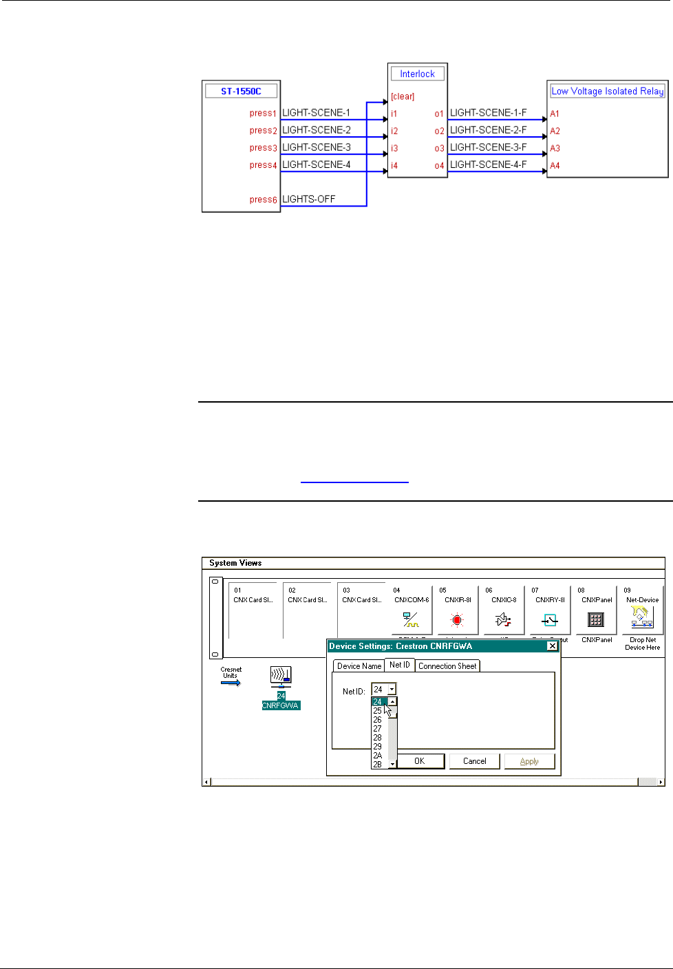
How to Create the Program
Configuration Manager
Use the Configuration Manager workspace (Project | Configure System) in SIMPL
Windows to select and configure all the devices that need to be included into the
system. For this example, add a CNRFGWA and ST-1550C to the system. The NET
ID of the CNRFGWA is set to 24 and the the RF ID of the ST-1550C is set to 10,
shown below.
NOTE: Consult the “Leading Specifications” on page 2 for the correct version of
SIMPL Windows. If using an early version of SIMPL Windows, Crestron
recommends a SIMPL Windows and operating system upgrade. The latest version
can be obtained from the Software Downloads page (Simplwin Library) of the
Crestron website (www.crestron.com). New users are required to register in order to
obtain access to the FTP site.
System View of the CNRFGWA NET ID Assignment in SIMPL Windows’ Configuration
Manager
Crestron ST-1550 & ST-1550C SmarTouch STS Touchpanels
Operations Guide - DOC. 5803 SmarTouch STS: Touchpanels •• 11
When the ST-1550C is dropped onto the CNRFGWA, the RF ID default address (10)
is automatically assigned. Verify or reassign in the Detail System View, shown after
this paragraph. Notice that unused slots are hidden.
Detail System View of the ST-1550C RFID Assignment in SIMPL Windows’ Configuration
Manager
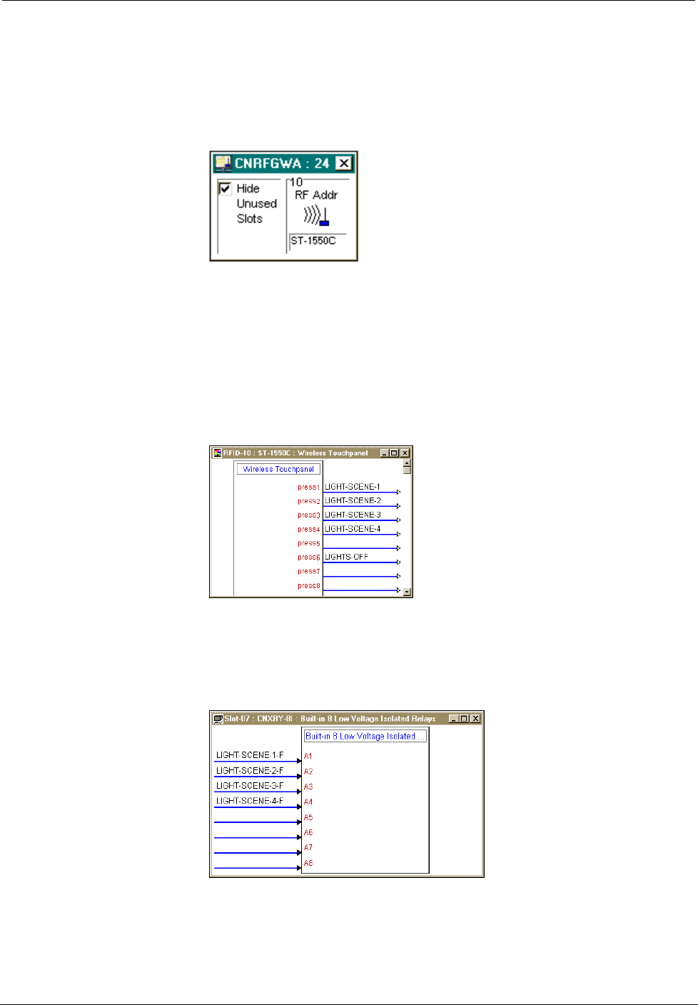
Programming Manager
Use the Programming Manager workspace (Project | Program System) in SIMPL
Windows to select symbols and assign their respective signals. For this example, the
touchpanel symbol was added automatically when the device was added to the
system in the Configuration Manager workspace. Expand the Network Modules
folder and double click on the ST-1550C for a detail view (alternatively CTRL+D or
drag and drop into Detail View). Assign signals as shown after this paragraph.
Detail View of the ST-1550C in SIMPL Windows’ Programming Manager
Expand the Central Control Modules folder. Double click on the Slot-07 icon for a
detailed view of the built-in relay (alternatively CTRL+D or drag and drop into
Detail View). Assign signals as shown after this paragtraph.
Detail View of the CNMSX-PRO Built-In Relay in SIMPL Windows’ Programming
Manager
All logic symbols necessary for the SIMPL Windows program must be added from
the Symbol Library in the Programming Manager workspace. In this example, drag
and drop one Interlock symbol from the Memory folder into the Logic folder in
Program View. Expand the Logic folder to display the Interlock symbol integrated
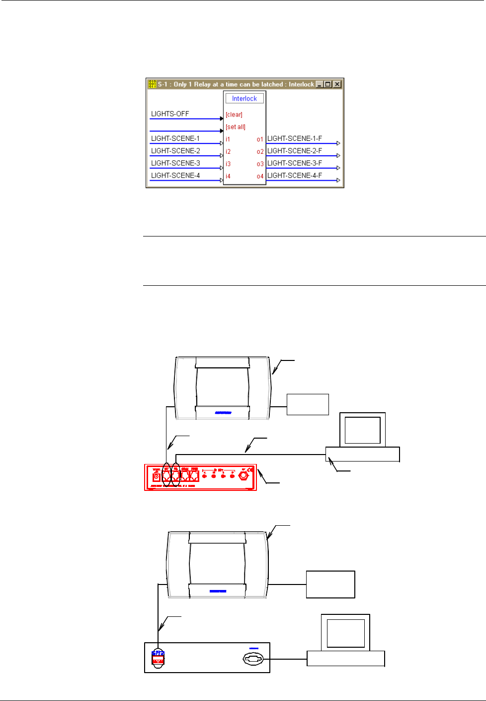
SmarTouch STS Touchpanels Crestron ST-1550 & ST-1550C
12 •• SmarTouch STS: Touchpanels Operations Guide - DOC. 5803
into this program. View the symbol in detail view (alternatively CTRL+D or drag
and drop into Detail View). Assign signals as shown below.
Detail View of an Interlock in SIMPL Windows’ Programming Manager
Loading a Program
REMINDER: Every network device within the Cresnet requires a unique identity
code (NET ID). These codes recognized by a two-digit hexadecimal number from 03
to FE. Matching NET IDs between touchpanel and VT Pro program is required if
new touchpanel screens are to be loaded.
To load a program, refer to the figures shown after this paragraph for typical
connection diagrams. Complete the following steps provided to ensure proper
connection to the system.
Typical Connection Diagram when Loading a Program from the ST-CP
15710 (PART OF ST-PK)
PC
CONTROL
SYSTEM
SERIAL
PORT
15717 (PART OF ST-PK)
USE ADAPTER
(PART OF ST-PK)
TOUCHPANEL
AC POWER PACK
(CRESTRON MODEL
OR EQUIVALENT)
NOTE:
UNITS IN THIS ILLUSTRATION
ARE NOT DRAWN TO SCALE.
Typical Connection Diagram when Loading a Program from the CNMSX
PC
NOTE:
UNITS IN THIS ILLUSTRATION
ARE NOT DRAWN TO SCALE.
TOUCHPANEL
ST-CBL (SOLD SEPARATELY)
CONTROL
SYSTEM SERIAL
PORT
AC POWER PACK
(CRESTRON MODEL
OR EQUIVALENT)
Crestron ST-1550 & ST-1550C SmarTouch STS Touchpanels
Operations Guide - DOC. 5803 SmarTouch STS: Touchpanels •• 13
NOTE: If the control system in use has a 4-pin network connector rather than a
modular (RJ11-type) NET connector, use a ST-CBL (sold separately) or make a
cable. Refer to the cable specifications, shown after the following steps.
1. Before making any connections to the touchpanel, verify that control
system is properly connected to the PC (using cable 15717 and adapter)
and powered on.
2. Attach the stereo connector end of the programming cable, part number
15710, to the touchpanel.
3. Attach the RJ11 connector end of the programming cable, part number
15710, to the connector labeled NET on the control system.
4. Attach the appropriate Crestron external AC power pack or equivalent
to touchpanel and plug into outlet.
5. Use Crestron VT Pro software to upload the panel design project to the
touchpanel. Refer to the software help file for upload settings.
6. After the touchpanel has been programmed, disconnect the
programming cable. The touchpanel communicates with the control
system via RF signals.
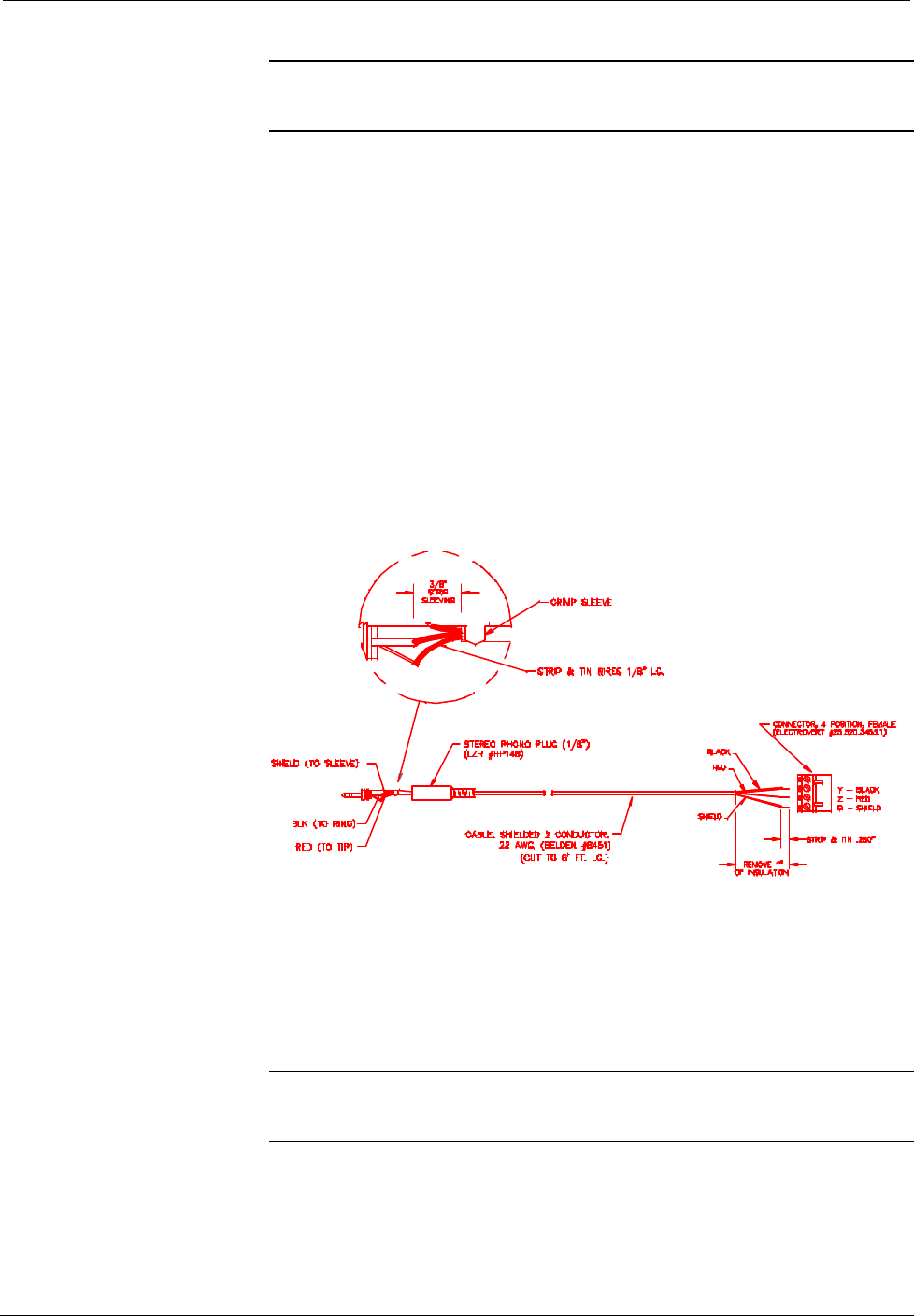
Programming Cable Specifications
Reserved Join Numbers
A reserved join number is a feature of the software that enables a designer to create a
button on a touchpanel page that completes a predetermined function. The table after
this paragraph provides a list of reserved join numbers available within SIMPL
Windows software.
NOTE: Many touchpanel configuration “shortcuts” are available via the software.
A button can be created on a page that either calls up the Preferences Menu, ramps
contrast, adjusts brightness, etc., via reserved join numbers.
SmarTouch STS Touchpanels Crestron ST-1550 & ST-1550C
14 •• SmarTouch STS: Touchpanels Operations Guide - DOC. 5803
Reserve Join Numbers for SmarTouch STS Touchpanel
JOIN NUMBER FUNCTION VALUE
1015
Power
Off
1016
Stand by
On
1017
Brightness
Low
1018
Brightness
Medium
1019
Brightness
High
1023
Contrast
Up
1024
Contrast
Down
1035
Reboots the System *
N/A
1036
Discharges ST-BTP **
N/A
1120 - 1123
Digital Battery Bargraph
Gauge Bottom (1120) to Gauge Top (1123)
1160
Keyclick Volume
Up
1161
Keyclick Volume
Down
1172
Keyclick
On
1173
Keyclick
Off
3072
Scheduler
Start Learn
3073
Scheduler
End Learn
3074 Scheduler
Increment Seconds
3075
Scheduler
Decrement Seconds
3076
Time & Date Adjustment
Increment Minutes
3077
Time & Date Adjustment
Decrement Minutes
3078
Time & Date Adjustment
Increment Hours
3079
Time & Date Adjustment
Decrement Hours
3080
Time & Date Adjustment
Increment Days
3081
Time & Date Adjustment
Decrement Days
3082
Time & Date Adjustment
Increment Months
3083
Time & Date Adjustment
Decrement Months
3084
Time & Date Adjustment
Increment Years
3085
Time & Date Adjustment
Decrement Years
3200 - 3327
Scheduler
Programmable Buttons
3360 Time & Date Adjustment Set Scratchpad Time & Date to Touchpanel's
Current Time & Date
3361
Time & Date Adjustment
Save Settings
3362 - 3423
Scheduler
(Odd Join Numbers Most
Commonly Used)
Even #s: Copy Schedule to Scratchpad
Odd #s: Copy Scratchpad to Schedule
(i.e., 3362: Copy Schedule 1 to Scratchpad
3363: Copy Scratchpad to Schedule 1)
3424
Scheduler
Select Event Button
* Holding a button (assigned with join number 1035) for more than five seconds places the touchpanel into
"setup mode". Use this mode to configure the touchpanel.
** While discharging, the touchpanel backlight is set to maximum and the timeouts are disabled.
NOTE: If designing an analog battery gauge bargraph, it can be displayed with any
of the standard command text on analog channel 2. Therefore, `A2 displays the
gauge as a bargraph that fills bottom to top. `D2 displays a bargraph that fills left to
right (as designed in the “st-1550/c basic template.vtp” project). Obtain the latest
version of VT Pro from the Software Downloads page (Touchpnl Library) of the
Crestron website (www.crestron.com). New users are required to register in order to
obtain access to the FTP site.
Crestron ST-1550 & ST-1550C SmarTouch STS Touchpanels
Operations Guide - DOC. 5803 SmarTouch STS: Touchpanels •• 15
Problem Solving
Troubleshooting
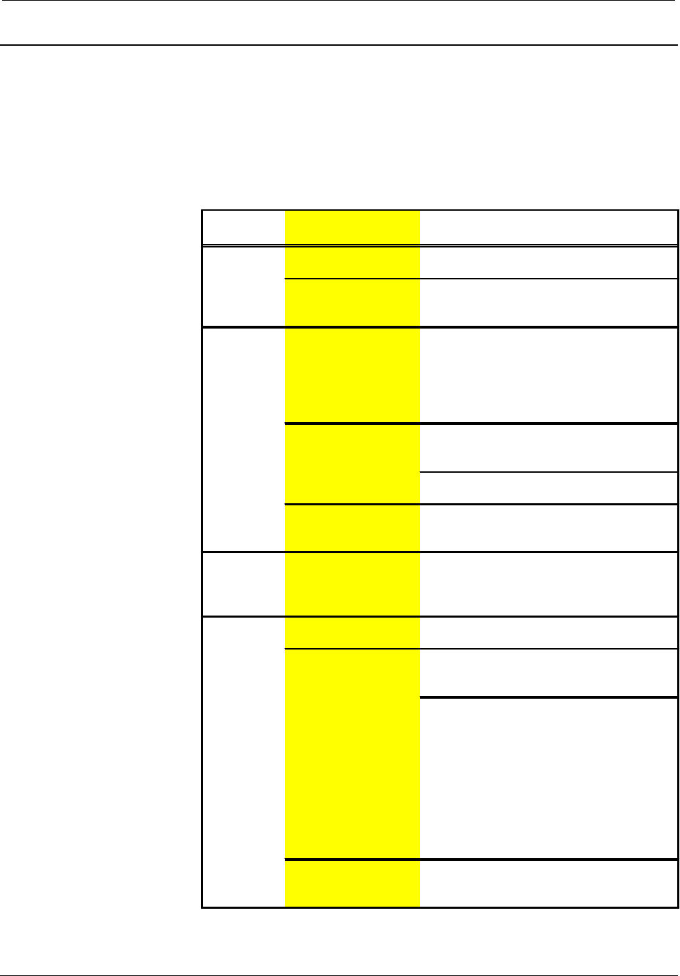
The table below and on the next page provides corrective action for possible trouble
situations. If further assistance is required, please contact a Crestron technical
support representative.
SmarTouch STS Touchpanel Toubleshooting
TROUBLE POSSIBLE
CAUSE(S)
CORRECTIVE ACTION
Project can
not be Touchpanel has
powered down. Power panel with power pack when
programming and uploading project.
uploaded to
the
touchpanel.
NET ID on touchpanel
is improperly set. Verify that NET ID match. Refer to "Interface"
in this Operations Guide and NET ID
parameters assigned in the program.
Project can
not be
uploaded to
touchpanel:
1. Screen is
black.
Touchpanel is in
standby or powered
down.
Touch the touchpanel to display a screen.
Verify that the panel has power supplied to it,
either battery or power pack.
2. Checking
communica-
tions error.
Incorrect COM port
specified.
Verify upload preferences is set to the COM
port being used to communicate to the
control system.
Verify upload preferences specifies RACK
(not the PANEL) as target of the upload.
3. Checking
panel type
error.
NET ID for panel and
VT Pro project NET ID
do not match.
Verify that panel NET ID matches the NET ID
set in the VT Pro program. Refer to
"Interface" in this Operations Guide.
Wrong
screens
appear on
touchpanel.
Screens were not
uploaded.
Upload screens as described in the help files
found in VT Pro.
Touchpanel
does not No power to the
touchpanel. Confirm that power pack is attached or
batteries are installed.
function. Touchpanel is
incorrectly calibrated. Select the Calibration button from the
Preferences and Settings Menu to enter
"calibration mode".
If the Calibration button cannot be reached,
complete the following steps.
Remove power (battery and/or power pack).
Reapply power while holding finger to the
touchscreen for approximately 10 seconds.
During this short period, the words "SETUP
MODE" appear as does the Opening Screen.
Touch the Opening Screen and select the
Calibration button from the Preferences and
Settings Menu to enter "calibration mode".
Touchpanel is not
communicating to the
control system.
Poll the network (F4 in either VT Pro or
SIMPL Windows) to verify communication.
SmarTouch STS Touchpanels Crestron ST-1550 & ST-1550C
16 •• SmarTouch STS: Touchpanels Operations Guide - DOC. 5803
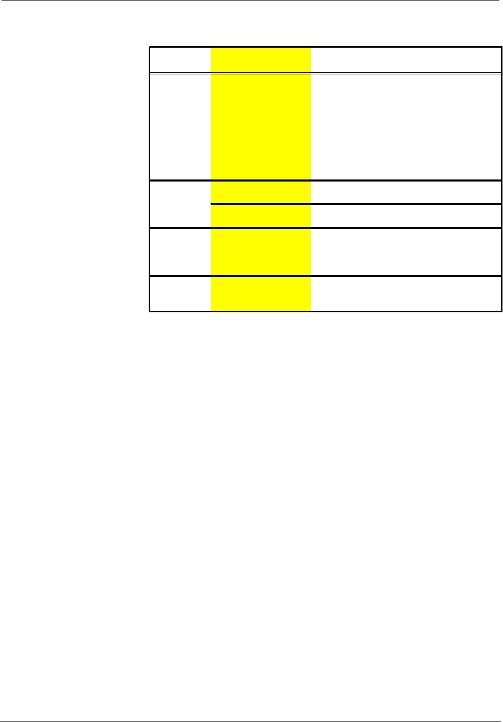
SmarTouch STS Touchpanel Toubleshooting (Continued)
TROUBLE POSSIBLE
CAUSE(S)
CORRECTIVE ACTION
Touchpanel
does not
function and
RF LED on
ST-CP
illuminates,
but COM or
IR LEDs do
not illuminate.
Touchpanel RF ID is
not set to match the RF
ID assigned in the
SmarTouch system
program.
Verify that RF ID match. Refer to "Interface"
in this Operations Guide and RF ID
parameters assigned in the program.
Touchpanel
display is
Standby or power down
timeout has elapsed.
Touch screen to reactivate.
dark. Power is not applied to
the touchpanel.
Verify that power is properly applied and all
connections are made.
Touchpanel
display is
dark or too
light.
Screen brightness or
contrast is improperly
set.
Hold a finger to the touchscreen for more
than 10 seconds as power is applied. The
display sets the brightness and contrast to a
safe value.
Touchpanel
exhibits slow
operation.
Compressed graphics
take time to
decompress.
If there are no memory problems,
decompressed graphics decrease the
drawing time of panel pages.
Further Inquiries
If after reviewing this Operations Guide for the SmarTouch STS Touchpanel, you
cannot locate specific information or have questions, please take advantage of
Crestron's award winning technical support team by calling:
• In the US and Canada, call Crestron’s corporate headquarters at
1-888-CRESTRON [1-888-273-7876] or 1-201-767-3400.
• In Europe, call Crestron International at +32-15-50-99-50.
• In Asia, call Crestron Asia at +852-2341-2016.
• In Latin America, call Crestron Latin America at +525-574-15-90.
For local support from exclusive Crestron factory-trained personnel call:
• In Australia, call Soundcorp at +613-941-61066.
• In New Zealand, call Amber Technologies at +649-410-8382.

Crestron ST-1550 & ST-1550C SmarTouch STS Touchpanels
Operations Guide - DOC. 5803 SmarTouch STS: Touchpanels •• 17
Return and Warranty Policies
Merchandise Returns / Repair Service
1. No merchandise may be returned for credit, exchange, or service
without prior authorization from CRESTRON. To obtain warranty
service for CRESTRON products, contact the factory and request an
RMA (Return Merchandise Authorization) number. Enclose a note
specifying the nature of the problem, name and phone number of
contact person, RMA number, and return address.
2. Products may be returned for credit, exchange, or service with a
CRESTRON Return Merchandise Authorization (RMA) number.
Authorized returns must be shipped freight prepaid to CRESTRON,
Cresskill, N.J., or its authorized subsidiaries, with RMA number clearly
marked on the outside of all cartons. Shipments arriving freight collect
or without an RMA number shall be subject to refusal. CRESTRON
reserves the right in its sole and absolute discretion to charge a 15%
restocking fee, plus shipping costs, on any products returned with an
RMA.
3. Return freight charges following repair of items under warranty shall
be paid by CRESTRON, shipping by standard ground carrier. In the
event repairs are found to be non-warranty, return freight costs shall be
paid by the purchaser.
CRESTRON Limited Warranty
CRESTRON ELECTRONICS, Inc. warrants its Cresnet products, denoted by a
"CN" prefix model number, to be free from manufacturing defects in materials and
workmanship for a period of three (3) years from the date of shipment to purchaser.
Disk drives and any other moving or rotating mechanical parts are covered for a
period of one (1) year. CRESTRON warrants all its other products for a period of
one year from the defects mentioned above, excluding touchscreen display
components which are covered for 90 days. Incandescent lamps are completely
excluded from Crestron's Limited Warranty. CRESTRON shall, at its option, repair
or replace any product found defective without charge for parts or labor. Repaired or
replaced equipment and parts supplied under this warranty shall be covered only by
the unexpired portion of the warranty.
CRESTRON shall not be liable to honor warranty terms if the product has been used
in any application other than that for which it was intended, or if it has been
subjected to misuse, accidental damage, modification, or improper installation
procedures. Furthermore, this warranty does not cover any product that has had the
serial number altered, defaced, or removed.
This warranty shall be the sole and exclusive remedy to the purchaser. In no event
shall CRESTRON be liable for incidental or consequential damages of any kind
(property or economic damages inclusive) arising from the sale or use of this
equipment. CRESTRON makes no other warranties nor authorizes any other party to
offer any warranty, expressed or implied, including warranties of merchantability for
this product. This warranty statement supersedes all previous warranties.
Trademark Information
All brand names, products names, and trademarks are the sole property of their respective owners.
Windows is a registered trademark of Microsoft Corporation. Windows95, Windows98 and WindowsNT
are trademarks of Microsoft Corporation.