Crestron Electronics STRFGWX GATEWAY User Manual Strfgwx
Crestron Electronics Inc GATEWAY Strfgwx
UserManual.wiki
>
Crestron Electronics
>
STRFGWX User Manual
Manual
Navigation menu
Upload a User Manual
Namespaces
Wiki Guide
HTML
PDF
Info
Views
User Manual
Discussion / Help
Navigation
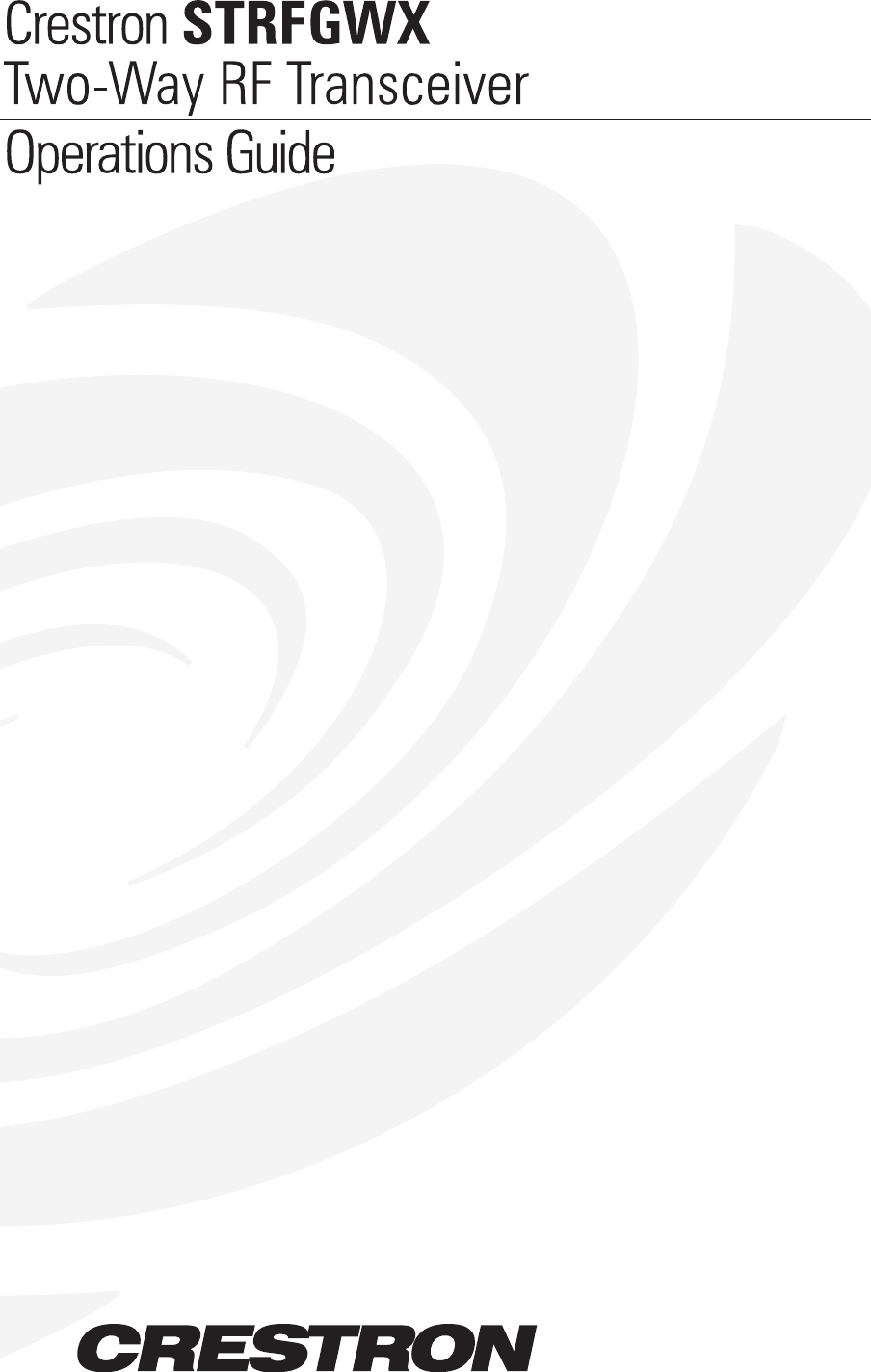

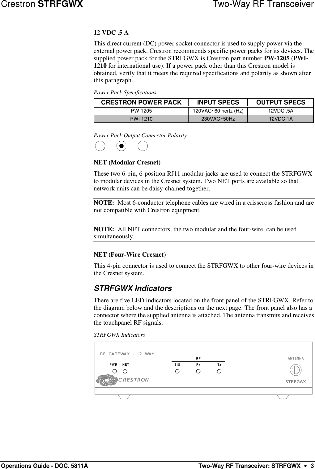
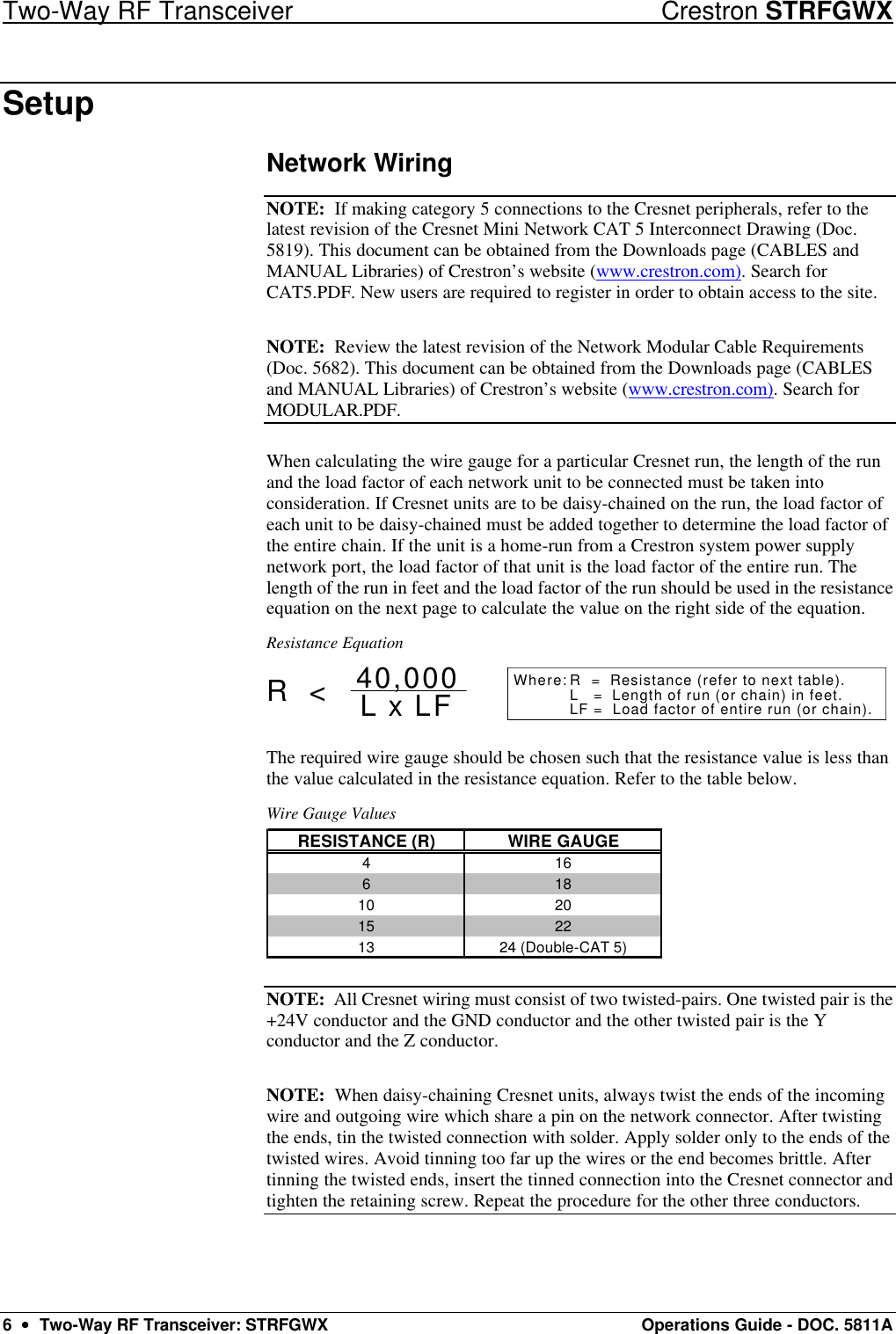
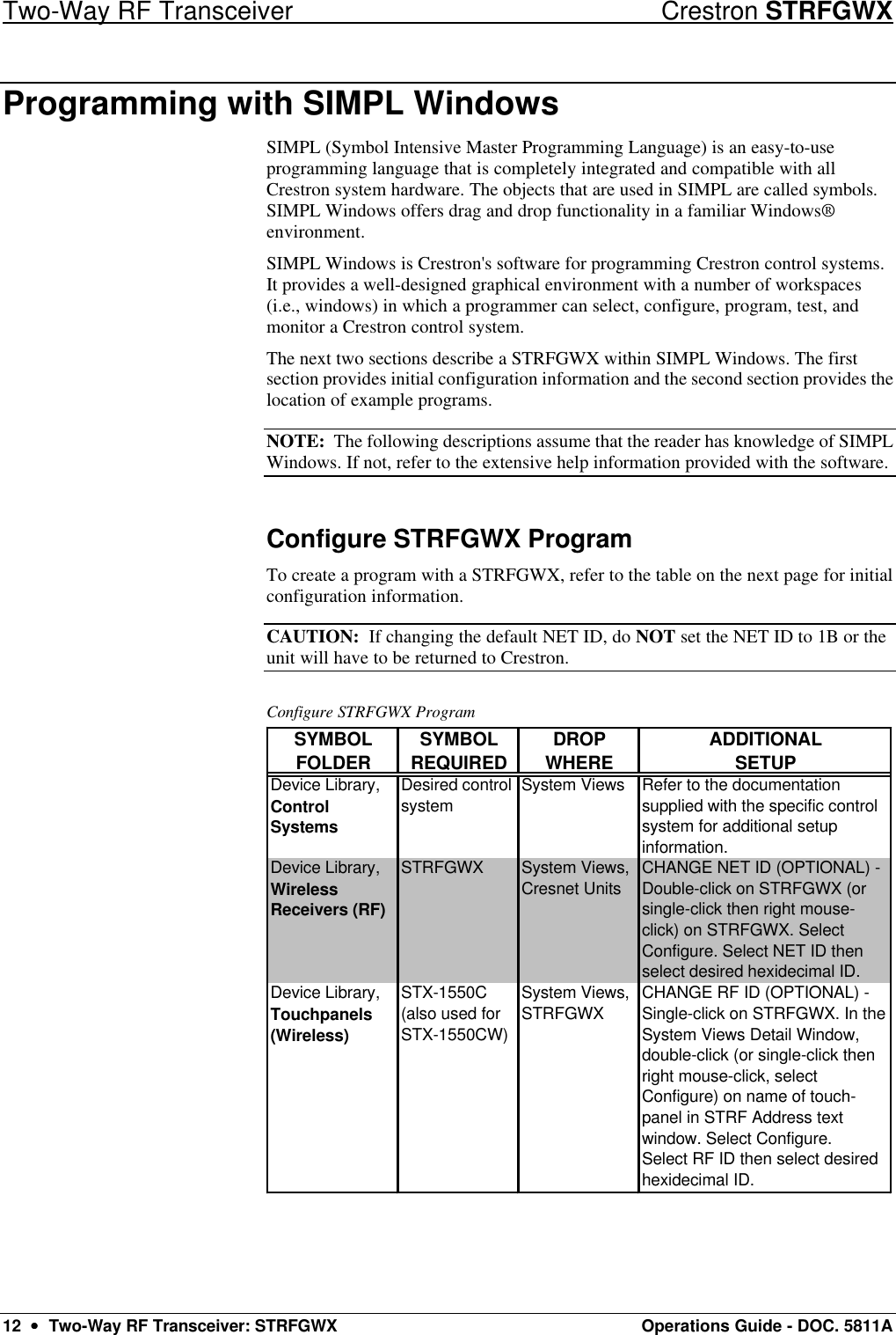
![Crestron STRFGWX Two-Way RF Transceiver Operations Guide - DOC. 5811A Two-Way RF Transceiver: STRFGWX •• 9 Firmware Upgrade To upgrade the firmware of the STRFGWX, a local PC that contains the Crestron Viewport (available in SIMPL Windows or VT Pro-e) is required. To connect the PC to the control system, refer to the “Obtaining Communications” section of the Operators Guide supplied with the appropriate control system. The latest version of the Operations Guides can be obtained from the Downloads page (MANUAL Library) of Crestron’s website (www.crestron.com). New users are required to register in order to obtain access to the FTP site. Firmware upgrade files are obtained from the What’s New page (Touchpanels section) or the Downloads page (TOUCHPNL and UPGRADES Libraries) of Crestron’s website. There have been two releases of STRFGWX firmware 1.5.0, PIC Ver 15 and 1.66 PIC Ver 19. Both versions may be directly upgraded to [2.4.1] PIC Ver 22. To upgrade the STRFGWX firmware, complete the following steps. CAUTION: To utilize firmware upgrade files, a STRFGWX with a firmware version earlier than 1.5.0 must be returned to Crestron. Refer to “Merchandise Returns / Repair Service” on page 16 for further information. Do NOT attempt to upgrade those firmware versions. CAUTION: Do NOT disconnect power from the STRFGWX until the firmware upgrade is complete and the RX and TX front panel LEDs remain unlit for approximately 50 seconds. Otherwise, unit will have to be returned to Crestron. 1. Make sure that no programs accessing the COM port of the PC. 2. At the PC, start SIMPL Windows or VT Pro-e. 3. From the SIMPL Windows or VT Pro-e menu bar, select Tools | Viewport to open the Crestron Viewport. NOTE: SIMPL Windows may open with an opening splash screen and may display the “What do you want to do?” dialog box. If so, close the dialog box and continue. 4. Refer to figure below. From the Viewport menu, select Setup | Communications settings (alternatively, depress Alt+D) to open the Port Settings dialog box. Accessing the Port Settings Dialog Box](https://usermanual.wiki/Crestron-Electronics/STRFGWX/User-Guide-175791-Page-13.png)
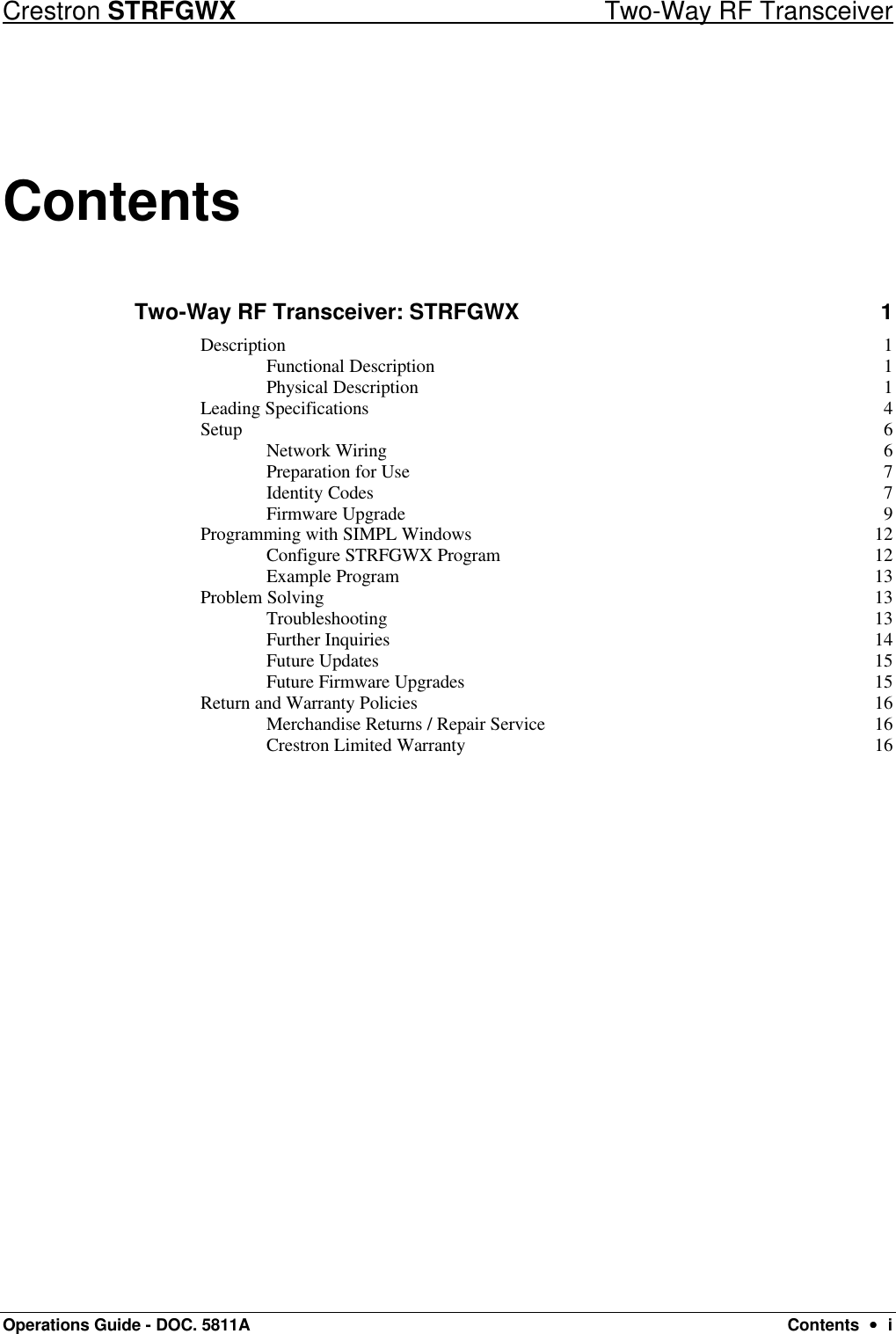
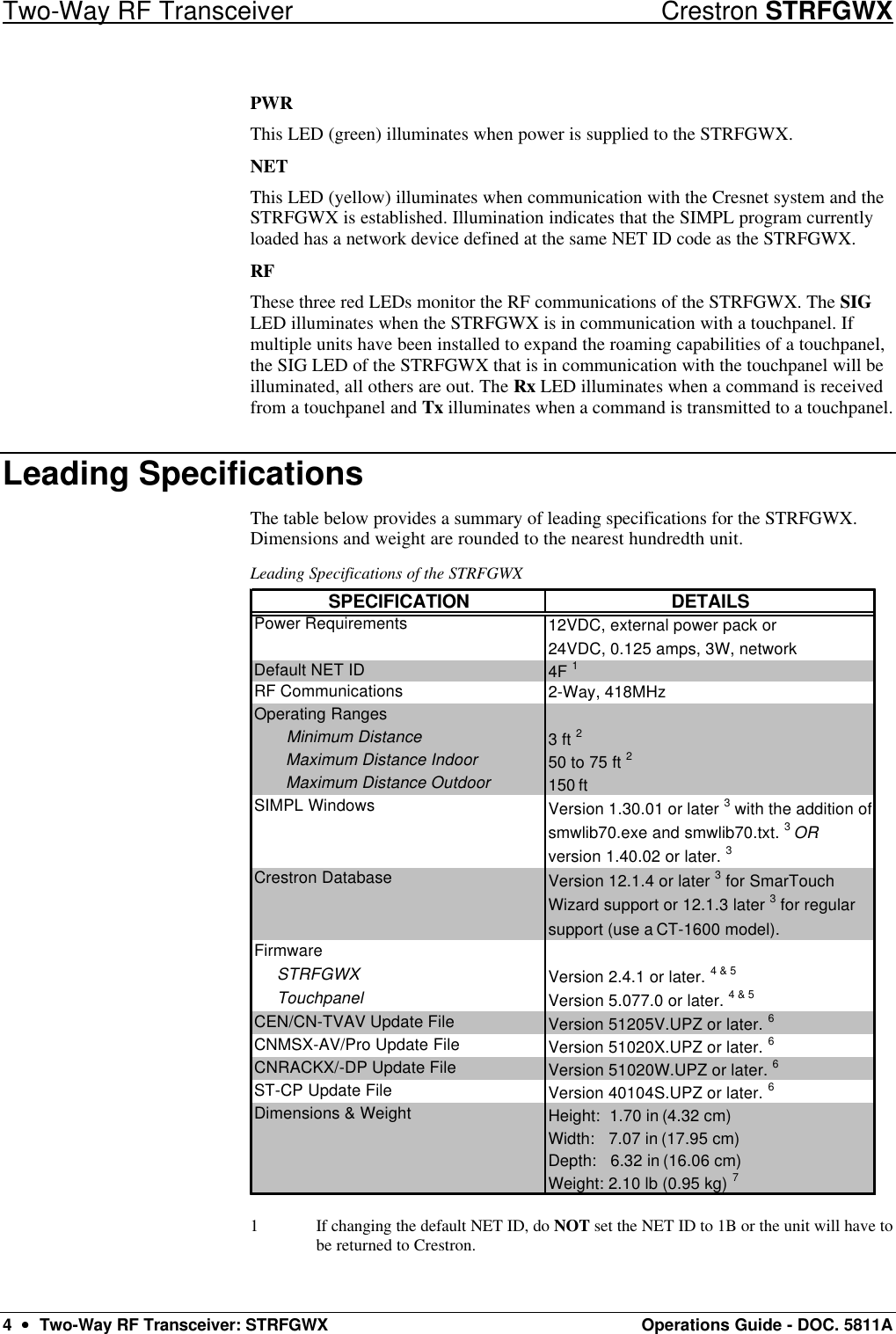
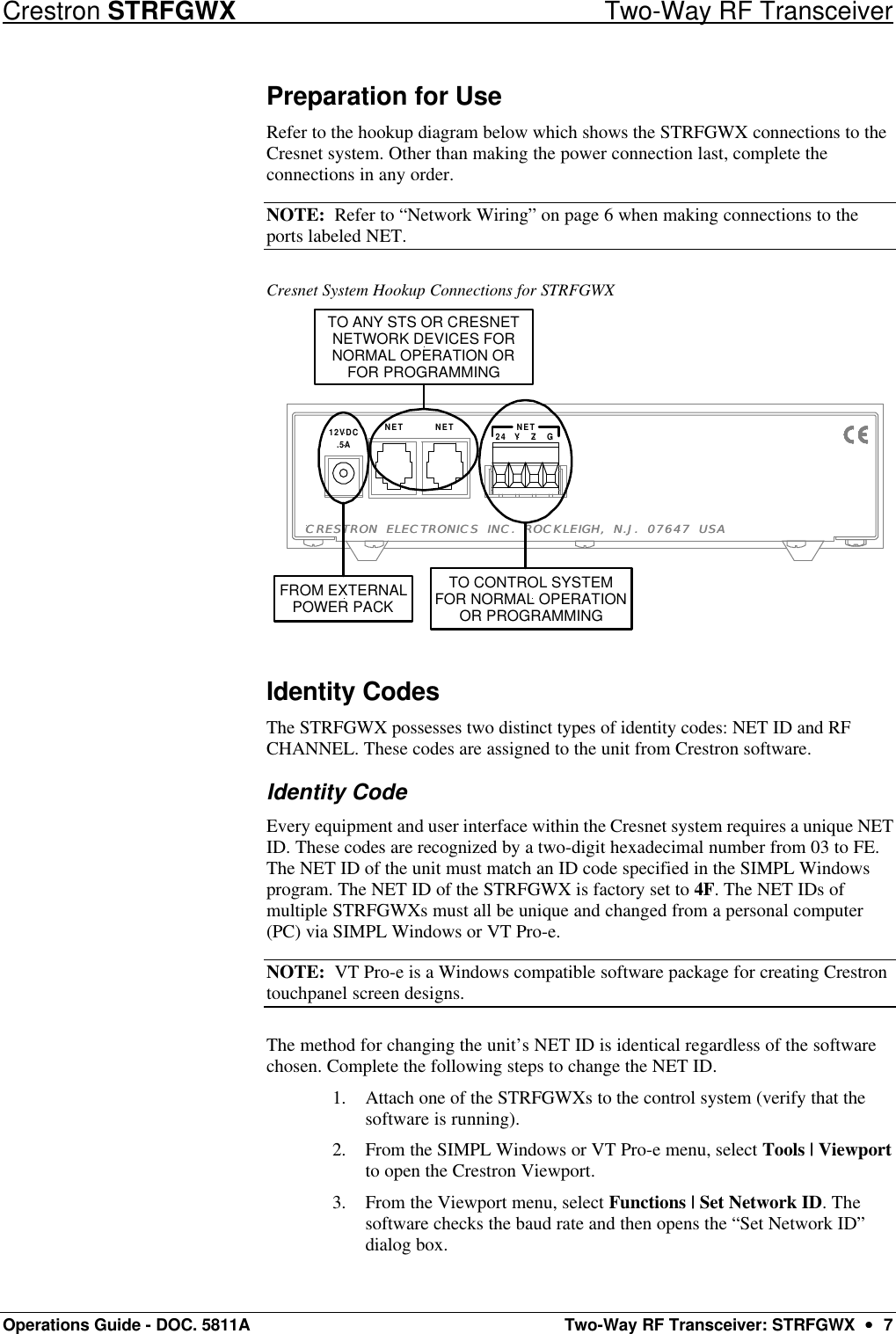
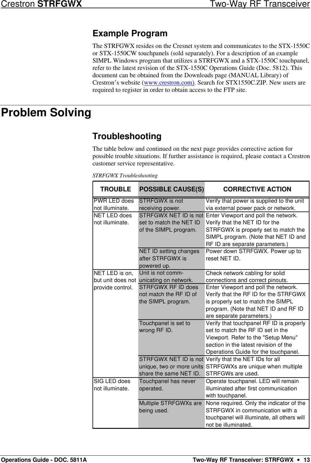
![Crestron STRFGWX Two-Way RF Transceiver Operations Guide - DOC. 5811A Two-Way RF Transceiver: STRFGWX •• 11 “Select Network ID” Dialog Box 8. As shown below, select the downloaded firmware (UPG) file and click Open. The transfer will complete automatically. “Select Firmware” Dialog Box NOTE: During the next step, do not interrupt power until the message is displayed. If the LEDs blink sporadically and the unit does NOT report the new version, disconnect the power and contact a Crestron customer support representative. NOTE: In the message in the next step, 7D and chan a have been user defined. 9. When the transfer is complete, observe the blinking RX and TX front panel LEDs. The LEDs will blink for 20 seconds, turn off for 10 seconds, and blink again for 20 seconds. Press F4 to verify completion of the process. The unit will report the message below in the Viewport. 7D: STRFGWX [2.4.1] RF chan a PIC Ver 22. NOTE: When the firmware of the STRFGWX is upgraded, the associated touchpanel(s) must also be upgraded. The units will not function properly if not upgraded with compatible firmware. 10. If the touchpanel firmware upgrade HAS been completed, close the Viewport, exit SIMPL Windows or VT Pro-e, and disconnect the programming cable from the PC and the control system. If NOT completed, perform the touchpanel firmware upgrade utilizing the firmware (CSF) file included with the download. Refer to the latest revision of the Operations Guide for the appropriate touchpanel for the firmware upgrade procedure. The latest version of the Operations Guides can be obtained from the Downloads page (MANUAL Library) of Crestron’s website (www.crestron.com). New users are required to register in order to obtain access to the FTP site.](https://usermanual.wiki/Crestron-Electronics/STRFGWX/User-Guide-175791-Page-15.png)
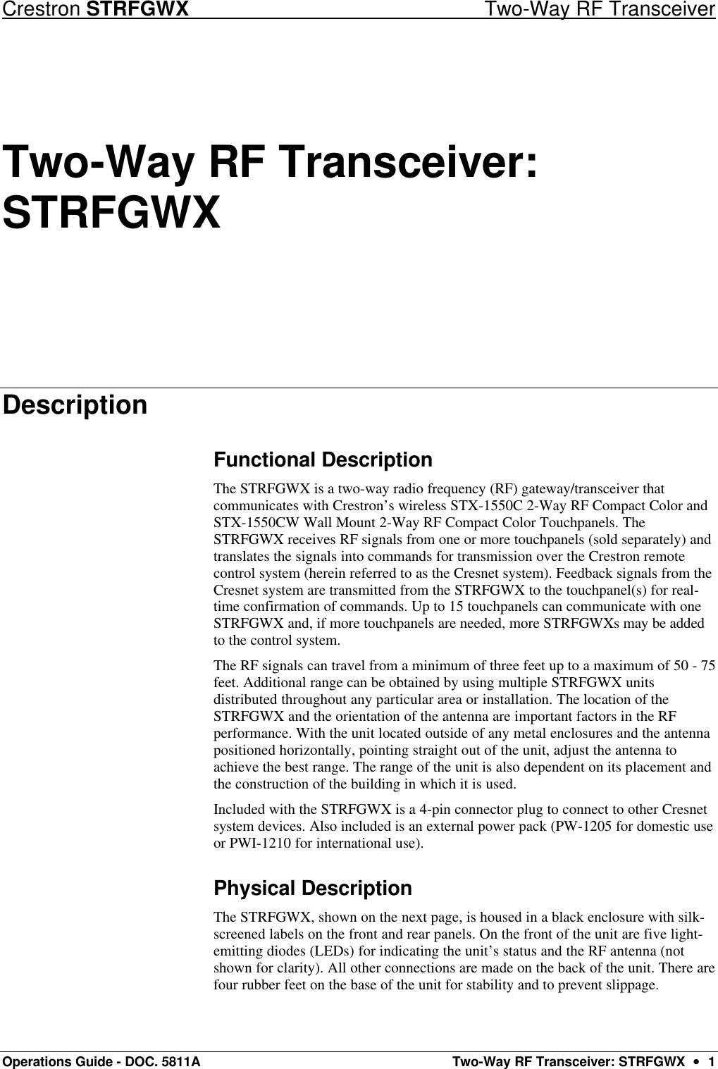
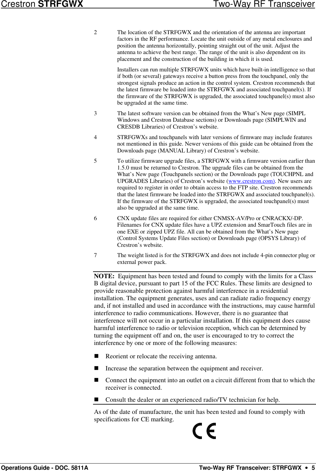
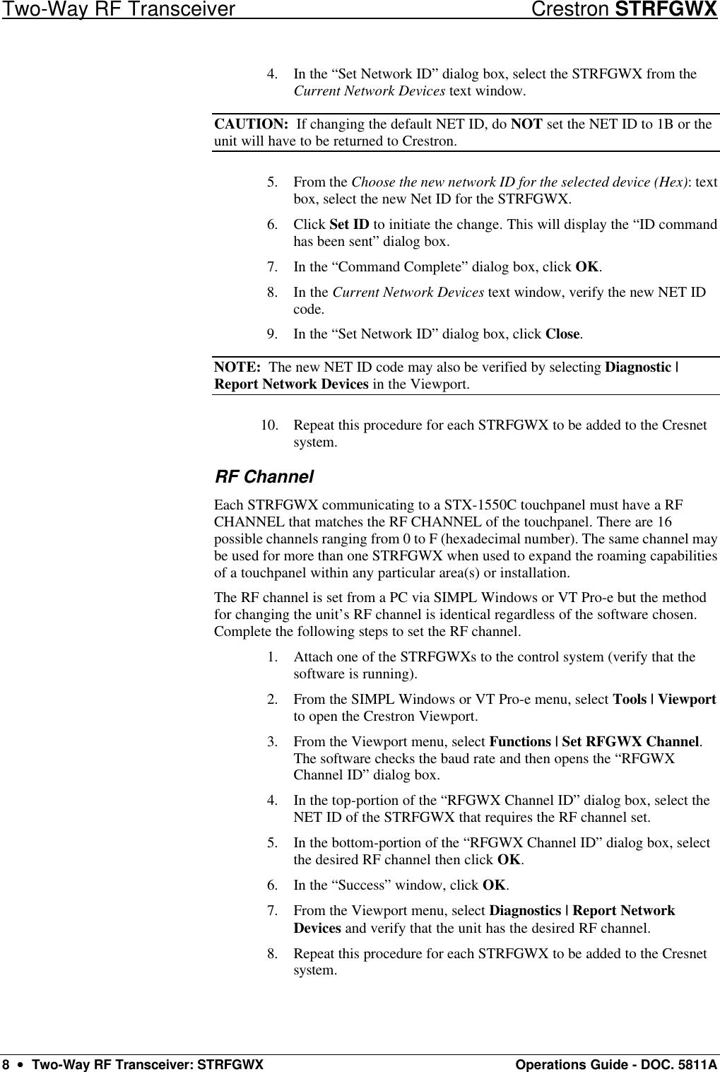
![Two-Way RF Transceiver Crestron STRFGWX 14 •• Two-Way RF Transceiver: STRFGWX Operations Guide - DOC. 5811A STRFGWX Troubleshooting (continued) TROUBLE POSSIBLE CAUSE(S) CORRECTIVE ACTIONTouchpanel is out of range. Position the touchpanel to within operating range. Refer to "Leading Specifications" on page 4 for details.Verify that the STRFGWX and touchpanel are on the same RF CHANNEL. Refer to "RF Channel" that begins on page 7 for details.Refer to the "Setup Menu" section in the latest revision of the Operations Guide for the touchpanel. Roaming area is too large and touchpanel becomes out of range.Install an additional STRFGWX in area to expand roaming area.STRFGWX is in vicinity of metal. Verify that large amount of metal is not in vicinity of transmission.Touchpanel is too close to STRFGWX. Position the touchpanel to within operating range. Refer to "Leading Specifications" on page 4 for details.Network wiring is incorrect. Check network cabling for solid connections and correct pinouts. STRFGWX is damaged. Contact a Crestron customer service representative. Intermittent response from STRFGWX during communication with touchpanel.Rx LED does not illuminate when operating touchpanel or Tx LED illuminates when active, but touchpanel does not respond.STRFGWX does not report NET ID when polling the network through Viewport. Other devices are reported. STRFGWX and touchpanel is not on same RF CHANNEL. Further Inquiries If after reviewing this Operations Guide, you cannot locate specific information or have questions, please take advantage of Crestron's award winning customer service team by calling: • In the US and Canada, call Crestron’s corporate headquarters at 1-888-Crestron [1-888-273-7876] or 1-201-767-3400. • In Europe, call Crestron International at +32-15-50-99-50. • In Asia, call Crestron Asia at +852-2341-2016. • In Latin America, call Crestron Latin America at +525-260-4336. For local support from exclusive Crestron factory-trained personnel call: • In Australia, call Soundcorp at +613-9488-1555. • In New Zealand, call Amber Technologies at +649-410-8382.](https://usermanual.wiki/Crestron-Electronics/STRFGWX/User-Guide-175791-Page-18.png)