Cross Match Technologies RJ0479V2 D Scan Authenticator CF User Manual
Cross Match Technologies GmbH D Scan Authenticator CF Users Manual
Contents
- 1. Users Manual
- 2. Quick Reference Guide
- 3. Co-axial Option Pamplet
Users Manual

Cross Match® Technologies, Inc.
D SCAN® AUTHENTICATOR CF™
Document Authentication Reader
User Manual
Version 2.1
Version 2.1 (April 2010)
Specifications are subject to change without prior notice.
Cross Match Technologies GmbH assumes no liability for maloperation or
improper use of products.
Cross Match® and D SCAN® are registered trademarks, and the CROSS
MATCH TECHNOLOGIES logo is a trademark of Cross Match
Technologies, Inc.
All other trademarks, brands and names are the property of their respective
owners and are protected by US and international copyright and trademark
laws.
No portion of this guide may be reproduced in any form or by any means
without the express written permission of Cross Match® Technologies.
© Copyright 2010, Cross Match Technologies. All rights reserved.

Basic healt h and safet y instructions iii
Basic health and safety instructions
The D SCAN® AUTHENTICATOR CF document reader is designed,
manufactured and tested to meet international safety standards. The document
reader contains an RF transmission device, and is therefore subject to national and
international regulations. The Authenticator transmits at a frequency of 13,56
MHz. However, all electric appliances can emit spurious RF-signals at other than
the specified frequency.
To ensure safe operation of the D SCAN AUTHENTICATOR CF:
• The operator of the D SCAN AUTHENTICATOR CF must observe the
guidelines and particularly the safety precautions outlined in this document
and according to related country regulation requirements.
• You must restrict the use of the device in potentially hazardous
environments. The environments include fuel depots, chemical plants and
areas where the air contains chemicals or particles (such as grain, dust, or
metal powders). The restrictions apply in any other area where you would
normally be asked to turn off your vehicle engine.
• Transmitted radio frequency energy may interfere with some hearing aids,
pacemakers or other medical devices if the person is positioned too close to
the document reader.
• To reduce the RF exposure refer to your related country regulation
requirements. See the specifications table and the section “Magnetic field
strength” on page 4-3 for detailed information.
• Read the User Manual on the CDROM for detailed information to operate
the D SCAN AUTHENTICATOR CF.
• Turn off the document reader when not in use.
• Do not open the device. Repairs must be done by Cross Match Technologies.
Changes or modifications not expressly approved by Cross Match
Technologies could void the user's authority to operate the equipment.
Cross Match Technologies GmbH assumes no liability for the customer's failure
to comply with these requirements.
iv D S C A N ® AUTHENTI CATOR CF™ User Manual v2.1

The optional coaxial light feature v
The optional coaxial light feature
The D SCAN® AUTHENTICATOR CF is a high performance device for reading
all kinds of personal identification documents such as passports and national ID
cards. Any document compliant to the specifications of the ICAO can be placed
on the glass plate on top of the device for capturing the image of the personalized
page. The optional RFID feature further provides the functionality for reading out
the contents of the digital data chip contained in the new electronic passports.
How does the optical reading of the device work?
The D SCAN AUTHENTICATOR CF device contains a built-in high resolution
camera and several sources of light. Each light source can be turned on before
taking one image with the camera. Thereby the user can take an image of the
personalized page as it appears under normal visible light or under ultraviolet
(UV) or infrared (IR) light. In the interest of a very uniform intensity level of the
light on the document page being captured the light sources are arranged in a way
to provide a diffuse kind of light rather than a directed light under a specific angle.
This is also helpful to avoid reflections. After the image was taken by the build-in
camera it is being transferred through the USB 2.0 interface cable to the PC. The
software belonging to the D SCAN AUTHENTICATOR CF receives the image
and makes it available through the Application Programming Interface (API).
Thereby the image becomes accessible for the application software of the system
integrator.
Among the available options is the "coaxial light" feature. This is an illumination
which works similar to the other ones but delivers its light under the same angle as
the camera view angle to the document. Thereby camera and illumination are
arranged on the same axis - or coaxially, hence the name.
Which functionality does the coaxial light feature
provide?
This optional feature provides the functionality of turning the coaxial illumination
on while all other illuminations are off, taking one image with the camera, turning
the coaxial illumination off, and making the captured image available as a digital
bitmap via the API to the application software of the system integrator. The
application can then take this image and display it on the screen of the PC so that
the operator can view it.
vi D S C A N ® AUTHENTI CATOR CF™ User Manual v2.1
A personalized page of a document covered with a protective laminate may show
certain retro reflective patterns when viewed with the coaxial illumination. When
viewed with one of the diffuse illuminations the same page will not show the retro
reflective pattern. Thereby the existence of such a laminate can be checked
visually.
The coaxial light product feature of the D SCAN AUTHENTICATOR CF does
not provide any kind of image processing or image analysis e.g. intended for the
automatic detection of tampering and alteration of documents having security
laminates such as the 3M™ Confirm™ Laminates.
Cross Match Technologies does not provide any product option or product
extension or separate product for performing such kind of automatic detections.
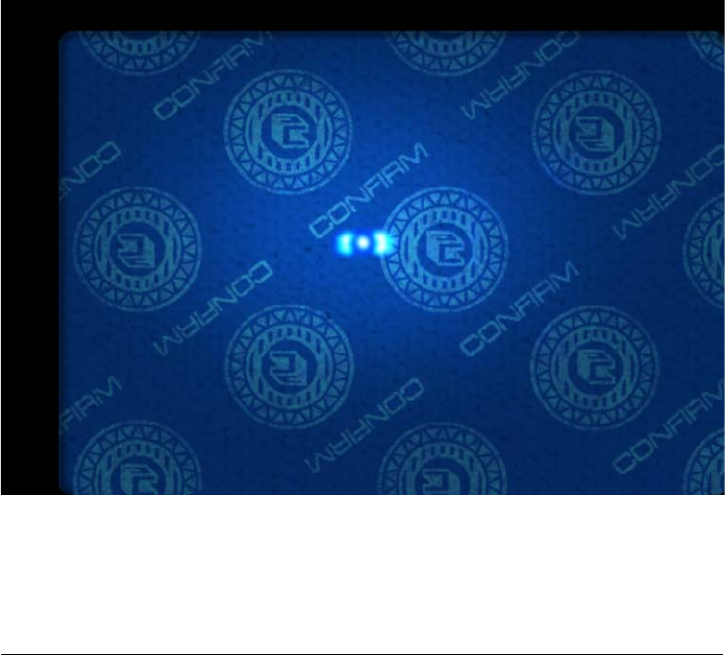
Image captured with an D SCAN AUTHENTICATOR CF under coaxial light
showing a document having a 3M™ Confirm™ Laminate on top of the
personalized page. The retro reflective marks are clearly visible while the
underlying text and pictures are almost invisible.
Notice to system integrators
System integrators shall be aware that an automatic detection of tampering
and alteration of documents having security laminates is the subject of a
technical invention filed by Minnesota Mining and Manufacturing Co. and
published as patent in the following countries: AU 685830, CA 2173230, DE
69418 887 T2, ES 2133583 T3, FR 0722597, GB 0722597, HK 1013873, IT
0722597, JP 09504629 T2, KR 0354883 B, US 6019287, US 6611612, and US
publication 2004-022420 A1.

The opt ional coaxial light feat ure vii
Disclaimer
Cross Match Technologies explicitly reminds the integrators of the D SCAN
AUTHENTICATOR CF of the existence of the above mentioned patents. The use
of the D SCAN AUTHENTICATOR CF for reading documents with the coaxial
light is authorized by Cross Match Technologies only for the purpose of taking the
image without any kind of image processing for the automatic detection of
tampering and alteration. Cross Match Technologies shall not be liable for any
violation of the rights and claims of the patents mentioned above. System
integrators and end users interested in performing such automatic detection shall
consider to contact the owner of the above mentioned patents for a potential
licensing.
This document applies to each D SCAN AUTHENTICATOR CF device if it is
equipped with the coaxial lighting feature option (CX2). System integrators and
resellers must provide this document to the end user.
Cross Match Technologies GmbH assumes no liability for the customer's failure
to comply with these requirements.
viii D S C A N ® AUTHENTI CATOR CF™ User Manual v2.1

Content s ix
Contents
Basic health and safety inst ruct ions .................................................... 0-iii
The optional coaxial light feat ure ........................................................ 0-v
How does t he optical reading of t he device work? ............................. 0-v
Which funct ionality does the coaxial light feat ure provide? ................. 0- v
Not ice t o syst em int egrat ors ................. .. .. .. .. .. .. .. ........... .. .. .. .. .. .. ... 0- vi
Disclaim er .................................................................................. 0- vii
I n t rodu ct ion
Appropriat e Operat ion ...................................................................... 1- 1
Who should read this book ................................................................ 1- 1
How this book is arranged ................................................................. 1-1
St andards ....................................................................................... 1-2
FCC st at em ent ................................................................................. 1- 2
I ndust ry Canada .............................................................................. 1-3
St at em ent of Com pliance .................................................................. 1- 3
Recycling inform at ion ....................................................................... 1-3
WEEE Directive .................................................................. .. .. ....... .. . 1- 3
Safety when operat ing ...................................................................... 1- 4
Glossary ......................................................................................... 1- 4
I n st a lla t ion
D SCAN AUTHENTI CATOR CF ............................................................. 2- 1
Front view ................................................................................... 2- 2
Top of the docum ent reader ........................................................... 2- 3
Am bient light cover ................................................................... 2- 4
Back view .................................................................................... 2- 5
Product label ............................................................................ 2- 6
System requirem ents ....................................................................... 2-6
Operat ing system ......................................................................... 2- 7
Hardware .................................................................................... 2- 7
I nstallat ion ...................................................................................... 2- 7
Rem ove t he contents .................................................................... 2- 7
List of cont ent s ............................................................................ 2-7
Prepare to use ............................................................................. 2- 7
Connect t he Aut henticat or CF ......................................................... 2- 8
At tach the Authenticat or CF t o a surface ............................................. 2-9
Prepare the inst allat ion ................................................................. 2-9
x D S C A N ® AUTHENTI CATOR CF™ User Manual v2.1
I nstallat ion ...................................................................................2- 9
How t o use the Aut he n t ica t or CF
Applicat ions and soft ware levels ......... .. .. .. .. .. ... .......... .. .. .. .. .. .. .. .. ......... 3- 1
Charact eristics of docum ent s ..............................................................3- 2
The m achine readable zone ............................................................3- 3
Align the docum ents ......................................................................3- 3
Read in a docum ent ..........................................................................3- 4
The Overview page .......................................................................3- 5
The cam era pict ures page ..............................................................3- 8
The im ages page ..........................................................................3- 9
The RFI D dat a groups page .......................................................... 3- 10
The barcode page ....................................................................... 3-11
The RFI D check result s page ......................................................... 3-12
The options page ........................................................................ 3- 13
Global result set t ings ............................................................... 3- 13
Workflow set tings .................................................................... 3- 14
Barcodes to read ..................................................................... 3- 14
Glare reduct ion m ode sett ings ................................................... 3- 14
M a in t en a nce
Cleaning ..........................................................................................4- 1
Clean the docum ent contact area ....................................................4- 1
Clean the case ..............................................................................4- 2
Aut henticat or CF specificat ions ................ .. .. .. .. .. .. .. ........... .. .. .. .. .. .. ......4- 2
Magnet ic field st rengt h ......................................................................4- 3
Pr oble m s a nd Cor re ct ions
The Authenticat or does not work .....................................................5- 1
Aut henticat or disconnect ed during operat ion .....................................5- 1
I nit ializat ion failed .........................................................................5- 2
Dark im age sect ions ......................................................................5- 2
Visualizat ion and processing speed too slow .....................................5-2
Creat ing a problem report ................. .. .. ... .. .. .. .......... .. ... .. .. .. .. ......... 5- 3
Cust om er Car e and Cont act I nform at ion
Technical Support .............................................................................6- 1
E- m ail .........................................................................................6- 1
Telephone and facsim ile .............................................................6- 1
Ret urn and repair of t he Authenticat or CF ........................................6- 2
Delivery cost s ..................................................................................6- 3
The product is in the warrant y period ...........................................6- 3
Cust om ers inside t he EU .........................................................6- 3
Content s xi
The product is not in t he warranty period ..................................... 6- 3
Contact inform at ion .......................................................................... 6- 3
Corporat e Headquart ers ............................................................. 6- 3
Corporat e Web Page .............................................................. 6- 3
Pr odu ct W ar ra nt y
Lim it ed Warrant y ............................................................................. 7- 1
Repair or Replacem ent .................................................................. 7-1
Lim it at ions .................................................................................. 7- 2
Out - of- Warrant y Repairs ............................................................... 7-3
I ndex
xii D S C A N ® AUTHENTI CATOR CF™ User Manual v 2.1

xiii
Figures
Figure 2 .1 : D SCAN AUTHENTICATOR CF front view .................................... 2- 2
Figure 2 .2 : D SCAN AUTHENTICATOR CF inst ruct ion label ............................ 2- 2
Figure 2 .3 : Top view of the D SCAN AUTHENTICATOR CF .............................................2-4
Figure 2 .4 : Am bient light cover posit ions .......................................... 2- 5
Figure 2 .5 : D SCAN AUTHENTICATOR CF back view .................................... 2- 5
Figure 2 .6 : D SCAN AUTHENTICATOR CF product label ................................ 2-6
Figure 2 .7 : D SCAN AUTHENTICATOR CF connect ion box ............................. 2- 8
Figure 2 .8 : Place the drill t em plate .................................................. 2-9
Figure 2 .9 : Rem ove rubber feet ...................................... .. ....... .. .. . 2- 10
Figure 2 .1 0 : Mount point s ............................................................. 2- 10
Figure 2 .1 1 : Fasten the Authent icat or CF ......................................... 2-11
Figure 3 .1 : The m achine readable zone ............................................ 3- 3
Figure 3 .2 : I nst ruction label on the cover ......................................... 3- 3
Figure 3 .3 : Posit ioning of a passport ................................................ 3- 4
Figure 3 .4 : Launching applicat ion .................................................... 3-5
Figure 3 .5 : Message about m issing background im ages ...................... 3- 5
Figure 3 .6 : Processing inform at ion .................................................. 3- 6
Figure 3 .7 : Overview dat a page ...................................................... 3- 6
Figure 3 .8 : Failed verificat ion ......................................................... 3- 7
Figure 3 .9 : Cam era pict ures page ................................................... 3- 8
Figure 3 .1 0 : I m ages page ............................................................... 3- 9
Figure 3 .1 1 : RFI D dat a groups page ............................................... 3- 10
Figure 3 .1 2 : Barcode page ............................................................. 3- 11
Figure 3 .1 3 : RFI D check results page .............................................. 3- 12
Figure 3 .1 4 : Opt ions page ............................................................. 3- 13
Figure 4 .1 : Clean the docum ent contact area .................................... 4-1
Figure 4 .3 : Magnet ic field st rengt h lat eral ........................................ 4- 3
Figure 4 .4 : Magnet ic field st rengt h front al ........................................ 4- 4
Figure 4 .5 : Magnet ic field st rengt h on t op ........................................ 4-4
xiv D S C A N ® AUTHENTI CATOR CF™ User Manual v2.1

xv
Tables
Table 1 .1 : Glossary of term s ............................................................ 1- 4
Table 2 .1 : Front features ................................................................. 2-3
Table 2 .2 : Top feat ures ................................................................... 2- 4
Table 2 .3 : Back feat ures .................................................................. 2- 5
Table 2 .4 : I llum inat ion codes ........................................................... 2-6
Table 4 .2 : Product specificat ions ....................................................... 4- 2
Table 6 .1 : The Technical Support depart m ent addresses ...................... 6- 1
Table 6 .2 : The Technical Support depart m ent num bers ........................ 6- 1
Table 6 .3 : The addresses for product returns ...................................... 6-2
xvi D SCAN® AUTHENTI CATOR CF™ User Manual v2.1

Appropriat e Operat ion 1-1
1
Chapter 0Introduction
Appropriate Operation
The D SCAN® AUTHENTICATOR CF captures color images and reads full
pages to capture and transmit personal and document data. The device can capture
an entire data page from any ID document in different types of light. The device
can read RFID data contactless found on the RFID tag.
It is intended for the use in IT-devices area and the operation and installation must
be in connection with suitable computer equipment. When operating, the
electrical installation and cabling must comply with the IEC 60950 standard.
Who should read this book
You should read this book if you are a user and you will operate the D SCAN
AUTHENTICATOR CF document authentication reader device.
How this book is arranged
•Chapter 1 “Introduction” covers standards for the manual and describes the
safety instructions. The chapter also contains a glossary of terms.
•Chapter 2 “Installation” describes the D SCAN AUTHENTICATOR CF and
how to install the document authentication reader.
•Chapter 3 “How to use the Authenticator CF” describes how to use the
indicators on the device to capture the best quality images.
•Chapter 4 “Maintenance” explains how to maintain the
D SCAN AUTHENTICATOR CF.
•Chapter 5 “Problems and Corrections” describes the problems, causes, and
corrections.
•Chapter 6 “Customer Care and Contact Information” explains how to get
the technical support that is available from Cross Match Technologies.

1- 2 D S C A N ® AUTHENTI CATOR CF™ User Manual v2.1
I nt roduct ion
Standards
The following standards are used in this book:
•Bold UPPER/lower case and tilted text identify important information.
• Special information can appear as a Note, Caution, Warning, or Danger.
N ot e
A Note contains additional information. To ignore a note can cause a delay, but not
mechanical damage or personal injury.
Ca ut ion
A Caution contains a method to prevent data loss or damage to equipment. To ignore the
caution can cause damage or data loss.
W arning
A Warning describes an action that can cause injury or loss of life. Mechanical damage can
occur.
D AN GER
A Warning describes an action or condition that causes injury or loss of life. Mechanical
damage can occur.
FCC statement
FCC ID: WO8RJ0479V2
This device complies with Part 15 of the FCC Rules. Operation is subject to the
following two conditions:
(1) this device may not cause harmful interference, and
(2) this device must accept any interference received, including interference that
may cause undesired operation.
The power source for the AUTHENTICATOR CF must provide an output voltage
of 18 - 24 V DC. The electric current range of the power supply unit must be min.
1 A and max. 7 A. Use only power supply units that comply with the class B limits
of 47 CFR 15, Subpart B.
N ot e:
This equipment has been tested and found to comply with the limits for a Class B digital
device, pursuant to part 15 of the FCC Rules. These limits are designed to provide
reasonable protection against harmful interference in a residential installation.
This equipment generates, uses and can radiate radio frequency energy and, if not installed
and used in accordance with the instructions, may cause harmful interference to radio
communications. However, there is no guarantee that interference will not occur in a
particular installation. If this equipment does cause harmful interference to radio or
television reception, which can be determined by turning the equipment off and on, the user
is encouraged to try to correct the interference by one or more of the following measures:
• Reorient or relocate the receiving antenna.
• Increase the separation between the equipment and receiver.
• Connect the equipment into an outlet on a circuit different from that to which the
receiver is connected.
• Consult the dealer or an experienced radio/TV technician for help.

I ndust r y Canada 1-3
I nt roduct ion
Industry Canada
IC: 7944A-RJ0479V2
This Class B digital apparatus complies with Canadian ICES-003. Operation is
subject to the following two conditions:
(1) this device may not cause interference, and
(2) this device must accept any interference, including interference that may cause
undesired operation of the device.
The power source for the AUTHENTICATOR CF must provide an output voltage
of 18 - 24 V DC. The electric current range of the power supply unit must be min.
1 A and max. 7 A. Use only power supply units that comply with the class B limits
of ICES-003.
Statement of Compliance
Cross Match Technologies GmbH, hereby, declares that this device is in
compliance with the essential requirements and other relevant provisions of
Directives 89/336/EEC and 2006/95/EC.
Declaration of Conformities may be directly obtained from Cross Match
Technologies GmbH.
Recycling information
Cross Match Technologies recommends that customers dispose of their used
computer hardware, monitors, printers and other peripherals in an
environmentally sound manner. Potential methods include reuse of parts or whole
products and recycling products, components and/or materials.
WEEE Directive
The following is the test of the Waste Electrical and Electronic
Equipment (WEEE) Directive.
In the European Union, this label indicates that this product should
not be disposed of with household waste. It should be desposited at
an appropriate facility to enable recovery and recycling.

1- 4 D S C A N ® AUTHENTI CATOR CF™ User Manual v2.1
I nt roduct ion
Safety when operating
This product has been designed, manufactured and tested according to
international safety standards. The following general safety precautions must be
observed during all phases of operation to ensure safe operation of the D SCAN
AUTHENTICATOR CF. Cross Match Technologies GmbH assumes no liability
for the customer's failure to comply with these requirements.
• When operating, the electrical installation and cabling must comply with the IEC
60950 standard.
• The power supply must be provided by an certified power supply unit with an output
voltage of 18 - 24 V DC. The electric current range of the power supply unit must be
min. 1 A and max. 7A. Use the desktop power pack which is provided with the
product package.
• To connect the document reader to a computer, use a shielded USB data cable as
supplied with the reader.
• The device must be operated only in a dry room. Exclude any condensation.
• The environmental temperature range is 41 °F to 113 °F (+5 °C to +45 °C).
Ca ut ion
Do not open the device. Repairs are only allowed by Cross Match Technologies. Changes
or modifications not expressly approved by Cross Match Technologies could void the user's
authority to operate the equipment.
• Whenever it is likely that the electrical protection has been compromised, the device
and system must be made unplugged and secured against unauthorized use.
• Do not apply mechanical stress to the document contact area. Do not throw heavy
objects onto it. The platen is made of glass and might be destroyed if not handled
properly. A broken platen might have sharp edges, which could cause injuries.
• Do not scratch the document contact area. The platen is vulnerable to sharp metallic
instruments (knives, scissors), extremely hard objects (diamonds) and also dust.
Scratches may reduce the image quality and thereby lead to scanning results below
the required quality specification.
• Always keep the document contact area clean. Use the recommended glass cleaner
and lint-free tissue for cleaning. Do not use oily or abrasive cleaners since they might
affect the platen surface quality.
• Do not pour liquids (water etc.) onto the D SCAN AUTHENTICATOR CF. The device
is protected against cleaning with a damp cloth or tissue, however, it is not
waterproof.
W arning
Do not look directly into the lights of the document contact area. Maintain a required
minimum distance of not less than 0.3 meters.
Glossary
This section contains some terms that are used in this manual.
Table 1.1
Glossary of term s
Te r m D e fin it ion
Ba rcode A means of storing data as a pattern of lines or dots.
CX Coaxial light illumination for image capture with light directed in
the same optical axis as the image pick-up.

Glossar y 1- 5
I nt roduct ion
DI N Deutsches Institut für Normung e.V. und deutsche Industrie-
Norm (German Institute for Standardization and Industrial
Standard Specification). Contains the fundamental standards for
many products of the industry.
DSE D SCAN Essentials.
Base level software for the D SCAN AUTHENTICATOR CF,
which runs on the external computer and support:
• USB driver
• Low level access to available illuminations, camera, and
RFID reader (APDU) via SDK
• Human interface control
DSX D SCAN Extensions. Optional middleware software which
supports:
• High level document access (optical and RFID) including
workflow support, cryptographic protocols, and OCR
• Optional SDKs for both software levels
• Optional document definitions for customer specific
documents
• Optional development support
• Supports future upgrade of firmware and software
ERZ Effective Reading Zone.
Fixed dimensional area, common to all MRTDs, in which the
machine readable data in the MRZ can be read by document
readers.
ePassport
( e M RP or
Elect r onica lly
enable d M RP)
A machine readable passport (MRP) containing a Contactless
Integrated Circuit (IC) within which is stored data from the MRP-
data page, a biometric measure of the passport holder and a
security object to protect the data with PKI cryptographic
technology, and which conforms to the specification of Doc 9303,
Part 1.
I ATA International Air Transport Association.
Is an international industry trade group of airlines headquartered
in Montreal, Quebec, Canada (where the ICAO also happens to
be headquartered, even though they are different entities).
On behalf of its Members and the entire aviation industry, IATA
works to ensure that new and enhanced security measures are
effective, internationally harmonized and minimize disruption to
passengers and shippers.
I CAO D oc 9 3 0 3 International Civil Aviation Organization.
The International Civil Aviation Organization (ICAO) has taken a
leading role in the creation of Machine Readable Travel
Documents (MRTDs) in co-operation with the International
Standardization Organization (ISO). The Standards are
contained in document 9303 of the ICAO.
Table 1.1
Glossary of term s
Te r m D e fin it ion

1- 6 D S C A N ® AUTHENTI CATOR CF™ User Manual v2.1
I nt roduct ion
I R Infrared radiation or light is an invisible electromagnetic radiation
that has a longer wavelength than visible light and is detected
most often by its heating effect. Infrared describes the part of the
electromagnetic spectrum with wavelengths between 700 nm
and 1mm. Near infrared light is closest in wavelength to visible
light and far infrared is closer to the microwave region of the
electromagnetic spectrum. Infrared light has many technology
and physics applications.
Ke nsin gt on
Se curity Slot
Also called a K-Slot or Kensington lock, is a small hole found on
almost all small or portable computer and electronics equipment,
particularly on expensive and relatively light ones. It is used for
attaching a lock, in particular those from Kensington Computer
Products Group, who are its originators.
Locks are generally secured in place with a key or some
mechanical PIN device and attached through a rubberized metal
cable. The end of the cable has a small loop which allows the
whole cable to be looped around a permanent object, such as a
heavy table or other similar equipment, thus securing it in place.
LED Light Emitting Diode.
Semiconductor which emits light if connected to voltage.
MRTD General Term for all Machine Readable Travel Documents.
Official document issued by a State or organization which
conforms to ICAO Doc 9303 specifications and which is used by
the holder for international travel (e.g. Passport, Visa, MRTD, ID
cards) and which contains mandatory eye readable data and a
separate mandatory data summary in a format which is capable
of being read by machine.
MRZ Machine Readable Zone.
Fixed dimensional area located on the MRTD, containing
mandatory and optional data formatted for machine reading
using OCR methods.
OCR Optical Character Recognition.
It is the mechanical or electronic translation of images of
handwritten or typewritten text on paper into machine-editable
text. It is scanned with a computer (NCI) and converted to an
editable text document (CI). OCR is already being used widely in
the legal profession, where searches that once required hours or
days can now be accomplished in a few seconds.
OCR- font OCR font is the term given to a set of special typeface style
developed for Optical Character Readers and Optical Character
Recognition software. Each character within a font will have a
defined reproducible size and shape. For OCR, these are defined
by ISO 1073-II and although use of OCR-B is preferred.
OCR fonts are standardized and designed to be both machine
and human readable. Some examples of OCR implementations
include bank checks, passports, serial labels and postal mail.
Table 1.1
Glossary of term s
Te r m D e fin it ion

Glossar y 1- 7
I nt roduct ion
RFI D or RF Radio Frequency Identification (RFID) is a method of identifying
unique items using radio waves. Typically, a reader
communicates with a tag, which holds digital information in a
microchip. But there are chipless forms of RFID tags that use
material to reflect back a portion of the radio waves beamed at
them. As well as the standard passport data already included,
this can also be used to store biometric features. The basic
technical specifications of the RF chip for use in passports have
been standardized by the ICAO.
RM A A Return Merchandise Authorization or Return Material
Authorization is a transaction whereby the recipient of a product
arranges to return goods to the supplier to have the product
repaired or replaced or in order to receive a refund or credit for
another product from the same retailer or corporation.
Sm ar t Car d A Smart Card, chip card, or integrated circuit card (ICC), is
defined as any pocket-sized card with embedded integrated
circuits which can process information. The card is made of
plastic, generally PVC, but sometimes ABS or polycarbonate.
The card may embed a hologram or other security features to
avoid counterfeiting. Smart Cards are defined according to the
card data read and wright features and the type of chip implanted
within the card. There is a wide range of options.
The most common type of Smart Card is the contact Smart Card
where electrical contacts located on the outside of the card
connect to a card reader when the card is inserted. Contact
Smart Cards are standardized in ISO/IEC 7816.
Contactless Smart Cards employ a radio frequency (RFID)
between card and reader without physical insertion of the card.
Instead the card is passed along the exterior of the reader and
read. Contactless Smart Cards are standardized in ISO/IEC
14443.
UV Ultraviolet (UV) light is represented in the light spectrum as light
with a wavelength of 200nm to 400nm. The UV spectrum is
divided into three regions: the near ultraviolet, the far ultraviolet,
and the extreme ultraviolet, all of which are present in natural
sunlight. These waves are invisible to the human eye.
VI Z Visual Inspection Zone.
Those portions of the MRTD (data page in the case of MRP)
designed for visual inspection, i.e. front and back (where
applicable), not defined as the MRZ.
Table 1.1
Glossary of term s
Te r m D e fin it ion
1- 8 D S C A N ® AUTHENTI CATOR CF™ User Manual v2.1
I nt roduct ion

D SCAN AUTHENTI CATOR CF 2-1
2
Chapter 0Installation
T
HI S
CHAPTER
DESCRI BES
THE
D SCAN AUTHENTI CATOR CF
AND
HOW
TO
I NSTALL
THE
DOCUMENT
AUTHENTI CATI ON
READER
.
D SCAN AUTHENTICATOR CF
The D SCAN AUTHENTICATOR CF (CF stands for Compact Full page) is a
compact and small full-page document reader. Some of the following
characteristics require additional software functions which might be contained in
D SCAN Extensions or project specific.
The document authentication reader has the following characteristics:
• Capability to capture images of an entire data page of an ID document and to
read RFID tag data contactless using a 13.56 MHz RFID Transceiver.
• Reads RFID and optical data of an ID document in one step without the need
to re-position the document. The One Step scanner.
• The additionally installed card reader provides a contact interface, which
allows the device to read the chip data of ID cards.
• Allows to check the authenticity of security elements of ID documents by
comparing the differently lit images (visible, IR, UV and CX light).
• High speed data capture and transmission using the USB 2.0 interface.
• The single RFID antenna covers the entire document contact area, so the
read function is not affected by the position of the chip inside the document.
• The extra large optical scanning area allows inspection of documents
without removal of the protective cover.
• It can be configured to perform all scanning and checking functions in a
fully automatic mode with no operator intervention.
• No moving parts and optional high-performance LED UV illumination
ensure maximum reliability.
• The D SCAN AUTHENTICATOR CF complies with ISO standards and
achieved excellent results in recent ICAO interoperability tests in Japan and
Singapore in 2005, and in Germany in 2006, where they were able to read all
presented passports.
2- 2 D S C A N ® AUTHENTI CATOR CF™ User Manual v2.1
I n st allat ion
• Special software controls the functional operation and the display of results.
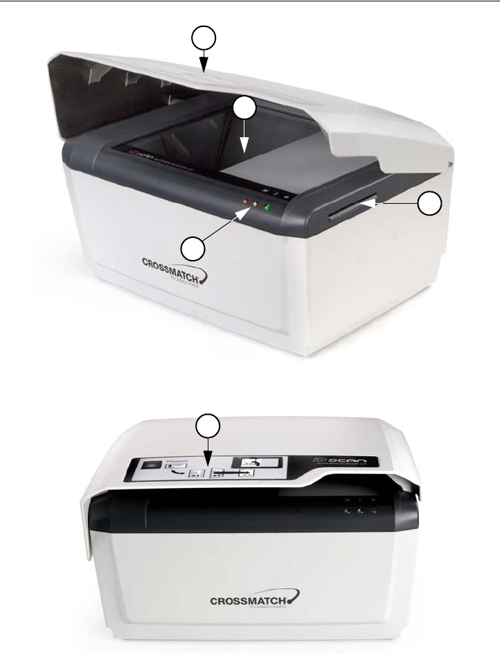
Front view
Figure 2.1
D SCAN AUTHENTI CATOR CF front view
Figure 2.2
D SCAN AUTHENTI CATOR CF inst ruct ion label
1
4
2
3
5

D SCAN AUTHENTI CATOR CF 2-3
I n st allat ion
Top of the document reader
The following section contains important details of the top of the device with a
brief description of each. The ambient light cover has been opened to better show
the details.
Table 2.1
Front feat ures
#D escr ipt ion
1Ambient light cover. The height-adjustable cover reduces outside light during
operation and protects the document contact area when the device is not in use.
2Document contact area. The glass bearing surface where you put the
documents to verify. The surface is divided into the optical scan area and the
document support area. The entire document contact area is covered by the
RFID antenna.
3Smart Card slot. The integrated contact smart card reader allows maximum
application comfort and uses the ISO 7816 protocol Type T=0 (asynchronous
half duplex character transmission protocol) and T=1 (asynchronous half duplex
block transmission protocol) to read cards.
4Status LEDs and Buzzer. Three LEDs can provide visible indications and a
volume-adjustable buzzer provides acoustical indication about the current mode
of the document reader.
Using the D SCAN Extensions application the LEDs light as follows:
•The backlit red light is the Status light and lights during the initialization
process or when the device is not ready for operation.
•The backlit yellow is the Processing light and lights when processing a
document. During this time, no other documents can be verified. After
processing it turns off, indicating that a new authentication can be started.
•The backlit green is the Operation light and lights after the device is
successfully initialized and when an authentication is completed.
Other programs can use the lights and the buzzer in different methods.
5 Instruction label. The label informs the user in principle how to position and
place a document correctly.
2- 4 D S C A N ® AUTHENTI CATOR CF™ User Manual v2.1
I n st allat ion
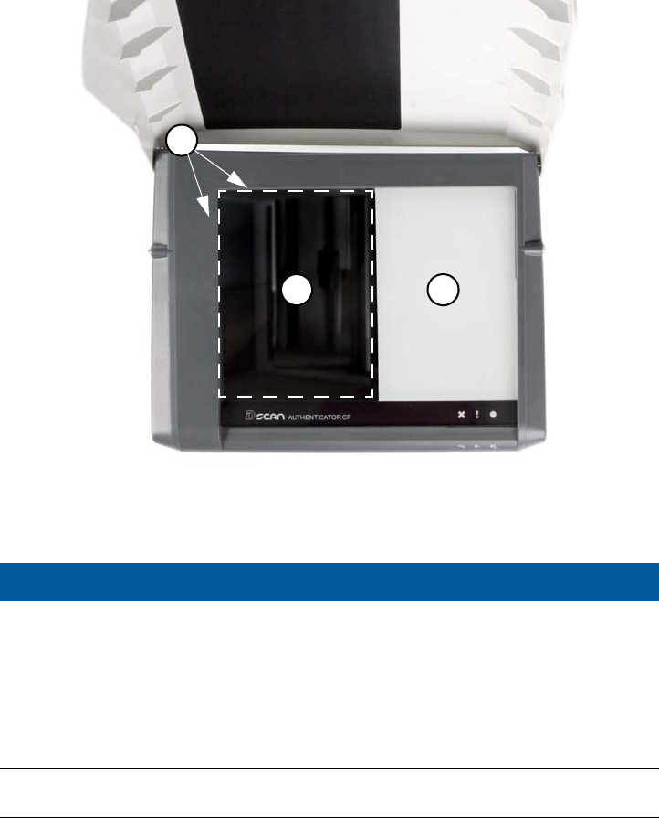
Figure 2.3
Top view of t he D SCAN AUTHENTI CATOR CF
Ambient light cover
The cover is attached by two bolts, one on each side, at the upper back of the
D SCAN AUTHENTICATOR CF. This allows three positions, closed (1),
operation (2) and open (3). To put the cover in one of these positions, lift the front
edge. Two ball catches hold the cover in the operation position.
Table 2.2
Top feat ures
#Descript ion
1Document position angle. The document positioning angle helps to guarantee
the exact final position of the document for authentication.
2Optical scan area. The glass bearing surface where documents are placed to be
verified. A dotted line shows the area where the device reads the document.
3Document support area. The part of the glass bearing surface which is not used
for scans. The area allows you to put larger documents down correctly. The area
is covered by the RFID antenna.
1
2 3
D SCAN AUTHENTI CATOR CF 2-5
I n st allat ion
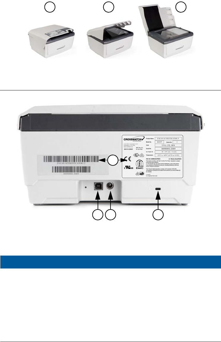
Figure 2.4
Am bient light cover posit ions
Back view
Figure 2.5
D SCAN AUTHENTI CATOR CF back view
Table 2.3
Back features
#D escr ip t io n
1USB-A connector. The USB 2.0 High Speed interface cable connects the
Authenticator to the computer and delivers the captured data to the computer.
2Power connector. Connects the power source to the computer and supplies 19
VDC to operate the document reader.
3Kensington security slot. Used to secure the unit in place with a key and
attached through a rubberized metal cable. The end of the cable has a small loop
which allows the whole cable to be looped around a permanent object, such as a
heavy table to secure it in place.
4Device labels. Shows manufacturer and product information.
1 2 3
1 2 3
4
2- 6 D S C A N ® AUTHENTI CATOR CF™ User Manual v2.1
I n st allat ion
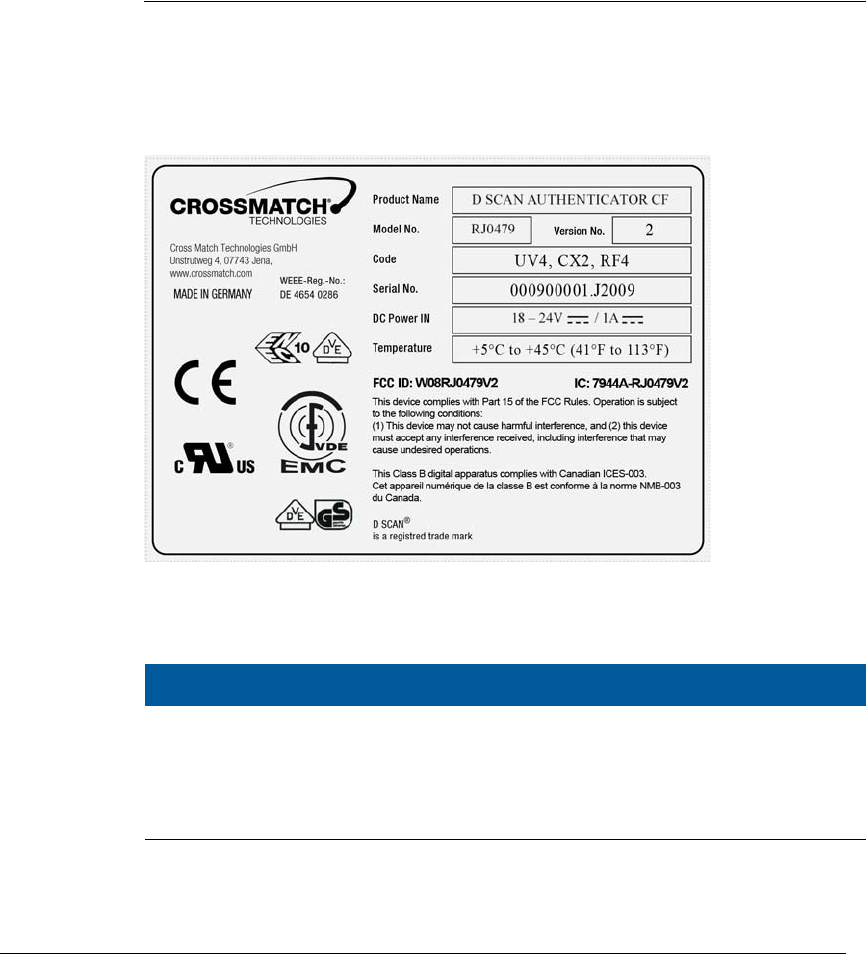
Product label
A label on the back of the device contains information on Manufacture, Product
Name, Model Number, Code Number, Serial Number, Connection Values, FCC
Compliance, CE Compliance and other Certification Symbols. The field Code
contains abbreviations, which indicate which illumination and RFID module is
installed. The Version No. indicates the revision number of the device.
Figure 2.6
D SCAN AUTHENTI CATOR CF product label
* The number behind each code indicates the version of the code.
System requirements
The D SCAN AUTHENTICATOR CF can be connected to a computer using the
USB 2.0 High Speed interface. This section describes the minimum system
requirements for the document reader.
Table 2.4
I llum inat ion codes
Code D e scr ip t ion
UV* UV high performance LED illumination.
CX* Coaxial light illumination (not available in all markets).
RF* RFI D data read-out functionality, incl. fully integrated antennas for
front and back page(s).

I nst allat ion 2-7
I n st allat ion
Operating system
• Windows XP Professional, Service Pack 2
• Windows Vista 32, Service Pack 1
• Microsoft .NET Framework 1.1 should be installed
• D SCAN Essentials Runtime
Hardware
The minimum requirements applies to desktop and laptop computers.
• 2 GHz or higher processor with SSE2 instruction set (Intel Pentium 4 or
Celeron or better, or AMD Athlon64 or better)
•1 GB RAM
• 100 MB free hard drive space
• USB2.0-compliant ports or USB 2.0 PCI/PCMCIA card
• 1024 x 768 Video-Resolution monitor
Installation
This section describes how to install the D SCAN AUTHENTICATOR CF.
Remove the contents
N ot e
Keep all original materials in the event you return the document reader.
Remove all the contents from the product package.
List of contents
The following items are included in the product package:
• D SCAN AUTHENTICATOR CF document authentication reader
• External power supply unit
• USB A-B signal cable
• D SCAN Essentials Runtime CD
• D SCAN AUTHENTICATOR CF User Manual on CD
• White/yellow test chart (creation of background images and calibration)
Prepare to use
Make sure that the following conditions exist before you use the D SCAN
AUTHENTICATOR CF.
• After transportation or storage at low temperature, allow the reader to
adjust to the temperature at the location of operation.
2- 8 D S C A N ® AUTHENTI CATOR CF™ User Manual v2.1
I n st allat ion
• Store the document reader in a warm dry location.
• The product is on a level surface.
• The surface of the document contact area is clean and dry.
• Protect the document reader from dust and humidity.
• Keep all sharp and pointed objects away from the document contact area
surface.
Connect the Authenticator CF
N ot e
Before you begin, ensure that the device reached room temperature before powering on the
device. The procedure applies to desktop and laptop computers.
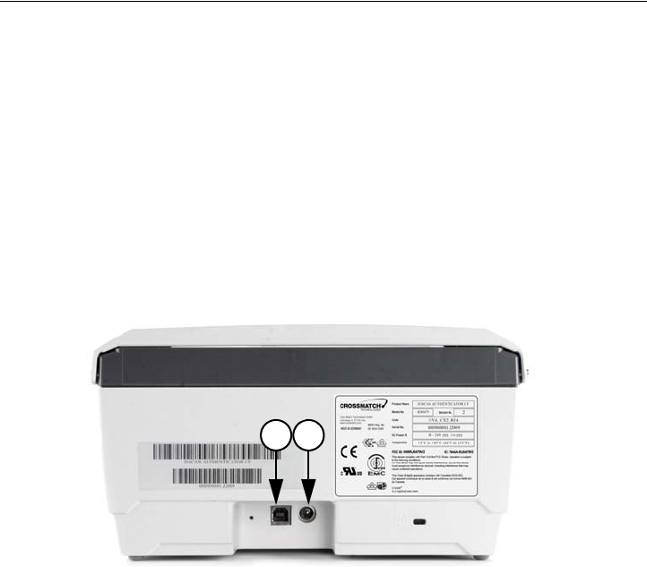
The connectors are on a connection box at the back of the device. Use the
following procedure to install the D SCAN AUTHENTICATOR CF USB and
power cables.
The connectors are on a connection box at the back of the device. Use the
following procedure to install the D SCAN AUTHENTICATOR CF USB and
power cables.
1 Put the device on a clean flat area like a table, that is free of dust.
2 Get the USB and power cables.
3 Lift the back of the device. You see the connection box with the power (2) and
USB (1) connectors.
4 Insert the cables into their related connectors in the connection box.
.
Figure 2.7
D SCAN AUTHENTI CATOR CF connect ion box
5 Connect the power supply to the AC electrical outlet.
• All LEDs should flash on and off. The yellow LED flashes to indicate the
standby mode.
N ot e
When you apply power is applied to the D SCAN AUTHENTICATOR CF, it is permanently
powered on. Unplug the device from the AC electrical outlet to completely turn the device
off.
6 Connect the other end of the USB cable to the USB 2.0 port of your computer.
7 You have completed the procedure.
21
At t ach t he Aut hent icat or CF to a surface 2-9
I n st allat ion
N ot e
Before you connect the D SCAN AUTHENTICATOR CF to the USB port of your computer
you must install the D SCAN Essentials software. The software provides the required
hardware drivers during the D SCAN AUTHENTICATOR CF installation.
You can use any USB port to plug in the D SCAN AUTHENTICATOR CF.
However, the first time you plug the device into a particular port, Windows will
install the driver for that device again.
Attach the Authenticator CF to a surface
You can attach the Authenticator CF to a flat surface like a table or counter top.
The document reader has four threaded mount points on the bottom of the case,
which are covered by the rubber feet. Use the drill template on page 2-12 to mark
the holes.
Prepare the installation
Make sure that the following conditions exist before you begin:
• The Authenticator CF is on a level surface.
• Collect the necessary pieces (drill template, four screws M4) and the tools
required for the surface you selected.
• Keep a soft cloth handy.
• Read the Authenticator CF User Manual.
Installation
To attach the Authenticator CF:
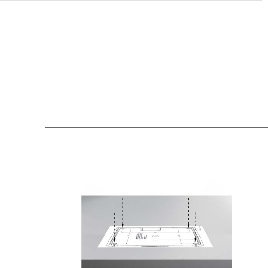
1 Put the drill template in position.
2 Mark the center of each hole.
Figure 2.8
Place the drill tem plat e
2- 10 D S C A N ® AUTHENTI CATOR CF™ User Manual v2.1
I n st allat ion
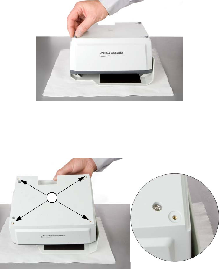
3 Make four holes.
4 Get the Authenticator CF and put it upside-down on a desk or table.
N ot e
Protect the top of the device with a soft cloth and keep all sharp or pointed objects away
from the surface.
Figure 2.9
Rem ove rubber feet
5 Remove all four rubber feet at the bottom. Lift the edge with your nail and pry
them away. You have now access to the four mount points (1) of the device.
Store the rubber feet in a safe place.
Ca ut ion
Do not press on the device. This may damage the cover.
Figure 2.10
Mount point s
6 Use M4 metric screws to fasten the Authenticator CF. The mount points on the
document reader are 0.295 inches (7.5 mm) deep.
1
At t ach t he Authenticat or CF to a surface 2-11
I n st allat ion
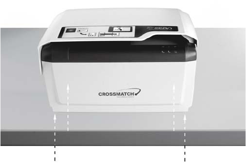
Ca ut ion
Make sure that the screws do not extend more than 0.295 inches (7.5 mm) above the
surface. Longer screws will damage the bottom of the device.
7 Attach the device to the surface with the four screws.
Figure 2.11
Fast en the Authenticator CF
8 You have completed the procedure.
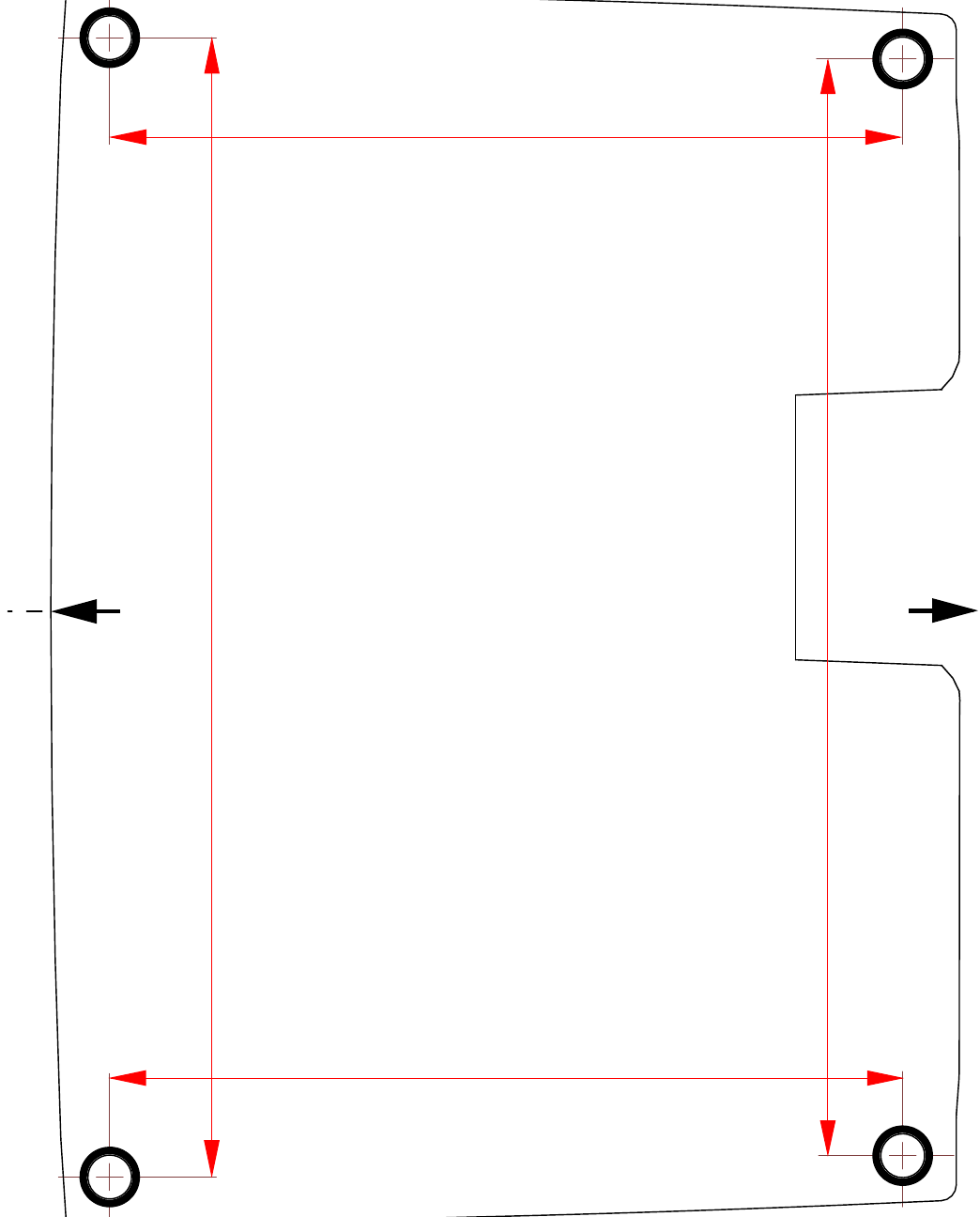
2- 12 D S C A N ® AUTHENTI CATOR CF™ User Manual v2.1
I n st allat ion
8.11 in (206 mm)
5.866 in (149 mm)
5.866 in (149 mm)
8.425 in (214 mm)
Front
Back
Drill Template
scale: 1:1
(use a borderless printing method)

Applicat ions and software levels 3-1
3
Chapter 0How to use the
Authenticator CF
T
HI S
CHAPTER
DESCRI BES
THE
FI ELDS
OF
APPLI CATI ON
,
THE
CHARACTERI STI CS
OF
DOCUMENTS
AND
HOW
TO
READ
A
DOCUMENT
WI TH
THE
D SCAN AUTHENTI CATOR
CF
USI NG
THE
D SCAN E
XTENSI ONS
DEMO
APPLI CATI ON
.
Applications and software levels
The D SCAN AUTHENTICATOR CF is available with two software levels, the
D SCAN Essentials and D SCAN Extensions to allow easy integration into
existing systems on different levels of completeness. Each software level exists as
a runtime license and a SDK license.
The D SCAN Essentials runtime software is provided for every document reader
and is necessary for accessing D SCAN AUTHENTICATOR devices on a
fundamental functional level for high level document authentication software
from D SCAN Extensions series as well as for direct device access by system
integrators.
D SCAN Essentials software allows low level access to the device:
•USB driver
• Illumination selection and turn on/off, image capturing, RFID reader access
on APDU (Application Protocol Data Unit) level
• Human interface control (buzzer and status LEDs)
• Optional SDK recommended for system integrators with experience in
document processing.
D SCAN Extensions software allows high level functionality:
• Business method level to access images
• Verification of security features and RFID access on data group level
• OCR functionality and internal implementations of cryptographic protocols
• ICAO Doc 9303 default document definition
Optional SDK with tools for the implementation of protocols like BAC, EAC, PA,
and AA.

3- 2 D S C A N ® AUTHENTI CATOR CF™ User Manual v2.1
How t o use t he Aut hent icat or CF
Using the D SCAN Extensions software and/or additional customized functions
the following main applications, without the demand of completeness are:
Airports
• Airline check-in and boarding, automated check-in
• ID verification at the time of check-in
• Creation of reference data for passenger tracking
• Faster, more precise and more efficient passenger handling
Rental car companies
•Check-in
• Verification of ID documents
• Verification of driver’s licenses
• Automated check-in for pre-registered customers
Banks
• Verification of ID documents
• Search against blacklists
• Transaction automation
Hotels
•Check-in
• Automated check-in for pre-registered guests
• Reading personal data from ID documents of guests and transmitting to
authorities
Border control
• Automated border control
• Authentication of ID documents
• Providing reliable and efficient border control
Mobile Communications
• ID verification of customers
• Search against blacklists
• Contract automation
Characteristics of documents
General properties of Machine Readable Travel Documents are standardized in
ICAO Doc 9303. This includes the structure, font, and location of the Machine
Readable Zone (MRZ), MRZ check digits, and some UV properties of the
document paper to be used in the document. Using the D SCAN Extensions
software, these features are always checked, and images in all available
illuminations are always captured depending on the installed hardware options.
The default document recognition and checking software works with ICAO 9303
compliant documents of ID1, ID2, and ID3 format. A machine readable zone
(MRZ) exactly as specified in Doc 9303, especially considering the OCR-B font,
is required.
Additionally, documents, which are not compliant with ICAO specifications, can
be detected and can be taught to the system on request.
Charact erist ics of docum ents 3-3
How t o use t he Aut hent icat or CF
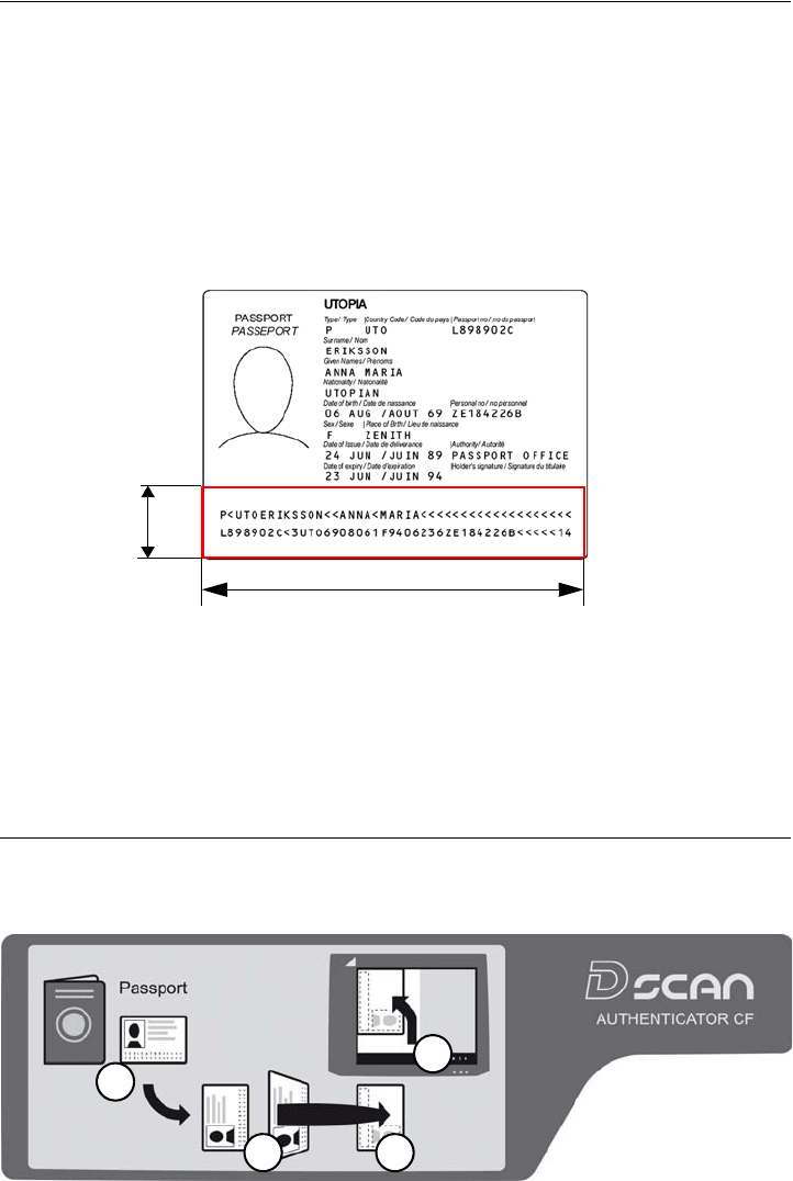
The machine readable zone
The ICAO Doc 9303 standard defines the Machine Readable Zone (MRZ) of any
Machine Readable Travel Document (MRTD). The position and dimensions of
the MRZ is different for every document type (e.g Passport, Visa. ID Card). The
certain definition for each document type can be found in ICAO Doc 9303. As an
example the MRZ for an Passport according to the ICAO Doc 9303 standard is
illustrated in the following graphic:
• 23.2 mm (0.91 in) height from the lower edge of the document
• Over the total width of the document
• It spans two lines and each line is 44 characters long
Figure 3.1
The m achine readable zone
The document contact area of the D SCAN AUTHENTICATOR CF goes beyond
the ICAO-MRZ. In customer specific applications, it is also possible to read zones
outside the MRZ of documents which do not meet the requirements of ICAO Doc
9303 as long as the physical conditions (font, size, printing quality, lamination,
etc.) of the document to be inspected allow this.
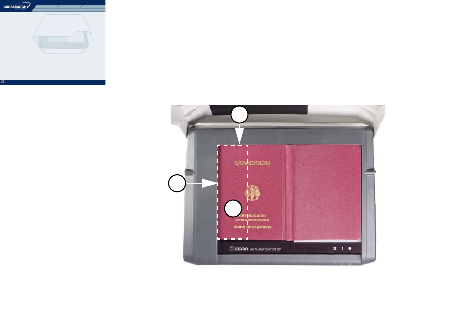
Align the documents
An instruction label on the cover provides schematic information for the user to
place a document.
Figure 3.2
I nst ruct ion label on the cover
23.2
(0.91)
document
width
1
2 3
4
3- 4 D S C A N ® AUTHENTI CATOR CF™ User Manual v2.1
How t o use t he Aut hent icat or CF
The procedure requires usually four steps:
1Find the data page.
2Rotate this page in such a manner that it faces down and the MRZ (M) is
pointing left.
3Put the page face down on the document contact area.
4Move the document along the left part of the positioning angle until it stops.
• The accurate final position must be along the left (L) and the back (B) part of
the document positioning angle.
Figure 3.3
Posit ioning of a passport
Read in a document
The following section describes a complete document reading process using the
D SCAN Show Case application as an example and explains how to use the
system correctly. The operation and display of results is controlled by the software
as well as all functions.
N ot e
The D SCAN Show Case is only part of the D SCAN Extensions SDK software package.
Depending on your used software and your station policy, the computer screens
may differ from this example. Also the status lights can be used in different
methods. However the operation of the D SCAN AUTHENTICATOR CF will
always be the same.
N ot e
Before a document is processed ensure that the document contact area is clean. Remove
smudges, laminate glue, finger prints or other dirt that may blur the document being
processed. Avoid touching the document glass with fingers prior put on a document.
The D SCAN AUTHENTICATOR CF is very easy to use and to handle:
1Power on the D SCAN AUTHENTICATOR CF.
2Ensure that the ambient light cover is in the operating position.
3Switch on your computer.
L
B
M
Read in a docum ent 3-5
How t o use t he Aut hent icat or CF
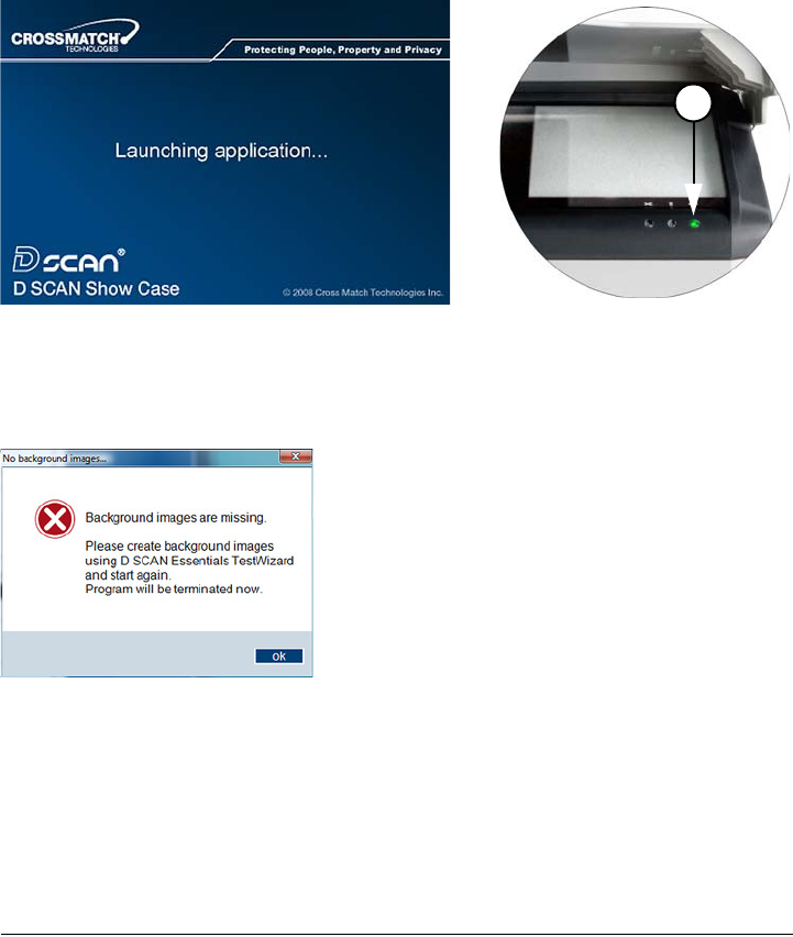
4Start the D SCAN Show Case application. The software initializes the D SCAN
AUTHENTICATOR CF and switches it to the operation mode.
• Depending on the performance of your computer, starting up can take a short
moment.
Figure 3.4
Launching application
• If no background correction images are stored on the connected computer a
related message appears.
Figure 3.5
Message about m issing background im ages
N ot e
Before you restart you must capture the missing background images. See the Technical
Reference Manual for detailed information.
• After successfully initialization the Overview window appears. The green
status light (1) is on and indicates the operation mode.
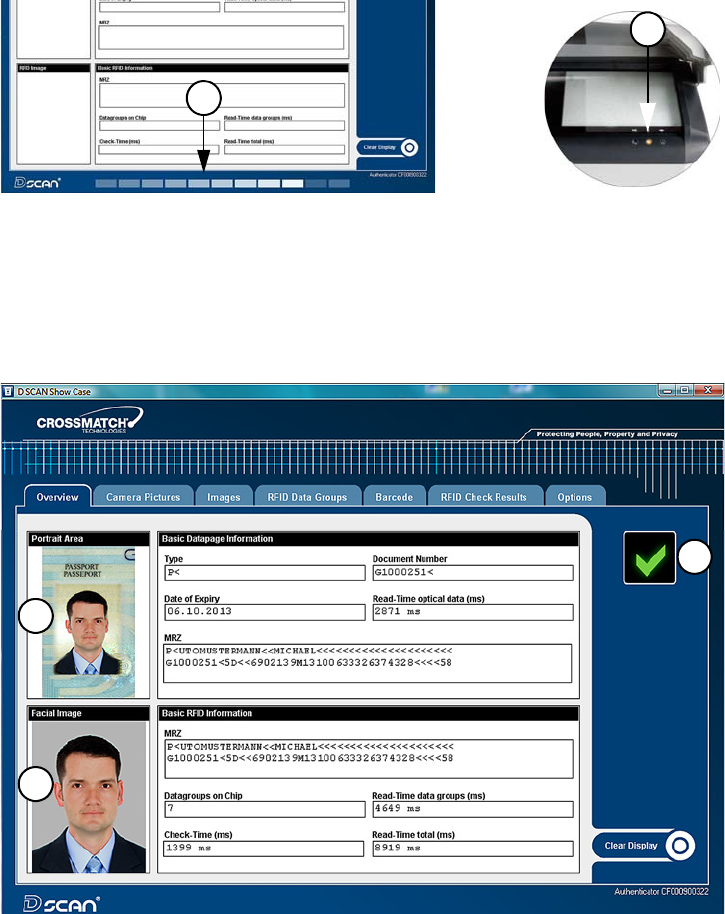
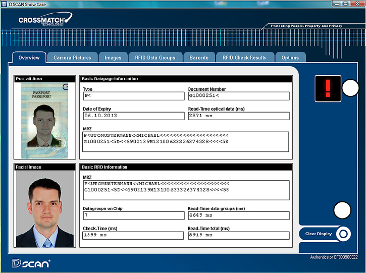
The Overview page
The Overview page is the default page to show the data of the processed
document. Use the Tabs at the top to navigate and to view all data and images.
1Put the data page of the document to be read face down on the document
contact area so that the MRZ is pointing left.
1
3- 6 D S C A N ® AUTHENTI CATOR CF™ User Manual v2.1
How t o use t he Aut hent icat or CF
W arning
Do not look directly into the lights of the document contact area. Maintain a required
minimum distance of not less than 11.8 inches (0.3 m).
2A short acoustic signal indicates that the document is in the correct position.
The processing starts automatically.
• A processing bar (2) is shown at the bottom and the processing light (3) is
yellow. The yellow processing light indicates that the data were recorded and
are being processed.
Figure 3.6
Processing inform at ion
N ot e
Do not move the document until the yellow processing light turns off.
• When the document reader has completed processing the document, the
processing light turns off, the green operation light comes on and a short
acoustic signal occurs.
• Now you can remove the document.
Figure 3.7
Overview dat a page
2
3
4
5
6
Read in a docum ent 3-7
How t o use t he Aut hent icat or CF
3 All data submitted to the computer are displayed on the computer screen.
• The upper part (4) shows the captured visible data, which are printed on the
document.
•The lower part (5) shows the chip data, which are stored on the RFID tag.
This allows you to compare both data sections manually.
• An optional status icon (6) is shown on the right side.and indicates the
operator quality checking information. This option can be disabled or
enabled on the Options page. See , “Global result settings” on page 3-13 for
more information.
In the event of errors, failed verifications, or if the processed document is not
recognized, the failed icon (7) appears.
•The Clear Display (8) button allows the operator to clear the displayed data.
• Repeat the operation with the same document to ensure that the problem was
not caused by mispositioning the document. Correct the position by lifting-
up and then repositioning the document.
Figure 3.8
Failed verificat ion
8
7
3- 8 D S C A N ® AUTHENTI CATOR CF™ User Manual v2.1
How t o use t he Aut hent icat or CF
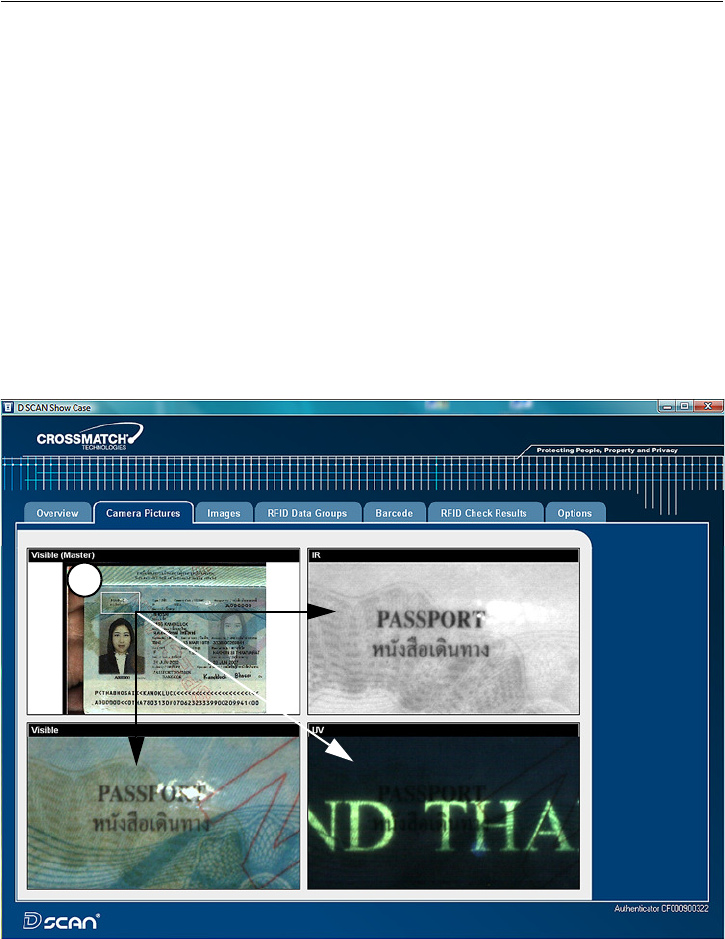
The camera pictures page
The Camera pictures page shows all available images captured under different
illuminations depending on the features installed in the document reader. The left
upper image is the Master image. It allows the operator to mark an area of interest
with the mouse cursor.
To mark an area:
1 Move the cursor to the desired position and click the left mouse button.
2 Keep the left mouse button pressed and draw a frame (1).
• The dimensions of the frame will be proportional to the length and width of
the image.
• The content of the frame applies to all displayed images on the screen as an
zoomed detail.
3 Move the cursor into the frame, then press and hold the left mouse button to
move the frame to any place within the image.
4 All other images on the page adjust to the moved frame.
5 Click the right mouse button to delete the frame.
Figure 3.9
Cam era pict ures page
1
Read in a docum ent 3-9
How t o use t he Aut hent icat or CF
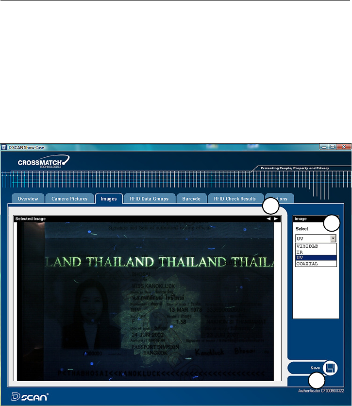
The images page
The Images page provides the ability to show all available images in full screen
resolution captured under different illuminations depending on the features
installed in the document reader.
1 To select a single image click the down arrow in the Select box and chose the
desired type of image from the list (1).
2 To view all images in sequence click on the left or right arrow (2) in the right
upper corner of the image and scroll through all available images.
3 Place the mouse cursor into a displayed image and use the mouse wheel to
zoom in or out an image. Press the right mouse button to switch off the zoom
function.
4 The button Save (3) allows you to store the chosen image on your local disk.
Figure 3.10
I m ages page
1
2
3
3- 10 D S C A N ® AUTHENTI CATOR CF™ User Manual v2.1
How t o use t he Aut hent icat or CF
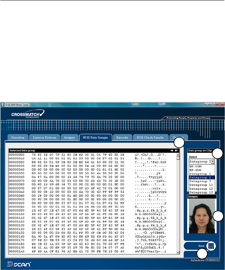
The RFID data groups page
The RFID Data groups page provides the ability to show all data groups in the
Hex-Format found on the RFID tag.
1 To select a single data group click the down arrow in the Select box and chose
the desired type of data group from the list (1).
• If no RFID data available the Select box is grayed out.
2 To view all data groups in sequence click on the left or right arrow (2) in the
right upper corner and scroll through all available data groups.
• If the content of a data group is an image, it will be displayed on the right
sight (3) below the Select box.
3 The button Save (4) allows you to store the content of the chosen data group on
your local disk.
Figure 3.11
RFI D dat a groups page
3
2
1
4
Read in a docum ent 3- 11
How t o use t he Aut hent icat or CF
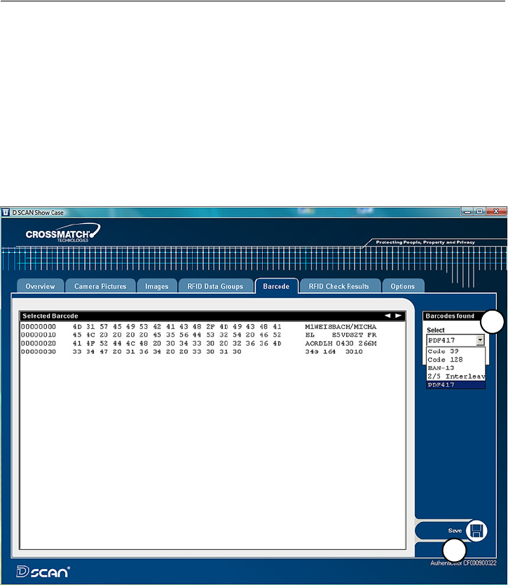
The barcode page
The Barcode page provides the ability to show every barcode found on the
document. As the default setting the PDF417 barcode will be read. To read
additionally barcodes you must enable these functions in the Barcodes to read box
on the Options page.
1 To select a single barcode click the down arrow in the Select box and chose
the desired barcode from the list (1).
2 If no barcode data available the Select box is grayed out.
3 To view all barcodes found click on the left or right arrow (2) in the right
upper corner and scroll through all available barcodes.
4 The button Save (2) allows you to store the content of the selected barcode on
your local disk.
Figure 3.12
Barcode page
2
1
3- 12 D S C A N ® AUTHENTI CATOR CF™ User Manual v2.1
How t o use t he Aut hent icat or CF
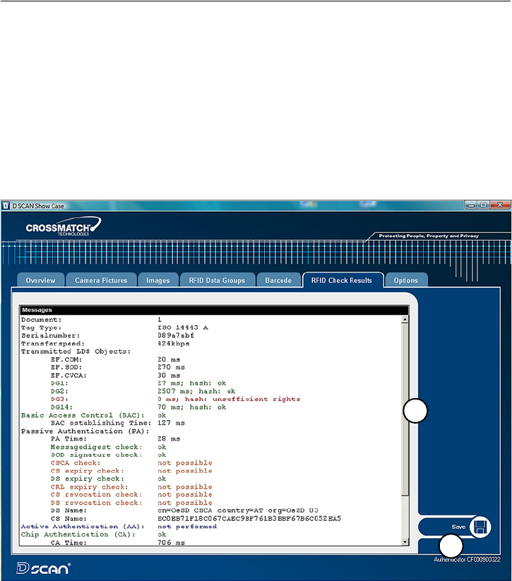
The RFID check results page
The RFID Check Results page shows the results of all performed security checks
during processing the document. It may helpful to find out the reason of failed
security checks.
• Green colored entries indicate successful security checks of the processed
document.
• Entries in red color indicate mistakes or failed security checks.
• The orange color indicates not performed security checks or features which
are not supported.
1Use the scroll bar (1) to view longer lists.
2The button Save (2) allows you to store the list on your local disk.
Figure 3.13
RFI D check result s page
The D SCAN AUTHENTICATOR CF is ready to process the next document.
1
2
Read in a docum ent 3- 13
How t o use t he Aut hent icat or CF
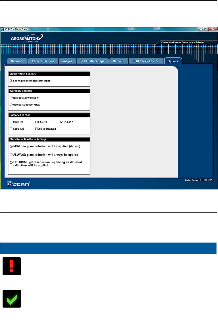
The options page
The Options page allows to change the default settings of the program and to
configure the appearance of functions.
Figure 3.14
Opt ions page
Global result settings
Two icons are used to show the operator quality checking information. The
function to display the icons can be enabled or disabled and applies only for ID
documents with MRZ.
I con D escr ip t io n
The red Failed icon indicates that:
• The MRZ check sums are not correct.
• The document is expired.
• The RFID data group read error(s).
• Any explicit error occurred during RFID verification.
The green OK checkmark indicates that:
• The MRZ check sums are correct.
• The document is not expired.
• The RFID data are read successfully.
• No explicit error occurred during RFID verification.
• Any other case occurred not listed above.

3- 14 D S C A N ® AUTHENTI CATOR CF™ User Manual v2.1
How t o use t he Aut hent icat or CF
Workflow settings
In the default workflow, normal ID documents are scanned, including security
checks, for:
•MRZ.
•RFID.
• Selected barcode type(s).
The barcode workflow can be used to demonstrate the reading speed of barcodes.
Only the enabled barcode type(s) will be checked. The more barcode types are
selected the longer the reading process takes.
Barcodes to read
Set the checkmark to read additional barcodes.
Glare reduction mode settings
The glare reduction feature is not supported by all AUTHENTICATOR devices.
Therefore glare reduction is deactivated as the default setting. Before you change
this setting make sure that you install D SCAN Essentials 1.3 or higher.
Cleaning 4- 1
4
Chapter 0Maintenance
T
HI S
CHAPTER
DESCRI BES
MAI NTENANCE
PROCEDURES
THAT
I NCREASE
THE
LI FE
OF
THE
DOCUMENT
READER
.
Cleaning
This section describes how to clean the document contact area and the case. A
clean document contact area is required for proper operation. Dirt can reduce the
image quality of the processed document. Clean the platen with normal glass
cleaner and make sure that no dirt, fluids or skin oils remain.
W arning
Do not pour liquids (water etc.) onto the document reader. The device is protected against
cleaning with a damp cloth or tissue. The device is not waterproof.
Ca ut ion
Do not use oil-based cleaners or abrasive cleaners.
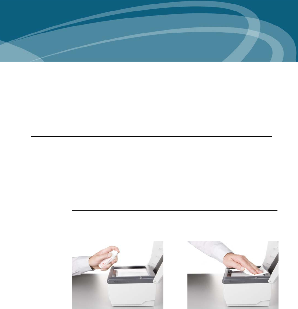
Clean the document contact area
1Open the ambient light cover of the document reader.
2Spray the glass cleaner onto the document contact area.
Figure 4.1
Clean the docum ent contact area
3With a lint-free cloth or tissue, wipe off the document contact area until clean
and dry.

4- 2 D S C A N ® AUTHENTI CATOR CF™ User Manual v2.1
Maint enance
4Make sure that the document contact area is dry before starting the reading
process.
Clean the case
W a r ning
Before you clean the case, disconnect the D SCAN AUTHENTICATOR CF from the
grounded outlet.
To remove smudges, laminate glue, finger prints or other dirt, and grime:
1Take a soft, lint free cloth and put a small amount of glass cleaner on it.
2Wipe the case in a direction AWAY from the document contact area.
Ca ut ion
Do not use acetone, oil-based, abrasive or other unauthorized cleaners. This may damage
the device and render it inoperable. Using unapproved cleaning solutions will void the
warranty.
Authenticator CF specifications
Table 4.2
Product specifications
I t e m Specificat ion
Re so lu t io n Native 475 ppi sensor for best recognition of high
density features
Dyna m ic r a nge Visible light and UV light 24 bit RGB color, IR light:
8 bit gray scale
I llu m in a t io n Visible light: wavelength 430-680 nm
IR light: wavelength 895 nm
UV light: wavelength 365 nm
Coaxial light (not available in all markets)
Docum e nt su pport field size 5.9 in x 7.4 in (151 mm x 189 mm), document
thickness is not limited
Opt ica l sca n form at Active size 5.3 in x 3.9 in (135 mm x 100 mm)
Opt ica l sca n nin g t im e approx. 2 seconds for all images combined
I m age for m at 2528 x 1888 pixels
Suppor t e d docu m e n t s Compliant with ICAO 9303 documents of ID1, ID2,
and ID3 format, other ID-1, ID-2 and ID-3
documents on request
Docum e nt t hick ness Not limited
RFI D opera t ing fre quency 13,56 MHz
RFI D m a gnet ic fie ld
st r e ng t h
Max. 4,0 A/m
Tr a nsm ission pow er Max 200 mW
RFI D ta g a cce ss According to ISO 14443 Type-A and Type-B plus
applicable ICAO recommendations in ICAO Doc
9303 including supplement, LDS 1.7,PKI 1.1

Magnet ic field st rengt h 4-3
Maint enance
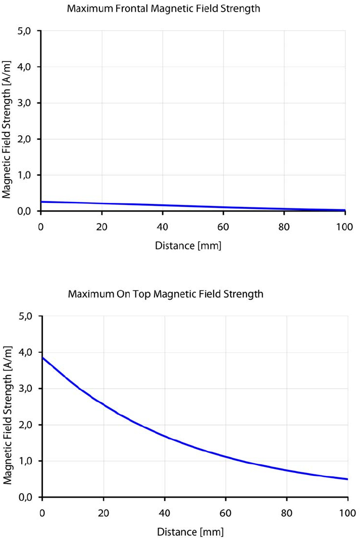
Magnetic field strength
The following diagrams show the distances (mm) to maintain in relation to the
magnetic field strength (A/m) for the AUTHENTICATOR CF document reader.
Figure 4.3
Magnet ic field st rength lateral
RFI D spee d All standardized rates, up to 848 Kbps, read-out
times depend on RFID tag, operating system, and
amount of data stored in the chip
Sm a rt ca rd rea der Contact SmartCard reader with landing contacts
and able to read cards according to ISO 7816
protocol Type T=0 (asynchronous half duplex
character transmission protocol) and T=1
(asynchronous half duplex block transmission
protocol).
Envir on m ent a l condit ions Indoor use, climate classification according to DIN
EN 60 721-3-3
Tem pera t ur e range 41 °F to 113 °F (+5 °C to +45 °C)
Hum idit y range 10 - 90% relative humidity, non condensing, no
direct sunlight exposure
Dim e nsions
( W x D x H)
10.36 in x 8.35 in x 5.89 in
(263 mm x 212 mm x 150 mm)
W eight 5.1 lbs (2,3 kg), excluding cables and power pack
I nte r face USB 2.0 High Speed, shielded cable
Pow er supply Rated input: 18 - 24 V DC / min. 1 A / max. 7 A,
Current used: Desktop power pack 19 V DC /
< 30W, wide-range, input AC 100-240 V, 50/60 Hz
Re gu la t or y FCC, CE
Table 4.2
Product specifications
I t e m Specificat ion
4- 4 D S C A N ® AUTHENTI CATOR CF™ User Manual v2.1
Maint enance
Figure 4.4
Magnet ic field st rength front al
Figure 4.5
Magnet ic field st rength on top

5-1
5
Chapter 0Problems and
Corrections
T
HI S
CHAPTER
CONTAI NS
COMMON
PROBLEMS
AND
STEPS
TO
CORRECT
THEM
.
Do the procedures in this section before you contact the Cross Match Technical
Support department.
The Authenticator does not work
The error messages displayed:
None. The yellow processing light is flashing.
First actions to correct the problem
1 Test the electrical outlet to ensure that the electrical outlet is working.
2 Check the correct installation of the power supply.
3 Verify USB cable is firmly connected to the computer or hub.
More actions to correct the problem
1 Check the correct installation of the hardware driver.
2 Replace the USB cable to find out if it is defective.
3 Contact the Technical Support department.
Authenticator disconnected during operation
The error messages displayed:
A broken connection message depends on your software configuration.
The yellow processing light is flashing.
First actions to correct the problem
1 Confirm the message Connection broken by clicking OK.
2 Re-establish the USB connection.
3 Re-connect the power to the Authenticator.

5- 2 D S C A N ® AUTHENTI CATOR CF™ User Manual v2.1
Problem s and Correct ions
4 Initialize the Authenticator again.
More actions to correct the problem
Contact the Technical Support department.
Initialization failed
The error messages displayed:
None. The yellow processing light is on.
First actions to correct the problem
1 Verify USB cable is firmly connected to the computer or hub.
2 Open the Windows Task Manager and close the DS_HAL Server.exe or the
DS_HAL ServerU.exe.
3 Initialize the Authenticator again.
More actions to correct the problem
1 Restart the computer.
2 Initialize the Authenticator again.
3 Contact the Technical Support department.
Dark image sections
The error messages displayed:
None
First actions to correct the problem
1 Clean the processing surface.
2 Ensure that you have no direct light exposure shining onto the processing
surface.
3 Verify the correct installation of all software and hardware components.
More actions to correct the problem
Contact the Technical Support department.
Visualization and processing speed too slow
The error messages displayed:
None
First actions to correct the problem
1 Verify the system requirements. See “System requirements” on page 2-6.
2 Verify that you do not use a USB 1.1 interface port.

5-3
Problem s and Correct ions
More actions to correct the problem
Contact the Technical Support department.
Creating a problem report
If the steps mentioned before were unsuccessful, please use the D SCAN
TestWizard to perform a complete interactive diagnostic of the system.
1 Start the D SCAN TestWizard.
2 Perform a complete system test.
3 Create a log file.
4 Save the log file.
5 Send the log file to the responsible Service Center.
5- 4 D S C A N ® AUTHENTI CATOR CF™ User Manual v2.1
Problem s and Correct ions

Technical Support 6-1
6
Chapter 0Customer Care and
Contact Information
THI S CHAPTER CONTAI NS TECHNI CAL SUPPORT I NFORMATI ON FOR THE PRODUCT
AND CONTACT I NFORMATI ON FOR THE COMPANY.
Technical Support
The Technical Support department is available for the
D SCAN AUTHENTICATOR CF.
E-mail
Cross Match Customer Care offers free technical hardware support on-line during
the warranty period, in the order that the requests are received.
If the warranty has expired, contact Technical Support by telephone or facsimile.
Telephone and facsimile
Customer Care is available at the following telephone numbers:
Table 6.1
The Technical Support depart m ent addresses
N orth Am erica a nd Sou t h Am erica Eu rope , Africa , Asia a n d Au st ra lia
CustomerCare@crossmatch.com Support-jena@crossmatch.com
Table 6.2
The Technical Support departm ent num bers
N orth Am erica a nd Sou t h Am erica Europe, Africa, Asia a nd Au st ra lia
Monday- Friday 8 am to 5:30 pm EST Monday- Friday 8 am to 4 pm CET
Customer Care
Tel: 1.866.276.7761 (Toll Free)
Tel: 1.561.622.9210 (International)
Fax: 1.561.622.8769
Customer Service
Tel: +49 (0)3641 4297-852
Fax: +49 (0)3641 4297-757

6- 2 D S C A N ® AUTHENTI CATOR CF™ User Manual v2.1
Custom er Car e and Cont act I nform at ion
Free technical support is available by telephone or facsimile for the
D SCAN AUTHENTICATOR CF under the warranty. After the warranty has
expired, technical support is available at a given cost per hour. Contact Technical
Support for complete information.
The Technical Support for the software products and the services purchased from
Cross Match Technologies is not included under the warranty. The Technical
Support for other products is available at a given cost to the customer. Support for
software development related questions is, up to a certain limit, usually included
in every SDK purchase.
When you contact Technical Support, make sure that you can provide the
following information:
• Company name
• Contact person
• The D SCAN AUTHENTICATOR CF serial number (found on the back of
product)
• The configuration of your PC workstation or laptop
• The error messages that appear on the screen
• The log file created by the D SCAN TestWizard, the test images and the
background images
• The used D SCAN software and version number
Return and repair of the Authenticator CF
You must have an RMA number to return a D SCAN AUTHENTICATOR CF for
repair or replacement. Contact the Technical Support department to request and
receive an RMA number. Put the RMA number on the outside of the box and on
the label.
The product is sent to the correct department for service or replacement, then
returned to the customer. Any product sent to Cross Match Technologies without
an RMA number is returned.
Table 6.3
The addresses for product ret urns
N orth Am erica a n d South Am e rica Europe, Africa , Asia and Aust ralia
Cross Match Technologies, Inc.
3960 RCA Boulevard, Suite 6001
Palm Beach Gardens, Florida
33410
USA
RMA: Rnnnn.nnnn
Cross Match Technologies GmbH
Service Department
Unstrutweg 4
07743 Jena
Germany
RMA RMAnnnn

Deliver y cost s 6-3
Custom er Car e and Cont act I nform at ion
Delivery costs
The product is in the warranty period
• The customer accepts all charges to send the product to Cross Match for
service.
• Cross Match accepts all charges to return the product to the customer.
Customers inside the EU
• Cross Match accepts all charges to send the product to Cross Match for
service and to return the product to the customer.
The product is not in the warranty period
The customer accepts all charges.
N ot e
You must return a product in the original boxes. If the original boxes are not available,
contact the Technical Support department for instructions.
Contact information
Corporate Headquarters
Cross Match Technologies, Inc.
3950 RCA Boulevard, Suite 5001
Palm Beach Gardens, FL 33410
USA
T: +1 (561) 622-1650
F: +1 (561) 622-9938
T: (866) 725-3926 (Toll Free)
General Mailbox: info@crossmatch.com
Sales Department: sales@crossmatch.com
Technical Support: CustomerCare@crossmatch.com
Corporat e W eb Pa ge
www.crossmatch.com
6- 4 D S C A N ® AUTHENTI CATOR CF™ User Manual v2.1
Custom er Car e and Cont act I nform at ion

Lim it ed Warrant y 7-1
7
Chapter 0Product Warranty
T
HI S
CHAPTER
CONTAI NS
THE
TEXT
OF
THE
PRODUCT
WARRANTY
.
Limited Warranty
Cross Match Technologies, Inc. and its subsidiaries (“Cross Match”) warrants that
the Cross Match Product (other than customized software) you have purchased
will be free from defects in material and workmanship in normal service and
under normal conditions for a period of one year from the date of shipment.
Normal service and normal conditions are defined in the Product documentation.
This Limited Warranty is subject to the terms and conditions set forth below.
Repair or Replacement
Unless otherwise stated herein, the sole obligation of Cross Match and your
exclusive remedy and recourse under this Limited Warranty is for Cross Match, at
its sole election, to either (i) repair the suspected defective Product and return the
same to you or (ii) replace the suspected defective Product, all on the terms set
forth below. The repair or replacement will provide you with a Product which, in
Cross Match’s opinion, performs consistently with its age and usage.
If you become aware that your Cross Match Product is defective in material or
workmanship in normal service and under normal conditions during its one year
Limited Warranty period, then you must promptly contact Cross Match’s
Customer Care Center, describe the suspected defect in detail and request a Return
Merchandise Authorization (“RMA”) number prior to sending the affected
Product for repair or requesting a replacement product. Please see your product
manual for more information on RMA’s. Unless otherwise specified by law, you
will pay the freight to send the Product to Cross Match’s designated Service
Center. Cross Match will pay the freight to return the repaired Product to you.
Each repaired or replacement Product is warranted (as set forth herein) for the
remaining portion of the original one year Limited Warranty.
THE FOREGOING CONSTITUTES YOUR SOLE AND EXCLUSIVE
REMEDY AND CROSS MATCH’S SOLE AND EXCLUSIVE LIABILITY IN
CONNECTION WITH YOUR CROSS MATCH PRODUCT, AND IS IN LIEU
OF ANY AND ALL OTHER REMEDIES WHICH MAY BE AVAILABLE TO
YOU.

7- 2 D S C A N ® AUTHENTI CATOR CF™ User Manual v2.1
Product Warranty
Limitations
This limited warranty does not cover visits to repair the Cross Match product at
your premises, or the commissioning of the Product on site. This Limited
Warranty is not a warranty, guarantee or promise that your Cross Match Product
will conform to its specification or will not fail. Some defects and failures are not
covered.
Cross Match shall incur no liability under this Limited Warranty and this Limited
Warranty is voidable by Cross Match if in Cross Match’s sole reasonable opinion:
(a) the Product is used other than under normal use and under proper
environmental and/or electrical conditions, as specified in the Product manual; (b)
the Product is not maintained as specified in the Product manual; (c) the Product is
subject to abuse, misuse, neglect, accident, flooding, storm, lightning, power
surges, dirty power, third-party errors or omissions, or acts of God; (d) the Product
is modified or altered (unless expressly authorized in writing by Cross Match); (e)
the Product is installed or used in combination or in assembly with products not
supplied or authorized by Cross Match; (f) there is a failure to follow specific
restrictions or operating instructions; or (g) payment for the Product has not been
timely made.
This Limited Warranty includes software “updates” (a revision or minor change to
a Product intended to correct defects and provided as a change in the then current
release of the Product). Software updates may be made from time to time in Cross
Match’s sole discretion. This Limited Warranty does not cover software
“upgrades” (a revision to a Product that adds new enhancements and functionality
resulting in a new release of the Product) or any software product or interface
customized by Cross Match to meet Purchaser’s specific requirements or
Purchaser furnished equipment or software. Software upgrades may be available
for purchase from time to time at Cross Match’s then current published prices.
This Limited Warranty does not provide additional hardware or computing
platform software or its installation when required by Cross Match software
supplied hereunder. If required, these may be obtained from Cross Match at the
published prices in effect at such time.
The Limited Warranty does not cover nondurable consumable items including, but
not limited to, batteries, paper, silicon pads, cleaning solution, towels, printer
cartridges and cables. Replacement supplies of these items may be ordered by
contacting Cross Match Sales at http://www.crossmatch.com/sales-contacts.php.
This Limited Warranty does not cover third party peripheral equipment (such as
laptops and printers) that are not provided by Cross Match.
Cross Match’s obligations hereunder are contingent upon your providing the
Product serial number as proof-of-purchase, and upon Cross Match’s
determination that the suspected malfunction is actually due to defects in material
or workmanship.
THIS LIMITED WARRANTY IS IN LIEU OF ALL OTHER
WARRANTIES RELATED TO THE CROSS MATCH PRODUCT,
WHETHER EXPRESS, IMPLIED, OR STATUTORY, INCLUDING THE
WARRANTIES OF MERCHANTABILITY AND FITNESS FOR A
PARTICULAR PURPOSE, ALL OF WHICH ARE HEREBY EXPRESSLY
DISCLAIMED BY CROSS MATCH. THIS LIMITED WARRANTY IS

Lim it ed Warrant y 7-3
Product Warranty
NOT TRANSFERABLE OR ASSIGNABLE TO ANY THIRD PARTY AND
SHALL BE FOR THE SOLE AND EXCLUSIVE BENEFIT OF THE
ORIGINAL PURCHASER OF THE CROSS MATCH PRODUCT
COVERED HEREUNDER; ANY ATTEMPTED TRANSFER OR
ASSIGNMENT HEREOF SHALL BE VOID AB INITIO.
Cross Match reserves the right to improve/modify products at any time, at its sole
discretion, as it deems necessary.
Out-of-Warranty Repairs
When warranty coverage for your Cross Match Product lapses, or for repairs or
replacements not covered by Cross Match’s warranty, (i) you will pay for all
repairs at Cross Match’s then-prevailing hourly labor rate (with a one hour
minimum) plus parts and shipping, (ii) you will pay Cross Match’s then-current
price for all replacement Products plus shipping, and (iii) you will pay Cross
Match’s then-prevailing hourly labor rate (with a one hour minimum after the first
15 minutes) for telephone support in 15 minute increments.
To obtain out-of-warranty service, you must obtain an RMA number and send the
affected Product, at your expense, to the designated Cross Match Service Center
for inspection. You will be contacted with an estimated price and time of repair or
replacement after analysis. No repairs or replacements will be made until Cross
Match receives a Purchase Order or credit card number from you. You shall pay
return freight charges, which will be added to the invoice, for the return of the
repaired Product or replacement Product.
In the event you decide not to have a unit repaired or replaced after receiving a
repair estimate, there will be a one hour labor charge at the prevailing hourly rate
for evaluation plus return freight charges.
At your request, Cross Match will, for a premium, ship a refurbished unit to you in
exchange for the failed unit. Cross Match will contact you with a price for the
exchange after receipt of the failed unit. The shipment will be made when Cross
Match receives a Purchase Order or credit card number from you. You will pay
return freight charges, which will be added to the invoice, for the exchange unit.
The original returned Product will become the property of Cross Match and will
not be returned to you. The refurbished unit will retain the remaining warranty
term of the original returned Product.
7- 4 D S C A N ® AUTHENTI CATOR CF™ User Manual v2.1
Product Warranty

I n dex - 1
Index
A
appropriat e operat ion 1 -1
Authenticat or CF
packing list 2 -7
unpack ing 2 -7
B
barcode 1 -4
basic healt h and safety 0 -iii, 0 -v
reduce t he RF exposure 0 - iii
repairs 0 - iii
safe oper at ion 0 -iii
t ransm it t ed radio fr equency 0 - iii
C
cam era pict ures 3 -8
clean the pr ocessing surface 4 -1
cleaning 4 -1
com m on problem s 6 -1
connect t he Aut hent icator CF 2 -8
connecting cables 2 -8
cont act inform at ion 6 -3
corporate headquarter s 6 -3
corpor ate headquarters 6 -3
corpor ate web page 6 -3
D
D SCAN Show Case
default workflow 3 -14
glare reduct ion 3 -14
D SCAN Show Case dem o software
Overview 3 -5
dim ensions 4 -3
E
e- m ail, see conta ct inform at ion
F
FCC st atem ent 1 -2
freight guidelines 6 -3
not under warranty 6 -3
under w arrant y 6 -3
G
glare r educt ion feat ure 3 -14
glass cleaner 4 -1
glossary 1 -4
H
help 6 -1
t ech nical 6 -1
how t his book is organized 1 -1
hum idy range 4 -3
I
I CAO Doc 9303 1 -5
im ages page 3 -9
im it ed w arrant y 7 -1
I ndust ry Canada 1 -3
inst allation 2 -7
interface 4 -3
L
lim ited warrant y
lim it at ions 7 -2
out-of- w arrant y repairs 7 -3
M
m agnet ic field st rength 4 -3
MRZ 1 -6
N
not under warrant y 6 -3
P
packing list 2 -7
pow er supply 4 -3
prepare t o use t he Aut hent icat or CF 2 -7
problem s 6 -1
product warrant y 7 -1
R
read in 3 -4
recycling inform at ion 1 -3
reduce t he RF exposure 0 - iii
repair or r eplacem ent 7 -1
repairs 0 -iii
repeat the operat ion 3 -7
resolution 4 -2
ret urns and repair 6 -2
RFI D tag
access 4 -2
operat ing frequency 4 -2
speed 4 -3
transm it t ing power 4 -2
RMA num ber 6 -2
runtim e soft ware 3 -1
S
safe operat ion 0 -iii
safet y 1 -4
soft ware levels 3 -1
specificat ions
dim ensions 4 -3
I ndex- 2 D S C A N ® AUTHENTI CATOR CF™ User Manual v2.1
hum idity r ange 4 -3
illum inat ion 4 -2
in t er face 4 -3
power supply 4 -3
regulat ory 4 -3
resolution 4 -2
tem perat ure range 4 -3
weight 4 -3
st andards
caut ion 1 -2
danger 1 -2
note 1 -2
warning 1 -2
st at em ent of com pliance 1 -3
syst em requirem ents 2 -6
hardware 2 -7
operat ing syst em 2 -7
T
technical help 6 -1
technical support 6 -1
e- m ail
ret urns and r epair 6 -2
telephone and fax 6 -1
tem per at ur e range 4 -3
t erm s 1 -4
transm it t ed r adio frequency 0 -iii
troubleshooting
see proble m s
U
under w arr ant y 6 -3
unpack t he Aut hent icat or CF 2 -7
unpacking the Aut hent icat or CF 2 -7
W
web page 6 -3
WEEE direct ive 1 -3
weight 4 -3
wipe off the case 4 -2
wipe off the pr ocessing surface 4 -1