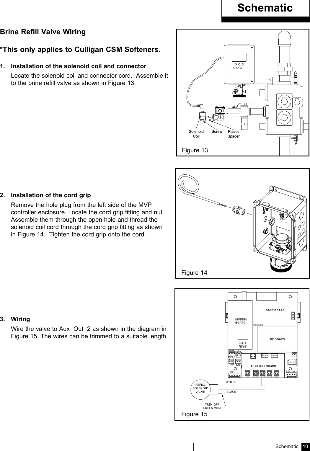
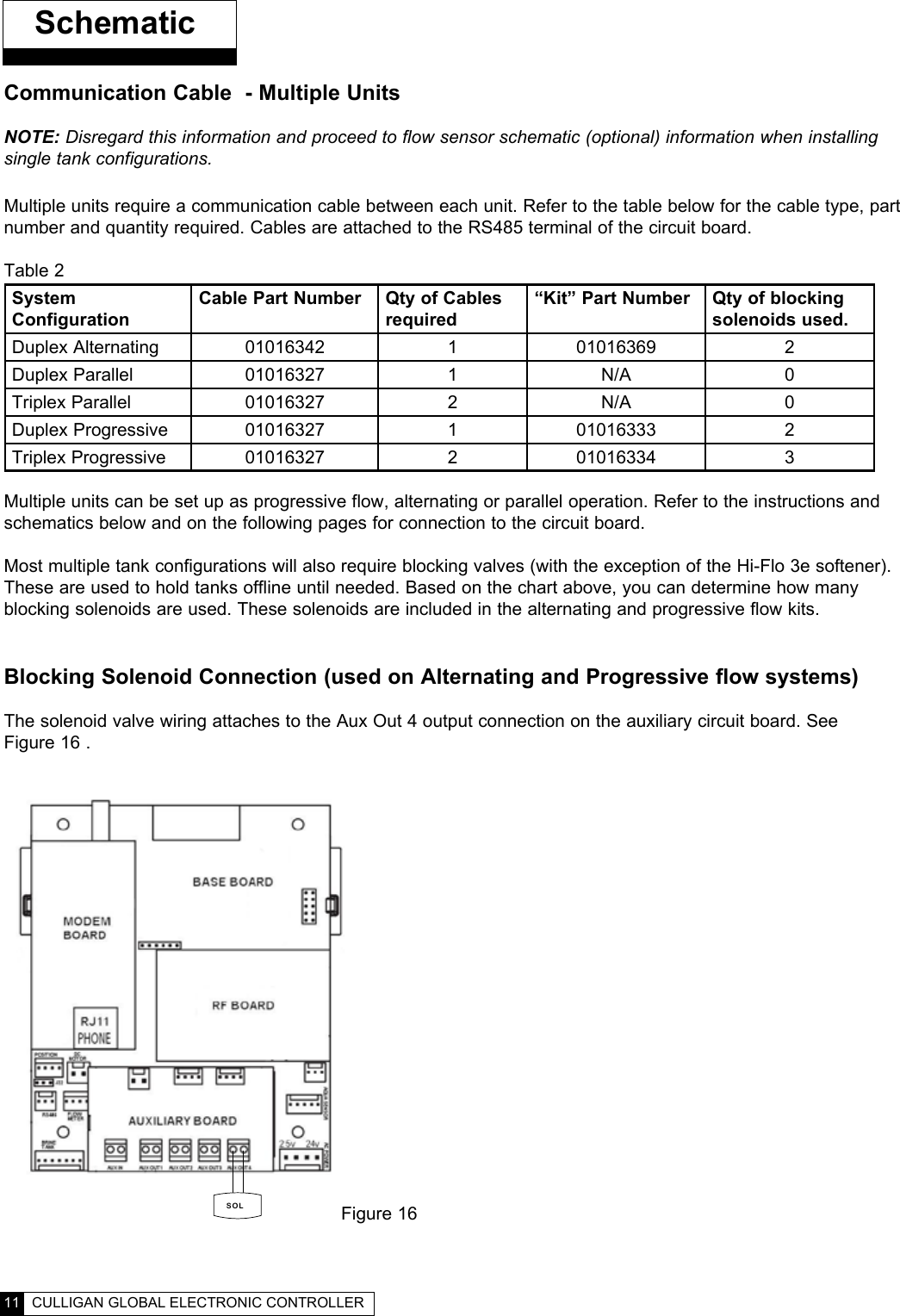
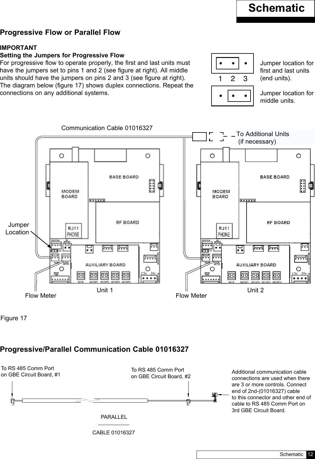
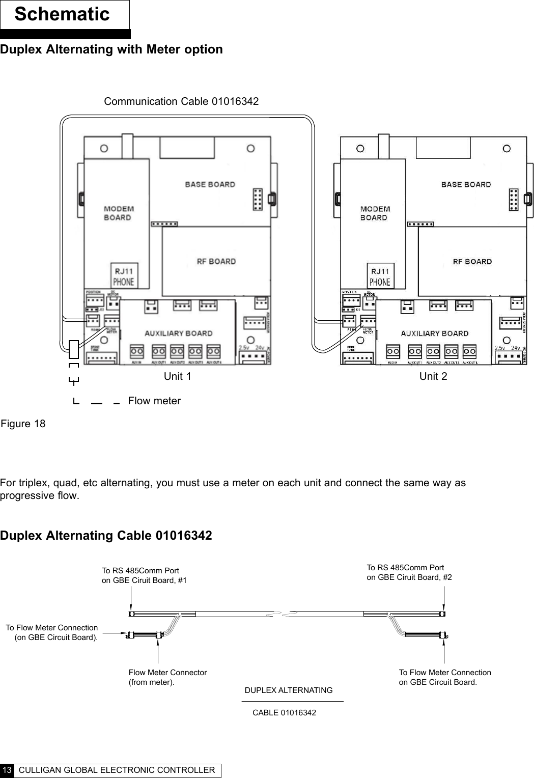
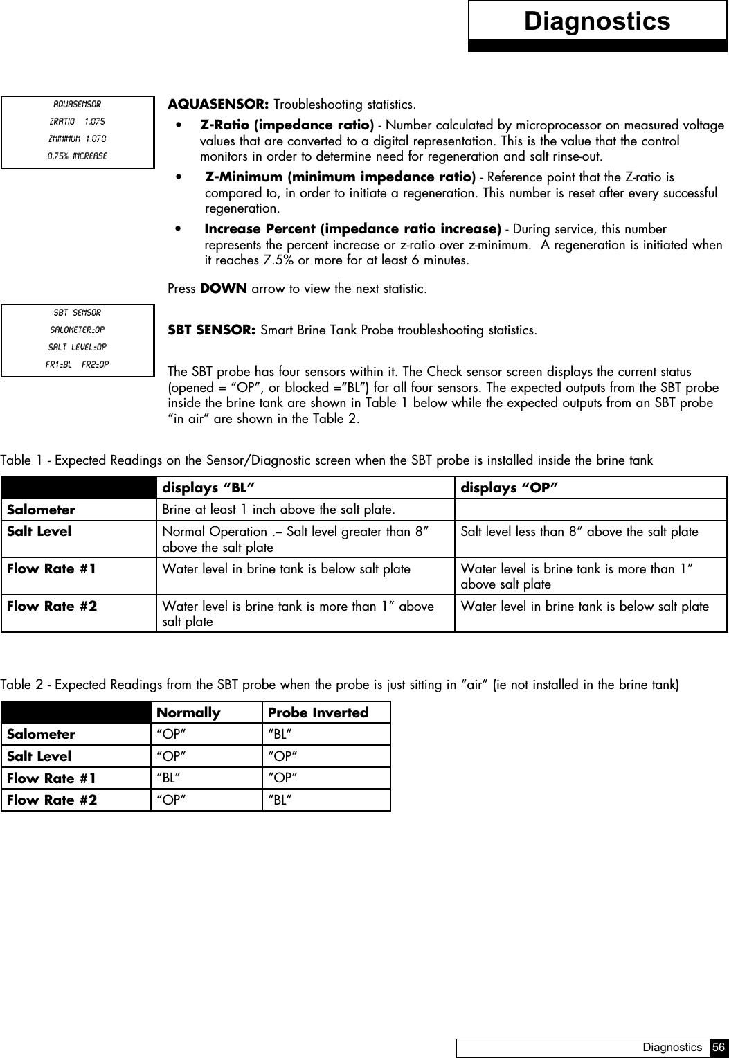
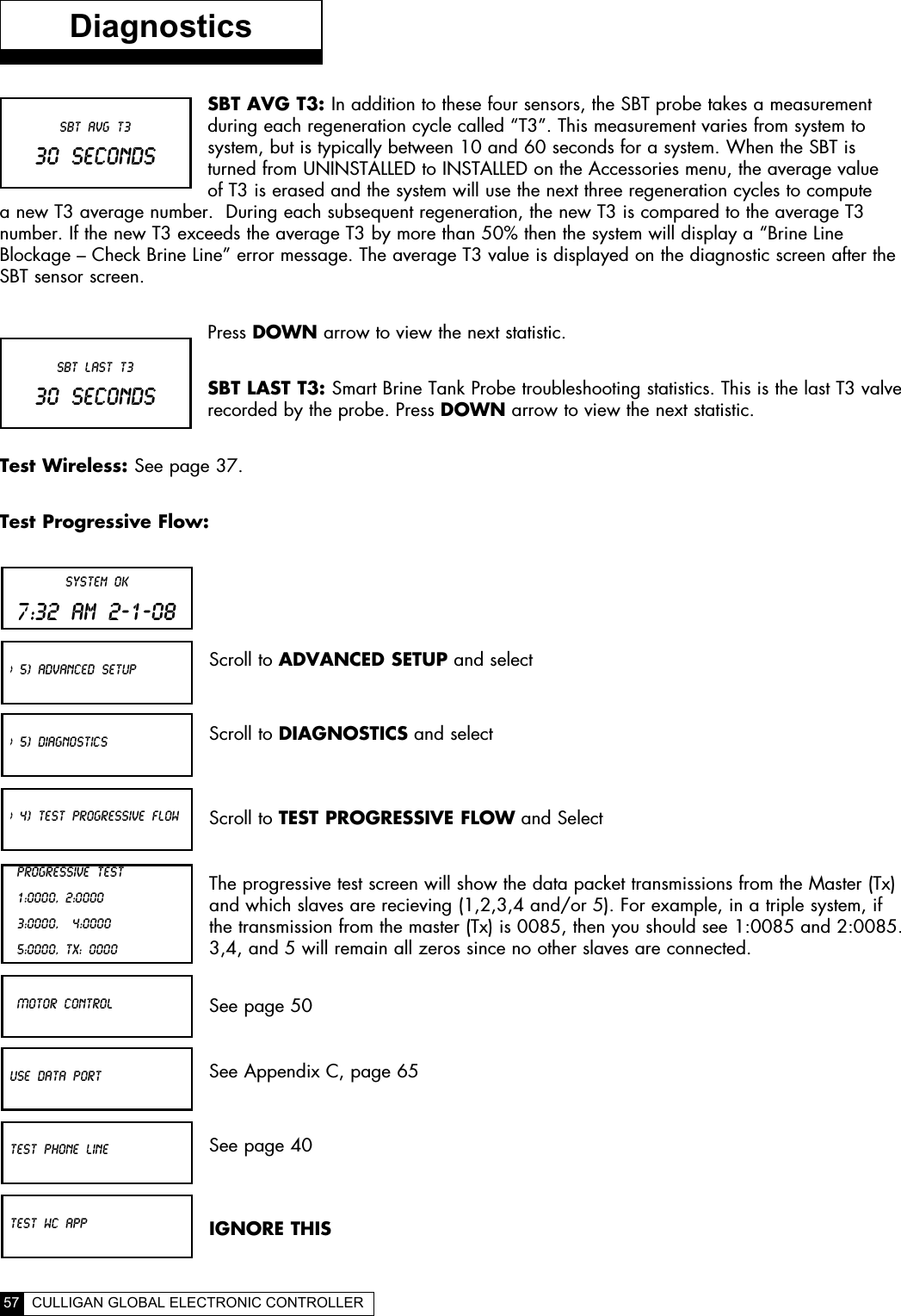
Culligan 01020553 Wireless Remote User Manual

Culligan International Company Wireless Remote

User Manual

CULLIGAN®Global Electronic (GBE)Softener & Filter ControllerFor Commercial/Industrial ApplicationsModels from 2008©2008  Culligan International CompanyCat. No. 01021161Rev. A  10/16/08DCO # 010703Installation,Operating andService InstructionsPrinted in USA
Read this Manual FirstBefore you operate the Culligan Global Controller, read this manual to become familiar with the device and  its capabilities.Watch for Special ParagraphsPlease read the special paragraphs in this manual. Examples are shown below.   NOTE   A Note provides information or highlights a procedure.                    CAUTION      A Caution tells how failing to follow instructions might cause       injury or damage the equipment in some way.About this Manual Contents This manual:  •  familiarizes the operator with the equipment  •  explains installation and setup procedures   •  provides basic programming information  •  explains the various modes of operation  •  gives specifications and troubleshooting information  TABLE OF CONTENTS  ii  i  CULLIGAN GLOBAL ELECTRONIC CONTROLLERThis equipment complies with Part 15 of the FCC rules. Any changes or modifications not expressly approved by the manufacturer could void the user’s authority to operate the equipment. Changes or modifications not expressly approved by the party responsible for compliance could void the user’s authority to operate  the equipment.WARNING!  Electrical shock hazard!  Unplug the unit before removing the cover or accessing any internal control parts.WARNING!  This device complies with part 15 of the FCC rules subject to the two following conditions: 1) This device may not cause harmful interference 2) this device must accept all interference received including interference that may cause undesired operation.CAUTION!  To reduce the risk of fire, use only No. 26 AWG or larger telecommunicaitons line cord.Products manufactured and marketed by Culligan International Company (Culligan) and its affiliates are protected by patents issued or pend-ing in the United States and other countries. Culligan reserves the right to change the specifications referred to in this literature at any time, without prior notice. Culligan, AquaSensor, Tripl-Hull, and SoftMinder are trademarks of Culligan International Company or its affiliates.The product is covered by the following patents:Softener and/or filter: US 5073255, 5273070, 6457698, 4534867: Israel 095754Sensor option: US 5699272Other US and foreign patents pending.
  TABLE OF CONTENTS  ii  i  CULLIGAN GLOBAL ELECTRONIC CONTROLLERCULLIGAN®GLOBAL ELECTRONIC (GBE) SOFTENER  & FILTER CONTROLLERInstallation,Operating andService InstructionsTable of Contents ................PageImportant Safety Information ....................................... iController Features ..................................................1-2Operation ....................................................................3Installation ...............................................................4-6Wiring Schematics .................................................7-17Circuit Board Layout ..............................................7Transformer ........................................................8-9Brine Refill Valve .................................................10Communication Cable .........................................11Progressive/ Parallel Flow ...................................12Alternating ...........................................................13Flow Meters .........................................................14Aqua-Sensor ........................................................15Aux Outputs .........................................................16Aux Input .............................................................17Programming .......................................................18-20Key Pad Operation  .............................................19-20Overview...................................................................21Commercial Setup ....................................................22First Time Setup ..................................................23-27Customizing the Setup ........................................28-32Progressive Flow .................................................29Regeneration .......................................................30Cycle Times .........................................................31Regeneration Triggers .........................................32Installation of Accessories ...................................33-45Aqua-Sensor ........................................................33Beeper Mode .......................................................33Smart brine Tank Sensor ....................................34Wireless Remote ............................................35-37Modem ............................................................37-41Low Meter ............................................................41Progressive Flow ............................................41-42Brine Reclaim .................................................42-43Service Phone Number  ......................................44Auxiliary Boards ..................................................46-48Manual Regeneration ...............................................49Manual Cycling .........................................................50System Information .............................................51-52Error & Alert Codes ..................................................53Diagnostics / Statistics ........................................54-57Check Sensors ....................................................55-57Menu Lockout ...........................................................58Menu Flow Chart .................................................59-62Appendix A - Meter K-Factors ..................................63Appendix B  - Parts & Accessories ..........................64Appendix C - PLC Output....................................65-68Appendix D - Control Settings ..................................69Index .........................................................................70
1  CULLIGAN GLOBAL ELECTRONIC CONTROLLERThe Culligan Global Electronic control (GBE) primary function is to initiate and control the regeneration process via methods that are most convenient and cost effective for the customer while offering many operational features and benefits. The controller is designed to operate a wide range of existing and new softener and filtration valves.Take control of your system and your productivityThe Culligan Global Electronic Controller (GBE) is an advanced design engineered to handle regeneration and monitoring of your water treatment equipment. It offers powerful programming options that can be used to operate and monitor any softener or filter system.  It also provides sensing capabilities, expanded communications and a multifunction keypad—all in one simple to use unit. GBE Controller Features Advanced Lighted OLED Display  The user is guided through brightly lit graphical menu screens with clear, multi-line, full text prompts   Membrane Keypad  The keypad uses sealed contacts for programming. No buttons to get dirty Program Beeper Emits an audible beep when keys are depressed to help identify valid (short beep) or invalid (3 short beeps) pushes.  Can be enabled or disabled.  Power Source Electrical power required is 24 Volt 50/60 Hz AC current.  A UL listed plug-in transformer (120V/24V) is provided.  Time of Day Displays current time of day in either 12-hour or 24 hour format Real Time Clock with a 5 Year Battery Back-up Keeps accurate time even during a power outage.  Updates automatically when the GBE is equipped with optional modem capability English or Metric Values Displays can be set to either English or Metric  Regeneration Interval Provides the ability to initiate a time clock regeneration based on a number of days (1 to 99) or a specific day of the week.   Regeneration Start Delay Allows a user determined number of hours (0-9) to be set for the purpose of increasing the amount of time between regenerations in a multi unit installation. Auxiliary Input Capable of accepting a remote signal from a dry contact device such as an operator push button for the purpose of initiating a regeneration sequence Auxiliary Output on Alarm Capable of sending a signal when an alarm/error is recognizedExpansion Board for Additional Outputso  Control blocking valveso  Control external solenoids or chemical feeders••••••••••••Controller FeaturesFigure 2Figure 1
CONTROLLER FEATURES   2 Progressive Flow Trip Point Allows multiple tank systems operating with flow meters to bring tanks on-line or off-line as facility flow demands increase or decrease Multiple Unit Communication  A communication cable interconnects multiple units to operate the controller in the Progressive Flow mode and prohibits them from regenerating at the same time.  Diagnostics The user can check the operation of sensors, progressive flow communication, motor positions, or an optional wireless displayTransformer is UL and CUL ListedRoHS CompliantOptional GBE Features Flow Meter/Sensor Input Supports various types of Hall effect flow sensors using a programmable “K” factor to initiate a regeneration sequence AquaSensor Input Supports the patented digital Culligan AquaSensor technology used to efficiently initiate and control a regeneration sequenceTelephone Modemo  Calls in reports on regenerations and alarm conditionso  Automatically updates time and date when calling ino  Automatically checks for and installs and firmware updates when calling in   Wireless Remote Display Displays the current status of the unit.  It can be located up to 200 feet away from the GBE controller (depending on building and interference).  The telephone modem can optionally be installed in the remote display   Smart Brine Tank Probe This probe monitors conditions inside the brine tank.  o  Predicts when more salt is neededo  Detects the presence of a salt bridge o  Detects eductor line pluggingo  Signals brine tank overfilling condition••••••••••Controller Features
Modes of OperationTime Clock The controller will initiate a regeneration based upon a time schedule of intervals of days (i.e., every 3 days) or on a specific day of week schedule (i.e., Mondays, Wednesdays and Saturdays).  Because regeneration will occur at the prescribed schedule regardless of water use, this method is usually the most inefficient method of water softener operation.Flow Meter/SensorWhen a flow meter or sensor is connected to the controller circuit board, the controller has the ability to measure the amount of water treated and initiate a regeneration sequence based upon the gallon capacity of the water treatment equipment. The controller can delay the regeneration signal until a convenient time of day (known as a delayed regeneration) or act and initiate the regeneration sequence as soon as the signal is received (known as immediate regeneration).When installing an alternating duplex system (one tank on-line, the other in standby), only one flow measuring device is required to be installed in the common outlet header of the system. Parallel systems (multiple tank sys-tems, all on-line simultaneously) require one flow device for each mineral tank in the system. This method is a proven, cost effective means to operate a water softening system.Aqua-Sensor (Softener use only)The Aqua-Sensor detects when a softener resin bed has reached its point of exhaustion and, as a result, initiate a regeneration sequence.  This is the most cost-effective method of operation and may be combined with any of the operational modes previously described. Progressive FlowThe Progressive Flow mode is used with up to six and as few as two mineral tanks in a system. It allows more than one tank in a system to either be on-line or off-line depending upon the downstream flow demand.  If flow demand is greater than the flow capability of the tank on-line, another tank can be brought on-line to help satisfy the excess demand.  Once the demand has decreased, the second tank is returned to a standby mode and the system reverts to just one tank on-line providing treated water.The progressive flow mode of operation relies on a user programmable set point or Trip Point. The Trip Point is a unit of flow (gallons or liters) on a per minute basis. Once attained the trip point will cause the second unit (in multiple resin tank system) to come on-line. Each additional tank in the system will subsequently be brought on-line as multiples of the trip point are attained. (Example: a 3 tank system with a trip point of 50 gpm will bring two tanks on-line once the facility flow demands is equal to or greater than the 50 gpm trip point. Should the flow demand reach 100 gpm or more, the third tank shall be brought on-line.)Additional tanks shall be returned to stand-by once the facility flow demand is <95% of the trip point for two tank systems, <95% of 2X the trip point for triplex systems and <95% of 3X the trip point for quad systems, and remains there for 60 seconds.Utilizing the progressive flow feature may allow the owner to use smaller units, resulting in the potential for reduced capital and operation costs.Differential Pressure (Filters only)When combined with an optional differential pressure device, the Culligan MVP controller has the ability to  initiate a backwashing sequence when the pressure differential across the media bed reaches a preset amount (usually 8 to 10 psi).Operation  Installation  4  3  CULLIGAN GLOBAL ELECTRONIC CONTROLLER
InstallationELECTRICAL INSTALLATIONCAUTION!Observe the precautions listed below before electrical installation of your GBE controller. Failure to do so may cause permanent damage to the controller.1.  Follow the local electrical code requirements.2.  Be sure electrical power is off and disconnected at the source before completing any wiring/cabling connections.3.  Provide a dedicated 120-volt circuit for the GBE system to ensure maximum electrical protection.4.  DO NOT include the GBE wiring cables in any conduit or raceway containing other 120-volt or higher circuits.5.  Maintain a distance of at least 10 feet between the GBE controller and any electrical distribution panels, raceways carrying 300 volts or more, and electrical motors of 1 horsepower or more.6.  Use the cabling provided. Failure to do so may effect performance of the GBE controller adversely.Note:  One transformer is required for each controller in the system. Do not attempt to operate multiple controllers without a dedicated transformer for each or your system will experience operational   difficulties.  Installation  4  3  CULLIGAN GLOBAL ELECTRONIC CONTROLLER
WIRING PROCEDURES AND DIAGRAMSPreparation1.  Loosen the screws or latches securing the controller access cover (Figure 3 or 4) on each controller  provided.2.  Using a small screwdriver, loosen all the terminal strip binding screws on the main circuit board that do not contain wires by turning counterclockwise until the wire clamp has been fully opened (see Figure 5).InstallationFigure 3Figure 5  Installation  6  5  CULLIGAN GLOBAL ELECTRONIC CONTROLLERFigure 4
 InstallationCable RoutingAll input and output connections to the circuit board are 24 volt or less. Although the cables do not have to be run in conduit, it is necessary that long runs of cable be supported or protected by strapping them to the equipment piping. If conduit will be used to route the shielded cables, three factors must be considered:1.  DO NOT share the same conduit or raceway with 120 volt or higher circuits.2.  Keep cables at least 6 inches away from 120 volt or higher electrical circuits.3.  GROUND the conduit (if metallic) to a known “earth ground” location.A series of holes are located on the sides of the controller (see Figure 6 and 7). Strain relief fittings are provided with the controller enclosure for interconnecting wiring. Install the plastic fittings as needed. Remove the com-pression nut and rubber sleeve from each fitting. Prior to connection of the cable wires to the circuit board, slide the compression nut and sleeve over the cable for the wiring connections. When wiring is completed, apply a small amount of silicone to the rubber sleeve and reassemble. This will assure all wiring is secure and assist in making the tightening of the fitting easier. Insert the plugs provided to block any holes not used for wiring or other accessories.Right Side ViewBrine Reclaim Solenoid (optional)Input Connection for Flow SensorOutput Connection for Remote AccessoriesInput Connection for Remote Accessories24 Volt Power  Input ConnectionBrine Reclaim Solenoid (optional)Brine Refill ValveBlocking Solenoid for Alternating OperationLeft Side ViewFigure 6 Figure 7  Installation  6  5  CULLIGAN GLOBAL ELECTRONIC CONTROLLER
GBE Circuit Board Layout–FrontKeypad connectorBatteryCR2032 (Postitive Side Up)SchematicOLED DisplayPhone line connection(optional)  GBE Circuit Board Layout–BackFigure 8Motor position cableMultiple unit jumperCommunication cable (optional)Flow meter cable (optional)Smart Brine Tank cable (optional)External regeneration signal connection (optional)Motor connectionProgrammable outputs (optional)Blocking valve connection (optional)Power cable from transformerAqua-Sensorcable (optional)Future useDo not connect anything to these.Data portFigure 9  Schematic  8  7  CULLIGAN GLOBAL ELECTRONIC CONTROLLER
CAUTIONConnecting 24V to the 2.5v connection on the circuit board will damage the circuit board.OutputsThe circuit board supports four outputs:•  Motor control (DC Motor)•  Blocking valve (Use Aux Out 4)•   Four programmable auxiliary outputs (Aux Out 1 through 4)•   Controller interface (communication between mul-tiple controllers) (RS485).  Note:  If you are using Aqua-Sensor, you should run the 2.5v wiring now as the cable is run through the same cord grip.  See page 15 for details. 1.  Locate the power cord among the controller parts. It has a white connector on one end and two spade connectors on the other.2.  Locate the cord grip among the parts.3.  To assemble the power cord, first run the cord grip nut over the spade terminal end of the power cord.4.  Next, run the spade terminals through a hole in the side of the controller FROM THE INSIDE. See figure 10.5.  Finally, run the cable through the bottom end of the cord grip, and assemble the grip to the controller wall.6.  Plug the board connector to the board where it says “24v”. The connector has four (4) connections but only two wires are connected. The other end of the power cord (with spade terminals) should be connected to the two 24VAC terminals on the transformer (see figure 12).DO NOT PLUG THE TRANSFORMER INTO THE WALL UNTIL ALL WIRING IS COMPLETED.Repeat the process for any additional units in the system.  Schematic  8  7  CULLIGAN GLOBAL ELECTRONIC CONTROLLERSchematic
24V Transformer The GBE control is powered by a 24V/50VA transformer. If there are multiple controls in the system being installed, each control will require its own transformer. It is recommended that the transformer be plugged into a dedicated 120V circuit.   CAUTION    Connecting 24V to the 2.5V connection on the circuit board will damage the circuit board1.  Connect one wire from the 24V cable to the outermost 24VAC transformer screw terminal (Reference Figure 12). The other end of the wire should be connected to one of the 24V terminals on the GBE control circuit board (Figure 11) by way of the white connector.2.  Repeat the process for the other 24V power supply wire attaching the second wire to the opposite terminal on the transformer and next to the other wire connected to the 24V pins on the GBE board.SchematicFigure 11POWER SUPPLYONE transformer is required for each ControlFigure 122.5VAC Aqua-Sensor Power Terminals24VAC Power TerminalsMETAL TABSConnect to white connector on main power cordIf using Aqua-Sensor, plug metal tabs at end of cord into connector24V Power ConnectionFigure 10  Schematic  10  9  CULLIGAN GLOBAL ELECTRONIC CONTROLLERTransformer connection
  Schematic  10  9  CULLIGAN GLOBAL ELECTRONIC CONTROLLERSchematicBrine Refill Valve Wiring *This only applies to Culligan CSM Softeners.1.  Installation of the solenoid coil and connector  Locate the solenoid coil and connector cord.  Assemble it to the brine refill valve as shown in Figure 13.2.  Installation of the cord grip  Remove the hole plug from the left side of the MVP controller enclosure. Locate the cord grip fitting and nut.  Assemble them through the open hole and thread the solenoid coil cord through the cord grip fitting as shown  in Figure 14.  Tighten the cord grip onto the cord.3.  Wiring  Wire the valve to Aux  Out  2 as shown in the diagram in Figure 15. The wires can be trimmed to a suitable length.SolenoidCoilScrew PlasticSpacer2.5VACP9 Power24VACVlvAux1SolP7 Aux2P8P5CamP1 P10SnsrAqua MeterP4Flow InP2AuxLCD  TRIM OFFGREEN WIREBLACKWHITEREFILLSOLENOID   VALVECIRCUIT BOARDMVPFigure 13Figure 14Figure 15
Communication Cable  - Multiple UnitsNOTE: Disregard this information and proceed to flow sensor schematic (optional) information when installing single tank configurations.Multiple units require a communication cable between each unit. Refer to the table below for the cable type, part number and quantity required. Cables are attached to the RS485 terminal of the circuit board.Table 2System ConfigurationCable Part Number Qty of Cables required“Kit” Part Number Qty of blocking solenoids used.Duplex Alternating 01016342 1 01016369 2Duplex Parallel 01016327 1 N/A 0Triplex Parallel 01016327 2 N/A 0Duplex Progressive 01016327 1 01016333 2Triplex Progressive 01016327 2 01016334 3Multiple units can be set up as progressive flow, alternating or parallel operation. Refer to the instructions and schematics below and on the following pages for connection to the circuit board.Most multiple tank configurations will also require blocking valves (with the exception of the Hi-Flo 3e softener). These are used to hold tanks offline until needed. Based on the chart above, you can determine how many blocking solenoids are used. These solenoids are included in the alternating and progressive flow kits.Blocking Solenoid Connection (used on Alternating and Progressive flow systems)The solenoid valve wiring attaches to the Aux Out 4 output connection on the auxiliary circuit board. See  Figure 16 .Schematic  Schematic  12 11  CULLIGAN GLOBAL ELECTRONIC CONTROLLERSOLFigure 16
Progressive Flow or Parallel FlowIMPORTANTSetting the Jumpers for Progressive FlowFor progressive flow to operate properly, the first and last units must have the jumpers set to pins 1 and 2 (see figure at right). All middle units should have the jumpers on pins 2 and 3 (see figure at right). The diagram below (figure 17) shows duplex connections. Repeat the connections on any additional systems.Progressive/Parallel Communication Cable 01016327  Schematic  12 11  CULLIGAN GLOBAL ELECTRONIC CONTROLLERSchematicTo RS 485 Comm Porton GBE Circuit Board, #1CABLE 01016327To RS 485 Comm Porton GBE Circuit Board, #2PARALLELAdditional communication cable connections are used when there are 3 or more controls. Connect end of 2nd-(01016327) cableto this connector and other end of cable to RS 485 Comm Port on 3rd GBE Circuit Board.To Additional Units (if necessary)Communication Cable 01016327Jumper LocationFigure 17Flow Meter Flow MeterUnit 1 Unit 2Jumper location for first and last units (end units).Jumper location for middle units.1    2    3
Schematic  Schematic  14 13  CULLIGAN GLOBAL ELECTRONIC CONTROLLERTo RS 485Comm Porton GBE Ciruit Board, #1To Flow Meter Connectionon GBE Circuit Board.CABLE 01016342Flow Meter Connector(from meter).To Flow Meter Connection(on GBE Circuit Board).To RS 485Comm Porton GBE Ciruit Board, #2DUPLEX ALTERNATINGDuplex Alternating with Meter option For triplex, quad, etc alternating, you must use a meter on each unit and connect the same way as  progressive flow.Duplex Alternating Cable 01016342Communication Cable 01016342Figure 18Unit 1 Unit 2Flow meter
(optional)2535 & 2536SignetBlackShieldRedBlackGreenRedPaddle Wheel(optional)SeametricsGreenRedBlackWhiteSINGLE OR PROGRESSIVEBareRedGreenBlackRedBlackWht/Clear2" Autrol Turbine Meter(optional)BlackWhiteRed2"Clack Meter(optional)  Schematic  14 13  CULLIGAN GLOBAL ELECTRONIC CONTROLLERSchematicFlow Sensor Meter Connections (Optional)The GBE Controller is capable of detecting the signal from a Hall effect sensor device to provide flow rate infor-mation, totalization and volume based regeneration initiation.There are several different types of flow measuring devices and differences in the wiring of the devices to the GBE circuit board do exist. Refer to the drawings below.For all but duplex alternating, a meter needs to be connected to each circuit board at the location shown below in the drawing. For duplex alternating meter connection, please refer back to page 13, Duplex Alternating with meter option.SEE PAGE 41 FOR PROGRAMMING AND PAGE 63 FOR K FACTORS.Figure 19Connector located at end of meter cableConnector 01010255 included with controller
2.5VMETAL TABSConnect to white connector on main power cord24VACon TRANSFORMERPower to circuit board 2.5VAC only required for Aqua-Sensor installationsPower to circuit board 24VSchematic  Schematic  16 15  CULLIGAN GLOBAL ELECTRONIC CONTROLLERAqua-Sensor Schematic (Optional)The Aqua-Sensor device requires a 2.5 VAC power source. This source is provided via two of the posts on the 24VAC/2.5VAC transformer (see figure 20). The two leads from the transformer are run through the same cable grip as the 24VAC and then must be pushed into the white power connector for connection to the 2.5v power pins on the GBE circuit board.The wire connector from the Aqua-Sensor probe is then routed through the included cable grip and plugged into the Aqua-Sensor terminal on the GBE circuit board. See below.Aqua-SensorIf you are going to install an Aqua-Sensor, you can set up the 2.5V power now.1.  Locate the power cord packed with the Aqua-Sensor. It has two spade terminals on one end of the cable and two metal “slip in” tabs on the other.2.  Locate the cord grip.3.  The cable can be run through the cable grip and wall from either end of the cable. Make sure the end with the metal tabs goes INSIDE the controller. The spade terminals should be coming out the top end of the grip.4.  Locate the connector at the end of the power cord. You may have already plugged it into the board.5.  Press the two metal tabs on the end of the power cord into the open slots on the connector. They will con-nect to the pins labeled “2.5V’ on the Base Board.The other end of the power cord with the spade terminals should be connected to the two 2.5VAC terminals on the transformer (see figure 20).    CAUTION - Verify wiring from terminals to circuit board are correct before applying power to     control. 24vac power must not be applied to the 2.5 vac terminals of the circuit board.POWER SUPPLYONE transformer is required for each  ControlFigure 20CAUTIONConnecting 24V to the 2.5V connection on the circuit board will damage the circuit board.2.5V Aqua-Sensor Power ConnectionRedBlackBlueWhite
Auxiliary Outputs (Optional)The Auxiliary Outputs - reference Figure 21) are output triacs that can be programmed to provide power to a “normally open” (normally no power to auxiliary output until power required) or a “normally closed” contact (user choice). These 24VAC outputs can be used for energizing a relay coil only. (2.1 Amp maximum power draw)Refer to the section on Programming (page 46) for additional information on the uses of this feature.34  Schematic  16 15  CULLIGAN GLOBAL ELECTRONIC CONTROLLERSchematicFigure 21
Auxiliary Input (Optional)One auxiliary input is provided for optional signal devices such as remote push buttons, differential pressure switches, hardness monitors, turbid meters, etc. for the purpose of receiving a regeneration signal.Select an UN-POWERED contact within the remote device that will close when regeneration is desired. The duration of the switch closure can be as low as 0 seconds; 6 seconds is the recommended minimum and default but can be as long as 999 seconds. The contact must automatically open following the start of a regeneration sequence. Connect this contact to the Aux In terminal shown in Figure 22. The illustration below is an example of how to use an external source to initiate regeneration.NC NO1POLENC NO2POLECCSOLRegen SignalEXTERNALSOURCE24V DPDTRELAYDUPLEX ALTERNATING WITH EXTERNAL SOURCESOLCommunication Cable 01016327Figure 22Schematic  Programming  18 17  CULLIGAN GLOBAL ELECTRONIC CONTROLLER
Programming The programming process requires various types of data input. The following information pertains to calculating the softening capacity of the water softening system. Filters do not have a capacity setting so this section can be skipped when programming a filter.Capacity SettingsThe capacity of a water softener is determined by two factors; resin amount and water chemistry. Single Tank SystemsNormally a single tank system has enough resin capacity to soften water for a minimum period of 24 hours.Time of regeneration is usually set to occur very early in the morning or at a time when no softened water isrequired. This is because when the softener is regenerating, hard water is typically bypassed through the system and into the facility if a demand for water if present.If regeneration is desired at a time of day when there is no water usage then the system must have a “reserve”capacity which must last an entire day if the regeneration signal (time clock, Aqua-Sensor and/or meter) occursat the beginning of the day. Subtract this reserve capacity from the total capacity to determine “capacity to signal”.Note:   If the reserve capacity is more than 1/3 of the total capacity,  a meter system may not reduce salt consumption relative to  a timeclock system.Multiple Tank SystemsMultiple tank systems offer the benefit of continuous soft water supply.  When using the Aqua-Sensor to initiate a regeneration sequence, the system capacity may be set for the maximum amount the system is capable of producing.  However multiple tank systems using only water meters and or time clock as the basis for regenera-tion initiation are recommended to be set up with a 10% reserve capacity. The purpose of the reserve capacity in multiple tank systems is to allow for subtle changes in water chemistry. You will be able to get the reserve capacity during programming.Determining Batch Set PointTo determine the batch set point for programming the Culligan GBE controller, use the following formula:      Total Capacity - Reserve Capacity  Gallons =       HardnessThe GBE will calculate this for you automatically. you can use the formula above to verify the setting.For more information on programming multi-tank systems, see page 41.  Programming   Programming  18 17  CULLIGAN GLOBAL ELECTRONIC CONTROLLER
Program Data InputThere are a couple of items to note that can make the programming of the Culligan GBE control a little easier. They are:Slew Rates  This term refers to the speed at which the display moves through the input of material. For example, holding down the up arrow key for (5) seconds when inputting minutes for Time of Day will cause the minutes to pass in (10) minute blocks of time. Press the up arrow or down arrow keys for shorter periods (less than 5 seconds) will slow the rate. To move through the programming slowly, do not hold down the up arrow or the down arrow keys. Beeper  A beeper is available to assist the user by providing an audible tone (about 70 decibels) to signify valid (0ne beep) and invalid (three beeps) key presses. The beeper can be deac-tivated in the programming mode. (If error occurs, beep will still be ON even if set to “No” programming.)Programming Mode Timeout If there is no keypad activity for a (3) minute period while in the programming mode, the controller will exit the programming mode and return to the main display. Any setting that was changed prior to the control timing out will revert back the original value. Pressing the check mark key saves the setting.Program Input Acceptance  For programming information to be accepted, the check mark key must be depressed prior to programming mode timeout. Programming   Navigating the Menus and Keypad  20 19  CULLIGAN GLOBAL ELECTRONIC CONTROLLER
  Navigating the Menus and Keypad  20 19  CULLIGAN GLOBAL ELECTRONIC CONTROLLERNavigating the Menus and Keypadsystem ok9:17 am 1-17-08 > 1) information  2) bypass  3) regenerate     4) set time and date  1) information > 2) bypass  3) regenerate     4) set time and date  1) information  2) bypass > 3) regenerate     4) set time and dateregenerationoff  regeneration> offregeneration> nowregeneration> toniteregenerationtonite > 1) information  2) bypass  3) regenerate     4) set time and dateregeneration tonite9:18 Am 1-17-08This is the “home” screen. Press any key except CANCEL (“x”) takes you to the main menu.This is the main menu. The pointer shows where you are in the menu. The UP and DOWN arrows move thru the menu.Pressing the CHECKMARK key selects that item on the menu.Here we see the current value for “regeneration” is “OFF”. Press the CHECK MARK turns on the pointer symbol. The pointer indicates that you can change the current value using the arrow keys.The arrow keys allow you to scroll thru the available options.Pressing the CHECK MARK key to select the new setting. The pointer symbol turns off to show this is the selected value.Pressing the CANCEL button from inside the menu always takes you one step closer to the “home” screen.Now we are back to the home screen. Note that the display has changed to show that regeneration is now scheduled for tonight.DOWN buttonCHECK MARK or OK buttonUP buttonCANCEL button
  Programming  22 21  CULLIGAN GLOBAL ELECTRONIC CONTROLLERGBE Controller ProgrammingThe programming for the GBE controller is all menu based. There are 5 top level menus with additional options below each. The top 5 are:1)  INFORMATION2)  MANUAL MODE3)  SET DATE / TIME4)  ACCESSORIES5)  ADVANCED SETUPHere is a brief explanation of what you will find under each menu1)   INFORMATION Selecting this menu item will scroll through the operating information for the unit.2)   MANUAL MODE Use this menu item to initiate a manual regeneration.3)   SET TIME / DATE Use this menu item to make changes to the time and/or date. This is initially done during first time set up and the information is saved in memory even in the event of a power outage. 4)   ACCESSORIES Use this menu item to set up any installed accessories. This includes meters, Aqua-Sensor, Smart Brine Tank probe, Modem, Wireless Remote, Aux In and Aux Outs. 5)   ADVANCED SETUP This menu item allows customization of the unit. There are 5 sub-menus which offer customization settings.1)  SYSTEM SETUP   This menu allows customization of many of the initial setup information. Water Hardness, Iron, Salt Type, Resin Volume are among the settings. 2)  REGENERATION SETUP   This menu allows customization of the salt dosage, reserve capacity, regeneration time and regeneration mode.3)  CYCLE TIMES  This menu allows customization of the units cycle times.4)  REGERATION TRIGGER   This menu allows customization of what can trigger regeneration, the regeneration interval, predict mode and days of regeneration.5)  DIAGNOSTICS   This menu allows diagnostics to be performed on sensors, wireless, progressive flow, motor control, data port, phone line (modem) and advanced statistics. Programming
  Programming  22 21  CULLIGAN GLOBAL ELECTRONIC CONTROLLERTypical Commercial SetupSetting up the GBE for a commercial installation requires a few additional steps. Follow the outline below to make sure everything is covered.1)  Run the first time setup (see pages 24 to 27)2)  Set up accessories (see pages 33) This includes:•  Water Meter (remember to set K Factor)•  Aqua-Sensor•  Aux In•  Aux Outs (needed for multi-tank, brine reclaim and refill on 4-cycle valves)•  Smart Brine Tank Sensor•  Wireless Remote•  Modem•  Service Phone•  External Filter3)   You must tell the controller if it is a multi-tank system. This is under Advanced Setup/System Setup (see pages 29). The MultiTank System setting is set to PROG FLOW for ALL multi-tank systems. Trip point settings will determine how unit operates (progressive, parallel or alternating - page 42).4)   If you are using immediate regeneration, you must change the Reserve Capacity setting under Advanced Setup/REGEN SETUP and the REGEN MODE. See pages 30.5)   Set/Review Cycle Times – This is under Advanced Setup/Cylce Times. Especially check the Brine Draw/Slow Rinse (BD/RINSE) and the Fast Rinse. 5-cycle valves have separate refill. See pages 31.6)   You need to do this setup procedure on each control in the system. You may want to write down the settings you change.7)  Refer to Appendix D for a quick programming chart. Programming
First Set-up ProcedureIf at any time you need to re-run First Time Setup - refer to instruction on page 58. After completing the plumbing connections to the water softener, follow these steps to turn  on and program the softener controller.STEP 1:  Plug in the wall transformerSTEP 2: Perform the on-display “First Time Setup” process (below)„ Moves up the menu‰ Moves down the menuP Changes the display, accept desired changeX  Cancel or exit1. When a new controller is first turned on, the display shows the following:   Press the down arrow to move tot he next question.2.  Electronic Serial NumberS/N: 00000123This screen is very important as it shows the electronic ID number of the controller.  Note: If this unit will be installed with a modem, it is required that this electronic ID number is reported back to Culligan on the IQR form.Press the DOWN arrow button to change the display to read “Set Month”.3.  Set Month•  If the default selection is correct, press the DOWN arrow to accept that value and move to the next question.  •  If the value displayed is NOT correct then press the CHECK MARK button to change the display to show a “>” symbol next to the displayed value.First Time Setup ProcessControllerRemoteSet MonthJanFirst Time SetupHit Down Arrow  First Time Setup Process  24 23  CULLIGAN GLOBAL ELECTRONIC CONTROLLER
  First Time Setup Process  24 23  CULLIGAN GLOBAL ELECTRONIC CONTROLLER•  The “>” symbol indicates that this value may be changed by pressing the UP and DOWN arrow buttons.  For example, pressing the DOWN arrow while the “>” mark is displayed changes the display from “JAN” to “FEB”.  •  Once the desired value is displayed accept the value by pressing the “CHECK MARK” button.   Press the DOWN arrow to accept that value and move to the next question.4.  Set DaySet Day1•  If the value displayed is NOT correct, pressing the “CHECK MARK” button will change the display, to show a “>” symbol next to the displayed value.  Use the UP or DOWN arrow to change the setting.  Once the desired value is displayed, this value can be accepted by pressing the “CHECK MARK” button.   Press the DOWN arrow to accept that value and move to the next question.5.  Set YearSet Year2008•  If the value displayed is NOT correct, pressing the “CHECK MARK” button will change the display, to show a “>” symbol next to the displayed value.  Use the UP or DOWN arrow to change the setting.  Once the desired value is displayed, this value can be accepted by pressing the “CHECK MARK” button.   Press the DOWN arrow to accept that value and move to the next question.6.  Set 12 Hour or 24 Hour Clock12 hr or 24 hr clock12•  If the value displayed is NOT correct, pressing the “CHECK MARK” button will change the display, to show a “>” symbol next to the displayed value.  Use the UP or DOWN arrow to change the setting.  Once the desired value is displayed, this value can be accepted by pressing the “CHECK MARK” button.   Press the DOWN arrow to accept that value and move to the next question.First Time Setup ProcessSet Month> FEB
7.  Set HourSet hour7•  If the value displayed is NOT correct, pressing the “CHECK MARK” button will change the display, to show a “>” symbol next to the displayed value.  Use the UP or DOWN arrow to change the setting.  Once the desired value is displayed, this value can be accepted by pressing the “CHECK MARK” button.   Press the DOWN arrow to accept that value and move to the next question.8.  Set MinuteSet minute32•  If the value displayed is NOT correct, pressing the “CHECK MARK” button will change the display, to show a “>” symbol next to the displayed value.  Use the UP or DOWN arrow to change the setting.  Once the desired value is displayed, this value can be accepted by pressing the “CHECK MARK” button.   Press the DOWN arrow to accept that value and move to the next question.9.  Set AM or PMSet am or pm7:32 am•  If the value displayed is NOT correct, pressing the “CHECK MARK” button will change the display, to show a “>” symbol next to the displayed value.  Use the UP or DOWN arrow to change the setting.  Once the desired value is displayed, this value can be accepted by pressing the “CHECK MARK” button.   Press the DOWN arrow to accept that value and move to the next question.10. Set Valve Type (4-cycle or 5-cycle)valve type4-cycleCSM and Hi-Flo 50 are 4-cycle valves and Hi-Flo 22 and Hi-Flo 3e are 5-cycle valves.•  If the value displayed is NOT correct, pressing the “CHECK MARK” button will change the display, to show a “>” symbol next to the displayed value.  Use the UP or DOWN arrow to change the setting.  Once the desired value is displayed, this value can be accepted by pressing the “CHECK MARK” button.   Press the DOWN arrow to accept that value and move to the next question.First Time Setup Process  First Time Setup Process  26 25  CULLIGAN GLOBAL ELECTRONIC CONTROLLER
  First Time Setup Process  26 25  CULLIGAN GLOBAL ELECTRONIC CONTROLLER11. Set Units (US-inch or metrics)unitsus-inch•  If the value displayed is NOT correct, pressing the “CHECK MARK” button will change the display, to show a “>” symbol next to the displayed value.  Use the UP or DOWN arrow to change the setting.  Once the desired value is displayed, this value can be accepted by pressing the “CHECK MARK” button.   Press the DOWN arrow to accept that value and move to the next question.12. Set Softener or Filteris this a softener or filter? softener•  If the value displayed is NOT correct, pressing the “CHECK MARK” button will change the display, to show a “>” symbol next to the displayed value.  Use the UP or DOWN arrow to change the setting.  Once the desired value is displayed, this value can be accepted by pressing the “CHECK MARK” button.   Press the DOWN arrow to accept that value and move to the next question.13. Set Water Hardnesswater hardness10 grains•  If the value displayed is NOT correct, pressing the “CHECK MARK” button will change the display, to show a “>” symbol next to the displayed value.  Use the UP or DOWN arrow to change the setting.  Once the desired value is displayed, this value can be accepted by pressing the “CHECK MARK” button.   Press the DOWN arrow to accept that value and move to the next question.14. Set Softener Resin Volumeresin volume?1.0 cu-ft•  If the value displayed is NOT correct, pressing the “CHECK MARK” button will change the display, to show a “>” symbol next to the displayed value.  Use the UP or DOWN arrow to change the setting.  Once the desired value is displayed, this value can be accepted by pressing the “CHECK MARK” button.   This value is found in the products installation manual in the specification table. Press the DOWN arrow to accept that value and move to the next question.First Time Setup Process
15. Setup is Completesystem ok7:32 am 2-1-08The circuit board microprocessor automatically calculates softener capacity. The control then automatically homes.  Contact your Culligan Man if the settings need to be customized.First Time Setup Process  Customizing the Setup  28 27  CULLIGAN GLOBAL ELECTRONIC CONTROLLERNote: For all commercial applications, you must adjust the cycle times. Most important is refill time. Refer to the Brine System charts in the product’s installation manual for cycle settings.
  Customizing the Setup  28 27  CULLIGAN GLOBAL ELECTRONIC CONTROLLERThe controller is designed to simplify the setup and installation process by making some default recommendations during the Initial Setup.  The default settings are designed to be appropriate for most common installations.  Default SettingsDownflow Brining2Standard Mesh Resin1Blue/Beige Eductor10.45 GPM Brine Flow Control10 PPM Iron1> 40 psi water pressure1 NaCl Salt1Time of Regen = 2:00 AM2Regen Time = Delayed2Dosage (calculated)2Predict Mode ON330% Reserve Capacity2Time Clock Backup = OFF3Day-of-week Regen = OFF3Pre-Rinse Mode = OFF1 1= these items are changed on the Main Menu / Advanced / System Setup Menu2= these items are changed on the Main Menu / Advanced / Regen Setup Menu3= these items are changed on the Main Menu / Advanced / Regen Trigger MenuThere may be times when the installer would prefer to override the default regeneration selections.  See Advanced Setup Menu, Regeneration Setup Menu or Regeneration Trigger Menu for information on changing default selections.Advanced System Set-up Menu•  Press the UP  „ or DOWN  ‰ arrow to scroll to menu item•  Press the CHECKMARK   P  key to select a menu item•  Press the UP   „ or DOWN  ‰   arrow to change a selection•  Press the CHECKMARK   P  key to save your selectionDefault Values are shown for each selectionScroll to ADV SETUP and selectSelect SYSTEM SETUP•••••••••••••••system ok7:32 am 2-1-08 > 5) Adv Setup > 1) system SetupCustomizing the Setup
The GBE controller can operate several types of valves. Select from 4-CYCLE, 5-CYCLE or GBV.   For Softeners:          For Filters:  CSM and Hi-Flo 50 are 5-CYCLE    All are 4-CYCLE  Hi-Flo 22 and Hi-Flo 3e are 4-CYCLE The type of resin changes how the GBE calculates capacity. Select from STANDARD or FINE. Unless you change from the standard Cullex®, leave this at STANDARD.Enter the water hardness (softeners only). This can be from an onsite test or from a water analysis. Enter in the units shown on screen. For US-INCH, enter the hardness in grains per gallon (gpg).This does NOT APPLY to commercial valves. Leave this set to A.Enter the amount of iron present. This value can come from an onsite test or a water analysis. Enter the value in ppm (mg/l).This setting is either ABOVE or BELOW 40 PSI. If the pressure is below 40 psi, the brine rinse time will be extended. This can be overridden by setting the brine rinse time manually by going to 5) ADV SETUP, then 3) CYCLE TIMES.Either standard sodium chloride (NACL) salt or potassium chloride (KCL) salt can be used. The GBE needs to know which type is being used.Select either SINGLE tank or PROGRESSIVE. Selecting PROGRESSIVE implies a multi-tank system. Please refer to page 41 for details on setting up a multi-tank system.THIS CAN BE IGNORED FOR COMMERCIAL APPLICATIONS.Enter the volume of resin in the tank. This information can be found in the product’s installation manual on the specifications page. Enter in the units shown. For US-INCH, enter the value in cubic feet.Select either US INCH or METRIC units. This will change the units when entering programming values such as resin volume and flow rates. If you change this to METRIC, please review your input for accuracy.Set this to ON or OFF. This setting will tell the unit to rinse to drain at the time intervals and duration set.IF PRERINSE MODE IS SET TO ON Select a prerinse time value from 1 to 240 hours. This tells the unit to rinse to drain if no flow is detected for this duration.Select the number of minutes the unit should rinse to drain when the NO FLOW duration has passed.This concludes the Advanced System Set-Up Menu. Continue to press the X key to return to the Main Menu.dial-asoftness aironpresent 0 ppmline pressureabove 40 psisalt typenacl multitank systemsingleCustomizing the Setup  Customizing the Setup  30 29  CULLIGAN GLOBAL ELECTRONIC CONTROLLERunitsus inchprerinse modeoffrinse if no flow>for 24 hoursrinse for>5 minutesbrine refill flow0.45 gpmresin volume1.00 cu/ft valve type4-cycle resin typestandard hardness gpg25
  Customizing the Setup  30 29  CULLIGAN GLOBAL ELECTRONIC CONTROLLERRegeneration Set-up•  Press the UP  „ or DOWN  ‰ arrow to scroll to menu item•  Press the CHECKMARK   P  key to select a menu item•  Press the UP   „ or DOWN  ‰   arrow to change a selection•  Press the CHECKMARK   P  key to save your selectionDefault Values are shown for each selectionScroll to ADV SETUP and selectSelect REGEN SETUPThis value is the salt dosage in pounds (LBS) for US INCH (total number of pounds of salt used per regeneration). The salt dosage contributes to calculating the resin capacity and is also used when a Smart Brine Tank Sensor is installed to help calculate salt usage and salt remaining. The higher the salt dosage the higher the capacity. Refer to the appendix of the unit’s installation manual for information on setting the salt dosage.For example, for a CSM 300-2 (10 ft³ of resin), and a desired capacity of 250,000 grains, the chart in the manual shows the dosage at 102 pounds.This setting is generally used for a single-delay system. For a multi-tank system, reserve capacity is not necessary and should be set to zero (0). If you do not change this value in a multi-tank system, your unit will regenerate when 30% of the capacity remains.This setting is used for time clock regeneration. This is the time of day that the unit will regenerate when needed.Select either DELAYED or IMMEDIATE. For multi-tank systems, this is normally set to IMMEDIATE. If immediate is selected, be sure to change the Reserve Capacity setting.Use this setting to prevent back-to-back regenerations on multi-tank systems, if necessary. When one unit is done regenerating, the next regeneration cannot begin until the set amount of time has passed.This concludes the Regeneration Set-Up section. Continue to press the X key until reaching the Main Menu.  > 5) Adv Setupsystem ok7:32 am 2-1-08 > 2) regen Setupsalt dosage9.0 lbsreserve capacity30%Customizing the SetupTime of regen2:00 AMregen modedelayedRegen lockoutfor 0 hours
Cycle Times•  Press the UP  „ or DOWN  ‰ arrow to scroll to menu item•  Press the CHECKMARK   P  key to select a menu item•  Press the UP   „ or DOWN  ‰   arrow to change a selection•  Press the CHECKMARK   P  key to save your selectionDefault Values are shown for each selectionScroll to ADV SETUP and selectSelect CYCLE TIMESSelect either USE DEFAULTS or CUSTOM. When USE DEFAULTS is selected, the pro-gram calculates the cycle times based on hardness and resin volume. When CUSTOM is selected, you can set custom cycle times.Use this setting to adjust the number of minutes for backwash. You generally will not need to change this setting.For commercial applications, this value can normally be set to 60 minutes. It can be extended if you find the brine is not being rinsed out properly within this time.This value is calculated for household units. For commercial units, you should adjust this value to 10 minutes, but it is not required.This will only show if you have selected a 5-cycle valve. This is the refill time. This value can be found in the unit’s installation manual. For example, if you have a Hi-Flo 22 WS-90 water softener (3 ft³) and you want to set a capacity of 60,000 grains, then using the chart in Appendix A of the Hi-Flo 22 manual show a time setting of 12 minutes.For a 4-cycle valve, the refill is controlled by AUX OUTPUT 2 and the refill time is set there. See page 46.This concludes the Cycle Times section. Continue to press the X key to return to the Main Menu. > 5) Adv Setupsystem ok7:32 am 2-1-08 > 3) cycle timescycle times>use defaultsbackwash time10 minutesbrine draw-rinse71 minutesfast rinse7 minutesCustomizing the Setup  Customizing the Setup  32 31  CULLIGAN GLOBAL ELECTRONIC CONTROLLERfill Time7 minutes
  Customizing the Setup  32 31  CULLIGAN GLOBAL ELECTRONIC CONTROLLER Regeneration Triggers•  Press the UP  „ or DOWN  ‰ arrow to scroll to menu item•  Press the CHECKMARK   P  key to select a menu item•  Press the UP   „ or DOWN  ‰   arrow to change a selection•  Press the CHECKMARK   P  key to save your selectionDefault Values are shown for each selectionScroll to ADV SETUP and selectSelect REGEN TRIGGERThis setting requires an optional flow meter (except Hi-Flo 22) or optional Aqua-Sensor. Use this setting to tell the controller whether the optional flow meter  or Aqua-Sensor is used to trigger a regeneration. If set to CAN TRIGGER, the flow meter is used to count the gallons of soft water until the batch value is reached, at which time a regeneration is triggered. You can install water meter and use it just to monitor flow rate and total usage, and not use it to trigger the regeneration. An Aqua-Sensor device (softeners) or differential pressure switch (filters) can be used to trigger the regeneration. You can have both the water meter and Aqua-Sensor/differential pressure installed and able to trig-ger regeneration. Either one can trigger the regeneration and everything is reset when regeneration is complete.Use this setting if using time clock regeneration only or if you would like to have a time clock backup for the installed trigger device. It is common to set this at 3 days, although not necessary.The Predict Mode is used in the flow meter mode to determine the optimum regeneration point. Before the regeneration starts, the control will compare the remaining capacity value with the average daily water use. If the average daily water usage is less than the remaining capacity, the controller will wait 24 more hours be3fore regeneration. If the remaining capacity is less than the average daily water usage, the control will initiate regeneration. This works in delay mode only. At any time, if the total capacity value is reached, the control will initiate an immediate regeneration.Use this setting to select the days of the week to regenerate. This is most useful when running the system as time clock only. For commercial multi-tank systems, leave all days to OFF.The program will go through the rest of the days of the week to set regeneration on or off.This concludes the Regeneration Trigger section. Continue to press the X key to return to the Main Menu. > 5) Adv Setupsystem ok7:32 am 2-1-08 > 4) Regen Triggerflow metercan triggerregen intervalsnumber of days: 0predict mode>offregeneration on monday>offCustomizing the Setupregeneration on monday, ...  >offAqua sensorcan trigger
Installation of the Aqua-Sensor ProbeAfter installing the Aqua-Sensor kit 01008779 - CSM, Hi-Flo 50 or the 01018959 - Hi-Flo 22, it is necessary to configure some settings.The Aqua-Sensor probe should be installed prior to loading the resin in the tank. Run the probe lead through the opening in the top of the tank. Systems with fiberglass tanks will have a tank plug on the cord. Systems with steel tanks require a 3/4” x 1/2” reducing bushing (included in kit) for the cord grip. Run the probe through the bushing prior to inserting into tank. Use a supplied strain relief to run the connector into the controller. Plug the connector into the circuit board at the position labeled Aqua-Sensor. Figure 23.From the home screen, press the DOWN arrow to ACCESSORIES.  Press the CHECK MARK button.From the ACCESSORIES screen, press the CHECK MARK button at AQUA SENSOR.Press the CHECK MARK button to change AQUA SENSOR setting.  Press the UP or DOWN arrow to change from NOT INSTALLED to INSTALLED.  Press the CHECK MARK when the correct AQUA SENSOR mode is displayed.Beeper ModeFrom the home screen, press the DOWN arrow to ACCESSORIES.  Press the CHECK MARK button.Press the DOWN arrow button to scroll to BEEPER. Press the CHECK MARK button at BEEPER.Press the CHECK MARK button to change BEEPER MODE setting.  Press the UP or DOWN arrow to change from ALWAYS OFF, ALWAYS ON, 12 HR WARNINGS OR 24 HR WARNINGS.  Press the CHECK MARK when the correct BEEPER MODE is displayed.key Press Beeps  Beeps on Alarm Always ON  Always  Always Always OFF  Never  Never 12 hour mode  Never  Between 8AM-8PM 24 hour mode  Never  Always  > 4) accessoriessystem ok7:32 am 2-1-08 > 1) aqua sensoraqua sensor>installed > 4) accessories > 2) beeperbeeper mode>always offsystem ok7:32 am 2-1-08Connect Aqua-Sensor connector here at lower right corner of circuit board  Installation of Accessories  34 33  CULLIGAN GLOBAL ELECTRONIC CONTROLLERInstallation of AccessoriesFigure 23
Installation of Accessories  Installation of Accessories  34 33  CULLIGAN GLOBAL ELECTRONIC CONTROLLERInstallation of the Smart Brine Tank (SBT) ProbeAfter the Smart Brine Tank Probe is installed, it is necessary to configure some settings.From the home screen, press the DOWN arrow to ACCESSORIES.  Press the CHECK MARK button.Press the DOWN arrow key to scroll to SBT SENSOR. Press the CHECK MARK button at SBT SENSOR.Press the CHECK MARK button to change SBT SENSOR setting.  Press the UP or DOWN arrow to change from NOT INSTALLED to INSTALLED.  Press the CHECK MARK when the correct SBT SENSOR mode is displayed.Press the CHECK MARK button to set BRINE TANK AREA setting.  Press the UP or DOWN arrow to change AREA SQ/IN.  See chart below for correct BRINE TANK AREA:18 x 38 Brine Tank - 250 sq in  39 x 48 Brine Tank - 1190 sq in24 x 40 Brine Tank - 450 sq in  42 x 48 Brine Tank - 1380 sq in24 x 50 Brine Tank - 450 sq in30 x 50 Brine Tank - 700 sq inPress the CHECK MARK when the correct BRINE TANK AREA is displayed.Press the CHECK MARK button to change SALT GEOMETRY setting.  Press the UP or DOWN arrow to change from PELLET, ROCK OR BRICK.  Press the CHECK MARK when the correct SALT GEOMETRY is displayed. > 4) accessoriessystem ok7:32 am 2-1-08 > 5) sbt sensorsbt sensor>installedsalt geometry>pelletbrine tank area>500 sq/inInstalling the Smart Brine Tank (SBT Probe) in to the Brine Tank1. Place the smart brine probe on top of the brine plate as shown in Figure 24 .2.  Loop the two zip ties thru the holes in the probe housing and loop the zip ties around the outside of the brine well as shown in Figure 25. IMPORTANT! Tighten zip ties securely to prevent movement.3. Use zip tie to snug the top of the brine tank probe against the top of the brine well.4.  Route the smart brine tank probe cable to an appropriate opening in the valve control housing. Use the strain-relief plug provided with the SBT probe for installation.5. Plug the SBT probe connector into the circuit board at the position labeled “Brine Tank” - Figure 26.Figure 24 Figure 25 Figure 26
Installation of AccessoriesInstalling the Wireless Remote Select a location for the wireless remote monitor (Figure 27).  The location must be near an electrical outlet.  If a modem is to be used in the remote, then the location should also be near a standard RJ-11 type telephone wall jack. Use the “Hole Drilling Template” as a guide to drilling two holes to mount the remote monitor.  If drilling into wall board, drill two 5/16” dia holes and insert the plastic drywall anchors into the holes securing them with the two #10 screws provided.  If drilling into a solid surface, drill two 7/32” holes into the surface and screw the two #10 screws into the holes.  In either case, leave a gap of approximately 3/32” between the head of the screw and the wall. (Optional) If a modem is to be installed into the remote monitor, refer to page 37 for installation and setup. Connect the power cord to the bottom of the remote monitor.  If a modem is to be used in the remote, plug a standard telephone extension cord into the bottom of the remote monitor.Hang the remote monitor on the two screws. Disconnect power to the softener. Open the control and connect the RF board into the controller circuit board. Make sure the RF board is fully seated into all of the sockets (Figure 28). Reconnect power.  Install RF board into unit controller. Line up pins in RF board and press firmly into black connectors. Note orientation of RF board (Figure 28). Follow the directions on the next page to program BOTH the main and remote monitor units to communicate with each other. If modem has been installed in the remote, it is also necessary to follow the directions in the next section of this manual to configure the main controller to use the modem in the remote.1.2.3.4.5.6.7.8.Caution!  Do not touch any surfaces of the circuit board. Electrical static discharges may cause damage to the board. Handle the circuit board by holding only the edges of the circuit board. Keep replacement boards in their special anti-static bags until ready for use. Mishandling of the circuit board will void the warranty.Figure 28RF Board (Note orientation)Back of GBE Board  Installation of Accessories  36 35  CULLIGAN GLOBAL ELECTRONIC CONTROLLERMODEM CONNECTIONPOWER CONNECTIONSCREWSFigure 27bFigure 27a5 3/8”
Installation of AccessoriesControl Valve Set-upFrom the home screen, press the DOWN arrow to ACCESSORIES.  Press the CHECK MARK button.Press the DOWN arrow to scroll to WIRELESS REM.Press the CHECK MARK button to change REMOTE DISPLAY setting.  Press the UP or DOWN arrow to change from NOT INSTALLED to INSTALLED.  Press the CHECK MARK when the correct REMOTE DISPLAY mode is displayed.Press the CHECK MARK button to change CHANNEL # setting.  Press the UP or DOWN arrow to change CHANNEL #.  Press the CHECK MARK when the correct CHANNEL# is displayed.   Wireless Remote Set-upFrom the home screen, press the DOWN arrow to SETUP.  Press the CHECK MARK button.From the SETUP screen, press the CHECK MARK button at RF SETUP.Press the CHECK MARK button to change CHANNEL # setting.  Press the UP or DOWN arrow to change CHANNEL #.  Press the CHECK MARK when the correct CHANNEL# is displayed.  Continue to press X to return to Home Screen.remote display>installedrf frequency>915 mhzchannel #>1NOTE:  The CHANNEL # for the control valve must be the same as the CHANNEL # for the Remote Display.NOTE:  Do not change RF FREQUENCY for North American installations. > 4) setupsystem ok7:32 am 2-1-08 > 1) RF SETUPchannel #>1rf frequency>915 mhzNOTE:  The CHANNEL # for the control valve must be the same as the CHANNEL # for the Remote Display.NOTE:  Do not change RF FREQUENCY for North American installations. > 4) accessoriessystem ok7:32 am 2-1-08 > 6) wireless rem  Installation of Accessories  36 35  CULLIGAN GLOBAL ELECTRONIC CONTROLLER
Installation of AccessoriesCheck Signal StrengthCheck the signal strength once the control valve and wireless remote are setup.  On the Softener Controller, go to the Main Menu/Advanced setup/Diagnostics/Test Wireless to check signal strength.  The signal strength indicator (SSI) will show a value of between 0 and 8.  If the SSI is at least 4, then the installation is complete.  It the SSI drops below 4, then it may be necessary to select an alternate location for the wireless remote.From the home screen, press the DOWN arrow to ADV SETUP.  Press the CHECK MARK button.Press the DOWN arrow to scroll to DIAGNOSTICS.Press the DOWN arrow to scroll to TEST WIRELESS.From the TEST WIRELESS screen, press the CHECK MARK button to test.Installing the Modem (optional)Note: The modem can be installed into either the back of the main controller or the back of the remote control board.  The functionality of the modem is the same in either installation with the important exception that automatic firmware updating is ONLY available on units which have the modem installed on the main controller.   Before installing the modem into the back of the GBE board or the back of the remote, the GBE circuit board or the remote must first be powered off.   When handling all circuit boards, take care to only touch the edges of the circuit boards – not the metal pins.   The electronics on all circuit boards can be damaged by static electricity.   Make sure all of the pins at all four connectors are aligned between the modem board and the main controller board.  Make sure that the modem board is fully seated into all four sockets. When all connections have been made restore power.1.2.3.4. > 5) adv setupsystem ok7:32 am 2-1-08 > 5) diagnostics > 3) test wireless wireless test230/230 rssi=8  Installation of Accessories  38 37  CULLIGAN GLOBAL ELECTRONIC CONTROLLER
Installation of AccessoriesInstalling in GBE BoardOpen the controller cover and locate the modem connection on the back of the board (see figure 29). Insert line modem board (P/N 01020307) into the socket on the back of the board. Make sure that all of the pins in all four connectors are aligned and make sure the modem is fully seated into all of the sockets. Installing in RemoteOpen the remote monitor housing by removing the two screws and squeezing the sides of the monitor housing slightly. Insert the modem board (P/N 01020307) into the socket on the back of the remote board (Figure 30). Make sure that all of the pins in all four connectors are aligned and make sure the modem is fully seated into all of the sockets. Snap the two halves of the remote housing back together using light finger pressure and insert the two screws.Modem Setup - GBEsystem ok7:32 am 2-1-08Modem BoardBack of GBE BoardFigure 29Modem Board Back of Remote Circuit Board  Installation of Accessories  38 37  CULLIGAN GLOBAL ELECTRONIC CONTROLLERFigure 30
From the home screen, press the DOWN arrow to ACCESSORIES.  Press the CHECK MARK button. Press the DOWN arrow to scroll to MODEM.If necessary, press the CHECK MARK button to change TELEPHONE MODEM setting.  Press the UP or DOWN arrow to change from NOT INSTALLED to INSTALLED.  Press the CHECK MARK when the correct TELEPHONE MODEM mode is displayed.If necessary, press the CHECK MARK button to change MODEM LOCATION setting.  Press the UP or DOWN arrow to select IN MAIN CONTROL VALVE or IN REMOTE.  Press the CHECK MARK when the correct MODEM LOCATION is displayed.If necessary, press the CHECK MARK button to change CALL FREQUENCY setting.  Press the UP or DOWN arrow to increase or decrease CALL FREQUENCY.   Press the CHECK MARK when the desired CALL FREQUENCY is displayed.The default value of EVERY 10 REGENS can be changed from 1 to 99 successful regenerations. If set to 1, the unit will call in the following morning after each regeneration. The interval can also be set to 0, meaning the unit would NEVER call in, unless there was a problem detected.  It is recommended for a typical installation the default value of EVERY 10 REGENS is used.Press the CHECK MARK button to change TIME ZONE setting.  Press the UP or DOWN arrow to increase or decrease TIME ZONE.   Press the CHECK MARK when the correct TIME ZONE is displayed.When using a modem, the control will occasionally access the internet to synchronize the date and time.   In order to do this correctly, the control must be told which time zone it is installed in. The time zone is specified as so many hours ahead or behind GMT time.  The “GMT offset” for some common cities are listed below:GMT OffsetNew York  -5:00 (and anywhere in EST)Chicago  -6:00 (CST)Denver  -7:00 (MST)Los Angeles  -8:00 (PST)London  0:00Paris  0:00Rome  +1:00 > 4) accessories > 7) ModemTelephone modem>installedModem location>in main controlCall frequency>every 10 regens time zone>00:00Installation of Accessories  Installation of Accessories  40 39  CULLIGAN GLOBAL ELECTRONIC CONTROLLER
Installation of AccessoriesPress the CHECK MARK button to change DEALER ID setting.   Press the UP or DOWN arrow to increase or decrease each digit of the DEALER ID.   Press the CHECK MARK to move to the next digit.  Press the CHECK MARK when the correct DEALER ID is displayed. The dealer ID is your dealership’s account number. Enter with leading zeroes, if necessary.Press the CHECK MARK button to change DATA PHONE # setting.   Press the UP or DOWN arrow to increase or decrease each digit of the DATA PHONE #.   Press the CHECK MARK to move to the next digit.  Press the CHECK MARK when the correct DATA PHONE # is displayed. Use a local number whenever possible.It is necessary to provide a telephone number to be called by the unit. Typically, it is desired that the unit call a local access number. These local access numbers, for nearly every area code around the globe, can be found from the www.myculligan.com website at http://www.myculligan.com/technical/tech_ref-gbe-boards.asp.  The unit can also be programmed with the default toll-free access number. Use a local number whenever possible. Test ModemThis menu attempts to send in a “test message”. The screen indicates whether or not this process is successful. Sending a “test message” will also update the time and date on the GBE controller to the correct time. If the modem is installed on the main controller (as opposed to installed in the remote control) then this testing process will also check to see if there is an updated version of firmware available on the Culligan servers.After conducting a phone line test, it is important to verify that the new time and date settings on the controller are correct. If the new time setting has the incorrect value for the “hours” it is likely that the time zone setting on the control is incorrect. The time zone setting is found under the MainMenu / Accessories / Modem screen and is displayed in the format of GMT +/- X hours. (See the section of this manual called “Installing the modem”From the home screen, press the DOWN arrow to ADV SETUP.  Press the CHECK MARK button.Press the DOWN arrow to scroll to DIAGNOSTICS.Press the DOWN arrow to scroll to TEST PHONELINE.From the TEST PHONELINE screen, press the CHECK MARK button to TEST.system ok7:32 am 2-1-08 > 5) adv setup > 5) diagnostics > 5) test phonelinemodem testemailing now please wait...dealer id>00000data phone #>18884137028  Installation of Accessories  40 39  CULLIGAN GLOBAL ELECTRONIC CONTROLLER
POSSIBLE RESULTSCONNECTING AN EXTERNAL FLOW METERMost metered commercial units require an external flow meter device. this requires an entry in the programming for the meter chosen. The entry is the pulses per gallon, or K Factor. Refer to the table on the page 63 for meter K Factors.From the home screen, press the DOWN arrow to ACCESSORIES. Press the CHECK MARK button.Press the DOWN arrow key to scroll to FLOW METER and press the CHECK MARK button.To change the value, press the CHECK MARK button and then use the UP ARROW or DOWN ARROW keys. Press the CHECK MARK button when done. Note: Hi-Flo 22 is to be set at 78 puls/Gal.Press the X key until you return to the main screen.  SETTING UP A MULTI-TANK SYSTEMA Multi-tank system requires additional programming.REMINDER: Any additional program changes such as REGEN SETUP, CYCLE TIMES and REGEN TRIGGER must be programmed into each control in the system.From the home screen, press the DOWN arrow to ACCESSORIES. Press the CHECK MARK button. Press the DOWN arrow key to scroll to SYSTEM SETUP and press the CHECK MARK button. > 4) Accessories > 9) Flow MeterFlow Meter80.0 Puls/Galmodem emailsuccessmodem test timeset successmodem testchecking for new fwmodem testno new fwInstallation of Accessoriessystem ok7:32 am 2-1-08 > 5) adv setup > 1) system setup  Installation of Accessories  42 41  CULLIGAN GLOBAL ELECTRONIC CONTROLLER
Installation of AccessoriesScroll through the settings until you see MultiTank System. Press the CHECK MARK  button and then use the UP ARROW or DOWN ARROW key to change from SINGLE to PROGRESSIVE flow. Press the CHECK MARK button when done.NOTE: all multi tank systems are to be set to PROGRESSIVE. See below on adjust-ments needed for alternating or parellel operation.Press the CHECK MARK button and then use the UP or DOWN arrow keys to set the progressive flow trip point. Press the CHECK MARK button when done.This setting establishes a flow rate which, when attained, will cause another unit to come on-line until the total flow rate is less than the established trip point for 30 seconds. Should the flow demand exceed the trip point by a rate equal to or greater than two times the trip point, another unit shall be brought on-line (assuming the system has more than two units in total). Each subsequent equivalent increase in flow demand shall continue to bring addi-tional units on line (up to six total units if the flow demand is six times the TRIP amount). Units shall be returned to a stand-by mode in the reverse order as the system flow decreases by a rate equal to or greater than the trip point. Generally, the trip point is the rated continuous flow rate of one unit. These values can be found in the unit’s instruction manual.NOTE: ALTERNATING OPERATION: To set up the GBE for alternating operation (one on, the rest standby), set the trip point to 999. It is unlikely that the system will reach 999 gallons per minute to bring on an additional unit.In a multi-tank system, one unit must be specified as master. All other units are slaves. For example, in a triplex system, select one unit to be the master and set this setting to MASTER. In the 2nd unit, set this to SLAVE 1. In unit 3, set it to SLAVE 2. You can have up to 5 slaves connected to a master.NOTE: PARALLEL OPERATION: To set up the GBE for parallel operation (all online), set the trip point to zero (0). As long as the flow is above zero, all units will stay online.You must also set the jumpers as explained on page 12 for progressive flow.Flow meters are required for progressive flow – one for each unit. See page 14 to set up the meters.Continue pressing the down key to cycle through the rest of the options (refer to page 29). At the System Setup screen press the “X” key to return to the main screen.NOTE: You must repeat this programming on all other units in the system. On slave units the PROG FLOW TRIP can be IGNORED; the only trip point recognized is the one set on the master unit.Brine ReclaimFor brine reclaim, AUX OUT 2 and AUX OUT 3 must be set to open and close the valves to direct the brine. There are 4 things to set for each aux output.1 –  Cycle Type (AUX X CYCLE TYPE) – can be set to NORMALLY ON or NORMALLY OFF. For brine reclaim, set it to NORMALLY OFF.2 –  Cycle Position (AUX OUT X) – Any cycle position can be selected here. For brine reclaim, we want the BRINEDRAW POS.3 –  Delay (AUX OUT DELAY) – This is the delay before the OUTPUT is “activated” in minutes. For brine reclaim we want delay on AUX 3 and no delay on AUX 2.4 –  On time (AUX OUT ON) – This is the number of minutes the OUTPUT is “activated”  in minutes. For brine reclaim, cycle type is NORMALLY OFF so this is the amount of time the Aux contact is on.multitank systemprogressiveprog Flow trip210 GPMprogress flow master  Installation of Accessories  42 41  CULLIGAN GLOBAL ELECTRONIC CONTROLLER
Installation of AccessoriesRefer to page 46 for more information on the operation of the Aux Outputs. Refer to the instructions below for step by step setting of these values.•  Press the UP  „ or DOWN  ‰ arrow to scroll to menu item•  Press the CHECKMARK   P  key to select a menu item•  Press the UP   „ or DOWN  ‰   arrow to change a selection•  Press the CHECKMARK   P  key to save your selectionDefault Values are shown for each selectionScroll to ACCESSORIES and selectSelect AUX OUTPUTSSelect AUX OUT 2Can be set to NORMALLY OFF or NORMALLY ON. For brine reclaim, set to NORMALLY OFF.This can be set to any cycle. For brine reclaim, change this to BRINEDRAW POS.This is the activation delay. For brine reclaim, leave at zero (0).Set this value to the number of minutes needed for aux 2 to be activated. Refer to the brine reclaim manual, 01018946, for recommended settings.Now set AUX OUT 3Select AUX OUT 3Can be set to NORMALLY OFF or NORMALLY ON. For brine reclaim, set to NORMALLY OFF.This can be set to any cycle. For brine reclaim, change this to BRINEDRAW POS. > 4) accessories > 4) aux outputs > 2) aux out 2  3) aux out 3aux2 cycle type normally offaux out 2service posaux2 outdelay 0 minsaux2 outon 0 mins  2) aux out 2 > 3) aux out 3aux3 cycle type normally offaux out 3service pos  Installation of Accessories  4443  CULLIGAN GLOBAL ELECTRONIC CONTROLLERsystem ok7:32 am 2-1-08
Installation of AccessoriesThis is the activation delay. For brine reclaim, set this to the same value that AUX2 OUT is set to be ON (last setting on AUX2). This allows AUX3 to turn on immediately after AUX2 turns off.Set this value to the number of minutes needed for aux 3 to be activated. Refer to the brine reclaim manual, 01018946, for recommended settings.This concludes setting the AUX OUT values for Brine Reclaim. Press the X key until you return to the Main Menu.SERVICE PHONE NUMBER If the Modem is not installed it is possible, in addition to displaying the error message, to display a message that reads “Call Culligan at: XXXXXXXXXX” where the telephone number XXXXXXXXXX can be programmed by the dealership (typically programmed to be the telephone number of the dealership).  This number is programmed under the menu: Main Menu / Accessories / Service Phone.From the home screen, press the DOWN arrow to ACCESSORIES.  Press the CHECK MARK button.Press the DOWN arrow to scroll to SERVICE PHONE. Press the CHECK MARK button at SERVICE PHONE.Press the CHECK MARK button to change SERVICE PHONE # setting.   Press the UP or DOWN arrow to increase or decrease each digit of the SERVICE PHONE #.   Press the CHECK MARK to move to the next digit.  Press the CHECK MARK when the correct SERVICE PHONE # is displayed.EXTERNAL FILTER  The unit can provide alarm feedback for a sediment or carbon filter installed upstream of the unit. The Auxiliary flow alarm can be used to monitor the flow through this filter.To use this feature it is necessary to specify the total lifetime totalized flow of the auxiliary filter in either gallons or liters at Main Menu/Accessories/Down  Once set, it will begin to track the total gallons through the system flow meter. Once the total flow reaches the specified lifetime totalized flow, the system will display the error message “Change Auxiliary Filter” on the main display as well as the remote display and via the telephone modem if these secondary devices are used.system ok7:32 am 2-1-08 > 4) accessories > 10) service phoneservice phone #>system ok7:32 am 2-1-08Note: Once the auxiliary filter has been replaced, the auxiliary filter alarm must be reset by returning to the same menu: Main Menu / Accessories / Auxiliary Flow Alarm.  Installation of Accessories  4443  CULLIGAN GLOBAL ELECTRONIC CONTROLLERaux3 outdelay 0 minsaux3 outon 0 mins
Installation of AccessoriesFrom the home screen, press the DOWN arrow to ACCESSORIES.  Press the CHECK MARK button.From the ACCESSORIES screen, press the CHECK MARK button at EXT. FILTER.Press the CHECK MARK button to change EXTERNAL FILTER ALARM setting.  Press the UP or DOWN arrow to change from INSTALLED to NOT INSTALLED.  Press the CHECK MARK when the correct EXTERNAL FILTER ALARM mode is displayed.Press the CHECK MARK button to change FILTER CAPACITY setting.  Press the UP or DOWN arrow to increase or decrease FILTER CAPACITY.   Press the CHECK MARK when the correct FILTER CAPACITY is displayed. > 11) ext. filterexternal filter alarm >installedfilter capacity>10000 gallons  Auxiliary Contacts  4645  CULLIGAN GLOBAL ELECTRONIC CONTROLLER > 4) accessories
Auxiliary BoardThe auxiliary board comes installed in all commercial equipment. It can control up to four, 24 VAC outputs (max current 2.1 amps output). Aux Output 1 is used to power the 24 VAC drive motor found on all valves. When Aux Output 1 is used for this, then Aux Output 4 is automatically configured to operate a solenoid which can be used for a standby or blocking. Aux Output 4 is powered during all cycles except service, and unpowered during service.For CSM and Hi-Flo 50 softeners, Aux Output 2 is used to power the refill solenoid. The Aux Output 2 “On” time needs to be set based on the desired salt dosage/capacity as found in the appendix of the unit’s installation manual. See the Aux Output 2 settings for a detailed example.Each Aux Output has the following settings:•  Cycle Type (AUX X CYCLE TYPE) – Can be set to NORMALLY ON, NORMALLY OFF or REPEAT CYCLE. This means the Output can always be on or always be off until it reaches the chosen cycle position. REPEAT CYCLE allows the output to turn on and off at a set interval during the cycle chosen.•  Cycle Position (AUX OUT X) – Any cycle position can be selected here. This is the cycle position that the AUX OUT is “activated” (turned on or off).•  Delay (AUXX OUT DELAY) – This is the delay before “activating”. You can have the AUX OUT activation delayed a specified number of minutes into the cycle.•  On time (AUXX OUT ON) – This is the number of minutes the AUX OUTPUT is “activated” in minutes. After the specified number of minutes, the OUTPUT is deactivated.•  Off Time (available only when Repeat Cycle is selected for Cycle Type) – This is the number of minutes of Off time during the chosen cycle. The aux output will cycle on and off during the selected cycle.For example, the chart below shows how the timing would work if the CYCLE TYPE was set to NORMALLY OFF, the CYCLE POSITION was set to BACKWASH, the DELAY minutes greater than zero, and ON minutes greater than zero.Delay MinutesOn MinutesService Backwash Brine DrawService Backwash Brine DrawON SECONDS@ 1500 gallons, on seconds is activated by GALLONS@ 3000 gallons, on seconds is activated by GALLONS@ 4500 gallons, on seconds is activated by OFF MINUTESOFF MINUTESEXAMPLEGALLONS: 1500ON SECONDS: 10OFF MINUTES: 15Figure 32Auxiliary Contacts  Auxiliary Contacts  4645  CULLIGAN GLOBAL ELECTRONIC CONTROLLERAuxiliary OutputsAuxiliary InputFigure 31
Auxiliary ContactsAux Output 2 ExampleAs mentioned above, for CSM and Hi-Flo 50 softeners, this output is used for the refill solenoid. As an example, let’s say we have a CSM-300-2 and we need to set this up for refill minutes. We are looking for a capacity around 250,000 grains (10 lbs/ft³).According to the chart on page 92 of the CSM installation manual (01016370), we are looking at a salt dosage of 10.2 lbs/ft³ and need to set the ON minutes of AUX2 to 17.Here is how to set this up:Scroll to ACCESSORIES and selectScroll to AUX OUTPUTS and selectScroll to AUX OUT 2 and selectLeave this set at NORMALLY OFF. We want the output to energize (turn on) the refill solenoidThis should be set to SERVICE POS.No delay is necessary.For our example, this would be set to 17.AUX OUTPUT 3 has the same menu options. Refer to the chart on page 48 for quick reference.    Auxiliary Contacts  48 47  CULLIGAN GLOBAL ELECTRONIC CONTROLLER > 4) accessories > 4) aux outputs > 2) aux out 2  3) aux out 3system ok7:32 am 2-1-08aux2 cycle type normally offaux out 2service posaux2 outdelay 0 minsaux2 outon 0 mins
Auxiliary Contacts  Auxiliary Contacts  48 47  CULLIGAN GLOBAL ELECTRONIC CONTROLLER  4) aux outputs  > 3) aux in  1) aux input  > 6 seconds  > 2) aux out#2   3) aux out#3 aux 2 Cycle type > normally off aux out 2 > service aux2 out  delay > 0 minutes aux2 out  on > o Minutes aux 2 cycle type > normally on aux out 2 > service aux2 out  delay > 0 minutes aux2 out  off >  o Minutes aux 2 cycle type > rep eat cycle aux out 2 > service aux2 out  gallons > 0 aux2 out  on 0 minutes(“NORMALLY ON” Type) (“REPEAT CYCLE” Type)(1)2)  > 4) Accessoriessystem ok7:32 am 2-1-08To use the auxiliary contacts, some configuration settings must be changed.From the home screen, press the DOWN arrow to ACCESSORIES. Press the CHECK MARK button. Press the DOWN arrow key to scroll to AUX IN. aux2 out  off 0 minutesAUX OUT 2 and AUX OUT 3 menu selection are the same.
Follow the procedure below to initiate a manual regeneration at the control valve or the remote display.system ok12:00 am 1-1-08                         1) information> 2) manual mode3) set date/time4) Accessories        Press DOWN arrow. Scroll to MANUAL MODE.  Press the CHECK MARK button to select.   The “REGEN OFF” value is the default setting.  Press the CHECK MARK button to change manual mode setting. Use the UP or DOWN arrow to change the set-ting.  Once the desired value is displayed, this value can be accepted by pressing the “CHECK MARK” button.By selecting the “REGEN TONITE” value the softener will regenerate that night at 2:00 AM (or at the preset regeneration time) By selecting the “REGEN NOW” value the softener will begin regeneration immediately.NOTE: In multi-tank systems, the regeration request is sent to the master control and it will allow the unit to regerate at the next availble time. Press the “CANCEL” button to return to the “home” screen.Manual Mode>Regen offManual ModeRegen toniteManual ModeRegen nowManual Regeneration  Manual Cycling  5049  CULLIGAN GLOBAL ELECTRONIC CONTROLLER
Manual cycling can be performed when the unit is starting either in SERVICE or while it is already within any portion of the REGENERATION process. If the unit is currently regenerating, the name of the current cycle position and the number of minutes remaining in the current cycle position will be displayed.From the home screen, press the DOWN arrow to ADV. SETUP.  Press the CHECK MARK button.Press the DOWN button to scroll to DIAGNOSTICS. Press the CHECK MARK button at DIAGNOSTICS.Press the DOWN button to scroll to MOTOR CONTROL. Press the CHECK MARK but-ton at MOTOR CONTROL.If control is not in regeneration, this is shown. To cycle the control valve without stopping press the CHECK button.  To stop the motor at the end of each cycle press the UP arrow.Menu StatusMOTOR AT POS S Motor at service positionMOTOR AT POS B Motor at backwash positionMOTOR AT POS E Motor at brine draw/slow rinse positionMOTOR AT POS F Motor at fast rinse/refill positionIf cycling the control during regeneration, this screen is shown after MOTOR CONTROL.Press the CHECK MARK button to change REGENERATION setting.  Press the UP or DOWN arrow to move to NEXT CYCLE, END REGEN NOW or END/CAN-CEL TRIG.   Press the CHECK MARK when the correct REGENERATION setting is displayed.system ok7:32 am 2-1-08 > 5) adv setupmotor at pos sup: forward > 5) diagnostics > 5) motor controlbackwash minutes left: 8>next cycleManual Cycling  Manual Cycling  5049  CULLIGAN GLOBAL ELECTRONIC CONTROLLER
The following information can be displayed at the control valve or remote display.system ok12:00 am 1-1-08  Press DOWN arrowPressing the CHECK MARK button will change the display to show a “>” symbol next to the displayed value. Press DOWN arrow to scroll through the “INFORMATION” menu.Displays salt level and approximate number of days of salt remaining. This screen will only be displayed if a Smart Brine Sensor is connected.Press DOWN arrow to view next screen.Displays approximate number of days of salt remaining. This screen will only be dis-played if a Smart Brine Tank Sensor is installed.Press DOWN arrow to view next screen.Displays the percent softening capacity remaining.Press DOWN arrow to view next screen.Displays the remaining softening capacity in gallons.    Press DOWN arrow to view next screen.    Displays the current flow rate.     Press DOWN arrow to view next screen.Displays the date when the next regeneration will occur (based on average daily water usage).Press DOWN arrow to view next screen.Displays today’s water usage.Informationsalt tank levelok  Information  5251  CULLIGAN GLOBAL ELECTRONIC CONTROLLERapprox 12 dayssalt remainingremain capacity80%current flowrate0.0 GPMremain capacity870 gallons  > 1) information  2) manual mode  3) set date/time  4) Accessoriesnext regen on1/8today’s usage115 gallons
Press DOWN arrow to view next screen. Displays average daily water usage.Press DOWN arrow to view next screen. Displays how many gallons remain before the optional filter cartridge needs to be replaced.Press the “CANCEL” button to return to the “home” screen.SET DATE/TIMEIf the unit loses time for some reason, you can use this setting to reset the correct date and time. Please note that if you have a modem installed and connected to the phone line, the unit will check for the correct time each time it calls in.To set the date and time:Scroll to Information and selectScroll to SET/TIMEScroll up or down to set monthScroll up or down to set the dateScroll up or down to set the year (4-digit)Choices are 24 HR (00:00 to 23:59) or 12 HR (AM/PM)Based on choice of CLOCK TYPE, scroll to select the hourScroll to set minutesIf you observe daylight savings in your area, set to YES.Press the X key until you return to the Main Menu.Information  Information  5251  CULLIGAN GLOBAL ELECTRONIC CONTROLLERaverage daily275 gallonsext filtr cap rem10,000 gallonssystem ok7:32 am 2-1-08 > 3) set date/time > 1) information  set month  set day  set year  clock type  set hour  set minutes  daylight savings
When the controller identifies that an error has occurred, it is programmed to take steps to attempt to correct the er-ror on it’s own. If it is unable to correct the problem, the controller will display the message “PROBLEM FOUND”. When an error message is displayed (on either the GBE Controller or the remote display), pressing the “CHECK-MARK” on the keypad will display the detected error condition(s). Some of these messages will also provide ad-ditional information to help correct the error. The following error messages may display on both the GBE controller display as well as the Remote Display (if one is connected:)If the words “PROBLEM FOUND” appear on the main screen, it indicates that there are one or more errors de-tected. Pushing the “CHECK MARK” button will display the first error present. Pressing the DOWN arrow will show any additional errors present. At the bottom of this list the user can “CLEAR THE ERROR” or “EXIT”. Pressing the “CHECK MARK” button on the “CLEAR THE ERROR” message causes the controller to re-check to see if the error condition still exists, if it still exists, the error will remain displayed on the main screen. If the error no longer exists the main menu will return to displaying “SYSTEM OK”. Error Description Reason for Error Comment/ Clearing Error MessagePOSITION SENSOR ERRORThe motor is turning, but the position sensor appears to be incorrectCheck the motor using manual motor control and the position sen-sors using Main Menu/ Advanced/ Diagnostics SensorsMOTOR POSITION ERRORMotor did not move when it should. No feed-back from switches.Use manual motor control to see if motor is actually working and not jammed. Use Diagnostics/ Sensor menu to verify that the opti-cal or mechanical position switches are workingBRINE BLOCKED The flow rate of brine or water to or from the brine tank is fully or partially blockedCheck brine line for blockages or air leaks. Check eductor and eductor screen for blockagesREPLACE FILTER MEDIA Total gallons thru the unit has exceeded the specified capacity of the mediaReplace the media. Reset the media filter life at Main Menu/ Advanced Setup/Regen Settings/ Media LifeREPLACE AUX FILTER MEDIATotal gallons thru the secondary filter (i.e. “Big Blue” filter) has exceeded the specified capac-ity of the big blueReplace optional filter cartridge. Reset the aux. Filter media life at Main Menu/ Accessories/ Aux Filter menuCALL CULLIGAN AT XXX-XXX-XXXXThis message is displayed if an error has been detected that requires servicing and no modem installed in the systemCall the number shown. If possible, place this call using a phone that will allow you to see and enter changes to the main controller if required by the service technician during the callSALT BRIDGING Brine tank has low concentration of brine Use a tool to break up any salt bridge inside the brine tankXX DAYS SALT RE-MAININGThis is a prediction of the number of days until it will be necessary to add salt to the brine tankSalt can be added to the brine tank at any time. It is recommended that the brine tank be filled to approximately  2/3 full. AQUA-SENSOR SALT ERRORAqua-Sensor did not detect brine during the regeneration cycleCheck brine tank - add salt if necessary. Check Z ratio of the Aqua-Sensor at Main Menu/ Advanced / Diagnostics/ SensorsNO REMOTE RF SIGNALMain board is not receiving a signal from the remoteRemote is off, out of range or on a different channel from the main board. If interference is suspected, try moving the remote closer or switching to a different channel on both the main and remote unitsLOW SALT LEVEL Salt level is low; less than 15 days of salt remaining.Contact Culligan dealer for salt deviery or fill brine tank with salt.LOW BATTERY Battery needs replacement. Replace with Panasonic Model# CR 2032 3V battery.BRINE OVERFILL Too much water in brine tank.Plugged drain line flow control (Unit will not draw brine).Slow leak to brine line.Faulty eductor pistonPower outage while control was in refill  position.Check edorctor; check fro brine draw.Clean drain line flow control.Clean eductor screen and nozzle.Replace ductor piston.NO REFILL Failure to refill brine tank. Refill restrictor plugged. Air in brine line causes float to slam shut.Clean or replace refill restrictor. Verify all tubing connections are properly assembled.Error & Alert Codes  Diagnostics  5453  CULLIGAN GLOBAL ELECTRONIC CONTROLLER
DiagnosticsThere is a large number of diagnostic menu screens to aid in setup and troubleshooting of the GBE.  Below is an overview of the menus.Advanced StatisticsFrom the home screen, press the DOWN arrow to ADV. SETUP.  Press the CHECK MARK button.Press the DOWN arrow button to scroll to DIAGNOSTICS. Press the CHECK MARK button at DIAGNOSTICS.From the DIAGNOSTICS screen, press the CHECK MARK button at ADVANCED STAT.The total number of gallons of soft water since the unit was installed is displayed.  Press DOWN arrow to view the next statistic.The CURRENT FLOW RATE of the unit is displayed.  Press DOWN arrow to view the next statistic.This is the total number of regenerations since the unit was installed   Press DOWN arrow to view the next statistic.This is the number of REGENS IN LAST 14 DAYS of operation.  Press DOWN arrow to view the next statistic.This is the number of DAYS SINCE LAST REGENERATION of unit.  Press DOWN arrow to view the next statistic.This is the date of last regeneration of unit (January 3).  Press DOWN arrow to view the next statistic.This shows what device triggered the last regeneration.  Press DOWN arrow to view the next statistic.This shows the REMAINING CAPACITY of the unit in gallons.  Press DOWN arrow to view the next statistic.This shows the TOTAL CAPACITY of the unit in gallons.  Press DOWN arrow to view the next statistic.system ok7:32 am 2-1-08 > 5) adv setuptotalized flow18203 gallons > 5) diagnostics > 1) advanced statcurrent flow rate5.0 gpmlast regen on:1/3days since last regen:1regens in last 14 days: 3total regens3remaining capacity613 gallonslast regen trigflow metertotal capacity891 gallons  Diagnostics  5453  CULLIGAN GLOBAL ELECTRONIC CONTROLLER
This shows the latest firmware version of unit.  Press DOWN arrow to view the next statistic.This shows the serial number of circuit board.  Press DOWN arrow to view the next statistic.The date and time showed here is when the unit last was powered up. This can be helpful if there was a power outage to see how long the unit has been on. Check Sensors - Main Board, Flow meter, and/or Aqua-Sensor.From the home screen, press the DOWN arrow to ADV. SETUP.  Press the CHECK MARK button.Press the DOWN arrow to scroll to DIAGNOSTICS. Press the CHECK MARK button at DIAGNOSTICS.Press the DOWN arrow to scroll to CHECK SENSORS. Press the CHECK MARK button at CHECK SENSORS.MAIN BOARD POSITION: Position of Home & Program switches. Press DOWN arrow to view the next statistic.Cycle Home Switch Program SwitchService Off OffBackwash On OnBrine Draw/Slow Rinse On OffFast rinse/Refill On OnFLOW METER: Current pulses per second. (K-Factor) - refer to page 63 to varify correct reading. Press DOWN arrow to view the next statistic.AQUASENSOR SUPPLY VOLTAGE:  This will be either PASS or FAIL. If this reading is FAIL, check the Aqua-Sensor connection to the circuit board and to the power supply. Press DOWN arrow to view the next statistic.fw110lt01may 9 2008s/n: 00001078last power up01-01-08 12:01 pmsystem ok7:32 am 2-1-08 > 5) adv setupmain board position sensor home: off Pos: off > 5) diagnostics > 2) check sensorsflow meter7 puls/secaquasensor supply voltage2.5vac: passDiagnostics  Diagnostics  5655  CULLIGAN GLOBAL ELECTRONIC CONTROLLER
AQUASENSOR: Troubleshooting statistics.  Z-Ratio (impedance ratio) - Number calculated by microprocessor on measured voltage values that are converted to a digital representation. This is the value that the control monitors in order to determine need for regeneration and salt rinse-out.  Z-Minimum (minimum impedance ratio) - Reference point that the Z-ratio is compared to, in order to initiate a regeneration. This number is reset after every successful regeneration.  Increase Percent (impedance ratio increase) - During service, this number represents the percent increase or z-ratio over z-minimum.  A regeneration is initiated when it reaches 7.5% or more for at least 6 minutes. Press DOWN arrow to view the next statistic.SBT SENSOR: Smart Brine Tank Probe troubleshooting statistics. The SBT probe has four sensors within it. The Check sensor screen displays the current status (opened = “OP”, or blocked =“BL”) for all four sensors. The expected outputs from the SBT probe inside the brine tank are shown in Table 1 below while the expected outputs from an SBT probe “in air” are shown in the Table 2.Table 1 - Expected Readings on the Sensor/Diagnostic screen when the SBT probe is installed inside the brine tankdisplays “BL”  displays “OP” Salometer  Brine at least 1 inch above the salt plate. Salt Level  Normal Operation .– Salt level greater than 8” above the salt plate Salt level less than 8” above the salt plate Flow Rate #1  Water level in brine tank is below salt plate  Water level is brine tank is more than 1” above salt plate Flow Rate #2  Water level is brine tank is more than 1” above salt plate Water level in brine tank is below salt plate Table 2 - Expected Readings from the SBT probe when the probe is just sitting in “air” (ie not installed in the brine tank)Normally  Probe Inverted Salometer  “OP”  “BL” Salt Level  “OP”  “OP” Flow Rate #1  “BL”  “OP” Flow Rate #2  “OP”  “BL” •••aquasensorzratio  1.075zminimum 1.0700.75% increasesbt sensorsalometer=opsalt level=opfr1=bl  fr2=opDiagnostics  Diagnostics  5655  CULLIGAN GLOBAL ELECTRONIC CONTROLLER
SBT AVG T3: In addition to these four sensors, the SBT probe takes a measurement during each regeneration cycle called “T3”. This measurement varies from system to system, but is typically between 10 and 60 seconds for a system. When the SBT is turned from UNINSTALLED to INSTALLED on the Accessories menu, the average value of T3 is erased and the system will use the next three regeneration cycles to compute a new T3 average number.  During each subsequent regeneration, the new T3 is compared to the average T3 number. If the new T3 exceeds the average T3 by more than 50% then the system will display a “Brine Line Blockage – Check Brine Line” error message. The average T3 value is displayed on the diagnostic screen after the SBT sensor screen.Press DOWN arrow to view the next statistic.SBT LAST T3: Smart Brine Tank Probe troubleshooting statistics. This is the last T3 valve recorded by the probe. Press DOWN arrow to view the next statistic.Test Wireless: See page 37.Test Progressive Flow:Scroll to ADVANCED SETUP and selectScroll to DIAGNOSTICS and selectScroll to TEST PROGRESSIVE FLOW and SelectThe progressive test screen will show the data packet transmissions from the Master (Tx) and which slaves are recieving (1,2,3,4 and/or 5). For example, in a triple system, if the transmission from the master (Tx) is 0085, then you should see 1:0085 and 2:0085. 3,4, and 5 will remain all zeros since no other slaves are connected.See page 50See Appendix C, page 65See page 40IGNORE THISsbt last t330 secondssbt avg t330 secondsDiagnostics  Menu Lockout and Menu Default  5857  CULLIGAN GLOBAL ELECTRONIC CONTROLLER > 5) advanced setup > 5) Diagnosticssystem ok7:32 am 2-1-08 > 4) Test Progressive Flow  Progressive Test  1:0000, 2:0000  3:0000,  4:0000  5:0000, Tx: 0000 Use Data Port Test phone line  Motor Control Test wc app
Menu Lockout and Menu DefaultMenu LockoutIt is possible to lock the keypad of the GBE controller so that users will only have access to the INFORMATION, MANUAL MODE, and SET DATE/TIME menu screens. The system can be locked by pushing the up and down arrow keys simultaneously and holding them down for 10 seconds.  Repeating this process will unlock the keypad. Menu DefaultBelow is the procedure to default the board to factory settings and begin the FIRST TIME SETUP.1.      Power down the control.2.      Press and hold “UP” and “CANCEL” buttons.3.      Power up the control while continuing to hold “UP” and “CANCEL” buttons. for at least 5 seconds4.      Release “UP” and “CANCEL” buttons. (display should be blank - if not go back to step 1)5.      Power down the control.6.       Power up the control again.  You should see the display light up for 2 seconds and then show FIRST TIME SETUP.7.      Follow FIRST TIME SETUP process on page 23.  Menu Lockout and Menu Default  5857  CULLIGAN GLOBAL ELECTRONIC CONTROLLER
Menu OverviewContinued on page 61  Menu Overview  6059  CULLIGAN GLOBAL ELECTRONIC CONTROLLER
Menu Overview  Menu Overview  6059  CULLIGAN GLOBAL ELECTRONIC CONTROLLER
Menu OverviewContinued from page 59  Menu Overview  6261  CULLIGAN GLOBAL ELECTRONIC CONTROLLER
Menu Overview  Menu Overview  6261  CULLIGAN GLOBAL ELECTRONIC CONTROLLER
ClackAutotrol Signet/ SeametricsFlow Device K-Factor Data Meter Type Installation Fitting Type (if applicable)Pipe Size Flow Range(Gal. Per Min.)1K-Factor -GallonsK-Factor -LitersHi-Flo 22 Integral 78 295.2Clack Brass Tee 1.5” 0.75 to 75 37 140Clack Stainless Steel Tee 2.0” 1.5 to 150 20 75.7Autotrol Plastic Body w/SS ends 1.5” 7 to 250 15 56.8Autotrol Plastic Body w/SS ends 2” 7 - 250 15 56.8SeaMetricsPaddlewheelAll 2” 3.1 - 195.8 18 58.1All 3” 6.6 - 440.6 11 41.6All 4” 11.74 - 783.2 6.5 24.6SignetPaddlewheel(Blue Nut)Sch. 80 PVC Tee1” 0.6 - 42 352.4 1333.81.25” 1.2 - 77 177.2 670.71.5” 1.6 - 106 117.9 446.32” 2.7 - 179 66.7 252.52.5” 3.8 - 256 43.0 162.83” 6.0 - 401 26.7 102.1Sch. 40Galvanized Tee1” 0.7 - 44 213.0 806.21.25” 1.2 - 80 127.7 483.31.5” 1.7 - 110 94.4 357.32” 2.8 - 184 58.4 221Type K Copper Tee1” 0.7 - 48 256.4 970.51.25” 1.1 - 75 176.4 667.71.5” 1.6 - 107 115.7 437.92” 2.8 - 187 63.4 240Type L Copper Tee1” 0.8 - 51 241.6 914.51.25” 1.2 - 78 170.9 646.91.5” 1.7 - 110 112.0 423.92” 2.9 - 192 61.7 235.5Sch. 40 SteelPipe Saddle2.5” 4.5 - 298 37.6 142.33” 6.9 - 460 23.2 87.84” 11.9 - 793 13.3 50.3Sch. 80 PVCSaddle2.5” 3.9 - 256 43.0 162.83”` 6.0 - 401 26.7 101.14” 10.5 - 701 15.0 56.8Brazolet-Sch 40 Copper Pipe-Sch 40 Bronze Pipe-Sch 40 Brass Pipe Weldolet-Sch 40 Steel Pipe2.5” 4.0 - 264 37.6 142.33” 6.2 - 411 24.3 924” 10.8 - 716 13.9 52.6 Appendix A  Appendix B  6463  CULLIGAN GLOBAL ELECTRONIC CONTROLLER
  Appendix B  6463  CULLIGAN GLOBAL ELECTRONIC CONTROLLERGBE Controller Parts & Accessories ListPart Number ItemComplete Controls01020677 GBE Controller Complete for CSM, HF50 SoftenerGBE Controller Complete for CSM, HF42, HF50 FilterHi-Flo 22 Softener Control Valve with GBE ControllerHi-Flo 22 Filter Control Valve with GBE ControllerHF3e Conversion Kit – 2”HF3e Conversion Kit – 1-1/2”Accessories and Replacement Parts01020745 Replacement GBE Board01020497 Replacement Key pad01020748 Auxiliary Board01020747 Modem Board01020750 RF Board01020553 Remote Display - Complete0101 Transformer01020447 Smart Brine Tank Accessory01008779 Aqua-Sensor – Steel Tank01018959 Aqua-Sensor – Fiberglass TankCR 2032 BatteryCables and Kits01016327 Communication Cable01016342 Communication Cable – Duplex Alternating01016333 Duplex Progressive Kit01016334 Triplex Progressive Kit01016369 Duplex Alternating Kit0102 SBT Extension Cable, 20ft0102 PLC-USB Communication Cable w/CD0102 PLC-RS485 Communication Cable0102 PLC-RS232 Communication Cable Appendix B
 Appendix C  Appendix B  6665  CULLIGAN GLOBAL ELECTRONIC CONTROLLERCulligan GBE Controller – Data Port Output The GBE controller is used to control water softeners, filters and commercial RO systems. This controller has the ability to provide “status messages” to a customer’s equipment using RS-232 and RS-485 communication protocols. These protocols are commonly used to send information from the GBE to either a customer’s PC or to a building management system or programmable logic controller (PLC). The information is “one-way” in that the GBE can send this information out, but the GBE cannot receive or respond to any commands sent into the communication port. The GBE sends a “status message” every 10 minutes. The information is send as a short text (ASCII), comma separated string of letters and numbers. The information contained in the “status message” depends upon what type of equipment is being controlled by the GBE.Single Water Softener or Filter controlled by GBE:The format of the “status message” is:   CULL,A,B,C,D,E,FExample:  CULL,52754,57.2,1,911,0x0000,1Where the values for the fields A thru F are as follows:A = total gallons since newB = current flow rate in gallons per minute  (57.2  means 57.2 gallons per minute )C = Current Status Indicator (0 = initialization, 1=service, 2=prerinse, 3=regen, 4= standby)D = capacity remaining in gallonsE = Error Flag (see below)F = 1Error Bit  Meaning0  Internal Valve Leak1  Salt Bridging Detected2  Brine Line Blocked3  Brine Tank Overfill Error4  Replace Media Filter5  No RF Remote Signal6  AquaSensor Salt Error  (possibly low salt or failed eduction)7  Motor Homing Error8  Motor Position Sensor Error9  Low Salt Level in Brine Tank10   (not used)11  AquaSensor Probe Fault  (probe has failed, not plugged in or AquaSensor transformer failed)12  Less than 14 Days Salt   The error flag is sent as a hexadecimal number in the format 0xWXYZ as follows:W X Y Z15 14 13 12 11 10 9 8 7 6 5 4 3 2 1 0
 Appendix C  Appendix B  6665  CULLIGAN GLOBAL ELECTRONIC CONTROLLEREach error bit is either ‘0’ meaning that this error is NOT present, or ‘1’ meaning that this error IS present. Each of the four-bit sections (W, X, Y and Z) are then combined into a four digit binary word which is converted to a hexa-decimal digit.As an example, if there are no errors present, then the value would be 0x0000. If there were a ‘Replace Media Filter’, ‘Aquasensor Salt Err’ and ‘Motor Position Sensor Error’ present then bits 4, 6 and 8 would be set to ‘1’ respectively and all other bits would be ‘0’.  W X Y ZError Bits 15 14 13 12 11 10 9 8 7 6 5 4 3 2 1 0Binary 0 0 0 0 0 0 0 1 0 1 0 1 0 0 0 0hexadecimal 0 1 5** 0Error Flag 0x0150*note that the first two characters of the error flag are always “0x” to signify that this is a hexadecimal number** In hexadecimal, the number 4 bit equals 1, the number 5 bit equals 2, the number 6 bit equals 4, and the number 7 bit equals 8. Therefore, when you add the #4 bit value to the #1 bit value, you get 5.So the value of the error flag would be 0x0150 if these three errors were present.NOTE: If the GBE is controlling a Filter (instead of a water softener) then the above message definitions are identi-cal, but that error flags 1,2,3,6,9 and 11 will always be zero for a filter)Progressive Flow System of Water Softeners controlled by GBE:The format of the “status message” for a progressive flow network consists of a series of individual lines of informa-tion, one line for each of the gbe controlled softeners.  For example, in a triplex progressive flow network, every 10 minutes, the data port on the master unit will send out the following three lines of information:CULL,A1,B1,C1,D1,E1,1CULL,A2,B2,C2,D2,E2,2CULL,A3,B3,C3,D3,E3,3example:  CULL,52754,3.7,1,9110,0x0000,1  CULL,42674,3.5,1,4321,0x0000,2  CULL,10204,0.0,4,5444,0x0000,3 The ‘1’ at the end of the first line indicates that this line is the status for the Master unit in the progressive flow net-work.  The ‘2’ and ‘3’ on the subsequent lines indicate that this data is for slave unit #1 and slave unit #2 respec-tively.  The information contained on each line is of the same format as described in the Single softener section above.Electrical ConnectionsThe Culligan Data Cable Connector is terminated with a D-sub9 style female termination.  The customer must pro-vide the following pin connections:
 Appendix CPin  Function                 3   (input)  TD  (data coming FROM the GBE board)2   (output)  RD  (this line is required even though no data is sent TO the GBE board)7   (input)  RTS8   (output)  CTS5   (signal gnd)  GNDThe data coming from the GBE board is at the following conditions:Bits Per Second: 9600Data Bits: 8Parity: NoneStop Bits: 1Flow Control: NoneThe following style data cables are available from Culligan:Cable P/N: xxxxxxxx 9-pin female RS-232 outputCable P/N: xxxxxxxx 9-pin female RS-485 outputCable P/N: xxxxxxxx USB style output cable - comes with CD-ROM which includes device drivers for Microsoft Windows VISTA, XP, and Windows 2000 operating systems                                                                                      Test Data PortOnce your cables are set up, you can test your connection using the Windows’ Hyperterminal program. This program is generally found under Start/All Programs/Accessories/Communications/HyperterminalWhen you open Hyperterminal it will ask you to create a name for the connection. Enter any name you choose and click OK.Next you are asked to select a COM port. From the drop down list, pick the COM port with the highest number and click OK.Next you are asked to set the properties for this COM port. They should be set as shown.After you click OK, Hyperterminal is ready to accept data.  Appendix C  6867  CULLIGAN GLOBAL ELECTRONIC CONTROLLER
  Appendix C  Appendix C  6867  CULLIGAN GLOBAL ELECTRONIC CONTROLLERReturn to the GBE controller and press the Down Arrow to enter the Menu.Using the down arrow, scroll down to number 5, Advanced Setup, and press the checkmark.Using the down arrow, scroll to number 5, Diagnostics, and press the checkmark.Scroll to number 6, Use Data Port. When you press the checkmark, the GBE controller will send a test message to the Hyperterminal screen. It will look similar to this:If you do not see the report, check your settings and make sure the cables are firmly connected. If you still don’t see the report, try some of the other COM ports.Every 10 minutes you should see a status message on the screen that will look similar to this:CULL,52754,57.2,1,911,0x0000,1This message was described at the beginning of this Appendix.*** MINI REPORT ***                   SN = 00001078             Date = 9/4/8            Time = 14:02            Total = 28696 GAL                 regen 14d = 0             trigger = Power Outage                      type = softener               hardness units = US                   Hardness = 25 grains                    Resin = 1.00 cu/ft                  avg mon = 710 GAL                 avg tue = 937 GAL                 avg wed = 1201 GAL                  avg thr = 839 GAL                 avg fri = 1364 GAL                  avg sat = 85 GAL                avg sun gal = 710 GAL                     bw time = 10 min                BD rinse = 71 min                 F rinse = 10 min                Fill = 441 sec              Dosage = 9.0 LBS                DAS = A       Iron = 0 PPM            Pressure = HIGH               Salt type = NaCl                Resin type = std                BF Flow control = 0.45 GPM                    Eductor Flow control = 32.0                    Reserve capacity = 25 %                       flow meter trig = yes                     aquasensor trig = yes                     regen interval = 7                  predict mode = no                 day of week mode = none                     brine type = Downflow                     pre-rinse mode = yes                    prerinse after 24 hours                       prerinse for 5 mins                   units = US          A/S = not installed                   SBT =  inst
 Appendix D  Index  7069  CULLIGAN GLOBAL ELECTRONIC CONTROLLER
  Index  Index  7069  CULLIGAN GLOBAL ELECTRONIC CONTROLLERAccessories 33-45Alternating 3, 11, 13-14, 17, 22, 42, 64Aqua-Sensor 3, 7, 8, 15, 21-22, 33, 53, 64Auxiliary Board 46-47Auxiliary Outputs 2, 11, 16, 43, 46-48Beeper 1, 19, 33Brine Reclaim 2, 22, 43Brine Refill 6, 10, 22, 27, 31, 47-48, 50, 55Cable 6, 7, 9, 11, 12, 13, 15, 17, 64Check Sensors 55-57Clock 52Communication Cable, 6, 7, 11, 12, 13, 17, 64Customizing the setup 28-34Cycle Times 21-22, 27, 31-32, 42Data Phone Number 44Diagnostics 2, 21, 27, 40, 50, 54-57Error Codes 53Features 1-2First Time Setup 22,23-27,58Flow Meters 1, 3, 7, 12-14, 18, 22, 32, 41, 42, 55, 63Information 51-52Installation - Electrical 4-17Jumper 12Keypad - Beeper 1, 19, 33Keypad - Lockout 58Keypad 1, 7, 19, 20, 58, 64K-Factors 1, 22, 41, 63Manual Cycling 50Manual Regeneration 49Menu Lockout 58Metric 30Modem 2, 21-22, 23, 35, 37-41, 53, 64Multi-Tank Systems 42Outputs 2, 11, 16, 43, 46-48Parallel 11, 12, 22, 42Parts List 64Phone Number 40, 44PLC Output 65Programming 18-58Progressive Flow 2, 3, 11, 12, 13, 21, 22, 29, 41-42, 64Pulses per gallon 41Quick Reference 70Reclaim 2, 22, 43Refill 6, 10, 22, 27, 31, 47-48, 50, 55Regeneration 30-31Remote 2, 21, 22, 35-37, 38, 39, 53, 64Reserve Capacity 30SBT 2, 21-22, 51Sensors 55-57Service Phone Number 44Setup - Advanced 28-30Setup - Commercial 22Setup - Customizing 28-34Setup - Cycle Times 31Setup - First Time 23-27Setup - Multi-Tank Systems 42Setup - Regeneration 30-31Setup - Reneration Triggers 21, 32Setup - Wireless Remote 36-37Smart Brine Tank 2, 21-22, 51Statistics 54Time Clock 3Time Zone 39Transformer 4, 8-9, 15, 64Triggers 21, 32Units of Measure 30Wireless Remote 2, 21, 22, 35-37, 38, 39, 53, 64
Materials & Description:  Global Electronic (GBE) Softener & Filter Controller IO GuidePN 01021161Size:    8.5” x 11” Color:   Black Ink, 2 sidedStock:  Front (2 sided) & Back (Blank) Covers on 110# White Index    Inside on 20# whiteOther:  Collate    Tape Bind, Black Down the 11” left side    3 Hole DrillThis page contains materials and DCO information.IT DOES NOT PRINT AS PART OF THE DOCUMENT!VENDOR MUST SUBMIT A MATERIAL CERTIFICATE OF COMPLIANCE WITH EACH SHIPMENT.  LET    CHANGE  BY  APRVD  DCO  DATE  A  NEW ART CREATED  BSM  KR  010703  08/13/08  A1  Revisions    BSM  KR  010703  09/04/08  A2  Revisions    BSM  KR  010703  09/18/08  A3  Revisions    BSM  KR  010703  09/25/08  A4  Minor revisions    BSM  KR  010703  10/02/08  A5  Minor revisions    BSM  KR  010703  10/15/08  A6  Minor revision    BSM  KR  010703  10/16/08

Navigation menu