Culligan 01020553 Wireless Remote User Manual
Culligan International Company Wireless Remote
Culligan >
User Manual

CULLIGAN®
Global Electronic (GBE)
Softener & Filter Controller
For Commercial/Industrial Applications
Models from 2008
©2008 Culligan International Company
Cat. No. 01021161
Rev. A 10/16/08
DCO # 010703
Installation,
Operating and
Service
Instructions
Printed in USA
Read this Manual First
Before you operate the Culligan Global Controller, read this manual to become familiar with the device and
its capabilities.
Watch for Special Paragraphs
Please read the special paragraphs in this manual. Examples are shown below.
NOTE A Note provides information or highlights a procedure.
CAUTION
A Caution tells how failing to follow instructions might cause
injury or damage the equipment in some way.
About this Manual
Contents
This manual:
• familiarizes the operator with the equipment
• explains installation and setup procedures
• provides basic programming information
• explains the various modes of operation
• gives specifications and troubleshooting information
TABLE OF CONTENTS ii
i CULLIGAN GLOBAL ELECTRONIC CONTROLLER
This equipment complies with Part 15 of the FCC rules. Any changes or modifications not expressly approved
by the manufacturer could void the user’s authority to operate the equipment. Changes or modifications not
expressly approved by the party responsible for compliance could void the user’s authority to operate
the equipment.
WARNING! Electrical shock hazard! Unplug the unit before removing the cover or accessing any internal control parts.
WARNING! This device complies with part 15 of the FCC rules subject to the two following conditions: 1) This device may
not cause harmful interference 2) this device must accept all interference received including interference that may cause
undesired operation.
CAUTION! To reduce the risk of fire, use only No. 26 AWG or larger telecommunicaitons line cord.
Products manufactured and marketed by Culligan International Company (Culligan) and its affiliates are protected by patents issued or pend-
ing in the United States and other countries. Culligan reserves the right to change the specifications referred to in this literature at any time,
without prior notice. Culligan, AquaSensor, Tripl-Hull, and SoftMinder are trademarks of Culligan International Company or its affiliates.
The product is covered by the following patents:
Softener and/or filter: US 5073255, 5273070, 6457698, 4534867: Israel 095754
Sensor option: US 5699272
Other US and foreign patents pending.

TABLE OF CONTENTS ii
i CULLIGAN GLOBAL ELECTRONIC CONTROLLER
CULLIGAN®
GLOBAL ELECTRONIC (GBE) SOFTENER
& FILTER CONTROLLER
Installation,
Operating and
Service
Instructions
Table of Contents ................Page
Important Safety Information ....................................... i
Controller Features ..................................................1-2
Operation ....................................................................3
Installation ...............................................................4-6
Wiring Schematics .................................................7-17
Circuit Board Layout ..............................................7
Transformer ........................................................8-9
Brine Refill Valve .................................................10
Communication Cable .........................................11
Progressive/ Parallel Flow ...................................12
Alternating ...........................................................13
Flow Meters .........................................................14
Aqua-Sensor ........................................................15
Aux Outputs .........................................................16
Aux Input .............................................................17
Programming .......................................................18-20
Key Pad Operation .............................................19-20
Overview...................................................................21
Commercial Setup ....................................................22
First Time Setup ..................................................23-27
Customizing the Setup ........................................28-32
Progressive Flow .................................................29
Regeneration .......................................................30
Cycle Times .........................................................31
Regeneration Triggers .........................................32
Installation of Accessories ...................................33-45
Aqua-Sensor ........................................................33
Beeper Mode .......................................................33
Smart brine Tank Sensor ....................................34
Wireless Remote ............................................35-37
Modem ............................................................37-41
Low Meter ............................................................41
Progressive Flow ............................................41-42
Brine Reclaim .................................................42-43
Service Phone Number ......................................44
Auxiliary Boards ..................................................46-48
Manual Regeneration ...............................................49
Manual Cycling .........................................................50
System Information .............................................51-52
Error & Alert Codes ..................................................53
Diagnostics / Statistics ........................................54-57
Check Sensors ....................................................55-57
Menu Lockout ...........................................................58
Menu Flow Chart .................................................59-62
Appendix A - Meter K-Factors ..................................63
Appendix B - Parts & Accessories ..........................64
Appendix C - PLC Output....................................65-68
Appendix D - Control Settings ..................................69
Index .........................................................................70
1 CULLIGAN GLOBAL ELECTRONIC CONTROLLER
The Culligan Global Electronic control (GBE) primary function is to
initiate and control the regeneration process via methods that are most
convenient and cost effective for the customer while offering many
operational features and benefits. The controller is designed to operate a
wide range of existing and new softener and filtration valves.
Take control of your system and your productivity
The Culligan Global Electronic Controller (GBE) is an advanced design
engineered to handle regeneration and monitoring of your water
treatment equipment. It offers powerful programming options that
can be used to operate and monitor any softener or filter system. It
also provides sensing capabilities, expanded communications and a
multifunction keypad—all in one simple to use unit.
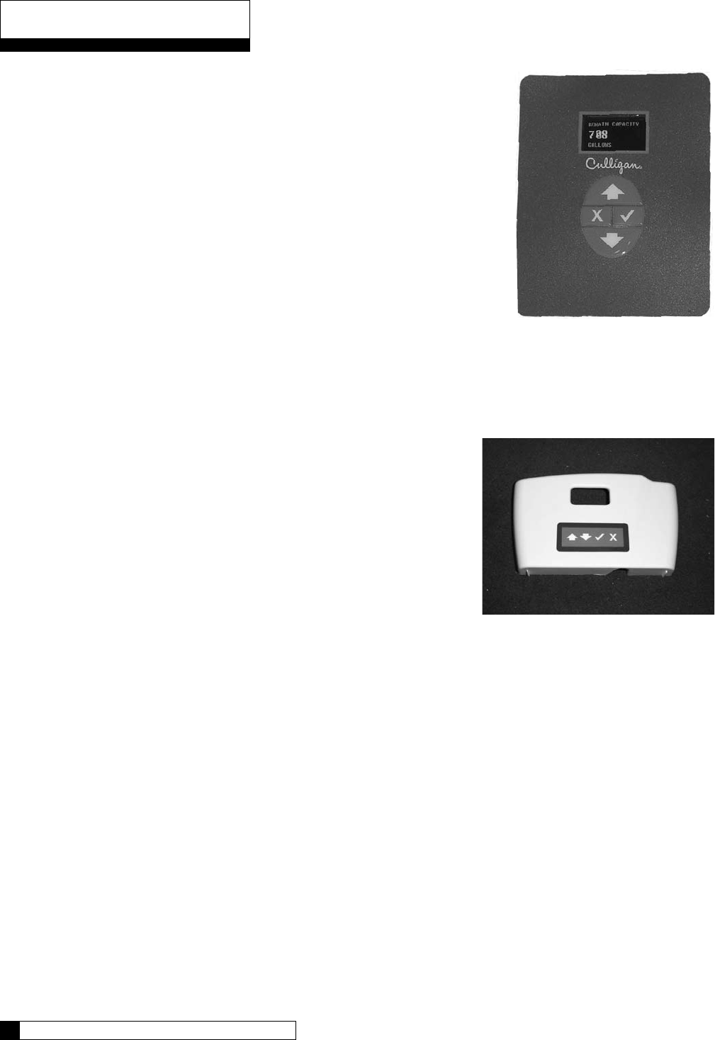
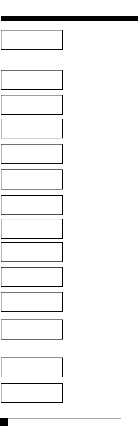
GBE Controller Features
Advanced Lighted OLED Display
The user is guided through brightly lit graphical menu screens
with clear, multi-line, full text prompts
Membrane Keypad
The keypad uses sealed contacts for programming. No buttons to get dirty
Program Beeper
Emits an audible beep when keys are depressed to help identify
valid (short beep) or invalid (3 short beeps) pushes. Can be
enabled or disabled.
Power Source
Electrical power required is 24 Volt 50/60 Hz AC current. A UL
listed plug-in transformer (120V/24V) is provided.
Time of Day
Displays current time of day in either 12-hour or 24 hour format
Real Time Clock with a 5 Year Battery Back-up
Keeps accurate time even during a power outage. Updates
automatically when the GBE is equipped with optional modem
capability
English or Metric Values
Displays can be set to either English or Metric
Regeneration Interval
Provides the ability to initiate a time clock regeneration based on a number of days (1 to 99) or a specific
day of the week.
Regeneration Start Delay
Allows a user determined number of hours (0-9) to be set for the purpose of increasing the amount of
time between regenerations in a multi unit installation.
Auxiliary Input
Capable of accepting a remote signal from a dry contact device such as an operator push button for the
purpose of initiating a regeneration sequence
Auxiliary Output on Alarm
Capable of sending a signal when an alarm/error is recognized
Expansion Board for Additional Outputs
o Control blocking valves
o Control external solenoids or chemical feeders
•
•
•
•
•
•
•
•
•
•
•
•
Controller Features
Figure 2
Figure 1

CONTROLLER FEATURES 2
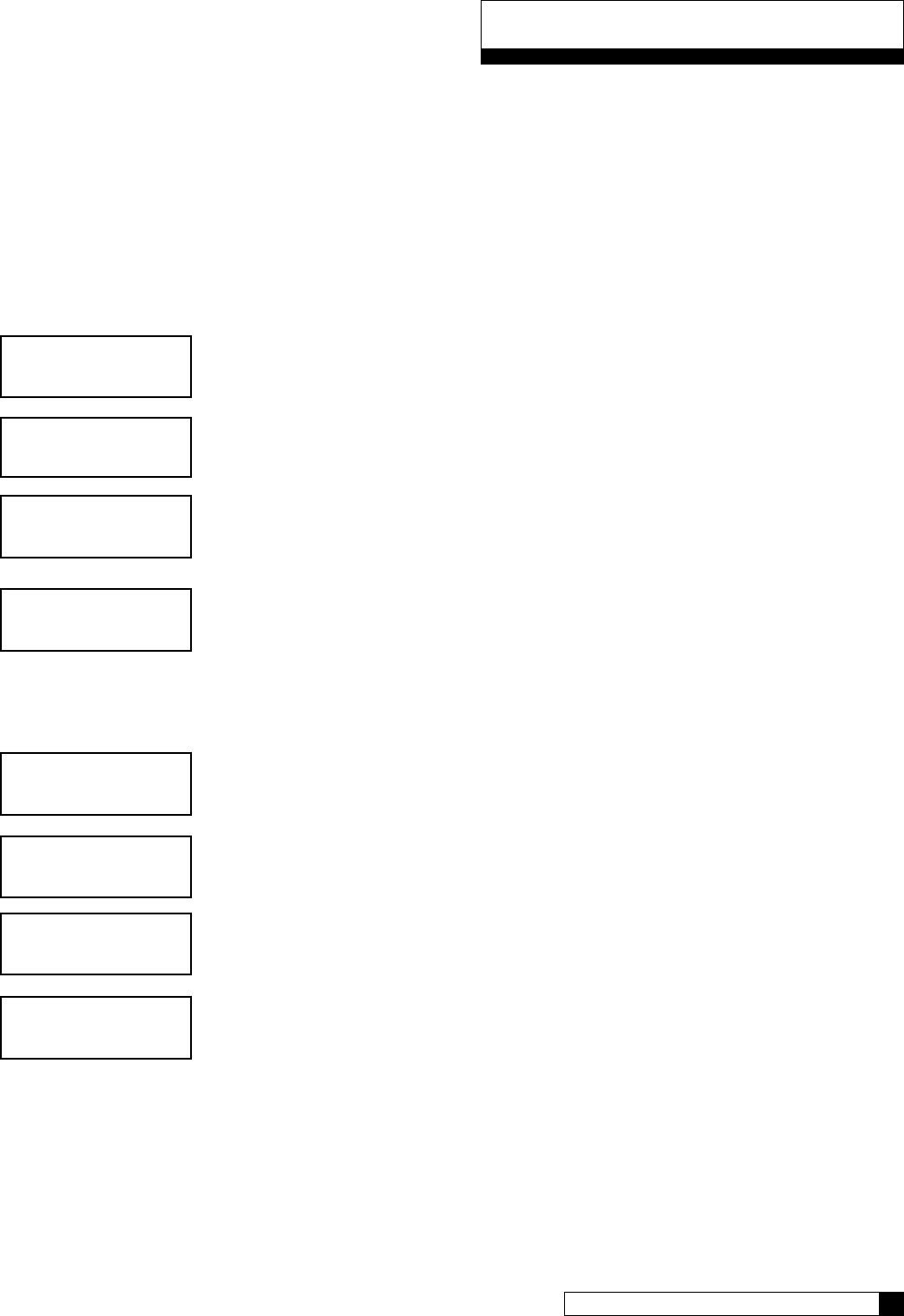
Progressive Flow Trip Point
Allows multiple tank systems operating with flow meters to bring tanks on-line or off-line as facility flow
demands increase or decrease
Multiple Unit Communication
A communication cable interconnects multiple units to operate the controller in the Progressive Flow
mode and prohibits them from regenerating at the same time.
Diagnostics
The user can check the operation of sensors, progressive flow communication, motor positions, or an
optional wireless display
Transformer is UL and CUL Listed
RoHS Compliant
Optional GBE Features
Flow Meter/Sensor Input
Supports various types of Hall effect flow sensors using a programmable “K” factor to initiate a
regeneration sequence
AquaSensor Input
Supports the patented digital Culligan AquaSensor technology used to efficiently initiate and control a
regeneration sequence
Telephone Modem
o Calls in reports on regenerations and alarm conditions
o Automatically updates time and date when calling in
o Automatically checks for and installs and firmware updates when calling in
Wireless Remote Display
Displays the current status of the unit. It can be located up to 200 feet away from the GBE controller
(depending on building and interference). The telephone modem can optionally be installed in the remote
display
Smart Brine Tank Probe
This probe monitors conditions inside the brine tank.
o Predicts when more salt is needed
o Detects the presence of a salt bridge
o Detects eductor line plugging
o Signals brine tank overfilling condition
•
•
•
•
•
•
•
•
•
•
Controller Features

Modes of Operation
Time Clock
The controller will initiate a regeneration based upon a time schedule of intervals of days (i.e., every 3 days) or
on a specific day of week schedule (i.e., Mondays, Wednesdays and Saturdays). Because regeneration will
occur at the prescribed schedule regardless of water use, this method is usually the most inefficient method of
water softener operation.
Flow Meter/Sensor
When a flow meter or sensor is connected to the controller circuit board, the controller has the ability to measure
the amount of water treated and initiate a regeneration sequence based upon the gallon capacity of the water
treatment equipment. The controller can delay the regeneration signal until a convenient time of day (known as
a delayed regeneration) or act and initiate the regeneration sequence as soon as the signal is received (known
as immediate regeneration).
When installing an alternating duplex system (one tank on-line, the other in standby), only one flow measuring
device is required to be installed in the common outlet header of the system. Parallel systems (multiple tank sys-
tems, all on-line simultaneously) require one flow device for each mineral tank in the system.
This method is a proven, cost effective means to operate a water softening system.
Aqua-Sensor (Softener use only)
The Aqua-Sensor detects when a softener resin bed has reached its point of exhaustion and, as a result, initiate
a regeneration sequence. This is the most cost-effective method of operation and may be combined with any of
the operational modes previously described.
Progressive Flow
The Progressive Flow mode is used with up to six and as few as two mineral tanks in a system. It allows more
than one tank in a system to either be on-line or off-line depending upon the downstream flow demand. If flow
demand is greater than the flow capability of the tank on-line, another tank can be brought on-line to help satisfy
the excess demand. Once the demand has decreased, the second tank is returned to a standby mode and the
system reverts to just one tank on-line providing treated water.
The progressive flow mode of operation relies on a user programmable set point or Trip Point. The Trip Point
is a unit of flow (gallons or liters) on a per minute basis. Once attained the trip point will cause the second unit
(in multiple resin tank system) to come on-line. Each additional tank in the system will subsequently be brought
on-line as multiples of the trip point are attained. (Example: a 3 tank system with a trip point of 50 gpm will bring
two tanks on-line once the facility flow demands is equal to or greater than the 50 gpm trip point. Should the flow
demand reach 100 gpm or more, the third tank shall be brought on-line.)
Additional tanks shall be returned to stand-by once the facility flow demand is <95% of the trip point for two
tank systems, <95% of 2X the trip point for triplex systems and <95% of 3X the trip point for quad systems, and
remains there for 60 seconds.
Utilizing the progressive flow feature may allow the owner to use smaller units, resulting in the potential for
reduced capital and operation costs.
Differential Pressure (Filters only)
When combined with an optional differential pressure device, the Culligan MVP controller has the ability to
initiate a backwashing sequence when the pressure differential across the media bed reaches a preset amount
(usually 8 to 10 psi).
Operation
Installation 4
3 CULLIGAN GLOBAL ELECTRONIC CONTROLLER

Installation
ELECTRICAL INSTALLATION
CAUTION!
Observe the precautions listed below before electrical installation of your GBE controller.
Failure to do so may cause permanent damage to the controller.
1. Follow the local electrical code requirements.
2. Be sure electrical power is off and disconnected at the source before completing any wiring/cabling
connections.
3. Provide a dedicated 120-volt circuit for the GBE system to ensure maximum electrical protection.
4. DO NOT include the GBE wiring cables in any conduit or raceway containing other 120-volt or higher
circuits.
5. Maintain a distance of at least 10 feet between the GBE controller and any electrical distribution
panels, raceways carrying 300 volts or more, and electrical motors of 1 horsepower or more.
6. Use the cabling provided. Failure to do so may effect performance of the GBE controller adversely.
Note: One transformer is required for each controller in the system. Do not attempt to operate multiple
controllers without a dedicated transformer for each or your system will experience operational
difficulties.
Installation 4
3 CULLIGAN GLOBAL ELECTRONIC CONTROLLER
WIRING PROCEDURES AND DIAGRAMS
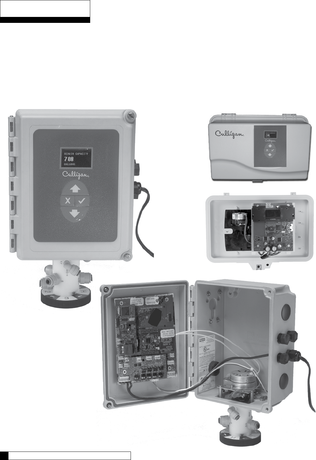
Preparation
1. Loosen the screws or latches securing the controller access cover (Figure 3 or 4) on each controller
provided.
2. Using a small screwdriver, loosen all the terminal strip binding screws on the main circuit board that do
not contain wires by turning counterclockwise until the wire clamp has been fully opened (see Figure 5).
Installation
Figure 3
Figure 5
Installation 6
5 CULLIGAN GLOBAL ELECTRONIC CONTROLLER
Figure 4
Installation
Cable Routing
All input and output connections to the circuit board are 24 volt or less.
Although the cables do not have to be run in conduit, it is necessary that long runs of cable be supported or
protected by strapping them to the equipment piping. If conduit will be used to route the shielded cables, three
factors must be considered:
1. DO NOT share the same conduit or raceway with 120 volt or higher circuits.
2. Keep cables at least 6 inches away from 120 volt or higher electrical circuits.
3. GROUND the conduit (if metallic) to a known “earth ground” location.
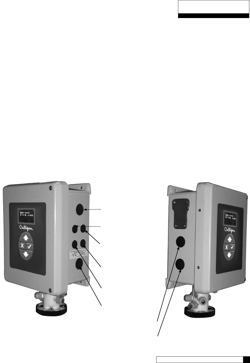
A series of holes are located on the sides of the controller (see Figure 6 and 7). Strain relief fittings are provided
with the controller enclosure for interconnecting wiring. Install the plastic fittings as needed. Remove the com-
pression nut and rubber sleeve from each fitting. Prior to connection of the cable wires to the circuit board, slide
the compression nut and sleeve over the cable for the wiring connections. When wiring is completed, apply a
small amount of silicone to the rubber sleeve and reassemble. This will assure all wiring is secure and assist
in making the tightening of the fitting easier. Insert the plugs provided to block any holes not used for wiring or
other accessories.
Right Side View
Brine Reclaim Solenoid
(optional)
Input Connection
for Flow Sensor
Output Connection
for Remote
Accessories
Input Connection
for Remote
Accessories
24 Volt Power
Input Connection
Brine Reclaim Solenoid
(optional)
Brine Refill Valve
Blocking Solenoid for
Alternating Operation
Left Side View
Figure 6 Figure 7
Installation 6
5 CULLIGAN GLOBAL ELECTRONIC CONTROLLER
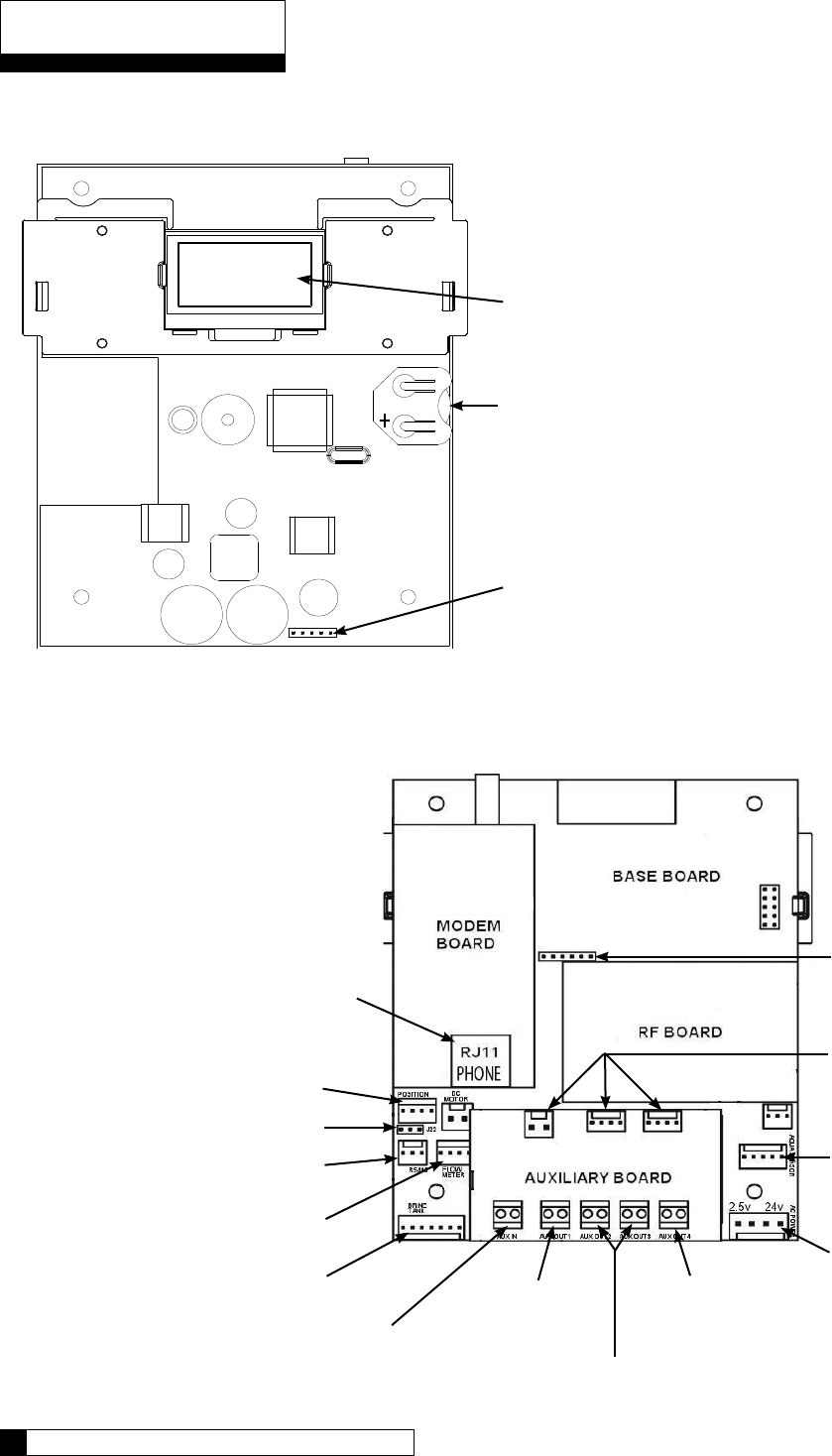
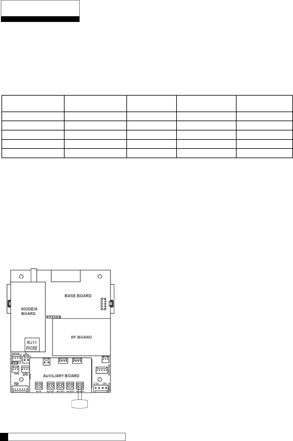
GBE Circuit Board Layout–Front
Keypad connector
Battery
CR2032 (Postitive Side Up)
Schematic
OLED Display
Phone line
connection
(optional)
GBE Circuit Board Layout–Back
Figure 8
Motor position cable
Multiple unit jumper
Communication cable (optional)
Flow meter cable
(optional)
Smart Brine Tank cable (optional)
External regeneration
signal connection (optional)
Motor
connection
Programmable outputs (optional)
Blocking valve
connection (optional)
Power cable
from transformer
Aqua-Sensor
cable (optional)
Future use
Do not connect
anything to these.
Data port
Figure 9
Schematic 8
7 CULLIGAN GLOBAL ELECTRONIC CONTROLLER
CAUTION
Connecting 24V to the 2.5v
connection on the circuit board
will damage the circuit board.
Outputs
The circuit board supports four outputs:
• Motor control (DC Motor)
• Blocking valve (Use Aux Out 4)
• Four programmable auxiliary outputs (Aux Out 1
through 4)
• Controller interface (communication between mul-
tiple controllers) (RS485).
Note: If you are using Aqua-Sensor, you should run the 2.5v wiring now as the cable is run through the same cord grip.
See page 15 for details.
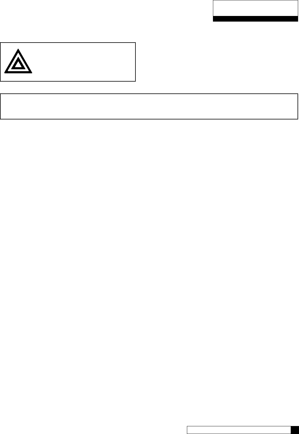
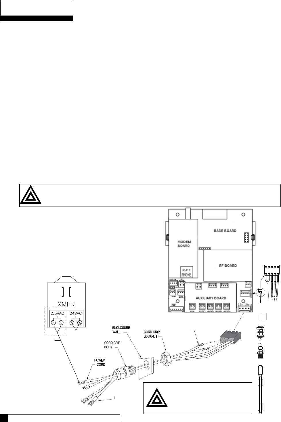
1. Locate the power cord among the controller parts. It has a white connector on one end and two spade connectors on the
other.
2. Locate the cord grip among the parts.
3. To assemble the power cord, first run the cord grip nut over the spade terminal end of the power cord.
4. Next, run the spade terminals through a hole in the side of the controller FROM THE INSIDE. See figure 10.
5. Finally, run the cable through the bottom end of the cord grip, and assemble the grip to the controller wall.
6. Plug the board connector to the board where it says “24v”. The connector has four (4) connections but only two wires are
connected. The other end of the power cord (with spade terminals) should be connected to the two 24VAC terminals on
the transformer (see figure 12).
DO NOT PLUG THE TRANSFORMER INTO THE WALL UNTIL ALL WIRING IS COMPLETED.
Repeat the process for any additional units in the system.
Schematic 8
7 CULLIGAN GLOBAL ELECTRONIC CONTROLLER
Schematic
24V Transformer
The GBE control is powered by a 24V/50VA transformer. If there are multiple controls in the system being
installed, each control will require its own transformer. It is recommended that the transformer be plugged into a
dedicated 120V circuit.
CAUTION
Connecting 24V to the 2.5V connection on the circuit board will damage the circuit board
1. Connect one wire from the 24V cable to the outermost 24VAC transformer screw terminal
(Reference Figure 12). The other end of the wire should be connected to one of the 24V terminals
on the GBE control circuit board (Figure 11) by way of the white connector.
2. Repeat the process for the other 24V power supply wire attaching the second wire to the opposite
terminal on the transformer and next to the other wire connected to the 24V pins on the GBE board.
Schematic
Figure 11
POWER SUPPLY
ONE transformer is required for each Control
Figure 12
2.5VAC Aqua-Sensor
Power Terminals
24VAC Power
Terminals
METAL TABS
Connect to white connector
on main power cord
If using Aqua-Sensor,
plug metal tabs at end
of cord into connector
24V Power Connection
Figure 10
Schematic 10
9 CULLIGAN GLOBAL ELECTRONIC CONTROLLER
Transformer connection
Schematic 10
9 CULLIGAN GLOBAL ELECTRONIC CONTROLLER
Schematic
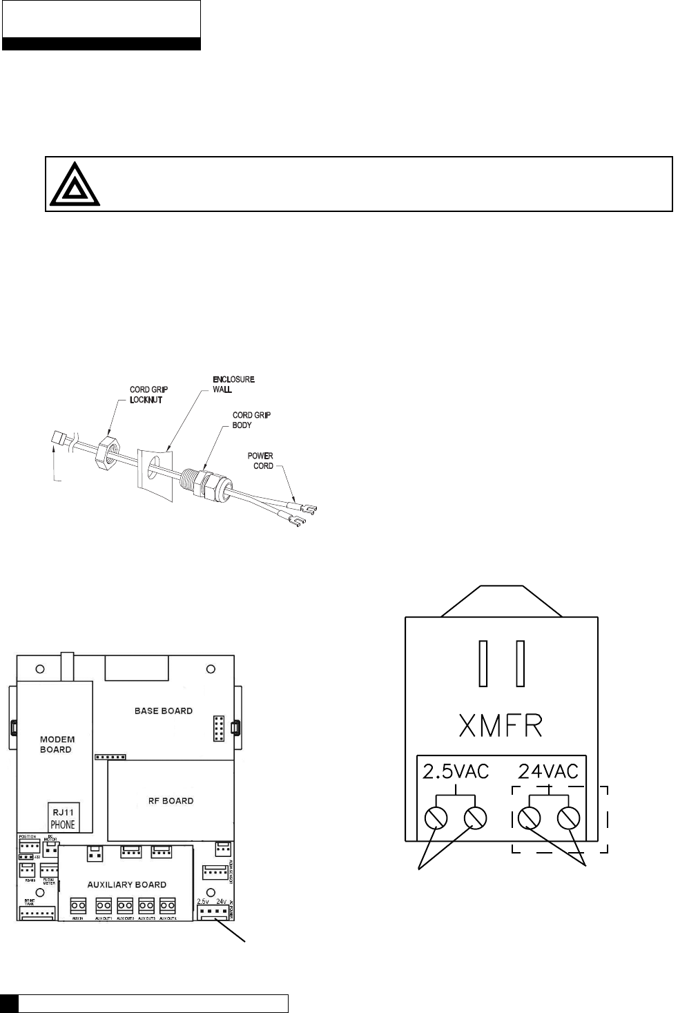
Brine Refill Valve Wiring
*This only applies to Culligan CSM Softeners.
1. Installation of the solenoid coil and connector
Locate the solenoid coil and connector cord. Assemble it
to the brine refill valve as shown in Figure 13.
2. Installation of the cord grip
Remove the hole plug from the left side of the MVP
controller enclosure. Locate the cord grip fitting and nut.
Assemble them through the open hole and thread the
solenoid coil cord through the cord grip fitting as shown
in Figure 14. Tighten the cord grip onto the cord.
3. Wiring
Wire the valve to Aux Out 2 as shown in the diagram in
Figure 15. The wires can be trimmed to a suitable length.
Solenoid
Coil
Screw Plastic
Spacer
2.5VAC
P9 Power
24VAC
Vlv
Aux1
Sol
P7 Aux2
P8P5
Cam
P1 P10
Snsr
Aqua Meter
P4
Flow In
P2
Aux
LCD
TRIM OFF
GREEN WIRE
BLACK
WHITE
REFILL
SOLENOID
VALVE
CIRCUIT BOARD
MVP
Figure 13
Figure 14
Figure 15
Communication Cable - Multiple Units
NOTE: Disregard this information and proceed to flow sensor schematic (optional) information when installing
single tank configurations.
Multiple units require a communication cable between each unit. Refer to the table below for the cable type, part
number and quantity required. Cables are attached to the RS485 terminal of the circuit board.
Table 2
System
Configuration
Cable Part Number Qty of Cables
required
“Kit” Part Number Qty of blocking
solenoids used.
Duplex Alternating 01016342 1 01016369 2
Duplex Parallel 01016327 1 N/A 0
Triplex Parallel 01016327 2 N/A 0
Duplex Progressive 01016327 1 01016333 2
Triplex Progressive 01016327 2 01016334 3
Multiple units can be set up as progressive flow, alternating or parallel operation. Refer to the instructions and
schematics below and on the following pages for connection to the circuit board.
Most multiple tank configurations will also require blocking valves (with the exception of the Hi-Flo 3e softener).
These are used to hold tanks offline until needed. Based on the chart above, you can determine how many
blocking solenoids are used. These solenoids are included in the alternating and progressive flow kits.
Blocking Solenoid Connection (used on Alternating and Progressive flow systems)
The solenoid valve wiring attaches to the Aux Out 4 output connection on the auxiliary circuit board. See
Figure 16 .
Schematic
Schematic 12
11 CULLIGAN GLOBAL ELECTRONIC CONTROLLER
SOL
Figure 16
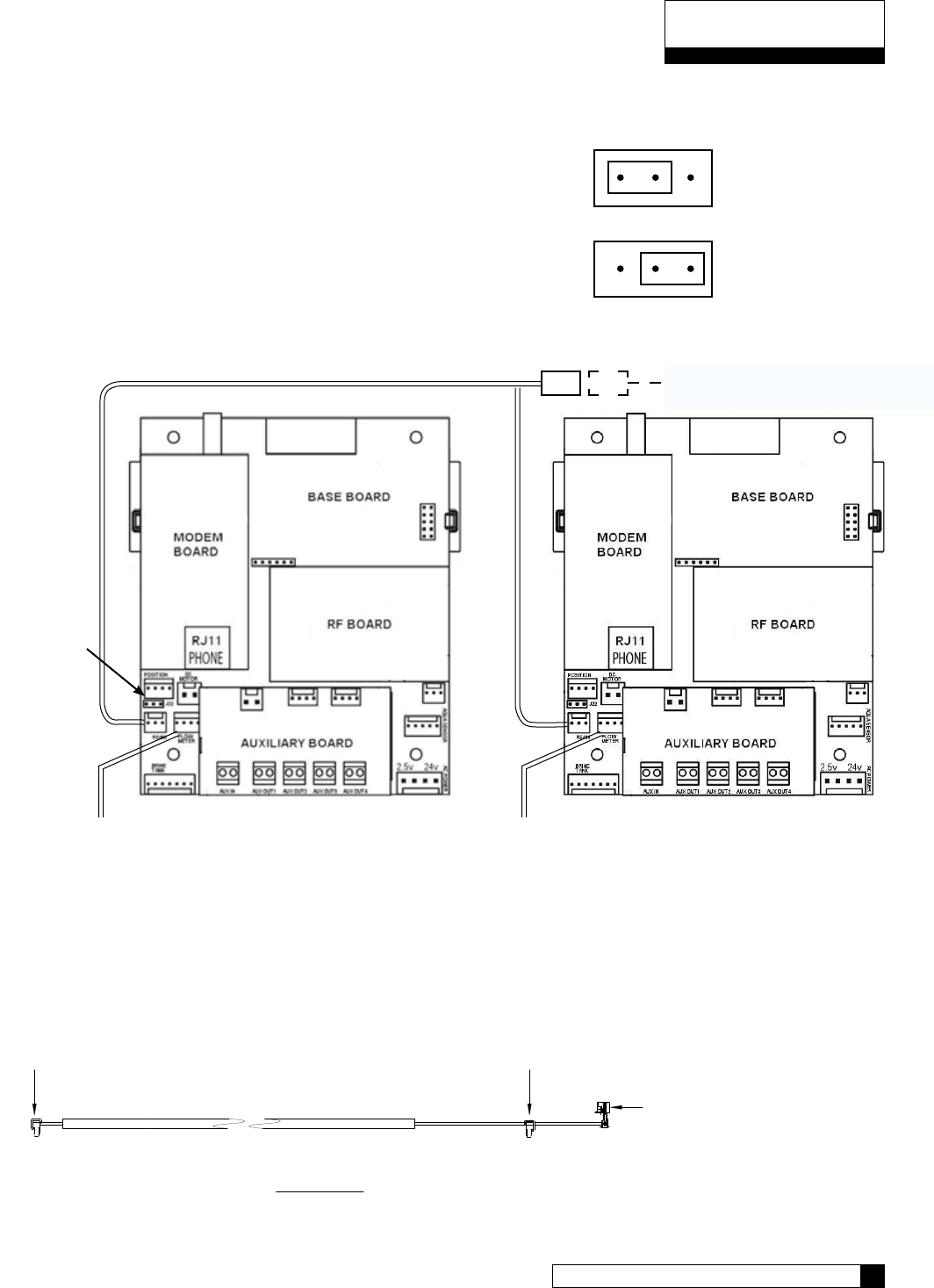
Progressive Flow or Parallel Flow
IMPORTANT
Setting the Jumpers for Progressive Flow
For progressive flow to operate properly, the first and last units must
have the jumpers set to pins 1 and 2 (see figure at right). All middle
units should have the jumpers on pins 2 and 3 (see figure at right).
The diagram below (figure 17) shows duplex connections. Repeat the
connections on any additional systems.
Progressive/Parallel Communication Cable 01016327
Schematic 12
11 CULLIGAN GLOBAL ELECTRONIC CONTROLLER
Schematic
To RS 485 Comm Port
on GBE Circuit Board, #1
CABLE 01016327
To RS 485 Comm Port
on GBE Circuit Board, #2
PARALLEL
Additional communication cable
connections are used when there
are 3 or more controls. Connect
end of 2nd-(01016327) cable
to this connector and other end of
cable to RS 485 Comm Port on
3rd GBE Circuit Board.
To Additional Units
(if necessary)
Communication Cable 01016327
Jumper
Location
Figure 17
Flow Meter Flow Meter
Unit 1 Unit 2
Jumper location for
first and last units
(end units).
Jumper location for
middle units.
1 2 3
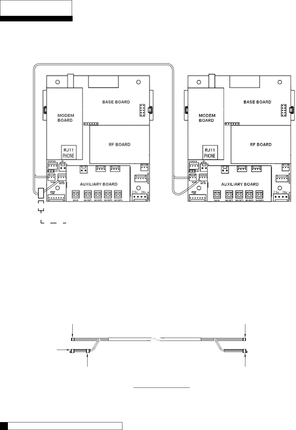
Schematic
Schematic 14
13 CULLIGAN GLOBAL ELECTRONIC CONTROLLER
To RS 485Comm Port
on GBE Ciruit Board, #1
To Flow Meter Connection
on GBE Circuit Board.
CABLE 01016342
Flow Meter Connector
(from meter).
To Flow Meter Connection
(on GBE Circuit Board).
To RS 485Comm Port
on GBE Ciruit Board, #2
DUPLEX ALTERNATING
Duplex Alternating with Meter option
For triplex, quad, etc alternating, you must use a meter on each unit and connect the same way as
progressive flow.
Duplex Alternating Cable 01016342
Communication Cable 01016342
Figure 18
Unit 1 Unit 2
Flow meter
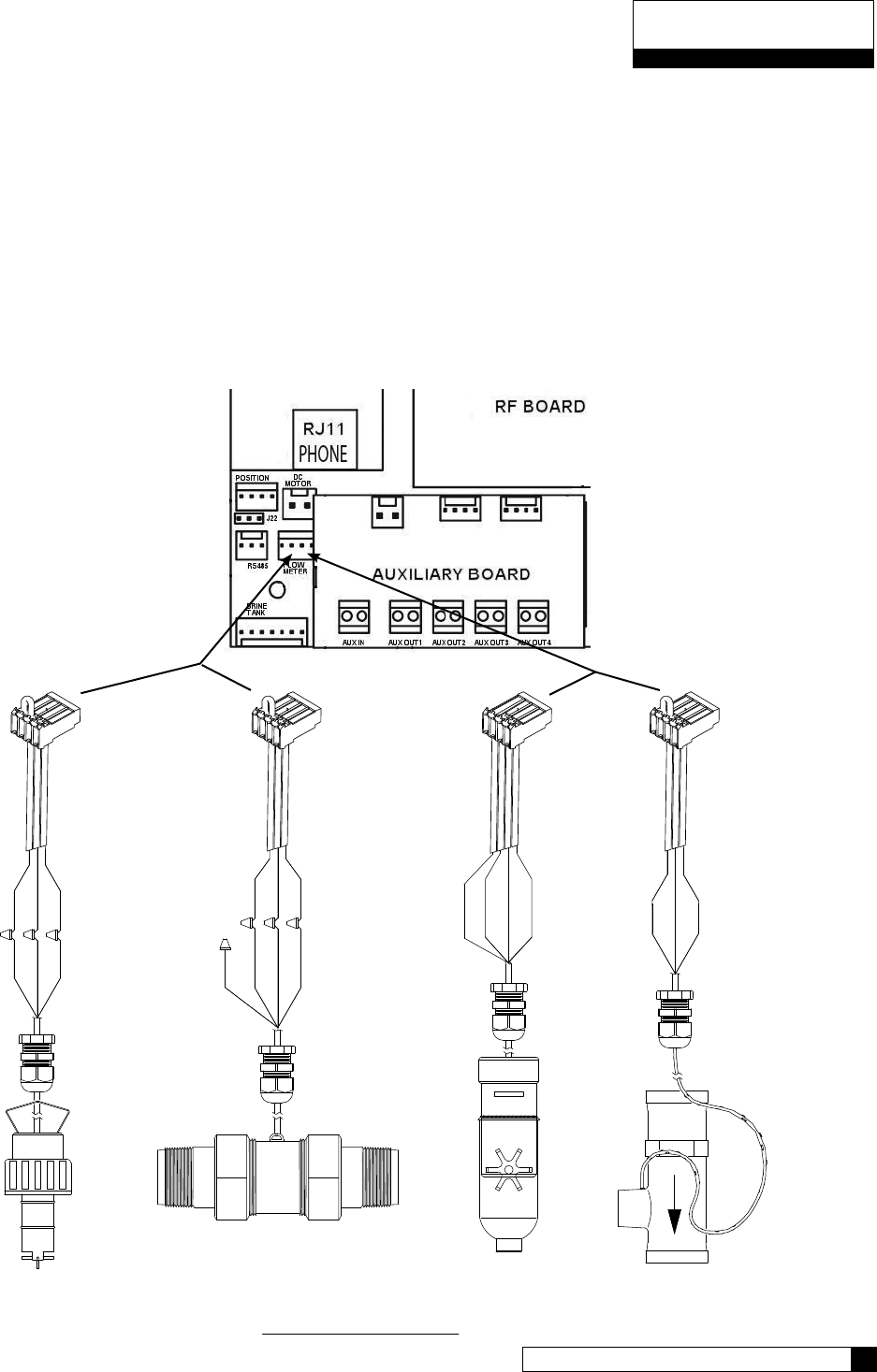
(optional)
2535 & 2536
Signet
Black
Shield
Red
Black
Green
Red
Paddle Wheel
(optional)
Seametrics
Green
Red
Black
White
SINGLE OR PROGRESSIVE
Bare
Red
Green
Black
Red
Black
Wht/Clear
2" Autrol Turbine Meter
(optional)
Black
White
Red
2"Clack Meter
(optional)
Schematic 14
13 CULLIGAN GLOBAL ELECTRONIC CONTROLLER
Schematic
Flow Sensor Meter Connections (Optional)
The GBE Controller is capable of detecting the signal from a Hall effect sensor device to provide flow rate infor-
mation, totalization and volume based regeneration initiation.
There are several different types of flow measuring devices and differences in the wiring of the devices to the
GBE circuit board do exist. Refer to the drawings below.
For all but duplex alternating, a meter needs to be connected to each circuit board at the location shown below
in the drawing. For duplex alternating meter connection, please refer back to page 13, Duplex Alternating with
meter option.
SEE PAGE 41 FOR PROGRAMMING AND PAGE 63 FOR K FACTORS.
Figure 19
Connector
located at
end of meter
cable
Connector
01010255 included
with controller
2.5V
METAL TABS
Connect to white
connector on main
power cord
24VAC
on TRANSFORMER
Power to circuit
board 2.5VAC
only required
for Aqua-Sensor
installations
Power to circuit
board 24V
Schematic
Schematic 16
15 CULLIGAN GLOBAL ELECTRONIC CONTROLLER
Aqua-Sensor Schematic (Optional)
The Aqua-Sensor device requires a 2.5 VAC power source. This source is provided via two of the posts on the
24VAC/2.5VAC transformer (see figure 20). The two leads from the transformer are run through the same cable
grip as the 24VAC and then must be pushed into the white power connector for connection to the 2.5v power
pins on the GBE circuit board.
The wire connector from the Aqua-Sensor probe is then routed through the included cable grip and plugged into
the Aqua-Sensor terminal on the GBE circuit board. See below.
Aqua-Sensor
If you are going to install an Aqua-Sensor, you can set up the 2.5V power now.
1. Locate the power cord packed with the Aqua-Sensor. It has two spade terminals on one end of the cable
and two metal “slip in” tabs on the other.
2. Locate the cord grip.
3. The cable can be run through the cable grip and wall from either end of the cable. Make sure the end with
the metal tabs goes INSIDE the controller. The spade terminals should be coming out the top end of the
grip.
4. Locate the connector at the end of the power cord. You may have already plugged it into the board.
5. Press the two metal tabs on the end of the power cord into the open slots on the connector. They will con-
nect to the pins labeled “2.5V’ on the Base Board.The other end of the power cord with the spade terminals
should be connected to the two 2.5VAC terminals on the transformer (see figure 20).
CAUTION - Verify wiring from terminals to circuit board are correct before applying power to
control. 24vac power must not be applied to the 2.5 vac terminals of the circuit board.
POWER SUPPLY
ONE transformer is
required for each Control
Figure 20
CAUTION
Connecting 24V to the 2.5V
connection on the circuit board
will damage the circuit board.
2.5V Aqua-Sensor Power Connection
Red
Black
Blue
White
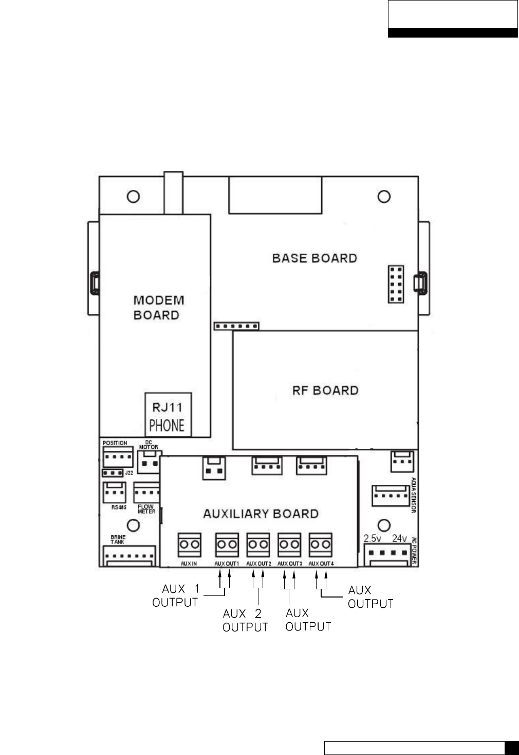
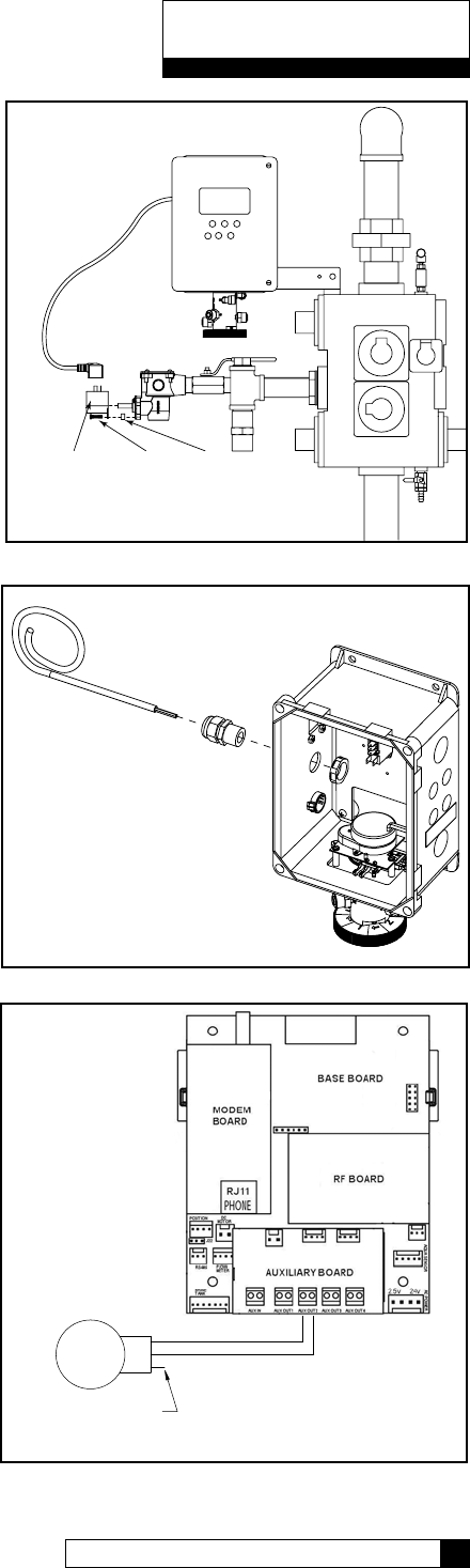
Auxiliary Outputs (Optional)
The Auxiliary Outputs - reference Figure 21) are output triacs that can be programmed to provide power to a
“normally open” (normally no power to auxiliary output until power required) or a “normally closed” contact (user
choice). These 24VAC outputs can be used for energizing a relay coil only. (2.1 Amp maximum power draw)
Refer to the section on Programming (page 46) for additional information on the uses of this feature.
3
4
Schematic 16
15 CULLIGAN GLOBAL ELECTRONIC CONTROLLER
Schematic
Figure 21
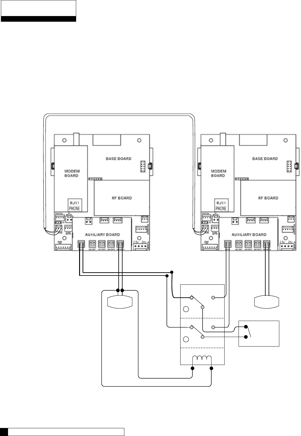
Auxiliary Input (Optional)
One auxiliary input is provided for optional signal devices such as remote push buttons, differential pressure
switches, hardness monitors, turbid meters, etc. for the purpose of receiving a regeneration signal.
Select an UN-POWERED contact within the remote device that will close when regeneration is desired. The
duration of the switch closure can be as low as 0 seconds; 6 seconds is the recommended minimum and default
but can be as long as 999 seconds. The contact must automatically open following the start of a regeneration
sequence. Connect this contact to the Aux In terminal shown in Figure 22. The illustration below is an example
of how to use an external source to initiate regeneration.
NC NO
1
POLE
NC NO
2
POLE
C
C
SOL
Regen Signal
EXTERNAL
SOURCE
24V DPDT
RELAY
DUPLEX ALTERNATING WITH EXTERNAL SOURCE
SOL
Communication Cable
01016327
Figure 22
Schematic
Programming 18
17 CULLIGAN GLOBAL ELECTRONIC CONTROLLER
Programming
The programming process requires various types of data input. The following information pertains to calculating
the softening capacity of the water softening system. Filters do not have a capacity setting so this section can be
skipped when programming a filter.
Capacity Settings
The capacity of a water softener is determined by two factors; resin amount and water chemistry.
Single Tank Systems
Normally a single tank system has enough resin capacity to soften water for a minimum period of 24 hours.
Time of regeneration is usually set to occur very early in the morning or at a time when no softened water is
required. This is because when the softener is regenerating, hard water is typically bypassed through the system
and into the facility if a demand for water if present.
If regeneration is desired at a time of day when there is no water usage then the system must have a “reserve”
capacity which must last an entire day if the regeneration signal (time clock, Aqua-Sensor and/or meter) occurs
at the beginning of the day. Subtract this reserve capacity from the total capacity to determine “capacity to signal”.
Note: If the reserve capacity is more than 1/3 of the total capacity,
a meter system may not reduce salt consumption relative to
a timeclock system.
Multiple Tank Systems
Multiple tank systems offer the benefit of continuous soft water supply. When using the Aqua-Sensor to initiate
a regeneration sequence, the system capacity may be set for the maximum amount the system is capable of
producing. However multiple tank systems using only water meters and or time clock as the basis for regenera-
tion initiation are recommended to be set up with a 10% reserve capacity. The purpose of the reserve capacity
in multiple tank systems is to allow for subtle changes in water chemistry. You will be able to get the reserve
capacity during programming.
Determining Batch Set Point
To determine the batch set point for programming the Culligan GBE controller, use the following formula:
Total Capacity - Reserve Capacity
Gallons = Hardness
The GBE will calculate this for you automatically. you can use the formula above to verify the setting.
For more information on programming multi-tank systems, see page 41.
Programming
Programming 18
17 CULLIGAN GLOBAL ELECTRONIC CONTROLLER

Program Data Input
There are a couple of items to note that can make the programming of the Culligan GBE control a little easier.
They are:
Slew Rates This term refers to the speed at which the display moves through the input of material. For
example, holding down the up arrow key for (5) seconds when inputting minutes for Time
of Day will cause the minutes to pass in (10) minute blocks of time. Press the up arrow
or down arrow keys for shorter periods (less than 5 seconds) will slow the rate. To move
through the programming slowly, do not hold down the up arrow or the down arrow keys.
Beeper A beeper is available to assist the user by providing an audible tone (about 70 decibels) to
signify valid (0ne beep) and invalid (three beeps) key presses. The beeper can be deac-
tivated in the programming mode. (If error occurs, beep will still be ON even if set to “No”
programming.)
Programming
Mode Timeout
If there is no keypad activity for a (3) minute period while in the programming mode, the
controller will exit the programming mode and return to the main display. Any setting that
was changed prior to the control timing out will revert back the original value. Pressing the
check mark key saves the setting.
Program Input
Acceptance
For programming information to be accepted, the check mark key must be depressed prior
to programming mode timeout.
Programming
Navigating the Menus and Keypad 20
19 CULLIGAN GLOBAL ELECTRONIC CONTROLLER
Navigating the Menus and Keypad 20
19 CULLIGAN GLOBAL ELECTRONIC CONTROLLER
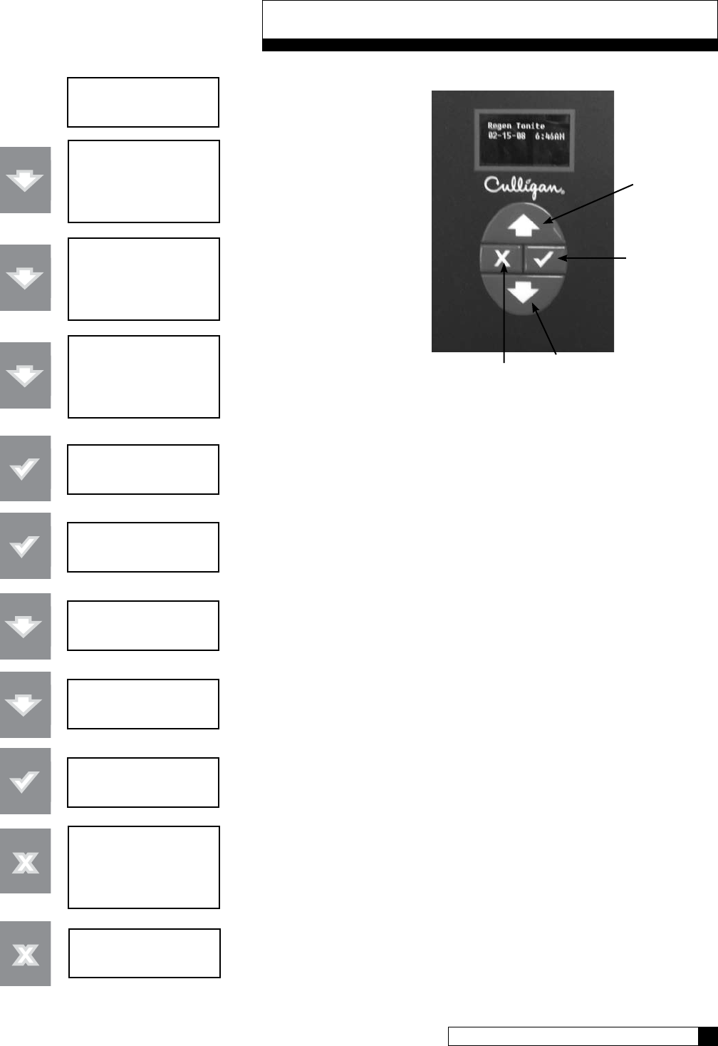
Navigating the Menus and Keypad
system ok
9:17 am 1-17-08
> 1) information
2) bypass
3) regenerate
4) set time and date
1) information
> 2) bypass
3) regenerate
4) set time and date
1) information
2) bypass
> 3) regenerate
4) set time and date
regeneration
off
regeneration
> off
regeneration
> now
regeneration
> tonite
regeneration
tonite
> 1) information
2) bypass
3) regenerate
4) set time and date
regeneration tonite
9:18 Am 1-17-08
This is the “home” screen.
Press any key except
CANCEL (“x”) takes you to
the main menu.
This is the main menu. The
pointer shows where you are
in the menu. The UP and
DOWN arrows move thru
the menu.
Pressing the CHECKMARK key
selects that item on the menu.
Here we see the current value for “regeneration”
is “OFF”. Press the CHECK MARK turns on the
pointer symbol. The pointer indicates that you
can change the current value using the arrow
keys.
The arrow keys allow you to scroll thru the
available options.
Pressing the CHECK MARK key to select the new
setting. The pointer symbol turns off to show this
is the selected value.
Pressing the CANCEL button from inside the
menu always takes you one step closer to the
“home” screen.
Now we are back to the home screen. Note that
the display has changed to show that regeneration
is now scheduled for tonight.
DOWN button
CHECK MARK
or OK button
UP button
CANCEL button

Programming 22
21 CULLIGAN GLOBAL ELECTRONIC CONTROLLER
GBE Controller Programming
The programming for the GBE controller is all menu based. There are 5 top level menus with additional options
below each. The top 5 are:
1) INFORMATION
2) MANUAL MODE
3) SET DATE / TIME
4) ACCESSORIES
5) ADVANCED SETUP
Here is a brief explanation of what you will find under each menu
1) INFORMATION
Selecting this menu item will scroll through the operating information for the unit.
2) MANUAL MODE
Use this menu item to initiate a manual regeneration.
3) SET TIME / DATE
Use this menu item to make changes to the time and/or date. This is initially done during first time set up
and the information is saved in memory even in the event of a power outage.
4) ACCESSORIES
Use this menu item to set up any installed accessories. This includes meters, Aqua-Sensor, Smart Brine
Tank probe, Modem, Wireless Remote, Aux In and Aux Outs.
5) ADVANCED SETUP
This menu item allows customization of the unit. There are 5 sub-menus which offer customization
settings.
1) SYSTEM SETUP
This menu allows customization of many of the initial setup information. Water Hardness, Iron,
Salt Type, Resin Volume are among the settings.
2) REGENERATION SETUP
This menu allows customization of the salt dosage, reserve capacity, regeneration time and
regeneration mode.
3) CYCLE TIMES
This menu allows customization of the units cycle times.
4) REGERATION TRIGGER
This menu allows customization of what can trigger regeneration, the regeneration interval,
predict mode and days of regeneration.
5) DIAGNOSTICS
This menu allows diagnostics to be performed on sensors, wireless, progressive flow, motor
control, data port, phone line (modem) and advanced statistics.
Programming

Programming 22
21 CULLIGAN GLOBAL ELECTRONIC CONTROLLER
Typical Commercial Setup
Setting up the GBE for a commercial installation requires a few additional steps. Follow the outline below to
make sure everything is covered.
1) Run the first time setup (see pages 24 to 27)
2) Set up accessories (see pages 33) This includes:
• Water Meter (remember to set K Factor)
• Aqua-Sensor
• Aux In
• Aux Outs (needed for multi-tank, brine reclaim and refill on 4-cycle valves)
• Smart Brine Tank Sensor
• Wireless Remote
• Modem
• Service Phone
• External Filter
3) You must tell the controller if it is a multi-tank system. This is under Advanced Setup/System Setup (see
pages 29). The MultiTank System setting is set to PROG FLOW for ALL multi-tank systems. Trip point
settings will determine how unit operates (progressive, parallel or alternating - page 42).
4) If you are using immediate regeneration, you must change the Reserve Capacity setting under Advanced
Setup/REGEN SETUP and the REGEN MODE. See pages 30.
5) Set/Review Cycle Times – This is under Advanced Setup/Cylce Times. Especially check the Brine Draw/
Slow Rinse (BD/RINSE) and the Fast Rinse. 5-cycle valves have separate refill. See pages 31.
6) You need to do this setup procedure on each control in the system. You may want to write down
the settings you change.
7) Refer to Appendix D for a quick programming chart.
Programming
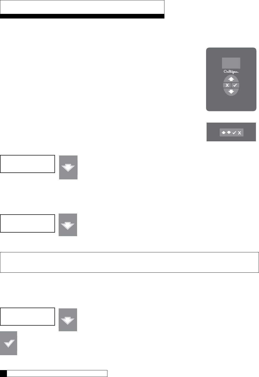
First Set-up Procedure
If at any time you need to re-run First Time Setup - refer to instruction on page 58.
After completing the plumbing connections to the water softener, follow these steps to turn
on and program the softener controller.
STEP 1: Plug in the wall transformer
STEP 2: Perform the on-display “First Time Setup” process (below)
„ Moves up the menu
‰ Moves down the menu
P Changes the display, accept desired change
X Cancel or exit
1. When a new controller is first turned on, the display shows the following:
Press the down arrow to move tot he next question.
2. Electronic Serial Number
S/N: 00000123
This screen is very important as it shows the electronic ID number of the controller.
Note: If this unit will be installed with a modem, it is required that this electronic ID number
is reported back to Culligan on the IQR form.
Press the DOWN arrow button to change the display to read “Set Month”.
3. Set Month
• If the default selection is correct, press the DOWN arrow to accept that value and move to the next
question.
• If the value displayed is NOT correct then press the CHECK MARK button to change the display to
show a “>” symbol next to the displayed value.
First Time Setup Process
Controller
Remote
Set Month
Jan
First Time Setup
Hit Down Arrow
First Time Setup Process 24
23 CULLIGAN GLOBAL ELECTRONIC CONTROLLER
First Time Setup Process 24
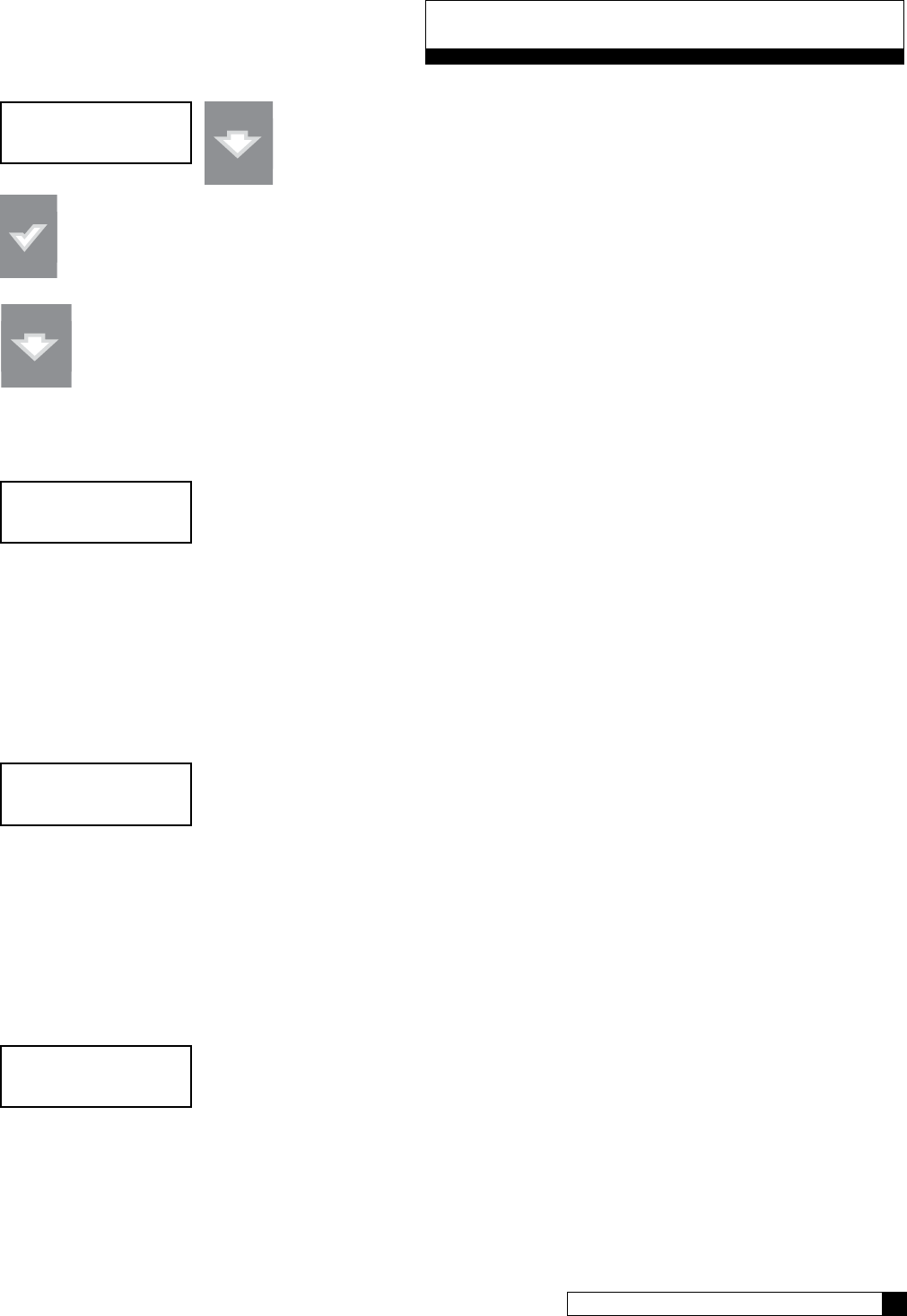
23 CULLIGAN GLOBAL ELECTRONIC CONTROLLER
• The “>” symbol indicates that this value may be changed by pressing the
UP and DOWN arrow buttons. For example, pressing the DOWN arrow
while the “>” mark is displayed changes the display from “JAN” to “FEB”.
• Once the desired value is displayed accept the value by pressing the “CHECK MARK” button.
Press the DOWN arrow to accept that value and move to the next question.
4. Set Day
Set Day
1
• If the value displayed is NOT correct, pressing the “CHECK MARK” button will change the display, to show
a “>” symbol next to the displayed value. Use the UP or DOWN arrow to change the setting. Once the
desired value is displayed, this value can be accepted by pressing the “CHECK MARK” button.
Press the DOWN arrow to accept that value and move to the next question.
5. Set Year
Set Year
2008
• If the value displayed is NOT correct, pressing the “CHECK MARK” button will change the display, to show
a “>” symbol next to the displayed value. Use the UP or DOWN arrow to change the setting. Once the
desired value is displayed, this value can be accepted by pressing the “CHECK MARK” button.
Press the DOWN arrow to accept that value and move to the next question.
6. Set 12 Hour or 24 Hour Clock
12 hr or 24 hr clock
12
• If the value displayed is NOT correct, pressing the “CHECK MARK” button will change the display, to show
a “>” symbol next to the displayed value. Use the UP or DOWN arrow to change the setting. Once the
desired value is displayed, this value can be accepted by pressing the “CHECK MARK” button.
Press the DOWN arrow to accept that value and move to the next question.
First Time Setup Process
Set Month
> FEB
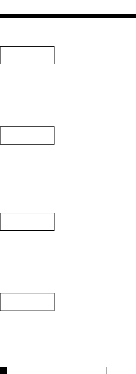
7. Set Hour
Set hour
7
• If the value displayed is NOT correct, pressing the “CHECK MARK” button will change the display, to show
a “>” symbol next to the displayed value. Use the UP or DOWN arrow to change the setting. Once the
desired value is displayed, this value can be accepted by pressing the “CHECK MARK” button.
Press the DOWN arrow to accept that value and move to the next question.
8. Set Minute
Set minute
32
• If the value displayed is NOT correct, pressing the “CHECK MARK” button will change the display, to show
a “>” symbol next to the displayed value. Use the UP or DOWN arrow to change the setting. Once the
desired value is displayed, this value can be accepted by pressing the “CHECK MARK” button.
Press the DOWN arrow to accept that value and move to the next question.
9. Set AM or PM
Set am or pm
7:32 am
• If the value displayed is NOT correct, pressing the “CHECK MARK” button will change the display, to show
a “>” symbol next to the displayed value. Use the UP or DOWN arrow to change the setting. Once the
desired value is displayed, this value can be accepted by pressing the “CHECK MARK” button.
Press the DOWN arrow to accept that value and move to the next question.
10. Set Valve Type (4-cycle or 5-cycle)
valve type
4-cycle
CSM and Hi-Flo 50 are 4-cycle valves and Hi-Flo 22 and Hi-Flo 3e are 5-cycle valves.
• If the value displayed is NOT correct, pressing the “CHECK MARK” button will change the display, to show
a “>” symbol next to the displayed value. Use the UP or DOWN arrow to change the setting. Once the
desired value is displayed, this value can be accepted by pressing the “CHECK MARK” button.
Press the DOWN arrow to accept that value and move to the next question.
First Time Setup Process
First Time Setup Process 26
25 CULLIGAN GLOBAL ELECTRONIC CONTROLLER
First Time Setup Process 26
25 CULLIGAN GLOBAL ELECTRONIC CONTROLLER
11. Set Units (US-inch or metrics)
units
us-inch
• If the value displayed is NOT correct, pressing the “CHECK MARK” button will change the display, to show
a “>” symbol next to the displayed value. Use the UP or DOWN arrow to change the setting. Once the
desired value is displayed, this value can be accepted by pressing the “CHECK MARK” button.
Press the DOWN arrow to accept that value and move to the next question.
12. Set Softener or Filter
is this a softener or filter?
softener
• If the value displayed is NOT correct, pressing the “CHECK MARK” button will change the display, to show
a “>” symbol next to the displayed value. Use the UP or DOWN arrow to change the setting. Once the
desired value is displayed, this value can be accepted by pressing the “CHECK MARK” button.
Press the DOWN arrow to accept that value and move to the next question.
13. Set Water Hardness
water hardness
10 grains
• If the value displayed is NOT correct, pressing the “CHECK MARK” button will change the display, to show
a “>” symbol next to the displayed value. Use the UP or DOWN arrow to change the setting. Once the
desired value is displayed, this value can be accepted by pressing the “CHECK MARK” button.
Press the DOWN arrow to accept that value and move to the next question.
14. Set Softener Resin Volume
resin volume?
1.0 cu-ft
• If the value displayed is NOT correct, pressing the “CHECK MARK” button will change the display, to show
a “>” symbol next to the displayed value. Use the UP or DOWN arrow to change the setting. Once the
desired value is displayed, this value can be accepted by pressing the “CHECK MARK” button.
This value is found in the products installation manual in the specification table.
Press the DOWN arrow to accept that value and move to the next question.
First Time Setup Process
15. Setup is Complete
system ok
7:32 am 2-1-08
The circuit board microprocessor automatically calculates softener capacity. The control then automatically homes.
Contact your Culligan Man if the settings need to be customized.
First Time Setup Process
Customizing the Setup 28
27 CULLIGAN GLOBAL ELECTRONIC CONTROLLER
Note: For all commercial applications, you must adjust the cycle times. Most important is refill time. Refer to the
Brine System charts in the product’s installation manual for cycle settings.

Customizing the Setup 28
27 CULLIGAN GLOBAL ELECTRONIC CONTROLLER
The controller is designed to simplify the setup and installation process by making some default recommendations
during the Initial Setup. The default settings are designed to be appropriate for most common installations.
Default Settings
Downflow Brining2
Standard Mesh Resin1
Blue/Beige Eductor1
0.45 GPM Brine Flow Control1
0 PPM Iron1
> 40 psi water pressure1
NaCl Salt1
Time of Regen = 2:00 AM2
Regen Time = Delayed2
Dosage (calculated)2
Predict Mode ON3
30% Reserve Capacity2
Time Clock Backup = OFF3
Day-of-week Regen = OFF3
Pre-Rinse Mode = OFF1
1= these items are changed on the Main Menu / Advanced / System Setup Menu
2= these items are changed on the Main Menu / Advanced / Regen Setup Menu
3= these items are changed on the Main Menu / Advanced / Regen Trigger Menu
There may be times when the installer would prefer to override the default regeneration selections. See
Advanced Setup Menu, Regeneration Setup Menu or Regeneration Trigger Menu for information on changing
default selections.
Advanced System Set-up Menu
• Press the UP „ or DOWN ‰ arrow to scroll to menu item
• Press the CHECKMARK P key to select a menu item
• Press the UP „ or DOWN ‰ arrow to change a selection
• Press the CHECKMARK P key to save your selection
Default Values are shown for each selection
Scroll to ADV SETUP and select
Select SYSTEM SETUP
•
•
•
•
•
•
•
•
•
•
•
•
•
•
•
system ok
7:32 am 2-1-08
> 5) Adv Setup
> 1) system Setup
Customizing the Setup
The GBE controller can operate several types of valves. Select from 4-CYCLE, 5-CYCLE or GBV.
For Softeners: For Filters:
CSM and Hi-Flo 50 are 5-CYCLE All are 4-CYCLE
Hi-Flo 22 and Hi-Flo 3e are 4-CYCLE
The type of resin changes how the GBE calculates capacity. Select from STANDARD or FINE.
Unless you change from the standard Cullex®, leave this at STANDARD.
Enter the water hardness (softeners only). This can be from an onsite test or from a water analysis.
Enter in the units shown on screen. For US-INCH, enter the hardness in grains per gallon (gpg).
This does NOT APPLY to commercial valves. Leave this set to A.
Enter the amount of iron present. This value can come from an onsite test or a water analysis.
Enter the value in ppm (mg/l).
This setting is either ABOVE or BELOW 40 PSI. If the pressure is below 40 psi, the brine
rinse time will be extended. This can be overridden by setting the brine rinse time manually by
going to 5) ADV SETUP, then 3) CYCLE TIMES.
Either standard sodium chloride (NACL) salt or potassium chloride (KCL) salt can be used. The
GBE needs to know which type is being used.
Select either SINGLE tank or PROGRESSIVE. Selecting PROGRESSIVE implies a multi-tank
system. Please refer to page 41 for details on setting up a multi-tank system.
THIS CAN BE IGNORED FOR COMMERCIAL APPLICATIONS.
Enter the volume of resin in the tank. This information can be found in the product’s installation
manual on the specifications page. Enter in the units shown. For US-INCH, enter the value in
cubic feet.
Select either US INCH or METRIC units. This will change the units when entering programming
values such as resin volume and flow rates. If you change this to METRIC, please review your
input for accuracy.
Set this to ON or OFF. This setting will tell the unit to rinse to drain at the time intervals and
duration set.
IF PRERINSE MODE IS SET TO ON
Select a prerinse time value from 1 to 240 hours. This tells the unit to rinse to drain if no flow is
detected for this duration.
Select the number of minutes the unit should rinse to drain when the NO FLOW duration has
passed.
This concludes the Advanced System Set-Up Menu. Continue to press the X key to return to the Main Menu.
dial-a
softness a
iron
present 0 ppm
line pressure
above 40 psi
salt type
nacl
multitank system
single
Customizing the Setup
Customizing the Setup 30
29 CULLIGAN GLOBAL ELECTRONIC CONTROLLER
units
us inch
prerinse mode
off
rinse if no flow
>for 24 hours
rinse for
>5 minutes
brine refill flow
0.45 gpm
resin volume
1.00 cu/ft
valve type
4-cycle
resin type
standard
hardness gpg
25
Customizing the Setup 30
29 CULLIGAN GLOBAL ELECTRONIC CONTROLLER
Regeneration Set-up
• Press the UP „ or DOWN ‰ arrow to scroll to menu item
• Press the CHECKMARK P key to select a menu item
• Press the UP „ or DOWN ‰ arrow to change a selection
• Press the CHECKMARK P key to save your selection
Default Values are shown for each selection
Scroll to ADV SETUP and select
Select REGEN SETUP
This value is the salt dosage in pounds (LBS) for US INCH (total number of pounds of salt used
per regeneration). The salt dosage contributes to calculating the resin capacity and is also used
when a Smart Brine Tank Sensor is installed to help calculate salt usage and salt remaining. The
higher the salt dosage the higher the capacity. Refer to the appendix of the unit’s installation
manual for information on setting the salt dosage.
For example, for a CSM 300-2 (10 ft³ of resin), and a desired capacity of 250,000 grains, the
chart in the manual shows the dosage at 102 pounds.
This setting is generally used for a single-delay system. For a multi-tank system, reserve capacity is
not necessary and should be set to zero (0). If you do not change this value in a multi-tank system,
your unit will regenerate when 30% of the capacity remains.
This setting is used for time clock regeneration. This is the time of day that the unit will regenerate
when needed.
Select either DELAYED or IMMEDIATE. For multi-tank systems, this is normally set to
IMMEDIATE. If immediate is selected, be sure to change the Reserve Capacity setting.
Use this setting to prevent back-to-back regenerations on multi-tank systems, if necessary. When
one unit is done regenerating, the next regeneration cannot begin until the set amount of time has
passed.
This concludes the Regeneration Set-Up section. Continue to press the X key until reaching the Main Menu.
> 5) Adv Setup
system ok
7:32 am 2-1-08
> 2) regen Setup
salt dosage
9.0 lbs
reserve capacity
30%
Customizing the Setup
Time of regen
2:00 AM
regen mode
delayed
Regen lockout
for 0 hours
Cycle Times
• Press the UP „ or DOWN ‰ arrow to scroll to menu item
• Press the CHECKMARK P key to select a menu item
• Press the UP „ or DOWN ‰ arrow to change a selection
• Press the CHECKMARK P key to save your selection
Default Values are shown for each selection
Scroll to ADV SETUP and select
Select CYCLE TIMES
Select either USE DEFAULTS or CUSTOM. When USE DEFAULTS is selected, the pro-
gram calculates the cycle times based on hardness and resin volume. When CUSTOM is
selected, you can set custom cycle times.
Use this setting to adjust the number of minutes for backwash. You generally will not
need to change this setting.
For commercial applications, this value can normally be set to 60 minutes. It can be
extended if you find the brine is not being rinsed out properly within this time.
This value is calculated for household units. For commercial units, you should adjust this
value to 10 minutes, but it is not required.
This will only show if you have selected a 5-cycle valve. This is the refill time. This value
can be found in the unit’s installation manual. For example, if you have a Hi-Flo 22 WS-
90 water softener (3 ft³) and you want to set a capacity of 60,000 grains, then using
the chart in Appendix A of the Hi-Flo 22 manual show a time setting of 12 minutes.
For a 4-cycle valve, the refill is controlled by AUX OUTPUT 2 and the refill time is set
there. See page 46.
This concludes the Cycle Times section. Continue to press the X key to return to the Main Menu.
> 5) Adv Setup
system ok
7:32 am 2-1-08
> 3) cycle times
cycle times
>use defaults
backwash time
10 minutes
brine draw-rinse
71 minutes
fast rinse
7 minutes
Customizing the Setup
Customizing the Setup 32
31 CULLIGAN GLOBAL ELECTRONIC CONTROLLER
fill Time
7 minutes
Customizing the Setup 32
31 CULLIGAN GLOBAL ELECTRONIC CONTROLLER
Regeneration Triggers
• Press the UP „ or DOWN ‰ arrow to scroll to menu item
• Press the CHECKMARK P key to select a menu item
• Press the UP „ or DOWN ‰ arrow to change a selection
• Press the CHECKMARK P key to save your selection
Default Values are shown for each selection
Scroll to ADV SETUP and select
Select REGEN TRIGGER
This setting requires an optional flow meter (except Hi-Flo 22) or optional Aqua-Sensor.
Use this setting to tell the controller whether the optional flow meter or Aqua-Sensor is
used to trigger a regeneration. If set to CAN TRIGGER, the flow meter is used to count
the gallons of soft water until the batch value is reached, at which time a regeneration
is triggered. You can install water meter and use it just to monitor flow rate and total
usage, and not use it to trigger the regeneration. An Aqua-Sensor device (softeners) or
differential pressure switch (filters) can be used to trigger the regeneration. You can have
both the water meter and Aqua-Sensor/differential pressure installed and able to trig-
ger regeneration. Either one can trigger the regeneration and everything is reset when
regeneration is complete.
Use this setting if using time clock regeneration only or if you would like to have a time
clock backup for the installed trigger device. It is common to set this at 3 days, although
not necessary.
The Predict Mode is used in the flow meter mode to determine the optimum regeneration
point. Before the regeneration starts, the control will compare the remaining capacity
value with the average daily water use. If the average daily water usage is less than the
remaining capacity, the controller will wait 24 more hours be3fore regeneration. If the
remaining capacity is less than the average daily water usage, the control will initiate
regeneration. This works in delay mode only. At any time, if the total capacity value is
reached, the control will initiate an immediate regeneration.
Use this setting to select the days of the week to regenerate. This is most useful when
running the system as time clock only. For commercial multi-tank systems, leave all days
to OFF.
The program will go through the rest of the days of the week to set regeneration on or
off.
This concludes the Regeneration Trigger section. Continue to press the X key to return to the Main Menu.
> 5) Adv Setup
system ok
7:32 am 2-1-08
> 4) Regen Trigger
flow meter
can trigger
regen intervals
number of days: 0
predict mode
>off
regeneration on monday
>off
Customizing the Setup
regeneration on monday, ...
>off
Aqua sensor
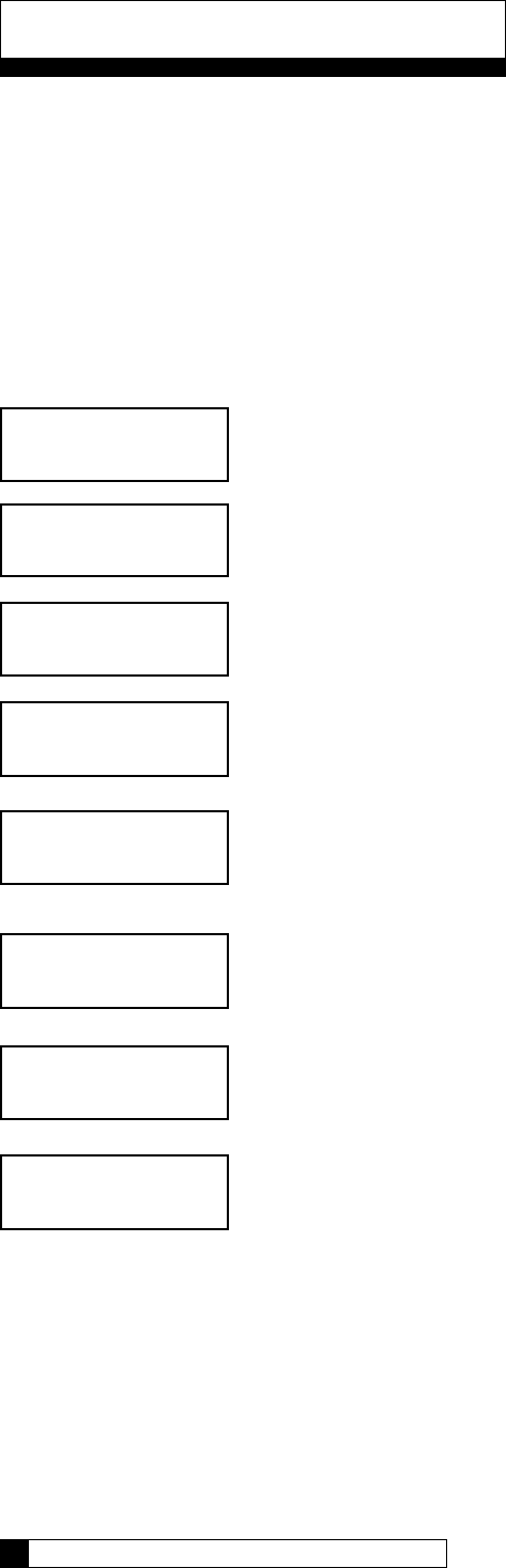
can trigger
Installation of the Aqua-Sensor Probe
After installing the Aqua-Sensor kit 01008779 - CSM, Hi-Flo 50 or the 01018959 - Hi-Flo
22, it is necessary to configure some settings.
The Aqua-Sensor probe should be installed prior to loading the resin in the tank. Run the
probe lead through the opening in the top of the tank. Systems with fiberglass tanks will
have a tank plug on the cord. Systems with steel tanks require a 3/4” x 1/2” reducing
bushing (included in kit) for the cord grip. Run the probe through the bushing prior to
inserting into tank. Use a supplied strain relief to run the connector into the controller. Plug
the connector into the circuit board at the position labeled Aqua-Sensor. Figure 23.
From the home screen, press the DOWN arrow to ACCESSORIES. Press the CHECK
MARK button.
From the ACCESSORIES screen, press the CHECK MARK button at AQUA SENSOR.
Press the CHECK MARK button to change AQUA SENSOR setting. Press the UP or
DOWN arrow to change from NOT INSTALLED to INSTALLED. Press the CHECK
MARK when the correct AQUA SENSOR mode is displayed.
Beeper Mode
From the home screen, press the DOWN arrow to ACCESSORIES. Press the CHECK
MARK button.
Press the DOWN arrow button to scroll to BEEPER. Press the CHECK MARK button at
BEEPER.
Press the CHECK MARK button to change BEEPER MODE setting. Press the UP or
DOWN arrow to change from ALWAYS OFF, ALWAYS ON, 12 HR WARNINGS
OR 24 HR WARNINGS. Press the CHECK MARK when the correct BEEPER MODE is
displayed.
key Press Beeps Beeps on Alarm
Always ON Always Always
Always OFF Never Never
12 hour mode Never Between 8AM-8PM
24 hour mode Never Always
> 4) accessories
system ok
7:32 am 2-1-08
> 1) aqua sensor
aqua sensor
>installed
> 4) accessories
> 2) beeper
beeper mode
>always off
system ok
7:32 am 2-1-08
Connect Aqua-Sensor connector
here at lower right corner of circuit
board
Installation of Accessories 34
33 CULLIGAN GLOBAL ELECTRONIC CONTROLLER
Installation of Accessories
Figure 23
Installation of Accessories
Installation of Accessories 34
33 CULLIGAN GLOBAL ELECTRONIC CONTROLLER
Installation of the Smart Brine Tank (SBT) Probe
After the Smart Brine Tank Probe is installed, it is necessary to configure some settings.
From the home screen, press the DOWN arrow to ACCESSORIES. Press the CHECK
MARK button.
Press the DOWN arrow key to scroll to SBT SENSOR. Press the CHECK MARK button at
SBT SENSOR.
Press the CHECK MARK button to change SBT SENSOR setting. Press the UP or DOWN
arrow to change from NOT INSTALLED to INSTALLED. Press the CHECK MARK when
the correct SBT SENSOR mode is displayed.
Press the CHECK MARK button to set BRINE TANK AREA setting. Press the UP or
DOWN arrow to change AREA SQ/IN. See chart below for correct BRINE TANK
AREA:
18 x 38 Brine Tank - 250 sq in 39 x 48 Brine Tank - 1190 sq in
24 x 40 Brine Tank - 450 sq in 42 x 48 Brine Tank - 1380 sq in
24 x 50 Brine Tank - 450 sq in
30 x 50 Brine Tank - 700 sq in
Press the CHECK MARK when the correct BRINE TANK AREA is displayed.
Press the CHECK MARK button to change SALT GEOMETRY setting. Press the UP or
DOWN arrow to change from PELLET, ROCK OR BRICK. Press the CHECK MARK
when the correct SALT GEOMETRY is displayed.
> 4) accessories
system ok
7:32 am 2-1-08
> 5) sbt sensor
sbt sensor
>installed
salt geometry
>pellet
brine tank area
>500 sq/in
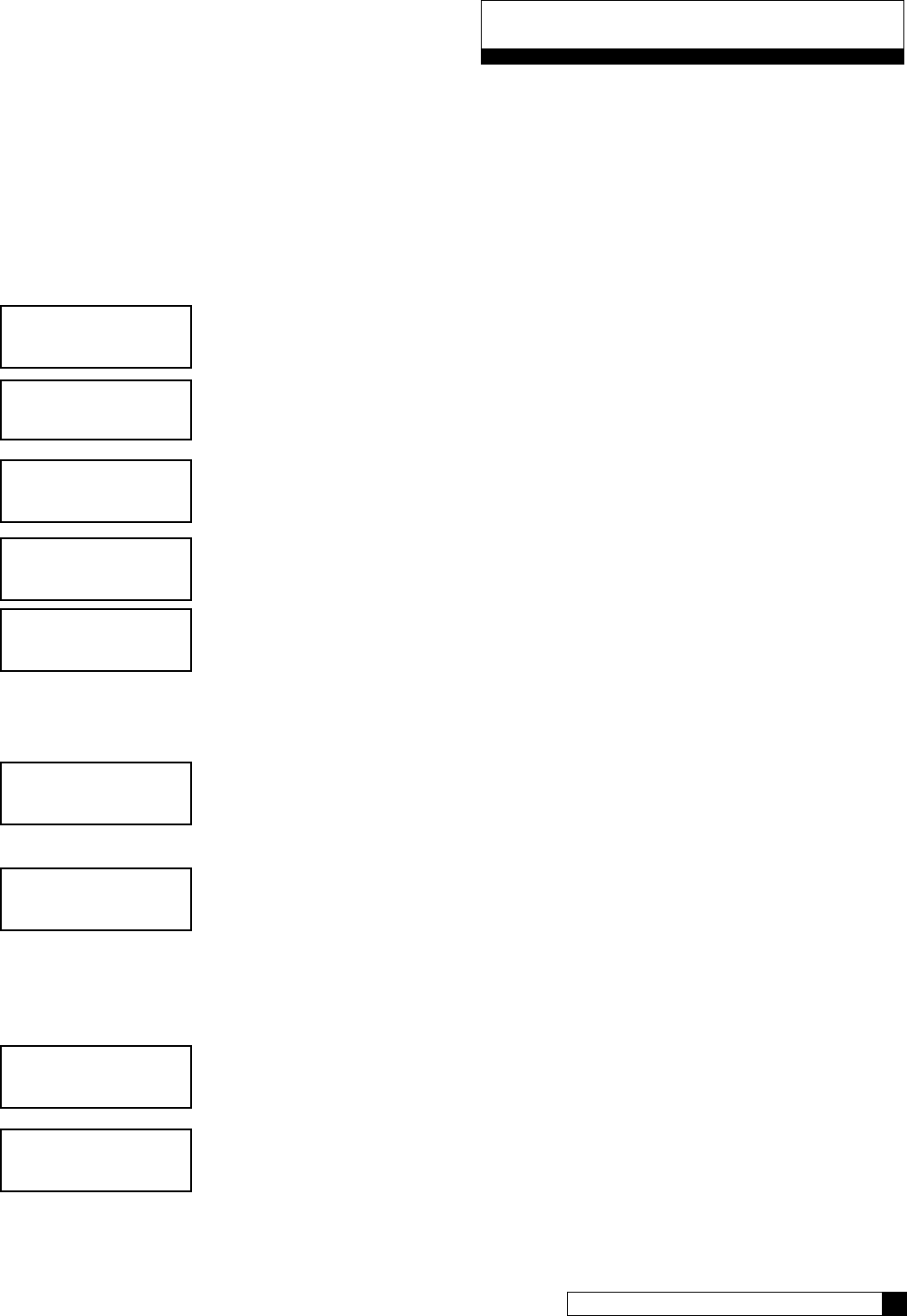
Installing the Smart Brine Tank (SBT Probe) in to the Brine Tank
1. Place the smart brine probe on top of the brine plate as shown in Figure 24 .
2. Loop the two zip ties thru the holes in the probe housing and loop the zip ties around the outside of the brine well as shown
in Figure 25. IMPORTANT! Tighten zip ties securely to prevent movement.
3. Use zip tie to snug the top of the brine tank probe against the top of the brine well.
4. Route the smart brine tank probe cable to an appropriate opening in the valve control housing. Use the strain-relief plug
provided with the SBT probe for installation.
5. Plug the SBT probe connector into the circuit board at the position labeled “Brine Tank” - Figure 26.
Figure 24 Figure 25 Figure 26
Installation of Accessories
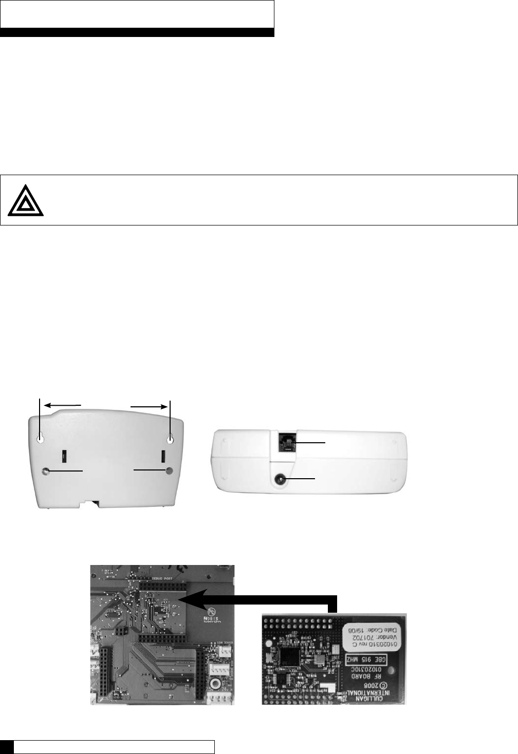
Installing the Wireless Remote
Select a location for the wireless remote monitor (Figure 27). The location must be near an electrical outlet. If a modem is
to be used in the remote, then the location should also be near a standard RJ-11 type telephone wall jack.
Use the “Hole Drilling Template” as a guide to drilling two holes to mount the remote monitor. If drilling into wall board,
drill two 5/16” dia holes and insert the plastic drywall anchors into the holes securing them with the two #10 screws
provided. If drilling into a solid surface, drill two 7/32” holes into the surface and screw the two #10 screws into the
holes. In either case, leave a gap of approximately 3/32” between the head of the screw and the wall.
(Optional) If a modem is to be installed into the remote monitor, refer to page 37 for installation and setup.
Connect the power cord to the bottom of the remote monitor. If a modem is to be used in the remote, plug a standard
telephone extension cord into the bottom of the remote monitor.
Hang the remote monitor on the two screws.
Disconnect power to the softener. Open the control and connect the RF board into the controller circuit board. Make sure
the RF board is fully seated into all of the sockets (Figure 28). Reconnect power.
Install RF board into unit controller. Line up pins in RF board and press firmly into black connectors. Note orientation of RF
board (Figure 28).
Follow the directions on the next page to program BOTH the main and remote monitor units to communicate with each
other. If modem has been installed in the remote, it is also necessary to follow the directions in the next section of this
manual to configure the main controller to use the modem in the remote.
1.
2.
3.
4.
5.
6.
7.
8.
Caution! Do not touch any surfaces of the circuit board. Electrical static discharges may cause damage to the
board. Handle the circuit board by holding only the edges of the circuit board. Keep replacement boards in their
special anti-static bags until ready for use. Mishandling of the circuit board will void the warranty.
Figure 28
RF Board (Note orientation)
Back of GBE Board
Installation of Accessories 36
35 CULLIGAN GLOBAL ELECTRONIC CONTROLLER
MODEM CONNECTION
POWER CONNECTION
SCREWS
Figure 27b
Figure 27a
5 3/8”
Installation of Accessories
Control Valve Set-up
From the home screen, press the DOWN arrow to ACCESSORIES. Press the CHECK MARK
button.
Press the DOWN arrow to scroll to WIRELESS REM.
Press the CHECK MARK button to change REMOTE DISPLAY setting. Press the UP or DOWN
arrow to change from NOT INSTALLED to INSTALLED. Press the CHECK MARK when the
correct REMOTE DISPLAY mode is displayed.
Press the CHECK MARK button to change CHANNEL # setting. Press the UP or DOWN arrow
to change CHANNEL #. Press the CHECK MARK when the correct CHANNEL# is displayed.
Wireless Remote Set-up
From the home screen, press the DOWN arrow to SETUP. Press the CHECK MARK button.
From the SETUP screen, press the CHECK MARK button at RF SETUP.
Press the CHECK MARK button to change CHANNEL # setting. Press the UP or DOWN arrow
to change CHANNEL #. Press the CHECK MARK when the correct CHANNEL# is displayed.
Continue to press X to return to Home Screen.
remote display
>installed
rf frequency
>915 mhz
channel #
>1
NOTE: The CHANNEL # for the control valve must be
the same as the CHANNEL # for the Remote Display.
NOTE: Do not change RF FREQUENCY for North
American installations.
> 4) setup
system ok
7:32 am 2-1-08
> 1) RF SETUP
channel #
>1
rf frequency
>915 mhz
NOTE: The CHANNEL # for the control valve must be the same as the
CHANNEL # for the Remote Display.
NOTE: Do not change RF FREQUENCY for North American installations.
> 4) accessories
system ok
7:32 am 2-1-08
> 6) wireless rem
Installation of Accessories 36
35 CULLIGAN GLOBAL ELECTRONIC CONTROLLER

Installation of Accessories
Check Signal Strength
Check the signal strength once the control valve and wireless remote are setup. On the Softener Controller, go to the Main
Menu/Advanced setup/Diagnostics/Test Wireless to check signal strength. The signal strength indicator (SSI) will show a
value of between 0 and 8. If the SSI is at least 4, then the installation is complete. It the SSI drops below 4, then it may be
necessary to select an alternate location for the wireless remote.
From the home screen, press the DOWN arrow to ADV SETUP. Press the CHECK MARK
button.
Press the DOWN arrow to scroll to DIAGNOSTICS.
Press the DOWN arrow to scroll to TEST WIRELESS.
From the TEST WIRELESS screen, press the CHECK MARK button to test.
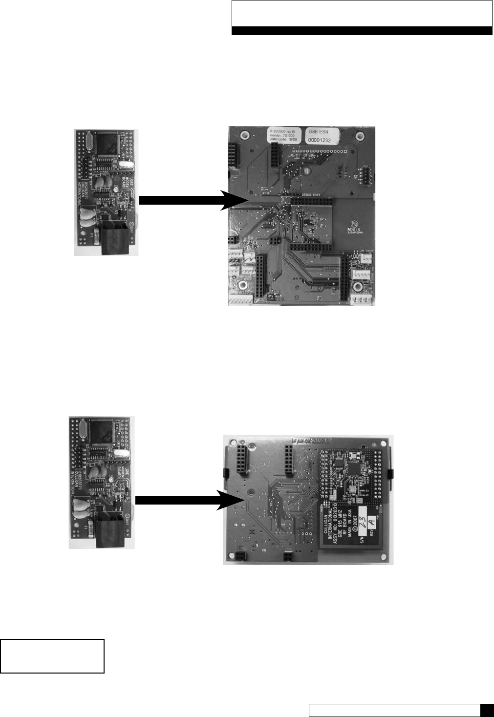
Installing the Modem (optional)
Note: The modem can be installed into either the back of the main controller or the back of the remote control board. The
functionality of the modem is the same in either installation with the important exception that automatic firmware updating is
ONLY available on units which have the modem installed on the main controller.
Before installing the modem into the back of the GBE board or the back of the remote, the GBE circuit board or the
remote must first be powered off.
When handling all circuit boards, take care to only touch the edges of the circuit boards – not the metal pins. The
electronics on all circuit boards can be damaged by static electricity.
Make sure all of the pins at all four connectors are aligned between the modem board and the main controller board.
Make sure that the modem board is fully seated into all four sockets.
When all connections have been made restore power.
1.
2.
3.
4.
> 5) adv setup
system ok
7:32 am 2-1-08
> 5) diagnostics
> 3) test wireless
wireless test
230/230 rssi=8
Installation of Accessories 38
37 CULLIGAN GLOBAL ELECTRONIC CONTROLLER
Installation of Accessories
Installing in GBE Board
Open the controller cover and locate the modem connection on the back of the board (see figure 29). Insert line modem board
(P/N 01020307) into the socket on the back of the board. Make sure that all of the pins in all four connectors are aligned and
make sure the modem is fully seated into all of the sockets.
Installing in Remote
Open the remote monitor housing by removing the two screws and squeezing the sides of the monitor housing slightly. Insert
the modem board (P/N 01020307) into the socket on the back of the remote board (Figure 30). Make sure that all of the pins
in all four connectors are aligned and make sure the modem is fully seated into all of the sockets. Snap the two halves of the
remote housing back together using light finger pressure and insert the two screws.
Modem Setup - GBE
system ok
7:32 am 2-1-08
Modem Board
Back of GBE Board
Figure 29
Modem Board Back of Remote Circuit Board
Installation of Accessories 38
37 CULLIGAN GLOBAL ELECTRONIC CONTROLLER
Figure 30
From the home screen, press the DOWN arrow to ACCESSORIES. Press the CHECK
MARK button.
Press the DOWN arrow to scroll to MODEM.
If necessary, press the CHECK MARK button to change TELEPHONE MODEM setting.
Press the UP or DOWN arrow to change from NOT INSTALLED to INSTALLED.
Press the CHECK MARK when the correct TELEPHONE MODEM mode is displayed.
If necessary, press the CHECK MARK button to change MODEM LOCATION
setting. Press the UP or DOWN arrow to select IN MAIN CONTROL VALVE or
IN REMOTE. Press the CHECK MARK when the correct MODEM LOCATION is
displayed.
If necessary, press the CHECK MARK button to change CALL FREQUENCY setting.
Press the UP or DOWN arrow to increase or decrease CALL FREQUENCY. Press the
CHECK MARK when the desired CALL FREQUENCY is displayed.
The default value of EVERY 10 REGENS can be changed from 1 to 99 successful regenerations. If set to 1, the
unit will call in the following morning after each regeneration. The interval can also be set to 0, meaning the unit
would NEVER call in, unless there was a problem detected. It is recommended for a typical installation the default
value of EVERY 10 REGENS is used.
Press the CHECK MARK button to change TIME ZONE setting. Press the UP or
DOWN arrow to increase or decrease TIME ZONE. Press the CHECK MARK when
the correct TIME ZONE is displayed.
When using a modem, the control will occasionally access the internet to synchronize the date and time. In order
to do this correctly, the control must be told which time zone it is installed in. The time zone is specified as so
many hours ahead or behind GMT time. The “GMT offset” for some common cities are listed below:
GMT Offset
New York -5:00 (and anywhere in EST)
Chicago -6:00 (CST)
Denver -7:00 (MST)
Los Angeles -8:00 (PST)
London 0:00
Paris 0:00
Rome +1:00
> 4) accessories
> 7) Modem
Telephone modem
>installed
Modem location
>in main control
Call frequency
>every 10 regens
time zone
>00:00
Installation of Accessories
Installation of Accessories 40
39 CULLIGAN GLOBAL ELECTRONIC CONTROLLER
Installation of Accessories
Press the CHECK MARK button to change DEALER ID setting. Press the UP or
DOWN arrow to increase or decrease each digit of the DEALER ID. Press the
CHECK MARK to move to the next digit. Press the CHECK MARK when the correct
DEALER ID is displayed. The dealer ID is your dealership’s account number. Enter with
leading zeroes, if necessary.
Press the CHECK MARK button to change DATA PHONE # setting. Press the UP or
DOWN arrow to increase or decrease each digit of the DATA PHONE #. Press the
CHECK MARK to move to the next digit. Press the CHECK MARK when the correct
DATA PHONE # is displayed. Use a local number whenever possible.
It is necessary to provide a telephone number to be called by the unit. Typically, it is
desired that the unit call a local access number. These local access numbers, for nearly
every area code around the globe, can be found from the www.myculligan.com website
at http://www.myculligan.com/technical/tech_ref-gbe-boards.asp. The unit can also
be programmed with the default toll-free access number. Use a local number whenever
possible.
Test Modem
This menu attempts to send in a “test message”. The screen indicates whether or not this process is successful.
Sending a “test message” will also update the time and date on the GBE controller to the correct time. If the
modem is installed on the main controller (as opposed to installed in the remote control) then this testing process
will also check to see if there is an updated version of firmware available on the Culligan servers.
After conducting a phone line test, it is important to verify that the new time and date settings on the controller are
correct. If the new time setting has the incorrect value for the “hours” it is likely that the time zone setting on the
control is incorrect. The time zone setting is found under the Main
Menu / Accessories / Modem screen and is displayed in the format of GMT +/- X hours. (See the section of this
manual called “Installing the modem”
From the home screen, press the DOWN arrow to ADV SETUP. Press the CHECK
MARK button.
Press the DOWN arrow to scroll to DIAGNOSTICS.
Press the DOWN arrow to scroll to TEST PHONELINE.
From the TEST PHONELINE screen, press the CHECK MARK button to TEST.
system ok
7:32 am 2-1-08
> 5) adv setup
> 5) diagnostics
> 5) test phoneline
modem test
emailing now please wait...
dealer id
>00000
data phone #
>18884137028
Installation of Accessories 40
39 CULLIGAN GLOBAL ELECTRONIC CONTROLLER
POSSIBLE RESULTS
CONNECTING AN EXTERNAL FLOW METER
Most metered commercial units require an external flow meter device. this requires an entry in the programming
for the meter chosen. The entry is the pulses per gallon, or K Factor. Refer to the table on the page 63 for meter K
Factors.
From the home screen, press the DOWN arrow to ACCESSORIES. Press the CHECK
MARK button.
Press the DOWN arrow key to scroll to FLOW METER and press the CHECK MARK
button.
To change the value, press the CHECK MARK button and then use the UP ARROW or
DOWN ARROW keys. Press the CHECK MARK button when done. Note: Hi-Flo 22 is
to be set at 78 puls/Gal.
Press the X key until you return to the main screen.
SETTING UP A MULTI-TANK SYSTEM
A Multi-tank system requires additional programming.
REMINDER: Any additional program changes such as REGEN SETUP, CYCLE TIMES and REGEN TRIGGER must
be programmed into each control in the system.
From the home screen, press the DOWN arrow to ACCESSORIES. Press the CHECK
MARK button.
Press the DOWN arrow key to scroll to SYSTEM SETUP and press the CHECK MARK
button.
> 4) Accessories
> 9) Flow Meter
Flow Meter
80.0 Puls/Gal
modem email
success
modem test time
set success
modem test
checking for new fw
modem test
no new fw
Installation of Accessories
system ok
7:32 am 2-1-08
> 5) adv setup
> 1) system setup
Installation of Accessories 42
41 CULLIGAN GLOBAL ELECTRONIC CONTROLLER
Installation of Accessories
Scroll through the settings until you see MultiTank System. Press the CHECK MARK
button and then use the UP ARROW or DOWN ARROW key to change from
SINGLE to PROGRESSIVE flow. Press the CHECK MARK button when done.
NOTE: all multi tank systems are to be set to PROGRESSIVE. See below on adjust-
ments needed for alternating or parellel operation.
Press the CHECK MARK button and then use the UP or DOWN arrow keys to set the
progressive flow trip point. Press the CHECK MARK button when done.
This setting establishes a flow rate which, when attained, will cause another unit to come on-line until the total flow
rate is less than the established trip point for 30 seconds. Should the flow demand exceed the trip point by a rate
equal to or greater than two times the trip point, another unit shall be brought on-line (assuming the system has
more than two units in total). Each subsequent equivalent increase in flow demand shall continue to bring addi-
tional units on line (up to six total units if the flow demand is six times the TRIP amount). Units shall be returned
to a stand-by mode in the reverse order as the system flow decreases by a rate equal to or greater than the trip
point. Generally, the trip point is the rated continuous flow rate of one unit. These values can be found in the unit’s
instruction manual.
NOTE: ALTERNATING OPERATION: To set up the GBE for alternating operation (one on, the rest standby), set the
trip point to 999. It is unlikely that the system will reach 999 gallons per minute to bring on an additional unit.
In a multi-tank system, one unit must be specified as master. All other units are slaves.
For example, in a triplex system, select one unit to be the master and set this setting to
MASTER. In the 2nd unit, set this to SLAVE 1. In unit 3, set it to SLAVE 2. You can
have up to 5 slaves connected to a master.
NOTE: PARALLEL OPERATION: To set up the GBE for parallel operation (all online), set the trip point to zero (0).
As long as the flow is above zero, all units will stay online.
You must also set the jumpers as explained on page 12 for progressive flow.
Flow meters are required for progressive flow – one for each unit. See page 14 to set up the meters.
Continue pressing the down key to cycle through the rest of the options (refer to page 29). At the System Setup
screen press the “X” key to return to the main screen.
NOTE: You must repeat this programming on all other units in the system. On slave units the PROG FLOW TRIP
can be IGNORED; the only trip point recognized is the one set on the master unit.
Brine Reclaim
For brine reclaim, AUX OUT 2 and AUX OUT 3 must be set to open and close the valves to direct the brine.
There are 4 things to set for each aux output.
1 – Cycle Type (AUX X CYCLE TYPE) – can be set to NORMALLY ON or NORMALLY OFF. For brine
reclaim, set it to NORMALLY OFF.
2 – Cycle Position (AUX OUT X) – Any cycle position can be selected here. For brine reclaim, we want the
BRINEDRAW POS.
3 – Delay (AUX OUT DELAY) – This is the delay before the OUTPUT is “activated” in minutes. For brine reclaim
we want delay on AUX 3 and no delay on AUX 2.
4 – On time (AUX OUT ON) – This is the number of minutes the OUTPUT is “activated” in minutes. For brine
reclaim, cycle type is NORMALLY OFF so this is the amount of time the Aux contact is on.
multitank system
progressive
prog Flow trip
210 GPM
progress flow master
Installation of Accessories 42
41 CULLIGAN GLOBAL ELECTRONIC CONTROLLER
Installation of Accessories
Refer to page 46 for more information on the operation of the Aux Outputs. Refer to the instructions below for step
by step setting of these values.
• Press the UP „ or DOWN ‰ arrow to scroll to menu item
• Press the CHECKMARK P key to select a menu item
• Press the UP „ or DOWN ‰ arrow to change a selection
• Press the CHECKMARK P key to save your selection
Default Values are shown for each selection
Scroll to ACCESSORIES and select
Select AUX OUTPUTS
Select AUX OUT 2
Can be set to NORMALLY OFF or NORMALLY ON. For brine reclaim, set to
NORMALLY OFF.
This can be set to any cycle. For brine reclaim, change this to BRINEDRAW POS.
This is the activation delay. For brine reclaim, leave at zero (0).
Set this value to the number of minutes needed for aux 2 to be activated. Refer to the
brine reclaim manual, 01018946, for recommended settings.
Now set AUX OUT 3
Select AUX OUT 3
Can be set to NORMALLY OFF or NORMALLY ON. For brine reclaim, set to
NORMALLY OFF.
This can be set to any cycle. For brine reclaim, change this to BRINEDRAW POS.
> 4) accessories
> 4) aux outputs
> 2) aux out 2
3) aux out 3
aux2 cycle type
normally off
aux out 2
service pos
aux2 out
delay 0 mins
aux2 out
on 0 mins
2) aux out 2
> 3) aux out 3
aux3 cycle type
normally off
aux out 3
service pos
Installation of Accessories 44
43 CULLIGAN GLOBAL ELECTRONIC CONTROLLER
system ok
7:32 am 2-1-08
Installation of Accessories
This is the activation delay. For brine reclaim, set this to the same value that AUX2 OUT
is set to be ON (last setting on AUX2). This allows AUX3 to turn on immediately after
AUX2 turns off.
Set this value to the number of minutes needed for aux 3 to be activated. Refer to the
brine reclaim manual, 01018946, for recommended settings.
This concludes setting the AUX OUT values for Brine Reclaim. Press the X key until you return to the Main Menu.
SERVICE PHONE NUMBER
If the Modem is not installed it is possible, in addition to displaying the error message, to display a message that
reads “Call Culligan at: XXXXXXXXXX” where the telephone number XXXXXXXXXX can be programmed by the
dealership (typically programmed to be the telephone number of the dealership). This number is programmed
under the menu: Main Menu / Accessories / Service Phone.
From the home screen, press the DOWN arrow to ACCESSORIES. Press the CHECK
MARK button.
Press the DOWN arrow to scroll to SERVICE PHONE. Press the CHECK MARK
button at SERVICE PHONE.
Press the CHECK MARK button to change SERVICE PHONE # setting. Press the
UP or DOWN arrow to increase or decrease each digit of the SERVICE PHONE #.
Press the CHECK MARK to move to the next digit. Press the CHECK MARK when the
correct SERVICE PHONE # is displayed.
EXTERNAL FILTER
The unit can provide alarm feedback for a sediment or carbon filter installed upstream of the unit. The Auxiliary
flow alarm can be used to monitor the flow through this filter.
To use this feature it is necessary to specify the total lifetime totalized flow of the auxiliary filter in either gallons or
liters at Main Menu/Accessories/Down Once set, it will begin to track the total gallons through the system flow
meter. Once the total flow reaches the specified lifetime totalized flow, the system will display the error
message “Change Auxiliary Filter” on the main display as well as the remote display and via the
telephone modem if these secondary devices are used.
system ok
7:32 am 2-1-08
> 4) accessories
> 10) service phone
service phone #
>
system ok
7:32 am 2-1-08
Note: Once the auxiliary filter has been replaced, the auxiliary filter alarm must be reset by returning
to the same menu: Main Menu / Accessories / Auxiliary Flow Alarm.
Installation of Accessories 44
43 CULLIGAN GLOBAL ELECTRONIC CONTROLLER
aux3 out
delay 0 mins
aux3 out
on 0 mins

Installation of Accessories
From the home screen, press the DOWN arrow to ACCESSORIES. Press the CHECK
MARK button.
From the ACCESSORIES screen, press the CHECK MARK button at EXT. FILTER.
Press the CHECK MARK button to change EXTERNAL FILTER ALARM setting. Press
the UP or DOWN arrow to change from INSTALLED to NOT INSTALLED. Press the
CHECK MARK when the correct EXTERNAL FILTER ALARM mode is displayed.
Press the CHECK MARK button to change FILTER CAPACITY setting. Press the UP or
DOWN arrow to increase or decrease FILTER CAPACITY. Press the CHECK MARK
when the correct FILTER CAPACITY is displayed.
> 11) ext. filter
external filter alarm
>installed
filter capacity
>10000 gallons
Auxiliary Contacts 46
45 CULLIGAN GLOBAL ELECTRONIC CONTROLLER
> 4) accessories
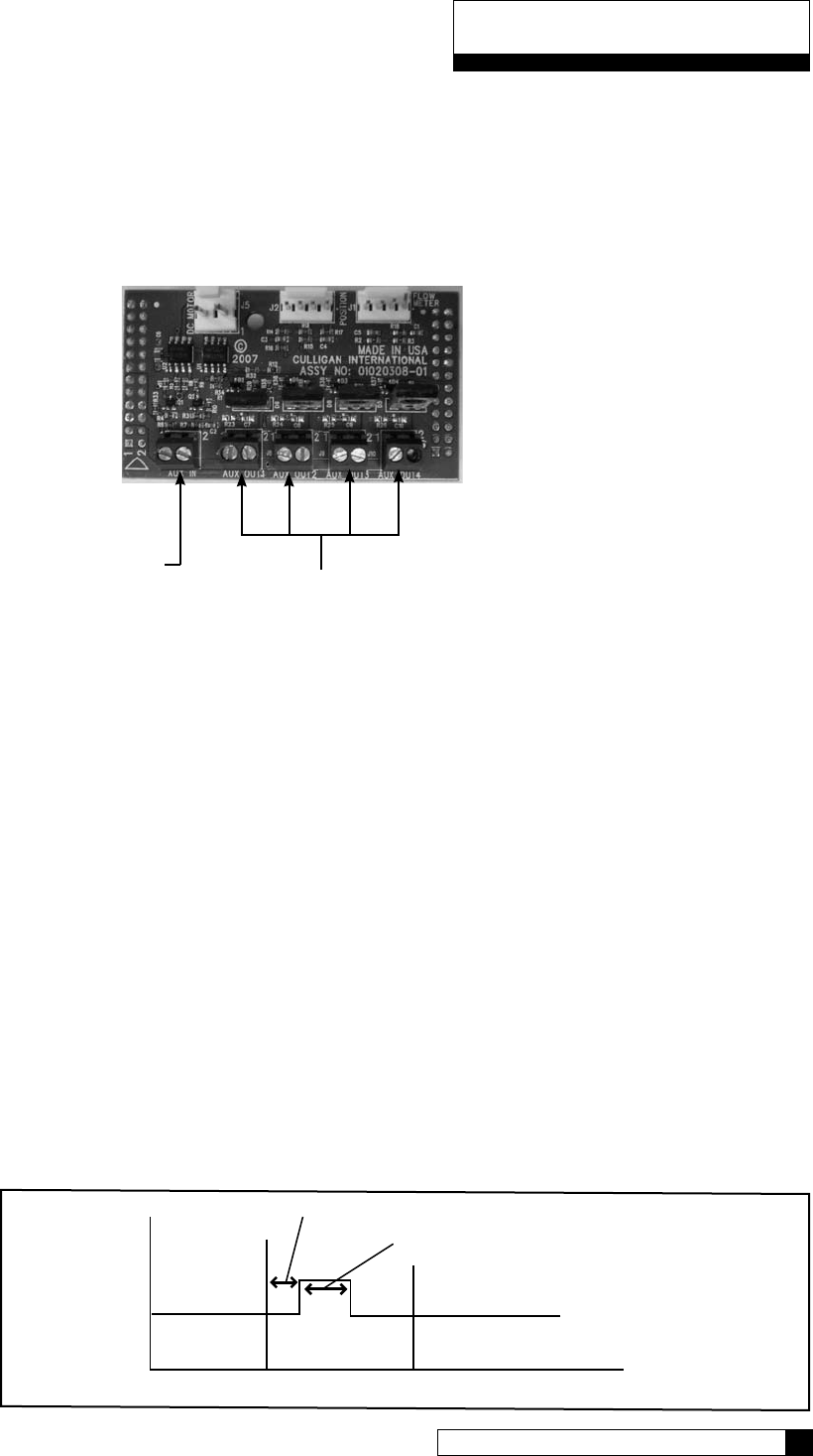
Auxiliary Board
The auxiliary board comes installed in all commercial equipment. It can control up to four, 24 VAC outputs (max
current 2.1 amps output). Aux Output 1 is used to power the 24 VAC drive motor found on all valves. When
Aux Output 1 is used for this, then Aux Output 4 is automatically configured to operate a solenoid which can be
used for a standby or blocking. Aux Output 4 is powered during all cycles except service, and unpowered during
service.
For CSM and Hi-Flo 50 softeners, Aux Output 2 is used to power the refill solenoid. The Aux Output 2 “On”
time needs to be set based on the desired salt dosage/capacity as found in the appendix of the unit’s installation
manual. See the Aux Output 2 settings for a detailed example.
Each Aux Output has the following settings:
• Cycle Type (AUX X CYCLE TYPE) – Can be set to NORMALLY ON, NORMALLY OFF or REPEAT CYCLE. This
means the Output can always be on or always be off until it reaches the chosen cycle position. REPEAT CYCLE
allows the output to turn on and off at a set interval during the cycle chosen.
• Cycle Position (AUX OUT X) – Any cycle position can be selected here. This is the cycle position that the AUX
OUT is “activated” (turned on or off).
• Delay (AUXX OUT DELAY) – This is the delay before “activating”. You can have the AUX OUT activation
delayed a specified number of minutes into the cycle.
• On time (AUXX OUT ON) – This is the number of minutes the AUX OUTPUT is “activated” in minutes. After the
specified number of minutes, the OUTPUT is deactivated.
• Off Time (available only when Repeat Cycle is selected for Cycle Type) – This is the number of minutes of Off
time during the chosen cycle. The aux output will cycle on and off during the selected cycle.
For example, the chart below shows how the timing would work if the CYCLE TYPE was set to NORMALLY
OFF, the CYCLE POSITION was set to BACKWASH, the DELAY minutes greater than zero, and ON minutes
greater than zero.
Delay Minutes
On Minutes
Service Backwash Brine Draw
Service Backwash Brine Draw
ON SECONDS
@ 1500 gallons, on seconds is activated by GALLONS
@ 3000 gallons, on seconds is activated by GALLONS
@ 4500 gallons, on seconds is activated by OFF MINUTES
OFF MINUTES
EXAMPLE
GALLONS: 1500
ON SECONDS: 10
OFF MINUTES: 15
Figure 32
Auxiliary Contacts
Auxiliary Contacts 46
45 CULLIGAN GLOBAL ELECTRONIC CONTROLLER
Auxiliary Outputs
Auxiliary Input
Figure 31

Auxiliary Contacts
Aux Output 2 Example
As mentioned above, for CSM and Hi-Flo 50 softeners, this output is used for the refill solenoid. As an example,
let’s say we have a CSM-300-2 and we need to set this up for refill minutes. We are looking for a capacity
around 250,000 grains (10 lbs/ft³).
According to the chart on page 92 of the CSM installation manual (01016370), we are looking at a salt dosage
of 10.2 lbs/ft³ and need to set the ON minutes of AUX2 to 17.
Here is how to set this up:
Scroll to ACCESSORIES and select
Scroll to AUX OUTPUTS and select
Scroll to AUX OUT 2 and select
Leave this set at NORMALLY OFF. We want the output to energize (turn on) the refill
solenoid
This should be set to SERVICE POS.
No delay is necessary.
For our example, this would be set to 17.
AUX OUTPUT 3 has the same menu options. Refer to the chart on page 48 for quick reference.
Auxiliary Contacts 48
47 CULLIGAN GLOBAL ELECTRONIC CONTROLLER
> 4) accessories
> 4) aux outputs
> 2) aux out 2
3) aux out 3
system ok
7:32 am 2-1-08
aux2 cycle type
normally off
aux out 2
service pos
aux2 out
delay 0 mins
aux2 out
on 0 mins
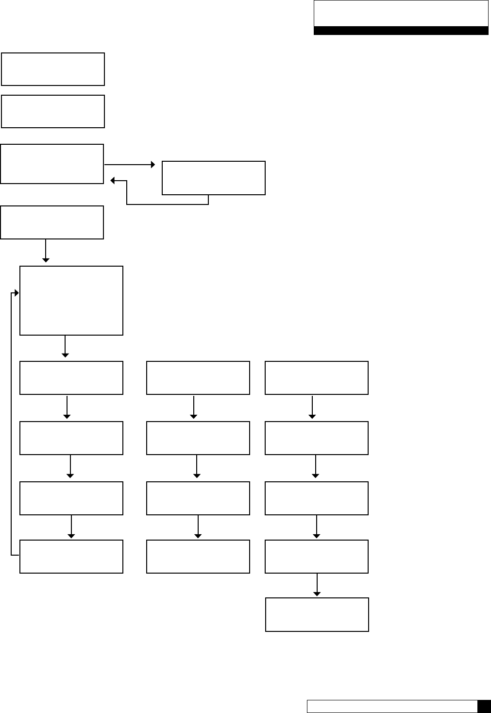
Auxiliary Contacts
Auxiliary Contacts 48
47 CULLIGAN GLOBAL ELECTRONIC CONTROLLER
4) aux outputs
> 3) aux in
1) aux input
> 6 seconds
> 2) aux out#2
3) aux out#3
aux 2 Cycle type
> normally off
aux out 2
> service
aux2 out
delay > 0 minutes
aux2 out
on > o Minutes
aux 2 cycle type
> normally on
aux out 2
> service
aux2 out
delay > 0 minutes
aux2 out
off > o Minutes
aux 2 cycle type
> rep eat cycle
aux out 2
> service
aux2 out
gallons > 0
aux2 out
on 0 minutes
(“NORMALLY ON” Type) (“REPEAT CYCLE” Type)
(1)
2)
> 4) Accessories
system ok
7:32 am 2-1-08
To use the auxiliary contacts, some configuration settings
must be changed.
From the home screen, press the DOWN arrow to
ACCESSORIES. Press the CHECK MARK button.
Press the DOWN arrow key to scroll to AUX IN.
aux2 out
off 0 minutes
AUX OUT 2 and AUX OUT 3 menu selection are the same.
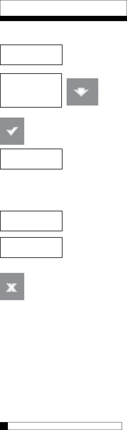
Follow the procedure below to initiate a manual regeneration at the control valve or the remote display.
system ok
12:00 am 1-1-08
1) information
> 2) manual mode
3) set date/time
4) Accessories Press DOWN arrow. Scroll to MANUAL MODE.
Press the CHECK MARK button to select.
The “REGEN OFF” value is the default setting.
Press the CHECK MARK button to change manual mode setting. Use the UP or DOWN arrow to change the set-
ting. Once the desired value is displayed, this value can be accepted by pressing the “CHECK MARK” button.
By selecting the “REGEN TONITE” value the softener will regenerate that night at 2:00
AM (or at the preset regeneration time)
By selecting the “REGEN NOW” value the softener will begin regeneration immediately.
NOTE: In multi-tank systems, the regeration request is sent to the master control and it
will allow the unit to regerate at the next availble time.
Press the “CANCEL” button to return to the “home” screen.
Manual Mode
>Regen off
Manual Mode
Regen tonite
Manual Mode
Regen now
Manual Regeneration
Manual Cycling 50
49 CULLIGAN GLOBAL ELECTRONIC CONTROLLER
Manual cycling can be performed when the unit is starting either in SERVICE or while it is already within any
portion of the REGENERATION process. If the unit is currently regenerating, the name of the current cycle position
and the number of minutes remaining in the current cycle position will be displayed.
From the home screen, press the DOWN arrow to ADV. SETUP. Press the CHECK
MARK button.
Press the DOWN button to scroll to DIAGNOSTICS. Press the CHECK MARK button at
DIAGNOSTICS.
Press the DOWN button to scroll to MOTOR CONTROL. Press the CHECK MARK but-
ton at MOTOR CONTROL.
If control is not in regeneration, this is shown.
To cycle the control valve without stopping press the CHECK button. To stop the motor at
the end of each cycle press the UP arrow.
Menu Status
MOTOR AT POS S Motor at service position
MOTOR AT POS B Motor at backwash position
MOTOR AT POS E Motor at brine draw/slow rinse position
MOTOR AT POS F Motor at fast rinse/refill position
If cycling the control during regeneration, this screen is shown after MOTOR CONTROL.
Press the CHECK MARK button to change REGENERATION setting. Press the UP
or DOWN arrow to move to NEXT CYCLE, END REGEN NOW or END/CAN-
CEL TRIG. Press the CHECK MARK when the correct REGENERATION setting is
displayed.
system ok
7:32 am 2-1-08
> 5) adv setup
motor at pos s
up: forward
> 5) diagnostics
> 5) motor control
backwash minutes left: 8
>next cycle
Manual Cycling
Manual Cycling 50
49 CULLIGAN GLOBAL ELECTRONIC CONTROLLER
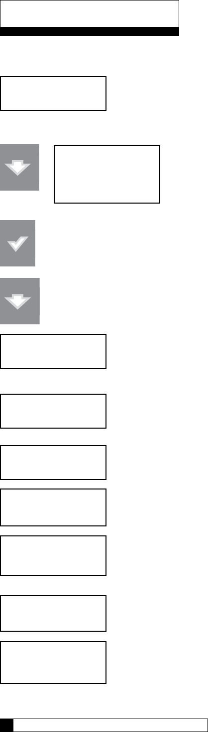
The following information can be displayed at the control valve or remote display.
system ok
12:00 am 1-1-08
Press DOWN arrow
Pressing the CHECK MARK button will change the display to show a “>” symbol next to the displayed
value.
Press DOWN arrow to scroll through the “INFORMATION” menu.
Displays salt level and approximate number of days of salt remaining. This screen will
only be displayed if a Smart Brine Sensor is connected.
Press DOWN arrow to view next screen.
Displays approximate number of days of salt remaining. This screen will only be dis-
played if a Smart Brine Tank Sensor is installed.
Press DOWN arrow to view next screen.
Displays the percent softening capacity remaining.
Press DOWN arrow to view next screen.
Displays the remaining softening capacity in gallons.
Press DOWN arrow to view next screen.
Displays the current flow rate.
Press DOWN arrow to view next screen.
Displays the date when the next regeneration will occur (based on average daily water
usage).
Press DOWN arrow to view next screen.
Displays today’s water usage.
Information
salt tank level
ok
Information 52
51 CULLIGAN GLOBAL ELECTRONIC CONTROLLER
approx 12 days
salt remaining
remain capacity
80%
current flowrate
0.0 GPM
remain capacity
870 gallons
> 1) information
2) manual mode
3) set date/time
4) Accessories
next regen on
1/8
today’s usage
115 gallons
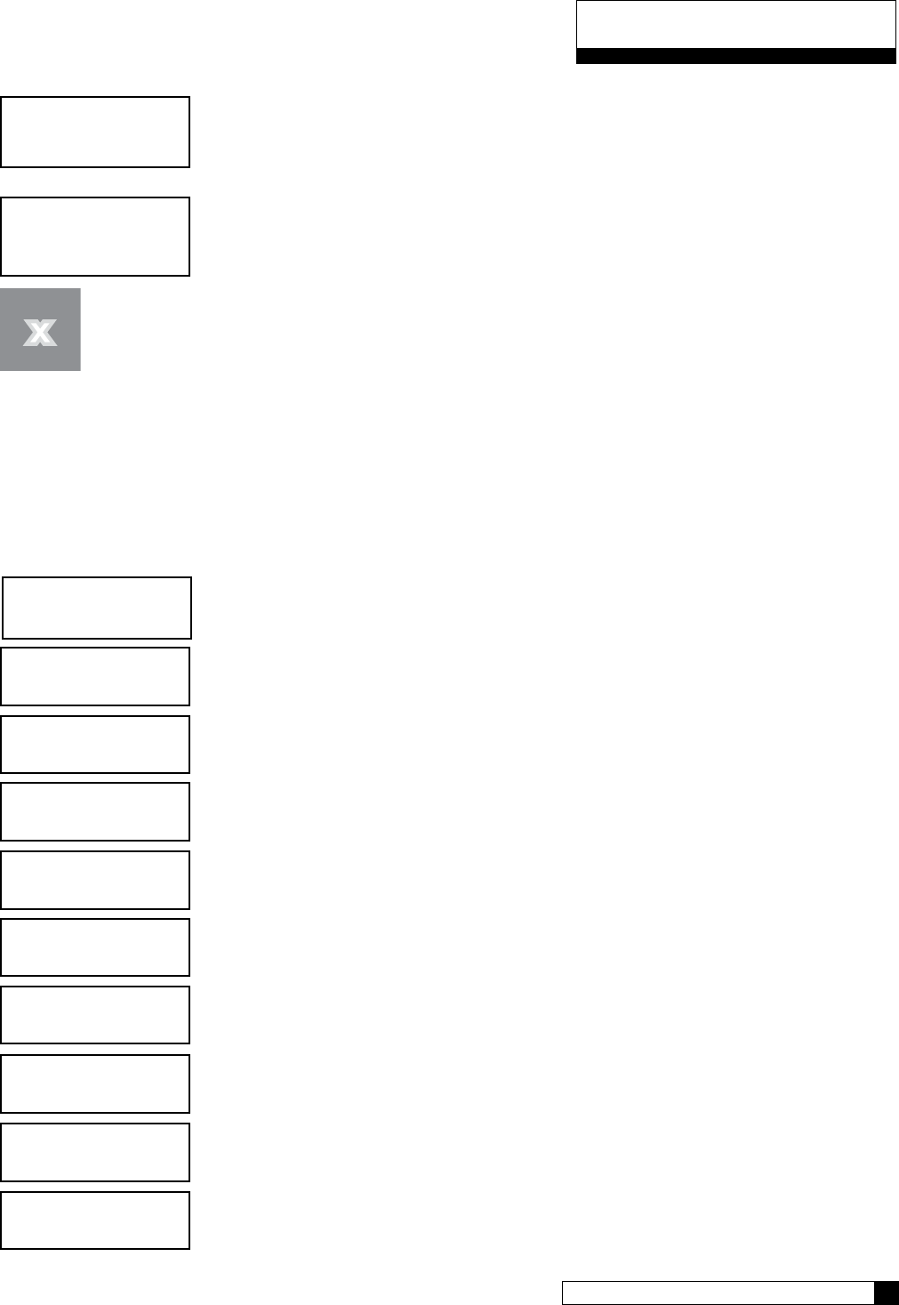
Press DOWN arrow to view next screen.
Displays average daily water usage.
Press DOWN arrow to view next screen.
Displays how many gallons remain before the optional filter cartridge needs to be
replaced.
Press the “CANCEL” button to return to the “home” screen.
SET DATE/TIME
If the unit loses time for some reason, you can use this setting to reset the correct date and time. Please note that if
you have a modem installed and connected to the phone line, the unit will check for the correct time each time it
calls in.
To set the date and time:
Scroll to Information and select
Scroll to SET/TIME
Scroll up or down to set month
Scroll up or down to set the date
Scroll up or down to set the year (4-digit)
Choices are 24 HR (00:00 to 23:59) or 12 HR (AM/PM)
Based on choice of CLOCK TYPE, scroll to select the hour
Scroll to set minutes
If you observe daylight savings in your area, set to YES.
Press the X key until you return to the Main Menu.
Information
Information 52
51 CULLIGAN GLOBAL ELECTRONIC CONTROLLER
average daily
275 gallons
ext filtr cap rem
10,000 gallons
system ok
7:32 am 2-1-08
> 3) set date/time
> 1) information
set month
set day
set year
clock type
set hour
set minutes
daylight savings

When the controller identifies that an error has occurred, it is programmed to take steps to attempt to correct the er-
ror on it’s own. If it is unable to correct the problem, the controller will display the message “PROBLEM FOUND”.
When an error message is displayed (on either the GBE Controller or the remote display), pressing the “CHECK-
MARK” on the keypad will display the detected error condition(s). Some of these messages will also provide ad-
ditional information to help correct the error.
The following error messages may display on both the GBE controller display as well as the Remote Display (if one
is connected:)
If the words “PROBLEM FOUND” appear on the main screen, it indicates that there are one or more errors de-
tected. Pushing the “CHECK MARK” button will display the first error present. Pressing the DOWN arrow will show
any additional errors present. At the bottom of this list the user can “CLEAR THE ERROR” or “EXIT”. Pressing the
“CHECK MARK” button on the “CLEAR THE ERROR” message causes the controller to re-check to see if the error
condition still exists, if it still exists, the error will remain displayed on the main screen. If the error no longer exists
the main menu will return to displaying “SYSTEM OK”.
Error Description Reason for Error Comment/ Clearing Error Message
POSITION SENSOR
ERROR
The motor is turning, but the position sensor
appears to be incorrect
Check the motor using manual motor control and the position sen-
sors using Main Menu/ Advanced/ Diagnostics Sensors
MOTOR POSITION
ERROR
Motor did not move when it should. No feed-
back from switches.
Use manual motor control to see if motor is actually working and
not jammed. Use Diagnostics/ Sensor menu to verify that the opti-
cal or mechanical position switches are working
BRINE BLOCKED The flow rate of brine or water to or from the
brine tank is fully or partially blocked
Check brine line for blockages or air leaks. Check eductor and
eductor screen for blockages
REPLACE FILTER MEDIA Total gallons thru the unit has exceeded the
specified capacity of the media
Replace the media. Reset the media filter life at Main Menu/
Advanced Setup/Regen Settings/ Media Life
REPLACE AUX FILTER
MEDIA
Total gallons thru the secondary filter (i.e. “Big
Blue” filter) has exceeded the specified capac-
ity of the big blue
Replace optional filter cartridge. Reset the aux. Filter media life at
Main Menu/ Accessories/ Aux Filter menu
CALL CULLIGAN AT
XXX-XXX-XXXX
This message is displayed if an error has
been detected that requires servicing and no
modem installed in the system
Call the number shown. If possible, place this call using a phone
that will allow you to see and enter changes to the main controller
if required by the service technician during the call
SALT BRIDGING Brine tank has low concentration of brine Use a tool to break up any salt bridge inside the brine tank
XX DAYS SALT RE-
MAINING
This is a prediction of the number of days until
it will be necessary to add salt to the brine
tank
Salt can be added to the brine tank at any time. It is recommended
that the brine tank be filled to approximately
2/3 full.
AQUA-SENSOR SALT
ERROR
Aqua-Sensor did not detect brine during the
regeneration cycle
Check brine tank - add salt if necessary. Check Z ratio of the Aqua-
Sensor at Main Menu/ Advanced / Diagnostics/ Sensors
NO REMOTE RF
SIGNAL
Main board is not receiving a signal from the
remote
Remote is off, out of range or on a different channel from the main
board. If interference is suspected, try moving the remote closer or
switching to a different channel on both the main and remote units
LOW SALT LEVEL Salt level is low; less than 15 days of salt
remaining.
Contact Culligan dealer for salt deviery or fill brine tank with salt.
LOW BATTERY Battery needs replacement. Replace with Panasonic Model# CR 2032 3V battery.
BRINE OVERFILL Too much water in brine tank.
Plugged drain line flow control (Unit will not
draw brine).
Slow leak to brine line.
Faulty eductor piston
Power outage while control was in refill
position.
Check edorctor; check fro brine draw.
Clean drain line flow control.
Clean eductor screen and nozzle.
Replace ductor piston.
NO REFILL Failure to refill brine tank. Refill restrictor
plugged.
Air in brine line causes float to slam shut.
Clean or replace refill restrictor. Verify all tubing connections are
properly assembled.
Error & Alert Codes
Diagnostics 54
53 CULLIGAN GLOBAL ELECTRONIC CONTROLLER
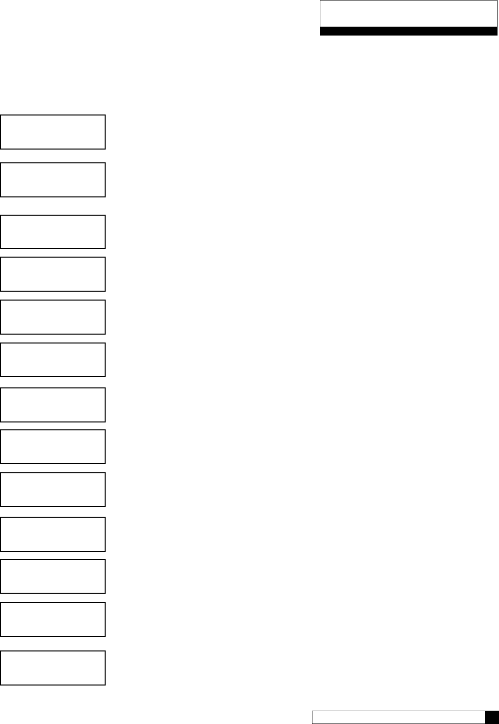
Diagnostics
There is a large number of diagnostic menu screens to aid in setup and troubleshooting of the GBE. Below is an
overview of the menus.
Advanced Statistics
From the home screen, press the DOWN arrow to ADV. SETUP. Press the CHECK
MARK button.
Press the DOWN arrow button to scroll to DIAGNOSTICS. Press the CHECK MARK
button at DIAGNOSTICS.
From the DIAGNOSTICS screen, press the CHECK MARK button at ADVANCED
STAT.
The total number of gallons of soft water since the unit was installed is displayed. Press
DOWN arrow to view the next statistic.
The CURRENT FLOW RATE of the unit is displayed. Press DOWN arrow to view the
next statistic.
This is the total number of regenerations since the unit was installed Press DOWN
arrow to view the next statistic.
This is the number of REGENS IN LAST 14 DAYS of operation. Press DOWN arrow
to view the next statistic.
This is the number of DAYS SINCE LAST REGENERATION of unit. Press DOWN
arrow to view the next statistic.
This is the date of last regeneration of unit (January 3). Press DOWN arrow to view the
next statistic.
This shows what device triggered the last regeneration. Press DOWN arrow to view
the next statistic.
This shows the REMAINING CAPACITY of the unit in gallons. Press DOWN arrow to
view the next statistic.
This shows the TOTAL CAPACITY of the unit in gallons. Press DOWN arrow to view
the next statistic.
system ok
7:32 am 2-1-08
> 5) adv setup
totalized flow
18203 gallons
> 5) diagnostics
> 1) advanced stat
current flow rate
5.0 gpm
last regen on:
1/3
days since last regen:
1
regens in last 14 days:
3
total regens
3
remaining capacity
613 gallons
last regen trig
flow meter
total capacity
891 gallons
Diagnostics 54
53 CULLIGAN GLOBAL ELECTRONIC CONTROLLER
This shows the latest firmware version of unit. Press DOWN arrow to view the next statistic.
This shows the serial number of circuit board. Press DOWN arrow to view the next statistic.
The date and time showed here is when the unit last was powered up. This can be helpful if there
was a power outage to see how long the unit has been on.
Check Sensors - Main Board, Flow meter, and/or Aqua-Sensor.
From the home screen, press the DOWN arrow to ADV. SETUP. Press the CHECK MARK
button.
Press the DOWN arrow to scroll to DIAGNOSTICS. Press the CHECK MARK button at
DIAGNOSTICS.
Press the DOWN arrow to scroll to CHECK SENSORS. Press the CHECK MARK button at
CHECK SENSORS.
MAIN BOARD POSITION: Position of Home & Program switches. Press DOWN arrow to view
the next statistic.
Cycle Home Switch Program Switch
Service Off Off
Backwash On On
Brine Draw/Slow Rinse On Off
Fast rinse/Refill On On
FLOW METER: Current pulses per second. (K-Factor) - refer to page 63 to varify correct reading.
Press DOWN arrow to view the next statistic.
AQUASENSOR SUPPLY VOLTAGE: This will be either PASS or FAIL. If this reading is FAIL,
check the Aqua-Sensor connection to the circuit board and to the power supply. Press DOWN
arrow to view the next statistic.
fw110lt01
may 9 2008
s/n: 00001078
last power up
01-01-08 12:01 pm
system ok
7:32 am 2-1-08
> 5) adv setup
main board position sensor
home: off Pos: off
> 5) diagnostics
> 2) check sensors
flow meter
7 puls/sec
aquasensor supply voltage
2.5vac: pass
Diagnostics
Diagnostics 56
55 CULLIGAN GLOBAL ELECTRONIC CONTROLLER
AQUASENSOR: Troubleshooting statistics.
Z-Ratio (impedance ratio) - Number calculated by microprocessor on measured voltage
values that are converted to a digital representation. This is the value that the control
monitors in order to determine need for regeneration and salt rinse-out.
Z-Minimum (minimum impedance ratio) - Reference point that the Z-ratio is
compared to, in order to initiate a regeneration. This number is reset after every successful
regeneration.
Increase Percent (impedance ratio increase) - During service, this number
represents the percent increase or z-ratio over z-minimum. A regeneration is initiated when
it reaches 7.5% or more for at least 6 minutes.
Press DOWN arrow to view the next statistic.
SBT SENSOR: Smart Brine Tank Probe troubleshooting statistics.
The SBT probe has four sensors within it. The Check sensor screen displays the current status
(opened = “OP”, or blocked =“BL”) for all four sensors. The expected outputs from the SBT probe
inside the brine tank are shown in Table 1 below while the expected outputs from an SBT probe
“in air” are shown in the Table 2.
Table 1 - Expected Readings on the Sensor/Diagnostic screen when the SBT probe is installed inside the brine tank
displays “BL” displays “OP”
Salometer Brine at least 1 inch above the salt plate.
Salt Level Normal Operation .– Salt level greater than 8”
above the salt plate
Salt level less than 8” above the salt plate
Flow Rate #1 Water level in brine tank is below salt plate Water level is brine tank is more than 1”
above salt plate
Flow Rate #2 Water level is brine tank is more than 1” above
salt plate
Water level in brine tank is below salt plate
Table 2 - Expected Readings from the SBT probe when the probe is just sitting in “air” (ie not installed in the brine tank)
Normally Probe Inverted
Salometer “OP” “BL”
Salt Level “OP” “OP”
Flow Rate #1 “BL” “OP”
Flow Rate #2 “OP” “BL”
•
•
•
aquasensor
zratio 1.075
zminimum 1.070
0.75% increase
sbt sensor
salometer=op
salt level=op
fr1=bl fr2=op
Diagnostics
Diagnostics 56
55 CULLIGAN GLOBAL ELECTRONIC CONTROLLER

SBT AVG T3: In addition to these four sensors, the SBT probe takes a measurement
during each regeneration cycle called “T3”. This measurement varies from system to
system, but is typically between 10 and 60 seconds for a system. When the SBT is
turned from UNINSTALLED to INSTALLED on the Accessories menu, the average value
of T3 is erased and the system will use the next three regeneration cycles to compute
a new T3 average number. During each subsequent regeneration, the new T3 is compared to the average T3
number. If the new T3 exceeds the average T3 by more than 50% then the system will display a “Brine Line
Blockage – Check Brine Line” error message. The average T3 value is displayed on the diagnostic screen after the
SBT sensor screen.
Press DOWN arrow to view the next statistic.
SBT LAST T3: Smart Brine Tank Probe troubleshooting statistics. This is the last T3 valve
recorded by the probe. Press DOWN arrow to view the next statistic.
Test Wireless: See page 37.
Test Progressive Flow:
Scroll to ADVANCED SETUP and select
Scroll to DIAGNOSTICS and select
Scroll to TEST PROGRESSIVE FLOW and Select
The progressive test screen will show the data packet transmissions from the Master (Tx)
and which slaves are recieving (1,2,3,4 and/or 5). For example, in a triple system, if
the transmission from the master (Tx) is 0085, then you should see 1:0085 and 2:0085.
3,4, and 5 will remain all zeros since no other slaves are connected.
See page 50
See Appendix C, page 65
See page 40
IGNORE THIS
sbt last t3
30 seconds
sbt avg t3
30 seconds
Diagnostics
Menu Lockout and Menu Default 58
57 CULLIGAN GLOBAL ELECTRONIC CONTROLLER
> 5) advanced setup
> 5) Diagnostics
system ok
7:32 am 2-1-08
> 4) Test Progressive Flow
Progressive Test
1:0000, 2:0000
3:0000, 4:0000
5:0000, Tx: 0000
Use Data Port
Test phone line
Motor Control
Test wc app

Menu Lockout and Menu Default
Menu Lockout
It is possible to lock the keypad of the GBE controller so that users will only have access to the INFORMATION,
MANUAL MODE, and SET DATE/TIME menu screens. The system can be locked by pushing the up and down
arrow keys simultaneously and holding them down for 10 seconds. Repeating this process will unlock the keypad.
Menu Default
Below is the procedure to default the board to factory settings and begin the FIRST TIME SETUP.
1. Power down the control.
2. Press and hold “UP” and “CANCEL” buttons.
3. Power up the control while continuing to hold “UP” and “CANCEL” buttons. for at least 5 seconds
4. Release “UP” and “CANCEL” buttons. (display should be blank - if not go back to step 1)
5. Power down the control.
6. Power up the control again. You should see the display light up for 2 seconds and then show FIRST
TIME SETUP.
7. Follow FIRST TIME SETUP process on page 23.
Menu Lockout and Menu Default 58
57 CULLIGAN GLOBAL ELECTRONIC CONTROLLER
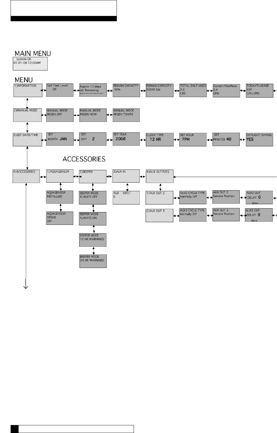
Menu Overview
Continued on page 61
Menu Overview 60
59 CULLIGAN GLOBAL ELECTRONIC CONTROLLER
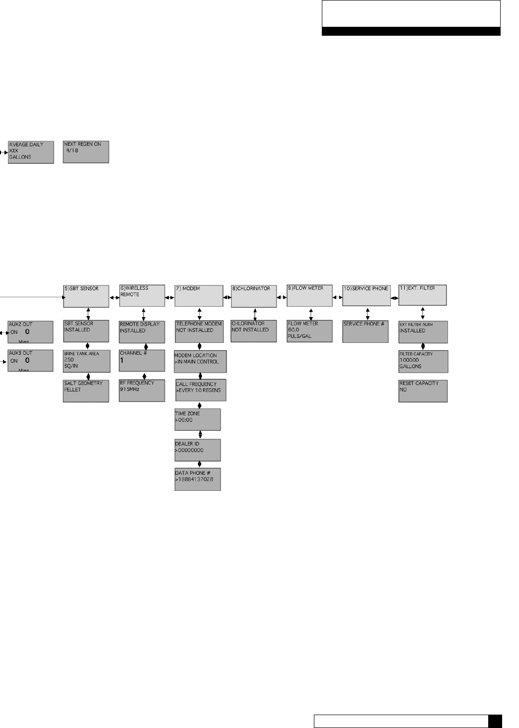
Menu Overview
Menu Overview 60
59 CULLIGAN GLOBAL ELECTRONIC CONTROLLER
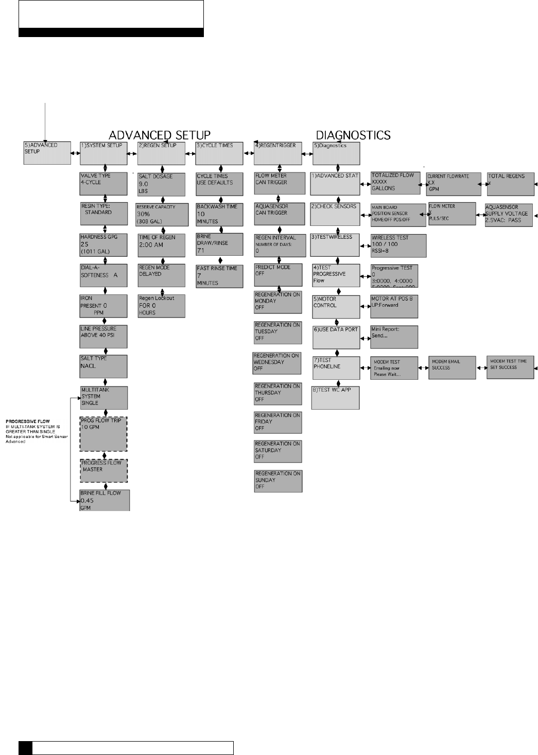
Menu Overview
Continued from page 59
Menu Overview 62
61 CULLIGAN GLOBAL ELECTRONIC CONTROLLER
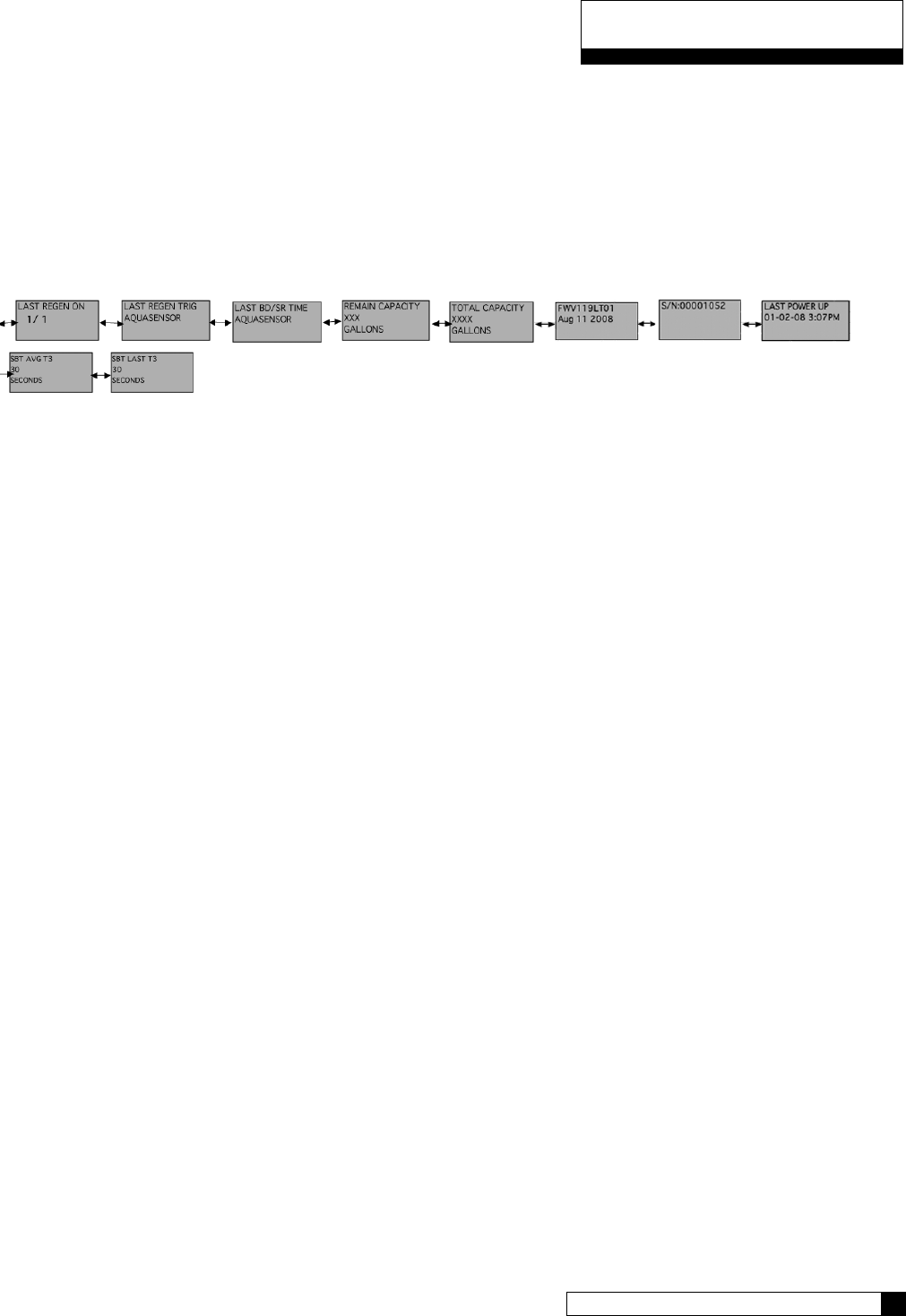
Menu Overview
Menu Overview 62
61 CULLIGAN GLOBAL ELECTRONIC CONTROLLER
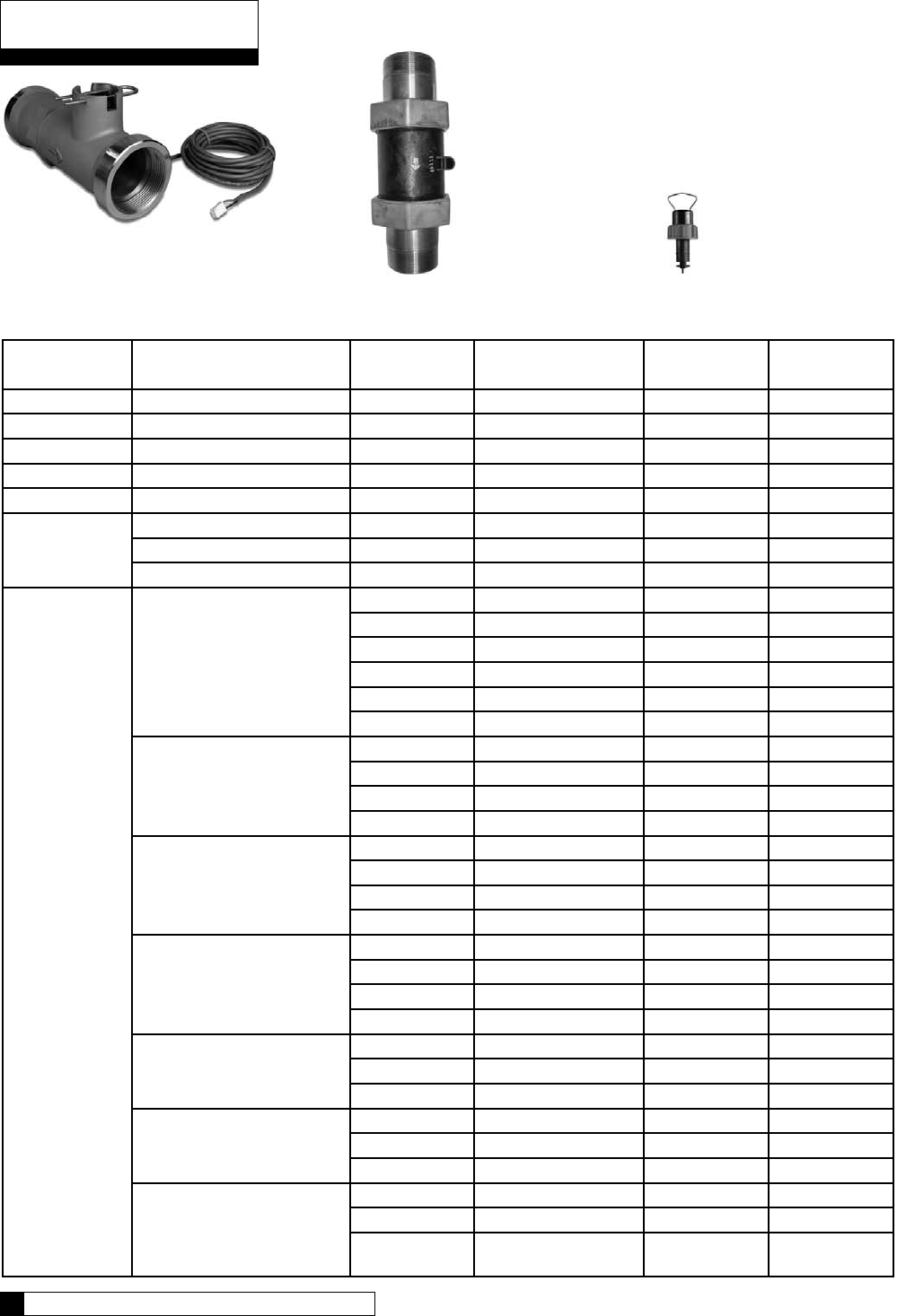
Clack
Autotrol Signet/ Seametrics
Flow Device K-Factor Data
Meter Type Installation Fitting
Type (if applicable)
Pipe Size Flow Range
(Gal. Per Min.)1
K-Factor -
Gallons
K-Factor -
Liters
Hi-Flo 22 Integral 78 295.2
Clack Brass Tee 1.5” 0.75 to 75 37 140
Clack Stainless Steel Tee 2.0” 1.5 to 150 20 75.7
Autotrol Plastic Body w/SS ends 1.5” 7 to 250 15 56.8
Autotrol Plastic Body w/SS ends 2” 7 - 250 15 56.8
SeaMetrics
Paddlewheel
All 2” 3.1 - 195.8 18 58.1
All 3” 6.6 - 440.6 11 41.6
All 4” 11.74 - 783.2 6.5 24.6
Signet
Paddlewheel
(Blue Nut)
Sch. 80 PVC Tee
1” 0.6 - 42 352.4 1333.8
1.25” 1.2 - 77 177.2 670.7
1.5” 1.6 - 106 117.9 446.3
2” 2.7 - 179 66.7 252.5
2.5” 3.8 - 256 43.0 162.8
3” 6.0 - 401 26.7 102.1
Sch. 40
Galvanized Tee
1” 0.7 - 44 213.0 806.2
1.25” 1.2 - 80 127.7 483.3
1.5” 1.7 - 110 94.4 357.3
2” 2.8 - 184 58.4 221
Type K Copper Tee
1” 0.7 - 48 256.4 970.5
1.25” 1.1 - 75 176.4 667.7
1.5” 1.6 - 107 115.7 437.9
2” 2.8 - 187 63.4 240
Type L Copper Tee
1” 0.8 - 51 241.6 914.5
1.25” 1.2 - 78 170.9 646.9
1.5” 1.7 - 110 112.0 423.9
2” 2.9 - 192 61.7 235.5
Sch. 40 Steel
Pipe Saddle
2.5” 4.5 - 298 37.6 142.3
3” 6.9 - 460 23.2 87.8
4” 11.9 - 793 13.3 50.3
Sch. 80 PVC
Saddle
2.5” 3.9 - 256 43.0 162.8
3”` 6.0 - 401 26.7 101.1
4” 10.5 - 701 15.0 56.8
Brazolet
-Sch 40 Copper Pipe
-Sch 40 Bronze Pipe
-Sch 40 Brass Pipe Weldolet
-Sch 40 Steel Pipe
2.5” 4.0 - 264 37.6 142.3
3” 6.2 - 411 24.3 92
4” 10.8 - 716 13.9 52.6
Appendix A
Appendix B 64
63 CULLIGAN GLOBAL ELECTRONIC CONTROLLER
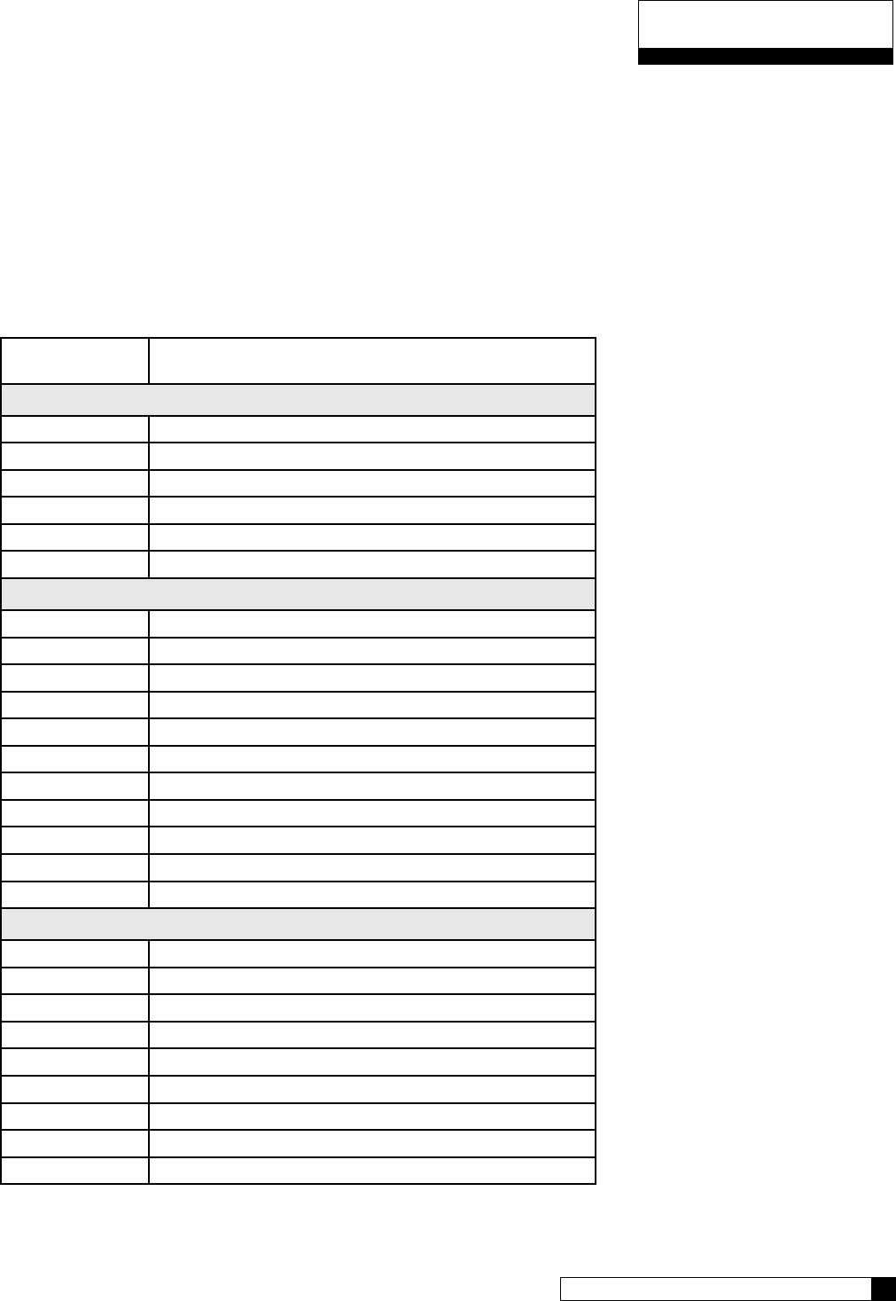
Appendix B 64
63 CULLIGAN GLOBAL ELECTRONIC CONTROLLER
GBE Controller Parts & Accessories List
Part Number Item
Complete Controls
01020677 GBE Controller Complete for CSM, HF50 Softener
GBE Controller Complete for CSM, HF42, HF50 Filter
Hi-Flo 22 Softener Control Valve with GBE Controller
Hi-Flo 22 Filter Control Valve with GBE Controller
HF3e Conversion Kit – 2”
HF3e Conversion Kit – 1-1/2”
Accessories and Replacement Parts
01020745 Replacement GBE Board
01020497 Replacement Key pad
01020748 Auxiliary Board
01020747 Modem Board
01020750 RF Board
01020553 Remote Display - Complete
0101 Transformer
01020447 Smart Brine Tank Accessory
01008779 Aqua-Sensor – Steel Tank
01018959 Aqua-Sensor – Fiberglass Tank
CR 2032 Battery
Cables and Kits
01016327 Communication Cable
01016342 Communication Cable – Duplex Alternating
01016333 Duplex Progressive Kit
01016334 Triplex Progressive Kit
01016369 Duplex Alternating Kit
0102 SBT Extension Cable, 20ft
0102 PLC-USB Communication Cable w/CD
0102 PLC-RS485 Communication Cable
0102 PLC-RS232 Communication Cable
Appendix B

Appendix C
Appendix B 66
65 CULLIGAN GLOBAL ELECTRONIC CONTROLLER
Culligan GBE Controller – Data Port Output
The GBE controller is used to control water softeners, filters and commercial RO systems. This controller has the
ability to provide “status messages” to a customer’s equipment using RS-232 and RS-485 communication protocols.
These protocols are commonly used to send information from the GBE to either a customer’s PC or to a building
management system or programmable logic controller (PLC). The information is “one-way” in that the GBE can
send this information out, but the GBE cannot receive or respond to any commands sent into the communication
port. The GBE sends a “status message” every 10 minutes. The information is send as a short text (ASCII), comma
separated string of letters and numbers.
The information contained in the “status message” depends upon what type of equipment is being controlled by
the GBE.
Single Water Softener or Filter controlled by GBE:
The format of the “status message” is: CULL,A,B,C,D,E,F
Example: CULL,52754,57.2,1,911,0x0000,1
Where the values for the fields A thru F are as follows:
A = total gallons since new
B = current flow rate in gallons per minute (57.2 means 57.2 gallons per minute )
C = Current Status Indicator (0 = initialization, 1=service, 2=prerinse, 3=regen, 4= standby)
D = capacity remaining in gallons
E = Error Flag (see below)
F = 1
Error Bit Meaning
0 Internal Valve Leak
1 Salt Bridging Detected
2 Brine Line Blocked
3 Brine Tank Overfill Error
4 Replace Media Filter
5 No RF Remote Signal
6 AquaSensor Salt Error (possibly low salt or failed eduction)
7 Motor Homing Error
8 Motor Position Sensor Error
9 Low Salt Level in Brine Tank
10 (not used)
11 AquaSensor Probe Fault (probe has failed, not plugged in or AquaSensor transformer failed)
12 Less than 14 Days Salt
The error flag is sent as a hexadecimal number in the format 0xWXYZ as follows:
W X Y Z
15 14 13 12 11 10 9 8 7 6 5 4 3 2 1 0
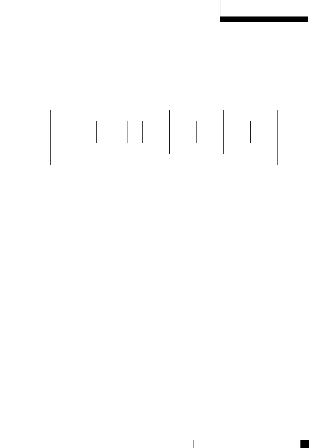
Appendix C
Appendix B 66
65 CULLIGAN GLOBAL ELECTRONIC CONTROLLER
Each error bit is either ‘0’ meaning that this error is NOT present, or ‘1’ meaning that this error IS present. Each of
the four-bit sections (W, X, Y and Z) are then combined into a four digit binary word which is converted to a hexa-
decimal digit.
As an example, if there are no errors present, then the value would be 0x0000.
If there were a ‘Replace Media Filter’, ‘Aquasensor Salt Err’ and ‘Motor Position Sensor Error’ present then bits 4,
6 and 8 would be set to ‘1’ respectively and all other bits would be ‘0’.
W X Y Z
Error Bits 15 14 13 12 11 10 9 8 7 6 5 4 3 2 1 0
Binary 0 0 0 0 0 0 0 1 0 1 0 1 0 0 0 0
hexadecimal 0 1 5** 0
Error Flag 0x0150
*note that the first two characters of the error flag are always “0x” to signify that this is a hexadecimal number
** In hexadecimal, the number 4 bit equals 1, the number 5 bit equals 2, the number 6 bit equals 4, and the
number 7 bit equals 8. Therefore, when you add the #4 bit value to the #1 bit value, you get 5.
So the value of the error flag would be 0x0150 if these three errors were present.
NOTE: If the GBE is controlling a Filter (instead of a water softener) then the above message definitions are identi-
cal, but that error flags 1,2,3,6,9 and 11 will always be zero for a filter)
Progressive Flow System of Water Softeners controlled by GBE:
The format of the “status message” for a progressive flow network consists of a series of individual lines of informa-
tion, one line for each of the gbe controlled softeners. For example, in a triplex progressive flow network, every
10 minutes, the data port on the master unit will send out the following three lines of information:
CULL,A1,B1,C1,D1,E1,1
CULL,A2,B2,C2,D2,E2,2
CULL,A3,B3,C3,D3,E3,3
example: CULL,52754,3.7,1,9110,0x0000,1
CULL,42674,3.5,1,4321,0x0000,2
CULL,10204,0.0,4,5444,0x0000,3
The ‘1’ at the end of the first line indicates that this line is the status for the Master unit in the progressive flow net-
work. The ‘2’ and ‘3’ on the subsequent lines indicate that this data is for slave unit #1 and slave unit #2 respec-
tively. The information contained on each line is of the same format as described in the Single softener section
above.
Electrical Connections
The Culligan Data Cable Connector is terminated with a D-sub9 style female termination. The customer must pro-
vide the following pin connections:
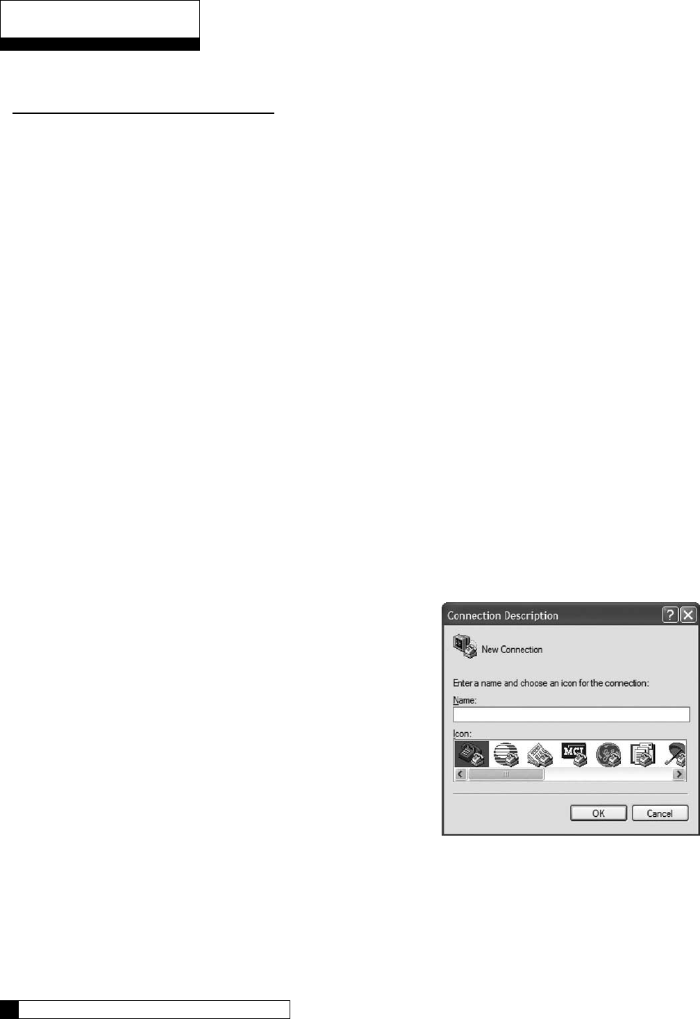
Appendix C
Pin Function
3 (input) TD (data coming FROM the GBE board)
2 (output) RD (this line is required even though no data is sent TO the GBE board)
7 (input) RTS
8 (output) CTS
5 (signal gnd) GND
The data coming from the GBE board is at the following conditions:
Bits Per Second: 9600
Data Bits: 8
Parity: None
Stop Bits: 1
Flow Control: None
The following style data cables are available from Culligan:
Cable P/N: xxxxxxxx 9-pin female RS-232 output
Cable P/N: xxxxxxxx 9-pin female RS-485 output
Cable P/N: xxxxxxxx USB style output cable - comes with CD-ROM which includes
device drivers for Microsoft Windows VISTA, XP, and
Windows 2000 operating systems
Test Data Port
Once your cables are set up, you can test your connection using the
Windows’ Hyperterminal program. This program is generally found
under Start/All Programs/Accessories/Communications/
Hyperterminal
When you open Hyperterminal it will ask you to create a name for
the connection. Enter any name you choose and click OK.
Next you are asked to select a COM port. From the drop down list,
pick the COM port with the highest number and click OK.
Next you are asked to set the properties for this COM port. They
should be set as shown.
After you click OK, Hyperterminal is ready to accept data.
Appendix C 68
67 CULLIGAN GLOBAL ELECTRONIC CONTROLLER
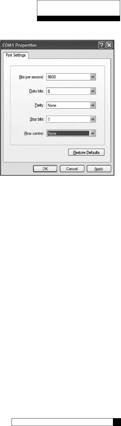
Appendix C
Appendix C 68
67 CULLIGAN GLOBAL ELECTRONIC CONTROLLER
Return to the GBE controller and press the Down Arrow to
enter the Menu.
Using the down arrow, scroll down to number 5, Advanced
Setup, and press the checkmark.
Using the down arrow, scroll to number 5, Diagnostics, and
press the checkmark.
Scroll to number 6, Use Data Port. When you press the
checkmark, the GBE controller will send a test message to the
Hyperterminal screen. It will look similar to this:
If you do not see the report, check your settings and make sure
the cables are firmly connected. If you still don’t see the report, try some of the other COM ports.
Every 10 minutes you should see a status message on the screen that will look similar to this:
CULL,52754,57.2,1,911,0x0000,1
This message was described at the beginning of this Appendix.
*** MINI REPORT ***
SN = 00001078
Date = 9/4/8
Time = 14:02
Total = 28696 GAL
regen 14d = 0
trigger = Power Outage
type = softener
hardness units = US
Hardness = 25 grains
Resin = 1.00 cu/ft
avg mon = 710 GAL
avg tue = 937 GAL
avg wed = 1201 GAL
avg thr = 839 GAL
avg fri = 1364 GAL
avg sat = 85 GAL
avg sun gal = 710 GAL
bw time = 10 min
BD rinse = 71 min
F rinse = 10 min
Fill = 441 sec
Dosage = 9.0 LBS
DAS = A
Iron = 0 PPM
Pressure = HIGH
Salt type = NaCl
Resin type = std
BF Flow control = 0.45 GPM
Eductor Flow control = 32.0
Reserve capacity = 25 %
flow meter trig = yes
aquasensor trig = yes
regen interval = 7
predict mode = no
day of week mode = none
brine type = Downflow
pre-rinse mode = yes
prerinse after 24 hours
prerinse for 5 mins
units = US
A/S = not installed
SBT = inst
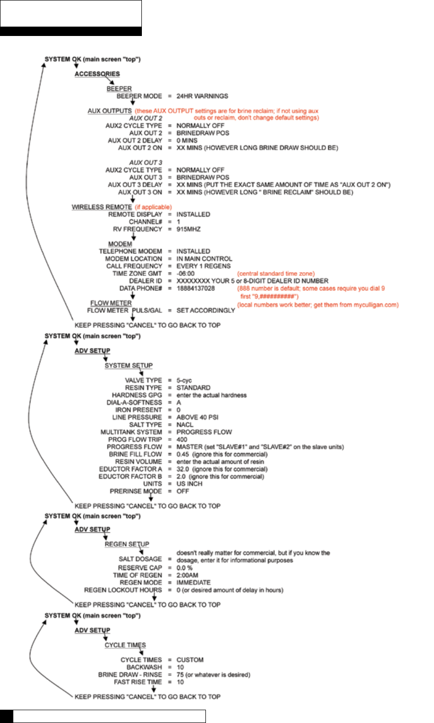
Appendix D
Index 70
69 CULLIGAN GLOBAL ELECTRONIC CONTROLLER

Index
Index 70
69 CULLIGAN GLOBAL ELECTRONIC CONTROLLER
Accessories 33-45
Alternating 3, 11, 13-14, 17, 22, 42, 64
Aqua-Sensor 3, 7, 8, 15, 21-22, 33, 53, 64
Auxiliary Board 46-47
Auxiliary Outputs 2, 11, 16, 43, 46-48
Beeper 1, 19, 33
Brine Reclaim 2, 22, 43
Brine Refill 6, 10, 22, 27, 31, 47-48, 50, 55
Cable 6, 7, 9, 11, 12, 13, 15, 17, 64
Check Sensors 55-57
Clock 52
Communication Cable, 6, 7, 11, 12, 13, 17, 64
Customizing the setup 28-34
Cycle Times 21-22, 27, 31-32, 42
Data Phone Number 44
Diagnostics 2, 21, 27, 40, 50, 54-57
Error Codes 53
Features 1-2
First Time Setup 22,23-27,58
Flow Meters 1, 3, 7, 12-14, 18, 22, 32, 41, 42, 55, 63
Information 51-52
Installation - Electrical 4-17
Jumper 12
Keypad - Beeper 1, 19, 33
Keypad - Lockout 58
Keypad 1, 7, 19, 20, 58, 64
K-Factors 1, 22, 41, 63
Manual Cycling 50
Manual Regeneration 49
Menu Lockout 58
Metric 30
Modem 2, 21-22, 23, 35, 37-41, 53, 64
Multi-Tank Systems 42
Outputs 2, 11, 16, 43, 46-48
Parallel 11, 12, 22, 42
Parts List 64
Phone Number 40, 44
PLC Output 65
Programming 18-58
Progressive Flow 2, 3, 11, 12, 13, 21, 22, 29, 41-42, 64
Pulses per gallon 41
Quick Reference 70
Reclaim 2, 22, 43
Refill 6, 10, 22, 27, 31, 47-48, 50, 55
Regeneration 30-31
Remote 2, 21, 22, 35-37, 38, 39, 53, 64
Reserve Capacity 30
SBT 2, 21-22, 51
Sensors 55-57
Service Phone Number 44
Setup - Advanced 28-30
Setup - Commercial 22
Setup - Customizing 28-34
Setup - Cycle Times 31
Setup - First Time 23-27
Setup - Multi-Tank Systems 42
Setup - Regeneration 30-31
Setup - Reneration Triggers 21, 32
Setup - Wireless Remote 36-37
Smart Brine Tank 2, 21-22, 51
Statistics 54
Time Clock 3
Time Zone 39
Transformer 4, 8-9, 15, 64
Triggers 21, 32
Units of Measure 30
Wireless Remote 2, 21, 22, 35-37, 38, 39, 53, 64

Materials & Description: Global Electronic (GBE) Softener & Filter Controller IO Guide
PN 01021161
Size: 8.5” x 11”
Color: Black Ink, 2 sided
Stock: Front (2 sided) & Back (Blank) Covers on 110# White Index
Inside on 20# white
Other: Collate
Tape Bind, Black Down the 11” left side
3 Hole Drill
This page contains materials and DCO information.
IT DOES NOT PRINT AS PART OF THE DOCUMENT!
VENDOR MUST SUBMIT A MATERIAL CERTIFICATE OF COMPLIANCE WITH EACH SHIPMENT.
LET CHANGE BY APRVD DCO DATE
A NEW ART CREATED BSM KR 010703 08/13/08
A1 Revisions BSM KR 010703 09/04/08
A2 Revisions BSM KR 010703 09/18/08
A3 Revisions BSM KR 010703 09/25/08
A4 Minor revisions BSM KR 010703 10/02/08
A5 Minor revisions BSM KR 010703 10/15/08
A6 Minor revision BSM KR 010703 10/16/08