Culligan 010291CL Bidirectional module User Manual
Culligan International Company Bidirectional module
Culligan >
User Manual

DRINKING WATER | AGUA POTABLE
ClearLink Pro™
Wireless Filtration Control
Installation and operating instructions
ClearLink Pro™
Control de Filtración de Agua Inalámbrico
Instrucciones de instalación y operación

2
PRECAUTIONS
WARNING: Follow all precautions indicated in the manual provided with the Culligan water treatment system.
WARNING: For systems using a booster or distribution pump, the pressure of the treated water cannot exceed
the pressure of the cold water supply.
CAUTION: Control box must be protected against freezing temperatures, frost, snow, sleet, and ice.
Exposure to these can produce cracks and product failures.
CAUTION: This product has a limited service life. We recommend that a record be kept regarding the
date of install and any other performed maintenance. Because of the product’s limited service life and
to prevent costly repairs or possible water damage, we strongly recommend that the control box be
replaced every ten years.
WARNING: For cold water use only. Do not use on hot water line.
the system be ushed thoroughly. Let the ltered water run for 5–6 minutes before using.
4
2
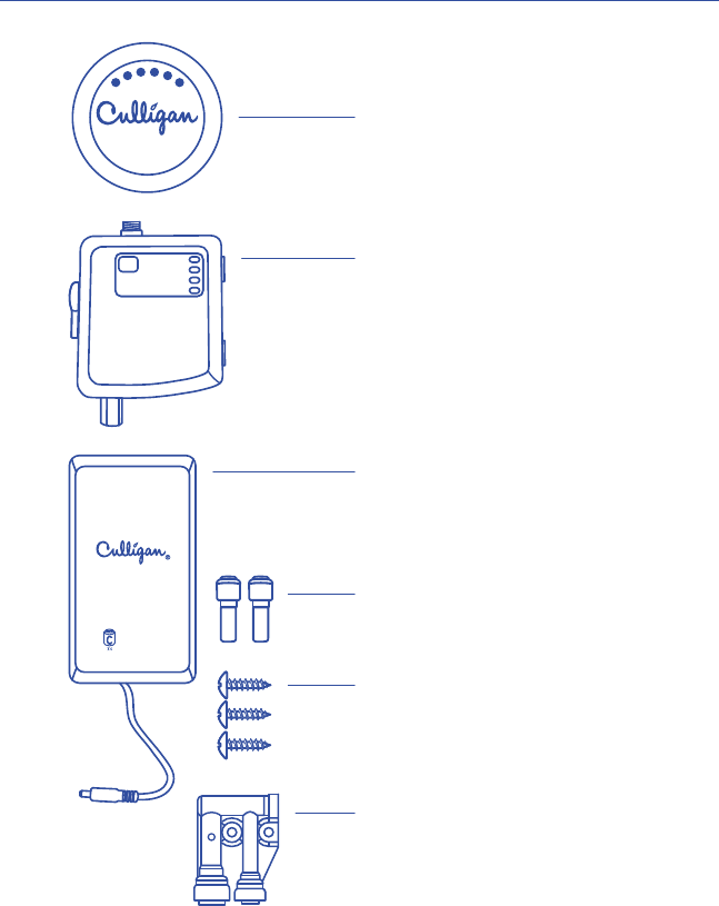
PARTS
INCLUDED:
3/8" x 1/4" Tube Adapter
SPECIFICATIONS
Temperature Range: 40 –100°°
English
3
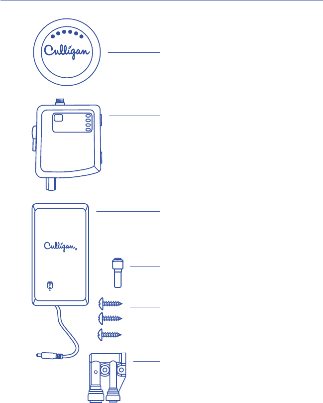
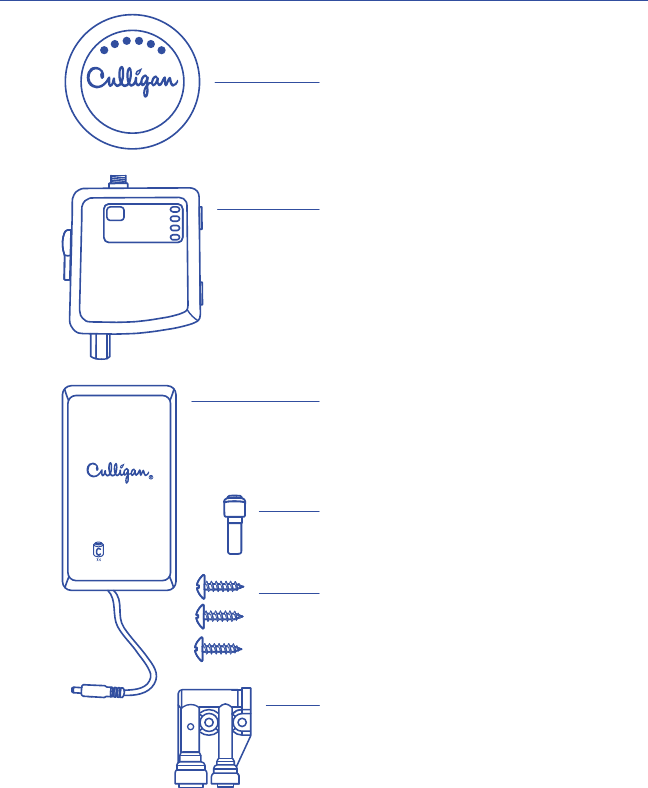
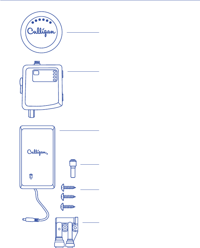
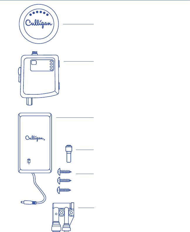
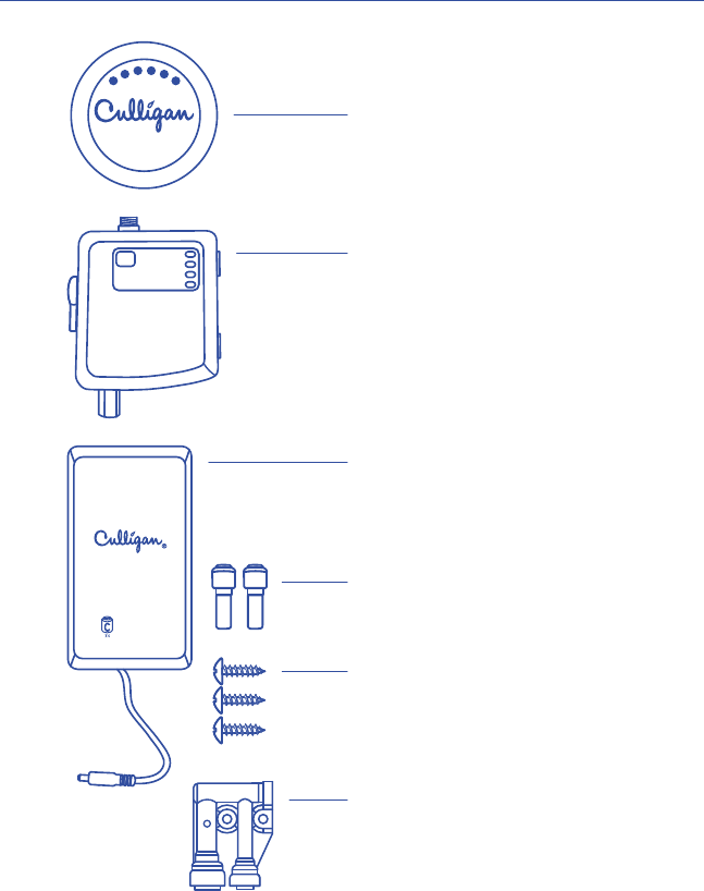
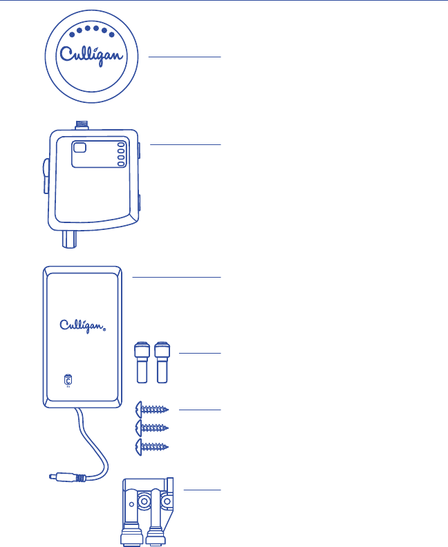
UNIVERSAL WIRELESS FILTRATION CONTROL
Remote Button
Button Part No.: 01029450
Trim Ring Part Nos.:
Chrome 01029452
Brushed Nickel 01029453
Oil Rubbed Bronze 01029454
Control Box
Part No.: 01029449
Air Gap
Battery Box
Part No.: 01029451
PARTS INCLUDED:
3/8" x 1/4" Tube Adapter

4
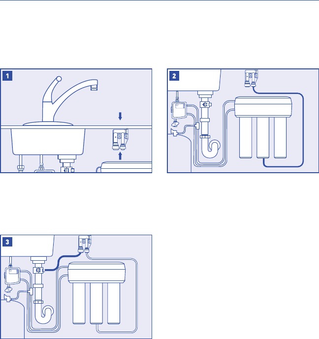
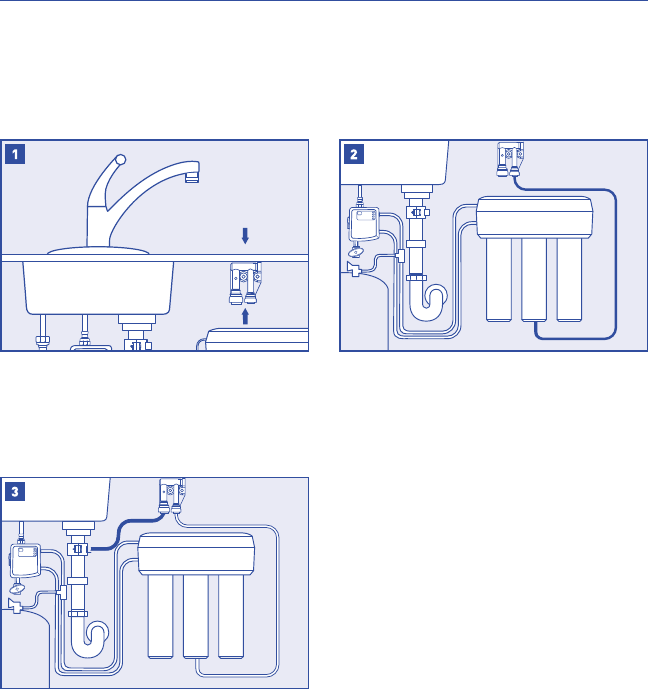
the kitchen faucet and allow all water to drain
from line.
SETTING CAPACITY AND TDS FUNCTION
NOTE: Set capacity and TDS function before starting installation.
NOTE: To access the dip switches for setting capacity and TDS function,
open the control box by removing the three screws in the rear cover.
Find the dip switches on the front of the circuit board.
SW2 and SW3 set the time and capacity for the lter reminder.
SW2: OFF = 500 gallons ON = 1000 gallons
SW3: OFF = 180 days ON = 365 days
The system will measure the dierence between the feed and product
water to determine if the RO is working.
SW1: OFF = Disabled ON = Enabled
SW6 is used for production testing and should be left in the o position.
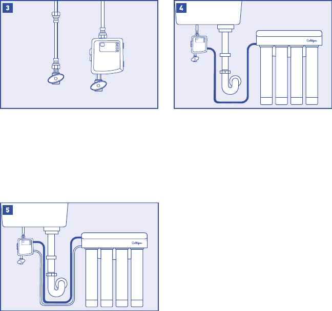
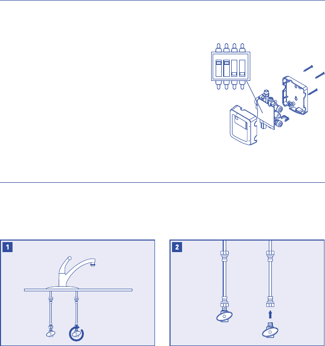
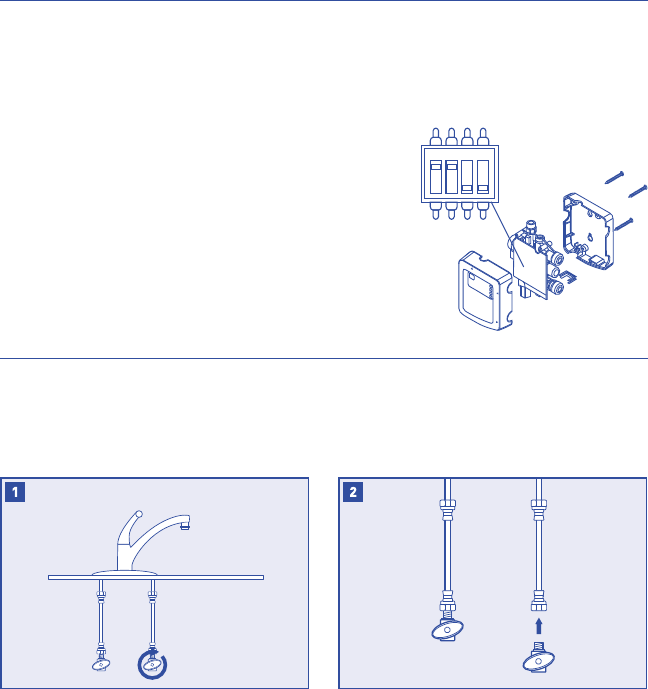
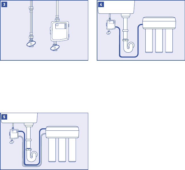
INSTALLATION
NOTE: Refer to the manual provided with your filter/RO for installation
instructions specific to that system.
NOTE: Some installations may require adapters and ttings not included with
the product. Review the manual and your installation before beginning.
NOTE: Consult your local plumbing codes and install accordingly.
Disconnect the cold water line from the cold water
NOTE:
is used, you may need to shorten the pipe using
a hacksaw or pipe cutter to accommodate the
control box.
SW6
SW3
SW2
SW1
ON
5
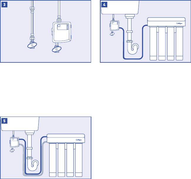
Connect the inlet on the RO/Filter system to the
port marked "RO/Filter >." Wet the end of the
plastic tubing with water and push it into the
quick connect tting adapter approximately 5/8˝
until it stops.
NOTE: This connection is plugged for remote
NOTE: This is the line that would normally come
from the supply tee or valve.
NOTE: Use the supplied adapter if your system
uses a 1/4" tube.
Connect the outlet on the RO/Filter system to the
port marked "RO/Filter <." Wet the end of the
plastic tubing with water and push it into the
quick connect tting adapter approximately 5/8"
until it stops.
NOTE: This is the line that would normally go to
your dedicated faucet.
NOTE: Connect the tank and/or post lter in
this line if required for your lter/RO system.
valve as shown. Tighten the lower end of cold water
line onto the top of the control box.
NOTE: The control box must be in a
vertical position.
NOTE: If space does not allow for mounting the
control box onto the valve, it can be alternatively
hung on a wall when using the holes on the back

6
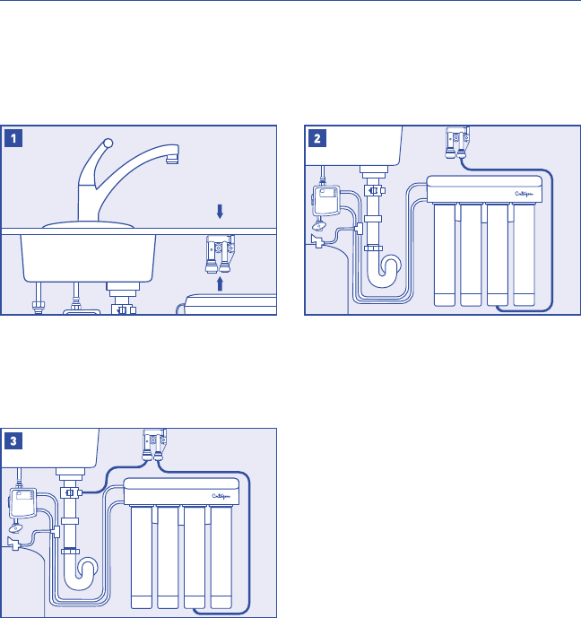
AIR GAP
RO AIR GAP INSTALLATION
NOTE: These steps are only for RO installations using an air gap.
NOTE: If your ltration system is not an RO, skip to System Startup on Page
NOTE: Install the drain connection to the drain plumbing according to the manual
provided with your RO system.
Connect the drain line coming from the RO
system to the small connection of the air
gap device.
top as possible and in a vertical orientation.
NOTE: Failure to mount the air gap device
vertically will cause it to leak water.
Connect the large tting of the air gap device to
the connection on the drain plumbing.

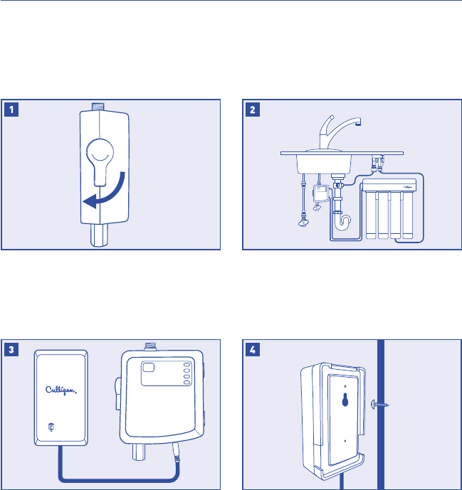
of the control box.
NOTE: The control box will beep and ash the
power light when powering up.
NOTE:
Conrm that the bypass valve is in the closed
Turn on the cold water supply and check for leaks.
If it leaks, refer to troubleshooting.
Use the provided screw to hang the battery box on
the side of the cabinet.
BYPASS

8
Turn on the faucet to full cold and push the button
to activate the system.
NOTE: The blue capacity lights should appear if
the button and control box are communicating.
NOTE: The button can be turned o with
a second push or by turning o the faucet.
NOTE: After startup, flush your system
according to manufacturer's specications.
It might take a few cycles for the button to
stay on while air is purged from the system.
remote button.

9
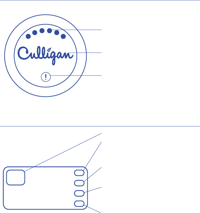
depending on lter capacity remaining,
6 lights = >80% and 1 light = <10%.
Culligan Logo: Flashes when treated water is not
available from the faucet. Stays solid while treated
water is being dispensed from the faucet.
Alert Indicator: Illuminates when the control box
batteries need replacing, lters need replacing, or
RO membrane needs replacing.
BUTTON DISPLAY GUIDE
CONTROL BOX OPERATION
RESET POWER
REPLACE BATTERIES
REPLACE FILTERS
Reset button for filter capacity.
Power: Flashes green at power up, lter capacity
reset, and while dispensing ltered water. Continues
to ash for 1 minute after the ow of ltered water
has stopped.
Replace Batteries: Flashes red when the batteries
for the control box need to be replaced. This indicator
automatically clears when new batteries are detected.
Replace Filters: Flashes red when the lters have
less than 10% of their life remaining due to ow or
time. This indicator is reset by pressing the reset
button for two seconds.
treated water has a TDS level greater than 25% of
the untreated water. This indicator will automatically
reset when low TDS water is detected.

10
TROUBLESHOOTING
LEAKS AT FILTER/RO INLET OR OUTLET CONNECTION:
and then conrm that the end of the tubing has a clean, square cut.
Low ow rates may not activate the control box electronics. Refer to your system manual to trouble
shoot a low ow condition.
Conrm that the bypass valve is in the down/closed position.
Some materials may block the wireless signal more than others. Try moving the button to an area on
FILTERED WATER FLOW WON'T TURN OFF: Low batteries for the control box can cause the system
to be stuck in the ltered position. The bypass valve can be used to allow unltered water ow to the
faucet while the issue is being corrected.
INTEGRITY

11
This warranty applies to the button, control box and battery box. This warranty covers defects in material
and workmanship only for 1 full year from the original date of delivery. Culligan will replace any part
by Culligan.
This product has been designed solely for use as a water ltration control. It is NOT warranted against
freezing or surges in water pressure, and neither this product nor its parts is warranted against defects
or deterioration caused by uses for which this product was not expressly intended.
THE FOREGOING WARRANTY IS EXCLUSIVE AND IN LIEU OF ALL OTHER WARRANTIES, EXPRESSED
CHARGES OR OTHER LOSSES, WHETHER BASED ON BREACH OF CONTRACT, TORTIOUS CONDUCT OR
ANY OTHER THEORY, INCURRED IN CONNECTION WITH THE PURCHASE, INSTALLATION, REPAIR OR
FILTER HOUSING OR ANY PART THEREOF.
device must accept all interference received including interference that may cause undesired operation.
Le présent appareil est conforme aux CNR d'Industrie Canada applicables aux appareils radio exempts de licence. L'exploitation est autorisée aux deux
même si le brouillage est susceptible d'en compromettre le fonctionnement.
This device complies with Health Canada’s Safety Code. The installer of this device should ensure that RF radiation is not emitted in excess of the Health
Canada’s requirement.
Cet appareil est conforme avec Santé Canada Code de sécurité 6. Le programme d’installation de cet appareil doit s’assurer que les rayonnements RF n’est
Changes or modications not expressly approved by the party responsible for compliance could void the user’s authority to operate the equipment.
utiliser cet équipement
This equipment has been tested and found to comply with the limits for a Class B digital device, pursuant to part 15 of the FCC Rules. These limits are
designed to provide reasonable protection against harmful interference in a residential installation. This equipment generates, uses and can radiate radio
frequency energy and, if not installed and used in accordance with the instructions, may cause harmful interference to radio communications. However,
there is no guarantee that interference will not occur in a particular installation. If this equipment does cause harmful interference to radio or television
reception, which can be determined by turning the equipment o and on, the user is encouraged to try to correct the interference by one or more of the
following measures:
— Reorient or relocate the receiving antenna.
— Increase the separation between the equipment and receiver.
— Connect the equipment into an outlet on a circuit dierent from that to which the receiver is connected.
— Consult the dealer or an experienced radio/TV technician for help.
Le présent appareil est conforme aux CNR d'Industrie Canada applicables aux appareils radio exempts de licence. L'exploitation est autorisée aux deux
même si le brouillage est susceptible d'en compromettre le fonctionnement.

12
PRECAUCIONES
ADVERTENCIA: Siga todas las precauciones indicadas en el manual provisto con el sistema de
tratamiento de agua de Culligan.
ADVERTENCIA: Para sistemas empleando una bomba de refuerzo o de distribución, la presión del
agua no tratado no puede exceder la presión del agua fría del suministro.
PRECAUCIÓN:
nieve, aguanieve, y hielo. El producto puede fallar si se expone a estos elementos.
PRECAUCIÓN: Este producto lleva una vida de servicio limitada. Se recomienda que se lleve un
registro de la instalación y de cualquier otro mantenimiento. Debido a la vida de servicio limitada,
y para evitar reparaciones costosas o posibles daños por agua, se recomienda enfáticamente que
ADVERTENCIA: Se debe utilizar únicamente con agua fría. No se debe utilizar con agua caliente.
PIEZAS
INCLUIDO
3/8" x 1/4"
ESPECIFICACIONES
Gama de Temperatura: 40 –100°°
Español
13
Botón del Control Remoto
Botón Núm.: 01029450
Opciones de Anillo de Borde:
Cromo 01029452
Níquel Cepillado 01029453
Bronce de Aceite Frotado 01029454
Parte Núm.: 01029449
Adaptadore de Tubo 3/8" x 1/4"
Entrehierro
Parte Núm.: 01029451
PIEZAS INCLUIDAS:

14
Desconecte la línea de suministro de agua fría,
drene toda el agua de la cañería.
1
NOTA: Favor de programar la capacidad y la función TDS antes de comenzar la instalación.
NOTA: Para obtener acceso a los interruptores DIP para la capacidad y la función TDS, abra
Localice los interruptores DIP en la parte frontal de la placa de circuito.
SW2: APAGADO = 500 galones ENCENDIDO = 1,000 galones
SW3: APAGADO = 180 días ENCENDIDO = 365 días
SW1: APAGADO = Inhabilitado ENCENDIDO = Habilitado
SW6 se usa para las pruebas de producción y debe permanecer
en la posición apagada.
INSTALACIÓN
NOTA: Favor de referirse al manual provisto con su filtro/sistema de osmosis inverso
para las instrucciones de instalación especificadas para sú sistema de filtración.
NOTA: Algunas instalaciones exigen adaptadores u otras piezas no incluidas con
este producto. Repase el manual y el proceso de instalación antes de comenzar.
NOTA: Consulte y instale de acuerdo con los códigos de plomería locales.
Desconecte la línea de agua fría de la válvula de
cierre de agua fría.
NOTA:
es posible que deba acortar la tubería con una
sierra para metales o un cortatubos a n de
SW6
SW3
SW2
SW1
ON

15
agua fría según la diagrama. Aprieta la parte inferior
de la línea de agua fría a la parte superior de la
NOTA:
instale verticalmente.
NOTA:
una pared usando conectadores exibles como
una alternativa.
Conecte la entrada del sistema de ltración al
aproximadamente 5/8" hasta que pare.
NOTA: Esta conexión está conectado para
de agua para el ltro no es el mismo suministro
NOTA: Esta es la línea que normalmente correría
desde la la válvula de suministro de agua.
NOTA: Use uno de los adaptadore suministrados
si su sistema emplea un tubo más pequeño.
Conecte la salida del sistema de ltración al
aproximadamente 5/8" hasta que pare.
NOTA: Esta es la línea que normalmente correría
hacia el grifo dedicado.
NOTA: Use uno de los adaptadore suministrados
si su sistema emplea un tubo más pequeño.

16
Conecte la púa grande del entrehierro a la
de osmosis inverso a la pequeña conexión púa
del entrehierro.
ENTREHIERRO
más cerca posible a la encimera.
NOTA: El entrehierro derramará agua si no se
instala verticalmente.
NOTA: Los siguientes pasos aplican únicamente a instalaciones de osmosis inverso
empleando un entrehierro.
NOTA: Si su sistema de ltración no es de osmosis inverso, brinque a la sección de
Inicio del Sistema en la página .
NOTA:
con sú sistema de osmosis inverso.

de pilas y enchufe al gato en la parte inferior de
NOTA:
de fuerza parpadeará al encender.
NOTA:
usarse también cuando un enchufe no
interruptor esté disponible.
Abra el suministro de agua fría para averiguar
si se derrama agua o no. Si el sistema está
derramando agua, consulte la sección de
Solución de Problemas.
baterías a la pared interior del cabinete.
BYPASS
Asegúrese que la válvula de derivación esté en la

18
Abra el grifo de agua fría completamente y
NOTA: La luces azules de capacidad deben
están comunicándose.
NOTA: El botón se puede apagar con un
NOTA:
acuerdo con las especicaciones del fabricante.
Puede que tome algunos ciclos para que el botón
permanezca encendido mientras aire sea
expulsado del sistema.
de control remoto.

19
Alarma: Enciende cuando las baterías de la
de control, los ltros, o la membrana de osmosis
inverso deben ser reemplazados.
GUÍA DE LA PANTALLA DEL BOTÓN
OPERACIÓN DE LA CAJA DE CONTROL
RESET POWER
REPLACE BATTERIES
REPLACE FILTERS
Botón de reinicio de capacidad del filtro.
Fuerza: Enciende de color verde al inicio, cuando
reinicia la capacidad del filtro, y mientras corra
agua filtrada. La luz parpadeará por 1 minuto
cuando las baterías para deben
ser reemplazadas.
los filtros tienen menos de 10% de vida según indica el
el botón de reinicio por dos segundos.
un nivel de TDS mayor de 25% del agua no ltrada.
Este indicador se reinicia automaticamente cuando
Luces de Capacidad del Filtro: Enseñan 16 luces
dependiendo de la capacidad del ltro que le quede,
6 luces = >80% y 1 luz = <10%.
Logo Culligan: Enciende cuando agua ltrada no esté
disponible desde el grifo. Permanece encendido
mientras agua ltrada corra desde el grifo.

20
Una arendala doblada podría estorbar en entrada completa del tubo. Use un destornillador pequeño
para asentar la arendala de nuevo, y entonces asegurarse de que el extremo del tubo tenga una
cortada cuadrada, y limpia.
NO
Algunos materiales pueden estorbar la señal inalámbrica mas que otros. Puede probar la señal
EL AGUA FILTRADA NO SE APAGA:
que el sistema se quede en la posición de agua ltrada. Se puede emplear la válvula de derivación

21
fabricación por un año completo desde la fecha original de entrega. Culligan reemplazará cualquier
Este producto ha sido diseñado solamente para ser usado como un control de ltración de agua.
de presión de agua. El uso indebido de este producto y sus componentes podría provocar defectos
o deterioro no están cubiertos por la garantía.
ESTE PRODUCTO.

Culligan International Company
Rosemont, Illinois 60018
www.culligan.com

DRINKING WATER | AGUA POTABLE
ClearLink Pro™
Wireless Filtration Control
Installation and operating instructions
ClearLink Pro™
Control de Filtración de Agua Inalámbrico
Instrucciones de instalación y operación

2
PRECAUTIONS
WARNING: Follow all precautions indicated in the manual provided with the Culligan water treatment system.
WARNING: For systems using a booster or distribution pump, the pressure of the treated water cannot exceed
the pressure of the cold water supply.
CAUTION: Control box must be protected against freezing temperatures, frost, snow, sleet, and ice.
Exposure to these can produce cracks and product failures.
CAUTION: This product has a limited service life. We recommend that a record be kept regarding the
date of install and any other performed maintenance. Because of the product’s limited service life and
to prevent costly repairs or possible water damage, we strongly recommend that the control box be
replaced every ten years.
WARNING: For cold water use only. Do not use on hot water line.
the system be ushed thoroughly. Let the ltered water run for 5–6 minutes before using.
4
2
PARTS
INCLUDED:
3/8" x 1/4" Tube Adapter
SPECIFICATIONS
Temperature Range: 40 –100°°
English
3
UNIVERSAL WIRELESS FILTRATION CONTROL
Remote Button
Button Part No.: 01029450
Trim Ring Part Nos.:
Chrome 01029452
Brushed Nickel 01029453
Oil Rubbed Bronze 01029454
Control Box
Part No.: 01029449
Air Gap
Battery Box
Part No.: 01029451
PARTS INCLUDED:
3/8" x 1/4" Tube Adapter
4
the kitchen faucet and allow all water to drain
from line.
SETTING CAPACITY AND TDS FUNCTION
NOTE: Set capacity and TDS function before starting installation.
NOTE: To access the dip switches for setting capacity and TDS function,
open the control box by removing the three screws in the rear cover.
Find the dip switches on the front of the circuit board.
SW2 and SW3 set the time and capacity for the lter reminder.
SW2: OFF = 500 gallons ON = 1000 gallons
SW3: OFF = 180 days ON = 365 days
The system will measure the dierence between the feed and product
water to determine if the RO is working.
SW1: OFF = Disabled ON = Enabled
SW6 is used for production testing and should be left in the o position.
INSTALLATION
NOTE: Refer to the manual provided with your filter/RO for installation
instructions specific to that system.
NOTE: Some installations may require adapters and ttings not included with
the product. Review the manual and your installation before beginning.
NOTE: Consult your local plumbing codes and install accordingly.
Disconnect the cold water line from the cold water
NOTE:
is used, you may need to shorten the pipe using
a hacksaw or pipe cutter to accommodate the
control box.
SW6
SW3
SW2
SW1
ON

5
Connect the inlet on the RO/Filter system to the
port marked "RO/Filter >." Wet the end of the
plastic tubing with water and push it into the
quick connect tting adapter approximately 5/8˝
until it stops.
NOTE: This connection is plugged for remote
NOTE: This is the line that would normally come
from the supply tee or valve.
NOTE: Use the supplied adapter if your system
uses a 1/4" tube.
Connect the outlet on the RO/Filter system to the
port marked "RO/Filter <." Wet the end of the
plastic tubing with water and push it into the
quick connect tting adapter approximately 5/8"
until it stops.
NOTE: This is the line that would normally go to
your dedicated faucet.
NOTE: Connect the tank and/or post lter in
this line if required for your lter/RO system.
valve as shown. Tighten the lower end of cold water
line onto the top of the control box.
NOTE: The control box must be in a
vertical position.
NOTE: If space does not allow for mounting the
control box onto the valve, it can be alternatively
hung on a wall when using the holes on the back

6
AIR GAP
RO AIR GAP INSTALLATION
NOTE: These steps are only for RO installations using an air gap.
NOTE: If your ltration system is not an RO, skip to System Startup on Page
NOTE: Install the drain connection to the drain plumbing according to the manual
provided with your RO system.
Connect the drain line coming from the RO
system to the small connection of the air
gap device.
top as possible and in a vertical orientation.
NOTE: Failure to mount the air gap device
vertically will cause it to leak water.
Connect the large tting of the air gap device to
the connection on the drain plumbing.

of the control box.
NOTE: The control box will beep and ash the
power light when powering up.
NOTE:
Conrm that the bypass valve is in the closed
Turn on the cold water supply and check for leaks.
If it leaks, refer to troubleshooting.
Use the provided screw to hang the battery box on
the side of the cabinet.
BYPASS
8
Turn on the faucet to full cold and push the button
to activate the system.
NOTE: The blue capacity lights should appear if
the button and control box are communicating.
NOTE: The button can be turned o with
a second push or by turning o the faucet.
NOTE: After startup, flush your system
according to manufacturer's specications.
It might take a few cycles for the button to
stay on while air is purged from the system.
remote button.
9
depending on lter capacity remaining,
6 lights = >80% and 1 light = <10%.
Culligan Logo: Flashes when treated water is not
available from the faucet. Stays solid while treated
water is being dispensed from the faucet.
Alert Indicator: Illuminates when the control box
batteries need replacing, lters need replacing, or
RO membrane needs replacing.
BUTTON DISPLAY GUIDE
CONTROL BOX OPERATION
RESET POWER
REPLACE BATTERIES
REPLACE FILTERS
Reset button for filter capacity.
Power: Flashes green at power up, lter capacity
reset, and while dispensing ltered water. Continues
to ash for 1 minute after the ow of ltered water
has stopped.
Replace Batteries: Flashes red when the batteries
for the control box need to be replaced. This indicator
automatically clears when new batteries are detected.
Replace Filters: Flashes red when the lters have
less than 10% of their life remaining due to ow or
time. This indicator is reset by pressing the reset
button for two seconds.
treated water has a TDS level greater than 25% of
the untreated water. This indicator will automatically
reset when low TDS water is detected.

10
TROUBLESHOOTING
LEAKS AT FILTER/RO INLET OR OUTLET CONNECTION:
and then conrm that the end of the tubing has a clean, square cut.
Low ow rates may not activate the control box electronics. Refer to your system manual to trouble
shoot a low ow condition.
Conrm that the bypass valve is in the down/closed position.
Some materials may block the wireless signal more than others. Try moving the button to an area on
FILTERED WATER FLOW WON'T TURN OFF: Low batteries for the control box can cause the system
to be stuck in the ltered position. The bypass valve can be used to allow unltered water ow to the
faucet while the issue is being corrected.
This device must accept all interference received including interference that may cause undesired operation.
Le présent appareil est conforme aux CNR d'Industrie Canada applicables aux appareils radio exempts de licence. L'exploitation est autorisée
radioélectrique subi, même si le brouillage est susceptible d'en compromettre le fonctionnement.
This device complies with Health Canada’s Safety Code. The installer of this device should ensure that RF radiation is not emitted in excess of the
Health Canada’s requirement.
Cet appareil est conforme avec Santé Canada Code de sécurité 6. Le programme d’installation de cet appareil doit s’assurer que les rayonnements RF
Changes or modications not expressly approved by the party responsible for compliance could void the user’s authority to operate the equipment.
Les changements ou modications non expressément approuvés par la partie responsable de la conformité pourraient annuler l'autorité de
This equipment has been tested and found to comply with the limits for a Class B digital device, pursuant to part 15 of the FCC Rules. These limits are
designed to provide reasonable protection against harmful interference in a residential installation. This equipment generates, uses and can radiate
radio frequency energy and, if not installed and used in accordance with the instructions, may cause harmful interference to radio communications.
However, there is no guarantee that interference will not occur in a particular installation. If this equipment does cause harmful interference to radio
or television reception, which can be determined by turning the equipment o and on, the user is encouraged to try to correct the interference by
one or more of the following measures:
— Reorient or relocate the receiving antenna.
— Increase the separation between the equipment and receiver.
— Connect the equipment into an outlet on a circuit dierent from that to which the receiver is connected.
— Consult the dealer or an experienced radio/TV technician for help.
Le présent appareil est conforme aux CNR d'Industrie Canada applicables aux appareils radio exempts de licence. L'exploitation est autorisée
radioélectrique subi, même si le brouillage est susceptible d'en compromettre le fonctionnement.

11
This warranty applies to the button, control box and battery box. This warranty covers defects in material
and workmanship only for 1 full year from the original date of delivery. Culligan will replace any part
by Culligan.
This product has been designed solely for use as a water ltration control. It is NOT warranted against
freezing or surges in water pressure, and neither this product nor its parts is warranted against defects
or deterioration caused by uses for which this product was not expressly intended.
THE FOREGOING WARRANTY IS EXCLUSIVE AND IN LIEU OF ALL OTHER WARRANTIES, EXPRESSED
CHARGES OR OTHER LOSSES, WHETHER BASED ON BREACH OF CONTRACT, TORTIOUS CONDUCT OR
ANY OTHER THEORY, INCURRED IN CONNECTION WITH THE PURCHASE, INSTALLATION, REPAIR OR
FILTER HOUSING OR ANY PART THEREOF.

12
PRECAUCIONES
ADVERTENCIA: Siga todas las precauciones indicadas en el manual provisto con el sistema de
tratamiento de agua de Culligan.
ADVERTENCIA: Para sistemas empleando una bomba de refuerzo o de distribución, la presión del
agua no tratado no puede exceder la presión del agua fría del suministro.
PRECAUCIÓN:
nieve, aguanieve, y hielo. El producto puede fallar si se expone a estos elementos.
PRECAUCIÓN: Este producto lleva una vida de servicio limitada. Se recomienda que se lleve un
registro de la instalación y de cualquier otro mantenimiento. Debido a la vida de servicio limitada,
y para evitar reparaciones costosas o posibles daños por agua, se recomienda enfáticamente que
ADVERTENCIA: Se debe utilizar únicamente con agua fría. No se debe utilizar con agua caliente.
PIEZAS
INCLUIDO
3/8" x 1/4"
ESPECIFICACIONES
Gama de Temperatura: 40 –100°°
Español
13
Botón del Control Remoto
Botón Núm.: 01029450
Opciones de Anillo de Borde:
Cromo 01029452
Níquel Cepillado 01029453
Bronce de Aceite Frotado 01029454
Parte Núm.: 01029449
Adaptadore de Tubo 3/8" x 1/4"
Entrehierro
Parte Núm.: 01029451
PIEZAS INCLUIDAS:
14
Desconecte la línea de suministro de agua fría,
drene toda el agua de la cañería.
1
NOTA: Favor de programar la capacidad y la función TDS antes de comenzar la instalación.
NOTA: Para obtener acceso a los interruptores DIP para la capacidad y la función TDS, abra
Localice los interruptores DIP en la parte frontal de la placa de circuito.
SW2: APAGADO = 500 galones ENCENDIDO = 1,000 galones
SW3: APAGADO = 180 días ENCENDIDO = 365 días
SW1: APAGADO = Inhabilitado ENCENDIDO = Habilitado
SW6 se usa para las pruebas de producción y debe permanecer
en la posición apagada.
INSTALACIÓN
NOTA: Favor de referirse al manual provisto con su filtro/sistema de osmosis inverso
para las instrucciones de instalación especificadas para sú sistema de filtración.
NOTA: Algunas instalaciones exigen adaptadores u otras piezas no incluidas con
este producto. Repase el manual y el proceso de instalación antes de comenzar.
NOTA: Consulte y instale de acuerdo con los códigos de plomería locales.
Desconecte la línea de agua fría de la válvula de
cierre de agua fría.
NOTA:
es posible que deba acortar la tubería con una
sierra para metales o un cortatubos a n de
SW6
SW3
SW2
SW1
ON
15
agua fría según la diagrama. Aprieta la parte inferior
de la línea de agua fría a la parte superior de la
NOTA:
instale verticalmente.
NOTA:
una pared usando conectadores exibles como
una alternativa.
Conecte la entrada del sistema de ltración al
aproximadamente 5/8" hasta que pare.
NOTA: Esta conexión está conectado para
de agua para el ltro no es el mismo suministro
NOTA: Esta es la línea que normalmente correría
desde la la válvula de suministro de agua.
NOTA: Use uno de los adaptadore suministrados
si su sistema emplea un tubo más pequeño.
Conecte la salida del sistema de ltración al
aproximadamente 5/8" hasta que pare.
NOTA: Esta es la línea que normalmente correría
hacia el grifo dedicado.
NOTA: Use uno de los adaptadore suministrados
si su sistema emplea un tubo más pequeño.
16
Conecte la púa grande del entrehierro a la
de osmosis inverso a la pequeña conexión púa
del entrehierro.
ENTREHIERRO
más cerca posible a la encimera.
NOTA: El entrehierro derramará agua si no se
instala verticalmente.
NOTA: Los siguientes pasos aplican únicamente a instalaciones de osmosis inverso
empleando un entrehierro.
NOTA: Si su sistema de ltración no es de osmosis inverso, brinque a la sección de
Inicio del Sistema en la página .
NOTA:
con sú sistema de osmosis inverso.
de pilas y enchufe al gato en la parte inferior de
NOTA:
de fuerza parpadeará al encender.
NOTA:
usarse también cuando un enchufe no
interruptor esté disponible.
Abra el suministro de agua fría para averiguar
si se derrama agua o no. Si el sistema está
derramando agua, consulte la sección de
Solución de Problemas.
baterías a la pared interior del cabinete.
BYPASS
Asegúrese que la válvula de derivación esté en la

18
Abra el grifo de agua fría completamente y
NOTA: La luces azules de capacidad deben
están comunicándose.
NOTA: El botón se puede apagar con un
NOTA:
acuerdo con las especicaciones del fabricante.
Puede que tome algunos ciclos para que el botón
permanezca encendido mientras aire sea
expulsado del sistema.
de control remoto.

19
Alarma: Enciende cuando las baterías de la
de control, los ltros, o la membrana de osmosis
inverso deben ser reemplazados.
GUÍA DE LA PANTALLA DEL BOTÓN
OPERACIÓN DE LA CAJA DE CONTROL
RESET POWER
REPLACE BATTERIES
REPLACE FILTERS
Botón de reinicio de capacidad del filtro.
Fuerza: Enciende de color verde al inicio, cuando
reinicia la capacidad del filtro, y mientras corra
agua filtrada. La luz parpadeará por 1 minuto
cuando las baterías para deben
ser reemplazadas.
los filtros tienen menos de 10% de vida según indica el
el botón de reinicio por dos segundos.
un nivel de TDS mayor de 25% del agua no ltrada.
Este indicador se reinicia automaticamente cuando
Luces de Capacidad del Filtro: Enseñan 16 luces
dependiendo de la capacidad del ltro que le quede,
6 luces = >80% y 1 luz = <10%.
Logo Culligan: Enciende cuando agua ltrada no esté
disponible desde el grifo. Permanece encendido
mientras agua ltrada corra desde el grifo.

20
Una arendala doblada podría estorbar en entrada completa del tubo. Use un destornillador pequeño
para asentar la arendala de nuevo, y entonces asegurarse de que el extremo del tubo tenga una
cortada cuadrada, y limpia.
NO
Algunos materiales pueden estorbar la señal inalámbrica mas que otros. Puede probar la señal
EL AGUA FILTRADA NO SE APAGA:
que el sistema se quede en la posición de agua ltrada. Se puede emplear la válvula de derivación

21
fabricación por un año completo desde la fecha original de entrega. Culligan reemplazará cualquier
Este producto ha sido diseñado solamente para ser usado como un control de ltración de agua.
de presión de agua. El uso indebido de este producto y sus componentes podría provocar defectos
o deterioro no están cubiertos por la garantía.
ESTE PRODUCTO.

Culligan International Company
Rosemont, Illinois 60018
www.culligan.com

ClearLink™
Wireless Filtration Control
Installation and operating instructions
Model US-CL
ClearLink™
Control de Filtración de Agua Inalámbrico
Instrucciones de instalación y operación
Modelo US-CL
DRINKING WATER | AGUA POTABLE

2
PRECAUTIONS
WARNING: Follow all precautions indicated in the manual provided with the water treatment system.
WARNING: For systems using a booster or distribution pump, the pressure of the treated water cannot
exceed the pressure of the cold water supply.
CAUTION: Control box must be protected against freezing temperatures, frost, snow, sleet, and ice.
Exposure to these can produce cracks and product failures.
CAUTION: This product has a limited service life. We recommend that a record be kept regarding
the date of install and any other performed maintenance. Because of the product’s limited service
life and to prevent costly repairs or possible water damage, we strongly recommend that the control
box be replaced every ten years.
WARNING: For cold water use only. Do not use on hot water line.
• After prolonged periods of non-use (such as during a vacation) it is recommended that the
system be ushed thoroughly. Let the ltered water run for 5–6 minutes before using.
• The US-CL estimates lter life based on ow and time. Changes in taste, odor, color,
and/or ow of the ltered water could indicate that the lter(s) should be replaced.
• Make certain that installation complies with all state and local laws and regulations.
PARTS
INCLUDED:
• Remote Button
• Control Box
• Battery Box
• 3/8" x 1/4" Tube Adapters
• Mounting Screws
• Air Gap
SPECIFICATIONS
Pressure Range: 30 –120 psi (207–827 kPa)
Temperature Range: 40 –100°F (4.4 – 37.7°C)
TOOLS & MATERIALS REQUIRED
• C Batteries x4
• AAA Batteries x2
• Screwdriver
• Adjustable Wrench
• Towels
• Pan or Bucket
English
3
UNIVERSAL WIRELESS FILTRATION CONTROL
Remote Button
Battery Box
Control Box
3/8" x 1/4" Tube Adpaters
Air Gap
Mounting Screws
PARTS INCLUDED:

4
INSTALLATION
NOTE: Refer to the manual provided with your filter/RO for installation
instructions specific to that system.
NOTE: Some installations may require adapters and ttings not included with
the product. Review the manual and your installation before beginning.
NOTE: Consult your local plumbing codes and install accordingly.
Turn o cold water shut-o valve then turn on
the kitchen faucet and allow all water to drain
from line.
Disconnect the cold water line from the cold water
shut-o valve.
NOTE: If rigid plumbing pipe (metal or plastic) is
used, you may need to shorten the pipe using a
hacksaw or pipe cutter to accommodate the
control box.
5
Tighten the control box to the cold water shut-o
valve as shown. Tighten the lower end of cold water
line onto the top of the control box.
NOTE: The control box must be in a
vertical position.
NOTE: If space does not allow for mounting the
control box onto the valve, it can be alternatively
hung on a wall when using the holes on the back
and a ex connection (purchased separately).
Connect the inlet on the RO/Filter system to the
blue port marked "RO/Filter >." Wet the end of
the plastic tubing with water and push it into the
quick connect tting adapter approximately 5/8˝
until it stops.
NOTE: This is the line that would normally come
from the water supply adapter.
NOTE: Use one of the supplied adapters if your
system uses 1/4" tube.
Connect the outlet on the RO/Filter system to the
white port marked "RO/Filter <." Wet the end of
the plastic tubing with water and push it into the
quick connect tting adapter approximately 5/8"
until it stops.
NOTE: This is the line that would normally go to
your dedicated faucet.
NOTE: Use one of the supplied adapters if your
system uses a 1/4" tube.
NOTE: Connect the tank and/or post lter in this
line if required for your lter/RO system.

6
Connect the large tting of the air gap device to
the connection on the drain plumbing.
Mount the air gap device as near to counter
top as possible and in a vertical orientation.
NOTE: Failure to mount the air gap device
vertically will cause it to leak water.
Connect the drain line coming from the RO
system to the small connection of the air
gap device.
RO AIR GAP INSTALLATION
NOTE: These steps are only for RO installations using an air gap.
NOTE: Not all systems require an air gap. Only systems using a drain connection
require the use of an air gap.
NOTE: If your ltration system does not have a drain connection, skip to System Startup on Page 7.
NOTE: Install the drain connection to the drain plumbing according to the manual
provided with your RO system.
AIR GAP

7
SYSTEM STARTUP
Install four C batteries (not included) into the
battery box and plug into the jack on the bottom
of the control box.
NOTE: The control box will beep and ash the
power light when powering up.
Conrm that the bypass valve is in the closed
position (pointed down).
Turn on the cold water supply and check for leaks.
If it leaks, refer to troubleshooting.
Use the provided screw to hang the battery box on
the side of the cabinet.
BYPASS

8
SYSTEM STARTUP
Turn on the faucet to full cold and push the button
to activate the system.
NOTE: The blue capacity lights should appear if
the button and control box are communicating.
NOTE: The button can be turned o with a second
push or by turning o the faucet.
NOTE: After startup, ush your system according
to manufacturer's specications. It might take
a few cycles for the button to stay on while air
is purged from the system.
Install two AAA batteries (not included) into the
remote button.

9
Filter Capacity Lights: Shows from 1-6 lights
depending on lter capacity remaining,
6 lights = >80% and 1 light = <10%.
Culligan Logo: Flashes when treated water is not
available from the faucet. Stays solid while treated
water is being dispensed from the faucet.
Alert Indicator: Illuminates when the control box
batteries need replacing or lters need replacing.
BUTTON DISPLAY GUIDE
CONTROL BOX OPERATION
RESET POWER
REPLACE BATTERIES
REPLACE FILTERS
Reset button for filter capacity.
Power: Flashes green at power up, lter capacity
reset, and while dispensing ltered water. Continues
to ash for 1 minute after the ow of ltered water
has stopped.
Replace Batteries: Flashes red when the batteries
for the control box need to be replaced. This indicator
automatically clears when new batteries are detected.
Replace Filters: Flashes red when the lters have
less than 10% of their life remaining due to ow or
time. This indicator is reset by pressing the reset
button for two seconds.
10
TROUBLESHOOTING
LEAKS AT FILTER/RO INLET OR OUTLET CONNECTION:
A rolled o-ring can block the tube from fully inserting. Use small screw driver
to re-seat the o-ring and then conrm that the end of the tubing has a clean, square cut.
LOW FILTERED WATER FLOW/SYSTEM RETURNS TO UNFILTERED FLOW AUTOMATICALLY:
Low ow rates may not activate the control box electronics. Refer to your system manual to trouble
shoot a low ow condition.
BUTTON IS COMMUNICATING BUT NO CHANGE IN WATER FLOW:
Conrm that the bypass valve is in the down/closed position.
BUTTON COMMUNICATION IS INTERMITTENT:
Some materials may block the wireless signal more than others.
Try moving the button to an area on the counter that is closer to the under-sink control box.
FILTERED WATER FLOW WON'T TURN OFF:
Low batteries for the control box can cause the system to be stuck in the ltered position.
The bypass valve can be used to allow unltered water ow to the faucet while the issue is
being corrected.
If leaks persist, or if there are other leaks from the control box, turn o water supply.
Call technical support at 1-800-721-7360.
PRODUCT REGISTRATION
Please be sure to go online within 30 days of purchase and register your product at
www.register.culligan.com.
THE US-CL IS CERTIFIED BY WQA AGAINST CSA B483.1, NSF/ANSI 372 FOR LOW LEAD
REQUIREMENT, NSF/ANSI 42 AND NSF/ANSI 58 FOR MATERIAL SAFETY AND STRUCTURAL
INTEGRITY
Model: CulRF-M used in devices ClearLink PB, ClearLink RI and ClearLink R
Contains the FCC ID: V7U-010291CL and IC: 6510B-010291CL
This device complies with Industry Canada licence-exempt RSS standard(s). Operation is subject to the following two conditions: (1) this device may not
cause interference, and (2) this device must accept any interference, including interference that may cause undesired operation of the device.
Le présent appareil est conforme aux CNR d'Industrie Canada applicables aux appareils radio exempts de licence. L'exploitation est autorisée aux deux
conditions suivantes : (1) l'appareil ne doit pas produire de brouillage, et (2) l'utilisateur de l'appareil doit accepter tout brouillage radioélectrique subi,
même si le brouillage est susceptible d'en compromettre le fonctionnement.
This Class B digital apparatus complies with Canadian ICES-003.
Cet appareil numérique de la classe B est conforme à la norme NMB-003 du Canada.

11
ONEYEAR LIMITED WARRANTY
This warranty applies to the button, control box and battery box. This warranty covers defects in material
and workmanship only for 1 full year from the original date of delivery. Culligan will replace any part
which in Culligan’s opinion is defective, unless: (1) any part of the unit has been subjected to any type of
tampering, alteration, or improper use after delivery, or (2) it has been repaired by anyone not approved
by Culligan. Culligan is not responsible for damage in transit, and claims for such damage should be
presented to the carrier by the customer. This warranty does not cover any labor, transportation, or
shipping expenses incurred. The hiring of any individual or service to install or maintain this product is
done at the discretion and expense of the purchaser.
This product has been designed solely for use as a water ltration control. It is NOT warranted against
freezing or surges in water pressure, and neither this product nor its parts is warranted against defects
or deterioration caused by uses for which this product was not expressly intended.
THE FOREGOING WARRANTY IS EXCLUSIVE AND IN LIEU OF ALL OTHER WARRANTIES, EXPRESSED
OR IMPLIED, WHETHER ORAL OR ARISING BY USAGE OF TRADE OR COURSE OF DEALING, INCLUDING,
WITHOUT LIMITATION, ANY WARRANTIES OF FITNESS OR MERCHANTABILITY. THIS WARRANTY IS THE
PURCHASER’S SOLE AND EXCLUSIVE REMEDY, IN NO EVENT SHALL CULLIGAN BE LIABLE FOR ANY
ANTICIPATED OR LOST PROFITS, INCIDENTAL DAMAGES, CONSEQUENTIAL DAMAGES, COSTS, TIME
CHARGES OR OTHER LOSSES, WHETHER BASED ON BREACH OF CONTRACT, TORTIOUS CONDUCT OR
ANY OTHER THEORY, INCURRED IN CONNECTION WITH THE PURCHASE, INSTALLATION, REPAIR OR
OPERATION OF THIS PRODUCT. CULLIGAN DOES NOT AUTHORIZE ANYONE TO ASSUME FOR IT ANY
LIABILITY OR TO MAKE ON ITS BEHALF ANY ADDITIONAL WARRANTIES IN CONNECTION WITH THE
FILTER HOUSING OR ANY PART THEREOF.
For servicing under this warranty, return any defective part to YOUR RETAILER within the 1 year period
referred to above. Be sure that you complete the online warranty registration within 30 days of purchase
and keep your original receipt, order form, or bill of sale to serve as a proof of purchase before returning.
Model: CulRF-M used in devices ClearLink PB, ClearLink RI and ClearLink R
Contains the FCC ID: V7U-010291CL and IC: 6510B-010291CL
This device complies with part 15 of the FCC Rules subject to the following two conditions: (1) This device may not cause harmful interference (2)
This device must accept all interference received including interference that may cause undesired operation.
Le présent appareil est conforme aux CNR d'Industrie Canada applicables aux appareils radio exempts de licence. L'exploitation est autorisée
aux deux conditions suivantes : (1) l'appareil nedoit pas produire de brouillage, et (2) l'utilisateur de l'appareil doit accepter tout brouillage
radioélectrique subi, même si le brouillage est susceptible d'en compromettre le fonctionnement.
This device complies with Health Canada’s Safety Code. The installer of this device should ensure that RF radiation is not emitted in excess of
the Health Canada’s requirement.
Cet appareil est conforme avec Santé Canada Code de sécurité 6. Le programme d’installation de cet appareil doit s’assurer que les
rayonnements RF n’est pas émis au-delà de I’exigence de Santé Canada.
Changes or modications not expressly approved by the party responsible for compliance could void the user’s authority to operate the
equipment.
Les changements ou modications non expressément approuvés par la partie responsable de la conformité pourraient annuler l'autorité de
l'utilisateur à utiliser cet équipement
This equipment has been tested and found to comply with the limits for a Class B digital device, pursuant to part 15 of the FCC Rules. These
limits are designed to provide reasonable protection against harmful interference in a residential installation. This equipment generates, uses
and can radiate radio frequency energy and, if not installed and used in accordance with the instructions, may cause harmful interference to
radio communications. However, there is no guarantee that interference will not occur in a particular installation. If this equipment does cause
harmful interference to radio or television reception, which can be determined by turning the equipment o and on, the user is encouraged to try
to correct the interference by one or more of the following measures:
— Reorient or relocate the receiving antenna.
— Increase the separation between the equipment and receiver.
— Connect the equipment into an outlet on a circuit dierent from that to which the receiver is connected.
— Consult the dealer or an experienced radio/TV technician for help.

12
PRECAUCIONES
ADVERTENCIA: Siga todas las precauciones indicadas en el manual provisto con el sistema de
tratamiento de agua de Culligan.
ADVERTENCIA: Para sistemas empleando una bomba amplicador o de distribución, la presión del
agua no tratado no puede exceder la presión del agua fría del suministro.
PRECAUCIÓN: Se exige que la caja de control sea protegida de temperaturas bajo cero,escarcha,
nieve, aguanieve, y hielo. El producto puede fallar si se expone a estos elementos.
PRECAUCIÓN: Este producto lleva una vida de servicio limitada. Se recomienda que se lleve un
registro de la instalación y de cualquier otro mantenimiento. Debido a la vida de servicio limitada,
y para evitar reparaciones costosas o posibles daños por agua, se recomienda enfáticamente que
la caja de control sea reemplazada cada diez años.
ADVERTENCIA: Se debe utilizar únicamente con agua fría. No se debe utilizar con agua caliente.
• Después de periodos extendidos sin uso (p. ej. durante vacaciones) es aconsejable enjuagar el
sistema dejando correr el agua por 5-6 minutos antes de usarlo.
• El US-CL mide la vida de un ltro según el nivel de ujo y el tiempo. Cambios en el sabor, olor,
color, y/o el ujo de agua ltrada podría indicar que el ltro debe ser reemplazado.
• Asegúrese de que la instalación cumpla con todas las leyes y regulaciones locales y estatales.
HERRAMIENTAS Y
MATERIALES REQUERIDOS
• Baterías C x4
• Baterías AAA x2
• Destornillador
• Llave Ajustable
• Toallas
• Bandeja o Cubeta
PIEZAS
INCLUIDO
• Botón del Control Remoto
• Caja de Control
• Caja de Batería
• Adaptadores 3/8" x 1/4"
• Tornillos de Montaje
• Entrehierro
ESPECIFICACIONES
Gama de Presión: 30 –120 psi (207–827 kPa)
Gama de Temperatura: 40 –100°F (4.4 – 37.7°C)
Español
13
PIEZAS INCLUIDAS:
Botón del Control Remoto
Caja de Batería
Caja de Control
Adaptadores de Tubo 3/8" x 1/4"
Entrehierro
Tornillos de Montaje
CONTROL DE FILTRACIÓN INALÁMBRICO UNIVERSAL

14
Desconecte la línea de suministro de agua fría,
después abra el grifo de la cocina y deje que
drene toda el agua de la cañería.
INSTALACIÓN
NOTA: Favor de referirse al manual provisto con su ltro/sistema de osmosis inverso
para las instrucciones de instalación especicadas para sú sistema de ltración.
NOTA: Algunas instalaciones exigen adaptadores u otras piezas no incluidas con
este producto. Repase el manual y el proceso de instalación antes de comenzar.
NOTA: Consulte y instale de acuerdo con los códigos de plomería locales.
Desconecte la línea de agua fría de la válvula
de cierre de agua fría.
NOTA: Si utiliza tubería rígida (de metal o plástico),
es posible que deba acortar la tubería con una sierra
para metales o un cortatubos a n de hacer espacio
para la caja de control.

15
Aprieta la caja de control a la válvula de cierre de
agua fría según la diagrama. Aprieta la parte inferior
de la línea de agua fría a la parte superior de la
caja de control.
NOTA: Se exige que la caja de control se
instale verticalmente.
NOTA: Si el espacio no permite que se monte la
caja de control a la válvula, puede ser colgada en
una pared usando conectadores exibles
(se vende aparte) como una alternativa.
Conecte la entrada del sistema de ltración al
puerto azul titulado "RO/Filter>" de la caja de
control. Moje el extremo del tubo de plástico con
agua y empújelo en el adaptador de conexión
rápido aproximadamente 5/8" hasta que pare.
NOTA: Esta es la línea que normalmente correría
desde el adaptador de suministro de agua.
NOTA: Use uno de los adaptadores suministrados
si su sistema emplea un tubo que mide 1/4".
Conecte la salida del sistema de ltración al
puerto blanco titulado "RO/Filter<" de la caja de
control. Moje el extremo del tubo de plástico con
agua y empújelo en el adaptador de conexión
rápido aproximadamente 5/8" hasta que pare.
NOTA: Esta es la línea que normalmente correría
hacia el grifo dedicado.
NOTA: Use uno de los adaptadores suministrados
si su sistema emplea un tubo que mide 1/4".
NOTA: Después del inicio, enjuague su sistema
según las instrucciones del fabricante.
16
Conecte la púa grande del entrehierro a la
conexión de drenaje.
Monte el entrehierro en la posición vertical lo
más cerca posible a la encimera.
NOTA: El entrehierro derramará agua si no se
instala verticalmente.
INSTALACIÓN DE ENTREHIERRO PARA OSMOSIS INVERSO
NOTA: Los siguientes pasos aplican únicamente a instalaciones de osmosis inverso
empleando un entrehierro.
NOTA: No se exige un entrehierro con todos los sistemas. Sólamente los sistemas
usando una conexión de drenaje necesitan el uso de un entrehierro.
NOTA: Si su sistema de ltración no es de osmosis inverso, brinque a la sección
de Inicio del Sistema en la página 7.
NOTA: Instale el conectador de drenaje al drenaje de acuerdo con el manual provisto
con sú sistema de osmosis inverso.
ENTREHIERRO
Conecte la línea de drenaje saliendo del sistema
de osmosis inverso a la pequeña conexión púa
del entrehierro.
17
INICIO DEL SISTEMA
Instale cuatro baterías C (no incluidas) en la caja
de pilas y enchufe al gato en la parte inferior de
la caja de control.
NOTA: La caja de control emitirá un pitido y la luz
de fuerza parpadeará al encender.
Asegúrese que la válvula de derivación esté en la
posición cerrada (apuntada hacia abajo).
Abra el suministro de agua fría para averiguar
si se derrama agua o no. Si el sistema está
derramando agua, consulte la sección de
Solución de Problemas.
Use el tornillo provisto para colgar la caja de
baterías a la pared interior del cabinete.
BYPASS

18
INICIO DEL SISTEMA
Instale dos baterías AAA (no incluidas) en el botón
de control remoto.
Abra el grifo de agua fría completamente y
empuja el botón para activar el sistema.
NOTA: La luces azules de capacidad deben
encenderse si el botón y la caja de control
están comunicándose.
NOTA: El botón se puede apagar con un
segundo empujón o apagando el grifo.
NOTA: Después del inicio, enjuague el sistema de
acuerdo con las especicaciones del fabricante.
Puede que tome algunos ciclos para que el botón
permanezca encendido mientras aire sea
expulsado del sistema.

19
Luces de Capacidad del Filtro: Enseñan 1-6 luces
dependiendo de la capacidad del ltro que le quede,
6 luces = >80% y 1 luz = <10%.
Logo Culligan: Enciende cuando agua ltrada no esté
disponible desde el grifo. Permanece encendido
mientras agua ltrada corra desde el grifo.
Alarma: Enciende cuando las baterías de la caja
de control, los ltros, o la membrana de osmosis
inverso deben ser reemplazados.
GUÍA DE LA PANTALLA DEL BOTÓN
OPERACIÓN DE LA CAJA DE CONTROL
RESET POWER
REPLACE BATTERIES
REPLACE FILTERS
Botón de reinicio de capacidad del filtro.
Fuerza: Enciende de color verde al inicio, cuando
reinicia la capacidad del filtro, y mientras corra
agua filtrada. La luz parpadeará por 1 minuto
después de que se cierre el flujo de agua.
Reemplazo de Baterías: Enciende de color rojo
cuando las baterías para la caja de control deben
ser reemplazadas.
Reemplazo de Filtros: Enciende de color rojo cuando
los filtros tienen menos de 10% de vida según indica el
flujo o el tiempo. Este indicador se reinicia empujando
el botón de reinicio por dos segundos.

20
SOLUCIÓN DE PROBLEMAS
FUGAS DE AGUA POR ENTRADA O SALIDA DEL FILTRO/SISTEMA DE OSMOSIS INVERSO:
Una arendala doblada podría estorbar en entrada completa del tubo. Use un destornillador pequeño
para asentar la arendala de nuevo, y entonces asegurarse de que el extremo del tubo tenga una
cortada cuadrada, y limpia.
FLUJO BAJO DE AGUA FILTRADA/EL SISTEMA CAMBIA DE AGUA FILTRADA A AGUA
NO FILTRADA AUTOMATICAMENTE:
El ujo bajo quizá no este activando la caja de control. Consulte el manual de su sistema de
ltración para averiguar cómo aumentar el ujo de agua.
EL BOTÓN COMUNICA PERO NO HAY CAMBIO EN EL FLUJO:
Conrme que la válvula de derivación esté en la posición cerrada/apuntada hacia abajo.
EL BOTÓN NO COMUNICA SIEMPRE:
Algunos materiales pueden estorbar la señal inalámbrica mas que otros. Intente mover
el botón a otra area ubicada más de cerca a la caja de control.
EL AGUA FILTRADA NO SE APAGA: Baterías de poca fuerza en la caja de control pueden causar
que el sistema se quede en la posición de agua ltrada. Se puede emplear la válvula de derivación
para permitir el ujo de agua no ltrada al grifo mientras se corrija el asunto.
Si las fugas de agua persisten, o si hay otras fugas de agua de la caja de control, favor de apagar el
suministro de agua. Sírvase llamar para ayuda técnica a 1-800-721-7360.
REGISTRO DE PRODUCTO
Asegúrese de registrar la compra de su producto en línea dentro
de los 30 días a partir de la compra en www.register.culligan.com.
LAS US-CL HA SIDO CERTIFICADOS POR LA WQA SEGÚN LAS NORMAS CSA B483.1, NSF/ANSI 372
PARA EL REQUISITO DE PLOMO BAJO, NSF/ANSI 42 Y NSF/ANSI 58 PARA LA SEGURIDAD DE LOS
MATERIALES Y LA INTEGRIDAD ESTRUCTURAL

21
GARANTÍA LIMITADA DE UN AÑO
La garantía se aplica al botón y la caja de batería. La garantía cubre los defectos en el material y la
fabricación por un año completo desde la fecha original de entrega. Culligan reemplazará cualquier
pieza que se considere defectuosa, con las siguientes excepciones: (1) si algún componente de la unidad
estuvo sujeto a algún tipo de manipulación, alteración o uso inapropiado después de la entrega, o (2)
si había sido reparado por una agencia no aprobada por Culligan. Culligan no asume responsabilidad
alguna por los daños durante el transporte, y en caso de algún reclamo debido a dichos daños, el cliente
deberá presentar el reclamo ante el transportista. Esta garantía no cubre ningún tipo de gastos de envío,
transporte o mano de obra en los que se haya incurrido. La contratación de un individuo o un servicio
para la instalación o mantenimiento de este producto se hace a la discreción del comprador y, por lo
tanto, cualquier gasto incurrido es responsabilidad del comprador mismo.
Este producto ha sido diseñado solamente para ser usado como un control de ltración de agua. La
garantía NO cubre daños producidos debido a las temperaturas bajo cero o el aumento repentino
de presión de agua. El uso indebido de este producto y sus componentes podría provocar defectos o
deterioro no están cubiertos por la garantía.
LA GARANTÍA SUSODICHA ES EXCLUSIVA Y SUSTITUYE CUALQUIER OTRA GARANTÍA, EXPRESA O
IMPLÍCITA, YA SEA UNA GARANTÍA VERBAL O UNA QUE DERIVE DEL USO O LA PRÁCTICA COMERCIAL,
INCLUIDA, DE MANERA SIN LÍMITE, CUALQUIER GARANTÍA DE APTITUD O COMERCIABILIDAD. ESTA
GARANTÍA ES EL ÚNICO RECURSO EXCLUSIVO DEL COMPRADOR. BAJO NINGUNA CIRCUNSTANCIA
CULLIGAN ASUMIRÁ LA RESPONSABILIDAD POR LA PÉRDIDA DE GANANCIAS ANTICIPADAS, LOS
DAÑOS ACCIDENTALES, DAÑOS CONSECUENTES, GASTOS, GASTOS DE TIEMPO DE MANO DE OBRA U
OTRO TIPO DE PÉRDIDAS, SEA POR EL INCUMPLIMIENTO DEL CONTRATO, UNA CONDUCTA ILÍCITA O
CUALQUIER OTRA TEORÍA, EN RELACIÓN CON LA COMPRA, LA INSTALACIÓN, LA REPARACIÓN O EL
FUNCIONAMIENTO DE ESTE PRODUCTO. CULLIGAN NO AUTORIZA A NINGUNA PERSONA A ASUMIR
RESPONSABILIDADES U OTORGAR GARANTÍAS ADICIONALES EN SU NOMBRE EN RELACIÓN CON
ESTE PRODUCTO.
Para obtener un servicio conforme a esta garantía, deberá devolver cualquier pieza defectuosa a
SU COMERCIANTE dentro del plazo de un año especicado anteriormente. Asegúrese de completar el
registro de garantía en línea dentro de los 30 días a partir de la compra y conserve la factura original,
la orden de compra o el comprobante de venta, ya que sirven como prueba de la compra para poder
realizar una devolución.

Culligan International Company
Rosemont, Illinois 60018
www.culligan.com
Technical Support M–F 8:00AM–4:30PM (CST)
Ayuda Técnica disponible de lunes a viernes, de 8:00 A.M. a 4:30 P.M. (CST)
1-800-721-7360
©2015 Culligan International Company 01029484 B

ClearLink™
Wireless Filtration Control
Installation and operating instructions
Model US-CL
ClearLink™
Control de Filtración de Agua Inalámbrico
Instrucciones de instalación y operación
Modelo US-CL
DRINKING WATER | AGUA POTABLE

2
PRECAUTIONS
WARNING: Follow all precautions indicated in the manual provided with the water treatment system.
WARNING: For systems using a booster or distribution pump, the pressure of the treated water cannot
exceed the pressure of the cold water supply.
CAUTION: Control box must be protected against freezing temperatures, frost, snow, sleet, and ice.
Exposure to these can produce cracks and product failures.
CAUTION: This product has a limited service life. We recommend that a record be kept regarding
the date of install and any other performed maintenance. Because of the product’s limited service
life and to prevent costly repairs or possible water damage, we strongly recommend that the control
box be replaced every ten years.
WARNING: For cold water use only. Do not use on hot water line.
• After prolonged periods of non-use (such as during a vacation) it is recommended that the
system be ushed thoroughly. Let the ltered water run for 5–6 minutes before using.
• The US-CL estimates lter life based on ow and time. Changes in taste, odor, color,
and/or ow of the ltered water could indicate that the lter(s) should be replaced.
• Make certain that installation complies with all state and local laws and regulations.
PARTS
INCLUDED:
• Remote Button
• Control Box
• Battery Box
• 3/8" x 1/4" Tube Adapters
• Mounting Screws
• Air Gap
SPECIFICATIONS
Pressure Range: 30 –120 psi (207–827 kPa)
Temperature Range: 40 –100°F (4.4 – 37.7°C)
TOOLS & MATERIALS REQUIRED
• C Batteries x4
• AAA Batteries x2
• Screwdriver
• Adjustable Wrench
• Towels
• Pan or Bucket
English
3
UNIVERSAL WIRELESS FILTRATION CONTROL
Remote Button
Battery Box
Control Box
3/8" x 1/4" Tube Adpaters
Air Gap
Mounting Screws
PARTS INCLUDED:
4
INSTALLATION
NOTE: Refer to the manual provided with your filter/RO for installation
instructions specific to that system.
NOTE: Some installations may require adapters and ttings not included with
the product. Review the manual and your installation before beginning.
NOTE: Consult your local plumbing codes and install accordingly.
Turn o cold water shut-o valve then turn on
the kitchen faucet and allow all water to drain
from line.
Disconnect the cold water line from the cold water
shut-o valve.
NOTE: If rigid plumbing pipe (metal or plastic) is
used, you may need to shorten the pipe using a
hacksaw or pipe cutter to accommodate the
control box.

5
Tighten the control box to the cold water shut-o
valve as shown. Tighten the lower end of cold water
line onto the top of the control box.
NOTE: The control box must be in a
vertical position.
NOTE: If space does not allow for mounting the
control box onto the valve, it can be alternatively
hung on a wall when using the holes on the back
and a ex connection (purchased separately).
Connect the inlet on the RO/Filter system to the
blue port marked "RO/Filter >." Wet the end of
the plastic tubing with water and push it into the
quick connect tting adapter approximately 5/8˝
until it stops.
NOTE: This is the line that would normally come
from the water supply adapter.
NOTE: Use one of the supplied adapters if your
system uses 1/4" tube.
Connect the outlet on the RO/Filter system to the
white port marked "RO/Filter <." Wet the end of
the plastic tubing with water and push it into the
quick connect tting adapter approximately 5/8"
until it stops.
NOTE: This is the line that would normally go to
your dedicated faucet.
NOTE: Use one of the supplied adapters if your
system uses a 1/4" tube.
NOTE: Connect the tank and/or post lter in this
line if required for your lter/RO system.
6
Connect the large tting of the air gap device to
the connection on the drain plumbing.
Mount the air gap device as near to counter
top as possible and in a vertical orientation.
NOTE: Failure to mount the air gap device
vertically will cause it to leak water.
Connect the drain line coming from the RO
system to the small connection of the air
gap device.
RO AIR GAP INSTALLATION
NOTE: These steps are only for RO installations using an air gap.
NOTE: Not all systems require an air gap. Only systems using a drain connection
require the use of an air gap.
NOTE: If your ltration system does not have a drain connection, skip to System Startup on Page 7.
NOTE: Install the drain connection to the drain plumbing according to the manual
provided with your RO system.
AIR GAP

7
SYSTEM STARTUP
Install four C batteries (not included) into the
battery box and plug into the jack on the bottom
of the control box.
NOTE: The control box will beep and ash the
power light when powering up.
Conrm that the bypass valve is in the closed
position (pointed down).
Turn on the cold water supply and check for leaks.
If it leaks, refer to troubleshooting.
Use the provided screw to hang the battery box on
the side of the cabinet.
BYPASS
8
SYSTEM STARTUP
Turn on the faucet to full cold and push the button
to activate the system.
NOTE: The blue capacity lights should appear if
the button and control box are communicating.
NOTE: The button can be turned o with a second
push or by turning o the faucet.
NOTE: After startup, ush your system according
to manufacturer's specications. It might take
a few cycles for the button to stay on while air
is purged from the system.
Install two AAA batteries (not included) into the
remote button.

9
Filter Capacity Lights: Shows from 1-6 lights
depending on lter capacity remaining,
6 lights = >80% and 1 light = <10%.
Culligan Logo: Flashes when treated water is not
available from the faucet. Stays solid while treated
water is being dispensed from the faucet.
Alert Indicator: Illuminates when the control box
batteries need replacing or lters need replacing.
BUTTON DISPLAY GUIDE
CONTROL BOX OPERATION
RESET POWER
REPLACE BATTERIES
REPLACE FILTERS
Reset button for filter capacity.
Power: Flashes green at power up, lter capacity
reset, and while dispensing ltered water. Continues
to ash for 1 minute after the ow of ltered water
has stopped.
Replace Batteries: Flashes red when the batteries
for the control box need to be replaced. This indicator
automatically clears when new batteries are detected.
Replace Filters: Flashes red when the lters have
less than 10% of their life remaining due to ow or
time. This indicator is reset by pressing the reset
button for two seconds.

10
TROUBLESHOOTING
LEAKS AT FILTER/RO INLET OR OUTLET CONNECTION:
A rolled o-ring can block the tube from fully inserting. Use small screw driver
to re-seat the o-ring and then conrm that the end of the tubing has a clean, square cut.
LOW FILTERED WATER FLOW/SYSTEM RETURNS TO UNFILTERED FLOW AUTOMATICALLY:
Low ow rates may not activate the control box electronics. Refer to your system manual to trouble
shoot a low ow condition.
BUTTON IS COMMUNICATING BUT NO CHANGE IN WATER FLOW:
Conrm that the bypass valve is in the down/closed position.
BUTTON COMMUNICATION IS INTERMITTENT:
Some materials may block the wireless signal more than others.
Try moving the button to an area on the counter that is closer to the under-sink control box.
FILTERED WATER FLOW WON'T TURN OFF:
Low batteries for the control box can cause the system to be stuck in the ltered position.
The bypass valve can be used to allow unltered water ow to the faucet while the issue is
being corrected.
If leaks persist, or if there are other leaks from the control box, turn o water supply.
Call technical support at 1-800-721-7360.
PRODUCT REGISTRATION
Please be sure to go online within 30 days of purchase and register your product at
www.register.culligan.com.
Model: CulRF-M used in devices ClearLink PB, ClearLink RI and ClearLink R
Contains the FCC ID: V7U-010291CL and IC: 6510B-010291CL
This device complies with Industry Canada licence-exempt RSS standard(s). Operation is subject to the following two conditions: (1) this device may not
cause interference, and (2) this device must accept any interference, including interference that may cause undesired operation of the device.
Le présent appareil est conforme aux CNR d'Industrie Canada applicables aux appareils radio exempts de licence. L'exploitation est autorisée aux deux
conditions suivantes : (1) l'appareil ne doit pas produire de brouillage, et (2) l'utilisateur de l'appareil doit accepter tout brouillage radioélectrique subi,
même si le brouillage est susceptible d'en compromettre le fonctionnement.
This Class B digital apparatus complies with Canadian ICES-003.
Cet appareil numérique de la classe B est conforme à la norme NMB-003 du Canada.

11
ONEYEAR LIMITED WARRANTY
This warranty applies to the button, control box and battery box. This warranty covers defects in material
and workmanship only for 1 full year from the original date of delivery. Culligan will replace any part
which in Culligan’s opinion is defective, unless: (1) any part of the unit has been subjected to any type of
tampering, alteration, or improper use after delivery, or (2) it has been repaired by anyone not approved
by Culligan. Culligan is not responsible for damage in transit, and claims for such damage should be
presented to the carrier by the customer. This warranty does not cover any labor, transportation, or
shipping expenses incurred. The hiring of any individual or service to install or maintain this product is
done at the discretion and expense of the purchaser.
This product has been designed solely for use as a water ltration control. It is NOT warranted against
freezing or surges in water pressure, and neither this product nor its parts is warranted against defects
or deterioration caused by uses for which this product was not expressly intended.
THE FOREGOING WARRANTY IS EXCLUSIVE AND IN LIEU OF ALL OTHER WARRANTIES, EXPRESSED
OR IMPLIED, WHETHER ORAL OR ARISING BY USAGE OF TRADE OR COURSE OF DEALING, INCLUDING,
WITHOUT LIMITATION, ANY WARRANTIES OF FITNESS OR MERCHANTABILITY. THIS WARRANTY IS THE
PURCHASER’S SOLE AND EXCLUSIVE REMEDY, IN NO EVENT SHALL CULLIGAN BE LIABLE FOR ANY
ANTICIPATED OR LOST PROFITS, INCIDENTAL DAMAGES, CONSEQUENTIAL DAMAGES, COSTS, TIME
CHARGES OR OTHER LOSSES, WHETHER BASED ON BREACH OF CONTRACT, TORTIOUS CONDUCT OR
ANY OTHER THEORY, INCURRED IN CONNECTION WITH THE PURCHASE, INSTALLATION, REPAIR OR
OPERATION OF THIS PRODUCT. CULLIGAN DOES NOT AUTHORIZE ANYONE TO ASSUME FOR IT ANY
LIABILITY OR TO MAKE ON ITS BEHALF ANY ADDITIONAL WARRANTIES IN CONNECTION WITH THE
FILTER HOUSING OR ANY PART THEREOF.
For servicing under this warranty, return any defective part to YOUR RETAILER within the 1 year period
referred to above. Be sure that you complete the online warranty registration within 30 days of purchase
and keep your original receipt, order form, or bill of sale to serve as a proof of purchase before returning.
Model: CulRF-M used in devices ClearLink PB, ClearLink RI and ClearLink R
Contains the FCC ID: V7U-010291CL and IC: 6510B-010291CL
This device complies with part 15 of the FCC Rules subject to the following two conditions: (1) This device may not cause harmful interference (2)
This device must accept all interference received including interference that may cause undesired operation.
Le présent appareil est conforme aux CNR d'Industrie Canada applicables aux appareils radio exempts de licence. L'exploitation est autorisée
aux deux conditions suivantes : (1) l'appareil nedoit pas produire de brouillage, et (2) l'utilisateur de l'appareil doit accepter tout brouillage
radioélectrique subi, même si le brouillage est susceptible d'en compromettre le fonctionnement.
This device complies with Health Canada’s Safety Code. The installer of this device should ensure that RF radiation is not emitted in excess of
the Health Canada’s requirement.
Cet appareil est conforme avec Santé Canada Code de sécurité 6. Le programme d’installation de cet appareil doit s’assurer que les
rayonnements RF n’est pas émis au-delà de I’exigence de Santé Canada.
Changes or modications not expressly approved by the party responsible for compliance could void the user’s authority to operate the
equipment.
Les changements ou modications non expressément approuvés par la partie responsable de la conformité pourraient annuler l'autorité de
l'utilisateur à utiliser cet équipement
This equipment has been tested and found to comply with the limits for a Class B digital device, pursuant to part 15 of the FCC Rules. These
limits are designed to provide reasonable protection against harmful interference in a residential installation. This equipment generates, uses
and can radiate radio frequency energy and, if not installed and used in accordance with the instructions, may cause harmful interference to
radio communications. However, there is no guarantee that interference will not occur in a particular installation. If this equipment does cause
harmful interference to radio or television reception, which can be determined by turning the equipment o and on, the user is encouraged to try
to correct the interference by one or more of the following measures:
— Reorient or relocate the receiving antenna.
— Increase the separation between the equipment and receiver.
— Connect the equipment into an outlet on a circuit dierent from that to which the receiver is connected.
— Consult the dealer or an experienced radio/TV technician for help.

12
PRECAUCIONES
ADVERTENCIA: Siga todas las precauciones indicadas en el manual provisto con el sistema de
tratamiento de agua de Culligan.
ADVERTENCIA: Para sistemas empleando una bomba amplicador o de distribución, la presión del
agua no tratado no puede exceder la presión del agua fría del suministro.
PRECAUCIÓN: Se exige que la caja de control sea protegida de temperaturas bajo cero,escarcha,
nieve, aguanieve, y hielo. El producto puede fallar si se expone a estos elementos.
PRECAUCIÓN: Este producto lleva una vida de servicio limitada. Se recomienda que se lleve un
registro de la instalación y de cualquier otro mantenimiento. Debido a la vida de servicio limitada,
y para evitar reparaciones costosas o posibles daños por agua, se recomienda enfáticamente que
la caja de control sea reemplazada cada diez años.
ADVERTENCIA: Se debe utilizar únicamente con agua fría. No se debe utilizar con agua caliente.
• Después de periodos extendidos sin uso (p. ej. durante vacaciones) es aconsejable enjuagar el
sistema dejando correr el agua por 5-6 minutos antes de usarlo.
• El US-CL mide la vida de un ltro según el nivel de ujo y el tiempo. Cambios en el sabor, olor,
color, y/o el ujo de agua ltrada podría indicar que el ltro debe ser reemplazado.
• Asegúrese de que la instalación cumpla con todas las leyes y regulaciones locales y estatales.
HERRAMIENTAS Y
MATERIALES REQUERIDOS
• Baterías C x4
• Baterías AAA x2
• Destornillador
• Llave Ajustable
• Toallas
• Bandeja o Cubeta
PIEZAS
INCLUIDO
• Botón del Control Remoto
• Caja de Control
• Caja de Batería
• Adaptadores 3/8" x 1/4"
• Tornillos de Montaje
• Entrehierro
ESPECIFICACIONES
Gama de Presión: 30 –120 psi (207–827 kPa)
Gama de Temperatura: 40 –100°F (4.4 – 37.7°C)
Español
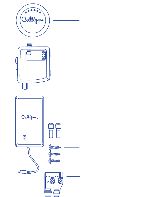
13
PIEZAS INCLUIDAS:
Botón del Control Remoto
Caja de Batería
Caja de Control
Adaptadores de Tubo 3/8" x 1/4"
Entrehierro
Tornillos de Montaje
CONTROL DE FILTRACIÓN INALÁMBRICO UNIVERSAL

14
Desconecte la línea de suministro de agua fría,
después abra el grifo de la cocina y deje que
drene toda el agua de la cañería.
INSTALACIÓN
NOTA: Favor de referirse al manual provisto con su ltro/sistema de osmosis inverso
para las instrucciones de instalación especicadas para sú sistema de ltración.
NOTA: Algunas instalaciones exigen adaptadores u otras piezas no incluidas con
este producto. Repase el manual y el proceso de instalación antes de comenzar.
NOTA: Consulte y instale de acuerdo con los códigos de plomería locales.
Desconecte la línea de agua fría de la válvula
de cierre de agua fría.
NOTA: Si utiliza tubería rígida (de metal o plástico),
es posible que deba acortar la tubería con una sierra
para metales o un cortatubos a n de hacer espacio
para la caja de control.
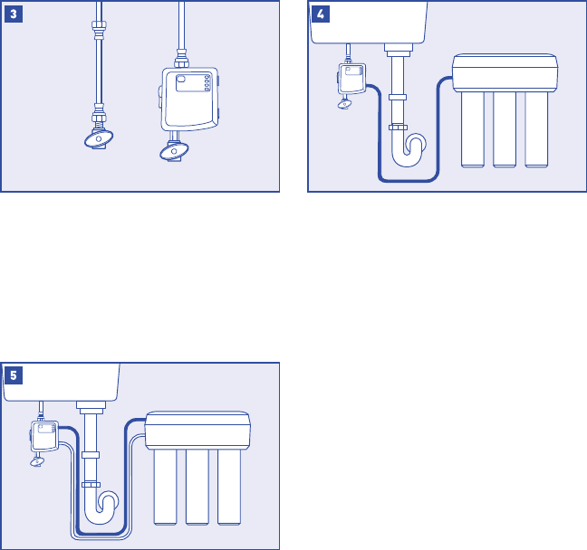
15
Aprieta la caja de control a la válvula de cierre de
agua fría según la diagrama. Aprieta la parte inferior
de la línea de agua fría a la parte superior de la
caja de control.
NOTA: Se exige que la caja de control se
instale verticalmente.
NOTA: Si el espacio no permite que se monte la
caja de control a la válvula, puede ser colgada en
una pared usando conectadores exibles
(se vende aparte) como una alternativa.
Conecte la entrada del sistema de ltración al
puerto azul titulado "RO/Filter>" de la caja de
control. Moje el extremo del tubo de plástico con
agua y empújelo en el adaptador de conexión
rápido aproximadamente 5/8" hasta que pare.
NOTA: Esta es la línea que normalmente correría
desde el adaptador de suministro de agua.
NOTA: Use uno de los adaptadores suministrados
si su sistema emplea un tubo que mide 1/4".
Conecte la salida del sistema de ltración al
puerto blanco titulado "RO/Filter<" de la caja de
control. Moje el extremo del tubo de plástico con
agua y empújelo en el adaptador de conexión
rápido aproximadamente 5/8" hasta que pare.
NOTA: Esta es la línea que normalmente correría
hacia el grifo dedicado.
NOTA: Use uno de los adaptadores suministrados
si su sistema emplea un tubo que mide 1/4".
NOTA: Después del inicio, enjuague su sistema
según las instrucciones del fabricante.

16
Conecte la púa grande del entrehierro a la
conexión de drenaje.
Monte el entrehierro en la posición vertical lo
más cerca posible a la encimera.
NOTA: El entrehierro derramará agua si no se
instala verticalmente.
INSTALACIÓN DE ENTREHIERRO PARA OSMOSIS INVERSO
NOTA: Los siguientes pasos aplican únicamente a instalaciones de osmosis inverso
empleando un entrehierro.
NOTA: No se exige un entrehierro con todos los sistemas. Sólamente los sistemas
usando una conexión de drenaje necesitan el uso de un entrehierro.
NOTA: Si su sistema de ltración no es de osmosis inverso, brinque a la sección
de Inicio del Sistema en la página 7.
NOTA: Instale el conectador de drenaje al drenaje de acuerdo con el manual provisto
con sú sistema de osmosis inverso.
ENTREHIERRO
Conecte la línea de drenaje saliendo del sistema
de osmosis inverso a la pequeña conexión púa
del entrehierro.

17
INICIO DEL SISTEMA
Instale cuatro baterías C (no incluidas) en la caja
de pilas y enchufe al gato en la parte inferior de
la caja de control.
NOTA: La caja de control emitirá un pitido y la luz
de fuerza parpadeará al encender.
Asegúrese que la válvula de derivación esté en la
posición cerrada (apuntada hacia abajo).
Abra el suministro de agua fría para averiguar
si se derrama agua o no. Si el sistema está
derramando agua, consulte la sección de
Solución de Problemas.
Use el tornillo provisto para colgar la caja de
baterías a la pared interior del cabinete.
BYPASS

18
INICIO DEL SISTEMA
Instale dos baterías AAA (no incluidas) en el botón
de control remoto.
Abra el grifo de agua fría completamente y
empuja el botón para activar el sistema.
NOTA: La luces azules de capacidad deben
encenderse si el botón y la caja de control
están comunicándose.
NOTA: El botón se puede apagar con un
segundo empujón o apagando el grifo.
NOTA: Después del inicio, enjuague el sistema de
acuerdo con las especicaciones del fabricante.
Puede que tome algunos ciclos para que el botón
permanezca encendido mientras aire sea
expulsado del sistema.
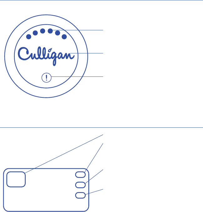
19
Luces de Capacidad del Filtro: Enseñan 1-6 luces
dependiendo de la capacidad del ltro que le quede,
6 luces = >80% y 1 luz = <10%.
Logo Culligan: Enciende cuando agua ltrada no esté
disponible desde el grifo. Permanece encendido
mientras agua ltrada corra desde el grifo.
Alarma: Enciende cuando las baterías de la caja
de control, los ltros, o la membrana de osmosis
inverso deben ser reemplazados.
GUÍA DE LA PANTALLA DEL BOTÓN
OPERACIÓN DE LA CAJA DE CONTROL
RESET POWER
REPLACE BATTERIES
REPLACE FILTERS
Botón de reinicio de capacidad del filtro.
Fuerza: Enciende de color verde al inicio, cuando
reinicia la capacidad del filtro, y mientras corra
agua filtrada. La luz parpadeará por 1 minuto
después de que se cierre el flujo de agua.
Reemplazo de Baterías: Enciende de color rojo
cuando las baterías para la caja de control deben
ser reemplazadas.
Reemplazo de Filtros: Enciende de color rojo cuando
los filtros tienen menos de 10% de vida según indica el
flujo o el tiempo. Este indicador se reinicia empujando
el botón de reinicio por dos segundos.

20
SOLUCIÓN DE PROBLEMAS
FUGAS DE AGUA POR ENTRADA O SALIDA DEL FILTRO/SISTEMA DE OSMOSIS INVERSO:
Una arendala doblada podría estorbar en entrada completa del tubo. Use un destornillador pequeño
para asentar la arendala de nuevo, y entonces asegurarse de que el extremo del tubo tenga una
cortada cuadrada, y limpia.
FLUJO BAJO DE AGUA FILTRADA/EL SISTEMA CAMBIA DE AGUA FILTRADA A AGUA
NO FILTRADA AUTOMATICAMENTE:
El ujo bajo quizá no este activando la caja de control. Consulte el manual de su sistema de
ltración para averiguar cómo aumentar el ujo de agua.
EL BOTÓN COMUNICA PERO NO HAY CAMBIO EN EL FLUJO:
Conrme que la válvula de derivación esté en la posición cerrada/apuntada hacia abajo.
EL BOTÓN NO COMUNICA SIEMPRE:
Algunos materiales pueden estorbar la señal inalámbrica mas que otros. Intente mover
el botón a otra area ubicada más de cerca a la caja de control.
EL AGUA FILTRADA NO SE APAGA: Baterías de poca fuerza en la caja de control pueden causar
que el sistema se quede en la posición de agua ltrada. Se puede emplear la válvula de derivación
para permitir el ujo de agua no ltrada al grifo mientras se corrija el asunto.
Si las fugas de agua persisten, o si hay otras fugas de agua de la caja de control, favor de apagar el
suministro de agua. Sírvase llamar para ayuda técnica a 1-800-721-7360.
REGISTRO DE PRODUCTO
Asegúrese de registrar la compra de su producto en línea dentro
de los 30 días a partir de la compra en www.register.culligan.com.

21
GARANTÍA LIMITADA DE UN AÑO
La garantía se aplica al botón y la caja de batería. La garantía cubre los defectos en el material y la
fabricación por un año completo desde la fecha original de entrega. Culligan reemplazará cualquier
pieza que se considere defectuosa, con las siguientes excepciones: (1) si algún componente de la unidad
estuvo sujeto a algún tipo de manipulación, alteración o uso inapropiado después de la entrega, o (2)
si había sido reparado por una agencia no aprobada por Culligan. Culligan no asume responsabilidad
alguna por los daños durante el transporte, y en caso de algún reclamo debido a dichos daños, el cliente
deberá presentar el reclamo ante el transportista. Esta garantía no cubre ningún tipo de gastos de envío,
transporte o mano de obra en los que se haya incurrido. La contratación de un individuo o un servicio
para la instalación o mantenimiento de este producto se hace a la discreción del comprador y, por lo
tanto, cualquier gasto incurrido es responsabilidad del comprador mismo.
Este producto ha sido diseñado solamente para ser usado como un control de ltración de agua. La
garantía NO cubre daños producidos debido a las temperaturas bajo cero o el aumento repentino
de presión de agua. El uso indebido de este producto y sus componentes podría provocar defectos o
deterioro no están cubiertos por la garantía.
LA GARANTÍA SUSODICHA ES EXCLUSIVA Y SUSTITUYE CUALQUIER OTRA GARANTÍA, EXPRESA O
IMPLÍCITA, YA SEA UNA GARANTÍA VERBAL O UNA QUE DERIVE DEL USO O LA PRÁCTICA COMERCIAL,
INCLUIDA, DE MANERA SIN LÍMITE, CUALQUIER GARANTÍA DE APTITUD O COMERCIABILIDAD. ESTA
GARANTÍA ES EL ÚNICO RECURSO EXCLUSIVO DEL COMPRADOR. BAJO NINGUNA CIRCUNSTANCIA
CULLIGAN ASUMIRÁ LA RESPONSABILIDAD POR LA PÉRDIDA DE GANANCIAS ANTICIPADAS, LOS
DAÑOS ACCIDENTALES, DAÑOS CONSECUENTES, GASTOS, GASTOS DE TIEMPO DE MANO DE OBRA U
OTRO TIPO DE PÉRDIDAS, SEA POR EL INCUMPLIMIENTO DEL CONTRATO, UNA CONDUCTA ILÍCITA O
CUALQUIER OTRA TEORÍA, EN RELACIÓN CON LA COMPRA, LA INSTALACIÓN, LA REPARACIÓN O EL
FUNCIONAMIENTO DE ESTE PRODUCTO. CULLIGAN NO AUTORIZA A NINGUNA PERSONA A ASUMIR
RESPONSABILIDADES U OTORGAR GARANTÍAS ADICIONALES EN SU NOMBRE EN RELACIÓN CON
ESTE PRODUCTO.
Para obtener un servicio conforme a esta garantía, deberá devolver cualquier pieza defectuosa a
SU COMERCIANTE dentro del plazo de un año especicado anteriormente. Asegúrese de completar el
registro de garantía en línea dentro de los 30 días a partir de la compra y conserve la factura original,
la orden de compra o el comprobante de venta, ya que sirven como prueba de la compra para poder
realizar una devolución.

Culligan International Company
Rosemont, Illinois 60018
www.culligan.com
Technical Support M–F 8:00AM–4:30PM (CST)
Ayuda Técnica disponible de lunes a viernes, de 8:00 A.M. a 4:30 P.M. (CST)
1-800-721-7360
©2015 Culligan International Company 01029484 A