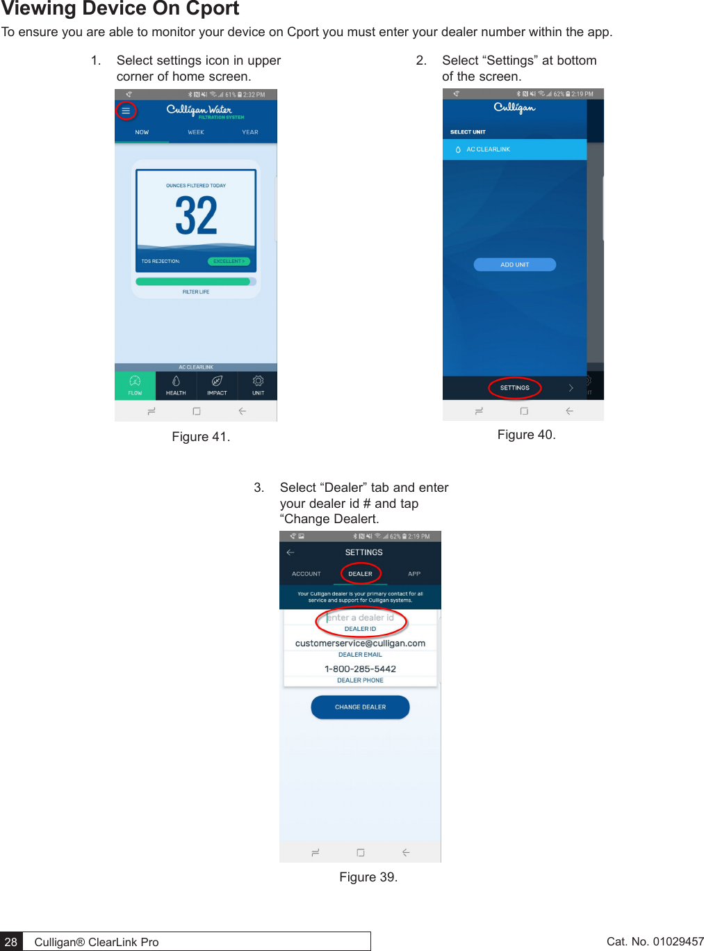
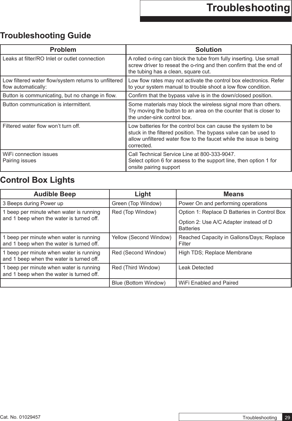
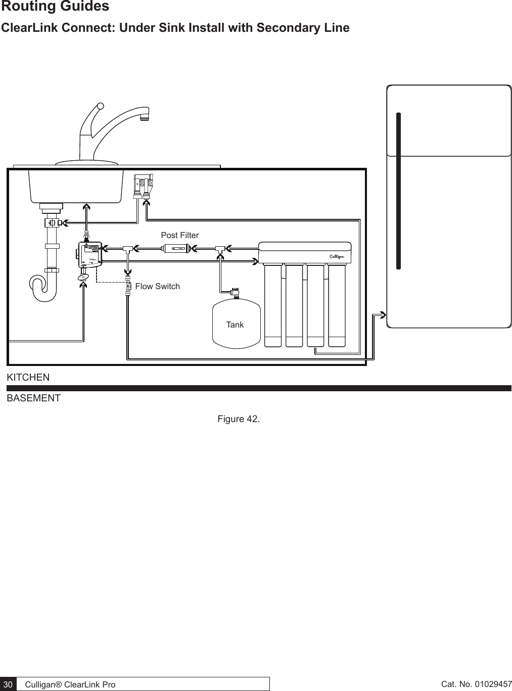
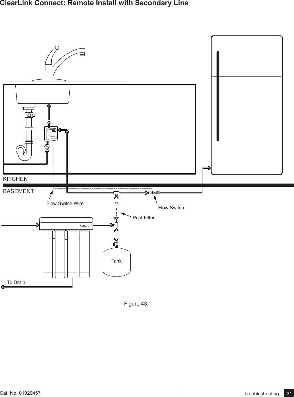
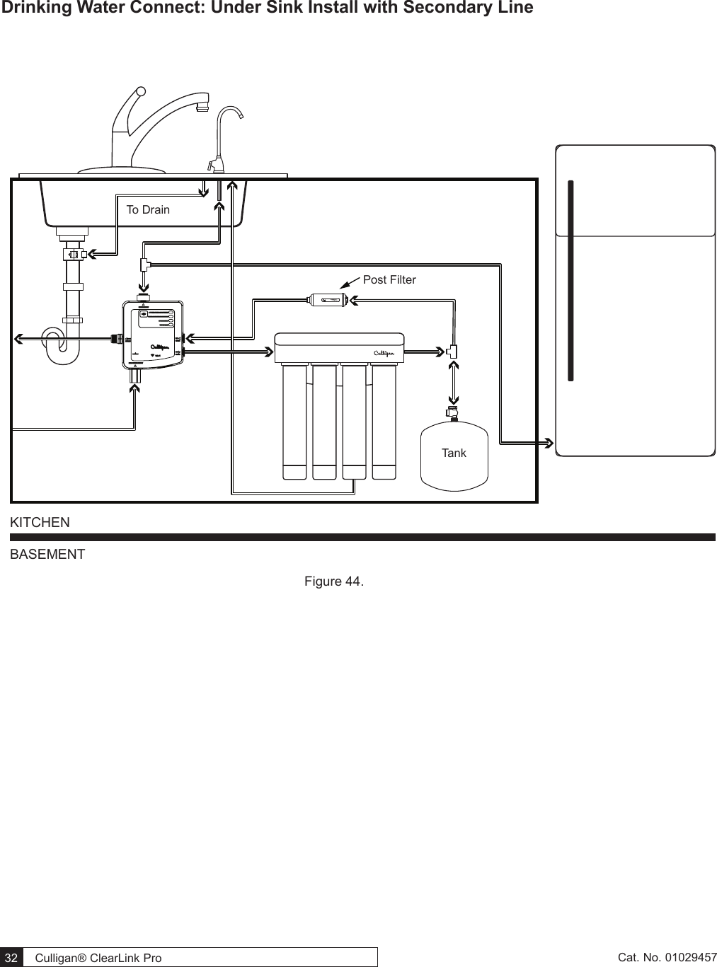
Culligan 010330CL Wireless Filtration Control User Manual
Culligan International Company Wireless Filtration Control
UserManual.wiki
>
Culligan
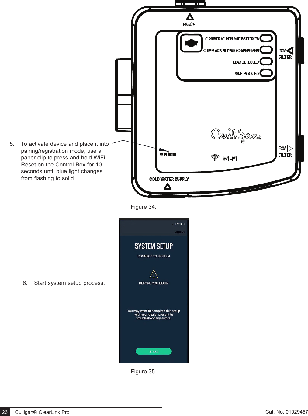
>
010330CL User Manual
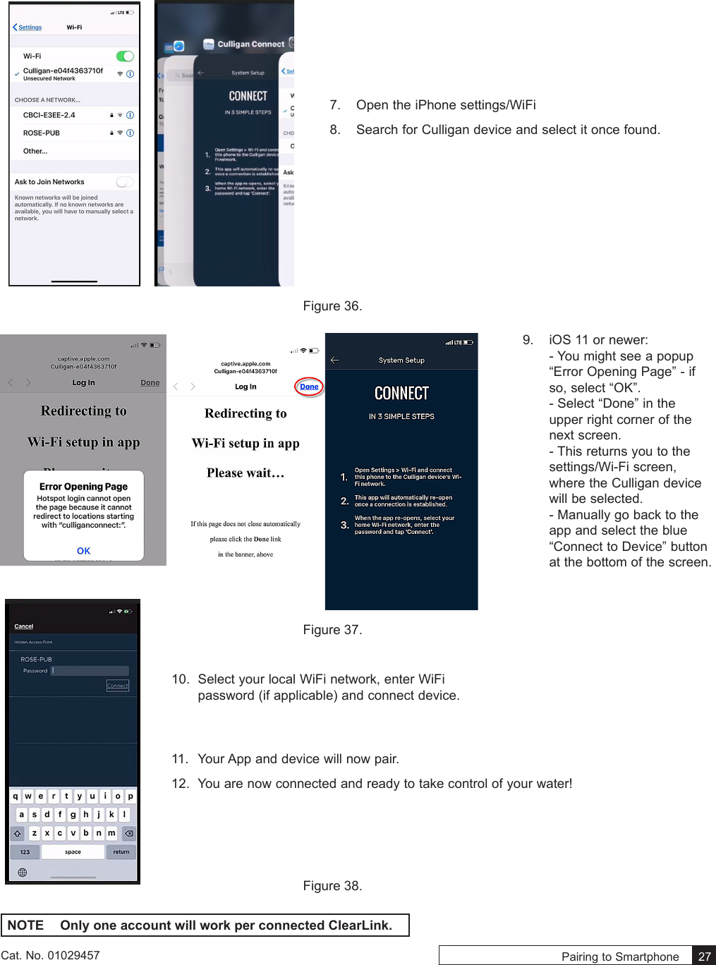
user manual
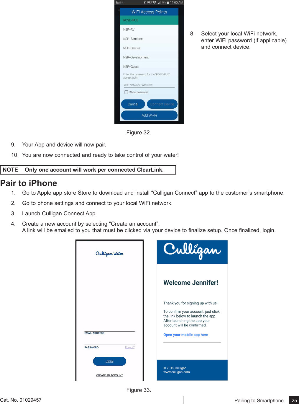
Navigation menu
Upload a User Manual
Namespaces
Wiki Guide
HTML
PDF
Info
Views
User Manual
Discussion / Help
Navigation