Culligan 010330CL Wireless Filtration Control User Manual
Culligan International Company Wireless Filtration Control
Culligan >
user manual

CULLIGAN®
ClearLink
Wireless Filtration Control
Models from 2018
©2018 Culligan International Com pa ny
Installation,
Operation, and
Service Instructions
with Parts Lists
Cat. No. 01029457
Rev. B 11/14/18
DCO # 018577
2 Culligan® ClearLink Pro 2 Cat. No. 01029457
Attention Culligan Customer:
Your local independently operated Culligan dealer employs trained service and maintenance personnel who are
experienced in the installation, function and repair of Culligan equipment. This publication is written specifically for these
individuals and is intended for their use.
We encourage Culligan users to learn about Culligan products, but we believe that product knowledge is best obtained by
consulting with your Culligan dealer. Untrained individuals who use this manual assume the risk of any resulting property
damage or personal injury.
NOTICE Please send any suggestions for improving this manual to productmanuals@culligan.com
WARNING! Electrical shock hazard! Prior to servicing equipment, disconnect power supply to
prevent electrical shock.
WARNING! If incorrectly installed, operated, or maintained, this product can cause severe injury.
Those who install, operate, or maintain this product should be trained in its proper
use, warned of its dangers, and should read the entire manual before attempting
to install, operate, or maintain this product. Failure to comply with any warning or
caution that results in any damage will void the warranty.
CAUTION! This product is not to be used by children or persons with reduced physical, sensory
or mental capabilities, or lack of experience or knowledge, unless they have been
given supervision or instruction.
CAUTION! Children should be instructed not to play with this appliance.
CAUTION! If the power cord from the power supply to the unit looks or becomes damaged, the
cord and power supply should be replaced by a Culligan Service Agent or similarly
qualified person in order to avoid a hazard.
NOTE This system is not intended for use with water that is microbiologically unsafe or of unknown quality
without adequate disinfection either before or after the system.
NOTE Check with your public works department for applicable local plumbing and sanitation codes. Follow
local codes if they differ from the standards used in this manual. To ensure proper and efficient
operation of the Culligan ClearLink Pro to your full satisfaction, carefully follow the instructions in this
manual.
Products manufactured and marketed by Culligan International Company (Culligan) and its affiliates are protected by pat-
ents issued or pending in the United States and other countries. Culligan reserves the right to change the specifications
referred to in this literature at any time without prior notice. Culligan, Aqua-Sensor, Tripl-Hull, and SoftMinder are trade-
marks of Culligan International Company or its affiliates.
Culligan International Company
9399 West Higgins Road, Suite 1100
Rosemont, Illinois 60018
1-847-430-2800
www.culligan.com

3
Cat. No. 01029457
Contents
Read this Manual First .................................................... 5
Introduction ........................................................................ 5
About this Manual ........................................................... 6
Safe Practices................................................................. 6
Serial Numbers ............................................................... 6
ClearLink Pro .................................................................. 7
ClearLink Connect .......................................................... 7
About Models..................................................................... 7
Drinking Water Connect .................................................. 8
Parts Included: ................................................................ 9
Tools and Materials Required ......................................... 9
Specications.................................................................. 9
Precautions ..................................................................... 9
Installation ......................................................................... 9
Setting Capacity and TDS Function (All Models) .......... 10
Installation (All Models)................................................. 11
External Flow Switch for a Secondary Outlet ............... 15
Flow Switch 40’ Wire Extension Kit (if applicable) ........ 17
Leak Sensor Installation ............................................... 17
System Startup
...................................................................................... 18
Button Display Guide .................................................... 21
Control Box Operation .................................................. 22
Pair to Android .............................................................. 23
Pairing to Smartphone ..................................................... 23
Pair to iPhone ............................................................... 25
Viewing Device On Cport
To ensure you are able to monitor your device on Cport
you must enter your dealer number within the app....... 28
Troubleshooting Guide ................................................. 29
Control Box Lights ........................................................ 29
Troubleshooting ............................................................... 29
Routing Guides ............................................................. 30
Replacement Parts List ................................................... 34
One-Year Limited Warranty ............................................. 35
Index ................................................................................ 36
Installation,
Operation
and Service
Instructions
Culligan® ClearLink Pro
Wireless Filtration Control
Models from 2018

4 Culligan® ClearLink Pro 4 Cat. No. 01029457
This page intentionally left blank.
Introduction 5
Cat. No. 01029457
Introduction
Read this Manual First
Before you operate the Culligan® ClearLink systems, read this manual to become familiar
with the device and its capabilities.
The ClearLink units are certified by WQA against CSA B483.1, NSF/ANSI 372 for low lead
requirement, NSF/ANSI 42 and NSF/ANSI 58 for material safety and structural integrity.
Model: CulRF-M5 used in devices ClearLink PB, ClearLink D-WiFi and ClearLink D.
WM-N-BM-30 used in device ClearLink D-WiFi.
Contains FCC ID: V7U-010330CL, IC: 6510B-010330CL, FCC ID: COF-WMNBM30 and
IC: 10293A-WMNBM30.
This device complies with part 15 of the FCC Rules subject to the following two conditions:
(1) This device may not cause harmful interference (2) This device must accept all interference received including
interference that may cause undesired operation.
Le présent appareil est conforme aux CNR Innovation, Sciences et Développement économique Canada applicables
aux appareils radio exempts de licence. L’exploitation est autorisée aux deux conditions suivantes : (1) l’appareil nedoit
pas produire de brouillage, et (2) l’utilisateur de l’appareil doit accepter tout brouillage radioélectrique subi, même si le
brouillage est susceptible d’en compromettre le fonctionnement.
This device complies with Health Canada’s Safety Code. The installer of this device should ensure that RF radiation is not
emitted in excess of the Health Canada’s requirement.
Cet appareil est conforme avec Santé Canada Code de sécurité 6. Le programme d’installation de cet appareil doit
s’assurer que les rayonnements RF n’est pas émis au-delà de I’exigence de Santé Canada.
Changes or modifications not expressly approved by the party responsible for compliance could void the user’s authority
to operate the equipment.
Les changements ou modifications non expressément approuvés par la partie responsable de la conformité pourraient
annuler l’autorité de l’utilisateur à utiliser cet équipement
This equipment has been tested and found to comply with the limits for a Class B digital device, pursuant to part 15 of
the FCC Rules. These limits are designed to provide reasonable protection against harmful interference in a residential
installation. This equipment generates, uses and can radiate radio frequency energy and, if not installed and used
in accordance with the instructions, may cause harmful interference to radio communications. However, there is no
guarantee that interference will not occur in a particular installation. If this equipment does cause harmful interference to
radio or television reception, which can be determined by turning the equipment off and on, the user is encouraged to try
to correct the interference by one or more of the following measures:
• Reorient or relocate the receiving antenna.
• Increase the separation between the equipment and receiver.
• Connect the equipment into an outlet on a circuit different from that to which the receiver is connected.
• Consult the dealer or an experienced radio/TV technician for help.
This device complies with Innovation, Science and Economic Development Canada’s licence-exempt RSS standard(s).
Operation is subject to the following two conditions: (1) this device may not cause interference, and (2) this device must
accept any interference, including interference that may cause undesired operation of the device.
Le présent appareil est conforme aux CNR Innovation, Sciences et Développement économique Canada applicables
aux appareils radio exempts de licence. L’exploitation est autorisée aux deux conditions suivantes : (1) l’appareil ne doit
pas produire de brouillage, et (2) l’utilisateur de l’appareil doit accepter tout brouillage radioélectrique subi, même si le
brouillage est susceptible d’en compromettre le fonctionnement.
This Class B digital apparatus complies with Innovation, Science and Economic Development Canada ICES-003.
Cet appareil numérique de la classe B est conforme à la norme NMB-003 du Innovation, Sciences et Développement
économique Canada.
6 Culligan® ClearLink Pro 6 Cat. No. 01029457
About this Manual
This manual:
• Familiarizes the operator with the equipment
• Explains installation and setup procedures
• Explains the various modes of operation
• Gives specifications and troubleshooting information
This publication is based on information available when approved for printing. Continuing design refinements could cause
changes that may not be included in this publication.
Safe Practices
Throughout this manual there are paragraphs set off by special headings.
Notice
Notice is used to emphasize installation, operation or maintenance information which is important, but does not present
any hazard. For example,
NOTICE The nipple must extend no more than 1 inch above the cover plate.
Caution
Caution is used when failure to follow directions could result in damage to equipment or property. For example,
CAUTION! Disassembly while under water pressure can result in flooding.
Warning
Warning is used to indicate a hazard which could cause injury or death if ignored. For example,
WARNING! Electrical shock hazard! Unplug the unit before removing the timer mechanism or
cover plates!
The CAUTION and WARNING paragraphs are not meant to cover all possible conditions and situations that may occur.
It must be understood that common sense, caution, and careful attention are conditions which cannot be built into the
equipment. These MUST be supplied by the personnel installing, operating, or maintaining the system.
Be sure to check and follow the applicable plumbing codes and ordinances when installing this equipment. Local codes
may prohibit the discharge of acid or caustic solutions to drain. An extra solution tank should be used to neutralize the
solution before discharging to drain.
Use protective clothing and proper face or eye protection equipment when handling chemicals or power tools.
Serial Numbers
The serial number is located on the back of the control box.
This publication is based on information available when approved for printing. Continuing design refinement could cause
changes that may not be included in this publication.
NOTE Do not remove or destroy the serial number. It must be referenced on request for warranty repair or
replacement.
About Models 7
Cat. No. 01029457
About Models
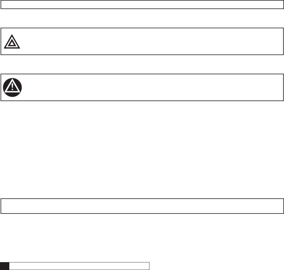
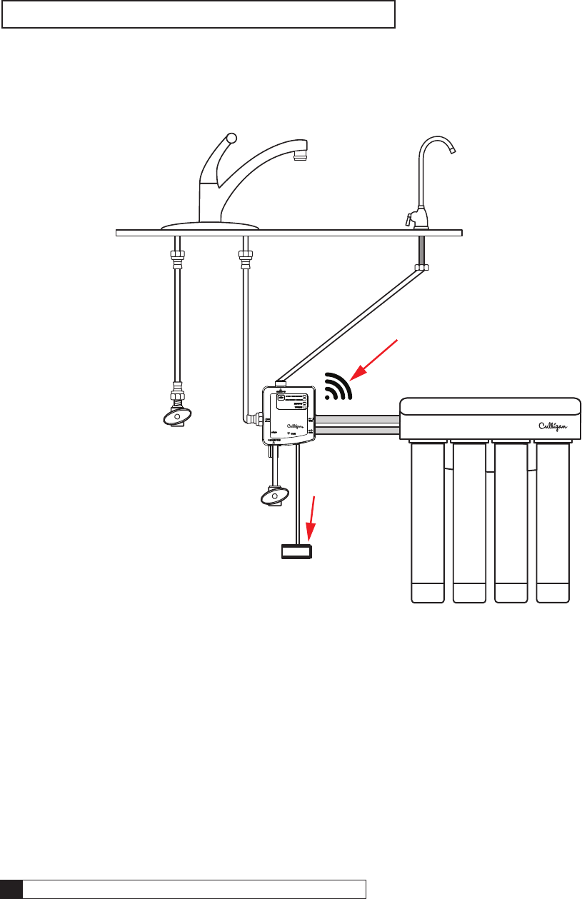
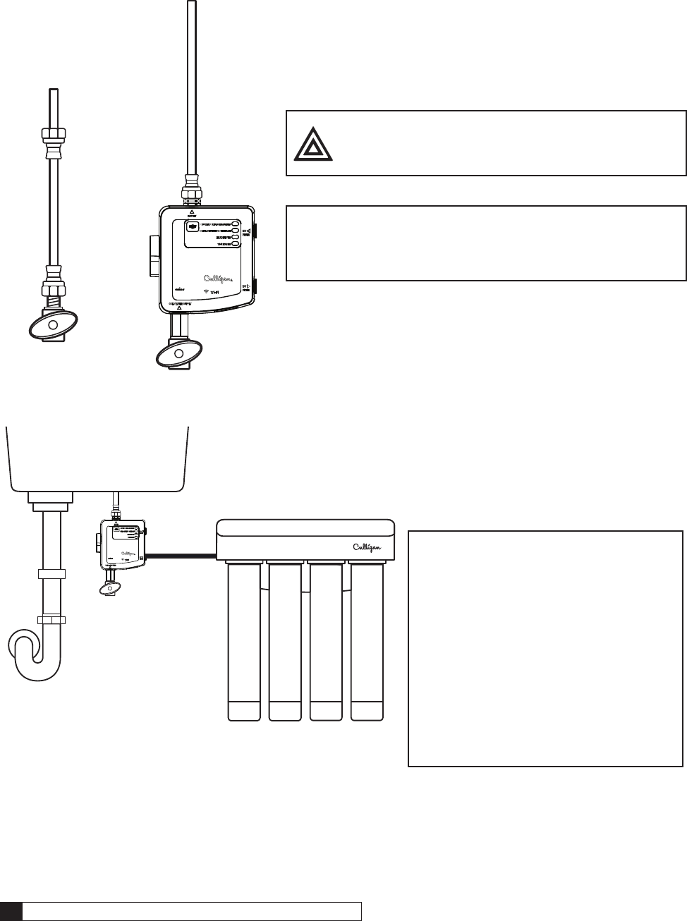
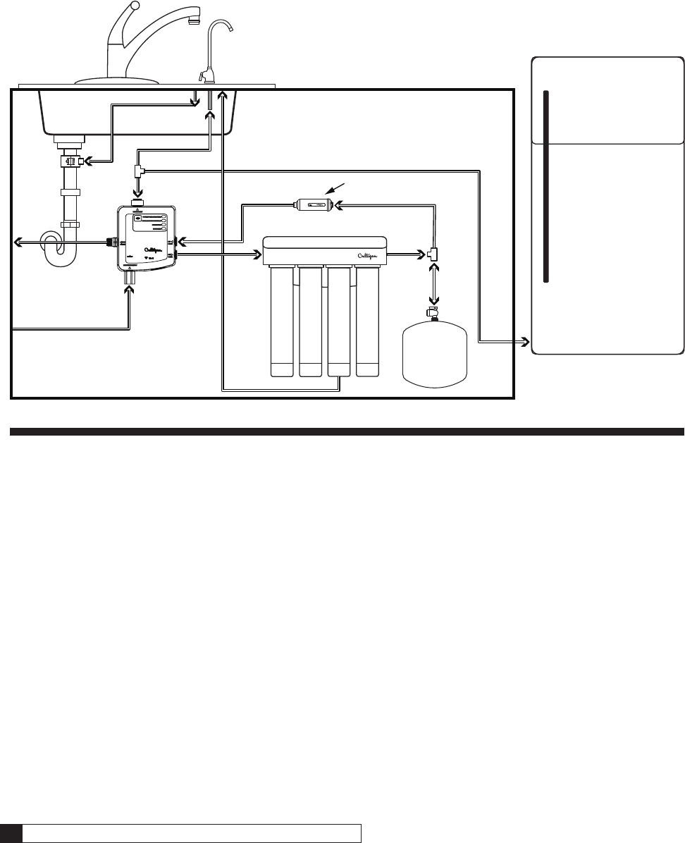
ClearLink Pro
Figure 1.
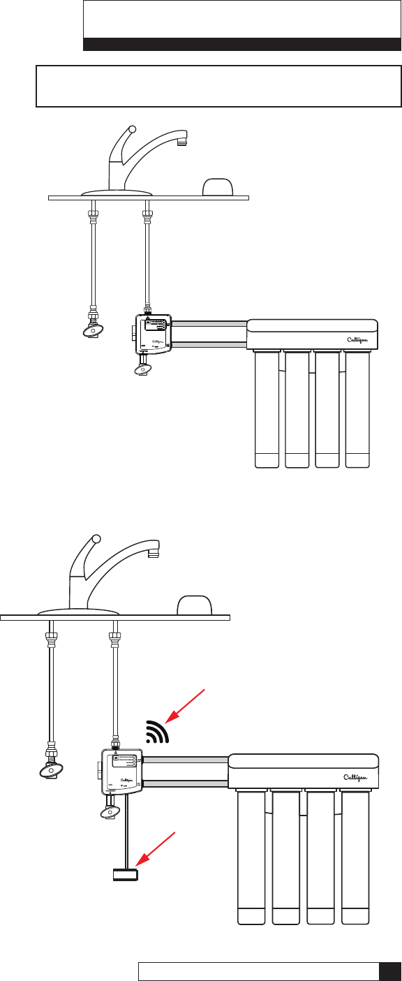
ClearLink Connect
Figure 2.
NOTE Illustrations are for overview purposes only, for
RO installations an air gap and RO tank is needed.
TheClearLinkPRO™isarst-to-market
wireless control system that allows you
togetCulligan®lteredwaterfromyour
main faucet. Installing an RO system
used to required a dedicated faucet,
which meant drilling a hole or losing a
soap dispenser. Now you can use your
existing faucet to wash vegetables with
yoursprayer,llpotsforcooking,or
simplyenjoyaglassoflteredwater.
The ClearLink Connect takes the ease of
using your current faucet and pairs it with the
technology of staying connected anywhere.
This Wi-Fi enabled ClearLink keeps all of the
same functionality of the ClearLink Pro but
adds the ability to connect to the Culligan
Connect App. Track water consumption,
contaminantsbeingremoved,lter/membrane
life and if a leak is detected from anywhere,
using the convenience of an app. +WiFi Capable
+Leak Sensor
8 Culligan® ClearLink Pro 8 Cat. No. 01029457
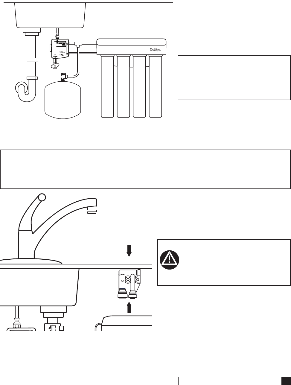
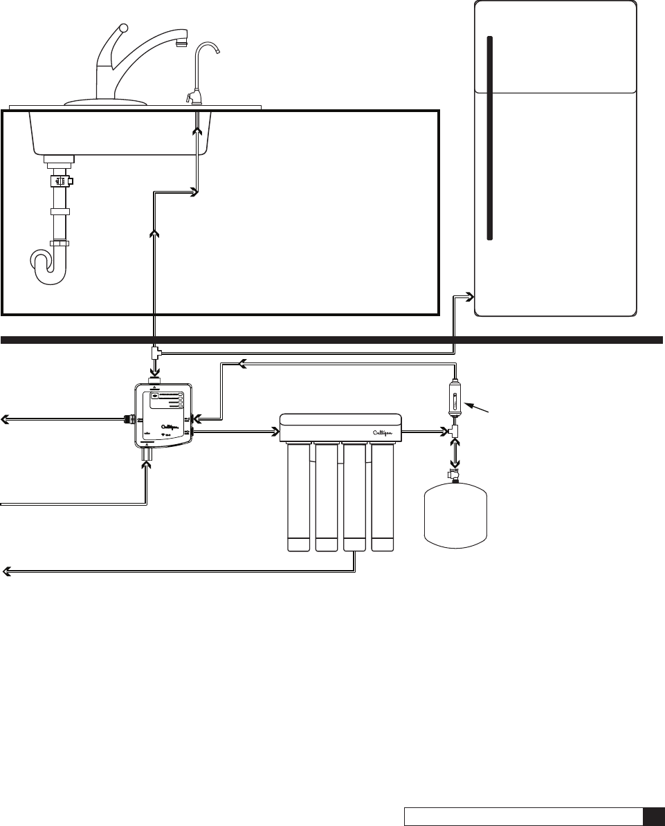
Drinking Water Connect
The Drinking Water Connect allows drinking water customers to stay connected to their system anywhere. This Wi-Fi
enabled product can be added to virtually any household drinking water installation and adds the ability to connect to
the Culligan Connect App. Track water consumption, contaminants being removed, filter / membrane life and if a leak
is detected from anywhere, using the convenience of an app.
Figure 3.
NOTE Separate connections for filtered and unfiltered water.
+ WiFi Capable
+ Leak Sensor
Installation 9
Cat. No. 01029457
Installation
Parts Included:
• Remote Button (not available with Drinking Water Connect)
• Control Box
• Battery Box
• 3/8” x 1/4” Tube Adapter
• Mounting Screws
• Air Gap (not available with Drinking Water Connect)
Tools and Materials Required
• D Batteries x4
• AAA Batteries x2
• Screwdriver
• Adjustable Wrench
• Towels
• Pan or Bucket
Specifications
Pressure Range: 30-120 psi (207-827 kPa)
Temperature Range: 40-100 ºF (4.4 - 37.7 ºC)
Precautions
WARNING! Follow all precautions indicated in the manual provided with the Culligan water
treatment system.
WARNING! For systems using a booster or distribution pump, the pressure of the treated water
cannot exceed the pressure of the cold water supply.
WARNING! Reducing the Booster pump pressure below incoming pressure will allow the proper
operation of the ClearLink.
WARNING! For cold water use only. Do not use on hot water line.
CAUTION! Control box must be protected against freezing temperatures, frost, snow, sleet and
ice. Exposure to these can produce cracks and product failures.
CAUTION! The Filter/RO should be flushed before installing into the system to ensure the proper
operation of the ClearLink.
CAUTION! This product has a limited service life. We recommend that a record be kept regarding
the date of install and any other performed maintenance. Because of the product’s
limited service life and to prevent costly repairs or possible water damage, we
strongly recommend that the control box be replaced every ten years.
• After prolonged periods of non-use (such as during a vacation) it is recommended that the system be flushed
thoroughly. Let the filtered water run for 5-6 minutes before using.
• The ClearLink estimates filter life based on flow and time. Changes in taste, odor, color and/or flow of the filtered
water could indicate that the filter(s) should be replaced.
• Make certain that installation complies with all state and local laws and regulations.
10 Culligan® ClearLink Pro 10 Cat. No. 01029457
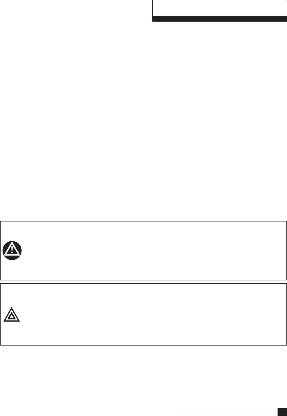
Setting Capacity and TDS Function (All Models)
NOTE Set capacity and TDS function before starting installation.
NOTE To access the dip switches for setting capacity and TDS function, open the control box by removing
the three screws in the rear cover.
Find the dip switches on the front of the circuit board. SW2 and SW3 set the time and capacity for the filter reminder.
SW1: OFF = Disabled ON = Enabled
Enables/Disables the TDS function (Enable only for RO systems). The system will measure the difference between the
feed and product water to determine if the RO is working. If installing an RO system with a Mineral Boost cartridge, this
feature may need to be disabled so that the alert indicator does not illuminate prematurely for RO membrane replacement.
SW2: OFF = 500 gallons ON = 1,000 gallons
SW3: OFF = 180 days ON = 365 days
SW6 is used for production testing and should be left in the off position.
SW6
SW3
SW2
SW1
ON
Figure 4. Dip Switches
Installation 11
Cat. No. 01029457
Installation (All Models)
NOTE If using an external flow switch, install the external flow switch before installing the
ClearLink. See “External Flow Switch for a Secondary Outlet” on page 15 for instructions.
NOTE Refer to the manual provided with your filter/RO for installation instructions specific to that system.
NOTE Some installations may require adapters and fittings not included with the product. Review the manual
and your installation before beginning.
NOTE Consult your local plumbing codes and install accordingly.
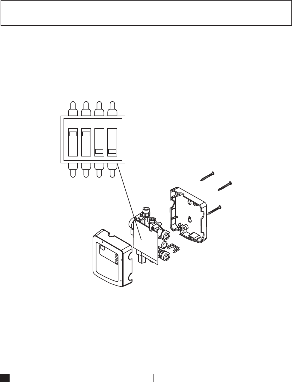
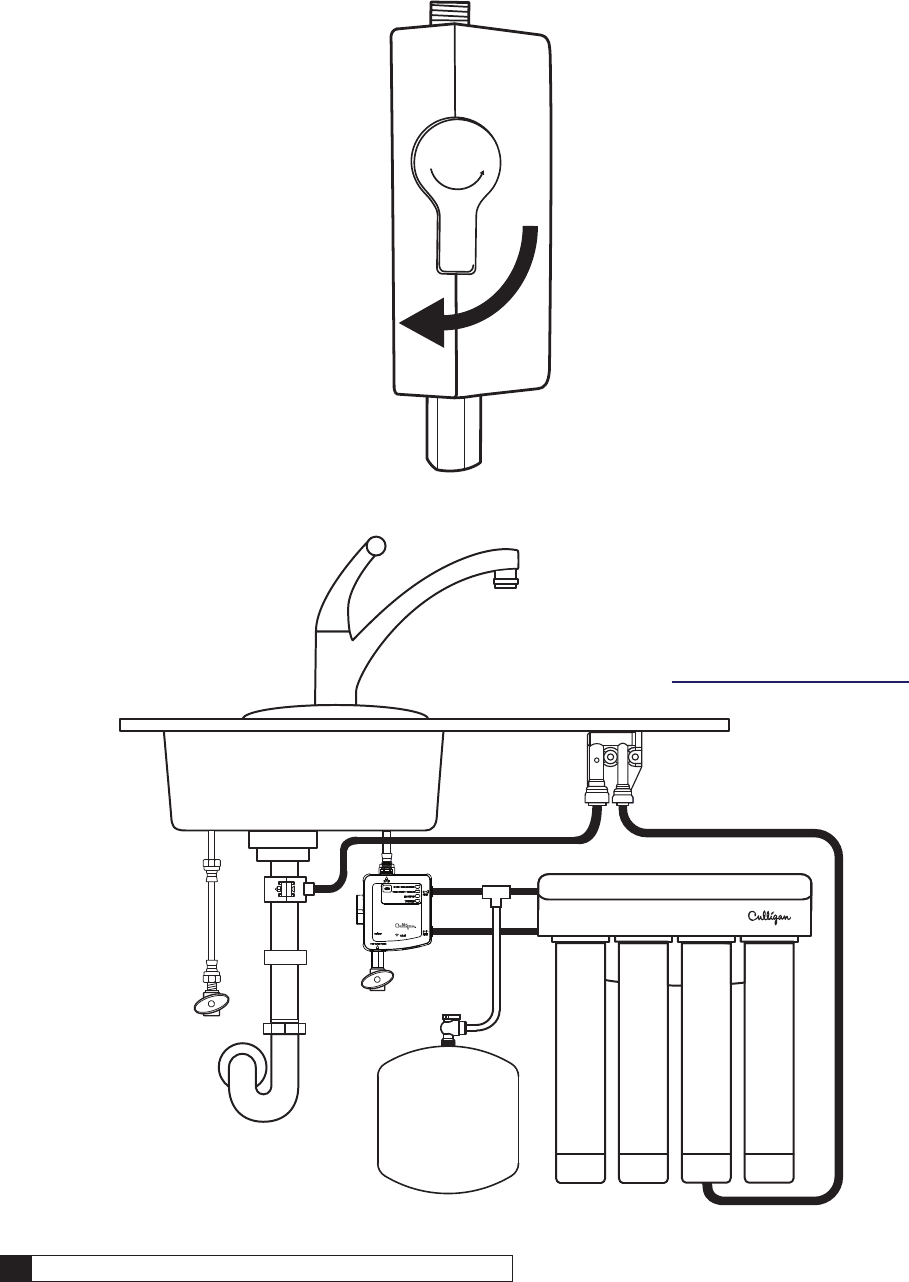
Figure 5.
Figure 6.
1. Turn off both hot and cold water
shut-off valve then turn on the
kitchen faucet and allow all
water to drain from line.
2. Disconnect the cold water line from the
cold water shut-off valve.
NOTE If rigid plumbing pipe (metal or
plastic) is used, you may need to
shorten the pipe using a hacksaw
or pipe cutter to accommodate
the control box.
12 Culligan® ClearLink Pro 12 Cat. No. 01029457
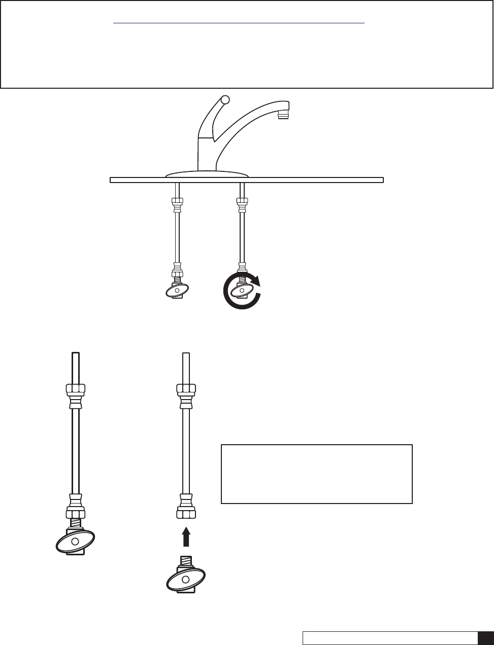
Figure 7.
Figure 8.
3. Connect the control box to the cold water shut-off valve and
the water line to the facet as shown. Culligan recommends
1/2 - 3/4 additional turns past finger-tight.
CAUTION! The stationary hex nut on the outlet of
the ClearLink should not be used to
over-tighten the hose fitting.
NOTE The control box must be in a vertical position.
NOTE If space does not allow for mounting the control
box onto the valve, it can be mounted on a wall and
connected using flexible lines. (purchased separately).
4. Connect the inlet on the RO/Filter
system to the port marked “RO/Filter
►.”Wettheendoftheplastictubing
with water and push it into the quick
connect fitting adapter approximately
5/8” until it stops.
NOTE All filters and RO membranes
should be flushed before
connecting any ClearLink device
to the filtration/RO system.
NOTE This connection is plugged for
remote system installations (Water
supply is not the same as the sink
such as basement installations).
This port is normally plugged
when installing the filtration/RO
system in a location other than the
kitchen cabinet.
NOTE Use the supplied adapter if your
system uses a 1/4” tube.
Installation 13
Cat. No. 01029457
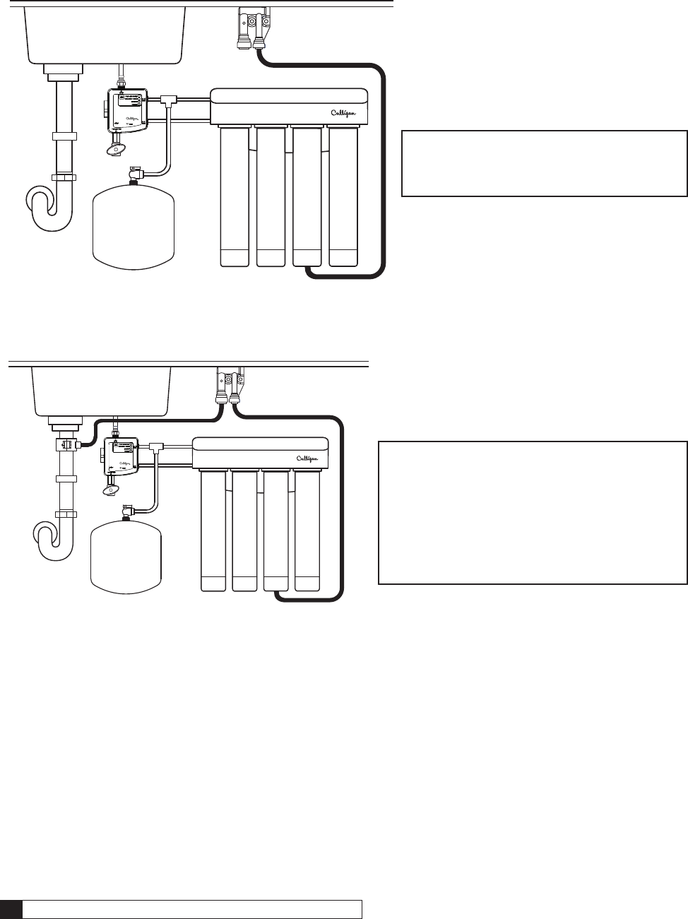
Tank
Figure 9.
NOTE Steps 6 through 8 are only for RO installations using an air gap.
NOTE If your filtration system is not an RO, skip to System Startup.
NOTE Install the drain connection to the drain plumbing according to the manual provided with your RO system.
NOTE Check and adhere to local plumbing codes for Air Gap installation.
AIR GAP
Figure 10.
5. Connect the product water outlet
on the RO/Filter system to the port
marked“RO/Filter►.”Wettheendof
the plastic tubing with water and push
it into the quick connect fitting adapter
until it stops.
NOTE This is the line that would
normally go to your dedicated
faucet.
NOTE Connect the tank and/or post filter
in this line if required for your filter/
RO system.
6. Mount the air gap device as near to counter
top as possible and in a vertical orientation.
WARNING! Install the air gap as high
as possible using air gap
installation bracket.
WARNING! Failure to mount the air
gap device vertically will
cause it to leak water.
14 Culligan® ClearLink Pro 14 Cat. No. 01029457
Tank
Figure 11.
Tank
Figure 12.
7. Connect the drain line coming from the
RO system to the 1/4” connection of the
air gap device.
NOTE Drain line adapters are available
through Culligan Marketplace that
can be used when considering the
best drain line connection.
8. Connect the 3/8” fitting of the air gap device
to the connection on the drain plumbing.
NOTE If the customer has a garbage disposal,
connect the RO drain line coming
from the air gap to the “auxiliary” port
(removable plug where a dishwasher
drain is typically hooked up) rather than
downstream of the disposal. The high
flow rate from a disposal sucking water
from a clogged sink will send water up
and out of the air gap.
Installation 15
Cat. No. 01029457
External Flow Switch for a Secondary Outlet
For use with ClearLink Connect and as an optional accessory on the Drink Water Connect.
No available for use with ClearLink PRO.
See “Routing Guides” on page 30.
NOTE External flow switch must be installed after the post filter.
NOTE If the inlet of the refrigerator (or similar) requires 1/4” tubing, the reducing stem should be installed as
close to the refrigerator as possible to reduce the pressure drop caused by smaller diameter tubing.
Tank
Figure 13.
To Secondary Outlet,
such as a refrigerator
16 Culligan® ClearLink Pro 16 Cat. No. 01029457
Flow Switch Wiring
NOTE The standard length of the flow switch wire is 3’.
If needed, a 40’ wire extension is available separately.
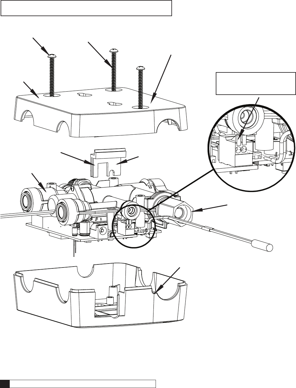
Figure 14. Flow Switch Wiring
1. Remove Screws
2. Remove the back cover.
3. Remove slider.
4. Remove manifold with
PCB.
5. Push on orange tab,
insert wire, then let
go of orange tab.
NOTE Gently pull on wires
to confirm that they
are fully inserted.
6. Reinsert the manifold
with PCB.
7. Reinsert slider.
8. Lay the wire into the groove.
9. Reinsert the
back cover
10. Reinsert screws.
Installation 17
Cat. No. 01029457
Flow Switch 40’ Wire Extension Kit (if applicable)
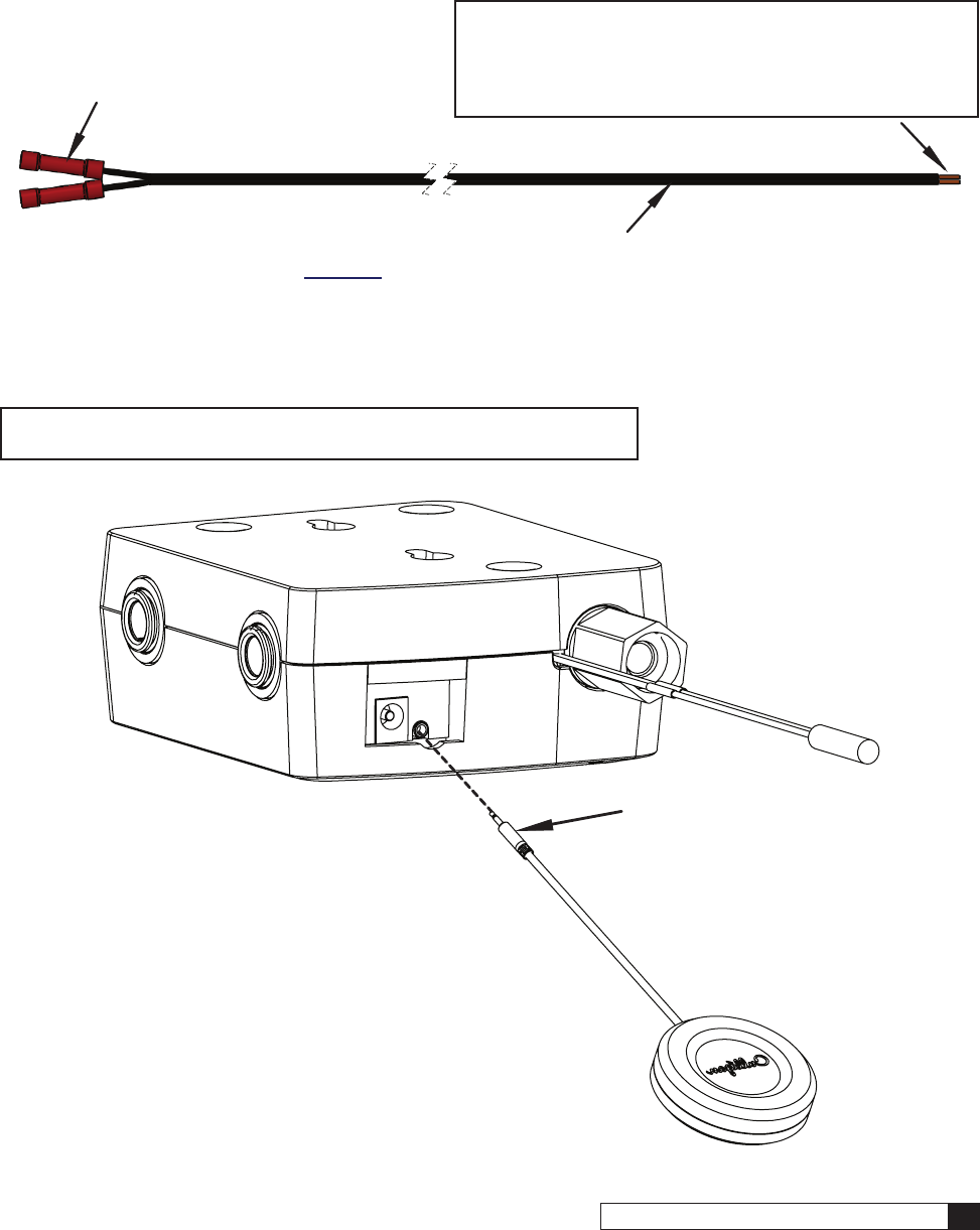
Figure 15.
Leak Sensor Installation
NOTE For use with ClearLink Connect and Drinking Water Connect.
Not available for use with ClearLink Pro.
Figure 16.
1. Connect flow switch wires
to the extension using the
supplied crimp connectors.
2. Cut wire to required length.
3. Using wire strippers, strip a 1/4” of insulation from the wire.
NOTE Stripping too much of the wire can cause
the wires to fray, which can cause the unit to
malfunction over time. Stripping too little of the
wire can prevent the ends from being able to have
proper contact with the connector on the PCB.
4. Insert wires into the connector
on the PCB, see Figure 14.
1. Plug in Leak Sensor
Installation 19
Cat. No. 01029457
D
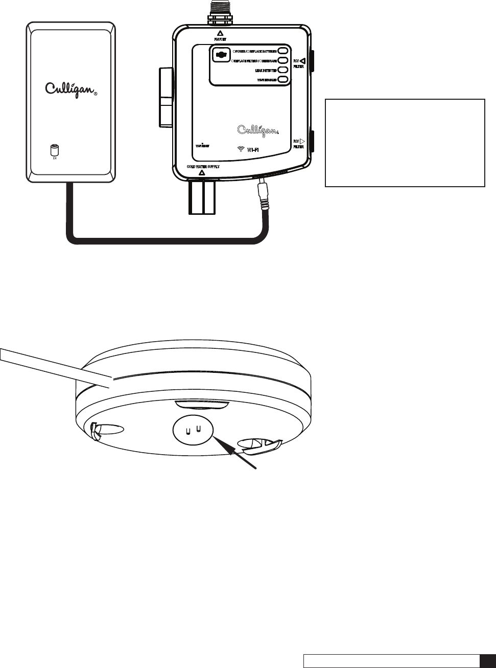
Figure 19.
Figure 20.
3. Install four D batteries (not
included) into the battery box
and plug into the jack on the
bottom of the control box.
NOTE The control box will beep
and flash the power light
when powering up.
NOTE AC adapter (01029455)
can also be used where
a non-switch-controlled
outlet is available.
4. Place a damp paper towel to the pins.
This should cause the leak sensor light on
the control box (page 18) to flash, the unit
to beep and the Culligan Connect App (if
setup) to notify the user of the error.
5. Dry pins and place at the lowest point in the
cabinet or under the ClearLink Control Box.
20 Culligan® ClearLink Pro 20 Cat. No. 01029457
Figure 21.
Figure 22.
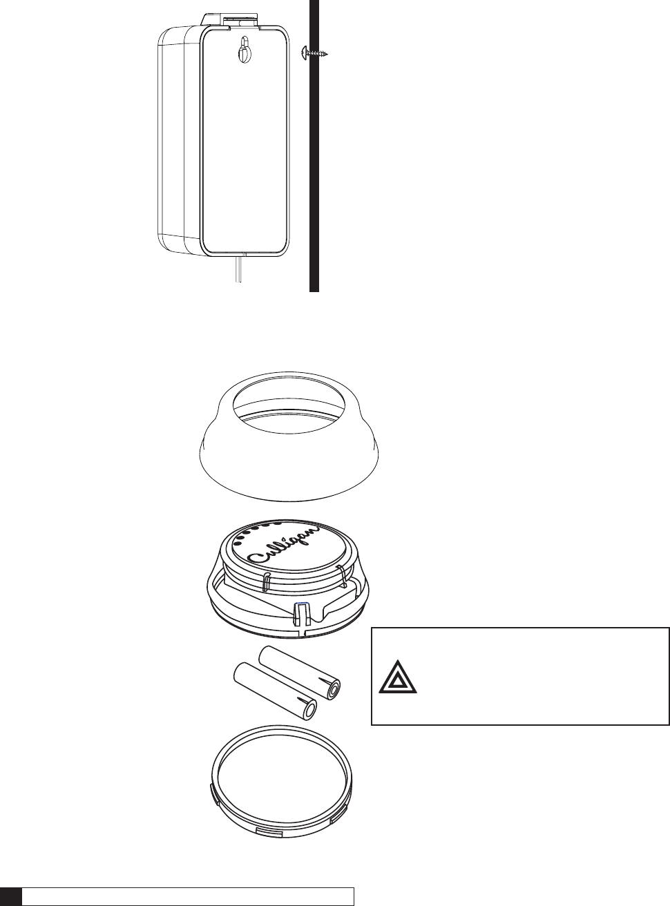
6. Use the provided screw to hang the
battery box on the side of the cabinet.
7. Install two AAA batteries (not
included) into the remote button.
CAUTION! If the button gets wet,
remove the batteries.
Air dry immediately!
Replace button, if
corrosion appears and/
or button malfunctions.
Installation 21
Cat. No. 01029457
Figure 23.
Button Display Guide
Figure 24.
8. Turn on the faucet to full cold and push
the button to activate the system.
NOTE All filters and RO membranes should be
flushed before connecting any ClearLink
device to the filtration/RO system.
NOTE The blue capacity lights should appear if the
button and control box are communicating.
NOTE The button can be turned off with a second
push or by turning off the faucet.
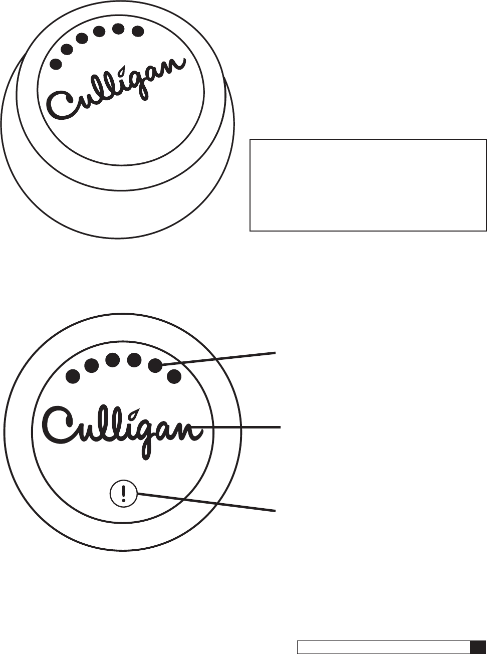
Culligan Logo: Flashes when treated water is
not available from the faucet. Stay solid while
treated water is being dispensed from the faucet.
Filter Capacity Lights: Shows from 1-6 lights
depending on filter capacity remaining, 6 lights
=> 80% and 1 light =<10%.
Alert Indicator: Illuminates when the control
box batteries need replacing, filters need
replacing, membrane needs replacing or if leak
is detected on connected versions.
22 Culligan® ClearLink Pro 22 Cat. No. 01029457
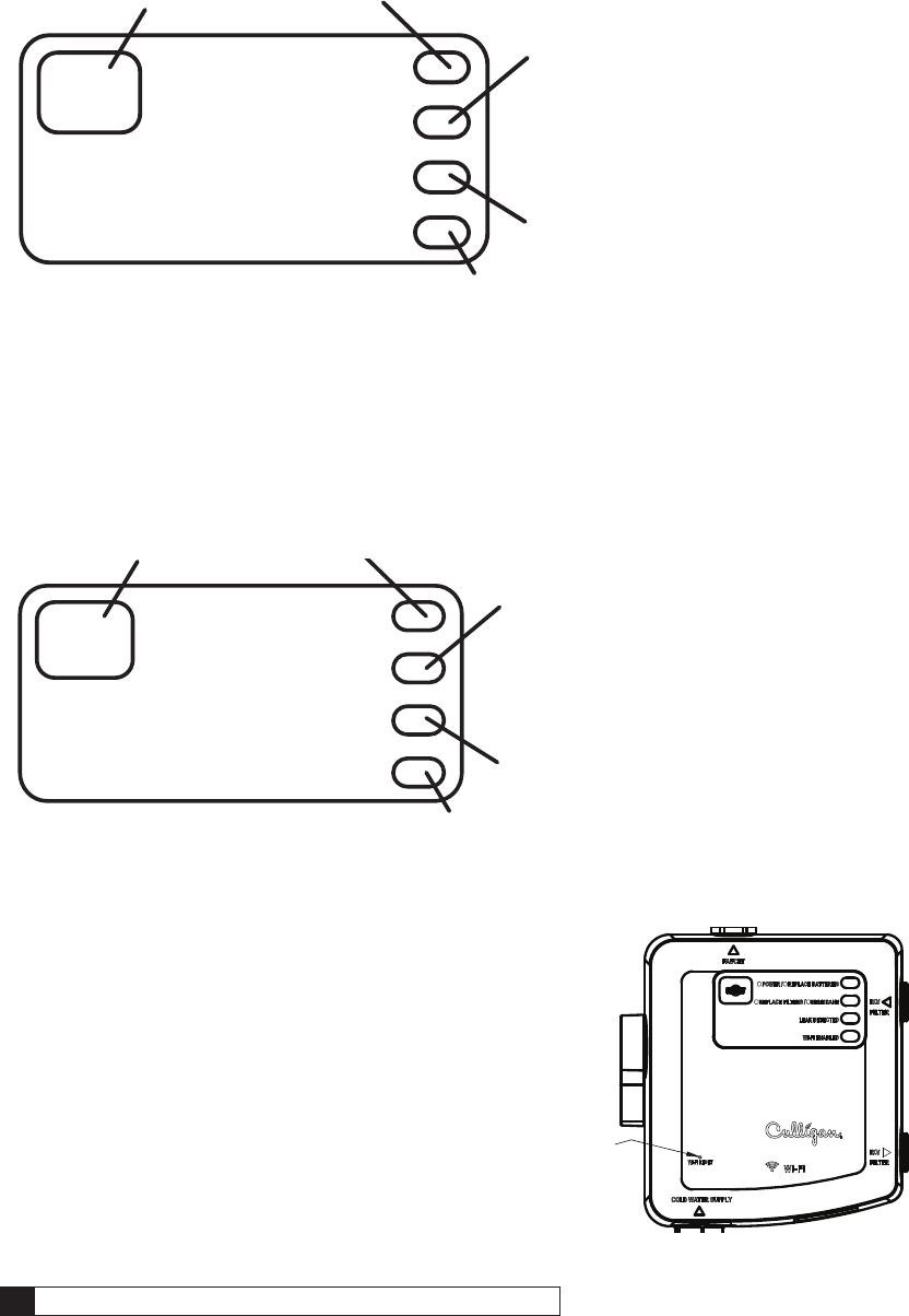
Control Box Operation
ClearLink
Figure 25.
ClearLink Connect and Drinking Water Connect
Figure 26.
Figure 27.
Replace Filters: Flashes red when the filters have
less than 10% of their life remaining due to flow or
time. This indicator is reset by pressing the reset
button for three seconds.
Power: Flashes green at power up, filter capacity reset,
and while dispensing filtered water. Continues to flash
for 1 minute after the flow of filtered water has stopped.
Reset Button
for filter capacity.
Replace RO Membrane: Flashes red when the treated water has a TDS level greater than 25%
of the untreated water. This indicator will automatically reset when low TDS water is detected.
Replace Batteries: Flashes red when the batteries
for the control box need to be replaced. This indicator
automatically clears when new batteries are detected.
Replace Filters: Flashes red when the filters have less than
10% of their life remaining due to flow or time. This indicator is
reset by pressing the reset button for two seconds.
Replace RO Membrane: Flashes red when the treated water
has a TDS level greater than 25% of the untreated water. This
indicator will automatically reset when low TDS water is detected.
Power: Flashes green at power up, filter capacity reset, and while dispensing filtered
water. Continues to flash for 1 minute after the flow of filtered water has stopped.
Replace Batteries: Flashes red when the batteries for the control box need to be
replaced. This indicator automatically clears when new batteries are detected.
Reset Button
for filter capacity.
WiFi Enabled: Flashes blue when the WiFi is connected to the control box.
Leak Detected: Flashed red when
the leak sensor has detected water.
WiFi Reset Button:
Press with paper clip.
One short press forces data upload.
Holding for 10 seconds will initiate device pairing.
Pairing to Smartphone 23
Cat. No. 01029457
Pairing to Smartphone
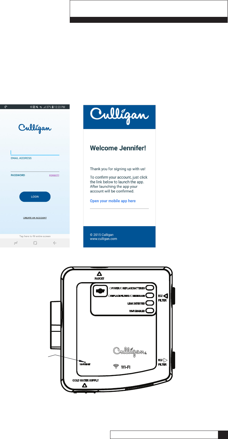
Pair to Android
1. Go to Google Play Store to download and install “Culligan Connect” app to the customer’s smartphone.
2. Go to phone settings and connect to your local WiFi network.
3. Launch Culligan Connect App.
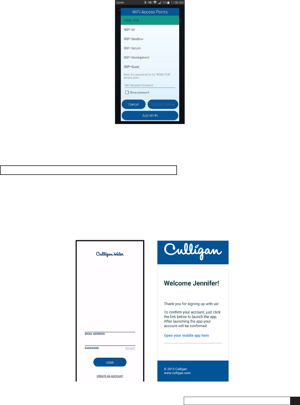
4. Create a new account by selecting “Create an account”.
A link will be emailed to you that must be clicked via your device to finalize setup.
Once finalized, login.
Figure 28.
Figure 29.
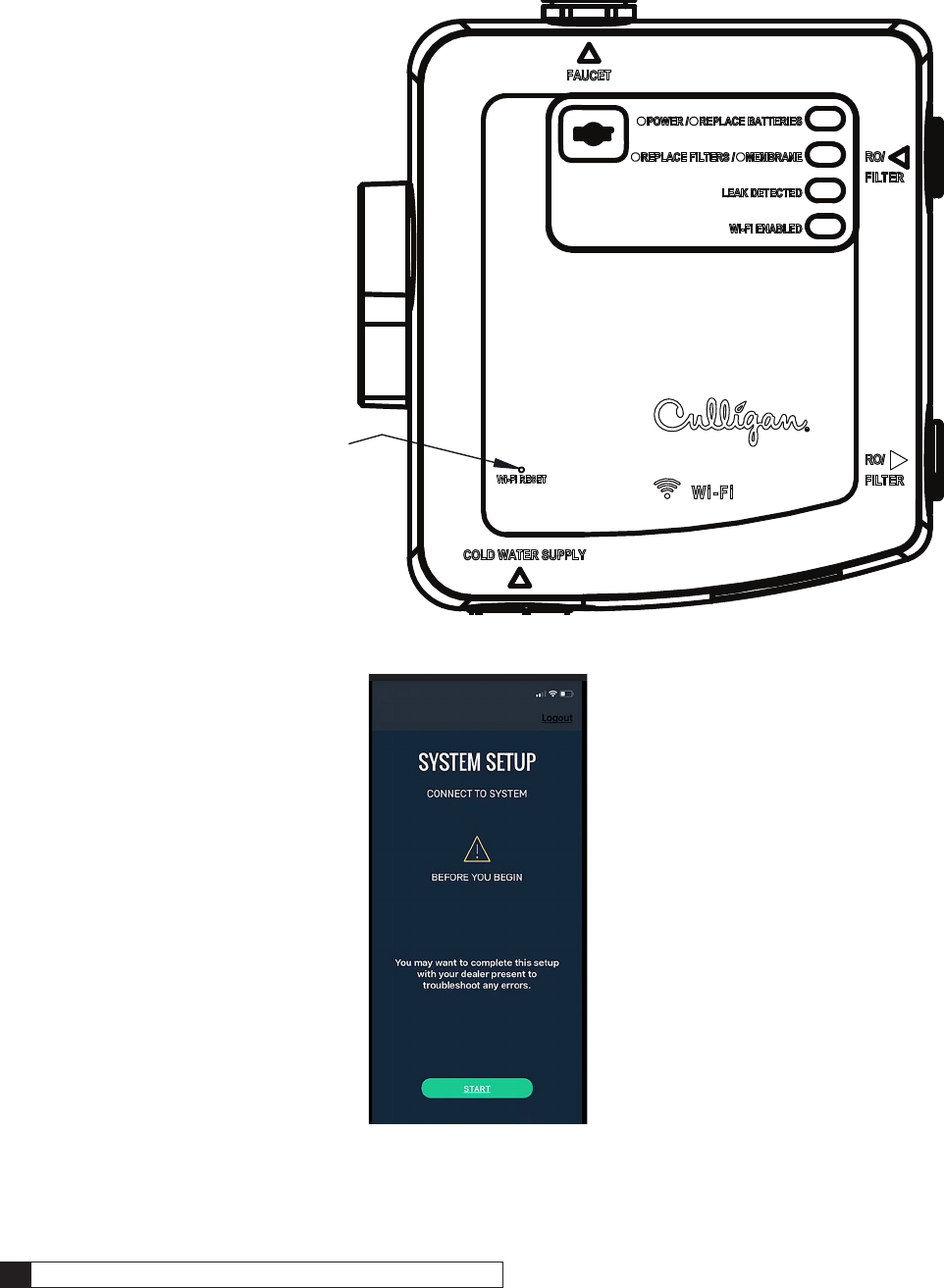
5. To activate device and place it into
pairing/registration mode, use a
paper clip to press and hold WiFi
Reset on the Control Box for 10
seconds until blue light changes
from flashing to solid.
24 Culligan® ClearLink Pro 24 Cat. No. 01029457
Figure 30.
Figure 31.
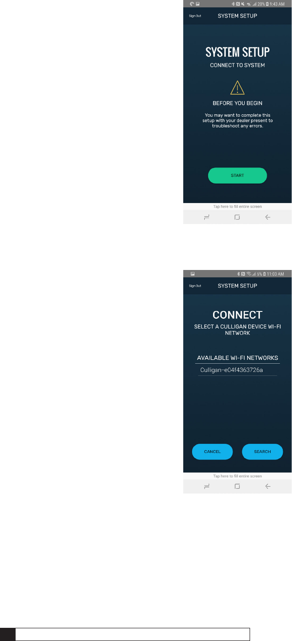
6. Start system setup process.
7. Search for Culligan device
and select it once found.
Pairing to Smartphone 25
Cat. No. 01029457
Figure 32.
9. Your App and device will now pair.
10. You are now connected and ready to take control of your water!
NOTE Only one account will work per connected ClearLink.
Pair to iPhone
1. Go to Apple app store Store to download and install “Culligan Connect” app to the customer’s smartphone.
2. Go to phone settings and connect to your local WiFi network.
3. Launch Culligan Connect App.
4. Create a new account by selecting “Create an account”.
A link will be emailed to you that must be clicked via your device to finalize setup. Once finalized, login.
Figure 33.
8. Select your local WiFi network,
enter WiFi password (if applicable)
and connect device.
26 Culligan® ClearLink Pro 26 Cat. No. 01029457
Figure 34.
Figure 35.
5. To activate device and place it into
pairing/registration mode, use a
paper clip to press and hold WiFi
Reset on the Control Box for 10
seconds until blue light changes
from flashing to solid.
6. Start system setup process.
Pairing to Smartphone 27
Cat. No. 01029457
Figure 36.
Figure 37.
Figure 38.
NOTE Only one account will work per connected ClearLink.
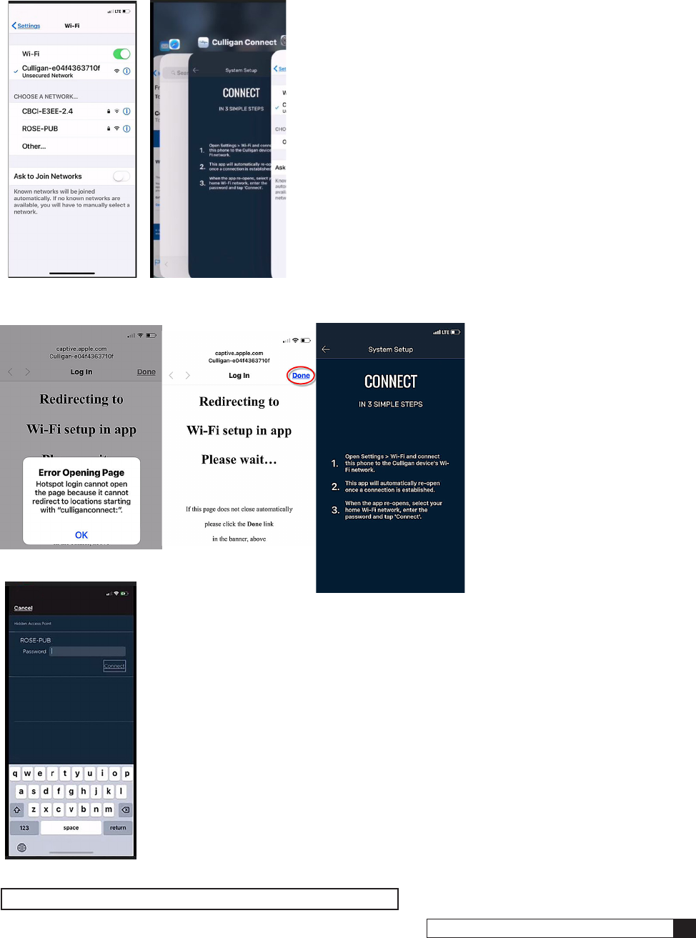
7. Open the iPhone settings/WiFi
8. Search for Culligan device and select it once found.
9. iOS 11 or newer:
- You might see a popup
“Error Opening Page” - if
so, select “OK”.
- Select “Done” in the
upper right corner of the
next screen.
- This returns you to the
settings/Wi-Fi screen,
where the Culligan device
will be selected.
- Manually go back to the
app and select the blue
“Connect to Device” button
at the bottom of the screen.
10. Select your local WiFi network, enter WiFi
password (if applicable) and connect device.
11. Your App and device will now pair.
12. You are now connected and ready to take control of your water!
28 Culligan® ClearLink Pro 28 Cat. No. 01029457
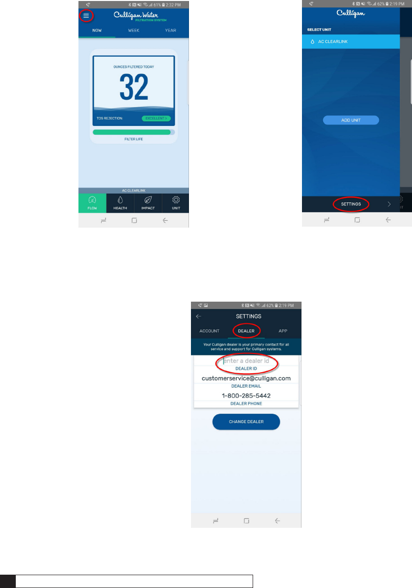
Viewing Device On Cport
To ensure you are able to monitor your device on Cport you must enter your dealer number within the app.
1. Select settings icon in upper
corner of home screen.
2. Select “Settings” at bottom
of the screen.
3. Select “Dealer” tab and enter
your dealer id # and tap
“Change Dealert.
Figure 39.
Figure 40.
Figure 41.
Troubleshooting 29
Cat. No. 01029457
Troubleshooting
Troubleshooting Guide
Problem Solution
Leaks at filter/RO Inlet or outlet connection A rolled o-ring can block the tube from fully inserting. Use small
screw driver to reseat the o-ring and then confirm that the end of
the tubing has a clean, square cut.
Low filtered water flow/system returns to unfiltered
flow automatically:
Low flow rates may not activate the control box electronics. Refer
to your system manual to trouble shoot a low flow condition.
Button is communicating, but no change in flow. Confirm that the bypass valve is in the down/closed position.
Button communication is intermittent. Some materials may block the wireless signal more than others.
Try moving the button to an area on the counter that is closer to
the under-sink control box.
Filtered water flow won’t turn off. Low batteries for the control box can cause the system to be
stuck in the filtered position. The bypass valve can be used to
allow unfiltered water flow to the faucet while the issue is being
corrected.
WiFi connection issues
Pairing issues
Call Technical Service Line at 800-333-9047.
Select option 6 for assess to the support line, then option 1 for
onsite pairing support
Control Box Lights
Audible Beep Light Means
3 Beeps during Power up Green (Top Window) Power On and performing operations
1 beep per minute when water is running
and 1 beep when the water is turned off.
Red (Top Window) Option 1: Replace D Batteries in Control Box
Option 2: Use A/C Adapter instead of D
Batteries
1 beep per minute when water is running
and 1 beep when the water is turned off.
Yellow (Second Window) Reached Capacity in Gallons/Days; Replace
Filter
1 beep per minute when water is running
and 1 beep when the water is turned off.
Red (Second Window) High TDS; Replace Membrane
1 beep per minute when water is running
and 1 beep when the water is turned off.
Red (Third Window) Leak Detected
Blue (Bottom Window) WiFi Enabled and Paired
30 Culligan® ClearLink Pro 30 Cat. No. 01029457
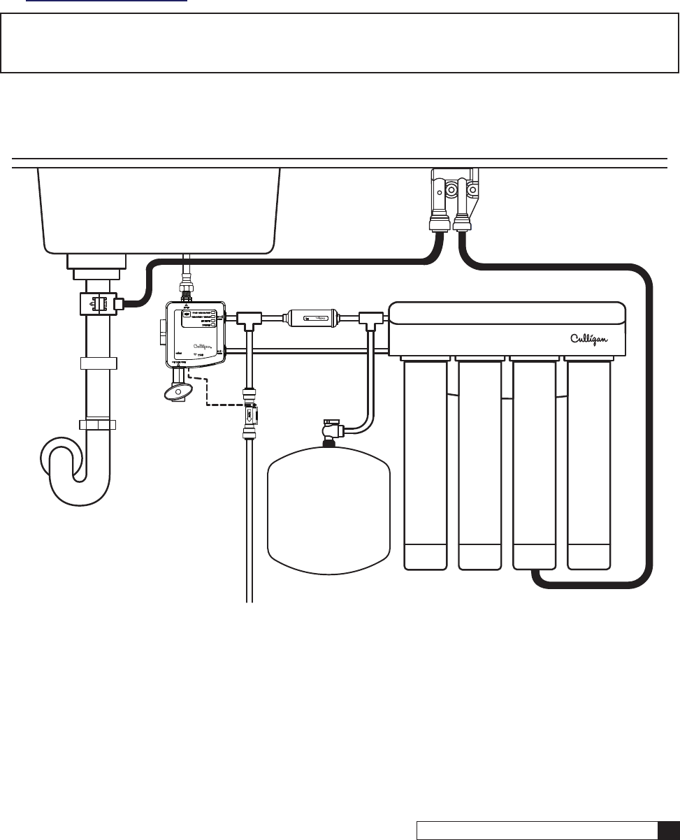
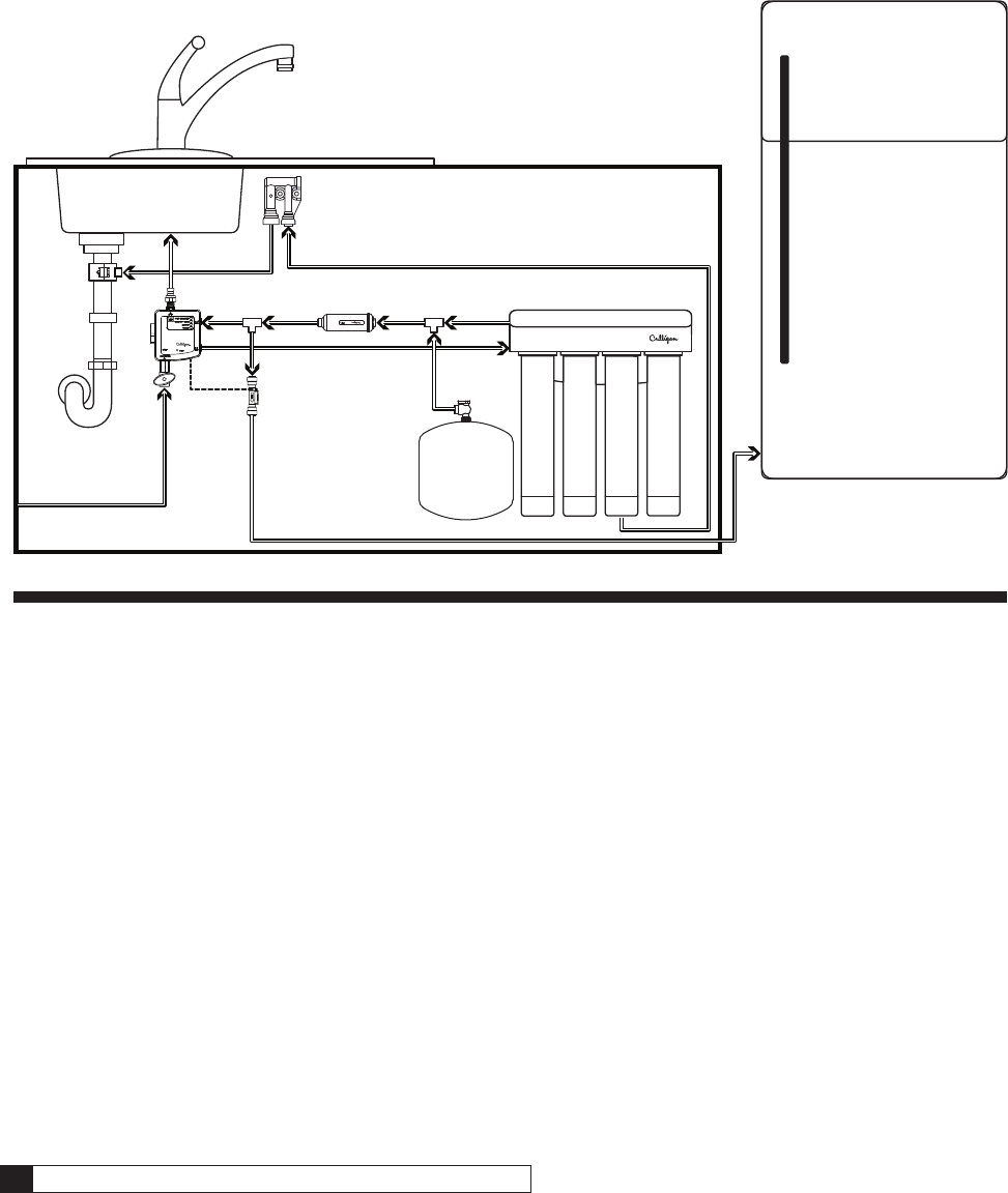
Routing Guides
ClearLink Connect: Under Sink Install with Secondary Line
Tank
Flow Switch
Post Filter
KITCHEN
BASEMENT
Figure 42.
Troubleshooting 31
Cat. No. 01029457
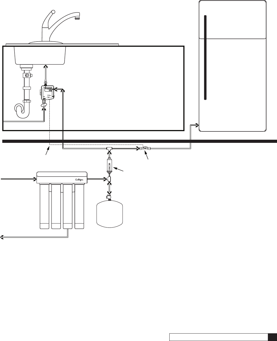
ClearLink Connect: Remote Install with Secondary Line
KITCHEN
BASEMENT
Flow Switch
Flow Switch Wire
To Drain
Post Filter
Tank
Figure 43.
32 Culligan® ClearLink Pro 32 Cat. No. 01029457
Drinking Water Connect: Under Sink Install with Secondary Line
KITCHEN
BASEMENT
To Drain
Post Filter
Tank
Figure 44.
Troubleshooting 33
Cat. No. 01029457
Drinking Water Connect: Remote Install with Secondary Line
KITCHEN
BASEMENT
To Drain
Post Filter
Tank
Cap outlet or run to wash
tub faucet or similar
Figure 45.
34 Culligan® ClearLink Pro 34 Cat. No. 01029457
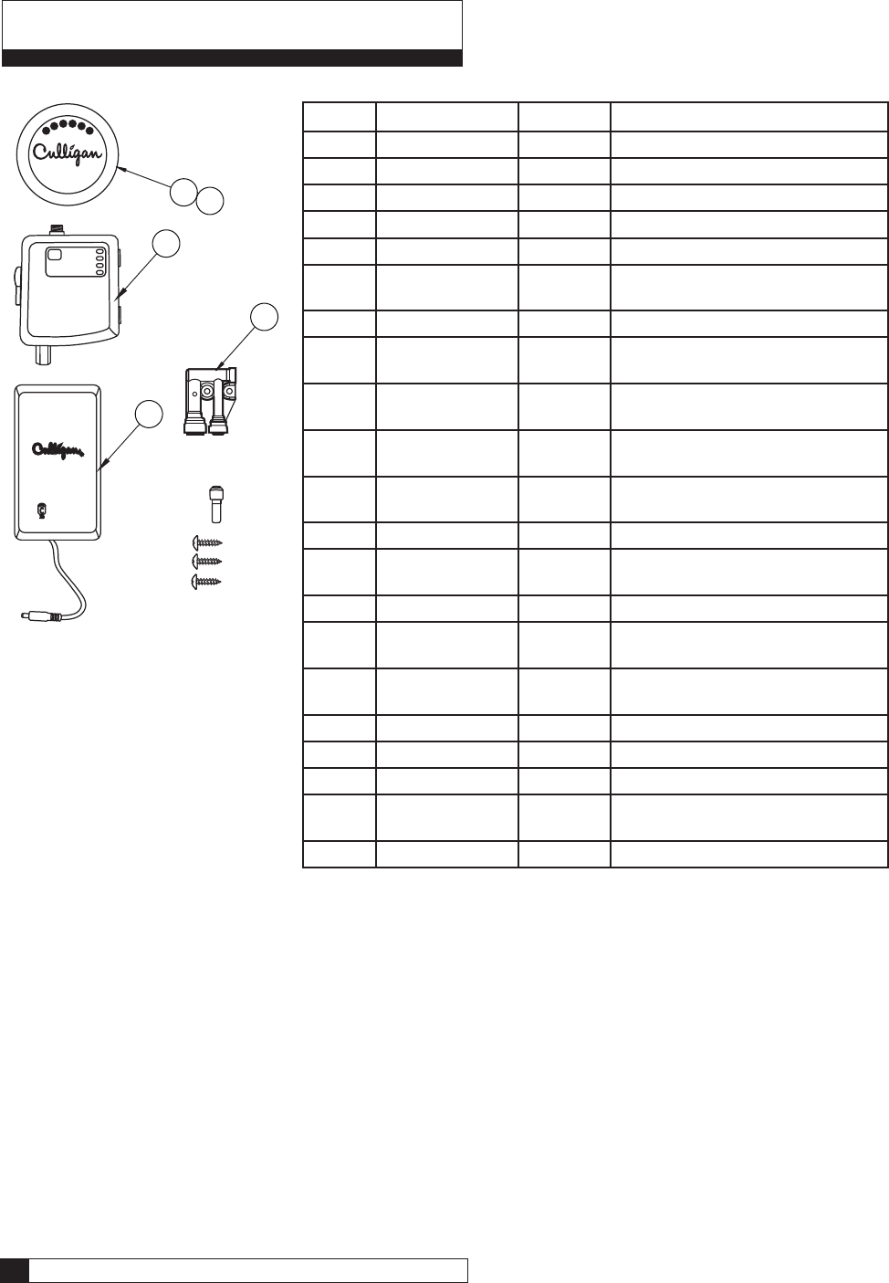
Replacement Parts List
4
3
1
5
2
Item Part Number Kit Description
A 01029472 — ClearLink Pro, Chrome
B 01029473 — ClearLink Pro, Brushed Nickel
C 01029474 — ClearLink Pro, Oil Rubbed Bronze
D 01033051 — ClearLink Connect, Chrome
E 01033052 — ClearLink Connect, Brushed Nickel
F 01033053 — ClearLink Connect, Oil Rubbed
Bronze
G 01033121 — Drinking Water Connect
1 01029450 A, B, C, D,
E, F Remote Button
2 01029452 A, D Remote Button, Trim Ring, Chrome
Finish
01029453 B, E Remote Button, Trim Ring, Brushed
Nickel Finish
01029454 C, F Remote Button, Trim Ring, Oil
Rubbed Bronze
3 01029449 A, B, C Control Box, ClearLink Pro
01033035 G Control Box, Drinking Water
Connect
01033034 D, E, F Control Box, ClearLink Connect
4 01033128 A, B, C, D,
E, F, G Battery Box, D Batteries
5 01030130 A, B, C, D,
E, F Air Gap
* 01033141 D, E, F Air Gap Mounting Bracket
* 01029455 — AC Adapter (optional)
* 01033130 D, E, F External Flow Switch with 3’ Wires**
* 01033170 — External Flow Switch, 40’ Wiring
Extension Kit (optional)
* 01033129 D, E, F, G Leak Sensor**
*Not Shown
**Not designed to work with ClearLink Pro.

Replacement Parts List 35
Cat. No. 01029457
One-Year Limited Warranty
This warranty applies to the button, control box and battery box. This warranty covers defects in material and
workmanship only for 1 full year from the original date of delivery. Culligan will replace any part which in Culligan’s opinion
is defective, unless: (1) any part of the unit has been subjected to any type of tampering, alteration, or improper use after
delivery, or (2) it has been repaired by anyone not approved by Culligan.
This product has been designed solely for use as a water filtration control. It is NOT warranted against freezing or surges
in water pressure, and neither this product nor its parts is warranted against defects or deterioration caused by uses for
which this product was not expressly intended.
THE FOREGOING WARRANTY IS EXCLUSIVE AND IN LIEU OF ALL OTHER WARRANTIES, EXPRESSED OR
IMPLIED, WHETHER ORAL OR ARISING BY USAGE OF TRADE OR COURSE OF DEALING, INCLUDING, WITHOUT
LIMITATION, ANY WARRANTIES OF FITNESS OR MERCHANTABILITY. THIS WARRANTY IS THE PURCHASER’S
SOLE AND EXCLUSIVE REMEDY, IN NO EVENT SHALL CULLIGAN BE LIABLE FOR ANY ANTICIPATED OR LOST
PROFITS, INCIDENTAL DAMAGES, CONSEQUENTIAL DAMAGES, COSTS, TIME CHARGES OR OTHER LOSSES,
WHETHER BASED ON BREACH OF CONTRACT, TORTIOUS CONDUCT OR ANY OTHER THEORY, INCURRED IN
CONNECTION WITH THE PURCHASE, INSTALLATION, REPAIR OR OPERATION OF THIS PRODUCT. CULLIGAN
DOES NOT AUTHORIZE ANYONE TO ASSUME FOR IT ANY LIABILITY OR TO MAKE ON ITS BEHALF ANY
ADDITIONAL WARRANTIES IN CONNECTION WITH THE FILTER HOUSING OR ANY PART THEREOF.

36 Culligan® ClearLink Pro 36 Cat. No. 01029457
Index
A
About Models 7
About this Manual 6
Alert Indicator 21
Android 23
B
Button 21
Button Display 21
C
Capacity 10
ClearLink 22
ClearLink Connect 7, 22, 30, 31
ClearLink Pro 7
Contents 3
Control Box 22
Control Box Lights 29
Control Box Operation 22
Cport 28
Culligan Logo 21
D
Drinking Water Connect 8, 22, 32, 33
E
External Flow Switch 15
F
Filter Capacity Lights 21
Flow Switch 15, 16, 17
I
Install 30, 31, 32, 33
Installation 9, 11
Introduction 5
iPhone 25
L
Leak Sensor 17
M
Materials 9
Models 7
O
Outlet 15
P
Pairing 23
Pairing to Smartphone 23
Pair to Android 23
Pair to Cport 28
Pair to iPhone 25
Parts 9
Parts List 34
Power 22
Precautions 9
R
Remote Install 31, 33
Replace Batteries 22
Replace Filters 22
Replacement Parts List 34
Replace RO Membrane 22
Reset Button 22
Routing Guides 30
S
Safe Practices 6
Serial Number 6
Serial Numbers 6
Setting Capacity 10
Specications9
Startup 18
Switch 16
Switch Wiring 16
System Startup 18
T
TDS 10
TDS Function 10
Tools 9
Troubleshooting 23, 29
Troubleshooting Guide 29
U
Under Sink Install 30, 32
W
Warranty 35
Wire Extension Kit 17
Wiring 16

Index 37
Cat. No. 01029457
Notes
38 Culligan® ClearLink Pro 38 Cat. No. 01029457
Materials & Description: ClearLink Pro Installation & Operating Guide PN 01029457
Size: 8.5” x 11”
Color: Black Ink, 2 sided
Stock: Front (2 sided) & Back (Blank) Covers on 110# White Index
Inside on 20# white
Other: Collate
Tape Bind, Black Down the 11” left side
This page contains materials and DCO in for ma tion.
IT DOES NOT PRINT AS PART OF THE DOC U MENT!
LET Change By Appv’d DCO Date
ANEW ART CREATED Motiva/JT AC/BM 016500 10/12/15
A1 FCC corrections JT JT 016500 12/07/15
A2 FCC/IC Changes JT JT 016500 02/05/16
B New Models, FCC/IC Update JT/VP AC 018577 11/14/18