Culligan Hd 202 Users Manual Hi Flo 55 Filters
HD-242 Hi-Flo55
2015-02-05
: Culligan Culligan-Hd-202-Users-Manual-533599 culligan-hd-202-users-manual-533599 culligan pdf
Open the PDF directly: View PDF ![]() .
.
Page Count: 19
Culligan®
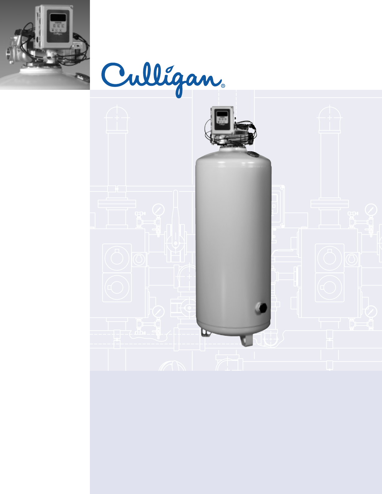
Heavy Duty
Commercial
Filters
Culligan’s Hi-Flo®55e Commercial
Filters
apartments
assisted living facilities
cafeterias
casinos
corporate campuses
educational facilities
food service
government
grocery
health clubs
hotel/hospitality
institutions
laundry
manufacturing facilities
theme parks
travel centers
vehicle wash Standard Features
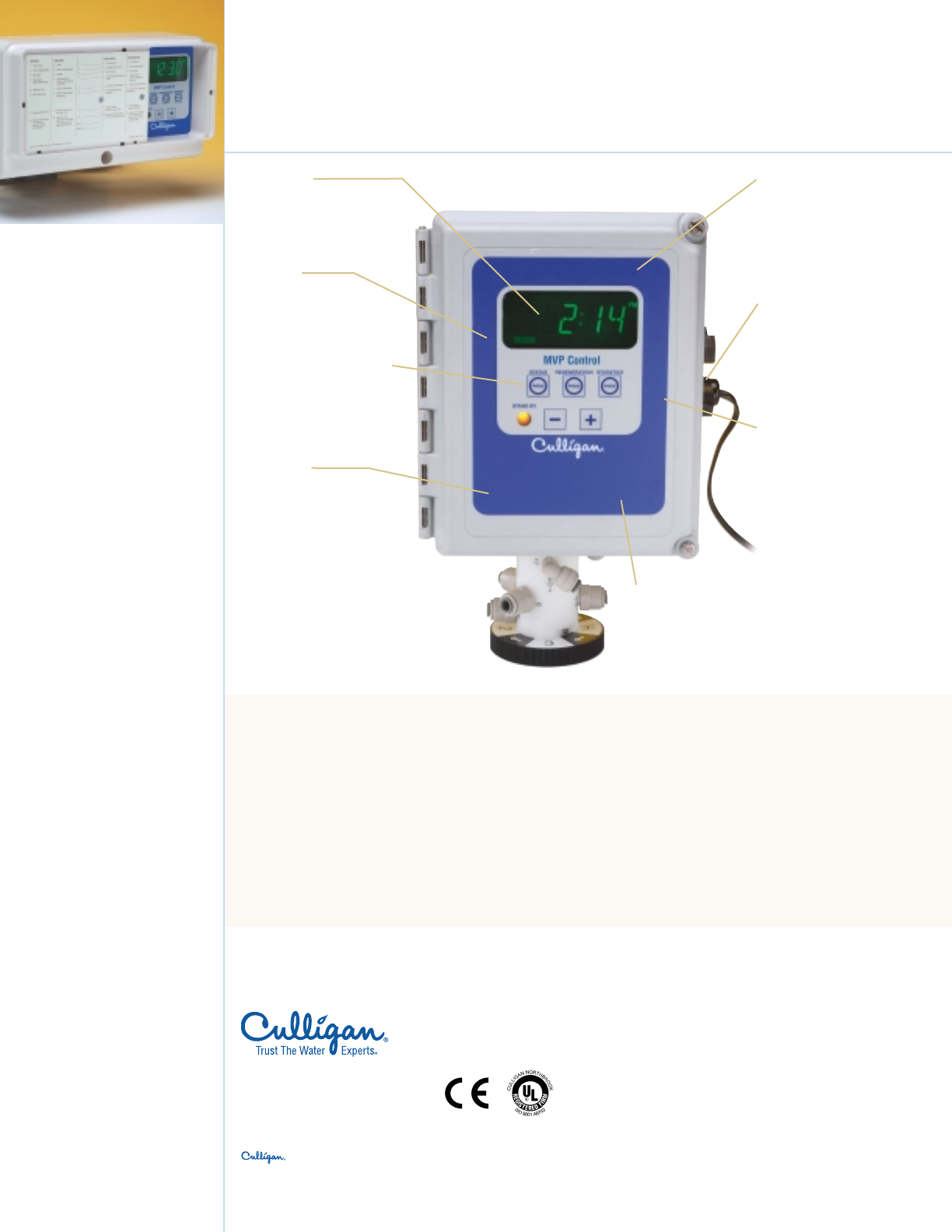
• 24 Volt Culligan’s MVP™ Controller – Field
programmable with a back-lit LCD display and
UL listed 120v/24v transformer.
• Single,Duplex,Triplex, or Quad Configurations
• Regeneration initiation by choice of time clock,
meter or differential pressure switch.
• Carbon Filters – For reduction of organics (flow
rates up to 39gpm), or chlorine (flow rates up to
77gpm).
• Depth Filters – Flow rates up to 193gpm.
• Top-Mounted Control Valve – Keeps plumbing
connections simple and adaptable. Full flow
porting with rounded orifices and wide-open
cartridges promote good flow characteristics and
low pressure fluctuations.
• Corrosion resistant tanks – Made of low carbon
steel with epoxy interior lining and finish coat
painted exterior.
Trust The Water Experts®
More

Culligan’s Hi-Flo®55e Commercial Filters
www.culligan.com™
1-800-CULLIGAN
©2003 Culligan International Co.
Printed in USA (12/03)
MOORE PART NO.47601
“Hey Culligan Man!”
®
Products manufactured and marketed by Culligan International Company (Culligan) and its affiliates are protected by patents issued or pending in the United States and other
countries. Culligan reserves the right to change the specifications referred to in this literature at any time, without prior notice. , Brunermatic, Hey Culligan Man,
Culligan Man, Culligan Commercial @ Work, www.culligan.com and Culligan Service Network are trademarks of Culligan International Company or its affiliates.
ISO 9001
Certification
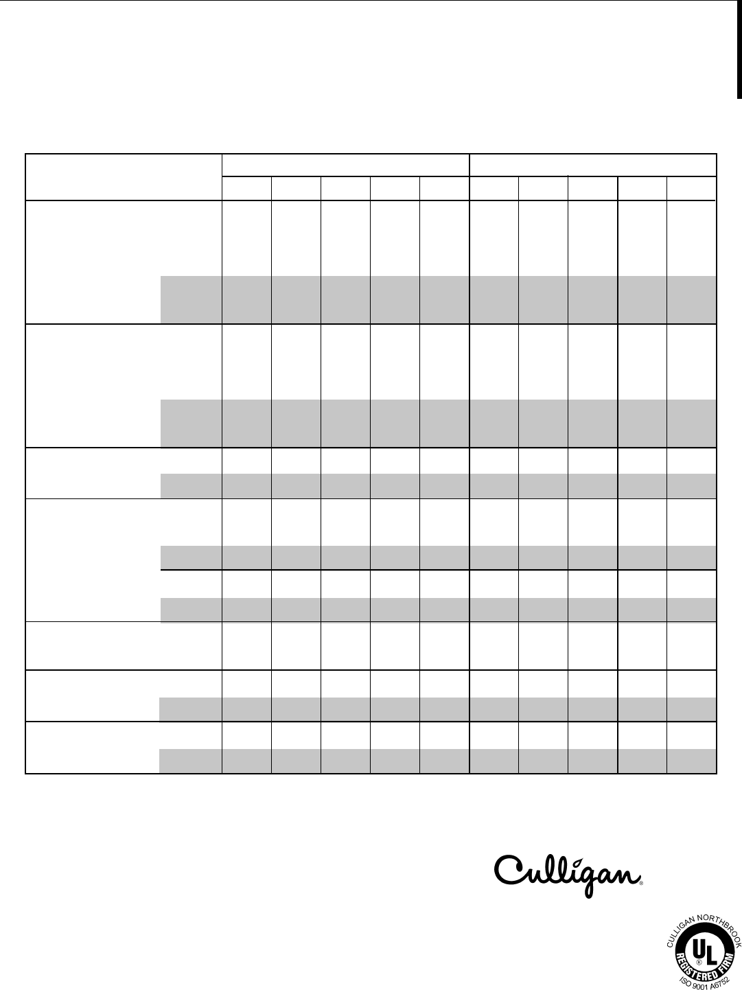
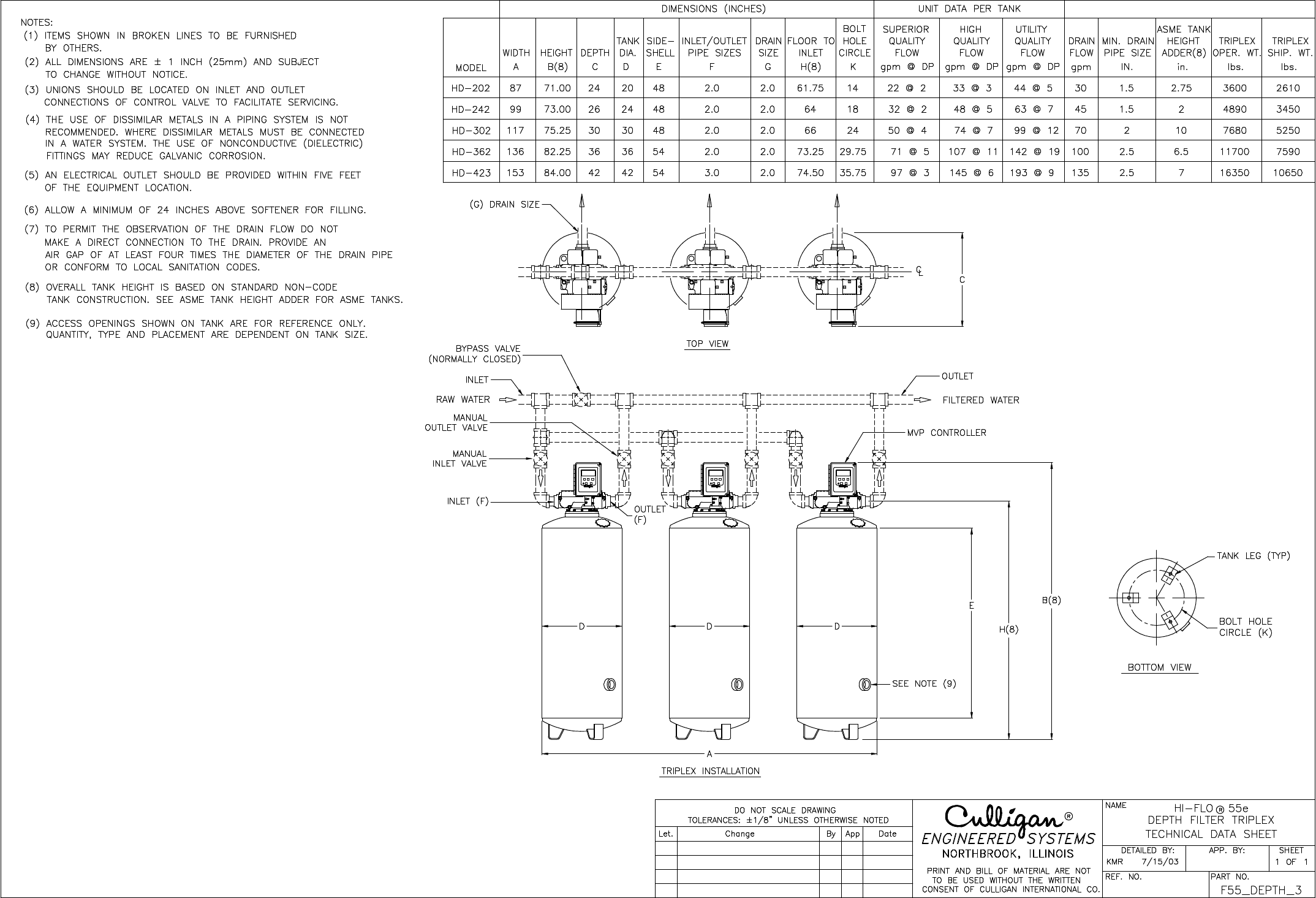
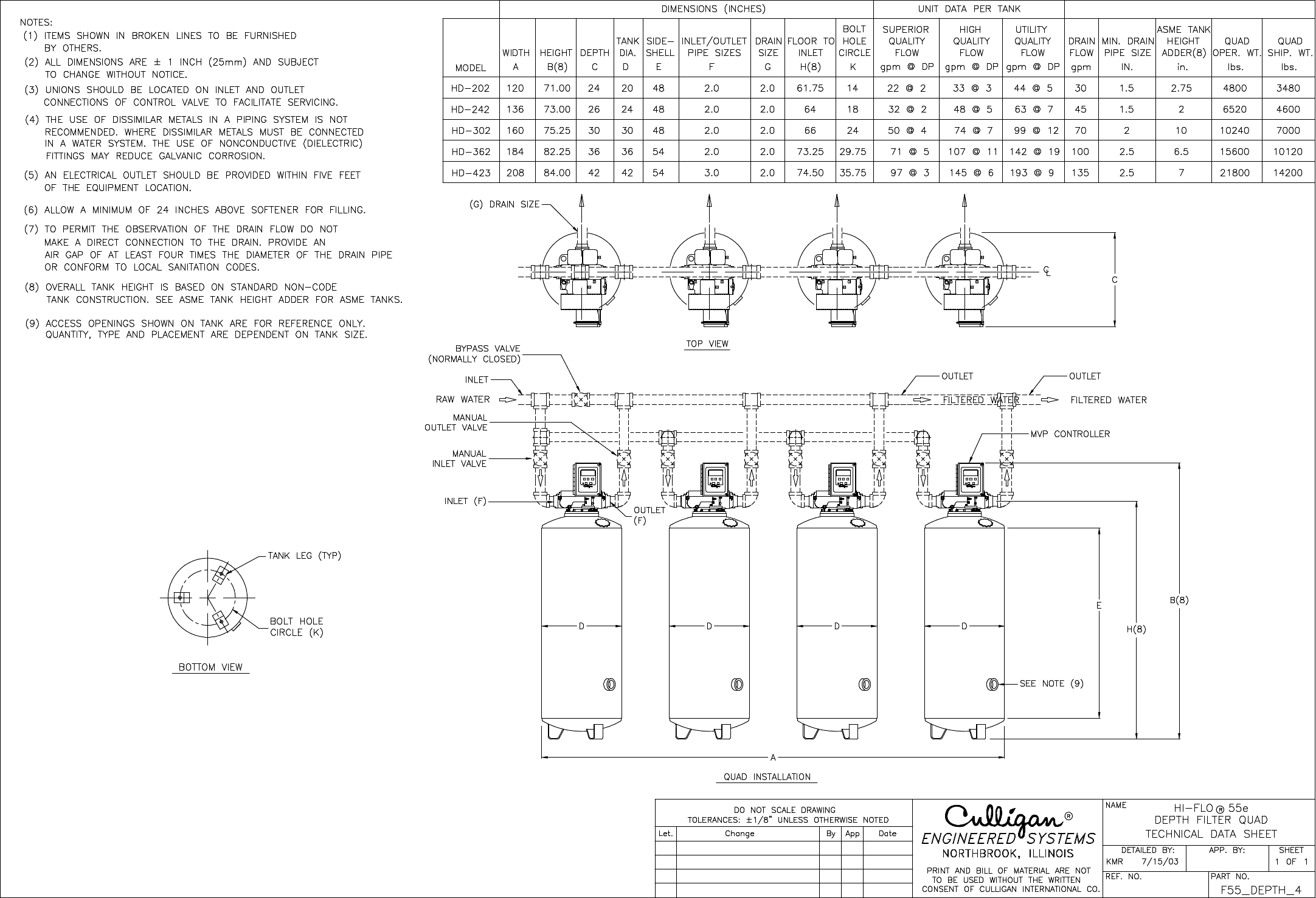
HD-202 22 2 33 3 44 5 30 2
HD-242 32 2 48 5 63 7 45 2
HD-302 50 4 74 7 99 12 70 2
HD-362 71 5 107 11 142 19 100 2
HD-423 97 3 145 6 193 9 135 3
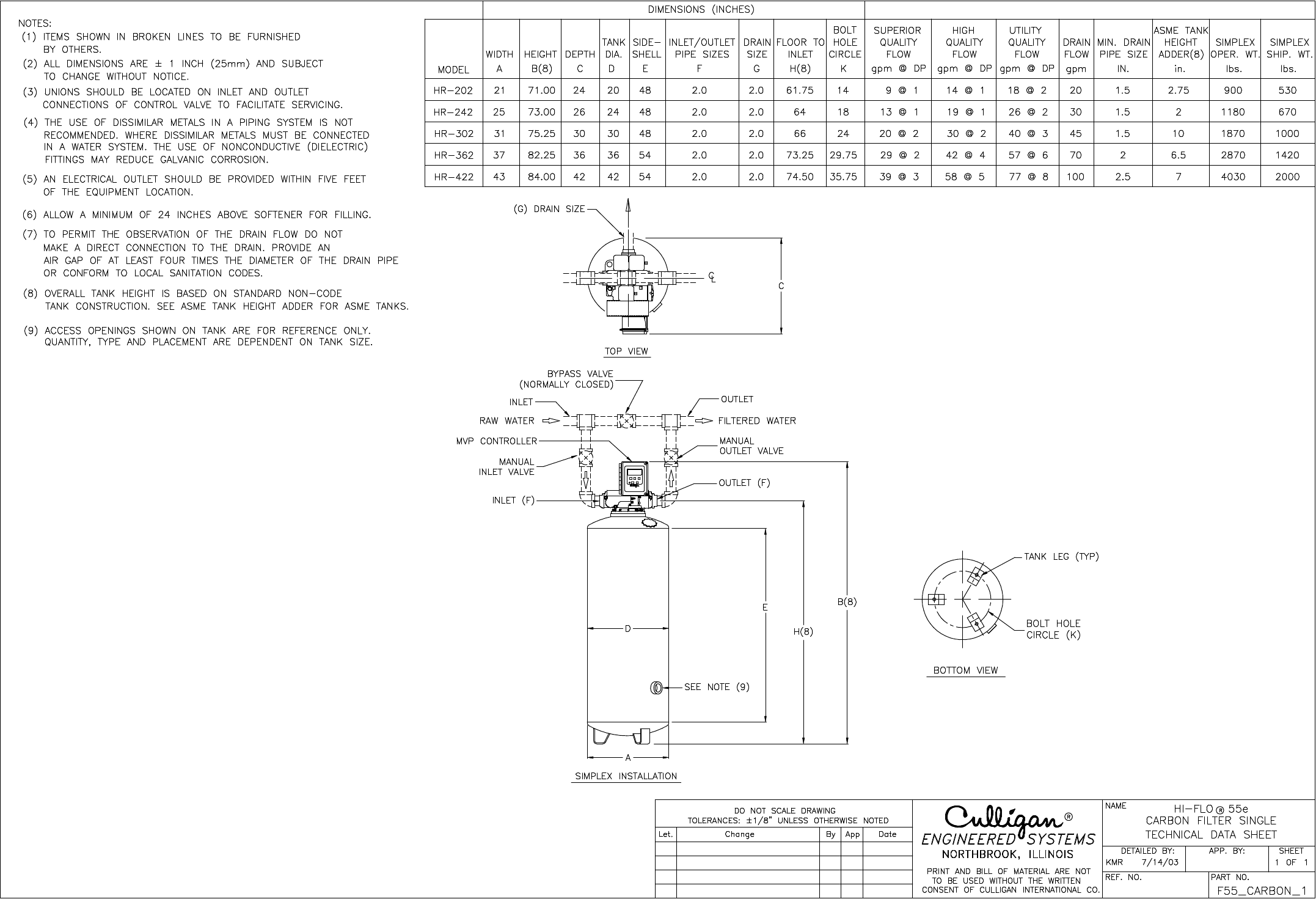
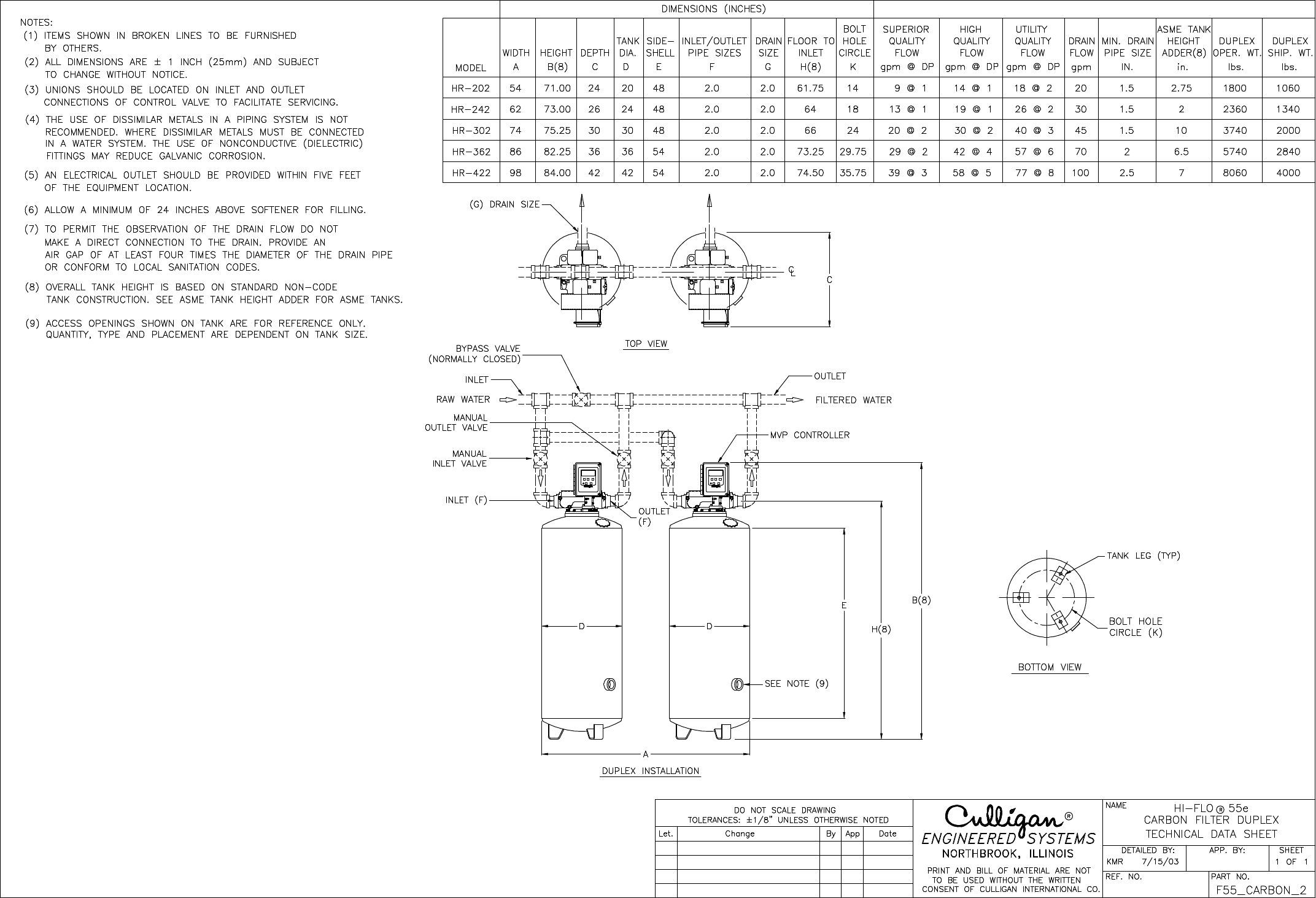
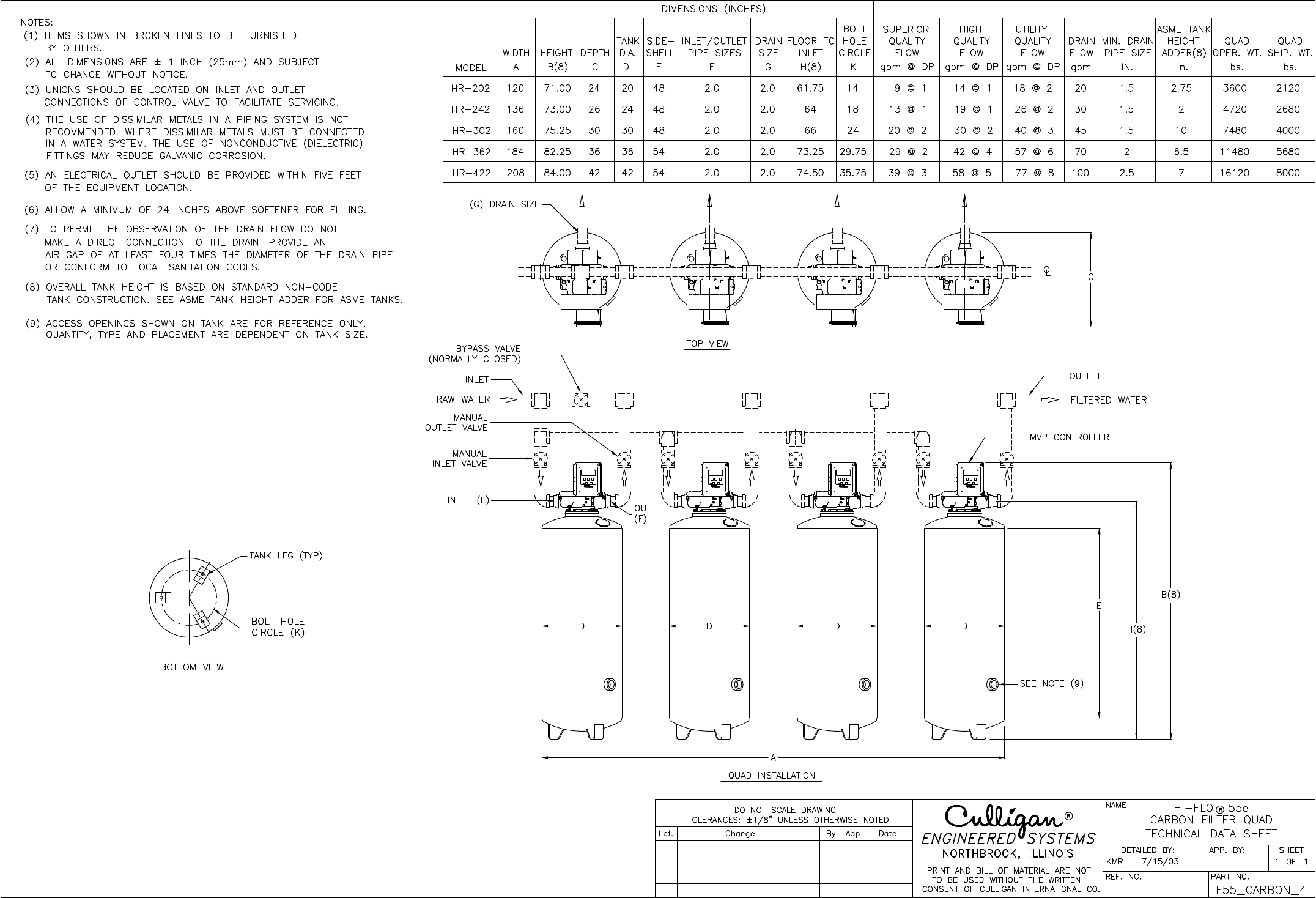
HR-202 1910114 1 1822220 2
HR-242 1311119 1 2622230 2
HR-302 2012130 1 4023245 2
HR-362 2912142 4 5726270 2
HR-422 3913158 5 77282100 2
Model Flow Rate
(GPM) Pressure
Loss (PSI) Flow Rate
(GPM) Pressure
Loss (PSI) Flow Rate
(GPM) Pressure
Loss (PSI)
Backwash
Flow Rate
(GPM)
Valve
Size
(inches)
Superior*
* Superior – Best quality water with lowest pressure loss. Recommended for influent suspended solid loads up to and greater than 300 ppm.
** High – Very good quality water with increased pressure loss. Recommended for influent suspended solid loads less than 300 ppm.
*** Utility – Satisfactory quality water with greatest pressure loss. Shorter on line time between backwashing. Recommended for influent suspended solid
loads less than 150 ppm.
1For Sediment and organic removal use the flow rates from the superior water quality column.
2 For chlorine removal only,use the flow rates from the utility water quality column.
All pressure drop figures are based on new filter media and a water temperature of 60°F.
Depth filters are capable of 10 micron effluent water quality, whereas all other filter types are capable of 40 micron effluent water quality.
Water Quality
High** Utility***
Depth Filters
Carbon Filters
System Specifications
Pressure: 30–100 psig
207–690 kPa
Power: 120 VAC/24 VAC
50/60 Hz
Temperature: 40–120°F
4–49°C
Applications and Benefits
• Food and Beverage–Superior taste and increased
cost savings.
• Drinking Water–Reduces turbidity and chlorine;
improves taste and clarity.
• Boilers—Turbidity reduction, minimize sludge
blowdown.
• Light Industry Processes—Reduces particulate matter.
• Pretreatment—For softeners, RO’s and DI systems.
• Vehicle Wash—Turbidity reduction.
Options
• Patented Progressive Flow-
Culligan’s MVP™ controller can
monitor flow demands,bringing
additional tanks on-line or off-line
as flows increase or decrease.
• Differential Pressure Switch
• A.S.M.E. Code Tanks
• Sample cocks and pressure gauges
• Separate source regeneration kits
• Skid mounting
• Flow meter
Warranty
Culligan’sHi-Flo 55e water filters are
backed by a limited 1-year warranty
against defects in material,
workmanship and corrosion.In
addition, tanks carry a limited 5-year
warranty.*
* See printed warranty for details.
Culligan will provide a copy of the
warranty upon request.
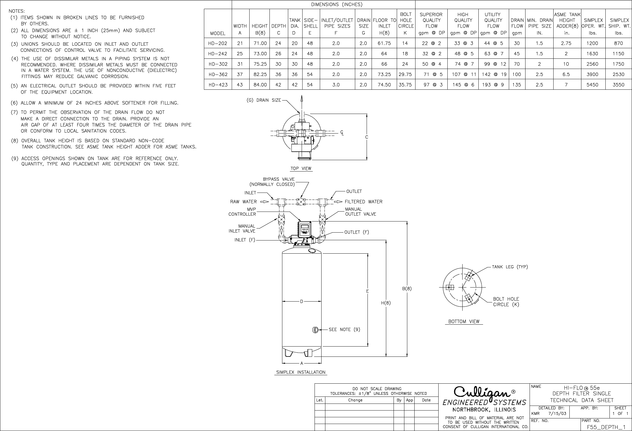
HI-FLO®
DEPTH FILTERS
FOR SEDIMENT REDUCTION
SPECIFICATIONS AND OPERATING DATA
Hi-Flo 55 Hi-Flo 50
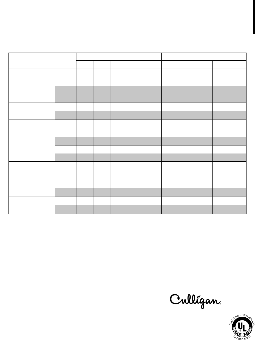
MODEL NUMBER HD-202 HD-242 HD-302 HD-362 HD-423 HD-483 HD-544 HD-604 HD-726 HD-846
Peak
Service Flow @ gpm 30 45 75 100 150 190 240 300 440 600
Pressure Drop @ psi @ 3 @ 4 @ 7 @ 10 @ 6 @ 10 @ 8 @ 10 @ 10 @ 10
L/min 114 170 284 379 568 719 908 1,140 1,670 2,270
@ kPa @ 21 @ 28 @ 42 @ 69 @ 41 @ 69 @ 55 @ 69 @ 69 @ 69
Normal
Service Flow @ gpm 15 20 35 50 70 90 110 140 200 270
Pressure Drop @ psi @ 1 @ 1 @ 2 @ 3 @ 2 @ 3 @ 3 @ 2 @ 2 @ 2
L/min 57 76 132 189 265 340 420 530 750 1,020
@ kPa @ 6.9 @ 6.9 @ 14 @ 21 @ 14 @ 20 @ 20 @ 14 @ 14 @ 14
Backwash Flow gpm 30 45 70 100 135 188 210 270 400 540
L/min 114 170 265 379 511 712 795 1,020 1,510 2,040
Tank Size
Diameter in 20 24 30 36 42 48 54 60 72 84
mm 510 610 760 910 1,070 1,220 1,370 1,520 1,830 2,130
Sideshell in 48 48 48 54 54 60 60 60 60 60
mm 1,220 1,220 1,220 1,370 1,370 1,520 1,520 1,520 1,520 1,520
Pipe Size
Inlet/Outlet in 2 2223344 66
Media Volume ft35 8 12 17 23 32 40 49 70 97
m30.142 0.227 0.340 0.481 0.651 0.906 1.13 1.39 1.98 2.75
Ship Weight, Approx. lb 870 1,150 1,750 2,530 3,550 7,000 8,800 10,800 18,500 25,000
kg 390 520 790 1,150 1,610 3,175 4,000 4,900 8,390 11,340
NOTES:
1 Service flow rates are based on 7 gpm/ft2 (26 L/m2/min) for Normal and 15 gpm/ft2 (57 L/m2/min) for Peak Flow rates. Actual service rate can vary from
2 to 20 gpm/ft2 (8 - 76 L/m2/min) depending upon the application and the raw water.
2 Backwash flow rates are based on 12-14 gpm/ft2 (45-53 L/m2/min) using 50° F (10° C) water. A different backwash rate may be required depending upon
water temperature or the type of carbon used.
3 Operational, maintenance and replacement requirements are essential for this product to perform as advertised. Service is available through independently
operated Culligan dealerships.
Commercial Systems
©2000 Culligan
1-800-CULLIGAN
www.culligan.com
Printed in USA Rev. 4/00
DCO 992587
SL-0070
Moore Part No. 46924

HI-FLO®
CULLAR® AUTOMATIC FILTERS FOR
DECHLORINATION AND ORGANIC ADSORPTION
SPECIFICATIONS AND OPERATING DATA
Hi-Flo 55 Hi-Flo 50
MODEL NUMBER HR-202 HR-242 HR-302 HR-362 HR-423 HR-4825 HR-543 HR-603 HR-724 HR-844
Dechlorination
Service Flow @ gpm 20 30 50 70 100 125 160 200 280 380
Pressure Drop @ psi @ 2 @ 2 @ 4 @ 8 @ 13 @ 16 @ 18 @ 13 @ 12 @ 16
L/min 76 114 189 265 379 473 606 757 1,060 1,440
@ kPa @ 14 @ 14 @ 28 @ 55 @ 90 @ 110 @ 124 @ 90 @ 83 @ 110
Organics Adsorption
Service Flow @ gpm 10 15 25 35 50 65 80 100 140 200
Pressure Drop @ psi @ 1 @ 1 @ 2 @ 3 @ 4 @ 4 @ 6 @ 4 @ 5 @ 6
L/min 38 57 95 132 189 246 303 379 530 757
@ kPa @ 6.9 @ 6.9 @ 14 @ 21 @ 28 @ 28 @ 41 @ 28 @ 34 @ 41
Backwash Flow gpm 20 30 45 70 100 136 160 210 270 400
L/min 76 114 170 265 379 515 606 795 1,020 1,510
Tank Size
Diameter in 20 24 30 36 42 48 54 60 72 84
mm 510 610 760 910 1,070 1,220 1,370 1,520 1,830 2,130
Sideshell in 48 48 48 54 54 60 60 60 60 60
mm 1,220 1,220 1,220 1,370 1,370 1,520 1,520 1,520 1,520 1,520
Pipe Size
Inlet/Outlet in 2 22222.53344
Media Volume ft36 8 12 18 24 32 40 48 70 96
m30.170 0.227 0.340 0.510 0.680 0.910 1.13 1.36 1.98 2.72
Ship Weight, Approx. lb 530 670 1,000 1,420 2,000 5,200 6,500 8,000 12,500 17,000
kg 240 300 450 640 910 2,400 2,900 3,600 5,700 7,700
NOTES:
1 Service flow rates are based on 5 gpm/ft2 (19 L/m2/min) for Organic Adsorption and 10 gpm/ft2 (38 L/m2/min) for Dechlorination. Actual flow rate may vary
depending upon the application and the raw water.
2 Backwash flow rates are based on 10 gpm/ft2 (38 L/m2/min) using 50° F (10° C) water. A different backwash rate may be required depending upon
water temperature or the type of carbon used.
3 Operational, maintenance and replacement requirements are essential for this product to perform as advertised. Service is available through independently
operated Culligan dealerships.
Commercial Systems
©2000 Culligan
1-800-CULLIGAN
www.culligan.com
Printed in USA Rev. 4/00
DCO 992587
SL-0071
Moore Part No. 46925
HR-422
HI-FLO®
CULLSORB® AUTOMATIC FILTERS FOR
IRON AND MANGANESE REDUCTION
SPECIFICATIONS AND OPERATING DATA
Hi-Flo 55 Hi-Flo 50
MODEL NUMBER HG-202 HG-242 HG-302 HG-362 HG-423 HG-4825 HG-5425 HG-6025 HG-723 HG-844
Service Flow @ gpm 10 15 25 35 50 65 80 100 140 190
Pressure Drop @ psi @ 3 @ 3 @ 4 @ 4 @ 4 @ 4 @ 6 @ 4 @ 5 @ 6
L/min 38 57 97 132 190 250 300 380 530 720
@ kPa @ 21 @ 21 @ 28 @ 28 @ 20 @ 28 @ 41 @ 28 @ 34 @ 41
Backwash Flow gpm 30 45 70 100 135 160 210 240 350 480
L/min 110 170 270 380 510 610 800 910 1,330 1,820
Tank Size
Diameter in 20 24 30 36 42 48 54 60 72 84
mm 510 610 760 910 1,070 1,220 1,370 1,520 1,830 2,130
Sideshell in 48 48 48 54 54 60 60 60 60 60
mm 1,220 1,220 1,220 1,370 1,370 1,520 1,520 1,520 1,520 1,520
Pipe Size
Inlet/Outlet in 2 22232.52.52.534
Media Volume ft35 8 12 19 25 34 43 53 76 104
m30.156 0.212 0.340 0.538 0.708 0.962 1.22 1.50 2.15 2.94
Ship Weight, Approx. lb 850 1,150 1,790 2,680 3,720 7,200 9,100 11,600 17,500 27,000
kg 385 522 812 1,220 1,690 3,300 4,100 5,300 7,900 12,000
NOTES:
1 Service flow rates are based on 5 gpm/ft2 (19 L/m2/min). Actual flow rate may vary depending upon the application and the raw water.
2 Backwash flow rates are based on 12-14 gpm/ft2 (45-53 L/m2/min) using 50° F (10° C) water. A different backwash rate may be required depending upon
water temperature or other water conditions.
3 Operational, maintenance and replacement requirements are essential for this product to perform as advertised. Service is available through independently
operated Culligan dealerships.
Commercial Systems
©2000 Culligan
1-800-CULLIGAN
www.culligan.com
Printed in USA Rev. 4/00
DCO 992587
SL-0071
Moore Part No. 46925
Softeners
• Hi-Flo®2E
• CSM
• Hi-Flo®55E
• Hi-Flo®50
Filters
• Hi-Flo® 2E
• Hi-Flo®42
• CSM
• Hi-Flo®55E
• Hi-Flo®50
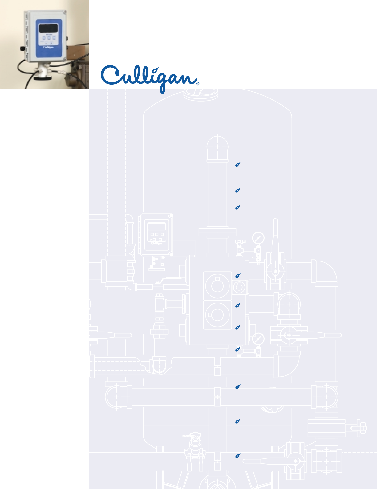
Introducing the Culligan®MVP Electronic Controller
Multifunctional
M
V
P
Versatile
Programmable
Sequences the regeneration process of water
softeners or filtration systems
Time,Volume, Aqua-Sensor®*or external device
Can be used as a simple timer or more
complex system integrator
Patented Progressive Flow** feature permits
smaller systems to provide greater flow rates
and treatment capacities
Will adapt to many types of water softeners,
filters or dealkalizers
As many as 6 controls may be linked together,
allowing for simple, future expansion
Operates on 24 VAC
Time based regeneration schedule can be
interval of days or hours or specific day of
week
Programmable trip point allows multiple
units to be brought online or offline as flow
demand increases or decreases
Two auxilliary outputs and one input can be
programmed to be active or deactive at any
point of the regeneration process.
Trust The Water Experts®
More
Culligan® MVP Designed With The Ease
of 24-volt Operation.
“Hey Culligan Man!”
®
,Aqua-Sensor, www.culligan.com and Hey Culligan Man are trademarks of Culligan International Company.
ISO 9001
Certification
Check for compliance with state and local laws and regulations. Do not use with water
that is microbiologically unsafe or of unknown quality without adequate disinfection
before or after the system.Systems certified for cyst reduction may be used on disinfected
waters that may contain filterable cysts.
* Aqua-Sensor: Patent # US 5,699,272
** Progressive Flow: Patent # US 5,060,167 , # US 5,351,199
corporate campuses
educational facilities
food service
grocery
hotel/hospitality
laundry
vehicle wash
MVP
Controller
•Battery Backup - The optional battery backup
will maintain the time of day for a minimum of 4
weeks using a 3.6V 1/2AA-lithium type battery as
supplied by Culligan.
•Regeneration Start Delay - A user determined
number of hours (up to 9) can be input for the
purpose of increasing time between multiple
regeneration initiations.
•Auxillary Input - capable of accepting a remote
signal from a dry contact device such as an
operator push-button for the purpose of
initiating the regeneration sequence.
•Segmented Brine Draw/Rinse Cycle - Brine
Reclaim Capability - allows the user to configure
the system for brine reclaim with a minimum of
additional valves and/or other types of hardware.
Power Source
Electrical power required
for the control is 24-volt
50/60 Hz AC current.A
plug-in transformer
(120v/24v) is provided.
Lock/Unlock
Allows the control to be easily
locked out from inadvertent
program changes or abuse.
Time of Day
Displays time in 12 hour
(AM/PM) or 24 hour formats.
EEPROM
Saves programmed and
statistical functions.
One-Touch Program Update
Update multiple controls
through the touch of a button
on the primary control.
Multi-Unit Communication Input/Output (RS485)
The communication input/output feature routinely
recognizes when another controller within a
multiple controller system is in a regeneration
sequence,prohibiting the chance of multiple units
regenerating simultaneously.
Program Beeper
Emits an audible beep
when key pads are
depressed to help identify
valid (short beep) or
invalid (3 short beeps)
key pad touches.Can be
enabled or disabled as
desired.
Screen Blanking
Allows the screen to go
blank once programming
is complete (After 5
minutes of no keypad
activity).
Additional MVP Features
www.culligan.com
1-800-CULLIGAN
©2003 Culligan International Co.
Printed in USA (5/03)
MOORE PART NO.46968
TM
THE XLF FLOW SENSOR PACKAGE
For use with IQS Electronic Water Treatment Equipment Controller
REGENERATION CONTROLS
Product Description
The XLF flow sensor package is an input device for the IQS type controller used to measure
treated water flow. Flow data then provides one or all of the following functions:
•repeatedly measure and deliver a specified volume of treated water.
•digital instantaneous flow rate.
•digital instantaneous total treated water usage.
Packages are available for use in treated water pipe sizes from 1 inch through 6 inch. A wide
variety of installation fittings are available to assure compatibility with many commonly used
plumbing materials:
•Threaded galvanized
•Copper sweat
•PVC; CPVC
•Iron
•Steel
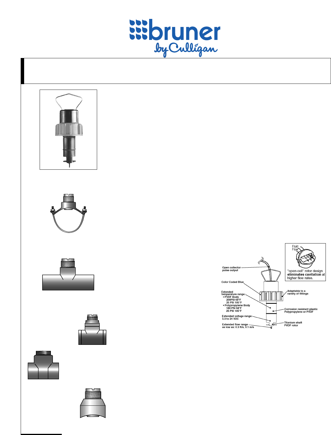
The XLF flow sensor package is comprised of:
•One (1) paddlewheel insertion type flow sensor element sized for the specified
pipe diameter
•One (1) installation fitting for the specified pipe type and size.
How It Works
The solid state paddlewheel flow sensor
works on a simple, but precise, electro-
mechanical principle. A magnetic rotor
positioned in the flow stream spins past a
solid state switch which in turn pulses a
low voltage DC current proportional to the
rate of flow. The rotor design ensures an
accurate, repeatable output throughout the
sensor's entire operating range with
negligible head loss and no cavitation.
Features & Benefits
•Flow range; 0.3 ft/s to 20 ft/s
•Low cost.
•Low pressure loss.
•Ease of installation and service.
•Excellent resistance to corrosion and wear
•High accuracy and repeatability.
•Compatible with most types of piping materials – PVC, copper, brass, galvanized iron and
steel.
•Wide range of temperature pressure and flow characteristics.
•Low voltage operation.
•Tested to NIST standards (National Institute of Standards and Techonology).
Iron Saddle
PVC Tee
Bronze
Brazolet
Iron Tee
Copper/Bronze Tees
XLF Flow Sensor
More
TM
Commercial Systems
©2000 Culligan International Co.
1-800-CULLIGAN
www.culligan.com
DCO 992196
Printed in USA 01/00
SL-0064
Moore Part No. 49004
Flow Sensor Selection
To select the flow sensor package that best fits your requirements,
consider these application parameters:
1.Determine Installation Fitting Type – fittings are available for a
variety of piping materials.
2.Determine Installation Fitting Size – identify the HIGHEST
anticipated flow rate which would occur regularly thru EACH tank
of a single/multiple tank network. Match this value against those in
the MINIMUM and MAXIMUM FLOW column of the Flow Rate
Range Table to find the corresponding installation Fitting Pipe Size.
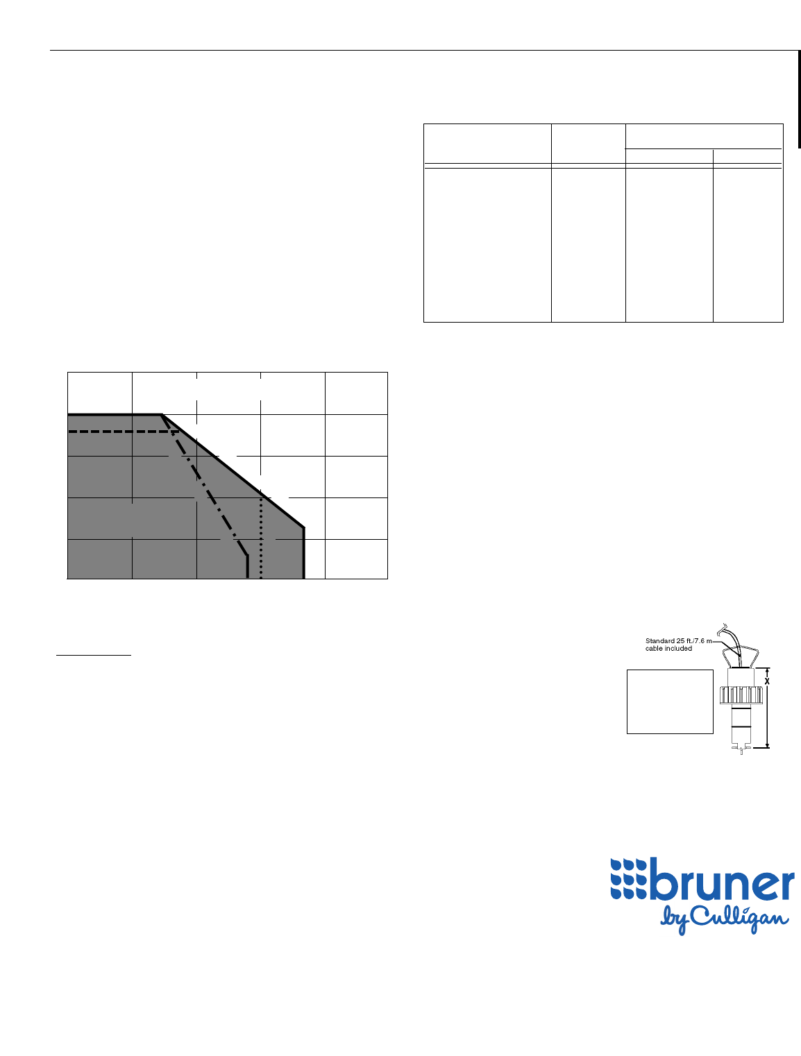
3.Verify Temperature/Pressure Operating Range – the maximum
operating pressure for the XLF series flow sensor is dependent on
the measured fluid temperature and type of installation fitting. Refer
to the Temperature/Pressure Graph for operating range. Refer to
OPTIONS paragraph for applications requiring a higher
temperature/pressure rating.
† PRESSURE LOSS FORMULA (S.G.=1.0)
( ) = Pressure Loss @ Actual Flow
(PSI) (GPM)
Options
Installation Fitting Service Plug:
Allows resumption of flow after depressurization and removal of flow
sensor element.
Wet Tap Assembly:
Provides a safe and fast method of removing a flow sensor element
without shutting off flow and pressure.
(Maximum Pressure – 100 psig @ 680F; Maximum Temperature – 140°F
@ 25 psig)
High Temperature/Pressure Applications:
Contact factory for pressures up to 1,500 psig and temperatures up to
300°F for stainless steel flow sensors.
Actual Flow (GPM)
CVFactor ■
200
150
100
50
0500F 1000F 1500F 2000F 2500F
Pressure (PSIG)
Operating Temperature
Temperature/Pressure Relationship Table
Operating Range
Flow Sensors
And Installation Fittings
For Temperature/Pressure Conditions beyond
Operating Range of XLF Sensors see OPTIONS
Metal Tees 0.5 to 2 in./Metal Weld-o-lets 2.5 to 8 in.
Bronze
Metal Weld-o-lets and Iron Saddles 10 in.-up
Iron Saddles 2 to 8 in.
▲ ■
Installation Fitting CvFlow Rate Range – (GPM)
Pipe Size – (Inches) Factor Minimum ▲Maximum
1 ** 39.0 0.7 44.0
11/4** 56.0 1.2 80.0
11/2** 84.0 1.7 110.0
2 ** 157.0 2.8 187.0
21/2*** 273.0 4.5 298.0
3 *** 483.0 6.9 460.0
4 *** 977.0 11.9 793.0
5 *** 1750.0 18.7 1247.0
6 *** 2846.0 27.0 1800.0
8 *** 5773.0 47.0 3118.0
10 *** 10,660.0 74.0 4915.0
Flow Rate Range Table
▲Choose the Installation Fitting Pipe Size principally on the MINIMUM flow rate that would
occur REGULARLY in the treated water stream of each water treatment tank.
DO NOT OVERSIZE THE INSTALLATION FITTING!
■CV= flow rate (GPM) @ 1.0 psi head loss; 60°F water temperature.
includes worst case requirement of 50 pipe diameters before and 5 pipe diameters
following the flow sensor location assuring minimum flow turbulence.
()
Specifications
Pressure Loss @ maximum rated flow: Less
than 3.5 psig. See formula †
• includes head loss of required straight length
of pipe both before and after flow sensor
location.(maximum requirement –55 diameters)
CVFactor:■See Flow Range
Table
Flow Rate Range: 0.3 thru 20 feet per
second fluid velocity
Output Linearity: ± 1% of maximum
range
Accuracy: ± 1% of maximum
range
Repeatability: ± 0.5% of full
range
Wetted Materials: Polypropylene, Viton,
Titanium, PVDF
*Maximum
Temperature: 185°F @ 25 psig
*Maximum
Pressure: 180 psig @ 680F
Installation Requirements:
*Maximum wire length 200 ft. –contact
between sensor and factory for greater
IQS/3 Controller distance requirements
*Number of pipe 15 minimum/
diameters required 55 maximum
adjacent to flow
sensor location
dependent on source
of upstream turbulence:
Electrical Output: Open Collector,
*Requires DC Current transistor, sinking
from IQS/3;+5VDC
@ 10 ma.
Environmental:
Ambient temperature -40F to 1220F
Relative Humidity: 0% to 100%
Non-condensing
Dimensions:
X:
1/2" thru 4" = 3.50"
5" thru 8" = 5.00"
10" up = 7.75"
*Refer to table for temperature/pressure/
installation fitting relationships.
** Threaded Tee Sch 40 Galv. Pipe
*** Cast Iron Saddle Sch 40 Pipe
FLOW SENSOR APPLICATION DATA

Culligan®Hi-Flo®2 and 2e Series, Hi-Flo®52 series, Hi-Flo®42 Series, Hi-Flo®55e Series,
CSM Series and Hi-Flo®50 Series
You have just purchased one of the finest water conditioners made. As an expression of our confidence in Culligan
International Company products, this product is warranted to the original end-user, when installed in accordance with
Culligan specifications, against defects in material and workmanship from the date of original installation, as follows:
For a period of ONE YEAR The entire conditioner.
For a period of TWO YEARS The control valve internal parts. The brine valve and its component
parts. The salt storage container internal components.
For a period of FIVE YEARS The control valve body, excluding internal parts.
The fiberglass wound container(s), if so equipped*.
The salt storage container(s), if so equipped.
The epoxy-lined steel conditioner tank(s), if so equipped.
For a period of TWELVE YEARS The conditioner tank, if it contains a plastic liner.
* The tank must be protected by a vacuum breaker device as described in the unit's operating manual. Damage to the tank
caused by vacuum is not covered by this warranty. The unit must be used in operating conditions that conform to Culligan's
recommended design guidelines. This warranty will not apply if the unit has been modified, repaired or altered by someone not
authorized by Culligan.
If a part described above is found defective within the specified period, you should notify your independently operated Culligan
dealer and arrange a time during normal business hours for the dealer to inspect the water conditioner on your premises. Any
part found defective within the terms of this warranty will be repaired or replaced by the dealer. You pay only freight from our
factory and local dealer charges.
We are not responsible for damage caused by accident, fire, flood, freezing, Act of God, misuse, misapplication, neglect, oxidizing
agents (such as chlorine, ozone, chloramines and other related components), alteration, installation or operation contrary to our
printed instructions, or by the use of accessories or components which do not meet Culligan specifications, is not covered by this
warranty. Refer to the specifications section in the Installation and Operating manual for application parameters.
Our product performance specifications are furnished with each water conditioning unit. TO THE EXTENT PERMITTED BY
LAW, CULLIGAN DISCLAIMS ALL IMPLIED WARRANTIES, INCLUDING WITHOUT LIMITATION WARRANTIES OF
MERCHANTABILITY AND FITNESS FOR PARTICULAR PURPOSE; TO THE EXTENT REQUIRED BY LAW, ANY SUCH
IMPLIED WARRANTIES ARE LIMITED IN DURATION TO THE ONE-YEAR PERIOD SPECIFIED ABOVE FOR THE ENTIRE
CONDITIONER. As a manufacturer, we do not know the characteristics of your water supply or the purpose for which you are
purchasing this product. The quality of water supplies may vary seasonally or over a period of time, and your water usage rate
may vary as well. Water characteristics can also differ considerably if this product is moved to a new location. For these rea-
sons, we assume no liability for the determination of the proper equipment necessary to meet your requirements, and we do
not authorize others to assume such obligations for us. Further, we assume no liability and extend no warranties, express or
implied, for the use of this product with a nonpotable water source or a water source which does not meet the conditions for
use described in the installation and operation manual(s) that accompany the equipment. OUR OBLIGATIONS UNDER THIS
WARRANTY ARE LIMITED TO THE REPAIR OR REPLACEMENT OF THE FAILED PARTS OF THE WATER CONDITIONER,
AND WE ASSUME NO LIABILITY WHATSOEVER FOR DIRECT, INDIRECT, INCIDENTAL, CONSEQUENTIAL, SPECIAL,
GENERAL, OR OTHER DAMAGES.
Some states do not allow the exclusion of implied warranties or limitations on how long an implied warranty lasts, so the above
limitation may not apply to you. Similarly, some states do not allow the exclusion of incidental or consequential damages, so
the above limitation or exclusion may not apply to you. This warranty gives you specific legal rights, and you may also have
other rights which vary from state to state. Consult your telephone directory for your local independently operated Culligan
dealer, or write Culligan International Company for warranty and service information.
Limited
WARRANTY
CULLIGAN INTERNATIONAL COMPANY
One Culligan Parkway
Northbrook, Illinois 60062
PN 01016557 Printed in U.S.A.
Hi-Flo 55e
CAD File: Hi-Flo 55e Depth Single.dwg

Hi-Flo 55e
CAD File: Hi-Flo 55e Depth Duplex.dwg
Hi-Flo 55e
CAD File: Hi-Flo 55e Depth Triplex.dwg
Hi-Flo 55e
CAD File: Hi-Flo 55e Depth Quad.dwg
Hi-Flo 55e
CAD File: Hi-Flo 55e Carbon Single.dwg
Hi-Flo 55e
CAD File: Hi-Flo 55e Carbon Duplex.dwg

Hi-Flo 55e
CAD File: Hi-Flo 55e Carbon Triplex.dwg
Hi-Flo 55e
CAD File: Hi-Flo 55e Carbon Quad.dwg
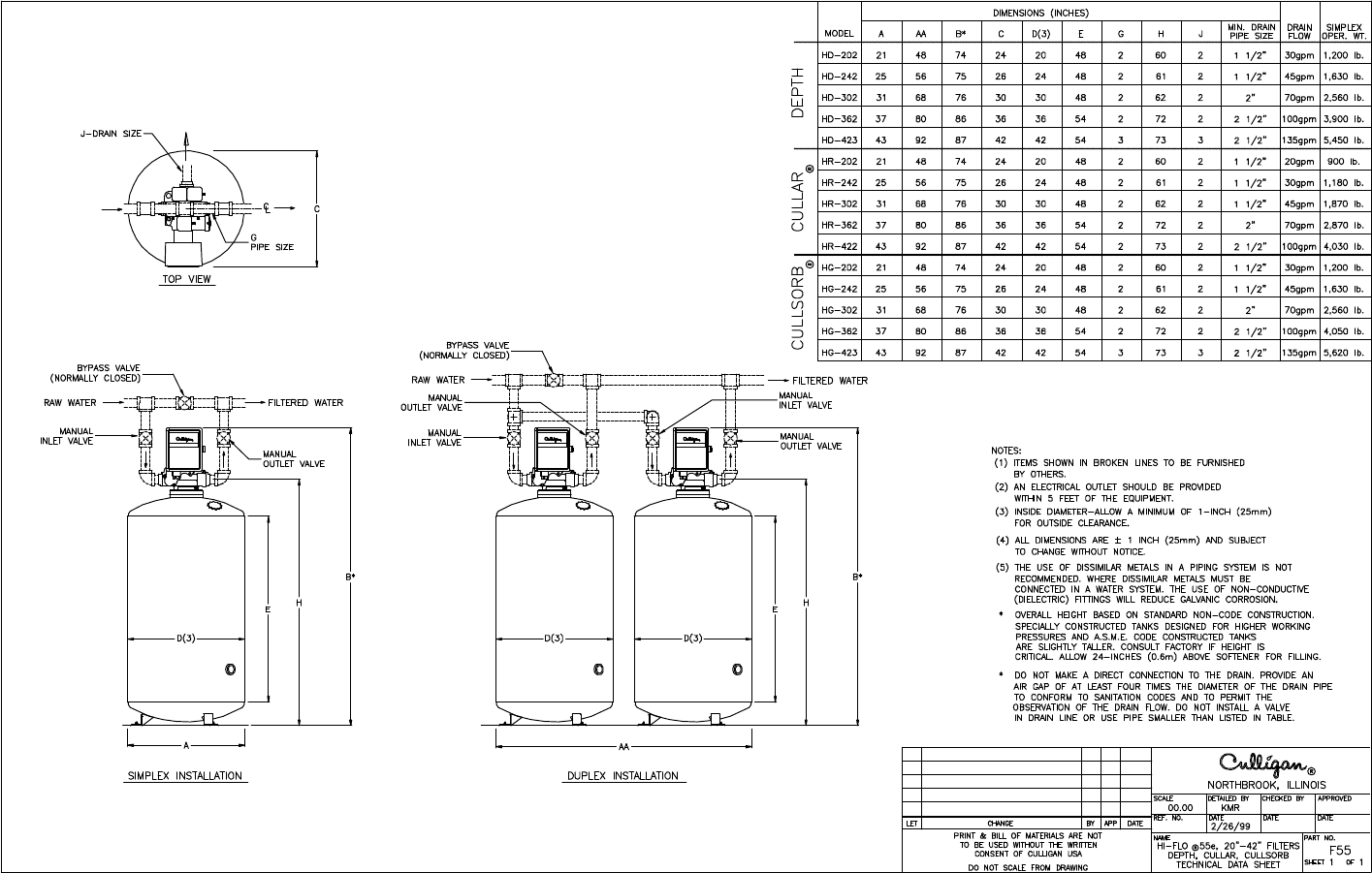
Hi-Flo 55e - Use for Cullsorb Only
CAD File: Filt_HF55.dwg
