Current 100286 Zigbee Drapery Track User Manual
Current Products Corp. Zigbee Drapery Track
Current >
User Manual

1
DRAPERY TRACK
Installation Manual and User Guide
2
TABLE OF CONTENTS
Diagram
List of Parts
Wall Mount Drapery Track Installation and Connecting the Motors
Ceiling Mount Drapery Track Installation and Connecting the
Motors
Install the Facia (Optional)
Start Up
Optional Programming Steps for the Track Drapery
Change Positions on the Track Drapery (Single)
Change Positions on the Track Drapery (Dual)
Enable or Disable Smart Assist
Pair the Remote Control
Grouping Multiple Drapery Together
Switch the Open and Close Positions
Change the Frequency
Swap the Open and Close Directions on a Single Drapery
Swap the Open and Close Directions on a Dual Drapery
Switch Motor Response Controls for a Dual Drapery
Master Reset the Drapery
Connect and Integrate the Drapery Track
Pair or Unpair a Remote Control
Connect the Bridge & App
Integrate with Amazon Echo- 434 FM
Integrate with Amazon Echo Plus- Zigbee with Current Products
Corp Bridge
Integrate with Amazon Echo Plus- Zigbee Native Hub
Troubleshooting
Using the Drapery Track
Using the TAU for Operation
Using Smart Assist
Using the Remote Control- Single Drapery
Using the Remote Control- Dual Drapery
Using the Light & Temperature Sensors on the Control Housing
Safety and Warning Statements
3
4
Wall Mount DRapery Track Installation
and connecting the motors
1. Install the Brackets
Fig. X
For additional help during installation of your drapery track, visit www.
currentproductscorp.com/support/drapery-track or call 1-844-307-7435.
Carefully measure to the center of the
window and make a small mark with
a pencil. Ideally a stud will be located
here, but if not you may either use
the anchors provided, or move to the
To be certain of bracket installation
height, carefully measure the curtain,
as some advertised curtain lengths
are not precise. To locate the top of
the center bracket protrusion, use
the following formula alongside the
corresponding chart.
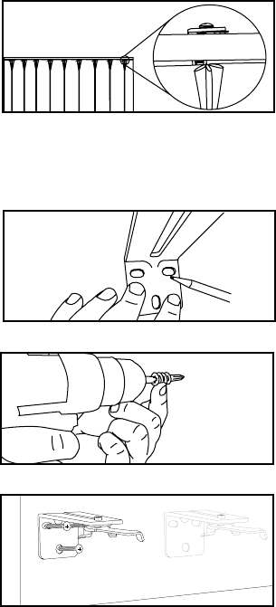
First, hold the center bracket up
against the wall and mark, with a
pencil, the location for each screw.
Once the screw locations are marked,
remove the bracket.
A) If using wall anchors, follow the
wall anchor. Set the torque on your
drill to the recommended level, and
screw in the drywall anchors. Place
the bracket against the wall, lining
the holes up with the anchors. Screw
in each screw to secure bracket. Do
not over torque. There should be
no movement by the bracket after
installation.
Fig. X
Fig. X
(For the anchors included with the
drapery track, follow the below steps
from the manufacturer’s website:
Press tip of SnapSkru anchor into
drywall using #2 Phillips screwdriver
or screw gun. Drive anchor clockwise
with wall.
Place item over anchor and insert
screw.
screw with minimum thread length =
thickness of item + 1-1/4” (32mm).
Maximum item thickness with 1-1/2”
long screw: 3/4”. For thicker items,
use a longer screw.
For more information, visit www.
toggler.com.
Fig. X
5
B) If drilling into studs, no wall
anchors are necessary. Carefully drill
a 5/32” drill bit for the pilot holes if
using the provided screws. Place the
bracket against the wall, lining the
holes in the bracket up with the holes
in the wall. Screw in each screw until
secure. Make sure your screw has solid
embedment into the stud. Do not over
torque. There should be no movement
by the bracket after installation.
Once the center bracket has been
installed, install each subsequent
bracket.
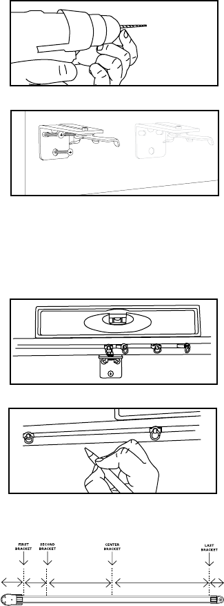
Pro Tip: The track can be used as
a straight edge to help locate the
correct position of the brackets. Once
the center bracket has been installed,
balance the track on the top of the
bracket with the carriers facing the
inside of the room. Place a level on the
a pencil to draw a line on the bottom
edge of the track where each bracket
needs to go.
There should be a bracket as close as
possible to each end of the track, an
additional bracket 5” inboard from
the motor end, 5” inboard from the
idler end, and brackets every 16”-32”
in between depending on drapery
weight.
Follow steps A or B above to install the
remaining brackets.
Fig. X
Fig. X
Fig. X
Fig. X
Xy
5” Every 16”-32” Every 16”-32”
Fig. X
6
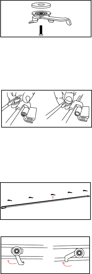
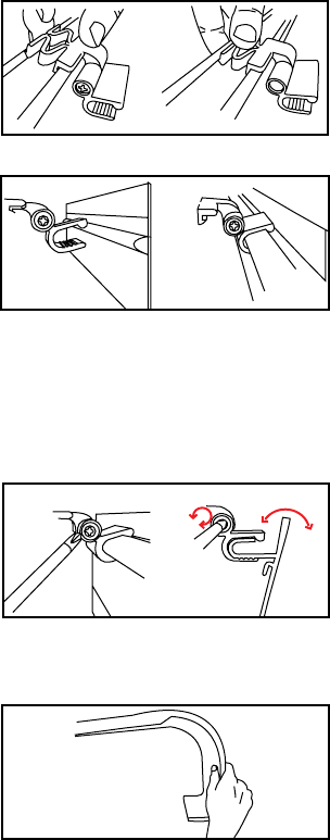
2. Install the Track
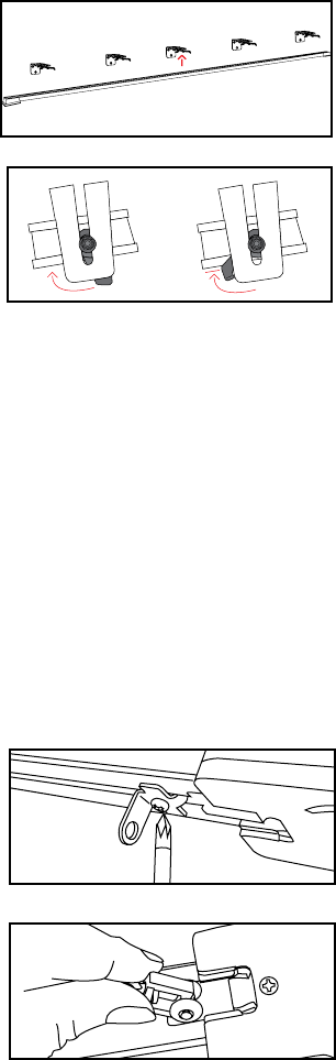
Starting in the middle, secure the track
onto each of the brackets using each
camlock. With the camlock arm open,
or facing towards you, push the track
upward so the camlock features rest in
the groove on the top of the track.
Turn the camlock arm to the left so the
features inside the top track groove
bite in and hold. Once all the camlocks
are closed, use a screwdriver to tighten
each camlock so the track is secure.
Fig. X
Fig. X
3. Adjust Number of Carriers
and Orient the Carrier Arms
It may be necessary to add or remove
carriers based on the curtain fullness.
To add or remove carriers, loosen the
screw on the hardstop and slide it out
of the track.
For drapery with pins, insert or
remove carriers until the correct
amount remain in the track. On a
center draw, do this on each side.
Fig. X
Fig. X
Pro Tip: If not using a fascia, the lip of
the camlock arm may be visible. If this
is an issue, camlocks can be turned
around by detaching them from the
brackets and reattaching them with
the arm facing the back of the bracket.
The track will be pushed up and rest
on the camlock wings during install,
and the camlock arms will need to
be turned to the right, then tightened
with a screwdriver to secure.
7
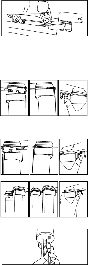
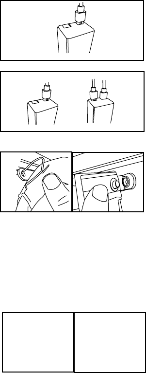
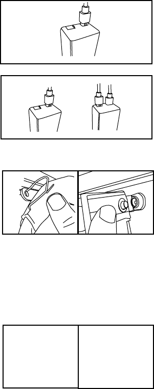
4. Connect the Motors
On a single drapery, insert the motor
shaft into the motor end of the drapery
track and twist the motor into place.
Push the locking tab up until it clicks
into place.
On a dual drapery, insert Motor 1
(large) into the room-side track motor
end and twist the motor into place.
Push the locking tab up until it clicks
into place.
Next, insert Motor 2 (small) into the
window-side track motor and twist
the motor into place. Push the locking
tab up until it clicks into place.
If you do not have a control box, plug
the cord from Motor 2 into the bottom
of Motor 1. If you do have a control
box, proceed to Step 6.
Fig. X
Fig. X
Fig. X
Fig. X
For drapery with snaps, the carriers
are connected with a cord. To remove
carriers simply slide the desired
number to be removed from the track
and cut the string. To add carriers the
whole string will need to be replaced.
Slide the hardstop back into the track
and tighten the screw.
Fig. X
8
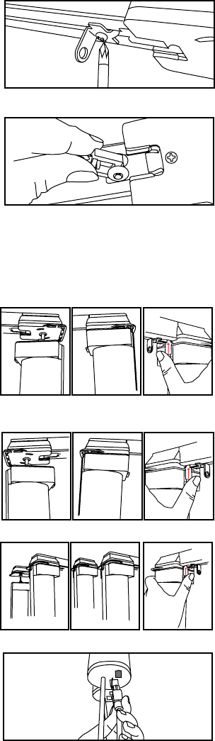
7. Attach the Drapery
Snap or hook the drapery into each
carrier, starting with the master
carrier arm(s) and ending with the
end(s) of the track. Wrap and pin the
remaining fabric around the motor,
hiding it from plain sight, but making
Fig. X
You are now ready to start up the drapery track.
On a single drapery, plug the motor
into the Motor 1 slot.
On a dual drapery, plug the room
side drapery into the Motor 1 slot and
window side drapery into the Motor 2
slot.
6. Connect the Control Box
(optional)
Fig. X
Fig. X
8. Installing a Baton (optional)
On pleated drapery carrier arms with
the baton attachment......
On snap drapery carrier arms with the
baton attachment....
Fig. X
9
Ceiling Mount DRapery Track
Installation and connecting the
motors
1. Install the Camlocks
Fig. X
The number of camlocks needed will
depend on the desired length of the
track. Mount a camlock every 16-32
inches along the ceiling. If installing
a fascia, be sure to use the included
small or large spacers. If not screwing
into a joice, use the included anchors.
For additional help during installation of your drapery track, visit www.
currentproductscorp.com/support/drapery-track or call 1-844-307-7435.
2. Install the Fascia Clips (optional)
Fig. X
If you are using a fascia, install all
the fascia clips into the track before
installing the track onto the camlocks.
Snap the fascia clips into the recess at
the top of the track, one side at a time.
Insert fascia clips at each end of the
track, then every 16-32 inches in
between where the camlocks will rest.
Fig. X
3. Install theTrack
Starting in the middle, secure the track
onto each of the camlocks. With the
camlock arm facing towards you, push
the track so the camlock features rest
in the groove on the top of the track.
Turn the camlock arm to the left so the
features inside the top track groove
bite in and hold.
Fig. X
10
5. Connect the Motors
Fig. X
On a single drapery, insert the motor
shaft into the motor end of the drapery
track and twist the motor into place.
Push the locking tab up until it clicks
into place.
On a dual drapery, insert Motor 1
(large) into the room-side track motor
end and twist the motor into place.
Push the locking tab up until it clicks
into place.
Next, insert Motor 2 (small) into the
window-side track motor and twist
the motor into place. Push the locking
tab up until it clicks into place.
If you do not have a control box, plug
the cord from Motor 2 into the bottom
of Motor 1. If you do have a control
box, proceed to Step 6.
Fig. X
Fig. X
Fig. X
4. Adjust Number of Carriers
It may be necessary to add or remove
carriers based on curtain.
To add or remove carriers, loosen the
screw on the hardstop and slide it out
of the track. Insert or remove carriers
until the correct amount remain in
the track. On a center draw, do this on
each side.
Slide the hardstop back into the track
and tighten the screw.
Fig. X
Fig. X
11
On a single drapery, plug the motor
into the Motor 1 slot.
On a dual drapery, plug the room
side drapery into the Motor 1 slot and
window side drapery into the Motor 2
slot.
6. Connect the Control Box
(optional)
Fig. X
Fig. X
7. Attach the Drapery
You are now ready to start up the drapery track.
Snap or hook the drapery into each
carrier, starting with the master
carrier arm(s) and ending with the
end(s) of the track. Wrap and pin the
remaining fabric around the motor,
hiding it from plain sight, but making
sure the pendant is accessible. Fig. X
8. Installing a Baton (optional)
On pleated drapery carrier arms with
the baton attachment......
On snap drapery carrier arms with the
baton attachment....
Fig. X
12
1. Install the Clips
(Optional) Install the Facia
On ceiling mount installations the
fascia clips will already be installed on
the track drapery, so proceed to step 2.
On wall mounted track installations,
snap the fascia clips into the recess at
the top of the drapery track, one side
each set of brackets.
Fig. X
2. Snap on the Fascia
Orient the fascia so the protrusion is
at the top. Starting in the middle, snap
the protruding feature of the fascia
Snap the protrusion into all the
remaining clips. Be sure the facia is
positioned where desired, with the
proper amount of fascia left on each
side of the track.
3. Style the Returns
The fascia style allows for returns to
be bent in either a rounded or angled
manner. By hand, gently bend the
fascia ends into the desired shape.
For hard bends, we recommend
removing the fascia from the clips,
help bend the fascia.
3. Adjust Fascia Angle
If desired, on fascias 3” and above, the
angle of the fascia can be adjusted by
using a phillips head screwdriver to
pivot the angle of the clip mouth. Be
sure to adjust the angle on all clips to
create a uniform look.
Fig. X
Fig. X
Fig. X
13
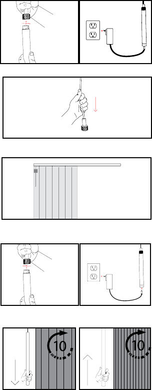
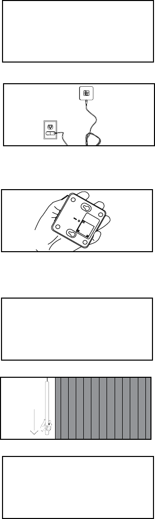
Start up
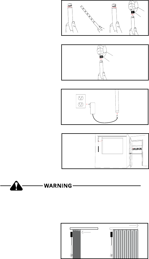
1. Connect Power
On battery powered units, untwist the
Fig. X
Be sure to secure any excess cord, leaving no more than 8 inches
unsecured, to reduce the risk of child strangulation.
Fig. X
Fig. X
Fig. X
On units with power and control over
CAT5, run the wire as desired to the
power and commuication port, then
plug the ethernet cable into the port at
the bottom of the control box housing.
On low voltage units, power up by
plugging the unit into the desired
outlet.
2. Set Limits
curtain moves to the full open and full
closed positions. These positions can
be changed at any time. To change
these positions, see the instructions
on page __.
Fig. X
On rechargeable battery powered
onto the unit.
14
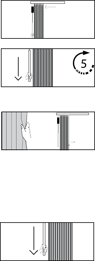
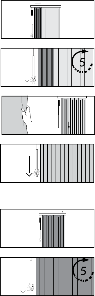
Change Positions on the drapery Track
(Single)
Change the open Position
2. Set the Open Position
By hand, pull the curtain until it
reaches the desired full open position.
3. Exit Mode
learn mode. The drapery will jog to
1. Enter Learn Mode
drapery moves towards the direction
you would like to set as the “open”
position. After the drapery reaches
the position, it will stop moving.
seconds, or until the drapery jogs.
Fig. X
Fig. X
Fig. X
Note: If you have a remote control
paired to the device, you can use it to
move the curtain into the desired full
open position. A press and release
will move the curtain half an inch in a
direction while a press and hold will
move the curtain continuously.
Fig. X
Optional Programming steps for the
Drapery Track
Does this feature still exist?
15
Change the Close Position
2. Set the Close Position
3. Exit Mode
learn mode. The drapery will jog to
1. Enter Learn Mode
drapery moves towards the direction
you would like to set as the “close”
position. After the drapery reaches
the position, it will stop moving.
seconds, or until the drapery jogs.
Fig. X
Fig. X
Note: If you have a remote control
paired to the device, you can use it to
move the curtain into the desired full
close position. A press and release
will move the curtain half an inch in a
direction while a press and hold will
move the curtain continuously.
By hand, pull the curtain until it
reaches the desired full close position.
Fig. X
Fig. X
16
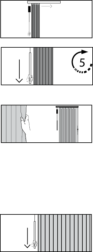
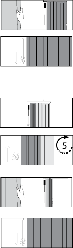
Change the open Position for the Room Side
curtain (Motor 1)
2. Set the Open Position
By hand, pull the curtain until it
reaches the desired full open position.
3. Exit Mode
exit learn mode. The drapery will jog
1. Enter Learn Mode
room side drapery moves towards the
direction you would like to set as the
“open” position. After the drapery
reaches the position, it will stop
jogs.
Change the Close Position for the room side
curtain
1. Enter Learn Mode
drapery moves towards the direction
you would like to set as the “close”
position. After the drapery reaches
the position, it will stop moving.
seconds, or until the drapery jogs.
Fig. X
Fig. X
Fig. X
Fig. X
Fig. X
Change Positions on the drapery Track
(dual)
Fig. X
17
2. Set the Close Position
By hand, pull the curtain until it
reaches the desired full close position.
3. Exit Mode
learn mode. The drapery will jog to
Fig. X
Fig. X
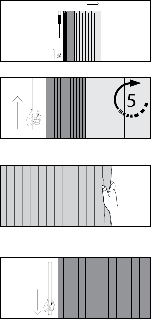
Change the open Position for the window side
curtain (Motor 2)
2. Set the Open Position
By hand, pull the curtain until it
reaches the desired full open position.
3. Exit Mode
exit learn mode. The drapery will jog
1. Enter Learn Mode
drapery moves towards the direction
you would like to set as the “open”
position. After the drapery reaches
the position, it will stop moving. Push
or until the drapery jogs.
Fig. X
Fig. X
Fig. X
Fig. X
18
Change the Close Position for the window side
curtain
2. Set the Close Position
By hand, pull the curtain until it
reaches the desired full close position.
3. Exit Mode
exit learn mode. The drapery will jog
1. Enter Learn Mode
drapery moves towards the direction
you would like to set as the “close”
position. After the drapery reaches
the position, it will stop moving. Push
or until the drapery jogs.
Fig. X
Fig. X
Fig. X
Fig. X
19
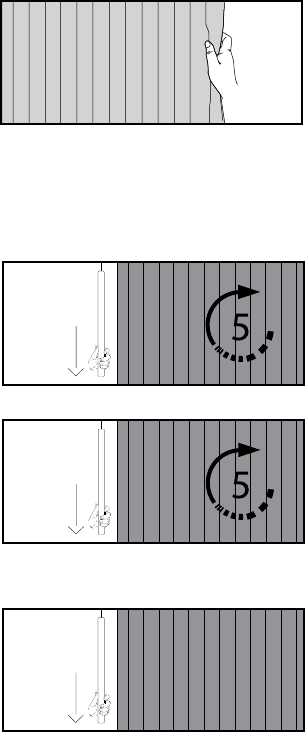
Enable or disable smart assist
Smart Assist allows users to pull the curtain manually and have the movement
complete automatically. All drapery tracks come with Smart Assist enabled.
1. Move the Drapery Manually
Begin with the curtain in the full open
or full closed position. Manually move
the drapery more than a foot towards
the opposite direction. If Smart Assist
is enabled, the drapery will begin to
complete the movement automatically.
If Smart Assist is disabled, the curtain
will remain in place.
2. Enable or Disable Smart
Assist
To disable Smart Assist pull down and
the drapery jogs, then release. Be sure
curtain reaches its limit.
To enable Smart Assist, pull down on
drapery jogs, then release.
or disabled.
Fig. X
Fig. X
Fig. X
Fig. X
20
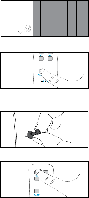
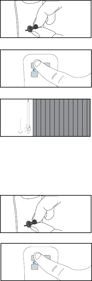
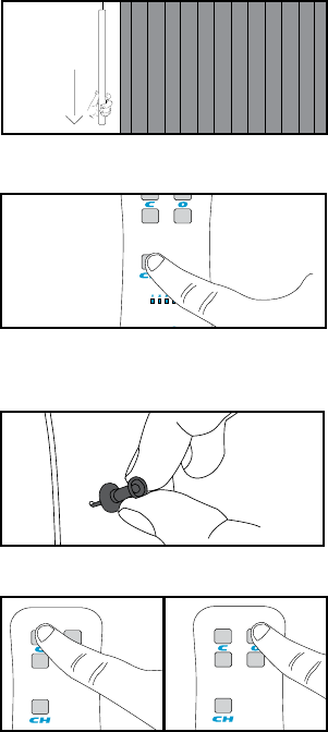
Pair the Remote to the drapery (FM)
1. Initiate Learn Mode
the drapery should start moving. The
second tug should stop it.
2. Connect the Remote
On multi-channel remotes, select the
channel you wish to pair to by pressing
the Channel button until the LED
corresponding with the appropriate
channel is lit.
Depress the “pairing” button on the
back of the remote by pushing a pen
or other object through the hole in the
back of the remote. The LEDs on the
front will scroll.
Press and release the top left button
on the remote. The drapery will jog to
Fig. X
Fig. X
Fig. X
Fig. X
2x
21
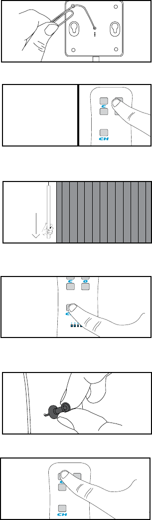
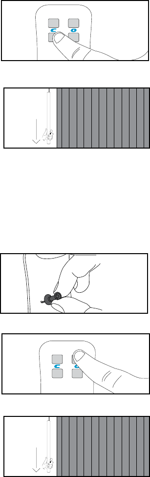
Pair the Remote to the drapery (Zigbee)
2. Initiate Learn Mode on Drapery
Pull down and release the Pendant
twice to enter learn mode.
start moving. The second tug should
stop it.
3. Connect the Remote to the
Drapery
On multi-channel remotes, select the
channel you wish to pair to by pressing
the Channel button until the LED
corresponding with the appropriate
channel is lit.
Depress the “pairing” button on the
back of the remote by pushing a pen
or other object through the hole in the
back of the remote. The LEDs on the
front will scroll.
Press and release the top left button
on the remote. The drapery will jog to
Fig. X
Fig. X
Fig. X
Fig. X
2x
1. Connect Remote to Bridge
If using the Current Products Corp.
bridge, use a tack or other object to
depress and release the recessed
button on the bottom of the bridge to
put the bridge into pairing mode. The
pairing mode.
Pull the “Pull” tab from the bottom of
the remote. If the tab has already been
pulled, push any button on the face of
the remote. The LEDs should scroll to
show it is seeking a bridge.
Fig. X
Fig. X
22
23
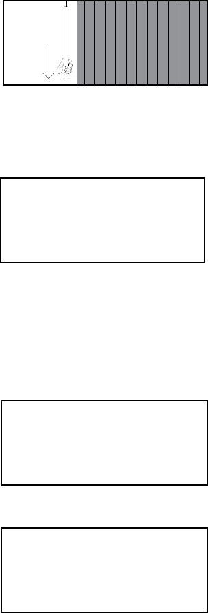
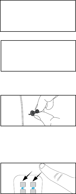
Switch the “Open” and “close” Positions
1. Set the Drapery Position
Move the drapery in the position you
would like to be recognized as “open”.
Fig. X
2. Learn the Position
Press and hold all three buttons on
Fig. X
Grouping Multiple Drapery Together
On a central unit you would like to
designate as the ‘Master’, press and
hold the”Sensors On/Off” button until
been successfully grouped.
1. Enter Pairing Mode
On each drapery you would like to
group, pull down on the Pendant
twice.
move. The second pull should stop it.
Fig. X
Fig. X
?
2x
allows users to control multiple units simultaneously with one manual
any one unit in the group has a sensor automated command triggered.
24
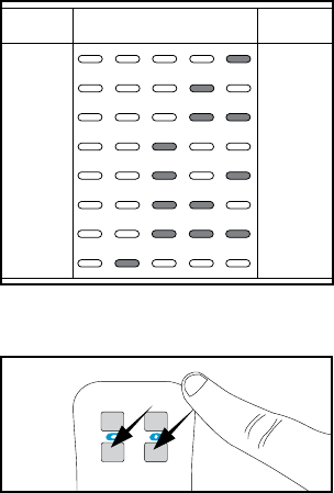
Change the Frequency (FLOW with bridge ONLY)
2. Enter Frequency Change
Mode on the Remote
Press a tack or pen through the hole
in the back of the remote to depress
the Program button (Fig. x). Press this
button three times to enter frequency
change mode. The LEDs will illuminate
to a representation of the current
frequency (Fig. x).
In rare instances it may become necessary to alter the frequency on which
the device communicates. The frequency will need to be changed on both
the unit and the remote. To do this, you must have the bridge and the multi-
channel remote.
In most instances, when the frequency of the device needs to be changed, the
user will recieve an alert through the Smart Phone app.
Fig. X
Fig. X
3. Change the Frequency
on the remote to move the frequency
up and down (Fig. X).
1. Enter Frequency Change
Mode through the app
Make sure the bridge is connected and
the Smart Phone application has been
downloaded.
Fig. X
Hit the gear icon to go to your device
and app settings, then go to Frequency
Settings.
frequency for your device.
Fig. X
?
25
434.625
434.825
435.025
435.225
435.425
435.625
435.825
436.025
1
2
3
4
5
6
7
8
Frequency
LED Pattern
Frequency
Number
Fig. X
current frequency (Fig. X). Stop when
you determine the frequency matches
the frequency from the bridge.
4. Exit Frequency Change Mode
When you reach the desired frequency,
exit the mode by pressing and
releasing one of the two lower remote
buttons.
Fig. X
26
Swap the Open and Close Directions on a
single drapery
In some cases, to maximize functionality, users may want to swap which
button on the remote control opens and closes the drapery.
Fig. X
1. Swap Directions
First, depress a tack or pin into hole
in the back of the remote to press and
release the recessed button twice.
The LEDs on the front of the remote
correct mode.
To swap the open and close directions,
press and release the top left button.
On the drapery you wish to swap the
open and close direction of, pull down
open and close directions. Fig. X
Swap the Open and Close Directions on a Dual
drapery
In some cases, to maximize functionality, users may want to swap which
button on the remote control opens and closes the drapery.
Fig. X
1. Swap Directions for Motor 1
First, depress a tack or pin into hole
in the back of the remote to press and
release the recessed button twice.
The LEDs on the front of the remote
correct mode.
To swap the open and close directions,
press and release the top left button.
Fig. X
Fig. X
x 2
x 2
27
Switch motor response Controls for a dual
drapery
On the drapery you wish to swap the
open and close direction of, pull down
open and close directions. Fig. X
Fig. X
2. Swap Directions for Motor 2
To swap the open and close directions
for motor 2, press and release the
bottom left button.
Fig. X
1. Swap Motors
First, depress a tack or pin into hole
in the back of the remote to press and
release the recessed button twice.
The LEDs on the front of the remote
correct mode.
To swap the motor controls, press and
release the top right button.
In some cases, to maximize functionality, users may want to swap the control
functions for the window side and room side curtains. Swaping this will
On the drapery you wish to swap the
window side and room side curtain
response buttons, pull down and
response buttons.
Fig. X
Fig. X
x 2
28
Master Reset the Drapery
2. Setup The Drapery for Reset
Move the curtain(s) to a position
halfway between full open and full
closed.
Fig. X
3. Reconnect Power
Reconnect power to the unit by
plugging the unit back in or by
reconnecting the battery tube.
Fig. X
In some instances it may become necessary to master reset your drapery.
Performing a master reset will restore the drapery to its factory settings,
erasing saved open and closed positions, groups, and all paired remotes.
3. Perform Master Reset
seconds or until the drapery jogs.
seconds or until the drapery jogs.
Your drapery has now been master
reset.
Fig. X
Fig. X
1. Remove Power
Disconnect power from the unit. For
hardwired units, simply unplug the
device. For battery powered units,
remove the battery tube by twisting it
off of the connection wire.
With power disonnected, pull down
on the Pendant or cord and release
once.
Fig. X
29
Connect & Integrate the drapery Track
Pair or Unpair A Remote Control
1. Initiate Learn Mode
the drapery should start moving. The
second tug should stop it.
2. Connect the Remote
If the remote is multi-channel, select
the channel you wish to pair to by
pressing the Channel button until
the LED corresponding with the
appropriate channel is lit.
Depress the “pairing” button on the
back of the remote by pushing a pen
or other object through the hole in the
back of the remote. The LEDs on the
front should begin to scroll.
To Pair: Press the top left button on
the remote to pair the new remote to
the drapery.
on the remote.
has been successful.
Fig. X
Fig. X
Fig. X
Fig. X Fig. X
2x
30
Setup with the bridge and app
1. Download the App
Download the Current Products Corp.
App Store. Follow the prompts to set
up your account.
3. Connect the Bridge
Once you have input your credentials,
the app will ask you to scan the QR
code located on the bottom of the
bridge.
Your bridge is now connected to your
account.
2. Connect Power to Bridge
Find an outlet in a location central to
the drapery you are installing in the
home. Insert the micro-usb end of the
included power cable into the power
port on the bridge. Plug the other end
of the cable into an outlet.
4. Learn the Devices
In the app under devices, hit the +
sign.
Pull down and release the Pendant
twice on the drapery you want to pair
to the bridge. You will see the device
pop up in the menu on your Smart
Phone screen.
Select the appropriate device, using
the “identify” button if needed.
Once the device has been selected,
name the device.
Repeat step 4 for all new devices.
Fig. X
Fig. X
Fig. X
Fig. X
Fig. X
Fig. X
Should adding a new device be separated
from connecting the bridge and app setup?
Also, should we have sections for setting up
groups, scenes, and schedules in the app in
the printed instructions?
2x
31
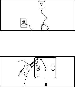
Setup with the bridge (No App)
1. Connect Power to Bridge
Find an outlet in a location central to
the drapery you are installing in the
home. Insert the micro-usb end of the
included power cable into the power
port on the bridge. Plug the other end
of the cable into an outlet.
Fig. X
Fig. X
Push a tack or pen into the hole in
the back of the bridge to depress and
release the recessed button. The blue
LED should illuminate.
2. Put Bridge into Pairing Mode
On any drapery you would like to pair
to the bridge pull down and release
the Pendant once to start the drapery,
then once again to stop it. The green
times to indicate the drapery has been
paired.
3. Pair Drapery
On any drapery you would like to pair
to the bridge pull down and release
the Pendant once to start the drapery,
then once again to stop it. The green
times to indicate the drapery has been
paired.
4. Pair Remote

32
Integrate with Amazon Echo - 434 FM
1. Set up your Echo
If your Alexa device is not yet set up, do
so now by following the instructions
that came with your device.
Also be sure the bridge has been setup.
For instructions on how to set up your
bridge and app, go to page ____.
2. Download the Skill
your Alexa App.
Search for the skill titled “My Curtains”
or “Current Products”. If you want to
be able to trigger Alexa using both
phrases, be sure to download both
skills.
3. Sign In
app. You are now able to control your
devices via Amazon Alexa.
Trigger Alexa using the trigger word selected when you installed the skill.
You can control devices, groups, or trigger scenes through Alexa, and create
custom names for each in the MyCurtains app.
Fig. X
Fig. X
Fig. X

33
Integrate with Amazon Echo Plus- ZigBee with
Current Products corp bridge
1. Set up your Echo
If your Alexa device is not yet set up, do
so now by following the instructions
that came with your device.
Also be sure the bridge has been setup.
For instructions on how to set up your
bridge and app, go to page ____.
2. Download the Skill
your Alexa App.
Search for the skill titled “My Curtains”
or “Current Products”. If you want to
be able to trigger Alexa using both
phrases, be sure to download both
skills.
3. Sign In
app. You are now able to control your
devices via Amazon Alexa.
Trigger Alexa using the trigger word selected when you installed the skill.
You can control devices, groups, or trigger scenes through Alexa, and create
custom names for each in the MyCurtains app.
Fig. X
Fig. X
Fig. X

34
Integrate with Amazon Echo Plus- ZigBee
1. Set up your Echo
If your Alexa device is not yet set up, do
so now by following the instructions
that came with your device.
2. Add a Device
From the menu in the Alexa app, go to
“Smart Home” and hit “Add a Device”.
Alternately, you can say “Alexa, search
for devices”.
After Alexa has completed her search,
on each drapery you want to pair to
Alexa.
3. Customize in App
In the Alexa app, you can change the
name of each device to better your
control of the devices. You can also
add custom commands. We suggest
custom naming each device, and
creating commands for “open” and
“close”.
Is this everything???
Fig. X
Fig. X
Fig. X
35
Troubleshooting
Integrate with Google Home
Integrate with Control4
Integrate with Samsung SmartThings
36
Using the DRapery Track
Using the TAU for Operation
on the desired movement.
On a single drapery
down once makes the curtain move towards the next position, depending on
a second time after stopping will allow the curtain to move in the opposite
direction.
On a dual drapery
the motor 1 slot. Pulling down once makes the curtain move towards the
next position, depending on if the curtain is open or closed. Pulling down a
second time will stop it. Pulling down a third time, shortly after stopping will
allow the curtain to move in the same direction as before. Pulling down after
several seconds will change the direction the curtain moves.
slot. Pushing up once makes the curtain move towards the next position,
depending on if the drapery is open or closed. Pushing up a second time will
stop it. Pushing up a third time, shortly after stopping will allow the curtain
to move in the same direction as before. Pulling down after several seconds
will change the direction the curtain moves.
Using Smart Assist
Smart Assist is a drapery track feature to allow users the ability to begin
an open or close movement manually, and have the drapery automatically
complete the movement.
To trigger Smart Assist, simply pull the curtain approximately one foot
curtain will continue moving in that direction until it reaches the full open or
closed position.

37
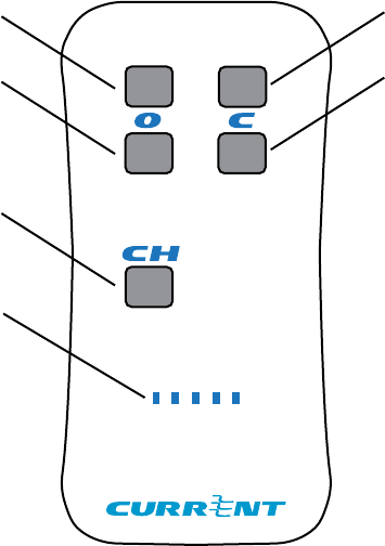
Using the Remote Control- Single Drapery
Channel
Selector
LED
Indicators
66%
closed
Full
Closed
66% Open
Full open
Full Open- A press and release moves the drapery to the full open position.
A press and hold will move the drapery towards the open position, and stop
it precisely upon release.
Full Closed- A press and release moves the drapery to the full closed position.
A press and hold will move the drapery towards the closed position, and stop
it precisely upon release.
66% Open- A press and release moves the drapery to the approximately
66% open position.
66% Closed- A press and release moves the drapery to the approximately
66% closed position.
Channel Selector- Successive presses and releases will change the remote
LED Indicators- Indicator lights for various remote functions.
38
Using the Remote Control- Dual Drapery
Channel
Selector
LED Indicators
Full Closed
secondary
Full Closed
Primary
Full Open
secondary
Full open
primary
Full Open Primary- A press and release moves the drapery plugged into the
motor 1 slot to the full open position.
Full Closed Primary - A press and release moves the drapery plugged into
the motor 1 slot to the full closed position.
Full Open Secondary- A press and release moves the drapery plugged into
the motor 2 slot to the full open position.
Full Closed Secondary- A press and release moves the drapery plugged into
the motor 2 slot to the full closed position.
Channel Selector- Successive presses and releases will change the remote
LED Indicators- Indicator lights for various remote functions.
39
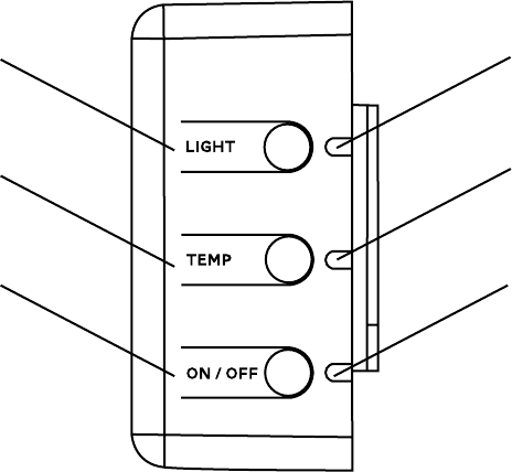
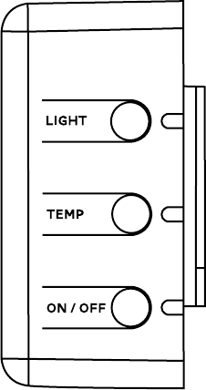
Using the Light & Temperature Sensors on the
control housing
Light Sensor
Control
Temperature
Sensor Control
Sensors Power
Light Sensor Control - A press and release displays the current mode of the
light sensor. A second press and release changes the mode of the automated
movements triggered by the light sensor.
Temperature Sensor Control- A press and release displays the current
mode of the temperature sensor. A second press and release changes the
mode of the automated movements triggered by the temperature sensor.
Sensors Power- A press and release displays the current mode. A second
press and release wil change the mode of all sensor enabled automated
movements between enabled or disabled.
Light and Temperature Sensor LED Indicators- Indicates which mode the
sensor is in when the corresponding button is pressed and released.
Sensors Power LED Indicator- Indicates which mode the sensors are in
when the corresponding button is pressed and released. A red LED means
the sensors are off. A green LED means they are on.
Light Sensor
LED Indicator
Temperature
Sensor LED
Indicator
Sensors Power
LED Indicator
40
Sensor Modes
The integrated light and temperature sensors
have three possible modes: Off, Fully Automatic,
and Semi-Automatic.
Off- The device will not make any movement
triggered by this sensor.
Fully Automatic- The device will open and close
the curtains based on the sensor readings.
Semi-Automatic- The device will close the
curtains based on sensor readings, but will not
open them.
These modes are indicated using the LEDs on the
right of the control box.
41
Statements
SAFETY INFORMATION
Read all warnings and instructions prior to installing the E-Wand™. Failure to follow
these instructions may result in property damage or serious personal injury.
WARNING
Do not use this product for anything other than its intended use. Any usage of the
parts of this kit outside of its intended purposes in not covered under the warranty.
CAUTION
-
ever removing or reinstalling drapery.
CAUTION
FCC STATEMENT
This device complies with Part 15 of the FCC Rules. Operation is subject to the
following two conditions:
1. This device may not cause harmful interference, and
2. This device must accept any interference received, including interference
that may cause undesired operation.
Warning:
could void the user’s authority to operate the equipment.
NOTE: This equipment has been tested and found to comply with the limits for a
Class B digital device, pursuant to Part 15 of the FCC Rules. These limits are designed
to provide reasonable protection against harmful interference in a residential
installation. This equipment generates, uses, and can radiate radio frequency
energy and, if not installed and used in accordance with the instructions, may cause
harmful interference to radio communications. However, there is no guarantee that
interference will not occur in a particular installation. If this equipment does cause
harmful interference to radio or television reception, which can be determined
by turning the equipment off and on, the user is encouraged to try to correct the
interference by one or more of the following measures:
• Reorient or relocate the receiving antenna.
• Increase the separation between the equipment and receiver.
• Connect the equipment into an outlet on a circuit different from that to
which the receiver is connected.
• Consult the dealer or an experienced radio/TV technician for help.
42
RF WARNING STATEMENT
This equipment complies with FCC/ISED radiation exposure limits set forth for an
uncontrolled environment. This equipment should be installed and operated to
provide a separation distance of at least 20 cm from all persons.
Cet équipement est conforme aux limites d’exposition au rayonnement FCC / ISED
établies pour un environnement non contrôlé. Cet équipement doit être installé et
utilisé de manière à assurer une distance de séparation d’au moins 20 cm de toutes
les personnes.
IC STATEMENT
This device complies with Industry Canada license-exempt RSS standard(s).
Operation is subject to the following two conditions: (1) this device may not cause
interference, and (2) this device must accept any interference, including interference
that may cause undesired operation of the device.
Le présent appareil est conforme aux CNR d’Industrie Canada applicables aux
appareils radio exempts de license. L’exploitation est autorisee aux deux conditions
suivantes: (1) l’appareil ne doit pas produire de brouillage, et (2) l’utilisateur de
l’appareil doit accepter tour brouillage radioélectrique subi, même si le brouillage est
susceptible d’en compromettre le fonctionnement.
WARRANTY INFORMATION
LIMITED WARRANTY
Current Products Corp. (the “Manufacturer”) hereby warrants to Customer that the
E-Wand™ (the “Product”) is and will remain for a period of one (1) year from the date
of delivery to Customer as evidenced by Customer’s proof of purchase (the “Warranty
Period”), free of defects in materials and workmanship, provided that the Product
Manual provided to Customer. Subject to the foregoing, if at any time during the
Warranty Period the Product fails to conform to the foregoing warranty by reason of
defects in materials or workmanship, Customer shall promptly notify Manufacturer
in writing, and Manufacturer at its option shall repair or replace the defective Product
or component part without charge to Customer, except for: (A) costs incurred in
transporting the Products or component parts to and from Manufacturer’s designated
dealer or its manufacturing plant; and (B) charges for labor or other costs incidental
to the removal or remounting of component parts repaired or replaced under this
Warranty, both of which shall be borne by Customer. Notwithstanding any provision
herein to the contrary, this Warranty shall not extend or obligate Manufacturer to take
used or operated in a manner which is not recommended by Manufacturer, including
any Products in which parts not manufactured or approved by Manufacturer have
43
LIMITATION OF LIABILITY
EXTEND BEYOND THE DESCRIPTION ON THE FACE HEREOF. IN NO EVENT SHALL
OTHER LEGAL RIGHTS
which vary from state to state.
been installed; (ii) Products which have not been regularly and properly serviced
(iii) ordinary wear and tear, service and maintenance and replacement items; (iv)
the Product has been used, or attempted to be used, for other than the customary
usage or for other than the Product’s intended use; (v) the Product has been subject
to mishandling, misuse, or abuse; (vi) the product has suffered damage resulting from
which the product was not designed to withstand; or (vii) damage to the Product
cause by battery decay or corrosion.
This Limited Warranty extends only to the original owner. This Limited Warranty
is not transferable. This Limited Warranty does not cover normal wear or tear or
deterioration which occurs with the passage of time. Batteries originally provided
with a new product, if any, are produced by a third party and are not warranted by
Manufacturer. No employee, distributor, dealer, agent or representative is authorized
to change the terms of this Limited Warranty in any way, to extend the warranty time
periods, or to grant additional warranties, and no attempt to do any of the foregoing
will be binding upon Manufacturer.