CyberTAN Technology BU067HS BT Module User Manual
CyberTAN Technology Inc. BT Module
User Manual

COMPANY CONFIDENTIAL
2!
BT Module
YouSong
lndustrial
District
,
Longhua
Town, Baoan, ShenZhen
Tel: +86-755-28128988#69085
Fax:+86-755-28129800#64886
Product Specification
!
M26H004.01
FCC ID:ʳˡˋˌˀ˕˨˃ˉˊ˛˦
M26H004.01
FCC ID: N89-BU067HS

COMPANY CONFIDENTIAL
2
CONTENTS
0. REVISION HISTORY
1. INTRODUCTION
1.1 SCOPE
1.2 FEATURE
1.3 FUNCTIONAL BLOCK DIAGRAM
2. MECHANICAL SPECIFICATION
2.1 Module demension
2.2 WTB Connector Specification
2.3 WTB connector Pin definition
3. ELECTRICAL SPECIFICATION
3.1 OPERATING CONDITION
3.2 BT RF SPECIFICATION
3.3 ON-BOARD ANTENNA SPECIFICATION
4. QUALITY
5. APPENDIX
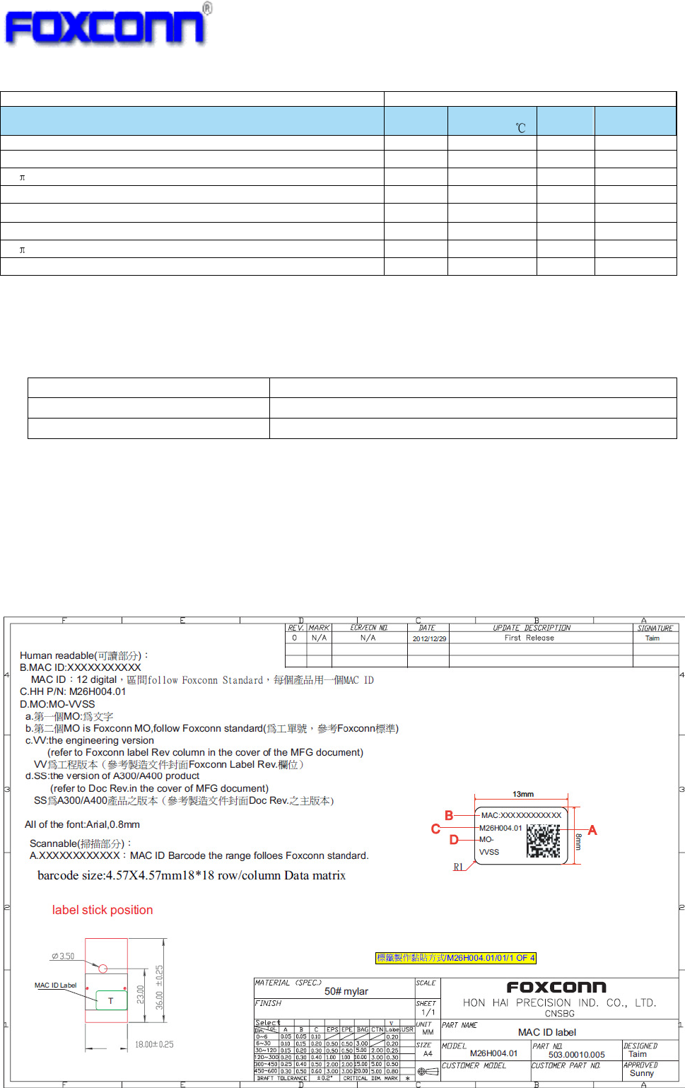
5.1 Label Information...............................................................................................................................7
5.2 Package Information .........................................................................................................................8

COMPANY CONFIDENTIAL
3
0. Revision History
Date Document
revision
Product
revision Change Description
2013/3/4 00 1. Initial release
2013/3/18
01
1. new add schematic
2. new add BOM
3. new add PCB layout
2013-5-15
02
1. update PCBA picture
2. update outline because add shielding
3. update label and package information
COMPANY CONFIDENTIAL
4
1. Introduction
Project Name: 3D TV BT Module
Project Number: M26H004.01.
This documentation describes the engineering requirements specification of 3D TV BT
Module. It is a confidential document of Foxconn.
1.1 Scope
The BT Module is compliant to Bluetooth 4.0 and EDR compliant:
Carrier Frequency: 2402MHz ~ 2480 MHz
Carrier Spacing: 1.0MHz
Duplexing: TDD
Modulation: FHSS/ GFSK, pi/4-DQPSK, 8DPSK
Symbol Rate: 1Mbps (GFSK), 2Mbps (pi/4-DQPSK), 3Mbps (8DPSK)
This module is designed with 8pin WTB connector and USB Interface, and it is installed
as a client device in TV platform.
1.2 Feature
Bluetooth 4.0+EDR compliant
Programmable output power control meets Class 1, Class 2 requirements.
Support PC and TV applications without external memory.
Support 3D Glass and BT remote control device
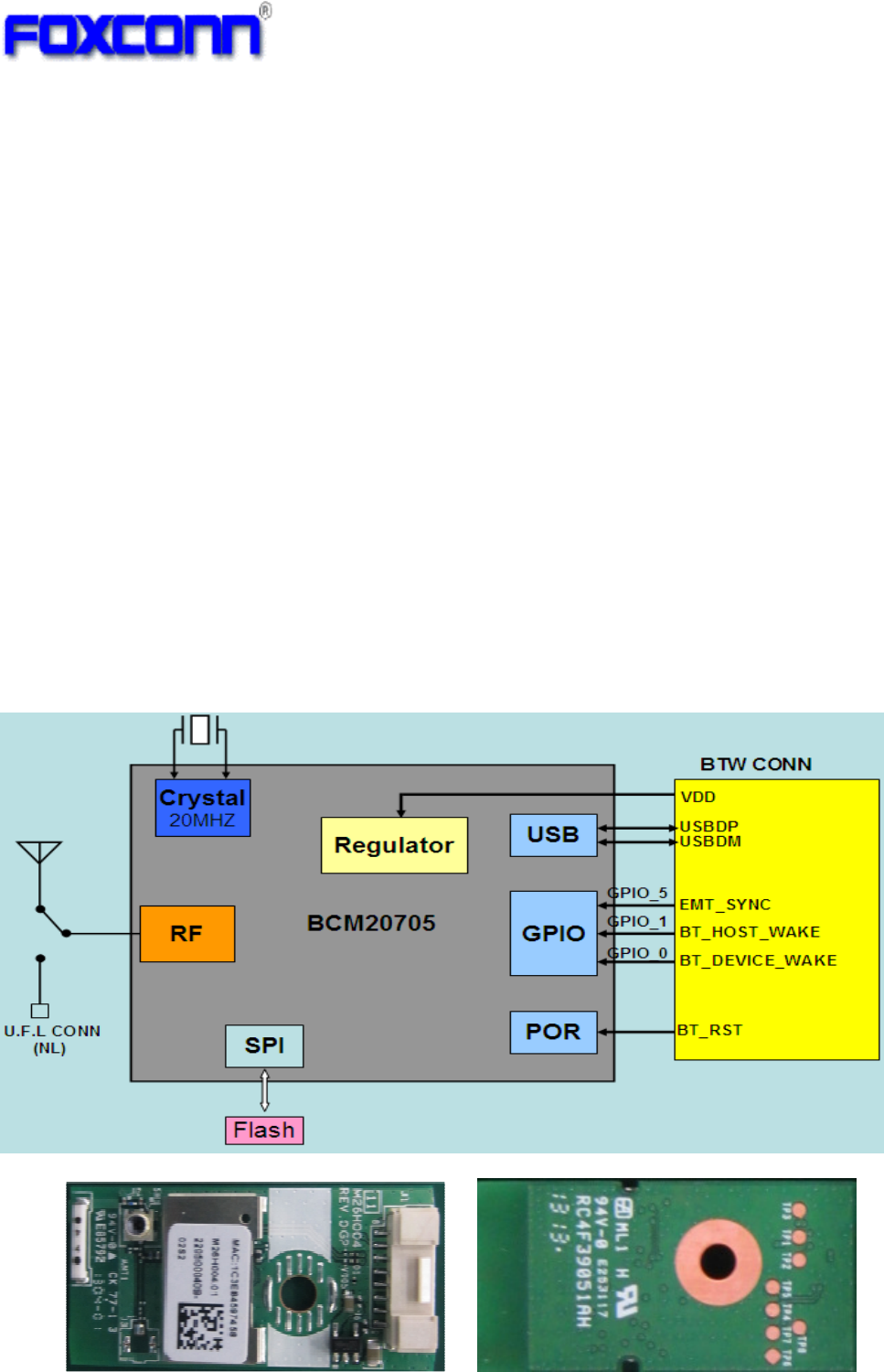
1.3 Functional Block Diagram
Sample picture is as below
Top View Bottom View
COMPANY CONFIDENTIAL
5
2. Mechanical Specification
2.1 Module dimension
Module Dimension: Typical PCB size (W×L): 18mm ×36mm.
2.2 WTB Connector Specification
8pin side entry type WTB CONN, 1.25mm pitch, detail spec as below:
2.3 WTB connector Pin definition
Pin
No
Pin Name I/O Description
1
BT_DEVICE_WAKE(GPIO_0)
I Allows the SOC host to wake up the BT device
2
BT_HOST_WAKE(GPIO_1) O Allows the BT device to wake up the SOC host
3
USB_5V PWR
DC +5V power input
4
HUSBDM I/O USB Data D-
5
HUSBDP I/O USB Data D+
6
GND GND Ground
7
3D_SYNC(GPIO_5) I 3D sync clock input
8
BT_RST I BT device reset
8 1
Unit: mm
COMPANY CONFIDENTIAL
6
3. Electrical Specification
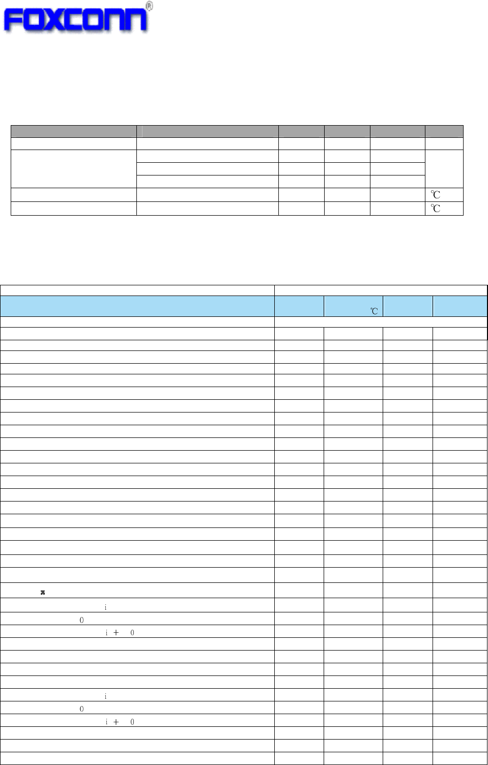
3.1 Operating Condition
Parameter Condition Min. Typ. Max. Unit
DC Input USB 5V 4.5 5.0 5.5 V
Tx Current 0.35
Rx Current 0.17
Module Current
(DC input nominal)
Standby Current 0.01
A
Operating Temperature -- 0 +60
Storage Temperature -- -40 +85
3.2 BT RF Specification
Items
Contents
TX Characteristics
Min.
Typ.
(@5.0V/25 )
Max.
Unit
1. Power Levels
BT Output Power (Basic Data Rate)@Class 2 -6 2.0 4 dBm
2. Initial Carrier Frequency Tolerance
Average Offset -75 -4.8 75 kHz
3. Carrier Drift
Drift Rate
DH1 -20 -5.54 20 kHz/50us
DH3 -20 6.11 20 kHz/50us
DH5 -20 5.38 20 kHz/50us
Average Drift
DH1 -25 -5 25 kHz
DH3 -40 -5 40 kHz
DH5 -40 -1 40 kHz
4. Modulation Characteristic
F1avg 140 155 175 kHz
F2max 115 130 kHz
F1/F2 Ratio 0.8 0.94
5. EDR Relative Transmit Power
2Mbps: P[DQPSK]-P[GFSK] -4 0.30 1 dB
3Mbps: P[8DPSK]-P[GFSK] -4 0.25 1 dB
6. EDR Carrier Frequency Stability and Modulation Accuracy
2Mbps: /4 DQPSK
Initial Frequency Error: ω -75 -6.1 75 kHz
Frequency Error: ω -10 -2.2 10 kHz
Block Frequency Error: ω ω -75 -7.5 75 kHz
RMS DEVM - 0.062 0.2
Peak DEVM - 0.158 0.35
99% DEVM (% Symbols <=0.3) 99% 100%
3Mbps: 8DPSK
Initial Frequency Error: ω -75 -9 75 kHz
Frequency Error: ω -10 -1.5 10 kHz
Block Frequency Error: ω ω -75 -10 75 kHz
RMS DEVM - 0.05 0.13
Peak DEVM - 0.13 0.25
99% DEVM (% Symbols <=0.13) 99% 100%
COMPANY CONFIDENTIAL
7
3.3 On-board Antenna Specification
Operating Frequency 2.40~2.5GHz
VSWR <=2.0:1
Antenna Type Chip ANT
4. Quality
The product quality must be followed-up by Foxconn factory quality control system.
5. Appendix
5.1 Label Information
Items
Contents
RX Characteristics
Min.
Typ.
(@5.0V/25 )
Max.
Unit
1. Minimum Input Level Sensitivity
GFSK (1Mbps) - -87 -70 dBm
/4 DQPSK (2Mbps) - -87 -70 dBm
8DPSK (3Mbps) - -80 -70 dBm
2. Maximum Input Level
GFSK (1Mbps) -20 0 dBm
/4 DQPSK (2Mbps) -20 -14 dBm
8DPSK (3Mbps) -20 -14 dBm
COMPANY CONFIDENTIAL
8
5.2 Package Information
Federal Communication Commission Interference Statement
This equipment has been tested and found to comply with the limits for a Class B digital
device, pursuant to Part 15 of the FCC Rules. These limits are designed to provide
reasonable protection against harmful interference in a residential installation. This
equipment generates, uses and can radiate radio frequency energy and, if not installed and
used in accordance with the instructions, may cause harmful interference to radio
communications. However, there is no guarantee that interference will not occur in a
particular installation. If this equipment does cause harmful interference to radio or
television reception, which can be determined by turning the equipment off and on, the
user is encouraged to try to correct the interference by one of the following measures:
- Reorient or relocate the receiving antenna.
- Increase the separation between the equipment and receiver.
- Connect the equipment into an outlet on a circuit different from that to which the
receiver is connected.
- Consult the dealer or an experienced radio/TV technician for help.
FCC Caution:
Any changes or modifications not expressly approved by the party responsible for
compliance could void the user's authority to operate this equipment.
This device complies with Part 15 of the FCC Rules. Operation is subject to the following
two conditions:
(1) This device may not cause harmful interference, and
(2) This device must accept any interference received, including interference that may
cause undesired operation.
FCC Radiation Exposure Statement:
This equipment complies with FCC radiation exposure limits set forth for an uncontrolled
environment. This transmitter module must not be co-located or operating in conjunction
with any other antenna or transmitter.
This End equipment should be installed and operated with a minimum distance of 20
centimeters between the radiator and your body.
IMPORTANT NOTE:
In the event that these conditions can not be met (for example certain laptop
configurations or co-location with another transmitter), then the FCC authorization is no
longer considered valid and the FCC ID can not be used on the final product. In these
circumstances, the OEM integrator will be responsible for re-evaluating the end product
(including the transmitter) and obtaining a separate FCC authorization.
End Product Labeling
The final end product must be labeled in a visible area with the following:
“Contains FCC ID: N89-BU067HS ”.
Manual Information to the End User
The OEM integrator has to be aware not to provide information to the end user regarding
how to install or remove this RF module in the user’s manual of the end product which
integrates this module.